NETSCOUT Systems SENSOR4X1 8902.11n SmartEdge Sensor User Manual Manual
NETSCOUT Systems, Inc. 8902.11n SmartEdge Sensor Manual
Manual

AirMagnet Enterprise Sensor 4 Series
SmartEdge Sensor

ii
Table of Contents
Copyright ....................................................................................................................... 1
AirMagnet Enterprise Sensor 4 Series SmartEdge Sensor ........................................ 2
Special Notes ............................................................................................................... 2
Introduction .................................................................................................................. 2
Product Package Content............................................................................................. 2
AirMagnet Enterprise Sensor 4 Series SmartEdge Sensor ........................................... 2
Product Models ......................................................................................................... 2
Accessories .................................................................................................................. 3
Installation ..................................................................................................................... 4
External Antenna Port Assignments ............................................................................. 4
Installation .................................................................................................................... 5
Sensor Zero Configuration ......................................................................................... 5
Mounting the Sensor Using the Mounting Bracket ..................................................... 5
Installing the Sensor on a T-Rail ................................................................................ 6
Antenna Installation ................................................................................................... 7
Powering Up Sensors ................................................................................................... 9
Power Options .............................................................................................................. 9
Powering Up via an 802.3af-Compliant PoE Injector ................................................. 9
Powering Up Directly via an 802.3af-Compliant Switch ............................................. 9
Powering Up via +12 volt Power Supply .................................................................... 9
Status LEDs ............................................................................................................... 10
Specifications .............................................................................................................. 11
Electrical Specifications .............................................................................................. 11
Mechanical Specification ............................................................................................ 13
Environmental Specifications ..................................................................................... 14
Antennas .................................................................................................................... 14
External Antenna Model .......................................................................................... 14
Internal Antenna Model ........................................................................................... 15
Sensor RF Connectors (External Antenna Models) .................................................... 16
Bottom Cover ............................................................................................................. 16
Standards Compliance ............................................................................................... 17
Standards and Agency Compliance ........................................................................... 17
FCC Interference Statement ....................................................................................... 17
Radiation Exposure Statement ................................................................................ 18
Industry Canada Statement ..................................................................................... 18
IC Radiation Exposure Statement ............................................................................ 18

Table of Contents
iii
Industry Canada Interference Statement ................................................................. 18
Industrie Déclaration de Canada ............................................................................. 18
Déclaration d'Exposition de Radiation d'IC .............................................................. 19
Industrie Déclaration d'Interférence de Canada ....................................................... 19
EU Declaration of Conformity ..................................................................................... 19
EN60950-1: (2006) .................................................................................................. 19
EN63211: 2008 ....................................................................................................... 19
EN 300 328 V1.7.1: (2006-10) ................................................................................. 19
EN 301 893 V1.5.1: (2008-12) ................................................................................. 19
EN 301 489-17 V2.1.1 (2009-05) ............................................................................. 20
CSA ......................................................................................................................... 21
Support ........................................................................................................................ 22
Hardware Warranty .................................................................................................... 22
Product Warranty period .......................................................................................... 22
Product Support ......................................................................................................... 23
Benefits of the Gold Support program include: ........................................................ 24
Contact Customer Support ...................................................................................... 24

1
Copyright
AirMagnet Enterprise Sensor 4 Series SmartEdge Sensor.
© 2012 Fluke Corporation, Inc. All rights reserved.
This document is furnished under license and may be used or copied only in accordance
with the terms specified in the license. The content of this document is furnished for
informational purposes only and should not be construed as a commitment on the part of
AirMagnet. AirMagnet. reserves the right to modify the content of this user guide without
notice.
No part of this document may be reproduced, transmitted, stored in a retrieval system, or
translated into any language in any form or by any means without the prior written
consent of AirMagnet.
AIRMAGNET SHALL NOT BE HELD LIABLE FOR ERRORS, INACCURACIES, OR
OMISSIONS THAT MAY EXIST IN THIS DOCUMENT; NOR FOR INCIDENTAL OR
CONSEQUENTIAL DAMAGES RESULTING FROM THE USE OF THIS CONTENT.
AirMagnet® and AirWISE® are registered trademarks, and the AirMagnet logo is a
trademark, of AirMagnet. All the other product names mentioned herein are trademarks
or registered trademarks of their respective companies.
Fluke Networks
2575 Augustine Dr., Santa Clara, CA 95054
USA
Compiled in the United States of America. May 2012.

2
AirMagnet Enterprise Sensor 4 Series SmartEdge
Sensor
Special Notes
AirMagnet Enterprise Sensor 4 Series SmartEdge Sensor technical documentation (in
PDF format) can be downloaded by registered customers from the "Documents /
Downloads" section of their My AirMagnet account. See
http://airmagnet.flukenetworks.com/my_airmagnet/
Introduction
AirMagnet Enterprise Sensor 4 Series SmartEdge Sensor represents the next
generation in 3X3 11n sensor technology.
AirMagnet Enterprise Sensor 4 Series SmartEdge Sensor is a new generation of the
AirMagnet SmartEdge Sensor family. It features the new high performance 1.8 GHz
ARM based processor, a 10/100/1000 MB Ethernet Base-T port with IEEE 802.3af
Power over Ethernet (PoE) compliance, one or two 802.11n 3X3 3 stream 450mbps
radios and a spectrum analyzer option.
Product Package Content
The product package contains the following items:
• One (1) printed AirMagnet Sensor Information Sheet
• One (1) AirMagnet Sensor
• Removable antennas (based on model configuration, see Sensor Product
Models)
• One mounting kit that includes (1) wall mounting bracket, two (2) wall
mounting anchors and two (2) wall mounting screws.
In case any of these items is missing or damaged, contact your AirMagnet product
reseller or AirMagnet technical support immediately.
AirMagnet Enterprise Sensor 4 Series SmartEdge Sensor
Product Models
Sensor Model
Features
SENSOR4-R1S0-I
AIRMAGNET SENSOR, 3X3 802.11n radio quantity 1, INTERNAL
ANTENNA.

AirMagnet Enterprise Sensor 4 Series SmartEdge Sensor
3
Sensor Model
Features
SENSOR4-R1S1-I
AIRMAGNET SPECTRUM SENSOR, 3X3 802.11n radio quantity 1,
INTERNAL ANTENNA.
SENSOR4-R2S0-I
AIRMAGNET SENSOR, 3X3 802.11n radio quantity 2, INTERNAL
ANTENNA.
SENSOR4-R2S1-I
AIRMAGNET SPECTRUM SENSOR, 3X3 802.11n radio quantity 2,
INTERNAL ANTENNA.
SENSOR4-R1S0-E
AIRMAGNET SENSOR, 3X3 802.11n radio quantity 1, 4
EXTERNAL ANTENNAS.
SENSOR4-R1S1-E
AIRMAGNET SPECTRUM SENSOR, 3X3 802.11n radio quantity 1,
4 EXTERNAL ANTENNAS.
SENSOR4-R2S0-E
AIRMAGNET SENSOR, 3X3 802.11n radio quantity 2, 8
EXTERNAL ANTENNAS.
SENSOR4-R2S1-E
AIRMAGNET SPECTRUM SENSOR, 3X3 802.11n radio quantity 2,
8 EXTERNAL ANTENNAS.
Accessories
Sold separately:
• AM/A5032 802.3af-compliant Power over Ethernet (PoE) adapter.
PowerDsine PD-3501/AC [PN 3536079]
• AM/A5033 UPA [PN 3536101]
• Cable Kit-Sensor 4: CD with USB to RS-232 driver 3; DB9 male/female
right angle adapter; DB9 Null Modem Serial Cable; USB to DB9 Serial
Adapter [PN 4221929]
4
Installation
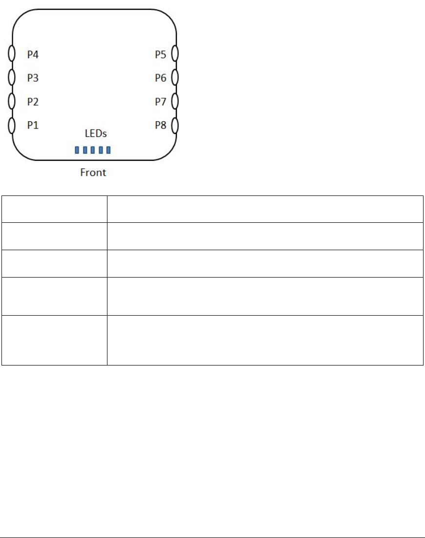
External Antenna Port Assignments
Use the following table and associated diagram to determine antenna port assignments
for each external antenna sensor model.
WLAN0 = 1st radio
WLAN1 = 2nd radio
Sensor Model
Port Assignments
SENSOR4-R1S0-E
P1-WLAN0-Ch0, P3-WLAN0-Ch1, P5-WLAN0-Ch2
SENSOR4-R1S1-E
P1-WLAN0-Ch0, P3-WLAN0-Ch1, P5-WLAN0-Ch2, P7-Spectrum
SENSOR4-R2S0-E
P1-WLAN0-Ch0, P3-WLAN0-Ch1, P5-WLAN0-Ch2, P4-WLAN1-Ch0,
P6-WLAN2-Ch1, P8-WLAN2-Ch2
SENSOR4-R2S1-E
P1-WLAN0-Ch0, P3-WLAN0-Ch1, P5-WLAN0-Ch2, P4-WLAN1-Ch0,
P6-WLAN2-Ch1, P8-WLAN2-Ch2,
P7-Spectrum
Installation
5
Installation
Sensor Zero Configuration
The sensor comes with a zero configuration feature that enables users to place the
Sensor on their network and have it automatically find and connect to the AirMagnet
Enterprise Server without having to configure the Sensor first. This concept simplifies the
process of configuring and managing Sensors during deployment. It also reduces the
overhead during regular maintenance cycles.
To take advantage of the Sensor zero configuration feature, the user must enable the
zero configuration feature on the AirMagnet Enterprise Server. This feature also carries
over to the Sensor properties screen on the AirMagnet Enterprise Console. The user can
change the Sensor’s shared secret key from the Console and have it automatically
forwarded to the Sensor.
For more information on sensor zero configuration, see the AirMagnet Enterprise User
Guide.
Note: For better performance, the sensor should be installed where maximum field of
view (FOV) can be achieved. This means that it should be deployed in places where it
can cover as large an area as possible with little or no obstruction. The instructions
below show how to install the sensor using the mounting bracket.
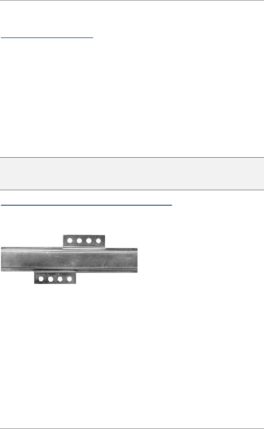
Mounting the Sensor Using the Mounting Bracket
The sensor can be mounted on any surface, such as a wall or ceiling, using the
AirMagnet Sensor Mounting Bracket kit.
1. Place the bracket horizontally so the screw-hole panels are flush
against the surface.
2. Attach the bracket to the surface using one screw anchor and one
screw in the top screw-hole panel and one screw anchor and one
screw in the bottom screw-hole panel.
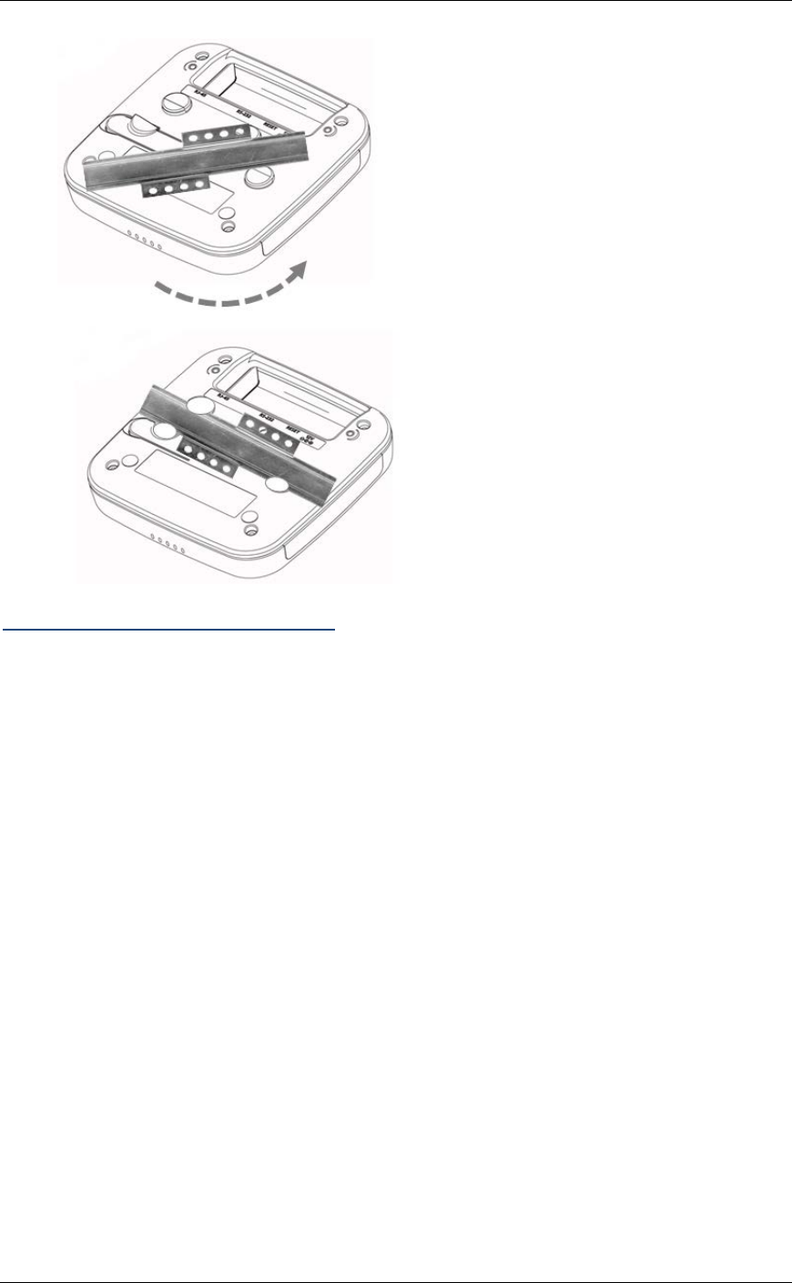
3. Place the bottom side of the sensor over the bracket at a 45 degree
angle between the two circular clips as shown.
4. Rotate the sensor until the sensor snaps into place.
To remove the sensor from the bracket, depress the flexible clip and rotate the sensor.
AirMagnet Enterprise Sensor 4 Series SmartEdge Sensor
6
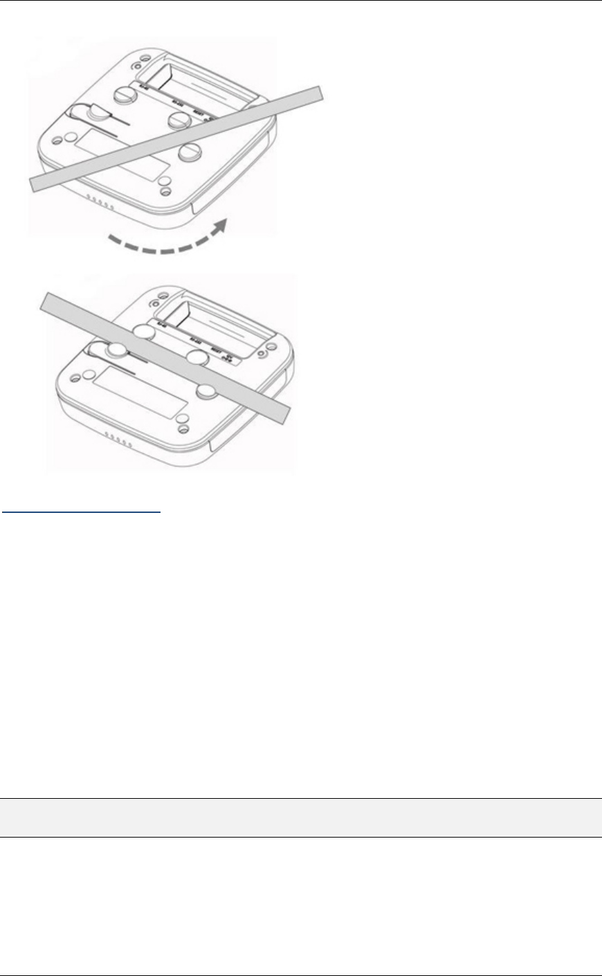
Installing the Sensor on a T-Rail
The ceiling of a building is an ideal place for installing the sensor in terms of FOV. You
can place the Sensor anywhere on a T-rail on the ceiling using the integrated T-rail clip.
1. Place the bottom side of the sensor over the T-rail at a 45 degree
angle between the two circular clips as shown.
2. Rotate the sensor until the sensor snaps into place.
To remove the sensor from the T-rail, depress the flexible clip and rotate the sensor.
Installation
7
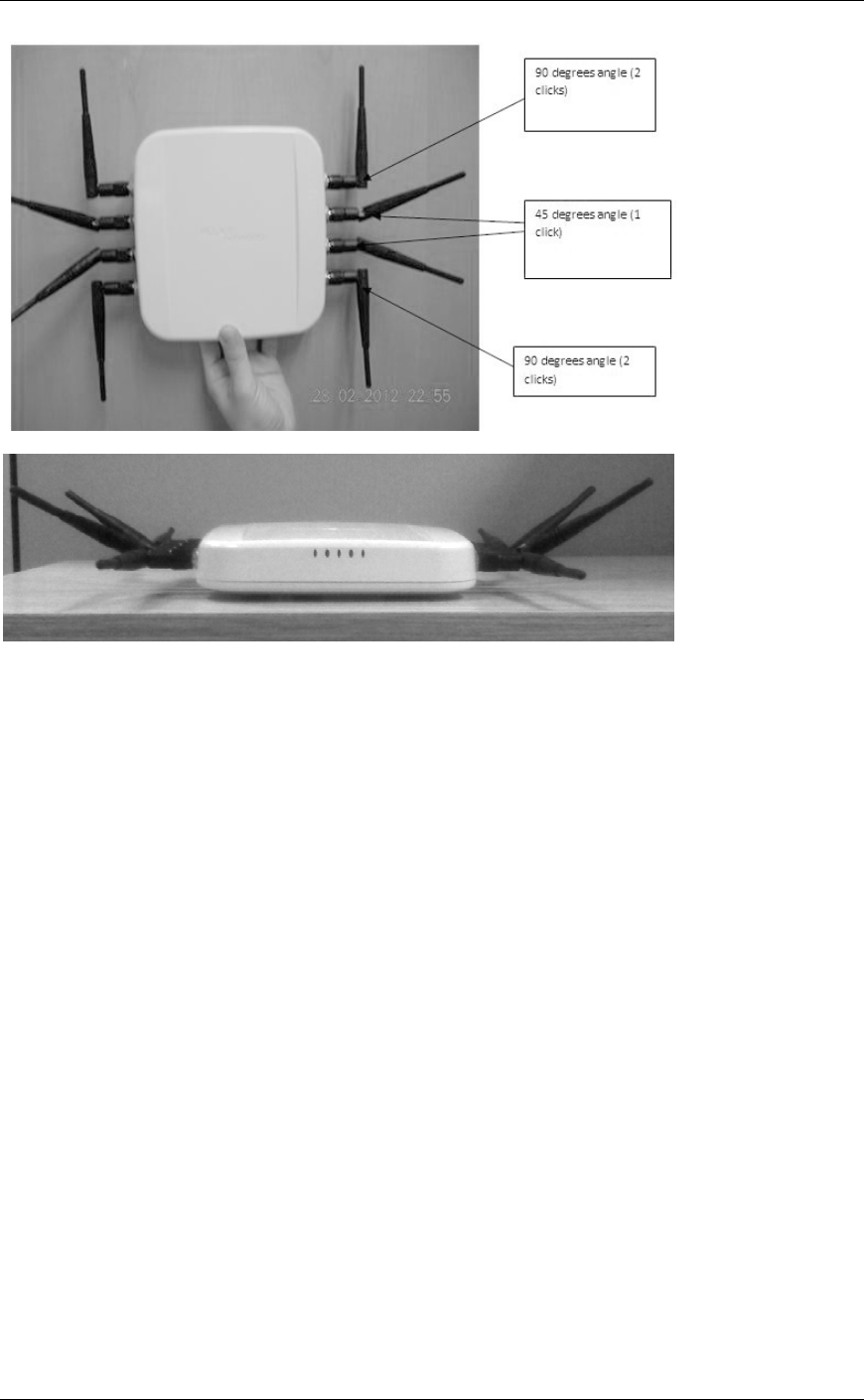
Antenna Installation
1. Screw on the supplied antennas to the RP-TNC connectors on the
sensor side plates.
2. Position the antenna angles as shown in the following "Antenna Angle
Positioning" section.
3. Hand tighten the antenna to the sensor while maintaining the angles
depicted.
4. Apply a small amount of Loctite or similar adhesive in the antenna
joint (elbow) to maintain antenna angle positioning during and after
sensor installation.
Antenna Angle Positioning
The following images indicate the recommended antenna positions for optimum
performance.
Note: With an antenna installed, as the antenna is rotated, it will click into position at
each 45 degree point in its rotation.
AirMagnet Enterprise Sensor 4 Series SmartEdge Sensor
8
9
Powering Up Sensors
Power Options
Customers deploying AirMagnet Enterprise can power their AirMagnet sensors using a
standard Ethernet cable, thus avoiding the need to run the standard electrical wiring to
each and every individual sensor. AirMagnet offers two Power over Ethernet (PoE)
options, and customers can typically make their own choice based on the quality of the
switch to which their AirMagnet sensors will be connected.
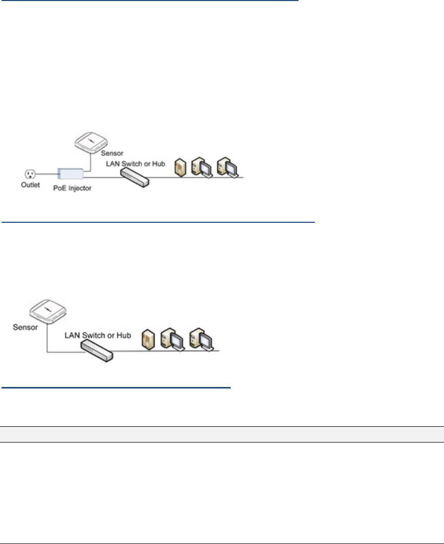
Powering Up via an 802.3af-Compliant PoE Injector
To power up sensor via an 802.3af-compliant PoE Injector:
1. Connect the PoE injector (via the Data Only port) to a network switch or
hub, using a 10/100 Ethernet cable.
2. Connect the PoE injector (via the Power and Data port) to the sensor
using another 10/100 Ethernet cable.
3. Plug the PoE power cord into an electrical outlet.
Powering Up Directly via an 802.3af-Compliant Switch
To power up the sensor directly via an 802.3af-compliant switch: Connect the sensor to
an IEEE 802.3af-compliant network switch (e.g., a Cisco Catalyst 3560 Series PoE-24)
using a 10/100 Ethernet cable.
Powering Up via +12 volt Power Supply
Use AM/A5033 UPA (sold separately).
Note: For 12 volt power supply, use only AM/A5033 UPA supplied by or authorized by Fluke.

AirMagnet Enterprise Sensor 4 Series SmartEdge Sensor
10
Status LEDs
LED
Color
Description
Power Blue
Solid – Power on Normal
Flash – sensor on but not ready – configuration.
OFF – no power
WLAN1 Green/Orange
Green Flashing – WiFi radio 1 RX mode
Orange Flashing – WiFi radio 1 TX mode
OFF – No WiFi 1 radio installed or sensor off
WLAN2 Green/Orange
Green Flashing – WiFi radio 2 RX mode
Orange Flashing – WiFi radio 2 TX mode
OFF – No WiFi 2 radio installed or sensor off
SA Red
Spectrum Analyzer – USB port
Flashing – spectrum not ready – configuration
Solid – On ready.
Off – no spectrum installed sensor off
LAN Yellow
Flashing – LAN is up and working.
Off – No traffic or sensor off

11
Specifications
Electrical Specifications
Specification
Detail
Operating Voltage
12VDC +/- 5%; 48V+/-10% (802.3af PoE)
Current Consumption
Max. 850 mA (12VDC); 210mA(48V PoE)
Processor
Marvell 88F6282, 1.86 GHz
WiFi Silicon
Atheros 9380 Mini-PCIe, Dual-band 802.11
n/a/b/g 3 spatial stream. Commercial Temp
System Memory
256MB DDR3
Input Power Requirement
PoE 802.3af Compliant or +12VDC
Data Rates
802.11an/gn 3SS
HT20 MCS 0-23 : 216.7 Mbps max
HT40 MCS 0-23 : 450 Mbps max
802.11a : 6, 9, 12, 18, 24, 36, 48, 54Mbps
802.11g :6, 9, 12, 18, 24, 36, 48 & 54Mbps
802.11b :1, 2, 5.5, 11Mbps
Frequency Band (for operating in US,
frequency is fixed in US band, user
cannot select other bands)
802.11n: dual band, same as 802.11a and
802.11b/g
802.11a:
5.15~5.25GHz, 5.25~5.35GHz,
5.47~5.725GHz, 5.725~5.875GHz
802.11b/g:
2.412~2.462GHz(US)
2.412~2.472GHz(Europe ETSI)
2.457~2.462GHz(Spain)
2.457~2.472GHz(France)

AirMagnet Enterprise Sensor 4 Series SmartEdge Sensor
12
Specification
Detail
Receive Sensitivity (Typical)
802.11n: 5 GHz band
-63dBm @ 135Mbps
-61dBm @ 270Mbps
-59 dBm @ 450Mbps
802.11n: 2.4 GHz band
-63dBm @ 130Mbps
-61dBm @ 270Mbps
-59 dBm @ 450Mbps
802.11a:
-85dBm @ 6Mbps
-86dBm @ 9Mbps
-85dBm @ 12Mbps
-83dBm @ 18Mbps
-78dBm @ 36Mbps
-73dBm @ 48Mbps
-82dBm @ 24Mbps
-72dBm @ 54Mbps
802.11b/g:
-81dBm @ 2Mbps
-87dBm @ 6Mbps
-85dBm @ 9Mbps
-85dBm @ 11Mbps
-85dBm @ 12Mbps
-84dBm @ 18Mbps
-84dBm @ 24Mbp
-81dBm @ 36Mbps
-73dBm @ 48Mbps
-74dBm @ 54Mbps

Specifications
13
Specification
Detail
Transmit Output Power (Typical)
802.11n: 5 GHz band
14~15dBm @ 135Mbps
9~11dBm @ 270Mbps
7~10dBm @ 450Mbps
802.11n: 2.4 GHz band
17dBm @ 135Mbps
12dBm @ 270Mbps
11dBm @ 450Mbps
802.11a:
14~15dBm @ 6-24Mbps
14~15dBm @ 36Mbps
11~13dBm @ 48Mbps
11~12dBm @ 54Mbps
802.11g:
16dBm for all rates
802.11b:
18dBm for all rates
Mechanical Specification
Item
Detail
Mechanical
- Seismic vibration PCB/Daughter-card/antenna connector
resiliency
- Integrated mounting bracket on bottom cover of housing.
Housing Size & Weight
Max. Dimensions: WxLxH = 7.5” x 7.5” x 1.5”.
Weight: Internal Antenna model: 15.8 oz, External Antenna
w/8 antennas attached: 29.5 oz
Status LEDS
Qty. 5. POWER, WLAN1, WLAN2, SA and LAN
LAN Port
10/100/1000Mbps RJ45 with Built-In 802.3af POE
Compliance

AirMagnet Enterprise Sensor 4 Series SmartEdge Sensor
14
Item
Detail
Serial Port
External Connector required, DB-9 male, RS-232 null
modem
External Switch
Reset switch
DC in Connector
DC power input jack.
RF Connector
RP-TNC for external models only.
Standard Antenna
(Dual Band 2.4G/5G)
Internal models PCB antenna: Qty 3, 6, or 7 depending on
internal antenna model.
External models SWIVEL R-TNC PLUG omnidirectional
dipole: Qty. 4 or 8 depending on external antenna model.
Environmental Specifications
Item
Detail
Operating
Temperature 32º to 131ºF (0º to 55ºC)
Storage Temperature
-40º to 158º F (-40º to 70ºC)
Operating Humidity
10 to 90% humidity (non-condensing) (DC power adapter
exclude)
Antennas
External Antenna Model
Specification
Detail
Standard
IEEE 802.11 a/b/g/n wireless LAN

Specifications
15
Specification
Detail
Length
143.5 mm (approximately 5.65 in.)
Color
White
Electrical
Operating Frequency: 2.4 ~ 2.4835 & 5.15 ~ 5.35 & 5.725 ~ 5.85 GHz
Polarization Type: Linear
Radiation Type: Toroidal
Antenna gain:
2.0 dBi max (2.4 ~ 2.4835 GHz)
2.3 dBi max (5.15 ~ 5.35 GHz)
1.0 dBi max (5.725 ~ 5.85 GHz)
Impedance: 50 Ohm nominal
V.S.W.R.: 2.0:1 max.
Mechanical
Connector: RP-TNC(M)
Core: N/A
Raw Material
Coaxial Cable: MIL-C-17 RG-178 B/U
Housing: TPU
Hinge: Polycarbonate
Internal Antenna Model
Specification
Detail
Standard
IEEE 802.11 a/b/g/n wireless LAN
Length x Width
2" X 0.65"

AirMagnet Enterprise Sensor 4 Series SmartEdge Sensor
16
Specification
Detail
Electrical
Operating Frequency: 2.4 ~ 2.4835 & 5.15 ~ 5.35 & 5.725 ~ 5.85 GHz
Polarization Type:Vertical, Omni directional
Antenna gain:
0.9 dBi max (2.4 ~ 2.4835 GHz)
3.1 dBi max (5.15 ~ 5.35 GHz)
4.8 dBi max (5.725 ~ 5.85 GHz)
Impedance: 50 Ohm nominal
V.S.W.R.: 2.0:1 max.
Sensor RF Connectors (External Antenna Models)
The sensor comes with 4 or 8 reverse polarity RP-TNC RF connectors (depending on
model purchased).
Bottom Cover
The sensor has an integrated T-rail mounting clip. It also has an embedded safety nut
for attaching extra safety cabling to conform to OSH PD standards

17
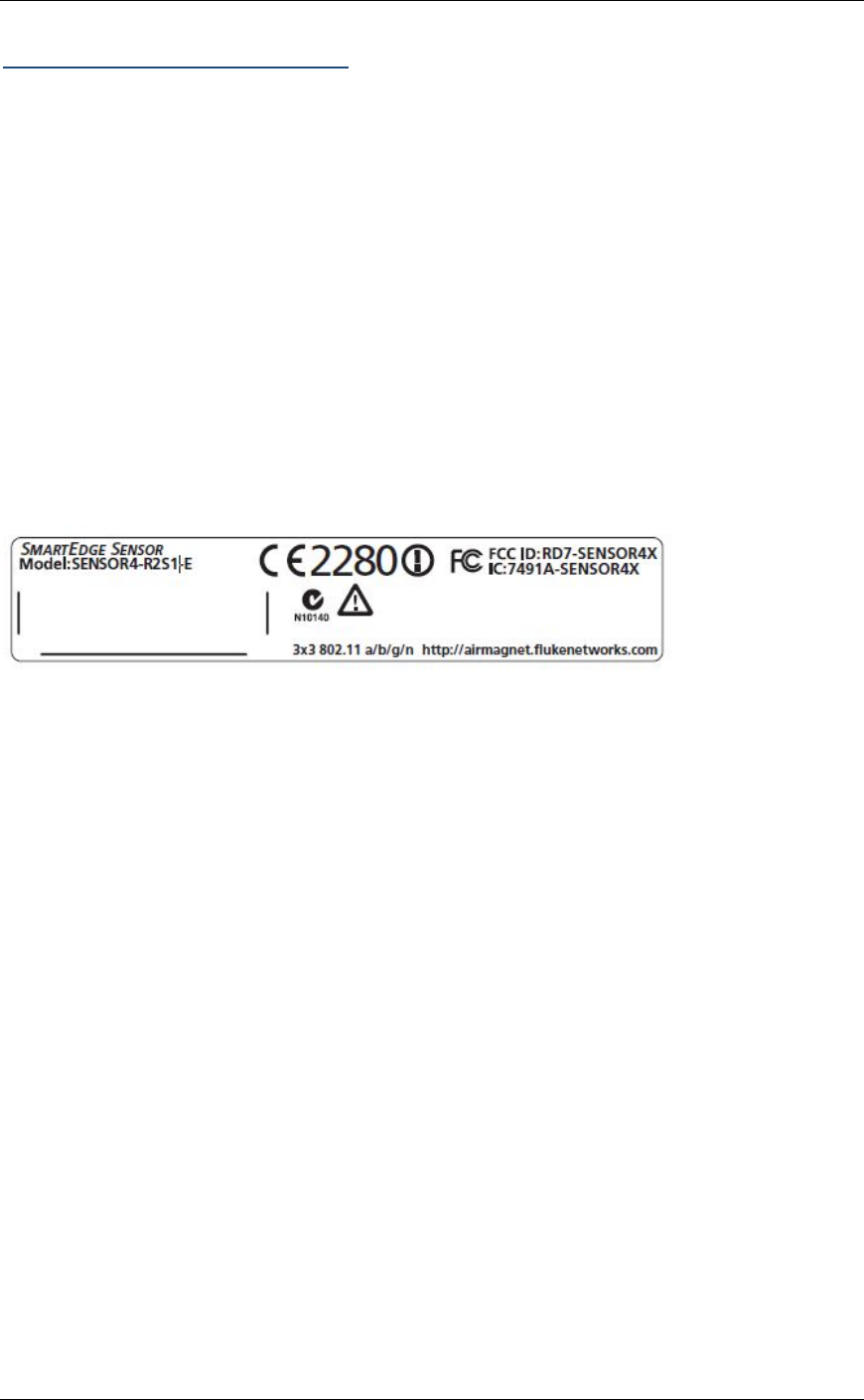
Standards Compliance
Standards and Agency Compliance
All products to be certified or tested to the following:
Item
Detail
Compliance
RoHS lead free.
CE (EN 300 328/ EN 301 489/ EN 301 893/ EN 60950)
FCC Part 15B/C/E, ANSI/UL 60950-1-2011
IC, CSA 60950-1-07, Including AMD1
CB Scheme report covering IEC 60950-1:2005+A1, EN 60950-
1:2006+A1+A11 and/or A12
Russia FSB Certification
FCC Interference Statement
This equipment has been tested and found to comply with the limits for a Class B digital
device, pursuant to Part 15 of the FCC Rules. These limits are designed to provide
reasonable protection against harmful interference in a residential installation. This
equipment generates, uses and can radiate radio frequency energy and, if not installed
and used in accordance with the instructions, may cause harmful interference to radio
communications. However, there is no guarantee that interference will not occur in a
particular installation. If this equipment does cause harmful interference to radio or
television reception, which can be determined by turning the equipment off and on, the
user is encouraged to try to correct the interference by one of the following measures:
• Reorient or relocate the receiving antenna.
• Increase the separation between the equipment and receiver.
• Connect the equipment into an outlet on a circuit different from that to
which the receiver is connected.
• Consult the dealer or an experienced radio/TV technician for help.
FCC Caution: Any changes or modifications not expressly approved by the party
responsible for compliance could void the user's authority to operate this equipment.
For operation within 5.15 ~ 5.25GHz frequency range, it is restricted to indoor
environment.

AirMagnet Enterprise Sensor 4 Series SmartEdge Sensor
18
This device complies with Part 15 of the FCC Rules. Operation is subject to the following
two conditions: (1) This device may not cause harmful interference, and (2) this device
must accept any interference received, including interference that may cause undesired
operation.
Radiation Exposure Statement
This equipment complies with FCC radiation exposure limits set forth for an uncontrolled
environment. This equipment should be installed and operated with minimum distance
20cm between the radiator & your body.
This transmitter must not be co-located or operating in conjunction with any other
antenna or transmitter.
The availability of some specific channels and/or operational frequency bands are
country dependent and are firmware programmed at the factory to match the intended
destination. The firmware setting is not accessible by the end user.
Sensor4 with Embedded type antenna and maximum antenna gain is 4.8 dBi in 5 GHz
and 2.0 dBi in 2.4 GHz.
Industry Canada Statement
This device complies with RSS-210 of the Industry Canada Rules. Operation is subject
to the following two conditions: (1) This device may not cause harmful interference, and
(2) this device must accept any interference received, including interference that may
cause undesired operation.
IC Radiation Exposure Statement
This equipment complies with IC radiation exposure limits set forth for an uncontrolled
environment. This equipment should be installed and operated with minimum distance
20cm between the radiator and your body.
Industry Canada Interference Statement
The device for the band 5150-5250 MHz is only for indoor usage to reduce potential for
harmful interference to co-channel mobile satellite systems;The maximum antenna gain
3.1 dBi permitted (for devices in the bands 5250-5350 MHz and 5470-5725 MHz) to
comply with the EIRP limit.
In addition, users should also be cautioned to take note that high- power radars are
allocated as primary users (meaning they have priority) of the bands 5250-5350 MHz
and 5650-5850 MHz and these radars could cause interference and/or damage to LE-
LAN devices.
Industrie Déclaration de Canada
Cet artifice se plie à RSS-210 de l'Industrie les Règles du Canada. L'opération est
soumise aux deux conditions suivantes : (1) Cet artifice peut ne pas provoquer
l'interférence malfaisante et (2) cet artifice doit accepter n'importe quelle interférence
reçue, en incluant l'interférence qui peut provoquer l'opération indésirable.

Standards Compliance
19
Déclaration d'Exposition de Radiation d'IC
Cet équipement se plie aux limites d'exposition IC de radiation présentées pour un
environnement non maîtrisé. Cet équipement devrait être installé et fait marcher avec la
distance minimale 20 centimètres entre le radiateur et votre corps.
Industrie Déclaration d'Interférence de Canada
L'artifice pour la bande 5150-5250 MHz est seulement pour l'usage en salle pour réduire
le potentiel pour l'interférence malfaisante au radiotéléphone de co-canal les systèmes
satellites; l'antenne maximum gagne 3.1 dBi permis (pour les artifices dans les bandes
5250-5350 MHz et 5470-5725 MHz) pour se plier à la limite d'EIRP.
En plus, on devrait aussi avertir des utilisateurs de prendre des notes que haut - les
radars de pouvoir sont alloués comme les utilisateurs primaires (le sens ils ont la
priorité) des bandes 5250-5350 MHz et 5650-5850 MHz et ces radars pourraient
provoquer l'interférence et-ou nuire aux artifices LE-LAN.
EU Declaration of Conformity
This device complies with the essential requirements of the R&TTE Directive 1999/5/EC.
The following test methods have been applied in order to prove presumption of
conformity with the essential requirements of the R&TTE Directive 1999/5/EC:
EN60950-1: (2006)
Safety of Information Technology Equipment.
EN63211: 2008
Product standard to demonstrate the compliance of radio base stations and fixed
terminal stations for wireless telecommunication systems with the basic restrictions or
the reference levels related to human exposure to radio frequency electromagnetic fields
(110MHz -40 GHz) - General public.
EN 300 328 V1.7.1: (2006-10)
Electromagnetic compatibility and Radio spectrum Matters (ERM); Wideband
Transmission systems; Data transmission equipment operating in the 2,4 GHz ISM band
and using spread spectrum modulation techniques; Harmonized EN covering essential
requirements under article 3.2 of the R&TTE Directive.
EN 301 893 V1.5.1: (2008-12)
Broadband Radio Access Networks (BRAN);5 GHz high performance RLAN;
Harmonized EN covering essential requirements of article 3.2 of the R&TTE Directive.
AirMagnet Enterprise Sensor 4 Series SmartEdge Sensor
20
EN 301 489-17 V2.1.1 (2009-05)
Electromagnetic compatibility and Radio spectrum Matters (ERM); ElectroMagnetic
Compatibility (EMC) standard for radio equipment; Part 17: Specific conditions for 2,4
GHz wideband transmission systems, 5 GHz high performance RLAN equipment and
5,8 GHz Broadband Data Transmitting Systems.
This device is a 2.4 GHz wideband transmission system (transceiver), intended for use
in all EU member states and EFTA countries, except in France and Italy where
restrictive use applies.
In Italy the end-user should apply for a license at the national spectrum authorities in
order to obtain authorization to use the device for setting up outdoor radio links and/or
for supplying public access to telecommunications and/or network services.
This device may not be used for setting up outdoor radio links in France and in some
areas the RF output power may be limited to 10 mW EIRP in the frequency range of
2454 – 2483.5 MHz. For detailed information the end-user should contact the national
spectrum authority in France.
Standards Compliance
21
CSA

22
Support
Hardware Warranty
LIMITED WARRANTY AND LIMITATION OF LIABILITY
Each fluke networks product is warranted to be free from defects in material and
workmanship under normal use and service unless stated otherwise herein. The
warranty period for the mainframe is one year and begins on the date of purchase.
Parts, accessories, product repairs and services are warranted for 90 days, unless
otherwise stated. Ni-Cad, Ni-MH and Li-Ion batteries, cables or other peripherals are all
considered parts or accessories. The warranty extends only to the original buyer or end
user customer of a Fluke networks authorized reseller, and does not apply to any
product which, in Fluke Networks’ opinion, has been misused, abused, altered,
neglected, contaminated, or damaged by accident or abnormal conditions of operation or
handling. Fluke Networks warrants that software will operate substantially in accordance
with its functional specifications for 90 days and that it has been properly recorded on
non-defective media. Fluke networks does not warrant that software will be error free or
operate without interruption.
Tools and test sets and other identified products are subject to the different warranties in
the matrix below or subject to other warranty terms and conditions that are provided with
certain products. The Tools and test set and AirMagnet products are not field
serviceable and customers should return them directly to Fluke Networks customer
support services for all repairs. Certain products, because of their applications, can be
supported for non-warranty maintenance by our customers. Some documentation and
replacement components are available for purchase from Fluke Networks.
Product Warranty period
Impact Tools and D-Impactor™ Five Pair impact tools (blades excluded, Can Wrench,
Probe Pic
Lifetime
TS®40 Series Test Sets
TS®52 Pro Test Sets
3 years
Butt-in telephone test sets (TS®40 Series excluded), Pro3000™ Analog Tone & Probe,
ADSL Splitter, Modular Adapters, Coax Strippers, Cable Strippers, Modular Crimper,
Need-L-Lock™ crimping pliers, TS®100 Cable Fault Finder, TS®90 Cable Fault Finder,
TS®250 ISDN Test Set, TS®1200 ADSL/POTS Test Set, JackRapid™ Punchdown Tool
(excludes bladehead), SpotCheck™ ADSL Presence Tester
18 months
Electrician’s Snips, D-Snips™ Scissors, Cable Splicing Knife

Support
23
90 days
AirMagnet Express Field Kit
90 days (netbook batteries not included)
Fluke Networks authorized resellers shall extend this warranty on new and unused
products to end-user customers only but have no authority to extend a greater or
different warranty on behalf of Fluke networks. Warranty support is available only if
product is purchased through a Fluke Networks authorized sales outlet or Buyer has
paid the applicable international price. To the extent permitted by law, Fluke Networks
reserves the right to invoice Buyer for repair/ replacement when a product purchased in
one country is submitted for repair in another country.
Fluke Networks warranty obligation is limited, at Fluke Networks option, to refund of the
purchase price, free of charge repair, or replacement of a defective product which is
returned to a Fluke Networks authorized service center within the warranty period.
To obtain warranty service, contact your nearest Fluke Networks authorized service
center to obtain return authorization information, then send the product to that service
center, with a description of the difficulty, postage and insurance prepaid (FOB
destination). Fluke Networks assumes no risk for damage in transit. Following warranty
repair, the product will be returned to Buyer, transportation prepaid (FOB destination). If
Fluke Networks determines that failure was caused by neglect, misuse, contamination,
alteration, accident or abnormal condition of operation or handling, or normal wear and
tear of mechanical components, Fluke Networks will provide an estimate of repair costs
and obtain authorization before commencing the work. Following repair, the product will
be returned to the Buyer transportation prepaid and the Buyer will be billed for the repair
and return transportation charges (FOB Shipping point).
THIS WARRANTY IS BUYER’S SOLE AND EXCLUSIVE REMEDY AND IS IN LIEU OF
ALL OTHER WARRANTIES, EXPRESS OR IMPLIED, INCLUDING BUT NOT LIMITED
TO ANY IMPLIED WARRANTY OF MERCHANTABILITY OR FITNESS FOR A
PARTICULAR PURPOSE. FLUKE NETWORKS SHALL NOT BE LIABLE FOR ANY
SPECIAL, INDIRECT, INCIDENTAL OR CONSEQUENTIAL DAMAGES OR LOSSES,
INCLUDING LOSS OF DATA, ARISING FROM ANY CAUSE OR THEORY.
Since some countries or states do not allow limitation of the term of an implied warranty,
or exclusion or limitation of incidental or consequential damages, the limitations and
exclusions of this warranty may not apply to every buyer. If any provision of this
Warranty is held invalid or unenforceable by a court or other decision-maker of
competent jurisdiction, such holding will not affect the validity or enforceability of any
other provision.
For Gold Support, see the Gold Support information page.
PO Box 777, Everett, WA 98206-0777, USA
Product Support
Fluke Networks' Gold Support is our comprehensive support and maintenance program
that offers expanded coverage for all AirMagnet products.

AirMagnet Enterprise Sensor 4 Series SmartEdge Sensor
24
Benefits of the Gold Support program include:
• Access to live 24 X 7 technical support.*
• Highly trained technical experts to help with product installation,
configuration, best practices & troubleshooting on call 24 hrs a day
including weekends and through the night.
• Multilingual technical support team.**
• Free software updates/upgrades (new features and product
enhancements) when available.
• Hardware support, repair and replacement for AirMagnet products.***
• Free access to "AirMagnet Certified Professional" web-based training for
certain AirMagnet products.
* Except United States holidays (New Years Day, Memorial Day, Labor Day, 4th of July,
Thanksgiving, Christmas)
** Multilingual support not available on weekends
*** Must meet terms and conditions as defined in the hardware warranty
Contact Customer Support
• Navigate to http://airmagnet.flukenetworks.com/my_airmagnet/ and log in
to My AirMagnet to access the “Exclusive” Gold- member only phone
numbers for your region.
• Submit a support request:
http://airmagnet.flukenetworks.com/support/submit-report.php
• Send email to support@AirMagnet.com.