NEXCOM IWF2220 Light Duty Industrial Access Point User Manual Manual

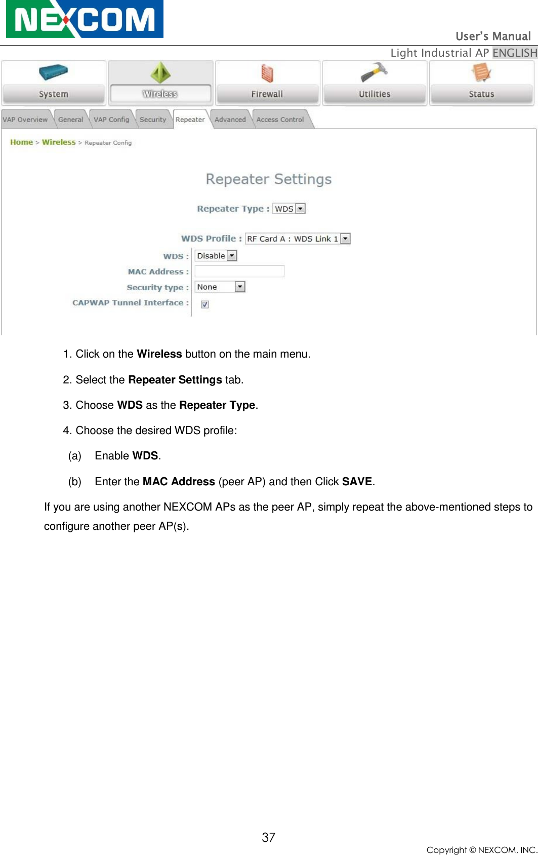
NEXCOM international Co.,LTD Light Duty Industrial Access Point Manual

Contents

user manual

        User Manual Light Industrial Access Point IWF2220  V1.2
                                                                         User’s Manual   Light Industrial AP ENGLISH 1 Copyright © NEXCOM, INC. Copyright & Disclaimer  Copyright The contents of this publication may not be reproduced in any part or as a whole, stored, transcribed in an information retrieval system, translated into any language, or transmitted in any form or by any means, mechanical, magnetic, electronic, optical, photocopying, manual, or otherwise, without the prior written permission of NEXCOM, INC.  Disclaimer NEXCOM, INC. does not assume any liability arising out the application or use of any products, or software described herein. Neither does it convey any license under its parent rights not the parent rights of others. NEXCOM further reserves the right to make changes in any products described herein without notice. The publication is subject to change without notice.  Trademarks NEXCOM is a registered trademark of NEXCOM, INC. Other trademarks mentioned in this publication are used for identification purposes only and may be properties of their respective owners.   FCC Statement: Federal Communication Commission Interference Statement  This equipment has been tested and found to comply with the limits for a Class B digital device, pursuant to Part 15 of the FCC Rules. These limits are designed to provide reasonable protection against harmful interference in a residential installation. This equipment generates, uses and can radiate radio frequency energy and, if not installed and used in accordance with the instructions, may cause harmful interference to radio communications. However, there is no guarantee that interference will not occur in a particular installation. If this equipment does cause harmful interference to radio or television reception, which can be determined by turning the equipment off and on, the user is encouraged to try to correct the interference by one of the following measures: ●  Reorient or relocate the receiving antenna.
                                                                         User’s Manual   Light Industrial AP ENGLISH 2 Copyright © NEXCOM, INC. ●  Increase the separation between the equipment and receiver. ●  Connect the equipment into an outlet on a circuit different from that to which the receiver is connected. ●  Consult the dealer or an experienced radio/TV technician for help.   FCC Caution: Any changes or modifications not expressly approved by the party  responsible for compliance could void the user’s authority to operate this equipment.   This device complies with Part 15 of the FCC Rules. Operation is subject to the following two conditions: (1) This device may not cause harmful interference, and (2) this device must accept any interference received, including interference that may cause undesired operation.   For product available in the USA/Canada market, only channel 1~11 can be operated. Selection of other channels is not possible.  This device and it's antennas(s) must not be co-located or operating in conjunction with any other antenna or transmitter except in accordance with FCC multi-transmitter product procedures.   This device is going to be operated in 5.15~5.25GHz frequency range, it is restricted in indoor environment only.  IMPORTANT NOTE: FCC Radiation Exposure Statement:
                                                                         User’s Manual   Light Industrial AP ENGLISH 3 Copyright © NEXCOM, INC. This equipment complies with FCC radiation exposure limits set forth for an uncontrolled environment. This equipment should be installed and operated with minimum distance 20cm between the radiator & your body.    Warning!  You are cautioned that changes or modifications not expressly approved by the party responsible for compliance could void your authority to operate the equipment.  1. Handling the unit: carry the unit with both hands and handle it with care.  2. Maintenance: to keep the unit clean, use only approved cleaning products or cleans with a dry cloth.
                                                                         User’s Manual   Light Industrial AP ENGLISH 4 Copyright © NEXCOM, INC. Table of Contents 1. Before You Start .................................................................................................................................. 6 1.1 Preface ................................................................................................................................................. 6 1.2 Document Conventions .................................................................................................................... 6 1.3 Package Content ................................................................................................................................ 7 2. System Overview and Getting Started ............................................................................................. 8 2.1 Introduction of NEXCOM Access Points ....................................................................................... 8 2.2 Hardware Description...................................................................................................................... 9 2.3 Hardware Installation .................................................................................................................... 11 2.4 Access Web Management Interface ............................................................................................. 12 3. Connect your AP to your Network .................................................................................................. 15 4. Adding Virtual Access Points .......................................................................................................... 21 5. Securing the AP ................................................................................................................................. 23 6. Creating a WDS Bridge between two APs ...................................................................................... 35 7. Web Management Interface Configuration ................................................................................... 38 7.1 System ............................................................................................................................................... 40 7.1.1 General ............................................................................................................................ 40 7.1.2 Network Interface ........................................................................................................... 42 7.1.3 Port .................................................................................................................................. 43 7.1.5 CAPWAP ......................................................................................................................... 46 7.1.6 IPv6 ................................................................................................................................. 47 7.2 Wireless ............................................................................................................................................ 48 7.2.1 VAP Overview ................................................................................................................. 48 7.2.2 General ........................................................................................................................... 50 7.2.3 VAP Configuration ......................................................................................................... 54 7.2.4 Security ........................................................................................................................... 55 7.2.5 Repeater ......................................................................................................................... 59 7.2.6 Advanced ........................................................................................................................ 60 7.2.7 Access Control ................................................................................................................ 62 7.3 Firewall ............................................................................................................................................. 66 7.3.1 Firewall List .................................................................................................................... 66 7.3.2 Service ............................................................................................................................ 70 7.3.3 Advanced ......................................................................................................................... 71 7.4 Utilities ............................................................................................................................................. 72 7.4.1 Change Password ............................................................................................................ 72 7.4.2 Backup & Restore ........................................................................................................... 72 7.4.3 System Upgrade ............................................................................................................. 74
                                                                         User’s Manual   Light Industrial AP ENGLISH 5 Copyright © NEXCOM, INC. 7.4.4 Reboot ............................................................................................................................ 74 7.4.5 Upload Certificate .......................................................................................................... 75 7.4.6 Channel Analysis ............................................................................................................ 75 7.5 Status ................................................................................................................................................ 77 7.5.1 Overview ......................................................................................................................... 77 7.5.2 Associated Clients .......................................................................................................... 78 7.5.3 WDS Link Status ............................................................................................................ 79 7.5.4 Event Log ........................................................................................................................80
                                                                         User’s Manual   Light Industrial AP ENGLISH 6 Copyright © NEXCOM, INC. 1. Before You Start 1.1 Preface  This manual is intended for using by system integrators, field engineers and network administrators to help them set up Access Points in their network environments. It contains step by step procedures and pictures to guide users with basic network system knowledge to complete the installation.    1.2 Document Conventions   Represents essential steps, actions, or messages that should not be ignored.  Note: Contains related information that corresponds to a topic.  Indicates that clicking this button will save the changes you made, but you must reboot the system for the changes to take effect.  Indicates that clicking this button will clear what you have set before the settings are applied.
                                                                         User’s Manual   Light Industrial AP ENGLISH 7 Copyright © NEXCOM, INC. 1.3 Package Content   The standard package of IWF2220 includes:    NEXCOM IWF2220    x1  CD-ROM (with User’s Manual and QIG)  x1   Ethernet Cable    x1   Power cord                                                       x1   Power Adaptor (12V)    x1   Detachable Antenna    x4         It is recommended to keep the original packing materials for possible future shipment when repair or maintenance is required.  Any returned product should be packed in its original packaging to prevent damage during delivery.
                                                                         User’s Manual   Light Industrial AP ENGLISH 8 Copyright © NEXCOM, INC. 2. System Overview and Getting Started 2.1 Introduction of NEXCOM Access Points  Indoor – IWF2220  The  NEXCOM’s  Enterprise  Access  Point  IWF  Series  are  embedded  with  802.11  a/b/g/n  MIMO technology,  designed  for  seamless  wireless  connectivity  in  enterprise  or  industrial  environments  of  all dimensions.  IWF2220  features  dual  radio  RF  cards  to  offer  flexible  implementations  needed  for  the growing wireless networking applications. The IWF Series make wireless communication fast, secure and easy.  They  support  business  grade  security,  namely  802.1X,  and  Wi-Fi  Protected  Access  (WPA  and WPA2). By pushing a purposely built button, the WES (Press-n-Connect) feature makes it easy to bridge wireless links of multiple access points for forming a wider wireless network coverage.  The  IWF  Series  also  features  multiple  ESSIDs  with  VLAN  tags  and  multiple  Virtual  APs,  great  for enterprise applications, such as separating traffic from different departments using different ESSIDs. The PoE LAN port is able to receive power from Power over Ethernet (PoE) sourcing devices.          Please note that screenshots are taken from APs which feature dual RF cards. Single RF Card APs can be configured in the same manner from the User Interface.
                                                                         User’s Manual   Light Industrial AP ENGLISH 9 Copyright © NEXCOM, INC. 2.2 Hardware Description This section depicts the hardware information including all panel description.  IWF2220 Front Panel  IWF2220 Front Panel
                                                                         User’s Manual   Light Industrial AP ENGLISH 10 Copyright © NEXCOM, INC.  Rear Panel  IWF2220 Rear Panel   1 Restart / Reset Press once to restart the system; to reset the system to factory default settings, hold for more than 5 seconds. 2 WES Button (RF B) WDS Easy Setup. Press the button to build up a WDS link with another peer. 4 WDS links can be set up per RF card.  Note that the WES Button only runs on the 5 GHz RF Card B. 3 LAN 1~4 Ports The ports for connections with LAN side devices. 4 Uplink Port (PoE) The port for uplink connection to another gateway or device. PoE (802.3at) is supported. 5 12V     2A Power Socket for the power adaptor
                                                                         User’s Manual   Light Industrial AP ENGLISH 11 Copyright © NEXCOM, INC. 2.3 Hardware Installation Please follow the steps mentioned below to install the hardware of IWF2220: Step 1.  Place the IWF2220 at the best location. The best location is usually at the center of your intended wireless network. Step 2.  Connect the IWF2220 to your network device. Connect one end of the Ethernet cable to the Uplink port of IWF2220 and the other end of the cable to a switch, a router, or a hub.  IWF2220 is then connected to your existing wired LAN network.  Step 3.  There are two ways to supply power to IWF2220 a)  Connect the DC power adaptor to the IWF2220 power jack socket. b)  The IWF2220 Uplink port is capable of receiving DC currents. Connect a (IEEE 802.3at-compliant) PSE device (e.g. a PoE-switch) to the Uplink port of IWF2220 with the Ethernet cable.   Now, the Hardware Installation is complete.   Please use only the power adapter supplied with the package.  Using a different power adapter may damage this system.  To verify the wired connection between the AP and your switch / router / hub, please also check the LED status indicator of the respective network devices.
                                                                         User’s Manual   Light Industrial AP ENGLISH 12 Copyright © NEXCOM, INC. 2.4 Access Web Management Interface NEXCOM Access Points support web-based configuration.  When hardware installation is complete, the AP can be configured through a PC by using a web browser. The default values of the AP’s LAN IP Address and Subnet Mask are:  IP Address: 192.168.1.1             Subnet Mask: 255.255.255.0     Example of entering the AP's default IP Address into a web browser   To access the web management interface (WMI), connect the administrator PC to the LAN port of the AP via an Ethernet cable. Then, set a static IP Address on the same subnet mask as the AP in TCP/IP settings of your PC, such as the following example: IP Address: 192.168.1.100 Subnet Mask: 255.255.255.0  Note: Please note that the IP Address used should not overlap with the IP Addresses of any other device within the same network to avoid IP conflict.    Launch the web browser on your PC and enter the IP Address of the AP (192.168.1.1) at the address field, and then press Enter.  The following Administrator Login Page will appear. Enter “admin” for both the Username and Password fields, and then click Login.
                                                                         User’s Manual   Light Industrial AP ENGLISH 13 Copyright © NEXCOM, INC. Administrator Login Page   After a successful login into AP, a System Overview page of the Web Management Interface (WMI) will appear.  The Web Management Interface - System Overview Page   To logout, simply click on the Logout button at the upper right hand corner of the interface to return to the Administrator Login Page. Click OK to logout.
                                                                         User’s Manual   Light Industrial AP ENGLISH 14 Copyright © NEXCOM, INC. Logout Prompt   For security reasons, it is strongly recommended to change the administrator’s password upon the completion of all configuration settings  Please follow the following steps to change the administrator’s password:  Change Password Page   Click on the Utilities icon on the main menu, and select the Change Password tab.   Enter the old password and then a new password with a length of up to 32 characters, and retype it in the Re-enter New Password field.   Congratulation! Now, the NEXCOM Access Point is installed and configured successfully.   It is strongly recommended to make a backup copy of your configuration settings.  After the AP’s network configuration is completed, please remember to change the IP Address of your PC Connection Properties back to its original settings in order to ensure that your PC functions properly in its real network environments.
                                                                         User’s Manual   Light Industrial AP ENGLISH 15 Copyright © NEXCOM, INC. 3. Connect your AP to your Network The following instructions depict how to establish the wireless coverage of your network.  The AP will connect to the network through its LAN port and provide wireless access to your network. After having prepared the AP’s hardware for configuration, set the TCP/IP settings of administrator’s computer to have a static IP Address of 192.168.1.10 and Subnet Mask of 255.255.255.0.  Step 1: Configuring the AP’s System Information   Enter the AP’s default IP Address (192.168.1.1) into the URL of a web browser.   Log in using Username: admin and Password: admin. The Web Management Interface will appear as shown below.
                                                                         User’s Manual   Light Industrial AP ENGLISH 16 Copyright © NEXCOM, INC. Web Management Interface Main Page (System Overview) From here, click on the System icon to get to the following page. On this Page you can make entries to the Name, Description, and Location fields as well as set the device’s time.  System Information Page There are two methods of setting up the time: Manual (indicated by the option Set Date & Time) and NTP. The default is Manual and requires individual setup every time the system starts up.  Simply choose a time zone and set the time accordingly. When it is finished, click SAVE.  Manually Time Setup  The alternative method is NTP. Upon selecting NTP under the Time field, the configuration changes to allow up to two NTP servers.  Simply enter a local NTP server’s IP Address (if available) or search online for an NTP server nearest to you.  Set the time zone and click SAVE.
                                                                         User’s Manual   Light Industrial AP ENGLISH 17 Copyright © NEXCOM, INC.  NTP Setup  Step 2: Configuring the AP’s Network Settings While still on this Page, click on the Network Interface tab to begin configuration of the network settings.  Network Settings Page If the deployment decides that the AP will be getting dynamic IP Addresses from the connected network, set Mode to DHCP; otherwise, set Mode to Static and fill in the required fields marked with a red asterisk (IP Address, Netmask, Gateway, and Primary DNS Server) with the appropriate values for the network. Click SAVE when you are finished to save changes that have been made.  Step 3: Configure the AP’s Wireless General Settings Click on the Wireless icon followed by the General tab. On this page we need to choose the Band and Channel that we wish to use.
                                                                         User’s Manual   Light Industrial AP ENGLISH 18 Copyright © NEXCOM, INC.  Wireless General Settings Page On this page, choose the RF card you would like to set up and select the band in which the AP is to broadcast its signal.  The rest of the fields are optional and can be configured at another time. Click SAVE if any changes have been made.           Note: •For IWF2220, the RF Card A supports only 2.4GHz bands (b/g/n) and RF Card B supports only 5GHz bands (a/n).
                                                                         User’s Manual   Light Industrial AP ENGLISH 19 Copyright © NEXCOM, INC.  Step 4: Configuring Wireless Coverage (VAP-1) To set up the AP’s wireless access, refer to the following VAP-1 configuration (other VAP configuration can refer to the same setup steps as done for VAP-1). Click on the Overview tab to proceed.  Virtual AP Overview Page  On this page click the hyperlink in the row and column that corresponds with VAP-1’s State. This will bring up the following page.
                                                                         User’s Manual   Light Industrial AP ENGLISH 20 Copyright © NEXCOM, INC.  VAP Configuration Page (RF Card A : VAP-1 shown)  The desired VAP profile can be selected from the drop-down menu of Profile Name and VAP-1 configuration will serve as an example for all other VAPs. Before proceeding further, please make sure that the VAP field is marked Enable; afterwards, enter an ESSID to represent the WLAN associated with AP’s VAP-1. It is suggested that Profile Name is used to describe what this particular VAP will be used for; otherwise, leave it as default. VLAN ID can be chosen at another time. Click SAVE to save all changes up to this point and Reboot the system to apply these revised settings.  Congratulations! After reboot, the AP can start to operate with these revised settings.
                                                                         User’s Manual   Light Industrial AP ENGLISH 21 Copyright © NEXCOM, INC. 4. Adding Virtual Access Points The AP possesses the feature of multi-ESSID; namely, it can behave as multiple virtual access points, providing different levels of services from the same physical AP device. Please click on the Wireless icon to review the VAP Overview page.  VAP Overview Page To proceed with specific VAP configuration, click on the corresponding cell in the State column and row of the VAP; the particular VAP’s Configuration page will then appear for further configuration.
                                                                         User’s Manual   Light Industrial AP ENGLISH 22 Copyright © NEXCOM, INC.  VAP Configuration Page (VAP-1 shown) Please select the desired RF card and VAP profile from the drop-down menu of Profile Name. Choose Enable for the VAP field.  Pick a descriptive Profile Name and an appropriate ESSID for clients to associate to. A VLAN ID can be provided to indicate the traffic through this particular VAP.  It may allow further management/control (e.g. access rights and Internet usage, etc) of each VAP with a management gateway. Click SAVE and then Reboot for the changes to take effect.
                                                                         User’s Manual   Light Industrial AP ENGLISH 23 Copyright © NEXCOM, INC. 5. Securing the AP Different VAP may require different levels of security. These instructions will guide the user through setting up different types of security for a particular VAP. Simply repeat the following steps for other VAP with security requirement.  Step 1: Ensure the intended VAP is Enabled  VAP Overview Page On the VAP Overview page, check the table to confirm the VAP State. If it is Enabled, skip to Step 2.  If not, click on to proceed with VAP Configuration for that particular VAP.
                                                                         User’s Manual   Light Industrial AP ENGLISH 24 Copyright © NEXCOM, INC.  VAP Configuration Page (RF Card A : VAP-1 as shown for example)  Select Enable for the VAP field and click SAVE. Click the Overview tab to return to the previous table to begin the next step.  Step 2: Configure Security Settings for your VAP The following instructions will guide the user to set up wireless security with a specific VAP.  If only restricted access of certain MAC addresses is desired, skip to Step3.  MAC restriction can be coupled with wireless security to provide extra protection. First, click on the corresponding cell in the column labeled Security Type. This hyperlink will direct the user to the following Security Settings page.
                                                                         User’s Manual   Light Industrial AP ENGLISH 25 Copyright © NEXCOM, INC.  Security Settings Page ( RF Card A : VAP-1  shown ) Select the desired Security Type from the drop-down menu, which includes None, WEP, 802.1X, WPA-PSK, and WPA-RADIUS.         802.11g+802.11n band does not support WEP nor WPA-PSK running TKIP. When the Security Type is set as such, the RF is only able to run ‘g’ band.
                                                                         User’s Manual   Light Industrial AP ENGLISH 26 Copyright © NEXCOM, INC.  None: Authentication is not required and data is not encrypted during transmission when this option is selected. This is the default setting as shown in the following figure.  Security Settings: None  WEP: WEP (Wired Equivalent Privacy) is a data encryption mechanism with key length selected from 64-bit, 128-bit, or 152-bit.  Security Settings: WEP  802.11 Authentication: Select from Open System, Shared Key, or Auto.
                                                                         User’s Manual   Light Industrial AP ENGLISH 27 Copyright © NEXCOM, INC.  WEP Key Length: Select a key length from 64-bit, 128-bit, 152-bit.  WEP Key Format: Select from ASCII or Hex format for the WEP key.  WEP Key Index: Select a key index from 1 through 4. The WEP key index is a number that specifies which WEP key is used for the encryption of wireless frames during data transmission.  WEP Keys: Provide the pre-defined WEP key value; the system supports up to 4 sets of WEP keys.   802.1X: When 802.1X Authentication is selected, RADIUS authentication and enhanced dynamic WEP are provided.  Security Settings: 802.1X Authentication  Dynamic WEP Settings:  o Dynamic WEP: For 802.1X security type, Dynamic WEP is always enabled to automatically generate WEP keys for encryption. o WEP Key Length: Select a key length from 64-bits or 128-bits.
                                                                         User’s Manual   Light Industrial AP ENGLISH 28 Copyright © NEXCOM, INC. o Re-keying Period: The time interval for the dynamic WEP key to be updated; the time unit is in seconds.  RADIUS Server Settings (A redundant server can also be added to the system):  o Host: Enter the IP address or domain name of the RADIUS server. o Authentication Port: The port number used by the RADIUS server. Specify a port number or use the default, 1812. o Secret Key: The secret key for the system to communicate with the RADIUS server. o Accounting Service: Enabling this option allows accounting of login and logouts through the RADIUS server. o Accounting Port: The port number used by the RADIUS server for accounting purposes.  Specify a port number or use the default, 1813. o Accounting Interim Update Interval: The system will update accounting information to the RADIUS server every interval period.
                                                                         User’s Manual   Light Industrial AP ENGLISH 29 Copyright © NEXCOM, INC.  WPA-PSK: Provides shared key authentication in WPA data encryption.  Security Settings: WPA-PSK  Cipher Suite:  Select an encryption method from TKIP (WPA), AES (WPA), TKIP (WPA2), AES (WPA2), or Mixed.  Pre-shared Key Type: Select a pre-shared key type: PSK (Hex) or Passphrase.   Pre-shared Key: Enter the key value for the pre-shared key; the format of the key value depends on the key type selected.  Group Key Update Period: The time interval for the Group Key to be renewed; the time unit is in seconds.
                                                                         User’s Manual   Light Industrial AP ENGLISH 30 Copyright © NEXCOM, INC.  WPA-RADIUS: Authenticates users by RADIUS and provides WPA data encryption.  Security Settings: WPA-RADIUS  WPA Settings: o Cipher Suite: Select an encryption method from TKIP (WPA), AES (WPA), TKIP (WPA2), AES (WPA2), or Mixed. o Group Key Update Period: The time interval for the Group Key to be renewed; the time unit is in seconds.  RADIUS Server Settings:  o Host: Enter the IP address or domain name of the RADIUS server. o Authentication Port: The port number used by the RADIUS server. Specify a port number or use the default, 1812. o Secret Key: The secret key for the system to communicate with the RADIUS server. o Accounting Service: Enabling this option allows accounting of login and logouts through the RADIUS server. o Accounting Port: The port number used by the RADIUS server for accounting purposes.  Specify a port number or use the default, 1813. o Accounting Interim Update Interval: The system will update accounting information to the
                                                                         User’s Manual   Light Industrial AP ENGLISH 31 Copyright © NEXCOM, INC. RADIUS server every interval period. When these configurations are finished and MAC restriction is not needed, click SAVE and Reboot the system. Otherwise, click on the Overview tab and proceed to the next step.  Step 3: Configuring MAC ACL (Access Control List) Clicking on the hyperlink corresponding with intended VAP in the MAC ACL column will bring the user to the Access Control Settings page.  Access Control Settings Page  Please choose among Disable, Allow, Deny, and RADIUS ACL from the drop-down menu of Access Control Type. 1) Disable Access Control: This means that there is no restriction for client devices to access the system. 2) MAC ACL Allow List: This means that only the client devices (identified by their MAC addresses) listed in the Allow List (“allowed MAC addresses”) are granted with access to the system. The administrator can temporarily block any allowed MAC address by checking Disable, until the administrator renews the listed MAC.
                                                                         User’s Manual   Light Industrial AP ENGLISH 32 Copyright © NEXCOM, INC.  MAC ACL Allow List   An empty Allow List means that there are no allowed MAC addresses. Make sure at least the MAC of the modifying system is included (e.g. network administrator’s computer).  3) MAC ACL Deny List: This means that all client devices are granted with access to the system except those listed in the Deny List (“denied MAC addresses”). The administrator can allow any denied MAC address to connect to the system temporarily by checking Enable.
                                                                         User’s Manual   Light Industrial AP ENGLISH 33 Copyright © NEXCOM, INC.  MAC ACL Deny List   RADIUS ACL: Authenticate incoming MAC addresses by an external RADIUS server.  When RADIUS ACL is selected, all incoming MAC addresses will be authenticated by an external RADIUS server.  Please note that each VAP MAC ACL and its security type (shown on the Security Settings page) share the same RADIUS configuration.
                                                                         User’s Manual   Light Industrial AP ENGLISH 34 Copyright © NEXCOM, INC.  RADIUS ACL Click SAVE and Reboot upon completing the related configurations to take effect.
                                                                         User’s Manual   Light Industrial AP ENGLISH 35 Copyright © NEXCOM, INC. 6. Creating a WDS Bridge between two APs WDS link creation is convenient for extending network coverage where running wires is not an option, effectively transferring the traffic to the other end of WLAN/LAN through the AP. Since this is a peer to peer connection, both APs will be configured the same way.  Step 1: Make sure the Band and Channel are matched between the WDS peers In order to create a valid WDS link, the two APs must be configured to use the same channel and band for their wireless settings. Click the Wireless icon and then General tab to go to the following page.  Wireless General Settings Page Please make sure both APs are using the same Band and Channel in order to establish a successful WDS link. Click SAVE if any changes have been made.
                                                                         User’s Manual   Light Industrial AP ENGLISH 36 Copyright © NEXCOM, INC. Step 2: Prevent Loops when Connecting Multiple APs When many APs are linked in this manner, undesired loops may form to lower overall WLAN performance. To prevent such occurrence, please make sure Layer 2 STP is enabled. To turn on this feature, please click on the System icon and the Network Interface tab.  Network Settings Page Please select Enable in the field labeled Layer2 STP. This will prevent data from looping or creating a broadcast storm. Click SAVE when completed, and then Reboot to allow updated settings to take effect.   Step 3: Building the WDS Link To extend the wireless coverage, each RF card supports up to 4 WDS links for connecting wirelessly to other WDS-capable APs (peer APs). By default, all WDS profiles are disabled.
                                                                         User’s Manual   Light Industrial AP ENGLISH 37 Copyright © NEXCOM, INC.  1. Click on the Wireless button on the main menu. 2. Select the Repeater Settings tab. 3. Choose WDS as the Repeater Type. 4. Choose the desired WDS profile: (a)  Enable WDS.   (b)  Enter the MAC Address (peer AP) and then Click SAVE.    If you are using another NEXCOM APs as the peer AP, simply repeat the above-mentioned steps to configure another peer AP(s).
                                                                         User’s Manual   Light Industrial AP ENGLISH 38 Copyright © NEXCOM, INC. 7.  Web Management Interface Configuration This chapter will guide the user through the AP’s detailed settings. The following table shows all the User Interface (UI) functions of NEXCOM’s Enterprise Access Points. The Web Management Interface (WMI) is the page where the status is displayed, control is issued and parameters are configured.  In the Web Management Interface; there are two main interface areas: Main Menu and Working Area.  The Working Area occupies the major area of the WMI, displayed in the center of the interface.  It is also referred to as the configuration page. The Main Menu, on the top of the WMI, allows the administrator to traverse to various management functions of the system. The management functions are grouped into branches: System, Wireless, Firewall, Utilities, and Status.  Table 1 NEXCOM Access Points’ Function Organization OPTION FUNCTION System General Network Interface Port Management CAPWAP IPv6 Wireless VAP Overview General  VAP Config Security  Repeater Advanced Access Control  Firewall  Firewall List  Service Advanced Utilities Change Password  Backup & Restore System Upgrade  Reboot Upload Certificate Channel Analysis
                                                                         User’s Manual   Light Industrial AP ENGLISH 39 Copyright © NEXCOM, INC. Status Overview Associated Clients  WDS Link Status Event Log    Note: On each configuration page, you may click SAVE to save the changes of your configured settings, but you must reboot the system for the changes to take effect.  After clicking SAVE, the following message will appear: “Some modification has been saved and will take effect after Reboot.” All online users will be disconnected during reboot or restart.
                                                                         User’s Manual   Light Industrial AP ENGLISH 40 Copyright © NEXCOM, INC. 7.1 System  Upon clicking the System icon, users can utilize this section for general configurations of the devices (e.g. Time Setup, Network Configurations, and System Logs).  This section includes the following functions: General, Network Interface, Port, Management, CAPWAP and IPv6. 7.1.1 General  System Information Page  System Information       For maintenance purposes, it is highly recommended to have the following information stated as clearly as possible:  Name: The system name used to identify this system.  Description: Further information about the system (e.g. device model, firmware version, and active date).  Location: The information on geographical location of the system for the administrator to locate the system easily.  Time  Device Time: Display the current time of the system.  Time Zone: Select an appropriate time zone from the drop-down list box.  Time: Synchronize the system time by reachable NTP servers or manual setup.
                                                                         User’s Manual   Light Industrial AP ENGLISH 41 Copyright © NEXCOM, INC. 1) Enable NTP:  By selecting Enabled NTP, the AP can synchronize its system time with the NTP server automatically. When this method is chosen, at least one NTP server's IP address or domain name must be provided.   NTP Time Configuration Fields Generally, networks should have a common NTP server (internal or external).  If there isn’t, locate a nearby NTP server on the web. 2) Manually set up: By selecting Manually set up, the administrator can manually set the system date and time.  Manual Time Configuration Fields ▬ Set Date: Select the appropriate Year, Month, and Day from the drop-down menu. ▬ Set Time: Select the appropriate Hour, Min, and Sec from the drop-down menu.   Unless Internet connection or NTP becomes unavailable, it is recommended to use NTP server for time synchronization because system time needs to be reconfigured upon reboot.
                                                                         User’s Manual   Light Industrial AP ENGLISH 42 Copyright © NEXCOM, INC. 7.1.2 Network Interface On this page, the network settings of the device can be configured; fields with a red asterisk (i.e. IP Address, Netmask, Default Gateway, and Primary DNS Server) are mandatory.  Network Settings Page  Mode: Determine the way to obtain the IP address, by DHCP or Static.  Static: The administrator can manually set up the static LAN IP address.  All required fields are marked with a red asterisk. o IP Address: The IP address of the LAN port. o Netmask: The Subnet mask of the LAN port. o Default Gateway: The Gateway IP address of the LAN port. o Primary DNS Server: The IP address of the primary DNS (Domain Name System) server. o Alternate DNS Server: The IP address of the substitute DNS server.  DHCP: This configuration type is applicable when the system is connected to a network with the presence of a DHCP server; all related IP information required will be provided by the DHCP server automatically.  Layer 2 STP: If the AP is set up to bridge other network components, this option can be enabled to prevent undesired loops because a broadcasting storm may occur in a multi-switch environment where broadcast packets are forwarded in an endless loop between switches. Moreover, a broadcast storm may consume most of the available system resources in addition to available bandwidth. Thus, enabling the Layer 2 STP can lower such undesired occurrence and derive the best available data path for network communication.
                                                                         User’s Manual   Light Industrial AP ENGLISH 43 Copyright © NEXCOM, INC. 7.1.3 Port The physical Ethernet ports of the AP can be configured to append a VLAN tag for upstream delivery.    VLAN ID: Enable selected implies that network traffic sent upstream from this LAN port will be tagged with the VLAN ID configured in the field below. Disable selected implies that traffic from this LAN port will not be tagged with a VLAN ID.  CAPWAP Tunnel Interface: Select a LAN, VAP or WDS interface to designate its traffic to pass through the CAPWAP Tunnel established between the AP and the controller. For network interfaces that are unchecked, their traffic will be forwarded locally into the internet if this AP is deployed remotely on the WAN side of a controller.     The ‘TIP’ in red at the bottom of the page explains that each service zone, from default to Service Zone 8, has its fixed, pre-determined VLAN ID number. Admin needs to enter one of the numbers in order to direct traffic back to a certain service zone.
                                                                         User’s Manual   Light Industrial AP ENGLISH 44 Copyright © NEXCOM, INC. 7.1.4 Management The management services (e.g. VLAN for Management, SNMP, and System log) can be configured here.  Management Services Page   VLAN for Management: When this is enabled, management traffic from the system will be tagged with a VLAN ID. In other words, administrator who wants to access the WMI must send management traffic with the same VLAN ID such as connecting to a specific VAP with the same VLAN ID. Enter a value between 1 and 4094 for the VLAN ID if the option is enabled.        Note: Management is done without the utilization of VLAN IDs on selected AP models.
                                                                         User’s Manual   Light Industrial AP ENGLISH 45 Copyright © NEXCOM, INC.  SNMP Configuration: By enabling the SNMP function, the administrator can obtain the system information remotely.  SNMP Configuration Fields  Enable/ Disable: Enable or Disable this function.  Community String: The community string is required when accessing the Management Information Base (MIB) of the system. o Read: Enter the community string to access the MIB with Read privilege.   o Write: Enter the community string to access the MIB with Write privilege.    Trap: When enabled, events on Cold Start, Interface UP & Down, and Association & Disassociation can be reported to an assigned server. o Enable/ Disable: Enable or Disable this function.  o Server IP Address: Enter the IP address of the assigned server that will receive the trap report.   System Log: When this function is enabled, specify an external SYSLOG server to accept SYSLOG messages from the system remotely.  System Log Fields  Enable/ Disable: Enable or Disable this function.  SYSLOG Server IP: The IP address of the Syslog server that will receive the reported events.  Server Port:  The port number of the Syslog server.  SYSLOG Level: Select the desired level of received events from the drop-down menu.
                                                                         User’s Manual   Light Industrial AP ENGLISH 46 Copyright © NEXCOM, INC. 7.1.5 CAPWAP CAPWAP is a standard interoperable protocol that enables a controller to manage a collection of wireless access points. There are 5 methods of auto AP discovery, namely DNS SRV, DHCP option, Broadcast, Multicast, and Static. Please refer to the Web page at System > CAPWAP.   CAPWAP: The CAPWAP feature can be turned on by selecting “Enable” or turned off by selecting “Disable”  Certificate Date Check: To enable this item, select Enable and click Manage Certificates to enter the Upload Certificate page. Please refer to the section 7.4.4. Upload Certificate.   DNS SRV Discovery: Using DNS SRV to discover acess controller.  Domain Name Suffix: Enter the suffix of the access controller, such as example.com.  DHCP Option Discovery: Using DHCP option to discover access controller.  Broadcast Discovery: Using Broadcast to discover access controller.  Multicast Discovery: Using muticast to discover access controller.  Static Discovery: Using Static approach to discover access controller.  AC Address: The IP address of the access controller. If it can not discover the first AC, it will try to discover the second AC.
                                                                         User’s Manual   Light Industrial AP ENGLISH 47 Copyright © NEXCOM, INC. 7.1.6 IPv6  The NEXCOM Access Point supports IPv6 and IPv4 dual stack addressing capability. IPv6 by default is disabled but it can be enabled on this tab page.   Mode: There are two options for acquiring an IPv6 address for this device.  Static: Configuring IPv6 address manually via this option if you have already acquired a permanent IPv6 address for operation.  DHCP: Acquire IPv6 address automatically from upstream server.
                                                                         User’s Manual   Light Industrial AP ENGLISH 48 Copyright © NEXCOM, INC. 7.2 Wireless This section includes the following functions: VAP Overview, General, VAP Configuration, Security, Repeater, Advanced, and Access Control. The NEXCOM Access Point supports up to eight Virtual Access Points (VAPs) per RF card. Each VAP can have its own settings (e.g. ESSID, VLAN ID, security settings, etc.). With such VAP capabilities, different levels of service can be configured to meet network requirements.  7.2.1 VAP Overview An overall status is collected on this page, including ESSID, State, Security Type, MAC ACL, and Advanced Settings, where the AP features 8 VAPs with respective settings. In this table, please click on the hyperlink to further configure each individual VAP.  VAP Overview Page  State: The hyperlink showing Enable or Disable links to the VAP Configuration page.
                                                                         User’s Manual   Light Industrial AP ENGLISH 49 Copyright © NEXCOM, INC.  VAP – State Page   Security Type: The hyperlink showing the security type links to the Security Settings Page.  VAP – Security Type Page  MAC ACL: The hyperlink showing Allow or Disable links to the Access Control Settings Page.
                                                                         User’s Manual   Light Industrial AP ENGLISH 50 Copyright © NEXCOM, INC.  VAP – MAC ACL Page  Advanced Settings: The advanced settings hyperlink links to the Advanced Wireless Settings Page.  VAP – Advanced Settings Page  7.2.2 General AP’s general wireless settings can be configured here:
                                                                         User’s Manual   Light Industrial AP ENGLISH 51 Copyright © NEXCOM, INC.  AP General Settings Page  RF Card Name: Select one RF card for further configuration.   Band: Select an appropriate wireless band: 802.11a, 802.11b, 802.11g, 802.11b+802.11g, 802.11g+802.11n, 802.11a+802.11n or select Disable if the wireless function is not required.   Pure 11n: Enable 802.11n network only.  Short Preamble: The short preamble with a 56-bit synchronization field can improve WLAN transmission efficiency. Select Enable to use Short Preamble or Disable to use Long Preamble with a 128-bit synchronization field.  Short Guard Interval (available when Band is 802.11g+802.11n or 802.11a+802.11n): The guard interval is the space between symbols (characters) being transmitted to eliminate inter-symbol interference. In order to further boost throughput with 802.11n, short guard interval is half of what it used to be; please select Enable to use Short Guard Interval or Disable to use normal Guard Interval.  Channel Width (available when Band is 802.11g+802.11n or 802.11a+802.11n): Double channel bandwidth to 40 MHz to enhance throughput.   Channel: Select the appropriate channel from the drop-down menu to correspond with your network settings, for example, Channel 1-11 is available in North American and Channel 1-13 in Europe, or choose the default 6.  Max Transmit Rate: The maximum wireless transmit rate can be selected from the drop-down menu.
                                                                         User’s Manual   Light Industrial AP ENGLISH 52 Copyright © NEXCOM, INC. The system will use the highest possible rate when Auto is selected. Please note that MCS0 ~ MCS15 are transmit rates only for n bands.  Transmit Power: The signal strength transmitted from the system can be selected among Auto, Highest, High, Medium, Low, and Lowest from the drop-down menu.  ACK Timeout: It indicates a period of time when the system waits for an Acknowledgement frame sent back from a station without retransmission. In other words, upon timeout, if the Acknowledgement frame is still not received, the frames will be retransmitted. This option can be used to tune network performance for extended coverage. For regular indoor deployments, please keep the default setting.  Beacon Interval (ms): The entered amount of time indicates how often the beacon signal will be sent from the access point.  Airtime Fairness: When enabled, this feature ensures all devices with different band compatibilities have the same air time. This feature is ideal for networks with devices supporting different bands.  Packet Delay Threshold (ms): This is Tx queue flushing mechanism, which purpose is to drop packets and immediately begin to process others if the queue has been processed for more than x milliseconds, where Default = 0 (disabled). Table 2 RF Configurations (under normal circumstances in certain countries) Band Channel Rate Power Disable N/A N/A N/A 802.11a 36, 40, 44, 48, 52, 56, 60, 64, 100, 104, 108, 112, 116, 120, 124, 128, 132, 136, 140 6M, 9M, 12M, 18M, 24M, 36M, 48M, 54M Auto, Lowest, Low, Medium, High, Highest 802.11b 1, 2, 3, 4, 5, 6, 7, 8, 9, 10, 11, 12, 13 1M, 2M, 5.5M, 11M 802.11g 1, 2, 3, 4, 5, 6, 7, 8, 9, 10, 11, 12, 13 6M, 9M, 12M, 18M, 24M, 36M, 48M, 54M 802.11b+802.11g 1, 2, 3, 4, 5, 6, 7, 8, 9, 10, 11, 12, 13 1M, 2M, 5.5M, 6M, 9M, 11M, 12M, 18M, 24M, 36M, 48M, 54M 802.11a+802.11n 36, 40, 44, 48, 52, 56, 60, 64, 100, 104, 108, 112, 116, 120, 124, 128, 132, 136, 140 6M, 9M, 12M, 18M, 24M, 36M, 48M, 54M, MCS0~15 802.11n+802.11g 1, 2, 3, 4, 5, 6, 7, 8, 9, 10, 11, 12, 13 1M, 2M, 5.5M, 11M, 12M, 18M, 24M, 36M, 48M, 54M, MCS0~15
                                                                         User’s Manual   Light Industrial AP ENGLISH 53 Copyright © NEXCOM, INC. *Please note that available values above will vary depending on the regulation of different countries.
                                                                         User’s Manual   Light Industrial AP ENGLISH 54 Copyright © NEXCOM, INC. 7.2.3 VAP Configuration This section provides configuration of each Virtual Access Point with settings such as Profile Name, ESSID, and VLAN ID. VAP Configuration Page To enable specific VAP, select the VAP from the drop-down list of Profile Name. The basic settings of each VAP are collected in the profile as follows:  VAP: Enable or Disable this VAP.  Profile Name: The profile name of a specific RF card and its VAP for identity / management purposes.  ESSID: ESSID (Extended Service Set ID) serves as an identifier for clients to associate with the specific VAP.  It can be coupled with different service levels like a variety of wireless security types.  VLAN ID: The NEXCOM Access Point supports tagged VLANs (virtual LANs). To enable VLAN function, each VAP shall be given a unique VLAN ID with valid values ranging from 1 to 4094.  CAPWAP Tunnel Interface: Select Checkbox to designate traffic for the VAP to pass through CAPWAP Tunnel established between the AP and the controller.
                                                                         User’s Manual   Light Industrial AP ENGLISH 55 Copyright © NEXCOM, INC. 7.2.4 Security  The Access Point supports various wireless authentication and data encryption methods in each VAP profile. With this, the administrator can provide different service levels to clients. The security type includes None, WEP, 802.1X, WPA-PSK, and WPA-RADIUS.  None: Authentication is not required and data is not encrypted during transmission when this option is selected. This is the default setting as shown in the following figure.  Security Settings: None   WEP: WEP (Wired Equivalent Privacy) is a data encryption mechanism based on a 64-bit, 128-bit, or 152-bit shared key algorithm.  Security Settings: WEP
                                                                         User’s Manual   Light Industrial AP ENGLISH 56 Copyright © NEXCOM, INC.  802.11 Authentication: Select from Open System, Shared Key, or Auto.  WEP Key Length: Select a key length from 64-bit, 128-bit, or 152-bit.  WEP Key Format: Select a WEP key format from ASCII or Hex.  WEP Key Index: Select a key index from 1~4. The WEP key index is a number that specifies which WEP key will be used for the encryption of wireless frames during data transmission.  WEP Keys: Provide the pre-defined WEP key value; the system supports up to 4 sets of WEP keys.   802.1X: When 802.1X Authentication is selected, RADIUS authentication and Dynamic WEP are provided.  Security Settings: 802.1X Authentication  Dynamic WEP Settings:  o Dynamic WEP: For 802.1X security type, Dynamic WEP is always enabled to automatically generate WEP keys for encryption. o WEP Key Length: Select a key length from 64-bit or 128-bit. o Re-keying Period: The time interval for the dynamic WEP key to be updated; the time unit is in seconds.  RADIUS Server Settings (Primary/Secondary):  o Host: Enter the IP address or domain name of the RADIUS server.
                                                                         User’s Manual   Light Industrial AP ENGLISH 57 Copyright © NEXCOM, INC. o Authentication Port: The port number used by the RADIUS server. Specify a port number or use the default, 1812. o Secret Key: The secret key for the system to communicate with the RADIUS server. o Accounting Service: Enabling this option allows accounting of login and logouts through the RADIUS server. o Accounting Port: The port number used by the RADIUS server for accounting purposes.  Specify a port number or use the default, 1813. o Accounting Interim Update Interval: The system will update accounting information to the RADIUS server every interval period.   WPA-PSK: WPA-PSK (Wi-Fi Protected Access Pre-shared Key) is a pre-shared key authentication method, a special mode of WPA.  Security Settings: WPA-PSK  Cipher Suite:  Select an encryption method from TKIP (WPA), AES (WPA), TKIP (WAP2), AES (WAP2), or Mixed.  Pre-shared Key Type: Select a pre-shared key type: PSK (Hex) or Passphrase.   Pre-shared Key: Enter the key value for the pre-shared key; the format of the key value depends on the key type selected.  Group Key Update Period: The time interval for the Group Key to be renewed; the time unit is in seconds.      WPA-RADIUS: If this option is selected, the RADIUS authentication and data encryption will both be enabled.
                                                                         User’s Manual   Light Industrial AP ENGLISH 58 Copyright © NEXCOM, INC.  Security Settings: WPA-RADIUS  WPA Settings: o Cipher Suite: Select an encryption method from TKIP (WPA), AES (WPA), TKIP(WAP2), AES (WAP2), or Mixed. o Group Key Update Period: The time interval for the Group Key to be renewed; the time unit is in seconds.  RADIUS Server Settings (Primary/Secondary):   o Host: Enter the IP address or domain name of the RADIUS server. o Authentication Port: The port number used by the RADIUS server. Specify a port number or use the default, 1812. o Secret Key: The secret key for the system to communicate with the RADIUS server. o Accounting Service: Enabling this option allows accounting of login and logouts through the RADIUS server. o Accounting Port: The port number used by the RADIUS server for accounting purposes.  Specify a port number or use the default, 1813. o Accounting Interim Update Interval: The system will update accounting information to the RADIUS server every interval period.
                                                                         User’s Manual   Light Industrial AP ENGLISH 59 Copyright © NEXCOM, INC. 7.2.5 Repeater  NEXCOM Access Points are capable of utilizing WDS to extend wireless network coverage.   If WDS is enabled, the AP can support up to 4 WDS links to its peer APs. Security Type (None, WEP, or WPA/PSK) can be configured to decide which encryption is to be used for WDS connections respectively. Please fill in remote peer’s MAC address and click SAVE to proceed; if setting revision is necessary, the CLEAR button can be used to clear the contents in the above WDS connection list.  Repeater Settings: WDS o WDS: Select Enable to enable the respective WDS links; Select Disable to remove them. o MAC Address: To input remote peer’s MAC address. o Security Type: None, WEP, or WPA-PSK. o CAPWAP Tunnel Interface: Select Checkbox to designate WDS traffic to pass through CAPWAP Tunnel established between the AP and the controller.
                                                                         User’s Manual   Light Industrial AP ENGLISH 60 Copyright © NEXCOM, INC. 7.2.6 Advanced  The advanced wireless settings for the Access Point’s VAP (Virtual Access Point) profiles allow customization of data transmission settings. The administrator can tune the following parameters to improve network communication performance if a poor connection occurs.  Advanced Wireless Settings Page  RTS Threshold: Enter a value between 1 and 2346. RTS (Request to Send) Threshold determines the packet size at which the system issues a request to send (RTS) before sending the fragment to prevent the hidden node problem. The RTS mechanism will be activated if the data size exceeds the value provided. A lower RTS Threshold setting can be useful in areas where many client devices are associating with the AP or in areas where the clients are far apart and can detect only the AP but not each other.   Fragmentation Threshold: Enter a value between 256 and 2346. The default is 2346. A packet size larger than this threshold will be fragmented (sent with several pieces instead of one chunk) before transmission. A smaller value results in smaller frames but allows a larger number of frames in transmission. A lower Fragment Threshold setting can be useful in areas where communication is poor or disturbed by a serious amount of radio interference.  DTIM Period: Input the DTIM Interval that is generated within the periodic beacon at a specified frequency. Higher DTIM will allow the wireless client to save more energy, but the throughput will be lowered.  Broadcast SSID: Disabling this function will stop the system from broadcasting its SSID. If broadcast of the SSID is disabled, only devices that have the correct SSID can connect to the system.  Wireless Station Isolation: By enabling this function, all stations associated with the system are isolated and can only communicate with the system.
                                                                         User’s Manual   Light Industrial AP ENGLISH 61 Copyright © NEXCOM, INC.  WMM: The default is Disable. Wi-Fi Multimedia (WMM) is a Quality of Service (QoS) feature that prioritizes wireless data packets based on four access categories: voice, video, best effort, and background. Applications without WMM and applications that do not require QoS are assigned to the best-effort category, which receives a lower priority than that of voice and video.  Therefore, WMM decides which data streams are more important and assigns them a higher traffic priority. This option works with WMM-capable clients only.  <To receive the benefits of WMM QoS> ▬ The application must support WMM. ▬ WMM shall be enabled on the Access Point. ▬ WMM shall be enabled in the wireless adapter on client’s computer.  IAPP: IAPP (Inter Access Point Protocol) is a protocol by which access points share information about the stations connected to them. When this function is enabled, the system will automatically broadcast information of associated wireless stations to its peer access points. This will help wireless stations roam smoothly among IAPP-enabled access points in the same wireless LAN.  IGMP Snooping: When IGMP snooping is enabled, IGMP packets are transferred via the Access Point’s network interface and the IP multicast host. Registration information is recorded and sorted into multicast groups. The internal switch can then intelligently forward traffic only to those ports that request multicast traffic. Adversely, without IGMP snooping, multicast traffic is treated like broadcast traffic, with packets forwarded to all ports causing network inefficiencies.  Multicast/Broadcast Rate: Bandwidth configuration for multicast/broadcast packets. If your wireless clients require a larger or smaller bandwidth for sending multicast/ broadcast packets, the administrator can customize the Access Point’s multicast/ broadcast bandwidth here.  Management Frame Rate: This feature controls the bandwidth for Management Frames. The higher the rate it, the shorter range the transmission covers
                                                                         User’s Manual   Light Industrial AP ENGLISH 62 Copyright © NEXCOM, INC. 7.2.7 Access Control  On this page, the network administrator can restrict the total number of clients connected to the Access Point, as well as specify particular MAC addresses that can or cannot access the device.  Access Control Settings Page  Maximum Number of Clients The NEXCOM Access Point supports various methods of authenticating clients for wireless LAN access. The default policy is unlimited access without any authentication requirement.  To restrict the station number of wireless connections, simply change the Maximum Number of Stations to a desired number.  For example, when the number of stations is set to 20, only 20 stations are allowed to connect to the specified VAP.
                                                                         User’s Manual   Light Industrial AP ENGLISH 63 Copyright © NEXCOM, INC.  Access Control Type The administrator can restrict the wireless access of client devices based on their MAC addresses.   Disable Access Control: When Disable is selected, there is no restriction for client devices to access the system.  MAC ACL Allow List: When selecting MAC ACL Allow List, only the client devices (identified by their MAC addresses) listed in the Allow List (“allowed MAC addresses”)are granted access to the system. The administrator can temporarily block any allowed MAC address by checking Disable, until the administrator re-Enables the listed MAC.  MAC Allow List  Note: An empty Allow List means that there is no allowed MAC address.  Make sure at least the MAC of the management system is included (e.g. network administrator’s computer)
                                                                         User’s Manual   Light Industrial AP ENGLISH 64 Copyright © NEXCOM, INC.  MAC ACL Deny List: When selecting MAC ACL Deny List, all client devices are granted access to the system except those listed in the Deny List (“denied MAC addresses”). The administrator can allow any denied MAC address to connect to the system temporarily by checking Disable.  Deny List
                                                                         User’s Manual   Light Industrial AP ENGLISH 65 Copyright © NEXCOM, INC.  RADIUS ACL: Authenticate incoming MAC addresses by an external RADIUS. When RADIUS ACL is selected, all incoming MAC addresses will be authenticated by an external RADIUS.  Please note that each VAP’s MAC ACL and its security type (shown on the Security Settings page) share the same RADIUS configuration.  RADIUS ACL
                                                                         User’s Manual   Light Industrial AP ENGLISH 66 Copyright © NEXCOM, INC. 7.3 Firewall The system provides an added security feature, Layer2 Firewall, in addition to the typical AP security. Layer2 Firewall offers a firewall function that is tailored specifically for Layer2 traffic, providing another choice of shield against possible security threats coming from/going to WLAN (AP interfaces); hence, besides firewall policies configured on  gateways, this extra security feature will assist to mitigate possible security breach. This section provides information in the following functions: Firewall Lists, Service and Advanced Firewall Settings.    7.3.1 Firewall List It provides an overview of firewall rules in the system; 6 default rules with up to a total of 20 firewall rules are available for configuration.  Firewall List Page From the overview table, each rule is designated with the following field;  No.: The numbering will decide the priority for the system to carry out the available firewall rules in the tables.  State: The check marks will enable the respective rules.  Action: DROP denotes a block rule; ACCEPT denotes a pass rule.  Name: Shows the name of the rule.  EtherType: Denotes the type of traffic subjected to this rule.  Remark: Shows the note of this rule.  Setting: 4 actions are available; Del denotes to delete the rule, Ed denotes to edit the rule, In denotes to insert a rule, and Mv denotes to move the rule.
                                                                         User’s Manual   Light Industrial AP ENGLISH 67 Copyright © NEXCOM, INC. >>To delete a specific rule, Del in the Setting column of firewall list will lead to the following page for removal confirmation. After the SAVE button is clicked and system is rebooted, the rule will be removed.      >>To edit a specific rule, Ed in the Setting column of the firewall list will lead to the following page for detail configuration. From this page, the rule can be edited from scratch or from an existing rule for revision. The following fields will be displayed:    Rule ID: The numbering of this specific rule will decide its priority among available firewall rules in the table.  Rule name: The rule name can be specified here.  EtherType: The drop-down list will provide the available types of traffic subjected to this rule.  Interface: It indicates inbound/outbound direction with desired interfaces.  Service (when EtherType is IPv4): Select the available upper layer protocols/services from the drop-down list.  DSAP/SSAP (when EtherType is IEEE 802.3): The value can be further specified for the fields in 802.2 LLC frame header.  Type (when EtherType is IEEE802.3): The field can be used to indicate the type of encapsulated traffic.  VLAN ID (when EtherType is 802.1 Q): The VLAN ID is provided to associate with certain VLAN-tagging traffic.  Priority (when EtherType is 802.1 Q): It denotes the priority level with associated VLAN traffic.  Encapsulated Type (when EtherType is 802.1 Q): It can be used to indicate the type of encapsulated traffic.  Opcode (when EtherType is ARP/RARP): This list can be used to specify the ARP Opcode in ARP header.  Source: MAC Address/Mask indicates the source MAC; IP Address/Mask indicates the source IP address (when EtherType is IPv4); ARP IP/MAC & MASK indicate the ARP payload fields.  Destination: MAC Address/Mask indicates the destination MAC; IP Address/Mask indicates the destination IP address (when EtherType is IPv4); ARP IP/MAC & MASK indicate the ARP payload fields.
                                                                         User’s Manual   Light Industrial AP ENGLISH 68 Copyright © NEXCOM, INC.  Action: The rule can be chosen to be Block or Pass.  Remark: Any note of this rule can be specified here. When the configuration for firewall rule is completed; please click SAVE and Reboot system to let the firewall rule take effect.  >>To insert a specific rule, In in the Setting column of the firewall list will lead to the following page for detail configuration with rule ID for the current inserted rule. From this page, a rule can be added or edited from an existing rule for revision.  >>To move a specific rule, Mv in the Setting column of the firewall list will lead to the following page for reordering confirmation. After the SAVE button is clicked and system is rebooted, the order of rules will be updated.  Please make sure all desired rules (state of rule) are checked and saved in the overview page; the rules will be enforced upon system reboot.
                                                                         User’s Manual   Light Industrial AP ENGLISH 69 Copyright © NEXCOM, INC.
                                                                         User’s Manual   Light Industrial AP ENGLISH 70 Copyright © NEXCOM, INC. 7.3.2 Service The administrator can add or delete firewall services here; the services in this list will become options to choose in firewall rule (when EtherType is IPv4).  The Access Point provides a list of rules to block or pass traffic of layer-3 or above protocols. These services are available to choose from a drop-down list of layer2 firewall rule edit page with Ether Type IPv4. The first 28 entries are default services and the administrator can add/delete any extra desired services. There are 28 firewall services available in default settings; these default services cannot be deleted but can be disabled. If changes are made, please click SAVE to save the settings before leaving this page.  Firewall Service Page
                                                                         User’s Manual   Light Industrial AP ENGLISH 71 Copyright © NEXCOM, INC. 7.3.3 Advanced At Firewall > Advanced, more advanced settings on firewall rules can be configured, providing extra security enhancement against DHCP and ARP traffic traversing the available interfaces of the system.   Trust Interface: Each VAP interface can be checked individually to mark as trusted interfaces; security enforcements on DHCP/ARP like DHCP snooping and ARP inspection will be carried out on non-trusted interfaces.  DHCP Snooping: When enabled, DHCP packets will be validated against possible threats like DHCP starvation attack; in addition, the trusted DHCP server (IP/MAC) can be specified to prevent rouge DHCP server.  ARP Inspection: When enabled, ARP packets will be validated against ARP spoofing. o Proxy ARP option when enabled, AP will reply ARP requests on behalf of downlink stations. The ARP table maintained by the AP will be used as a look up table upon receipt of ARP request from AP uplink. Adversely, without Proxy ARP, ARP request is broadcasted down into the AP’s wireless network causing network inefficiencies. o Force DHCP option when enabled, the AP only learns MAC/IP pair information through DHCP packets. Since devices configured with static IP address does not send DHCP traffic, any clients with static IP address will be blocked from internet access unless its MAC/IP pair is listed and enabled on the Static Trust List. o Trust List Broadcast can be enabled to let other APs (with L2 firewall feature) learn the trusted MAC/IP pairs to issue ARP requests. o Static Trust List can be used to add MAC or MAC/IP pairs of devices that are trusted to issue ARP request. Other network nodes can still send their ARP requests; however, if their IP appears on the static list (with different MAC), their ARP requests will be dropped to prevent eavesdropping. If any settings are changed, please click SAVE to save the configuration before leaving this page.
                                                                         User’s Manual   Light Industrial AP ENGLISH 72 Copyright © NEXCOM, INC. 7.4 Utilities The following utility features on this page allow the administrator to maintain the system: Change Password, Backup & Restore, System Upgrade, Reboot, Upload Certificate, Channel Analysis.  7.4.1 Change Password To protect the Web Management Interface from unauthorized access, it is highly recommended to change the administrator’s password to a secure password. Only alpha-numeric characters are allowed, and it is also recommended to make use of a combination of both numeric and alphabetic characters.  Change Password Page The administrator can change password on this page. Enter the original password (“admin”) and new password, and then re-enter the new password in the Re-enter New Password field. Click SAVE to save the new password.  7.4.2 Backup & Restore This function is used to backup and restore the Access Point’s settings. The AP can also be restored to factory default using this function. It can be used to duplicate settings to other access points (backup settings of this system and then restore on another AP).
                                                                         User’s Manual   Light Industrial AP ENGLISH 73 Copyright © NEXCOM, INC.  Backup & Restore Page  Reset to Default:     Click Reset to load the factory default settings of the Access Point. A pop-up Page will appear to re-confirm the request to reboot the system. Click OK to proceed, or click Cancel to cancel the reboot request.  Reboot Confirmation Prompt   A warning message as displayed below will appear during the reboot period. The system power must be kept on before the completion of the reboot process.   The System Overview page will appear upon reboot completion.  Backup System Settings: Click Backup to save the current system settings to a local disk such as the hard disk drive (HDD) of a local computer or a compact disc (CD).  Restore System Settings: Click Browse to search for a previously saved backup file, and then click Upload to restore the settings. The backup file will replace the active configuration file currently running on the system.  After network parameters have been reset / restored, the network settings of the administrator PC may need to be changed to ensure that the IP address of the administrator PC is on the same subnet mask as the AP.
                                                                         User’s Manual   Light Industrial AP ENGLISH 74 Copyright © NEXCOM, INC. 7.4.3 System Upgrade The Access Point provides a web firmware upload / upgrade feature. The administrator can download the latest firmware from the website and save it on the administrator’s PC. To upgrade the system firmware, click Browse to choose the new firmware file you downloaded onto your PC and then click Upload to execute the process. There will be a prompt confirmation message to notify the administrator to restart the system after a successful firmware upgrade.  Please restart the system after upgrading the firmware.  System Upgrade Page  Note:   It is recommended to check the firmware version number before proceeding further.  Please make sure you have the correct firmware file.   Firmware upgrade may sometimes result in the loss of data.  Please ensure that all necessary settings are written down before upgrading the firmware.   During firmware upgrade, please do not turn off the power.  This may permanently damage the system.  7.4.4 Reboot This function allows the administrator to restart the AP safely.  The process takes approximately three minutes. Click Reboot to restart the system. Please wait for the blinking timer to complete its countdown before accessing the system’s Web Management Interface again. The System Overview page will appear after a successful reboot. Occasionally, it is necessary to reboot the AP to ensure that parameter changes are submitted.
                                                                         User’s Manual   Light Industrial AP ENGLISH 75 Copyright © NEXCOM, INC.  Reboot Page 7.4.5 Upload Certificate  This function is used to configure a valid certificate for security validation required in CAPWAP.   Upload Certificate:  It provides flexibility to support customer’s own Certificate, Private Key, or Trusted Certificate for a means of security verification for CAPWAP or other security needs to ensure the authenticity of this AP to other network entities.  Use Default Certificate: Click Use Default Certificate to use the default certificate and key.    7.4.6 Channel Analysis  The Channel Analysis is an excellent tool for IT staff to quickly grasp an idea of what the channel dynamics are. Included for channel analysis is a spectrogram, density graph and other charts to detect interference from
                                                                         User’s Manual   Light Industrial AP ENGLISH 76 Copyright © NEXCOM, INC. Bluetooth devices, Microwave devices, Cordless phones, and etc.      Note: •  Please be reminded that when Channel Analysis is in progress, the RF card loses its capability to serve clients and kicks off current users. •  The browser used to implement Channel Analysis should have Java Runtime Environment installed beforehand, or it would not display any information. •  The system only allows 1 operator to use this function at one time. •  Channel Analysis only runs on the 2.4GHz RF Card A of IWF2220.
                                                                         User’s Manual   Light Industrial AP ENGLISH 77 Copyright © NEXCOM, INC. 7.5 Status This page is used to view the current condition and state of the system and it includes the following functions: Overview, Associated Clients, WDS Link Status and Event Log. 7.5.1 Overview The System Overview page provides an overview of the system status for the administrator.  System Overview Page
                                                                         User’s Manual   Light Industrial AP ENGLISH 78 Copyright © NEXCOM, INC. Table 3 Status Page's Organizational Layout Item Description System System Name The system name of the Access Point. Firmware Version The current firmware version of the Access Point. Build Number The current firmware build number of the Access Point. Location The location of the Access Point. Site The site of the Access Point. Device Time The system time of the Access Point. System Up Time The time that the system has been in operation. LAN Interface MAC Address The MAC address of the LAN Interface. IP Address The IP address of the LAN Interface. Subnet Mask The Subnet Mask of the LAN Interface. Gateway The Gateway of the LAN Interface. Radio Status MAC Address The MAC address of the RF Card. Band The RF band in use. Channel The channel specified. Tx Power Transmit Power level of RF card. AP Status Profile Name The profile name of AP. BSSID Basic Service Set ID. ESSID Extended Service Set ID. Security Type Security type of the Virtual AP. Online Clients The number of online clients. Tunnel The status of the used Tunnel. IPv6 Status  Enabled/ Disabled. CAPWAP Status  Enabled/ Disabled.  7.5.2 Associated Clients The administrator can remotely oversee the status of all associated clients on this page. When a low SNR is found here, the administrator can tune the corresponding parameters or investigate the settings of associated clients to improve network communication performance.
                                                                         User’s Manual   Light Industrial AP ENGLISH 79 Copyright © NEXCOM, INC.  Associated Client Status Page  Associated VAP: The name of a VAP (Virtual Access Point) that the client is associated with.  ESSID: The Extended Service Set ID which the client is associated with.    MAC Address: The MAC address of associated clients.  SNR: The Signal to Noise Ratio of respective client’s association.  Idle Time: Time period that the associated client is inactive for; the time unit is in seconds.  Disconnect: Upon clicking Kick, the client will be disconnected from the system.  7.5.3 WDS Link Status The administrator can review detailed information of the repeater function at Status > WDS Link Status. Information of WDS status, traffic statistics, encryption and other details are provided.
                                                                         User’s Manual   Light Industrial AP ENGLISH 80 Copyright © NEXCOM, INC.  7.5.4 Event Log The Event Log provides a record of system activities. The administrator can monitor the system status by checking this log.  Event Log Page Each line in the log represents an event record; in each line, there are 4 fields:  Date / Time: The time & date when the event happened.  Hostname: Indicates which host recorded this event. Note that all events on this page are local events, so the hostname in this field is always the same. In remote SYSLOG service however, this field will help the administrator identify which event is from this Access Point.
                                                                         User’s Manual   Light Industrial AP ENGLISH 81 Copyright © NEXCOM, INC.  Process name: Indicate the event generated by the running instance.  Description: Description of the event. To save the file locally, click SAVE LOG; to clear all of the records, click CLEAR.  P/N: V10020130328

Navigation menu