NEXCOM MWF220H Industrial Wi-Fi mCPIe High Power Radio module, Single RF, IEEE802.11an/a 2x2 MIMO User Manual
NEXCOM international Co.,LTD Industrial Wi-Fi mCPIe High Power Radio module, Single RF, IEEE802.11an/a 2x2 MIMO
NEXCOM >
User Manual

MWF220H RF Module User Manual
V1.1

Content
Preface .......................................................................................................................................................... 3
RF Module Overview ................................................................................................................................ 10
Introduction ........................................................................................................................................ 10
RF module form factor ...................................................................................................................... 10
Mini PCIe pin definition ................................................................................................................... 11
System block diagram ....................................................................................................................... 12
Installation .................................................................................................................................................. 13
Product specification ................................................................................................................................. 14
Antenna specifications ............................................................................................................................... 15
Note: ............................................................................................................................................................ 16

Preface
This manual is for WLAN service providers or network administrators to set up a network environment
using the IWF series Product line. It contains step-by-step procedures and graphic examples to guide MIS
staff or individuals with slight network system knowledge to complete the installation.
Copyright
This publication, including all photographs, illustrations and software, is protected under international
copyright laws, with all rights reserved. No part of this manual may be reproduced, copied, translated or
transmitted in any form or by any means without the prior written consent from NEXCOM International Co.,
Ltd.
Disclaimer
The information in this document is subject to change without prior notice and does not represent
commitment from NEXCOM International Co., Ltd. However, users may update their knowledge of any
product in use by constantly checking its manual posted on our website: http://www.nexcom.com.
NEXCOM shall not be liable for direct, indirect, special, incidental, or consequential damages arising out of
the use of any product, nor for any infringements upon the rights of third parties, which may result from such
use. Any implied warranties of merchantability or fitness for any particular purpose is also disclaimed.
Acknowledgements
IWF series are trademarks of NEXCOM International Co., Ltd. All other product names mentioned herein
are registered trademarks of their respective owners.
Regulatory Compliance Statements
This section provides the FCC compliance statement for Class B devices and describes how to keep the
system CE compliant.
Declaration of Conformity
Federal Communication Commission Interference Statement
This equipment has been tested and found to comply with the limits for a Class B digital device, pursuant to
Part 15 of the FCC Rules. These limits are designed to provide reasonable protection against harmful
interference in a residential installation. This equipment generates, uses and can radiate radio frequency
energy and, if not installed and used in accordance with the instructions, may cause harmful interference to
radio communications. However, there is no guarantee that interference will not occur in a particular
installation. If this equipment does cause harmful interference to radio or television reception, which can be
determined by turning the equipment off and on, the user is encouraged to try to correct the interference by

one of the following measures:
- Reorient or relocate the receiving antenna.
- Increase the separation between the equipment and receiver.
- Connect the equipment into an outlet on a circuit different from that
to which the receiver is connected.
- Consult the dealer or an experienced radio/TV technician for help.
FCC Caution: Any changes or modifications not expressly approved by the party responsible for compliance
could void the user's authority to operate this equipment.
This device complies with Part 15 of the FCC Rules. Operation is subject to the following two conditions: (1)
This device may not cause harmful interference, and (2) this device must accept any interference received,
including interference that may cause undesired operation.
IMPORTANT NOTE:
Radiation Exposure Statement:
This equipment complies with FCC radiation exposure limits set forth for an uncontrolled environment. This
equipment should be installed and operated with minimum distance 20cm between the radiator & your body.
This transmitter must not be co-located or operating in conjunction with any other antenna or transmitter.
Country Code selection feature to be disabled for products marketed to the US/CANADA
Operation of this device is restricted to indoor use only

This device is intended only for OEM integrators under the following conditions:
The antenna must be installed such that 20 cm is maintained between the antenna and users, and
The transmitter module may not be co-located with any other transmitter or antenna,
For all products market in US, OEM has to limit the operation channels in CH1 to CH11 for 2.4G band by
supplied firmware programming tool. OEM shall not supply any tool or info to the end-user regarding to
Regulatory Domain change.
As long as 3 conditions above are met, further transmitter test will not be required. However, the OEM
integrator is still responsible for testing their end-product for any additional compliance requirements
required with this module installed
IMPORTANT NOTE
In the event that these conditions can not be met (for example certain laptop configurations or co-location
with another transmitter), then the FCC authorization is no longer considered valid and the FCC ID cannot
be used on the final product. In these circumstances, the OEM integrator will be responsible for
re-evaluating the end product (including the transmitter) and obtaining a separate FCC authorization.
End Product Labeling
This transmitter module is authorized only for use in device where the antenna may be installed such that 20
cm may be maintained between the antenna and users. The final end product must be labeled in a visible area
with the following: “Contains FCC ID: YHI-MWF220H”.
Manual Information to the End User
The OEM integrator has to be aware not to provide information to the end user regarding how to install or
remove this RF module in the user’s manual of the end product which integrates this module.The end user
manual shall include all required regulatory information/warning as show in this manual.
CE
The product(s) described in this manual complies with all applicable European Union (CE) directives if it
has a CE marking.
For computer systems to remain CE compliant, only CE-compliant parts may be used. Maintaining CE
compliance also requires proper cable and cabling techniques.
RoHS Compliance

NEXCOM RoHS Environmental Policy and Status Update
NEXCOM is a global citizen for building the digital infrastructure. We are committed to providing
green products and services, which are compliant with European Union RoHS (Restriction on Use
of Hazardous Substance in Electronic Equipment) directive 2011/65/EU, to be your trusted green
partner and to protect our environment.
RoHS restricts the use of Lead (Pb) < 0.1% or 1,000ppm, Mercury (Hg) < 0.1% or 1,000ppm, Cadmium (Cd)
< 0.01% or 100ppm, Hexavalent Chromium (Cr6+) < 0.1% or 1,000ppm, Polybrominated biphenyls (PBB)
< 0.1% or 1,000ppm, and Polybrominated diphenyl Ethers (PBDE) < 0.1% or 1,000ppm.
In order to meet the RoHS compliant directives, NEXCOM has established an engineering and
manufacturing task force to implement the introduction of green products. The task force will ensure that we
follow the standard NEXCOM development procedure and that all the new RoHS components and new
manufacturing processes maintain the highest industry quality levels for which NEXCOM are renowned.
The model selection criteria will be based on market demand. Vendors and suppliers will ensure that all
designed components will be RoHS compliant.
How to recognize NEXCOM RoHS Products?
For existing products where there are non-RoHS and RoHS versions, the suffix “(LF)” will be added to the
compliant product name.
All new product models launched after January 2013 will be RoHS compliant. They will use the usual
NEXCOM naming convention.
Safety Information
Before installing and using the device, note the following precautions:
▪▪ Read all instructions carefully.
▪▪ Do not place the unit on an unstable surface, cart, or stand.
▪▪ Follow all warnings and cautions in this manual.
▪▪ When replacing parts, ensure that your service technician uses parts specified by the anufacturer.
▪▪ Avoid using the system near water, in direct sunlight, or near a heating device.
Installation Recommendations
Ensure you have a stable, clean working environment. Dust and dirt can get into components and cause a
malfunction.
Use containers to keep small components separated.
Adequate lighting and proper tools can prevent you from accidentally damaging the internal components.
Most of theprocedures that follow require only a few simple tools, including the following:

▪▪ A Philips screwdriver
▪▪ A flat-tipped screwdriver
▪▪ A grounding strap
▪▪ An anti-static pad
Using your fingers can disconnect most of the connections. It is recommended that you do not use
needle-nose pliers to disconnect connections as these can damage the soft metal or plastic parts of the
connectors.
Safety Precautions
1. Read these safety instructions carefully.
2. Keep this User Manual for later reference.
3. Disconnect this equipment from any AC outlet before cleaning. Use a damp cloth. Do not use liquid or
spray detergents for cleaning.
4. For plug-in equipment, the power outlet socket must be located near the equipment and must be easily
accessible.
5. Keep this equipment away from humidity.
6. Put this equipment on a stable surface during installation. Dropping it or letting it fall may cause damage.
7. The openings on the enclosure are for air convection to protect the equipment from overheating. DO NOT
COVER THE OPENINGS.
8. Make sure the voltage of the power source is correct before connecting the equipment to the power outlet.
9. Place the power cord in a way so that people will not step on it. Do not place anything on top of the power
cord. Use a power cord that has been approved for use with the product and that it matches the voltage and
current marked on the product’s electrical range label. The voltage and current rating of the cord must be
greater than the voltage and current rating marked on the product.
10. All cautions and warnings on the equipment should be noted.
11. If the equipment is not used for a long time, disconnect it from the power source to avoid damage by
transient overvoltage.
12. Never pour any liquid into an opening. This may cause fire or electrical shock.
13. Never open the equipment. For safety reasons, the equipment should be opened only by qualified service
personnel.
14. If one of the following situations arises, get the equipment checked by service personnel:
a. The power cord or plug is damaged.
b. Liquid has penetrated into the equipment.
c. The equipment has been exposed to moisture.
d. The equipment does not work well, or you cannot get it to work according to the user’s manual.
e. The equipment has been dropped and damaged.
f. The equipment has obvious signs of breakage.
15. Do not place heavy objects on the equipment.

16. CAUTION: DANGER OF EXPLOSION IF BATTERY IS INCORRECTLY REPLACED. REPLACE
ONLY WITH THE SAME OR
EQUIVALENT TYPE RECOMMENDED BY THE MANUFACTURER. DISCARD USED BATTERIES
ACCORDING TO THE
MANUFACTURER’S INSTRUCTIONS.
Technical Support and Assistance
1. For the most updated information of NEXCOM products, visit NEXCOM’s website at www.nexcom.com.
2. For technical issues that require contacting our technical support team or sales representative, please have
the
following information ready before calling:
– Product name and serial number
– Detailed information of the peripheral devices
– Detailed information of the installed software (operating system, version, application software, etc.)
– A complete description of the problem
– The exact wordings of the error messages
Warnings
Read and adhere to all warnings, cautions, and notices in this guide and the documentation supplied with the
chassis, power supply, and accessory modules. If the instructions for the chassis and power supply are
inconsistent with these instructions or the instructions for accessory modules, contact the supplier to find out
how you can ensure that your computer meets safety and regulatory requirements.
1. Handling the unit: carry the unit with both hands and handle it with care.
2. Opening the enclosure: disconnect power before working on the unit to prevent electrical shocks.
3. Maintenance: to keep the unit clean, use only approved cleaning products or clean with a dry cloth.
Cautions
Electrostatic discharge (ESD) can damage system components. Do the described procedures only at an ESD
workstation.
If no such station is available, you can provide some ESD protection by wearing an antistatic wrist strap and
attaching it to a metal part of the computer chassis.
Conventions Used in this Manual

Warning: Information about certain situations, which if not observed, can cause personal
injury. This will prevent injury to yourself when performing a task.
Caution: Information to avoid damaging components or losing data.
Note: Provides additional information to complete a task easily.
RF Module Overview
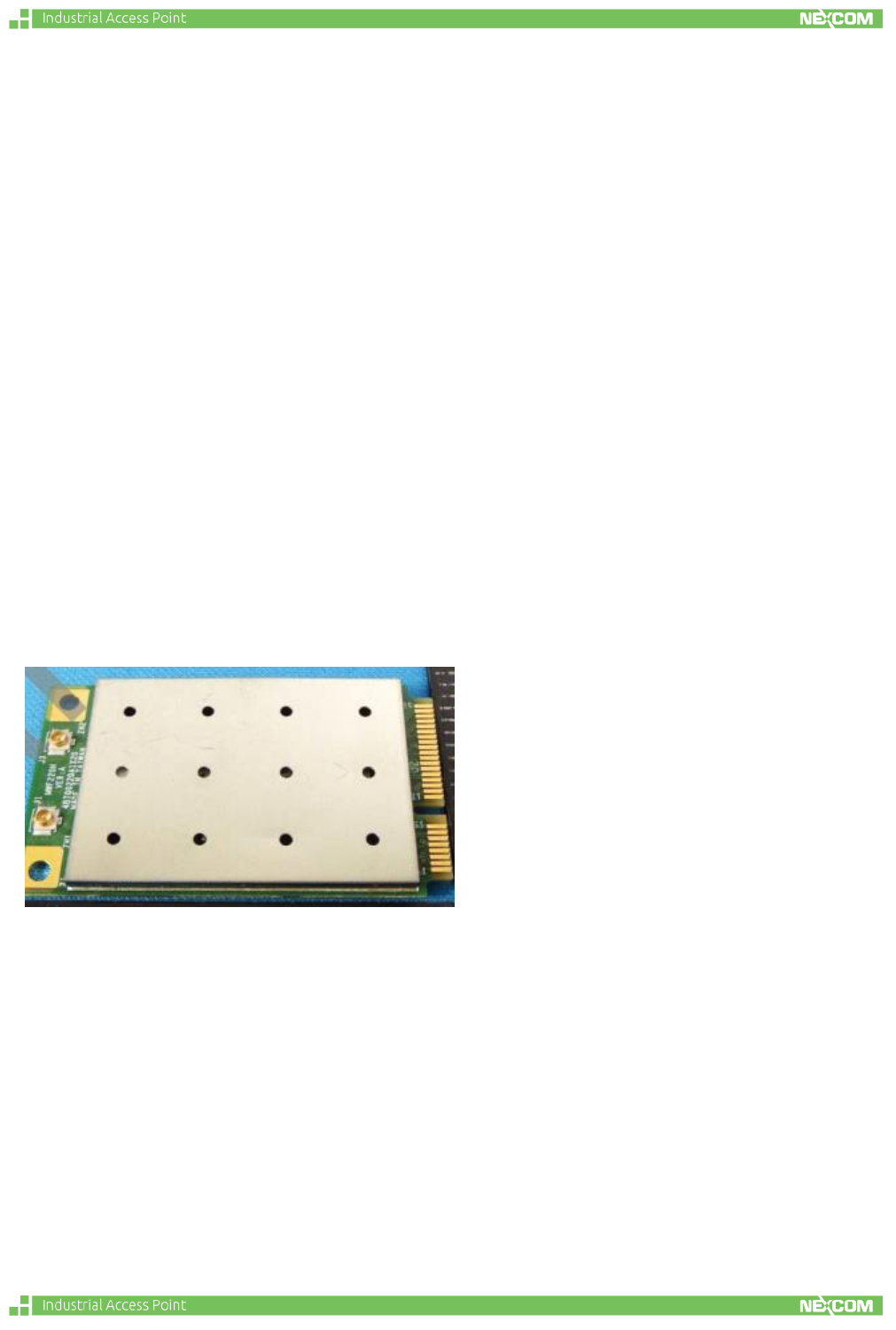
Introduction
The MWF220H RF module is designed for the user to implement cost effective
solution to industrial wireless high power network products. The standard mPCI-e
form factor makes it easy to install and fix in the embedded board.
Key Features:
- Qualcomn Atheros RF chip
- Standard full size mPCIe interface
- High Power up to 24dBm.
RF module form factor
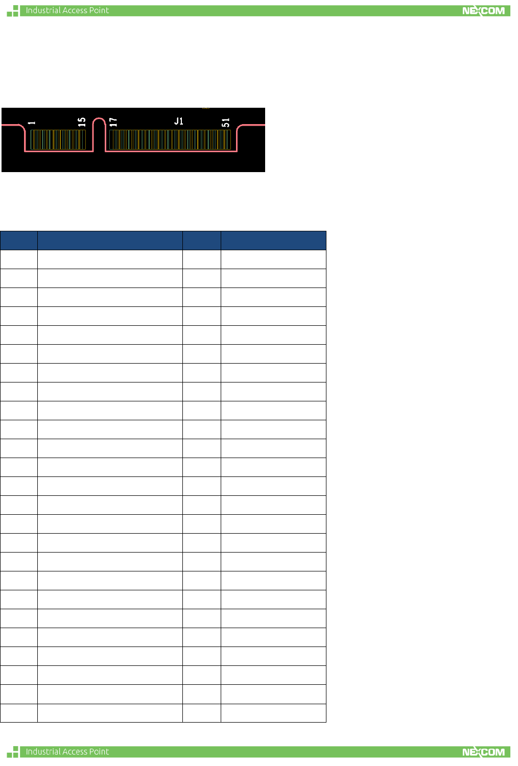
Mini PCIe pin definition
Logical symbol of RF module
Pin description
PIN
Definition
PIN
Definition
1
WAKE_L
2
3.3V
3
RESERVED
4
GND
5
RESERVED
6
NC
7
CLKREQ_L
8
NC
9
GND
10
NC
11
REFCLK-
12
NC
13
REFCLK+
14
NC
15
GND
16
NC
17
NC
18
GND
19
NC
20
W_DISABLE_L
21
GND
22
PERST_L
23
PERn0
24
3.3VAUX
25
PERp0
26
GND
27
GND
28
NC
29
GND
30
NC
31
PETn0
32
NC
33
PETp0
34
GND
35
GND
36
USB_D-
37
NC
38
USB_D+
39
3.3V
40
NC
41
3.3V
42
NC
43
GND
44
LED_WLAN_L
45
RESERVED
46
NC
47
RESERVED
48
NC
49
5V
50
GND
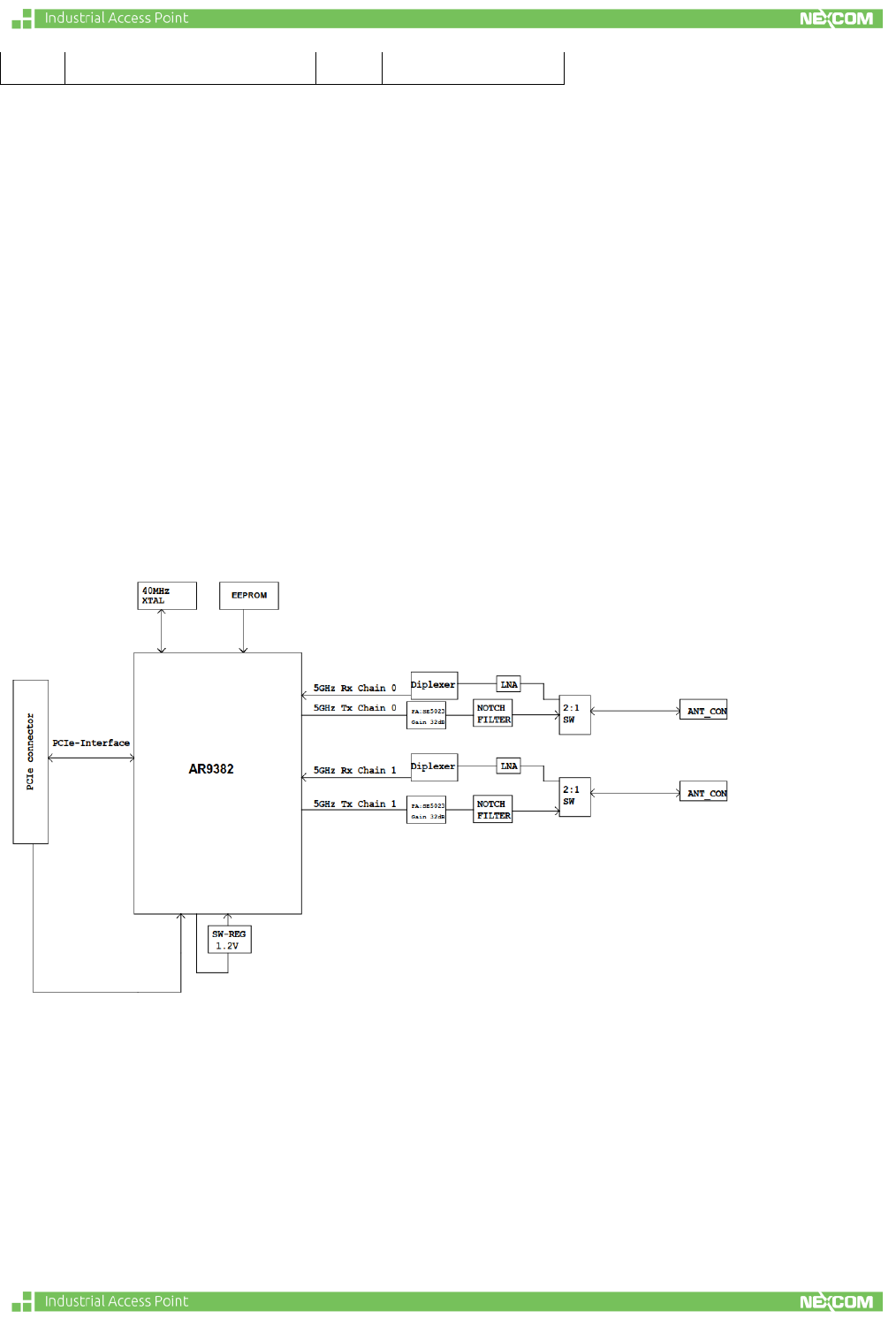
System block diagram
51
5V
52
3.3V
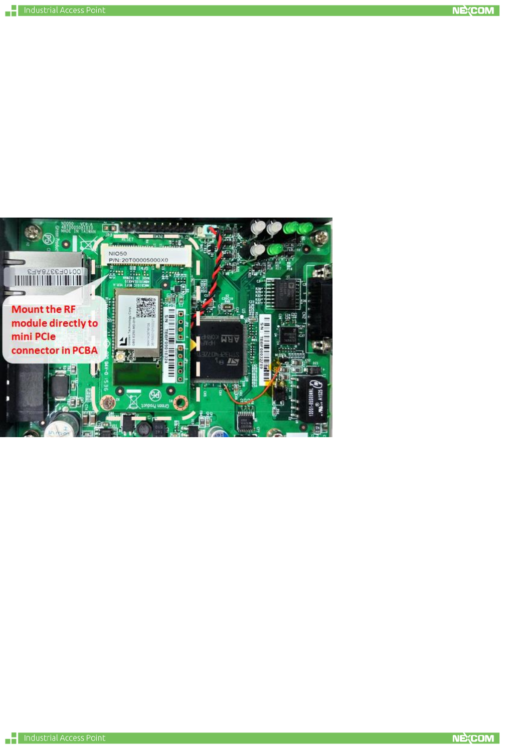
Installation
The installation of RF module is very easy. Just follow the steps below and you can
complete the installation:
Insert the radio module into mini PCIe slot in the PCBA.
Screw up to fasten the module tightly inside PCBA.
Note: The mini PCIe pin definition is different from standard mini PCIe module in
other Wi-Fi application. The embedded PCBA should follow the mini PCIe pin
definition to design the pin assignment to connect this radio module.
Product specification
Main Chip
QCA9382 Dual-Band 2 x 2 MIMO 802.11 an WLAN Single chip
Memory
M24C32-FMC6TG, 32K, SOP-8, EEPROM
Crystal
XTAL,SMD,40MHz,4pin,21ppm,3.2X2.5MM
PA
SE5023L, 5 GHz, 26dBm Power Amplifier with Power Detector
Power Supply
DC 5V&3.3V (5V used to external PA)
MIMO
5GHz, 2T2R
I/O interface
mPCI-E
Temperature spec
-20~+80
PCB Size
30x50.8mm
Output Power
21dBm@MCS15
Power consumption
Max 9.6W
RF output power : IEEE 802.11a/n
a. IEEE802.11a
1. 27dBm@6M
2. 24dBm@54M
b. IEEE802.11a/n HT20
1. 27dBm@MCS0
2. 24dBm@MCS7
c. IEEE802.11a/n HT40
1. 26dBm@MCS0
2. 23dBm@MCS7
Receive Sensitivity : IEEE 802.11a/n
a. IEEE802.11a
1. -95dBm@6M
2. -80dBm@54M
b. IEEE802.11a/n HT20
1. -95dBm@MCS0
2. -76dBm@MCS7
c. IEEE802.11a/n HT40
1. -92dBm@MCS0
2. -75dBm@MCS7
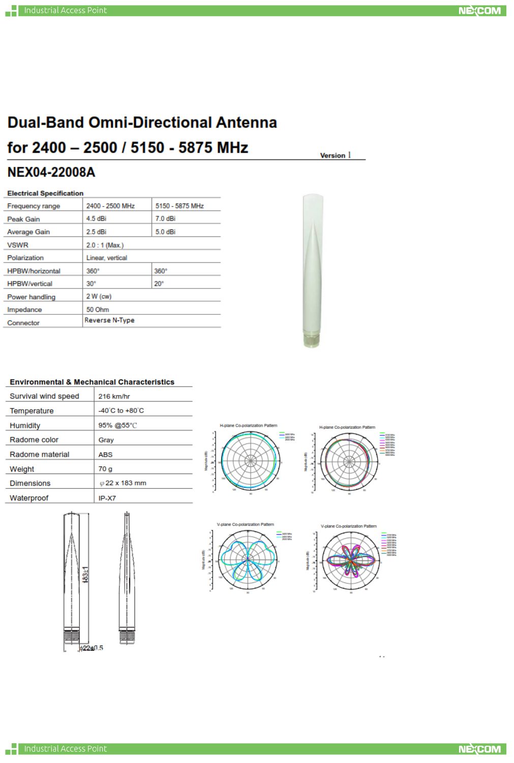
Antenna specifications

Note:
i. The module is limited to installation in mobile or fixed applications, according
to Part 2.1091(b).
ii. Separate approval is required for all other operating configurations, including
portable configurations with respect to Part 2.1093 and different antenna
configurations.