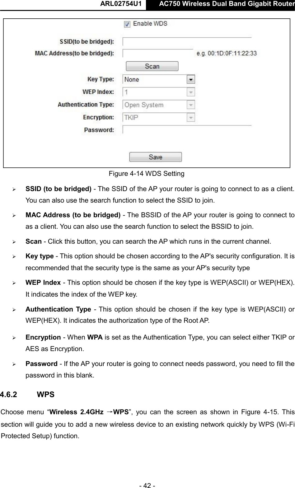
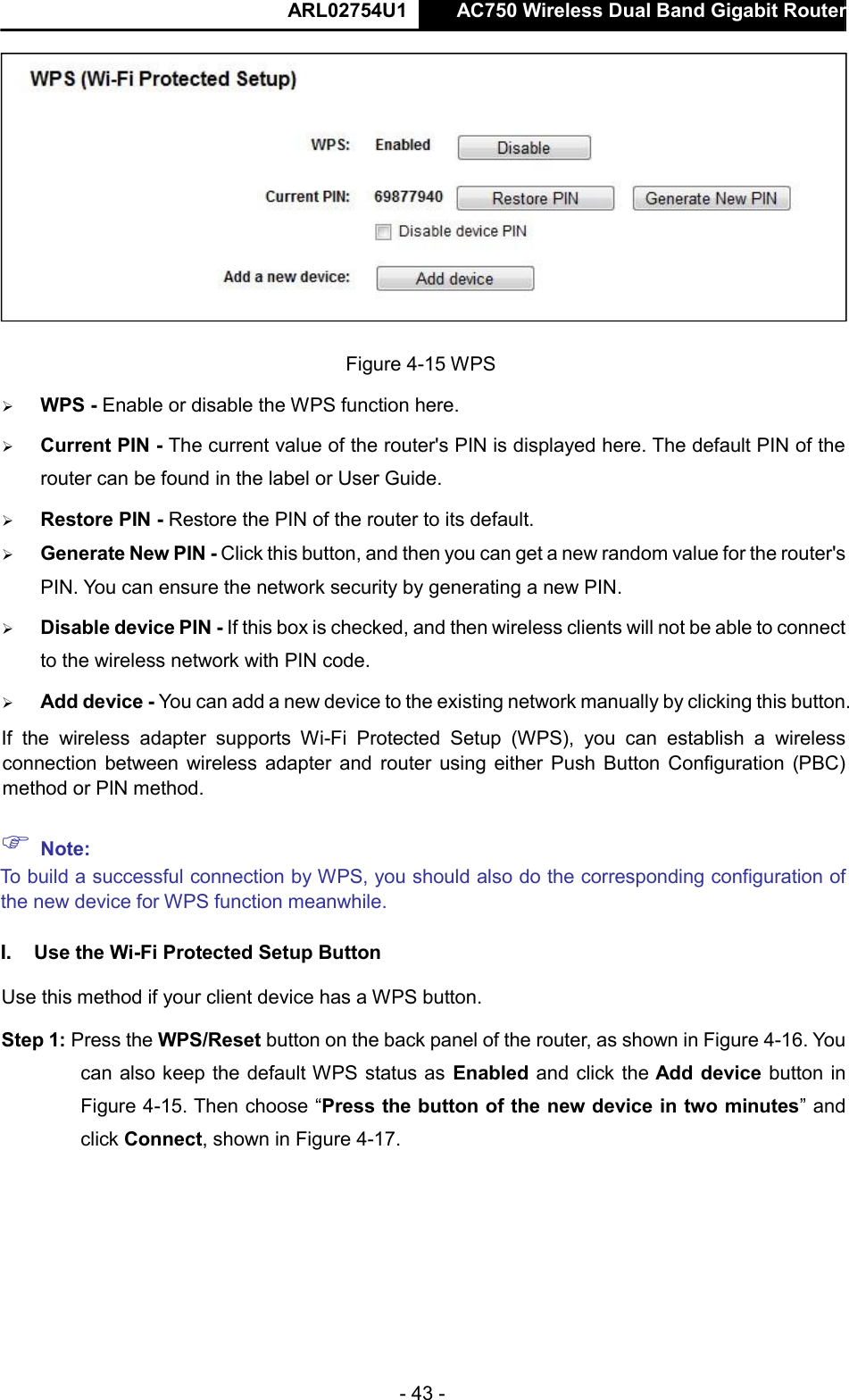
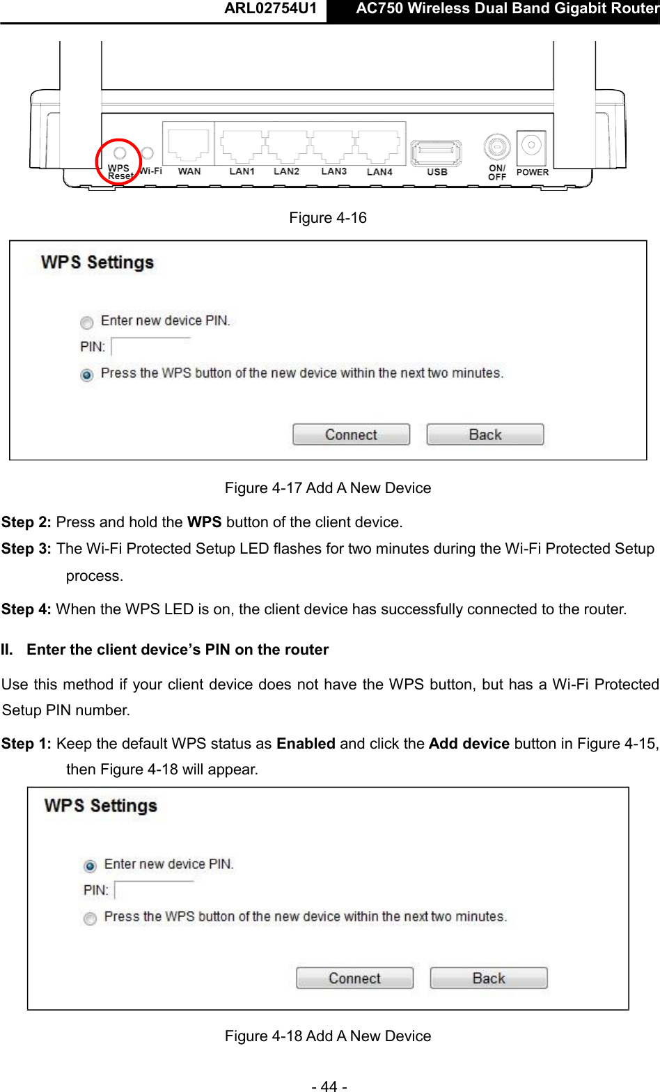
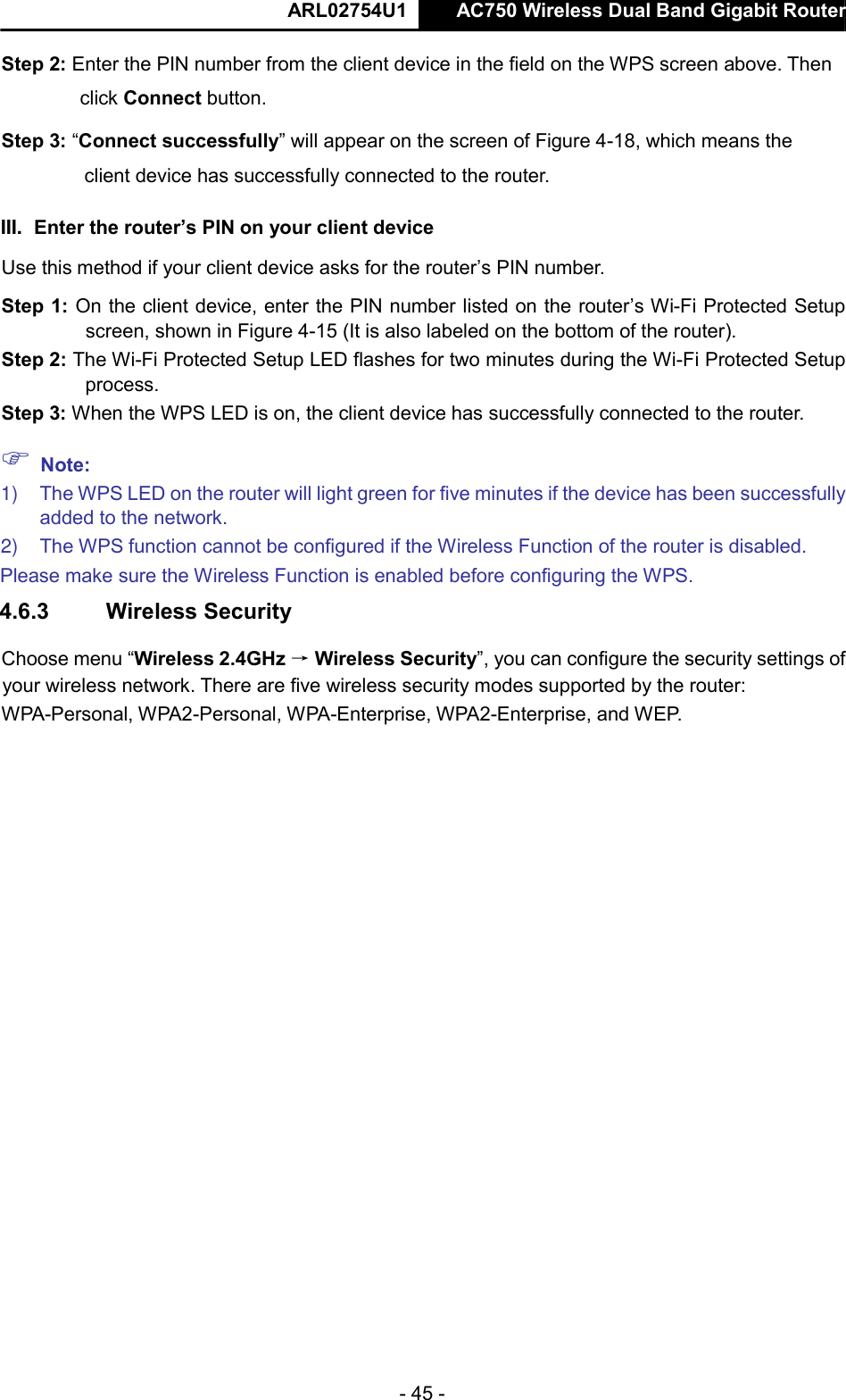
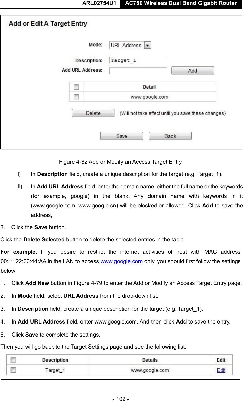
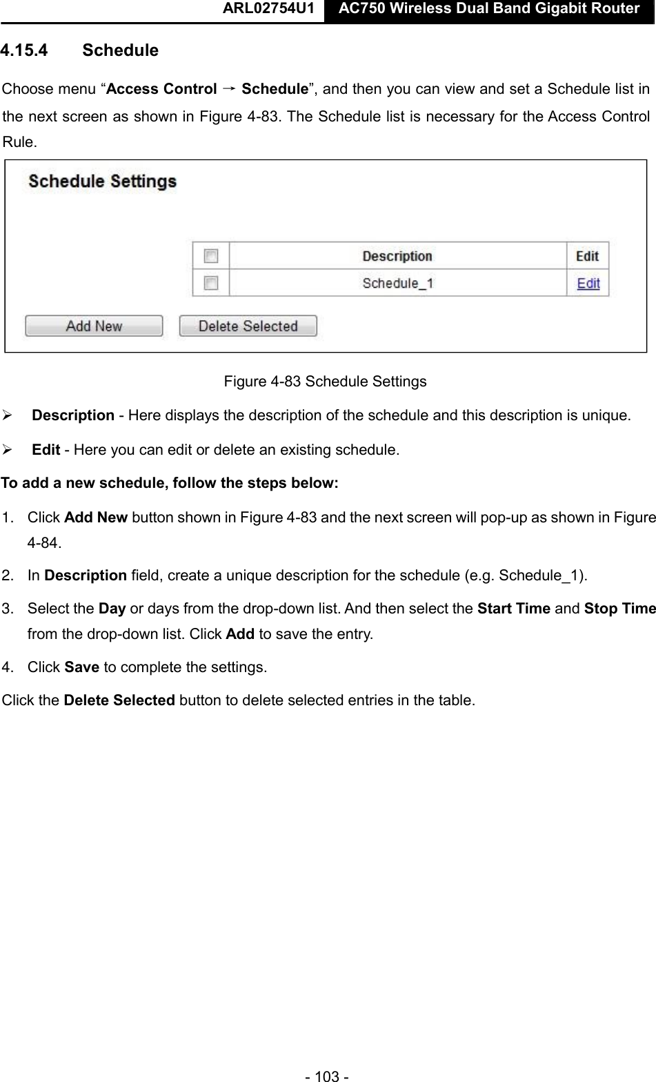
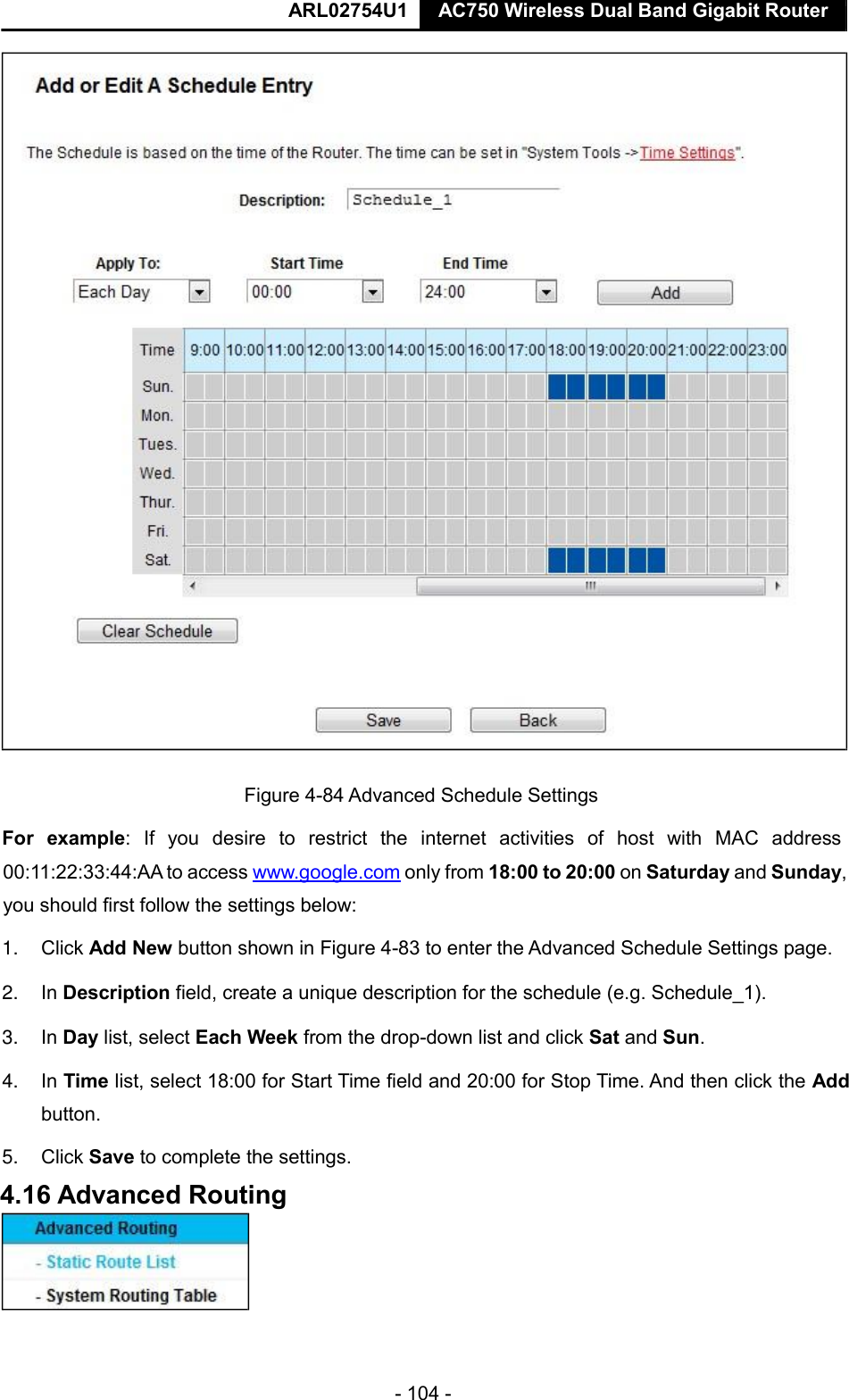
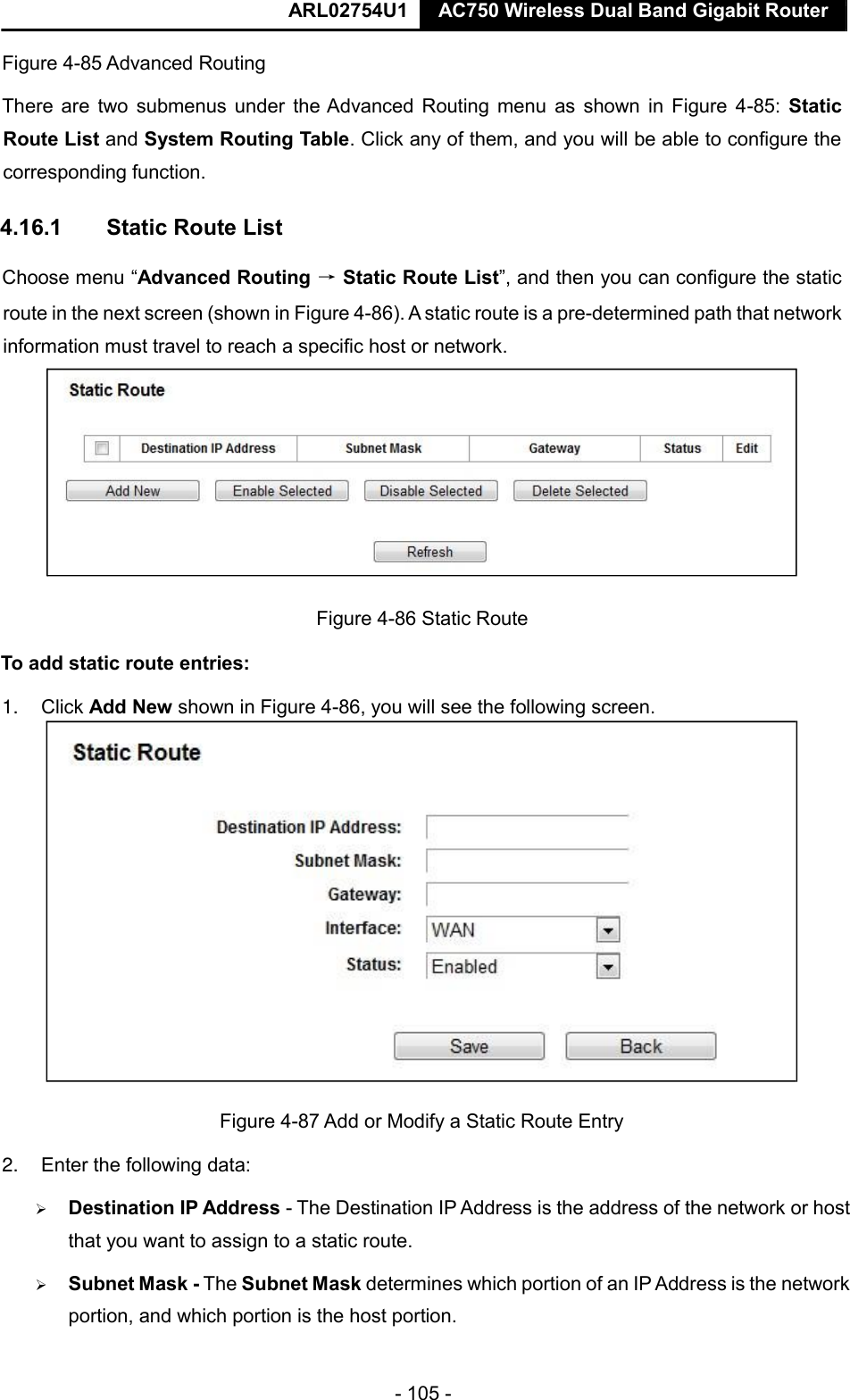
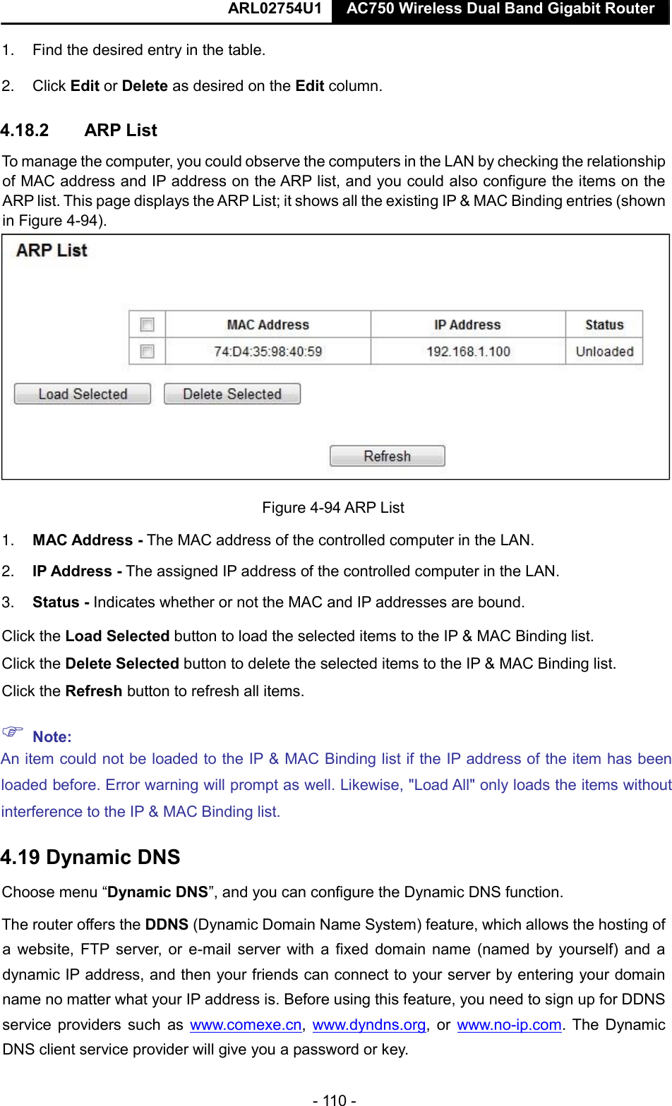
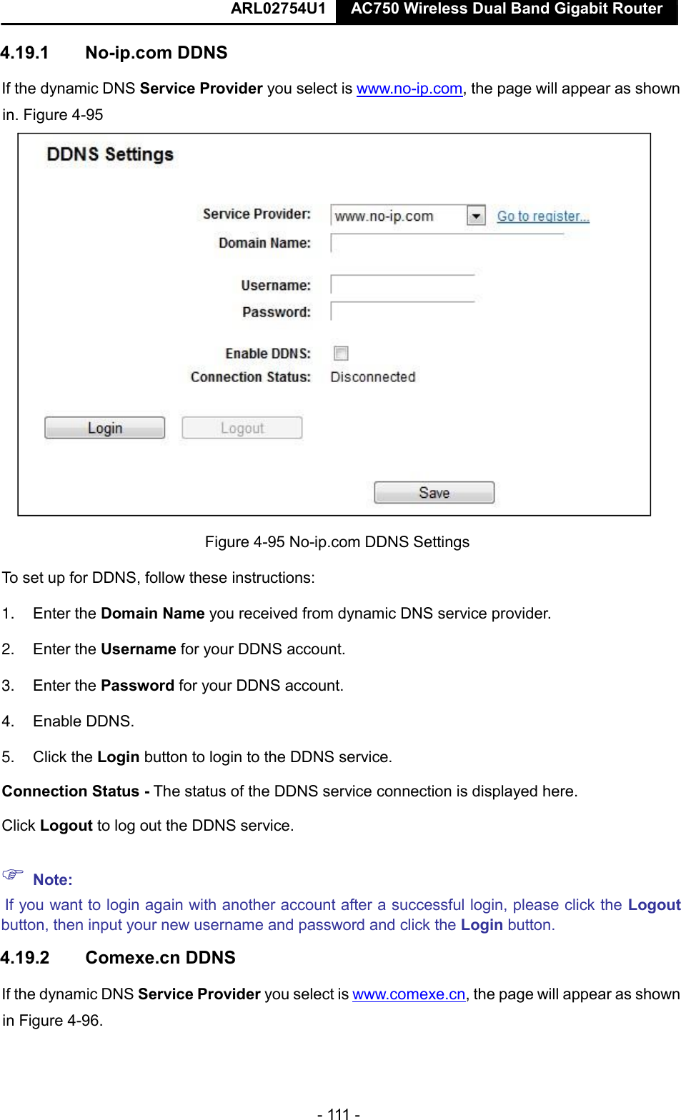
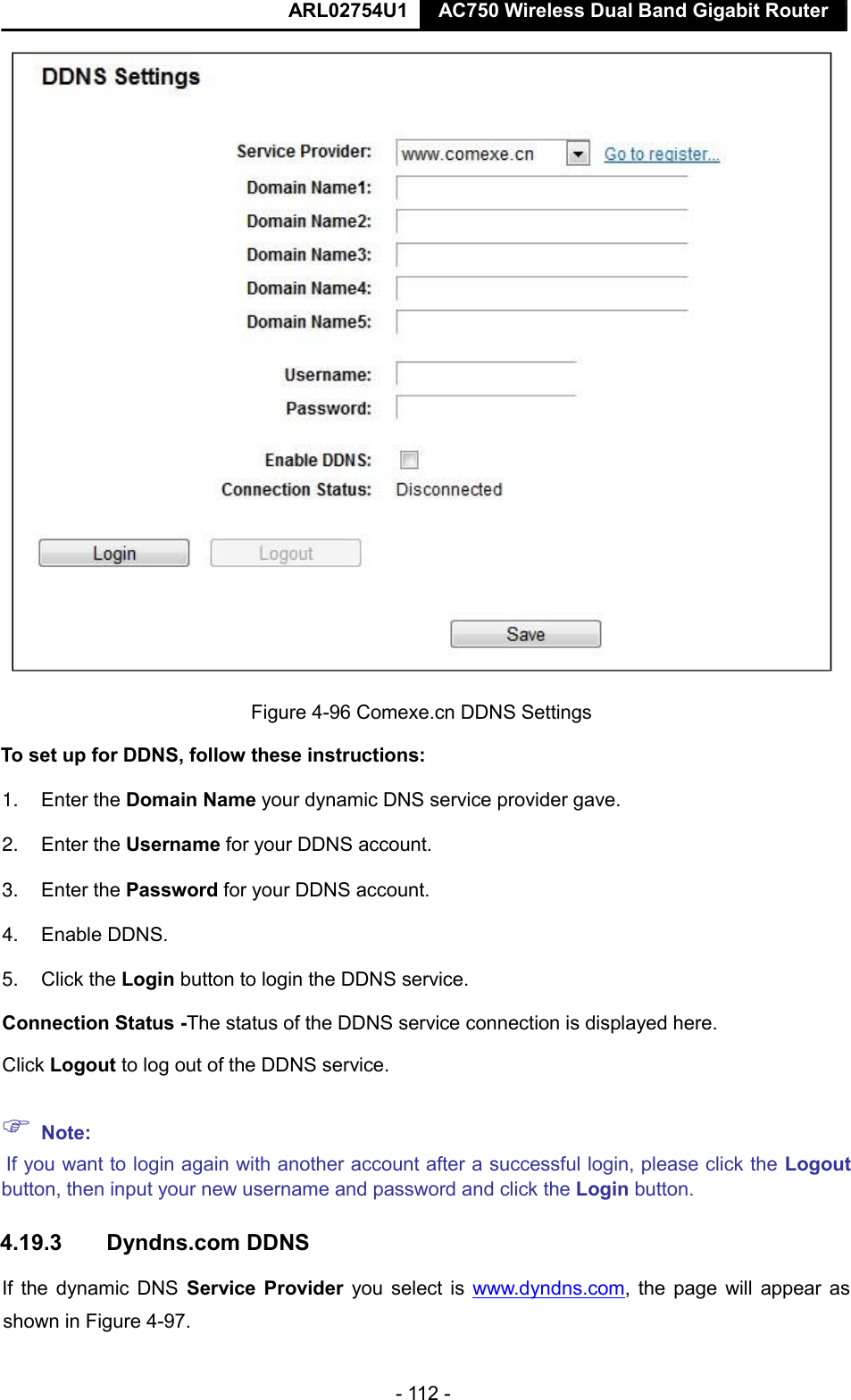
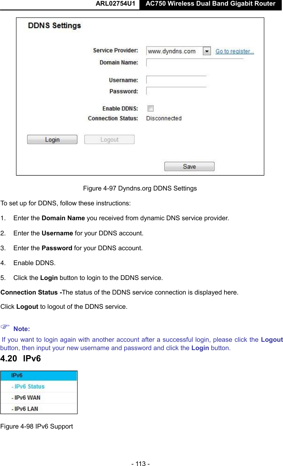
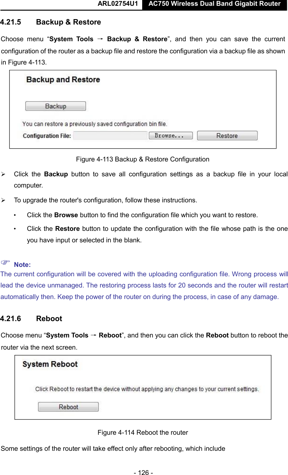
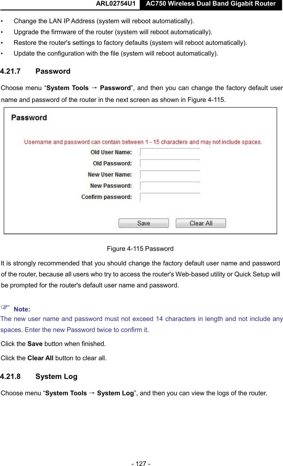
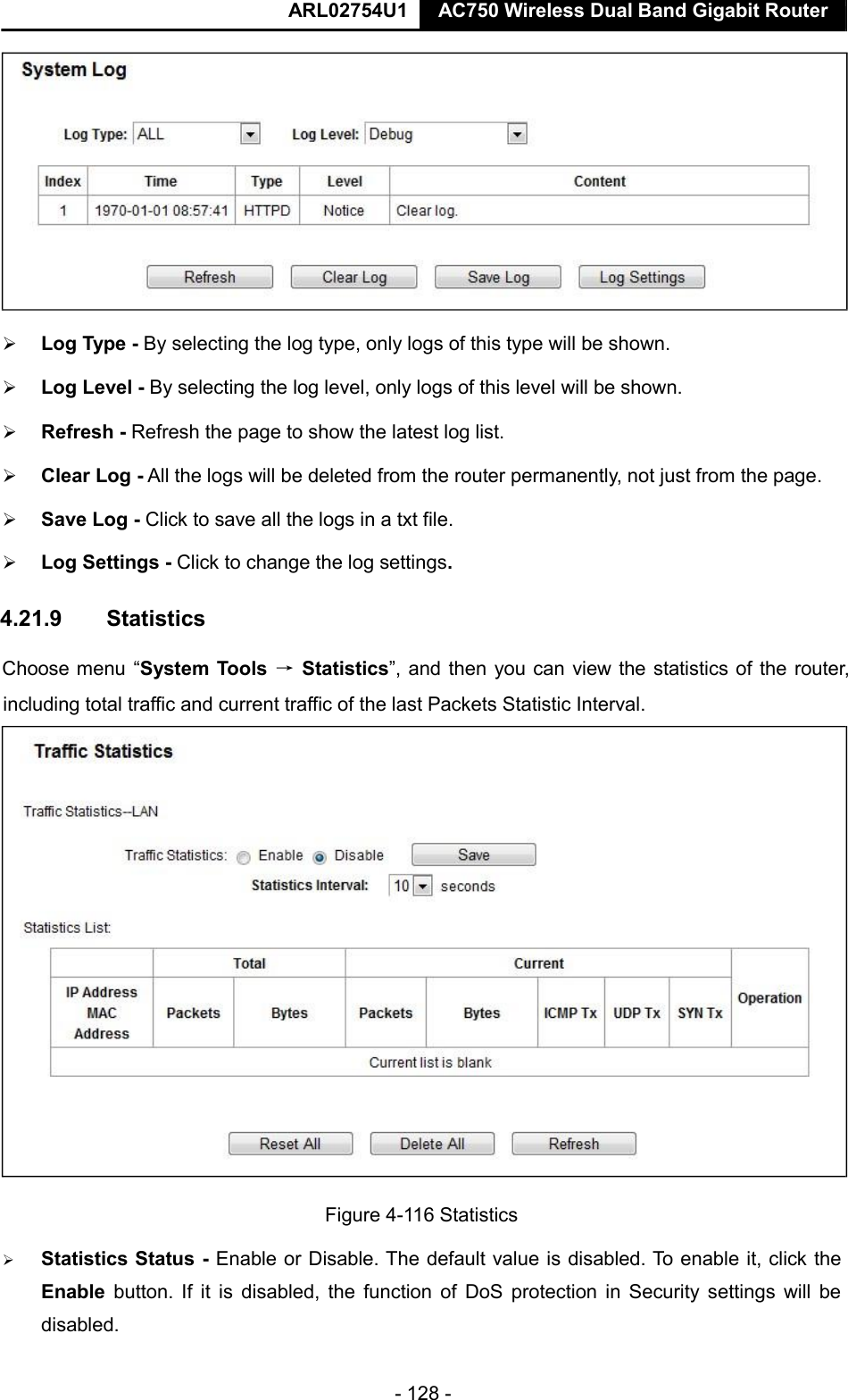
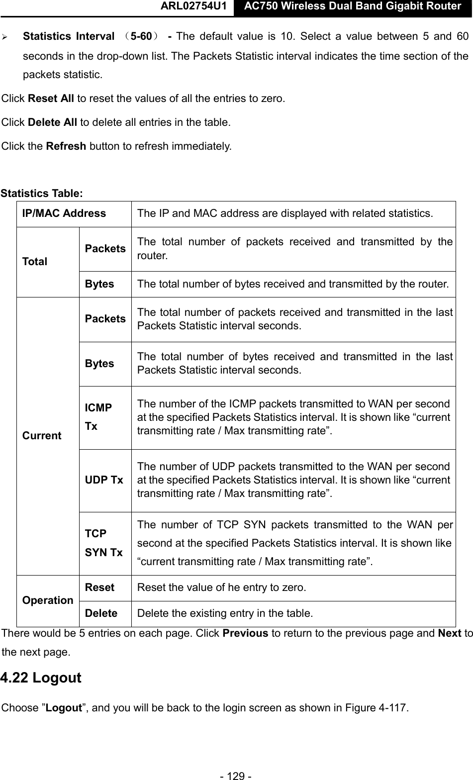
NEXXT SOLUTIONS ACX750 AC750 Wireless Dual Band Gigabit Router User Manual ARL02754U1 UG
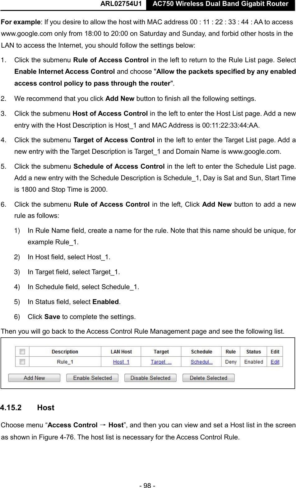
NEXXT SOLUTIONS AC750 Wireless Dual Band Gigabit Router ARL02754U1 UG
UserManual.wiki
>
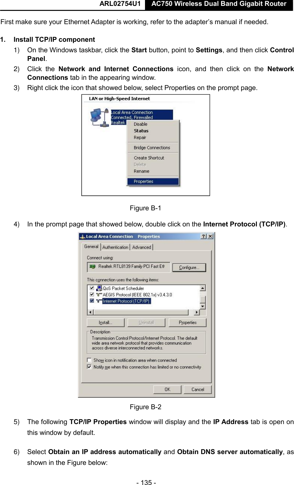
NEXXT SOLUTIONS
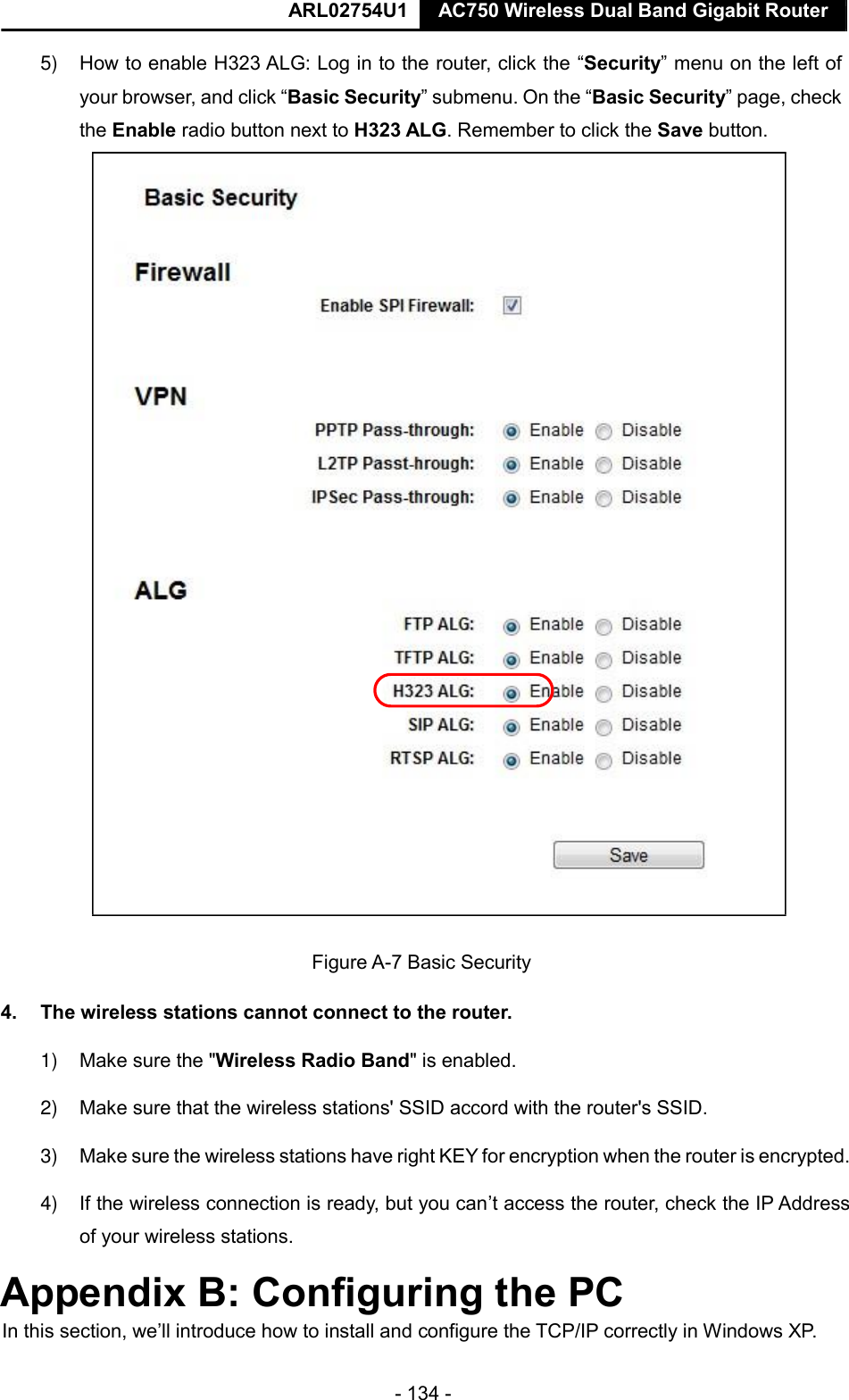
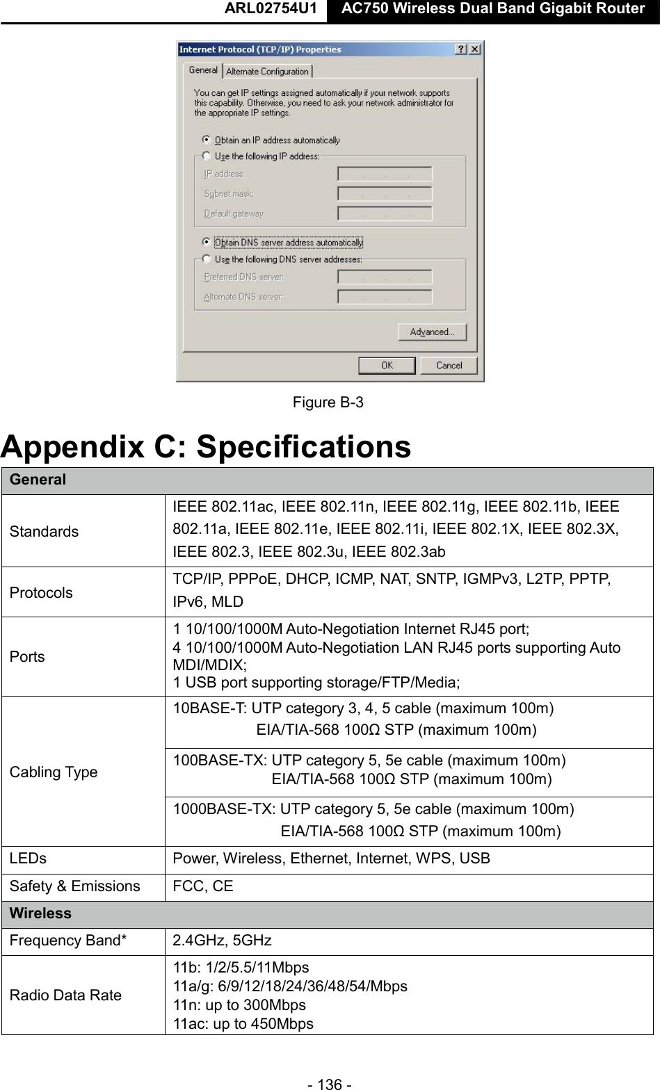
>
ACX750 User Manual
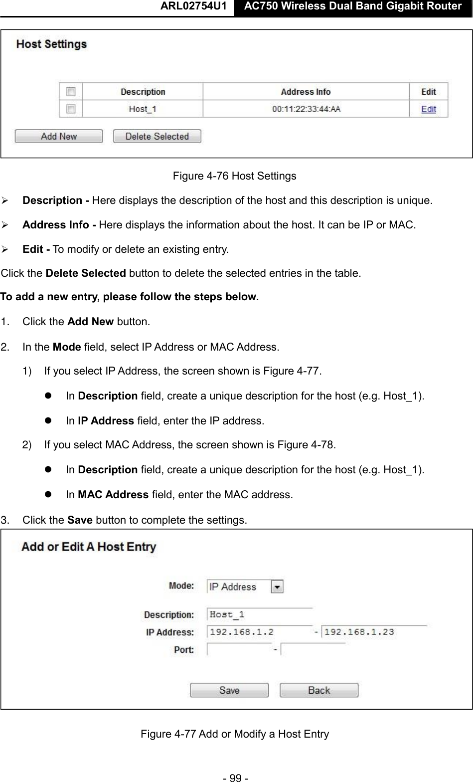
ARL02754U1_UG
Navigation menu
Upload a User Manual
Namespaces
Wiki Guide
HTML
PDF
Info
Views
User Manual
Discussion / Help
Navigation

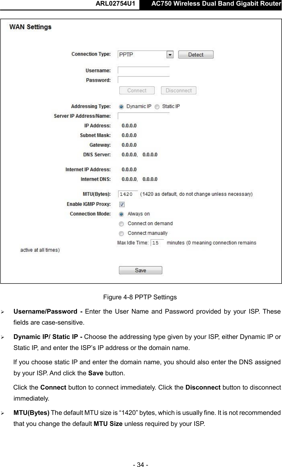
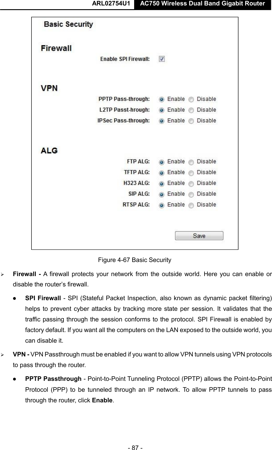
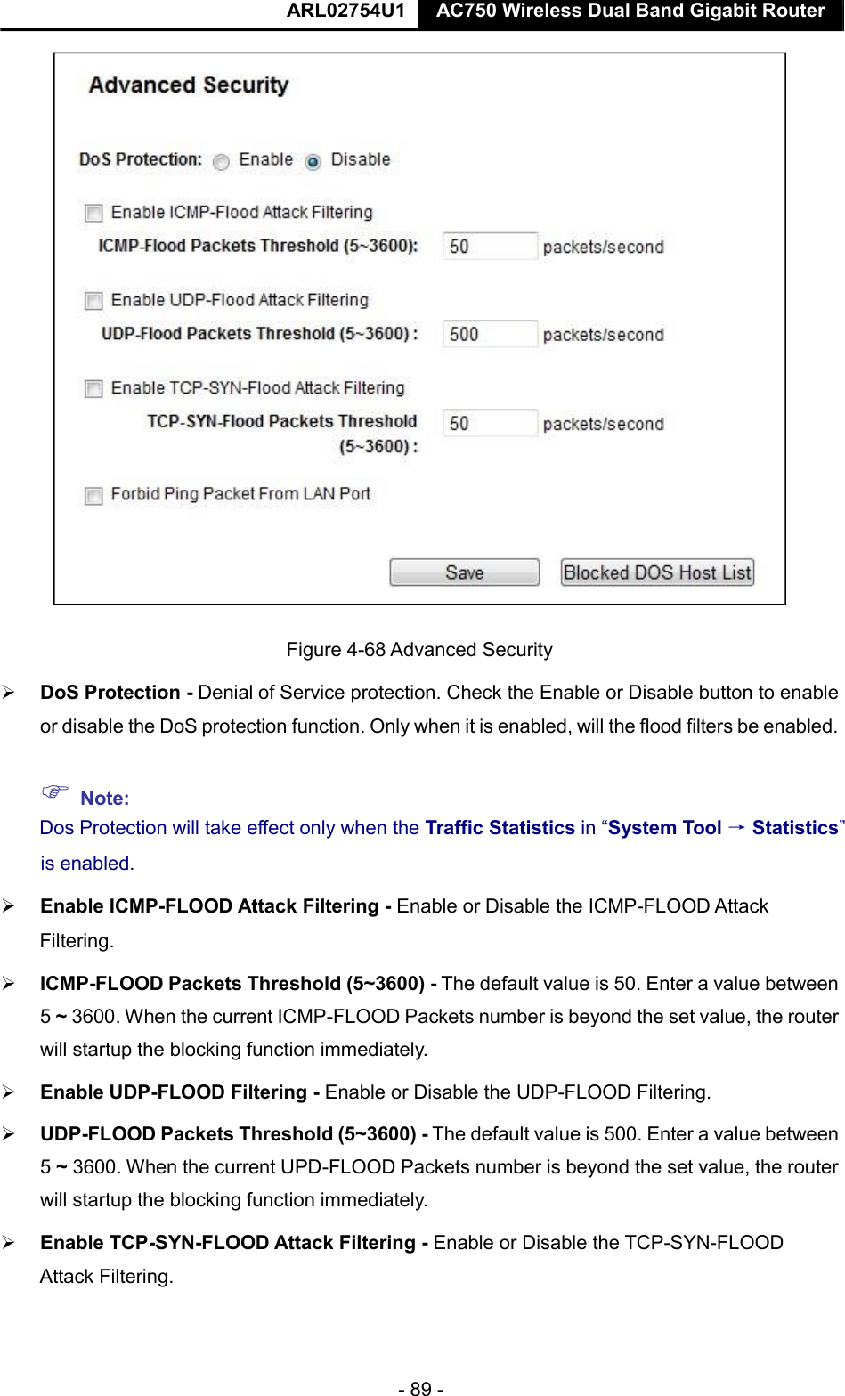
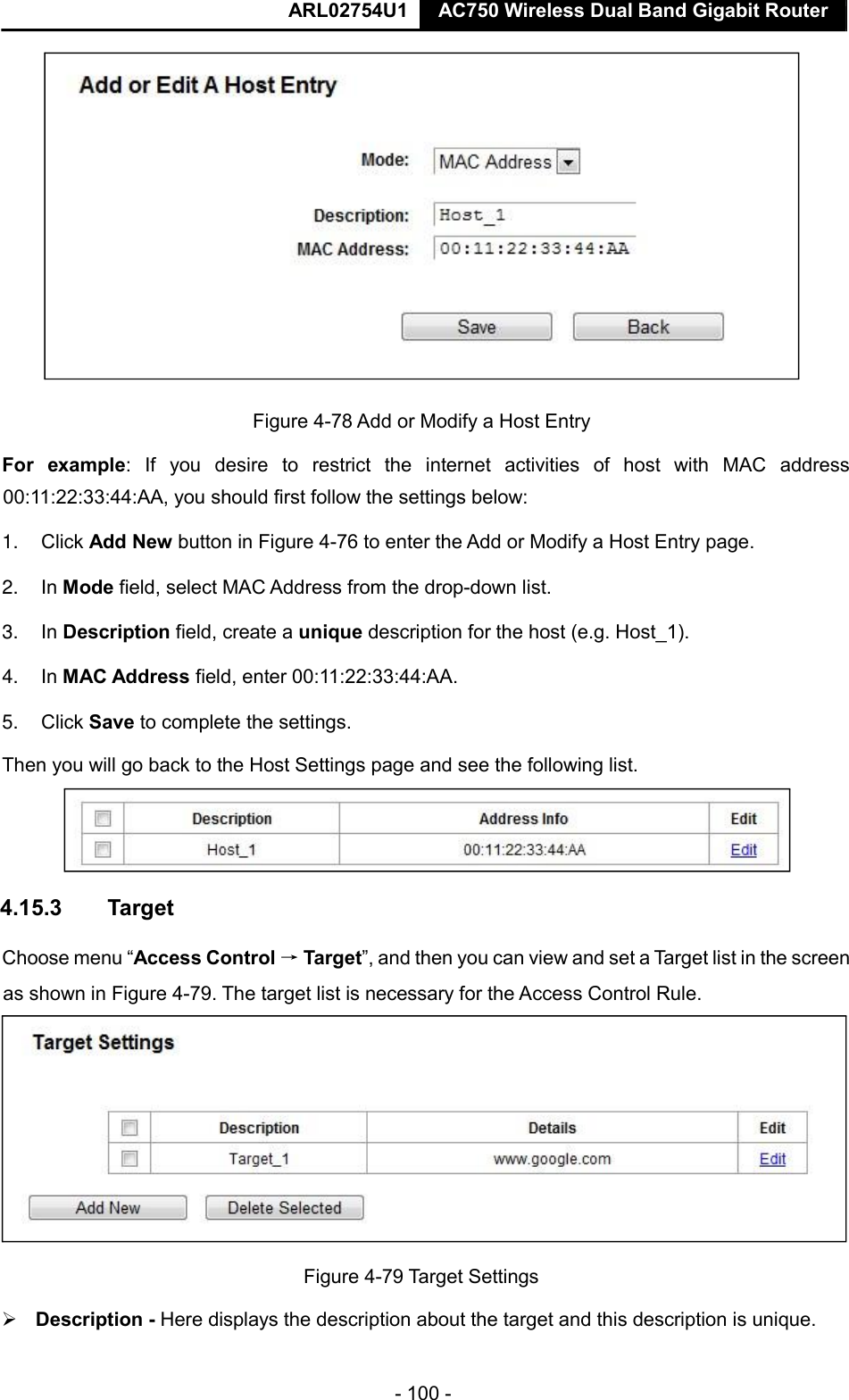
![ARL02754U1 AC750 Wireless Dual Band Gigabit Router - 137 - Frequency Expansion DSSS (Direct Sequence Spread Spectrum) Modulation 11ac: 256-QAM for OFDM 11n/g/a: QPSK,BPSK,16-QAM, 64-QAM for OFDM 11b: CCK,DQPSK,DBPSK Security WEP, WPA/WPA2, WPA2-PSK/WPA-PSK Sensitivity @PER 5G: 2.4G: 11a 6Mbps:-91dBm 11g 54M:-74dBm 11a 54Mbps:-74dBm 11n HT20:-72dmB 11ac HT20:-66dBm 11n HT40:-69dBm 11ac HT40:-64dBm 11ac HT80:-61dBm Environmental and Physical Temperature Operating: 0℃~40℃ (32℉~104℉) Storage: -40℃~70℃ (-40℉~158℉) Humidity Operating: 10% - 90% RH, Non-condensing Storage: 5% - 90% RH, Non-condensing * Only 2.412GHz~2.462GHz is allowed to be used in USA, which means only channel 1~11 is available for American users to choose. Appendix D: Glossary 802.11ac - IEEE 802.11ac is a wireless computer networking standard of 802.11.This specification will enable multi-station WLAN throughput of at least 1 gigabit per second .This is accomplished by extending the air interface concepts embraced by 802.11n: wider RF bandwidth, more MIMO spatial streams, multi-user MIMO, and high-density modulation (up to 256 QAM). 802.11n - 802.11n builds upon previous 802.11 standards by adding MIMO (multiple-input multiple-output). MIMO uses multiple transmitter and receiver antennas to allow for increased data throughput via spatial multiplexing and increased range by exploiting the spatial diversity, perhaps through coding schemes like Alamouti coding. The Enhanced Wireless Consortium (EWC) [3] was formed to help accelerate the IEEE 802.11n development process and promote a technology specification for interoperability of next-generation wireless local area networking (WLAN) products. 802.11b - The 802.11b standard specifies a wireless networking at 11 Mbps using direct-sequence spread-spectrum (DSSS) technology and operating in the unlicensed radio spectrum at 2.4GHz, and WEP encryption for security. 802.11b networks are also referred to as Wi-Fi networks. 802.11g - specification for wireless networking at 54 Mbps using direct-sequence spread-spectrum (DSSS) technology, using OFDM modulation and operating in the unlicensed radio spectrum at 2.4GHz, and backward compatibility with IEEE 802.11b devices, and WEP encryption for security. DDNS (Dynamic Domain Name System) - The capability of assigning a fixed host and domain name to a dynamic Internet IP Address.](https://usermanual.wiki/NEXXT-SOLUTIONS/ACX750/User-Guide-3026462-Page-145.png)