NIDEC MOBILITY G8D-246S-B Keyless Entry Sytem Receiver User Manual
OMRON Automotive Electronics Co. Ltd. Keyless Entry Sytem Receiver
Contents
- 1. User Manual
- 2. Regulatory statement
User Manual

50J6
Receiver, RF Keyless Entry System
Table of contents
1. Constitution of the Radio Frequency Keyless Entry system with Door Lock
Controller for vehicle ...................................................................................... 1
2. User’s manual (provisionally) .......................................................................... 2
3. Block diagram ................................................................................................ 3
4. Specification ................................................................................................... 4
5 PCB
5.1 Circuit diagram ........................................................................................... 5
5.2 Parts layout (front)...................................................................................... 6
5.3 Pattern layout .................................................................................... 7
5.4 Parts list ...................................................................................................... 9
5.5 Connector ..................................................…................................................. 12
6. Photographs .................................................................................................... 13

1. Constitution of the Radio Frequency Keyless Entry
System with Door Lock Controller for vehicle
The radio frequency keyless entry is a system that it controlls locking and unlocking the door by
wireless remote controller. This system consists of two components. The TRANSMITTER is a device that
transmits the signal when the button is pressed. The transmission signal consists of several synchronous
codes, unique identification code, security code and function code. The RECEIVER is fixed inside the
vehicle. It works intermittently to prevent the battery exhaustion. When the receiver detects the
synchronous code, it runs continuously to receive the signals completely. After receiveing the signal, the
receiver decides which operation will be performed. The user can select the following operations by
pressing the button of the remote transmitter.
OPERATION ACTION
LOCK Lock the door
UNLOCK Unlock the door (Open the window)
PANIC Beep the horn and flush the small light. (it continues 30 seconds)
This receiver also controls wired operation. When the key is in the driver’s side key cylinder, all doors will
Unlock if the key is turned to UNLOCK and hold more than one second. In case of the operation time is shorter,
the only diver’s side door is mechanically unlocked. It is also available to control the door lock status by using
the remote door control switch(both driver’s and passenger’s side).
Transmitter
f = 313.85MHz
- 1 -
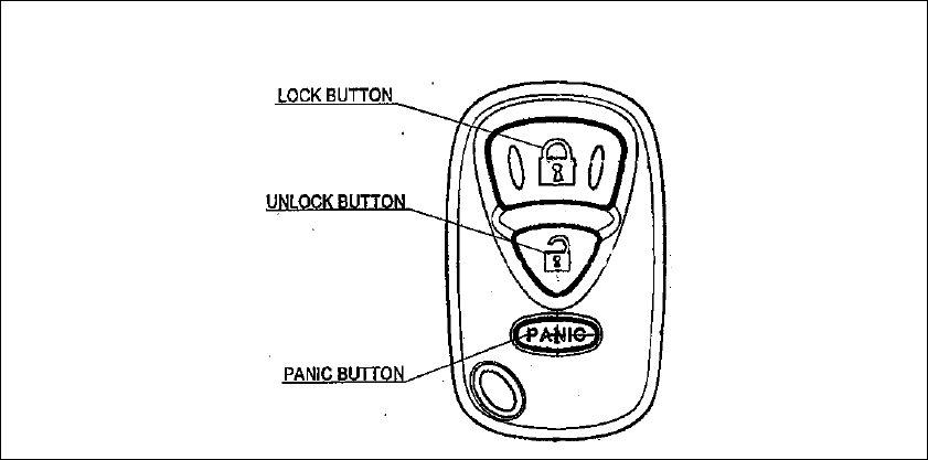
2. User’s manual (provisionally)
REMOTE TRANSMITTER
You can lock and unlock your vehicle with the remote transmitter.
LOCK
When you push the LOCK button, all the doors will lock.
You cannot lock any of the doors with the remote transmitter if any door is open or the key is in the
ignition switch.
UNLOCK
When you push the UNLOCK button , all the doors will unlock.
You cannot unlock any of the doors with the remote transmitter if the key is in the ignition switch.
When you push the UNLOCK button more than about 1.0 second , the window will open.
PANIC MODE
Panic mode allows you to remotely sound your vehicle’s horn to attract attention. To activate this
mode , press and hold the PANIC button for about one seconds. Your vehicle’s horn will beep for about
30 seconds.
To cancel Panic mode before 30 seconds , press any button on the remote transmitter. You can also
turn the ignition switch is in ON
- 2 -
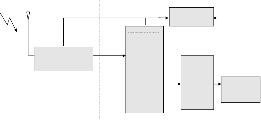
3. Block diagram
This is the block diagram concerning to the receiver.
RECEIVING
MODULE
EEPROM
12V (car battery)
POWER
SOURCE
(
5V
)
data
DOOR
MOTOR
output DRIVING
CIRCUIT
Figure 3.1 block diagram of the receiver
- 3 -

4. Specification
4.1 RF block
Local clock frequency 325.8MHz
Frequency generation Crystal resonator
Modulation Single Superheterodyne
Bandwidth ±200KHz
Sensitivity 30dBuV
4.2 Others
Dimension 50 mm× 40 mm×25 mm
Weight 25 g
Battery Power Source (DC 5V)
Operation Voltage DC 5V, 10mA
Operation temperature -30℃ ~ +80℃
- 4 -
5. PCB
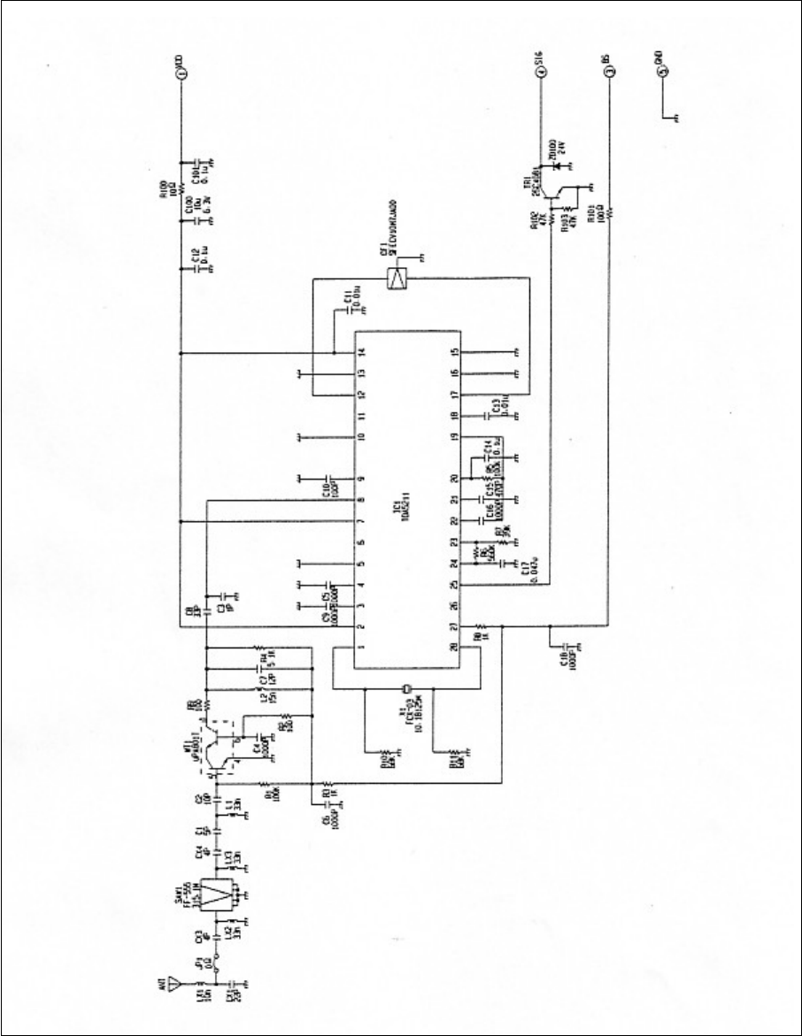
5.1 Circuit diagram
Figure 5.1 Circuit diagrams
- 5 -
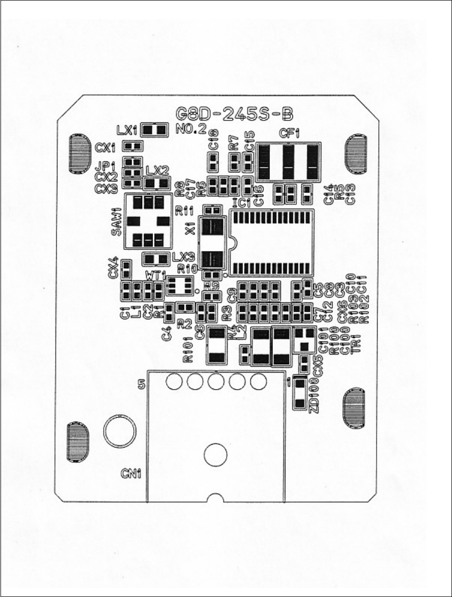
5.2 Parts layout
Figure 5.2 Parts layout (front)
- 6 -
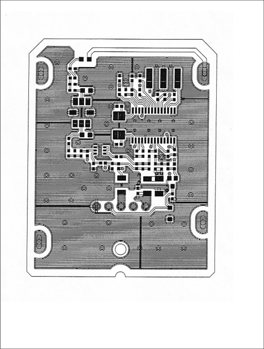
5.3 Pattern layout
Figure 5.3 Pattern layout (front)
- 7 -
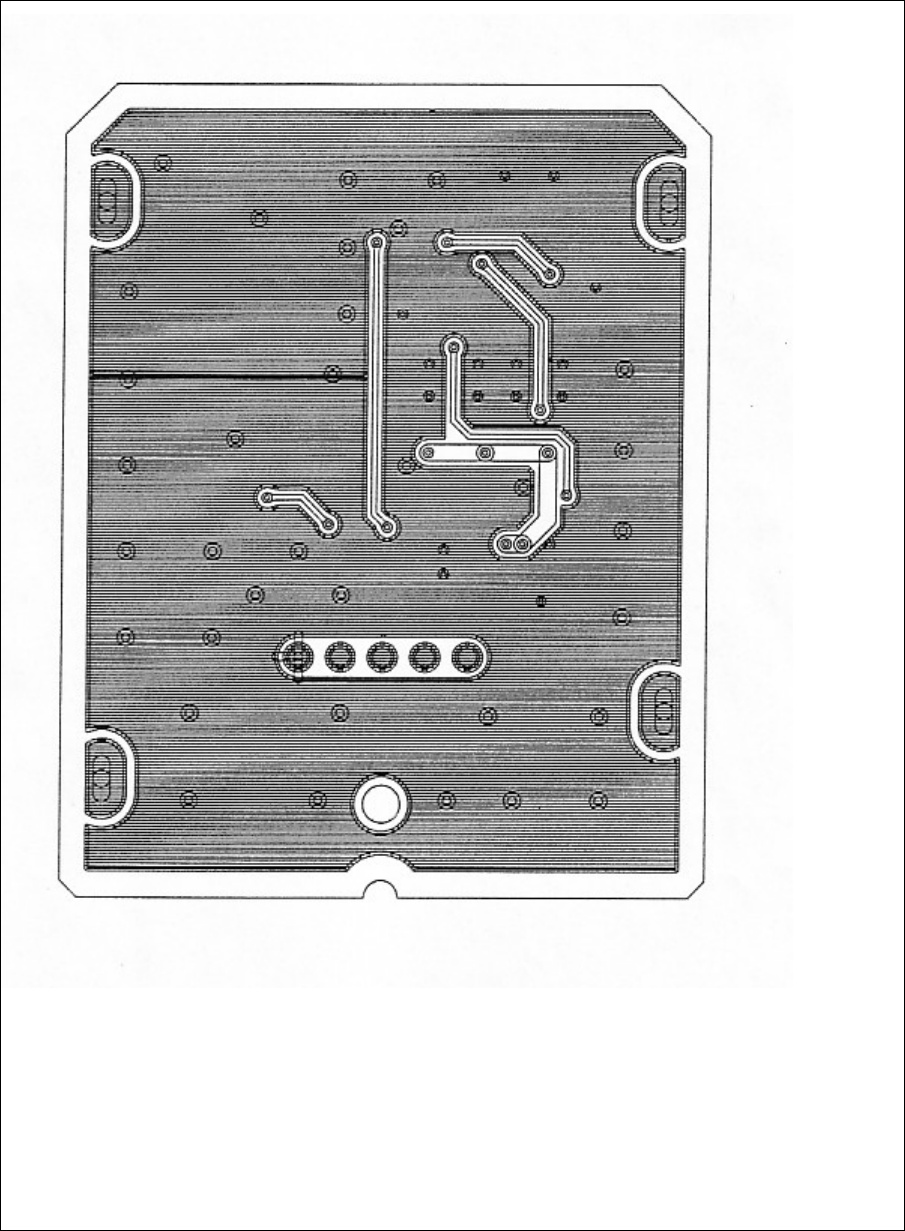
igure 5.4 pattern layout (back)
- 8 -

5.4 Parts list
No
PART NAME MANUFACTURE QTY
TYPE SPECIFICATION REMARKS
1
WAVE DETECTION IC INFINEON 1 TDA5211GEG 28-PIN IC1
2
SAW FILTER EPSON 1 FF-555 315.1M 315.1MHz SAW1
3
CERAMIC FILTER MURATA 1 SFECV10M7JA00-R0 3-PIN CF1
4
CRYSTAL RIVER 1 FCX-03-10.18125 CI=150Ω CL=SERIES
X1
OSCILLATOR -30-30 10.18125MHz+387Hz
5
DOUBLE TRANSISTOR NEC 1 UPA801-T1 6-PIN MINI MOLD
WT1
2SC4226(X2)
6
TRANSISTOR ROHM 1 2SC4081T106R TR1
7
ZENER DIODE NEC 1 RD24SB-T1 200mW ,24V ZD100
8
CERAMIC CAPACITOR * 2 CCM-L10CH1H040C-T2 4pF ,50V CX3,CX4
1005 SIZE
9
CERAMIC CAPACITOR 1 CCM-L10CH1H050C-T2 5pF ,50V C1
* 1005 SIZE
10
CERAMIC CAPACITOR * 1 CCM-L10CH1H100D-T2 10pF ,50V C2
1005 SIZE
11
CERAMIC CAPACITOR * 1 CCM-L10CK1H010C-T2 1pF ,50V C3
1005 SIZE
12
CERAMIC CAPACITOR * 6 CKM-L10R1H102K-T2 1000pF,50V C4,5,6,9,16
1005 SIZE 18
13
CERAMIC CAPACITOR * 1 CCM-L10CH1H120J-T2 12pF ,50V C7
1005 SIZE
14
CERAMIC CAPACITOR * 1 CCM-L10CH1H330J-T2 33pF,50V C8
1005 SIZE
15
CERAMIC CAPACITOR * 1 CCM-L10CH1H101J-T2 100pF,50V C10
1005 SIZE
16
CERAMIC CAPACITOR MURATA 2 GRP155B11C103KA01E 0,01uF ,16V C11,13
1005 SIZE
17
CERAMIC CAPACITOR MURATA 3 GRP155B11A104KA01E 0.1uF ,10V C12,14,C101
1005 SIZE
18
CERAMIC CAPACITOR MURATA 1 GRP155B11H471KA01E 470pF ,50V C15
1005 SIZE
19
CERAMIC CAPACITOR MURATA 1 GRP155B11A473KA01E 0.047uF ,10V C17
1005 SIZE
NOTE:
・ ・ DESIGNED CHECKED APPROVED
・ ・
・ ・
・ ・
・ ・ G8D-246S-B
・ ・ SHEET No ( 1 / 3)
A ・ ・ DETEAILED LISY OF PARTS
SYM DATE E/C CONTENTS E/C No SIGN DWG NO.

No
PART NAME MANUFACTURE QTY
TYPE SPECIFICATION REMARKS
20
TANTALUM CAPACITOR MURATA 1 GRM31CB10J106KC01L 10uF ,6.3V C100
3216 SIZE
21
CHIP CAPACITOR MURATA 1 CCM-L10CH1H220J-T2 22pF CX1
1005 SIZE
22
CHIP INDUCTOR MURATA 1 LQP18MN10NG00D 10nH LX1
1608 SIZE
23
CHIP INDUCTOR MURATA 2 LQW18AN33NG00D 33nH LX2,LX3
1608 SIZE
24
CHIP INDUCTOR MURATA 1 LQP15MN33NG00D 33nH L1
1005 SIZE
25
CHIP INDUCTOR MURATA 1 LQP15MN15NG00D 15nH L2
1005 SIZE
26
SQUARE * 2 RK10CAZ100KJ-T1 100kΩ ,1/16W R1,5
CHIP RESISTOR 1005 SIZE
27
SQUARE * 2 RK10CAZ100J-T1 100Ω ,1/16W R2,9
CHIP RESISTOR 1005 SIZE
28
SQUARE * 2 RK10CAZ1KJ-T1 1kΩ ,1/16W R3,8
CHIP RESISTOR 1005 SIZE
29
SQUARE * 1 RK10CAZ5.1KJ-T1 5.1kΩ,1/16W R4
CHIP RESISTOR 1005 SIZE
30
SQUARE * 1 RK10CAZ560KJ-T1 560kΩ,1/16W R6
CHIP RESISTOR 1005 SIZE
31
SQUARE * 1 RK10CAZ39KJ-T1 39kΩ,1/16W R7
CHIP RESISTOR 1005 SIZE
32
SQUARE * 2 RK10CAZ68KJ-T1 68kΩ,1/16W R10,11
CHIP RESISTOR 1005 SIZE
33
SQUARE * 1 RK32CAY10J-T1 10Ω,1/4W R100
CHIP RESISTOR 3216 SIZE
34
SQUARE * 1 RK32CAY100J-T1 100Ω,1/4W R101
CHIP RESISTOR 3216 SIZE
35
AQUARE * 2 RK10CAZ47KJ-T1 47kΩ,1/16W R102,103
CHIP RESISTOR 3216 SIZE
36
JUMPER RESISTOR * 1 RK10CAZ00-T1 0Ω,1/16W JP1
3216 SIZE
37
CONNECTOR JAE 1 IL-AG5-5P-S3L2 5 POLE CN1
38
PWB SINKO 1 FR4
39
ANTENNA SUZUKI PRESS 1 C2680R 1/2H t=0.5
NOTE:
G8D-246S-B
SHEET No ( 2 / 3 )
DETEAILED LISY OF PARTS
DWG NO.

No
PART NAME MANUFACTURE QTY
TYPE SPECIFICATION REMARKS
40
CASE F-PLUS 1 ABS BLACK
41
BASE F-PLUS 1 ABS BLACK
42
NAME PLATE AMEMIYA 1
NOTE:
G8D-246S-B
SHEET No ( 3 / 3 )
DETEAILED LISY OF PARTS
DWG NO.

5.5 Connector
This is the pin assignment of the connector.
No. I/O Assignment Memorandum
1 INPUT Battery 5V
2 − (Not used)
3 INPUT Battery saving 5V
4 OUTPUT SIGNAL Active Lo
5 Ground GND
- 9 -