NINGBO DOOYA MECHANIC and ELECTRONIC TECHNOLOGY DM280228 Tubular Motor User Manual DM28CEQ S
NINGBO DOOYA MECHANIC & ELECTRONIC TECHNOLOGY CO., LTD. Tubular Motor DM28CEQ S
User manual
Tubular Motor-
DM28CEQ/S
Specification
(A-OO)
DM28CEQ/S
2N.m
12V
433.925MHz
28RPM
1. Don’t operate motors wheuin low wltage alarm:
① Motor stop running When the supply voltage is lower than 7 v, and it will restart
again
when the voltage is greater than 7.5V
②If the voltage is less than 10v, the motor will alarm for 10 times to prompt it needs to
be charged every timewhen the motor is working.
2. Optrating:
①The valid interval of the emitter button is 10s,the emitter will quit the set after 10s
②The motor will run or beep for hint,please do the next step after the hint.
3. Set limit position:
①After the up limit and down limit setting,and the up limit down limit and third limit
position are at the same location
②After limit setting,with power and memory function;
③Into the match-code status 2 minutes later, it will quit out the setting limits status
automatically
④It will delete every memory and restore the factory settings
4. When the motor running without any operation, the maximum running time is 6 minutes,it will
stop automatically
5 If the emitterlost,please set up again with new emitter
READING
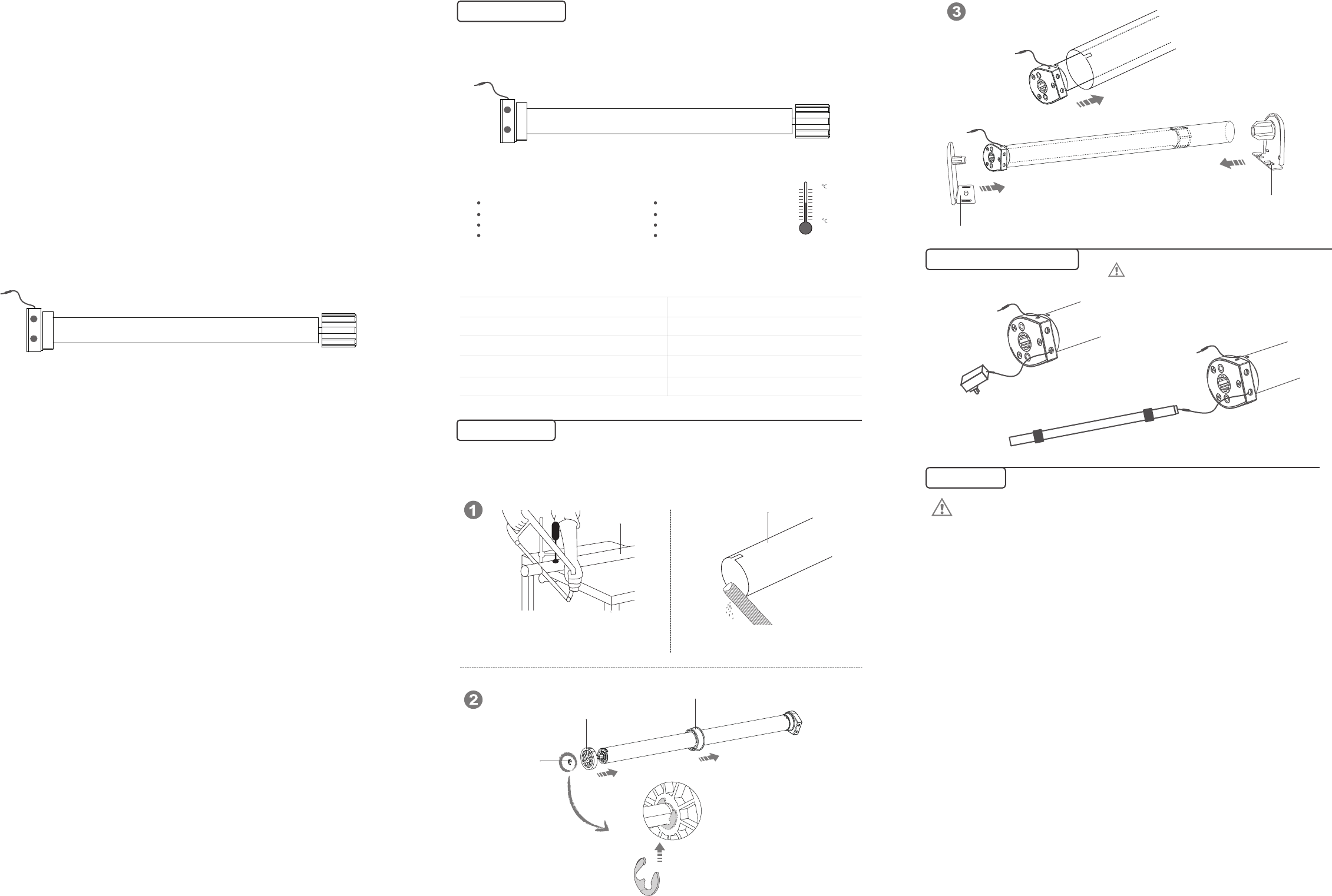
12V battery pole
The motor can be charged by both the power
adapter or the 12V supply electricity.Is that is
rechargeable by solar panel or adaptor when
the battery is low.
Product introduction
Functional features:
Jogging&tilt function
Set electronic limit
Set /delete the third limit position
Low standby power
Integrated radio control
Setting up + add emitter +delete emitter
Motor direction setting option
Resistance stop function
Signal wire
-10
85
Operating
temperature
Technical Dare
Emission frequency(MHz)
Type
Rated Torque(N.m)
Rated Voltage(V)
Rated speed(RPM)
①Driving tube must be close-fitting with crown and drive adapter.
②Choose crown and drive adapter based on the driving tube.
Motor Installation
Drive tube
Drive tube
② Runner
① Crown
③ Circlip
Rechargeable Description
Stroke support
Tail insert bracket
Operation note
Please read the fallowngprecautions befor use:
电
机
操
作
指
南
②Long press the stop button for 2s,the roller blinds will move to the third limit
Already set
up, down
limit position
2, The third limit cancel (P2→Stop→Stop)
2, Set up limit
1, Enter the limit setting mode
(Up→Up+Stop)
Adapter or
battery rod
3 Limit position
The blind
run up
The blind
stops
P2
P2
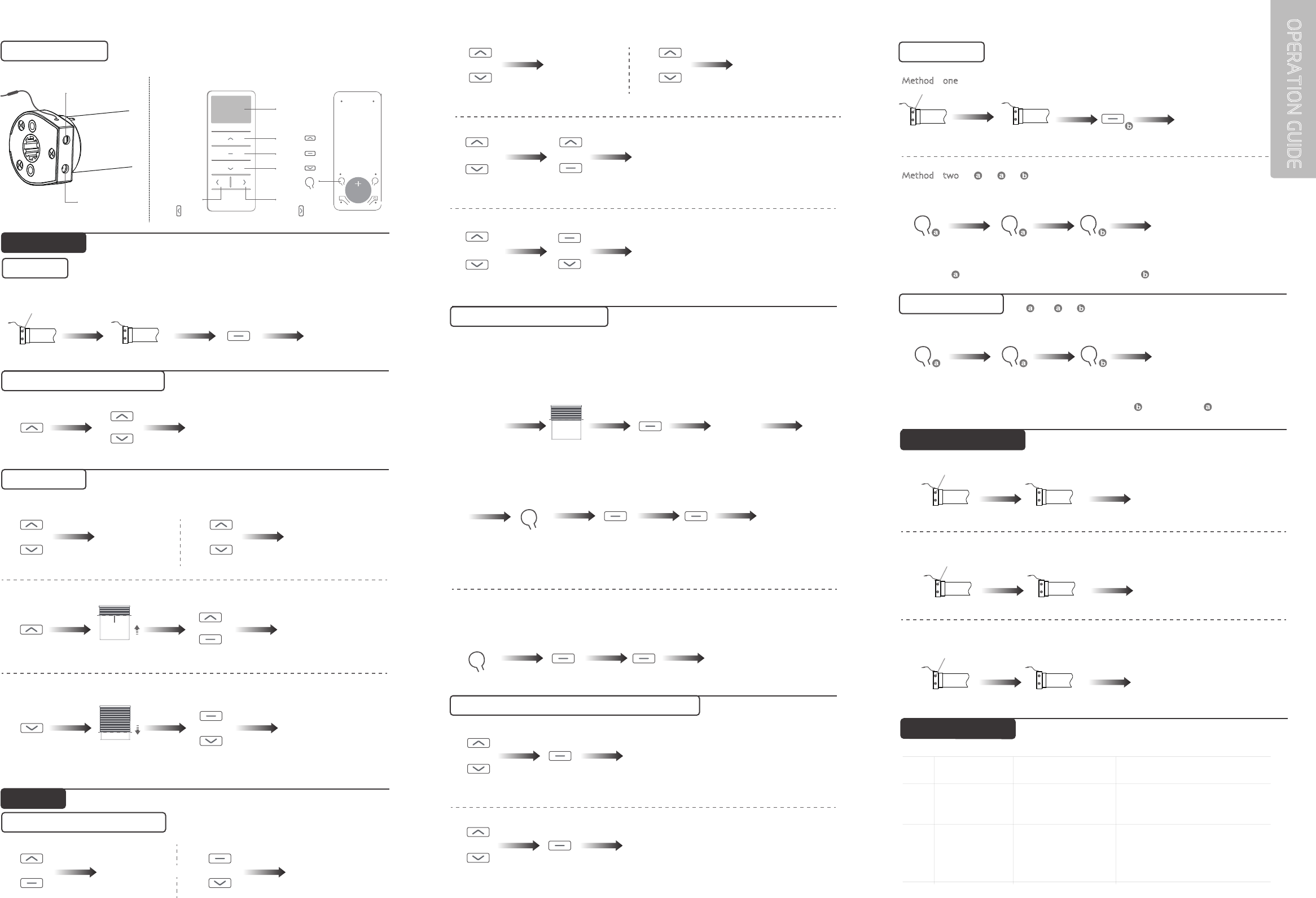
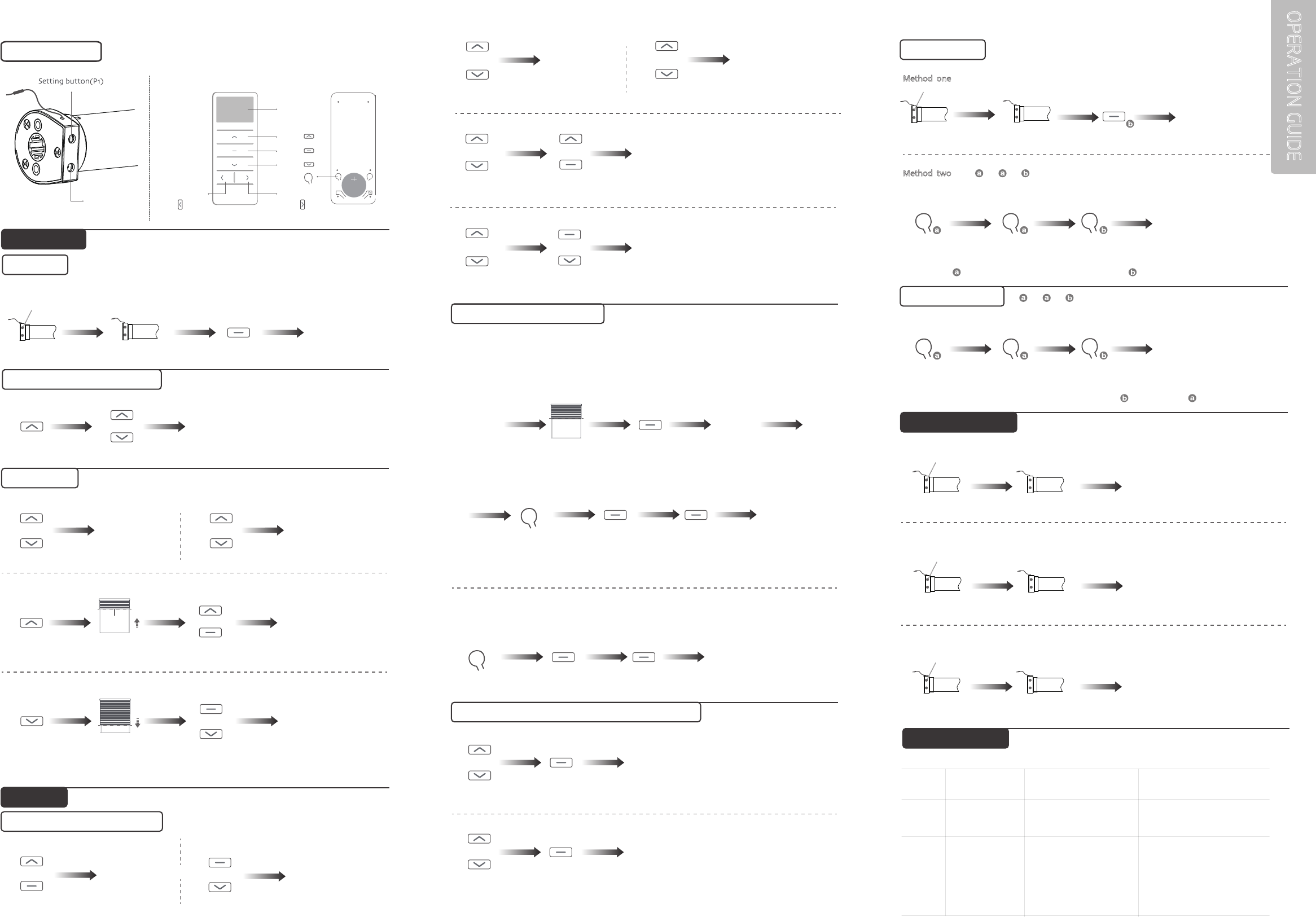
Setting button(P1)
3, Set down limit (Down→Stop+Down)
2 The third limit position setting
1, The third limit position setting (P2→Stop→Stop)
①After the up limit and down limit setting, you can set the third limit point between them as the half open
position;
1 Fine-tune up/down limit position
Enter the limit setting mode
1
2
The motor alarms
when it is working Charge the battery
Motor can’t
running
a,Activate the motor after fully charged
b,Set up the match code
c,Contact the engineers for after-sales.
The voltage is low in
the alarm mode
a,The battery is not
activated. b,Theemitter is
not matched.
c,If press P1 button for a
P2
M
P2
Lithium Cell
3V
Up
Display
Setting
Channel“+”
(P1+)
Stop
Down
Channel“-”
(P1-)
P2
Or Dot-move Or Continuous moving
+
+
+Enter fine-tune
up limit mode +Enter fine-tune
down limit mode
Or +
或+
2 The reverse of direction setting
The blind
run down
+
Or
USER MODE
Functions that can be operated under any mode
Note: After setting up the up and down limit into user mode.
Note: Can not be fine-tune up/down limit position at the same time.
Button specification
Press
1
s
Run for hint x1
Press
2
s
Successful change
the direction
Press
1
sPress
2
s
Press
2
s
Press
1
s
Run for hint x2
“Di” x3
The up
limit point
Confirm the Blind
to stop in the up
limit positio
n
Set up
is ok
Run for hint x2
“Di” x3
Set up
is ok
The down
limit point
Confirm the Blind
to stop in the down
limit position
Press
2
s
The blind
run down
Press
1
s
Run for hint x1
“Di” x1
Run for hint x1
“Di” x1
Press
5
s Press
5
s
Or Dot-move Or Continuous moving
Press
1
sPress
2
s
Press
1
s Press
2
s
Run for hint x2
“Di” x3
Press
1
s Press
2
s
Run for hint x2
“Di” x3
Run for hint x2
“Di” x3
Press
1
s
Press
1
sPress
1
sPress
1
s
Run for hint x1
“Di” x1
Run for hint x1
“Di” x1
The third limit position
(any position)
Any
position
Confirm the new up limit point
Confirm the new down limit point
Set up
is ok
Run for hint x1
“Di” x1
Run for hint x1
“Di” x1
Run for hint x1
“Di” x1 Set up
is ok
Press
1
sPress
1
sPress
1
s
OPERATION GUIDE
Press 2s Press 2s
Run for hint x2
“Di” x3“Di” x1
If you need to reverse the rotateon of the motor controlled by the emitter,please run the reverse
of direction setting(as lists in the second point of the P1 button setting)
FACTORY MODE
1 Setting up
Run for hint x1
loosen P1
Set up is ok
Press 5s Press 1s
Press 5s Press 1s
Run for hint x1
“Di” x1
Run for hint x1
Run for hint x2
“Di” x3
Run for hint x1
3 Dot-move/Continuous moving function switch switch
Notes: Repetitive operation dot-move and continuous moving function switching cycle, under the dot-move function,
according to the upor down button more than 2S release motor linkage operation.
Dot-move function
Continuous moving
function
+
+
Adjust the new
up limit point
Adjust the new
down limit point
PHENOMENON REASON PROCESSING METHODNUMBER
FAULT AND SOLUTION
Run for hint x3
Long Press P1
loosen P1
3, Restore factory settings
“Di”x3
Set up is ok
Long Press P1
loosen P1
2, The reverse of direction setting
Run for hint x2 “Di”x2
Successful change
the direction
Long Press P1
loosen P1
1, Activate motor for the first time
Run for hint x1 “Di~~”x1
Activate is ok
P1 BUTTON OPERATION
P2 →P2 →P2
5 Delete one emitter
P2 P2
P2
Press 1s Press 1s Press 1s
Run for hint x2
“Di” x3
Run for hint x1
“Di” x1
Run for hint x1
“Di” x1
One emitter
is deleted
Note:With the same method,you only can delete the emitter not the emitter
P2 P2
P2
4 Add Emitter
P2 →P2 →P2
loosen P1
Press 1s
Press 2s Press 2s
Press 1s Press 1s
Run for hint x2
“Di” x3
Run for hint x2
“Di” x3
Run for hint x1
“Di” x1
Run for hint x1
“Di” x1
Run for hint x1 “Di” x1
Method two
Method one
Note:Emitter is the one already matched code, while emitter has not
Emitter adding is ok
Emitter adding is ok

Tubular Motor-
DM28LEQ/S
Specification
(A-OO)
DM28LEQ/S
2N.m
12V
433.925MHz
28RPM
Rated Voltage(V)
Rated Torque(N.m)
Functional features:
Jogging&tilt function
Set electronic limit
Set /delete the third limit position
Low standby power
Integrated radio control
Setting up+add emitter+delete emitter
Motor direction setting option
Resistance stop function
-10
85
Emission frequency(MHz)
Rated speed(RPM)
1. Please charge the battery and make sure it is fully charged before the first use
2. Don’t operate motors wheuin low wltage alarm:
①Motor stop running When the supply voltage is lower than 7 v, and it will restart
again when the voltage is greater than 7.5V
②If the voltage is less than 10v, the motor will alarm for 10 times to prompt it needs
to be charged every timewhen the motor is working.
3. Optrating:
①The valid interval of the emitter button is 10s,the emitter will quit the set after 10s
②The motor will run or beep for hint,please do the next step after the hint.
4. Set limit position:
①After the up limit and down limit setting,and the up limit down limit and third limit
position are at the same location
②After limit setting,with power and memory function;
③Into the match-code status 2 minutes later, it will quit out the setting limits status
automatically
④It will delete every memory and restore the factory settings
5. When the motor running without any operation, the maximum running time is 6
minutes,it will stop automatically
6. If the emitterlost,please set up again with new emitter
The motor has a built-in battery,using the charger to
recharge.You can also use solar panels to charge;when
the battery is low, insert thecharge,charger light shows
red light.batteries isfull when the red light turns to green.
Note:When the battery power is low,you can hear the alarm ten "beep" every time the
motor runs. It indicates the battery needs to be charged. Then plug in the charger with
red light.The light turns green when the battery is fully charged.
Operating
temperature
Parameter
Type
Rechargeable Description
Signal wire
OPERATION GUIDE
1
2
PHENOMENON REASON
The motor alarms
when it is working
PROCESSING METHOD
Charge the battery
The motor is
not running
a,Activate the motor after fully charged
b,Set up the match code
c,Contact the engineers for after-sales
The voltage is low in the
alarm mode
a,The battery is not activated.
b,The emitter is not matched.
c,If press P1 button for a long time
while with no reaction.may be the
power is short-ciralit or the ciralit
board or the motor is broken.
NUMBER
1, The third limit position setting
①After the up limit and down limit setting, you can set the third limit point between them as the half open position;
Press 2s
Press 1s
Press 1s
Press 1s
Press 5sPress 5s
Press 5s Press 1s
Press 1s Press 1s Press 1s
Press 1s Press 1s
Press 1s
Press 1s
Press 5s Press 1s
Press 2s
Press 2s
Press 2s
Press 2s
Press 2s
Run for hint x2
“Di” x3
Run for hint x2
“Di” x3
Run for hint x2
“Di” x3
Run for hint x2
“Di” x3
Run for hint x2
“Di” x3
Run for hint x1
“Di” x1
Run for hint x1
“Di” x1
Run for hint x1
“Di” x1
Run for hint x1
“Di” x1
Run for hint x1
“Di” x1
Run for hint x1
“Di” x1
Run for hint x1
Run for hint x2
“Di” x3
Run for hint x1
Run for hint x2
“Di” x3
Run for hint x1
“Di” x1
Run for hint x1
“Di” x1
“Di” x1
If you need to reverse the rotateon of the motor controlled by the emitter,please run the reverse of direction
setting(as lists in the second point of the P1 button setting)
Up
Stop
Down
Setting
Button specification
P2 P2
P2
4 Add Emitter
P2 →P2 →P2
P2 →P2 →P2
5 Delete one emitter
3 Dot-move/Continuous moving function switch switch
2, The third limit cancel (P2→Stop→Stop)
P1 BUTTON OPERATION
2, Set up limit
3, Set down limit
( Up→Up+Stop)
P2
P2
P2 P2
P2
(Down→Stop+Down)
Run for hint x3
2 The third limit position setting
1 Fine-tune up/down limit position
Enter the limit setting mode
Notes: Repetitive operation dot-move and continuous moving function switching cycle, under the dot-move
function, according to the upor down button more than 2S release motor linkage operation.
P2
M
P2
Lithium Cell
3V
Channel“+”
(P1+)
Channel “-”
(P1-)
P2
or orDot-move Continuous moving
Dot-move function
Continuous moving
function
+
+
++
Adjust the new
up limit point
Adjust the new
down limit point
+Conrm the new up limit point
Conrm the new down limit point
+
+
+
+
or
FACTORY MODE
FACTORY MODE
USER MODE
Functions that can be operated under any mode
Note: After setting up the up and down limit into user mode.
Note: Can not be ne-tune up/down limit position at the same time.
loosen P1
Display
1 Setting up
Run for hint x1
Run for hint x1
loosen P1
Set up is ok
The blind
run down
The blind
run up
The blind
run down
2 The reverse of direction setting
Successful change
the direction
3 limit position
1, Enter the limit setting mode
Conrm the Blind
to stop in the up
limit position
Conrm the Blind
to stop in the down
limit position
The up
limit point
The down
limit point
Set up is ok
Set up is ok
Enter ne-tune
up limit mode
Enter ne-tune
down limit mode
Press 1s
Press 2s Press 2s
Press 1s Press 1s
Press 1s Press 1s Press 1s
Long Press P1
loosen P1
Long Press P1
loosen P1
Long Press P1
loosen P1
Run for hint x2
“Di” x3
Run for hint x2
“Di” x3
Run for hint x2
“Di” x3
Run for hint x1
“Di” x1
Run for hint x1
“Di” x1
Run for hint x1 “Di” x1
Run for hint x1
“Di” x1
Run for hint x1
“Di” x1
Dot-move Continuous moving
or
or
or
or
Press 1s
Press 1s Press 2s
Press 1s Press 2s
Press 2s
Already set
up, down
limit position
Any
position
The third limit position
(any position)
The motor
stops
Set up is ok
Set up is ok
②Long press the stop button for 2s,the roller blinds will move to the third limit
Method two
Method one
Note:Emitter is the one already matched code, while emitter has not
Emitter adding is ok
Emitter adding is ok
One emitter
is deleted
Note:With the same method,you only can delete the emitter not the emitter
1, Activate motor for the rst time
2, The reverse of direction setting
3, Restore factory settings
Run for hint x1
Run for hint x2
“Di~~”x1
“Di”x2
“Di”x3
Set up is ok
Successful change
the direction
Activate is ok
FAULT AND SOLUTION
Recharger or
solar rechargeable
board port
Warning:
This device complies with Industry Canada RSS-210. Operation is subject to the following two conditions:
(1) this device may not cause interference, and (2) this device must accept any interference,
including interference that may cause undesired operation of the device.
Le présent appareil est conforme aux CNR d’Industrie Canada applicables aux appareils radio RSS-210.
L’exploitation est autorisée aux deux conditions suivantes :
(1) l’appareil ne doit pas produire de brouillage, et
(2) l’utilisateur de l’appareil doit accepter tout brouillage radioélectrique subi, même si le brouillage est
susceptible d’en compromettre le fonctionnement.
The device meets the exemption from the routine evaluation limits in section 2.5 of RSS 102 and compliance
with RSS-102 RF exposure, users can obtain Canadian information on RF exposure and compliance.
Le dispositif rencontre l’exemption des limites courantes d’évaluation dans la section 2.5 de RSS 102 et la
conformité à l’exposition de RSS-102 rf, utilisateurs peut obtenir l’information canadienne sur l’exposition et la
conformité de rf.
This transmitter must not be co-located or operating in conjunction with any other antenna or transmitter.
This equipment should be installed and operated with a minimum distance of 5 mm between the radiator
and your body.
Cet émetteur ne doit pas être Co-placé ou ne fonctionnant en même temps qu’aucune autre
antenne ou émetteur. Cet équipement devrait être installé et actionné avec une distance minimum
de 5mm entre le radiateur et votre corps.
FCC Warning:
1. This device complies with Part 15 of the FCC Rules. Operation is subject to the following two
conditions:
(1) This device may not cau se harmful interference.
(2) This device must accept any interference received, including interference that may cause
undesired operation.
2. Changes or modifications not expressly approved by the party responsible for compliance could
void the user's authority to operate the equipment.
NOTE: This equipment has been tested and found to comply with the limits for a Class B digital
device, pursuant to Part 15 of the FCC Rules. These limits are designed to provide reasonable
protection against harmful interference in a residential installation.
This equipment generates uses and can radiate radio frequency energy and, if not installed and
used in accordance with the instructions, may cause harmful interference to radio communications.
However, there is no guarantee that interference will not occur in a particular installation. If this
equipment does cause harmful interference to radio or television reception, which can be
determined by turning the equipment off and on, the user is encouraged to try to correct the
interference by one or more of the following measures:
Reorient or relocate the receiving antenna.
Increase the separation between the equipment and receiver.
Connect the equipment into an outlet on a circuit different from that to which the receiver is
connected.
Consult the dealer or an experienced radio/TV technician for help.