NITGEN and SW101-MP Fingkey Access Plus User Manual
NITGEN & COMPANY Fingkey Access Plus Users Manual
UserManual.wiki
>
NITGEN and
>
SW101 MP User Manual
User Manual
Navigation menu
Upload a User Manual
Namespaces
Wiki Guide
HTML
PDF
Info
Views
User Manual
Discussion / Help
Navigation
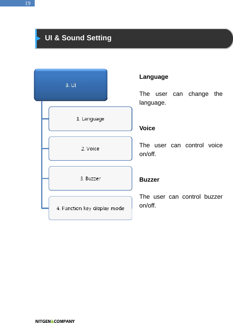
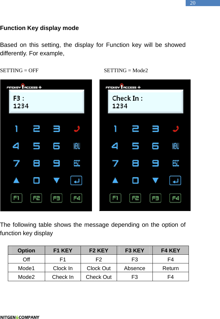
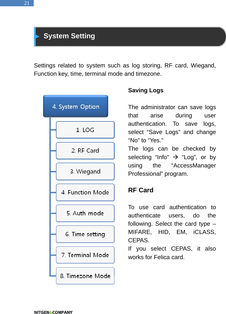
![34 Using Keyphone If you want to use keyphone, just touch the phone-icon. You can call anyone you want to talk with. The man who gets the call can open the door just pushing the button [*][7][8][9] on his phone.](https://usermanual.wiki/NITGEN-and/SW101-MP/User-Guide-1440817-Page-34.png)