NOFIQ Fire and Safety Systems 102040A ZigBee Fire control and indicating apparatus User Manual 1020 1000 0025 HL E v6 4
NOFIQ Fire & Safety Systems BV ZigBee Fire control and indicating apparatus 1020 1000 0025 HL E v6 4
Users Manual

NOFIQ®
fire prevention system
Manual for design,
installation, acceptance,
use and maintenance
Reference: 1020.1000.0025 EN
Version number: 6.4 - March 2009
Document name: HL-E
Publication: NOFIQ® systems BV
NOFIQ systems BV – Postbus 510 – 9400 AM Assen – the Netherlands
(T) 0592 – 40 42 01 (F) 0592 – 40 42 82
www.nofiq.com - info@nofiq.com

NOFIQ® Systems page 2
Declaration of conformity
We, undersigned
NOFIQ® systems BV, Nijverheidsweg 16 9403 VN ASSEN, Nederland
Declare hereby that the following products:
Complete wireless fire protection system consisting of:
• NOFIQ® N20-BASE (alarm management station)
• NOFIQ® N20-BASE_HUB (radio and transmitting station)
• NOFIQ® N20-HUB (signal repeater)
• NOFIQ® N20-FE (detection, alarm and extinguishing component)
• NOFIQ® N80-FE (detection, alarm and extinguishing component)
are tested and meet the essential requirements of the following European Directives:
- 1999/5/EG, Radio and telecommunication terminal equipment (R&TTE)
- 2004,108,EG, Electromagnetic compatibility (EMC)
- 2006/95/EG, Low voltage directive (LVD)
The aforementioned products meet the essential requirements of the:
R&TTE Directives 1999/5/EC based on the agreement with the following harmonised standards:
- EN 60950-1 (2001)
- EN 301 489-1 V.1.4.1 and EN 301 489-3 V.1.4.1
- EN 300 440-1 V.1.3.1 and EN 300 440-2 V.1.1.1
The equipment also complies with the RECOMMENDATION OF THE COUNCIL (1999/519/EG) of the 12th July 1999
regarding the limited exposure of the population to electromagnetic fields from 0 Hz - 300 GHz, complying the
judgement of TüV Rheinland EPS BV as a Notified Body (nr. 1856).
For the EMC Directives 2004/108/EEG based on the following harmonised standards:
- EN 55022 (1998)
- EN 55024 (1999)
- EN 50130-4 / A2 (2003)
- EN 61000-3-2 (2002)
For the LVD Directives 2006/95/EG based on the following harmonised standards:
- EN 60950-1 (2001)
The equipment also complies with the RECOMMENDATION OF THE COUNCIL (1999/519/EG) of the 12th July 1999
regarding the limited exposure of the population to electromagnetic fields from 0 Hz - 300 GHz, complying the
judgement of TüV Rheinland EPS BV as a Notified Body (nr. 1856).
The technical documentation required regarding the relevant conformity procedures in Directives for proving the
presumption of agreement with the directives mentioned has been composed under undersigned’s responsibility and
will be placed at the disposal of the relevant authorities by request.
The product conformity with the abovementioned standards and directives is confirmed by the EG conformity mark.
The technical documentation required regarding the relevant
conformity procedures can be requested at:
NOFIQ® systems BV, Nijverheidsweg, 16, 9403 VN ASSEN, the Netherlands
E-mail: info@NOFIQ®.com - Internet: www.NOFIQ®.com
G.M. de Groot
General Director
1 March 2009
page 3
NOFIQ® Systems
Preamble
Limited liability
The set-up and content of this manual has been composed with the utmost care. Yet we do not accept
liability for any mistakes or inaccuracies that might occur in the manual.
NOFIQ® products are updated regularly. Therefore it is possible for certain instructions, specifications or
figures in this documentation to be deviating. Furthermore NOFIQ® systems BV and NOFIQ® holding BV are
entitled to revise this publication and make changes to its content.
NOFIQ® systems BV and NOFIQ® holding BV do not accept any liability for direct damage caused by
incorrect use or use other than mentioned in the manual.
NOFIQ® systems BV and NOFIQ® holding BV only accept legal liability for direct damage for which NOFIQ®
is liable based on non-fulfilment and/or unlawful action. This damage however is restricted to compensation
charged or to be charged for the performance in question by NOFIQ® systems BV and NOFIQ® holding BV.
No liability for consequential damage
In no case are NOFIQ® systems BV and NOFIQ® holding BV and her distributors liable for damage (including,
but not restricted to indemnity for loss of revenue, business interruption, loss of business information or
any other financial loss) caused by (incorrect) use of or any prevention from use of these products, even
if NOFIQ® systems BV and NOFIQ® holding BV and her distributors are informed about the risk of such
damage.
Extending Declaration of conformity
Beside the Declaration of conformity a extending Declaration for productcertification (EN 45011)
is given on basis of the Guideline BRL K21014 of Kiwa Certification and the European Norms EN 54-4 and
EN 54-25 by TüV Rheinland EPS BV.
The technical documentation required regarding the
relevant conformity procedures can be requested at:
NOFIQ systems B.V.
Nijverheidsweg 16
9403 VN ASSEN
the Netherlands
www.nofiq.com
info@nofiq.com
G.M. de Groot
General Director
1 March 2009

NOFIQ® Systems page 4
Limited warranty
Limited warranty manufacturer
NOFIQ® systems BV and NOFIQ® Holding BV guarantee that the NOFIQ® products in principle
function or will function in pursuance of the information in the manual and accompanying
documentation material.
No other warranty
NOFIQ® systems BV, NOFIQ® Holding BV and her distributors offer no warranty, neither explicit,
nor implicit, including but not restricted to the salability or suitability regarding the NOFIQ®
products and accompanying documentation material for any other application than described in
the manual.
Modifications to the product
NOFIQ® systems BV and NOFIQ® Holding BV are not liable for modifications made by the
user. Likewise no liability is accepted for consequences of those modifications, whether or not
influencing the product conformity of the CE-mark.
Trademarks
NOFIQ® is a registered trademark of NOFIQ® systems BV and NOFIQ® Holding BV. All other
company or product names are (registered) trademarks, or service brands owned by (NOFIQ®
systems BV and) NOFIQ® Holding BV.
NOFIQ® is a registered European patent.
FirePro is a registered European patent.
Violation of these patents, in any form, will be prosecuted with all means of appeal available.
.

page 5
NOFIQ® Systems
Table of Contents
1. Foreword 9
1.1 Manual set-up 9
1.2 Use of icons 10
2. An overview of the NOFIQ® system 11
2.1 General 11
2.2 Components of the NOFIQ® system 11
2.3 Wireless communication between the components 13
2.4 Alarm messages 14
2.5 Error messages 16
2.6 Authorisation 16
3. The NOFIQ® BASE 17
3.1 General 17
3.2 Functionality of the NOFIQ® BASE 17
4. The NOFIQ® BASE-HUB 19
4.1 General 19
4.2 Functionality of the NOFIQ® BASE-HUB 19
5. The NOFIQ® HUB 21
5.1 General 21
5.2 Functionality of the NOFIQ® HUB 22
6. The NOFIQ® FE 23
6.1 General 23
6.2 Functionality of the NOFIQ® FE 24
7. Safety and environment 25
7.1 General 25
7.2 General safety precautions 25
7.3 Use of aerosol extinguishing components 25
7.4 Safety precautions during maintenance and installation 26
7.5 Safety precautions after a fire 27
7.6 Environmental aspects 27
8. Designing the installation of the NOFIQ® system 29
8.1 General 29
8.2 Calculating the amount of extinguishing agent 31
9. Installation of the NOFIQ® system 33
9.1 General 33
9.2 Storage and transport 33
9.3 Conditional requirements for an operational system 34
9.4 Preparing the installation 34
9.5 Concise installation procedure 36
10. Installation of the NOFIQ® BASE 39
10.1 General 39

NOFIQ® Systems page 6
10.2 Conditional requirements for the NOFIQ® BASE 39
10.3 Requirements 39
10.4 Technical specifications of the NOFIQ® BASE 41
10.5 Installation and configuration instructions NOFIQ® BASE 41
11. Installation of the NOFIQ® BASE-HUB 47
11.1 General 47
11.2 Requirements 47
11.2 Technical specifications of the NOFIQ® BASE-HUB 48
11.3 Installation and configuration instructions NOFIQ® BASE-HUB 48
12. Configuration and data management NOFIQ® BASE 51
12.1 General 51
12.2 Requirements 51
12.3 Configuring and managing data in the NOFIQ® BASE 51
12.4 Menu terminal application NOFIQ® BASE 53
13. Installation of a NOFIQ® HUB 60
13.1 General 60
13.2 Requirements 60
13.3 Technical specifications of the NOFIQ® HUB 61
13.4 Installation and configuration instructions NOFIQ® HUB 61
14. Configuration of a NOFIQ® HUB or a NOFIQ® FE 65
14.1 General 65
14.2 Requirements 65
14.3 Configuring a NOFIQ® HUB or NOFIQ® FE 65
15. Installation of a NOFIQ® FE 73
15.1 General 73
15.2 Requirements 73
15.3 Technical specifications of a NOFIQ® FE 74
15.4 Installation and configuration instructions NOFIQ® FE 74
15.5 Additional special instructions for installation of a standalone NOFIQ® FE 80
16. Installation of a InterNOFIQBus 81
16.1 General 81
16.2 Requirements 81
16.3 Installation and configuration instructions InterNOFIQBus 82
17. Putting the NOFIQ® system into operation 86
17.1 General 86
17.2 Putting the system into operation 86
18. Acceptance of the NOFIQ® system 87
18.1 General 87
18.2 Activities for acceptance 87
19. The NOFIQ® BASE in daily use 88
19.1 General 88

page 7
NOFIQ® Systems
19.2 Control panel 88
19.3 Alphanumeric display 89
19.4 Indication LEDs 89
19.5 Buttons (keypad) 90
19.6 Locks 90
19.7 Alarm or error messages and accompanying indicators 92
19.8 Overview alarm messages 92
19.9 Overview error messages 93
19.10 Menu structure 94
19.11 Menu options and their use 97
20. The NOFIQ® BASE-HUB in daily use 101
20.1 General 101
20.2 Statuses of the NOFIQ® BASE-HUB and accompanying indicators 101
20.3 Use of the button of the NOFIQ® BASE-HUB 101
21. The NOFIQ® HUB in daily use 102
21.1 General 102
21.2 Statuses of a NOFIQ® HUB and accompanying indicators 102
21.3 Use of the button of a NOFIQ® HUB 102
22. The NOFIQ® FE in daily use 103
22.1 General 103
22.2 Operation of the NOFIQ® FE’s sensors 103
22.3 Statuses of a NOFIQ® FE and accompanying indicators 104
22.4 Use of the button of a NOFIQ® FE 105
23. Alarm or error, what to do? 106
23.1 General 106
23.2 How do you recognize an alarm or error? 106
23.3 How does the system handle an alarm? 109
23.4 What to do yourself in case of an alarm? 110
23.5 How does the system handle an error? 111
23.6 What to do yourself in case of an error? 111
24. Maintenance of the NOFIQ® system 114
24.1 General 114
24.2 Maintenance agreement 114
24.3 Periodical inspections and preventive maintenance 115
24.4 Dismantling equipment 115
24.5 Carrying out software updates 116
24.6 Carrying out hardware updates 116
24.7 Reading out log files of the NOFIQ® BASE 116
25. Maintenance of the NOFIQ® BASE 118
25.1 General 118
25.2 Periodical inspections and preventive maintenance NOFIQ® BASE 118

NOFIQ® Systems page 8
25.3 Repairs of the NOFIQ® BASE 119
25.4 Replacing the battery of the NOFIQ® BASE 119
25.5 Replacing the NOFIQ® BASE 119
26. Maintenance of the NOFIQ® BASE-HUB 121
26.1 General 121
26.2 Periodical inspections and preventive maintenance BASE-HUB 121
26.3 Repairs of the NOFIQ® BASE-HUB 122
26.4 Replacing the NOFIQ® BASE-HUB 122
27. Maintenance of the NOFIQ® HUB 123
27.1 General 123
27.2 Periodical inspections and preventive maintenance NOFIQ® HUB 123
27.3 Repairs of a NOFIQ® HUB 123
27.4 Replacing the battery-pack of a NOFIQ® HUB 123
27.5 Replacing a NOFIQ® HUB 125
28. Maintenance of the NOFIQ® FE 126
28.1 General 126
28.2 Periodical inspections and preventive maintenance NOFIQ® FE 126
28.3 Repairs of a NOFIQ® FE 127
28.4 Replacing the battery-pack of a NOFIQ® FE 128
28.5 Solving errors in a standalone NOFIQ® FE 128
28.5 Replacing a NOFIQ® FE 130
28.6 Relocating a NOFIQ® FE 131
29. Service and warranty 132
30. Support 133
31. Index 134
32. List of figures and tables 136
32.1 List of figures 136
32.2 List of tables 137
33. Abbreviations 138
34. Glossary 139
35. Certification 142
36. Appendices 144
36.1 Program of Requirements (example) 144
36.2 Installation plan (example) 148
36.3 Acceptance Report (example) 149
36.4 Log book (example) 152
36.5 Maintenance Report (example) 155
36.6 Overview status transitions 159
36.7 Specifications external antenna 160
36.8 Specifications FirePro® aerosol extinguishing components 161
36.9 FirePro® Material Safety Data Sheet 163
36.10 Regulatory information radio communication 168

page 9
NOFIQ® Systems
1. Foreword
This is the manual for the NOFIQ® fire prevention system. This manual describes design, installation,
acceptance, use and maintenance of the NOFIQ® system.
For end-users there is a separate user guide. The user guide only focuses on daily use of the NOFIQ®
system and is aimed at NOFIQ® users with authorisation level 1 or 2. Authorisation levels and associated
powers will be explained in paragraph 2.6.
1.1 Manual set-up
The manual for design, installation, acceptance, use and maintenance is divided as follows:
Chapter 2 states an overview of the NOFIQ® system and its functionality. The chapters 3 through 6 will
describe the functionality of the NOFIQ® system’s components separately.
Chapter 7 informs you on safety measures during installation and use of the NOFIQ® equipment.
Chapter 8 focuses on designing of the application and installation of the system.
Chapter 9 offers a step-by-step overview of the installation and configuration of a NOFIQ® system.
The chapters 10 through 16 handle the installation and configuration of the NOFIQ® system’s components
separately.
Chapter 17 deals with putting the NOFIQ® system into operation. Chapter 18 deals with acceptance of the
NOFIQ® system.
Chapters 19 through 22 inform you on daily use of the system. These chapters offer information on the
operation of keys, buttons, menus, LEDs and buzzers of the NOFIQ® system’s components.
Chapter 23 handles the alarm messages and error messages generated by the NOFIQ® system, how the
system deals with these messages and what the user should do.
Chapter 24 through 28 deal with periodical checks and preventive maintenance on the NOFIQ® system
and its components.
Lastly we offer you an alphabetical index, lists of tables, figures and abbreviations as well as appendices
with background information.
NOFIQ® Systems page 10
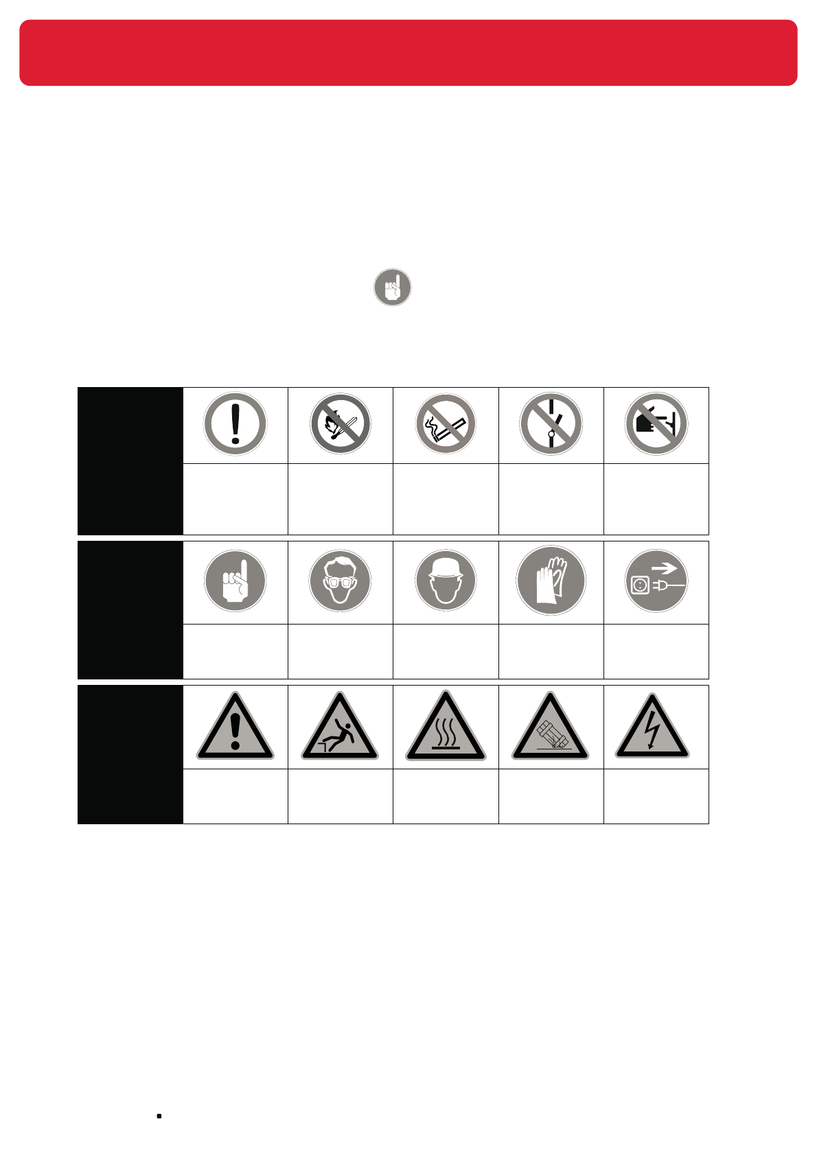
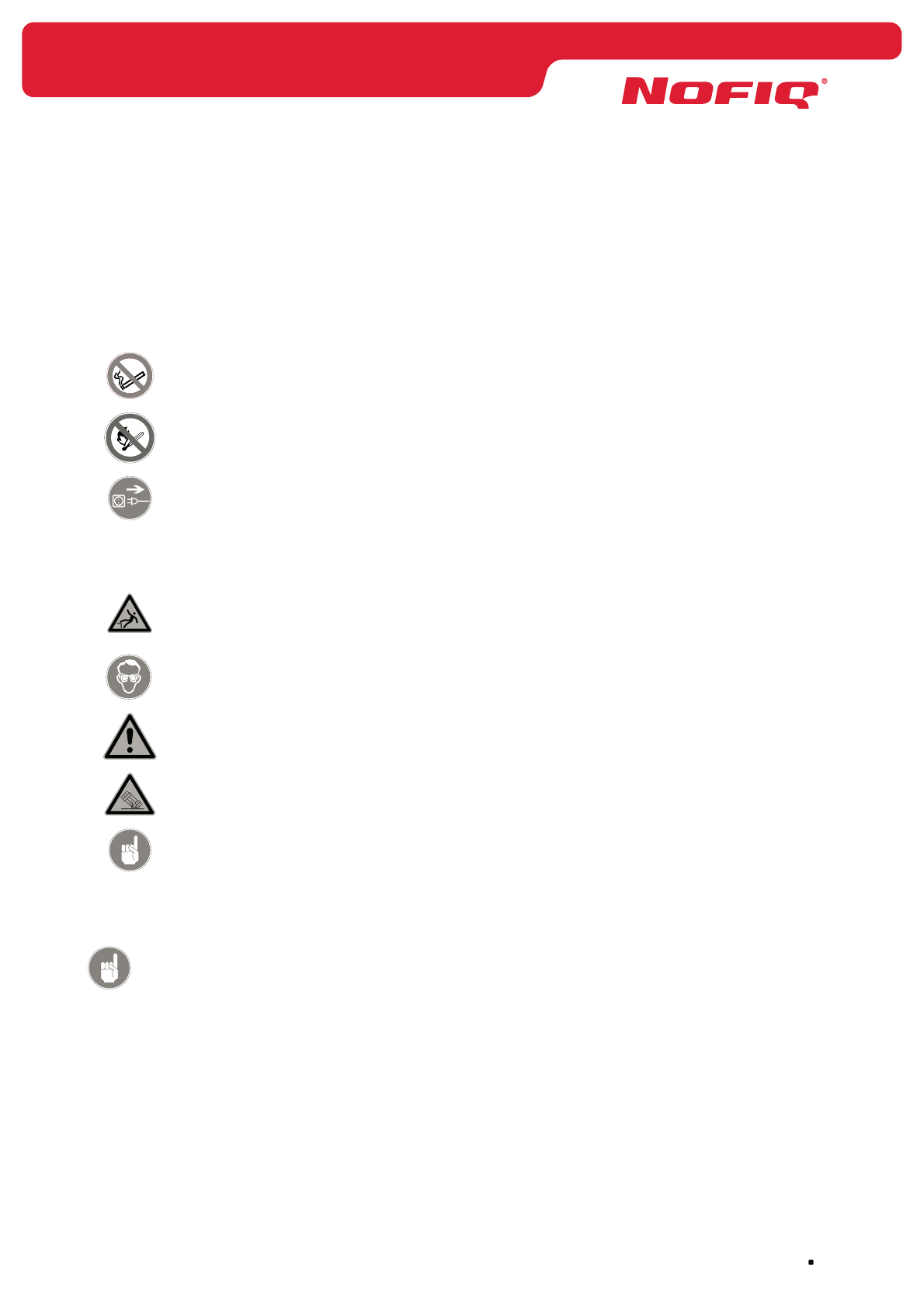
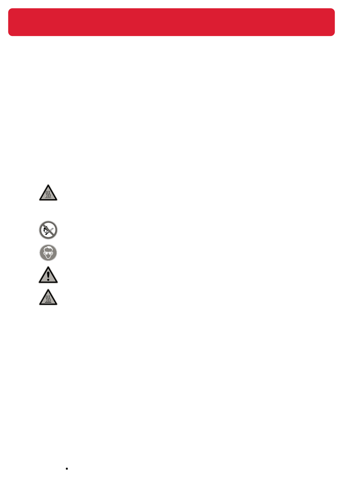
1.2 Use of icons
In this manual various icons are used to inform you about prohibitions, orders, warnings and useful tips.
You will regularly encounter the following icon:
This icon means ‘Attention’ and is followed by a tip or a clue.
Within this manual you could encounter the following icons.
Prohibition
Be careful!
Fire, open
flame and
smoking
prohibited
No smoking Switching off
prohibited
Switching on
prohibited
Order
Attention!
Eye
protection
mandatory
Safety
helmet
mandatory
Safety
gloves
mandatory
Disconnect
Warning
Danger
Falling due
to level
difference
Hot surface Damage High voltage

page 11
NOFIQ® Systems
2. An overview of the NOFIQ® system
2.1 General
The NOFIQ® fire prevention system is a complete fire prevention system. The system has been especially
designed for detecting, alarming and extinguishing a fire in enclosed compartments containing electrical
components (maximum 1500 Volt DC and 1000 Volt AC). The NOFIQ® system is primarily meant for
objects that cannot be entered by humans. The system is pre-eminently suited for application in:
• switch cabinets
• meter boxes
• patch cabinets
• computers
The NOFIQ® system is used to detect a fire at its source in its earliest stadium and to extinguish this fire.
Already in the initial phase of fire, the detection and extinguishing component will alarm the surrounding
area and send a message to the alarm management station. If a fire really ignites, the extinguishing
component will extinguish the fire thanks to the built-in aerosol fire-extinguishing component. In the
meantime the alarm management station has notified the fire brigade or another fire-fighting service.
The NOFIQ® fire prevention system uses FirePro aerosol fire-extinguishing components.
The FirePro® aerosol fire-extinguishing components are pre-eminently suited for extinguishing fires of the
following fire classes:
• A, solids
• B, liquids
• C, gasses
• F, oils and fats
2.2 Components of the NOFIQ® system
A NOFIQ® system consists of the following components:
• NOFIQ® N20-BASE
hereafter NOFIQ® BASE
This the alarm management station which offers information on all
extinguishing and communication components within the system as well
as on the status of the system as a whole.
A detailed description of the NOFIQ® N20-BASE’s functionality is
provided in chapter 3.
• NOFIQ® N20-BASE_HUB
hereafter NOFIQ® BASE-HUB
This is the transfer station, the antenna, of the NOFIQ® N20-BASE (the
alarm management station)
A detailed description of the NOFIQ® N20-BASE-HUB’s functionality is
provided in chapter 4.
• NOFIQ® N20-HUB
hereafter NOFIQ® HUB
This is a signal repeater that enhances or repeats the communication
signal between the components of the NOFIQ® system.
A detailed description of the NOFIQ® N20-HUB’s functionality is provided
in chapter 5.

NOFIQ® Systems page 12
• NOFIQ® N20-FE
hereafter NOFIQ® FE
This is the detection and extinguishing component (FE= Fire
Extinguisher) of the system which is able to detect a fire as well as
extinguish it thanks to the built-in FirePro® aerosol extinguishing
component.
A detailed description of the NOFIQ® N20-FE’s functionality is provided
in chapter 6.
At the moment the following types of NOFIQ® N20-FE are available:
NOFIQ• ® N20-FE
an FE equipped with an extinguishing component containing 20
grams of aerosol extinguishing agent
NOFIQ• ® N80-FE
an FE equipped with an extinguishing component containing 80
grams of aerosol extinguishing agent
Both types make use of the same socket.
Attention!
The NOFIQ® FE is also available in a standalone version.
(see chapter 15.5, page 80)
The NOFIQ® system consists of a maximum of 511 detecting and extinguishing components (NOFIQ®
FE), which are connected through wireless radio communication to the alarm management station, the
NOFIQ® BASE. The radio connection is used to monitor the system and to send alarm and error messages
to the alarm management station.
To ensure sound radio connections two or more signal repeaters (NOFIQ® HUB) are required. These will
be installed at different locations inside the building to guarantee that every FE is always within radio
reach of the NOFIQ® BASE. A NOFIQ® network requires at least two NOFIQ® HUBs in order to guarantee a
backup communication route in case a HUB (temporarily) fails. The transmission path between an FE and
the BASE may not span more than 32 signal repeaters.
Since the NOFIQ® BASE itself does not contain radio equipment, it is connected to the NOFIQ® BASE-HUB
through a fire-resistant cable. The NOFIQ® BASE-HUB functions as the BASE’s forwarding and receiving
station.
page 13
NOFIQ® Systems
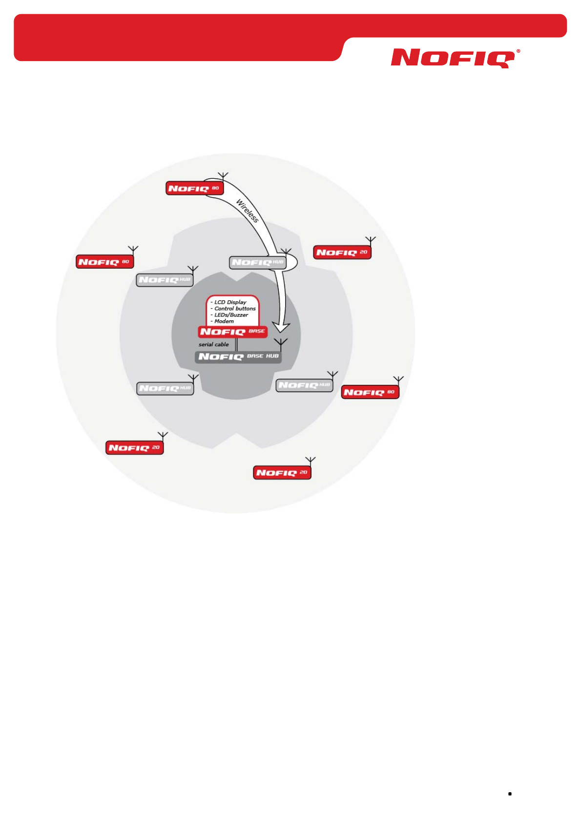
The next figure shows an overview of the components of the NOFIQ® system and its mutual relation.
Figure 1 Overview of the NOFIQ® system
2.3 Wireless communication between the components
Transferring information between the individual components of the NOFIQ® system is done by wireless
communication.
The NOFIQ® system uses the IEEE 802.15.4 standard on a 2.4 GHz frequency. This frequency is part
of the ISM band (Industry, Scientific and Medical). This band is freely available in Europe for alarm
purposes.
The system makes use of the ZigBee™ radio protocol. Thanks to this protocol creating networks on the
spot is very easy. Therefore installation and operation of the NOFIQ® system is very user friendly, for the
order of installation as well as for the expansion of the network.

NOFIQ® Systems page 14
Communication is encrypted by means of scrambling. This makes it very difficult for external devices to
decode or overhear communication within the NOFIQ® network.
All NOFIQ® FE’s and NOFIQ® HUBs regularly (at least once per 5 minutes) send a status report to
the NOFIQ® BASE. This acts like a heartbeat, informing the system that the device in question is still
operative and available.
A NOFIQ® FE’ s heartbeat contains the following information:
battery condition (only if batteries are its primary power supply);•
current CO increase on location;•
current temperature on location;•
current operational status of the FE.•
A NOFIQ® FE sends the status report to the nearest available NOFIQ® HUB. If correctly received, this HUB
will send an acknowledge signal back to the FE. If the NOFIQ® FE does not receive an acknowledge signal,
it will send the status report again. After a certain number of failed attempts, the FE will automatically
use a backup route via another NOFIQ® HUB.
The NOFIQ® HUB forwards messages from an FE via other HUBs to the NOFIQ® BASE. These messages
are received by the NOFIQ® BASE-HUB which functions as transfer station of the NOFIQ® BASE.
Communication between HUBs uses the same system of retrying and looking for a backup route.
Attention!
The NOFIQ® FE is also available in a standalone version. In that case there is
no question of a NOFIQ® system/network (with BASE, BASE-HUB and HUBS)
and thus no wireless communication takes place. (see chapter 15.5, page 80)
The NOFIQ® system generates different messages which can be separated into two categories:
messages concerning fire alarms;•
messages concerning errors in the network or the system (malfunction warnings).•
2.4 Alarm messages
A NOFIQ® FE, the detection and extinguishing component of the NOFIQ® system is equipped with two
sensors: a carbon monoxide (CO)sensor and a temperature sensor. With these sensors an FE monitors
its surroundings. If its sensors detect a significant raise in CO concentration or temperature, the FE will
initiate an alarm.
The NOFIQ® system applies three different types of alarm messages:
Alert•
Fire alarm•
Extinguishing•
page 15
NOFIQ® Systems
Alert
As soon as a NOFIQ® FE’s sensors register a steep increase in temperature or CO concentration (without
exceeding a critical point), the NOFIQ® FE sends an Alert to the alarm management station (the NOFIQ®
BASE). With this alert the FE warns that probably something is not right at its location and that a fire may
be developing. The Alert can only be shut down on the spot. This has been designed especially in this way
to oblige a custodian to check whether a dangerous situation has arisen at the location in question. Thus
a critical situation can be diagnosed quickly.
Fire alarm
If the temperature and the CO concentration have exceeded a critical level, the NOFIQ® FE will initiate
a Fire alarm. This alarm warns that a fire has been detected and that the NOFIQ® FE will start an
extinguishing sequence within 10 seconds. Within those 10 seconds the FE in question can be disabled
by pressing the FE’s button (Suspend). If someone would be doing maintenance work (welding, cleaning)
at the location in question and forgot to Suspend the FE, the maintenance activities could be causing an
alarm, although there is no question of fire. That is why there is a 10 second-countdown between the Fire
alarm and the actual extinguishing routine.
Extinguishing
When the 10 second countdown expires the aerosol fire-extinguishing component will be activated and an
extinguishing routine is started. The FE will now report an Extinguishing alarm.
Every alarm message will be notified to a fire alarm station (e.g. the fire brigade) or an private alarm
station. Notification can be executed in several ways: through the switch contacts and/or through the
telephone modem of the NOFIQ® BASE.
For every message type up to 5 telephone numbers can be programmed. Each message type has its
own priority. If the system is in error and the NOFIQ® BASE is notifying this error message to a service
provider by calling the programmed telephone number, the alarm management system will cancel this
task immediately if an Alert or Fire Alarm is received. The NOFIQ® BASE will immediately dial the first
number programmed for the alarm message in question. As soon as a connection has been established a
specified sequence of DTMF-numbers (tone dialling) will be played to identify the nature of the message.
For every message type a separate combination of dual-tones has been programmed.
Message type Priority Telephone numbers DTMF-sequence
ALARM
(Fire Alarm or Extinguishing)
High maximum 5 programmable
see also Table 19
ALERT Medium maximum 5 programmable
see also Table 19
MALFUNCTION Low maximum 5 programmable
see also Table 19
Table 1 Message priority
In chapter 23 you will find what you need to do yourself in case of an alarm message.
Attention!
The NOFIQ® FE is also available in a standalone version. In that case there is
no question of a NOFIQ® system/network (with BASE, BASE-HUB and HUBS).
Alarm and error messages therefore will not be notified to the BASE.
(see chapter 15.5, blz 80)
NOFIQ® Systems page 16
2.5 Error messages
The NOFIQ® system is able to generate error messages (MALFUNCTION) and shows these malfunction
warnings on the alphanumeric display of the NOFIQ® BASE. The error messages state which device is
in error and, if possible, the nature of the error. These messages are supported by the lighting of a LED
indicator in the right column of the control panel. In addition the buzzer will give a audible signal.
All error messages will be notified to a maintenance service.
Attention!
These error messages are no fire alarms, but warnings that an error has
occurred in the equipment or in the communication between the system’s
components.
In paragraph 19.9 we offer an in-depth look at the various error messages the system generates.
In chapter 23 you will find what you need to do yourself in case of an error message.
2.6 Authorisation
The NOFIQ® system applies 4 authorisation levels. These authorisation levels are used to ensure that only
users with the appropriate powers are able to execute certain tasks.
Authorisation
level
Tasks allowed Which user?
Level 1 Use of control panel NOFIQ• ® BASE (without
authorisation key)
Everyone
Level 2 All powers of level 1•
In possession of an authorisation key for the •
NOFIQ® BASE
Use of control panel NOFIQ• ® BASE (with
authorisation key)
Resetting the system after an alarm•
Custodian NOFIQ® system
(trained personnel)
Level 3 All powers of level 1 and 2•
In possession of a key to open the NOFIQ• ®
BASE’s cabinet
Installation and configuration of the components •
of the system
Execute software updates•
NOFIQ® service provider
Level 4 All powers of level 1, 2 and 3•
Execute hardware updates •
Exchange printed-circuit boards •
Manufacturer NOFIQ®
equipment (OEM)
Table 2 Authorisation levels
There are two manuals available for the NOFIQ® system:
• User Guide This manual is meant for users with authorisation
level 1 or 2.
• Manual for design, installation,
acceptance, use and maintenance
This manual is meant for users with authorisation
level 3 or 4.
page 17
NOFIQ® Systems
3. The NOFIQ® BASE
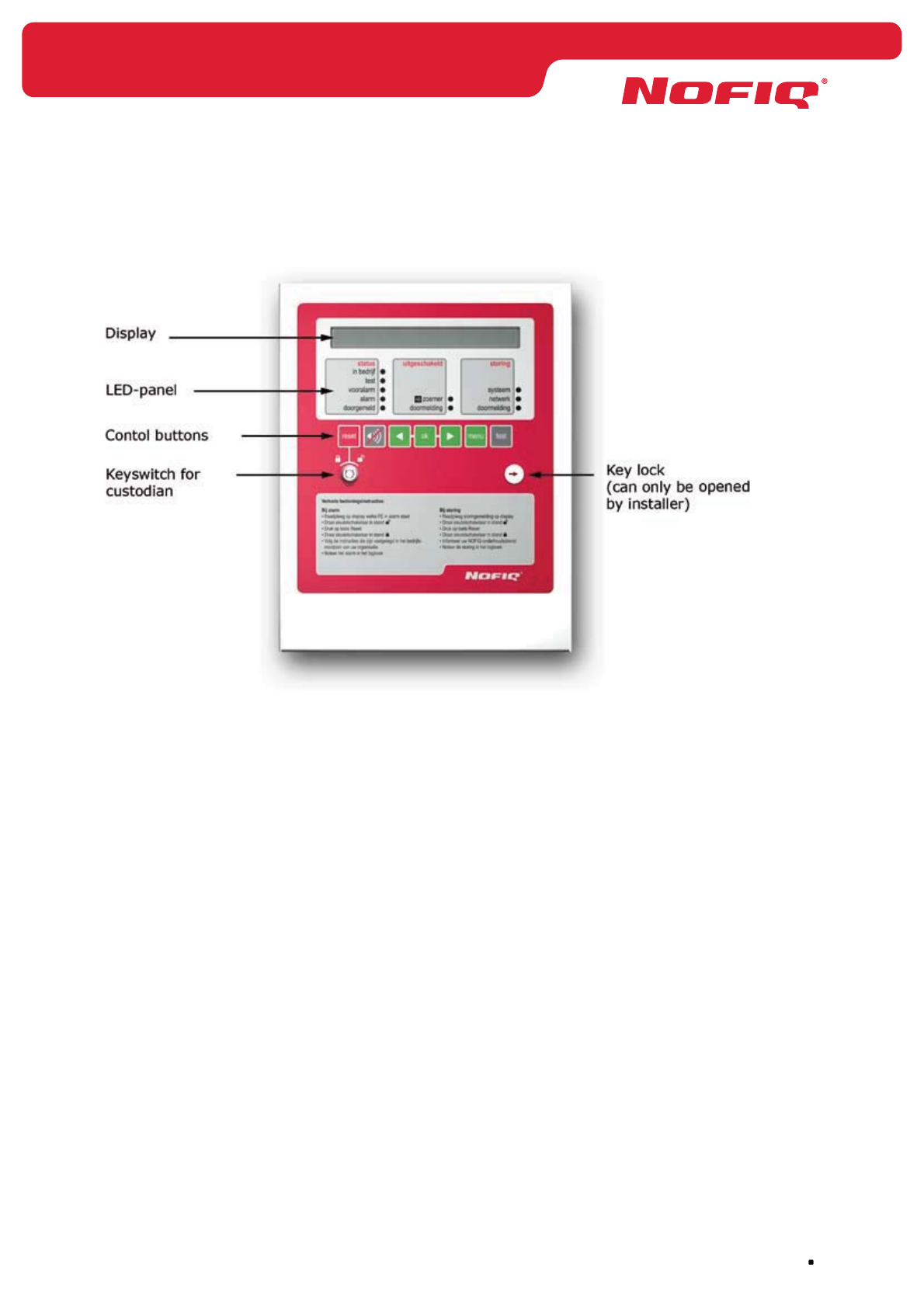
Figure 2 NOFIQ® BASE
3.1 General
The NOFIQ® BASE is the alarm management station of the NOFIQ® fire protection system. The NOFIQ®
BASE is the central point of the detection and fire-extinguishing components (NOFIQ® FE’s) and the signal
repeaters (NOFIQ® HUBs) present at the customer’s premises.
The NOFIQ® BASE registers all alarm and error messages from NOFIQ® FE’s and/or NOFIQ® HUBs. The
NOFIQ® BASE alarms an external fire-fighting service (e.g. a fire brigade) if one of the NOFIQ® FE’s
generates a fire alarm.
In order to monitor the system and its components all FE’s and HUBs regularly (at least once per 5
minutes) send a status report (heartbeat) to the NOFIQ® BASE. If the NOFIQ® BASE fails to receive this
signal twice in a row, the system will generate an error message.
The NOFIQ® BASE itself does not contain radio equipment. In order to receive all wireless messages from
NOFIQ® FE’s and HUBs, the NOFIQ® BASE is connected to the NOFIQ® BASE-HUB; the NOFIQ® BASE-HUB
functions as the BASE’s antenna.
3.2 Functionality of the NOFIQ® BASE
The NOFIQ® BASE has the following functionality and properties:
Alphanumeric LCD-display with backlight. •
This display offers room for 2 lines of 40 characters each. The display shows all alarm and error
messages. Moreover it displays all actions and options when using the maintenance and alarm
menus.

NOFIQ® Systems page 18
Ten LEDs (indicator lights) in the colours yellow, red and green to indicate the system’s status. •
Seven control buttons for input and information queries from the NOFIQ• ® BASE. The buttons are
used to navigate through the menus and to execute options in those menus.
Buzzer for signalling alarms and error messages. •
RJ11 analogue telephone connector to notify a fire brigade in case of alarm or a service provider •
in case of an error by means of the built-in modem.
Possibility to set 5 different telephone number for each message type •
(1 main number and 4 numbers as backup).
RS232 connector to execute installation and maintenance tasks by means of a laptop. •
Adapter (AC/DC) for connection to the mains power supply •
(230 V, 50 Hz for Europe; 110 V 60Hz for the United States of America).
Battery for 24 hours’ secondary power supply in case of power failure. •
When mains power has been restored after a power failure, the battery will reload automatically.
Attention!
The batteries for the NOFIQ® system are supplied by your NOFIQ® provider.
Only those batteries may be used for your NOFIQ® devices.
Five potential-free switch contacts (24 V, 1 A). •
These can be used to drive other equipment or connections not part of the NOFIQ® system (for
example for notification through another fire alarm system).
Attention!
At this moment there are three (3) switch contacts active in the software, as
called error, alarm, fire-alarm.
Authorisation lock. •
Interface for communication with the NOFIQ• ® BASE-HUB. The BASE-HUB functions as the BASE’s
forwarding and receiving station for all radio communication within the NOFIQ® system.
How to handle the NOFIQ® BASE in daily use is described in chapter 19.

page 19
NOFIQ® Systems
4. The NOFIQ® BASE-HUB
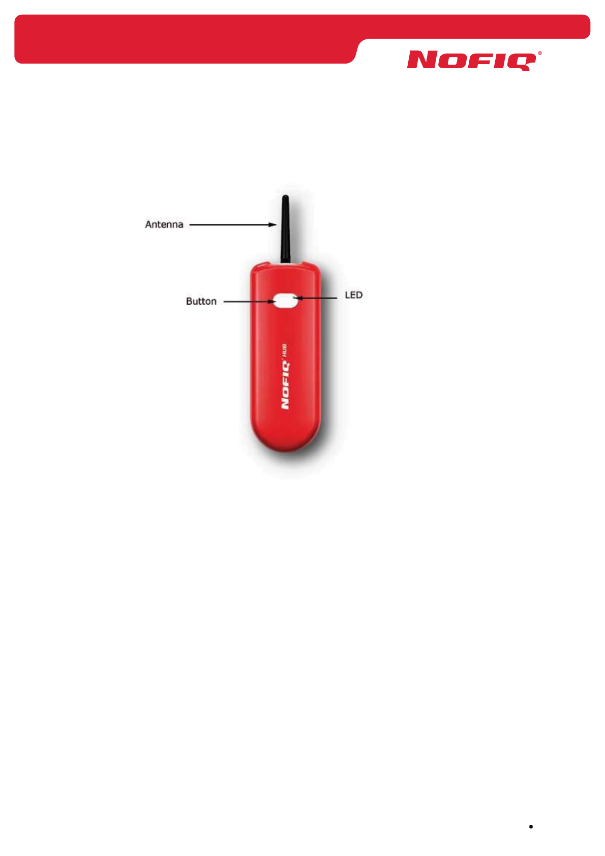
Figure 3 NOFIQ® BASE-HUB
4.1 General
From the outside the NOFIQ® BASE-HUB looks similar to the NOFIQ® HUB, except for its marking. The
NOFIQ® BASE-HUB is the transfer station, the antenna, of the NOFIQ® BASE. Therefore the NOFIQ®
BASE-HUB is directly connected to the NOFIQ® BASE by means of a fire-resistant cable (maximum 3
metres).
Another difference with a normal NOFIQ® HUB is that the NOFIQ® BASE-HUB has no power supply of its
own, but uses the primary as well as the secondary power supply of the NOFIQ® BASE thanks to its direct
connection to the NOFIQ® BASE.
Furthermore the BASE-HUB has no buzzer.

NOFIQ® Systems page 20
4.2 Functionality of the NOFIQ® BASE-HUB
The NOFIQ® BASE-HUB has the following functionality and properties:
Communicate all transmissions to the NOFIQ• ® BASE.
The NOFIQ® BASE-HUB is the forwarding and receiving station of the NOFIQ® BASE and therefore
essential for operation of the NOFIQ® BASE .
Status indication of the device by LEDs in the colours yellow, red and green. •
Button. •
RS232 connector for communication with the NOFIQ• ® BASE.
Bootstrap loader connector for maintenance. •
Power supply directly through the NOFIQ• ® BASE.
No battery pack: secondary power supply through the NOFIQ• ® BASE.
Antenna for radio communication (standard: 802.15.4) on a 2.4 GHz frequency.•
How to handle the NOFIQ® BASE-HUB in daily use is described in chapter 20.
page 21
NOFIQ® Systems
5. The NOFIQ® HUB
Figure 4 NOFIQ® HUB
5.1 General
The NOFIQ® HUB is a signal repeater, a radio unit supporting connections over longer distances by
receiving and forwarding radio messages from NOFIQ® FE’s and other NOFIQ® HUBs to the NOFIQ®
BASE. The NOFIQ® HUB routes messages through the NOFIQ® network without overloading the data
communication capabilities of the network. All devices in the network automatically select the best route
to the NOFIQ® BASE based on connection calculations.
A NOFIQ® network needs at least two NOFIQ® HUBs, even if only one NOFIQ® FE has been installed.
The presence of at least two HUBs guarantees a backup communication route from a NOFIQ® FE to the
NOFIQ® BASE. Should one of the HUBs fail (temporarily), the FE will still be able to communicate with the
BASE via another HUB.
A NOFIQ® HUB always looks for two so-called parents. If its primary parent does not respond to
a transmission, the HUB will automatically choose its secondary parent as the (backup) route for
communication.
The number of HUBs to be installed depends on the number of FE’s in the system and the distance
between the FE’s and the BASE. A sufficient number of HUBs ensures that all FE’s stay within radio reach
of the NOFIQ® BASE.

NOFIQ® Systems page 22
5.2 Functionality of the NOFIQ® HUB
The NOFIQ® HUB has the following functionality and properties:
Determining the best communication route to the NOFIQ• ® BASE.
Communicating the quality of the connection with the NOFIQ• ® BASE to all other devices within
the network.
Regularly sending a status report (heartbeat) to the NOFIQ• ® BASE.
Communicating status changes to the NOFIQ• ® BASE.
For example when the battery level is low an error message will be sent to the NOFIQ® BASE.
Listening to and forwarding of messages from other devices within the network. •
Status indication of the device by LEDs in the colours yellow, red and green. •
Button. •
Buzzer to signal alarm and error messages. •
NOFIQ• ® MIC connector to execute installation and maintenance tasks by means of a laptop.
Adapter (AC/DC) for connection to the mains power supply •
(230 V, 50 Hz for Europe; 110 V 60Hz for the United States of America).
Battery-pack for 24 hours’ secondary power supply in case of power failure. •
Attention!
The battery-packs for the NOFIQ® system are supplied by your
NOFIQ® provider. Only those battery-packs may be used for your
NOFIQ® devices.
• Antenna for radio communication (standard: 802.15.4) on a 2.4 GHz frequency.
How to handle the NOFIQ® HUB in daily use is described in chapter 21.
page 23
NOFIQ® Systems
6. The NOFIQ® FE
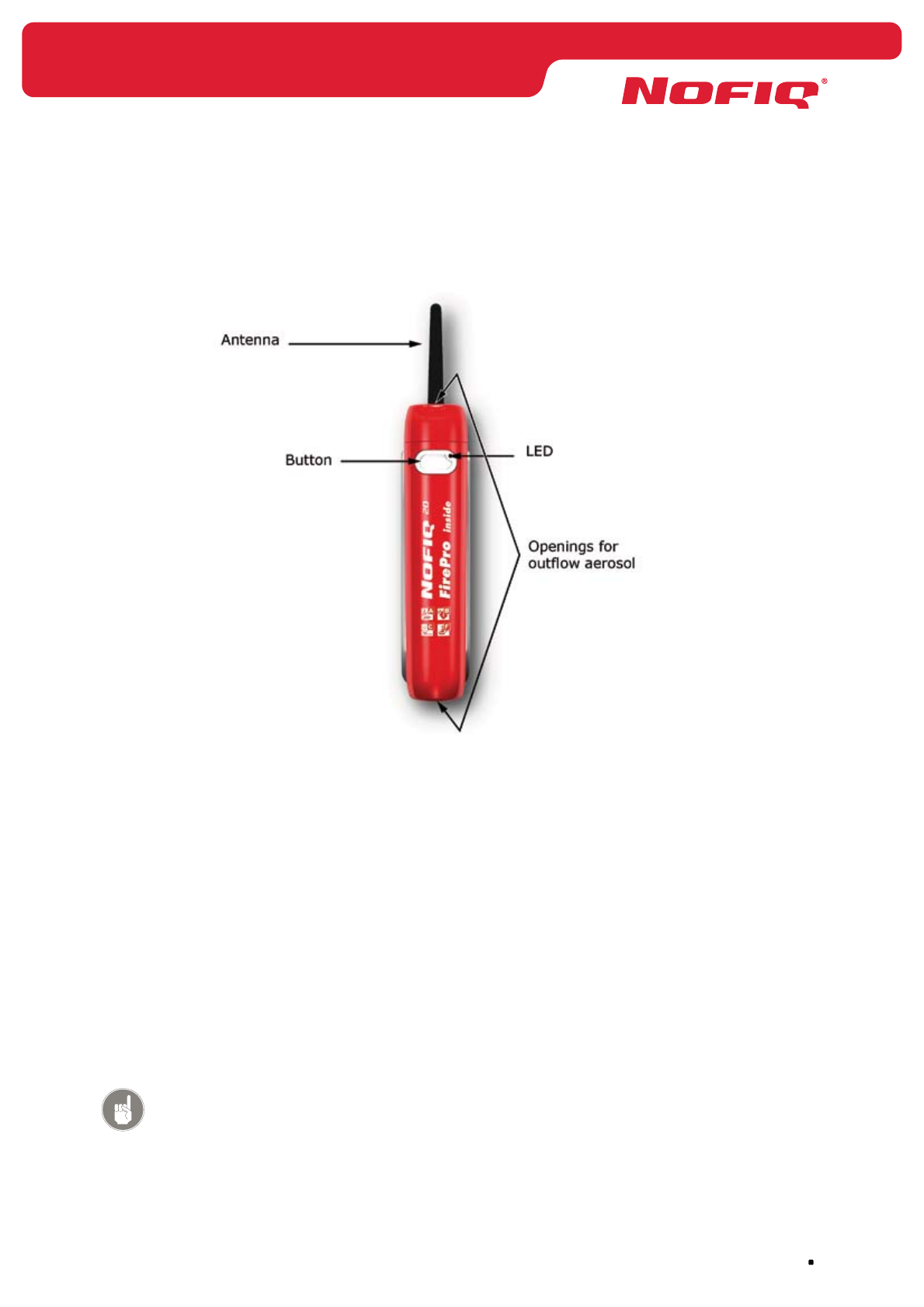
Figure 5 NOFIQ® FE
6.1 General
The NOFIQ® FE (FE = Fire Extinguisher) is the detection and extinguishing unit of the NOFIQ® system. A
NOFIQ® FE monitors a switch cabinet. In case of fire it initiates an alarm and extinguishes the fire thanks
to the built-in FirePro® aerosol fire-extinguishing component.
In order to detect a starting fire the NOFIQ® FE is equipped with two sensors: a carbon monoxide (CO)
sensor and a temperature sensor.
2 to 4 FE’s can be linked into a so-called InterNOFIQBus. When one of the FE’s in such a InterNOFIQBus
detects a fire, all the other linked FE’s will initiate an extinguishing routine.
Each NOFIQ® FE communicates its status to the NOFIQ® BASE.
Attention!
The NOFIQ® FE is also available in a standalone version. In that case there is
no question of a NOFIQ® system/network (with BASE, BASE-HUB and HUBS)
and thus no wireless communication takes place. (see chapter 15.5, page 80)

NOFIQ® Systems page 24
6.2 Functionality of the NOFIQ® FE
The NOFIQ® FE has the following functionality and properties:
Temperature sensor for measuring the temperature. •
If this sensor detects a significant raise in temperature or if a the temperature exceeds a certain
limit, the NOFIQ® FE will initiate an alarm.
CO sensor for measuring the carbon monoxide concentration. •
If the CO sensor detects a significant raise in CO concentration, the NOFIQ® FE will initiate an
alarm.
Potential-free switch contact. •
It can be used to disable a fan inside the switch cabinet, thus preventing the fan from spreading
the aerosol gas which would hinder the extinguishing routine.
Interface for linking 2, 3 or 4 FE’s in a so-called InterNOFIQBus in order to protect larger objects. •
FirePro• ® aerosol extinguishing component containing an aerosol gas to extinguish a fire.
Activator for the FirePro• ® aerosol extinguishing component.
Status indication of the device by LEDs in the colours yellow, red and green. •
Button. •
Buzzer to signal alarm and error messages. •
NOFIQ• ® MIC connector to execute installation and maintenance tasks by means of a laptop.
Power supply: battery-pack. •
Attention!
The battery-packs for the NOFIQ® system are supplied by your
NOFIQ® provider. Only those battery-packs may be used for your
NOFIQ® devices.
Optional: Adapter (AC/DC) for connection to the mains power supply •
(230 V, 50 Hz for Europe; 110 V 60Hz for the United States of America).
Attention!
The adapters for the NOFIQ® system are supplied by your NOFIQ® provider.
Only those adapters may be used for your NOFIQ® devices.
Antenna for radio communication (standard: 802.15.4) on a 2.4 GHz frequency.•
How to handle the NOFIQ® FE in daily use is described in chapter 22.

page 25
NOFIQ® Systems
7. Safety and environment
7.1 General
In this chapter we focus on safety precautions and environmental requirements when installing, using or
maintaining the NOFIQ® system.
7.2 General safety precautions
During installation and daily use of the equipment it is of the utmost importance to reduce safety risks for
yourself, the environment and the equipment to a minimum.
In general the following rules apply:
Treat the equipment carefully.•
Follow the safety regulations mentioned in the instructions for installation, use, maintenance and •
dismantling of the equipment.
Always act according to the instructions of your organisation’s emergency plan. This manual does •
not provide all safety precautions since these may differ for each organisation and location.
Warning!
The primary power supply for the NOFIQ® system is supplied by the public
electricity network. A fire alarm system, including all its power supply systems,
has to be connected to the electricity network by a separate end group.
The power switch of this electricity group must be indicated by the text
“Do not switch off, NOFIQ® fire protection system”.
7.3 Use of aerosol extinguishing components
Each NOFIQ® FE is provided with a FirePro® aerosol extinguishing component. In the designated
concentrations the aerosol extinguishing agent is not harmful to man, animal or plant.
The aerosol extinguishing components are pre-eminently suited for extinguishing fires of the following fire
classes:
A, solids•
B, liquids•
C, gasses•
F, fats and oils•
NOFIQ® Systems page 26
Warning!
Dry aerosol extinguishing components may not be used for fires concerning
the following materials (unless tests by accredited test laboratories have
proven otherwise):
core fires as stated in class A;•
oxygen carrying chemicals like nitrocellulose and gun powder;•
reactive metals like lithium, sodium, potassium, magnesium, titanium, •
zirconium, uranium and plutonium
metal oxides•
organic peroxides and hydrazine•
fire class D, metals•
Furthermore dry aerosol extinguishing components may not be used in
spaces with flammable liquids or substances that could cause an explosive
vapour or air mixture and for which a zoning in compliance with NPR 7910-
1 or -2 has been determined, unless adequate provisions have been made in
order to comply to the European ATEX-directive.
If a FirePro® aerosol extinguishing component has been activated, it can be disposed of as normal waste
after it has been dismantled.
If a FirePro® aerosol extinguishing component has not been activated with the extinguishing agent still in
its container, please return it to your supplier.
Attention!
Clean the location.
When the FirePro® aerosol extinguishing component has been activated,
after a certain amount of time the particles will deposit in the protected
object as dry dust.
• Remove this residue shortly after activation (within a couple of hours at
the most).
• Sweep up the residue by means of a brush or a damp cloth.
• Use special sprays suited for removing the residue from electronic parts.
page 27
NOFIQ® Systems
7.4 Safety precautions during maintenance and
installation
During installation and maintenance heed at least the following precautions:
Do not smoke.•
Fire and open flame prohibited.•
Switch off all equipment not needed for and during your activities. •
If you have to carry out maintenance on a location, where a NOFIQ®
FE has been installed, you need to deactivate (Suspend) the FE to
prevent it from extinguishing. You can deactivate (Suspend) the FE
by pressing the FE’s button for 2 seconds. After finishing the opera-
tions, reactivate the FE by pressing the button for 2 seconds.
Guard against falling and slipping. •
See to adequate foot-gear.
Use a solid ladder which is stabilized on the floor.
Use eye protection during drilling.•
See too sufficient illumination.•
Prevent damage to the equipment.•
Never paint the equipment.•
Attention!
When there are maintenance or other activities into the cabinet, you need to put the
NOFIQ FE’s into SUSPEND status before starting the activities or maintenance. This is
for safety reasons and to prevent NOFIQ for extinguishing during these activities.
When the activities are finished, you need to bring the cabinet back to the operational
temperature before the NOFIQ FE’s are reactivated to the normal status.
Due to a fast warming of the cabinet, there is a chance for alarming and extinguishing.
NOFIQ® Systems page 28
7.5 Safety precautions after a fire
If a fire has been detected, the NOFIQ® system will notify this to a fire alarm station. The custodian, the
fire brigade or another fire protection service will take countermeasures.
If you have to enter one of the locations where there has been fire, heed the following safety
precautions:
The extinguishing agent which pours out of the FirePro• ® aerosol
extinguishing component is warm. Although the aerosol cools down
quickly, there is a danger of burning.
In the designated concentrations the aerosol extinguishing agent is
not harmful to man, animal or plant.
Fire and open flame prohibited.•
Use eye protection during drilling. •
Wear protective clothing.
During a fire combustion products will be released. These combus-•
tion products contain toxic substances like carbon monoxide, carbon
dioxide and nitrogen oxide which are health threatening.
The location of the fire and any objects at that location can be very •
warm.
Danger of burning.
7.6 Environmental aspects
All NOFIQ® equipment meet strict environmental requirements. A few examples:
the aerosol in the extinguishing component is not harmful to man, animal and plant;•
all products are soldered lead-free;•
the equipment’s housing can be recycled (provided with recycling logo).•
Within this scope we would like to focus your attention to the following:
Never just dispose of parts and equipment; some parts may be reused or recycled.•
Never put old batteries in the normal waste; batteries belong to chemical waste and should be •
collected separately.
page 29
NOFIQ® Systems
If a FirePro® aerosol extinguishing component has been activated, it can be disposed of as normal waste
after it has been dismantled.
If a FirePro® aerosol extinguishing component has not been activated with the extinguishing agent still in
its container, please return it to your supplier.
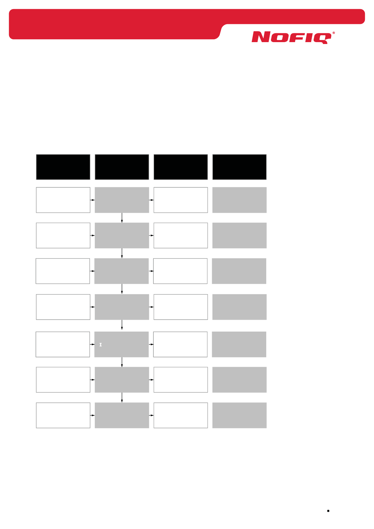
8. Design installation of the NOFIQ® system
8.1 General
For a accurate operation and application of the NOFIQ® fire protection system it is important to start with
designing the application and installation of the system.
Hereto the process schedule below should be used.
Maintenance
contract
Operational
installation
Installation
Installation
plan
PoR
Report
Requirements
and wishes
customer
Input
Maintenance
Acceptance
Put into
operation
Installing
Designing detail
Designing
Site
Survey
Process step
Maintenance
Report
AR / Log book
Operational
installation
Installation
Installation
plan
PoR
Report
Output
NOFIQ
service provider
NOFIQ
service provider
NOFIQ
service provider
NOFIQ
service provider
NOFIQ
service provider
NOFIQ
service provider
NOFIQ
service provider
Process owner

NOFIQ® Systems page 30
Figure 6 Design process NOFIQ® system
Attention!
Execution of these processes is restricted to qualified NOFIQ® service
providers. This qualification is demonstrated through the personal certificate
“NOFIQ® service provider”.
Site Survey
To get a overview about the quality of the radiocommunication in a building, just carry out a site survey
to get information about the radio messages in a building. The results must be recorded in an report.
Designing
During drafting of the installation design a Program of Requirements (PoR) is drawn up in close
consultation with the customer and based on general fire protection regulations. The necessary data for a
PoR is provided in appendix 36.1.
Designing detail
Based on this Program of Requirements a detailed design plan will be made, containing at least:
• the objects to be protected by NOFIQ® FE’s,
• the number of NOFIQ® FE’s needed for each object;
how to calculate this is explained in paragraph 8.2,
• the projection of the NOFIQ® FE’s (position and direction);
how to project an FE is explained in paragraph 8.2,
• the NOFIQ® HUBs needed for communicating to the NOFIQ® BASE,
• the location for the NOFIQ® BASE.
These design details result into an installation plan.
Installing
Based on the installation plan the actual installation is done by qualified personnel in accordance with the
operative regulations for installing in electrical installations.
An example of an installation plan is provided in the appendices.
Put into operation
The NOFIQ® system is put into operation by qualified personnel under responsibility of the NOFIQ®
service provider. This comprises all necessary activities to make the installation functioning and
operational in accordance with the Program of Requirements and the installation plan.
Acceptance
After the system has been installed and put into operation an ‘Acceptance Report’ will be drawn up.
This report contains a declaration by the NOFIQ® service provider that everything has been installed in
accordance with the PoR. An example of such a report is provided in appendix 36.3.
Furthermore the service provider will supply the customer with a log book and will instruct him in using
and maintaining the NOFIQ® system. An example of a log book is provided in appendix 36.4.
Maintenance
The service provider and the customer must draw up a maintenance contract. This contract records all
the necessary periodical checks and preventive maintenance, how often these have be executed and who
will execute the maintenance activities.
page 31
NOFIQ® Systems
Maintenance report
The actual maintenance will be recorded in a Maintenance Report which contains all checks executed and
the specific activities resulting from those checks.
An example of such a report is provided in appendix 36.5.
8.2 Calculating the amount of extinguishing agent
The size of the object to be protected determines the amount of extinguishing agent needed to effectively
extinguishing a fire. The amount necessary determines the number of NOFIQ® FE’s to be installated at
the location in question.
Depending on the object’s capacity you have to calculate the amount of extinguishing agent necessary
and thus the number of FE’s needed. At the moment we can offer the following FE types:
• the NOFIQ® FE 20 equipped with a FirePro® extinguishing component containing 20 grams of aerosol
extinguishing agent
• the NOFIQ® FE 80 equipped with a FirePro® extinguishing component containing 80 grams of aerosol
extinguishing agent
Both types make use of the same socket type, so for installation purposes the chosen type makes no
difference.
The next table indicates for which fire classes the NOFIQ® FE’s are suited and the maximum object
capacity 1 NOFIQ® FE can extinguish for the fire class in question.
Fire class Properties Maximum capacity
(NOFIQ® FE20)
Maximum capacity
(NOFIQ® FE80)
A Solids 0,24 m30,84 m3
B Liquids 0,25 m30,95 m3
C Gasses 0,44 m31,64 m3
F Fats and oils 0,17 m3 0,65 m3
Table 3 Capacity extinguishing agent per fire class
The number of NOFIQ® FE’s needed for an object also determines the projection, in other words the
position and direction in which the NOFIQ® FE’s have to be mounted.
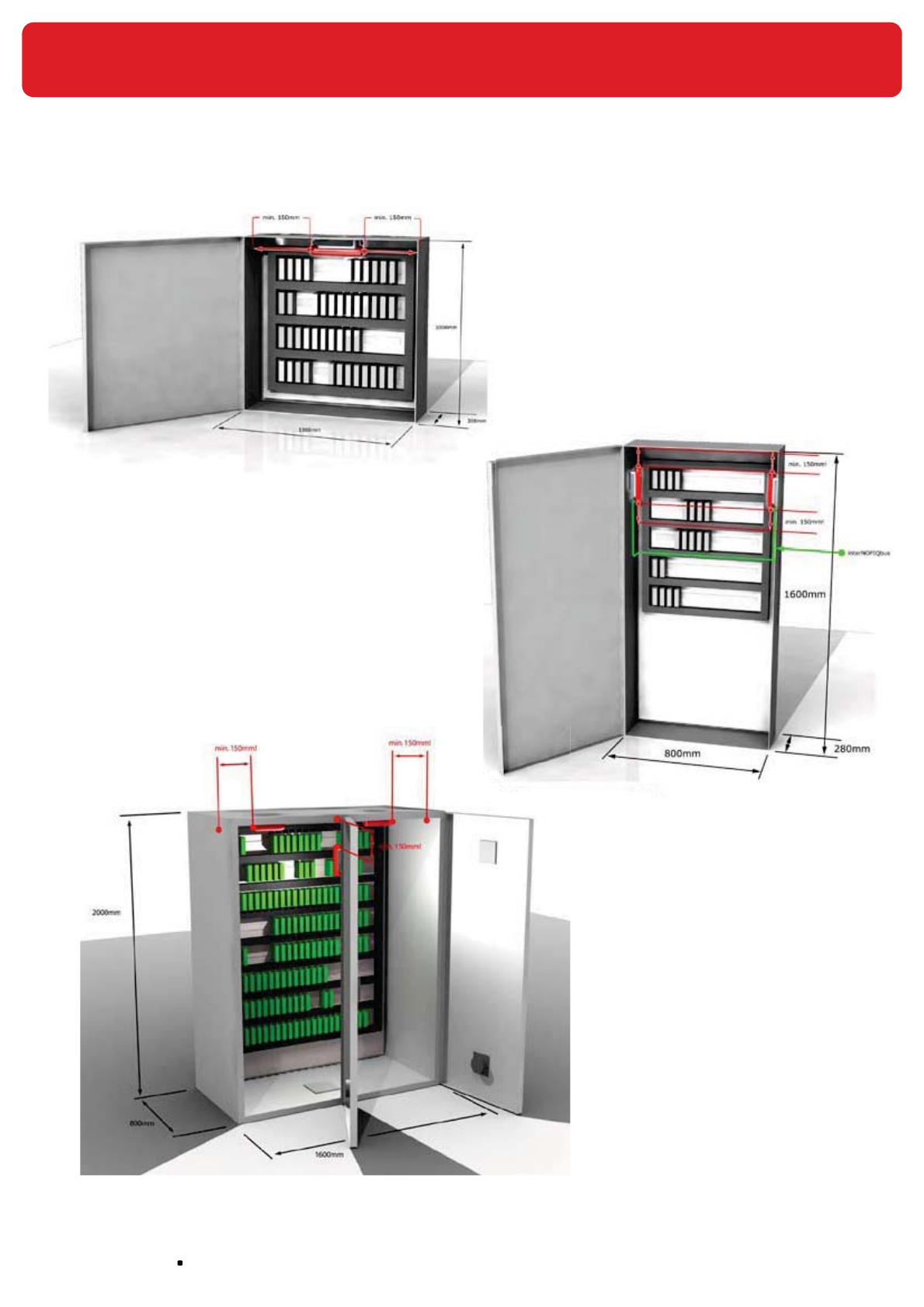
When applying 1 NOFIQ® FE it will be placed in the middle of the object on the upper side, having the
outflow openings pointing to the left and the right.
Ensure that both outflow openings have at least 15 cm of free outflow space in order to prevent damage
to equipment. Since the antenna always has to point upwards, the antenna has to be placed separate
from the FE and connected to the NOFIQ® FE by an antenna extension cord.
When applying 2 or more NOFIQ® FE’s these are placed on the side of the object in question, having the
outflow openings pointing upwards and downwards. Ensure that both outflow openings have at least 15
cm of free outflow space in order to prevent damage to equipment. When applying more than 1 FE in an
object these FE’s have to be linked into an InterNOFIQBus.
NOFIQ® Systems page 32
Figure 7c
Projection NOFIQ® FE80
in a large cabinet
Figure 7a
Projection one NOFIQ® FE in a small cabinet
Figure 7b
Projection two NOFIQ® FE’s
in a large cabinet

page 33
NOFIQ® Systems
For a complete overview of the “listing” see the productcertificate according to the BRL K21014.
NOFIQ® Systems page 34
9. Installation of the NOFIQ® system
9.1 General
This chapter treats the conditions and terms for installing a complete NOFIQ® system.
In paragraph 9.5 you will find a step-by-step procedure for installation and configuration of the NOFIQ®
system. The next chapters will elaborate on the installation and configuration of the separate components
of the NOFIQ® system, respectively:
NOFIQ• ® BASE
This is the alarm management station.
NOFIQ• ® BASE-HUB
This is the transfer station, the antenna, of the NOFIQ® BASE. It receives all wireless messages
from the FE’s and HUBs within the network.
NOFIQ• ® HUB
The NOFIQ® HUB is a signal repeater, a radio unit supporting connections over longer distances
by receiving and forwarding radio messages from NOFIQ® FE’s and other NOFIQ® HUBs to the
NOFIQ® BASE.
Attention!
In order to operate adequately the NOFIQ® system needs at least two (2)
NOFIQ® HUBs.
NOFIQ• ® FE
2 to 4 FE’s can be linked into a so-called InterNOFIQBus. When one of the FE’s in such a
InterNOFIQBus detects a fire, all the other linked FE’s will initiate an extinguishing routine
simultaneously.
Attention!
Ensure that you have a profound knowledge of the safety precautions as stated
in chapter 7.
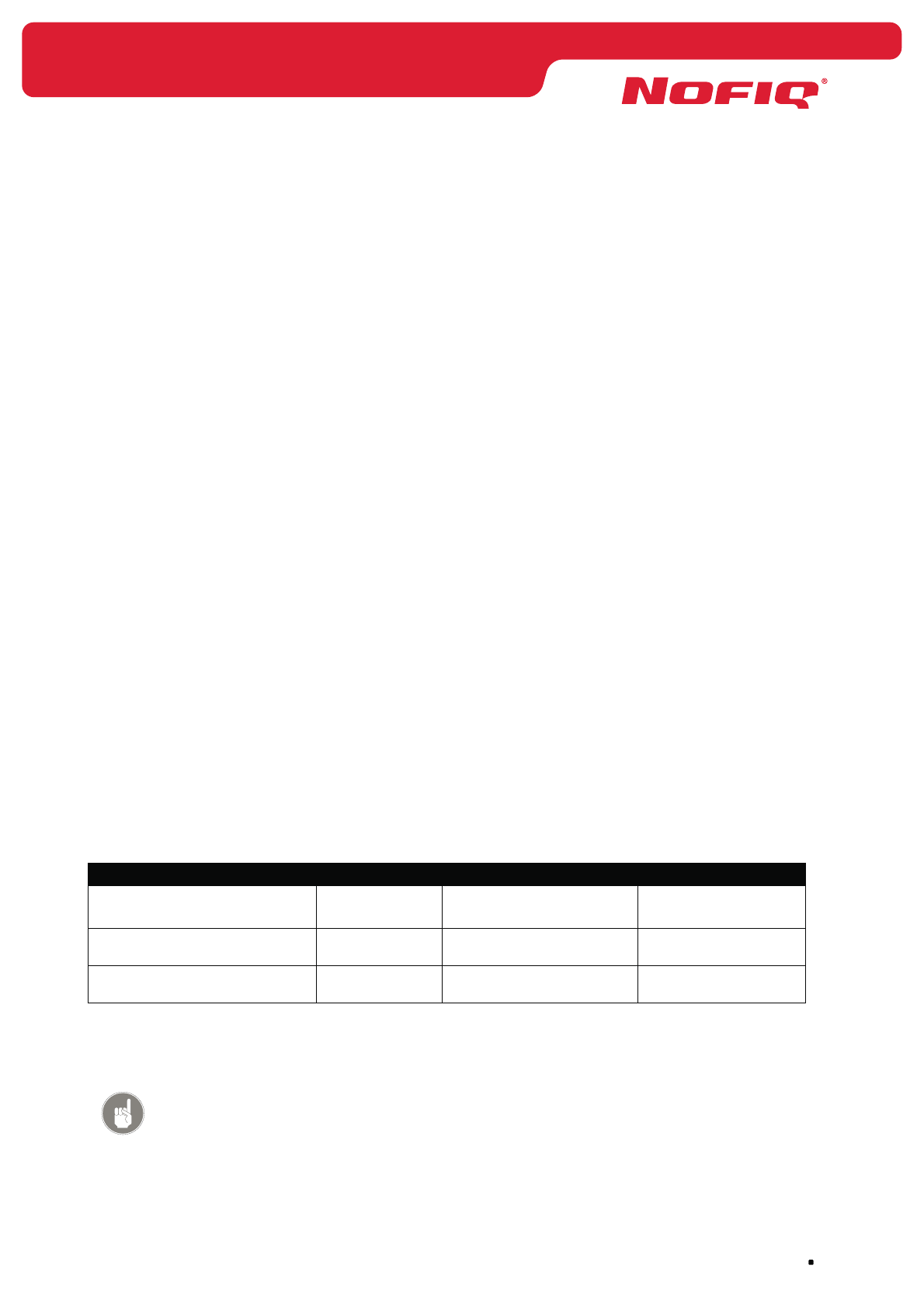
9.2 Storage and transport
It is of the utmost importance that the components of the NOFIQ® system are treated carefully at all
times. During storage as well as during transport of the equipment the following conditional requirements
must be met.
Conditions NOFIQ® BASE NOFIQ® BASE-HUB NOFIQ® HUB NOFIQ® FE
Storage
Temperature in (oC) -20 to +50 -20 to +50 -20 to +50 -20 to +40
Air humidity (%)
(no condensation)
25 to 75 25 to 75 25 to 75 25 to 75
Air pressure (kPa) 86 to 106 86 to 106 86 to 106 86 to 106
page 35
NOFIQ® Systems
Conditions NOFIQ® BASE NOFIQ® BASE-HUB NOFIQ® HUB NOFIQ® FE
Transport (during a maximum of 24 hours)
Temperature in (oC) -35 to +85 -35 to +85 -35 to +85 -35 to +50
Air humidity (%)
(no condensation)
< 95 < 95 < 95 < 95
Air pressure (kPa) 86 to 106 86 to 106 86 to 106 86 to 106
Table 4 Conditional requirements storage and transport
Ensure furthermore that:
all electronics are packaged in packaging that is guarded against the negative influence of •
electrostatic discharge;
the equipment always is transported and stored in its packaging;•
after installation packaging will kept as much as possible in order to transport it safely in case of •
repair or moving of the system.
9.3 Conditional requirements for an operational system
For a correct and reliable operation of all components of the NOFIQ® system the following conditional
requirements must be met for equipment in use (see also the conditional requirements for storage and
transport in paragraph 9.2).
Conditions NOFIQ® BASE NOFIQ® BASE-HUB NOFIQ® HUB NOFIQ® FE
Operative
Temperature in (oC) -10 to +60 -10 to +60 -10 to +60 -10 tot 45
Air humidity (%)
(no condensation)
< 95 < 95 < 95 < 95
Air pressure (kPa) 86 to 106 86 to 106 86 to 106 86 to 106
Table 5 Conditional requirements operational system
9.4 Preparing the installation
The design plan made according to the Program of Requirements (see chapter 8) includes an installation
plan. Based on this installation plan you need to prepare the installation.
This installation plan contains at least the following:
the objects to be protected by NOFIQ• ® FE’s,
the number of NOFIQ• ® FE’s needed for each object;
the projection of the NOFIQ• ® FE’s (position and direction);
the NOFIQ• ® HUBs needed for communicating to the NOFIQ® BASE,
the location for the NOFIQ• ® BASE.
It is imperative that all NOFIQ® FE’s can communicate with the NOFIQ® BASE. That means that you have
to install sufficient HUBs and on the right locations to ensure that wireless communication from each FE
to the NOFIQ® BASE is guaranteed.

NOFIQ® Systems page 36
For each NOFIQ® FE and NOFIQ® HUB you have to determine in advance an identifiable name or code.
This code is used when you register each device at the NOFIQ® BASE. When the NOFIQ® BASE displays a
message you will immediately know which device it concerns and where it is located.
Examples
If you are going to install 5 NOFIQ® FE’s in 5 different cabinets you could give each FE the name of the
cabinet in question (Cabinet 1, Cabinet 2, etc.).
If you are going to install 6 NOFIQ® FE’s in 3 cabinets you could choose the codes Cabinet 1-1, Cabinet
1-2, Cabinet 2-1, Cabinet 2-2 or the codes Cabinet 1-Left, Cabinet 1-Right, etc.
The choice is all yours but we do advise to choose easily identifiable names (‘Switch cabinet Building 2’ is
a lot clearer than ‘101-30-02’).
Provide each FE and HUB with the chosen name or code (e.g. using a sticker) for ease of recognition
during installation and in daily use.
During designing the application and installation of the NOFIQ® system you have to take the following
into consideration as well:
a NOFIQ• ® system consists of a maximum of 511 NOFIQ® HUBs (signal repeaters) and NOFIQ®
FE’s (detection and extinguishing components).
a NOFIQ• ® system demands at least 2 NOFIQ® HUBs (signal repeaters).
the transmission path from one specific NOFIQ• ® FE to the NOFIQ® BASE should not exceed 32
NOFIQ® HUBs.
Attention!
It is possible to determine the Short Network Addresses (SNA) for each
NOFIQ® FE and NOFIQ® HUB in advance (in stead of consulting the NOFIQ®
BASE for each separate SNA).
Essentially determining the SNA is free, but the following restrictions apply:
the SNA 0 has been reserved for the NOFIQ• ® BASE-HUB
the SNA must not exceed 65534•
each SNA must be unique and may occur only once within one NOFIQ• ®
system!
Attention!
Suppose you have decided to number all HUBs from 101 (to 999) and all FE’s
from 1000. You have to realise that if you want to add a HUB or FE to the
system at a later stage and you consult the NOFIQ® BASE for the first available
SNA, the BASE will offer 1 as SNA. The NOFIQ® BASE does not take your way of
numbering into account, but merely searches for the first available number.
But by keeping up the installation plan meticulously you can always recover
the first available SNA, fitting in your numbering sequence.

page 37
NOFIQ® Systems
Attention!
During installation you need a computer (laptop, notebook or PC) provided
with a RS232 connection (or with a USB/RS232 converter).
The following applications must have been installed on this computer:
HyperTerminal, •
a Windows application usually already installed.
NOFIQ• ® PC Control,
an application supplied by your NOFIQ® supplier.
9.5 Concise installation procedure
This paragraph offers a concise step-by-step overview of the installation of an entire NOFIQ® system.
This overview is based on an installation of all required components of a system, i.e. a NOFIQ® BASE, a
NOFIQ® BASE-HUB, two or more NOFIQ® HUBs and one or more NOFIQ® FE’s.
If you want to add a (extra) HUB or (extra/standalone) FE to a system in operation, you only have to
execute the steps in question.
The installations of the specific system components will be explained in separate chapters. In the step-
by-step plan below each step states in which chapter(s) the step in question will be explained in detail.
1. Check the components and accessories present.
Each chapter on the installation of the system’s components contains a paragraph called
‘Requirements’. This paragraph will tell you which parts, accessories and data are required for
installation of the device in question.
2. Programming the Network Security Key (NSK).
Then you have to program the Network Security Key into the NOFIQ® BASE. Hereto you connect
a computer with the NOFIQ® BASE by means of a null modem cable and then you start the
terminal application as described in paragraph 12.3. When you have started the application, you
select the menu Services and then the option Network Security Key.
3. Installation of the NOFIQ® BASE.
First of all you have to install the NOFIQ® BASE.
Chapter 10 explains in detail the installation of the NOFIQ® BASE.
4. Installation of the NOFIQ® BASE-HUB.
After you have mounted the NOFIQ® BASE you have to install the NOFIQ® BASE HUB and connect
it to the NOFIQ® BASE by means of the fire-resistant cable.
Chapter 11 explains in detail the installation of the NOFIQ® BASE-HUB.
5. Configuration of the NOFIQ® BASE and the NOFIQ® BASE-HUB.
If you have installed the NOFIQ® BASE and the NOFIQ® BASE-HUB you have to prepare the
NOFIQ® BASE for communication with the other components within the system. Hereto you
connect a computer with the NOFIQ® BASE by means of a null modem cable and then you start
the terminal application as described in paragraph 12.3. When you have started the application,
you select:

NOFIQ® Systems page 38
menu 3. Services •
option 3. Network Status•
option 3. BASE-HUB•
option 2. Modify BASE-HUB •
You need to set the following data:
The SNA for the NOFIQ• ® BASE-HUB;
this is always 0
The network identification number•
The network channel;•
this is a number in the range 11 through 26.
After setting the data, you select:
option 3. Make operational •
Executing this option makes the BASE-HUB and thus also the NOFIQ® BASE operational.
Chapter 12 explains in detail the configuration of the NOFIQ® BASE.
6. Installation of 2 or more NOFIQ® HUBs.
After installation and configuration of the NOFIQ® BASE and the NOFIQ® BASE-HUB, you have to
install two (or more) NOFIQ® HUBs.
Attention!
In order to operate adequately the NOFIQ® system needs at least
two (2) NOFIQ® HUBs . Thus a backup route for communication is
guaranteed.
Chapter 13 explains in detail the installation of a NOFIQ® HUB.
7. Configuration of a NOFIQ® HUB.
After installation of a NOFIQ® HUB, you have to configure that HUB.
Chapter 14 explains in detail the configuration of a NOFIQ® HUB.
8. Installation of a NOFIQ® FE.
After installation and configuration of the NOFIQ® HUBs, you have to install one or more NOFIQ®
FE’s.
Chapter 15 explains in detail the installation of a NOFIQ® FE.
9. Configuration of a NOFIQ® FE
After installation of a NOFIQ® FE, you have to configure that FE.
Chapter 14 explains in detail the configuration of a NOFIQ® FE.
10. Installation of NOFIQ® FE’s into a InterNOFIQBus. (optional)
If you want to protect a larger object, you can do that by linking 2, 3 or 4 NOFIQ® FE’s into a so-
called InterNOFIQBus.
Chapter 16 explains in detail the installation of a InterNOFIQBus.

page 39
NOFIQ® Systems
11. Adding NOFIQ® HUBs and NOFIQ® FE’s to the NOFIQ® BASE.
You can add a NOFIQ® HUB or a NOFIQ® FE to the NOFIQ® BASE as follows.
You connect a computer to the NOFIQ® BASE by means of a null modem cable and then you start
the terminal application as described in paragraph 12.3.
For adding a NOFIQ® FE to the NOFIQ® BASE you then select:
menu 3. Services •
option 3. Network Status•
option 1. FE•
option 4. Add FE to network•
For adding a NOFIQ® HUB to the NOFIQ® BASE you then select:
menu 3. Services •
option 3. Network Status•
option 2. HUB•
option 4. Add HUB to network•
12. Downloading the Granted nodes database.
After installation of all components of the NOFIQ® system, you have to download the Granted
nodes database from the NOFIQ® BASE and store it at a secure place. If something should go
wrong with the NOFIQ® BASE, uploading the database will suffice to restore the data; adding all
devices again would not be necessary.
You can download the Granted nodes database using the terminal application of the NOFIQ®
BASE (see chapter 12.3).
NOFIQ® Systems page 40
10. Installation of the NOFIQ® BASE
10.1 General
This chapter explains the installation of the NOFIQ® BASE.
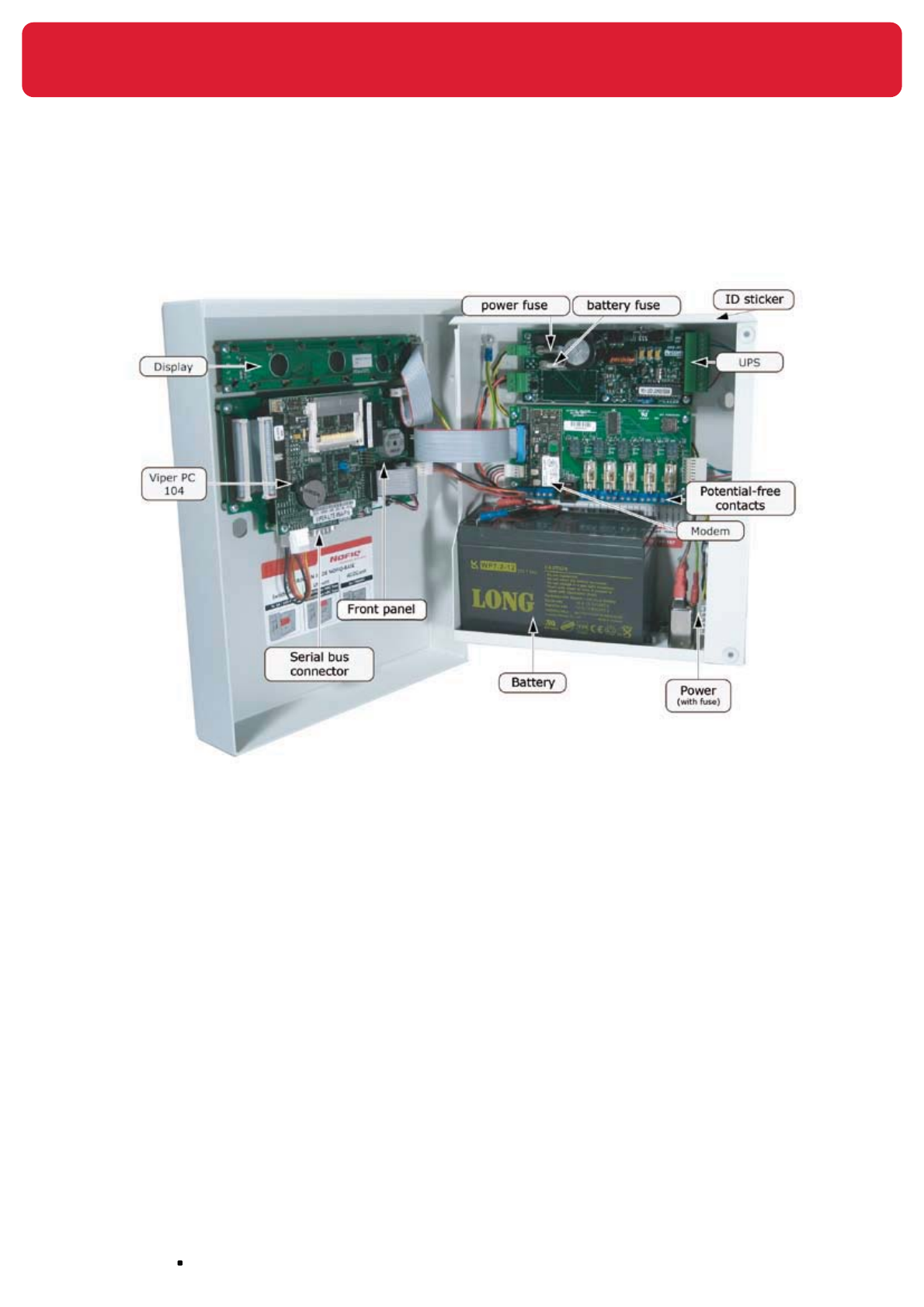
The figure below shows the interior of the NOFIQ® BASE.
Figure 8 Interior NOFIQ® BASE
10.2 Conditional requirements for the NOFIQ® BASE
When determining the place of the NOFIQ® BASE the following conditional requirements must be taken
into account:
the location must be clean and dry;•
there must be sufficient space to use and open the NOFIQ• ® BASE;
the damage risk must be minimal;•
the fire risk must be low;•
there must be sufficient illumination (minimum 100 lux, maximum 500 lux);•
the background noise should not exceed 50 dB(a) otherwise the buzzer cannot be heard •
properly;
temperature, air humidity and air pressure should not exceed the limits as mentioned in •
paragraph 9.3.

page 41
NOFIQ® Systems
10.3 Requirements
For installation of the NOFIQ® BASE you will need:
NOFIQ• ® BASE
Keys belonging to the NOFIQ• ® BASE
Fixing material•
Right-angled euro connector•
BASE-HUB cable (4-wire fire-resistant cable) •
Maximum length: 3 metres
Battery •
Attention!
The battery for the NOFIQ® system is supplied by your NOFIQ® provider.
Only these batteries can be used for your NOFIQ® devices.
Null modem cable for adding HUBs and FE’s by means of a computer•
Modem cable to connect the NOFIQ• ® BASE to a telephone line
Network Security Key (NSK) •
This is the unique encoding key for the entire NOFIQ® network. This number is identical for each
device (BASE, FE, HUB, BASE-HUB) in one and the same NOFIQ® system.
Network ID •
This is the unique identification number for the entire NOFIQ® network. This number is identical
for each device (BASE, FE, HUB, BASE-HUB) in one and the same NOFIQ® system.
Network Channel •
This is the radio channel for the network.

NOFIQ® Systems page 42
10.4 Technical specifications of the NOFIQ® BASE
Internal power supply
type: maintenance-free lead battery
voltage (volt/Ah) 12V DC / 7.2 Ah
External mains power adapter
power supply 100 .. 240 V AC
45 .. 60 Hz
power consumption 35 W
voltage (volt/A.) 12V DC / 2.1 A
connection right-angled euro connector
Fuses
Potential-free switch contacts 5 x 2A / 24 V-fast
UPS-unit F1 5A/20mm HRC fuse
F2 3A/20mm HRC fuse
AC/DC-unit 2A / 250 V
Output/input
5 potential-free switch contacts 24V DC / 1A (driven in case of alarm or error)
RS232 connector for configuration and maintenance of the NOFIQ® BASE
RJ11 analogue telephone connector for notification of alarm and error messages via telephone network
Modem cable shielded CAT.5 STP 24AWG 4 pairs
Other
weight 4 kg
dimensions (h x w x d) 304 mm x 244 mm x 89 mm
acoustic signal buzzer 4 - 5 kHz @ 65 dB(A)
optical signal LEDs (yellow, red, green)
housing metal / IP30
10.5 Installation and configuration instructions NOFIQ®
BASE
Attention!
Heed the safety precautions as stated in chapter 7.
Attention!
It is of the utmost importance to execute the instructions consecutively in the
order given.
page 43
NOFIQ® Systems
1. Check if all necessary equipment and accessories for installation are present. See paragraph
10.3.
2. Attach the NOFIQ® BASE to the wall with the fixing material supplied. In the BASE’s backside
holes have been made for this purpose.
Attention!
First disconnect the battery cable (PL4 at the UPS). This creates more room
and diminishes the risk of damaging the temperature sensor. Reconnect
the cable when the NOFIQ® BASE has been attached.
Attach the NOFIQ® BASE at such a height that users have a good view at the display and can use
the control panel buttons easily.
Make sure that the fastening is solid and safe and can bear the NOFIQ®
BASE’s weight (including the battery) without any problems.
Guard against falling and slipping.
Use a solid ladder which is stabilized on the floor.
Use eye protection during drilling.
3. Connect the fire-resistant cable to the NOFIQ® BASE. This cable provides the connection between
the NOFIQ® BASE and the NOFIQ® BASE-HUB and is fire-resistant during at least 30 minutes.
Cabling must be applied in such a way that damage risks are minimal. The construction must be
placed in a closed tubular or sleeved system (according to operative regulations).
NOFIQ® Systems page 44
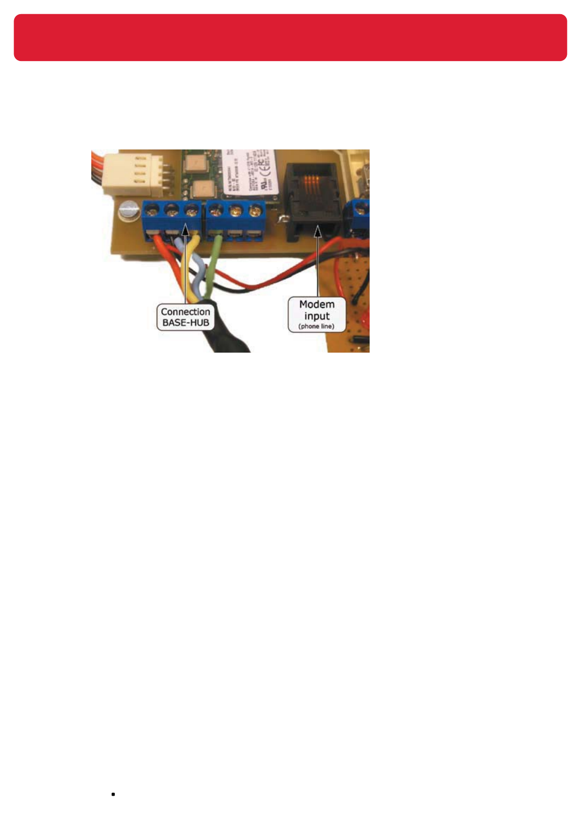
The figure below shows the correct way of connecting the fire-resistant cable to the NOFIQ® BASE:
Figure 9 Connection fire-resistant NOFIQ® BASE
The right connections (from left to right):
Red: Exit +4 Volt
Blue: Minus
Yellow: Serial communication (TX)
Green: Serial communication (RX)
4. Connect the modem cable to the NOFIQ® BASE.
5. Connect the potential-free switch contacts.
The NOFIQ® BASE can switch 5 potential-free contacts (max. 24 Volt and max. 1 Ampere).
page 45
NOFIQ® Systems
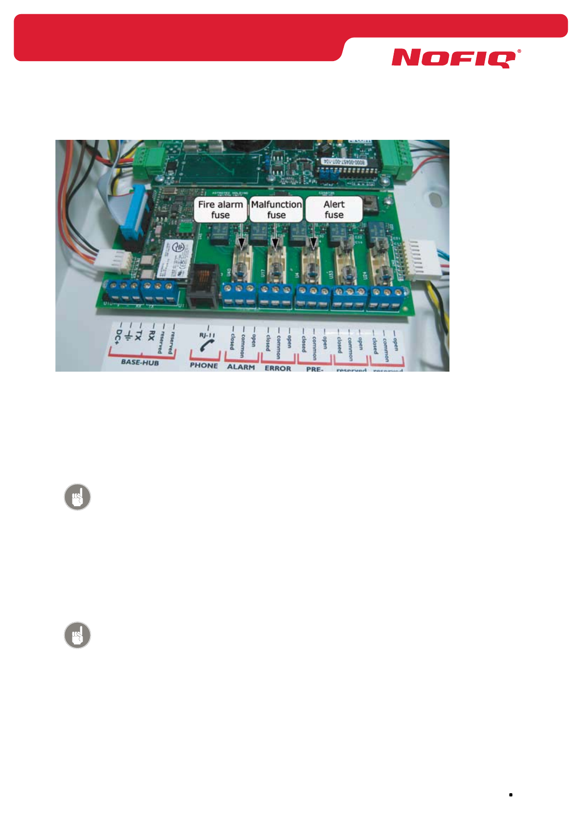
Figure 10 Connection potential-free switch contacts
Three of the switch contacts are in use for (from left to right):
Fire alarm•
Malfunction•
Alert •
Attention!
At this moment there are three (3) switch contacts in de NOFIQ BASE
implemented in the software.
The connection order for each switch contact is:
Normally closed (NC) (left)•
Common (middle, via the fuse)•
Normally open (NO) (right) •
Attention!
A potential-free switch contact keeps the position in which it has been put
the last time. If a power failure occurs, the position will not change.
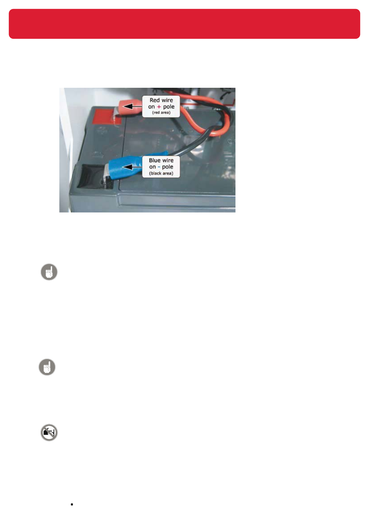
6. Put the battery into the NOFIQ® BASE and connect it.
NOFIQ® Systems page 46
Figure 11 Connection battery NOFIQ® BASE
The red contact point must be connected to the plus side (red facet).
The blue contact point must be connected to the minus side (black facet).
Attention!
The battery for the NOFIQ® system is supplied by your
NOFIQ® provider. Only these batteries can be used for your
NOFIQ® devices.
7. Fastening the right-angled euro connector.
Connect the right-angled euro connector supplied to the cabling of the public electricity network.
This connector is supplied to ensure that the power supply can only be switched off if the BASE’s
cabinet is open. Thus unauthorised users will not be able to switch off power by pulling loose the
connector.
Warning!
The primary power supply for the NOFIQ® system is supplied by the public
electricity network. A fire alarm system, including all its power supply
systems, has to be connected to the electricity network by a separate end
group.
The power switch of this electricity group must be indicated by the text
“Do not switch off, NOFIQ® fire protection system”.
Warning!
Do not connect the BASE’s power connector to the public electricity
network before the NOFIQ® BASE-HUB has been installed and connected to
the NOFIQ® BASE by means of the fire-resistant cable.

page 47
NOFIQ® Systems
8. Programming the Network Security Key (NSK).
First of all you have to program the Network Security Key into the NOFIQ® BASE. Hereto you
connect a computer with the NOFIQ® BASE by means of a null modem cable and then you start
the terminal application as described in paragraph 12.3. When you have started the application,
you select the menu Services and then the option Network Security Key.
9. Install the NOFIQ® BASE-HUB. See chapter 11 for a detailed description of the NOFIQ® BASE-
HUB’s installation.
10. Connect the NOFIQ® BASE’s power connector to the public electricity network.
It may take a while (several minutes) before the NOFIQ® BASE has been started.
Warning!
Do not execute this step before the NOFIQ® BASE-HUB has been installed
and connected to the NOFIQ® BASE by means of the fire-resistant cable.
11. Connect the null modem cable to the serial port of the NOFIQ® BASE.
When the NOFIQ® BASE is connected to a computer by means of a null modem cable, you can
use the computer to consult the NOFIQ® BASE’s data, to configure the NOFIQ® BASE and to add
FE’s and HUBs to the BASE.
Chapter 12 describes how to configure the NOFIQ® BASE.

NOFIQ® Systems page 48
11. Installation of the NOFIQ® BASE-HUB
Figure 12 The NOFIQ® BASE-HUB
11.1 General
This chapter explains the installation of the NOFIQ® BASE-HUB.
The figure below shows the NOFIQ® BASE-HUB. From the outside the NOFIQ® BASE-HUB looks similar to
the NOFIQ® HUB, except for its marking. Other differences between NOFIQ® BASE-HUB and NOFIQ® HUB:
1. The NOFIQ® BASE-HUB has no batteries but uses the primary and secondary power supply of the
NOFIQ® BASE.
2. The NOFIQ® BASE-HUB uses a serial communication connection to the NOFIQ® BASE; they are
mutually linked by a fire-resistant cable.
3. The NOFIQ® BASE-HUB has no buzzer.
11.2 Requirements
For installation of the NOFIQ® BASE-HUB you will need:
NOFIQ• ® BASE-HUB
Socket for the NOFIQ• ® BASE-HUB including orange connector
Antenna•
Torque Wrench for connecting antenna•
Fire-resistant cable (4-wire) of maximum 3 metres •

page 49
NOFIQ® Systems
Attention!
There is only one fire-resistant cable connecting the NOFIQ® BASE and
the NOFIQ® BASE-HUB. If you have already fixed this cable to the NOFIQ®
BASE, you only have to fasten this very cable to the connector of the
NOFIQ® BASE-HUB.
11.2 Technical specifications of the NOFIQ® BASE-HUB
Internal power supply
internal power supply via NOFIQ® BASE
External power supply
external power supply via NOFIQ® BASE
Output/input
RS232 connector for communicating with the NOFIQ® BASE
Communication
frequency 2.4 GHz (ISM band)
radio protocol ZigBee™
antenna see specifications in Appendices
Other
weight 250 grams
dimensions (h x w x d) 199 mm x 74 mm x 46 mm (excluding the antenna)
height including antenna: 272 mm
housing polycarbonate / class V-2 / IP30
optical signal 3 LEDs (yellow, green, red) see also paragraph 20.2
11.3 Installation and configuration instructions NOFIQ®
BASE-HUB
Attention!
Heed the safety precautions as stated in chapter 7.
Attention!
It is of the utmost importance to execute the instructions consecutively in the
order given.
1. Check if all necessary equipment and accessories for installation are present. See paragraph
11.2.
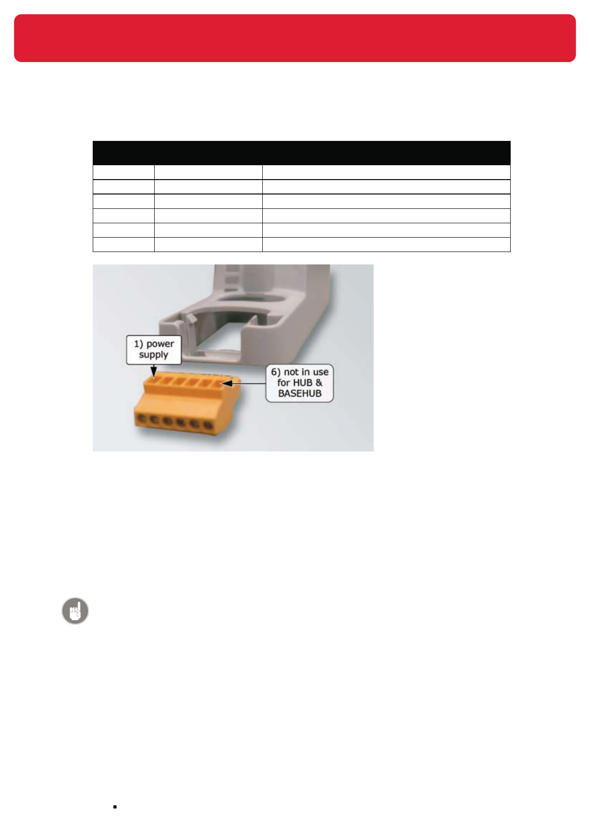
2. Remove the orange connector from the socket.
3. Connect the fire-resistant cable from the NOFIQ® BASE to the connector of the NOFIQ® BASE-
HUB.
The right connection (from left to right) is as follows:
NOFIQ® Systems page 50
Connector
port
Wire colour fire-
resistant cable
Connection
1. Red: Power exit +4 Volt
2. Blue: Minus
3. Yellow: Serial communication (TX)
4. Green: Serial communication (RX)
5. -
6. -
Figure 13 Connection fire-resistant cable to connector NOFIQ® BASE-HUB
4. Place the connector back into the socket.
5. Determine the place where the NOFIQ® BASE-HUB must be fixed.
6. Attach the socket to the wall.
7. Attach the antenna to the NOFIQ® BASE-HUB.
Attention!
Turn the antenna with a Torque Wrench thoroughly tight.
8. Click the NOFIQ® BASE-HUB into the socket.
9. Attach the cabling to the wall by using clamps according to the operative regulations.
10. When the NOFIQ® BASE-HUB has been attached to the wall and is ready for operation, you can
plug the NOFIQ® BASE’s power connector into the plug socket. It may take several minutes
before the NOFIQ® BASE has been started.

page 51
NOFIQ® Systems
11. When you have installed the NOFIQ® BASE and the NOFIQ® BASE-HUB you have to prepare
the NOFIQ® BASE for communication with the other components within the system. Hereto you
connect a computer with the NOFIQ® BASE by means of a null modem cable and then you start
the terminal application as described in paragraph 12.3. When you have started the application,
select:
menu 3. Services •
option 3. Network Status•
option 3. BASE-HUB•
option 2. Modify BASE-HUB •
You need to set the following data:
The SNA for the NOFIQ• ® BASE-HUB;
this is always 0
The network identification number•
The network channel; •
this is a number in the range 11 through 26.
After setting the data, you select:
option 3. Make operational •
Executing this option makes the BASE-HUB and thus also the NOFIQ® BASE operational.

NOFIQ® Systems page 52
12. Configuration and data management
NOFIQ® BASE
12.1 General
This chapter explains how to configure the NOFIQ® BASE and how to change the BASE’s settings.
Furthermore it contains an overview of the data on the system’s components the BASE offers. For setting
and/or changing the data you need to connect a computer (laptop, notebook or PC) to the NOFIQ® BASE
by means of a null modem cable.
12.2 Requirements
For setting or reading the data in the NOFIQ® BASE you will need:
a computer (laptop, notebook or PC)•
a null modem cable •
12.3 Configuring and managing data in the NOFIQ® BASE
In order to configure the NOFIQ® BASE do as follows:
1. Open the NOFIQ® BASE with the (mechanical) key (lock at the right).
2. Connect a computer (laptop, notebook or PC) by means of a null modem cable to the NOFIQ®
BASE’s serial port.
3. Start the computer.
4. When the computer has been started, select on your computer the communication application
HyperTerminal.
This application is usually installed by default in each MS Windows version.
Choose in consecutive order:
Start
Programs
Accessories
Communications
HyperTerminal
5. Fill in a name for the connection (e.g. NOFIQ®) and click OK.
6. Next the screen ‘Connect to’ appears. Select in the field at the bottom a COM port available (e.g.
‘Direct to Com1’).
Click OK.
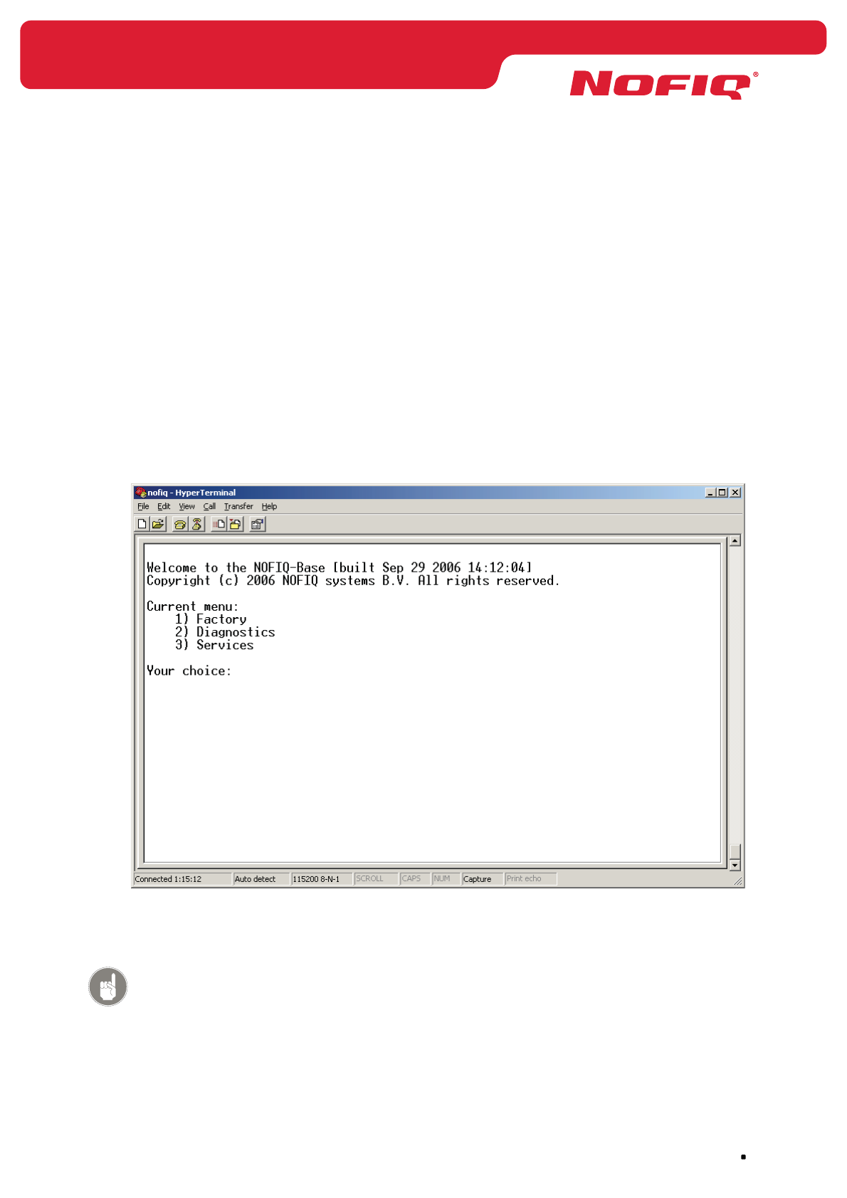
page 53
NOFIQ® Systems
7. Next the screen ‘Port Settings’ appears.
Select the following settings:
Bits per second: 115200
Data bits: 8
Parity: None
Stop bits: 1
Flow control: None
Click OK.
8. Open the connection (Call)
Press Enter.
Next a screen appears that approximately looks as follows:
You are now in the terminal (maintenance) application for the NOFIQ® BASE. This terminal
application enables you to set, change or read data .
Attention!
This application does not have the same function as the Maintenance
Menu which appears in the display of the NOFIQ® BASE and which can be
accessed by means of the buttons of the control panel of the BASE.

NOFIQ® Systems page 54
The menu structure and the options available in the terminal application are explained in
paragraph 12.4.
12.4 Menu terminal application NOFIQ® BASE
The main menu of the terminal application for the NOFIQ® BASE has the following submenus:
1. Factory
The submenu will be explained in paragraph 12.4.1.
2. Diagnostics
The submenu will be explained in paragraph 12.4.2.
3. Services
The submenu will be explained in paragraph 12.4.3.
With the options of this menu you are able to (among other things):
set and read the Network Security Key •
read out the first available Short Network Address •
set the radio channel for the NOFIQ• ® BASE-HUB
make the NOFIQ• ® BASE-HUB operational
add or remove a NOFIQ• ® HUB to the network
add or remove a NOFIQ• ® FE to the network
query for details about registered NOFIQ• ® HUBs or NOFIQ® FE’s
set telephone numbers for notification •
Attention!
The menu interaction uses a time-out. If your are working within the menu and
do not choose an option during a certain amount of time, pressing Enter will
result in the text ‘Time-out’ on screen. Next the application will return to the
main menu.
Attention!
Some data entry items have a text that looks like as follows:
“New NSK or ENTER”
If you do not want to change anything, press Enter in such a case. The data for
the option in question remain unchanged.
12.4.1 The Factory menu
By using the options of the Factory menu you can query data about the NOFIQ® BASE’s factory status.
The Factory menu contains the following options:
Nr. Menu option Application
1 Test BASE hardware Choose this option to test the hardware of the NOFIQ® BASE.
2 Serial number This option shows the serial number of this device.

page 55
NOFIQ® Systems
Nr. Menu option Application
3 Console This option has been reserved for factory use; with this option
someone can login to the system to, for example, modify the
software.
0 Back Choose this option to return to the main menu.
12.4.2 The Diagnostics menu
By using the options of the Diagnostics menu you can query data about the software and hardware of the
NOFIQ® BASE.
The Diagnostics menu contains the following options:
Nr. Menu option Application
1 Test BASE hardware Choose this option to test the hardware of the NOFIQ® BASE.
2 Hardware version This option shows the version numbers of the hardware of this
device.
3 Software version This option shows the version numbers of the software installed at
this device.
0 Back Choose this option to return to the main menu.
12.4.3 The Services menu
With the options of this menu you are able to (among other things):
set or read the Network Security Key (NSK) • - menu option 1
read out the first available Short Network Address for a HUB or •
an FE
- menu option 2
set the radio channel of the NOFIQ• ® BASE-HUB - menu option 3, then
- menu option 3, then
- menu option 2
make the NOFIQ• ® BASE-HUB operational (and with that the
NOFIQ® BASE)
- menu option 3, then
- menu option 3, then
- menu option 3
add a NOFIQ• ® HUB to the NOFIQ® BASE - menu option 3, then
- menu option 2, then
- menu option 4
add an NOFIQ• ® FE to the NOFIQ® BASE - menu option 3, then
- menu option 1, then
- menu option 4
download error data • - menu option 4
Furthermore you can use this menu to read and set data on the elements of the entire NOFIQ® network:
all FE’s, all HUBs and the BASE-HUB.
12.4.4 The Network Status submenu
With the options of the Network Status you can read, change or set (status) data for each component in
the NOFIQ® network.
How to access the Network Status submenu:

NOFIQ® Systems page 56
1. Choose in the Main menu option 3. Services
2. Choose in the Services menu option 3. Network Status.
The Network Status submenu offers the following options:
1 FE
2 HUB
3 BASE-HUB
0 Back
The options are explained below.
Nr Option Nr. Options Application
1FE
1 Show all FE’s This option shows a list of all FE’s.
The information shown is explained in
paragraph 12.4.5.
2 Show all FE’s in error This option shows a list of all FE’s in error,
for example after they have executed an
extinguishing.
3 Show FE details This option shows details of an FE. After
selecting an FE’s SNA the information about the
FE in question will be shown. The information is
explained in paragraph 12.4.5.
4 Add FE to network With this option you can add an FE to the
network. Consecutively record the SNA and the
location of the FE.
5 Remove FE from network With this option you can remove an FE from
the network. Select the FE to be removed. Next
type ‘y’ to confirm the removal.
6 Modify FE Select the FE to be modified.
Next you have the following choices:
1. Enable FE
2. Disable FE
3. Location
change the location data of the FE.
0 Back Choose this option to return to the Network
Status submenu.
2 HUB 1 Show all HUBs This option shows a list of all HUBs.
The information shown is explained in
paragraph 12.4.6.
2 Show all HUBs in error This option shows a list of all HUBs in error.
3 Show HUB details This option shows details of a HUB. After
selecting an HUB’s SNA the information
about the HUB in question will be shown. The
information is explained in paragraph 12.4.6.

page 57
NOFIQ® Systems
Nr Option Nr. Options Application
4 Add HUB to network With this option you can add an HUB to the
network. Consecutively record the SNA and the
location of the HUB.
5 Remove HUB from network With this option you can remove an HUB from
the network. Select the HUB to be removed.
Next type ‘y’ to confirm the removal.
6 Modify HUB Select the HUB to be modified.
Next you have the following choices:
1. Enable FE
2. Disable FE
3. Location
change the location data of the FE.
0 Back Choose this option to return to the Network
Status submenu.
3 BASE-HUB
1 Show BASE-HUB details This option shows the following details of the
NOFIQ® BASE-HUB:
-Network Address
-Network ID
-Network Channel
-Mode (status)
2 Modify BASE-HUB With this option you can set the NOFIQ® BASE-
HUB’s data, namely:
• Network Address
The SNA for the NOFIQ® BASE-HUB is always 0.
• Network ID
The network’s identification number.
• Network Channel
The network’s radio channel.
This is a number in the range 11 through 26.
3 Make operational With this option you make the BASE-HUB
operational. Use this option if the NOFIQ®
BASE-HUB is in FACTORY status.
0 Back Choose this option to return to the Network
Status submenu.
12.4.5 Shown data on a NOFIQ® FE
When you query data on all FE’s (Network Status menu: option 1. FE and then: option 1. Show all FE’s)
the terminal application shows a screen that looks like this:
SNA D O PP SP St SAFErrors Pw CO Tmp Last heartbeat
702 - - 0 712 SA - - - ------- B 0 20 03/09 10:23:43
703 - - 711 713 SA - - - ------- B 0 19 03/09 10:23:58
704 - - 711 713 SA - - - ------- B 0 20 03/09 10:23:59
701 x - 712 711 EA - - - ------- B 0 27 03/09 10:24:26
705 - - 0 712 SA x - - EI----- B 0 18 03/09 09:59:59

NOFIQ® Systems page 58
803 - - 0 711 SA - - - ------- B 0 21 03/09 10:26:11
Explanation of the data on screen
SNA Short Network Address
The FE’s Short Network Address.
DDisabled
This column is marked (x) if the FE has been disabled.
OOffline
This column is marked (x) if the FE is offline.
PP Primary Parent
This is the SNA of the HUB that functions as the FE’s Primary Parent.
0 NOFIQ® BASE-HUB
n/a No primary parent available
SP Secondary Parent
This is the SNA of the HUB that functions as the FE’s Secondary Parent.
0 NOFIQ® BASE-HUB
n/a No secondary parent available
St Status (see also paragraph 22.3)
The FE’s status.
Options:
SA Safe
FA Factory – the NOFIQ® FE has not yet reported to the BASE
AL Alert
PE Fire alarm
EA Extinguishing activated
SSuspend
This column is marked (x) if the FE is in Suspend status.
AAlert
This column is marked (x) if the temperature or CO concentration measured correspond with
the conditions for Alert.
FFire

page 59
NOFIQ® Systems
This column is marked (x) if the temperature or CO concentration measured correspond with
the conditions for Fire Alarm.
Errors Malfunction
If an FE has detected one or more errors, this column will state an E followed by one or more
letter codes (each code has its own position)
Code Pos.
E 1 An error has occurred; the following positions will clarify the error(s). .
I 2 Internal error
C 3 Error CO sensor
T 4 Error temperature sensor
R 5 Error relay (potential-free switch contact)
I 6 Error igniter extinguishing component
B 7 Error InterNOFIQBus
Pw Power
This column shows which type of power supply is used by the FE.
Options:
B Battery
BL Battery low
BC Battery critical
M Mains power
CO Carbon monoxide
This column shows the difference in CO concentration (in ppm) between the most recent
reading and the reading from one minute before.
Tmp Temperature
This column shows the latest measured temperature in degrees Celsius.
Last
heartbeat
Status report
This column shows the date and time of the FE’s most recent heartbeat (status report)
received at the NOFIQ® BASE.
22.4.6 Shown data on a NOFIQ® HUB
When you query data about all HUBs (Network Status menu: option 1. HUB and then: option 1. Show all
HUBs) the terminal application shows a screen that looks like this:
SNA D O PP SP Errors Pw Last heartbeat
711 - - 0 712 -- B 03/09 10:23:43

NOFIQ® Systems page 60
712 - - 711 713 -- B 03/09 10:23:58
713 - - 712 711 -- B 03/09 10:23:59
714 - - 0 713 -- B 03/09 10:24:26
Explanation of the data on screen
SNA Short Network Address
The HUB’s Short Network Address.
DDisabled
This column is marked (x) if the HUB has been disabled.
OOffline
This column is marked (x) if the HUB is offline.
PP Primary Parent
This is the SNA of the HUB that functions as this HUB’s Primary Parent.
SP Secondary Parent
This is the SNA of the HUB that functions as this HUB’s Secondary Parent.
Errors Malfunction
If an HUB has detected an error, this column will state an E (error) followed by a letter code
Options:
I Internal error
Pw Power
This column shows which type of power supply is used by the HUB.
Options:
B Battery
BL Battery low
BC Battery critical
M Mains power
Last
heartbeat
Status report
This column shows the date and time of the HUB’s most recent heartbeat (status report)
received at the NOFIQ® BASE.

page 61
NOFIQ® Systems
13. Installation of a NOFIQ® HUB
13.1 General
This chapter explains the installation of a NOFIQ® HUB.
From the outside the NOFIQ® HUB looks similar to the NOFIQ® BASE-HUB (except for its marking).
In contrast to the NOFIQ® BASE-HUB the NOFIQ® HUB uses batteries as secondary power supply.
Furthermore the NOFIQ® HUB is provided with a buzzer.
Attention!
In order to operate properly the NOFIQ® system needs at least two (2) NOFIQ®
HUBs . Thus a backup route for communication between an FE and the BASE is
guaranteed.
Whenever you install the very first NOFIQ® HUB in a new NOFIQ® system, the
system will generate an error message (Parent missing), since there is no
backup route (via a second HUB) available yet. As soon as the second HUB is
correctly installed, the error message will disappear automatically.
13.2 Requirements
For installation of the NOFIQ® HUB you will need:
NOFIQ• ® HUB
Socket for the NOFIQ• ® HUB including orange connector
Antenna / Torque Wrench for connecting antenna•
Mains power adapter •
Attention!
The adapter for the NOFIQ® system is supplied by your NOFIQ® provider.
Only these adapters can be used for your NOFIQ® devices.
Battery-pack •
Attention!
The battery-pack for the NOFIQ® system is supplied by your
NOFIQ® provider. Only these battery-packs can be used for your
NOFIQ® devices.
Network Security Key (NSK) •
this can be obtained from the NOFIQ® BASE or the installation plan
Short Network Address (SNA) •
this can be obtained from the NOFIQ® BASE or the installation plan
Network ID •
this can be obtained from the NOFIQ® BASE or the installation plan
Network Channel •
this can be obtained from the NOFIQ® BASE or the installation plan
NOFIQ® Systems page 62
13.3 Technical specifications of the NOFIQ® HUB
Internal power supply
type power supply lithium battery FeS2
voltage (volt / amp.) 3V / 3000mA
lifetime max. 2 years
External mains power adapter
power 230 V, 50 Hz for Europe;
110 V 60Hz for the United States of America
voltage (volt / amp.) 4V DC / 1200 mA
Output/input
RS232 connector for configuration and maintenance of the NOFIQ® HUB
Communication
frequency 2.4 GHz (ISM band)
radio protocol ZigBee™
antenna see specifications in Appendices
Other
weight 250 grams
dimensions (h x w x d) 199 mm x 74 mm x 46 mm (excluding the antenna)
height including antenna: 272 mm
housing polycarbonate / class V-2 / IP30
acoustic signal buzzer, 4 – 5 kHz @ 55 dB(A)
optical signal 3 LEDs (yellow, green, red) see also paragraph 21.2
13.4 Installation and configuration instructions NOFIQ®
HUB
Attention!
Heed the safety precautions as stated in chapter 7.
Attention!
It is of the utmost importance to execute the instructions consecutively in the
order given.
1. Retrieve the Network Security Key (NSK), the Short Network Address (SNA), the Network ID
and the Network Channel from the NOFIQ® BASE or the installation plan. Hereto you connect
a computer to the NOFIQ® BASE by means of a null modem cable and then you start the
terminal application as described in paragraph 12.3. When you have started the application, you
consecutively select:
menu 3. Services
option 1. Network Security Key
option 2. First available short network address
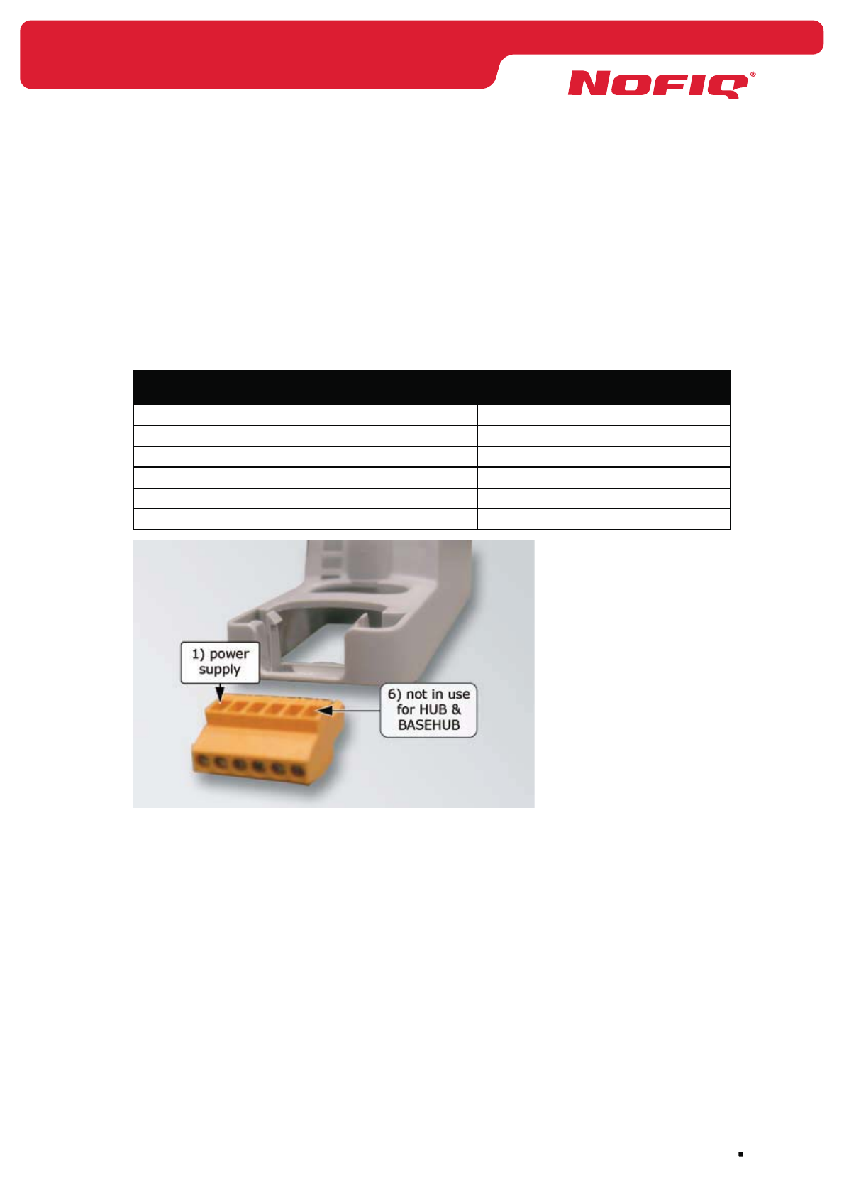
page 63
NOFIQ® Systems
Write down all data.
2. Check if all necessary equipment and accessories for installation are present. See paragraph
13.2.
3. Remove the orange connector from the socket.
4. Connect the NOFIQ® HUB’s mains power adapter to the orange connector.
The right connection (from left to right) is as follows:
Connector
port
Wire colour Connection
1. Black with white stripe and red sleeve Power supply +4 Volt
2. Black (completely black) Minus / earth
3.
4.
5. -
6. -
Figure 14 Connection NOFIQ® HUB connector
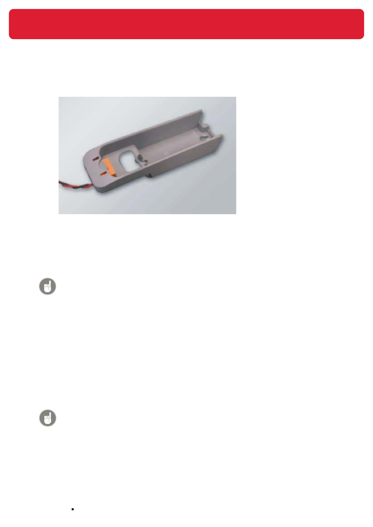
NOFIQ® Systems page 64
5. Place the connector back into the socket.
6. Take the NOFIQ® HUB out of the socket and remove the lid of the battery holder (push with your
finger in the direction of the arrow).
7. Place the battery-pack and connect the battery connector (red on the outside, black on the
inside). The connector has been made in such a way that there is only one possible way to
connect it.
Attention!
The battery-pack for the NOFIQ® system is supplied by your
NOFIQ® provider. Only these battery-packs can be used for your
NOFIQ® devices.
8. Place the lid back onto the battery holder.
9. Configure the NOFIQ® HUB
Connect the NOFIQ® HUB by means of a Maintenance Interface cable (MIC) to a computer (e.g. a
laptop). Start the application ‘NOFIQ® PC Control’. Program the Network Security Key (NSK), the
Short Network Address (SNA), the Network ID and the Network Channel, as described in chapter
14.
10. Determine the place where the NOFIQ® HUB must be fixed.
11. Fix the socket (at its destined location).
Attention!
A NOFIQ® HUB must always be fixed vertically in order that the antenna
points upwards.
12. Attach the antenna to the NOFIQ® HUB.

page 65
NOFIQ® Systems
Attention!
Turn the antenna with a Torque Wrench thoroughly tight.
13. Click the NOFIQ® HUB into the socket.
14. Plug the adapter into the plug socket.
15. Press the NOFIQ® HUB’s button for two seconds. On release of the button the NOFIQ® HUB leaves
factory status.
16. Add the NOFIQ® HUB to the NOFIQ® BASE.
Hereto you connect a computer to the NOFIQ® BASE by means of a null modem cable and then
you start the terminal application as described in paragraph 12.3. When you have started the
application, you consecutively select:
menu 3. Services
option 3. Network Status
option 2. HUB
option 4. Add HUB to network
Attention!
Downloading the Granted nodes database.
After installation of all components of the NOFIQ® system, you have to
download the Granted nodes database from the NOFIQ® BASE and store it at a
secure place. If something should go wrong with the NOFIQ® BASE, uploading
the database will suffice to restore the data; adding all devices again would
not be necessary.
You can download the Granted nodes database by means of the terminal
application of the NOFIQ® BASE (see chapter 12.3)
Attention!
In order to operate adequately the NOFIQ® system needs at least two (2)
NOFIQ® HUBs. Thus a backup route for communication between an FE and the
BASE is guaranteed.
Whenever you install the very first NOFIQ® HUB in a new NOFIQ® system, the
system will generate an error message (Parent missing), since there is no
backup route (via a second HUB) available yet. As soon as the second HUB is
correctly installed, the error message will disappear automatically.

NOFIQ® Systems page 66
14. Configuration NOFIQ® HUB or NOFIQ® FE
14.1 General
A NOFIQ® HUB as well as a NOFIQ® FE needs to be configured so that all components of the
NOFIQ® network will function and communicate properly. For every NOFIQ® FE and NOFIQ® HUB its
network address (SNA) must be recorded as well as the Network Security Key, the Network ID and the
Network Channel.
Attention!
Configuration of a standalone FE.
A standaln FE has already been configured when it leaves factory. By defauit
it is set that the potential-free contact switches in case of Fire alarm (Pre-
extinguishing).
Only if you want to change these settings, you must configure a standalone FE.
If you do not wish to change the settings, configuration is not needed.
14.2 Requirements
In order to read or set data of a NOFIQ® HUB or FE you will need:
a computer (laptop, notebook of PC)•
a NOFIQ• ® Maintenance Interface cable (D-MIC-RA0100)
the software application NOFIQ• ® PC Control (PC_Control.exe)
Network Security Key (NSK) •
this can be obtained from the NOFIQ® BASE or the installation plan
Short Network Address (SNA) •
this can be obtained from the NOFIQ® BASE or the installation plan
Network ID •
this can be obtained from the NOFIQ® BASE or the installation plan
Network Channel •
this can be obtained from the NOFIQ® BASE or the installation plan
14.3 Configuring a NOFIQ® HUB or NOFIQ® FE
In order to configure a HUB or FE do as follows:
1. Connect one end of the NOFIQ® Maintenance Interface cable (MIC) to the communication port
(com-port) of the computer (or else through a USB/RS232 adapter).
2. Connect the other end of the MIC cable to the appropriate connector of the HUB or FE.
3. Start the computer.
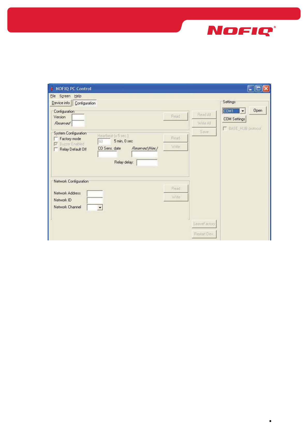
page 67
NOFIQ® Systems
4. Start the application ‘NOFIQ® PC Control’ (PC_Control.exe)
The next screen appears:
5. Click the button ‘Com Settings’ to set the communication data.
A pop-up screen appears.
Select in this screen the following settings:
Port: COM1 (or else the first available COM port)
Baud rate: 57600
Data bits: 8
Stop bits: 1
Parity: None
Flow control: None
6. Click OK.
7. Click the button ‘Open’ (upper right on the screen).
Then the communication with the HUB or FE is started.
8. Click the button ‘Read’ in the section Configuration.
Click the button ‘Read’ in the section System Configuration.
Click the button ‘Read’ in the section Network Configuration.
Now all information is read and the screen will look (approximately) as follows:
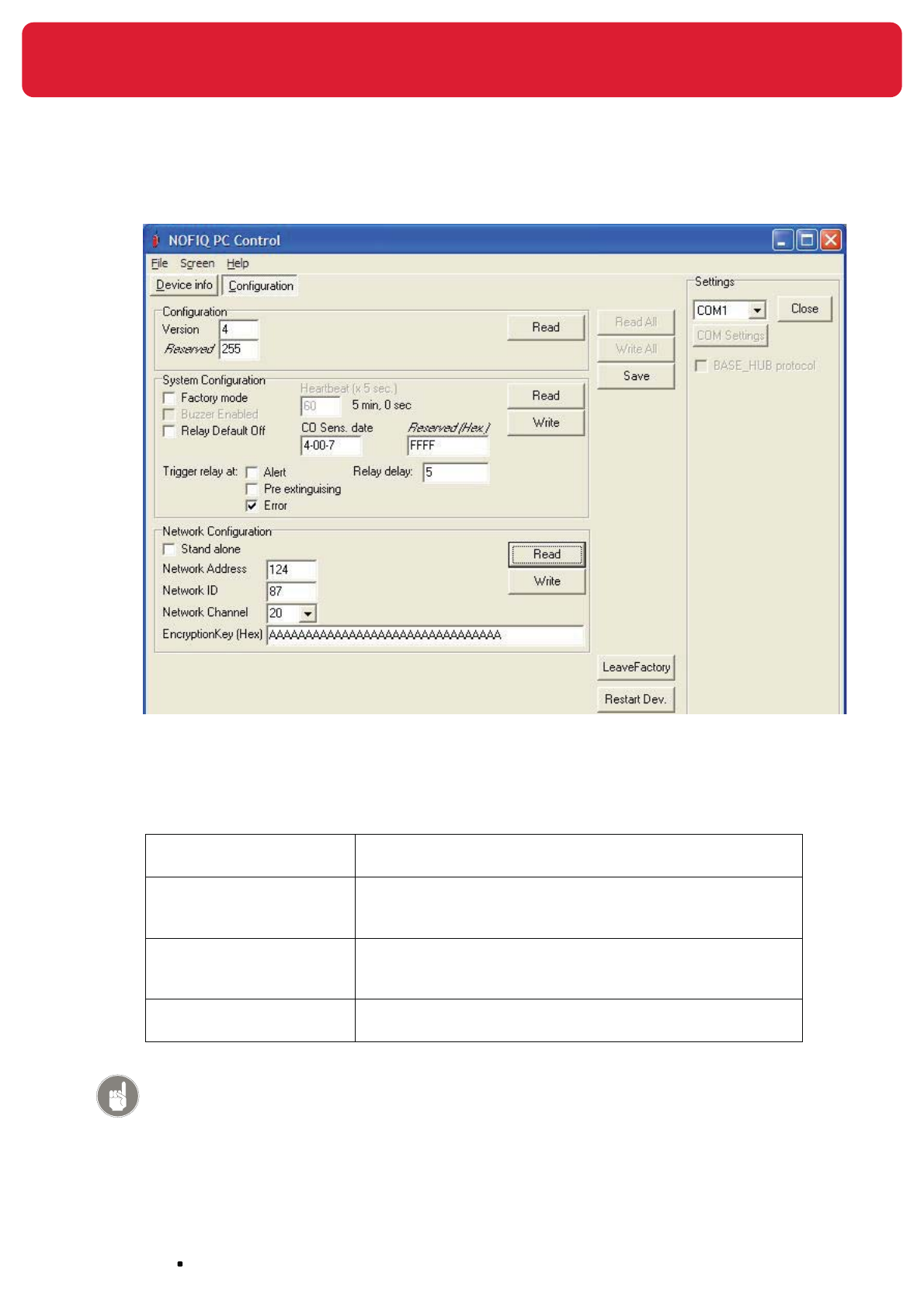
NOFIQ® Systems page 68
9. You are now able to configure the HUB or FE.
For a standalone FE the field ‘Standalone’ is ticked by default. In this case the fields ‘Network
Address’, Network ID, Network Channel and Encryption Key do not apply.
If you want to configure an FE for a network, you need to fill in at least the following fields:
Network Address• This is the HUB’s or FE’s Short Network Address (SNA); a
number in the range [2..65534].
Network ID• This is the network’s identification number; a number in
the range [1..255]. This number must be identical for each
device in the network.
Network Channel• This is the network’s radio channel; a number in the range
[11..26]. This number must be identical for each device in
the network.
Encryption Key •
(Hex)
This the system’s Network Security Key (NSK); a number of
32 digits (32*[0..9]).
Attention!
The data mentioned above are mandatory for an FE in a NOFIQ network.
Other data for a HUB or FE are set by default. If required you can change
the other data in the section System Configuration. The meaning of all
buttons and fields of this screen are explained in the next paragraphs.

page 69
NOFIQ® Systems
10. If you have set all data:
Click the button ‘Write’ in the section System Configuration.
Click the button ‘Write’ in the section Network Configuration.
Click the button ‘Save’.
All data have been saved.
11. Click the button ‘Restart Device’.
The NOFIQ® HUB or NOFIQ® FE is now configured.
14.3.1 Fields and buttons from screen section Configuration
The screen section Configuration offers data about the software.
Version
The software version.
Reserved
Software data. These are of no concern for the user.
Read
With this button you reed the software data of the HUB or FE.
14.3.2 Fields and buttons from screen section System Configuration
The screen section System Configuration offers data about the HUB or FE. These data can be modified.
Factory mode
Ticking this option will put the HUB or FE into Factory status.
Buzzer enabled
If this option is ticked, the buzzer of this device is enabled.
Relay Default Off
The default position for the FE’s relay (switch contact) is closed. If you tick this option, the relay’s default
position will be open.
Heartbeat
This is the time interval between each heartbeat the device sends.
Attention!
If the heartbeat interval is set lower than 5 minutes (60 x 5 seconds), this will
have a negative effect on the batteries’ lifetime.
CO sens. date
This is the production date of the CO sensor.

NOFIQ® Systems page 70
Reserved
Software data. These are of no concern for the user.
Trigger relay at
Here you can choose in which situation the FE’s potential-free contact must be switched. You can choose
from:
• Alert
• Pre-extinguishing (Fire alarm)
• Error (Malfunction)
Relay delay
The delay time (in seconds) before the potential-free contact will be switched.
The maximum number of seconds that can be set is 120.
Read
Click this button to read the configuration data of the HUB or FE.
Write
Click this button to write the (modified) data of an HUB or FE. Click the button ‘Save’ to actually save the
data.
14.3.3 Fields and buttons from screen section Network
Configuration
The screen section Network Configuration offers information about network settings of a HUB or FE.
These data can be modified.
Standalone
This field must be ticked if the FE is to function standalone. If this field is ticked, the fields like ‘Network
Address’, ‘Network ID’, ‘Network Channel’ and ‘Encryption Key’ will not be available.
Network Address
This the Short Network Address, the unique network address granted to the HUB or FE.
Attention!
The network address of the BASE-HUB is 0; this number can never be granted
to a HUB or FE.
Network ID
The is a unique identification number of the entire NOFIQ® network; a number in the range [1..255].
This number must be identical for each device (HUB, FE and BASE-HUB) in the network. Thanks to this
ID different networks are separated from each other and FE data cannot turn up in another network (e.g.
the neighbour’s network) by accident.

page 71
NOFIQ® Systems
Network Channel
This the network’s radio channel; a number in the range [11..26]. This number must be identical for all
devices in the network.
Encryption Key (Hex)
This the Network Security Key (NSK), a code that prevents interception of NOFIQ® network
communication by external devices. The NSK s a number of 32 digits (32 * [0..9]).
This code must be identical for each device in the network.
Read
Click this button to read the network data of the HUB or FE.
Write
Click this button to write the (modified) network data of an HUB or FE. Click the button ‘Save’ to actually
save the data.
14.3.4 Other buttons from screen section Configuration
Read All
Click this button to read all data of the HUB or FE.
Write All
Click this button to write all (modified) data of an HUB or FE. Click the button ‘Save’ to actually save the
data.
Save
Click this button to save data.
Leave Factory
Click this button to have the HUB or FE leave factory status.
Restart Dev.
Click this button to restart a FE, HUB or BASE-HUB.
Device Info
Click this button to retrieve device information on the FE of HUB. Next a screen appears; this screen’s
data and buttons will be explained in paragraph 14.3.5.
14.3.5 Buttons and data on the screen Device info
Clicking the Device Info button gathers information about the NOFIQ® FE or NOFIQ® HUB. If you click this
button, the following screen appears:
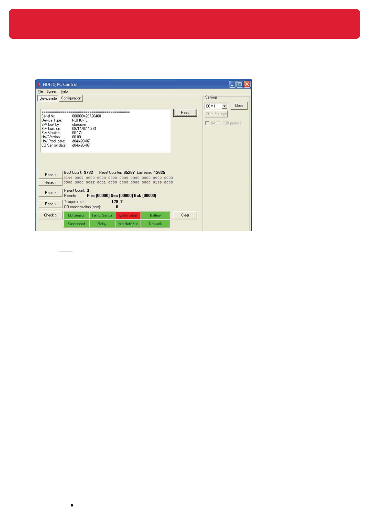
NOFIQ® Systems page 72
Read
Click all Read buttons to read the information.
The screen shows the following data:
Serial number•
Device type (NOFIQ• ® FE or NOFIQ® HUB)
Software data (version and production date)•
Hardware data (version and production date)•
CO sensor production date •
In the lower section the following data are displayed:
the device’s parents •
the temperature and CO concentration measured•
Reset
Click this button to reset the counter to 0.
Check
With this button you can check the operation of the elements of the device in question.
A properly operating part is displayed in green, a malfunctioning part is displayed in red.
The following items will be checked:
• CO sensor
• Temperature sensor
• Igniter of the extinguishing component (Igniter circuit)
• Batteries (green = battery OK; yellow = battery low); red = battery critical)

page 73
NOFIQ® Systems
This square will not be shown when the device operates on mains power.
• Suspended (red = suspended)
• Potential-free switch contact (Relay)
• InterNOFIQBus
• Network (not applicable to a standalone FE)
Attention!
Since a standalone NOFIQ® FE cannot notify an error message to a BASE, it is
not possible to determine at once which type of error has occurred. When you
have connected the FE in question via a MIC to a computer (laptop) and then
start this program (NOFIQ PC Control) , you can determine the error(s) by
using the button Check. (see chapter 15.5, page 80)
Clear
Click this button to clear the screen.
Configuration
Click this button to read or modify all configuration data as described in paragraph 14.3.

NOFIQ® Systems page 74
15. Installation of a NOFIQ® FE
15.1 General
This chapter explains the installation of a NOFIQ® FE.
15.2 Requirements
For installation of the NOFIQ® FE you will need:
NOFIQ• ® FE
Socket for the NOFIQ• ® FE including orange connector
Antenna + antenna extension cord •
Torque Wrench for connecting antenna•
Warning stickers •
“NOFIQ® fire protection system, in case of fire or alarm: do not panic, close cabinet doors and and
alert expert assistance”
Mains power adapter (use is optional for an FE) •
Attention!
The adapter for the NOFIQ® system is supplied by your NOFIQ® provider.
Only these adapters can be used for your NOFIQ® devices.
Battery-pack •
Attention!
The battery-pack for the NOFIQ® system is supplied by your
NOFIQ® provider. Only these battery-packs can be used for your
NOFIQ® devices.
Network Security Key (NSK) •
this can be obtained from the NOFIQ® BASE or the installation plan
Short Network Address (SNA) •
this can be obtained from the NOFIQ® BASE or the installation plan
Network ID •
this can be obtained from the NOFIQ® BASE or the installation plan
Network Channel •
this can be obtained from the NOFIQ® BASE or the installation plan

page 75
NOFIQ® Systems
15.3 Technical specifications of a NOFIQ® FE
Internal power supply
type power supply lithium battery FeS2
voltage (volt / amp.) 3V / 3000mA
lifetime max. 2 years
External mains power adapter (optional)
power 230 V, 50 Hz for Europe;
110 V 60Hz for the United States of America
voltage (volt / amp.) 4V DC / 1200 mA
Output/input
RS232 connector for configuration and maintenance of the NOFIQ® FE
1 x potential-free switch contact 24 V / 1 A (for disabling a fan)
InterNOFIQBus 0.2 A (group extinguishing)
Extinguishing agent
FirePro® (weight) 20 grams extinguishing agent (FP-20)
80 grams extinguishing agent (FP-80)
Communication
frequency 2.4 GHz (ISM band)
radio protocol ZigBee™
antenna see specifications in Appendices
Other
weight 350 grams (NOFIQ® FE20)
dimensions (h x w x d) FE 20 - 182 mm x 44 mm x 68 mm (excluding the antenna)
height including antenna: 249 mm
FE 80 - 204 mm x 68 mm x 98 mm (excluding the antenna)
height including antenna: 271 mm
housing polycarbonate / class V-2 / IP30
acoustic signal buzzer, 4 – 5 kHz @ 55 dB(A)
optical signal 3 LEDs (yellow, green, red) see also paragraph 22.3
15.4 Installation and configuration instructions NOFIQ® FE
Attention!
Heed the safety precautions as stated in chapter 7.
Attention!
Additional instructions for installation of a standalone NOFIQ® FE you will find
in paragraph 15.5.
Attention!
It is of the utmost importance to execute the instructions consecutively in the
order given.
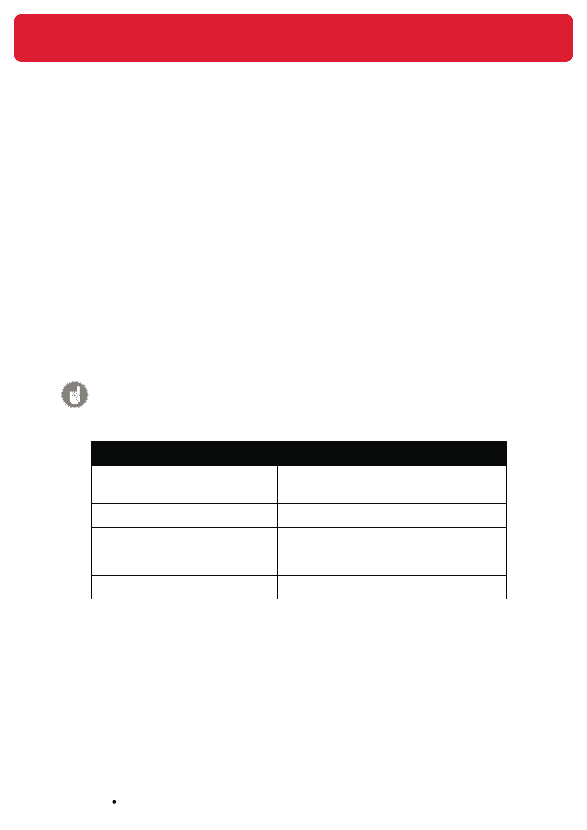
NOFIQ® Systems page 76
1. Retrieve the Network Security Key (NSK), the Short Network Address (SNA), the Network ID
and the Network Channel from the NOFIQ® BASE or the installation plan. Hereto you connect
a computer to the NOFIQ® BASE by means of a null modem cable and then you start the
terminal application as described in paragraph 12.3. When you have started the application, you
consecutively select:
menu 3. Services •
option 1. Network Security Key•
option 2. First available short network address •
Write down all data.
2. Check if all necessary equipment and accessories for installation are present. See paragraph
15.2.
3. Remove the orange connector from the socket.
4. Connect the NOFIQ® FE’s mains power adapter (optional) to the orange connector.
Attention!
Using a mains power adapter is optional for an FE in a network modus.
The FE used as a standalone, you must use the mains power adapter.
The right connection (from left to right) is as follows:
Connector
port
Wire colour Connection
1. Black with white stripe and
red sleeve
Power supply +4 Volt
2. Black (completely black) Minus / earth
3. InterNOFIQBus (with fire-resistant cable)
see chapter 16.
4. InterNOFIQBus (with fire-resistant cable)
see chapter 16.
5. - Common - Potential-free switch contact
(max. 24V, max. 1A)
6. - Normally closed - Potential-free switch contact
(max. 24V, max. 1A)
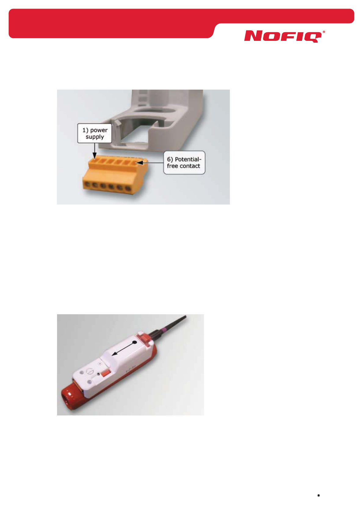
page 77
NOFIQ® Systems
Figure 15 Connection NOFIQ® FE connector
5. Connect the potential-free switch contact. (optional)
Connect the potential-free switch contact with the device in question (e.g. a ventilator) via
connector port 5 and 6.
By default the potential-free contact will be switched in case of Fire alarm (Pre-extinguishing).
If required you can change these settings. The potential-free contact can be switched in case of
Alert, Pre-extinguishing or Error. This option can be set during configuration of the FE.
6. Place the connector back into the socket.
7. Take the NOFIQ® FE out of the socket and remove the lid of the battery holder (push with your
finger in the direction of the arrow).
Figure 16 Placement batteries NOFIQ® FE
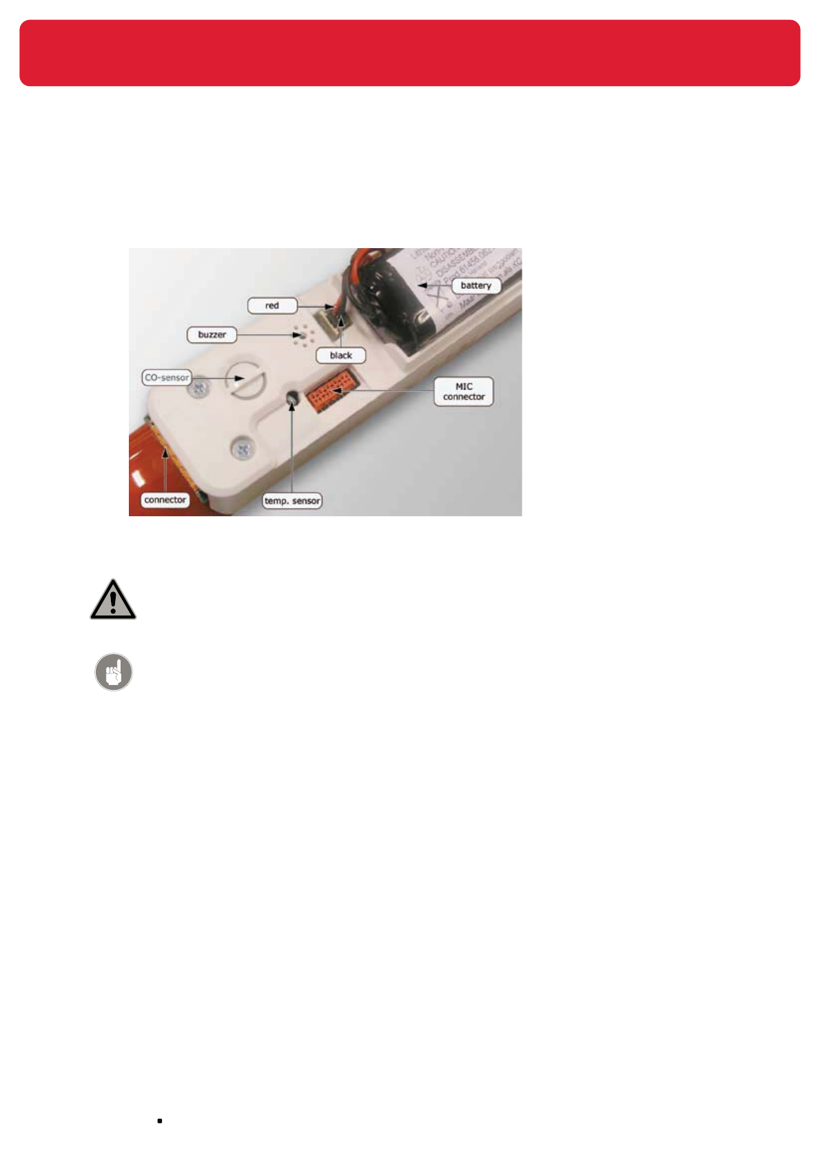
NOFIQ® Systems page 78
8. Place the battery-pack and connect the battery connector (red on the outside, black on the
inside). The connector has been made in such a way that there is only one possible way to
connect it.
Figure 17 NOFIQ® FE Elements and battery connection
Attention!
Wrong battery placement could lead to ignition of the FirePro® aerosol
extinguishing component.
Attention!
The battery-pack for the NOFIQ® system is supplied by your
NOFIQ® provider. Only these battery-packs can be used for your
NOFIQ® devices.
9. Place the lid back onto the battery holder.
10. Configure the NOFIQ® FE
Connect the NOFIQ® FE by means of a Maintenance Interface cable (MIC) to a computer (e.g.
a laptop). Start the application ‘NOFIQ® PC Control’. Program the Network Security Key (NSK),
the Short Network Address (SNA), the Network ID and the Network Channel. In addition you can
change in which situation the potential-free contact must be switched (by default this happens in
case of Fire alarm (Pre-extinguishing).
Configuration is described in chapter 14.
11. Determine the place where the NOFIQ® FE must be fixed.

page 79
NOFIQ® Systems
Attention!
The number of NOFIQ® FE’s needed for an object also determines the
projection, in other words the position and direction in which the NOFIQ®
FE’s have to be mounted.
When applying 1 NOFIQ® FE it will be placed in the middle of the object
on the upper side, having the outflow openings pointing to the left and
the right.
Ensure that both outflow openings have at least 15 cm of free outflow
space in order to prevent damage to equipment. Since the antenna
always has to point upwards, the antenna has to be placed separate from
the FE and connected to the NOFIQ® FE by an antenna extension cord.
When applying 2 or more NOFIQ® FE’s these are placed on the side of the
object in question, having the outflow openings pointing upwards and
downwards. Ensure that both outflow openings have at least 15 cm of
free outflow space in order to prevent damage to equipment.
See also Figure 7 Projection NOFIQ® FE.
12. Fix the socket (at its destined location).
13. Attach the antenna to the NOFIQ® FE.
Attention!
If the FE is installed into a steel cabinet the antenna must be placed
outside the cabinet. In that case the antenna must be linked to the
NOFIQ® FE by means of a antenna extension cord (NOFIQ® accessory).
Prevent the cable from being pinched or knotted.
Turn the antenna extension cord with a Torque Wrench thoroughly tight
onto the NOFIQ® FE!
Let op!
When applying 1 NOFIQ® FE it will be placed in the middle of the object
on the upper side, having the outflow openings pointing to the left and
the right. (see picture 7 projection NOFIQ FE)
Since the antenna always has to point upwards, you need to place the
antenna separate from the NOFIQ® FE.
Make sure that the antenna points upwards.
Link the antenna to the NOFIQ® FE by means of a antenna extension
cord.
Prevent the cable from being pinched or knotted.
14. Click the NOFIQ® FE into the socket.

NOFIQ® Systems page 80
15. Plug the adapter (optional) into the plug socket.
16. Press the NOFIQ® FE’s button for two seconds. On release of the button the NOFIQ® FE leaves
factory status.
17. Affix the warning sticker to the outside of the protected object on eye level.
18. Add the NOFIQ® FE to the NOFIQ® BASE.
Hereto you connect a computer with the NOFIQ® BASE by means of a null modem cable and then
you start the terminal application as described in paragraph 12.3. When you have started the
application, you consecutively select:
menu 3. Services •
option 3. Network Status•
option 1. FE•
option 4. Add FE to network•
Attention!
Downloading the Granted nodes database.
After installation of all components of the NOFIQ® system, you have to
download the Granted nodes database from the NOFIQ® BASE and store it at a
secure place. If something should go wrong with the NOFIQ® BASE, uploading
the database will suffice to restore the data; adding all devices again would
not be necessary.
You can download the Granted nodes database by means of the terminal
application of the NOFIQ® BASE (see chapter 12.3).
Attention!
If an FE’s primary power supply is changed from mains power to batteries (e.
g. if the FE has been moved), this will lead to an error message. You can solve
this error by accessing the BASE’s terminal program (see chapter 12). First
you remove the FE in question (Remove FE from network) and then you add it
again (Add FE to network).
Attention!
If a NOFIQ® FE at one stage has been part of an InterNOFIQBus and you want
this FE to function on its own (but within a network), it is imperative that after
disconnecting the FE from the InterNOFIQBus the FE is restarted by pressing
its button for 10 seconds. Thus you prevent an error message.

page 81
NOFIQ® Systems
15.5 Additional special instructions for installation of a
standalone NOFIQ® FE
Installation of a standalone NOFIQ® FE mainly happens as described in the previous paragraph. The
following special instructions and exceptions apply when installing a standalone FE:
• An FE leaves factory in standalone configuration.
As a precautionary measure we advise to connect the potential-free contact of the NOFIQ• ® FE to
an external alarm of signalling device, for example a siren, a flashing light or a GSM module. In
case of fire the appropriate person or organisation can then be notified in order to take repressive
countermeasures.
The potential-free contact will be switched by default in case of Fire alarm (Pre-extinguishing). •
We advise you to keep this setting..
If required you can change these settings during configuration of the FE.•
Since the NOFIQ• ® FE is not part of a system or network, network data such as SNA, NSK, Net-
work ID and Network Channel do not apply.
The antenna (or antenna extension cord) do not have to be mounted on the FE (although these •
are supplied as a standard accessory).
Mount the small cap in stead of the antenna.•
A standalone NOFIQ• ® FE is not added to a BASE.
It is possible to link 2, 3 or 4 standalone FE into an InterNOFIQBus.•
The standalone NOFIQ• ® FE has to be connected with the main power adapter for a lifetime
quarantee of main power.

NOFIQ® Systems page 82
16. Installation of a InterNOFIQBus
16.1 General
This chapter explains the installation of a InterNOFIQBus.
An InterNOFIQBus is a combination of 2, 3 or 4 mutually linked NOFIQ® FE’s. Thanks to the
InterNOFIQBus it is possible to protect larger objects (e.g. a larger switch cabinet). Installation of a
InterNOFIQBus is optional and is not required for a proper operation of the NOFIQ® system.
Standalone NOFIQ® FE’s can also be linked into an InterNOFIQBus (see also paragraph 15.5).
16.2 Requirements
For installation of the InterNOFIQBus you will need:
2, 3 or 4 NOFIQ• ® FE’s
Sockets for each NOFIQ• ® FE including orange connectors
Antennas + antenna extension cords •
Warning sticker •
“NOFIQ® fire protection system, in case of fire or alarm: do not panic, close cabinet doors and alert
expert assistance”
Mains power adapter for each NOFIQ• ® F (use is optional)
Attention!
The adapter for the NOFIQ® system is supplied by your NOFIQ® provider.
Only these adapters can be used for your NOFIQ® devices.
Battery-pack •
Attention!
The battery-pack for the NOFIQ® system is supplied by your
NOFIQ® provider. Only these battery-packs can be used for your
NOFIQ® devices.
Fire-resistant cables (2-wire) for connecting the FE’s to be linked. •
The maximum total length of the fire-resistant cables used is 6 metres.
Network Security Key (NSK) •
this can be obtained from the NOFIQ® BASE or the installation plan
Short Network Address (SNA) •
this can be obtained from the NOFIQ® BASE or the installation plan
Network ID •
this can be obtained from the NOFIQ® BASE or the installation plan
Network Channel •
this can be obtained from the NOFIQ® BASE or the installation plan

page 83
NOFIQ® Systems
16.3 Installation and configuration instructions
InterNOFIQBus
Attention!
Heed the safety precautions as stated in chapter 7.
Attention!
It is of the utmost importance to execute the instructions consecutively in the
order given.
1. Retrieve the Network Security Key (NSK), the Short Network Address (SNA), the Network ID
and the Network Channel from the NOFIQ® BASE or the installation plan. Hereto you connect
a computer to the NOFIQ® BASE by means of a null modem cable and then you start the
terminal application as described in paragraph 12.3. When you have started the application, you
consecutively select:
menu 3. Services•
option 1. Network Security Key•
option 2. First available short network address •
Write down all data.
2. Check if all necessary equipment and accessories for installation are present. See paragraph
16.2.
3. Remove the orange connector from the socket
4. Connect the NOFIQ® FE’s mains power adapter (optional) to the orange connector.
Attention!
Using a mains power adapter is optional for an FE.
The right connection (from left to right) is as follows:
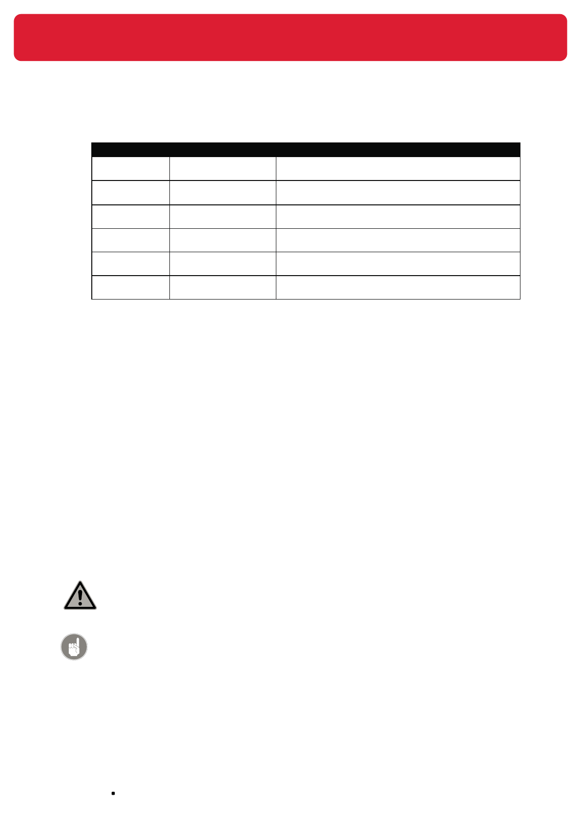
NOFIQ® Systems page 84
Connector port Wire colour Connection
1. Black with white stripe
and red sleeve
Power supply +4 Volt
2. Black (completely
black)
Minus / earth
3. Red InterNOFIQBus (with fire-resistant cable)
see chapter 16.
4. White InterNOFIQBus (with fire-resistant cable)
see chapter 16.
5. - Common - Potential-free switch contact
(max. 24V, max. 1A)
6. - Normally closed - Potential-free switch contact
(max. 24V, max. 1A)
5. Connect the fire-resistant cables to the FE’s to be linked.
Connect the cable attached to connector port 3 with connector port 3 of the second FE. Connect
the cable attached to connector port 3 of the second FE with connector port 3 of the third FE, etc.
In the same way you must connect the FE’s of the InterNOFIQBus via connector port 4.
6. Connect the potential-free switch contact. (optional)
Connect the potential-free switch contact with the device in question (e.g. a ventilator) via
connector port 5 and 6.
By default the potential-free contact will be switched in case of Fire alarm (Pre-extinguishing).
If required you can change these settings. The potential-free contact can be switched in case of
Alert, Pre-extinguishing or Error. This option can be set during configuration of the FE.
7. Place the connectors back into their sockets.
8. Take each NOFIQ® FE out of its socket and remove the lid of the battery holder (push with your
finger in the direction of the arrow).
9. Place the battery-pack and connect the battery connector (red on the outside, black on the
inside). The connector has been made in such a way that there is only one possible way to
connect it.
Attention!
Wrong battery placement could lead to ignition of the FirePro® aerosol
extinguishing component.
Attention!
The battery-pack for the NOFIQ® system is supplied by your
NOFIQ® provider. Only these battery-packs can be used for your
NOFIQ® devices.
10. Place the lids back onto the battery holders.

page 85
NOFIQ® Systems
11. Configure the NOFIQ® FE’s.
Connect each NOFIQ® FE by means of a Maintenance Interface cable (MIC) to a computer (e.g.
a laptop). Start the application ‘NOFIQ® PC Control’. Program the Network Security Key (NSK),
the Short Network Address (SNA), the Network ID and the Network Channel. In addition you can
change in which situation the potential-free contact must be switched (by default this happens in
case of Fire alarm (Pre-extinguishing).
Configuration is described in chapter 14.
12. Determine the place where the InterNOFIQBus must be fixed.
Attention!
This distance between the outflow openings and the object to be protected
must be at least 15 cm. There should not be any obstacles between the
extinguishing component and the object.
Attention!
When applying 2 or more NOFIQ® FE’s these are placed on the side of the
object in question, having the outflow openings pointing upwards and
downwards. Ensure that both outflow openings have at least 15 cm of free
outflow space in order to prevent damage to equipment.
See also Figure 7 Projection NOFIQ® FE.
19. Fix the sockets (at their destined locations).
20. Attach the antennas to the NOFIQ® FE’s.
Attention!
If the FE is installed into a steel cabinet the antenna must be placed
outside the cabinet. In that case the antenna must be linked to the NOFIQ®
FE by means of a antenna extension cord (NOFIQ® accessory).
Prevent the cable from being pinched or knotted.
Turn the antenna extension cord with a Torque Wrench thoroughly tight
onto the NOFIQ® FE!
13. Click the NOFIQ® FE’s into their sockets.
14. Plug the adapters (optional) into the plug sockets.
15. Attach the cabling to the wall by using clamps according to the operative regulations.
16. To test the InterNOFIQBus press the button of one of the FE’s for 1 second. On release of the
button, the yellow, red and green LED of the other FE’s will blink briefly. Next the green LED will
blink once per 5 minutes. The InterNOFIQBus is now ready for operation.

NOFIQ® Systems page 86
17. Affix the warning sticker to the outside of the protected object on eye level.
18. Add the NOFIQ® FE’s to the NOFIQ® BASE.
Hereto you connect a computer to the NOFIQ® BASE by means of a null modem cable and then
you start the terminal application as described in paragraph 12.3. When you have started the
application, you consecutively select:
menu 3. Services •
option 3. Network Status•
option 1. FE•
option 4. Add FE to network•
Attention!
Downloading the Granted nodes database.
After installation of all components of the NOFIQ® system, you have to
download the Granted nodes database from the NOFIQ® BASE and store it at a
secure place. If something should go wrong with the NOFIQ® BASE, uploading
the database will suffice to restore the data; adding all devices again would
not be necessary.
You can download the Granted nodes database by means of the terminal
application of the NOFIQ® BASE (see chapter 12.3).
Attention!
If an FE’s primary power supply is changed from mains power to batteries (e.
g. if the FE has been moved), this will lead to an error message. You can solve
this error by accessing the BASE’s terminal program (see chapter 12). First
you remove the FE in question (Remove FE from network) and then you add it
again (Add FE to network).
Attention!
If a NOFIQ® FE at one stage has been part of an InterNOFIQBus and you want
this FE to function on its own (but within a network), it is imperative that after
disconnecting the FE from the InterNOFIQBus the FE is restarted by pressing
its button for 10 seconds. Thus you prevent an error message.

page 87
NOFIQ® Systems
17. Putting the NOFIQ® system into operation
17.1 General
This chapter explains which actions have to be taken to put the NOFIQ® system into operation.
17.2 Putting the system into operation
Putting the NOFIQ® system into operation must be done by qualified personnel under responsibility of
the NOFIQ® service provider. Putting the NOFIQ® system into operation contains all activities necessary
to make the installation functioning and operational according to the Program of Requirements and the
installation plan.
When the system is put into operation checks must be made to ensure that the NOFIQ® system actually
functions as it should function. The checks executed for this scope, take place in view of the Program of
Requirements and the installation plan.

NOFIQ® Systems page 88
18. Acceptance of the NOFIQ® system
18.1 General
This chapter explains which actions have to be taken for acceptance of the NOFIQ® system.
18.2 Activities for acceptance
The NOFIQ® service provider draws up an Acceptance Report in which the service provider certifies,
that the NOFIQ® system is operational and functions according to Program of Requirements and the
installation plan.
By means of documentation it must be proved that all components applied in the NOFIQ® system meet
the demanded requirements of quality and compatibility.
During the acceptance procedure the owner of the NOFIQ® system must be handed an Acceptance Report
as well as a log book.
An example of a Acceptance Report is provided in Appendix 36.3.
An example of a log book is provided in Appendix 36.4.
The NOFIQ® service provider should instruct the user in the NOFIQ® system’s functioning and in the
periodic and preventive maintenance required. The name of the custodian for the NOFIQ® system in
question should be recorded in the log book and in the NOFIQ® service provider’s registry.
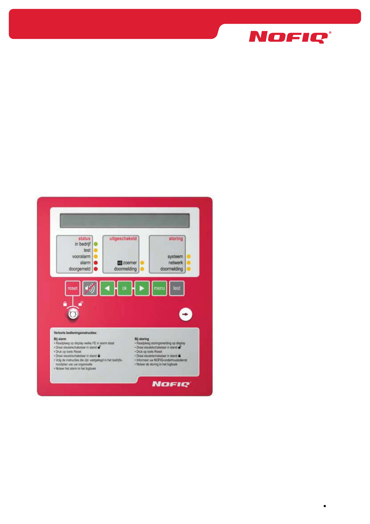
page 89
NOFIQ® Systems
19. The NOFIQ® BASE in daily use
19.1 General
This chapter describes how to handle the NOFIQ® BASE in daily use. It gives you an overview of the
NOFIQ® BASE control panel and how to use it. Furthermore it offers an overview of the structure and
options of the NOFIQ® BASE’s user menu. Finally this chapter throws a light upon the alarm and error
messages that are shown in the control panel’s display.
19.2 Control panel
The NOFIQ® BASE control panel looks as follows:
Figure 18 Control panel NOFIQ® BASE
On the control panel of the NOFIQ® BASE you will discern the following elements:
Alphanumeric display •
The display will be described in paragraph 19.3
Indication lights •
The indication lights (LEDs) will be described in paragraph 19.4
Buttons •
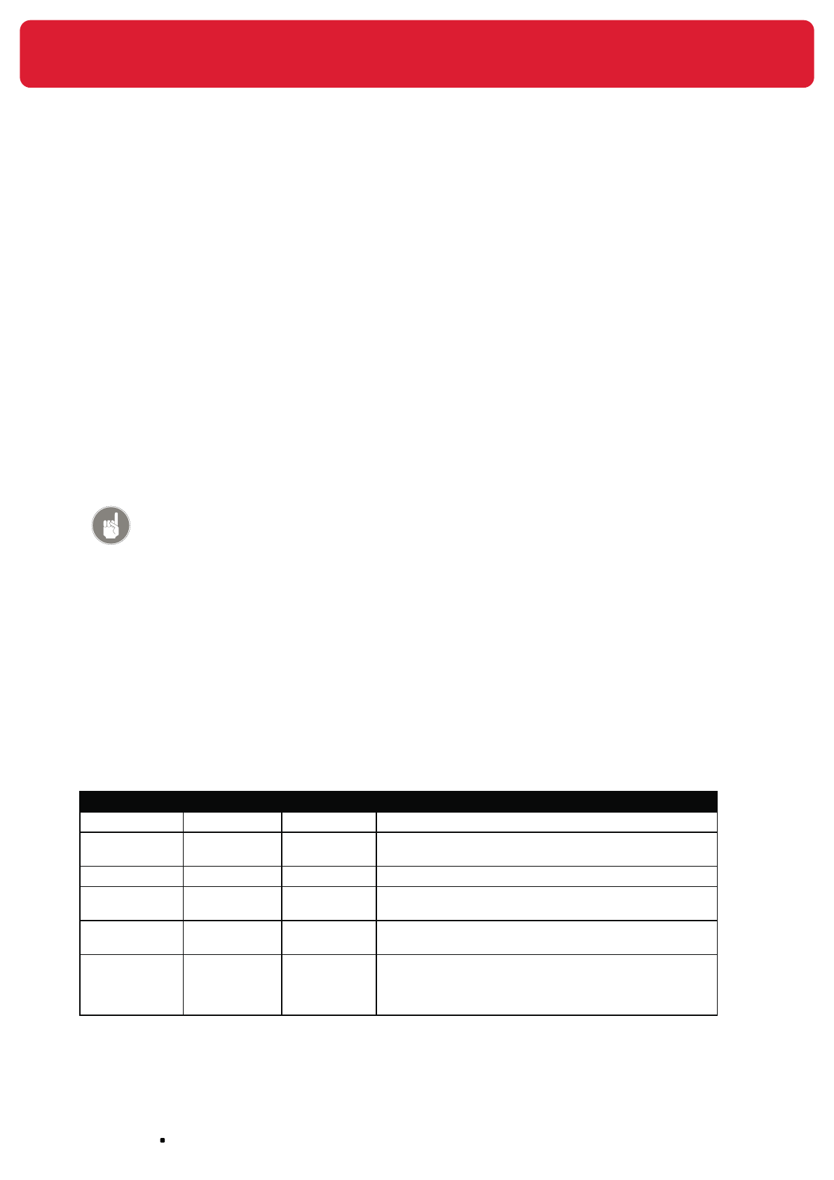
NOFIQ® Systems page 90
The buttons on the control panel will be described in paragraph 19.5
Locks •
The locks on the control panel will be described in paragraph 19.6
19.3 Alphanumeric display
On the upper side of the control panel you will identify a small screen. This is a two-line display for 40
characters on each line. The display is provided with backlight.
In this display the system’s status is shown. If a NOFIQ® FE initiates an alarm or the system reports an
error message, such a message will appear in the display of the control panel.
The top line of the display show the status of the system.
The bottom line of the display shows the menu option or task which can be selected. If the system’s
status is OPERATIONAL, the bottom line shows the current time and date.
Attention!
If your are navigating in the menu, the top line shows the position in the menu
structure.
The menu structure of the NOFIQ® BASE will be described in detail in paragraph 19.10
The menu options and their application will be described in detail in paragraph 19.11.
Alarm messages that may appear in the display, are described in paragraph 19.8.
Error messages shown in the display and their meaning are described in paragraph 19.9.
19.4 Indication LEDs
The control panel of the NOFIQ® BASE is provided with 10 indication LEDs (lights). These lights are
divided into 3 columns, namely Status, Disabled and Malfunction.
You will identify the following LEDs:
Column Text LED colour Meaning
Status Operational Green This LED burns when the system is operational.
Status Test Yellow This LED burns when you are testing the system (with
the button Test, or through the maintenance menu)
Status Alert Yellow This LEDs blinks when a NOFIQ® FE is in Alert.
Status Alarm Red This LED burns when a NOFIQ® FE has reported an alarm
(Fire Alarm or Extinguishing alarm).
Status Notified Red This LED burns when an alert, alarm or error has been
notified to the appropriate service.
Disabled Buzzer Yellow This LED burns when the buzzer has been disabled. The
buzzer can be disabled and enabled through the menu
MAINTENANCE, option <Function Control>. For this an
authorisation key is required.
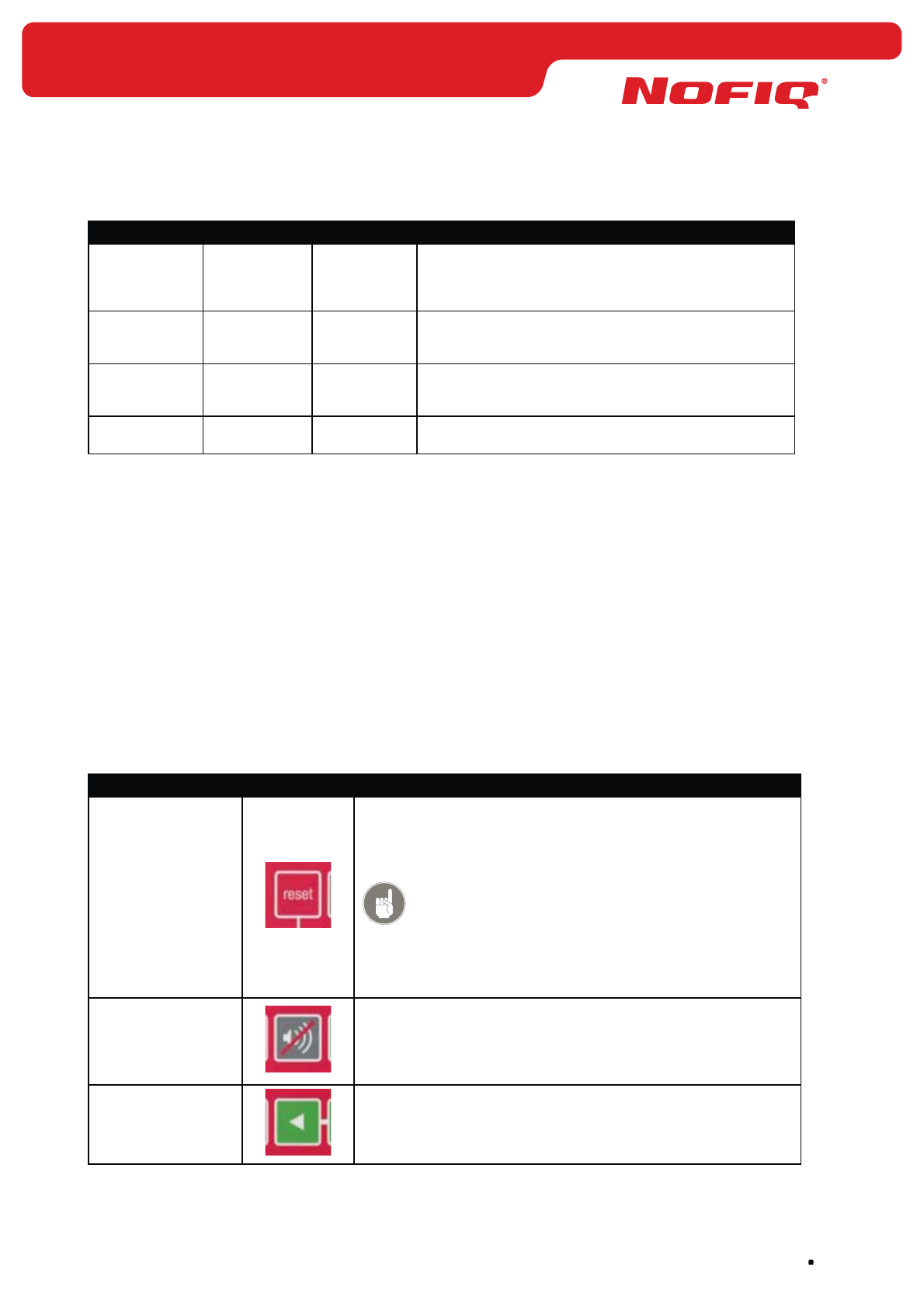
page 91
NOFIQ® Systems
Column Text LED colour Meaning
Disabled Notification Yellow This LED burns when notification has been disabled.
Notification can be disabled and enabled through the
menu MAINTENANCE, option <Function Control>. For
this an authorisation key is required.
Malfunction System Yellow This LED blinks if an error has been detected within
the system. It concerns errors and malfunctions in the
equipment itself and in the power supply.
Malfunction Network Yellow This LED blinks if an error has been detected within
the network. It concerns errors in the communication
between the devices within the network.
Malfunction Notification Yellow This LED burns when there is an error or fault in the
notification (e.g. in the relays or the modem).
Table 6 Indication LEDs NOFIQ® BASE
Further information on the behaviour of the NOFIQ® BASE’s LEDs and buzzer in case of an alarm or an
error can be found in paragraph 19.7.
Alarm messages that are shown in the display, are described paragraph 19.8.
Error messages that are shown in the display, are described paragraph 19.9
19.5 Buttons (keypad)
Below the indication LEDS there are 7 buttons.
These buttons are used to execute action and navigate through the menu.
From left to right you will identify the following buttons:
Button Use
Reset With this button you can reset the alarm management station.
In case of alarm the FE’s in alarm will be disabled (identifiable by
the #-sign in front of the FE’s data in the display); the BASE will
return to its operational status and LED behind Status Notification
will go out.
You need an authorisation key (mechanical key) to use the button
Reset.
Use the button Reset only when the cause of the alarm or error is
known and recorded into the log book.
Buzzer Off With this button you can switch off the buzzer.
This is a temporary switching-off in case an Extinguishing has taken
place. If you want to disable the buzzer completely, you need to
do that by means of the menu MAINTENANCE - option <Function
Control> (authorisation key required).
<With this button you can navigate to the left. Within the menu this
button will take you an option to the left; within a message this
button will take you one line back. This button is only functional
when leftmost of the second line an arrow to the left (<) is shown.
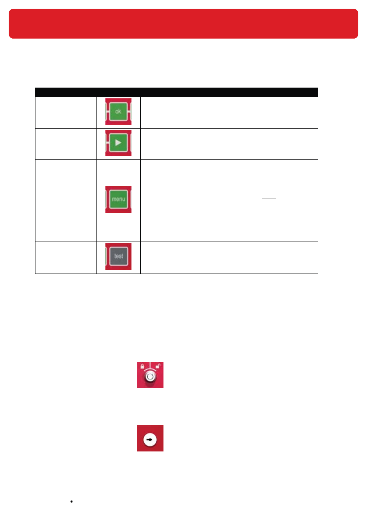
NOFIQ® Systems page 92
Button Use
OK With this button you can select a menu option or confirm a choice
or action.
>With this button you can navigate to the right. Within the menu this
button will take you an option to the right; within a message this
button will take you one line forward. This button is only functional
when leftmost of the second line an arrow to the right (<) is shown.
Menu With the button Menu you can start the menu. Then you can
navigate in the menu with the < and > buttons and then select
menu options with the button OK.
When working in the menu the button Menu will take you one level
higher in the menu structure.
When working in the menu MAINTENANCE you must select the
option <EXIT> to leave this menu.
The top line of the display shows the position in the menu structure.
An example: The top line of the display shows Maintenance:FE List:
Details. If you press the button Menu, you will go to Maintenance:
FE List. From there on you can navigate by using the buttons <, OK
and >.
Test With the button Test you can execute a test. This test checks if all
indicators (display, lights and buzzer) function.
When you press this button, the LED Status – Test will burn. Next
the display will show the text Test, the buzzer will sound and the
LEDs will blink for a few seconds. This test stops automatically.
Table 7 Buttons control panel NOFIQ® BASE
19.6 Locks
The control panel of the NOFIQ® BASE is provided with two locks:
Lock for authorisation key
(mechanical key)
In the left lock (below the button Reset) fits
an authorisation key. The authorisation key is
required to reset the system (button Reset)
and to perform certain options within the menu
MAINTENANCE.
For using this key authorisation level 2 is
required.
By turning the key to the right in the direction
of the opened padlock sign, you will unlock the
authorisation. By turning the key to the left in
the direction of the locked padlock sign, you will
lock the authorisation.
Lock for opening the station’s
cabinet
In the right lock (below right of the button Test)
fits a key to open the station’s cabinet.
For using this key authorisation level 3 is
required.
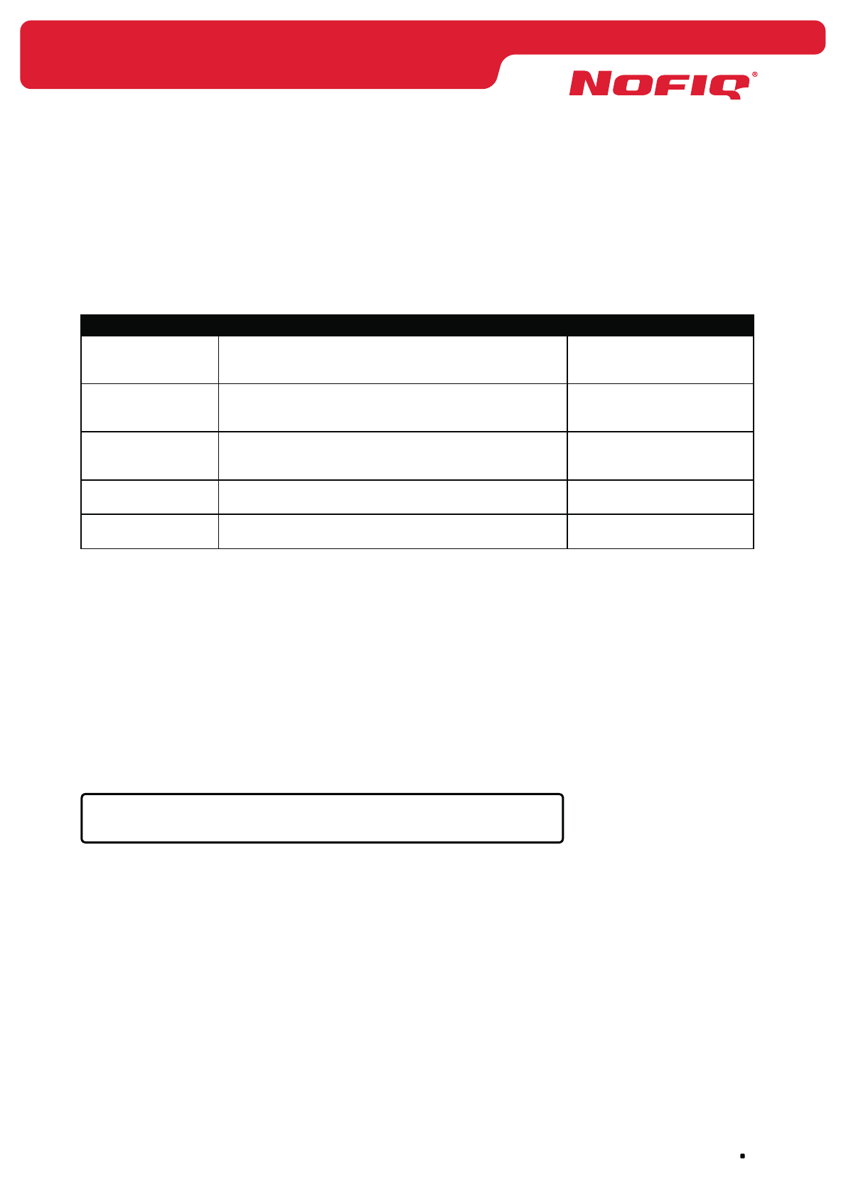
page 93
NOFIQ® Systems
19.7 Alarm or error messages and accompanying
indicators
The table below lists the different alarm and error messages which can be identified on the NOFIQ® BASE
and how to recognize these by the accompanying LED and buzzer behaviour.
Status LED behaviour Buzzer behaviour
MALFUNCTION One or more yellow Malfunction LEDs blink twice briefly
every 2 seconds
Beeps at 5 kHz, exactly
corresponding with the LED
pattern.
ALERT Yellow led (Status - Alert) blinks twice every second. Beeps at 5 kHz, exactly
corresponding with the LED
pattern.
FIRE ALARM Yellow led blink thrice every seconds. Beeps at 5 kHz, exactly
corresponding with the LED
pattern.
EXTINGUISHING Red LED burns continuously Continuous signal sweep
between 4 and 5 KHz.
EXTINGUISHING-
SILENT
Red LED burns continuously Silent.
Table 8 Indicators alarm and error messages
19.8 Overview alarm messages
An alarm message will be shown in the alphanumeric display.
The top line of the display shows the alarm message plus time and date.
The bottom line of the display shows additional information about the message, for example which device
it concerns.
If the information comprises several lines or if there are several alarm messages (identifiable by the < >
arrows in the left corner) you can page through these lines by using the >-button and the <-button.
The next example shows how the system displays an alarm.
ALERT 11:48:12 02/10/2006 #ALARMS:1
<FE:1-2>
The NOFIQ® system applies three different types of alarm messages:
Alert•
Fire alarm•
Extinguishing•
Alert
As soon as a NOFIQ® FE’s sensors register a steep increase in temperature or CO concentration (without
exceeding a critical point), the NOFIQ® FE sends an Alert to the alarm management station (the NOFIQ®
BASE). With this alert the FE warns that probably something is not right at its location and that a fire may
be developing. The Alert can only be shut down on the spot. This has been designed especially in this way
to oblige a custodian to check whether a dangerous situation has arisen at the location in question. Thus
a critical situation can be diagnosed quickly.
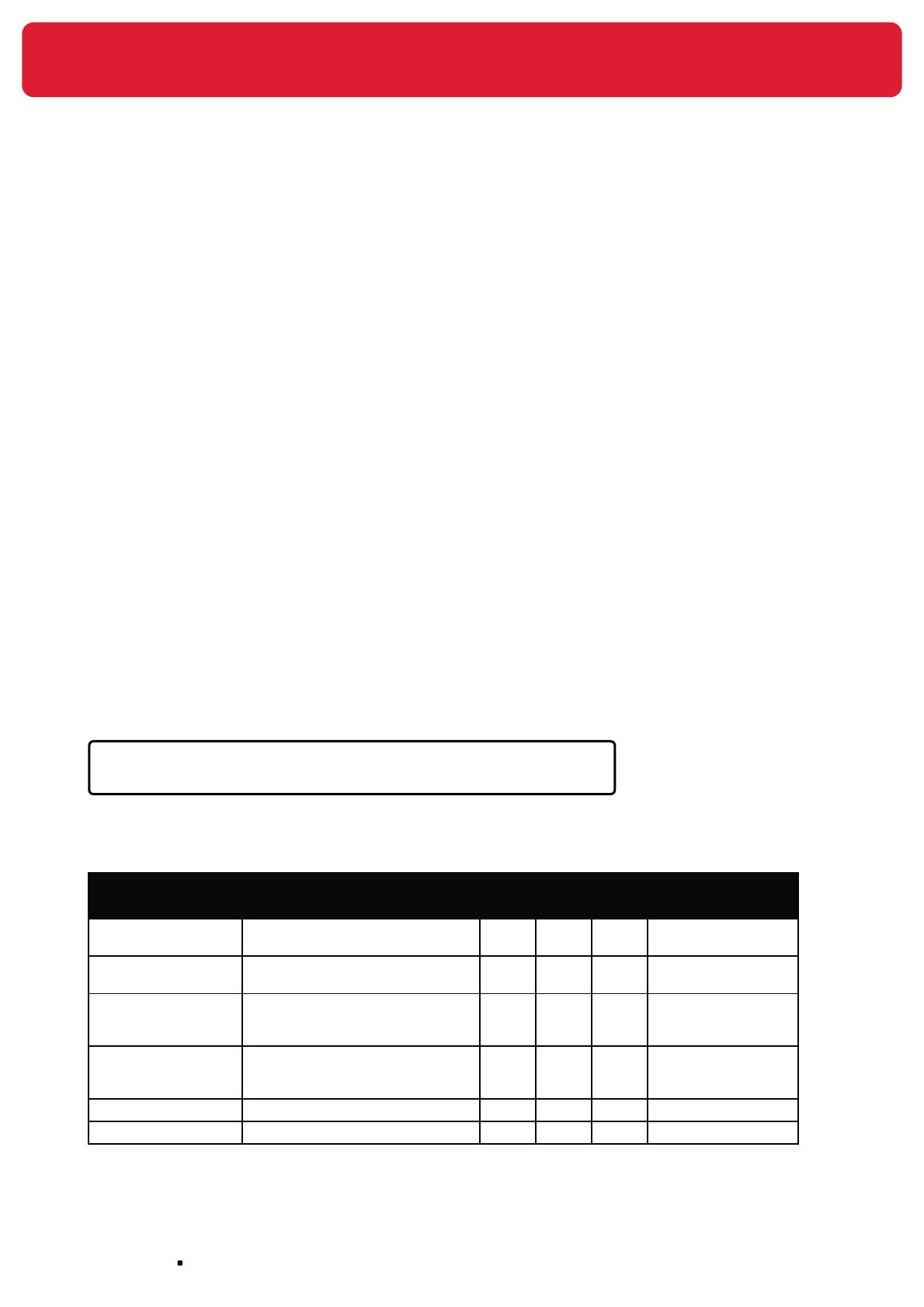
NOFIQ® Systems page 94
Fire alarm
If the temperature and the CO concentration have exceeded a critical level, the NOFIQ® FE will initiate
a Fire alarm. This alarm warns that a fire has been detected and that the NOFIQ® FE will start an
extinguishing sequence within 10 seconds. Within those 10 seconds the FE in question can be disabled
by pressing the FE’s button (Suspend). If someone would be doing maintenance work (welding, cleaning)
at the location in question and forgot to Suspend the FE, the maintenance activities could be causing an
alarm, although there is no question of fire. That is why there is a 10 second-countdown between the Fire
alarm and the actual extinguishing routine.
Extinguishing
When the 10 second countdown expires the aerosol fire-extinguishing component will be activated and an
extinguishing routine is started. The FE will now report an Extinguishing alarm.
How the system deals with an alarm and what you need to do yourself, is explained in chapter 23.
19.9 Overview error messages
An error message will be shown in the alphanumeric display.
The top line of the display shows the message ‘MALFUNCTION’.
The bottom line of the display shows additional information about the message, for example which device
it concerns and what kind of error is reported.
If the information comprises several lines or if there are several alarm messages (identifiable by the < >
arrows in the left corner) you can page through these lines by using the >-button and the <-button.
The next example shows how the system displays an error message.
MALFUNCTION #ERROR:2
-> <FE:101:Offline>
The list below shows the different error messages that the system can initiate and how these are shown
on the control panel.
Error message Meaning and description Applies to: Indication LED on
the control panel
BASE HUB FE
Offline A heartbeat of an HUB or FE is
missing.
X X Network
Suspend-state
activated
An FE has been temporarily
disabled (Suspended).
X Network
Disabled The FE has executed an
extinguishing and has been
disabled.
X Network
Parent missing At least one HUB or FE misses a
‘parent’ that guarantees a backup
route.
X X Network
BASE-HUB An error in the BASE-HUB. Network
Cause unknown Internal (unknown) error. X X X System
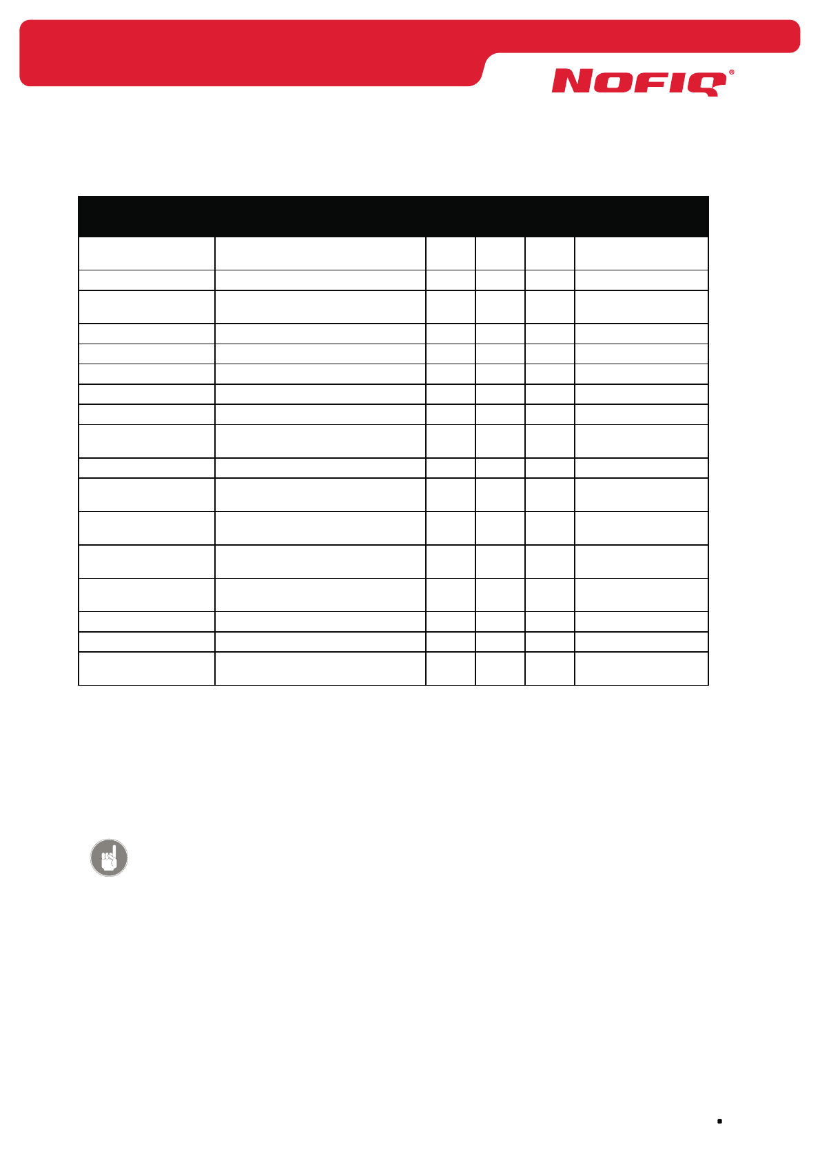
page 95
NOFIQ® Systems
Error message Meaning and description Applies to: Indication LED on
the control panel
BASE HUB FE
Temperature sensor An error in the temperature
sensor.
X System
CO sensor An error in the CO sensor. X System
LCD An error in the alphanumeric
display.
X System
LED An error in the LEDs. X System
Keypad An error in the keypad buttons. X System
Modem An error in the modem. X System
Buzzer An error in the buzzer. X System
Battery (UPS) An error in the battery. X System
Igniter extinguishing
component
An error in the igniter of the
FirePro® extinguishing component.
X System
Relay A switch relay is faulty. X X System
InterNOFIQBus An error in the communication
within an InterNOFIQBus.
X System
Battery failure The level of the battery is low or
missing
X System
Battery level low The level of the battery-pack is
low
X1X System
Battery level critical The level of the battery-pack is
critical.
X1X System
Mains power loss Mains power is down. X X System
Notification An error in the notification. X Notification
Network Network communication is not
available.
X Network
1 Detection of these errors is only possible if mains power is down (Mains power loss).
Table 9 Overview error messages
The indicators (LEDs and buzzer, if any) of the devices in question also show the device’s status. In the
next chapters for each NOFIQ® device (FE, HUB or BASE-HUB) you will find a status overview and the
accompanying indicator behaviour.
Attention!
If due to an error in network communication contact with a NOFIQ® FE has
(temporarily) been interrupted, nothing is changed in the functionality of the
FE: it keeps on detecting and it alarms and extinguishes when circumstances
require such actions.
How the system deals with an error and what you need to do yourself, is explained in chapter 23.
19.10 Menu structure
The NOFIQ® BASE is provided with a number of menu’s to query or modify data and settings of the
system and its individual components.

NOFIQ® Systems page 96
Attention!
Changing settings is only permitted to authorised users. For this an
authorisation key is required. Menu options that require authorisation are
identifiable by the @-sign.
Attention!
The system’s status determines which menu’s are available. The menu options
in the menu MALFUNCTION, ALERT, FIRE ALARM and EXTINGUISHING are only
available if the system is in the status in question.
When the system is in OPERATIONAL status, only the menu’s MAINTENANCE
and INFORMATION will be available. As soon as the system’s status changes,
the menu will adapt automatically.
The system is in one of the following statuses:
OPERATIONAL •
MAINTENANCE•
ALARM (Alert, Fire alarm or Extinguishing)•
MALFUNCTION•
Attention!
If you are working in the NOFIQ® BASE’s menu MAINTENANCE and an FE
reports an alarm, the alarm will not be shown in the display (although it is
registered in the background).
As soon as you exit the menu MAINTENANCE, the system will go into alarm
status.
How to use the control panel’s buttons to navigate through the menu’s and select menu options is
explained in paragraph 19.5
Next a list is shown of the various menu’s and the menu options in those menu’s. In paragraph 19.11
these menu options are explained in detail.
Attention!
A @ before a menu option indicates that this option (plus sub options if any)
can only be executed by an authorised user in possession of an authorisation
key.
OPERATIONAL
@ <MAINTENANCE>
<INFORMATION>

page 97
NOFIQ® Systems
MAINTENANCE
<FE List>
<FE:SNA:LOCATION>
<DETAILS>
@ <EDIT>
<ENABLE>
<DISABLE >
<REMOVE >
<HUB List>
<HUB:SNA:LOCATION>
<DETAILS>
@ <EDIT>
<ENABLE>
<DISABLE >
<REMOVE >
<MISSING DEVICES >
<FUNCTION CONTROL >
@
<BUZZER >
<ENABLE >
<DISABLE >
<NOTIFICATION >
<ENABLE>
<DIRECT>
<DELAYED>
<DISABLE>
<SETTINGS>
<SET DATE>
<SET TIME>
<SET LANGUAGE>
@ <SET MODEM>

NOFIQ® Systems page 98
<DTMF>
<DISABLE >
<DIAGNOSTICS>
<SELF TEST>
<SOFTWARE VERSION>
<SERIAL NUMBER
BASE>
<EXIT >
MALFUNCTION
<DETAILS>
<MAINTENANCE>
ALERT
<DETAILS>
FIRE ALARM
<DETAILS>
EXTINGUISHING
<DETAILS>
<SILENT>
19.11 Menu options and their use
This paragraph explains the menu options in the various menu’s.
How to use the control panel’s buttons to navigate through the menu’s and select menu options is
explained in paragraph 19.5.
Attention!
A @ before a menu option indicates that this option (plus sub options if any)
can only be executed by an authorised user in possession of an authorisation
key.
OPERATIONAL
When the system’s status is OPERATIONAL, pressing the button Menu will offer the following options:

page 99
NOFIQ® Systems
@ • <MAINTENANCE> Press the button OK. Next press the button Menu to enter the
menu MAINTENANCE. This menu will be explained in detail below.
<INFORMATION>• This option offers general information about the NOFIQ® system.
MAINTENANCE
The MAINTENANCE menu offers the following options:
<FE LIST>• This options shows a list of all FE’s in the NOFIQ® system.
Next you can select an FE.
• <DETAILS> View details of the FE selected.
• @
<EDIT>
Modify data of the FE selected.
For this authorisation is required.
<ENABLE>• enable the FE
<DISABLE >• disable the FE
A disabled FE is
identifiable in the
display by #-sign in
front of the FE.
<REMOVE >• remove the FE
<HUB LIST>• This options shows a list of all HUBs in the NOFIQ® system.
Next you can select an HUB.
• <DETAILS> View details of the HUB selected.
• @
<EDIT>
Modify data of the HUB selected.
For this authorisation is required.
<• ENABLE>enable the HUB
<• DISABLE>disable the HUB
<• REMOVE>remove the HUB
<MISSING DE-•
VICES>
This options shows a list of all devices that are no longer detected
by the system.
@ •
<FUNCTION CON-
TROL>
With this option the buzzer and notification can be enabled or
disabled.
For this authorisation is required.
<BUZZER>•
<ENABLE>• enable the buzzer
<DISABLE >• disable the buzzer
<NOTIFICATION>•

NOFIQ® Systems page 100
<ENABLE>• enable notification,
next choose between:
• <DIRECT>
direct notification
• <DELAYED>
notification with a
1 minute delay
(notification via
the potential-free
switch contacts
is always without
delay)
<DISABLE >• disable notification
<SETTINGS >• With this option time, date, language and modem properties can be
set.
<SET DATE>• Set the correct date.
<SET TIME>• Set the correct time.
<SET LANGUAGE>• Set the desired language.
@ •
<SET MODEM>
Set the desired modem properties.
Choose between:
<DTMF> •
enable modem using DTMF-
tones
<DISABLE> •
disable modem
<DIAGNOSTICS>• With this option you can query system data.
<SELF TEST>• Use this to execute a system test.
<SOFTWARE VER-•
SION>
The version number of the software.
<SERIAL NUMBER •
BASE>
The serial number of the NOFIQ®
BASE.
<EXIT>• This option takes you back to the main menu.
When working in the menu MAINTENANCE you must select the
option <EXIT> to leave this menu.
You cannot use the button Menu to take you from the menu
MAINTENANCE to a higher menu level.

page 101
NOFIQ® Systems
MALFUNCTION
If the system reports an error, the menu MALFUNCTION will appear. The bottom line of the display shows
which device it concerns and what kind of error is reported. Pressing the button Menu will offer the
following options:
<DETAILS>• This options offers details about the error.
<MAINTENANCE >• This options takes you to the menu MAINTENANCE.
ALERT
If an FE reports an Alert, the menu ALERT will appear. The bottom line of the display shows the FE(‘s) in
Alert. Pressing the button Menu will offer the following options:
<DETAILS>• This options offers details about the Alert.
Attention!
When the system’s status is Alert, Fire alarm or Extinguishing, the menu
MAINTENANCE cannot be entered. First of all the system should be reset using
the button Reset on the control panel.
FIRE ALARM
If an FE reports a Fire alarm, the menu FIRE ALARM will appear. The bottom line of the display shows the
FE(‘s) in Fire alarm. Pressing the button Menu will offer the following options:
<DETAILS>• This options offers details about the Fire alarm.
Attention!
When the system’s status is Alert, Fire alarm or Extinguishing, the menu
MAINTENANCE cannot be entered. First of all the system should be reset using
the button Reset on the control panel.
EXTINGUISHING
If an FE reports an Extinguishing alarm, the menu EXTINGUISHING will appear. The bottom line of the
display shows the FE(‘s) in Extinguishing. Pressing the button Menu will offer the following options:
<DETAILS>• This options offers details about the Extinguishing alarm
<SILENT>• This option shows the FE’s that have executed their extinguishing
routine.
Attention!
When the system’s status is Alert, Fire alarm or Extinguishing, the menu
MAINTENANCE cannot be entered. First of all the system should be reset using
the button Reset on the control panel.
NOFIQ® Systems page 102
20. The NOFIQ® BASE-HUB in daily use
20.1 General
This chapter describes how to handle the NOFIQ® BASE-HUB in daily use. It offers an overview of the
possible statuses for the NOFIQ® BASE-HUB and how its status is identified by the indicators (LEDs). The
NOFIQ® BASE-HUB is not equipped with a buzzer.
Furthermore you can learn how to use the button of the NOFIQ® BASE-HUB.
20.2 Statuses of the NOFIQ® BASE-HUB and accompanying
indicators
A NOFIQ® BASE-HUB is in one of the following statuses:
Status Meaning
SAFE The NOFIQ® BASE-HUB functions properly.
ACTIVE The NOFIQ® BASE-HUB is operational but has not yet received any network
messages.
FACTORY This status is used for testing during manufacturing and during installation.
Table 10 Statuses NOFIQ® BASE-HUB and their meaning
The LEDS of the NOFIQ® BASE-HUB show the device’s status. The table below shows the various statuses
of the BASE-HUB and the accompanying LED behaviour.
Attention!
The NOFIQ® BASE-HUB is not equipped with a buzzer.
Status LED behaviour Buzzer behaviour
SAFE Green LED blinks on every message received. n/a
ACTIVE Red LED blinks every second. n/a
FACTORY Yellow LED blinks alternately 1 second on, 1
second off.
n/a
Table 11 Statuses NOFIQ® BASE-HUB and accompanying LED behaviour
20.3 Use of the button of the NOFIQ® BASE-HUB
You can use the button of the NOFIQ® BASE-HUB in the following situations:
To leave factory status of the NOFIQ• ® BASE-HUB.
A NOFIQ® BASE-HUB that has just been installed is in factory status (FACTORY).
To leave this status when the NOFIQ® BASE-HUB is in working order, press the button for 2 sec-
onds. On release of the button, the NOFIQ® BASE-HUB will have the status SAFE or ACTIVE.
To restart the NOFIQ• ® BASE-HUB
To restart the NOFIQ® BASE-HUB press the button for 10 seconds. On release of the button, the
NOFIQ® BASE-HUB will have the status SAFE or ACTIVE.
page 103
NOFIQ® Systems
21. The NOFIQ® HUB in daily use
21.1 General
This chapter explains how to handle a NOFIQ® HUB in daily use. It offers an overview of the possible
statuses of the NOFIQ® HUB and how its status is identified by the indicators (LEDs and buzzer).
Furthermore you can learn how to use the button of the NOFIQ® HUB.
21.2 Statuses of a NOFIQ® HUB and accompanying
indicators
A NOFIQ® HUB is in one of the following statuses:
Status Meaning
SAFE The NOFIQ® HUB functions properly and has 2 parents within radio reach.
FACTORY This status is used for testing during manufacturing and during installation.
MALFUNCTION An error has been detected in the device or in the communication. If more errors
will be detected the NOFIQ® HUB will send additional error messages to the NOFIQ®
BASE.
OFFLINE The NOFIQ® HUB has not found any parents, for example since these are out of its
radio reach.
Table 12 Statuses NOFIQ® HUB and their meaning
The indicators (LEDs and buzzer) of the NOFIQ® HUB show the device’s status. The table below shows the
various statuses of a HUB and the accompanying LED and buzzer behaviour.
Status LED behaviour Buzzer behaviour
SAFE Green LED blinks once every 5 seconds Silent
FACTORY Yellow LED blinks alternately 1 second on, 1
second off.
Silent
MALFUNCTION Yellow LED blinks every 2 seconds 2 x briefly Silent
OFFLINE Red LED blinks every 2 seconds 2 x briefly Buzzer beeps every time the
LED blinks (4 KHz)
Table 13 Statuses NOFIQ® HUB and accompanying indicator behaviour
21.3 Use of the button of a NOFIQ® HUB
You can use the button of the NOFIQ® HUB in the following situations:
To leave factory status of the NOFIQ• ® HUB.
A NOFIQ® HUB that has just been installed is in factory status (FACTORY).
To leave this status when the NOFIQ® HUB is in working order, press the button for 2 seconds. On
release of the button, the NOFIQ® HUB will have the status SAFE.
To restart the NOFIQ• ® HUB
To restart the NOFIQ® HUB press the button for 10 seconds. On release of the button, the
NOFIQ® HUB will have the status SAFE.
To send a heartbeat (status report)•
To send a heartbeat (as a kind of test status report) briefly press the button.

NOFIQ® Systems page 104
22. The NOFIQ® FE in daily use
22.1 General
This chapter explains how to handle a NOFIQ® FE in daily use. It offers an overview of the possible
statuses of the NOFIQ® FE and how its status is identified by the indicators (LEDs and buzzer).
Furthermore you can learn how to use the button of the NOFIQ® FE.
22.2 Operation of the NOFIQ® FE’s sensors
Each NOFIQ® FE is provided with a temperature sensor and a carbon monoxide (CO) sensor. With these
sensors the NOFIQ® FE monitors its surroundings. If the temperature or the CO concentration increase
steeply or exceeds a certain limit, the FE will send an alarm to the NOFIQ® BASE.
The NOFIQ® system applies three different types of alarm messages:
Alert•
Fire alarm•
Extinguishing•
Alert
As soon as a NOFIQ® FE’s sensors register a steep increase in temperature or CO concentration (without
exceeding a critical point), the NOFIQ® FE sends an Alert to the alarm management station (the NOFIQ®
BASE). With this alert the FE warns that probably something is not right at its location and that a fire may
be developing. The Alert can only be shut down on the spot. This has been designed especially in this way
to oblige a custodian to check whether a dangerous situation has arisen at the location in question. Thus
a critical situation can be diagnosed quickly.
Fire alarm
If the temperature and the CO concentration have exceeded a critical level, the NOFIQ® FE will initiate
a Fire alarm. This alarm warns that a fire has been detected and that the NOFIQ® FE will start an
extinguishing sequence within 10 seconds. Within those 10 seconds the FE in question can be disabled
by pressing the FE’s button (Suspend). If someone would be doing maintenance work (welding, cleaning)
at the location in question and forgot to Suspend the FE, the maintenance activities could be causing an
alarm, although there is no question of fire. That is why there is a 10 second-countdown between the Fire
alarm and the actual extinguishing routine.
Extinguishing
When the 10 second countdown expires the aerosol fire-extinguishing component will be activated and an
extinguishing routine is started. The FE will now report an Extinguishing alarm.
If an FE reports a an alarm automatically a notification will be forwarded to the fire brigade or another
fire-fighting service.
page 105
NOFIQ® Systems
Attention!
The NOFIQ® FE is also available in a standalone version. In that case there is
no question of a NOFIQ® system/network (with BASE, BASE-HUB and HUBS).
Alarm and error messages therefore will not be notified to the BASE. (see
chapter 15.5, page 80)
22.3 Statuses of a NOFIQ® FE and accompanying indicators
A NOFIQ® FE is in one of the following statuses:
Status Meaning
SAFE The NOFIQ® FE functions properly; no fire or error has been detected.
SUSPEND If an FE’s location or the itself needs maintenance, you can temporarily disable the
device by pressing the button for 2 seconds.
If an FE reports a Fire Alarm you can temporarily disable the FE in question within 10
seconds by briefly pressing its button.
MALFUNCTION An error has been detected in the FE. If possible the FE will still monitor its
surroundings. If an alarm situation should occur the alarm status will get priority to
the error status.
ALERT The sensors have detected a steep increase but the situation is not yet critical and
demands no extinguishing (yet).
FIRE ALARM A fire has been detected; within 10 seconds the FE will start an extinguishing routine.
Within those 10 seconds the device can be deactivated by briefly pressing the button
(SUSPEND).
EXTINGUISHING The aerosol extinguishing component has been activated to extinguish the fire. If an
FE is in this status, maintenance is required, since the extinguishing agent has been
spent and the FE could be damaged by the fire.
FACTORY This status is used for testing during manufacturing and during installation.
Table 14 Statuses NOFIQ® FE and their meaning
The indicators (LEDs and buzzer) of the NOFIQ® FE show the device’s status. The table below shows the
various statuses of a FE and the accompanying LED and buzzer behaviour.
Status LED behaviour Buzzer behaviour
SAFE Green LED blinks once every 5 seconds Silent
SUSPEND Yellow LED blinks every second 1 x briefly Silent
MALFUNCTION Yellow LED blinks every 2 seconds 2 x briefly Beeps at 5 kHz, exactly
corresponding with the LED
pattern.
ALERT Yellow LED blinks every second 2 x briefly Beeps at 5 kHz, exactly
corresponding with the LED
pattern.
FIRE ALARM Red LED blinks for 8 seconds in rapid succession, then
continuously for 2 seconds.
Continuous signal sweep
between 4 and 5 KHz.
EXTINGUISHING Red LED blinks every 2 seconds 2 x briefly Beeps at 4 kHz, exactly
corresponding with the LED
pattern.

NOFIQ® Systems page 106
FACTORY Yellow LED blinks alternately 1 second on, 1 second off. Silent
Table 15 Statuses NOFIQ® FE and accompanying indicator behaviour
22.4 Use of the button of a NOFIQ® FE
You can use the button of the NOFIQ® FE in the following situations:
• To leave factory status of the NOFIQ® FE.
A NOFIQ® FE that has just been installed is in factory status (FACTORY).
To leave this status when the NOFIQ® FE is in working order, press the button for 2 seconds. On
release of the button, the NOFIQ® FE will have the status SAFE.
• To break off a Fire Alarm
If a NOFIQ® FE reports a Fire Alarm, you have got ten seconds to break off this alarm and to
prevent the FE from extinguishing. It could happen that for example welding activities inside the
switch cabinet cause an increase in temperature which prompt the FE to report a Fire Alarm,
although there is no question of fire.
By pressing the button briefly within those 10 seconds the Fire Alarm will be interrupted and the
FE in question will be temporarily disabled (SUSPEND status).
• To break off an Alert
With an Alert the FE warns that probably something is not right at its location and that a fire
may be developing. By briefly pressing the button the Alert will be stopped. The Alert can only
be shut down on the spot. This has been designed especially in this way to oblige a custodian to
check whether a dangerous situation has arisen at the location in question. An Alert can never be
interrupted or reset from the NOFIQ® BASE.
Attention!
If the conditions causing the Alert are still present, the FE will go back
into Alert after pressing the FE’s button. Only if the conditions are OK
(for example after a drop in temperature), pressing the button will get
the FE back into SAFE status.
• To disable a NOFIQ® FE temporarily
If an FE’s location or the FE itself needs maintenance, you can temporarily disable the FE
by pressing the button for 2 seconds. The FE in question will then be in SUSPEND status. To
reactivate the FE press the button for 2 seconds.
• To restart the NOFIQ® FE
To restart the NOFIQ® FE press the button for 10 seconds. On release of the button, the NOFIQ®
FE will have the status SAFE.
page 107
NOFIQ® Systems
23. Alarm or error, what to do?
23.1 General
This chapter explains what you need to do yourself if the NOFIQ® system reports an alarm or error.
Paragraph 23.2 explains how to recognize an alarm or error message on the NOFIQ® BASE.
Paragraph 23.3 explains how the NOFIQ® system handles an alarm message.
Paragraph 23.4 explains what you need to do yourself in case of an alarm.
Paragraph 23.5 explains how the NOFIQ® system handles an error message.
Paragraph 23.6 explains what you need to do yourself in case of an error message.
23.2 How do you recognize an alarm or error?
As soon as the NOFIQ® system detects an error within the network or receives an alarm from an FE, a
message is sent to the NOFIQ® BASE. The alarm or error is shown in the NOFIQ® BASE’s display.
Attention!
The NOFIQ® FE is also available in a standalone version. In that case there is
no question of a NOFIQ® system/network (with BASE, BASE-HUB and HUBS).
Alarm and error messages therefore will not be notified to the BASE. (see
chapter 15.5, page 80)
An alarm or error message will be shown in the alphanumeric display.
The top line of the display shows the message (MALFUNCTION, ALERT, etc.).
The bottom line of the display shows additional information about the message, for example which device
it concerns.
If the information comprises several lines or if there are several alarm or error messages (identifiable
by the < > arrows in the left corner) you can page through these lines by using the >-button and the
<-button.
The next example shows how the system displays an error message:
MALFUNCTION #ERRORS:2
-> <FE:101:Offline>
The next example shows how the system displays an alarm:
ALERT 11:48:12 02/10/2006 #ALARMS:1
<FE:1-2>
The NOFIQ® system applies three different types of alarm messages:
Alert•
Fire alarm•
Extinguishing•

NOFIQ® Systems page 108
Alert
As soon as a NOFIQ® FE’s sensors register a steep increase in temperature or CO concentration (without
exceeding a critical point), the NOFIQ® FE sends an Alert to the alarm management station (the NOFIQ®
BASE). With this alert the FE warns that probably something is not right at its location and that a fire may
be developing. The Alert can only be shut down on the spot. This has been designed especially in this way
to oblige a custodian to check whether a dangerous situation has arisen at the location in question. Thus
a critical situation can be diagnosed quickly.
Fire alarm
If the temperature and the CO concentration have exceeded a critical level, the NOFIQ® FE will initiate
a Fire alarm. This alarm warns that a fire has been detected and that the NOFIQ® FE will start an
extinguishing sequence within 10 seconds. Within those 10 seconds the FE in question can be disabled
by pressing the FE’s button (Suspend). If someone would be doing maintenance work (welding, cleaning)
at the location in question and forgot to Suspend the FE, the maintenance activities could be causing an
alarm, although there is no question of fire. That is why there is a 10 second-countdown between the Fire
alarm and the actual extinguishing routine.
Extinguishing
When the 10 second countdown expires the aerosol fire-extinguishing component will be activated and an
extinguishing routine is started. The FE will now report an Extinguishing alarm.
The next table shows the behaviour of LEDS and buzzer in case of an alarm or error message.
Status LED behaviour Buzzer behaviour
MALFUNCTION One or more yellow Malfunction LEDs blink twice
briefly every 2 seconds
Beeps at 5 kHz, exactly
corresponding with the LED
pattern.
ALERT Yellow led (Status - Alert) blinks twice every second. Beeps at 5 kHz, exactly
corresponding with the LED
pattern.
FIRE ALARM Yellow led blink thrice every seconds. Beeps at 5 kHz, exactly
corresponding with the LED
pattern.
EXTINGUISHING Red LED burns continuously Continuous signal sweep
between 4 and 5 KHz.
EXTINGUISHING-
SILENT
Red LED burns continuously Silent.
Table 16 Indicators alarm and error messages

page 109
NOFIQ® Systems
The list below shows the different error messages that the system can initiate and how these are shown
on the control panel.
Error message Meaning and description Applies to: Indication LED on
the control panel
BASE HUB FE
Offline A heartbeat of an HUB or FE is
missing.
X X Network
Suspend-state
activated
An FE has been temporarily
disabled (Suspended).
X Network
Disabled The FE has executed an
extinguishing and has been
disabled.
X Network
Parent missing At least one HUB or FE misses a
‘parent’ that guarantees a backup
route.
X X Network
Is using a not
granted HUB
A device uses a HUB which has not
yet been added to the BASE
X X Network
BASE-HUB An error in the BASE-HUB. Network
Cause unknown Internal (unknown) error. XXXSystem
Temperature sensor An error in the temperature
sensor.
X System
CO sensor An error in the CO sensor. X System
LCD An error in the alphanumeric
display.
X System
LED An error in the LEDs. X System
Keypad An error in the keypad buttons. X System
Modem An error in the modem. X System
Buzzer An error in the buzzer. X System
Battery (UPS) An error in the battery. X System
Igniter extinguishing
component
An error in the igniter of the
FirePro® extinguishing component.
X System
Relay A switch relay is faulty. X X System
InterNOFIQBus An error in the communication
within an InterNOFIQBus.
X System
Battery failure The level of the battery is low or
missing.
X System
Battery level low The level of the battery-pack is
low
X1X System
Battery level critical The level of the battery-pack is
critical.
X1X System
Mains power loss Mains power is down. X X System
Notification An error in the notification. X Notification
Network Network communication is not
available.
X Network
1 Detection of these errors is only possible if mains power is down (Mains power loss).
Table 17 Overview error messages
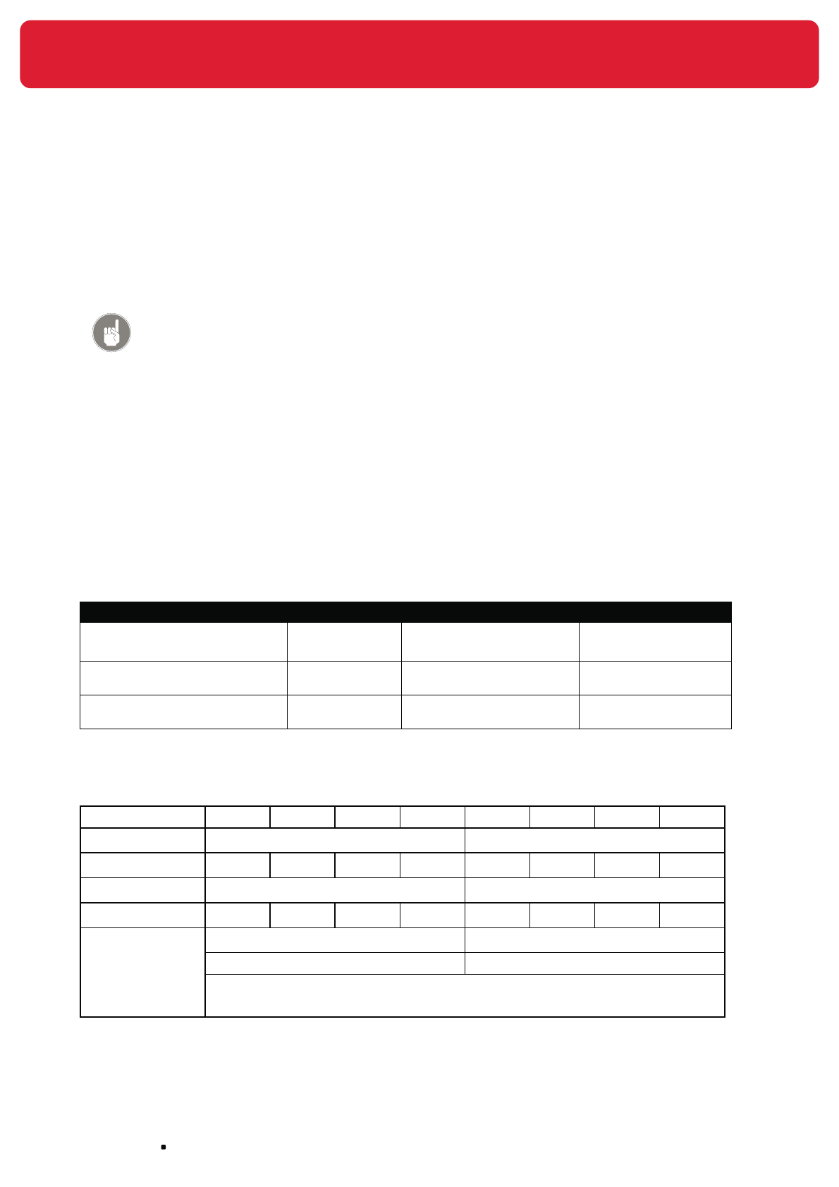
NOFIQ® Systems page 110
23.3 How does the system handle an alarm?
If an FE reports an alarm automatically a notification will be forwarded to the fire brigade or another
(private) fire-fighting service.
Attention!
The NOFIQ® FE is also available in a standalone version. In that case there is
no question of a NOFIQ® system/network (with BASE, BASE-HUB and HUBS).
Alarm and error messages therefore will not be notified to the BASE.
(see chapter 15.5, page 80)
Notification can be executed in several ways: through the switch contacts and/or through the telephone
modem of the NOFIQ® BASE.
For each message type up to 5 telephone numbers can be programmed. Each message type has its
own priority. If the system is in error and the NOFIQ® BASE is notifying this error message to a service
provider by calling the programmed telephone number, the alarm management system will cancel this
task immediately if an Alert or Fire Alarm is received. The NOFIQ® BASE will immediately dial the first
number programmed for the alarm message in question. As soon as a connection has been established a
specified sequence of DTMF-numbers (tone dialling) will be played to identify the nature of the message.
For every message type a separate combination of dual-tones has been programmed. These tones are
repeated for 20 seconds, after which the system breaks off the connection.
Message type Priority Telephone numbers DTMF-sequence
ALARM
(Fire Alarm or Extinguishing)
High maximum 5 programmable
see also Table 19
ALERT Medium maximum 5 programmable
see also Table 19
MALFUNCTION Low maximum 5 programmable
see also Table 19
Table 18 Message priority
Default the following DTMF-tones are programmed.
ALARM # 1 # 2 # 1 # 2 # 1 # 2 # 1 # 2
ALERT # 3 # 3 # 3 # 3
MALFUNCTION # 4 # 4
time interval of 2 seconds time interval of 2 seconds
The DTMF tone settings will be repeated for 20 seconds.
# X: DTMF tone of the telephone key in question
Table 19 DTMF tones for messages
page 111
NOFIQ® Systems
Warning!
It is possible to disable notification of alarms and errors via the modem, for
example during tests or maintenance checks. In that case messages are not
notified by means of the NOFIQ® BASE’s modem. Notification (or making
an alarm bell go off) will always take place by means of the NOFIQ® BASE’s
potential-free switch contacts.
Always make sure that notification is (re-)enabled when tests and checks
have been concluded!
23.4 What to do yourself in case of an alarm?
In case of an Alert
If a NOFIQ® FE reports an Alert, the situation at the location in question is not OK. Act as follows:
1. Check the situation at the location in question and take action if necessary.
2. Press the button of the NOFIQ® FE in question shortly to cancel the Alert warning and to bring the
NOFIQ® FE back into SAFE status.
Attention!
If the conditions that caused the Alert are still present, the FE will again
cause an Alert after the button is pressed. Only if conditions are good
(e.g. after temperature has dropped to normal levels), pressing the
button will bring the FE into SAFE status.
3. Go to the NOFIQ® BASE.
Put the authorisation key into the authorisation lock (left lock) and turn the key to the right.
4. Press the button Reset. The system will be restored. This is imperative since the Alert has been
forwarded and the LED in question keeps burning until the system has been restored.
5. Turn the authorisation key to the left and take it out of the lock.
6. Register all data concerning the Alert in the log book.
In case of a Fire Alarm
If a NOFIQ® FE reports a Fire Alarm, it will start extinguishing within 10 seconds. Within those 10 seconds
you can interrupt extinguishing by pressing the button of the FE in question. In practice this usually
means that an Fire Alarm will pass into an Extinguishing alarm.
In case of an Extinguishing-alarm
If a NOFIQ® FE reports an Extinguishing alarm and this alarm has been forwarded to a Fire Alarm Centre
or a Private Alarm Centre (identifiable by the burning red LED behind the status ‘Notification’ on the
NOFIQ® BASE), you have to act as follows:
1. Put the authorisation key into the authorisation lock (left lock) and turn the key to the right.

NOFIQ® Systems page 112
2. Press the button Reset. The system will be restored.
3. Turn the authorisation key to the left and take it out of the lock.
4. Act according to instructions as stated in the emergency plan of your organisation.
5. Register all data concerning the alarm in the log book.
Attention!
If you press the button Reset after an extinguishing, the system will initiate an
error message since the FE(‘s) in question is/are disabled. This error message
will be forwarded (if this function is enabled).
If a NOFIQ® FE has carried out an extinguishing, the entire FE must be replaced since correct operation of
the FE is no longer guaranteed. Replacing an FE is explained in paragraph 28.6.
23.5 How does the system handle an error?
If the NOFIQ® BASE registers an error message, automatically a notification will be forwarded to the
NOFIQ® service provider.
Notification can be executed in several ways: through the switch contacts and/or through the telephone
modem of the NOFIQ® BASE.
For notification of an error up to 5 telephone numbers can be programmed. As soon as a connection
has been established a specified sequence of DTMF-numbers (tone dialling) will be played to identify the
nature of the message. These tones are repeated for 20 seconds, after which the system breaks off the
connection.
Attention!
The NOFIQ® FE is also available in a standalone version. In that case there is
no question of a NOFIQ® system/network (with BASE, BASE-HUB and HUBS).
Alarm and error messages therefore will not be notified to the BASE.
How to proceed in case of an error in a standalone FE, is explained in
paragraph 28.5.
23.6 What to do yourself in case of an error?
If an error message has been displayed on the NOFIQ® and this error has been forwarded to a NOFIQ®
service provider (identifiable by the burning red LED behind the status ‘Notification’ on the NOFIQ®
BASE), you have to act as follows:
1. Put the authorisation key into the authorisation lock (left lock) and turn the key to the right.
2. Press the the button Reset. The system will be restored.
3. Turn the authorisation key to the left and take it out of the lock.
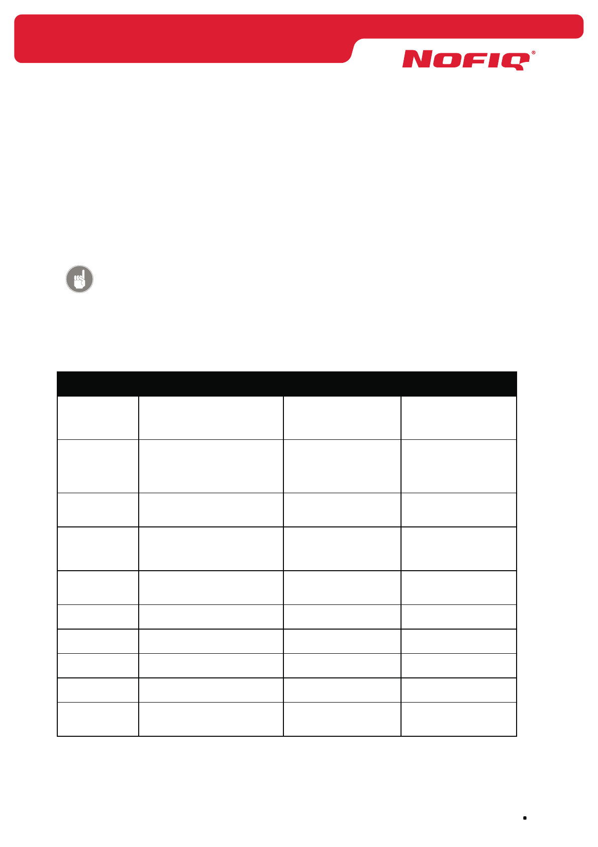
page 113
NOFIQ® Systems
4. Register the error message and the device in question in the log book.
5. Consult the Manual or User Guide for possible follow-up measures.
Certain errors restore automatically. If a HUB or FE loses contact due to interference in radio
communication (e.g. during operation of a heavy machine), this error will be reported to the NOFIQ®
BASE. As soon as communication is restored (because the machine has been turned off), the error
message will disappear.
Attention!
If due to an error in network communication contact with a NOFIQ® FE has
(temporarily) been interrupted, nothing is changed in functionality of the FE: it
keeps on detecting and it alarms and extinguishes when circumstances require
such actions.
Next follows a list with error messages, their meaning plus possible causes and solutions.
Error message Meaning and possible cause Solution Action
Offline A heartbeat (status report)
of a HUB or FE is missing, for
example due to interference.
Variable If the error is not
restored automatically,
contact your NOFIQ®
service provider
Suspend-state
activated
An FE has been disabled
temporarily, for example
because of maintenance in
the cabinet where the FE is
installed.
Re-enable the FE as soon
as the situations permits.
Press the FE’s button for
2 seconds.
Disabled An FE has carried out an
extinguishing an has been
disabled.
The FE must be replaced. Contact your NOFIQ®
service provider
Parent missing At least one HUB or FE misses
a ‘parent’ that guarantees a
backup route.
Variable If the error is not
restored automatically,
contact your NOFIQ®
service provider
Is using a not
granted HUB
A FE or HUB uses a HUB which
has not yet been added to the
BASE.
The HUB must be added
to the BASE
(granted nodes database)
Add the HUB in question
to the BASE
(see chapter 12)
BASE-HUB An error has been detected in
the BASE-HUB.
Variable Contact your NOFIQ®
service provider
Cause unknown An internal (unknown) error has
been detected.
Variable Contact your NOFIQ®
service provider
Temperature
sensor
An error has been detected in
the temperature sensor.
Perhaps the FE must be
replaced.
Contact your NOFIQ®
service provider
CO sensor An error has been detected in
the CO sensor.
Perhaps the FE must be
replaced.
Contact your NOFIQ®
service provider
LCD An error has been detected in
the alphanumeric display of the
NOFIQ® BASE.
Replacement or repair Contact your NOFIQ®
service provider

NOFIQ® Systems page 114
Error message Meaning and possible cause Solution Action
LED An error has been detected in
one or more of the LEDs of the
NOFIQ® BASE.
Replacement or repair Contact your NOFIQ®
service provider
Keypad An error has been detected in
one or more of the buttons of
the NOFIQ® BASE.
Replacement or repair Contact your NOFIQ®
service provider
Modem An error has been detected
in the modem of the NOFIQ®
BASE.
Replacement or repair Contact your NOFIQ®
service provider
Buzzer An error has been detected in
the buzzer of the NOFIQ® BASE.
Replacement or repair Contact your NOFIQ®
service provider
Battery (UPS) An error has been detected in
the battery of the NOFIQ® BASE.
Replacement or repair Contact your NOFIQ®
service provider
Igniter
extinguishing
component
An error has been detected
in the igniter of the FirePro®
extinguishing component.
Perhaps the FE must be
replaced.
Contact your NOFIQ®
service provider
Relay A switch relay is faulty. Replacement or repair Contact your NOFIQ®
service provider
InterNOFIQBus An error in the communication
within an InterNOFIQBus.
Variable Contact your NOFIQ®
service provider
Battery failure The level of the battery is low or
missing.
The battery must be
replaced in due course.
Contact your NOFIQ®
service provider
Battery level low The level of the battery-pack is
low
The battery-pack must be
replaced in due course.
Contact your NOFIQ®
service provider
Battery level
critical
The level of the battery-pack is
critical.
The battery-pack must
be replaced as soon as
possible.
Contact your NOFIQ®
service provider
Mains power loss Mains power is down. The
battery (NOFIQ® BASE) or the
battery-pack (NOFIQ® HUB or
FE) provide emergency power.
Mains power must be
restored.
Contact your power
supplier. The error will
disappear as soon as
mains power is restored.
Notification An error in the notification (via
the relays or the modem).
Variable Contact your NOFIQ®
service provider
Network Network communication is not
available.
Variable If the error is not
restored automatically,
contact your NOFIQ®
service provider
Table 20 Errors: cause and possible solutions
Warning!
Repairs on NOFIQ® equipment may only be executed by your NOFIQ® service
provider.

page 115
NOFIQ® Systems
24. Maintenance of the NOFIQ® system
24.1 General
This chapter explains the general terms for maintenance of a NOFIQ® system. Furthermore this chapter
offers information about general maintenance activities. In the next chapters maintenance of the
separate components of the NOFIQ® system is explained.
24.2 Maintenance agreement
At the start of the system’s use the certified service provider and the user of the NOFIQ® system have to
conclude a maintenance agreement.
The user must appoint one or two personnel who are educated and instructed to function as custodian
(instructed personnel). The NOFIQ® service provider will give the custodian all necessary instructions.
The maintenance agreement contains detailed arrangements on execution of periodical inspections and
preventive maintenance. The example below gives an impression of the various maintenance aspects.
Periodical inspections and preventive maintenance
Once per month
Once per year
Long-term
maintenance in
years
After a fire
NOFIQ® BASE X X X
Primary power supply X X X
Secondary power supply X X X
Notification equipment for fire alarms X X X
Notification equipment for error messages X X X
NOFIQ® BASE-HUB X X X
NOFIQ® HUB X X X
Mains power adapter X X X
NOFIQ® FE X X X
FirePro® aerosol extinguishing components
(container and igniter)
15 years X
CO sensor 5 years X
Mains power adapter FE (optional) X X X
Batteries 2 years X
Warnings signs object(s) X X X
Changes in respect of Program of Requirements and
installation plan
XX X
Organisation’s emergency plan X X X
Log book X X X
Custodian Qualified personnel
Table 21 Overview periodical inspections and preventive maintenance

NOFIQ® Systems page 116
The experiences and results of the periodical inspections and the preventive maintenance have to
be recorded in a Maintenance Report and into the log book. An example of a log book is provided in
Appendix 36.4. An example of a Maintenance report is provided in Appendix 36.5.
24.3 Periodical inspections and preventive maintenance
The NOFIQ® system can only keep functioning properly when all equipment is checked and maintained
regularly. This concerns visual inspections as well as functional testing. The custodian of the NOFIQ®
system as well the NOFIQ® service provider have to execute inspections and tests at set times.
Based on the maintenance agreement between the user and the NOFIQ® service provider periodical
inspections and preventive maintenance have to be done:
visual inspections: •
you check based on what you see.
functional testing: •
you check the functionality by carrying out certain actions.
The chapters 25 up to and including 28 explain which periodical inspections and preventive maintenance
have to be done for the separate components of the NOFIQ® system. Furthermore these chapter focus on
other maintenance activities like replacing batteries or replacing an entire device.
The next paragraphs deal with general inspections to be carried out.
24.3.1 General visual inspections NOFIQ® system
Regularly (at least once a month) carry out the following inspections:
Check whether the sticker with the text “Do not switch off, NOFIQ• ® fire protection system” is still
present at the group switch of the power distribution point.
Check whether escape routes are free of obstacles and ready to be opened immediately.•
Check the illumination of the safety icons for the escape routes.•
Check whether the NOFIQ• ® BASE is sufficiently illuminated.
Check whether within the detection zones there have been changes in ventilation or outflow •
space for the NOFIQ® FE’s.
Check whether the organisation’s emergency plan still meets current regulations.•
Check whether the Program of Requirements and the installation plan harmonize with the actual •
situation.
Check whether the log book has been kept by the custodian and add records to the log book •
yourself if necessary.
Check whether the personnel in question is sufficiently educated and knowledgeable about risks, •
dangers and safety precautions.
24.4 Dismantling equipment
In the following situations dismantling of equipment is required:
a device is faulty and needs to be replaced (for example an FE after an extinguishing);•
a device is faulty and needs to be repaired;•
equipment needs to be moved (for example when the system is relocated).•

page 117
NOFIQ® Systems
Heed the following safety precautions during any form of dismantling:
Switch off power.•
Prevent damage to the the equipment. •
Prevent damage to the surroundings. •
If possible use the original packaging during transport. •
Mind the conditional requirements (as mentioned in paragraph 9.2) •
when transporting equipment that needs to be repaired.
Never just dispose of parts and equipment; some parts may be reused •
or recycled.
Never put old batteries in the normal waste; batteries belong to chem-•
ical waste and should be collected separately.
If a FirePro• ® aerosol extinguishing component has been activated, it
can be disposed of as normal waste after it has been dismantled.
If a FirePro• ® aerosol extinguishing component has not been activated
with the extinguishing agent still in its container, please return it to
your supplier.
24.5 Carrying out software updates
For carrying out software updates separate instructions will be provided by your NOFIQ® service provider.
24.6 Carrying out hardware updates
For carrying out hardware updates separate instructions will be provided by your NOFIQ® service
provider.
24.7 Reading out log files of the NOFIQ® BASE
All data are saved by the NOFIQ® BASE in log files, and can be downloaded to a computer and then be
viewed by a spreadsheet application like Microsoft Excel.
To read out these log files do as follows:
1. Connect a computer (laptop, notebook or PC) to the NOFIQ® BASE and start the terminal
application of the NOFIQ® BASE as described in paragraph 12.3.
2. Choose option 3) Services.
3. Choose option 4) Error logs.
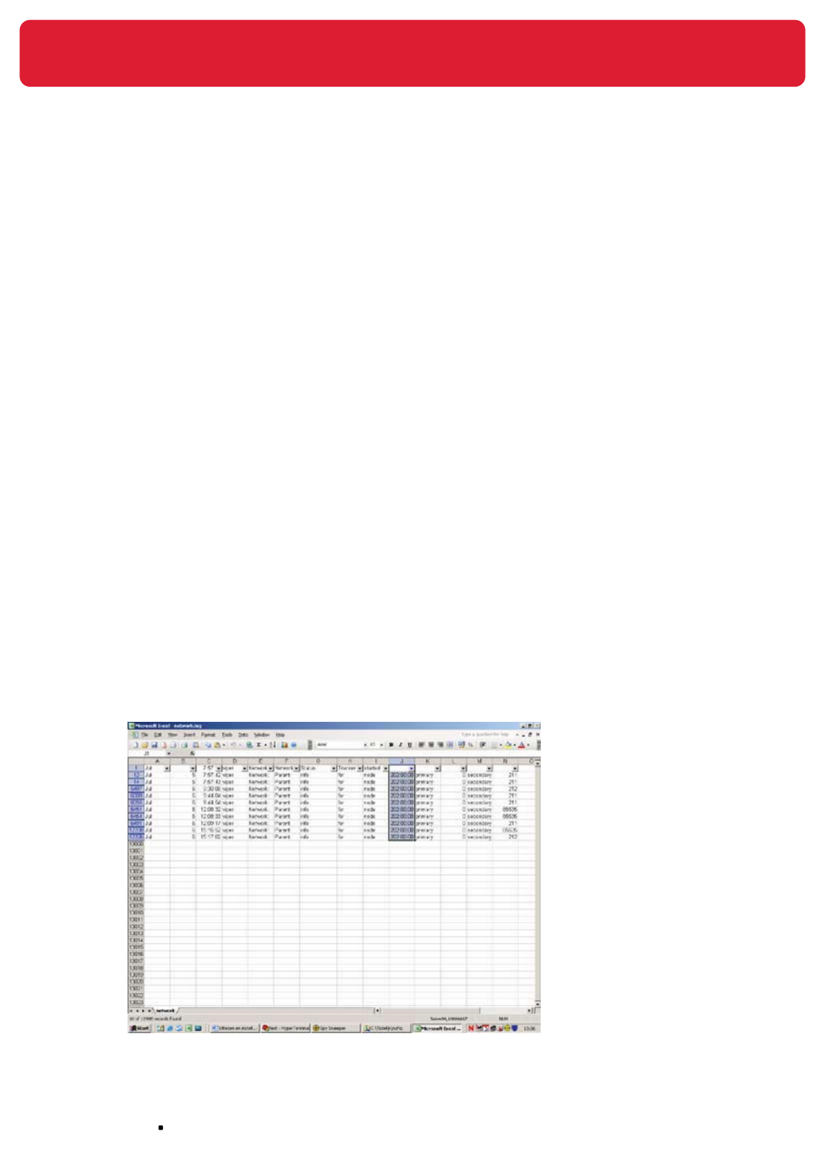
NOFIQ® Systems page 118
4. Choose option 1) Download all log files.
Next all log files will be downloaded to the hard disk of the computer.
The log files are downloaded as a compressed file (zip-file).
This file will get the following name structure:
log files_yyyy-mm-dd.tgz.
The compressed file contains the following log files:
applic.log• Log information of the fire monitor application, contains (among
other things) information on which errors occurred.
eventlog.log• Log information of the log application itself.
extcomm.log• Log information of the software for serial communication, especially
the communication with the BASE-HUB.
extio.log• Log information of the software driving the hardware, like the
display, the LEDs and the buzzer.
network.log• Log information of the software processing the network messages,
like HUB and FE status reports (heartbeats).
swwatchdog.log• Log information of the watchdog mechanism. Contains (among
other things) information about the process that caused a reset of
the BASE.
unittest.log• Only used for software development.
With an application like WinZip you can expand all compressed log files; with an application like
Microsoft Excel you can open the log file. By applying separations between the spaces, data will
be divided into columns.
By using the option Autofilter in Excel (option Data, option Filter, option Autofilter) you will be
able to select data per column and then put these in a graphical display if desired. Thus a log file
of a specific HUB or FE can be viewed (see the example below).

page 119
NOFIQ® Systems
25. Maintenance of the NOFIQ® BASE
25.1 General
This chapter explains in detail maintenance of the NOFIQ® BASE. This maintenance comprises periodical
inspections, functional testing as well as practical maintenance like replacing the battery or replacing the
entire NOFIQ® BASE.
Attention!
Before carrying out maintenance, we advise you to activate the menu
MAINTENANCE on the NOFIQ® BASE (see paragraph 19.11). Thus you will
prevent reporting and notification of error messages (e.g. ‘HUB: Offline’) which
are caused by the maintenance activities. As soon as you have concluded your
activities, leave the menu MAINTENANCE by selecting and confirming the
option <Exit>.
25.2 Periodical inspections and preventive maintenance
NOFIQ® BASE
Based on the maintenance agreement between the user and the NOFIQ® service provider periodical
inspections and preventive maintenance have to be carried out:
visual inspections: •
you check the NOFIQ® BASE based on what you see.
functional testing: •
you check operating of the NOFIQ® BASE by carrying out certain actions.
25.2.1 Visual inspections NOFIQ® BASE by the custodian
Regularly (at least once a month) carry out the following inspections:
Check the outside of the NOFIQ• ® BASE.
Clean the NOFIQ® BASE on the outside if necessary.
Check whether the optical indicators function properly by performing a test with the button • Test.
Check whether the original texts are still legible. •
Reapply the texts if they are badly legible.
Check whether the housing is intact and the NOFIQ• ® BASE is thoroughly fastened..
Record the maintenance work into the log book.•
25.2.2 Functional testing NOFIQ® BASE by the maintenance expert
Regularly (at least once a year) carry out the following inspections:
Check the outside of the NOFIQ• ® BASE.
Clean the NOFIQ® BASE on the outside if necessary
Check whether the original texts are still legible. •
Reapply the texts if they are badly legible.
Download the Granted nodes database and store it at a safe place. •
Downloading the Granted nodes database is done by using the terminal application of the NOFIQ®
BASE (see chapter 12.3).

NOFIQ® Systems page 120
Check whether the housing is intact and the NOFIQ• ® BASE is thoroughly fastened.
Check whether the cabling is well secured.•
Check the internal wiring and cabling for mechanical damage. •
Check the connecting points for corrosion.•
Check the settings of the time-clock.•
Compare the software present with the software implemented.•
Interrupt the primary power supply and check whether the error messaging, LEDs and buzzer •
function properly.
Interrupt the secondary power supply and check whether the error messaging, LEDs and buzzer •
function properly.
Check the battery’s voltage. •
Test the notification function in case of an alarm. •
Do this in consultation with the custodian and the receiver of the alarm notifications.
Test the notification function in case of an error. •
Do this in consultation with the custodian and the receiver of the error notifications.
Check whether the buttons of the NOFIQ• ® BASE function properly.
Check whether the optical indicators function properly by performing a test with the button • Test.
After finishing the maintenance, test the functionality of all equipment that has been disabled •
during maintenance.
Record the maintenance work into the log book.•
25.3 Repairs of the NOFIQ® BASE
Repairs comprise all activities necessary to return the NOFIQ® system into its nominal state. Carrying out
repairs is restricted to the NOFIQ® service provider.
Repairs should be carried out immediately in such a way that stoppage is restricted to a minimum.
Attention!
After finishing the repairs you need to carry out functional tests.
Record the repairs into the log book.
25.4 Replacing the battery of the NOFIQ® BASE
To replace the battery of the NOFIQ® BASE do as follows:
1. Open the cabinet of the NOFIQ® BASE with the key.
2. Switch off mains power.
3. Disconnect the battery’s connectors and remove the old battery.

page 121
NOFIQ® Systems
Attention!
Never put old batteries in the normal waste; batteries belong to chemical
waste and should be collected separately.
4. Position the new battery and connect it.
The red contact point must be connected to the plus side (red facet).
The blue contact point must be connected to the minus side (black facet).
Attention!
The battery for the NOFIQ® system is supplied by your NOFIQ® provider.
Only these batteries can be used for your NOFIQ® device.
5. Switch on mains power.
6. Close the NOFIQ® BASE cabinet and lock it.
25.5 Replacing the NOFIQ® BASE
If a NOFIQ® BASE is faulty and beyond repair, it must be replaced. Do as follows:
1. Download from the faulty NOFIQ® BASE the Granted Nodes database (with all data on the
system’s FE’s and HUBs). Hereto you connect a computer to the NOFIQ® BASE and start the
terminal application (see chapter 12.3).
2. When you have started the application, you consecutively select:
option 3. Services•
option 5. Granted nodes database•
option 1. Download granted nodes database •
Download the database to the computer.
3. Remove the faulty NOFIQ® BASE from its location. Heed the instructions for dismantling as
mentioned in paragraph 24.4.
4. Install and configure a new NOFIQ® BASE as described in chapter 10.
5. Upload the database to the new NOFIQ® BASE. Hereto you connect a computer to the NOFIQ®
BASE and start the terminal application (see chapter 12.3).
When you have started the application, you consecutively select:
option 3. Services•
option 5. Granted nodes database•
option 2. Upload granted nodes database •
Upload the database to the NOFIQ® BASE.

NOFIQ® Systems page 122
26. Maintenance of the NOFIQ® BASE-HUB
26.1 General
This chapter explains in detail maintenance of the NOFIQ® BASE-HUB. This maintenance comprises
periodical inspections, functional testing as well as practical maintenance like replacing the entire NOFIQ®
BASE-HUB.
Attention!
Before carrying out maintenance, we advise you to activate the menu
MAINTENANCE on the NOFIQ® BASE (see paragraph 19.11). Thus you will
prevent reporting and notification of error messages (e.g. ‘HUB: Offline’) that
are caused by the maintenance activities. As soon as you have concluded your
activities, leave the menu MAINTENANCE by selecting and confirming the
option <Exit>.
26.2 Periodical inspections and preventive maintenance
BASE-HUB
Based on the maintenance agreement between the user and the NOFIQ® service provider periodical
inspections and preventive maintenance have to be carried out:
visual inspections: •
you check the NOFIQ® BASE-HUB based on what you see.
functional testing: •
you check operating of the NOFIQ® BASE-HUB by carrying out certain actions.
26.2.1 Visual inspections NOFIQ® BASE-HUB by the custodian
Regularly (at least once a month) carry out the following inspections:
Check the outside of the NOFIQ• ® BASE-HUB.
Clean the NOFIQ® BASE-HUB on the outside if necessary
Check whether the original texts are still legible. •
Reapply the texts if they are badly legible.
Check whether the LEDs function properly.•
Check whether the housing is intact and the NOFIQ• ® BASE-HUB is thoroughly fastened.
Record the maintenance work into the log book.•
26.2.2 Functional testing NOFIQ® BASE-HUB by the maintenance
expert
Regularly (at least once a year) carry out the following inspections:
Check the outside of the NOFIQ• ® BASE-HUB.
Clean the NOFIQ® BASE-HUB on the outside if necessary
Check whether the original texts are still legible. •
Reapply the texts if they are badly legible.
Check whether the cabling is well secured.•
Check the connecting points for corrosion.•
page 123
NOFIQ® Systems
Check whether the LEDs of the NOFIQ• ® BASE-HUB function properly.
After finishing the maintenance, test the functionality of all equipment that has been disabled •
during maintenance.
Record the maintenance work into the log book.•
26.3 Repairs of the NOFIQ® BASE-HUB
Repairs comprise all activities necessary to return the NOFIQ® system into its nominal state. Carrying out
repairs is restricted to the NOFIQ® service provider.
Repairs should be carried out immediately in such a way that stoppage is restricted to a minimum.
Attention!
After finishing the repairs you need to carry out functional tests.
Record the repairs into the log book.
26.4 Replacing the NOFIQ® BASE-HUB
If a NOFIQ® BASE-HUB is faulty and beyond repair, it must be replaced. Do as follows:
Warning!
Switch off mains power and disconnect the battery (secondary power supply)
of the NOFIQ® BASE.
1. Remove the faulty NOFIQ® BASE-HUB from its socket. Heed the instructions for dismantling as
mentioned in paragraph 24.4. Check whether the socket must be replaced.
2. Install and configure a new NOFIQ® BASE-HUB as described in chapter 11.
3. Make the new NOFIQ® BASE-HUB operational as described in paragraph 11.4.

NOFIQ® Systems page 124
27. Maintenance of the NOFIQ® HUB
27.1 General
This chapter explains in detail maintenance of the NOFIQ® HUB. This maintenance comprises periodical
inspections, functional testing as well as practical maintenance like replacing the entire NOFIQ® HUB.
Attention!
Before carrying out maintenance, we advise you to activate the menu
MAINTENANCE on the NOFIQ® BASE (see paragraph 19.11). Thus you will
prevent reporting and notification of error messages (e.g. ‘HUB: Offline’) that
are caused by the maintenance activities. As soon as you have concluded your
activities, leave the menu MAINTENANCE by selecting and confirming the
option <Exit>.
27.2 Periodical inspections and preventive maintenance
NOFIQ® HUB
Based on the maintenance agreement between the user and the NOFIQ® service provider periodical
inspections and preventive maintenance have to be carried out:
• visual inspections:
you check each NOFIQ®-HUB based on what you see.
• functional testing:
you check operating of each NOFIQ®-HUB by carrying out certain actions.
27.2.1 Visual inspections NOFIQ® HUB by the custodian
Regularly (at least once a month) carry out the following inspections:
Check the outside of the NOFIQ• ® HUB.
Clean the NOFIQ® HUB on the outside if necessary
Check whether the original texts are still legible. •
Reapply the texts if they are badly legible.
Check whether the LEDs function properly.•
Check whether the housing is intact and the NOFIQ• ® HUB is thoroughly fastened.
Check whether the numbering/address of the NOFIQ• ® HUB harmonizes with the data of the loca-
tion in question.
Record the maintenance work into the log book.•
27.2.2 Functional testing NOFIQ® HUB by the maintenance expert
Regularly (at least once a year) carry out the following inspections:
Check the outside of the NOFIQ• ® HUB.
Clean the NOFIQ® HUB on the outside if necessary
Check whether the original texts are still legible. •
Reapply the texts if they are badly legible.
Check whether the LEDs function properly.•
Check whether the housing is intact and the NOFIQ• ® HUB is thoroughly fastened.
page 125
NOFIQ® Systems
Check whether the numbering/address of the NOFIQ• ® HUB harmonizes with the data of the loca-
tion in question.
Check the internal wiring and cabling for mechanical damage. •
Check the connecting points for corrosion.•
Interrupt the primary power supply and check whether the error messaging, LEDs and buzzer •
function properly.
Interrupt the secondary power supply and check whether the error messaging, LEDs and buzzer •
function properly.
After finishing the maintenance, test the functionality of all equipment that has been disabled •
during maintenance.
Record the maintenance work into the log book.•
27.3 Repairs of a NOFIQ® HUB
Repairs comprise all activities necessary to return the NOFIQ® system into its nominal state. Carrying out
repairs is restricted to the NOFIQ® service provider.
Repairs should be carried out immediately in such a way that stoppage is restricted to a minimum.
Attention!
After finishing the repairs you need to carry out functional tests.
Record the repairs into the log book.
27.4 Replacing the battery-pack of a NOFIQ® HUB
The NOFIQ® battery-packs have an average lifetime of at least 2 years.
The actual lifetime depends on the environmental conditions in which the devices operate. Temperature
and air humidity have a major influence on the batteries’ lifetime. If a device regularly operates under
high temperatures, the batteries’ lifetime will be reduced. Since the NOFIQ® HUB makes use of a mains
power adapter, the real lifetime of the battery-pack will prove to be longer than 2 years. A NOFIQ® device
not connected to mains power will generate an error message when the energy level in the batteries is
low. In that case the batteries have to be replaced within several weeks.
Attention!
The battery-pack of a NOFIQ® HUB must be replaced when the HUB has been
operational on battery supply (secondary power supply) for more than 24
hours in total.
To replace the battery-pack of a NOFIQ® HUB do as follows:
Warning!
Switch off mains power.

NOFIQ® Systems page 126
1. Take the NOFIQ® HUB out of its socket.
2. Remove the lid of the battery holder (push with your finger in the direction of the arrow).
3. Disconnect the battery connector and remove the old battery-pack.
Attention!
Never put old batteries in the normal waste; batteries belong to chemical
waste and should be collected separately.
4. Place the battery-pack and connect the battery connector (red on the outside, black on the
inside). The connector has been made in such a way that there is only one possible way to
connect it.
Attention!
The battery-pack for the NOFIQ® system is supplied by your
NOFIQ® provider. Only these battery-packs can be used for your
NOFIQ® devices.
5. Replace the lid onto the battery holder.
6. Place the lid back onto the battery holder.
27.5 Replacing a NOFIQ® HUB
If a NOFIQ® HUB is faulty and beyond repair, it must be replaced. Do as follows:
1. Remove the NOFIQ® HUB in question from the NOFIQ® BASE. Hereto you connect a computer to
the NOFIQ® BASE and start the terminal application (see chapter 12.3).
2. When you have started the application, you consecutively select:
option 3. Services•
option 3. Network Status•
option 2. HUB•
option 5. Remove HUB from network •
3. Remove the faulty NOFIQ® HUB from its socket. Heed the instructions for dismantling as
mentioned in paragraph 24.4. Check whether the socket must be replaced.
4. Install and configure a new NOFIQ® HUB as described in chapter 13.
5. Add the new NOFIQ® HUB to the NOFIQ® BASE as described in chapter 13.

page 127
NOFIQ® Systems
28. Maintenance of the NOFIQ® FE
28.1 General
This chapter explains in detail maintenance of the NOFIQ® FE. This maintenance comprises periodical
inspections, functional testing as well as practical maintenance like replacing the battery-pack or
replacing a faulty NOFIQ® FE or an FE that has carried out an extinguishing.
Attention!
Before carrying out maintenance, we advise you to activate the menu
MAINTENANCE on the NOFIQ® BASE (see paragraph 19.11). Thus you will
prevent reporting and notification of error messages (e.g. ‘HUB: Offline’) that
are caused by the maintenance activities. As soon as you have concluded your
activities, leave the menu MAINTENANCE by selecting and confirming the
option <Exit>.
28.2 Periodical inspections and preventive maintenance
NOFIQ® FE
Based on the maintenance agreement between the user and the NOFIQ® service provider periodical
inspections and preventive maintenance have to be carried out:
visual inspections: •
you check each FE based on what you see.
functional testing: •
you check operating of each FE by carrying out certain actions.
28.2.1 Visual inspections NOFIQ® FE by the custodian
Regularly (at least once a month) carry out the following inspections:
Check the outside of the NOFIQ• ® FE.
Clean the NOFIQ® FE on the outside if necessary
Check whether the original texts are still legible. •
Reapply the texts if they are badly legible.
Check whether the LEDs function properly.•
Check whether the housing is intact and the NOFIQ• ® FE is thoroughly fastened.
Check whether the numbering/address of the NOFIQ• ® FE harmonizes with the data of the location
in question.
Check whether the housing is free of corrosion. •
Check whether the projection (position and direction of placement) of the NOFIQ• ® FE harmonizes
with the data from the Program of Requirements and the installation plan.
Check whether the NOFIQ• ® warning sticker is affixed to the outside of the protected object.
Record the maintenance work into the log book•

NOFIQ® Systems page 128
28.2.2 Functional testing NOFIQ® FE and InterNOFIQBus by the
maintenance expert
Regularly (at least once a year) carry out the following inspections:
Check the outside of the NOFIQ• ® FE.
Clean the NOFIQ® FE on the outside if necessary.
Check whether the original texts are still legible. •
Reapply the texts if they are badly legible.
Check whether the LEDs function properly.•
Check whether the housing is intact and the NOFIQ• ® FE is thoroughly fastened.
Check whether the numbering/address of the NOFIQ• ® FE harmonizes with the data of the location
in question.
Check whether the projection (position and direction of placement) of the NOFIQ• ® FE harmonizes
with the data from the Program of Requirements and the installation plan.
Check whether the NOFIQ• ® warning sticker is affixed to the outside of the protected object.
Check whether the cabling is well secured.•
Check the internal wiring and cabling for mechanical damage. •
Check the connecting points for corrosion.•
Interrupt the primary power supply and check whether the error messaging, LEDs and buzzer •
function properly.
Interrupt the secondary power supply and check whether the error messaging, LEDs and buzzer •
function properly.
Test whether the InterNOFIQBus is operational by pressing the button of one of the linked FE’s •
for 1 second. After releasing the button, the yellow, red and green LED of the other FE’s will blink
briefly.
After finishing the maintenance, test the functionality of all equipment that has been disabled •
during maintenance.
Record the maintenance work into the log book.•
Attention!
The FirePro® aerosol extinguishing components’ lifetime is at least 20
years. After 15 years the extinguishing components should be tested.
28.3 Repairs of a NOFIQ® FE
Repairs comprise all activities necessary to return the NOFIQ® system into its nominal state. Carrying out
repairs is restricted to the NOFIQ® service provider.
Repairs should be carried out immediately in such a way that stoppage is restricted to a minimum.
Attention!
After finishing the repairs you need to carry out functional tests.
Record the repairs into the log book.

page 129
NOFIQ® Systems
28.4 Replacing the battery-pack of a NOFIQ® FE
The NOFIQ® battery-packs have an average lifetime of at least 2 years.
The actual lifetime depends on the environmental conditions in which the devices operate. Temperature
and air humidity have a major influence on the batteries’ lifetime. If a device regularly operates under
high temperatures, the batteries’ lifetime will be reduced. A NOFIQ® FE not connected to mains power
will generate an error message when the energy level in the batteries is low. In that case the batteries
have to be replaced within several weeks.
To replace the battery-pack of a NOFIQ® HUB do as follows:
Warning!
Switch off mains power.
1. Take the NOFIQ® FE out of its socket.
2. Remove the lid of the battery holder (push with your finger in the direction of the arrow).
3. Disconnect the battery connector and remove the old battery-pack.
Attention!
Never put old batteries in the normal waste; batteries belong to chemical
waste and should be collected separately.
4. Place the battery-pack and connect the battery connector (red on the outside, black on the
inside). The connector has been made in such a way that there is only one possible way to
connect it.
Attention!
The battery-pack for the NOFIQ® system is supplied by your
NOFIQ® provider. Only these battery-packs can be used for your
NOFIQ® devices.
5. Place the lid back onto the battery holder.
6. Place the NOFIQ® FE back into its socket.

NOFIQ® Systems page 130
28.5 Solving errors in a standalone NOFIQ® FE
A standalone NOFIQ FE will generate a message if an error has occurred. A standalone FE is not
connected to a BASE and therefore it is not possible to determine at once which type of error has
occurred. A standalone NOFIQ FE generates a message if an error has occurred in one of the following
elements:
• temperature sensor
• CO sensor
• igniter of the FirePro® aerosol extinguishing component
• relay (potential-free switch contact)
• InterNOFIQBus
Furthermore the NOFIQ FE generates an error message in the following cases:
• battery level low
• battery level critical
• unknown (internal) error
In order to determine the type of error, do as follows:
1. Connect the NOFIQ FE via a MIC with a computer and start the program “NOFIQ PC Control”
(see chapter 14)
2. Start the communication with the NOFIQ FE (see chapter 14).
3. Click the button Device Info
4. Click the button Check.
Next the program checks the operation of the elements of the device in question.
A properly operating part is displayed in green, a malfunctioning part is displayed in red.
The following items will be checked:
• CO sensor
• Temperature sensor
• Igniter of the extinguishing component (Igniter circuit)
• Batteries (green = battery OK; yellow = battery low); red = battery critical)
This square will not be shown when the devices operates on mains power.
• Suspended (red = suspended)
• Potential-free switch contact (Relay)
• InterNOFIQBus
• Network (not applicable to a standalone FE)
Based on these data you can determine the cause of the error and take the necessary countermeasures.

page 131
NOFIQ® Systems
28.6 Replacing a NOFIQ® FE
After a NOFIQ® FE has carried out an extinguishing, the entire NOFIQ® FE must be replaced as soon as
possible. Since there has been fire, the FE might be damaged. Even if the fire has been extinguished
before actual damage has been done, the temperature increase could have deranged the FE’s sensors,
meaning that the reliability of the device is no longer guaranteed.
If a NOFIQ® FE is faulty it should be replaced as well.
To replace an FE do as follows:
1. Remove the NOFIQ® FE in question from the NOFIQ® BASE. Hereto you connect a computer to
the NOFIQ® BASE and start the terminal application (see chapter 12.3).
2. When you have started the application, you consecutively select:
option 3. Services•
option 3. Network Status•
option 1. FE•
option 5. Remove FE from network •
3. Remove the faulty NOFIQ® FE. Dismantle the socket (it could damaged by the heat of the fire).
Heed the instructions for dismantling as mentioned in paragraph 24.4. Check whether the socket
must be replaced.
4. Cleanse the location
When the FirePro® aerosol extinguishing component has been activated, after a certain amount of
time the particles will deposit in the protected object as dry dust.
Remove this residue shortly after activation (within a couple of hours at the most).•
Sweep up the residue by means of a brush or a damp cloth.•
Use special sprays suited for removing the residue from electronic parts. •
5. Install and configure a new NOFIQ® FE as described in chapter 15.
6. Add the new NOFIQ® FE to the NOFIQ® BASE as described in chapter 15.
If a FirePro® aerosol extinguishing component has been activated, it can be disposed of as normal waste
after it has been dismantled.
If a FirePro® aerosol extinguishing component has not been activated with the extinguishing agent still in
its container, please return it to your supplier.

NOFIQ® Systems page 132
28.7 Relocating a NOFIQ® FE
If you need to relocate an FE, heed the following:
Attention!
If an FE’s primary power supply is changed from mains power to battery (e.
g. if the FE has been moved), this will lead to an error message. You can solve
this error by accessing the BASE’s terminal program (see chapter 12). First
you remove the FE in question (Remove FE from network) and then you add it
again (Add FE to network).
Attention!
If a NOFIQ® FE at one stage has been part of an InterNOFIQBus and you want
this FE to function on its own (but within a network), it is imperative that after
disconnecting the FE from the InterNOFIQBus the FE is restarted by pressing
its button for 10 seconds. Thus you prevent an error message.
Attention!
Modify the FE’s location data in the NOFIQ® BASE.
Modify these data through the terminal application on the NOFIQ® BASE;
consecutively choose:
option 3. Services•
option 3. Network Status•
option 1. FE•
option 5. Modify FE•

page 133
NOFIQ® Systems
29. Service and warranty
The components of the NOFIQ® system have been manufactured with the utmost care and inspected
according to current quality directives. If yet something is wrong with the equipment, please contact your
NOFIQ® service provider.
Liability under this warranty is restricted to repairing or replacing those parts that prove to be flawed
regarding material, completion or design. The conditions of this warranty do not apply in the following
situations:
the equipment has been damaged, disassembled or wrongly used after installation;•
the equipment has been modified after installation by unauthorised personnel;•
batteries have been used which have not been supplied and approved by your NOFIQ• ® service
provider.
Attention!
The batteries for the NOFIQ® system are supplied by your NOFIQ® provider.
Only these batteries can be used for your NOFIQ® devices.
If you use other batteries than those supplied by your NOFIQ® service provider, the warranty for this
equipment is void.
If the system reports that batteries need to be replaced (‘Battery low’ or ‘Battery critical’), please contact
your NOFIQ® service provider.
For detailed information on warranty we refer to our general business terms.
Below you can write down the address of your NOFIQ® service provider.
Name NOFIQ® service provider:
Address:
Postal code:
City:
Telephone:
Fax:
E-mail:

NOFIQ® Systems page 134
30. Support
Through the website of NOFIQ®, www.NOFIQ®.com, we will keep you informed about among other things:
the latest developments•
answers to FAQ •
background information•
technical specifications•
user experience•
For technical questions, problems and maintenance please contact your NOFIQ® service provider.
A
Acceptance 87
report 30, 87
Acceptance Report 87
Aerosol
fire classes 25
safety 25
use 25
Alarm 106
alert 15, 92, 103, 106
extinguishing 15, 93, 103,
107
fire alarm 15, 93, 103, 107
what to do? 109
Alarm message
indicators 92
types 92
Alarm messages 14
types 14, 103, 106
Alert 15, 92, 103, 106
Alphanumeric display 89
Authorisation 16
Authorisation level 16
Authorisation lock 91
B
Battery-pack
replacing 124, 128
Button
NOFIQ BASE-HUB 101
NOFIQ FE 105
NOFIQ HUB 102
Buttons
NOFIQ BASE 90
C
Components
system 11
Conditional requirements
operational system 34
storage 33
transport 33
Configuration
NOFIQ BASE 51
NOFIQ FE 65
NOFIQ HUB 65
Standalone 67
Control panel
NOFIQ BASE 88
CO sensor
NOFIQ FE 103
D
Data management
NOFIQ FE 56, 58
Dismantling 115
Display
NOFIQ BASE 89
DTMF-tones 109
E
Error 106
causes 112
solutions 112
standalone 128
what to do? 112
Error message
indicators 92
overview 93
Error messages 16
Extinguishing alarm 15, 93,
103, 107
Extinguishing compound
calculation amount 31
F
Fire alarm 15, 93, 103, 107
Fire classes 31
Functionality
NOFIQ BASE 17
NOFIQ FE 23
NOFIQ HUB 22
Functional testings
NOFIQ BASE 118
NOFIQ BASE-HUB 121
NOFIQ FE 126
NOFIQ HUB 123
H
Hardware
updates 116
I
Icons 10
Inspections
NOFIQ BASE 118
NOFIQ BASE-HUB 121
NOFIQ FE 126
NOFIQ HUB 123
NOFIQ systeem 115
Installation
concise 36
InterNOFIQBus 81
NOFIQ BASE 39
NOFIQ BASE-HUB 47
NOFIQ FE 73
NOFIQ HUB 60
NOFIQ system 33
preparation 34
safety 26
InterNOFIQBus
installation 81
L
Log book 115
Log files 116
M
Maintenace Report 31
Maintenance
hardware 116
log files 116
NOFIQ BASE 118
NOFIQ BASE-HUB 121
NOFIQ FE 126
NOFIQ HUB 123
safety 26
software 116
system 114
Maintenance eport 115
Menu options
NOFIQ BASE 97
Menu structure
NOFIQ BASE 94
Messages
alarm 14
error messages 16
priority 15, 109

page 135
NOFIQ® Systems
31. Index
N
NOFIQ BASE 17
alphanumeric display 89
authorisation lock 91
buttons 90
configuration 51
control panel 88
data management 51
display 89
functionality 17
installation 39
maintenance 118
menu options 97
menu structure 94
reading log files 116
replacing 120
settings 51
technica specifications 41
terminal application 53
test 91
use 88
NOFIQ BASE-HUB
button 101
indicators 101
installation 47
maintenance 121
replacing 122
status 101
technical specifications 48
use 101
NOFIQ FE 23
button 105
change power supply 79,
85, 131
configuration 65
CO sensor 103
functionality 23
indicators 104
installation 74
maintenance 126
numbering 35
relocating 131
replacing 130
sensors 103
standalone 23, 103
status 104
suspend 104
technical specifications 74
temperature sensor 103
type FE20 12
type FE80 12
types 31
use 103
NOFIQ HUB 21
button 102
configuration 65
functionality 22
indicators 102
installation 60
maintenance 123
numbering 35
replacing 125
status 102
technical specifications 61
use 102
NOFIQ PC Control 66
NOFIQ system
acceptance 87
components 11
installation 33
maintenance 114
overview 11
put into operation 86
P
Priority
messages 15, 109
Projection 31, 78
Put into operation 86
R
Relocating
NOFIQ FE 131
Repairs 122, 124, 127
Replacing
battery 119
battery-pack 124, 128
NOFIQ BASE 120
NOFIQ BASE-HUB 122
NOFIQ FE 130
NOFIQ HUB 125
Report
Acceptance 30
Maintenance 31
S
Safety
aerosol 25
after fire 27
icons 10
installation 26
maintenance 26
precautions 25
Software
updates 116
Specifications
NOFIQ BASE 41
NOFIQ BASE-HUB 48
NOFIQ FE 74
NOFIQ HUB 61
Standalone
NOFIQ FE 23, 103
Standalone FE 23, 103
configuration 67
errors 128
installation 80
Status 95
NOFIQ BASE 95
NOFIQ BASE-HUB 101
NOFIQ FE 104
NOFIQ HUB 102
Status report 14
Storage 33
Suspend
status 104
System
installation 33
statuses 95
T
Temperature sensor
NOFIQ FE 103
Terminal application 53
Transport 33

NOFIQ® Systems page 136
Figure 1 Overview of the NOFIQ® system 13
Figure 2 NOFIQ® BASE 17
Figure 3 NOFIQ® BASE-HUB 19
Figure 4 NOFIQ® HUB 21
Figure 5 NOFIQ® FE 23
Figure 6 Design process NOFIQ® system 29
Figure 7 Projection NOFIQ® FE in a small and a large cabinet. 32
Figure 8 Interior NOFIQ® BASE 39
Figure 9 Connection fire-resistant NOFIQ® BASE 43
Figure 10 Connection potential-free switch contacts 44
Figure 11 Connection battery NOFIQ® BASE 45
Figure 12 The NOFIQ® BASE-HUB 47
Figure 13 Connection fire-resistant cable to connector NOFIQ® BASE-HUB 49
Figure 14 Connection NOFIQ® HUB connector 62
Figure 15 Connection NOFIQ® FE connector 76
Figure 16 Placement batteries NOFIQ® FE 76
Figure 17 NOFIQ® FE Elements and battery connection 77
Figure 18 Control panel NOFIQ® BASE 88

page 137
NOFIQ® Systems
32. List of figures and tables
32.1 List of figures
Table 1 Message priority 15
Table 2 Authorisation levels 16
Table 3 Capacity extinguishing agent per fire class 31
Table 4 Conditional requirements storage and transport 34
Table 5 Conditional requirements operational system 34
Table 6 Indication LEDs NOFIQ® BASE 90
Table 7 Buttons control panel NOFIQ® BASE 91
Table 8 Indicators alarm and error messages 92
Table 9 Overview error messages 94
Table 10 Statuses NOFIQ® BASE-HUB and their meaning 101
Table 11 Statuses NOFIQ® BASE-HUB and accompanying LED behaviour 101
Table 12 Statuses NOFIQ® HUB and their meaning 102
Table 13 Statuses NOFIQ® HUB and accompanying indicator behaviour 102
Table 14 Statuses NOFIQ® FE and their meaning 104
Table 15 Statuses NOFIQ® FE and accompanying indicator behaviour 104
Table 16 Indicators alarm and error messages 107
Table 17 Overview error messages 108
Table 19 DTMF tones for messages 109
Table 20 Errors: cause and possible solutions 113
Table 21 Overview periodical inspections and preventive maintenance 114

NOFIQ® Systems page 138
32.2 List of tables

page 139
NOFIQ® Systems
33. Abbreviations
AC/DC Alternating Current / Direct Current
CO Carbon monoxide
DTMF Dual Tone Multi Frequency.
FE Fire Extinguisher
This is the extinguishing component of the NOFIQ® system
Hz (GHz) Hertz (Gigahertz)
ISM band Industrial, Science and Medical band. Radio frequency band especially
reserved for these purposes.
LED (led) Light Emitting Diode
MIC Maintenance Interface Cable
This cable provides the connection between a computer and a HUB or FE.
MSDS Material Safety Data Sheet
This data sheet offers information on risks, dangers and safety
precautions of a certain material or substance.
NSK Network Security Key
This is the unique code for the entire NOFIQ® network which prevents
interception of NOFIQ® network communication by external devices. This
key is identical for each device (BASE, FE, HUB, BASE-HUB) in one and
the same NOFIQ® system.
SNA Short Network Address
This the unique network address granted to the HUB or FE. Each FE or
HUB has its own SNA. The SNA of the BASE-HUB is 0.

NOFIQ® Systems page 140
34. Glossary
Acceptance Report Document presenting an overview of the system and declaring
that the NOFIQ® system is operational and in compliance with
the reference points as recorded in the Program of Requirements.
Furthermore this documents declares that all components applied
and all elements of the installation are in compliance with the
operative requirements on quality and compatibility.
Aerosol Colloid mixture of solid or liquid particles in a gaseous medium.
Alarm management station Central system that gathers and processes information on all
connected detection and extinguishing components. If required it
initiates proceeding actions (like notifying an alarm or error).
The NOFIQ® BASE is the alarm management station of the
NOFIQ® system.
Alarm message Message shown in the display of the NOFIQ® BASE reporting that
a NOFIQ® FE has detected a (possible) fire.
Alert Alarm indicating that the sensors of a NOFIQ® FE have detected a
situation which could point to a starting fire.
Authorisation The system acknowledges different authorisation levels to ensure
that only properly qualified users are allowed to carry out certain
activities.
Custodian (trained
personnel)
Personnel, whether or not in the user’s service, in possession of
a compulsory certificate of qualification. He or she is instructed in
the duties appointed and in risks resulting from incorrect actions.
Emergency plan Description of organisational measures and precautions within a
company or organisation to limit the consequences of incidents to
a minimum.
Error message Message shown in the NOFIQ® BASE’s display reporting that
an error has occurred in the equipment or in the network’s
communication.
An error message is not identical to an alarm message; an alarm
message is only generated in case of a (possible) fire.
Extinguishing The extinguishing routine by a NOFIQ® FE.
Fire alarm Status in which a NOFIQ® FE has detected a fire and prepares to
extinguish the fire (within 10 seconds after the Fire Alarm).

page 141
NOFIQ® Systems
FirePro®Aerosol extinguishing component.
Fire-resistant cable Cable which in case of fire guarantees to maintain its functionality
for at least 30 minutes.
Heartbeat See Status report.
InterNOFIQBus Linking of 2 to 4 NOFIQ® FE’s.
Log book Registry for recording notes on management, inspection and
maintenance of the system.
Maintenance expert Personnel in possession of a compulsory certificate of qualification
for maintaining the NOFIQ® system and charged with and
responsible for maintenance of NOFIQ® systems.
Maintenance Report Document by the NOFIQ® service provider offering an overview of
the system. It declares that the NOFIQ® system is maintained in
compliance with current directives, that the system is operational
and still in compliance with the reference points recorded in the
Program of Requirements.
Network Security Key This is the unique code for the entire NOFIQ® network which
prevents interception of NOFIQ® network communication by
external devices. This key is identical for each device (BASE, FE,
HUB, BASE-HUB) in one and the same NOFIQ® system.
NOFIQ® BASE Alarm management station.
NOFIQ® BASE-HUB Signal repeater linked to the NOFIQ® BASE. The NOFIQ® BASE-
HUB functions as receiving station of the NOFIQ® BASE.
NOFIQ® FE Detection and extinguishing component.
NOFIQ® HUB Signal repeater.
Program of Requirements
(PoR)
Document in which the reference points for realising a
NOFIQ® fire protection system are recorded and authorised
unambiguously by expert personnel.
Projection The position and direction in which a device (especially an FE) is
placed.
Short Network Address This the unique network address granted to a HUB or FE. Each FE
or HUB has its own SNA.

NOFIQ® Systems page 142
Standalone NOFIQ® FE A NOFIQ® FE that is not part of a NOFIQ® network.
Astandalone NOFIQ® FE does not use wireless communication
with (other) NOFIQ® devices. The other functionality of a
standalone NOFIQ® FE is identical to that of a NOFIQ® FE in a
NOFIQ® network.
Status report Information sent by a NOFIQ® FE or NOFIQ® HUB reporting its
status to the system.
Suspend Status of a NOFIQ® FE in which its operation is temporarily
disabled (for example during maintenance).
User Personnel responsible for management of the NOFIQ® system, or
the owner of the NOFIQ® system.

page 143
NOFIQ® Systems
35. Certification
For development of the NOFIQ® system the following national and international directives have been
consulted:
Directives /
normative
references Document
BRL-K23001/03 Autonomous stationary extinguishing systems based on dry aerosols
BRL-K21014/03 Aerosol fire-extinguishing systems for fire protection at the source in enclosed
compartments containing electrical components
DIN 50018 Environmental testing
Corrosion test - Alternating condensation in an atmosphere containing sulphur
dioxide
ETSI EN 301 489 - 1 Electromagnetic compatibility and Radio Spectrum Matters (ERM); Electromagnetic
Compatibility (EMC) standard for radio and services;
Part 1: Common technical requirements
ETSI EN 301 489 - 3 Electromagnetic compatibility and Radio Spectrum Matters (ERM); Electromagnetic
Compatibility (EMC) standard for radio and services;
Part 3: Specific conditions for Short-Range Devices (SRD) operating on frequencies
between 9 KHz and 40 GHz
ETSI EN 300 440 - 1 Electromagnetic compatibility and Radio Spectrum Matters (ERM); Electromagnetic
Compatibility (EMC) standard for radio and services;
Part 1: Technical characteristics and test methods
ETSI EN 300 440 - 2 Electromagnetic compatibility and Radio Spectrum Matters (ERM); Electromagnetic
Compatibility (EMC) standard for radio and services;
Part 2: Harmonized EN covering essential requirements under Article 3.2 of the
R&TTE Directive
EN 50130 - 4 Alarm systems - Part 4: Electromagnetic compatibility - Product family standard:
Immunity requirements for components of fire, intruder and social alarm systems
NEN - EN 54 - 2 Fire detection and fire alarm systems -
Part 2: Control and indicating equipment (including correction sheet)
NEN - EN 54 - 4 Fire detection and fire alarm systems -
Part 4: Power supply equipment (including correction sheet)
NEN - EN 54 - 5 Fire detection and fire alarm systems -
Part 5: Thermal alarm devices - Point detectors
PrNEN - EN 54 - 13 Fire detection and fire alarm systems -
Part 13: Compatibility of system components
PrNEN - EN 54 - 18 Fire detection and fire alarm systems -
Part 18: Input/output devices
PrNEN - EN 54 - 21 Fire detection and fire alarm systems -
Part 21: Alarm transmission and fault warning routing equipment
NEN - EN 54 - 25 Fire detection and fire alarm systems -
Part 25: Components using radio links
NEN - EN 12094 - 1 Fixed fire-fighting systems - Components for gas extinguishing systems -
Part 1: Requirements and test methods for electrical automatic control and delay
devices

NOFIQ® Systems page 144
Directives /
normative
references Document
ISO 7240 - 6 Fire detection and alarm systems -
Part 6: Carbon monoxide fire detectors using electro-chemical cells
IEC 68 Basic Environmental testing procedures -
Part 1: 1998+A1: 1992 general and guidance
IEC EN 60068-2-1 Environmental testing
Part 2-1: Tests - Tests A: Cold
IEC EN 60068-2-2 Basic environmental testing procedures
Part 2-2: Tests - Tests B: Dry Heat
IEC EN 60068-2-6 Environmental testing
Part 2-6: Tests - Tests Fc: Vibration (sinusoidal)
IEC EN 60068-2-27 Environmental testing
Part 2-27: Tests - Tests Ea: Shock
IEC EN 60068-2-30 Environmental testing
Part 2-30: Tests - Tests Db Damp heat cyclic
IEC EN 60068-2-32 Environmental testing
Part 2-32: Tests - Tests Ed: Free Fall
IEC EN 60068-2-56 Environmental testing
Part 2-56: Tests - Tests Cb: Damp heat, steady state
IEC EN 60068-2-75 Environmental testing
Part 2-75: Tests - Tests Eh: Hammer Test
IEC EN 60068-2-78 Environmental testing
Part 2-78: Tests - Tests Cab: Damp heat, steady state
IEC EN 60529 Degrees of protection provided by enclosures (IP code)

page 145
NOFIQ® Systems
36. Appendices
36.1 Program of Requirements (example)
1. General data
Project number
Object(s) protected Switch cabinet (s) ®
Computer(s) ®
Meter box(es) ®
Other ®
Custodian NOFIQ® system Name company:
Contact person:
Address:
Postal code and City:
Telephone:
E-mail:
NOFIQ® service provider Name company:
Contact person:
Address:
Postal code and City:
Telephone:
E-mail:
Competent authorities
(if applicable)
Name company:
Contact person:
Address:
Postal code and City:
Telephone:
E-mail:
Documents Drawing number
2. Design data
Design Object 1 m x m x m = m ®3
Object 2 m x m x m = m ®3
Object 3 m x m x m = m ®3
Object 4 m x m x m = m ®3
Projection NOFIQ® FE’s BRL K21014 ®
Explanation
When applying 1 NOFIQ® FE it will be placed in the middle of the
object on the upper side, having the outflow openings pointing to the
left and the right.
Ensure that both outflow openings have at least 15 cm of free outflow
space in order to prevent damage to equipment.
When applying 2 or more NOFIQ® FE’s these are placed on the side of
the object in question, having the outflow openings pointing upwards
and downwards. Ensure that both outflow openings have at least 15
cm of free outflow space in order to prevent damage to equipment.

NOFIQ® Systems page 146
2. Design data
External adapter for FE’s desirable Yes ®
No ®
Fire class A (solid) ®
B (liquids) ®
C (gasses) ®
D (oils and fats) ®
Antenna outside of the object to be
protected (Faraday’s cage)
Object 1 ®
Object 2 ®
Object 3 ®
Object 4 ®
InterNOFIQBus Not applicable ®
Air changes inside object Object 1, < 1 m/s ®
Object 2, < 1 m/s ®
Object 3, < 1 m/s ®
Object 4, < 1 m/s ®
Temperature inside object Object 1, °C ®
Object 2, °C ®
Object 3, °C ®
OBject 4, °C ®
Controls Object 1, ventilation provision ®
Object 2, ventilation provision ®
Object 3, ventilation provision ®
Object 4, ventilation provision ®
Identification On the outside of the protected object warning signs must be af- ®
fixed with the text “AUTOMATIC FIRE PROTECTION SYSTEM, in case of
fire or alarm: do not panic, close cabinet doors object and alert expert
assistance”
NOFIQ® BASE and BASE-HUB Placement at the reception desk ®
Placement at the main entrance ®
Other ®
Explanation
The NOFIQ® BASE and the BASE-HUB should be placed at the
reception, behind the desk.
Power supply NOFIQ® BASE Separate end group ®
Identification group switch ®
“DO NOT SWITCH OFF, NOFIQ® SYSTEM”
Error messages to Name person ®
Tel nr. 1: ®
Tel nr. 2: ®
Tel nr. 3: ®
Tel nr. 4: ®
Alert message to Name person ®
Tel nr. 1: ®
Tel nr. 2: ®
Tel nr. 3: ®
Tel nr. 4: ®

page 147
NOFIQ® Systems
2. Design data
Fire alarm message to Name person ®
Tel nr. 1: ®
Tel nr. 2: ®
Tel nr. 3: ®
Tel nr. 4: ®
Telephone dialler needed Yes ®
No ®
Notification through main fire alarm
station
Yes ®
No ®
Notification equipment for error
messages
Not applicable ®
PAS (Private alarm station) ®
State name and telephone number PAS ®
Alarm report code ®
Notification equipment for alarm
messages
Not applicable ®
FAS (Firee alarm station) ®
State name and telephone number FAS ®
Alarm report code ®
3. Acceptance, management and maintenance
Acceptance Report Yes ®
No ®
Log book Yes ®
No ®
Maintenance agreement Yes ®
No ®
Explanation
The NOFIQ® service provider and the customer must draw up a
maintenance contract.
Custodian (trained personnel) Name :
Telephone number :
Emergency plan present Yes ®
No ®
Explanation
Presence of the NOFIQ® system must be recorded in the emergency
plan.
4. References
Directives / normative references • BRL K21014/01

NOFIQ® Systems page 148
5. Approval
Custodian NOFIQ® system Name company:
Contact person:
Address:
Postal code and City:
Telephone:
E-mail:
Signature:
PoR-drafter Name company:
Contact person:
Address:
Postal code and City:
Telephone:
E-mail:
Signature:
Competent authorities
(if applicable)
Name company:
Contact person:
Address:
Postal code and City:
Telephone:
E-mail:
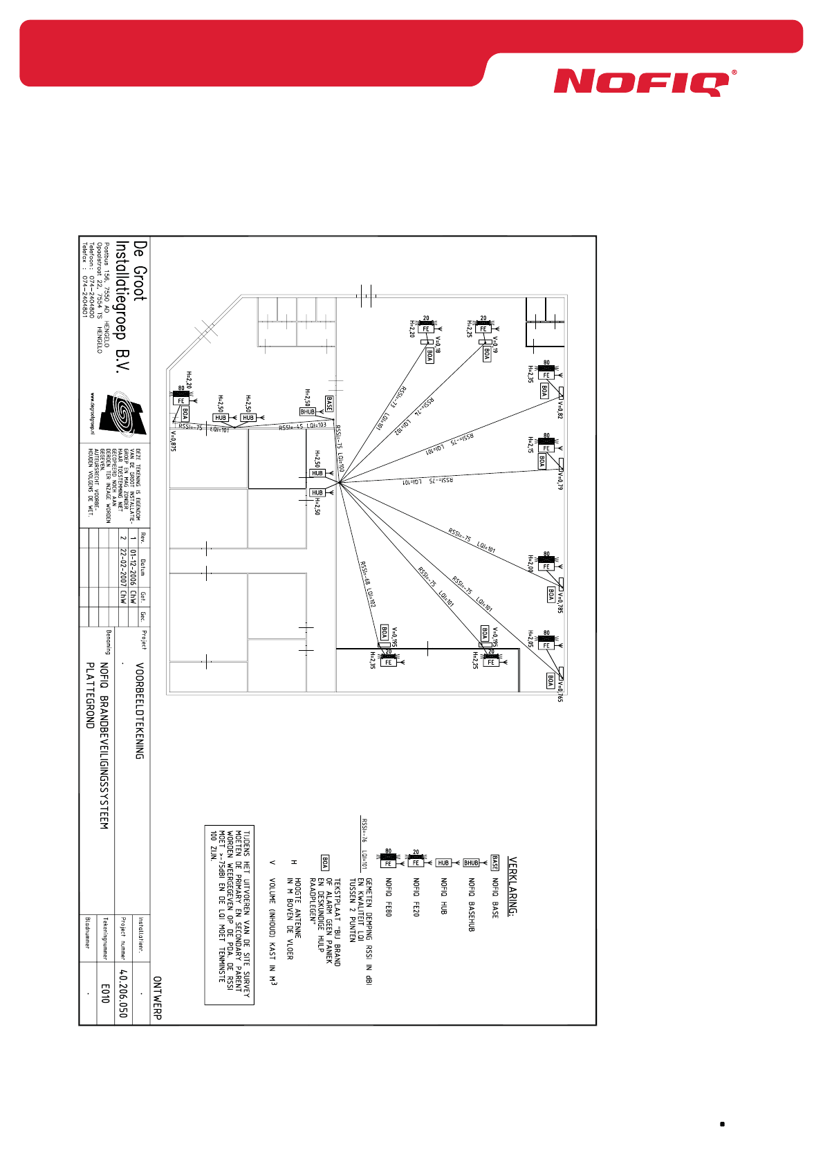
page 149
NOFIQ® Systems
36.2 Installation plan (example)
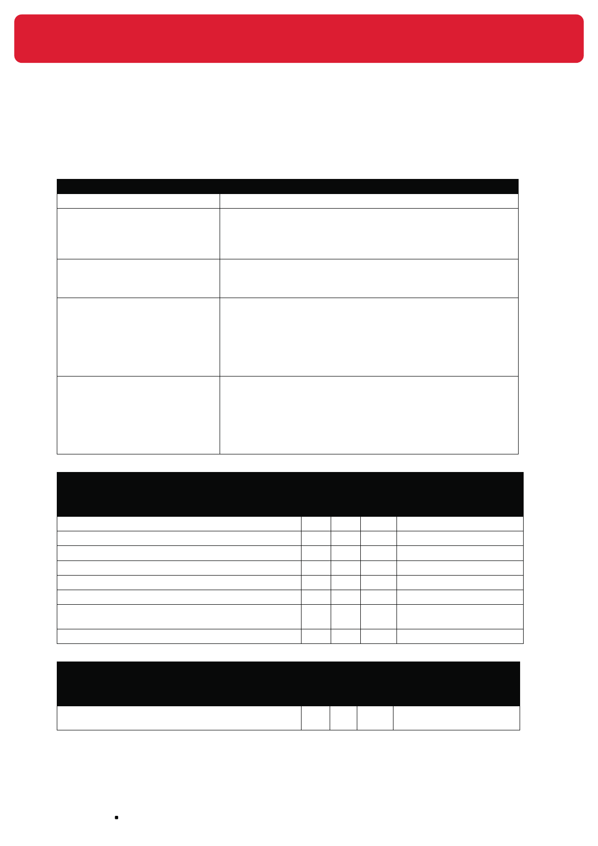
NOFIQ® Systems page 150
36.3 Acceptance Report (example)
Project number
Object(s) protected Switch cabinet (s) ®
Computer(s) ®
Meter box(es) ®
Other ®
Network Configuration Network ID: ®
Network Channel: ®
Encryption Key (HEX): ®
Custodian NOFIQ® system Name company:
Contact person:
Address:
Postal code and City:
Telephone:
E-mail:
NOFIQ® service provider Name company:
Contact person:
Address:
Postal code and City:
Telephone:
E-mail:
2. Document check
Points of interest Complied Comments
Yes No N/A
Program of Requirements validated
Installation plan present
Signed maintenance agreement
Log book present
User Guide present
Acceptance NOFIQ® system recorded into log book
Custodian (trained personnel) NOFIQ® system appointed
and recorded into log book
Emergency plan adjusted with presence NOFIQ® system
3. Design check
Points of interest Complied Comments
Yes No N/A
Projection NOFIQ® FE’s in compliance with
BRL K21014
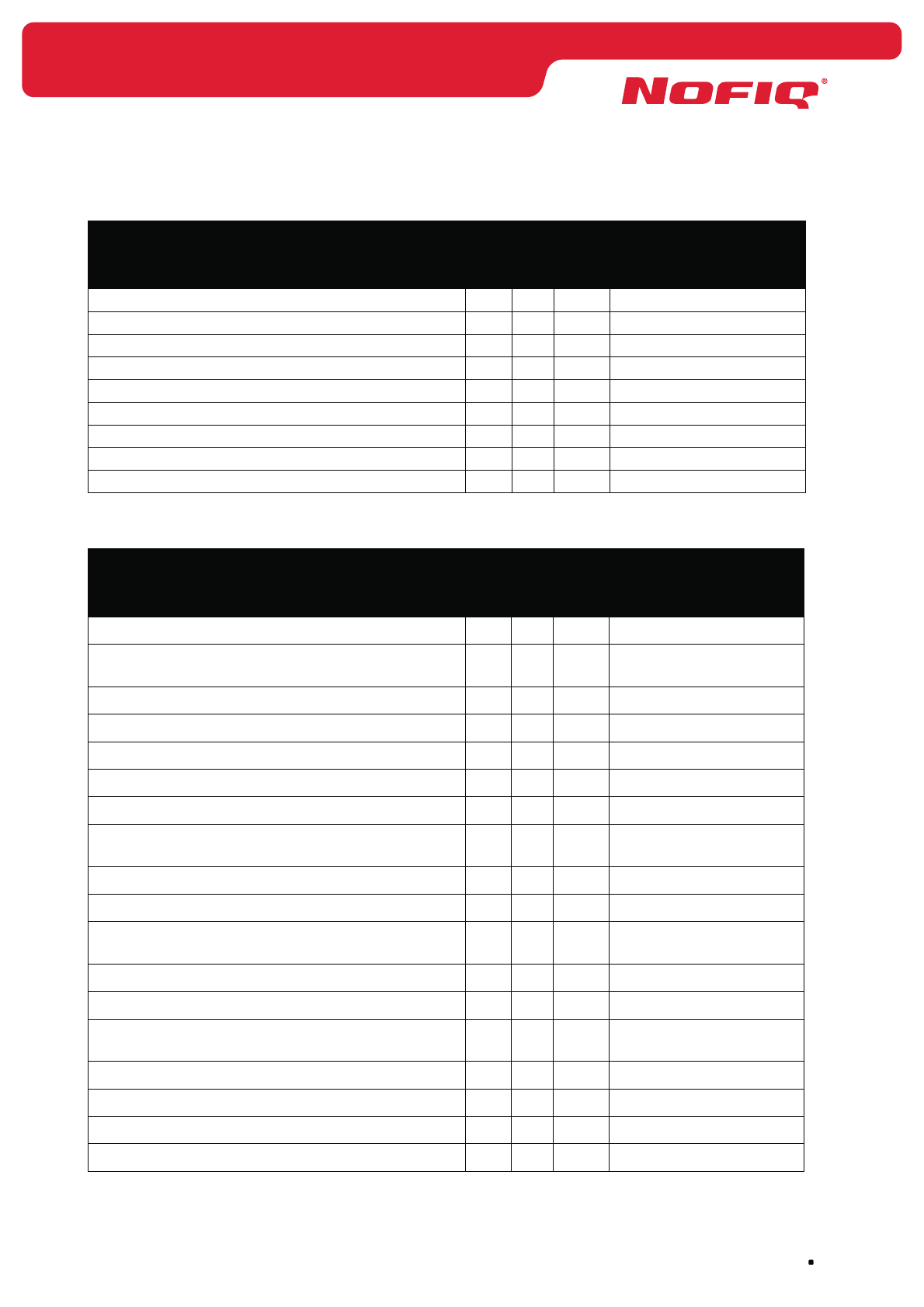
page 151
NOFIQ® Systems
4. Check on Components NOFIQ® system
Points of interest Complied Comments
Yes No N/A
NOFIQ® BASE
Fire-resistant cable
NOFIQ® BASE-HUB
NOFIQ® HUB
Mains power adapter HUB
NOFIQ® FE
Mains power adapter FE
External antenna FE
Warning sticker for object
5. Check NOFIQ® BASE
Points of interest Complied Comments
Yes No N/A
Appropriately fastened
General illumination of at least 100 lux and
500 lux at the most
Emergency illumination at least 10 lux
Acoustic indicators clearly audible
Surroundings clean and dry
Low risk for mechanical damage
Low fire risk
Free space to the front side, enabling rotating
parts to be opened completely.
Power supply via separate end group
Cabling in tubular system and clamped
Group switch identified with warning “DO NOT
SWITCH OFF, NOFIQ® fire protection system”
Telephone numbers error messages programmed
Telephone numbers alert messages programmed
Telephone numbers fire alarm messages
programmed
Telephone dialler
Notification through main fire alarm station
Notification of error messages
Notification of fire alarm messages
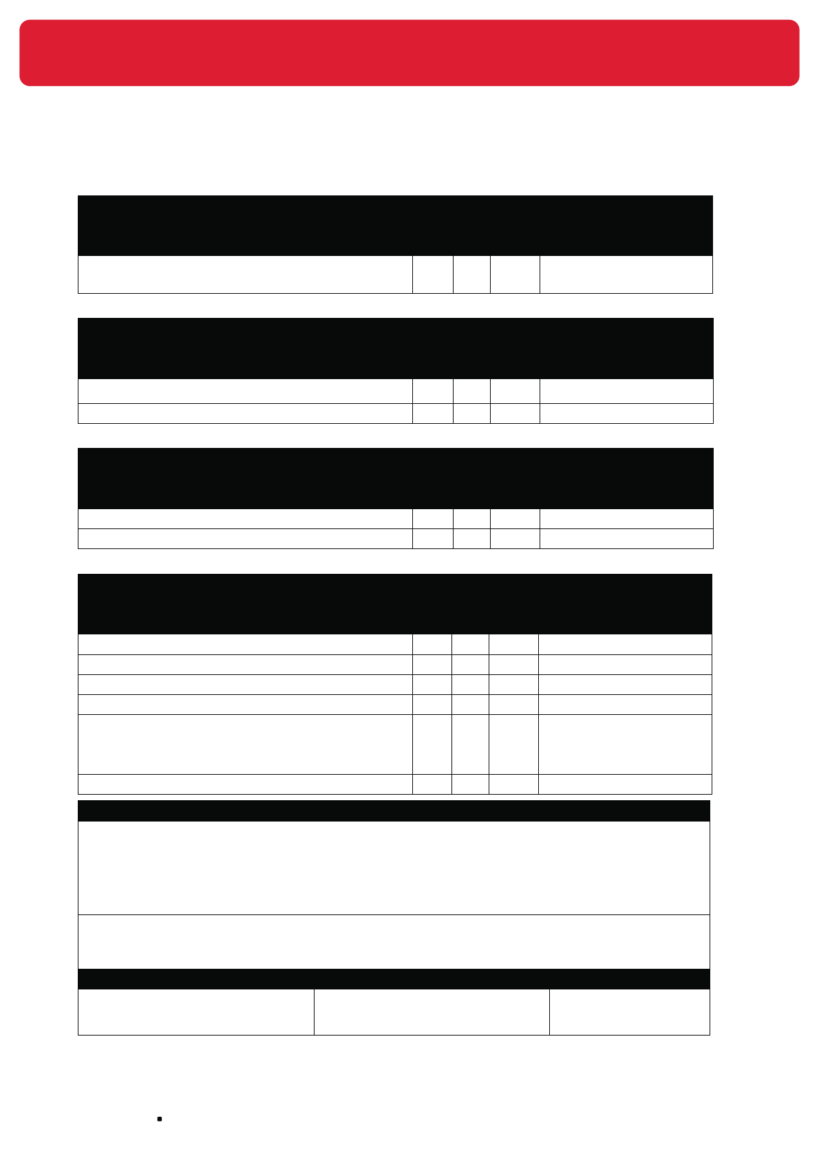
NOFIQ® Systems page 152
5. Check NOFIQ® BASE
Points of interest Complied Comments
Yes No N/A
Potential-free switch contacts connected and
operative
6. Check NOFIQ® BASE-HUB
Points of interest Complied Comments
Yes No N/A
Appropriately fastened
Cabling in tubular system and clamped
7. Check NOFIQ® HUB
Points of interest Complied Comments
Yes No N/A
Appropriately fastened
Mains power adapter connected
8. Check NOFIQ® FE
Points of interest Complied Comments
Yes No N/A
Appropriately fastened
Mains power adapter connected
InterNOFIQBus connected
Potential-free switch contact connected and operative
Warning sign on outside of protected object “AUTOMATIC
FIRE PROTECTION SYSTEM, in case of fire or alarm: do
not panic, close cabinet doors object and alert expert
assistance”
Antenna outside of the protected object
9. Comments
Undersigned declares on behalf of the certified NOFIQ® service provider that the NOFIQ® system
is designed, installed, put into operation and accepted conformably to the starting-points in the
Program of Requirements, the manual of NOFIQ® systems BV and the BRL K21014.
Name Date Signature
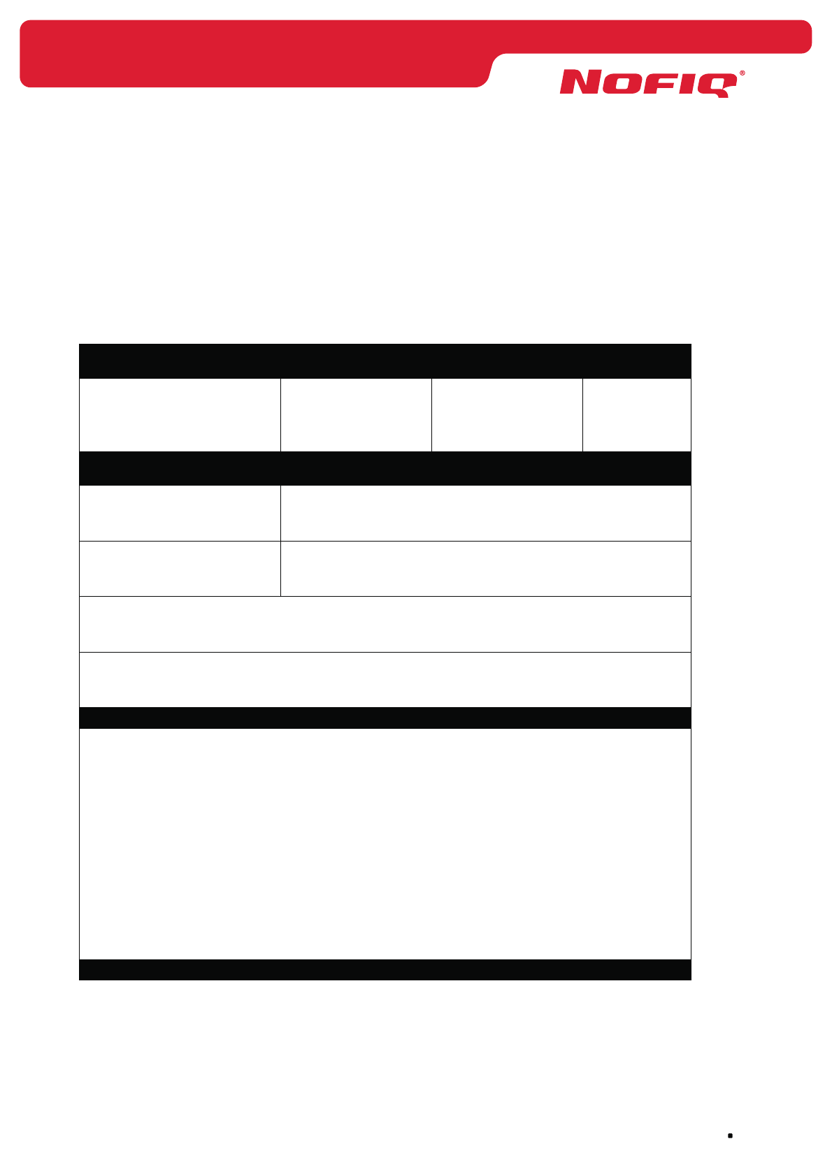
page 153
NOFIQ® Systems
36.4 Log book (example)
Into the log book everything in regard with the NOFIQ® system should be recorded (like alarms, errors,
inspections carried out, repairs and changes).
Making entries into the log book is restricted to the representatives mentioned below: the custodian(s)
(trained personnel), the NOFIQ® service provider or its maintenance expert(s).
All errors which cannot be solved, have to be reported to the maintenance service
immediately
Name Telephone number Signature Date
The following custodians (trained personnel) are responsible for the NOFIQ® system and its
periodical inspections
Name custodian Attainability
during office-hours
out of office-hours
Name alternate during absence Attainability
during office-hours
out of office-hours
Receiving centre for fire alarm messages
Receiving centre for error messages
Time schedule monthly periodical inspections
Check at least once per month:
• NOFIQ® BASE
• NOFIQ® BASE-HUB
• NOFIQ® HUB
• NOFIQ® FE
• Notification error
• Notification alert
• Notification fire alarm / extinguishing
Each 1st / 2nd / 3rd / 4th Monday / Tuesday / Wednesday / Thursday / Friday of the month
Time schedule yearly periodical inspections

NOFIQ® Systems page 154
Check at least once per year after acceptance and maintenance has been carried out by a maintenance
expert:
Attainability NOFIQ® BASE, NOFIQ® BASE-HUB, NOFIQ® HUB and NOFIQ® FE
Changes in comparison with reference points Program of Requirements
Each 1st / 2nd / 3rd / 4th Monday / Tuesday / Wednesday / Thursday / Friday of the month
January ®
®February
March ®
April ®
®May
®June
July ®
®August
®September
October ®
®November
®December
Every event (so without any exceptions) regarding the NOFIQ® system should be recorded into the
log book. We advise you to record each event, the periodical inspections as well, into the log book
immediately.
During the yearly maintenance the custodian (trained personnel) and the maintenance service will
review the system’s behaviour during the past period and will take countermeasures if necessary.
The events must be specified by adding a code to the schedule, e.g. Cm1 = monthly check of the
NOFIQ® BASE.
In the column ”What” (see below) the following abbreviations can be applied:
A Genuine fire alarm internal
B Genuine fire alarm external
C Spurious fire alarm internal
D Spurious fire alarm external
E False fire alarm internal
F False fire alarm external
Cm Monthly check (inspection)
Cy Yearly check (inspection)
Ac Acceptance
Md Modification, change, (software) modification
X Expansion
M Maintenance by maintenance service
S Error (each erroneous occurrence within the system not being an alarm message)
Sc Error solved by custodian (trained personnel)
Sm Error solved by door maintenance service
V Visit (if none of the activities above has been carried out)
1 NOFIQ® BASE
2 NOFIQ® BASE-HUB
3 NOFIQ® HUB
4 NOFIQ® FE
5 Notification alarm messages
6 Notification error messages
7 Control functions

page 155
NOFIQ® Systems
Who When Where What Why
Name Date + time Object Code from list Cause of alarm /
error
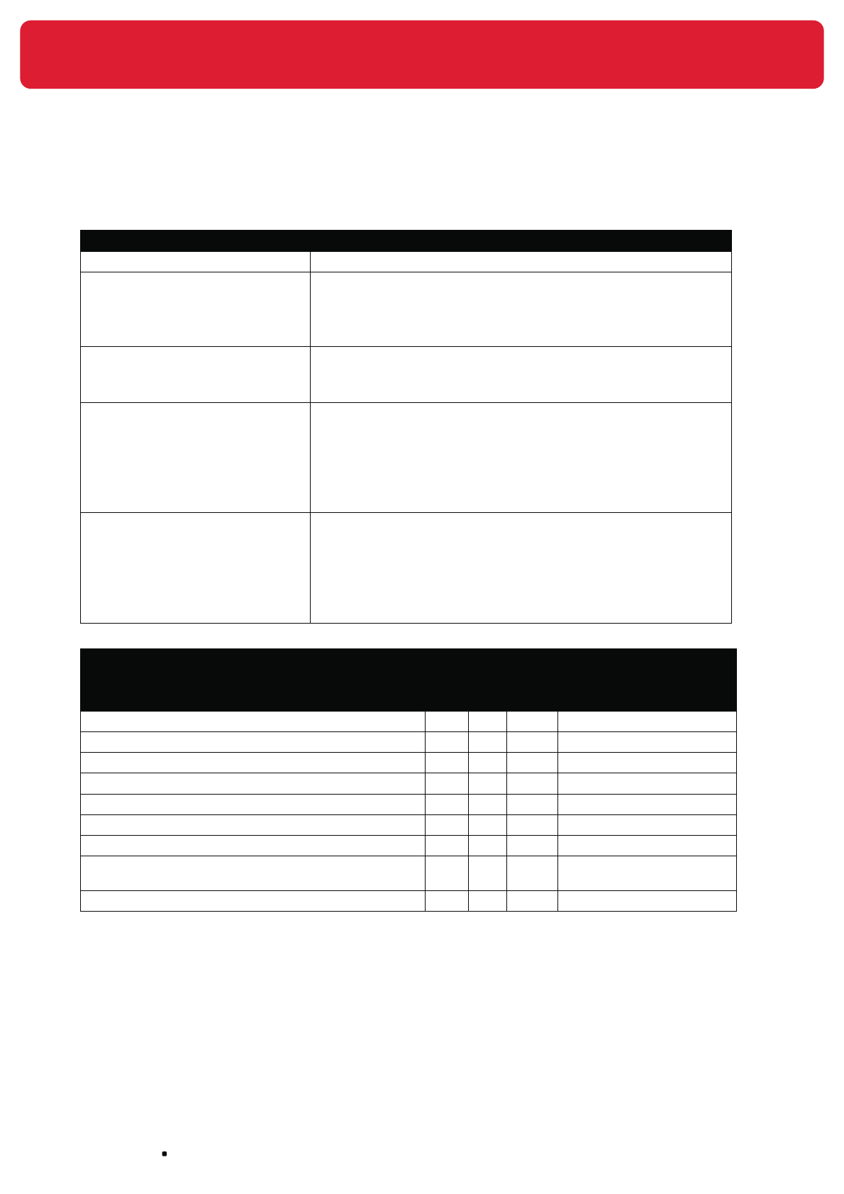
NOFIQ® Systems page 156
36.5 Maintenance Report (example)
1. General data
Project number
Object(s) protected Switch cabinet (s)
Computer(s)
Meter box(es)
Other
Configuration network Network ID:
Network Channel:
Encryption key (HEX):
Custodian NOFIQ® system Name company:
Contact person:
Address:
Postal code and City:
Telephone:
E-mail:
NOFIQ® service provider Name company:
Contact person:
Address:
Postal code and City:
Telephone:
E-mail:
2. Document check
Points of interest Complied Comments
Yes No N/A
Program of Requirements validated
Installation plan present
Acceptance Report
Signed maintenance agreement
Log book present
User Guide present
Acceptance NOFIQ® system recorded into log book
Custodian (trained personnel) NOFIQ® system appointed
and recorded into log book
Emergency plan adjusted with presence NOFIQ® system

page 157
NOFIQ® Systems
3. Maintenance NOFIQ® BASE
Points of interest Complied Comments
Yes No N/A
Appropriately fastened
Housing intact
General illumination of at least 100 lux and 500 lux at
the must
Emergency illumination at least 10 lux
Texts on the NOFIQ® BASE are clearly legible
Acoustic indicators OK
Optical indicators (LEDs) OK
Surroundings clean and dry
Low risk for mechanical damage
Low fire risk
Free space to the front side, enabling rotating parts to
be opened completely.
Power supply via separate end group
Primary power supply OK
Secondary power supply OK
Cabling in tubular system and clamped
Internal wiring OK
Connection points OK
Potential-free switch contacts OK
Notification of error messages OK
Notification of alarm messages OK
Setting time-clock OK
Keypad (buttons) NOFIQ® BASE functioning OK
Installed software up-to-date
Group switch identified with warning “DO NOT SWITCH
OFF, NOFIQ® fire protection system”
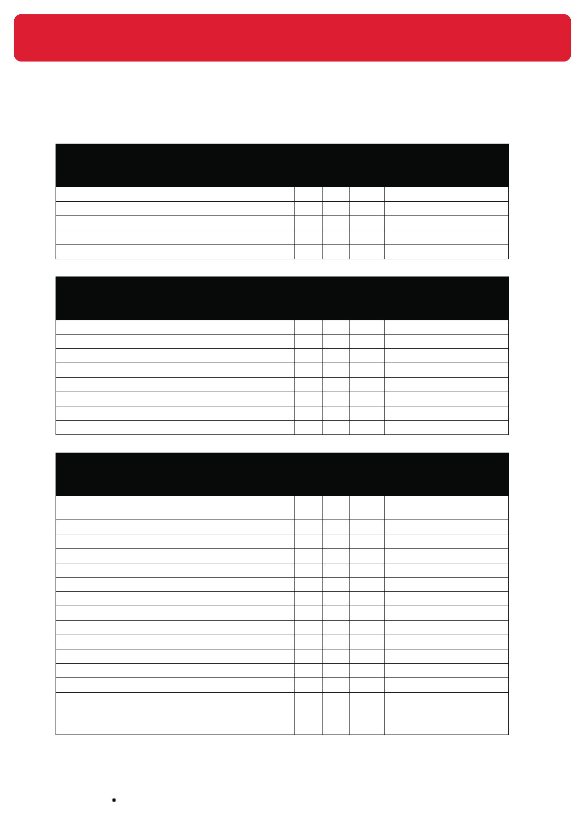
NOFIQ® Systems page 158
4. Maintenance NOFIQ® BASE-HUB
Points of interest Complied Comments
Yes No N/A
Appropriately fastened
Housing intact
Cabling in tubular system and clamped
Optical indicators (LEDs) OK
Connection points OK
5. Maintenance NOFIQ® HUB
Points of interest Complied Comments
Yes No N/A
Appropriately fastened
Housing intact
Numbering/address OK
Acoustic indicators OK
Optical indicators (LEDs) OK
Primary power supply OK
Secondary power supply OK
Connection points OK
6. Maintenance NOFIQ® FE
Points of interest Complied Comments
Yes No N/A
Projection NOFIQ® FE’s conformably to BRL K21014 (in
development)
Appropriately fastened
Housing intact
Numbering/address OK
Acoustic indicators OK
Optical indicators (LEDs) OK
Primary power supply OK
Secondary power supply OK
Connection points OK
Appropriately fastened
Potential-free switch contact OK
InterNOFIQBus OK
Cabling in tubular system and clamped
Warning sign on outside of protected object “AUTOMATIC
FIRE PROTECTION SYSTEM, in case of fire or alarm: do
not panic, close cabinet doors object and alert expert
assistance”
page 159
NOFIQ® Systems
6. Maintenance NOFIQ® FE
Points of interest Complied Comments
Yes No N/A
Antenna - connection OK
Antenna - placement OK
7. Comments
Undersigned declares on behalf of the certified NOFIQ® service provider that maintenance on the NOFIQ®
system has been carried out according to the directives mentioned above.
Name Date Signature

NOFIQ® Systems page 160
36.6 Overview status transitions
New status
Safe Alert Fire alarm Extinguishing Malfunction /
Suspend
Current status
Safe
CO ∆20ppm/60
sec
or
T ∆ 2 °C/60 sec
or
T > 50 °C
T ∆ 5 °C/60
sec
or
T > 54 °C
or :
CO
∆20ppm/60
sec
ánd
T ∆ 2 °C/60
sec
User presses
the FE-button
for 2 seconds
Alert
User presses
the FE-button
briefly
T ∆ 5 °C/60
sec
or
T > 54 °C
or :
CO
∆20ppm/60
sec
ánd
T ∆ 2 °C/60
sec
User presses
the FE-button
for 2 seconds
Fire alarm
10 seconds
after message
Fire alarm
User presses
the FE-button
briefly
Extinguishing
Malfunction /
Suspend
User presses
the FE-button
for 2 seconds

page 161
NOFIQ® Systems
36.7 Specifications external antenna
The external antenna used for the NOFIQ® BASE-HUB, the NOFIQ® HUB and the NOFIQ® FE has the
following specifications
General
Manufacturer Hyperlink Technologies
Product 2.4 GHz 2 dBi External Antenna
Product number W036485-0001
Electrical characteristics
Working frequency range 2400 ~ 2483 MHz
S.W.R. <= 2,0
Antenna gain 2 dBi
Antenna radiation pattern Omni-directional
Impedance 50 Ohm
Material
Colour of outer cover Mat Black
Material of outer cover ABS
Connector type 50 Ohm
Reverse Polarity SMA Plug Hex
Tube Copper (C3604)
Total length 77 mm
Environmental
Operation temperature -30 °C ~ 60 °C
Storage temperature -30 °C ~ 60 °C
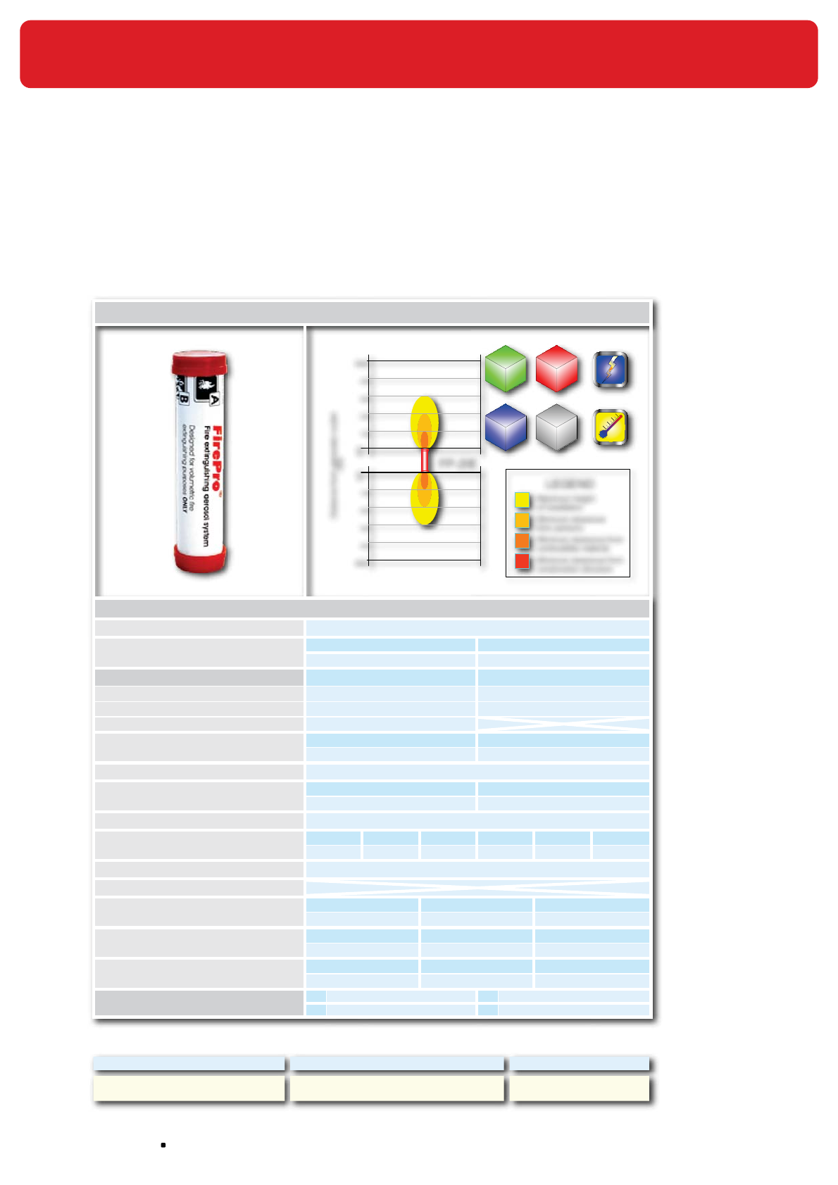
NOFIQ® Systems page 162
36.8 Specifications FirePro® aerosol extinguishing
components
36.8.1 Spec sheet FirePro FP-20
Manufactured by Master dealers / Distributor Trade Mark
Celanova Ltd. / FirePro Systems ltd FirePro®
FirePro® Condensed Aerosolo generatars: FP-20E
FP-20E
400
300
200
100
Distance from generator outlet
mm
0
500 Minimum clearance from
Maximum height
Minimum clearance from
Minimum clearance
LEGEND
of installation
construction structure
combustible material
from persons
400
300
200
100
0
500
B
Max
C
Max
A
Max
0.30 m
3
0.28 m
3
0.20 m
3
K
Max
0.19 m
3
Technical Data
Mass of SBK (Aerosol Generating Solid Compound) 20 g
Generators gross weight Weght Tollerance
105 g ± 5%
Activation mode/s Electrically Thermally
Value of activation 6/12/24/36 V D/C 0.8 A 3-4 s 172° C
SBK activation device Heating elements with 2.3 Ω Resistance Termocord
Activation line supervision current (Max) 5 mA
Aerosol discharge time Min. Max
3 seconds 6 seconds
Number of discharge outlet 2
Generator dimension Height Diameter
128 mm 30 mm
Self activation temperature of SBK 300° C
Classes of Fire
(NFPA 2010)
ABCDK
NO
Usable inside potentially explosive atmosphere
YES
Maximum height of installation NA
Minimum clearance (mm)
From persons From combustible material From construction structure
200 100 0
Environmental parameters ODP1GWP2ALT3
Zero Zero Negligible4
Technical Parameters Electrical conductivity Corrosion
Oxygen depletion After discharge
Nil up to 24KV Negligible4Negligible4
Note 1ODP: Ozone Depletion Potential 3ALT: Atmospheric Life Time
2GWP: Global Worming Potential 4Within the parameters for use
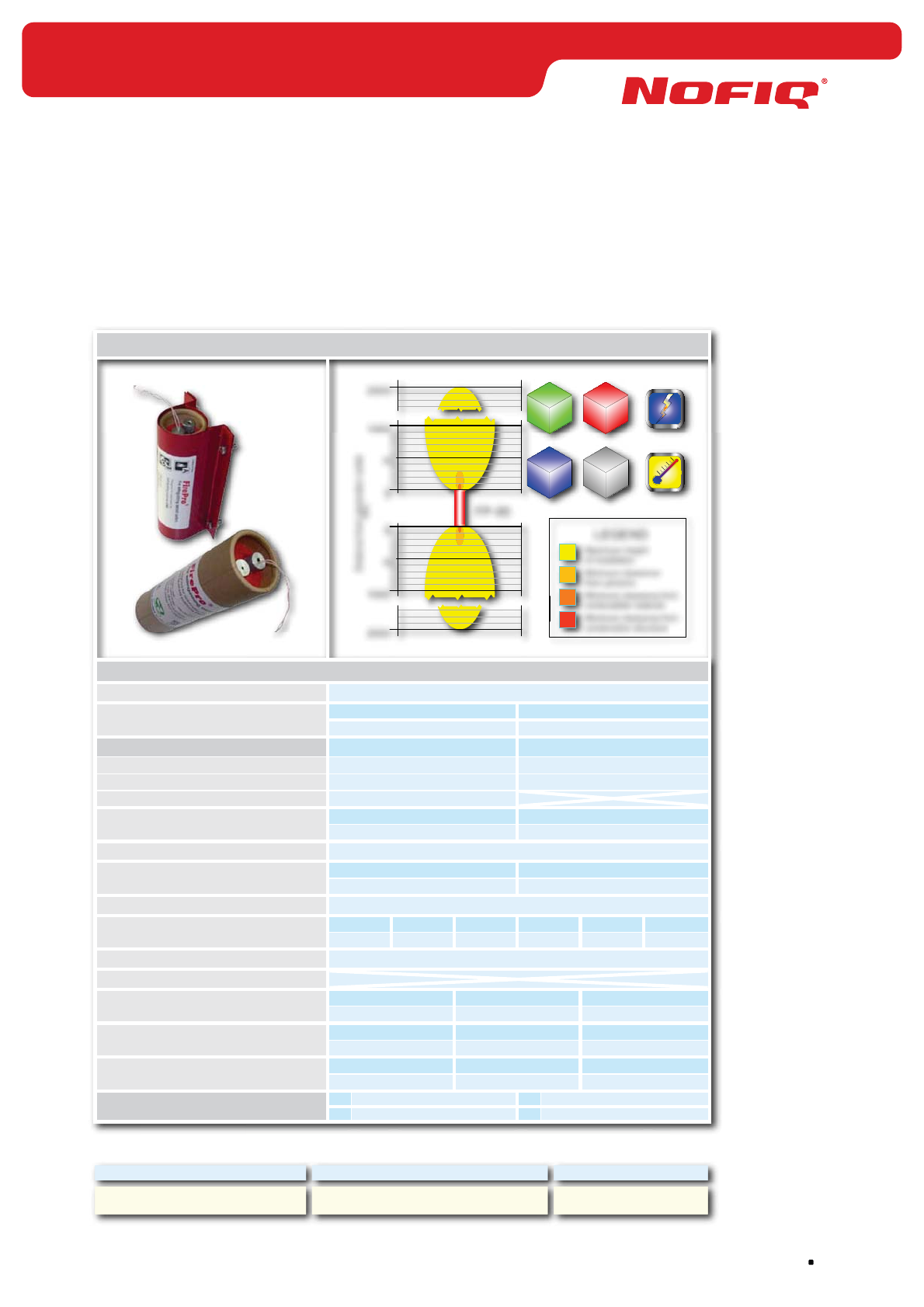
page 163
NOFIQ® Systems
36.8.2 Spec sheet FirePro FP-80
Manufactured by Master dealers / Distributor Trade Mark
Celanova Ltd. / FirePro Systems ltd FirePro®
Manufactured by Master dealers / Distributor Trade Mark
Celanova Ltd. / FirePro Systems ltd FirePro®
FirePro® Condensed Aerosolo generatars: FP-80
FP-80
Distance from generator outlet
mm
Minimum clearance from
Maximum height
Minimum clearance from
Minimum clearance
LEGEND
of installation
construction structure
combustible material
from persons
2000
1000
500
0100
200
300
400
600
700
800
900
1000
500
0100
200
300
400
600
700
800
900
2000
B
Max
C
Max
A
Max
0.90 m
3
0.85 m
3
0.60 m
3
K
Max
0.57 m
3
Technical Data
Mass of SBK (Aerosol Generating Solid Compound) 80 g
Generators gross weight Weght Tollerance
800 g ± 5%
Activation mode/s Electrically Thermally
Value of activation 6/12/24/36 V D/C 0.8 A 3-4 s 172° C
SBK activation device Heating elements with 2.3 Ω Resistance Termocord
Activation line supervision current (Max) 5 mA NA
Aerosol discharge time Min. Max
4 seconds 8 seconds
Number of discharge outlet 2
Generator dimension Height Diameter
180 mm 50 mm
Self activation temperature of SBK 300° C
Classes of Fire
(NFPA 2010)
ABCDK
NO
Usable inside potentially explosive atmosphere
YES
Maximum height of installation NA
Minimum clearance (mm)
From persons From combustible material From construction structure
300 100 0
Environmental parameters ODP1GWP2ALT3
Zero Zero Negligible4
Technical Parameters Electrical conductivity Corrosion
Oxygen depletion After discharge
Nil up to 24KV Negligible4Negligible4
Note 1ODP: Ozone Depletion Potential 3ALT: Atmospheric Life Time
2GWP: Global Worming Potential 4Within the parameters for use
NOFIQ® Systems page 164
36.9 FirePro® Material Safety Data Sheet
FirePro Systems Ltd./ Celanova Ltd.
FirePro
®
Issue date: 01.01.2007
1. Identification of the Substance/Company
1.1 Trade name :FirePro®
1.2 Manufacturer/Supplier : FirePro Systems Ltd./Celanova Limited
6, Koumandarias & Spyrou Araouzou Str.,
Tonia Court II, 6ht Floor
Limassol - 3076 , Cyprus
Phone : 00357-25-379999
Fax : 00357-25-354432
e-mail : mail@firepro.info
website : www.firepro.info
1.3 Telephone number in case of emergency: + 357-25-379999
2. Composition/Information on Ingredients
2.1 Component Wt.% CAS No. EINECS Class, R and S
phrases
Potassium Nitrate 77 7757-79-1 231-818-8 See section 15
Potassium Carbonate 4 584-08-7 209-529-3 See section 15
Magnesium 1 7439-95-4 231-104-6 See section 15
Epoxy Resin Polymer 18 25068-38-6 any “polimerizate,
polycondensate, or
polyadduct” is
exempted by
81/437/EEG
See section 15
3. Hazards Identification
- Hazards for humans related to the SBK solid compound has not been found.
- Hazards for humans related to the aerosol released by the solid compound have not been established
because TLV’s are not applicable.
- Signs and symptoms related to the aerosol phase are only referred to acute exposure and/or chronic
overexposures, while in real life the exposure will be very short (i.e. in the event of an accidental
discharge when people were not evacuated on time).
3.1 For humans
Threshold Limit Values : None established
Signs and Symptoms by acute exposure
Eye Contact
Inhalation
Skin Contact
Ingestion
Chronic Overexposure
Medical Conditions Generally
Aggravated by Exposure
For Environment
: At normal contact no injury
: Not a likely route of entry
: At normal contact no injury
: At normal contact no injury
: At normal contact no injury
: None known
: None established
4. First-Aid Measures
First-Aid measures are referred to acute exposure and/or chronic over exposure
4.1 Inhalation
Eye Contact
Skin Contact
Ingestion
: Remove from exposure area to fresh air.
: If necessary wash eyes.
: Change clothing and shoes. Wash skin with soap.
: Not likely.
page 165
NOFIQ® Systems
FirePro Systems Ltd./ Celanova Ltd.
FirePro
®
Issue date: 01.01.2007
5. Fire fighting Measures
5.1 Extinguishing Media : This is an Extinguishing Agent
5.2 Unusual Fire and Explosion Hazards : The material does not present an explosion danger. It can be
ignited by means of a fire. Hot aerosol is present in the close up
area of the outlets
5.3 Special Procedures : In places where there is a fire always wear personal protecting
equipment and clothing
6. Accidental Release Measures
6.1 Personal Precautions
Respiratory Protection
Hand Protection
Eye Protection
Skin and Body Protection
: at normal contact not needed
: at normal contact not needed
: at normal contact not needed
: at normal contact not needed
6.2 Environmental Precautions
Waste Disposal Methods : See section 13
6.3 Clean up Precautions : Sweep up
7. Handling and storage
7.1 Handling Precautions : Avoid contact with combustible materials.
7.2 Storage Precautions
Storage Class
: Should be stored in original container. Keep dry.
: 9 miscellaneous , solid
8. Exposure Controls and Personal Protection
8.1 Exposure : Before entering a room with the material in aerosol phase vent
properly to avoid unnecessary exposure.
8.2 Personal protection
Respiratory Protection
Hand Protection
Eye Protection
Skin and Body Protection
: at normal contact not needed
: at normal contact not needed
: at normal contact not needed
: at normal contact not needed
9. Physical and Chemical Characteristics
9.1 Appearance
Colour
Odour
Relative Density
Solubility in water
Ph (if in water, % Conc.)
Boiling Point
Vapour Pressure (mm Hg)
Vapour Density
Flash Point
Flammability Limits in Air
(% by volume)
Auto Flammability
Explosive Properties
Oxidizing Properties
: Solid
: Off white
: None
: Not applicable
: Insoluble
: Not determined
: Not applicable
: Not applicable
: Not applicable
: Not applicable
: Not applicable
: Not applicable
: Not applicable
: Not determined
NOFIQ® Systems page 166
FirePro Systems Ltd./ Celanova Ltd.
FirePro
®
Issue date: 01.01.2007
10. Stability and Reactivity
10.1 Stability
Conditions to avoid
: Stable
: None known
10.2 Hazardous Reactions
Conditions to avoid
: Will not occur
: None known
10.3 Materials to Avoid : None known
10.4 Hazardous Decompositions Products : None ascertained
11. Toxicological Information
The TLV’s (Treshold Limit Values) of the chemicals released in the aerosol phase are applicable only in
case of long, as long as a complete professional life, exposure. This is not the case of a real life situation.
11.1 Product
The potential damage is not caused by the product mixture composition, but by the fact that it is respirable.
The TLV’s apply in case of long exposure, sometimes exposure during a complete professional life, whilst
in this case is once only and short (in case of accidental discharge when evacuation does not take place
on time).
In case of fire the toxicity is caused by the fire itself and the products involved in the fire.
11.2 Components
Potassium Nitrate Toxicity : Oral LD50 (rat) 3750 mg/Kg
Target Organs : Blood, central nervous system
Potassium Carbonate Toxicity : Oral LD50 (rat) 1870 mg/Kg / Oral LD50
(mouse) 2570 mg/Kg
Target Organs : Respiratory system
Magnesium Toxicity : Oral LD50 (dog) 230 mg/Kg
Target Organs : Central nervous system, liver, kidneys
Epoxy Resin Polymer Toxicity : Oral LD50 (rat) 11.4 g/Kg
Irritation Data : Skin (guinea pig) 2750 mg/55 days Inert
Eye (rabbit) 100 mg Mild
12. Ecological Information
12.1 Mobility
Absorption/Desorption
: with present data no problems
: with present data no problems
12.2 Degradability
Biotic and Abiotic Degradation
Aerobic and Anaerobic Degradation
Persistence
: with present data no problems
: with present data no problems
: with present data no problems
: with present data no problems
12.3 Accumulation
Bioaccumulation Potential
Biomagnification
: with present data no problems
: with present data no problems
: with present data no problems
12.3 Short and Long Term Effects on
Ecotoxicity
Aquatic Organisms
Soil Organisms
Plants and Terrestrial animals
: with present data no problems
: with present data no problems
: with present data no problems
: with present data no problems
12.4 Other Adverse Effects
Ozone Depleting Potential (ODP)
Photochemical Ozone Creation
Potential
Global Warming Potentials (GWP)
Effects on Waste Water Treatment
Plants
: none
: none
: none
: with present data no problems
13. Disposal Considerations
13.1 Dispose of in Compliance with local, state and national regulations.
page 167
NOFIQ® Systems
FirePro Systems Ltd./ Celanova Ltd.
FirePro
®
Issue date: 01.01.2007
14. Transportation Information
14.1 Hazard Class or Division : 9 miscellaneous, solid
: For additional transport information contact FirePro Systems Ltd /
Celanova Limited
15. Regulatory Information
For 15.1 Components:
The EU classification and R&S phrases, referred to the components of the SBK compound are related only
to the single components considered as separate chemical entities. Once mixed in the production of the
SBK compound, the risk sentences of the single components are not applicable being the SBK compound
a separate chemical entity.
15.1 Product
Potassium Nitrate EU Classification
R Phrases
S Phrases
Oxidizer
8
16
41
-
Contact with combustible material
may cause fire
Keep away from sources of
ignition – No smoking
In case of fire and/or explosion, do
not breathe fumes
Potassium Carbonate EU Classification
R Phrases
S Phrases
Irritant
22
36/37/38
26
37/39
-
Harmful if swallowed
Irritating to eyes, respiratory
system and skin
In case of contact with eyes, rinse
immediately with plenty of water
and seek medical advice
Wear suitable gloves and eye/face
protection
Magnesium EU Classification
R Phrases
S Phrases
Flammable
15
17
2
43
7/8
-
Contact with water liberates highly
flammable gases
Spontaneously flammable in air
Keep out of reach of children
In case of fire never use water
Keep container tightly closed and
dry
Epoxy Resin Polymer EU Classification
R Phrases
S Phrases
Irritant
36/38
43
53
28
37/39
61
-
Irritating to eyes and skin
May cause sensitisation by skin
contact
May cause long-term adverse
effects in the aquatic environment
In case of contact with skin, rinse
with water
Wear suitable gloves and eye/face
protection
Avoid release to the environment.
Refer to special instructions/
Safety Data Sheets
NOFIQ® Systems page 168
FirePro Systems Ltd./ Celanova Ltd.
FirePro
®
Issue date: 01.01.2007
Limit Values for Exposure
EINECS Status
Restrictions on Marketing and Use
: None listed
: All components are included in EINECS inventories
: None (Refer to any other national measures that may be relevant)
16. Other Information
16.1 None Known
17. Disclaimer
17.1 The data in the above material safety data sheet reflect the current state of knowledge of our product and
shall be used only as a guideline. No binding statements as to the contractually agreed product
characteristics may be inferred there from.

page 169
NOFIQ® Systems
36.10 Regulatory information radio communication
For sending information between the different elements the NOFIQ® system uses wireless radio
communication.
The NOFIQ® system uses the IEEE 802.15.4 standard on a frequency of 2.4 GHz. This frequency is part of
the ISM band (Industry, Scientific and Medical), which is freely available in Europe for alarm purposes.
The system is classified as a 2.4 GHz wireless fire-extinguishing system for indoor use and is
aimed for use in the following countries:
EU members Belgium, Bulgaria, Cyprus, Denmark, Germany, Estonia, Finland, France, Greece,
Hungary, Ireland, Italy, Latvia, Lithuania, Luxembourg, Malta, Netherlands, Austria,
Poland, Portugal, Romania, Slovenia, Slovak Republic, Spain, Czech Republic,
United Kingdom, Sweden
EFTA members Liechtenstein, Norway, Iceland, Switzerland
FCC
FCC-ID and label can be found in the battery compartment of the NOFIQ N20-BASE_HUB, N20-HUB,
N20-FE and N80-FE.
Compliance statement (part 15.19)
This device complies with Part 15 of the FCC Rules. Operation is subject to the following conditions:
1. this device may not cause harmful interference, and
2. this device must accept any interference received, including interference that may cause undesired
operation
Warning (part 15.21)
Changes or modifications not expressly approved by the party responsible for compliance could void the
user’s authority to operate the equipment. This in particular is applicable for the antenna which has been
delivered with this device.
RF Exposure (OET Bulletin 65)
To comply with FCC RF exposure requirements for mobile transmitting devices, this transmitter should
only be used or installed at locations where there is at least 20cm separation distance between the
antenna and all persons
Information to the User (part 15.105 (b))
Note: This equipment has been tested and found to comply with the limits for a Class B digital device,
pursuant to part 15 of the FCC Rules. These limits are designed to provide reasonable protection against
harmful interference in a residential installation. This equipment generates, uses and can radiate radio
frequency energy and, if not installed and used in accordance with the instructions, may cause harmful
interference to radio communications. However, there is no quarantee that interference will not occur in a
particular installation. If this equipment does cause harmful interference to radio or television reception,
which can be determined by turning the equipment off and on, the user is encouraged to try to correct
the interference by one or more of the following measures:
- Reorient or relocate the receiving antenna.
- Increase the separation between the equipment and receiver.
- Connect the equipment into an outlet on a circuit different from that to which the receiver is connected.
- Consult the dealer or an experienced radio/TV technician for help.
Copyright ©2009 NOFIQ® Systems BV - All rights reserved.
Nothing from this publication may be duplicated and/or published by means of print, photocopy, microfilm
or otherwise without prior written consent of the publisher.
Although the utmost care has been taken with this publication, errors and omissions cannot be entirely
excluded. The composers and/or publishers of this publication therefore accept no liability, not even
for direct or indirect damage, occurring due to or in relation with any mistake that could occur in this
publication.