NOMi 3210 Brickstream 3D+ Camera User Manual
NOMi Corporation Brickstream 3D+ Camera
UserManual.wiki
>
NOMi
>
3210 User Manual
>
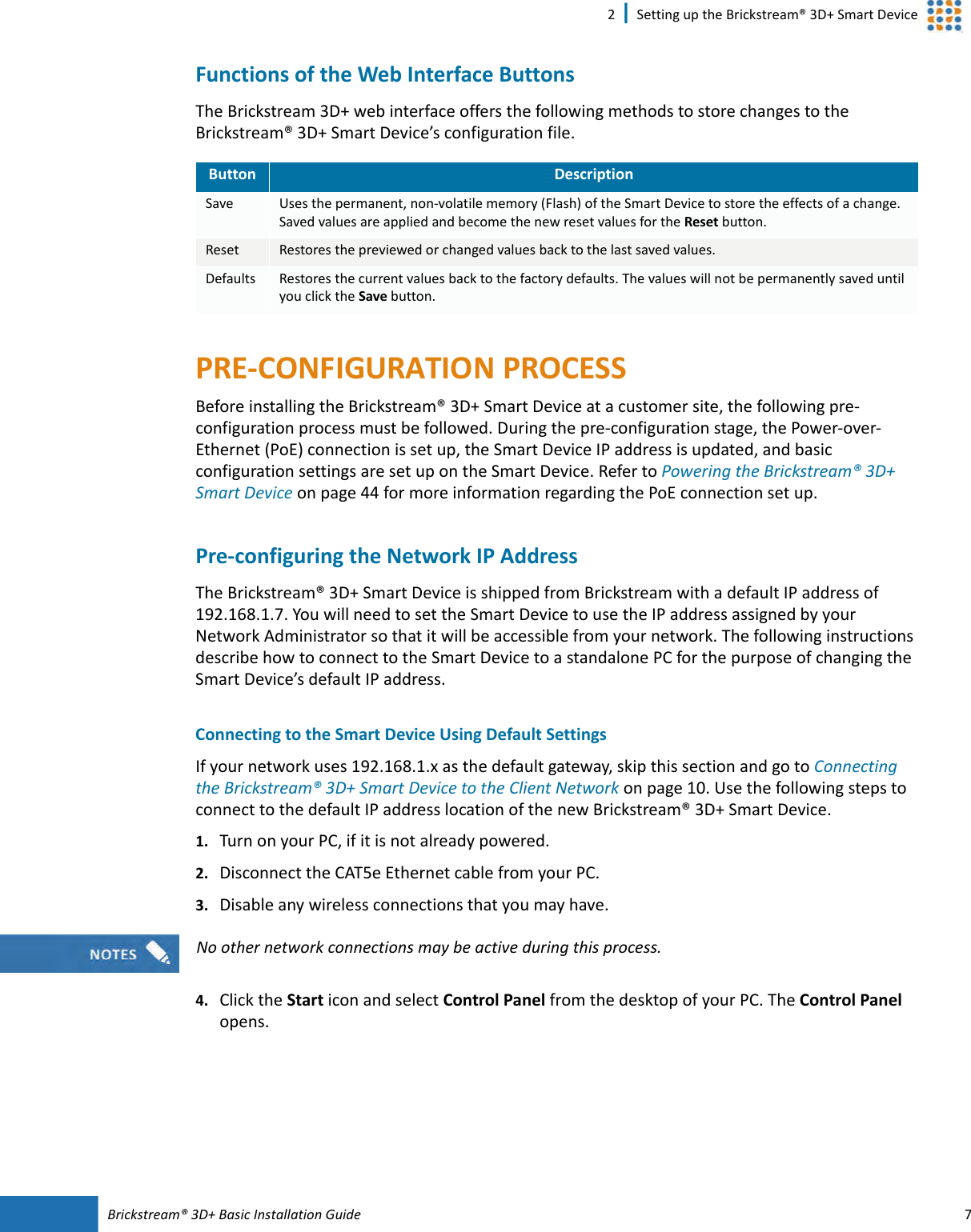
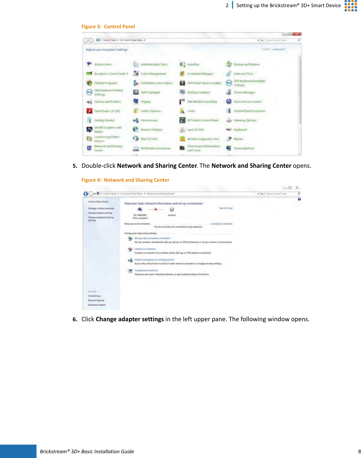
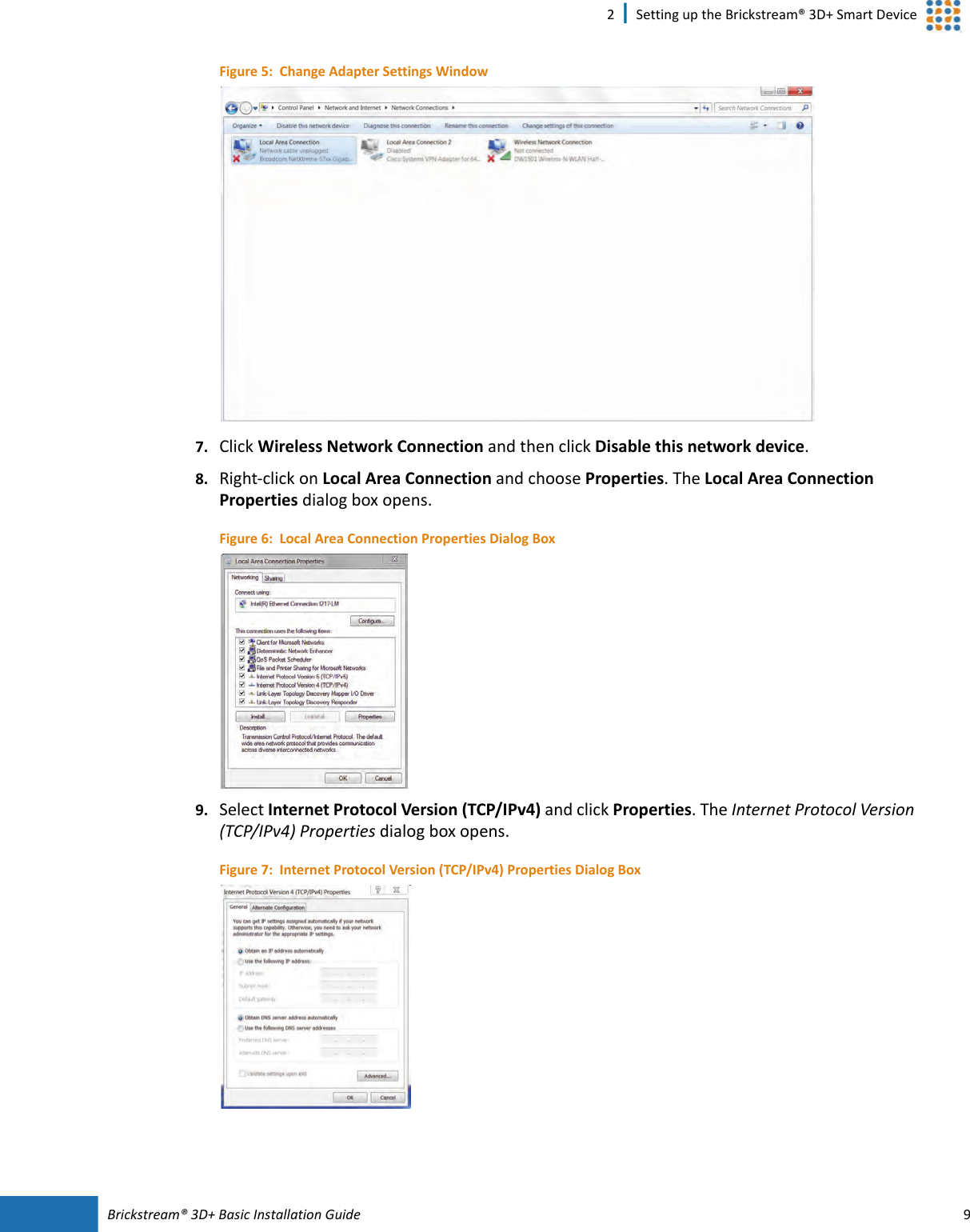
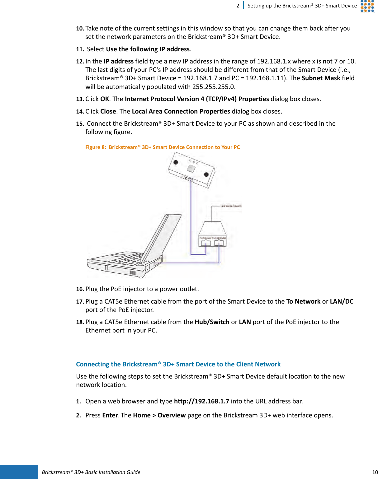
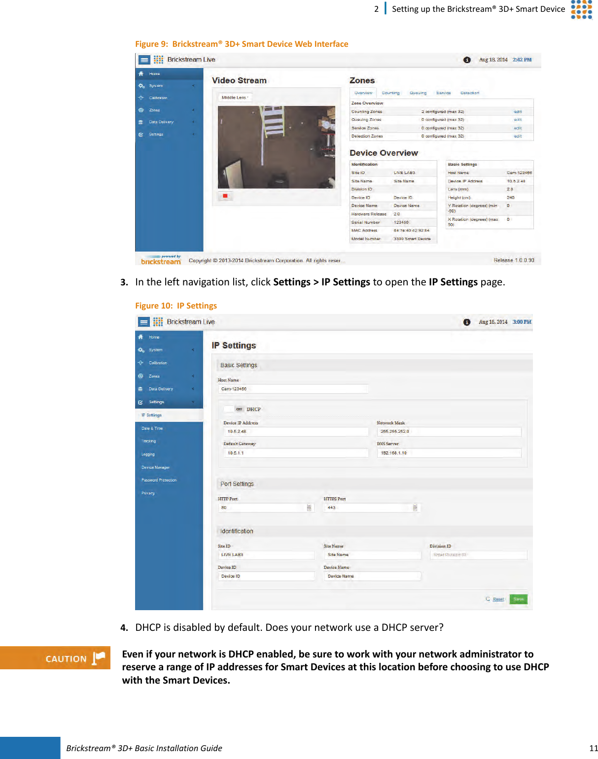
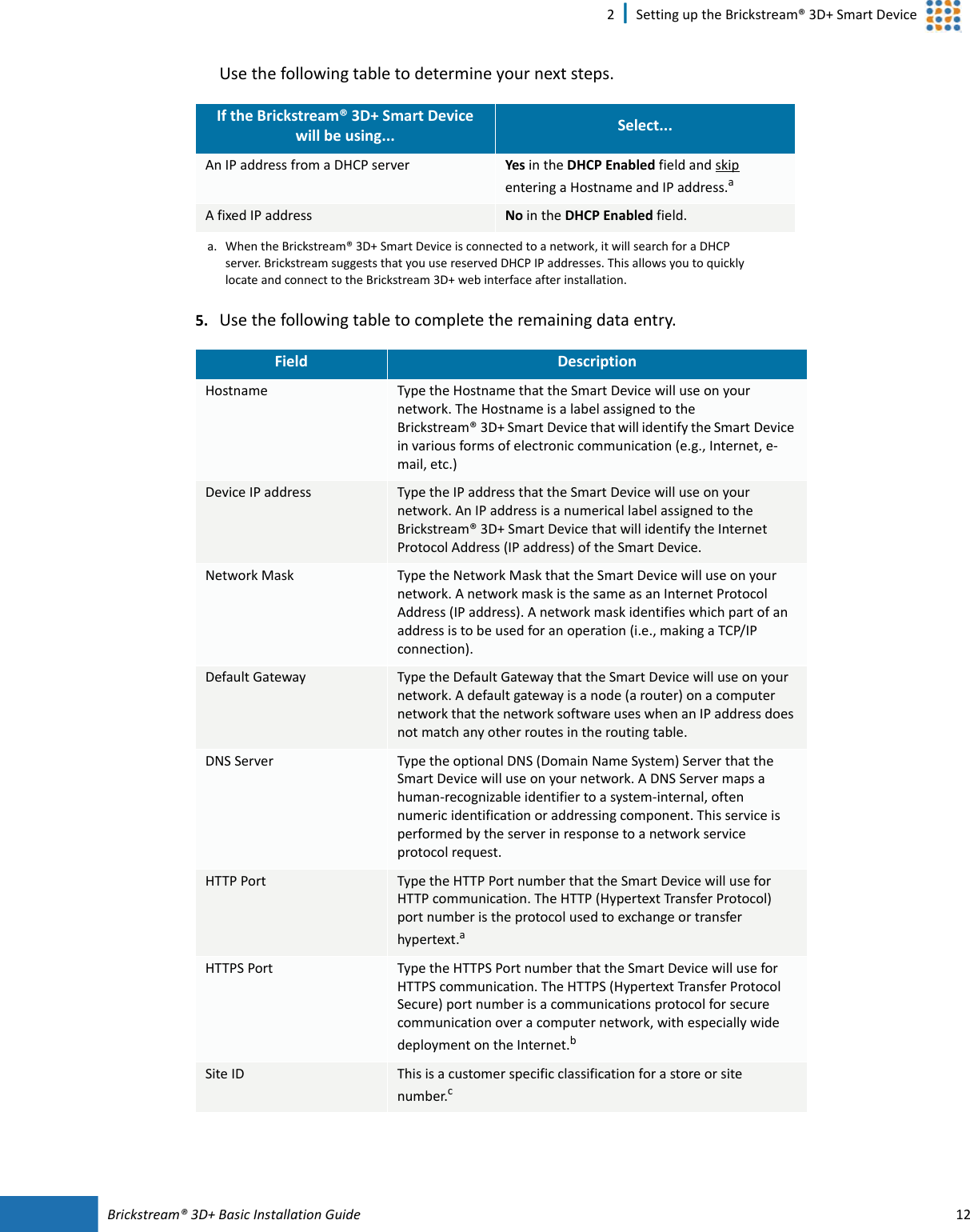
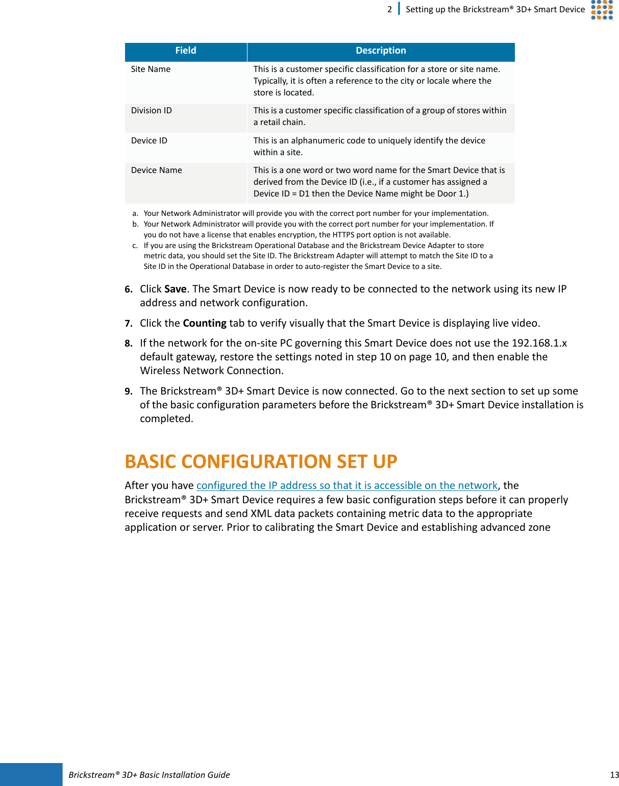
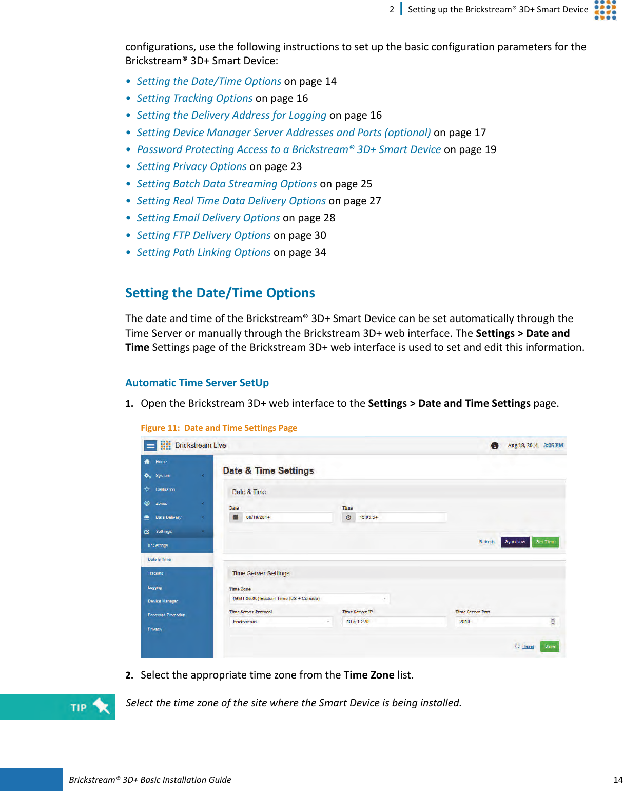
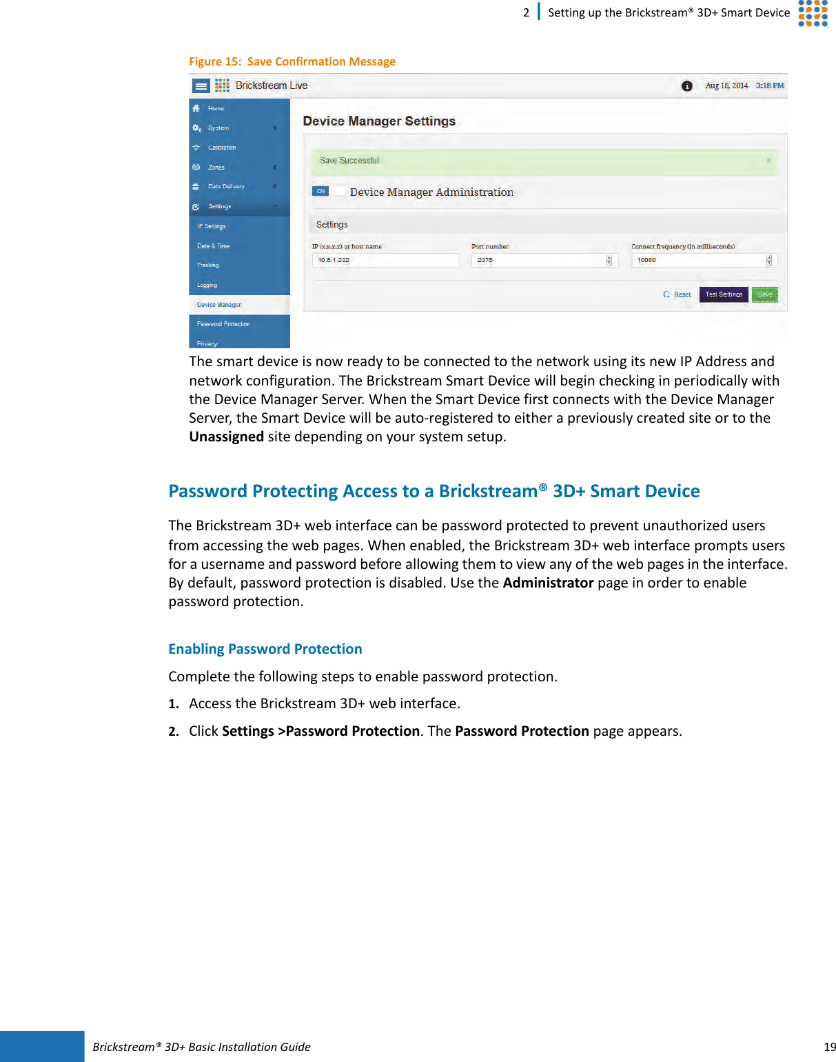
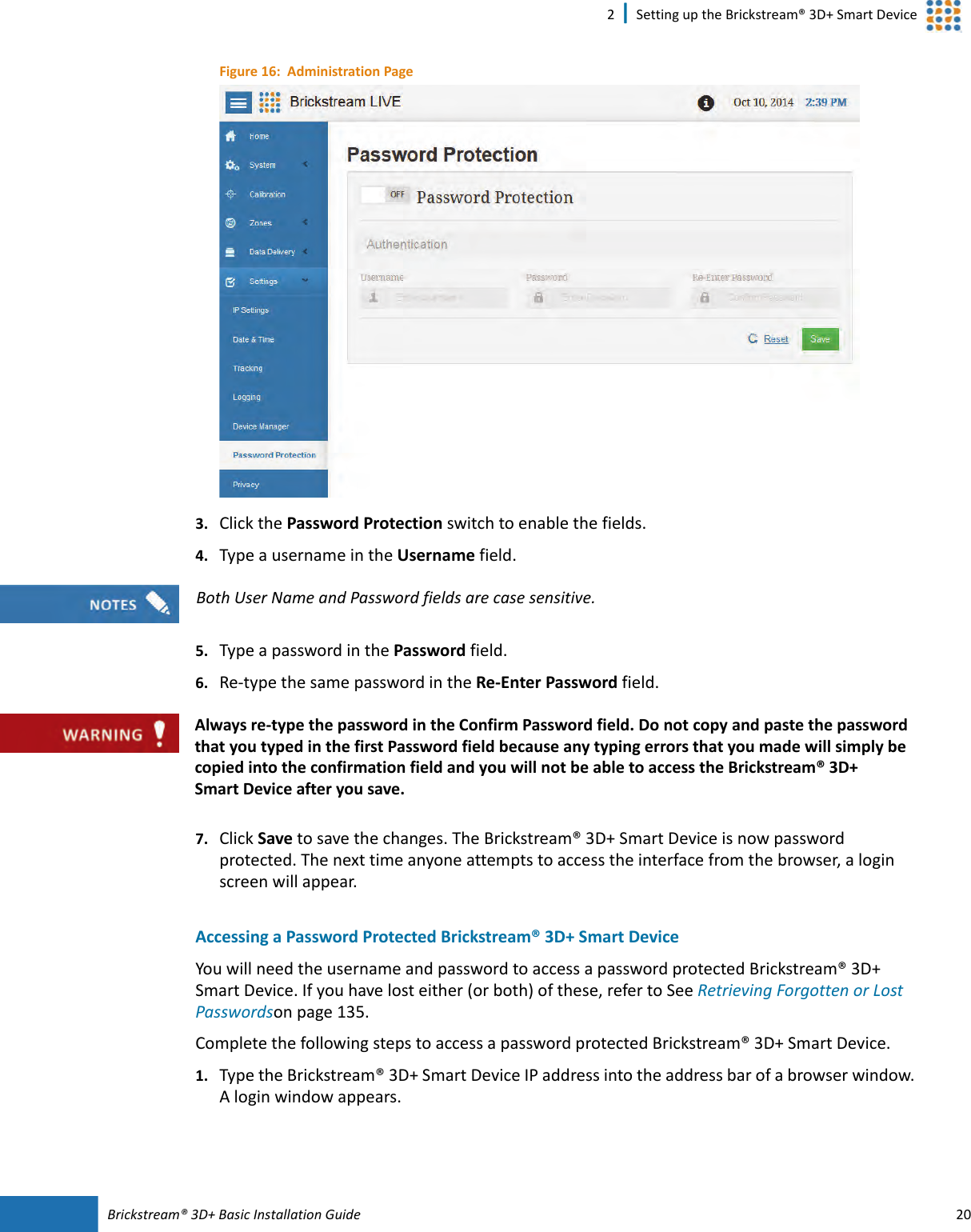
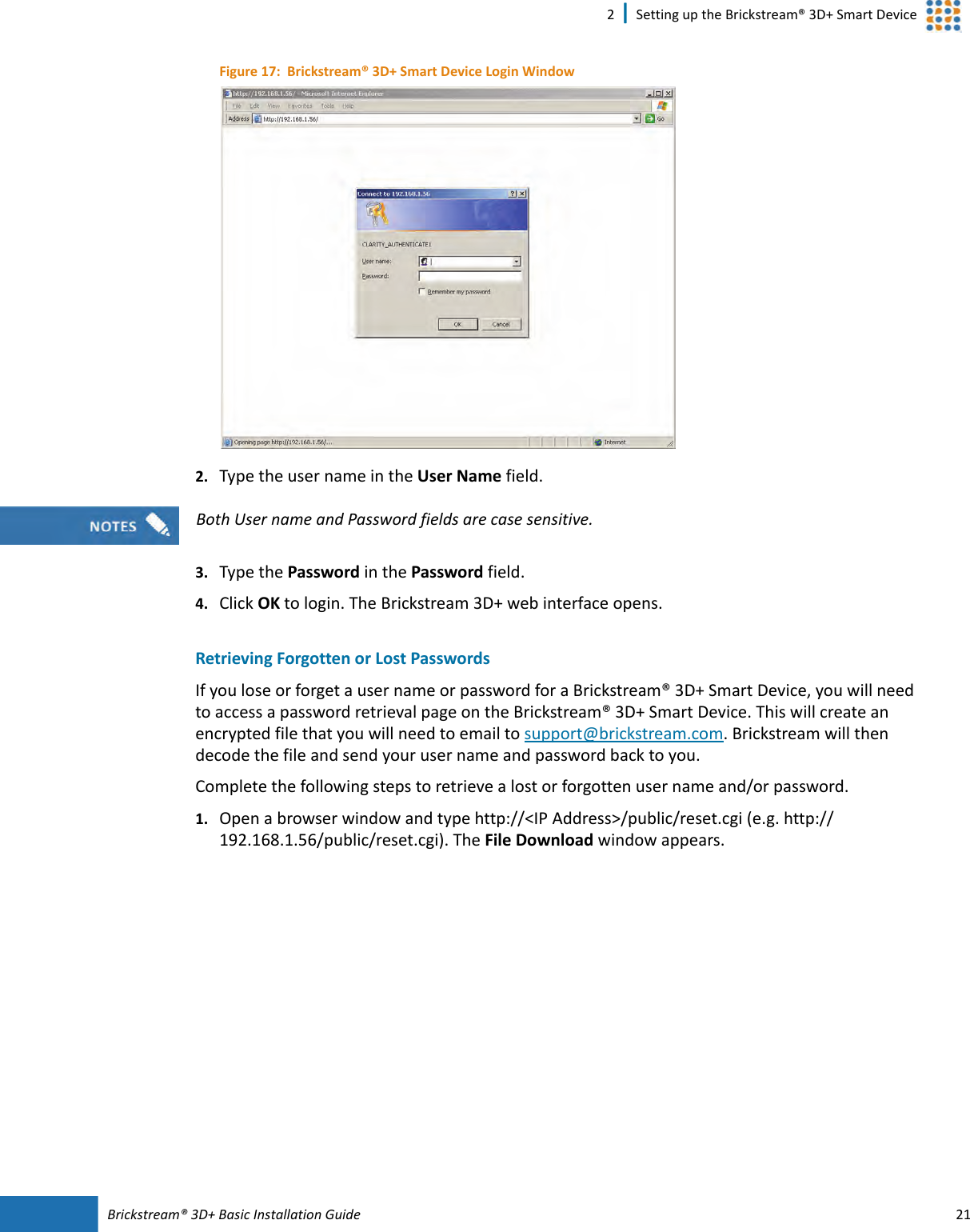
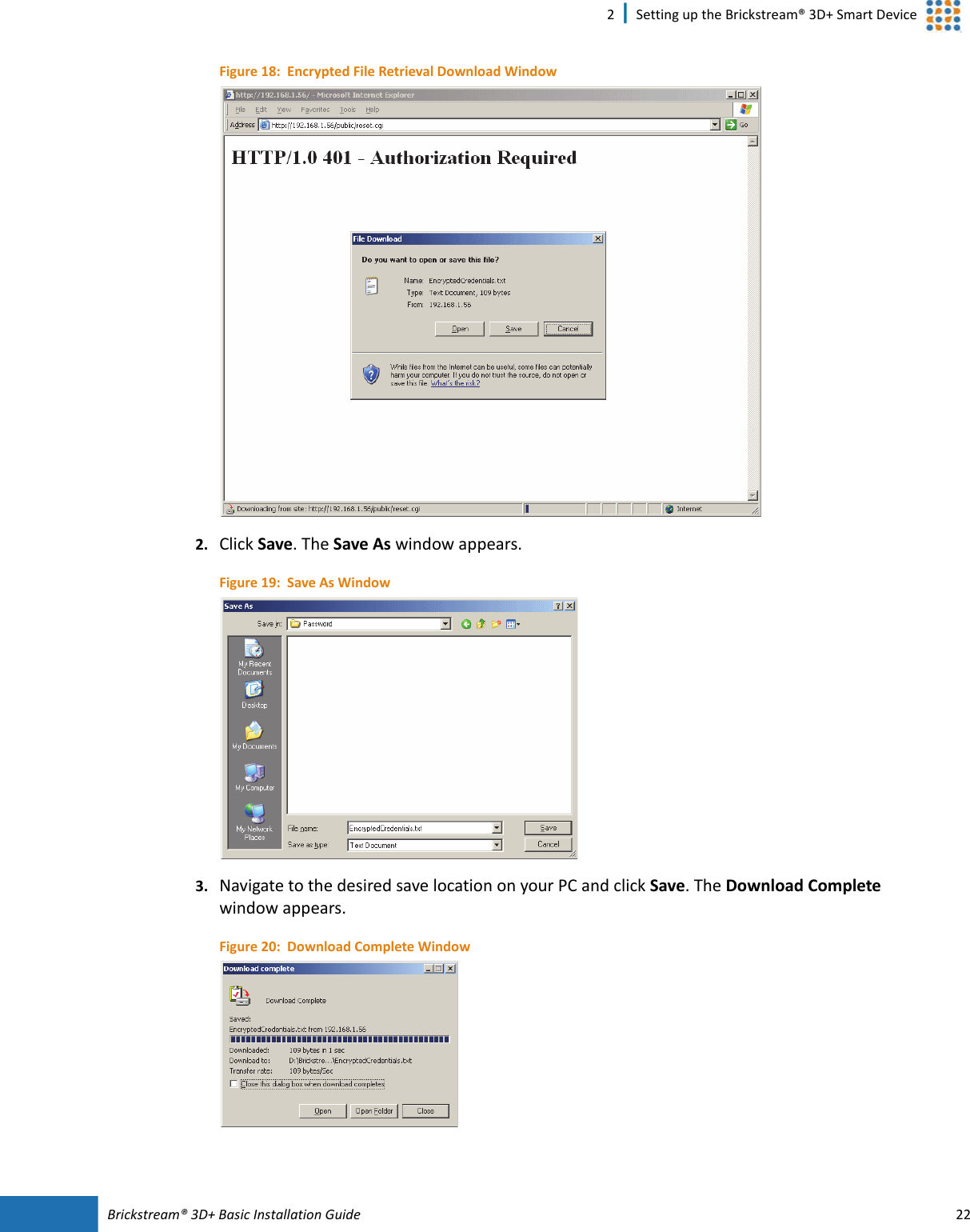
User Manual 1
Contents
1.
User Manual 1
2.
User Manual 2
User Manual 1
Navigation menu
Upload a User Manual
Namespaces
Wiki Guide
HTML
PDF
Info
Views
User Manual
Discussion / Help
Navigation