Contents
- 1. User Manual 1
- 2. User Manual 2
User Manual 2
Brickstream® 3D+ Basic Installation Guide 44
3 | Installing the Brickstream® 3D+ Smart Device On-Site
3INSTALLING THE BRICKSTREAM® 3D+
SMART DEVICE ON-SITE
SMART DEVICE ACCESSORIES
The proper installation and use of the Brickstream® 3D+ Smart Device requires accessories that
provide a way to mount the Smart Device and network connectivity using a Power-over-Ethernet
(PoE) switch or PoE injector. The following section provides an overview of the different PoE
devices and mounts that are available for use with the Brickstream® 3D+ Smart Device.
Powering the Brickstream® 3D+ Smart Device
Industry standard 802.3af PoE connections (with CAT5e Ethernet cable) are supported to
facilitate the combined power and network connection to the Brickstream® 3D+ Smart Device.
If VPN routers are required, Brickstream recommends using Cisco Small Business RV180 with the
Smart Device implementation.
Power output of the selected PoE switch(es) must minimally support 7 W typical power for each
connected Smart Device, but must be rated for up to 12.95 W maximum per Smart Device.
When selecting from the PoE options, for each Smart Device you will connect to the PoE, allow
12.95 W in the power budget calculation as described in the PoE’s documentation. The
Brickstream® 3D+ Smart Device is PoE Class 3, so the PoE must support Class 3 or higher.
Ensure network lights are lit on the Ethernet port of the Brickstream® 3D+ Smart Device after
connecting all cables. This ensures the physical connectivity of the network.
All connections use standard CAT5e or higher Ethernet cables. No special cables are necessary.
Brickstream® 3D+ Basic Installation Guide 45
3 | Installing the Brickstream® 3D+ Smart Device On-Site
The following table describes how to connect the Brickstream® 3D+ Smart Device to the network/
PoE cables using one of the following methods.
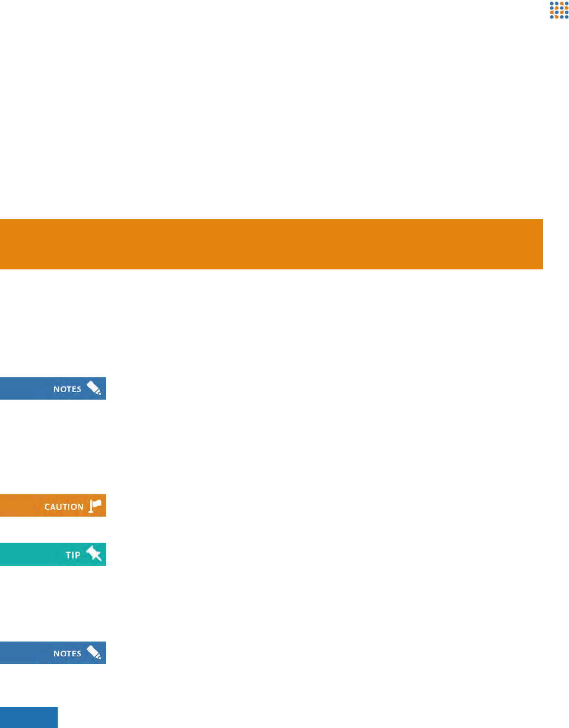
Option Connect Using... Diagram Legend
1 Single-port PoE
injector
Figure 43: Connection with Single-port PoE Injector 1Ethernet switch
2Single-port PoE
Injector
3Brickstream® 3D+
Smart Device
2 Endspan PoE
switch
Figure 44: Connection with EndSpan PoE Switch 1PoE switch
2Brickstream® 3D+
Smart Devices
Brickstream® 3D+ Basic Installation Guide 46
3 | Installing the Brickstream® 3D+ Smart Device On-Site
Mounting a Smart Device
The type of lens that is used in the Brickstream® 3D+ Smart Device or the placement of the
Smart Device will determine what type of mount will be used to support your installation. Refer
to Appendix B: Smart Devices/Lens Selection Tables on page 57 to ensure that you have the
appropriate lens for each installation height and door width.
Mount Guidelines
The following is a description of the basic mounting guidelines for installing the Brickstream® 3D+
Smart Device.
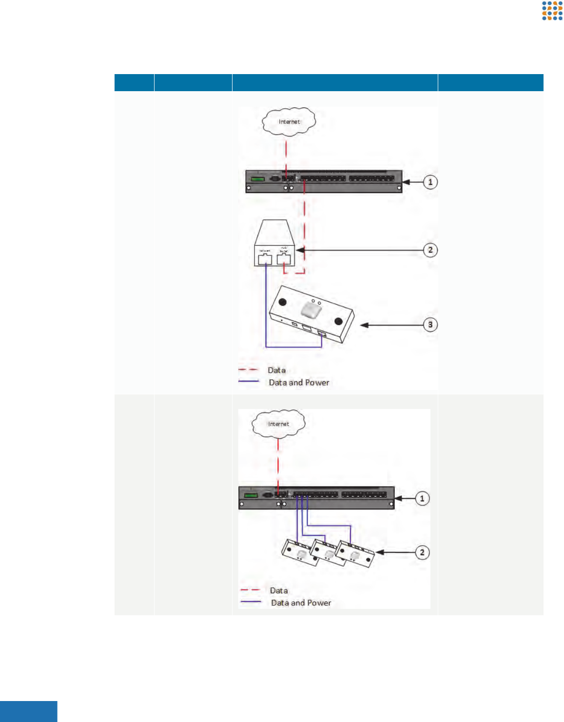
3 Multi-port
midspan PoE
injector
Figure 45: Connection with Multi-port Midspan PoE
Injector
1Ethernet switch
2Multi-port PoE Injector
3Brickstream® 3D+
Smart Devices
Option Connect Using... Diagram Legend
It is important to work with your sales engineer to determine optimal coverage, placement, and
mounting.

Brickstream® 3D+ Basic Installation Guide 47
3 | Installing the Brickstream® 3D+ Smart Device On-Site
•Customer-provided mounting brackets should attach to the Smart Device using male ¼”-20
thread per inch bolts
•Mount at a height between 30 cm (1 ft) higher than the tallest person to be tracked, and up to
9.5 m (31.2 ft) with the appropriate lenses
•Smart Device must be within 30 cm (1 ft) radius of the specific Smart Device installation
specification measurements
•Smart Device must be mounted within 5 cm of specified height range supported by the size of
lenses used
•X and Y tilts must be within 1 degree of specification
•Mount in a downward-looking orientation and level in both tilt and yaw such that it is looking
straight down, if possible, for optimal system performance
•Avoid including a side wall in the Smart Device’s field of view, if possible
•Avoid the Smart Device’s field of view looking through a glass wall or large window, if possible
•Brickstream recommends that Smart Device installed over a door should be slightly rotated 5
degrees especially if permanent mats are installed under the direct view of the Smart Device
•At installation sites where 0 degree downward-looking mounting is not possible, mounting at
an angle is supported up to 10 degrees with the basic license
•Additional license key required for mounting angles greater than 10 degrees
•Mount in such a way that the area of interest is positioned at, or very close to the center of the
Smart Device field of view
•Mounting bracket or mounting holes should provide adequate space to allow for one 10/
100BaseT CAT5e cable to be run above the mounting location
•Maintenance loops of CAT5e cable at least 1 m (3 ft) should be bundled and stored in the
ceiling above the mounting location when using recessed mounting brackets
•Allow clearance for hanging signs
•If you cannot see both stereoscopic lenses of the Smart Device when looking up at it from the
area you want to monitor, the view is obstructed and requires adjustment to surrounding
objects, adjustment to Smart Device installation height, or use of the Obstructed View
Calculator (available from your Brickstream representative)
•Avoid Smart Device placement that includes swinging/glass doors in the Smart Device’s field of
view
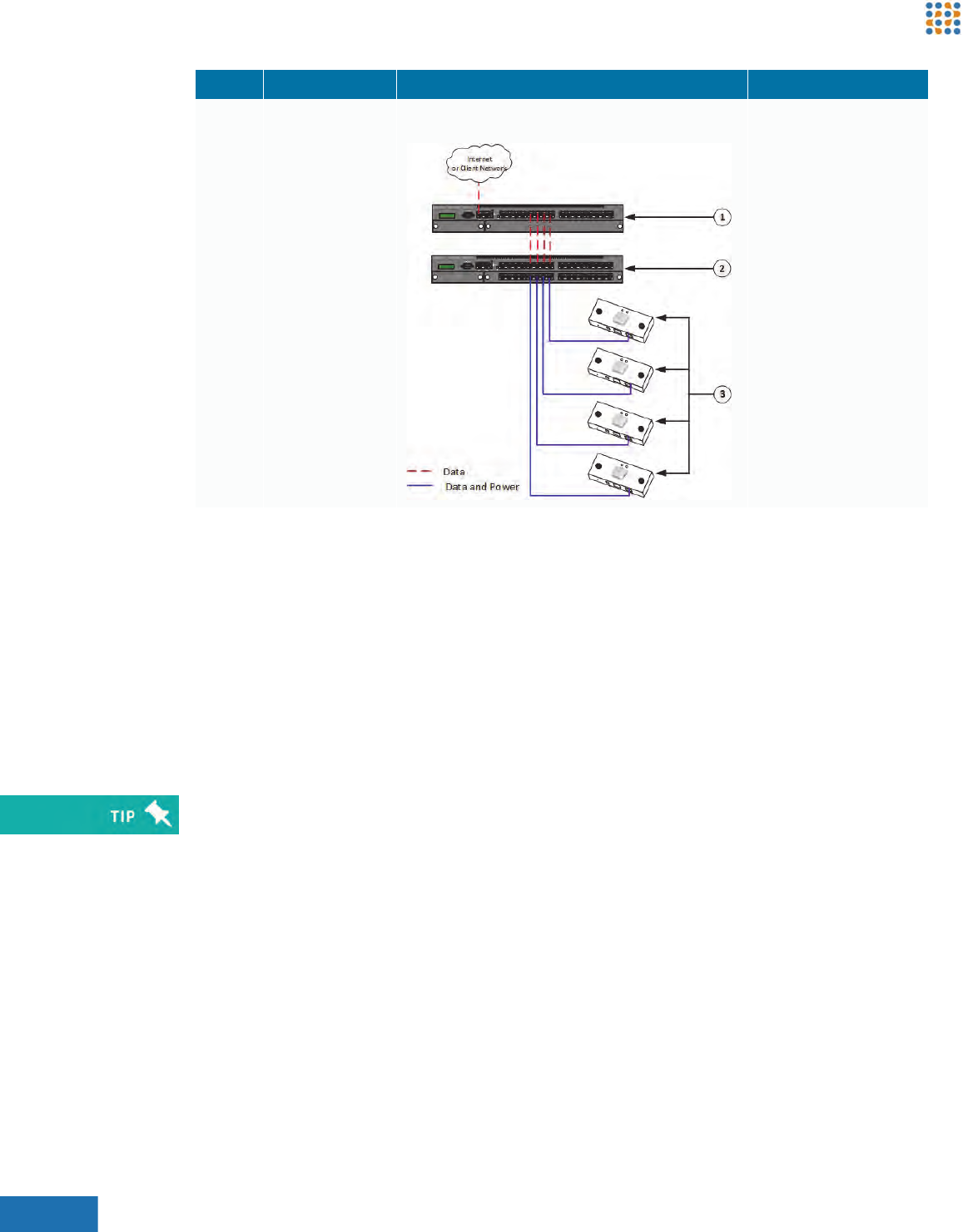
•The Smart Device installed at an entrance or exit for counting applications should be mounted
so that you can see the complete doorway from the lens. The coverage model should cover the
Brickstream® 3D+ Basic Installation Guide 48
3 | Installing the Brickstream® 3D+ Smart Device On-Site
entire entryway corridor, following the rule of thumb for coverage of 20% door and 80% floor,
as shown in the following figures
•It is critical that there is a clear chokepoint — a point which all traffic you wish to be measured
is forced through — to ensure accurate count data
Mount Types
Mount types required for each Smart Device installation at a site are identified in the Site
Installation Specification. The following is a description of each mount type that can be used with
the Brickstream® 3D+ Smart Device.
Figure 46: Smart Device Orientation - Top View Figure 47: Sample Coverage Area
Mount Type Application Examples
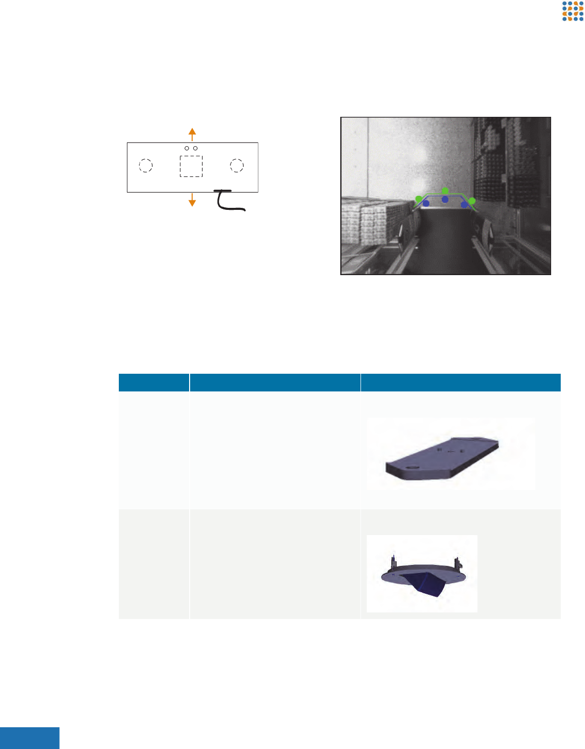
Surface Used for non drop-ceiling environments,
drop-ceiling environments, or
environments in which you want minimal
disturbance to ceilings. Use the supplied
¼-in. (6.35 mm) machine bolt to apply the
Smart Device to the mount using the
standardized camera mounting hole in the
center of the back of the Smart Device
before attaching the mount to the desired
surface.
Figure 48: Surface Mount
(Click to interact with drawing)
Recessed Used for aesthetically pleasing, low-profile
mounting in a drop ceiling. Available as
X-axis tilt or Y-axis tilt. Requires
reinforcement with lightweight backer
board, such as Luan plywood.
Figure 49: Recessed Mount
(Click to interact with drawing)
Store Interior
Store Exterior
Brickstream® 3D+ Basic Installation Guide 49
3 | Installing the Brickstream® 3D+ Smart Device On-Site
INSTALLING THE SMART DEVICE
The following steps provide the recommended work flow for the installation process. For details
pertinent to a specific circumstance, contact your Brickstream Sales Engineer or Technical
Support.
1. Ensure that a site survey is performed by qualified technicians to determine where cables
should be dropped in consideration of lens coverage specifications. The site survey outcome
provides information to build a site design with a Specification document and Bill of Materials
(BOM) identifying:
•Types of Smart Devices required to meet the coverage needs for the areas of interest
•Size of lenses required for each area of interest, based on ceiling height, clearance, and
other considerations, such as those described in Mount Types on page 48
•The number of Smart Devices required to adequately cover all areas of interest
•Installation positions, as defined by at least two measurements from permanent fixtures in
the coverage area, such as walls.
•Installation mounts that are needed
2. Verify that there are no obstructions preventing mounting in the desired location.
3. Run the CAT5e Ethernet from the PoE source to each installation position.
4. Unpack mounting hardware.
5. Carefully unpack all Smart Devices and inspect for physical damage prior to installation.
6. For each recessed mount, perform Installing a Recessed Mount on page 50.
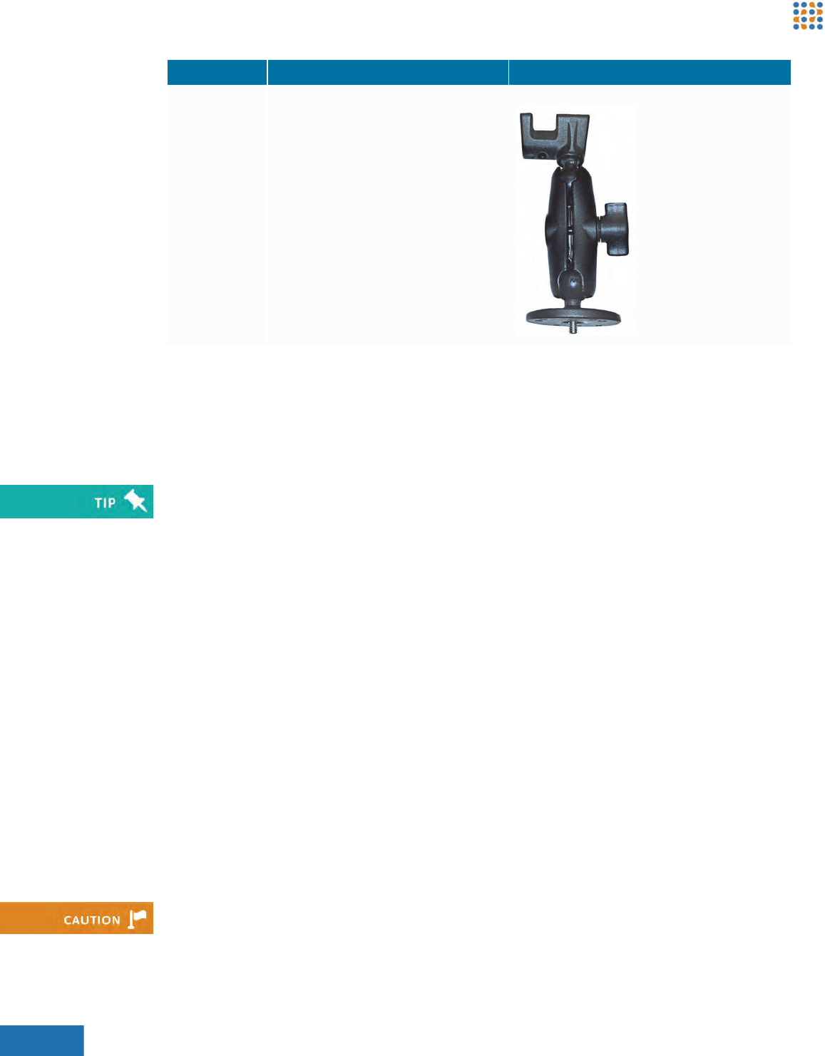
Pendant with
RAM mount
Used in situations where the mount must
fully articulate both X axis and Y axis, by
applying the RAM mount to a CCTV pole
and then applying the Smart Device to the
RAM mount’s universal camera mount.
Figure 50: RAM Mount
Mount Type Application Examples
To ensure accurate calibration, allow the Smart Device to acclimatize for at least one hour before
installation.
Do not press on any of the lenses as the slightest shift in orientation can compromise calibration,
resulting in inaccurate tracking.
Brickstream® 3D+ Basic Installation Guide 50
3 | Installing the Brickstream® 3D+ Smart Device On-Site
7. For each surface mount, perform Installing a Surface Mount on page 50.
Installing a Recessed Mount
Follow these steps to install a Brickstream recessed mount:
1. Remove from the ceiling the tile that is to be used for the mount location.
2. If the tile material requires reinforcing, apply backer board to the tile where the recessed
mount will be installed, trimming the backer board for exact fit.
3. Measure the distance from the edge of the tile to the center of the Smart Device location.
4. Use the Recessed Mount Cutting template included at the end of this document to ensure
correct size and shape for cutting the tile and backer board.
5. Cut through tile and backer board following the line drawn from the template.
6. Insert the recessed mount.
7. Insert the Smart Device into the mount, using the screw provided to secure it in the slot.
8. Connect the CAT5e Ethernet cable.
9. Secure the mount to the tile with the provided hardware.
10. Use twine or wire to secure the recessed mount to a permanent structure inside the ceiling,
such as a beam.
11. Make any final adjustments to the position of the mount in the tile.
12. If necessary, adjust the tilt of the Smart Device in the mount using the screw and degree
markings on the mount.
Installing a Surface Mount
Follow these steps to install a Brickstream surface mount:
1. If you are installing the surface mount on tile, remove from the ceiling the tile that is to be
used for the mount location.
2. If the tile requires reinforcement, apply lightweight plywood (e.g., Luan in the US) as a backer
board to the tile where the recessed mount will be installed, trimming the backer board for
exact fit.
3. If the surface mount will be applied onto solid surface, apply the surface mount directly to the
solid surface.
4. Connect the CAT5e Ethernet cable.
5. Secure the mount to the surface with the hardware provided.
Also connect the GPIO now if this site requires it.

Brickstream® 3D+ Basic Installation Guide 51
3 | Installing the Brickstream® 3D+ Smart Device On-Site
LED Boot Sequence
The following is the normal startup (boot) sequence for a Brickstream 3D+ Smart Device.
1. Access the Smart Device web interface to verify that the area of interest is properly displayed.
For detailed information about calibrating and configuring the Brickstream® 3D+ Smart Device,
refer to the Brickstream® 3D+ Smart Device Basic Configuration Guide.
Brickstream® 3D+ Basic Installation Guide 52
Appendix A | Brickstream® 3D+ Smart Device Specifications
ABRICKSTREAM® 3D+ SMART DEVICE
SPECIFICATIONS
The following tables provide specifications for the Brickstream® 3D+ Smart Device.
Network Specifications
Bandwidth requirements for the Brickstream® 3D+ Smart Device are at their highest during and
immediately following device installation.
For optimal network performance Brickstream recommends a high-speed DSL or T1 connection,
or better. To minimize bandwidth requirements on an on-going basis, Brickstream 3D+ transmits
analytics data in configurable increments, with independently configurable data capture and
transmission rates to reduce network overhead. Semi-random distribution of data packets
decreases spikes in network demand. On an on-going basis, each Smart Device only requires
about 0.05 kbps of bandwidth for analytics..
During solution delivery the initial bandwidth requirements can be greater due to the need to access
the Brickstream 3D+’s browser-based user interface, as well as capturing and transmitting a period
of raw video during validation to ensure configuration accuracy. An average of approximately
128 kbps per Smart Device is needed initially during configuration and validation.
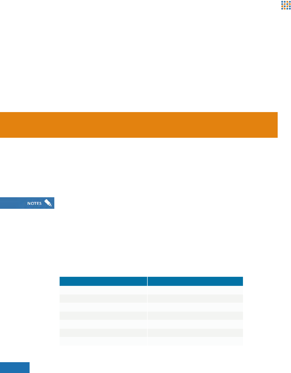
Item Specification
Cabling Category 5e (CAT5e) or better
Ethernet Single channel 10/100 Mbps Ethernet or higher
Power IEEE 802.3af PoE Type 1, Class 3
Addressing DHCP or Static IP
Protocols TCP/IP, DHCP
Time Synchronization SNTP, Daytime Protocol, Proprietary
Data Delivery HTTP, SMTP, FTP

Brickstream® 3D+ Basic Installation Guide 53
Appendix A | Brickstream® 3D+ Smart Device Specifications
Secure Data Delivery HTTPS, FTPSa
Software Upgrade TFTP, HTTP
a. FTPS is different than SFTP. Brickstream does not currently support the SFTP protocol.
Item Specification
Brickstream® 3D+ Basic Installation Guide 54
Appendix A | Brickstream® 3D+ Smart Device Specifications
Technical Specifications
Lenses
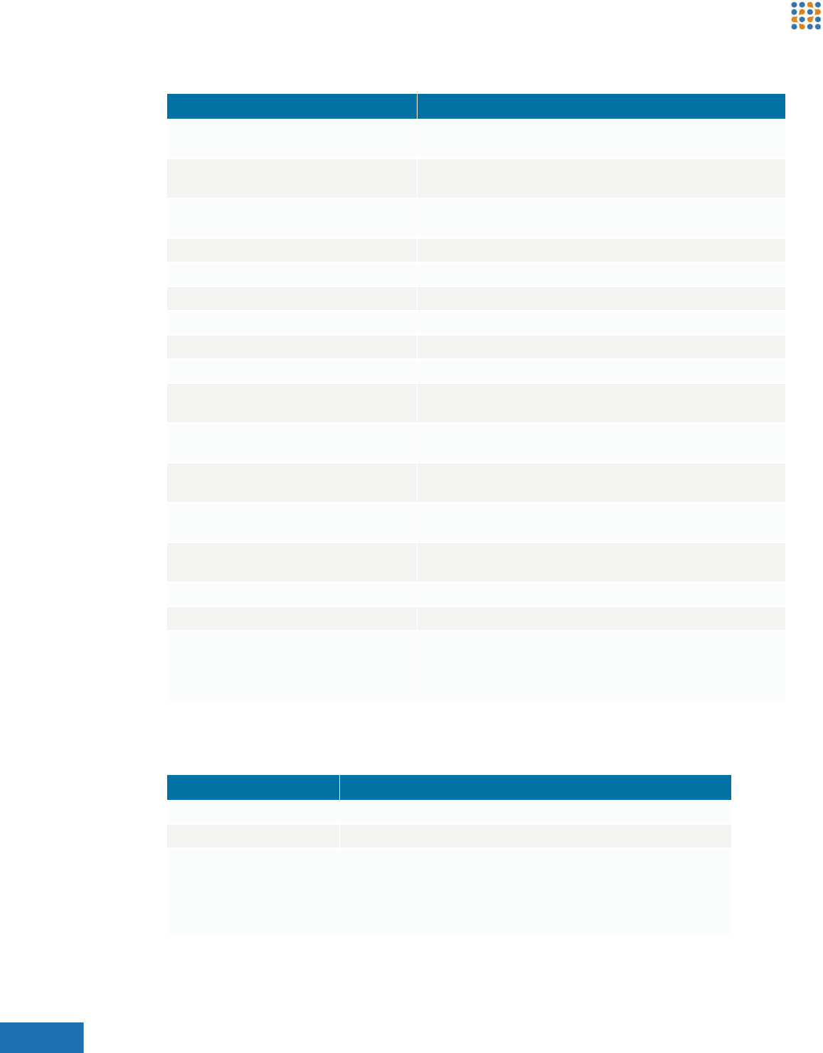
Item Specification
Device Dimensions 76 x 152 x 38 mm
3 x 6 x 1.5 in.
Lens Options Ranges from 2.0 mm to 6 mm supporting heights from 2.4m to 12m
(8 ft up to 39 ft)
Enclosure White powder-coated, die-cast aluminum. Black available by special
order.
Field Upgradable Supports software upgrades over TFTP
Power PoE (Class 3, Type 1 PD, 12 W max)
Power Consumption 7 W typical, 12 W rated maximum
Weight 1.1 pounds/0.5 kg
LEDs 2 multi-state RGB
Emissions Compliance Complies with CE rules and Part 15 Class A of FCC Rules
Operating Temperature 0° to 45° C
32° to 113° F
Storage Temperature -30° to 60° C
-22° to 140° F
GPIO Supports up to three inputs/outputs for pulse alert delivery and
receipt
Memory 512 MB RAM
512 MB NAND Flash ROM
MicroSD Support 4 GB and 16 GB
Not removable or swappable
Operating System Linux
Physical Ports USB 2.0, Digital I/O, RS485
Certifications FCC Part15 Class A, cUL
CE mark
CE Class A
UL, CB
Specification Monochrome Stereo Lenses
Function Behavior analytics
Quantity 2
Focal Length Options 2.0 mm
2.5 mm
3.0 mm
3.9 mm
5.7 mm
Brickstream® 3D+ Basic Installation Guide 55
Appendix A | Brickstream® 3D+ Smart Device Specifications
Logical Port Specifications
The following logical ports are the default configuration for the Brickstream® 3D+ Smart Device.
LED Functionality
This section provides a detailed explanation of the LED light functions on the Brickstream® 3D+
Smart Device.
Image Sensor 752 x 480 pixels
Wide VGA
High Dynamic Range (HDR)
Resolution 0.4 megapixels
Pan/Tilt/ZoomaN/A
Video StreamsbN/A
Video Compression None
Frame Rate N/A
a. Initial release supports pan and tilt. Zoom functionality will be provided in a future release.
b. Pan and tilt on Streams 2 and 3 can be adjusted through the ONVIF API.
Default Port Protocol Direction Default Dataa
a. All listed port numbers are configurable.
TCP 2010 HTTP Outbound XML data, time synchronization, diagnostics/logging
TCP 21 FTP Outbound Validation video
TCP 990 SFTP
UDP 69 TFTP Outbound & inbound Software upgrade
TCP 80 HTTP Inbound Software upgrade, web-based configuration utility
TCP 443 HTTPS Inbound
ICMP Inbound Ping
Status LED Illumination Indication
1 Blinking amber at three-
second intervals
Connected with neither the time sync server nor the data server
Blinking green at three-
second intervals
Connected to time sync and/or data servers
2Red Operating with factory-default IP address (192.168.1.7)
Progressivea
a. See Resetting the Brickstream® LIVE Smart Device on page 65.
Indicates whether the Smart Device has reverted back to its
default factory settings and is also used with the manual reset
button.
Specification Monochrome Stereo Lenses

Brickstream® 3D+ Basic Installation Guide 56
Appendix A | Brickstream® 3D+ Smart Device Specifications
Shipping Weight
This section provides shipping weight for the Brickstream® 3D+ Smart Device and its accessories.
Part Numbers
Item Shipping Weight
Boxed Unboxed
Brickstream® 3D+ Smart Device
Surface Mount .048 kg / 1.7 oz
RAM Mount 10.9 oz
Recessed Mount, 9 in. .737 kg / 26 oz .377 kg / 13.3 oz
Brickstream® 3D+ Basic Installation Guide 57
Appendix B | Smart Devices/Lens Selection Tables
BSMART DEVICES/LENS SELECTION TABLES
For detailed planning information, see the “Planning the Solution Design” chapter in the
Brickstream® LIVE Advanced Installation Guide. Use the following tables to determine which lens
type is appropriate for your installation.
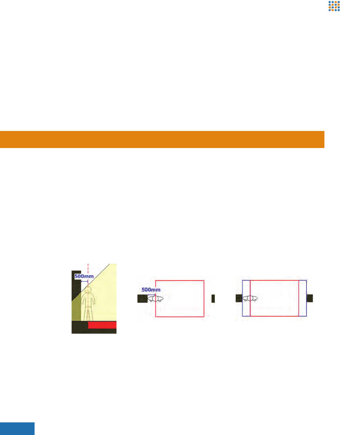
ABOUT COVERAGE WIDTHS
The coverage widths shown in the following tables include an extra meter from the coverage
widths shown by default in the Excel spreadsheet. This increased coverage assumes that there
are walls bordering each side of the coverage width. Having walls on each side of the coverage
area allows additional coverage because an individual’s center of mass can never be completely
against the wall. In fact, it is typically at least half a meter from the wall.
Figure 51: Additional Coverage Illustrations
Brickstream® 3D+ Basic Installation Guide 58
Appendix B | Smart Devices/Lens Selection Tables
BRICKSTREAM 3D+ STEREO LENS COVERAGE
The following tables provide the coverage measurements based upon the installation height for
each type of Brickstream 3D+ stereo lens:
•Brickstream 3D+ 2.0 mm Stereo Lenses
•Brickstream 3D+ Stereo 2.5 mm Lenses
•Brickstream 3D+ 3.0 mm Stereo Lenses
•Brickstream® LIVE 3.9 mm Stereo Lenses
•Brickstream 3D+ 5.7 mm Stereo Lenses
Brickstream 3D+ 2.0 mm Stereo Lenses
The following measurements apply for only the 2.0 mm lenses:
All measurements are in meters, except for lens sizes which are in millimeters (mm).
Lens Size (mm) Smart Device
Installation Height (m)
Coverage Area
Width (m) Height (m)
2.0 2.4 1.6 1.1
2.5 1.8 1.3
2.6 2.0 1.4
2.7 2.2 1.6
2.8 2.4 1.7
2.9 2.6 1.9
3 2.8 2.0
3.1 3.0 2.2
3.2 3.2 2.4
3.3 3.4 2.5
3.4 3.6 2.7
3.5 3.8 2.8
3.6 4.1 3.0
3.7 4.3 3.1
3.8 4.5 3.3
3.9 4.7 3.4
4 4.9 3.6
4.1 5.1 3.8
4.2 5.3 3.9
4.3 5.5 4.1
4.4 5.7 4.2

Brickstream® 3D+ Basic Installation Guide 59
Appendix B | Smart Devices/Lens Selection Tables
Brickstream 3D+ Stereo 2.5 mm Lenses
The following measurements apply for only the 2.5 mm stereo lenses:
Lens Size (mm) Smart Device
Installation Height (m)
Coverage Area
Width (m) Height (m)
2.5 3.5 2.9 2.1
3.6 3.0 2.2
3.7 3.2 2.3
3.8 3.3 2.4
3.9 3.5 2.6
4 3.7 2.7
4.1 3.8 2.8
4.2 4.0 2.9
4.3 4.1 3.0
4.4 4.3 3.2
4.5 4.5 3.3
4.6 4.6 3.4
4.7 4.8 3.5
4.8 4.9 3.6
4.9 5.1 3.8
5 5.2 3.9
5.1 5.4 4.0
5.2 5.6 4.1
5.3 5.7 4.2
5.4 5.9 4.3
5.5 6.0 4.5

Brickstream® 3D+ Basic Installation Guide 60
Appendix B | Smart Devices/Lens Selection Tables
Brickstream 3D+ 3.0 mm Stereo Lenses
The following measurements apply for only the 2.9 mm stereo lenses:
Lens Size (mm)
Smart Device
Installation
Height (m)
Coverage Area
Width (m) Height (m)
3.0 4 2.9 2.1
4.1 3.1 2.2
4.2 3.2 2.3
4.3 3.3 2.4
4.4 3.4 2.5
4.5 3.6 2.6
4.6 3.7 2.7
4.7 3.8 2.8
4.8 4.0 2.9
4.9 4.1 3.0
5 4.2 3.1
5.1 4.3 3.2
5.2 4.5 3.3
5.3 4.6 3.4
5.4 4.7 3.5
5.5 4.8 3.6
5.6 5.0 3.7
5.7 5.1 3.8
5.8 5.2 3.9
5.9 5.4 4.0
6 5.5 4.1
6.1 5.6 4.2
6.2 5.7 4.2
6.3 5.9 4.3
6.4 6.0 4.4
6.5 6.1 4.5

Brickstream® 3D+ Basic Installation Guide 61
Appendix B | Smart Devices/Lens Selection Tables
Brickstream® LIVE 3.9 mm Stereo Lenses
The following measurements apply for only the 3.9 mm stereo lenses:
Lens Size (mm)
(Sheet 1 of 2)
Smart Device
Installation
Height (m)
Coverage Area
Width (m) Height (m)
3.9 4.7 2.9 2.1
4.8 3.0 2.2
4.9 3.1 2.3
5 3.2 2.3
5.1 3.3 2.4
5.2 3.4 2.5
5.3 3.5 2.5
5.4 3.6 2.6
5.5 3.7 2.7
5.6 3.8 2.8
5.7 3.9 2.8
5.8 4.0 2.9
5.9 4.1 3.0
6 4.2 3.1
6.1 4.3 3.1
6.2 4.4 3.2
6.3 4.5 3.3
6.4 4.6 3.4
6.5 4.7 3.4
6.6 4.8 3.5
6.7 4.9 3.6
6.8 5.0 3.7
6.9 5.1 3.7
7 5.2 3.8
7.1 5.3 3.9
7.2 5.3 4.0
7.3 5.4 4.0
7.4 5.5 4.1
7.5 5.6 4.2
7.6 5.7 4.2
7.7 5.8 4.3
7.8 5.9 4.4

Brickstream® 3D+ Basic Installation Guide 62
Appendix B | Smart Devices/Lens Selection Tables
3.9 7.9 6.0 4.5
8 6.1 4.5
Lens Size (mm)
(Sheet 2 of 2)
Smart Device
Installation
Height (m)
Coverage Area
Width (m) Height (m)

Brickstream® 3D+ Basic Installation Guide 63
Appendix B | Smart Devices/Lens Selection Tables
Brickstream 3D+ 5.7 mm Stereo Lenses
The following measurements apply for only the 5.7 mm stereo lenses:
Lens Size (mm)
(Sheet 1 of 2)
Smart Device
Installation
Height (m)
Coverage Area
Width (m) Height (m)
5.7 6 2.8 2.0
6.1 2.8 2.1
6.2 2.9 2.1
6.3 3.0 2.2
6.4 3.0 2.2
6.5 3.1 2.3
6.6 3.2 2.3
6.7 3.2 2.4
6.8 3.3 2.4
6.9 3.4 2.5
7 3.4 2.5
7.1 3.5 2.6
7.2 3.6 2.6
7.3 3.7 2.7
7.4 3.7 2.7
7.5 3.8 2.8
7.6 3.9 2.8
7.7 3.9 2.9
7.8 4.0 2.9
7.9 4.1 3.0
8 4.1 3.0
8.1 4.2 3.1
8.2 4.3 3.1
8.3 4.3 3.2
8.4 4.4 3.2
8.5 4.5 3.3
8.6 4.5 3.3
8.7 4.6 3.4

Brickstream® 3D+ Basic Installation Guide 64
Appendix B | Smart Devices/Lens Selection Tables
5.7 8.8 4.7 3.4
8.9 4.7 3.5
9 4.8 3.5
9.1 4.9 3.6
9.2 4.9 3.6
9.3 5.0 3.7
9.4 5.1 3.7
9.5 5.1 3.8
Lens Size (mm)
(Sheet 2 of 2)
Smart Device
Installation
Height (m)
Coverage Area
Width (m) Height (m)
Brickstream® LIVE Advanced Installation Guide 65
Appendix C | Troubleshooting Brickstream® LIVE Smart Devices
CTROUBLESHOOTING BRICKSTREAM® LIVE
SMART DEVICES
TROUBLESHOOTING FTP CONNECTIONS
The following errors may occur when configuring the FTP delivery options.
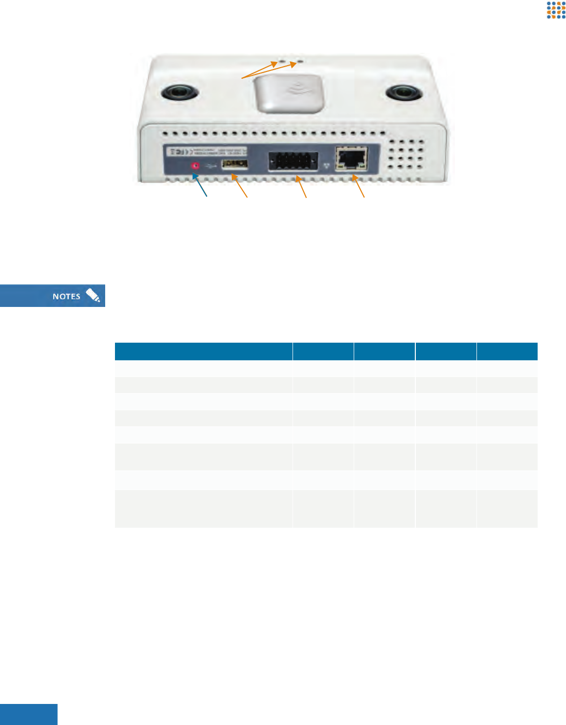
RESETTING THE BRICKSTREAM® LIVE SMART DEVICE
The Brickstream® LIVE Smart Device has a small reset button just to the left of the USB port that
allows you to do the following tasks:
•Reset the Smart Device network configuration by resetting the IP address of the Smart Device
to 192.168.1.7.
•Reset all Smart Device parameters and the network configuration to factory defaults, deletes
all zones, and resets the license code.
•Disable loading and running the current software, force-boot with the factory-installed
software upgrade via TFTP.
•Reset Privacy Options.
Refer to Figure 52 to complete the following steps to perform a reset.
Error Cause
Failed to connect 36 Incorrect Server IP Address
Failed to connect 64 Incorrect Port Number
Failed to connect 530 password not accepted Incorrect Username and/or Password
Resetting the device can cause data loss. To avoid accidental loss of data, make sure that if you
have not performed a reset on a Brickstream® LIVE Smart Device before, be sure to call your
Brickstream contact person to walk you through resetting the Smart Device in the safest manner.
Brickstream® LIVE Advanced Installation Guide 66
Appendix C | Troubleshooting Brickstream® LIVE Smart Devices
Figure 52: Smart Device Reset Location
The following steps describe how to reset the Brickstream® LIVE Smart Device:
1. Insert a paper clip into the reset button on the Brickstream® LIVE Smart Device and depress
the button until the desired color illuminates on LED 2, then release the button. Use the
following chart to determine how long to hold in the reset button.
2. The desired LED color illuminates and stays lit for 10 seconds, during which time you must
press and release the Reset button again to confirm the action. After confirming the action,
the Smart Device executes the action and reboots the Smart Device.
Status LEDs
USB PortReset PoE/LAN PortGPIO Port
LED 2 shows a sequence of colors depending on how long you depress the Reset button. For example
if you want to disable booting of the current interface by depressing the button for 8 seconds, during
this time LED 2 turns green, then amber, and finally red.
Function 3 Seconds 6 Seconds 9 Seconds 12 Seconds
Reset IP address to 192.168.1.7 X X X X
Restore factory default settings X X X
Delete configured zones X X X
Reset licensing X X X
Disable booting the current software X X
Update software via TFTP from
upgrade.brickstream.local and 192.168.1.18
X X
Reset all privacy optionsaX
LED color Green Amber Red Green/
Amber
cadence
a. Available in future release of Brickstream® LIVE Smart Device.
Brickstream® LIVE Advanced Installation Guide 67
Appendix C | Troubleshooting Brickstream® LIVE Smart Devices
TROUBLESHOOTING FIRMWARE UPGRADES WHEN
USING A TFTP SERVER
If you have trouble downloading the file, complete the following steps to test the TFTP Server
install.
1. Open a MS-DOS prompt and navigate to any directory that is in your system path (e.g.
c:\window\system32).
2. Issue the following command “tftp -i <PC IP Address> <Source Filename> <Destination
Filename> . If the command is successful, you will see “Transfer Successful: ##### bytes in ##
seconds, ###### bytes.
TROUBLESHOOTING LOW-CEILING INSTALLATIONS
The accuracy of the Brickstream smart device can be compromised if the smart device is installed
on a ceiling less than Brickstream's minimum supported mounting height of 2.4 m. The main issue
with installing at a height below Brickstream's minimum supported mounting height of 2.4 m is
the distance between the smart device and the objects being tracked has to be at least 30 cm. If
the object being tracked is less than 30 cm away from the smart device, the accuracy can be
compromised.
Relocation Solution
Consider an alternative, higher camera placement that allows the same flow of traffic. Another
mounting option that may provide more distance between the smart device and the objects
being tracked is the recessed mount. Refer to Mount Guidelines on page 46 for more information.
Tracking Configuration Solution
If you cannot relocate the Smart Device to a higher installation location with a view of the same
flow of traffic and the Smart Device is mounted within 10% of the minimum recommended
mounting height of 2.4 m, follow these steps.
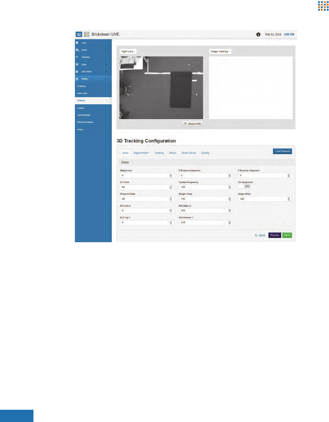
1. Access the 3D Tracking Configuration page.
2. On the Basic tab decrease the Distance Filter in cm to accommodate shorter tracks.
The source filename and destination filename must be different.
Brickstream® LIVE Advanced Installation Guide 68
Appendix C | Troubleshooting Brickstream® LIVE Smart Devices
Figure 53: Basic Tab of 3D Tracking Configuration Page
3. Select Height Image from the list above the right image pane.
Brickstream® LIVE Advanced Installation Guide 69
Appendix C | Troubleshooting Brickstream® LIVE Smart Devices
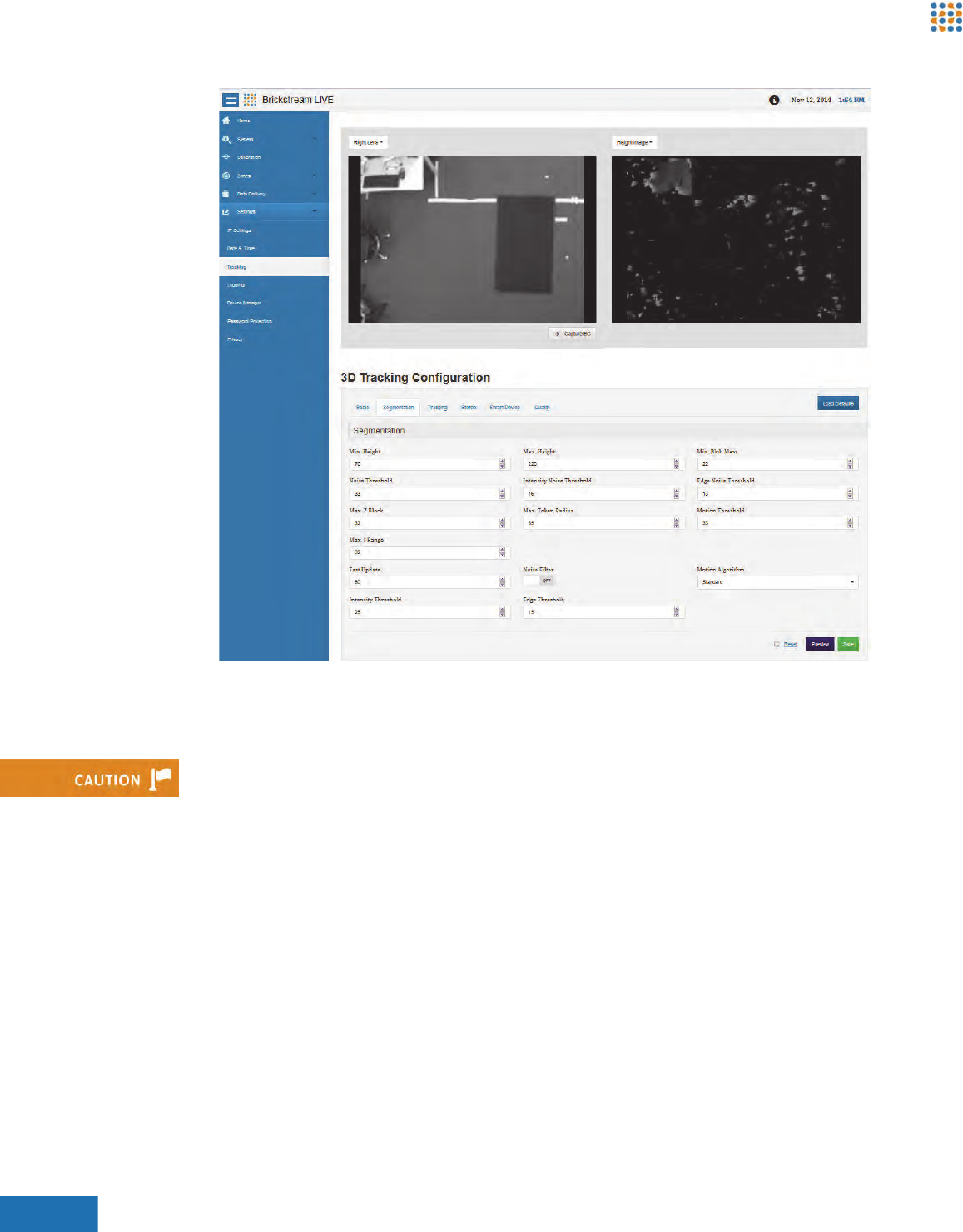
Figure 54: Segmentation Tab of 3D Tracking Configuration Page
4. If light gray patches on the Height Image are observed in the area to be tracked, click the
Stereo tab, reduce Surface Validation Diff. ratio to a minimum of .1 (default value is 1.0) and/
or increase Surface Validation Size up to a maximum to 500 pixels (default value is 200).
5. Leave the Max Disparity setting at the default of 32 pixels for a mounted height of 2.4 m.
6. Verify that the pink percentage on the Calibration page is still in an appropriate range after
making the adjustments.
RESOLVING INOPERABLE BRICKSTREAM DEVICE
ISSUES
The following topics will help you troubleshoot problems you may experience with Brickstream
devices. Please review these topics before submitting a Support ticket or RMA form to
Brickstream.
The Surface Validation settings should only be adjusted as a last resort on validation failures when
the system is reporting noisy or incorrect disparity readings. Over-adjusting these values can
negatively impact accuracy.
Brickstream® LIVE Advanced Installation Guide 70
Appendix C | Troubleshooting Brickstream® LIVE Smart Devices
Power Issue
Follow these steps to troubleshoot Smart Device power issues.
1. Determine if the device will power on at all.
2. Verify if the device ever worked.
Connectivity Issue
Follow these steps to troubleshoot Smart Device connectivity issues.
1. Determine if you can connect to the device on the IP address that you believe it to reside on.
2. If you still cannot access the Smart Device, record the sequence and display of the lights on the
Smart Device when the Smart Device is powered on after you have performed in the
preceding steps.
3. Call Brickstream Technical Support to receive additional assistance based on these findings.
Connecting a Smart Device with Default IP to a Custom Network
Use the following steps to connect to the default IP address location of the new
Brickstream® LIVE Smart Device.
1. Turn on your PC, if it is not already powered.
2. Disconnect the CAT5e Ethernet cable from your PC.
3. Disable any wireless connections that you may have.
IF… THEN…
The device will power on Go to the Connectivity Issue topic.
The device will not power on Try a different Power-over-Ethernet (POE) source. If it still doesn’t power on,
contact Brickstream Technical Support for additional assistance.
IF… THEN…
The device previously worked Identify the changes that were made that may have caused it to stop working.
The device never worked
IF… THEN…
You can connect to the device Try to browse to the IP address. If the Brickstream LIVE web interface displays,
connectivity is not the root issue. Go to Firmware Issue on page 74.
You cannot connect to the device Perform a manual reset to green so the IP address resets to 192.168.1.7, as
described in Resetting the Brickstream® LIVE Smart Device on page 65.
Please ensure that you are on a 192.168.1.xx network then attempt to connect to that IP address.
If not, see Connecting a Smart Device with Default IP to a Custom Network on page 70
No other network connections may be active during this process.
Brickstream® LIVE Advanced Installation Guide 71
Appendix C | Troubleshooting Brickstream® LIVE Smart Devices
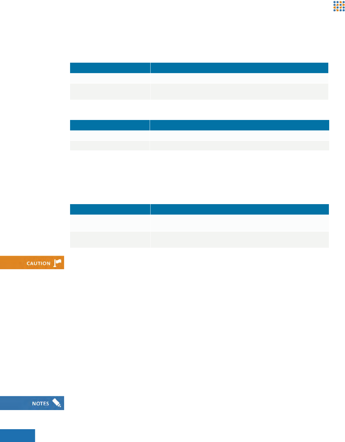
4. Click the Start icon and select Control Panel from the desktop of your PC. The Control Panel
opens.
Figure 55: Control Panel
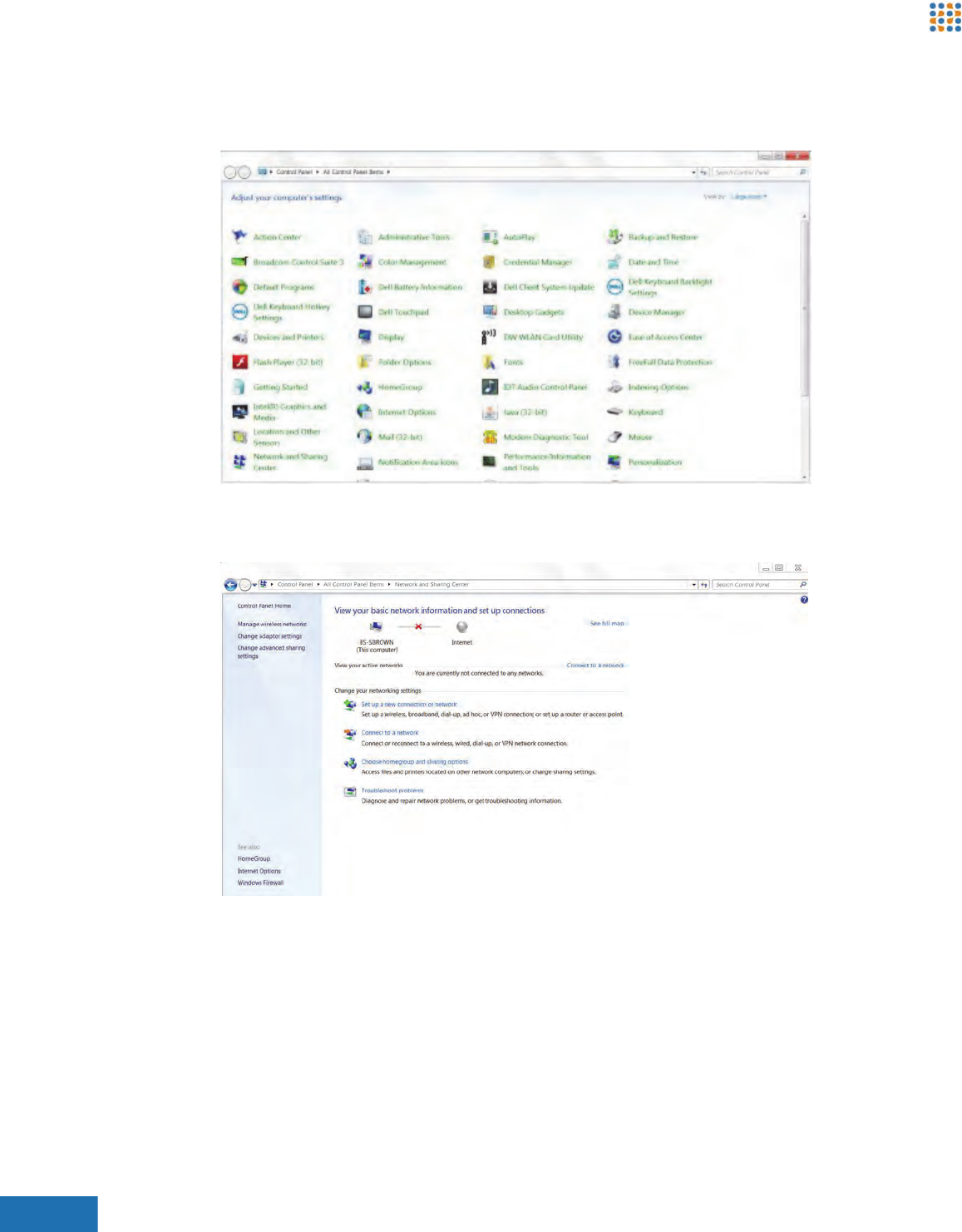
5. Double-click Network and Sharing Center. The Network and Sharing Center opens.
Figure 56: Network and Sharing Center
6. Click Change adapter settings in the left upper pane. The following window opens.
Brickstream® LIVE Advanced Installation Guide 72
Appendix C | Troubleshooting Brickstream® LIVE Smart Devices
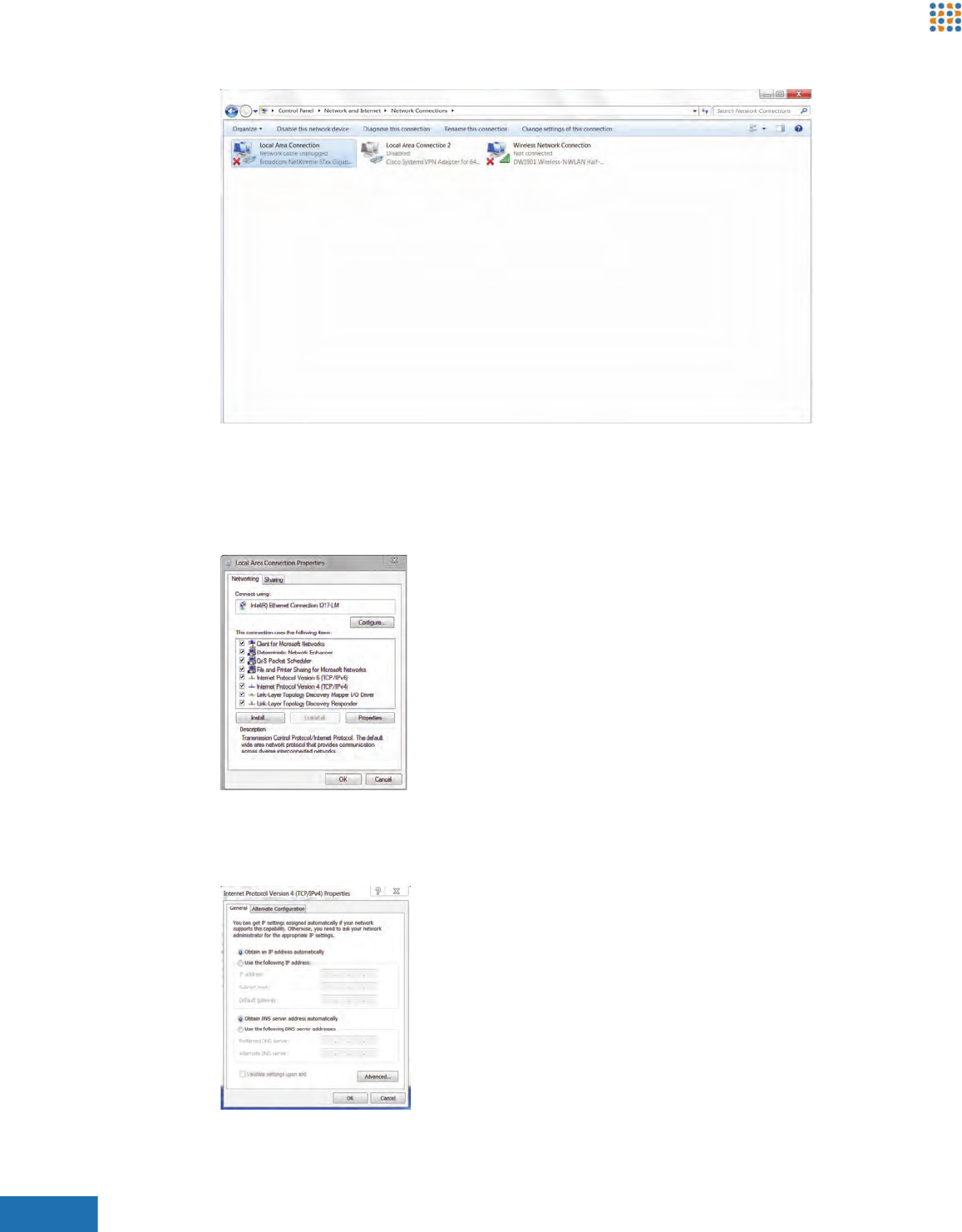
Figure 57: Change Adapter Settings Window
7. Click Wireless Network Connection and then click Disable this network device.
8. Right-click on Local Area Connection and choose Properties. The Local Area Connection
Properties dialog box opens.
Figure 58: Local Area Connection Properties Dialog Box
9. Select Internet Protocol Version (TCP/IPv4) and click Properties. The Internet Protocol Version
(TCP/IPv4) Properties dialog box opens.
Figure 59: Internet Protocol Version (TCP/IPv4) Properties Dialog Box
Brickstream® LIVE Advanced Installation Guide 73
Appendix C | Troubleshooting Brickstream® LIVE Smart Devices
10. Take note of the current settings in this window so that you can change them back after you
set the network parameters on the Brickstream® LIVE Smart Device.
11. Select Use the following IP address.
12. In the IP address field type a new IP address in the range of 192.168.1.x where x is not 7 or 10.
The last digits of your PC’s IP address should be different from that of the Smart Device (i.e.,
Brickstream® LIVE Smart Device = 192.168.1.7 and PC = 192.168.1.11). The Subnet Mask field
will be automatically populated with 255.255.255.0.
13. Click OK. The Internet Protocol Version 4 (TCP/IPv4) Properties dialog box closes.
14. Click Close. The Local Area Connection Properties dialog box closes.
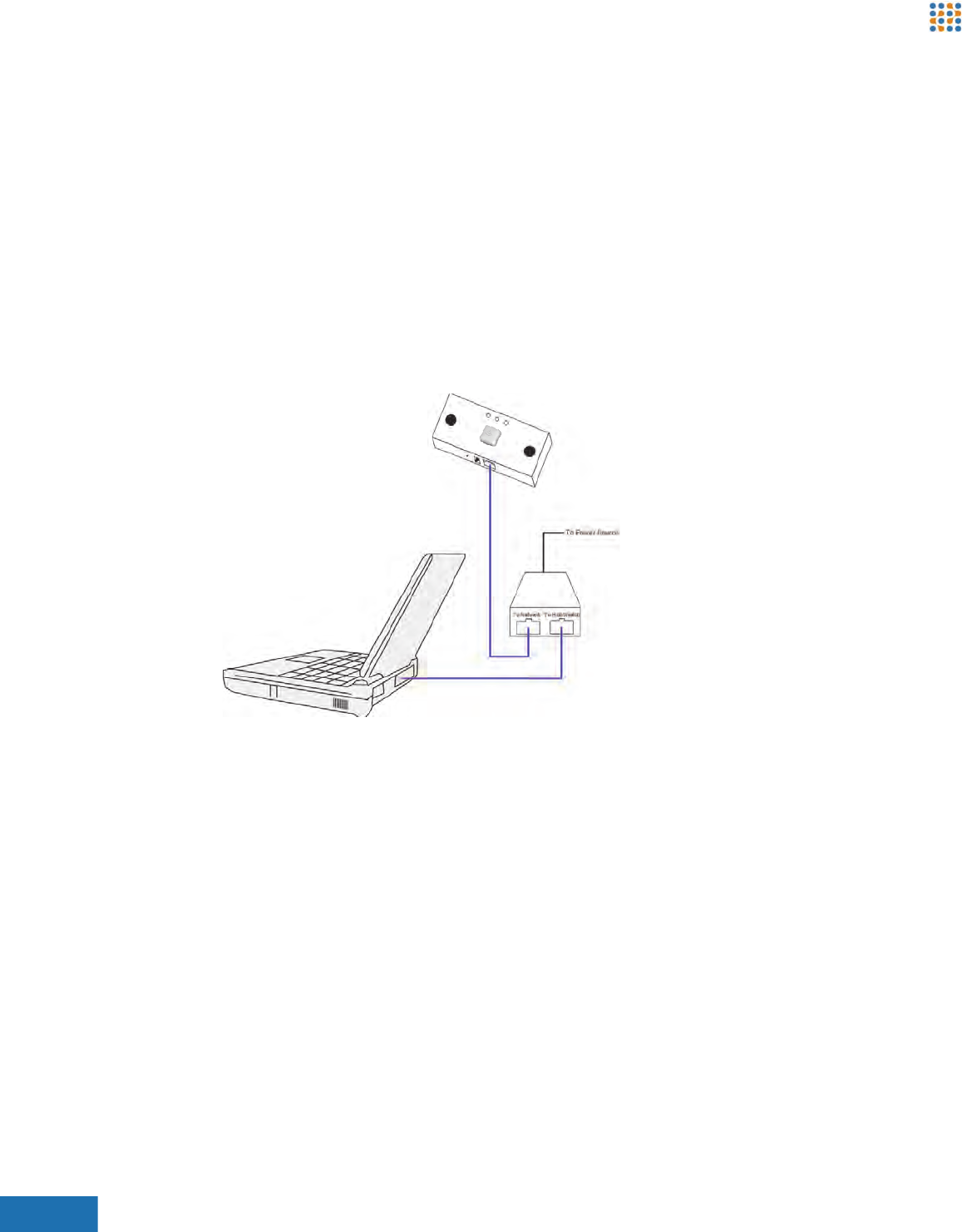
15. Connect the Brickstream® LIVE Smart Device to your PC as shown and described in the
following figure.
Figure 60: Brickstream® LIVE Smart Device Connection to Your PC
16. Plug the PoE injector to a power outlet.
17. Plug a CAT5e Ethernet cable from the port of the Smart Device to the To Network or LAN/DC
port of the PoE injector.
18. Plug a CAT5e Ethernet cable from the Hub/Switch or LAN port of the PoE injector to the
Ethernet port in your PC.
Brickstream® LIVE Advanced Installation Guide 74
Appendix C | Troubleshooting Brickstream® LIVE Smart Devices
Firmware Issue
Follow these steps to determine whether the root cause is a firmware issue.
1. If the Smart Device has been manually reset to RED (as described in Resetting the
Brickstream® LIVE Smart Device on page 65), follow the instructions to reload firmware to the
Smart Device as described in Installing the Brickstream® LIVE Smart Device Firmware on
Factory Direct Smart Devices on page 81.
2. What firmware version is currently on the device? Verify the version of firmware that the
Smart Device is running by checking the Release number displayed in the footer of the
Brickstream LIVE web interface. Contact Brickstream Technical Support with this information
to receive additional instructions.
ADJUSTMENTS TO TRACKING CONFIGURATION
This section is designed for advanced users who configure standard counting installations.
Tracking Issues
Follow these steps to troubleshoot Smart Device tracking issues.
1. Set the Smart Device to the default values on the Calibration page and recalibrate
automatically to ensure there is not an issue because the settings were changed.
2. Have a person stand under the device after recalibration and determine if they appear to be
displayed with the correct height, within a few centimeters.
3. If the height display is incorrect, manually calibrate the Smart Device as described in step 9 of
Automatically Calibrating a Setting Smart Device Height and Rotation on page 53.
4. If manual calibration does not address the issue, see Advanced Troubleshooting of Tracking
Issues on page 74.
Advanced Troubleshooting of Tracking Issues
Before attempting this procedure, be sure you have completed all steps of Tracking Issues on
page 74.
1. Record the percentage of pixels that display in pink (undefined) and in good condition.
2. Have a person stand under the device after recalibration and determine if they appear to be
displayed in the percentage of pink pixels.
3. If the Calibration page displays in pink pixels, capture a right lens image and a left lens image
from the device following the instructions in step and send these images along with the
Height Image data through a RMA request.
Changing any settings on the 3D Tracking Configuration page can drastically impact the accuracy
and functionality of the Brickstream® LIVE Smart Device. Do not make changes on this page
without the guidance of Brickstream Technical Support.
Brickstream® LIVE Advanced Installation Guide 75
Appendix C | Troubleshooting Brickstream® LIVE Smart Devices
Troubleshooting Under-Counting Issues with Patterned Mats
This topic provides instructions to resolve under counting issues when a Brickstream® LIVE
Smart Device has trouble counting due to a patterned mat blocking the line of view.
Problem
Certain types of patterned floor mats and flooring patterns that are within the line of view of a
Brickstream® LIVE Smart Device can prevent the Smart Device from capturing all tracks and
therefore under-count traffic. When viewed on the Calibration page, the flooring may appear to
float higher than floor level.
Solution
Follow these steps to prevent under counting due to patterned mats.
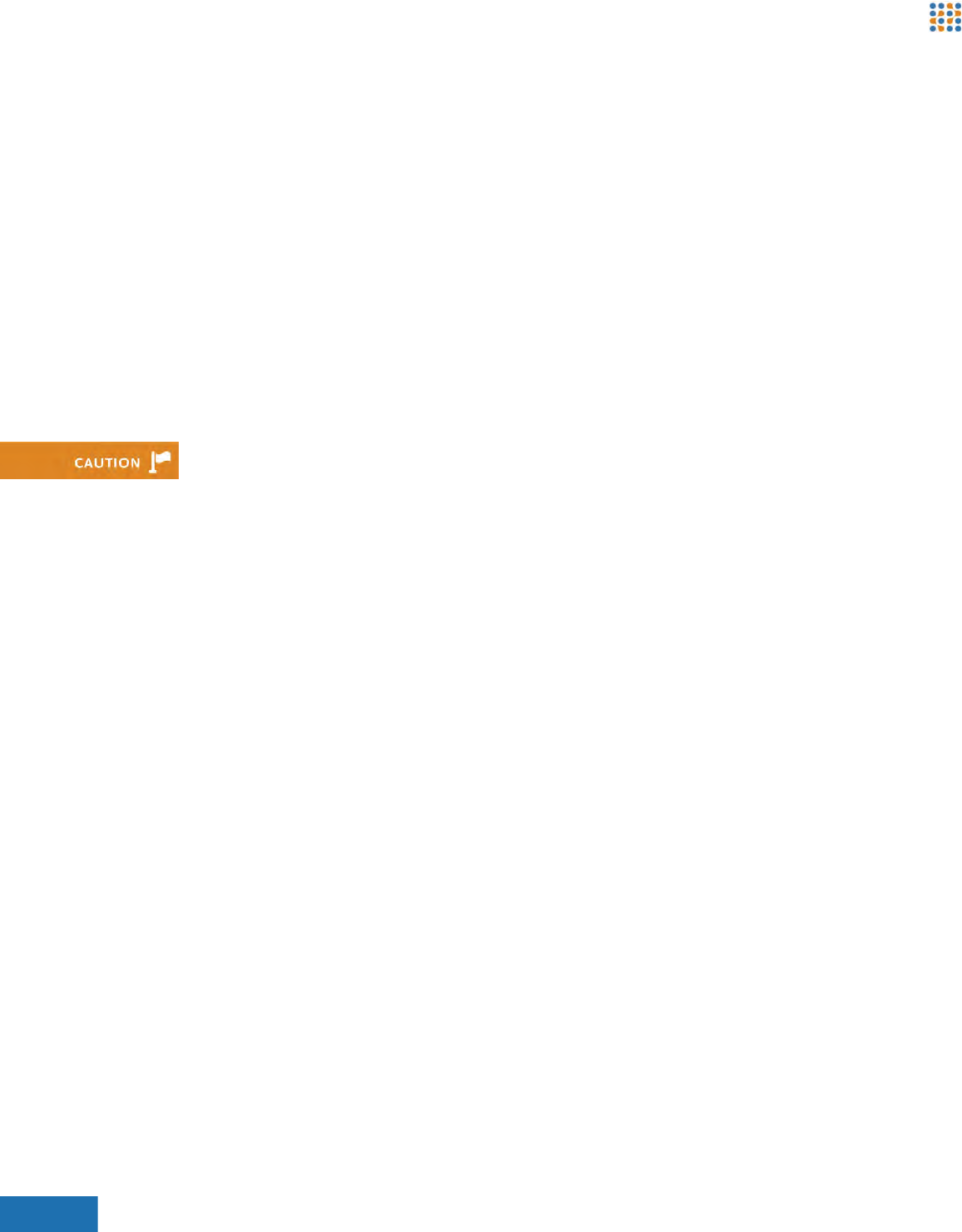
1. Ensure the Smart Device is calibrated properly and that person heights are generally within a
160cm - 180cm range in the Height Map in the right pane of the Counting Zone Manager
page. The following figure shows a desirable height map, indicated by the predominance of
yellow and dark yellow.
Figure 61: Example of Good Height Map
2. If there is a horizontally repeating pattern, twist the Smart Device by 5 to 10 degrees if tracks
are being dropped from the Smart Device’s view due to the patterns in a floor mat. This
interrupts the horizontally repeating pattern.
Figure 62: Horizontally Repeating Pattern Figure 63: Interrupted Patter Following Twisting Smart Device
Brickstream® LIVE Advanced Installation Guide 76
Appendix C | Troubleshooting Brickstream® LIVE Smart Devices
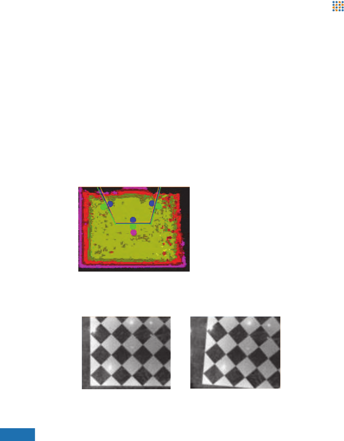
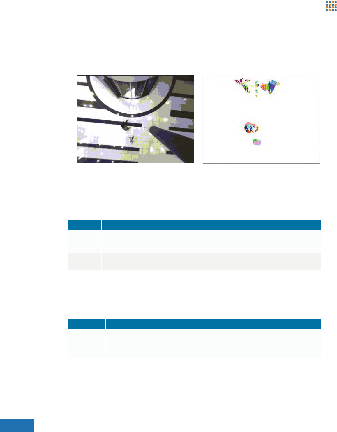
3. Check the Height Image on the right pane of the 3D Tracking Configuration page if it is not
possible to twist the Smart Device. The floor area should be mostly black, as shown in Figure
64. If there are large white patches on the color as shown in Figure 65, the smart device is
viewing the floor as being higher in the view, which will interfere while counting. If no white
patches exist, skip to step 12.
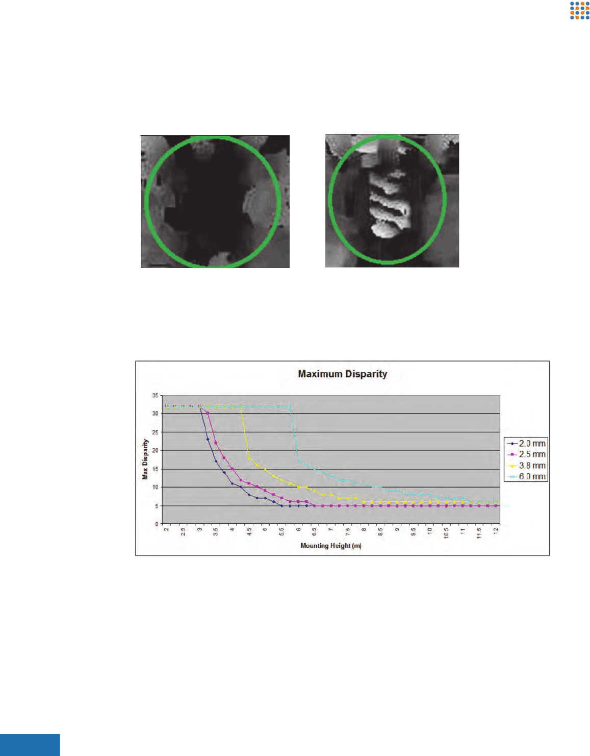
4. If the tracks are being dropped in the area where white patches exist, go to the Stereo sub-tab
of the 3D Tracking Configuration page and adjust the Max. Disparity according to the chart in
Figure 66. The Max Disparity setting will help the Smart Device ignore noise created by the
floor mat which it interprets as being close to the lens.
Figure 66: Maximum Disparity Chart
5. Save the changes.
6. Capture a new background on the Calibration page.
7. If the white patches still exist on the Height Image and if the device is still under-counting,
adjust the Surface Validation Diff. setting on the Stereo sub-tab from 1.0 to 0.5 .
8. Click Preview.
Figure 64: Good Height Image Figure 65: Bad Height Image
Brickstream® LIVE Advanced Installation Guide 77
Appendix C | Troubleshooting Brickstream® LIVE Smart Devices
9. Use the following table to determine your next action:
10. Save settings when white areas are no longer present.
11. When the Surface Validation Size and Surface Validation Diff settings are over-adjusted,
measured person heights can be affected. In the Height Image on the 3D Tracking
Configuration page, a person's shoulders and head should be visible in the image as light areas
at the top of each person as they walk through the scene, similar to Figure 67.
Figure 67: Height Image Examples
12. Adjust the following settings if the white patches are not present in the Height Image and the
Smart Device is under-counting.
If... Then...
If the white patches are no longer present Save the settings and capture a new background.
If the white patches are still present Adjust the setting gradually down to 0.1 and preview until white
patches are removed.
If the Surface Validation Diff setting at 0.1
does not remove the white patches
Adjust the Surface Validation Size setting gradually from 200 to 500
and preview.
Field Description
Surface Validation Size By increasing this value, the smart device measures a larger area around each pixel to
verify and set the smoothness of the area around it.
Surface Validation Diff. On a surface, the measurement of distance between the Smart Device and the
surface is actually determined by the results of many measurements. Some of these
measurements are discarded in order to address variance. By decreasing this setting,
more erroneous data is removed from the measurement to arrive at a smoother
surface reading.
Sub-Tab Field Description
Segmentation Min. Blob Mass Set this parameter to the lowest recommended setting of 16. Reducing
this setting will result in the Smart Device tracking what it interprets as
smaller objects within its view.
Tracking Min Obj Mass Set this parameter to the lowest recommended setting of 180. Reducing
this setting will result in the Smart Device tracking what it interprets as
smaller objects within its view.
Brickstream® LIVE Advanced Installation Guide 78
Appendix C | Troubleshooting Brickstream® LIVE Smart Devices
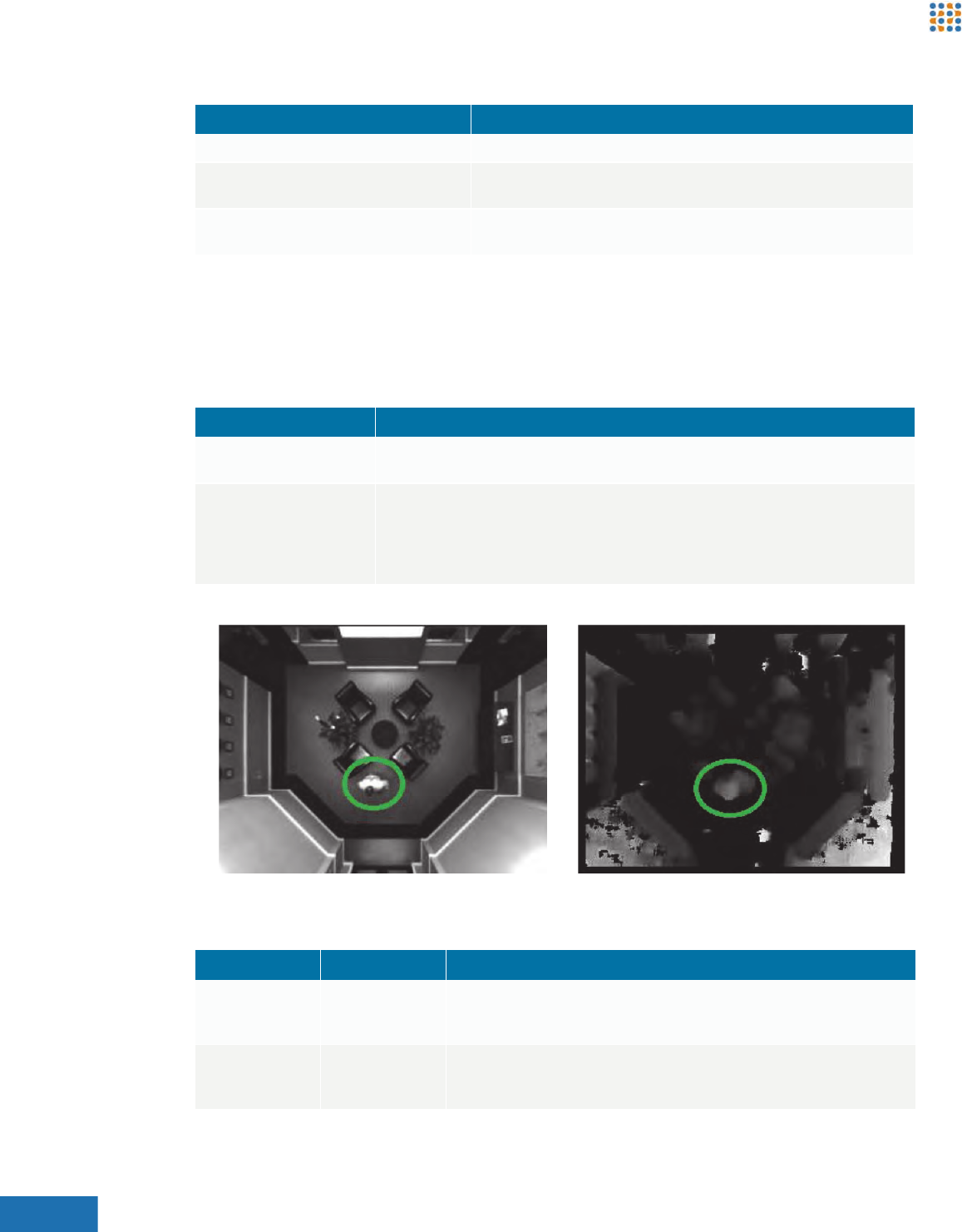
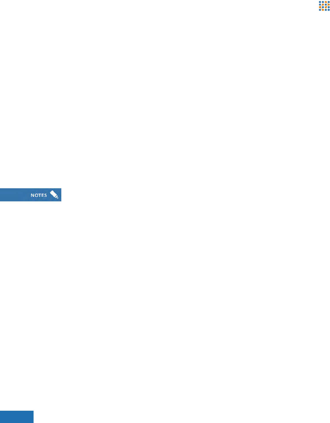
Which settings to adjust depends on the circumstances of the problem. When these two
settings are over-adjusted, the segmentation of people becomes less defined, as observed in
the Segmentation image, selected the right pane menu. In Figure 68, multi-colored segments
are closely grouped, which is an indication that segmentation is good. If these segments are
not closely grouped and they are poorly defined, the under counting problem worsens.
Figure 68: Correct Segmentation
13. Save the settings and capture a background.
14. If the tracks are being lost when people are walking into the scene close together, select the
Couples setting for the Counting Method on the Calibration Settings page.
15. Change both the Max. Z Block and Max. I Range settings on the Segmentation sub-tab of the
3D Tracking Configuration page to 32.
16. Save settings and capture a background.
17. If the problem persists, set the Max. I Range to the recommended maximum of 64.
18. If accuracy issues still exist after the preceding changes have been made, adjust the Person
Radius setting on the Tracking sub-tab.
19. When couples counting is enabled, the Person Radius setting is automatically changed from
34 to 28. If the Smart Device is over-counting (i.e., double counting), this setting can be
increased back to 34. If the Smart Device continues to under-count, lower the Person Radius
setting to 22.
Field Description
Max Z Block Reducing this setting increases the number of vertical parts people are broken into for analysis by
the device. By reducing this setting, the device is more likely to track people who walk together
closely.
Max I Range This is a measure of pixel intensity. Increasing this setting will allow the device to group more pixels
together based on their intensity and reduce the likelihood of under counting.
Field Description
Person Radius The Smart Device views each person as a shape similar to a cylinder. When you lower this setting,
you are instructing the Smart Device to shrink the size of the cylinder it interprets as a person. The
result is that more objects are tracked as people. The opposite effect will be observed when this
setting is increased.
Brickstream® LIVE Advanced Installation Guide 79
Appendix C | Troubleshooting Brickstream® LIVE Smart Devices
20. Save settings and capture a background.
21. If problems still persist, attempt to manually set and visually verify calibration parameters.
RESOLVING HIGH UNDEFINED DISPARITY DURING
CALIBRATION
If a Brickstream® LIVE Smart Device displays in pink 80-100% (high undefined disparity) and will
not calibrate, then complete the following steps to attempt to manually calibrate the
Smart Device.
1. Modify the Height field manually on the Calibration page of the smart device’s Web
application so that it is the actual mounting height of the smart device.
2. Capture the background.
3. Go to the 3D Tracking Configuration page.
4. Click the Quality tab.
5. Change the Undefined Threshold field value from 50 to 100.
6. Return to the Calibration page and check the Show Height checkbox to verify if people are
being tracked.
7. Change the height of the Smart Device manually until the height of adults appear in 160-
180cm, if they are being tracked.
8. Let the device run until several people pass through the count zone (ideally at least 50 arrivals
and exits) then go to the Counting page and check the Height Map to verify if the height map
looks good and colors are in the mustard yellow range.
9. If the Height Map does not show predominantly the mustard yellow range, clear the height
map and redo steps 6 through 8 if the height map is incorrect.
CAPTURING IMAGES FOR ADVANCED TECHNICAL
SUPPORT
Go to the 3D Tracking Configuration page of the Smart Device. The initial video displays, and
images are generated for the right lens view and the left lens view, both of which are available for
about 10 seconds. Capture images from both the right lens and the left lens as follows:
1. Change the address to (http://<ipaddress>/rightImage.jpg) once the video displays. An image
from the right lens displays.
2. Right-click the image and select Save Image As or Save Picture As (depending on which
browser you use) to store your image.
3. Open the file you just saved to verify if you can see the image.
4. Return to the 3D Tracking Configuration page and click the drop down arrow list box
underneath the image and select Left Lens from the list option.
Typically, undefined disparity issues are caused by shiny, marble floors or reflective walls.

Brickstream® LIVE Advanced Installation Guide 80
Appendix C | Troubleshooting Brickstream® LIVE Smart Devices
5. Change the address to (http://<ipaddress>/leftImage.jpg) once the video displays. An image
from the left lens displays.
6. Right-click the image and select Save Image As or Save Picture As (depending on which
browser you use) to store your image.
7. Open the saved files to verify if you can see the images.
8. Email these images to your Brickstream representative and await further instructions.