NORDICTRACK Treadmill Manual L0910020
User Manual: NORDICTRACK NORDICTRACK Treadmill Manual NORDICTRACK Treadmill Owner's Manual, NORDICTRACK Treadmill installation guides
Open the PDF directly: View PDF ![]() .
.
Page Count: 32

www.nordictrack.com
Model No. NTL08009.0
Serial No.
Write the serial number in the space
above for reference.
Serial Number
Decal
QUESTIONS?
If you have questions, or if parts are
damaged or missing, DO NOT CON-
TACT THE STORE; please contact
Customer Care.
iMPORTANT: Please register this
product (see the limited warranty
on the back cover of this manual)
before contacting Customer Care.
CALL TOLL-FREE:
1-888-825-2588
Mon.-Fri. 6 a.m.-6 p.m. MT
Sat. 8 a.m.-4 p.m. MT
ON THE WEB:
www.nordictrackservice.com
A AL
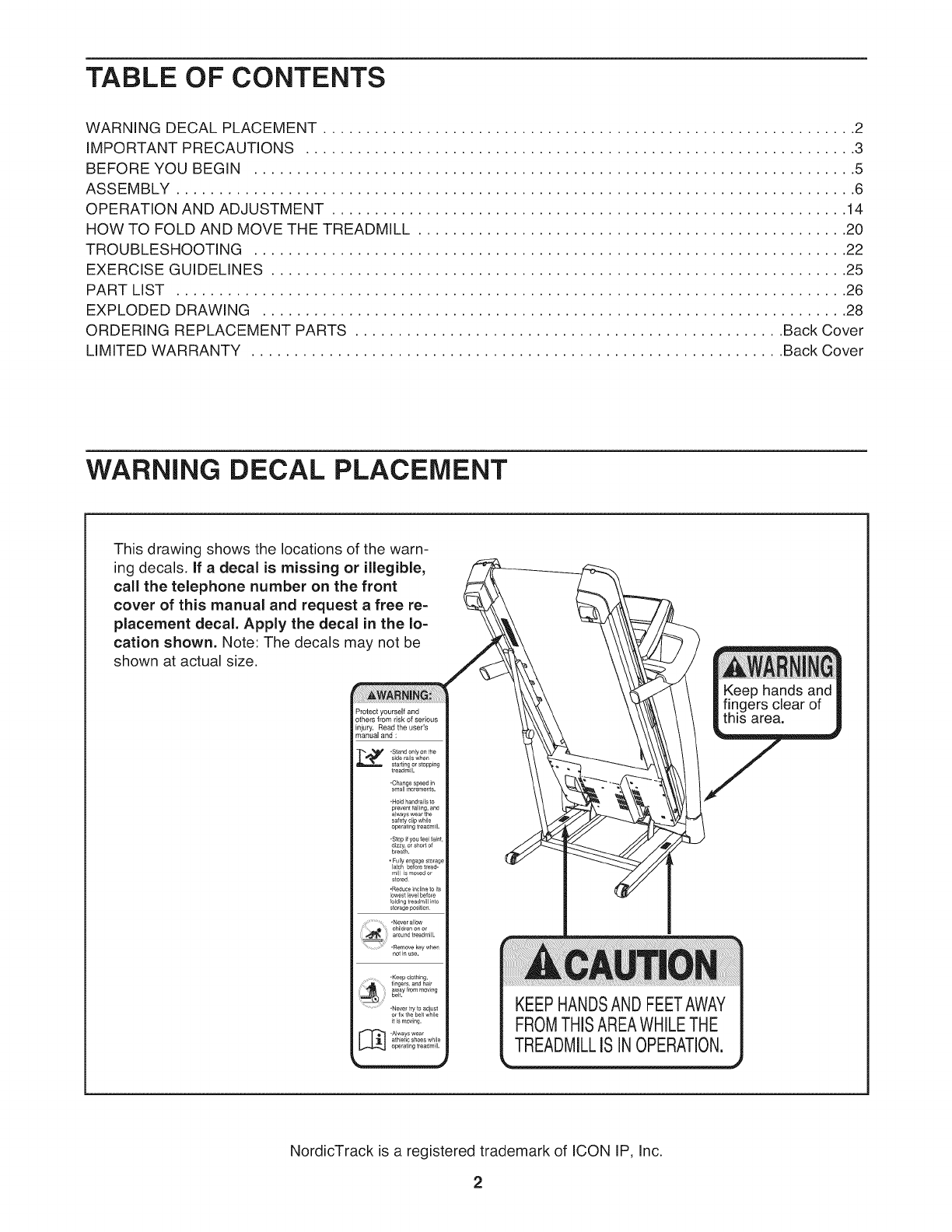
TABLE OF CONTENTS
WARNING DECAL PLACEMENT .............................................................. 2
IMPORTANT PRECAUTIONS ................................................................ 3
BEFORE YOU BEGIN ...................................................................... 5
ASSEMBLY ............................................................................... 6
OPERATION AND ADJUSTMENT ............................................................ 14
HOW TO FOLD AND MOVE THE TREADMILL .................................................. 20
TROUBLESHOOTING ..................................................................... 22
EXERCISE GUIDELINES ................................................................... 25
PART LIST .............................................................................. 26
EXPLODED DRAWING .................................................................... 28
ORDERING REPLACEMENT PARTS .................................................. Back Cover
LIMITED WARRANTY .............................................................. Back Cover
WARNING DECAL PLACEMENT
This drawing shows the locations of the warn-
ing decals, If a decal is missing or illegible,
call the telephone number on the front
cover of this manual and request a free re-
placement decal. Apply the decal in the lo-
cation shown. Note: The decals may not be
shown at actual size.
Protect yourself and
others from risk of serious
injury. Read the user's
manual and :
• Star_ only on the
side rals wflen
sa #7 orso _n
,_;_;_,,._pg
.Hold handra Is to
p_event falling, and
always wear the
safety clip wNle
ope atiPg treadmill,
roll s moved or
stored
• Reduce incline to its
lowest level before
foldL_g treadmill i_to
storage posit_oa
,Never allow
children on or
..... d treadmill,
•Remove key whe
notinuse.
•Keep clothing,
•Neve_ try to adiust
or llx the bell while
ff is moving.
_.Always wear
athletLc shoes while
operating t_eadmfll.
KEEPHANDSANDFEETAWAY
FROMTHISAREAWHILETHE
TREADMILLISINOPERATION.
NordicTrack is a registered trademark of ICON IP, Inc.
2

iMPORTANT PRECAUTIONS
3
4
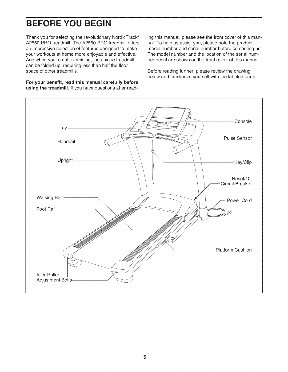
BEFORE YOU BEGIN
Thank you for selecting the revolutionary NordicTrack ®
A2550 PRO treadmill. The A2550 PRO treadmill offers
an impressive selection of features designed to make
your workouts at home more enjoyable and effective.
And when you're not exercising, the unique treadmill
can be folded up, requiring less than half the floor
space of other treadmills.
For your benefit, read this manual carefully before
using the treadmill. If you have questions after read-
ing this manual, please see the front cover of this man-
ual. To help us assist you, please note the product
model number and serial number before contacting us.
The model number and the location of the serial num-
ber decal are shown on the front cover of this manual.
Before reading further, please review the drawing
below and familiarize yourself with the labeled parts.
Tray
Handrail
Console
Pulse Sensor
Upright Key/Clip
Reset/Off
Breaker
Walking Belt
Foot Rail
Power Cord
Platform Cushion
Idler Roller
Adjustment Bolts.
5
ASSEMBLY
Assembly requires two persons. Set the treadmill in a cleared area and remove all packing materials. Do not
dispose of the packing materials until assembly is completed. Note: The underside of the treadmill walking
belt is coated with high-performance lubricant. During shipping, some lubricant may be transferred to the top of
the walking belt or the shipping carton. This is normal and does not affect treadmill performance, if there is lubri-
cant on top of the walking belt, simply wipe off the lubricant with a soft cloth and a mild, non-abrasive cleaner.
Assembly requires the included hex keys _and your own Phillips screwdriver _ ,
adjustable wrench _:_, needlenose pliers _ , and scissors _ .
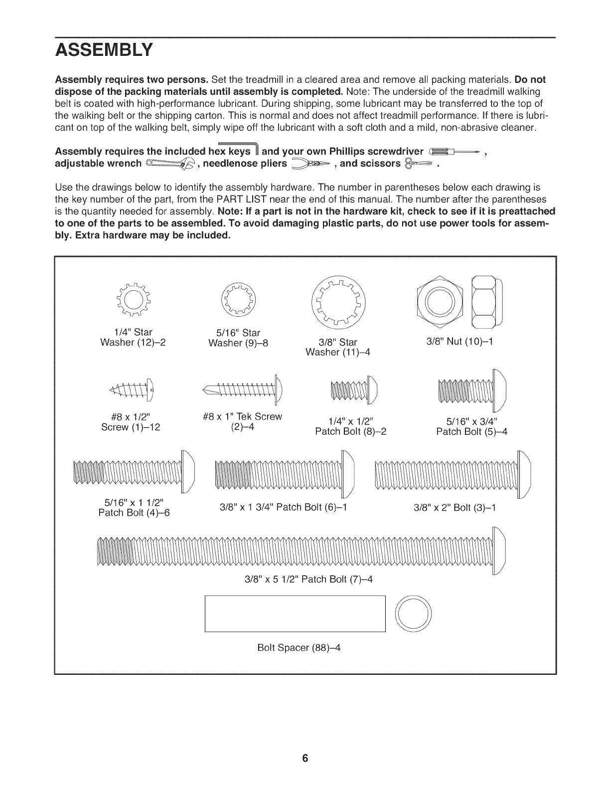
Use the drawings below to identify the assembly hardware. The number in parentheses below each drawing is
the key number of the part, from the PART LiST near the end of this manual. The number after the parentheses
is the quantity needed for assembly. Note: If a part is not in the hardware kit, check to see if it is preattached
to one of the parts to be assembled. To avoid damaging plastic parts, do not use power tools for assem-
bly. Extra hardware may be included.
1/4" Star
Washer (12)-2
#8 x 1/2"
Screw (1)-12
5/16" Star
Washer (9)-8 3/8" Star
Washer (11)-4
#8 x 1" Tek Screw
(2)-4 1/4" x 1/2"
Patch Bolt (8)-2
3/8" Nut (10)-1
5/16" x 3/4"
Patch Bolt (5)-4
5/16"x 1 1/2"
Patch Bolt (4)-6 3/8" x 1 3/4" Patch Bolt (6)-1 3/8" x 2" Bolt (3)-1
3/8" x 5 1/2" Patch Bolt (7)-4
Bolt Spacer (88)-4
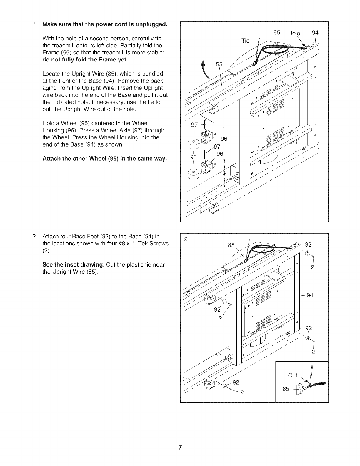
1. Make sure that the power cord is unplugged.
With the help of a second person, carefully tip
the treadmill onto its left side. Partially fold the
Frame (55) so that the treadmill is more stable;
do not fully fold the Frame yet.
Locate the Upright Wire (85), which is bundled
at the front of the Base (94). Remove the pack-
aging from the Upright Wire. Insert the Upright
wire back into the end of the Base and pull it out
the indicated hole. If necessary, use the tie to
pull the Upright Wire out of the hole.
Hold a Wheel (95) centered in the Wheel
Housing (96). Press a Wheel Axle (97) through
the Wheel. Press the Wheel Housing into the
end of the Base (94) as shown•
Attach the other Wheel (95) in the same way.
55
Tie
85 Hole 94
•Attach four Base Feet (92) to the Base (94) in
the locations shown with four #8 x 1" Tek Screws
(2).
See the inset drawing. Cut the plastic tie near
the Upright Wire (85).
2
85\
92
92
2
cut j
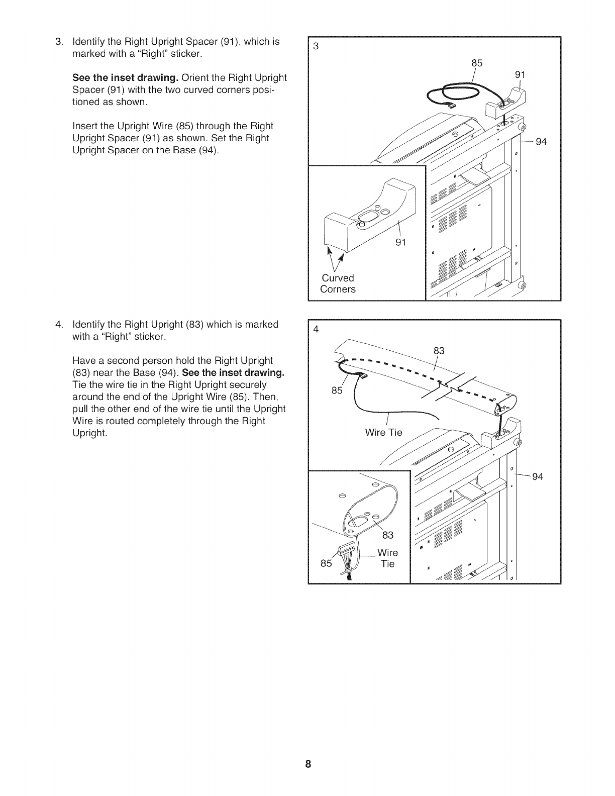
.Identify the Right Upright Spacer (91), which is
marked with a "Right" sticker.
See the inset drawing. Orient the Right Upright
Spacer (91) with the two curved corners posi-
tioned as shown.
Insert the Upright Wire (85) through the Right
Upright Spacer (91) as shown. Set the Right
Upright Spacer on the Base (94).
Curved
Corners
91
85 91
.Identify the Right Upright (83) which is marked
with a "Right" sticker.
Have a second person hold the Right Upright
(83) near the Base (94). See the inset drawing.
Tie the wire tie in the Right Upright securely
around the end of the Upright Wire (85). Then,
pull the other end of the wire tie until the Upright
Wire is routed completely through the Right
Upright.
85
Wire Tie
Tie
83
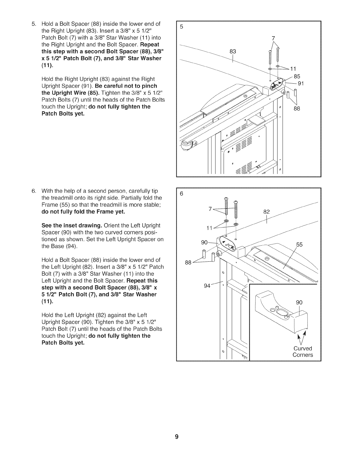
5. 5
Holda BoltSpacer(88)insidethelowerendof
theRightUpright(83).Inserta3/8"x 5 1/2"
PatchBolt(7)witha3/8"StarWasher(11)into
theRightUprightandtheBoltSpacer.Repeat
thisstepwith a second Bolt Spacer (88), 3/8"
× 5 1/2" Patch Bolt (7), and 3/8" Star Washer
(11).
Hold the Right Upright (83) against the Right
Upright Spacer (91). Be careful not to pinch
the Upright Wire (85). Tighten the 3/8" x 5 1/2"
Patch Bolts (7) until the heads of the Patch Bolts
touch the Upright; do not fully tighten the
Patch Bolts yet.
83
88
,With the help of a second person, carefully tip
the treadmill onto its right side. Partially fold the
Frame (55) so that the treadmill is more stable;
do not fully fold the Frame yet.
See the inset drawing. Orient the Left Upright
Spacer (90) with the two curved corners posi-
tioned as shown. Set the Left Upright Spacer on
the Base (94).
Hold a Bolt Spacer (88) inside the lower end of
the Left Upright (82). Insert a 3/8" x 5 1/2" Patch
Bolt (7) with a 3/8" Star Washer (11) into the
Left Upright and the Bolt Spacer. Repeat this
step with a second Bolt Spacer (88), 3/8" x
5 1/2" Patch Bolt (7), and 3/8" Star Washer
(11).
Hold the Left Upright (82) against the Left
Upright Spacer (90). Tighten the 3/8" x 5 1/2"
Patch Bolt (7) until the heads of the Patch Bolts
touch the Upright; do not fully tighten the
Patch Bolts yet.
88
82
55
90
Curved
Corners
9
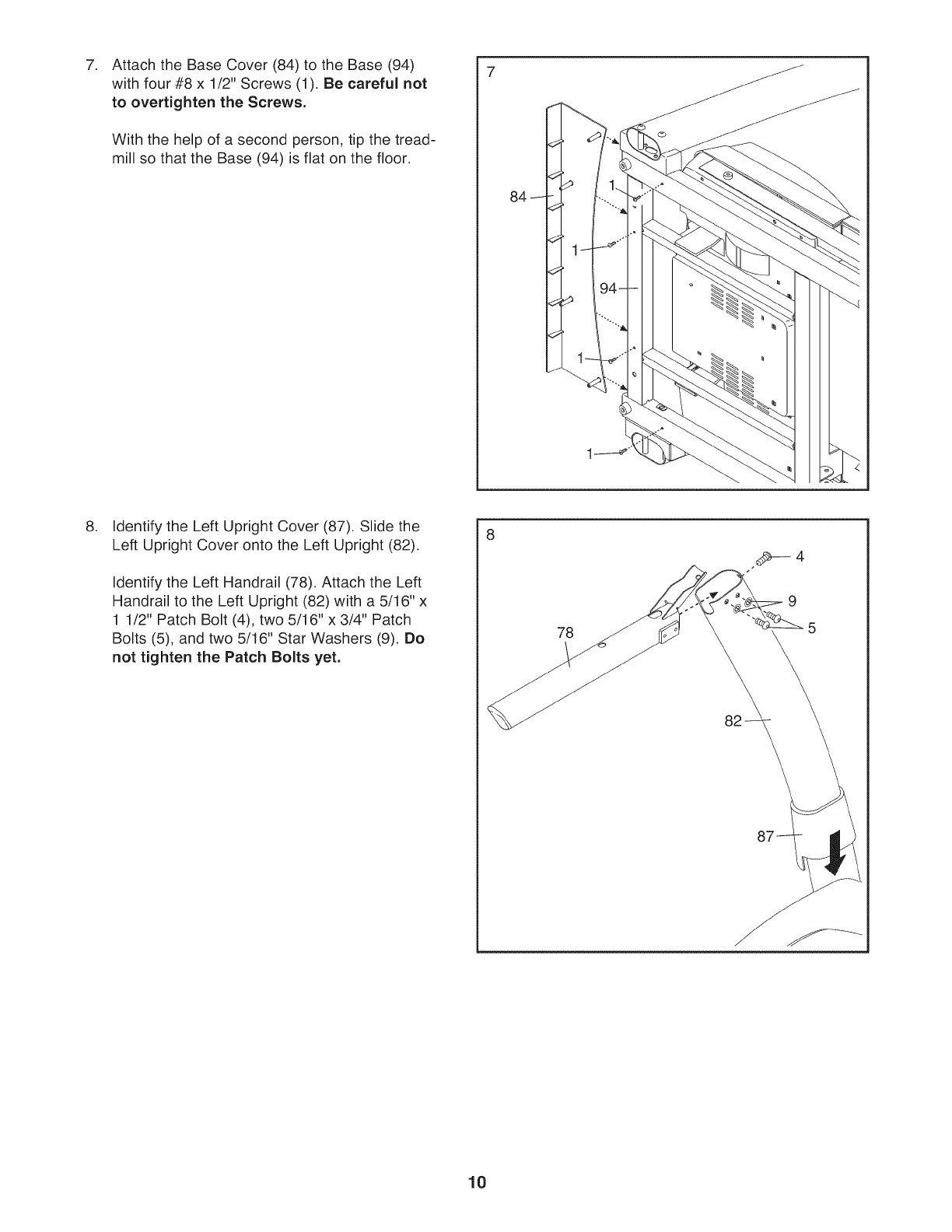
7. 7
Attach the Base Cover (84) to the Base (94)
with four #8 x 1/2" Screws (1). Be careful not
to overtighten the Screws.
With the help of a second person, tip the tread-
mill so that the Base (94) is flat on the floor.
.Identify the Left Upright Cover (87). Slide the
Left Upright Cover onto the Left Upright (82).
Identify the Left Handrail (78). Attach the Left
Handrail to the Left Upright (82) with a 5/16" x
1 1/2" Patch Bolt (4), two 5/16" x 3/4" Patch
Bolts (5), and two 5/16" Star Washers (9). Do
not tighten the Patch Bolts yet.
8
78
9
5
82
10
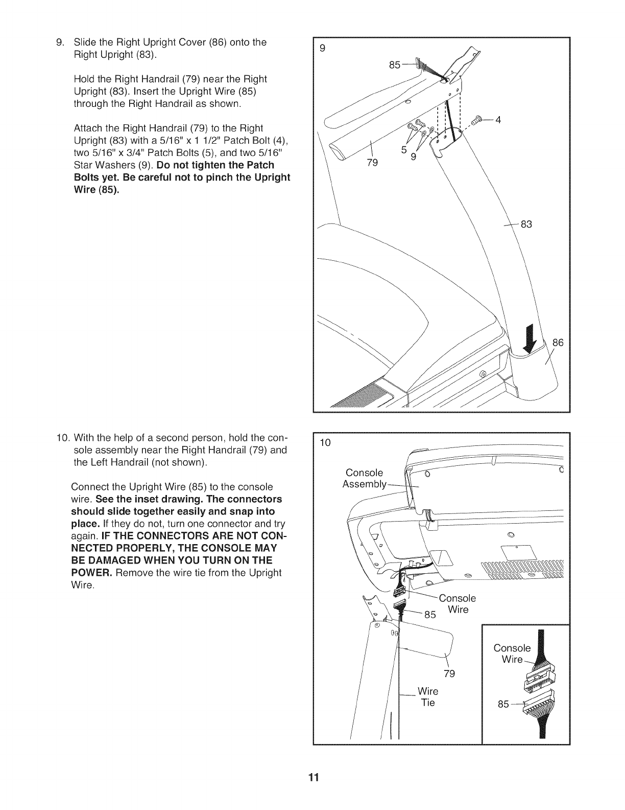
Slide the Right Upright Cover (86) onto the
Right Upright (83).
Hold the Right Handrail (79) near the Right
Upright (83). Insert the Upright Wire (85)
through the Right Handrail as shown.
Attach the Right Handrail (79) to the Right
Upright (83) with a 5/16" x 1 1/2" Patch Bolt (4),
two 5/16" x 3/4" Patch Bolts (5), and two 5/16"
Star Washers (9). Do not tighten the Patch
Bolts yet. Be careful not to pinch the Upright
Wire (85).
10. With the help of a second person, hold the con-
sole assembly near the Right Handrail (79) and
the Left Handrail (not shown).
Connect the Upright Wire (85) to the console
wire, See the inset drawing. The connectors
should slide together easily and snap into
place. If they do not, turn one connector and try
again. IF THE CONNECTORS ARE NOT CON-
NECTED PROPERLY, THE CONSOLE MAY
BE DAMAGED WHEN YOU TURN ON THE
POWER. Remove the wire tie from the Upright
Wire.
10
Console
Assembl,
Console
Wire
Wire
Tie
79
Console
Wirej
85-
11
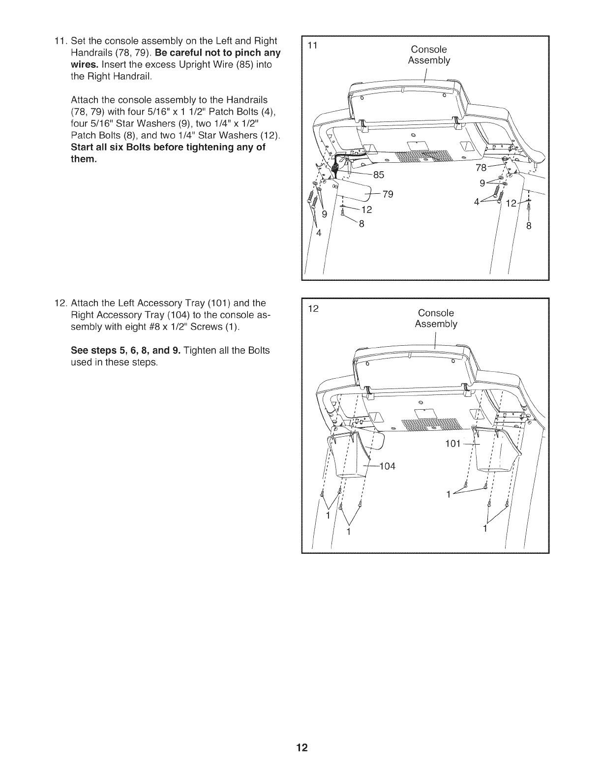
11. Set the console assembly on the Left and Right
Handrails (78, 79). Be careful not to pinch any
wires. Insert the excess Upright Wire (85) into
the Right Handrail.
Attach the console assembly to the Handrails
(78, 79) with four 5/16" x 1 1/2" Patch Bolts (4),
four 5/16" Star Washers (9), two 1/4" x 1/2"
Patch Bolts (8), and two 1/4" Star Washers (12).
Start all six Bolts before tightening any of
them.
11 Console
Assembly
12. Attach the Left Accessory Tray (101) and the
Right Accessory Tray (104) to the console as-
sembly with eight #8 x 1/2" Screws (1).
See steps 5, 8, 8, and 9. Tighten all the Bolts
used in these steps.
12 Console
Assembly
101
12
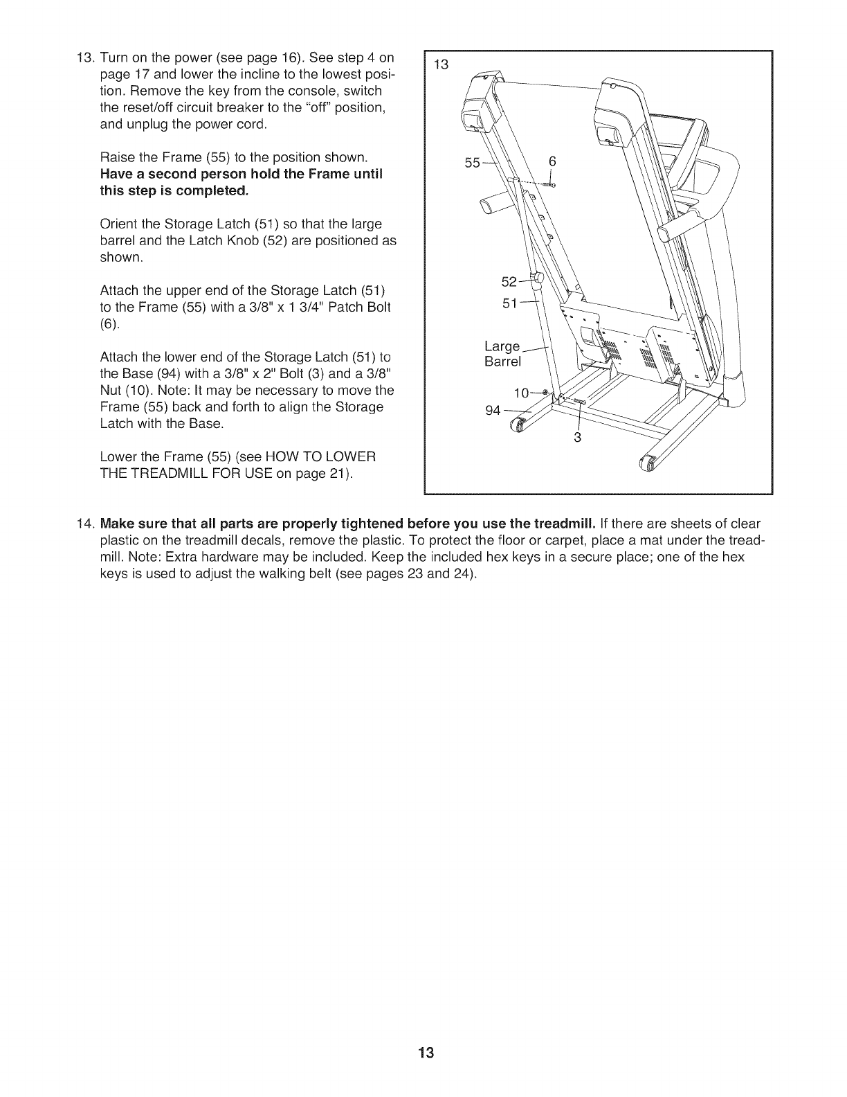
13. Turn on the power (see page 16). See step 4 on
page 17 and lower the incline to the lowest posi-
tion. Remove the key from the console, switch
the reset/off circuit breaker to the "off" position,
and unplug the power cord.
Raise the Frame (55) to the position shown.
Have a second person hold the Frame until
this step is completed.
Orient the Storage Latch (51) so that the large
barrel and the Latch Knob (52) are positioned as
shown.
Attach the upper end of the Storage Latch (51)
to the Frame (55) with a 3/8" x 1 3/4" Patch Bolt
(6).
Attach the lower end of the Storage Latch (51) to
the Base (94) with a 3/8" x 2" Bolt (3) and a 3/8"
Nut (10). Note: It may be necessary to move the
Frame (55) back and forth to align the Storage
Latch with the Base.
Lower the Frame (55) (see HOW TO LOWER
THE TREADMILL FOR USE on page 21).
13
52
51
Barrel
6
3
14. Make sure that all parts are properly tightened before you use the treadmill. If there are sheets of clear
plastic on the treadmill decals, remove the plastic. To protect the floor or carpet, place a mat under the tread-
mill. Note: Extra hardware may be included. Keep the included hex keys in a secure place; one of the hex
keys is used to adjust the walking belt (see pages 23 and 24).
13
OPERATION AND ADJUSTMENT
THE PRE-LUBRICATED WALKING BELT
Your treadmill features a walking belt coated with high-
performance lubricant. IMPORTANT: Never apply sil-
icone spray or other substances to the walking
belt or the walking platform. Such substances will
deteriorate the walking belt and cause excessive
wear.
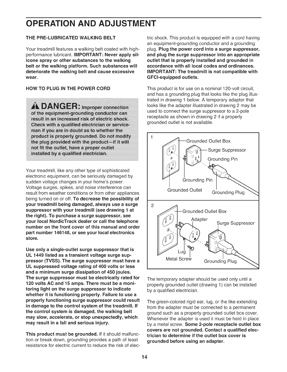
HOW TO PLUG IN THE POWER CORD
tric shock. This product is equipped with a cord having
an equipment-grounding conductor and a grounding
plug. Plug the power cord into a surge suppressor,
and plug the surge suppressor into an appropriate
outlet that is properly installed and grounded in
accordance with all local codes and ordinances.
IMPORTANT: The treadmill is not compatible with
GFCl-equipped outlets.
This product is for use on a nominal 120-volt circuit,
and has a grounding plug that looks like the plug illus-
trated in drawing 1 below. A temporary adapter that
looks like the adapter illustrated in drawing 2 may be
used to connect the surge suppressor to a 2-pole
receptacle as shown in drawing 2 if a properly
grounded outlet is not available.
Your treadmill, like any other type of sophisticated
electronic equipment, can be seriously damaged by
sudden voltage changes in your home's power.
Voltage surges, spikes, and noise interference can
result from weather conditions or from other appliances
being turned on or off. To decrease the possibility of
your treadmill being damaged, always use a surge
suppressor with your treadmill (see drawing 1 at
the right). To purchase a surge suppressor, see
your local NordicTrack dealer or call the telephone
number on the front cover of this manual and order
part number 146148, or see your local electronics
store.
Use only a single-outlet surge suppressor that is
UL 1449 listed as a transient voltage surge sup-
pressor (TVSS). The surge suppressor must have a
UL suppressed voltage rating of 400 volts or less
and a minimum surge dissipation of 450 joules.
The surge suppressor must be electrically rated for
120 volts AC and 15 amps. There must be a moni-
toring light on the surge suppressor to indicate
whether it is functioning properly. Failure to use a
properly functioning surge suppressor could result
in damage to the control system of the treadmill. If
the control system is damaged, the walking belt
may slow, accelerate, or stop unexpectedly, which
may result in a fall and serious injury.
This product must be grounded, if it should malfunc-
tion or break down, grounding provides a path of least
resistance for electric current to reduce the risk of elec-
I--Grounded Outlet Box
_..] _Surge Suppressor
__'_. Grounding Pin
Grounding Pin
Grounded Outlet Grounding Plug
2
_A-]L-Grounded Outlet Box
/ll _JI Adapter
__._.. -.___Su rge buppressor
wlelal Screw Groundir_g Plug
The temporary adapter should be used only until a
properly grounded outlet (drawing 1) can be installed
by a qualified electrician.
The green-colored rigid ear, lug, or the like extending
from the adapter must be connected to a permanent
ground such as a properly grounded outlet box cover.
Whenever the adapter is used it must be held in place
by a metal screw. Some 2-pole receptacle outlet box
covers are not grounded. Contact a qualified elec-
trician to determine if the outlet box cover is
grounded before using an adapter.
14
CONSOLE DIAGRAM
_--zzzzssz
[Intermix_IH$Illl 2.81
\
f
START STOP
7
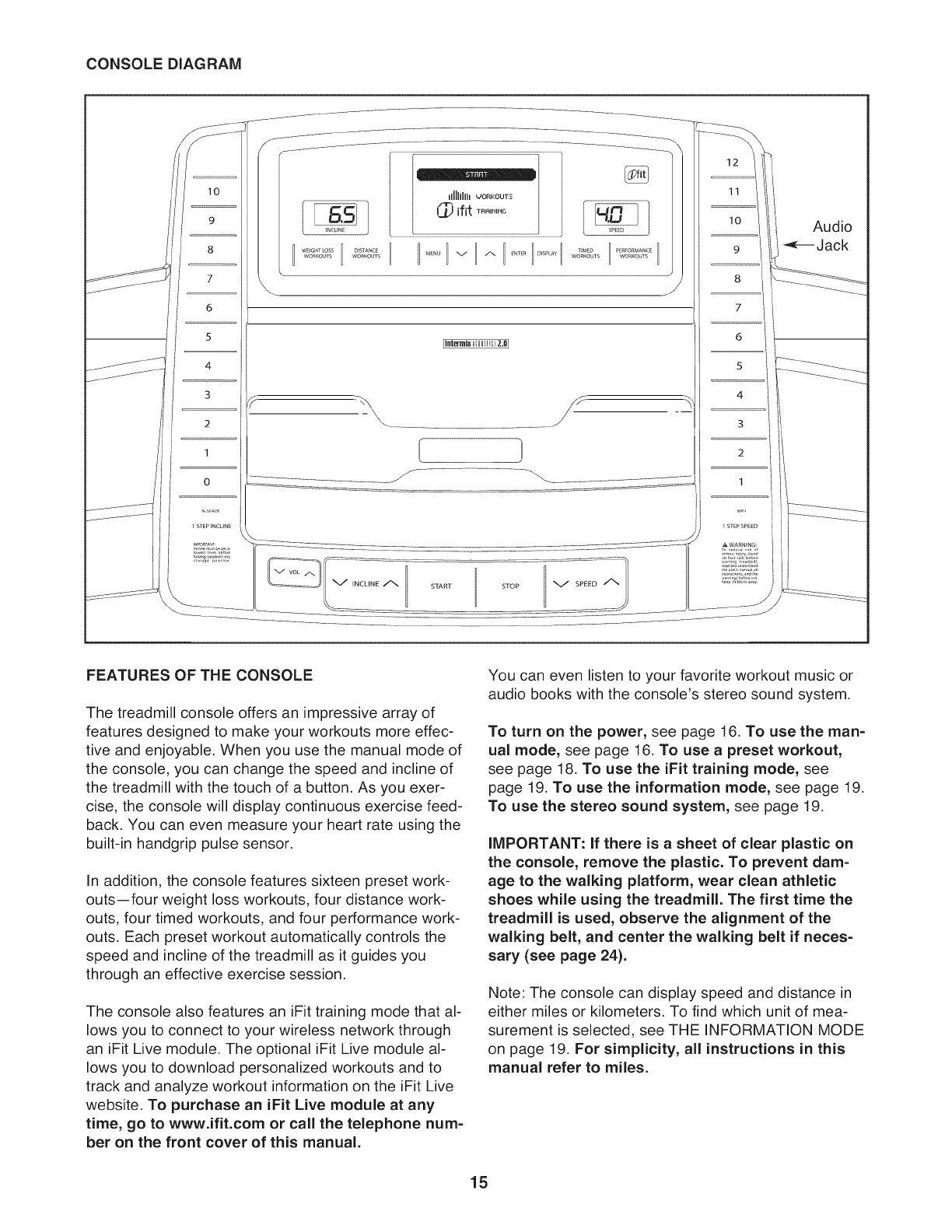
FEATURES OF THE CONSOLE
The treadmill console offers an impressive array of
features designed to make your workouts more effec-
tive and enjoyable. When you use the manual mode of
the console, you can change the speed and incline of
the treadmill with the touch of a button. As you exer-
cise, the console will display continuous exercise feed-
back. You can even measure your heart rate using the
built-in handgrip pulse sensor.
In addition, the console features sixteen preset work-
outs--four weight loss workouts, four distance work-
outs, four timed workouts, and four performance work-
outs. Each preset workout automatically controls the
speed and incline of the treadmill as it guides you
through an effective exercise session.
The console also features an iFit training mode that al-
lows you to connect to your wireless network through
an iFit Live module. The optional iFit Live module al-
lows you to download personalized workouts and to
track and analyze workout information on the iFit Live
website. To purchase an iFit Live module at any
time, go to www.ifit.com or call the telephone num-
ber on the front cover of this manual.
You can even listen to your favorite workout music or
audio books with the console's stereo sound system.
To turn on the power, see page 16. To use the man-
ual mode, see page 16. To use a preset workout,
see page 18. To use the iFit training mode, see
page 19. To use the information mode, see page 19.
To use the stereo sound system, see page 19.
IMPORTANT: If there is a sheet of clear plastic on
the console, remove the plastic. To prevent dam-
age to the walking platform, wear clean athletic
shoes while using the treadmill. The first time the
treadmill is used, observe the alignment of the
walking belt, and center the walking belt if neces-
sary (see page 24).
Note: The console can display speed and distance in
either miles or kilometers. To find which unit of mea-
surement is selected, see THE INFORMATION MODE
on page 19. For simplicity, all instructions in this
manual refer to miles.
15
HOW TO TURN ON THE POWER HOW TO USE THE MANUAL MODE
iMPORTANT: if the treadmill has been exposed to
cold temperatures, allow it to warm to room tem-
perature before turning on the power, if you do not
do this, you may damage the console displays or
other electrical components.
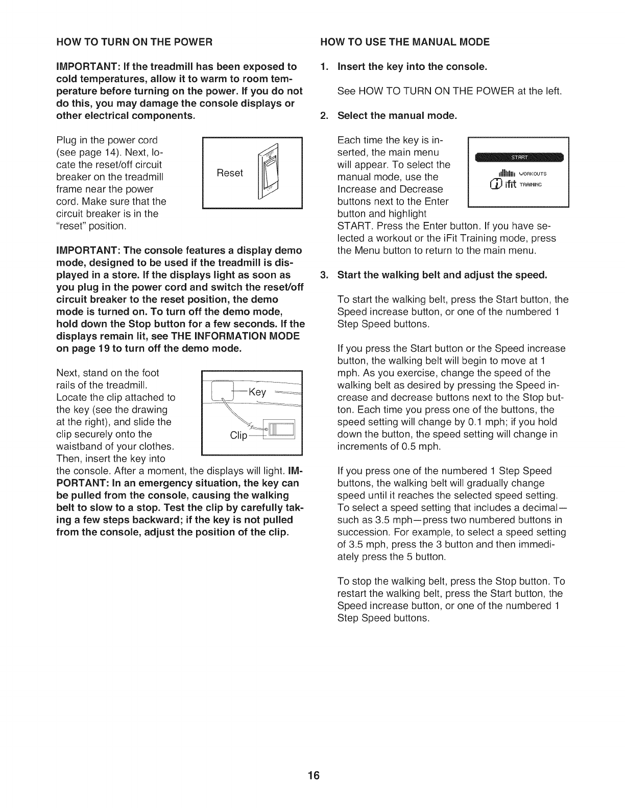
Plug in the power cord
(see page 14). Next, lo-
cate the reset/off circuit
breaker on the treadmill
frame near the power
cord. Make sure that the
circuit breaker is in the
"reset" position.
Reset
iMPORTANT: The console features a display demo
mode, designed to be used if the treadmill is dis-
played in a store, if the displays light as soon as
you plug in the power cord and switch the reset/off
circuit breaker to the reset position, the demo
mode is turned on. To turn off the demo mode,
hold down the Stop button for a few seconds. If the
displays remain lit, see THE INFORMATION MODE
on page 19 to turn off the demo mode.
Next, stand on the foot
rails of the treadmill.
Locate the clip attached to
the key (see the drawing
at the right), and slide the
clip securely onto the
waistband of your clothes.
Then, insert the key into
the console. After a moment, the displays will light. IM-
PORTANT: In an emergency situation, the key can
be pulled from the console, causing the walking
belt to slow to a stop. Test the clip by carefully tak-
ing a few steps backward; if the key is not pulled
from the console, adjust the position of the clip.
1. insert the key into the console.
See HOW TO TURN ON THE POWER at the left.
2. Select the manual mode.
Each time the key is in-
serted, the main menu
will appear. To select the
manual mode, use the
Increase and Decrease
buttons next to the Enter
button and highlight
START. Press the Enter button. If you have se-
lected a workout or the iFit Training mode, press
the Menu button to return to the main menu.
Illlllllll _ORKOUTS
(_ ifit TRRINING
3. Start the walking belt and adjust the speed.
To start the walking belt, press the Start button, the
Speed increase button, or one of the numbered 1
Step Speed buttons.
If you press the Start button or the Speed increase
button, the walking belt will begin to move at 1
mph. As you exercise, change the speed of the
walking belt as desired by pressing the Speed in-
crease and decrease buttons next to the Stop but-
ton. Each time you press one of the buttons, the
speed setting will change by 0.1 mph; if you hold
down the button, the speed setting will change in
increments of 0.5 mph.
If you press one of the numbered 1 Step Speed
buttons, the walking belt will gradually change
speed until it reaches the selected speed setting.
To select a speed setting that includes a decimal--
such as 3.5 mph--press two numbered buttons in
succession. For example, to select a speed setting
of 3.5 mph, press the 3 button and then immedi-
ately press the 5 button.
To stop the walking belt, press the Stop button. To
restart the walking belt, press the Start button, the
Speed increase button, or one of the numbered 1
Step Speed buttons.
16
4. Change the incline of the treadmill as desired. 6. Measure your heart rate if desired.
.
To change the incline of the treadmill, press the
Incline increase or decrease button, or one of the 1
Step Incline buttons numbered 0 to 10. Each time
you press one of the buttons, the incline will gradu-
ally change until it reaches the selected incline set-
ting.
Select adisplay mode and monitor your
progress with the display.
The console offers several display modes. The dis-
play mode that you select will determine which
workout information is shown. To select the de-
sired display mode, repeatedly press the Display
button or the Increase and Decrease buttons next
to the Enter button.
As you walk or run on the treadmill, the center dis-
play can show the following workout information:
-The incline level of the treadmill.
-The speed of the walking belt.
-The distance that you have walked or run.
-The elapsed time.
-Your heart rate (see step 6 on this page).
-The approximate number of calories you have
burned.
Regardless of which display mode you select, the
speed and incline settings will appear in the speed
and incline displays.
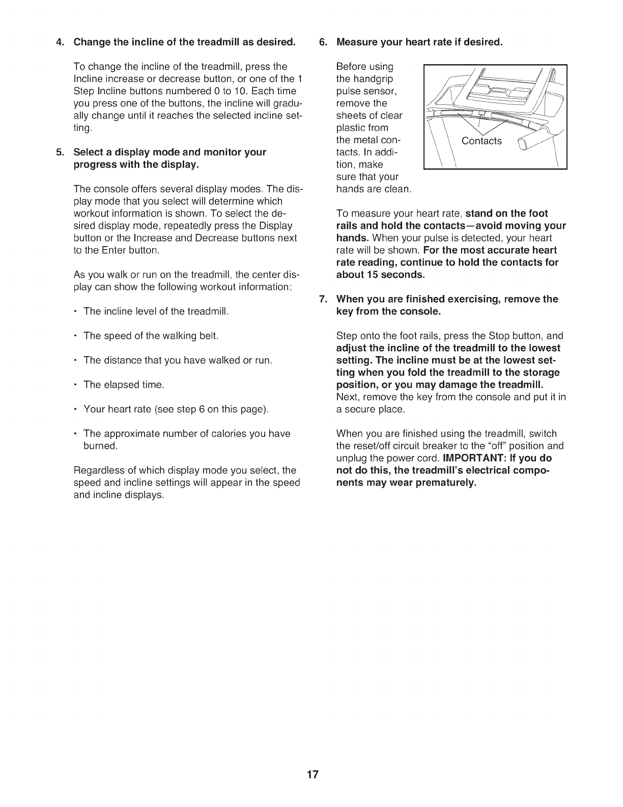
.
Before using
the handgrip
pulse sensor,
remove the
sheets of clear
plastic from
the metal con-
tacts. In addi-
tion, make
sure that your
hands are clean.
Contacts
To measure your heart rate, stand on the foot
rails and hold the contacts--avoid moving your
hands. When your pulse is detected, your heart
rate will be shown, For the most accurate heart
rate reading, continue to hold the contacts for
about 15 seconds.
When you are finished exercising, remove the
key from the console.
Step onto the foot rails, press the Stop button, and
adjust the incline of the treadmill to the lowest
setting. The incline must be at the lowest set-
ting when you fold the treadmill to the storage
position, or you may damage the treadmill.
Next, remove the key from the console and put it in
a secure place.
When you are finished using the treadmill, switch
the reset/off circuit breaker to the "off" position and
unplug the power cord. IMPORTANT: If you do
not do this, the treadmill's electrical compo-
nents may wear prematurely.
17

HOW TO USE A PRESET WORKOUT
1. Insert the key into the console.
See HOW TO TURN ON THE POWER on page 16.
2. Select a preset workout.
If you have selected a workout or the iFit Training
mode, press the Menu button to return to the main
menu.
To select a preset workout, use the Increase and
Decrease buttons next to the Enter button and
highlight WORKOUTS. Press the Enter button.
You can also press the Weight Loss Workouts but-
ton, Distance Workouts button, Timed Workouts
button, or Performance Workouts button.
Use the Increase and Decrease buttons to select
the desired workout. When you select a workout,
the display will show the name, the duration, the
maximum speed setting, the maximum incline set-
ting, and a profile of the speed settings of the work-
out. Press the Enter button. Note: When a distance
workout is selected, the duration of the workout will
not appear in the display.
3. Start the workout.
Press the Start button to start the workout. A mo-
ment after you press the button, the treadmill will
automatically adjust to the first speed and incline
settings of the workout. Hold the handrails and
begin walking.
Each preset workout is divided into segments. One
speed setting and one incline setting are pro-
grammed for each segment. Note: The same
speed and/or incline setting may be programmed
for consecutive segments.
During the workout, the profile will show your
progress. Press the Display button repeatedly to
view the profile. The flashing segment of the profile
represents the current segment of the workout.
The height of the flashing segment indicates the
speed setting for the current segment.
At the end of each segment, a series of tones will
sound and the next segment of the profile will
begin to flash. If a new speed and/or incline setting
.
is programmed for
the next segment, Current Segment
the speed and/or
incline setting will
flash in the displays ||||||
for a few seconds
and the treadmill will automatically adjust to the
new speed and incline settings.
The workout will continue in this way until the last
segment of the profile flashes in the display and
the last segment ends. The walking belt will then
slow to a stop.
Note: The calorie goal for each weight loss
workout is an estimate of the number of calo-
ries that you will burn during the workout. The
actual number of calories that you burn will de-
pend on your weight, in addition, if you manu-
ally change the speed or incline of the treadmill
during the workout, the number of calories you
burn will be affected.
If the speed or incline setting is too high or too low
at any time during the workout, you can manually
override the setting by pressing the Speed or
Incline buttons; however, when the next segment
of the workout begins, the treadmill will auto-
matically adjust to the speed and incline set-
tings for the next segment.
To stop the workout at any time, press the Stop
button. To restart the workout, press the Start but-
ton or the Speed increase button. The walking belt
will begin to move at 1 mph. When the next seg-
ment of the workout begins, the treadmill will auto-
matically adjust to the speed and incline settings
for the next segment.
Select a display mode and monitor your
progress with the display.
See step 5 on page 17.
5. Measure your heart rate if desired.
.
See step 6 on page 17.
When you are finished exercising, remove the
key from the console.
See step 7 on page 17.
18
HOW TO USE THE IFIT TRAINING MODE
The console features the revolutionary iFit Live mod-
ule. The optional iFit Live module allows you to connect
to your wireless network and unlocks exciting new fea-
tures. For example, you can download personalized
workouts and track and analyze workout information on
the iFit Live website. To purchase an iFit Live mod-
ule at any time, go to www.ifit.com or call the tele-
phone number on the front cover of this manual.
To select the iFit training mode, use the increase and
Decrease buttons next to the Enter button and high-
light IFIT TRAINING. Press the Enter button. For more
information on the iFit training mode, go to
www.iFit.com. Note: To use an iFit Live module, you
must have your own wireless network and access to a
computer with an internet connection.
The console features a display demo mode, designed
to be used if the treadmill is displayed in a store. While
the demo mode is turned on, the console will function
normally when you plug in the power cord, switch the
reset/off circuit breaker to the reset position, and insert
the key into the console. However, when you remove
the key, the displays will remain lit, although the but-
tons will not function, if the demo mode is turned on,
the word "ON" will appear in display while the informa-
tion mode is selected. To turn on or turn off the demo
mode, press the Speed decrease button.
The display will also show the contrast level of the dis-
play. Press the incline increase and decrease buttons
to adjust the contrast.
To exit the information mode, remove the key from the
console.
THE INFORMATION MODE
The console features an information mode that keeps
track of the total distance that the walking belt has
moved and the total number of hours that the treadmill
has been used. The information mode also allows you
to select miles or kilometers to measure distance, and
to turn on and turn off the display demo mode. You
can also adjust the contrast level of the display.
To select the information mode, hold down the Stop
button, insert the key into the console, and then re-
lease the Stop button. When the information mode is
selected, the following information will appear in the
display:
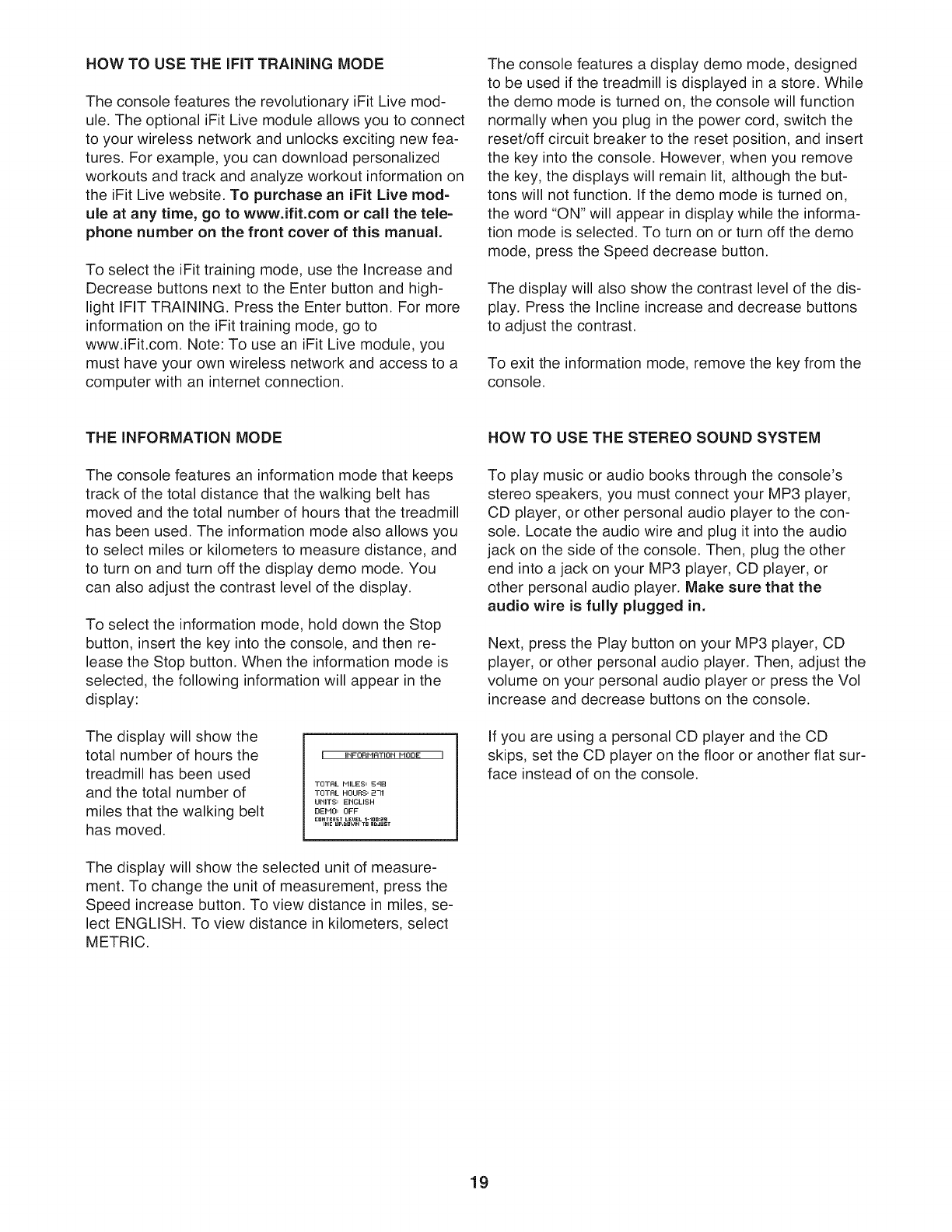
The display will show the
total number of hours the
treadmill has been used
and the total number of
miles that the walking belt
has moved.
IINFORP1RTION MODE I
TOTRL MILES= S'tB
TOTRL HOURS= 231
UNITS= ENGLISH
DEFIO= OFF
E._TRnSTLEVELl-l..=ag
INE ur._wN T_ H_dU_T
The display will show the selected unit of measure-
ment. To change the unit of measurement, press the
Speed increase button. To view distance in miles, se-
lect ENGLISH. To view distance in kilometers, select
METRIC.
HOW TO USE THE STEREO SOUND SYSTEM
To play music or audio books through the console's
stereo speakers, you must connect your MP3 player,
CD player, or other personal audio player to the con-
sole. Locate the audio wire and plug it into the audio
jack on the side of the console. Then, plug the other
end into a jack on your MP3 player, CD player, or
other personal audio player. Make sure that the
audio wire is fully plugged in.
Next, press the Play button on your MP3 player, CD
player, or other personal audio player. Then, adjust the
volume on your personal audio player or press the Vol
increase and decrease buttons on the console.
if you are using a personal CD player and the CD
skips, set the CD player on the floor or another flat sur-
face instead of on the console.
19
HOW TO FOLD AND MOVE THE TREADMILL
HOW TO FOLD THE TREADMILL FOR STORAGE
Before folding the treadmill, adjust the incline to the
lowest position, if you do not do this, you may damage the
treadmill when you fold it. Remove the key and unplug the
power cord. CAUTION: You must be able to safely lift 45
Ibs. (20 kg) to raise, lower, or move the treadmill.
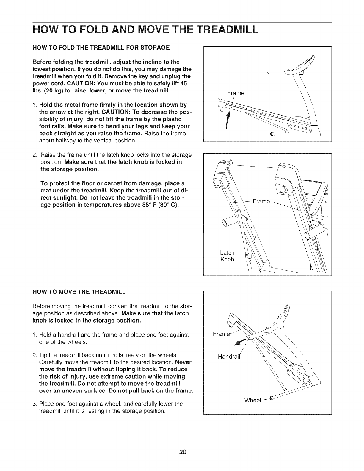
1. Hold the metal frame firmly in the location shown by
the arrow at the right. CAUTION: To decrease the pos-
sibility of injury, do not lift the frame by the plastic
foot rails. Make sure to bend your legs and keep your
back straight as you raise the frame. Raise the frame
about halfway to the vertical position.
2. Raise the frame until the latch knob locks into the storage
position. Make sure that the latch knob is locked in
the storage position.
To protect the floor or carpet from damage, place a
mat under the treadmill. Keep the treadmill out of di-
rect sunlight. Do not leave the treadmill in the stor-
age position in temperatures above 85°F (30°C).
Frame
Latch
Knob
HOW TO MOVE THE TREADMILL
Before moving the treadmill, convert the treadmill to the stor-
age position as described above. Make sure that the latch
knob is locked in the storage position.
1. Hold a handrail and the frame and place one foot against
one of the wheels.
2. Tip the treadmill back until it rolls freely on the wheels.
Carefully move the treadmill to the desired location. Never
move the treadmill without tipping it back. To reduce
the risk of injury, use extreme caution while moving
the treadmill. Do not attempt to move the treadmill
over an uneven surface. Do not pull back on the frame.
3. Place one foot against a wheel, and carefully lower the
treadmill until it is resting in the storage position.
Handrail
Wheel
20
HOW TO LOWER THE TREADMILL FOR USE
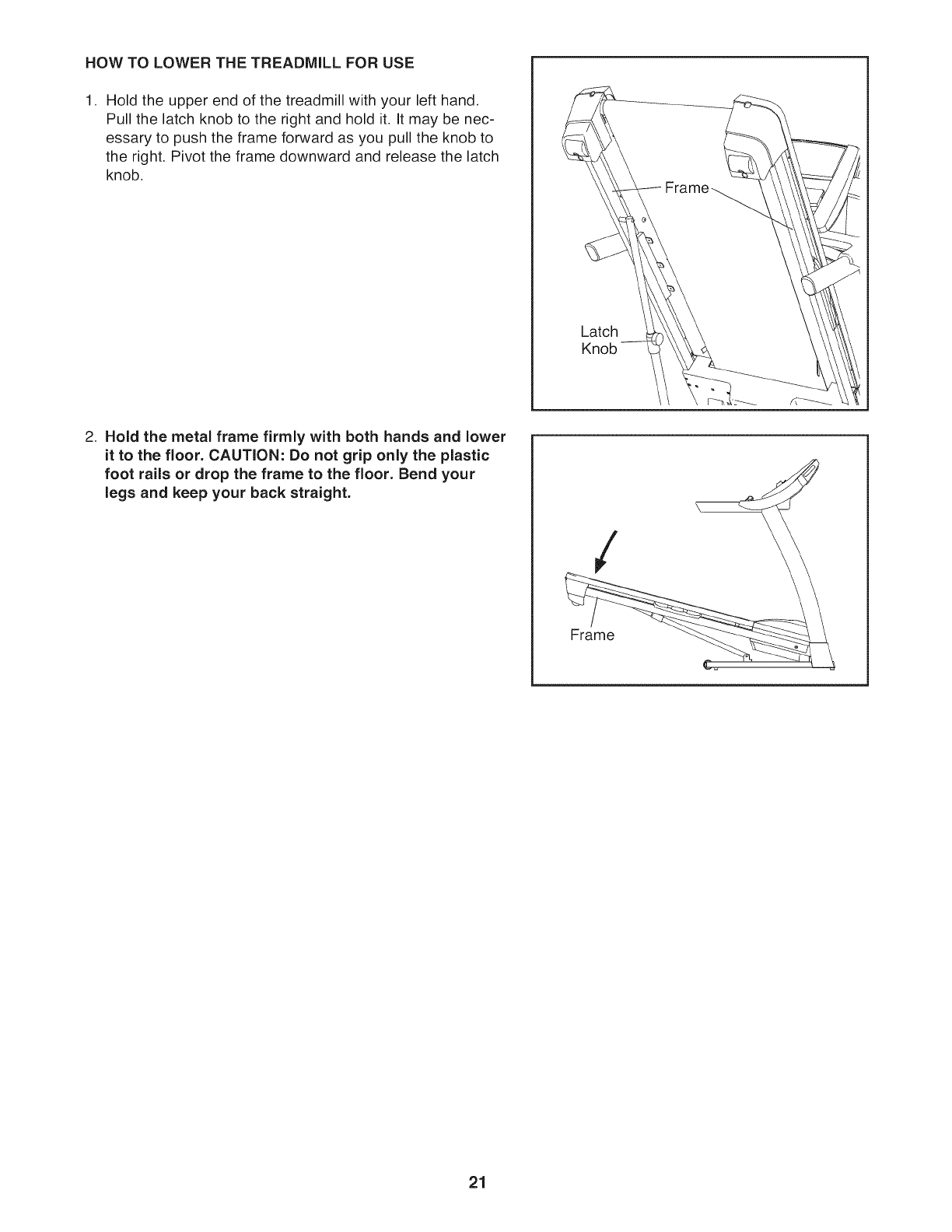
1. Hold the upper end of the treadmill with your left hand.
Pull the latch knob to the right and hold it. It may be nec-
essary to push the frame forward as you pull the knob to
the right. Pivot the frame downward and release the latch
knob.
2. Hold the metal frame firmly with both hands and lower
it to the floor. CAUTION: Do not grip only the plastic
foot rails or drop the frame to the floor. Bend your
legs and keep your back straight.
Latch
Kn
/
Frame
21
TROUBLESHOOTING
Most treadmill problems can be solved by following the simple steps below. Find the symptom that
applies, and follow the steps listed, if further assistance is needed, see the front cover of this manual.
PROBLEM: The power does not turn on
Make sure that the power cord is plugged into a surge suppressor, and that the surge suppressor
is plugged into a properly grounded outlet (see page 14). Use only a single-outlet surge suppres-
sor that meets all of the specifications described on page 14. IMPORTANT: The treadmill is not
compatible with GFCl-equipped outlets.
SOLUTION: a.
b. After the power cord has been plugged in, make sure that the key is inserted into the console.
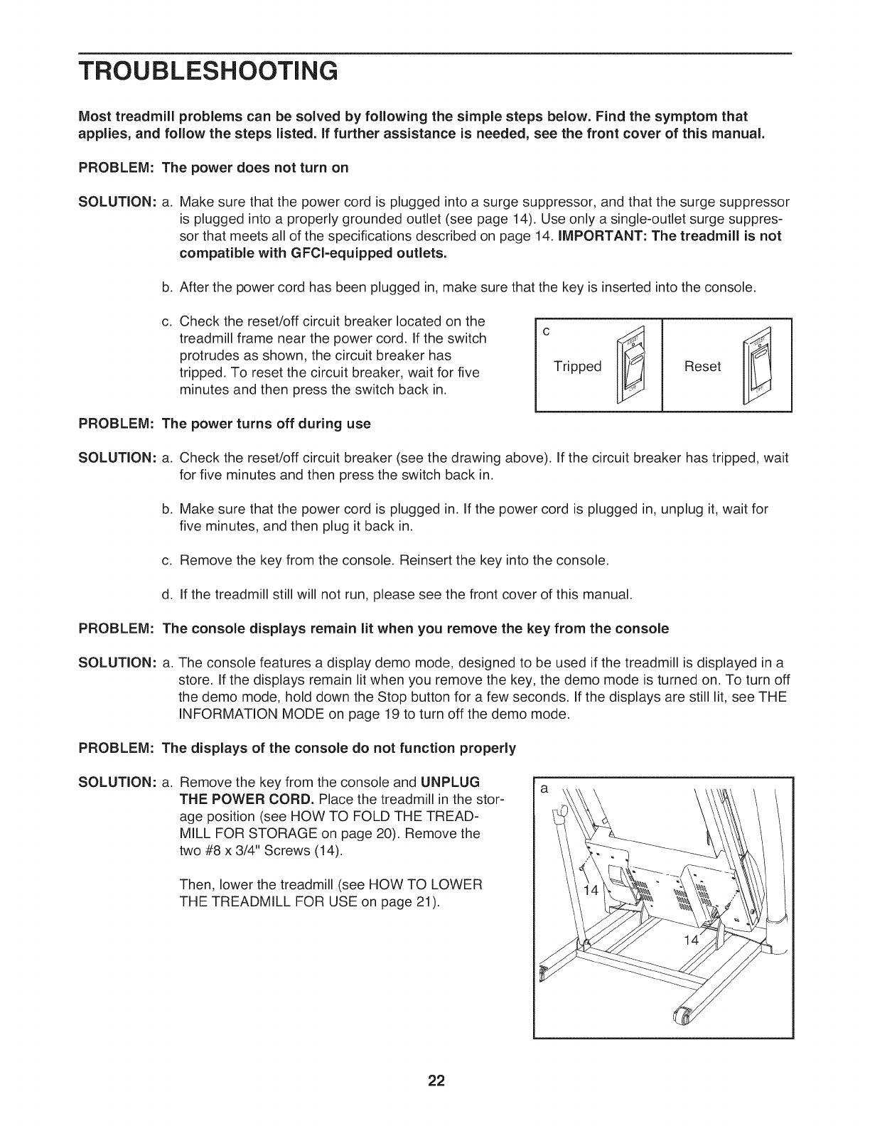
Check the reset/off circuit breaker located on the
treadmill frame near the power cord. If the switch
protrudes as shown, the circuit breaker has
tripped. To reset the circuit breaker, wait for five
minutes and then press the switch back in.
C.
PROBLEM: The power turns off during use
c
Tripped Reset
SOLUTION: a. Check the reset/off circuit breaker (see the drawing above). If the circuit breaker has tripped, wait
for five minutes and then press the switch back in.
b. Make sure that the power cord is plugged in. If the power cord is plugged in, unplug it, wait for
five minutes, and then plug it back in.
c. Remove the key from the console. Reinsert the key into the console.
d. If the treadmill still will not run, please see the front cover of this manual.
PROBLEM: The console displays remain lit when you remove the key from the console
SOLUTION: a. The console features a display demo mode, designed to be used if the treadmill is displayed in a
store. If the displays remain lit when you remove the key, the demo mode is turned on. To turn off
the demo mode, hold down the Stop button for a few seconds. If the displays are still lit, see THE
INFORMATION MODE on page 19 to turn off the demo mode.
PROBLEM: The displays of the console do not function properly
SOLUTION: a. Remove the key from the console and UNPLUG
THE POWER CORD. Place the treadmill in the stor-
age position (see HOW TO FOLD THE TREAD-
MILL FOR STORAGE on page 20). Remove the
two #8 x 3/4" Screws (14).
Then, lower the treadmill (see HOW TO LOWER
THE TREADMILL FOR USE on page 21).
22
Remove the four #8 x 3/4" Screws (14) and care-
fully remove the Motor Hood (61).
61
14
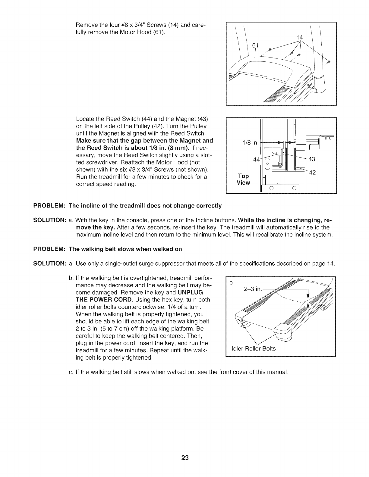
Locate the Reed Switch (44) and the Magnet (43)
on the left side of the Pulley (42). Turn the Pulley
until the Magnet is aligned with the Reed Switch.
Make sure that the gap between the Magnet and
the Reed Switch is about 1/8 in. (3 ram). If nec-
essary, move the Reed Switch slightly using a slot-
ted screwdriver. Reattach the Motor Hood (not
shown) with the six #8 x 3/4" Screws (not shown).
Run the treadmill for a few minutes to check for a
correct speed reading.
1/8 in. l
44-
Top
View ¢%
o o I
- 43
_42
PROBLEM: The incline of the treadmill does not change correctly
SOLUTION: a. With the key in the console, press one of the Incline buttons. While the incline is changing, re-
move the key. After a few seconds, re-insert the key. The treadmill will automatically rise to the
maximum incline level and then return to the minimum level. This will recalibrate the incline system.
PROBLEM: The walking belt slows when walked on
SOLUTION: a. Use only a single-outlet surge suppressor that meets all of the specifications described on page 14.
b. If the walking belt is overtightened, treadmill perfor-
mance may decrease and the walking belt may be-
come damaged. Remove the key and UNPLUG
TIlE POWER CORD. Using the hex key, turn both
idler roller bolts counterclockwise, 1/4 of a turn.
When the walking belt is properly tightened, you
should be able to lift each edge of the walking belt
2 to 3 in. (5 to 7 cm) off the walking platform. Be
careful to keep the walking belt centered. Then,
plug in the power cord, insert the key, and run the
treadmill for a few minutes. Repeat until the walk-
ing belt is properly tightened.
213 '
Idler Roller Bolts
c. If the walking belt still slows when walked on, see the front cover of this manual.
23
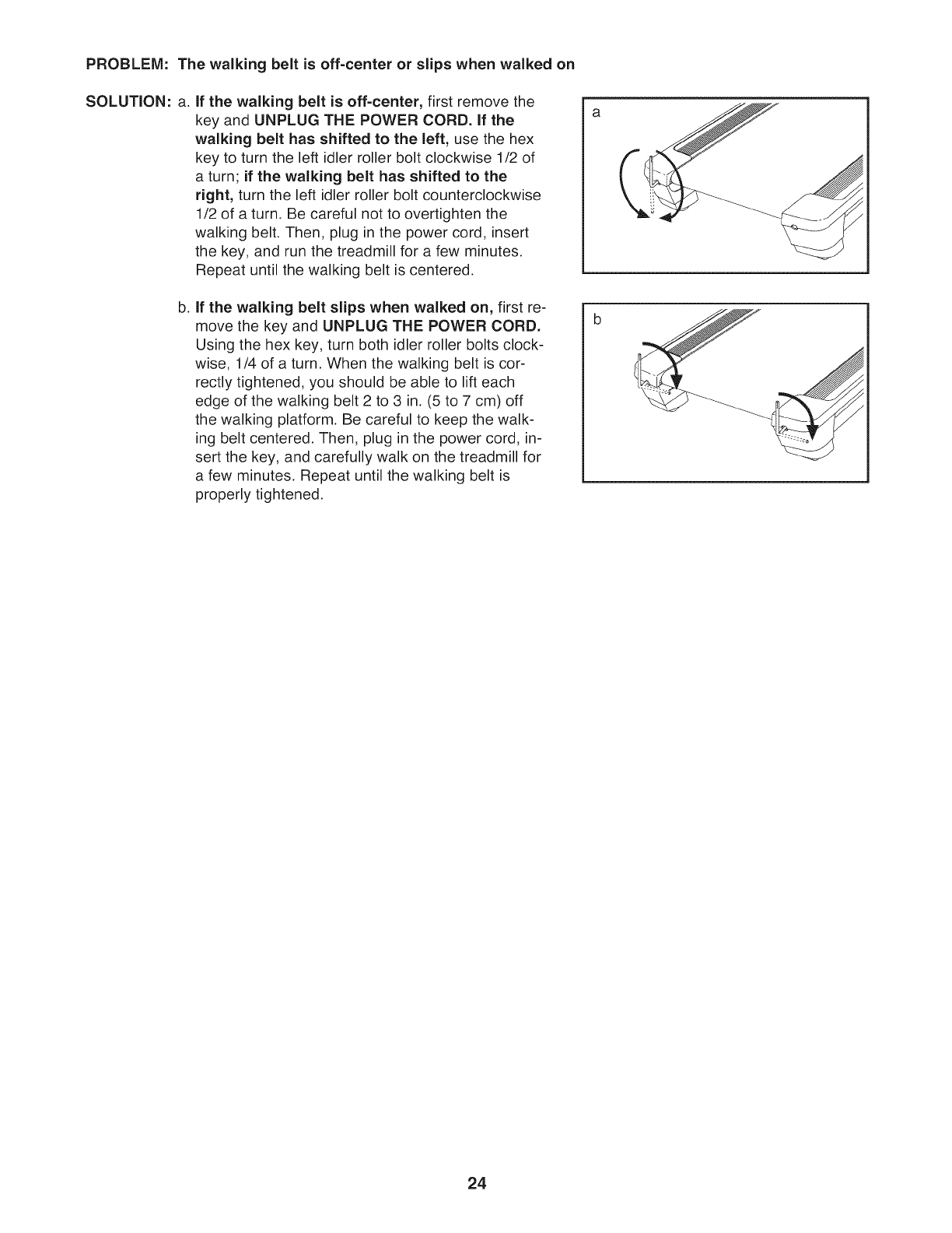
PROBLEM: The walking belt is off-center or slips when walked on
SOLUTION: a. If the walking belt is off-center, first remove the
key and UNPLUG THE POWER CORD. If the
walking belt has shifted to the left, use the hex
key to turn the left idler roller bolt clockwise 1/2 of
a turn; if the walking belt has shifted to the
right, turn the left idler roller bolt counterclockwise
1/2 of a turn, Be careful not to overtighten the
walking belt. Then, plug in the power cord, insert
the key, and run the treadmill for a few minutes.
Repeat until the walking belt is centered.
b. if the walking belt slips when walked on, first re-
move the key and UNPLUG THE POWER CORD.
Using the hex key, turn both idler roller bolts clock-
wise, 1/4 of a turn, When the walking belt is cor-
rectly tightened, you should be able to lift each
edge of the walking belt 2 to 3 in, (5 to 7 cm) off
the walking platform. Be careful to keep the walk-
ing belt centered, Then, plug in the power cord, in-
sert the key, and carefully walk on the treadmill for
a few minutes, Repeat until the walking belt is
properly tightened.
24
EXERCISE GUiDELiNES
These guidelines will help you to plan your exercise
program. For detailed exercise information, obtain a
reputable book or consult your physician. Remember,
proper nutrition and adequate rest are essential for
successful results.
EXERCISE INTENSITY
Whether your goal is to burn fat or to strengthen your
cardiovascular system, exercising at the proper inten-
sity is the key to achieving results. You can use your
heart rate as a guide to find the proper intensity level.
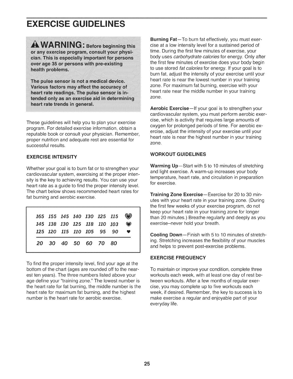
The chart below shows recommended heart rates for
fat burning and aerobic exercise.
165 I55 145 140 130 125 115 _)_
145 138 130 125 118 110 103 q.W)
125 120 115 110 105 95 90 W
20 30 40 50 60 70 80
To find the proper intensity level, find your age at the
bottom of the chart (ages are rounded off to the near-
est ten years). The three numbers listed above your
age define your "training zone." The lowest number is
the heart rate for fat burning, the middle number is the
heart rate for maximum fat burning, and the highest
number is the heart rate for aerobic exercise.
Burning Fat--To burn fat effectively, you must exer-
cise at a low intensity level for a sustained period of
time, During the first few minutes of exercise, your
body uses carbohydrate calories for energy. Only after
the first few minutes of exercise does your body begin
to use stored fat calories for energy, If your goal is to
burn fat, adjust the intensity of your exercise until your
heart rate is near the lowest number in your training
zone, For maximum fat burning, exercise with your
heart rate near the middle number in your training
zone.
Aerobic Exercise--if your goal is to strengthen your
cardiovascular system, you must perform aerobic exer-
cise, which is activity that requires large amounts of
oxygen for prolonged periods of time, For aerobic ex-
ercise, adjust the intensity of your exercise until your
heart rate is near the highest number in your training
zone.
WORKOUT GUIDELINES
Warming Up--Start with 5 to 10 minutes of stretching
and light exercise, A warm-up increases your body
temperature, heart rate, and circulation in preparation
for exercise.
Training Zone Exercise--Exercise for 20 to 30 min-
utes with your heart rate in your training zone. (During
the first few weeks of your exercise program, do not
keep your heart rate in your training zone for longer
than 20 minutes.) Breathe regularly and deeply as you
exercise-never hold your breath.
Cooling Down--Finish with 5 to 10 minutes of stretch-
ing, Stretching increases the flexibility of your muscles
and helps to prevent post-exercise problems.
EXERCISE FREQUENCY
To maintain or improve your condition, complete three
workouts each week, with at least one day of rest be-
tween workouts. After a few months of regular exer-
cise, you may complete up to five workouts each
week, if desired. Remember, the key to success is to
make exercise a regular and enjoyable part of your
everyday life.
25

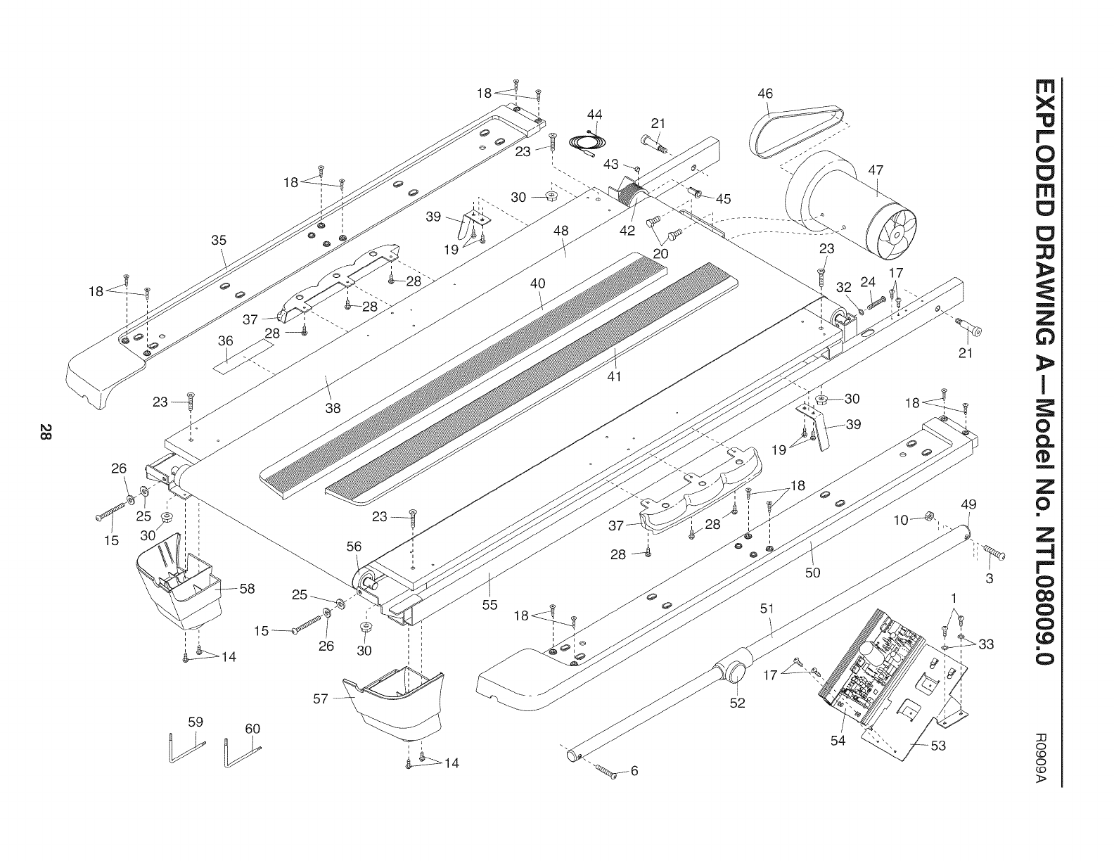
PART LIST--Model No. NTL08009.0 R0909A
To locate the parts listed below, see the EXPLODED DRAWING near the end of this manual.
Key No. Qty. Description Key No. Qty. Description
1 16 #8 x 1/2" Screw 51 1 Storage Latch
2 4 #8 x 1" Tek Screw 52 1 Latch Knob
3 1 3/8" x 2" Bolt 53 1 Electronics Bracket
4 6 5/16" x 1 1/2" Patch Bolt 54 1 Controller
5 4 5/16"x 3/4" Patch Bolt 55 1 Frame
6 1 3/8" x 1 3/4" Patch Bolt 56 1 Idler Roller
7 4 3/8" x 5 1/2" Patch Bolt 57 1 Right Frame Foot
8 2 1/4" x 1/2" Patch Bolt 58 1 Left Frame Foot
9 8 5/16" Star Washer 59 1 Hex Key
10 5 3/8" Nut 60 1 5/32" Hex Key
11 4 3/8" Star Washer 61 1 Motor Hood
12 2 1/4" Star Washer 62 4 Lift Frame Bushing
13 1 Pulse Crossbar 63 2 Lift Frame Spacer
14 44 #8 x 3/4" Screw 64 2 Frame Spacer
15 2 1/4" x 1 3/4" Bolt 65 1 Lift Frame
16 2 3/8" x 1 3/4" Bolt 66 1 Incline Motor
17 11 #8 x 1/2" Washer Head Screw 67 2 Incline Motor Spacer
18 12 #12 x 1/2" Screw 68 2 Hood Mount
19 4 Belt Guide Screw 69 1 Belly Pan
20 2 Drive Motor Bolt 70 1 Reset/Off Circuit Breaker
21 4 3/8" x 2 1/8" Bolt 71 1 Power Cord
22 2 3/8" x 1 3/8" Bolt 72 2 Grommet
23 4 5/16" x 1 1/4" Bolt 73 1 Lift Motor Wire
24 1 Drive Roller Bolt 74 2 Releasable Tie
25 2 1/4" Flat Washer 75 1 15 1/2" Tie
26 2 1/4" Lock Washer 76 7 8" Tie
27 2 U-Nut 77 2 Handrail Cap
28 6 #8 x 3/4" Truss Head Screw 78 1 Left Handrail
29 2 3/8" Jam Nut 79 1 Right Handrail
30 4 5/16" Flange Nut 80 2 Console Clamp
31 4 Hood Clip 81 1 Console Frame
32 1 1/4" Star Washer 82 1 Left Upright
33 2 #8 Star Washer 83 1 Right Upright
34 4 #8 x 1" Truss Head Screw 84 1 Base Cover
35 1 Left Foot Rail 85 1 Upright Wire
36 1 Warning Decal 86 1 Right Upright Cover
37 2 Platform Cushion 87 1 Left Upright Cover
38 1 Walking Platform 88 4 Bolt Spacer
39 2 Belt Guide 89 2 Caution Decal
40 1 Left Foot Rail Cover 90 1 Left Upright Spacer
41 1 Right Foot Rail Cover 91 1 Right Upright Spacer
42 1 Drive Roller/Pulley 92 4 Base Foot
43 1 Magnet 93 1 Audio Wire
44 1 Reed Switch 94 1 Base
45 1 Reed Switch Clamp 95 2 Wheel
46 1 Drive Motor Belt 96 2 Wheel Housing
47 1 Drive Motor 97 2 Wheel Axle
48 1 Walking Belt 98 1 Key/Clip
49 1 Latch Cap 99 8 Wire Tie
50 1 Right Foot Rail 100 1 Console
26

Key No. Qty. Description Key No. Qty. Description
101 1 Left Accessory Tray 108 1 Site Warning Decal
102 1 Console Base 109 1 Wire Tie Clamp
103 1 WiFi Module Housing * - 6" Blue Wire, M/F
104 1 Right Accessory Tray * - 4" Red Wire, M/F
105 1 Access Door * - 14" Black Wire, M/F
106 1 Pulse Bar * - 8" White Wire, M/F
107 3 Pulse Ground Wire * - User's Manual
Note: Specifications are subject to change without notice. For information about ordering replacement parts, see
the back cover of this manual. *These parts are not illustrated.
27
o0
i'
i
i
i
i'
i
i
36 28
39
19
26
23 -_ 38
i
15
59
i
4O
48
2O
41
55 18_, _
i
i
52
46
23
19
51
o
5O
54
47
17
21
18_+__4
i,
3
1
m
X
r""
0
m
m
Z
63
I
0
m
Z
0
!
Z
...4
r"
O
Q
0
¢0
!
O
o
r..,o
o
r..,o
>
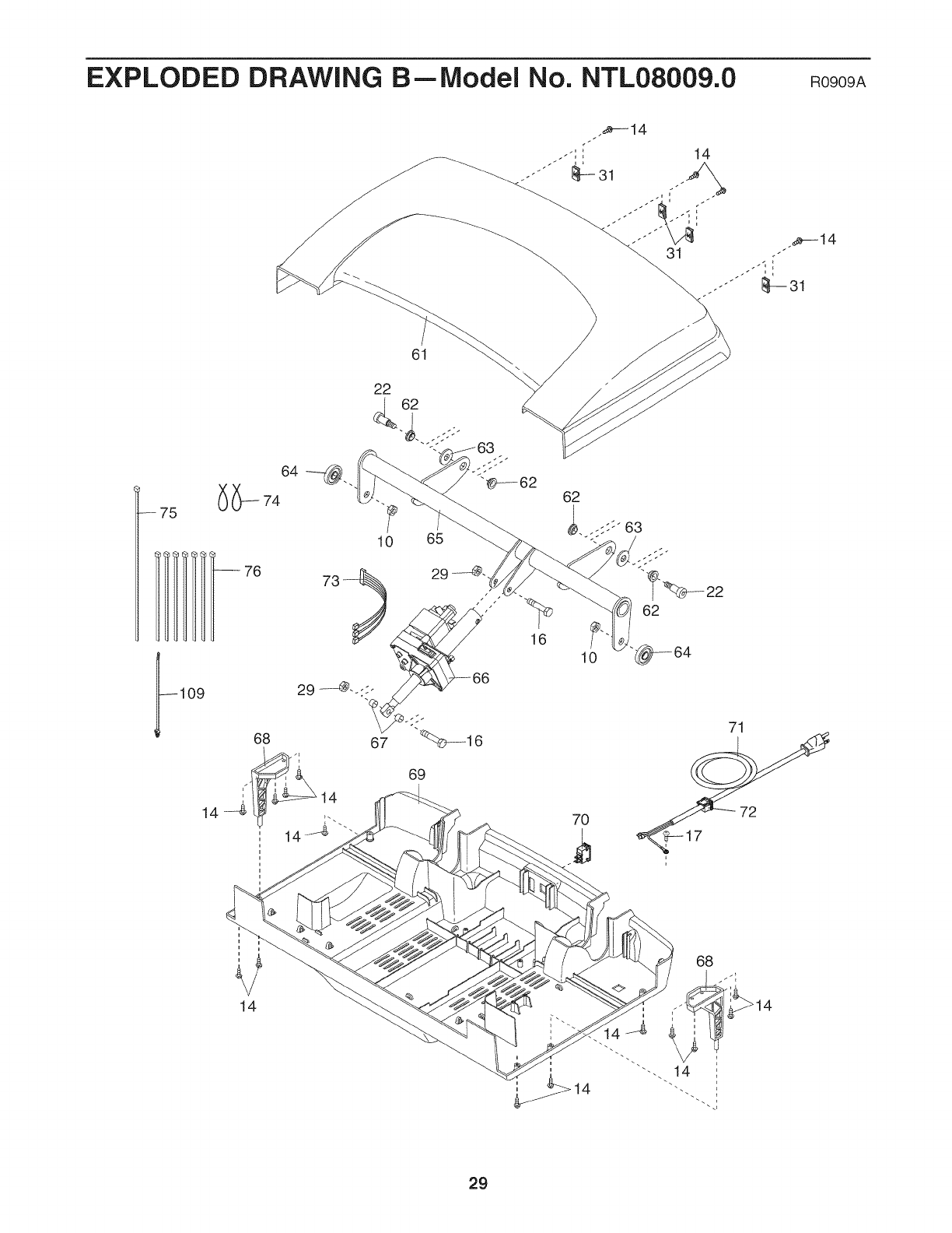
EXPLODED DRAWING B--Model No. NTL08009.0 RogogA
--75
--109
61
10 65
68
69
16 10
70
62
71
72
68
29
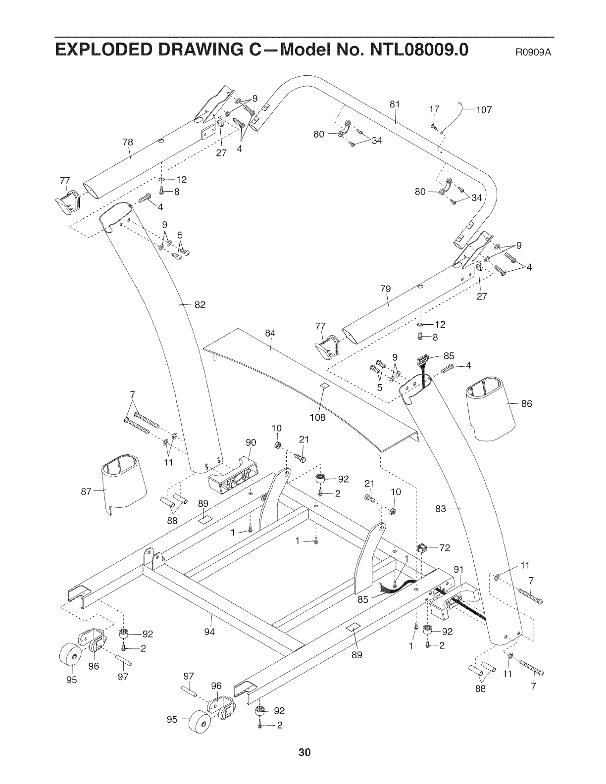
EXPLODED DRAWING CmModel No. NTL08009.0 ROgOgA
80
81
7
88
82
84
90
79 27
86
94
95
89
88
30
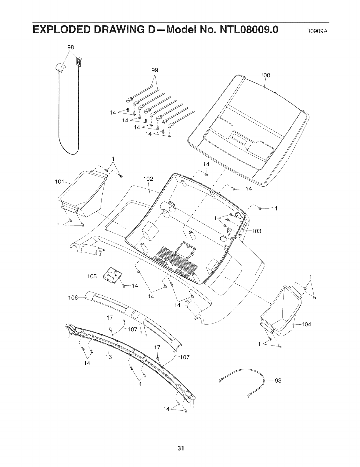
EXPLODED DRAWING D--Model No. NTL08009.0 RoeoeA
98
99 100
14 14
101 102
14
=103
17
14
13 (
14
17
07
93
31

ORDERING REPLACEMENT PARTS
To order replacement parts, please see the front cover of this manual. To help us assist you, be prepared to pro-
vide the following information when contacting us:
o the model number and serial number of the product (see the front cover of this manual)
o the name of the product (see the front cover of this manual)
o the key number and description of the replacement part(s) (see the PART LIST and the EXPLODED
DRAWING near the end of this manual)
LIMITED WARRANTY
iMPORTANT: You must register this product within 30 days of the purchase date to avoid added
fees for service needed under warranty. Go to www.nordJctrackservJce.com/registration.
ICON Health & Fitness, Inc. (ICON) warrants this product to be free from defects in workmanship and
material, under normal use and service conditions. The frame and drive motor are warranted for a life-
time. Parts and labor are warranted for one (1) year from the date of purchase.
This warranty extends only to the original purchaser. ICON's obligation under this warranty is limited to
repairing or replacing, at ICON's option, the product through one of its authorized service centers. All re-
pairs for which warranty claims are made must be preauthorized by ICON. If the product is shipped to a
service center, freight charges to and from the service center will be the customer's responsibility. For
replacement parts shipped while the product is under warranty, the customer will be responsible for a
minimal handling charge. For in-home service, the customer will be responsible for a minimal trip charge.
This warranty does not extend to any damage to a product caused by or attributable to freight damage,
abuse, misuse, improper or abnormal usage, or repairs not provided by an ICON authorized service cen-
ter; to products used for commercial or rental purposes or as store display models; or to products trans-
ported or purchased outside the US. No other warranty beyond that specifically set forth above is autho-
rized by ICON.
ICON is not responsible or liable for indirect, special, or consequential damages arising out of or in con-
nection with the use or performance of the product; damages with respect to any economic loss, loss of
property, loss of revenues or profits, loss of enjoyment or use, or costs of removal or installation; or other
consequential damages of whatsoever nature. Some states do not allow the exclusion or limitation of in-
cidental or consequential damages. Accordingly, the above limitation may not apply to you.
The warranty extended hereunder is in lieu of any and all other warranties, and any implied warranties of
merchantability or fitness for a particular purpose are limited in their scope and duration to the terms set
forth herein. Some states do not allow limitations on how long an implied warranty lasts. Accordingly, the
above limitation may not apply to you.
This warranty gives you specific legal rights. You may also have other rights that vary from state to state.
iCON Health &Fitness, Inc., 1500 S. 1000 W., Logan, UT 84321-9813
Part No. 289518 R0909A Printed in USA © 2009 ICON IP, Inc.
