NORDYNE Air Handler (indoor Blower&evap) Manual L0611479
User Manual: NORDYNE NORDYNE Air Handler (indoor blower&evap) Manual NORDYNE Air Handler (indoor blower&evap) Owner's Manual, NORDYNE Air Handler (indoor blower&evap) installation guides
Open the PDF directly: View PDF ![]() .
.
Page Count: 8
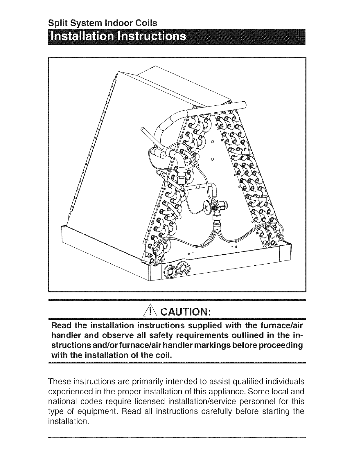
Split System Indoor Coils
CAUTION:
Read the installation instructions supplied with the furnace/air
handier and observe all safety requirements outlined in the in-
structions and/or furnace/air handier markings before proceeding
with the installation of the coil.
These instructions are primarily intended to assist qualified individuals
experienced in the proper installation of this appliance. Some local and
national codes require licensed installation/service personnel for this
type of equipment. Read all instructions carefully before starting the
installation.
Table of Contents
1. General information ............................................................................................................... 3
2. Coil Specifications ................................................................................................................. 3
3. Coil Installation ....................................................................................................................... 4
, Upflow Furnace/Air Handler
• Downflow Electric Furnace
Downflow Electric Furnace/Air Handler with Integral Coil Cabinet or Optional Coil Cabinet
4, Refrigerant Line Connections ............................................................................................... 6
5, Restrictor Change=Out ........................................................................................................... 7
6, Completing the installation ................................................................................................... 7
Condensate Drain
Air Filters
Close-off Plates and Panels
Refrigerant Charging
7, Maintenance and Service ...................................................................................................... 8
1. GENERAL iNFORMATiON
C(*)QA/DA coils are designed for upflow and
downflow furnace/air handler applications. The
C(*)QA coils incorporate "single shot" coupling
refrigerant connections for easy installation. The
C(*)DA coils are furnished with down-turned
refrigerant connections, ready for brazing.
Read the installation manual supplied with the
outdoor unit for refrigerant line connection pro-
cedure, required line sizes, and other information
pertaining to the system installation.
1. Make certain that the air delivery of the
furnace/air handler is adequate to handle
the static pressure drop of the coil, filter, and
duct work.
2. In orifice style models check the orifice size
of the coil's expansion device and confirm
that it is suitable for application with the
intended outdoor unit.
3. Where precise forming of the refrigerant
lines is required, a copper tubing bender
designed for the size lines used is recom-
mended. Avoid sharp bends and contact of
the refrigerant lines with metal surfaces.
4. Refrigerant lines should be wrapped
with pressure sensitive neoprene or other
suitable material where they pass through
the raw edges of holes.
5. The coil enclosure (if provided) and suction
line must be insulated as needed to prevent
condensate from forming and causing
property damage.
6. Coil must be level for proper conden-
sate drainage.
7. Do not remove seals from the coil until the
tubing connections are ready to be made.
NOTE: Optional cooling/heating equipment must
be properly sized and installed in accordance
with the furnace manufacturer's specifications
and approved recommendations. "Heating only"
furnace air circulators may have to be replaced
with multi-speed "Heating/Cooling" blowers to
upgrade the air delivery (CFM) when an add-on
coil is installed. Refer to Coil Specifications for
recommended CFM and allow for pressure drop
across the coil and filters.
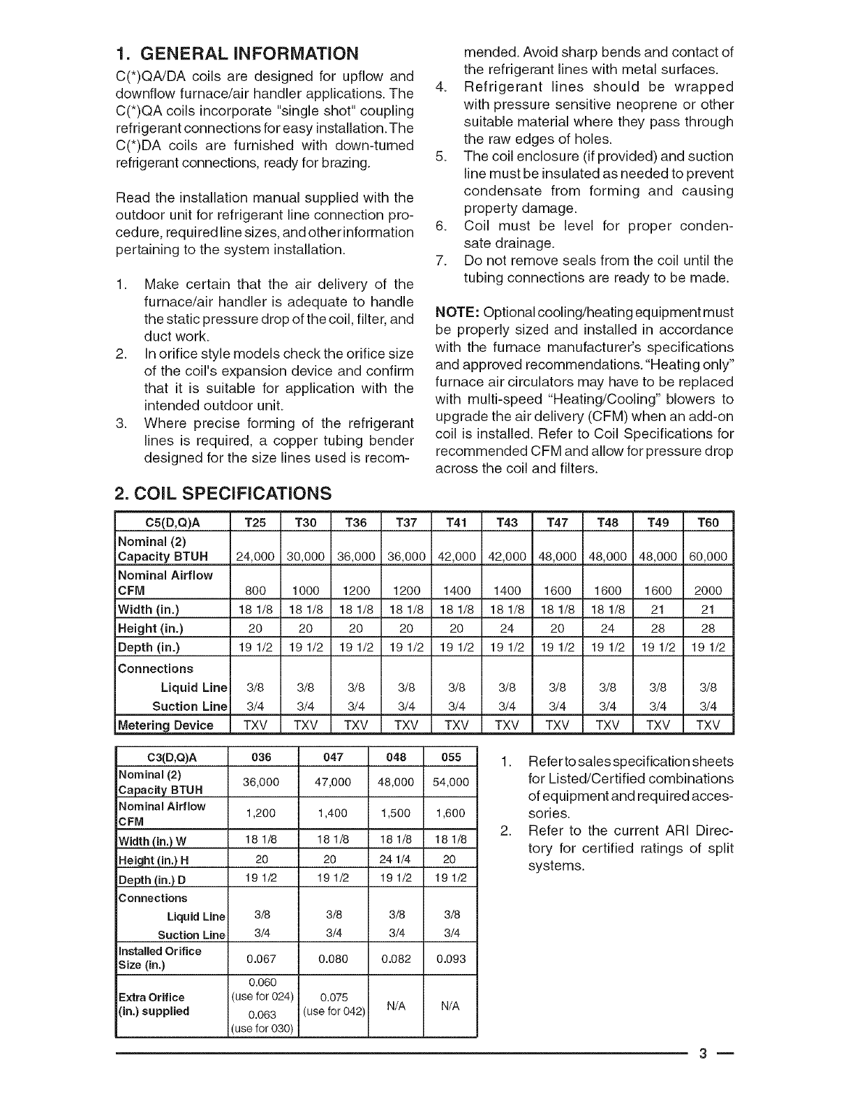
2. COIL SPECIFICATIONS
CS(D,Q)A T25 T30 T36 T37 T41 T43 T47 T48 T49 T60
Nominal (2)
Capacity BTUH 24,000 30,000 36,000 36,000 42,000 42,000 48,000 48,000 48,000 60,000
Nominal Airflow
CFM 800 1000 1200 1200 1400 1400 1600 1600 1600 2000
Width (in.) 18 1/8 18 1/8 18 1/8 18 1/8 18 1/8 18 1/8 18 1/8 18 1/8 21 21
Height (in.) 20 20 20 20 20 24 20 24 28 28
Depth (in.) 19 1/2 19 1/2 19 1/2 19 1/2 19 1/2 19 1/2 19 1/2 19 1/2 19 1/2 19 1/2
Connections I I
Liquid Line I 3/8 I 3/8 I 3/8 I 3/8 I 3/8 I 3/8 I 3/8 I 3/8 I 3/8 I 3/8
Suction Line 3/4 3/4 3/4 I 3/4 3/4 3/4 I 3/4 3/4 3/4 3/4
=H
Meter ng Dev ce TXV TXV TXV '1 TXV TXV TXV i TXV TXV TXV TXV
C3(D,Q)A
Nominam (2)
Capacity BTUH
Nominam Airflow
CFM
Width (in.) W
Height (in.) H
Depth (in.) D
Connections
Liquid Line
Suction Line
Installed Orifice
Size (in.)
Extra Orifice
(in,) supplied
036
36,000
1,200
18 1/8
20
19 1/2
3/8
3/4
0.067
0.060
(use for 024)
0.063
(use for 030)
047 048 055
47,000 48,000 54,000
1,400 1,500 1,600
181/8 181/8 181/8
20 24 1/4 20
191/2 191/2 191/2
3/8 3/8 3/8
3/4 3/4 3/4
0.080 0.082 0.093
0.075
(use for 042) N/A N/A
1. Refer to sales specification sheets
for Listed/Certified combinations
of equipment and required acces-
sories.
2. Refer to the current ARI Direc-
tory for certified ratings of split
systems.
m
3. COiL iNSTALLATiON Downflow FE/E* Electric Furnace:
z WARNING:
Electric furnaces may be connected to
more than one supply circuit.
Upflow Furnace:
1. Disconnect all electrical power to
the furnace.
2. Install the coil in the coil cabinet and level
it as needed to allow proper condensate
drainage or make a plenum to enclose the
coil or drop the duct directly over it.
3. Seal the enclosure as required to minimize
air leakage.
4. Connect the refrigerant lines as outlined
in the Refrigerant Lines section.
1. Ensure that all electrical power to the
furnace is off.
2. Use the appropriate Coil Conversion Kit
which includes 2 air filters, close-off plates
(2 sets) and a coil hold down bracket.
3. Remove the filter located at the top of the
furnace cabinet.
4. Remove the refrigerant line knockouts lo-
cated at the top and bottom of the furnace
cabinet.
5. Install the coil and level it as needed to
ensure proper condensate drainage.
6. Secure the coil hold down bracket with
screws.
7. Add air filters to the sides of the coil.
8. Cut the floor opening for the refrigerant lines
and drain line (See Figure 6).
9. Connect the refrigerant lines as outlined in
the Refrigerant Line Connection section.
Connect the drain line and ensure that there
is a water trap in the water line.
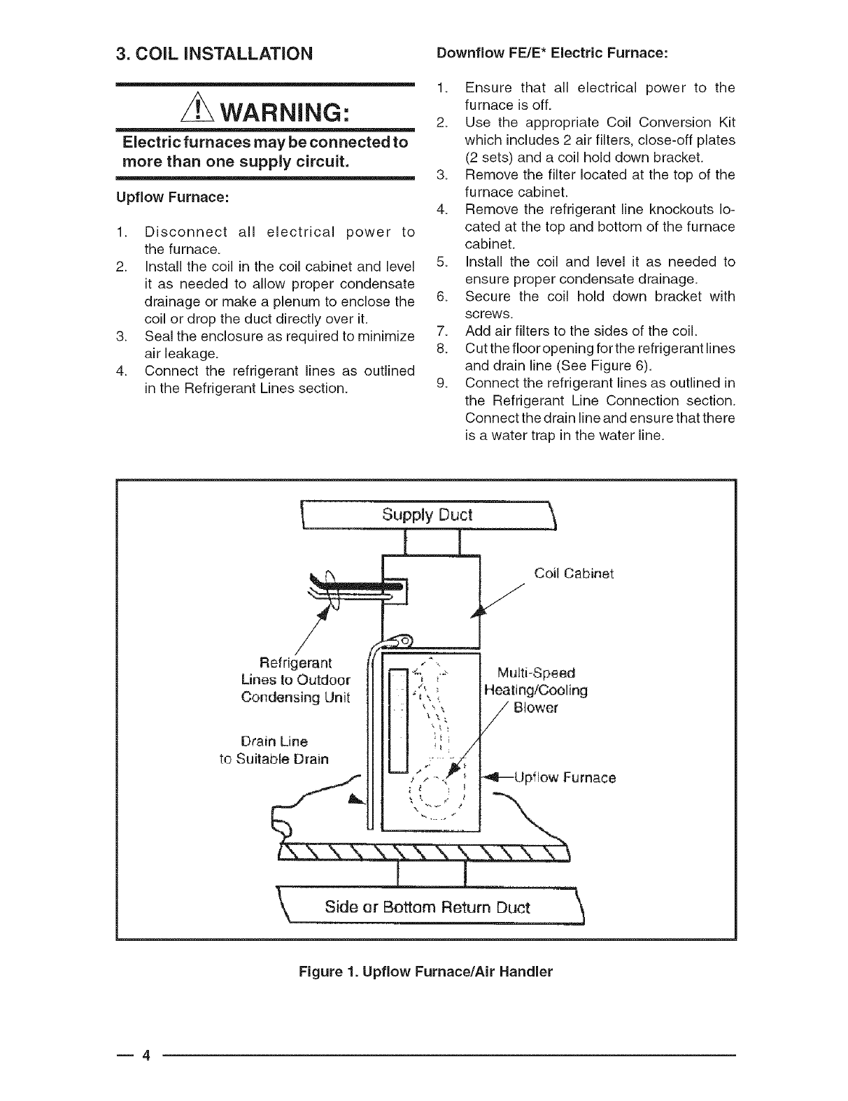
Refrigerant
Lines to Outdoor
Condensing Unit
Drain Line
to Suitable Drain
Supply Duct
[i]
\
Coil Cabinet
Multi-Speed
Heating/Cooling
Blower
"_i_Upf]ow Furnace
Side er Bottom Return Duct
Figure 1. Upflow Furnace/Air Handier
m4
AIR FILTERS (2)
CLOSE OFF
(SEEFIGURE4
FLOOR
CUT-OUT
(SEE FIGURE 5)
REMOVE FILTER
MULTI-SPEED
"HEATINGtCOOLING"
BLOWER
DOWNFLOW
ELECTRIC
FURNACE
CLOSE-
OFF
PLATES EFRIGERANT
(SEE FIGURE 3) LINES TO
DRAIN LINE TO "J OUTDOOR
CONDENSING
SUITABLE DRAIN UNIT
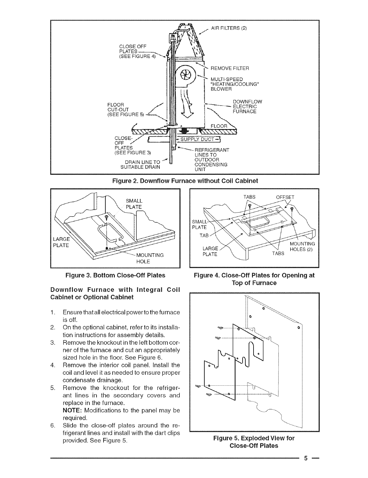
Figure 2. Downflow Furnace without Coil Cabinet
PLATE
-MOUNTING
HOLE
SMALL
PLATE
Figure 3. Bottom Close=Off Plates
Downflow Furnace with Integral Coil
Cabinet or Optional Cabinet
1. Ensure that all electrical power to the furnace
is off.
2. On the optional cabinet, refer to its installa-
tion instructions for assembly details.
3. Remove the knockout in the left bottom cor-
ner of the furnace and cut an appropriately
sized hole in the floor. See Figure 6.
4. Remove the interior coil panel. Install the
coil and level it as needed to ensure proper
condensate drainage.
5. Remove the knockout for the refriger-
ant lines in the secondary covers and
replace in the furnace.
NOTE: Modifications to the panel may be
required.
6. Slide the close-off plates around the re-
frigerant lines and install with the dart clips
provided. See Figure 5.
TABS OFFSET
SMA _::_"_'..... " '
_ \\ _ MOUNTING
LARGE/_ _ J__ HOLES(2)
PLATE _k I TABS
Figure 4. Close-Off Plates for Opening at
Top of Furnace
\
Figure 5. Exploded View for
Close=Off Plates
m
7. Snap the bushings around the lines and into
the close-off panels.
8. Connect the refrigerant lines as outlined in
the refrigerant lines section.
4. REFRIGERANT LINE
CONNECTIONS
CAUTION:
in orifice style coils before proceeding
with the connection of the refrigerant
lines, confirm that the orifice size
meets the requirements outlined in the
outdoor unit installation manual.
Factory installed orifice sizes are listed in the
Specifications section. If the restrictor orifice
must be replaced, see Section 5, Restrictor
Change=Out.
1. Remove the protective caps from the coil
and refrigerant line set couplings.
2. With a soft, dust-free cloth, carefully wipe
clean all coupling threads and seals to
remove any dust or material which could
contaminate the refrigerant system.
3. Using refrigerant oil, lightly lubricate the
diaphragm, seal, and mating threads.
4. Connect the couplings as follows:
a.) Line up the refrigerant line with the coil
coupling and thread together by hand to
ensure proper thread mating. Hold the hex
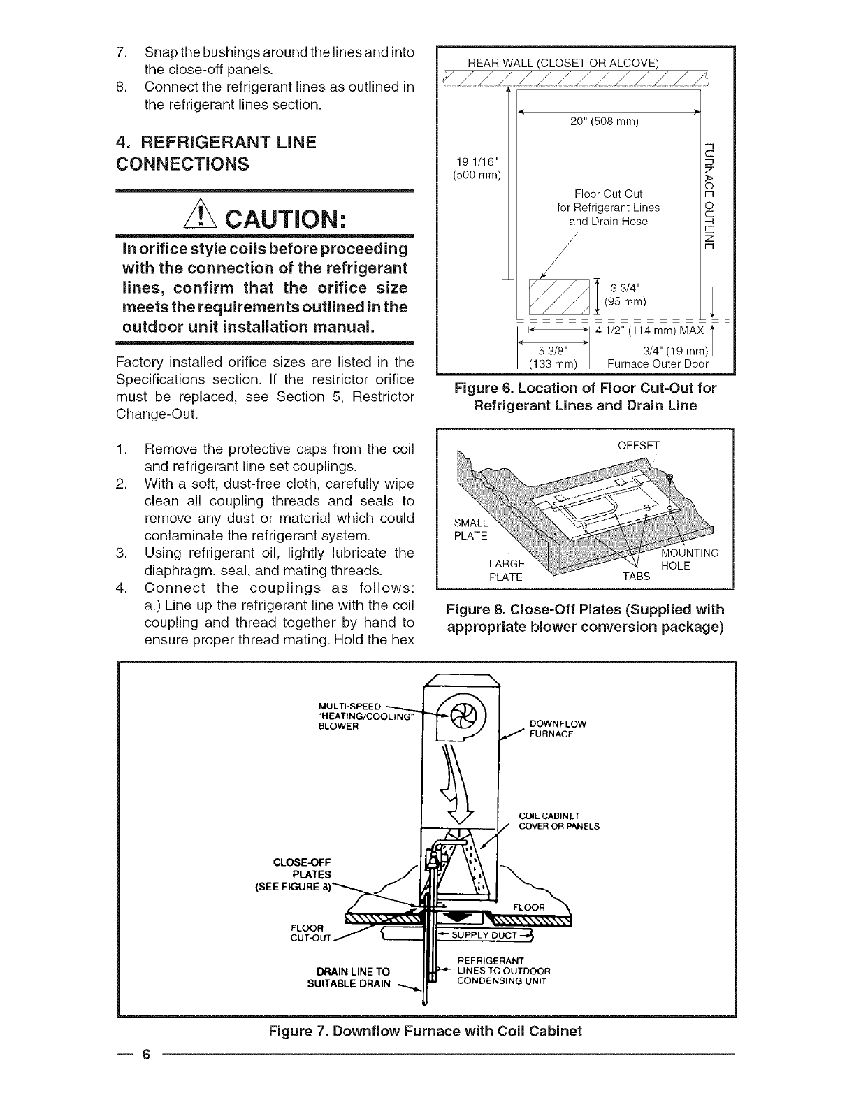
REAR WALL (CLOSET OR ALCOVE)
19 1/16"
(500 ram)
20" (508 mm)
-fl
:]:]
Z
©
Floor Cut Out rn
for Refrigerant Lines O
and Drain Hose -_
r'-
/_
[11
/
33/4,,
(95 mm)
I
5 3/8"
(133 mm)
Figure 6. Location of Floor Cut-Out for
Refrigerant Lines and Drain Line
=
4 1/2" (114 mm) MAX l
/
3/4" (19 mm)/
Furnace Outer Door
OFFSET
OUNTING
OLE
PLATE _ TABS
Figure 8. Close-Off Plates (Supplied with
appropriate blower conversion package)
MULTI-SPEED
"HEATING/COOLING"
BLOWER
CLOSE-OFF
PLATES
(SEE FIGURE
DOWNFLOW
/FURNACE
COIL CABINET
COVER OR PANELS
FLOOR
CUT'OU
DRAIN LINETO
SUITABLE DRAIN
_ SUPPLY 0 UCT -4'{)
REFRIGERANT
LINES TO OUTDOOR
CONDENSING UNIT
Figure 7. Downflow Furnace with Coil Cabinet
m6

5_
6_
of the male coupling with a wrench and
slowly wrench tighten the union nut until a
definite resistance (bottoming out) is felt.
b.) Mark the position of the union nut (match
lines on the line coupling and the coil cou-
pling), then tighten the coupling an additional
1/4 turn to ensure a leakproof connection.
Use the Torque Values table (below) if a
torque wrench is used.
On C(*)D coils with TXV where brazing is
required to make the line connection it is
required to wrap a wet rag around the suc-
tion tube between the sensing bulb and the
joint being brazed to avoid damage to the
bulb.
Check the system for leaks.
5. RESTRICTOR CHANGE=OUT
NOTE: If the orifice must be replaced, follow
these steps.
1. Connect only the suction line coupling to
the coil as indicated in Section 4.
2. Reclaim the holding charge from the coil
and suction vapor line through the schraeder
port using the methods approved under
the Refrigerant Transition and Recovery
Certification Program.
3. Open the distributor body by using open
end wrenches and turning the swivel nut
(smallerwrench) counterclockwise. Remove
the restrictor, being careful not to scratch the
bore or the distributor body (See Figures 9
and 10).
4. Select the proper size restrictor and place
it rounded end down into the distributor
body (See Figure 11).
5. Realign the swivel nut and distributor. Start
the threads by hand then continue to tighten
with the wrenches until a resistance is felt.
Match the position of the nut and then tighten
an additional 1/4 turn. If a torque wrench is
used, tighten the nut with the values for the
3/8" line.
6. Evacuate the system through the schraeder
port on the vapor line.
Torque Values
Coupling Size Torque
3/8" (10 mm) 10 - 12 ft. Ibs.
Liquid Line Coupling 14 - 16 Nm
3/4" (19 mm) or
7/8" (22 ram)
Vapor Line Coupling
34 - 45 ft. Ibs.
46 - 61 Nm
Figure g. Wrenches on
Distributor Body and Assembly Nut
Figure 10.
..... J
Removal of Orifice
Figure 11. Restrictor
Insertion in Distributor Body
7. Connect the liquid line as instructed in Sec-
tion 4. Check the connections for leaks.
6. COMPLETING THE INSTALLATION
CAUTION'.
The indoor coil must be checked to
ensure a level installation. Failure to do
so may result in improper condensate
disposal, causing structural damage,
premature equipment failure, or pos-
sible personal injury.
m

Condensate Drain:
1. Thread the 3/4" drain fitting (included) into
the lowest tapped hole on the condensate
pan. Hand tighten the fitting. If a different
configuration is required, use only PVC or
similar material for the fitting.
NOTE: Overtightening the fitting may crack
the drain pan and create a condensate
leak.
2. Slip the drain line over the end of the fitting,
add the clamp provided and run to a suit-
able drain. Avoid bending or pinching of the
line.
3. During the system checkout, inspect the
drain line and connections to verify proper
condensate disposal.
Air Filter -- Air filters are not provided as an
integral part of this coil, however, a filter must
be installed upstream of the coil and inspected
frequently. When the filter becomes clogged
with dust or lint, it should be replaced (dispos-
able type) or cleaned (washable type).The filter
should be inspected and replaced or cleaned at
least twice during the year, generally at the start
of each heating and cooling season.
Close=Off Plates and Panels-- Install the nec-
essary air close-off plates around the refrigerant
lines and drain line where required. Reinstall
all inner and outer panels of the furnace/air
handler that were previously removed to install
the indoor coil.
Refrigerant Charging -- C(*)Q series indoor
coils contain a "holding charge" to prevent
entrance of moisture and contaminants during
shipment. The total system operating charge
of R-22 refrigerant is in the outdoor unit and is
adequate for the matched listed system including
15 feet of line set.
WARNING:
Ensure that all electrical power to the
furnace and outdoor (condensing) unit
is off before performing any mainte-
nance or service on the system.
It will be necessary to evacuate the indoor coil
and line set prior to charging. Refer to the outdoor
unit installation manual for detailed charging
instructions.
7. MAINTENANCE AND SERVICE
To ensure optimum system performance and
to minimize the possibility of equipment failure,
the following periodic maintenance should be
performed on the coil:
1. The air filter installed with the system should
be checked and cleaned or replaced twice
per year.
2. Check the coil, drain pan, and condensate
drain line for cleanliness at the start of each
heating and cooling season. Clean and
remove any debris as required.
CAUTION:
Do not operate the system without hav-
ing a suitable filter in place in the return
air duct system. Always replace the
filter with the same size and type.
I INSTALLER: PLEASE LEAVE THESE INSTALLATION I
INSTRUCTIONS WITH THE HOMEOWNER
ir
7086350
CERTIFICATION
APPLIES ONLY WHEN
THE COMPLETE
SYSTEM IS LISTED
WITH ARI
O'Fallon, MO NORDYNE
7086350 (Replaces 7084890)
Specifications and illustrations subject to change
without notice and without incurring obligations.
Printed in U.S.A. (09/06)
