NORDYNE Controls And HVAC Accessories Manual L0612180
User Manual: NORDYNE NORDYNE Controls and HVAC Accessories Manual NORDYNE Controls and HVAC Accessories Owner's Manual, NORDYNE Controls and HVAC Accessories installation guides
Open the PDF directly: View PDF ![]() .
.
Page Count: 2
Field Replacement Furnace Vent Transition Kit, #904106
For M3RL Series Furnaces
IMPORTANT: Read these instructions and the M3RL
Installation Instructions carefully before beginning
the installation.
GENERAL
These instructions are primarily intended to assist quali-
fied individuals experienced in the proper vent and com-
bustion intake pipe installations of this appliance. This kit
is to be used for field replacement of a non-condensing
manufactured housing furnace with an M3RL series fur-
nace. It may be used at elevations up to 8,000 feet above
sea level. M3RL furnace series are condensing gas
furnaces and must be vented with PVC or equivalent pipe
to prevent vent corrosion. Using the replacement vent
caps in this kit, you may easily install the vent and
combustion air intake pipes for the newfurnace utilizing an
existing roof jack as a chase. Some local codes require
licensed installation/service personnel for installation of
this type of equipment.
Contents of Kit:
1. Installation Instructions for Field Replacement
Furnace Venting.
2. 2- Replacement Vent Caps
3. 2-2" RubberCouplings
4. 4-2"DiameterClamps
5. 2- 90° SPIG X HUB Elbows
6. 6- #10 Sheet Metal Screws
ZL WARNING!
The replacement furnace must be installed by a
qualified service technician in accordance with
these instructions and all codes having
jurisdiction. Failure to follow these instructions
could result in serious injury, property damage,
or death. The qualified service technician
performing this work assumes responsibility for
this furnace installation.
INSTALLING THE KIT
A. Verify structural integrity of the roof flashing and
upperand lower combustion air pipes. NOTE: Do
not use this kit with existing roof jacks that are not
sound.
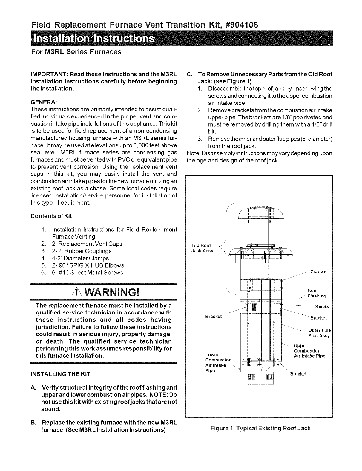
C. To Remove Unnecessary Parts from the Old Roof
Jack: (see Figure 1)
1. Disassemble the top roof jack by unscrewing the
screws and connecting it to the upper combustion
air intake pipe.
2. Remove brackets from the combustion air intake
upper pipe. The brackets are 1/8" pop riveted and
must be removed by drilling them with a 1/8" drill
bit.
3. Removetheinnerand outerflue pipes (6"diameter)
from the roof jack.
Note: Disassembly instructions may varydepending upon
the age and design of the roof jack.
f
Top Roof < _,
Jack Assy /,,_7{/_,F!_';;];'_,_[
Ili !!'Il!!
Bracket::::H::|
'1I
I= i
Lower !
Combustion _ _ .................
Air intake --... _ o2_; :
Pipe " L o !! _ ?'
.... Screws
Roof
Flashing
............... Rivets
Bracket
- - Outer Flue
Pipe Assy
" _ Upper
Combustion
Air intake Pipe
_' _ Bracket
B. Replace the existing furnace with the new M3RL
furnace. (See M3RL Installation Instructions) Figure 1. Typical Existing Roof Jack

l
12' Min.
Aboverool
or expecte_
snow level
13' Max.
1
10" Min.
__ [
J
Screw
Roof Fmashing
Roof _
Lower Combusion
Air Intake Pipe \
\
5" to 13"__ 2" 90 °Elbow
----r_ j/Large Radius
_-__-_*"'_ i Hub x Hub 2Req,
i I I_ \ I :: Seal With
1/<S,,,eoneSeo,ant
ReploeementCap
Upper Combustion
Air mntake Pipe
(8" Dia.)
iii!
2" 90 ° Elbow Screw
Large Radius
Hul5 X Hub \\
2 Req. _
Add 2or More Screws
j Through Upper and Lower
j/ PipesYo Prevent Telescoping.
Repmacement Cap
SeamWith
Siffcone Seamant
2" 90 ° Elbow
_Large Radius
Spig X Hub 2 Req.
Rubber CouIpling
2" Dia. =2 Req.
Furnace
Figure 2. Vent and Combustion Air
Intake Pipe Installation
D, To Install Vent and Combustion Air Intake Pipe
(see M3RL Installation Instructions)
After the M3RL furnace is set in place:
1. Choose vent pipe material based on table 1.
2. Install 2" rubber couplings on the furnace pipes and
assemble 90° SPIG x HUB elbow (large radius).
Material
Schedule 40 PVC
PVC-DWV
SDR-21*
& SDR-26*
ABS-DWV
Schedule 40 ABS
Foam/Cellular
Core PVC
Standard
D1785
D2665
D2241
D2661
F628
F891
Table 1. Vent Pipe Material
3. Place bottom and top replacement caps on the
roof jack. DO NOT screw the caps down at this
time
4. Cut 2" plastic pipes and route the vent and
combustion air intake pipes through the
replacement caps as shown in Figure 2.
Note: The maximum height from the top of the
furnace to the top of the flue pipe must be no
longer than 13 feet.
5. Join all the pipes and elbows using appropriate
plastic solvent cement.
6. Screw the top and the bottom replacement caps
to the outer pipes. Note: At least two screws must
be used on each cap.
7. Tighten the upper hose clamps on the 2" rubber
couplings.
8. Securethe combustionairintakepipetothelower
combustion air intake pipe at the bottom of the
upper pipe using at least two screws.
9. Seal around the two pipes on the top and bottom
replacement caps with silicone sealant.
O'Fatton, MO NORI tNE 708300A
!11 708300A (Replaces 7083000)
Specifications and illustrations subject to change
without notice and without incurring obligations.
Printed in USA (0204)
