NORDYNE Air Handler (indoor Blower&evap) Manual L0801591
User Manual: NORDYNE NORDYNE Air Handler (indoor blower&evap) Manual NORDYNE Air Handler (indoor blower&evap) Owner's Manual, NORDYNE Air Handler (indoor blower&evap) installation guides
Open the PDF directly: View PDF ![]() .
.
Page Count: 20
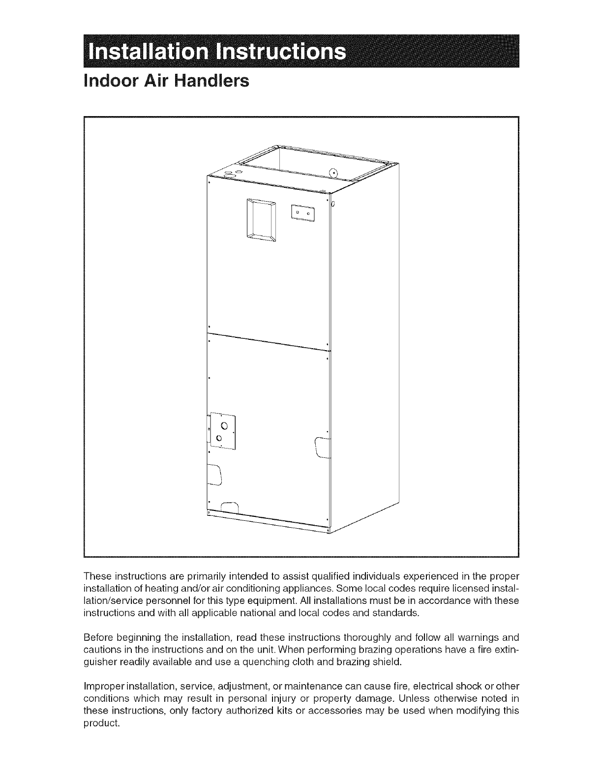
indoor Air Handlers
These instructions are primarily intended to assist qualified individuals experienced in the proper
installation of heating and/or air conditioning appliances. Some local codes require licensed instal-
lation/service personnel for this type equipment. All installations must be in accordance with these
instructions and with all applicable national and local codes and standards.
Before beginning the installation, read these instructions thoroughly and follow all warnings and
cautions in the instructions and on the unit. When performing brazing operations have a fire extin-
guisher readily available and use a quenching cloth and brazing shield.
Improper installation, service, adjustment, or maintenance can cause fire, electrical shock or other
conditions which may result in personal injury or property damage. Unless otherwise noted in
these instructions, only factory authorized kits or accessories may be used when modifying this
product.

Table of Contents
1. Air Handier Specifications ................................................................................................... 4=5
Unit Dimensions .................................................................................................................... 4
2, Installation Requirements ....................................................................................................... 5
Minimum Ampacity and Maximum Overcurrent Protection ................................................... 5
3. Air Ducts, Filters, Horizontal Applications ............................................................................ 6
4. Verify Pressurization ............................................................................................................... 9
5. Refrigerant Line Connections ................................................................................................ 9
6. Electrical Wiring ..................................................................................................................... 11
7. Start=up and Adjustment ....................................................................................................... 13
8. Optional Humidistat (Variable Speed Only) ......................................................................... 17
9. Care and Maintenance ........................................................................................................... 18
3
1. AiR HANDLER SPECiFiCATiONS
Indoor Air Handlers are designed and approved
for attic, basement, alcove, closet and crawl
space installations.
Factory ready horizontal Air Handlers may be
applied in upflow or horizontal-left and -right
discharge applications. These units may also
be applied indownflow discharge when applied
with the appropriate field kit (See Technical
Specifications).
Vertical only Air Handlers are factory ready for
upflow applications.These units may be applied
indownflow or horizontal left and right discharge
applications when applied with the appropriate
field kit (See Technical Specifications).
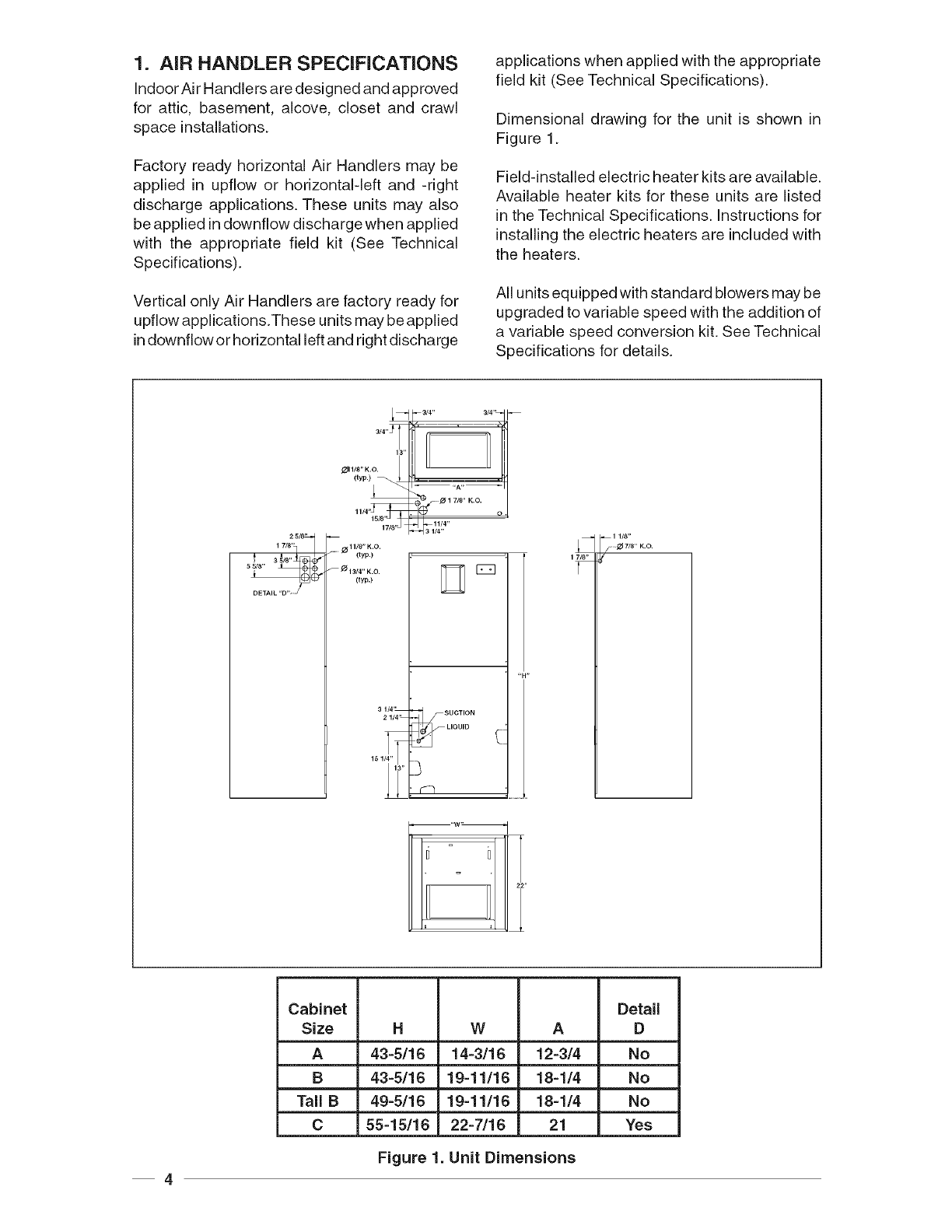
Dimensional drawing for the unit is shown in
Figure 1.
Field-installed electric heater kits are available.
Available heater kits for these units are listed
in the Technical Specifications. Instructions for
installing the electric heaters are included with
the heaters.
All units equipped with standard blowers may be
upgraded to variable speed with the addition of
a variable speed conversion kit. See Technical
Specifications for details.
2 5/8"-]
17/8'q
5 5/8"
i
DETAIL"D"_
J--
3/4" 7
13'
_11/8" K.O.
(typ.)
11/4"15/8
_11/8"K.0.
-" (typ.)
_ _ 13/4" K.O.
(typ.)
3114'_
21/4'L
151_
SUCTION
LIQUID
•
4
Cabinet Detail
Size HW A D
A 43=5/16 14=3/16 12=3/4 No
B 43=5/16 19=11/16 18-1/4 No
Tall B 49=5!16 19=11/16 18-1/4 No
C 55=15!16 22=7/16 21 Yes
Figure 1. Unit Dimensions
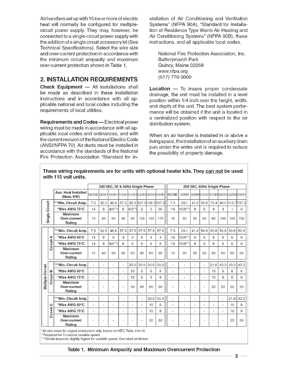
Air handlers set up with 15 kw or more of electric
heat will normally be configured for multiple-
circuit power supply. They may, however, be
connected to a single-circuit power supply with
the addition of a single ci rcuit accessory kit (See
Technical Specifications). Select the wire size
and over-current protection in accordance with
the minimum circuit ampacity and maximum
over-current protection shown in Table 1.
2. INSTALLATION REQUIREMENTS
Check Equipment -- All installations shall
be made as described in these installation
instructions and in accordance with all ap-
plicable national and local codes including the
requirements of local utilities.
Requirements and Codes-- Electrical power
wiring must be made in accordance with all ap-
plicable local codes and ordinances, and with
the cu rrent revision of the National Electric Code
(ANSI/NFPA 70). Air ducts must be installed in
accordance with the standards of the National
Fire Protection Association "Standard for In-
stallation of Air Conditioning and Ventilation
Systems" (NFPA 90A), "Standard for Installa-
tion of Residence Type Warm Air Heating and
Air Conditioning Systems" (NFPA 90B), these
instructions, and all applicable local codes.
National Fire Protection Association, Inc.
Batterymarch Park
Quincy, Maine 02269
www.nfpa.org
(617) 770-3000
Location -- To insure proper condensate
drainage, the unit must be installed in a level
position within 1/4 inch over the height, width,
and depth of the unit. The best system perfor-
mance will be obtained if the unit is located in
a centralized position with respect to the air
distribution system.
When an air handler is installed in or above a
living space, the installation of an auxiliary drain
pan under the entire unit is required to reduce
the possibility of property damage.
These wiring requirements are for units with optional heater kits. They can not be used
with 115 volt units.
240 VAC, 50 & 60Hz Single Phase
Au=..eatInstalledIN_N_lnn<_lnn_ InlnHInl<_ln>n_ln><_ln*n_l
_"°m_w_I.... ! !..........I ! I ! ! !.........................
O'°5 *WireAWG75°C!14 ! 8 !8<_*>!8 !4<3q2 ! 0 !00!
__ Maximum I I I I I I I I I
Over-currentI 18 I 40I 80 I 60I 901128118611781
Rating ! !! !!!!!I
***Min, Circuit Arnp._
*wireAwG60oc! 14! 8 ! 6 14141414141
*w,reAwG_oc!14 ! 8 !8<6-_!8 ! 6 ! 6 ! 6 ! 6 !
u Maximum I I I I I I I I I
Over-current I 18 1461 80 1661691691661861
I!Rating ! !! !!!!!I
Circuit Amp. - - - - 25.6 59.6 56.6 56.9 .... ....
=-*wire_w_°°°c! - !-!- !- !19!6!6!6!_
'_ *WireAWG75°C ! - !-! - !-! 19! 8 ! 8 ! 8 !
Ma=_mu.,,I I I I I I I I I
Over-_urrentI - I - I - I - 1391691661691
Ratng ! ! ! ! ! ! ! ! I
Amp. - - - - - - 25.0 50.0 ...... . .
"*,,io.Circ.,.Wire_W_00oc!_ !-! - !-!-!-!1618!_
_ *w_reAW_°c!- ! - ! - ! - ! - ! - ! 16!8 !
Ma=_.,u.,, I I I I I I I I I
Over-_urrentI - I - I - I - I - I - 1361691
Ratng ! ! ! ! ! ! ! ! I
*All wire sizes for copper conductors only, based on NEC Table 310-16.
**Required for C-cabinet variable speed.
**Circuit arnpacity slightly higher for variable speed. See label on blower.
Table 1. Minimum Ampacity and Maximum Overcurrent Protection
5
Allservicingandcleaningoftheairhandlercan
be donefrom the front.Adequatehorizontal
clearancesshouldbe providedto allowfor
serviceandcareoftheunit.Aminimum24inch
clearanceatthefrontoftheunitisrecommended.
Theseunitsaresuitableforattic,closet,crawl
spaceoralcoveinstallationat zeroclearance
fromcombustibles.
CondensateDrain -- The condensate pan
has primary and secondary drain connections.
The connections have 3/4 inch female pipe
threads.
All condensate drains should be a minimum
of 3/4 inch PVC pipe or equivalent. The drain
should maintain a minimum horizontal slope in
the direction of discharge of not less than 1 inch
vertical for every 10 feet of horizontal.
If the air handler is located in or above a living
space where damage may result from conden-
sate overflow, an auxiliary drain pan shall be
installed under the unit. A separate drain line
should extend from the pan to a conspicuous
point and serve as an alarm indicating that the
primary drain is restricted. As an alternative to
a separate drain line, an approved water level
indicator or float switch device should be used to
shut down the unit in the event water is detected
in the auxiliary pan.
Install a 5 inch trap in the condensate drain
line as close to the coil as possible. Make sure
that the top of the trap is below the bottom of
the drain pan to prevent the condensate from
overflowing the drain pan. Prime the trap with
water. Insulate the drain if it is located in an
unconditioned space, and test the condensate
line for leaks. Consult local codes for additional
restrictions or precautions.
NOTE: There must be only one trap in the drain
line. Using more than one trap may prevent
drainage.
IMPORTANT:
The plastic drain pan must be level
or slightly sloped toward the drain
lines.
3. AIR DUCTS, FILTERS,
HORIZONTAL APPLICATIONS
Air ducts should be installed inaccordance with
the standards of the National Fire Protection
Association "Standard for Installation of Air
Conditioning and Ventilation Systems" (NFPA
90A), "Standard for Installation of Residence
Type Warm Air Heating and Air Conditioning
Systems" (NFPA 90B), these instructions, and
all applicable local codes.
Use transition fittings if the supply and/or return
air openings of the unit do not match the duct
openings. These transitions should be dimen-
sioned in accordance with standard practice as
specified inthe ASHRAE recommendations for
duct transitions.
Flexible connectors should be used between the
unit and the ductwork to prevent transmission of
vibration from the unit to the structure. If electric
heater kits are installed, heat resistant material
must be used for the flexible connector at the
supply air end of the unit.
Air Filter Installation -- The filter may be lo-
cated in the return air duct system or installed
into the air handler filter track located in the
bottom of the unit.
To install the filter, remove the filter door. The
filter sizes for the air handler cabinets are:
Cabinet Filter
12x20x1
18x20x1
C 20x20x1
z WARNING:
Never operate the unit without a fil-
ter or with the doors removed. Dust
and lint in the return air can build up
on internal components, resulting
in a loss of efficiency, equipment
damage, and possible fire risk.
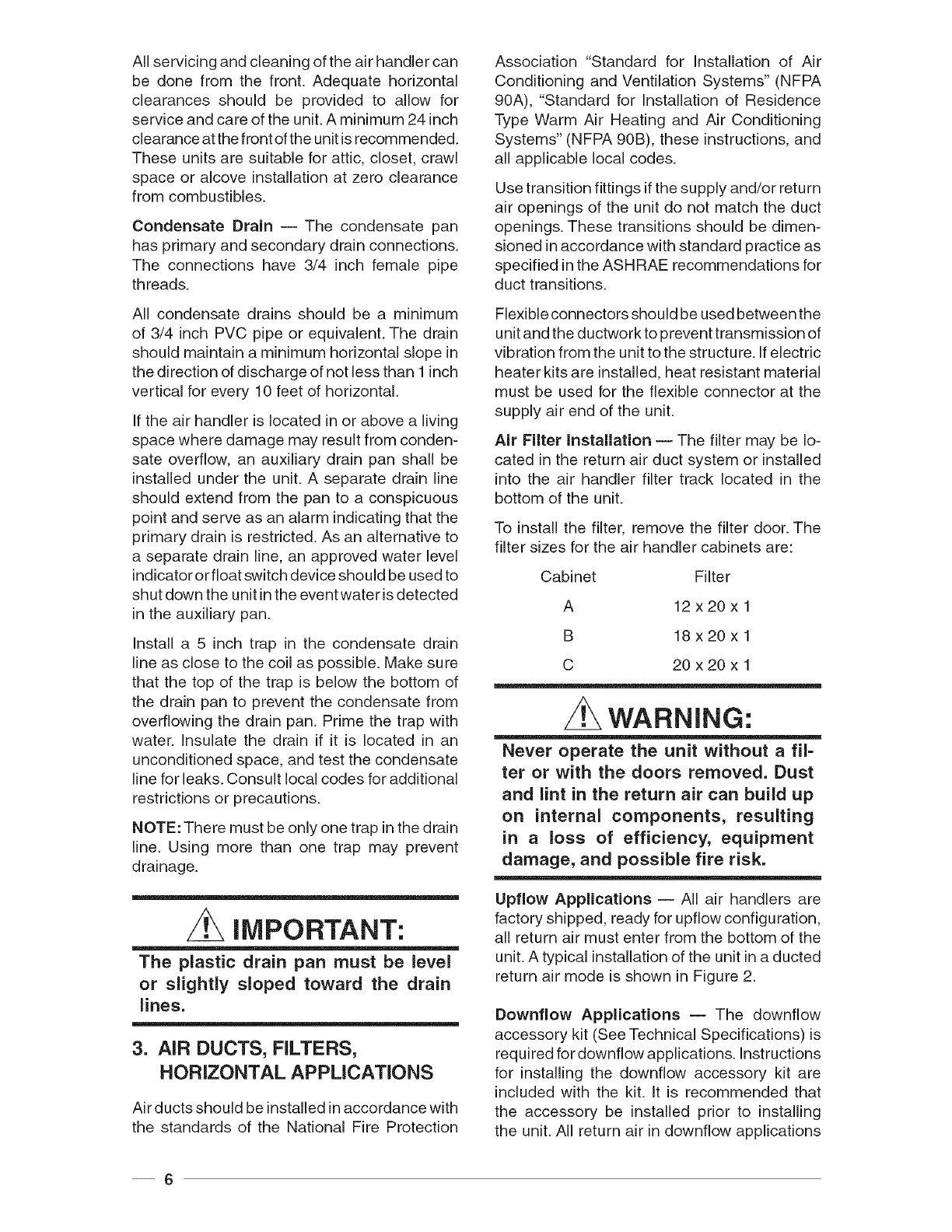
Upflow Applications -- All air handlers are
factory shipped, ready for upflow configuration,
all return air must enter from the bottom of the
unit. A typical installation of the unit in a ducted
return air mode is shown in Figure 2.
Downflow Applications -- The downflow
accessory kit (See Technical Specifications) is
required for downflow applications. Instructions
for installing the downflow accessory kit are
included with the kit. It is recommended that
the accessory be installed prior to installing
the unit. All return air in downflow applications
6
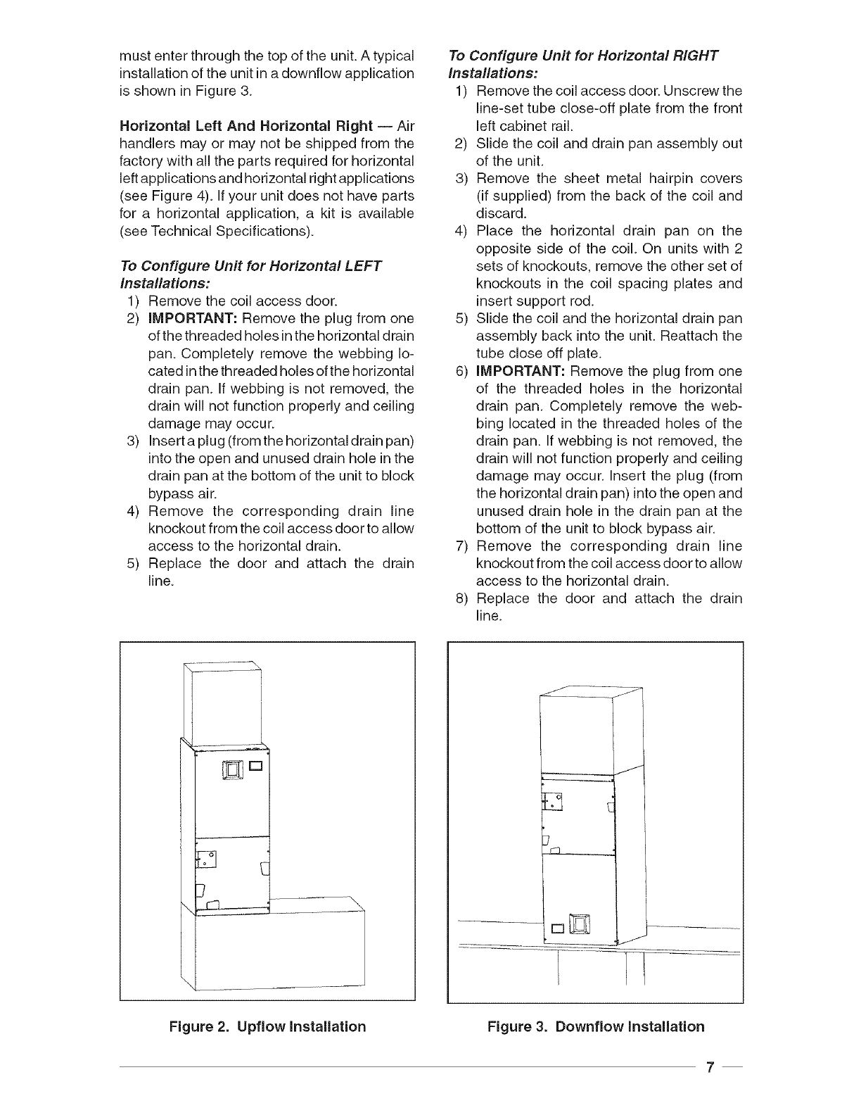
mustenterthroughthetopoftheunit.Atypical
installationoftheunitinadownflowapplication
isshowninFigure3.
Horizontal Left And Horizontal Right -- Air
handlers may or may not be shipped from the
factory with all the parts required for horizontal
left applications and horizontal right applications
(see Figure 4). If your unit does not have parts
for a horizontal application, a kit is available
(see Technical Specifications).
To Configure Unit for Horizontal LEFT
Installations:
1) Remove the coil access door.
2) iMPORTANT: Remove the plug from one
of the threaded holes in the horizontal drain
pan. Completely remove the webbing lo-
cated in the threaded holes of the horizontal
drain pan. If webbing is not removed, the
drain will not function properly and ceiling
damage may occur.
3) Insert a plug (from the horizontal drain pan)
into the open and unused drain hole in the
drain pan at the bottom of the unit to block
bypass air.
4) Remove the corresponding drain line
knockout from the coil access door to allow
access to the horizontal drain.
5) Replace the door and attach the drain
line.
To Configure Unit for Horizontal RIGHT
Installations:
1) Remove the coil access door. Unscrew the
line-set tube close-off plate from the front
left cabinet rail.
2) Slide the coil and drain pan assembly out
of the unit.
3) Remove the sheet metal hairpin covers
(if supplied) from the back of the coil and
discard.
4) Place the horizontal drain pan on the
opposite side of the coil. On units with 2
sets of knockouts, remove the other set of
knockouts in the coil spacing plates and
insert support rod.
5) Slide the coil and the horizontal drain pan
assembly back into the unit. Reattach the
tube close off plate.
6) iMPORTANT: Remove the plug from one
of the threaded holes in the horizontal
drain pan. Completely remove the web-
bing located in the threaded holes of the
drain pan. If webbing is not removed, the
drain will not function properly and ceiling
damage may occur. Insert the plug (from
the horizontal drain pan) into the open and
unused drain hole in the drain pan at the
bottom of the unit to block bypass air.
7) Remove the corresponding drain line
knockout from the coil access door to allow
access to the horizontal drain.
8) Replace the door and attach the drain
line.
J
L______ J
Figure 3. Downflow InstallationFigure 2. Upflow Installation
7
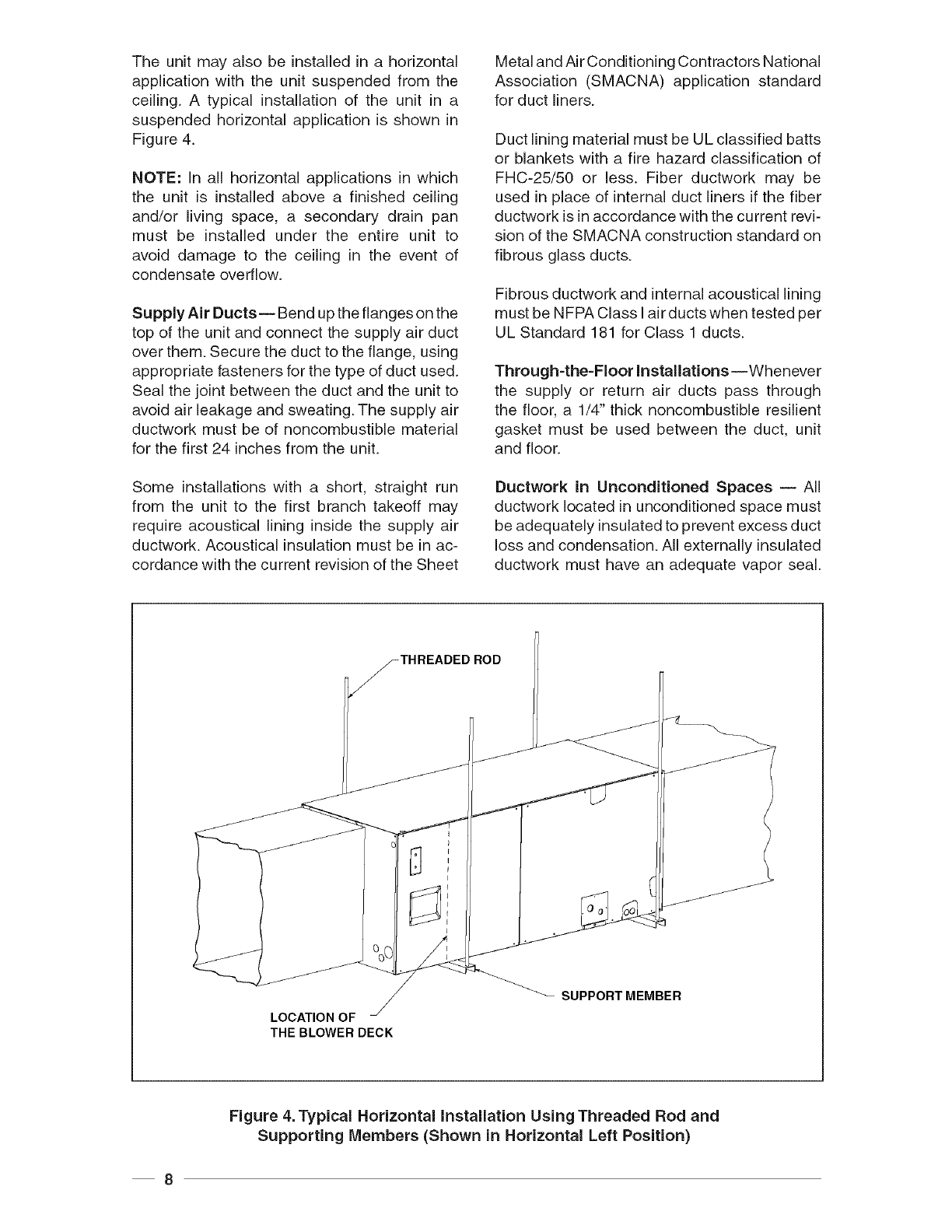
The unitmayalsobeinstalledin a horizontal
applicationwiththe unitsuspendedfromthe
ceiling.A typicalinstallationof the unit in a
suspendedhorizontalapplicationis shownin
Figure4.
NOTE:In all horizontalapplicationsin which
the unit is installedabovea finishedceiling
and/or livingspace,a secondarydrainpan
must be installed underthe entire unit to
avoiddamageto the ceilingin the eventof
condensateoverflow.
SupplyAir Ducts-- Benduptheflangesonthe
topof theunitandconnectthesupplyairduct
overthem.Securetheducttotheflange,using
appropriatefastenersforthetypeofductused.
Sealthejointbetweentheductandtheunitto
avoidairleakageandsweating.Thesupplyair
ductworkmustbeof noncombustiblematerial
forthefirst24inchesfromtheunit.
Someinstallationswith a short,straightrun
from the unitto the first branchtakeoffmay
requireacousticallininginsidethe supplyair
ductwork.Acousticalinsulationmustbein ac-
cordancewiththecurrentrevisionoftheSheet
MetalandAirConditioningContractorsNational
Association(SMACNA)applicationstandard
forductliners.
DuctliningmaterialmustbeULclassifiedbatts
or blanketswitha firehazardclassificationof
FHC-25/50or less.Fiberductworkmay be
usedinplaceof internalductlinersifthefiber
ductworkisinaccordancewiththecurrentrevi-
sionoftheSMACNAconstructionstandardon
fibrousglassducts.
Fibrousductworkandinternalacousticallining
mustbeNFPAClassI airductswhentestedper
ULStandard181forClass1ducts.
Through-the-FloorInstallations--Whenever
the supplyor returnair ductspassthrough
thefloor,a 1/4"thicknoncombustibleresilient
gasketmustbe usedbetweenthe duct,unit
andfloor.
Ductworkin Unconditioned Spaces -- All
ductwork located in unconditioned space must
be adequately insulated to prevent excess duct
loss and condensation. All externally insulated
ductwork must have an adequate vapor seal.
_-THREADED ROD
LOCATION OF
THE BLOWER DECK
SUPPORT MEMBER
Figure 4. Typical Horizontal Installation Using Threaded Rod and
Supporting Members (Shown in Horizontal Left Position)
8
ConsultyourDistributorfortherecommended
typeandthicknessof insulationforyourarea
as requiredbylocalcodes.
4. VERIFY PRESSURIZATION
WARNING".
NITROGEN
HEALTH []
FLAMMABILITY []
REACTIVITY []
OMinimal Hazard 1Slight Hazard
This coil is pressurized with Nitro-
gen. Pressure must be relieved in
order to prevent the potential of an
injury or fatality from the cap during
the removal process, Avoid direct
face exposure or contact with valve
when gas is escaping. Always ensure
adequate ventilation is present during
the depressurization process. Any
uncertainties should be addressed
before proceeding.
VERIFY PRESSURiZATiON:
Test by depressing Schrader valve and listen
for escaping gas
If no pressure is found, test coil for leak
- If no leak is found, install coil
- If leak is found, clearly mark leak
location and return coil to your dis-
tributor for processing
5. REFRIGERANT LINE
CONNECTIONS
Note: Do not remove seals from the coil until
tubing connections are ready to be made.
Note: The air handler coil does not contain
a refrigerant charge. Reference installation
instructions included with outdoor unit for
information regarding the refrigerant charge
included in the outdoor unit.
Note: The following instructions are for air
handler models employing an orifice for the
refrigerant metering device.
The orifice employed in the air handlers has
been sized for use with the most popularly
matched outdoor unit.The orifice size in the coil
as shipped from the factory is listed on the air
handler rating plate. Check that the orifice size
provided with the air handler is correct for the
outdoor unit being applied. If the orifice size is
incorrect it should be replaced as follows:
z WARNING:
NITROGEN
HEALTH []
FLAMMABILITY []
REACTIVITY []
0Minimal Hazard 1 Slight Hazard
This coil is pressurized with Nitro-
gen. Pressure must be relieved in
order to prevent the potential of an
injury or fatality from the cap during
the removal process. Avoid direct
face exposure or contact with valve
when gas is escaping. Always ensure
adequate ventilation is present dur-
ing the depressurization process.
Any uncertainties should be ad-
dressed before proceeding.
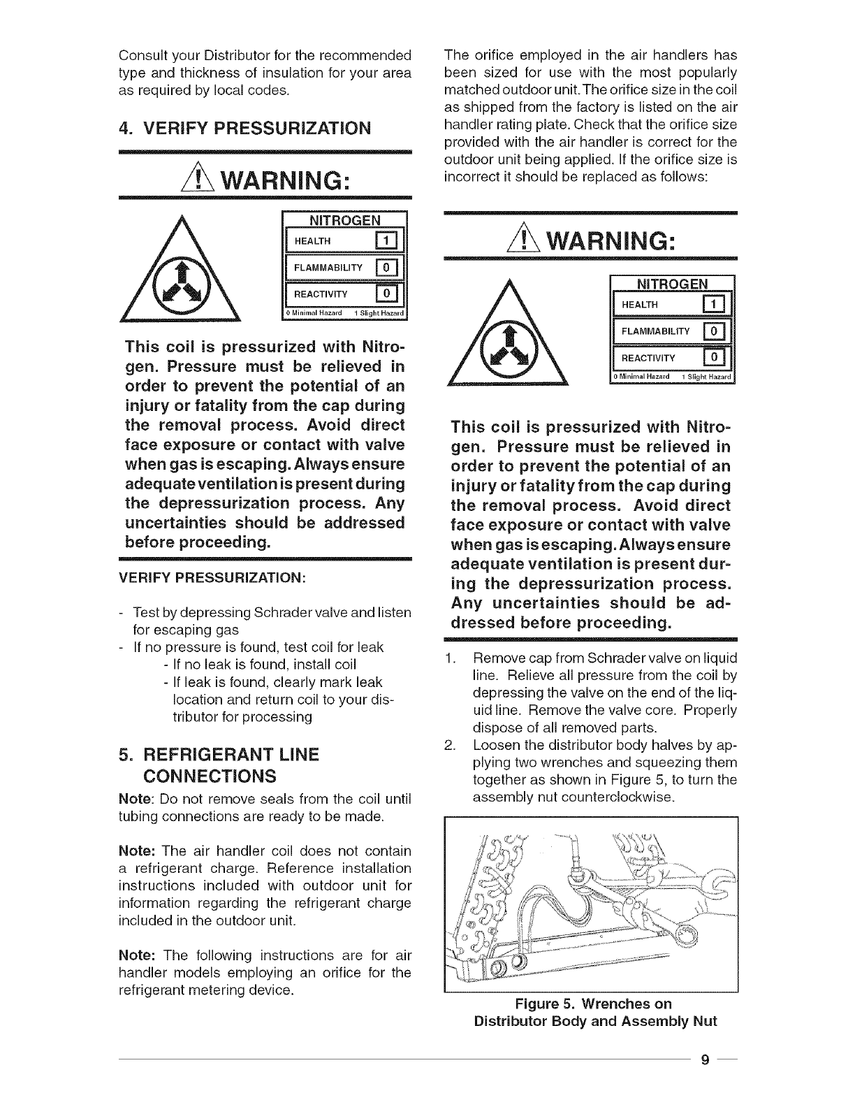
1. Remove cap from SchradervaIve on liquid
line. Relieve all pressure from the coil by
depressing the valve on the end of the liq-
uid line. Remove the valve core. Properly
dispose of all removed parts.
2. Loosen the distributor body halves by ap-
plying two wrenches and squeezing them
together as shown in Figure 5, to turn the
assembly nut counterclockwise.
Figure 5. Wrenches on
Distributor Body and Assembly Nut
9
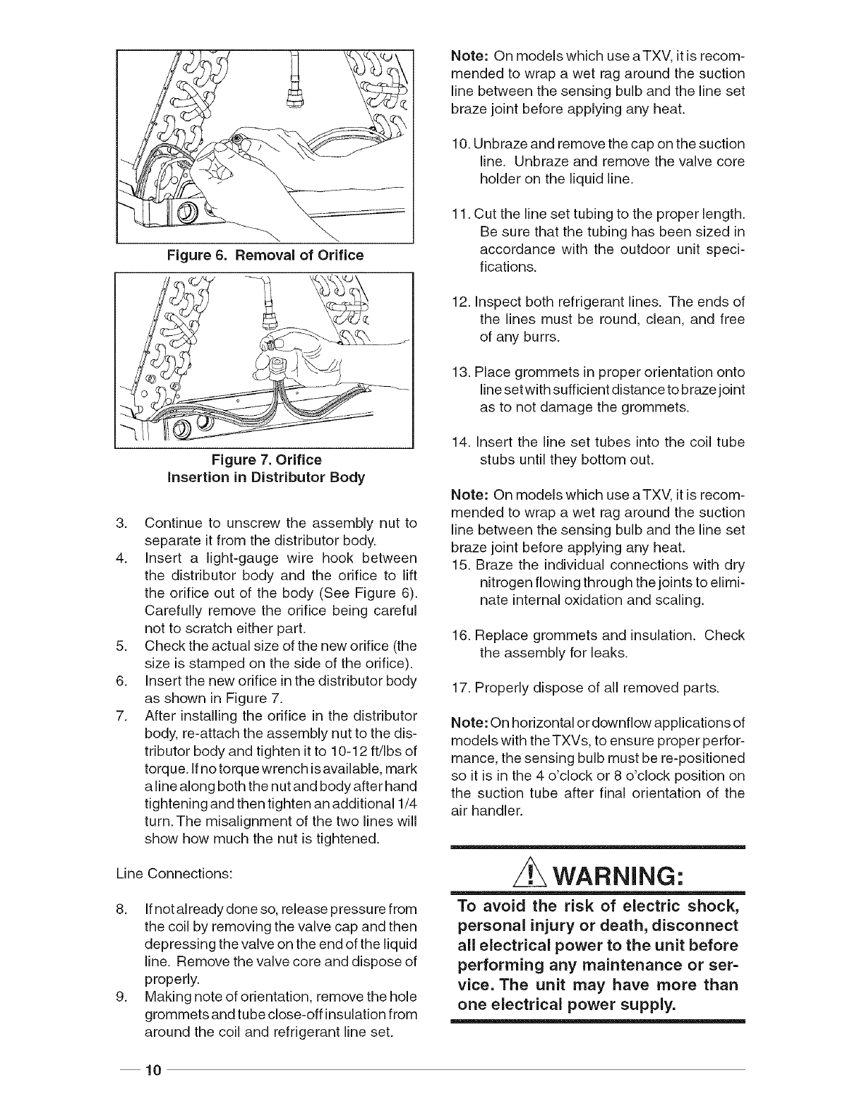
Figure6. Removalof Orifice
Figure 7. Orifice
insertion in Distributor Body
3. Continue to unscrew the assembly nut to
separate it from the distributor body.
4. Insert a light-gauge wire hook between
the distributor body and the orifice to lift
the orifice out of the body (See Figure 6).
Carefully remove the orifice being careful
not to scratch either part.
5. Check the actual size of the new orifice (the
size is stamped on the side of the orifice).
6. Insert the new orifice inthe distributor body
as shown in Figure 7.
7. After installing the orifice in the distributor
body, re-attach the assembly nut to the dis-
tributor body and tighten it to 10-12 ft/Ibs of
torque. If no torque wrench isavailable, mark
a line along both the nut and body after hand
tightening and then tighten an additional 1/4
turn.The misalignment of the two lines will
show how much the nut is tightened.
Line Connections:
8. Ifnot already done so, release pressure from
the coil by removing the valve cap and then
depressing the valve on the end of the liquid
line. Remove the valve core and dispose of
properly.
9. Making note of orientation, remove the hole
grommets and tube close-off insulation from
around the coil and refrigerant line set.
10
Note: On models which use aTXV, it is recom-
mended to wrap a wet rag around the suction
line between the sensing bulb and the line set
braze joint before applying any heat.
10. Unbraze and remove the cap on the suction
line. Unbraze and remove the valve core
holder on the liquid line.
11. Cut the line set tubing to the proper length.
Be sure that the tubing has been sized in
accordance with the outdoor unit speci-
fications.
12. Inspect both refrigerant lines. The ends of
the lines must be round, clean, and free
of any burrs.
13. Place grommets in proper orientation onto
lineset with sufficient distance to braze joint
as to not damage the grommets.
14. Insert the line set tubes into the coil tube
stubs until they bottom out.
Note: On models which use aTXV, it is recom-
mended to wrap a wet rag around the suction
line between the sensing bulb and the line set
braze joint before applying any heat.
15. Braze the individual connections with dry
nitrogen flowing through the joints to elimi-
nate internal oxidation and scaling.
16. Replace grommets and insulation. Check
the assembly for leaks.
17. Properly dispose of all removed parts.
Note: On horizontal or downflow applications of
models with the TXVs, to ensure proper perfor-
mance, the sensing bulb must be re-positioned
so it is in the 4 o'clock or 8 o'clock position on
the suction tube after final orientation of the
air handler.
z WARNING:
To avoid the risk of electric shock,
personal injury or death, disconnect
all electrical power to the unit before
performing any maintenance or ser-
vice. The unit may have more than
one electrical power supply.
6. ELECTRICAL WiRiNG
General -- Electrical power wi ring must be made
in accordance with all applicable local codes
and ordinances, and with the current revision of
the National Electric Code (ANSI/NFPA 70). If
any of the original wire as supplied with the unit
must be replaced, it must be replaced with wire
material having the same gauge and tempera-
ture rating. Disconnection means: a means to
disconnect the appliance must be incorporated
in the fixed wiring.
LineVoltage-- Before proceeding with the elec-
trical connections, make certain that the voltage,
frequency, and phase of the supply source are
the same as those specified on the rating plate.
Also, verify that the service provided by the utility
is sufficient to handle the additional load imposed
by this equipment.
See the unit wiring label for proper high and low
voltage wiring. Make all electrical connections in
accordance with the National Electric Code and
any applicable local codes or ordinances.
Use a separate branch electrical circuit for this
unit. A disconnecting means must be located
within sight of, and readily accessible to, the
unit. When electric heat packages with circuit
breakers are field-installed, the circuit breaker
may be used as a disconnecting means in most
applications. Reference the NEC and Local Codes
for Disconnect requirements.
208/240 volt units are shipped from the factory
wired for 240 volt transformer operation. For 208
volt operation, remove the lead from the trans-
former terminal marked 240v and connect it to
the terminal marked 208v. For maximum ampacity
and overcurrent protection, see Table 1.
Provide power supply (or supplies) for the unit in
accordance with Table 1, the unit wiring diagram
and the unit rating plate.
When a heater kit is installed: Connnect the
2 wire plug of the air handler with the mating
2 wire plug of the heater kit. Connect the line
voltage leads to the circuit breaker or terminal
block provided. Connect the heater kit plug with
the mating receptacle on the air handler control
board. When installing a 25 kw or 30 kw heater
kit, follow the instructions provided with the kit
for proper installation.
When a heater kit is not installed: Remove the 2
wire plug of the air handler by cutting the wires
and discarding the plug. Strip the ends of the 2
air handler wires and connect to the line-voltage
leads with the 2 wire nuts provided.
Use copper wire only for the line voltage power
supply to this unit. Aluminum supply wire may
be used if a heater kit is installed. Use UL listed
conduit and a conduit connector for connecting
the supply wires to the unit and for obtaining
proper grounding. Grounding may also be ac-
complished by using the grounding lug provided
inthe control box. Field supplied bushings for the
power supply cables must be added to support
and protect the power supply cables.
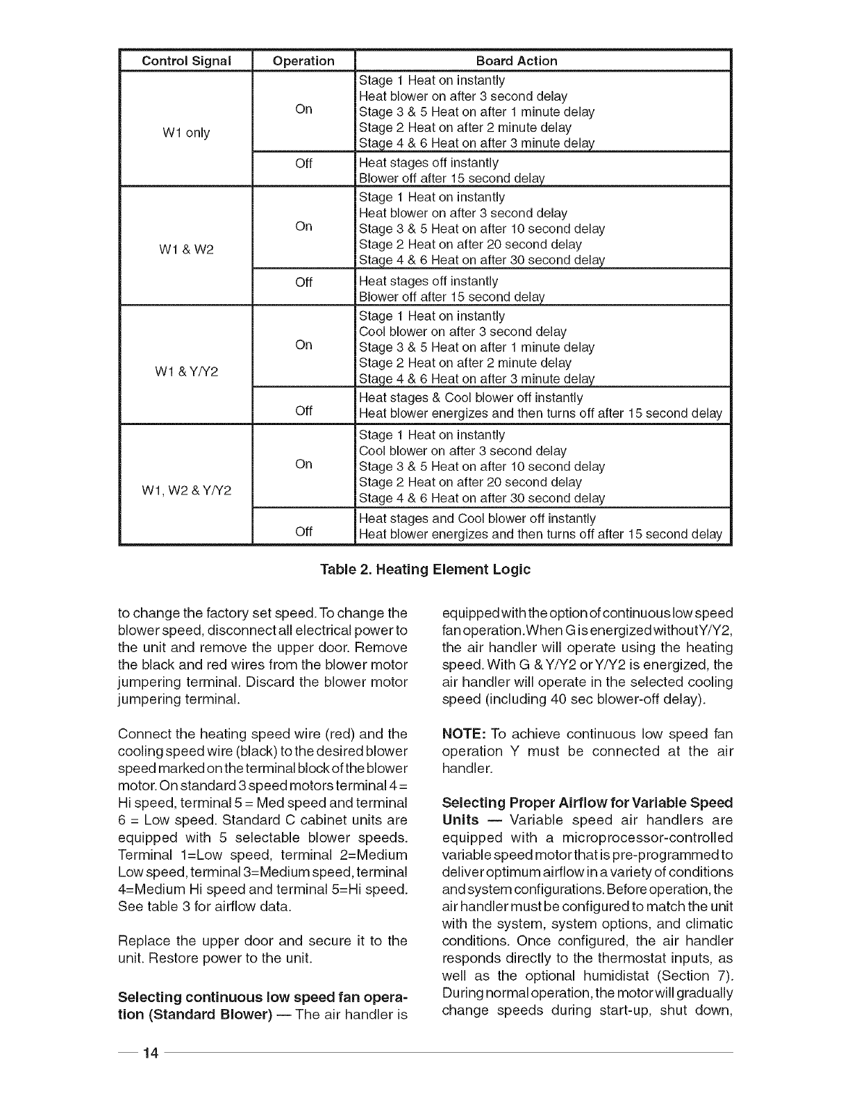
HEATING ELEMENT LOGIC
The control board in the air handler controls the
timing sequence of the elements. Depending on
the thermostat connection, there are 2 timing
sequence variations that can be chosen. See
table 2 for element sequence timing. The board
also is equipped with a 3 second blower on delay
and a 15 second blower off delay.
z WARNING:
The unit cabinet must have an uninter-
rupted and unbroken electrical ground
to minimize the risk of personal injury
if an electrical fault should occur.This
ground may consist of electrical wire
or approved conduit when installed
in accordance with existing national
or local codes.
Low Voltage -- Install the grommet, which is
packed with the unit, in the hole for low-voltage
wires.When the low voltage wires are positioned
in this grommet, the grommet will prevent chafing
and/or shorting of the low voltage leads. Connect
the low-voltage wiring to the thermostat and the
outdoor unit and the appropriate screw terminal
located on the control board.
NOTE: Where local codes require that the
thermostat wiring must be routed through
a conduit or raceway, splices can be made
inside the unit; however, all wiring must
be NEC Class 1 and must be separated from
incoming power leads.
11
NOTE: Jumper
Wl and W2
together for
shorter
staging time.
See a 2
Thermostat
GRW Y
000 )
Air Handier
c
A/C OD Section
NOTE: Jumper r
W1 and W2 /
together for /
shorter /
staging time.
See table 2
o @\
Y/Y2 (_ "--_-
G @--
c @
Thermostat
G R W2C E O Y /
OOO000_)[
NOTE: Jumper
betweenW2 and E is
requiredwhenno OD
T-Stat isused.
Air Handier Heat Pump OD
Section
Typical Air Conditioner w/Standard
Air Handier
NOTE: Jumper Thermostat
Wl and W2
together for
shorter G RW Y_
staging le.
See table 2
Yl \_
o @.
G G
R G
° @
NOTE: inAC appLications,the Oand Y connection
must be connected as shown.
Air Handier NC OD Section
Typical Air Conditioner with
Variable Speed Air Handler
Typical Heat Pump w/Standard Air Handler
NOTE: Jumper
Wl and W2
together for
shorter
staging time.
See table 2
Thermostat
G RW2C E O Y
COY
Air Handler Heat Pump OD
Section
Typical Heat Pump with Optional Outdoor
Thermostat and Variable Speed Air Handler
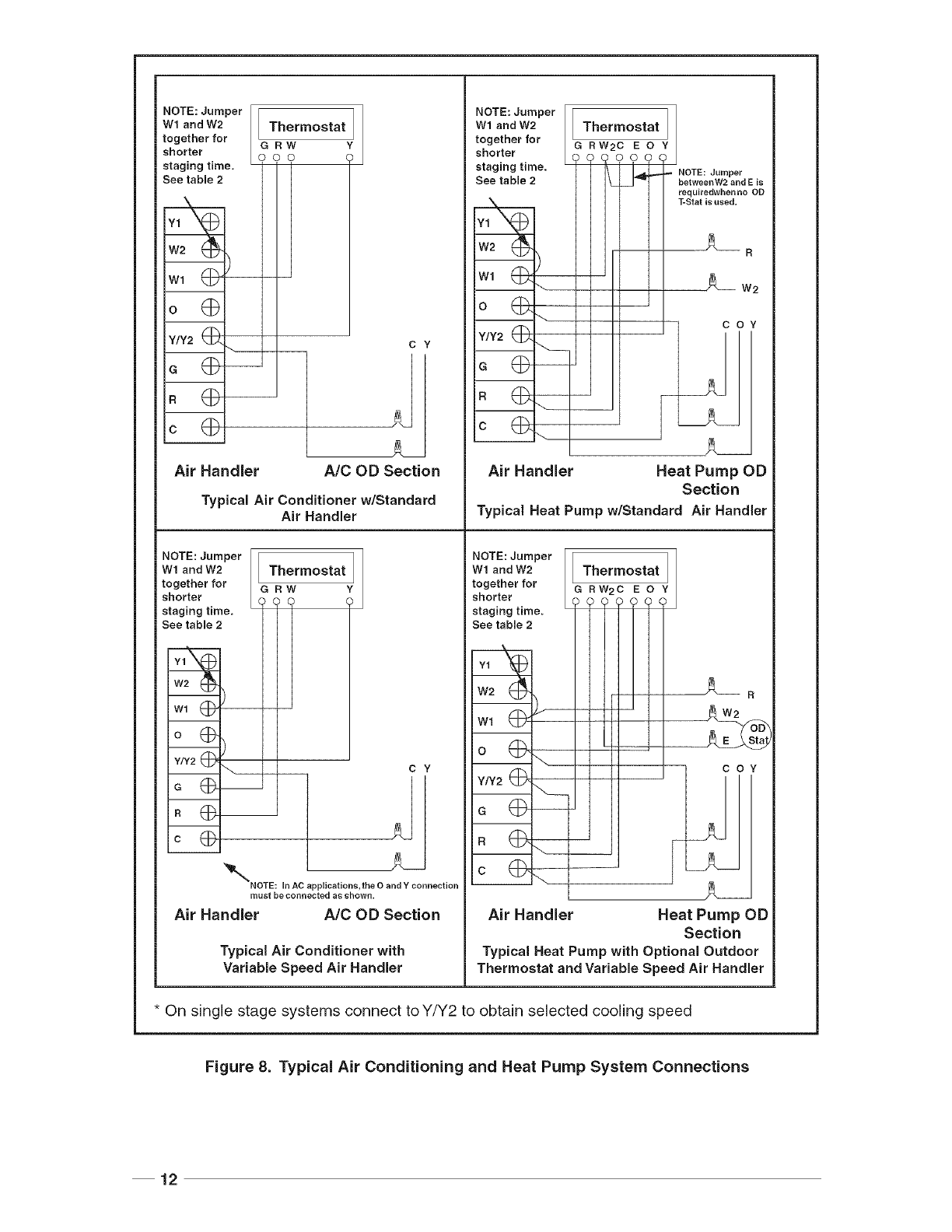
* On single stage systems connect to Y/Y2 to obtain selected cooling speed
Figure 8. Typical Air Conditioning and Heat Pump System Connections
12
NOTE: Jumper [I I ]
Wl and W2 / I Thermostat I /
together for / IG R W Y2 Y1
shorter /
SS't 't ,te'7? t
°@_ t I
o @
_ NOTE: in AC applications, the 0 and Y
connection mustbeconnectedasshown,
Air Handler
_Y2
I C Y1
A/C OD Section
Typical 2-Stage Air Conditioner
with Variable Speed Air Handler
NOTE: Jumper [
Wl and W2 /
together for /
shorter [
staging time. '
See table 2
Y/Y2 (_ \. _
G (_--
c (_-_
Thermostat J
G RW2C O Y1 Y2 WlW3
, O (I/_
o[
COY1 _
Air Handler Heat Pump OD Section
Typical 2-Stage Cooling Heat Pump with
Optional Outdoor Thermostat and Variable
Speed Air Handler
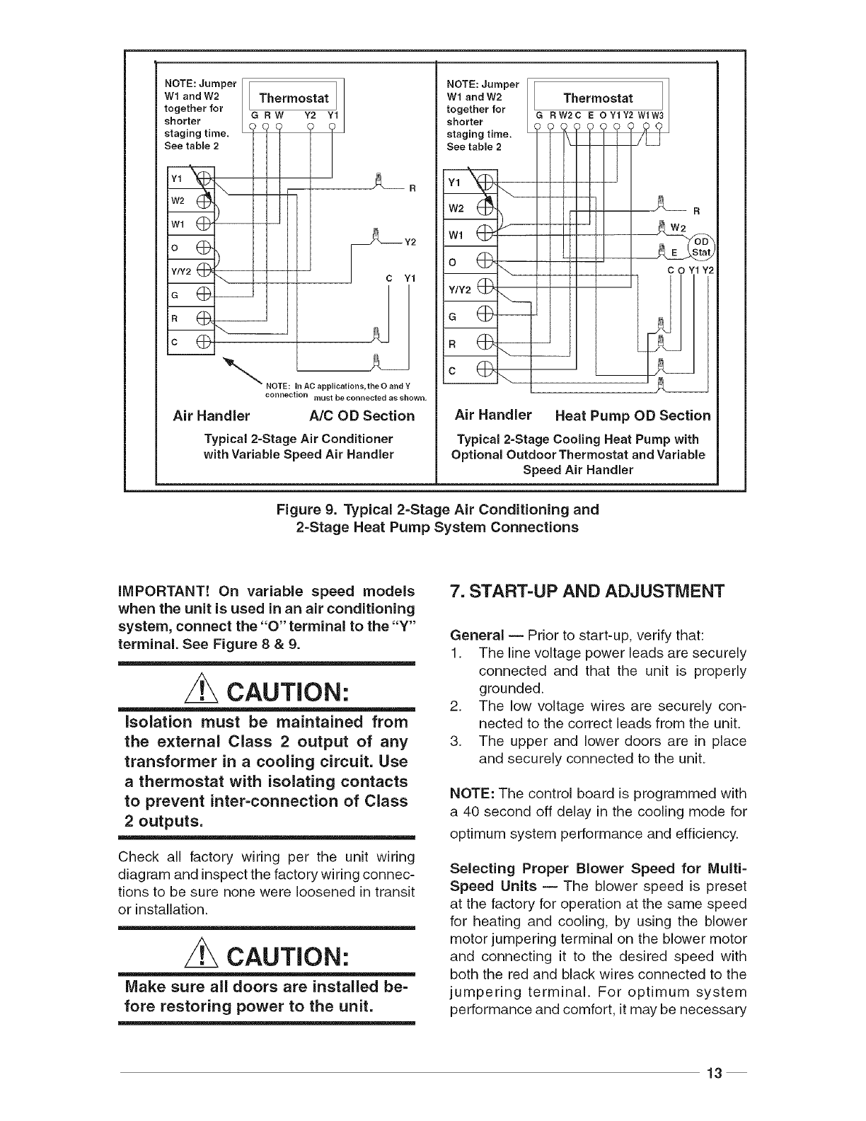
Figure 9. Typical 2-Stage Air Conditioning and
2-Stage Heat Pump System Connections
iMPORTANT! On variable speed models
when the unit is used in an air conditioning
system, connect the "O" terminal to the "Y"
terminal. See Figure 8 &9.
CAUTION:
isolation must be maintained from
the external Class 2 output of any
transformer in a cooling circuit. Use
a thermostat with isolating contacts
to prevent inter-connection of Class
2 outputs.
Check all factory wiring per the unit wiring
diagram and inspect the factory wiring connec-
tions to be sure none were loosened in transit
or installation.
CAUTION:
Make sure all doors are installed be-
fore restoring power to the unit.
7. START=UP AND ADJUSTMENT
General -- Prior to start-up, verify that:
1. The line voltage power leads are securely
connected and that the unit is properly
grounded.
2. The low voltage wires are securely con-
nected to the correct leads from the unit.
3. The upper and lower doors are in place
and securely connected to the unit.
NOTE: The control board is programmed with
a 40 second off delay in the cooling mode for
optimum system performance and efficiency.
Selecting Proper Blower Speed for Multi-
Speed Units -- The blower speed is preset
at the factory for operation at the same speed
for heating and cooling, by using the blower
motor jumpering terminal on the blower motor
and connecting it to the desired speed with
both the red and black wires connected to the
jumpering terminal. For optimum system
performance and comfort, it may be necessary
13
Control Signal Operation
W1 only
W1 &W2
W1 & Y/Y2
On
Off
On
Off
On
Off
On
W 1, W2 & Y/Y2
Off
Board Action
IStage 1 Heat on instantly
Heat blower on after 3 second delay
iStage 3 & 5 Heat on after 1 minute delay
Stage 2 Heat on after 2 minute delay
iStage 4 & 6 Heat on after 3 minute delay
Heat stages off instantly
Blower off after 15 second delay
IStage 1 Heat on instantly
Heat blower on after 3 second delay
Stage 3 & 5 Heat on after 10 second delay
Stage 2 Heat on after 20 second delay
lStage 4 & 6 Heat on after 30 second delay
IHeat stages off instantly
Blower off after 15 second delay
IStage 1 Heat on instantly
Cool blower on after 3 second delay
I
iStage 3 & 5 Heat on after 1 minute delay
Stage 2 Heat on after 2 minute delay
IStage 4 & 6 Heat on after 3 minute delay
IHeat stages & Cool blower off instantly
Heat blower energizes and then turns off after 15 second delay
iStage 1 Heat on instantly
Cool blower on after 3 second delay
iStage 3 & 5 Heat on after 10 second delay
JStage 2 Heat on after 20 second delay
IStage 4 & 6 Heat on after 30 second delay
IHeat stages and Cool blower off instantly
Heat blower energizes and then turns off after 15 second delay
Table 2. Heating Element Logic
to change the factory set speed.To change the
blower speed, disconnect all electrical power to
the unit and remove the upper door. Remove
the black and red wires from the blower motor
jumpering terminal. Discard the blower motor
jumpering terminal.
Connect the heating speed wire (red) and the
cooling speed wire (black) to the desired blower
speed marked on the terminal block of the blower
motor. On standard 3 speed motors terminal 4 =
Hi speed, terminal 5 = Med speed and terminal
6 = Low speed. Standard C cabinet units are
equipped with 5 selectable blower speeds.
Terminal 1=Low speed, terminal 2=Medium
Low speed, terminal 3=Medium speed, terminal
4=Medium Hi speed and terminal 5=Hi speed.
See table 3 for airflow data.
Replace the upper door and secure it to the
unit. Restore power to the unit.
Selecting continuous low speed fan opera=
tion (Standard Blower) -- The air handler is
equippedwith the option of continuouslowspeed
fan operation.When G isenergized withoutY/Y2,
the air handier wiii operate using the heating
speed. With G &Y/Y2 orY/Y2 is energized, the
air handier will operate in the selected cooling
speed (including 40 sec blower-off delay).
NOTE: To achieve continuous low speed fan
operation Y must be connected at the air
handler.
Selecting Proper Airflow for Variable Speed
Units -- Variable speed air handlers are
equipped with a microprocessor-controlled
variable speed motor that is pre-programmed to
deliver optimum airflow ina variety of conditions
and system configurations. Before operation, the
air handler must be configured to match the unit
with the system, system options, and climatic
conditions. Once configured, the air handler
responds directly to the thermostat inputs, as
well as the optional humidistat (Section 7).
D uring no rmal ope ration, the motor will grad ually
change speeds during start-up, shut down,
14
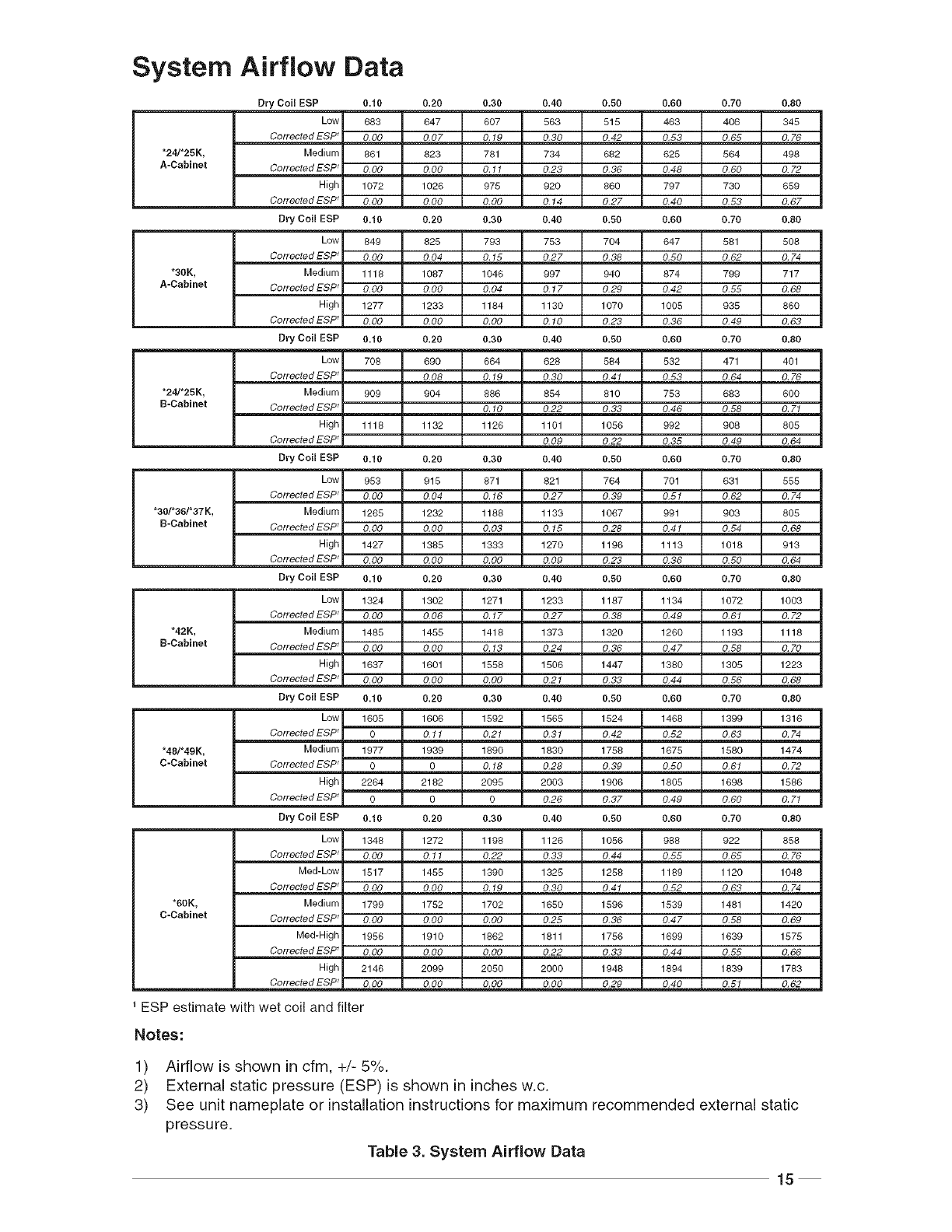
System Airflow Data
"24/'25K,
A-Cabinet
Dry Coil EBP 0.10 0.20 0.30 0.40 0.50 0.60 0.70 0.80
Low 683 647 807 583 515 463 408 345
CorrectedESP _O,O0 O,O7 0,19 0,30 0.42 0,53 0,65 0,76
Medium 861 823 781 734 682 625 564 498
Co rrectedESP_ O,OO O,OO 0,11 0,23 0,36 0,48 0,60 0.72
High 1072 1026 975 920 860 797 730 859
Co rrectedESP_ O,OO O,OO O.OO 0,14 0,27 0.40 0.53 0,67
Dry Coil EBP 0.10 0.20 0.30 0.40 0.50 0.60 0.70 0.80
Low 849 825 793 753 704 647 581 508
CorrectedESP _0,00 0,04 0,15 0,27 0,38 0,50 0,62 0,74
*3OK, Medium 1118 1087 1046 997 940 874 799 717
A-Cabinet CorrectedESP _O.OO O,OO 0,04 0,17 0.29 0,42 0,55 0,68
High 1277 1233 1184 1130 1070 1005 935 860
CorrectedESP _O,OO O, OO 0,00 0,10 0,23 0,36 0,49 0,63
Dry Coil EBP 0.10 0.20 0.30 0.40 0.50 0.60 0.70 0.80
"24/'25K,
B-Cabinet
Low 708 890 664 628 584 532 471 401
Corrected ESP _O,08 O,19 O,30 O,41 O,53 O, 64 O,76
Medium 909 904 886 854 810 753 883 600
Corrected ESP _O,10 0.22 0,38 0,46 0,58 O,71
High 1118 1132 1126 1101 1056 992 908 805
Corrected ESP _O.09 0,22 O,85 O,49 O,64
Dry Coil ESP 0.10 0.20 0.30 0.40 0.50 0.60 0.70 0.80
Low 953 915 871 821 764 701 631 555
CorrectedESP _0,00 0,04 0,16 0,27 0,39 0,51 0,62 0,74
"30/'38/'37K, Medium 1265 1232 1188 1133 1067 991 903 805
B-Cabinet CorrectedESP _O,OO O, OO 0,03 0,15 0,28 0,41 0,54 0,68
High 1427 1385 1333 1270 1196 1113 1018 913
eorrected ESP _0,00 O, O0 O,OO 0,09 0,23 0,36 0.50 0,64
Dry Coil EBP 0.10 0.20 0.30 0.40 0.50 0.60 0.70 0.80
Low 1324 1302 1271 1233 1187 1134 1072 1003
CorrectedESP _0,00 0,06 0,17 0.27 0,38 0,49 0,61 0,72
"42K, Medium 1485 1455 1418 1373 1320 1260 1193 1118
B-Cabinet CorrectedESP _O.OO O,OO 0,13 0,24 0,36 0,47 0,58 0,70
High 1637 1601 1558 1506 1447 1380 1305 1223
Corrected ESP _O,OO O,OO O,OO 0,21 0,33 0,44 0.56 0,68
Dry Coil EBP 0.10 0.20 0.30 0.40 0.50 0.60 0.70 0.80
"48/'49K,
C-Cabinet
Low 1605 1606 1592 1565 1524 1468 1399 1318
Corrected ESP _ 0 0,11 0,21 0,31 0,42 0,52 0,63 0,74
Medium 1977 1939 1890 1830 1758 1675 1580 1474
Corrected ESP_ 0 0 0,18 0,28 0,39 0,50 0,61 0,72
High 2264 2182 2095 2003 1906 1805 1698 1586
Corrected ESP_ 0 0 0 0,26 0,37 0,49 0,60 0,71
Dry Coil ESP 0.10 0.20 0.30 0.40 0.50 0.60 0.70 0.80
*60K,
C-Cabinet
Low 1348 1272 1198 1126 1056 988 922 858
Corrected ESP _O,OO 0,11 0,22 0,83 0,44 0,55 0,65 0.76
Med-Low 1517 1455 1390 1325 1258 1189 1120 1048
CorrectedESP _O,OO O, OO 0,19 0,30 0,41 0,52 0.63 0,74
Medium 1799 1752 1702 1650 1596 1539 1481 1420
Corrected ESP _O.OO O,OO O,OO 0,25 0,36 0,47 0,58 0,69
Med-High 1956 1910 1862 1811 1756 1699 1639 1575
Corrected ESP _O,OO O,OO O,OO 0,22 0,33 0,44 0,55 0,66
High 2146 2099 2050 2000 1948 1894 1839 1783
Corrected ESP_ O,O0 O,O0 O,O0 O,O0 0,29 O,40 O. 51 O,62
ESP estimate with wet coil and filter
Notes:
1) Airflow is shown in cfm, +/- 5%.
2) External static pressure (ESP) is shown in inches w.c.
3) See unit nameplate or installation instructions for maximum recommended external static
pressure.
Table 3. System Airflow Data
15
A-CABINET
Switch I Nominal
Number I Capacity
CFM 1 2 3 411.512.012,513.0
mmmdmlmld /
540 0 0 0 1 _ /
600 o o o o _ I
660 o o io_ I
715 iooi_ I
790 1 oool
870 1 o i ol
915 o i o 11 I
988 1 1 011 I
1015 0 1 0 o l I _
1060 0 1 1 o l I _
1075 1 1 0 o l I _
1165 1110111 []
B-CABINET
Switch Nominal
Number Capacity
0FM72001 2 3 4_2"53'013"54'(00 1
800 oo o om I I I
85o i 0 0 i _ I I
88o 0 0 i 0 _ I I
948 i 0 0 0 I _ I
i040 i 0 i 0 I _ I
i068 0 i 0 i I _ I
1146 i i 0 i I I
1206 0 i 0 0 I I
1268i i oo l l
1326o,,o II I
13_0i,,o III
Note: 1=ON, 0=OFF
C-CABINET
Switch Nominal
Number I Capacity
OFM 1 2 3 413.013.54,015.0
iml /1075 0 0 0 1
1135 1 0 0 1_ I
1225 0 0 0 0 _ I
1295 1 0 0 0
1380 0 0 1 01
1460 1 0 1 01
1525 0 1 0 11
1625 11 011 I _
1740 010 01 I _
1860 11 0 ol l l []
196o o I i o l I I []
2090 1 1 1 ol l l []
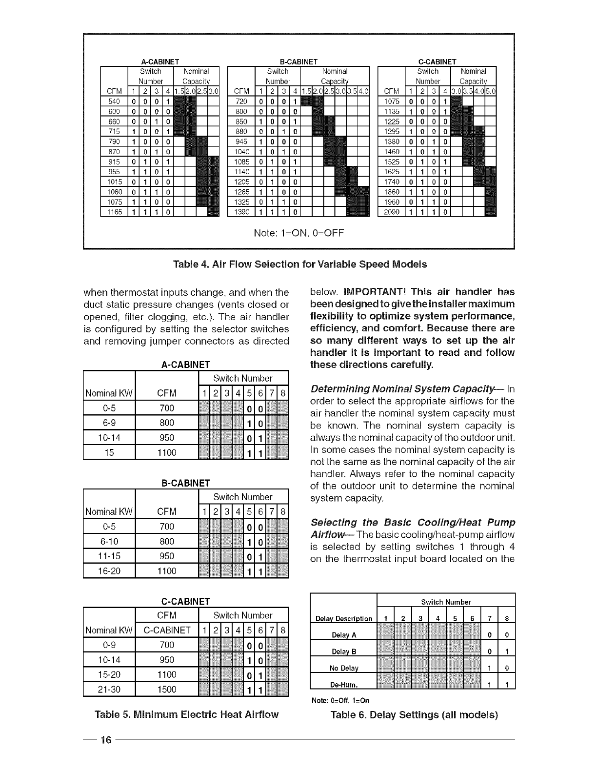
Table 4. Air Flow Selection for Variable Speed Models
when thermostat inputs change, and when the
duct static pressure changes (vents closed or
opened, filter clogging, etc.). The air handler
is configured by setting the selector switches
and removing jumper connectors as directed
A-CABINET
Switch Number
NominaIKW CFM 1 2 3 4 5 6 7 8
0-5 700 0 0
6-9 8oo 1 o
to-t4 950 01
15 1100 1 1
B-CABINET
Switch Number
NominaIKVV CFM 1 2 3 4 5 6 7 8
0-5 700 0 0
6-t0 8oo 1 0
tt-t5 950 oi
16-20 1100 1 1
C-CABINET
Switch Number
below. IMPORTANT! This air handier has
been designed to givethe installer maximum
flexibility to optimize system performance,
efficiency, and comfort. Because there are
so many different ways to set up the air
handler it is important to read and follow
these directions carefully.
Determining Nominal System Capacity--In
order to select the appropriate airflows for the
air handler the nominal system capacity must
be known. The nominal system capacity is
always the nominal capacity of the outdoor unit.
In some cases the nominal system capacity is
not the same as the nominal capacity of the air
handler. Always refer to the nominal capacity
of the outdoor unit to determine the nominal
system capacity.
Selecting the Basic Cooling/Heat Pump
Airflow---The basic cooling/heat-pump airflow
is selected by setting switches 1 through 4
on the thermostat input board located on the
Nominal KW
0-9
10-14
15-20
21-30
CFM
C-CABINET 1 2 3 4 5 6 7 8
700 0 0.
950 1 o
ttoo o
1500 1 1
Table 5. Minimum Electric Heat Airflow
Switch Number
Delay Description 1 2 3 4 5 6 78
De,o,A 0 0
De,o,B 0,
No Delay 1O
De-Hum, 1 1
Note: O=Off, 1=On
Table 6. Delay Settings (all models)
16
blower.Allairflowsforothermodesofoperation
(exceptelectricheat)are determinedby this
basicsetting.
Table4showsthebasicairflowvaluesversusthe
airflowselectorswitchsettings.Table4alsoshows
therangeofbasicairflowsettingsrecommended
foreachnominalsystemcapacity.
Note:The15+SEERvanablespeedairhandlers
thatarematchedwitha2-stagecoolingoutdoor
unit,areprogrammedto operateat 75%of the
selectedairflowwhilethesystemisintheIo-cool
modeand100%oftheselectedairflowwhilein
hi-coolmode.
NOTE:TheCFMvalueslistedin thetablesare
notdependentonductstaticpressure.Themotor
automaticallycompensatesforchangesinduct
staticpressure(withinthelimitsof themotor).
Formaximumcapacityand energyefficiency,
select an airflowat or near the top of the
rangefor thatnominalcapacity.Formaximum
dehumidification,select an airflownear the
middleor bottomof therangefor thatnominal
capacity.Additionalinformationon humidity
controlcan be foundin the sectionslabeled
"Humidistat"and"DelaySetting".
NOTE: If coil icing is observed,the basic
cooling/heat-pumpairflowselectedmaybetoo
low.Double-checktobesurethesettingselected
iswithintherangeshowninTable4.Alsocheck
to besurethesystemis properlycharged(see
outdoorunit InstallationInstructions).If icing
continuesto occur,raisetheselectedairflow
oneortwosteps.
Whenoperatingintheheatpumpmode,ahigher
basicairflowsettingwill increasethe energy
efficiencyandcapacitybutwill alsodecrease
thesupplyairtemperature.
Selecting the Minimum Electric Heat A irflow--
The minimum electric heat airflow is selected by
setting switches 5 and 6. Selecting the minimum
electric heat airflow sets the minimum air flow
that will be produced whenever electric heater
kits are used. When the electric heater kits are
energized along with a heat pump, the airflow
may be higher depending on the basic cooling/
heat-pump airflow setting.
Reference Table 5 for recommended minimum
electric heat airflow settings. The minimum
electric heat airflow setting may be set higher,
but must never be set lower than the setting
shown in Table 5.
Selecting the Delay Profile--The delay profile
is selected by setting switches 7 and 8 (see
Table 6). Delay profile selection controls the
start-up and shut-down characteristics of the air
handler. By varying the start-up and shut-down
characteristics of the air handler the system
can be optimized for energy efficiency, humidity
control, and comfort.
Select "Delay A" or "Delay B" for highest energy
efficiency. "Delay A" has a two-step "on" delay.
The blower will begin operation at 31% airflow
for 30 seconds. The second step operation is
75% airflow for 30 seconds. After the two-step
"on" delay has been completed, the blower
operation will be 100% until the thermostat has
been satisfied. "Delay A" also provides a 60
second "off" delay at 50% airflow.
"Delay B" has a single step 30 second"on" delay at
50% airflow."Delay B"also provides a 90 second
"off" delay at 50% airflow. Select the delay profile
which is most suited to the application.
The "De-Hum." delay profile may be used when
humidity control is desired without the use of
the optional humidistat. If the "De-Hum." delay
profile is selected, the air handler will run at 75%
airflow for the first 10 minutes of each cooling
cycle. If the "De-Hum." delay profile is selected,
the basic cooling/heat-pump speed should be
selected at or near the top of the range for that
nominal capacity (see Table 4).
8. OPTIONAL HUMIDISTAT
(Variable Speed Only)
The optional humidistat may be installed in the
return air duct to provide excellent humidity
control when needed and maximum system
capacity and energy efficiency when humidity
levels are normal. The humidistat senses when
humidity inthe return air stream is above a preset
level (field adjustable) and sends a signal to the
motor to reduce the airflow so that more moisture
may be removed until the humidity level drops.
The air handler is pre-programmed for humidistat
operation. Remove jumper connector installed
between the two terminals marked "HUM" on
the circuit board.
17
Note:The 15+ SEERair handlersthat are
matchedwith a 2-stagecoolingoutdoorunit
and the humidistatis installedwill not drop
below75%oftheselectedblowerspeedwhen
thesystemisoperatinginIo-coolmodeandthe
humidistatopens.
Installation--Installthehumidistatinthereturn
airductasdirectedintheinstallationinstructions
includedwiththekit.Wirethehumidistatthrough
thelow-voltagewireentranceintheairhandler
(Figure1)tothequick-connectterminalsmarked
"HUM".Wirethehumidistatto openon risein
humidity.
9. CARE AND MAINTENANCE
General -- For continued high performance,
and to minimize the risk of equipment failure, it
is essential that periodic maintenance be per-
formed on this equipment.The ability to properly
perform maintenance on this equipment requires
certain mechanical skills and tools. Ifyou do not
possess these skills, contact your dealer for
maintenance. Consult your local dealer as to
the availability of a maintenance contract.
Do not store any of the following on, or in contact
with, the unit: Rags, brooms, vacuum cleaners,
or other cleaning tools, spray or aerosol cans,
soap powders, bleaches, waxes, cleaning
compounds, plastics or plastic containers,
paper bags or other paper products, gasoline,
kerosene, cigarette lighter fluid, dry cleaning
fluids, paint thinners, or other volatile fluids.
Proper maintenance is most important to achieve
the best performance from an air handler. At a
minimum, this maintenance should include the
following items.
1. Inspect and clean or replace the air filter at
the beginning of each heating and cooling
season, or more frequently as required.
2. Inspect the cooling coil, drain pan, and
condensate drain at the beginning of each
cooling season for cleanliness. Clean these
components as necessary using a mild
detergent and water. Flush the coil, drain
pan, and condensate drain after cleaning
to remove all detergent. Use caution when
cleaning these components so that the
insulation does not become wet.
3. Inspect the blower motor and wheel for
cleanliness at the beginning of each heat-
ing and cooling season. Clean the motor
as necessary.
4. Inspect electrical connections for tightness
at the beginning of each heating and cooling
season. Service as necessary.
Z WARNING:
Use caution when removing parts
from this unit. Personal injury can
result from sharp metal edges pres-
ent in all equipment of sheet metal
construction.
18

19

iNSTALLER: PLEASE LEAVE THESE
iNSTALLATiON iNSTRUCTiONS
WiTH THE HOMEOWNER
liellllllMlllllllllllriIIIll 708709A (Replaces 7087090)
Specifications and illustrations subject to change
without notice and without incurring obligations.
Printed in U.S.A. (07/07)
