NPG Display Branch NL2501 LCD Monitor User Manual 01 English cover
NPG Display Ltd Taiwan Branch LCD Monitor 01 English cover
UserManual.wiki
>
NPG Display Branch
>
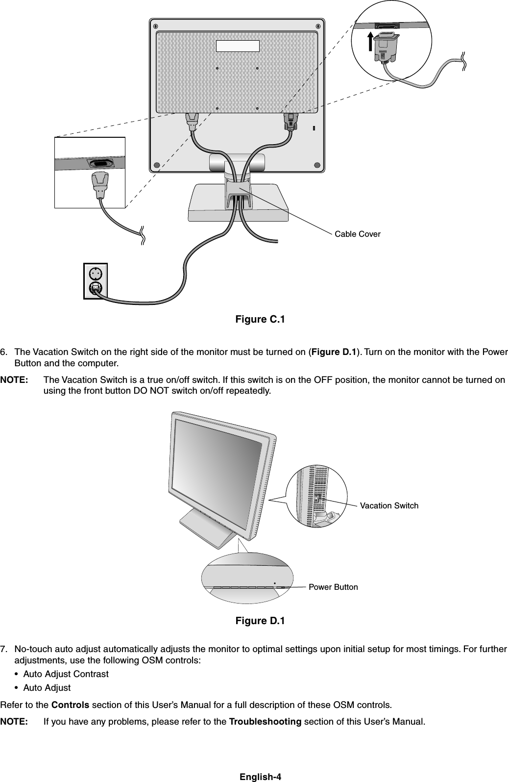
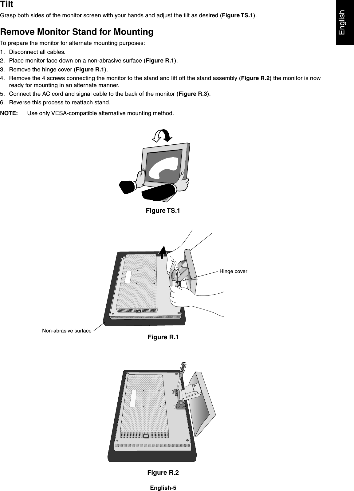
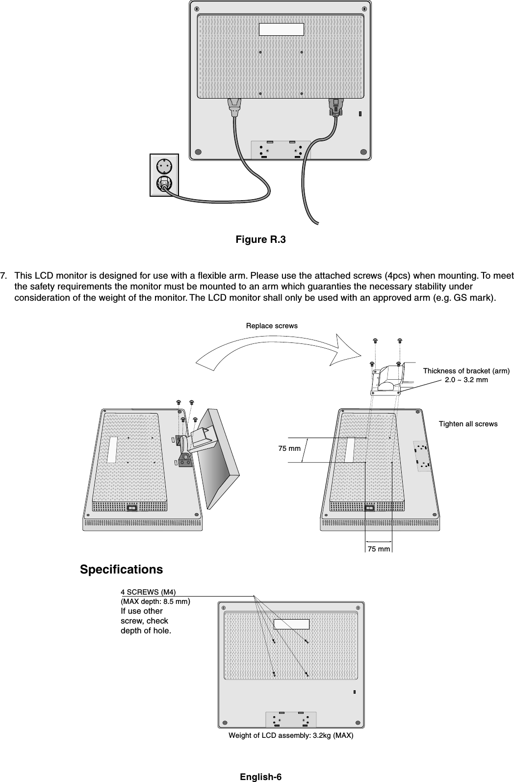
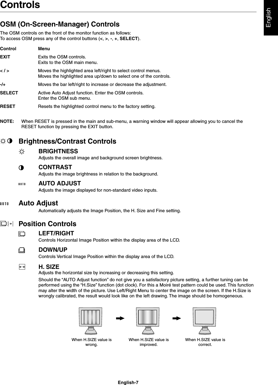
NL2501 User Manual
users manual
Navigation menu
Upload a User Manual
Namespaces
Wiki Guide
HTML
PDF
Info
Views
User Manual
Discussion / Help
Navigation