NTN Buzztime NTN2420 2.4GHz Playmaker System User Manual 0751241
NTN Buzztime, Inc. 2.4GHz Playmaker System 0751241
Manual
BT2420A

1
2.4GHz Playmaker
Product Document
For Service Providers
by
Kevin Lee
Revision 1.0
July 20, 2006

2
1. Installation Requirements
1.1 Pre-installation
1.1.1 Set up charging trays. These charging trays are similar to the ones
we currently use. However, the supplied power adapter is lower in
voltage and has a different plug.
1.1.2 Connect the power adapter to the charging tray.
1.1.3 Place all Playmakers into the charging tray. This step is crucial as it
brings the Playmakers out of shipping mode and into standard
operating mode. You should hear a beep and a light should come
on to indicate proper insertion.
1.1.4 If the above procedure is ignored, the Playmaker will not power on,
i.e., remains in ship mode.
1.2 PC Installation
(Follow current SOP for PC installation)
1.3 Antenna Installation
ONLY CERTIFIED TECHNICIAN SHALL PERFORM INSTALLATION
1.3.1 Identify an ideal location nearest the PC, but central to the play
area for installing the antenna. Be sure to:
§ Select a spot where the antenna will be visible (direct line-of-
sight) from almost everywhere in location
§ Avoid large metallic surfaces, such as kitchen equipment, pipes,
ducts, aluminum foils, light fixtures and mirrors
§ Avoid potential sources of interference, such as neon signs,
fluorescent lights, TV’s , projectors, electrical lines, electrical
panels, compressors, microwave ovens, wi-fi access points, etc.
§ Point antenna either vertically up or down
§ Use only the supplied 2.4GHz antenna
§ Use only one antenna
§ Upon successful installation, affix label to the front of the base
station unit that states “Do not tamper. Antenna shall not
be removed by users.”
§ Keep the PC system out of reach from the users.
1.3.2 Other recommendations:
§ If location has open ceiling, locate wooden crossbeams for
mounting antenna
3
§ If ceiling has aluminum tiles, try to install antenna away from
the tiles.
§ Never install antenna on sprinkler system as it may be in direct
violation of the fire code (plus liability issue)
1.3.3 Using bit-error rate to identify antenna placement:
§ This new model uses what’s known as digital spread-spectrum
to communicate with the base. As such BER, or bit-error rate is
used to identify how well the remote units are communicating
with the base.
§ To access BER reading from the Playmaker, remove a unit from
the charging tray and turn it on.
§ After the initial beep, press the keys “Log off”, “Back space” and
“Back space” one at a time. There is no need to rush.
§ At this point, you should be presented with a login screen.
Proceed to log in with the following password: 53846. If you
mistyped the password, turn the unit off and on again, and
repeat the above bullet point.
§ Use the cursor keys to select “BER Test” and press “Enter”.
§ The BER reading should now be displayed. It is a measurement
of how well the Playmaker is receiving from the base station. It
should be 00 at all times. If it fluctuates beyond 00 moderately,
the reception quality is borderline acceptable. If it stays above
00 half the time, you are likely to have an RF issue.
§ Note that BER reading may fluctuate when the Playmaker is on
the move. As such, only take the reading while the Playmaker
is stationary.
§ Once BER testing is completed, you may hit the “Cancel” key to
return to the main diagnostic menu, or press the power button
to turn the unit off. Never leave the unit in the diagnostic menu.
1.4 Programming the Playmaker Units
The Playmakers at this point should be in the charging tray. If not,
proceed to 1.1. Also, the PC should be installed and powered up before
the following steps are taken:
1.4.1 Remove Playmakers from the charging tray
1.4.2 Turn on ONE Playmaker unit and make sure it registers with the
base station. This process automatically sets the Playmaker unit #.
1.4.3 If an error message appears on the display, try powering off the
Playmaker and turning it on again. If symptom persists, it may
indicate (i) a problem with the Playmaker, which you will resolve
later; (ii) the antenna may be installed improperly or disconnected;
4
or (iii) the mode number may not be ideal for avoiding interference
(see Section 1.5.)
1.4.4 Upon successful registration, you should see the NTN Buzztime logo
or our game menu.
1.4.5 Repeat from Section 1.4.2 one Playmaker at a time. The
registration process should only take a couple of seconds for each
unit.
1.5 Mode Selection and Restrictions
There are currently 14 modes, and the idea is to have different modes for
locations in close proximity where it could interfere with each other.
Mode is also used for improving RF communications at the location if
there are inference sources lingering around. Technically speaking, Mode
number corresponds to a frequency hopping scheme that the Playmakers
and base use to communicate with one another.
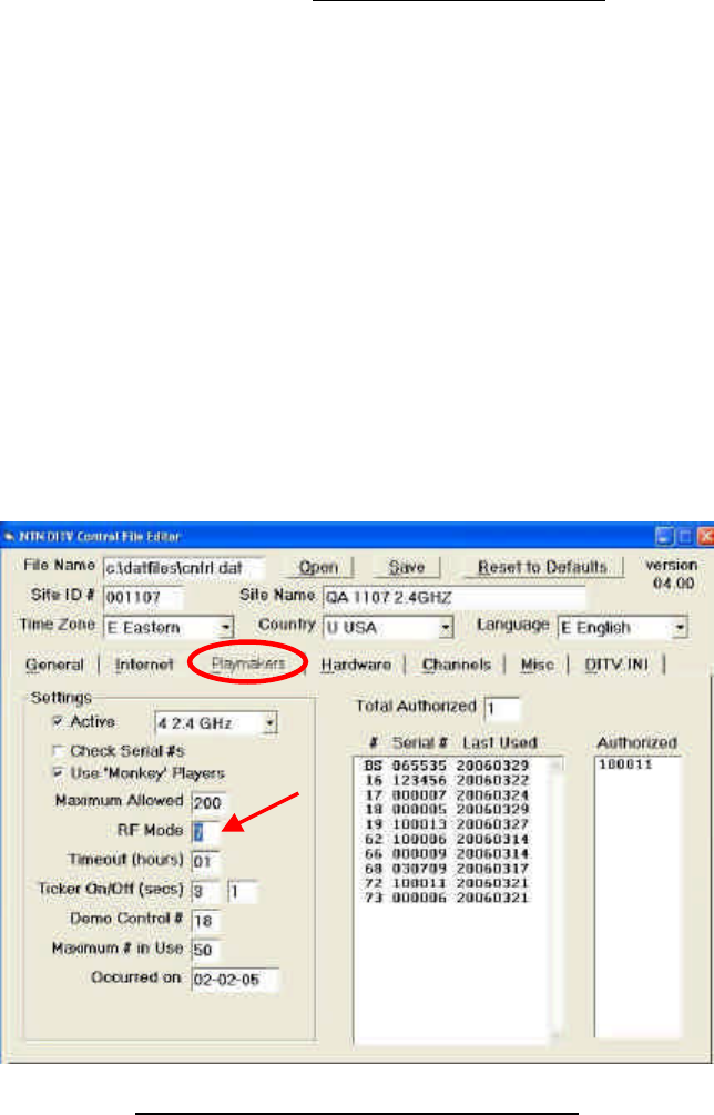
Before the system gets shipped to a location for installation, the base
station should be pre-configured with a mode number. Under normal
circumstances, the default mode number should work fine for the location.
However when the need arises, the mode number can be changed from
the Control File Editor.
Figure 1 Changing Mode in Control File Editor
Before switching modes, the following points must be considered:

5
1.5.1 Is there another location within RF range? If unsure about this,
place a call to our customer service center to inquire about the
mode(s) currently being used in nearby locations. A rule of thumb
is that if the closest location is over 1,000 ft away, the same mode
number can be used. Otherwise, a different mode number must be
selected.
1.5.2 Mode numbers are between 1 and 14.
1.5.3 Different mode numbers may improve or worsen RF performance.
Select the mode number that performs the best. Use BER as the
guide (see 1.6.4) to determine the best mode.
1.5.4 Mode numbers should NOT be the first line of defense to get
optimal RF performance. Antenna placement is.
1.5.5 Note that the mode numbers on the Playmakers are automatically
set when they are initially powered on.
1.6 Diagnostic Features
1.6.1 To log in to the diagnostic menu:
§ Turn on the Playmaker unit.
§ After the initial beep, press the keys “Log off”, “Back space” and
“Back space” one at a time.
§ At this point, you should be presented with a login screen.
Proceed to log in with the following password: 53846. If you
mistyped the password, press the “Cancel” key and reenter.
The following items are available from the diagnostic menu:
§ Change Base ID
§ De-Registration
§ BER Test
§ Memory Test
§ LCD Test
§ Keypad Test
§ Battery Level
§ Contrast Change
§ Parameter Settings
§ Shipping Mode
1.6.2 Change Base ID
The Base ID is pre-configured for the location. Do not change this
setting unless otherwise instructed.
6
1.6.3 De-registration
Registration is a process in which the Playmaker seeks out the base
station and initiates communication by first acquiring a slot # from
the base. This slot # is known to us as the unit #. This number is
sequentially assigned by the base station, and it is between 1 and
200. Once the limit is reached, the base will look for an available
slot # starting from 1 again.
When this function is selected, the Playmaker will send out a de-
registration request to the base. The application at this time shall
process the request and send back a command to perform the
actual de-registration. If unsuccessful, you will simply see “Cancel
Key to exit”. Otherwise, you will see “DONE …” and “SHUTTING
DOWN …”.
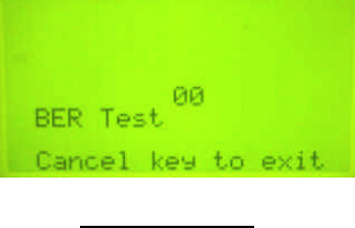
1.6.4 BER Test
BER is a measurement of how well the Playmaker is receiving from
Playmaker. It should be 00 at all times. If it fluctuates beyond 00
moderately, the reception quality is only borderline acceptable. If
it stays above 00 half the time, you are likely to have an RF issue.
Figure 2 BER Test
Note that BER reading will fluctuate when the Playmaker is on the
move. As such, only take the reading while the Playmaker is
stationary.
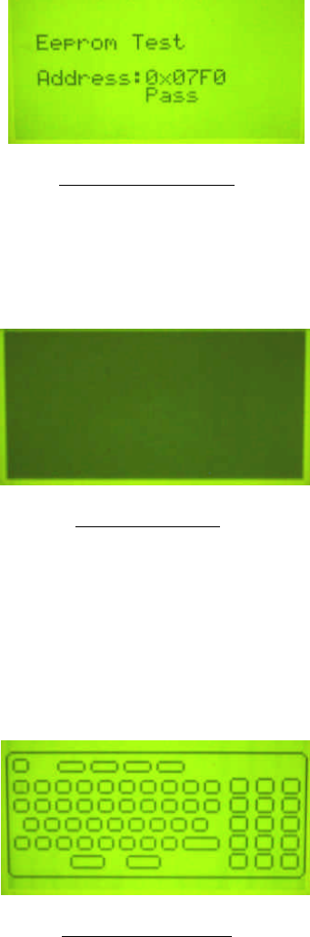
1.6.5 Memory Test
This test is solely to give us an idea if the EEPROM is ok. Once
started, it will take a few seconds to scan through the memory to
identify if there is a fault.
7
Figure 3 Memory Test
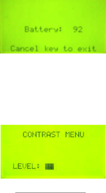
1.6.6 LCD Test
Select this test to activate every pixel on the LCD display, i.e.,
turns the display dark. This is for identifying any dead pixels.
Figure 4 LCD Test
1.6.7 Keypad Test
This test allows every key to be tested, including the Cancel key.
Select this test and an image of the keypad will appear on screen
with a button that represents each key. Press the key to be tested
and it will fill in the respective button on the display. If all buttons
are filled, then the keypad is performing as it should.
Figure 5 Keypad Test
Note that by pressing the Cancel key the first time, it will fill in the
Cancel button on the display. Pressing it the second time will exit
this test.
1.6.8 Battery Level
8
Selecting this option will show the current battery charge level in
real time.
Figure 6 Battery Level
1.6.9 Contrast Change
This is for changing the contrast of the LCD display. By using the
up-arrow and down-arrow keys, you can adjust the display to dark
or light.
Figure 7 Contrast Change
1.6.10 Ship Mode
This option activates the Ship mode, which essentially is the
battery conservation mode where it allows the Playmaker to be
stored for a longer period of time. Alternatively, holding down
CAPS – X – Down Arrow – Right Arrow will also engage this mode.
Once this mode is activated, the Power button will not work. To
deactivate this mode, place the unit into the charger.
Federal Communication Commission Interference Statement
This equipment has been tested and found to comply with the limits for a Class B digital
device, pursuant to Part 15 of the FCC Rules. These limits are designed to provide
reasonable protection against harmful interference in a residential installation. This
equipment generates, uses and can radiate radio frequency energy and, if not installed
and used in accordance with the instructions, may cause harmful interference to radio
communications. However, there is no guarantee that interference will not occur in a
particular installation. If this equipment does cause harmful interference to radio or
television reception, which can be determined by turning the equipment off and on, the
user is encouraged to try to correct the interference by one of the following measures:
- Reorient or relocate the receiving antenna.
- Increase the separation between the equipment and receiver.
- Connect the equipment into an outlet on a circuit different from that
to which the receiver is connected.
- Consult the dealer or an experienced radio/TV technician for help.
FCC Caution: Any changes or modifications not expressly approved by the party
responsible for compliance could void the user's authority to operate this equipment.
This device complies with Part 15 of the FCC Rules & Canada-Industry Canada (IC)
Operation is subject to the following two conditions: (1) This device may not cause harmful
interference, and (2) this device must accept any interference received, including
interference that may cause undesired operation.
IMPORTANT NOTE:
Radiation Exposure Statement
(Model: BT2400A FCC ID: M8SNTN2400)
This equipment complies with FCC & IC radiation exposure limits set forth for an
uncontrolled environment.
End users must follow the specific operating instructions for satisfying RF exposure
compliance.
This transmitter must not be co-located or operating in conjunction with any other antenna
or transmitter.
To maintain compliance with FCC RF exposure compliance requirements, please follow
operation instruction as documented in this manual.
(Model: BT2420A FCC ID: M8SNTN2420)
This equipment complies with FCC & IC radiation exposure limits set forth for an
uncontrolled environment. This equipment should be installed and operated with minimum
distance 20cm between the radiator & your body.
This transmitter must not be co-located or operating in conjunction with any other antenna
or transmitter.

Professional installation instruction (Base Station Model BT2420A)
Please be advised that due to the unique function supplied by this product, this
device is intended for use with our interactive entertainment software and
licensed third-party software only and will be distributed through controlled
distribution channel which has trained professional to install this product and
will not be sold directly to the general public through retail store.
1. Installation personal
This product is designed for specific application and needs to be installed
by a qualified personal who has RF and related rule knowledge. The
general user shall not attempt to install or change the setting.
2. Installation location
The product shall be installed at a location where the radiating antenna can
be kept 20 cm from nearby person in normal operation condition to meet
regulatory RF exposure requirement.
3. External antenna
Use only the antennas which have been approved by NTN Buzztime, Inc.
The non-approved antenna(s) may produce unwanted spurious or
excessive RF transmitting power which may lead to the violation of FCC
limit and is prohibited.
4. Installation procedure
Please refer to user’s manual for the detail.
5. Warning
Please carefully select the installation position and make sure that the final
output power does not exceed the limit set force in US Rule CFR 47 part 15
section 15.247. The violation of the rule could lead to serious federal
penalty.