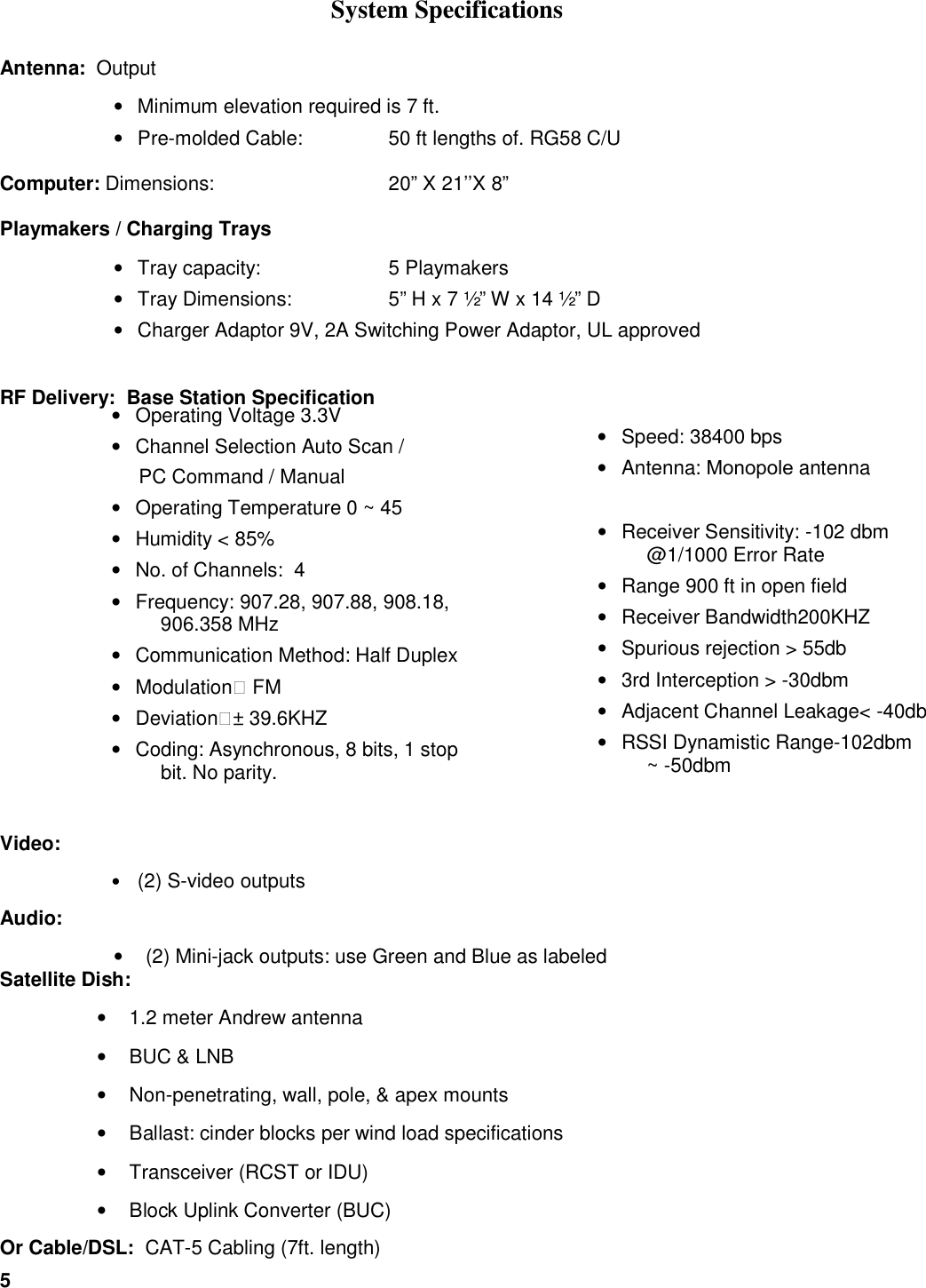
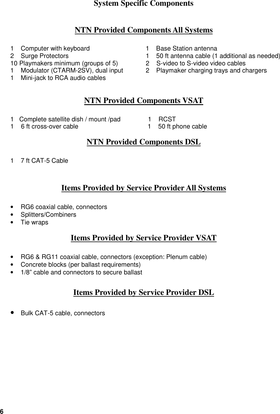
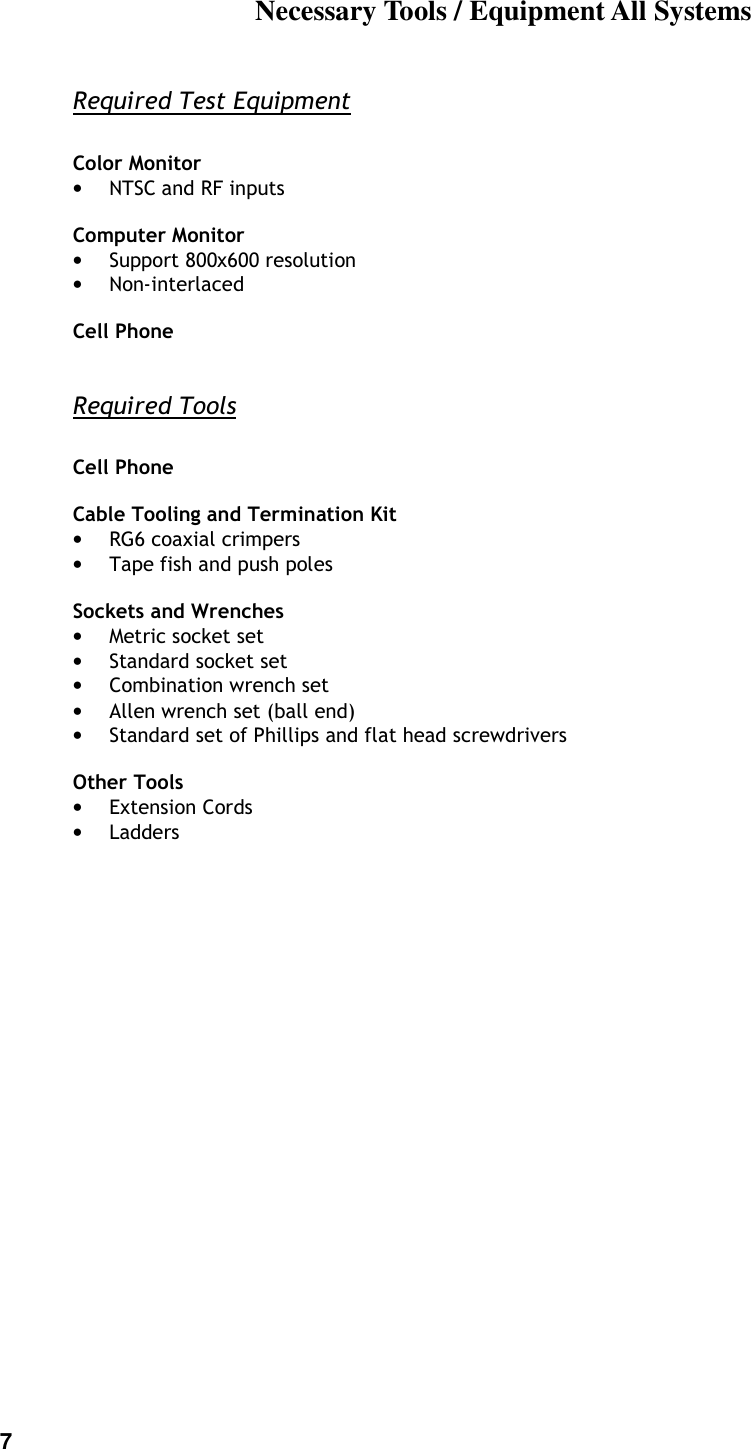
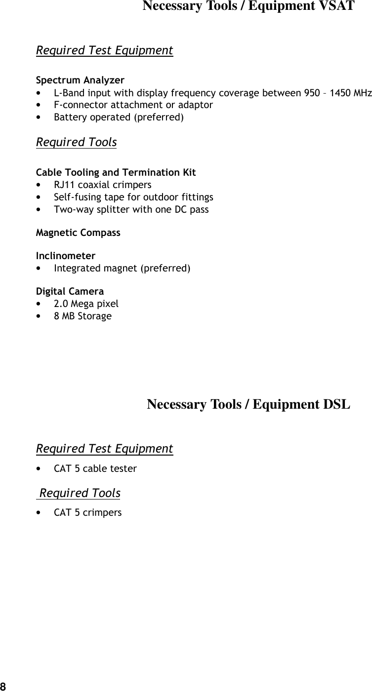
NTN Buzztime NTN900H11 Host Data Terminal User Manual iTV2 Installation Manual

NTN Buzztime, Inc. Host Data Terminal iTV2 Installation Manual

User manual

             NTN iTV2  Installation Manual
2   Table of Contents   1. Installations Overview ...........................................................................................................3 2. Pre-Installation Video Checklist .............................................................................................4 3. System Specifications ...........................................................................................................5 4. System Specific Components................................................................................................6 5. NTN Provided Components All Systems................................................................................6 6. NTN Provided Components VSAT.........................................................................................6 7. NTN Provided Components DSL ...........................................................................................6 8. Items Provided by Service Provider All Systems ....................................................................6 9. Items Provided by Service Provider VSAT .............................................................................6 10. Items Provided by Service Provider DSL ...............................................................................6 11. Necessary Tools / Equipment All Systems.............................................................................7 12. Necessary Tools / Equipment VSAT......................................................................................8 13. Necessary Tools / Equipment DSL ........................................................................................8 14. Installation Expectations........................................................................................................9 Do not: ...............................................................................................................10 15. Playmaker Related Tests ....................................................................................................11 Duplicate Address....................................................................................................11 Playmaker Reception Test.......................................................................................11 Playmaker Signal to Noise Test ...............................................................................13 16. Emergency Redundancy Option (VSAT only) ......................................................................14 17. Final Check.........................................................................................................................14
3   Installations Overview The NTN Communications Inc. Interactive Hospitality System Installation includes:  CPU     Downlink / Uplink or Cable/DSL  Video integration  RF delivery system     Downlink/Uplink (VSAT) The  system  receives  and  transmits  data  from  satellite  G3C  using  VSAT  technology.  System components  include  the  RCST  (transceiver),  BUC  (block  uplink  converter),  LNB,  and  1.2  meter antenna. OR Cable/DSL The system receives and transmits data via internet connectivity. The NTN CPU is connected to an available LAN port of a site-sponsored router/cable modem that has been preconfigured for NTN. Video integration The  NTN  CPU’s  video  output  signal  is  a  National  Television  Standards  Committee  (NTSC)  video signal.  This signal can be integrated by connecting to straight video inputs or by first converting into an RF signal using a video modulator, then inserting into the existing video distribution system via a signal combiner.   RF delivery system The Base Station transmits to and receives RF signals from, wireless keypads called Playmakers, on a 900 MHz frequency via one antenna installed over the playing area.  Participants interact with the system using Playmakers.   A 2.4GHZ system is also in use with customer’s on specific packages and/or with specific RF delivery response issues.        PC Modulator  TV Distribution      RCST or Cable/DSL Optional 56k Modem BS Ant
4   Pre-Installation Video Checklist This checklist is provided to identify any pre-existing video distribution issues, prior to initiating installation of the NTN Trivia System.    Site Name:                   Site ID#:            Technician:                 Service Group:             TV/Monitors Type  Number  Input  (RF, S-video, etc) Standard                         High Definition                         Projection                         Other                         Total                          Distribution (check all that apply)     # Set Top Boxes / Receivers  Zoned + #  Cable                            Satellite                            Video (NTSC)                           RF matrix                             Please describe any exceptional issues relating to video quality: Status (Good, Fair, Poor)   I have reviewed the video distribution of my establishment with the NTN Technician and acknowledge the above-described exceptional issues prior to installation of the NTN Trivia System.  Signature:                  Print                  Date:
5  System Specifications Antenna:  Output •  Minimum elevation required is 7 ft. •  Pre-molded Cable:  50 ft lengths of. RG58 C/U  Computer: Dimensions:       20” X 21’’X 8”   Playmakers / Charging Trays •  Tray capacity:    5 Playmakers •  Tray Dimensions:    5” H x 7 ½” W x 14 ½” D •  Charger Adaptor 9V, 2A Switching Power Adaptor, UL approved  RF Delivery:  Base Station Specification            Video:  • (2) S-video outputs  Audio:  •  (2) Mini-jack outputs: use Green and Blue as labeled Satellite Dish:  •  1.2 meter Andrew antenna •  BUC & LNB •  Non-penetrating, wall, pole, & apex mounts •  Ballast: cinder blocks per wind load specifications •  Transceiver (RCST or IDU) •  Block Uplink Converter (BUC) Or Cable/DSL:  CAT-5 Cabling (7ft. length) •  Speed: 38400 bps •  Antenna: Monopole antenna  •  Receiver Sensitivity: -102 dbm @1/1000 Error Rate •  Range 900 ft in open field •  Receiver Bandwidth200KHZ •  Spurious rejection > 55db •  3rd Interception > -30dbm •  Adjacent Channel Leakage< -40db •  RSSI Dynamistic Range-102dbm ~ -50dbm  •  Operating Voltage 3.3V •  Channel Selection Auto Scan /       PC Command / Manual •  Operating Temperature 0 ~ 45 •  Humidity < 85% •  No. of Channels:  4 •  Frequency: 907.28, 907.88, 908.18, 906.358 MHz •  Communication Method: Half Duplex •  Modulation: FM •  Deviation:± 39.6KHZ •  Coding: Asynchronous, 8 bits, 1 stop bit. No parity.
6  System Specific Components NTN Provided Components All Systems 1  Computer with keyboard  1  Base Station antenna 2  Surge Protectors  1  50 ft antenna cable (1 additional as needed) 10 Playmakers minimum (groups of 5)     2    S-video to S-video video cables 1  Modulator (CTARM-2SV), dual input  2  Playmaker charging trays and chargers 1  Mini-jack to RCA audio cables       NTN Provided Components VSAT  1   Complete satellite dish / mount /pad               1    RCST  1    6 ft cross-over cable          1    50 ft phone cable  NTN Provided Components DSL 1  7 ft CAT-5 Cable                 Items Provided by Service Provider All Systems •  RG6 coaxial cable, connectors  •  Splitters/Combiners •  Tie wraps Items Provided by Service Provider VSAT •  RG6 & RG11 coaxial cable, connectors (exception: Plenum cable) •  Concrete blocks (per ballast requirements)  •  1/8” cable and connectors to secure ballast Items Provided by Service Provider DSL • Bulk CAT-5 cable, connectors
7  Necessary Tools / Equipment All Systems Required Test Equipment   Color Monitor • NTSC and RF inputs  Computer Monitor • Support 800x600 resolution • Non-interlaced  Cell Phone  Required Tools  Cell Phone  Cable Tooling and Termination Kit • RG6 coaxial crimpers  • Tape fish and push poles  Sockets and Wrenches • Metric socket set • Standard socket set • Combination wrench set • Allen wrench set (ball end) • Standard set of Phillips and flat head screwdrivers  Other Tools • Extension Cords • Ladders
8   Necessary Tools / Equipment VSAT Required Test Equipment   Spectrum Analyzer • L-Band input with display frequency coverage between 950 – 1450 MHz • F-connector attachment or adaptor • Battery operated (preferred) Required Tools  Cable Tooling and Termination Kit • RJ11 coaxial crimpers • Self-fusing tape for outdoor fittings • Two-way splitter with one DC pass  Magnetic Compass  Inclinometer • Integrated magnet (preferred)  Digital Camera • 2.0 Mega pixel • 8 MB Storage    Necessary Tools / Equipment DSL Required Test Equipment • CAT 5 cable tester  Required Tools • CAT 5 crimpers
9    Installation Expectations •  All cable runs must be secured, neat, and professional. •  Video integration should not affect or degrade customer’s existing video signal. •  RF Antenna should be placed at least 7’ above the ground. •  Playmakers should respond fast in the main playing area. •  Contact the Call Center per service release expectations.  •  Complete post-installation/sign-off checklist: include signature by an authorized site representative, preferably management. •  Insure facility is left in clean condition, to the satisfaction of the customer. Installation Procedures PC Location: •  Identify the PC location as indicated on the work order. •  Identify the power source and open Ethernet port dedicated for the NTN system. •  It is critical to locate the PC in close proximity to the play area for optimal system performance. •  PC location should be well ventilated. •  Always leave the keyboard attached to the computer to enable future maintenance procedures. Power Source: • Do not put the power source on the same circuit as any motorized units, as it will create power surge when motors are activated. •  Avoid circuits controlled by wall switches. •  Advised the customer the NTN computer and RCST must always have power. Component functionality check: •  Gather & confirm all components are onsite. •  Boot up and test PC for functionality, using a portable color monitor (required tool). •  Plug in Chargers and initiate charging all Playmakers® •  Verify no pre-existing video distribution problems are present
10     Connectivity See VSAT Installation Manual or Tools Menu-Internet Adaptor Setup Video •  Modulate and Insert the two iTV channels into the existing distribution system.  Audio •  Connect the provided audio cables from the PC’s sound output to the modulator’s audio inputs so the NTN system will be ready for future sound features. RF Delivery When installing antenna line, be sure to permanently mount the antenna after verifying range within the playing area. For optimal coverage, antenna should be in line-of-sight to the center of the playing area.  However, given cable length restrictions, it is probable that the antenna will merely penetrate the periphery of the playing area. This is acceptable.  •  Used the 25 ft or 100 ft antenna cable provided by NTN. •  Antenna must be placed at least 7 ft high and in the quietest location, as determined by signal/noise diagnostics. •  Turn on and test all Playmakers. •  Relocate the RF antenna if necessary. •  Once the best antenna location is determined, permanently mount the antenna.  Restrictions    Do not: •  Locate antenna near any potential sources of interference to the NTN system (neon and fluorescent lights, projection TVs, electrical lines, electrical panel’s etc.) •  Allow antennae mount to come in contact with any metal. •  Run cable parallel to electrical lines. •  Splice cable. •  Mount antenna with any mirror between the antenna and the playing area. •  Use more than 1 antenna.
11   Playmaker Related Tests Duplicate Address  Each Playmaker has an address or “unit number” assigned to it. These addresses or unit numbers allow the computer to recognize the Playmakers individually. Playmakers with the same address will respond as a single unit, interfering with one another. The address appears as a three-digit number on the third line of the LCD immediately after the unit is powered up. Check all Playmaker addresses to verify that there are no duplicates. Upon finding duplicate address problem, please call NTN and the customer service representative will correct the problem for you immediately.   Playmaker Reception Test In some cases, the Playmakers exhibit a lag between input and execution.  If the unit does not respond in two or three attempts, place it in the charging tray for about 5 to 8 seconds and the unit will reset itself. Remove the unit from the charging tray and try again. If this does not solve the problem the batteries may not be fully charged or the playmaker needs repair. 1.  Test Procedure Between Game Cycles  a.  Press <START> UNIT XXX b.  Two symbols are momentarily displayed to the right side of this greeting.  The battery symbol represents the level of charge as indicated by the number of horizontal lines.   Newer Playmakers give the charge level a numerical value ranging from 0 - 99. The antenna symbol blinks indicating a search for the antenna.  It disappears when the antenna is located.  The Playmaker screen will go blank after a few seconds.         Battery   Battery: 99  Antenna   c.  Press <MENU> ↓↓↓↓ NTN Games, <↓↓↓↓>, select Manager Functions. d.  Press <ENTER> ↓↓↓↓ Manager Functions menu, <↓↓↓↓>, select Manager Functions, press <ENTER>.  e.  Type in site password.  Default password is ABCD, press <ENTER>. f.  <↓↓↓↓>, select Ch. A On Screen Menu, and press <ENTER>. •  Note: If menu choice Ch. A On Screen Menu is not available, move to the next section of this form “2. Test Procedure During Game Cycle” and start on step “f.”.  a.  Main Menu is now showing on the video screen. <↓↓↓↓>, select 5  Technical Support, press <ENTER>, or select <5> from the red numbers in the text area of the playmaker.  b.  Support menu, default is 1 Diagnostic Screen.  c.  Press <1> or <ENTER>.  TV screen will show Packets & Errors on top and Playmaker Monitor on the bottom.  The Playmaker is now ready to have all the keys pressed in any sequence to ensure they will show up on the Playmaker’s screen.  Press every key, one key at a time.
12  d.  If any key does not show on the screen or if a Playmaker fails, contact NTN Customer Service Representative (CSR) to troubleshoot. If the NTN CSR is unable to resolve the problem, ask for an RMA number and pack the defective playmaker in a provided return envelope and call Airborne to pick up the package.  e.  Press <ENTER> to end the test. 2.  Test Procedure During Game Cycle  a.  Press <START> UNIT XXX  b.  Two symbols are momentarily displayed to the right side of this greeting.  The battery symbol represents the level of charge as indicated by the number of horizontal lines.   Newer Playmakers give the charge level a numerical value ranging from 0 - 99. The antenna symbol blinks indicating a search for the antenna.  It disappears when the antenna is located.  The Playmaker screen will go blank after a few seconds.         Battery   Battery: 99  Antenna   c.  Press <MENU> ↓↓↓↓ NTN Games, <↓↓↓↓>, select Manager Functions. d.  Press <ENTER> ↓↓↓↓ Manager Functions menu, <↓↓↓↓>, select Manager Functions, press <ENTER>.  e.  Type in site password.  Default password is ABCD, press <ENTER>.  f.  Menu options will show as End (game name) where the game name (e.g. Countdown) represents games running on corresponding channels. <↓↓↓↓>, select End (game name) for the game on channel A, press <ENTER>. g.  The playmaker screen will refresh with the previously selected choice removed, and after a moment will refresh again with the choice Ch. A On-screen Menu added. <↓↓↓↓>, select Ch. A On-screen Menu, press <ENTER>.  h.  Main Menu is now showing on the video screen. <↓↓↓↓>, select 5  Technical Support, press <ENTER>, or select <5> from the red numbers in the text area of the playmaker.  i.  Support menu, default is 1 Diagnostic Screen.  j.  Press <1> or <ENTER>.  TV screen will show Packets & Errors on top and Playmaker Monitor on the bottom.  The Playmaker is now ready to have all the keys pressed in any sequence to ensure they will show up on the Playmaker’s screen.  Press every key, one key at a time.  k.  If any key does not show on the screen or if a Playmaker fails, contact NTN Customer Service Representative (CSR) to troubleshoot. If the NTN CSR is unable to resolve the problem, ask for an RMA number and pack the defective playmaker in a provided return envelope and call Airborne to pick up the package.  l.  Press <ENTER> to end the test.
13  Playmaker Signal to Noise Test Press the <Start> key and then press the Z key after the first beep ends.  As the display lights up, immediately type in the password YFIN or on the playmaker. Press <Enter>. The Playmaker display will then show:  1)WS    2)ZPwd  3)Cha   4)Rst    5)Tst    6)HwT  7)FTt    8)NPwd  9)Sram  Q)Exit  Press 7 and the display will change to:  1)Ch1    2)Ch2    3)Ch3   4)Ch4    5)N/S Ratio  Press 5 and the display will change to:     Welcome   Adc:  XXX (Battery Level)     XXX Playmaker Number)  N/S:  XXX:XXX  YYY (Noise:Signal Channel)  <Cancel> to end test  If, by pressing the Z key, the “Password Pls” message does not appear, then the version is probably one of the older ones. In which case, the N key will be used in place of the Z. In this case, the screen will be very similar:  1)WS    2)Seq    3)Pwd   4)Cha    5)Rst    6)Tst   7)HwT   8)FTt    9)Sram  Q)Exit From this point, the screens/options are the same.
14   Emergency Redundancy Option (VSAT only) Customers have the option of 56k dial up redundancy connecting the server modem to an available phone jack. A 50ft phone cable is provided. If not used, leave the phone cable coiled and plugged into the modem. This allows Customer Service to assist the customer with connectivity if needed.  Final Check •  Power down and restart the computer, verifying that the boot up sequence is successful. •   Complete the Installation Service Release SOP

Navigation menu