NVIDIA P1453 3D Vision Pro Embedded Hub User Manual
NVIDIA Corporation 3D Vision Pro Embedded Hub
NVIDIA >
User Manual
Last Update: 5/22/12 Page 1 of 10
P1453
3D Vision Pro Embedded Hub
Manual
Last Update: 5/22/12 Page 2 of 10
Table of Contents
Getting to Know the P1453 _____________________________________________________________________ 3
System Requirements___________________________________________________________________________ 4
Installation Guide ______________________________________________________________________________ 5
Product Specicification_________________________________________________________________________ 8
Regulatory Compliance Statement ______________________________________________________ 9
Last Update: 5/22/12 Page 3 of 10
Getting to Know the P1453
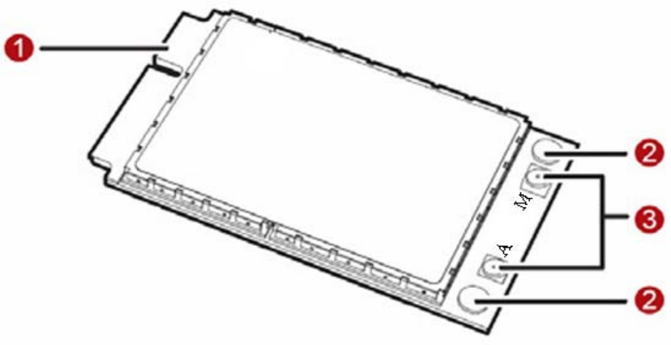
The following figure shows the appearance of the P1453. The actual product may differ.
① Mini PCI Express connector
It is used to connect the P1453 to the WWAN Mini PCI Express interface of the PC.
② Screw holes
They are used to fix the P1453 on the main board of the PC with screws.
③ Antenna interfaces
They are used to connect antenna. Please note that only MAIN antenna (M) is used for RF connection, AUX
antenna (A) is for mechanical retention only.
Last Update: 5/22/12 Page 4 of 10
System Requirements
Before you begin, please review the following minimum system requirements to ensure your Laptop meets
the hardware requirements necessary to enjoy the 3D Vision experience.
1) MicrosoftWindowsVista32/64‐bitorWindows732/64‐bit
2) 3D‐capabledisplay
3) NVIDIAgraphicscards
Last Update: 5/22/12 Page 5 of 10
Installation Guide
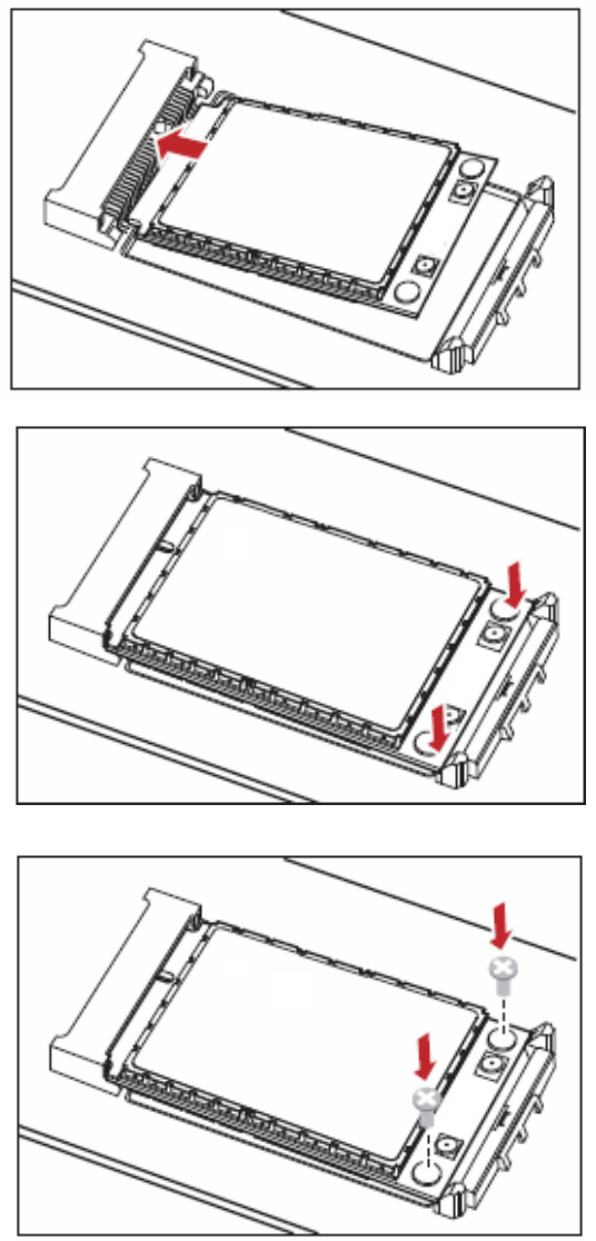
1. Installing the P1453 onto the Main Board of the PC
Insert the Mini PCI Express connector of the P1453 into the WWAN Mini PCI Express interface on the main
board of the PC.
2. Press downwards to fix the P1453 in the module slot.
3. Use a screwdriver to fix the P1453 onto the main board of the PC with two screws provided in the P1453
packing box.
Last Update: 5/22/12 Page 6 of 10
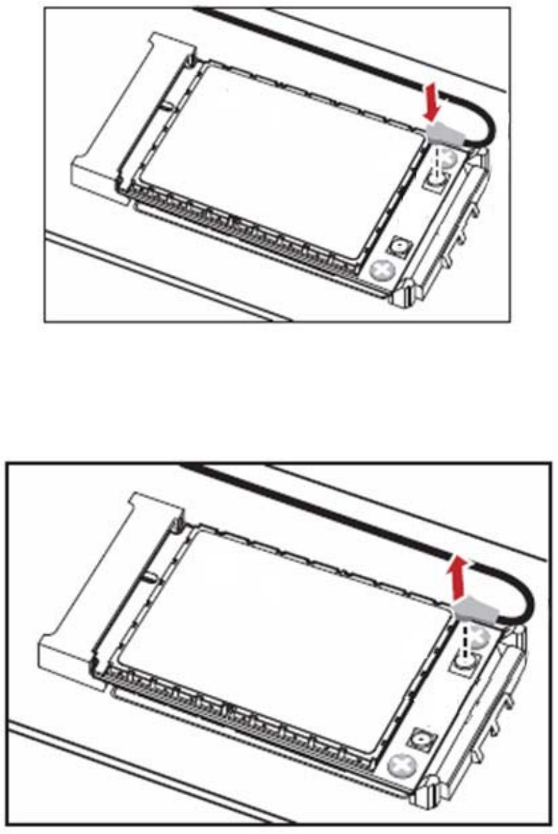
4. Insert the connector of the main antenna into the MAIN antenna interface (M) of the P1453 according to
the indication on the label of the P1453.
Note: Insert the antenna connectors vertically into the antenna interfaces of the P1453.
Do not pinch the antenna cable or damage the connectors. Otherwise, the wireless performance of the
P1453 may be reduced or the P1453 cannot work normally.
Ensure that the antenna cables are routed through the channel in the frame of the PC and do not lay across
the raised edges of the frame.
Removing the P1453 from the Main Board of the PC
1. Disconnect the antenna cables from the P1453. You can lift the connectors with a small screwdriver.
2. Remove the two screws with the screwdriver.
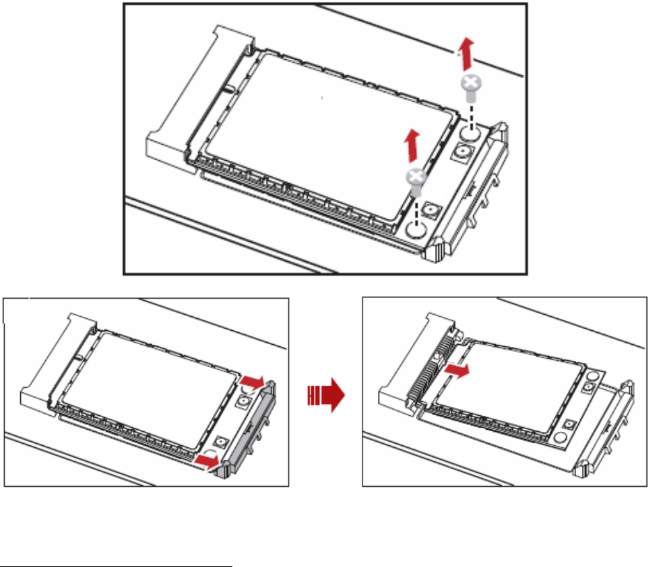
Last Update: 5/22/12 Page 7 of 10
3. Slide backwards the two clips to release the P1453 from the slot. Then, lift up the P1453.
Installing the P1453 Software
The driver of P1453 is included in NVIDIA graphics driver; you can down load the driver from
http://www.nvidia.com/page/home.html
1, Double click the driver to run the program
2. Follow the prompts of the installation wizard.
Uninstalling the Management Program
1. Choose Start >Control Panel
2. Find the management program, and click Add/Remove Program to uninstall the management program.
Note:
It is recommended to restart the computer after the uninstallation to ensure that the management program is
completely uninstalled.
3D Vision Pro Embedded Hub, P1453

Last Update: 5/22/12 Page 8 of 10
Technical Specification:
1.1. Power Input: DC 3.3V @140mA
1.2. Transmission mode: RF
1.3. Frequency: 2406~2473 MHz
1.4. RF channel quantity: 68
1.5. Center of Channel: 2406MHz /2407MHz/2408M…2472MHz/2473MHZ
1.6. Channel Interval: 1MHz
1.7. Width of Channel: ≤1.0MHz
1.8. Data Rate: <1Mbps
1.9. Modulate mode: GFSK
1.10. Effective distance: 25m
1.11. Operating Temperature: 0℃~55℃
1.12. Antenna type: PIFA
Table for Filed Antenna
Ant. Brand Model Name/Part No. Antenna Type Connector Gain (dBi)
1 Perfect UJ-1015-P4-140 PIFA U. FL 3.42dBi
2 SmartApproach SE-ECQR1-001 PIFA U. FL 1.30dBi
3 Cortec NB0258-A PIFA U. FL 3.84dBi
Last Update: 5/22/12 Page 9 of 10
Federal Communication Commission Interference Statement
This equipment has been tested and found to comply with the limits for a Class B digital device, pursuant to
Part 15 of the FCC Rules. These limits are designed to provide reasonable protection against harmful
interference in a residential installation. This equipment generates, uses and can radiate radio frequency
energy and, if not installed and used in accordance with the instructions, may cause harmful interference to
radio communications. However, there is no guarantee that interference will not occur in a particular
installation. If this equipment does cause harmful interference to radio or television reception, which can be
determined by turning the equipment off and on, the user is encouraged to try to correct the interference by
one of the following measures:
- Reorient or relocate the receiving antenna.
- Increase the separation between the equipment and receiver.
- Connect the equipment into an outlet on a circuit different from that to which the receiver is connected.
- Consult the dealer or an experienced radio/TV technician for help.
FCC Caution: Any changes or modifications not expressly approved by the party responsible for compliance
could void the user's authority to operate this equipment. This device complies with Part 15 of the FCC Rules.
Operation is subject to the following two conditions:
(1) This device may not cause harmful interference, and
(2) This device must accept any interference received, including interference that may cause undesired
operation.
FCC Radiation Exposure Statement:
This equipment complies with FCC radiation exposure limits set forth for an uncontrolled environment.. This
transmitter must not be co-located or operating in conjunction with any other antenna or transmitter.
This device is intended only for OEM integrators that the transmitter module may not be co-located with any
other transmitter or antenna.
IMPORTANT NOTE:
In the event that these conditions can not be met (for example certain laptop configurations or co-location
with another transmitter), then the FCC authorization is no longer considered valid and the FCC ID can not
be used on the final product. In these circumstances, the OEM integrator will be responsible for re-evaluating
the end product (including the transmitter) and obtaining a separate FCC authorization.
End Product Labelling
The final end product must be labelled in a visible area with the following:
“Contains FCC ID: VOB-P1453”
Manual Information to the End User
The OEM integrator has to be aware not to provide information to the end user regarding how to install or
remove this RF module in the user’s manual of the end product which integrates this module.
Canada Statement
This device complies with Industry Canada licence-exempt RSS standard(s). Operation is subject to the
following two conditions: (1) this device may not cause interference, and (2) this device must accept any
interference, including interference that may cause undesired operation of the device.
Le présent appareil est conforme aux CNR d'Industrie Canada applicables aux appareils radio exempts de
licence. L'exploitation est autorisée aux deux conditions suivantes : (1) l'appareil ne doit pas produire de
brouillage, et (2) l'utilisateur de l'appareil doit accepter tout brouillage radioélectrique subi, même si le
brouillage est susceptible d'en compromettre le fonctionnement.
Caution Exposure:
This device meets the exemption from the routine evaluation limits in section 2.5 of RSS102 and users can
obtain Canadian information on RF exposure and compliance.
Le dispositif répond à l'exemption des limites d'évaluation de routine dans la section 2.5 de RSS102
et les utilisateurs peuvent obtenir des renseignements canadiens sur l'exposition aux RF et le respect.

Last Update: 5/22/12 Page 10 of 10
The final end product must be labeled in a visible area with the following:
The Industry Canada certification label of a module shall be clearly visible at all times when installed in the
host device, otherwise the host device must be labelled to display the Industry Canada certification number
of the module, preceded by the words “Contains transmitter module”, or the word “Contains”, or similar
wording expressing the same meaning, as follows:
Contains transmitter module IC: 7361A-P1453, where 7361A-P1453 is the module’s certification number
The integrator is responsible for final product compliance with IC ICES-003 and FCC Part 15, Sub. B –
Unintentional Radiators.
This device has been designed to operate with the antenna listed in above table, and having a peak gain of
3.84dBi @ 2.4GHz,, Antennas not of the same type and having a higher gain specified above are strictly prohibited
for use with this device. The required antenna impedance is 50 ohms.
Europe—EU Declaration of Conformity and Restrictions
Hereby, NVIDIA Corporation,declares that this equipment complies with the essential requirements and
other relevant provisions of Directive 1999/5/EC.
If the module is incorporated into an OEM product, the OEM product manufacturer must ensure compliance
of the final product to the European Harmonised EMC, and low voltage/safety standards. A Declaration of
Conformity must be issued for each of these standards and kept on file as described in the R&TTE Directive.
The final product must not exceed the specified power ratings, antenna specifications and installation
requirements as specified in this user manual. If any of these specifications are exceeded in the final
product then a submission must be made to a notified body for compliance testing to all of the required
standards.
Important Note: In Europe the regulations for the 2.4GHz frequency band are only harmonized for devices
with an e.i.r.p. of less than 10mW (10dBm). In the case of e.i.r.p. of more than 10mW the manufacturer or
his authorized representative established within the community or the person responsible for placing the
equipment on the market shall notify the national authority responsible in the relevant Member State for
spectrum management of the intention to place such equipment on its national market. This notification shall
be given no less than four weeks in advance of the start of placing on the market.
Because of this, NVIDIA recommends that the user limits the output power to 10mW (10dBm) for Europe to
avoid having to deal with the local authorities for spectrum management of each relevant member state
Caution: Exposure to Radio Frequency Radiation.
To comply with RF exposure compliance requirements, This device must not be co-located or operating in
conjunction with any other antenna or transmitter.
Taiwan - NCC Statement
根據交通部低功率管理辦法規定:
第十二條
經型式認證合格之低功率射頻電機,非經許可,公司、商號或使用者均不得擅自變更頻率、加大功率或變更原
設計之特性及功能。
第十四條
低功率射頻電機之使用不得影響飛航安全及干擾合法通信;經發現有干擾現象時,應立即停用,至無干擾時方
得繼續。並改善前項合法通信,指依電信法規定作業之無線電通信。低功率射頻電機須忍受合法通信或工業、
科學及醫療用電波輻射性電機設備之干擾。