NVIDIA P1860 Development Platform User Manual Jetson User Guide HW x
NVIDIA Corporation Development Platform Jetson User Guide HW x
NVIDIA >
user manual-revised 2

NVIDIAJetsonTK1ProUserManual
Before you start
This document is intended to cover the Hardware aspects of the Jetson TK1 Pro Development Kit. The
document covers how to bring the board up for the first time – and includes information about all the
available interfaces on the platform (including header connectors).
Tip: Please refer to the documentation provided with the Android package that comes with the Jetson TK1 Pro
Development Kit for more details regarding the software options on the platform.
Assumptions
This document assumes you have received a Jetson TK1 Pro Development Kit from NVIDIA with a pre-
installed Android OS. If this is not the case, please contact your NVIDIA representative.
Hardware
You should have received the following items with your Jetson TK1 Pro Platform as depicted in Error!
Reference source not found.:
• Jetson TK1 Pro Platform which consists of:
o Jetson TK1 Pro Main Board (P1860)
o Tegra VCM board (connected to the main board – top) (P1859)
o Embedded Breakout Board (connected to the main board – bottom) (P1892)
o Touch Screen Display (P1332)
• Power Supply
• 3 Antennas (Wi-Fi, Bluetooth and GPS)
• USB cable (mini-USB to USB)
• mDP cable
• Cable for Touch Screen (Touch and Power)
Minimum Hardware Setup
The minimum requirements to bring the system up are:
• Power Supply
• Touch Screen Display or HDMI monitor(not provided)
o mDP and Tyco cables (are required for the Touch Screen configuration)
o HDMI cable(not provided) can be used for HDMI monitor instead of Touch Screen
• USB Keyboard and Mouse (not provided) but strongly recommended
While the Jetson TK1 Pro platform supports multiple configurations and its modular approach provides
flexibility, the section below focuses on bringing the platform up for the first time with the minimum
configuration effort required.
Connections need to be done to: the Main board (P1860), the EBB board (P1892) and Touch Screen
(P1332).
Main Board (P1860) Minimum Connections
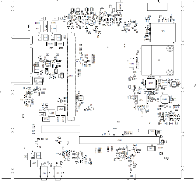
Figure 1 shows all the main board component with labels.
Bottom:
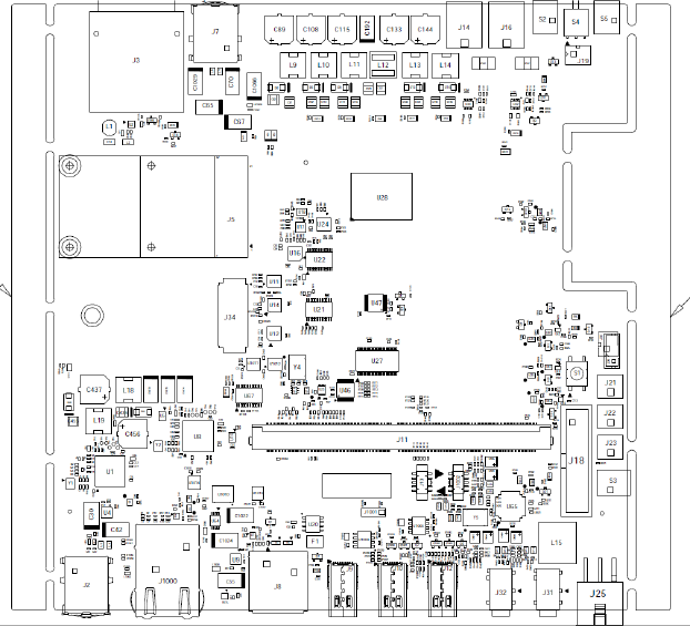
Top:
Figure 1: Mainboard with Component Labels
The following connections need to be made on the main board (P1860) as a minimum in order to boot
Jetson TK1 Pro for the first time:
Power Supply (J14): Power supply can be connected to the connector labeled J14 as shown on Error!
Reference source not found..
mDP Connector (J9): Using the mDP cable provided, the board needs to be connected to the Touch
Screen Display included in the package.
Main Board (P1860) Optional Connections
The following connections are not required for the board to boot.
USB Mouse and Keyboard (J2&J3): While this is optional, is highly recommended that a USB mouse
and keyboard are plugged-in in to the platform via the main board J2 connector.
HDMI Connector (J8): This is only required if the Touch Screen provided with the platform will not be
used.
USB Connection (J35): The USB cable provided with the Jetson TK1 Pro platform while is not required
to boot it is recommended to be connected to mini-USB connector labeled “Host PC USB (Console)” on
the Jetson TK1 Pro board and to a USB 2.0 port on the workstation running Ubuntu Linux 12.04. The
“Host PC USB (Console)” port is labeled J4 on Figure 1. The USB connection enables debug and
development capabilities. Please refer to the.CHM documentation file for more details on how to
configure this capability.
Ethernet Connection (J1000): While the Ethernet port connection is optional – and may require
further configuration not covered on this document – to gain network access, an Ethernet cable can be
connected to the port labeled J1000 on Figure 1.
EBB Board (P1892) Minimum Connections
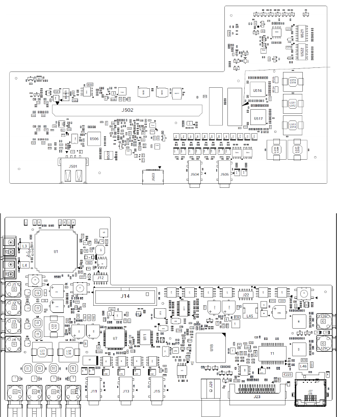
Error! Reference source not found. shows all the EBB board component with labels. Please be aware
that some connectors - while accessible on the side of the board - their labels are not visible as are
placed on the other side of the EBB board. Please refer to Figure 3 for details on these connectors.
Bottom:
Top:
Figure 3: EBB board with Component Labels
The following connections need to be made on the main board (P1892) as a minimum in order to boot
Jetson TK1 Pro for the first time (assuming the Touch Panel Display is utilized):
Touch Screen Connector (J23): Using the Tyco cable provided, the board needs to be connected to
the display as well.
If the Touch Panel Display will not be utilized a HDMI monitor can be used instead.
RF module
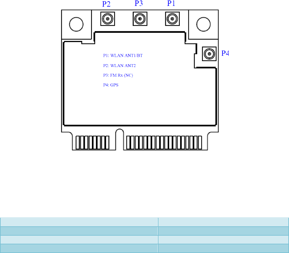
Jetson TK1 Pro comes equipped with a Wi-Fi/BT/GPS module (labeled J6 on Figure 1). The board is
shipped with 3 different antennas that need to be connected to J6. The Communication Module (J6) has
four different connectors as depicted on Figure .
Figure 4: Communication Module (J6) - Antenna Connectors
.
Antenna (Part Number)
Connects on:
311-0046-000 (2.4GHz
–
Wi-Fi Main / Bluetooth)
P1
311-0045-000 (5GHz
–
Wi-Fi Aux)
P2
311-0047-000 (GPS)
P4
Table 1: Antenna Mapping of Communication Module (J6)
The antennas shall be connected as described on Table 1.
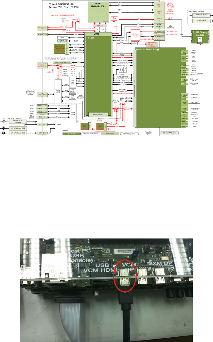
Jetson TK1 Pro Hardware Architecture
The Jetson TK1 Pro board architecture is depicted on Figure below. The modular architecture allows
maximum flexibility and custom configurations.
Figure 5: Jetson TK1 Pro Hardware Architecture
It is important to highlight the use of SMSC’s 9514 in order to simplify the connection to the Jetson TK1
Pro Platform. With this approach only a USB connection is needed (via J4) in order to have a serial
console, network connectivity to the board (i.e. NFS drive mounting, etc.) and reflashing of the system.
Boot up
Step 1, Connect the touch panel to the P1860 main platform. The miniDP cable should plug into the VCM
DP port. Main platform side:
Figure 6
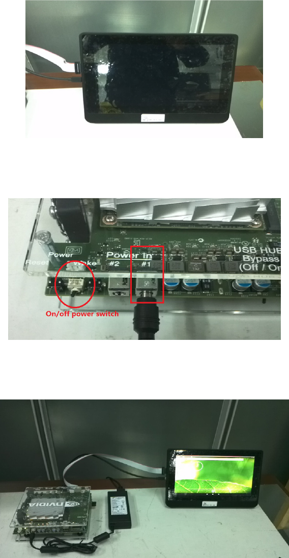
Touch panel side:
Figure 7
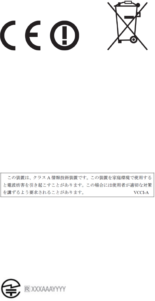
Step 2, plug the AC-DC adaptor into the Power In #1 port and turn on the power switch.
Figure 8
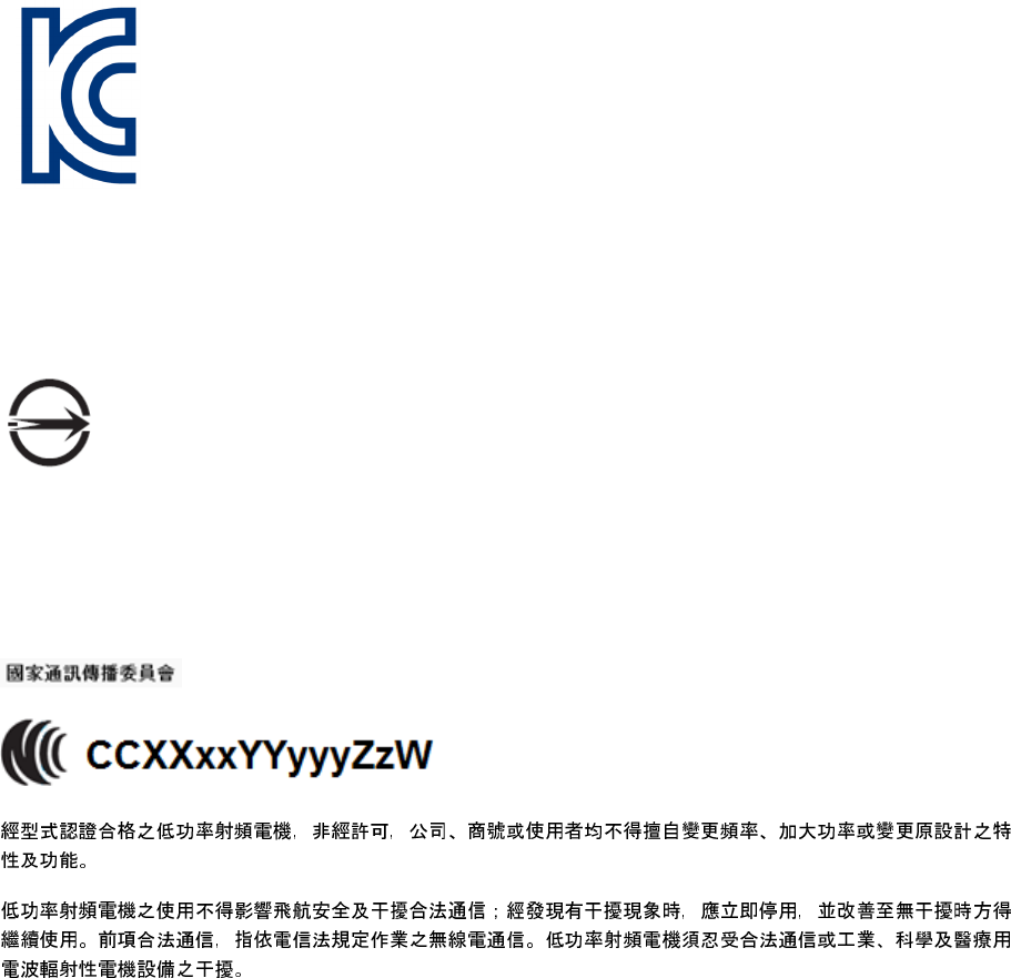
Step 3, done.
Figure 9: Jetson TK1 Pro up and running

Compliance
The P1860 is compliant with the regulations listed in this section.
United States
Federal Communications Commission (FCC)
FCC ID: VOB-P1860
This device complies with part 15 of the FCC Rules. Operation is subject to the following two conditions:
(1) this device may not cause harmful interference, and (2) this device must accept any interference
received, including any interference that may cause undesired operation of the device.
This equipment has been tested and found to comply with the limits for a Class A digital device,
pursuant to Part 15 of the FCC Rules. These limits are designed to provide reasonable protection against
harmful interference in a residential installation. This equipment generates, uses and can radiate radio
frequency energy and, if not installed and used in accordance with the instructions, may cause harmful
interference to radio communications. However, there is no guarantee that interference will not occur
in a particular installation.
If this equipment does cause harmful interference to radio or television reception, which can be
determined by turning the equipment off and on, the user is encouraged to try to correct the
interference by one or more of the following measures:
Reorient or relocate the receiving antenna.
Increase the separation between the equipment and receiver.
Connect the equipment into an outlet on a circuit different from that to which the receiver is
connected.
Consult the dealer or an experienced radio/TV technician for help.
FCC Warning: The FCC requires that you be notified that any changes or modifications to this device not
expressly approved by the manufacturer could void the user’s authority to operate the equipment.
Caution: Within the 5.15 to 5.25 GHz band (5 GHz radio channels 34 to 48) this device is restricted to
indoor operations to reduce any potential for harmful interference to co-channel Mobile Satellite
System (MSS) operations
RF Radiation Exposure Statement:
This equipment complies with FCC RF radiation exposure limits set forth for an uncontrolled
environment. This equipment should be installed and operated with a minimum distance of 20
centimeters between the radiator and your body.

Underwriters Laboratories (UL)
I.T.E E204896
Canada
Industry Canada (IC)
IC: 7361A-P1860
CAN ICES-3(A)/NMB-3(A)
This device complies with Industry Canada license-exempt RSS standard(s). Operation is subject to the
following two conditions: (1) this device may not cause interference, and (2) this device must accept any
interference, including interference that may cause undesired operation of the device.
Le présent appareil est conforme aux CNR d'Industrie Canada applicables aux appareils radio exempts de
licence. L'exploitation est autorisée aux deux conditions suivantes : (1) l'appareil ne doit pas produire de
brouillage, et (2) l'utilisateur de l'appareil doit accepter tout brouillage radioélectrique subi, même si le
brouillage est susceptible d'en compromettre le fonctionnement.
The device meets the exemption from the routine evaluation limits in section 2.5 of RSS 102 and
compliance with RSS-102 RF exposure, users can obtain Canadian information on RF exposure and
compliance.
Le dispositif rencontre l'exemption des limites courantes d'évaluation dans la section 2.5 de RSS 102 et
la conformité à l'exposition de RSS-102 rf, utilisateurs peut obtenir l'information canadienne sur
l'exposition et la conformité de rf.
This transmitter must not be co-located or operating in conjunction with any other antenna or
transmitter. This equipment should be installed and operated with a minimum distance of 20
centimeters between the radiator and your body.
Cet émetteur ne doit pas être Co-placé ou ne fonctionnant en même temps qu'aucune autre antenne ou
émetteur. Cet équipement devrait être installé et actionné avec une distance minimum de 20
centimètres entre le radiateur et votre corps.
i.the device for operation in the band 5150–5250 MHz is only for indoor use to reduce the potential for harmful interference
to co-channel mobile satellite systems;
ii.the maximum antenna gain permitted for devices in the band 5725–5825 MHz shall comply with the e.i.r.p. limits
specified for point-to-point and non point-to-point operation as appropriate.
This radio transmitter (identify the device by certification number) has been approved by Industry Canada to operate with the
antenna types listed below with the maximum permissible gain indicated. Antenna types not included in this list, having a gain
greater than the maximum gain indicated for that type, are strictly prohibited for use with this device.
European Union
European Conformity; Conformité Européenne (CE)
This device bears the CE mark and class-2 identifier in accordance with Directive 1999/5/CE
This device complies with the following Directives:
EMC Directive for Class A, I.T.E equipment.
R&TTE Directive for radio equipment
RoHS Directive for hazardous substances
Japan
Voluntary Control Council for Interference (VCCI)
Translation:
This is a Class A product based on the standard of the VCCI Council. If this is used near a radio or
television receiver in a domestic environment, it may cause radio interference. Install and use the
equipment according to the instruction manual.
Radio/ Telecommunications Certification
(i) les dispositifs fonctionnant dans la bande 5 150-5 250 MHz sont réservés uniquement pour une
utilisation à l’intérieur afin de réduire les risques de brouillage préjudiciable aux systèmes de satellites mobiles utilisant les mêmes
canaux;
(iii) le gain maximal d’antenne permis (pour les dispositifs utilisant la bande 5 725-5 825 MHz)
doit se conformer à la limite de p.i.r.e. spécifiée pour l’exploitation point à point et non point à point, selon le cas.
Cet émetteur radio (identifier le dispositif par numéro de certification ou le numéro de modèle si Catégorie II) a été approuvé par
Industrie Canada pour fonctionner avec les types d'antenne énumérés ci-dessous avec le gain maximal admissible indiquée. Types
d'antennes ne figurant pas dans cette liste, ayant un gain supérieur au gain maximum indiqué pour ce type, sont strictement interdits pour
une utilisation avec cet appareil.
China
State Radio Regulation of China (SRRC)
CMIIT ID: YYYYxxxxxx
South Korea
Radio Research Agency (RRA)
Korean Agency for Technology and Standards (KATS)
MSIP-CMM-NVA-P1860
Taiwan
Bureau of Standards, Metrology and Inspection (BSMI)
R33088
This device complies with CNS 13438 (2006) Class A
National Communications Commission
Translation:

Certified by the type of low-power radio, non-licensed, company, firm or user is not allowed to change the frequency, increase
the power or change the characteristics of the original design and function.
The use of low-power radio-frequency devices shall not influence aircraft security and interfere legal communications;
interference phenomenon discovered over time, should be immediately suspended, and improved to no interference may
continue to be used. Legal communications, referring to the provisions of the Telecommunications Act of radio communications
operations. Low-power radio communications to tolerate interference radiated devices legal or industrial, scientific and medical
radio waves.
India
Wireless Planning & Coordination Wing (WPC)
ETA CERTIFICATION NO: XXXX/YYYY/WROL
Russia/Kazakhstan/Belarus
EurAsian Customs Union
Complies with the technical regulations of the Customs Union (CU TR)
Russian Federal Agency for Communication
Israel
Standards Institution of Israel (SII)
Ministry of Communications (MoC)
Additional information
Please contact your NVIDIA representative or visit http://www.nvidia.com/object/jetson-automotive-
development-platform.html for more details.