Naim Audio Ovator S 400 English White Paper
User Manual: Naim Audio Ovator S-400 - English White Papers | Naim Audio
Open the PDF directly: View PDF ![]() .
.
Page Count: 8
Page 1 of 8Copyright Naim Audio 2010
Introduction
High-end hi-fi loudspeaker design is a multidisciplinary
endeavour embracing elements of acoustics,
mechanics, materials science, vibration, electronics and
musical psychology. Thanks both to the extraordinary
discrimination of our ears and our hard-wired sensitivity
to ideas and emotions expressed through music, success
in speaker design requires that all these elements be
thoroughly optimised. An exceptional high-end speaker is
truly more than the sum of its parts.
So the story of the Ovator S-400 is not simply that of its
novel BMR drive unit technology, it is one of the optimisation
of a multitude of interdependent factors where even the
apparently mundane can have an influential role. The S-400
builds on proven Naim speaker design techniques while
simultaneously introducing new technologies, new ideas
and new refinements, all of which are incorporated in a
product that offers a striking yet subtle aesthetic and
provides great ease of installation.
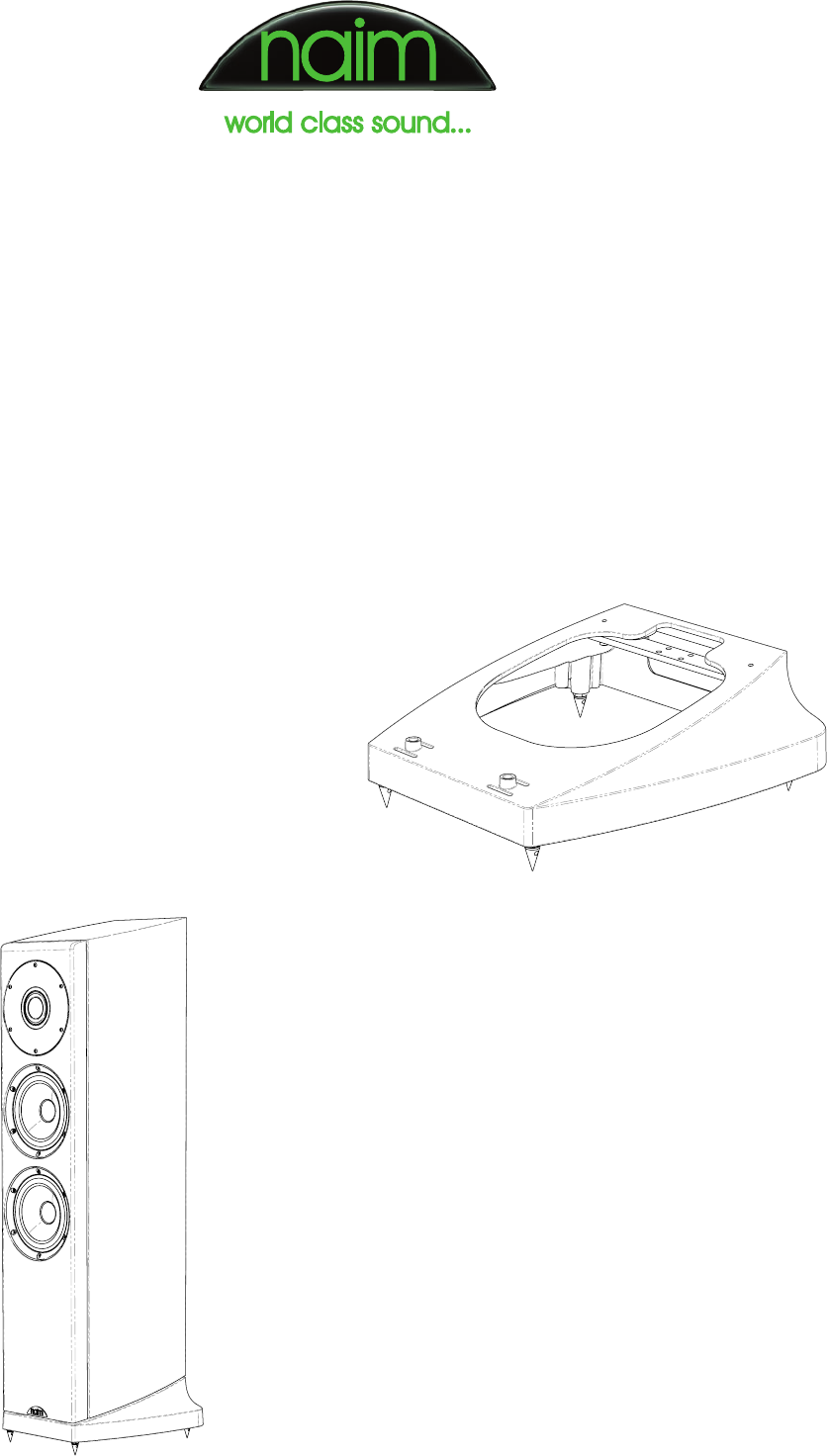
Ovator S-400 plinth, cabinet and driver chassis
The foundation of the S-400 is its plinth. An extremely rigid
high pressure aluminium die-casting, it supports the cabinet
and provides mounting points for the floor spikes, passive
crossover module (or active loom interface) and terminal
panel. The floor spikes are made from hardened stainless
steel and screw into M8 tapped holes at the front and rear.
The S-400’s cabinet attaches to the plinth at two locations
towards the front and via a leaf-spring at the rear. This leaf
spring is a 200mm-long non-magnetic stainless steel bar
that runs laterally underneath the cabinet and attaches
centrally to its underside. At each end the leaf-spring is
bolted, via tapped bosses, to the plinth. The front locations
comprise stand-off bosses through which a bolt is inserted
and screwed into the cabinet. A slot feature on either side
of each boss introduces some controlled compliance to
the front cabinet locations that, in combination with the
leaf-spring, results in the cabinet decoupling from the
plinth rotationally (forward and backward) above 12Hz.
To predict and fine-tune its vibrational characteristics
the entire plinth/cabinet system was the subject of Finite
Element Analysis (FEA) modelling, with the aim of ensuring
that any resonant behaviour within the audible band is
minimised. Limited decoupling of the system outside the
audible band is inherent in achieving this aim. Although
the cabinet/plinth leaf-spring was first introduced on the
Naim Allae loudspeaker the leaf-sprung cabinet concept
goes back to the Intro and Credo.
Ovator S-400
DESIGN, ENGINEERING AND TECHNOLOGY
Roy George – Naim Audio, Paul Neville – Naim Audio,
Karl-Heinz Fink – Fink Audio and Lampos Ferekidis – Fink Audio
October 2010
Naim Audio Ltd · Southampton Road · Salisbury · Wilts · SP1 2LN · England
Ovator S-400 Loudspeaker
A precision die-cast plinth houses the crossover module
and incorporates a stainless steel leaf spring to decouple
cabinet vibrations from the floor
Page 2 of 8Copyright Naim Audio 2010
FEA was also used to optimise the Ovator S-400’s
cabinet. It has 18mm-thick sides produced from seven
sheets of MDF which are bonded under heat and pressure
and formed into a curve that contributes significantly
to the cabinet’s overall structural performance. This
construction effectively incorporates constrained layer
damping within the material to create an immensely
rigid and non-resonant panel. A laminate of two 18mm
sheets forms the front panel to produce an extremely stiff
and inherently well damped baffle whose outside edges
are generously radiused to minimise diffraction effects.
Internal bracing and strategic mass damping contribute
further to a cabinet that, in acoustic radiation terms, is
fundamentally inert. An internal lining of 20mm wool felt
controls resonances within the enclosed air.
The lower portion of the cabinet is divided into two separate
15 litre closed box enclosures, one for each bass driver.
Closed box loading was chosen because of the distinct
advantages it offers over other loading techniques in terms
of time domain performance and dynamic compression.
Low frequency system resonance is at 48Hz with a Q of 0.63
delivering bass weight without ‘overloading’ smaller rooms.
In reality a true closed box system doesn’t exist as there
are always air leaks. These leaks may not be symmetrical,
leading to hysteresis in the internal pressure change with
cone movement. Changes in ambient temperature and
atmospheric pressure may also be reflected too slowly,
causing the cone to be deflected from its correct rest
position. To obviate these undesirable effects Naim has
engineered a controlled, symmetrical pressure equalisation
system between the two bass drivers’ cabinet volumes and
the external air which ensures that the significant design
effort expended on bass unit linearity is not squandered.
Both the Ovator bass driver and BMR chassis are custom
designed high-pressure die-castings modelled using FEA
to optimise their performance. The bass driver chassis,
for example, has a triangulated structure that not only
provides great rigidity but also maximises the open area
behind the cone. Additionally it features minimal area
mating surfaces so that vibration transfer to the cabinet is
controlled and predictable.
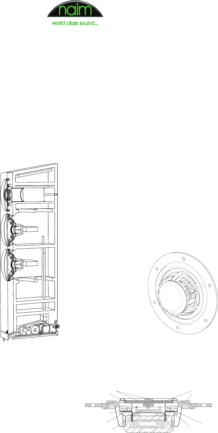
Ovator S-400 BMR module
The Ovator BMR driver – which uses a novel operating
principle (detailed in the Appendix) – has its own separate
enclosure formed by a 10mm thick composite cylinder fixed
within the cabinet. An integral elastomeric mounting ring
decouples the BMR module from the rest of the cabinet,
which both prevents low frequency mechanical energy
from the bass drivers interacting with the BMR and stops
mid/high frequency mechanical energy being transmitted
to the cabinet. The BMR enclosure is gradient filled with a
mix of wool felt and reticulated foam and incorporates a
vent at the back so that changes in ambient temperature or
atmospheric pressure do not impact upon performance.
What makes the Ovator BMR drive unit so special
Development of the Naim BMR driver used in the S-400
has taken four years. Every part has undergone an
extensive evaluation regarding its influence on the sound,
including the motor, the membrane (panel), the surround,
the voice coil and the spider.
Cutaway drawing of the
Ovator S-400 cabinet.
Features of note include
the isolated BMR module,
separate enclosures for the
two bass drivers and the
provision of controlled ‘leaks’
between the latter and the
external air
Rear view of the Ovator
BMR unit showing the die-cast
chassis. An elastomeric mount
decouples the BMR module
from the main cabinet
basket
main magnet
top magnet
spider
u-yoke
panel
foam damper
surround
flexible mount
pole piece
damper
voice coil former
voice coil
vent hole
Cross-section of the Naim S-400 BMR driver
Page 3 of 8Copyright Naim Audio 2010
BMR driver - motor
Although the BMR crosses over at 700Hz in the S-400 and
so experiences peak diaphragm excursions of less than
1mm, the motor was intensively optimised using FEA.
Several aspects needed to be addressed during the
motor’s development. First it had to generate a certain
magnetic flux density in the air gap since this influences
the final sensitivity of the drive unit. Another requirement
was that it should not interfere acoustically with the
sound radiated from the rear of the panel, thus a very
compact form factor was mandatory. Furthermore it
should provide sufficient cooling that the voice coil’s
operating temperature remains low, which prevents the
driver from running into thermal compression.
The finalised motor design uses a double neodymium
magnet configuration positioned inside the voice coil.
Neodymium was chosen because of its ten-fold higher
energy product compared to ferrite. This allows for
a very compact design with the two magnets placed
above and below the pole piece. From a magnetic
point of view the driver’s metal U-cup could have been
smaller but the deep shape assures a high thermal
capacity so that heat is quickly dissipated from the
voice coil into the metal. A copper shield covering the
pole piece helps reduce distortion and also controls the
amount of high frequency output due to its influence on
the driver’s impedance.
BMR driver - voice coil
Voice coil mass is a crucial design variable in a BMR
design. The lower the mass, the less additional balancing
mass is required. For this reason the Naim BMR’s voice
coil is wound from copper-clad aluminium instead of
pure copper. After evaluating a range of possible voice
coil former materials, we selected glassfibre as giving
the best sounding result. Technically its good heat
resistance and high stiffness make it an ideal choice
for a BMR.
BMR driver - membrane (panel)
A BMR’s membrane material has a large impact on its
sound, if not the largest. Various panel combinations were
evaluated before we settled on a sandwich material based
on a Nomex honeycomb core covered by paper skins on
either side. This combines low weight with good damping
and high stiffness, the panel’s stiffness being chosen such
that the first bending mode occurs in the frequency range
where the panel would otherwise start to beam its output.
BMR driver - surround
In a conventional cone drive unit the surround fulfils
two functions. At low frequencies it helps controls the
movement of the diaphragm, while at high frequencies
it terminates the diaphragm in order to control breakup
modes. In a BMR used as a mid/high frequency driver
the requirements are completely different. With 1mm
maximum excursion there is no need to control the
movement at low frequencies and when the panel
becomes modal the surround acts as a balancing mass.
Thus the weight, diameter and damping of the surround
are chosen such that good control of all bending modes,
in particular the first, is achieved.
How a BMR behaves in different rooms
Compared to conventional, more directional loudspeakers
a BMR-based loudspeaker behaves differently in different
listening room environments. Because of the BMR’s
consistently wider dispersion, the reverberant behaviour
of the room is more significant. More important than a
particular reverberation time is a reverberation time
that’s consistent across the audible frequency range. A
BMR loudspeaker also benefits from being positioned
reasonably distant from adjacent walls.
Ovator S-400 bass driver
Although the S-400’s bass driver looks conventional there
are numerous technical subtleties hidden within.
As with the BMR, the 165mm unit’s motor is the result of
thorough FEA modelling. The pole piece is designed to
achieve very high linearity of driving force which, together
with the spider’s linear suspension characteristics,
guarantees extremely low distortion at low frequencies.
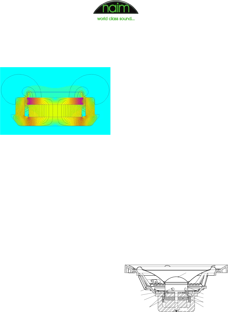
FEA model of the S-400 BMR driver magnetic circuit showing
the even flux density achieved in the magnet gap
B B
u-cup
spider
basket
dustcap
cone
roll surround
aluminum
demodulation
rings
pole piece
voice coil former
magnet
voice coil
voice coil former
vent hole
Cross-section of the S-400 bass unit
Page 4 of 8Copyright Naim Audio 2010
Two demodulation rings reduce impedance variations
while the voice coil is moving and also minimise distortion
originating from demagnetisation caused by the voice
coil’s fluctuating magnetic field.
The bass driver’s cone is made of long-fibre paper
with medium stiffness and was chosen to match the
sound character of the BMR. So as not to compromise
the driver’s dynamic behaviour its rubber surround
applies only light damping and the first breakup
mode is controlled instead by the shape of the cone
and surround. Within the divided closed box cabinet
the twin bass drivers achieve the target alignment of
a 48Hz fundamental resonance with a total Q of 0.63
to guarantee the best compromise between low-end
extension and transient behaviour.
Ovator S-400 crossover
A significant benefit of using a BMR to cover the entire mid
and high frequency band is that the typical 2kHz–3kHz
crossover, with its unavoidable phase and dispersion
discontinuities, is eliminated. The S-400 crosses over
between its bass drivers and BMR at 700Hz with fourth
order acoustic slopes and minimal phase discontinuity.
Because of the similarly wide dispersion of the bass
drivers and BMR at crossover there is no dispersion
discontinuity.
The crossover module itself is attached to the underside
of the plinth and comprises an MDF panel carrying
a glassfibre printed circuit board. It is suspended
from the plinth via an elastomeric mounting system
and selected crossover components also benefit
from discrete mechanical decoupling. Topology of
the printed circuit board borrows many of the layout
and earthing principles of Naim power amplifiers.
Components are all of extremely high quality, each
selected following extensive technical analysis and
listening tests. Crossover filter and equalisation curves
were extensively computer modelled and correlated
with measurement and listening.
bass drivers
BMR
L1
C3 C4
R1 C1
L2
R2
R3
C2
C5
L4
L5
L3
R4
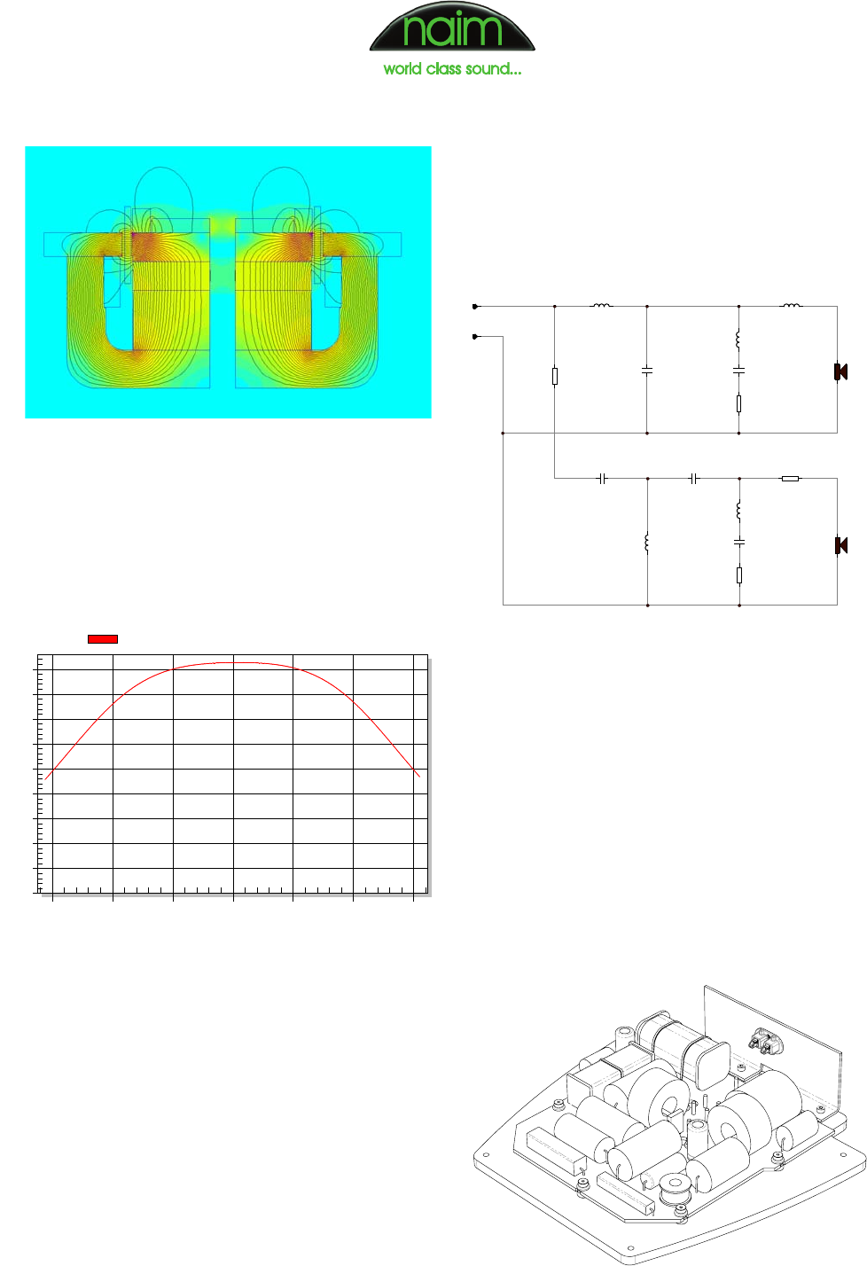
FEA model of the S-400 bass driver magnetic circuit showing
the even flux density achieved in the magnet gap
Circuit schematic of the Ovator S-400 crossover. Acoustic
slopes are 4th-order Linkwitz-Riley to ensure that the drivers
remain in phase throughout the crossover region
Suspended from the plinth to isolate it from vibration, the
crossover module combines careful layout with meticulous
choice of components
KLIPPEL
0
1
2
3
4
5
6
7
8
9
-7,5 -5,0 -2,5 0,0 2,5 5,0 7,5
Force factor Bl vs. displacement X
NAIM S-400
Bl [N/A]
Displacement X [mm]
Bl(X)
Klippel Analyzer measurement of the linearity of the S-400
bass unit's motor
Page 5 of 8Copyright Naim Audio 2010
The crossover presents a benign load to the driving
amplifier with a minimum impedance of 4 ohms at 3kHz
and a maximum phase shift throughout the entire audible
band of ±35°.
For bi-amp or tri-amp active operation the entire crossover
can be removed and replaced with an active wiring loom
adaptor. The terminal panel is also exchanged for one
carrying three sets of input terminals.
Ovator S-400 connectors
Custom-designed input terminals are fitted to the S-400
that deliver a significant advance on conventional items.
Design of the terminals was informed by experience
gained from the Naim Hi-Line and Power-Line projects
to generate an innovative and high performance speaker
connection solution.
The terminal is designed to work optimally with the new
Naim high conductivity copper speaker pin but can also
accept standard banana plugs. Sprung contacts optimise
contact pressure and minimise contact resistance. These
are manufactured from a unique grade of copper alloy with
an IACS (International Annealed Copper Standard) of over
90 per cent and enhanced spring properties. The terminal
housing is designed to eliminate eddy currents and allow
the contacts to float in order to minimise microphonic
effects. The complete housing is also decoupled within
the aluminium back plate of the speaker.
Ovator S-400 in use
Installing and setting-up the S-400 is simple. The speaker
has pre-fitted floor spikes, each with a rubber protector
which can be removed once it is in its final position.
The S-400 is a wide bandwidth, neutrally balanced
and uncoloured speaker capable of very high volume
levels without significant compression or distortion. Its
exceptional time domain behaviour and extremely low
noise floor mean that fine musical detail is reproduced
naturally with coherence and clarity. It is designed
primarily for ‘free-space’ use within the listening room,
well away from walls, but because of its consistent and
wide dispersion it is relatively insensitive to positioning. Its
listening sweet-spot is also considerably wider than that
of typical conventional speakers.
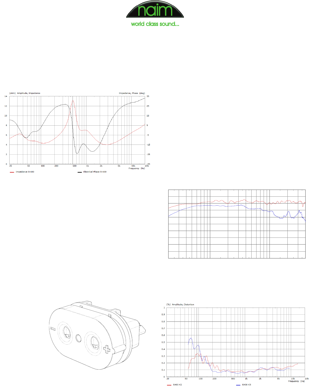
Impedance modulus (red trace) and phase (black trace)
versus frequency
Naim-designed input terminals
1k 10k
90
80
70
60
50
40
(dB) Level, Voltage Sensitivity
Frequency (Hz)
200 500 2k 5k 20k
85
75
65
55
45
S-400 power response (blue trace) and on-axis pressure
response (red trace)
S-400 second harmonic distortion (red trace) and third harmonic
distortion (blue trace)
Page 6 of 8Copyright Naim Audio 2010
APPENDIX – How the Balanced Mode Radiator
(BMR) drive unit works
A BMR is a circular flat panel loudspeaker that covers much
of the audio bandwidth with exceptionally wide sound
dispersion. It employs components similar to those of a
conventional moving coil drive unit (a surround attached
to the rear of the panel to join it flexibly to the frame, a
voice coil coupled directly to the panel and centred via
a spider, and a moving coil actuator that provides motive
force) but its vibrational behaviour is quite different.
In a traditional moving coil loudspeaker the diaphragm
acts as a ‘rigid piston’ at low frequencies but becomes a
multimodal (complexly resonant) object as it enters its so-
called breakup region. At this point it normally becomes
unusable because the frequency response becomes very
uneven and the sound highly coloured.
In a BMR there is no breakup region. Instead a limited
number of evenly spread resonant modes (usually two to
four) are carefully positioned within the frequency band
such that modal, bending-wave operation starts in the
frequency range where piston-like operation of the panel
would otherwise cause the driver to ‘beam’ its output over
a progressively narrower angle as frequency increases.
The result is a drive unit that operates like a piston at low
frequencies but becomes a bending wave device at high
frequencies, thereby maintaining wide dispersion across
the entire frequency range. Acoustically, the behaviour of
a BMR approximates that of an ideal ‘point source’.
Free disk driven by ‘ideal’ force
The underlying operating principle of a BMR can be
explained using simulation results obtained for an isotropic
disk of 85mm panel diameter. The disk is driven at its first
nodal line (a circle with a diameter 68 per cent that of the
panel), initially with an ‘ideal’ force that has no associated
mass or damping.
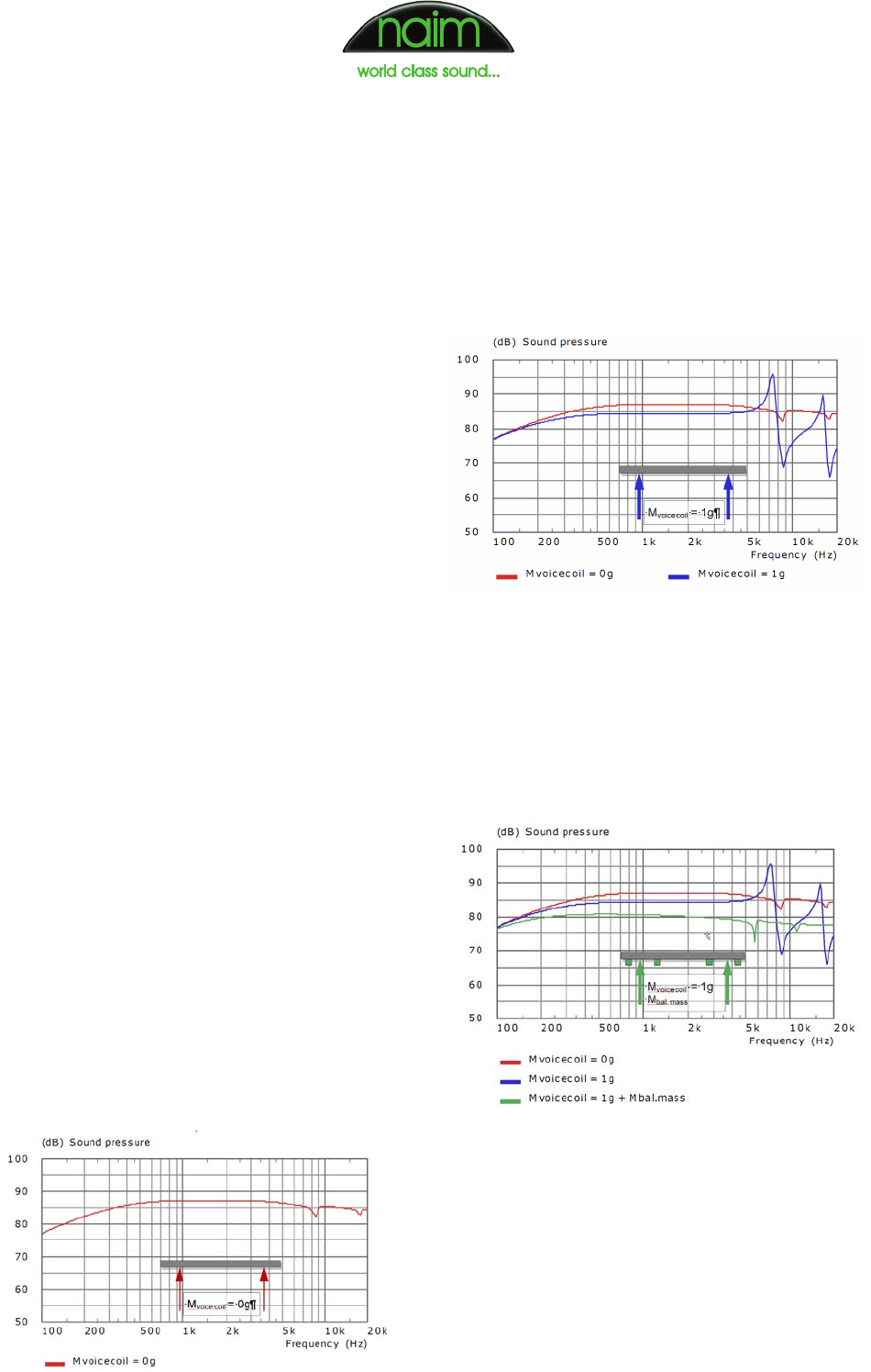
The resulting on-axis frequency response is shown in the
diagram below (red curve). Under these conditions the flat
disk shows a naturally balanced response with only small
dips at the second and third modes (the first mode is fully
suppressed because the panel is driven at its nodal line).
Free disk driven by ‘real’ force
Of course, in the real world there is always a mass
associated with the voice coil that applies force to the
panel. A voice coil mass of only 1g is assumed for the
simulation result plotted in the blue curve below, which
shows that even such a small mass destroys the natural
balancing of the disk.
Balanced disk driven by ‘real’ force
The acoustical behaviour of the free disk is restored,
though, if additional masses, called balancing masses, are
placed at pre-determined diameters (below). Note that the
masses are not normally added at the centre or the edge,
since these are always anti-nodes of all modes.
From the above simulations it is clear that it is only when
a mass-carrying voice coil is attached to the disk that
its previously faultless acoustic behaviour is disturbed.
But the performance of a free disk can be restored by
balancing the voice coil mass with additional masses.
This operating principle gave the Balanced Mode
Radiator its name.
Free disk driven by ‘ideal’ force
Free disk driven by ‘real’ force
Balanced disk driven by ‘real’ force

Page 7 of 8Copyright Naim Audio 2010
Off-axis behaviour
Traditionally, a uniform response over the audible range
has been an obvious aim for the loudspeaker designer.
This is usually verified by acquiring the on-axis frequency
response together with one or two off-axis responses. The
on-axis response is measured in front of the loudspeaker,
usually level with the tweeter at a distance of 1 to 2 metres.
Horizontal off-axis responses are measured at the same
height but with the microphone offset from the speaker’s
forward axis by a given angle (eg 15°, 30° etc).
The two figures below show response curves for a
typical two-way loudspeaker comprising a 165mm bass-
midrange driver and 25mm dome tweeter with a crossover
frequency around 3kHz. Curves measured at 0°, 30°, 60°
and 90° are shown in the first figure while the second
shows a horizontal frequency/directivity plot, where the
level is colour-coded and plotted against frequency over
the angular range –90° to +90°.
The frequency/directivity plot reveals that with increasing
frequency the 165mm bass-midrange driver starts
projecting sound more to the front. When the tweeter
takes over at around 3kHz the directivity widens again
until the tweeter itself begins to become directional
above 8kHz.
Equivalent results for the Naim BMR are shown below.
From the colour-coded directivity plot we can see that
the BMR radiates much more broadly than the two-way
loudspeaker discussed above. Due to its combination
of piston-like operation at low frequencies and bending
wave radiation at higher frequencies, the BMR drive unit
sustains very broad radiation up to 25kHz. Even at 90°
measuring angle the high frequency level is only 10dB
below the on-axis reference level.
Since the BMR unit can operate down to 100Hz, the
loudspeaker system designer is free to choose a
crossover frequency that fulfils the requirements of the
cabinet geometry and the low frequency driver.
1k 10k
90
80
70
60
50
40
(dB) Level, Voltage Sensitivity
Frequency (Hz)
200 500 2k 5k 20k
85
75
65
55
45
82
79
76
73
70
67
64
61
58
55
52
49
46
43
40
37
34
1k 10k
90
60
30
0
-30
-60
-90
(deg) Axial angle
Voltage Sensitivity, Level (dB)
Frequency (Hz)
200 500 2k 5k 20k
75
45
15
-15
-45
-75
On- and off-axis response of a typical two-way system
Directivity plot of a typical two-way system
On- and off-axis response of the S-400 system
Directivity plot of the S-400 system

Page 8 of 8Copyright Naim Audio 2010
What is a meaningful response measurement
for a BMR?
Because of the BMR driver’s different vibrational
behaviour, the on-axis frequency response curve is
no longer an accurate indicator of the tonality of the
loudspeaker. In fact during the development of the Naim
BMR it became clear that the on-axis response is as
good, or bad, an indicator as any other single frequency
response measured at any arbitrary angle.
A smooth on-axis response is desirable since it defines
the tonality of the direct sound from the loudspeaker.
But the BMR’s broad radiation makes it necessary that
the off-axis output should be free of any strong side-
lobes, otherwise the spectrally modified off-axis sound
reflected from the side walls or ceiling of the listening
room will cause audible colorations. Thus for a BMR-
based loudspeaker it is necessary to measure both the
horizontal and vertical frequency dispersion and the
acoustic power.
The acoustic power (or sound power) response
describes the total acoustic energy the loudspeaker
radiates into the room versus frequency. It is an essential
measurement for characterising loudspeakers with
broad dispersion or a large radiating area – like large
dipole loudspeakers, omnidirectional loudspeakers or
BMR-based loudspeakers.
A meaningful assessment of a BMR-based system
can only be performed on the basis of a range of
measurements including the on-axis response, the
acoustic power response and dispersion data for the
horizontal and vertical planes. The acquisition of this
data takes more time than the measurement of a single
response curve, consequently the development time for
a BMR is considerably longer than for a conventional
cone-based woofer or dome tweeter, since each step in
the development cycle needs to be verified by all the
above-mentioned measurements.
