Nanotron Technologies CMCSENS0108V2 CMC TC SD - Wireless Sensor Network User Manual UserMan
Nanotron Technologies GmbH CMC TC SD - Wireless Sensor Network UserMan
Manual

FCC Required Exhibit 12
CMC-TC SD
User Manual (UserMan)
Version 1.01
NA-08-0000-0034-1.01
Document Information
CMC-TC SD (UserMan)
Page ii NA-08-0000-0034-1.01 © 2008 Nanotron Technologies GmbH.
Document Information
Document Title: CMC-TC SD (UserMan)
Document Version: 1.01
Published (yyyy-mm-dd): 2008-04-17
Current Printing: 2008-4-17, 4:46 pm
Document ID: NA-08-0000-0034-1.01
Document Status: Released
Disclaimer
Nanotron Technologies GmbH believes the information contained herein is correct and accurate at the time of release. Nanotron
Technologies GmbH reserves the right to make changes without further notice to the product to improve reliability, function or
design. Nanotron Technologies GmbH does not assume any liability or responsibility arising out of this product, as well as any
application or circuits described herein, neither does it convey any license under its patent rights.
As far as possible, significant changes to product specifications and functionality will be provided in product specific Errata
sheets, or in new versions of this document. Customers are encouraged to check the Nanotron website for the most recent
updates on products.
Trademarks
nanoNET© is a registered trademark of Nanotron Technologies GmbH. All other trademarks, registered trademarks, and product
names are the sole property of their respective owners.
This document and the information contained herein is the subject of copyright and intellectual property rights under international
convention. All rights reserved. No part of this document may be reproduced, stored in a retrieval system, or transmitted in any
form by any means, electronic, mechanical or optical, in whole or in part, without the prior written permission of Nanotron
Technologies GmbH.
Copyright © 2008 Nanotron Technologies GmbH.
Life Support Policy
These products are not designed for use in life support appli-
ances, devices, or systems where malfunction of these prod-
ucts can reasonably be expected to result in personal injury.
Nanotron Technologies GmbH customers using or selling
these products for use in such applications do so at their own
risk and agree to fully indemnify Nanotron Technologies
GmbH for any damages resulting from such improper use or
sale.
Electromagnetic Interference / Compatibility
Nearly every electronic device is susceptible to electromag-
netic interference (EMI) if inadequately shielded, designed, or
otherwise configured for electromagnetic compatibility.
To avoid electromagnetic interference and/or compatibility
conflicts, do not use this device in any facility where posted
notices instruct you to do so. In aircraft, use of any radio fre-
quency devices must be in accordance with applicable regula-
tions. Hospitals or health care facilities may be using
equipment that is sensitive to external RF energy.
With medical devices, maintain a minimum separation of 15
cm (6 inches) between pacemakers and wireless devices and
some wireless radios may interfere with some hearing aids. If
other personal medical devices are being used in the vicinity
of wireless devices, ensure that the device has been ade-
quately shielded from RF energy. In a domestic environment
this product may cause radio interference in which case the
user may be required to take adequate measures.
CAUTION! Electrostatic Sensitive Device. Pre-
caution should be used when handling the
device in order to prevent permanent damage.
FCC User Information
Statement according to FCC part 15.19:
This device complies with Part 15 of the FCC Rules. Opera-
tion is subject to the following two conditions: (1) this device
may not cause harmful interference, and (2) this device must
accept any interference received, including interference that
may cause undesired operation.
Statement according to FCC part 15.21:
Modifications not expressly approved by this company could
void the user's authority to operate the equipment.
RF exposure mobil:
The internal / external antennas used for this mobile transmit-
ter must provide a separation distance of at least 20 cm from
all persons and must not be co-located or operating in con-
junction with any other antenna or transmitter."
Statement according to FCC part 15.105:
This equipment has been tested and found to comply with the
limits for a Class A and Class B digital device, pursuant to Part
15 of the FCC Rules. These limits are designed to provide
reasonable protection against harmful interference in a resi-
dential installation and against harmful interference when the
equipment is operated in a commercial environment.
This equipment generates, uses, and can radiate radio fre-
quency energy and, if not installed and used in accordance
with the instructions as provided in the user manual, may
cause harmful interference to radio communications. How-
ever, there is no guarantee that interference will not occur in a
particular installation. Operation of this equipment in a resi-
dential area is likely to cause harmful interference in which
case the user will be required to correct the interference at his
or her own expense.
If this equipment does cause harmful interference to radio or
television reception, which can be determined by turning the
equipment off and on, the user is encouraged to try to correct
the interference by one or more of the following measures:
• Reorient or relocate the receiving antenna.
• Increase the separation between the equipment and
receiver.
• Connect the equipment into an outlet on a circuit different
from that to connected.
• Consult the dealer or an experienced technician for help.
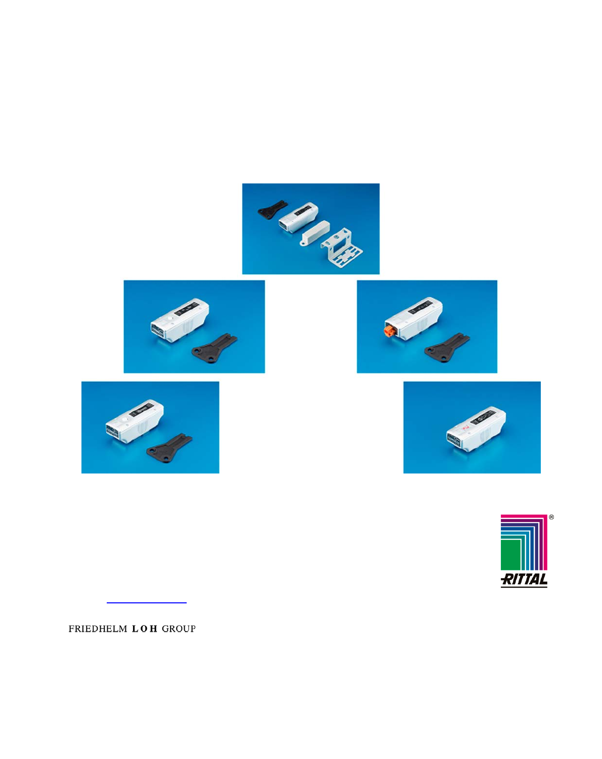
EN Wireless Temperature Sensor DK 7320.505
Wireless Humidity Sensor DK 7320.515
Wireless Access Sensor DK 7320.535
Wireless Digital Input Sensor DK 7320.585
Wireless Measuring System (Performance) Sensor DK 7320.242
Assembly, Installation and Operation
US Representative
Rittal Corporation
One Rittal Place
Springfield, OH 45504
Telefon: +1(937)399 05 00
Fax: +1(937)390 55 99
eMail: rittal@rittal-corp.com
Website: www.rittal-corp.com
A37 627 09 IT 74
Published: 18/04/2008
Microsoft Windows is a registered trademark of Microsoft Corporation.
Acrobat Reader is a registered trademark of Adobe Systems Incorporated.
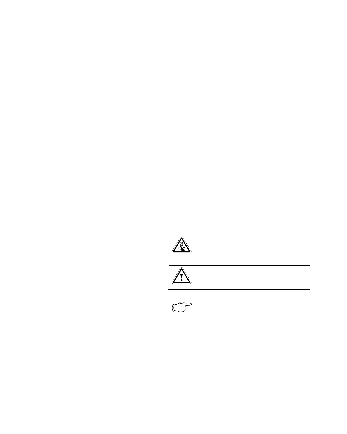
Table of Contents
1 Documentation Notes .......................2
1.1 Associated Documents ....................... 2
1.2 Retention of the Documents................ 2
1.3 Used Symbols ..................................... 2
2 Safety Notes....................................... 2
3 Unit Description................................. 3
3.1 Housing ............................................... 3
3.2 Register Wireless Sensor with Wireless
I/O-Unit ................................................ 4
3.2.1 Additional Digital Input ........................4
3.2.2 Additional Wireless Measuring System
Sensor ................................................. 5
3.3 Switch Off Wireless Sensor and Reset
to Factory Settings .............................. 6
3.4 Functions and Settings on the PUII
Web Page............................................ 6
3.4.1 General Overview (Status Window).... 6
3.4.2 Sensor Overview (Status Window) ..... 6
3.4.3 General View (Sensor Configuration) . 7
4 Accessories .......................................8
4.1 Required Accessories ......................... 8
4.2 Optional Accessories ..........................8
5 Proper Use .........................................8
6 Assembly ...........................................8
6.1 Assembly Notes .................................. 8
6.2 Sensor Housing Installation ................ 8
6.3 Notes for the Installation of the Access
Sensor 7320.535................................. 9
7 Maintenance and Cleaning ............... 9
7.1 Cleaning .............................................. 9
8 Storage and Disposal........................9
8.1 Storage................................................ 9
8.2 Disposal............................................... 9
9 Customer Service..............................9
10 Technical Specifications...................9
10.1 Temperature/Humidity and Access
Sensor ................................................. 9
10.2 Digital Input and Measuring System
Sensor ............................................... 10
10.3 Measuring/Lifecheck Cycles ............. 11
11 Declarations of Conformity ............ 11
1 Documentation Notes
The audience for this guide is the technical special-
ists familiar with the assembly, installation and op-
eration of the wireless sensors.
• You should read this operating guide prior to the
commissioning and store the guide so it is readily
accessible for subsequent use.
Rittal cannot accept any liability for damage and
operational malfunctions that result from the non-
observance of this guide.
1.1 Associated Documents
The guides for other CMC-TC components and their
safety notes also apply together with this guide.
1.2 Retention of the Documents
This guide and all associated documents are part of
the product. They must be given to the operator of
the unit and must be stored so they are available
when needed.
1.3 Used Symbols
The following safety and other notes are used in this
guide:
Symbol for a handling instruction:
• This bullet point indicates that you should perform
an action.
Safety and other notes:
Danger!
Immediate danger to health and life!
Warning!
Possible danger for the product and
the environment!
Note!
Useful information and special features.
2 Safety Notes
Observe the subsequent general safety notes for
the installation and operation of the unit:
Assembly and installation of the wireless sensor, in
particular for wiring the enclosures with mains
power, may be performed only by a trained electri-
cian. Other tasks associated with the wireless sen-
sor, such as the assembly and installation of system
components with tested standard connectors, and
the operation and configuration of the wireless sen-
sor may be performed only by instructed personnel.
Observe the valid regulations for the electrical instal-
lation for the country in which the unit is installed
and operated, and the national regulations for acci-
dent prevention. Also observe any company-internal
regulations (work, operating and safety regulations).
Use only genuine or recommended parts and ac-
cessories. The use of other parts can void the liabil-
ity for any resulting consequences.
Do not make any changes to the wireless sensor
that are not described in this guide or in the associ-
ated guides.
Do not make any changes to the system compo-
nents that are not described in this guide or in the
associated guides.
The operational safety of the unit is guaranteed only
for its approved use. The limit values stated in the
technical specifications may not be exceeded under
any circumstances. In particular, this applies to the
permitted ambient temperature range and to the
permitted IP protection category. When used with a
higher required IP protection category, the wireless
sensor must be installed in a housing or enclosure
with a higher IP protection category. The IP protec-
tive cover can also be used.
The operation of the wireless sensor in direct con-
tact with water, aggressive materials or inflammable
gases and vapours is prohibited.
In addition to these general safety notes, also ob-
serve any special safety notes listed for the specific
tasks in the individual sections.
Danger!
The sensor contains a battery and
consequently may never come in con-
tact with fire! Explosion danger!
3 Unit Description
The wireless sensors can be used for monitoring the
temperature (7320.505),
humidity (7320.515),
access (7320.535),
external signals 10-30 V DC (7320.585) and
wireless connection quality (7320.242).
Up to 16 wireless sensors can be connected to a
Wireless I/O-Unit. The temperature and humidity
sensor is mounted behind a protective membrane.
The temperature sensor or the humidity sensor send
a signal every 60 seconds and 120 seconds, re-
spectively. The access sensor and the digital input
send a message when a status change occurs. The
wireless measuring system has a digital display with
a display range 0 to 9. The value of the display pro-
vides information about the wireless connection
quality. The wireless measuring system has the
same design as the wireless sensor. This allows the
measuring system to be installed instead of the
sensors to evaluate the wireless con-nection quality.
A measuring system must be available for commis-
sioning the wireless sensor network. After the com-
missioning, the measuring system can also be used
for other installations.
All sensors contain a long-life 3.6 V lithium primary
cell that can be replaced if necessary.
The sensors are installed using the supplied at-
tachment bracket, which, for example, can be fas-
tened to the enclosure frame. The sensors are sim-
ply plugged onto this bracket. If a higher IP degree
of protection is required, the sensors (tempera-
ture/humidity/access) can be simply upgraded with
the IP protective cover.
The battery and the wireless connection quality of
the sensors are monitored.
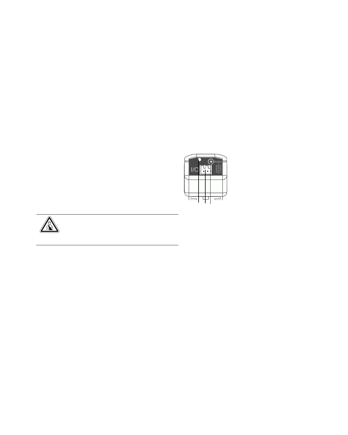
3.1 Housing
The wireless sensor is located in its own housing.
Explanation of the key and LED:
1 2 3
Fig. 1 Wireless sensor operator panel
Key
1LED for the status display for reset and learn mode
- briefly flashing once: Wireless connection check OK or
registration successful
- flashing three times: Wireless connection check not OK
or registration not successful
- flashing quickly: Switch off operation.
- flashing once (long): switched between NC to NO (only
digital input sensor)
22-pole connection socket, only digital input.
3Control key for the programming mode and reset.
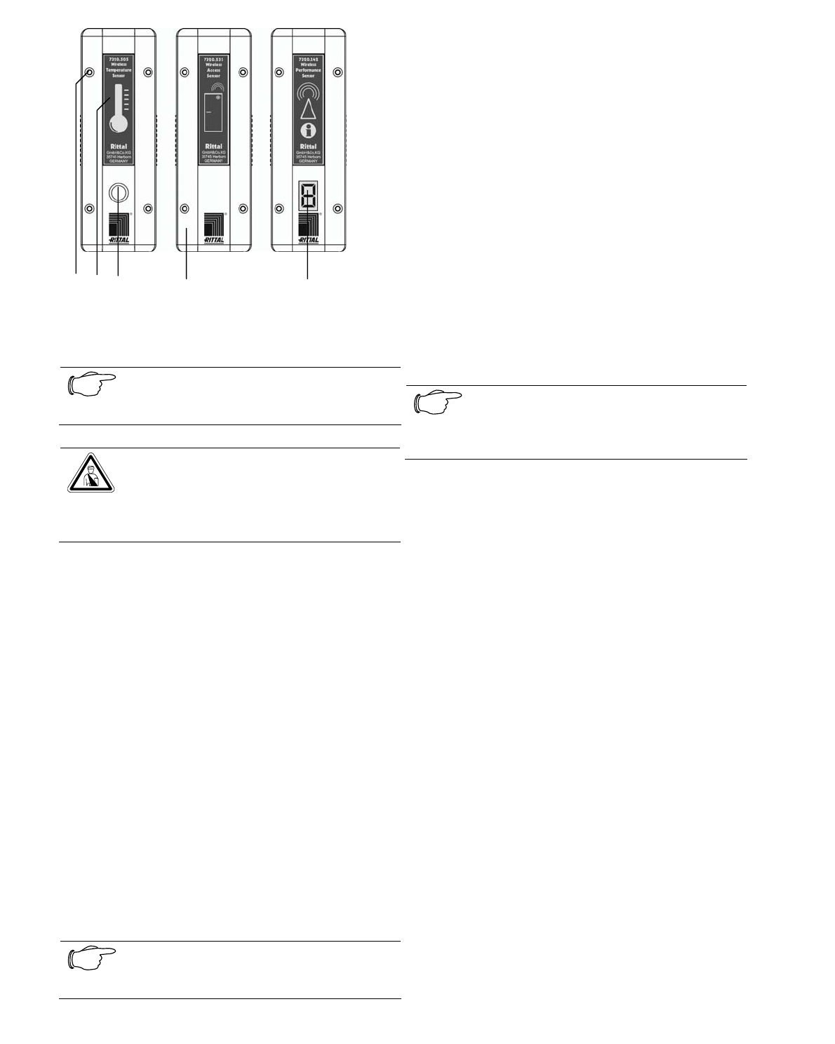
4 5 6 7 8
Fig. 2 Wireless sensor from above
4Housing screws for replacing the 3.6 V lithium
primary cell.
Note!
Please consult the operating manual for
the Rittal replacement battery.
Danger!
Immediate danger to health and life!
Only genuine Rittal spare parts may be
used.
5System designation The label contains the infor-
mation about the model number and the sensor
icon.
6Membrane The probe for the temperature or the
humidity sensor is located behind the membrane.
The membrane should not be touched, it could be
damaged.
7 The access sensor is operated using Hall sensors
and must be fastened together with the permanent
magnet included in the package in accordance with
the installation guide.
8 The LED display of the measuring system shows
the digits 0 to 9. 0 indicates no signal received,
whereas 9 indicates that the best signal is received.
3.2 Register Wireless Sensor with
Wireless I/O-Unit
Before the sensor can be installed and used, it must
be connected to a Wireless I/O-Unit. This requires
that the Wireless I/O-Unit is placed in programming
mode (Press the "C" key for three seconds).
Note!
Refer to the Wireless I/O-Unit 7320.240
operating manual for details.
The wireless sensor must be placed near the Wire-
less I/O-Unit.
If a repeater is used, the sensor must still be first
registered directly with the Base Unit!
The control key, see Figure 1 (3), on the wireless
sensor must be pressed 1 second to place the sys-
tem in registration mode.
If the LED of the sensor flashes once briefly, the
registration was successful.
If the LED of the sensor flashes briefly three times
successively, the registration was not successful
and must be repeated. The sensor switches itself off
automatically.
If the registration was successful, the sensor can be
used with the Wireless I/O-Unit and the Processing
Unit II.
If the sensor has been already used with a different
I/O-Unit, he has to be resetted first (see Chapter
3.3)
Note!
For details of the registration, refer to the
operating manuals for the Wireless I/O-
Unit and the Processing Unit II.
3.2.1 Additional Digital Input
Normally Closed (NC)
The digital input 7320.585 has the "Normally
Closed" (NC) function in its delivered state.
"OK" will be signalled for the NC function when a
voltage between 10 V and 30 V is present at the
terminal, see Figure 1 (2).
If no voltage is present at the terminal, see Figure 1
(2), the system will signal "Alarm".
Normally Open (NO)
If the digital input 7320.585 is to be operated in the
NO mode, the sensor must be reprogrammed. The
key on the wireless sensor, see Figure 1 (3), must
be pressed for two seconds. This changes the func-
tion. The change is represented as a sensor change
in the Wireless I/O-Unit and must be acknowledged
on the Processing Unit II.
An alarm will be signalled for the NO function when
a voltage between 10 V and 30 V is present at the
terminal, see Figure 1 (2).
If no voltage is present at the terminal, Figure 1 (2),
the system signals "OK".
A new change of the function requires that the de-
scribed process is repeated.
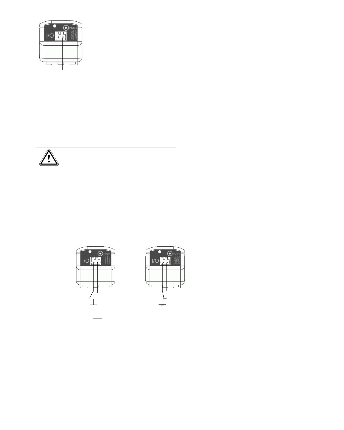
Terminals for signal input 10 to 30 V DC
1 2
Fig. 3 Digital input terminal
1 The + pole of the external 10 to 30 V DC sig-
nal must be connected to this terminal.
2 The earth (Gnd) of the external 10 to 30 V DC
signal must be connected to this terminal.
The externally monitored system must provide the
10 to 30 V DC voltage.
Warning!
The safety of the appliance is only
given if the external circuit connected
to the digital input sensor is protected
against exceeding currents >2A by
adequate external means.
If only a potential-free contact is available, the Rittal
24 V DC power pack 7320.425 can also be used for
the voltage signal.
Circuit diagram for the use of a potential-free
contact with a 24 V power pack
+24V DC
Gnd
+24V DC
Gnd
NO: open = OK NC: closed
= OK
Fig. 4 Circuit diagram for the digital input
Alarm output behaviour for a wireless malfunc-
tion
If a short-term wireless malfunction occurs between
the Digital Input Sensor and the Wireless I/O-Unit,
alarms or alarm changes will be represented in the
alarm log as follows.
1. Alarm will be ended during the wireless mal-
function: The alarm will be indicated on the
PUII until the next Lifecheck.
2. Alarm begins during the malfunction: The
PUII signals the alarm only after the next
Lifecheck.
3. Complete, terminated alarm process during
the malfunction: The malfunction will be in-
dicated on the PUII after the next Lifecheck
by an entry being made in the alarm log.
4. Two or more complete, terminated alarms
during the malfunction: One (!) alarm will be
signalled on the PUII after the next Life-
check.
3.2.2 Additional Wireless Measuring Sys-
tem Sensor
The wireless measuring system has a digital display
with a display range 0 to 9. The value of the display
provides information about the wireless connection
quality. The wireless measuring system has the
same design as the wireless sensor. This allows the
measuring system to be installed instead of the
sensors to evaluate the wireless con-nection quality.
A measuring system must be available for commis-
sioning the wireless sensor network. After the com-
missioning, the measuring system can also be used
for additional installations, for example, for exten-
sions or changes. The wireless measuring system is
registered once and then reused afterwards with the
Wireless I/O-Unit or it is registered with a different
wireless sensor network. The latter requires that the
wireless measuring system sensor is switched off
(see Section 3.3) and re-registered with a new Wire-
less I/O-Unit. The measuring system is trained with
the Wireless I/O-Unit like a normal sensor. The re-
sult can be seen on the sensor display, see Figure 2
(8).
Operation of the measuring system once it has
been trained with the Wireless I/O-Unit:
1. Press the key, see Figure 1 (3), 1 second
-> the most recent measurement result is displayed
-> the number 1 flashes in the display
2. Press the key, see Figure 1 (3), several times to
select the digits 1 to 5
- Digit 1 selected = measuring cycle duration 1 min-
ute
- Digit 2 selected = measuring cycle duration 5 min-
utes
- Digit 3 selected = measuring cycle duration 10
minutes
- Digit 4 selected = measuring cycle duration 1 hour
- Digit 5 selected = measuring cycle duration 10
hours
-> The measurement begins after 30 seconds.
-> The flashing of the point in the display signals
that a test package is being received.
-> The measurement result is displayed at the end
of the measurement cycle. The LED display of the
measuring system shows the digits 0 to 9. This
corresponds to a percentage value of 0 to 100%
sent packages received from the Wireless I/O-Unit.
0 indicates no signal received, whereas 9 indicates
that the best signal is received. A detailed coding of
the display values is contained in Table Tab. 1.
-> After a measurement, the measuring system
switches itself off automatically.
-> If the wireless measuring system sensor has
been switched off for a longer period of time or has
been used for a different I/O-Unit in the meantime,
the sensor must be retrained.
Display Successful
received
packages
[%]
Evaluation
9 100 OK
8 99-98 OK
7 97-96 conditionally suitable, repeater
necessary
6 95-94 conditionally suitable, repeater
necessary
5 93-92 conditionally suitable, repeater
necessary
4 91-90 conditionally suitable, repeater
necessary
3 89-80 not suitable
2 79-50 not suitable
1 49-25 not suitable
0 <25 not suitable
Tab. 1 Measured value display - > receiving quality
assignment
3.3 Switch Off Wireless Sensor and
Reset to Factory Settings
To reset a wireless sensor to its factory settings, the
key, see Figure 1 (3), on the wireless sensor must
be pressed continually for five seconds until the
sensor LED flashes continually. The key can then
be released.
This switches off the wireless sensor and restores
the factory settings so the wireless sensor can be
used for a new setup on a Wireless I/O-Unit.
3.4 Functions and Settings on the PUII
Web Page
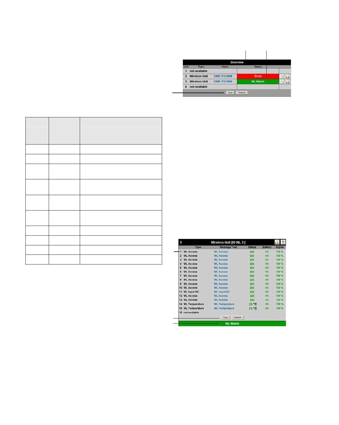
3.4.1 General Overview (Status Window)
1 2
3
Fig. 5 Overview display browser window
Key
1 Overview display.
2 Status of the I/O-Unit: The status of all wireless
sensors of the I/O-Unit is summarised. The most
critical status is always displayed
"No Alarm" = All sensors are OK
"Warning" = At least one sensor has issued a warning
"Alarm" = At least one sensor has issued an alarm
"Error" = The sensor is out of range or does not have
connection with the Wireless I/O-Unit.
3 Clear button: Acknowledge events.
Click the Clear button to acknowledge configuration
changes of all connected sensors.
Refresh button: All sensors are refreshed. This
causes the CMC-TC PU to be re-queried and the
Web page rebuilt.
3.4.2 Sensor Overview (Status Window)
1
2
3
Fig. 6 Sensors overview
Key
1 Sensors of the PUII unit, up to 16 wireless sensors
are grouped here.
2 Clear button: Acknowledge events.
Click the Clear button to acknowledge configuration
changes of all connected sensors.
Refresh button: All sensors are refreshed. This
causes the CMC-TC PU to be re-queried and the
Web page rebuilt.
3 Status line: The status of all wireless sensors of the
PUII is summarised. The most critical status is al-
ways displayed.
"OK" = All sensors are OK
"Warning" = At least one sensor has issued a warning
"Alarm" = At least one sensor has issued an alarm
"Error" = The sensor is out of range or does not have
connection with the Wireless I/O-Unit.
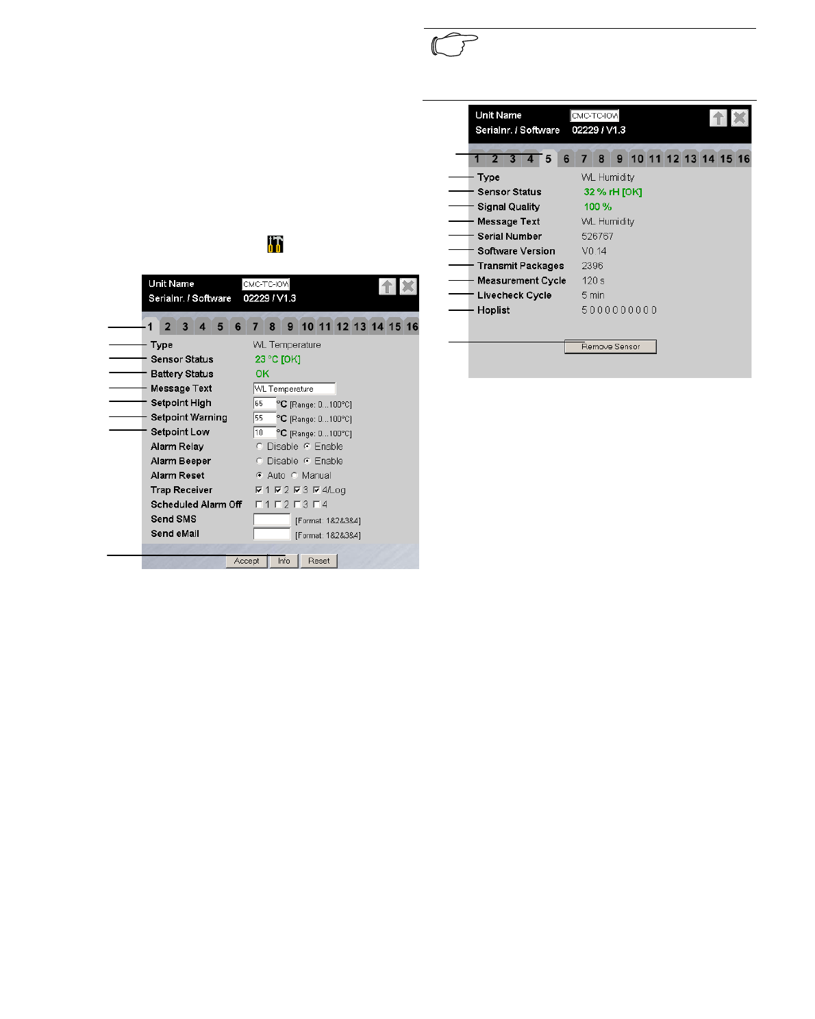
3.4.3 General View (Sensor Configura-
tion)
You can individually set the attached sensors. Be-
cause the structure of the configuration overview is
generally always identical, it is shown here as an
example.
To reach this page, click the tool icon or click the
sensor name directly.
1
2
9
3
4
5
6
7
8
Fig. 7 Configuring the sensor – overview
Key
1 Sensor connection number.
2 Connected sensor type.
3 Current status of the connected sensor.
4 The battery status
"red": The battery must be replaced
"green": The battery is operational.
5 This message text will also be transferred when a
status change is sent and serves as information for
the recipient of the message to identify the sensor.
You can delete the specified text and add your own
message text (e.g. TempSensorRack1).
6 The highest upper temperature/humidity limit, which,
when exceeded, causes an alarm message to be is-
sued (only for temperature and humidity sensors).
7 Mean temperature/humidity limit, which, when ex-
ceeded, causes a warning message to be issued
(only for temperature and humidity sensors).
8 The lowest lower temperature/humidity limit, which,
when undershot, causes an alarm message to be
issued (only for temperature and humidity sensors).
9 The "Info" button is used to reach the information
menu of the sensor.
Note!
For details, please refer to the operating
manuals for the Wireless I/O-Unit and the
Processing Unit II.
2
3
4
5
6
7
8
9
10
11
12
1
Fig. 8 Information for the Wireless Sensor
The information menu is reached using the Info button,
see Fig. 7, item 9
Key
1 Sensor connection number.
2 Connected sensor type.
3 Current status of the connected sensor.
4 Signal quality, the wireless connection from the
sensor to the Wireless I/O-Unit is displayed as a
percentage value.
0-49% = red = inadequate signal quality
50-79% = orange = critical signal quality
80-100% = green = adequate signal quality
5 Information: "Message text" for the sensor.
6 Information: Serial number of the sensor.
7 Information: Software version of the sensor.
8 Information: The number of data packages of this
sensor that have been received by the I/O-Unit since
the commissioning of the sensor or since the last re-
start of the Wireless I/O-Unit.
9 Information: The time separation of the data pack-
ages to the measured values.
10 Information: The time interval with which the con-
nection from the wireless sensor to the Wireless I/O-
Unit is checked.
11 Information of the hoplist; the information route via
existing repeaters is displayed.
1st position: Sensor connection number
2nd -10th position: The repeater number in accor-
dance with the connection sequence. The route with
the best connection quality is chosen automatically.
The repeaters can be registered as sensors and so
receive a number. They are listed in connection se-
quence until the hoplist ends with the "0". The free
numbers are filled with zeros. The digit "0" is always
the Wireless I/O-Unit connected as central system to
the Processing Unit II.
12 The Remove Sensor button can be used to remove
the current sensor from the I/O-Unit.
Note
The communications timing between
the I/O-Unit and the sensor can require
that Remove Sensor must be clicked
several times before the remove com-
mand is accepted.
4 Accessories
4.1 Required Accessories
The operation of the sensor always requires a Wire-
less I/O-Unit, a Processing Unit II and a measuring
system sensor with the appropriate connection ac-
cessories.
Note!
For details, please refer to the operating
manuals for the Wireless I/O-Unit and the
Processing Unit II.
4.2 Optional Accessories
Accessories Required num-
ber of items Model No.
IP protective
cover 1 DK 7320.245
Tab. 2 Optional accessories
The protective cover 7320.245 can be used option-
ally for the following sensors:
- temperature (7320.505)
- humidity (7320.515)
- access (7320.535)
This increases the protection category of the sen-
sors from IP40 to IP54.
5 Proper Use
The Rittal Wireless sensors are used to monitor the
temperature (7320.505), the humidity (7320.515),
access (7320.535),10-30 V DC signal as digital
input (7320.585).
A use different from that described here is consid-
ered to be an improper use. Rittal cannot accept any
liability for damage resulting from the improper use
or the non-observance of this guide. The guides for
the used accessories may apply.
6 Assembly
6.1 Assembly Notes
Install the wireless sensor in an enclosure or in a
suitable housing system so that it also has addi-
tional protection from external effects. The sensor
can also be equipped with the IP protective cover.
This cover provides dampness protection and im-
proves protection against dust. Consider the permit-
ted ambient temperature and humidity operational
areas and the application-related required IP degree
of protection.
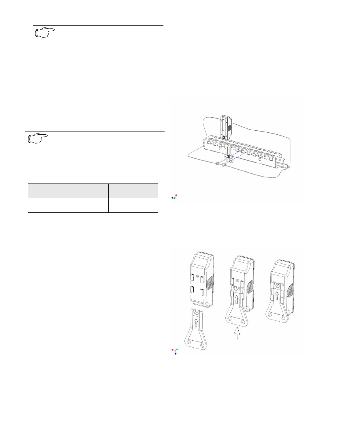
6.2 Sensor Housing Installation
The attachment bracket included in the package is
fastened to the enclosure frame using the included
T25-Torx screws.
Fig. 9 Installation of the attachment bracket
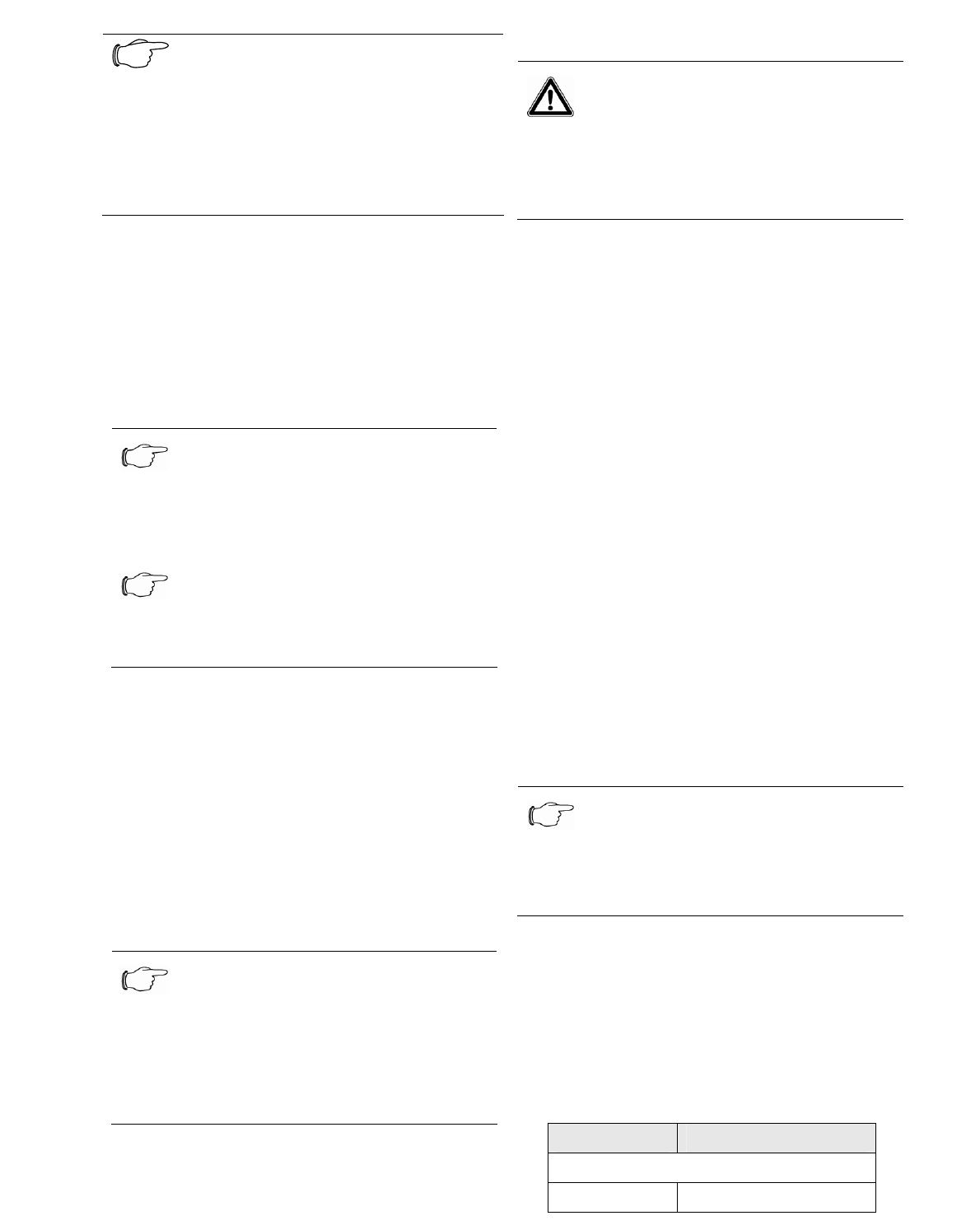
To fasten the sensor, simply push it onto the at-
tachment bracket.
Fig. 10 Attaching the sensor to the attachment bracket
As an alternative to the screwed connection, the
sensor can also be attached using the provided
adhesive strips.
Note!
In this case, the surfaces to be glued
must be cleaned using a cleaning cloth
and an alcohol-based cleaning solution.
To ensure a long-lasting adhesive con-
nection, the cleaned surface and the ad-
hesive surface may no longer be touched
after the cleaning and before use of the
adhesive strip.
6.3 Notes for the Installation of the Ac-
cess Sensor 7320.535
For the installation of the access sensor, the pack-
age contains a separate installation drawing that
shows the installation of the sensor and of the mag-
net in the various Rittal housings.
Note!
For the installation of the access sensor
7320.535, with closed door, the magnet
must be positioned centrally on the sen-
sor.
Note!
For the installation of the access sensor
7320.535 with the magnet, the function
must be tested after the installation.
7 Maintenance and Cleaning
The Rittal Wireless Sensor may only be opened to
replace the battery. Only genuine Rittal batteries
may be used. For the replacement, the removal of
four screws shown in Figure 2 item 4 allows the
cover to be separated from the housing. The circuit
board must be removed to give access to the bat-
tery plug connector. Ensure that the correct polarity
is maintained when the battery is replaced. After it
has been replaced, the housing with the seals must
be closed securely.
Note!
The housing may only be opened in ac-
cordance with the operating manual for
the Rittal replacement battery.
For the replacement action, the service
technician must be earthed with an
earthing strap.
7.1 Cleaning
Warning!
Danger of damage!
Do not use any aggressive sub-
stances, such as white spirit, acid,
etc., for cleaning because such sub-
stances can damage the unit.
Use a slightly moistened soft cloth to clean the
housing.
8 Storage and Disposal
8.1 Storage
If the device is not used over an extended period of
time, we recommend that the device is reset to set it
into the initial state.
Further information concerning the operating condi-
tions is contained in the technical specifications.
8.2 Disposal
Because the wireless sensor contains a battery, the
system must be given for disposal to a hazardous
waste site. The country-specific regulations for dis-
posal of the battery must be observed.
9 Customer Service
If you have any technical questions or questions
concerning our product spectrum, contact the follow-
ing service address:
Tel.: +49 (0)2772/505-1855
http://www.rimatrix5.com
eMail: info@rittal.de
Note!
To allow us to process your enquiry
quickly and correctly, please always
specify the article number in the subject
line for e-mails.
Further information and the current operating manu-
als can be downloaded from "Security" at
www.rimatrix5.com
10 Technical Specifications
10.1 Temperature/Humidity and Access
Sensor
Designation 7320.505/.515/.535
Housing
Housing type Plastic
Height 90 mm
Width 30 mm
Depth 30 mm
Protection
category
IP 40 to EN 60529
Increased
protection
category
through the
use of an IP
protective
cover only for:
7320.505
7320.515
7320.535
IP 54 to EN 60529
Operational area / conditions
Temperature -25 to +65 °C
Humidity 10-90% rel. humidity
Storage tem-
perature
-25 to +65 °C
Rated voltage 3.6 V DC
Do not operate the sensor in direct
contact with water/rain.
Do not operate the sensor when
subjected to direct sunlight.
Measuring tolerance
Temperature
sensor
+/- 3 °K
Humidity
sensor
tolerances at
20 °C
+/- 3% rel. humidity for
the range 20-80% rel.
humidity
+/- 4% rh for the range
10-20% rh
+/- 4% rel. humidity for
the range 80-90% rel.
humidity
Lithium primary cell
Rated volt-
age
3.6 V DC
Operational
lifetime at
–5°C to
+25°C
Up to 5 years.
The operational lifetime of
an access sensor de-
pends on its frequency of
activation.
Wireless technology
Technology Chirp
ISM band 2.4 GHz to 2.48 GHz
Regulation
(CE)
R&TTE 1999/5/EG
Technical Specifications
10.2 Digital Input and Measuring System
Sensor
Designation 7320.585/242
Housing
Housing type Plastic
Height 90 mm
Width 30 mm
Depth 30 mm
Protection category IP 40 to EN 60529
Operational area / conditions
Temperature +5 to +45 °C
Humidity 10-90% rel. humidity
Storage tempera-
ture
-25 to +65 °C
Rated voltage 3.6 V DC
Do not operate the sensor in direct
contact with water/rain.
Do not operate the sensor when sub-
jected to direct sunlight.
Lithium primary cell
Rated voltage 3.6 V DC
Operational lifetime
Digital input at
+5 °C to +25 °C
Up to 5 years.
The operational life-
time depends on the
frequency of activa-
tion.
Operational lifetime
Measuring system
sensor at +5 °C to
+25 °C
Depends on the fre-
quency of use
Wireless technology
Technology Chirp
ISM band 2.4 GHz to 2.48 GHz
Regulation
(CE)
R&TTE 1999/5/EU
Technical Specifications
10.3 Measuring/Lifecheck Cycles
Measuring cycles
Temperature sensor 60 seconds
Humidity sensor 120 seconds
Measuring cycles of the sensors
Lifecheck
Temperature sensor 300 seconds
Humidity sensor 300 seconds
Access sensor 120 seconds
Digital input sensor 120 seconds
Lifecheck cycles of the sensors
11 Declarations of Conformity
This device satisfies the requirements of the follow-
ing EU regulation:
1999/5/EU Regulation for wireless systems and
telecommunications terminals and the
mutual recognition of their confor-
mance
Hereby Rittal declares, that CMC
Wireless I/O-Unit and CMC Wireless
sensor is in compliance with essential
requirements and other relevant
provisions of Directive 1999/5/EC.
In France, the operation is only permitted indoors.
Certification
This device complies with Part 15 of the FCC Rules.
Operation is subject to the following two conditions:
(1) This device may not cause harmful interference,
and (2) this device must accept any interference
received, including interference that may cause
undesired operation.
FCC ID: SIFCMCSENS0108V2
Statement according to FCC part 15.21:
Modifications not expressly approved by this com-
pany could void the user's authority to operate the
equipment.
Statement according to FCC part 15.105:
Note: This equipment has been tested and found to
comply with the limits for a Class A digital device,
pursuant to part 15 of the FCC Rules. These limits
are designed to provide reasonable protection
against harmful interference when the equipment is
operated in a commercial environment. This equip-
ment generates, uses, and can radiate radio fre-
quency energy and, if not installed and used in ac-
cordance with the instruction manual, may cause
harmful interference to radio communications. Op-
eration of this equipment in a residential area is
likely to cause harmful interference in which case
the user will be required to correct the interference
at his own expense.
Statement according to FCC part 15.105:
NOTE: This equipment has been tested and found
to comply with the limits for a Class B digital device,
pursuant to Part 15 of the FCC Rules. These limits
are designed to provide reasonable protection
against harmful interference in a residential installa-
tion. This equipment generates, uses and can radi-
ate radio frequency energy and, if not installed and
used in accordance with the instructions, may cause
harmful interference to radio communications. How-
ever, there is no guarantee that interference will not
occur in a particular installation. If this equipment
does cause harmful interference to radio or televi-
sion reception, which can be determined by turning
the equipment off and on, the user is encouraged to
try to correct the interference by one or more of the
following measures:
. Reorient or relocate the receiving antenna.
. Increase the separation between the equipment
and receiver.
. Connect the equipment into an outlet on a circuit
different from that to which the receiver is con-
nected.
. Consult the dealer or an experienced radio/TV
technician for help.

Revision History
CMC-TC SD (UserMan)
© 2008 Nanotron Technologies GmbH. NA-08-0000-0034-1.01 Page 12
Revision History
Version Date Description/Changes
1.01 2008-04-17 Initial version.

About Nanotron Technologies GmbH
CMC-TC SD (UserMan)
Page 13 NA-08-0000-0034-1.01 © 2008 Nanotron Technologies GmbH.
About Nanotron Technologies GmbH
Nanotron Technologies GmbH develops world-class wireless products for demanding applications based
on its patented Chirp transmission system - an innovation that guarantees high robustness, optimal use of
the available bandwidth, and low energy consumption. Since the beginning of 2005, Nanotron's Chirp tech-
nology has been a part of the IEEE 802.15.4a draft standard for wireless PANs which require extremely
robust communication and low power consumption.
ICs and RF modules include nanoNET TRX Transceiver, nanoLOC TRX Transceiver, and ready-to-use or
custom wireless solutions. These include, but are not limited to, industrial monitoring and control applica-
tions, medical applications (Active RFID), security applications, and Real Time Location Systems (RTLS).
nanoNET is certified in Europe, United States, and Japan and supplied to customers worldwide.
Headquartered in Berlin, Germany, Nanotron Technologies GmbH was founded in 1991 and is an active
member of IEEE and the ZigBee alliance.
Further Information
For more information about this product and other products from Nanotron Technologies, contact a sales
representative at the following address:
Nanotron Technologies GmbH
Alt-Moabit 60
10555 Berlin, Germany
Phone: +49 30 399 954 - 0
Fax: +49 30 399 954 - 188
Email: sales@nanotron.com
Internet: www.nanotron.com