Nanotron Technologies NANONET-TRX nanoNET TRX 2.4 GHz CSS Transceiver User Manual UserMan
Nanotron Technologies GmbH nanoNET TRX 2.4 GHz CSS Transceiver UserMan
UserMan
FCC Required Exhibit 12
nanoNET TRX User
Manual (UserMan)
FCC ID: SIFNANONET-TRX
FCC Information to the user pursuant to FCC Rules
Part 15, Subpart B, can be found on page iii.
nanoNET TRX User Manual (UserMan)
FCC ID: SIFNANONET-TRX
NA-04-0000-0304-1.00 Copyright © 2005 All Rights Reserved
Page ii Nanotron Technologies GmbH, Alt-Moabit 61, 10555 Berlin, Germany
Document Information
Document title: nanoNET TRX User Manual (UserMan)
Version/release number: 1.00
Released (yyyy-mm-dd): 2001-01-21
Current printing: 2005-1-26, 11:13 am
Document ID: NA-04-0000-0304-1.00
Disclaimer
Nanotron Technologies GmbH reserves the right to make changes without further notice to the product to
improve reliability, function or design. Nanotron Technologies GmbH does not assume any liability arising
out of the application or use of any product or circuits described herein.
Trademarks
All product names mentioned herein are the trademarks of their respective owners.
Life Support Policy
These products are not designed for use in life support appliances, devices, or systems where malfunction
of these products can reasonably be expected to result in personal injury. Nanotron Technologies GmbH
customers using or selling these products for use in such applications do so at their own risk and agree to
fully indemnify Nanotron Technologies GmbH for any damages resulting from such improper use or sale.
Address Information
Nanotron Technologies GmbH
Alt-Moabit 61
10555 Berlin
Germany
Tel: +49 (0) 30 - 399954-0
Fax: +49 (0) 30 - 399954-188
Email: info@nanotron.com
Web: www.nanotron.com
Copyright © 2005 Nanotron Technologies GmbH.
This document and the information contained herein is the subject of copyright and intellectual property
rights under international convention. All rights reserved. No part of this document may be reproduced,
stored in a retrieval system, or transmitted in any form by any means, electronic, mechanical or optical, in
whole or in part, without the prior written permission of Nanotron
Technologies GmbH.
CAUTION! Electrostatic Sensitive Device. Precaution should be used when handling the
device in order to prevent permanent damage.
nanoNET TRX User Manual (UserMan)
FCC ID: SIFNANONET-TRX
Copyright © 2005 All Rights Reserved NA-04-0000-0304-1.00
Nanotron Technologies GmbH, Alt-Moabit 61, 10555 Berlin, Germany Page iii
Regulatory Information
Electromagnetic Interference / Compatibility
Nearly every electronic device is susceptible to electromagnetic interference (EMI) if inadequately shielded,
designed, or otherwise configured for electromagnetic compatibility.
To avoid electromagnetic interference and/or compatibility conflicts, do not use this device in any facility
where posted notices instruct you to do so. In aircraft, use of any radio frequency devices must be in accor-
dance with applicable regulations. Hospitals or health care facilities may be using equipment that is sensi-
tive to external RF energy. With medical devices, maintain a minimum separation of 6 inches (15 cm)
between pacemakers and wireless devices and some wireless radios may interfere with some hearing aids.
If other personal medical devices are being used in the vicinity of wireless devices, ensure that the device
has been adequately shielded from RF energy. In a domestic environment this product may cause radio
interference in which case the user may be required to take adequate measures.
EC Declaration of Conformity
The 2.4GHz Chirp Spread Spectrum (CSS) Low-Power RF Transceiver, model number nanoNET TRX has
been certified to comply with the requirements of the R&TTE Directive
1999/5/EC and the standards EN 300 328 V 1.4.1:2003, EN 301 489-17 V1.2.1, and
EN 60950-1:2001.
FCC User Information
Statement according to FCC part 15.19:
This device complies with Part 15 of the FCC Rules. Operation is subject to the following two conditions: (1)
this device may not cause harmful interference, and (2) this device must accept any interference received,
including interference that may cause undesired operation.
Statement according to FCC part 15.21:
Modifications not expressly approved by this company could void the user's authority to operate the equip-
ment.
RF exposure mobil:
The internal / external antennas used for this mobile transmitter must provide a separation distance of at
least 20 cm from all persons and must not be co-located or operating in conjunction with any other antenna
or transmitter."
Statement according to FCC part 15.105:
This equipment has been tested and found to comply with the limits for a Class A and Class B digital device,
pursuant to Part 15 of the FCC Rules. These limits are designed to provide reasonable protection against
harmful interference in a residential installation and against harmful interference when the equipment is
operated in a commercial environment.
This equipment generates, uses, and can radiate radio frequency energy and, if not installed and used in
accordance with the instructions as provided in the user manual, may cause harmful interference to radio
communications. However, there is no guarantee that interference will not occur in a particular installation.
Operation of this equipment in a residential area is likely to cause harmful interference in which case the
user will be required to correct the interference at his or her own expense.
If this equipment does cause harmful interference to radio or television reception, which can be determined
by turning the equipment off and on, the user is encouraged to try to correct the interference by one or more
of the following measures:
• Reorient or relocate the receiving antenna.
• Increase the separation between the equipment and receiver.
• Connect the equipment into an outlet on a circuit different from that to connected.
• Consult the dealer or an experienced technician for help.
0681

nanoNET TRX User Manual (UserMan)
FCC ID: SIFNANONET-TRX
NA-04-0000-0304-1.00 Copyright © 2005 All Rights Reserved
Page iv Nanotron Technologies GmbH, Alt-Moabit 61, 10555 Berlin, Germany

nanoNET TRX User Manual (UserMan)
FCC ID: SIFNANONET-TRX
Copyright © 2005 All Rights Reserved NA-04-0000-0304-1.00
Nanotron Technologies GmbH, Alt-Moabit 61, 10555 Berlin, Germany
Page v
Table of Contents
1. About the nanoNET TRX RF Performance Evaluation Kit . . . . . . . . . . . 1
2. nanoNET TRX RF Test Module Version 5. . . . . . . . . . . . . . . . . . . . . . . . . 3
3. nanoNET TRX RF Test Module Version 12. . . . . . . . . . . . . . . . . . . . . . . . 5
4. nanoNET MCF Microcontroller Board . . . . . . . . . . . . . . . . . . . . . . . . . . . 7
5. Using the RF Performance Evaluation Kit . . . . . . . . . . . . . . . . . . . . . . . 11
5.1. Power Supply . . . . . . . . . . . . . . . . . . . . . . . . . . . . . . . . . . . . . . . . . . . . . . . . . . . . . . 11
5.2. Flash Software. . . . . . . . . . . . . . . . . . . . . . . . . . . . . . . . . . . . . . . . . . . . . . . . . . . . . . 11
5.3. Setting Up the MCF Boards. . . . . . . . . . . . . . . . . . . . . . . . . . . . . . . . . . . . . . . . . . . . 11
5.4. Error Indications . . . . . . . . . . . . . . . . . . . . . . . . . . . . . . . . . . . . . . . . . . . . . . . . . . . . 14
5.5. Installing the RF Performance Analysis Tool. . . . . . . . . . . . . . . . . . . . . . . . . . . . . . . 15
5.6. Shutting Down an MCF Board. . . . . . . . . . . . . . . . . . . . . . . . . . . . . . . . . . . . . . . . . . 15
6. RF Performance Analysis Tool . . . . . . . . . . . . . . . . . . . . . . . . . . . . . . . . 17
6.1. Preparing for RF Evaluation . . . . . . . . . . . . . . . . . . . . . . . . . . . . . . . . . . . . . . . . . . . 18
6.2. Starting the RFPAT Application. . . . . . . . . . . . . . . . . . . . . . . . . . . . . . . . . . . . . . . . . 18
6.3. Initializing and Selecting a Chip Register Settings File . . . . . . . . . . . . . . . . . . . . . . . 19
6.4. Initializing Chip with Default Values. . . . . . . . . . . . . . . . . . . . . . . . . . . . . . . . . . . . . . 20
6.5. Test Modes . . . . . . . . . . . . . . . . . . . . . . . . . . . . . . . . . . . . . . . . . . . . . . . . . . . . . . . . 20
7. Antenna Specifications for Model 17010.11. . . . . . . . . . . . . . . . . . . . . . 21
7.1. Vertical Diagram for Model 17010.11 . . . . . . . . . . . . . . . . . . . . . . . . . . . . . . . . . . . . 22
7.2. Azimuth Diagram for Model 17010.11 . . . . . . . . . . . . . . . . . . . . . . . . . . . . . . . . . . . . 23

nanoNET TRX User Manual (UserMan)
FCC ID: SIFNANONET-TRX
NA-04-0000-0304-1.00 Copyright © 2005 All Rights Reserved
Page vi Nanotron Technologies GmbH, Alt-Moabit 61, 10555 Berlin, Germany
nanoNET TRX User Manual (UserMan)
FCC ID: SIFNANONET-TRX
Copyright © 2005 All Rights Reserved NA-04-0000-0304-1.00
Nanotron Technologies GmbH, Alt-Moabit 61, 10555 Berlin, Germany Page 1
1. About the nanoNET TRX RF Performance Evaluation Kit
The nanoNET TRX is a highly integrated mixed signal chip utilizing a new wireless communica-
tion technology – Chirp Spread Spectrum (CSS) – developed by Nanotron. It is designed for
robust wireless networks operating in the 2.45 GHz ISM band, and has extremely low power con-
sumption over a wide range of operating temperatures. The nanoNET TRX RF Performance
Evaluation Kit enables the testing and measurement of wireless communication using the
nanoNET TRX chip in real world conditions and facilitates the development of applications using
the powerful features of the nanoNET MCF microcontroller board. With the Evaluation Kit, the
range, robustness, and performance of the nanoNET TRX transceiver can be demonstrated.
The nanoNET MCF microcontroller board uses the Motorola ColdFire microcontroller which pro-
vides a powerful platform for application development for wireless communication. It also pro-
vides an Xilinx FPGA to extend the microcontroller bus structure for further applications (for
example, a graphic display), two ADCs creating two analog input channels, a DAC with two ana-
logue output channels, a power supply block, and mounting connectors for up to two nanoNET
RF Test Modules.
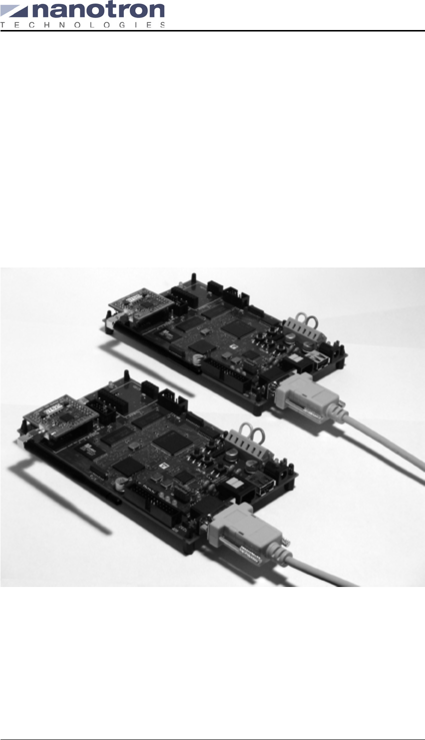
Figure 1: RF Performance Evaluation Kit hardware
The evaluation kit includes:
Two nanoNET TRX RF Test Modules
The nanoNET TRX RF Test Module contains the nanoNET TRX transceiver along with exter-
nal circuitry required for its operation. It provides basic RF functionality including transmission
(TX), and reception (RX), as well as basic digital operations.
Two 2.4 GHz Omnidirectional Antennas
These high-quality sleeve dipole omnidirectional indoor antennas have a frequency range of
2.40 to 2.48 GHz.
nanoNET TRX User Manual (UserMan)
FCC ID: SIFNANONET-TRX
NA-04-0000-0304-1.00 Copyright © 2005 All Rights Reserved
Page 2 Nanotron Technologies GmbH, Alt-Moabit 61, 10555 Berlin, Germany
Two nanoNET MCF Microcontroller Boards
The nanoNET MCF Microcontroller board provides an effective platform for the evaluation of
the nanoNET TRX chip, as it uses Motorola’s ColdFire® MCF5272 Integrated Microproces-
sor, an IC ideally suited for getting the highest performance out of the nanoNET TRX chip.
Note: The MCF boards have been preflashed with the RFPAT firmware required for use with
the RFPAT user interface and is, therefore, ready for use.
Two RS232 Serial Cables
These are used to connect the MCF boards to one or two PCs using the RS232 ports.
Software CD
This CD contains the nanoNET RF Performance Analysis Tool (RFPAT) and related configu-
ration files. The RFPAT application can be used to perform a wide range of tests, including
basic RF packet transmission and reception demonstrations, interference testing, and coex-
istence tests. Configuration files for the specific chip included on the RF Test Module are pro-
vided.
nanoNET TRX RF Performance Evaluation Kit Quick Start Guide
The nanoNET TRX RF Performance Evaluation Kit Quick Start Guide provides basic instruc-
tions for setting up and running the kit. This User Manual provides a description of the basic
and advanced tasks that can be performed using RFPAT software in conjunction with the
included MCF boards and the RF Test Modules.
FCC certification is valid only for the complete Evaluation Kit. To use components of
the Evaluation Kit individually, such as the RF Test Module, the user is responsible
for obtaining a separate grant from the FCC.
nanoNET TRX User Manual (UserMan)
FCC ID: SIFNANONET-TRX
Copyright © 2005 All Rights Reserved NA-04-0000-0304-1.00
Nanotron Technologies GmbH, Alt-Moabit 61, 10555 Berlin, Germany Page 3
2. nanoNET TRX RF Test Module Version 5
The nanoNET TRX RF Test Module Version 5 contains the nanoNET TRX (48 pin) transceiver
along with external circuitry required for its operation. It provides RF functions, including modula-
tion, transmission (TX), and reception (RX), as well as basic digital operations.
Each block of the RF Test Module Version 5 is described in the following sections.
nanoNET TRX (48 Pin) Transceiver (48 pin)
The nanoNET TRX transceiver has extremely low power consumption, operates over a wide
range of temperatures, and performs effortlessly in robust wireless networks operating in the
2.45 GHz ISM band. The new transmission technology Chirp Spread Spectrum (CSS) devel-
oped by Nanotron has up and down chirps with a symbol duration of Tsymbol = 1 µs and an
effective bandwidth of Bchirp = 64 MHz. The chip offers three different data rates: 500 kbps, 1
Mbps, and 2 Mbps.
Note: The RF Test Module Version 5 includes a preproduction phase nanoNET TRX Chip
and does not conform in all points to the nanoNET TRX Chip specifications.
SMA Connector
The SMA connector is used to connect a 50 Ω antenna to the RF Test Module.
Impedance Matching Circuits
At the RF interface of the TRX, there is a differential impedance of 150 Ω, which is matched to
the unsymmetrical (single ended) 50 Ω impedance of the SMA connector by a 150 Ω / 50 Ω
RF balun. Additional external components at the RF interface have a power and noise match-
ing function that allows a sharing of the antenna without an external RX/TX – RF switch.
CDDL - Complementary Dispersive Delay Line
The CDDL is a highly sophisticated SAW filter which incorporates two filters within a single
device. Within the nanoNET system, the SAW Filter is responsible for distinguishing between
two possible incoming signals that are generated by another nanoNET transceiver. This
received signal is either an up-chirp, a down-chirp, or a folded pulse (up-chirp and down-chirp
at the same time). All of these signals have the same center frequency and the same band-
width. The difference between an up-chirp and a down-chirp occurs only in the phase infor-
mation of the complete spectrum. This phase information is enough for the CDDL to
compress a pulse at one output port and expand it at the other (that is, to extend the incoming
nanoNET TRX User Manual (UserMan)
FCC ID: SIFNANONET-TRX
NA-04-0000-0304-1.00 Copyright © 2005 All Rights Reserved
Page 4 Nanotron Technologies GmbH, Alt-Moabit 61, 10555 Berlin, Germany
signal to the doubled duration). In this way the CDDL acts like a matched filter for one of the
possible transmitted pulses.
32768 Hz Quartz
The 32768 Hz Quartz is used for the real time clock oscillator.
16 MHz Quartz
The 16 MHz Quartz provides a frequency reference for the Local Oscillator and for other digi-
tal activities in the chip.
EEPROM
This memory is used for storing basic parameters for the nanoNET TRX transceiver and for
storing the ID of the chip.
Connectors
Two connectors are provided to mount the RF Test Module Version 5 on an either an Evalua-
tion Board or an Adapter Board. These connectors provide to the RT Test Module a regulated
3.3 V power supply as well as control signals and data.
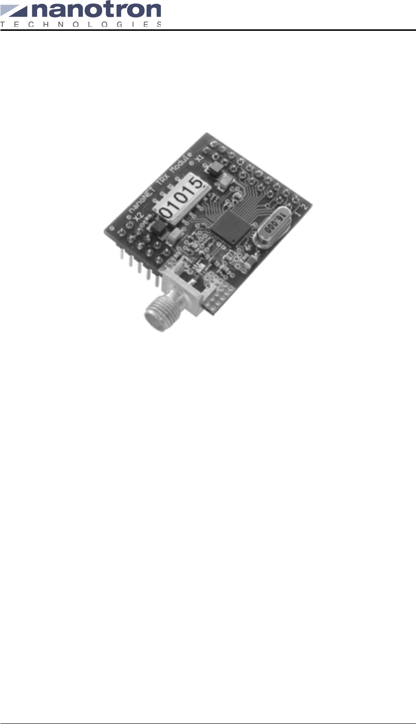
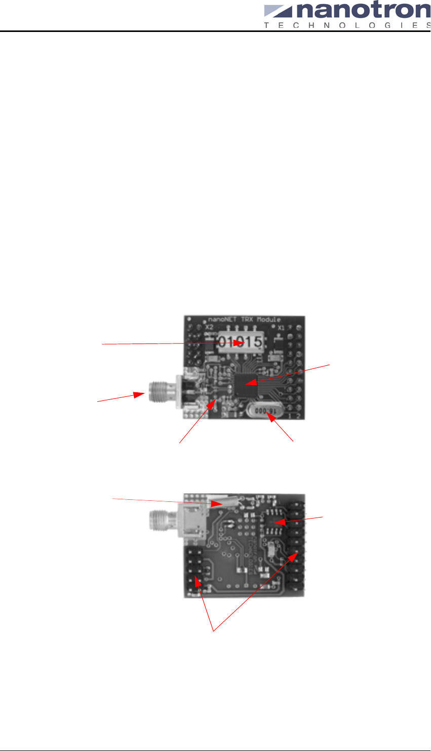
Figure 2: RF Test Module Version 5
nanoNET TRX
SMA Connector
RX/TX input/output
CDDL
Impedance matching
circuits
(48 Pin) IC
Connectors
16 MHz Quartz
EEPROM
Top side
Bottom side
32768 Hz Quartz
nanoNET TRX User Manual (UserMan)
FCC ID: SIFNANONET-TRX
Copyright © 2005 All Rights Reserved NA-04-0000-0304-1.00
Nanotron Technologies GmbH, Alt-Moabit 61, 10555 Berlin, Germany Page 5
3. nanoNET TRX RF Test Module Version 12
The nanoNET TRX RF Test Module Version 12 contains the nanoNET TRX (44 pin) transceiver
along with external circuitry required for its operation. It provides basic RF functionality including
transmission (TX), and reception (RX), as well as basic digital operations.
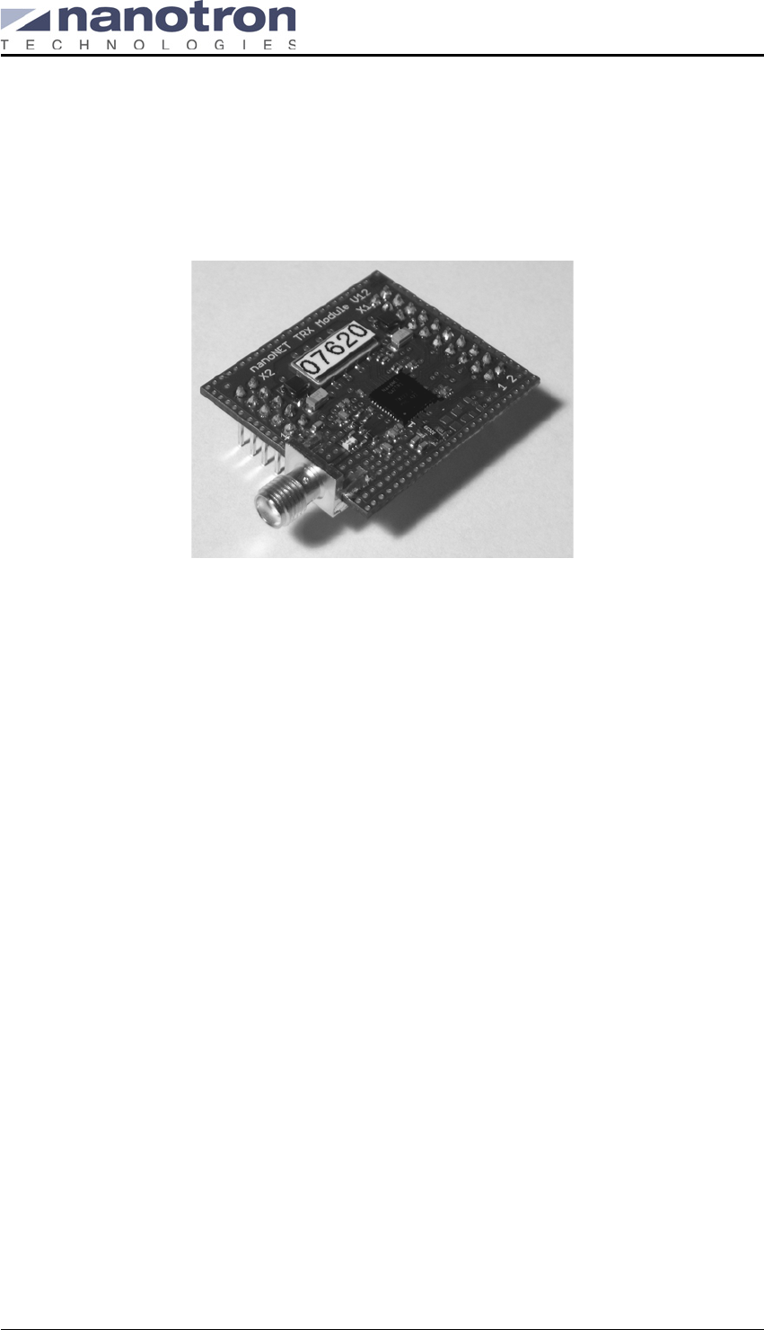
Figure 3: nanoNET TRX RF Test Module (Ver. 12)
The nanoNET TRX RF Test Module consists of the following components:
nanoNET TRX Transceiver (44 pin)
The nanoNET TRX transceiver has extremely low power consumption, operates over a wide
range of temperatures, and performs effortlessly in robust wireless networks operating in the
2.45 GHz ISM band. The new transmission technology Chirp Spread Spectrum (CSS) devel-
oped by Nanotron Technologies has up and down chirps with a symbol duration of Tsymbol = 1
µs and an effective bandwidth of Bchirp = 64 MHz. The chip offers three different data rates:
500 kbps, 1 Mbps, and 2 Mbps.
SMA connector (RX/TX input/output)
The SMA connector is used to connect a 50 Ω antenna to the RF Test Module Version 12.
Impedance Matching Circuits
At the RF interface of the TRX, there is a differential impedance of 150 Ω, which is matched to
the unsymmetrical (single ended) 50 Ω impedance of the SMA connector by a 150 Ω / 50 Ω
RF balun. Additional external components at the RF interface have a power and noise match-
ing function that allows a sharing of the antenna without an external RX/TX – RF switch.
CDDL – Complementary Dispersive Delay Line
The CDDL is a highly sophisticated SAW filter which incorporates two filters within a single
device. Within the nanoNET system, the SAW Filter is responsible for distinguishing between
two possible incoming signals that are generated by another nanoNET transceiver. This
received signal is either an up-chirp, a down-chirp, or a folded pulse (up-chirp and down-chirp
at the same time). All of these signals have the same center frequency and the same band-
width. The difference between an up-chirp and a down-chirp occurs only in the phase infor-
mation.This phase information is enough for the CDDL to compress a pulse at one output port
and expand it at the other (that is, to extend the incoming signal to the doubled duration). In
this way the CDDL acts like a matched filter for one of the possible transmitted pulses.
nanoNET TRX User Manual (UserMan)
FCC ID: SIFNANONET-TRX
NA-04-0000-0304-1.00 Copyright © 2005 All Rights Reserved
Page 6 Nanotron Technologies GmbH, Alt-Moabit 61, 10555 Berlin, Germany
32768 Hz Quartz
The 32768 Hz Quartz is used for the real time clock oscillator.
16 MHz Quartz
To provide the required 16 MHz, the RF Test Module uses either a 16 MHz Quartz or a 16
MHz external oscillator, depending on the chip used. Modules with the 16 MHz Quartz use the
internal oscillator circuitry and can operate within a range of between 0°C to 85°C. Modules
with the 16 MHz Quartz external oscillator do not use the internal oscillator circuitry and can
operate within a range of -40°C to 85°C.
Connectors
Two connectors are provided to mount the RF Test Module on an either an Evaluation Board
or an Adapter Board. These connectors provide to the Test Module a regulated 3.3 V power
supply as well as control signals and data.
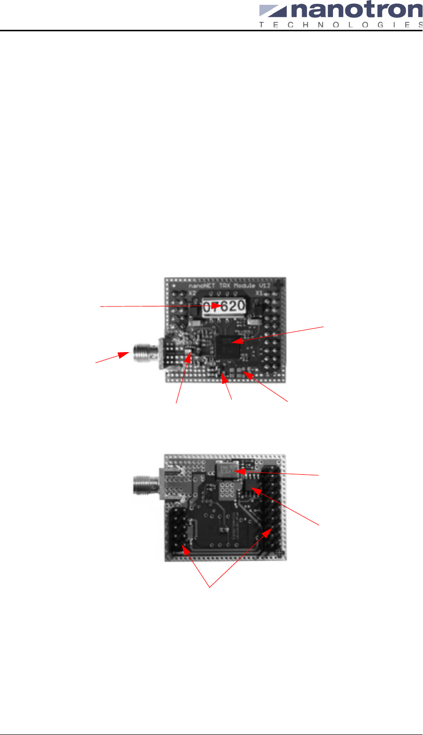
Figure 4: nanoNET TRX RF Test Module (Version 12) Components
nanoNET TRX
SMA Connector
RX/TX input/output
CDDL
Impedance matching
circuits
transceiver
Connectors
Pads for 16 MHz
Quartz
Top side
Bottom side
32768 Hz
Quartz
16 MHz external
EEPROM
oscillator
nanoNET TRX User Manual (UserMan)
FCC ID: SIFNANONET-TRX
Copyright © 2005 All Rights Reserved NA-04-0000-0304-1.00
Nanotron Technologies GmbH, Alt-Moabit 61, 10555 Berlin, Germany Page 7
4. nanoNET MCF Microcontroller Board
The nanoNET MCF Microcontroller Board is designed to be used with the nanoNET TRX RF
Test Modules for evaluating the RX and TX of the nanoNET TRX transceiver. It supports up to
two RF Test Modules for wireless communication as well as supporting baseband communica-
tion for application testing free of interference from wireless transmissions. The MCF board
includes a 66 MHz Motorola ColdFire© microcontroller, 32 MB RAM, 2 MB flash memory, two
ADCs with two analogue input channels, a DAC with two analogue output channels, a power
supply block, and a wide range of interfaces.
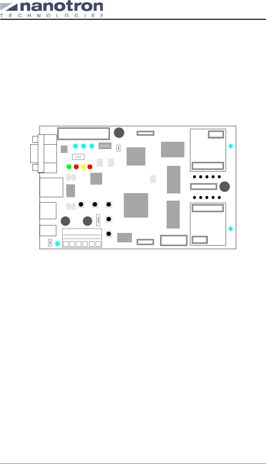
Figure 5: MCF Microcontroller board component locations
The nanoNET MCF Microcontroller Board consists of following components:
Motorola ColdFire© Microcontroller
The Motorola ColdFire© microprocessor MCF5272, clocked at 66 MHz, is based on a vari-
able-length RISC processor with a 32-bit address bus and a 32-bit data bus. A 2 MByte boot
flash as well as a 32 MByte SDRAM are provided as external components on the board.
Xilinx FPGA
The MCF board provides an FPGA (Field Programmable Gate Array) to extend the microcon-
troller bus structure for add on applications using connectors X7a and X7b.
Connector X1 (Power Supply Jack)
This 2.1 mm barrel connector provides a supply voltage to the board. For details on the power
supply for the MCF board, see "Power Supply" on page 11.
Connector X2 (USB)
The MCF board provides a USB interface (full speed specified by version 1.1). The USB inter-
face is not used for the Evaluation Kit.
Connector X3 (Ethernet 10/100BASE TX)
The MCF Board provides a 10/100BASE TX Ethernet interface to use, for example, to con-
nect to boards for a fast wired communication channel or to a network if a TCP/IP stack is part
of the software. The Ethernet interface is not used for the Evaluation Kit
TX_RX
JP4
X8a
X8b
X10a
X10b
TX_RX
X7a
Module 1
Module 2
X9
TX_RX1
MISO
MOSI
SPISS2
µCVCC1
SPISS1
/INT
µCRESE
PWRUPR
SPICLK
X7b
X11
X6
BDM
CFG3 CFG2 CFG1
L3
L2 L1
L0
X4
X3
X2
X1 PWR
JP1
Reset
MK1
K2
K3
JP2
JP3
RS232
connector
Ethernet
connector
USB
connector
Power
connector
BDM
connector
Te r m i n al
blocks
Socket one
for RF Module
Socket two
for RF Module
SPI Bus con-
nector
Digital I/O
Add-on application
connector
1
RS232
Ethernet
USB
Coldfire
MCF5722
Xilinix
FPGA
flash
memory
RAM
memory
RAM
memory
1
1
DIP
switch
nanotron
TECHNOLGOGIES
Add-on application
connector
X5
nanoNET TRX User Manual (UserMan)
FCC ID: SIFNANONET-TRX
NA-04-0000-0304-1.00 Copyright © 2005 All Rights Reserved
Page 8 Nanotron Technologies GmbH, Alt-Moabit 61, 10555 Berlin, Germany
Connector X4 (RS232 Serial Interface)
The MCF board provides an RS232 serial interface for connecting to a serial port of a PC.
The UART1 of the controller uses an external driver that provides RS232 compatibility for
connection of terminal.
Connector X5 (Terminal Blocks)
This power supply using a CAGE CLAMP® (series 236) provides an alternate power supply
for the board. See Table 1: "MCF board power supply guidelines" on page 5–11 for minimum
and maximum voltage requirements for the board. The polarity of the terminal blocks are
shown below:
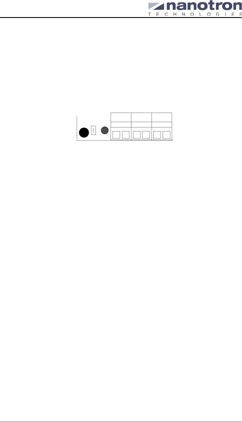
Figure 6: Connector X5 (Terminal Blocks)
The analogue and digital 3.3 V supply voltages of the RF Test Module mounted on connec-
tors X8a and X8b are fed separately from connector X5 to connector X8a so that both cur-
rents of the module can be measured. Connect the Ampere meter between pins 3 and 4 to
measure the power supply current of the digital part of the TRX chip, and between pins 5 and
6 for the power supply current of the analogue part of the TRX chip.
In normal operation, both pins 3 and 4 and pins 5 and 6 must be shorted.
Connector X6 (BDM for Flash Memory and MCF5272 Debugging)
The MCF board provides a BDM connector that can be used to program the flash memory as
well as to run the MCF5272 microcontroller in debug mode. A special adapter is required to
interface between a parallel port cable connected to a standard IBM PC parallel port (DB25
female connector) on the PC and the BDM connector on the MCF board. The BDM is not
used for the Evaluation Kit.
Note: The RF Performance Evaluation Kit does not include a development environment nor
an adapter to connect a parallel port cable to the BDM connector. Contact a Nanotron
Technologies sales representative for information about the RF Performance Develop-
ment Kit.
Connectors X7a and X7b (add-on application board)
The MCF board provides an interface for extending the microcontroller bus structure for fur-
ther applications, such as an LCD matrix display. The Evaluation Kit does not require an add-
on application and, therefore, X7a and X7b are, therefore, not used.
Connectors X8a and X8b (Digital I/O signals of Module 1)
The nanoNET TRX RF Test Modules included in the Evaluation Kit are mounted on these
interfaces (labeled Module 1) on each MCF board. Connector X8a provides a supply power
to the RF Test Module, while connector X8b provides signals between the RF Test Module
and the MCF5272 ColdFire© microprocessor.
Note: Do not mount the RF Test Module on the set of connectors X10a and X10b (labeled
Module 2) as they are not used in the Evaluation Kit.
Connector X9 (ADC and DAC)
This user-definable connector provides two ADCs (analogue to digital converter) creating two
analogue input channels, a DAC (digital to analogue converter) with two analogue output
channels. This connector is not used in the Evaluation Kit.
–+3456
PWR
JP4

nanoNET TRX User Manual (UserMan)
FCC ID: SIFNANONET-TRX
Copyright © 2005 All Rights Reserved NA-04-0000-0304-1.00
Nanotron Technologies GmbH, Alt-Moabit 61, 10555 Berlin, Germany Page 9
Connector X10a and X10b (Digital I/O signals of Module 2)
This second set of connectors (labeled Module 2) is provided for a second RF Test Module
or for an SPI interface and is used in a development environment only. These connectors are
not used with the Evaluation Kit. If an RF Test Module is mounted on the MCF board using
these connectors, an error will be generated.
Connector X11 (Digital I/O)
This connector is used to transmit digital I/O signals from/to RF Test Module(s). Its voltage
level is 3.3 V and it is not buffered. It can be used to provide a baseband connection without
RF interference. It is used primarily for testing applications and is not used for the Evaluation
Kit.
Status Indication LEDs
The LEDs CFG1, CFG2, and CFG3 provide a boot up status indication. During boot up, all
three LEDs (CFG1, CFG2, CFG3) are illuminated briefly to indicate that the boot up was suc-
cessful. They are also used as error indicators. If a few seconds after boot up, they begin to
start flashing intermittently, then the MCF board needs to be rebooted. The boot process can
be restarted by pushing the Reset button to restart. They can also be configured by software
to provide an indication of the status of the Ethernet controller during board operation. They
are configured for this purpose for the Evaluation Kit.
LEDs L0, L1, L2, L3 are used as error indicators. If a few seconds after boot up, they begin to
continuously blink 5 times per second, the likely cause is that an RF Test Module has been
placed in the wrong socket. Reinstall the RF Test Module in connectors X8a and X8b
(Module 1). Also, after the MCF board has booted up, LED L3 will flash continually indicat-
ing the board is operating. These LEDs are also part of the user interface for the Coldfire©
microcontroller and can be configured by software as user-definable status indications.
Except LED3, they are not configured for the Evaluation Kit.
The power indication LED (PWR) will be illuminated to indicate a correct power supply has
been attached to the board, either in the Power Supply Jack (X1) or in the Terminal Blocks
(X5). The TX_RX LEDs indicates an RF Module is transmitting or receiving data. It is switched
off by default. To enable this LED, check the RfTxExtPampOutEn register in the more set-
tings dialog. See "Viewing Chip Register Settings" on page 33 for details.
Jumpers
The MCF board provides a number of jumpers for taking measurements, changing settings,
or giving access to I/O lines:
Jumper 1 is used (closed as default) to connect the appropriate ports of the controller to
the LEDs. Otherwise these ports can be used for another purpose instead of the LEDs.
Jumper 2 (default is opened) is the parallel connection of the appropriate ports of the con-
troller to the key buttons (K1, K2, M1 and M2). They can also be used for another purpose
instead of key buttons if desired.
Jumper 3 (default is opened) is the output of the Pulse Width Modulator, it can be con-
nected to a speaker for example.
Jumper 4 is (default is closed) used to measure the load current of the ColdFire board.
In the Evaluation Kit, the default settings are used.
Key Buttons
The MCF board provides a set of five key buttons (labeled RESET, M, K1, K2 and K3). The
RESET button is used to reset the microprocessor in the event of an error during boot up. The
remaining four are software configured and not used for the Evaluation Kit.

nanoNET TRX User Manual (UserMan)
FCC ID: SIFNANONET-TRX
NA-04-0000-0304-1.00 Copyright © 2005 All Rights Reserved
Page 10 Nanotron Technologies GmbH, Alt-Moabit 61, 10555 Berlin, Germany
nanoNET TRX User Manual (UserMan)
FCC ID: SIFNANONET-TRX
Copyright © 2005 All Rights Reserved NA-04-0000-0304-1.00
Nanotron Technologies GmbH, Alt-Moabit 61, 10555 Berlin, Germany Page 11
5. Using the RF Performance Evaluation Kit
For a smooth operation of the Evaluation Kit, two computers that have RS232 connector ports
(or one computer with two RS232 connector ports) are required with both running Microsoft®
Windows® 2000 or XP operating system and each having a minimum of 5MB hard disk space.
Also, a power supply is required, either as a 2.1 mm barrel connector or as a bare wire for use
with the board’s terminal block.
5.1. Power Supply
The power supply is provided by either connector X1 or x5 (see "nanoNET MCF Microcontroller
Board" on page 7). The MCF board provides connectors (X7a and X7b) for an external periph-
eral device such as an LED display, although the Evaluation Kit does not include an external
device. Nevertheless, the following guidelines should be followed when providing a power supply
for the board.
Warning: Recommended voltage for the Evaluation Kit without the use of an external device is
7.5 V as a higher voltage will generate heat due to power dissipation.
A lower supply voltage is preferable as higher supply voltages cause the voltage regulator to
heat up.The polarity of the inner connector is positive.
The board provides three supply voltages: 3.3 V, 1.8 V and 5 V. The microcontroller and the
nanoNET TRX RF Test Modules operate at 3.3 V while the core voltage of the FPGA is 1.8 V. A
5 V supply is fed to the external connectors X7a and X7b for add-on applications.
As soon as the external supply voltage is applied, the power LED is illuminated.
5.2. Flash Software
The MCF Boards have been pre-flashed with the RFPAT flash software for use with the RF Per-
formance Evaluation Tool.
5.3. Setting Up the MCF Boards
Warning: Since the Coldfire Microprocessor does not boot when the RX line on the serial (D-
Sub 9) connector has a voltage level above 1.3 Volts, connect the RS232 serial cable
AFTER the board has finished its boot sequence and the LED L3 begins to continu-
ously blink indicating a successful boot-up.
It is important that the steps described below be followed precisely to bring the MCF Boards up to
a running state.
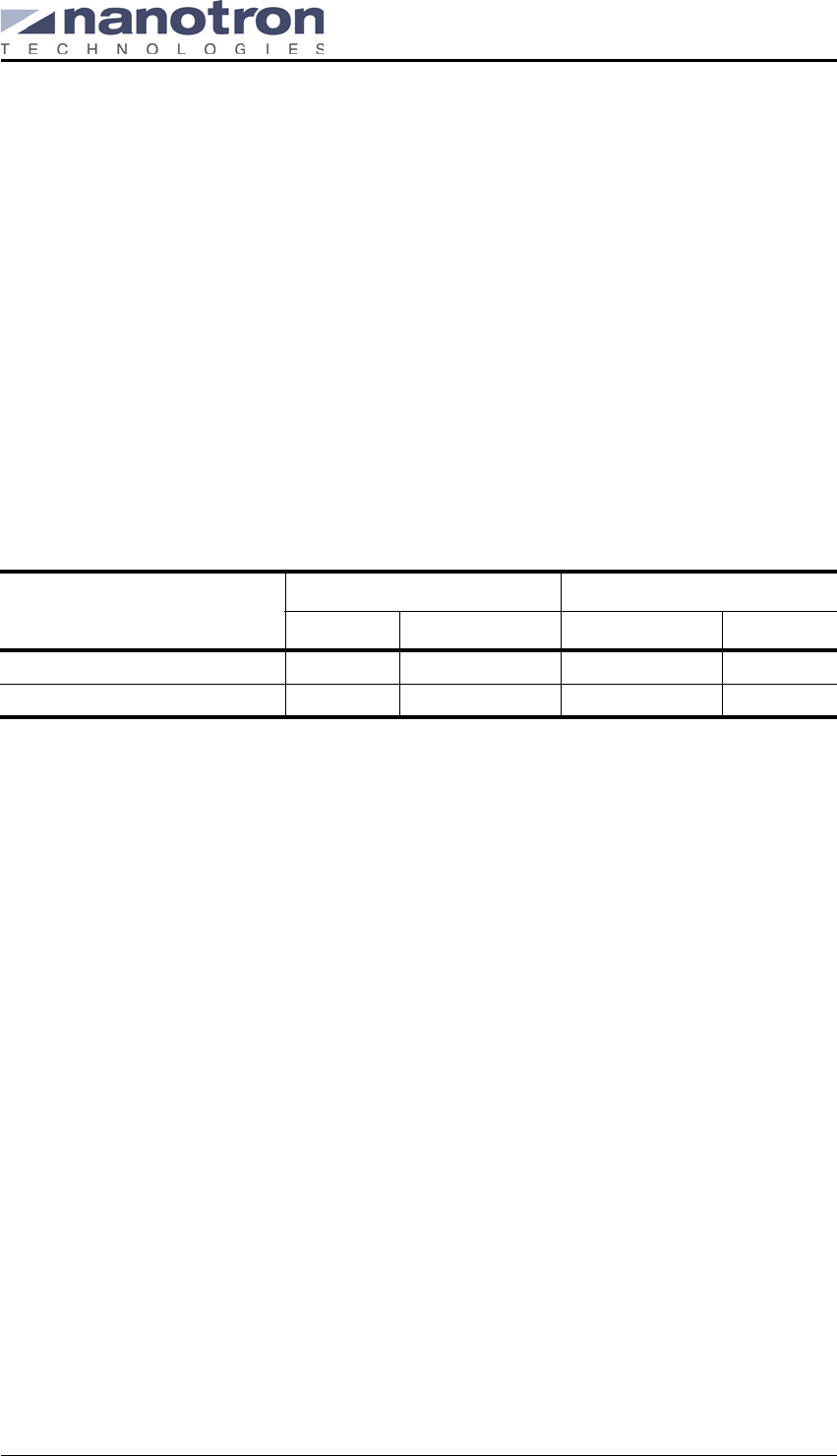
Table 1: MCF board power supply guidelines
Operating Mode
Minimum Maximum
Absolute Recommended Recommended Absolute
Without external device 4.5 V 4.8 V 6 V 9 V
With external device 6.2 V 6.5 V 7.5 V 9 V
nanoNET TRX User Manual (UserMan)
FCC ID: SIFNANONET-TRX
NA-04-0000-0304-1.00 Copyright © 2005 All Rights Reserved
Page 12 Nanotron Technologies GmbH, Alt-Moabit 61, 10555 Berlin, Germany
For each MCF board:
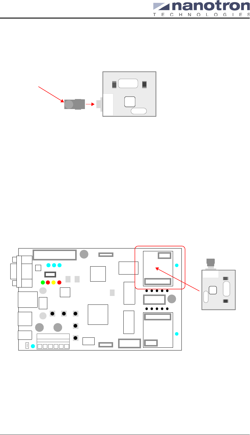
1. Attach to one of the nanoNET TRX RF Test Modules a 2.4 GHz sleeve dipole antenna model
17010.11 that has been provided in the Evaluation Kit.
Figure 7: Attaching antenna to RF Test Module
Warning: To use the Evaluation Kit, you MUST use the antennas that have been provided
with the Evaluation Kit in order to remain within the scope of FCC Certification
for FCC Class A and Class B devices. The usage of any other antenna voids the
users authority to operate the equipment under FCC regulations.
For specifications of the 2.4 GHz sleeve dipole antenna model 17010.11, see
"Antenna Specifications for Model 17010.11" on page 21.
2. Carefully install the RF Test Module onto the MCF board using the two connectors labelled
Module 1 (connectors X8a/b).
Note: The Evaluation Kit uses only one RF Test Module per board and for the kit to operate
correctly, the RF Test Module MUST be mounted on the connectors labelled Module 1
or an error will be generated (LEDs 1 to 4 blinking continuously indicating this error).
Figure 8: Mounting the RF Test Module on the MCF board
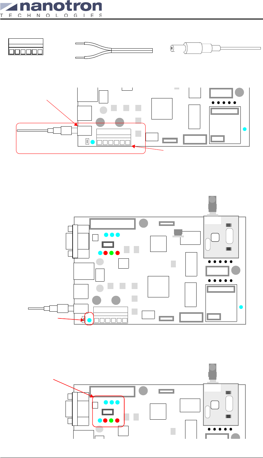
3. Connect the MCF board to an external DC power supply. The guidelines described in Table 1:
"MCF board power supply guidelines" on page 11 should be followed when providing a power
supply for the board.
The MCF board provides two power supply connectors - a 2.1 mm barrel connector (label X1)
as well as terminal blocks (label X5) with CAGE CLAMP® (series 236). The terminal blocks
(maximum 2.5mm2 conductor) can be used when a reliable power supply connection is
required. The polarity of the power supply is as shown.
nanoNET TRX Module_v12
X2 X1
2.4 GHz antenna
nanoNET MCF µC
nanoNET TRX Module_v11
X2 X1
Module 1Module 2
Assembled
TRX RF Test Module
nanoNET TRX User Manual (UserMan)
FCC ID: SIFNANONET-TRX
Copyright © 2005 All Rights Reserved NA-04-0000-0304-1.00
Nanotron Technologies GmbH, Alt-Moabit 61, 10555 Berlin, Germany Page 13
Figure 9: Terminal blocks, barrel connector and power supply options
Figure 10: Connecting the barrel connector power supply
4. Once the power supply has been provided, the Power LED will illuminate to indicate the board
has been powered up. It then begins its boot up process.
Figure 11: Power supply indicator
5. After a period of a few seconds, three LEDs (CFG1, CFG2, CFG3) will illuminate briefly to indi-
cate that the Ethernet controller has been initialized.
Figure 12: MCF board LEDs
+–
+
–
red
black
+–
Terminal Blocks Barrel connectorBare wire
pwr
+–
X5
X1
To Power supply
Terminal blocks
2.1 mm barrel connector
Socket 1
nanoNET TRX Module_v11
X2 X1
pwr
power LED
nanoNET MCF µC
Socket 1
nanoNET TRX Module_v1
X2 X1
MCF LEDs
CFG3CGG2 CFG1
L3 L2 L1
L0
nanoNET MCF µC
nanoNET TRX User Manual (UserMan)
FCC ID: SIFNANONET-TRX
NA-04-0000-0304-1.00 Copyright © 2005 All Rights Reserved
Page 14 Nanotron Technologies GmbH, Alt-Moabit 61, 10555 Berlin, Germany
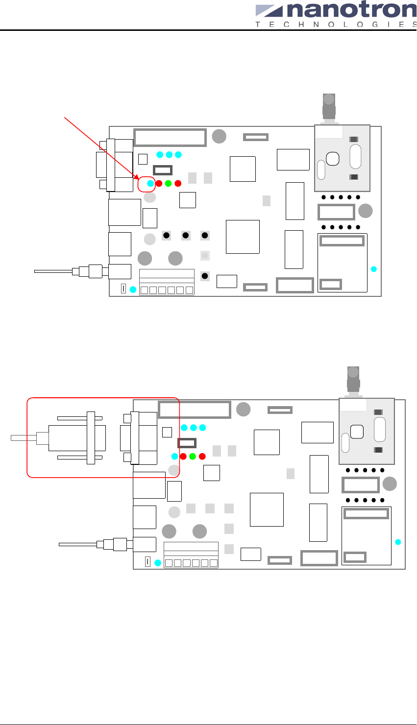
6. Once the MCF board has been successfully booted up, LED L3 will flash continually indicat-
ing the board is operating.
Figure 13: Running indicator (LED 3)
7. Finally, connect a 9-pin RS232 cable to the RS232 connector on the MCF board (label X4)
and to a RS232 serial port on a computer running either Microsoft® Windows® 2000 or XP.
Figure 14: Connecting the RS23 cable to the MCF board
Repeat this procedure with the second MCF board and then launch the RF Performance Evalua-
tion Tool. See "Installing the RF Performance Analysis Tool" on page 15.
5.4. Error Indications
A number of conditions will generate an error, the most common of which is the nanoNET TRX
RF Test Module installed in the wrong socket on the MCF board. To indicate this and any other
error condition, the MCF board causes the LEDs (L0, L1, L2, L3) to blink continuously.
Socket 1
nanoNET TRX Module_v1
X2 X1
Running LED
L3
nanoNET MCF µC
Socket 1
nanoNET TRX Module_v11
X2 X1
RS232
X4
To RS232 Serial Port on
computer
nanoNET MCF µC

nanoNET TRX User Manual (UserMan)
FCC ID: SIFNANONET-TRX
Copyright © 2005 All Rights Reserved NA-04-0000-0304-1.00
Nanotron Technologies GmbH, Alt-Moabit 61, 10555 Berlin, Germany Page 15
To resolve this error condition:
1. Disconnect from power supply and the RS232 cable from the MCF board before attempting
any troubleshooting.
2. Ensure that the RF Test Module is installed in the socket labeled Module 1.
3. Reconnect the power supply as in step 3 in "Setting Up the MCF Boards" on page 11.
4. If the MCF board continues to show an error condition (LEDs blinking continuously), then
push the Reset button to restart the boot process.
The power LED and LEDs (CFG1, CFG2, CFG3) will illuminate briefly to indicate that the boot up
was successful.
5. Reconnect the RS232 cable.
5.5. Installing the RF Performance Analysis Tool
To install the RF Performance Analysis Tool:
1. Copy to a destination directory, for example, C:\RFPAT\, (on both PCs if two PCs are to be
used) the RF Performance Analysis Tool (RFPAT) executable (RFPAT.exe) from the nanoNET
RF Evaluation Kit CDROM.
2. Ensure that the two MCF boards are connected to the RS232 ports.
3. Launch two instances (two on one PC or one each on two PCs) of the RFPAT software by
running rfpat.exe.
For details on using the RFPAT software, see "RF Performance Analysis Tool" on page 17.
5.6. Shutting Down an MCF Board
To safely shut down the MCF board:
1. Close the RFPAT applications running on the MCF boards.
2. Disconnect the power supply and the RS232 cables from the boards.
3. Disconnect the antennas from the nanoNET TRX RF Test Modules.
4. Carefully remove the nanoNET TRX RF Test Module from the MCF boards.
5. Store the Evaluation Kit hardware in ESD protection bags.

nanoNET TRX User Manual (UserMan)
FCC ID: SIFNANONET-TRX
NA-04-0000-0304-1.00 Copyright © 2005 All Rights Reserved
Page 16 Nanotron Technologies GmbH, Alt-Moabit 61, 10555 Berlin, Germany
nanoNET TRX User Manual (UserMan)
FCC ID: SIFNANONET-TRX
Copyright © 2005 All Rights Reserved NA-04-0000-0304-1.00
Nanotron Technologies GmbH, Alt-Moabit 61, 10555 Berlin, Germany Page 17
6. RF Performance Analysis Tool
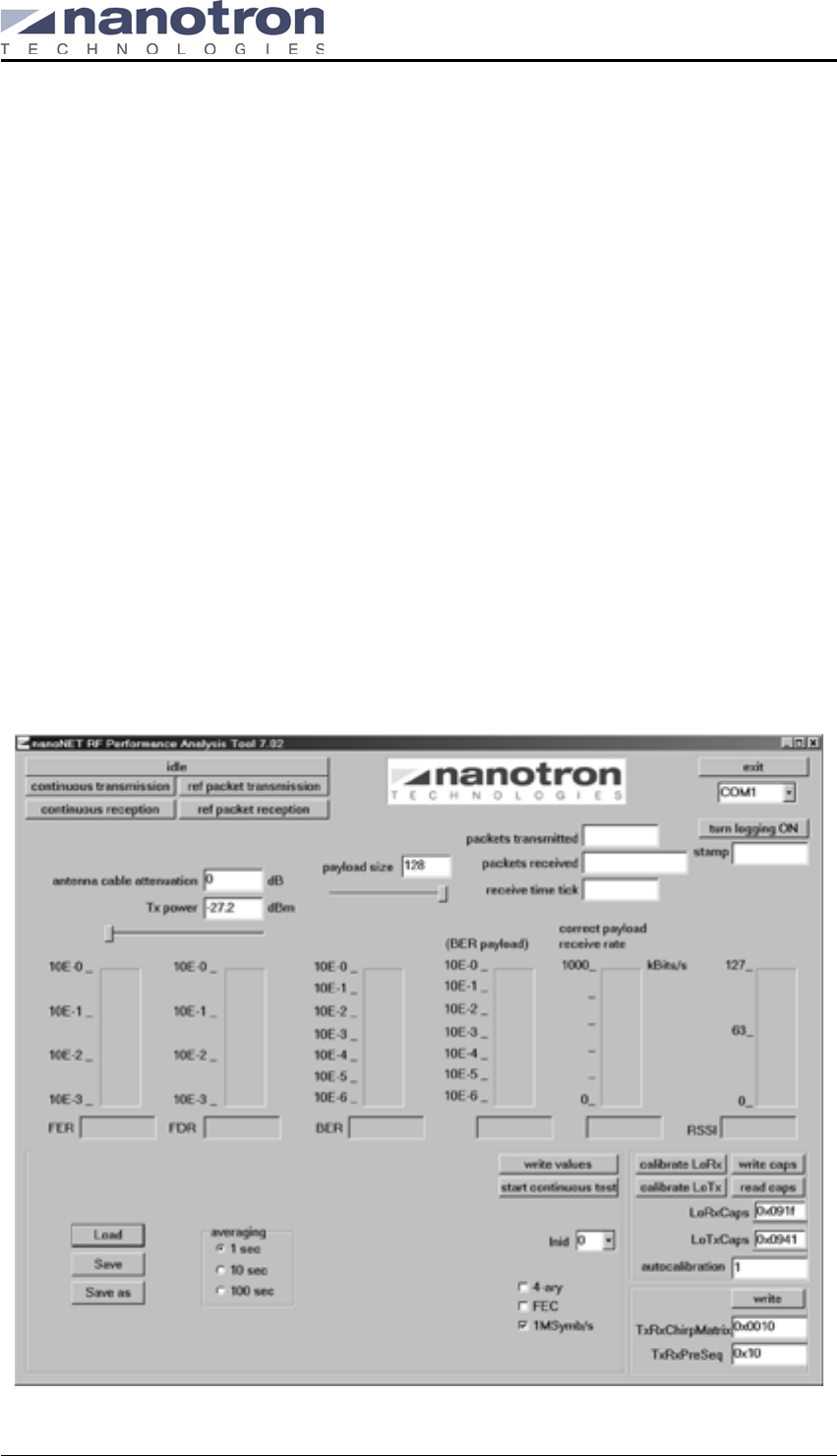
The RF Performance Analysis Tool (RFPAT) provides a convenient means of evaluating the
wireless link between two stations. It does so by evaluating the RF performance of the nanoNET
TRX hardware. It enables the user to perform short and long term measurements of several
types of error rates for different nanoNET TRX register configurations. And since the RFPAT
application is also used for internal chip evaluation purposes, it gives access to many TRX chip
registers that are not used for common operations.
The RFPAT application cannot be expected to demonstrate all features of the nanoNET TRX
transceiver. In fact, only a small fraction of features are used while many others remain
untouched, such as CSMA, RTS/CTS, real time clock, time beacon packets, TDMA mode, pack-
ets longer than 128 bytes, and so on.
The RFPAT tool consists of two parts:
Firmware portion flashed onto the MCF Microcontroller Board
This program accesses the nanoNET TRX hardware. It performs the transmission and recep-
tion of packets and updates a variety of statistic counters. The two MCF boards included in
the kit have been pre-flashed with the firmware portion of the tool.
Executable and a configuration file provided on the software CD
The executable RFPAT.exe is a GUI that runs on a Windows® PC. It sends commands to the
MCF Microcontroller Board, reads the statistic counter values, calculates and averages the
values and rates to be displayed, and then formats them appropriately.
Figure 15: RF Performance Analysis Tool Version 7.02
nanoNET TRX User Manual (UserMan)
FCC ID: SIFNANONET-TRX
NA-04-0000-0304-1.00 Copyright © 2005 All Rights Reserved
Page 18 Nanotron Technologies GmbH, Alt-Moabit 61, 10555 Berlin, Germany
6.1. Preparing for RF Evaluation
Once the Evaluation Kit has been assembled and connected to a PC(s), prepare the RFPAT
application for RF evaluations as follows:
1. Start two instances of the RFPAT application, one for each TRX transceiver connected to the
MCF board.
2. Load the configuration files and verify that the settings have been written to each of the trans-
ceivers.
3. Select a test mode on the TX station.
4. Select a test mode on the RX station.
5. Perform the evaluation.
These steps are described in detail in the remainder of this document.
6.2. Starting the RFPAT Application
It is assumed in this section that the hardware of the Evaluation Kit has been set up and running
properly. If not, refer to the document nanoNET TRX RF Performance Evaluation Kit Quick Start
Guide for set up procedures.
To start up the RFPAT application
1. Ensure that the Evaluation Kit hardware is powered on and running, as described in "Setting
Up the MCF Boards" on page 11.
The LED L3 should be flashing intermittently on each MCF board indicating both boards are
running properly.
2. Start two instances of the RFPAT application RFPAT.exe (in the RFPAT_702_104 directory) .
The Evaluation Kit requires two sets of stations for the evaluation of RF performance. There-
fore, one instance of the application needs to be running for each of the two MCF boards in
the Kit. Launch a second instance of the application for the second MCF board.
With two applications running, one will serve as a sending station (TX) while the second will
serve as the receiving station (RX).
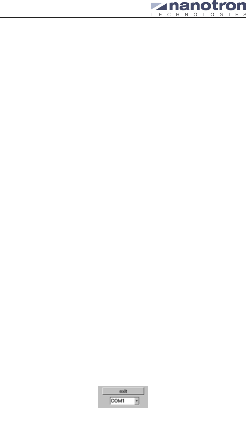
Manually Selecting the COM Ports
Manual setting of the COM port is possible by choosing an available COM port from the drop-
down list.
If a different COM port is required than the one automatically selected by the RFPAT application,
choose an available port from the dropdown list.
On each running RFPAT application, a drop-down list is provided which shows all the available
COM ports on the PC to which one (or both) of the MCF boards via the RS232 cable are con-
nected. When the RFPAT application is launched, it searches for the first free COM port on the
PC and automatically selects that free port. It appears as the port displayed.
Figure 16: COM port drop-down list
nanoNET TRX User Manual (UserMan)
FCC ID: SIFNANONET-TRX
Copyright © 2005 All Rights Reserved NA-04-0000-0304-1.00
Nanotron Technologies GmbH, Alt-Moabit 61, 10555 Berlin, Germany Page 19
6.3. Initializing and Selecting a Chip Register Settings File
The chip register settings file is an ASCII configuration file that provides a set of parameters for
the specific chip on the RF Test Module included in the kit. It also provides additional configura-
tion settings required for the RFPAT application (for example, autocalibration). The file can be
visually inspected, if required, to check which chip register settings are in the file. These same
settings are also displayed in the various fields of the RFPAT application user interface, where
they can be overwritten, if required.
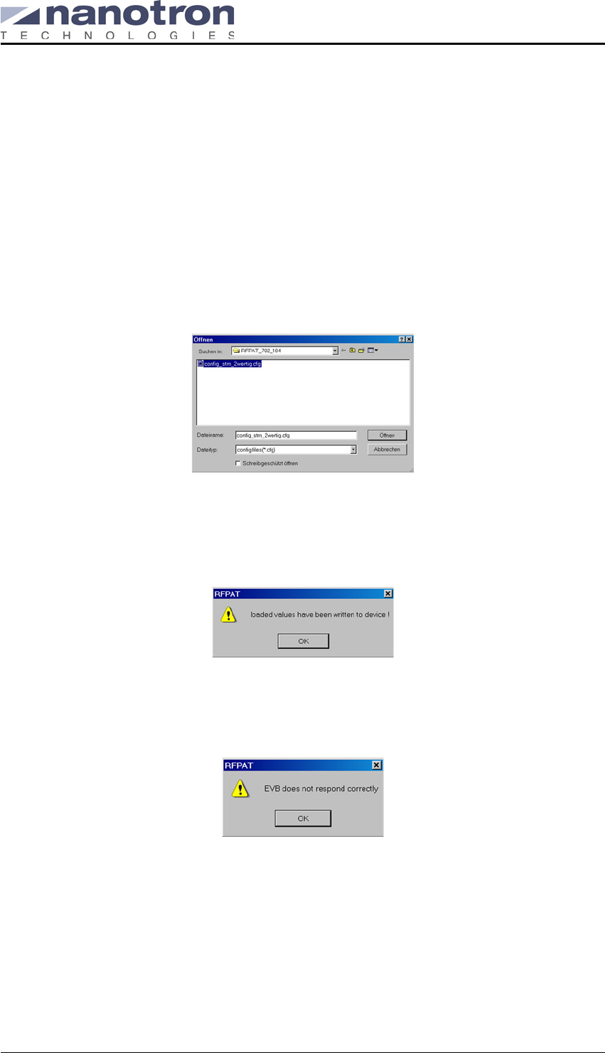
To load the chip register settings file
1. Select the Load button and navigate to the RFPAT directory that contains the configuration
file (same directory as the RFPAT application).
Figure 17: Configuration file
2. Select Open to initialize the chip registers with settings from the configuration file and to con-
figure the RFPAT application. A message should appear indicating the initialization was suc-
cessful.
Figure 18: Configuration load successful message
If the initialization was unsuccessful, a message should appear indicating the MCF Evaluation
Board is not responding correctly.
Figure 19: Configuration load unsuccessful message
Some possible reasons for the error message include no power connection (is the LED L3
flashing?), RS232 cable not connected properly, or the configuration file not compatible with
the chip on the RF Test Module.
3. Click OK to complete the configuration load.
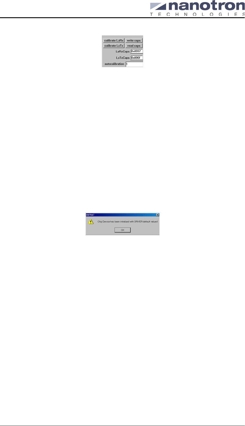
After the values have been written to the chip, the frequency values of the Local Receive
Oscillator Capacitors (LoRxCaps) and Local Transmit Oscillator Capacitors (LoTxCaps) are
read back from the chip and displayed in the RFPAT user interface, as shown below.
nanoNET TRX User Manual (UserMan)
FCC ID: SIFNANONET-TRX
NA-04-0000-0304-1.00 Copyright © 2005 All Rights Reserved
Page 20 Nanotron Technologies GmbH, Alt-Moabit 61, 10555 Berlin, Germany
Figure 20: Local receive and transmit oscillator capacitor settings
This provides a means of verifying that the chip registers have been updated. If the
LoRxCaps and LoTxCaps values are either 0x0000 or 0x0FFF, then the RFPAT firmware
has not properly initialized the chip with the configuration values. In this case, reload the con-
figuration file.
After you have successfully run two instances of the RF Performance Evaluation Tool and initial-
ized the chip with register settings, you are ready to start the measurements. See "Test Modes"
on page 20.
6.4. Initializing Chip with Default Values
Normally, the loading of the configuration file will initialize the chip. However, if the RFPAT appli-
cation attempts to communicate with the chip before the configuration file has been loaded, the
chip will be initialized with default values taken from the firmware. A message should appear indi-
cating this initialization.
Figure 21: Chip initialization with default values message
As with loading the configuration file, after the values have been written to the chip, the fre-
quency values LoRxCaps and LoTxCaps are read back from the chip and displayed in the
RFPAT application.
6.5. Test Modes
The RFPAT application provides a wide range of test modes for evaluating the wireless link.
Continuous Transmission Mode
This mode is used to determine the throughput of the wireless link by measuring the correct
payload receive rate.
Reference Packet Mode
This mode is used for measuring the precise frame error rate, frame drop rate, and bit error
rate at a user-defined TX output power and payload size.
Continuous Chirp Test Mode
This mode is used to determine the chip output power by sending a continuous stream of
chirps that can be measured by laboratory test equipment.
nanoNET TRX User Manual (UserMan)
FCC ID: SIFNANONET-TRX
Copyright © 2005 All Rights Reserved NA-04-0000-0304-1.00
Nanotron Technologies GmbH, Alt-Moabit 61, 10555 Berlin, Germany Page 21
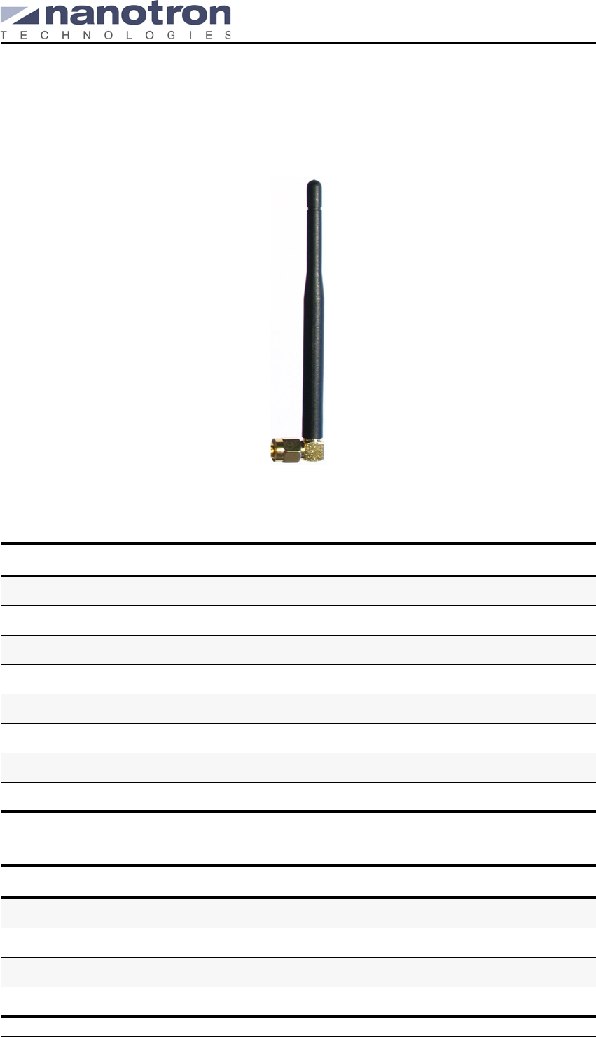
7. Antenna Specifications for Model 17010.11
This section provides the specifications for the antenna used by the nanoNET TRX, namely,
Antenna Model 17010.11, as shown below:
Figure 22: Model 17010.11
Electrical Items Specifications
Model 17010.11
Type of antenna Sleeve dipole antenna
Frequency range 2.40~2.48 GHz
Electrical length 1 / 2 λ
Nominal impedance 50 Ω
Polarization Vertical
V.S.W.R Less than 2.0
Gain 2.15 dBi
Mechanical Items Specifications
Element ø 0.1x7 CuAg -wire
Sleeve Urethane (black)
Connector SMA-male (right angle)
Antenna total length 90 ± 2mm
nanoNET TRX User Manual (UserMan)
FCC ID: SIFNANONET-TRX
NA-04-0000-0304-1.00 Copyright © 2005 All Rights Reserved
Page 22 Nanotron Technologies GmbH, Alt-Moabit 61, 10555 Berlin, Germany
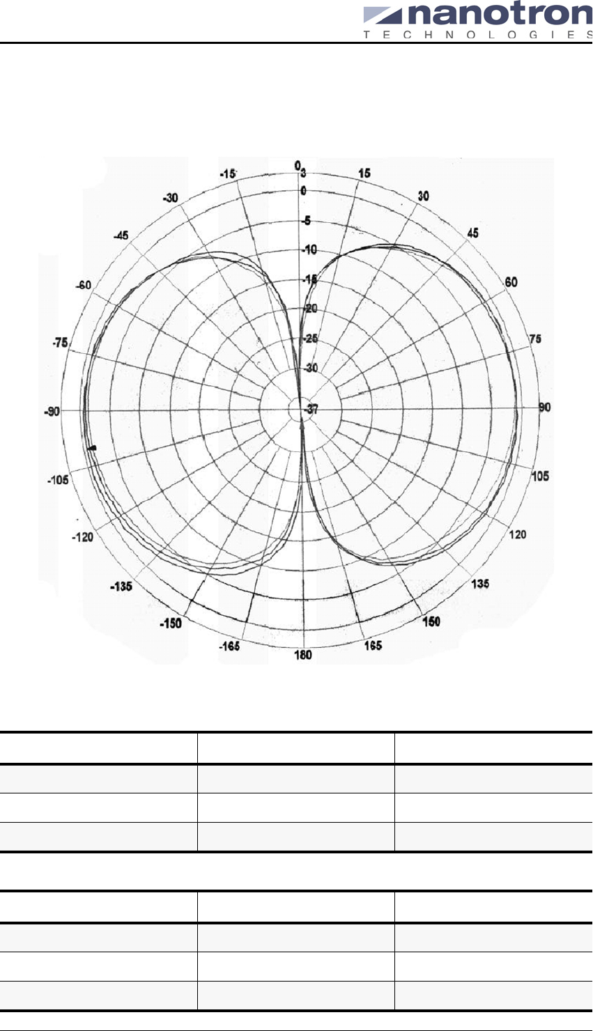
7.1. Vertical Diagram for Model 17010.11
The following shows the vertical diagram for the antenna model 17010.11 measured at
2.40 GHz, 2.45 GHz, and 2.50 GHz
Figure 23: Vertical Diagram for Antenna model 17010.11
Beam Peak Values
Null Depth Values
Frequency [dB] at [deg]
2.40 GHz -0.61 -99.94
2,45 GHz -0.74 81.95
2,50 GHz -0.64 67.96
Frequency [dB] at [deg]
2.40 GHz -38.47 -4.00
2,45 GHz -53.94 -2.00
2,50 GHz -41.44 177.90
nanoNET TRX User Manual (UserMan)
FCC ID: SIFNANONET-TRX
Copyright © 2005 All Rights Reserved NA-04-0000-0304-1.00
Nanotron Technologies GmbH, Alt-Moabit 61, 10555 Berlin, Germany Page 23
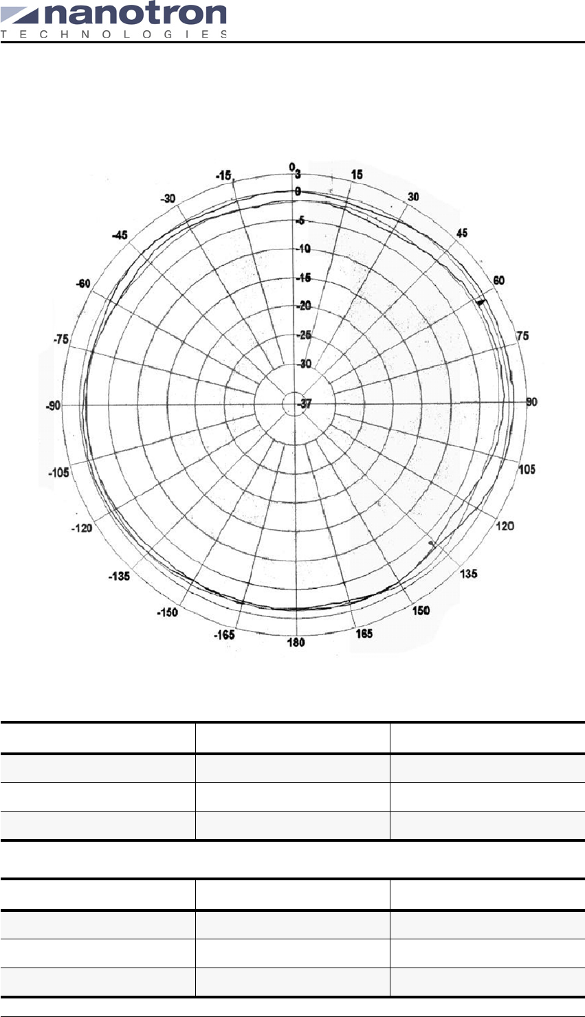
7.2. Azimuth Diagram for Model 17010.11
The following shows the Azimuth diagram for the antenna model 17010.11 measured at
2.40 GHz, 2.45 GHz, and 2.50 GHz
Figure 24: Azimuth Diagram for Antenna model 17010.11
Beam Peak Values
Null depth values
Frequency [dB] at [deg]
2.40 GHz 0.85 61.97
2,45 GHz -0.38 111.94
2,50 GHz -0.69 143.92
Frequency [dB] at [deg]
2.40 GHz -2.26 135.92
2,45 GHz -3.57 125.93
2,50 GHz -2.59 113.94

nanoNET TRX User Manual (UserMan)
FCC ID: SIFNANONET-TRX
NA-04-0000-0304-1.00 Copyright © 2005 All Rights Reserved
Page 24 Nanotron Technologies GmbH, Alt-Moabit 61, 10555 Berlin, Germany