Napco Security Technologies 76520619 SW-BOLT-TRANS, WIRELESS TRANSMITTER User Manual SW Bolt Trans WI1360A 01 INSTALL pub
Napco Security Systems Inc SW-BOLT-TRANS, WIRELESS TRANSMITTER SW Bolt Trans WI1360A 01 INSTALL pub
USERS MANUAL
1
GENERAL DESCRIPTION
The SW-BOLT-TRANS wireless transmitter is designed for use with the
SW-EZ-WL Touchpad wireless receiver, which is wired to the SW-EZ9P
Panel. The SW-BOLT-TRANS is used with the SW-BOLT-SENSOR and a
N/C door contact, sending the status of the deadbolt (locked/unlocked) and the
associated door (open/closed) to the receiver in the SW-EZ-WL Touchpad.
The SW-BOLT-TRANS is powered by a 3-volt Type DL123A lithium
battery, which will power the transmitter for up to 5 years. When battery
voltage drops below normal, a low-battery report will be sent to the receiver.
Each transmitter has a unique factory-programmed code that distinguishes
itself to the receiver.
TRANSMITTER AND RECEIVER OPERATION
When learning transmitters into the SW-EZ-WL Touchpad receiver, it is
necessary to keep the Touchpad faceplate open in order to examine the re-
ceiver LED and operate the Mode button (with a pen tip). There are three re-
ceiver Modes: Learn Mode, Replace Mode, and Clear Mode.
Learn Mode
Learn Mode allows the learning of the first transmitter detected by the
receiver. To make learning transmitters as easy as possible, when power is
first applied to the SW-EZ-WL Touchpad, the receiver LED flashes rapidly,
indicating the Touchpad receiver is in Learn Mode. The LED not flashing upon
power-up indicates the presence of a previously learned transmitter within the
Touchpad receiver. In Learn Mode, you cannot re-learn a transmitter that has
previously been learned. You will either need to clear ALL data from the re-
ceiver, or add a second transmitter to the receiver.
•To clear all data, refer to the Clear Mode section below.
•To learn a Secondary transmitter, press the Mode Button to re-start Learn
Mode (the LED will begin to flash rapidly) and a Secondary transmitter
can be learned. See page 5, step 17 for this procedure.
Learn Mode is used when installing new systems, or adding a new Secondary
transmitter to an existing system.
Replace Mode
Replace Mode is used when an existing transmitter within an existing
system must be replaced. Replace Mode allows a new transmitter to replace
(overwrite) existing transmitter data. To enter Replace Mode, start in Learn
Mode (rapid flashing), then press the Mode Button again (with a pen tip) and
the receiver will slowly flash. This slowly flashing LED indicates the receiver is
in Learn Mode. The receiver will overwrite either the Primary or Secondary
transmitter data, depending on the state of the transmitter shunt connector (if
the shunt connector is removed from the address jumper, the Primary transmit-
ter will be overwritten; if the shunt connector is placed on the address jumper,
the Secondary transmitter will be overwritten).
Clear Mode
You can erase ALL pre-existing transmitter data from the receiver
Touchpad at any time. Simply press and hold the Mode Button (about 6 sec-
onds--use a pen tip) until the LED turns on steady. (While holding the Mode
Button, the LED will flash rapidly--after about 6 seconds the LED will then turn
on steady). Release the button and the LED will resume flashing rapidly, indi-
cating the receiver is once again in Learn Mode with all pre-existing data
erased.
INSTALLING A SECOND SW-BOLT-TRANS
The wireless EZ system can include up to two SW-EZ-WL Touchpads,
and each wireless Touchpad can include up to two SW-Bolt-Trans transmitters
supervising two doors.
IMPORTANT: With a single SW-EZ-WL Touchpad installation with
two doors protected by two transmitters, one transmitter must be config-
ured as a Primary (NO shunt connector installed into the address jumper) and
the other transmitter must be configured as a Secondary (with the shunt con-
nector installed). The Primary transmitter should always be installed to protect
the door most often used to ARM the system and EXIT the premises. The
Secondary transmitter should be used to protect a second door that will be
used only for ENTRY (or to disarm when armed Stay).
Although the Secondary door can, in theory, be used as an exit door, to
do so you must always be certain the Primary door deadbolt is locked before
arming, thus defeating the foolproof nature of the EZ system. The Ready light
will NOT indicate the status of the Primary door deadbolt (the Ready light will
ONLY indicate the status of the Secondary door deadbolt). Therefore, press-
ing Away and exiting through the Secondary door (with the Primary door dead-
bolt remaining unlocked) will result in the system automatically reverting to an
unarmed state after the exit delay expires. As a result, the homeowner should
be instructed to use the door protected by the Secondary transmitter FOR
ENTRY ONLY (or to disarm when armed Stay).
Similarly, with a single SW-EZ-WL Touchpad installation with one
exit door protected by one transmitter, the Ready light will always be on
regardless of the position of the protected deadbolt. This is designed to allow
the arming of the system with the exit door open.
Furthermore, because the Touchpad integral PIR may not always be
able to supervise the Secondary transmitter, care must be taken to ensure an
intruder can not disarm the system by turning the deadbolt latch at the Secon-
dary transmitter. Using an additional PIR to generate an alarm before the in-
truder can turn the deadbolt latch may not be sufficient (standard PIR’s false
alarm features may cause it to take too long to detect an intruder). Additional
perimeter and/or interior intruder detection devises, such as window foil, glass
breaks or additional PIR’s, may be required to ensure the intruder will be de-
tected by the system before the deadbolt latch at the Secondary transmitter
can be thrown. Note: If the Secondary transmitter deadbolt is unlocked, the
READY light will be out; if the READY light is out when attempting to arm the
system, all monitored deadbolts (except at the primary door) must be exam-
ined and locked before the system can be armed.
Test the Secondary Transmitter
The Secondary transmitter should always be tested prior to installation,
as follows: After installing and learning the Primary transmitter, place the Sec-
ondary transmitter in the selected mounting location and remove the cover.
Remove the SW-EZ-WL Touchpad from its backplate and have someone
observe the receiver LED as the Secondary transmitter tamper switch is
pressed and released. The receiver LED should flicker several times. If it does
not, try another mounting location. If a location cannot be found, a second SW-
EZ-WL or SW-EZ Touchpad must be used.
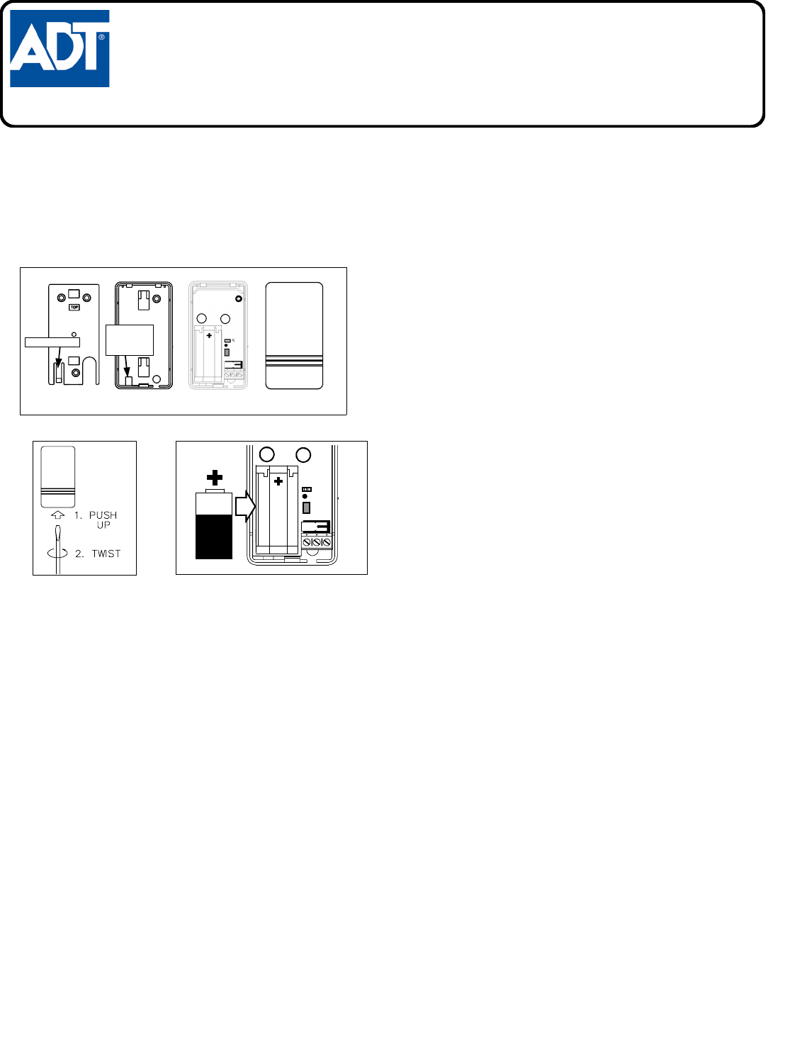
Fig. 1. SW-Bolt-Trans Component Parts
ADT SAFEWATCH EZ
SW-BOLT-TRANS
INSTALLATION INSTRUCTIONS
WI1360 12/04
© ADT 2004
FRONT COVER PC BOARD INSIDE REAR COVER MOUNTING PLATE
(RETAINING TAB)
INSERT
SCREWDRIVER
TO PUSH IN
RETAINING TAB
Fig. 2. Opening the case Fig. 3. Installing the battery
J1
2
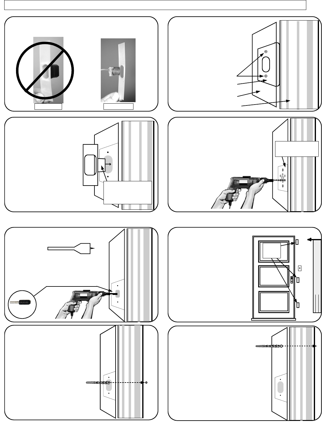
MOUNT AND WIRE THE SW-BOLT-SENSOR AND WIRE THE DOOR SENSOR TO THE SW-BOLT-TRANS
Test fit the SW-Bolt-Sensor
into the deadbolt strike hole.
For increased kick-in protec-
tion, place the sensor "tab"
closer to the inside (protected)
side of the premises. Deter-
mine if the deadbolt hole will
need enlarging. The SW-
Bolt-Sensor requires a depth
of approximately 1". In addi-
tion, one side of the deadbolt
hole must be enlarged to accom-
modate the sensor "tab".
Remove the strike plate
Screws
Remove the two screws
securing the deadbolt
strike plate to the door
frame. If there is a dust cup
installed, it must be re-
moved.
2
Strike Plate
Door Frame
Molding
Screws
3
Place "tab" closer to the
inside (protected) side of the
premises. The "tab" side of
the deadbolt hole must be
enlarged if necessary.
Enlarge the deadbolt hole us-
ing the supplied drilling guide.
Secure the steel drilling guide to the
bolt hole using the strike plate
screws. With a ¼" bit, hold the drill
level and drill through the (2) holes of
the guide matching the location of the
sensor "tab" to a depth of approxi-
mately 1½".
Remove the
drill guide
when done.
4
The template is used as a
guide for enlarging the
existing deadbolt hole.
Do not use an EZ Bolt-Cup for this installation.
Use only an SW-Bolt-Sensor as shown below.
1
EZ Bolt-Cup SW-Bolt-Sensor
Drill Door Contact Hole
Drill a hole (B) for a 3/8” re-
cessed door contact sensor. To
maintain Door Kick-in Protection,
the sensor must be placed on the
"latch side" of the inside door frame
or the top of the door frame (header).
Install the door contact magnet into
the door. When the door is closed,
the magnet must be adjacent to the
sensor. Warning: When drilling
through door frame, always stay
clear of high voltage wiring which
may be present in the wall cavity.
8 B
Drill access hole for
SW-Bolt-Sensor
Drill a 3/8” hole in the deadbolt
hole (A) for a two conductor
wire to be run from the SW-
Bolt-Sensor to the edge of the
door jamb. From this point, the
wire can emerge from the wall
and be placed next to the door
jamb or can continue through
the wall to the SW-Bolt-Trans,
as necessary.
7
A
Locate the SW-Bolt-
Trans:
Mount the SW-Bolt-Trans inside a
drop ceiling, above the door
frame, or in any location suitable
for the installation (see illustration
for possible locations). Using its
mounting base as a template,
mark the mounting holes and wire
access hole (leaving at least ¾"
from the edge of the door molding
to allow for the greater width of the
SW-Bolt-Trans case). Drill the
wire access hole as necessary.
6
Possible
mounting
locations
Rotary Wood
Rasp
To increase the depth of the dead-
bolt hole, use a 1" spade bit
(shown).
Remove the remaining wood from the
deadbolt hole opening using a rotary wood
rasp. The opening must not obstruct the
installed SW-Bolt-Sensor or the closed
deadbolt.
5
1"
3
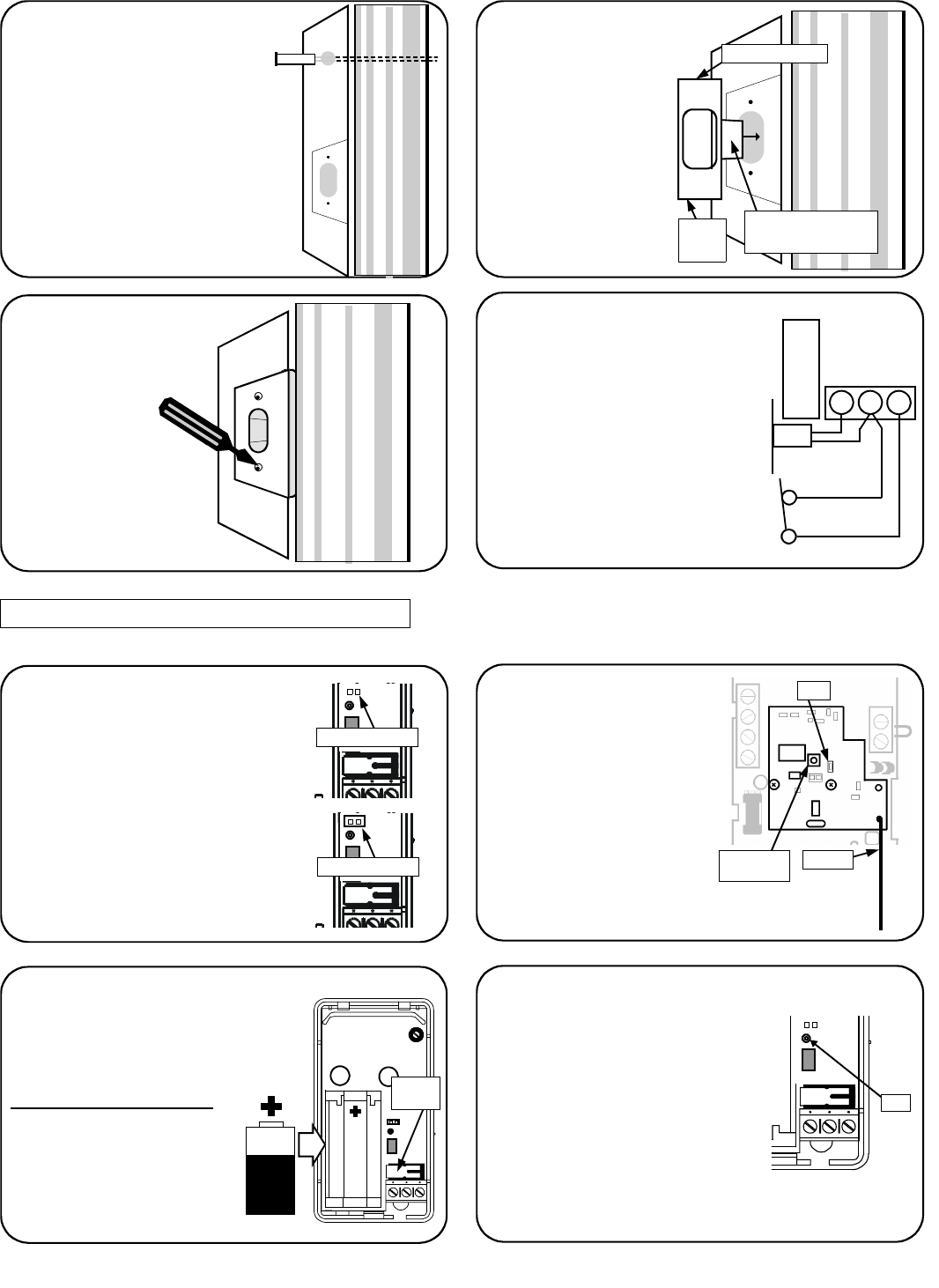
LEARN TRANSMITTERS AND TEST SYSTEM
Install strike plate
Place strike plate over
the SW-Bolt-Sensor.
Align properly over screw
holes and punch
through the plastic
flange of the SW-
Bolt-Sensor with an awl
or other sharp tool. Re-
place the 2 screws to se-
cure the strike plate. En-
sure that the SW-Bolt-
Sensor hole is centered in
the strike plate opening.
11
Install SW-Bolt-
Sensor
Using a wire snake, pull
wire from the deadbolt
strike hole and into the
SW-Bolt-Trans wire ac-
cess hole in wall. Place
the SW-Bolt-Sensor into
deadbolt hole. If the plas-
tic SW-Bolt-Sensor
flanges protrude past the
area covered by the strike
plate, it may be trimmed
with a knife (see image).
10
Install Recessed Door
Contact
The door contact sensor wires
must be connected to the SW-
Bolt-Trans.
Insert wire snake into the SW-
Bolt-Trans wire access hole and
out through the door contact
sensor hole in the door frame.
Connect the end of the sensor
wires to the wire snake and pull
wires into door frame and out
the SW-Bolt-Trans wire access
hole in wall.
9
Place "tab" closer to the
inside (protected) side of
the premises.
Flange (cut to size)
Install the SW-Bolt-Trans
(Note: Do NOT install battery until
wiring is complete). Mount the Transmit-
ter base (screws provided) with all wires
from the wall hidden under the Transmit-
ter. Wire the SW-Bolt-Trans as follows:
•Twist together one wire from the SW-
Bolt-Sensor and one from the door
contact and screw into center terminal.
•Insert the remaining SW-Bolt-Sensor
wire into the left terminal and secure.
•Insert the remaining door contact wire
into the right terminal and secure.
Do NOT install the Transmitter cover.
12
BATT.
BOLT
COM
DOOR
SW-BOLT
SENSOR
N/C DOOR
SENSOR
Flange
(cut to
size)
Multiple Transmitters--Notes
The Primary transmitter that is lo-
cated in the same room as the
Touchpad is designated as
"Transmitter #1", and its jumper
must NOT be installed.
If there is a Secondary transmitter
installed ("Transmitter #2"), it MUST
have a shunt on the Address
jumper. See page 2 for more infor-
mation. Remove all transmitter
covers before proceeding.
13
J1
Jumper not installed
J1
Jumper installed
Prepare Receiver to
Learn Transmitters
With all wiring in place, apply
power to the control panel. (the
Touchpad receiver will power up)
To ensure that the receiver is
cleared of all data, use a pen tip
to push and hold the button in
the center of the Touchpad (see
illustration) until the LED is on
steady, then release the button.
The LED will start flashing, indi-
cating the receiver is in Learn Mode and ready to learn
new transmitters.
14
Push Button
(use pen tip)
LED
Antenna
Test SW-Bolt-Trans
Note: Transmitters
CANNOT be programmed
with their covers on. Remove
all transmitter covers.
Unlock and open door.
While pressing and holding
the tamper switch, insert bat-
tery (as shown), then release
the tamper switch.
15 (Cont'd)
For a few seconds, the trans-
mitter will begin a self-diagnostic
process, then the LED inside the
SW-Bolt-Trans will flicker, indicating
the SW-Bolt-Trans is transmitting a
signal to the receiver.
The Touchpad LED will stop flicker-
ing and a chime will sound--
indicating that the transmitter is suc-
cessfully programmed into the
Touchpad memory.
16
J1
J1
Tamper
Switch LED
4
RESTRICTED USE AGREEMENT FOR
ADT SECURITY SERVICES, INC.’S INSTALLATION MANUAL
Copyright in the design of this installation manual and the arrangement of
information and materials contained therein (the “Installation Manual”), is
the exclusive property of ADT Security Services, Inc. (“ADT”), and/or its
affiliates, unless otherwise indicated. The data contained in this Installa-
tion Manual is ADT proprietary, confidential, and trade secret information
and may not be copied, compiled, or distributed or sold without the prior
written consent of ADT. By accepting possession of or by using this In-
stallation Manual, you acknowledge that you will not gain any rights to,
and agree to protect and preserve the confidentiality of, the information
contained therein. You further acknowledge and agree that you will not
use the Installation Manual for any purpose other than for the benefit of
ADT and for the installation of the product covered by the Installation
Manual and that upon ADT’s request, or upon termination of your use of
the product or relationship with ADT, you must cease all use of the Instal-
lation Manual and must return all copies in your possession to ADT.
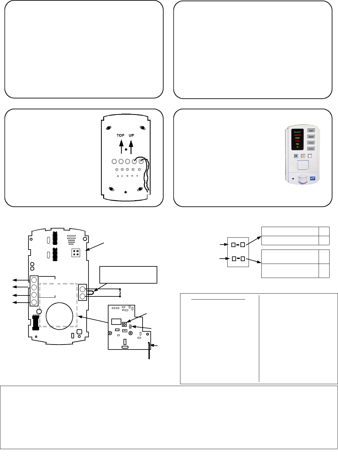
Install the EZ Touchpad
Face
Double-check all connections to the
EZ Touchpad using the wiring dia-
gram as a guide. The antenna must
be carefully pushed through the hole
in the case and dangle down the in-
side of the wall (see step 3). Snap
the front of the EZ Touchpad onto
the base by first inserting the 2 slots
in the top onto the corresponding
tabs on the base and then snapping
the bottom into place.
20
IMPORTANT: Seal
access holes
First create a service
loop of wires that is long
enough to allow the receiver
button to be pressed and the
LED to be observed.
Then seal the access holes
with putty (supplied) to ensure
EZ Touchpad is air tight. This
important step is necessary to
prevent air drafts from enter-
ing the EZ Touchpad from the
wall cavity.
19
Test Transmitters
1. Close the door. The Touchpad cover should indi-
cate "Ready".
2. Press STAY (the STAY light flashes).
3. Engage the deadbolt. Both the ARMED and STAY lights
on the Touchpad should turn on (the system armed
STAY).
4. Disengage the deadbolt and the system should disarm and
turn back off (READY light turns on).
5. Open the door. The Touchpad should sound a chime.
If there is a problem, see Troubleshooting on page 9.
To learn a second transmitter, start again at step 13.
17 Test Transmitter Signal Level
Test the transmitter to confirm signal strength. Press and
release the tamper switch. The receiver LED should flicker
in unison with the transmitter LED; if not, there is a problem
with the installation (see Troubleshooting on page 9).
Close the Transmitter Case
Snap the front of the Transmitter cover onto the base by
inserting the 2 slots in the top onto the corresponding tabs
on the base and then snapping the bottom into place.
18
EZ Touchpad Configuration Jumper JP1
EZ Touchpad Wiring Diagram
JP1
EZ Touchpad
Address
EZ Touchpad
Zone 2 Configuration
EZ Touchpad Address # 1 off
EZ Touchpad Address # 2 ON
EZ Touchpad PIR and AUX
Zone enabled as Zone 2* off
Only EZ Touchpad AUX
Zone enabled as Zone 2* ON
* If AUX ZONE is used, cut Jumper 3 (JP3).
AUX. ZONE
(N/C)
JP1 Configuration
Jumper
JP
ADDR
PIR≠
AUX2
T 16
T 17
T 18
T 14
To EZ9 Panel Terminals
(+)PWR
(-)GND
DATA
(+)
REM BUS
1
2
3
4
8
9
AUX ZN(+)
COM(-)
NOTE: Cut JP3 if AUX
ZONE is used.
Mode
Button
LED
Antenna
SW-EZ-WL Receiver
Circuit Board
(Inside Touchpad)
PART 15 MANUAL STATEMENT
CAUTION: Changes or modifications not expressly
approved by manufacturer could void the user’s
authority to operate the equipment.
RADIO AND TELEVISION INTERFERENCE
This equipment has been tested and found to comply
with the limits pursuant to Part 15 of the FCC rules.
These limits are designed to provide reasonable
protection against harmful interference in a residential
installation. This equipment generates, uses and can
radiate radio frequency energy and, if not installed
and used in accordance with the instructions, may
cause harmful interference to radio communications.
However, there is no guarantee that interference will
not occur in a particular installation. If this equipment
does cause harmful interference to radio or television
reception, which can be determined by turning the
equipment off and on, the user is encouraged to try
to correct the interference by one or more of the
following measures:
--Reorient or relocate the receiving antenna.
--Increase the separation between the equipment
and the receiver.
--Connect the equipment into an outlet on a circuit
different from that to which the receiver is con-
nected.
Consult the dealer or an experienced radio/TV
technician for help. You may also find helpful the
following booklet, prepared by the FCC: "How to
Identify and Resolve Radio-TV Interference Prob-
lems." This booklet is available from the U.S. Gov-
ernment Printing Office, Washington D.C. 20402.
Changes and Modifications not expressly approved
by the manufacturer or registrant of this equipment
can void your authority to operate this equipment
under Federal Communications Commissions rules.