Napco Security Technologies GEMPX Mini Reader Module User Manual GEM PX WI1269B 17 A4 Paper INSTALL pub
Napco Security Systems Inc Mini Reader Module GEM PX WI1269B 17 A4 Paper INSTALL pub
User Manual
1
GEM-PX
Proximity Reader
Installation Instructions
R
333 Bayview Avenue
Amityville, New York 11701
For Sales and Repairs, (800) 645-9445
For Technical Service, (800) 645-9440
Publicly traded on NASDAQ Symbol: NSSC
© NAPCO 2004 WI1269B 10/04
GENERAL DESCRIPTION
The GEM-PX is a NAPCO proprietary proximity card reader
which combines with the GEM-PXCV cover to provide com-
plete system status using indicator LED’s. The GEM-PX
reader can only be used with GEM 36-bit proprietary prox-
imity cards. The GEM-PX reader consists of the proximity
reader module, which is fully encapsulated in weather resis-
tant potting and the snap on GEM-PXCV cover which
houses additional LED’s. The multicolored LED on the
GEM-PX provides standard visual feedback as to access
condition (door “locked” or “unlocked”), and the additional
LED’s in the GEM-PXCV cover provide feedback as to sys-
tem condition (system “armed” or “disarmed”). Together,
the GEM-PX and GEM-PXCV is an indoor/outdoor prox-
imity card reader providing potted electronics, low power
consumption and durability all in a small, easy to install
package.
SPECIFICATIONS
12V Nominal, 50mA standby current.
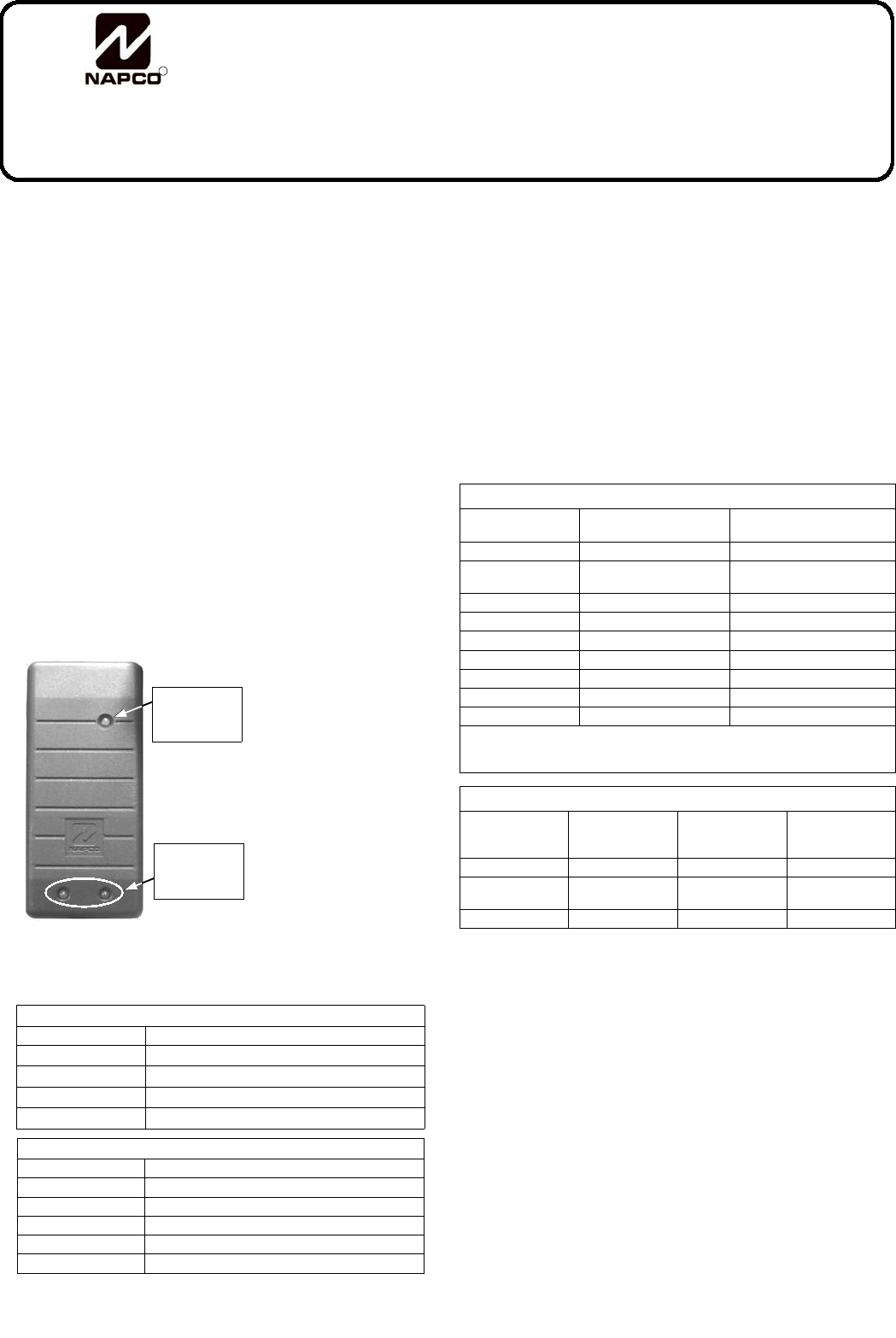
LED Indications
The GEM-PX reader contains a multicolored LED which
provides visual feedback
as to access condition
when access cards are
presented to the reader.
Table 1 below displays
the LED indications and
their meanings.
The GEM-PXCV pro-
vides two LED's to indi-
cate system condition,
as displayed in Table 2
below:
Stealth Mode is used to hide the ACM’s Armed and Status
LEDs. When Stealth Mode is enabled, the GEM-PXCV
system status LEDs are normally off but are turned on for 1
minute by any of the following events:
•Press a request to exit button
•Press a request to arm button
•Present a valid ARM/DISARM or ARM card to the
reader
When Stealth Mode is disabled ("normal operation"), the
LED's are always enabled and mimic the Keypad Status
LEDs for the following functions only: Armed, Disarmed,
Ready to Arm, Not-Ready to Arm and Alarm. Note: When
the system is in alarm, Stealth Mode is disabled. "Access
Only" cards do not affect the status of Stealth Mode.
MOUNTING THE GEM-PX
Before mounting the card reader, always plan ahead and deter-
mine the route all wires will follow before drilling into wall mount-
ing surfaces. For more information regarding various system
designs, refer to WI1121 for complete installation instructions.
Install the GEM-PX as follows:
1. Determine mounting location. Using the template
(Figure 1) and a pencil, lightly mark the location of the two
mounting holes and the two wire feed holes.
2. Route the Reader Wires. The minimum number of wires
required to activate the reader are displayed in Table 3.
Determine which wires will be needed and plan how these
wires will be accessed from behind the mounting location.
3. Install dry wall mounting hardware. Use hardware such
as molly bolts, toggle bolts or other anchoring devices.
Drill the smallest hole needed for the device. Warning:
Use caution when drilling holes--there may be high voltage
wiring in wall.
4. Drill wire feed holes. Minimum size for the top feed hole
Table 1: Access Status LED (Top)
LED INDICATION ACCESS CONDITION
Steady Red Door Locked
Steady Green Door Unlocked
Alternating Green & Red (Downloading PCD-Windows Program to ACM)
Momentary Green Card Read--Door Remains Locked
Table 2: System Status LED's (Bottom)
LED INDICATION SYSTEM CONDITION
Steady Red System Armed
Red LED is off System Disarmed
Blinking Red System in Alarm
Steady Green System Ready to Arm
Green LED is off System Not Ready to Arm
Table 3: Proximity Card Reader Connections
GEM-ACM1D Termi-
nal Number
GEM-ACM1D Terminal
Description
HID Model 6005B (Prox Point
Plus ) Wires
17 (+) Reader Power Red (+ DC)
18 (-) Reader Power Black (- Ground) & (Shielded
Ground)
19 Reader Data 1 White (Data 1)
20 Reader Data 0 Green (Data 0)
21 (-) Red LED Brown (Red LED)
22 (-) Red & Green LED Orange (Green LED)
23 (-) Reader Sounder Yellow (Beeper)
(Not Used) (Not Used) Blue (Hold)
(Not Used) (Not Used) Violet (Card Present)
* Tamper Connection not available on HID 6005B
Be sure to place jumper JP1 in correct configuration for 5 volt of 12 volt reader
operation.
Table 4: GEM-PX Wire Connections
GEM-PX Wires GEM-ACM1D
Terminal
Description
GEM-ACM1D
Terminal Number
GEM-2D Terminal
Number
Red Reader Power 17 (+) 35 (+)
Orange Active Low Red
Armed LED
30 48
Green Status Green LED 31 49
Access
Status LED
(see table 1)
System
Status LED's
(see table 2)
2
The device complies with Part 15 of the FCC Rules. Operation is subject to the following two conditions: (1) this device may not cause harmful
interference, and (2) this device must accept any interference received, including interference that may cause undesired operation.
Any changes or modifications not expressly approved by the party responsible for compliance could void the authority to operate the equipment.
(A) is 1/2", but can be made larger if necessary. Note: Do
not exceed a diameter that can be concealed by the GEM-
PXCV reader cover. The diameter of the bottom feed hole
(B) should not exceed 1/2" and should be made as small
as possible. Note: Use care to ensure that the bottom
feed hole (B) does not damage the structural integrity of
the bottom mounting hole anchoring device.
5. Route the reader wires from behind the mounting loca-
tion through the top wire feed hole (A).
6. Insert the 3 LED System Status wires into the bottom
wire feed hole (B) and then out of the top wire feed hole
(A).
7. Connect the reader wires as displayed in Table 3. Con-
nect the GEM-PX wires as displayed in table 4, below.
8. Note: Do not apply power until all wiring is complete.
9. Push all wires back into wall. Use care not to damage
the wiring or the mounting surface.
10. Mount the reader base using two #4 mounting screws
(supplied).
11. Install cover. Place the GEM-PXCV proximity reader
cover over the reader base and snap on to secure.
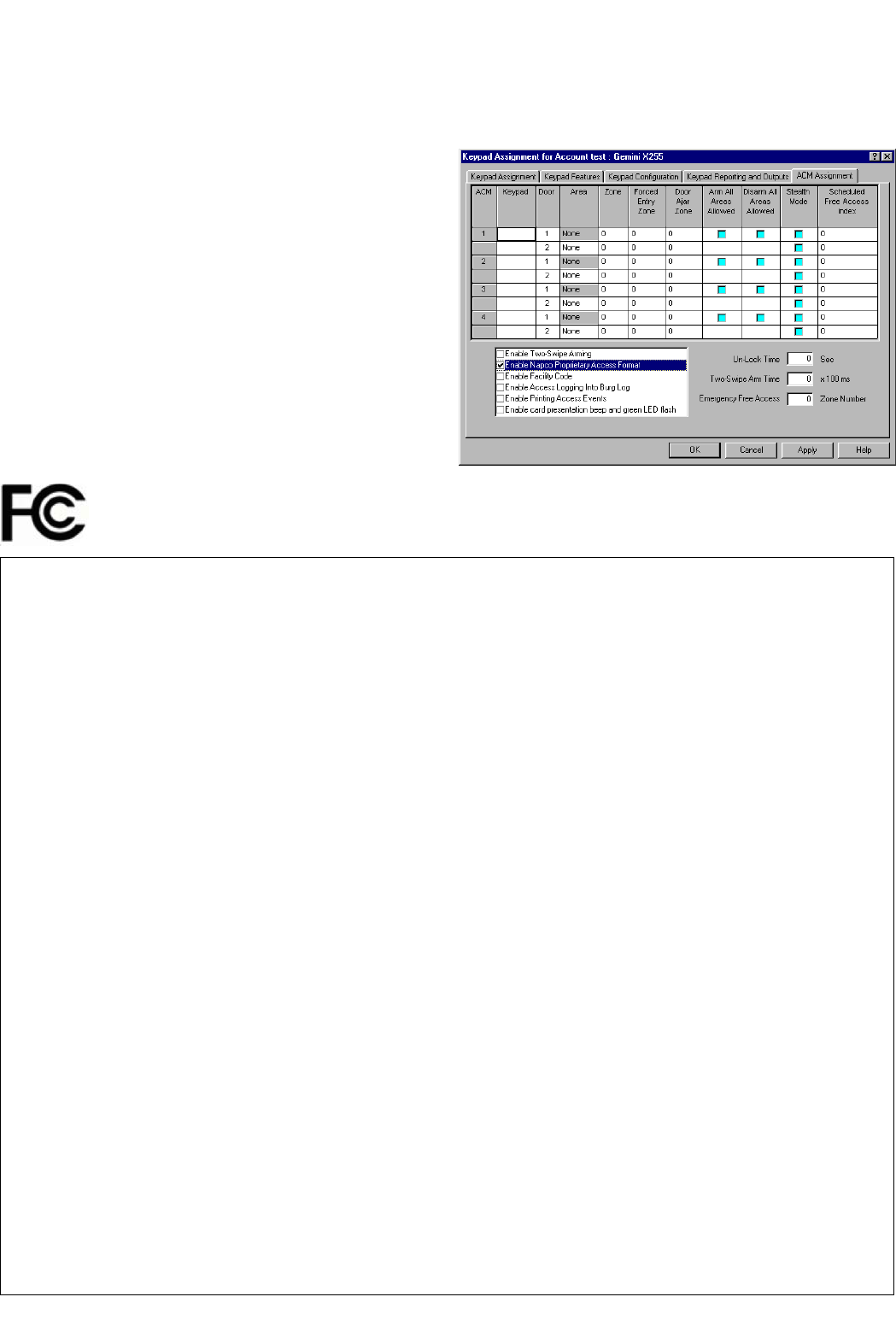
PROGRAMMING THE PANEL
In PCD-Windows Quickloader Download software, you must
enable the ACM1D to use the NAPCO proprietary proximity
card format. In the Keypad Assignment Screen, click the
ACM Assignment tab (see image below). Check Enable
Napco Proprietary Access Format to enable. Click OK to
save.
NAPCO SECURITY SYSTEMS, INC. (NAPCO) warrants its products to
be free from manufacturing defects in materials and workmanship for thirty-six
months following the date of manufacture. NAPCO will, within said period, at
its option, repair or replace any product failing to operate correctly without
charge to the original purchaser or user.
This warranty shall not apply to any equipment, or any part thereof, which
has been repaired by others, improperly installed, improperly used, abused,
altered, damaged, subjected to acts of God, or on which any serial numbers
have been altered, defaced or removed. Seller will not be responsible for any
dismantling or reinstallation charges.
THERE ARE NO WARRANTIES, EXPRESS OR IMPLIED, WHICH
EXTEND BEYOND THE DESCRIPTION ON THE FACE HEREOF. THERE
IS NO EXPRESS OR IMPLIED WARRANTY OF MERCHANTABILITY OR A
WARRANTY OF FITNESS FOR A PARTICULAR PURPOSE.
ADDITIONALLY, THIS WARRANTY IS IN LIEU OF ALL OTHER
OBLIGATIONS OR LIABILITIES ON THE PART OF NAPCO.
Any action for breach of warranty, including but not limited to any implied
warranty of merchantability, must be brought within the six months following
the end of the warranty period.
IN NO CASE SHALL NAPCO BE LIABLE TO ANYONE FOR ANY
CONSEQUENTIAL OR INCIDENTAL DAMAGES FOR BREACH OF THIS
OR ANY OTHER WARRANTY, EXPRESS OR IMPLIED, EVEN IF THE LOSS
OR DAMAGE IS CAUSED BY THE SELLER'S OWN NEGLIGENCE OR
FAULT.
In case of defect, contact the security professional who installed and
maintains your security system. In order to exercise the warranty, the product
must be returned by the security professional, shipping costs prepaid and
insured to NAPCO. After repair or replacement, NAPCO assumes the cost of
returning products under warranty. NAPCO shall have no obligation under
this warranty, or otherwise, if the product has been repaired by others,
improperly installed, improperly used, abused, altered, damaged, subjected to
accident, nuisance, flood, fire or acts of God, or on which any serial numbers
have been altered, defaced or removed. NAPCO will not be responsible for
any dismantling, reassembly or reinstallation charges.
This warranty contains the entire warranty. It is the sole warranty and any
prior agreements or representations, whether oral or written, are either
merged herein or are expressly canceled. NAPCO neither assumes, nor
authorizes any other person purporting to act on its behalf to modify, to
change, or to assume for it, any other warranty or liability concerning its
products.
In no event shall NAPCO be liable for an amount in excess of NAPCO's
original selling price of the product, for any loss or damage, whether direct,
indirect, incidental, consequential, or otherwise arising out of any failure of the
product. Seller's warranty, as hereinabove set forth, shall not be enlarged,
diminished or affected by and no obligation or liability shall arise or grow out of
Seller's rendering of technical advice or service in connection with Buyer's
order of the goods furnished hereunder.
NAPCO RECOMMENDS THAT THE ENTIRE SYSTEM BE
COMPLETELY TESTED WEEKLY.
Warning: Despite frequent testing, and due to, but not limited to, any or
all of the following: criminal tampering, electrical or communications
disruption, it is possible for the system to fail to perform as expected. NAPCO
does not represent that the product/system may not be compromised or
circumvented; or that the product or system will prevent any personal injury or
property loss by burglary, robbery, fire or otherwise; nor that the product or
system will in all cases provide adequate warning or protection. A properly
installed and maintained alarm may only reduce risk of burglary, robbery, fire
or otherwise but it is not insurance or a guarantee that these events will not
occur. CONSEQUENTLY, SELLER SHALL HAVE NO LIABILITY FOR ANY
PERSONAL INJURY, PROPERTY DAMAGE, OR OTHER LOSS BASED ON
A CLAIM THE PRODUCT FAILED TO GIVE WARNING. Therefore, the
installer should in turn advise the consumer to take any and all precautions for
his or her safety including, but not limited to, fleeing the premises and calling
police or fire department, in order to mitigate the possibilities of harm and/or
damage.
NAPCO is not an insurer of either the property or safety of the user's
family or employees, and limits its liability for any loss or damage including
incidental or consequential damages to NAPCO's original selling price of the
product regardless of the cause of such loss or damage.
Some states do not allow limitations on how long an implied warranty
lasts or do not allow the exclusion or limitation of incidental or consequential
damages, or differentiate in their treatment of limitations of liability for ordinary
or gross negligence, so the above limitations or exclusions may not apply to
you. This Warranty gives you specific legal rights and you may also have
other rights which vary from state to state.
NAPCO LIMITED WARRANTY