Napco Security Technologies PX4041 Proximity Door Lock User Manual PDL3000 WI1021 PROG PDF
Napco Security Systems Inc Proximity Door Lock PDL3000 WI1021 PROG PDF
UserManual.wiki
>
Napco Security Technologies
>
PX4041 User Manual
Users Manaual
Navigation menu
Upload a User Manual
Namespaces
Wiki Guide
HTML
PDF
Info
Views
User Manual
Discussion / Help
Navigation
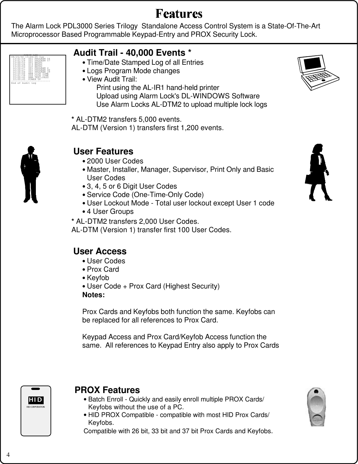
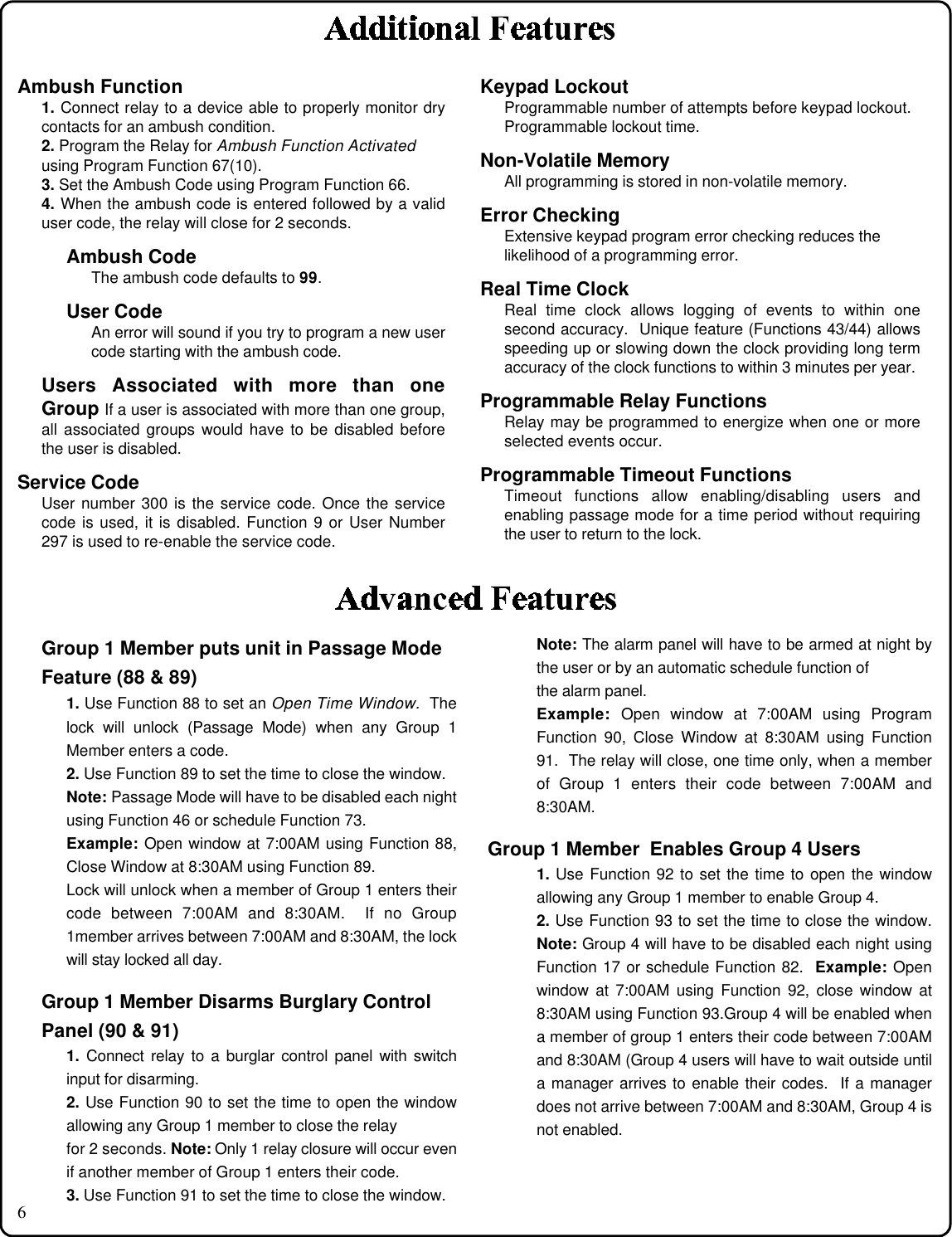
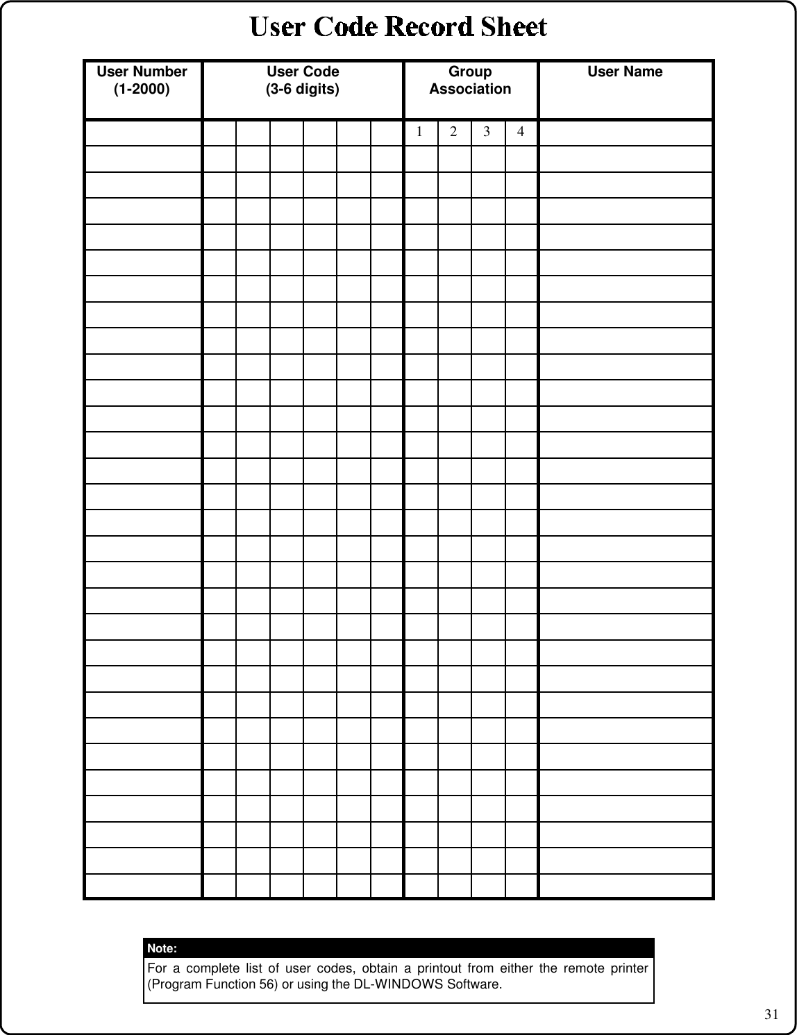
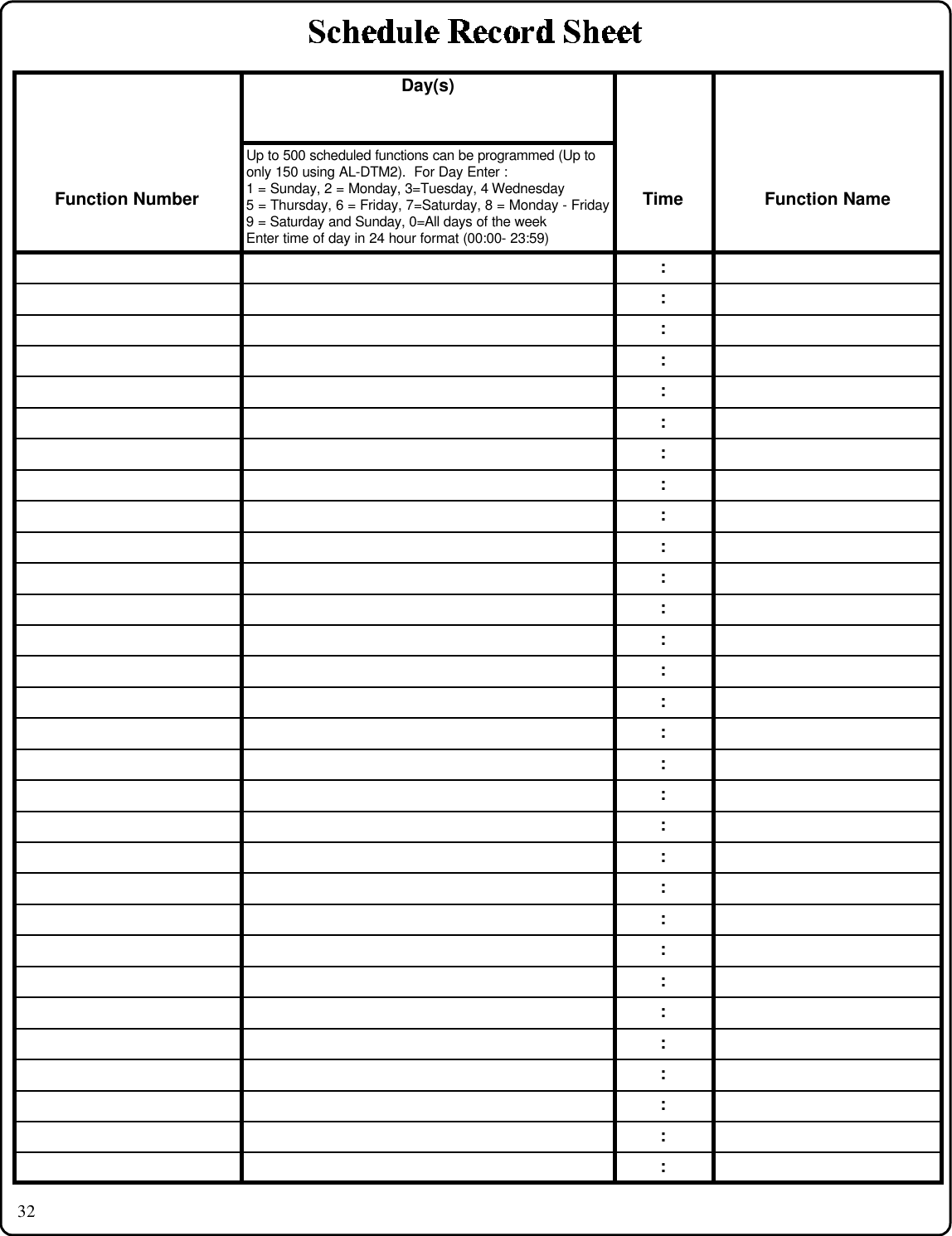
![8Lock OperationImportant: Before attempting to program any codes orfunctions, Note the following:• While the lever or knob may be rotated at any time, the latchwill not be engaged to unlock the door unless a valid codehas been entered.• When a valid code is entered, the lock will unlockimmediately and remain unlocked for about 3 seconds (orlonger, if reprogrammed by functions 53 and 54).Programming - NotesIt is recommended that all programming be prepared inadvance using the PDL3000 Programming Sheets forreference while programming. User Code and ScheduleRecording sheets are provided on pages 30, 31 and 32.Secure Programming Sheets when finished.PROGRAM LEVELSYou must have the programming authority level equal to theauthority level required to access a programming function.Programming authority levels can have a value of 1, 2, 3, 4 orM. A programming authority level of M (Master) is associatedwith the Master Code and cannot be associated with any otheruser.CODE TYPESProgram level ability is fixed according to table on page 15.The codes are defaulted to the tabulated group associationswhen adding codes using Program Function 2.Master Code - User 1: Always enabled and can program allfunctions, can't be group associated.Installer Codes - Users 2 & 3: Allow all functions exceptmaster code change.Manager Codes - Users 4 - 6: Can program all functionsexcept functions relating to lock configuration, no default groupassociation.Supervisors - User 7 - 9: Can only program functions relatingto day to day operation, no default group association.Print Only Codes - Users 10 & 11: Allow access to print audittrail only.Basic User Codes: No program ability, default groupassociation.Program Level Required - Theprogram level required to accessthe Function. PossibleProgramming Levels of 1,2,3,4 andM, where M = Master Code.Program Authority Level of Usermust be equal to the Function thatis to be accessed.3. Disable User ; 3 ; [ _ _ _ ] :4. Enable User ; 4 ; [ _ _ _ ] :• User Number must be between 2 and 2000. 2Enabling/Disabling Users (By User Number)Programming key sequence.Function NameProgrammingInformationIf a wrong key is pressed during code entry, hold any key continuously until the error sound is heard (7 short beeps),this will clear the entry. Re-enter the key sequence again.General Program Mode InformationVisible LED and Audible Sounder IndicatorsNormal BatteryActivity LED SOUNDERKeypress 1 RED Flash 1 BeepEnter Valid Enabled Code 3 GRNFlashes 3 BeepsEnter Invalid No/Wrong Code 6 RED Flashes 6 BeepsSuccessful Program Entry 2 GRNFlashes 2 BeepsUnsuccessful Program Entry 7 RED Flashes 7 BeepsLow Battery is indicated by a Yellow Flash during Key Press and a Long Beep.](https://usermanual.wiki/Napco-Security-Technologies/PX4041/User-Guide-126998-Page-8.png)
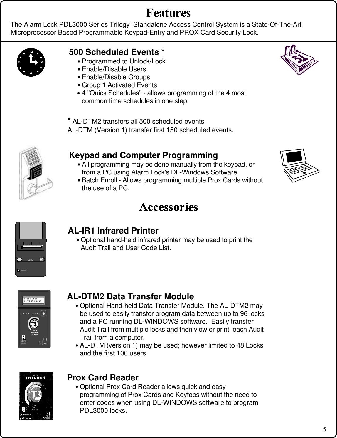
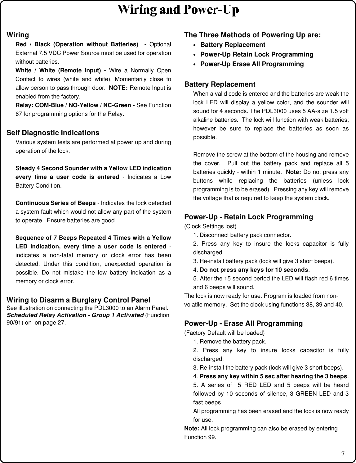
![9Battery InstallationRemove the back cover and install battery pack. The lock will beep 3 times. To load the default program press anykey within 5 seconds, the lock will beep slowly while the default values are loaded and beep rapidly upon completion.Entering Program Mode1. Enter Master Code 1 2 3 4 5 6 Default Master Code2. Press and hold ; until 8 beeps are sounded.Program a new Master Code.; 1 ; [ _ _ _ _ _ _ ] ; [ _ _ _ _ _ _ ] :New Master Code Confirm New Master CodeSetting the Clock - While still in Program Mode enter the following commands to set the clock.Program the Date.; 3 8 ; [ _ _ _ _ _ _ ] : DateProgram the Time.; 3 9 ; [ _ _ _ _ ] : TimeProgram the Weekday.; 4 0 ; [ _ ] : DayProgram Daylight Saving Time.; 4 1 ; [ _ _ ] :For Example: To set time to 8:25 P.M.;Enter: ; 3 9 ; 2 0 2 5 :For Example: To set time to 8:25 A.M.;Enter: ; 3 9 ; 0 8 2 5:For Example: August 25, 2000;Enter:; 3 8 ; 0 8 2 5 0 0 :For day enter: 1 for Sunday, 2 for Monday, 3 for Tuesday, 4 for Wednesday,5 for Thursday, 6 for Friday and 7 for Saturday.Program ModeThe keypad sounder will beep every 6 secondsand the keypad LED will flash green every 6seconds while in program mode when no keysare pressed. NOTE: There is a 3 minuteTimeout if no keys are pressed while inProgram Mode.For Example: To program the Default DST Mode;Enter: ; 4 1 ; 1 2 :](https://usermanual.wiki/Napco-Security-Technologies/PX4041/User-Guide-126998-Page-9.png)
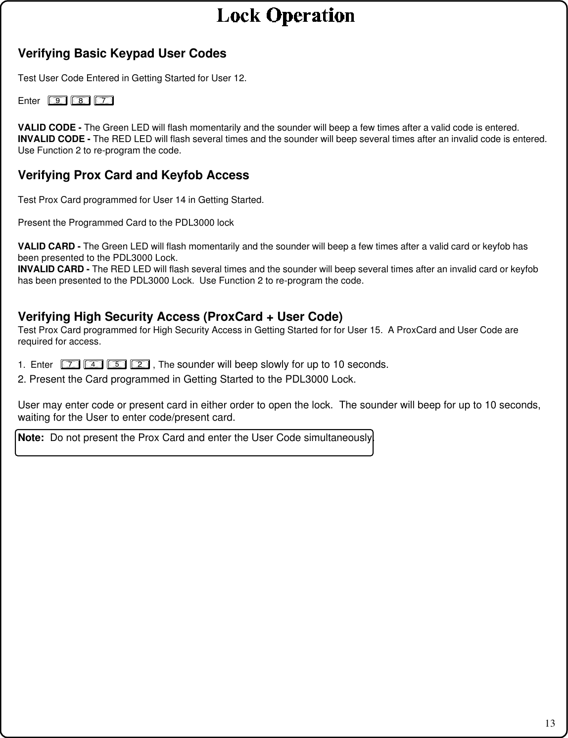
![10User ProgrammingAdd a Basic User CodeProgram a User Code of 987. Use Function 2, and add the new user as User 12. Refer to Function 2 (page 15).; 2 ; 1 2 ; 9 8 7 :Add another Basic User CodeProgram a User Code of 246. Use Function 2, and add the new user as User 13. Refer to Function 2 (page 15).; 2 ; 1 3 ; 2 4 6 :Programming the PDL3000 for ProxCard AccessProgram the PDL3000 for ProxCard Access as User 14.; 2 ; 1 4 : [Beep Beep Beep ... Beep]High Security Access (ProxCard + User Code Access)Program the PDL3000 for High Security Access for User 15. A ProxCard and User Code are required for access.; 2 ; 1 5 : [Beep Beep Beep ... Beep] Program a User Code of 7452. Use Function 2, and add the new user as User 15. Refer to Function 2 (page 15).; 2 ; 1 5 ; 7 4 5 2 :In order for User 15 to open the Lock, a User Code must be entered and a ProxCard must be presented to the PDL3000 Lock. User may entercode or present card in either order to open the lock. The sounder will beep for up to 10 seconds, waiting for the User to enter code/present card.User Code ConflictsCare should be taken not to program a new user code which matches the first digits of any other user code (only the code with theleast number of digits would be recognized). Example: If user codes 123 and 123456 are both entered in the system only code 123would be recognized, unless the ENTER Key has been enabled (Function 69).To program user codes that match the first digits ofother codes, see program Function 69. An error will sound if you try to program a new user code which matches the first digits of theMaster User Code.User Number (12) Code for User 12User Number (13) Code for User 13The sounder will beep rapidly for 10seconds. Present a CARD to the lockwhile the sounder is still beeping. TheCARD is now programmed for accessby user 14.The sounder will beep rapidly for 10seconds. Present a CARD to the lockwhile the sounder is still beeping. TheCARD is now programmed for access byuser 15.Note: For High Security Access, the user can present the card first orenter the CODE first. In either case the sounder will beep slowly for up to10 seconds waiting for the user to complete the sequence.Present CARD for User 14 within the 10-second period, the beepingwill stop after the Prox Card has been programmed.Present CARD for User 15 within the 10-second period, thebeeping will stop after the Prox Card has been programmed.HIHIHIHI](https://usermanual.wiki/Napco-Security-Technologies/PX4041/User-Guide-126998-Page-10.png)
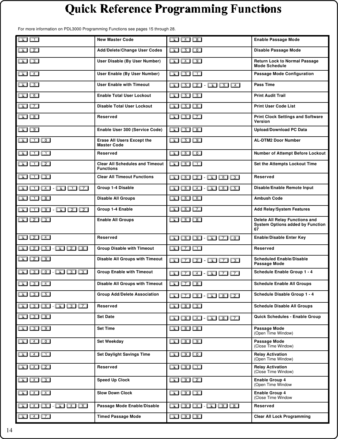
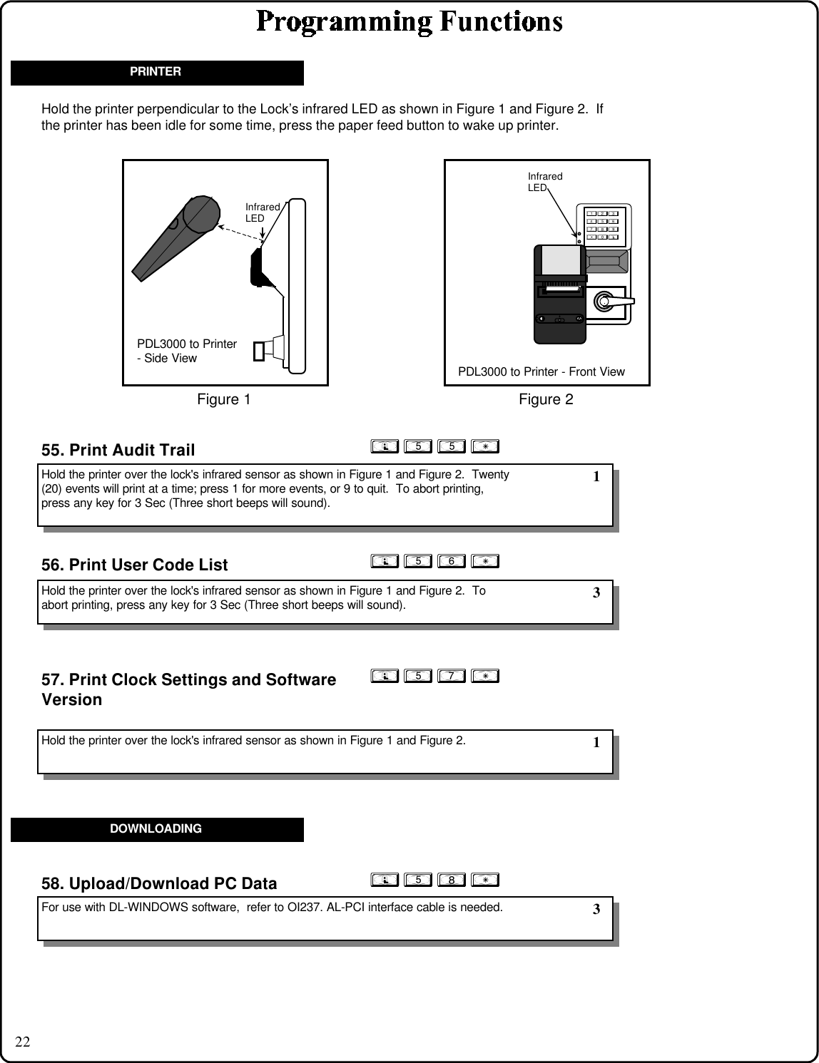
![11ALARM LOCK SYSTEMS, INCVERSION 9.00 org REC08/25/00 13:11:28 FriClock adjust setting +0Cycle count hex 00000EF39 day ct hex 00Door # 01Printing the Lock’s Time, Date and Day. Refer toPrinter Functions (page 22) for proper Printer-Lockpositioning.From Program Mode enter the following command:; 5 7 :User Programming (Continued)Deleting a ProxCard/User CodeDelete ProxCard Access for the ProxCard programmed for User 12.; 2 ; 1 2 : [Beep Beep Beep Beep Beep Beep Beep Beep Beep Beep ... Beep] DO NOT Present a CARD during the 10-second periodThe sounder will beep rapidly for 10 seconds.DO NOT Present a CARD to the lock while the sounder is still beeping.Wait for the Sounder to stop beeping. The ProxCard and code programmed for user 12 has now been deleted.Note: Deleting a ProxCard associated with User 12 with also delete the User Code programmed for User 12.ProxCard Batch EnrollProgram multiple Prox Cards successively using the PDL3000 Batch Enroll Feature.Program 50 Prox Cards for Users 100-150.; 2 ; 1 0 0 : [Beep Beep Beep ... Beep]User 100 (Present CARD for User 100 within 10-second period, the beeping will stop after the ProxCard has been programmed.)User 101 (Present CARD for User 101 within 10-second period, three beeps will sound at the keypad.) [Beep Beep Beep]User 102 (Present CARD for User 102 within 10-second period, three beeps will sound at the keypad.) [Beep Beep Beep]• • • User 150 (Present CARD for User 150 within 10-second period, three beeps will sound at the keypad.) [Beep Beep Beep]Printer Functions (AR-IR1 PRINTER required)08/25/00 13:06:35 FriUSER|USER |GROUP|PROGNUM |CODE | |LEVL 1 123456 .... 1234 12 987 .... .... 13 246 .... .... 153 7894 .... ....1843 2457 .... ....Printing the Lock’s User Code List. Refer to PrinterFunctions (page 22) for proper Printer-Lock positioning.From Program Mode enter the following command:; 5 6 :Printing the Lock’s Audit Trail. Refer to PrinterFunctions (page 22) for proper Printer-Lock positioning.From Program Mode enter the following command:; 5 5 :ALARM LOCK------- AUDIT LOG -------08/25/00 13:06:35 Fri 13:01:59 0001 PROGRAM 56 13:01:29 0001 PROGRAM 57 13:00:53 0001 ENTRY 13:00:26 0013 ENTRY 13:00:03 0012 ENTRY 12:56:27 0001 PROGRAM 2 12:56:27 0001 PROGRAM 40 12:56:04 0001 PROGRAM 39 12:55:00 NEW CLCK TIME 12:01:39 OLD CLCK TIME -------------------------End of Audit LogHIHIHIHINote: Batch Enroll will not programUsers 297 through 300, these are SpecialFunction User Codes, See Page 15 formore information. After a Prox Card/Keyfob for User 296 has been BatchEnrolled the next card presented will batchEnroll as User 301.](https://usermanual.wiki/Napco-Security-Technologies/PX4041/User-Guide-126998-Page-11.png)
![12Keypad ProgrammingEntering Program Mode1. Enter Master Code 1 2 3 4 5 6 Default Master Code2. Press and hold ;Program the Master CodeNew Master Code (User Number 1); 1 ; [ _ _ _ _ _ _ ] ; [ _ _ _ _ _ _ ] : New Master Code Confirm Master CodeExiting Program ModeThere are 2 ways to exit Program Mode:1. Hold down any key for 3 seconds2. Press no keys for 3 minutes(Program Mode Timeout).ProxCard Enroll and Batch Enroll; 2 ; [ _ _ _ _ ] :(User Number)CommunicationThe PDL3000 lock can also be programmed using acomputer with Alarm Lock's DL-WINDOWSSoftware and AL-PCI cable.“BeepBeep” “BeepBeep” “BeepBeep” “BeepBeep”Sounder will sound 2 short beeps 4 times to indicatethe program mode is active.Program ModeWhen no keys are pressed, the keypad sounderwill beep every 6 seconds and the keypad LEDwill flash green every 6 seconds. NOTE: Thereis a 3 minute Program Mode Timeout if no keysare pressed while in Program Mode. A steadytone will sound indicating there is 15 seconds leftto press a key or Program Mode will timeout.Tri-ColorStatus LEDInfrared LED (Printer)PC Interface/AL-DTM22 series of 4 Quick Beeps oncethe Exit Sequence has initiated. “BeepBeepBeepBeep” “BeepBeepBeepBeep”The PDL3000 lock can also be programmed using AlarmLock's AL-DTM2 Data Transfer Module and a computerrunning Alarm Lock's DL-WINDOWS Software.AL-DTM2Keypad will Beep for 10 seconds, present ProxCard toPDL3000. When ProxCard has been programmed, beepingwill stop. Present additional card if desired (Batch Enroll)HIDHIDHID CORPORATIONDL3500 Lock (mounted on door) IBM COMPATIBLELAPTOP COMPUTERTO SERIAL PORT (DB-9)E.G. <COM 1>AL-PCI-+NOTE: Observe Tab Directionwhen inserting cable into DL3500 Lock.PDL3000 Lock (mounted on door)PDL3000Note:AL-DTM2 has beenconfigured using acomputer runningDL-WINDOWSsoftware. Refer toDL-WINDOWSSoftwaredocumentationOI237.DL3500 Lock (mounted on door)-+NOTE: Observe Tab Directionwhen inserting cable into DL3500 Lock.-+(Tab to the left) PLUG IN THEN ENTER YOUR CODEAL-DTMPDL3000 Lock (mounted on door)PDL3000AL-DTM2Prox Card/Keyfob](https://usermanual.wiki/Napco-Security-Technologies/PX4041/User-Guide-126998-Page-12.png)
![151. New Master Code (User Number 1)2. Add/Delete/Change User Codes 2-2000; 1 ; [ _ _ _ _ _ _ ] ; [ _ _ _ _ _ _ ] :(New Master Code) (Confirm New Master Code)Users programmed with Function 2 will default to a GroupAssociation and a Program Level Ability as follows:USER TYPE USER NUMBER GROUP DEFAULTASSOCIATIONPROGRAMLEVEL ABILITYMaster Code 1-1, 2, 3, 4, MasterInstaller Codes 2 & 3 none 1, 2, 3, 4Manager Codes 4 - 6 none 1, 2, 3Supervisor Codes 7 - 9 none 1, 2Print Only Codes 10 - 11 none 1Basic User Codes 12 - 50 none noneBasic User Codes Group 1 51 - 100 1noneBasic User Codes Group 2 101 - 150 2noneBasic User Codes Group 3 151 - 200 3noneBasic User Codes Group 4 201 - 250 4noneBasic User Codes 251 - 296 none noneQuick Enable User 300 Code 297 none noneQuick PC Access Code 298 none noneAL-DTM2 Code 299 none noneService Code 300 none noneBasic User Codes 301-2000 none none; 2 ; [ _ _ _ _ ] * ; [ _ _ _ _ _ _ ] : (User Number)• User Number must be between 2 and 2000.• To delete a code/card, leave the User Code blank and wait for the rapid beeping to stop• User Code must be 3-6 digits.• Deleting a ProxCard also deletes the associated User Code.• Master Code must be 6 digits-only.• Master Code is Keypad Code Access only, Prox Cards and Keyfobs cannot beprogrammed as the Master Code. 3 MUSERSUser 299 is a Non-Pass Code. This is the only code that will initiate data transfer with the AL-DTM2.NOTE:* To Program ProxCard, enter: AND Present ProxCard.](https://usermanual.wiki/Napco-Security-Technologies/PX4041/User-Guide-126998-Page-15.png)
![16USERS (Continued); 6 : 6. Enable Total User7. Disable Total User Lockout ; 7 :User Lockout ModeEnables/Disables all User Codes (Except User 1 Code) from operating the lock. Note: No otherprogramming functions or schedules will re-enable users. Users must be re-enabled with function 7 M5. User Enable with Timeout(Enter Timeout, XXX Hours); 5 ; [ _ _ _ _ ] ; [ _ _ _ _ ] :(User Number) (XXX Hours)• User Numbers must be between 2-2000.• Hours must be between 1 - 999.• Can override a disabled user. 2; 1 0 ; 0 0 0 :10. Erase All Users Except the MasterService Code is a One-Time-Only Code. Once it is used, it is disabled until enabled again.NOTE: User Number 297 can also be used to reset Service Code Use.; 9 :9. Enable User 300 (Service Code)Erases all user codes except the Master Code (User 1). 2 M11. Reserved3. Disable User ; 3 ; [ _ _ _ _ ] : (User Number)4. Enable User ; 4 ; [ _ _ _ _ ] : (User Number)User Enable/Disable (By User Number)• User Number must be between 2 and 2000.NOTE: Will Enable/Disable users even if the user is associated with an enabled group. 28. Reserved](https://usermanual.wiki/Napco-Security-Technologies/PX4041/User-Guide-126998-Page-16.png)
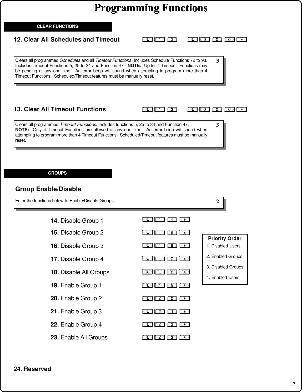
![18GROUPS; 2 5 ; [ _ _ _ ] :(XXX Hours)25. Timed Disable Group 1Group Enable/Disable with Timeout (Enter Timeout, XXX Hours)• Hours must be between 1 - 999.Enter the functions below to Enable/Disable groups for the amount of time entered in hours.NOTE: Only 4 Timeout Functions are allowed at any one time. An error beep will soundwhen attempting to program more than 4 Timeout Functions. 2; 3 5 ; [ _ _ _ ] ; [ _ _ _ _ ] :(User Number) (Groups)35. Group Add/Delete Association• Groups that are not Selected are then Disassociated from the User (See Group DefaultAssociation on page 15).• User Number must be between 2 and 2000.• 1 or more (1-4) groups to associate with user may be selected.Add Example: To associate user 67 with groups 1, 2 and 4;Enter: ; 3 5 ; 6 7 ; 1 2 4 :Delete Example: To remove all group associations for user 67;Enter: ; 3 5 ; 6 7 :NOTE: If a user is associated with more than one group, all associated groups would haveto be disabled before the user is disabled.; 2 6 ; [ _ _ _ ] :(XXX Hours)26. Timed Disable Group 2; 2 7 ; [ _ _ _ ] :(XXX Hours)27. Timed Disable Group 3; 2 8 ; [ _ _ _ ] :(XXX Hours)28. Timed Disable Group 4; 2 9 ; [ _ _ _ ] :(XXX Hours)29. Timed Disable All Groups; 3 0 ; [ _ _ _ ] :(XXX Hours)30. Timed Enable Group 1; 3 1 ; [ _ _ _ ] :(XXX Hours)31. Timed Enable Group 2; 3 2 ; [ _ _ _ ] :(XXX Hours)32. Timed Enable Group 3; 3 3 ; [ _ _ _ ] :(XXX Hours)33. Timed Enable Group 4; 3 4 ; [ _ _ _ ] :(XXX Hours)34. Timed Enable All Groups 336 - 37. ReservedClear All Timeout Functions by entering Function 13.NOTE:](https://usermanual.wiki/Napco-Security-Technologies/PX4041/User-Guide-126998-Page-18.png)
![19; 3 8 ; [ _ _ _ _ _ _ ] :(Date)38. Set Date42. Reserved• Use Month Day Year format - MMDDYY - Single digit months and days are entered witha preceding zero.• Enter Only the last two digits of the year.For Example: March. 8, 2000;Enter:; 3 8 ; 0 3 0 8 0 0 : 339. Set Time ; 3 9 ; [ _ _ _ _ ] :(Time)• Time must be 4 digits• Use 24 Hour Format (add 12 hours to program P.M. time)For Example: To set time to 8:25 P.M.;Enter: ; 3 9 ; 2 0 2 5 :For Example: To set time to 8:25 A.M.;Enter: ; 3 9 ; 0 8 2 5 : 3; 4 0 ; [ _ ] :(Day)40. Set Weekday• For day enter: 1 for Sunday, 2 for Monday, 3 for Tuesday, 4 for Wednesday, 5 for Thursday, 6for Friday and 7 for Saturday.For Example: To set day to Sunday;Enter: ; 4 0 ; 1 : 341. Set Daylight Savings Time ; 4 1 ; [ _ _ ] : (DST Mode)NOTE: Daylight Savings Time (DST) Adjustment is programmable as shown in the table below.All modes adjust time at 2AM. * Default DST Mode is 12. 4CLOCK SETTINGSDST Mode Time Forwarded Time Regressed01 No DST Adjustment02 1st Sunday in March 4th Tuesday in Sept.03 Last Sat. in March Last Sat. in Sept.04 Last Sunday in March Last Sunday in Sept.05 Last Sunday in March 4th Sunday in Oct.06 Last Sunday in March Last Sunday in Oct.07 Last Sunday in March 1st Sunday in Sept.08 April 1st September 30th09 April 1st October 1st10 April 1st Last Sunday in Oct.11 1st Sunday in April 2nd Sunday in Oct.* 12 (U.S.A. &Canada)1st Sunday in April Last Sunday in Oct.DST Mode Time Forwarded Time Regressed13 Last Friday in April Last Thurs. in Sept.14 May 1st September 30th15 1st Sunday in Sept. 1st Sunday in April16 2nd Tuesday in Sept. 3rd Tuesday in April17 1st Sunday in Oct. Last Sunday in Feb.18 1st Sunday in Oct. 3rd Sunday in March19 1st Sunday in Oct. Last Sunday in Mar.20 2nd Sunday in Oct. 2nd Sunday in Mar.21 3rd Sunday in Oct. 2nd Sunday in Feb.22 Last Sunday in Oct. 1st Sunday in March23 Last Sunday in Oct. Last Sunday in Mar.24 1st Sunday in Nov. Last Sunday in Feb.](https://usermanual.wiki/Napco-Security-Technologies/PX4041/User-Guide-126998-Page-19.png)
![20CLOCK ADJUST; 4 3 ; [ _ _ ] : (seconds)43. Speed Up Clock; 4 4 ; [ _ _ ] : (seconds)44. Slow Down Clock• Number of seconds to Speed Up/Slow Down clock each day must be 0-55 seconds.Always consider the current setting when using this function. (Use of this function is notcumulative.) For example, if the clock needs to be sped up 10 seconds per day and thecurrent setting is 10, program 20 seconds using Function 43.Example 1: Clock is losing 13 seconds every day, enter:; 4 3 ; 1 3 :.This example assumes that the clock adjust setting was at the factory default of zero.Function 57 can be used to print the current clock adjust setting.Example 2: Clock is gaining 13 seconds every day, enter:; 4 4 ; 1 3 :.This example assumes that the clock adjust setting was at the factory default of zero.Function 57 can be used to print the current clock adjust setting.Example 3: To set the clock adjust setting back to the factory default of zero, enter:; 4 3 : or ; 4 4 :Clock Adjust 4; 4 5 :45. Enable Passage Mode; 4 6 :46. Disable Passage Mode47. Timed Passage Mode ; 4 7 ; [ _ _ _ ] :(XXX Hours)• Allows passage through the door without the need for a code using Function 45. Re-Lock using Function 46.• Programmed Schedules will override the state of the lock using Functions 45 and 46. If itis required that programmed schedules do not override passage mode, Enable/DisablePassage Mode Enable/Disable - Schedule will Override 2• Hours must be between 1 - 999.Allows passage through the door without the need for a code for the programmed amountof time. 2PASSAGE MODE](https://usermanual.wiki/Napco-Security-Technologies/PX4041/User-Guide-126998-Page-20.png)
![2149. Disable Passage Mode50. Return Lock to Normal Passage Mode Schedule(The PDL3000 will lock or unlock depending on the current schedule.)• Allows passage through the door without the need for a code using Function 48. Re-Lockusing Function 49.• Programmed Schedules will not override the state of the lock using functions 48 and 49.If it is required that programmed schedules do override passage mode, Enable/DisablePassage mode using Functions 45/46. Use Function 50 to return the lock to scheduledfunctions.Passage Mode Enable/Disable - Schedule will not Override 2PASSAGE MODE; 4 9 :48. Enable Passage Mode ; 4 8 :; 5 0 :; 5 2 :52. Set Pass Time to 3 Sec.; 5 3 :; 5 4 : Use the functions below to change the pass time to 3, 10 or 15 seconds. The Pass Time isdefaulted to 3 seconds. The Pass Time is the time the lock stays unlocked after a UserCode is entered.Pass Time 453. Set Pass Time to 10 Sec.54. Set Pass Time to 15 Sec.PASS TIMESee Scheduled functions 72 and 73 for scheduled passage mode.NOTE:51. Passage Mode Configuration ; 5 1 ; [ _ ] : (Mode)Mode 1 (Normal): Passage mode must be enabled/disabled using Function 45 and 46.Mode 2: Group 2 toggles passage mode.Mode 3: Group 2 enables, Group 3 disables passage mode ** Disable passage mode has priority if user is a member of both Groups 2 and 3.](https://usermanual.wiki/Napco-Security-Technologies/PX4041/User-Guide-126998-Page-21.png)
![2360. Number of Attempts Before Lockout61. Set the Attempts Lockout Time• Number of attempts before lockout must be 1-9 attempts.• The number of attempts is reduced by half every time the keypad is locked out without asuccessful code entry (default is 6 attempts).• The attempt count is reset each time a valid code is entered.• Lockout Time must be 1-60 seconds.How long the keypad is locked out after a series of unsuccessful attempts (default is 15seconds). 4 4LOCKOUT; 6 4 : 64. Disable Remote Input• Wire a Normally Open Contact to Wires (White & White). Momentarily close to allow person to passthrough door.• Enter the functions below to Disable/Enable the Remote Input.NOTE: The Remote Input is enabled as part of the default program.Remote Input; 6 5 :65. Enable Remote Input; 6 6 ; [ _ _ ] :(Ambush Code)66. Ambush Code• Ambush code must be 2 digits.• An error will sound if the ambush code matches the 1st two digits of any user code. SeeUsing Ambush Function on page 6. 2 3REMOTE INPUTAMBUSH; 6 0 ; [ _ ] :(Number of Attempts); 6 1 ; [ _ _ ] :(Lockout Time)62-63. Reserved59. AL-DTM2 Door Number• Door Number must be between 1- 96. Note: Door Number must be between 1-48 forAL-DTM (Version 1).For use with Alarm Lock’s AL-DTM2 Data Transfer Module. Using the AL-DTM2 up to96 locks can be Downloaded/Uploaded and History LOGs can be retrieved. Enter a doornumber for each lock. After configuring the AL-DTM2, using Alarm Lock's DL-WINDOWS Software, any of the following data transfers can be initiated by plugging theAL-DTM2 into the lock and simply entering User Code 299 at the lock.• Upload Lock Program• Upload History LOG• Download Lock Program 4AL-DTM2; 5 9 ; [ _ _ ] :Door Number)](https://usermanual.wiki/Napco-Security-Technologies/PX4041/User-Guide-126998-Page-23.png)
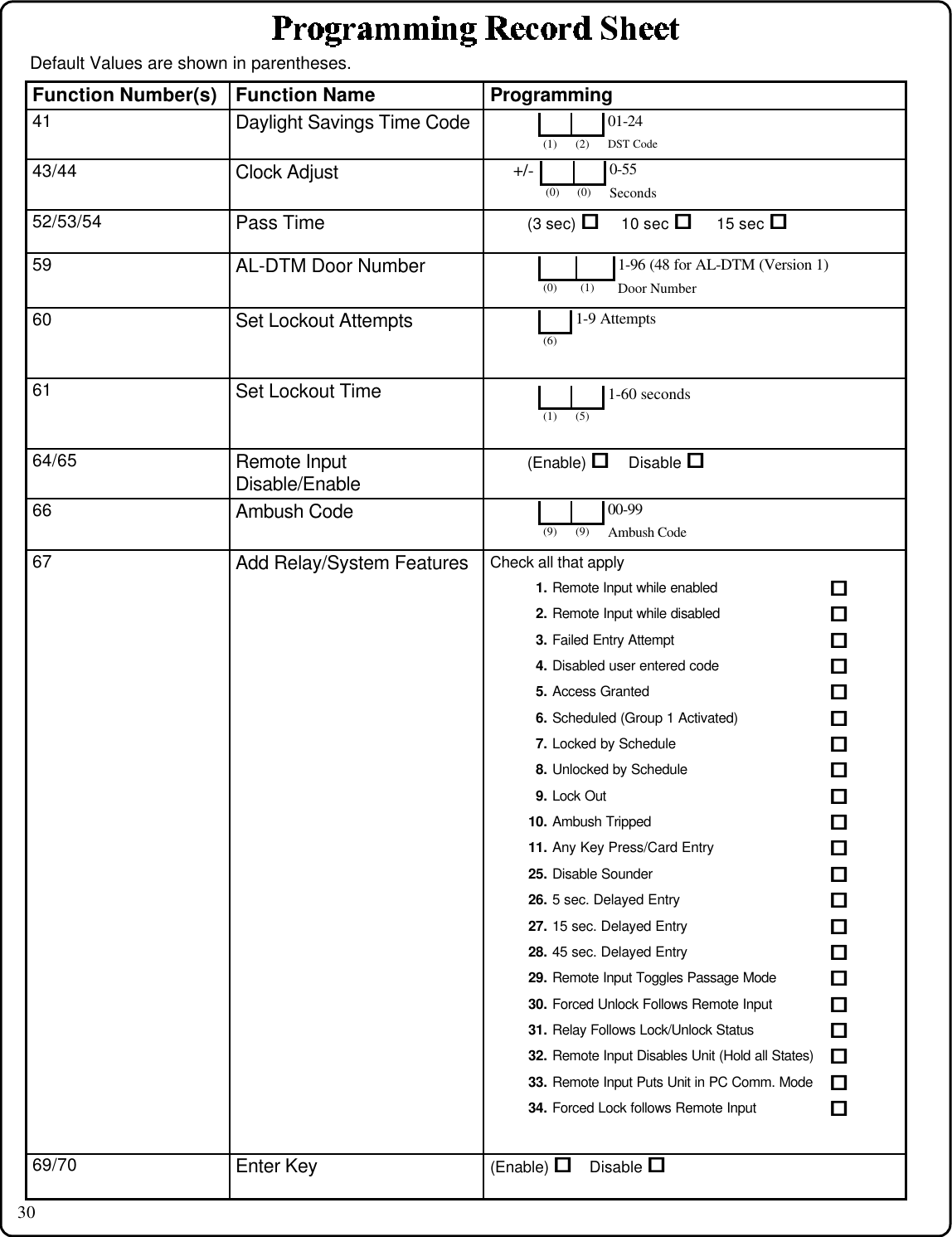
![2412-24. Reserved; 6 7 ; [ _ _ ] :(Relay Function / System Feature)67. Add Relay/System FeaturesRELAY / SYSTEM FEATURES68. Delete All Relay Functions andSystem Options added by Function 67; 6 8 ; 0 0 0 :Delete all Relay Functions programmed by Function 67.• Relay FunctionsProgram 1 or more events below to activate the Relay for 2 seconds.1. Remote Input while enabled 7. Locked by Schedule2. Remote Input while disabled 8. Unlocked by Schedule3. Failed Entry Attempt 9. Lock Out4. Disabled User entered code/card 10. Ambush Tripped5. Access Granted 11. Any key press/card entry6. Scheduled (Group 1 Activated) Function 90 31. Relay Follows Lock/Unlock Status ** 4• System Options25. Disable Sounder26. 5 sec. Delayed Entry *27. 15 sec. Delayed Entry *28. 45 sec. Delayed Entry *• Remote Input Functions29. Remote Input Toggles Passage Mode30. Forced Unlock Follows Remote Input **32. Remote Input Disables Unit (Hold all States)34. Forced Lock Follows Remote Input *** Features 26, 27 & 28 delay users 12 and greater only, except 297, 298 and 299.** Features 30, 31, 32 & 34 should be used with External DC Power unless feature is used for short a duration andinfrequently (sustained closure of remote input or relay will drain batteries. Scheduled events will not occur duringsustained closure of remote input). Sustained closure of remote input may affect proper audit trail operation.• PC Communication Functions33. Remote Input Puts Unit in PC Communication Mode 4](https://usermanual.wiki/Napco-Security-Technologies/PX4041/User-Guide-126998-Page-24.png)
![25Scheduled Passage and GroupUse the functions below to Enable/Disable Groups at the time programmed.• For day enter: 1 for Sunday, 2 for Monday, 3 for Tuesday, 4 for Wednesday, 5 forThursday, 6 for Friday and 7 for Saturday, 8 for Monday to Friday, 9 for Saturday andSunday, 0 for all days of week.SCHEDULES74. Schedule Enable Group 1 ; 7 4 ; [ _ ] ; [ _ _ _ _ ] :(Day) (Time)75. Schedule Enable Group ; 7 5 ; [ _ ] ; [ _ _ _ _ ] :(Day) (Time)76. Schedule Enable Group ; 7 6 ; [ _ ] ; [ _ _ _ _ ] :(Day) (Time)77. Schedule Enable Group ; 7 7 ; [ _ ] ; [ _ _ _ _ ] :(Day) (Time)78. Schedule Enable AllGroups ; 7 8 ; [ _ ] ; [ _ _ _ _ ] :(Day) (Time)79. Schedule Disable Group 1 ; 7 9 ; [ _ ] ; [ _ _ _ _ ] :(Day) (Time)80. Schedule Disable Group 2 ; 8 0 ; [ _ ] ; [ _ _ _ _ ] :(Day) (Time)81. Schedule Disable Group 3 ; 8 1 ; [ _ ] ; [ _ _ _ _ ] :(Day) (Time)82. Schedule Disable Group 4 ; 8 2 ; [ _ ] ; [ _ _ _ _ ] :(Day) (Time)83. Schedule Disable AllGroups ; 8 3 ; [ _ ] ; [ _ _ _ _ ] :(Day) (Time) 3Clear All Schedule and Timeout Functions by entering Function 12.NOTE:72. Schedule Enable PassageMode (Unlock); 7 2 ; [ _ ] ; [ _ _ _ _ ] :(Day) (Time)73. Schedule Disable PassageMode (Lock) ; 7 3 ; [ _ ] ; [ _ _ _ _ ] :(Day) (Time)GroupsENTER KEY• When this function is enabled the user must press the : key after any valid User Code entry;allows user codes which are subsets of other user codes.Example:1 2 3 : is a valid user code;1 2 3 4 : is a valid user code1 2 3 4 5 6 : (hold ; ) for Master User Code to enter Program Mode.Enter Key 471. ReservedPassageMode69. Enable : as Enter Key70. Disable : as Enter Key](https://usermanual.wiki/Napco-Security-Technologies/PX4041/User-Guide-126998-Page-25.png)
![26; 8 5 ; [ _ ] :(Group); 8 7 ; [ _ ] :(Group); 8 6 ; [ _ ] :(Group)84. Business Quick Schedule 7AM-5PM, Monday - Friday; 8 4 ; [ _ ] :(Group)QUICK SCHEDULES85. Day Quick Schedule7AM-5PM, All days86. Evening Quick Schedule3PM-1AM, All days87. Night Quick Schedule11PM-9AM, All days88. Passage Mode(Open Time Window); 8 8 ; [ _ ] ; [ _ _ _ _ ] :(Day) (Time)• For day enter: 1 for Sunday, 2 for Monday, 3 for Tuesday, 4 for Wednesday, 5 forThursday, 6 for Friday and 7 for Saturday, 8 for Monday to Friday, 9 for Saturday andSunday, 0 for all days of week.• Enter time of day in 24 hour format.Enter the Open and Close Window Functions below to set up a Window where if any Group1 User Code is entered within the programmed window, Passage Mode will be activated.See Group 1 Member in Puts Lock in Passage Mode on page 6.Scheduled Passage Mode (Group 1 Activated)89. Passage Mode(Close Time Window); 8 9 ; [ _ ] ; [ _ _ _ _ ] :(Day) (Time)SCHEDULES GROUP 1 ACTIVATED 3• Group number must be 1-4Enter the number of the group that is to be enabled for the time specified for the QuickSchedules below: 3Quick Schedules - Enable Group](https://usermanual.wiki/Napco-Security-Technologies/PX4041/User-Guide-126998-Page-26.png)
![27To Disarm a Burglary Control Panel90. Relay Activation(Open Time Window); 9 0 ; [ _ ] ; [ _ _ _ _ ] :(Day) (Time)• Also program Relay Function 6 using Function 67 (; 6 7 ; 6 :).• For day enter: 1 for Sunday, 2 for Monday, 3 for Tuesday, 4 for Wednesday, 5 forThursday, 6 for Friday and 7 for Saturday, 8 for Monday to Friday, 9 for Saturday andSunday, 0 for all days of week.• Enter time of day in 24 hour format.Enter the Open and Close Window Functions below to set up a Window where if any Group1 User Code is entered within the programmed window the relay will be activated for 2seconds. For use with a Control Panel that has a key switch disarm option. See Disarminga Burglar Alarm on page 6.Scheduled Relay Activation (Group 1 Activated); 9 1 ; [ _ ] ; [ _ _ _ _ ] :(Day) (Time)91. Relay Activation(Close Time Window)SCHEDULES GROUP 1 ACTIVATED 3BurglaryControlPanelRelayOutputSwitchInputAlarm Panel with Switched Input for DisarmingBurglaryControlPanelRelayOutputSwitchInputExternalRelayArmedLugPowerAlarm Panel with Switched Input for Toggled Arm/DisarmNotes:1. Group 1 Disarms a Burglary ControlPanel will always disarm an alarm system.Arming should be performed by othermeans (such as Alarm Panel Keypad/Schedule).2. Use a qualified electrical/alarm specialistto review your current alarm system andadd additional components as needed(such as a relay, wire, resistors, connectorsand/or diodes) and change the operation ofyour alarm system (by programming).](https://usermanual.wiki/Napco-Security-Technologies/PX4041/User-Guide-126998-Page-27.png)
![28; 9 9 ; 0 0 0 :99. Clear All Lock ProgrammingClears all programming. Audit Trail contents are maintained. MCLEAR ALL PROGRAMMING94 - 98. Reserved92. Enable Group 4(Open Time Window); 9 2 ; [ _ ] ; [ _ _ _ _ ] :(Day) (Time)• For day enter: 1 for Sunday, 2 for Monday, 3 for Tuesday, 4 for Wednesday, 5 forThursday, 6 for Friday and 7 for Saturday, 8 for Monday to Friday, 9 for Saturday andSunday, 0 for all days of week.• Enter time of day in 24 hour format.Enter the Open and Close Window Functions below to set up a Window where if any Group1 User Code is entered within the programmed window, Group 4 will be enabled. SeeGroup 1 Member enables Group 4 Members on page 6.Scheduled Group 4 Enable (Group 1 Activated)93. Enable Group 4(Close Time Window); 9 3 ; [ _ ] ; [ _ _ _ _ ] :(Day) (Time) 3](https://usermanual.wiki/Napco-Security-Technologies/PX4041/User-Guide-126998-Page-28.png)
![33ACCESS = Entry into a restricted area.AMBUSH = An AMBUSH CODE used before a USER CODE and programmed for Relay Ambush can be used to alert security, or trip asilent-alarm on a Burglary Control Panel.AUDIT TRAIL = A log of previously date/time stamped events that have occurred.BURGLARY CONTROL PANEL = Provides local alarm and remote communication to request security for burglary/break-in. A PDL3000 relayoutput used for Ambush can provide a silent-alarm and call-for-help.CLOCK• REAL TIME CLOCK = An accurate built-in clock that allows date/time stamping of events. The clock can be slowed or speeded up to finetune long term accuracy of the clock to within three minutes per year.• CLOCK SETTINGS = Printout includes date, time, weekday, and clock speed.• CLOCK SPEED = The clock can be adjusted to allow faster/slower speeds and therefore increasing clock accuracy.CODE = Numeric sequence of numbers (such as: 123). If Star-Enter-Key is required, must be followed by a [*] key.• AMBUSH CODE = A predefined two-digit AMBUSH CODE entered before a USER CODE, with RELAY AMBUSH ACTIVATED. Causingthe door to unlock and cause the relay to momentarily close, for a Security Team to respond. A Burglary Control Panel can send aSilent-Alarm requesting security response through remote communication.• BASIC USER CODE = User Code used by User 12-50, 251-296, 301-2000. (Does not allow programming)• INSTALLER CODE = User Code used by User 2-3. (Allows all programming except master functions)• INVALID CODE = A code that has not been programmed in the lock.• MANAGER CODE = User Code used by User 4-6. (Allows most of the programming functions)• MASTER CODE = User Code used by User 1. Default code is 123456. Master Code has complete control of the lock.• PRINT ONLY USER CODE = User Code used by User 10-11. (Allows no programming except print functions)• QUICK ENABLE USER 300 CODE = User code 297 used to Re-enable Service Code User Code 300.• QUICK PC ACCESS CODE = Permits upload/download to DL-Windows Software on IBM/compatible computer running MicrosoftWindows 95, 98, or NT 4.0.• SERVICE CODE = User 300. Allows only one entry, then needs to be re-enabled by another code to regain access again.• SUPERVISOR CODE = User Code for User 7 to 9. Can only program day-to-day operation, no default group association.• USER CODE = Code used by Users. Code is 3 to 6 numeric digits long, allowing controlled entry through door.• VALID CODE = An entered code that has been programmed in the unit.COM PORT = A computer serial communications port used to communicate with the Lock and/or Data Transfer Module.DATA TRANSFER MODULE = A device that permits transfer of program/data between a computer and up to 96 locks.DATE = Month, Day and Year entered as MMDDYY.DAY OF WEEK = Sunday through Saturday (where 1 = Sunday and 7 = Saturday).DELAYED ENTRY = Delays user passage through door, allowing camera/security guard to observe the person passing through the door.DISABLE = Turn off.DL-Windows = Computer software used to communicate with the Lock and/or Data Transfer Module.DOOR NUMBER = Identification of each door with a specific number (1-96). (Used with AL-DTM2 Transfer Module)ENABLE = Turn on.EVENTS = Recorded lock activity.](https://usermanual.wiki/Napco-Security-Technologies/PX4041/User-Guide-126998-Page-33.png)
![34FUNCTION (also called Programming Functions) = are the numbers used to program lock features (enabling/disabling Users, User Groups,Passage Mode, Schedules, etc.).GROUP• USER GROUP = Defining a user to specific groups, allows user entry when the group is allowed entry.• GROUP 1 DISARMS BURGLAR CONTROL = Manager Group 1 USER CODE entry can disarm an alarm panel during a predefined schedule.Should the Manager enter outside of the scheduled time, the alarm will not disarm. The alarm panel must be armed through other means (suchas an Alarm Panel Keypad). The Burglary Alarm Panel must be programmed to disarm from an Armed State Only and the zone input must beprogrammed for input disarming.• GROUP 1 ENABLES GROUP 4 USERS = Manager Group 1 USER CODE entry during a predefined schedule will allow access to Group 4Users.• GROUP 1 PUTS UNIT IN PASSAGE = Manager Group 1 USER CODE entry during a pre-defined schedule will unlock unit.INSTALLER = See.... CODE, INSTALLER.KEYFOB = A special keychain HID device. It is used in the same manner as a Prox Card by placing it near the Prox Card Reader.KEYPAD = 10-numeric keys, asterisk and special [AL] key.KEYPAD PROGRAMMING = Ability to program the lock through the keypad.KEYPRESS = Pressing a button on the Lock’s Keypad.LEVEL ABILITY = Predefined User Types (such as Master, Installer, Manager, Supervisor, and Print Only User) have specific abilities to programand/or control the lock.• LOCKOUT = Keypad is programmed to lockout users, for a specified period of time, when a specified number of invalid code entries areperformed.• LOCKOUT ATTEMPTS = A specified number of invalid user code entries (1-9), that will disable the keypad for a predefined period of time(1-60 seconds).LOCKOUT TIME = A predefined time (1-60) seconds that the lock will stop accepting codes, after a specified number of invalid user code entries(1-9).LOG = See... AUDIT TRAIL.MANAGER = See... CODE, MANAGER.MASTER = See... CODE, MASTER.PASSAGE = Allow anyone to pass through the door without USER CODES. (Door is Unlocked)PRINTER = A printout device (such as: An Infrared Printer or computer printer).PROGRAM MODE = A mode allowing program/data to be entered through the keypad. Only specific users can program a lock manually, byentering their USER CODE, followed by the [AL] key. To exit program mode, hold any key until repeated beeps are heard.PROGRAMMABLE RELAY FUNCTIONS = The relay can be programmed for one or more functions.PROX CARD = A special plastic card HID device that is detected when by placed near the PDL3000 or PROX Card Reader.RELAY = Switched output allowing remote control of other devices. External power source is required.• Relay, Ambush Activated - Ambush Code entered prior to a User Code will trip a relay. This will alert Security or trip a zone on an Alarm Panel.• Relay, Any Keypress - First keypress of any sequence.• Relay, Authorized Entry - Valid User Code entered.• Relay, Disabled User Entered Code - Valid User Code entered but the user is disabled.• Relay, Failed Entry Attempt - Invalid User Code entered.• Relay, Lockout - Should several Invalid User Codes be entered that exceed the number of lockout attempts (1-9), then the lock will stop acceptingkeypad entries for the Lockout Time (1-60 seconds). The Relay output can be used to indicate tampering of the keypad.• Relay, Group 1 Activation - A Group 1 Manager can enter a User Code and can disarm a Burglary Alarm Panel using the Relay Output.](https://usermanual.wiki/Napco-Security-Technologies/PX4041/User-Guide-126998-Page-34.png)