Napoleon Fireplaces Npi40 Users Manual W415 0616_C
NPI40 to the manual 663c7ea1-8651-4308-8d9b-11dd110fcbd9
2015-02-05
: Napoleon-Fireplaces Napoleon-Fireplaces-Npi40-Users-Manual-493290 napoleon-fireplaces-npi40-users-manual-493290 napoleon-fireplaces pdf
Open the PDF directly: View PDF ![]() .
.
Page Count: 44
W415-0616 / C / 06.04.08
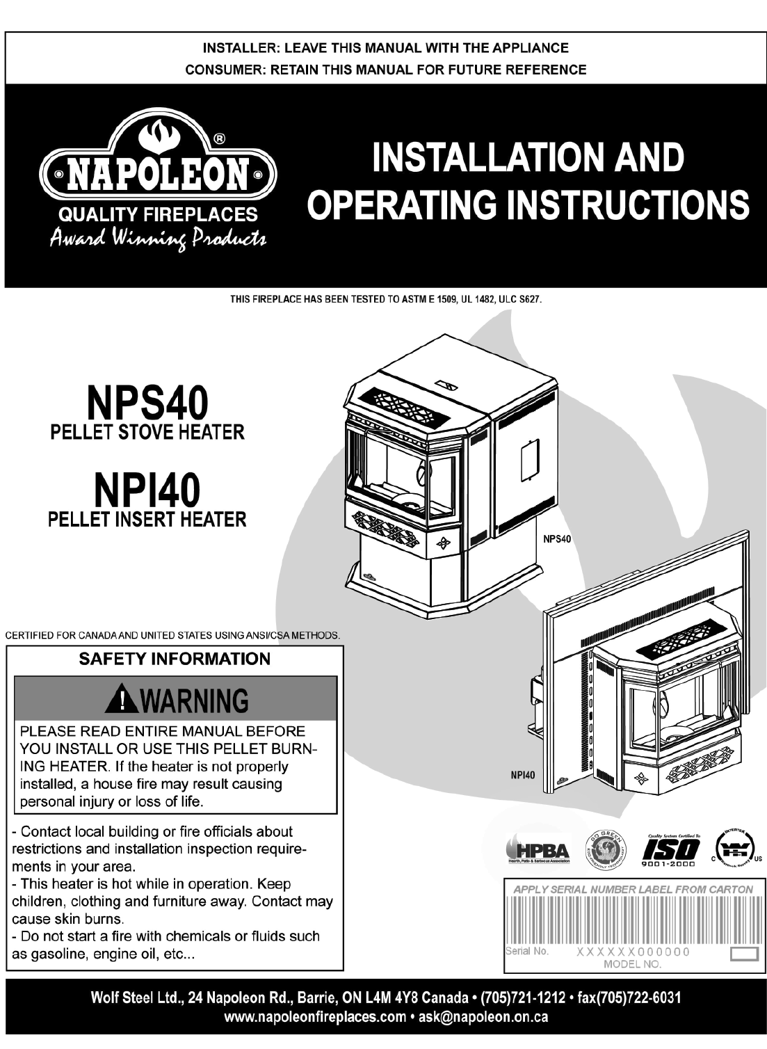
1
$10.00 W415-0616 / C / 06.04.08

W415-0616 / C / 06.04.08
2
TABLE of CONTENTS
PLEASE RETAIN THIS MANUAL FOR FUTURE REFERENCE
PG 3-5 INTRODUCTION
Warranty
Warnings and safety precautions
6-10 GENERAL INTRODUCTION
General Instructions
Pellet Quality
Specifi cations
Heating Specifi cations
Dimensions
Specifi cations
EPA Compliance
10-11 GENERAL INSTALLATION
Planning your Installation
Heater Placement
Installation Options
Floor Protection Requirements
Safety Features
Outside Air
Mobile Home
12-13 GENERAL VENTING
Type of Vent
Installing Pellet Vent
Venting the Pellet Heater
Pellet Vent Termination
Alcove Installation (NPS40 Only)
Minimum Air Terminal Installations
14-17
NPS40 INSTALLATIONS
Minimum Clearance to Combustibles
Straight Installation
Corner Installation
Vertical Installation Examples
Horizontal Exhaust Through Wall Installation
Through wall with vertical rise and horizontal
termination installation
Minimum Inside vertical clearance
Class A Chimney Retrofi t
Hearth Mount Installation
17-22
NPI40 INSTALLATIONS
Minimum Clearance to Combustibles
Minimum Mantle Clearances
Rear or Top Vent Conversion Instructions
Installation Overview
Installation into a Masonry Fireplace
Prior to Installation
Installation into a masonry fi replace
Horizontal Vent Installation
Vertical Vent Installation
Installation into a Factory Built Fireplace
Framing (Built-in)
Prior to Installation
Installation into a masonry fi replace
Liner Installation
Installation into a combustible built in enclosure
Minimum framing dimensions
Minimum Enclosure Clearances
23
NPI40 FINISHING
Flashing Installation
Trivet NPI40
Installing the viewing door NPS40 and NPI40
24
OPERATING INSTRUCTIONS
Start up
Shut down
Lighting heater manually
Proper pellet loading
25-28 GENERAL MAINTENANCE NPS40
AND NPI40
29 NORMAL OPERATING SOUNDS
30 WIRING DIAGRAM
31-35 REPLACEMENT PARTS
36-38 TROUBLE SHOOTING
39 MAINTENANCE LOG
40 NOTES
Before installation, consult with the authority having jurisdiction (building department, fi re department etc...) to
determine if there is the need to obtain a permit.
NOTE: Changes, other than editorial, are denoted by a vertical line in the margin.

W415-0616 / C / 06.04.08
3
NAPOLEON ® Pellet Heaters are manufactured under the strict Standard of the World Recognized
ISO 9001 : 2000 Quality Assurance Certifi cate.
NAPOLEON ® products are designed with superior components and materials, assembled by trained craftsmen
who take great pride in their work. The complete fi replace is thoroughly inspected by a qualifi ed technician before
packaging to ensure that you, the customer, receives the quality product that you expect from NAPOLEON ®.
NAPOLEON PELLET HEATERS PRESIDENT'S LIFETIME LIMITED
WARRANTY
The following materials and workmanship in your new NAPOLEON® Pellet Heater are warranted against
defects for as long as you own the heater. This covers: the pellet hopper, outer shell, ceramic glass (thermal
breakage only) and ash drawer.
The combustion chamber and heat exchanger are warranted against defects for a period of fi ve years. All
other wearable parts and electrical components such as blowers, thermal switches and burn pot are covered and
Napoleon® will provide replacement parts free of charge during the fi rst year of the limited warranty.
Labour related to warranty repair is covered free of charge during the fi rst year. Repair work, however, requires
the prior approval of an authorized company offi cial. Labour costs to the account of NAPOLEON® are based
on a predetermined rate schedule and any repair work must be done through an authorized NAPOLEON®
dealer.
NAPOLEON® warrants its products against manufacturing defects to the original purchaser only -- i.e., the individual or legal entity (registered customer) whose name appears
on the warranty registration card fi led with NAPOLEON® -- provided that the purchase was made through an authorized NAPOLEON® dealer and is subject to the following
conditions and limitations:
This factory warranty is non-transferable and may not be extended whatsoever by any of our representatives.
The Pellet Heater must be installed by an authorized service technician or contractor. Installation must be done in accordance with the installation instructions included with
the product and all local and national building and fi re codes.
This limited warranty does not cover damages caused by misuse, lack of maintenance, accident, alterations, abuse or neglect. Operating heater on high for extended periods
of time, is neglect. Parts installed from other manufacturers will nullify this warranty.
This limited warranty further does not cover any scratches, dents, corrosion or discoloring caused by excessive heat, abrasive and chemical cleaners nor chipping on porce-
lain enamel parts, nor any venting components used in the installation of the fi replace.
In the fi rst year only, this warranty extends to the repair or replacement of warranted parts which are defective in material or workmanship provided that the product has been
operated in accordance with the operation instructions and under normal conditions.
After the fi rst year, with respect to the President's Limited Lifetime Warranty, NAPOLEON® may, at its discretion, fully discharge all obligations with respect to this warranty by
refunding to the original warranted purchaser the wholesale price of any warranted but defective parts).
After the fi rst year, NAPOLEON® will not be responsible for installation, labour or any other costs or expenses related to the reinstallation of a warranted part, and such
expenses are not covered by this warranty.
Notwithstanding any provisions contained in the President's Limited Lifetime Warranty, NAPOLEON’S responsibility under this warranty is defi ned as above and it shall not in
any event extend to any incidental, consequential or indirect damages.
This warranty defi nes the obligations and liability of NAPOLEON® with respect to the NAPOLEON® pellet heater and any other warranties expressed or implied with respect
to this product, its components or accessories are excluded.
NAPOLEON® neither assumes, nor authorizes any third party to assume, on its behalf, any other liabilities with respect to the sale of this product. NAPOLEON® will not be
responsible for: over-fi ring, downdrafts, spillage caused by environmental conditions such as rooftops, buildings, nearby trees, hills, mountains, inadequate vents or ventilation,
excessive venting confi gurations, insuffi cient makeup air, or negative air pressures which may or may not be caused by mechanical systems such as exhaust blowers, furnaces,
clothes dryers, etc.
Any damages to fi replace, combustion chamber, heat exchanger, brass trim or other component due to water, weather damage, long periods of dampness, condensation,
damaging chemicals or cleaners will not be the responsibility of NAPOLEON®.
The bill of sale or copy will be required together with a serial number and a model number when making any warranty claims from your authorized dealer. The warranty regis-
tration card must be returned within fourteen days to register the warranty.
Regular cleaning of the fi ne ash generated during the operation of this heater is a necessary part of maintaining your pellet heater. Failure of any components, which is at-
tributed to poor maintenance, is not warrantable and will not be covered by this policy.
NAPOLEON® reserves the right to have its representative inspect any product or part thereof prior to honouring any warranty claim.
ALL SPECIFICATIONS AND DESIGNS ARE SUBJECT TO CHANGE WITHOUT PRIOR NOTICE DUE TO ON-GOING PRODUCT IMPROVEMENTS. NAPOLEON® IS A REGIS-
TERED TRADEMARK OF WOLF STEEL LTD. PATENTS U.S. 5.303.693.801 - CAN. 2.073.411, 2.082.915. © WOLF STEEL LTD.
CONDITIONS AND LIMITATIONS
W415-0616 / C / 06.04.08
4
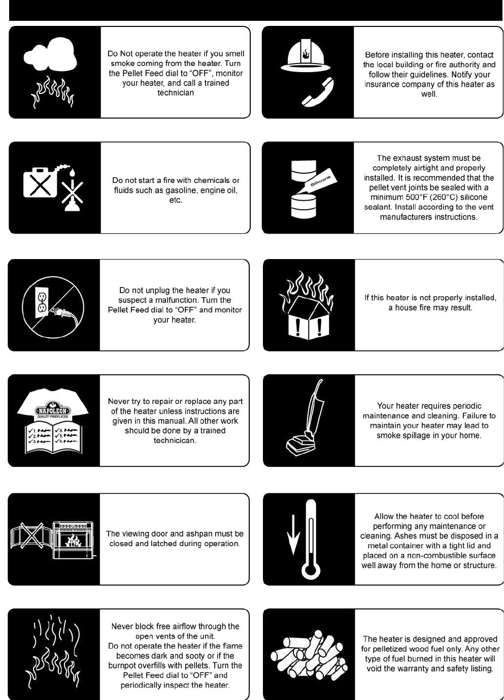
WARNINGS AND SAFETY PRECAUTIONS
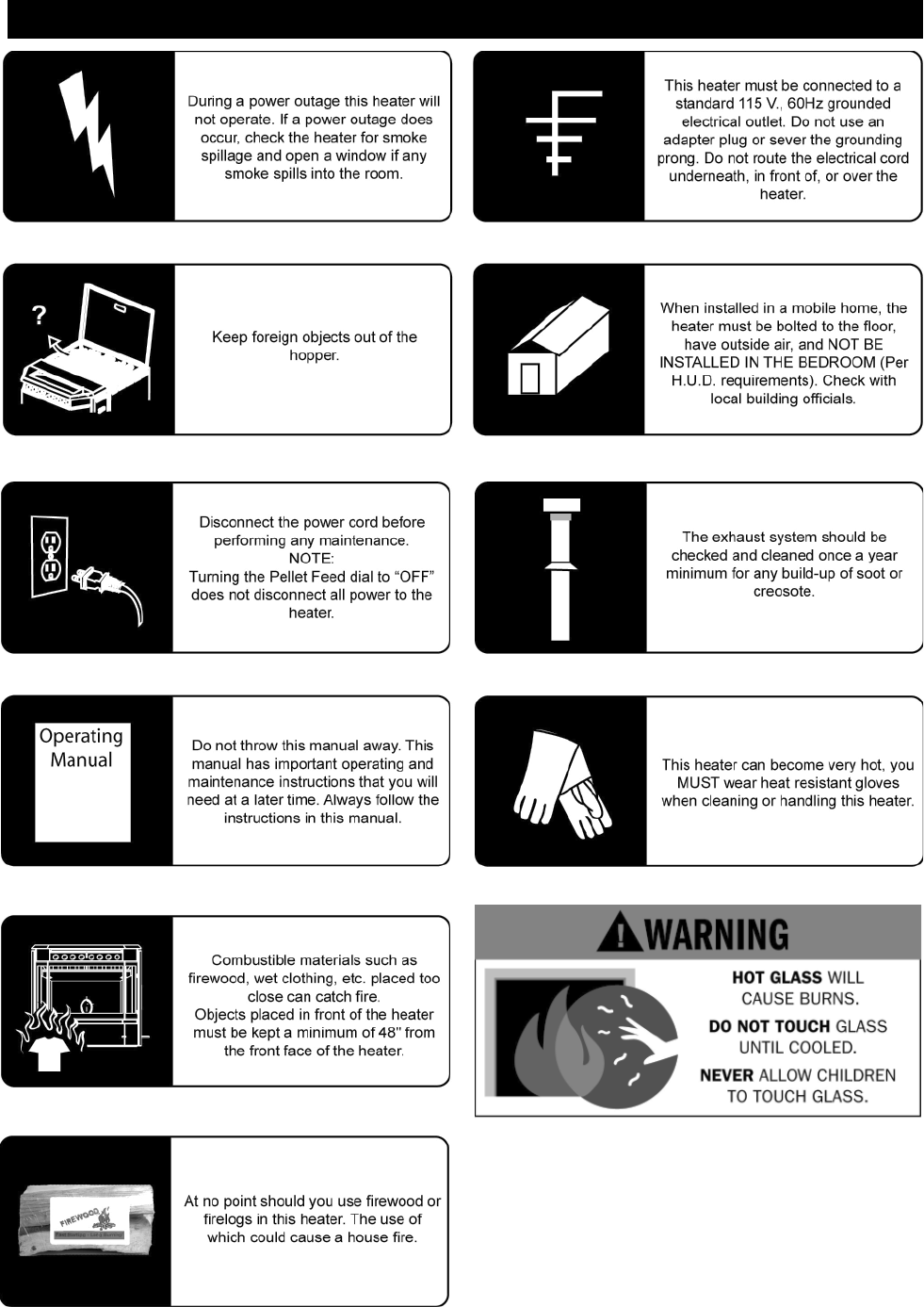
W415-0616 / C / 06.04.08
5
WARNINGS AND SAFETY PRECAUTIONS
W415-0616 / C / 06.04.08
6
GENERAL INTRODUCTION
GENERAL INSTRUCTIONS
Thank you for purchasing the Wolf Steel Ltd. Pellet Heater.
This heater is designed for use with Pelletized Wood Only.
Please read this entire manual before installation and use of this pellet fuel-burning room heater. Failure to follow
these instructions could result in property damage, bodily injury or even death.
Keep this manual handy for future reference.
This Pellet Heater, when installed, must be electrically grounded in accordance with the local codes, or in the absence
of local codes, use the current CSA C22.1 Canadian Electrical Code in Canada or the ANSI/NFPA 70 National Electrical
Code in the United States.
This heater will not operate using natural draft or without a power source for the blower systems and fuel feed system.
PELLET QUALITY
Pellet quality is important, please read the following:
Your Wolf Steel Ltd. Pellet Heater has been designed to burn premium hard or soft wood pellets only. Do not use
any other type of fuel such as fi re logs or fi re starting pellet, as this will void the warranties stated in this manual.
The performance and heat output of the pellet heater is directly related to the quality and moisture of the pellets.
Store pellets in a cool dry area to prevent moisture absorption.
P.F.I. PELLET STANDARDS:
If the fuel does not comply to this standard the unit may not operate as designed.
We recommend the use of premium grade (1% ash content) for longer stove life and less frequent cleaning.
Fines (fi ne particles) 1% maximum through a 1/8" screen
Bulk Density 40 pound per cubic foot minimum
Size 1/4" to 5/16" diameter, 1/2" - 1 1/2" long maximum
Ash Content 1% maximum (Premium grade)
3% maximum (Standard grade)
Moisture Content 8% maximum
Heat Content Approximately 8200 BTU per pound minimum
Approximate Maximum Heating Capacity (in square feet)* 800 to 2000 Sq. Feet
Burn Rate (Pounds per Hour)** 1.0 to 5.0
Maximum Burn Time on Low Burn** 55 Hours (NPS40), 45 Hours (NPI40)
Hopper Capacity 55 Pounds (NPS40), 45 Pounds (NPI40)
* Heating capacity will vary depending on the home's fl oor plan, degree of insulation, and the outside temperature. It is
also affected by the fuel size, quality, and moisture level.
** Small pellets will increase or decrease the stated burn rates and burn times. Differences of plus or minus 20% de-
pending on fuel quality may occur.
HEATING SPECIFICATIONS
It is important to select and use only pellets that are dry and free of dirt or any impurities such as high salt con-
tent. Dirty fuel will adversely affect the operation and performance of the unit and will void the warranty. The
Pellet Fuel Industries (P.F.I.) has established standards for wood pellet manufacturers. We recommend the use
of pellets that meet or exceed these standards. Ask your dealer for a recommended pellet type.
!
WARNING
SPECIFICATIONS
W415-0616 / C / 06.04.08
7
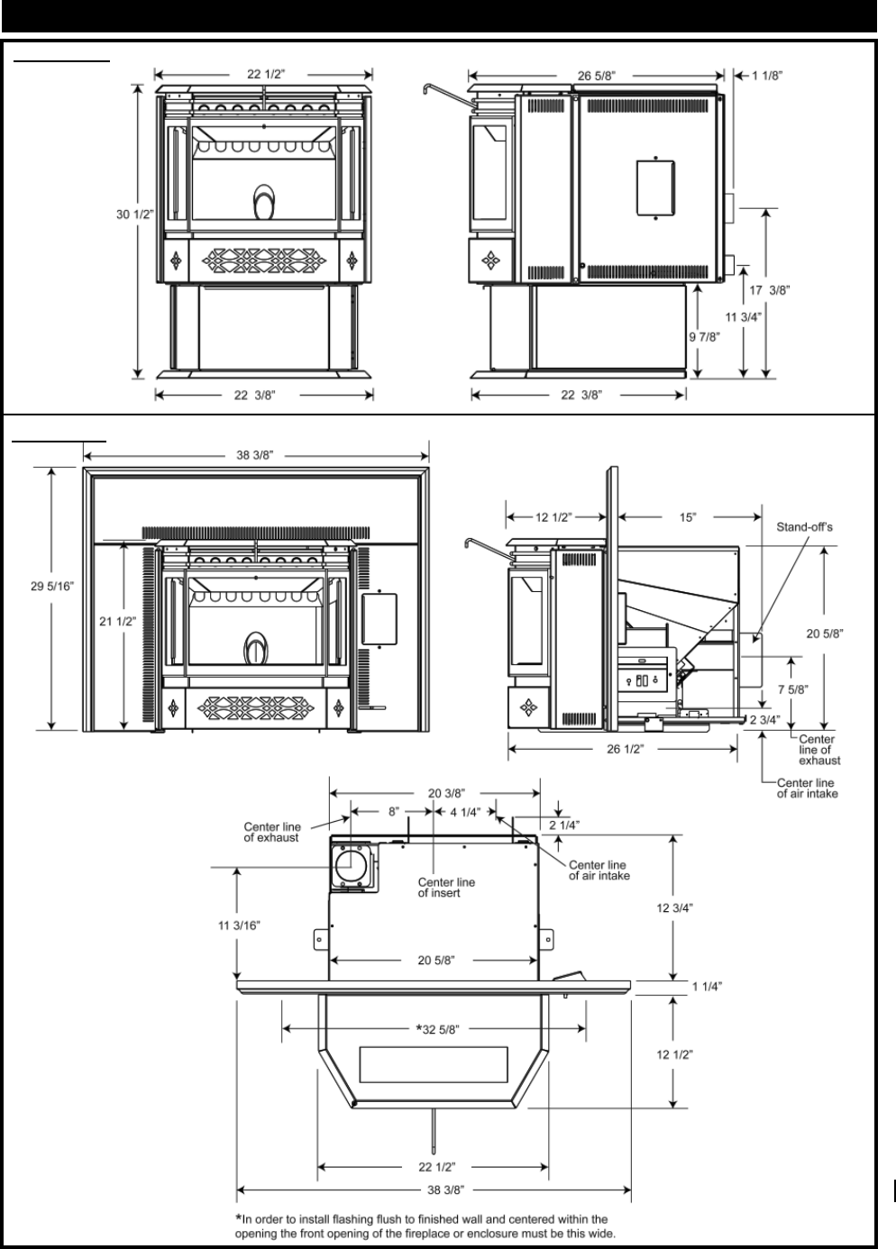
DIMENSIONS
Figures 1a-b
NPI40 with NI800 Flashing Shown
NPS40
Figures 2a-c
W415-0616 / C / 06.04.08
8
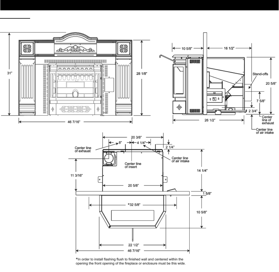
DIMENSIONS CONTINUED
Figures 3a-c NPI40 with AK9 Adapter and CISK Flashing Shown
W415-0616 / C / 06.04.08
9
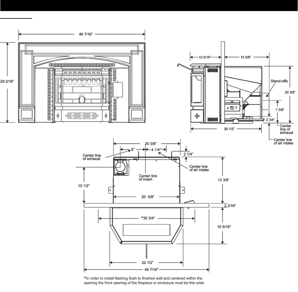
DIMENSIONS CONTINUED
Figures 4a-c NPI40 with AK8 Adapter and GICSK Flashing Shown
W415-0616 / C / 06.04.08
10
HEATER PLACEMENT
PLANNING YOUR INSTALLATION
Have an authorized dealer install the heater. If you install the heater yourself, have your dealer review your installation
plans and/or installation.
Draw out a detailed plan of the installation including dimensions and verify the dimensions with the requirements listed in
this manual.
For built-in enclosures, when determining the location of the heater, locate the wall studs (for horizontal penetrations). You
may wish to adjust the heater position slightly to ensure the vent does not intersect with a framing member.
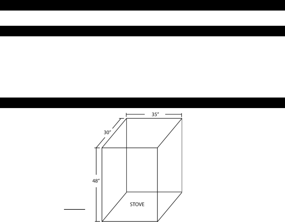
Heater must be positioned so that no combustibles are within, or can swing within (e.g. drapes, doors), 48" of the front of
the heater.
If the heater is placed in a location where the ceiling height is less than 7' above the base of the heater, the installation
must follow the requirements in the section "Alcove Installations Requirements"
Read this entire manual before you install and use this heater. failure to follow the instructions may result in
property damage, bodily injury, or even death.
Check with local building offi cials for any permits required for installation of this pellet heater and notify your insurance
company before proceeding with installation.
Before installing we recommend placing the heater outside and load 5 pounds of pellets inside the hopper. Plug the heater
in and let it run on HIGH until the pellets run out. This will cure the paint and burn off the oils on the steel, there by mini-
mizing any smell inside the home.
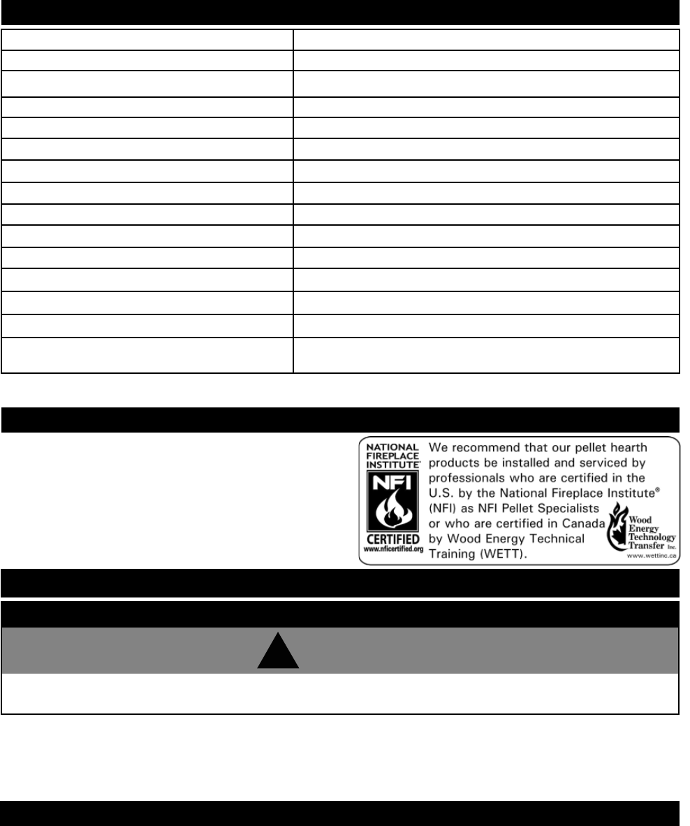
Electrical Rating 115 Volts, 3.6 Amps, 60Hz
Watts During Start-Up Sequence 400 (approximately)
Watts During Operation 180 (approximately)
NPS40 Width 22 3/8"
NPS40 Height 30 1/2"
NPS40 Depth 26 5/8"
Weight 210 Pounds
Exhaust Collar 3"
Intake Collar 2"
NPS40 Hopper Cap. 55 Pounds
NPI40 Hopper Cap. 45 Pounds
EPA Exempt
Burn Rate** 1.0 to 5.0 (Pounds Per Hour)
BTU/h** 8500 to 42500
Minimum Fireplace Opening Size Front: 22 1/2* W x 20 5/8 H x 14 1/4 D
Back: 20 3/8 W
This heater is EPA exempt from Phase II requirements, but
has been tested for emissions using EPA test methods by
Warnock Hersey.
SPECIFICATIONS
EPA COMPLIANCE
* In order to install fl ashing fl ush to fi nished wall and centered within the opening the front opening of the fi replace or
enclosure must be 32 5/8" wide.
!
WARNING
GENERAL INSTALLATION

W415-0616 / C / 06.04.08
11
INSTALLATION OPTIONS
NPS40:
To install in a Residential or Mobile Home see the section "Mobile Home Requirements".
For alcove installations see the section "Alcove Installation Requirements".
For horizontal vent or vertical vent see the section "General Venting".
See the section "Outside Air" for this option.
NPI40:
The insert can be adapted to vent out the rear or vertically.
To install as an insert into an existing masonry fi replace factory built fi replace or a built in combustible enclosure see Insert
Installation.
FLOOR PROTECTION REQUIREMENTS
NPS40:
The heater must be installed on a non-combustible fl oor protector extending the full depth of the heater and extending a
minimum 6" in front and on either side (minimum .018" thick - 26 gauge).
The fl oor protector must extend under and 2" beyond each side and rear of a "Tee" (if used).
NPI40:
In the case of the NPI40, the fl oor protector must have a R-value of 0.4 hr ft²°F
BTU
SAFETY FEATURES
BLOWER OVER-RIDE SWITCH:
Your heater is equipped with a convection blower that circulates hot air into your room. This switch will automatically turn
the blower on, when the temperature at the back of the fi re box reaches a certain temperature. The blower can cycle from
your desired setting to maximum speed depending on the feed rate. When the heater cools back down, the blower will
return to the initial setting.
VACUUM SWITCH:
This switch will sense lack of air fl ow through the heater and shut down the pellet feed. This lack of fl ow could be caused
by a blocked vent.
POWER FAILURE:
In the event of a power failure, the heater will shut down. Once power is restored, the heater will re-start, unless the con-
vection air temperature has gone above the high limit switch setting. If this happens, contact your local dealer.
OUTSIDE AIR
Available from your Napoleon Dealer (114KT)
Outside air must not be drawn from an enclosed space (garage, unventilated crawl space).
NOTE: Wolf Steel Ltd. strongly suggests using outside air for all residential installations, especially for those that
are energy effi cient, air-tight homes.
Outside air supply must not be over 15' long.
Outside air vents must be made with 1 3/4" diameter or larger metal or aluminum duct with a metal screen attached to the
end to keep out rodents (P.V.C. or other materials may not be used).
The outside air inlet must not be above or within 12" of the chimney termination, must have a rain cap or down-turned
elbow to prevent the water from entering and be located so that it will not become plugged by snow or other material.
Outside air is mandatory for a combustible built-in enclosure install for the NPI40.
HIGH LIMIT SWITCH:
Your heater is equipped with a high limit switch. In the event that the temperature of the heater approaches an unsafe
operating temperature, this switch will shut down the pellet feed, which will eventually shut down the unit. If this happens,
it is important to fi nd out why the unit overheated. Contact your local dealer.
LOW LIMIT SWITCH:
This switch will automatically shut down the heater if the fi re goes out.
W415-0616 / C / 06.04.08
12
Figure 6
MOBILE HOME
The heater must be grounded to the steel chassis of the mobile home (Some states do not
require this; check with your local building department).
Figure 5
Installation into a manufactured home or mobile home should be installed in accordance with the Manufactured Home
Construction and Safety Standard, Title 24 CFR, Part 3280, in the United States or the Mobile Home Standard, CAN/CSA
Z240 MH Series, in Canada.
GENERAL VENTING
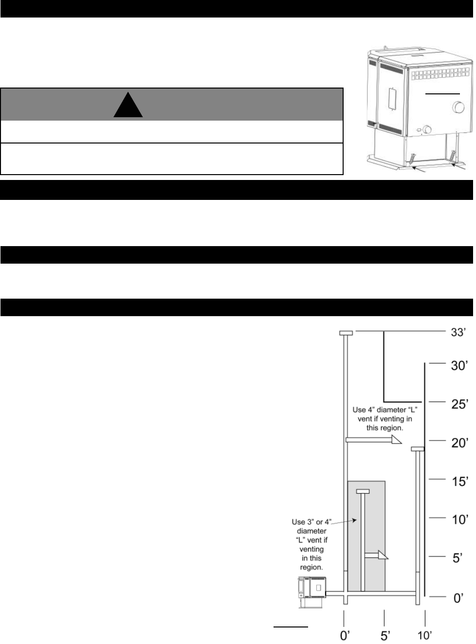
Must be an approved 3" or 4" Diameter Type "L" or "PL" vent, vented to the outside or connect the vent to a factory built
type "A" chimney using an adaptor; and/or stainless steel chimney liner for masonry fi replace installations. Use 4" diam-
eter vent if vent or liner height is over 15' or if installation is over 4,000' above sea level.
TYPE OF VENT
MAXIMUM VENTING:
Maximum venting height is 33'. Maximum horizontal offset is 10'. Use no more than
180° of elbows (two 90' elbows, or two 45' elbows and one 90' elbow, etc), plus
termination.
PELLET VENT MUST MAINTAIN A MINIMUM 3" CLEARANCE TO ANY COMBUSTIBLE (install vent at clearances
specifi ed by the vent manufacturer).
DO NOT CONNECT THE PELLET VENT TO A VENT OR CHIMNEY SERVING ANY OTHER APPLIANCE OR HEATER.
DO NOT INSTALL A FLUE DAMPER IN THE EXHAUST VENTING SYSTEM OF THIS UNIT.
INSTALLING THE PELLET VENT
The vent must have a support bracket every 5' when on the exterior wall.
To achieve optimum performance, keep vent runs as short as possible, especially
on horizontal installations.
VENT INSTALLATION:
Termination must exhaust above the air inlet elevation, and parallel or above the
exhaust output of the pellet appliance. It is recommended that at least 3' of vertical
pipe be installed to create some natural draft. This is to help prevent the possibility
of smoke or odour during the appliance shut down or in the event of a power out-
age.
Horizontal sections must have a 1/4" rise every 12" of travel if longer than 3'.
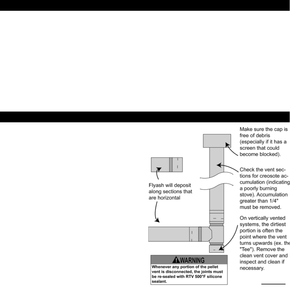
The pellet vent connections must be sealed with HI-Temp RTV Silicone and
screwed together with at least 3 3/8" long stainless steel screws.
Seal each vent section by injecting a liberal amount of 500°F
(260°C) RTV silicone sealant into the gap. We recommend sealing
the outside of the vent connections to permit easier access when
servicing.
Do not install in a sleeping room.
The structural integrity of the manufactured home fl oor, wall, and ceiling roof
must be maintained.
!
WARNING
W415-0616 / C / 06.04.08
13
Use an approved wall thimble when passing the vent through walls and a ceiling support/fi re stop spacer when passing
the vent through ceilings (maintain a 3" clearance to any combustibles).
The vent termination must have an approved cap (to prevent water from entering) or a 45° downturn.
If the termination is located on a windy side of the house, a shield is recommended to prevent soot from building up on the
side of the house.
Horizontal terminations must protrude 12" from the wall, vertical terminations require a minimum 24" above the highest
point that it penetrates through the roof.
Depending on pellet quality, vent confi guration and air settings, black soot may occur on the terminal wall.
PELLET VENT TERMINATION
VENTING THE PELLET HEATER
ALCOVE INSTALLATION (NPS40 ONLY)
Minimum Alcove Dimensions
Figure 7
W415-0616 / C / 06.04.08
14
**
**
* Recommended to prevent condensation on windows and thermal breakage
** This is a recommended distance. For additional requirements check local codes.
A
B
C
D
E
F
G
H
I
K
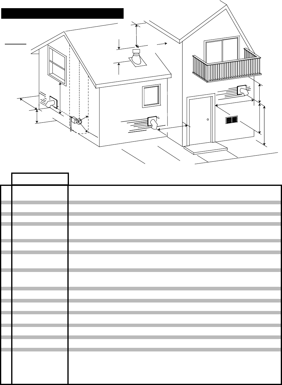
24 INCHES
48 INCHES
12 INCHES*
18 INCHES
0 INCHES
3 INCHES
9 INCHES
3 FEET
7 FEET**
12 INCHES**
24 INCHES
2 FEET
Clearance above grade, veranda porch, deck or balcony.
Clearance beside or below any windows or doors that open.
Clearance above any window or door that opens.
Vertical clearance to ventilated soffit located above the terminal within a horizontal
distance of 2 feet from the centerline of the terminal.
Clearance to an outside corner wall.
Clearance to an inside combustible corner wall or protruding combustible ob-
structions ( vent chase, etc.).
Clearance to a non-mechanical air supply inlet to the building or a combustion
air inlet to any other appliance.
Clearance to a mechanical air supply inlet.
Clearance above a paved sidewalk or paved driveway located on public property.
Clearance under a veranda, porch, deck or balcony.
Clearance above the roof.
Clearance from an adjacent wall including neighbouring buildings.
CLEARANCE
A
J
D
K
I
H
E
C
B
G
F
E
J
(Including Vegetation and Mulch)
MINIMUM AIR TERMINAL INSTALLATIONS
L3 FEET within a
height of 15 FEET
above the meter/
regulator assembly
Clearance to each side of center line extended above natural gas or porpane
meter/regulator assembly or mechanical vent.
Illustration dimensions are to the center and the exhaust exit point of the vent.
B
L
Figure 8
W415-0616 / C / 06.04.08
15
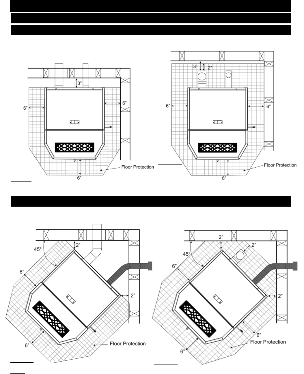
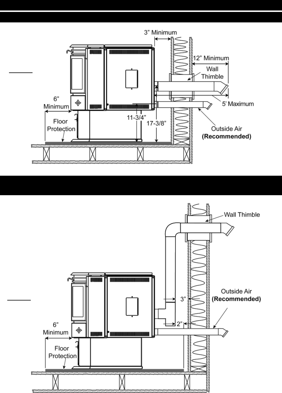
STRAIGHT INSTALLATION
Through the Wall Installations Interior Vertical Vents
CORNER INSTALLATION
Through the Wall Vents Interior Vertical Vents
NOTE: If interior vertical pellet vent is used, the clearance to the back wall is determined by the upward-turning
elbow or "Tee". It will vary in depth depending on the brand of pellet vent used (it is approximately 5"). Before
placing the heater, connect the elbow or "Tee" and allow for the minimum 3" clearance to the combustible wall.
Figure 9
Figure 10
Figure 11 Figure 12
MINIMUM CLEARANCE TO COMBUSTIBLES
NPS40 INSTALLATION
W415-0616 / C / 06.04.08
16
VENTING INSTALLATION EXAMPLES
Figure 13
THROUGH WALL WITH VERTICAL RISE AND HORIZONTAL
TERMINATION INSTALLATION
Figure 14
HORIZONTAL EXHAUST THROUGH WALL INSTALLATION
W415-0616 / C / 06.04.08
17
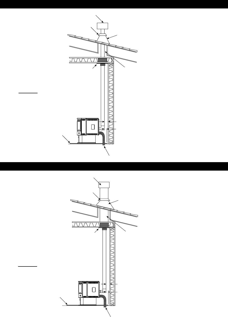
MINIMUM INSIDE VERTICAL CLEARANCES
Outside air (Recommended)
(Installation showing inlet of out-
side air in ventilated crawl space)
Ceiling Support Vent must maintain 3”
clearance to combus-
tibles.
Vertical Cap
Roof Flashing
Storm Collar
Floor Protection
3”
2”
Class A Chimney
Ceiling Support
Outside air (Recommended)
(Installation showing inlet of out-
side air in ventilated crawl space)
Vent must maintain 3”
clearance to combus-
tibles.
Roof Flashing
Storm Collar
Floor Protection
3”
2”
Vertical Cap
CLASS A CHIMNEY RETROFIT
Figure 15
Figure 16
W415-0616 / C / 06.04.08
18
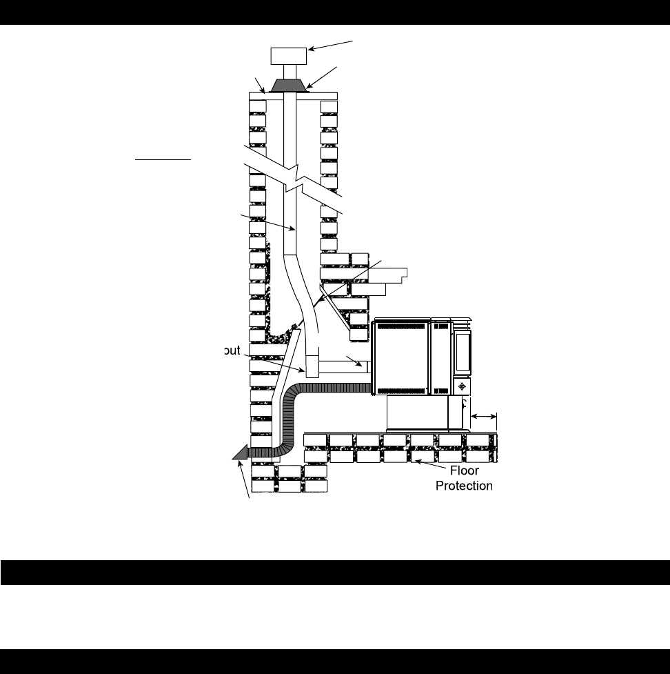
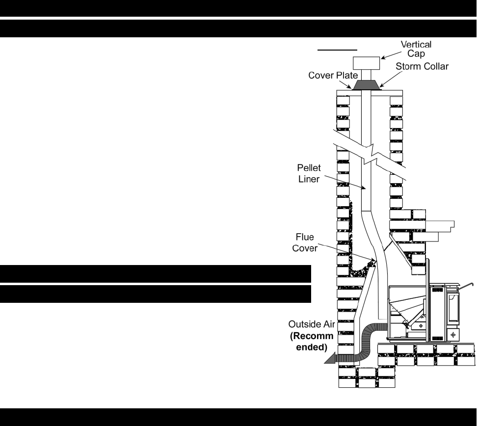
Figure 17
HEARTH MOUNT INSTALLATION
Floor
Protection
6”
MIN
Clean-out
tee
Outside Air
(Recommended)
Storm Collar
Vertical Cap
Chimney Cap
Bring outside air
to the stove
Pellet
Liner
Flue Cover
Pellet
Vent
Clean all ashes out of the inside of the fi replace. Make sure that the chimney and fi replace are free of cracks, loose
mortar, cresote deposits, blockage or other signs of deterioration. If necessary, have any repair work done by a qualifi ed
professional before installing the insert.
Do not remove bricks or mortar from the fi replace.
1. Remove the fi replace damper or fasten it permanently open.
2. Measure the throat of the fi replace and mark this shape on a piece of 24 gauge sheet metal (fl ue cover). Cut a hole
sized for the pellet liner to lie directly below the fi replace fl ue opening. Allow two inches of material for a fl ange on all
sides and cut to these measurements. Bend down the fl anges. If you have never done this before, it might be a good
idea to make a cardboard pattern and test it fi rst. fasten this fl ue cover in position as high as possible with two
masonry screws per side through the fl anges into the fi replace.
3. If you plan on connecting outside air it is recommended to do so at this time.
4. Connect the pellet vent with a clean out tee to the back of the stove. Refer to manufacturer's installation instructions
and the "General Venting Section".
5. Run a liner down the chimney and connect to tee.
6. Position the stove in it's fi nal location.
7. Pull the excess length of liner out through the top of the chimney. Trim the excess liner, install the cap and cap the
chimney.
PRIOR TO INSTALLATION
INSTALLATION INTO A MASONRY FIREPLACE
W415-0616 / C / 06.04.08
19
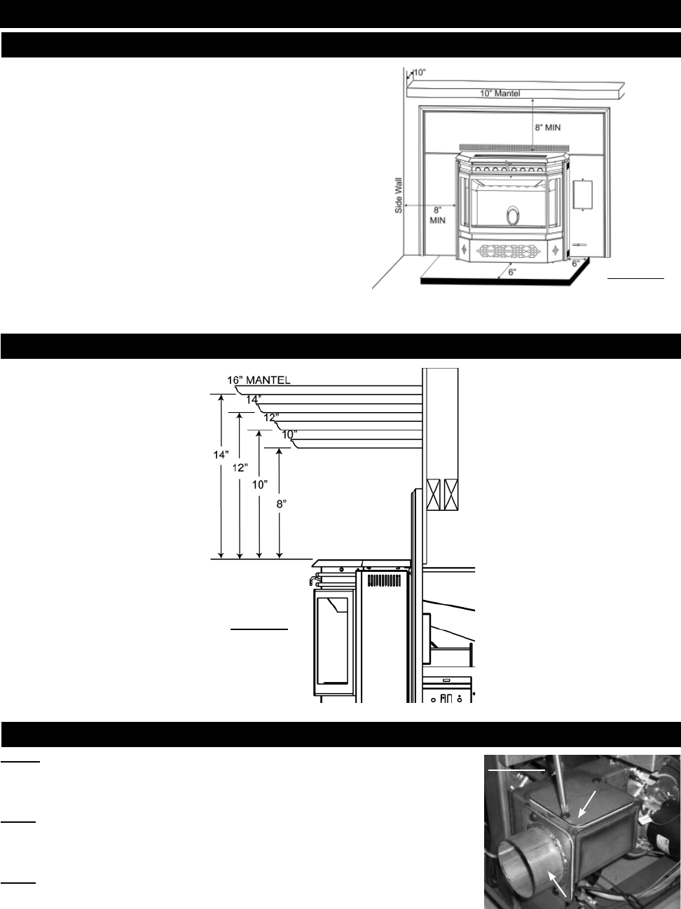
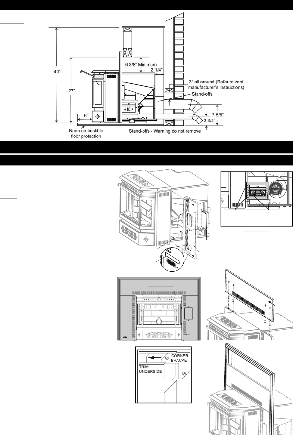
MINIMUM CLEARANCES TO COMBUSTIBLES
Side wall to unit 8"
Maximum mantel depth 10"
Mantel to top of unit 8"
Top facing to unit 6 3/8"
Side facing to unit 6"
Floor protection* 6"*
* Floor Protection: Minimum 6" in front of door and to either
side.
MINIMUM MANTEL CLEARANCES
REAR TO TOP VENT CONVERSION INSTRUCTIONS
NOTE: The insert is factory shipped in a rear vent confi guration.
1. To vent exit vertically, remove the two screws holding the exhaust cover.
NOTE: Be careful not to damage the gasket.
2. Remove the two screws holding the exhaust tube
NOTE: Be careful not to damage the gasket.
3. Attach the exhaust tube and gasket in the vertical position.
4. Attach the exhaust cover and gasket over the horizontal exit.
Figure 18
Exhaust Tube
Exhaust Cover
Figure 20
Figure 19
NPI40 INSTALLATION
W415-0616 / C / 06.04.08
20
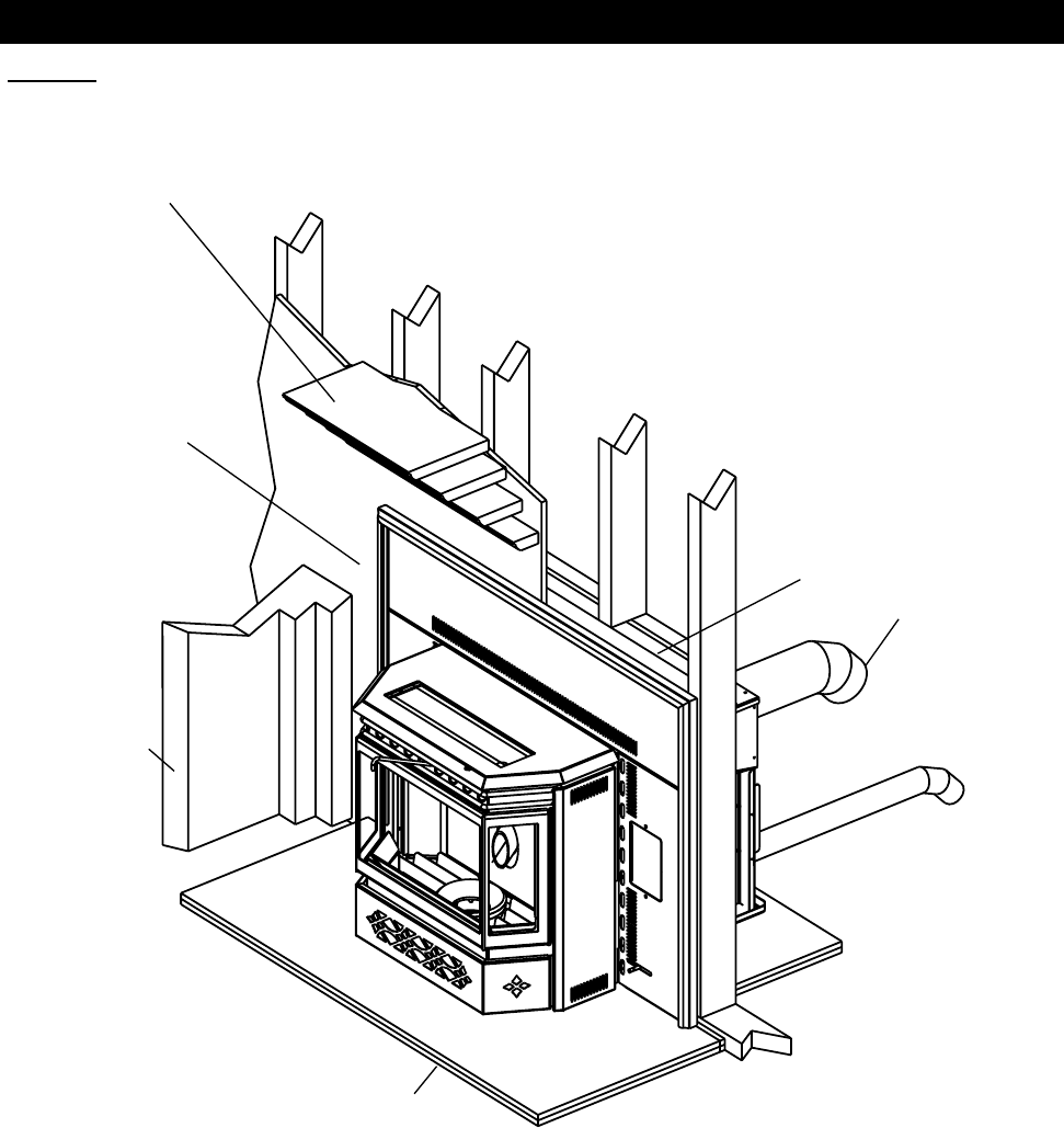
NPI40 INSTALLATION OVERVIEW
See the section
“INSTALLATION - MINIMUM
MANTEL CLEARANCES”
Drywall
(or other
combustible
material)
See the sections
“GENERAL VENTING”
and “INSTALLATION”
See the section
“MINIMUM FRAM-
ING DIMENSIONS”
Side
Wall
See the section
“MINIMUM
CLEARANCES TO
COMBUSTIBLES”
See the section
“INSTALLATION
INTO A BUILT-IN
ENCLOSURE”
Figure 21
W415-0616 / C / 06.04.08
21
Figure 22
INSTALLATION INTO A MASONRY FIREPLACE
Stand-offs (See Dimensions on page 7) may be removed to fi t
the insert into the fi replace.
When installing the insert into a masonry fi replace, do not
remove any bricks or masonry. If necessary, the damper plate
may be removed from the smoke shelf, to accommodate the
chimney liner. Do not weaken the structure, or reduce the
protection for combustible materials to less then that required
by the National Building Code.
A non-combustible hearth must cover the fl ooring underneath,
as well as extend a minimum of six inches in front and to both
sides of the heater.
Clean all ashes out of the inside of the fi replace. Make sure
that the chimney and fi replace are free of cracks, loose mortar,
creosote deposits, blockage or other signs of deterioration. If
necessary, have any repair work done by a qualifi ed profes-
sional before installing the insert.
Do not remove bricks or mortar from the fi replace.
Install fl oor protection if necessary.
PRIOR TO INSTALLATION
INSTALLATION INTO A MASONRY FIREPLACE
HORIZONTAL VENT INSTALLATION
VERTICAL LINER INSTALLATION
1. If you plan on connecting outside air it is recommended to
do so at this time.
2. A hole must be made in the back of the fi replace to accommodate
the pellet vent. Connect the pellet vent to the back of the stove and
position in place. Refer to manufacturer's installation instructions
and the "General Venting Section".
3. Connect the vent cap to vent.
1. If you plan on connecting outside air it is recommend to
do so at this time.
2. Remove the fi replace damper or fasten it permanently
open.
3. Measure the throat of the fi replace and mark this shape on a piece of 24
gauge sheet metal (fl ue cover). Cut a hole sized for the pellet liner to lie directly below the fi replace fl ue opening. Allow
two inches of material for a fl ange on all sides and cut to these measurements. Bend down the fl anges. If you have
never done this before, it might be a good idea to make a cardboard pattern and test it fi rst. fasten this fl ue cover in
position as high as possible with two masonry screws per side through the fl anges into the fi replace.
4. Convert the exhaust tube to a vertical application. See "Rear to Top Vent Conversion Instructions" section.
5. Run a liner down the chimney and connect to the exhaust tube. Refer to manufacturer's installation instructions and
the "General Venting Section".
6. Position the insert in it's fi nal location.
7. Pull the excess length of liner out through the top of the chimney. Trim the excess length and cap the vent.
W415-0616 / C / 06.04.08
22
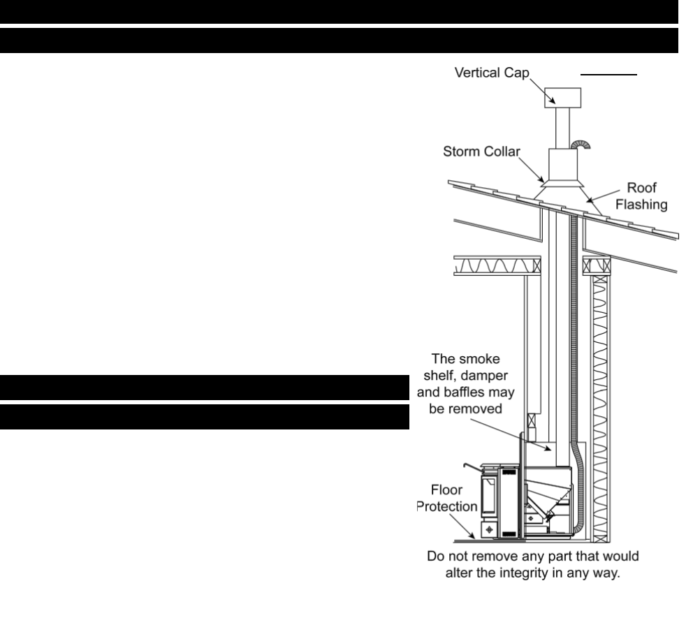
INSTALLATION INTO A FACTORY BUILT (METAL) FIREPLACE
Figure 23
Stand-offs (See Dimensions on page 7) may be removed to fi t the insert
into the fi replace.
When installing the insert into a factory built fi replace, you must not modify
any part that would alter the integrity in any way. Bolted or screwed to-
gether pieces (smoke shelf/defl ectors) may be removed, but must be able
to be re-installed if the insert was removed.
External trim pieces, which do not affect the operation of the fi replace,
may be removed provided they are available to be re-installed in event the
insert is removed.
A warning label must be attached to the back wall of the fi replace stating
that "This fi replace has been altered to accommodate a fi replace insert and
must be re-inspected by a qualifi ed person prior to re-use as a factory built
fi replace".
A non-combustible hearth must cover the fl ooring underneath, as well as
extend a minimum of six in front and to both sides of the heater.
Install fl oor protection if necessary.
PRIOR TO INSTALLATION
INSTALLATION INTO A MASONRY FIREPLACE
LINER INSTALLATION
1. If you plan on connecting outside air it is recommended to do so
at this time. As illustrated connect the air vent to the back of the
insert, fl ex the vent up through the A vent chimney and bend the
vent 180°.
2. Remove the fi replace damper or fasten it permanently open.
3. Convert the exhaust tube to a vertical application. See "Rear to
Top Vent Conversion Instructions" section.
4. Run a liner down the chimney and connect to the exhaust tube.
Refer to manufacturer's installation instructions and the "General
Venting Section".
5. Install fl ashing. See "NPI Finishing - Flashing Installation" section.
6. Position the insert in it's fi nal location.
7. Pull the excess length of liner out through the top of the chimney. Trim the excess length and cap the vent. Cover the
A vent chimney to weatherproof.
W415-0616 / C / 06.04.08
23
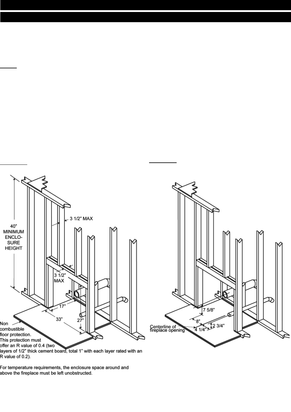
Figure 24a
MINIMUM FRAMING DIMENSIONS
When installing the insert as a "Built-in" heater, it is important to maintain the "Clearances to Combustibles" as illustrated
in Figure 24a-b.
A non-combustible heart must cover the fl ooring underneath, as well as, a minimum of six inches in front and to both sides
of the heater.
NOTE: The stand-offs located on the back of the insert must not be removed when installing the insert into a
built-in combustible enclosure.
1. Install fl oor protection.
2. Frame structure maintaining minimum clearances. Locate and frame openings for both the exhaust and outside air.
Outside air is mandatory for "Enclosure" installations.
3. Refer to the vent manufacturer's installation instructions and to "General Venting" section. Connect the vent.
4. Install fl ashing. See "NPI40 Finishing - Flashing Installation" section.
5. Consideration must be taken during installation that removal of the insert is necessary for inspection and annual
maintenance. Install the vent cap.
Figure 24b
INSTALLATION INTO A COMBUSTIBLE BUILT-IN ENCLOSURE
W415-0616 / C / 06.04.08
24
1. Secure the Right Flashing to the
right side of the unit using two of the
#8 x 1/2" screws.
NOTE: Feed the Air Control Rod into the
Air Control Slot on the Right Flashing
before securing. (FIGURE 26)
2. Twist spring handle (supplied with
the heater) onto the air control rod
until it hits the stop.
3. Remove the two control panel
securing screws, discard the screws
and shipping bracket. (FIGURE 27)
4. Secure the control panel to the Right
Flashing using the two #8 x 3/8" screws.
(FIGURE 20) Secure the Left Flashing
with the remaining #8 x 1/2" screws.
(FIGURE 26)
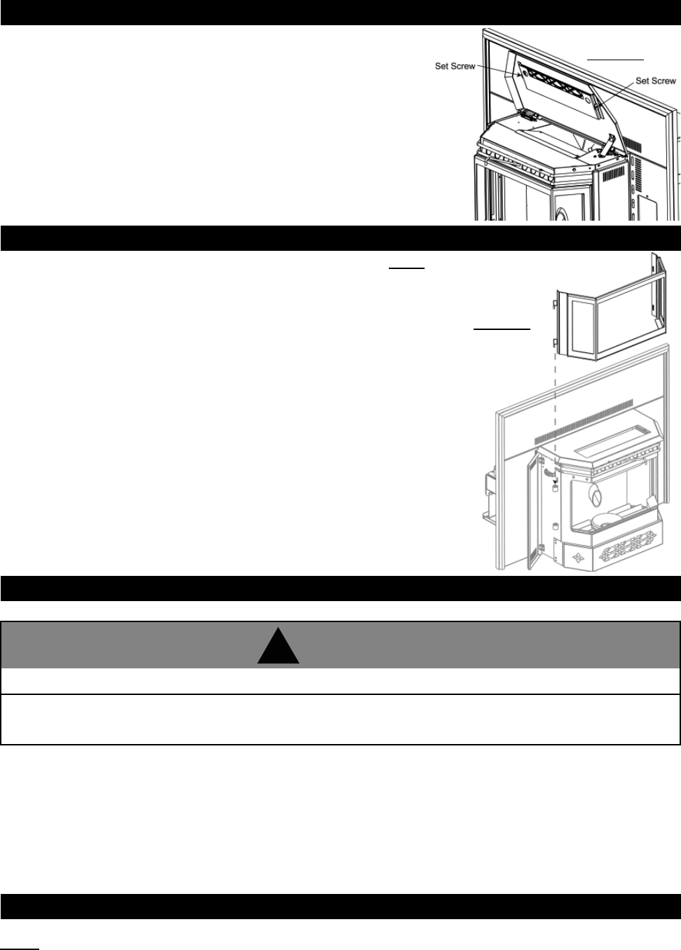
5. Align the holes in the top of the Right and
Left Flashing with those on the bottom lip
of the Top Flashing and secure from the
rear using the four #8-32 x 3/8" screws,
washers and nuts. (FIGURE 29)
6. The three pieces of trim are assembled in
the same manner as a picture frame. Place the
corner brackets (with screw loosened) into the trim
sections. Tighten the screw spreading the two
pieces apart. Attach the adjoining section. Repeat
with the opposite side. Tighten all screws fi rmly.
(FIGURE 30)
7. Slide the assembled trim down over the fl ashing.
(FIGURE 31)
8. Affi x the logo to the bottom left hand corner of the left fl ashing.
Figure 25
MINIMUM ENCLOSURE CLEARANCES
TRIM
ASSEMBLY
FIGURE 30
FIGURE 31
FLASHING INSTALLATION
FIGURE 26
CONTROL
PANEL
AIR
CONTROL
ROD
AIR
CONTROL
SLOT
RIGHT
FLASHING
BURN
RATE LABEL
LOW
HIGH
1
2
3
4
5
LOW
H
I
GH
1
2
3
4
5
FIGURE 27
PUSH TO START / POUSSEE POUR COMMENCER
5
3
1
2
4
OPTIMUM
1
3
5
4
2
SHIPPING
BRACKET
SECURING
SCREWS
CONTROL
PANEL
SECURING
SCREWS
TOP
FLASHING
FIGURE 29
FIGURE 28
NPI40 FINISHING
W415-0616 / C / 06.04.08
25
TRIVET NPI40
The trivet for the NPI40 is attached by two set screws on the inside of the hopper
lid. Figure 32
INSTALL VIEWING DOOR NPS40 AND NPI40
Figure 33
(Insert
Illustrated)
The main viewing door has been boxed separate from the heater, but MUST be installed before burning
the heater.
1. Open both side panels, exposing the bushing on the left and the latches on the right.
2. Align the pins on the door to the bushing on the left side of the heater.
Lower into place until both bushings touch.
3. Engage the latch hooks into the door frame. Snap the rear handle hook to
lock the latch closed.
Before loading pellets into the hopper fi rst transfer the pellets from it's original plastic bag to a metal bucket.
NOTE: If the pellets are kept in the plastic bag, the bag may come in contact with the heater causing the bag to
melt and the pellets to spill.
DO NOT load pellets into the hopper if they have been exposed to moisture. Moisture can cause pellets to swell and
cause blockage in the feed system. Thoroughly dry pellets before placing into hopper.
PROPER PELLET LOADING
LIGHTING HEATER MANUALLY
Your heater can be lit manually without using the automatic igniter by following the procedure below.
1. Press the start switch
2. Turn feed dial to "Optimum"
3. Place a "handful" of pellets into the burn pot.
4. Cover with a small amount of approved (non-volatile) fi re starter gel.
5. Light fi re starter with a match and close the viewing door.
Heater may be hot.
Other than placing a handful of pellets in the burn pot for lighting manually, never feed pellets through the
glass viewing door. An "OVERFIRE" condition could occur, if more pellets enter the fi rebox then what the feed
tube can deliver. Pellets must only be burned within the burn pot.
!
WARNING
W415-0616 / C / 06.04.08
26
Never use gasoline, lantern fuel, lighter fl uid to start or "freshen-up" a fi re in this heater. Keep all such fl uids
away from heater when in use.
!
WARNING
Heater may be hot
!
WARNING
It is not recommended to burn the unit on low or
high. the most effi cient setting is 4 (optimum).
!
WARNING
Due to different installation set ups, length and size of venting and fuel quality, the low feed setting from the factory will not
always be correct. It may be necessary to experiment with feed rate vs air control. (For example, #2 may be your lowest
setting).
Always operate this heater with the door closed.
If this is the fi rst time the heater has started or the heater has run out of pellets, the auger will need to be purged.
Press "START" switch, turn the pellet feed dial to high to fi ll the auger full of pellets and pull the air control rod all the way
out allowing air fl ow into the fi re. If the heater does not reach the required temperature and turns off after 15 minutes,
press the start switch again. This time turn the pellet feed dial to low, to prevent over fi lling the burn pot and continue with
the start-up instructions below.
OPERATING INSTRUCTIONS
START-UP
SHUT-DOWN
To turn your heater off, simply turn the feed dial counter-clockwise until the dial clicks to the "OFF" position. This will stop
the feed of pellets. The blowers will continue to run to cool the heater. When cool enough, the heater will shut down. DO
NOT unplug unit while combustion blower is operating. This may lead to smoke escaping from the heater into the
room.
1. Press "START" switch
2. Rotate the Pellet feed dial rate to optimum
3. Adjust the air control rod to the preferred setting (this position will vary depending on venting confi guration and fuel
quality).
4. If the heater stops running after approximately 15 minutes, press "START" switch again.
If no ignition is apparent and pellets are building up in the burn pot, remove pellets from the burn pot before restarting.
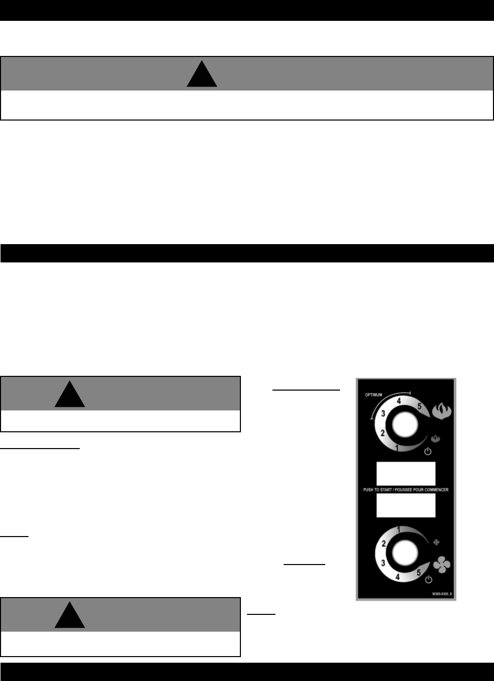
Blower Speed Dial
By adjusting the Blower Speed dial you will vary the rate of
airfl ow into the room by varying the speed of the convection
blower. When you fi rst start the heater, it should be placed in the
"OFF" position in order to heat up the unit as quickly as pos-
sible. Once the room has come up to temperature, the control
may be set to a comfortable level.
NOTE: The convection blower may cycle to high automati-
cally depending on the setting of the pellet feed rate and the
Blower Speed. This is a normal safety feature of the unit.
Once the heater has cooled down the blower will return to
the set speed.
NOTE: The fl ashing amber light corresponds to the au-
ger motor feeding the pellets. Wood pellets of different
quality may affect the performance of the heater. If the
heater has trouble operating at the ends of it's range,
adjust the feed rate accordingly.
Pellet
Feed
Dial
Auger
Cycle
Light
Start
Switch
Blower
Dial
Pellet Feed Dial
This switch controls
the amount of heat
output. The switch
has a scale (dial)
from 1 through 5. At
setting 5 the pellet
feed rate is the
greatest.
Figure 34
The pellet heater can be operated with or without the ring in place over the burn pot. With the ring in place, a more ef-
fi cient burn will occur, however more fi ner fl y ash will be experienced. It may be necessary to clean the burn pot of ash
more frequently.
W415-0616 / C / 06.04.08
27
The front of the heater becomes very hot during operation. Let the heater cool completely before conducting
service.
!
WARNING
Figure 35
GENERAL MAINTENANCE NPS40 AND NPI40
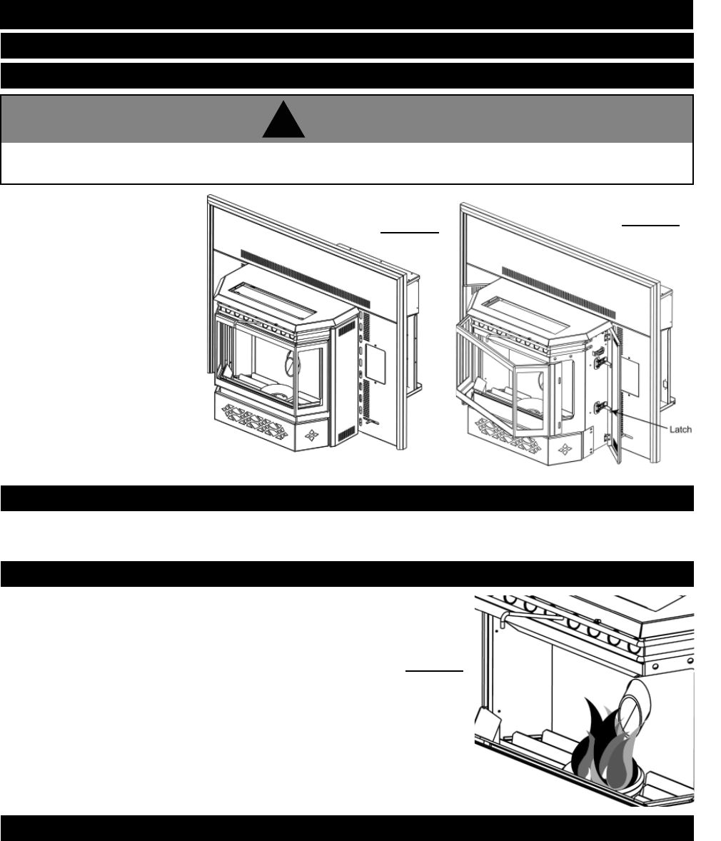
DAILY (WHENEVER USING THE HEATER)
1. Open the side doors on either
side of the heater.
2. On the right side of the heater
are two latches. Release the
latches by pulling the rear
handle forward and
disengaging the hook from
the door frame. Swing open
the viewing door.
Ashes should be placed in a metal container with a tight fi tting lid. The container should be placed on a non-combustible
fl oor, well away from combustible materials, pending fi nal disposal. If ashes are disposed of by burial in soil or otherwise
locally dispersed, they should be retained in the closed container until all cinders are thoroughly cooled.
OPEN MAIN VIEWING DOOR
DISPOSAL OF ASHES
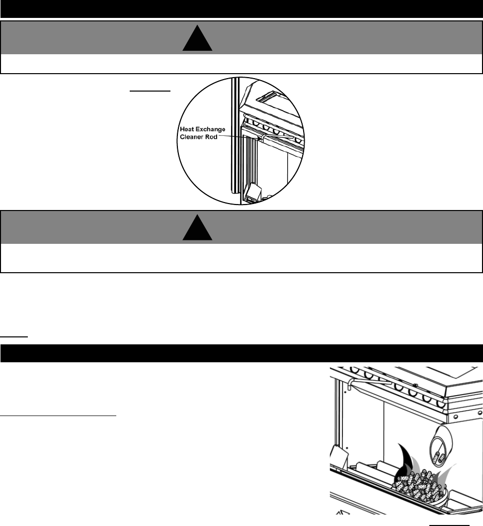
When burning, the fl ames should be bright orange with embers jumping from the
burn pot.
INSPECT THE BURN POT
If the glass is not kept clean, permanent discolouration and/or blemishes may result. If glass should ever crack, it must be
replaced using 5mm thick ceramic glass available from your Napoleon Dealer.
DO NOT SUBSTITUTE MATERIALS
DO NOT CLEAN GLASS WHEN HOT
DO NOT use abrasive cleaners to clean glass or plated parts.
DO NOT OPERATE THIS HEATER WITH THE GLASS DOOR OPEN
Figure 37
CLEANING GLASS DOOR
Figure 36
W415-0616 / C / 06.04.08
28
The front edge of the hopper lid becomes very hot, do not touch the area below the handle.
!
WARNING
If the pellets build up over the burn pot, turn the pellet feed switch to "OFF".
If the fl ames seem to be coming only from the sides, or are orange/black, turn the
heater off and check for build up of pellets.
The most likely causes are:
1. Feed rate has been set to maximum for an extended period of time. Turn feed
rate to optimum.
2. The door, glass, or ash pan is open or has an air leak.
3. The burn pot requires cleaning.
4. The exhaust system requires cleaning.
5. The heater requires adjustment.
6. Poor pellet quality
MAKE SURE PELLETS ARE NOT PILING UP
Figure 39
With the heater cool (or wearing heat resistant gloves), slide the heat exchange cleaner rod up and down several times to
prevent the build up of ash on the heat exchange tubes.
Keep the viewing door closed so the fl y ash does not enter the room.
NOTE: More frequent cleaning may be required depending upon pellet quality.
CLEANING THE HEAT EXCHANGE TUBES
Figure 38
This rod becomes very hot during operation. Wait till heater has cooled completely or you MUSt wear heat
resistant gloves when cleaning or handling this heater.
!
WARNING
W415-0616 / C / 06.04.08
29
Make certain the heater has fully cooled (approximately 25 minutes) before opening the door and conducting service.
!
WARNING
The fi re box becomes very hot during operation. Let the heater cool completely before conducting service.
!
WARNING
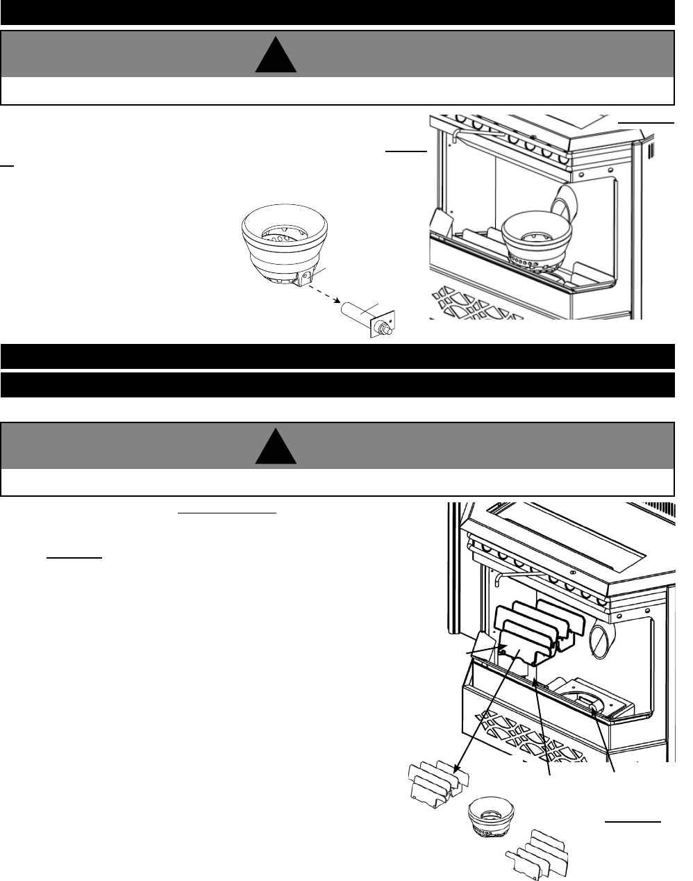
To clean the burn pot, open the door and knock away any debris on the burn
pot. If severely clogged, remove the burn pot to gain better access.
If removing the burn pot set aside on a non-combustible surface. See Figure
40. Once removed, discard all material that has accumulated in the burn pot.
Make certain that all openings are clear of any build up of ash from the ledge
below the burn pot.
CLEANING THE BURN POT
Re-install the burn pot ensuring it sits level
in the heater. Also must ensure the ignitor
and the burn pot locating notch line up
when reinstalling the burn pot.
Figure 40
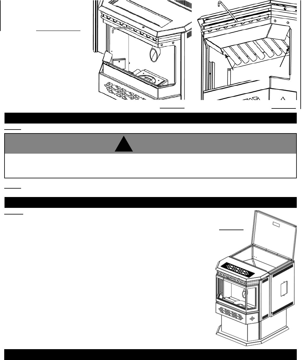
The more frequently you clean out the fl y ash, the more effi cient your heater will burn.
1. Open the viewing door. See Figure 35 and 36
2. Lift the burn pot out and set aside on a non-combustible surface.
See Figure 40. Remove the right and left louvres by lifting the louvres up
and out of the fi rebox setting them on a non-combustible surface.
VACUUM FIREBOX
Figure 41
IGNITOR
LOCATING NOTCH
LOUVRES
AIR HOUSING
FIREBOX
BI-WEEKLY (OR EVERY 10 BAGS OF PELLETS)
W415-0616 / C / 06.04.08
30
The products of combustion will contain small particles of fl y ash. The fl y ash will collect in the exhaust venting system and
restrict the fl ow of the fl ue gases. Incomplete combustion occurs during startup, shutdown, or incorrect operation of the
room heater will lead to some soot formation which will collect in the exhaust venting system. The exhaust venting system
should be inspected at least once every year to determine if cleaning is necessary.
NOTE: More frequent cleaning may be required depending on pellet quality.
NOTE: The heater becomes very hot during operation. Let the heater cool completely and disconnect the power
cord prior to conducting service.
SEMI-ANNUALLY (OR EVERY TWO TONS OF PELLET)
SOOT AND FLY ASH FORMATION
NPS40:
Run the heater until the pellets run out, then open the hopper and vacuum out the
entire hopper. The dust and any other debris near the bottom should be removed to
prevent excessive build-up.
VACUUM HOPPER
Figure 44
Cleaning the Optional Plated Surfaces
Fingerprints or other marks left on plated surfaces may become etched in place if they
are not wiped clean prior to turning the heater on. Wipe the gold with a non-abrasive
cleaning solvent and a soft cloth (make sure the heater is cool). Other cleaners may
leave a fi lm that may become etched into the fi nish.
3. Vacuum out the fi rebox,
louvres, air housing, burn pot
and the opening at the top of
the exhaust manifold of all fl y
ash. See Figure 42 and 43.
4. Replace the louvres and burn
pot, latch the viewing door
closed and close both side
doors.
Figure 42 Figure 43
Disconnect the power cord prior to conducting service. The following section details extensive maintenance
procedures. We strongly suggest these items be carried out by a trained service technician, possibly by a service
agreement set up with your dealer.
!
WARNING
Exhaust Manifold
Opening
W415-0616 / C / 06.04.08
31
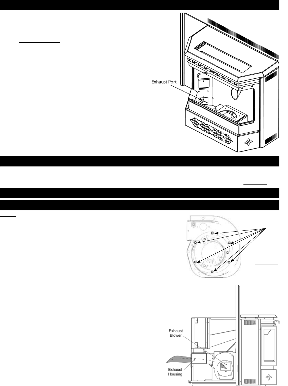
CLEAN THE VERTICAL EXHAUST DUCT
Insert a vacuum into the exhaust port holes and remove
as much fl y ash as possible from behind the left and right
exhaust manifolds. Once clean, replace the exhaust port
doors and secure with the screws.
CLEAN EXHAUST HOUSING (INSERT ONLY)
To clean the exhaust blower and exhaust housing, the heater must be pulled out from the fi replace cavity. Remove the vent-
ing from the exhaust collar. If installed as a top vent, remove cover plate from the rear of the housing. If installed as a rear
vent, remove the cover plate from the top of the housing. Vacuum out the housing back to blower outlet. See Figure 47.
Figure 45
If the PRPP40 or the brick kit NP841KT is in place, remove that accessory
fi rst.
1. Open side door, release the latch and pivot the viewing door wide open.
See Figure 35 and 36.
2. Remove the one screw on each exhaust port located on either side of
the fi re box. Remove the exhaust port doors and set aside on a
non-combustible surface.
SEMI-ANNUALLY (OR EVERY TWO TONS OF PELLET)
Figure 47
CLEAN THE EXHAUST BLOWER
Nuts
Figure 46
NOTE: Do not attempt this maintenance without a replacement exhaust
blower motor mounting gasket.
1. Remove the six nuts holding the exhaust blower motor in place.
2. Pull the motor out being careful not to damage the wiring, unplug the two
wires that are connecting the motor and gently set aside. (The pieces of
gasket may be discarded.
3. Start by cleaning the exhaust tube by feeding a brush or rag through the
inside of the tube and out the exhaust blower housing.
4. Vacuum out the exhaust ports and the blower housing.
5. With a bristle brush vacuum, clean the blades of the motor.
6. Place the new exhaust blower mounting gasket around the screw holes being
very careful not to tear it.
7. Re-attach the wiring to the motor and place it back on to the
housing, taking care that the side of the motor does not tear the
gasket and then re-attach the nuts.
W415-0616 / C / 06.04.08
32
CLEAN THE VENT
Figure 48
Check for air leaks around the door, glass, and ash pan and replace gaskets as required.
Air leaks into the fi rebox will decrease the heater's performance greatly, leading to excessive soot, ineffi cient burning, and
may even cause a malfunction.
Test the door seal by shutting the door on a piece of paper in various locations. If the paper can be easily slid out, air may
be leaking around the door seal. Carefully inspect the door gasket and door catch.
Inspect the door gasket to make sure it is fully attached. Heater gasket cement can be used to re-attach if necessary. If
the door gasket is worn or fl attened, replace.
Check the door to make sure it latches correctly. The latch should engage with a slight amount of resistance, yet not be
too diffi cult.
If the glass is cracked, replace.
CHECK ALL SEALS
Vent system should be cleaned using chimney sweep
brushes. We recommend this be done by a qualifi ed chimney
sweep.
W415-0616 / C / 06.04.08
33
Figure 49
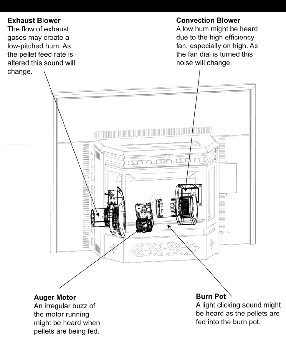
NORMAL OPERATING SOUNDS
W415-0616 / C / 06.04.08
34
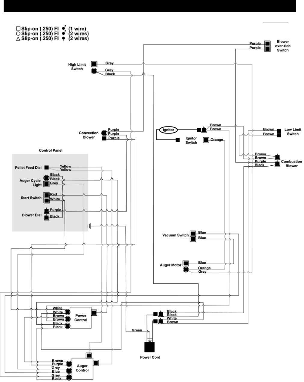
WIRING DIAGRAM
Figure 51

W415-0616 / C / 06.04.08
35
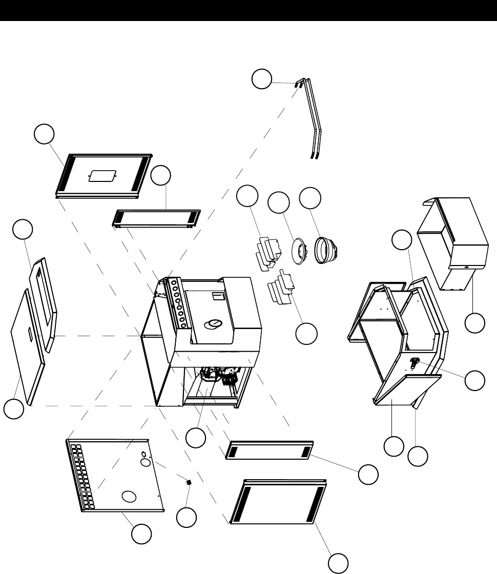
#
PART NO. DESCRIPTION
1 W660-0052 LOW LIMIT SWITCH 140°F (80°C)
2 W660-0053 OVER-RIDE SWITCH 160°F (71°C)
3 W660-0054 IGNITION SWITCH 120°F (60°C)
4 W660-0055 HIGH LIMIT SWITCH 200°F (93°C)
5 W660-0056 VACUUM SWITCH
6 W380-0020 CONTROL KNOB
7* W195-0004 POWER CORD
8 W435-0009 AUGER MOTOR
9 W062-0021 CONVECTION BLOWER
10 W062-0022 COMBUSTION BLOWER
11 W290-0111 COMBUSTION BLOWER MOUNTING GASKET
12 W290-0120 COMBUSTION BLOWER MOTOR MOUNTING GASKET
13 W290-0113 CONVECTION BLOWER GASKET
14* W255-0020 PRESSURE FITTING TAP
15 W570-0107 AUGER SCREW
16 W390-0002 DOOR LATCH
17 W190-0019 POWER CONTROL
18 W190-0020 AUGER CONTROL
19 W405-0001 AMBER LIGHT
20 W660-0058 POWER SWITCH
21 W660-0063 PELLET FEED SWITCH
22 W660-0062 VARIABLE SPEED W/O PAL NUT SWITCH
23 W555-0061 SCRAPER ROD
24 W105-0012 NYLON BUSHING
25 W570-0110 SCREW SET
26* W750-0163 HARNESS WIRE
27* W385-0334 NAPOLEON® LOGO
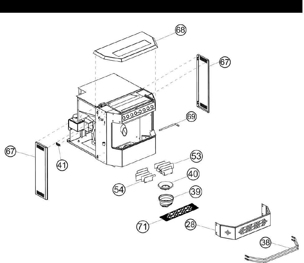
28 W010-1528 CONTROL DOOR
29 W475-0555 BOTTOM OI PANEL
30 W720-0089 IGNITOR HOUSING
31 W390-0012 CONTROL PANEL LATCH
32 W010-1490 EXHAUST TUBE
33 W357-0004 IGNITOR
34* W325-0042 SMALL BLACK WIRE HANDLE
35 W350-0361 CONTROL HOUSING
36 W615-0073 AIR CONTROL SPACER
37 W080-0777 MOTOR BRACKET
38 W010-1491 COMBUSTION AIR TUBE ASSEMBLY
39 W030-0022 ACCENT BAR (2)
40 W135-0320 CAST, BURN POT
41 W135-0321 CAST, RING
42 W430-0002 MAGNETIC DOOR CATCH ASSEMBLY (2)
43* W290-0120 MOTOR MOUNTING GASKET
44 W290-0119 IGNITION GASKET
45 W460-0004 RECEPTACLE
46* W615-0078 SPACER, LATCH
47 W300-0038 GLASS, FRONT
48 W300-0037 GLASS, SIDE
49* W562-0022 GLASS GASKET
50 W290-0122 EXHAUST GASKET
51 W010-1612 EXHAUST COLLAR
REPLACEMENTS
Contact your dealer for questions concerning prices and availability of replacement parts. Normally all parts can be or-
dered through your Authorized dealer or distributor.
When ordering replacement parts always give the following in formation:
1. Model and Serial Number of the fi replace
2. Installation Date of the fi replace
3. Part Number
4. Description of part
5. Finish
For warranty replacement parts, a photocopy of the original invoice will be required.
* Identifi es items which are not illustrated. For further information, contact your Authorized dealer.
COMMON COMPONENTS TO BOTH UNITS
#
PART NO. DESCRIPTION
52 W010-0219 EXHAUST COVER
53 W290-0122 EXHAUST GASKET
54 W010-1673 RIGHT LOUVRE ASSEMBLY
55 W010-1685 LEFT LOUVRE ASSEMBLY
56 W010-1567 AIR CONTROL
57 W010-1508 WELDED TOP ASSEMBLY
58 W010-1527 SIDE DOOR ASSEMBLY
59 W010-1529 HOPPER DOOR ASSEMBLY
60 W010-1667 ASH PAN ASSEMBLY
61 W010-1668 PEDESTAL SIDE DOOR ASSEMBLY
62 W035-0191 PEDESTAL BASE
63* W555-0059 AIR CONTROL ROD
64 W475-0482 OUTER REAR PANEL
65 W475-0484 OUTER PANEL, RIGHT
66 W475-0485 OUTER PANEL, LEFT
67 W652-0040 PEDESTAL GASKET
68 W010-1670 SIDE DOOR ASSEMBLY
69 W010-1671 WELDED HOPPER LID ASSEMBLY
70 W555-0069 AIR CONTROL ROD
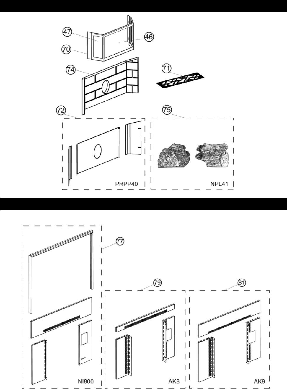
71 W225-0195 DOOR FRAME, BLACK
71 W225-0195G DOOR FRAME, GOLD
71 W225-0195SC DOOR FRAME, SATIN CHROME
72 GS200-G TRIVET
72 GS200-SS TRIVET
73 PRPP40 PORCELAIN REFLECTIVE RADIANT PANELS
74* 114KT OUTSIDE AIR KIT - 5 FT (2" DIA.)
75 NP841KT BRICK, REFRACTORY
76 NPL41 DECORATIVE LOG SET
77* NPHE-40 HOPPER EXTENSION (INCREASES HOPPER
CAPACITY FROM 55 LBS TO 100 LBS PELLETS)
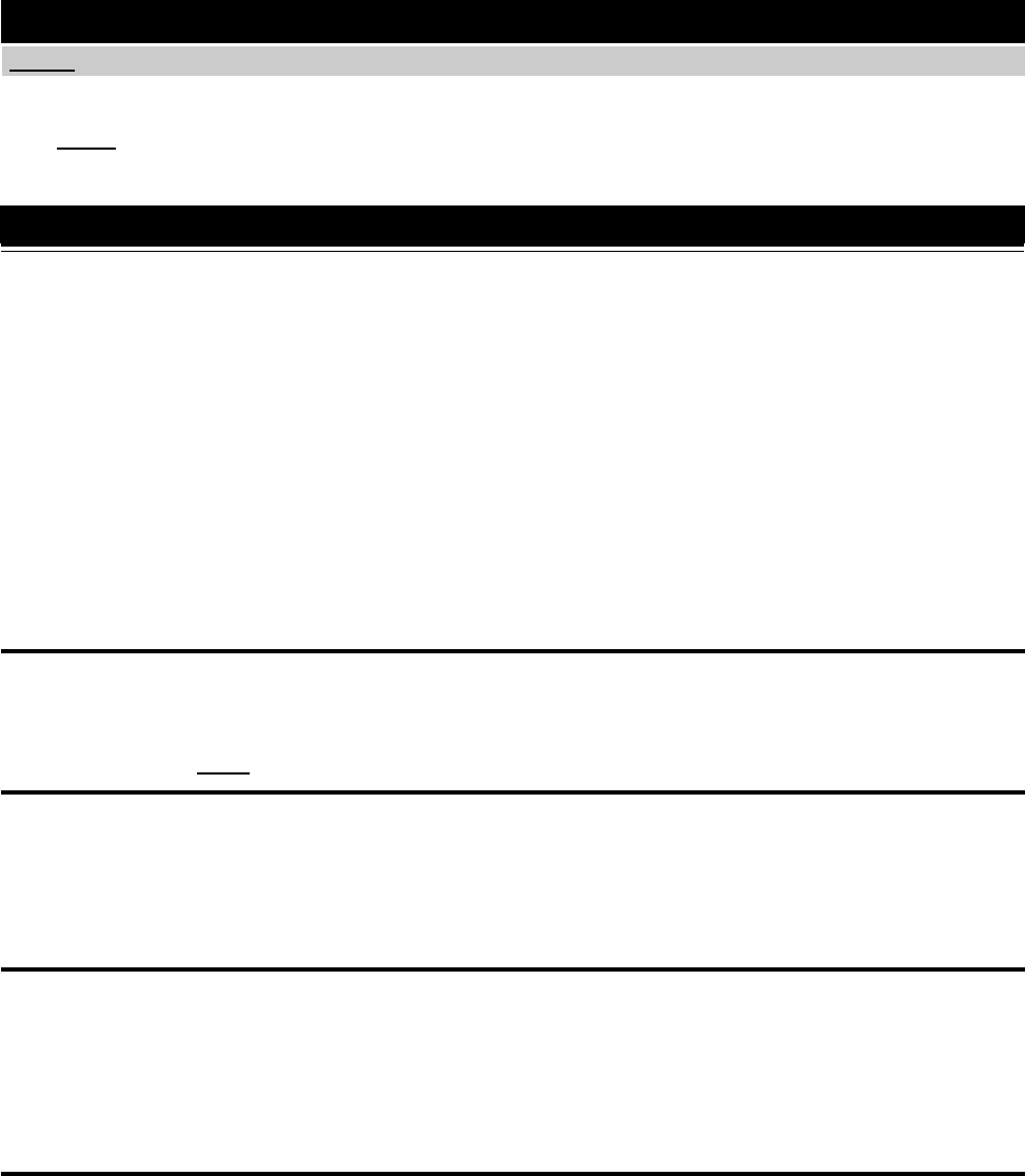
78 NI800 8" BLACK FLASHING WITH BLACK TRIM
79* GICSK ARCHED CAST IRON SURROUND
80 AK8 ADAPTOR KIT (REQ'D FOR GICSK)
81* CISK CAST IRON SURROUND KIT - BLACK
81* CISKK CAST IRON SURROUND KIT - ENAMEL BLACK
81* CISKN CAST IRON SURROUND KIT - MOJOLICA BROWN
81* CISKB CAST IRON SURROUND KIT - MOJOLICA BLUE
81* CISKF CAST IRON SURROUND KIT - MOJOLICA GREEN
82* AK9 ADAPTOR KIT (REQ'D FOR CISK)
NPI40 COMPONENTS
COMMON ACCESSORIES
NPS40 COMPONENTS
NPI40 ACCESSORIES
NPS40 ACCESSORIES
W415-0616 / C / 06.04.08
36
COMMON REPLACEMENTS PARTS
W415-0616 / C / 06.04.08
37
NPS40 REPLACEMENTS PARTS
57
38
61
44
63
65
57
64
56
58
59
60 66
15
31
39
54
40
53
W415-0616 / C / 06.04.08
38
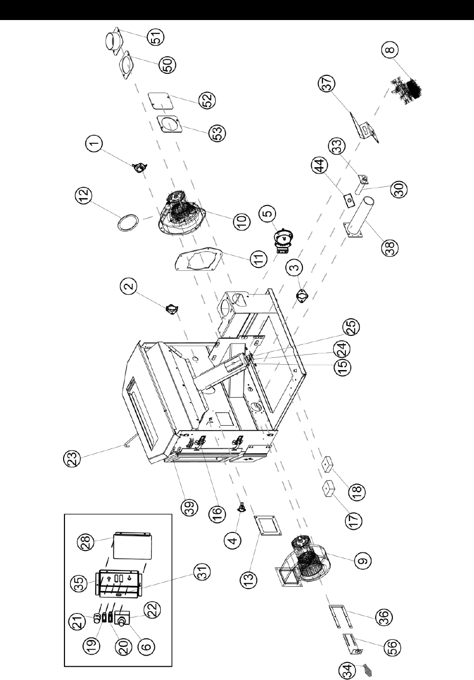
NPI40 REPLACEMENTS PARTS
W415-0616 / C / 06.04.08
39
NPI40 ACCESSORY PARTS
COMMON ACCESSORY PARTS
W415-0616 / C / 06.04.08
40
TROUBLESHOOTING
SYMPTOM TEST SOLUTION
*NOTE: All troubleshooting procedures should be carried out by qualifi ed technicians or installers.
The heater will
not start
Smoke in the
room
The exhaust
blower is not
operating
The ignitor will
not light the
pellets however
everything else in
the heater oper-
ates
The auger motor
is not functioning
normally
- Make certain there is power to the outlet and that the heater is plugged in.
- With the heater unplugged, examine all connections. Make sure no exposed wires are
touching the heater (except the chassis ground wire) and that they are all fi rmly
connected.
- Check the manual reset hi limit switch
- Check the stability and placement of connections against the wiring diagrams in this
manual.
- Check that the burn pot is positioned properly.
- Push the "START" switch. If the heater fails to start, unplug the unit.
- Ensure that connections to the power control module are connected.
- Place a jumper wire between the red and white wires that attach to the start switch.
- Plug stove in, if stove starts replace switch.
- Replace the power control if this fails.
CAUTION: Check the ignitor resistance before installing a new start-up timer as it may
result in another failure to the new start-up timer due to a short in the ignitor. The proper
resistance through the ignitor should be 30Ω to 50Ω (± 3Ω).
- Check all gasket seals.
- Vent connections all sealed.
- Unit has failed to reach 140°F within 15 minutes and the blower has shut off.
- Restart unit.
NOTE: A minimal amount of smoke is normal during the start up process.
- Remove the left side access panel and check all connections against the wiring
diagram. For the insert - remove from cavity.
- Apply 115V AC directly to the exhaust blower and if the motor does not run, replace the
blower.
- If the motor runs, have a dealer check the wire harness.
- See "The heater will not operate when hot" section
- Contact your local dealer or a certifi ed technician for service.
- Push the burn pot back against the ignitor tube making sure the ignitor lines up to the
hole in the burn pot.
- Make certain the air control rod is pushed in to start up position.
- Check all the electrical connections on the 120°F (49°C) temperature sensor located on
the exhaust channel.
- Place a jumper wire between the two leads on the 120°F (49°C) temperature sensor
and if the ignitor works, replace the sensor.
- If it still fails to light, replace the ignitor.
- Make certain the exhaust blower is operating
- Check the condition of the vacuum hose (located on the left side of the heater). Should
not be cracked or torn.
- Check the manual reset button on the 200°F (93°C) temperature sensor. Before
re-setting the red button, check for the cause of the over-heating.
- Check that the auger set screw is tight and not slipping.
- If the auger still does not work, then apply 115V AC directly to the auger motor. If it still
does not work, replace it.
- Check the auger by bypassing the 200°F (93°) temperature sensor with a jumper wire.
If auger works, replace the sensor.
- Check the vacuum sensor by placing a jumper wire between the blue wire and the
black wire that are attached to the sensor. If the auger works, test to see if the exhaust
blower is producing enough vacuum (may require cleaning).
- If not, replace the vacuum sensor.
CAUTION: When checking connections, installing jumper wires (for test purposes only) or replacing
components, unplug heater from the receptacle to prevent electrical shock or dampage to the compo-
nent. NOTE: Many of the following tests will require that the side panels are removed from the stove
or the insert be removed from its cavity to access the components. Before troubleshooting always
confi rm that all components are clean and free of ash build up.

W415-0616 / C / 06.04.08
41
TROUBLESHOOTING CONTINUED
SYMPTOM
Feed rate dial has
no effect on the
fi re (timer control
only)
The convection
blower is not
functioning nor-
mally
The heater will
not operate when
hot
TEST SOLUTION
- Secure all connections to the power control module.
- Perform a resistance test to the potentiometer by placing the two test leads
from a multi meter into the leads of the potentiometer. The potentiometer should have a
range of 850 KΩ (± 10%).
Potentiometer Readings:
Full counter-clockwise (switched off) = open circuit, overload or infi nite
resistance
Low fi re .......... 900 KΩ to 1,050 KΩ
High fi re ......... 56 KΩ to 62 KΩ
If the range is not close or does not vary then replace the potentiometer.
- Using the wiring diagram, compare all the connections between the controller, switch,
and the convection blower.
- If the convection motor will not run, apply 115V AC to the motor directly. Replace the
blower controller if the motor runs. The convection blower has failed if the motor does
not run. Replace the blower.
- If the convection blower runs on high at all times (no control with the blower controller),
check the connections from the 160°F (71°C) sensor (located on the upper left side on
the rear of the fi re wall) and convection blower controller to the blower. Disconnect one
of the wires from the sensor and if control of the convection blower returns to the
blower controller, replace the sensor.
- If the motor is still on high, re-connect the sensor and replace the convection blower
controller.
General
- Check the hopper for fuel.
- Incorrect air damper setting may cause excessive air to consume the fi re too quickly
before the next drop of fuel. Therefore leaving the fuel completely unburned in the burn
pot and will cause the fuel to burn cold and very slowly. Fuel also may build up and
smother the fi re.
NOTE: The unit may require a change to the vent system or installation of fresh air to
correct air to fuel ratio problems.
- Combustion blower failure may occur because it is not turning fast enough to generate
the proper vacuum in the fi re box. Do a visual check to see if the motor is turning.
- Check vacuum levels in the exhaust channel by bypassing the vacuum switch, then
remove the vacuum hose from vacuum switch. When checking the vacuum exhaust
place the open end of the vacuum hose on the gauge (readings must be above 0.10"
W.C. on low fi re). (NOTE: if the motor fails to reach a 0.10" W.C., then replace the
combustion blower).
- Poor quality fuel may not produce enough heat to keep the stove burning or
operational.
- If the exhaust temperature sensor fails try bypassing the sensor located on the exhaust
blower. If the stove operates properly, the unit may require cleaning or a new sensor.
Contact your local deal for service.
- Unplug the stove, open the left side panel and jump the two brown leads that are
attached to the 140°F (60°C) temperature sensor. If the stove operates replace the
140°F (60°C) sensor.

W415-0616 / C / 06.04.08
42
TROUBLESHOOTING CONTINUED
SYMPTOM TEST SOLUTION
The 200°F (93°)
high limit tem-
perature sensor
has tripped
The heater will
not turn off
The heater keeps
going out
Excessive carbon
build up in the
fi rebox, low heat
out put
Unit is burning
dirty and lazy
- Reset the sensor and determine whether it was the convection blower or 160°F (71°C)
temperature sensor failure. Bypass the 160°F (71°C) sensor. Does the convection
blower not come on high? If no than replace the blower.
- Disconnect one of the brown wires from the exhaust temperature sensor and if the unit
continues to operate, contact your local dealer for service.
- Compare the wiring diagram to the start control module and the connections to the
140°F (60°C) temperature sensor. Check the connections.
- Remove one of the brown wires from the 140°F (60°C) temperature sensor. The heater
should be shut down right away as long as the start button was not pressed within 15
minutes of this test. If the heater shuts down within 15 minutes, replace the 140°F
(60°C) sensor. If the heater does not shut down in 15 minutes, test the switch.
- The heater must be cold to test the switch. Pull the plug, then plug the heater back in. If
the heater fails to start, replace the switch.
- Due to different installation set ups, length and size of venting and fuel quality, the low
feed setting from the factory will not always be correct. It may be necessary to
experiment with feed rate vs air control. (For example, #2 may be your lowest setting).
- If the heater goes out and leaves fresh unburned pellets or cigarette-like ashes in the
burn pot, the fi re is going out before the heater shuts off.
- Check to see if the air control rod is in the correct position.
- Turn the feed rate up slightly (poor quality pellets will require slightly higher settings).
- Check to see if the heater needs a more complete cleaning as well as the burn pot,
venting, etc...
- Was there a power failure?
- Contact your local dealer for service
- If the heater goes out and there are no pellets in the liner, the auger is stopping.
- See "The auger motor will not function normally" and "The exhaust blower will not
function normally".
- Check quality of pellets. Even pellets from the same manufacturer can vary in quality
since the materials they use to form pellets may also vary.
- Moisture content of pellets too high. Pellets must be stored in a dry place. Areas such
as a garage are too damp causing pellets to absorb moisture.
- Check that all exhaust and intake pathways are clear of any obstructions.
- Burn pot is clean.
- Pellets are dry.
- Venting and terminal are clear of obstructions.
- Exhaust blower is operation and is clean.

W415-0616 / C / 06.04.08
43
SERVICE AND MAINTENANCE LOG
Dealer's Name:
Dealer's Address:
City: State/Province: Zip Code/Postal Code:
Serial Number: Date of Purchase: Date Installed:
Notes:
OWNERSHIP RECORDS
SERVICE DATE SERVICE TECHNICIAN SERVICE DESCRIPTION

W415-0616 / C / 06.04.08
44
NOTES
