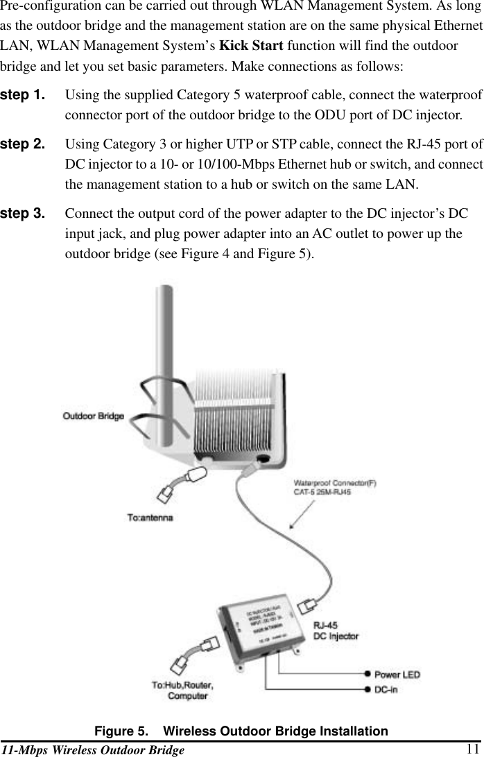
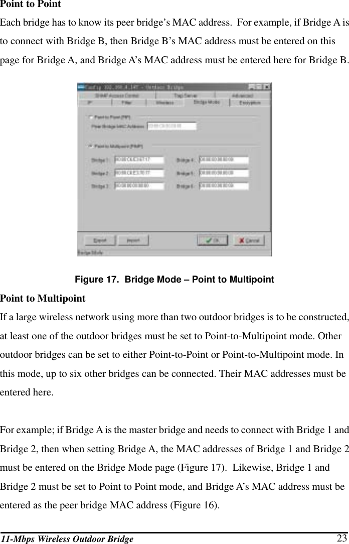
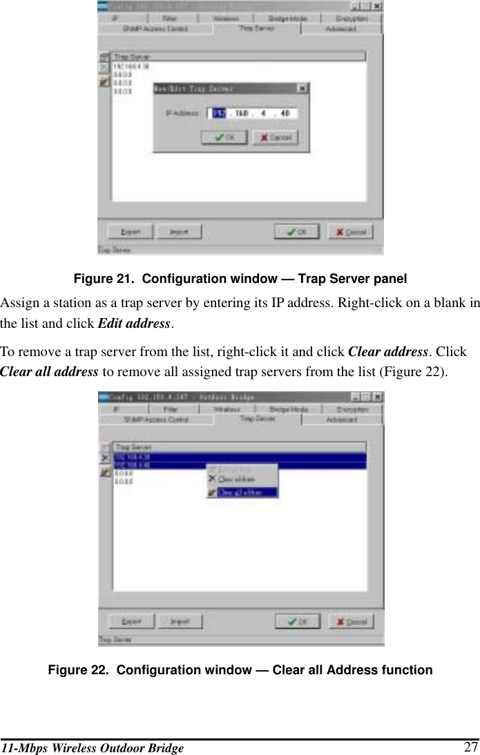
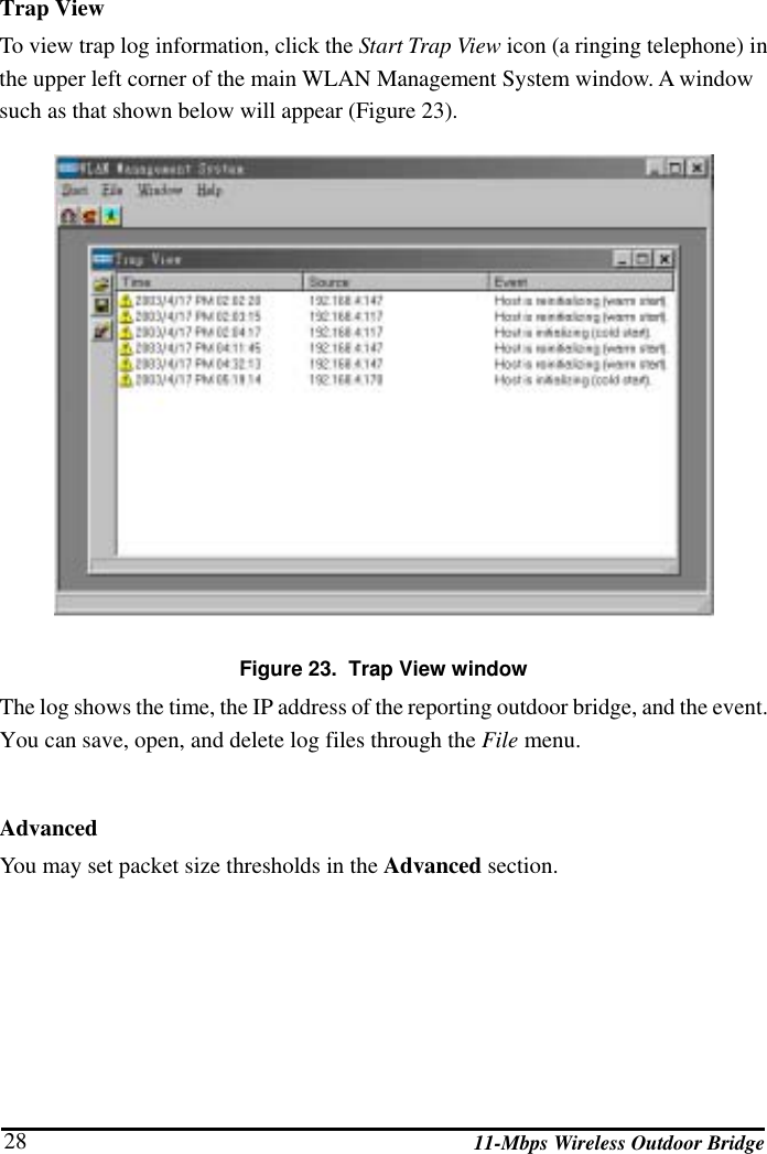
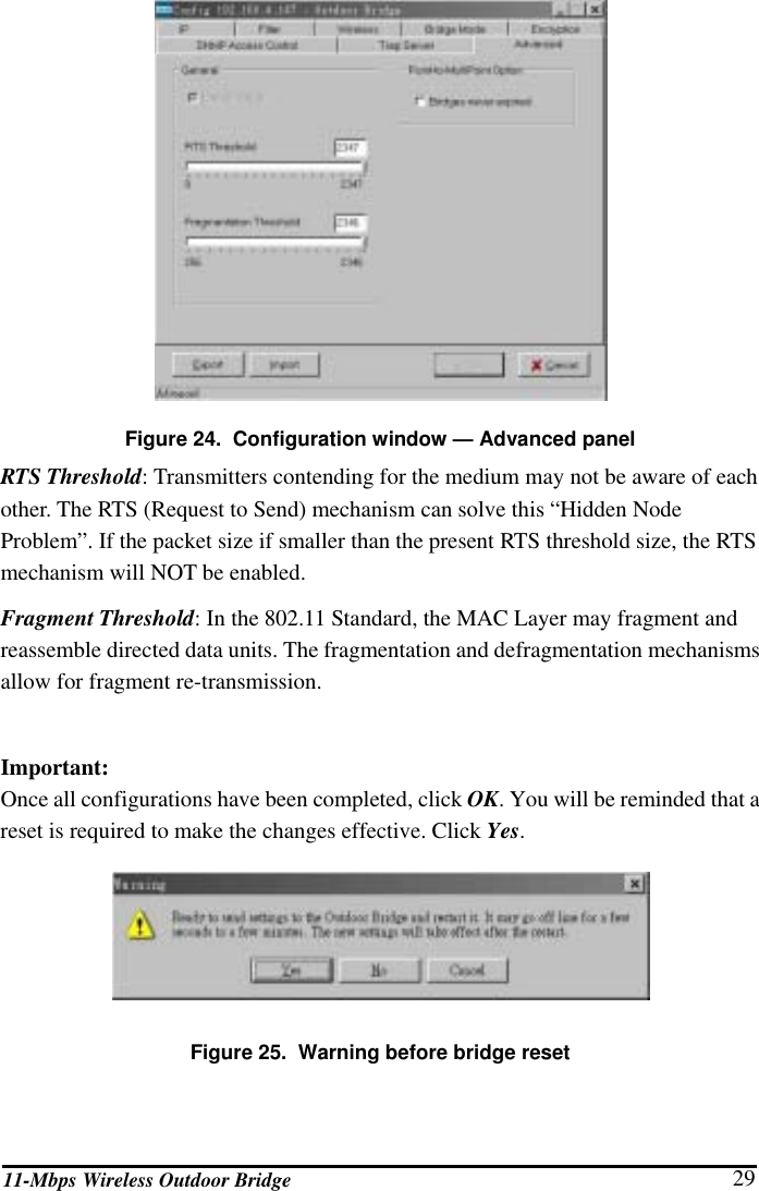
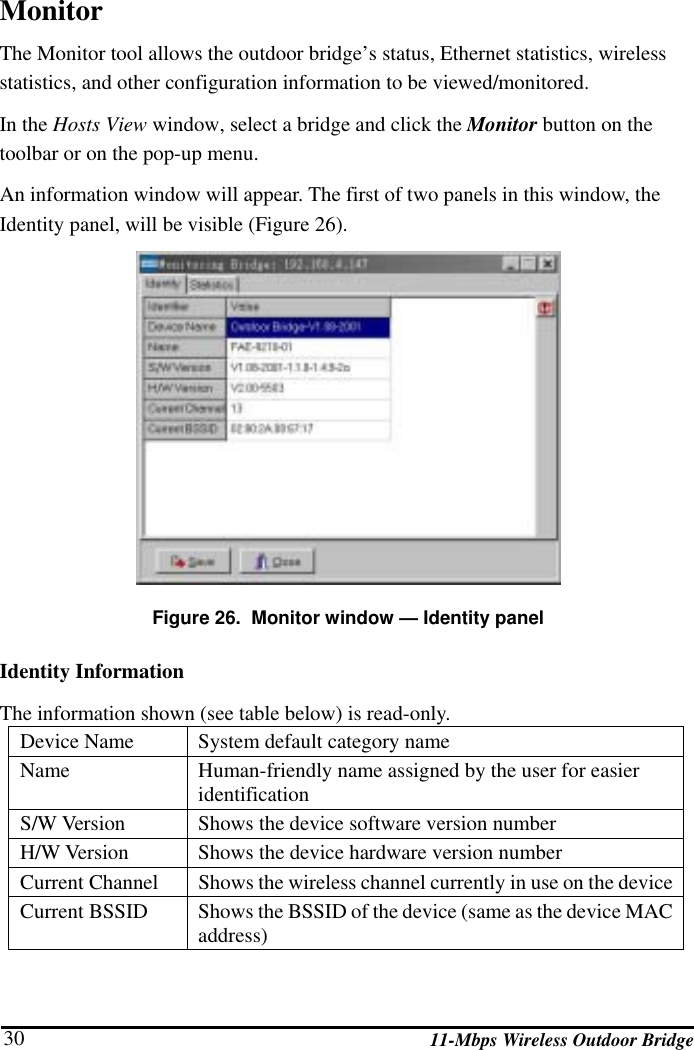
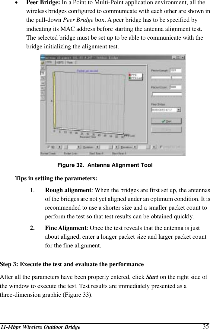
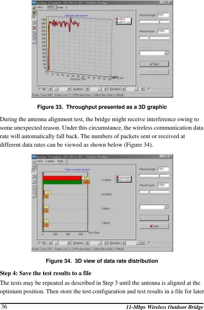
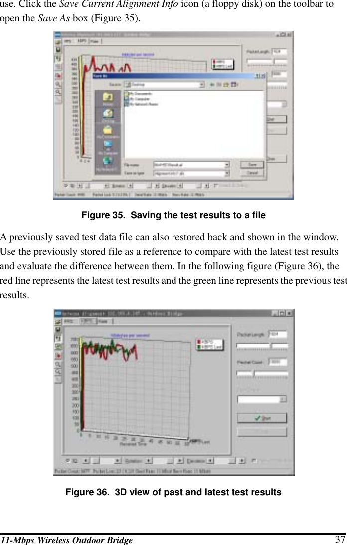
National Datacomm 9210S01 OUTDOOR BRIDGE User Manual USERS MANUAL
National Datacomm Corporation OUTDOOR BRIDGE USERS MANUAL
UserManual.wiki
>
National Datacomm
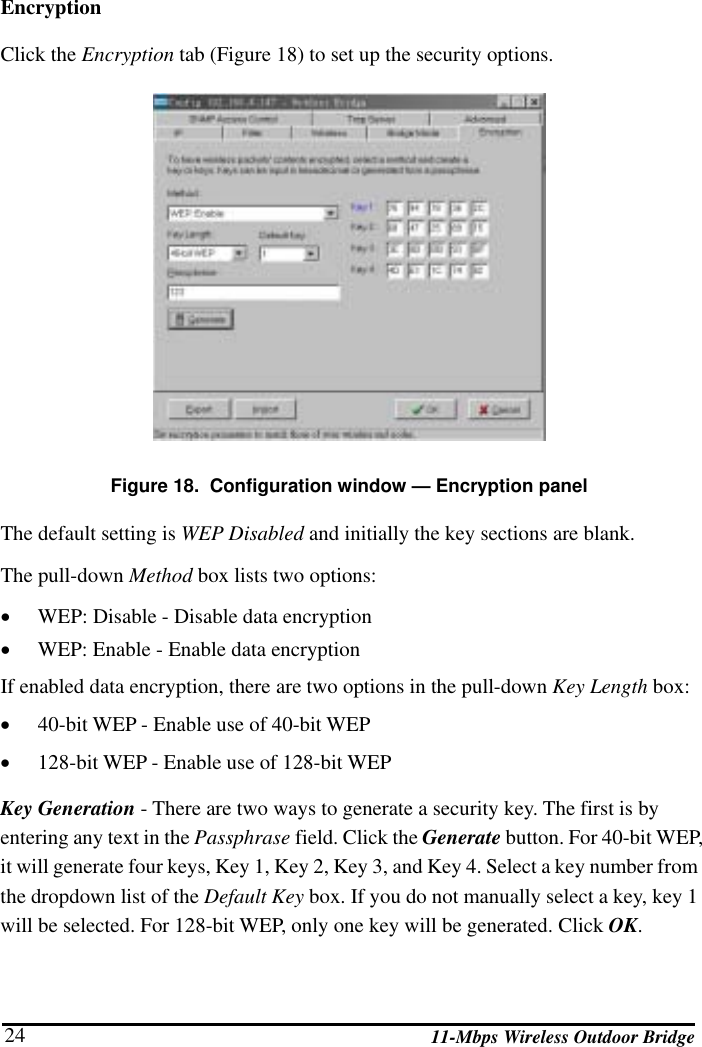
>
9210S01 User Manual
USERS MANUAL
Navigation menu
Upload a User Manual
Namespaces
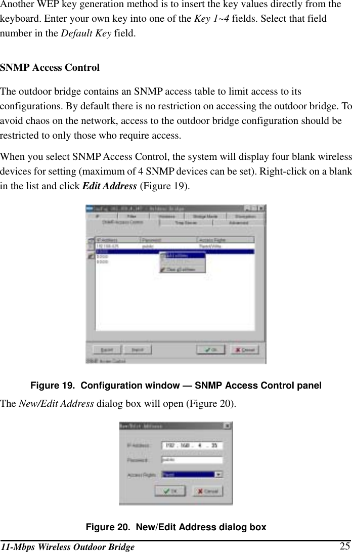
Wiki Guide
HTML
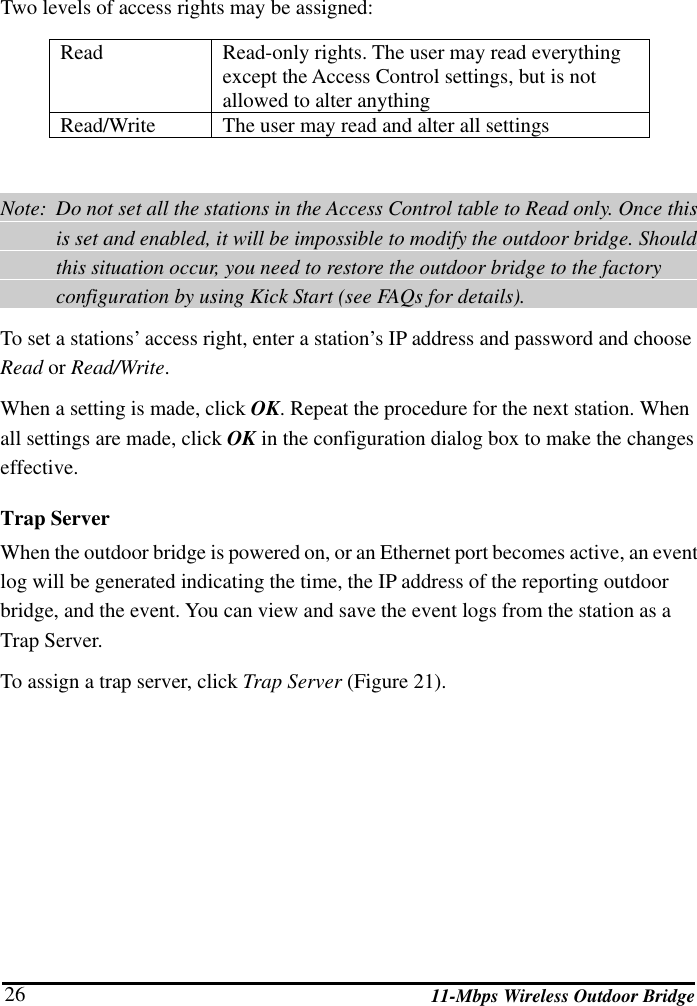
PDF
Info
Views
User Manual
Discussion / Help
Navigation

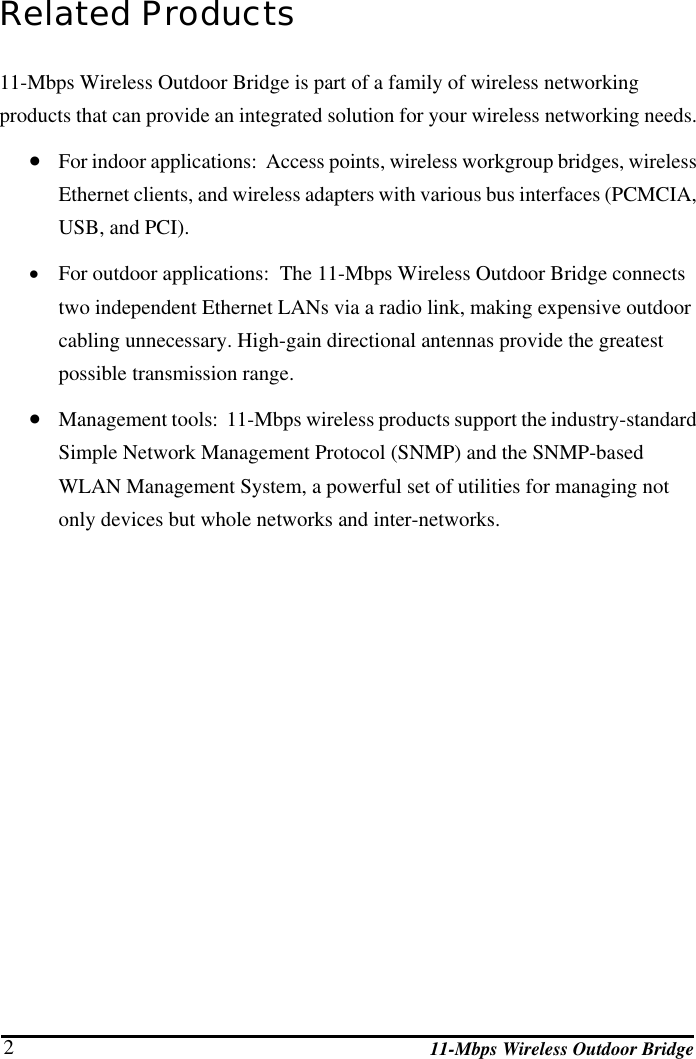
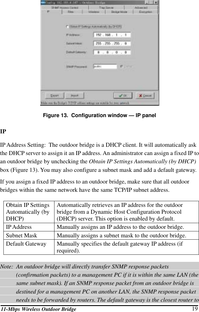
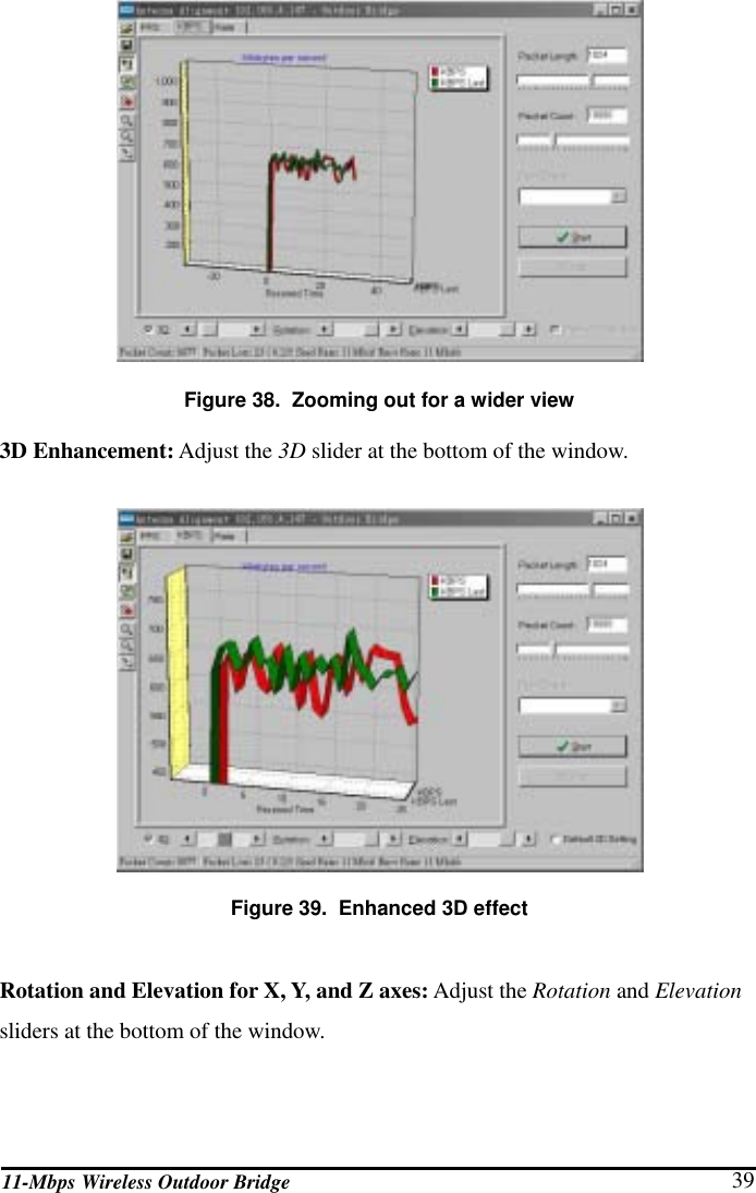
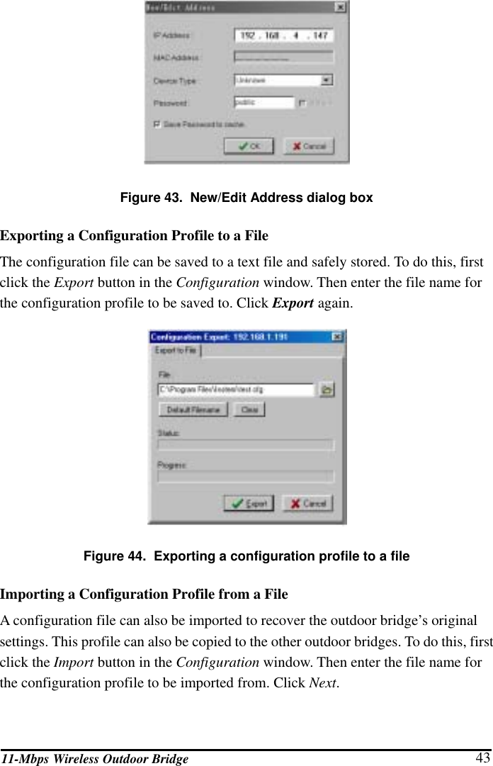
![11-Mbps Wireless Outdoor Bridge 38 Step 5: View test results as a three-dimensional graphic The Antenna Alignment utility allows the user to view the test results in multiple ways: • 2D (two-dimensional) or 3D (three-dimensional) • Zoom in for a magnified view or zoom out for a wider view • Rotation: rotate the view angle from side view • Elevation: rotate the view angle from top view Zooming in for a magnified view: Click the Zoom In icon (a magnifying glass and a plus sign [+]) from the toolbar. Click the right button of the mouse and drag the graphic window to adjust the result’s focus. Figure 37. Zooming in for a magnified view Zooming out for a wider view: Click the Zoom Out icon (magnifying glass and a minus sign [-]) from the toolbar.](https://usermanual.wiki/National-Datacomm/9210S01/User-Guide-355717-Page-46.png)