National Instruments At Users Manual Serial Hardware And Software For Windows User
PCI to the manual 766d9239-6427-4e27-8b05-c71a94e88d21
2015-02-05
: National-Instruments National-Instruments-At-Users-Manual-493622 national-instruments-at-users-manual-493622 national-instruments pdf
Open the PDF directly: View PDF ![]() .
.
Page Count: 208 [warning: Documents this large are best viewed by clicking the View PDF Link!]
- Serial Hardware and Software for Windows User Manual
- Support
- Important Information
- Compliance
- Contents
- About This Manual
- Chapter 1 Introduction
- Chapter 2 PCI Serial Hardware Installation, Verification, and Configuration
- Chapter 3 PXI Serial Hardware Installation, Verification, and Configuration
- Chapter 4 PCMCIA Serial Hardware Installation, Verification, and Configuration
- Chapter 5 AT Serial Hardware Installation, Verification, and Configuration
- Chapter 6 Using Your Serial Hardware
- Appendix A Connector Descriptions
- Appendix B Serial Port Information
- Appendix C Uninstalling the Hardware and Software
- Appendix D Troubleshooting and Common Questions
- Appendix E Specifications
- Appendix F Technical Support Resources
- Glossary
- Index
- Figures
- Figure 2-1. PCI Serial Board Installation
- Figure 2-2. Device Manager for PCI Serial Board Ports
- Figure 2-3. Port Settings Tab
- Figure 2-4. Advanced Settings Dialog Box
- Figure 2-5. PCI Serial Board Installation
- Figure 2-6. Device Manager Tab for PCI Serial Board Ports
- Figure 2-7. Port Settings Tab
- Figure 2-8. Advanced Port Settings Dialog Box
- Figure 2-9. Installing the PCI Serial Board
- Figure 2-10. niports Configuration Utility
- Figure 2-11. General Port Settings Dialog Box
- Figure 3-1. Installing the PXI Serial Board
- Figure 3-2. Device Manager for PXI Serial Board Ports
- Figure 3-3. Port Settings Tab
- Figure 3-4. Advanced Settings Dialog Box
- Figure 3-5. Installing the PXI Serial Board
- Figure 3-6. Device Manager for PXI Serial Board Ports
- Figure 3-7. Port Settings Tab
- Figure 3-8. Advanced Settings Dialog Box
- Figure 3-9. Installing the PXI Serial Board
- Figure 3-10. niports Configuration Utility
- Figure 3-11. General Port Settings Dialog Box
- Figure 4-1. Inserting a PCMCIA Serial Card
- Figure 4-2. Device Manager for PCMCIA Serial Card Ports
- Figure 4-3. Port Settings Tab
- Figure 4-4. Advanced Settings Dialog Box
- Figure 4-5. Inserting a PCMCIA Serial Card
- Figure 4-6. Device Manager Ports List for PCMCIA Serial Card Correctly Installed
- Figure 4-7. Port Settings Tab
- Figure 4-8. Advanced Port Settings Dialog Box
- Figure 4-9. Inserting a PCMCIA Serial Card
- Figure 4-10. niports Configuration Utility
- Figure 4-11. General Port Settings Dialog Box
- Figure 4-12. Resource Configuration Dialog Box for the PCMCIA-485
- Figure 4-13. Resource Configuration Dialog Box for the PCMCIA-485/2
- Figure 5-1. AT Serial Board Installation
- Figure 5-2. Device Manager for AT Serial Board Ports
- Figure 5-3. Port Settings Tab
- Figure 5-4. Advanced Settings Dialog Box
- Figure 5-5. AT Serial Board Installation
- Figure 5-6. Device Manager Ports List for AT Serial Board Correctly Installed
- Figure 5-7. Port Settings Tab
- Figure 5-8. Advanced Port Settings Dialog Box
- Figure 5-9. AT Serial Board Installation
- Figure 5-10. niports Configuration Utility
- Figure 5-11. General Port Settings Dialog Box
- Figure 5-12. PnP Port Configuration Dialog Box for the AT-232/4
- Figure A-1. DB-9 Connector Pin Locations
- Figure A-2. 10-Position Modular Jack Pin Locations
- Figure A-3. DB-25 Connector Pin Locations
- Figure A-4. Connecting the Cables to Your Four-Port PCI Serial Board
- Figure A-5. 68-Pin Connector Pin Locations
- Figure A-6. 100-Pin Connector Pin Locations
- Figure B-1. Typical Full-Duplex System
- Figure B-2. Typical Half-Duplex System
- Figure B-3. Multidrop Network Using Terminating Resistors
- Figure B-4. Transmission Line Using Bias Resistors
- Figure B-5. Straight-Through Cabling in a DTE-to-DCE Interface
- Figure B-6. Null-Modem Cabling in a DTE-to-DTE Interface
- Figure C-1. Selecting an Interface to Uninstall
- Figure C-2. Selecting an Interface to Uninstall
- Figure C-3. Selecting an Interface to Uninstall
- Figure C-4. Selecting an Interface to Uninstall
- Figure C-5. Selecting an Interface to Uninstall
- Figure C-6. Selecting an Interface to Uninstall
- Figure C-7. Selecting an Interface to Uninstall
- Figure C-8. Selecting an Interface to Uninstall
- Figure C-9. Selecting an Interface to Uninstall
- Figure C-10. Selecting an Interface to Uninstall
- Figure C-11. Selecting an Interface to Uninstall
- Figure C-12. Selecting an Interface to Uninstall
- Figure D-1. Selecting an Interface to Uninstall
- Figure D-2. Ports List in Device Manager
- Figure D-3. Ports List in Device Manager
- Figure D-4. Multi-Function Adapter Class in the Device Manager
- Tables
- Table 1-1. PXI Board Names and Descriptions
- Table 6-1. Transceiver Control Modes
- Table 6-2. Transceiver Mode Control Bytes
- Table 6-3. DeviceIoControl Function Input Values
- Table A-1. DB-9 Pin Descriptions
- Table A-2. 10-Position Modular Jack Pin Descriptions
- Table A-3. DB-25 Pin Descriptions
- Table A-4. 68-Pin Connector Pin Descriptions
- Table A-5. 100-Pin Connector Pin Descriptions
- Table B-1. RS-232, RS-422, and RS-485 Features
- Table D-1. Standard DOS-Based Addresses

Serial
Serial Hardware and
Software for Windows
User Manual
PCI, PXI , PCMCIA, and AT
Serial Hardware
Serial Hardware and Software for Windows
™
December 2000 Edition
Part Number 322983A-01
Support
Worldwide Technical Support and Product Information
ni.com
National Instruments Corporate Headquarters
11500 North Mopac Expressway Austin, Texas 78759-3504 USA Tel: 512 794 0100
Worldwide Offices
Australia 03 9879 5166, Austria 0662 45 79 90 0, Belgium 02 757 00 20, Brazil 011 284 5011,
Canada (Calgary) 403 274 9391, Canada (Ottawa) 613 233 5949, Canada (Québec) 514 694 8521,
China (Shanghai) 021 6555 7838, China (ShenZhen) 0755 3904939, Denmark 45 76 26 00,
Finland 09 725 725 11, France 01 48 14 24 24, Germany 089 741 31 30, Greece 30 1 42 96 427,
Hong Kong 2645 3186, India 91805275406, Israel 03 6120092, Italy 02 413091, Japan 03 5472 2970,
Korea 02 596 7456, Mexico 5 280 7625, Netherlands 0348 433466, New Zealand 09 914 0488,
Norway 32 27 73 00, Poland 0 22 528 94 06, Portugal 351 1 726 9011, Singapore 2265886, Spain 91 640 0085,
Sweden 08 587 895 00, Switzerland 056 200 51 51, Taiwan 02 2528 7227, United Kingdom 01635 523545
For further support information, see the Technical Support Resources appendix. To comment on the
documentation, send e-mail to techpubs@ni.com
©Copyright 1997, 2000 National Instruments Corporation. All rights reserved.

Important Information
Warranty
The serial hardware is warranted against defects in materials and workmanship for a period of one year from the date of shipment,
as evidenced by receipts or other documentation. National Instruments will, at its option, repair or replace equipment that proves
to be defective during the warranty period. This warranty includes parts and labor.
The media on which you receive National Instruments software are warranted not to fail to execute programming instructions,
due to defects in materials and workmanship, for a period of 90 days from date of shipment, as evidenced by receipts or other
documentation. National Instruments will, at its option, repair or replace software media that do not execute programming
instructions if National Instruments receives notice of such defects during the warranty period. National Instruments does not
warrant that the operation of the software shall be uninterrupted or error free.
A Return Material Authorization (RMA) number must be obtained from the factory and clearly marked on the outside of
the package before any equipment will be accepted for warranty work. National Instruments will pay the shipping costs of
returning to the owner parts which are covered by warranty.
National Instruments believes that the information in this document is accurate. The document has been carefully reviewed
for technical accuracy. In the event that technical or typographical errors exist, National Instruments reserves the right to
make changes to subsequent editions of this document without prior notice to holders of this edition. The reader should consult
National Instruments if errors are suspected. In no event shall National Instruments be liable for any damages arising out of
or related to this document or the information contained in it.
EXCEPT AS SPECIFIED HEREIN,NATIONAL INSTRUMENTS MAKES NO WARRANTIES,EXPRESS OR IMPLIED,AND SPECIFICALLY DISCLAIMS ANY
WARRANTY OF MERCHANTABILITY OR FITNESS FOR A PARTICULAR PURPOSE.CUSTOMER’S RIGHT TO RECOVER DAMAGES CAUSED BY FAULT OR
NEGLIGENCE ON THE PART OF NATIONAL INSTRUMENTS SHALL BE LIMITED TO THE AMOUNT THERETOFORE PAID BY THE CUSTOMER.NATIONAL
INSTRUMENTS WILL NOT BE LIABLE FOR DAMAGES RESULTING FROM LOSS OF DATA,PROFITS,USE OF PRODUCTS,OR INCIDENTAL OR
CONSEQUENTIAL DAMAGES,EVEN IF ADVISED OF THE POSSIBILITY THEREOF. This limitation of the liability of National Instruments will
apply regardless of the form of action, whether in contract or tort, including negligence. Any action against National Instruments
must be brought within one year after the cause of action accrues. National Instruments shall not be liable for any delay in
performance due to causes beyond its reasonable control. The warranty provided herein does not cover damages, defects,
malfunctions, or service failures caused by owner’s failure to follow the National Instruments installation, operation, or
maintenance instructions; owner’s modification of the product; owner’s abuse, misuse, or negligent acts; and power failure or
surges, fire, flood, accident, actions of third parties, or other events outside reasonable control.
Copyright
Under the copyright laws, this publication may not be reproduced or transmitted in any form, electronic or mechanical, including
photocopying, recording, storing in an information retrieval system, or translating, in whole or in part, without the prior written
consent of National Instruments Corporation.
Trademarks
CVI™,LabVIEW
™, National Instruments™,ni.com
™,andPXI
™are trademarks of National Instruments Corporation.
Product and company names mentioned herein are trademarks or trade names of their respective companies.
WARNING REGARDING USE OF NATIONAL INSTRUMENTS PRODUCTS
(1) NATIONAL INSTRUMENTS PRODUCTS ARE NOT DESIGNED WITH COMPONENTS AND TESTING FOR A LEVEL
OF RELIABILITY SUITABLE FOR USE IN OR IN CONNECTION WITH SURGICAL IMPLANTS OR AS CRITICAL
COMPONENTS IN ANY LIFE SUPPORT SYSTEMS WHOSE FAILURE TO PERFORM CAN REASONABLY BE
EXPECTED TO CAUSE SIGNIFICANT INJURY TO A HUMAN.
(2) IN ANY APPLICATION, INCLUDING THE ABOVE, RELIABILITY OF OPERATION OF THE SOFTWARE PRODUCTS
CAN BE IMPAIRED BY ADVERSE FACTORS, INCLUDING BUT NOT LIMITED TO FLUCTUATIONS IN ELECTRICAL
POWER SUPPLY, COMPUTER HARDWARE MALFUNCTIONS, COMPUTER OPERATING SYSTEM SOFTWARE
FITNESS, FITNESS OF COMPILERS AND DEVELOPMENT SOFTWARE USED TO DEVELOP AN APPLICATION,
INSTALLATION ERRORS, SOFTWARE AND HARDWARE COMPATIBILITY PROBLEMS, MALFUNCTIONS OR
FAILURES OF ELECTRONIC MONITORING OR CONTROL DEVICES, TRANSIENT FAILURES OF ELECTRONIC
SYSTEMS (HARDWARE AND/OR SOFTWARE), UNANTICIPATED USES OR MISUSES, OR ERRORS ON THE PART OF
THE USER OR APPLICATIONS DESIGNER (ADVERSE FACTORS SUCH AS THESE ARE HEREAFTER
COLLECTIVELY TERMED “SYSTEM FAILURES”). ANY APPLICATION WHERE A SYSTEM FAILURE WOULD
CREATE A RISK OF HARM TO PROPERTY OR PERSONS (INCLUDING THE RISK OF BODILY INJURY AND DEATH)
SHOULD NOT BE RELIANT SOLELY UPON ONE FORM OF ELECTRONIC SYSTEM DUE TO THE RISK OF SYSTEM
FAILURE. TO AVOID DAMAGE, INJURY, OR DEATH, THE USER OR APPLICATION DESIGNER MUST TAKE
REASONABLY PRUDENT STEPS TO PROTECT AGAINST SYSTEM FAILURES, INCLUDING BUT NOT LIMITED TO
BACK-UP OR SHUT DOWN MECHANISMS. BECAUSE EACH END-USER SYSTEM IS CUSTOMIZED AND DIFFERS
FROM NATIONAL INSTRUMENTS' TESTING PLATFORMS AND BECAUSE A USER OR APPLICATION DESIGNER
MAY USE NATIONAL INSTRUMENTS PRODUCTS IN COMBINATION WITH OTHER PRODUCTS IN A MANNER NOT
EVALUATED OR CONTEMPLATED BY NATIONAL INSTRUMENTS, THE USER OR APPLICATION DESIGNER IS
ULTIMATELY RESPONSIBLE FOR VERIFYING AND VALIDATING THE SUITABILITY OF NATIONAL
INSTRUMENTS PRODUCTS WHENEVER NATIONAL INSTRUMENTS PRODUCTS ARE INCORPORATED IN A
SYSTEM OR APPLICATION, INCLUDING, WITHOUT LIMITATION, THE APPROPRIATE DESIGN, PROCESS AND
SAFETY LEVEL OF SUCH SYSTEM OR APPLICATION.

Compliance
FCC/Canada Radio Frequency Interference Compliance*
Determining FCC Class
The Federal Communications Commission (FCC) has rules to protect wireless communications from interference.
The FCC places digital electronics into two classes. These classes are known as Class A (for use in industrial-
commercial locations only) or Class B (for use in residential or commercial locations). Depending on where it is
operated, this product could be subject to restrictions in the FCC rules. (In Canada, the Department of
Communications (DOC), of Industry Canada, regulates wireless interference in much the same way.)
Digital electronics emit weak signals during normal operation that can affect radio, television, or other wireless
products. By examining the product you purchased, you can determine the FCC Class and therefore which of the two
FCC/DOC Warnings apply in the following sections. (Some products may not be labeled at all for FCC; if so, the
reader should then assume these are Class A devices.)
FCC Class A products only display a simple warning statement of one paragraph in length regarding interference and
undesired operation. Most of our products are FCC Class A. The FCC rules have restrictions regarding the locations
where FCC Class A products can be operated.
FCC Class B products display either a FCC ID code, starting with the letters EXN,
or the FCC Class B compliance mark that appears as shown here on the right.
Consult the FCC web site http://www.fcc.gov for more information.
FCC/DOC Warnings
This equipment generates and uses radio frequency energy and, if not installed and used in strict accordance with the
instructions in this manual and the CE Mark Declaration of Conformity**, may cause interference to radio and
television reception. Classification requirements are the same for the Federal Communications Commission (FCC)
and the Canadian Department of Communications (DOC).
Changes or modifications not expressly approved by National Instruments could void the user’s authority to operate
the equipment under the FCC Rules.
Class A
Federal Communications Commission
This equipment has been tested and found to comply with the limits for a Class A digital device, pursuant to part 15
of the FCC Rules. These limits are designed to provide reasonable protection against harmful interference when the
equipment is operated in a commercial environment. This equipment generates, uses, and can radiate radio frequency
energy and, if not installed and used in accordance with the instruction manual, may cause harmful interference to
radio communications. Operation of this equipment in a residential area is likely to cause harmful interference in
which case the user will be required to correct the interference at his own expense.
Canadian Department of Communications
This Class A digital apparatus meets all requirements of the Canadian Interference-Causing Equipment Regulations.
Cet appareil numérique de la classe A respecte toutes les exigences du Règlement sur le matériel brouilleur du
Canada.
Class B
Federal Communications Commission
This equipment has been tested and found to comply with the limits for a Class B digital device, pursuant to part 15
of the FCC Rules. These limits are designed to provide reasonable protection against harmful interference in a
residential installation. This equipment generates, uses and can radiate radio frequency energy and, if not installed
and used in accordance with the instructions, may cause harmful interference to radio communications. However,
there is no guarantee that interference will not occur in a particular installation. If this equipment does cause harmful
interference to radio or television reception, which can be determined by turning the equipment off and on, the user
is encouraged to try to correct the interference by one or more of the following measures:
•Reorient or relocate the receiving antenna.
•Increase the separation between the equipment and receiver.
•Connect the equipment into an outlet on a circuit different from that to which the receiver is connected.
•Consult the dealer or an experienced radio/TV technician for help.
Canadian Department of Communications
This Class B digital apparatus meets all requirements of the Canadian Interference-Causing Equipment Regulations.
Cet appareil numérique de la classe B respecte toutes les exigences du Règlement sur le matériel brouilleur du
Canada.
European Union - Compliance to EEC Directives
Readers in the EU/EEC/EEA must refer to the Manufacturer's Declaration of Conformity (DoC) for information**
pertaining to the CE Mark compliance scheme. The Manufacturer includes a DoC for most every hardware product
except for those bought for OEMs, if also available from an original manufacturer that also markets in the EU, or
where compliance is not required as for electrically benign apparatus or cables.
* Certain exemptions may apply in the USA, see FCC Rules §15.103 Exempted devices,and§15.105(c).
Also available in sections of CFR 47.
** The CE Mark Declaration of Conformity will contain important supplementary information and instructions
for the user or installer.

©National Instruments Corporation vii Serial Hardware and Software for Windows
Contents
About This Manual
Conventions ...................................................................................................................xiii
Related Documentation..................................................................................................xiv
Chapter 1
Introduction
How to Use This Manual ...............................................................................................1-1
What You Need to Get Started ......................................................................................1-2
Optional Equipment.......................................................................................................1-3
Serial Hardware Overview.............................................................................................1-3
PCI Kits ...........................................................................................................1-3
PXI Kits ...........................................................................................................1-4
PCMCIA Kits ..................................................................................................1-6
AT Kits ............................................................................................................1-6
NI-Serial Software Overview ........................................................................................1-8
Time-Saving Development Tools..................................................................................1-8
Chapter 2
PCI Serial Hardware Installation, Verification, and Configuration
Windows 2000 ...............................................................................................................2-1
Install the Software..........................................................................................2-1
Install the Hardware ........................................................................................2-2
Verify the Installation......................................................................................2-4
Configure Communication Port Settings.........................................................2-5
Windows Me/9x.............................................................................................................2-9
Install the Software..........................................................................................2-9
Install the Hardware ........................................................................................2-10
Verify the Installation......................................................................................2-12
Configure Communication Port Settings.........................................................2-14
Windows NT..................................................................................................................2-18
Install the Software..........................................................................................2-18
Install the Hardware ........................................................................................2-18
Verify the Installation......................................................................................2-20
Configure Communication Port Settings.........................................................2-21
Contents
Serial Hardware and Software for Windows viii ni.com
Chapter 3
PXI Serial Hardware Installation, Verification, and Configuration
Windows 2000............................................................................................................... 3-1
Install the Software ......................................................................................... 3-1
Install the Hardware ........................................................................................ 3-2
Verify the Installation ..................................................................................... 3-4
Configure Communication Port Settings ........................................................ 3-5
Windows Me/9x............................................................................................................. 3-9
Install the Software ......................................................................................... 3-9
Install the Hardware ........................................................................................ 3-10
Verify the Installation ..................................................................................... 3-11
Configure Communication Port Settings ........................................................ 3-13
Windows NT ................................................................................................................. 3-17
Install the Software ......................................................................................... 3-17
Install the Hardware ........................................................................................ 3-17
Verify the Installation ..................................................................................... 3-19
Configure Communication Port Settings ........................................................ 3-20
Chapter 4
PCMCIA Serial Hardware Installation, Verification, and Configuration
Windows 2000............................................................................................................... 4-1
Install the Software ......................................................................................... 4-1
Install the Hardware ........................................................................................ 4-2
Verify the Installation ..................................................................................... 4-3
Configure Communication Port Settings ........................................................ 4-5
Windows Me/9x............................................................................................................. 4-8
Install the Software ......................................................................................... 4-8
Install the Hardware ........................................................................................ 4-9
Verify the Installation ..................................................................................... 4-10
Configure Communication Port Settings ........................................................ 4-13
Windows NT ................................................................................................................. 4-16
Install the NI-Serial Software ......................................................................... 4-16
Install the PCMCIA Serial Hardware ............................................................. 4-17
Verify the Installation ..................................................................................... 4-18
Configure Communication Port Settings ........................................................ 4-19

Contents
©National Instruments Corporation ix Serial Hardware and Software for Windows
Chapter 5
AT Serial Hardware Installation, Verification, and Configuration
Windows 2000 ...............................................................................................................5-1
Install the Software..........................................................................................5-1
Install the Hardware ........................................................................................5-2
Verify the Installation......................................................................................5-4
Configure Communication Port Settings.........................................................5-5
Windows Me/9x.............................................................................................................5-9
Install the Software..........................................................................................5-9
Install the Hardware ........................................................................................5-10
Verify the Installation......................................................................................5-12
Configure Communication Port Settings.........................................................5-14
Windows NT..................................................................................................................5-18
Installing the Microsoft PnP ISA Enabler Driver............................................5-18
Install the NI-Serial Software..........................................................................5-19
Install the Serial Hardware ..............................................................................5-19
Verify the Installation......................................................................................5-21
Configure Communication Port Settings.........................................................5-22
Chapter 6
Using Your Serial Hardware
General Programming Requirements.............................................................................6-1
Advanced Transceiver Control for the PCI/PXI/PCMCIA/AT-485 Boards .................6-1
Four-Wire Mode..............................................................................................6-2
Two-Wire Mode: DTR with Echo...................................................................6-2
Two-Wire Mode: DTR Controlled..................................................................6-2
Two-Wire Mode: TXRDY Auto Control ........................................................6-3
Setting the Transceiver Control Mode ............................................................6-3
Setting the Transceiver Mode with DeviceIoControl......................................6-4
Appendix A
Connector Descriptions
Appendix B
Serial Port Information
Appendix C
Uninstalling the Hardware and Software
Contents
Serial Hardware and Software for Windows x ni.com
Appendix D
Troubleshooting and Common Questions
Appendix E
Specifications
Appendix F
Technical Support Resources
Glossary
Index
Figures
Figure 2-1. PCI Serial Board Installation ................................................................ 2-3
Figure 2-2. Device Manager for PCI Serial Board Ports......................................... 2-4
Figure 2-3. Port Settings Tab................................................................................... 2-7
Figure 2-4. Advanced Settings Dialog Box............................................................. 2-8
Figure 2-5. PCI Serial Board Installation ................................................................ 2-11
Figure 2-6. Device Manager Tab for PCI Serial Board Ports.................................. 2-13
Figure 2-7. Port Settings Tab................................................................................... 2-16
Figure 2-8. Advanced Port Settings Dialog Box ..................................................... 2-17
Figure 2-9. Installing the PCI Serial Board ............................................................. 2-19
Figure 2-10. niports Configuration Utility................................................................. 2-21
Figure 2-11. General Port Settings Dialog Box......................................................... 2-22
Figure 3-1. Installing the PXI Serial Board ............................................................. 3-3
Figure 3-2. Device Manager for PXI Serial Board Ports......................................... 3-4
Figure 3-3. Port Settings Tab................................................................................... 3-7
Figure 3-4. Advanced Settings Dialog Box............................................................. 3-8
Figure 3-5. Installing the PXI Serial Board ............................................................. 3-10
Figure 3-6. Device Manager for PXI Serial Board Ports......................................... 3-12
Figure 3-7. Port Settings Tab................................................................................... 3-15
Figure 3-8. Advanced Settings Dialog Box............................................................. 3-16
Figure 3-9. Installing the PXI Serial Board ............................................................. 3-18
Figure 3-10. niports Configuration Utility................................................................. 3-20
Figure 3-11. General Port Settings Dialog Box......................................................... 3-21
Figure 4-1. Inserting a PCMCIA Serial Card .......................................................... 4-3
Figure 4-2. Device Manager for PCMCIA Serial Card Ports.................................. 4-4
Contents
©National Instruments Corporation xi Serial Hardware and Software for Windows
Figure 4-3. Port Settings Tab ...................................................................................4-6
Figure 4-4. Advanced Settings Dialog Box .............................................................4-7
Figure 4-5. Inserting a PCMCIA Serial Card...........................................................4-10
Figure 4-6. Device Manager Ports List for PCMCIA Serial Card
Correctly Installed .................................................................................4-11
Figure 4-7. Port Settings Tab ...................................................................................4-14
Figure 4-8. Advanced Port Settings Dialog Box......................................................4-15
Figure 4-9. Inserting a PCMCIA Serial Card...........................................................4-17
Figure 4-10. niports Configuration Utility .................................................................4-19
Figure 4-11. General Port Settings Dialog Box .........................................................4-20
Figure 4-12. Resource Configuration Dialog Box for the PCMCIA-485..................4-22
Figure 4-13. Resource Configuration Dialog Box for the PCMCIA-485/2...............4-23
Figure 5-1. AT Serial Board Installation..................................................................5-3
Figure 5-2. Device Manager for AT Serial Board Ports ..........................................5-4
Figure 5-3. Port Settings Tab ...................................................................................5-7
Figure 5-4. Advanced Settings Dialog Box .............................................................5-8
Figure 5-5. AT Serial Board Installation..................................................................5-11
Figure 5-6. Device Manager Ports List for AT Serial Board
Correctly Installed .................................................................................5-13
Figure 5-7. Port Settings Tab ...................................................................................5-16
Figure 5-8. Advanced Port Settings Dialog Box......................................................5-17
Figure 5-9. AT Serial Board Installation..................................................................5-20
Figure 5-10. niports Configuration Utility .................................................................5-22
Figure 5-11. General Port Settings Dialog Box .........................................................5-23
Figure 5-12. PnP Port Configuration Dialog Box for the AT-232/4..........................5-25
Figure A-1. DB-9 Connector Pin Locations .............................................................A-2
Figure A-2. 10-Position Modular Jack Pin Locations...............................................A-3
Figure A-3. DB-25 Connector Pin Locations ...........................................................A-4
Figure A-4. Connecting the Cables to Your Four-Port PCI Serial Board.................A-5
Figure A-5. 68-Pin Connector Pin Locations............................................................A-6
Figure A-6. 100-Pin Connector Pin Locations..........................................................A-8
Figure B-1. Typical Full-Duplex System .................................................................B-4
Figure B-2. Typical Half-Duplex System.................................................................B-4
Figure B-3. Multidrop Network Using Terminating Resistors.................................B-5
Figure B-4. Transmission Line Using Bias Resistors...............................................B-6
Figure B-5. Straight-Through Cabling in a DTE-to-DCE Interface.........................B-7
Figure B-6. Null-Modem Cabling in a DTE-to-DTE Interface ................................B-7
Figure C-1. Selecting an Interface to Uninstall ........................................................C-2
Figure C-2. Selecting an Interface to Uninstall ........................................................C-4
Figure C-3. Selecting an Interface to Uninstall ........................................................C-5
Contents
Serial Hardware and Software for Windows xii ni.com
Figure C-4. Selecting an Interface to Uninstall........................................................ C-7
Figure C-5. Selecting an Interface to Uninstall........................................................ C-9
Figure C-6. Selecting an Interface to Uninstall........................................................ C-10
Figure C-7. Selecting an Interface to Uninstall........................................................ C-12
Figure C-8. Selecting an Interface to Uninstall........................................................ C-14
Figure C-9. Selecting an Interface to Uninstall........................................................ C-16
Figure C-10. Selecting an Interface to Uninstall........................................................ C-17
Figure C-11. Selecting an Interface to Uninstall........................................................ C-19
Figure C-12. Selecting an Interface to Uninstall........................................................ C-21
Figure D-1. Selecting an Interface to Uninstall........................................................ D-2
Figure D-2. Ports List in Device Manager ............................................................... D-12
Figure D-3. Ports List in Device Manager ............................................................... D-14
Figure D-4. Multi-Function Adapter Class in the Device Manager ......................... D-17
Tables
Table 1-1. PXI Board Names and Descriptions .................................................... 1-5
Table 6-1. Transceiver Control Modes................................................................... 6-2
Table 6-2. Transceiver Mode Control Bytes .......................................................... 6-4
Table 6-3. DeviceIoControl Function Input Values .............................................. 6-5
Table A-1. DB-9 Pin Descriptions .......................................................................... A-2
Table A-2. 10-Position Modular Jack Pin Descriptions.......................................... A-3
Table A-3. DB-25 Pin Descriptions ........................................................................ A-4
Table A-4. 68-Pin Connector Pin Descriptions....................................................... A-7
Table A-5. 100-Pin Connector Pin Descriptions..................................................... A-9
Table B-1. RS-232, RS-422, and RS-485 Features................................................. B-1
Table D-1. Standard DOS-Based Addresses........................................................... D-15

©National Instruments Corporation xiii Serial Hardware and Software for Windows
About This Manual
This manual contains instructions to help you install and configure the
National Instruments serial hardware and the NI-Serial software for
Windows 2000/NT/Me/9x. This manual includes information about the
following serial hardware:
• PCI-232/2, PCI-232/4, PCI-232/8, PCI-232/16, PCI-485/2,
PCI-485/4, and PCI-485/8 boards in both isolated and nonisolated
versions
• PXI-8420 (two, four, eight, and 16 port), PXI-8421 (two, four, and
eight port), PXI-8422 (two and four port), and PXI-8423 (two and
four port)
• PCMCIA-232, PCMCIA-232/2, PCMCIA-232/4, PCMCIA-485, and
PCMCIA-485/2
• AT-232/2, AT-232/4, AT-485/2, and AT-485/4 boards in both isolated
and nonisolated versions
This manual assumes that you are already familiar with
Windows 2000/NT/Me/9x.
Conventions
The following conventions appear in this manual:
»The »symbol leads you through nested menu items and dialog box options
to a final action. The sequence File»Page Setup»Options directs you to
pull down the File menu, select the Page Setup item, and select Options
from the last dialog box.
♦The ♦symbol indicates that the following text applies only to a specific
product, a specific operating system, or a specific software version.
This icon denotes a note, which alerts you to important information.
This icon denotes a caution, which advises you of precautions to take to
avoid injury, data loss, or a system crash.
AT serial boards AT serial boards refers to all port versions of the AT serial boards.

About This Manual
Serial Hardware and Software for Windows xiv ni.com
bold Bold text denotes items that you must select or click on in the software,
such as menu items and dialog box options. Bold text also denotes
parameter names.
DTR Signal names with an overscore, such as DTR, indicate that the signal is
active low.
italic Italic text denotes variables, emphasis, a cross reference, or an introduction
to a key concept. This font also denotes text that is a placeholder for a word
or value that you must supply.
monospace Text in this font denotes text or characters that you should enter from the
keyboard, sections of code, programming examples, and syntax examples.
This font is also used for the proper names of disk drives, paths, directories,
programs, subprograms, subroutines, device names, functions, operations,
variables, filenames and extensions, and code excerpts.
monospace bold Bold text in this font denotes the messages and responses that the computer
automatically prints to the screen. This font also emphasizes lines of code
that are different from the other examples.
PCI serial boards PCI serial boards refers to all port versions of the PCI serial boards.
PCMCIA serial boards PCMCIA serial boards refers to all versions of the PCMCIA serial boards.
PXI serial boards PXI serial boards refers to all port versions of the PXI serial boards.
Related Documentation
The following documents contain information that you might find helpful
as you read this manual:
•ANSI/EIA-232-D Standard, Interface Between Data Terminal
Equipment and Data Circuit-Terminating Equipment Employing
Serial Binary Data Interchange
•EIA/RS-422-A Standard, Electrical Characteristics of Balanced
Voltage Digital Interface Circuits
•EIA-485 Standard, Standard for Electrical Characteristics of
Generators and Receivers for Use in Balanced Digital
Multipoint Systems
•Microsoft Win32 Software Developer Kit, Online Documentation for
Win32 Overviews,Win32 Reference,Microsoft Programmer’s Guide
to Windows 98/95,andMicrosoft Windows NT System Guide,
Microsoft Corporation
About This Manual
©National Instruments Corporation xv Serial Hardware and Software for Windows
•NS16550AF Universal Asynchronous Receiver/Transmitter with
FIFOs, National Semiconductor
•ST16C654 Asynchronous Receiver/Transmitter with FIFOs,
EXAR Corporation
©National Instruments Corporation 1-1 Serial Hardware and Software for Windows
1
Introduction
This chapter explains how to use this manual, lists what you need to get
started and optional equipment you can order, and briefly describes the
serial hardware and the NI-Serial software.
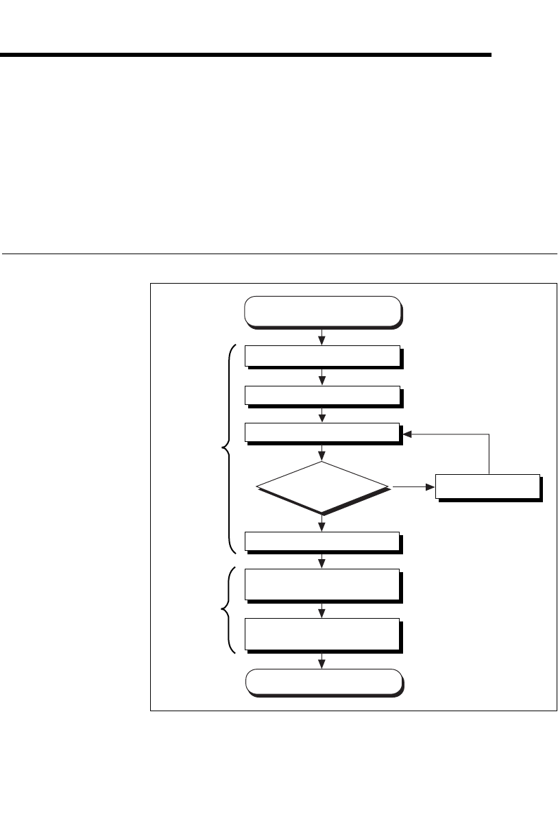
How to Use This Manual
Ye s
No
Chapters
2, 3, 4, and 5
Write Application Program
Passes?
Gather What You Need
to Get Started
Chapter 1
Install the NI Serial Software
Learn About Transceiver
Control Modes
Review Programming
Requirements
Install the Serial Hardware
Configure the Serial Port
Verify the Installation
Troubleshooting
Chapter 6

Chapter 1 Introduction
Serial Hardware and Software for Windows 1-2 ni.com
What You Need to Get Started
Before you install your serial hardware and the NI-Serial software, make
sure you have all of the following items:
❑Windows 2000/NT/Me/9xinstalled on your computer
❑One of the following serial boards, which is included in your kit:
PCI Kits
–PCI-232 (two, four, eight, or 16 port)
–PCI-485 (two, four, or eight port)
–PCI-232 isolated (two or four port)
–PCI-485 isolated (two or four port)
PXI Kits
–PXI-8420 (two, four, eight, or 16 port)
–PXI-8421 (two, four, or eight port)
–PXI-8422 (two or four port)
–PXI-8423 (two or four port)
PCMCIA Kits
–PCMCIA-232 (one, two, or four port)
–PCMCIA-485 (one or two port)
AT Kits
–AT-232 (two or four port)
–AT-485 (two or four port)
–AT-232 (two or four port) isolated
–AT-485 (two or four port) isolated
❑CD, NI-Serial Software for Windows 2000/NT/Me/9x,whichis
included in your kit

Chapter 1 Introduction
©National Instruments Corporation 1-3 Serial Hardware and Software for Windows
Optional Equipment
For more information about ordering the following optional equipment,
contact National Instruments:
•DB-9 RS-485 termination connector (PCI-485, PCMCIA-485,
PXI-8421, PXI-8423, and AT-485 only)
•10-position modular jack to DB-9 cable (PCI, PXI, and AT four-port
boards only)
•10-position modular jack to DB-25 cable (PCI, PXI, and AT four-port
boards only)
•68-pin to DB-9 adapter cable (PCI and PXI eight-port boards only)
•RS-232 9-pin to 9-pin null modem cable
•RS-232 9-pin to 25-pin null modem cable
•RS-485 9-pin to 9-pin null modem cable
•Breakout box (PCI/PXI-232 16-port board only)
Serial Hardware Overview
PCI Kits
The serial hardware gives you a variety of solutions for serial
communication. The PCI-232 boards work with the RS-232 protocols, and
the PCI-485 boards work with the RS-422 and RS-485 protocols. You can
use the PCI-232 boards for serial communication up to distances of 50 ft.
You can connect the PCI-485 boards to up to 31 devices using serial cable
lengths up to 4,000 ft.
Additionally, the PCI serial boards are available in a two-port version
(PCI-232/2 and PCI-485/2), a four-port version (PCI-232/4 and
PCI-485/4), an eight-port version (PCI-232/8 and PCI-485/8), and a
sixteen-port version (PCI-232/16). The two-port versions use DB-9
connectors. The four-port versions use 10-position modular jacks to
provide all four connections on a single back panel. Optional cable
accessories convert the 10-position modular jacks to either DB-9 or DB-25
connectors with standard pinouts. The eight-port versions use adapter
cables to convert the 68-pin connector on the board to eight DB-9
connectors. The 16-port version uses a breakout box to convert the 100-pin
connector on the board to sixteen DB-9 connectors. Throughout this
manual, PCI serial boards refers to all versions of the PCI serial boards.
Chapter 1 Introduction
Serial Hardware and Software for Windows 1-4 ni.com
The isolated PCI-232 and PCI-485 boards are designed for applications in
harsh environments. Isolated ports provide reliable communication in
situations involving ground loops from different ground levels or high
common mode voltage induced on the lines in noisy environments.
Non-isolated ports may not provide reliable communication in those
situations. The isolation between each communication port and the host PC
ensures the safe operation of the PC and the devices connected to other
ports on the same board, in case of accidental high voltages on
communication lines.
The PCI-485 boards support four hardware transceiver control modes
for reliable communication with two- and four-wire devices. For more
information about transceiver control modes, refer to Chapter 6, Using
Your Serial Hardware.
All serial hardware uses standard 16550-compatible UARTs (Universal
Asynchronous Receiver/Transmitters) for complete compatibility
with standard PC COM ports. The serial hardware contains FIFOs
(First-In-First-Out) buffers to reduce susceptibility to interrupt latency
for faster transmission rates. Full Plug and Play compatibility allows
switchless configuration and installation. For more information about
the serial hardware specifications and operating conditions, refer to
Appendix E, Specifications.
PXI Kits
The serial hardware gives you a variety of solutions for serial
communication. The RS-232 boards (PXI-8420 and PXI-8422) work with
the RS-232 protocols. The RS-485 boards (PXI-8421 and PXI-8423) work
with the RS-422 and RS-485 protocols. You can use the RS-232 boards for
serial communication up to distances of 50 ft. You can connect the RS-485
boardstoupto31devicesusingserialcablelengthsupto4,000ft.
Additionally, the PXI serial boards are available in a two-port version, a
four-port version, an eight-port version (PXI-8420 and PXI-8421 only),
and a 16-port version (PXI-8420 only). The two-port versions use DB-9
connectors. The four-port versions use 10-position modular jacks to
provide all four connections on a single front panel. Optional cable
accessories convert the 10-position modular jacks to either DB-9 or DB-25
connectors with standard pinouts. The eight-port versions use two different
adapter cables to convert the 68-pin connector on the board to eight DB-9
connectors. The 16-port version uses a breakout box to convert the 100-pin
connector on the board to sixteen DB-9 connectors. Throughout this
manual, PXI serial boards refers to all versions of the PXI serial boards.

Chapter 1 Introduction
©National Instruments Corporation 1-5 Serial Hardware and Software for Windows
The isolated PXI boards are designed for applications in harsh
environments. Isolated ports provide reliable communication in situations
involving ground loops from different ground levels or high common mode
voltage induced on the lines in noisy environments. Non-isolated ports may
not provide reliable communication in those situations. The isolation
between each communication port and the host PC ensures the safe
operation of the PC and the devices connected to other ports on the same
board, in case of accidental high voltages on communication lines.
The RS-485 boards (PXI-8421 and PXI-8423) support four hardware
transceiver control modes for reliable communication with two- and
four-wire devices. For more information about transceiver control modes,
refer to Chapter 6, Using Your Serial Hardware.
All serial hardware uses standard 16550-compatible UARTs (Universal
Asynchronous Receiver/Transmitters) for complete compatibility
with standard PC COM ports. The serial hardware contains FIFOs
(First-In-First-Out) buffers to reduce susceptibility to interrupt latency
for faster transmission rates. Full Plug and Play compatibility allows
switchless configuration and installation. For more information about
the serial hardware specifications and operating conditions, refer to
Appendix E, Specifications.
Table 1-1 lists the PXI serial board numbers and corresponding board
descriptions.
Table 1-1. PXI Board Names and Descriptions
PXI Board Name Description
PXI-8420 RS-232 two port
RS-232 four port
RS-232 eight port
RS-232 16 port
PXI-8421 RS-485 two port
RS-485 four port
RS-485 eight port
PXI-8422 RS-232 two port isolated
RS-232 four port isolated
PXI-8423 RS-485 two port isolated
RS-485 four port isolated
Chapter 1 Introduction
Serial Hardware and Software for Windows 1-6 ni.com
PCMCIA Kits
The serial hardware gives you a variety of solutions for serial
communications. The PCMCIA-232 interfaces work with the RS-232
protocols, and the PCMCIA-485 interfaces work with the RS-422 and
RS-485 protocols. You can use the PCMCIA-232 hardware for serial
communication up to distances of 50 ft. You can connect the PCMCIA-485
hardware with up to 31 devices using serial cable lengths up to 4,000 ft.
The PCMCIA-232 is available with one, two, or four ports. The
PCMCIA-485 is available in a one-port version or two-port version.
All PCMCIA cards come with cables for each port that terminates in a
standard DB-9 D-Sub connector. Throughout this manual, references to
PCMCIA serial interfaces generally refer to all versions of the interfaces.
The PCMCIA-485 interfaces support four hardware transceiver control
modes for reliable communication with two-wire and four-wire devices.
Refer to Chapter 6, Using Your Serial Hardware, for more information
about transceiver control modes.
All of the serial hardware uses standard 16550-compatible UARTs
(Universal Asynchronous Receiver/Transmitters) for 100 percent
compatibility with standard PC COM ports. The serial hardware contains
FIFOs (First-In-First-Out buffers) for reduced susceptibility to interrupt
latency and faster transmission rates. Full Plug and Play compatibility gives
you the convenience of switchless configuration and installation. Refer to
Appendix E, Specifications, for more information about the serial hardware
specifications and operating conditions.
AT Kits
The serial hardware gives you a variety of solutions for serial
communications. The AT-232 boards work with the RS-232 protocols, and
the AT-485 boards work with the RS-422 and RS-485 protocols. You can
use the AT-232 hardware for serial communication up to distances of 50 ft.
You can connect the AT-485 hardware with up to 31 devices using serial
cable lengths up to 4,000 ft.
The AT boards are available in three different versions:
•Shared IRQ: All ports on the board share the same IRQ.
•Isolated: All ports on the board are isolated and share the same IRQ.
Chapter 1 Introduction
©National Instruments Corporation 1-7 Serial Hardware and Software for Windows
Additionally, the AT serial boards are available in a two-port version
(AT-232/2 and AT-485/2) or a four-port version (AT-232/4 and AT-485/4).
The two-port versions use DB-9 connectors. The four-port versions use
10-position modular jacks to provide all four connections on a single back
panel. Optional cable accessories convert the 10-position modular jacks to
either DB-9 or DB-25 connectors with standard pinouts. Throughout this
manual, references to AT serial boards generally refer to all versions of the
boards.
The isolated AT-232 and AT-485 boards are designed for applications in
harsh environments. Isolated ports provide reliable communication in
situations involving ground loops from different ground levels or high
common mode voltage induced on the lines in noisy environments. The
non-isolated ports may not provide reliable communication in those
situations. The isolation between each communication port and the host PC
ensures safe operation of the PC and the devices connected to other ports
on the same board in case of accidental high voltages on communication
lines.
The AT-485 boards support four hardware transceiver control modes
for reliable communication with two- and four-wire devices. For more
information about transceiver control modes, refer to Chapter 6, Using
Your Serial Hardware.
All serial hardware uses standard 16550-compatible UARTs (Universal
Asynchronous Receiver/Transmitters) for complete compatibility
with standard PC COM ports. The serial hardware contains FIFOs
(First-In-First-Out) buffers to reduce susceptibility to interrupt latency
for faster transmission rates. Full Plug and Play compatibility allows
switchless configuration and installation. For more information about
the serial hardware specifications and operating conditions, refer to
Appendix E, Specifications.

Chapter 1 Introduction
Serial Hardware and Software for Windows 1-8 ni.com
NI-Serial Software Overview
The NI-Serial software for Windows 2000/NT/Me/9xincludes a native
Windows 2000/Me/9xdevice driver and Windows NT kernel driver that
provide full interrupt-driven, buffered I/O for multiple COM ports. You
can obtain a maximum baud rate of either 460.8 KBaud (PCI/PXI-485 kits)
or 115.2 KBaud (PCI/PXI/PCMCIA/AT-232 kits). You can also use up to
256 serial ports under Windows 2000 or up to 99 serial ports under
Windows NT/Me/9x. The NI-Serial software also includes a configuration
utility, which is fully integrated into the Windows 2000/Me/9xDevice
Manager and Windows NT Control Panel. For more information about
software specifications, refer to Appendix E, Specifications.
The NI-Serial software includes the following components:
•Device driver
•Diagnostic utility
•Configuration utility
•Product manuals
Time-Saving Development Tools
Your kit includes the NI-Serial software for Windows 2000/NT/Me/9x.In
addition, you can order the Measurement Studio or LabVIEW software
from National Instruments to speed your application development time and
make it easier to communicate with your instruments.
LabVIEW is an easy-to-use, graphical programming environment you can
use to acquire data from thousands of different instruments, including
IEEE 488.2 devices, VXI devices, serial devices, PLCs, and plug-in data
acquisition boards. After you have acquired raw data, you can convert it
into meaningful results using the powerful data analysis routines in
LabVIEW. LabVIEW also comes with hundreds of instrument drivers,
which dramatically reduce software development time, because you do not
have to spend time programming the low-level control of each instrument.
Chapter 1 Introduction
©National Instruments Corporation 1-9 Serial Hardware and Software for Windows
Measurement Studio bundles LabWindows/CVI for C programmers,
ComponentWorks for Microsoft Visual C++ programmers, and
ComponentWorks++ for Microsoft Visual C++ programmers.
Measurement Studio is designed for building measurement and automation
applications with the programming environment of your choice:
•LabWindows/CVI is an interactive ANSI C programming environment
designed for building virtual instrument applications.
LabWindows/CVI delivers a drag-and-drop editor for building user
interfaces, a complete ANSI C environment for building your test
program logic, and a collection of automated code generation tools, as
well as utilities for building automated test systems, monitoring
applications, or laboratory experiments.
•ComponentWorks for Visual Basic is a collection of ActiveX controls
designed for building virtual instrumentation systems. Based on
ActiveX technology, ComponentWorks controls are configured
through simple property pages. You can use the ComponentWorks
GPIB, Serial, and VISA I/O controls and property pages to set up
communication with your instruments.
•ComponentWorks++ for Visual C++ takes advantage of integrated
C++ libraries and ActiveX to help you build measurement and
automation applications. With the ComponentWorks++ instrument
classes, you can use the IEEE 488.2 library and VISA, an
industry-standard I/O library, to communicate with GPIB, VXI, or
Serial devices using the same set of components.
After you install your serial hardware and the NI-Serial software, you can
use standard serial I/O functions in LabVIEW and Measurement Studio
with your serial interface. If you already have one or more of these
applications and want to use them with your serial interface, refer to your
product documentation for information about serial I/O functions. For
ordering information, contact National Instruments.

©National Instruments Corporation 2-1 Serial Hardware and Software for Windows
2
PCI Serial Hardware Installation,
Verification, and Configuration
This chapter describes how to install the NI-Serial software and PCI serial
hardware and how to verify the installation. It also describes how to
configure the communication port settings.
To begin your installation, see the section of this chapter containing
instructions for your operating system (Windows 2000, Windows Me/9x,or
Windows NT.)
Windows 2000
Install the Software
Before you install your serial hardware, complete the following steps to
install the NI-Serial software for Windows 2000:
1. Select Start»Settings»Control Panel.
2. Double-click on the Add/Remove Programs icon. The Add/Remove
Programs dialog box appears.
3. ClickontheAdd New Programs button and then the CD or Floppy
button.
4. When prompted, insert the NI-Serial Software for Windows
2000/NT/Me/9x CD and click on the Next button.
5. When prompted, click on the Finish button to install the program files
from the CD.
6. The setup wizard begins. The setup wizard guides you through the
necessary steps to install the NI-Serial software. To exit the setup
wizard at any time, click on the Cancel button.
7. If you need to install your hardware, or if this is your first time to install
the NI-Serial software for Windows 2000, skip to the next section,
Install the Hardware. Otherwise, continue to step 8.
8. If your hardware is already installed, restart Windows 2000.

Chapter 2 PCI Serial Hardware Installation, Verification, and Configuration
Serial Hardware and Software for Windows 2-2 ni.com
9. Windows 2000 should automatically detect your hardware and display
the Found New Hardware Wizard. Complete the wizard by clicking
Next in each window and then Finish. When you complete the wizard,
continue to the Verify the Installation section.
If the Found New Hardware Wizard does not appear, refer to the
Forcing Windows to Detect Your Hardware section in Appendix D,
Troubleshooting and Common Questions.
Install the Hardware
Note If you are installing a PCI-485, you might need to adjust the value of the bias
resistors, depending on your application. Bias resistors are not available on the eight-port
PCI-485. For more information, refer to Appendix B, Serial Port Information.
Caution Before you remove your board from the package, touch the antistatic plastic
package to a metal part of your system chassis to discharge electrostatic energy, which can
damage several components on your serial board.
To install your PCI serial board, complete the following steps:
1. Turn off your computer. Keep the computer plugged in so that it
remains grounded while you install the PCI serial board.
2. Remove the top or side cover of the computer.
3. Find an unused PCI expansion slot in your computer.
4. Remove the corresponding expansion slot cover on the back panel of
the computer.
5. Touch a metal part on your chassis to discharge any static electricity.
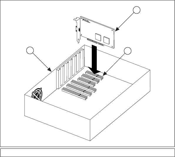
6. Insert the PCI serial board into the slot with the serial connectors
toward the opening on the back panel. Make sure that you insert the
board all the way into the slot. The board might seem to click firmly
into place, even though it is only part of the way in. Figure 2-1 shows
how to install the PCI serial board into an expansion slot.
Chapter 2 PCI Serial Hardware Installation, Verification, and Configuration
©National Instruments Corporation 2-3 Serial Hardware and Software for Windows
Figure 2-1. PCI Serial Board Installation
7. Screw the PCI serial board mounting bracket to the back panel
mounting rail of the computer.
8. Replace the cover.
9. Turn on your computer and start Windows 2000.
10. Windows 2000 should automatically detect your hardware and display
the Found New Hardware Wizard. Complete the wizard by clicking
Next in each window and then Finish.
If the Found New Hardware Wizard does not appear, refer to the
Forcing Windows to Detect Your Hardware section in Appendix D,
Troubleshooting and Common Questions.
The serial hardware installation is complete. Continue to the next section,
Verify the Installation.
1PC 2 PCI Serial Board 3PCISlot
2
3
1
Chapter 2 PCI Serial Hardware Installation, Verification, and Configuration
Serial Hardware and Software for Windows 2-4 ni.com
Verify the Installation
To verify the hardware and software installation, complete the following
steps:
1. Select Start»Settings»Control Panel and double-click on the
System icon.
2. Click on the Hardware tabandclickontheDevice Manager button.
3. Double-click on the Ports (COM & LPT) icon to display all of
the ports.
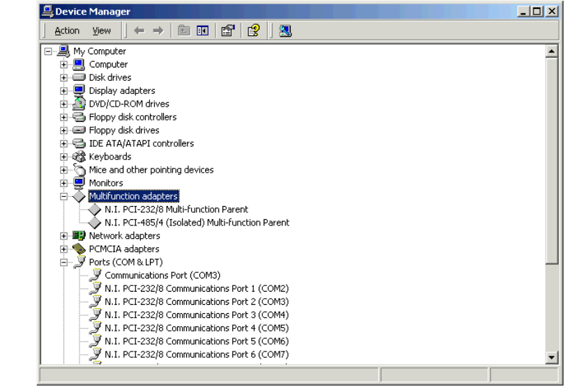
4. Double-click on the Multi-function adapters icon.
The PCI serial boards are configured as devices belonging to the
multi-function adapters class. The multi-function parent device is
listed under the Multi-function adapters icon, and each child device
is listed as a port under the Ports (COM & LPT) icon.
Figure 2-2 shows the Device Manager tab for serial hardware that is
installed properly.
Figure 2-2. Device Manager for PCI Serial Board Ports
Chapter 2 PCI Serial Hardware Installation, Verification, and Configuration
©National Instruments Corporation 2-5 Serial Hardware and Software for Windows
5. Verify the hardware resources, as follows:
a. In the Device Manager under Multi-function adapters,
double-click on a serial board.
b. ClickontheResources tab. If the resources were assigned
properly, the Resources tab shows which resources are assigned
to your serial ports.
c. Repeat steps 5a and 5b until you have verified the resources for
each board.
6. (Optional) To determine which physical port is associated with COMx,
note the Port 1, Port 2, etc. entries next to the COM numbers. For all
serial hardware, PORT1 refers to the top port, PORT2 refers to the next
port down, and so on.
7. Run the diagnostic utility, as follows: select Start»Programs»
National Instruments»NI-Serial»Diagnostics.
The diagnostic utility verifies that your serial driver is installed
properly, that the configuration of your hardware does not conflict with
anything else in your system, and that the serial driver can
communicate with your hardware correctly.
If the test is successful, your serial hardware and software are installed
properly. If the test fails, refer to Appendix D, Troubleshooting and
Common Questions, to troubleshoot the problem.
8. After you verify the hardware and software installation, connect the
cables. See Appendix A, Connector Descriptions, for information
about cable connections.
Configure Communication Port Settings
The serial configuration utility is fully integrated into the Windows 2000
Device Manager. You can use it to view or change the configuration of
your serial ports.
To configure a serial port, complete the following steps:
1. Select Start»Settings»Control Panel and double-click on the
System icon.
2. ClickontheHardware tabandclickontheDevice Manager button.
3. Double-click on the Ports (COM & LPT) icon.

Chapter 2 PCI Serial Hardware Installation, Verification, and Configuration
Serial Hardware and Software for Windows 2-6 ni.com
4. Double-click on the port you want to configure and refer to the
following instructions:
•To view the hardware resources assigned to the serial port, click
on the Resources tab.
•To view or change the port settings, click on the Port Settings tab.
For more information about the settings, refer to the next section,
Port Settings Tab.
•To change the RS-485 transceiver mode, or to enable or disable
the FIFOs on the serial hardware, in the Port Settings tab, click
on the Advanced button. For more information about the settings,
refer to the next section, Port Settings Tab.
Note Transceiver modes apply to RS-485 interfaces only. For more information about
transceiver modes, refer to Chapter 6, Using Your Serial Hardware.
5. To save your changes, click on the OK button. To exit without saving
the changes, click on the Cancel button.
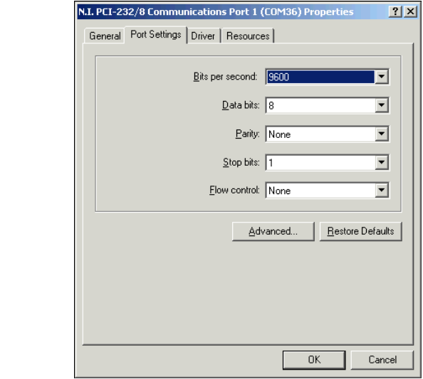
Port Settings Tab
In the Port Settings tab, you can change any of the settings by clicking on
the arrow button to the right of a field. When you click on the arrow button,
a list of valid values for that field appears and you can select the desired
setting from the list. Figure 2-3 shows the Port Settings tab.

Chapter 2 PCI Serial Hardware Installation, Verification, and Configuration
Serial Hardware and Software for Windows 2-8 ni.com
Advanced Settings
To view or change the advanced settings, click on the Advanced button.
Figure 2-4 shows the Advanced Settings dialog box.
Figure 2-4. Advanced Settings Dialog Box
The following sections describe the advanced settings options.
Transceiver Mode
This field shows the transceiver mode in use, and applies only to PCI-485
boards. For more information about transceiver modes, refer to Chapter 6,
Using Your Serial Hardware.

Chapter 2 PCI Serial Hardware Installation, Verification, and Configuration
©National Instruments Corporation 2-9 Serial Hardware and Software for Windows
Use FIFO Buffers
FIFO buffers are present on the 16550-compatible UARTs—one for the
transmitter and one for the receiver. The Receive Buffer control sets the
number of characters received in the FIFO before the PC is interrupted to
read the data. The Transmit Buffer control sets the maximum number of
bytes written to the FIFO in a block when the PC is interrupted to write the
data. When you configure FIFO settings, consider the following points:
•You can select larger FIFO buffer sizes to reduce the number of
interrupts your PC receives and therefore minimize system overhead.
•If transfer rates are high, you can lower the Receive Buffer value to
prevent overrun errors due to interrupt latency.
•If your data transfer sizes are small and your Receive Buffer value is
above your data sizes, your system is less efficient. Therefore, set the
Receive Buffer value below your data sizes.
Restore Defaults
To reset the fields to their default values at any time, click on the Restore
Defaults button.
Windows Me/9x
Install the Software
Before you install your serial hardware, complete the following steps to
install the NI-Serial software for Windows Me/9x:
1. Select Start»Settings»Control Panel.
2. Double-click on the Add/Remove Programs icon. The Add/Remove
Programs dialog box appears.
3. ClickontheInstall button.
4. When prompted, insert the NI-Serial Software for Windows
2000/NT/Me/9x CD,andclickontheNext button.
5. When prompted, click on the Finish button to install the program files
from floppy disks or CD-ROM.
6. The setup wizard begins. The setup wizard guides you through the
necessary steps to install the NI-Serial software. To exit the setup
wizard at any time, click on the Cancel button.
7. If you need to install your hardware, or if this is your first time to install
the NI-Serial software for Windows Me/9x, skip to the next section,
Install the Hardware. Otherwise, continue to step 8.

Chapter 2 PCI Serial Hardware Installation, Verification, and Configuration
Serial Hardware and Software for Windows 2-10 ni.com
8. If your hardware is already installed, restart Windows Me/9x.
9. Windows Me/9xshould automatically detect your hardware and
display one or more New Hardware Found dialog boxes. Your
operating system (Windows Me/9x)mayshowtheWindows Default
Driver option. If so, make sure the Windows Default Driver is
selected and click on the OK button. If the Windows Default Driver
option is not shown, the installation continues automatically. When
you finish, continue to the Verify the Installation section.
If no New Hardware Found dialog box appears, refer to the Forcing
Windows to Detect Your Hardware sectioninAppendixD,
Troubleshooting and Common Questions.
Install the Hardware
Note If you are installing a PCI-485, you might need to adjust the value of the bias
resistors, depending on your application. Bias resistors are not available on the eight-port
PCI-485. For more information, refer to Appendix B, Serial Port Information.
Caution Before you remove your board from the package, touch the antistatic plastic
package to a metal part of your system chassis to discharge electrostatic energy, which can
damage several components on your serial board.
To install your PCI serial board, complete the following steps:
1. Turn off your computer. Keep the computer plugged in so that it
remains grounded while you install the PCI serial board.
2. Remove the top or side cover of the computer.
3. Find an unused PCI expansion slot in your computer.
4. Remove the corresponding expansion slot cover on the back panel of
the computer.
5. Touch a metal part on your chassis to discharge any static electricity.
6. Insert the PCI serial board into the slot with the serial connectors
toward the opening on the back panel. Make sure that you insert the
board all the way into the slot. The board might seem to click firmly
into place, even though it is only part of the way in. Figure 2-5 shows
how to install the PCI serial board into an expansion slot.

Chapter 2 PCI Serial Hardware Installation, Verification, and Configuration
©National Instruments Corporation 2-11 Serial Hardware and Software for Windows
Figure 2-5. PCI Serial Board Installation
7. Screw the PCI serial board mounting bracket to the back panel
mounting rail of the computer.
8. Replace the cover.
9. Turn on your computer and start Windows Me/9x.
10. Windows Me/9xshould automatically detect your hardware and
display one or more New Hardware Found dialog boxes. Your
operating system (Windows Me/9x)mayshowtheWindows Default
Driver option. If so, make sure the Windows Default Driver is
selected and click on the OK button. If the Windows Default Driver
option is not shown, the installation continues automatically.
If no New Hardware Found dialog box appears, refer to the Forcing
Windows to Detect Your Hardware sectioninAppendixD,
Troubleshooting and Common Questions.
The serial hardware installation is complete. Continue to the next section,
Verify the Installation.
1PC 2 PCI Serial Board 3PCISlot
2
3
1
Chapter 2 PCI Serial Hardware Installation, Verification, and Configuration
Serial Hardware and Software for Windows 2-12 ni.com
Verify the Installation
Before you verify the installation, keep in mind that the serial ports
built into your computer are typically named from COM1 to COM4.
Windows Me/9xtypically issues port names to the ports on NI serial
hardware starting with COM5, COM6, and so on. If not enough resources
are available to assign to all the NI serial ports, the port with the higher
COMxname is not configured.
To verify the hardware and software installation, complete the following
steps:
1. Select Start»Settings»Control Panel and double-click on the
System icon.
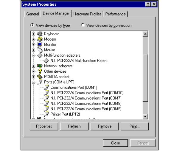
2. Click on the Device Manager tabandclickontheView devices by
type button.
3. Double-click on the Ports (COM & LPT) icon to display all of
the ports.
4. Double-click on the Multi-function adapters icon.
The PCI serial boards are configured as devices belonging to the
multi-function adapters class. The multi-function parent device is
listed under the Multi-function adapters icon, and each child device
is listed as a port under the Ports (COM & LPT) icon.
Chapter 2 PCI Serial Hardware Installation, Verification, and Configuration
©National Instruments Corporation 2-13 Serial Hardware and Software for Windows
Figure 2-6 shows the Device Manager tab for serial hardware that is
installed properly.
Figure 2-6. Device Manager Tab for PCI Serial Board Ports
5. Verify the hardware resources, as follows:
a. In the Device Manager tab, under Multi-function adapters,
double-click on a serial board.
b. ClickontheResources tab. If the resources were assigned
properly, the Resources tab shows which resources are assigned
to your serial ports.
c. Repeat steps 5a and 5b until you have verified the resources for
each board.

Chapter 2 PCI Serial Hardware Installation, Verification, and Configuration
Serial Hardware and Software for Windows 2-14 ni.com
6. (Optional) To determine which physical port is associated with COMx,
complete the following steps:
a. In the Device Manager tab, under Ports (COM & LPT),
double-click on the serial port (COMx).
b. Click on the Port Settings tab to display the serial number of the
serial hardware and the physical port number starting at 1. For all
serial hardware, PORT1 refers to the top port, PORT2 refers to the
next port down, and so on.
7. Run the diagnostic utility, as follows: select Start»Programs»
National Instruments Serial»Diagnostics.
The diagnostic utility verifies that your serial driver is installed
properly, that the configuration of your hardware does not conflict
with anything else in your system, and that the serial driver can
communicate with your hardware correctly.
If the test is successful, your serial hardware and software are installed
properly. If the test fails, refer to Appendix D, Troubleshooting and
Common Questions, to troubleshoot the problem.
8. After you verify the hardware and software installation, connect the
cables. See Appendix A, Connector Descriptions, for information
about cable connections.
Configure Communication Port Settings
The serial configuration utility is fully integrated into the Windows Me/9x
Device Manager. You can use it to view or change the configuration of
your serial ports.
To configure a serial port, complete the following steps:
1. Select Start»Settings»Control Panel and double-click on the
System icon.
2. Click on the Device Manager tabandclickontheView devices by
type button.
3. Double-click on the Ports (COM & LPT) icon.
Note If you want your serial ports to use the names COM1, COM2, COM3, or COM4,
refer to the Common Questions section of Appendix D, Troubleshooting and
Common Questions.

Chapter 2 PCI Serial Hardware Installation, Verification, and Configuration
©National Instruments Corporation 2-15 Serial Hardware and Software for Windows
4. Double-click on the port you want to configure and refer to the
following instructions:
•To view the hardware resources assigned to the serial port, click
on the Resources tab.
•To view or change the port settings, click on the Port Settings tab.
For more information about the settings, refer to the next section,
Port Settings Tab.
•To change the RS-485 transceiver mode, or to enable or disable
the FIFOs on the serial hardware, in the Port Settings tab, click
on the Advanced button. For more information about the settings,
refer to the next section, Port Settings Tab.
Note Transceiver modes apply to RS-485 interfaces only. For more information about
transceiver modes, refer to Chapter 6, Using Your Serial Hardware.
5. To save your changes, click on the OK button. To exit without saving
the changes, click on the Cancel button.
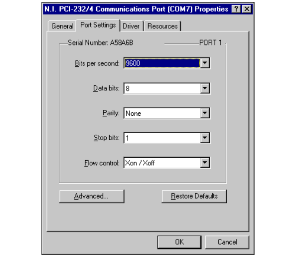
Chapter 2 PCI Serial Hardware Installation, Verification, and Configuration
Serial Hardware and Software for Windows 2-16 ni.com
Port Settings Tab
In the Port Settings tab, you can change any of the settings by clicking on
the arrow button to the right of a field. When you click on the arrow button,
a list of valid values for that field appears and you can select the desired
setting from the list. Figure 2-7 shows the Port Settings tab.
Figure 2-7. Port Settings Tab
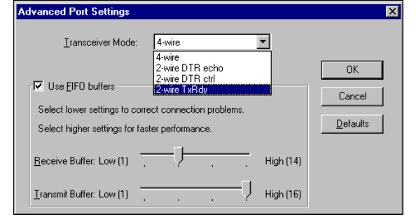
Chapter 2 PCI Serial Hardware Installation, Verification, and Configuration
©National Instruments Corporation 2-17 Serial Hardware and Software for Windows
Advanced Port Settings
To view or change the advanced port settings, click on the Advanced
button. Figure 2-8 shows the Advanced Port Settings dialog box.
Figure 2-8. Advanced Port Settings Dialog Box
The following sections describe the advanced port setting options.
Transceiver Mode
This field shows the transceiver mode in use, and applies only to PCI-485
boards. For more information about transceiver modes, refer to Chapter 6,
Using Your Serial Hardware.
Use FIFO Buffers
FIFO buffers are present on the 16550-compatible UARTs—one for the
transmitter and one for the receiver. The Receive Buffer control sets the
number of characters received in the FIFO before the PC is interrupted to
read the data. The Transmit Buffer control sets the maximum number of
bytes written to the FIFO in a block when the PC is interrupted to write the
data. When you configure FIFO settings, consider the following points:
•You can select larger FIFO buffer sizes to reduce the number of
interrupts your PC receives and therefore minimize system overhead.
•If transfer rates are high, you can lower the Receive Buffer value to
prevent overrun errors due to interrupt latency.
•If your data transfer sizes are small and your Receive Buffer value is
above your data sizes, your system is less efficient. Therefore, set the
Receive Buffer value below your data sizes.

Chapter 2 PCI Serial Hardware Installation, Verification, and Configuration
Serial Hardware and Software for Windows 2-18 ni.com
Restore Defaults
To reset the fields to their default values at any time, click on the Restore
Defaults button.
Windows NT
Install the Software
Before you install your serial hardware, complete the following steps to
install the NI-Serial software for Windows NT:
1. LoginasAdministrator or as a user who has Administrator
privileges.
2. Select Start»Settings»Control Panel.
3. Double-click on the Add/Remove Programs icon. The Add/Remove
Programs dialog box appears.
4. Click on the Install button.
5. When prompted, insert the NI-Serial Software for Windows
2000/NT/Me/9x CD,andclickontheNext button.
6. When prompted, click the Finish button to install the program files.
7. The setup wizard begins. The setup wizard guides you through the
necessary steps to install the NI-Serial software. To exit the setup
wizard at any time, click on the Cancel button.
Note The setup wizard backs up the Windows NT serial driver serial.sys to
serial.bak andthenoverwritesserial.sys. You can find serial.sys in
the WinNT\system32\drivers directory.
8. If your hardware is already installed, restart Windows NT and continue
to the Verify the Installation section.
The software installation is complete. Continue to the next section, Install
the Hardware.
Install the Hardware
Note If you are installing a PCI-485, you might need to adjust the value of the bias
resistors, depending on your application. Bias resistors are not available on the eight-port
PCI-485. For more information, refer to Appendix B, Serial Port Information.
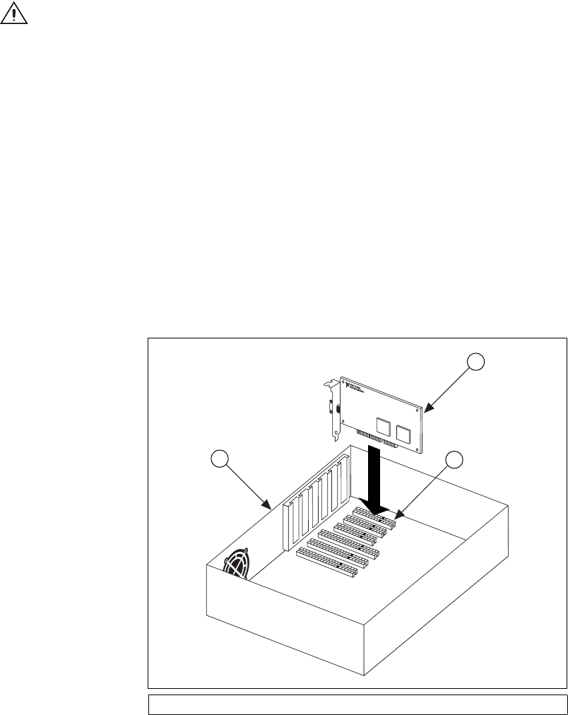
Chapter 2 PCI Serial Hardware Installation, Verification, and Configuration
©National Instruments Corporation 2-19 Serial Hardware and Software for Windows
Caution Before you remove your board from the package, touch the antistatic plastic
package to a metal part of your system chassis to discharge electrostatic energy, which can
damage several components on your serial board.
To install your PCI serial board, complete the following steps:
1. Turn off your computer. Keep the computer plugged in so that it
remains grounded while you install the PCI serial board.
2. Remove the top or side cover of the computer.
3. Find an unused PCI expansion slot in your computer.
4. Remove the corresponding expansion slot cover on the back panel of
the computer.
5. Touch a metal part on your chassis to discharge any static electricity.
6. Insert the PCI serial board into the slot with the serial connectors
toward the opening on the back panel. Make sure that you insert the
board all the way into the slot. The board might seem to click firmly
into place, even though it is only part of the way in. Figure 2-9 shows
how to install the PCI serial board into an expansion slot.
Figure 2-9. Installing the PCI Serial Board
1PC 2 PCI Serial Board 3PCISlot
2
3
1
Chapter 2 PCI Serial Hardware Installation, Verification, and Configuration
Serial Hardware and Software for Windows 2-20 ni.com
7. Screw the PCI serial board mounting bracket to the back panel
mounting rail of the computer.
8. Replace the cover.
9. Turn on your computer and start Windows NT.
The hardware installation is complete. Continue to the next section, Verify
the Installation.
Verify the Installation
To verify the hardware and software installation, complete the following
steps:
1. Determine which physical port is associated with COMx, as follows:
a. Select Start»Settings»Control Panel and double-click on the
niports icon.
A list of installed National Instruments ports with their logical
COMxnames appears. If your interface is not on this list, refer to
Appendix D, Troubleshooting and Common Questions.
b. Select the COM port that you want to verify and click on the
Settings button.
The General Port Settings dialog box displays the serial number
of the serial hardware and the physical port number starting at 1.
For all serial hardware, PORT1 refers to the top port, PORT2
refers to the next port down, and so on.
2. Run the diagnostic utility, as follows: select
Start»Programs»National Instruments Serial»diagnostics.
The diagnostic utility verifies that your serial driver is installed
properly, that the configuration of your hardware does not conflict with
anything else in your system, and that the serial driver can
communicate with your hardware correctly.
If the test is successful, your serial hardware and software are installed
properly. If the test fails, refer to Appendix D, Troubleshooting and
Common Questions, to troubleshoot the problem.
3. After you verify the hardware and software installation, connect the
cables. See Appendix A, Connector Descriptions, for information
about cable connections.
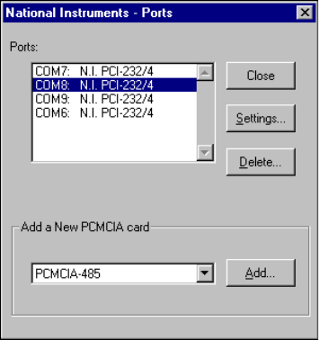
Chapter 2 PCI Serial Hardware Installation, Verification, and Configuration
©National Instruments Corporation 2-21 Serial Hardware and Software for Windows
Configure Communication Port Settings
The serial configuration utility is fully integrated into the Windows NT
Control Panel. You can use it to view or change the configuration of your
serial ports.
To configure a serial port, complete the following steps:
1. Select Start»Settings»Control Panel and double-click on the niports
icon. A list of installed National Instruments ports appears, as shown
in Figure 2-10.
Figure 2-10. niports Configuration Utility
2. Select the port that you want to configure and refer to the following
instructions:
•To remove hardware information about the port from
WindowsNT,clickontheDelete button. You should do this
before you remove your hardware.
•To view or change the port settings, click on the Settings button.
For more information about the settings, refer to the next section,
General Port Settings.
•In the General Port Settings dialog box, click on the Resources
button to view the resources for the port.
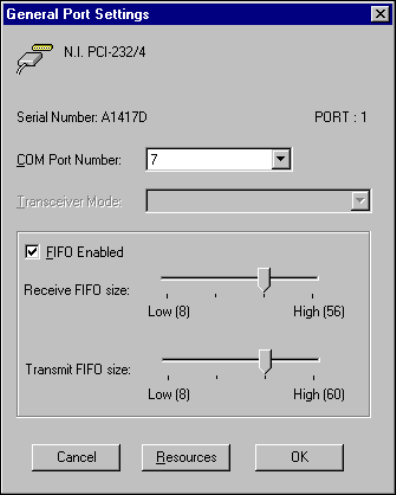
Chapter 2 PCI Serial Hardware Installation, Verification, and Configuration
Serial Hardware and Software for Windows 2-22 ni.com
General Port Settings
The following sections describe the options you can set in the General
Port Settings dialog box, shown in Figure 2-11.
Figure 2-11. General Port Settings Dialog Box
COM Port Number
You can use the COM Port Number control to change the logical COMx
name of the selected port.
Transceiver Mode
The Transceiver Mode list box shows the transceiver mode in use, and
applies only to PCI-485 boards. For more information about transceiver
modes, refer to Chapter 6, Using Your Serial Hardware.
FIFO Enabled
You can use the FIFO Enabled checkbox to enable or disable the
FIFO buffers on the selected port. FIFO buffers are present on the
16550-compatible UARTs—one for the transmitter and one for the
receiver.
Chapter 2 PCI Serial Hardware Installation, Verification, and Configuration
©National Instruments Corporation 2-23 Serial Hardware and Software for Windows
FIFO Buffer Size
The Receive FIFO size control sets the number of characters received in
the FIFO before the PC is interrupted to read the data. The Transmit FIFO
size control sets the maximum number of bytes written to the FIFO in a
block when the PC is interrupted to write the data. When you configure
FIFO settings, consider the following points:
•You can select larger FIFO buffer sizes to reduce the number of
interrupts your PC receives and therefore minimize system overhead.
•If transfer rates are high, you can lower the Receive FIFO size value
to prevent overrun errors due to interrupt latency.
•If your data transfer sizes are small and your Receive FIFO size value
is above your data sizes, your system is less efficient. Therefore, set the
Receive FIFO size value below your data sizes.
Resources
To view the resource configuration dialog box for the selected port, click
on the Resources button. You cannot change these resources; they are
automatically assigned.

©National Instruments Corporation 3-1 Serial Hardware and Software for Windows
3
PXI Serial Hardware Installation,
Verification, and Configuration
This chapter describes how to install the NI-Serial software and PXI serial
hardware and how to verify the installation. It also describes how to view
or change the communication port settings.
To begin your installation, see the section of this chapter containing
instructions for your operating system (Windows 2000, Windows Me/9x,or
Windows NT.)
Windows 2000
Install the Software
Before you install your serial hardware, complete the following steps to
install the NI-Serial software for Windows 2000:
1. Select Start»Settings»Control Panel.
2. Double-click on the Add/Remove Programs icon. The Add/Remove
Programs dialog box appears.
3. ClickontheAdd New Programs button and then the CD or Floppy
button.
4. When prompted, insert the NI-Serial Software for Windows
2000/NT/Me/9x CD and click on the Next button.
5. When prompted, click on the Finish button to install the program files
from the CD.
6. The setup wizard begins. The setup wizard guides you through the
necessary steps to install the NI-Serial software. To exit the setup
wizard at any time, click on the Cancel button.
7. If you need to install your hardware, or if this is your first time to install
the NI-Serial software for Windows 2000, skip to the next section,
Install the Hardware. Otherwise, continue to step 8.
8. If your hardware is already installed, restart Windows 2000.

Chapter 3 PXI Serial Hardware Installation, Verification, and Configuration
Serial Hardware and Software for Windows 3-2 ni.com
9. Windows 2000 should automatically detect your hardware and display
the Found New Hardware Wizard. Complete the wizard by clicking
Next in each window and then Finish. When you complete the wizard,
continue to the Verify the Installation section.
If the Found New Hardware Wizard does not appear, refer to the
Forcing Windows to Detect Your Hardware section in Appendix D,
Troubleshooting and Common Questions.
Install the Hardware
Caution Before you remove your board from the package, touch the antistatic plastic
package to a metal part of your system chassis to discharge electrostatic energy, which can
damage several components on your serial board.
To install your PXI serial board, complete the following steps:
1. Turn off your PXI or CompactPCI chassis. Keep the chassis plugged
in so that it remains grounded while you install the PXI serial board.
2. Find an unused PXI or CompactPCI 5 V peripheral slot.
3. Remove the corresponding filler panel.
4. Touch a metal part on your chassis to discharge any static electricity.
5. Insert the PXI serial board into the 5 V slot. Use the injector/ejector
handle to fully inject the device into place. Figure 3-1 shows how
to install the PXI serial board into a PXI or CompactPCI chassis.

Chapter 3 PXI Serial Hardware Installation, Verification, and Configuration
©National Instruments Corporation 3-3 Serial Hardware and Software for Windows
Figure 3-1. Installing the PXI Serial Board
6. Screw the PXI serial board front panel to the front panel mounting rail
of the PXI or CompactPCI chassis.
7. Turn on your PXI or CompactPCI chassis and start Windows 2000.
8. Windows 2000 should automatically detect your hardware and display
the Found New Hardware Wizard. Complete the wizard by clicking
Next in each window and then Finish.
If the Found New Hardware Wizard does not appear, refer to the
Forcing Windows to Detect Your Hardware section in Appendix D,
Troubleshooting and Common Questions.
The serial hardware installation is complete. Continue to the next section,
Verify the Installation.
1 Injector/Ejector Handle (In Down
Position)
2 PXI Serial Board
3 PXI Chassis
4 Injector/Ejector Rail
8
7
6
5
4
3
2
1
ON STANDBY
4
1
2
3
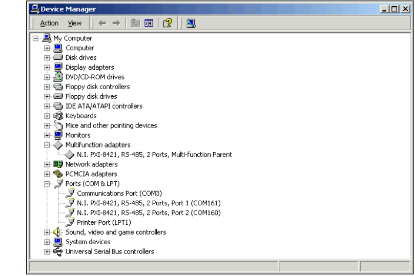
Chapter 3 PXI Serial Hardware Installation, Verification, and Configuration
Serial Hardware and Software for Windows 3-4 ni.com
Verify the Installation
To verify the hardware and software installation, complete the following
steps:
1. Select Start»Settings»Control Panel and double-click on the
System icon.
2. Click on the Hardware tabandclickontheDevice Manager button.
3. Double-click on the Ports (COM & LPT) icon to display all of
the ports.
4. Double-click on the Multi-function adapters icon.
The PXI serial boards are configured as devices belonging to the
multi-function adapters class. The multi-function parent device is
listed under the Multi-function adapters icon, and each child device
is listed as a port under the Ports (COM & LPT) icon.
Figure 3-2 shows the Device Manager tab for serial hardware that is
installed properly.
Figure 3-2. Device Manager for PXI Serial Board Ports
Chapter 3 PXI Serial Hardware Installation, Verification, and Configuration
©National Instruments Corporation 3-5 Serial Hardware and Software for Windows
5. Verify the hardware resources, as follows:
a. In the Device Manager under Multi-function adapters,
double-click on a serial board.
b. ClickontheResources tab. If the resources were assigned
properly, the Resources tab shows which resources are assigned
to your serial ports.
c. Repeat steps 5a and 5b until you have verified the resources for
each board.
6. (Optional) To determine which physical port is associated with COMx,
note the Port 1, Port 2, etc. entries next to the COM numbers. For all
serial hardware, PORT1 refers to the top port, PORT2 refers to the next
port down, and so on.
7. Run the diagnostic utility, as follows: select Start»Programs»
National Instruments»NI-Serial»Diagnostics.
The diagnostic utility verifies that your serial driver is installed
properly, that the configuration of your hardware does not conflict with
anything else in your system, and that the serial driver can
communicate with your hardware correctly.
If the test is successful, your serial hardware and software are installed
properly. If the test fails, refer to Appendix D, Troubleshooting and
Common Questions, to troubleshoot the problem.
8. After you verify the hardware and software installation, connect the
cables. See Appendix A, Connector Descriptions, for information
about cable connections.
Configure Communication Port Settings
The serial configuration utility is fully integrated into the Windows 2000
Device Manager. You can use it to view or change the configuration of
your serial ports.
To configure a serial port, complete the following steps:
1. Select Start»Settings»Control Panel and double-click on the
System icon.
2. ClickontheHardware tabandclickontheDevice Manager button.
3. Double-click on the Ports (COM & LPT) icon.

Chapter 3 PXI Serial Hardware Installation, Verification, and Configuration
Serial Hardware and Software for Windows 3-6 ni.com
4. Double-click on the port you want to configure and refer to the
following instructions:
•To view the hardware resources assigned to the serial port, click
on the Resources tab.
•To view or change the port settings, click on the Port Settings tab.
For more information about the settings, refer to the next section,
Port Settings Tab.
•To change the RS-485 transceiver mode, or to enable or disable
the FIFOs on the serial hardware, in the Port Settings tab, click
on the Advanced button. For more information about the settings,
refer to the next section, Port Settings Tab.
Note Transceiver modes apply to RS-485 interfaces only. For more information about
transceiver modes, refer to Chapter 6, Using Your Serial Hardware.
5. To save your changes, click on the OK button. To exit without saving
the changes, click on the Cancel button.
Port Settings Tab
In the Port Settings tab, you can change any of the settings by clicking on
the arrow button to the right of a field. When you click on the arrow button,
a list of valid values for that field appears and you can select the desired
setting from the list. Figure 3-3 shows the Port Settings tab.
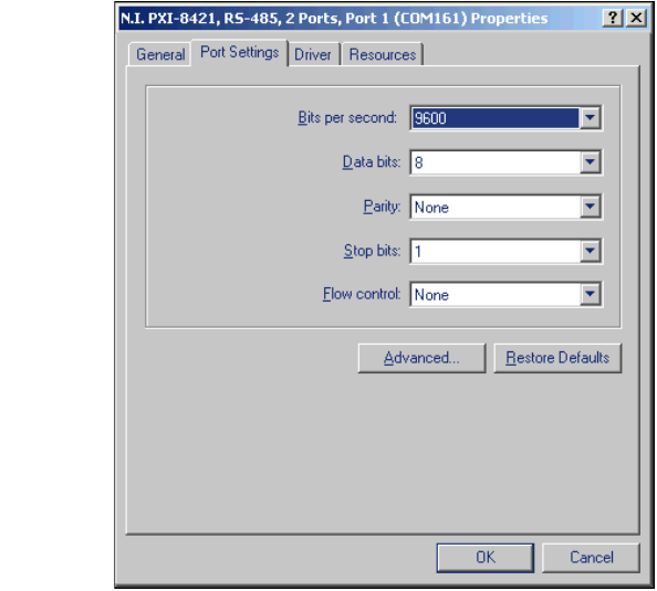
Chapter 3 PXI Serial Hardware Installation, Verification, and Configuration
©National Instruments Corporation 3-7 Serial Hardware and Software for Windows
Figure 3-3. Port Settings Tab
Advanced Settings
To view or change the advanced settings, click on the Advanced button.
Figure 3-4 shows the Advanced Settings dialog box.
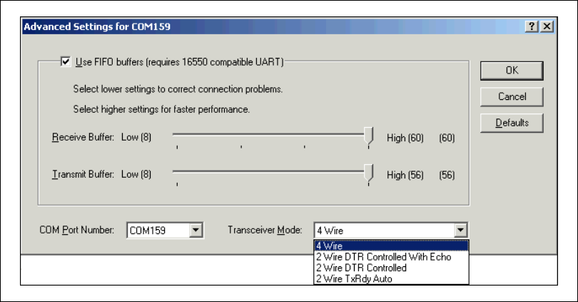
Chapter 3 PXI Serial Hardware Installation, Verification, and Configuration
Serial Hardware and Software for Windows 3-8 ni.com
Figure 3-4. Advanced Settings Dialog Box
The following sections describe the advanced settings options.
Transceiver Mode
This field shows the transceiver mode in use, and applies only to RS-485
boards. For more information about transceiver modes, refer to Chapter 6,
Using Your Serial Hardware.
Use FIFO Buffers
FIFO buffers are present on the 16550-compatible UARTs—one for the
transmitter and one for the receiver. The Receive Buffer control sets the
number of characters received in the FIFO before the PC is interrupted to
read the data. The Transmit Buffer control sets the maximum number of
bytes written to the FIFO in a block when the PC is interrupted to write the
data. When you configure FIFO settings, consider the following points:
•You can select larger FIFO buffer sizes to reduce the number of
interrupts your PC receives and therefore minimize system overhead.
•If transfer rates are high, you can lower the Receive Buffer value to
prevent overrun errors due to interrupt latency.
•If your data transfer sizes are small and your Receive Buffer value is
above your data sizes, your system is less efficient. Therefore, set the
Receive Buffer value below your data sizes.

Chapter 3 PXI Serial Hardware Installation, Verification, and Configuration
©National Instruments Corporation 3-9 Serial Hardware and Software for Windows
Restore Defaults
To reset the fields to their default values at any time, click on the Restore
Defaults button.
Windows Me/9x
Install the Software
Before you install your serial hardware, complete the following steps to
install the NI-Serial software for Windows Me/9x:
1. Select Start»Settings»Control Panel.
2. Double-click on the Add/Remove Programs icon. The Add/Remove
Programs dialog box appears.
3. ClickontheInstall button.
4. When prompted, insert the NI-Serial Software for Windows
2000/NT/Me/9x CD and click on the Next button. The setup wizard
begins. The setup wizard guides you through the necessary steps to
install the NI-Serial software. To go back and change values where
appropriate, click on the Back button. To exit the setup wizard at any
time, click on the Cancel button.
5. If you need to install your hardware, or if this is your first time to install
the NI-Serial software for Windows Me/9x, skip to the next section,
Install the Hardware. Otherwise, continue to step 6.
6. If your hardware is already installed, restart Windows Me/9x.
Windows Me/9xshould automatically detect your hardware and
display one or more New Hardware Found dialog boxes. Make sure
that Windows Default Driver is selected and click on the OK button.
When you finish, continue to the Verify the Installation section.
If no New Hardware Found dialog box appears, refer to the Forcing
Windows to Detect Your Hardware sectioninAppendixD,
Troubleshooting and Common Questions.
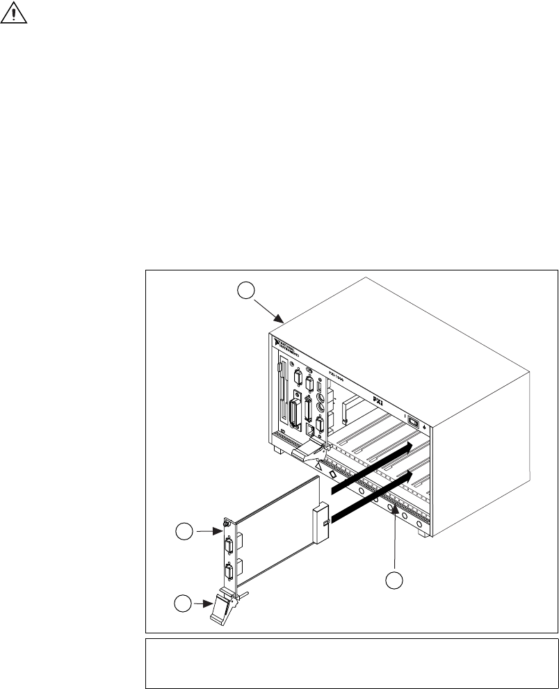
Chapter 3 PXI Serial Hardware Installation, Verification, and Configuration
Serial Hardware and Software for Windows 3-10 ni.com
Install the Hardware
Caution Before you remove your board from the package, touch the antistatic plastic
package to a metal part of your system chassis to discharge electrostatic energy, which can
damage several components on your serial board.
To install your PXI serial board, complete the following steps:
1. Turn off your PXI or CompactPCI chassis. Keep the chassis plugged
in so that it remains grounded while you install the PXI serial board.
2. Find an unused PXI or CompactPCI 5 V peripheral slot.
3. Remove the corresponding filler panel.
4. Touch a metal part on your chassis to discharge any static electricity.
5. Insert the PXI serial board into the 5 V slot. Use the injector/ejector
handle to fully inject the device into place. Figure 3-5 shows how
to install the PXI serial board into a PXI or CompactPCI chassis.
Figure 3-5. Installing the PXI Serial Board
1 Injector/Ejector Handle (In Down
Position)
2 PXI Serial Board
3 PXI Chassis
4 Injector/Ejector Rail
8
7
6
5
4
3
2
1
ON STANDBY
4
1
2
3
Chapter 3 PXI Serial Hardware Installation, Verification, and Configuration
©National Instruments Corporation 3-11 Serial Hardware and Software for Windows
6. Screw the PXI serial board front panel to the front panel mounting rail
of the PXI or CompactPCI chassis.
7. Turn on your PXI or CompactPCI chassis and start Windows Me/9x.
8. Windows Me/9xshould automatically detect your hardware and
display one or more New Hardware Found dialog boxes. Make sure
that Windows Default Driver is selected and click on the OK button.
If no New Hardware Found dialog box appears, refer to the Forcing
Windows to Detect Your Hardware sectioninAppendixD,
Troubleshooting and Common Questions.
The serial hardware installation is complete. Continue to the next section,
Verify the Installation.
Verify the Installation
Before you verify the installation, keep in mind that the serial ports
built into your computer are typically named from COM1 to COM4.
Windows Me/9xtypically issues port names to the ports on NI serial
hardware starting with COM5, COM6, and so on. If not enough resources
are available to assign to all the NI serial ports, the port with the higher
COMxname is not configured.
To verify the hardware and software installation, complete the following
steps:
1. Select Start»Settings»Control Panel and double-click on the
System icon.
2. ClickontheDevice Manager tabandclickontheView devices by
type button.
3. Double-click on the Ports (COM & LPT) icon to display all of
the ports.
4. Double-click on the Multi-function adapters icon.
The PXI serial boards are configured as devices belonging to the
multi-function adapters class. The multi-function parent device is
listed under the Multi-function adapters icon, and each child device
is listed as a port under the Ports (COM & LPT) icon.
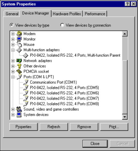
Chapter 3 PXI Serial Hardware Installation, Verification, and Configuration
Serial Hardware and Software for Windows 3-12 ni.com
Figure 3-6 shows the Device Manager tab for serial hardware that is
installed properly.
Figure 3-6. Device Manager for PXI Serial Board Ports
5. Verify the hardware resources, as follows:
a. In the Device Manager tab, under Multi-function adapters,
double-click on a serial board.
b. ClickontheResources tab. If the resources were assigned
properly, the Resources tab shows which resources are assigned
to your serial ports.
c. Repeat steps 5a and 5b until you have verified the resources for
each board.

Chapter 3 PXI Serial Hardware Installation, Verification, and Configuration
©National Instruments Corporation 3-13 Serial Hardware and Software for Windows
6. (Optional) To determine which physical port is associated with COMx,
complete the following steps:
a. In the Device Manager tab, under Ports (COM & LPT),
double-click on the serial port (COMx).
b. Click on the Port Settings tab to display the serial number of the
serial hardware and the physical port number starting at 1. For all
serial hardware, PORT1 refers to the top port, PORT2 refers to the
next port down, and so on.
7. Run the diagnostic utility, as follows: select
Start»Programs»National Instruments Serial»diagnostics.
The diagnostic utility verifies that your serial driver is installed
properly, that the configuration of your hardware does not conflict with
anything else in your system, and that the serial driver can
communicate with your hardware correctly.
If the test is successful, your serial hardware and software are installed
properly. If the test fails, refer to Appendix D, Troubleshooting and
Common Questions, to troubleshoot the problem.
8. After you verify the hardware and software installation, connect the
cables. See Appendix A, Connector Descriptions, for information
about cable connections.
Configure Communication Port Settings
The serial configuration utility is fully integrated into the Windows Me/9x
Device Manager. You can use it to view or change the configuration of
your serial ports.
To configure a serial port, complete the following steps:
1. Select Start»Settings»Control Panel and double-click on the
System icon.
2. ClickontheDevice Manager tabandclickontheView devices by
type button.
3. Double-click on the Ports (COM & LPT) icon.
Note If you want your serial ports to use the names COM1, COM2, COM3, or COM4,
refer to the Common Questions section of Appendix D, Troubleshooting and
Common Questions.

Chapter 3 PXI Serial Hardware Installation, Verification, and Configuration
Serial Hardware and Software for Windows 3-14 ni.com
4. Double-click on the port you want to configure and refer to the
following instructions:
•To view the hardware resources assigned to the serial port, click
on the Resources tab.
•To view or change the port settings, click on the Port Settings tab.
For more information about the settings, refer to the next section,
Port Settings Tab.
•To change the RS-485 transceiver mode, or to enable or disable
the FIFOs on the serial hardware, in the Port Settings tab, click
on the Advanced button. For more information about the settings,
refer to the next section, Port Settings Tab.
Note Transceiver modes apply to RS-485 interfaces only. For more information about
transceiver modes, refer to Chapter 6, Using Your Serial Hardware.
5. To save your changes, click on the OK button. To exit without saving
the changes, click on the Cancel button.
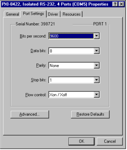
Chapter 3 PXI Serial Hardware Installation, Verification, and Configuration
©National Instruments Corporation 3-15 Serial Hardware and Software for Windows
Port Settings Tab
In the Port Settings tab, you can change any of the settings by clicking on
the arrow button to the right of a field. When you click on the arrow button,
a list of valid values for that field appears and you can select the desired
setting from the list. Figure 3-7 shows the Port Settings tab.
Figure 3-7. Port Settings Tab
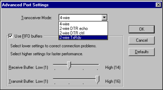
Chapter 3 PXI Serial Hardware Installation, Verification, and Configuration
Serial Hardware and Software for Windows 3-16 ni.com
Advanced Port Settings
To view or change the advanced port settings, click on the Advanced
button. Figure 3-8 shows the Advanced Port Settings dialog box.
Figure 3-8. Advanced Settings Dialog Box
The following sections describe the advanced settings options.
Transceiver Mode
This field shows the transceiver mode in use, and applies only to RS-485
boards. For more information about transceiver modes, refer to Chapter 6,
Using Your Serial Hardware.
Use FIFO Buffers
FIFO buffers are present on the 16550-compatible UARTs—one for the
transmitter and one for the receiver. The Receive Buffer control sets the
number of characters received in the FIFO before the PC is interrupted to
read the data. The Transmit Buffer control sets the maximum number of
bytes written to the FIFO in a block when the PC is interrupted to write the
data. When you configure FIFO settings, consider the following points:
•You can select larger FIFO buffer sizes to reduce the number of
interrupts your PC receives and therefore minimize system overhead.
•If transfer rates are high, you can lower the Receive Buffer value to
prevent overrun errors due to interrupt latency.
•If your data transfer sizes are small and your Receive Buffer value is
above your data sizes, your system is less efficient. Therefore, set the
Receive Buffer value below your data sizes.

Chapter 3 PXI Serial Hardware Installation, Verification, and Configuration
©National Instruments Corporation 3-17 Serial Hardware and Software for Windows
Restore Defaults
To reset the fields to their default values at any time, click on the Restore
Defaults button.
Windows NT
Install the Software
Before you install your serial hardware, complete the following steps to
install the NI-Serial software for Windows NT:
1. LoginasAdministrator or as a user who has Administrator
privileges.
2. Select Start»Settings»Control Panel.
3. Double-click on the Add/Remove Programs icon. The Add/Remove
Programs dialog box appears.
4. ClickontheInstall button.
5. When prompted, insert the NI-Serial Software for Windows
2000/NT/Me/9x,and click on the Next button. The setup wizard
begins. The setup wizard guides you through the necessary steps to
install the NI-Serial software. To go back and change values where
appropriate, click on the Back button. To exit the setup wizard at any
time, click on the Cancel button.
Note The setup wizard backs up the Windows NT serial driver serial.sys to
serial.bak andthenoverwritesserial.sys. You can find serial.sys in
the WinNT\system32\drivers directory.
6. If you your hardware is already installed, restart Windows NT and
continue to the Verify the Installation section.
The software installation is complete. Continue to the next section, Install
the Hardware.
Install the Hardware
Caution Before you remove your board from the package, touch the antistatic plastic
package to a metal part of your system chassis to discharge electrostatic energy, which can
damage several components on your serial board.
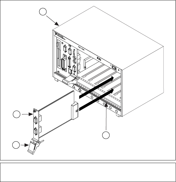
Chapter 3 PXI Serial Hardware Installation, Verification, and Configuration
Serial Hardware and Software for Windows 3-18 ni.com
To install your PXI serial board, complete the following steps:
1. Turn off your PXI or CompactPCI chassis. Keep the PXI or
CompactPCI chassis plugged in so that it remains grounded while you
install the PXI serial board.
2. Find an unused PXI or CompactPCI 5 V peripheral slot.
3. Remove the corresponding filler panel.
4. Touch a metal part on your chassis to discharge any static electricity.
5. Insert the PXI serial board into the 5 V slot. Use the injector/ejector
handle to fully inject the device into place. Figure 3-9 shows how to
install the PXI serial board into a PXI or CompactPCI chassis.
Figure 3-9. Installing the PXI Serial Board
1 Injector/Ejector Handle (In Down
Position)
2 PXI Serial Board
3 PXI Chassis
4 Injector/Ejector Rail
8
7
6
5
4
3
2
1
ON STANDBY
4
1
2
3
Chapter 3 PXI Serial Hardware Installation, Verification, and Configuration
©National Instruments Corporation 3-19 Serial Hardware and Software for Windows
6. Screw the PXI serial board front panel to the front panel mounting rail
of the PXI or CompactPCI chassis.
7. Turn on your PXI or CompactPCI chassis and start Windows NT.
The serial hardware installation is complete. Continue to the next section,
Verify the Installation.
Verify the Installation
To verify the hardware and software installation, complete the following
steps:
1. Determine which physical port is associated with COMx, as follows:
a. Select Start»Settings»Control Panel and double-click on the
niports icon.
A list of installed National Instruments ports with their logical
COMxnames appears. If your interface is not on this list, refer to
Appendix D, Troubleshooting and Common Questions.
b. Select the COM port that you want to verify and click on the
Settings button.
The General Port Settings dialog box displays the serial number
of the serial hardware and the physical port number starting at 1.
For all serial hardware, PORT1 refers to the top port, PORT2
refers to the next port down, and so on.
2. Run the diagnostic utility, as follows: select
Start»Programs»National Instruments Serial»diagnostics.
The diagnostic utility verifies that your serial driver is installed
properly, that the configuration of your hardware does not conflict with
anything else in your system, and that the serial driver can
communicate with your hardware correctly.
If the test is successful, your serial hardware and software are installed
properly. If the test fails, refer to Appendix D, Troubleshooting and
Common Questions, to troubleshoot the problem.
3. After you verify the hardware and software installation, connect the
cables. See Appendix A, Connector Descriptions, for information
about cable connections.
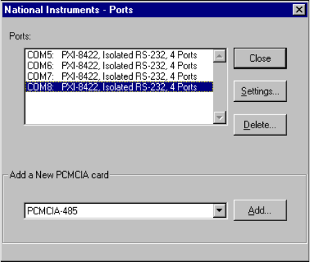
Chapter 3 PXI Serial Hardware Installation, Verification, and Configuration
Serial Hardware and Software for Windows 3-20 ni.com
Configure Communication Port Settings
The serial configuration utility is fully integrated into the Windows NT
Control Panel. You can use it to view or change the configuration of your
serial ports.
To configure a serial port, complete the following steps:
1. Select Start»Settings»Control Panel and double-click on the niports
icon. A list of installed National Instruments ports appears, as shown
in Figure 3-10.
Figure 3-10. niports Configuration Utility
2. Select the port that you want to configure and refer to the following
instructions:
•To remove hardware information about the port from
WindowsNT,clickontheDelete button. You should do this
before you remove your hardware.
•To view or change the port settings, click on the Settings button.
For more information about the settings, refer to the next section,
General Port Settings.
•In the General Port Settings dialog box, click on the Resources
button to view the resources for the port.
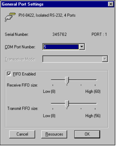
Chapter 3 PXI Serial Hardware Installation, Verification, and Configuration
©National Instruments Corporation 3-21 Serial Hardware and Software for Windows
General Port Settings
The following sections describe the options you can set in the General
Port Settings dialog box, shown in Figure 3-11.
Figure 3-11. General Port Settings Dialog Box
COM Port Number
You can use the COM Port Number control to change the logical COMx
name of the selected port.
Transceiver Mode
The Transceiver Mode list box shows the transceiver mode in use, and
applies only to RS-485 boards. For more information about transceiver
modes, refer to Chapter 6, Using Your Serial Hardware.
FIFO Enabled
You can use the FIFO Enabled checkbox to enable or disable the
FIFO buffers on the selected port. FIFO buffers are present on the
16550-compatible UARTs—one for the transmitter and one for the
receiver.
Chapter 3 PXI Serial Hardware Installation, Verification, and Configuration
Serial Hardware and Software for Windows 3-22 ni.com
FIFO Buffer Size
The Receive FIFO size control sets the number of characters received in
the FIFO before the PC is interrupted to read the data. The Transmit FIFO
size control sets the maximum number of bytes written to the FIFO in a
block when the PC is interrupted to write the data. When you configure
FIFO settings, consider the following points:
•You can select larger FIFO buffer sizes to reduce the number of
interrupts your PC receives and therefore minimize system overhead.
•If transfer rates are high, you can lower the Receive FIFO size value
to prevent overrun errors due to interrupt latency.
•If your data transfer sizes are small and your Receive FIFO size value
is above your data sizes, your system is less efficient. Therefore, set the
Receive FIFO size value below your data sizes.
Resources
To view the resource configuration dialog box for the selected port, click
on the Resources button. You cannot change these resources; they are
automatically assigned.

©National Instruments Corporation 4-1 Serial Hardware and Software for Windows
4
PCMCIA Serial Hardware
Installation, Verification, and
Configuration
This chapter describes how to install the NI-Serial software and PCMCIA
serial hardware and how to verify the installation. It also describes how to
view or change the communication port settings.
To begin your installation, see the section of this chapter containing
instructions for your operating system (Windows 2000, Windows Me/9x,or
Windows NT.)
Windows 2000
Install the Software
Before you install your serial hardware, complete the following steps to
install the NI-Serial software for Windows 2000:
1. Select Start»Settings»Control Panel.
2. Double-click on the Add/Remove Programs icon. The Add/Remove
Programs dialog box appears.
3. ClickontheAdd New Programs button and then the CD or Floppy
button.
4. When prompted, insert the NI-Serial Software for Windows
2000/NT/Me/9x CD and click on the Next button.
5. When prompted, click on the Finish button to install the program files
from the CD.
6. The setup wizard begins. The setup wizard guides you through the
necessary steps to install the NI-Serial software. To exit the setup
wizard at any time, click on the Cancel button.
7. If you need to install your hardware, or if this is your first time to install
the NI-Serial software for Windows 2000, skip to the next section,
Install the Hardware. Otherwise, continue to step 8.
Chapter 4 PCMCIA Serial Hardware Installation, Verification, and Configuration
Serial Hardware and Software for Windows 4-2 ni.com
8. Windows 2000 should automatically detect your hardware and display
the Found New Hardware Wizard. Complete the wizard by clicking
Next in each window and then Finish. When you complete the wizard,
continue to the Verify the Installation section.
If the Found New Hardware Wizard does not appear, refer to the
Forcing Windows to Detect Your Hardware section in Appendix D,
Troubleshooting and Common Questions.
Install the Hardware
To install the PCMCIA-232 or PCMCIA-485 in your computer, first start
Windows 2000. If the card is not already inserted, insert it into a free PC
Card (PCMCIA) socket the same way you insert a disk into a floppy drive.
The card has no jumpers or switches to set, and you do not need to shut
down the system before you insert it.
Windows 2000 should automatically detect your hardware and display the
Found New Hardware Wizard. Complete the wizard by clicking Next in
each window and then Finish.
If the Found New Hardware Wizard does not appear, refer to the Forcing
Windows to Detect Your Hardware sectioninAppendixD,
Troubleshooting and Common Questions.

Chapter 4 PCMCIA Serial Hardware Installation, Verification, and Configuration
©National Instruments Corporation 4-3 Serial Hardware and Software for Windows
Figure 4-1 shows how to insert a PCMCIA serial card and how to connect
the cable.
Figure 4-1. Inserting a PCMCIA Serial Card
The serial hardware installation is complete. Continue to the next section,
Verify the Installation.
Verify the Installation
To verify the hardware and software installation, complete the following
steps:
1. Select Start»Settings»Control Panel and double-click on the
System icon.
2. ClickontheHardware tabandclickontheDevice Manager button.
3. Double-click on the Ports (COM & LPT) icon to display all of
the ports.
4. Double-click on the Multi-function adapters icon.
The PCMCIA serial cards are configured as devices belonging to the
multi-function adapters class. The multi-function parent device is
listed under the Multi-function adapters icon, and each child device
is listed as a port under the Ports (COM & LPT) icon.
1PCMCIASocket 2 PCMCIA Serial Cable
1
2
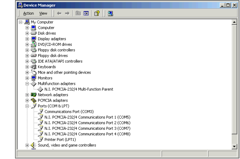
Chapter 4 PCMCIA Serial Hardware Installation, Verification, and Configuration
Serial Hardware and Software for Windows 4-4 ni.com
Figure 4-2 shows the Device Manager tab for serial hardware that is
installed properly.
Figure 4-2. Device Manager for PCMCIA Serial Card Ports
5. Verify the hardware resources, as follows:
a. In the Device Manager under Multi-function adapters,
double-click on a serial card.
b. ClickontheResources tab. If the resources were assigned
properly, the Resources tab shows which resources are assigned
to your serial ports.
c. Repeat steps 5a and 5b until you have verified the resources for
each board.
6. (Optional) To determine which physical port is associated with COMx,
note the Port 1, Port 2, etc. entries next to the COM numbers. For all
serial hardware, PORT1 refers to the top port, PORT2 refers to the next
port down, and so on.

Chapter 4 PCMCIA Serial Hardware Installation, Verification, and Configuration
©National Instruments Corporation 4-5 Serial Hardware and Software for Windows
7. Run the diagnostic utility, as follows: select Start»Programs»
National Instruments»NI-Serial»Diagnostics.
The diagnostic utility verifies that your serial driver is installed
properly, that the configuration of your hardware does not conflict with
anything else in your system, and that the serial driver can
communicate with your hardware correctly.
If the test is successful, your serial hardware and software are installed
properly. If the test fails, refer to Appendix D, Troubleshooting and
Common Questions, to troubleshoot the problem.
8. After you verify the hardware and software installation, connect the
cables. See Appendix A, Connector Descriptions, for information
about cable connections.
Configure Communication Port Settings
The serial configuration utility is fully integrated into the Windows 2000
Device Manager. You can use it to view or change the configuration of
your serial ports.
To configure a serial port, complete the following steps:
1. Select Start»Settings»Control Panel and double-click on the
System icon.
2. ClickontheHardware tabandclickontheDevice Manager button.
3. Double-click on the Ports (COM & LPT) icon.
4. Double-click on the port you want to configure and refer to the
following instructions:
•To view the hardware resources assigned to the serial port, click
on the Resources tab.
•To view or change the port settings, click on the Port Settings tab.
For more information about the settings, refer to the next section,
Port Settings Tab.
•To change the RS-485 transceiver mode, or to enable or disable
the FIFOs on the serial hardware, in the Port Settings tab, click
on the Advanced button. For more information about the settings,
refer to the next section, Port Settings Tab.
Note Transceiver modes apply to RS-485 interfaces only. For more information about
transceiver modes, refer to Chapter 6, Using Your Serial Hardware.
5. To save your changes, click on the OK button. To exit without saving
the changes, click on the Cancel button.

Chapter 4 PCMCIA Serial Hardware Installation, Verification, and Configuration
Serial Hardware and Software for Windows 4-6 ni.com
Port Settings Tab
In the Port Settings tab, you can change any of the settings by clicking on
the arrow button to the right of a field. When you click on the arrow button,
a list of valid values for that field appears and you can select the desired
setting from the list. Figure 4-3 shows the Port Settings tab.
Figure 4-3. Port Settings Tab

Chapter 4 PCMCIA Serial Hardware Installation, Verification, and Configuration
©National Instruments Corporation 4-7 Serial Hardware and Software for Windows
Advanced Settings
To view or change the advanced settings, click on the Advanced button.
Figure 4-4 shows the Advanced Settings dialog box.
Figure 4-4. Advanced Settings Dialog Box
The following sections describe the advanced settings options.
Transceiver Mode
This field shows the transceiver mode in use, and applies only to
PCMCIA-485 boards. For more information about transceiver modes, refer
to Chapter 6, Using Your Serial Hardware.

Chapter 4 PCMCIA Serial Hardware Installation, Verification, and Configuration
Serial Hardware and Software for Windows 4-8 ni.com
Use FIFO Buffers
FIFO buffers are present on the 16550-compatible UARTs—one for the
transmitter and one for the receiver. The Receive Buffer control sets the
number of characters received in the FIFO before the PC is interrupted to
read the data. The Transmit Buffer control sets the maximum number of
bytes written to the FIFO in a block when the PC is interrupted to write the
data. When you configure FIFO settings, consider the following points:
•You can select larger FIFO buffer sizes to reduce the number of
interrupts your PC receives and therefore minimize system overhead.
•If transfer rates are high, you can lower the Receive Buffer value to
prevent overrun errors due to interrupt latency.
•If your data transfer sizes are small and your Receive Buffer value is
above your data sizes, your system is less efficient. Therefore, set the
Receive Buffer value below your data sizes.
Restore Defaults
To reset the fields to their default values at any time, click on the Restore
Defaults button.
Windows Me/9x
Install the Software
Install the NI-Serial software for Windows Me/9xbefore you install the
hardware:
1. Select Start»Settings»Control Panel.
2. Double-click on the Add/Remove Programs icon in the Control Panel
to launch the Add/Remove Programs applet. The Add/Remove
Programs dialog box appears.
3. Click on the Install button.
4. When prompted, insert the NI-Serial Software for Windows
2000/NT/Me/9x CD and click on the Next button to proceed.
The software installation wizard begins.
The setup wizard guides you through the necessary steps to install the
NI-Serial software. You can go back and change values where
appropriate by clicking on the Back button. You can exit the setup
where appropriate by clicking on the Cancel button.
Chapter 4 PCMCIA Serial Hardware Installation, Verification, and Configuration
©National Instruments Corporation 4-9 Serial Hardware and Software for Windows
5. If you need to install your hardware, or if this is your first time to install
the NI-Serial software for Windows Me/9x, skip to the next section,
Install the Hardware. Otherwise, continue to Step 6.
6. If your hardware is already installed, restart Windows Me/9x.
Windows Me/9xshould automatically detect your hardware and
display one or more New Hardware Found dialog boxes. When you
finish, continue to the Verify the Installation section.
If no New Hardware Found dialog box appears, refer to the section
Forcing Windows to Detect Your Hardware in Appendix D,
Troubleshooting and Common Questions.
Install the Hardware
To install the PCMCIA-232 or PCMCIA-485 in your computer, first start
Windows Me/9x. If the card is not already inserted, insert it into a free PC
Card (PCMCIA) socket the same way you insert a disk into a floppy drive.
The card has no jumpers or switches to set, and you do not need to shut
down the system before you insert it.
Windows Me/9xautomatically displays one or more New Hardware
Found dialog boxes when it detects and configures a PC Card.
If the New Hardware Found dialog box does not appear, refer to the
Forcing Windows to Detect Your Hardware section in Appendix D,
Troubleshooting and Common Questions.
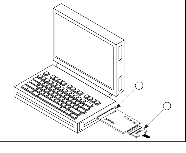
Chapter 4 PCMCIA Serial Hardware Installation, Verification, and Configuration
Serial Hardware and Software for Windows 4-10 ni.com
Figure 4-5 shows how to insert a PCMCIA serial card and how to connect
the cable.
Figure 4-5. Inserting a PCMCIA Serial Card
The serial hardware installation is complete. Continue to the next section,
Verify the Installation.
Verify the Installation
When you begin to verify the installation, keep in mind that the serial ports
built into the computer are typically named from COM1 to COM4.
Windows Me/9xtypically issues port names to the ports on NI serial
hardware starting with COM5, COM6, and so on. If not enough resources
are available to assign to all the NI serial ports, the port with the higher
COMxname is left unconfigured.
Double-click on the System icon in the Control Panel. In the System
Properties window that appears, select the Device Manager tab, and click
on the View devices by type button at the top of the page. If necessary,
double-click on the Ports (COM & LPT) icon to view all of the ports.
1PCMCIASocket 2 PCMCIA Serial Cable
1
2
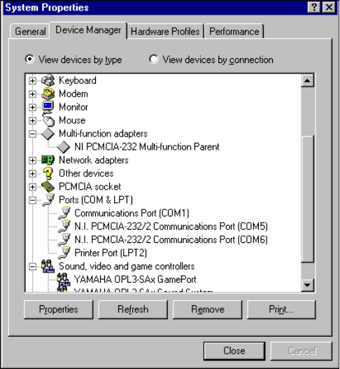
Chapter 4 PCMCIA Serial Hardware Installation, Verification, and Configuration
©National Instruments Corporation 4-11 Serial Hardware and Software for Windows
The two-port and four-port PCMCIA cards are configured as devices
belonging to the “multi-function adapters”class. The multi-function parent
device is listed under the Multi-function adapters icon, and each child
device is listed as a port under the Ports (COM & LPT) icon. If you have
installed one of these interfaces, double-click on the Multi-function
adapters icon as well as the Ports (COM & LPT) icon.
If a circled exclamation point appears through the port icon, the serial port
is not installed properly. A problem with the port could have occurred
because Windows Me/9xcould not acquire resources for the port, or
because an interrupt request resource conflict exists. If no circled
exclamation point appears, the serial hardware is installed correctly.
Figure 4-6 shows an example of NI serial hardware that is installed
properly.
Figure 4-6. Device Manager Ports List for PCMCIA Serial Card Correctly Installed
Chapter 4 PCMCIA Serial Hardware Installation, Verification, and Configuration
Serial Hardware and Software for Windows 4-12 ni.com
Verify the Hardware Resources
For every port of the newly installed serial interface, double-click on
the name of the serial port in the Device Manager. Then, click on the
Resources tab. If the resources were assigned correctly, the Resources
page shows which resources are assigned to your serial ports.
If Windows Me/9xdid not assign any resources to the port, the Resources
page shows only a Set Configuration Manually button. Click on the Set
Configuration Manually button and try to assign conflict-free resources
to your serial hardware. For instructions, refer to the Selecting
Conflict-Free Resources section of Appendix D, Troubleshooting and
Common Questions. You might have to free an interrupt request level so
that one can be assigned to your serial hardware. For instructions, refer to
the section Freeing an Interrupt Request Level in Appendix D,
Troubleshooting and Common Questions.
When you have finished verifying the hardware resources, proceed to the
next section.
Determine Which Physical Port Is Associated
with COMx
For every port of the newly installed serial interface, double-click on the
name of the serial port in the Device Manager. Then, click on the Port
Settings tab. The top of this page displays the serial number of the serial
hardware, and the physical port number starting at 1.
When you have finished verifying the driver installation and physical port,
proceed to the next section.
Run the Diagnostic Test
To verify and test the installation, run the diagnostic program that came
with your NI-Serial software. The diagnostic program verifies that your
serial driver is installed properly, that the configuration of your hardware
does not conflict with anything else in your system, and that the serial
driver can communicate with your hardware correctly.
To run the test, select the diagnostics item under Start»Programs»
National Instruments Serial.
If the diagnostic test completes with no failures, your serial hardware
and software are installed properly. If it fails, refer to Appendix D,
Troubleshooting and Common Questions, for troubleshooting instructions.

Chapter 4 PCMCIA Serial Hardware Installation, Verification, and Configuration
©National Instruments Corporation 4-13 Serial Hardware and Software for Windows
After you verify the hardware and software installation, connect the cables.
See Appendix A, Connector Descriptions, for information about cable
connections.
Configure Communication Port Settings
The serial configuration utility is fully integrated with the Windows Me/9x
Device Manager. You can use it to examine or modify the configuration of
the serial port.
Follow these steps to configure the serial port. Repeat the configuration
procedure for each serial port in your system.
1. Select Start»Settings»Control Panel and double-click on the System
icon. The System Properties window appears.
2. Select the Device Manager tab, and click on the View devices by type
button at the top of the page.
3. Double-click on the Ports (COM & LPT) icon.
4. Double-click on the name of the port you want to configure.
You can now view or change information about your serial port in the
following ways:
•ClickontheResources tab to view information about the hardware
resources assigned to the serial port.
•ClickonthePort Settings tab to view information about the software
configuration for the serial port. Refer to the next section, Port Settings
Tab, for more information.
•On the Port Settings tab,clickontheAdvanced button to change the
RS-485 transceiver mode and to enable or disable the FIFOs on the
serial hardware. Refer to the next section, Port Settings Tab,formore
information.
Note If you use two-wire TXRDY mode, FIFOs must be enabled. Transceiver modes
apply to RS-485 interfaces only. For more information about transceiver modes, refer to
Chapter 6, Using Your Serial Hardware.
After you have selected the serial port parameters for the current port, click
on the OK button to save the changes or click on the Cancel button to exit
the dialog box without saving changes.
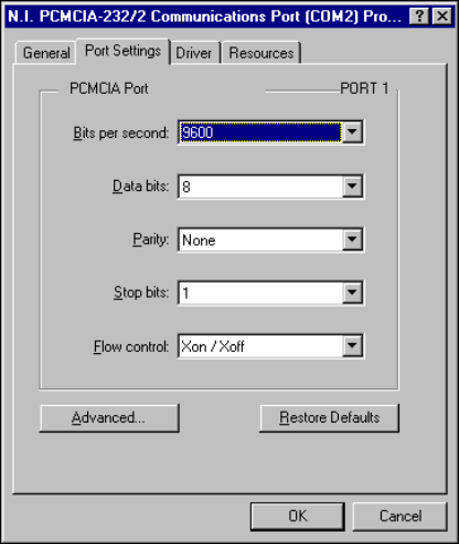
Chapter 4 PCMCIA Serial Hardware Installation, Verification, and Configuration
Serial Hardware and Software for Windows 4-14 ni.com
Port Settings Tab
On the Port Settings tab, you can change any of the settings by clicking on
the arrow button to the right of the setting. When you click on the arrow
button, a list of valid values for that setting appears. Select the desired
setting from the list. Figure 4-7 shows the Port Settings tab.
Figure 4-7. Port Settings Tab
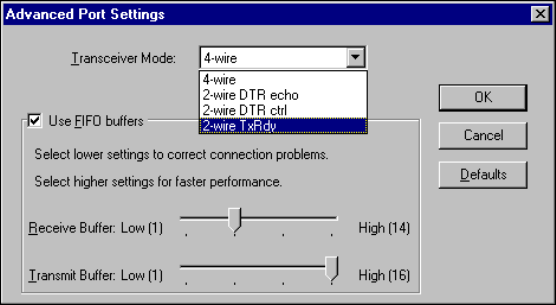
Chapter 4 PCMCIA Serial Hardware Installation, Verification, and Configuration
©National Instruments Corporation 4-15 Serial Hardware and Software for Windows
Advanced Port Settings
You can view or change the advanced port settings by clicking on the
Advanced buttononthePort Settings tab. Figure 4-8 shows the
Advanced Port Settings dialog box.
Figure 4-8. Advanced Port Settings Dialog Box
The following sections describe the advanced settings options.
Transceiver Mode
This field shows the transceiver mode in use, and applies only to
PCMCIA-485 boards. For more information about transceiver modes,
refer to Chapter 6, Using Your Serial Hardware.
Use FIFO Buffers
FIFO buffers are present on the 16550-compatible UARTs—one for the
transmitter and one for the receiver. The Receive Buffer control sets the
number of characters received in the FIFO before the PC is interrupted to
read the data. The Transmit Buffer control sets the maximum number of
bytes written to the FIFO in a block when the PC is interrupted to write the
data. When you configure FIFO settings, consider the following points:
•You can select larger FIFO buffer sizes to reduce the number of
interrupts your PC receives and therefore minimize system overhead.
•If transfer rates are high, you can lower the Receive Buffer value to
prevent overrun errors due to interrupt latency.
•If your data transfer sizes are small and your Receive Buffer value is
above your data sizes, your system is less efficient. Therefore, set the
Receive Buffer value below your data sizes.

Chapter 4 PCMCIA Serial Hardware Installation, Verification, and Configuration
Serial Hardware and Software for Windows 4-16 ni.com
Note If you want your serial hardware ports to use the names COM1, COM2, COM3, or
COM4, refer to the Common Questions section of Appendix D, Troubleshooting and
Common Questions.
Restore Defaults
To reset the fields to their default values at any time, click on the Restore
Defaults button.
Windows NT
Install the NI-Serial Software
Install the NI-Serial software for Windows NT before you install the
hardware.
1. LogonasAdministrator or as a user who has Administrator
privileges.
2. Select Start»Settings»Control Panel.
3. Double-click on the Add/Remove Programs icon in the Control Panel
to launch the Add/Remove Programs applet. The Add/Remove
Programs dialog box appears.
4. Click on the Install button.
5. When prompted, insert the NI-Serial Software for Windows
2000/NT/Me/9x CD and click on the Next button to proceed.
The software installation wizard begins.
The setup wizard guides you through the necessary steps to install the
NI-Serial software. You can go back and change values where
appropriate by clicking on the Back button. You can exit the setup
where appropriate by clicking on the Cancel button.
Note This installation backs up the Microsoft Windows NT serial driver serial.sys to
serial.bak andthenoverwrites
serial.sys. You can find serial.sys in the
Windows NT...\system32\drivers directory.
The software installation is complete. Proceed to the next section, Install
the PCMCIA Serial Hardware.
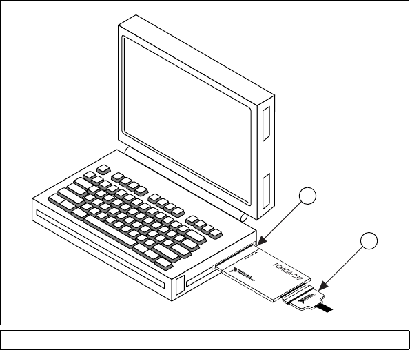
Chapter 4 PCMCIA Serial Hardware Installation, Verification, and Configuration
©National Instruments Corporation 4-17 Serial Hardware and Software for Windows
Install the PCMCIA Serial Hardware
Complete the following steps to install the PCMCIA-232 or PCMCIA-485
in your computer:
1. Shut down the computer.
2. Insert the card into a free PC Card (PCMCIA) socket the same way you
insert a disk into a floppy drive. The card has no jumpers or switches
to set.
3. Power on the computer and start Windows NT.
Figure 4-9 shows how to insert a PCMCIA serial card and how to connect
the cable.
Figure 4-9. Inserting a PCMCIA Serial Card
Proceed to the next section, Select Resources for the PCMCIA Card.
1PCMCIASocket 2 PCMCIA Serial Cable
1
2
Chapter 4 PCMCIA Serial Hardware Installation, Verification, and Configuration
Serial Hardware and Software for Windows 4-18 ni.com
Select Resources for the PCMCIA Card
Complete the following steps to select resources for your PCMCIA card.
1. Select Start»Settings»Control Panel.
2. Double-click on the niports icon.
3. Select the PCMCIA card you just installed from the Add a New
PCMCIA Card list,andclickontheAdd button.
4. In the Resource Configuration dialog box, select nonconflicting base
I/O address and IRQ settings for your port/card, and click on OK.
For more information on selecting resources for your port/card, refer
to the Resource Settings section.
5. Exit niports and restart the computer.
After you have selected resources for your PCMCIA card, proceed to the
next section, Verify the Installation.
Verify the Installation
Determine Which Physical Port Is Associated
with COMx
Select Start»Settings»Control Panel, and double-click on niports.Alist
showing installed National Instruments ports with their logical COMx
names appears. If your interface is not on the list, refer to Appendix D,
Troubleshooting and Common Questions.
Select the COM port you want and click on the Settings button to display
the General Port Settings dialog box for that port. This dialog box
displays the physical port number starting at 1.
When you have finished verifying the driver installation and physical port,
proceed to the next section, Run the Diagnostic Test.
Run the Diagnostic Test
To verify and test the installation, run the diagnostic program that came
with your NI-Serial software. The diagnostic program verifies that your
serial driver is installed properly, that the configuration of your hardware
does not conflict with anything else in your system, and that the serial
driver can communicate with your hardware correctly.
To run the test, select the diagnostics item under Start»Programs»
National Instruments Serial.
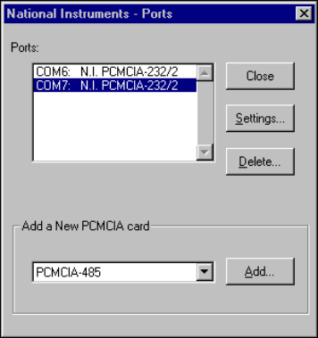
Chapter 4 PCMCIA Serial Hardware Installation, Verification, and Configuration
©National Instruments Corporation 4-19 Serial Hardware and Software for Windows
If the diagnostic test completes with no failures, your serial hardware and
software are installed properly. If it fails, refer to Appendix D,
Troubleshooting and Common Questions, for troubleshooting instructions.
After you verify the hardware and software installation, connect the cables.
See Appendix A, Connector Descriptions, for information about cable
connections.
Configure Communication Port Settings
The serial configuration utility is fully integrated with the Windows NT
Control Panel. You can use it to examine or modify the configuration of the
serial port.
Follow these steps to configure the serial port.
1. Select Start»Settings»Control Panel and double-click on the niports
icon. A list of National Instruments ports appears, as shown in
Figure 4-10.
Figure 4-10. niports Configuration Utility
2. Select the port you are interested in.
3. ClickontheSettings button to view or configure the port settings.
Refer to the next section, GeneralPortSettings, for more information.
4. ClickontheResources button in the General Port Settings dialog
box to view or configure the resources for the port. Refer to the
Resource Settings section, for more information.
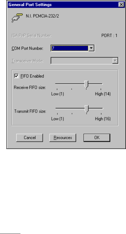
Chapter 4 PCMCIA Serial Hardware Installation, Verification, and Configuration
Serial Hardware and Software for Windows 4-20 ni.com
5. Click on Delete to remove hardware information about the port from
Windows NT. You should do this before you physically remove your
PCMCIA card.
6. Click on Add to configure resources for a new PCMCIA card.
General Port Settings
This section describes the options you can set in the General Port Settings
dialog box, shown in Figure 4-11.
Figure 4-11. General Port Settings Dialog Box
COM Port Number
You can use the COM Port Number control to change the COMxname of
the port selected.
Transceiver Mode
The transceiver mode selection shows the transceiver mode in use, and
applies only to PCMCIA-485 cards. Refer to Chapter 6, Using Your Serial
Hardware, for more information about transceiver modes. If you use
two-wire TXRDY mode, FIFOs must be enabled.
Chapter 4 PCMCIA Serial Hardware Installation, Verification, and Configuration
©National Instruments Corporation 4-21 Serial Hardware and Software for Windows
FIFO Enabled
You can use the FIFO Enabled control to enable or disable the FIFO
buffers on the serial port. FIFO buffers are present on the
16550-compatible UARTs—one for the transmitter and one for the
receiver.
FIFO Buffers
The FIFO buffer control is available by clicking on the Advanced button
on the Port Settings tab. FIFO buffers are present on the 16550-compatible
UARTs—one for the transmitter and one for the receiver. The receive FIFO
trigger denotes the number of characters received in the FIFO before the PC
is interrupted to read the data. The transmit FIFO trigger denotes the
maximum number of bytes written to the FIFO in a block when the PC is
interrupted to write the data. Consider the following points when selecting
FIFO settings:
•You can select larger FIFO settings to reduce the number of interrupts
and therefore minimize system overhead.
•If transfer rates are high, you can lower receive FIFO settings to reduce
the number of interrupts and therefore prevent overrun errors due to
interrupt latency.
•If data transfer sizes are small, selecting receive FIFO settings just
above data sizes can reduce efficiency, so select lower settings.
Resources
ClickontheResources button to display the resource configuration dialog
box for the port. For more information on resource configuration, refer to
the next section, Resource Settings.
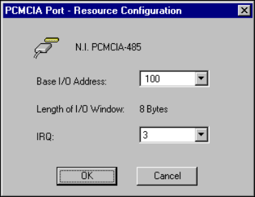
Chapter 4 PCMCIA Serial Hardware Installation, Verification, and Configuration
Serial Hardware and Software for Windows 4-22 ni.com
Resource Settings
The following sections explain the resource configuration options for each
serial interface.
PCMCIA-232, PCMCIA-485, PCMCIA-232/4
Figure 4-12 shows the resource configuration dialog box for a
PCMCIA-485. The PCMCIA-232 and PCMCIA-232/4 dialog boxes
are similar.
Figure 4-12. Resource Configuration Dialog Box for the PCMCIA-485
Base I/O Address: The base I/O address assigned to the port.
IRQ: The IRQ assigned to the port.
Length: The size (in bytes) of the I/O window.
For the PCMCIA-232 and PCMCIA-485, the
length is 8 (the size of the I/O window for one
port).
For the PCMCIA-232/4, the length is 32 bytes
(the size of the I/O window for four ports).
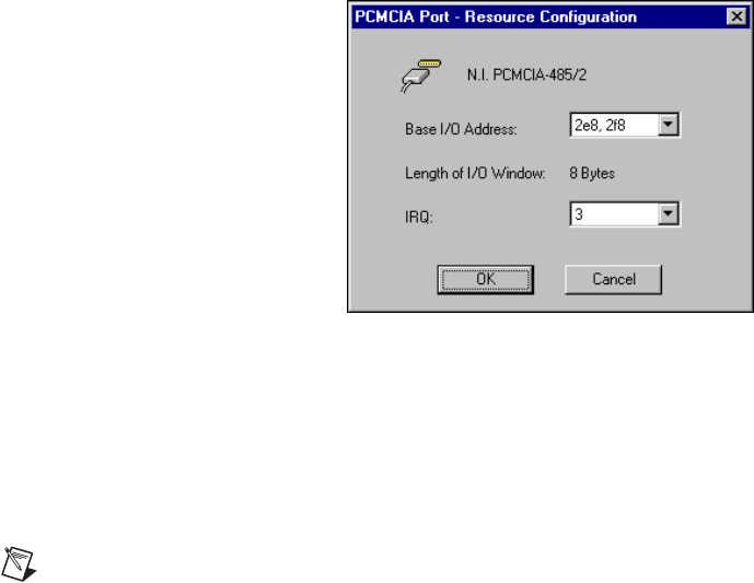
Chapter 4 PCMCIA Serial Hardware Installation, Verification, and Configuration
©National Instruments Corporation 4-23 Serial Hardware and Software for Windows
PCMCIA-232/2, PCMCIA-485/2
These cards require two base I/O settings, one for each port, and they share
an IRQ.
Figure 4-13 shows the resource configuration dialog box for a
PCMCIA-485/2. The PCMCIA-232/2 dialog box is similar.
Figure 4-13. Resource Configuration Dialog Box for the PCMCIA-485/2
Base I/O Address: The base I/O addresses assigned to the two
ports.
IRQ: The IRQ shared by the two ports.
Length: The size of each I/O window (in bytes).
Note When you select resources for the PCMCIA cards, use the Microsoft Windows NT
diagnostics utility to make sure that the resources have not been assigned to any other
device. This utility displays a list of I/O port addresses and IRQ levels that are currently
being used in your system.

©National Instruments Corporation 5-1 Serial Hardware and Software for Windows
5
AT Serial Hardware Installation,
Verification, and Configuration
This chapter describes how to install the NI-Serial software and AT serial
hardware and how to verify the installation. It also describes how to view
or change the communication port settings.
To begin your installation, see the section of this chapter containing
instructions for your operating system (Windows 2000, Windows Me/9x,or
Windows NT.)
Windows 2000
Install the Software
Before you install your serial hardware, complete the following steps to
install the NI-Serial software for Windows 2000:
1. Select Start»Settings»Control Panel.
2. Double-click on the Add/Remove Programs icon. The Add/Remove
Programs appears.
3. ClickontheAdd New Programs button and then the CD or Floppy
button.
4. When prompted, insert the NI-Serial Software for Windows
2000/NT/Me/9x CD and click on the Next button.
5. When prompted, click on the Finish button to install the program files
from the CD.
6. The setup wizard begins. The setup wizard guides you through the
necessary steps to install the NI-Serial software. To exit the setup
wizard at any time, click on the Cancel button.
7. If you need to install your hardware, or if this is your first time to install
the NI-Serial software for Windows 2000, skip to the next section,
Install the Hardware. Otherwise, continue to step 8.
8. If your hardware is already installed, restart Windows 2000.

Chapter 5 AT Serial Hardware Installation, Verification, and Configuration
Serial Hardware and Software for Windows 5-2 ni.com
9. Windows 2000 should automatically detect your hardware and display
the Found New Hardware Wizard. Complete the wizard by clicking
Next in each window and then Finish. When you complete the wizard,
continue to the Verify the Installation section.
If the Found New Hardware Wizard does not appear, refer to the
Forcing Windows to Detect Your Hardware section in Appendix D,
Troubleshooting and Common Questions.
Install the Hardware
Note If you are installing a AT-485, you might need to adjust the value of the bias resistors,
depending on your application. For more information, refer to Appendix B, Serial Port
Information.
Caution Before you remove your board from the package, touch the antistatic plastic
package to a metal part of your system chassis to discharge electrostatic energy, which can
damage several components on your serial board.
To install your AT serial board, complete the following steps:
1. Turn off your computer. Keep the computer plugged in so that it
remains grounded while you install the AT serial board.
2. Remove the top or side cover of the computer.
3. Find an unused AT expansion slot in your computer.
4. Remove the corresponding expansion slot cover on the back panel of
the computer.
5. Touch a metal part on your chassis to discharge any static electricity.
6. Insert the AT serial board into the slot with the serial connectors toward
the opening on the back panel. Make sure that you insert the board all
the way into the slot. The board might seem to click firmly into place,
even though it is only part of the way in. Figure 5-1 shows how to
install the AT serial board into an expansion slot.

Chapter 5 AT Serial Hardware Installation, Verification, and Configuration
©National Instruments Corporation 5-3 Serial Hardware and Software for Windows
Figure 5-1. AT Serial Board Installation
7. Screw the AT serial board mounting bracket to the back panel
mounting rail of the computer.
8. Replace the cover.
9. Turn on your computer and start Windows 2000.
10. Windows 2000 should automatically detect your hardware and display
the Found New Hardware Wizard. Complete the wizard by clicking
Next in each window and then Finish.
If the Found New Hardware Wizard does not appear, refer to the
Forcing Windows to Detect Your Hardware section in Appendix D,
Troubleshooting and Common Questions.
The serial hardware installation is complete. Continue to the next section,
Verify the Installation.
1PC 2ATSocket 3 AT Serial Card
1
2
3
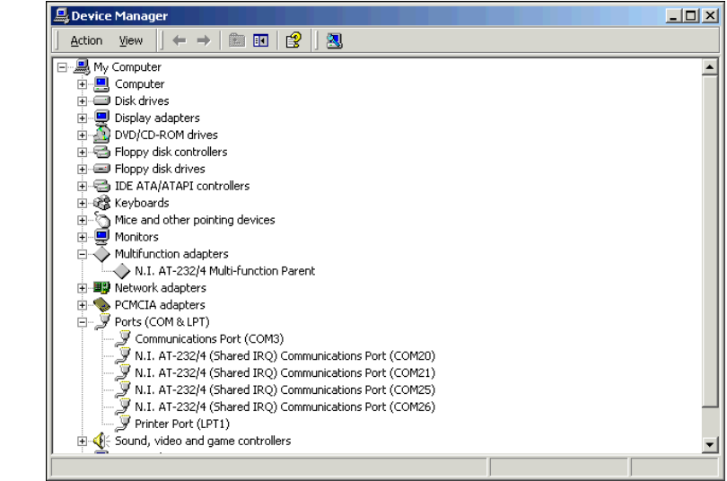
Chapter 5 AT Serial Hardware Installation, Verification, and Configuration
Serial Hardware and Software for Windows 5-4 ni.com
Verify the Installation
To verify the hardware and software installation, complete the following
steps:
1. Select Start»Settings»Control Panel and double-click on the
System icon.
2. Click on the Hardware tabandclickontheDevice Manager button.
3. Double-click on the Ports (COM & LPT) icon to display all of
the ports.
4. Double-click on the Multi-function adapters icon.
The AT serial boards are configured as devices belonging to the
multi-function adapters class. The multi-function parent device is
listed under the Multi-function adapters icon, and each child device
is listed as a port under the Ports (COM & LPT) icon.
Figure 5-2 shows the Device Manager tab for serial hardware that is
installed properly.
Figure 5-2. Device Manager for AT Serial Board Ports
Chapter 5 AT Serial Hardware Installation, Verification, and Configuration
©National Instruments Corporation 5-5 Serial Hardware and Software for Windows
5. Verify the hardware resources, as follows:
a. In the Device Manager under Multi-function adapters,
double-click on a serial board.
b. ClickontheResources tab. If the resources were assigned
properly, the Resources tab shows which resources are assigned
to your serial ports.
c. Repeat steps 5a and 5b until you have verified the resources for
each board.
6. (Optional) To determine which physical port is associated with COMx,
note the Port 1, Port 2, etc. entries next to the COM numbers. For all
serial hardware, PORT1 refers to the top port, PORT2 refers to the next
port down, and so on.
7. Run the diagnostic utility, as follows: select Start»Programs»
National Instruments»NI-Serial»Diagnostics.
The diagnostic utility verifies that your serial driver is installed
properly, that the configuration of your hardware does not conflict with
anything else in your system, and that the serial driver can
communicate with your hardware correctly.
If the test is successful, your serial hardware and software are installed
properly. If the test fails, refer to Appendix D, Troubleshooting and
Common Questions, to troubleshoot the problem.
8. After you verify the hardware and software installation, connect the
cables. See Appendix A, Connector Descriptions, for information
about cable connections.
Configure Communication Port Settings
The serial configuration utility is fully integrated into the Windows 2000
Device Manager. You can use it to view or change the configuration of
your serial ports.
To configure a serial port, complete the following steps:
1. Select Start»Settings»Control Panel and double-click on the
System icon.
2. ClickontheHardware tabandclickontheDevice Manager button.
3. Double-click on the Ports (COM & LPT) icon.

Chapter 5 AT Serial Hardware Installation, Verification, and Configuration
Serial Hardware and Software for Windows 5-6 ni.com
4. Double-click on the port you want to configure and refer to the
following instructions:
•To view the hardware resources assigned to the serial port, click
on the Resources tab.
•To view or change the port settings, click on the Port Settings tab.
For more information about the settings, refer to the next section,
Port Settings Tab.
•To change the RS-485 transceiver mode, or to enable or disable
the FIFOs on the serial hardware, in the Port Settings tab, click
on the Advanced button. For more information about the settings,
refer to the next section, Port Settings Tab.
Note Transceiver modes apply to RS-485 interfaces only. For more information about
transceiver modes, refer to Chapter 6, Using Your Serial Hardware.
5. To save your changes, click on the OK button. To exit without saving
the changes, click on the Cancel button.
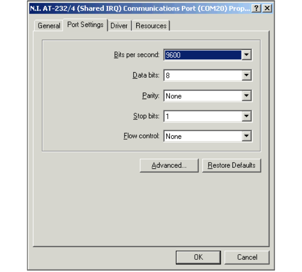
Chapter 5 AT Serial Hardware Installation, Verification, and Configuration
©National Instruments Corporation 5-7 Serial Hardware and Software for Windows
Port Settings Tab
In the Port Settings tab, you can change any of the settings by clicking on
the arrow button to the right of a field. When you click on the arrow button,
a list of valid values for that field appears and you can select the desired
setting from the list. Figure 5-3 shows the Port Settings tab.
Figure 5-3. Port Settings Tab
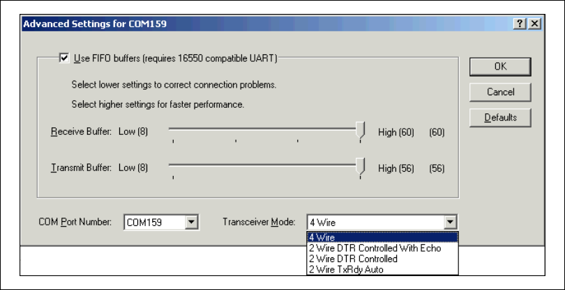
Chapter 5 AT Serial Hardware Installation, Verification, and Configuration
Serial Hardware and Software for Windows 5-8 ni.com
Advanced Settings
To view or change the advanced settings, click on the Advanced button.
Figure 5-4 shows the Advanced Settings dialog box.
Figure 5-4. Advanced Settings Dialog Box
The following sections describe the advanced settings options.
Transceiver Mode
This field shows the transceiver mode in use, and applies only to AT-485
boards. For more information about transceiver modes, refer to Chapter 6,
Using Your Serial Hardware.

Chapter 5 AT Serial Hardware Installation, Verification, and Configuration
©National Instruments Corporation 5-9 Serial Hardware and Software for Windows
Use FIFO Buffers
FIFO buffers are present on the 16550-compatible UARTs—one for the
transmitter and one for the receiver. The Receive Buffer control sets the
number of characters received in the FIFO before the PC is interrupted to
read the data. The Transmit Buffer control sets the maximum number of
bytes written to the FIFO in a block when the PC is interrupted to write the
data. When you configure FIFO settings, consider the following points:
•You can select larger FIFO buffer sizes to reduce the number of
interrupts your PC receives and therefore minimize system overhead.
•If transfer rates are high, you can lower the Receive Buffer value to
prevent overrun errors due to interrupt latency.
•If your data transfer sizes are small and your Receive Buffer value is
above your data sizes, your system is less efficient. Therefore, set the
Receive Buffer value below your data sizes.
Restore Defaults
To reset the fields to their default values at any time, click on the Restore
Defaults button.
Windows Me/9x
Install the Software
Install the NI-Serial software for Windows Me/9xbefore you install the
hardware.
1. Select Start»Settings»Control Panel.
2. Double-click on the Add/Remove Programs icon in the Control Panel
to launch the Add/Remove Programs applet. The Add/Remove
Programs dialog box appears.
3. ClickontheInstall button.
4. When prompted, insert the NI-Serial Software for Windows
2000/NT/Me/9x CD,and click on the Next button to proceed.
The software installation wizard begins.
The setup wizard guides you through the necessary steps to install the
NI-Serial software. You can go back and change values where
appropriate by clicking on the Back button. You can exit the setup
where appropriate by clicking on the Cancel button.

Chapter 5 AT Serial Hardware Installation, Verification, and Configuration
Serial Hardware and Software for Windows 5-10 ni.com
5. If you need to install your hardware, or if this is your first time to install
the NI-Serial software for Windows Me/9x, skip to the next section,
Install the Hardware. Otherwise, continue to Step 6.
6. If your hardware is already installed, restart Windows Me/9x.
Windows Me/9xshould automatically detect your hardware and
display one or more New Hardware Found dialog boxes, but you
must make sure Windows Default Driver is selected and click on OK.
When you finish, continue to the Verify the Installation section.
If no New Hardware Found dialog box appears, refer to the Forcing
Windows to Detect Your Hardware sectioninAppendixD,
Troubleshooting and Common Questions.
Install the Hardware
This section describes how to install your AT serial hardware.
Note If you are installing a AT-485, you might need to adjust the value of the bias
resistors, depending on your application. For more information, refer to Appendix B,
Serial Port Information.
Caution Before you remove your board from the package, touch the antistatic plastic
package to a metal part of your system chassis to discharge electrostatic energy, which can
damage several components on your serial board.
To install your AT serial board, complete the following steps:
1. Turn off your computer. Keep the computer plugged in so that it
remains grounded while you install the AT serial board.
2. Remove the top or side cover of the computer.
3. Find an unused AT expansion slot in your computer.
4. Remove the corresponding expansion slot cover on the back panel of
the computer.
5. Touch a metal part on your chassis to discharge any static electricity.
6. Insert the AT serial board into the slot with the serial connectors toward
the opening on the back panel. Make sure that you insert the board all
the way into the slot. The board might seem to click firmly into place,
even though it is only part of the way in. Figure 5-5 shows how to
install the AT serial board into an expansion slot.

Chapter 5 AT Serial Hardware Installation, Verification, and Configuration
©National Instruments Corporation 5-11 Serial Hardware and Software for Windows
Figure 5-5. AT Serial Board Installation
7. Screw the AT serial board mounting bracket to the back panel
mounting rail of the computer.
8. Replace the cover.
9. Turn on your computer and start Windows Me/9x.
10. Watch for Windows Me/9xto display one or more New Hardware
Found dialog boxes. In the dialog box, select Windows Default
Driver and click on OK.
If no New Hardware Found dialog box appears, refer to the Forcing
Windows to Detect Your Hardware sectioninAppendixD,
Troubleshooting and Common Questions.
The serial hardware installation is complete. Continue to the next section,
Verify the Installation.
1PC 2ATSocket 3 AT Serial Card
1
2
3
Chapter 5 AT Serial Hardware Installation, Verification, and Configuration
Serial Hardware and Software for Windows 5-12 ni.com
Verify the Installation
When you begin to verify the installation, keep in mind that the serial
ports built into the computer are typically named from COM1 to COM4.
Windows Me/9xtypically issues port names to the ports on NI serial
hardware starting with COM5, COM6, and so on. If not enough resources
are available to assign to all the NI serial ports, the port with the higher
COMxname is left unconfigured.
Double-click on the System icon in the Control Panel. In the System
Properties window that appears, select the Device Manager tab, and click
on the View devices by type button at the top of the page. If necessary,
double-click on the Ports (COM & LPT) icon to view all of the ports.
The shared IRQ AT serial boards are configured as devices belonging to the
“multi-function adapters”class. The multi-function parent device is listed
under the Multi-function adapters icon, and each child device is listed as
a port under the Ports (COM & LPT) icon. If you have installed one of
these interfaces, double-click on the Multi-function adapters icon as well
as the Ports (COM & LPT) icon to look at the ports resources. To modify
the hardware resources, double-click on the Multi-Function adapters
icon.
If a circled exclamation point appears through the port icon, the serial port
is not installed properly. A problem with the port may have occurred
because Windows Me/9xcould not acquire resources for the port, or
because an interrupt request resource conflict exists. If no circled
exclamation point appears, the serial hardware is installed correctly.
Figure 5-6 shows an example of NI serial hardware that is installed
properly.
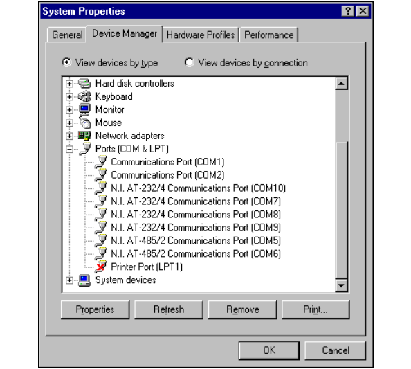
Chapter 5 AT Serial Hardware Installation, Verification, and Configuration
©National Instruments Corporation 5-13 Serial Hardware and Software for Windows
Figure 5-6. Device Manager Ports List for AT Serial Board Correctly Installed
Verify the Hardware Resources
For every port of the newly installed serial interface, double-click on the
name of the serial port in the Device Manager. Then, click on the
Resources tab. If the resources were assigned correctly, the Resources
page shows which resources are assigned to your serial ports.
If Windows Me/9xdid not assign any resources to the port, the Resources
page shows only a Set Configuration Manually button. Click on the Set
Configuration Manually button and try to assign conflict-free resources
to your serial hardware. For instructions, refer to the Selecting
Conflict-Free Resources section of Appendix D, Troubleshooting and
Common Questions. You may have to free an interrupt request level so that
one can be assigned to your serial hardware. For instructions, refer to the
Freeing an Interrupt Request Level section in Appendix D,
Troubleshooting and Common Questions.
When you have finished verifying the hardware resources, proceed to the
next section.
Chapter 5 AT Serial Hardware Installation, Verification, and Configuration
Serial Hardware and Software for Windows 5-14 ni.com
Determine Which Physical Port Is Associated
with COMx
For every port of the newly installed serial interface, double-click on the
name of the serial port in the Device Manager. Then, click on the Port
Settings tab. The top of this page displays the serial number of the serial
hardware, and the physical port number starting at 1. On all serial hardware,
PORT1referstothetopport,PORT2referstothenextportdown,and
so on.
When you have finished verifying the driver installation and physical port,
proceed to the next section.
Run the Diagnostic Test
To verify and test the installation, run the diagnostic program that came
with your NI-Serial software. The diagnostic program verifies that your
serial driver is installed properly, that the configuration of your hardware
does not conflict with anything else in your system, and that the serial
driver can communicate with your hardware correctly.
To run the test, select the diagnostics item under Start»Programs»
National Instruments Serial.
If the diagnostic test completes with no failures, your serial hardware
and software are installed properly. If it fails, refer to Appendix D,
Troubleshooting and Common Questions, for troubleshooting instructions.
After you verify the hardware and software installation, connect the cables.
See Appendix A, Connector Descriptions, for information about cable
connections.
Configure Communication Port Settings
The serial configuration utility is fully integrated into the Windows Me/9x
Device Manager. You can use it to view or change the configuration of
your serial ports.
Follow these steps to configure the serial port. Repeat the configuration
procedure for each serial port in your system.
1. Select Start»Settings»Control Panel and double-click on the
System icon. The System Properties window appears.
2. Select the Device Manager tab, and click on the View devices by type
button at the top of the page.

Chapter 5 AT Serial Hardware Installation, Verification, and Configuration
©National Instruments Corporation 5-15 Serial Hardware and Software for Windows
3. Double-click on the Ports (COM & LPT) icon.
4. Double-click on the name of the port you want to configure.
You can now view or change information about your serial port in the
following ways:
•To view the hardware resources assigned to the serial port, click on the
Resources tab.
•To view or change the port settings, click on the Port Settings tab.
For more information about the settings, refer to the next section, Port
Settings Tab.
•To change the RS-485 transceiver mode, or to enable or disable the
FIFOs on the serial hardware, in the Port Settings tab, click on the
Advanced button. For more information about the settings, refer to the
next section, Port Settings Tab.
Note If you use two-wire TXRDY mode, FIFOs must be enabled. Transceiver modes
apply to RS-485 interfaces only. For more information about transceiver modes, refer to
Chapter 6, Using Your Serial Hardware.
5. To save your changes, click on the OK button. To exit without saving
the changes, click on the Cancel button.
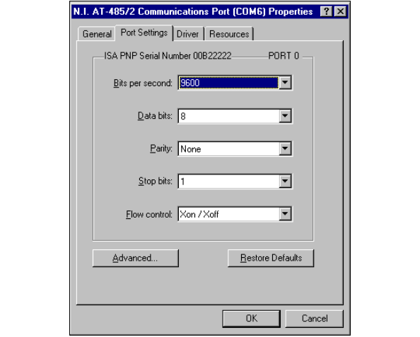
Chapter 5 AT Serial Hardware Installation, Verification, and Configuration
Serial Hardware and Software for Windows 5-16 ni.com
Port Settings Tab
On the Port Settings tab, you can change any of the settings by clicking on
the arrow button to the right of the setting. When you click on the arrow
button, a list of valid values for that setting appears. Select the desired
setting from the list. Figure 5-7 shows the Port Settings tab.
Figure 5-7. Port Settings Tab
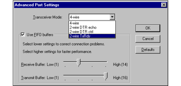
Chapter 5 AT Serial Hardware Installation, Verification, and Configuration
©National Instruments Corporation 5-17 Serial Hardware and Software for Windows
Advanced Port Settings
You can view or change the advanced port settings by clicking on the
Advanced buttononthePort Settings tab. Figure 5-8 shows the
Advanced Port Settings dialog box.
Figure 5-8. Advanced Port Settings Dialog Box
The following sections describe the advanced settings options.
Transceiver Mode
The transceiver mode selection is available by clicking on the Advanced
button on the Port Settings tab. It shows the transceiver mode in use, and
applies only to AT-485 boards. For more information about transceiver
modes, refer to Chapter 6, Using Your Serial Hardware.

Chapter 5 AT Serial Hardware Installation, Verification, and Configuration
Serial Hardware and Software for Windows 5-18 ni.com
Use FIFO Buffers
The FIFO buffer control is available by clicking on the Advanced button
on the Port Settings tab. FIFO buffers are present on the 16550-compatible
UARTs—one for the transmitter and one for the receiver. The receiver
FIFO trigger denotes the number of characters received in the FIFO before
the PC is interrupted to read the data. The transmit FIFO trigger denotes the
maximum number of bytes written to the FIFO in a block when the PC is
interrupted to write the data. Consider the following points when selecting
FIFO settings:
•You can select larger FIFO settings to reduce the number of interrupts
and therefore minimize system overhead.
•If transfer rates are high, you can lower receive FIFO settings to
prevent overrun errors due to interrupt latency.
•If data transfer sizes are small, selecting receive FIFO settings just
above data sizes can reduce efficiency, so select lower settings.
Note If you want your serial hardware ports to use the names COM1,COM2,COM3,or
COM4, refer to the Common Questions section of Appendix D, Troubleshooting and
Common Questions.
Windows NT
Installing the Microsoft PnP ISA Enabler Driver
When you install an AT board, you must install the PnP ISA Enabler
Driver.
The AT serial hardware is Plug and Play. Windows NT 4.0 does not support
Plug and Play. In order for Windows NT to detect and install the Plug and
Play hardware, you must install the PnP ISA Enabler driver included on
your Windows NT 4.0 CD-ROM. Complete the following steps to install
the driver:
1. Locate the Pnpisa.inf file in the Drvlib\Pnpisa\X86 folder on
the Windows NT 4.0 CD-ROM.
2. Right-click on the Pnpisa.inf file, then select Install on the menu
that appears.
3. Restart the computer.

Chapter 5 AT Serial Hardware Installation, Verification, and Configuration
©National Instruments Corporation 5-19 Serial Hardware and Software for Windows
Install the NI-Serial Software
Install the NI-Serial software for Windows NT before you install the
hardware. Make sure that you have already installed the PnP ISA Enabler
driver as described in the previous section.
1. LogonasAdministrator or as a user who has Administrator
privileges.
2. Select Start»Settings»Control Panel.
3. Double-click on the Add/Remove Programs icon in the Control Panel
to launch the Add/Remove Programs applet. The Add/Remove
Programs dialog box appears.
4. ClickontheInstall button.
5. When prompted, insert the NI-Serial Software for Windows
2000/NT/Me/9x CD and click on the Next button to proceed.
The software installation wizard begins.
The setup wizard guides you through the necessary steps to install
the NI-Serial software. You can go back and change values where
appropriate by clicking on the Back button. You can exit the setup
where appropriate by clicking on the Cancel button.
Note This installation backs up the Microsoft Windows NT serial driver serial.sys to
serial.bak andthenoverwritesserial.sys. You can find serial.sys in the
Windows NT.....\system32\drivers directory.
The software installation is complete. Proceed to the next section, Install
the Serial Hardware.
Install the Serial Hardware
This section describes how to install your AT serial board.
Note If you are installing an AT-485, you might need to adjust the value of the bias
resistors, depending on your application. For more information, refer to Appendix B,
Serial Port Information.
Caution Electrostatic discharge can damage several components on your board. To avoid
such damage in handling the board, touch the antistatic plastic package to a metal part of
your computer chassis before removing the board from the package.
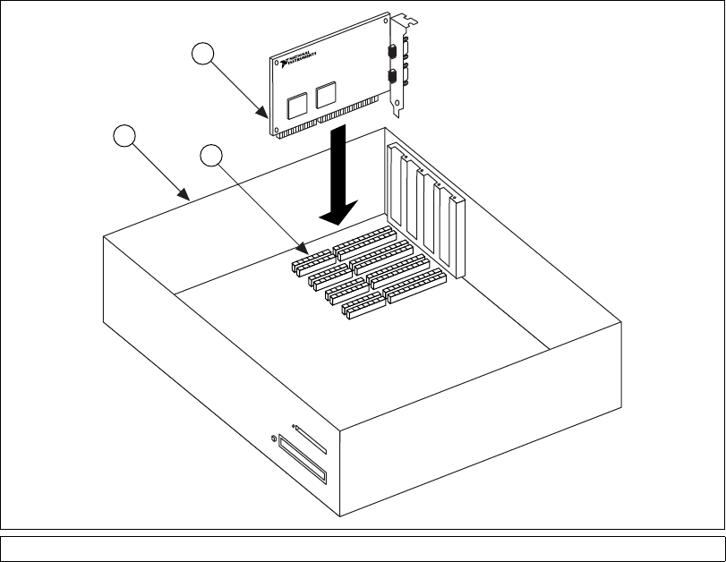
Chapter 5 AT Serial Hardware Installation, Verification, and Configuration
Serial Hardware and Software for Windows 5-20 ni.com
Complete the following steps to install your AT serial board:
1. Turn off your computer. Keep the computer plugged in so that it
remains grounded while you install the AT serial board.
2. Remove the top or side cover of the computer.
3. Remove the expansion slot cover on the back of the computer.
4. Insert the AT serial board into an unused slot with the serial connectors
sticking out of the opening on the back panel. Make sure that you insert
the board all the way into the slot. The board may seem to click firmly
into place, even though it is only part of the way in. Figure 5-9 shows
the installation of an AT serial board.
Figure 5-9. AT Serial Board Installation
5. Screw the mounting bracket of the AT serial board to the back panel
rail of the computer.
6. Replace the cover, and turn on your computer.
1PC 2ATSocket 3 AT Serial Card
1
2
3
Chapter 5 AT Serial Hardware Installation, Verification, and Configuration
©National Instruments Corporation 5-21 Serial Hardware and Software for Windows
7. Windows NT displays one or more New Hardware Found dialog
boxes, depending on your serial hardware. In each dialog box, make
sure that Windows Default Driver is selected, and click on OK.
8. The serial configuration software displays a PnP Port Configuration
dialog box. Select a nonconflicting base I/O address and IRQ setting
for the port/card, and click on OK. For more information on selecting
resources for your post/card, refer to the Resource Settings section.
9. After you have selected the resources for all ports, choose to restart the
computer when the system prompts you.
The serial hardware installation is now complete.
Verify the Installation
Determine Which Physical Port Is Associated
with COMx
Select Start»Settings»Control Panel, and double-click on niports.Alist
showing installed National Instruments ports with their logical COMx
names appears. If your interface is not on the list, refer to Appendix D,
Troubleshooting and Common Questions.
Select the COM port you want and click on the Settings button to display
the General Port Settings dialog box for that port. This dialog box
displays the serial number of the serial hardware and the physical port
number starting at 1. On all serial hardware, PORT1 refers to the top port,
PORT2 refers to the next port down, and so on.
When you have finished verifying the driver installation and physical port,
proceed to the next section, Run the Diagnostic Test.
Run the Diagnostic Test
To verify and test the installation, run the diagnostic program that came
with your NI-Serial software. The diagnostic program verifies that your
serial driver is installed properly, that the configuration of your hardware
does not conflict with anything else in your system, and that the serial
driver can communicate with your hardware correctly.
To run the test, select the diagnostics item under Start»Programs»
National Instruments Serial.
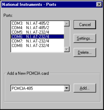
Chapter 5 AT Serial Hardware Installation, Verification, and Configuration
Serial Hardware and Software for Windows 5-22 ni.com
If the diagnostic test completes with no failures, your serial hardware
and software are installed properly. If it fails, refer to Appendix D,
Troubleshooting and Common Questions, for troubleshooting instructions.
After you verify the hardware and software installation, connect the cables.
See Appendix A, Connector Descriptions, for information about cable
connections.
Configure Communication Port Settings
The serial configuration utility is fully integrated with the Windows NT
Control Panel. You can use it to examine or modify the configuration of the
serial port.
Follow these steps to configure the serial port.
1. Select Start»Settings»Control Panel and double-click on the niports
icon. A list of National Instruments ports appears, as shown in
Figure 5-10.
Figure 5-10. niports Configuration Utility
2. Select the port you are interested in.
3. Click on the Settings button to view or configure the port settings.
Refer to the next section, GeneralPortSettings, for more information.
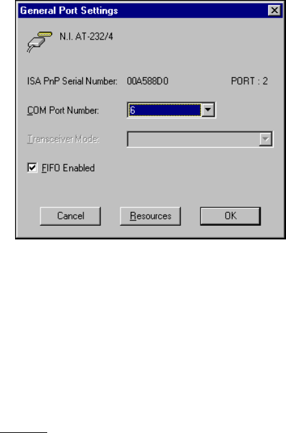
Chapter 5 AT Serial Hardware Installation, Verification, and Configuration
©National Instruments Corporation 5-23 Serial Hardware and Software for Windows
4. ClickontheResources button in the General Port Settings dialog
box to view or configure the resources for the port. Refer to the
Resource Settings section, later in this chapter, for more information.
5. Click on Delete to remove hardware information about the port from
Windows NT. You should do this before you remove the serial
interface from the system.
General Port Settings
This section describes the options you can set in the General Port Settings
dialog box, shown in Figure 5-11.
Figure 5-11. General Port Settings Dialog Box
COM Port Number
You can use the COM Port Number control to change the COMxname
of the port selected.
Transceiver Mode
The transceiver mode selection shows the transceiver mode in use, and
applies only to AT-485 boards. Refer to Chapter 6, Using Your Serial
Hardware, for more information about transceiver modes. If you use
two-wire TXRDY mode, FIFOs must be enabled.
Chapter 5 AT Serial Hardware Installation, Verification, and Configuration
Serial Hardware and Software for Windows 5-24 ni.com
FIFO Enabled
You can use the FIFO Enabled control to enable or disable the
FIFO buffers on the serial port. FIFO buffers are present on the
16550-compatible UARTs—one for the transmitter and one for the
receiver.
FIFO Buffer Size
FIFO buffers are present on the 16550-compatible UARTs—one for the
transmitter and one for the receiver. The receiver FIFO trigger denotes the
number of characters received in the FIFO before the PC is interrupted to
read the data. The transmit FIFO trigger denotes the maximum number of
bytes written to the FIFO in a block when the PC is interrupted to write the
data. Consider the following points when selecting FIFO settings:
•You can select larger FIFO settings to reduce the number of interrupts
and therefore minimize system overhead.
•If transfer rates are high, you can lower receive FIFO settings to reduce
the number of interrupts and therefore prevent overrun errors due to
interrupt latency.
•If data transfer sizes are small, selecting receive FIFO settings just
above data sizes can reduce efficiency, so select lower settings.
Resources
ClickontheResources button to display the resource configuration dialog
box for the port. For more information on resource configuration, refer to
the next section, Resource Settings.
Resource Settings
The following sections explain the resource configuration options for each
serial interface.
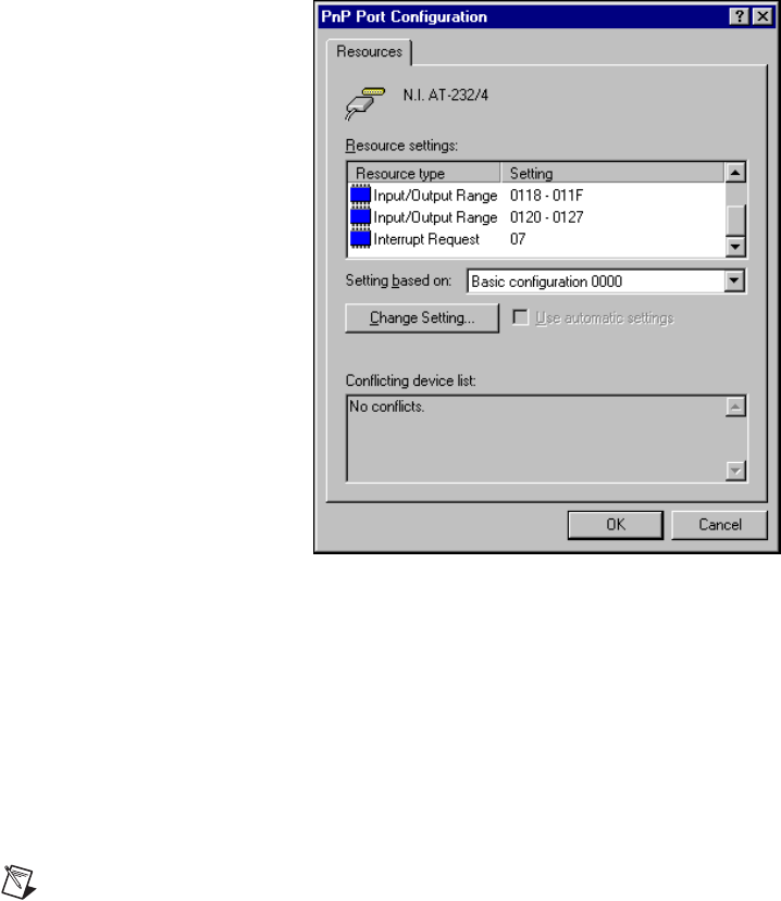
Chapter 5 AT Serial Hardware Installation, Verification, and Configuration
©National Instruments Corporation 5-25 Serial Hardware and Software for Windows
AT Boards (Shared IRQ)
Figure 5-12 shows the PnP Port Configuration dialog box for an
AT-232/4 with shared IRQ. The dialog boxes for other shared IRQ AT
boards are similar.
Figure 5-12. PnP Port Configuration Dialog Box for the AT-232/4
Each shared IRQ AT board requires multiple base I/O settings (one for each
port) and one IRQ that is shared between the ports.
Input/Output Range: Each Input/Output Range listing
displays the I/O address ranges assigned
to the corresponding port on the board.
Interrupt Request: The IRQ shared between the ports on the
board.
Note The niports utility informs you if your resources conflict with the resources of any
other interface in the system. It does not check for conflicts with ports on the same board.
Make sure to assign base I/O addresses that do not conflict with those assigned to another
port on the same board.

Chapter 5 AT Serial Hardware Installation, Verification, and Configuration
Serial Hardware and Software for Windows 5-26 ni.com
Note If you are unable to change the base I/O address by double-clicking on the
Input/Output Range control, select a different Basic Configuration in the Setting based on:
control.
AT Boards (Non-Shared IRQ)
Each port on the board requires one I/O window and one IRQ.
Input/Output Range: The base I/O address range assigned to
the port.
IRQ: TheIRQassignedtotheport.

©National Instruments Corporation 6-1 Serial Hardware and Software for Windows
6
Using Your Serial Hardware
This chapter describes how to set the hardware transceiver control mode for
your RS-485 interfaces and lists some general programming requirements.
General Programming Requirements
The NI-Serial software is fully integrated into the standard Windows
communications software. NI serial ports are used like any other Windows
communications (COM) port. Windows has standard communication
functions for use within either Win16 or Win32 applications.
When you develop your application, remember that you must use
the standard Microsoft Windows serial communication functions. For
information about Microsoft Windows serial communication functions,
refer to the Win32 Software Development Kit andtotheWin32 Overviews
and Win32 Reference online help.
If you have LabVIEW or Measurement Studio and want to use it with your
serial hardware, refer to your LabVIEW or Measurement Studio
documentation for information about serial I/O functions.
Advanced Transceiver Control for the
PCI/PXI/PCMCIA/AT-485 Boards
Note Transceiver modes apply only to the PCI/PXI/PCMCIA/AT-485 boards.
The RS-485 boards support four modes of hardware transceiver control.
You can use hardware flow control to enable and disable your transmitters
and receivers so that they function on different bus topologies. Table 6-1
lists the status of the transmitters and receivers under each of the
transceiver control modes.
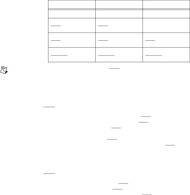
Chapter 6 Using Your Serial Hardware
Serial Hardware and Software for Windows 6-2 ni.com
Note Signal names with an overscore, such as DTR, indicate that the signal is active low.
Four-Wire Mode
Use the four-wire mode for most full-duplex systems. In this mode, the
transmitter and receiver are always enabled. This mode is the default.
Two-Wire Mode: DTR with Echo
Use this mode in half-duplex systems where the DTR (Data Terminal
Ready) line must control the transmitter. In the DTR-with-echo mode, the
transmitter is tri-stated when the DTR signal of the UART (Universal
Asynchronous Receiver/Transmitter) is asserted. To transmit, your
application must first clear the DTR bit to enable the transmitter. After the
data is fully transmitted, your application once again sets the DTR bit to
disable the transmitter. Because the receiver is always enabled in this
mode, you not only receive packets from other devices, you also receive the
packets sent from your transmitter.
Two-Wire Mode: DTR Controlled
This mode is similar to the two-wire, DTR-with-echo mode. Use this mode
in half-duplex systems where the DTR line must control the transmitter.
Although this mode uses the same method as the DTR-with-echo mode to
control the transmitter, the hardware automatically disables the receiver
whenever the transmitter is enabled. Thus, you do not receive the packets
sent from your transmitter.
Table 6-1. Transceiver Control Modes
Mode Transmitter Receiver
Four-wire mode Always enabled Always enabled
Two-wire mode:
DTR with echo
Enabled with
DTR unasserted
Always enabled
Two-wire mode:
DTR controlled
Enabled with
DTR unasserted
Enabled with
DTR asserted
Two-wire mode:
TXRDY auto control
Enabled with
TXRDY asserted
Enabled with
TXRDY unasserted

Chapter 6 Using Your Serial Hardware
©National Instruments Corporation 6-3 Serial Hardware and Software for Windows
Two-Wire Mode: TXRDY Auto Control
In this mode, the serial hardware transparently enables the transmitter and
receiver in a two-wire system. Use this mode to remove the burden of flow
control from your application. By connecting the transmitter to the
TXRDY (Transmit Ready) line, the hardware enables the transmitter for
each byte to be transmitted. Also, the hardware disables the receiver
whenever the transmitter is enabled, so you do not receive the packets sent
from your transmitter.
Note When you are communicating with a two-wire device, National Instruments
recommends that you use the two-wire TXRDY auto control mode. Because this mode
handles the transmitter/receiver enabling for a two-wire connection in your hardware,
it reduces the software overhead required to perform this operation in your application
program.
For more information about serial communication in two- or four-wire modes, refer to the
Serial Communication Issues sectioninAppendixB,Serial Port Information.
Setting the Transceiver Control Mode
Windows 2000
To set the transceiver control mode, use the Windows 2000 Device
Manager. For instructions on how to use the Device Manager, refer to the
chapter with installation instructions for your hardware platform. The mode
you select in the Device Manager is automatically configured when you
open a port on a serial interface.
Windows Me/9x
To set the transceiver control mode, use the Windows Me/9xDevice
Manager. For instructions on how to use the Device Manager, refer to
chapter with installation instructions for your hardware platform. The mode
you select in the Device Manager is automatically configured when you
open a port on a serial interface.
You can also set the hardware transceiver control mode from within a DOS
application. For each port you want to control, write the control byte for the
mode you want to select to the scratch register of the UART. Table 6-2
shows the control bytes for each mode.

Chapter 6 Using Your Serial Hardware
Serial Hardware and Software for Windows 6-4 ni.com
The scratch register is located at offset 7 from the base address of the port.
For example, if COM2 were located at base address 0x3F8, and you want
to set the board to two-wire mode with DTR control, you would write a
0x02 to address 0x3FF. The board would immediately switch to the
two-wire mode with DTR control.
Windows NT
To set the transceiver control mode, use the serial configuration utility.
For instructions on how to use the utility, refer to chapter with installation
instructions for your hardware platform. The mode you select in the
configuration utility is automatically configured when you open a port on
a serial interface.
Setting the Transceiver Mode with DeviceIoControl
The NI-Serial software extends the DeviceIoControl Windows function
for programming the transceiver control mode. To program the transceiver
control mode using DeviceIoControl, complete the following steps:
1. Add the following lines to your source code:
#include <winioctl.h>
#define IOCTL_SERIAL_SET_TRANSCEIVER_MODE
CTL_CODE(FILE_DEVICE_SERIAL_PORT,37,
METHOD_BUFFERED,FILE_ANY_ACCESS)
2. Use the Win32 function DeviceIoControl, as follows:
a. Use the defined control code value listed in step 1 to set the
transceiver mode.
b. Use the input buffer values (unsigned long) listed in Table 6-3 for
programming different transceiver modes.
Table 6-2. Transceiver Mode Control Bytes
Transceiver Mode Control Byte
Four-wire mode 0x00
Two-wire mode: DTR with echo 0x01
Two-wire mode: DTR controlled 0x02
Two-wire mode: TXRDY auto control 0x03

Chapter 6 Using Your Serial Hardware
©National Instruments Corporation 6-5 Serial Hardware and Software for Windows
For example, to set TXRDY two-wire auto control mode, use the
following code:
Windows 2000
ULONG TranceiverMode = 131;
ULONG dummy;
DeviceIoControl(hDevice,
IOCTL_SERIAL_SET_TRANSCEIVER_MODE,(PVOID)
&TransceiverMode,sizeof(ULONG),NULL,0,&dummy,NULL);
Windows NT/Me/9x
ULONG TranceiverMode = 131;
DeviceIoControl(hDevice,
IOCTL_SERIAL_SET_TRANSCEIVER_MODE,(PVOID)
&TransceiverMode,sizeof(ULONG),lpOutBuffer,
nOutBufferSize,lpBytesReturned,lpOverlapped);
Table 6-3. DeviceIoControl Function Input Values
Transceiver Mode
DeviceIoControl
Function Input Value
Four-wire mode 128
Two-wire mode: DTR with echo 129
Two-wire mode: DTR controlled 130
Two-wire mode: TXRDY auto control 131

©National Instruments Corporation A-1 Serial Hardware and Software for Windows
A
Connector Descriptions
Connecting Cables
For the PCMCIA serial cards and two-port PCI, PXI, and AT serial boards,
you can use the standard DB-9 connector found on most serial cables.
To use the DB-9 connector with the four-port serial boards, you need the
10-position modular jack to DB-9 cable, which is available from National
Instruments. You can also use a DB-25 connector with the four-port serial
boards by ordering the 10-position modular jack to DB-25 converter cable
from National Instruments. The eight-port serial boards include a pig tail
cable adapter, providing eight standard DB-9 connectors. The 16-port
boards include a break out box, providing 16 standard DB-9 connectors.
Note To achieve the specified isolation voltage for four-port isolated PCI or AT serial
boards, use only the 10-position modular jack to DB-9 cable included in your four-port
isolated PCI or AT serial board kit.
For more information about cable connectors, see the connector
descriptions in this appendix.
Connecting Two-Wire Devices
The PCI-485, PCMCIA-485, RS-485 PXI (PXI-8421 and PXI-8423), and
AT-485 boards are designed to work with either two- or four-wire devices.
If you are using a two-wire device, refer to the device documentation for
specific wiring instructions.
In general, half-duplex networks use a single twisted pair of wires for
communication in both directions, so you must connect both the transmitter
and the receiver at each end of the same pair of wires. For example, to
connect an RS-485 data acquisition device to a port on your board using
half-duplex communication, you need a single twisted pair of wires. At the
board, connect the TXD+ and RXD+ signals (pins 8 and 4 on a
DB-9 connector, pins 5 and 20 on a DB-25 connector) together and to one
wire. Connect the other end of this wire to both the TXD+ and RXD+
signals on the data acquisition device. Use the same method to connect the
TXD–and RXD–signals (pins 9 and 5 on a DB-9 connector, pins 22 and 7
on a DB-25 connector) to the second wire.
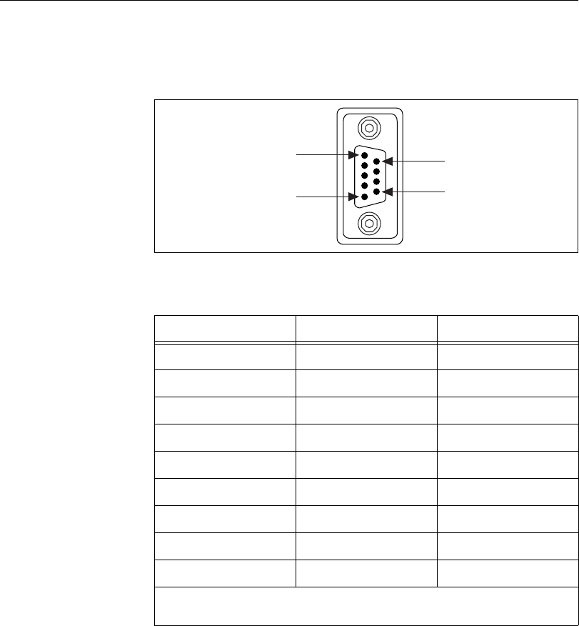
Appendix A Connector Descriptions
Serial Hardware and Software for Windows A-2 ni.com
For information about setting the transceiver mode for two-wire
communication, refer to Chapter 6, Using Your Serial Hardware.Formore
information about duplex architectures, refer to Appendix B, Serial Port
Information.
DB-9 Connector
Figure A-1 and Table A-1 give the pin locations and descriptions of the
DB-9 connector, the 10-position modular jack to DB-9 cable, the cable
adapter for the eight-port board, and the DB-9 connectors to the 16-port
breakout box.
Figure A-1. DB-9 Connector Pin Locations
Table A-1. DB-9 Pin Descriptions
DB-9 Pin 232 Signal 485 Signal
1DCD* GND
2RXD CTS+ (HSI+)
3TXD RTS+ (HSO+)
4DTR* RXD+
5GND RXD–
6DSR* CTS–(HSI–)
7RTS RTS–(HSO–)
8CTS TXD+
9RI* TXD–
* These signals are not supported by the isolated 232 boards or ports 9-16 of the RS-232
sixteen-port board.
PIN 1
PIN 9
PIN 5
PIN 6
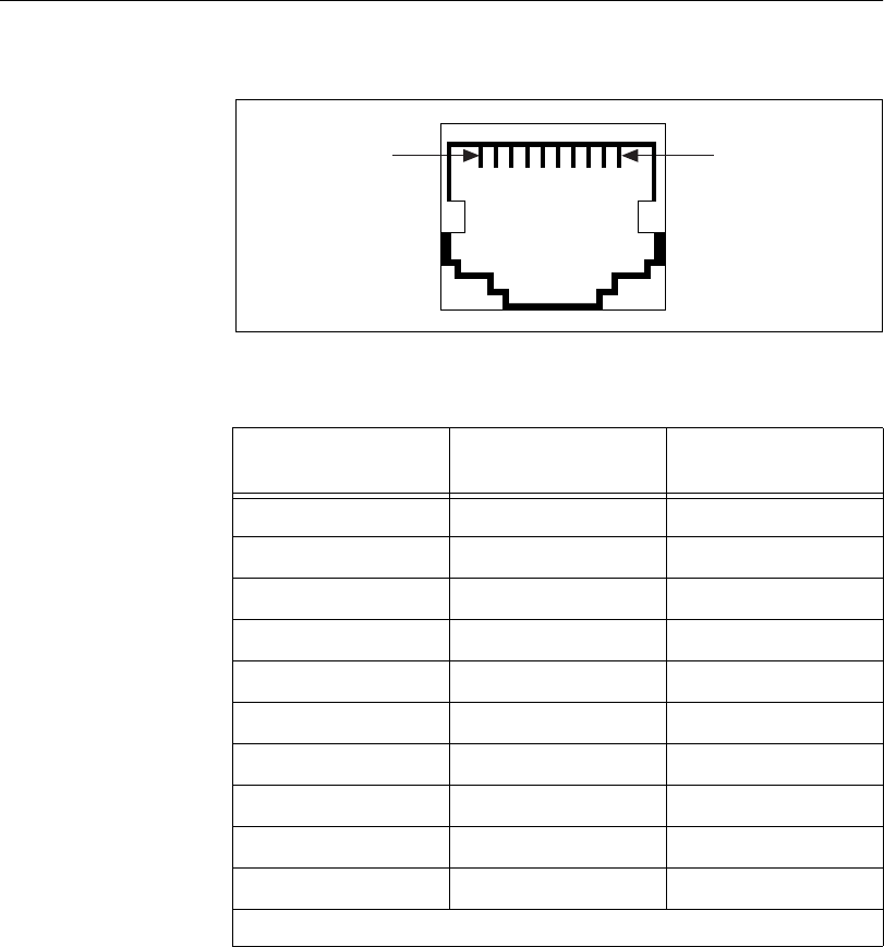
Appendix A Connector Descriptions
©National Instruments Corporation A-3 Serial Hardware and Software for Windows
Modular Jack Connector
Figure A-2 and Table A-2 give the pin locations and descriptions of the
10-position modular jack.
Figure A-2. 10-Position Modular Jack Pin Locations
Table A-2. 10-Position Modular Jack Pin Descriptions
10-Position
Modular Jack Pin 232 Signal 485 Signal
10 DCD* GND
9RXD CTS+ (HSI+)
8TXD RTS+ (HSO+)
7DTR* RXD+
6GND RXD–
5DSR* CTS–(HSI–)
4RTS RTS–(HSO–)
3CTS TXD+
2RI* TXD–
1No Connect No Connect
* These signals are not supported by the isolated 232 ports.
Pin 10Pin 1
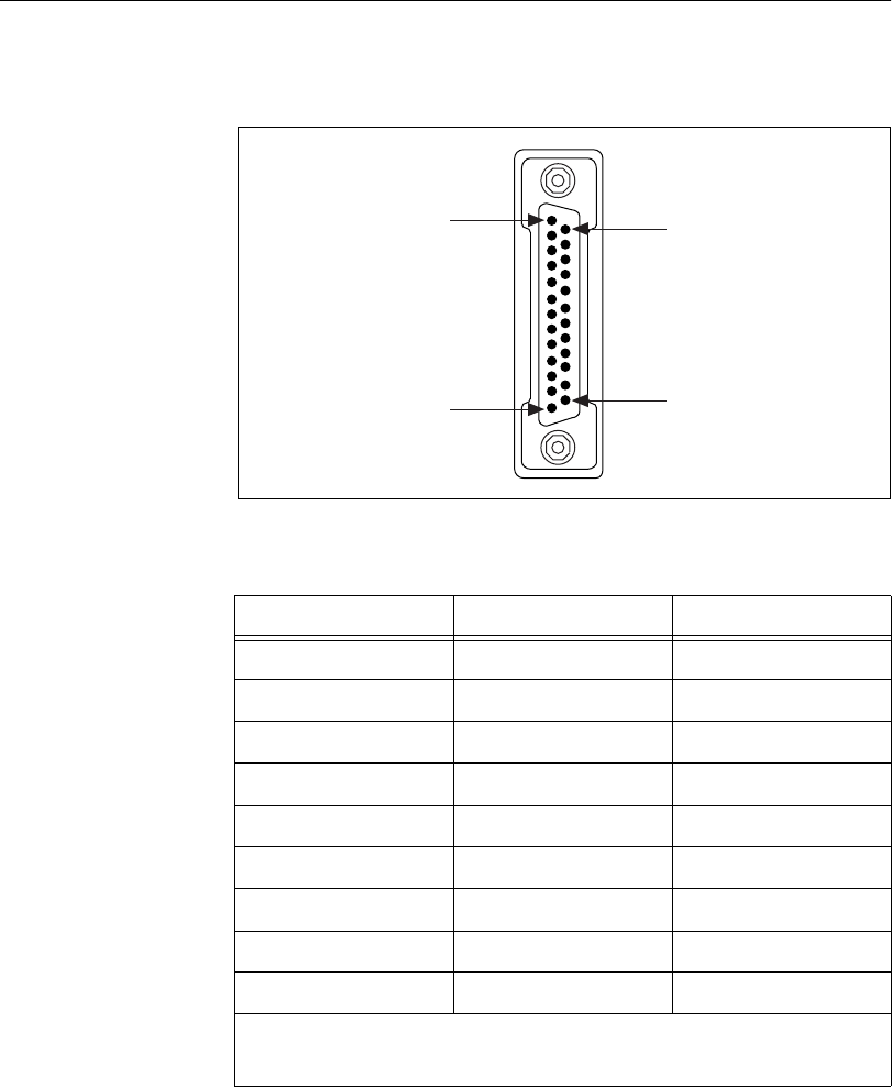
Appendix A Connector Descriptions
Serial Hardware and Software for Windows A-4 ni.com
DB-25 Connector
Figure A-3 and Table A-3 give the pin locations and descriptions of the
DB-25 connector, which is on the optional 10-position modular jack
to DB-25 cable.
Figure A-3. DB-25 Connector Pin Locations
Table A-3. DB-25 Pin Descriptions
DB-25 Pin 232 Signal 485 Signal
2TXD RTS+ (HSO+)
3RXD CTS+ (HSI+)
4RTS RTS–(HSO–)
5CTS TXD+
6DSR* CTS–(HSI–)
7GND RXD–
8DCD* GND
20 DTR* RXD+
22 RI* TXD–
Pins not listed in this table are No Connect.
* These signals are not supported by the isolated 232 ports.
PIN 1
PIN 25
PIN 13
PIN 14
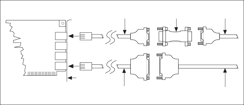
Appendix A Connector Descriptions
©National Instruments Corporation A-5 Serial Hardware and Software for Windows
Figure A-4 shows how to connect the cables when you install a four-port
PCI serial board.
Figure A-4. Connecting the Cables to Your Four-Port PCI Serial Board
Serial Board
Additional
Serial Cable
Additional
Serial Cable
10-Position Modular Jack
to DB-9 Cable
10-Position Modular Jack
to DB-25 Cable
485 Terminator
(485 Boards Only)
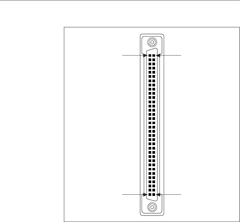

Appendix A Connector Descriptions
©National Instruments Corporation A-7 Serial Hardware and Software for Windows
Table A-4. 68-Pin Connector Pin Descriptions
68-Pin Connector Port
485
Signal
485
D-Sub 9
Connector
232
Signal
232
D-Sub 9
Connector
12345678
66 57 49 40 32 23 15 6RXD–5DCD 1
68 59 51 42 34 25 17 8CTS+ 2RXD 2
65 56 48 39 31 22 14 5RTS+ 3TXD 3
64 55 47 38 30 21 13 4RXD+ 4DTR 4
60 60 43 43 26 26 9 9 GND 1GND 5
63 54 46 37 29 20 12 3CTS–6DSR 6
62 53 45 36 28 19 11 2RTS–7RTS 7
61 52 44 35 27 18 10 1TXD+ 8CTS 8
67 58 50 41 33 24 16 7TXD–9RI 9
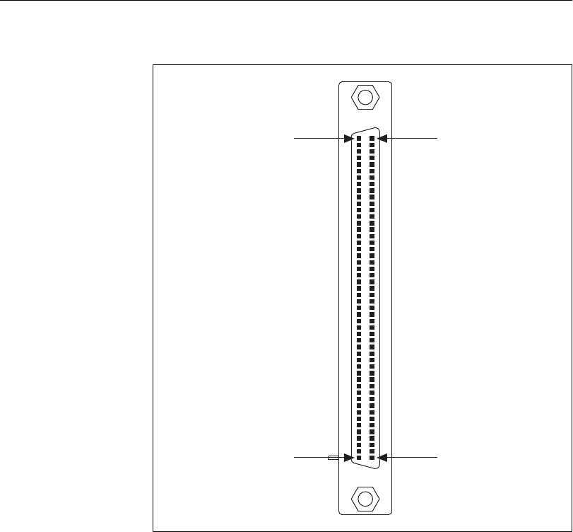

Appendix A Connector Descriptions
©National Instruments Corporation A-9 Serial Hardware and Software for Windows
Table A-5. 100-Pin Connector Pin Descriptions
100-Pin Connector Port
232
Signal
232
D-Sub 9
Connector
12345678910 11 12 13 14 15 16
246 642 10 38 14 34 — — — — — — — — DCD* 1
347 743 11 39 15 35 18 32 20 30 22 28 24 26 RXD 2
448 844 12 40 16 36 19 33 21 31 23 29 25 27 TXD 3
549 945 13 41 17 37 — — — — — — — — DTR* 4
111150 50 50 50 51 51 51 51 100 100 100 100 GND 5
52 96 56 92 60 88 64 84 — — — — — — — — DSR* 6
53 97 57 93 61 89 65 85 68 82 70 80 72 78 74 76 RTS 7
54 98 58 94 62 90 66 86 69 83 71 81 73 79 75 77 CTS 8
55 99 59 95 63 91 67 87 — — — — — — — — RI* 9
* These signals are not supported on ports 9-16 of the 16-port PCI and PXI serial boards.

©National Instruments Corporation B-1 Serial Hardware and Software for Windows
B
Serial Port Information
This appendix describes the RS-232, RS-422, and RS-485 standards and
explains some of the issues involved with these types of serial
communication.
Table A-1 lists the features of the RS-232, RS-422, and RS-485 standards.
RS-232
As specified in the ANSI/EIA-232-D Standard, Interface Between Data
Terminal Equipment and Data Circuit-Terminating Equipment Employing
Serial Binary Data Interchange, RS-232 standardizes serial
communication between computers, and between computer terminals and
modems. Most applications use the RS-232 standard to interface
peripherals to personal computers. RS-232 uses transmission lines in which
the state of each signal is represented by referencing the voltage level of a
single line to ground. RS-232 was designed for serial communication up to
Table B-1. RS-232, RS-422, and RS-485 Features
Feature RS-232 RS-422 RS-485
Type of
transmission lines
Single ended Differential Differential
Maximum number
of drivers
1132
Maximum number
of receivers
110 32
Maximum cable
length
50 ft 4,000 ft 4,000 ft
Maximum data rate 20 kbytes/s 10 Mbytes/s 10 Mbytes/s
Maximum CMV ±25V ±7 V +12 to –7V
Driver output 5to25V 2to6V 1.5 to 6 V
Driver load >3kΩ100 Ω60 Ω

Appendix B Serial Port Information
Serial Hardware and Software for Windows B-2 ni.com
distances of 50 ft and with data rates up to 20 kbytes/s. However, because
of improvements in line drivers and cabling, you can usually increase the
actual performance of the bus past the limitations on speed and distance
recommended in the specification.
RS-422
As specified in the EIA/RS-422-A Standard, Electrical Characteristics of
Balanced Voltage Digital Interface Circuits, RS-422 defines a serial
interface much like RS-232. However, RS-422 uses balanced
(or differential) transmission lines. Balanced transmission lines use two
transmission lines for each signal. The state of each signal is represented,
not by a voltage level on one line referenced to ground as in RS-232, but
rather by the relative voltage of the two lines to each other. For example,
the TX signal is carried on two wires, wire A and wire B. A logical 1 is
represented by the voltage on line A being greater than the voltage on
line B. A logical 0 is represented by the voltage on line A being less than
the voltage on line B. Differential voltage transmission creates a signal that
is more immune to noise as well as voltage loss due to transmission line
effects. Thus, you can use RS-422 for longer distances (up to 4,000 ft) and
greater transmission speeds (up to 10 Mbytes/s) than RS-232.
RS-485
As specified in the EIA-485 Standard, Standard for Electrical
Characteristics of Generators and Receivers for Use in Balanced Digital
Multipoint Systems, RS-485 expands on the RS-422 standard by increasing
the number of devices you can use from 10 to 32 and by working with
half-duplex bus architectures. Unlike the RS-422 standard, RS-485
addresses the issue of using multiple transmitters on the same line. RS-485
defines the electrical characteristics necessary to ensure adequate signal
voltages under maximum load, short-circuit protection. RS-485 can also
withstand multiple drivers driving conflicting signals at the same time.

Appendix B Serial Port Information
©National Instruments Corporation B-3 Serial Hardware and Software for Windows
Serial Communication Issues
This section explains some serial communication issues, including duplex
architectures, termination methods, bias resistors, and types of connecting
equipment.
Duplex Architectures
Duplex refers to the means of bandwidth usage in a serial system. The two
common means of bi-directional serial communication are full duplex and
half duplex. Half-duplex communication involves a transmitter and a
receiver connected to each end of the same wire or pair of wires. Because
the same transmission line both sends and receives data, devices cannot
send data in both directions at the same time. First, one device transmits
over the wire(s) to the receiver of the second device. When the first device
finishes transmitting, both devices switch the connections from their
transmitter to their receiver, or vice versa. The device that was receiving
data can then transmit over the line.
In full-duplex communication, the devices use a separate wire (or pair of
wires) for simultaneous transmission in each direction. Thus, the devices
do not switch between transmitting and receiving.
In a differential serial bus (such as RS-422 or RS-485), a half-duplex
system transmits and receives over the same twisted pair of wires.
Thus, half-duplex communication is often referred to as two-wire
communications. Likewise, full-duplex communication is often referred
to as four-wire communications, because the full-duplex system uses a
separate pair of wires for communication in each direction.
Full Duplex
A typical full-duplex multidrop bus architecture involves a master-slave
protocol. Only one device, the master, can control access to the bus. All
other devices are slaves. Slave devices must wait for the master to give them
access to the bus. In a typical full-duplex system, one transmission line
connects the bus master transmitter to all of the slave receivers. A second
transmission line connects all of the slave transmitters to the bus master
receiver. Because each transmission line has two separate wires, a
full-duplex system is often referred to as a four-wire system. Figure B-1
shows a typical full-duplex system.
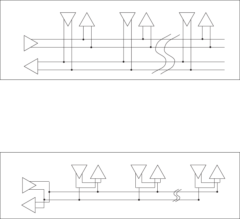
Appendix B Serial Port Information
Serial Hardware and Software for Windows B-4 ni.com
Figure B-1. Typical Full-Duplex System
Half Duplex
A typical half-duplex multidrop bus architecture also involves a
master-slave protocol. However, in a half-duplex system, all transmitters
and receivers are connected to the same transmission line. A half-duplex
system is often referred to as a two-wire system. Figure B-2 shows a typical
half-duplex system.
Figure B-2. Typical Half-Duplex System
MASTER
Slave 1 Slave 2 Slave n
Tx
Tx Rx Tx Rx Tx Rx
Rx
MASTER
Slave 1 Slave 2 Slave n
Tx
Tx Rx Rx
Tx Rx
Tx
Rx
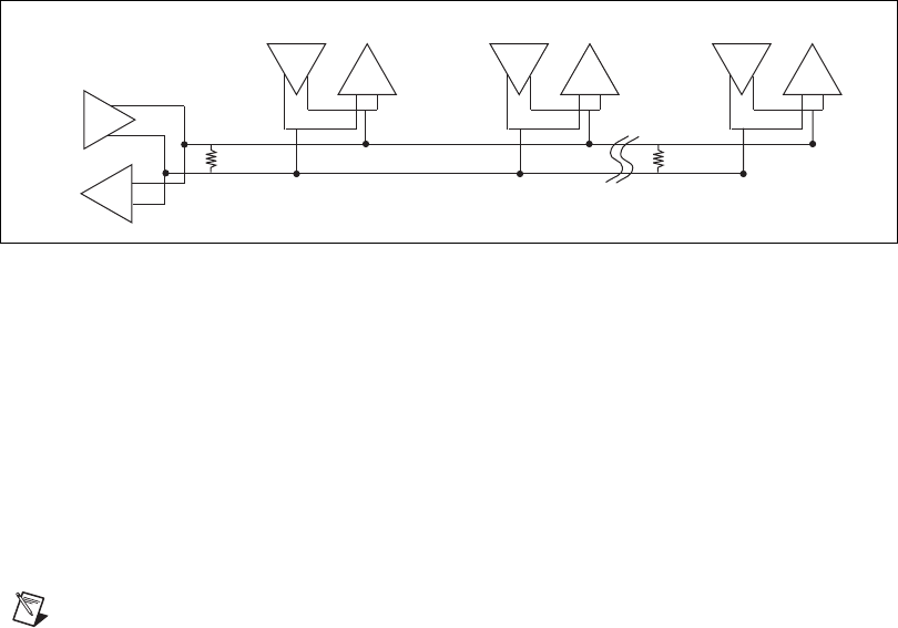
Appendix B Serial Port Information
©National Instruments Corporation B-5 Serial Hardware and Software for Windows
Termination
Because each differential pair of wires is a transmission line, you must
properly terminate the line to prevent reflections. A common method of
terminating a two-wire multidrop RS-485 network is to install terminating
resistors at each end of the multidrop network. If you daisy-chained
multiple instruments together, you need a terminating resistor at only the
first and last instruments. The terminating resistor should match the
characteristic impedance of the transmission line (typically 100 to 120 Ω).
You can order an optional DB-9 RS-485 termination connector that
contains embedded terminating resistors for easy termination from
National Instruments. For ordering information, contact National
Instruments.
Figure B-3 shows a multidrop network using terminating resistors.
Figure B-3. Multidrop Network Using Terminating Resistors
Bias Resistors
A transmission line enters an indeterminate state if no nodes are
transmitting on it. This indeterminate state can cause the receivers to
receive invalid data bits from noise picked up on the cable. To prevent a line
from receiving these data bits, force the transmission line into a known
state. To do so, install two 620 Ωbias resistors at one node on the
transmission line; doing so creates a voltage divider that forces the voltage
between the differential pair to be greater than 200 mV, the threshold
voltage for the receiver. You should install these resistors on only one node.
Note Bias resistors are not available on the eight-port PCI-485 or eight-port PXI-8421.
MASTER
Slave 1
100 Ω
Slave 2 Slave n
100 Ω
Tx
Tx Rx Tx Rx Tx Rx
Rx
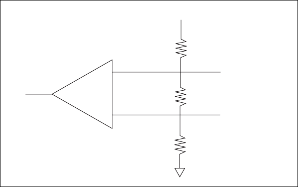
Appendix B Serial Port Information
Serial Hardware and Software for Windows B-6 ni.com
Figure B-4 shows a transmission line using bias resistors.
Figure B-4. Transmission Line Using Bias Resistors
On the PCI RS-485 2- and 4-port serial cards, there are four
user-configurable bias resistors in front of each connector. These resistors
are socketed and pre-loaded with 620 Ωresistors. They are connected to the
receive signals of each port to maintain a known state when the bus is idle.
The connections are made as follows:
•RXD+ and CTS–arepulleduptoVCC
•RXD–andCTS+arepulleddowntoGND
Rather than using two 620 Ωresistors at one node, you can increase the
value of the resistors and put them at every node. For instance, if there are
eight nodes in a system, you can use 4.7 kΩresistors at each node to
effectively achieve the same result.
620
Bias Resistor
+5
A
Rx
B
620
Bias Resistor
100
Termination Resistor
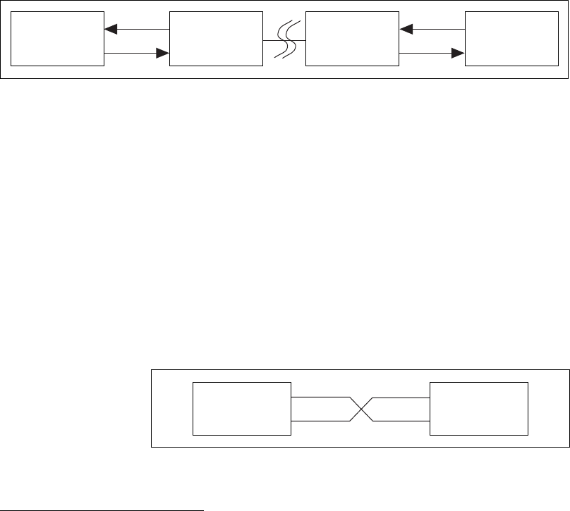
Appendix B Serial Port Information
©National Instruments Corporation B-7 Serial Hardware and Software for Windows
DTE vs. DCE
In the RS-232 specification, DTE (Data Terminal Equipment) and DCE
(Data Communications Equipment)1refer to the types of equipment on
either end of a serial connection. In general, DTE and DCE refer to
computer equipment and modems, respectively. Because the RS-232
specification mainly involves connecting a DTE directly to a DCE and vice
versa, the pinouts are defined so that cabling is simple. That is, a cable
connected a computer to a modem by wiring pin 1 to pin 1, pin 2 to pin 2,
and so on. This method is known as straight-through cabling.
Figure B-5 shows straight-through cabling in a DTE-to-DCE interface.
Figure B-5. Straight-Through Cabling in a DTE-to-DCE Interface
Straight-through cabling is still the standard method to connect a modem to
your PC. However, because many applications use serial communication to
connect two or more DTEs without modems, the cabling becomes more
complicated. If two DTEs are wired together using a straight-through cable,
one transmitter is connected to the other transmitter, and one receiver is
connected to the other receiver. In this setup, no transmissions can occur.
Thus, these applications must use a cabling scheme that connects the
transmitter on one device to the receiver on the other device and vice versa.
This method is known as null-modem cabling, because it replaces the two
modems that traditional RS-232 applications would require between the
two DTEs. To communicate from one serial port to another, use a
null-modem cable.
Figure B-6 shows null-modem cabling in a DTE-to-DTE interface.
Figure B-6. Null-Modem Cabling in a DTE-to-DTE Interface
1In Revision D of the RS-232 specification, a DCE is a Data Circuit-Terminating Equipment.
Rx D
Tx D
Pin 3
Pin 2
DTE
Pin 3
Pin 2
DCE
Pin 3
Pin 2
DCE
Pin 3
Pin 2
DTE
Rx D
Tx D
Rx D
Tx D
Rx D
Tx D
Pin 2
Pin 3Pin 3
Pin 2
DTE DTE

©National Instruments Corporation C-1 Serial Hardware and Software for Windows
C
Uninstalling the
Hardware and Software
This appendix describes how to uninstall your serial hardware and the
NI-Serial software.
To begin your uninstallation, see the section of this appendix containing
instructions for your hardware platform and operating system:
PCI Hardware
Windows 2000 ...................................................................C-2
Windows Me/9x.................................................................C-3
Windows NT ......................................................................C-5
PXI Hardware
Windows 2000 ...................................................................C-7
Windows Me/9x.................................................................C-8
Windows NT ......................................................................C-10
PCMCIA Hardware
Windows 2000 ...................................................................C-12
Windows Me/9x.................................................................C-13
Windows NT ......................................................................C-15
AT Hardware
Windows 2000 ...................................................................C-17
Windows Me/9x.................................................................C-18
Windows NT ......................................................................C-20
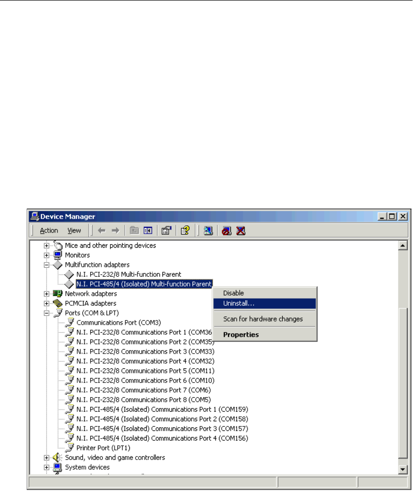
Appendix C Uninstalling the Hardware and Software
Serial Hardware and Software for Windows C-2 ni.com
PCI Hardware
Windows 2000
Uninstall the Hardware
Before you physically remove the serial hardware from your system, you
must remove the hardware information. To do so, complete the following
steps:
1. Select Start»Settings»Control Panel and double-click on the
System icon.
2. Select the Hardware tabandclickontheDevice Manager button.
3. Double-click on the Multi-function adapters icon.
4. From the Multi-function adapters list, right-click on the National
Instruments interface that you want to uninstall, as shown in
Figure C-1.
Figure C-1. Selecting an Interface to Uninstall
Appendix C Uninstalling the Hardware and Software
©National Instruments Corporation C-3 Serial Hardware and Software for Windows
5. Choose the Uninstall... option.
6. In the Confirm Device Removal dialog box, click on the OK button
to remove the hardware information, or click on the Cancel button to
cancel your request.
Uninstall the Software
Before you uninstall the NI-Serial software, you must remove the hardware
information from your system, as described in the previous section.
To uninstall the NI-Serial software, complete the following steps:
1. Select Start»Settings»Control Panel.
2. Double-click on the Add/Remove Programs icon. The Add/Remove
Programs dialog box appears. This dialog box lists the software that
you can uninstall.
3. Select NI-Serial and click on the Change/Remove button. The
uninstallation program removes all folders, utilities, and registry
entries associated with the NI-Serial software.
4. Shut down Windows 2000, turn off your computer, and physically
remove the serial interfaces from your system.
The uninstallation program removes only items that the setup wizard
installed. If you added anything to a directory that the setup wizard created,
the uninstallation program does not delete that directory. You must remove
any remaining components yourself.
To reinstall the hardware and software, refer to Chapter 2, PCI Serial
Hardware Installation, Verification, and Configuration.
Windows Me/9x
Uninstall the Hardware
Before you physically remove the serial hardware from your system, you
must remove the hardware information. To do so, complete the following
steps:
1. Select Start»Settings»Control Panel and double-click on the
System icon.
2. Select the Device Manager tabandclickontheView devices by type
button.
3. Double-click on the Multi-function adapters icon.

Appendix C Uninstalling the Hardware and Software
Serial Hardware and Software for Windows C-4 ni.com
4. From the Multi-function adapters list, select the National
Instruments interface that you want to uninstall, as shown in
Figure C-2.
Figure C-2. Selecting an Interface to Uninstall
5. Click on the Remove button.
6. In the Confirm Device Removal dialog box, click on the OK button
to remove the hardware information, or click on the Cancel button to
cancel your request.
Uninstall the Software
Before you uninstall the NI-Serial software, you must remove the hardware
information from your system, as described in the previous section.
To uninstall the NI-Serial software, complete the following steps:
1. Select Start»Settings»Control Panel.
2. Double-click on the Add/Remove Programs icon. The Add/Remove
Programs dialog box appears. This dialog box lists the software that
you can uninstall.
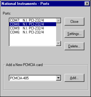
Appendix C Uninstalling the Hardware and Software
©National Instruments Corporation C-5 Serial Hardware and Software for Windows
3. Select the NI-Serial software you want to uninstall, and click on the
Add/Remove button. The uninstallation program removes all folders,
utilities, and registry entries associated with the NI-Serial software.
4. Shut down Windows Me/9x, turn off your computer, and physically
remove the serial interfaces from your system.
The uninstallation program removes only items that the setup wizard
installed. If you added anything to a directory that the setup wizard created,
the uninstallation program does not delete that directory. You must remove
any remaining components yourself.
To reinstall the hardware and software, refer to Chapter 2, PCI Serial
Hardware Installation, Verification, and Configuration.
Windows NT
Uninstall the Hardware
Before you physically remove the serial hardware from your system, you
must remove the hardware information. To do so, complete the following
steps:
1. LoginasAdministrator or as a user who has Administrator
privileges.
2. Select Start»Settings»Control Panel and double-click on the
niports icon.
3. From the Ports list, select the port of the board you want to uninstall,
as shown in Figure C-3.
Figure C-3. Selecting an Interface to Uninstall
Appendix C Uninstalling the Hardware and Software
Serial Hardware and Software for Windows C-6 ni.com
4. Click on the Delete button.
5. Repeat steps 3 and 4 until you have removed every PCI serial port that
you want to uninstall.
Uninstall the Software
Before you uninstall the NI-Serial software, you must remove the hardware
information from your system, as described in the previous section.
To uninstall the NI-Serial software, complete the following steps:
1. Select Start»Settings»Control Panel.
2. Double-click on the Add/Remove Programs icon. The Add/Remove
Programs dialog box appears. This dialog box lists the software that
you can uninstall.
3. Select the NI-Serial software you want to uninstall, and click on the
Add/Remove button. The uninstallation program removes all folders,
utilities, and registry entries associated with the NI-Serial software.
4. Shut down Windows NT, turn off your computer, and physically
remove the serial interfaces from your system.
The uninstallation program removes only items that the setup wizard
installed. If you added anything to a directory that the setup wizard created,
the uninstallation program does not delete that directory. You must remove
any remaining components yourself.
To reinstall the hardware and software, refer to Chapter 2, PCI Serial
Hardware Installation, Verification, and Configuration.
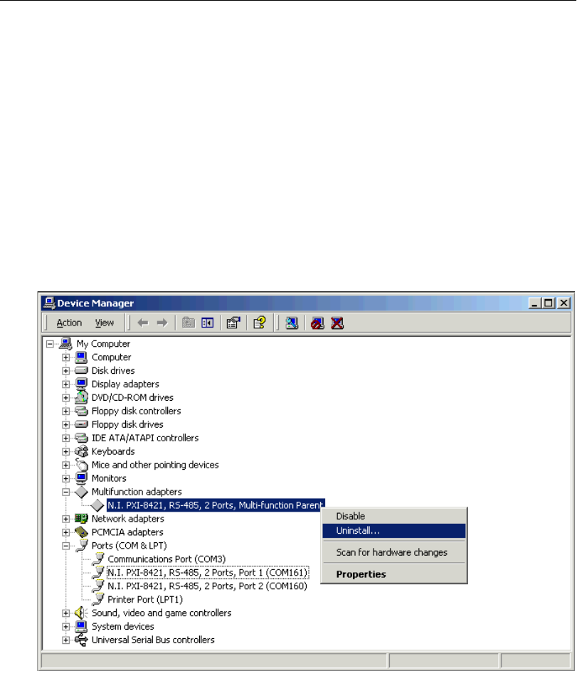
Appendix C Uninstalling the Hardware and Software
©National Instruments Corporation C-7 Serial Hardware and Software for Windows
PXI Hardware
Windows 2000
Uninstall the Hardware
Before you physically remove the serial hardware from your system, you
must remove the hardware information. To do so, complete the following
steps:
1. Select Start»Settings»Control Panel and double-click on the
System icon.
2. Select the Hardware tabandclickontheDevice Manager button.
3. Double-click on the Multi-function adapters icon.
4. From the Multi-function adapters list, right-click on the National
Instruments interface that you want to uninstall, as shown in
Figure C-4.
Figure C-4. Selecting an Interface to Uninstall
Appendix C Uninstalling the Hardware and Software
Serial Hardware and Software for Windows C-8 ni.com
5. Choose the Uninstall... option.
6. In the Confirm Device Removal dialog box, click on the OK button
to remove the hardware information, or click on the Cancel button to
cancel your request.
Uninstall the Software
Before you uninstall the NI-Serial software, you must remove the hardware
information from your system, as described in the previous section.
To uninstall the NI-Serial software, complete the following steps:
1. Select Start»Settings»Control Panel.
2. Double-click on the Add/Remove Programs icon. The Add/Remove
Programs dialog box appears. This dialog box lists the software that
you can uninstall.
3. Select NI-Serial and click on the Change/Remove button. The
uninstallation program removes all folders, utilities, and registry
entries associated with the NI-Serial software.
4. Shut down Windows 2000, turn off your computer, and physically
remove the serial interfaces from your system.
The uninstallation program removes only items that the setup wizard
installed. If you added anything to a directory that the setup wizard created,
the uninstallation program does not delete that directory. You must remove
any remaining components yourself.
To reinstall the hardware and software, refer to Chapter 3, PXI Serial
Hardware Installation, Verification, and Configuration.
Windows Me/9x
Uninstall the Hardware
Before you physically remove the serial hardware from your system, you
must remove the hardware information. To do so, complete the following
steps:
1. Select Start»Settings»Control Panel and double-click on the
System icon.
2. Select the Device Manager tabandclickontheView devices by type
button.
3. Double-click on the Multi-function adapters icon.
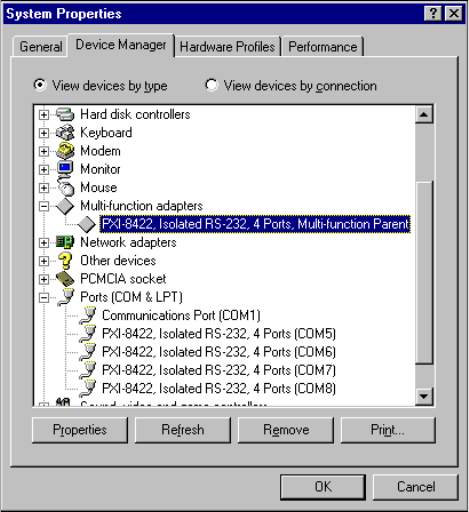
Appendix C Uninstalling the Hardware and Software
©National Instruments Corporation C-9 Serial Hardware and Software for Windows
4. From the Multi-function adapters list, select the National
Instruments interface that you want to uninstall, as shown in
Figure C-5.
Figure C-5. Selecting an Interface to Uninstall
5. ClickontheRemove button.
6. In the Confirm Device Removal dialog box, click on the OK button
to remove the hardware information, or click on the Cancel button to
cancel your request.
Uninstall the Software
Before you uninstall the NI-Serial software, you must remove the hardware
information from your system, as described in the previous section.
To uninstall the NI-Serial software, complete the following steps:
1. Select Start»Settings»Control Panel.
2. Double-click on the Add/Remove Programs icon. The Add/Remove
Programs dialog box appears. This dialog box lists the software that
you can uninstall.

Appendix C Uninstalling the Hardware and Software
Serial Hardware and Software for Windows C-10 ni.com
3. Select the NI-Serial software you want to uninstall, and click on the
Add/Remove button. The uninstallation program removes all folders,
utilities, and registry entries associated with the NI-Serial software.
4. Shut down Windows Me/9x, turn off your computer, and physically
remove the serial interfaces from your system.
The uninstallation program removes only items that the setup wizard
installed. If you added anything to a directory that the setup wizard created,
the uninstallation program does not delete that directory. You must remove
any remaining components yourself.
To reinstall the hardware and software, refer to Chapter 3, PXI Serial
Hardware Installation, Verification, and Configuration.
Windows NT
Uninstall the Hardware
Before you physically remove the serial hardware from your system, you
must remove the hardware information. To do so, complete the following
steps:
1. LoginasAdministrator or as a user who has Administrator
privileges.
2. Select Start»Settings»Control Panel and double-click on the niports
icon. From the Ports list, select the port of the board you want to
uninstall, as shown in Figure C-6.
Figure C-6. Selecting an Interface to Uninstall
Appendix C Uninstalling the Hardware and Software
©National Instruments Corporation C-11 Serial Hardware and Software for Windows
3. ClickontheDelete button.
4. Repeat steps 3 and 4 until you have removed every PXI serial port that
you want to uninstall.
Uninstall the Software
Before you uninstall the NI-Serial software, you must remove the hardware
information from your system, as described in the previous section.
To uninstall the NI-Serial software, complete the following steps:
1. Select Start»Settings»Control Panel.
2. Double-click on the Add/Remove Programs icon. The Add/Remove
Programs dialog box appears. This dialog box lists the software that
you can uninstall.
3. Select the NI-Serial software you want to uninstall, and click on the
Add/Remove button. The uninstallation program removes all folders,
utilities, and registry entries associated with the NI-Serial software.
4. Shut down Windows NT, turn off your computer, and physically
remove the serial interfaces from your system.
The uninstallation program removes only items that the setup wizard
installed. If you added anything to a directory that the setup wizard created,
the uninstallation program does not delete that directory. You must remove
any remaining components yourself.
To reinstall the hardware and software, refer to Chapter 3, PXI Serial
Hardware Installation, Verification, and Configuration.
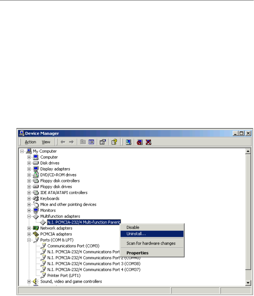
Appendix C Uninstalling the Hardware and Software
Serial Hardware and Software for Windows C-12 ni.com
PCMCIA Hardware
Windows 2000
Uninstall the Hardware
Before you physically remove the serial hardware from your system, you
must remove the hardware information. To do so, complete the following
steps:
1. Select Start»Settings»Control Panel and double-click on the
System icon.
2. Select the Hardware tabandclickontheDevice Manager button.
3. Double-click on the Multi-function adapters icon.
4. From the Multi-function adapters list, right-click on the National
Instruments interface that you want to uninstall, as shown in
Figure C-7.
Figure C-7. Selecting an Interface to Uninstall
Appendix C Uninstalling the Hardware and Software
©National Instruments Corporation C-13 Serial Hardware and Software for Windows
5. Choose the Uninstall... option.
6. In the Confirm Device Removal dialog box, click on the OK button
to remove the hardware information, or click on the Cancel button to
cancel your request.
Uninstall the Software
Before you uninstall the NI-Serial software, you must remove the hardware
information from your system, as described in the previous section.
To uninstall the NI-Serial software, complete the following steps:
1. Select Start»Settings»Control Panel.
2. Double-click on the Add/Remove Programs icon. The Add/Remove
Programs dialog box appears. This dialog box lists the software that
you can uninstall.
3. Select NI-Serial and click on the Change/Remove button. The
uninstallation program removes all folders, utilities, and registry
entries associated with the NI-Serial software.
4. Remove the PCMCIA serial interface from your system.
The uninstallation program removes only items that the setup wizard
installed. If you added anything to a directory that the setup wizard created,
the uninstallation program does not delete that directory. You must remove
any remaining components yourself.
To reinstall the hardware and software, refer to Chapter 4, PCMCIA Serial
Hardware Installation, Verification, and Configuration.
Windows Me/9x
Uninstall the Hardware
Before physically removing the serial hardware, you must remove the
hardware information from the Windows Me/9xDevice Manager.
Follow these steps to uninstall the hardware:
1. Double-click on the System icon under Start»Settings»Control
Panel.TheSystem Properties dialog box appears.
2. Select the Device Manager tab.
3. ClickontheView devices by type button.
4. Double-click on the Ports (COM & LPT) icon.
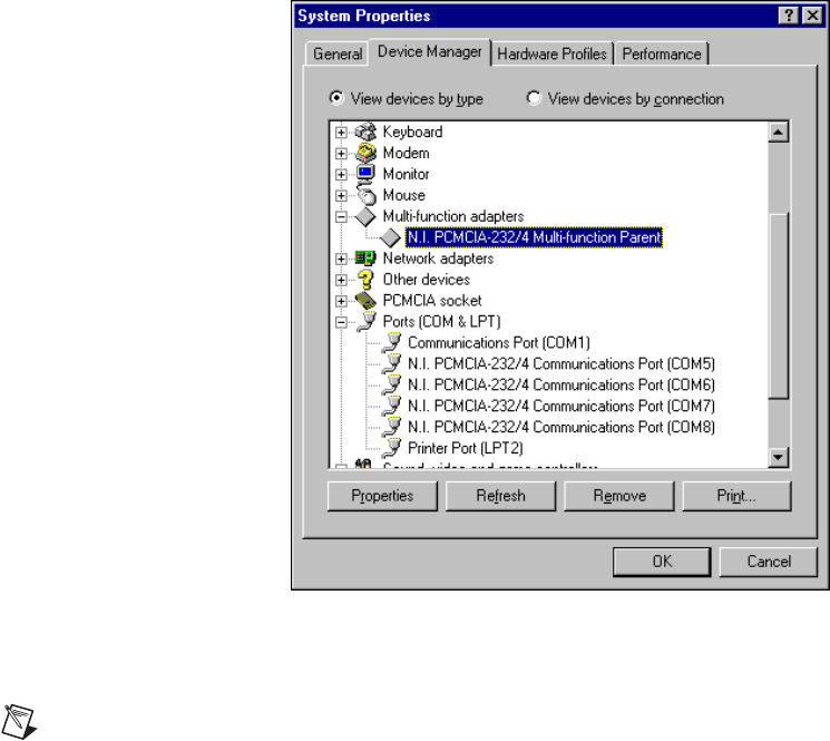
Appendix C Uninstalling the Hardware and Software
Serial Hardware and Software for Windows C-14 ni.com
5. Select the National Instruments port to remove from the list of ports,
as shown in Figure C-8.
Figure C-8. Selecting an Interface to Uninstall
6. Click on the Remove button.
Note To remove ports on two-port and four-port PCMCIA cards from within the Device
Manager, you must open the Multi-function adapters class, select the name of your
interface, and click on the Remove button.
7. In the Confirm Device Removal dialog box, click on the OK button
to remove this interface or click on Cancel to cancel your request.
Appendix C Uninstalling the Hardware and Software
©National Instruments Corporation C-15 Serial Hardware and Software for Windows
Uninstall the Software
Before uninstalling the software, remove all serial port information from
the Windows Me/9xDevice Manager, as described in the previous section.
You do not need to shut down Windows Me/9xbefore uninstalling the
software.
Complete the following steps to remove the NI-Serial software:
1. Select Start»Settings»Control Panel.
2. Double-click on the Add/Remove Programs icon in the Control Panel
to launch the Add/Remove Programs applet. The Add/Remove
Programs Properties dialog box appears. This dialog box lists the
software available for removal.
3. Select the serial software you want to remove, and click on the
Add/Remove button. The uninstall program runs and removes all
folders, programs, VxDs, DLLs, and registry entries associated with
the NI-Serial software.
4. Remove your PCMCIA card from your computer.
To reinstall the hardware and software, refer to Chapter 4, PCMCIA Serial
Hardware Installation, Verification, and Configuration.
Windows NT
Uninstall the Hardware
Before physically removing the serial hardware, you must remove the
hardware information from the Windows NT Control Panel.
Follow these steps to uninstall the hardware:
1. Double-click on the niports icon under Start»Settings»Control
Panel.
2. Select the port to remove from the list of ports as shown in Figure C-9.
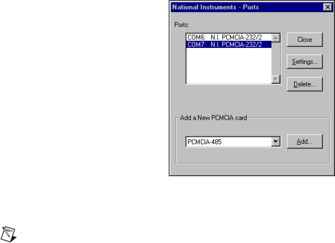
Appendix C Uninstalling the Hardware and Software
Serial Hardware and Software for Windows C-16 ni.com
Figure C-9. Selecting an Interface to Uninstall
3. Click on the Delete button.
Note For two-port and four-port PCMCIA cards, all ports on the interface are removed.
Uninstall the Software
Before uninstalling the software, remove all serial port information from
the Windows NT Control Panel, as described in the previous section. You
do not need to shut down Windows NT before uninstalling the software.
Complete the following steps to remove the NI-Serial software:
1. Select Start»Settings»Control Panel.
2. Double-click on the Add/Remove Programs icon in the Control Panel
to launch the Add/Remove Programs applet. The Add/Remove
Programs Properties dialog box appears. This dialog box lists the
software available for removal.
3. Select the serial software you want to remove, and click on the
Add/Remove button. The uninstall program runs and removes all
folders, utilities, and registry entries associated with the NI-Serial
software.
4. Shut down Windows NT, power off your computer, and remove your
serial interfaces.
To reinstall the hardware and software, refer to Chapter 4, PCMCIA Serial
Hardware Installation, Verification, and Configuration.
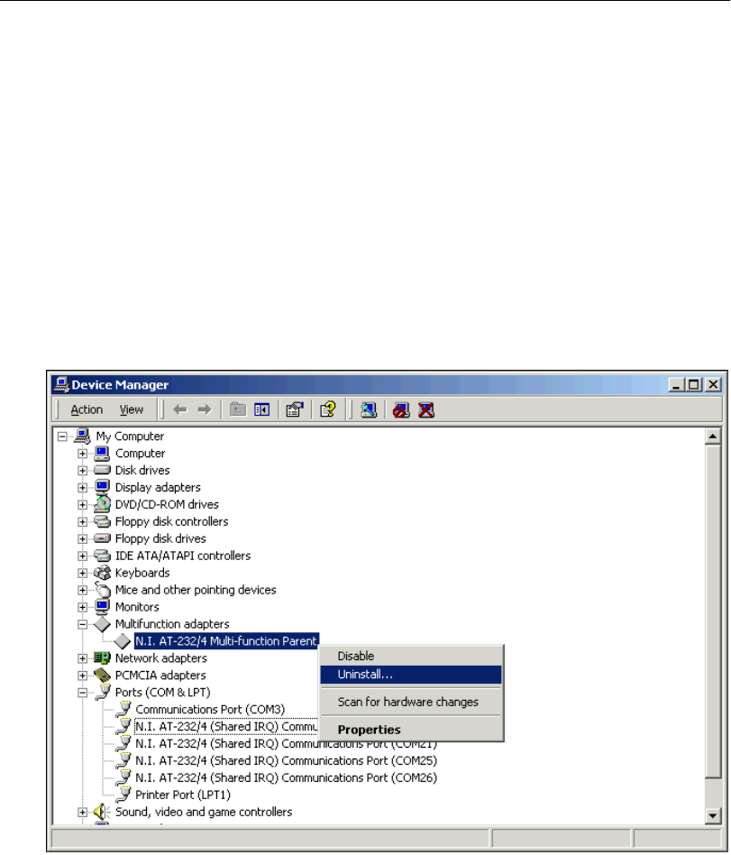
Appendix C Uninstalling the Hardware and Software
©National Instruments Corporation C-17 Serial Hardware and Software for Windows
AT Hardware
Windows 2000
Uninstall the Hardware
Before you physically remove the serial hardware from your system, you
must remove the hardware information. To do so, complete the following
steps:
1. Select Start»Settings»Control Panel and double-click on the
System icon.
2. Select the Hardware tabandclickontheDevice Manager button.
3. Double-click on the Multi-function adapters icon.
4. From the Multi-function adapters list, right-click on the National
Instruments interface that you want to uninstall, as shown in
Figure C-10.
Figure C-10. Selecting an Interface to Uninstall
Appendix C Uninstalling the Hardware and Software
Serial Hardware and Software for Windows C-18 ni.com
5. Choose the Uninstall... option.
6. In the Confirm Device Removal dialog box, click on the OK button
to remove the hardware information, or click on the Cancel button to
cancel your request.
Uninstall the Software
Before you uninstall the NI-Serial software, you must remove the hardware
information from your system, as described in the previous section.
To uninstall the NI-Serial software, complete the following steps:
1. Select Start»Settings»Control Panel.
2. Double-click on the Add/Remove Programs icon. The Add/Remove
Programs dialog box appears. This dialog box lists the software that
you can uninstall.
3. Select NI-Serial and click on the Change/Remove button. The
uninstallation program removes all folders, utilities, and registry
entries associated with the NI-Serial software.
4. Shut down Windows 2000, turn off your computer, and physically
remove the serial interfaces from your system.
The uninstallation program removes only items that the setup wizard
installed. If you added anything to a directory that the setup wizard created,
the uninstallation program does not delete that directory. You must remove
any remaining components yourself.
To reinstall the hardware and software, refer to Chapter 5, AT Serial
Hardware Installation, Verification, and Configuration.
Windows Me/9x
Uninstall the Hardware
Before physically removing the serial hardware, you must remove the
hardware information from the Windows Me/9xDevice Manager.
Follow these steps to uninstall the hardware:
1. Double-click on the System icon under Start»Settings»Control
Panel.TheSystem Properties dialog box appears.
2. Select the Device Manager tab.
3. Click on the View devices by type button.
4. Double-click on the Ports (COM & LPT) icon.
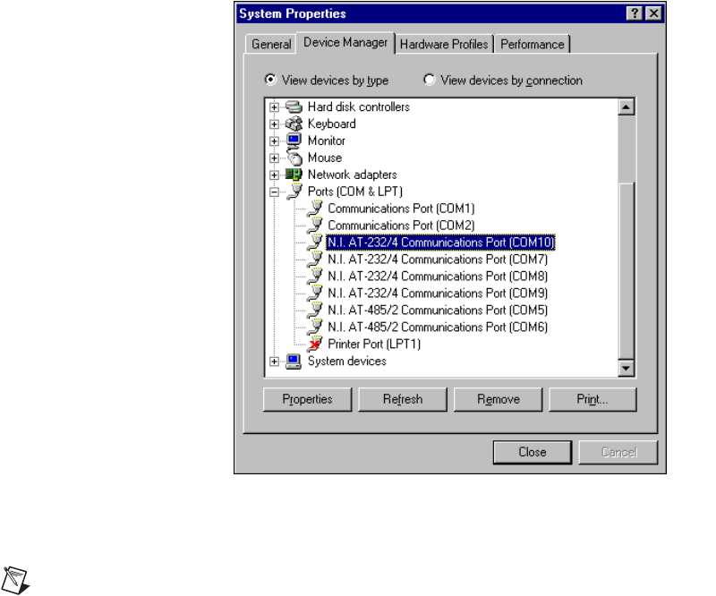
Appendix C Uninstalling the Hardware and Software
©National Instruments Corporation C-19 Serial Hardware and Software for Windows
5. Select the National Instruments port to remove from the list of ports,
as shown in Figure C-11.
Figure C-11. Selecting an Interface to Uninstall
6. ClickontheRemove button.
Note To remove ports on shared IRQ AT boards from within the Device Manager, you
must open the Multi-function adapters class, select the name of your interface, and click
on the Remove button.
7. In the Confirm Device Removal dialog box, click on the OK button
to remove this interface or click on Cancel to cancel your request.
Appendix C Uninstalling the Hardware and Software
Serial Hardware and Software for Windows C-20 ni.com
Uninstall the Software
Before uninstalling the software, remove all serial port information from
the Windows Me/9xDevice Manager, as described in the previous section.
You do not need to shut down Windows Me/9xbefore uninstalling the
software.
Complete the following steps to remove the NI-Serial software:
1. Select Start»Settings»Control Panel.
2. Double-click on the Add/Remove Programs icon in the Control Panel
to launch the Add/Remove Programs applet. The Add/Remove
Programs Properties dialog box appears. This dialog box lists the
software available for removal.
3. Select the serial software you want to remove, and click on the
Add/Remove button. The uninstall program runs and removes all
folders, programs, VxDs, DLLs, and registry entries associated with
the NI-Serial software.
4. Shut down Windows Me/9x, turn off your computer, and physically
remove the serial interfaces from your system.
To reinstall the hardware and software, refer to Chapter 5, AT Serial
Hardware Installation, Verification, and Configuration.
Windows NT
Uninstall the Hardware
Before physically removing the serial hardware, you must remove the
hardware information from the Windows NT Control Panel.
Follow these steps to uninstall the hardware:
1. Double-click on the niports icon under Start»Settings»Control
Panel.
2. Select the port to remove from the list of ports as shown in
Figure C-12.
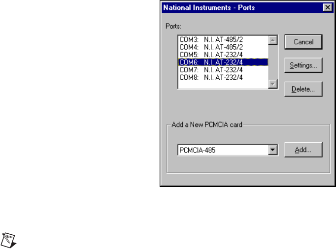
Appendix C Uninstalling the Hardware and Software
©National Instruments Corporation C-21 Serial Hardware and Software for Windows
Figure C-12. Selecting an Interface to Uninstall
3. ClickontheDelete button.
Note For shared IRQ AT boards, all ports on the interface are removed.
Uninstall the Software
Before uninstalling the software, remove all serial port information from
the Windows NT Control Panel, as described in the previous section. You
do not need to shut down Windows NT before uninstalling the software.
Complete the following steps to remove the NI-Serial software.
1. Select Start»Settings»Control Panel.
2. Double-click on the Add/Remove Programs icon in the Control Panel
to launch the Add/Remove Programs applet. The Add/Remove
Programs Properties dialog box appears. This dialog box lists the
software available for removal.
3. Select the serial software you want to remove, and click on the
Add/Remove button. The uninstall program runs and removes all
folders, utilities, and registry entries associated with the NI-Serial
software.
4. Shut down Windows NT, power off your computer, and remove your
serial interfaces.
To reinstall the hardware and software, refer to Chapter 5, AT Serial
Hardware Installation, Verification, and Configuration.

©National Instruments Corporation D-1 Serial Hardware and Software for Windows
D
Troubleshooting and
Common Questions
This appendix describes how to troubleshoot problems and answers some
common questions.
To find the information you are looking for, see the section of this appendix
for your operating system:
Windows 2000
Forcing Windows to Detect Your Hardware ......................D-2
Troubleshooting Diagnostic Messages...............................D-3
Common Questions ............................................................D-4
Windows Me/9x
Freeing an Interrupt Request Level ....................................D-6
Selecting Conflict-Free Resources .....................................D-7
Troubleshooting Diagnostic Messages...............................D-9
Resolving Resource Conflicts with Legacy Boards ...........D-11
Forcing Windows to Detect Your Hardware ......................D-11
Common Questions ............................................................D-14
Windows NT
Missing Serial Port in the niports List ................................D-18
Resolving Resource Conflicts ............................................D-19
Troubleshooting Diagnostic Messages...............................D-20
Common Questions ............................................................D-22

Appendix D Troubleshooting and Common Questions
Serial Hardware and Software for Windows D-2 ni.com
Windows 2000
Forcing Windows to Detect Your Hardware
If Windows 2000 did not display the Found New Hardware Wizard, it did
not detect your hardware. To solve this problem, complete the following
steps:
1. Select Start»Settings»Control Panel and double-click on the
System icon.
2. Select the Hardware tabandclickontheDevice Manager button.
3. Double-click on the Multi-function adapters icon.
4. From the Multi-function adapters list, right-click on the National
Instruments interface that you want to uninstall, as shown in
Figure D-1. (This example shows a PCI interface.)
Figure D-1. Selecting an Interface to Uninstall
Appendix D Troubleshooting and Common Questions
©National Instruments Corporation D-3 Serial Hardware and Software for Windows
5. Choose the Uninstall... option.
6. In the Confirm Device Removal dialog box, click on the OK button
to remove the hardware information, or click on the Cancel button to
cancel your request.
7. ClickontheScan for Hardware Changes icon at the top of the
Device Manager window.
8. Windows 2000 should automatically detect your hardware and display
the Found New Hardware Wizard. Complete the wizard by clicking
Next in each window and then Finish.
Troubleshooting Diagnostic Messages
This section lists possible error messages returned by the diagnostic utility,
along with solutions.
No National Instruments Serial Port Found or
Diagnostic Utility Does Not Show All Installed Ports
If the No National Instruments serial port found error message
appears or the diagnostic utility does not show all the ports you installed,
follow all the steps in the Forcing Windows to Detect Your Hardware
section above.
Address Test Failed
If the address test failed, Interrupt test cannot be
performed error message appears, you might have an address conflict
with legacy boards in your system. To solve this problem, change the base
addresses assigned to your legacy boards and refer to the Resolving
Resource Conflicts with Legacy Boards section.
Interrupt Test Failed
If the Interrupt test failed error message appears, you might have
an IRQ conflict with legacy boards in your system. To solve this problem,
change the IRQ level assigned to your legacy boards and refer to the next
section, Resolving Resource Conflicts with Legacy Boards.
Appendix D Troubleshooting and Common Questions
Serial Hardware and Software for Windows D-4 ni.com
Resolving Resource Conflicts with Legacy Boards
Resource conflicts typically occur if your system contains legacy boards
that use resources that are not reserved properly. If a resource conflict
exists, write down the resource that caused the conflict and refer to the
Microsoft Windows 2000 user’s guide for instructions on how to use the
Device Manager to reserve I/O and IRQ resources for legacy boards.
Common Questions
How can I determine which type of serial hardware I have installed?
1. Select Start»Settings»Control Panel and double-click on the
System icon.
2. Click on the Hardware tabandclickontheDevice Manager button.
3. Double-click on the Ports (COM & LPT) icon to display a list of
installed ports.
How can I determine which version of the NI-Serial software I have
installed?
The Read Me file gives the version of the software. To open the file, select
Start»Programs»National Instruments»NI-Serial»Read Me.
What do I do if the diagnostic test fails with an error?
Refer to the Troubleshooting Diagnostic Messages section earlier in this
appendix.
How can I determine which port is associated with COMx?
To determine which physical port is associated with COMx, complete the
following steps:
1. In the Device Manager, under Ports (COM & LPT), double-click on
a serial port.
2. Note the Port 1, Port 2, etc. entries next to the COM numbers. For all
serial hardware, PORT1 refers to the top port, PORT2 refers to the next
port down, and so on.
How can I change the COM numbers of my National Instruments
serial ports?
1. Select Start»Settings»Control Panel and double-click on the
System icon.
2. Click on the Hardware tabandclickontheDevice Manager button.
Appendix D Troubleshooting and Common Questions
©National Instruments Corporation D-5 Serial Hardware and Software for Windows
3. Double-click on the Ports (COM & LPT) icon.
4. Double-click on the port you want to configure.
5. ClickonthePort Settings tab.
6. ClickontheAdvanced button. The Advanced Settings dialog box
should pop up.
7. Change the COM number in the COM Port Number field. (You can
use a COM number that is designated as in use, as long as no hardware
is actually using that COM number.)
How do I remove information about serial boards from the Device
Manager?
Refer to the hardware uninstallation section for your hardware platform in
Appendix C, Uninstalling the Hardware and Software.
What is the maximum baud rate supported and how can I set it?
The maximum baud rate supported is 460.8 Kbaud for RS-485 and
115.2 Kbaud for RS-232. To set the baud rate, use the SetCommState
Win32 function and pass the actual value of the baud rate in the BaudRate
field of the DCB structure.

Appendix D Troubleshooting and Common Questions
Serial Hardware and Software for Windows D-6 ni.com
Windows Me/9x
Freeing an Interrupt Request Level
To free an interrupt request level for your serial port, you must disable the
device that is using the interrupt request level. To view the system-wide
allocation of interrupt request resources and remove a device, complete the
following steps:
1. Select Start»Settings»Control Panel and double-click on the
System icon.
2. Click on the Device Manager tab.
3. Double-click on the Computer icon and click on the View
Resources tab.
4. ClickontheInterrupt Request (IRQ) button. Scan through the list of
IRQ settings to determine which devices are using which interrupt
request levels.
5. When you locate a device that you are not currently using, click on the
Cancel button.
6. In the Device Manager tab, double-click on the icon for that device.
7. In the Device usage field, a checkmark appears to the left of the current
configuration, usually Original Configuration (Current).Clickon
the checkbox to remove the checkmark.
8. ClickontheResources tab and make sure that Use automatic settings
is unchecked.
9. Repeat steps 7 through 9 for each unused device.
10. Click on the OK button to save your changes.
11. Restart Windows Me/9xto assign resources to your serial port. Then,
complete step 6 in the installation verification section of the chapter for
your hardware platform.

Appendix D Troubleshooting and Common Questions
©National Instruments Corporation D-7 Serial Hardware and Software for Windows
Selecting Conflict-Free Resources
PCI and PXI Boards
When the Device Manager indicates a conflict with another device, you can
usually correct the problem by manually selecting conflict-free resources.
To do so, complete the following steps:
1. Select Start»Settings»Control Panel and double-click on the
System icon.
2. ClickontheDevice Manager tabandclickontheView devices by
type button.
3. Double-click on the Multi-function adapters icon.
4. From the Multi-function adapters list, double-click on the serial
interface that you want to change.
5. ClickontheResources tab.
6. Uncheck the Use automatic settings checkbox and click on the
Change Setting button. If the system does not allow you to change the
settings, select the configuration that gives you a conflict-free base
address and interrupt level from the Setting based on list box.
7. ClickontheOK button to save your changes.
AT Boards
When the Device Manager indicates a conflict with another device, you can
usually correct the problem by manually selecting conflict-free resources.
To do so, complete the following steps:
1. Select Start»Settings»Control Panel.
2. Double-click on the System icon.
3. Select the Device Manager tab, and click on the View devices by type
button at the top of the page.
4. Double-click on the Ports (COM & LPT) icon. A list of installed
ports appears.
5. Double-click on the name of the serial port you want to change, then
clickontheResources tab.
Note To change the resources of ports on shared IRQ AT boards from within the Device
Manager, you must open the Multi-function adapters class and double-click on the name
of your interface. Use the Resources page to change the resources. Any resource changes
are automatically reflected to the child devices.

Appendix D Troubleshooting and Common Questions
Serial Hardware and Software for Windows D-8 ni.com
6. Uncheck the Use automatic settings checkbox and click on the
Change Setting button. If the system does not allow you to change the
settings, select the configuration that gives you a conflict-free base
address and interrupt level from the Setting based on list box.
7. Click on the OK button to save your changes.
PCMCIA Boards
When the Device Manager indicates a conflict with another device, you can
usually correct the problem by manually selecting conflict-free resources.
To do so, complete the following steps:
1. Select Start»Settings»Control Panel and double-click on the
System icon.
2. Click on the Device Manager tabandclickontheView devices by
type button.
3. Double-click on the Multi-function adapters icon.
4. From the Multi-function adapters list, double-click on the serial
interface that you want to change.
5. Click on the Resources tab.
Note To change the resources of ports on two-port or four-port PCMCIA cards from
within the Device Manager, you must open the Multi-function adapters class and
double-click on the name of your interface. Use the Resources page to change the
resources. Any resource changes are automatically reflected to the child devices.
6. Uncheck the Use automatic settings checkbox and click on the
Change Setting button. If the system does not allow you to change the
settings, select the configuration that gives you a conflict-free base
address and interrupt level from the Setting based on list box.
7. Click on the OK button to save your changes.
Appendix D Troubleshooting and Common Questions
©National Instruments Corporation D-9 Serial Hardware and Software for Windows
Troubleshooting Diagnostic Messages
This section lists possible error messages returned by the diagnostic utility,
along with solutions.
No National Instruments Serial Port Found
If the No National Instruments serial port found error message
appears, complete the following steps:
1. Verify the hardware resources, as follows:
a. In the Device Manager tab, under Multi-function adapters,
double-click on a serial board.
b. If a serial board is missing from the Multi-function adapters list,
reinstall the hardware and software. For instructions on how to do
so, refer to the installation and verification chapter for your
hardware plaform.
c. ClickontheResources tab. If the resources were assigned
properly, the Resources tab shows which resources are assigned
to your serial ports.
d. Check the hardware resources. If they are in conflict, refer to the
previous section, Troubleshooting Diagnostic Messages.
2. In some versions of Windows Me/9x, in the Device Manager, the
Driver tab shows information about the installed driver. Make sure that
the National Instruments serial driver is installed for the port.
If the serial driver is a Microsoft driver, reinstall the NI-Serial
software. For instructions on how to do so, refer to the installation and
verification chapter for your hardware platform.
3. Make sure that the National Instruments serial driver is installed, as
follows:
a. Locate the niserial.vxd file in the \Windows\system
directory.
b. If the niserial.vxd file is missing, reinstall the hardware and
software. For instructions on how to do so, refer to the installation
and verification chapter for your hardware platform.
Appendix D Troubleshooting and Common Questions
Serial Hardware and Software for Windows D-10 ni.com
Diagnostic Utility Does Not Show All Installed Ports
If the diagnostic utility does not show all the ports you installed, complete
the following steps:
1. Verify the hardware resources, as follows:
a. In the Device Manager tab, under Multi-function adapters,
double-click on a serial board.
b. If a serial board is missing from the Multi-function adapters list,
reinstall the hardware and software. For instructions on how to do
so, refer to the installation and verification chapter for your
hardware platform.
c. ClickontheResources tab. If the resources were assigned
properly, the Resources tab shows which resources are assigned
to your serial ports.
d. Check the hardware resources. If they are in conflict, refer to the
previous section, Troubleshooting Diagnostic Messages.
2. In some versions of Windows Me/9x, in the Device Manager, the
Driver tab shows information about the installed driver. Make sure that
the National Instruments serial driver is installed for the port.
If the serial driver is a Microsoft driver, reinstall the NI-Serial
software. For instructions on how to do so, refer to the installation and
verification chapter for your hardware platform.
3. Physically make sure the correct number of boards/ports are installed.
Address Test Failed
If the address test failed, Interrupt test cannot be
performed error message appears, you might have an address conflict
with legacy boards in your system. To solve this problem, change the base
addresses assigned to your legacy boards and refer to the Resolving
Resource Conflicts with Legacy Boards section later in this appendix.
Interrupt Test Failed
If the Interrupt test failed error message appears, you might have
an IRQ conflict with legacy boards in your system. To solve this problem,
change the IRQ level assigned to your legacy boards and refer to the next
section, Resolving Resource Conflicts with Legacy Boards.
Appendix D Troubleshooting and Common Questions
©National Instruments Corporation D-11 Serial Hardware and Software for Windows
Resolving Resource Conflicts with Legacy Boards
Resource conflicts typically occur if your system contains legacy boards
that use resources that are not reserved properly. If a resource conflict
exists, write down the resource that caused the conflict and refer to the
Microsoft Windows Me/9xuser’s guide for instructions on how to use the
Device Manager to reserve I/O and IRQ resources for legacy boards.
Forcing Windows to Detect Your Hardware
PCI and PXI Hardware
If Windows Me/9xdid not display the New Hardware Found dialog box,
it did not detect your hardware. To solve this problem, complete the
following steps:
1. Select Start»Settings»Control Panel and double-click on the
System icon.
2. ClickontheDevice Manager tabandclickontheView devices by
type button.
3. Double-click on the Other Devices icon. Windows Me/9xlists the
boards it does not recognize under Other Devices.
4. Double-click on the Multi-function adapters icon, where
Windows Me/9xlists the parent devices of the PCI or PXI ports.
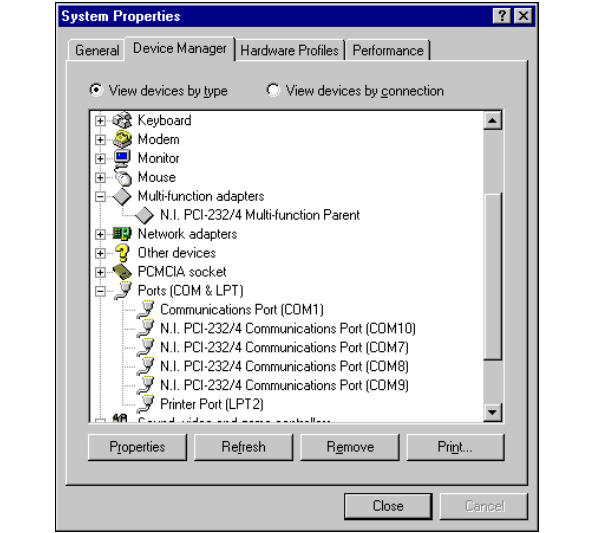
Appendix D Troubleshooting and Common Questions
Serial Hardware and Software for Windows D-12 ni.com
5. Select the interface that Windows Me/9xdid not detect, as shown in
Figure D-2. (This example shows a PCI interface.)
Figure D-2. Ports List in Device Manager
6. Click on the Remove button.
7. Click on the OK button to remove the serial hardware information.
8. Repeat steps 5 through 7 until you have removed all serial interfaces.
9. Click on the Refresh button.
10. Windows Me/9xshould automatically detect your hardware and
display one or more New Hardware Found dialog boxes. Your
operating system (Windows Me/9x)mayshowtheWindows Default
Driver option. If so, make sure the Windows Default Driver is
selected and click on the OK button. If the Windows Default Driver
option is not shown, the installation continues automatically.

Appendix D Troubleshooting and Common Questions
©National Instruments Corporation D-13 Serial Hardware and Software for Windows
AT and PCMCIA Hardware
If Windows does not detect your serial hardware correctly, or you have
been using your serial hardware with the default Windows Me/9xserial
driver or an older version of the NI-Serial software, Windows Me/9xdoes
not display the New Hardware Found dialog box. To fix this problem,
follow these steps:
1. Select Start»Settings»Control Panel.
2. Double-click on the System icon.
3. Select the Device Manager tab.
4. ClickontheView devices by type button.
5. Double-click on the Ports (COM & LPT) icon to display a list of all
ports that Windows Me/9xrecognizes.
If you have already installed the hardware, double-click on Other
Devices to display where Windows Me/9xlists the ports it does not
recognize.
6. Select a National Instruments port name from the list of ports that
corresponds to a serial port (for example, COM 5, COM 6, COM 7, or
COM 8). Figure D-3 shows the Ports list in the Device Manager with
a port selected. (This example shows an AT interface.)
Note To remove ports on shared IRQ cards, you must open the Multifunction adapter
class, select the name of the interface, and click on the Remove button.
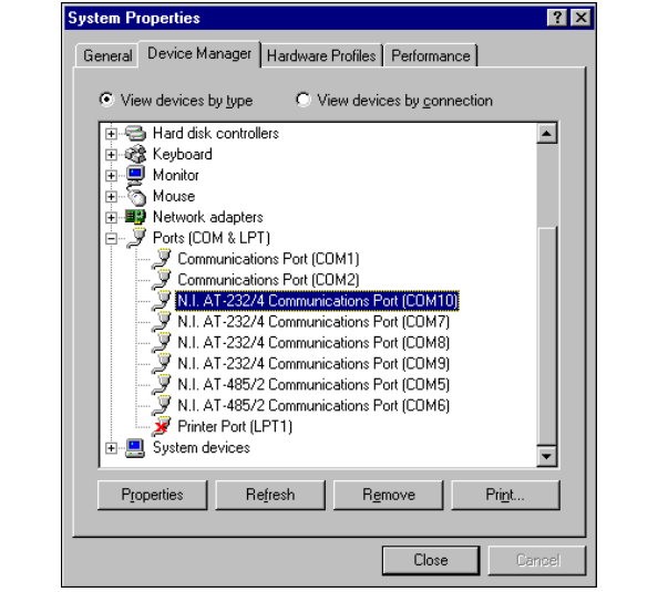
Appendix D Troubleshooting and Common Questions
Serial Hardware and Software for Windows D-14 ni.com
Figure D-3. Ports List in Device Manager
7. Click on the Remove button, and click on OK to confirm the removal
of the serial hardware information.
Repeat steps 6 and 7 until all serial board entries are removed. Then, click
on Refresh to force Windows Me/9xto detect the serial hardware and
display the New Hardware Found dialog box.
Common Questions
How can I determine which type of serial hardware I have installed?
1. Select Start»Settings»Control Panel and double-click on the
System icon.
2. Click on the Device Manager tabandclickontheView devices by
type button.
3. Double-click on the Ports (COM & LPT) icon to display a list of
installed ports.

Appendix D Troubleshooting and Common Questions
©National Instruments Corporation D-15 Serial Hardware and Software for Windows
How can I determine which version of the NI-Serial software I have
installed?
The Read Me file gives the version of the software. To open the file, select
Start»Programs»National Instruments Serial»Read Me.
What do I do if the diagnostic test fails with an error?
Refer to the Troubleshooting Diagnostic Messages section earlier in this
appendix.
How can I determine which port is associated with COMx?
To determine which physical port is associated with COMx, complete the
following steps:
1. In the Device Manager tab, under Ports (COM & LPT), double-click
on a serial port.
2. Click on the Port Settings tab to display the serial number of the serial
hardware and the physical port number starting at 1. For all serial
hardware, PORT1 refers to the top port, PORT2 refers to the next port
down, and so on.
How can I change the COM numbers of my National Instruments
serial ports?
To name serial ports COM1, COM2, COM3, or COM4, change the base
address of the port. To do so, refer to the Troubleshooting Diagnostic
Messages section earlier in this appendix.
When you change the base address, Windows Me/9xautomatically
converts it to the corresponding COM name listed in Table D-1. You do not
need to change the IRQ setting for Windows Me/9xto change the name.
Table D-1. Standard DOS-Based Addresses
COM Port Base Address
COM1 3f8
COM2 2f8
COM3 3e8
COM4 2e8
Appendix D Troubleshooting and Common Questions
Serial Hardware and Software for Windows D-16 ni.com
How do I change the resources assigned to the serial interface?
♦PCI and PXI Boards
The PCI and PXI serial boards are configured as devices belonging to the
multi-function adapters class. The multi-function parent device is listed
under the Multi-function adapters icon, and each child device is listed as
a port under the Ports (COM & LPT) icon.
To change the resources of serial ports, complete the following steps:
1. In the Device Manager tab, under Multi-function adapters,
double-click on a serial interface.
2. Click on the Resources tab to change the resources. Your changes are
automatically reflected to the child devices under Ports (COM &
LPT).
♦AT and PCMCIA Boards
Because the shared IRQ boards are single physical devices that support
multiple ports, they are registered as “multi-function adapters”in the
Device Manager. Each port is a child device listed under Ports (COM &
LPT).WindowsMe/9xdoes not allow the resources of the multi-function
child devices to be changed directly.
To change the resources of ports on shared IRQ boards from within the
Device Manager, you must open the Multi-function adapters class and
double-click on the Multi-function Parent item that corresponds to your
National Instruments serial interface. Use the Resources page to change
the resources. Any resource changes are automatically reflected to the child
devices. Figure D-4 shows the Multi-function adapters class in the
Device Manager. (This example shows an AT interface.)
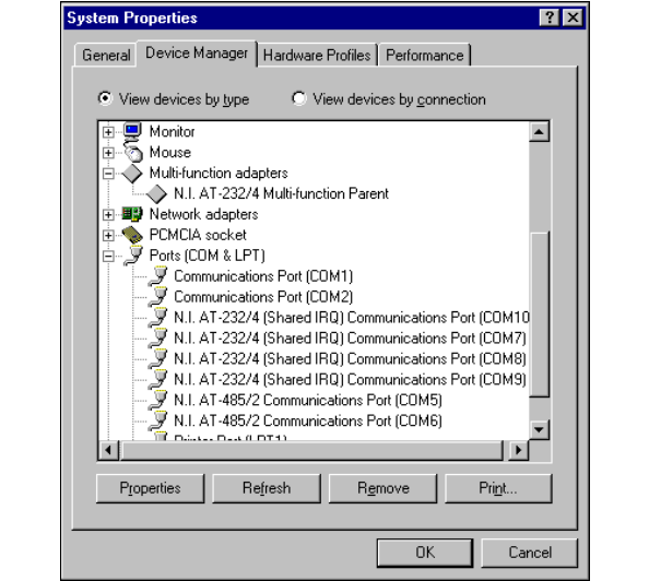
Appendix D Troubleshooting and Common Questions
©National Instruments Corporation D-17 Serial Hardware and Software for Windows
Figure D-4. Multi-Function Adapter Class in the Device Manager
How do I remove information about serial boards from the Device
Manager?
Refer to the hardware uninstallation section for your hardware platform and
operating system in Appendix C, Uninstalling the Hardware and Software.
What is the maximum baud rate supported and how can I set it?
The maximum baud rate supported is 460.8 Kbaud for RS-485 and
115.2 Kbaud for RS-232. To set the baud rate, use the SetCommState
Win32 function and pass the actual value of the baud rate in the BaudRate
field of the DCB structure.
How many interrupts are required for my serial interface?
If you have a shared IRQ board or an isolated board, you need one interrupt
per board. This is the hardware that currently ships with Windows Me/9x.
If you have an older non-shared IRQ board, you need as many interrupts as
there are ports on the board.

Appendix D Troubleshooting and Common Questions
Serial Hardware and Software for Windows D-18 ni.com
Windows NT
Missing Serial Port in the niports List
PCI and PXI Boards
The serial configuration utility contains configuration information for
serial hardware that is installed in your system.
To start the configuration utility, select Start»Settings»Control Panel
anddouble-clickontheniports icon.
If your PCI or PXI serial hardware is missing from this list, complete the
following steps:
1. Physically make sure that your board is installed properly.
2. Make sure that the National Instruments serial driver is installed,
as follows:
a. Locate serial.sys in the WinNT\system32\drivers
directory.
b. Right-click on serial.sys and select Properties.
c. ClickontheVersion tab. If the Company Name is Microsoft,
the National Instruments serial driver is not installed properly.
To solve this problem, reinstall the NI-Serial software. For
instructions on how to do so, refer to the installation and
verification chapter for your hardware platform.
AT Boards
The serial configuration utility niports contains configuration information
for serial hardware it is aware of that is installed in your system.
To start the configuration utility, select Start»Settings»Control Panel,
anddouble-clickontheniports icon.
If your AT serial board is missing from the list, follow these steps:
1. Make sure the hardware is installed.
2. Make sure you have installed the Microsoft PnP ISA Enabler driver.
niports cannot recognize the AT boards without the Microsoft PnP
ISA Enabler driver. For more information, refer to the Installing the
Microsoft PnP ISA Enabler Driver section of Chapter 5, AT Serial
Hardware Installation, Verification, and Configuration.
Appendix D Troubleshooting and Common Questions
©National Instruments Corporation D-19 Serial Hardware and Software for Windows
PCMCIA Boards
The serial configuration utility niports contains configuration information
for serial hardware it is aware of that is installed in your system.
To start the configuration utility, select Start»Settings»Control Panel,
and double-click on the niports icon.
If serial ports are missing from this list, make sure you selected resources
for your PCMCIA card as described in the Select Resources for the
PCMCIA Card section in Chapter 4, PCMCIA Serial Hardware
Installation, Verification, and Configuration.
Resolving Resource Conflicts
Resource conflicts occur when your system contains hardware that is
configured to use the same resources as your serial interface. The serial
driver detects some resource conflicts when it loads. When the driver
detects conflicts as it loads, it records an error message describing the
conflict.
To resolve a resource conflict, complete the following steps:
1. Select Start»Programs»Administrative Tools»Event Viewer to run
the Event Viewer and determine which resource is in conflict.
2. Change the resources of the device that caused the conflict.
To help you select conflict-free resources, you can use the
Windows NT Diagnostics utility. This utility displays a list of the
I/O port addresses, interrupt levels, and DMA channels that your
system is currently using. You can assign resources that are not listed
by this utility to your device.
To run the Windows NT Diagnostics utility, select
Start»Programs»Administrative Tools»Windows NT Diagnostics.
Appendix D Troubleshooting and Common Questions
Serial Hardware and Software for Windows D-20 ni.com
Troubleshooting Diagnostic Messages
This section lists possible error messages returned by the diagnostic utility,
along with solutions.
No National Instruments Serial Port Found
If the No National Instruments serial port found error message
appears, complete the following steps:
1. Verify the hardware resources, as follows:
a. Select Start»Settings»Control Panel and double-click on the
niports icon.
b. In the Ports list, select a port and click on the Settings button.
If the serial port is missing from the Ports list, reinstall the
hardware and software. For instructions on how to do so, refer to
the installation and verification chapter for your hardware
platform.
c. In the General Port Settings dialog box, click on the Resources
button to view the resources for the port.
d. Check the hardware resources. If they are in conflict, refer to the
previous section, Resolving Resource Conflicts.
2. Make sure that the National Instruments serial driver is installed,
as follows:
a. Locate the serial.sys file in the WinNT\system32\drivers
directory.
b. If the serial.sys file is missing, reinstall the hardware and
software. For instructions on how to do so, refer to the installation
and verification chapter for your hardware platform.
c. Right-click on the serial.sys file and select Properties.
d. ClickontheVersion tab. If the Company Name is Microsoft,
the National Instruments serial driver is not installed properly.
To solve this problem, reinstall the NI-Serial software. For
instructions on how to do so, refer to the installation and
verification chapter for your hardware platform.
Appendix D Troubleshooting and Common Questions
©National Instruments Corporation D-21 Serial Hardware and Software for Windows
Diagnostic Utility Does Not Show All Installed Ports
If the diagnostic utility does not show all the ports you installed, complete
the following steps:
1. Verify the hardware resources, as follows:
a. Select Start»Settings»Control Panel and double-click on the
niports icon.
b. In the Ports list, select a port and click on the Settings button.
If the serial port is missing from the Ports list, reinstall the
hardware and software. For instructions on how to do so, refer to
the installation and verification chapter for your hardware
platform.
c. In the General Port Settings dialog box, click on the Resources
button to view the resources for the port.
d. Check the hardware resources. If they are in conflict, refer to the
previous section, Resolving Resource Conflicts.
2. Make sure that the National Instruments serial driver is installed,
as follows:
a. Locate the serial.sys file in the WinNT\system32\drivers
directory.
b. If the serial.sys file is missing, reinstall the hardware and
software. For instructions on how to do so, refer to the installation
and verification chapter for your hardware platform.
c. Right-click on the serial.sys file and select Properties.
d. ClickontheVersion tab. If the Company Name is Microsoft,
the National Instruments serial driver is not installed properly.
To solve this problem, reinstall the NI-Serial software. For
instructionsonhowtodoso,refertotheinstallationand
verification chapter for your hardware platform.
3. Physically make sure the correct number of boards and ports are
installed.
Address Test Failed
If the address test failed, Interrupt test cannot be
performed error message appears, you might have an address conflict
with legacy boards in your system. To solve this problem, change the base
addresses assigned to your legacy boards. For instructions on how to do so,
refer to your legacy board documentation.
Appendix D Troubleshooting and Common Questions
Serial Hardware and Software for Windows D-22 ni.com
Interrupt Test Failed
If the Interrupt test failed error message appears, you might have
an IRQ conflict with legacy boards in your system. To solve this problem,
change the IRQ level assigned to your legacy boards. For instructions on
how to do so, refer to your legacy board documentation.
Common Questions
How can I determine which type of serial hardware I have installed?
To display a list of installed ports, select Start»Settings»Control Panel
anddouble-clickontheniports icon.
How can I determine which version of the NI-Serial software I have
installed?
The Read Me file gives the version of the software. To open the file, select
Start»Programs»National Instruments Serial»Read Me.
What do I do if the diagnostic test fails with an error?
Refer to the Troubleshooting Diagnostic Messages section earlier in this
appendix.
How can I determine which port is associated with COMx?
To determine which physical port is associated with COMx, complete the
following steps:
1. Select Start»Settings»Control Panel and double-click on the
niports icon.
A list of installed National Instruments ports with their logical COMx
names appears. If your interface is not on this list, refer to the Missing
Serial Port in the niports List section earlier in this appendix.
2. SelectaCOMportandclickontheSettings button.
The General Port Settings dialog box displays the serial number of
the serial hardware and the physical port number starting at 1. For all
serial hardware, PORT1 refers to the top port, PORT2 refers to the next
port down, and so on.
How can I change the COM numbers of my National Instruments
serial ports?
Refer to the general port settings section in the installation and verification
chapter for your hardware platform.
Appendix D Troubleshooting and Common Questions
©National Instruments Corporation D-23 Serial Hardware and Software for Windows
What is the maximum baud rate supported and how can I set it?
The maximum baud rate supported is 460.8 Kbaud for RS-485 and
115.2 Kbaud for RS-232. To set the baud rate, use the SetCommState
Win32 function and pass the actual value of the baud rate in the BaudRate
field of the DCB structure.
How many interrupts are required for my serial interface?
If you have a shared IRQ card or an isolated serial card, you need one
interrupt per card. This is the hardware that currently ships with
Windows NT.
If you have an older, non-shared IRQ card, you need as many interrupts as
there are ports on the card.

©National Instruments Corporation E-1 Serial Hardware and Software for Windows
E
Specifications
This appendix describes the characteristics of the serial hardware, the
NI-Serial software, along with the recommended operating conditions.
PCI Serial Hardware
Two-Port Boards
Dimensions............................................. 10.67 by 14.22 cm
(4.2 by 5.6 in.)
I/O connector.......................................... DB-9
Power requirement (from PCI channel)
PCI-485/2
+5 VDC.................................... 350 mA typical
750 mA maximum
PCI-232/2
+5 VDC.................................... 50 mA typical
100 mA maximum
±12 VDC.................................. 20 mA typical
200 mA maximum
Isolated Two-Port Boards
Dimensions............................................. 10.67 by 14.22 cm
(4.2 by 5.6 in.)
I/O connector.......................................... DB-9
Isolation voltage
From port to port............................. 2000 Vrms/60s
From any port to host computer...... 2000 Vrms/60s

Appendix E Specifications for PCI Serial Hardware
Serial Hardware and Software for Windows E-2 ni.com
Power requirement (from PCI channel)
PCI-485/2
+5 VDC ....................................800 mA typical
1300 mA maximum
PCI-232/2
+5 VDC ....................................400 mA typical
650 mA maximum
Four-Port Boards
Dimensions .............................................10.67 by 17.27 cm
(4.2 by 6.8 in.)
I/O connector1.........................................10-position modular jack
Power requirement (from PCI channel)
PCI-485/4
+5 VDC ....................................700 mA typical
1300 mA maximum
PCI-232/4
+5 VDC ....................................70 mA typical
150 mA maximum
±12 VDC ..................................40 mA typical
400 mA maximum
Isolated Four-Port Boards
Dimensions .............................................10.67 by 17.27 cm
(4.2 by 6.8 in.)
I/O connector1.........................................10-position modular jack
Isolation voltage
From port to port .............................2000 Vrms/60s
From any port to host computer ......2000 Vrms/60s
1The four-port PCI serial boards require a cable to convert the 10-position modular jack to either DB-9 or DB-25 connectors.

Appendix E Specifications for PCI Serial Hardware
©National Instruments Corporation E-3 Serial Hardware and Software for Windows
Power requirement (from PCI channel)
PCI-485/4
+5 VDC.................................... 1000 mA typical
1500 mA maximum
PCI-232/4
+5 VDC.................................... 500 mA typical
750 mA maximum
Eight-Port Boards
Dimensions............................................. 10.67 by14.48 cm
(4.2 by 5.7 in.)
I/O connector1........................................ 68-position, SCSI type connector
Power requirement (from PCI channel)
PCI-485/8
+5 VDC.................................... 1100 mA typical
2000 mA maximum
PCI-232/8
+5 VDC.................................... 100 mA typical
180 mA maximum
±12 VDC.................................. 80 mA typical
800 mA maximum
16-Port Boards
Dimensions............................................. 10.67 by17.52 cm
(4.2 by 6.9 in.)
I/O connector2........................................ 100-position, SCSI type
connector
Power requirement (from PCI channel)
PCI-232/16
+5 VDC.................................... 250 mA typical
500 mA maximum
1The eight-port PCI serial boards require a cable, which is included in your kit, to convert the 68-position connector to
eight DB-9 connectors.
2The 16-port PCI serial boards require a breakout box, which is included in your kit, to separate the 100-position connector to
16 DB-9 connectors.

Appendix E Specifications for PCI Serial Hardware
Serial Hardware and Software for Windows E-4 ni.com
Environmental Characteristics
Operating environment
Component temperature ..................0 to 70 °C
Relative humidity ............................10 to 90%, noncondensing
Storage environment
Temperature.....................................–40 to 120 °C
Relative humidity ............................5 to 90%, noncondensing
EMI.........................................................FCC Class A Verified
Software Characteristics
Maximum serial transfer rate1
RS-485.............................................460,800 bps
RS-232.............................................115,200 bps
1Actual speed may vary considerably from speed shown due to system and instrumentation capabilities.

Appendix E Specifications for PXI Serial Hardware
©National Instruments Corporation E-5 Serial Hardware and Software for Windows
PXI Serial Hardware
Two-Port Boards
Dimensions............................................. 100 by 160 mm
(3.94by6.30in.)
I/O connector.......................................... DB-9
Power requirement (from PXI channel)
PXI-8420/2
+5 VDC.................................... 100 mA typical
150 mA maximum
±12 VDC.................................. 20 mA typical
200 mA maximum
PXI-8421/2
+5 VDC.................................... 350 mA typical
750 mA maximum
PXI-8422/2
+5 VDC.................................... 400 mA typical
650 mA maximum
PXI-8423/2
+5 VDC.................................... 800 mA typical
1300 mA maximum
Four-Port Boards
Dimensions............................................. 100 by 160 mm
(3.94by6.30in.)
I/O connector1........................................ 10-position modular jack
Power requirement (from PXI channel)
PXI-8420/4
+5 VDC.................................... 125 mA typical
200 mA maximum
±12 VDC.................................. 40 mA typical
400 mA maximum
1The four-port PXI serial boards require a cable to convert the 10-position modular jack to either DB-9 or DB-25 connectors.

Appendix E Specifications for PXI Serial Hardware
Serial Hardware and Software for Windows E-6 ni.com
PXI-8421/4
+5 VDC ....................................350 mA typical
750 mA maximum
PXI-8422/4
+5 VDC ....................................500 mA typical
750 mA maximum
PXI-8423/4
+5 VDC ....................................1000 mA typical
1500 mA maximum
Eight-Port Boards
Dimensions .............................................100 by 160 mm
(3.94by6.30in.)
I/O connector1.........................................68-position, SCSI type connector
Power requirement (from PXI channel)
PXI-8420/8
+5 VDC ....................................150 mA typical
250 mA maximum
±12 VDC ..................................80 mA typical
800 mA maximum
PXI-8421/8
+5 VDC ....................................1100 mA typical
2000 mA maximum
16-Port Boards
Dimensions .............................................100 by 160 mm
(3.94by6.30in.)
I/O connector2.........................................100-position, SCSI type
connector
Power requirement (from PXI channel)
PXI-8420/16
+5 VDC ....................................500 mA typical
750 mA maximum
1The eight-port PXI serial boards require cables, which are included in your kit, to convert the 68-position connector to
eight DB-9 connectors.
2The 16-port PCI serial boards require a breakout box, which is included in your kit, to separate the 100-position connector to
16 DB-9 connectors.

Appendix E Specifications for PXI Serial Hardware
©National Instruments Corporation E-7 Serial Hardware and Software for Windows
Environmental Characteristics
Operating environment
Component temperature.................. 0 to 70 °C
Relative humidity............................ 10 to 90%, noncondensing
Storage environment
Temperature .................................... –40 to 120 °C
Relative humidity............................ 5 to 90%, noncondensing
EMI ........................................................ FCC Class A Verified
Software Characteristics
Maximum serial transfer rate1
RS-485 ............................................ 460,800 bps
RS-232 ............................................ 115,200 bps
1Actual speed may vary considerably from speed shown due to system and instrumentation capabilities.

Appendix E Specifications for PCMCIA Serial Hardware
Serial Hardware and Software for Windows E-8 ni.com
PCMCIA Serial Hardware
Hardware Specifications
Dimensions .............................................85.6 by 54.0 by 0.5 cm
(3.370 by 2.126 by 0.197 in.)
I/O connector ..........................................Special cable with DB-9 Dsub
connector and converter for
PC card
Power requirement
(from PCMCIA expansion slot)
PCMCIA-232 ..................................+5 VDC 40 mA typical
PCMCIA-485 ..................................+5 VDC 100 mA typical
PCMCIA-232/2 ...............................+5 VDC 60 mA typical
PCMCIA-485/2 ...............................+5 VDC 100 mA typical
PCMCIA-232/4 ...............................+5 VDC 60 mA typical
Operating environment
Component temperature ..................0 to 70°C
Relative humidity ............................10 to 90%, noncondensing
Storage environment
Temperature.....................................–40 to 120°C
Relative humidity ............................5 to 90%, noncondensing
EMI.........................................................FCC Class A verified
Software Specifications
Maximum serial transfer rate1................115,200 bps
1Actual speed may vary considerably from speed shown due to system and instrumentation capabilities.

Appendix E Specifications for AT Serial Hardware
©National Instruments Corporation E-9 Serial Hardware and Software for Windows
AT Serial Hardware
Hardware Characteristics
Two-Port AT Serial Boards (Nonisolated)
Dimensions............................................. 10.67 by 16.51 cm
(4.2 by 6.5 in.)
I/O connector.......................................... DB-9
Power requirement
(from PC AT I/O channel)
AT-485/2.......................................... +5 VDC 390 mA typical
510 mA maximum
AT-232/2.......................................... +5 VDC 260 mA typical
340 mA maximum
AT-485/2 (Shared IRQ)................... +5 VDC 140 mA typical
180 mA maximum
AT-232/2 (Shared IRQ)................... +5 VDC 70 mA typical
100 mA maximum
Two-Port AT Serial Boards (Isolated)
Dimensions............................................. 10.67 by 18.70 cm
(4.2 by 7.4 in.)
I/O connector.......................................... DB-9
Isolation Voltage
From Port to Port ............................ 3000 Vrms/60s
From Any Port to Host
Computer ........................................ 2000 Vrms/60s
Power Requirement
(from PC AT I/O channel)
AT-485/2 Isolated............................ +5 VDC 220 mA typical
260 mA maximum
AT-232/2 Isolated............................ +5 VDC 160 mA typical
200 mA maximum

Appendix E Specifications for AT Serial Hardware
Serial Hardware and Software for Windows E-10 ni.com
Four-Port AT Serial Boards (Nonisolated)
Dimensions .............................................10.67 by 16.51 cm
(4.2 by 6.5 in.)
I/O connector1.........................................10-position modular jack
Power Requirement
(from PC AT I/O channel)
AT-485/4 ..........................................+5 VDC 160 mA typical
200 mA maximum
AT-232/4 ..........................................+5 VDC 110 mA typical
150 mA maximum
AT-485/4 (Shared IRQ)....................+5 VDC 160 mA typical
200 mA maximum
AT-232/4 (Shared IRQ)....................+5 VDC 110 mA typical
150 mA maximum
Four-Port AT Serial Boards (Isolated)
Dimensions .............................................10.67 by 25.40 cm
(4.2 by 10.0 in.)
I/O connector2.........................................10-position modular jack
Isolation voltage
From Port to Port.............................3000 Vrms/60s
From Any Port to Host
Computer .........................................2000 Vrms/60s
Power Requirement
(from PC AT I/O channel)
AT-485/4 Isolated.............................+5 VDC 300 mA typical
360 mA maximum
AT-232/4 Isolated.............................+5 VDC 280 mA typical
320 mA maximum
1The four-port AT serial board requires a cable to convert the 10-position modular jack to either DB-9 or DB-25 connectors.
2The four-port isolated AT serial board requires cables, which are included in your kit, to convert the 10-position modular jack
to a DB-9 connector. Use only the type of cables provided in your kit.

Appendix E Specifications for AT Serial Hardware
©National Instruments Corporation E-11 Serial Hardware and Software for Windows
Environmental Characteristics
Operating environment
Component temperature.................. 0 to 70°C
Relative humidity............................ 10 to 90%, noncondensing
Storage environment
Temperature .................................... –40 to 120°C
Relative humidity............................ 5 to 90%, noncondensing
EMI
AT serial .......................................... FCC Class B verified
AT serial isolated............................. FCC Class A verified
Software Characteristics
Maximum serial transfer rate ................. 115,200 bps1
1Actual speed may vary considerably from speed shown due to system and instrumentation capabilities.

©National Instruments Corporation F-1 Serial Hardware and Software for Windows
F
Technical Support Resources
Web Support
National Instruments Web support is your first stop for help in solving
installation, configuration, and application problems and questions. Online
problem-solving and diagnostic resources include frequently asked
questions, knowledge bases, product-specific troubleshooting wizards,
manuals, drivers, software updates, and more. Web support is available
through the Technical Support section of ni.com
NI Developer Zone
The NI Developer Zone at ni.com/zone is the essential resource for
building measurement and automation systems. At the NI Developer Zone,
you can easily access the latest example programs, system configurators,
tutorials, technical news, as well as a community of developers ready to
share their own techniques.
Customer Education
National Instruments provides a number of alternatives to satisfy your
training needs, from self-paced tutorials, videos, and interactive CDs to
instructor-led hands-on courses at locations around the world. Visit the
Customer Education section of ni.com for online course schedules,
syllabi, training centers, and class registration.
System Integration
If you have time constraints, limited in-house technical resources, or other
dilemmas, you may prefer to employ consulting or system integration
services. You can rely on the expertise available through our worldwide
network of Alliance Program members. To find out more about our
Alliance system integration solutions, visit the System Integration section
of ni.com

Appendix F Technical Support Resources
Serial Hardware and Software for Windows F-2 ni.com
Worldwide Support
National Instruments has offices located around the world to help address
your support needs. You can access our branch office Web sites from the
Worldwide Offices section of ni.com. Branch office Web sites provide
up-to-date contact information, support phone numbers, e-mail addresses,
and current events.
If you have searched the technical support resources on our Web site and
still cannot find the answers you need, contact your local office or National
Instruments corporate. Phone numbers for our worldwide offices are listed
at the front of this manual.
©National Instruments Corporation G-1 Serial Hardware and Software for Windows
Glossary
Prefix Meaning Value
p- pico- 10–12
n- nano- 10–9
µ- micro- 10–6
m- milli- 10–3
k- kilo- 103
M- mega- 106
G- giga- 109
t- tera- 1012
°degrees
Ωohms
% percent
A amperes
ANSI American National Standards Institute
bbits
Bbytes
baud bits per second
bps bits per second
CCelsius
COM Computer Output Microform; used in reference to a communication port
CTS clear to send
DB-xx subminiature D connector, where xx is the number of pins

Glossary
Serial Hardware and Software for Windows G-2 ni.com
DCD data carrier detect
DCE data communications equipment or data circuit-terminating equipment
DLL dynamic link library
DMA direct memory access
DSR data set ready
DTE data terminal equipment
DTR data terminal ready—the overscore denotes that the signal is active low
duplex the means of bandwidth usage in a serial system
EIA Electronic Industries Association
EMI electromagnetic interference
FCC Federal Communications Commission
FIFO First-In-First-Out
ft feet
GND ground
HSI handshake input
HSO handshake output
Hz Hertz
IEEE Institute of Electrical and Electronic Engineers
in. inches
I/O input/output
IRQ interrupt request
ISA Industry Standard Architecture
Kbaud kilobits per second
m meters

Glossary
©National Instruments Corporation G-3 Serial Hardware and Software for Windows
MB megabytes of memory
PC personal computer
PCI Peripheral Components Interconnect
RAM random-access memory
RI ring indicator
RTS request to send
RX receive
RXD receive data—the overscore denotes that the signal is active low
s seconds
SCSI Small Computer Systems Interface
TX transmit
TXD transmit data—the overscore denotes that the signal is active low
TXRDY transmit ready—the overscore denotes that the signal is active low
UART Universal Asynchronous Receiver/Transmitter
V volts
VDC volts direct current
VXI VME eXtensions for Instrumentation
Win16 describes a 16-bit Windows application
Win32 describes a 32-bit Windows application

©National Instruments Corporation I-1 Serial Hardware and Software for Windows
Index
Numerics
100-pin connector, A-8
pin descriptions (table), A-9
pin locations (figure), A-8
10-position modular jack, A-3
pin descriptions (table), A-3
pin locations (figure), A-3
16-port boards specifications
PCI, E-3
PXI, E-6
68-pin connector, A-6
pin descriptions (table), A-7
pin locations (figure), A-6
A
advanced port settings
AT, Windows Me/9x,5-17
dialog box (figure)
AT, Windows Me/9x,5-17
PCI, Windows Me/9x,2-17
PCMCIA, Windows Me/9x,4-15
PXI, Windows Me/9x,3-16
PCI, Windows Me/9x,2-17
PCMCIA, Windows Me/9x,4-15
PXI, Windows Me/9x,3-16
transceiver mode
AT, Windows Me/9x,5-17
PCI, Windows Me/9x,2-17
PCMCIA, Windows Me/9x,4-15
PXI, Windows Me/9x,3-16
advanced settings
AT, Windows 2000, 5-8
dialog box (figure)
AT, Windows 2000, 5-8
PCI, Windows 2000, 2-8
PCMCIA, Windows 2000, 4-7
PXI, Windows 2000, 3-8
PCI, Windows 2000, 2-8
PCMCIA, Windows 2000, 4-7
PXI, Windows 2000, 3-7
transceiver mode
AT, Windows 2000, 5-8
PCI, Windows 2000, 2-8
PCMCIA, Windows 2000, 4-7
PXI, Windows 2000, 3-8
using FIFO buffers, 2-9, 2-17, 3-8, 3-16,
4-8, 4-15, 5-9, 5-18
advanced transceiver control, 6-1
four-wire mode, 6-2
setting transceiver control mode, 6-3
transceiver mode control bytes (table), 6-4
transceiver mode control modes (table), 6-2
two-wire mode: DTR controlled, 6-2
two-wire mode: DTR with Echo, 6-2
two-wire mode: TXRDY auto control, 6-3
AT serial board installation (figure), 5-3,
5-11, 5-20
B
bias resistors, B-5
using in transmission line (figure), B-6
C
cable connection, A-1
changing communication port settings
Windows 2000, 2-5, 3-5, 4-5, 5-5
Windows NT, 2-21, 3-20, 4-19, 5-22
changing resources assigned to serial
interface, D-16
COM port number, 2-22, 3-21, 4-20, 5-23
Index
Serial Hardware and Software for Windows I-2 ni.com
common questions
changing resources assigned to serial
interface, D-16
determining number of interrupts required
for a serial interface, D-17, D-23
determining port associated with COMx
Windows 2000, D-4
Windows Me/9x,D-15
Windows NT, D-22
determining type of serial hardware
installed
Windows 2000, D-4
Windows Me/9x,D-14
Windows NT, D-22
determining version of NI-Serial software
installed
Windows 2000, D-4
Windows Me/9x,D-15
Windows NT, D-22
diagnostic test failure
Windows 2000, D-4
Windows Me/9x,D-15
Windows NT, D-22
maximum supported baud rate
Windows 2000, D-5
Windows Me/9x,D-17
Windows NT, D-23
naming National Instruments serial ports
Windows 2000, D-4
Windows Me/9x,D-15
Windows NT, D-22
removing information about serial boards
from Device Manager
Windows 2000, D-5
Windows Me/9x,D-17
Windows 2000, D-4
Windows Me/9x,D-14
Windows NT, D-22
communication port settings
viewing or changing
Windows 2000, 2-5, 3-5, 4-5, 5-5
Windows Me/9x, 2-14, 3-13,
4-13, 5-14
Windows NT, 2-21, 3-20, 4-19, 5-22
ComponentWorks, 1-9
ComponentWorks++, 1-9
configuration
resource settings, 5-24
conflict-free resources, D-7
selecting, D-7
connecting cables, A-1
connecting cables to four-port PCI serial board
(figure), A-5
connecting two-wire devices, A-1
conventions, xiii
customer education, F-1
D
DB-25 connector, A-4
pin descriptions (table), A-4
pin locations (figure), A-4
DB-9
100-pin connector pin descriptions
(figure), A-8
100-pin connector pin descriptions
(table), A-9
68-pin connector pin descriptions
(figure), A-6
68-pin connector pin descriptions
(table), A-7
connector, A-2
pin descriptions (table), A-2
pin locations (figure), A-2
DCE vs. DTE, B-7
default restoration, 2-9, 2-18, 3-9, 3-17, 4-8,
4-16, 5-9
determining number of interrupts required for
a serial interface, D-23
Index
©National Instruments Corporation I-3 Serial Hardware and Software for Windows
determining port associated with COMx
Windows 2000, D-4
Windows Me/9x, 4-12, 5-14, D-15
Windows NT, 4-18, 5-21, D-22
determining type of serial hardware installed
Windows 2000, D-4
Windows Me/9x,D-14
Windows NT, D-22
determining version of NI-Serial software
installed
Windows 2000, D-4
Windows Me/9x,D-15
Windows NT, D-22
development tools for saving time, 1-8
Device Manager for AT serial board ports
(figure),5-4,5-13
Device Manager for PCI serial board ports
(figure),2-4,2-13
Device Manager for PCMCIA serial card ports
(figure),4-4,4-11
Device Manager for PXI serial board ports
(figure),3-4,3-12
Device Manager ports list (figure), D-12, D-14
DeviceloControl, 6-4
input values (table), 6-5
setting transceiver mode with, 6-4
diagnostic messages
address test failed
Windows 2000, D-3
Windows Me/9x,D-10
Windows NT, D-21
diagnostic utility does not show all
installed ports
Windows Me/9x,D-10
Windows NT, D-21
interrupt test failed
Windows 2000, D-3
Windows Me/9x,D-10
Windows NT, D-22
no National Instruments serial port found
Windows 2000, D-3
Windows Me/9x,D-9
Windows NT, D-20
troubleshooting
Windows 2000, D-3
Windows Me/9x,D-9
Windows NT, D-20
diagnostic test failure
Windows 2000, D-4
Windows Me/9x,D-15
Windows NT, D-22
DOS-based addresses (table), D-15
DTE vs. DCE, B-7
DTE-to-DCE interface, B-7
straight-through cabling in (figure), B-7
DTE-to-DTE interface, B-7
null-modem cabling in (figure), B-7
duplex architectures, B-3
full duplex, B-3
half duplex, B-4
E
eight-port boards specifications
PCI, E-3
PXI, E-6
environmental characteristics
AT, E-11
PCI, E-4
PXI, E-7
F
FIFO buffer size, 2-23, 3-22, 4-21, 5-24
FIFO buffers, 2-9, 2-17, 3-8, 3-16, 4-8, 4-15,
5-9, 5-18
FIFO enabled, 2-22, 3-21, 4-21, 5-24
FIFO buffer size, 2-23, 3-22, 4-21, 5-24
Index
Serial Hardware and Software for Windows I-4 ni.com
forcing Windows to detect hardware
Windows 2000, D-2
Windows Me/9x,D-11
four-port boards
connecting cables to (figure), A-5
isolated four-port boards
AT, E-10
PCI, E-2
specifications
AT, E-10
PCI, E-2
PXI, E-5
four-wire mode, 6-2
freeing an interrupt request level, D-6
full duplex, B-3
full-duplex system (figure), B-4
G
general port settings
AT, 5-23
dialog box (figure), 5-23
transceiver mode, 5-23
COM port number, 2-22, 3-21, 4-20, 5-23
FIFO enabled, 2-22, 3-21, 4-21, 5-24
PCI, 2-22
dialog box (figure), 2-22
transceiver mode, 2-22
PCMCIA, 4-20
dialog box (figure), 4-20
transceiver mode, 4-20
PXI, 3-21
dialog box (figure), 3-21
transceiver mode, 3-21
resources, 2-23, 3-22, 4-21, 5-24
general programming requirements, 6-1
getting started, 1-2
glossary, G-1
H
half duplex, B-4
half-duplex system (figure), B-4
hardware installation
AT, Windows 2000, 5-2
AT, Windows Me/9x,5-10
AT, Windows NT, 5-19
getting started, 1-2
PCI, Windows 2000, 2-2
PCI, Windows Me/9x,2-10
PCI, Windows NT, 2-18
PCMCIA, Windows 2000, 4-2
PCMCIA, Windows Me/9x,4-9
PCMCIA, Windows NT, 4-17
PXI, Windows 2000, 3-2
PXI, Windows Me/9x,3-10
PXI, Windows NT, 3-17
verification
AT, Windows 2000, 5-4
AT, Windows Me/9x,5-12
AT, Windows NT, 5-21
PCI, Windows 2000, 2-4
PCI, Windows Me/9x,2-12
PCI, Windows NT, 2-20
PCMCIA, Windows 2000, 4-3
PCMCIA, Windows Me/9x,4-10
PCMCIA, Windows NT, 4-18
PXI, Windows 2000, 3-4
PXI, Windows Me/9x,3-11
PXI, Windows NT, 3-19
hardware specifications
AT, E-9
PCI, E-1
PCMCIA, E-8
PXI, E-5
Index
©National Instruments Corporation I-5 Serial Hardware and Software for Windows
I
installation
AT serial board installation (figure), 5-3,
5-11, 5-20
determining port associated with COMx
Windows Me/9x, 4-12, 5-14
Windows NT, 4-18, 5-21
getting started, 1-2
installing the PnP ISA Enabler
Driver, 5-18
PCI serial board installation (figure), 2-3,
2-11, 2-19
PCMCIA serial card installation (figure),
4-3, 4-10, 4-17
PXI serial board installation (figure), 3-3,
3-10, 3-18
running the diagnostic test
AT, Windows Me/9x,5-14
AT, Windows NT, 5-21
PCMCIA, Windows Me/9x,4-12
PCMCIA, Windows NT, 4-18
selecting resources for the PCMCIA
card, 4-18
serial hardware
AT, Windows 2000, 5-2
AT, Windows Me/9x,5-10
AT, Windows NT, 5-19
PCI, Windows 2000, 2-2
PCI, Windows Me/9x,2-10
PCI, Windows NT, 2-18
PCMCIA, Windows 2000, 4-2
PCMCIA, Windows Me/9x,4-9
PCMCIA, Windows NT, 4-17
PXI, Windows 2000, 3-2
PXI, Windows Me/9x,3-10
PXI, Windows NT, 3-17
serial software
Windows 2000, 2-1, 3-1, 4-1, 5-1
Windows Me/9x,2-9,3-9,4-8,5-9
Windows NT, 2-18, 3-17, 4-16, 5-19
verification
AT, 5-1
PCI, 2-1
PCMCIA, 4-1
PXI, 3-1
verifying hardware installation, 4-10
AT, Windows 2000, 5-4
AT, Windows Me/9x,5-12
AT, Windows NT, 5-21
PCI, Windows 2000, 2-4
PCI, Windows Me/9x,2-12
PCI, Windows NT, 2-20
PCMCIA, Windows 2000, 4-3
PCMCIA, Windows Me/9x,4-12
PCMCIA, Windows NT, 4-18
PXI, Windows 2000, 3-4
PXI, Windows Me/9x,3-11
PXI, Windows NT, 3-19
verifying hardware resources
AT, Windows Me/9x,5-13
PCMCIA, Windows Me/9x,4-12
installing the PnP ISA Enabler Driver, 5-18
interrupt request level, D-6
freeing, D-6
introduction, 1-1
isolated four-port boards
AT, E-10
PCI, E-2
isolated two-port boards
AT, E-9
PCI, E-1
L
LabVIEW, 1-8
LabWindows/CVI, 1-9
legacy boards
resolving resource conflicts with
Windows 2000, D-4
Windows Me/9x,D-11
Index
Serial Hardware and Software for Windows I-6 ni.com
M
maximum supported baud rate
Windows 2000, D-5
Windows Me/9x,D-17
Windows NT, D-23
Measurement Studio, 1-8
missing serial port in the niports list, D-18
modular jack connector, A-3
pin descriptions (table), A-3
pin locations (figure), A-3
multidrop network using terminating resistors
(figure), B-5
multi-function adapter class in the Device
Manager (figure), D-17
N
naming National Instruments serial ports
standard DOS-based addresses
(table), D-15
Windows 2000, D-4
Windows Me/9x,D-15
Windows NT, D-22
National Instruments Web support, F-1
NI Developer Zone, F-1
niports configuration utility (figure)
AT, 5-22
PCI, 2-21
PCMCIA, 4-19
PXI, 3-20
null-modem cabling in a DTE-to-DTE
interface (figure), B-7
number of interrupts required for a serial
interface, D-17
O
optional equipment, 1-3
overview of serial hardware
AT, 1-6
PCI, 1-3
PCMCIA, 1-6
PXI, 1-4
overview of serial software, 1-8
P
PCI serial board installation (figure), 2-3,
2-11, 2-19
PCMCIA card installation (figure), 4-3,
4-10, 4-17
pin descriptions
100-pin connector pin descriptions
(figure), A-8
100-pin connector pin descriptions
(table), A-9
68-pin connector pin descriptions
(figure), A-6
68-pin connector pin descriptions
(table), A-7
DB-25
connector, A-4
connector pin descriptions
(table), A-4
connector pin locations (figure), A-4
DB-9
100-pin description (table), A-9
68-pin description (table), A-7
connector, A-2
connector pin descriptions
(table), A-2
connector pin locations (figure), A-2
PnP port configuration dialog box for the
AT-232/4 (figure), 5-25
port settings tab
AT, Windows 2000, 5-7
AT, Windows Me/9x,5-16
options
advanced port settings
AT, Windows Me/9x,5-17
PCI, Windows Me/9x,2-17
Index
©National Instruments Corporation I-7 Serial Hardware and Software for Windows
PCMCIA, Windows
Me/9x,4-15
PXI, Windows Me/9x,3-16
advanced settings
AT, Windows 2000, 5-8
PCI, Windows 2000, 2-8
PCMCIA, Windows 2000, 4-7
PXI, Windows 2000, 3-7
PCI, Windows 2000, 2-6
PCI, Windows Me/9x,2-16
PCMCIA, Windows 2000, 4-6
PCMCIA, Windows Me/9x,4-14
PXI, Windows 2000, 3-6
PXI, Windows Me/9x,3-15
restore defaults button, 2-9, 2-18, 3-9,
3-17, 4-8, 4-16, 5-9
ports list in Device Manager (figure),
D-12, D-14
PXI serial board installation (figure), 3-3,
3-10, 3-18
PXI serial board names and descriptions
(table), 1-5
R
related documentation, xiv
removing information about serial boards
from Device Manager
Windows 2000, D-5
Windows Me/9x,D-17
resolving resource conflicts, D-19
resolving resource conflicts with legacy
boards
Windows 2000, D-4
Windows Me/9x,D-11
resource configuration dialog box for the
PCMCIA-485 (figure), 4-22
resource configuration dialog box for the
PCMCIA-485/2 (figure), 4-23
resource settings, 4-22, 5-24
AT boards (non-shared IRQ), 5-26
AT boards (shared IRQ), 5-25
PCMCIA-232, PCMCIA-485,
PCMCIA-232/4, 4-22
PCMCIA-232/2, PCMCIA-485/2, 4-23
restoring defaults, 2-9, 2-18, 3-9, 3-17, 4-8,
4-16, 5-9
RS-232 standard, B-1
features (table), B-1
RS-422 standard, B-2
features (table), B-1
RS-485 standard, B-2
features (table), B-1
running the diagnostic test
AT, Windows Me/9x,5-14
AT, Windows NT, 5-21
PCMCIA, Windows Me/9x,4-12
PCMCIA, Windows NT, 4-18
S
selecting an interface to uninstall (figure)
AT, Windows 2000, C-17
AT, Windows Me/9x,C-19
AT, Windows NT, C-21
PCI, Windows 2000, C-2, D-2
PCI, Windows Me/9x,C-4
PCI, Windows NT, C-5
PCMCIA, Windows 2000, C-12
PCMCIA, Windows Me/9x,C-14
PCMCIA, Windows NT, C-16
PXI, Windows 2000, C-7
PXI, Windows Me/9x,C-9
PXI, Windows NT, C-10
selecting conflict-free resources, D-7
selecting resources for the PCMCIA
card, 4-18
serial communication issues, B-3
bias resistors, B-5
DTE vs. DCE, B-7
duplex architectures, B-3
termination, B-5
Index
Serial Hardware and Software for Windows I-8 ni.com
serial hardware
forcing Windows to detect
Windows 2000, D-2
Windows Me/9x,D-11
general programming requirements, 6-1
installation
AT, Windows 2000, 5-2
AT, Windows Me/9x,5-10
AT, Windows NT, 5-19
PCI, Windows 2000, 2-2
PCI, Windows Me/9x,2-10
PCI, Windows NT, 2-18
PCMCIA, Windows 2000, 4-2
PCMCIA, Windows Me/9x,4-9
PCMCIA, Windows NT, 4-17
PXI, Windows 2000, 3-2
PXI, Windows Me/9x,3-10
PXI, Windows NT, 3-17
overview
AT, 1-6
PCI, 1-3
PCMCIA, 1-6
PXI, 1-4
selecting an interface to uninstall (figure)
AT, Windows 2000, C-17
AT, Windows Me/9x,C-19
AT, Windows NT, C-21
PCI, Windows 2000, C-2, D-2
PCI, Windows Me/9x,C-4
PCI, Windows NT, C-5
PCMCIA, Windows 2000, C-12
PCMCIA, Windows Me/9x,C-14
PCMCIA, Windows NT, C-16
PXI, Windows 2000, C-7
PXI, Windows Me/9x,C-9
PXI, Windows NT, C-10
uninstalling
AT, Windows 2000, C-17
AT, Windows Me/9x,C-18
AT, Windows NT, C-20
PCI, Windows 2000, C-2
PCI, Windows Me/9x,C-3
PCI, Windows NT, C-5
PCMCIA, Windows 2000, C-12
PCMCIA, Windows Me/9x,C-13
PCMCIA, Windows NT, C-15
PXI, Windows 2000, C-7
PXI, Windows Me/9x,C-8
PXI, Windows NT, C-10
using, 6-1
serial port information, B-1
serial software
installation
Windows 2000, 2-1, 3-1, 4-1, 5-1
Windows Me/9x,2-9,3-9,4-8,5-9
Windows NT, 2-18, 3-17, 4-16, 5-19
overview, 1-8
uninstalling
Windows 2000, C-3, C-8, C-13, C-18
Windows Me/9x,C-4,C-9,
C-15, C-20
Windows NT, C-6, C-11, C-16, C-21
setting transceiver control mode, 6-3
setting with DeviceloControl, 6-4
software characteristics
AT, E-11
PCI, E-4
PCMCIA, E-8
PXI, E-7
software installation
getting started, 1-2
Windows 2000, 2-1, 3-1, 4-1, 5-1
Windows Me/9x,2-9,3-9,4-8,5-9
Windows NT, 2-18, 3-17, 4-16, 5-19
specifications, E-1
16-port boards
PCI, E-3
PXI, E-6
AT, E-9
Index
©National Instruments Corporation I-9 Serial Hardware and Software for Windows
eight-port boards
PCI, E-3
PXI, E-6
environmental characteristics
AT, E-11
PCI, E-4
PXI, E-7
four-port boards
AT, E-10
PCI, E-2
PXI, E-5
isolated four-port boards
AT, E-10
PCI, E-2
isolated two-port boards
AT, E-9
PCI, E-1
PCI, E-1
PCMCIA, E-8
PXI, E-5
software characteristics
AT, E-11
PCI, E-4
PCMCIA, E-8
PXI, E-7
two-port boards
AT, E-9
PCI, E-1
PXI, E-5
standard DOS-based addresses (table), D-15
straight-through cabling in a DTE-to-DCE
interface (figure), B-7
system integration, by National
Instruments, F-1
T
technical support resources, F-1
termination, B-5
multidrop network using terminating
resistors (figure), B-5
time-saving development tools, 1-8
transceiver control modes (table), 6-2
transceiver mode
AT, Windows 2000, 5-8
AT, Windows Me/9x,5-17
AT, Windows NT, 5-23
PCI, Windows 2000, 2-8
PCI, Windows Me/9x,2-17
PCI, Windows NT, 2-22
PCMCIA, Windows 2000, 4-7
PCMCIA, Windows Me/9x,4-15
PCMCIA, Windows NT, 4-20
PXI, Windows 2000, 3-8
PXI, Windows Me/9x,3-16
PXI, Windows NT, 3-21
setting with DeviceloControl, 6-4
transceiver mode control bytes (table), 6-4
transmission line using bias resistors
(figure), B-6
troubleshooting, D-1
diagnostic messages
Windows 2000, D-3
Windows Me/9x,D-9
Windows NT, D-20
forcing Windows to detect your hardware
Windows 2000, D-2
Windows Me/9x,D-11
freeing an interrupt request level, D-6
missing serial port in the niports list, D-18
resolving resource conflicts, D-19
resolving resource conflicts with legacy
boards
Windows 2000, D-4
Windows Me/9x,D-11
selecting conflict-free resources, D-7
two-port boards specifications
AT, E-9
isolated two-port boards
AT, E-9
PCI, E-1
Index
Serial Hardware and Software for Windows I-10 ni.com
PCI, E-1
PXI, E-5
two-wire devices, A-1
connecting, A-1
typical full-duplex system (figure), B-4
typical half-duplex system (figure), B-4
U
uninstalling serial hardware
AT Windows Me/9x,C-18
AT, Windows 2000, C-17
AT, Windows NT, C-20
PCI, Windows 2000, C-2
PCI, Windows Me/9x,C-3
PCI, Windows NT, C-5
PCMCIA, Windows 2000, C-12
PCMCIA, Windows Me/9x,C-13
PCMCIA, Windows NT, C-15
PXI, Windows 2000, C-7
PXI, Windows Me/9x,C-8
PXI, Windows NT, C-10
uninstalling serial software
Windows 2000, C-3, C-8, C-13, C-18
Windows Me/9x,C-4,C-9,C-15,C-20
Windows NT, C-6, C-11, C-16, C-21
using FIFO buffers, 2-9, 2-17, 3-8, 3-16, 4-8,
4-15, 5-9, 5-18
using serial hardware, 6-1
using this manual, 1-1
V
verifying hardware installation
AT, Windows 2000, 5-4
AT, Windows Me/9x,5-12
AT, Windows NT, 5-21
PCI, Windows 2000, 2-4
PCI, Windows Me/9x,2-12
PCI, Windows NT, 2-20
PCMCIA, Windows 2000, 4-3
PCMCIA, Windows Me/9x,4-10
PCMCIA, Windows NT, 4-18
PXI, Windows 2000, 3-4
PXI, Windows Me/9x,3-11
PXI, Windows NT, 3-19
verifying hardware resources
AT, Windows Me/9x,5-13
PCMCIA, Windows Me/9x,4-12
viewing or changing communication port
settings
Windows 2000, 2-5, 3-5, 4-5, 5-5
Windows Me/9x, 2-14, 3-13, 4-13, 5-14
Windows NT, 2-21, 3-20, 4-19, 5-22
W
Web support from National Instruments, F-1
Win32 Overviews and Win32 Reference, 6-1
Win32 Software Development Kit, 6-1
worldwide technical support, F-2
