National Instruments Hse Linking Device And The Ni Fbus Software 370578B 01 Users Manual Getting Started With Your
370578B-01 to the manual 4e48e3dd-0fe3-41bd-b57e-226e7b738785
2015-02-05
: National-Instruments National-Instruments-Hse-Linking-Device-And-The-Ni-Fbus-Software-370578B-01-Users-Manual-493954 national-instruments-hse-linking-device-and-the-ni-fbus-software-370578b-01-users-manual-493954 national-instruments pdf
Open the PDF directly: View PDF ![]() .
.
Page Count: 39
- Getting Started with Your HSE Linking Device and the NI-FBUS Software
- Support
- Important Information
- Contents
- About This Manual
- Chapter 1 Introduction
- Chapter 2 Installation and Configuration
- Chapter 3 Starting the NIFB Process
- Appendix A Troubleshooting and Common Questions
- Appendix B Technical Support and Professional Services
- Glossary
- Index

Fieldbus
Getting Started with Your
HSE Linking Device and
the NI-FBUSTM Software
HSE Linking Device and NI-FBUS Software
February 2004 Edition
Part Number 370578B-01
Support
Worldwide Technical Support and Product Information
ni.com
National Instruments Corporate Headquarters
11500 North Mopac Expressway Austin, Texas 78759-3504 USA Tel: 512 683 0100
Worldwide Offices
Australia 1800 300 800, Austria 43 0 662 45 79 90 0, Belgium 32 0 2 757 00 20, Brazil 55 11 3262 3599,
Canada (Calgary) 403 274 9391, Canada (Ottawa) 613 233 5949, Canada (Québec) 450 510 3055,
Canada (Toronto) 905 785 0085, Canada (Vancouver) 514 685 7530, China 86 21 6555 7838,
Czech Republic 420 224 235 774, Denmark 45 45 76 26 00, Finland 385 0 9 725 725 11,
France 33 0 1 48 14 24 24, Germany 49 0 89 741 31 30, Greece 30 2 10 42 96 427, India 91 80 51190000,
Israel 972 0 3 6393737, Italy 39 02 413091, Japan 81 3 5472 2970, Korea 82 02 3451 3400,
Malaysia 603 9131 0918, Mexico 001 800 010 0793, Netherlands 31 0 348 433 466,
New Zealand 0800 553 322, Norway 47 0 66 90 76 60, Poland 48 22 3390150, Portugal 351 210 311 210,
Russia 7 095 783 68 51, Singapore 65 6226 5886, Slovenia 386 3 425 4200, South Africa 27 0 11 805 8197,
Spain 34 91 640 0085, Sweden 46 0 8 587 895 00, Switzerland 41 56 200 51 51, Taiwan 886 2 2528 7227,
Thailand 662 992 7519, United Kingdom 44 0 1635 523545
For further support information, refer to the Technical Support and Professional Services appendix. To comment
on the documentation, send email to techpubs@ni.com.
© 2003–2004 National Instruments Corporation. All rights reserved.

Important Information
Warranty
The media on which you receive National Instruments software are warranted not to fail to execute programming instructions, due to defects
in materials and workmanship, for a period of 90 days from date of shipment, as evidenced by receipts or other documentation. National
Instruments will, at its option, repair or replace software media that do not execute programming instructions if National Instruments receives
notice of such defects during the warranty period. National Instruments does not warrant that the operation of the software shall be
uninterrupted or error free.
A Return Material Authorization (RMA) number must be obtained from the factory and clearly marked on the outside of the package before
any equipment will be accepted for warranty work. National Instruments will pay the shipping costs of returning to the owner parts which are
covered by warranty.
National Instruments believes that the information in this document is accurate. The document has been carefully reviewed for technical
accuracy. In the event that technical or typographical errors exist, National Instruments reserves the right to make changes to subsequent
editions of this document without prior notice to holders of this edition. The reader should consult National Instruments if errors are suspected.
In no event shall National Instruments be liable for any damages arising out of or related to this document or the information contained in it.
EXCEPT AS SPECIFIED HEREIN, NATIONAL INSTRUMENTS MAKES NO WARRANTIES, EXPRESS OR IMPLIED, AND SPECIFICALLY DISCLAIMS ANY WARRANTY OF
MERCHANTABILITY OR FITNESS FOR A PARTICULAR PURPOSE. CUSTOMER’S RIGHT TO RECOVER DAMAGES CAUSED BY FAULT OR NEGLIGENCE ON THE PART OF
NATIONAL INSTRUMENTS SHALL BE LIMITED TO THE AMOUNT THERETOFORE PAID BY THE CUSTOMER. NATIONAL INSTRUMENTS WILL NOT BE LIABLE FOR
DAMAGES RESULTING FROM LOSS OF DATA, PROFITS, USE OF PRODUCTS, OR INCIDENTAL OR CONSEQUENTIAL DAMAGES, EVEN IF ADVISED OF THE POSSIBILITY
THEREOF. This limitation of the liability of National Instruments will apply regardless of the form of action, whether in contract or tort, including
negligence. Any action against National Instruments must be brought within one year after the cause of action accrues. National Instruments
shall not be liable for any delay in performance due to causes beyond its reasonable control. The warranty provided herein does not cover
damages, defects, malfunctions, or service failures caused by owner’s failure to follow the National Instruments installation, operation, or
maintenance instructions; owner’s modification of the product; owner’s abuse, misuse, or negligent acts; and power failure or surges, fire,
flood, accident, actions of third parties, or other events outside reasonable control.
Copyright
Under the copyright laws, this publication may not be reproduced or transmitted in any form, electronic or mechanical, including photocopying,
recording, storing in an information retrieval system, or translating, in whole or in part, without the prior written consent of National
Instruments Corporation.
Trademarks
FieldPoint™, LabVIEW™, Lookout™, National Instruments™, NI™, ni.com™, and NI-FBUS™ are trademarks of National Instruments
Corporation.
Product and company names mentioned herein are trademarks or trade names of their respective companies.
Patents
For patents covering National Instruments products, refer to the appropriate location: Help»Patents in your software, the patents.txt file
on your CD, or ni.com/patents.
WARNING REGARDING USE OF NATIONAL INSTRUMENTS PRODUCTS
(1) NATIONAL INSTRUMENTS PRODUCTS ARE NOT DESIGNED WITH COMPONENTS AND TESTING FOR A LEVEL OF
RELIABILITY SUITABLE FOR USE IN OR IN CONNECTION WITH SURGICAL IMPLANTS OR AS CRITICAL COMPONENTS IN
ANY LIFE SUPPORT SYSTEMS WHOSE FAILURE TO PERFORM CAN REASONABLY BE EXPECTED TO CAUSE SIGNIFICANT
INJURY TO A HUMAN.
(2) IN ANY APPLICATION, INCLUDING THE ABOVE, RELIABILITY OF OPERATION OF THE SOFTWARE PRODUCTS CAN BE
IMPAIRED BY ADVERSE FACTORS, INCLUDING BUT NOT LIMITED TO FLUCTUATIONS IN ELECTRICAL POWER SUPPLY,
COMPUTER HARDWARE MALFUNCTIONS, COMPUTER OPERATING SYSTEM SOFTWARE FITNESS, FITNESS OF COMPILERS
AND DEVELOPMENT SOFTWARE USED TO DEVELOP AN APPLICATION, INSTALLATION ERRORS, SOFTWARE AND
HARDWARE COMPATIBILITY PROBLEMS, MALFUNCTIONS OR FAILURES OF ELECTRONIC MONITORING OR CONTROL
DEVICES, TRANSIENT FAILURES OF ELECTRONIC SYSTEMS (HARDWARE AND/OR SOFTWARE), UNANTICIPATED USES OR
MISUSES, OR ERRORS ON THE PART OF THE USER OR APPLICATIONS DESIGNER (ADVERSE FACTORS SUCH AS THESE ARE
HEREAFTER COLLECTIVELY TERMED “SYSTEM FAILURES”). ANY APPLICATION WHERE A SYSTEM FAILURE WOULD
CREATE A RISK OF HARM TO PROPERTY OR PERSONS (INCLUDING THE RISK OF BODILY INJURY AND DEATH) SHOULD
NOT BE RELIANT SOLELY UPON ONE FORM OF ELECTRONIC SYSTEM DUE TO THE RISK OF SYSTEM FAILURE. TO AVOID
DAMAGE, INJURY, OR DEATH, THE USER OR APPLICATION DESIGNER MUST TAKE REASONABLY PRUDENT STEPS TO
PROTECT AGAINST SYSTEM FAILURES, INCLUDING BUT NOT LIMITED TO BACK-UP OR SHUT DOWN MECHANISMS.
BECAUSE EACH END-USER SYSTEM IS CUSTOMIZED AND DIFFERS FROM NATIONAL INSTRUMENTS' TESTING
PLATFORMS AND BECAUSE A USER OR APPLICATION DESIGNER MAY USE NATIONAL INSTRUMENTS PRODUCTS IN
COMBINATION WITH OTHER PRODUCTS IN A MANNER NOT EVALUATED OR CONTEMPLATED BY NATIONAL
INSTRUMENTS, THE USER OR APPLICATION DESIGNER IS ULTIMATELY RESPONSIBLE FOR VERIFYING AND VALIDATING
THE SUITABILITY OF NATIONAL INSTRUMENTS PRODUCTS WHENEVER NATIONAL INSTRUMENTS PRODUCTS ARE
INCORPORATED IN A SYSTEM OR APPLICATION, INCLUDING, WITHOUT LIMITATION, THE APPROPRIATE DESIGN,
PROCESS AND SAFETY LEVEL OF SUCH SYSTEM OR APPLICATION.

© National Instruments Corporation v HSE Linking Device and NI-FBUS Software
Contents
About This Manual
How To Use the Manual Set..........................................................................................vii
Conventions ...................................................................................................................viii
Related Documentation..................................................................................................ix
Chapter 1
Introduction
What You Need to Get Started ......................................................................................1-1
Hardware Description ....................................................................................................1-1
Software Description .....................................................................................................1-1
NI-FBUS Interface Configuration Utility .......................................................1-2
Choosing Configuration Software...................................................................1-2
Optional Fieldbus Network Tools..................................................................................1-4
Chapter 2
Installation and Configuration
Installing the Software ...................................................................................................2-1
Installing the HSE Linking Device................................................................................2-2
Setting the NI-FBUS Software to Use Your HSE Linking Device ...............................2-2
Setting the Ethernet Interface ..........................................................................2-3
Setting the HSE Linking Device .....................................................................2-4
Setting the H1 Port Communication Parameters and Interface Name ............2-6
Testing the Installation...................................................................................................2-7
Changing or Deleting Existing Interface Information.....................................2-7
Importing Device Descriptions......................................................................................2-8
Chapter 3
Starting the NIFB Process
Beginning to Use Your NI-FBUS Software ..................................................................3-1
Appendix A
Troubleshooting and Common Questions

© National Instruments Corporation vii HSE Linking Device and NI-FBUS Software
About This Manual
This manual contains instructions on how to install and configure the
NI-FBUS software with an HSE Linking Device. The HSE Linking Device
is an HSE device used to attach H1 links to the High Speed Ethernet.
The NI-FBUS software is intended for use with Windows 2000/NT/XP
because Windows 9x is less robust than Windows 2000/NT/XP. This
manual assumes that you are already familiar with your Windows operating
system.
How To Use the Manual Set
Refer to the Foundation Fieldbus Overview to learn the basics of Fieldbus.
The Foundation Fieldbus Overview also includes tutorials to lead you
through developing a simple Fieldbus application.
Refer to this getting started manual to install and configure the NI-FBUS
software with your HSE linking device.
If you are using the National Instruments FBUS-HSE/H1 Linking Device
as your HSE linking device, refer to the Installation Guide: FBUS-HSE/H1
LD Fieldbus Network Module Linking Device and the FBUS-HSE/H1
Linking Device (LD) User Manual to install the HSE linking device.
If you are using an HSE linking device from a third-party vendor, refer to
the installation guide or user manual provided from the vendor to install
your HSE linking device.
If you are using the NI-FBUS Configurator, refer to the NI-FBUS
Configurator User Manual to install and use the NI-FBUS Configurator
software.
If you are using the NI-FBUS Communications Manager Application
Programmer Interface (API), refer to the NI-FBUS Communications
Manager User Manual to learn how to use the NI-FBUS Communications
Manager API for your application. Refer to the NI-FBUS Communications
Manager Function Reference Manual to look up specific information about
NI-FBUS Communications Manager functions, such as syntax and error
messages.

About This Manual
HSE Linking Device and NI-FBUS Software viii ni.com
Conventions
The following conventions appear in this manual:
»The » symbol leads you through nested menu items and dialog box options
to a final action. The sequence File»Page Setup»Options directs you to
pull down the File menu, select the Page Setup item, and select Options
from the last dialog box.
This icon denotes a note, which alerts you to important information.
This icon denotes a caution, which advises you of precautions to take to
avoid injury, data loss, or a system crash.
bold Bold text denotes items that you must select or click in the software, such
as menu items and dialog box options. Bold text also denotes parameter
names.
Fieldbus The generic term Fieldbus refers to any bus that connects to field devices.
This includes Foundation Fieldbus, CAN, DNET, and Profibus. In this
manual, the term Fieldbus refers specifically to the Foundation Fieldbus,
which includes H1 and HSE fieldbus.
italic Italic text denotes variables, emphasis, a cross reference, or an introduction
to a key concept. This font also denotes text that is a placeholder for a word
or value that you must supply.
monospace Text in this font denotes text or characters that you should enter from the
keyboard, sections of code, programming examples, and syntax examples.
This font is also used for the proper names of disk drives, paths, directories,
programs, subprograms, subroutines, device names, functions, operations,
variables, filenames, and extensions.
monospace bold Bold text in this font denotes the messages and responses that the computer
automatically prints to the screen. This font also emphasizes lines of code
that are different from the other examples.
monospace italic Italic text in this font denotes text that is a placeholder for a word or value
that you must supply.

About This Manual
© National Instruments Corporation ix HSE Linking Device and NI-FBUS Software
NI-FBUS software In this manual, the term NI-FBUS software refers to either the NI-FBUS
Communications Manager or NI-FBUS Configurator software.
Platform Text in this font denotes a specific platform and indicates that the text
following it applies only to that platform.
Related Documentation
The following documents contain information that you might find helpful
as you read this manual:
General Fieldbus Web sites
• Fieldbus Foundation—responsible for the definition of the Foundation
Fieldbus specification.
–fieldbus.org
Fieldbus system development documentation
• Fieldbus Foundation resources
–Wiring and Installation 31.25 kbit/s, Voltage Mode, Wire Medium
• Relcom Fieldbus resources online
– Wiring Design and Installation Guide
– Online Tutorial
–FAQ
– Sample Fieldbus Topologies
•Fieldbus Standard for Use in Industrial Control Systems, Part 2,
ISA-S50.02.1992
Fieldbus device development documentation
•Developing Your First Foundation Fieldbus Device, available from
the Fieldbus, Inc. Web site at fieldbusinc.com
•Foundation Specification: 31.25 kbit/s Physical Layer Profile for the
Foundation Fieldbus Physical Layer Specifications
•Function Block Application Process, Part 1
•Function Block Application Process, Part 2
• IEC Standard 1158-2 and ISA Standard ISA S50.02

© National Instruments Corporation 1-1 HSE Linking Device and NI-FBUS Software
1
Introduction
This chapter lists what you need to get started and includes a brief
description of the HSE Linking Device and the NI-FBUS software.
What You Need to Get Started
To install your NI-FBUS software, you need the following items:
❑HSE linking device
❑Installation disks
❑Ethernet adapter installed on your computer
❑Windows 2000/NT/XP installed on your computer
Hardware Description
Foundation Fieldbus includes both H1 (31.25 kbit/s) and High Speed
Ethernet (100 Mbit/s) specifications. HSE Linking Device is a high-speed
Ethernet (HSE) device used to integrate H1 fieldbus segments into the HSE
backbone from an Ethernet-based network. The HSE Linking Device
provides standard UDP/TCP access to H1 field devices.
Software Description
Your kit includes either the NI-FBUS Communications Manager software
or the NI-FBUS Configurator software. Depending on the system you
purchase, you may receive both disks; if this is the case, you should use the
NI-FBUS Configurator software.
The NI-FBUS Communications Manager software is used by the interface
boards or linking device to communicate over the bus. Additionally, it
provides a high-level API advanced users can use to interface with the
National Instruments Foundation Fieldbus communication stack and
hardware.
Chapter 1 Introduction
HSE Linking Device and NI-FBUS Software 1-2 ni.com
Most users use the NI-FBUS Configurator. In addition to providing the
functionality of the NI-FBUS Communications Manager in a graphical
format, it includes additional functionality to allow you to configure a
Fieldbus H1 and/or HSE network. It can automatically generate the
schedule for the network and configure field devices and hosts to transmit
and receive alarms and trends.
NI-FBUS Interface Configuration Utility
The NI-FBUS Interface Configuration Utility lets you view and change
the hardware configuration parameters for your Fieldbus interfaces. In
Windows 2000/NT/XP, you also can edit your hardware configuration
parameters and add and delete interfaces.
The NI-FBUS Interface Configuration Utility helps you to configure the
following information:
• Logical name for each port on your Fieldbus board or linking device;
you can access the port using the interface name
• Device description information
– Base directory for device description files
– Location of the standard text dictionary
You need to import device descriptions if you use the NI-FBUS
Communications Manager to communicate with devices that have
manufacturer-specific blocks or parameters.
• Fieldbus communication parameters for each Fieldbus interface
Choosing Configuration Software
Foundation Fieldbus links must be configured. Only with configuration
software can you do things like set device addresses, clear devices, and
download (necessary if you are setting up a system for the first time).
Your configuration software must match the interface board or linking
device your computer is using to connect to the bus. National Instruments
offers the NI-FBUS Configurator with a National Instruments Foundation
Fieldbus interface board or linking device to let you configure your
Fieldbus links.
Interface boards, linking devices and configuration software are sold
separately because multiple interface boards can reside in the same
computer and multiple HSE linking devices can be accessed through the
ethernet network. By default, the NI-FBUS Configurator is licensed for use
on one machine, with up to four Fieldbus links (segments). If you have
more than four links (ports on the boards or linking devices), you need to

Chapter 1 Introduction
© National Instruments Corporation 1-3 HSE Linking Device and NI-FBUS Software
purchase a link upgrade for each link in excess of four. To do so, download
the order form from ni.com/fieldbus.
Note The connection to one interface port on the interface board or linking devices is
viewed as one link by the NI-FBUS Configurator, regardless of how many links might
actually be joined by repeaters. This is important for software licensing of the NI-FBUS
Configurator.
If you want to use the board or linking device to read and write values only
(but not configure) and you are a programmer, you can make calls to the
API in the NI-FBUS Communications Manager and do not need the
NI-FBUS Configurator. This is possible only if you already have used
third-party hardware and configuration software to configure the link.
Table 1-1 describes the National Instruments Fieldbus software.
Table 1-1. National Instruments Fieldbus Software
Software Application Short Name Description File Name
NI-FBUS
Communications
Manager
NIFB process This must be running
for you to use your
HSE linking device as
a Fieldbus interface to
communicate between
the linking device and
the bus.
nifb.exe
NI-FBUS Interface
Configuration Utility
Interface Config Used to configure your
HSE link and HSE
linking device.
fbconf.exe
NI-FBUS
Configurator
NI-FBUS
Configurator
Used to configure the
devices on the bus,
set the parameters for
control loops, and
other Fieldbus
configuration tasks.
fcs.exe

Chapter 1 Introduction
HSE Linking Device and NI-FBUS Software 1-4 ni.com
Optional Fieldbus Network Tools
Your kit includes either the NI-FBUS Communications Manager software,
NI-FBUS Configurator software, or both. In addition, you can order the
LabVIEW DSC, and/or Lookout from National Instruments. If you have
not already done so, you also can order the NI-FBUS Configurator.
LabVIEW DSC helps you perform data acquisition and analysis, create a
human-machine interface (HMI), or develop an advanced supervisory
control application in a graphical development environment.
LabVIEW DSC includes real-time process monitoring, historical trending,
alarm and event reporting, online configuration, and PLC connectivity.
Lookout helps you create graphical representations on a computer screen
of real-world devices such as switches, dial gauges, chart recorders,
pushbuttons, knobs, sliders, and meters. After linking these images to your
field instruments, you can configure Lookout to generate alarms, log data
to disk, animate custom graphics, print reports, automatically adjust
setpoints, historically trend information, warn operators of malfunctions,
and so on.
NI-FBUS Dialog
System
NI-FBUS Dialog Used to view the
devices on the bus
and manually read
and write parameter
values. Not for
configuration.
nifbdlg.exe
Server Explorer Server Explorer Lets you configure
the attributes of
the communication
resource, device, and
items of your network,
and the groups and
items of your OPC
server.
serverexplorer.exe
Table 1-1. National Instruments Fieldbus Software (Continued)
Software Application Short Name Description File Name

© National Instruments Corporation 2-1 HSE Linking Device and NI-FBUS Software
2
Installation and Configuration
Installing the Software
(Windows 2000/NT/XP) Complete the following steps to install your
NI-FBUS software.
Caution If you are reinstalling the NI-FBUS software over an existing version, write down
your board configuration and any port configuration parameters you changed from the
default settings. Reinstalling may cause you to lose any existing board and port
configuration information.
1. Log in as Administrator or as a user that has Administrator
privileges.
2. Insert installation disk 1 or your NI-FBUS program CD.
3. Select Start»Run.
4. In the Run dialog box, enter x:\setup, where x is the letter of the drive
containing the disk (usually a or b).
The interactive setup program takes you through the necessary steps to
install the software.
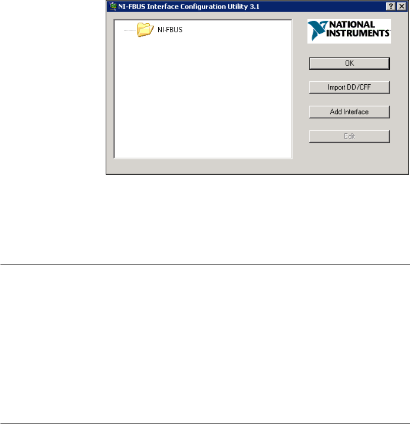
5. At the end of the setup, the installer starts the NI-FBUS Interface
Configuration Utility as shown in Figure 2-1. If you have not yet
installed your HSE linking device, click OK to return. You will
install your HSE linking device in a later step.
The installation program copies nifb.dll into the \System32 directory.
The installation program also adds information to the Windows Registry.
Chapter 2 Installation and Configuration
HSE Linking Device and NI-FBUS Software 2-2 ni.com
Figure 2-1. The NI-FBUS Interface Configuration Utility
Continue to the Installing the HSE Linking Device section to configure and
install your HSE linking device.
Installing the HSE Linking Device
If you are using a National Instruments FBUS-HSE/H1 Linking Device as
your HSE linking device, refer to the Installation Guide: FBUS-HSE/H1
LD Fieldbus Network Module Linking Device and the FBUS-HSE/H1
Linking Device (LD) User Manual for installation instructions.
If you are using an HSE linking device from a third-party vendor, refer to
the documentation provided by the vendor to install your HSE linking
device.
Setting the NI-FBUS Software to Use Your
HSE Linking Device
After you have configured and installed your HSE linking device, you are
ready to set the NI-FBUS software.
To do this, you first must set the Ethernet interface. The Ethernet interface
is an HSE interface that accesses an HSE linking device or HSE field
device.
Chapter 2 Installation and Configuration
© National Instruments Corporation 2-3 HSE Linking Device and NI-FBUS Software
Note You can connect only one NI-FBUS port to a link or Fieldbus segment.
Setting the Ethernet Interface
To use the NI-FBUS Interface Configuration Utility to add, view, or
change your Ethernet interface, complete the following steps:
1. Start the NI-FBUS Interface Configuration Utility. Select Start»
Programs»National Instruments»NI-FBUS»Interface
Configuration Utility.
2. In the Interface Config window, select the icon of the Ethernet board
you want to change and click Edit. If you are adding the Ethernet
interface, click Add Interface.
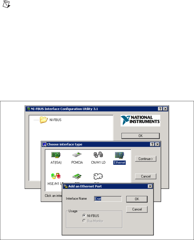
3. Choose Ethernet as the Interface Type. The NI-FBUS Interface
Configuration Utility displays the Ethernet interface name and some
configuration information as shown in Figure 2-2. You cannot change
the name for the Ethernet interface. Click OK.
Figure 2-2. Add the Ethernet Interface

Chapter 2 Installation and Configuration
HSE Linking Device and NI-FBUS Software 2-4 ni.com
Note Only one Ethernet interface can be added in the NI-FBUS software. If one Ethernet
interface already exists in the interface list, the interface type Ethernet will be prohibited,
and you cannot add a new Ethernet interface.
4. Click Edit to display the NI-FBUS Interface Configuration Utility
network communication information for the Ethernet interface
5. Change the network communication parameter settings to the settings
you want.
Caution Do not modify the network communication parameters without good reason.
If settings are incorrectly modified, the NI-FBUS software might not work well.
6. After verifying the information you just entered, click OK.
Setting the HSE Linking Device
Use the NI-FBUS Interface Configuration Utility to set the Fieldbus
communication parameters and interface name by completing the
following steps:
1. Start the NI-FBUS Interface Configuration Utility. Select Start»
Programs»National Instruments»NI-FBUS»Interface
Configuration Utility.
2. In the Interface Config window, select the icon of the HSE Linking
Device you want to change and click Edit. If you are adding the HSE
linking device, click Add Interface.
3. Choose HSE/H1 LD as the Interface Type. The NI-FBUS Interface
Configuration Utility listens on the Ethernet network and lists the
found HSE linking devices with their IP addresses and Device IDs.
4. Select the HSE linking device you want to add, and click Add.
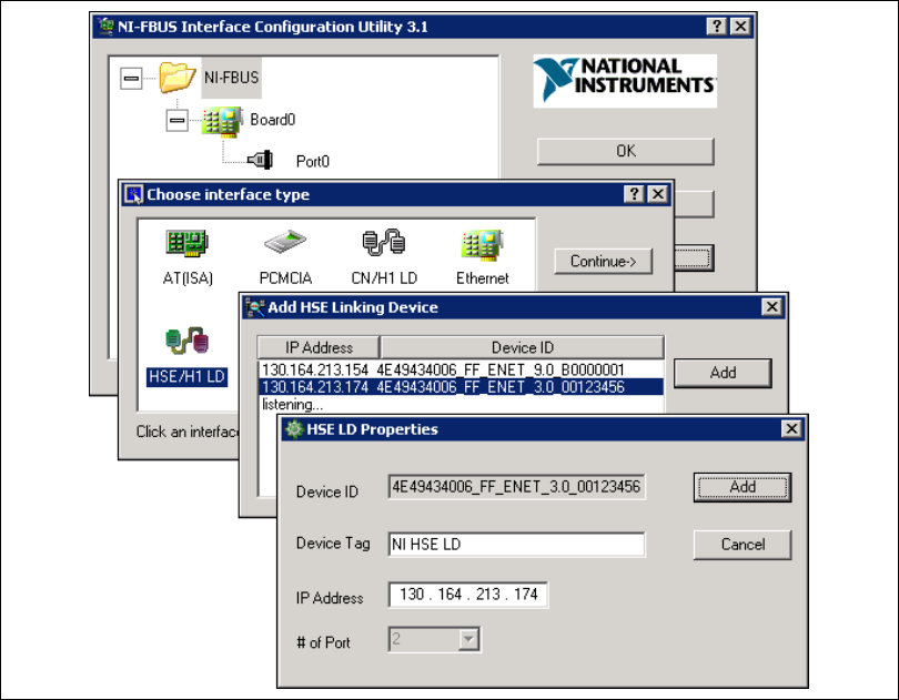
5. The NI-FBUS Interface Configuration Utility displays the device ID,
device tag, IP address, and port number of the linking device as shown
in Figure 2-3.
Chapter 2 Installation and Configuration
© National Instruments Corporation 2-5 HSE Linking Device and NI-FBUS Software
Figure 2-3. Add the HSE Linking Device
6. If the Device Tag field is blank, enter a unique tag. The device tag is
the name visible on the HSE Fieldbus to other devices.
7. After verifying the information you just entered, click OK or Add.
The dialog box for entering port information for the Fieldbus interface
opens.
8. Click OK.
Chapter 2 Installation and Configuration
HSE Linking Device and NI-FBUS Software 2-6 ni.com
Setting the H1 Port Communication Parameters and Interface Name
Use the NI-FBUS Interface Configuration Utility to set the Fieldbus
communication parameters and interface name by completing the
following steps:
1. Start the NI-FBUS Interface Configuration Utility. Select Start»
Programs»National Instruments»NI-FBUS»Interface
Configuration Utility.
2. Select the port you want to edit, and click Edit.
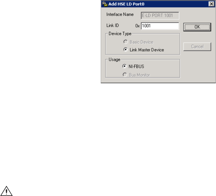
3. The NI-FBUS Interface Configuration Utility displays the default
interface name and some configuration information as shown in
Figure 2-4.
Figure 2-4. HSE Linking Device Port Properties
4. Enter an Interface Name for the port, or use the default name. The
interface name is for local use on the PC. It must be unique within
a PC, but the same linking device may be referenced by different
interface names in different PCs.
5. Enter a unique link ID in the Link ID field, or use the default link ID.
The default link ID is read from the HSE linking device, or is assigned
by the NI-FBUS if the link ID read from the HSE linking device is
invalid. The valid link ID number starts from 0x1001. When NIFB is
starting up, it will set the link ID of the H1 port as the link ID number
you set here, and set the H1 address as 0x10.
Caution Do not modify the link ID parameter without good reason. If the link ID is
incorrectly modified, this port on the HSE linking device might not work well with
NI-FBUS software on other PCs.

Chapter 2 Installation and Configuration
© National Instruments Corporation 2-7 HSE Linking Device and NI-FBUS Software
6. Select a Device Type, and then select Link Master Device.
7. Make sure that NI-FBUS is selected for Usage.
8. Click OK.
9. Repeat steps 2 through 8 for each port on the HSE linking device.
10. Click OK again to exit the configuration utility.
11. Restart the NIFB process by selecting Start»Programs»National
Instruments»NI-FBUS»NI-FBUS Communications Manager for
the changes you made in the NI-FBUS Interface Configuration Utility
take effect.
Testing the Installation
Start the NIFB process by selecting Start»Programs»National
Instruments»NI-FBUS»NI-FBUS Communications Manager.
The NIFB process must be running in the background to use a Fieldbus
application.
On successful startup, the NIFB displays a message confirming successful
process startup, the title bar of the NIFB window changes to
NI-FBUS (running), and an icon appears on the Windows taskbar. It may
take a few minutes for NIFB to start up and this message to display.
If NI-FBUS does not start up successfully, the configuration for the
Ethernet interface or the HSE linking device might be incorrect. If the
NIFB process does not start up successfully, refer to Appendix A,
Troubleshooting and Common Questions.
Changing or Deleting Existing Interface Information
To change or delete information about any interface that you have already
entered, complete the following steps:
1. Select Start»Programs»National Instruments»NI-FBUS»
Interface Configuration Utility.
2. Click the Boardx icon, where x refers to the board number of the
interface you want to change or delete.
3. Click Edit. You can edit the interface configuration information that
you entered earlier, or you can click Delete to delete this interface
entirely.
Interfaces are numbered beginning with zero. If you delete an
interface, the NI-FBUS Interface Configuration Utility renumbers all
the remaining interfaces. For example, if you delete Board0, it appears
Chapter 2 Installation and Configuration
HSE Linking Device and NI-FBUS Software 2-8 ni.com
that you deleted the last interface, because all the remaining interface
numbers are decreased by one automatically.
To reinstall the interface, refer to the Installing the HSE Linking
Device section and the Setting the NI-FBUS Software to Use Your
HSE Linking Device section.
Importing Device Descriptions
The device description files contain information about the types of blocks
and parameters supported by your Fieldbus device, along with online help
describing the uses of given parameters. If your Fieldbus device uses
manufacturer-specific device description files, you must import the device
description files (shipped with the device, or available from the device
manufacturer). To do so, complete the following steps:
1. Insert the device description disk or CD (if supplied by your Fieldbus
device manufacturer) into the disk drive of the host computer.
2. Select Start»Programs»National Instruments»NI-FBUS»
Interface Configuration Utility to run the Interface Configuration
Utility.
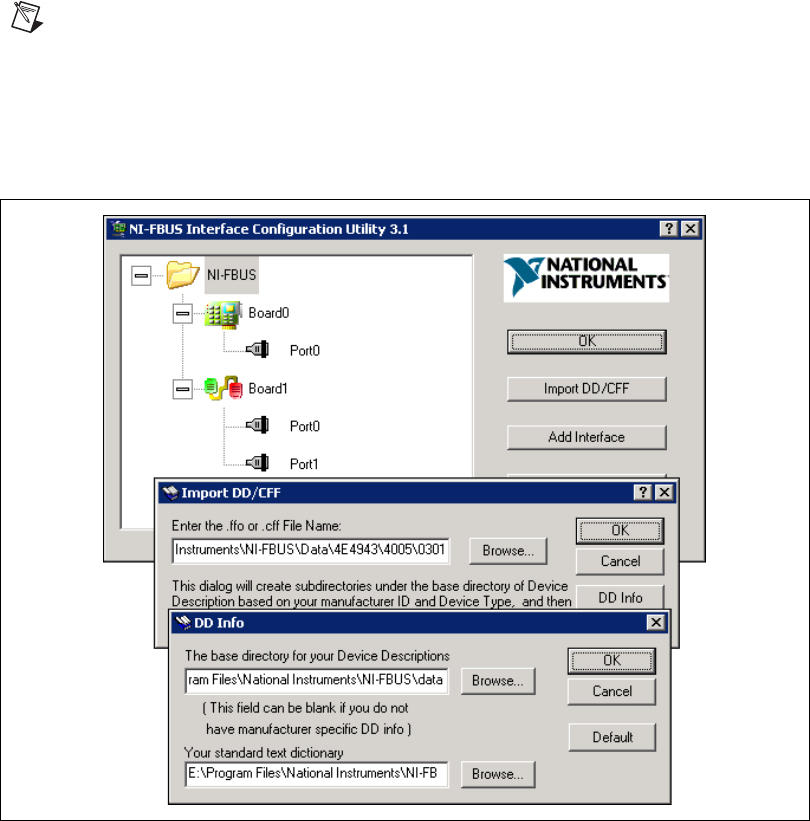
3. Click Import DD/CFF. The Import DD/CFF dialog box opens.
4. Click Browse, browse to the .ffo device description file path, and
click Open. Typically, the device description for your Fieldbus device
is supplied on a disk from the manufacturer. For each device, there are
two device description files, one that ends in .ffo and one that ends
in .sym. Select the .ffo file, and the corresponding .sym file will
be imported automatically. The file name will be in the form
Digit Digit Digit Digit.ffo (for example, 0101.ffo).
Table 2-1. Board Renumbering
Original Address Address after Deleting Board1
Board0 Board0
Board1 (deleted)
Board2 Board1
Board3 Board2
Chapter 2 Installation and Configuration
© National Instruments Corporation 2-9 HSE Linking Device and NI-FBUS Software
Note If you are importing device descriptions for multiple devices, you might see that they
can have the same filenames. Each file contains information about the device and its
manufacturer, and will be placed appropriately in the hierarchy under the base directory.
5. Click OK. A window opens that gives the full path to which the .ffo
and .sym files were copied.
6. Click DD Info. The DD Info dialog box opens as shown in Figure 2-5.
Figure 2-5. Import DD file
7. If the base directory field is blank, enter a base directory. The base
directory you enter here will be where NI-FBUS looks for all device
descriptions. Do not change the base directory after you have started
importing device descriptions; otherwise, NI-FBUS will not be able to
find the device descriptions you previously imported. Your device
description files will automatically be placed in the appropriate
manufacturer ID subdirectory under this base directory.
Chapter 2 Installation and Configuration
HSE Linking Device and NI-FBUS Software 2-10 ni.com
Your base directory will include a folder for each different manufacturer for
which you have imported a device description. For example, if you import
the device description for the National Instruments FP-3000 device, you
will find a folder called 4e4943. This is the National Instruments
Foundation Fieldbus device manufacturer ID number.
The next layer of folders is the device type. For example, the FP-3000 has
a device type ID number of 4005.
Underneath this layer of directories you will find the individual device
description files (.ffo and .sym).
8. If necessary, click Browse to select the standard text dictionary,
provided with NI-FBUS. The text dictionary has a .dct extension.
9. Click OK.
For more information on device descriptions, refer to the Device
Descriptions section of the Foundation Fieldbus Overview document.

© National Instruments Corporation 3-1 HSE Linking Device and NI-FBUS Software
3
Starting the NIFB Process
The NIFB process must be running any time you want to use your
HSE linking devices as the Fieldbus interfaces to communicate between
the linking device and the bus.
On successful startup, the NIFB displays a message confirming successful
process startup, the title bar of the NIFB window changes to
NI-FBUS (running), and an icon appears on the Windows taskbar. It may
take a few minutes for NIFB to start up and this message to display.
Beginning to Use Your NI-FBUS Software
If you are using the NI-FBUS Communications Manager, refer to the
NI-FBUS Communication Manager User Manual for information on using
your software. If you are using the NI-FBUS Configurator, refer to the
NI-FBUS Configurator User Manual for information on using your
software.
If NI-FBUS is unable to connect to and initialize an interface device,
and you decide to continue NI-FBUS startup, NI-FBUS will not try to
reconnect to that interface again. This is true of all interface types supported
by this software.

© National Instruments Corporation A-1 HSE Linking Device and NI-FBUS Software
A
Troubleshooting and
Common Questions
This appendix describes how to troubleshoot common problems that occur
while getting started with Fieldbus.
Error Messages
Utility could not access or locate the registry.
• If using Windows 2000/NT/XP, make sure you are logged in to
Windows with Administrator privileges.
• Your registry entries for NI-FBUS may have been deleted or corrupted.
Uninstall the NI-FBUS software, then reinstall the software as
described in the Installing the Software section of Chapter 2,
Installation and Configuration.
The HSE linking device cannot be found.
• Verify the HSE Linking device settings as described in the Setting
the HSE Linking Device section of Chapter 2, Installation and
Configuration.
• Select Start»Programs»National Instruments»NI-FBUS»
Interface Configuration Utility. Make sure your HSE linking
device appears under the list of interfaces.
• Make sure your HSE linking device is online.
NIFB Problems
When using the HSE Linking device with Windows 2000/NT/XP,
Nifb returns an error message stating that the linking device cannot
be found.
• Verify the HSE Linking device settings as described in the Setting
the HSE Linking Device section of Chapter 2, Installation and
Configuration.

Appendix A Troubleshooting and Common Questions
HSE Linking Device and NI-FBUS Software A-2 ni.com
• Select Start»Programs»National Instruments»NI-FBUS»
Interface Configuration Utility. Make sure your HSE linking
device appears under the list of interfaces.
• Make sure your HSE linking device is online.
When a Fieldbus device is connected to the bus, the NIFB process often
hangs when the title bar reads Waiting for Startup Completion. If I
disconnect the cables, it starts properly.
This is probably due to a device address conflict. In the NI-FBUS Interface
Configuration Utility, make sure that the interface is not at the same address
as anything else on the link.
The NIFB process hangs, does not start up, or never shows that it is
running.
• The Fieldbus network address is not unique. Remove the cable from
the HSE Linking device. Restart the NIFB process. If it runs
successfully, there is probably a Fieldbus network address conflict.
If you have FP-3000 network modules on the bank, powering them off
and then back on will cause them to look on the bus for available
addresses and change addresses if necessary.
• Check for multiple copies of nifb.dll on the machine. If multiple
copies are found, NI-FBUS was incorrectly re-installed. Uninstall
NI-FBUS, search for any remaining copies of nifb.dll, delete them,
then reinstall the software.
• Check how many interface boards are showing up in the Interface
Configuration Utility. Make sure that this matches the number of
boards in the system. Also check that the number of ports match the
physical hardware (one port versus two port boards).
Interface Configuration Problems
When using the NI-FBUS Interface Configuration Utility on a
Windows 2000/NT machine, the error message utility could not
access or locate the registry appears.
• Make sure you are logged in to Windows with Administrator
privileges.
• Your registry entries for NI-FBUS may have been deleted or corrupted.
Uninstall the NI-FBUS software, then reinstall the software as
described in the Installing the Software section of Chapter 2,
Installation and Configuration.
Appendix A Troubleshooting and Common Questions
© National Instruments Corporation A-3 HSE Linking Device and NI-FBUS Software
In the Interface Configuration Utility, I see more boards than what
physically exist in the machine.
Select Edit for the extra board. In the next window, select Delete.
Caution You should not attempt to make unguided changes in the Windows Registry.
Doing so can cause a number of problems with your system.
Problems Using Manufacturer-Defined Features
NI-FBUS uses identifying information in the actual device to locate the
device description for the device. The identifying information includes
four resource block parameters: MANUFAC_ID, DEV_TYPE, DEV_REV, and
DD_REV. If the identifying information is incorrect, NI-FBUS will not be
able to locate the device description for the device. When it has located
the device description, NI-FBUS matches the block types in the device
description with the actual blocks in the device by using the Item ID of
the block characteristics record.
If the blocks in the device do not match the blocks in the description, or
if there is no appropriate device description for the manufacturer, device
type, device revision, and device description revision being returned by
the device, then there is a device description mismatch. In either case,
NI-FBUS uses only the standard dictionary (nifb.dct) and you will
be unable to use any manufacturer-supplied functionality.
These parameters can be read from the device resource block.
The following procedure will help you troubleshoot a
DD_SIZE_MISMATCH_ERROR by finding out if there is a device description
available on your computer that matches what your device expects.
Complete the following steps to use the NI-FBUS Dialog utility to check
device description files.
1. Start the NIFB process. Wait until the process has finished initializing.
2. Select Start»Programs»National Instruments»NI-FBUS»
NI-FBUS Dialog.
3. Right-click Open Descriptors and choose Expand All.
4. After the expansion is complete, click Cancel to close the Expand All
window.
5. Right-click the resource block for your device. It should be under
Open Descriptors»Session»Interface Name»Device Name»
VFD Name»Resource Block Name. Select Read Object.

Appendix A Troubleshooting and Common Questions
HSE Linking Device and NI-FBUS Software A-4 ni.com
6. Select the Read by Name radio button and enter MANUFAC_ID as
the name. Click Read. Write down the hexidecimal number found
in parenthesis (0xnumber) in Table A-1.
7. Repeat step 6 for the name DEV_TYPE.
8. Repeat step 6 for the name DEV_REV.
9. Repeat step 6 for the name DD_REV.
10. Repeat steps 5 through 9 for each device, then close the NI-FBUS
Dialog utility.
11. In the Interface Configuration Utility, click DD Info. Write down the
base directory specified for device descriptions. Close the Interface
Configuration Utility.
12. Use Windows Explorer to view the contents of the base directory
specified in the Interface Configuration Utility. The Fieldbus
specification defines the directory hierarchy for storing device
descriptions. There is a different subdirectory for each device
manufacturer. Under the base directory, you should see a directory
with the number from step 6 for the first device.
13. Under the appropriate manufacturer directory, there is a directory for
each device type that you have from that manufacturer. Check to make
sure that you see a directory with the number from step 7.
14. Under the appropriate device type directory, there are individual device
descriptions. The device description file name is a combination of the
device revision (the number from step 8) and the device description
revision (the number from step 9). The device revision is the first two
digits, and the device description revision is the second two digits. For
example, if your number from step 8 was 2 and from step 9 was 1, you
should see files called 0201.ffo and 0201.sym. Device descriptions
are backward compatible. This means that instead of seeing 0201, you
might see 0202. This is allowed by the Fieldbus specification. Also,
having additional files in this directory is not a problem. The NI-FBUS
Table A-1. Device Names
Resource Block Parameter Name
MANUFAC_ID
DEV_TYPE
DEV_REV
DD_REV

Appendix A Troubleshooting and Common Questions
© National Instruments Corporation A-5 HSE Linking Device and NI-FBUS Software
Configurator will use the most recent device description revision for
a given device revision. If you do not have the appropriate .ffo
and .sym files, you must obtain them from the device manufacturer.
Be sure to import them properly by clicking DD Info and using the
Import DD button in the Interface Configuration Utility.
15. Repeat steps 12 through 14 for each device.
The second cause for this problem is when the contents of the file do
not accurately describe the device characteristics, even if the device
identification information matches the file identification information.
This problem is caused when a device manufacturer makes a change
to the firmware of the device without incrementing the device revision,
in violation of the Foundation Fieldbus recommendation. If this is the
case, you must contact your device manufacturer for a resolution.
Uninstalling the Software
To uninstall your NI-FBUS software, select Start»Settings»Control
Panel»Add/Remove Programs.
If you are only using the Communications Manager, select NI-FBUS
Communications Manager to uninstall. If you are using the NI-FBUS
Configurator, select NI-FBUS Configurator.
The uninstall utility does not remove the NI-FBUS directory itself or any
files in the \Data\Nvm directory. To completely uninstall the software,
manually remove the files in the \Data\Nvm directory and the NI-FBUS
directory structure.

© National Instruments Corporation B-1 HSE Linking Device and NI-FBUS Software
B
Technical Support and
Professional Services
Visit the following sections of the National Instruments Web site at
ni.com for technical support and professional services:
•Support—Online technical support resources include the following:
–Self-Help Resources—For immediate answers and solutions,
visit our extensive library of technical support resources available
in English, Japanese, and Spanish at ni.com/support. These
resources are available for most products at no cost to registered
users and include software drivers and updates, a KnowledgeBase,
product manuals, step-by-step troubleshooting wizards,
conformity documentation, example code, tutorials and
application notes, instrument drivers, discussion forums,
a measurement glossary, and so on.
–Assisted Support Options—Contact NI engineers and other
measurement and automation professionals by visiting
ni.com/support. Our online system helps you define your
question and connects you to the experts by phone, discussion
forum, or email.
•Training and Certification—Visit ni.com/training for
self-paced training, eLearning virtual classrooms, interactive CDs,
and Certification program information. You also can register for
instructor-led, hands-on courses at locations around the world.
•System Integration—If you have time constraints, limited in-house
technical resources, or other project challenges, NI Alliance Program
members can help. To learn more, call your local NI office or visit
ni.com/alliance.
If you searched ni.com and could not find the answers you need, contact
your local office or NI corporate headquarters. Phone numbers for our
worldwide offices are listed at the front of this manual. You also can visit
the Worldwide Offices section of ni.com/niglobal to access the branch
office Web sites, which provide up-to-date contact information, support
phone numbers, email addresses, and current events.

© National Instruments Corporation G-1 HSE Linking Device and NI-FBUS Software
Glossary
A
Alarm A notification the NI-FBUS Communications Manager software
sends when it detects that a block leaves or returns to a particular
state.
API See Application Programmer Interface.
Application Function blocks.
Application Programmer
Interface
A message format that an application uses to communicate with
another entity that provides services to it.
Asynchronous Communication that occurs at times that are not predetermined.
B
Bank The combination of one FieldPoint network module and one or more
terminal bases and I/O modules.
Basic device A device that can communicate on the Fieldbus, but cannot become
the LAS.
Block A logical software unit that makes up one named copy of a block and
the associated parameters its block type specifies. The values of the
parameters persist from one invocation of the block to the next. It can
be a resource block, transducer block, or function block residing
within a virtual field device.
Bus The group of conductors that interconnect individual circuitry in a
computer. Typically, a bus is the expansion vehicle to which I/O or
other devices are connected. Examples of PC buses are the ISA and
PCI buses.
Bus scheduler See Link Active Scheduler.

Glossary
HSE Linking Device and NI-FBUS Software G-2 ni.com
C
CCelsius.
Cable A number of wires and shield in a single sheath.
Channel A pin or wire lead to which you apply or from which you read the
analog or digital signal.
Communication stack Performs the services required to interface the user application to the
physical layer.
Control loop A set of connections between blocks used to perform a control
algorithm.
CPU Central processing unit.
D
Data Link Layer The second-lowest layer in the ISO seven-layer model (layer two).
The Data Link Layer splits data into frames to send on the physical
layer, receives acknowledgment frames, and re-transmits frames if
they are not received correctly. It also performs error checking to
maintain a sound virtual channel to the next layer.
DD See Device Description.
Descriptor A number returned to the application by the NI-FBUS
Communications Manager, used to specify a target for future
NI-FBUS calls.
Device A sensor, actuator, or control equipment attached to the Fieldbus.
Device address A memory address that you use to access a device in a computer
system.
Device Description A machine-readable description of all the blocks and block
parameters of a device.
Device ID An identifier for a device that the manufacturer assigns.
No two devices can have the same device ID.
Device tag A name you assign to a Fieldbus device.
Directory A structure for organizing files into convenient groups. A directory
is like an address showing where files are located. A directory can
contain files or subdirectories of files.
Driver Device driver software installed within the operating system.

Glossary
© National Instruments Corporation G-3 HSE Linking Device and NI-FBUS Software
E
Event An occurrence on a device that causes a Fieldbus entity to send the
Fieldbus event message.
F
Field device A Fieldbus device connected directly to a Fieldbus.
Fieldbus An all-digital, two-way communication system that connects control
systems to instrumentation. A process control local area network
defined by ISA standard S50.02.
Fieldbus cable Shielded, twisted pair cable made specifically for Fieldbus that has
characteristics important for good signal transmission and are within
the requirements of the Fieldbus standard.
Fieldbus Foundation An organization that developed a Fieldbus network specifically based
upon the work and principles of the ISA/IEC standards committees.
Fieldbus Network Address Location of a board or device on the Fieldbus; the Fieldbus node
address.
Foundation Fieldbus
specification
The communications network specification that the Fieldbus
Foundation created.
FP-3000 National Instruments network interface module for the
FieldPoint I/O system.
Function block A named block consisting of one or more input, output, and contained
parameters. The block performs some control function as its
algorithm. Function blocks are the core components you control a
system with. The Fieldbus Foundation defines standard sets of
function blocks. There are ten function blocks for the most basic
control and I/O functions. Manufacturers can define their own
function blocks.
Function Block Application The block diagram that represents your control strategy.
H
H1 The 31.25 kbit/second type of Fieldbus.
HSE High Speed Ethernet. The 100 Mbit/second type of Fieldbus.
HMI Human-Machine Interface. A graphical user interface for the process
with supervisory control and data acquisition capability.

Glossary
HSE Linking Device and NI-FBUS Software G-4 ni.com
I
IEC International Electrotechnical Commission. A technical standards
committee which is at the same level as the ISO.
K
Kbits Kilobits.
Kernel The set of programs in an operating system that implements basic
system functions.
L
LabVIEW DSC The LabVIEW Datalogging and Supervisory Control (DSC)
Module builds on the power of LabVIEW for high channel count
and distributed applications. It adds easy networking, channel and
I/O management, alarm and event management, historical
datalogging, real-time trending, and OPC integration to the
LabVIEW environment.
Link A Foundation Fieldbus network is made up of devices connected by
a serial bus. This serial bus is called a link (also known as a segment).
Link Active Scheduler The Fieldbus device that is currently controlling access to the
Fieldbus. A device that is responsible for keeping a link operational.
The LAS executes the link schedule, circulates tokens, distributes
time, and probes for new devices.
Link master device A device that is capable of becoming the LAS.
Live list The list of all devices that are properly responding to the Pass Token.
Lookout National Instruments Lookout is a full-featured object-based
automation software system that delivers unparalleled power and
ease of use in demanding industrial measurement and automation
applications.
Loop See Control loop.
M
Mode Type of communication.

Glossary
© National Instruments Corporation G-5 HSE Linking Device and NI-FBUS Software
N
Network address The Fieldbus network address of a device.
Nifb.exe The NIFB process that must be running in the background for you to
use your AT-FBUS or PCMCIA-FBUS interface to communicate
between the board and the Fieldbus.
NI-FBUS API The NI-FBUS Communications Manager.
NI-FBUS Communications
Manager
Software shipped with National Instruments Fieldbus interfaces that
lets you read and write values. It does not include configuration
capabilities.
NI-FBUS Configurator National Instruments Fieldbus configuration software. With it, you
can set device addresses, clear devices, change modes, and read and
write to the devices.
NI-FBUS Fieldbus
Configuration System
See NI-FBUS Configurator.
NI-FBUS process Process that must be running in the background for you to use your
AT-FBUS or PCMCIA-FBUS interface to communicate between the
board and the Fieldbus.
O
Object An element of an object dictionary.
OPC OLE for Process Control.
P
Parameter One of a set of network-visible values that makes up a function block.
PC Personal Computer.
Physical Layer The layer of the communication stack that converts digital Fieldbus
messages from the communication stack to actual physical signals on
the Fieldbus transmission medium and vice versa.
PLC See Programmable Logic Controller.
Programmable Logic
Controller
A device with multiple inputs and outputs that contains a program
you can alter.

Glossary
HSE Linking Device and NI-FBUS Software G-6 ni.com
R
Repeater Boost the signals to and from the further link.
Resource block A special block containing parameters that describe the operation of
the device and general characteristics of a device, such as
manufacturer and device name. Only one resource block per device is
allowed.
Roundcard A hardware interface for developing Foundation Fieldbus-compliant
devices.
S
sSeconds.
Segment See Link.
Server Device that receives a message request.
Service Services allow user applications to send messages to each other
across the Fieldbus using a standard set of message formats.
Session A communication path between an application and the NI-FBUS
Communications Manager.
Signal An extension of the IEEE 488.2 standard that defines a standard
programming command set and syntax for device-specific
operations.
Stack A set of hardware registers or a reserved amount of memory used for
calculations or to keep track of internal operations.
T
Tag A name you can define for a block, virtual field device, or device.
Terminator A device used to absorb the signal at the end of a wire.
Trend A Fieldbus object that allows a device to sample a process variable
periodically, then transmit a history of the values on the network.

Glossary
© National Instruments Corporation G-7 HSE Linking Device and NI-FBUS Software
V
VCR See Virtual Communication Relationship.
VFD See Virtual Field Device.
Virtual Communication
Relationship
Preconfigured or negotiated connections between virtual field
devices on a network.
Virtual Field Device The virtual field device is a model for remotely viewing data
described in the object dictionary. The services provided by the
Fieldbus Messaging Specification allow you to read and write
information about the object dictionary, read and write the data
variables described in the object dictionary, and perform other
activities such as uploading/downloading data and invoking
programs inside a device. A model for remotely viewing data
described in the object dictionary.

© National Instruments Corporation I-1 HSE Linking Device and NI-FBUS Software
Index
B
board renumbering (table), 2-8
C
changing or deleting existing interface
information, 2-7
common questions, A-1
communication parameters, setting the H1
port, 2-6
properties (figures), 2-6
configuration, 2-1
choosing software, 1-2
troubleshooting interface problems, A-2
conventions used in the manual, viii
D
device descriptions, importing, 2-8
import DD file (figure), 2-9
device names (table), A-4
diagnostic tools (NI resources), B-1
documentation
conventions used in the manual, viii
how to use the manual set, vii
NI resources, B-1
related documentation, ix
drivers (NI resources), B-1
E
error messages, A-1
examples (NI resources), B-1
F
Fieldbus
optional network tools, 1-4
software (table), 1-3
H
hardware, description, 1-1
help
technical support, B-1
how to use manual set, vii
HSE Linking Device
installation, 2-2
setting the NI-FBUS software, 2-2
add the HSE linking device
(figure), 2-5
set the Ethernet interface, 2-3
adding interface (figure), 2-3
set the linking device, 2-4
I
import device descriptions, 2-8
import DD file (figure), 2-9
installation, 2-1
HSE Linking Device, 2-2
testing, 2-7
instrument drivers (NI resources), B-1
interface
changing or deleting information, 2-7
setting H1 port name, 2-6
properties (figures), 2-6
introduction, 1-1
Index
HSE Linking Device and NI-FBUS Software I-2 ni.com
K
KnowledgeBase, B-1
L
LabVIEW DSC, 1-4
Lookout, 1-4
N
National Instruments support and
services, B-1
NI support and services, B-1
NIFB, troubleshooting, A-1
NIFB process, starting, 3-1
NI-FBUS
interface configuration utility, 1-2
figure, 2-2
HSE Linking Device, 2-4
using the software, 3-1
NI-FBUS Communications Manager, 1-4
NI-FBUS Configurator, 1-4
NI-FBUS Monitor, 1-4
O
optional Fieldbus network tools, 1-4
P
programming examples (NI resources), B-1
R
related documentation, ix
renumbering (table), 2-8
S
software
choosing configuration software, 1-2
description, 1-1
installation, 2-1
NI-FBUS Interface Configuration
Utility (figure), 2-2
LabVIEW DSC, 1-4
Lookout, 1-4
National Instruments Fieldbus software
(table), 1-3
NI-FBUS Communications Manager, 1-4
NI-FBUS Configurator, 1-4
NI-FBUS Monitor, 1-4
setting NI-FBUS software to use HSE
Linking Device, 2-2
uninstalling, A-5
using NI-FBUS software, 3-1
using your HSE Linking Device
add the HSE linking device
(figure), 2-5
set the Ethernet interface, 2-3
adding interface (figure), 2-3
set the linking device, 2-4
software (NI resources), B-1
support, technical, B-1
T
technical support, B-1
testing the installation, 2-7
training and certification (NI resources), B-1
troubleshooting
device names (table), A-4
error messages, A-1
interface configuration problems, A-2
NIFB, A-1
uninstalling the software, A-5
using manufacturer-defined features, A-3
troubleshooting (NI resources), B-1
