Nautel Maine VS300 Low Power FM Broadcaster User Manual VS300 LPFM OPS MAINT
Nautel Maine Inc Low Power FM Broadcaster VS300 LPFM OPS MAINT
User Manual

VS300
Low Power FM Transmitter
Operations and Maintenance
Manual
Document:VS300-LPFM-OPS-MAINT
Issue: 0.1 2011-03-11
Status: Preliminary
Nautel Limited
10089 Peggy’s Cove Road
Hackett’s Cove, NS Canada B3Z 3J4
Phone: +1.902.823.3900 or
Toll Free: +1.877.6NAUTEL (6628835) (Canada & USA only)
Fax: +1.902.823.3183
Nautel Inc.
201 Target Industrial Circle
Bangor, Maine USA 04401
Phone: +1.207.947.8200
Fax: +1.207.947.3693
Customer Service (24 hour support)
+1.877.628.8353 (Canada & USA only)
+1.902.823.5100 (International)
Email: support@nautel.com
Web: www.nautel.com
The comparisons and other information provided in this document
have been prepared in good faith based on publicly available
information. The reader is encouraged to consult the respective
manufacturer's most recent published data for verification.
© Copyright 2011 NAUTEL. All rights reserved.
VS300 Operations and Maintenance Manual Table of contents
Page v
Contents
Release control record vii
About this manual ix
About safety xiii
Safety precautions xv
ECTI ON N TEN TI ON A LLY REM OVED
Operating the transmitter 2-1
User interface 2-7
Viewing transmitter log 2-18
Viewing tool menu panels 2-25
Viewing real-time meters 2-32
Setting time and date 2-35
Managing presets 2-37
Setting local/remote control 2-57
Resetting alarms 2-57
Viewing transmitter status 2-58
Setting user accounts 2-59
Software configuration 2-62
Changing hardware settings 2-77
Configuring remote inputs and outputs 2-86

VS300 Operations and Maintenance Manual Table of contents
Page vi Issue 0.1 2011-03-11
Setting pilot sample level 2-92
Front panel display settings 2-93
Configure test signal generator 2-95
Setting station ID parameters 2-97
Using an external 10 MHz input 2-99
Routine maintenance 3-1
Scheduled maintenance 3-1
Performing on-air checks 3-3
Replacing the exciter/control PWB battery 3-5
Inspecting lightning protection systems 3-6
Non-standard maintenance 4-1
Upgrading software 4-1
List of terms 5-1

VS300 Operations and Maintenance Manual
Issue 0.1 2011-03-11 Page vii
Release control record
Issue Date Reason
0.1 2011-03-11 Initial manual release of VS300 LPFM product
(NARF64A and NARF64A/01)

VS300 Operations and Maintenance Manual
Page viii Issue 0.1 2011-03-11

VS300 Operations and Maintenance Manual
Issue 0.1 2011-03-11 Page ix
About this manual
This manual provides technical information needed when operating, maintaining and troubleshooting
an VS300 transmitter. This manual is intended for use by transmitter operators and field technicians.
Using this manual
If you are responsible for configuring or operating a transmitter, see Section 2, “Operating the
transmitter” on page 2-1 and Section 3, “Using the event log” on page 3-1.
If you are performing scheduled maintenance, or planning your maintenance schedule, see Section 3,
“Routine maintenance” on page 3-1.
If you are performing non-standard maintenance such as a software upgrade, see Section 4, “Non-
standard maintenance” on page 4-1.
Performing procedures
When using procedures in this manual, perform each step in sequence.
• If you are asked to see another section of this manual, or another document, refer to that
section or document for additional information, then continue the procedure.
• If you are asked to go to another step within the procedure, jump directly to that step with-
out performing the intervening steps.
• If you are asked to go to another section or document, stop the procedure and perform the
tasks described in the other section or document.
• If you are asked to check a voltage, use a digital voltmeter and test the voltage relative to
ground (unless otherwise instructed).
• If you are asked to check a signal, use an oscilloscope and test the signal relative to ground
(unless otherwise instructed).

VS300 Operations and Maintenance Manual
Page x Issue 0.1 2011-03-11
Technical support
Nautel offers technical support to customers over the Internet and by telephone. Nautel’s customer
support team will answer your questions and work with you to identify and resolve problems.
For 24-hour technical support, call toll free at 1.877.628.8353 (in USA and Canada only) or call
1.902.823.5100 (international) or find us on the Internet at http://www.nautel.com.
For parts and tools information, see “Parts and tools” on page 9-1 of the VS300 Pre-Installation
Manual.
For extended warranty information, see “Pre-installation assistance” on page 10-1 of the
VS300 Pre-Installation Manual.
VS300 transmitter manuals
The VS300 documentation suite includes the following documents:
VS300 Pre-installation Manual, VS300-PREINST. Provides instructions and reference
information needed when planning and preparing for the installation of a VS300 transmitter.
Nautel Site Protection Manual. Provides detailed information about protecting your site from
lightning-related hazards.
VS300 Installation Manual, VS300-INST. Provides instructions and reference information
needed when installing a VS300 transmitter.
VS300 Operating and Maintenance Manual, VS300-OPS-MAINT. Provides instructions for
operating, maintaining and troubleshooting a VS300 transmitter. It also provides reference
information needed when performing diagnostic procedures.
CAUTION: FAILURE TO COMPLY WITH RECOMMENDATIONS MAY VOID YOUR
MANUFACTURER'S WARRANTY. FOR MORE INFORMATION, REVIEW YOUR
WARRANTY DOCUMENTS.
Tip: When you have completed a task or a step, put a checkmark beside the step number.

VS300 Operations and Maintenance Manual
Issue 0.1 2011-03-11 Page xi
VS300 Troubleshooting Manual, VS300-TROUBLE. Provides detailed technical information
about the VS300 transmitter, including electrical schematics and mechanical drawings.
Nautel website / Online resources
The Nautel website provides useful resources to keep you up to date on your VS300.
Nautel User Group (NUG)
The website includes a special section that customers can log into in order to access the Nautel
customer newsletter, product manuals, frequently asked questions (FAQ), information sheets, and
information about field upgrades.
Documentation: online and printed
The website’s NUG section provides online access to all the documentation for your VS300.
Documentation is provided in Acrobat (PDF) format. You can use the documentation online or print
the sections that you need.
When using online documents:
• Click on blue text (hyperlinks) to jump to a related section, or to get additional information
(e.g., view a term’s definition).
• To search a document to find keywords, use Find in Acrobat Reader’s Edit menu.
• To quickly find a specific section, click the section in the PDF file’s Bookmarks list.
When using printed documents:
• To find a specific term, go to the List of Terms section near the end of the manual.

VS300 Operations and Maintenance Manual
Page xii Issue 0.1 2011-03-11
VS300 Operations and Maintenance Manual
Issue 0.1 2011-03-11 Page xiii
About safety
All Nautel transmitters are designed to meet the requirements of EN60215, Safety Requirements for
Radio Transmitters.
The philosophy of EN60215 is that the removal of any cover or panel that can only be opened using
a tool is a maintenance activity, and that any person performing a maintenance activity is expected to
be trained for that activity. Under EN60215, it is assumed that trained personnel will be
knowledgeable and will take precautions such as removing all power to the transmitter before
accessing its components.
Electrical hazards
To remove power from the transmitter, switch off and lock out the ac power.
DANGER - HIGH VOLTAGE
Indicates dangerous voltage (in excess of 72 volts), capable of causing a fatal
electrical shock, are present on or near parts bearing this label.
After turning off the ac power, always perform a measurement to confirm that the power is off
before touching anything within the transmitter. If the wrong breaker was opened, the equipment will
be live.
Use only a non-contact voltage probe or a safety voltmeter (available from vendors such as Fluke,
Ideal, and Teagam).
Use a proper lockout procedure to ensure that another worker cannot accidentally reapply power
while you are performing maintenance on any part of the transmitter or site.
WARNING: It is not enough to switch off RF power. The power line is
still connected. Disconnect and lock out the upstream supply before
servicing.
WARNING: Do not use an ordinary multimeter to check for voltage,
since it may have been left inadvertently on the AMP (A) range,
triggering a short and an arc blast that could result in severe burns
and even death.
VS300 Operations and Maintenance Manual
Page xiv Issue 0.1 2011-03-11
Lightning hazards
Before opening the transmitter and touching internal parts, remove and solidly ground the antenna
connection.
RF hazards
A serious RF hazard and very high voltages exist in the vicinity of the antenna and its networks
during normal operations.
Toxic hazards
Some devices used in this equipment contain beryllium oxide ceramic, which is non-hazardous during
normal device operation and under normal device failure conditions. These devices are specifically
identified with “(BeO)” in the Description column of the Troubleshooting Manual’s parts list(s).
Do not cut, crush or grind devices because the resulting dust may be hazardous if inhaled.
Unserviceable devices should be disposed of as harmful waste.
Physical hazards
DANGER - MOVING BLADES
Fan blades can cause injury. Lock out power before removing safety features.
Other hazards
Ensure that appropriate fire alarms and fire extinguishers are available. Extinguishers must be suitable
for use on electrical fires.
Many other site safety risks exist. It is beyond the scope of this manual to identify all the risks and
procedures.
WARNING: It is not enough to ground the antenna terminal with the
antenna still connected. Even a small impedance in the ground strap
will result in lethal voltages during a lightning strike.

VS300 Operations and Maintenance Manual
Issue 0.1 2011-03-11 Page xv
Safety precautions
This section provides very important information about protecting the safety of personnel and
equipment:
• Personal safety - see page xv
• Site safety - see page xvi
• Equipment safety - see page xviii
Personal safety
Training
The training of any personnel who will have physical access to the site or the transmitter is very
important. Personnel must be familiar with the transmitter, so that they can avoid physical danger,
and be aware of hazards to themselves and the equipment.
Nautel offers a number of training courses covering the basic fundamentals of RF systems and
transmitters, and the operation and maintenance of the transmitter. For more information about
available courses and schedules, go to the Nautel website at http://www.nautel.com/Training.aspx,
or ask your Nautel sales representative.
Site orientation
When you give personnel access to the transmitter site (e.g., hiring new personnel, or giving access
keys to personnel), perform a site orientation to ensure that they are familiar with the site, on-site
procedures, and on-site hazards. Cover the following topics:
• Securing the site (locking doors and fences) to prevent unauthorized access
• How and when to call for technical support or emergency assistance
• Areas of the site and pieces of equipment that are off limits

VS300 Operations and Maintenance Manual
Page xvi Issue 0.1 2011-03-11
Voltage awareness
Ensure that all personnel that are able to access areas with high voltage circuits or high field strengths
are aware of the hazards associated with high voltage. Cover the following topics:
• High voltage or high field strength areas where caution is required
• Physical risks of electric shock
• Risks for personnel with pacemakers or other medical implants
• Induced voltages in high field strength areas
• On-site risks during thunderstorms and lightning strikes
• Operation of safety interlocks (if installed)
First aid
Nautel does not offer first aid training, since the hazards associated with high voltage and RF energy
are not specific to the transmitter. However, the customer should provide first aid training to all per-
sonnel who have access to the transmitter site. First aid training should include CPR, care of burns,
artificial respiration, and defibrillation if specific equipment is available on-site.
Site safety
Controlling access
Transmitters and antennas generate and carry dangerous voltages that can be harmful or fatal. It is
very important that you control access to the site and its equipment. To secure your transmitter site,
use:
• Locking steel or security doors to prevent casual access
• A perimeter fence to keep trespassers away from the antenna system and feedline
• “No Trespassing” signs
• An alarm system

VS300 Operations and Maintenance Manual
Issue 0.1 2011-03-11 Page xvii
Marking hazards
Place warning signs close to any hazardous areas or systems (e.g., the feedline or the antenna system).
Make the signs large enough that they cannot be missed. Provide signage in all languages used in the
region. These signs are intended not only for authorized personnel, but also for emergency
responders or accidental trespassers.
Qualifying site personnel
Make sure that personnel who have access to the site are qualified to work around electronics and
high voltage systems.
Ac power protection
You should take steps to protect equipment from surges (over-voltage spikes) on the ac power lines.
Surges may occur during thunderstorms, or because of malfunctions in the electrical distribution grid.
Surge suppressors and ac power conditioners can prevent serious damage to your on-site equipment,
including the transmitter.
RF protection
Transmitters and their antenna systems create intense radio frequency fields at the transmitter site,
particularly near the feedline, antenna and tower. At some sites, these fields may cause biological
effects, including the heating of body tissues. Intense fields can also create dangerous high voltages
on ungrounded, conductive surfaces and objects. At certain points where high voltage conductors
come close to grounded conductors (e.g., at feedline junctions or on the tower), dangerous electrical
arcing or flashovers can occur. It is very important that you take the following steps to prevent
damage to equipment or personnel due to RF fields:
• Use safety interlocks to de-energize transmitters if personnel open doors or panels accessing
high field areas
• Place warning signs in any locations where high fields can occur
• Train personnel about the short-term and long-term hazards of RF radiation
• Physically block access to the area around the antenna system, feedline and tower
• Ground all exposed conductive surfaces or objects in high field areas
The RF connection to the transmitter output can be a serious safety hazard. Connect a 50 Ω test load
during installation and commissioning. It is recommended that a switch be used to automatically
connect the transmitter to the antenna system without human contact with the transmitting
conductors.

VS300 Operations and Maintenance Manual
Page xviii Issue 0.1 2011-03-11
Safety interlocks
The transmitter contains an electrical interlock, which is an external circuit that turns off the RF
output if any of its switches are opened.
Equipment safety
Electrostatic protection
The transmitter’s systems are very rugged and resistant to damage. However, it is possible for damage
to occur because of high voltage electrostatic discharges during servicing. Train all service personnel
to ground themselves to bleed off any static charge before opening the transmitter or touching any
exposed components. Provide a grounding wand or known ground (e.g., a grounded metal table) that
personnel can use to discharge themselves.
Surge protection
Surge protection is recommended for your entire site. However, even if you do not use a surge
protector on the service entrance to the site, you should install a surge protector in the transmitter’s
ac power feed to prevent over-voltage from entering the transmitter.
Lightning protection
The transmitter is designed to resist lightning strike damage. However, intense or repeated strikes
could damage the transmitter. We recommend that you install lightning suppression on the antenna,
tower and feedline to reduce the effect of lightning strikes on the transmitter itself (and to protect the
rest of your site equipment and your personnel). For detailed information about lightning protection,
see the Nautel Site Preparation Manual, available from your Nautel sales agent, or online from the
Nautel website.
Physical protection
Consider physical hazards to equipment at your site, including the transmitter. Ensure that equipment
is protected from weather (e.g., rain or flooding), even during extreme weather events. Place
equipment so that it is not in the path of swinging doors or high-traffic areas. Do not allow wheeled
items like office chairs or tables with wheels in the transmitter room, as these may damage equipment
if accidentally pushed or knocked over. Do not place the transmitter under water pipes, drains, or
sprinklers. Keep any equipment that generates heat, like the transmitter, away from flammable
materials like ceiling panels, cubicle dividers, and curtains.


VS300 Operations and Maintenance Manual Description
Page 1-2Issue 0.1 2011-03-11

VS300 Operations and Maintenance Manual Operating the transmitter
Issue 0.1 2011-03-11 Page 2-1
Section 2: Operating the transmitter
This section provides information about operating the VS300 transmitter:
•User interface - see page 2-7
–Front panel UI - see page 2-7
•Turning RF on and off - see page 2-8
•Saving settings - see page 2-8
–Advanced user interface - see page 2-12
•Logging in to the AUI - see page 2-14
•Menu page - see page 2-16
•Viewing transmitter log - see page 2-18
–Managing the log - see page 2-19
•Viewing tool menu panels - see page 2-25
•Viewing real-time meters - see page 2-32
•Setting time and date - see page 2-35
•Managing presets - see page 2-37
•Setting local/remote control - see page 2-57
•Resetting alarms - see page 2-57
•Viewing transmitter status - see page 2-58
•Setting user accounts - see page 2-59
–Setting user role - see page 2-60
–Editing account information - see page 2-60
•Software configuration - see page 2-62
–Network setup - see page 2-64
–Upgrading software - see page 2-68
–Email configuration - see page 2-69
–Notifications - see page 2-70
–Upload files - see page 2-72
–Audio player - see page 2-73

VS300 Operations and Maintenance Manual Operating the transmitter
Page 2-2 Issue 0.1 2011-03-11
•Changing hardware settings - see page 2-77
–Configuring ARM watchdog - see page 2-78
–Calibrating exciter TCXO - see page 2-79
–Calibrating audio inputs - see page 2-81
–Configuring RF drive source - see page 2-83
–Connecting an external analog exciter - see page 2-83
–ARM reset - see page 2-84
–OS recovery - see page 2-84
•Configuring remote inputs and outputs - see page 2-86
•Setting pilot sample level - see page 2-92
•Front panel display settings - see page 2-93
•Configure test signal generator - see page 2-95
•Setting station ID parameters - see page 2-97
•Using an external 10 MHz input - see page 2-99
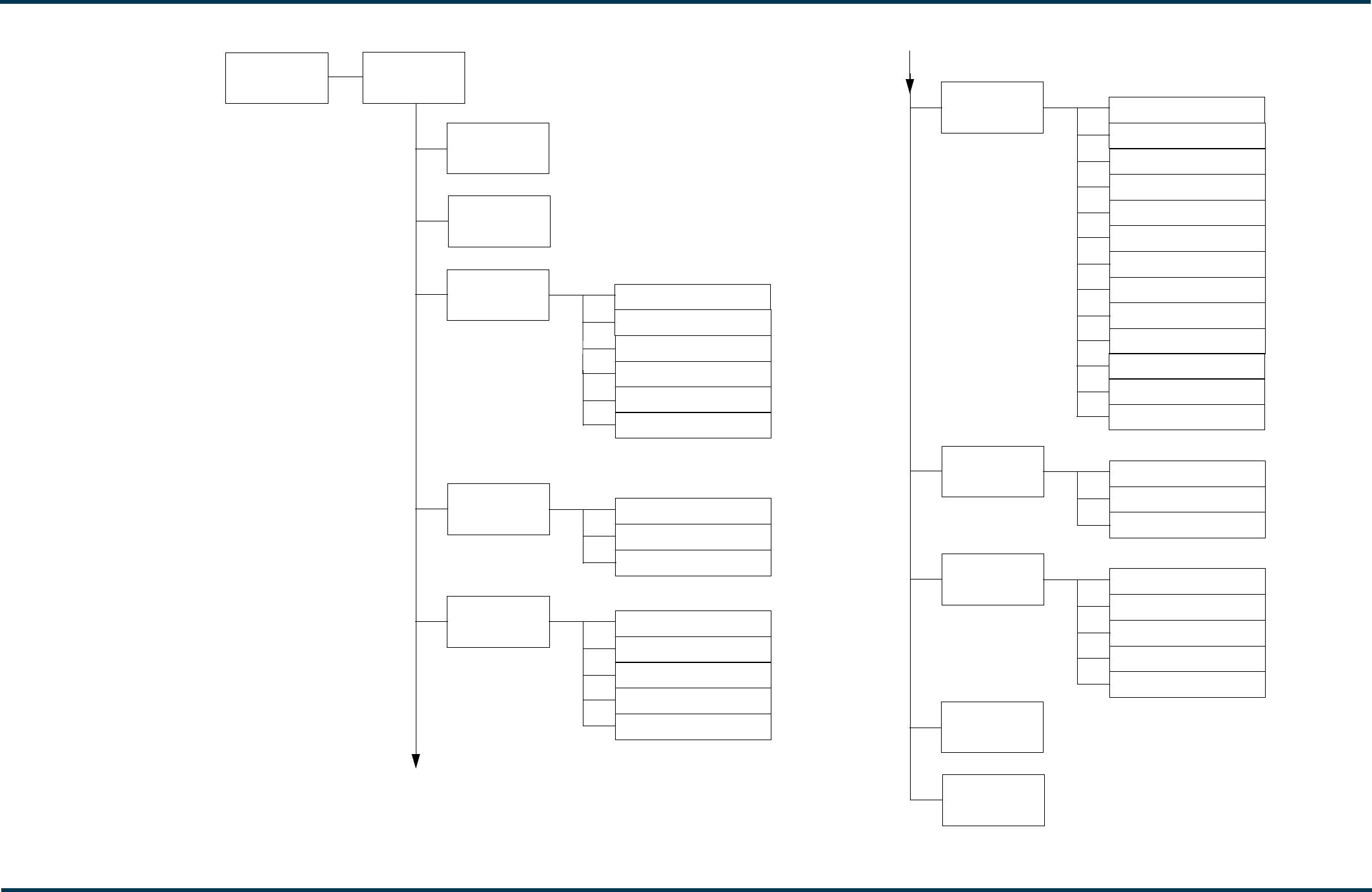
Issue 0.1 2011-03-11 Page 2-3
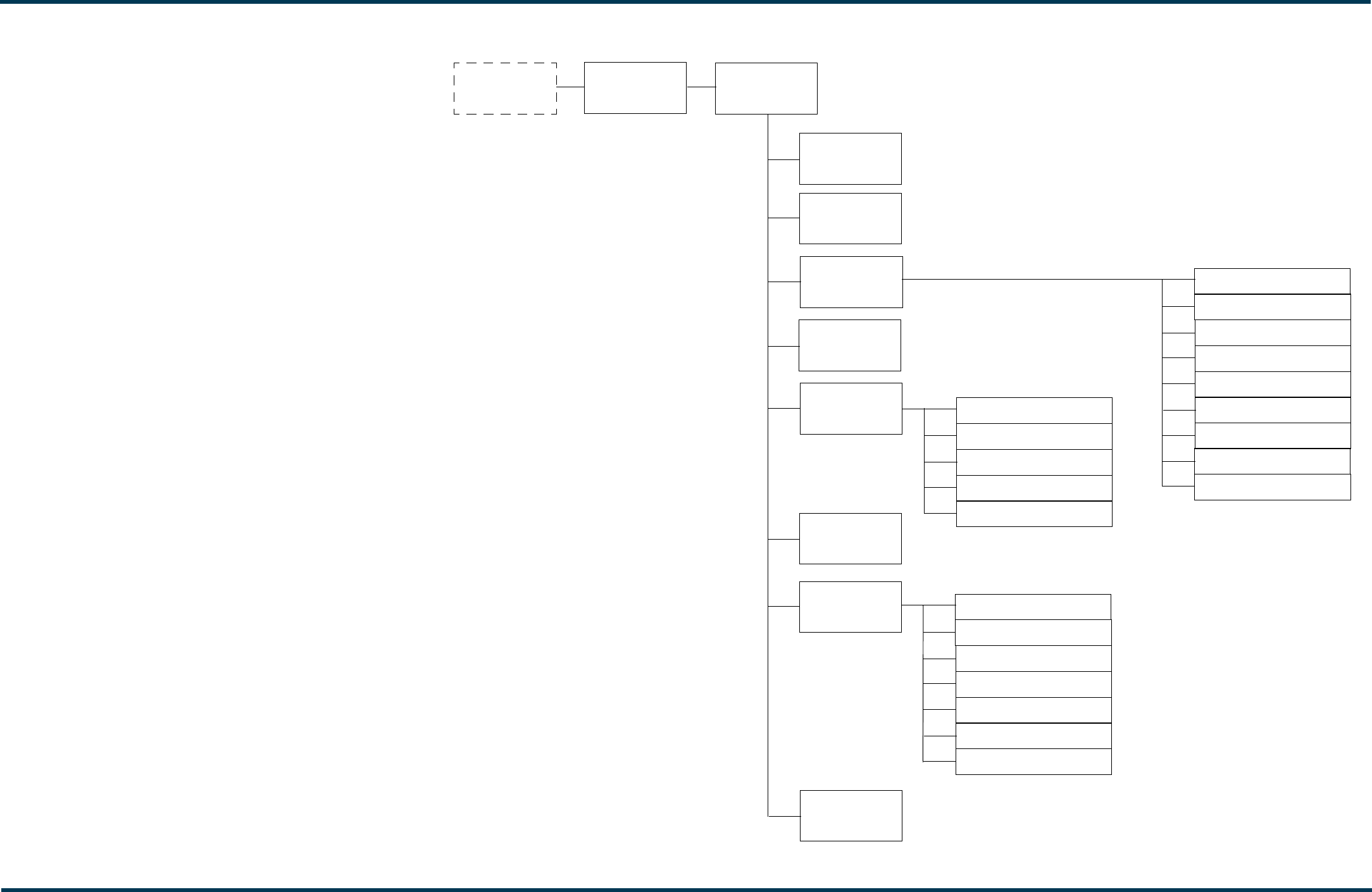
Figure 2-1: VS Transmitter Front Panel Display Menu Tree (Sheet 1 of 2)
Main Menu
Top Level
Status Screen
Select Preset
User Settings
First Time
Setup Screens
RF On/Off
View Status
displayed during
initial turn-on only
Help
Local/Remote
Reset Alarms
System Settings
FRONT PANEL UI
View Alarms
View Meters
View Log
Clear Log
Thresholds
ARM Watchdog
Console Select
Calibration
RF Drive Source
ARM Reset
OS Recovery
Edit Presets (see Fig. 2-2)
Remote I/O
Set Clock
Network Settings
Pilot Sample
LCD Settings
Signal Gen
View SW Versions
Station ID
Ext. 10 MHz Input
Issue 0.1 2011-03-11 Page 2-4
Figure 2-2: VS Transmitter Front Panel Display Menu Tree - Edit Presets (Sheet 2 of 2)
Edit Presets
Select Preset to
Edit or Create
New Preset
Frequency
Main Audio
Output Power
Source
Stereo Mode
Preemphasis
Low Pass Filter
Pilot Settings Level
Phase
1 PPS Sync
SCA Settings SCA Reduction
MPX SCAs
MPX SCA Input
Internal SCA 1
Internal SCA 2
RDS Settings Enable
Data Source
Baud Rate
RDS Level
Limiter Settings Hard Limiter
AGC Limiter
2-Slope Limiter
Audio Loss Enable
Threshold
Timeout
Action
Preset
RDS Phase
PS Name
PI Code
Program Type
Traffic Flags
Music/Speech
DI Code
AF Data
Local Echo
Copy Another
Preset
Audio Delay
Input Levels
Audio Player
FRONT PANEL UI

Issue 0.1 2011-03-11 Page 2-5 (2-6 blank)
Figure 2-3: VS Transmitter AUI Flow Diagram
Menu (Return to)
Home
HOME PAGE
Presets
System
Review
General
Main Audio
SCA
Controller
Exciter
Hardware Exciter TCXO
Audio Input Calibration
Miscellaneous
User Accounts Username
Password
User Role
Software Network Setup
Upgrade Software
Email Configuration
Notifications
Upload Files
RDS
Other Audio
Remote I/O Inputs
Outputs
Status
(Transmitter
Status)
Log
Audio Player
REMOTE AUI
VS300 Operations and Maintenance Manual Operating the transmitter
Issue 0.1 2011-03-11 Page 2-7
User interface
The user can interface with the VS300 using one of two methods:
• Locally, using the front panel display and navigational buttons (see “Front panel UI”).
• Remotely, via a LAN connection, using the advanced user interface (AUI) pages (see
“Advanced user interface” on page 2-12)
See the complete menu hierarchy illustrated in Figures 2.1 and 2.2 (for the local front panel menu)
and Figure 2.3 (for the remote AUI menu). When a user interfacing function can be performed from
both the front panel display and the remote AUI, both are described in this section.
Front panel UI
The front panel UI is 4 x 20 character LCD display (see Figure 2.5). The UI can be controlled by its
adjacent keypad. The UI contains a menu-based series of pages that serve specific functions. Similar
interfacing, as well as more advanced functionality, is available on the remotely accessed AUI (see
“Front panel UI screens” on page 2-9).
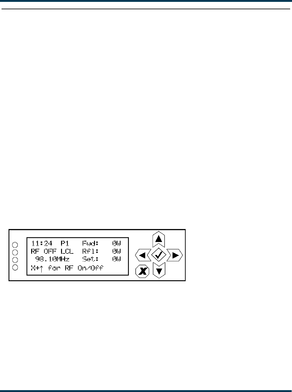
LCD display
This display shows all the UI screens. The display’s top level screen, used for viewing purposes only,
is shown in Figure 2.4.
Figure 2.4: Top Level Screen
The top level screen displays the following information:
• Line 1: current time, active preset (P#) and the transmitter’s actual forward power.
• Line 2: RF operating status (ON or OFF), the local (LCL) or remote (RMT) control status
and the transmitter’s reflected power level.
• Line 3: operating frequency and the desired power setpoint.
• Line 4: instructions to turn the transmitter’s RF power stage on or off.
VS300 Operations and Maintenance Manual Operating the transmitter
Page 2-8 Issue 0.1 2011-03-11
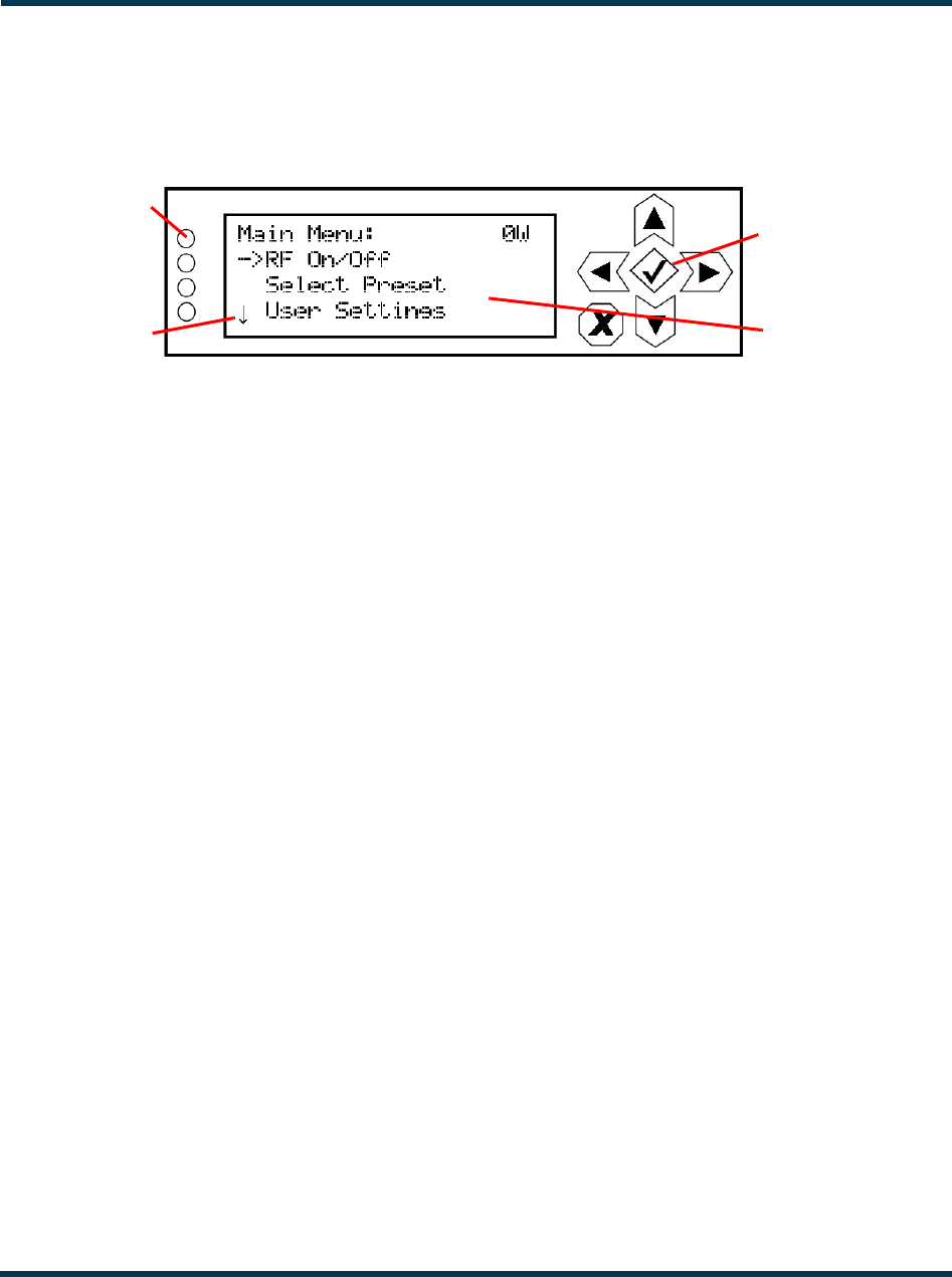
Main menu
This main menu is the starting point for navigating through the UI screens. See Table 2.1 on page 2-
9 for a list of screens and their basic functions.
Figure 2.5: Main Menu
Navigational buttons
There are six push-buttons on the right-hand side of the LCD display that allow navigation through
the UI pages, as well as modifying selected settings.
– Up and down - on menu and list screens, moves cursor up and down through the
associated page; on edit screens, increases and decreases the value of a parameter being
modified.
– Left - on menu and list screens, exits to the next higher level screen; on edit screens,
moves the editing cursor left, as applicable.
– Right - on menu and list screen, goes to the next lower level screen; on edit screens,
moves the editing cursor right, as applicable.
– Checkmark - on menu screens, goes to the next lower level screen; on edit screens, acts
as an “accept” or “save” function; in some cases the display will prompt its use.
– X - on menu and list screens, exits to the next higher level screen; on edit screens, acts as
a “cancel” function; in some cases the display will prompt its use.
Turning RF on and off
From any UI screen, pressing X and the up arrow simultaneously, toggles the RF on/off status. You
can also use the Main Menu -> RF On/Off screen to toggle the status.
Saving settings
Many of the UI screens allow for modifying a selected setting. Use the checkmark button to save a
change. Use the X button to cancel a change and revert back to the previously stored value.
LEDs
There are four LEDs on the left-hand side of the LCD display that provide the operational status of
various sections of the transmitter - Exciter, Power Amplifier, Output Network and Power Supply
(see Figure 2.5 on page 2-8). The LEDs can glow green, amber or red. Typically, green indicates
normal operation, amber indicates a warning, and red indicates a fault or error. Refer to the
Troubleshooting section for more detailed information on LED status.
Navigational
Buttons
LCD Display
LEDs
Cursor

VS300 Operations and Maintenance Manual Operating the transmitter
Issue 0.1 2011-03-11 Page 2-9
Front panel UI screens
Table 2.1 defines the available front panel display screens.
Table 2.1: Front Panel UI Screens
UI Screen Function See Page
First Time Setup Screens Guides the user through initial setup of the transmitter.
Provides prompts to set frequency, output power and audio
input. Refer to the VS Series Quick Start Guide, provided in
the transmitter’s packing box, for details.
VS Series
Quick-Start
Guide
Main Menu Choose options and navigate to other screens. page 2-8
Select Preset Select and activate a user-defined preset. page 2-40
User Settings Edit various transmitter user settings (see other User
Settings options in this table).
-
User Settings - Edit Presets Edit various parameters for a user-defined preset (see the
following rows for all Edit Presets options).
page 2-40
User Settings - Edit Presets
- Output Power
Edit the selected preset’s output power. page 2-42
User Settings - Edit Presets
- Frequency
Edit the selected preset’s operating frequency. page 2-42
User Settings - Edit Presets
- Main Audio
Edit the selected preset’s main audio characteristics such
as source, stereo mode, pre-emphasis and low pass
filtering.
page 2-42
User Settings - Edit Presets
- Audio Inputs
Edit the selected preset’s audio input type. page 2-38
User Settings - Edit Presets
- Pilot Settings
Edit the selected preset’s pilot settings such as level, phase
and 1 PPS synchronization.
page 2-45
User Settings - Edit Presets
- SCA Settings
Edit the selected preset’s SCA settings such as SCA
reduction, MPX SCAs, MPX SCA input and internal SCA (1
and 2) generator characteristics.
page 2-46
User Settings - Edit Presets
- RDS Settings
Edit the selected preset’s RDS settings such as enable/
disable, data source, baud rate, level, phase, program type,
alternate frequency data, etc.
page 2-48
User Settings - Edit Presets
- Limiter Settings
Edit the selected preset’s limiter settings. Limiter types
include hard limiter, AGC limiter or 2-slope limiter.
page 2-52

VS300 Operations and Maintenance Manual Operating the transmitter
Page 2-10 Issue 0.1 2011-03-11
User Settings - Edit Presets
- Audio Loss
Edit the selected preset’s audio loss functionality, such as
enable/disable, setting threshold, setting timeout period,
setting resulting action and selecting a backup preset.
page 2-54
User Settings - Edit Presets
- Audio Delay
Edit the selected preset’s audio delay. page 2-56
User Settings - Edit Presets
- Copy Another Preset
Copy the selected preset’s settings to another preset. page 2-56
User Settings - Remote
I/O
Configure the remote inputs and outputs for the transmitter. page 2-86
User Settings - Set Clock Set precise time and date. page 2-36
User Settings - Network
Settings
View and/or set network information such as MAC address
(view only), DHCP on/off status, IP address, netmask and
gateway.
page 2-64
User Settings - Pilot Sample Set the pilot sample level for the rear panel BNC connector. page 2-92
User Settings - LCD Settings Set the front panel display’s contrast, backlight and timeout. page 2-93
User Settings - Signal Gen Enable/disable and setup the internal signal generator. page 2-95
User Settings - Station ID Set station ID parameters for re-broadcasting primary
information as a secondary station.
page 2-97
User Settings - Ext. 10 MHz
Inp
Enable/disable the use of an external 10 MHz signal. page 2-100
Local/Remote Select local or remote control of the transmitter. page 2-57
View Status View various transmitter parameters (see other View Status
options in this table).
-
View Status - View Alarms View all active transmitter alarms. page 2-24
View Status - View Meters View the levels of various transmitter parameters, including
forward power, reflected power, PA voltage, PA current and
low level dc supply voltages.
page 2-34
View Status - View Log View the transmitter’s events log, including alarms,
commands, etc.
page 2-24
Table 2.1: Front Panel UI Screens
UI Screen Function See Page

VS300 Operations and Maintenance Manual Operating the transmitter
Issue 0.1 2011-03-11 Page 2-11
View Status - Clear Log Clear the transmitter’s events log. page 2-24
View Status - View SW
Versions
View the versions of software installed on the transmitter. -
Reset Alarms Initiate an attempt to reset all alarms controlled by latched
protection circuits.
page 2-57
System Settings Edit various transmitter system settings (see other System
Settings options in this table).
-
System Settings -
Thresholds
Factory set; no user adjustments required. -
System Settings - ARM
Watchdog
Enable, disable or force a reset of the ARM watchdog
feature.
page 2-78
System Settings - Console
Select
Factory set; no user adjustments required -
System Settings -
Calibration
Set calibration values or run calibration routines for various
parameters (e.g., TCXO offset, forward/reflected power,
program input levels, etc.).
page 2-79
System Settings - RF Drive
Source
Select either internal or external exciter. page 2-83
System Settings - ARM
Reset
Initiate a reset of the exciter/control PWB’s ARM processor page 2-84
System Settings - OS
Recovery
Initiate a recovery reset of the operating system in the event
of a failed software upgrade.
page 2-85
Table 2.1: Front Panel UI Screens
UI Screen Function See Page
VS300 Operations and Maintenance Manual Operating the transmitter
Page 2-12 Issue 0.1 2011-03-11
Advanced user interface
The VS300’s advanced user interface (AUI) (see Figure 2.6) is available via remote connection only.
To access the AUI, you need a PC (and a web browser) that is connected to the VS300 - directly or
through a switch - via its rear panel LAN connection (A1J8A). The AUI has a wide range of displays,
including:
– Tool menu panels (spectrum analyzer, signal constellation, Lissajous plot, etc.)
– Real-time meters
– Detailed transmitter status and events log
–Presets
– Hardware configuration
– User accounts
– Software configuration
– Remote input/output configuration
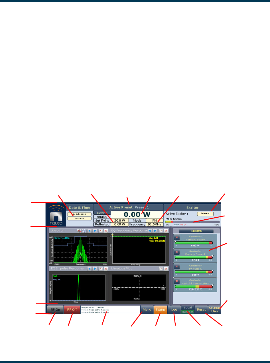
Each AUI page provides information about a specific transmitter function. All navigation through
the AUI pages begins on the main screen (or Home page), shown in Figure 2.6.
Figure 2.6: Using the AUI (Home page shown)
RF On Menu
Forward
Date,
Time
Modulation
Level
RF Off Status Local/
Top
Banner
Bottom
Banner
Events
Remote
Reset
Tool Menu
Panel
Displays
(up to 4 on
screen or
one full
screen)
Log
Power
Mode,
Frequency
Set Point,
Reflected
Selected
Meters
Active
Exciter
Power
Active
Preset
Change
User
Activity
Window

VS300 Operations and Maintenance Manual Operating the transmitter
Issue 0.1 2011-03-11 Page 2-13
The top banner is permanent on all AUI pages and includes:
Nautel Logo: From any AUI page, click the Nautel logo to return to the Home page.
Date & Time: Displays day, month, year and current time. Click on date or time to shortcut to the
Set Time and Date window (see Setting time and date on page 2-35).
Active Preset: Displays the name of the active preset, power set point based on the active preset,
current forward power and reflected power levels, as well as the operating mode and carrier
frequency.
Active Exciter: Displays the active exciter (internal or external) and the FM modulation, with rms
(yellow) and peak (red) values.
The bottom banner is also permanent on all AUI pages and includes:
RF On: Click to enable the transmitter’s RF power stage.
RF Off: Click to disable the transmitter’s RF power stage.
Activity Window: Displays various messages to reflect specific user interface commands, such as RF
on/off, local/remote control, or reset.
Menu: Click to open the Menu page, which allows navigation to various other pages (see Menu page
on page 2-16).
Status: Click to shortcut to the Transmitter Status page (see Viewing transmitter status on page 2-
35), which provides current alarm and status details for the transmitter. When the Status button is
red, one or more alarms of severity level 10 is currently being reported, and the transmitter is in an
‘off-air’ state. When the Status button is orange, one or more alarms of severity level 5 (but none of
severity level 10) is currently being reported, but the transmitter is still ‘on-air’, possibly at reduced
power. When the Status button is green, the transmitter is operating normally. In this case, there are
no alarms being reported, or there is one or more alarms of severity level 1 (but none of severity level
5 or 10). This page is also available through the Menu page.
Log: Click to shortcut to the Transmitter Log page, which displays historical alarm and status records
for the transmitter (see Viewing transmitter log on page 2-18).
VS300 Operations and Maintenance Manual Operating the transmitter
Page 2-14 Issue 0.1 2011-03-11
Local/Remote: Displays the operational control status of the transmitter. Click the desired button to
select local or remote. If Local is highlighted, remote users cannot change any settings. Similarly, if
Remote is highlighted, local users cannot change the transmitter status, except for RF Off and Local/
Remote. To change the local/remote status from the front panel display, see “Setting local/remote
control” on page 2-57
Reset: Resets protection circuits and power supplies that were inhibited, but are now alarm-free. To
initiate an alarm reset from the front panel display, see “Resetting alarms” on page 2-57
Change User: Click to display a login menu. Using your remote keyboard, enter your Username and
Password, then click OK. If you do not have a user account, see “Setting user accounts” on page 2-59.
The displays between the top and bottom menus, contains user selected pages. These pages provide
access to a variety of AUI functions such as transmitter status and hardware settings. The following
paragraphs describes how to use these pages.
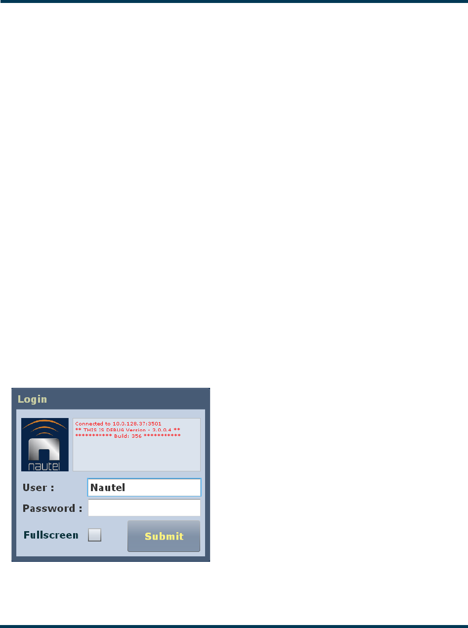
Logging in to the AUI
The transmitter’s remote AUI provides a means to restrict access of transmitter control functions to
authorized users only.
To access the AUI using a web browser, you must configure your network settings (see “Network
setup” on page 2-64). On the computer being used to remotely access the AUI, enter the VS300’s IP
address into the Internet browser’s address bar and then log in to the AUI application via the login
menu (see Figure 2.6).
Figure 2.6: AUI Login Menu
Enter your User name (default is “Nautel”) and Password (default is blank), then click Submit. If you
do not have a user account, see “Setting user accounts” on page 2-59.

VS300 Operations and Maintenance Manual Operating the transmitter
Issue 0.1 2011-03-11 Page 2-15
AUI pages
Table 2.2 defines the available AUI pages.
Table 2.2: AUI Pages
AUI Page Function See Page
Home View meters, tool menu panels, choose options and
navigate to other pages.
page 2-12
Menu Choose options and navigate to other pages. page 2-16
Log View and analyze transmitter events . page 2-18
Tool Menu Choose tool menu panel options. page 2-25
System Review Choose meters for display. page 2-32
Set Time & Date Set precise time and date. page 2-35
Presets Activate and edit user-defined presets. page 2-37
Transmitter Status View transmitter’s current active faults and operational
status.
page 2-58
User Accounts Set user permission rights and define user account
information.
page 2-59
Software Calibrate and refresh the AUI screen, restart the
server, set network information, perform software
upgrades and configure email and alarm notification
parameters.
page 2-62
Hardware Define system configuration and set/calibrate
transmitter parameters and thresholds.
page 2-79
Remote I/O Define remote digital inputs and outputs. page 2-86
VS300 Operations and Maintenance Manual Operating the transmitter
Page 2-16 Issue 0.1 2011-03-11
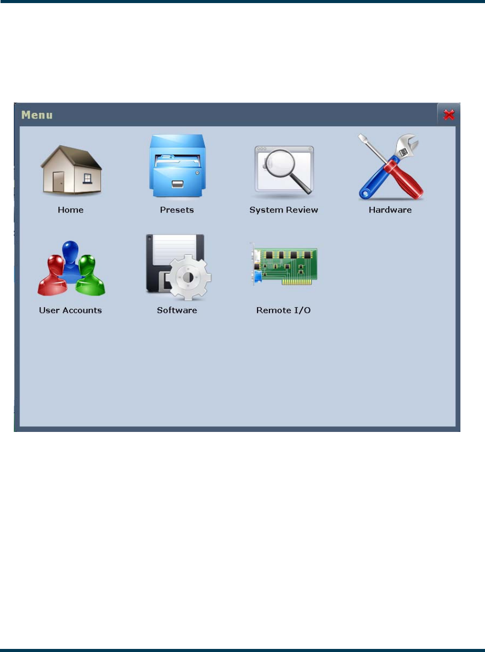
Menu page
From the home page, click the Menu button to view the Menu page (see Figure 2.7). From this page,
you can select one of the following sub-menus:
Figure 2.7: Menu Page
Select Home to return to the home page (see Figure 2.6 on page 2-12).
Select Presets to load, edit, or save presets (see “Managing presets” on page 2-37).
Select System Review to view the meters of various parameters relating to the controller, exciter,
power supplies and RF components (see “Viewing real-time meters” on page 2-32).
Select Hardware to access pages that allow system configuration, setting/calibrating transmitter
parameters and thresholds, setting IBOC parameters and storing LUT data to active exciter (see
“Changing hardware settings” on page 2-64).

VS300 Operations and Maintenance Manual Operating the transmitter
Issue 0.1 2011-03-11 Page 2-17
Select User Accounts to access a page that displays a list of users with access to the AUI and,
depending on permission level, allows editing of user accounts (see “Setting user accounts” on
page 2-59).
Select Software to access a page that provides help with performing network configuration, software
upgrades, email configuration, alarm notifications, uploading files, audio player setup and livewire
setup (see “Software configuration” on page 2-62).
Select Remote I/O to access a page that allows assignation of remote digital inputs and digital outputs
(see “Configuring remote inputs and outputs” on page 2-82).
VS300 Operations and Maintenance Manual Operating the transmitter
Page 2-18 Issue 0.1 2011-03-11
Viewing transmitter log
You can view transmitter log information using the remote AUI (see “Using the AUI”) or using the
local front panel display (see “Using the front panel” on page 2-24).
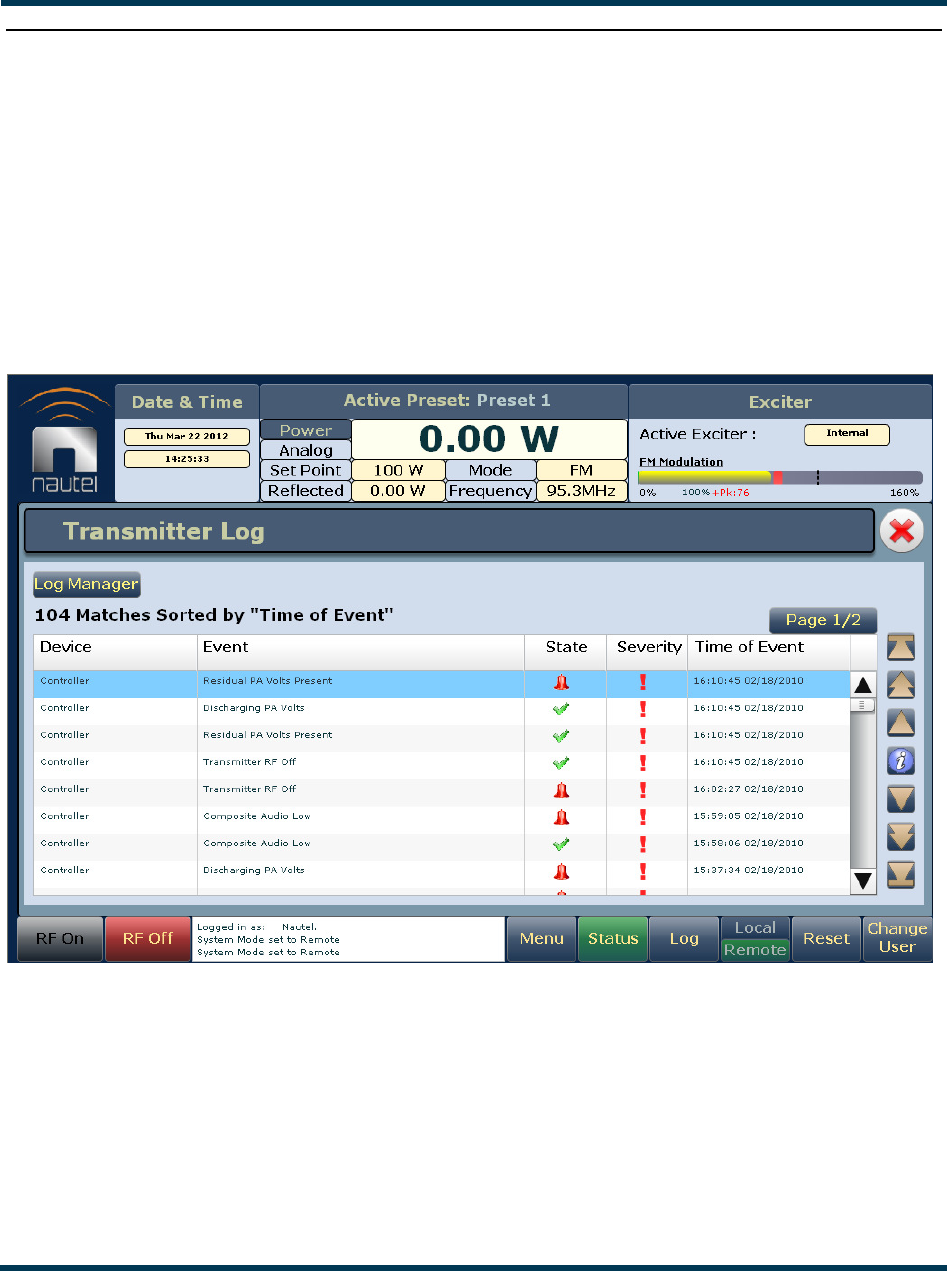
Using the AUI
You can view the VS300’s events log using the AUI’s Log page - see Figure 2.8. This page shows a
configurable log of all transmitter events. To view the Log page, click the Log button in the bottom
banner of any AUI screen.
Figure 2.8: Log page
The main screen displays a chronological listing of events. Depending on the selections made in the
Log Manager screen (see “Managing the log” on page 2-12), the events displayed may be filtered by
the originating device (Controller, Exciter or All), and the time of occurrence.
Refer to the VS300 Troubleshooting Manual to cross-reference the alarm name to possible causes and
troubleshooting tips.

VS300 Operations and Maintenance Manual Operating the transmitter
Issue 0.1 2011-03-11 Page 2-19
The number of log matches displayed is shown below the Log Manager button (e.g., 104 Matches
Sorted by “Time of Event”). You can scroll through the list using the scroll bar or the up and down
arrow buttons to the right of the scroll bar. When there are more than 100 matches in the list, a
Page #/# tab will appear to allow viewing of further listings. In this case, click on Page #/#, select
the desired page from the Select Page window, then click OK to view that page or Cancel to return
to the Transmitter Log page. The columns in the display indicate specific information about the
event:
–Device indicates the origin device of the event (Controller, Exciter or All).
–Event indicates the event name.
–State indicates whether the event is active (red bell) or cleared (green checkmark) and in
some cases, indicates whether the RF was turned on or off (see Legend under Log
Manager, Figure 2.14 on page 2-23).
–Severity indicates how the event affects transmitter operation [a single orange ! indicates
low severity (RF output not affected); a single red ! indicates medium severity (RF output
is reduced); three red ! indicates high severity (RF output is inhibited)].
–Time of Event indicates the time and date that the event that occurred.
With an event highlighted, click the i button on the right-hand side of the display to view that specific
event’s details (see “Event Information page” on page 2-17). This page is similar to the Transmitter
Status page (see “Transmitter Status page” on page 2-58), except that it is a snapshot taken at the
exact time at which the event occurred. The Alarms tab lists all events that were active at the time of
the selected event, by name and severity [1 = low (RF output not affected), 5 = medium (RF output
is reduced), 10 = high (RF output is inhibited)]. The Meters tab allows selection of various metered
parameters to view for troubleshooting purposes. You can also select a time span (between 1 second
and 24 hours) when viewing Meters. The time of the event is always the centre point of the time span
(e.g., if you select a timespan of 10 Minutes, then the meter indications will span from 5 minutes
before the event to 5 minutes after the event).
Managing the log
You can manage the VS300 AUI’s events log by clicking on the Log Manager button (see
Figure 2.9). This screen provides options to perform various event monitoring operations such as
filtering, copying, deletion and statistical analysis. Click X to close this window.
Figure 2.9: Log Manager options
VS300 Operations and Maintenance Manual Operating the transmitter
Page 2-20 Issue 0.1 2011-03-11
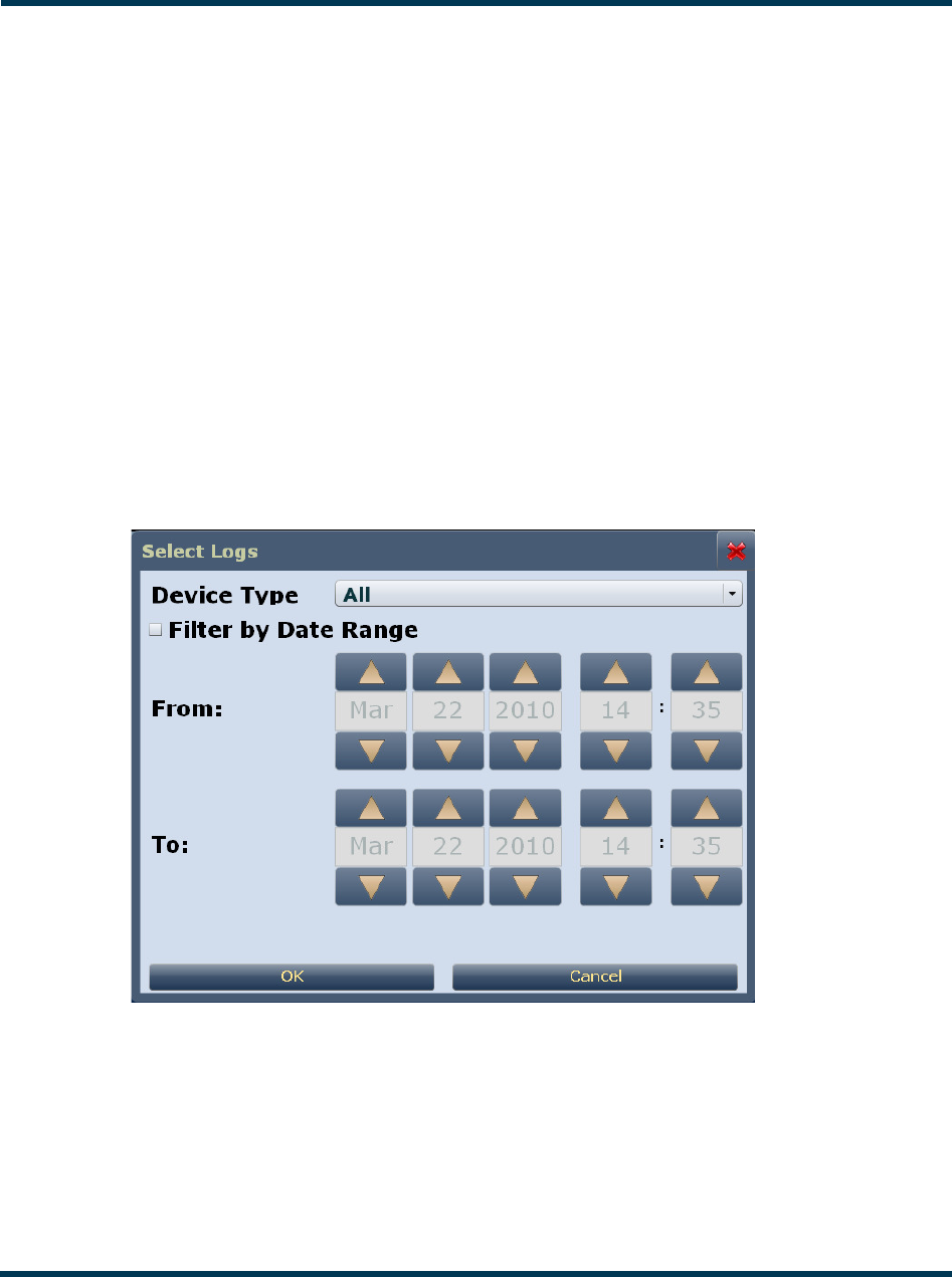
Filter
You can filter transmitter events based on their origin or date by clicking the Filter button in the log
manager (see Filter - Select Logs - see Figure 2.10).
Click the Device Type drop-down arrow, and select the desired device type to filter events based on
the type selected. Click the OK button or the Cancel button when done.
–All - displays all transmitter events
–Controller - displays controller events only
–Exciter - displays exciter events only
Click the Filter by Date Range checkbox to filter events based on a specific date and time range, and
the device type selected. Click the OK button or the Cancel button when done.
Click the Cancel button or X to close this window and discard changes.
Figure 2.10: Filter - Select Logs
VS300 Operations and Maintenance Manual Operating the transmitter
Issue 0.1 2011-03-11 Page 2-21
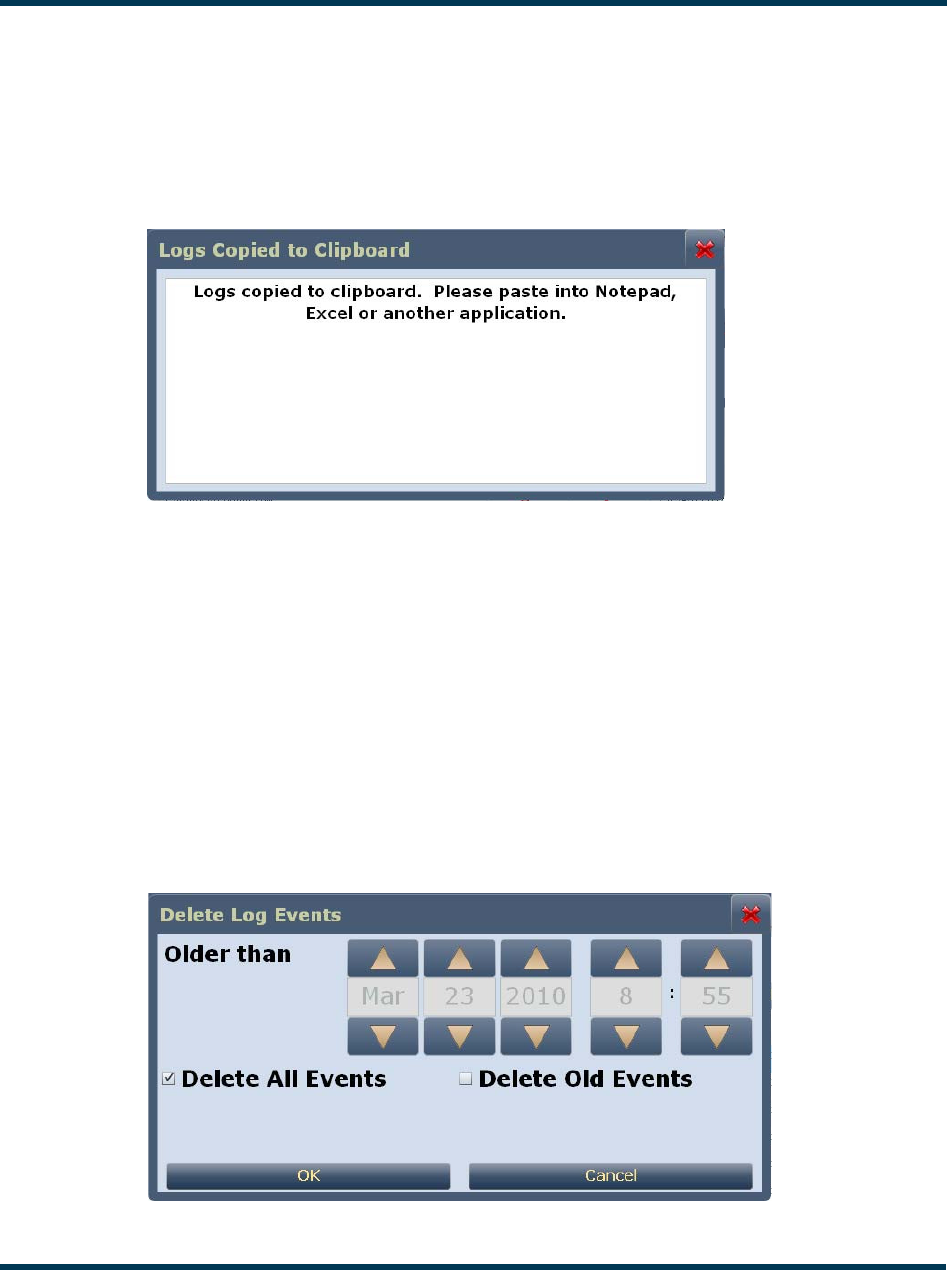
Copy
You can create a copy of all the logs in the selected list (copied to the remote user’s computer
clipboard) by clicking on the Copy button in the log manager (see Copy Logs - see Figure 2.11). You
can paste the tab-delimited text copy of the logs into a text editing program such as Word, Excel,
Notepad, etc. Click X to close this window.
Figure 2.11: Copy Logs
Delete
You can delete all events or a selection of events by clicking on the Delete button in the log manager
(see Delete Logs - see Figure 2.12).
Click the Delete All Events checkbox and click OK to delete all events.
Click the Delete Old Events checkbox to allow deletion of events that occurred prior to (Older
than) a specified date and time. Use the up and down arrows to select the date and time and click OK
to delete the specified events.
Click the Cancel button or X to close this window and discard changes.
Figure 2.12: Delete Logs
VS300 Operations and Maintenance Manual Operating the transmitter
Page 2-22 Issue 0.1 2011-03-11
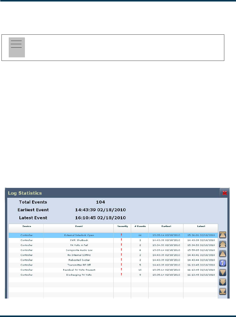
Statistics
You can view statistical information on the events being displayed by clicking on the Statistics
button in the log manager (see Log Statistics - see Figure 2.13).
The Log Statistics screen indicates the Total Events (number of occurrences) and the time and date
of the Earliest Event and the Latest Event. You can scroll through the list using the scroll bar (if
applicable) or the up and down arrow buttons to the right of the scroll bar. The columns in the
display indicate specific information about the events:
–Device indicates the origin device of the event (Controller, Exciter or All).
–Event indicates the event name.
–Severity indicates how the event affects transmitter operation [a single orange ! indicates
low severity (RF output not affected); a single red ! indicates medium severity (RF output
is reduced); three red ! indicates high severity (RF output is inhibited)].
–# Events indicates the number of occurrences of that event during the filtered period.
–Earliest indicates the time and date of the first event, within the filtered period.
–Latest indicates the time and date of the latest event, within the filtered period.
Click X to close this window.
Figure 2.13: Log Statistics
Note:
Only the events subject to the user-defined filtering parameters will be displayed on the Log
Statistics screen.
VS300 Operations and Maintenance Manual Operating the transmitter
Issue 0.1 2011-03-11 Page 2-23
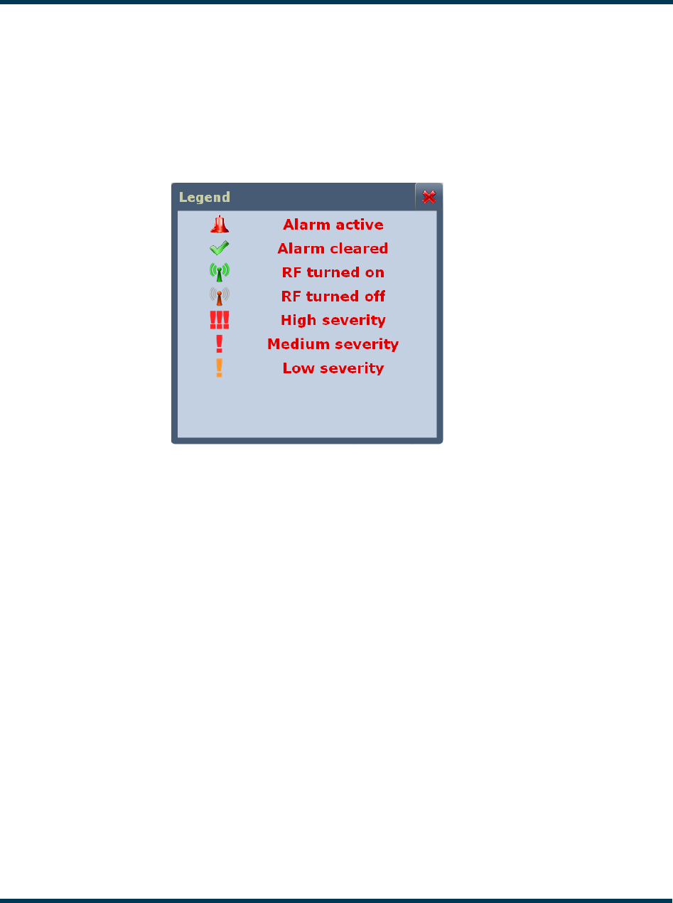
Legend
Click on the Legend button in the log manager (see Figure 2.14) to display a legend that describes the
meaning of the symbols shown in the State and Severity columns of the Log page.
Click X to close this window.
Figure 2.14: Log Manager - Legend
Use the Reset button at the bottom of any AUI screen to attempt to clear any latching alarms that are
holding the transmitter in an “off-air” state. If the offending alarm has cleared, the transmitter should
resume operation. See “Reset:” on page 2-14.
VS300 Operations and Maintenance Manual Operating the transmitter
Page 2-24 Issue 0.1 2011-03-11
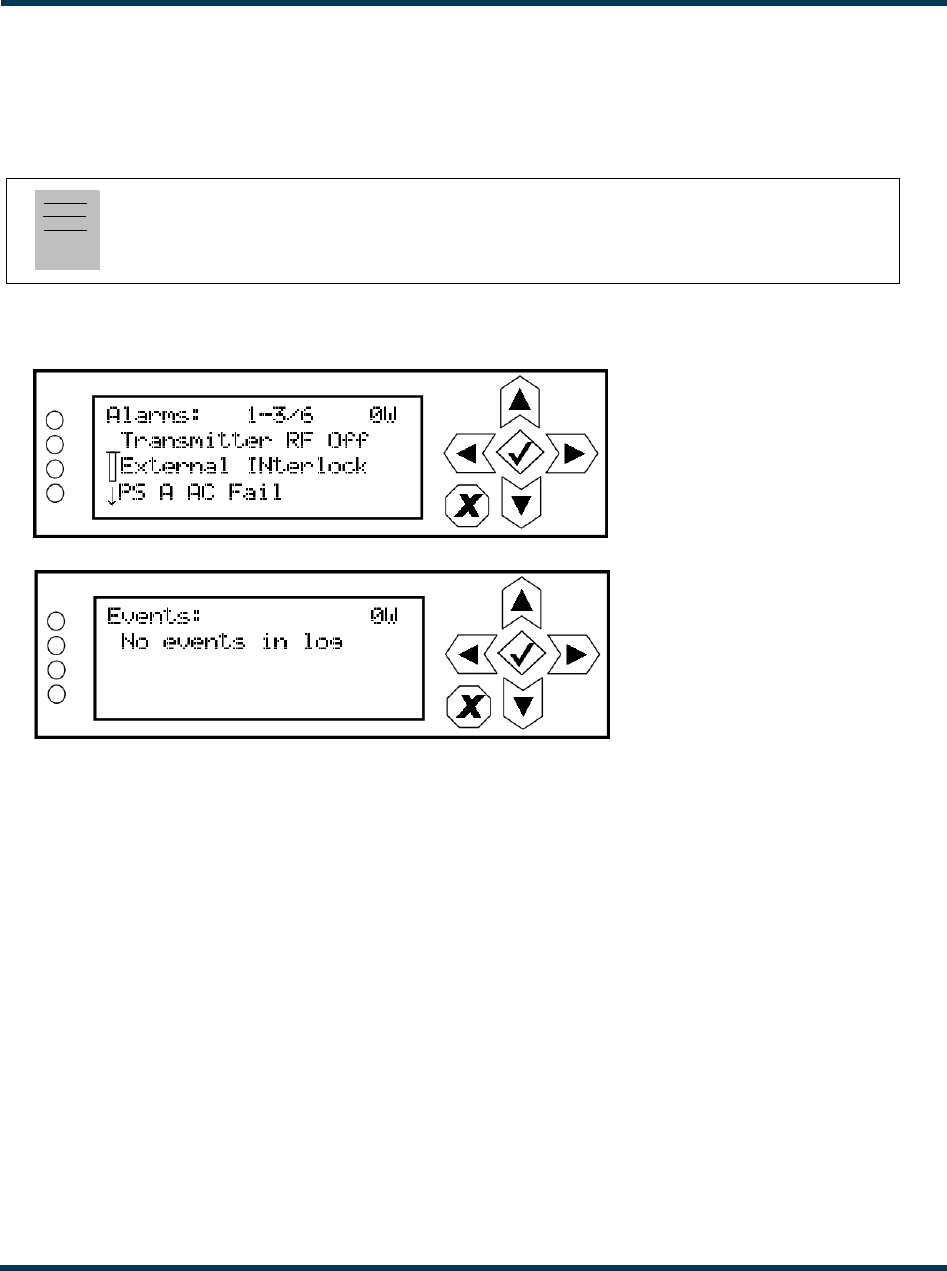
Using the front panel
When you select View Status -> Alarms or View Status -> View Log from the Main Menu (see
Figure 2.15), you can view various active or logged events, respectively, of the VS300. These
parameters are displayed on multiple pages of Meters screens.
Figure 2.15: View Alarms and View Logs Screens
The View Alarms screen displays only alarms that are currently active. Older alarms that have cleared
may still be present in the View Events screen.
Use the up and down buttons to scroll through the list of alarms or events.
Refer to the VS300 Troubleshooting Manual to cross-reference the alarm name to possible causes and
troubleshooting tips.
When you select Clear Log from the View Status menu, you will delete all logged events.
Use the Reset Alarms command in the front panel UI’s Main Menu -> Reset Alarms screen to
attempt to clear any latching alarms that are holding the transmitter in an “off-air” state. If the
offending alarm has cleared, the transmitter should resume operation. See “Resetting alarms” on
page 2-57.
Note:
This screen is for viewing purposes only and does not offer the same level of analytical features as
the AUI’s Log page (see Figure 2.8 on page 2-18).
VS300 Operations and Maintenance Manual Operating the transmitter
Issue 0.1 2011-03-11 Page 2-25
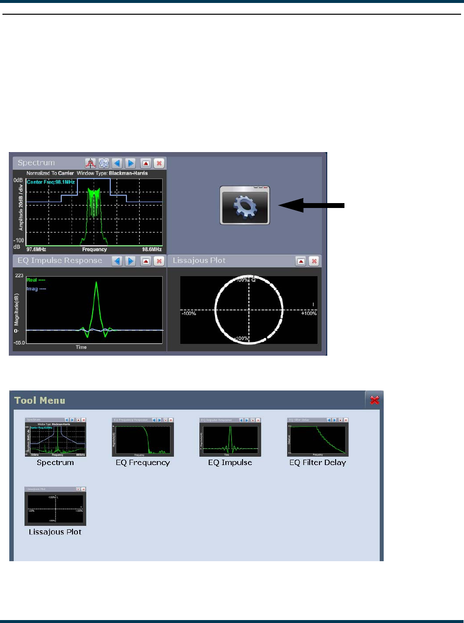
Viewing tool menu panels
The VS300 AUI provides five tool menu panels that you can choose to display on the AUI home
page (see Figure 2.16). Up to four tool menu panels can be displayed at one time, including a
spectrum analyzer. To view all the tool menu options (see Figure 2.17), close one of the existing tool
menu panels on the Home page by clicking X in the top, right corner of the tool menu panel, and
then click anywhere in the blank space (see Figure 2.16).
Figure 2.16: Tool Menus on Home page
Figure 2.17: Tool Menu Options
Click on the desired tool menu panel to display it. See Table 2.3 on page 2-26 for a description of
each tool menu panel.
Click in this space
to view the Tool
Menu options
(see Figure 2.17)

VS300 Operations and Maintenance Manual Operating the transmitter
Page 2-26 Issue 0.1 2011-03-11
Table 2.3: Tool Menu Panels
Tool Menu Description Reference
Spectrum Analyzer Displays a spectrum analyzer, capable of monitoring various
RF sections of the transmitter, including the RF output.
See page 2-27
EQ Frequency Displays the frequency response of the modulator’s EQ filter. See page 2-28
EQ Impulse Displays the impulse response of the modulator’s EQ filter. See page 2-29
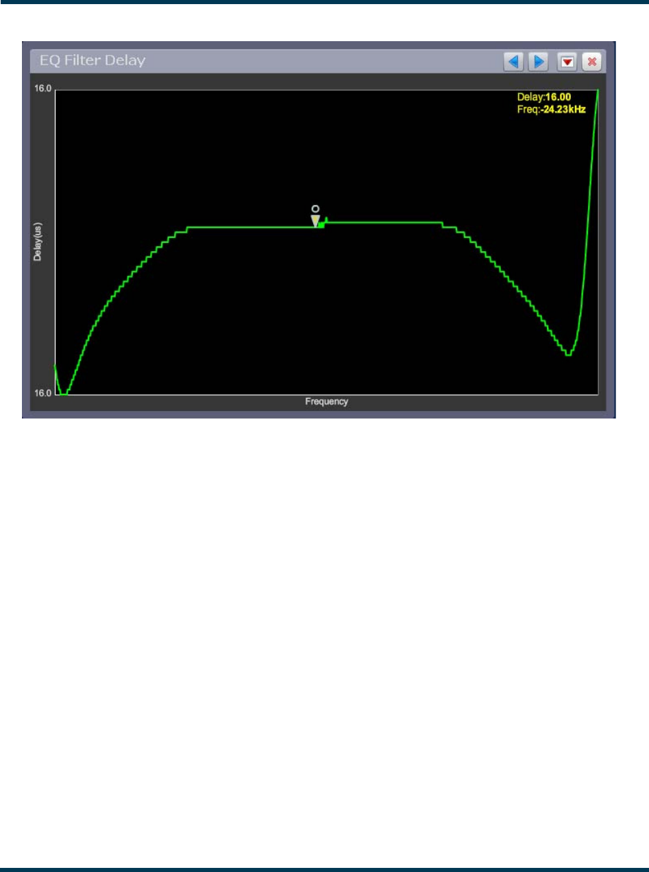
EQ Filter Delay Displays the delay of the modulator’s EQ filter across its
bandwidth
See page 2-30
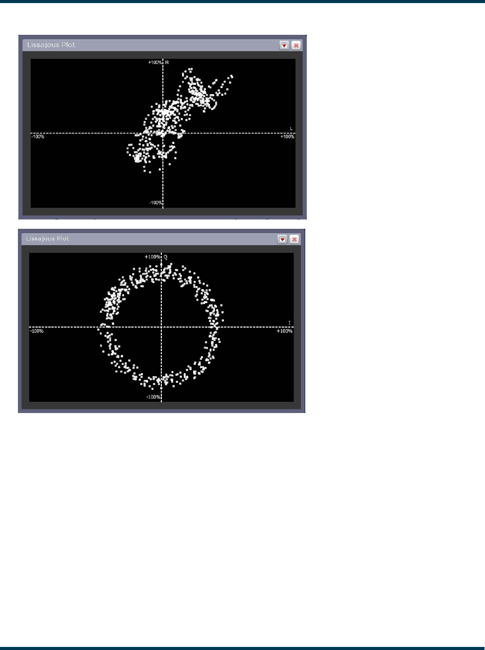
Lissajous Plot Displays a Lissajous figure that represents the relationship
between the two applicable channels (either L and R or I and
Q).
See page 2-31
VS300 Operations and Maintenance Manual Operating the transmitter
Issue 0.1 2011-03-11 Page 2-27
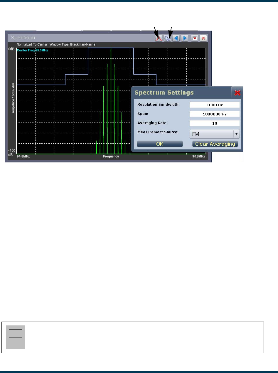
Figure 2.18: Spectrum Analyzer
Spectrum analyzer
See Figure 2.18. The carrier level is normalized to its unmodulated carrier level at 0 dB. Graph center
is always at the carrier frequency.
Click on the panel to display a cursor in the approximate area. The cursor position (frequency and
amplitude) is noted in the upper, right-hand corner of the panel. Click in other areas of the panel to
provide a coarse adjustment of the cursor position.
Use the left and right buttons to make fine adjustments to the cursor position.
Use the up or down button to maximize (if minimized) or minimize (if maximized) the panel size.
Use the “peak” button to place the cursor on the next successive peak in the spectrum.
Use the “cog” button to gain access to spectrum settings (see Figure 2.18) such as resolution
bandwidth, span, averaging rate and the actual measurement source (FM or MPX) that is being
displayed. Click OK to save changes or X to discard changes and close the window.
Note:
The FM spectrum analyzer displays the ideal spectrum generated by the DSP. It is not necessarily
the same as the spectrum seen at the RF output.
Peak Cog
VS300 Operations and Maintenance Manual Operating the transmitter
Page 2-28 Issue 0.1 2011-03-11
Equalizer screens
The VS300’s exciter includes a fixed equalizer to optimize audio perfomance. There are three menus
available in the tool panel - EQ Frequency, EQ Impulse Response and EQ Filter Delay. Coefficients
are selected based on your channel frequency. All frequencies shown are relative to the channel
frequency.
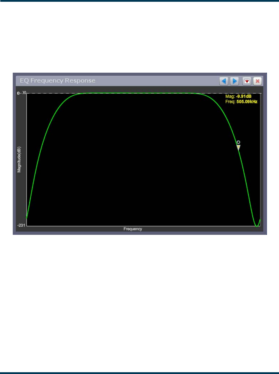
Figure 2.19: EQ Frequency
EQ frequency
See Figure 2.19. This panel displays the frequency response of the modulator’s EQ filter.
Click on the panel to display a cursor in the approximate area. The cursor position (magnitude and
amplitude) is noted in the upper, right-hand corner of the panel. Click in other areas of the panel to
provide a coarse adjustment of the cursor position.
Use the left and right buttons to make fine adjustments to the cursor position.
Use the up or down button to maximize (if it was minimized) or minimize (if it was maximized) the
panel size.
VS300 Operations and Maintenance Manual Operating the transmitter
Issue 0.1 2011-03-11 Page 2-29
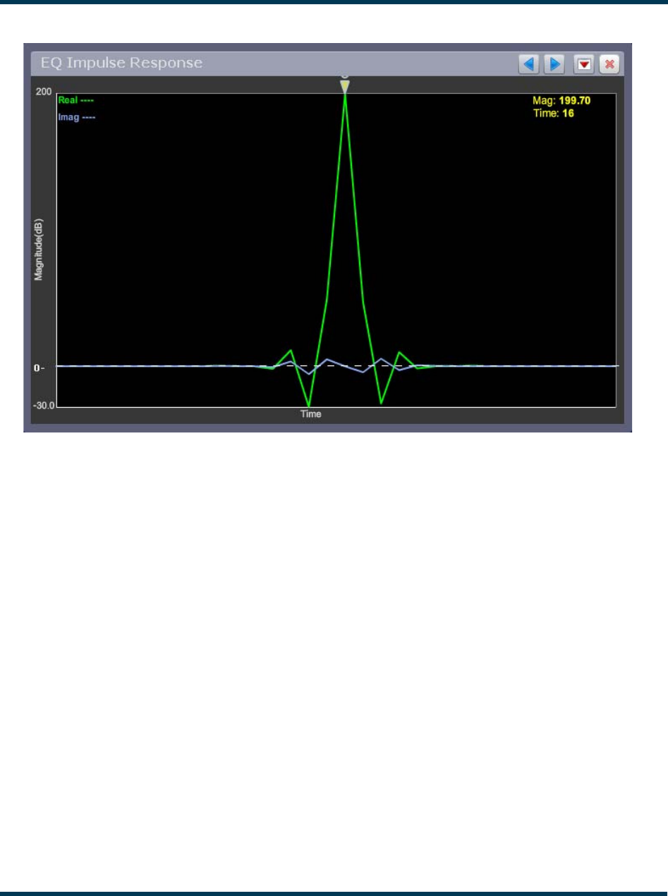
Figure 2.20: EQ Impulse
EQ impulse response
See Figure 2.20. This panel displays the impulse response of the modulator’s EQ filter.
Click on the panel to display a cursor in the approximate area. The cursor position (magnitude and
time) is noted in the upper, right-hand corner of the panel. Click in other areas of the panel to
provide a coarse adjustment of the cursor position.
Use the left and right buttons to make fine adjustments to the cursor position.
Use the up or down button to maximize (if it was minimized) or minimize (if it was maximized) the
panel size.
VS300 Operations and Maintenance Manual Operating the transmitter
Page 2-30 Issue 0.1 2011-03-11
Figure 2.21: EQ Filter Delay
EQ filter delay
See Figure 2.21. This panel displays the delay of the modulator’s EQ filter across its bandwidth.
Click on the panel to display a cursor in the approximate area. The cursor position (delay and
frequency) is noted in the upper, right-hand corner of the panel. Click in other areas of the panel to
provide a coarse adjustment of the cursor position.
Use the left and right buttons to make fine adjustments to the cursor position.
Use the up or down button to maximize (if it was minimized) or minimize (if it was maximized) the
panel size.
VS300 Operations and Maintenance Manual Operating the transmitter
Issue 0.1 2011-03-11 Page 2-31
Figure 2.22: Lissajous Plots
Lissajous plot
See Figure 2.22. This panel displays a Lissajous plot that represents either left and right audio content
or a representation of the FM modulated signal (I and Q). I and Q will be automatically selected when
using MPX as the main audio source. Left and right audio content is displayed for all other audio
sources.
The plot consists of a group of sequential samples to allow signal analysis. In L and R mode, the
L+R portion of the signal tends to dominate the plot, resulting in the majority of samples appearing
in the lower, left and upper, right quadrants. In I and Q mode, signals that are of equal frequency and
90 degrees out-of-phase result in a circular display.
Use the up or down button to maximize (if it was minimized) or minimize (if it was maximized) the
panel size.
L and R mode
I and Q mode
VS300 Operations and Maintenance Manual Operating the transmitter
Page 2-32 Issue 0.1 2011-03-11
Viewing real-time meters
You can view meters using the remote AUI (see “Using the AUI”) or using the local front panel
display (see “Using the front panel” on page 2-34).
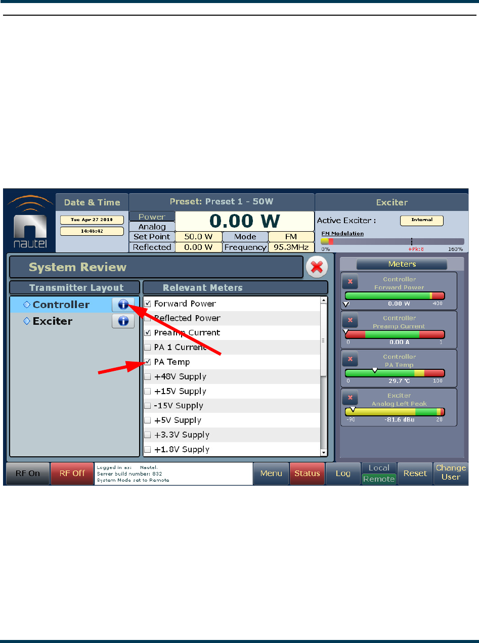
Using the AUI
The VS300’s AUI can display many metered parameters on the right hand side of its home page. To
view all the meter options, click the Meters button on the right-hand side of the AUI. This opens the
System Review page (see Figure 2.23).
Figure 2.23: System Review page (Meter Options)
Click the appropriate transmitter sub-system from the Transmitter Layout list to view the Relevant
Meters for that sub-system. The Transmitter Layout list contains Controller and Exciter sub-systems.
Click on the check-box next to the desired parameter in the Relevant Meters list to select it for display
in the Meters section of the AUI home page. If necessary, use the scroll bar on the right side of the
page to find the desired meter.
SELECTED
METERS
INFORMATION
BUTTON
VS300 Operations and Maintenance Manual Operating the transmitter
Issue 0.1 2011-03-11 Page 2-33
Each meter is a colour-coded bar with minimum and maximum values. The meter’s current value is
indicated by an arrow on the colour-coded bar, as well as a displayed value below the meter. A
parameter value in the green section of a meter bar indicates the parameter is within the range for
normal operation. A parameter value in the yellow section (as applicable) of a meter bar indicates the
parameter is still within an operational range, but is approaching design limitations. A parameter value
in the red section of a meter bar indicates the parameter is outside normal operating conditions.
To delete a meter from the home page, click the X in the upper, left corner of the meter’s box in the
Meters section or de-select the check-box in the Relevant Meters list.
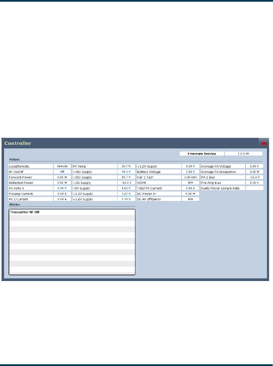
To view detailed info on a specific transmitter sub-system (e.g., Controller), select the desired sub-
system and then click on the i (information) button to the right of the sub-system name (see
Figure 2.24).
Figure 2.24: Detailed Sub-System Information (Controller shown)
This screen displays the status of the selected sub-system, as well as real-time meter values. The
Alarms section shows all active alarms pertaining to the sub-system.
VS300 Operations and Maintenance Manual Operating the transmitter
Page 2-34 Issue 0.1 2011-03-11
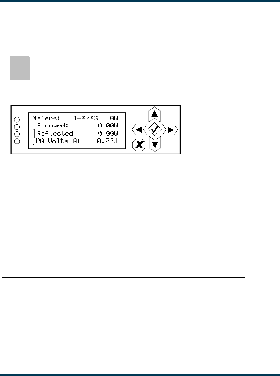
Using the front panel
When you select View Status -> View Meters from the Main Menu (see Figure 2.25) you can view
various metered parameters of the VS300. These parameters are displayed as a list on the View
Meters screen.
Figure 2.25: View Meters Screen
Use the up and down buttons to scroll through the following list of metered parameters:
Note:
This screen is for viewing purposes only and does not offer the same level of analytical features as
the AUI’s System Review page (see Figure 2.23 on page 2-32).
Forward (forward power) +1.8V Dig L
Reflected (reflected power) +1.2V Dig R
PA Volts A Battery MPX SCA
Preamp Curr Fan 1 Peak Mod
PA1 Curr TCXO MPX RMS
Heatsink Temp Ext 10 MHz VSWR
+48V Bal L delta 10 MHz
+15V Bal R DC Power In
-15V MPX DC-RF Eff
+5V Int SCA1 Avg PA Diss
+3.3V Int SCA2
VS300 Operations and Maintenance Manual Operating the transmitter
Issue 0.1 2011-03-11 Page 2-35
Setting time and date
The VS300’s internal clock uses a backup battery, and therefore maintains an accurate time and date,
even during power outages. The time and date needs to be set when the transmitter is first installed,
or after a power outage if the backup battery has failed.
You can set the time and date using the remote AUI (see “Using the AUI”) or using the local front
panel display (see “Using the front panel” on page 2-36).
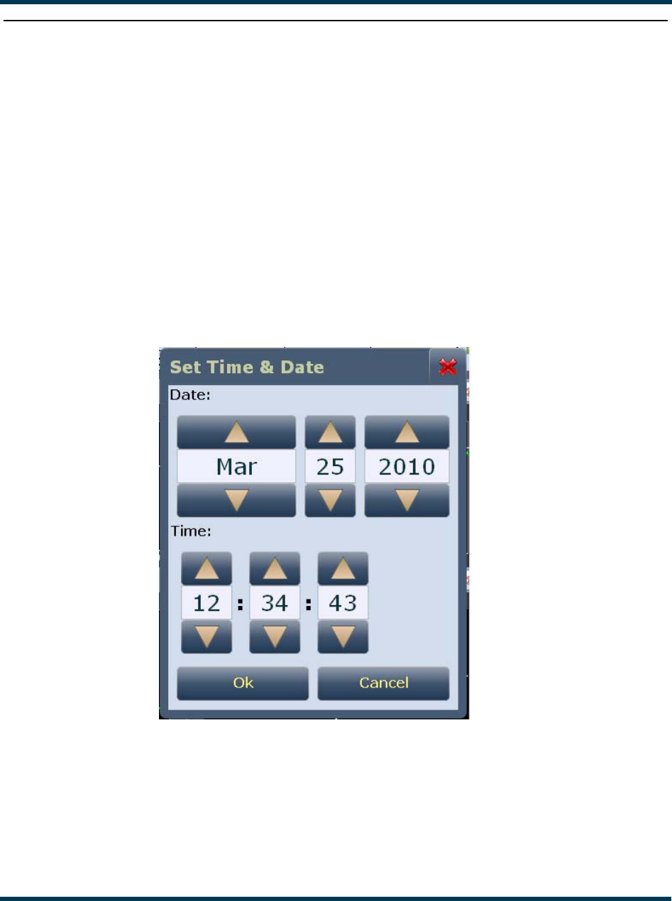
Using the AUI
You can remotely set the VS300’s time and date from the AUI’s Set Time & Date page - see
Figure 2.26. To view the Set Time & Date page, click on the time or date in the upper, left corner of
any AUI page.
Figure 2.26: Set Time & Date page
The Set Time & Date page contains editable fields for the date (month, day and year) and time
(hours, minutes and seconds). The clock is displayed in 24-hour format.
Use the up and down buttons to increase or decrease the desired value in the specific field. Click the
OK button to accept changes or click the Cancel button or X to discard changes and close the
window.
VS300 Operations and Maintenance Manual Operating the transmitter
Page 2-36 Issue 0.1 2011-03-11
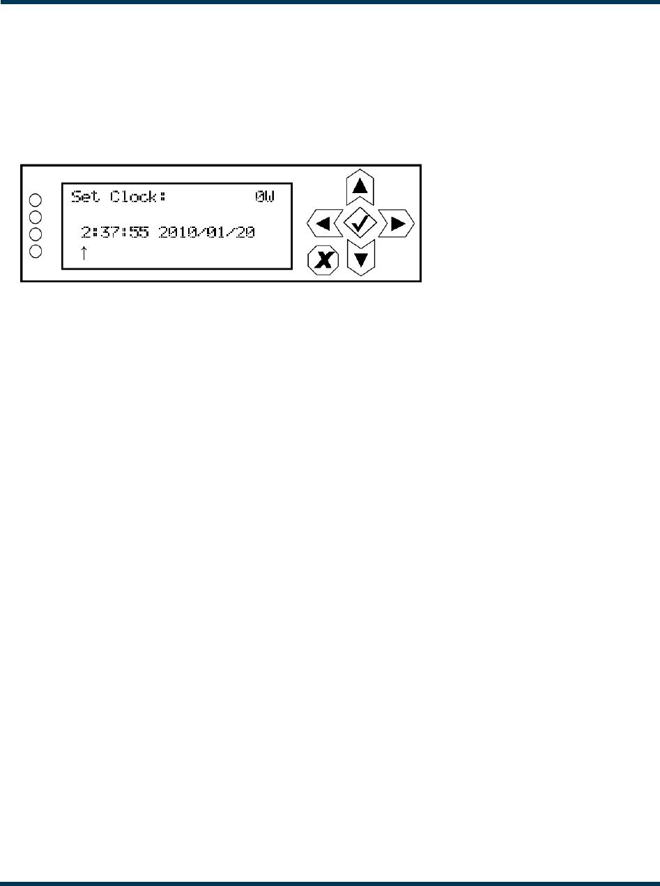
Using the front panel
When you select User Settings -> Set Clock from the Main Menu menu (see Figure 2.27) you can
set the current time and date. The time appears on the top line of the top level screen (see Figure 2.4
on page 2-7).
Figure 2.27: Set Clock screen
To change the time or date, use the right and left arrow buttons to move the cursor to the desired
field (hours, minutes, seconds, year, month, day), and use the up and down arrow buttons to increase
or decrease the value of the selected field as desired. When complete, press the accept (checkmark)
button to save the change. Press the cancel (X) button to discard changes and return to the previous
menu.
VS300 Operations and Maintenance Manual Operating the transmitter
Issue 0.1 2011-03-11 Page 2-37
Managing presets
Presets contain operational data (power level, frequency, mode, program input characteristics) for the
transmitter. You can create presets and manage their various settings.
You can manage presets using the remote AUI (see “Using the AUI”) or using the local front panel
display (see “Using the front panel” on page 2-40).
Using the AUI
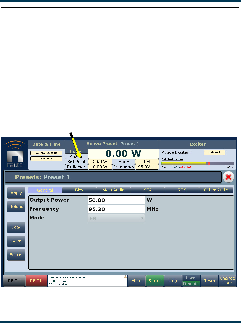
The Presets page (see Figure 2.28) allows you to create up to 63 operating presets or edit existing
presets. To view the Presets page, select Presets from the Menu options or double-click in the
Power section of the top banner.
Figure 2.28: Presets page (General tab shown)
DOUBLE-CLICK IN
THIS SECTION

VS300 Operations and Maintenance Manual Operating the transmitter
Page 2-38 Issue 0.1 2011-03-11
Loading presets. When you first enter the Presets page, the current preset is displayed. If the
current preset is not the preset you want to work with, use the Load button on the left side of the
Presets page to call up a window containing a list of alternate presets.
Select the desired preset and click the Load button to view or enable editing of the preset. Click the
Delete button to delete the selected preset. Click the Cancel button or X to close this window.
Applying presets. Click the Apply button to enable the preset as the transmitter’s active preset.
Reloading presets. Click the Reload button to load the saved values in the selected preset,
overwriting any temporarily edited values.
Editing or creating presets. To change the settings for a selected preset, or to establish settings
for a new preset, change the value in the desired tab(s) and field(s) by entering new values or selecting
from the drop-down menus, as appropriate. When you edit a field in an existing preset, note that an
asterisk appears at the beginning of the preset name in the top, left corner. When changes are
complete, click the Save button and then click the Save Preset window’s Save button. If you are
creating a new preset, you can also enter a new name (e.g., Preset 4 - MPX) in the preset window
before clicking the Save button. Click the X button to discard changes and return to the home page.
Parameters that can be edited are:
General tab:
• Output Power (enter value in W)
• Frequency (enter value in MHz)
• Mode [temporarily disabled; defaulted to FM (analog) mode]
Main Audio tab:
• Audio Source (select Left/Right/Mono, MPX, Primary Digital or Secondary Digital)
For Left/Right/Mono:
– Analog Level (enter value in dBu)
– Audio Mode (select Mono L, Mono R or Stereo)
– 15kHz Lowpass (select On or Off)
– Preemphasis (select 0 us, 25 us, 50 us or 75 us)
For MPX:
– MPX Level (enter value in Vpp)
For Primary Digital or Secondary Digital:
– Secondary Source (select Playlist); displayed for Secondary Digital only
– Digital Level (enter value in dBFS)
– Audio Mode (select Mono L, Mono R or Stereo)
– 15kHz Lowpass (select On or Off)
– Preemphasis (select 0 us, 25 us, 50 us or 75 us)

VS300 Operations and Maintenance Manual Operating the transmitter
Issue 0.1 2011-03-11 Page 2-39
SCA tab:
• MPX SCA (select Enabled or Disabled). If Enabled, enter:
– Input Level (enter value in Vpp)
• SCA Reduction (enter percentage)
• Internal SCA1 or SCA2 (select Enabled or Disabled). If Enabled, enter:
– Injection Level (enter percentage)
– Frequency (enter value in kHz)
– Input Level (enter value in dBu)
– 7.5kHz Lowpass Filter (select Yes or No)
– Preemphasis (select 0 us, 50 us, 75 us or 150 us)
– Mode (select FM or DSB-SC)
RDS tab:
• RDS (select Enabled or Disabled). If Enabled, enter:
– Data Source (select Internal, Ext. ASCII, Ext. UECP, ASCII Over IP, or UECP Over IP)
– RDS Local Echo(select Enabled or Disabled); displayed for Ext. ASCII source only
– Injection Level (enter percentage)
– Phase (enter value in degrees)
– Baud Rate (select 75, 150, 300, 60, 1200, 2400, 4800, 9600, 19200, 38400 or 57600 bps); displayed for Ext.
UECP and Ext. ASCII sources only
– PI Code (hex) (enter value)
– PS Code (enter value)
– PTY (select from various program choices)
– PTYN (enter value)
– Music/Speech (select Music or Speech)
– Traffic Info (select None, TA, TP or TA+TP)
– Artificial Head (select Yes or No)
– Compression Flag (select Yes or No)
– Dynamic (select Yes or No)
– Stereo (select Yes or No)
– Alt. Frequencies (select None or 1 through 6)
– Alt. Freq. 1 through 6 (enter frequency in MHz)
Other Audio tab:
• Pilot Level (enter percentage)
• Pilot 1 PPS Sync (select On or Off). If On, enter:
– Pilot Sync Phase (enter value in degrees)
• Audio Delay (select Yes or No). If Yes, enter:
– Audio Delay (enter value in ms)
• Audio Loss Timeout (select Yes or No). If Yes, enter:
– Action (None, Inhibit or Change Preset)
– Timeout Minutes (enter value in minutes)
– Timeout Seconds (enter value in seconds)
– Threshold (enter percentage)
• Hard Limiter (select Yes or No). If Yes, enter:
– Hard Limit (enter percentage)
VS300 Operations and Maintenance Manual Operating the transmitter
Page 2-40 Issue 0.1 2011-03-11
• AGC Limiter (select Enabled or Disabled). If Enabled, enter:
–AGC Limit (enter percentage)
– Time Constant (enter value in ms)
• Two Slope Limiter (select Enabled or Disabled). If Enabled, enter:
– Threshold (enter percentage)
– Gain (enter percentage)
Saving presets. Click the Save button to save preset information.
Using the front panel
Selecting the active preset
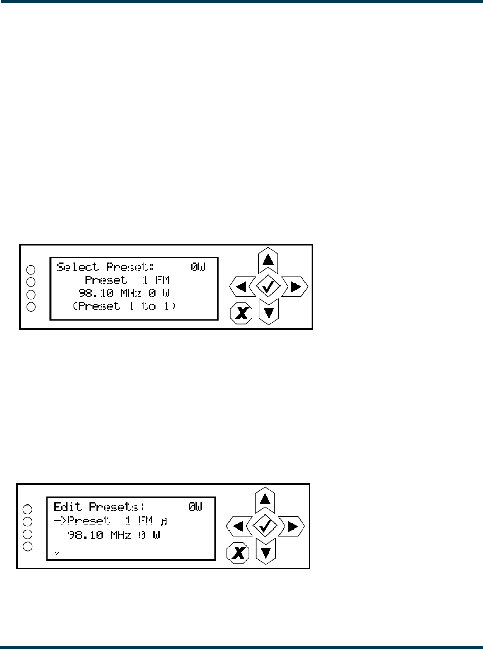
When you choose Select Preset from the Main Menu (see Figure 2.29) you can select the active
preset for transmitter operation.
Figure 2.29: Select Preset screen
Use the up and down buttons to scroll through the existing presets. Press the accept (checkmark)
button to enable the preset as the transmitter’s active preset. Press the cancel (X) button to return to
the previous menu.
Editing or creating presets
When you select User Settings -> Edit Presets from the Main Menu (see Figure 2.30) you can create
up to 63 operating presets or edit existing presets.
Figure 2.30: Edit Preset screen
VS300 Operations and Maintenance Manual Operating the transmitter
Issue 0.1 2011-03-11 Page 2-41
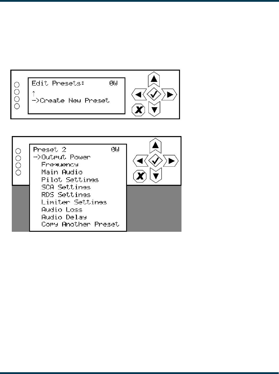
Use the up and down buttons to scroll through the existing presets, or scroll to the bottom of the list
to Create New Preset (see Figure 2.31). Press the accept (checkmark) button to enter the editing
menu for that preset (see Figure 2.32 on page 2-41). Press the cancel (X) button to return to the
previous menu. When you create a new preset, the next available preset number is assigned (e.g.,
Preset 5).
Figure 2.31: Create New Preset screen
Figure 2.32: Preset Editing menu
Within the Preset Editing menu, use the up and down buttons to scroll through the options and press
the accept (checkmark) button to enter the selected editing menu/screen. Press the cancel (X) button
to return to the previous menu. Parameters that can be edited are:
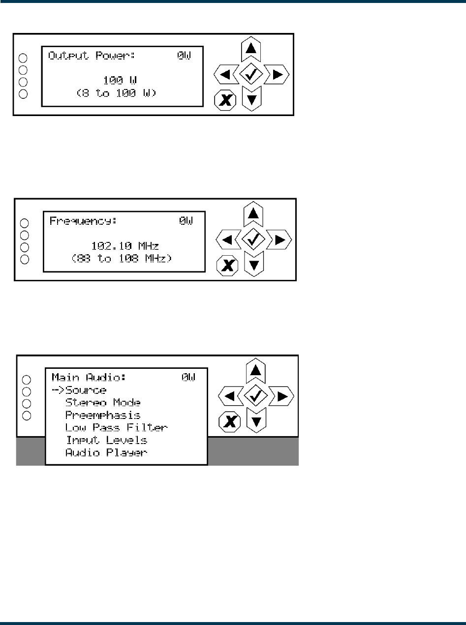
Output Power. See Figure 2.33. Use the up and down buttons to edit the output power (in 1 W
increments, up to a maximum of 100 W), then press the accept (checkmark) button to save the
change. Press the cancel (X) button to discard changes and return to the previous menu.
VS300 Operations and Maintenance Manual Operating the transmitter
Page 2-42 Issue 0.1 2011-03-11
Figure 2.33: Output Power screen
Frequency. See Figure 2.34. Use the up and down buttons to edit the output power (in 0.01 MHz
increments, then press the accept (checkmark) button to save the change. Press the cancel (X) button
to return to the previous menu.
Figure 2.34: Frequency screen
Main Audio. When you select Main Audio from the Preset editing options screen, you can edit
various main audio parameters (see Figure 2.35).
Figure 2.35: Main Audio menu
Use the up and down buttons to scroll through the main audio menu options, then press the accept
(checkmark) or right arrow button to enter the selected editing screen. Figure 2.36 shows the editing
screens for the Main Audio menu. Press the cancel (X) button to discard changes and return to the
previous menu.
VS300 Operations and Maintenance Manual Operating the transmitter
Issue 0.1 2011-03-11 Page 2-43
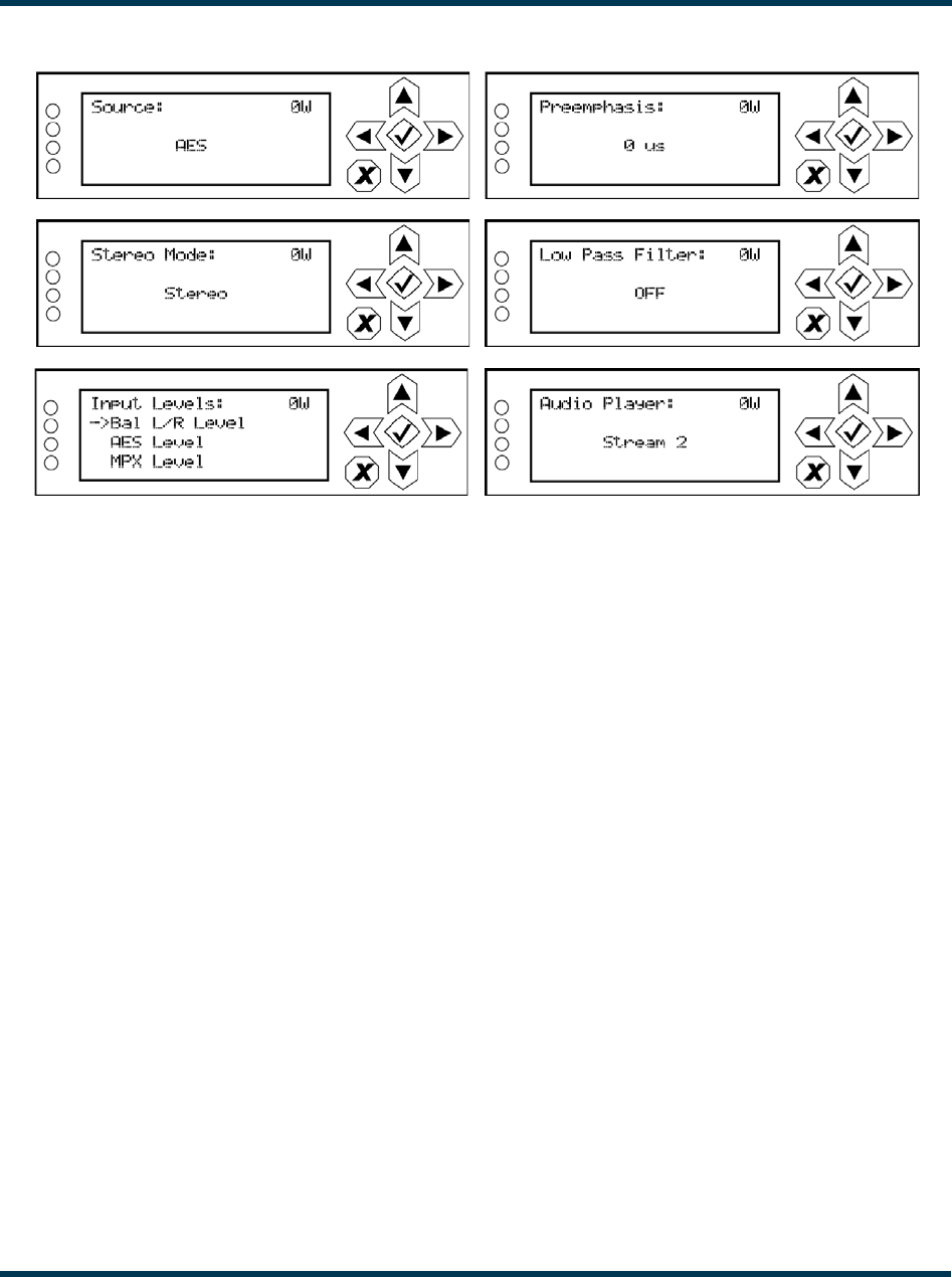
Figure 2.36: Main Audio editing screens
•Source: Use the up and down buttons to locate the desired audio source - AES, MPX,
Analog L/R or Audio Player, then press the accept (checkmark) button to save the change.
Press the cancel (X) button to discard changes and return to the previous menu.
•Stereo Mode: Use the up and down buttons to locate the desired stereo mode - Stereo,
Right Mono, Left Mono or L+R Mono then press the accept (checkmark) button to save the
change. Press the cancel (X) button to discard changes and return to the previous menu.
•Preemphasis: Use the up and down buttons to locate the desired preemphasis
characteristic - 0 us, 25 us, 50 us or 75 us, then press the accept (checkmark) button to save
the change. Press the cancel (X) button to discard changes and return to the previous menu.
•Low Pass Filter: Use the up and down buttons to toggle between ON or OFF, then press the
accept (checkmark) button to save the change. Press the cancel (X) button to discard changes
and return to the previous menu.
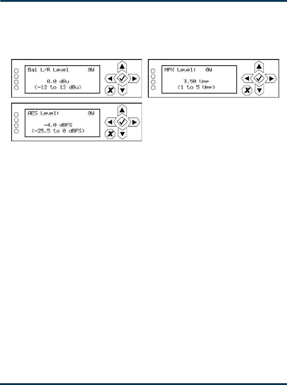
•Input Levels: Use the up and down buttons to move the cursor to the desired audio input
and then press the right button to enable editing of the parameter. Figure 2.37 on page 2-44
shows all the editing screens for the Input Levels sub-menu. Within any of the editing
screens, use the up and down buttons to edit a parameter value, noting the minimum and
maximum limitations indicated at the bottom of the display. When complete, press the
accept (checkmark) button to save the change. Press the cancel (X) button to discard changes
and return to the previous menu.
VS300 Operations and Maintenance Manual Operating the transmitter
Page 2-44 Issue 0.1 2011-03-11
•Audio Player: Use the up and down buttons to select File Playlist or Stream 1 through
Stream 255, then press the accept (checkmark) button to save the change. Press the cancel
(X) button to discard changes and return to the previous menu.
Figure 2.37: Input Levels editing screens
•Bal L/R Level: Select a level between -12 and 12 dBu.
•MPX Level: Select a level between 1 and 5 V peak-to-peak.
•AES Level: Select a level between -255 and 0 dBFS.
VS300 Operations and Maintenance Manual Operating the transmitter
Issue 0.1 2011-03-11 Page 2-45
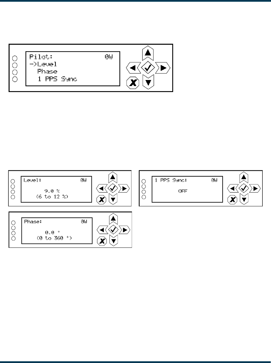
Pilot Settings. When you select Pilot Settings from the Preset editing options screen, you can edit
the settings of the pilot signal (see Figure 2.38).
Figure 2.38: Pilot Settings menu
Use the up and down buttons to move the cursor to the desired pilot setting and then press the right
button to enable editing of the parameter. Figure 2.39 shows all the editing screens for the Pilot
Settings menu. Within any of the editing screens, use the up and down buttons to edit or toggle a
parameter value, noting the minimum and maximum limitations indicated at the bottom of the
display. When complete, press the accept (checkmark) button to save the change. Press the cancel (X)
button to discard changes and return to the previous menu.
Figure 2.39: Pilot Settings editing screens
•Level: Select a level between 6 and 12%.
•Phase: Select a phase angle between 0 and 360 degrees.
•1 PPS Sync: Select ON or OFF.
VS300 Operations and Maintenance Manual Operating the transmitter
Page 2-46 Issue 0.1 2011-03-11
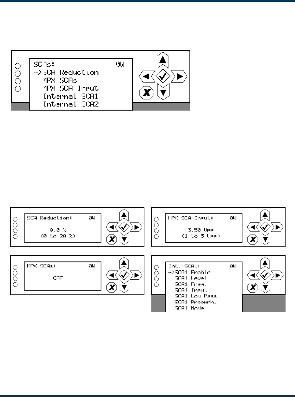
SCA Settings. When you select SCA Settings from the Preset editing options screen, you can edit
various SCA parameters (see Figure 2.40).
Figure 2.40: SCA Settings menu
Use the up and down buttons to move the cursor to the desired SCA setting and then press the right
button to enable editing of the parameter. Figure 2.41 shows all the editing screens for the SCA
Settings menu. Within any of the editing screens, use the up and down buttons to edit or toggle a
parameter value, noting the minimum and maximum limitations indicated at the bottom of the
display. When complete, press the accept (checkmark) button to save the change. Press the cancel (X)
button to discard changes and return to the previous menu. If you select Internal SCA1 or Internal
SCA2, there is a sub-menu that contains additional SCA settings (see Figure 2.42 on page 2-47).
Figure 2.41: SCA Settings editing screens
•SCA Reduction: Select a value between 0 and 20%.
•MPX SCAs: Select ON or OFF.
•MPX SCA Input: Select a level between 1 and 5 V peak-to-peak (of MPX SCAs is ON).
•Int. SCA1 or Int. SCA2 (see Figure 2.42 on page 2-47).
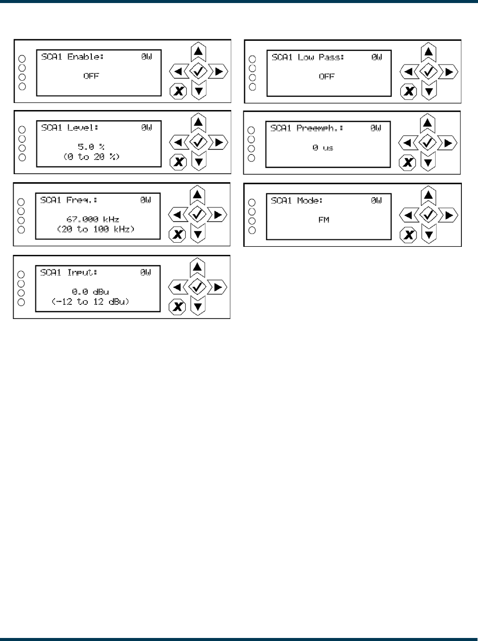
VS300 Operations and Maintenance Manual Operating the transmitter
Issue 0.1 2011-03-11 Page 2-47
Figure 2.42: Internal SCA1 and SCA2 editing screens
•SCA Enable: Select ON or OFF.
•SCA Level: Select a level between 0 and 20%.
•SCA Freq: Select a frequency between 20 and 100 kHz.
•SCA Input: Select a level between -12 and 12 dBu.
•SCA Low Pass: Select ON or OFF.
•SCA Preemph: Select the desired pre-emphasis characteristic - 0 us, 50 us, 75 us or 150 us.
•SCA Mode: Select FM or DSB-SC.
VS300 Operations and Maintenance Manual Operating the transmitter
Page 2-48 Issue 0.1 2011-03-11
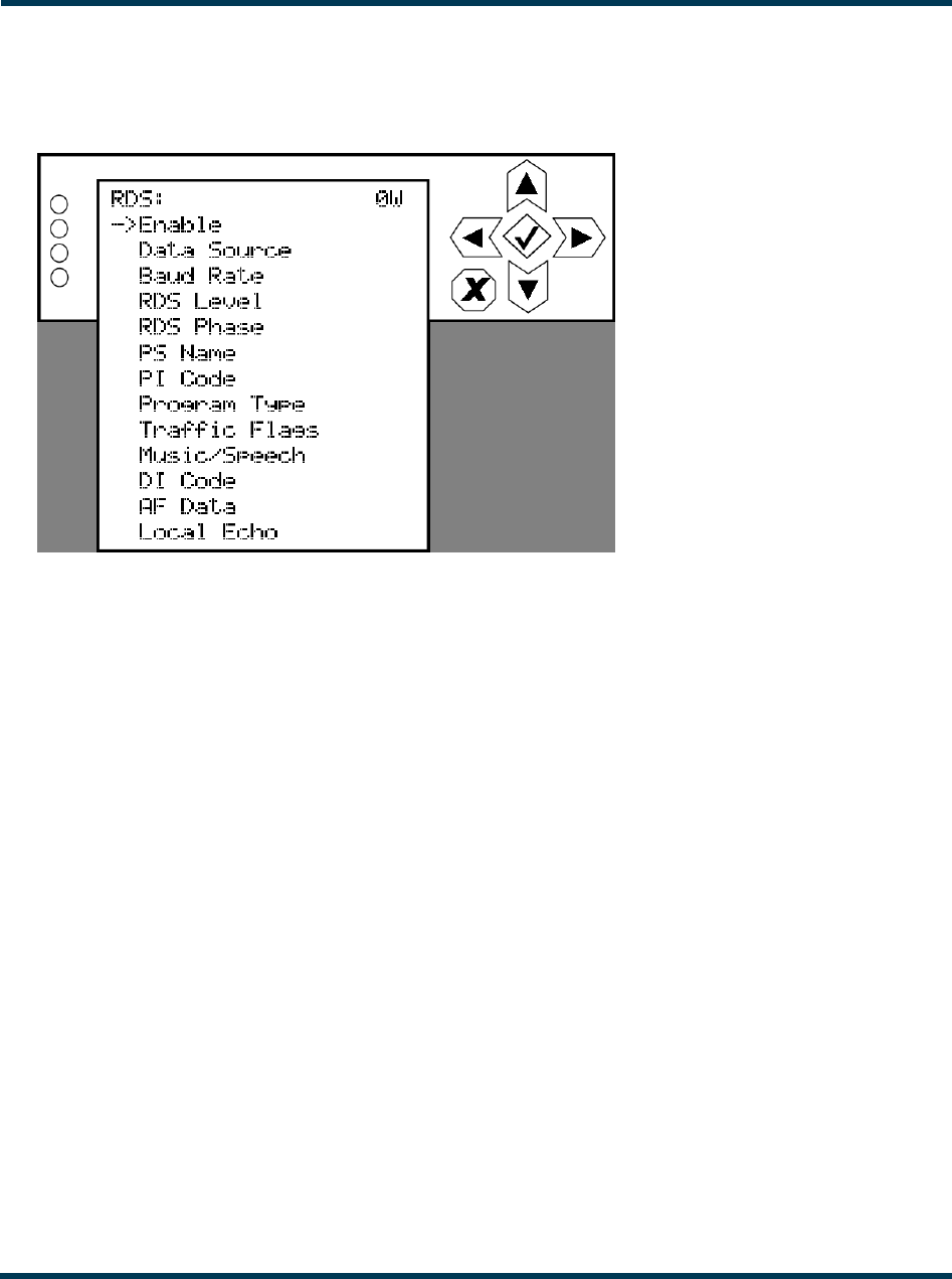
RDS Settings. When you select RDS Settings from the Preset editing options screen, you can edit
various RDS parameters (see Figure 2.43).
Figure 2.43: RDS Settings menu
Use the up and down buttons to move the cursor to the desired RDS setting and then press the right
button to enable editing of the parameter. Figure 2.44 on page 2-49 shows all the editing screens for
the RDS Settings menu. Within any of the editing screens, use the arrow buttons to edit or toggle a
parameter value, noting the minimum and maximum limitations indicated at the bottom of the
display (as applicable). When complete, press the accept (checkmark) button to save the change.
Press the cancel (X) button to discard changes and return to the previous menu. If you select DI
Code (see Figure 2.45 on page 2-50) or AF Data (see Figure 2.46 on page 2-51), there are associated
sub-menus that contain additional setting options .
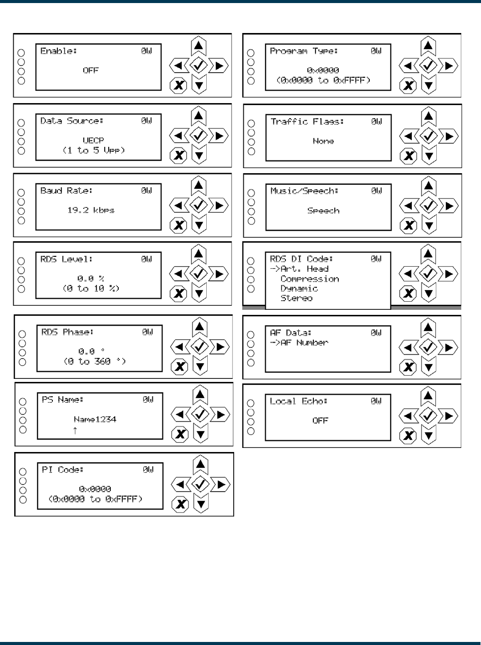
VS300 Operations and Maintenance Manual Operating the transmitter
Issue 0.1 2011-03-11 Page 2-49
Figure 2.44: RDS Settings editing screens
•Enable: Select ON or OFF.
•Data Source: Select Internal, Ext. ASCII, Ext. UECP, ASCII Over IP, or UECP Over IP.
•Baud Rate: Select 150 bps, 300 bps, 600 bps, 1.2 kbps, 2.4 kbps, 4.8 kbps, 9.6 kbps,
19.2 kbps, 38.4 kbps, 57.6 kbps or 115.2 kbps.
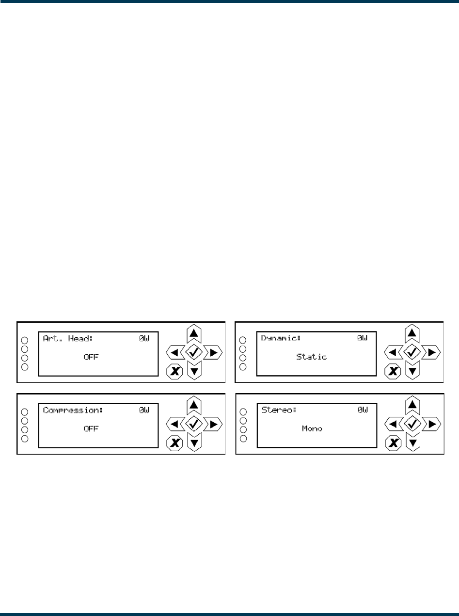
VS300 Operations and Maintenance Manual Operating the transmitter
Page 2-50 Issue 0.1 2011-03-11
•RDS Level: Select a value between 0 and 10%.
•RDS Phase: Select a value between 0 and 360 degrees.
•PS Name: Enter an 8-character name. Use the right and left arrows to move the cursor to
the desired character. Use the up and down arrows to edit the character.
•PI Code: Enter a hex value between 0x0000 and 0xFFFF.
•Program Type: Select the program type from various choices.
•Traffic Flags: Select None, TA/TP, TP or TA.
•Music/Speech: Select Music or Speech.
•DI Code: See Figure 2.45.
•AF Data: See Figure 2.46 on page 2-51.
•Local Echo: Select ON or OFF.
Figure 2.45: DI Code editing screens
•Art. (Artificial) Head: Select ON or OFF.
•Compression: Select ON or OFF.
•Dynamic: Select Dynamic or Static.
•Stereo: Select Stereo or Mono.
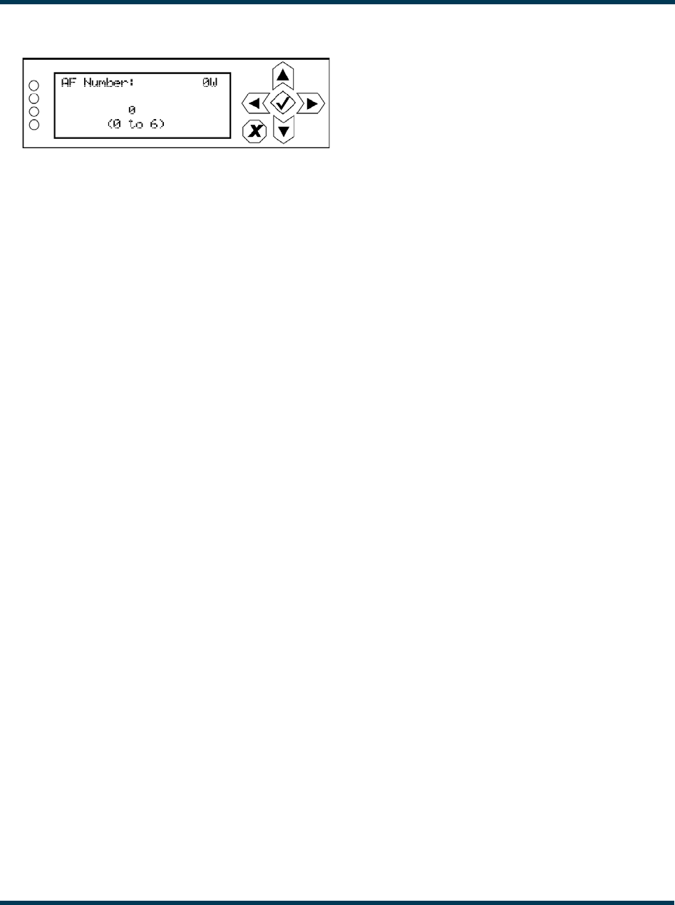
VS300 Operations and Maintenance Manual Operating the transmitter
Issue 0.1 2011-03-11 Page 2-51
Figure 2.46: AF Data editing screen
•AF Number: Select the number of alternate frequencies (between 0 and 6).
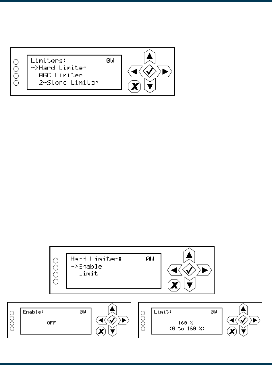
VS300 Operations and Maintenance Manual Operating the transmitter
Page 2-52 Issue 0.1 2011-03-11
Limiter Settings. When you select Limiter Settings from the Preset editing options screen, you
can edit various limiter parameters (see Figure 2.47).
Figure 2.47: Limiter Settings menu
Use the up and down buttons to move the cursor to the desired limiter and then press the right
button to enter the associated sub-menu for:
•Hard Limiter (see Figure 2.48)
•AGC Limiter (see Figure 2.44 on page 2-49)
•2-Slope Limiter (see Figure 2.44 on page 2-49).
Within a sub-menu, use the up and down buttons to move the cursor to the desired limiter setting
and then press the right button to enter the associated editing screen. Within any of the editing
screens, use the arrow buttons to edit or toggle a parameter value, noting the minimum and
maximum limitations indicated at the bottom of the display (as applicable). When complete, press the
accept (checkmark) button to save the change. Press the cancel (X) button to discard changes and
return to the previous menu.
Figure 2.48: Hard Limiter sub-menu and editing screens
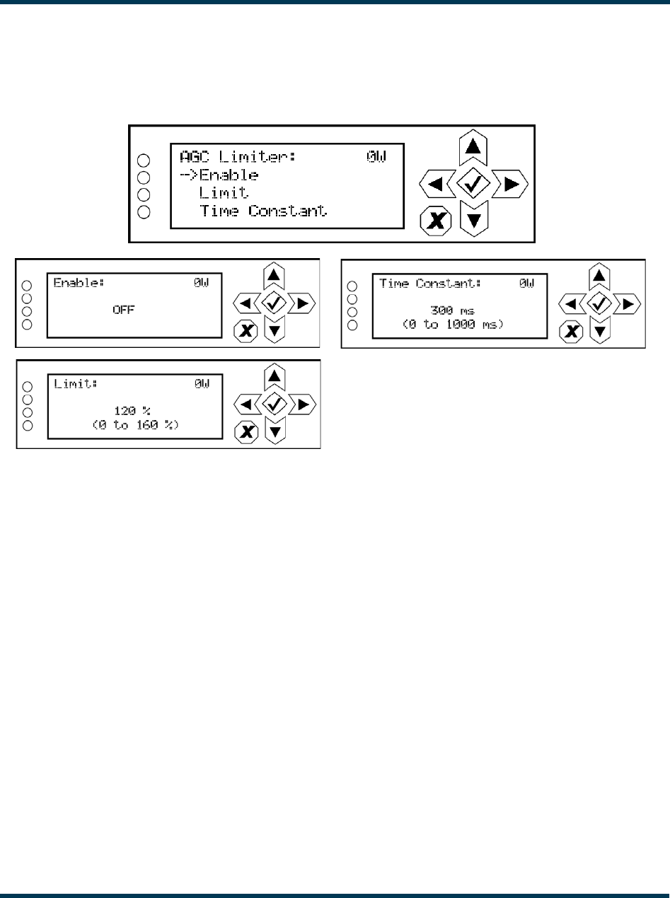
VS300 Operations and Maintenance Manual Operating the transmitter
Issue 0.1 2011-03-11 Page 2-53
•Enable: Select ON or OFF.
•Limit: Select a value between 0 and 160%.
Figure 2.49: AGC Limiter sub-menu and editing screens
•Enable: Select ON or OFF.
•Limit: Select a value between 0 and 160%.
•Time Constant: Select a value between 0 and 100 ms.
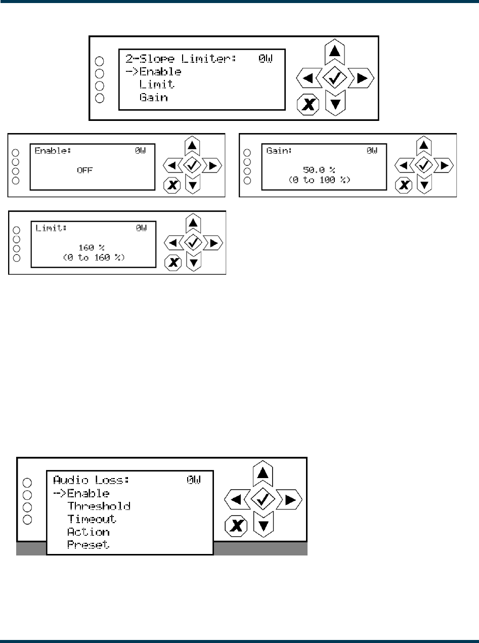
VS300 Operations and Maintenance Manual Operating the transmitter
Page 2-54 Issue 0.1 2011-03-11
Figure 2.50: 2-Slope Limiter sub-menu and editing screens
•Enable: Select ON or OFF.
•Limit: Select a value between 0 and 160%.
•Gain: Select a value between 0 and 100 %.
Audio Loss. When you select Audio Loss from the Preset editing options screen, you can edit the
parameters related to an audio loss (see Figure 2.51).
Figure 2.51: Audio Loss menu
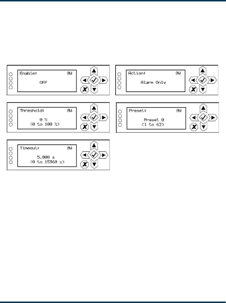
VS300 Operations and Maintenance Manual Operating the transmitter
Issue 0.1 2011-03-11 Page 2-55
Use the up and down buttons to move the cursor to the desired audio loss menu item and then press
the right button to enable editing of the item. Figure 2.52 shows all the editing screens for the Audio
Loss menu. Within any of the editing screens, use the up and down buttons to edit a parameter value,
noting the minimum and maximum limitations indicated at the bottom of the display (as applicable).
When complete, press the accept (checkmark) button to save the change. Press the cancel (X) button
to discard changes and return to the previous menu.
Figure 2.52: Audio Loss editing screens
•Enable: Determines whether the audio loss feature is used. Select ON or OFF.
•Threshold: Sets the audio threshold below which the transmitter will take action. Select a
value between 0 and 100%.
•Timeout: Sets the time period of low audio (based on the threshold setting) after which the
transmitter will take action. Select a value between 0 and 15360 seconds (256 minutes).
•Action: Determines the action taken by the transmitter when the audio has been below the
threshold for the timeout period. Select Alarm Only, Switch Preset or RF Inhibit.
•Preset: Determines the preset that becomes active after an audio loss if the audio loss action
action is set to Switch Preset.
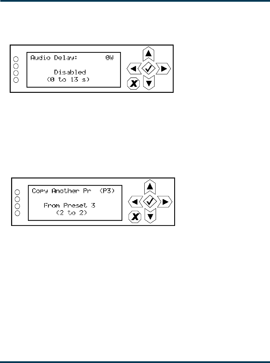
VS300 Operations and Maintenance Manual Operating the transmitter
Page 2-56 Issue 0.1 2011-03-11
Audio Delay. When you select Audio Delay from the Preset editing options screen, you can edit or
disable the audio delay period (see Figure 2.53).
Figure 2.53: Audio Delay menu
Use the up and down buttons to change the audio delay setting between disabled and any time period
between 0 and 13 seconds, then press the accept (checkmark) button to save the change. Press the
cancel (X) button to discard changes and return to the previous menu.
Copy another preset. When you select Copy Another Preset from the Preset editing options
screen, you can copy the settings from another preset into the preset that is being edited (see
Figure 2.54). Note the preset being edited is displayed in parentheses [e.g., (P3)].
Figure 2.54: Copy Another Preset Screen
Use the up and down buttons to select the preset (see available presets in parentheses on the bottom
line of the display) that you wish to copy to the selected preset for editing. Press the accept
(checkmark) button to save the change. Press the cancel (X) button to discard changes and return to
the previous menu.
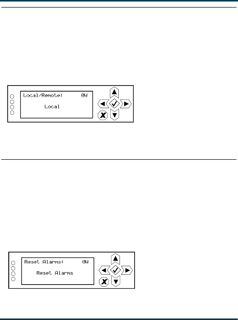
VS300 Operations and Maintenance Manual Operating the transmitter
Issue 0.1 2011-03-11 Page 2-57
Setting local/remote control
You can set the transmitter’s local/remote control using the remote AUI’s Local/Remote button (see
“Local/Remote:” on page 2-14) or using the local front panel display (see “Using the front panel”).
Using the front panel
When you select Local/Remote from the Main Menu, you can set the local/remote operating
control for the VS300 (see Figure 2.55 on page 2-57).
Figure 2.55: Local/Remote Selection Screen
Use the up and down buttons to toggle between Local and Remote. Press the accept (checkmark)
button to save the change. Press the cancel (X) button to discard changes and return to the previous
menu.
Resetting alarms
You can attempt to reset any latching transmitter alarms that are holding the transmitter in an “off-
air” state using the remote AUI’s Reset button (see “Reset:” on page 2-14) or using the local front
panel display (see “Using the front panel”).
Using the front panel
When you select Reset Alarms from the Main Menu, you can attempt to reset latched protection
circuits in the VS300 (see Figure 2.56). If the alarm condition has been cleared, the alarm indication
on the View Alarms screen should disappear.
Figure 2.56: Reset Alarms Screen
Use the up and down buttons to toggle between Reset Alarms and Cancel. Press the accept
(checkmark) button to save the change. Press the cancel (X) button to return to the previous menu.
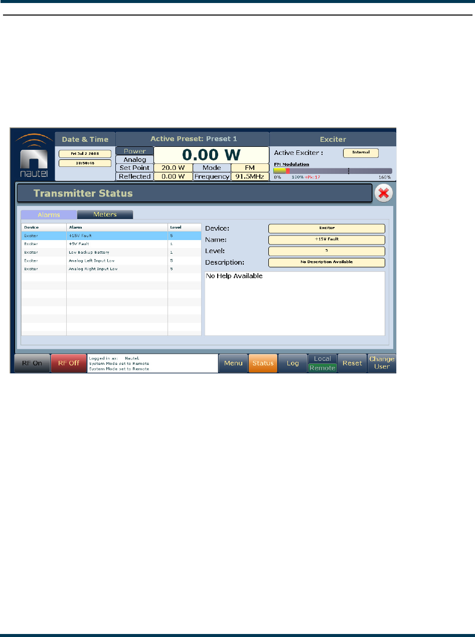
VS300 Operations and Maintenance Manual Operating the transmitter
Page 2-58 Issue 0.1 2011-03-11
Viewing transmitter status
You can view the VS300’s operational status using the AUI’s Transmitter Status page - see
Figure 2.57. This page shows current active alarms and status to aid in fault diagnosis. To view the
Transmitter Status page, select Transmitter Status from the Menu options.
Figure 2.57: Transmitter Status page
Click the X to close this page and return to the home page.
The left-hand section of the Transmitter Status displays tabs that list all transmitter alarms and
meters (as selected). Alarms are listed by their host device (Controller or Exciter), alarm name and
severity level [1 = low (RF output not affected), 5 = medium (RF output is reduced), 10 = high (RF
output is inhibited)].
Click an item in the Alarms or Meters tab to display its details on the right-hand section. For the
Alarms tab, details include a description of the alarm and help text (e.g., troubleshooting tips). For the
Meters tab, click Show Meter List to display a list of selectable meters. Select the desired real-time
meters to display on the left-hand side of the screen to assist in troubleshooting. Meter colour coding
is identical to that described in “Viewing real-time meters” on page 2-32.
Click the Reset button at the bottom of any AUI screen to attempt to clear any latching alarms that
are holding the transmitter in an “off-air” state (see “Reset:” on page 2-14). If the offending alarm
has cleared, the transmitter should resume operation.
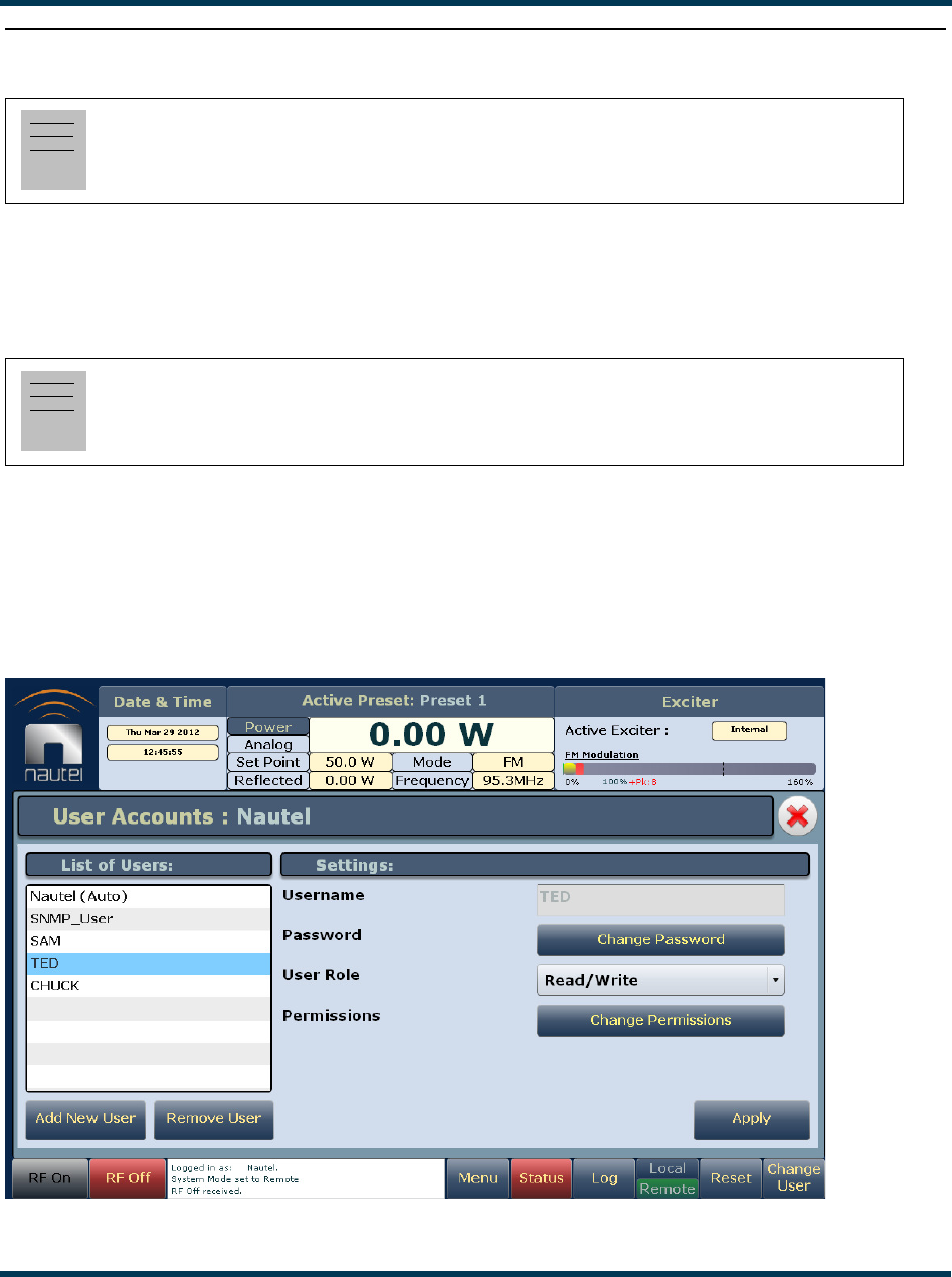
VS300 Operations and Maintenance Manual Operating the transmitter
Issue 0.1 2011-03-11 Page 2-59
Setting user accounts
Depending on user permission rights, you can set up accounts to allow certain users to access and
control features of the AUI using the User Accounts page - see Figure 2.58. To view the User
Accounts page, select User Accounts from the Menu options. Click X in the upper, right corner to
close this page, discard changes and return to the home page.
The VS300 contains a a default user account when it leaves the factory. This account appears as
Nautel (Auto) in the List of Users and has Super User permission level. The default Username is
“Nautel”. The default Password is blank. It is recommended that this account be deleted once the
desired user account(s) is (are) created (see “First-time login” on page 2-61).
Figure 2.58: User Accounts page
Note:
This function is only available via remote connection to the AUI.
Note:
Depending on the permission level assigned to a given user, some features shown in Figure 2.58
may not be displayed or available.

VS300 Operations and Maintenance Manual Operating the transmitter
Page 2-60 Issue 0.1 2011-03-11
Setting user role
There are three levels of role that can be assigned to users, each with their own specific functionality.
All users have permission to change their own username and password, but are otherwise limited to
the following functions:
•Read Only: Can monitor equipment data only. No administrative or control functions.
•Read/Write: Can monitor and control equipment. No administrative functions.
•Super User: Can perform all functions. Super User is the only permission level that allows
addition, removal or modification of users.
Editing account information
If you have Super User permission level, you can edit any user account.
Editing an existing account. To edit an existing user account, click on the desired user in the
List of Users on the left side of the User Accounts panel. The Settings for that user will be displayed
on the right-hand side of the User Accounts panel. You can edit the Username, Password, User Role
(see “Setting user role”) and Permissions.
Changing the password. To change your password, click Change Password. A menu appears
that prompts you to enter the old password, new password and confirmation of the new password.
Click the OK button to accept changes or the Cancel button to discard changes and exit this menu.
Changing permissions. To change permissions to specific functions, click Change Permissions.
A menu appears that contains five selectable items - Presets, Hardware Configuration, Software
Configuration, Remote I/O and Clear Log. Check the items for which you are allowing edit
permission. Click the OK button to accept changes or the Cancel button to discard changes and exit
this menu.
Adding an account. To add a new user account, click Add New User. Enter the username, click
the OK button to accept, then set the account information in the Settings section. Click the Cancel
button or X to discard changes and exit this menu.
Removing an account. To remove a user account, select the desired user from the List of Users
and click the Remove User button. A verification prompt will appear. Click the OK button to accept
changes or the Cancel button to discard changes and exit this menu.
To save your changes, click Apply.

VS300 Operations and Maintenance Manual Operating the transmitter
Issue 0.1 2011-03-11 Page 2-61
First-time login
When you enter the User Accounts page for the first time, it is recommended you create an account
and then delete the default Nautel account, as follows:
1. Login to the AUI using the deafult Username (“Nautel”) and Password (blank).
2. Set up your own Super User account, with your desired Username and Password.
3. Logout of the AUI, then login to your new Super User account.
4. Delete the Nautel (Auto) account.
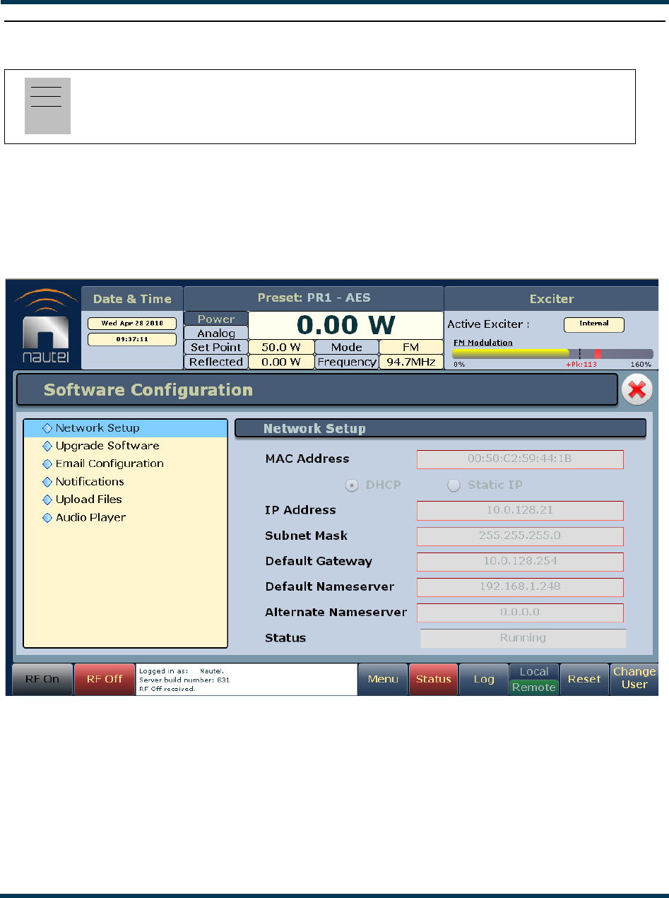
VS300 Operations and Maintenance Manual Operating the transmitter
Page 2-62 Issue 0.1 2011-03-11
Software configuration
You can perform software upgrades to the AUI or transmitter, or perform various restarts or resets
using the Software Configuration page - see Figure 2.59. To view the Software Configuration page,
select Software Configuration from the Menu options. Click X in the upper, right corner to close
this page and return to the home page. The following options are available:
Figure 2.59: Software Configuration page
•Network Setup: The AUI allows viewing of network parameters. Configuration of these
parameters is done locally, using the front panel UI (see “Network setup” on page 2-64).
•Upgrade Software: Allows for uploading software upgrade files for various transmitter sub-
systems (e.g., Controller, Exciter, etc.) (see “Upgrading software” on page 2-68).
Note:
Unless otherwise noted, the following functions are only available via remote connection to the
AUI.

VS300 Operations and Maintenance Manual Operating the transmitter
Issue 0.1 2011-03-11 Page 2-63
•Email Configuration: Allows configuration of email parameters (e.g., server name, port
number, etc.) (see “Email configuration” on page 2-69).
•Notifications: Allows configuration of email notifications to be sent for user-selected alarm
occurrences (see “Notifications” on page 2-70).
•Upload Files: Allows uploading of audio files and software upgrade files (see “Upload files”
on page 2-72).
•Audio Player: Allows configuration of an audio player to play audio files, Shoutcast audio
streams or Livewire audio streams (see “Audio player” on page 2-73).

VS300 Operations and Maintenance Manual Operating the transmitter
Page 2-64 Issue 0.1 2011-03-11
Network setup
Network settings are configured using the local front panel display (see “Using the front panel”).
Once you have established an IP address, you can login remotely and view (but not change) these
settings using the remote AUI (see “Using the AUI”).
Determining DHCP setting
One of the main decisions in configuring the network connection on your VS300 transmitter is
whether you set DHCP to ON or OFF. If you are connecting to a network, consult with a network
administrator before connecting the transmitter to your network to determine whether to enable
(turn ON) or disable (turn OFF) the DHCP setting.
When DHCP is set to ON (default from factory), IP addresses are assigned automatically. In order for
this feature to function properly, you must have a network-viewable DHCP server on your network.
If a DHCP server is not present, you (or your network administrator) must provide static addresses
for IP, netmask, gateway and nameservers (gateway and nameservers are optional). You must enter
them manually using the front panel. In this case, DHCP should be set to OFF.
Using the front panel
From the front panel, in local mode, you can set or change network settings. To view the Network
Settings screen, select User Settings -> Network Settings from the Main Menu. See Figure 2.60 on
page 2-65. Configure the network as follows:
Use the up and down buttons to move the cursor to the desired parameter and then press the right
button to enable editing of the setting. Within any of the editing screens, use the left and right
buttons to select a character for editing and then use the up and down buttons to edit a setting. Press
the accept (checkmark) button to save the change. Press the cancel (X) button to discard changes and
return to the previous menu.
•MAC Address: Set during factory testing; cannot be modified.
• Set DHCP to ON or OFF (see “Determining DHCP setting”).
•If DHCP was set to OFF enter the IP Address, Netmask, Gateway, Nameserver 1 and
Nameserver 2 (gateway and nameservers are optional). A nameserver (also called a DNS)
translates a host name (e.g., mail.nautel.com) to an IP address such as in configuring email
(see “Email configuration” on page 2-69).
If you are using a laptop to connect to the VS300, see “Connecting a laptop directly to the
transmitter” on page 2-66.
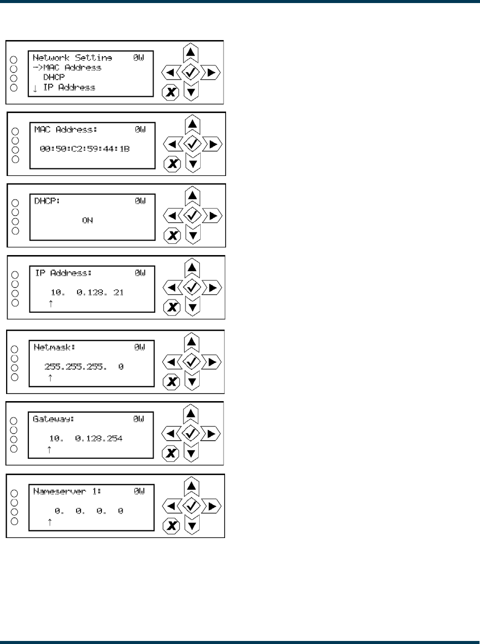
VS300 Operations and Maintenance Manual Operating the transmitter
Issue 0.1 2011-03-11 Page 2-65
Figure 2.60: Network Settings screen
Set during factory testing; cannot be modified
Set to ON if your network has a DHCP server. Automatically
assigns IP, netmask, gateway and nameservers.
Set to OFF if you do not have a DHCP server or if you wish
to assign static addresses.
All addresses shown are for reference purposes only
Specify a nameserver (or DNS) to enable the use of
host names. If no nameserver is entered, only direct IP
addresses can be used to configure the email server
and any live streams such as Livewire or Shoutcast.
Typical netmask address shown. Consult with your network
administrator.
VS300 Operations and Maintenance Manual Operating the transmitter
Page 2-66 Issue 0.1 2011-03-11
Connecting a laptop directly to the transmitter
If connecting to the VS300 directly with a laptop, you must set a static IP address on the VS300 and
your laptop.
1. From the front panel UI’s Main Menu, go to User Settings/Network Settings and set the
IP address as follows:
– DHCP: OFF
– IP Address: 10.10.10.2
– Netmask: 255.255.255.0
2. Set the transmitter for Remote control.
3. On the laptop, go to Start Menu/Control Panel/Network Connections/Local Area
Network.
4. In the Local Area Network Status, open the General tab and choose Properties. Scroll
down and highlight Internet Protocol (TCP/IP). Choose Properties.
5. In the Internet Protocol (TCP/IP) Properties window, select Use the following IP address.
6. Enter the following settings:
– IP Address: 10.10.10.1
– Subnet Mask: 255.255.255.0
– Default Gateway: 192.168.1.2
7. In the Internet Protocol (TCP/IP) Properties window, select OK.
8. In the Local Area Connection Properties window, select OK.
9. In the Local Area Connection Status window, select Close.
10. Close the Network Connections window.
Note:
The following steps assume the operating system is Windows XP. Adapt as required for
computers with different operating systems.
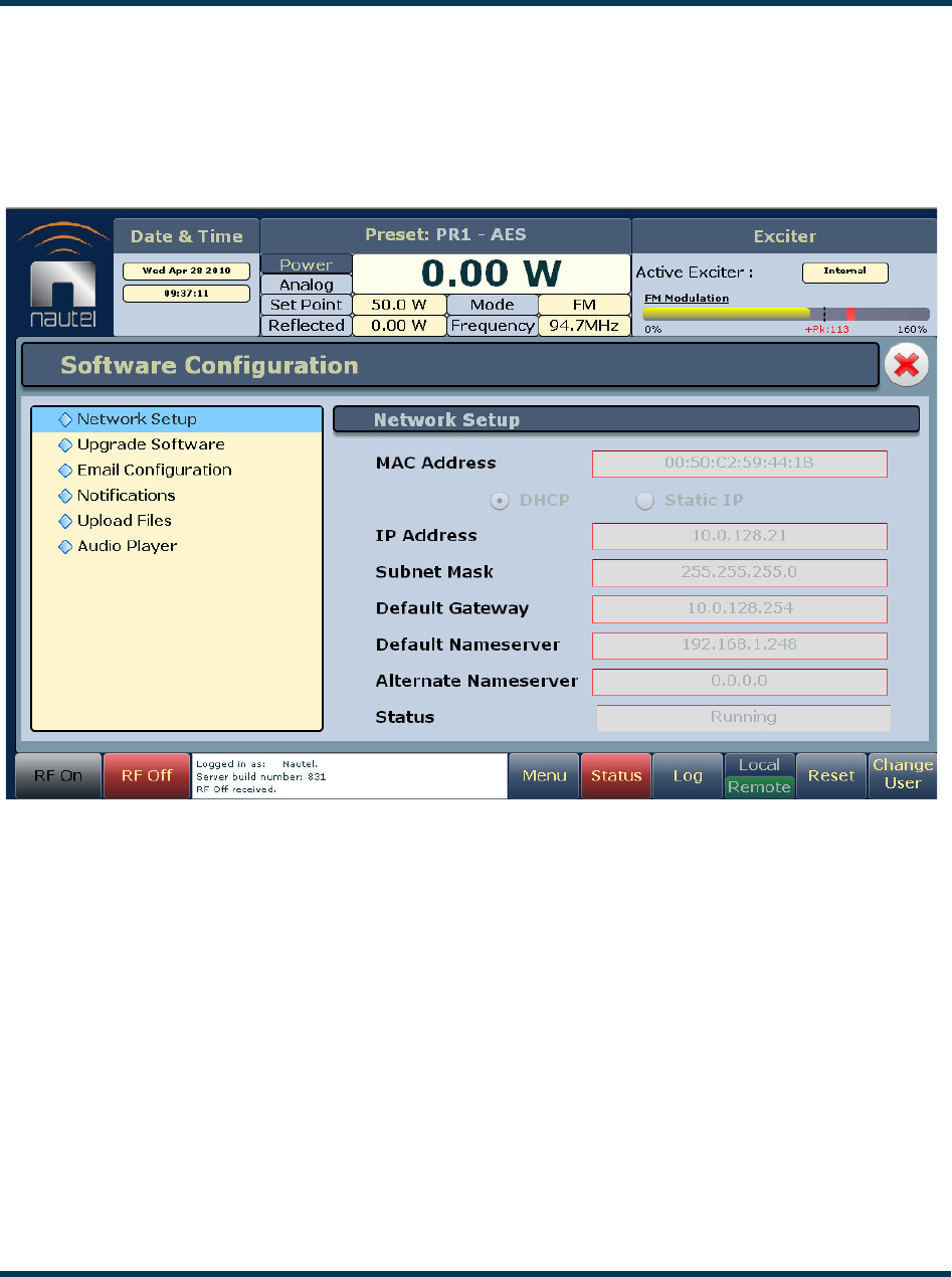
VS300 Operations and Maintenance Manual Operating the transmitter
Issue 0.1 2011-03-11 Page 2-67
Using the AUI
By entering the VS300’s established IP address into an Internet browser’s address bar, and then
logging into the AUI, you can view the network parameters configured through the front panel UI
using the Network Setup page - see Figure 2.61. You cannot modify parameters from this page.
Figure 2.61: Network Setup page
All addresses shown are for reference purposes only
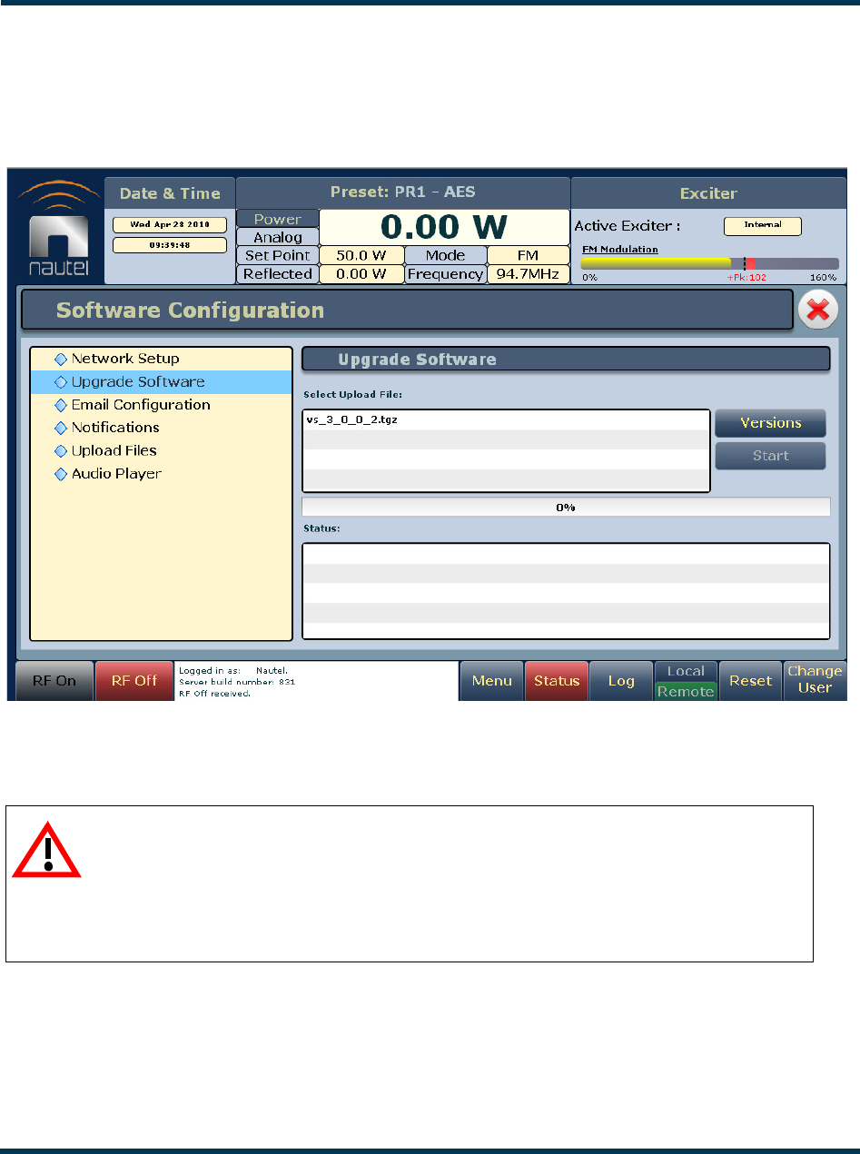
VS300 Operations and Maintenance Manual Operating the transmitter
Page 2-68 Issue 0.1 2011-03-11
Upgrading software
See Figure 2.62.
Figure 2.62: Upgrade Software page
To upgrade a transmitter subsystem’s software, see “Upgrading software” in Section 4, “Non-
standard maintenance” on page 4-1 of this manual.
CAUTION:
If you are upgrading from a software version prior to V1.2, the ARM Watchdog
feature must be DISABLED during the software upgrade process. Failure to
observe this may result in a non-operational transmitter that will require a full
operating system recovery. Refer to “Configuring ARM watchdog” on page 2-78
for details on disabling the ARM watchdog feature.
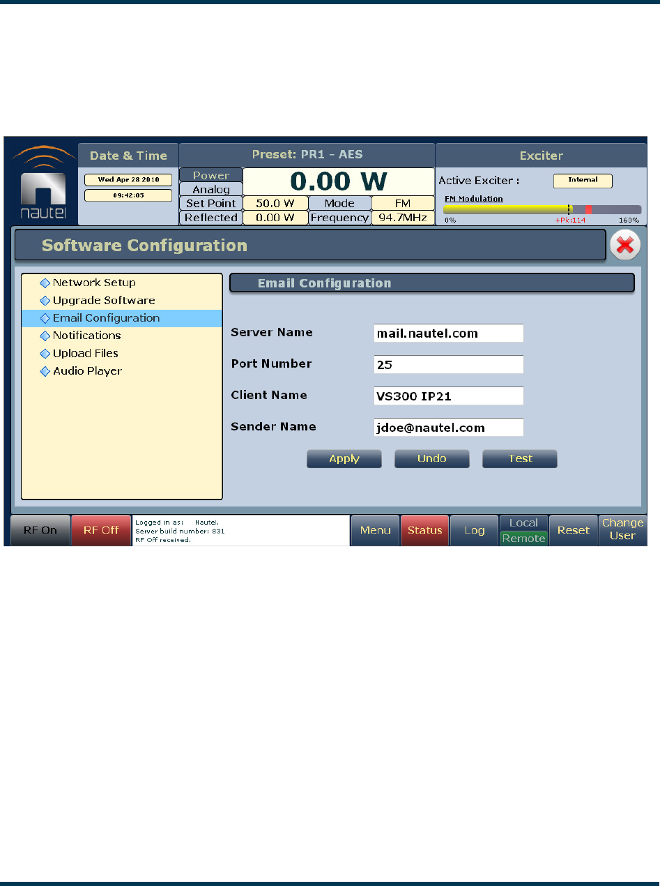
VS300 Operations and Maintenance Manual Operating the transmitter
Issue 0.1 2011-03-11 Page 2-69
Email configuration
Email configuration (see Figure 2.63) is required if the notification feature is used (see
“Notifications” on page 2-70).
Figure 2.63: Email Configuration page
To configure the email feature, perform the following steps:
1. Enter the four fields, noting the following:
–Server Name: In order to enter a server name (e.g., mail.nautel.com), at least one
nameserver IP address must be entered (see “Network setup” on page 2-64).
–Port Number: Enter the addressing information used to identify the senders and
receivers of messages. Typically set to 25 for SMTP systems.
–Client Name: Set to a name that associates to the transmitter such as station
identification (e.g., NV40_WXYZ). This name will be included in notification emails.
–Sender Name: Enter as a standard email address (e.g., xxxxxxx@yyyyy.zzz).
2. When complete click Apply or click Undo to restore the previous setting. Use the Test
button to enter an email address to test your settings. Click the OK button to run the test or
the Cancel button to return to the Email Configuration page.
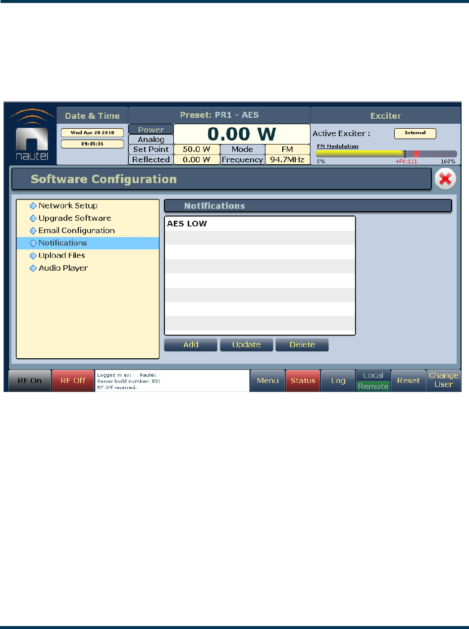
VS300 Operations and Maintenance Manual Operating the transmitter
Page 2-70 Issue 0.1 2011-03-11
Notifications
The notifications feature (see Figure 2.64) provides a means for the transmitter to issue emails
triggered by user defined alarm events.
Figure 2.64: Notifications page
To configure the notifications feature, perform the following steps:
1. Pre-existing notifications are displayed in the Notifications list. Click Add to create a new
item for notification, click Update (after highlighting an existing item) to edit an existing
item or click Delete to erase an item.
2. When you click Add or Update, the screen in Figure 2.65 will appear. This screen allows you
to add or edit a Notification Name, Recipient Email, and define the alarm list by device
type (Exciter or Controller). Add or remove alarms by moving them (using the >> and <<
arrow buttons) from the Available Alarms list to the Selected Alarms list. An email is issued
when any alarm in the Selected Alarms list is active.
3. When complete click the OK button to accept changes or the Cancel button to discard
changes and return to the Notifications page.
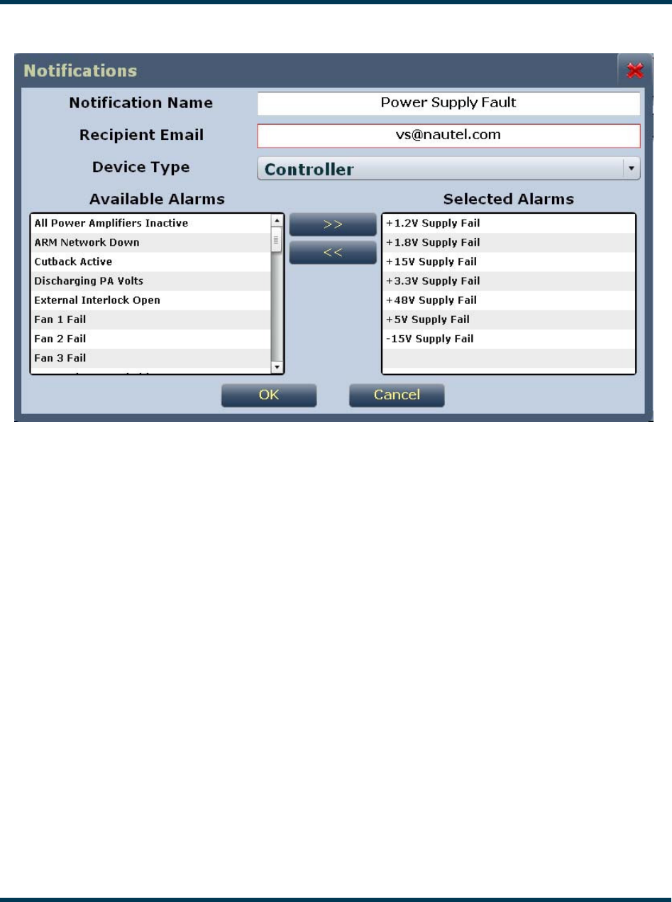
VS300 Operations and Maintenance Manual Operating the transmitter
Issue 0.1 2011-03-11 Page 2-71
Figure 2.65: Notifications adding/updating page
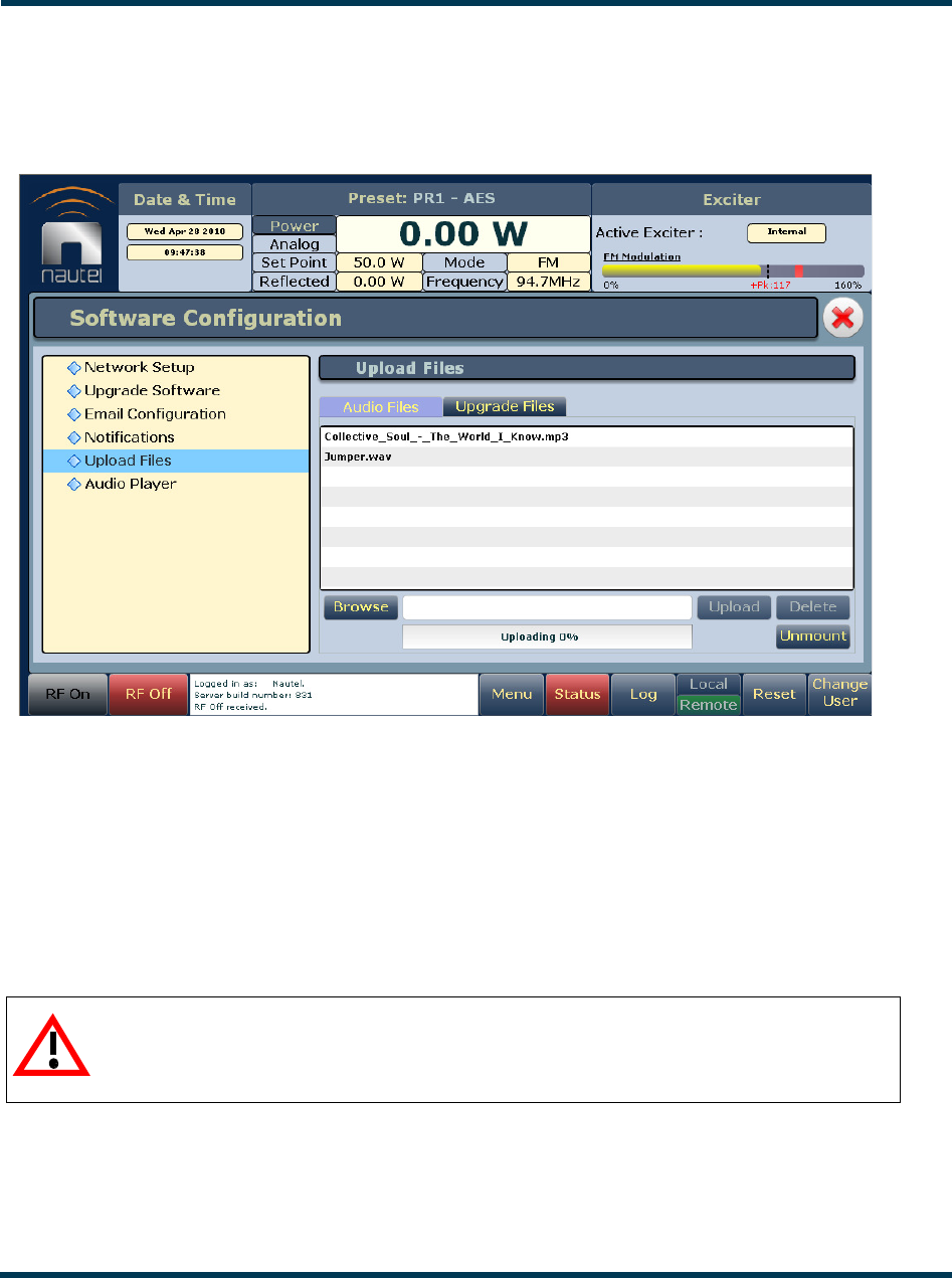
VS300 Operations and Maintenance Manual Operating the transmitter
Page 2-72 Issue 0.1 2011-03-11
Upload files
See Figure 2.66.
Figure 2.66: Upload Files page
Using the Audio Files tab, you can upload audio files with either .mp3 or .wav extensions.
Audio files are stored on a USB drive plugged into the USB-A (A1J8B) or USB-B (A1J8C) connector on
the rear of the transmitter. The USB drive must be formatted with a FAT32 file system.
Use the Browse button to locate a file and then click Upload to upload the file. To remove a file
from the USB drive, select a file from the list and click Delete. Before removing a USB drive from
the rear of the transmitter, click the Unmount button.
Using the Upgrade Files tab, you can upload Nautel supplied software upgrade files that contain a
.tgz extension. Use the Browse button to locate a file and then click Upload to upload the file. To
remove a file, select a file from the list and click Delete.
CAUTION:
Failure to click the Unmount button before removing a mounted USB drive may
result in lost or corrupt files.
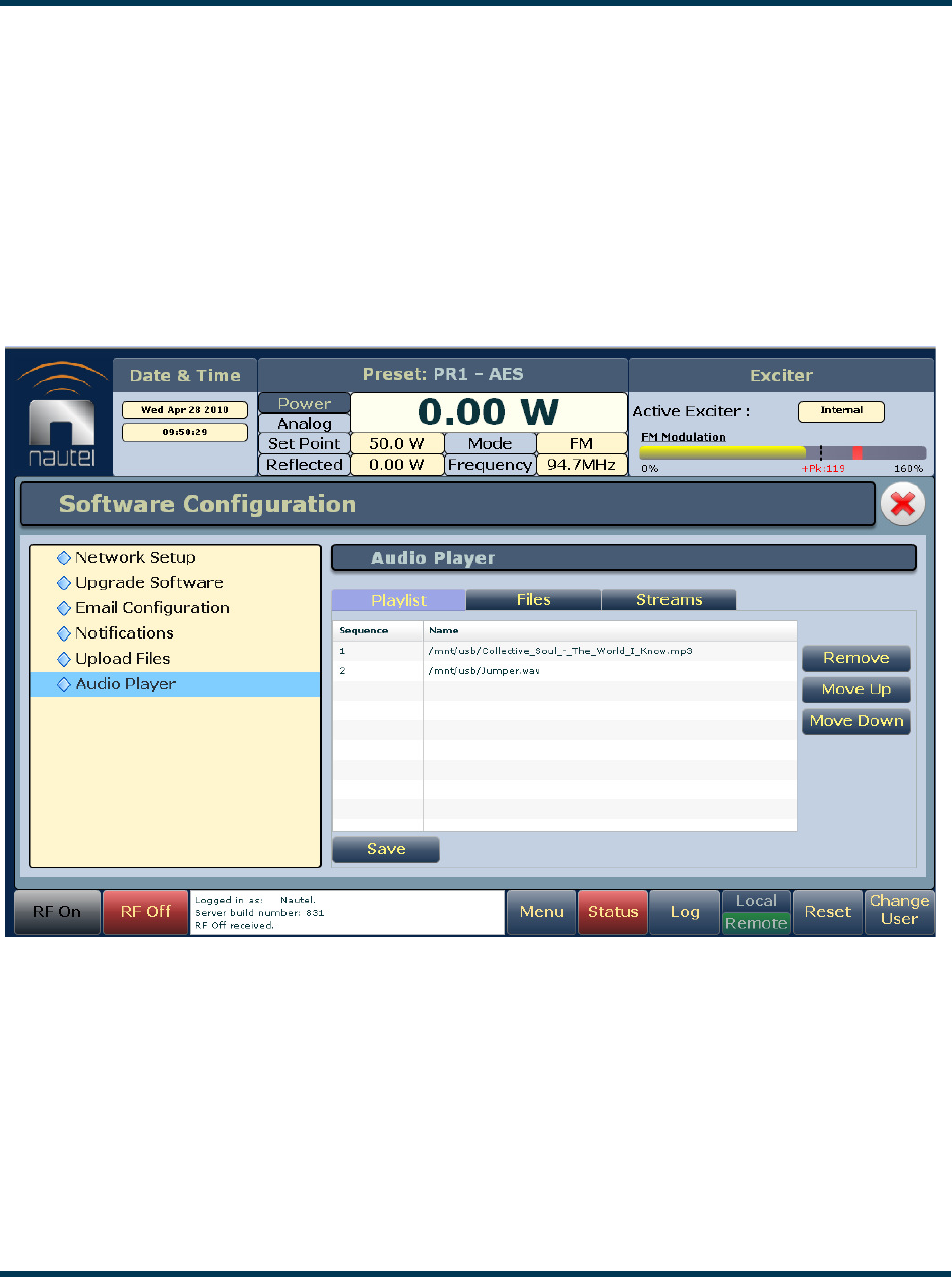
VS300 Operations and Maintenance Manual Operating the transmitter
Issue 0.1 2011-03-11 Page 2-73
Audio player
The built-in audio player (see Figure 2.67) can use a file playlist, Livewire or Shoutcast as an audio
source. These sources must be configured before they can be used. This section describes how to
configure audio player sources. The Audio Player page has three selectable tabs:
–Playlist
–Files - see page 2-74
–Streams - see page 2-75
Figure 2.67: Audio Player page - Playlist tab
Playlist
The Playlist tab (see Figure 2.67) displays the audio files and sequence that currently make up the
playlist. Only audio files that are supported (e.g., .wav or .mp3 files) will be played. Also, you must
activate a preset that has Playlist selected in the Main Audio -> Secondary Digital -> Secondary
Source in the Presets menu.
Use the Move Up and Move Down buttons on the right-hand side of the display to change the
playlist sequence.
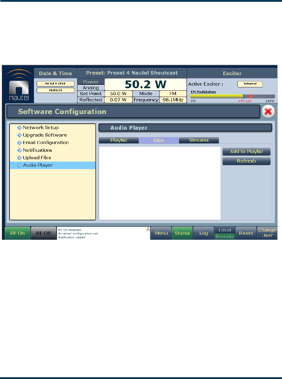
VS300 Operations and Maintenance Manual Operating the transmitter
Page 2-74 Issue 0.1 2011-03-11
Use the Remove button to delete audio files from the playlist.
Use the Save button to save the new configuration whenever a change is made to the file playlist. If
the playlist is currently playing, changes will not take effect until the playlit is started again.
Figure 2.68: Audio Player page - Files tab
Files
The Files tab (see Figure 2.68) is used for adding audio files to the playlist. Audio files must be stored
on a USB device plugged into the USB-A (A1J8B) or USB-B (A1J8C) connector on the rear of the
transmitter; they are not stored in the transmitter. Only the audio files stored in the root directory of
the most recently connected USB device appear on the playlist. The list will be empty if no USB
device is connected.
Click the Refresh button to force an update of the playlist.
The audio player supports only one USB device at a time. If multiple USB devices are connected,
only the most recently connected USB is recognized as the active USB drive. If multiple USB devices
are connected and one is removed, both devices are unmounted.
To add an audio file to the playlist, select the file(s) from the list and click the Add to Playlist button.
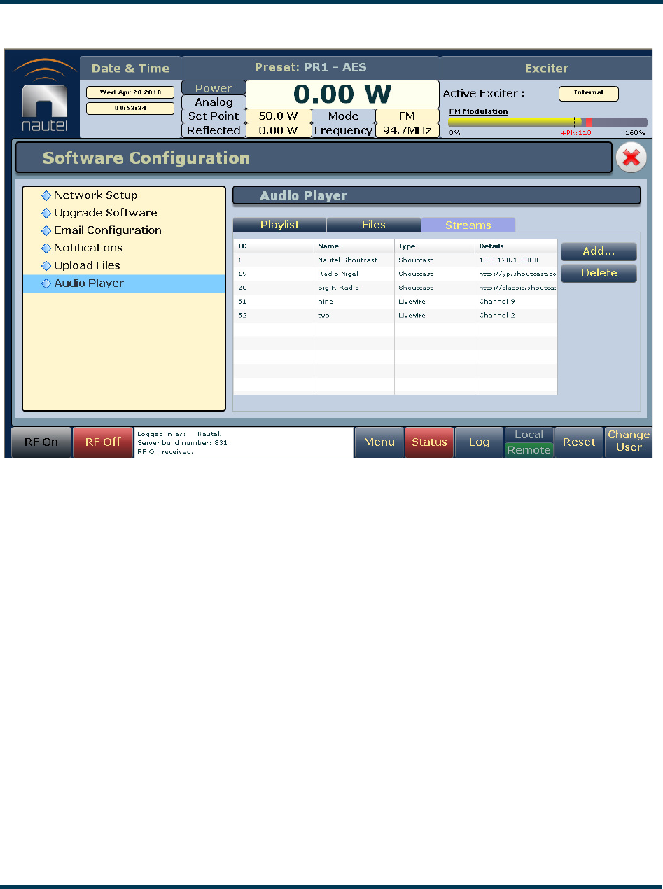
VS300 Operations and Maintenance Manual Operating the transmitter
Issue 0.1 2011-03-11 Page 2-75
Figure 2.69: Audio Player page - Streams tab
Streams
The VS300 is capable of playing audio streams in either Shoutcast or Livewire format.
The audio player supports Shoutcast playlists and IP addresses for audio streams. For a Shoutcast
playlist enter the URL for the station. For an audio stream, enter the IP address followed by a colon,
then the port for that stream (e.g., 10.10.10.1:8080).
For Livewire, enter the channel that contains the desired audio.
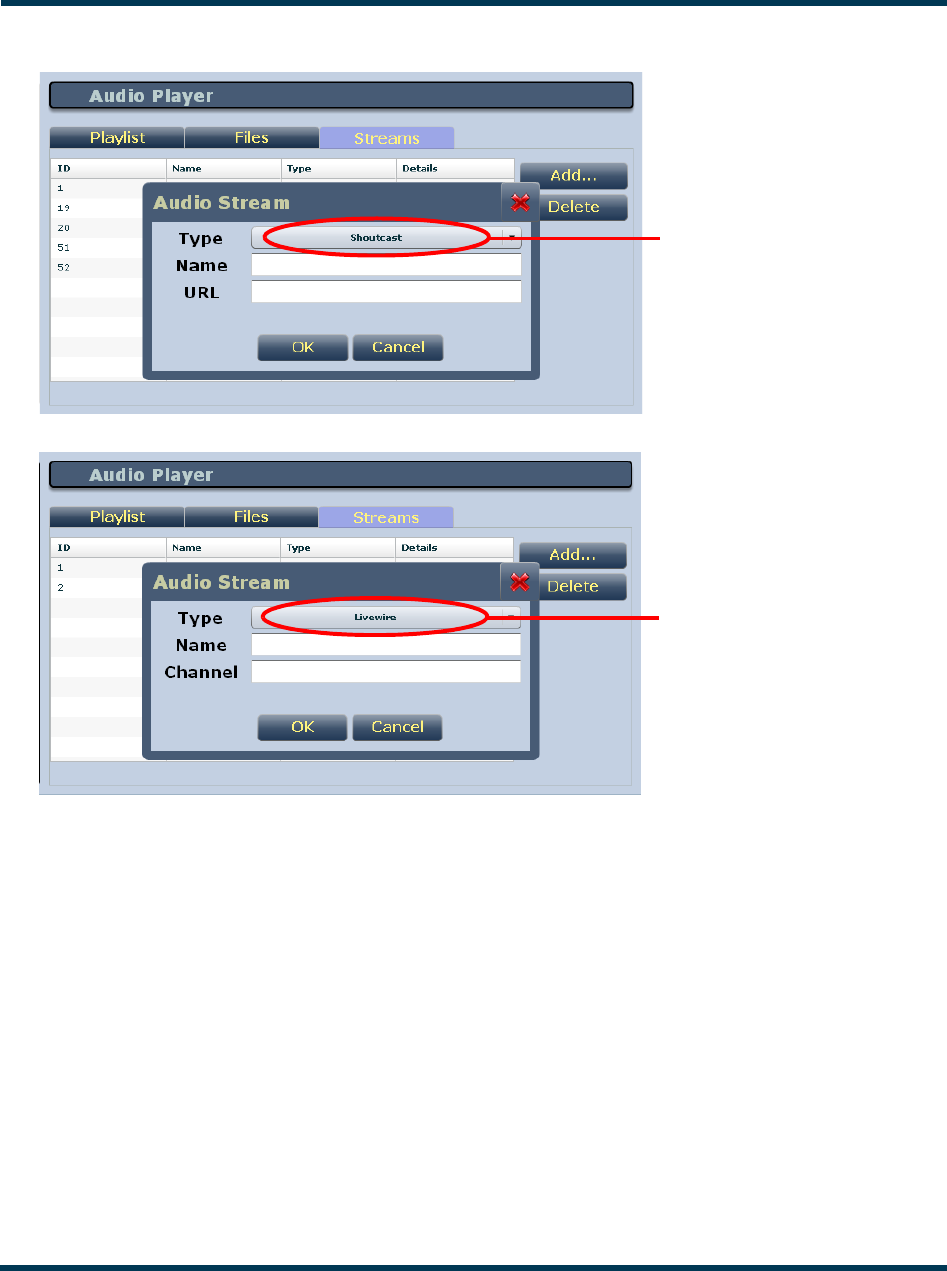
VS300 Operations and Maintenance Manual Operating the transmitter
Page 2-76 Issue 0.1 2011-03-11
Figure 2.70: Adding Audio Streams
Adding an audio stream. Add a new audio stream as follows:
1. From the Streams tab (see Figure 2.69 on page 2-75), click the Add... button.
2. Use the drop-down menu to select the desired Type of audio stream - Shoutcast or
Livewire (see Figure 2.70).
3. Enter the appropriate information for the audio server (Name and URL for Shoutcast;
Name and Channel for Livewire). Make sure the VS300 can access the location.
4. Click OK to add the audio stream or click Cancel to discard changes.
Livewire Type
Shoutcast Type
VS300 Operations and Maintenance Manual Operating the transmitter
Issue 0.1 2011-03-11 Page 2-77
Changing hardware settings
You can establish calibration values and fault thresholds for critical parameters of the VS300 using
the remote AUI or using the local front panel display. The following options are available:
•Configuring ARM watchdog - see page 2-78
•Calibrating exciter TCXO - see page 2-79
•Calibrating audio inputs - see page 2-81
•Configuring RF drive source - see page 2-83
•ARM reset - see page 2-84
•OS recovery - see page 2-84
WARNING: Hardware settings are established at the factory and
should not require any adjustment. Making changes to these settings
may void your warranty. Contact Nautel before making changes.
Note:
Changing threshold values in the System Settings -> Thresholds menu and changing the console
selection in the System Settings -> Console Select menu is not normally required, and should only
be performed by trained personnel. Information on these sub-menus is not included in the manual.
Contact Nautel for assistance.
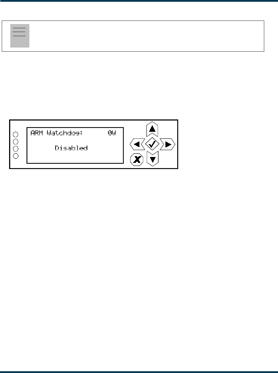
VS300 Operations and Maintenance Manual Operating the transmitter
Page 2-78 Issue 0.1 2011-03-11
Configuring ARM watchdog
From the front panel UI, you can enable or disable the ARM watchdog feature. This feature, when
enabled, monitors communication between the ARM processor and the DSP processor on the
exciter/control PWB. If communication is lost for more than 30 seconds, the transmitter will initiate
an alarm and reboot the ARM. To view the ARM Watchdog screen, select System Settings -> ARM
Watchdog from the Main Menu (see Figure 2.71).
Figure 2.71: ARM Watchdog Screen
Use the up and down buttons to toggle between Enabled and Disabled. Press the accept
(checkmark) button to save the change. Press cancel (X) to discard changes and return to the previous
menu.
Note:
ARM watchdog configuration is only available using the front panel display.
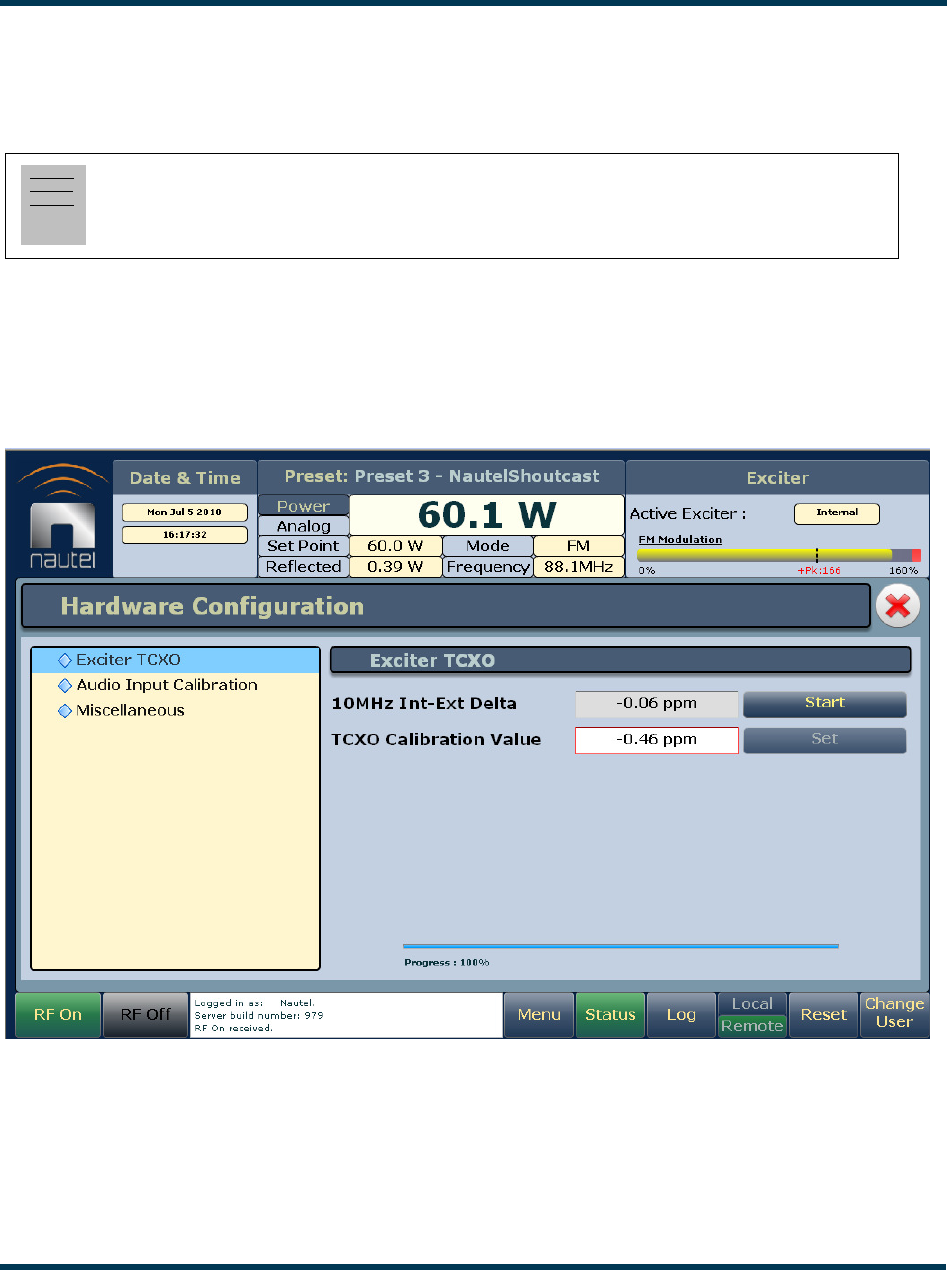
VS300 Operations and Maintenance Manual Operating the transmitter
Issue 0.1 2011-03-11 Page 2-79
Calibrating exciter TCXO
You can calibrate the internal clock reference to an external 10 MHz clock using the remote AUI (see
“Using the AUI”) or using the local front panel display (see “Using the front panel” on page 2-80).
Using the AUI
To view the AUI’s Exciter TCXO screen (see Figure 2.72), select Hardware Configuration from the
Menu options.
Figure 2.72: AUI - Exciter TCXO calibration page
To automatically calibrate the internal reference, click the Start button. The progress bar at the
bottom of the page will indicate that the calibration is in progress or complete. The TCXO
Calibration Value will appear when calibration is complete. Alternatively, if the required calibration
value is known, you can enter it in the TCXO Calibration Value field and click the Set button.
Note:
During calibration, the external 10 MHz clock should be connected to the EXT 10 MHz IN
(A1J4B) BNC connector on the rear of the VS300.
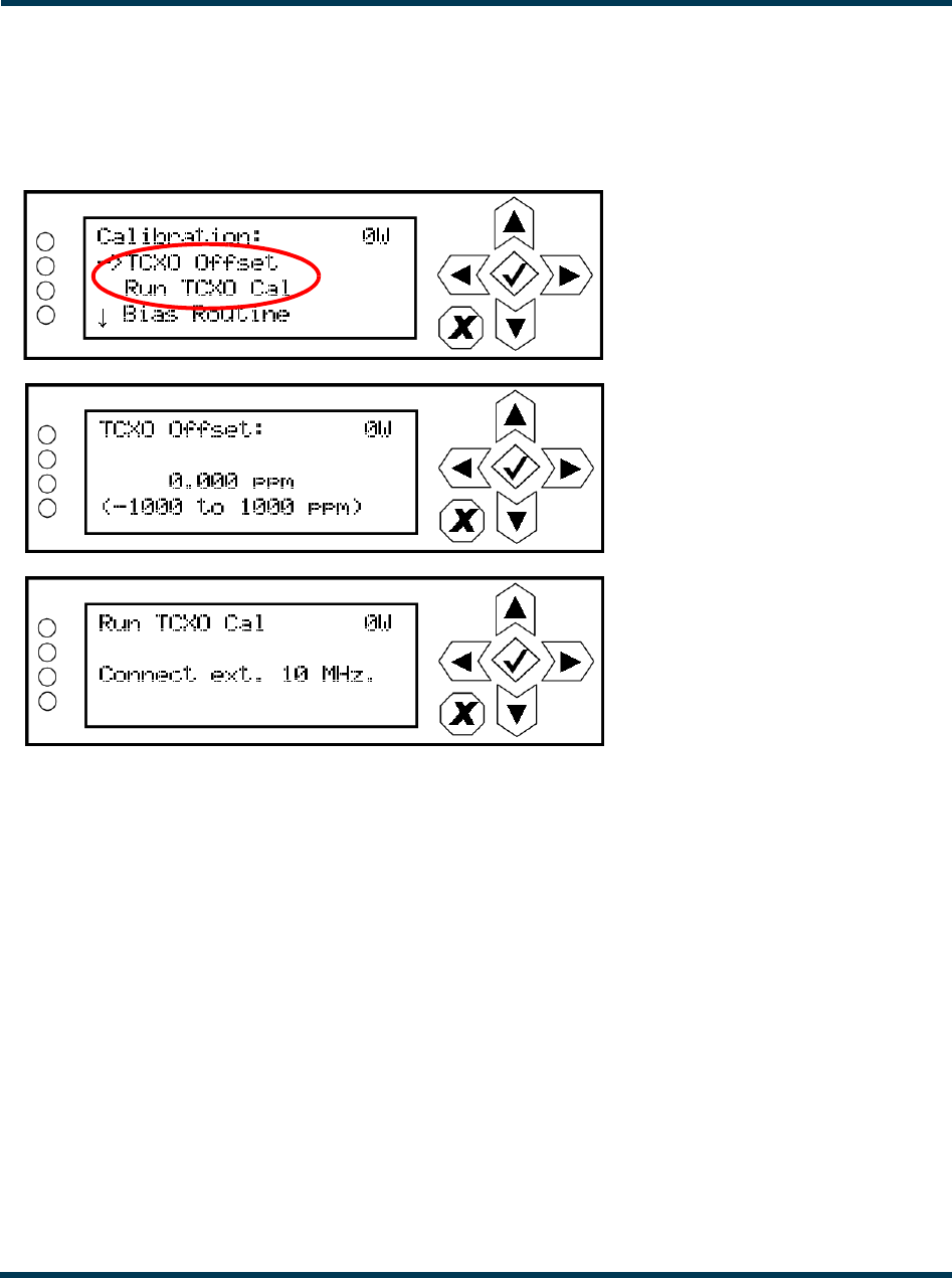
VS300 Operations and Maintenance Manual Operating the transmitter
Page 2-80 Issue 0.1 2011-03-11
Using the front panel
To view the front panel’s TCXO calibration screens (see Figure 2.73), select System Settings ->
Calibration from the Main Menu.
Figure 2.73: Front Panel - TCXO calibration screens
Use the up or down arrow to place the cursor next to TCXO Offset, then press the accept
(checkmark) button to enter the TCXO Offset screen. Use the up and down arrows to set the TCXO
offset value (in ppm) for the external 10 MHz source. When complete, press the accept (checkmark)
button to save the change. Press cancel (X) to discard changes and return to the previous menu.
From the calibration menu, press the down arrow to place the cursor next to Run TCXO Cal, then
press the accept (checkmark) button to enter the Run TCXO Cal screen. The calibration routine will
begin when the external 10 MHz source is connected.
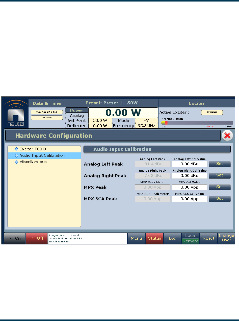
VS300 Operations and Maintenance Manual Operating the transmitter
Issue 0.1 2011-03-11 Page 2-81
Calibrating audio inputs
You can calibrate analog and MPX (composite) audio inputs using the remote AUI (see “Using the
AUI”) or using the local front panel display (see “Using the front panel” on page 2-82).
Using the AUI
To view the AUI’s Audio Input Calibration screen (see Figure 2.74), select Hardware
Configuration from the Menu options. The peak meter value of each applied audio input (analog
left, analog right, MPX or MPX SCA) will be displayed. Enter the calibration value and click Set to
save changes.
Figure 2.74: Audio Input Calibration screen
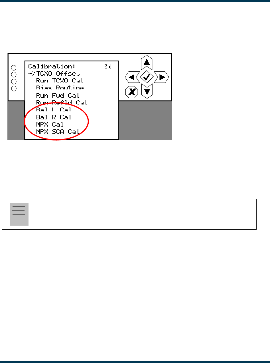
VS300 Operations and Maintenance Manual Operating the transmitter
Page 2-82 Issue 0.1 2011-03-11
Using the front panel
To view the front panel’s audio input calibration screens (see Figure 2.75), select System Settings ->
Calibration from the Main Menu.
Figure 2.75: Front Panel - Audio Input calibration screens
Use the up or down arrow to place the cursor next to the desired audio input calibration item (Bal L
Cal, Bal R Cal, MPX Cal or MPX SCA Cal), then press the accept (checkmark) button to enter the
selected audio input. Use the up and down arrows to set the new calibration value for the selected
audio input. When complete, press the accept (checkmark) button to save the change. Press cancel
(X) to discard changes and return to the previous menu.
Note:
Forward power (Run Fwd Cal) and reflected power (Run Refld Cal) calibrations are performed
at the factory and should not require user adjustment. Contact Nautel for assistance, if necessary.
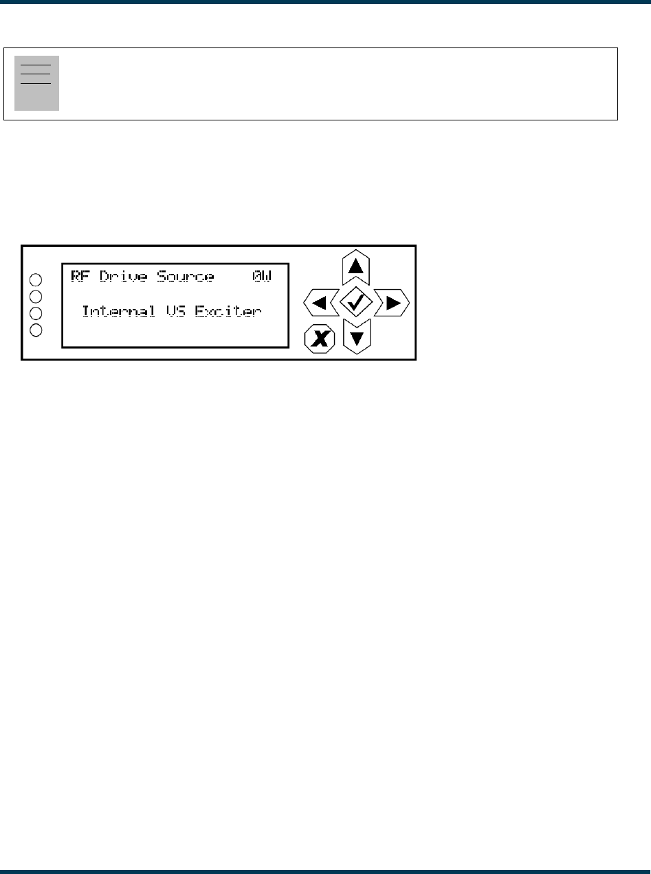
VS300 Operations and Maintenance Manual Operating the transmitter
Issue 0.1 2011-03-11 Page 2-83
Configuring RF drive source
From the front panel UI, you can configure the source of the transmitter’s RF drive (internal or
external). To view the RF Drive Source screen, select System Settings -> RF Drive Source from the
Main Menu (see Figure 2.76).
Figure 2.76: RF Drive Source Menu
Use the up and down buttons to toggle between Internal VS Exciter and External Exciter. Press the
accept (checkmark) button to save the change. Press cancel (X) to discard changes and return to the
previous menu. If you select External Exciter, proceed to “Connecting an external analog exciter”
for connection details.
Connecting an external analog exciter
Configure the transmitter for an external analog exciter as follows:
1. Change the RF drive source.
2. Turn off the transmitter, remove it from its host cabinet and place it on a suitable work
surface.
3. Remove the top cover.
4. Disconnect W5P1 from A1J1 and connect it to J4 on the inside of the box.
5. Re-install the top cover and re-insert the transmitter in its host cabinet.
6. With a user-supplied CAT5 cable, connect a wire between A1J1-7 (RF mute) and the the RF
mute input on the external exciter. Note: The RF mute signal from the VS300 is active low
and will not function if the external exciter is not configured in the same way.
Note:
Configuration of the RF drive source is only available using the front panel display.
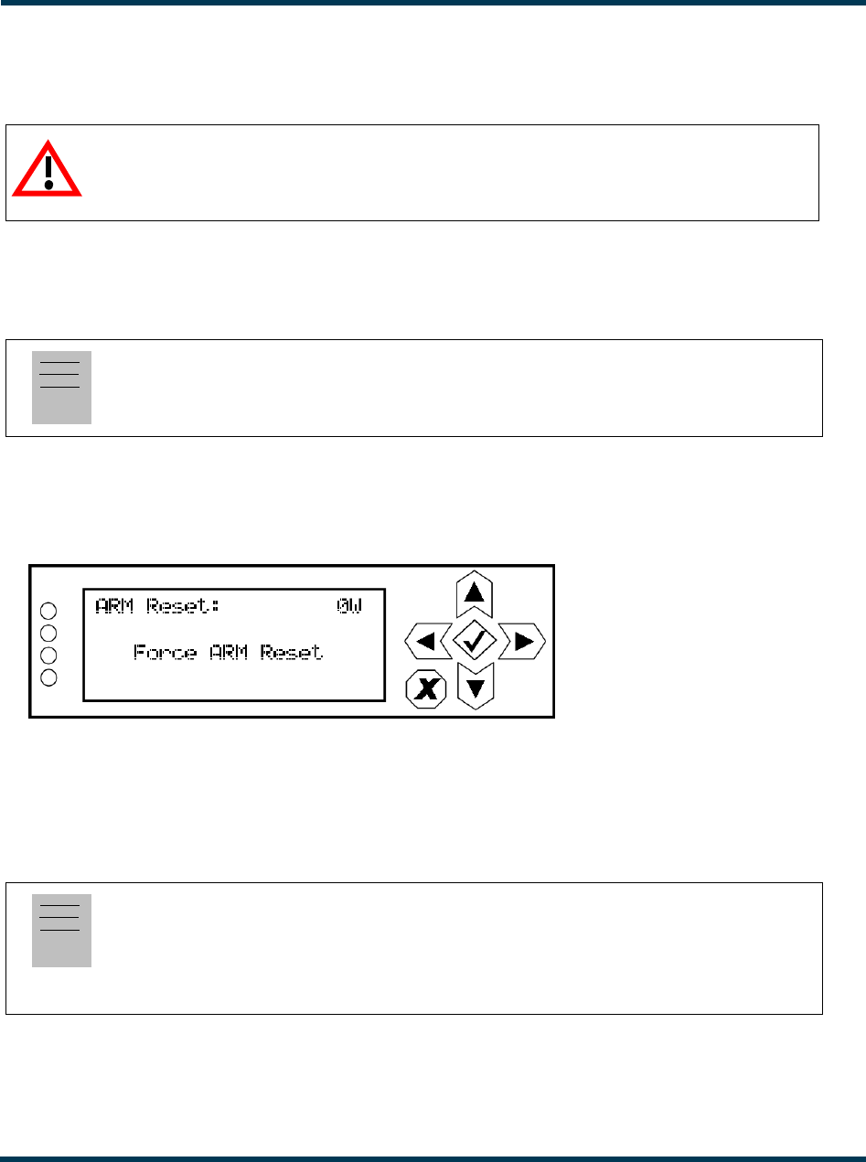
VS300 Operations and Maintenance Manual Operating the transmitter
Page 2-84 Issue 0.1 2011-03-11
7. Connect the external exciter’s RF output to J4 (RF DRIVE IN) on the rear panel of the VS300
through an attenuator such that the level out of the exciter at the desired setpoint converts to
+ 20 dBm .
8. Turn on the transmitter and resume operation.
ARM reset
From the front panel UI, you can reset the ARM on the exciter/control PWB. To view the ARM
Reset screen, select System Settings -> ARM Reset from the Main Menu (see Figure 2.77).
Figure 2.77: ARM Reset Screen
Use the up and down buttons to toggle between Force ARM Reset and Cancel. Press the accept
(checkmark) button to save the change. If a reset is selected, it will occur immediately. Select Cancel
or press X to abort the reset and return to the previous menu.
OS recovery
From the front panel UI, you can perform a recovery reset of the operating system (OS). You will
also need to install a flash drive, provided by Nautel, in one of the USB ports on the rear of the
VS300. To view the OS Recovery screen, select System Settings -> OS Recovery from the Main
Menu (see Figure 2.78).
CAUTION:
The maximum input level is +23 dBm. Exceeding this level could cause unstable
operation or damage to the VS300.
Note:
An ARM reset is only available using the front panel display.
Note:
An OS recovery reset can restore the transmitter’s operating system. It should only be required if a
problem occurs during a software upgrade
This feature is only available using the front panel display.
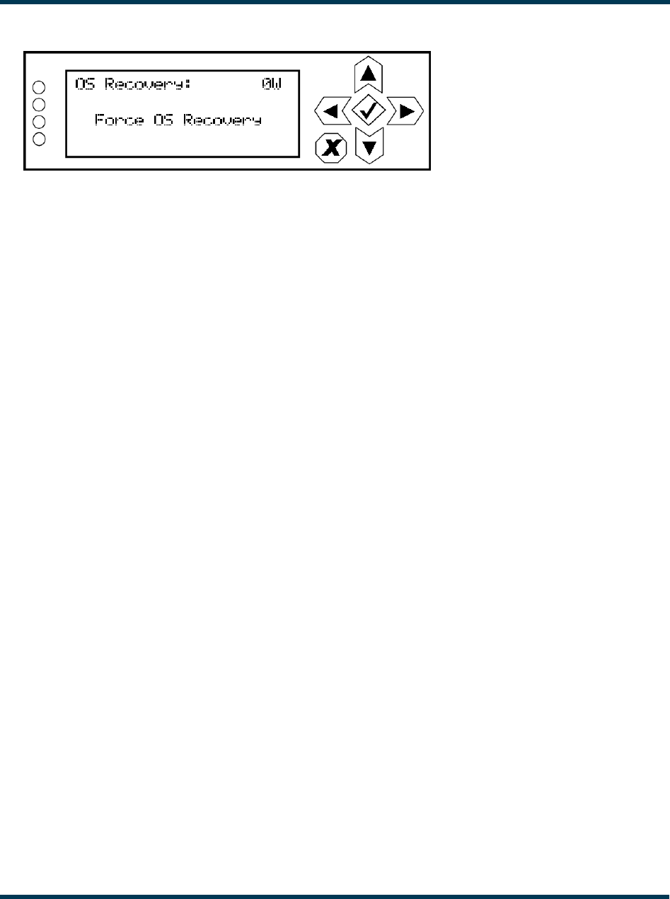
VS300 Operations and Maintenance Manual Operating the transmitter
Issue 0.1 2011-03-11 Page 2-85
Figure 2.78: OS Recovery Screen
Use the up and down buttons to toggle between Force OS Recovery and Cancel. Press the accept
(checkmark) button to save the change. Select Cancel or press X to abort the recovery and return to
the previous menu.
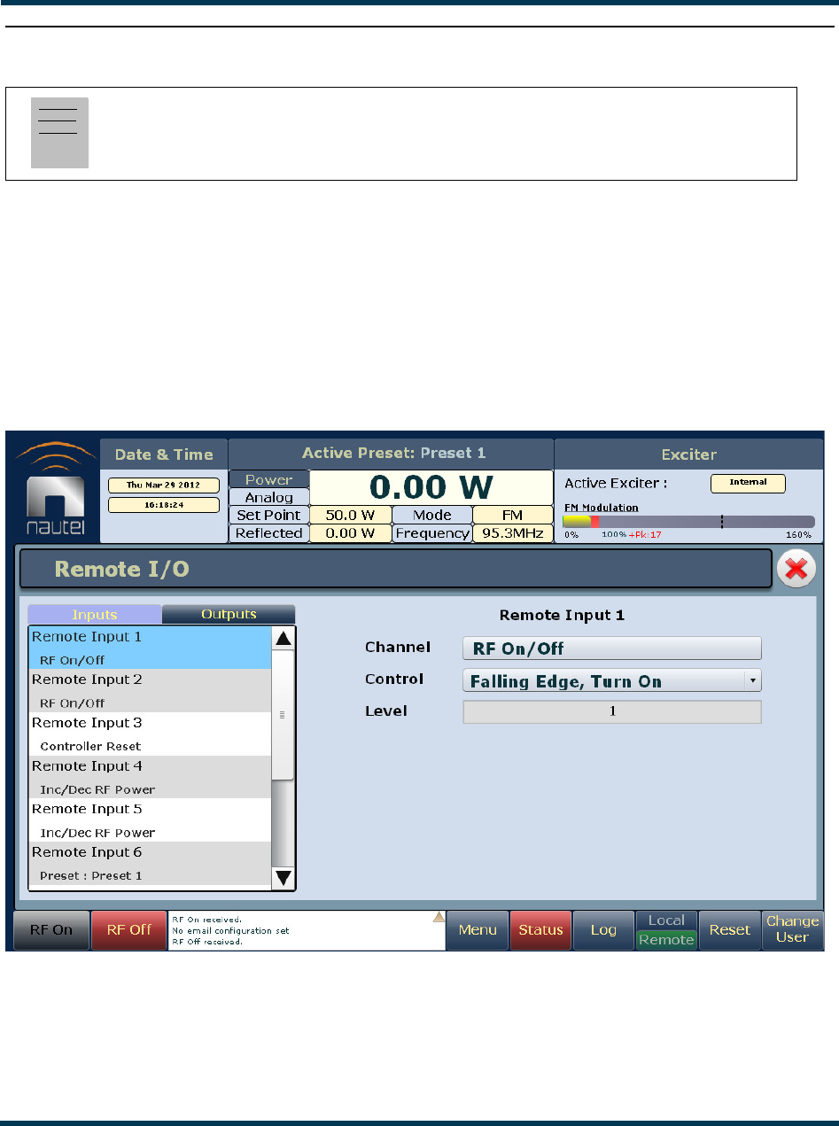
VS300 Operations and Maintenance Manual Operating the transmitter
Page 2-86 Issue 0.1 2011-03-11
Configuring remote inputs and outputs
You can define and configure your remote input/output interface for the transmitter using the
Remote I/O Page (Inputs tab selected) - see Figure 2.79. To view the Remote I/O page, select
Remote I/O from the Menu options. Click X in the upper, right corner to close this page and return
to the home page.
Refer also to the VS300 Pre-installation Manual for information on remote inputs and outputs and
their factory default settings.
Figure 2.79: Remote I/O Page (Inputs tab selected)
Click the Inputs (see “Digital inputs” on page 2-87) or Outputs (see “Digital outputs” on page 2-89)
tab to view or edit detail on the digital inputs or outputs.
Note:
This function is only available via remote connection to the AUI. However, you can view the
status of remote inputs and outputs on the front panel display.

VS300 Operations and Maintenance Manual Operating the transmitter
Issue 0.1 2011-03-11 Page 2-87
Digital inputs
Using the Inputs tab (see Figure 2.79 on page 2-86), you can configure up to 10 digital inputs that
allow you to remotely control various operational characteristics of the transmitter. Unless otherwise
noted, these inputs are only accepted by the transmitter if the remote/local status is set to remote.
That setting can only be made by a local user using the front panel UI.
Nautel presets the digital inputs prior to shipping. See the VS300 Pre-installation Manual for details.
Select the desired digital input (1 through 10) from the list. The Channel and Control settings for the
selected input, as well as the current logic level (1 or 0), are displayed on the right-hand side of the
page. You can define the Channel and Control settings as follows:
Select channel
You can configure digital inputs 1 through 10 for one of a variety of control inputs. Click the existing
Channel bar to display the Select a remote window. From this window select one of the following
options by clicking Load:
•Not Assigned. No effect on transmitter operation, regardless of logic level.
•RF On/Off. Same as clicking RF On (telling the system to provide RF power, if possible) or Rf
Off on the AUI.
•Controller Reset. Causes a system reset.
•Inc/Dec RF Power. Same as clicking Increase or Decrease on the AUI.
•Preset: NAME. Selects the associated preset (from a list of all pre-defined presets) as active.
Configure control logic
You can configure the active/inactive control logic for each of the 10 digital inputs. Click the existing
Logic bar to display the applicable drop-down menu options, which may include:
•Rising Edge Turn On/Reset. Logic ‘1’ (high or rising edge) activates the input (or causes a
reset, as appropriate).
•Falling Edge Turn On/Reset. Logic ‘0’ (low or trailing edge) activates the input (or causes a
reset, as appropriate).
•Rising Edge Turn Off. Logic ‘1’ (high or rising edge) de-activates the input.
•Falling Edge Turn Off. Logic ‘0’ (low or trailing edge) de-activates the input.
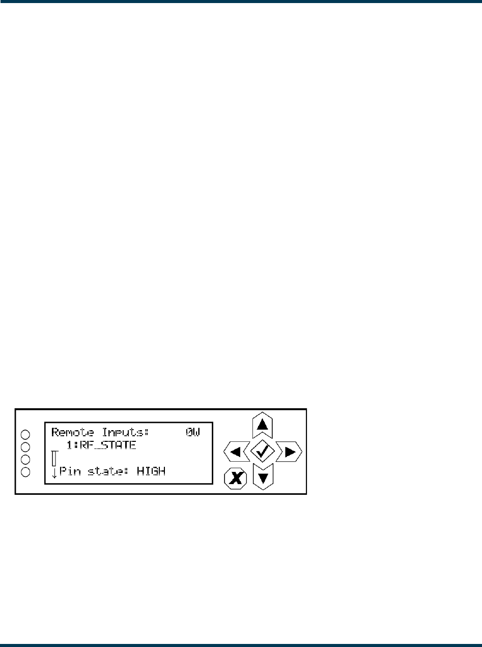
VS300 Operations and Maintenance Manual Operating the transmitter
Page 2-88 Issue 0.1 2011-03-11
•Falling Edge Toggle. Logic ‘0’ (low or trailing edge) de-activates the input; next logic ‘0’ (low
or trailing edge) activates the input.
•Rising Edge Toggle. Logic ‘1’ (high or rising edge) activates the input; next logic ‘1’ (high or
rising edge) de-activates the input.
•Rising Edge, Turn On. Falling Edge Turn Off. Logic ‘1’ (high or rising edge) activates the
input; logic ‘0’ (low or trailing edge) de-activates the input.
•Falling Edge, Turn On. Rising Edge Turn Off. Logic ‘0’ (low or trailing edge) activates the
input; logic ‘1’ (high or rising edge) de-activates the input.
•Active High, Increase. Logic ‘1’ (high) causes a power increase.
•Active Low, Increase. Logic ‘0’ (low) causes a power increase.
•Active High, Decrease. Logic ‘1’ (high) causes a power decrease.
•Active Low, Decrease. Logic ‘0’ (low) causes a power decrease.
Click Apply to activate changes. Click Undo to cancel changes.
View digital inputs on the front panel display
To view the status of digital inputs 1 through 10 on the front panel display, select User Settings ->
Remote I/O -> Remote Inputs from the Main Menu (see Figure 2.80).
Figure 2.80: Remote Inputs Screen (Input 1 shown)
Use the up and down buttons to scroll through the remote inputs. These inputs correspond to the
remote inputs set through the remote AUI . The screen is for viewing purposes only. It contains the
input number (1 through 10) and name, as well as the current logic state of the associated input pin.
Press cancel (X) to return to the previous menu.
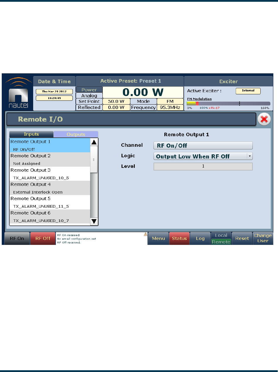
VS300 Operations and Maintenance Manual Operating the transmitter
Issue 0.1 2011-03-11 Page 2-89
Digital outputs
Using the Digital Outputs Page - see Figure 2.81, you can configure up to 16 digital outputs that
indicate either the presence of various alarms or the status of operator controlled circuits.
Nautel presets the digital outputs prior to shipping. See the VS300 Pre-installation Manual for details.
Figure 2.81: Digital Outputs Page
Select the desired digital output (1 through 16) from the list. The Channel and Logic settings for the
selected output, as well as the current logic level (1 or 0), are displayed on the right-hand side of the
page. You can define the Channel and Logic settings as follows:

VS300 Operations and Maintenance Manual Operating the transmitter
Page 2-90 Issue 0.1 2011-03-11
Select channel
You can configure digital outputs 1 through 16 to monitor a variety of alarm and status outputs. Click
the existing Channel bar to display the Select a remote window. From this window, select one of
the channels, then click Load to accept:
•Not Assigned. No alarm or status parameter is monitored.
•Local/Remote. The active logic level indicates the transmitter is in local control. The inactive
logic level indicates the transmitter is in remote control.
•RF On/Off. The active logic level indicates the transmitter’s RF power stage is on (enabled).
The inactive logic level indicates the transmitter’s RF power stage is off.
•Preset Status (1-4 default). The active preset’s output will be indicated by a logic low. The
remaining, non-active preset outputs will be open collector.
•Various Alarms. The active logic level indicates that the selected alarm is occurring. Any
transmitter alarm can be selected as a digital output. Refer to the VS300 Troubleshooting Man-
ual for a description of each alarm.
Configure logic
You can configure the active/inactive logic for each of the 16 digital outputs. Click the existing Logic
bar to display the applicable drop-down menu options. For example, if the selected channel is RF On/
Off, the drop-down options are:
•Output Low When Off. Logic ‘0’ (low) indicates the output is true (RF is off); Logic ‘1’
(high) indicates the output is false (RF is on).
•Output Low When On. Logic ‘0’ (low) indicates the output is true (RF is on); Logic ‘1’ (high)
indicates the output is false (RF is off).
Click Apply to activate changes. Click Undo to cancel changes.
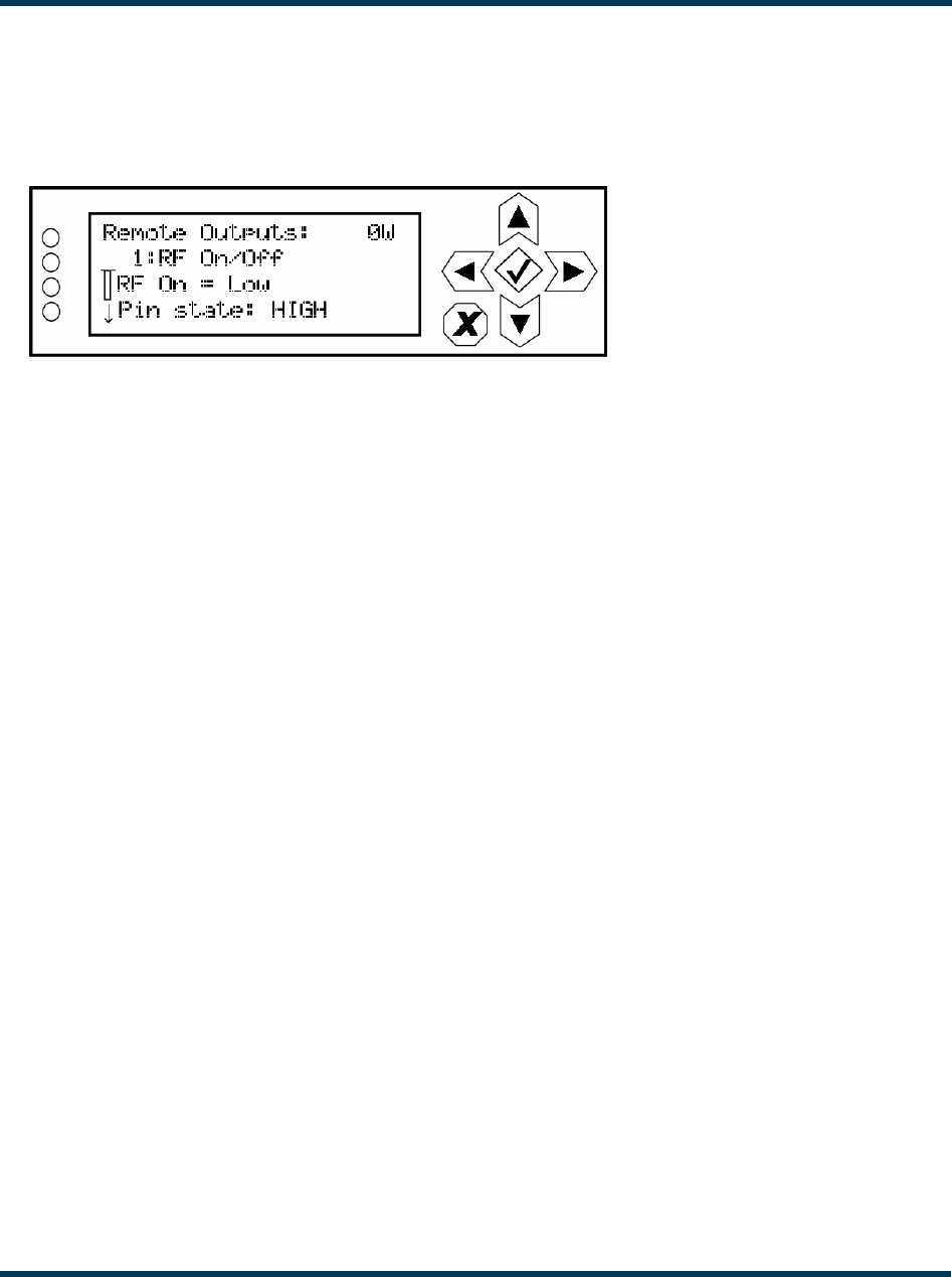
VS300 Operations and Maintenance Manual Operating the transmitter
Issue 0.1 2011-03-11 Page 2-91
View digital outputs on the front panel display
To view the status of digital outputs 1 through 16 on the front panel display, select User Settings ->
Remote I/O -> Remote Outputs from the Main Menu (see Figure 2.73).
Figure 2.82: Remote Outputs Screen (Output 1 shown)
Use the up and down buttons to scroll through the remote outputs. These outputs correspond to the
remote outputs set through the remote AUI . The screen is for viewing purposes only. It contains the
output number (1 through 16) and name, a logic description of the output’s active state (e.g., “RF
On = Low” or “Active High”) as well as the current logic state of the associated output pin. Press
cancel (X) to return to the previous menu.
Analog outputs
There are four analog outputs that can be remotely monitored. These outputs are factory defined and
are not user configurable. Refer to the VS300 Pre-Installation Manual for a list of these analog outputs.
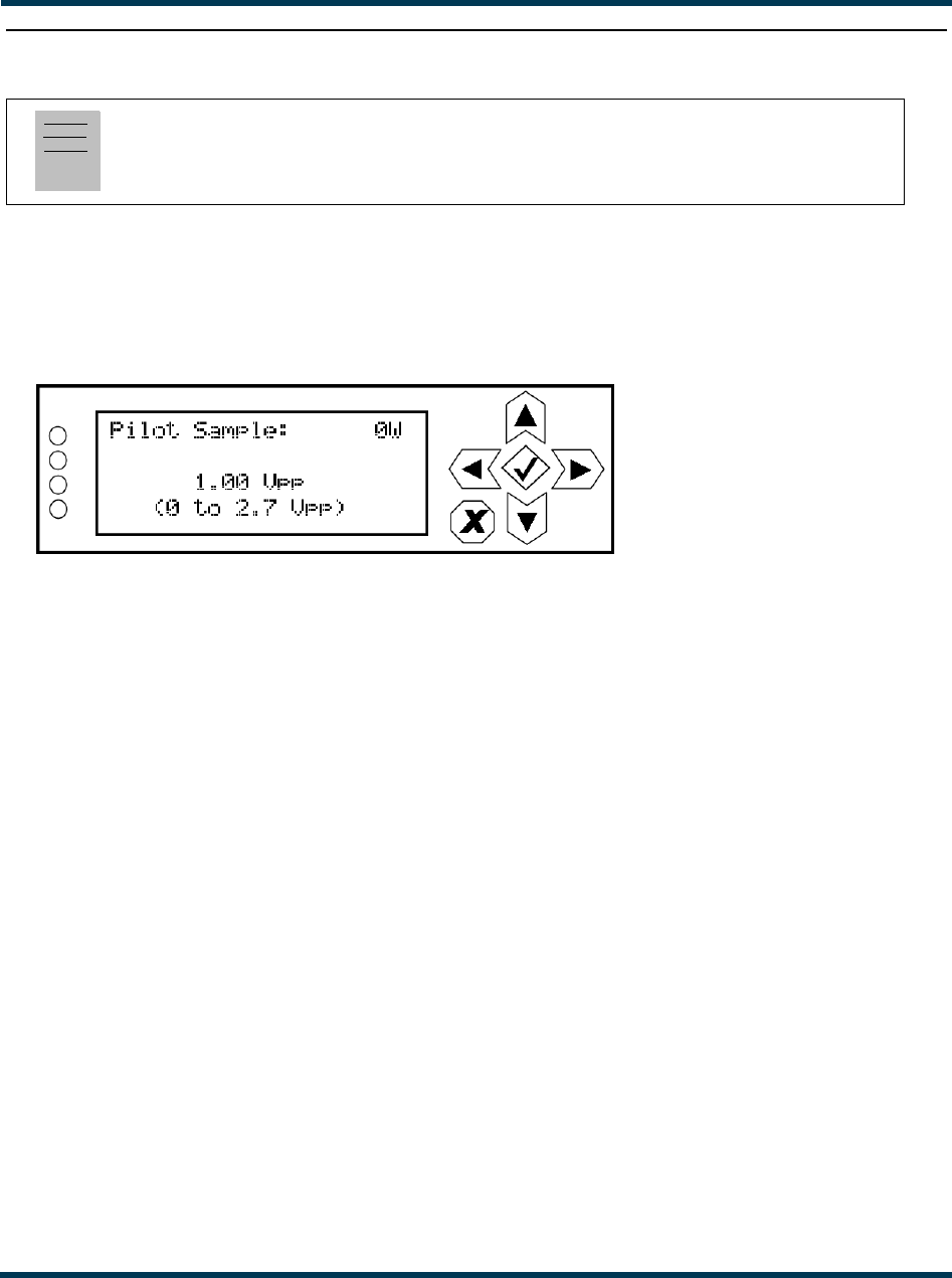
VS300 Operations and Maintenance Manual Operating the transmitter
Page 2-92 Issue 0.1 2011-03-11
Setting pilot sample level
From the front panel, you can set the level of the pilot sample that is applied to the PILOT SAMPLE
OUT (A1J4A) BNC connector on the rear of the VS300. To view the Pilot Sample screen, select User
Settings -> Pilot Sample from the Main Menu (see Figure 2.83).
Figure 2.83: Pilot Sample Screen
Use the up and down buttons to edit the pilot sample level. Press the accept (checkmark) button to
save the change. Press cancel (X) to discard changes and return to the previous menu.
Note:
Setting the pilot sample is only available using the front panel display.
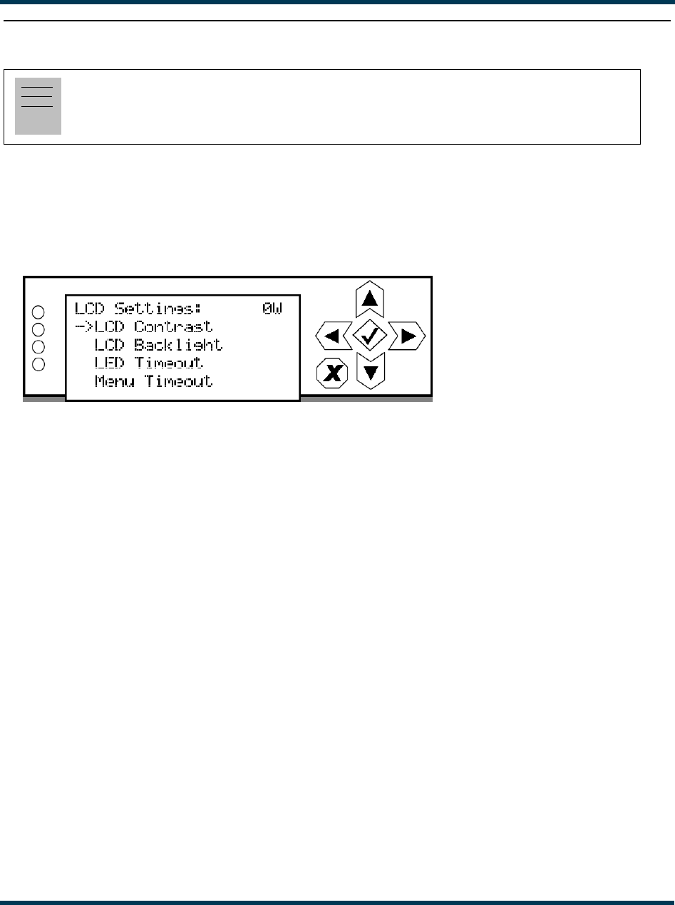
VS300 Operations and Maintenance Manual Operating the transmitter
Issue 0.1 2011-03-11 Page 2-93
Front panel display settings
From the front panel, you can configure the LCD display’s contrast, brightness and backlight
settings. To view the LCD Settings screen, select User Settings -> LCD Settings from the Main
Menu (see Figure 2.84).
Figure 2.84: LCD Settings Menu
This menu has four sub-menu options:
•LCD Contrast - sets the display contrast.
•LCD Backlight - sets the brightness of the display’s backlight during normal use.
•LED Timeout - sets a time delay, after a period of non-use, that the brightness of the display’s
backlight will dim. Can also be disabled.
•Menu Timeout - sets a time delay, after a period of non-use, that the front panel screen will
revert back to the main menu.
Use the up and down buttons to move the cursor to the desired display setting and then press the
right button to enable editing of the setting. Figure 2.85 on page 2-94 shows the editing screens for
the LCD Settings menu. Within any of the editing screens, use the up and down buttons to edit a
setting. Press the accept (checkmark) button to save the change. Press cancel (X) to discard changes
and return to the previous menu.
Note:
Front panel display settings are only available using the front panel display.
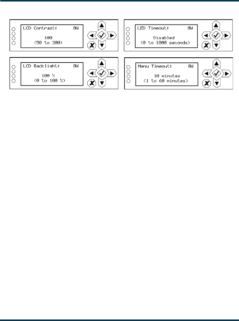
VS300 Operations and Maintenance Manual Operating the transmitter
Page 2-94 Issue 0.1 2011-03-11
Figure 2.85: LCD Settings Editing Screens
•LCD Contrast: Select a value between 50 (lighter contrast) and 200 (darker contrast).
•LCD Backlight: Select a value between 0 and 100%.
•LED Timeout: Select disabled (i.e., no timeout) or select a time period between 0 and 1800
seconds (30 minutes).
•Menu Timeout: Select a time period between 1 and 60 minutes.
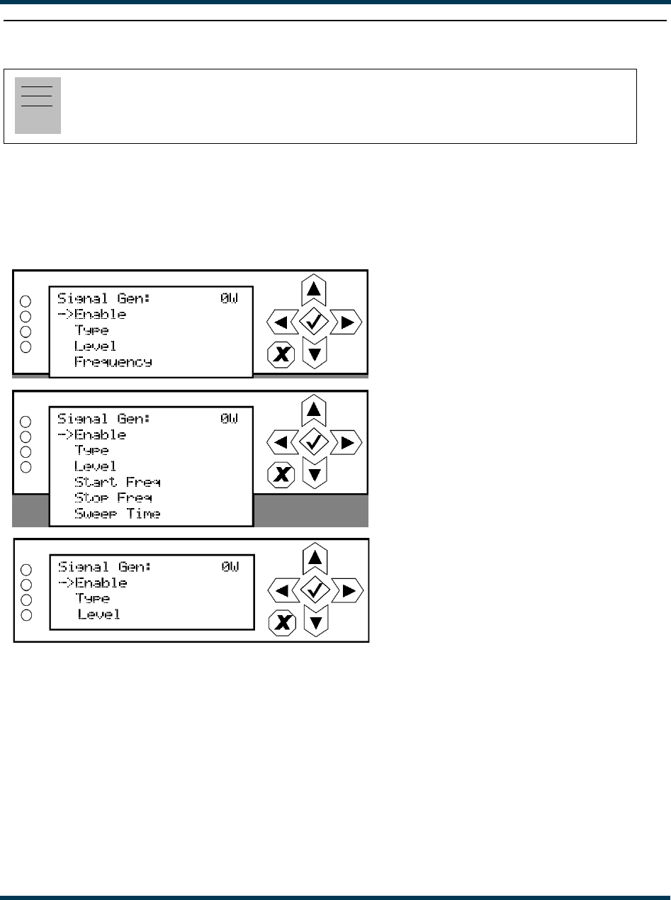
VS300 Operations and Maintenance Manual Operating the transmitter
Issue 0.1 2011-03-11 Page 2-95
Configure test signal generator
From the front panel UI, you can configure the test signal generator output of the VS300. Note that
a different menu will appear depending on the currently configured test signal type. To view the
Signal Gen screen, select User Settings -> Signal Gen from the Main Menu (see Figure 2.86).
Figure 2.86: Signal Generator Menus
Use the up and down buttons to move the cursor to the desired line item and then press the right
button to enable editing.
Figure 2.87 on page 2-96 shows all possible editing screens for the Signal Gen menu. Within any of
the editing screens, use the up and down buttons to edit the setting. Press the accept (checkmark)
button to save the change. Press cancel (X) to discard changes and return to the previous menu.
Note:
The test signal generator function is only available using the front panel display.
Displayed when Type
is set to Sine Wave
Displayed when Type
is set to Sine Sweep
Displayed when Type
is set to Bandlimited Noise
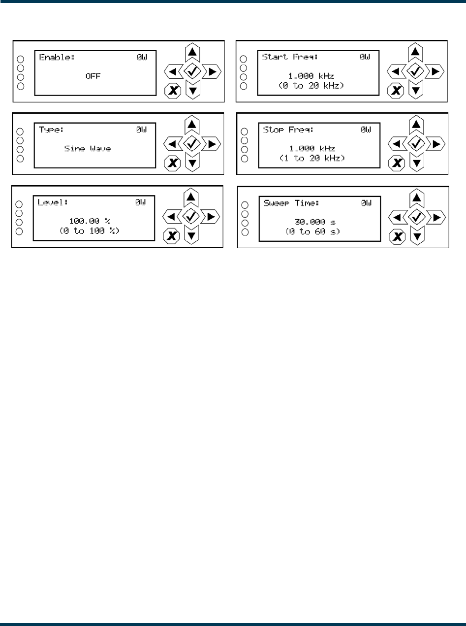
VS300 Operations and Maintenance Manual Operating the transmitter
Page 2-96 Issue 0.1 2011-03-11
Figure 2.87: Signal Generator Editing Screens
•Enable: Select ON or OFF.
•Type: Select None, Sine Wave, Sine Sweep or Bandlimited Noise.
•Level: Select a value between 0 and 100 %.
•Start Freq: When Type is set to Sine Sweep, select a start frequency between 0 and 20 kHz.
•Stop Freq: When Type is set to Sine Sweep, select a stop frequency between 1 and 20 kHz.
•Sweep Time: When Type is set to Sine Sweep, select a time between 0 and 60 seconds.
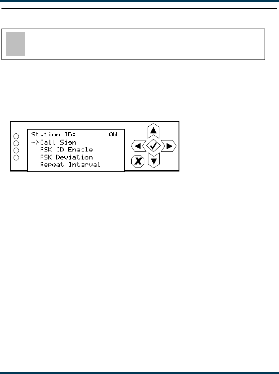
VS300 Operations and Maintenance Manual Operating the transmitter
Issue 0.1 2011-03-11 Page 2-97
Setting station ID parameters
In certain applications, the VS300 may be used as a translator to re-broadcast primary information as
a secondary station on an alternate frequency. To allow the secondary station to be identified, you can
set station ID parameters such as call sign, FSK deviation and repeat interval. To view the Station ID
screen, select User Settings -> Station ID from the Main Menu (see Figure 2.88).
Figure 2.88: Station ID Menu
This menu has four sub-menu options:
•Call Sign - sets the station’s call sign letters.
•FSK ID Enable - enables (ON) or disables (OFF) the station ID feature.
•FSK Deviation - sets the amount of carrier shift from the original carrier frequency. Select a
value between -25 kHz and 25 kHz.
•Repeat Interval - determines how often the call sign is broadcast using FSK (recommended
at least once per hour). Select a value between 1 and 60 minutes.
Use the up and down buttons to move the cursor to the desired display setting and then press the
right button to enable editing of the setting. Figure 2.89 on page 2-98 shows the editing screens for
the Station ID menu. Within any of the editing screens, use the up and down buttons to edit a setting.
In the Call Sign editing screen, use the left and right buttons to select a character for editing. Press
the accept (checkmark) button to save the change. Press cancel (X) to discard changes and return to
the previous menu.
Note:
Station ID settings are only available using the front panel display.
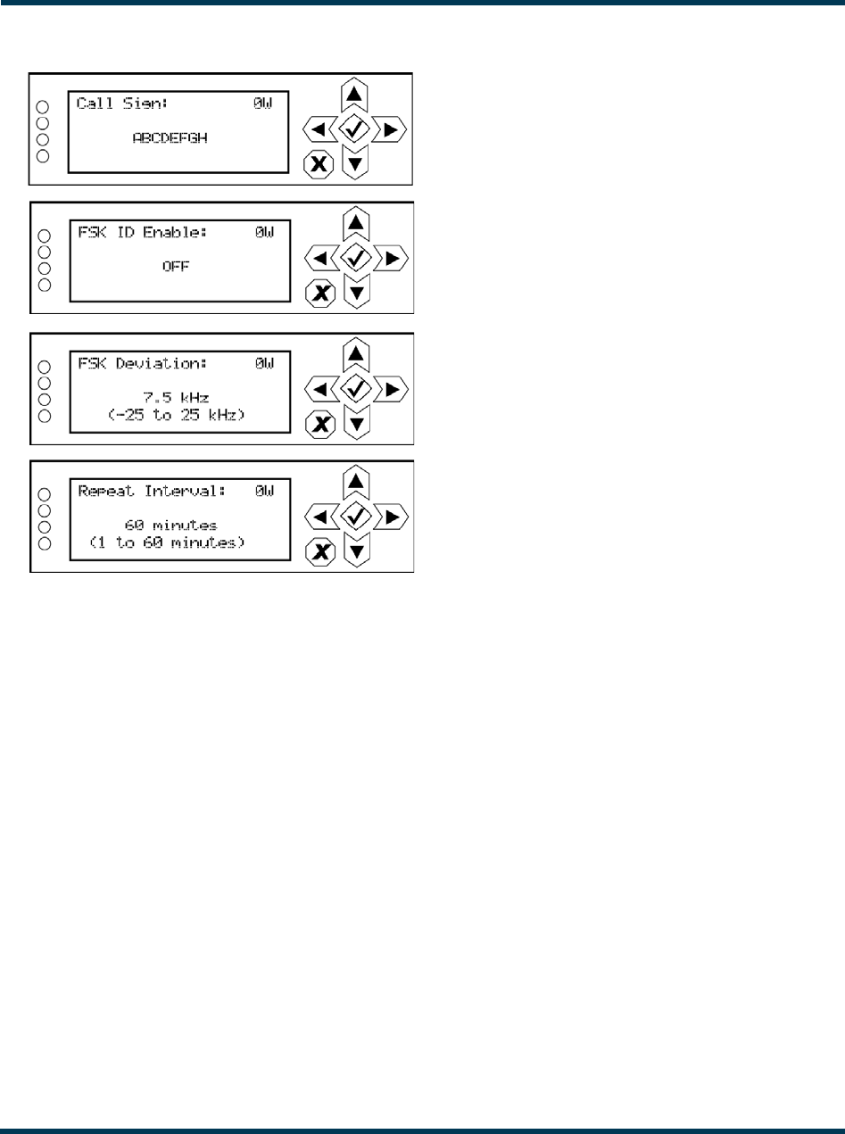
VS300 Operations and Maintenance Manual Operating the transmitter
Page 2-98 Issue 0.1 2011-03-11
Figure 2.89: Station ID Editing Screens
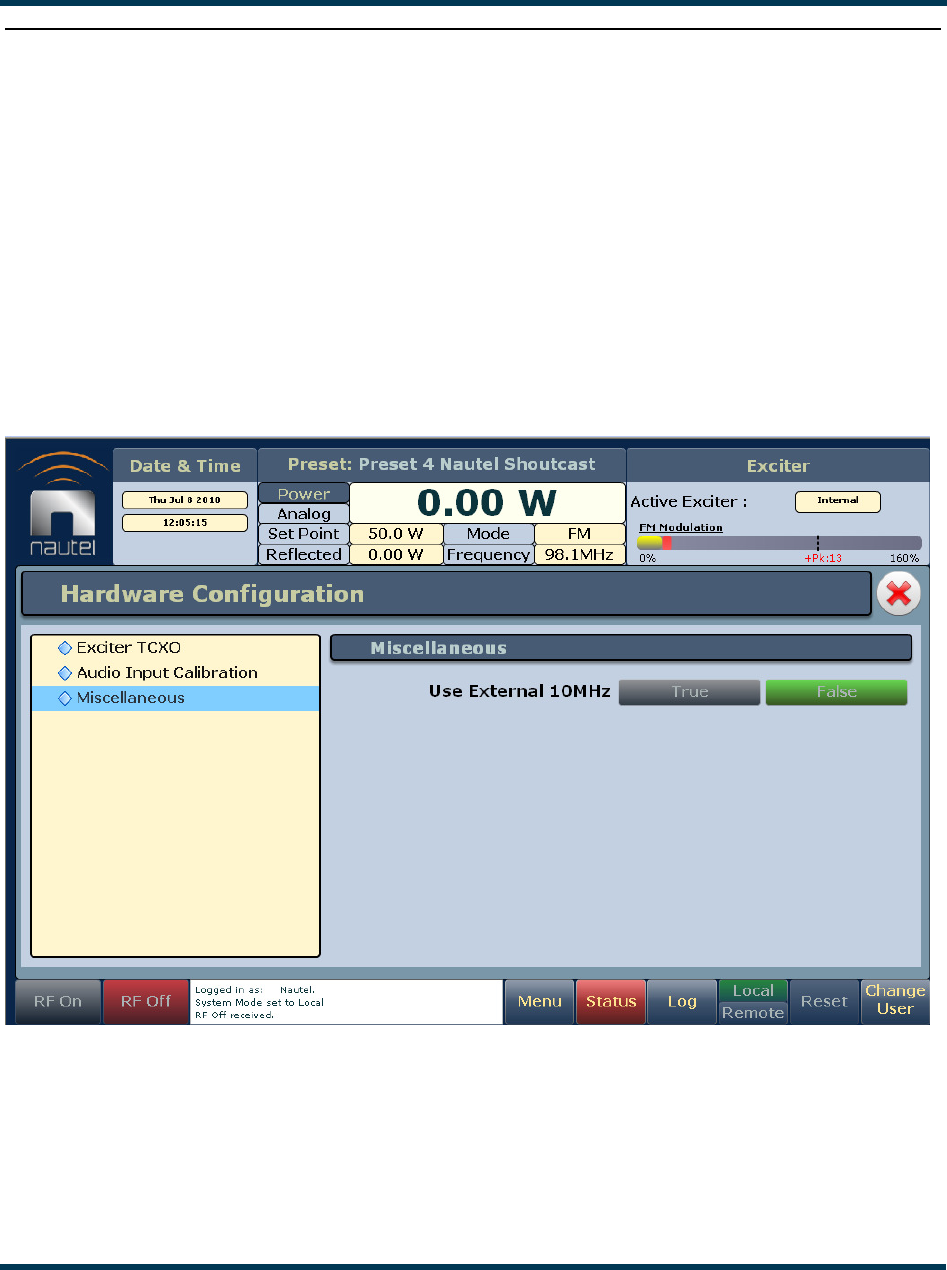
VS300 Operations and Maintenance Manual Operating the transmitter
Issue 0.1 2011-03-11 Page 2-99
Using an external 10 MHz input
You can configure the VS300 to accept an external 10 MHz input using the remote AUI (see “Using
the AUI”) or using the local front panel display (see “Using the front panel” on page 2-100).
Using the AUI
You can view the selection buttons for the external 10 MHz input on the the AUI’s Miscellaneous
screen (see Figure 2.90) by selecting Hardware Configuration from the Menu options. True and
False buttons for Use External 10MHz will be displayed. Click True if you are using an external
10 MHz signal. Click False if not. Click X in the upper, right corner to close this page and return to
the home page.
Figure 2.90: Miscellaneous screen
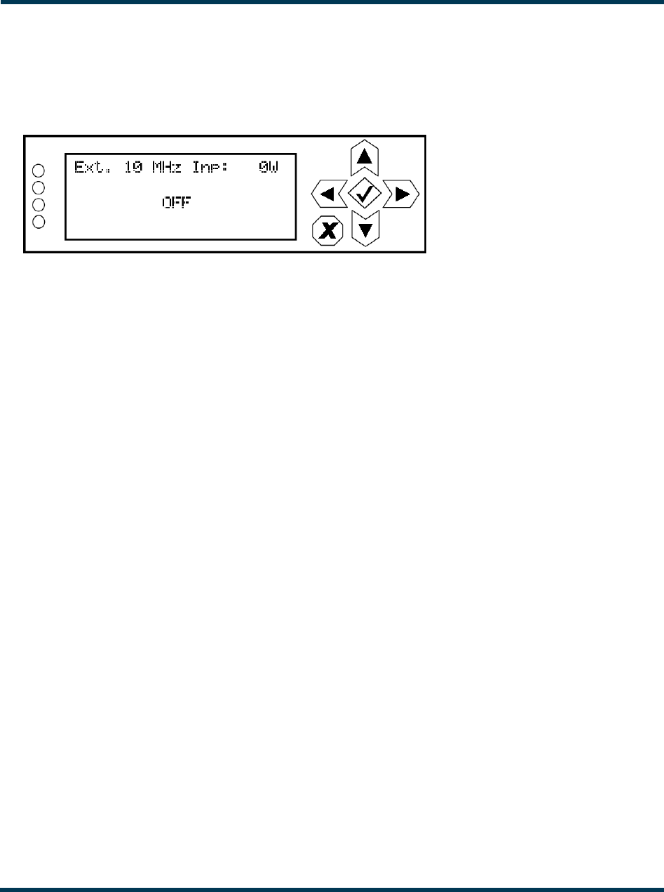
VS300 Operations and Maintenance Manual Operating the transmitter
Page 2-100 Issue 0.1 2011-03-11
Using the front panel
To view the enable/disable screen for the external 10 MHz input (see Figure 2.91), select User
Settings -> Ext. 10 MHz Inp from the Main Menu.
Figure 2.91: Front Panel - External 10 MHz Input screen
Use the up or down arrow to toggle between ON (using external 10 MHz input) and OFF (not using
external 10 MHz input), then press the accept (checkmark) button to save the change. Press cancel
(X) to discard changes and return to the previous menu.

VS300 Operations and Maintenance Manual Routine maintenance
Issue 0.1 2011-03-11 Page 3-1
Section 3: Routine maintenance
This section provides instructions for performing routine maintenance on the VS300 transmitter.
This section includes the following topics:
•Scheduled maintenance
–Cleaning fan filters
–Checking hardware - see page 3-2
–Battery replacement - see page 3-2
•Performing on-air checks - see page 3-3
•Replacing the exciter/control PWB battery - see page 3-5
•Inspecting lightning protection systems - see page 3-6
Scheduled maintenance
Scheduled maintenance consists of performing a visual inspection of the VS300 at scheduled
intervals. The recommended minimum time between scheduled maintenance visits is three months.
Local operating and environmental conditions may dictate more frequent visits, while in remote sites,
less frequent visits may be acceptable. Experience and system reliability will determine the most
practical schedule for a specific installation.
Cleaning fan filters
Clean the fan filters, noting there is one on each side of the transmitter. Gently remove the fan filter
cover and guard, rinse the filters with water, then re-install the filters and guards. If a fan filter
becomes damaged, replace it as soon as possible. You can order the filter from Nautel (part #
HAS72) or obtain one from any local supplier of HVAC supplies.
Note:
A site located in a dirty area using open-air cooling requires more extensive cleaning than a site
located in a clean area using closed-air cooling.

VS300 Operations and Maintenance Manual Routine maintenance
Page 3-2 Issue 0.1 2011-03-11
Checking hardware
All hardware must be checked at least once a year. Nautel recommends more frequent checking if the
VS300 is subjected to above average thermal cycling, caused by turning the VS300 on and off.
• To prevent damaging the hardware, ensure that the proper size tools are used. In most cases,
hardware is metric.
• A mounting surface or terminal that has changed colour indicates a loose hardware
connection.
Battery replacement
The VS300's exciter/control PWB contains a battery backup circuit that allows the time and date to
update during ac power failure. The battery should be replaced every 12 months. See “Replacing the
exciter/control PWB battery” on page 3-5.
VS300 Operations and Maintenance Manual Routine maintenance
Issue 0.1 2011-03-11 Page 3-3
Performing on-air checks
You should check the on-air quality of the transmitter’s signal periodically. This check can be done
locally at the transmitter site, or remotely from another location in the transmitter’s coverage area.
Interval
Every 12 months, or as required by law.
Parts and tools
• High-quality receiver, compatible with the modulation scheme used on the transmitter.
Procedure
1. Monitor the transmitter signal to identify any problems:
– Use a high quality receiver to monitor audio quality.
– Take a portable receiver to different locations in your coverage areas to identify any
problems with the antenna pattern or areas of localized interference.
2. Obtain the Proof of Performance document that was completed during factory testing and
provided with the transmitter. Use the front panel UI or the remote AUI to compare current
transmitter meter readings with those in the Proof of Performance document and in Table 3.1 on
page 3-4, which shows expected meter readings at 88 MHz, 98 MHz and 108 MHz. When
comparing data, use the frequency column closest to your operating frequency.
Note:
Nautel completes the Proof of Performance document with the transmitter operating at 98 MHz,
terminated into a precision 50 ohm load. Measurements made at other operating frequencies may not
yield the same readings. The data in Table 3.1 on page 3-4 is an example of measured meter values
and is provided as a troubleshooting aid. Your front panel meter readings may not be exactly the
same as shown, but if an out-of-tolerance condition exists, an alarm will be displayed.
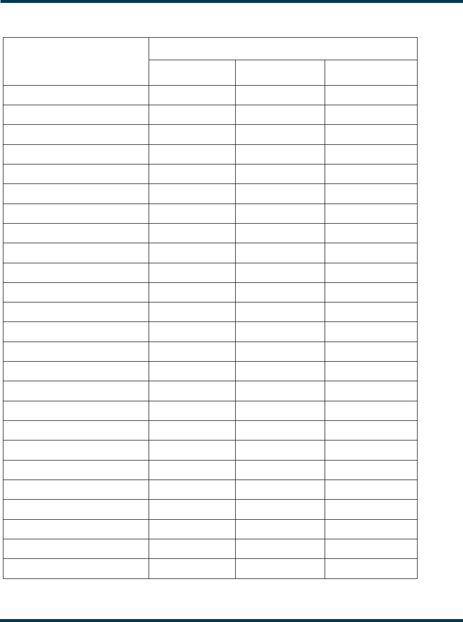
VS300 Operations and Maintenance Manual Routine maintenance
Page 3-4 Issue 0.1 2011-03-11
Table 3.1: Expected Transmitter Meter Readings
Meter Parameter
(displayed on front panel
UI or remote AUI
Meter Value at ...
88 MHz 98 MHz 108 MHz
Forward (forward power) 100 W 100 W 100 W
Reflected (reflected power) 0.20 W 0.02 W 0.34 W
Preamp Curr 397 mA 505 mA 412 mA
PA1 Curr 5.4 A 5.8 A 5.7 A
PA V 22.8 V 22.2 V 24.9 V
Heatsink Temp 27°C 27°C 27°C
+48V 48 V 48.1 V 48.1 V
+15V 15.6 V 15.6 V 15.6 V
-15V -15.4 V -15.4 V -15.4 V
+5V 5.01 V 5.01 V 5.01 V
+3.3V 3.28 V 3.28 V 3.29 V
+1.8V 1.78 V 1.82 V 1.83 V
+1.2V 1.20 V 1.20 V 1.20 V
Battery 3.00 V 3.00 V 3.00 V
Fan 1 6518 RPM 6517 RPM 6512 RPM
VSWR 1.10 1.02 1.11
Delta 10 MHz N/A N/A N/A
Total PA Curr 5.4 A 5.8 A 5.7 A
DC Power In 124 W 131 W 144 W
DC-RF Eff 80.9 % 76.3 % 69.4 %
Avg PA Diss 24 W 31 W 44 W
PA1 Bias 0.00 V 0.00 V 0.00 V
Preamp Bias 2.80 V 2.80 V 2.80 V
Fwd Atten 0 dB 0 dB 0 dB
DAC Gain 100 % 100 % 100 %

VS300 Operations and Maintenance Manual Routine maintenance
Issue 0.1 2011-03-11 Page 3-5
Replacing the exciter/control PWB battery
Replace the battery on the exciter/control PWB (A1) once a year, or whenever the Controller - Low
Battery alarm appears (on the front panel UI or via remote AUI). Chemical leakage from an old
battery can cause damage. Also, the exciter/control PWB’s microcontroller may not retain its settings
if ac power is turned off while the backup battery power is low. The battery should be replaced while
ac power is applied to the transmitter.
Interval
Every 12 months.
Parts and tools
Replacement battery: 3 V lithium coin cell, 20 mm (Nautel Part # BBLT01, Panasonic # CR2032).
Procedure
Perform the following steps to replace the battery:
1. Ensure ac power is being applied to the transmitter.
2. Gain access to the exciter/control PWB (A1) by removing the transmitter’s top cover.
3. Replace battery BT1 on the exciter/control PWB. See Figures MD-1 and MD-2 in the
mechanical drawings section at the end of the VS300 Troubleshooting Manual to locate the
exciter/control PWB (A1) and its battery (BT1).
4. Re-install the transmitter’s top cover.
5. Check for any alarms on the front panel UI or remote AUI. Battery related alarms should
clear. (See “Viewing transmitter status” on page 2-58.)

VS300 Operations and Maintenance Manual Routine maintenance
Page 3-6 Issue 0.1 2011-03-11
Inspecting lightning protection systems
You should inspect the lightning protection systems that are connected to your VS300 transmitter, ac
power, RF feedline, antenna and tower periodically to ensure that your site, equipment and personnel
are fully protected.
Interval
Every 6 months.
Parts and tools
Depends on your site, but may include a digital multimeter, ladder, binoculars, and continuity tester.
Procedure
Perform the following steps to test the lightning protection systems:
1. Test the continuity between ground available at your lightning arrestor and ground available
on various pieces of equipment connected to the transmitter. Ensure that there is no
resistance (near 0 ohms, accounting for multimeter test lead resistance).
2. Physically inspect the lightning arrestor to ensure that all connections are tight. Also look for
any sign of scoring or burning (indications of possible damage from earlier lightning strikes).
3. Using binoculars, visually inspect the hardware on the tower. Look for charred, broken or
frayed connections and corrosion.
VS300 Operations and Maintenance Manual Non-standard maintenance
Issue 0.1 2011-03-11 Page 4-1
Section 4: Non-standard maintenance
This section provides instructions for performing non-standard maintenance on the VS300
transmitter. This section includes the following topics:
•Upgrading software
Upgrading software
Periodically, enhancements or improvements to the operating system are identified and made
available. Perform a software upgrade, as required, as follows:
Parts and tools
• Laptop (i.e., local computer for direct connection) or network computer with Windows and
Internet Explorer Web browser
• CAT5 Ethernet cable
• Upgrade software (*.tgz file), provided via email or web download
Preliminary checks
1. Determine the current software revision installed. Via the advanced user interface (AUI)
screen, go to Menu/Software/Upgrade Software. Select the *.tgz file in the Select Upload
File list (should highlight in blue) and click Versions. Note the current software revision for
Audio Player, AUI, Server, SNMP Agent, Axia Livewire Module, Watchdog and Controller.
2. Contact Nautel for the most recent software revision and download *.tgz file to a laptop or
network location.
CAUTION:
If you are upgrading from a software version prior to V1.2, the ARM Watchdog
feature must be DISABLED during the software upgrade process. Failure to
observe this may result in a non-operational transmitter that will require a full
operating system recovery. Refer to “Configuring ARM watchdog” on page 2-78
for details on disabling the ARM watchdog feature.

VS300 Operations and Maintenance Manual Non-standard maintenance
Page 4-2 Issue 0.1 2011-03-11
Transferring upgrade file
The following steps assume either the laptop will be used to connect directly to the transmitter OR
the transmitter and network computer are currently connected to the same network.
Transmitter IP configuration
1. From the transmitter AUI, go to Menu/Software/Network Setup.
2. Record your current network settings (IP Address, Subnet Mask, Default Gateway).
3. If connecting to the transmitter directly with a laptop, you must set a static IP address. This
can only be done via the front panel interface. From the front panel UI’s Main Menu, go to
User Settings/Network Settings and set the IP address as follows:
– DHCP: OFF
– IP Address: 10.10.10.2
– Netmask: 255.255.255.0
4. Set the transmitter for Remote control.
Laptop IP setup
The following steps assume the operating system is Windows XP. Adapt as required for computers
with different operating systems.
1. On the laptop go to Start Menu/Control Panel/Network Connections/Local Area
Network.
2. In the Local Area Network Status, open the General tab and choose Properties. Scroll
down and highlight Internet Protocol (TCP/IP). Choose Properties.
3. In the Internet Protocol (TCP/IP) Properties window, select Use the following IP address.
4. Enter the following settings:
– IP Address: 10.10.10.1
– Subnet Mask: 255.255.255.0
– Default Gateway: 192.168.1.2
5. In the Internet Protocol (TCP/IP) Properties window, select OK.
6. In the Local Area Connection Properties window, select OK.
VS300 Operations and Maintenance Manual Non-standard maintenance
Issue 0.1 2011-03-11 Page 4-3
7. In the Local Area Connection Status window, select Close.
8. Close the Network Connections window.
Transfer software upgrade file to transmitter
1. If using a laptop, connect the laptop network interface card to the transmitter LAN (A1J8A)
connector on the rear panel using a CAT5 Ethernet cable. Open Internet Explorer and
search for 10.10.10.2. The transmitter login screen should appear.
2. If using a network computer, open Internet Explorer and search for the IP address recorded
in Step 2 of “Transmitter IP configuration” on page 4-2. The transmitter login screen should
appear.
3. At the transmitter login screen enter:
– User: “Nautel” or “****”, where **** is the user assigned user name
– Password: leave blank (default) or “****”, where **** is the user assigned password
4. Navigate through the AUI to Menu/Software/Upload Files, select the upgrade files tab
and press Browse. Locate the software update *.tgz file stored on the laptop or network
computer, and press Upload to load the file into the transmitter upload file list. Allow this
operation to complete.
Installing new software
1. Using the front panel UI, set the transmitter to RF Off and for Remote control. Perform the
following steps remotely using the AUI on the laptop.
2. Go to the AUI Menu/Software/Upgrade Software screen and select the update *.tgz file
from the Select Upload Files list (should highlight in blue) and press Start.
CAUTION:
If you are upgrading from a software version prior to V1.2, the ARM Watchdog
feature must be DISABLED during the software upgrade process. Failure to
observe this may result in a non-operational transmitter that will require a full
operating system recovery. Refer to “Configuring ARM watchdog” on page 2-78
for details on disabling the ARM watchdog feature.
CAUTION:
Do not leave this page until the flash process is complete.

VS300 Operations and Maintenance Manual Non-standard maintenance
Page 4-4 Issue 0.1 2011-03-11
3. After a successful load (status is 100% complete and a message indicates a successful load),
cycle the ac power (turn off, then on) on the VS300.
4. This completes the software upgrade. Restore the former network settings on the transmitter
and laptop as required (see Step 2 of “Transmitter IP configuration” on page 4-2).
5. Login and repeat Step 1 of “Preliminary checks” on page 4-1 to determine if the current
version is the same as the upgrade version - this confirms the upgrade was successful.
6. If the upgrade was not successful, repeat Step 1 through Step 5. If still unsuccessful, contact
Nautel.

VS300 Operations and Maintenance Manual List of terms
Issue 0.1 2011-03-11 Page 5-1
Section 5: List of terms
This section defines some of the terms that are used in Nautel documentation.
AES-EBU. Audio Engineering Society/European Broadcasting Union (AES/EBU) is the name of a
digital audio transfer standard. The AES/EBU digital interface is usually implemented using 3-pin
XLR connectors (the same type connector used in professional microphones). One cable carries both
left-channel and right-channel audio data to the receiving device.
ARM. Advanced RISC (Reduced Instruction Set Computer) Machine. The specific ARM used in VS
transmitters is ARM926, and is used for remote AUI functionality.
AUI. The Advanced User Interface is the web interface that allows for extensive control and
monitoring of the transmitter.
Cutback. A reduction in RF output power, caused by the occurrence of multiple shutbacks within a
pre-defined period.
Cycling ac power. Turning off (disabling), then turning on (enabling) the ac power source.
DHCP. Dynamic Host Carrier Protocol.
DSP. Digital Signal Processing. Used for transmitter control and signal processing.
EEPROM. Electrically Erasable Programmable Read-Only Memory.
Foldback. A reduction in RF output power, caused by adverse load conditions (high VSWR). No
shutbacks or cutbacks have occurred.
HD Radio. HD Radio is another term for In-Band-On-Channel (IBOC) technology. HD Radio is a
trademark of iBiquity Digital Corporation.
IBOC. Nautel In-Band-On-Channel technology provides high quality digital audio over existing FM
radio channels.
Intermediate Power Amplifier (IPA). Refers to circuitry within the transmitter that amplifies the
exciter's RF output to a level sufficient to drive the final RF amplifiers.
Latching alarm. An alarm that, while active, keeps the transmitter in an ‘RF inhibited’ state. This
type of alarm (e.g., High SWR Shutdown) require a reset - via the front panel or remote AUI - to
attempt to restore transmitter operation.

VS300 Operations and Maintenance Manual List of terms
Page 5-2 Issue 0.1 2011-03-11
LED. Light Emitting Diode (also referred to as lamp).
LUT. Look-Up Table.
MPX. Refers to the multiplexed baseband signal. Also referred to as the composite signal.
Preset. A setting that controls power level, frequency and audio parameters. The VS300 allows you
to pre-program multiple presets.
PWB. Printed Wiring Board.
Shutback. A complete, but temporary loss of RF output power, caused by any one of a variety of
faults, including high VSWR, high reject load power, RF drive failure, or an open external interlock.
Shutdown. A complete and permanent loss of RF output power. Typically follows repeated
cutback, foldback or shutback events.
SPI. Serial Peripheral Interface. A synchronous serial data link standard that operates in full duplex
mode. Devices communicate in master/slave mode where the master device initiates the data frame.
Multiple slave devices are allowed with individual slave select (chip select) lines. Also referred to as a
"four wire" serial bus.
Surge protection panel. An electrical panel that protects equipment from electrical surges in the
ac power supply, antenna or site ground caused by lightning strikes.
VSWR. Voltage standing wave ratio. This is an expression of the ratio of forward voltage to reverse
voltage on the feedline and antenna system. An ideal VSWR of 1:1 provides maximum transmitter-
antenna efficiency.

VS300
Operations and Maintenance Manual
Document: VS300-LPFM-OPS-MAINT
Issue: 0.1 2011-03-11
Nautel Limited
10089 Peggy’s Cove Road
Hackett’s Cove, NS Canada B3Z 3J4
Phone: +1.902.823.3900 or
Toll Free: +1.877.6NAUTEL (6628835) (Canada & USA only)
Fax: +1.902.823.3183
Nautel Inc.
201 Target Industrial Circle
Bangor, Maine USA 04401
Phone: +1.207.947.8200
Fax: +1.207.947.3693
Customer Service (24 hour support)
+1.877.628.8353 (Canada & USA only)
+1.902.823.5100 (International)
Email: support@nautel.com
Web: www.nautel.com
© Copyright 2011 NAUTEL. All rights reserved.