Nautilus Treadmill T914 Users Manual T9 12_14_16 Assembly Inst_RevC
Nautilus-Treadmill-t914
Nautilus-Treadmill-t916
Nautilus-Treadmill-t912
Nautilus T914 Commercial Treadmill Assembly Manual NLS_T9_12_14_16_AM_RevC_web Troubleshoot Nautilus T914 Commercial Treadmill Assembly |
2015-02-05
: Nautilus Nautilus-Treadmill-T914-Users-Manual-494049 nautilus-treadmill-t914-users-manual-494049 nautilus pdf
Open the PDF directly: View PDF ![]() .
.
Page Count: 5

Assembly Instructions
TREADMILLS
Models

Please read assembly instructions completely before beginning.
IMPORTANT
!
!
Due to the treadmill’s size and weight, the unit requires two people to move and assemble. Several steps of
the assembly process will also require two people to perform.
Carefully unpack the machine and check to ensure all parts have been included in the box.
After treadmill is assembled, read through your Owner’s Manual for complete safety information, installation
requirements and operating instructions.
•
•
•
Required Assembly Tools
#2 Phillips Screwdriver
9/16” Socket and Driver
5/32 Allen Wrench
9/16 Wrench
•
•
•
•
Hardware Contents
Item Number Item Description Quantity
1 #10-32 x .50” Phillips Head Screw 15
2 ¼-20 x .50” Allen Head Screw 4
5 3/8-16 x 2.75” Bolt 2
6 3/8” Spring Washer 3
7 3/8” Washer 4
17 Nut, 3/8 -16 NC Finish 2
18 Screw, 3/8 - 16 x 5 2

Step 1 - Install Console
Assembly Procedure
Note: For ease of assembly, install Console Assembly before folding Treadmill Uprights into position.
Plug the four connectors on the Console Assembly (#10) into the four connectors on the Treadmill Uprights
(#11).
Insert the Console Assembly (#10) into the Treadmill Uprights (#11) using extreme care not to damage or
pinch any of the wiring harnesses. Gently pull the excess slack from the wire harness at the bottom of the
Treadmill Uprights.
Use four Allen Screws (#2) to secure the Console Assembly.
•
•
•
10
11
2
Step 2 - Secure Treadmill Uprights
Fold the Treadmill Uprights (#11) into place
using extreme care to avoid pinching the
wiring harness at the base of the uprights.
Use two Bolts (#5), three Spring Washers
(#6), four Washers (#7), two Bolts (#18), two
Nuts (#17), and the two Pivot Bolts (#15) to
secure the uprights.
•
NOTE: T912 is shown.
T914/T916 have only
three connectors on the
console and upright.

Step 3 - Attach Side Frame Covers
Use 10 Phillips Head Screws (#1) to attach the left and right Side Frame Covers (#12). •
12
1
Step 4 - Attach Top Motor Cover ( T912 only )
Locate the white Data Center Cable (#16) coming from the treadmill Motor Control Board. Carefully plug the
Data Center Cable into the Top Motor Cover (#13).
Use two Phillips Head Screws (#1) to secure the Top Motor Cover onto the Kick Plate using care to avoid
pinching the Data Center Cable.
•
•
16
13
1
Step 4 - Attach Top Motor Cover ( T914 & T916 )
Use two Phillips Head Screws (#1) to secure the Top Motor Cover onto the Kick Plate. •
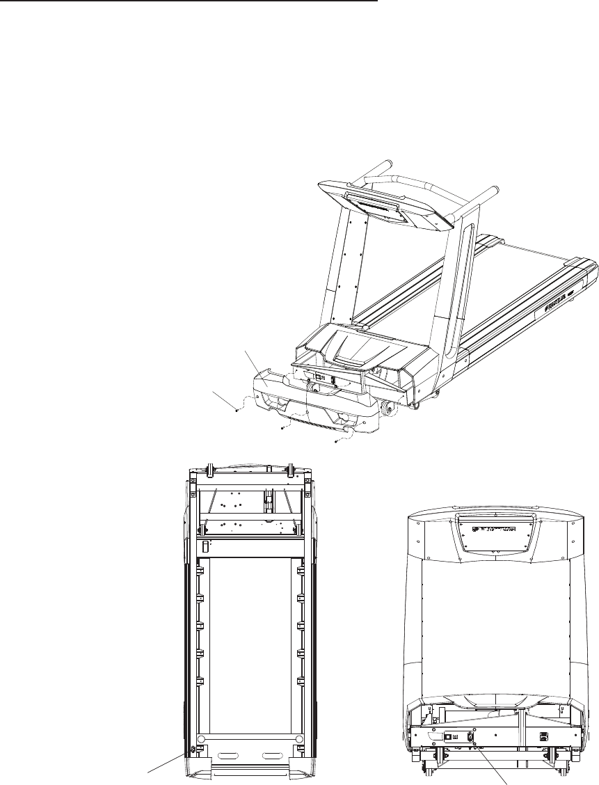
Step 5 - Attach Front Motor Cover
Determine whether you will plug in the treadmill using the front or bottom power receptacle.
If you are using the front power receptacle, plug the Power Cord into the front of the treadmill as shown.
If you are using the bottom power receptacle, plug the Power Cord into the the bottom power receptacle
located under the right side rail as shown.
Use three Phillips Head Screws (#1) to secure the Front Motor Cover (#16).
•
•
•
Assembly of your Nautilus Commercial Series Treadmill is complete!
Please refer to your Commercial Series Owners Manual
for information on proper use of your treadmill.
For more information visit our website Nautilus.com or call: 800-NAUTILUS (800-628-8458)
1
16
PN 41282C
