NavCom Technology SR7100 Network Radio User Manual SR7100 master
NavCom Technology, Inc. Network Radio SR7100 master
User Manual

Safari Network User Guide
i
Contents
Notices ................................................................... v
Chapter 1
Introduction ...........................................1-1
System Overview .....................................................1-1
Applications .............................................................1-2
Unique Features .......................................................1-3
System Advantages ..................................................1-5
Safari Network Components ....................................1-6
Radio Modules (NCU, SCU, and RU)....................1-7
Port Expander......................................................1-8
Subnetwork Control Unit (SCU)...........................1-9
Safari Network Services ..........................................1-10
Chapter 2
Safari Network Planning........................2-1
Planning Overview ...................................................2-1
Initial Planning .........................................................2-2
Network Management Port .................................2-3
Unit IDs ...............................................................2-4
NCU and SCU Radio Frequencies.........................2-5
Multiple SCUs......................................................2-6
Network Services Planning ..................................2-7
Network Services and Channel Assignments........2-7
Channel Assignments and Bandwidth..................2-9
Ethernet Wireless LAN Service............................2-13
Data Throughput vs. Port Speed........................2-18
Data Interception Protection .............................2-18
Multiple NCUs...................................................2-19
Chapter 3
Installation .............................................3-1
Installation Overview................................................3-1
Safety and Operational Precautions..........................3-1
External Antenna Grounding ...............................3-1
Power Lines .........................................................3-2
Additional Safety Cautions...................................3-3
Power Input .............................................................3-3
Providing AC Power through the Port Expander ..3-4
Option 1 .............................................................3-5
Option 2 .............................................................3-5
Providing Power through the J1 Connector .........3-7

Safari Network User Guide
ii
Antenna Configuration.............................................3-9
Using the External Antenna .................................3-9
Communication Ports ............................................3-10
COM1...............................................................3-11
COM2...............................................................3-11
COM3...............................................................3-11
Cable Connections and Wiring...............................3-13
Radio Unit (NCU or Remote) .............................3-13
Subnetwork Control Unit (SCU).........................3-15
Chapter 4
Configuration.........................................4-1
HyperTerminal Program Interface.............................4-1
Configuring as an NCU ............................................4-3
Configuring the network..........................................4-5
Bring up the Network Management Menu..........4-7
Service Configuration ..........................................4-8
List Services .......................................................4-11
NCU Configuration ...........................................4-12
NCU Port Configuration ....................................4-14
View NCU Configuration ...................................4-15
NCU Advanced Configuration ...........................4-16
View Advanced Configuration ...........................4-18
Remote Configuration - Adding an RU...............4-19
RU Port Configuration .......................................4-20
List RUs..............................................................4-24
SCU Configuration.................................................4-25
Chapter 5
Monitoring & Changes ..........................5-1
Displaying Network Information ..............................5-1
Current Configuration .........................................5-2
Real Time Network Usage....................................5-4
Deleting Network Components................................5-5
Deleting a Service................................................5-5
Deleting All Services (Erasing the Service Table)...5-5
Deleting an RU ....................................................5-6
Deleting an SCU..................................................5-6
Deleting All Units in the Network (NCU, SCUs and
RUs) ....................................................................5-7
Reconfiguring NCU, RUs, and COM Ports ................5-7
Reconfiguring the NCU’s Basic and Advanced
Configuration......................................................5-7

Safari Network User Guide
iii
Reconfiguring the NCU Port Configuration..........5-8
Reconfiguring an RU............................................5-8
Reconfiguring an RU’s Port(s) ..............................5-9
Appendix A
Troubleshooting.................................... A-1
Types of Problems....................................................A-1
If a radio is not communicating ...........................A-1
If data transmission is incomplete or in error .......A-5
If the Signal-to-Noise (S/N) ratio is too low..........A-6
Appendix B
Radio Frequencies ..................................B-1
Appendix C
Glossary................................................. C-1
Appendix D
Specifications ........................................ D-1
NCU, RU, SCU ........................................................ D-1
Port Expander Module ............................................ D-2

Safari Network User Guide
iv
Safari Network User Guide
v
Notices
Safari Network User Guide
P/N 96-310010-3001
Ver. 0.1 July 2003
Serial Number: ______________________________________
Date Delivered: ______________________________________
Copyright
© 2003 by NavCom Technology, Inc.
All rights reserved. No part of this work or the computer
programs described herein may be reproduced or stored
or transmitted by any means, without the written
permission of the copyright holders. Translation in any
language is prohibited without the permission of the
copyright holders.
Trademarks
The ‘find your way’, ‘NavCom Globe,’ Safari Network, and
NAVCOM TECHNOLOGY logos are trademarks of
NavCom Technology, Inc. All other product and brand
names are trademarks or registered trademarks of their
respective holders.

Safari Network User Guide
vi
FCC Notice
This equipment has been tested and found to comply with
the limits for a class B digital device, pursuant to part 15 of
the FCC Rules. These limits are designed to provide
reasonable protection against harmful interference in a
residential installation. This equipment generates, uses,
and can radiate radio frequency energy and if not installed
and used in accordance with the instructions, may cause
harmful interference to radio communications. However,
there is no guarantee that interference will not occur in a
particular installation. If this equipment does cause
harmful interference to radio or television reception,
which can be determined by turning the equipment off
and on, the user is encouraged to try to correct the
interference by one of more of the following measures:
Reorient or relocate the receiving antenna.
Increase the separation between the equipment and
receiver.
Connect the equipment into an outlet on a circuit
different from that to which the receiver is connected.
Consult the dealer or an experienced radio/TV
technician for help.
This equipment has been certified to comply with the
limits for a class B computing device, pursuant to FCC
Rules. In order to maintain compliance with FCC
regulations, shielded cables must be used with this
equipment. Operation with non-approved equipment or
unshielded cables is likely to result in interference to radio
and TV reception. The user is cautioned that changes and
modifications made to the equipment without the
approval of manufacturer could void the user’s authority
to operate this equipment.

Safari Network User Guide
vii
RF Exposure Compliance
The SR-7100 complies with the FCC exposure limits.
Users’ and bystanders’ heads are recommended to be a
minimum of 20 cm away from the Spread Spectrum Radio
(SSR) transmitting antenna when used in the basic
configuration. If transmitting system is modified from
basic setup, check FCC regulations for compliance with
exposure limits.
User Notice
NAVCOM TECHNOLOGY, INC. SHALL NOT BE
RESPONSIBLE FOR ANY INACCURACIES, ERRORS, OR
OMISSIONS IN INFORMATION CONTAINED HEREIN,
INCLUDING, BUT NOT LIMITED TO, INFORMATION
OBTAINED FROM THIRD PARTY SOURCES, SUCH AS
PUBLICATIONS OF OTHER COMPANIES, THE PRESS, OR
COMPETITIVE DATA ORGANIZATIONS.
THIS PUBLICATION IS MADE AVAILABLE ON AN “AS IS”
BASIS AND NAVCOM TECHNOLOGY, INC. SPECIFICALLY
DISCLAIMS ALL ASSOCIATED WARRANTIES, WHETHER
EXPRESS OR IMPLIED. IN NO EVENT WILL NAVCOM
TECHNOLOGY, INC. BE LIABLE FOR DIRECT, INDIRECT,
SPECIAL, INCIDENTAL, OR CONSEQUENTIAL DAMAGES
IN CONNECTION WITH THE USE OF OR RELIANCE ON
THE MATERIAL CONTAINED IN THIS PUBLICATION, EVEN
IF ADVISED OF THE POSSIBILITY OF SUCH DAMAGES.
NAVCOM TECHNOLOGY, INC. RESERVES THE RIGHT TO
MAKE IMPROVEMENTS OR CHANGES TO THIS
PUBLICATION AND THE PRODUCTS AND SERVICES
HEREIN DESCRIBED AT ANY TIME, WITHOUT NOTICE OR
OBLIGATION.

Safari Network User Guide
viii
Limited Warranty
NavCom warrants that its products will be free from
defects in material and workmanship at the time of
delivery. Under this warranty, parts found to be defective
in material or in workmanship will be repaired or replaced
at the discretion of NavCom at no cost to the Customer,
provided that the Customer returns the defective product
to NavCom and pays all transportation charges, duties,
and taxes associated with the return of the product. Parts
replaced during the warranty period do not extend the
period of the basic warranty.
This provision does not extend to any NavCom products
which have been subject to misuse, accident or improper
installation, maintenance or application, nor does it
extend to products repaired or altered outside the
NavCom production facility unless authorized in writing
by NavCom.
THIS PROVISION IS EXPRESSLY ACCEPTED BY THE
CUSTOMER IN LIEU OF ANY OR ALL OTHER
AGREEMENTS, STATEMENTS OR REPRESENTATIONS,
EXPRESSED OR IMPLIED, IN FACT OR IN LAW,
INCLUDING THE IMPLIED WARRANTIES OF
MERCHANTABILITY AND FITNESS FOR A PARTICULAR
PURPOSE AND OF ALL DUTIES OR LIABILITIES OF
NAVCOM TO THE CUSTOMER ARISING OUT OF THE USE
OF THE GOODS, AND NO AGREEMENT OR
UNDERSTANDING VARYING OR EXTENDING THE SAME
WILL BE BINDING UPON NAVCOM UNLESS IN WRITING,
SIGNED BY A DULY-AUTHORIZED OFFICER OF NAVCOM.

Safari Network User Guide
ix
Limitation of Liability
IN NO EVENT SHALL NAVCOM BE LIABLE FOR SPECIAL,
INCIDENTAL, OR CONSEQUENTIAL DAMAGES,
INCLUDING BUT NOT LIMITED TO LOSS OF PROFIT OR
OPPORTUNITY. CUSTOMER’S SOLE AND EXCLUSIVE
REMEDY IS STATED IN NAVCOM’S WARRANTY
ACCOMPANYING THE PRODUCT. IN NO EVENT SHALL
NAVCOM’S LIABILITY EXCEED THE REPAIR, REPLACEMENT
OR COST OF THE SPECIFIC PRODUCT PURCHASED FROM
NAVCOM.
International Sales
Products sold by NavCom, including equipment and
software, may be exported from the United States only in
accordance with the Export Administration Regulations.
Diversion contrary to United States law is prohibited.
Customer warrants and represents that it is eligible to
receive Products under United States law and agrees to
abide by any export or re-export restrictions imposed by
NavCom or by the manufacturer or publisher of any
products or software that NavCom resells.

Safari Network User Guide
x
Use of this Document
This User Guide is intended to be used by someone
familiar with the concepts of radio frequency transmitting
equipment.
indicates additional information to make better use of
the product.
a
indicates a caution, care, and/or safety situation.
Revisions to this User Guide can be obtained in a digital
format from support.navcomtech.com
Safari Network User Guide
1-1
Chapter 1 Introduction
The Safari Network
TM
SR-7100 System offers unique
capabilities that make it an extremely versatile wireless
communications solution. Whether you have a single
point-to-point application or a sophisticated multi-point
data network, the Safari Network can support your
applications and requirements.
System Overview
The Safari Network is based on a Star topology cellular
architecture. It supports simultaneous packet and circuit
switched data communication. The Safari Network
consists of three major components:
Network Control Unit (NCU)
The NCU acts as the overall controller of the Safari
Network, ensuring the most effective allocation of
network resources, and providing a single point of
control for all network components. The NCU also
acts as the gateway between the Safari Network and
other networking environments such as the Internet,
wired LANs, and the public switched telephone
network.
Subnetwork Control Units (SCUs)
Subnetwork Control Units (SCU) are used to extend
the range, or circumvent line-of-sight limitations. The
SCU allows the network administrator to create an
additional cell that manages its associated Remote
Units (RUs) through channel assignment, frame
synchronization, frequency synchronization, packet
assembly and packet routing. In essence, the SCU
creates semi-autonomous
cells within a single Safari
Network under full control of the NCU.

Safari Network User Guide
1-2
Remote Units (RUs)
Remote Units (RUs) deployed in a Safari Network can
either operate solely within the coverage area of one
NCU, or roam throughout the network without losing
connectivity as they move from one SCU cell to
another. RUs may be utilized in both fixed or mobile
environments, and offer a multitude of physical user
interfaces and protocols in support of applications.
These components work together in various
combinations to enable the implementation of
multiple network topologies.
Applications
The Safari Network meets the requirements of a number
of applications, including but not limited to:
Asset management
Automatic vehicle location services
Vehicle health monitoring
Data acquisition
Machine control
Telemetry
Mobile Local Area Networking
Wireless security monitoring

Safari Network User Guide
1-3
Unique Features
The Safari Network has many unique features to meet
mobile communication needs:
Simultaneous Services
The Safari Network simultaneously supports multiple
communication services, enabling network
administrators to offer users a large array of
communication alternatives. It can be customized
according to user’s needs to provide a mix of point-
to-point, broadcast, multipoint-to-multipoint, and
Ethernet LAN services. The Safari Network can also be
configured to simultaneously support both circuit
switched and packet switched data, thereby allowing
users to give priority to latency-sensitive traffic such as
voice, video and streaming data, while also
supporting traditional LAN traffic such as file sharing,
email and web browsing.
Multiple Data Rate Selection
System data rates of 512kbs, 240kbs, and 96kbs can
be chosen. This allows the flexibility of choosing a
data rate specifically for the projects’ distance or
throughput requirements. A lower data rate transmits
a farther distance, but yields less Forward/Return
bandwidth availability for the network. A higher data
rate transmits a shorter distance, but yields higher
bandwidth availability for the network.
Multiple Connectivity Options
Multiple ports are provided on each RU to conduct
concurrent sessions of dissimilar services. Port &
Protocol options for the SAFARI NETWORK are
RS232/Async, RS422/Async, RS422/HDLC High Level
Data Link Control, and 10BaseT/Ethernet. These user
interfaces, combined with a powerful onboard
microprocessor and user-selectable data rates, allow

Safari Network User Guide
1-4
for multiple, simultaneous services and offer users a
variety of options for connecting to the Safari
Network.
Current protocols under development are Vehicle
CAN Bus, Circuit Switched Voice, USB, and Infrared
serial data interfaces. These interfaces will be
available in a near future release.
Dedicated Network
The Safari Network enables users to create an “always
on” dedicated, private communication network for
both fixed and mobile assets within a localized area. It
provides network administrators with full control of all
RUs, bandwidth, access, and services.
The ability to receive data from RUs at a central
location allows superior management of personnel
and assets. For example, productivity of field workers
can be monitored to increase overall efficiency.
Vehicle health information can be analyzed to predict
and prevent vehicular failure.
The Safari Network provides a high degree of
flexibility and control, allowing users to manage their
resources effectively.
Rugged Design
The rugged design of the Safari Network components
provides protection against harsh environments
common to areas such as farms, construction sites,
mines, and marine vessels. Units are watertight and
sealed to protect against environmental hazards such
as dust, moisture, vibration, and hot and cold
extremes.

Safari Network User Guide
1-5
Safari Network Management System
The Safari Network management system design
allows those with little or no technical background to
manage the overall network configuration. It is
equipped with both a simple text-based configuration
structure (accessible from any of the ASYNC ports),
and an intuitive browser-based configuration interface
accessible via the Ethernet port (this interface will be
available in a near future release). Network
administrators can use either method to configure,
reconfigure, and manage all RUs in their Safari
Network.
System Advantages
The Safari Network has several major advantages over
licensed and traditional cellular radio systems:
Safari Network is a license-free, no fee system. There
are no implementation delays associated with
frequency coordination and license applications.
There are also no costs associated with annual license
fees, no monthly connection charges, and no data
volume charges.
Lower transmission power utilized in the system
minimizes the DC power requirements.
The larger bandwidth available in the license-free ISM
band permits the provision of data rates significantly
greater than those supported by licensed and
traditional systems.
Safari Network User Guide
1-6
Safari Network Components
A typical Safari Network is made up of several components
interfaced together in order to achieve maximum
productivity and range throughout a project.
The minimum requirements for a Safari Network are one
Network Control Unit (NCU), and one Remote Unit (RU).
A Safari Network must have at least one NCU, and can
contain as many as 400 RUs and SCUs. Multiple NCUs
could be synchronized to a master NCU for simultaneous
interference-free operation to improve data throughput.
The Safari Network usually consists of two modules, a
Radio Module (NCU, SCU, or RU) and a Port Expander. A
systems integrator could opt to interface directly to J1 and
J2 without using the Safari Network Port Expander.
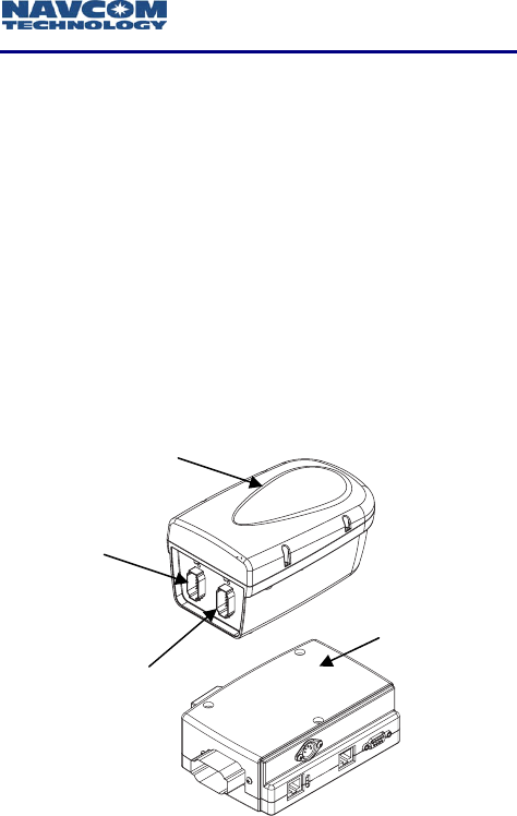
Figure 1-1: Safari Network Radio Module and Port Expander
Radio Module
Port
Expander
J1
COM3
J2
COM1 & COM2

Safari Network User Guide
1-7
Radio Modules (NCU, SCU, and RU)
All radio modules have the same form factor for
convenient mounting; however, the internal configuration
differs. The radio is typically mounted outside and
preferably as high as possible to provide the best
coverage. Its chassis is fully sealed and protected to
withstand harsh environments. A plastic radome is
provided to protect the radio and optional GPS antennas
against impact. The radome can be removed when
externally mounted antennas are required.
Each radio supports four communication ports (COM1 to
COM4). Interface to the radio is through two rugged 12-
pin connectors J1 (COM3) and J2 (COM1 & COM2), as
shown in Figure 1-1 on page 1-6.
The radio is available in two different models
Model # 1 with COM1 set as Ethernet
Model # 2 with COM1 set as Serial
COM1 Serial Mode possible configurations are:
RS 232 ASYNC
RS 422 ASYNC
RS 422 SYNC
COM2 Serial Mode possible configurations are:
RS 422 ASYNC
RS 422 SYNC
COM3 Serial Mode possible configurations are:
RS 232 ASYNC
TTL ASYNC for internal GPS Engine interface.
COM4 is dedicated for a CAN Bus interface.
Safari Network User Guide
1-8
Port Expander
The Port Expander is used to provide a standard connector
interface for access to COM1 & COM2 ports of the radio.
The J2 connector of the radio module connects to the Port
Expander module via a cable of up to a maximum of 300
feet.
The Port Expander is intended for installation in an
office or vehicle cab. Although rugged in
construction, it is not environmentally sealed.
In the basic configuration, the Safari Network RU is
externally powered through J1. The radio then passes
through a regulated voltage to the Port Expander. This is
typically the case where the RU is used in a mobile
environment and is powered by the vehicle battery.
Alternatively, the Port Expander can supply power to the
radio through the J2 connector. An optional AC-powered
Active Port Expander (Figure 1-2) should be used, which
converts AC to DC for operating the radio. This
configuration is desirable when an AC power source is
available.
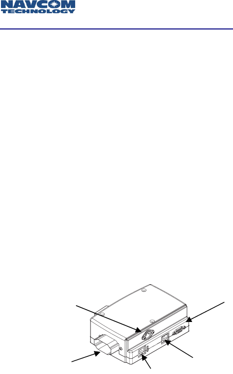
Figure 1-2: Safari Network AC Port Expander
To
radio
COM1
RJ45 (Ethernet)
COM2
R
J
45
(
Serial
)
COM1
DB9 (Serial)
5-Pin DIN Jack
External Power Source
(Optional)
Safari Network User Guide
1-9
Subnetwork Control Unit (SCU)
The SCU allows the administrator to create additional,
semi-autonomous cells in the Safari Network that are
managed by the NCU. These cells may be contiguous or
non-contiguous. By deploying SCUs, the administrator can
circumvent line-of-sight obstacles and extend the range of
the Safari Network. The SCU also controls and manages its
associated RUs. The SCU directs bandwidth utilization
through channel assignment, frame synchronization,
frequency synchronization, packet assembly and packet
routing.
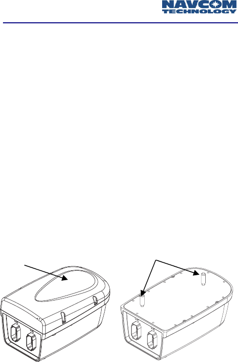
Each SCU is comprised of two radio modules synchronized
to operate simultaneously without degradation in
performance. Each radio module has its own independent
antenna (see Figure 1-3). Depending on the traffic flow,
the SCU may improve the overall network data
throughput. Multiple levels of SCUs can be added to the
Safari Network without adversely affecting the network
operation.
Figure 1-3: SCU with and without Radome
Antenna
Radome
Safari Network User Guide
1-10
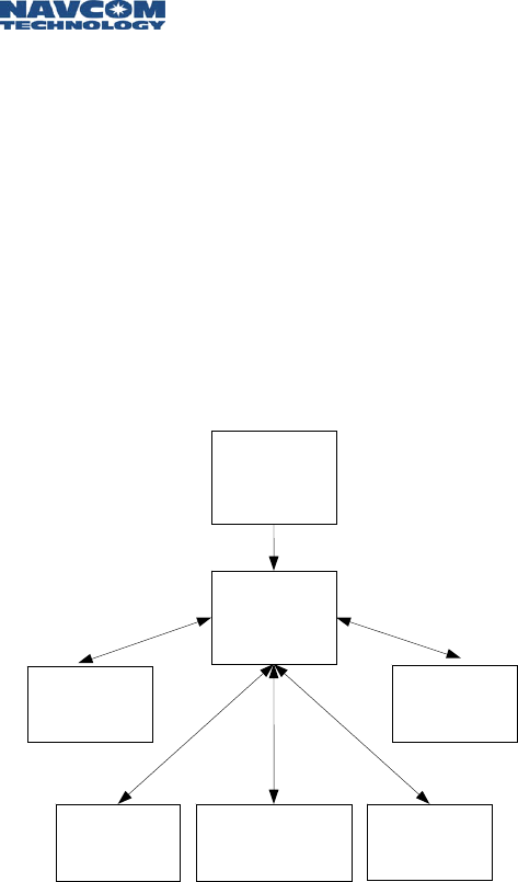
Safari Network Services
The Safari Network provides several network services,
which can be configured for single applications, or
simultaneous use in multiple applications. Each service
listed is associated with a basic interconnectivity diagram
detailing data flow.
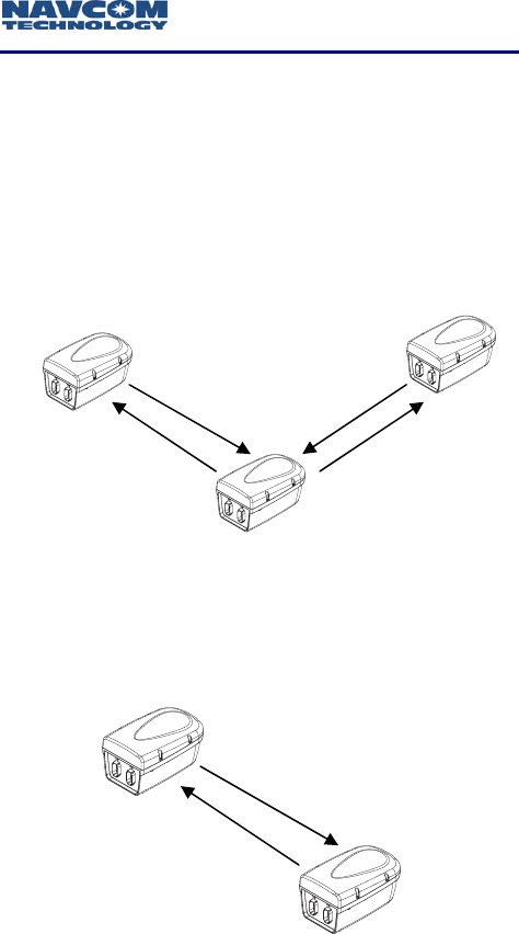
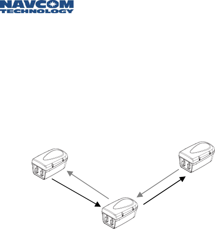
Remote-to-Remote
Two-way dedicated serial communication between
two RUs, and the NCU.
Figure 1-4: Bi-Directional NCU, RU to RU
Remote-to-NCU
Two-way dedicated serial communication between
one RU and the NCU.
Figure 1-5: Bi-Directional NCU to Single RU
NCU
RU 2 RU 1
NCU
RU 1
Safari Network User Guide
1-11
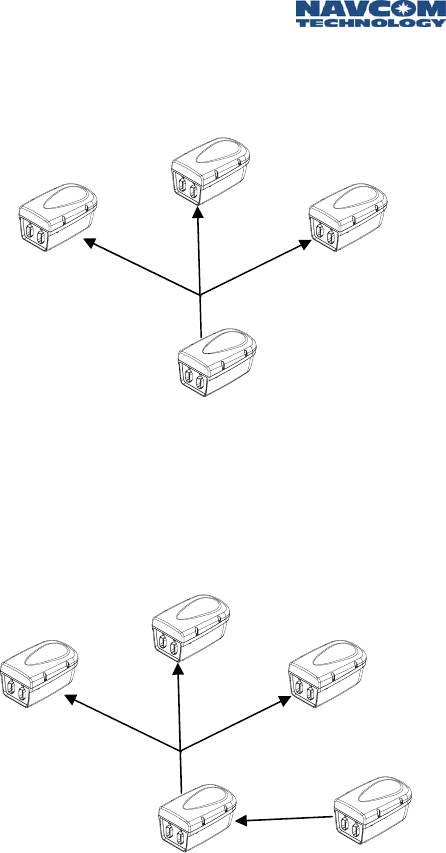
Broadcast from NCU
One-way serial communication from the NCU to
multiple RUs.
Figure 1-6: NCU Broadcaster
Broadcast from Remote
Relaying of one-way serial communication input from
a single RU by the NCU, out to multiple RUs on a
one-way serial communication link.
Figure 1-7: NCU Remote Broadcaster
NCU
RU 1
RU 2
RU 3
NCU
RU 1
RU 2
RU 3
RU 4
Safari Network User Guide
1-12
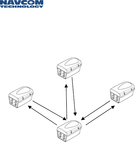
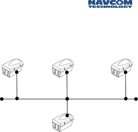
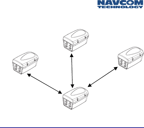
Multipoint Network (with return)
Two-way serial communication between multiple
RUs, and the NCU via the NCU. Radios can be
configured to transmit data to a specific port, or
broadcast data to all units that use this service. When
broadcasting data the originating radio will receive
the data as well.
Figure 1-8: Bi-Directional NCU Multipoint Network
NCU
RU 2 RU 1
RU 3
Safari Network User Guide
1-13
Ethernet Wireless LAN
Wireless bi-directional, full-duplex LAN capability
among the RUs and the NCU using Ethernet port
(COM1) of the radios. Provides an IP communication
link between radios as well as a connection to the
Internet via NCU.
Figure 1-9: NCU Ethernet Wireless LAN
NCU
RU
2
RU
1
RU
3
Safari Network User Guide
1-14
NCU
RU 2
RU 1
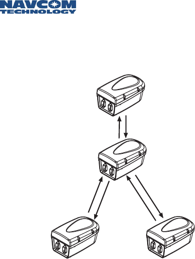
SCU
SCU Repeater
SCU devices may be used to create additional cells,
extending the range to RUs or bypassing path
obstacles.
Figure 1-10: SCU Repeater

Safari Network User Guide
2-1
Chapter 2 Safari Network Planning
The key to successful implementation and management
of your wireless Safari Network is planning—knowing in
advance exactly what your requirements are, how you
will make use of the network, and what settings will be
required to accomplish your goals.
Planning Overview
It is recommended that this chapter be read in its
entirety before attempting to install and configure
your network components.
There are several steps involved in the planning of your
Safari Network:
Determine the location(s) of the RU(s), and assess the
need for SCUs.
Assign Radio Unit IDs.
Determine radio frequency(s).
Determine service(s).
Determine throughput requirements for each service.
Assign Channel numbers for each service.
Determine port setup requirements.
Safari Network User Guide
2-2
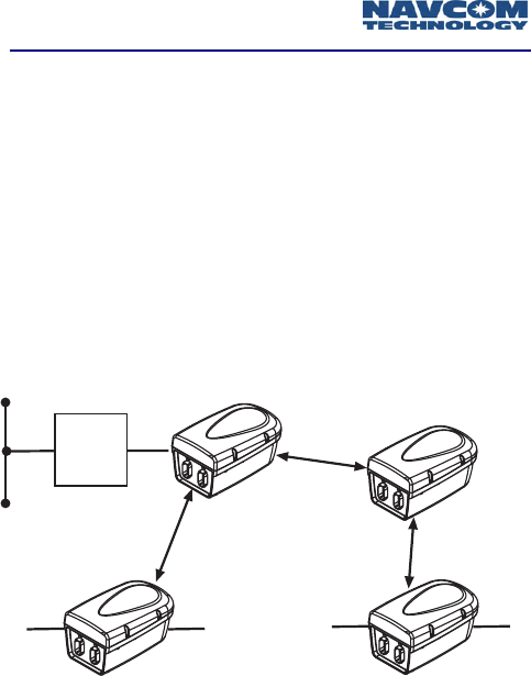
Initial Planning
Determine your hardware requirements based on the
number of RUs you will need, the distances between each
RU and the NCU. Line-of-sight limitations (i.e., physical
obstructions) should be assessed. It is advisable to have
the NCU located at the highest elevation point in the
network in order to overcome line of sight limitations. If
this is not possible, an SCU can be added to the network
to compensate.
Review your communications and networking needs and
perform a site survey. Draw a map of the network that
indicates how many units will be required, and their
locations relative to the location of the NCU.
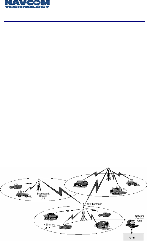
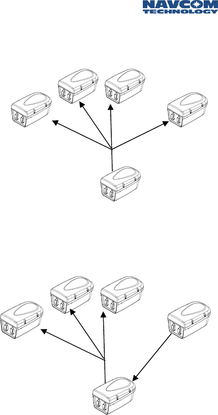
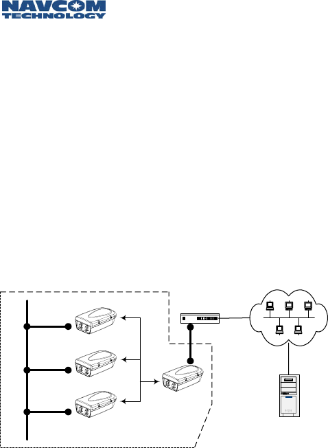
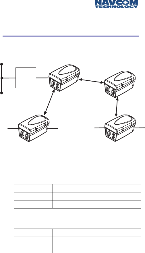
You will need to install Subnetwork Control Units in the
network if any RU:
Will be more than 14-20 miles from the NCU
(depending on data speed).
Will not have a direct line of sight to the NCU (such
as obstruction from buildings, trees, mountainous or
hilly terrain, etc.).
Figure 2-1: Safari Network

Safari Network User Guide
2-3
Network Management Port
All Safari Network functions and services are done via the
Network Management Port (NMP). Choosing this port
should be one of the first planning considerations. By
factory default, the Safari Network radio module has
COM2 set to the Network Management Port (NMP). All
functions referred to in this chapter must be initiated via
the NMP.
For Network Management, COM2 or COM3 should be
selected. Network Management is not allowed via COM1.
In order to simplify reconfiguration and diagnostics it is
desirable to have a permanent connection at the NCU for
Administrative functions. The port that Network
Management is being initiated from can also be assigned
services; however, these services will not function while
the network is being administered. Chapter 4
Configuration details Network Management and
Administration.
When Network Management is initiated, the
service on that port will temporarily be disabled in
order to allow the administration of the network
via that port. After Network Administration is
complete, a power cycle will restore the port to its
configured service.
Safari Network User Guide
2-4
Unit IDs
Each Safari Network radio module has a serial number
(physical ID), which is printed on a label attached to the
unit. SCUs, which contain two radios, have two physical
IDs, one for the upstream radio and one for the
downstream radio.
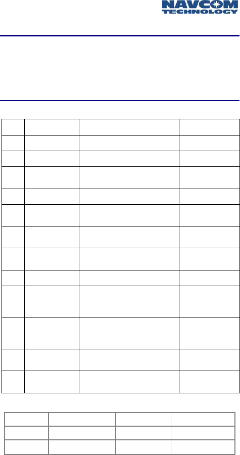
You will need to assign a Unit ID to each radio from 100
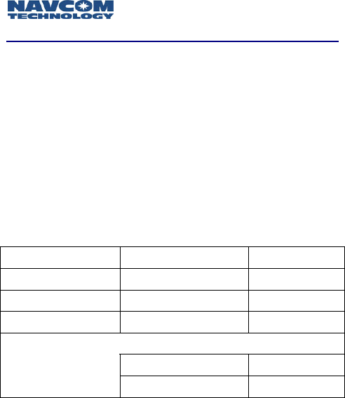
to 600. Table 2-1 shows a typical Safari Network ID setup.
Network ID “100” is reserved for NCU only!
Table 2-1: Safari Network Unit ID Matrix
Radio Unit Physical ID Unit ID
NCU 0x06f12345
100
RU 0x06f28374
201
RU 0x06f03748
202
SCU
(upstream) 0x06f50726 501
(downstream) 0x06f59374 502
Safari Network User Guide
2-5
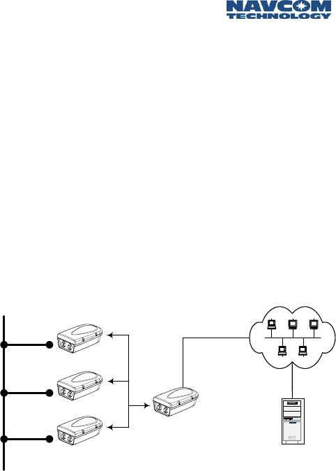
NCU and SCU Radio Frequencies
NCUs and SCUs must have a radio carrier frequency
assigned to each. The RUs automatically set themselves to
the frequency of the NCU, or SCU within closest range.
In addition to the Unit ID for the SCU, there is an
associated Parent ID. This ID simply refers to the ID that
the SR-7100 SCU locks to on power up, and is set
automatically.
See Appendix B, Radio Frequencies, for channel, frequency
and throughput rates. Figure 2-2 illustrates the Frequency,
Unit ID, and Parent ID affiliation.
Figure 2-2: Safari Network NCU/SCU Example
Router
NCU Unit ID = 100
RU RU
SCU
Unit ID = 501
Parent ID = 100
Unit ID = 502
Parent ID = 100
Freq = F8
Safari Network User Guide
2-6
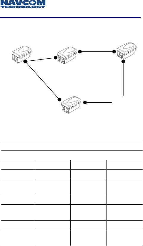
Multiple SCUs
In Figure 2-3, the Safari Network uses three SCUs.
Figure 2-3: Safari Network NCU/Multiple SCU Example
Table 2-2 shows how the frequencies would be assigned.
NCU Frequency = F8
SCU Frequencies Assigned
Unit ID Parent ID Uplink Downlink
501 100 F8 (auto)
502 100 F12
(assigned)
503 502 F12 (auto)
504 502 F14
(assigned)
505 100 F8 (auto)
506 100 F16
(assigned)
Table 2-2: Safari Network NCU/Multiple SCU
Network Frequency Assignments
NCU
SCU
SCU
F8 F8
F8
505
501
502 503
504
F12 F12
F14
F16
506
100
SCU

Safari Network User Guide
2-7
Network Services Planning
Once the IDs have been assigned to the Safari Network’s
radio units, and the frequency settings have been
determined, a plan must be devised for the types of
applications you will be using. This involves identifying:
The service type(s), described in Chapter 1 and
below.
Which radio(s) will be sending data through that
service.
Which radio(s) will be receiving data through that
service.
After identifying these three requirements, then you can
determine the Channel assignments and port
configurations for each radio unit in the network.
Network Services and Channel Assignments
As expressed in Chapter 1, various services can be
configured singularly, or in a multitude of combinations.
Below are some of the Safari Network configurations
possible.
Remote-to-Remote
Remote-to-NCU
Broadcast from NCU
Broadcast from Remote
Multipoint
Ethernet Wireless LAN
(requires radios factory pre-configured for Ethernet)

Safari Network User Guide
2-8
When services are setup in your Safari Network, you define
communication paths, or logical “Channels,” between the
various radio modules in the network. To set up multiple
services you assign distinct and separate Channels for each
service. This is so that individual sessions of those services
can occur simultaneously over the different Channels.
Once a Channel is assigned to a service (in some instances
two Channels, one transmit and one receive), you then
assign the same Channel value(s) to the communication
ports of the radio modules that will be sending and
receiving data through those services.
An example detailed in Table 2-3, Row 2 (Service/
Broadcast From NCU), shows the NCU with a Radio ID of
100 (100 is always reserved for NCUs) set up to transmit
data to the RUs on Channel 1 and COM1. Table 2-3 also
details in Row 2 that the RUs (In this example Radio IDs
2xx) are set up by the NCU to receive the broadcast data
from Channel 1, COM1 of the NCU on COM2 of the RUs
at a bandwidth of 4.8 Kbps. In this example no data is
returned from the RUs to the NCU.
Channel
#
Service Radio
ID
COM
Port Tx Rx
Forward
Band-
width
Return
Band-
width
100
(NCU) COM1 1
Broad-
cast
from
NCU
201,
202,
203,
204
COM2 1
4.8Kbps 0
Table 2-3: Service/Channel Planning Example
This unique Channel/port flexibility allows for planning a
multi-service, multi-session network by assigning different
Channels to different services, and taking advantage of the
Safari Network radio module’s three COM ports.
Safari Network User Guide
2-9
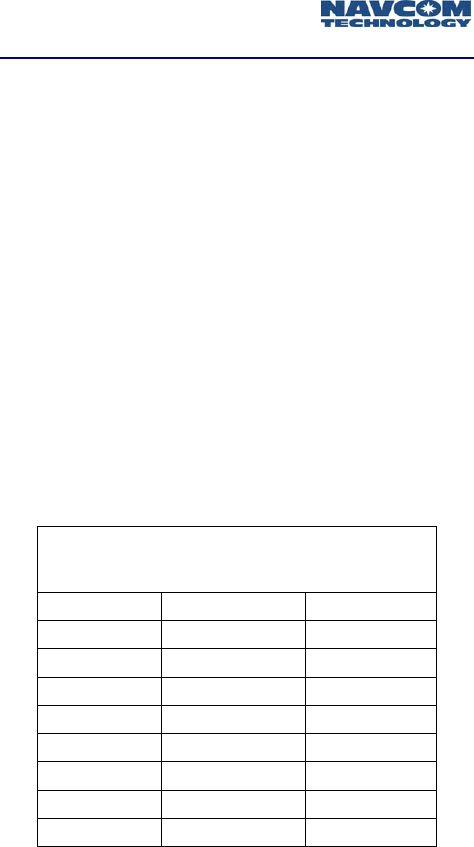
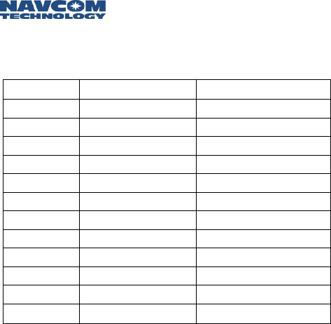
Channel Assignments and Bandwidth
The term bandwidth in the context of the Safari Network
simply means data rate, or capacity. The amount of data
that is, or can be, sent through a given communications
circuit per second. After assigning a Channel ID to a
service, you must set the amount of forward and/or return
bandwidth for that Channel. As bandwidth values are
assigned, the total forward or return bandwidth is
decreased by the same amount.
The total bandwidth of the Safari Network radio module is
512k, with 51.2k being allocated to network resources.
The remaining 460.8k is split equally between Forward
and Return. Forward bandwidth is the amount of data
transmitted from the NCU to other destinations; Return
bandwidth is the amount of data received by the NCU.
The sum of all forward bandwidth assigned to services
cannot exceed the forward radio bandwidth (230.4k), and
the sum of all return bandwidth assigned to services
cannot exceed the return radio bandwidth (230.4k). The
preset bandwidth choices are detailed in Table 2-4.
Bandwidth vs. Throughput Matrix
512K 240K 96K
230.4 108.0 43.2
204.8 96.0 38.4
179.2 84.0 33.6
153.6 72.0 28.8
128.0 60.0 24.0
102.4 48.0 19.2
76.8 36.0 14.4
51.2 24.0 9.6
25.6 12.0 4.8
Table 2-4: Safari Network Bandwidth/Throughput Options
Safari Network User Guide
2-10
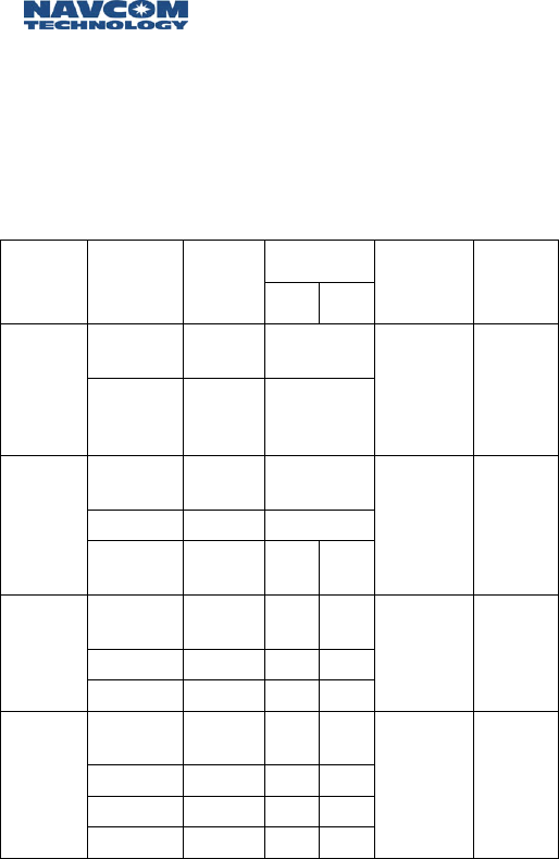
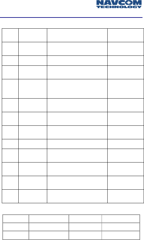
Channels are assigned to services as values ranging from 1
to 254. A Channel number must be assigned to one or
more of the radio module’s communication ports (COM1,
COM2, or COM3) in order for that port to use a service.
Table 2-5 details examples of service/Channel planning.
These examples are further detailed in Figures 2-4 though
Figure 2-7.
Channel #
Service Radio ID COM
Port Tx Rx
Forward
Band-
width
Return
Band-
width
100
(NCU) COM1 1
Broad-
cast
from
NCU
201 202
203
204
COM1 1
25.6K 0
100
(NCU) COM2 n/a
204 COM2 2
Broad-
cast
from
Remote 201 202
203 COM2 2 2
25.6K 25.6K
100
(NCU) COM2 n/a n/a
202 COM2 3 4
Remote-
to-
Remote
203 COM2 4 3
25.6K 25.6K
100
(NCU) COM2 n/a n/a
205 COM2 5 5
206 COM2 5 5
Multi-
point
207 COM2 5 5
25.6K 25.6K
Table 2-5: Safari Network Service Examples
Safari Network User Guide
2-11
Channel 1 is used as a Broadcast from NCU service.
Since transmissions are only from the NCU, there is
no Return bandwidth setting. The Forward Bandwidth
is set to 25.6k.
Figure 2-4: Safari Network Table 5 Broadcast from NCU
Channel 2 is used for a Broadcast from Remote
service. The NCU receives, and retransmits data, thus
the forward and return bandwidth must be set.
Figure 2-5: Safari Network Table 5 Broadcast From Remote
NCU
201
Channel 1
Forward Bandwidth =25.6k
202 203
204
NCU
201
Channel 2
Forward & Return Bandwidth
=25.6k
202
203
RU
204
Safari Network User Guide
2-12
In the Remote-To-Remote configuration, Channel 3
(black) is the transmit Channel for SR-7100 Unit ID
202, and the receive Channel for SR-7100 Unit ID
203. The forward & return bandwidth for this
Channel is set to 25.6k. Channel 4 (gray) is the
transmit Channel for SR-7100 Unit ID 203, and the
receive Channel for SR-7100 Unit ID 202. The forward
& return bandwidth for this Channel is set to 25.6k.
The NCU receives, and retransmits data bi-
directionally, thus the forward and return bandwidth
must be set.
Figure 2-6: Safari Network Table 5 Remote-To-Remote
In the Multipoint configuration, Channel 5 is
configured as the transmit and receive Channel for
each RU in the network. The forward and return
bandwidth for this Channel is set to 25.6k. The NCU
manages all of the bi-directional data traffic of each
RU, thus the forward and return bandwidth must be
set for each RU.
Although the Multipoint configuration allows data to
be received and transmitted throughout the
established Channels, additional application software is
required to prevent collisions between the various data
exchanges.
NCU
202
203
Black = Channel 3
Gray = Channel 4
Safari Network User Guide
2-13
Figure 2-7: Safari Network Table 5 Multipoint
Ethernet Wireless LAN Service
You can create an Ethernet Wireless LAN service using
Safari Network radio modules that have COM1 ports
configured for Ethernet networking.
This configuration must be preset at the factory.
Any Safari Network radio modules that are
purchased without this option must be returned to
the factory in order to be reconfigured.
The Safari Network extends the wired LAN network
beyond the length of the cables, and acts as an Ethernet
switch that filters and forwards packets between the
devices for network segments. It can be configured to
operate as part of an existing LAN network, as a private
LAN connected to an existing LAN network, or to an ISP
through a DSL/Cable router.
NCU
205
207
206
Channel 5

Safari Network User Guide
2-14
In the Ethernet mode, the Safari Network acts as an IP
host where its IP address can be configured manually, or
acquired automatically via Dynamic Host Configuration
Protocol (DHCP). It then can be addressed using IP
applications such as Ping.
To create an Ethernet service, assign a Channel to the
Ethernet service. This Channel number will be assigned to
COM1 of all radio modules that will make up the network
(see Chapter 4: Configuration).
Table 2-6 is an example of Ethernet Service and Channel
assignments for an Ethernet Wireless LAN service.
Channel
#
Service Radio
ID
COM
Port Tx Rx
Forward
Band-
width
Return
Band-
width
100
(NCU) COM1 1
Ethernet 201
202
203
204
COM1 1
230.4K 230.4K
Table 2-6: Ethernet Service/Channel assignments
Safari Network User Guide
2-15
202
201
NCU
203
ISP /
INTERNET
COM1
CH1
COM1
CH1
COM1
CH1
Private LAN
COM1
CH1
DSL /
CABLE ROUTER
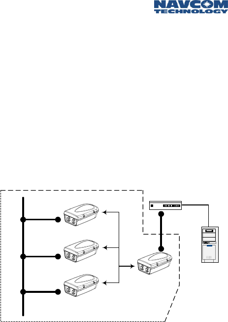
Safari Network - Internet via DSL/Cable router.
If there is no existing network available, Figure 2-8 is a
recommended setup. The NCU’s Ethernet Port should
be connected to the LAN Port of the DSL/Cable
router. The WAN Port of the router connects to the
DSL/Cable modem’s LAN port. In this configuration
the Safari Network belongs to a private LAN, and is
hidden from external network intrusions via the
Internet if the router is equipped with firewall
protection. Although accessing the Internet from the
Safari Network’s private LAN is allowed, file and
resource sharing are not possible on devices that
reside on opposite sides of the router. An exception is
if the router has a DMZ port.
Figure 2-8: SR-7100 - Router - Internet Connection
Safari Network User Guide
2-16
202
201
NCU
203 ISP /
INTERNET
COM1
CH1
COM1
CH1
COM1
CH1
DSL /
CABLE ROUTER
Private LAN
COM1
CH1
Internal LAN
Safari Network – Internal LAN - Internet via DSL/Cable
router.
The connections for Figure 2-9 are exactly the same
as in Figure 2-8 with respect to the Safari
Network/Router interface. The difference is now we
have added a Local Area Network of users on the
WAN side of the router. As in the previous
configuration (Figure 2-8), the Safari Network belongs
to a private LAN, and is hidden from external network
intrusions via the Internet, or any users on the Internal
LAN if the router is equipped with firewall protection.
Although accessing the Internet from the Safari
Network’s private LAN is allowed, file and resource
sharing are not possible between devices that reside
on the sides of the router. An exception is if the router
has a DMZ port.
Figure 2-9: Safari Network – Router - Internal LAN – Internet
Safari Network User Guide
2-17
202
201
NCU
203 ISP /
INTERNET
COM1
CH1
COM1
CH1
COM1
CH1
COM1
CH1
Internal LAN
Safari Network connects directly to an Internal LAN
and becomes part of the LAN.
The connections for Figure 2-10 are exactly the same
as in Figure 2-8, with respect to the Safari
Network/Router interface. The difference is now we
have added a Local Area Network of users, and
removed the Router. In this configuration, the Safari
Network no longer belongs to a private LAN, and is
no longer hidden from external network intrusions via
the Internet, or any users on the Internal LAN.
Accessing the Internet from the Safari Network is
allowed, while file and resource sharing is possible
between all devices that reside on the Internal LAN. A
software/hardware firewall solution is possible to
protect the Internal LAN from Internet intrusions, but
the Safari Network will not be protected from local
users.
Figure 2-10: Safari Network – Internal LAN - Internet

Safari Network User Guide
2-18
Data Throughput vs. Port Speed
As previously discussed in Channel Assignments &
Bandwidth, configuring a radio module’s ports involves
setting data throughput and port speed.
The data throughput setting is the over-the-air pass-
through capability, and must correspond with the
capacity needed for the chosen service of that port.
The port speed applies to the rate at which data is
sent and received across the port to the attached
device.
Port speed can be configured at a higher rate than the
Channel throughput. However, if average throughput
exceeds Channel throughput capacity, data will be lost.
Data Interception Protection
The Safari Network incorporates protection against
intentional or unintentional interception, interference, or
unauthorized access data on the network. The SR-7100
modulation uses a proprietary patented version of direct
sequence spread spectrum. By spreading carriers at low
energy across a wide bandwidth, it makes any type of
radio interception, or interference difficult to implement.
Each radio module is manufactured with a unique
hardware address. To enter any Safari Network every
unit’s address must be pre-approved by the network
administrator. Each radio module must be specifically
authorized by the network administrator to access any
offered service.
The network administrator must set the radio module to a
unique programmed spreading code common to each
network. To communicate on the network, Safari Network
radio modules must utilize a unique pre-pended training
pattern set by the network administrator (called a Unique
Word).

Safari Network User Guide
2-19
These parameters CANNOT be changed in any RU or SCU
from the NCU. Each individual radio module in the
network must be changed at the unit.
Additionally, data encryption such as triple DES or PGP
can be employed at the application level to provide an
extra level of security.
Multiple NCUs
As discussed in Chapter 1, Introduction, typically one NCU
is used in a single network. However, there are instances
where an application may require a redundancy of NCUs.
A backup NCU (B-NCU) (or multiples) can be
programmed to duplicate the primary NCU, and switched
into backup service if needed simply by powering on the
B-NCU.
Multiple coexisting networks can be established in order
to expand the total bandwidth available. NCUs have been
designed to operate synchronously to prevent jamming in
this scenario. Synchronization of the NCUs can be
accomplished by physically cabling them together via the
J1 ports, or configuring one NCU as a synchronous
transmitter, and the other NCUs as a synchronous
receiver. This is accomplished with the external
synchronization setting in the NCU setup. The primary
NCU is set for transmit synchronization, and the
secondary NCUs are set for receive synchronization.

Safari Network User Guide
2-20
Safari Network User Guide
3-1
Chapter 3 Installation
Once you have planned your network installation and
configuration you can physically install your network
components.
Installation Overview
This chapter provides instructions and information on
mounting the radio units, providing power, configuring
the antenna, and using the communication ports. It
discusses several safety and operational precautions with
which you must be familiar before attempting your first
power up of the Safari Network.
Safety and Operational Precautions
aCautions
The SR-7100 should be professionally installed due to
antenna placement requirements and configuration
of communication ports.
External Antenna Grounding
Make sure that the antenna and radio/controller system is
electrically grounded to provide some protection against
voltage surges and static charges.
Article 810 of the National Electrical Code, ANSI/NFPSA
70, provides information with regard to proper grounding
of the mast and supporting structure, grounding of the
lead-in wire to a discharge unit, size of grounding
conductors, location of antenna discharge unit,
connection to grounding electrodes, and requirements for
the grounding electrode.
Safari Network User Guide
3-2
Power Lines
Do not locate the antenna near overhead light or power
circuits, or where it could fall into such power lines or
circuits.
a
When installing or realigning an outside antenna
system, extreme care should be taken to keep
from touching such power lines or circuits.
Contact with them could be fatal.
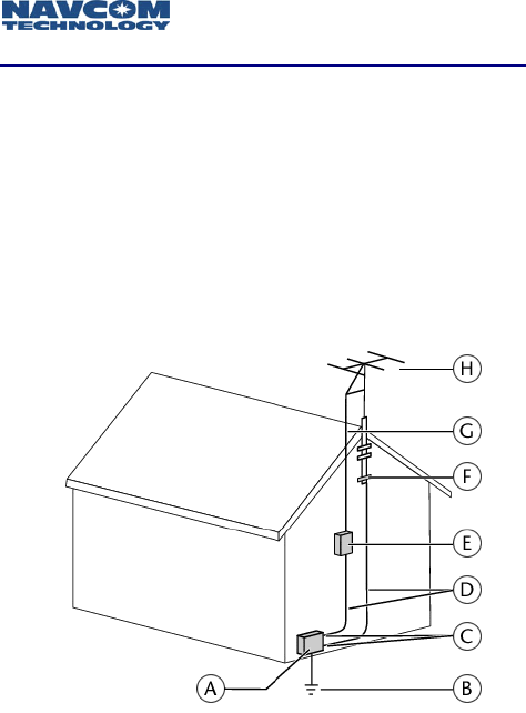
Figure 3-1: Antenna and Satellite Grounding
A Electric service equipment
B Power service grounding electrode system
(NEC Art 250, Part H)
C Ground clamps
D Grounding conductors (NEC Section 810-21)
E Antenna discharge unit (NEC Section 810-20)
F Ground clamp
G Lead-in Signal Cable
H Antenna/Radio/Controller Combination

Safari Network User Guide
3-3
Additional Safety Cautions
It is recommended that users’ and bystanders’ heads
be a minimum of 20 cm away from a unit’s
transmitting antenna when used in the basic
configuration. If the transmitting system is modified
from factory setup, check FCC regulations for
compliance with exposure limits.
Do not directly connect units via an RF cable without
enough proper attenuation. This will damage the
system.
Do not disconnect the antenna cable when the radio
has power applied. This will damage the RF
transmitter and void the warranty.
When the radio is operating at full power, the
maximum antenna gain allowed is 5.5 dBi per FCC
regulation part 15.
If there is no standard J1 cable attached to the J1
connector on the radio, a J1 power jumper plug
must be inserted. See Option 1, below.
Power Input
The SR-7100 radio module can be powered in two
different ways:
Through the Port Expander to J2. This power
configuration is recommended for the NCU and SCU
since these units are typically mounted at a high
elevation. With this configuration, the On/Off switch
on the Port Expander will turn the system on and off.
Through the J1 connector on the radio. This power
configuration is recommended for Remote Units
because they are typically mounted vehicles with a
DC voltage source. With this configuration, the
On/Off switch on the Port Expander will turn the
system on and off.
Safari Network User Guide
3-4
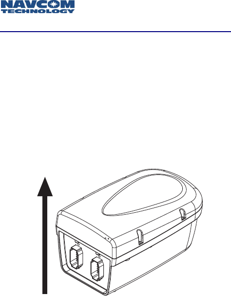
UP
Providing AC Power through the Port Expander
This configuration, recommended for the NCU and SCU,
requires the use of the Port Expander with the DIN
connector for power input and the AC power supply.
1. Mount the radio unit in the selected location per your
site planning. If using the internal antenna, be sure to
mount the unit in the position shown in Figure 3-2
below, with the omni-directional radiation pattern
along the horizontal plane.
Figure 3-2: Correct Mounting Position for Internal Antenna
Safari Network User Guide
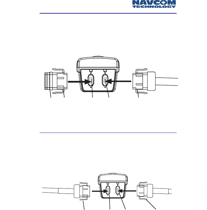
3-5
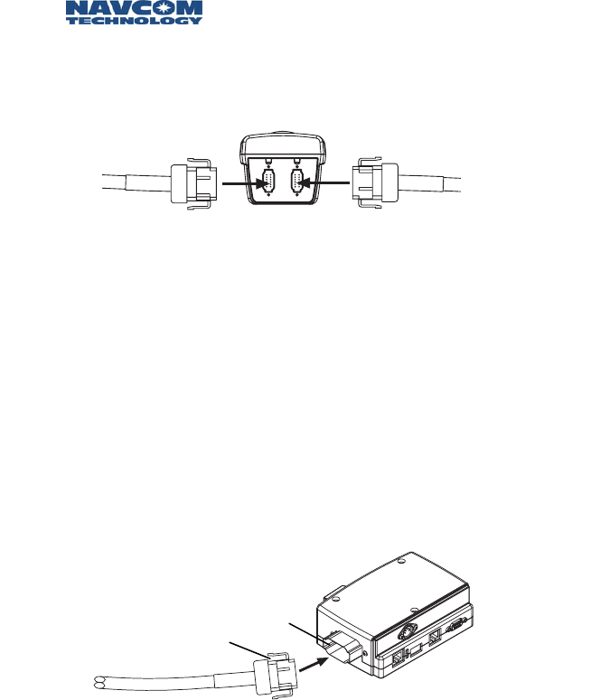
J1 plug J2 cable
Option 1
2. Insert the J1 plug into the radio’s J1 connector, and
the J2 cable into the radio’s J2 connector. The
connectors are keyed to only fit one way.
Figure 3-3: Use of J1 “Plug”
Option 2
3. Connect the J1 cable into the radio’s J1 connector,
and the J2 cable into the radio’s J2 connector. The
connectors are keyed to only fit one way.
Figure 3-4: J1 Cable Connection
Power
jumper
plug
Gray
connector
Gray
key
Black
key
Black
connector
Gray
connector
Gray
key
Black
key
Black
connector
J1 cable J2 cable
Safari Network User Guide
3-6
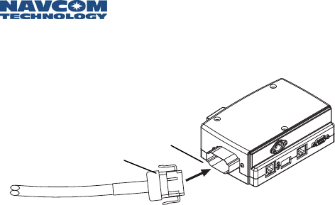
4. Connect the other end of the J2 cable to the end of
the Port Expander (maximum distance 300 feet).
Figure 3-5: J2 to Port Expander Connection
5. Plug in the Port Expander’s 5V/24V DC power supply
to the DIN connector on the Port Expander, and to
the AC power source.
6. Turn on the Port Expander. This will provide power
to—and turn on—the radio.
Black
key
Black
connector
Safari Network User Guide
3-7
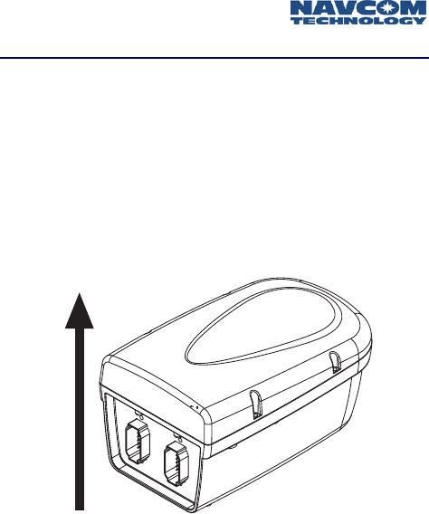
UP
Providing Power through the J1 Connector
This configuration, recommended for Remote units in
vehicles, requires the use of the Port Expander without the
DIN connector for power input.
1. Mount the radio unit in the selected location per your
site planning. If using the internal antenna, be sure to
mount the unit in the position shown in Figure 3-6
below, with the omni-directional radiation pattern
along the horizontal plane.
Figure 3-6: Correct Mounting Position for Internal Antenna
Safari Network User Guide
3-8
2. Connect the J1 cable into the J1 connector, and the J2
cable into the J2 connector. The connectors are keyed
to only fit one way.
Figure 3-7: Use of J1 Cable
3. Connect the four 20 AWG wires at the other end of
the J1 cable as follows:
• Connect the red wire to the Vdc + of the voltage
source.
• Connect the green wire to the Ground of the
voltage source.
• Connect the white wire to the ignition signal. If
there is no ignition signal, connect the white wire
to the red wire at the voltage source.
• Connect the black wire to the chassis ground.
4. Connect the other end of the J2 cable to the end of
the Port Expander.
Figure 3-8: J2 to Port Expander Connection
5. Turn on the Port Expander. This will turn on the
radio.
Black
key
Black
connector
J1 cable J2 cable

Safari Network User Guide
3-9
Antenna Configuration
There are two antenna configurations:
A 0 dBi antenna is embedded in each NCU and
Remote unit underneath the radome. Two 0 dBi
antennas are embedded in each SCU. The antennas
are vertically polarized with an omni-directional
radiation pattern.
For longer range RF transmission, an external 5.5 dBi
antenna with RF cable has been included. The
antenna is vertically polarized with omni-directional
radiation pattern. This antenna configuration is
recommended for NCUs and SCUs.
Using the External Antenna
To replace the 0 dBi antenna with the 5.5 dBi antenna,
follow these steps:
1. Turn power off and remove the radome from the
radio.
2. Unscrew the embedded antenna from the SMA
connector on the radio.
3. Connect the right angle SMA connector on the 6dBi
antenna’s RF cable to the SMA connector on the
radio.
4. Vertically mount the 5.5 dBi antenna.
Figure 3-9: 5.5 dBi Antenna Orientation
UP
Safari Network User Guide
3-10
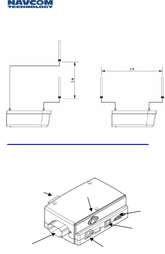
5. For an SCU, it is recommended to mount the two
antennas with either 2 feet (min.) of vertical
separation or 3 feet (min.) of horizontal separation to
minimize intermodulation (if using 5.5 db antennas).
Figure 3-10: SCU Antenna Separation
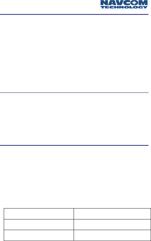
Communication Ports
There are three external radio communication ports:
COM1, COM2, and COM3. COM1 and COM2 are
accessible from the Port Expander:
Figure 3-11: Communication Ports
COM1
DB9 (Serial)
To Radio module COM1
RJ45 (Ethernet)
COM2
RJ45 (Serial)
Switch Power
Safari Network User Guide
3-11
COM1
COM1 is pre-configured at the factory as Serial or Ethernet
based on the unit ordered.
The DB9 connector on the right side of the front
panel of the Port Expander provides access to COM1
Serial port (which can be RS232 or RS422).
The RJ45 connector on the left side of the front panel
of the Port Expander provides access to
COM1/Ethernet.
COM2
COM2 is factory pre-configured as RS232 or RS422. The
RJ45 connector in the middle of the front panel on the
Port Expander allows access to COM2. An RJ45/DB9
converter cable is also provided to change COM2 to a
DB9 connector.
COM3
COM3 is configured as RS232 protocol for all units. It is
not accessible from the Port Expander, but can be
accessed only through the J1 connector and cable.
The J1 cable composition is made up of one CAT5 cable
with 4 twisted pairs for signals, plus 4 power wires.
For NCUs and Remote Units (J1):
Green CAT5 wire RxD (pin 2 on DB9)
White/Green CAT5 wire TxD (pin 3 on DB9)
Blue CAT5 wire Ground (pin 5 on DB9)
Table 3-1: DB9 Pinouts, NCU and Remote (J1)
Safari Network User Guide
3-12
For SCUs (two signals, one for upstream, one for
downstream):
Orange CAT5 wire RxD (pin 2 on DB9)
White/Orange CAT5 wire TxD (pin 3 on DB9)
Blue CAT5 wire Ground (pin 5 on DB9)
Table 3-2: COM3/RS232 for SCU-Upstream (J1)
Green CAT5 wire RxD (pin 2 on a DB9 )
White/Green CAT5 wire TxD (pin 3 on a DB9)
Blue CAT5 wire Ground (pin 5 on a DB9)
Table: 3-3: COM3/RS232 for SCU-Downstream (J1)
J1 cable has two green wires. One is 20 AWG
stranded and the other is 24 AWG solid, and is part
of the twisted pair data cable. These wires should
not be confused.
For a complete description of the J1 and J2 pin
assignments, see the section Cable Connections and Wiring
on the next page.
Proceed to Chapter 4: Configuration to configure the radio
units in the network.
Safari Network User Guide
3-13
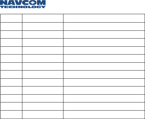
Cable Connections and Wiring
When a Port Expander will not be used, such as when a
radio unit is mounted on a vehicle, refer to Table 3-4 for
pin assignments and associated cable wiring.
Radio Unit (NCU or Remote)
J1 Signal name Functions Cable wiring
Pin 1 GND Chassis Connect to chassis ground Black, 20 gauge
Pin 2 Ext Vin 9-36 V DC power in Red, 20 gauge
Pin 3 Auto On
Disable See note 1 White/Blue
CAT 5
Pin 4 GND IO COM3, ground Blue, CAT 5
Pin 5 RS232 In COM3, connect to TxD
on DTE
White/Green
CAT 5
Pin 6 RS232 Out COM3, connect to RxD
on DTE Green, CAT 5
Pin 7 CAN L CAN bus White/Brown
CAT 5
Pin 8 CAN H CAN bus Brown, CAT 5
Pin 9 NetSync B
For NCU synchronization,
to NetSync B on
other NCUs
White/Orange
CAT 5
Pin
10 NetSync A
For NCU synchronization,
to NetSync A on
other NCUs
Orange, CAT 5
Pin
11 Vin RTN Ground for 9-36 V DC
power
Green,
20 gauge
Pin
12 IGN Main See Note 1 below White,
20 gauge
Table 3-4: J1 Cable Connector, NCU and Remote
Note 1. Radio status Pin 12 high Pin 12 low
Pin 3 open Power ON Power OFF
Pin 3 grounded Power ON Power ON
Safari Network User Guide
3-14
Table 3-5: J2 Cable for NCU and Remote
J2 Signal Cable wiring
Pin 1 Multi Rx- White/Blue, CAT 5
Pin 2 Multi Rx+ Blue, CAT 5
Pin 3 Multi Tx+ White/Green, CAT 5
Pin 4 Multi Tx- Green, CAT 5
Pin 5 IGN Alt Green, 20 gauge
Pin 6 IGN In White, 20 gauge
Pin 7 PE6V Red, 20 gauge
Pin 8 GND Black, 20 gauge
Pin 9 R2P A White/Brown, CAT 5
Pin 10 R2P B Brown, CAT 5
Pin 11 P2R B White/Orange, CAT 5
Pin 12 P2R A Orange, CAT 5
Safari Network User Guide
3-15
Subnetwork Control Unit (SCU)
J1 Signal
name Functions Cable wiring
Pin 1 GND
Chassis
Connect to chassis
ground
Black, 20
gauge
Pin 2 Ext Vin 9-36 V DC power in Red, 20 gauge
Pin 3 Auto On
Disable See note 1 White/Blue,
CAT 5
Pin 4 GND IO
COM3_SCU_upstream &
COM3_SCU_downstream,
ground
Blue, CAT 5
Pin 5 RS232 In COM3_SCU_downstream,
connect to TxD on DTE
White/Green,
CAT 5
Pin 6 RS232 Out COM3_SCU_downstream,
connect to RxD on DTE Green, CAT 5
Pin 7 CAN L CAN bus White/Brown,
CAT 5
Pin 8 CAN H CAN bus Brown, CAT 5
Pin 9 RS232 In COM3_SCU_upstream,
connect to TxD on DTE
White/Orange,
CAT 5
Pin
10 RS232 Out COM3_SCU_upstream,
connect to RxD on DTE Orange, CAT 5
Pin
11 Vin RTN Ground for 9-36 V DC
power
Green, 20
gauge
Pin
12 IGN Main See Note 1 below White, 20
gauge
Table 3-6: J1 Connector for SCU
Note 1. Radio status Pin 12 high Pin 12 low
Pin 3 open Power ON Power OFF
Pin 3 grounded Power ON Power ON
Safari Network User Guide
3-16
Table 3-7: J2 Cable for SCU
J2 Signal name Cable wiring
Pin 1 Multi Rx- White/Blue, CAT 5
Pin 2 Multi Rx+ Blue, CAT 5
Pin 3 Multi Tx+ White/Green, CAT 5
Pin 4 Multi Tx- Green, CAT 5
Pin 5 IGN Alt Green, 20 gauge
Pin 6 IGN In White, 20 gauge
Pin 7 PE6V Red, 20 gauge
Pin 8 GND Black, 20 gauge
Pin 9 R2P A White/Brown, CAT 5
Pin 10 R2P B Brown, CAT 5
Pin 11 P2R B White/Orange, CAT 5
Pin 12 P2R A Orange, CAT 5

Safari Network User Guide
4-1
Chapter 4 Configuration
Once you have planned your network installation and
configuration, as discussed in Chapter 2, and physically
installed your network components, as discussed in
Chapter 3, you can specify services and configure the
NCU, RU and SCU components to deliver the services
you require.
This chapter describes version 3.1.06e of the
configuration software.
The configuration software discussed in this chapter
is text menu-based. A graphical, browser-based
software interface—for networks configured as a
wireless Ethernet LAN—may be available in a later
release.
HyperTerminal Program Interface
HyperTerminal is a text–based communication program
that can be used for sending Administrative commands to
the SR-7100 radio. HyperTerminal Private Edition 6.3 (or
higher), which has the best compatibility among different
operating system platforms, is recommended. The
program can be downloaded for free from
www.hilgraeve.com/htpe/download.html.
Safari Network User Guide
4-2
Use the provided RJ45-DB9 converter cable to
connect the COM2 port on the Port Expander that is
connected to the NCU with a COM port on your
administrative computer.
Launch a HyperTerminal program from the computer
and set the following parameters for the
HyperTerminal program:
• Baud = 57600 bps
• Data bits = 8
• Parity = NONE
• Stop bits = 1
• Flow Control = NONE
Figure 4-1: Set-up Process
Launch
HyperTerm
Program
Display
"Admin.Page"
Sel. "Local Config"
Config as NCU
Sel: "Net Mgmt"
Sel: "Remote Config"
Config. Remote
Sel. "Net. Mgmt"
Sel. "Svc Config"
Set Up Svcs.
Sel: "Net Mgmt"
Sel: "SCU Config"
Config. SCU
Sel: "Net Mgmt"
Sel: "NCU Config"
Config NCU
Safari Network User Guide
4-3
Configuring as an NCU
The SR-7100 radio defaults to an RU (Remote Unit). Before
you can use the radio as an NCU, you need to configure it
as an NCU.
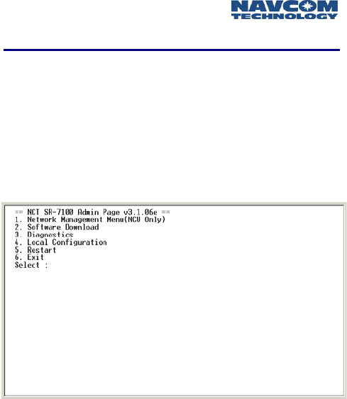
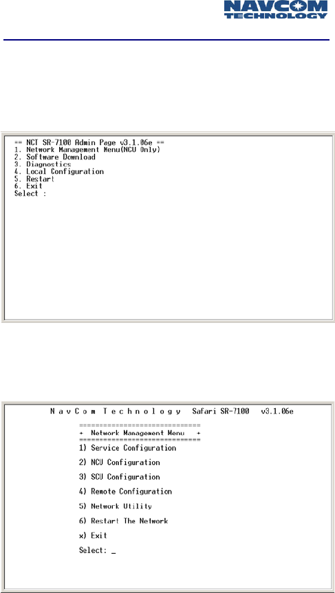
Initiate a HyperTerminal program and turn the radio ON
through the Port Expander. Within 10 seconds, type the
word “admin” in the HyperTerminal window and press
the Enter key. The Admin Page appears like the following:
Image 4-1: Admin Page
Do not select 2. Software Download with this
version of software (future implementation). If
accidentally selected you must perform a
hardware power restart, followed by typing
“admin” within 10 seconds.
Do not select 3. Diagnostics with this version of
software (future implementation). If selected, type
“admin” to return to Admin Page.
Safari Network User Guide
4-4
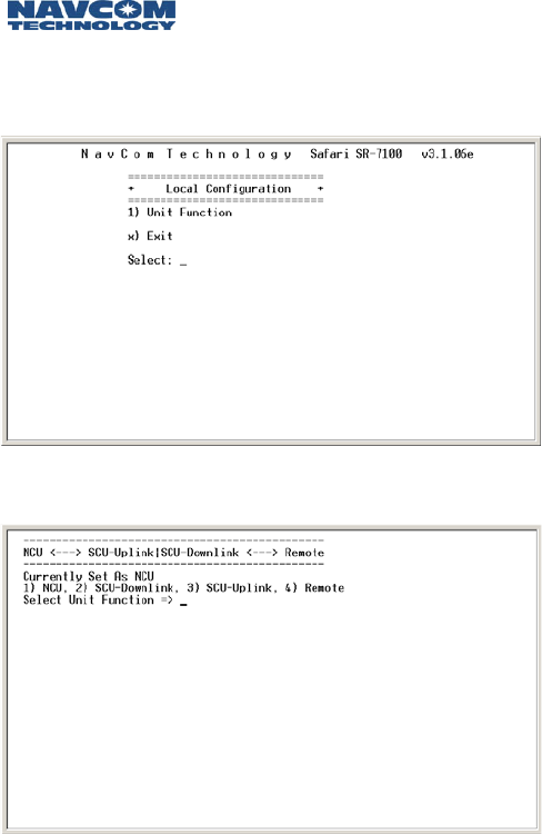
Select: 4. Local Configuration
by typing 4 and pressing the Enter key. The Local
Configuration window appears like the following:
Image 4-2: Local Configuration
Select: 1) Unit Function
Image 4-3: Unit Function
To set the radio as the NCU, select: 1) NCU
A message will direct you to perform a unit reset. Press the
Enter key again to return to the Local Configuration page.
Safari Network User Guide
4-5
Press x to return to the Admin Page. Press 5 plus enter,
followed within 10 seconds with “admin”.
Configuring the network
To illustrate the logic of network configuration, let’s
consider an example of a typical network system.
Figure 4-2: Sample Network
There is 1 NCU with a physical ID of 6F3A6E8. It will
be automatically assigned Unit ID 100.
There are 2 RUs:
There is 1 SCU containing two radio modules named
SCU uplink and SCU downlink.
RU Physical ID Assigned Unit ID
1 6F3FFFF 201
2 6F3EEEE 202
SCU Physical ID Assigned Unit ID
SCU uplink 6F3DDDD 301
SCU downlink 6F3CCCC 302
Router
NCU
ID = 100
RU RU
ID = 201 ID = 202
SCU
ID = 301
ID = 302

Safari Network User Guide
4-6
A router is connected to a wired LAN and the COM1
on the NCU. The Internet will be accessible from the
COM1 port on RU 201 or 202 or both. Therefore, a
WLAN channel will be established and named
Channel 1. The COM1 ports on NCU, RU 201 and
RU 202 will all be assigned to Channel 1. The data
throughput is set at 179.2Kbps for both upload and
download.
Also, there will be a serial communication link
between 201 COM2 and 202 COM2 with a
throughput rate of 25.6Kbps. Therefore, a Remote-to-
Remote service will be setup with forward channel 2
and return channel 3 on 25.6Kbps data rate. Note:
Because the Remote-to-Remote passes both upstream
and down, it consumes two times the data rate from
the maximum throughput. Note: Com 3 (not used in
this example) could be used for additional services
such as GPS reporting. A special cable may be
required in some applications.
The SCU is transparent to the service setup. The NCU
in on frequency 4 and the SCU downlink is on
frequency 2. The two RUs will automatically search for
the best frequency to log onto the network.
All example screens in this chapter pertain to this example
setup (illustrated in Figure 4-2 on the previous page).
Safari Network User Guide
4-7
Bring up the Network Management Menu
Initiate a HyperTerminal program and turn on the radio
through the Port Expander. Within 10 seconds, type the
word “admin” in the HyperTerminal window and press
the Enter key. The Admin Page appears like the following:
Image 4-4: Admin Page
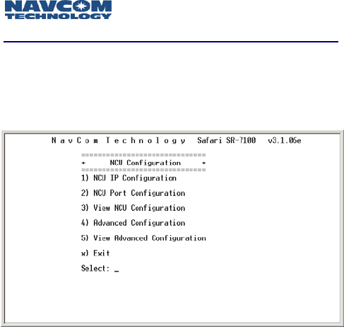
Select option 1. Network Management Menu by typing
1 and pressing the Enter key. The Network Management
Menu appears like the following:
Image 4-5: Network Management Menu
Safari Network User Guide
4-8
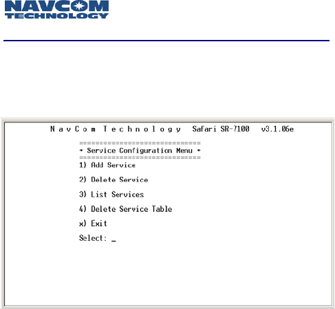
Service Configuration
At the Network Management Menu, select option
1) Service Configuration. The Service Configuration page
appears like the following:
Image 4-6: Service Configuration Menu
At the Service Configuration Menu, select option
1) Add Service and you will be prompted to select the
type of the service, to assign service ID and to select the
data throughput for the services.
Types of services are:
- Broadcast from NCU
- Broadcast from Remote
- Remote to Remote
- Multipoint - Multipoint
- Wireless LAN
- Remote to NCU
After selecting the service type, you are prompted to enter
the Service ID for the selected service type. Values are 1 –
254. You will type the value and press the Enter key.
Safari Network User Guide
4-9
After entering the Service ID, you are prompted to choose
the Forward Channel Bandwidth by entering one of the
following options (Note: this list of speed options will be
provided when the Total System Throughput is set at
512Kbps (factory setting). If you wish to change it to a
lower rate of 240 or 96Kbps, see NCU Advanced
Configuration (Data Rate Selection) on page 4-16 for
instructions and select from the options provided.
Forward Channel Bandwidth
0 NONE
1 25.6K
2 51.2K
3 76.8K
4 102.4K
5 128.0K
6 153.6K
7 179.2K
8 204.8K
9 230.4K
Table 4-1
If adding a Point to Point or Multipoint service, you will
also be prompted to enter another service ID (for the
return channel).
Safari Network User Guide
4-10
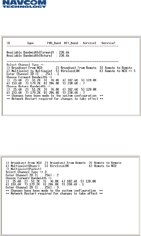
The following screen is an example of adding a WLAN
channel with assigned channel ID of 1 and forward and
return bandwidth of 179.2Kbps.
Image 4-7: Adding a WLAN Channel
The following screen shows steps of adding a Remote to
Remote service with assigned forward channel ID of 2 and
return channel ID of 3 and 25.6Kbps bandwidth in both
directions.
Image 4-8: Adding a Remote to Remote Service
Repeat the steps in this section to add additional network
services.
Safari Network User Guide
4-11
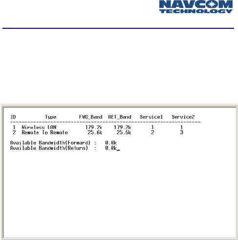
List Services
When all channels are added in the network, you can
select:
3) List Services
from the Service Configuration menu to double check (as
shown in the following example).
Image 4-9: List Services
Safari Network User Guide
4-12
NCU Configuration
At the Network Management menu, select:
2) NCU Configuration
The NCU Configuration page appears like the following:
Image 4-10: NCU Configuration
If the network you are setting up does not include
Ethernet services, skip this section and go directly to
NCU Port Configuration.
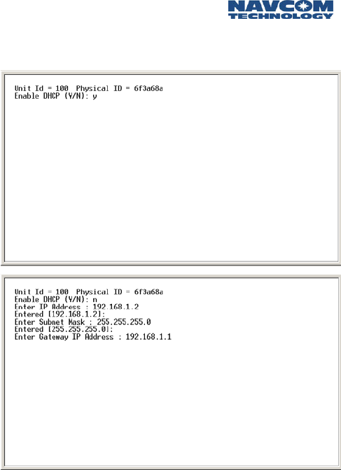
If you are setting up a network including Ethernet services,
select 1) NCU IP Configuration from NCU Configuration
menu and you will be prompted to answer IP address
related questions.
The NCU unit needs to be assigned with DHCP-enabled or
a fixed IP address. If DHCP is not enabled, then you have
to select an IP address, Subnetwork Mask and Gateway IP
address that is acceptable to your network. If using a
Linksys router, the router has a default IP address of
192.168.1.1 which is the gateway IP address. Therefore it
is convenient to assign NCU an IP address of 192.168.1.2.
The subnet mask address is 255.255.255.0.
Safari Network User Guide
4-13
The following screens show the steps of this configuration
process.
Image 4-11: Configuration Process
Safari Network User Guide
4-14
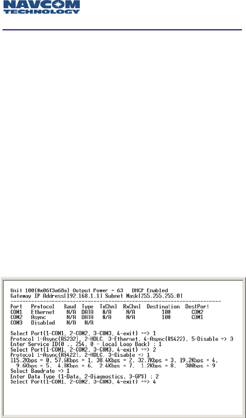
NCU Port Configuration
At the NCU Configuration menu, select:
2) NCU Port Configuration
and you will be prompted to configure the ports by
selecting the protocol, the DCE/DTE transfer data rate
and, in case of setting up serial communication ports, the
Unit ID for the ultimate destination unit and the port ID
on the ultimate destination unit.
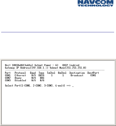
The following screen is an example of NCU port
configuration while the COM1 is set for Ethernet and
COM2 is set for Diagnostics. Since Ethernet at the NCU is
treated as broadcasting mode, there is no need to identify
the ultimate destination. It is recommended to set COM2
at the NCU as the diagnostics interface for network
management purposes (unless you elect to use the
Browser interface via Ethernet). The data rate for the
diagnostic port is always 57.6Kbps. Note: COM3 is
available on J1 at the NCU by use of a special cable.
COM3 could be used to broadcast differential corrections
to GPS receivers or to report position messages in real
time. Here it is left disabled.
Image 4-12: NCU Port Configuration
Safari Network User Guide
4-15
The service ID is the channel ID identified from the Service
Configuration page and in this example service 1 is a
WLAN type of service and assigned to COM1.
View NCU Configuration
At the NCU Configuration menu, select:
3) View NCU Configuration
and you will see the primary settings for the NCU.
Image 4-13: NCU Configuration
Safari Network User Guide
4-16
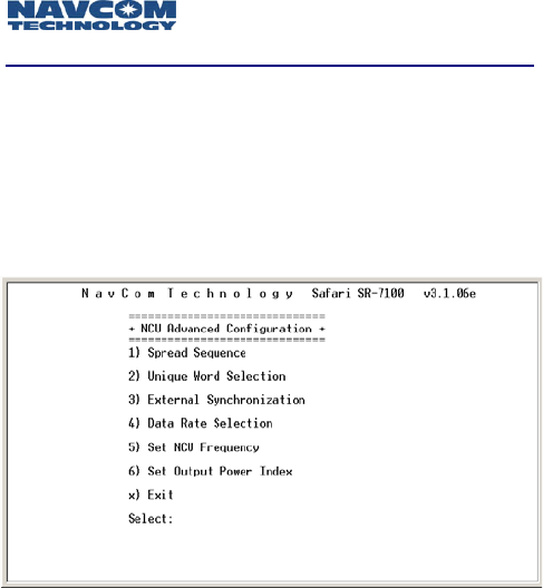
NCU Advanced Configuration
The NCU Advanced Configuration menu is used to set
network parameters for specialized cases. Changes made
here may require reconfiguration of every RU and SCU in
the network.
At the NCU Configuration menu, select:
4) Advanced Configuration.
Image 4-14: NCU Advanced Configuration Menu
1) Spread Sequence (future option)
The Spread Sequence is a parameter used for security
purposes. It is method of radio communication in which a
spreading code is used to encode data onto a radio carrier
frequency. Values are 1 – 6. The selected value must be
common across the system. Type the value and press the
Enter key. You will be returned to the Network Control Unit
Setup menu.
2) Unique Word (future option)
The Unique Word is another parameter for security
purposes. It is a pre-pended data pattern used as a training
pattern signal to the intended data recipient for receiver
signal acquisition. Values are 1 - 9. The assigned value will
be common across the system. Type the value and press the

Safari Network User Guide
4-17
Enter key. You will be returned to the Network Control Unit
Setup menu.
3) External Synchronization
Options are Transmit and Receive. Normally, this would be
set to Transmit. In situations where there will be two NCUs
linked together, you would set one of the NCUs to Receive.
Type the value (t or r) and press the Enter key. Then type x
and press the Enter key. You will be returned to the Network
Control Unit Setup menu.
4) Total System Data Throughput Selection
This is the total over-the-air data transfer capacity of a
system, in both directions (inbound plus outbound). For the
SR-7100 System, this is 96, 240, or 512Kbps.
5) Set Base Frequency
This is the system center radio frequency. Depending on the
data rate, there are a different number of frequency channels
available for operation. For the highest data rate, there are
five non-overlapping channels that can be operated. (See
Appendix A for a list of frequency values.) Type a value and
press the Enter key. You will be returned to the Network
Control Unit Setup menu.
6) Set Output Power Index
This is the power level for radio transmissions from the NCU.
Options are 0 – 63, with 0 representing minimum power as
allowed by the FCC for each data rate, and 63 representing
full power. Type a value and press the Enter key. You will be
returned to the Network Control Unit Setup menu.
In our example, select Set Base Unit Frequency to set it to
frequency 4, and select Set Output Power Index to set it to
63.
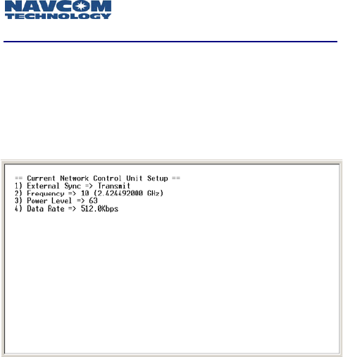
Safari Network User Guide
4-18
View Advanced Configuration
When done, select Exit to return to the Network
Management Menu.
At the NCU configuration menu, select 5) View
Advanced Configuration and you will see the advanced
settings for the NCU.
Image 4-15: NCU Advanced Settings
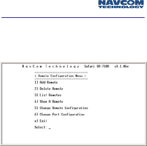
Safari Network User Guide
4-19
Remote Configuration - Adding an RU
At the Network Management menu, select:
4) Remote Configuration
The Remote Configuration menu appears like the
following:
Image 4-16: Remote Configuration Menu
At the Remote Configuration menu, select:
1) Add Remote
and you will be prompted to enter the Unit ID (the logical
radio ID) for the radio unit by typing its value and pressing
the Enter key. For RUs, the Unit ID can be chosen from
101 to 599 (100 is reserved for NCU).
Then you will be prompted to enter the physical ID of the
unit (as it is listed on the RU label).
When you are prompted whether or not to enable DHCP,
enter y or n as appropriate. If you are using a router with
its DHCP server enabled, enter y to enable the DHCP on
remotes. If you enter n, you will be prompted to enter
your assigned remote’s IP Address and Subnet Mask.
Then you will be prompted to enter the Output Power
level (which is usually the same as that set for the NCU).
Use 63 for the maximum power level permitted by the
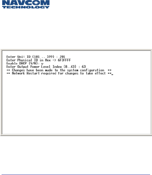
Safari Network User Guide
4-20
FCC for each data rate. Lower power level can be set by
using 62 - 0.
The following example screen shows the steps of adding
the RU 201.
Image 4-17: Adding an RU
Repeat this process to add all RUs included in the
network.
RU Port Configuration
At the Remote Configuration menu, select:
6) Change Port Configuration
and you will prompted to enter the Unit ID for the RU
to be configured. In our example, RU 201 is the first
unit to be configured, so enter 201 and return.
Then you will be prompted to select a port to
configure: COM1, COM2, COM3. In our example,
COM1 is selected first for configuration.
After you select a port to configure, you are
prompted to select the protocol for the port to
communicate with the computer or other
communication device. Options are different
depending on the port selected. You can follow the
Safari Network User Guide
4-21
on-screen prompt. In our example, COM1 is assigned
for Ethernet and COM2 is assigned for Asynch.
Next you will be prompted to enter the baud rate for
the port to communicate with the computer or other
communication device across the DCE/DTE interface.
(For Ethernet protocol, this step is skipped) Options
are detailed in Table 4-2.
BAUD RATE
115200 0
57600 1
38400 2
32768 3
19200 4
9600 5
4800 6
2400 7
1200 8
300 9
Table 4-2
In this example, COM2 is assigned with data rate of
19.2Kbps and COM1 is Ethernet.
Next enter the Data Type for the port. (This is skipped
for Ethernet protocol.) Options are:
0-Data (Used to pass user data traffic)
1-Diagnostics (Used for administrative
communications with NCU controller)
In this example, both COM1 and COM2 are for Data
communication.
You will then be prompted to enter the Service ID for
the port (this corresponds to the service ID configured
in service configuration for the transmit channel). If
required by the type of service, you may also be
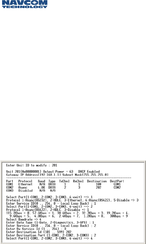
Safari Network User Guide
4-22
prompted to enter a second service ID (for the
service’s receive channel). For a Remote-NCU service,
there is just one channel ID for both transmit and
receive.
In this case, COM1 is assigned with channel 1 and
COM2 is assigned with forward channel 2 and return
channel 3. Please refer to service example in
Configuring the Network on page 4-5.
Then you will be prompted to enter the unit ID of the
Ultimate Destination radio (This is skipped for
Ethernet and Broadcasting type of services). In this
example, the ultimate destination of unit 201 COM2
is Unit 202.
Enter the Ultimate Destination Port for the channel
(COM1, COM2 or COM3), which is the port that will
receive this port’s transmission. In this example, the
ultimate destination of unit 201 COM2 is Unit 202
COM2.
The following screen shows the steps of configuring
the COM1 and COM2 on RU 201.
Image 4-18: Configuring Ports
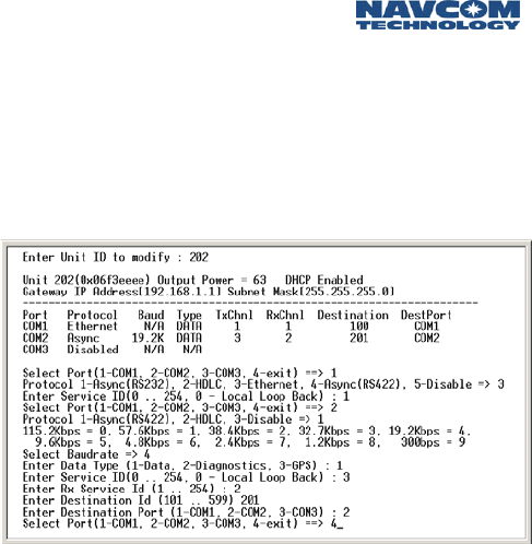
Safari Network User Guide
4-23
You can now choose:
6) Change Port Configuration
again from the Remote Configuration menu to
configure the ports for Remote 202.
The following screen shows the steps configuring the
ports on RU 202. Please notice the sequence of service ID
for COM2 is the opposite to that of 201 COM2.
Image 4-19: Configuring Ports
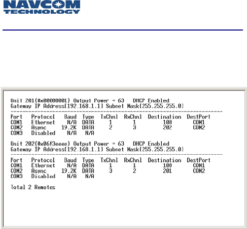
Safari Network User Guide
4-24
List RUs
At the Remote Configuration menu, select:
3) List Remotes
and you will see the configuration for all RUs.
Image 4-20: RU Configuration
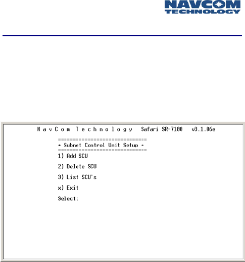
Safari Network User Guide
4-25
SCU Configuration
Bring up the Subnetwork Control Unit Setup menu:
At the Network Management menu, select:
4) SCU Configuration
The Subnetwork Control Unit Setup menu appears like the
following:
Image 4-21: Subnetwork Control Unit Setup Menu
At the Subnetwork Control Unit Setup menu, select:
1) Add SCU
and you will be prompted to:
Enter the SCU-Uplink Unit ID. In our example, it is
301.
Enter the SCU Uplink physical ID, which is labeled on
the outer case of the SCU unit. In our example, it is
6F3DDDD.
Enter the RF output power for the SCU Uplink. In our
example, it is 63, the max power.
Enter the SCU-Downlink Unit ID. In our example, it is
302.
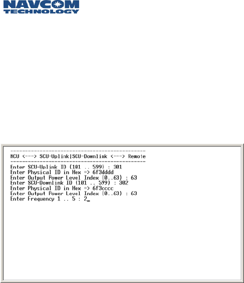
Safari Network User Guide
4-26
Enter the SCU Downlink physical ID that is labeled on
the case of SCU unit. In our example, it is 6F3CCCC.
Enter the RF output power for the SCU Downlink. In
our example, it is set at 63, the max power.
Enter the SCU Downlink frequency (should be
different from the NCU frequency). In our example, it
is frequency 2.
The following screen shows the steps of the SCU
configuration.
Image 4-22: SCU Configuration
Safari Network User Guide
5-1
Chapter 5 Monitoring & Changes
After you have configured your network services and
added units to the network (as described in Chapter 4),
you may occasionally need to monitor network usage
and make changes to your network configuration. Here
you will find descriptions of procedures for displaying
network information, removing network services and
components, and modifying configuration parameters.
This chapter describes version 3.1.06e of the
configuration software.
Displaying Network Information
The Safari Network configuration software enables you to
display current configuration information as well as real
time network usage information from the Network
Management Menu.
To access the SR-7100 Network Management Menu:
1. Launch a terminal program (such as HyperTerminal)
on the computer.
2. Turn on the NCU through the Port Expander. Within
10 seconds, type the word “admin” and press the
Enter key.
3. At the NCT SR-7100 Admin Page, select:
1. Network Management Menu
by typing 1 and pressing the Enter key.
Real Time Network Usage information is very useful to
monitor the health of the whole network and diagnostics
for network abnormality. It is recommended to reserve
COM2 port on the NCU for network management
displaying real time RU status and to change network
configuration if required.

Safari Network User Guide
5-2
To setup COM2 on NCU for network management, go to
the Network Management menu, then the NCU
configuration menu and then the NCU Port Configuration
menu to configure COM2 as Async protocol, 57.6 Kbps
baud rate and “diagnostics” for data type.
Since the COM2 port is readily available on the Port
Expander which is located close to a PC, it is convenient to
set NCU COM2 port for Network management.
Current Configuration
The following information can be displayed about the
network within the Network Management Menu:
NCU settings
Network services
RU settings (all or one at a time)
Network SCUs
To display NCU settings:
1. At the Network Management menu, select:
2) NCU Configuration.
2. At the NCU Configuration menu, select:
3) View NCU Configuration
to see the current setting for NCU communication
ports, its physical ID.
3. At the NCU Configuration menu, select:
5) View Advanced Configuration
to see the current settings for the NCU’s external
sync, RF frequency, RF output power level and data
throughput settings. Press the Enter key to return to
the Network Management menu.

Safari Network User Guide
5-3
To display network services:
1. At the Network Management menu, select:
1) Service Configuration.
2. At the Service Configuration menu, select:
3) List Services
to see all network services with forward and return
bandwidth and available forward and return
bandwidth.
Adding services is discussed in Chapter 4. Deleting
services is discussed later in this chapter.
To display RUs:
1. At the Network Management menu, select:
4) Remote Configuration
2. At the Remote Configuration menu, select:
3) List Remotes
to see configuration for all RUs. The configuration
information for each RU includes: unit logical ID, unit
physical ID, RF output power level, DHCP status and
three communication port configuration.
3. Or at the Remote Configuration menu, select:
4) Show a Remote
then enter the unit’s ID at the prompt to see the
configuration information for the RU.
Adding RUs is discussed in Chapter 4. Reconfiguring
RUs and ports is discussed later in this chapter.
To display SCUs:
1. At the Network Management Menu, select:
3) SCU Configuration
2. At the SCU Configuration menu, select:
3) List SCU’s
to view the configuration information for SCUs.

Safari Network User Guide
5-4
Real Time Network Usage
The following information can be displayed about real
time network usage:
Units logged on
Units using services
To display units logged on:
1. At the Network Management menu, select:
5) Network Utility
2. At the Network Utility menu, select:
1) List Units Logged On
Any unit currently logged on to the network will be listed
with its direct parent unit ID, signal to noise level (S/N)
how many synchronization message received out of 1000,
how many unique words received out of 1000 and how
many correct data packages received out of 1000.
This information is important for evaluating an RU’s status.
When an RU is within the line-of-sight range from its
direct parent (either the NCU or a SCU) and without
strong in-band interference, the S/N displayed for the RU
should be higher than level “3” and all three indicators
should be 1000 out of 1000. If not, there are potential
issues with the RF link. Enter x to return to the Network
Utility menu.
To display units using services:
1. At the Network Management menu, select:
5) Network Utility
2. At the Network Utility menu, select:
2) List Units Using Services
The RUs using each service are listed, by ID and port.
Press the Enter key to return to the Network Management
submenu, then enter x to return to the Network Utility
menu.
Safari Network User Guide
5-5
Deleting Network Components
Deleting a Service
1. At the Network Management menu, select:
1) Service Configuration
2. At the Service Configuration menu, select:
2) Delete Service
to delete one service setting from the service table.
You are prompted to enter the Service ID.
BE SURE TO ENTER THE CORRECT SERVICE ID TO
BE DELETED. THERE IS NO UNDO OPTION.
After the service is deleted, you are advised to perform a
Network Restart—either a software restart from the
Network Management Menu or hardware restart by
turning off and on the Port Expander. The change will not
take effect until a network restart.
Deleting All Services (Erasing the Service Table)
1. At the Network Management menu, select:
1) Service Configuration
2. At the Service Configuration menu, select:
4) Delete Service Table
and erase all service settings.
You are prompted to enter y or n to confirm that you
want to erase the service database. Respond yes only if you
are sure that you want to erase all services.
After the Service Table is erased, you are advised to
perform a Network Restart, either a software restart from
the Network Management Menu or hardware restart by
turning off and on the Port Expander. The change will not
take effect until a network restart.

Safari Network User Guide
5-6
Deleting an RU
1. At the Network Management menu, select:
3) Remote Configuration
2. At the Remote Configuration menu, select:
2) Delete Remote
3. Enter the Unit ID (the network name) for the RU to be
deleted by typing its value and pressing the Enter key.
BE SURE TO ENTER THE CORRECT UNIT ID TO BE
DELETED. THERE IS NO UNDO OPTION. Press the
Esc. key to abort.
After the RU is deleted, you are advised to perform a
Network Restart—either a software restart from the
Network Management Menu or hardware restart by
turning off and on the Port Expander. The change won’t
take effect until a network restart.
Deleting an SCU
1. At the Network Management menu, select:
3) SCU Configuration
2. At the SCU configuration menu, select:
2) Delete SCU
You are prompted to enter the Unit ID for either one unit
in a SCU pair to delete this SCU pair from the network.
Since there is no reconfiguration for an SCU, if you
have configured an SCU with a mistake (such as the
wrong physical ID number), you need to delete this
SCU, and then add a new one with the correct
settings.
After the SCU is deleted, you are advised to perform a
Network Restart—either a software restart from the
Network Management Menu or hardware restart by
turning off and on the Port Expander. The change won’t
take effect until a network restart.

Safari Network User Guide
5-7
Deleting All Units in the Network (NCU, SCUs and RUs)
1. At the Network Management menu select:
5) Network Utility
2. At the Network Utility menu, select:
3) Delete Unit Table (NCU, SCUs, and RUs)
You are prompted to enter Y or N to confirm that you
want to erase the Table. RESPOND YES ONLY IF YOU ARE
SURE THAT YOU WANT TO ERASE ALL DATA ENTRIES.
Reconfiguring NCU, RUs, and COM Ports
The Safari Network configuration software enables you to
reconfigure previously configured NCU and RUs and their
communication ports from the Network Management
Menu.
Reconfiguring the NCU’s Basic and Advanced
Configuration
If you only need to reconfigure the port settings on
the NCU unit, go to Reconfiguring the NCU Port
Configuration on the next page.
1. At the Network Management menu, select:
2) NCU Configuration
2. At the NCU Configuration menu, select either:
1) NCU IP Configuration
for changing the IP address setting for NCU or select:
4) Advanced Configuration
for changing the advanced settings such as operating
frequency or network data rate.
Some of the setting change requires a network restart to
take effect.

Safari Network User Guide
5-8
Reconfiguring the NCU Port Configuration
1. At the Network Management menu, select:
1) NCU Configuration
2. At the NCU Configuration menu, select:
2) NCU Port Configuration
The new setting overwrites the existing settings.
Reconfiguring an RU
If you only need to reconfigure a port setting on an
RU, go to Reconfiguring an RU’s Port(s) on the next
page.
1. At the Network Management menu, select:
4) Remote Configuration
2. At the Remote Configuration menu, select:
5) Change Remote Configuration
3. Enter the Unit ID for the RU by typing its value and
pressing the Enter key.
4. The current configuration is displayed. Enter the
physical ID of the RU (as it appears on the radio).
5. When prompted whether or not to enable DHCP,
enter Y or N as appropriate. If you enter No, you will
be prompted to enter the RU’s IP Address.
6. Enter the Output Power level index (which is usually
the same as that set for the NCU).
The change will take effect when the RU logs on.

Safari Network User Guide
5-9
Reconfiguring an RU’s Port(s)
If you need to reconfigure other settings on the RU,
use the procedure in Reconfiguring an RU on the
previous page.
1. At the Network Management menu, select:
4) Remote Configuration
2. At the Remote Configuration menu, select:
6) Change Port Configuration
3. Enter the Unit ID for the RU by typing its value and
pressing the Enter key.
4. The current configuration is for the RU is displayed,
and you are prompted to select a port to configure:
• 1-COM1
• 2-COM2
• 3-COM3
• 4-exit
5. Enter the port using the number value (1 – 3). The
option to exit (4) is provided for when you have
completed configuring the RU’s ports.
6. After you select a port to configure, you are
prompted to enter the protocol for the port. Available
protocols are different among the three COM ports.
An example is:
• 1-Async (RS232)
• 2-HDLC
• 3-Ethernet
• 4-Async (RS422)
• 5-Disable
7. Enter the protocol using the number value (1 – 5).

Safari Network User Guide
5-10
8. Next you are prompted to enter the baud rate for the
port. Options are:
• 115.2 Kbps = 0
• 57.6 Kbps = 1
• 38.4 Kbps = 2
• 32.7 Kbps = 3
• 19.2 Kbps = 4
• 9.6 Kbps = 5
• 4.8 Kbps = 6
• 2.4 Kbps = 7
• 1.2 Kbps = 8
• 300 bps = 9
9. Enter the baud rate using the number value (0 – 9).
10. Next enter the Data Type for the port. Options are:
• 1-Data
• 2-Debug
• 3- GPS
11. Enter the data type using the number value (1,3).
This is normally set to Data.
12. You will then be prompted to enter the Service ID for
the port (this corresponds to the service ID configured
in service configuration for the transmit channel).
13. For a Remote to Remote service, you will also be
prompted to enter a second service ID (for the
service’s receive channel).
14. Enter the Ultimate Destination ID for the port, which
is the RU ID that will receive this port’s transmission.
15. Enter the Ultimate Destination Port for the port
(COM1, COM2 or COM3), which is the port on the
Destination ID that will receive this port’s
transmission.
You can now choose to configure another port, in which
case repeat steps 1 through 10, or select 4) exit when
done. The change will take effect after the RU logs on.
Safari Network User Guide
A-1
Appendix A Troubleshooting
Routine operation of the Safari Network should generally
be straightforward; however, problems with
communications can sometimes occur, and these
problems will need to be diagnosed and corrected. This
chapter discusses potential problems that may be
experienced by network users, along with the possible
causes and the appropriate corrective actions.
Types of Problems
The types of problems that may occur in the network are:
A radio is not communicating at all (see below).
A radio is communicating, but there are errors with—or
omission of—data (see page A-5).
A radio is communicating, but the signal-to-noise (S/N)
level is less than 3 (see page A-6).
If a radio is not communicating
Confirm that the radio is not communicating (using the
configuration software on the NCU) by listing all units
logged onto the network:
1. Launch a terminal program (such as HyperTerminal).
If you have reserved COM2 on the NCU as a Network
Management port, go to Step 5.
2. Power up the NCU through the Port Expander. Within
10 seconds, type the word “admin” and press the
Enter key.
3. When the NCT SR-7100 Admin Page appears, select:
1. Network Configuration Menu.

Safari Network User Guide
A-2
4. At the Network Configuration Menu, select:
5) Network Management.
5. At the Network Management submenu, select:
1) List Units Logged On.
6. If the radio in question is not logged on (you may
need to try this repeatedly over a period of time),
proceed to the table on the next page.
Review the following tables to determine the cause of the
problem, and then attempt to resolve it with the
suggested corrective action(s).
This equipment generates, uses, and can radiate radio
frequency energy and, if not installed and used in
accordance with the instructions, may cause harmful
interference to radio communications. However, there is
no guarantee that interference will not occur in a
particular installation. If this equipment does cause
harmful interference to radio or television reception,
which can be determined by turning the equipment off
and on, the user is encouraged to try to correct the
interference by one or more of the following measures:
Reorient or relocate the receiving antenna.
Increase the separation between the equipment and
receiver.
Connect the equipment into an outlet on a circuit
different from that to which the receiver is connected.
Consult the dealer or an experienced radio/TV
technician for help.

Safari Network User Guide
A-3
Possible Cause Corrective Action
The radio is out of
range of the NCU
or an SCU.
Relocate the radio to within 20 miles of the
NCU or an SCU (14 miles @ 512 Kbps).
If the radio needs to operate outside this
range, install and configure an SCU in the
network that is within range of the radio.
To install an SCU, refer to
Chapter 3: Installation.
To configure an SCU, refer to
Chapter 4: Configuration.
The radio does not
have a clear line of
sight to the NCU
or to an SCU.
Relocate the radio so that it has a clear line
of sight to the NCU or an SCU. A clear line
of sight means no obstruction from terrain
or structures on the ground between the
radio and the NCU or SCU.
If the radio cannot be relocated so that it
has a clear line of sight to the NCU or SCU,
install and configure an SCU in the network
to bypass the obstruction.
To install an SCU, refer to
Chapter 3: Installation.
To configure an SCU, refer to
Chapter 4: Configuration.

Safari Network User Guide
A-4
Possible Cause Corrective Action
The radio’s output
power is
insufficient.
Reconfigure the RU’s output power from
the NCU, using the maximum setting (63).
Confirm that the NCU’s output power is
also maximized, and do the same for any
SCU configured between them.
To configure an NCU, refer to
Chapter 4: Configuration.
To configure an SCU, refer to
Chapter 4: Configuration.
To reconfigure an RU, refer to
Chapter 5: Operation.
Transmit and
receive antennas
are cross
polarized.
Reposition the units and/or external
antennae so that they are all oriented
properly and perpendicular to the ground.
The radio was
configured with
an incorrect ID.
Check the physical ID of the radio.
Reconfigure the RU so that the correct
physical ID is used.
To reconfigure an RU, refer to
Chapter 5: Operation.
The radio’s ports
and channel
assignments were
not configured
properly.
Review the port assignments of all RUs to
verify that each source and destination
channel IDs match up.
To review port assignments, refer to
Chapter 5: Operation.
To assign channel Ids, refer to
Chapter 4: Configuration.

Safari Network User Guide
A-5
Possible Cause Corrective Action
Radio is
misconfigured as
NCU or SCU
Go to local setting and set the Radio as RU.
Radio is not
powered on.
Check source power, cabling, switch
position.
If data transmission is incomplete or in error
If a radio is communicating with the network but there
still is a high rate of missing data during transmissions, a
possible cause is that the data throughput exceeds
channel throughput. Reconfigure the radio’s port so that
the data transfer is equal to or less than the data
throughput of the channel assigned to the port.
1. Launch a terminal program (such as HyperTerminal).
2. Turn on the NCU through the Port Expander. Within
10 seconds, type the word “admin” and press the
Enter key.
3. At the NCT SR-7100 Admin Page, select:
1. Network Configuration Menu
4. At the Network Configuration Menu, select:
3) Unit Configuration
5. At the Remote Configuration Menu, select:
6) Change Port Configuration
6. Enter the Unit ID to be modified (such as 201, 202,
etc.).
7. All of the unit’s ports will be displayed. Enter the port
to be reconfigured.

Safari Network User Guide
A-6
8. Go through each step to change the configuration of
the port. Be sure to enter a data baud rate that is
equal to or less than the data throughput of the
channel assigned to the port. Also be sure that the
port speed does not cause more data to be
transferred than can be handled by the assigned
channel’s throughput. A mismatch here could result
in data loss.
9. Exit to the Configuration Menu.
10. Restart the RU to receive a new configuration.
If the Signal-to-Noise (S/N) ratio is too low
If a radio is communicating with the network but its error
rate is excessive, there are three possible causes:
Check for loose and broken antenna connections.
Check transmission path for a proper line of sight and
suitable distance.
Check for interference from outside the network, such
as from another 2.4 GHz system.
If there is another 2.4 GHz system causing radio
interference, change the NCU or SCU frequency:
1. Launch a terminal program (such as HyperTerminal).
2. Turn on the NCU through the Port Expander. Within
10 seconds, type the word “admin” and press the
Enter key.
3. At the NCT SR-7100 Admin Page, select:
1. Network Configuration Menu
4. At the Network Configuration Menu, select:
1) Network Control Unit (NCU) Setup
5. At the Network Control Unit Setup menu, select:
5) Set Base Frequency

Safari Network User Guide
A-7
6. Change the frequency assignment.
7. Exit to the Configuration Menu. If there are no SCUs
in the network, perform a Network Restart and the
procedure is completed.
If, however, there are SCUs in the network, you may also
need to change the uplink frequency assignment for those
SCUs that communicate directly with the NCU. Use the
procedure for reconfiguring units, described in Chapter 5:
Operation.

Safari Network User Guide
A-8
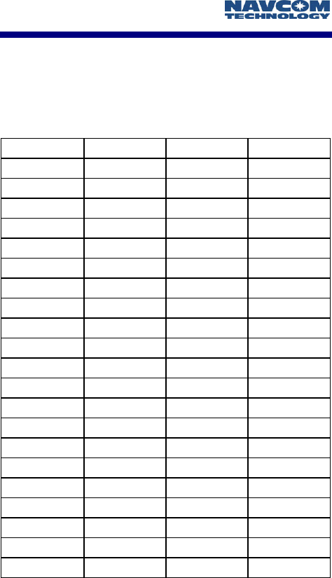
Safari Network User Guide
B-1
Appendix B Radio Frequencies
Frequencies are assigned in number values from 0 to 20,
depending on maximum throughput rate. Frequencies F0
through F20 have the following center frequencies:
Channel 96Kbps 240Kbps 512Kbps
F0/CH1 2.402568 2.404836 2.409372
F1/CH2 2.406348 2.412396 2.424492
F2/CH3 2.410128 2.419956 2.439612
F3/CH4 2.413908 2.427516 2.454732
F4/CH5 2.417688 2.435076 2.469852
F5/CH6 2.421468 2.442636
F6/CH7 2.425248 2.450196
F7/CH8 2.429028 2.457756
F8/CH9 2.432808 2.465316
F9/CH10 2.436588 2.472876
F10/CH11 2.440368
F11/CH12 2.444148
F12/CH13 2.447928
F13/CH14 2.451708
F14/CH15 2.455488
F15/CH16 2.459268
F16/CH17 2.463048
F17/CH18 2.466828
F18/CH19 2.470608
F19/CH20 2.474388
F20/CH21 2.478168

Safari Network User Guide
B-2

Safari Network User Guide
C-1
Appendix C Glossary
Asynchronous: a communications system in which data
transmission may start at any time and is indicated by
a start bit, e.g. RS-232.
Bandwidth: the difference between the highest and
lowest frequencies of a transmission channel (the
width of its allocated band of frequencies). The term
is often used to mean data rate or capacity - the
amount of data that is, or can be, sent through a
given communications circuit per second.
Network Control Unit (NCU): a radio that exerts control
of the system through supervisory control and system
timing. This radio also stores the system
configuration, and relays those settings to the other
radios in a system.
Channel: a frequency band selection. The SR-7100 System
offers the choice of up to 21 Channels within the 2.4
GHz spectrum. May also be used to describe a virtual
path between two network ports.
Channel ID (or Service ID): a number used to uniquely
identify a specific data exchange.
Data Throughput: the data pass-through capability for a
Service in a particular direction. For example, a point-
to-point Service may be configured to have a Data
Throughput of 19.2 Kbps in one direction and a Data
Throughput of 9.6 Kbps in the other direction.
DHCP: Short for Dynamic Host Configuration Protocol, a
protocol for assigning dynamic IP addresses to
devices on a network. With dynamic addressing, a
device can have a different IP address every time it
connects to the network. In some systems, the
device's IP address can even change while it is still
connected. DHCP also supports a mix of static and
dynamic IP addresses.

Safari Network User Guide
C-2
Dynamic addressing simplifies network administration
because the software keeps track of IP addresses
rather than requiring an administrator to manage the
task. This means that a new computer can be added
to a network without the hassle of manually assigning
it a unique IP address. Many ISPs use dynamic IP
addressing for dial-up users.
Ethernet: a system of connecting computers together to
facilitate intercommunication, commonly known as a
Local-Area-Network (LAN).
Ethernet WLAN: Ethernet Wireless Local Area Network.
Employing Ethernet via a radio system.
Frequency: radio carrier frequency used to deliver
information.
Gateway: A node on a network that serves as an entrance
to another network. In enterprises, the gateway is the
computer that routes the traffic from a workstation to
the outside network that is serving the Web pages. In
homes, the gateway is the ISP that connects the user
to the internet.
In enterprises, the gateway node often acts as a proxy
server and a firewall. The gateway is also associated
with both a router, which use headers and forwarding
tables to determine where packets are sent, and a
switch, which provides the actual path for the packet
in and out of the gateway.
HDLC: Short for High-level Data Link Control, a
transmission protocol used at the data link layer
(layer 2) of the OSI seven layer model for data
communications. The HDLC protocol embeds
information in a data frame that allows devices to
control data flow and correct errors. HDLC is an ISO
standard developed from the Synchronous Data Link
Control (SDLC) standard.
Inbound: toward the system NCU.

Safari Network User Guide
C-3
Interface Standard: a description of a port’s configuration
for handling data. The SR-7100 supports the
following port Interface Standards: Asynchronous
RS232, Asynchronous RS422, Synchronous RS422,
and Ethernet.
Local Area Network (LAN): A computer network that
spans a relatively small area. Most LANs are confined
to a single building or group of buildings. However,
one LAN can be connected to other LANs over any
distance via telephone lines and radio waves. A
system of LANs connected in this way is called a wide-
area network (WAN).
Most LANs connect workstations and personal
computers. Each node (individual computer) in a LAN
has its own CPU with which it executes programs, but
it also is able to access data and devices anywhere on
the LAN. This means that many users can share
expensive devices, such as laser printers, as well as
data. Users can also use the LAN to communicate
with each other, by sending e-mail or engaging in
chat sessions.
Outbound: away from the system NCU.
Port Expander Module: the device used to present the
radio user with indicators, control switches, and data
interface ports. This device is usually connected to the
Radio Module.
Port Speed: the rate at which data is sent and received
across a port. A Port Speed of 19.2 Kbps indicates a
send rate of 19.2 Kbps and a receive rate of 19.2
Kbps. Port Speed is independent of the Data
Throughput of the Service.
Radio Module: the device used to transmit and receive
signals over radio frequencies. This device is usually
connected to the Port Expander Module.

Safari Network User Guide
C-4
Remote Unit (RU): a radio used in a remote location or
vehicle. It is programmed and controlled by the
Network Control Unit.
Service: the ability to exchange data among two or more
units within a system.
Service (or Channel) ID: a number used to uniquely
identify a specific data exchange.
Service Type: a particular variety of data exchange. The
SR-7100 System offers four different Service Types.
They are: point-to-point, broadcast, multi-point
network, and Ethernet WLAN.
Spread Sequence: a method of radio communication in
which a spreading code is used to encode data onto a
radio carrier frequency.
Subnet: A portion of a network that shares a common
address component. On TCP/IP networks, subnets are
defined as all devices whose IP addresses have the
same prefix. For example, all devices with IP addresses
that start with 100.100.100. would be part of the
same subnet. Dividing a network into subnets is
useful for both security and performance reasons. IP
networks are divided using a subnet mask.
Subnetwork Control Unit (SCU): Controls and manages
its associated remotes and bandwidth utilization
through channel assignment, frame synchronization,
frequency synchronization, packet assembly and
packet routing to create semi-autonomous cells.
Dynamic bandwidth assignment allows unutilized
channels to be reassigned based on channel routing
requirements, semi-independent operation for traffic
within the SCU cell, internet access point for the cell
allowing multiple internet access points in a single
network, and seamless roaming of remote units
between cells.

Safari Network User Guide
C-5
Synchronization: the condition where a common timing
source is used to regulate the occurrence of actions or
events.
Total System Data Throughput: The total data transfer
capacity of a system, in both directions (Inbound plus
Outbound). For example, a Total System Data
Throughput of 115.2 Kbps may be configured to offer
57.6 Kbps Outbound and 57.6 Kbps Inbound.
Unique Word: a pre-pended data pattern used as an
attention signal to the intended data recipient. There
are 9 Unique Words.
Wide Area Network (WAN): A computer network that
spans a relatively large geographical area. Typically, a
WAN consists of two or more local area networks
(LANs).
Computers connected to a wide-area network are
often connected through public networks, such as the
telephone system. They can also be connected
through leased lines or satellites. The largest WAN in
existence is the Internet.

Safari Network User Guide
C-6

Safari Network User Guide
D-1
Appendix D Specifications
NCU, RU, SCU
Frequency 2.4000 - 2.4835 GHz
Spreading Code Direct Sequence
Range, Line of Sight 20 miles
Transmitter:
Output Power
Output Power Control
Modulation
Bandwidth per Channel
500 mW
63 steps
Patented M-ARY GMSK
3 MHz @ 96 Kbps
Receiver:
Sensitivity
-108 dBm @ 10E-6 at
throughput of 96 Kbps
Data Transmission:
Forward Error Correction
Error Detection
Access Authentication
User Selectable Data Rates
K=7 Rate 1/2 Viterbi Decoding
16 bit CRC
48 bit Unique ID
512 Kbps, 240 Kbps, 96 Kbps
Processing Gain 18 dB
On Board Memory 2 MB Flash Memory
1 MB RAM expandable to 2 MB
Power Requirements 9 to 36 VDC
Power Consumption 8 Watts max.
Connectors:
Interface to Port Expander
2.4 GHz Antenna Connector
Optional GPS Antenna Connector
2 12-pin Connectors
SMA
SMA
Operating Modes Point-to-Point
Point-to-Multipoint
Multipoint Network
Wireless LAN
Operating Environment -40ºC to +70ºC
Enclosure Watertight and Ruggedized

Safari Network User Guide
D-2
Antennas 1½” 0 dBi Dipole
Optional External Antennas
up to 5.5 dBi
Dimensions 5.00"H x 6.02"W x 9.64"L
Weight 1.5 lb
FCC Compliance FCC Part 15
Port Expander Module
Power Consumption 4 Watts
Interfaces RJ-11 -------- Telephone
RJ-45 -------- Ethernet 802.3
RJ-45 -------- RS232/RS422
DB-9 --------- RS232
USB ---------- USB
Infrared ----- IrDA
Indicators 4 LEDs
On/Off Switch for System
Operating Environment -40ºC to +70ºC
Dimensions 1.98"H x 4.25"W x 5.93"L
Weight 1.0 lb