Navico Auckland HS35 2.4 GHz TRANSCEIVER User Manual Installation Manual
Navico Auckland Limited 2.4 GHz TRANSCEIVER Installation Manual
UserManual.wiki
>
Navico Auckland
>
HS35 User Manual
>
Installation Manual
Contents
1.
Installation Manual
2.
Operation Manual
Installation Manual
Navigation menu
Upload a User Manual
Namespaces
Wiki Guide
HTML
PDF
Info
Views
User Manual
Discussion / Help
Navigation
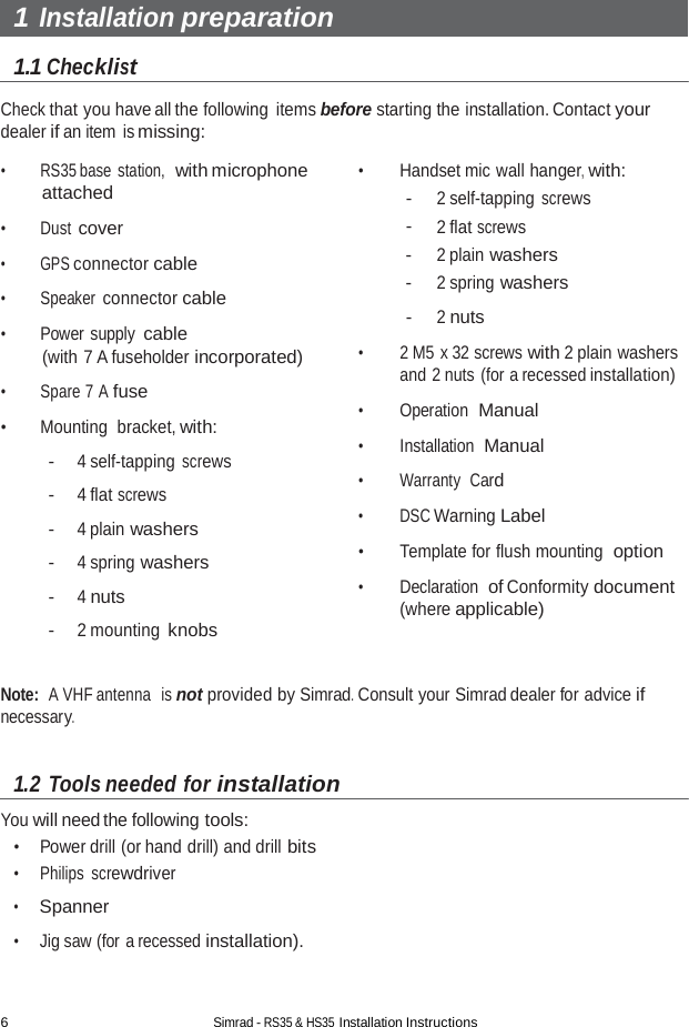
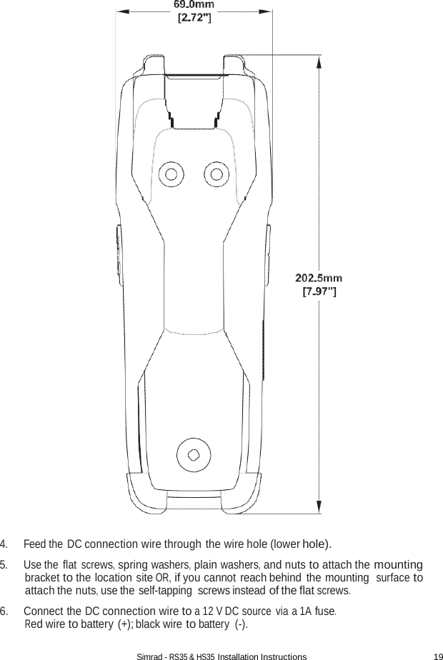
![18 Simrad - RS35 & HS35 Installation Instructions 4 HS35 Handset installation Drill 3 x 04.0mm mounting holes 122.0mm [4.80] Drill 1 x 03.5mm Wire hole 13.0mm [0.51] 1. Choose a suitable location that ensures sufficient room is allocated to allow the HS35 handset to fit securly in the charging bracket. 2. Hold the supplied mounting bracket at the chosen location and use a soft pencil to mark the 3 screw holes and 1 wire hole positions onto the mounting surface. 3. Drill the 3 screw holes (0 4.0 mm) and 1 wire hole (0 3.5mm) where marked. Drill completely through the mounting surface. Note: If you are drilling into fiberglass, use a small drill bit to drill pilot holes before drill- ing the screw holes.](https://usermanual.wiki/Navico-Auckland/HS35.Installation-Manual/User-Guide-2054190-Page-20.png)