Navico LOWFMMOD2V1 GPS product with built in FM Transmitter User Manual
Navico Inc GPS product with built in FM Transmitter Users Manual
Navico >
Users Manual
Pub. 988-0160-191
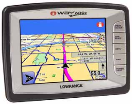
Turn-by-Turn Mapping GPS and MP3 Player
Operation Instructions

Copyright © 2007 Lowrance Electronics, Inc.
All rights reserved.
No part of this manual may be copied, reproduced, republished, trans-
mitted or distributed for any purpose, without prior written consent of
Lowrance. Any unauthorized commercial distribution of this
manual is strictly prohibited.
Lowrance® is a registered trademark and iWAY is a trademark of
Lowrance Electronics, Inc.
Points of Interest Data in this unit are by infoUSA, copy-
right 2001-2007, All Rights Reserved. infoUSA is a
trademark of infoUSA, Inc.
Mapping Database, copyright 2007 NAVTEQ.
NAVTEQ ON BOARD is a trademark of NAVTEQ.
Lowrance Electronics may find it necessary to change or end our poli-
cies, regulations and special offers at any time. We reserve the right to
do so without notice. All features and specifications subject to change
without notice. All screens in this manual are simulated.
For free owner's manuals and the most current information on
this product, its operation and accessories,
visit our web site:
www.lowrance.com
Lowrance Electronics Inc.
12000 E. Skelly Dr.
Tulsa, OK USA 74128-2486
Printed in USA.
i
Table of Contents
Preface: Introducing GPS........................................................ 1
How Lowrance GPS and the GPS System Work......................... 2
Section 1: Installation & Accessories.................................... 3
Power Cable ................................................................................... 3
External Connections.................................................................... 3
USB-to-PC Cable Connect ............................................................ 5
Other Accessories .......................................................................... 5
Mounting Brackets........................................................................ 6
Section 2: Map Mode Operation ............................................. 7
Touch Screen ................................................................................. 8
Map Mode and On-Screen Commands......................................... 9
Map Display Toolbar................................................................... 10
Auto Zoom .................................................................................... 11
Map Orientation button.............................................................. 11
Location Information button .................................................. 12
Get Location Information.................................................... 12
Map Mode Practice Run.............................................................. 13
Creating and Saving Contacts............................................ 14
Section 3: Music Mode Operation ........................................ 19
Getting Music on the iWAY........................................................ 19
Music Mode Display and On-Screen Commands ...................... 19
Visualization effects screen ........................................................ 20
Output Mode button.................................................................... 20
Audio Search/Browse Music Files.............................................. 22
Music Mode Practice Run ........................................................... 23
Section 4: Main Menu.............................................................. 25
Directions List ......................................................................... 25
Trip Calculator ........................................................................ 26
Route Via Destinations ........................................................... 27
Cancel Navigation ................................................................... 31
Routing Options....................................................................... 32
Turn Preview ....................................................................... 33
Categories Drawn.................................................................... 34
My Trails.................................................................................. 35
Language.................................................................................. 35
Safety Mode ............................................................................. 36
Sound and Voice Setup ........................................................... 37
Interface Options..................................................................... 38
Keyboard .............................................................................. 39
Brightness............................................................................ 39
Transparency ....................................................................... 39
Calibrate Screen .................................................................. 39
ii
Units of Measure ..................................................................... 40
Reset Options........................................................................... 41
Device Information.................................................................. 41
Navigation Mode ..................................................................... 41
Transfer Data .......................................................................... 42
GPS Simulator......................................................................... 43
Picture Viewer ......................................................................... 44
Gauge Page .............................................................................. 45
Satellite Status / GPS Status button ..................................... 46
Time Settings........................................................................... 48
Section 5: Searching, Finding and Navigating................... 49
Using the Virtual Keyboard ....................................................... 50
Auto Complete feature ............................................................ 50
Fuel, Lodging, Restaurants and other POIs.............................. 53
Using the Name Filter ............................................................ 54
Navigating to a Selected POI ................................................. 55
Recent Destinations ................................................................ 55
Address Book ........................................................................... 56
Choosing New Destinations while Navigating...................... 57
Considering Temporary or Local Conditions......................... 58
Section 6: Point-to-Point Navigation.................................... 59
About Straight-line Navigation Mode (Point-to-Point) ............ 59
Switch Between Navigation Modes ........................................... 60
Straight-line Navigation Commands......................................... 61
Waypoints = Contacts ................................................................. 61
Set a Waypoint ............................................................................ 61
Create Waypoint at Current Position .................................... 61
Create Waypoint on Map ........................................................ 62
Navigate To a Waypoint ............................................................. 63
Following Navigation Indicators................................................ 64
Navigating With Trails............................................................... 66
NauticPath USA Marine Electronic Charts........................... 70
Reading NauticPath Map Information ...................................... 71
Enhanced Lake Maps.................................................................. 72
Elevation Contour Lines............................................................. 74
iii
Notes
iv
A CAREFUL NAVIGATOR NEVER RELIES ON ONLY ONE
METHOD TO OBTAIN POSITION INFORMATION.
CAUTION
When showing turn-by-turn navigation data, a GPS unit will show
the shortest, most direct route to the destination. There are times
when it may give directions, such as a U-turn, that may be prohib-
ited in some locations. While navigating, a driver is responsible for
noting all traffic signs and obeying all local traffic laws. When fol-
lowing turn-by-turn directions, a driver must take advantage of all
available navigation tools, and must visually check to make sure a
clear, safe path to the next destination is available.
WARNING!
When a GPS unit is used in a vehicle, the
vehicle operator is solely responsible for
operating the vehicle in a safe manner.
Vehicle operators must maintain full sur-
veillance of all pertinent driving condi-
tions at all times. An accident or collision
resulting in damage to property, personal
injury or death could occur if the operator
of a GPS-equipped vehicle fails to pay full
attention to travel conditions and vehicle
operation while the vehicle is in motion.
Do not attempt to configure, adjust
or enter information into your GPS
unit while driving.
1
Preface: Introducing GPS
And, how this manual can get you out on the road, fast!
Welcome to the exciting world of turn-by-turn GPS navigation. Before
you grab the iWAY 600c GPS unit and begin installing it, please give
us a moment or two to explain how the manual can help you get the
best performance from your mapping GPS receiver and MP3 music
player. Our goal for this book is to get you on the road fast with a
minimum of fuss.
The manual has been designed so you don't have to read the whole
thing from front to back for the information you want. At the start (or
end) of each segment we will tell you what content is coming up next. If
it's a concept you are already familiar with we will show you how and
where to skip ahead for the next important topic. We have also made it
easy to look up any tips you may need from time to time. Here's how:
The manual is organized into five sections. This preface will introduce
you to GPS, your iWAY unit and the manual’s organization. The first
section will help you install the iWAY in your vehicle. We also will
show you how to use the USB cable to connect the iWAY to your PC.
We will finish by describing some of the available accessories.
Section 2 covers Mapping Mode Operation. It will show you how easy it
is to run the iWAY right out of the box. This section features a one-
page GPS Practice Run. If you have already jumped ahead and figured
out how to install the unit yourself turn to the Map Mode Practice Run
and head for the road with your GPS unit.
In Section 3 we leave Mapping mode and introduce you to Music Mode
Operation. The manual will explain everything you need to know about
getting music into your iWAY, arranging the files on the unit and cre-
ating and using play lists. If you are in a hurry to get some music play-
ing skip to the Music Practice Run.
Section 4 describes the Main Menu, the commands used to configure
settings such as screen brightness, sound levels and units of measure.
We will also show you how to use features like the Trip Calculator.
Finally, in Section 5, the manual will go into detail on how to search for
and navigate to points of interest, addresses and contacts you have cre-
ated. We will also offer tips on how to understand and follow the auto-
matic turn-by-turn routes you have created. Before we go any further
we would like to take just a moment to explain how the iWAY works.
2
How Lowrance GPS and the GPS System Work
You will navigate a little easier if you understand the basics of how the
iWAY scans the sky to show you where you are and where you are go-
ing. You will use the iWAY's touch screen and buttons to enter com-
mands and control its functions.
As long as there is no interference and the unit is locked on to a satel-
lite signal it will display your location on a moving map and help
guide you to your destination. The power cord speaker allows you to
hear verbal turn-by-turn driving instructions and listen to MP3 music
files.
The internal antenna tunes in to a couple of dozen GPS (Global Posi-
tioning System) and WAAS satellites circling the earth. The unit lis-
tens to signals from as many satellites as it can "see" above the horizon
then computes its location in relation to those satellites. The iWAY
plots your position on the map display on-screen.
For the system to work the unit must have a clear view of the satellites.
Unlike radio or television signals, GPS works at very high frequencies.
These signals can be easily blocked by trees, buildings, an automobile
roof, even your body.
The iWAY's hard drive contains highly detailed road and highway
mapping data for Hawaii, Alaska, the 48 contiguous United States and
most of Canada.
The iWAY 600c is the world's first portable navigation device with sat-
ellite imagery in full color. It's also the first automotive GPS to contain
color satellite photos. This unit contains photos for more than 150 of
the largest metropolitan areas in the United States and Canada.
When you're in an area covered by satellite photography, you can tog-
gle the map display between road map view, satellite view or satellite
view with map overlay. This function is controlled by the Map View
button on the Map Display Toolbar.
If you would like to know more about GPS and its companion system
WAAS, visit our web site and check out the GPS Product Guide section
(www.lowrance.com/Support/gps.asp). It includes a GPS tutorial, fre-
quently asked questions and a glossary.
3
Section 1:
Installation & Accessories
Information in this section includes how to connect the unit to your
car's power, the unit's external connections and the various accessories
included with the unit. This section also will explain some of the op-
tional accessories available for the unit.
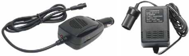
Power Cable
Since the unit does not have an internal battery the power cable will be
used to provide power to the unit. Also, the unit does not have a built-
in speaker, so all audio will be played through the power cable speaker.
The power cable is designed to plug into a car's cigarette lighter. An
optional wall power adapter for home use is available.
Power cable-speaker (left) and optional wall power adapter (right) for
indoor use.
To use the power cable, plug the cable's cigarette lighter adapter into
the cigarette lighter receptacle. Then insert the other end of the cable
into the power socket on the back of the unit.
External Connections
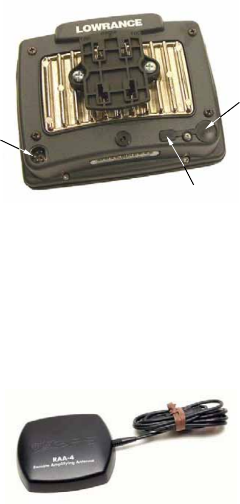
On the back of the unit are several connections for external cords. Use
the power socket connection for the power cord. The external antenna
socket is for attaching an optional external antenna module. The USB
cable socket is used with the USB-to-PC cable cord. The USB-to-PC
cable cord is for transferring music, pictures and other files to the unit.
4
External connections on the back of the iWAY 600c.
NOTE:
Certain vehicles are equipped with special windshields containing
metal in the glass. These models may prevent any GPS unit from
receiving satellite signals and establishing a "lock." If the GPS will
not navigate inside, test it outside the car. Also, confirm the wind-
shield type by consulting your vehicle's owner's manual or the vehi-
cle dealer. If the unit has difficulty receiving satellite signals you
can use an optional external antenna. Some of these windshields
have a specific location where the external antenna will work. Oth-
erwise you must place the external antenna near a side window, a
rear window or on the car exterior with the magnet mount. To buy
an external antenna, see the accessory ordering information inside
this manual's back cover.
The optional RAA-4 external antenna module.
Power
socket
for
power
cord.
USB-to-PC cable
socket
External
antenna
socket

5
Caution:
If you do not connect the external antenna to the unit correctly it
could prevent the unit from receiving satellite signals with the
external antenna. Also, do not mount in line with a radar an-
tenna. Radar radiates high energy signals that can interfere
with GPS signal reception.
USB-to-PC Cable Connect
The iWAY package includes a USB-to-PC cable so you can copy files
from your computer to the unit's hard drive.
USB-to-PC cable connect.
Other Accessories
The iWAY package includes a soft fabric face cover to protect the
screen from damage when the unit is not in use.
Use a microfiber towel to clean the unit’s screen. Check your local re-
tailer as they are often available where shop towels or auto cleaning
towels are sold.
Caution:
Do not use any chemicals, including window cleaners, on the
screen or damage may occur. Cleaning fabrics other than a mi-
crofiber towel may scratch the screen. Damage caused by incor-
6
rect cleaning is not covered by the warranty. We strongly rec-
ommend you only use a microfiber towel to clean the unit's
screen.
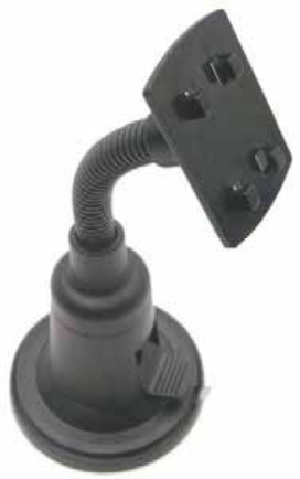
Mounting Brackets
Mounting brackets are available for GPS units through LEI Extras.
Permanent and temporary mounts suitable for boat, aircraft and mo-
torcycle handlebars are available. Each of these mounts work without
screws or adhesives. To safely install any GPS unit please refer to the
instruction sheet packed with the mounting bracket. To check the
availability of optional accessories go to our web site at www.lei-
extras.com.
Automotive mounting bracket shipped with the GPS unit.
7
Section 2:
Map Mode Operation
This section addresses Map Mode operation, including the different
menus and features associated with the unit. Map Mode includes all
navigation features from finding the nearest restaurant to planning a
road trip across the country.
iWAY
600c GPS unit.
1. SPEAK/VOLUME – Push this button once and the unit will repeat
the current navigation instruction. Press and hold this button to adjust
the frequency and volume of spoken instructions and music playback.
2. MAP/MUSIC – Use the Map/Music button to switch between the
unit’s two modes. Map Mode shows your current position on a moving
map as well as information on your current route. Use Music Mode to
select an audio play list, adjust volume and set various music play con-
trols.
3. MENU – Press this button to access the menus and submenus. The
four Main Menu screens contain settings that control operations or pro-
vide additional information. The unit is designed to work great right
out of the box but as you become more familiar with the unit and what
it can do you will eventually want to begin customizing some of the set-
tings.
4. FIND – The Find button is used to search for destinations. Press
this button to access the three Find menus. The Find menus are dis-
cussed in detail in Section 5. Section 5 also explains searching and fol-
lowing a generated route.
1
2
3
4
5
8
5. POWER/LIGHT – The Power button turns the unit on and off. It
also controls the backlight. Press POWER to turn the unit on. To acti-
vate the backlight press POWER again. The unit has three preset back-
light levels. Repeatedly pressing POWER will cycle through the back-
light settings. To turn the unit off, press and hold the POWER key for 3
seconds.
Touch Screen
You will use the touch screen for many of the unit's controls. You will
use the on-screen toolbars as well as menus and textual lists to select
entries and change features. Since the screen responds to pressure,
with practice, you will learn exactly the right amount of pressure to
operate the touch screen.
From time to time you may notice a slight delay after pressing an on-
screen button and seeing the unit respond. The delay may be necessary
while the unit retrieves information from the hard drive. On-screen
menus and dialogs have an "X" icon in the top right corner, just like
you are used to seeing on your home computer. Exit all menus and dia-
logs by pressing X.
Opening Warning Dialog and Language Menus
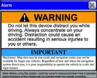
When first powering the unit up you will see a Warning dialog stating,
"Do not let this device distract you while driving. Always concentrate on
your driving. Distraction could cause an accident resulting in serious
injuries to you or others." Press X to close this dialog.
The opening Warning dialog box.
When you close the opening Warning dialog box you will see a Lan-
guage – Text menu. You will need to select the text language the unit
will display. Use the scroll bar at the right of the Language – Text
menu to make your language selection and press NEXT.
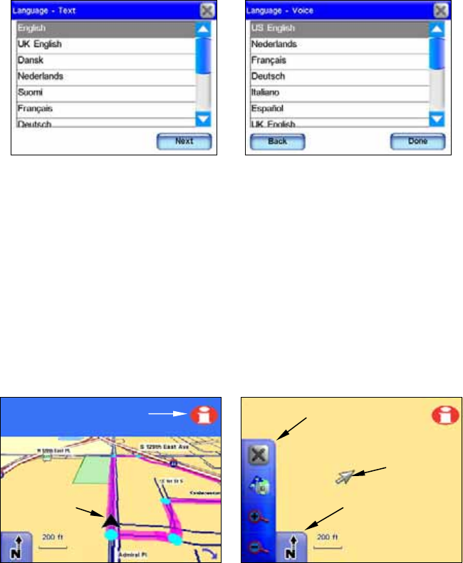
9
When you press NEXT the Language – Voice menu will appear. Use this
menu to select the spoken language used by the unit while giving turn-
by-turn voice instructions. When you make your selection the unit will
speak a short test message. Press BACK if you would like to reselect the
text language or press DONE to continue to the map screen. You must
press DONE in the Language – Voice menu to continue to the map
screen. Pressing X will not close the Language - Voice menu.
The opening Language – Text menu is shown at left. The opening Lan-
guage – Voice menu is shown at right.
Map Mode and On-Screen Commands
The map display shows your position and route from an overhead view.
By default the unit displays the map in 3D view. The unit’s map screen
is the main display mode. It shows your position as well as your sur-
roundings.
The black arrow icon represents you on-screen. The black arrow icon
always points in the direction you are traveling. While the unit is
tracking your position, the black arrow icon remains in the center of
the map screen. The map screen scrolls and the map changes to reflect
your surroundings.
A black arrow icon (left) indicates your position on the map screen.
The map screen with map display toolbar buttons is shown at right.
Black a
r
row
icon
Map display
toolbar
Curso
r
Map Orientation
button
Location Information
button
10
While the map display provides information about your surroundings,
you also can use it to explore locations other than your current position.
All of the tools you will need to operate the Map Mode display are
available on-screen. When the unit is navigating the map display tool-
bar buttons at the left of the map screen are hidden.
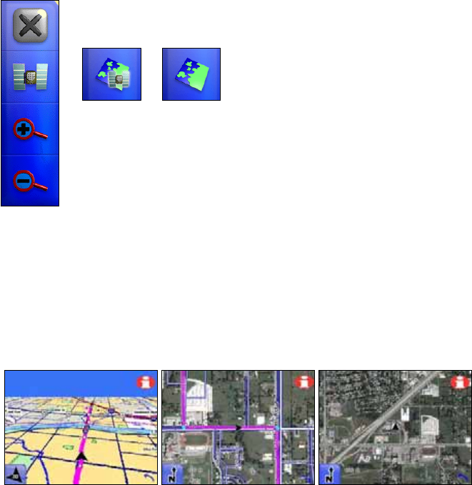
Map Display Toolbar
The Map Display Toolbar is used to control the map screen. To bring up
the Map Display Toolbar touch the map screen and the cursor and toolbar
will appear. The Map Display Toolbar buttons are:
Clear Cursor clears the toolbar from the screen and centers the map
on your current position.
Map Mode toggles between three different map screen modes. You can
view the regular map screen or, if you are in an area covered by a satel-
lite image, you can view the screen in two different satellite modes.
When traveling in a metropolitan area covered by satellite imagery you
can view the satellite image with or without map overlay. The satellite
map screens are for select metropolitan areas only.
The regular map screen mode, far left, is shown in the default 3D view.
Satellite image mode with map overlay is shown in the center figure.
Satellite image mode without map overlay is shown far right. Both
satellite image modes are shown in the North Up view.
X clears the cursor and map display toolbar from map screen.
The Map Mode button toggles between
three different map screen modes.
Zoom In.
Zoom Out.

11
Zoom In and Zoom Out increases or decreases the map view. Control
the zoom to get the most detail possible while still showing all of the
necessary area. You can use this feature in combination with the Move
Map function to focus on an area other than your current location.
Auto Zoom
The Auto Zoom feature is designed to show the most map detail possi-
ble while navigating. As the map screen moves to track your position,
Auto Zoom will enlarge the map based on your speed and the distance
to the next turn.
If you prefer to manually control the zoom level, you can turn the Auto
Zoom feature off by pressing the AUTO ZOOM button (see following figure)
located in the bottom left corner of the map screen. You can turn this
feature back on in the same way.
Press the Auto Zoom button to toggle the feature on and off. The Over-
lay Data Hide button will clear overlay data boxes from the map
screen. Select it again to bring them back. Use the Map Orientation
button to select between three different map views.
When the Auto Zoom feature is on it will take control any time the map
cursor isn't on-screen. When the cursor is on-screen use the Zoom In
and Zoom Out buttons on the Map Display Toolbar to control the map
size. When you clear the cursor from the screen, Auto Zoom will auto-
matically recalculate the map size.
Map Orientation button
The Map Orientation button is in the bottom left corner of the map
screen, just to the left of the Auto Zoom button. Touch this button to
select between three different map views:
North Up Track Up 3D View
Auto Zoom button
Overlay Data Hide button
Map Orientation button
12
North Up always shows the map with North at the top of the screen.
Track Up rotates the map so that the direction you are traveling is al-
ways at the top of the screen. 3D view displays the map from a position
above and slightly behind the black arrow icon.
Location Information button
The Location Information button, shown at left, is located in
the top right corner of the map screen. Pressing this button
will bring up the Location Information or POI Information
screen, depending on whether the cursor is on-screen.
Create Contacts
You can use the Location Information button to save a contact at your
current position and add it to the Address Book. Press the button to
bring up the Location Information screen for your current position, now
select ADD TO ADDRESSBOOK to save your position as a contact.
Location Information screen.
Get Location Information
You can use the Location Information button to get information for on-
screen items. Touch the map screen to bring up the cursor. Now "high-
light" a street, a landmark or POI (Point Of Interest) symbol on the map
screen by placing the cursor on the item.
If the location is a symbol it will be highlighted by a red halo and a yellow
pop-up text box will appear, identifying the item. Now press the Location
Information button.
A screen will appear with detailed information about that particular
location. The following figures show a POI symbol on the map screen
highlighted with the cursor and the POI Information screen for that
selected item.
13
A business location (right) highlighted with the cursor. The cursor can
highlight other symbols on the map and provide information on those
locations, as well.
Map Mode Practice Run
The following is a 10-step "Practice Run" that will walk you through
the most basic Map Mode operation. Using the following steps, you can
learn to navigate to a destination. Begin with the unit installed in your
vehicle. You might want to start by navigating to a destination you are
familiar with. Don't be surprised if the unit shows a different route
than you would normally take.
1. Press the POWER key.
2. When your position is acquired, press anywhere on the map screen to
bring up the Map Cursor and the Map Display Toolbar.
3. Use the cursor to select a destination on the map screen; a location a
short distance away.
4. Once your desired location is selected with the map cursor press the
Location Information button in the top right corner of the map screen.
5. The Location Information screen should appear showing details
about the location you selected including its distance from your current
position and its lat/lon coordinates.
6. Press GOTO in the Location Information screen. The unit should gen-
erate a route and ask if you wish to navigate the route. Select YES.
7. Follow the route created by the unit.
8. If you are comfortable finding your way in the area try departing
from the route the unit creates to see how it recalculates to correct for
wrong or missed turns.
9. Once you arrive at your destination the unit will ask you if you wish
to cancel the route. Select YES or NO.
Curso
r
Highlighted
location
14
10. To return to your previous location use the same steps outlined
above.
Creating and Saving Contacts
Use the Location Information button to view information on almost any
symbol on the map screen. It also is a good way to create a saved con-
tact in the Address Book. Touch the map screen to bring up the cursor.
Use the cursor to select and highlight a symbol or location on the map
screen. Now press the Location Information button in the top right cor-
ner of the map screen. Select ADD TO ADDRESSBOOK from the information
screen to save a contact at the selected location.
The cursor has been used to highlight a location on-screen, at left.
Once the Location Information button is pressed the POI Information
screen (right) will appear.
When you select ADD TO ADDRESSBOOK in the information screen, the Edit
Contact screen will appear. From this screen you can choose to GOTO
the location or add an on-screen symbol at that location by pressing
SYMBOL.
The Edit Contact screen (left) shows a saved contact. The Find By
Name screen (right) is the screen you will see when you press the Ad-
dress Book command in the Find 1 screen. Tulsa Boat Sales, right fig-
ure, is the only entry saved in the Address Book.
15
If you want to place a symbol at a particular location on the map screen
select a symbol from the Symbol Window screen. When you exit the
Symbol Window screen after highlighting a symbol, the symbol will
appear at the cursor's location on the map screen.
The symbol will remain on the map screen until you delete it by select-
ing DELETE in the Contact Information screen. To change a saved sym-
bol, press SYMBOL again and highlight and select the new symbol in the
Symbol Window screen. Choose the one that best represents the se-
lected location then close the dialog by pressing X in the upper right
corner.
The Symbol Window screen is shown at left. To access this screen
press Symbol in the Edit Contact screen. The Contact Information
screen (right) will appear when you highlight and select one of your
Address Book entries in the Find By Name screen.
The symbol should appear on the map screen. The symbol should also
appear in the Contact Information screen. You can create a contact in
the Address Book at your current position. If the cursor and map dis-
play toolbar are on-screen press X and clear them from the map screen.
Press the LOCATION INFORMATION button in the top right hand corner of the
map screen. Press ADD TO ADDRESSBOOK if you want to save your current
location in the unit's Address Book. If you want to change any informa-
tion about a contact saved in the Address Book go to the Contact In-
formation screen and press EDIT.
The Edit Contact screen will appear. Now press above each entry, such
as Name, Address or Phone Number and a keyboard will appear. Use
the keyboard to make changes to a contact's information.
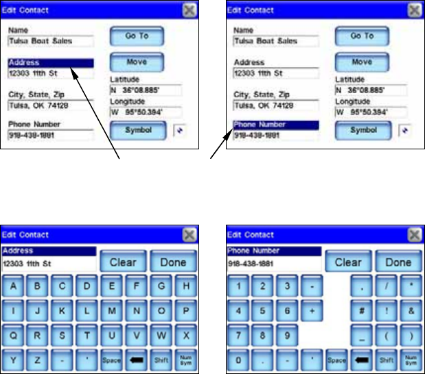
16
To change information about a saved contact in the Address Book,
highlight the entry you wish to change in the Edit Contact screen;
such as Address or Phone Number. A keyboard (following figures) will
appear allowing you to enter the new information.
The Edit Contact screen "letters" keyboard for the Address entry is
shown at left. To toggle between the letters and numbers keyboard
screen press the Num/Sym button in the bottom right corner of the
Edit Contact screen. The Edit Contact screen "numbers" keyboard for
the Phone Number entry is shown at right.
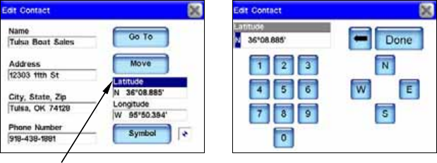
If you want to manually enter the latitude or longitude for a contact,
press and highlight either the Latitude or Longitude entries in the Edit
Contact screen. When you do, a keyboard will appear. Use the keyboard
to enter the specific latitude or longitude, then press DONE. Pressing the
arrow button in the keyboard screen will set the selected coordinate
values to zero.
The Move button in the Edit Contact screen will move a selected way-
point. When you press the MOVE button a dialog box will appear asking,
"Do you wish to move this contact position from the map?" Select either
YES or NO. If you select YES the map screen will appear. Use the cursor
to select where on the map screen you want to move the waypoint.
17
The Latitude entry is highlighted in the Edit Contact screen, at left.
When Latitude is highlighted and selected it will bring up the Edit
Contact screen keyboard for the Latitude entry, shown at right. You
can use the keyboard to manually enter the latitude. The Longitude
entry works the same way.
18
Notes
19
Section 3:
Music Mode Operation
The unit can display satellite images for select metropolitan areas.
Getting Music on the iWAY
Use the USB-to-PC cable to connect the unit to a computer. Once con-
nected, the unit can be treated like a removable disk. That means you
can add new folders, rename folders or files, and copy and delete files
the same way you would on a computer. Before copying music to the
unit consider creating subfolders to sort the music by artist, album or
genre. However you prefer to arrange your music.
Music Mode Display and On-Screen Commands
The Music Mode screen contains an area for visualization effects with a
set of play control buttons along the right side and bottom of the main
music screen.
WARNING:
Listening to music or even the verbal turn-by-turn in-
structions with headphones can seriously impede your
ability to drive. Be sure to check your local laws before
using headphones while driving.
All of the Music Mode commands are accessible on-screen. The unit will
play MP3 and Ogg Vorbis. The unit will not recognize WMA music
files. Whenever you switch to Music Mode the unit automatically
searches the hard drive for the related media files.
20
You can copy pre-made play list files from a computer to the unit and
play the songs in the play lists by selecting them from the song browser
screen. When you select a folder to play, the unit automatically creates
a play list from all the music stored in the folder.
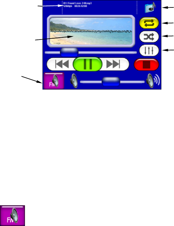
The Music Mode screen.
The Music Mode screen features and control buttons are:
Now playing box
The Now Playing box displays the name, position and quality of the
song that is playing. Touch the screen inside the Now Playing box to
open the Browse Music Files screen to select another song or play list
to play next.
Visualization effects screen
The Visualization effects screen provides either a waveform or spec-
trum analyzer effect in time with the music that's playing. To switch
between the available visualization effects press the screen inside the
Visualization area.
Output Mode button
To hear MP3 music and turn-by-turn instructions through
your car's FM radio, press the OUTPUT MODE button. The
volume slider is replaced by two up and down arrow buttons.
Tune the radio to a vacant FM radio frequency; one not used by a com-
mercial radio station in your area. Use the up and down arrow buttons
to tune the iWAY to the same frequency as the radio.
You can choose any odd numbered frequency between 88.1 and 107.9
MHz. Once the unit is tuned to the same frequency as the car radio you
should be able to hear the unit's sound through your car's audio sys-
tem.
Now playing
box
Visualization
effects screen
Find Music
Repeat
Equalizer
Shuffle
Output Mode
button
21
Find Music
To find a particular song or play list by its filename press the FIND MUSIC
symbol. This will bring up the Audio Search screen. Touch anywhere
inside the Name Filter box to open a virtual keyboard. Enter all or part
of a song's filename and press DONE.
Repeat
When Repeat is turned on, at the end of a play list or song if you are
playing one song the unit will immediately start playing the play list
again. When Repeat is turned off it will stop playing music and wait for
you to select a new song or play list.
Shuffle
When Shuffle is turned on, at the end of a song the unit will randomly
choose another song from the current play list to play next. The button
is yellow when the option is turned on and white when the option is
turned off.
Equalizer
The Equalizer is used to customize the audio levels of music playback.
To adjust levels press and drag the slider for the control you want to
adjust, moving it up to increase the level and down to decrease it. Sig-
nificantly increasing any of the equalizer levels may cause audio distor-
tion. If you have problems with audio distortion decreasing the Preamp
level may resolve them.
The play control buttons.
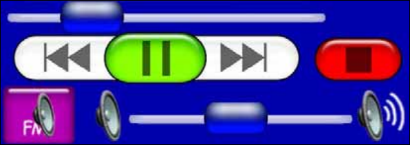
The play control buttons are:
Song position slider indicates the playback position for each song.
Whenever a song begins to play the Song Position slider starts at the
far left and moves right. Drag the blue button on the Song Position
slider right or left to skip to any point in a song.
Volume slider adjusts the volume.
Volume slider
Play / Pause
Stop
Previous Next
Song position slider
22
Play/Pause starts a song or play list. If no play list or song has been
selected, the unit will automatically generate a play list from all the
music on the hard drive. If a song is playing, pressing this button will
pause the song. Press the button to begin playing the song again.
Stop stops the song playing.
Previous skips to the previous song.
Next skips to the next song.
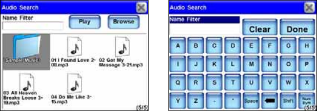
Audio Search/Browse Music Files
If you have trouble finding a particular song stored in the unit use the
Audio Search feature. To access the Audio Search feature press the FIND
MUSIC button in the top right corner of the Music screen. Now press
NAME FILTER and a virtual keyboard will appear. Use the keyboard to en-
ter all or part of the song file name you are searching for. Now press
DONE. The Audio Search screen will provide a list of all music files
stored in the unit that match the text you entered in the Name Filter
box. Choose the music file you want and select PLAY to begin playing the
song or select BROWSE to open the Browse Music Files screen containing
all your music files. If you make a mistake while entering a song name
in the Name Filter box press the CLEAR button to start over.
Press the Find Music button in the top right corner of the Music
screen to bring up the Audio Search screen, shown at left. The Audio
Search screen virtual keyboard is shown at right.
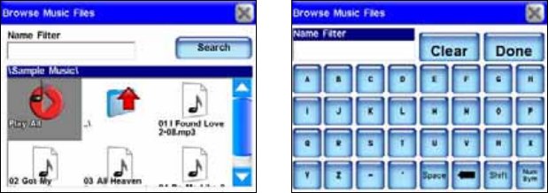
The Browse Music Files screen shows all songs and play lists stored on
the unit's hard drive. If you have sorted the music by album or artist
you can select a folder and play only the songs in that folder or you can
choose a specific song. You also can select PLAY ALL in the Browse Music
Files screen to play all the music contained in that screen. The Browse
Music Files screen also has a keyboard to search for music files. Press
NAME FILTER to bring up the Browse Music Files keyboard. This keyboard
works exactly the same as the Audio Search keyboard.
23
The Browse Music Files screen, at left. The Browse Music Files virtual
keyboard is shown at right.
Music Mode Practice Run
The following is a 10-step "Practice Run" that will walk you through
the most basic Music Mode operations. Follow these steps to start lis-
tening to music files. Start at your home computer. You will need some
MP3 or Ogg Vorbis music files.
1. Connect the iWAY to your home computer using the USB-to-PC ca-
ble connect. Turn the unit on.
2. Your computer should read the iWAY as if it were an external de-
vice; just like a card reader or external hard drive. Browse to the iWAY
on your computer. If you are using a PC you should open up My Com-
puter and look for a drive named "iWay600c." If you are using a Mac,
the iWAY should show up as a disc on the desktop. Now copy the music
files to the unit by either "dragging or dropping" the files straight to
the unit or you can "copy and paste" them. With Mac systems, when
you are done "browsing", you should eject the disc before unplugging
the unit from the computer; or you can turn off the iWAY. An easy way
to eject the disc is to drag it to the trash.
3. Once the music files are copied, turn the unit off and disconnect the
unit from the computer.
4. Move the unit to your vehicle and turn the unit on.
5. Press the MAP/MUSIC button and select Music Mode.
6. Touch the screen inside the Now Playing box to view the music files
stored on the unit. Use the touch screen to highlight and select a song
from the list. The song should begin playing.
7. If you haven’t changed the output mode, the audio should be playing
through the power cord's built-in speaker or through headphones, if
attached.
24
8. To play the audio through your car’s radio, press the OUTPUT MODE
button in the bottom left corner of the Music Mode screen. The volume
slider will be replaced by two up and down arrow buttons. Find an
empty frequency on your car's radio and use the up and down arrow
buttons to tune the unit to the same frequency as the radio.
9. To have the unit create a play list of all songs in the music folder
press the PLAY button with no song selected. The unit will begin playing
the first song in the music directory.
10. If you press SHUFFLE the unit will play songs in the music folder in
random order. To stop the music press STOP.
25
Section 4:
Main Menu
The unit's Menu feature contains four menu screens. The menus can be
used to customize the operation of the unit and come with default set-
tings so you can use the unit right out of the box. That way you may
never need to make changes.
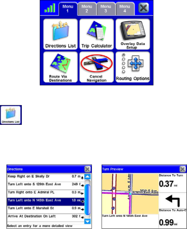
Menu 1
Directions List
The Directions list is generated whenever the unit begins
navigating to a destination. It is a list of all the turns from
the start of a route to the end, including an arrow icon
indicating the direction of each turn. You can view the list by pressing
and dragging the blue slider bar at the right of the Directions list
screen. You can select any individual instruction on-screen for more
detailed information. If Turn Preview is on, the Directions list will be
displayed automatically when the GPS is lost.
The Directions list (left) for a generated route. A turn preview for the
generated route is shown at right.
26
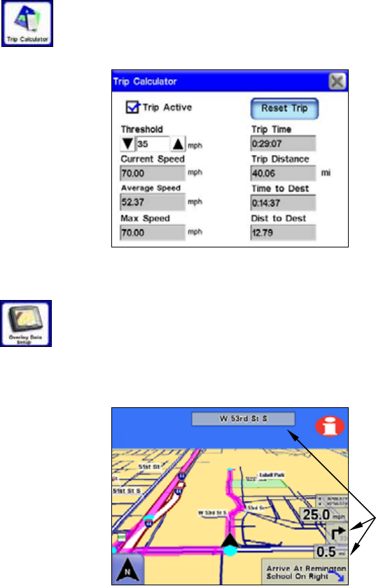
Trip Calculator
The Trip Calculator keeps track of detailed information
concerning your route. You can use it to find the distance of
your daily commute or to calculate your average speed on a
cross-country road trip.
Pressing the Reset Trip button will reset all on-screen values to zero.
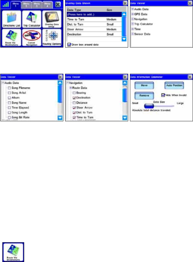
Overlay Data Setup
Overlay Data boxes provide information about the route you
are following. Select OVERLAY DATA SETUP from Menu 1 to
choose which information to display on-screen. Overlay data
appears in semi-transparent boxes on the map screen. The transpar-
ency level of overlay data boxes can be controlled from the Interface
Options screen.
Map screen with overlay data boxes.
To get to the Interface Options screen, press INTERFACE OPTIONS in Menu
2. Overlay data can be used to show information such as the distance to
your next turn, the direction and angle of a turn, your speed, estimated
time to destination, text directions and the current road you are travel-
ing on.
Ove
r
lay data
boxes
27
Overlay Data Setup command in Menu 1, far left. If you select "(Add
here …)" in the Overlay Data Shown screen (center figure) the Data
Viewer screen will appear. The Data Viewer screen is shown far right.
The Data Viewer screen left and center figure. The Data Information
screen for the Odometer setting is shown at right.
In the Data Viewer screen select the overlay data you want to display
on-screen. The Data Viewer screen is arranged in an expanding tree
format. Press the + sign to view the sub-categories listed under each
main category. When you select Audio Data (left figure above) its sub-
categories will appear. Press in the box to the left of each category to
activate it.
When a feature is activated (center figure above) a check mark will ap-
pear in the box next to it. The size of on-screen overlay data boxes can
be controlled by using the slider in the Data Information screen (right
figure above). Each Data Viewer category has its own Data Information
screen. Bring up the Data Information screen by highlighting and
pressing on the category in the Overlay Data Shown screen.
Route Via Destinations
While the unit is designed to generate a route from your
current position to a selected destination, sometimes you will
want more control over where you are going.
The Route Via Destinations command allows you to access the Routes
menu where you can store and manage routes you have created. Creat-
ing a route lets you navigate to several different locations during a sin-
gle trip. This option will guide you to each location in the route in a
specific order.
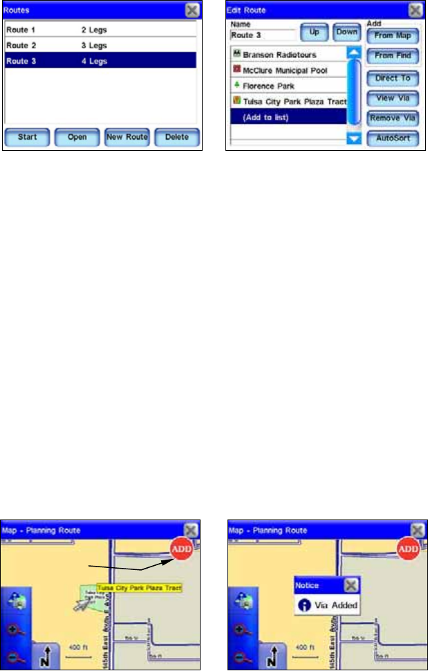
28
Use the Routes list menu (left) to store and manage different routes.
The Edit Route screen, at right, shows the details of a stored route.
Each route contains different "legs." Each leg is a destination in the
route. The Edit Route screen contains all of the routing controls for a
generated route from the Routes list.
If you have arrived in an unfamiliar town on a business trip or vacation
you can search through a list of nearest hotels, or a specific hotel, and
have the unit create a route to the hotel. If you decide to visit a local
attraction or restaurant you can add that to your route. To create a
route the unit must find your current position. Once the unit has pin
pointed your location, select ROUTE VIA DESTINATIONS from Menu 1. This
will bring up the Routes menu. Select NEW ROUTE and the Edit Route
screen will appear.
From the Edit Route screen you have two options to choose from in or-
der to find a specific location and begin to generate a route. Select ei-
ther the FROM MAP button or the FROM FIND button. If you select FROM MAP
the map screen will appear. Use the cursor arrow on-screen to select a
specific location (or address) then press the ADD button on-screen. A
dialog box will appear notifying you the location has been added to your
route. You can continue to select and add other locations in this same
manner.
The Add to route button is shown at left. When you select a location to
add to a route you will see a dialog box like the one at right.
Add to route
button
29
Once you have added all the locations in your route go back to the Route
Via Destinations menu and you should see the route you created in the
Routes list. To navigate the route, highlight it and select START from the
bottom of the screen.
Another way to set up a route with multiple waypoints is to perform a
search for a location, press GOTO, and begin navigating; then search for
another location and press GOTO for that location. The unit will provide
you with an option of detouring to that location, adding it to the begin-
ning of the route, or setting it as a new final destination which would
add it to the end of the route.
Detouring to a different location while navigating is explained under
the heading "Choosing New Destination while Navigating" in Section 5.
To view the destinations in a particular route select OPEN and the Edit
Route screen will appear.
You will be able to see all the locations in a route in this screen. To de-
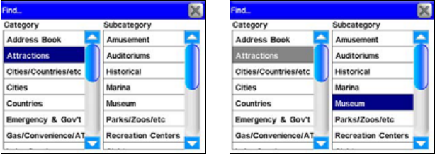
lete a route from the Routes menu press DELETE. If you select FROM FIND
in the Edit Route screen the Find menu will appear. In this menu you
can search for a desired destination by Category and Subcategory.
The Category and Subcategory list in the Find menu. In this example a
search is being conducted for a museum to add to a route.
Selecting a Category or Subcategory will bring up the Find By menu
with three options: Name Entry, Near Current Location and Near Cur-
sor. Depending on how you want to search for a specific location will
determine which option you should select.
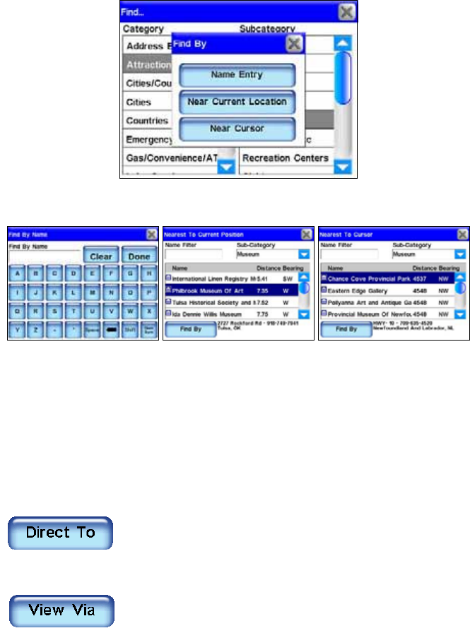
30
The Find By menu with its three options: Name Entry, Near Current
Location and Near Cursor.
The three menus for the three Find By options.
To learn more about the specifics of "Searching, Finding and Navigat-
ing" refer to Section 5. Once you have found your desired destination
select it and add it to your route. You can add as many as 99 waypoints
to a route. If you want to rearrange the order of the waypoints in a
route list you can use the UP and DOWN buttons in the Edit Route screen
to move a highlighted waypoint higher or lower in the list.
The other Edit Route screen buttons and their function:
Use the Direct To button in the Edit Route screen to
go directly to any "leg" in a route. Highlight a
specific leg from the route and press DIRECT TO and
the unit will begin navigating to that destination (or leg).
When you highlight a specific "leg" in a route, and
press the VIEW VIA button in the Edit Route screen, it
will bring up the POI Information screen. The POI
Information screen provides information about that particular leg. In
the POI Information screen you can view the Directions List for that
leg, view that leg on the map screen by pressing the FIND ONMAP button
or you can add that leg to your Address Book by pressing the ADD TO AD-
DRESSBOOK button.
31
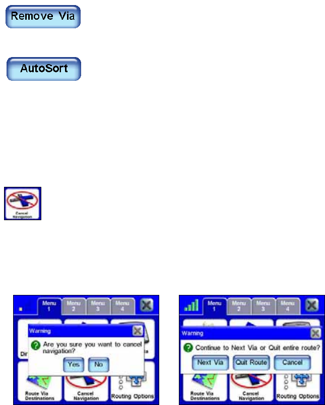
If you want to remove a "leg" from a route in the
Edit Route screen, highlight the entry and press the
REMOVE VIA button. The destination (leg) will be re-
moved from that particular route.
If you prefer, the unit can generate a route for you
among several locations even if you don't know
which order you want to go in. Enter all of the
destinations in any order then press the AUTOSORT button located at the
bottom of the Edit Route screen.
The unit will organize the list of locations to create the shortest possi-
ble route. This can be useful if you are on a business trip and need to
visit several clients at different locations. Put in all their addresses,
choose AUTOSORT and then let the unit pick the shortest path.
Cancel Navigation
When you have reached your destination the unit will
display a dialog box asking if you want to cancel navigation.
Select YES to stop receiving navigation instructions.
You can also cancel navigation to a destination at any time using the
Cancel Navigation command. From Menu 1 select CANCEL NAVIGATION.
Again the unit will display a dialog box to confirm your choice. Choose
YES and the unit will stop generating navigation instructions to the
current destination.
The Cancel Navigation Warning dialog box at left. When navigating a
route with multiple destinations, and you choose to cancel your route,
you will see the warning dialog box shown at right.
If you are navigating a route with multiple destinations, when you
choose Cancel Navigation, the unit will give you a choice to cancel
navigation of the entire route or cancel navigation to the current desti-
nation and continue on to the next destination in the route.
32
Routing Options
Routing Options are used to control exactly how the unit
generates a route from your current position to a selected
destination.
When generating a route, the unit can analyze certain types of roads or
turns and adjust their value to prefer or avoid them. Preferred road
types will occur more often in your routes. The unit will deliberately try
to take those types of roads.
The Avoid on Routes screen.
Roads or turns that you choose to Avoid will show up less, although the
unit may have to generate a longer route to avoid them. The three slide
controls in the Avoid on Routes screen allow you to control how much
you want to avoid or prefer the associated options when generating a
route. The farther you move the slider to the left or right, the more it
will affect the routes generated by the unit.
If you change these values significantly and notice the unit has begun
generating poor routes try using the RESET TO DEFAULTS button to see if
that helps. You can use the RECALCULATE ROUTE button to automatically
generate a new route to the same destination using the new prefer-
ences. Take advantage of this option when you are trying to learn the
right amount of avoidance to make sure the unit gives you what you
want.
Avoid Cross-Traffic Turns
Use this option to avoid turns across busy lanes of traffic. The unit will
not avoid cross-traffic turns at major intersections where you will likely
have a protected turn at a traffic light. Sometimes you would have to
drive miles out of your way to avoid taking a cross-traffic turn some-
where in your route. Then again, sometimes it's worth it. Practice with
this setting to find the value that's right for your driving experience.
33
Prefer/Avoid Toll Roads
By default, toll roads have a fairly high value in routes generated by
the unit because they are usually quality roads with high speed limits
allowing you to get where you are going faster. If you would like to save
on the cost of traveling toll roads consider setting the unit to generally
Avoid toll roads by pressing and dragging the TOLL ROADS slider to the
right. If you want to drive free drag the slider all the way to the right
and the unit will not use toll roads at all. If you prefer the convenience
of toll roads, and don't mind the cost, you can give them an even
greater value by pressing and dragging the slider to the left.
Prefer/Avoid Interstates
Interstate Highways may not be as expensive to travel as toll roads but
sometimes the stress of merging and exiting, combined with the high
speed, make interstates less attractive – especially for short trips
across town. The default setting is designed to avoid Interstates for
very short trips but if you feel like it's sending you to the highway too
often try setting the unit to Avoid Interstates. Press and drag the INTER-
STATES slider to the right. Like toll roads, you might prefer the speed of
Interstate travel. You can set the unit to prefer Interstates by pressing
and dragging the slider to the left.
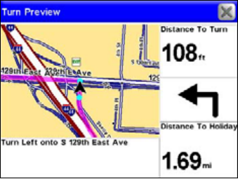
Turn Preview
The Turn Preview checkbox allows you to select whether or not the unit
displays a Turn Preview screen whenever you approach a turn in your
route. A Turn Preview is designed to prepare you for upcoming turns.
You can access the Turn Preview for any turn in a route by going to the
Directions list.
A Turn Preview screen is shown above. If you are navigating in one of
the two satellite map modes, the turn preview will still look like the
above figure. The Turn Preview screen will not show your turn using
satellite imagery. The Turn Preview screen always shows your turn in
the regular map screen mode.
34
As shown in the previous figure, the Turn Preview screen includes a
close-up map of the turn itself and a magenta line showing your path.
Additional data boxes show the text instruction, the distance from your
current location to the turn, the direction of the turn and the total dis-
tance from the turn to the end of the route. If you want the unit to
automatically show you Turn Previews whenever you are navigating
make sure TURN PREVIEW is checked in the Avoid on Routes screen. You
can turn this feature off by unchecking the box. The Turn Preview
screen will not show your turn using satellite imagery. The Turn Pre-
view screen always shows your turn in the regular map screen mode.
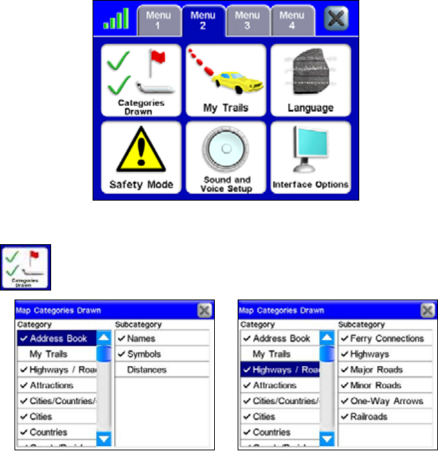
Menu 2
Categories Drawn
Categories Drawn lets you choose how much map data you
want to display on the map screen. This information includes
contacts, points of interest, cities, highways, etc.
Use the Map Categories Drawn screen to customize what is displayed
on the map screen. In this example, the category My Trails and sub-
category Distances are turned off because there is not a check mark
next to the entry. In the right figure you can see what Map Categories
Drawn features have been activated in the Highways/Roads category.
35
The Map Categories Drawn Menu is divided into two columns, "Cate-
gory" and "Subcategory." You can turn any category or subcategory on
or off. If you turn off a category none of its subcategories will appear.
Press and highlight any item to turn it on or off. When it is highlighted
press it again to check it (turn it on) or uncheck it (turn it off). Use the
scrollbar next to the category or subcategory to scroll through the list.
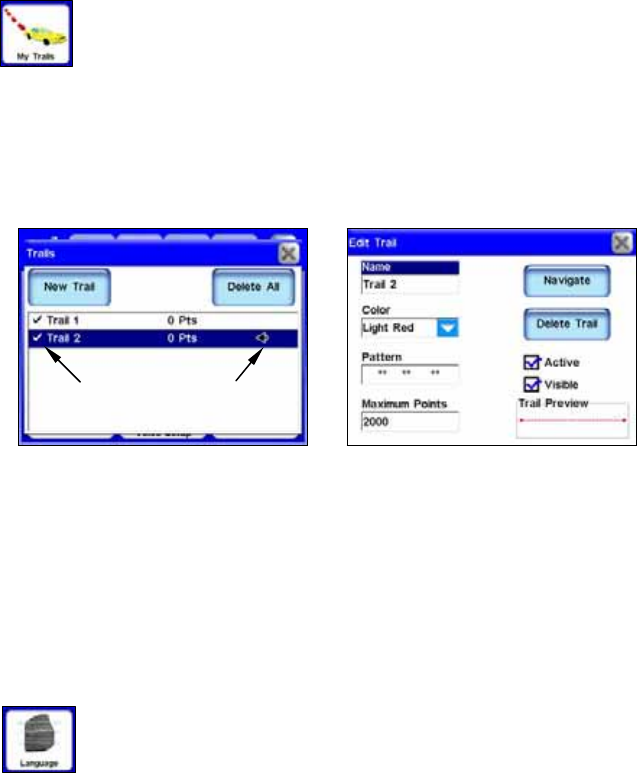
My Trails
Most GPS units are designed to record plot trails which are a
record of where you have been. By default Trails are hidden
in the unit to save on-screen clutter. You can choose to
display Trails, which will show your travel history on the map screen.
Use the My Trails command to control how the unit records and dis-
plays Trails. To view the Trails menu select MYTRAILS from Menu 2. The
Trails Menu lists all of the Trails stored on the unit with icons to indi-
cate which trail is active that is, which one is currently recording
your travel and which ones should be displayed.
Trails Menu (left) with Trail 2 highlighted. Trail 2 is active, indicated
by the arrow on the right. The Edit Trail screen (right) allows you to
modify an existing Trail.
From the Trails Menu you can start a new Trail or edit or delete an
existing Trail. To modify an existing Trail press its entry in the list.
The Edit Trail screen will appear. In the Edit Trail screen you can
choose to Navigate a selected Trail (converting it into a route), delete it,
rename it or modify its display characteristics such as color, pattern
and visibility.
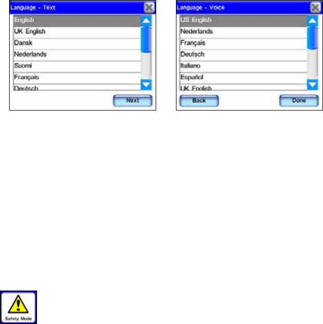
Language
In the Language menu you can choose both the text and
spoken voice language. When you press the Language button
the Language – Text menu will appear. In this menu you
have the option of choosing to display the unit's text in English, UK
English, Dansk, Nederlands, Suomi, Francais, Deutsch, Italiano,
Norsk, Portugues, Espanol and Svenska.
ArrowCheck mark
36
The Language – Text menu is shown at left and the Language – Voice
menu is shown at right.
Once you have selected the text language in the Language – Text
menu, press NEXT in the bottom right corner of the screen. This will
bring up the Language – Voice menu. In this menu you can choose
what language the unit uses when giving spoken turn-by-turn instruc-
tions.
The same languages available as text are available as spoken instruc-
tions. When finished making your selection in the Language – Voice
menu press DONE. You must press DONE in the Language – Voice menu
to return to the Main Menu. Pressing X will not close the Language -
Voice menu.
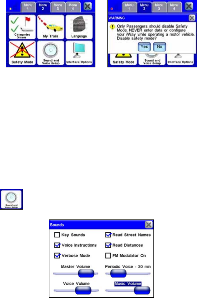
Safety Mode
The Safety Mode feature prevents drivers from operating the
unit while the vehicle is in motion. The unit will navigate
and play music while moving. The Power button will also
work but the touch-screen buttons are temporarily disabled whenever
Safety Mode is on. The screen buttons become responsive when the ve-
hicle stops.
However, if a passenger is available to act as navigator Safety Mode
can be turned off. When this feature is disabled a large red X will ap-
pear on the Safety Mode button. This switches the unit to Passenger
Mode so the passenger can operate the unit while the vehicle is moving.
To disable Safety Mode and switch to Passenger Mode make sure the
vehicle is not moving.
From Menu 2 select SAFETY MODE to turn this feature on or off. When
this feature is selected a dialog box will appear stating, "Only Passen-
gers should disable Safety Mode. Never enter data or configure your
iWAY while operating a motor vehicle. Disable safety mode?" Select YES
or NO to turn this feature on or off.
37
The red X on the Safety Mode button (left) indicates the feature is
turned off. The disable Safety Mode Warning dialog box is shown at
right.
WARNING:
When a GPS unit is used in a vehicle the vehicle operator
is solely responsible for operating the vehicle in a safe
manner. Vehicle operators must maintain full surveillance
of all pertinent driving conditions at all times. An accident
or collision resulting in damage to property, personal in-
jury or death could occur if the operator of a GPS-
equipped vehicle fails to pay full attention to travel condi-
tions and vehicle operation while the vehicle is in motion.
Do not attempt to configure, adjust or enter information
into your GPS unit while driving.
Sound and Voice Setup
Much of the information you will receive from the unit will
come in the form of sounds. Use the Sound and Voice Setup
menu to adjust the type and frequency of audio output the
unit provides.
Press inside the box to the left of each feature to check it (turn on) and
uncheck it (turn off).
38
Key Sounds: When this feature is on the unit will emit a sound every
time you enter a command.
Voice Instructions: If you turn off Voice Instructions, voice instructions
can still be accessed by pressing the SPEAK button on the map screen.
When you do, the unit will state the current navigation instruction.
Verbose Mode: This feature will cause the unit to give slightly more de-
tailed spoken navigation instructions.
Read Street Names: When this feature is active the unit will tell you the
name of the streets you navigate.
Read Distances: When this feature is active the unit will tell you the
distance to your next turn.
FM Modulator On: This feature controls the FM Modulator in the Music
Screen. The feature must be checked for the FM Modulator to work.
Music Volume: This setting only affects music playback; spoken instruc-
tions will remain unchanged.
Periodic Voice – 20 min: Use this feature to increase or decrease the fre-
quency of spoken instructions. Periodic Voice instructions are repeated
at set intervals and are intended as reminders.
Voice Volume: This setting only affects spoken instructions; your music
volume will remain unchanged.
Music Volume: This setting controls all audio output.
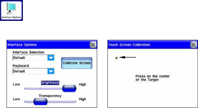
Interface Options
The Interface Options menu allows you to control the visual
display of the unit, including brightness and transparency.
You can also use Interface Options to access the Calibrate
Screen feature in case the unit's touch screen isn't responding pre-
cisely.
The Interface Options menu, left, and the Touch Screen Calibration
feature, at right.
Small target
icon
39
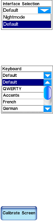
Interface Selection
Interface Selection allows you to change the
unit's visual appearance. To change the unit's
current skin display, press the arrow key
under the Interface Selection header and a
drop-down box will appear showing all of the
available skins. Choose a skin from the list
and the unit will display the new skin automatically. Screenshots
throughout this manual were taken using the "Default" skin mode. The
"Nightmode" skin is designed to make the unit easier to read when travel-
ing at night.
Keyboard
Keyboard allows you to choose the layout of
the unit's virtual keyboard. You will use the
virtual keyboard when entering information
for some of the unit's Find screens. See Using
the Virtual Keyboard in Section 5. A drop
down box will appear when you press the
arrow key under the Keyboard header. Use
the slider to scroll through the drop down box
list and make your selection.
Brightness
The Brightness Slider controls the brightness of the screen. Use the
slider bar to adjust the screen's brightness to your preference.
Transparency
The Transparency Slider controls the transparency of overlay data
boxes that appear on the map screen. Increasing transparency will
make it easier to see the background map, but may interfere with the
legibility of the overlays. Decreasing transparency clarifies overlays but
it also obscures underlying map information. Adjust this control to your
preference.
Calibrate Screen
The Calibrate Screen feature is used to calibrate the unit's touch
screen. If you find that the unit isn't responding correctly when you
touch the screen, select INTERFACE OPTIONS from Menu 2.
This will bring up the Interface Options screen. In
the Interface Options screen press the CALIBRATE
SCREEN button. The Touch Screen Calibration menu
will appear with a small target icon somewhere on-screen. A message
in the center of the screen will read "Press on the center of the Target."
40
When you do, a new target will appear somewhere on-screen. Press
each of the targets in turn. After the third time the screen should be
calibrated. The calibration screen will disappear, returning you to the
Interface Options screen.
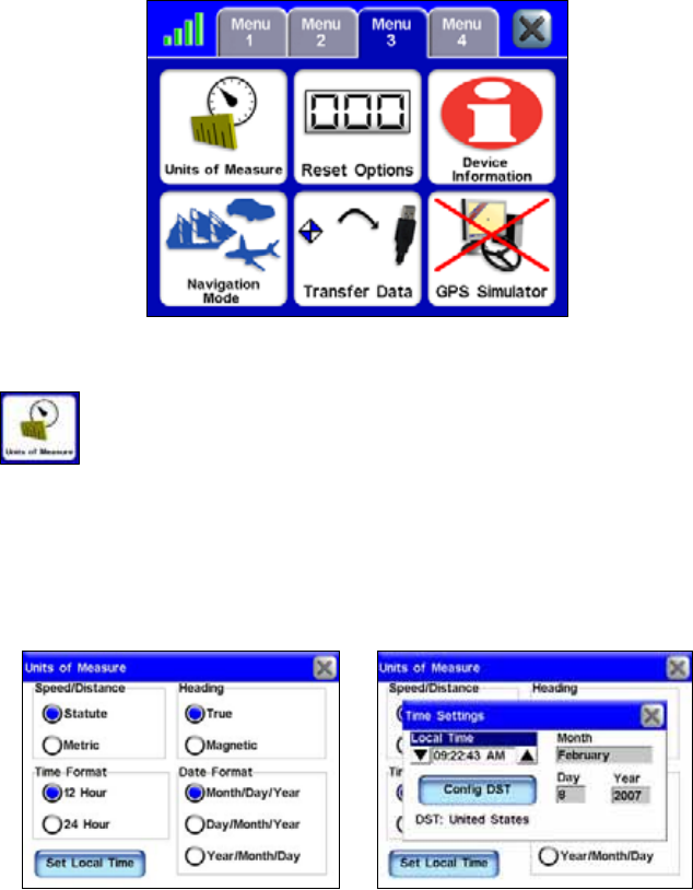
Menu 3
Units of Measure
Use this feature to adjust the units of measure, including
speed and distance (statute miles or meters), your heading
(true or magnetic), the current time (12 hour or 24 hour
format) and the date (Month/Day/Year, Day/Month/Year or
Year/Month/Day).
Highlight the circle next to the format you prefer. Press the SET LOCAL
TIME button in the Units of Measure screen to bring up the Time Set-
tings feature. Use the Set Local Time feature to adjust the time dis-
played by the unit.
The Units of Measure screen, at left, and the Time Settings feature
show at right.
41
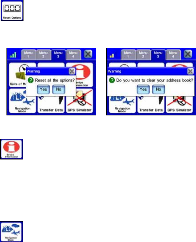
Reset Options
To reset all settings to the factory defaults, select RESET
OPTIONS. A dialog box will appear asking if you want to "Reset
all the options?" To reset all options select YES. Once you
reset the options another dialog box will appear asking, "Do you want
to clear your address book?" Select YES or NO depending on whether you
want to clear all your Address Book contacts.
Reset Options confirmation dialogs.
Device Information
From time to time, Lowrance updates the operating system
software in some of its products. These software upgrades are
usually offered to customers as free downloads from our web
site, www.lowrance.com.
Complete information and instructions for installing an update will be
available on the update's page at the Lowrance web site. These up-
grades make the unit perform better or introduce a new feature or
function. You can find out what software version is running in your
unit by using the Device Information command.
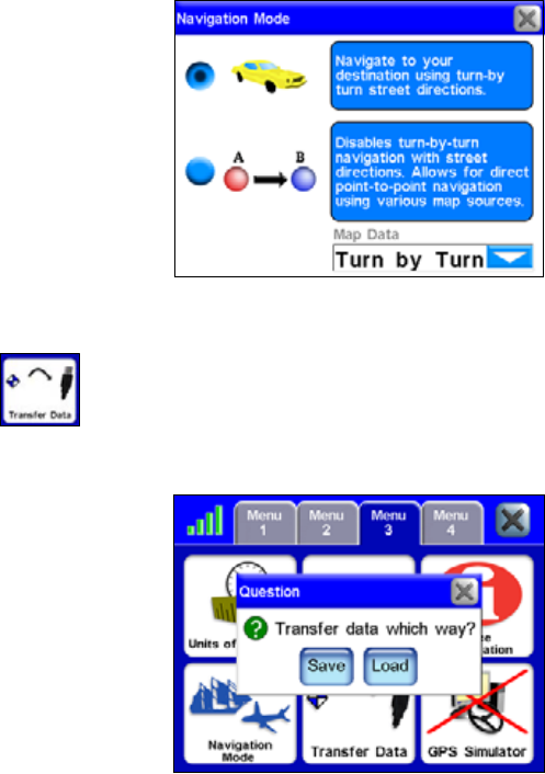
Navigation Mode
The iWAY's primary function is to provide turn-by-turn
navigation instructions, but it also can display plot trails and
perform traditional straight-line or point-to-point navigation
in off road situations.
Point-to-point mode uses straight-line navigation, the original method
used by the Global Positioning System. This function is handy when
you want to find a map feature, waypoint or point of interest on a lake,
in coastal waters or in off-road areas where turn-by-turn won't work.
Point-to-point mode does not include audible voice directions. For more
information concerning Point-to-Point mode, refer to Section 6: Point-
to-Point Navigation.
42
The Navigation Mode screen.
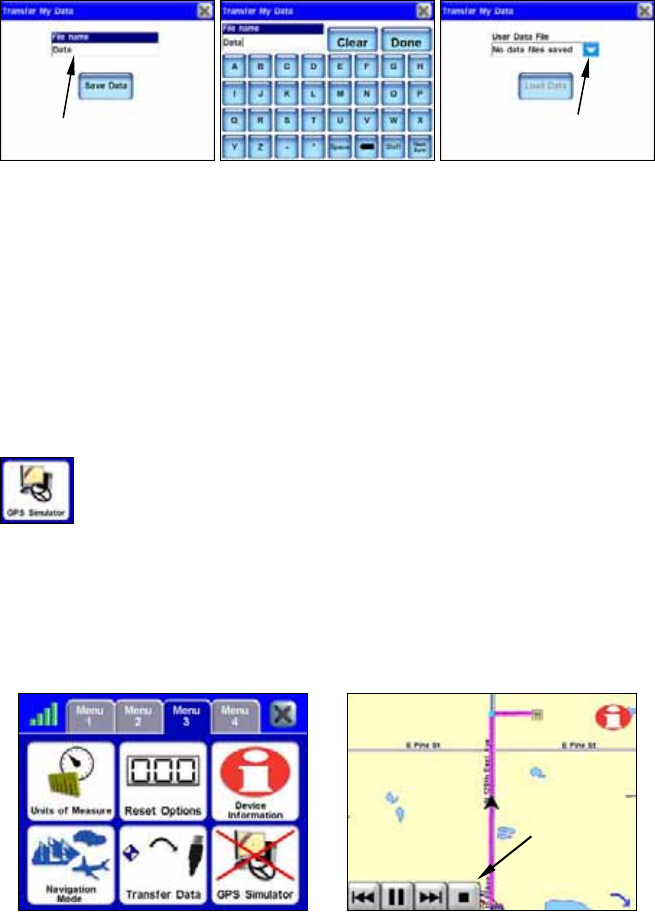
Transfer Data
In addition to storing media files, such as music and pictures,
you can store and transfer GPS data files to the unit. This is
a way to save contacts, trails and routes that you have
created. You will use the USB-to-PC cable to transfer GPS data files
between the unit and your home computer.
Transfer Data dialog box.
After you connect the iWAY to your home computer, power the unit up.
To save data to the unit or to unload data from the unit select TRANSFER
DATA from Menu 4. A dialog box will appear asking, "Transfer data
which way?" You will have two choices: Save or Load.
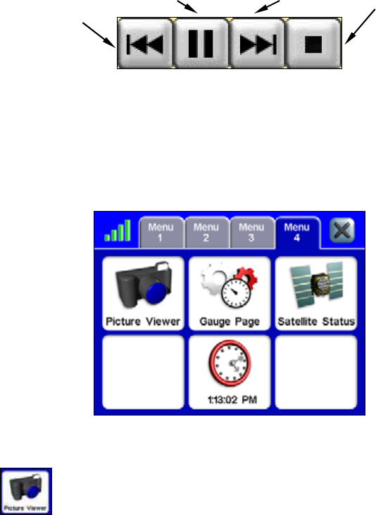
When you press SAVE or LOAD the Transfer My Data screen will appear.
Select the dropdown box and make sure to select the file name of the
GPS data file you want to load. If you are saving data you can select
the File Name text box to enter a new name describing the data you are
saving.
43
The Transfer My Data screens for both the Save and Load commands
are shown far left and far right. When you select Save Data in the far
left Transfer My Data screen, a keyboard will appear (center) allowing
you to enter a file name.
When you transfer GPS data files to the unit, the file will be added to
all the "normal" places where you would access that data. For example,
any routes in the GPS data file will be added to the Route Via Destina-
tions list. Any trials will be added to the My Trails list. Waypoints will
be added to the Address Book. All of these files should be visible from
the map screen.
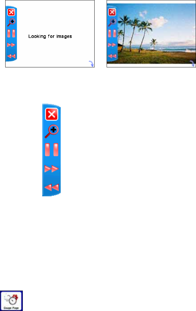
GPS Simulator
The unit has a GPS Simulator allowing it to simulate the
navigation of a route. The simulator control buttons are
located in the bottom left of the map screen.
If you are in Simulator Mode while driving and reach a speed of about
15 miles per hour or greater, and the unit acquires a satellite lock, the
unit will leave Simulator Mode. If the unit does not have satellite lock
it will prompt you to simulate when you begin to navigate a route. If
the prompt is ignored for 20 seconds the unit will assume you do not
wish to simulate a route.
The red X on the GPS Simulator button (left) indicates the feature is
turned off. The unit simulating a route is shown at right. The simula-
tor control buttons are located in the bottom left corner of the map
screen.
Simulator
control
buttons
Drop down box
File name text box
44
The GPS Simulator control buttons.
Use the REVERSE button to move backwards along a route. Stop or re-
sume motion along the route using the PLAY /PAUSE button or speed up
simulation by pressing FORWARD. To stop simulating a route and return
to your starting location press STOP. The unit will remain in Simulator
Mode until you turn it off. To turn off Simulator Mode select GPS SIMU-
LATOR from Menu 3.
Menu 4
Picture Viewer
The unit can display .gif and .jpg images stored to the hard
drive. To view images saved to the unit select PICTURE VIEWER
from Menu 4. You can play the images as a slideshow or view
a single image.
To view a picture slideshow you must have photo images stored in the
unit. The unit will automatically search the hard drive for any usable
images. Use the picture toolbar on the left side of the screen to control
the image display.
To get images on the iWAY you will use the USB-to-PC cable. Follow
the same steps outlined for loading music files to the unit. When you
place images on the unit they will automatically be loaded to the Pic-
ture Viewer.
Reverse
Play/Pause Forward Stop
45
The toolbar, on the left side of the screen in both figures, can be hid-
den using the arrow icon located in the bottom right corner of the
screen.
The picture toolbar controls are:
Close Slideshow returns to the Main Menu.
Zoom In enlarges the image, zooming in on the center of the display.
You can press and drag anywhere within the image display to focus on
a particular area.
Play / Pause Slideshow allows you to control whether the unit auto-
matically cycles through the available images or displays a single im-
age.
Next Image and Previous Image skips forward or backward among
the available images.
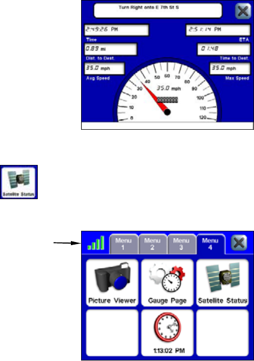
Gauge Page
The Gauge Page contains helpful information on one screen,
including your estimated time of arrival, time to destination,
distance to destination, average speed and max speed.
Close Slideshow
Zoom In
Play / Pause Slideshow
Previous Image
Next Image
46
The Gauge Page.
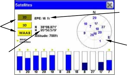
Satellite Status / GPS Status button
The GPS Status button will open the Satellites screen. The
Satellites screen provides information on the satellite signals
the unit is monitoring to determine your position. You can
access the Satellites screen from any of the four Menu screens by press-
ing the GPS Status button.
The GPS Status button from Menu 4.
The GPS Status button is located in the top left corner of each Menu
screen and is represented by four colored bars that change color de-
pending on the strength of the satellite lock. You can also access the
Satellites screen by selecting SATELLITE STATUS from Menu 4.
GPS
Status
button
47
The Satellites screen.
Current Position Lock
The three buttons along the left side of the Satellites screen indicate
the quality of the units position lock. If 2D, 3D or WAAS is not high-
lighted the unit may not have a satellite lock.
2D lock does not include your altitude. The unit must receive reliable
signals from 3 satellites to establish a 2D lock.
3D means the unit has achieved a more reliable lock, including not only
your coordinate location but also your altitude (or elevation). The unit
must receive reliable signals from 4 satellites to establish a 3D lock.
WAAS means the GPS unit is receiving reliable correction signals from
the FAA's Wide Area Augmentation System. WAAS is designed for use
in aircraft, but occasionally terrestrial vehicles can attain a WAAS
lock. This is the most accurate position signal available.
EPE (Estimated Position Error)
The Estimated Position Error (EPE) represents the expected error from
a benchmark location. If the EPE shows 50 feet, then the position
shown by the unit is estimated to be within 50 feet of the actual loca-
tion. The smaller the position error number, the more accurate the sat-
ellites fix.
Satellite Display
The Satellite Display, located on the right side of the Satellites screen,
is a circle that serves as a graphical view of the satellites overhead.
Each satellite is shown on the circular chart relative to your position.
The GPS receiver is tracking satellites that are in light blue type. The
receiver hasn't locked onto a satellite if the number is in dark blue.
Lat/Lon Coordinates
The Satellites page shows your coordinates in latitude and longitude.
These numbers can be used to pinpoint your location on any map or to
create contacts at your position on another GPS unit.
Estimated
Position
Error (EPE)
Current
Position
Lock
buttons
Satellite
Display
Lat/Lon
Coordinates
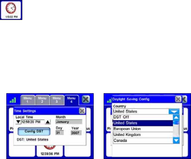
48
Time Settings
This feature is represented by a clock at the bottom of Menu
4. Pressing this button will open the Time Settings feature.
You can use this feature to adjust the month, day, year and
Local Time display.
To adjust the time display use the up and down arrows located to the
left and right of the Local Time display. Since the unit will not auto-
matically update when you travel to a different time zone you will need
to reset the time manually.
Use the Config DST button to adjust for Daylight Savings Time. When
you press this button the Daylight Saving Configuration menu will ap-
pear. Press this feature and scroll through the list of countries to make
your selection.
The Time Settings feature is shown at left. Press the Config DST but-
ton in the Time Settings screen to bring up the Daylight Saving Config
menu shown at right. Use the scroll bar to scroll through the list and
make your selection.
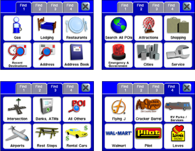
49
Section 5:
Searching, Finding and Navigating
The unit's most important function is generating routes to help you get
from where you are to where you want to go. There are several ways to
do this. The easiest is the GOTO command in the POI Information or
Location Information screen. Use the map cursor to select any location
on the map and press the Location Information button located in the
top right corner of the map screen.
In the POI Information screen select GOTO. The unit will generate a
route. The route will be highlighted by a magenta line on the map
screen. While the Go To command is an easy way to generate a route,
several other options are available. To access these options press the
FIND button on the right side of the unit. This will bring up the first of
four Find screens.
The Find 1 menu, left, and the Find 2 menu, at right.
The Find 3 menu, left, and the Find 4 menu, at right.
All the options in the Find menus point to a database of POIs stored in
the unit's hard drive. All the Find menus give you the option of search-
ing through a number of different categories. Gas, Banks, ATMs, Lodg-
ing and even Restaurants have been divided into their own categories.
50
No matter which Find category you choose, you will be able to search
for places nearest your current position or cursor – if the cursor is ac-
tive on-screen – or to search for specific locations by name. While the
Address feature allows you to enter a street address and navigate di-
rectly to it, the Address Book feature allows you to save and then
search through a list of address entries saved in the unit.
Almost any location can be saved in the Address Book as long as the
unit recognizes the location’s address. When you find an address you
want to save, choose ADD TO ADDRESSBOOK in the POI Information or Lo-
cation Information screen and it will be stored in the Address Book.
Using the Virtual Keyboard
The search options in the various Find menus will require you to enter
certain kinds of data, such as a shop name, address, State or Province.
You will use a virtual keyboard to enter letters, numbers and symbols.
When prompted to enter keyboard information, the keyboard will ap-
pear. The header of each Find Address screen will display what type of
information to enter. Notice the button in the bottom right corner of the
Find Address keyboard, NUM/SYM, which stands for Numbers/Symbols.
Use this button to toggle between the letters and numbers keyboard.
The "letters" keyboard is shown at left. The "numbers" keyboard is
shown at right.
Push DONE when the text field contains the information you want to
enter. When you do, the unit will sometimes provide a list with more
than one location that closely resembles the information you entered.
Scroll through the list of addresses provided by the unit and choose
your desired destination by highlighting and selecting it.
Auto Complete feature
The unit has an Auto Complete feature. Before you finish entering the
name of a state or province the unit may generate a list of possible
choices for you.
51
In the following two figures the letter "A" was entered. When the letter
"L" was entered next, the unit came up with a list that included Ala-
bama, Alaska and Alberta. Highlight and select your choice from the
generated list.
In the Find Address screen at left the letter "A" was entered. When the
letter "L" was selected the Auto Complete feature generated the list of
locations in the right figure.
Find Address
To search for a location by address, press the ADDRESS button in the
Find 1 screen. The Find Address screen will appear with the word
"Choose" on-screen. Press CHOOSE and a keyboard will appear. Use the
keyboard to enter the name of a State or Province. The auto complete
feature may generate a list of choices for you before you finish making
your entry. If the Auto Complete feature does not generate a list of
choices, press DONE when you have finished making your entry. Once
the unit has determine what State or Province you want to search in,
another keyboard will appear. In this screen you will enter a City or
ZIP code. When the unit has determined what city you wish to search
in, it will prompt you to enter an address.
When the Choose button (left) is selected a keyboard (right) will ap-
pear. This screen allows you to enter a specific State/Province by
name. To return to the previous screen press X or when you have fin-
ished entering your choice, press Done.
52
The unit will ask you to enter a City or ZIP code, far left. Press
"Choose" and a keyboard (center) will appear. Once you have entered
the City or ZIP code another screen (right) will appear asking you to
enter an address.
When you have entered an address, the unit will sometimes provide a
list with more than one address that closely resembles the one you are
searching for. Scroll through the list of addresses provided by the unit
and choose your desired destination by highlighting and selecting it on-
screen.
When you have entered an address a dialog box (left) will appear stat-
ing, "Finding street address. Please wait." Once the unit has found the
address it will prompt you to choose one of three options: Add to Ad-
dressbook, Find on Map or Go To.
Once the unit has determined the exact address, a dialog box will ap-
pear with three choices: Add to Addressbook, Find on Map or Go To. If
you select GOTO the unit will generate a route to your selected address.
Selecting ADD TO ADDRESSBOOK will place the address in the unit's Ad-
dress Book.
If you select FIND ON MAP the unit will show the location on the map dis-
play. Any time you perform an on-screen search with the map cursor,
by default, the distances listed for search results will be calculated
from the cursor position and not your current position.
To see an alphabetical list of states, provinces or countries leave the
Country or State/Province selection box empty and press DONE. Use the
slider to scroll through the list.
53
Fuel, Lodging, Restaurants and other POIs
Most of the options in the Find menus work essentially the same. We
will use the GAS command as an example but you can follow essentially
the same steps to locate and navigate to any POI stored in the unit.
To find a nearby gas station:
1. Press the FIND button on the right side of the unit.
2. Select GAS from the Find 1 screen. A screen will appear with a list of
gas stations nearest to your current position. Wait a moment for the
unit to finish compiling the list.
3. Highlight and select a gas station from the list. Once you make your
selection the POI Information screen will appear.
4. Now select GOTO from the POI Information screen and the unit will
generate a route to the gas station.
Use the Gas command in the Find 1 menu to locate the nearest gas sta-
tion. The Nearest To Current Position screen (left) will appear. Scroll
through the list and select a gas station. The POI Information screen
(right) will appear. Select Go To and the unit will generate a route to
the gas station.
The unit has several ways to perform searches. If you are navigating,
the unit searches for locations nearest to your current route. If you
have the cursor on-screen the unit will search for locations nearest to
the cursor.
If you are not navigating, and do not have the cursor on-screen, the
unit will search for locations near your current position. You can choose
a specific search setting by pressing the FIND BY button in the bottom
left corner of the Nearest To Current Position screen.
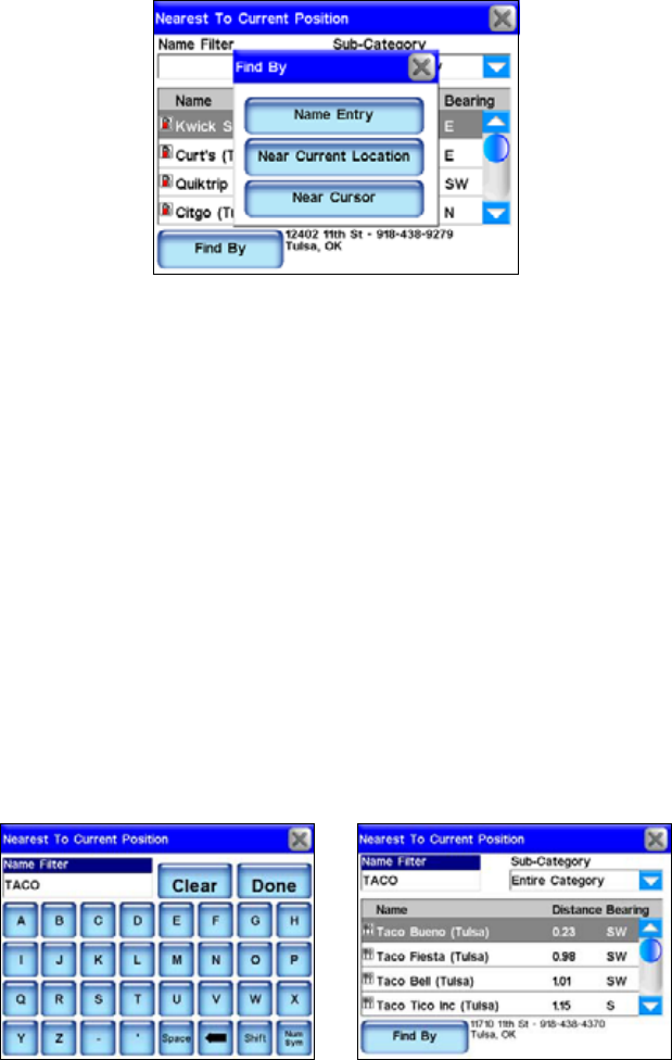
54
The Nearest To Current Position screen's Find By menu allows you to
search for a location by Name Entry, Near Current Location or Near
Cursor.
The Find By menu allows you to search for a location by Name Entry,
Near Current Location or Near Cursor. Searching for a specific name
allows you to find the closest Texaco or Shell gas station depending on
your preference. It is often used in restaurant searches.
Using the Name Filter
Sometimes a search returns too many results or more results than you
feel like scrolling through. The Name Filter in the Nearest To Current
Position screen can help you narrow your search. To use the Name Fil-
ter, press the NAME FILTER field and a keyboard will appear. Type all or
part of the name you are looking for and press DONE.
The unit will return to the previous list but it will only show those loca-
tions whose names contain the text you entered in the Name Filter
field. For example, you could significantly narrow a search by entering
the word "Taco" in the Name Filter field. This returns results for all the
nearest Taco Bells, Taco Buenos and any other restaurant nearby with
"Taco" anywhere in the name, as shown in the following figures.
To search for a specific restaurant by name, press in the Name Filter
field, left figure. Search results for the word "Taco" are shown at right.
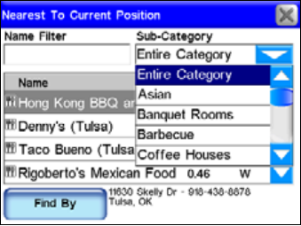
55
You can also use the Sub-Category field to narrow your search. Press
the arrow button next to Entire Category and a drop down box will ap-
pear allowing you to choose a specific restaurant type. The Sub-
Category feature works the same in almost all the Find menus.
Use the Sub-Category feature to help narrow your search. In this fig-
ure, you can see the sub-category list for the Restaurants search
screen in the Find 1 menu.
Navigating to a Selected POI
When the unit returns a list of nearest POIs choose the one that you
desire and touch its line on-screen. The unit will display a POI Infor-
mation screen with details about the location you have selected. Since
this is the result of a POI search, the POI Information screen will likely
have the name of the POI, its street address and probably even a phone
number. That can help when calling ahead to get a table at a restau-
rant. Much more important are the Go To and Find On Map com-
mands.
Select FIND ONMAP to have the unit close the POI Information screen
and center the map on the selected POI. This will help when trying to
determine where a POI is in relation to your current position or to
some other part of town. If want to go directly to the POI press GOTO.
The iWAY will generate a route from your current position, or last
known position if it doesn't have a satellite lock, to the selected desti-
nation.
Recent Destinations
The Recent Destinations command in the Find 1 menu will provide a
list of your most recent destinations. If the destination has an on-
screen symbol the list will show its street address whenever possible.
You can use the Find Recent menu to quickly get back on your route if
you diverted to POI along the way or to navigate back and forth be-
tween two locations on a common commute.
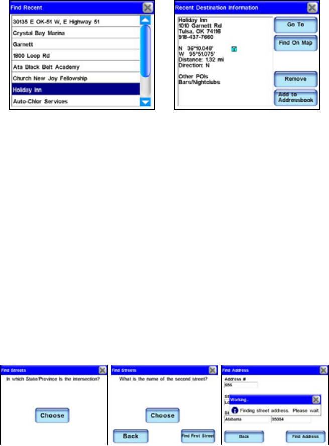
56
The Find Recent screen is shown at left. When one of the recent desti-
nation entries is highlighted and selected the Recent Destination In-
formation (right) screen appears.
Address Book
Address Book allows you to navigate to contacts you have saved. To
save a contact, use the Location Information or POI Information screen
and select ADD TO ADDRESSBOOK. Contact creation is explained under the
heading "Creating and Saving Contacts" in Section 2. Once you have
saved an address select ADDRESS BOOK in the Find 1 menu.
The Find By Name menu will appear allowing you to enter the saved
contact's name or you can scroll through your address book using the
slide tool. You can also use the Find By Name field to search through
your entire Address Book.
Intersection
Use the Intersection command from the Find 3 menu to navigate to any
street intersection stored in the unit. This can be useful when you don't
have a specific street address. When INTERSECTION is selected, the Find
Streets screen will appear. Now select CHOOSE and the virtual keyboard
will appear.
When you have entered the name of the first street the unit will ask for
the name of the second street. Use the keyboard to enter the name of
the second street. Once the second street name has been entered press
Done and the unit will begin searching for the intersection.
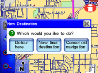
57
Use the keyboard to enter the name of the first street. Enter the name
of the street without direction or street type modifiers such as "N." for
"North" or "Ave." for Avenue. When finished entering the street name,
press DONE. Another Find Streets screen will appear asking you to enter
the name of the second street. Press CHOOSE and use the virtual key-
board to enter the name of the second street. When you press DONE a
dialog box will appear stating, "Finding street address. Please wait."
If the unit is not able to locate the intersection you are searching for a
dialog box will appear telling you it was unable to locate the intersec-
tion. When the unit finds the intersection you are searching for a dialog
box will appear stating, "Please choose an option." You will have three
options: Add to Addressbook, Find on Map or Go To.
Choosing New Destinations while Navigating
No matter which method the unit uses to generate a route it responds
the same. It generates a route from your current position to a chosen
destination. If you select an alternate destination or a new destination
while driving ï whether you use the cursor on-screen or the Address
feature in the Find menu ï a dialog box will appear asking, "Which
would you like to do?"
You will have three choices: Detour here, New final destination or Can-
cel old navigation. Make your selection and the unit will generate a
route to the alternate destination. Once you have reached your destina-
tion a dialog box will appear asking, "Do you want to cancel your
route?" This feature can be useful when you are traveling to a destina-
tion and want to stop for lunch along the way. Search for the nearest
restaurant, detour to the restaurant and then the unit will automati-
cally switch back to your original destination.
A dialog box will appear on-screen when you select a new destination
while navigating.

58
Detour here will make the unit immediately navigate to
the new selected location. Once you arrive, the unit will
resume navigating to your original destination.
New final destination will add the new location to the
end of the current route. So, if you are navigating to a
nearby restaurant and choose to set a gas station as your
New Final Destination, the unit will direct you to the restaurant first
and send you to the gas station after you have finished eating.
Cancel old navigation will stop navigating to your
original destination and start navigating to the new
location.
Considering Temporary or Local Conditions
Unfortunately, the unit cannot be aware of any temporary or local con-
ditions that could affect your course. Short-term construction, traffic
jams or local bans on U-turns could affect a generated route.
If you are following a route and conditions make it impossible or incon-
venient to follow the routing instructions use your best judgment.
When you deviate from your route the unit will begin generating a new
one based on your new position.
This feature will help when dealing with unexpected local conditions.
The most important step in learning how to follow generated routes is
practice. Use the unit as often as possible and pay attention to the way
it "thinks." In time you will learn exactly how to get the most out of the
information provided by the unit.
59
Section 6:
Point-to-Point Navigation
The iWAY 600C's primary job is providing turn-by-turn road naviga-
tion, but it can also display plot trails and perform traditional straight-
line or point-to-point navigation in off road situations.
This section will explain how to operate the unit in point-to-point navi-
gation mode and how to use the two additional map sets described be-
low. In this section, we assume you already have a basic understanding
of the buttons, menus and turn-by-turn functions.
In addition to the turn-by-turn NAVTEQ road maps, the hard drive
also contains NauticPath USA marine coastal charts and MapCre-
ate topographical maps for North America. The MapCreate series 7
data contains thousands of inland lakes with bottom contours and
other underwater details.
Turn-by-turn navigation does not work with any of these optional
point-to-point map sets.
NOTE:
When using Standard (MapCreate) or NauticPath map data, you
must search for POIs with the SEARCH ALL POIS BY NAME button. The
other search categories do not work with these point-to-point maps.
On the map, if a symbol for a POI or other item is selected with the
cursor, pressing the Location Information button displays a POI in-
formation screen for that item.
Caution:
The iWAY 600C is designed for primary use inside automobiles,
but the waterproof case and point-to-point navigation make it
suitable for the outdoors. However, the automotive mounting
bracket is not designed for boats, motorcycles or off-road vehi-
cles. These installation types require an optional bracket and
cradle designed for rugged outdoor use.
If you are interested in outdoor mounts, see the accessory ordering in-
formation inside this manual's back cover.
About Straight-line Navigation Mode (Point-to-Point)
You have probably heard the old adage, "The shortest distance between
two points is a straight line." Well, that's exactly what straight-line
navigation is. It allows you to create a straight-line navigation course
between yourself and another point on the map screen.
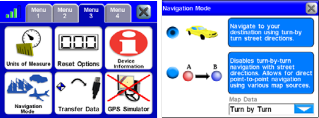
60
The iWAY's Point-to-Point mode uses straight-line navigation, the origi-
nal method used by the Global Positioning System. This function is
handy when you want to find a map feature, waypoint or point of interest
on a lake, in coastal waters or in off-road areas where turn-by-turn won't
work. Point-to-Point mode does not include audible voice directions.
Switch Between Navigation Modes
To change to Point-to-Point mode, press the MENU key, then select MENU
3 and press the NAVIGATION MODE button to display the Navigation Mode
screen.
Select the Navigation Mode button in Menu 3 to access the Navigation
Mode screen. The Navigation Mode screen allows you to switch be-
tween the unit's two different navigation modes.
Turn-by-Turn (car image) is selected as the default setting. Choose
Point-to-Point (A to B image), and a warning message appears asking if
you are sure you want to change modes. Choose YES and close the Navi-
gation Mode screen.
NOTE:
When you switch to line navigation, there is no need to change set-
tings in the Map Data pull-down menu unless you are using nauti-
cal charts or lake contours. Select NauticPath map data when you
want to use coastal charts. Select Standard (MapCreate) map data
when you want to see enhanced underwater detail for select lakes.
Switching back to Point-to-Point mode will automatically select
Turn-by-Turn Map Data.
WARNING:
When displaying straight-line navigation data to a posi-
tion (waypoint) a GPS unit will show the shortest, most
direct path. The unit provides navigation data to the
waypoint regardless of obstructions.
61
Therefore, the prudent navigator will not only take ad-
vantage of all available navigation tools when traveling
to a waypoint, but will also visually check to make sure
a clear, safe path to the waypoint is always available.
Straight-line Navigation Commands
There are two basic commands used for straight-line navigation: Go To
Cursor and Go To Waypoint. The Go To Cursor command will guide
you to any spot, landscape feature or waypoint you select on the map
with the cursor arrow.
The Go To Waypoint command works with the iWAY 600 Address Book
feature. This command lets you look up waypoints you have created
and saved, then takes you to them. (This also works for commercial
Points of Interest (POIs). In fact, you can launch straight-line naviga-
tion to anything you can look up with the Find key.)
But before you head off into the woods on your ATV, or across the lake
in your boat, it's important that you understand the term "waypoint."
Why? To navigate back to your trailhead or boat ramp, you must first
mark the spot by making a waypoint there.
Waypoints = Contacts
If you have been creating contacts and adding them to the Address
Book in turn-by-turn mode, you already understand the waypoint con-
cept. A turn-by-turn "contact" is actually a "waypoint" in point-to-point
mode, and vice versa. The Address Book in your iWAY is essentially a
waypoint list with additional features, like places to record street ad-
dresses or phone numbers. All navigation modes in this unit share the
same Address Book for storing contacts/waypoints.
"Waypoint" is the term originally used in GPS to mark a spot. It's the
word still commonly used in all straight-line GPS navigation. A way-
point is similar to an electronic "address" based on the latitude and lon-
gitude of a position on the earth. A waypoint represents a location or
destination that you can store in the unit's memory and recall later for
navigational purposes.
Set a Waypoint
Turn on the iWAY. Wait until it locks-on to the satellites and deter-
mines your position.
Create Waypoint at Current Position
Press the LOCATION INFORMATION button in the upper right corner of the
screen. This calls up the Waypoint Information screen. Select ADD TO
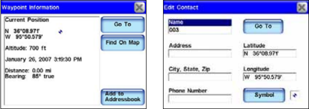
62
ADDRESSBOOK to create and save the waypoint. The Edit Contact (Way-
point) screen appears. You can accept the default name and symbol,
edit them, or just select X to close the screen.
Waypoint Information screen, left. Edit screen for this waypoint, right.
(If you do want to change the waypoint name, symbol or any of the
other information boxes, simply touch anywhere inside the relevant box
and the iWAY's virtual keyboard will appear. This allows you to enter
new information or modify the old.)
With your starting place safely marked with a waypoint, you can
now head off on your outdoor adventure. Whenever you find a spot
you may want visit again, use the Location Information button to set
a waypoint there.
Create Waypoint on Map
Let's say you're headed for a place you've never been before, but you
know approximately where it is on a map. You can use the cursor and
the Location Information button to set a waypoint there so you can
navigate to it.
Touch the screen to launch the Map Display Toolbar and the cursor ar-
row. Use the cursor and the Zoom In and Zoom Out buttons to move
around the map and find where you want to go. Zoom in close and center
the point of the cursor on your destination.
Press the LOCATION INFORMATION button in the upper right corner of the
map screen. This calls up the Waypoint Information screen. Select ADD
TO ADDRESSBOOK to create and save the waypoint. The Edit Waypoint
screen appears. As before, you can change the name and symbol or just
accept the defaults. Select X to close the screen and select the CLEAR CUR-
SOR button to clear the cursor and toolbar from the screen.
63
Navigate To a Waypoint
Find and Go To Waypoint
Unless you happen see the waypoint nearby on the map, the fastest
way to navigate to a waypoint is to look it up in the Address Book by
using the Find button.
Press the FIND key, then choose ADDRESS BOOK. You can look up the way-
point one of three ways:
Method A: If you have several waypoints, drag the slider bar to scroll
down the list and select the waypoint. Or, just tap the up and down ar-
row buttons.
Method B: To search by name, touch the FIND BY NAME box to launch the
virtual keyboard. This allows you to enter the waypoint name (or just
enough of it) to find it in the Address Book.
Method C: Choose the FIND BY button, which gives you the option to
search by name or narrow the search by looking near your current loca-
tion or near the cursor location.
When you find and select the desired waypoint, the Waypoint Informa-
tion screen appears. Choose GOTO and the iWAY draws a red course
line straight from your current position to the waypoint. We'll describe
how to use the course line for guidance in a few moments in the seg-
ment on "Following Navigation Indicators."
Go To Cursor
The Go To Cursor command is handy for navigating to a waypoint you
can see nearby on the map. If you don't need to move the map around,
you can be navigating with just five finger strokes.
1. Touch the screen to call up the toolbar and cursor.
2. Select the waypoint with the cursor.
3. Press the LOCATION INFORMATION button in the corner.
4. Choose GOTO.
5. Press the CLEAR CURSOR button (X).
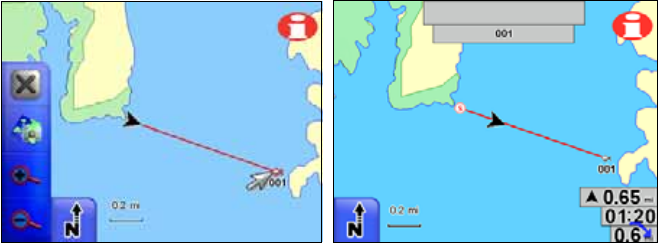
64
Navigating with the Go To Cursor command. At left, the boater has
selected a waypoint (fish symbol) with the cursor and started navigat-
ing. The figure at right shows the straight-line navigation course after
the cursor and toolbar have been cleared from the screen.
The Go To Cursor command is extremely powerful because it's not lim-
ited to waypoints — it can navigate you to any place you can pick out
on the map. It doesn't matter if your destination is a waypoint, a POI, a
landscape feature or just a spot in the middle of a lake. Just move
around the map to find the place, then use the same commands above
(starting with step 2) to select and go to it.
Following Navigation Indicators
Your iWAY provides a slightly different set of steering indicators in
point-to-point mode. The map still moves as you travel. The black cur-
rent position arrow still points in the direction you are headed. But, the
textual and audible turn instructions are gone.
Course Line
Text and audio instructions have been replaced with the red course line,
which is shown in the preceding two figures. When you navigate some-
where, an "S" symbol is placed at your starting position, and your desti-
nation is highlighted. The course line connects the start and destination.
The simplest way to guide yourself is to zoom in closely, then steer so
that the current position arrow moves along the course line. When you
reach your destination, remember to tell the unit to stop navigating.
Press the MENU key and select the CANCEL NAVIGATION button.
Steering Arrow and other Overlay Data
As in turn-by-turn mode, you can display different types of navigation
information as Overlay Data. Some overlay categories do not work the
same in point-to-point mode, but there are several data types that will
help you steer in roadless areas. One of the easiest to use is the Steer-
ing Arrow overlay.
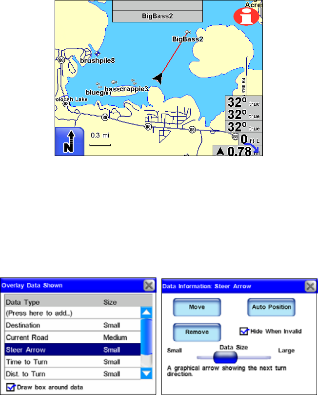
65
Navigating to a fishing spot using course line and Overlay Data boxes,
seen in lower right corner. From top to bottom, they are: bearing,
course, track, off course and steering arrow/distance.
The Steering Arrow overlay is a graphical arrow showing which way to
steer to the destination. It always points straight toward the destina-
tion, regardless of the map orientation. The steer arrow automatically
shows the distance from the current position to the destination.
In the example figure above, the boat is headed straight toward a fish-
ing spot, so the steering arrow is pointing straight ahead.
Select an overlay data item (left) to display its information screen.
In addition to the steer arrow, the most commonly used Overlay Data
for point-to-point navigation are described below:
Track: The actual direction you are traveling over the ground. Shown
in degrees in true or magnetic format.
Bearing: The direction to the current destination from your current posi-
tion, shown in degrees true or magnetic. Steer so your Track matches the
Bearing and you will be headed straight for your destination.
66
Course: The direction you should be traveling to reach your destina-
tion when you are on the original course line.
Off Course (Pos Error): The distance (to the left or to the right) from
the course line.
Steer so your Track, Bearing and Course match, and you will be headed
straight for your destination along your original course.
Navigating With Trails
Displaying and editing trails are discussed earlier in this manual un-
der the topics Categories Drawn and My Trails. The following instruc-
tions will show you how to navigate with trails.
The Trails feature is always turned on in this unit, and it works in both
point-to-point and turn-by-turn modes. However, trails are especially
useful in off-road or marine situations. They help you retrace your
steps where no roads exist for reference.
A trail, or plot trail, is a history of the path you have taken. This travel
history is represented by a line extending from the back of the current
position arrow. As you move, the unit draws this line by recording or plot-
ting a string of trail points along your path. The iWAY's built-in memory
can save 100 trails, with up to 10,000 points recorded per trail. (The de-
fault setting is 2,000 points per trail.) When trail length exceeds the
maximum point setting, the iWAY will begin recording a trail over itself.
You can save a set of up to 100 trails in a GPS data file (*.usr file for-
mat) on the unit's hard drive. The trails can then be deleted from the
unit's memory and you can record a new set of trails to save in another
GPS data file. With a USB connection, these GPS data files can also be
backed up on a computer hard drive.
NOTE:
GPS data files, also referred to as "user files," can contain trails,
routes and the waypoints (contacts) in your Address Book. Maxi-
mum capacity per file is 1,000 waypoints, 100 routes and 100 trails.
These files can by opened by our MapCreate custom mapping soft-
ware, or by our GPS Data Manager program. These programs allow
you to view and edit GPS data on the computer screen. The GPS
Data Manager can be downloaded free from www.lowrance.com.
GPS data files containing trails can then be reloaded from the unit's
hard drive to iWAY's memory. By backing up your GPS data, you can
keep different sets of trails, routes and waypoints for different pur-
poses. For example, a substitute school bus driver could record trails of
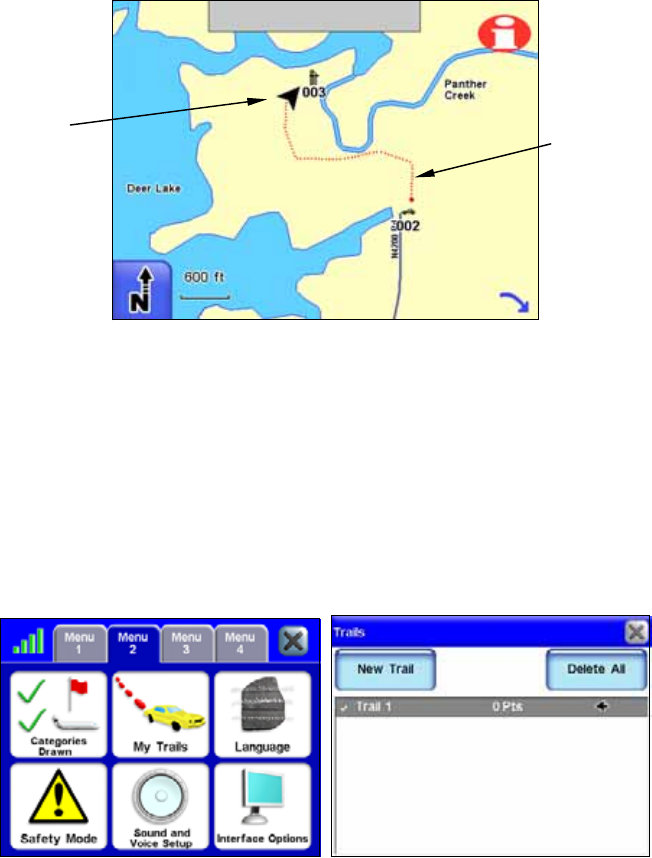
67
all the bus routes he drives in one file for work. Another file could con-
tain personal GPS data for fishing or vacation travel.
Recording a trail in a roadless area. This hunter can retrace his path
from parking area to hunting stand even in the dark.
In the example figure above, a hunter is riding an all terrain vehicle
(ATV) from a parking area (waypoint 002, the car symbol) to a hunting
stand (waypoint 003). The hunter is first making his approach in day-
light and recording a trail which he will save. Then he can safely re-
trace his path through the woods before dawn and after dusk.
If you want to preserve a specific trail from Point A to Point B, you
should first create a new trail at Point A. Go to MENU 2, select MYTRAILS,
then press the NEW TRAIL button. (In the example shown below, any old
trails have been deleted and a new trail is already started.)
The My Trails button on Menu 2 (left figure) calls up the Trails Menu
(right) where you can create, edit or delete trails.
When you arrive at Point B, stop recording and save the trail you just
made. This happens automatically when you start another trail with
the NEW TRAIL button.
Trail line
Hunter
on ATV
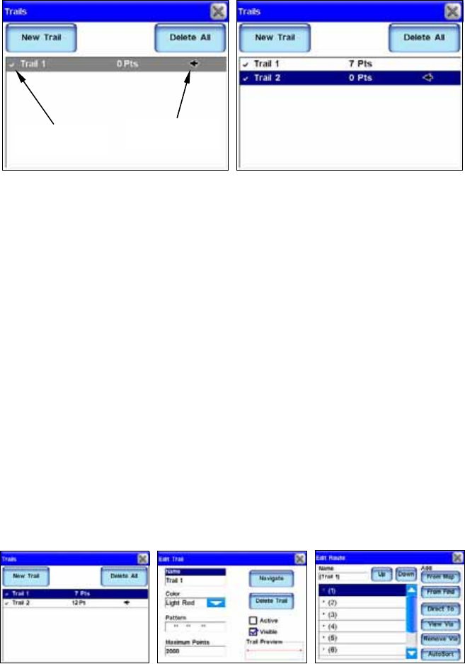
68
At left, Trails Menu with Trail 1 ready to record. The Active symbol
shows that any travel will be recorded in this, the active trail. At right,
selecting New Trail button automatically stops recording and saves
Trail 1 by creating Trail 2 and making Trail 2 active.
There are two ways to guide yourself with a saved trail: Visual Trailing
and the Navigate Trail command.
Visual Trailing is the simplest. It works when you follow a trail for-
ward (from beginning to end) or backward (from end to beginning).
Zoom in closely on the map so the trail is clearly visible. Begin moving
and glance at the map screen. Steer so that your current position arrow
traces along the trail you have saved.
The Navigate Trail command converts a trail into a route and then
shows navigation information along the route. Since the unit is actually
performing point-to-point navigation, the Steer Arrow and other Over-
lay Data are working and can give you guidance.
Go to MENU 2 and press the MYTRAILS button. On the Trails Menu, select
the trail you want to navigate, which calls up the Edit Trail Menu.
Press the NAVIGATE button. The trail is converted to a route and the Edit
Route menu appears. With the first point in the route selected, press
the DIRECT TO button and the unit begins navigating.
From left to right, menu sequence for navigating a trail.
Begin traveling and follow the Steer Arrow overlay and the route
course line for guidance.
Visible Trail
(check symbol)
Active Trail
(arrow symbol)
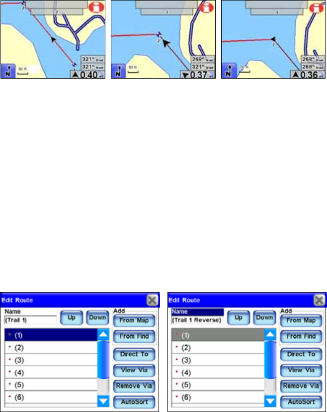
69
Navigating a route made from a trail. Fig. 1 shows boat on first leg of
the route. In Fig. 2 boat nears point two and unit automatically
switches navigation to point three. Boat is still tracking 321
q
, but bear-
ing overlay now shows point three is 269
q
away. Steer arrow also
swings left, showing which way to turn. Fig. 3 shows boat has turned
on new course. Boat track is 268
q
which now matches the bearing to
point three which is 0.36 mile away. Steer arrow points straight ahead.
Simply running the Navigate Trail command will lead you along a trail
from starting point to ending point — forward order. You can also back
track a trail, or follow it in reverse order (from ending point to starting
point.) However, this requires you to manually edit the route to change
the point order.
To back track, you begin with the same steps for navigating a trail for-
ward. When you get to the Edit Route menu, you must change the route
order. The following figures will guide you through the process:
1. Select the NAME box and use the virtual keyboard to change the route
name from "(Trail 1)" to "(Trail 1 Reverse)". Changing the name helps
you tell a forward route from a reversed route. The parentheses ( ) in-
dicate this route was made from a trail. 2. Select point 1 and press the
DOWN button to move it to the bottom of the list.
Fig. 1 Fig. 2 Fig. 3
Step 2
Step 1
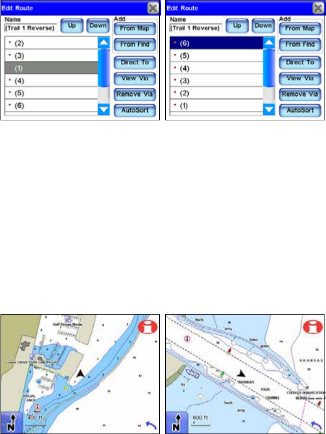
70
3. Point 1 is now half-way down the list. It should be at the bottom, just
above the text "(Add to list)". 4. Use the UP and DOWN buttons to move
the points until they are all in reverse order, with the original end
point at the top of the list. With the end point selected, press the DIRECT
TO button and navigation begins.
NauticPath
USA Marine Electronic Charts
NauticPath USA map data provides electronic charts covering the
U.S. East and West coasts, Hawaii, Gulf coast, Great Lakes, Alaska,
the Bahamas, Puerto Rico and the U.S. Virgin Islands.
NauticPath features depth contours, intertidal zones and spot sound-
ings, navigational aids with view range and coverage. You can view
extensive object-oriented detail including list of lights, tides and cur-
rents, wrecks and obstructions, marine services, restricted areas and
anchorage database information.
These figures show the offshore/coastal detail you will get when using
NauticPath
USA marine charts in the iWAY.
Step 3 Step 4
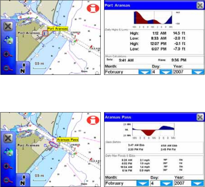
71
Reading NauticPath Map Information
Use the cursor on the map screen to highlight a map feature or symbol
and a pop-up information box appears identifying the item. Certain
symbols offer additional information.
For example, use the cursor to select a chart symbol, then press the
INFORMATION button in the top right corner of the map screen. A screen
appears with detailed information about the selected item. Information
for almost any on-screen symbol can be accessed as long as you are able
to highlight it with the cursor.
The Port Aransas, Texas tide symbol in the left figure has been high-
lighted with the cursor. In the right figure the Information button has
been selected to view tidal information for that station.
The cursor has selected the Aransas Pass tidal current station. Press-
ing the Information button calls up the tidal current table.
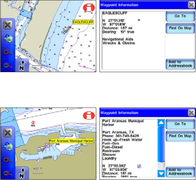
72
The cursor has been used to highlight a shipwreck symbol, and a
popup box appeared describing the selected item. The Information
button was then selected to view waypoint information on the wreck.
The cursor has selected the Port Aransas Municipal Harbor marina
symbol. In the right figure the Information button has been selected to
view information on the marina, including available amenities.
Enhanced Lake Maps
The Standard map data is based on our MapCreate series 7 software
which covers all 50 states in the U.S.A. The data includes land-based
topographic contour lines, public hunting areas and depth contours for
more than 3,000 U.S. inland lakes.
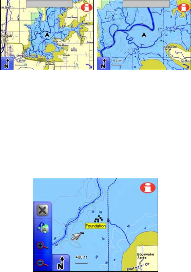
73
These figures show the lake detail included in the enhanced lake
maps. More detail appears as you zoom in. This is a man-made lake;
these examples clearly show the submerged river and stream channels
that formed the lake.
In addition to underwater contour features, these lake maps show en-
hanced shoreline features, small islands and various bottom structures.
Underwater features on man-made lakes reflect conditions prior to in-
undation of the lake. Each depth contour line is labeled with its actual
depth.
With enhanced lake maps you can identify submerged structures such
as rivers and creek channels, ponds, streams, roads, foundations, rail-
roads, pipelines, oil and gas wells, foundations, bridges, etc. However,
the amount of detail varies from one lake to another. All lakes do not
have this enhanced detail.
Fishermen will appreciate that underwater features, such as bridges,
old creek channels, roads and other items, can be identified by using
the cursor. Select a lake feature with the cursor and a pop up box ap-
pears, identifying the feature. An old house foundation is shown.
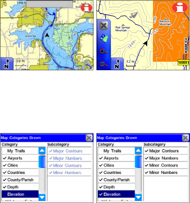
74
Elevation Contour Lines
Topographic information is displayed as major and minor contour lines
with numbers showing the elevation above sea level.
At left, different colors mark parks and public hunting areas. At right,
topo contours and the border of a game refuge are shown. Cursor has
selected a contour line, launching a pop-up box showing the elevation.
Topographic contour lines are available when the Turn-by-Turn or
Standard map data sets are selected. To turn them on, you must press
the MENU key, then press MENU 2 and select the CATEGORIES DRAWN but-
ton. Scroll down the list and check ELEVATION to turn on topo line dis-
play.
You must turn on Elevation in Categories Drawn to see topo lines. At
left, elevation is off; at right the feature is on.
75
Notes
76
Notes
77
FCC Compliance
This device complies with Part 15 rules. Operation is subject to the fol-
lowing two conditions:
1. This device may not cause harmful interference, and
2. This device must accept any interference received, including inter-
ference that may cause undesired operation. This equipment has been
tested and found to comply with the limits of a Class B digital device,
pursuant to Part 15 of the FCC Rules. These limits are designed to pro-
vide reasonable protection against harmful interference when the
equipment is operated in a residential environment.
This equipment generates, uses, and radiates radio frequency energy,
and if not installed and used in accordance with the instructions, may
cause harmful interference. However, there is no guarantee that inter-
ference will not occur. If this equipment does cause interference to ra-
dio or television reception, which can be determined by turning the
equipment off and on, the user is encouraged to correct the interference
by one of the following measures:
xReorient or relocate the receiving antenna.
xIncrease separation between the equipment and receiver.
xConnect the equipment into an outlet on a circuit different from
which the receiver is connected.
xConsult the dealer or an experienced radio/TV technician.
Changes or modifications not expressly approved by the manufacturer
could void the user's authority to operate the equipment.
78
Canadian Compliance Statement
This Class B Digital apparatus meets all the requirements of the Ca-
nadian Interference-Causing Equipment Regulations.
Cet appareil numerique de la classe B respecte les exigences du Regle-
ment sur le material broilleur du Canada.
This device complies with Class B Limits of Industry Canada. Opera-
tion is subject to the following two conditions:
1. This device may not cause harmful interference, and
2. This device must accept any interference received, including inter-
ference that may cause undesired operation.

79
Lowrance Mapping Database
End User License Agreement
The data (“Data”) is provided for your personal, internal use only
and not for resale. It is protected by copyright, and is subject to the
following terms and conditions which are agreed to by you, on the
one hand, and Lowrance Electronics, Inc. (“Lowrance”) and its li-
censors (including their licensors and suppliers) on the other hand.
© 2004 NAVTEQ. All rights reserved.
The Data for areas of Canada includes information taken with per-
mission from Canadian authorities, including: © Her Majesty the
Queen in Right of Canada, © Queen's Printer for Ontario, © Canada
Post, GeoBase.
TERMS AND CONDITIONS
Personal Use Only. You agree to use this Data together with the
iWAY 600c GPS receiver for the solely personal, non-commercial
purposes for which you were licensed, and not for service bureau,
time-sharing or other similar purposes; for purposes of clarity, such
“personal, non-commercial purposes” shall include use in your in-
ternal business operations. Accordingly, but subject to the restric-
tions set forth in the following paragraphs, you may copy this Data
only as necessary for your personal use to (i) view it, and (ii) save it,
provided that you do not remove any copyright notices that appear
and do not modify the Data in any way. You agree not to otherwise
reproduce, copy, modify, decompile, disassemble or reverse engineer
any portion of this Data, and may not transfer or distribute it in any
form, for any purpose, except to the extent permitted by mandatory
laws.
Restrictions. Without limiting the preceding paragraph, you may
not use this Data with any products, systems, or applications in-
stalled or otherwise connected to or in communication with vehicles,
and which are capable of dispatch, fleet management or similar ap-
plications.
No Warranty. This Data is provided to you “as is,” and you agree
to use it at your own risk. Lowrance and its licensors (and their li-
censors and suppliers) make no guarantees, representations or war-
ranties of any kind, express or implied, arising by law or otherwise,

80
including but not limited to, content, quality, accuracy, complete-
ness, effectiveness, reliability, fitness for a particular purpose, use-
fulness, use or results to be obtained from this Data, or that the
Data or server will be uninterrupted or error-free.
Disclaimer of Warranty: LOWRANCE AND ITS LICENSORS
(INCLUDING THEIR LICENSORS AND SUPPLIERS) DISCLAIM
ANY WARRANTIES, EXPRESS OR IMPLIED, OF QUALITY,
PERFORMANCE, MERCHANTABILITY, FITNESS FOR A PAR-
TICULAR PURPOSE OR NON-INFRINGEMENT. Some States,
Territories and Countries do not allow certain warranty exclusions,
so to that extent the above exclusion may not apply to you.
Disclaimer of Liability: LOWRANCE AND ITS LICENSORS
(INCLUDING THEIR LICENSORS AND SUPPLIERS) SHALL
NOT BE LIABLE TO YOU: IN RESPECT OF ANY CLAIM, DE-
MAND OR ACTION, IRRESPECTIVE OF THE NATURE OF THE
CAUSE OF THE CLAIM, DEMAND OR ACTION ALLEGING ANY
LOSS, INJURY OR DAMAGES, DIRECT OR INDIRECT, WHICH
MAY RESULT FROM THE USE OR POSSESSION OF THE IN-
FORMATION; OR FOR ANY LOSS OF PROFIT, REVENUE,
CONTRACTS OR SAVINGS, OR ANY OTHER DIRECT, INDI-
RECT, INCIDENTAL, SPECIAL OR CONSEQUENTIAL DAM-
AGES ARISING OUT OF YOUR USE OF OR INABILITY TO USE
THIS INFORMATION, ANY DEFECT IN THE INFORMATION,
OR THE BREACH OF THESE TERMS OR CONDITIONS,
WHETHER IN AN ACTION IN CONTRACT OR TORT OR BASED
ON A WARRANTY, EVEN IF LOWRANCE OR ITS LICENSORS
HAVE BEEN ADVISED OF THE POSSIBILITY OF SUCH DAM-
AGES. Some States, Territories and Countries do not allow certain
liability exclusions or damages limitations, so to that extent the
above may not apply to you.
Export Control. You agree not to export from anywhere any part
of the Data provided to you or any direct product thereof except in
compliance with, and with all licenses and approvals required un-
der, applicable export laws, rules and regulations.
Entire Agreement. These terms and conditions constitute the en-
tire agreement between Lowrance (and its licensors, including their
licensors and suppliers) and you pertaining to the subject matter
hereof, and supersedes in their entirety any and all written or oral

81
agreements previously existing between us with respect to such
subject matter.
Governing Law. The above terms and conditions shall be gov-
erned by the laws of the Illinois, without giving effect to (i) its con-
flict of laws provisions, or (ii) the United Nations Convention for
Contracts for the International Sale of Goods, which is explicitly
excluded. You agree to submit to the jurisdiction of Illinois for any
and all disputes, claims and actions arising from or in connection
with the Data provided to you hereunder.
Government End Users. If the NAVTEQ Data is being acquired
by or on behalf of the United States government or any other entity
seeking or applying rights similar to those customarily claimed by
the United States government, (i) for acquisitions conducted by the
Department of Defense, the NAVTEQ Data is licensed with “Lim-
ited Rights” in accordance with the rights set forth at DFARS
252.227-7013(b)(3), Technical Data-Noncommercial Items, and
NAVTEQ Data delivered or otherwise furnished with “Limited
Rights” shall be marked with the “Limited Rights Notice” set forth
at DFARS 252.227-7013(f)(3), and shall be treated in accordance
with such Notice and; (ii) for civilian agency acquisitions, the NAV-
TEQ Data is licensed in accordance with the rights set forth at FAR
52.227-14(g)(1), Rights in Data-General (Protection of limited rights
data and computer software). In the event that the Contracting Of-
ficer requires the delivery of limited rights NAVTEQ Data that has
been withheld or would otherwise be withholdable in accordance
with FAR 52.227-14(g)(1), the NAVTEQ Data is licensed with “Lim-
ited Rights” as set forth in the “Limited Rights Notice” at FAR
52.227-14(g)(2) (Alternate II), which shall be affixed to the NAVTEQ
Data and the NAVTEQ Data shall be treated in accordance with
such Notice (which shall be marked on any reproduction of these
data, in whole or in part).
If the Contracting Officer refuses to use either of the licenses cited
in (i) or (ii), herein, the Contracting Officer must notify NAVTEQ
prior to seeking additional or alternative rights in the NAVTEQ
Data.
82
Notes
83
LOWRANCE ELECTRONICS
FULL ONE-YEAR WARRANTY
"We," "our," or "us" refers to LOWRANCE ELECTRONICS, INC., the manufacturer of
this product. "You" or "your" refers to the first person who purchases this product as a
consumer item for personal, family or household use.
We warrant this product against defects or malfunctions in materials and workmanship,
and against failure to conform to this product's written specifications, all for one (1) year
from the date of original purchase by you. WE MAKE NO OTHER EXPRESS WAR-
RANTY OR REPRESENTATION OF ANY KIND WHATSOEVER CONCERNING THIS
PRODUCT. Your remedies under this warranty will be available so long as you can show
in a reasonable manner that any defect or malfunction in materials or workmanship, or
any non-conformity with the product's written specifications, occurred within one year
from the date of your original purchase, which must be substantiated by a dated sales
receipt or sales slip. Any such defect, malfunction, or non-conformity which occurs within
one year from your original purchase date will either be repaired without charge or be
replaced with a new product identical or reasonably equivalent to this product, at our
option, within a reasonable time after our receipt of the product. If such defect, malfunc-
tion, or non-conformity remains after a reasonable number of attempts to repair by us,
you may elect to obtain without charge a replacement of the product or a refund for the
product. THIS REPAIR, OR REPLACEMENT OR REFUND (AS JUST DESCRIBED) IS
THE EXCLUSIVE REMEDY AVAILABLE TO YOU AGAINST US FOR ANY DEFECT,
MALFUNCTION, OR NON-CONFORMITY CONCERNING THE PRODUCT OR FOR
ANY LOSS OR DAMAGE RESULTING FROM ANY OTHER CAUSE WHATSOEVER.
WE WILL NOT UNDER ANY CIRCUMSTANCES BE LIABLE TO ANYONE FOR ANY
SPECIAL, CONSEQUENTIAL, INCIDENTAL, OR OTHER INDIRECT DAMAGE OF
ANY KIND.
Some states do not allow the exclusion or limitation of incidental or consequential dam-
ages, so the above limitations or exclusions may not apply to you.
This warranty does NOT apply in the following circumstances: (1) when the product has
been serviced or repaired by anyone other than us; (2) when the product has been con-
nected, installed, combined, altered, adjusted, or handled in a manner other than accord-
ing to the instructions furnished with the product; (3) when any serial number has been
effaced, altered, or removed; or (4) when any defect, problem, loss, or damage has resulted
from any accident, misuse, negligence, or carelessness, or from any failure to provide
reasonable and necessary maintenance in accordance with the instructions of the owner's
manual for the product.
We reserve the right to make changes or improvements in our products from time to time
without incurring the obligation to install such improvements or changes on equipment or
items previously manufactured.
This warranty gives you specific legal rights and you may also have other rights which
may vary from state to state.
REMINDER: You must retain the sales slip or sales receipt proving the date of your origi-
nal purchase in case warranty service is ever required.
LOWRANCE ELECTRONICS
12000 E. SKELLY DRIVE, TULSA, OK 74128
(800) 324-1356
84
How to Obtain Service…
…in the USA:
We back your investment in quality products with quick, expert service
and genuine Lowrance parts. If you're in the United States and you
have technical, return or repair questions, please contact the Factory
Customer Service Department. Before any product can be returned,
you must call customer service to determine if a return is necessary.
Many times, customer service can resolve your problem over the phone
without sending your product to the factory. To call us, use the follow-
ing toll-free number:
800-324-1356
8 a.m. to 5 p.m. Central Standard Time, M-F
Lowrance Electronics may find it necessary to change or end our ship-
ping policies, regulations, and special offers at any time. We reserve the
right to do so without notice.
…in Canada:
If you're in Canada and you have technical, return or repair questions,
please contact the Factory Customer Service Department. Before any
product can be returned, you must call customer service to determine if
a return is necessary. Many times, customer service can resolve your
problem over the phone without sending your product to the factory. To
call us, use the following toll-free number:
800-661-3983
905-629-1614 (not toll-free)
8 a.m. to 5 p.m. Eastern Standard Time, M-F
…outside Canada and the USA:
If you have technical, return or repair questions, contact the dealer in
the country where you purchased your unit. To locate a dealer near
you, visit our web site, www.lowrance.com and look for the Dealer Loca-
tor.
Accessory Ordering Information
for all countries
To order Lowrance GPS accessories, please contact:
1) Your local sporting goods, marine, aviation, automobile or consumer
electronics store. Most quality dealers that handle outdoor electronic
equipment or other consumer electronics should be able to assist you
with these items.
To locate a Lowrance dealer near you, visit our web site, and look for
the Dealer Locator (www.lowrance.com/support/dealerlocator). Or, you
can consult your telephone directory for listings.
2) U.S. customers: LEI Extras Inc., PO Box 129, Catoosa, OK 74015-0129
Call 1-800-324-0045 or visit our web site www.lei-extras.com.
3) Canadian customers can write:
Lowrance/Eagle Canada, 919 Matheson Blvd. E. Mississauga, Ontario
L4W2R7 or fax 905-629-3118.
Shipping Information
If it becomes necessary to send a product for repair or replacement, you
must first receive a return authorization number from Customer
Service. Products shipped without a return authorization will not be
accepted. When shipping, we recommend you do the following:
1. Please do not ship the knobs or mounting bracket with your unit.
2. If you are sending a check for repair, please place your check in an
envelope and tape it to the unit.
3. For proper testing, include a brief note with the product describing
the problem. Be sure to include your name, return shipping address
and a daytime telephone number. An e-mail address is optional but
useful.
4. Pack the unit in a suitable size box with packing material to prevent
any damage during shipping.
5. Write the Return Authorization (RA) number on the outside of the
box underneath your return address.
6. For your security, you may want to insure the package through your
shipping courier. Lowrance does not assume responsibility for goods
lost or damaged in transit.

Visit our web site:
Lowrance Pub. 988-0160-191 © Copyright 2007
All Rights Reserved
Printed in USA 020807 Lowrance Electronics, Inc.