Navico LVR880US FIXED MARINE TRANSCEIVER User Manual USERS MANUAL
Navico Auckland Limited FIXED MARINE TRANSCEIVER USERS MANUAL
UserManual.wiki
>
Navico
>
LVR880US User Manual
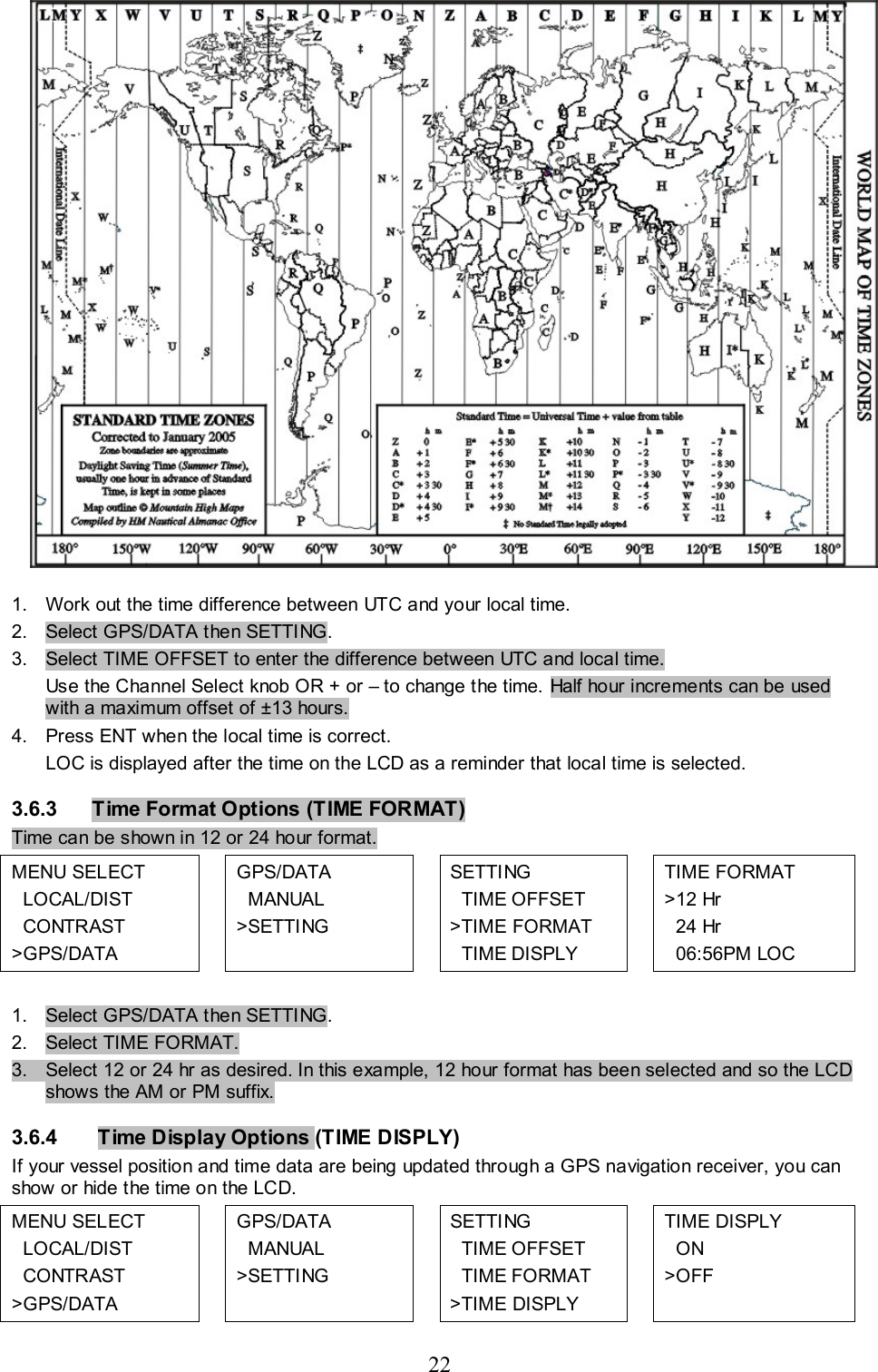
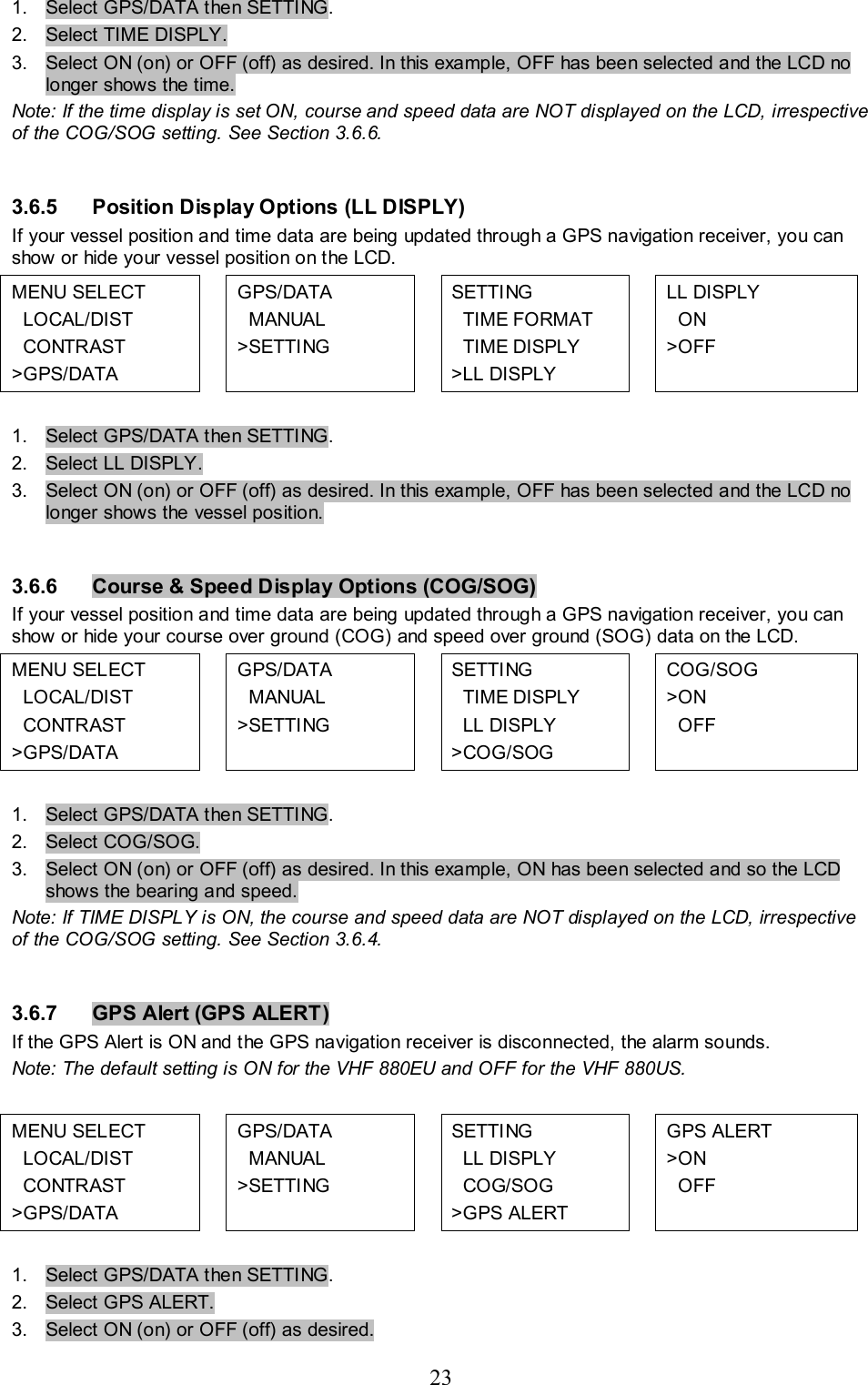
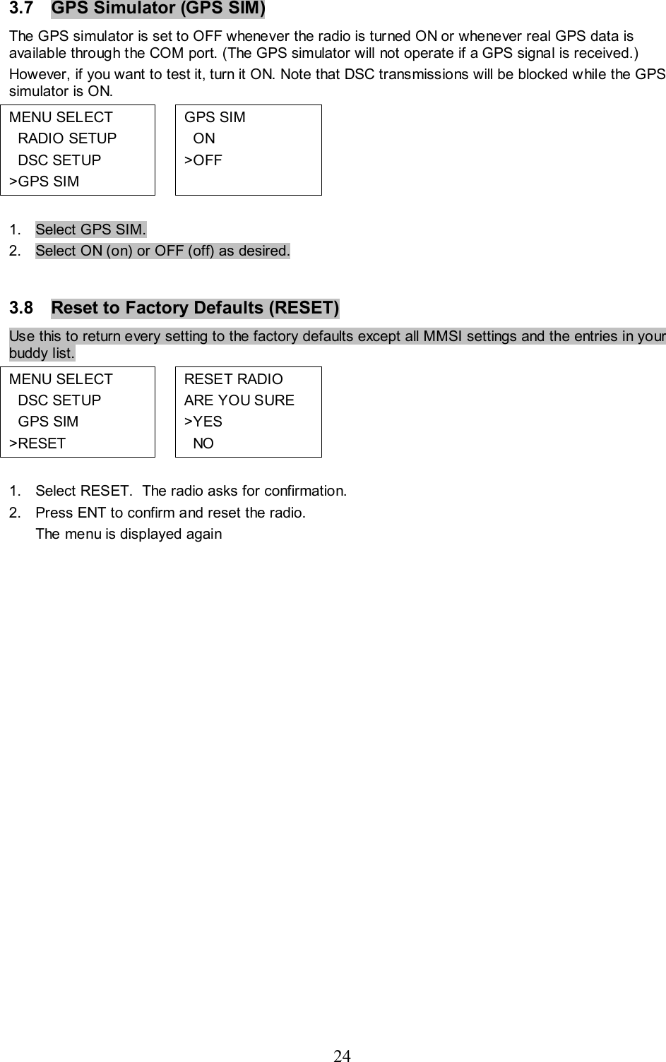
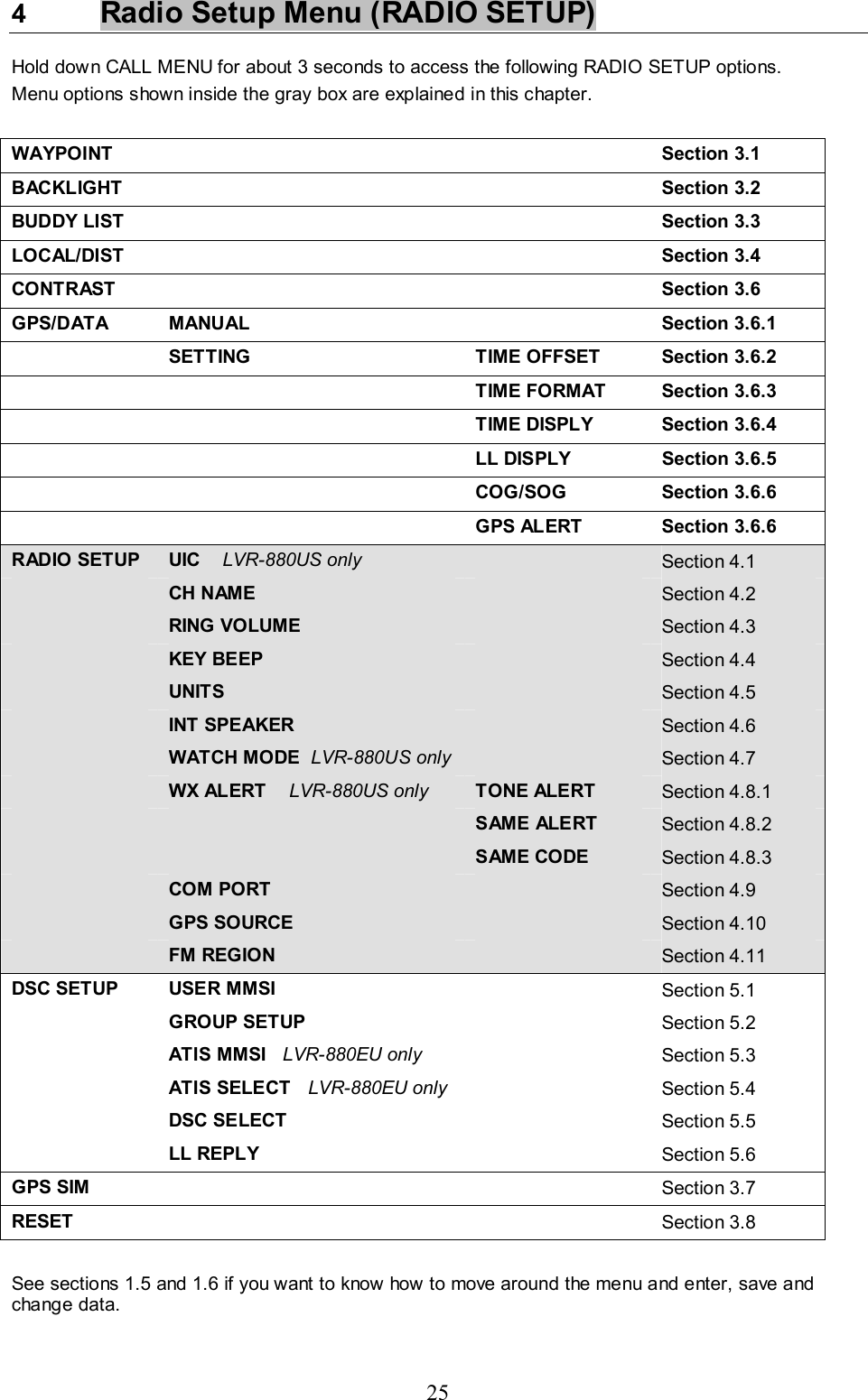
USERS MANUAL
Navigation menu
Upload a User Manual
Namespaces
Wiki Guide
HTML
PDF
Info
Views
User Manual
Discussion / Help
Navigation