Navico VHFLINK2 HANDHELD VHF MARINE TRANSCEIVER User Manual
Navico Auckland Limited HANDHELD VHF MARINE TRANSCEIVER
Navico >
User Manual
lowrance.com
ENGLISH
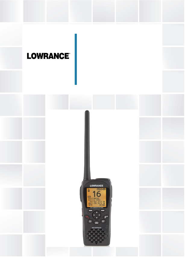
Link-2
Marine Handheld VHF Radio
User Guide
Lowrance - Link-2 Installation and Operation Instructions 3
Copyright © 2013 Navico
All rights reserved.
Lowrance® is a registered trademark of Navico
No part of this manual may be copied, reproduced, republished, transmitted or
distributed for any purpose, without prior written consent of Lowrance.
Any unauthorized commercial distribution of this manual
is strictly prohibited.
Lowrance may nd it necessary to change or end policies, regulations, and
special oers at any time. We reserve the right to do so without warning.
All features and specications are also subject to change without warning.
All screens in this manual are simulated.
For free owner’s manuals and the most current information on this product, its
operation and accessories, visit our web site: www.lowrance.com
Important safety information
Please read carefully before installation and use.
DANGER
This is the safety alert symbol. It is used to alert you to poten-
tially hazardous situations. Obey all safety messages that follow
this symbol to avoid possible injury or death.
WARNING WARNING indicates a potentially hazardous situation which, if
not avoided, could result in death or serious injury
CAUTION CAUTION indicates a potentially hazardous situation which, if
not avoided, could result in minor or moderate injury.
CAUTION
CAUTION used without the safety alert symbol indicates a
potentially hazardous situation which, if not avoided, may result
in property damage.
Contents
Safety and operational information ................................................................. 7
Important ...........................................................................................................................................................................8
Safety Training Information .....................................................................................................................................8
Section 1 - General information ........................................................................9
Section 2 - Controls and keys ...........................................................................10
2-1 Keys/Controls and functions ....................................................................................................... 11
Section 3 - Operating the radio .......................................................................14
3-1 Power On/O ................................................................................................................................... 14
3-2 Adjusting the Squelch level ....................................................................................................... 14
3-3 Volume control ................................................................................................................................ 14
3-4 Channel selection .......................................................................................................................... 15
3-5 Receiving and transmitting ........................................................................................................ 15
3-6 Dual Watch operation ................................................................................................................... 16
3-7 3CH operation (Favorite Channel) ........................................................................................... 16
3-7-1 Add a favorite channel for the first time ......................................................................................... 16
3-7-2 Modify or delete favorite channel ......................................................................................................16
3-8 Scan Operation ............................................................................................................................... 16
3-9 Navigation mode ........................................................................................................................... 17
3-10 WP select mode ............................................................................................................................ 18
3-11 Plotter mode ................................................................................................................................ 18
3-12 GPS satellite mode ...................................................................................................................... 19
Section 4 - Advanced setup ..............................................................................20
4-1 Waypoint ............................................................................................................................................ 21
4-1-1 Add a new waypoint ...................................................................................................................................21
4-1-2 Edit a waypoint ...............................................................................................................................................22
4-1-3 Delete a waypoint ........................................................................................................................................23
4-1-4 Set a route to a stored waypoint ........................................................................................................ 24
4-2 Backlight adjustment ................................................................................................................... 24
4-3 Lamp timer ....................................................................................................................................... 24
4-4 Buddy list (Manage your buddy list) ........................................................................................ 25
4-4-1 Add a new buddy name ...........................................................................................................................25
4-4-2 Edit a buddy name .......................................................................................................................................26
4-4-3 Delete a buddy name.................................................................................................................................26
4-5 Contrast adjustment ..................................................................................................................... 27
Lowrance - Link-2 Installation and Operation Instructions 5Lowrance - Link-2 Installation and Operation Instructions4
4-6 GPS/DATA .......................................................................................................................................... 27
4-6-1 Manual (Manually enter your position and UTC time) ...........................................................28
4-6-2 Settings: LL display (Show or hide your position) .....................................................................28
4-6-3 Settings: Time display (Show or hide the time) ..........................................................................29
4-6-4 Time offset (Local time) .............................................................................................................................29
4-6-5 Settings: Time format (12 or 24 hour clock) ..................................................................................30
4-6-6 Settings: COG/SOG (Course & speed display options) ...........................................................31
4-6-7 GPS alert..............................................................................................................................................................31
4-6-8 Turn GPS ENABLE on/off ........................................................................................................................... 32
4-6-9 Set Magnetic Variation (MAG VAR) .....................................................................................................32
4-7 Radio setup ....................................................................................................................................... 33
4-7-1 Channel Bank selection (UIC) ................................................................................................................33
4-7-2 Channel name editing (CH NAME) ....................................................................................................33
4-7-3 Ring volume adjustment (RING VOLUME) .....................................................................................34
4-7-4 Beep volume adjustment (KEY BEEP) ...............................................................................................34
4-7-5 Select unit (UNITS) ........................................................................................................................................ 34
4-7-6 Set the Priority channel (WATCH MODE) ........................................................................................35
4-7-7 Weather alerts (WX ALERT) .....................................................................................................................35
4-7-8 Set NMEA output (NMEA OUT) ............................................................................................................35
4-7-9 Favourite Channel Setup (FAV CH SETUP) .....................................................................................36
4-8 DSC setup ........................................................................................................................................ 37
4-8-1 Enter or check your user MMSI (USER MMSI) ...............................................................................37
4-8-2 Maintain groups (GROUP SETUP) ........................................................................................................ 38
4-8-2-1 Enter your groups ............................................................................................................................ 38
4-8-2-2 Edit groups .......................................................................................................................................... 39
4-8-2-3 Delete a group .................................................................................................................................. 39
4-8-3 Response to individual calls (INDIV REPLY) ...................................................................................40
4-8-4 Enable DSC functionality (DSC SELECT) .........................................................................................40
4-8-5 Response type to LL polling calls (LL REPLY) .............................................................................. 40
4-8-6 Automatic Channel switching (AUTO SWITCH) ........................................................................41
4-8-7 DSC Test Reply (TEST REPLY) ................................................................................................................. 42
4-8-8 Set the inactivity timer (TIMEOUT) ...................................................................................................42
4-9 ATIS SETUP (EU only) ..................................................................................................................... 43
4-9-1 Enter or check your ATIS MMSI (ATIS MMSI) .................................................................................43
4-9-2 Enable ATIS functionality (ATIS SELECT) ..........................................................................................44
4-10 Get Buddy ...................................................................................................................................... 44
4-11 Track log ........................................................................................................................................... 45
4-12 Erase track ....................................................................................................................................... 45
4-13 Reset (Reset to factory defaults) ............................................................................................. 45
Section 5 - Sending and Receiving DSC Calls ..................................................46
5-1 What is DSC? .................................................................................................................................... 46
5-1-1 Maritime mobile service identity ........................................................................................................46
5-1-2 How can I obtain a MMSI number? ...................................................................................................46
5-2 DSC call types .................................................................................................................................. 47
5-3 Send an Individual call (INDIVIDUAL) ...................................................................................... 48
5-4 Reply to the Last Call (LAST CALL) ............................................................................................ 49
5-5 Send a Group call (GROUP) .......................................................................................................... 49
5-6 Send an All Ships call (ALL SHIPS) ............................................................................................. 50
5-7 Reply to a call in your Call Log (CALL LOG) ........................................................................... 51
5-8 Reply to a call in your Distress Log (DISTRESS LOG) ........................................................... 52
5-9 Request the LL position of a buddy (LL REQUEST) ............................................................ 53
5-10 Track your buddy request (TRACK BUDDY) ......................................................................... 53
5-10-1 Add or delete a buddy (TRACKLIST) ...............................................................................................53
5-10-2 Select your TRACK BUDDY ....................................................................................................................54
5-10-3 Set the time interval of tracking .......................................................................................................54
5-10-4 Start tracking ................................................................................................................................................. 54
5-11 Make a DSC test call (DSC TEST) .............................................................................................. 55
5-11-1 Send a DSC TEST call ................................................................................................................................55
5-11-2 Receiving an incoming DSC TEST call reply (DSC TEST ACK) ..........................................55
5-11-3 Acknowledging an incoming DSC TEST call .............................................................................56
5-12 View User MMSI and GPS information .................................................................................. 56
5-14 Receiving DSC Calls ..................................................................................................................... 57
5-15 Receiving an All Ships Call (ALL SHIPS) ................................................................................. 57
5-16 Receiving an Individual Call (INDIV) ...................................................................................... 58
5-17 Receiving a Group Call (GROUP) ............................................................................................. 58
5-18 Receiving a Geographic Area Call (GEOGRAPH) ................................................................ 59
5-19 Receiving a Polled Position Call (POSITION) ....................................................................... 59
Section 6 - Distress calls ...................................................................................60
6-1 Send a Distress call ......................................................................................................................... 60
8-2 Receiving a Distress Call (DISTRESS!) ....................................................................................... 61
8-3 Distress Acknowledgement (DISTRESS ACK) or Distress Relay All Ships (DISTRESS
REL) .............................................................................................................................................................. 62
8-4 Distress Relay Individual (INDIV DISTR RELAY) ..................................................................... 63
Section 7 - Installation Instructions ................................................................64
7-1 Batteries and charger .................................................................................................................. 64
7-1-1 Installing the battery pack .....................................................................................................................64
7-1-2 Initial charge ...................................................................................................................................................64
7-1-3 GPS connector ................................................................................................................................................65

Lowrance - Link-2 Installation and Operation Instructions 7Lowrance - Link-2 Installation and Operation Instructions6
7-1-4 Mounting battery charger to flat surface .....................................................................................66
7-1-5 Mounting battery charger and bracket onto wall ..................................................................66
7-2 Installing the belt clip ................................................................................................................... 67
7-3 Installing and removing the antenna ..................................................................................... 68
Appendix A - Technical specifications ............................................................69
A-1 General: ..................................................................................................................................................................69
A-2 Receiver: ................................................................................................................................................................69
A-3 Transmitter: .........................................................................................................................................................69
A-4 GPS and Navigation:.......................................................................................................................................70
A-5 Digital Selective Calling (DSC): ..................................................................................................................70
A-6 Standards: ..............................................................................................................................................................70
Appendix B - Frequency charts ........................................................................ 71
International marine channels ........................................................................................................................... 71
Special notes on international channel usage.........................................................................................72
USA channel chart ..................................................................................................................................................... 73
Special notes on usa channel usage ..............................................................................................................74
CANADA channel chart .......................................................................................................................................... 75
Special notes on canada channel usage .....................................................................................................76
Weather channels ......................................................................................................................................................77
Appendix C - EU inland waterway channels ..................................................78
Special channels 2 .................................................................................................................................................... 81
Countries of Intended use in the EU: ............................................................................................................. 81
Safety and operational information
FCC Statement
This device complies with part 15 of the FCC Rules. Operation is subject to the follow-
ing two conditions: (1) This device may not cause harmful interference, and (2) this
device must accept any interference received, including interference that may cause
undesired operation.
FCC regulations require that members of the general public should not be exposed
to excessive levels of radio frequency radiation. To comply with the specied limits it
is recommended that this radio is operated in such a manner as to limit transmission
to no more than ve minutes in any half hour period and that the antenna is kept at
least 8 inches from any part of the body during transmission.
CAUTION: Changes or modications not expressly approved by the manufacturer
could void the user’s authority to operate the equipment.
Industry Canada Statement
Under Industry Canada regulations, this radio transmitter may only operate using
an antenna of a type and maximum (or lesser) gain approved for the transmitter by
Industry Canada. To reduce potential radio interference to other users, the antenna
type and its gain should be so chosen that the equivalent isotropically radiated power
(e.i.r.p.) is not more than that necessary for successful communication.
Conformément à la réglementation d’Industrie Canada, le présent émetteur radio peut
fonctionner avec une antenne d’un type et d’un gain maximal (ou inférieur) approuvé
pour l’émetteur par Industrie Canada. Dans le but de réduire les risques de brouillage radi-
oélectrique à l’intention des autres utilisateurs, il faut choisir le type d’antenne et son gain
de sorte que la puissance isotrope rayonnée équivalente (p.i.r.e.) ne dépassepas l’intensité
nécessaire à l’établissement d’une communication satisfaisante.
This radio transmitter Link-2 (IC:4697A-LINK2) has been approved by Industry Canada
to operate with the antenna types listed below with the maximum permissible gain
and required antenna impedance for each antenna type indicated. Antenna types not
included in this list, having a gain greater than the maximum gain indicated for that
type, are strictly prohibited for use with this device.
Le présent émetteur radio Link-2 (IC:4697A-LINK2) a été approuvé par Industrie Canada
pour fonctionner avec les types d’antenne énumérés ci-dessous et ayantun gain admis-
sible maximal et l’impédance requise pour chaque type d’antenne. Les types d’antenne
non inclus dans cette liste, ou dont le gain est supérieur au gain maximal indiqué, sont
strictement interdits pour l’exploitation de l’émetteur.
Antenna type: Flexible with SMA type connection supplied with the radio.
It is the owner’s sole responsibility to install and use this instrument in such a manner
that will not cause accidents, personal injury or property damage.
Lowrance disclaims all liability for any use of this product in a way that may cause
accidents, damage or that may violate the law.
Governing Language: This statement, any instruction manuals, user guides and other
information relating to the product (Documentation) may be translated to, or has been
translated from, another language (Translation). In the event of any conict between
any Translation of Documentation, the English language version of the Documentation
will be the ocial version of the Documentation.
This manual represents the Link-2 radio at the time of printing. Lowrance reserves the
right to make changes to specications without notice

Lowrance - Link-2 Installation and Operation Instructions 9Lowrance - Link-2 Installation and Operation Instructions8
Important
1. DSC functions will not operate until you have entered your user MMSI.
2. The radio channels installed into the radio may vary from country to country, depending
upon the model and government or national communications authority regulations.
3. Lowrance recommends that you check the radio operating licensing requirements of your
country before using the radio. The operator is solely responsible for observing proper
radio installation and usage practices.
4. This radio is designed to generate a digital maritime distress call to facilitate search
and rescue. To be eective as a safety device, this radio must be used only within the
geographic range of a shore-based VHF marine Channel 70 distress and safety watch
system. The geographic range may vary but under normal conditions is approximately 20
nautical miles..
Section 1 - General information
Congratulations on your purchase of this handheld VHF marine radio Link-2, designed
and built using superior technology and craftsmanship. It provides the following useful
features:
• Adjustable contrast settings for the LCD
• Adjustable keypad backlighting for easy night time use
• Waterproof and submersible to comply with JIS-7
• GPS latitude and longitude (LL) and time display
• Built-in GPS sensor
• Choice of High or Low (5 W or 1 W) transmission power
• Special CH16 key for quick access to the priority (international distress) channel
• Special 3CH key to select your three favorite channels
• Flexible dual watch facility
• DSC (Digital Selective Calling) capability that meets CLASS-D standards
• DISTRESS call button to automatically transmit the MMSI and position until an
acknowledgement is received
• Easy access to a buddy list of up to 20 favorite people
• LL position polling information
• Buddy tracking capacity
• Weather alert facility (US only)
• ATIS facility for inland waterways (Europe only).
CAUTION
Battery caution: This device uses a Lithion Ion battery - please observe the following
cautions.
• Do not disassemble
• Do not incinerate or expose to re
• Dispose of used batteries according to local codes and requirements.
Safety Training Information
When transmitting, hold the radio in a vertical position with its microphone 2 inches (5 cm)
away from your mouth and keep the antenna at least 2 inches (5 cm) away from your head
and body.
The radio must be used with a maximum operating duty cycle not exceeding 50%, in typical
Push-to Talk congurations.
DO NOT transmit for more than 50% of total radio use time (50% duty cycle). Transmitting
more than 50% of the time can cause FCC RF exposure compliance requirements to be
exceeded.
To maintain compliance with the Body Worn conguration use only supplied accessories.
Other body-worn accessories or congurations may not comply with the FCC RF exposure
requirements and should be not be used.
The information listed above provides the user with the information needed to make him or
her aware of RF exposure, and what to do to assure that this radio operates with the FCC RF
exposure limits of this radio.
This Marine VHF radio also complies with the following guidelines and standards regarding
RF energy and electromagnetic energy levels as well as evaluation of those levels for human
exposure:
• FCC OET Bulletin 65 Edition 97-01 Supplement C, Evaluating Compliance with FCC
Guidelines for Human Exposure to Radio Frequency Electromagnetic Fields.
• American National Standards Institute (C95.1-1992), IEEE Standard for Safety Levels with
Respect to Human Exposure to Radio Frequency Electromagnetic Fields, 3 kHz to 300
GHz.
• American National Standards Institute (C95.3-1992), IEEE Recommended Practice
for the Measurement of Potentially Hazardous Electromagnetic Fields — RF and
Microwave.
M
9
GO
MOB
Link-2 MARINE VHF/GPS
CALL
MENU
WX
NAV
HI/LO
WATERPROOF
16
PHONE-PORTOP
03:00 UTC
36°45.193`S
174°42.486`E
3CH
SCAN
20
Lowrance - Link-2 Installation and Operation Instructions 11Lowrance - Link-2 Installation and Operation Instructions10
Section 2 - Controls and keys
Speaker
CALL/MENU Mic
WX/NAV
HI/LO/GPS
Low battery indicator
Favorite channels:
1, 2 or 3
Speaker/Mic jack
Channel
Vol + and Vol -
GPS Antenna
Right Softkey
CH /
SQL /
PWR/LOCK/EXIT
Tx Power: HI or LO
GO/MOB
Status:
T (transmit) or
R (receive)
Signal strength
16/9 key
DISTRESS Key
PTT
VHF Antenna
Left Softkey
Working mode
channel name
Time COG/SOG
Latitude
Longitude
2-1 Keys/Controls and functions
PWR/LOCK/EXIT PWR: To turn the unit on and o, press and hold down PWR /
/ EXIT (red key) for more than 2 seconds and release.
LOCK: The keylock, locks and unlocks keypad. Press PWR / /
EXIT (red key) for 1 second and release. A key icon will ap-
pear on screen to indicate whether keylock is on or o.
EXIT: Also used to EXIT some menu items. Short press PWR /
/ EXIT (red key) for 1 second and release.
VOL Volume Adjustment - located on the side of the radio. Press
to increase or press to decrease until a comfortable volume is
reached.
SQL / Squelch or Threshold Level - located on the central control dial.
Sets the threshold level for the minimum receiver signal. 16
steps available.
CH / Channel select - located on the central control dial. Press to
select a higher channel or press to select a lower channel.
16/9 Priority Channel. Press to cancel all other modes and to tune
into the priority channel. Press again to return to your original
channel. To make Channel 09 the default instead, hold down
16/9 until a beep sounds and 09 is displayed (US only).
Left softkey (3CH/EXIT) This radio utilizes ‘soft keys’ where the functionality of each
softkey button will change depending on the mode the radio is
in. The bottom line of the LCD display will indicate the function
of each softkey located immediately below.
3CH softkey:
3CH
The 3CH softkey is used to initiate a Three Favorite
Channels scan function. Press to toggle between your favorite
channels. The , , or symbol appears on the LCD to show
which favorite channel is selected.
If you want to scan all three favorite channels, press 3CH, then
immediately press and hold SCAN.
To add a favorite channel for the rst time, select that channel
then hold 3CH to store it in the CH1 location. Repeat the pro-
cedure to store two more favorite channels in the CH2 and CH3
locations respectively.
If you try and add another favorite channel it will overwrite the
existing CH3. CH1 and CH2 will remain unless you delete them.
To delete a favorite channel, select that channel then hold
Channel Bank

Lowrance - Link-2 Installation and Operation Instructions 13Lowrance - Link-2 Installation and Operation Instructions12
down 3CH until a dialog box appears to prompt the deletion.
EXIT softkey:
EXIT
The EXIT softkey is used when navigating menus
to clear incorrect entries, to exit from a menu without saving
changes and to back up to the previous screen.
Right softkey (SCAN/ENTER)
SCAN softkey:
SCAN
The SCAN softkey is used to initiate a channel scan
function. Quick press and release for Dual Watch - scan
between your current channel and the priority channel in DUAL
mode.
Press and hold down SCAN for more than 2 seconds to enter
ALL SCAN mode where the priority channel is checked every
1.5 seconds.
When a signal is received, scanning stops at that channel and
“R” appears on the screen. If the signal ceases for more than 5
seconds, the scan restarts.
In ALL SCAN mode, you may wish to ‘skip’ a channel because
it may alway be busy and therefore stops the scan. If you wish
to ‘skip’ a channel, hold down the left softkey for more than 2
seconds.
SKIP
will appear on the screen and the channel
will be skipped. To cancel the skip, manually select the skipped
channel and press the left softkey for more than 2 seconds.
It is not possible to skip over the priority channel.
ENTER softkey:
ENTER
Use the ENTER softkey when navigating menus and to
conrm entries and edits.
CH / Channel Select. The current channel is shown on the screen in
BIG digits with the channel description information below the
channel number.
Press CH / to step through the available channels one at a
time, or hold down to scroll quickly through all the available
channels. See Appendix B for a listing of channel charts.
Alphanumeric Entry. This key can also be used for menu selec-
tion and alphanumeric entry. Press CH / to scroll the cursor
up or down menu options when navigating menus.
When editing an item that contains only numbers, press - CH
to count through the numbers or hold down to scroll through
quickly.
To enter a character, press CH to step through the alphabet or
hold down to scroll through quickly.
HI/LO/ Transmission Power. High (HI) 5 W or Low (LO) 1 W. Press to
toggle between high or low transmission powers for the entire
channel bank. The or selection is shown on the LCD screen.
Some channels allow only low power transmissions. Error beeps
will sound if the power transmission setting is incorrect.
Some channels allow only low power transmissions initially, but
can be changed to high power by holding down HI/LO and PTT
all at the same time. See Appendix B for a complete listing of
channel charts.
Hold down key to enter GPS Satellite mode.
WX/NAV WX. Quickly press to access Weather channels. Press again to
return to your previous mode.
For non US models: The Wx key can be programmed to a
weather channel of your choice. See section 4-11 to program
your favourite channel.
NAV. Hold down WX/NAV for more than 3 seconds to enter
Navigation mode. Bearing, Distance and cross track error from
the last selected waypoint will display on the screen. If no WP is
set, it will appear “NO ACTIVE ROUTE!!” prompt.
GO/MOB Press GO/MOB if you are navigating to waypoint and want to
reset the XTE (cross track error) as shown on the screen.
If someone falls overboard, hold down GO/MOB for about 3
seconds to mark the position.
The latitude and longitude of the Man Overboard position is
shown on the screen and is automatically set as the destination
waypoint.
PTT Push To Talk. Push to start transmitting then talk into the mic.
CALL/MENU CALL. Quickly press the CALL/MENU key to access the DSC Call
menu. The call mode is used for making DSC calls. US only.
MENU. Hold down the CALL/MENU key more than 3 seconds to
access the Menu Setup mode and to customize your VHF radio.
Please refer to the following sections for more details.
Lowrance - Link-2 Installation and Operation Instructions 15Lowrance - Link-2 Installation and Operation Instructions14
Section 3 - Operating the radio
3-1 Power On/Off
You can turn on the unit by pressing PWR/ switch (on the top side of radio) until the
screen and backlight are on. You can also adjust the volume to a comfortable level, by
pressing the VOL / keys on the side of unit.
Note: Press the PWR/ key at any time will turn the display backlight on.
3-2 Adjusting the Squelch level
The SQUELCH control enables you to set the levels of your desired signal. It determines
how strong your signal can be before you can hear it, before it “breaks squelch.” It aims to
keep any static, unwanted, weak or distant signals from interrupting your conversations.
There are 16 signals to choose from when adjusting the squelch level. To increase the
levels, raise the “Squelch Gate” higher so that only stronger signals can get through. Level
“0” for instance, means that there is no “Squelch Gate” and everything will get through.
To adjust the squelch level, press SQL / accordingly.
3-3 Volume control
Press VOL / to adjust the volume level. A volume sub-menu will appear when pressed.
It times-out after 5 seconds.
3-4 Channel selection
To manually select a channel, press CH to increase, or press CH to decrease the chan-
nel number. Communication channels are located on channel 01-28 and 60-88. For more
detailed channel chart information, refer to Appendix B.
16/9 (Priority channel)
Press to cancel all other modes and to tune into the priority channel. Press again to return
to your original channel. The default Priority Channel is CH16.
For US models: To make Channel 09 the priority channel, hold down 16/9 until a beep
sounds and 09 is displayed.
3-5 Receiving and transmitting
CAUTION
Transmitting without an antenna may damage the radio.
1. To turn power on, press the PWR key for more than 2 seconds.
2. Adjust for comfortable volume level. ( The squelch level temporarily set to “0”).
3. Set the suitable Squelch level to mute noise if necessary.
4. Press CH / to select the desired channel.
When receiving a signal, appears on screen and audio is emitted from the speaker.
Further volume adjustment may be needed to get your desired setting.
5. Press HI/LO to select the output power.
Choose low power to conserve battery power, or choose high power for longer
distance communications.
6. Press and hold “PTT” to transmit, then speak into the microphone, while appears
on the screen.
7. Release PTT, to receive conversation.
Note: Some channels are for low power only. Channel 70 cannot be used for
transmission.
For clear and audible transmission:
• Pause for a few seconds after pressing PTT
• Hold the microphone 5 to 10 cm (2 to 4 inches) away from your mouth and speak at
a normal volume.
Lowrance - Link-2 Installation and Operation Instructions 17Lowrance - Link-2 Installation and Operation Instructions16
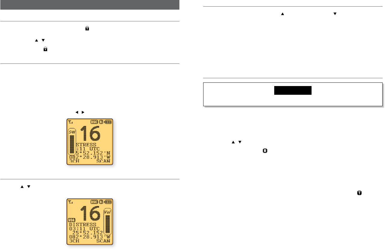
3-6 Dual Watch operation
Dual watch monitors channel 16 while receiving another channel. To activate this, you
must:
1. Select the desired operating channel (e.g. CH88).
2. Push the SCAN key repeatedly until appears on screen.
3. To cancel dual watch, press SCAN (once) until disappears.
If a signal is received on channel 16, dual watch pauses on channel 16 until the signal
disappears.
To transmit on the selected channel during dual watch, press and hold PTT.
3-7 3CH operation (Favorite Channel)
You can instantly access the three most frequently used channels by 3CH mode, Three Fa-
vorite Channels. Press to toggle between your favorite channels. The , , or symbols
appear on the LCD to show which of your favorite channel is selected.
3-7-1 Add a favorite channel for the first time
1. Select the desired channel, then hold 3CH to store it. The CH1 symbol appears on
the screen.
2. Repeat the procedure to store two more favorite channels in the CH2 and CH3
locations.
3-7-2 Modify or delete favorite channel
If you try and add another favorite channel it will overwrite the existing CH3. But CH1 and
CH2 will remain unless you delete them.
To delete a favorite channel:
• Select that channel, then hold down 3CH until a dialog box appears to prompt the
deletion.
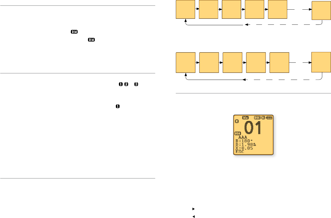
3-8 Scan Operation
Scanning is an eective way to locate signals quickly over a wide frequency range.
All Scan
All channels in the set are scanned sequentially, in repeated cycles (CH16 is checked every
1.5 seconds).
01 02 03 16 04 88
3CH Scan
Press and hold down the SCAN key in the 3CH mode, you will then enter a 3CH SCAN
mode. However, only the 3CH and CH16 will be scanned.
01 15 18 16 01 18
3-9 Navigation mode
Press and hold down NAV key, (US only), or just press the NAV key (EU only) to enter the
Navigation Mode. It will display: Bearing, Distance and cross track error from the last
selected waypoint.
If no WP is set, ‘NO ACTIVE ROUTE!!’ will appear to prompt you that no WP is selected.
During Nav Mode:
• PTT – return to normal mode and TX
• 16/9 – return to normal mode and go to 16/9
• NAV – return to normal mode
• GO – Reset the cross track error (XTE)
• SQL – Go to WP select Mode
• SQL – Go to Plotter Mode
• Other key – error beep.

Lowrance - Link-2 Installation and Operation Instructions 19Lowrance - Link-2 Installation and Operation Instructions18
3-10 WP select mode
WP LIST 13
CAMP 1 MOB 1
CAMP 2 MOB 2
CAMP 3 MOB 3
DOCK 1 PARK 1
DOCK 2 PARK 2
EXIT
ENTER
• CH / – Page up down the list
• SQL - Go to Plotter Mode
• SQL - Returns to Navigation Mode.
Note: During WP Select Mode, press ENTER right-key to ash the rst WP, then press
CH / to select next WP, press ENTER right-key again to set the WP as your next
destination and enter navigation mode.
3-11 Plotter mode
During plotter mode:
• Softkey It will zoom in/out the circle to see more/less area
• SQL Go to Navigation Mode
• SQL Go to WP select Mode
• PTT Return to normal mode and TX
• 16/9 Return to normal mode and go to 16/9
• NAV Go to normal mode
• Other key Error beep.
To avoid screen clutter, a maximum of 5 waypoint icons closest to you plus the active
waypoint are shown.
3-12 GPS satellite mode
Press and hold the HI/LO/ key to enter GPS satellite mode.
During GPS satellite mode:
• PTT Return to normal mode and TX
• 16/9 (16) Return to normal model and go to 16/9
• Return to normal mode
• Left softkey Return to normal mode
• Other key Error Beep.
Lowrance - Link-2 Installation and Operation Instructions 21Lowrance - Link-2 Installation and Operation Instructions20
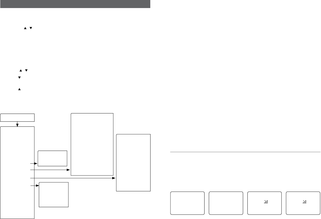
Section 4 - Advanced setup
How to display and navigate menus
1. Hold down CALL/MENU key for more than 1 second to enter the set up menu.
2. Press CH / to scroll up and down the menu until the cursor is positioned at the
desired items. Press ENTER softkey to select the item.
3. Make any changes then press ENTER softkey to conrm changes. Otherwise, press
EXIT softkey to ignore.
4. Press EXIT softkey to go back or exit. Any changes are activated as soon as you enter/
exit the screen.
How to enter Alphanumeric data
Use the CH / key to enter characters.
1. Press to enter and count through numbers and letters, and hold down to select
the desired character.
2. Press to go through letters of the alphabet, and hold down to select the desired
character.
3. Press ENTER to conrm.
The following options are available through MENU:
• ATISMMSI
(EU only)
•ATISSELECT
(EU only)
• WAYPOINT
• BACKLIGHT
• LAMP
• BUDDY LIST
• CONTRAST
• GPS/DATA
• RADIOSETUP
• DSC SETUP
• ATISSETUP
(EU only)
• GETBUDDY)
• TRACK LOG
• ERASE TRACK
• RESET
MENU
• MANUALL/L
• SETUP
• UIC (non EU)
• CHNAME
• RINGVOLUME
• KEY BEEP
• UNITS
• WATCHMODE(non EU)
• WXALERT(non-EU)
• NMEAOUT
• FAVCHSETUP(non US)
• USER MMSI
• GROUP SETUP
• INDIV REPLY
• DSCSELECT
• LLREPLY
• AUTO SWITCH
• TESTREPLY
• TIMEOUT
Hold down the CALL/ MENU key for more than 1 second to enter radio set-up mode. This
allows the following functions to be accessed. Scroll down the list and press ENTER. To
exit the Menu or sub-menu modes press 16 or EXIT.
WAYPOINT Selects the WP List Entry to enter names and LL positions for a WP. Up to
500 WP can be stored.
BACKLIGHT Sets the backlight level: 8 levels.
LAMP Sets the backlight lamp time out.
BUDDY LIST Selects the Buddy List Entry to enter names and MMSI’s for regularly
called DSC stations. Up to 20 names can be stored (US only).
CONTRAST Selects display contrast setting: 8 levels.
GPS/DATA Select to change the following GPS/DATA settings: Time Oset, Format,
Display, LL Display, COG/SOG, GPS Alert, GPS Enabled.
RADIO SETUP Select to change the following radio settings: Band, CH Name, Ring Tone
Volume, Beep Volume, Units, Watch mode, WX alert.
DSC SETUP Select to change the following DSC settings: User MMSI enter, Group
MMSI, INDIV RELAY AND LL Relay (US only).
ATIS SETUP Select to change the following ATIS settings: ATIS MMSI Enter, ATIS
Select. (EU Only).
GET BUDDY Enable or disable Buddy Data and Auto Function.
TRACK LOG Set the distance interval for recording the track points.
ERASE TRACK Erase track history points.
RESET Reset to factory settings.
4-1 Waypoint
You can store up to 500 waypoints and their LL positions. When your WAYPOINT LIST is
full, you cannot make a new entry until you have deleted an existing one.
• Each waypoint name can have a maximum of 6 alphanumeric characters
• The most recent waypoint name will be displayed at the top of your waypoint list.
4-1-1 Add a new waypoint
ENTER WP
MOOR 1
12°32.233’N
132°45.651’W
WP LIST
►NEW WP
FISH1
ENTER WP
_ _ _ _ __ _ _
_° _ . _ _ _’ N
_ _° _ . _ _
ENTER WP
MOOR 1
_° _ . _ _ _N
_ _° _ . _ _ _W
Lowrance - Link-2 Installation and Operation Instructions 23Lowrance - Link-2 Installation and Operation Instructions22
SAVE
MOOR 1
►YES
NO
1. Hold down CALL/MENU for 3 seconds (US ONLY); or press MENU key (EU only).
2. The cursor is at WAYPOINT, press ENTER.
3. Select WP LIST, and then NEW WP.
4. Use the CH / to enter the new waypoint name, one alphanumeric character at
a time. Select one waypoint symbol (there are 20 icons available); and then press
ENTER until the cursor moves to the latitude line.
5. Use the CH / to enter the latitude of the waypoint, one number at a time; then
press ENTER. The cursor moves to the longitude.
6. Use the CH / to enter the longitude waypoint, one number at a time, then press
ENTER.
7. A new screen appears automatically to show the new waypoint details. If they are
correct, press ENTER to STORE the new waypoint. (If they are not correct, select
EXIT).
4-1-2 Edit a waypoint
WP EDIT
FISH 2
12°32.233’N
132°45.651’W
MENU SELECT
►WAYPOINT
BACKLIGHT
LAMP
WAYPOINT
►WP LIST
WP LIST
NEW WP
FISH 1
►FISH 2
WP EDIT
MOOR 1
12°32.233’N
132°45.651’W
SAVE
MOOR1
►YES
NO
1. Hold down CALL/MENU (US only); or press MENU (EU only).
2. The cursor is at WAYPOINT. Press ENTER.
3. Select WP LIST, then push ENTER, the cursor is at new WP. Scroll down to the
waypoint you want to edit then push ENTER.
4. Select WP EDIT and press ENTER.
5. The waypoint details are displayed and the cursor is positioned at the rst character
of the name.
6. Use the CH / to change the rst character of the waypoint name then press
ENTER, or just press ENTER to skip to the next character.
When you reach the last character of the waypoint name, make any changes if nec-
essary, then press ENTER to move the cursor to the waypoint icon.
Note: If you do not want to change the waypoint name waypoint icon, press ENTER
repeatedly until the cursor moves to the latitude.
To change the waypoint icon, use the CH / to change the icon or press ENTER to skip
to latitude. To change latitude, use the CH / to change the rst digit or press ENTER to
skip to the next digit. Repeat if necessary. When you reach the last digit, push ENTER to
move the cursor to longitude.
Note: If you do not want to change the latitude, press ENTER repeatedly until the cursor
moves to the longitude.
1. Repeat the previous step to change or press ENTER to continue.
2. A new screen appears. Press ENTER if you want to STORE the new waypoint. If you
want to keep the original entry, move the cursor to NO then press ENTER.
4-1-3 Delete a waypoint
FISH 2
GO
WP EDIT
►DELETE
MENU SELECT
►WAYPOINT
BACKLIGHT
LAMP
WAYPOINT
►WP LIST
NEAREST WP
TEMP
WP LIST
NEW WP
FISH 1
►FISH 2
DELETE
FISH 2
►YES
NO
WP LIST
NEW WP
FISH 1
►HOME
Hold down CALL/MENU for about 3 seconds (US only); or press MENU (EU only).
1. The cursor is at WAYPOINT, press ENTER.
2. Select WP list and press ENTER. The cursor is at new WP, scroll down to the waypoint
you want to delete, then press ENTER.
3. The cursor is at GO. Move the cursor to delete and push ENTER.
4. The waypoint is deleted immediately and the revised waypoint list is displayed.
Lowrance - Link-2 Installation and Operation Instructions 25Lowrance - Link-2 Installation and Operation Instructions24
4-1-4 Set a route to a stored waypoint
HOME
►GO
WP EDIT
DELETE
MENU SELECT
►WAYPOINT
BACKLIGHT
LAMP
WAYPOINT
►WP LIST
NEAREST WP
TEMP
WP LIST
NEW WP
FISH 1
►HOME
GO
HOME
►YES
NO
1. Hold down CALL/MENU for about 3 seconds (US only); or press MENU (EU only).
2. The cursor is at WAYPOINT. Press ENTER.
3. The cursor is at WP list, press ENTER. The cursor is at new WP, scroll down to the
waypoint to use as the route then press ENTER.
4. The cursor is at GO and push ENTER and enter the navigation mode. The waypoint is
set as your next destination.
4-2 Backlight adjustment
1. Select BACKLIGHT and press ENTER. There are 8 backlight levels.
2. SQ / to adjust the setting. Press ENTER to conrm the setting and return to the
MENU SELECT.
MENU SELECT
WAYPOINT
►BACKLIGHT
LAMP
BACKLIGHT
■ ■ ■ ■
LO HI
4-3 Lamp timer
1. Select LAMP and press ENTER. There are 4 timer settings: Always on, 5s, 15s, 30s
(default).
2. Press CH / to adjust the setting. Press ENTER to conrm the setting and return to
the MENU SELECT.
MENU SELECT
WAYPOINT
►BACKLIGHT
LAMP
LAMP TIMEOUT
►ALWAYS ON
5 SECOND
15 SECOND
4-4 Buddy list (Manage your buddy list)
You can use the buddy list to store names and associated MMSIs of 20 DSC stations that
you call frequently. Buddy names are stored in the order of entry, with the most recent
entry rst.
The following sections demonstrates how to use BUDDY LIST, these include: to add, edit,
and delete entries.
4-4-1 Add a new buddy name
You can enter up to 20 buddy names. When your BUDDY LIST is full, you cannot make a
new entry until you have deleted an existing entry.
• Each buddy name can have a maximum of 11 alphanumeric characters
• The most recent buddy name entered is shown at the top of your buddy list.
ENTER NAME
STARFISH 2
ENTER MMSI
_ _ _ _ _ _ _ _ _
MENU SELECT
LAMP
►BUDDY LIST
CONTRAST
BUDDY LIST
►MANUAL NEW
ENTER NAME
_ _ _ _ _ _ _ _ _
ENTER MMSI
_ _ _ _ _ _ _ _ _
►MANUAL NEW
STARFISH 2
SEA ROSE
MERMAID
ENTER NAME
STARFISH 2
ENTER MMSI
0 _ _ _ _ _ _ _
ENTER NAME
STARFISH 2
ENTER MMSI
123456789
STARFISH 2
123456789
►STORE
CANCEL
1. Hold down CALL/MENU for 3 seconds.
2. Select BUDDY LIST then press ENTER.
3. The cursor is at <MANUAL>. Push ENTER.
4. Use the CH / to enter the new buddy name one character at a time. Then press
ENTER until the cursor moves to the MMSI entry line.
5. Use CH / to enter the 9-digit MMSI that is associated with that buddy name, one
number at a time, then press ENTER.
6. After you enter the last digit of the MMSI, a new screen appears automatically to
show the new buddy name and MMSI. Check that it is correct; and then push ENTER
to save the new entry. (If it is not correct, select EXIT).
Lowrance - Link-2 Installation and Operation Instructions 27Lowrance - Link-2 Installation and Operation Instructions26
4-4-2 Edit a buddy name
EDIT NAME
SEA ROSE_ _ _
EDIT MMSI
123456789
MENU SELECT
BACKLIGHT
LAMP
►BUDDYLIST
BUDDY LIST
MENU SELECT
►SEA ROSE
MERMAID
SEA ROSE
►EDIT
DELETE
EDIT NAME
SEA ROSE
EDIT MMSI
123456789
EDIT NAME
SEA ROSE
EDIT MMSI
123456798
SEA ROSE
123456798
►STORE
CANCEL
1. Press and hold down CALL/MENU for about 3 seconds.
2. Select BUDDY LIST then press ENTER.
3. Scroll down to the entry you want to edit then press ENTER .
4. The buddy name is displayed and the cursor is positioned at EDIT. Press ENTER.
5. The buddy name and MMSI are displayed. The cursor is at the rst character of the
name.
6. Use CH / to change the rst character of the buddy name then press ENTER, or
just press ENTER to skip to the next character. Repeat if necessary. When you reach
the last character of the buddy name, make any changes if needed, then press
ENTER to move the cursor to the MMSI.
Note: If you do not want to change the buddy name, just press ENTER repeatedly until
the cursor moves to the MMSI line.
7. To change the MMSI, use CH / to change the rst number or press ENTER to skip
to the next number. Repeat if necessary. When you reach the last number, press
ENTER to display the SAVE screen.
Note: If you do not want to change the MMSI, press ENTER repeatedly until the SAVE
screen appears.
8. Press ENTER to save the edits or CANCEL to keep the original entry.
4-4-3 Delete a buddy name
DELETE BUDDY
SEA ROSE
►YES
NO
MENU SELECT
BACKLIGHT
LAMP
►BUDDY LIST
BUDDY LIST
MANUAL NEW
►SEA ROSE
MERMAID
SEA ROSE
EDIT
►DELETE
1. Hold down CALL/MENU for about 3 seconds.
2. Select BUDDY LIST. Press ENTER to display the list of buddy names.
3. Scroll down to the buddy name you want to delete then press ENTER.
4. Select DELETE then select YES.
5. The buddy name is deleted and the revised buddy list is displayed.
4-5 Contrast adjustment
1. Select CONTRAST and press ENTER. There are 8 contrast levels. The higher the
numbers, the darker LCD screen.
2. SQ / to adjust the setting, Press ENTER to conrm the setting and return to the
MENU SELECT.
MENU SELECT
LAMP
BUDDY LIST
►CONTRAST
CONTRAST
■ ■ ■ ■
LO HI
4-6 GPS/DATA
You can use the GPS/DATA menu to:
• manually enter your position data
• manually enter the time data
• show or hide your position
• show or hide the time
• oset the UTC time to show your local time
• format the time display
• show or hide your course (COG) and speed (SOG)
• turn GPS ENABLE ON/OFF
• set True or Magnetic Bearing
• turn NO GPS DATA alarm sound ON/OFF.
Note: This information is important because it will be used if you send a DISTRESS call.
If GPS data is not available, the NO GPS alert will sound for 5 seconds (or until you press
any button) and the screen will request you to enter the position data manually.
This will repeat every 4 hours if you do not enter the position data manually. After you
have entered the position data, you must update it within 23.5 hours otherwise NO GPS
alert sequence repeats.
Lowrance - Link-2 Installation and Operation Instructions 29Lowrance - Link-2 Installation and Operation Instructions28
4-6-1 Manual (Manually enter your position and UTC time)
Use the GPS/DATA menu to manually enter your latitude and longitude and the UTC (time
data).
If GPS receives data automatically - all manual entries will be erased.
MANUAL L/L
27°45.210’N
112°36.567’W
12:56 UTC
LOCAL/DST
BACKLIGHT
CONTRAST
►GPS/TIME
GPS/DATA
►MANUAL L/L
SETUP
MANUAL L/L
_° _ . _ _ _N
_ _° _ . _ _ _W
_ _:_ _UTC
1. Select GPS/DATA in radio setup MENU.
2. The cursor is at MANUAL. Push ENTER.
3. The cursor is at the rst latitude position.
4. Use the CH / to enter the latitude one number at a time. Press ENTER to move
cursor to the longitude line.
5. Use the CH / to enter the longitude coordinates one number at a time. Press
ENTER to move cursor to the UTC line.
6. Use the CH / to enter the UTC one number at a time then press ENTER.
7. After you enter the last number of the UTC, a new screen appears automatically to
show the position and time data. The prex M indicates a manual entry. If you made
a mistake, repeat these steps to enter the correct data.
4-6-2 Settings: LL display (Show or hide your position)
If your position and time data is being updated automatically, you can use LL DISPLAY to
choose whether to show or hide your position on the screen.
LL DISPLAY
►ON
OFF
MENU SELECT
BUDDY LIST
CONTRAST
►GPS/DATA
GPS/DATA
MANUAL
►SETUP
SETUP
TIME FORMAT
TIME DISPLAY
►LL DISPLAY
1. In the radio setup MENU, select GPS/DATA, then SETUP.
2. Move the cursor to LL Display and press ENTER.
3. The cursor is at ON (to show your position).
If you want to hide your position, move the cursor to OFF. Press ENTER to conrm your
selection.
4-6-3 Settings: Time display (Show or hide the time)
If your position and time data is being updated, you can use TIME DISPLAY to choose
whether to show or to hide the time on the screen.
TIME DISPLY
►ON
OFF
MENU SELECT
BUDDY LIST
CONTRAST
►GPS/DATA
GPS/DATA
MANUAL
►SETUP
SETUP
TIME OFFSET
TIME FORMAT
►TIME DISPLY
1. In the radio setup MENU, select GPS/DATA, then SETUP.
2. Move the cursor to TIME DISPLAY and press ENTER.
3. The cursor is at ON (to show the time).
If you want to hide the time, move the cursor to OFF.
4. Press ENTER to conrm the selection.
4-6-4 Time offset (Local time)
If your position and time data is being updated, you can use TIME OFFSET to enter the
time dierence between UTC and local time - so your local time is displayed on the
screen.
TIME OFFSET
+ 03.30
12:56 PM LOC
MENU SELECT
BUDDY LIST
CONTRAST
►GPS/DATA
GPS/DATA
MANUAL
►SETUP
SETUP
►TIME OFFSET
TIME FORMAT
TIME DISPLY
1. Work out the time dierence between UTC and your local time.
2. In the radio setup MENU, select GPS/DATA, then SETUP.
3. The cursor is at TIME OFFSET and press ENTER.
4. Enter + or – followed by the time dierence between UTC and your local time. Half
hour increments can be used (as in this example). Local time is shown with the sux
LOC.
5. Press ENTER to conrm the selection.
Lowrance - Link-2 Installation and Operation Instructions 31Lowrance - Link-2 Installation and Operation Instructions30
ZABC D F GHI
N
O
P
Q
R
S
T
U
WE
STANDARD TIME ZONES
Corrected to March 2013
Zone boundaries are approximate
Daylight Saving Time (Summer Time),
usually one hour in advance of Standard
Time, is kept in some places
Map outline © Mountain High Maps
Compiled by HM Nautical Almanac Office
V
XKL
P
Q
Q
R
V
UT
S
R
Q
P*
T
S
A
ZA
C
Z
AB
B
B
C
S
S
S
R
HI* K
K
M
M
H
H
H
IK
FG
E
D*
*
E*
*
C
CD
G
F
I
K
H
D
F
LM
Z
Z
P
N
0° 30°E 60°E 90°E 120°E 150°E
30°W
60°W
90°W
120°W
150°W
180° 180°
M
N
N
O
O
Z
Z
Z
C
D
D
E
F
E*
F*
K
L
*
*
L
LM
M
P
O
Q
A
S
U
W
V*
A
Y
M
LM Y
P
K
H
M
XX
W
W
X
M*
W
M*M*
MM
L
M
M†
I
F
G
I
I
K
L
M
Z
International Date Line
International Date Line
WORLD MAP OF TIME ZONES
R
C
B
B
A
P
R
C
R
Q
*
T
U
Q
§
§
W
M
E
†
M
L
H
I
C
M*
C
B
E
G
E
B
G
H
I
I*
K
K*
– 7
– 8
– 9
– 9 30
–10
–10 30
L
L*
M
M
M*
M†
–11
–11 30
–12
–12 45
–13
–14
V
V*
W
X
Y
+ 9
+ 9 30
+10
+11
+12
hhhm
m
m
m
Z
A
B
C
C*
D
0
– 1
– 2
– 3
– 3 30
– 4
hm
E
E*
E†
F
F*
– 5 30
– 5 45
– 6
– 6 30
D*
– 4 30
– 5
N
O
P
P*
Q
+ 1
+ 2
+ 3
+ 3 30
+ 4
Q*
R
S
T
U
+ 4 30
+ 5
+ 6
+ 7
+ 8
Standard Time = Universal Time – value from table
h
No Standard Time legally adopted
Universal Time = Standard Time + value from table
hh
mm
§
4-6-5 Settings: Time format (12 or 24 hour clock)
Use TIME FORMAT to show the time in 12 or 24 hour format, depending on your
preference.
TIME FORMAT
►12 HR
24 HR
12:56 PM LOC
MENU SELECT
BUDDY LIST
CONTRAST
►GPS/DATA
GPS/DATA
MANUAL
►SETUP
SETUP
TIME OFFSET
►TIME FORMAT
TIME DISPLY
1. In the radio setup MENU, select GPS/DATA, then SETUP.
2. Move the cursor to TIME FORMAT and press ENTER.
The cursor is at 12 HR (to show the sux: am or pm). If you want to use the 24 Hr
clock, move the cursor to 24 HR.
3. Press ENTER to conrm the selection.
4-6-6 Settings: COG/SOG (Course & speed display options)
If your position and time data is being updated, you can use COG/SOG to choose whether
to show or hide your course over ground (COG) and speed over ground (SOG) data on the
screen.
Note: Despite the COG/SOG setting, if TIME DISPLAY is ON, the course and speed will not
display on screen.
COG/SOG
►ON
OFF
MENU
BUDDY LIST
CONTRAST
►GPS/DATA
GPS/DATA
MANUAL
►SETTING
SETUP
TIME DISPLAY
LL DISPLY
►COG/SOG
COAST GUARD
356° 12.6KTS
27°34.126’N
109°55.568’W
1. In the radio setup MENU, select GPS/DATA, then SETUP.
2. Move the cursor to COG/SOG and push ENTER.
3. Select ON or OFF as desired, In this example, ON has been selected, so the screen
shows the bearing and speed.
If COG/SOG is set on, the time will not display on screen.
4-6-7 GPS alert
You can choose to turn the GPS ALERT on/o.
GPS ALERT
►ON
OFF
MENU SELECT
BUDDY LIST
CONTRAST
►GPS/DATA
GPS/DATA
MANUAL
►SETTING
SETUP
LL DISPLY
COG/SOG
►GPS ALERT
1. In the radio setup MENU, select GPS/DATA, then SETUP.
2. Move the cursor to GPS ALERT and press ENTER.
3. Select ON/OFF as desired, in this example, ON has been selected, so if the GPS signal
is lost, then the NO GPS alert will sound.
Lowrance - Link-2 Installation and Operation Instructions 33Lowrance - Link-2 Installation and Operation Instructions32
4-6-8 Turn GPS ENABLE on/off
You can choose to turn the built in GPS function on/o.
SETUP
COG/SOG
GPS ALERT
►GPS ENABLED
GPS ENABLED
►ON
OFF
1. In the radio setup MENU, select GPS/DATA, then SETUP.
2. Move the cursor to GPS ENABLED and press ENTER.
3. Select ON/OFF as desired, in this example, ON has been selected, so the built in GPS
is turned ON.
4-6-9 Set Magnetic Variation (MAG VAR)
SETUP
GPS ALERT
GPS ENABLED
►MAG VAR
MAG VAR
00.0°W AUTO
MAG VARIATION
XX.X°W (OR E)
SAVE
►YES
NO
AUTO
1. In the radio setup MENU, select GPS/DATA, then SETUP.
2. Select MAG VAR.
3. Press ENTER to select the rst digit to adjust. Use CH / to adjust the MAGNETIC
dierence between true and variation, then press ENTER to conrm selection.
4. Select YES to save your changes.
Note: AUTO MAG VAR default is 00.0 for TRUE.
Note: W is the default and tenths of a degree is required.
4-7 Radio setup
The RADIO SETUP submenu is used to set up functions of the radio.
MENU SELECT
CONTRAST
GPS/DATA
►RADIO SETUP
4-7-1 Channel Bank selection (UIC)
Non-EU models only
You can select the: USA, International, or Canadian channel band. The channel bands are
listed in the appendix sections.
RADIO SETUP
►UIC
CH NAME
RING VOLUME
UIC
►USA
INT’L
CANADA
1. In the radio setup MENU, select RADIO SETUP.
2. The cursor is at UIC, press ENTER.
3. The cursor is at USA. If you want to select the International channel band, move the
cursor to INT’L. If you want to select the Canadian channel band, move the cursor to
CANADA.
4. Press ENTER to conrm your choice.
5. The new channel band is selected. Depending on your choice, the USA, INT’L, or
CAN icon is shown on the screen.
4-7-2 Channel name editing (CH NAME)
To setup the channel name to ON or to blank the rst line.
1. Select RADIO SETUP, CH NAME, and then press ENTER. Then select the desired
channel name by using the CH / . Press ENTER then the screen will show the
channel name, EDIT and DELETE (Maximum of 12 characters).
2. Select EDIT and press ENTER to edit the existing name tag. Input the new name over
the existing one and press ENTER to display the YES/NO conrmation.
To delete the channel name, just select DELETE then press ENTER.
3. Press ENTER to conrm the new channel name and then press cancel to return to the
menu.
Lowrance - Link-2 Installation and Operation Instructions 35Lowrance - Link-2 Installation and Operation Instructions34
RADIO SETUP
UIC
►CH NAME
RING VOLUME
CH NAME
CALLING
CALLING
►EDIT
DELETE
4-7-3 Ring volume adjustment (RING VOLUME)
1. Select the RING VOLUME by pressing CH / and choose your preference by
selecting the option: HIGH or LOW setting.
2. Press ENTER again to conrm the changes.
RADIO SETUP
UIC
CH NAME
►RING VOLUME
RING VOLUME
►HIGH
LOW
4-7-4 Beep volume adjustment (KEY BEEP)
1. Select the KEY BEEP, then press CH / to select one of the following options will
be displayed: HIGH, LOW, OFF as your key beep settings.
2. Press ENTER again to conrm.
RADIO SETUP
CH NAME
►RING VOLUME
KEY BEEP
KEY BEEP
HIGH
►LOW
OFF
4-7-5 Select unit (UNITS)
You can select your preferred measurement units for distance and cross track error.
1. Select RADIO SETUP, then UNITS.
2. Select your preferred measurement units and press ENTER.
RADIO SETUP
RING VOLUME
KEY BEEP
►UNITS
UNITS
►METRIC
NAUTICAL
STATUTE
4-7-6 Set the Priority channel (WATCH MODE)
US models only
If you are operating on the USA or Canada Channel banks, you can have the priority
channel to cover both CH16 and CH09 as well as the working channel, similar to a TRI
WATCH.
1. Select RADIO SETUP, then WATCH MODE.
2. Select the desired setting, and then press ENTER.
RADIO SETUP
KEY BEEP
UNITS
►WATCH MODE
WATCH MODE
►ONLY 16
16CH+9CH
4-7-7 Weather alerts (WX ALERT)
US models only.
The NOAA provides several weather forecast channels on US and Canadian channel
banks.
If severe weather such as storms or hurricanes are forecast, the NOAA broadcasts a
weather alert on 1050 Hz. You can choose to watch weather alerts.
RADIO SETUP
UNITS
WATCH MODE
►WX ALERT
WX ALERT
►ON
OFF
1. Select RADIO SETUP then WX ALERT.
2. The cursor is ON (NOAA weather alerts on 1050 Hz on normal mode). If you do not
want to watch these weather alerts, move the cursor to OFF.
3. Press ENTER for to conrm your selection.
If you chose to receive the weather alerts, the beeps will sound whenever a weather
alert is broadcast. Just press any button to hear it.
4-7-8 Set NMEA output (NMEA OUT)
RADIO SETUP
WATCH MODE
WX ALERT
►NMEA OUT
NMEA OUT
►ON
OFF
Lowrance - Link-2 Installation and Operation Instructions 37Lowrance - Link-2 Installation and Operation Instructions36
The Link-2 can output NMEA0183 sentences when docked in the charging cradle.
Supported sentences are: RMC, GGA, GLL, GNS, GSV.
1. Select RADIO SETUP then NMEA OUT.
2. Select ON/OFF then press ENTER to conrm your desired choice.
4-7-9 Favourite Channel Setup (FAV CH SETUP)
EU and AUS models only.
The Wx key can be programmed to a weather channel of your choice so that you have
quick access to that channel.
1. Select RADIO SETUP then FAV CH SETU.
2. Press CH UP/DOWN key to select a channel that you want to save as your WX favorite
channel. Press ENT to save the selection. The WX icon
Wx
will indicate each time your
favourite channel is selected.
4-8 DSC setup
The DSC Setup submenu is used to set behavior of the DSC functions.
4-8-1 Enter or check your user MMSI (USER MMSI)
Note: You must enter your user MMSI before you can access the DSC functions.
When you have entered your MMSI correctly, you can display it any time. Your MMSI will
also briey appear on the startup screen each time the radio is turned on.
USER MMSI
INPUT AGAIN
--------------
►USER MMSI
GROUP SETUP
INDIV REPLY
INPUT USER
MMSI
--------------
USER MMSI
876543210
►STORE
CANCEL
USER MMSI
876543210
►STORE
CANCEL
1. Select DSC SETUP then USER MMSI. Press ENTER.
NO MMSI ID
STORED!
If you have already entered your MMSI, it is shown on the screen.
If this is the rst time that you are entering your MMSI, a dashed line appears with
the cursor under the rst position. You need to enter your MMSI along the dashed
line, one number at a time.
Note: this is a one-time operation. The MMSI cannot be changed once it is entered in the
radio.
2. Press CH / to select the rst number of your MMSI. Press ENTER to conrm the
number and move to the next position. If you make an error, select the < character
then press ENTER to backup.
3. When you have entered the last number, push ENTER to advance to the next screen.
The cursor is at STORE.
4. Check whether the displayed MMSI is correct, then press ENTER to store, or CANCEL
to backup.
Lowrance - Link-2 Installation and Operation Instructions 39Lowrance - Link-2 Installation and Operation Instructions38
5. Enter your MMSI again as a password check, then push ENTER to permanently store
the user MMSI and return to the MENU.
Note: You can view your stored user MMSI at anytime by selecting MMSI/GPS under the
CALL menu.
4-8-2 Maintain groups (GROUP SETUP)
You can program up to three group MMSI numbers and associated Group names. Group
MMSI numbers always begin with a zero (0). You only enter the last 8 digits of the group
ID number, the intial”0” is automatically entered.
4-8-2-1 Enter your groups
Use GROUP MMSI to create, edit, or delete 1, 2, or 3 groups of people that you call
frequently. The entries within a group are stored in alphanumeric order. A group MMSI
always has nine numbers and always starts with 0.
A group name can have a maximum of 12 alphanumeric characters.
FISHER 1
012345678
►STORE
CANCEL
DSC SETUP
USER MMSI
►GROUP SETUP
INDIV REPLY
GROUP SETUP
►MANUAL NEW
FISHING 1
GROUP NAME
- - - - - - - -
GROUP MMSI
0 - - - - - - -
1. Select DSC SETUP then GROUP SETUP.
2. If this is FIRST TIME that you’re entering a group name, no group appears. Otherwise,
any existing group names. The cursor is at MANUAL NEW.
3. Use CH / to enter the new group name, one alphanumeric character at a time.
4. Press ENTER to conrm each correct alphanumeric character and to move to the
next position.
5. When you have entered the group name, push ENTER so the cursor moves to the
MMSI line.
6. Use CH / to enter the MMSI associated with that group name, one number at a
time. Pushes ENTER to conrm a number and move to the next position.
7. If you make an error, select the < character then press ENTER.
8. When you have entered the last number of the MMSI, a new screen appears
automatically.
9. The cursor is at STORE, check that it is correct and, if so push ENTER to save the new
entry. (If it is not correct, select CANCEL).
4-8-2-2 Edit groups
You can change a group name or group MMSI at any time.
FISHERS
067891234
►STORE
CANCEL
GROUP SETUP
MANUAL NEW
►FISHING 1
SAILING
FISHING 1
012345678
►EDIT
DELETE
EDIT NAME
FISHING 1
EDIT MMSI
01235678
1. Select DSC SETUP then GROUP SETUP.
2. The names of your groups are displayed. Move the cursor to the group you want to
edit and push ENTER.
The group name and MMSI are displayed, the cursor is at the EDIT, press ENTER.
3. Use the CH / to change the group name. Or, to edit only the MMSI press ENTER
repeatedly until the cursor moves to the MMSI line.
If you need to change the MMSI associated with that group name, use CH / to
change the number then press ENTER.
If you do not need to change the MMSI, press ENTER repeatedly to step through the
MMSI and then press ENTER.
4. When you are nished, press ENTER to display the next screen.
5. The cursor is at STORE, press ENTER to save the new entry or select CANCEL to EXIT.
4-8-2-3 Delete a group
1. Select GROUP SETUP and press ENTER. The existing group names are displayed on
screen.
2. Select what you want to delete and press the ENTER. It will display EDIT or DELETE
item.
3. Select DELETE and press ENTER. It will display DELETE GROUP menu; arrow points
to YES, then press thee ENTER to empty the group and return to the GROUP SETUP
screen. The LCD displays the group as follow.
EILEEN
053421608
EDIT
►DELETE
DELETE GROUP
EILEEN
►YES
NO
GROUP SETUP
MANUAL
SAILING
FISHING 2
Lowrance - Link-2 Installation and Operation Instructions 41Lowrance - Link-2 Installation and Operation Instructions40
4-8-3 Response to individual calls (INDIV REPLY)
You can respond to an incoming call with either: an automatic response or, with a manual
response.
An automatic response sends an acknowledgement and sets-up the channel ready for a
conversation.
A manual response asks if you want to acknowledge the call, and then asks if you want to
converse with the caller.
DSC SETUP
USER MMSI
GROUP SETUP
►INDIV REPLY
INDIV REPLY
MANUAL
►AUTO
1. Select DSC SETUP, then INDIV REPLY.
2. Select AUTO, for an automatic response, or select MANUAL for a manual response.
4-8-4 Enable DSC functionality (DSC SELECT)
To turn o the DSC function temporarily, such as sailing to inland water or no DSC region.
1. Select DSC SETUP, then DSC SELECT.
2. Select OFF to turn the DSC function o.
3. Press ENTER to conrm your choice and return to the menu.
DSC SETUP
GROUP SETUP
INDIV REPLY
►DSC SELECT
DSC SELECT
ON
►OFF
4-8-5 Response type to LL polling calls (LL REPLY)
You can set up the radio to respond to an LL polling request in one of three ways:
• MANUAL reply manually to any incoming LL polling requests from your buddies
• AUTO automatically replies to any incoming LL polling requests from any of your
buddies
• OFF ignores all incoming buddy LL polling requests.
DSC SETUP
INDIV REPLY
DSC SELECT
►LL REPLY
LL REPLY
►MANUAL
AUTO
OFF
1. Select DSC SETUP then LL REPLY.
2. Select your response and press ENT to conrm and return to the menu.
4-8-6 Automatic Channel switching (AUTO SWITCH)
When a DSC call is received, it may include a request to change to a specic channel for
subsequent communications. If a channel switch request is included, your options are:
• allow the radio to switch to the requested channel immediately by pressing the ENT
button, or
• do nothing to allow the radio to automatically switch to the requested channel after
a delay of 10 seconds, or
• cancel the automatic switch and remain on the current channel by pressing the EXIT
button.
However, automatic switching to a subsequent communications channel on receipt of a
DSC call might in some cases disrupt important ongoing communications if the working
channel changes without the operator knowing.
You can prevent the radio from automatically switching from the current working
channel by setting the AUTO SWITCH feature to OFF.
If the AUTO SWITCH feature is set to OFF, an
X
will be displayed on the LCD to remind
you that this feature is set to off. Additionally, the text “AUTO SW OFF” will be included in
an All Ships or Group call replacing the text “AUTO CHxx”
DSC SETUP
DSC SELECT
LL REPLY
►AUTO SWITC
AUTO SWITCH
►ON
OFF
1. Select DSC SETUP, then AUTO SWITCH.
2. Select ON to enable automatic channel switching.
3. Select OFF to disable automatic channel switching.
Lowrance - Link-2 Installation and Operation Instructions 43Lowrance - Link-2 Installation and Operation Instructions42
4-8-7 DSC Test Reply (TEST REPLY)
You can respond to incoming DSC TEST calls with an automatic response or with a manual
response.
• MANUAL manual response is required, press ENT to confirm or press EXIT to cancel.
• AUTO automatically replies after a 10 second delay with an ACK to any incoming
DSC TEST call.
DSC SETUP
LL REPLY ▲
AUTO SWITC
►TEST REPLY
TIMEOUT
TEST REPLY
►AUTO
MANUAL
4-8-8 Set the inactivity timer (TIMEOUT)
You can set the inactivity timer with the following options:
• AUTOMATED you can set the inactivity timer to automatically timeout after a
period of inactivity for the following two categories: NON-DISTRESS or
DISTRESS
Timeout options are:
DISTRESS: NO TIMEOUT; 5 MINS; 10 MINS (default is NO TIMEOUT)
NON-DISTR: NO TIMEOUT; 10 MINS; 15 MINS (default is 15 MINS)
• NON AUTO you can set the inactivity timer to exit any non-automated procedure
activity.
Timeout options are:
NO TIMEOUT; 10 MINS; 15 MINS (default is 10 MINS)
Note: If NO TIMEOUT is selected, then you must press the EXIT key to exit the procedure.
Example: to set a 10 minute TIMEOUT for non-automated functions:
1. Select TIMEOUT, then select NON AUTO
2. Select desired timeout period: NO TIMEOUT, 10 MINS or 15 MINS
NON AUTO
NO TIMEOUT
►10 MINS
15 MINS
TIMEOUT
AUTOMATED
►NON AUTO
DSC SETUP
LL REPLY ▲
AUTO SWITC
TEST REPLY
►TIMEOUT
In this example, 10 MINS has been selected, meaning the radio will exit any non-automated
procedure after a period of 10 minutes of non-activity.
4-9 ATIS SETUP (EU only)
This submenu is used to adjust settings for the ATIS function.
• Press MENU and then select ATIS SETUP, press ENTER to enter the submenu.
You must enter your ATIS MMSI to access ATIS functionality if you are navigating inland
waterways within Europe.
ATIS sends a digital message any time that you release the PTT key. An ATIS MMSI always
starts with the number 9.
4-9-1 Enter or check your ATIS MMSI (ATIS MMSI)
You must enter your ATIS MMSI before you can access the ATIS functions. This is a once-
only operation.
You can display and read your ATIS MMSI at any time, but you get only one opportunity
to enter your ATIS MMSI.
MENU SELECT
GPS/DATA
RADIO SETUP
►ATIS SETUP
ATIS SETUP
►ATIS MMSI
ATIS SELECT
INPUT ATIS
MMSI
9 - - - - - - -
ATIS MMSI
9100005366
►STORE
CANCEL
ATIS MMSI
INPUT AGAIN
9 - - - - - - -
ATIS MMSI
9100005366
►STORE
CANCEL
1. Select ATIS SETUP then ATIS MMSI and press the ENTER. If an existing MMSI is stored,
the values appear.
2. If the MMSI is blank, a dashed line will appear, except for the initial number ’9’. Then
enter ATIS MMSI along the dashed line. Press ENTER to conrm each entry and then
move to the next line.
3. If you make an error, press CH until < appears, then press the ENTER to backup and
correct the entry.
4. When you have entered the last number of the MMSI, a conrmation screen appears.
The cursor is at STORE, press ENTER to store your ATIS MMSI.
5. Enter your ATIS MMSI again as a password and check the conrmation screen
appears again, select STORE and press ENTER to permanently store your ATIS MMSI
and return to the menu.
6. You can view your stored ATIS MMSI at anytime by selecting ATIS MMSI in the ATIS
SETUP menu.
Lowrance - Link-2 Installation and Operation Instructions 45Lowrance - Link-2 Installation and Operation Instructions44
4-9-2 Enable ATIS functionality (ATIS SELECT)
When ATIS is enabled, the following occurs:
• DUAL watch, Tri Watch and scan functions are disabled
• Inland waterways rules require 1 W Tx power on Channels 06, 08, 10, 11, 12, 13, 14, 15,
17, 71, 72, 74, and 77 and 31 if enabled.
To enable/disable ATIS:
MENU SELECT
GPS/DATA
RADIO SETUP
►ATIS SETUP
ATIS SETUP
ATIS MMSI
►ATIS SELECT
ATIS SELECT
ON
►OFF
1. Select ATIS SETUP, then ATIS SELECT. Press ENTER to display ATIS SELECT ON/OFF.
2. Select ON to turn the ATIS function on.
3. Press the ENTER to conrm your choice and return to the menu.
4-10 Get Buddy
When the GET BUDDY function is enabled, the radio will transmit your LL data to your
Buddies in your BUDDY list each time you release the PTT key. If your buddy also has their
GET BUDDY functioned enabled, your details (USER MMSI (or ATIS MMSI) and LL) will
appear on their radio such as the distance and bearing to you.
MENU SELECT
RADIO SETUP
DSC SETUP
►GET BUDDY
GET BUDDY
ON
►OFF
1. Select GET BUDDY and then press ENTER.
GB
will appear on the LCD.
2. Select ON or OFF as required, then press ENTER to conrm the selection.
4-11 Track log
Set the distance interval to 25 m, 50 m, or 100 m for recording the track points when
navigating.
MENU SELECT
DSC SETUP
GET BUDDY
►TRACK LOG
TRACK LOG
25M
►50M
100M
1. Select TRACK LOG, then press ENTER, the 25 m, 50 m, 100 m appear on the screen.
2. Select your desired and press ENTER to confirm.
4-12 Erase track
Erase the TRACK HISTORY from the plotter screen.
MENU SELECT
GET BUDDY
TRACK LOG
►ERASE TRACK
ERASE TRACK
YES
►NO
1. Select ERASE TRACK, then press ENTER, the radio asks for conrmation.
2. Select Yes, then press ENTER to erase the track line of the plotter screen.
4-13 Reset (Reset to factory defaults)
Use RESET to return every setting on the radio to the factory defaults, except your MMSI,
Group MMSIs and ATIS MMSI.
1. Select RESET, press ENTER, the radios asks for conrmation.
2. Select yes, press ENTER to reset the radio and return to the menu.
Lowrance - Link-2 Installation and Operation Instructions 47Lowrance - Link-2 Installation and Operation Instructions46
Section 5 - Sending and Receiving DSC Calls
5-1 What is DSC?
DSC (Digital Selective Calling) is a semi-automated method of establishing VHF, MF,
and HF radio calls. It has been designated as an international standard by the IMO
(International Maritime Organization) and is part of the GMDSS (Global Maritime Distress
and Safety System).
Currently, you are required to monitor Distress Channel 16, but DSC will eventually
replace listening watches on distress frequencies and will be used to broadcast routine
and urgent maritime safety information.
DSC enables you to send and receive calls from any vessel or coast station that is
equipped with DSC functionality and within geographic range. Calls can be categorised
as distress, urgency, safety, or routine, and DSC selects a working channel automatically.
CAUTION
Due to EU regulations, DSC may not be available in the Link-2 (EU) model.
5-1-1 Maritime mobile service identity
An MMSI is a nine-digit number used on Marine Transceiver capable of using Digital
Selective Calling (DSC). This number is used like a telephone number to selectively call
other vessels.
5-1-2 How can I obtain a MMSI number?
Contact your local dealer.
WARNING
This radio is designed to generate a digital maritime distress and safety call to
facilitate search and rescue. To be eective as a safety device, this equipment must
be used only within communication range of a shore – based VHF marine channel
70 distress and safety watch system. The range of signal may vary but under normal
conditions should be approximately 10 nautical miles.
Quickly press the DSC/MENU key to pop up the DSC menu. Users can then select
the DSC call type to send. The channel remains unchanged and allows normal Tx
operation.
5-2 DSC call types
Quick press the CALL/MENU key to select DSC call type to send.
Note: Only 4 calls can be shown at any one time on the screen.
Press CH / to scroll up and down the call types until the cursor is positioned at the
desired option. Press ENTER.
The call types are:
Call Type Description
INDIVIDUAL Make a new call, by inputting the MMSI or pick up from the list max 20.
LAST CALL Recalls last call no matter what type of call it is.
GROUP Sends transmissions that are only received by radios that share a common
group MMSI number, there is up to 3 group MMSI numbers can be stored
and called.
ALL SHIPS Makes an Urgency, Safety or Routine call to all ships. A confirmation screen
follows the priority selection of these options. The Safety call is for advisory
alert only.
CALL LOG Allows a review of all stored calls by number and time of call. An individual
call type can be placed to the selected MMSI/NAME in the LOG. The LOG
contains all received call types except DISTRESS calls. The call at the end of
the list is automatically erased. The earliest call is stored at the end of the
list.
Note: Only 20 calls can be stored at one time.
DISTRESS LOG Allows a review of all stored Distress calls by number and time of call. An
individual call type can be placed to the selected MMSI / NAME in the LOG.
The call at the end of the list is automatically erased. This means the earliest
call is stored at the end of the list. There are only 10 calls that can be stored.
SEND CALL
LL REQUEST Enables you to request GPS position information from any vessel that has
a known MMSI number. The request can be picked up through the buddy
list or manual entry.
TRACK BUDDY Track the GPS position information from up to three vessels that have a
known MMSI number.
DSC TEST You can test your radio’s DSC operation by sending a DSC TEST CALL to a
Buddy or other station equipped with a DSC radio.
MMSI/GPS The radio’s MMSI can be viewed as well as the current position.

Lowrance - Link-2 Installation and Operation Instructions 49Lowrance - Link-2 Installation and Operation Instructions48
5-3 Send an Individual call (INDIVIDUAL)
You can call anyone who has an DSC equipped radio providing you know their MMSI.
MANUAL MMSI
0 - - - - - - -
DSC CALL
►INDIVIDUAL
LAST CALL
GROUP
INDIVIDUAL
►ROUTINE
SAFETY
URGENCY
INDIVIDUAL
►MANUAL NEW
SEA ROSE
MERMAID
112345678
INDIVIDUAL
ROUTINE
WAITING ACK
112345678
INDIVIDUAL
ROUTINE
►SET CHANNEL
112345678
INDIVIDUAL
ROUTINE
►SEND?
112345678
INDIVIDUAL
ROUTINE
CALLING...
INDIV ACK
112345678
PRESS PTT
EXIT->EXIT
To call another person:
1. Press CALL/MENU to enter DSC mode, then select INDIVIDUAL.
2. The cursor is at ROUTINE. Press ENTER to make a routine call or select to another
priority level: SAFETY or URGENCY.
3. Select MANUAL NEW to call a person that is not in your buddy list, otherwise
select the name of your buddy. Press ENT. If you selected MANUAL NEW, you need to
enter the user MMSI and then press ENT.
4. Select the working channel and press ENT. (Note: Duplex channels cannot usually be
called and are automatically eliminated from the suggested call list. If the call is to a
Coast Station, the radio will recognize this and select the correct channel).
5. The radio summarizes the call details and asks for conrmation to send the call
(SEND?). Press ENT to send the call. The radio goes to CH70 and the Tx is displayed
on the screen while the DSC call is being sent.
6. If the call is acknowledged (ACK), press PTT to talk. If there is no reply, try making the
call again.
5-4 Reply to the Last Call (LAST CALL)
This facility is useful and used frequently.
DSC CALL
INDIVIDUAL
►LAST CALL
GROUP
SEAROSE
INDIVIDUAL
ROUTINE
10:22AM LOC
CHOOSE CH
►INTER-SHIP
MANUAL
SEAROSE
INDIVIDUAL
ROUTINE
►SEND?
1. Select DSC CALL then LAST CALL.
2. The contact details of the most recent incoming call are displayed. Press ENT.
3. Choose a working channel to talk on. Select the INTER-SHIP and press ENT. The
radio automatically lists all Inter-ship (Simplex) channels that can be used. Duplex
channels cannot usually be called, however, If you wish to use a Duplex channel,
select MANUAL instead, then select your channel of choice. If the call is to a Coast
Station (MMSI begins with 00) the radio will recognize this and specify the correct
channel to talk on.
4. The call details are shown. Press ENT to send the call. The Tx symbol is displayed on
the LCD while the call is being sent.
5. If the call is acknowledged (INDIV ACK) press PTT to talk. If there is no reply a
message asks if you want to retry (SEND AGAIN?). Press ENT to retry the call.
5-5 Send a Group call (GROUP)
You should have already stored the GROUP MMSI before making the call. Group calls are
always sent with ROUTINE priority.
RD GROUP
012345678
ROUTINE
►SEND?
DSC CALL
INDIVIDUAL
LAST CALL
►GROUP
GROUP
►RD GROUP
GROUP #2
GROUP #3
RD GROUP
012345678
ROUTINE
►SET CHANNEL
RD GROUP
012345678
ROUTINE
CALLING . . .
1. Press CALL/MENU to show the DSC CALL menu.
2. The cursor is at LAST CALL. Move the cursor to GROUP and push ENTER. The names
of your groups are displayed.
3. Select the group that you want to call and press ENTER.

Lowrance - Link-2 Installation and Operation Instructions 51Lowrance - Link-2 Installation and Operation Instructions50
4. Select the working channel and press ENTER to SEND the call.
Note: Duplex channels cannot usually be called and are automatically eliminated from
the suggested call list.
The Tx icon is displayed on the screen while the call is being sent.
5-6 Send an All Ships call (ALL SHIPS)
DSC CALL
LAST CALL
GROUP
►ALL SHIPS
ALL SHIPS
►SAFETY
URGENCY
CHOOSE CH
INTER-SHIP
►MANUAL
ALL SHIPS
SAFETY
►SEND?
ALL SHIPS
SAFETY
CALLING...
1. Press CALL/MENU to show the DSC CALL menu.
2. The cursor is at LAST CALL Move the cursor to ALL SHIPS and press ENTER.
3. There are 2 priority levels available:
URGENCY: when a serious situation or problem has occurred and could lead to a
distress situation.
SAFETY: to send safety information to all other boats in range.
4. Move the cursor to the priority level that is appropriate to your present situation
then press ENTER.
5. Select the working channel and press Enter. Duplex channels which are not usually
called are automatically eliminated from the suggested call list.
6. The radio asks for conrmation of the ALL SHIPS call. Press ENTER to select YES and
send the ALL SHIPS call.
7. The Tx icon is displayed on the screen while the call is being sent.
8. If the call is acknowledged press PTT to speak.
5-7 Reply to a call in your Call Log (CALL LOG)
Your call log contains the contact details of the 20 most recent incoming calls - so you can
use the call log to reply to any of these quickly. When the call log is full, the oldest entry is
overwritten. Therefore, to select the priority level:
112345678
INDIVIDUAL
ROUTINE
►SET CHANNEL
DSC CALL
GROUP
ALL SHIPS
►CALL LOG
112345678
INDIVIDUAL
ROUTINE
09:45 UTC
112345678
►CALL BACK
DELETE
SAVE MMSI
112345678
INDIVIDUAL
ROUTINE
►SENT?
1. Press call/menu to show the DSC CALL menu.
2. The cursor is at last call.
3. The contact details of the most recent incoming call are shown.
4. (Optional) If you want to save this log entry in your BUDDY LIST, move the cursor
to MMSI then press ENTER and enter a buddy name. The MMSI is automatically
displayed.
5. The cursor is at CALL BACK. Press ENTER.
6. Select the working channel and press ENTER.
Note: Duplex channels cannot usually be called and are automatically eliminated
from the suggested call list. If the call is to a Coast Station, the channel is selected
automatically.
7. The call details are shown. Pushes ENTER to send the call. The Tx icon is shown on
the screen while the call is being sent.
8. If the call is acknowledged, press PTT to talk.
9. If there is no reply (UNABLE TO ACKNOWLEDGE), a message asks if you want to retry
(SEND AGAIN?).
10. Select YES, then press ENTER to retry the call.
This cycle repeats twice. If the call still cannot be placed, the radio returns to normal
operation.
Lowrance - Link-2 Installation and Operation Instructions 53Lowrance - Link-2 Installation and Operation Instructions52
5-8 Reply to a call in your Distress Log (DISTRESS LOG)
Your distress log contains the contact details of the 10 most recent relayed distress calls,
so that you can reply to any of these quickly. When the distress log is full, the oldest entry
is overwritten to select the priority level.
FRED
►CALL BACK
DELETE
DSC CALL
ALL SHIPS
CALL LOG
►DIST LOG
DISTRESS
10:03 UTC
82◦ 50.123’N’
127◦ 45.456’W
FRED
DISTRESS
PIRACY
ALL RELAY
FRED
INDIVIDUAL
ROUTINE
►SET CHANNEL
FRED
INDIVIDUAL
ROUTINE
►SEND?
1. Press DSC MENU to show the DSC CALL menu.
2. The cursor is at LAST CALL. Move the cursor to DIST CALL and push ENTER.
3. The contact details of the most recent incoming distress call are shown as the rst
entry (01) in the distress log. Move the cursor to step through the distress calls and
select the entry that you want to call.
The details are displayed over two screens that alternate every 1.5 seconds: one screen
shows the location and UTC time of the boat in distress. The other screen shows the
nature of the emergency (if specied) and the MMSI of the boat that relayed the
distress call.
4. The cursor is at CALL BACK. Press ENTER.
5. Select the working channel and press ENTER.
Note: Duplex channels cannot usually be called and are automatically eliminated from
the suggested call list. If the call is to a coast station, the channel is selected automatically.
6. The call details are shown. Press ENTER to send the call.
The Tx icon is shown on the screen while the call is being sent.
7. If the call is acknowledged, press PTT to talk.
8. If there is no reply (UNABLE TO ACKNOWLEDGE); a message asks if you want to retry
(SEND AGAIN?).
9. Select YES, then push ENTER to retry the call.
This cycle repeats twice. If the call still cannot be placed, the radio returns to normal
operation.
5-9 Request the LL position of a buddy (LL REQUEST)
SAM
LL REQUEST
CALLING . . .
DSC CALL
CALL LOG
DIST LOG
►LL REQUEST
LL REQUEST
►SAM
VHF7200
BUDDY #3
SAM
LL REQUEST
►SEND?
SAM
LL REQUEST
WAITING ACK
1. Press CALL/MENU to enter DSC MENU, then select LL REQUEST.
2. Select the buddy whose LL position you want to request, then press ENT to send the
request.
3. The working channel name is displayed while the radio waits for an
acknowledgement from your buddy. If there is no reply after 30 seconds, the radio
asks if you want to retry.
5-10 Track your buddy request (TRACK BUDDY)
Use the TRACK LIST option to select a buddy (or buddies) whose position you want to
track. Specify the time interval through the INTERVAL option, to start the track alterna-
tively. If the buddy name and time interval are already set to your preference, just start
tracking.
5-10-1 Add or delete a buddy (TRACKLIST)
ADD NEW
►KATHY
SEA ROSE
DSC CALL
DIST LOG
LL REQUEST
►TRACK BUDDY
TRACK BUDDY
START TRACK
SET BUDDY
►TRACKLIST
TRACKLIST
►ADD NEW
SAM
TRACKLIST
►ADD NEW
KATHY
SAM
1. Press CALL/MENU to enter DSC MENU, then select TRACK BUDDY.
2. Select TRACKLIST. Any buddies that are already on the track list will be listed.
Note: To delete a buddy from the track list, select the buddy that you want to delete, then

Lowrance - Link-2 Installation and Operation Instructions 55Lowrance - Link-2 Installation and Operation Instructions54
press ENTER. Select Yes and press ENTER to conrm your choice.
3. Select ADD NEW to show your buddy list.
4. Select the target buddy then press ENTER to add that buddy to the track list.
5-10-2 Select your TRACK BUDDY
Select your buddy as follows:
SET BUDDY
KATHY
►ON
OFF
DSC CALL
DIST LOG
LL REPLY
►TRACK BUDDY
TRACK BUDDY
TRACK START
►SET BUDDY
TRACK LIST
SET BUDDY
►KATHY OFF
SAM ON
BUDDY #3 OFF
1. Press CALL/MENU to enter DSC MODE, then select TRACK BUDDY.
2. Select SET BUDDY and scroll down to your desired buddy. Your can set a maximum
of three buddies to track.
3. Select ON to track that buddy, or OFF to not. Press ENTER to conrm. (Repeat for the
other two buddies if necessary.)
5-10-3 Set the time interval of tracking
Set the time interval as follows:
DSC CALL
DIST LOG
LL REPLY
►TRACK BUDDY
TRACK BUDDY
SET BUDDY
TRACK LIST
►INTERVAL
INTERVAL
►15 MINUTES
30 MINUTES
1 HOUR
1. Press CALL/MENU to enter DSC mode, then select TRACK BUDDY.
2. Select INTERVAL, and choose the desired time interval. Press ENTER to conrm.
5-10-4 Start tracking
Start tracking as follows:
START TRACK
►YES
NO
DSC CALL
DIST LOG
LL REPLY
►TRACK BUDDY
TRACK BUDDY
►START BUDDY
SET BUDDY
TRACK LIST
SET TRACK
KATHY 1 OFF
SAM 2 ON
BUDDY #3 3 OFF
1. Press CALL/MENU to enter DSC mode, then select TRACK BUDDY.
2. Select START TRACK, then YES. The START TRACK display changes to STOP TRACK. To
stop tracking at any time, just press YES.
3. As soon as you start tracking, an LL Request is sent immediately on CH70 and your
radio; and it waits for acknowledgement of the (rst) buddy’s LL position to be
displayed on your radio screen.
Each of the selected buddies is polled for their LL positions at regular time intervals.
When information is received, a friendly ring tone sounds and the position is shown on
the screen. Pressing any key cancels the screen.
The position that is received is not stored in your radio’s Log, but is broadcast over
NMEA0183 to the Chartplotters. Press any key to acknowledge, or wait for the automatic
20 second timeout.
Note: The Link-2 is capable of receiving and displaying the LL position data at normal or
enhanced resolution.
5-11 Make a DSC test call (DSC TEST)
You can test your radio’s DSC operation by sending a DSC TEST CALL to a Buddy or other
station equipped with a DSC radio.
Note: You should not use a routine DSC call to test your radio and you should minimize
the use of the safety channel for test purposes.
5-11-1 Send a DSC TEST call
1. Select DSC CALL then DSC TEST.
2. Select the buddy you want to call from your buddy list, or Select MANUAL NEW then
enter the MMSI of the individual you want to call.
3. Press ENT to accept the selection.
4. Press ENT again to SEND the call. Channel 70 is selected automatically and the
TX
symbol is shown on the LCD while the call is being sent.
5. The radio waits for an acknowledgement (WAIT). If the call is acknowledged a
notication is displayed.
TOM
DSC TEST
►SEND?
DSC TEST
MANUAL NEW
SAM
►TOM
DSC CALL
LL REQUEST▲
TRACK BUDDY
►DSC TEST
MMSI/GPS
TOM
DSC TEST
WAIT.. 00:17
6. If there is no reply after 30 seconds, the radio asks you if you want to retry.
5-11-2 Receiving an incoming DSC TEST call reply (DSC TEST ACK)
1. When you receive notication of a DSC TEST reply, press SILENC soft key to silence
the alert.
Lowrance - Link-2 Installation and Operation Instructions 57Lowrance - Link-2 Installation and Operation Instructions56
2. If the radio recognizes the user MMSI as one of your buddies, the buddy’s name is
displayed in place of the user MMSI.
5-11-3 Acknowledging an incoming DSC TEST call
The radio sounds a friendly two-tone alert when it detects an incoming DSC TEST call.
Note: If TEST REPLY is set to AUTO, no sound will be emitted.
1. If the radio recognizes the MMSI as one of your buddies, your buddy’s name is
displayed in place of the MMSI.
2. Press SILENC soft key to silence the alert.
3. The radio will automatically acknowledge the call if TEST REPLY is set to AUTO (See
section 4-8-7) and after a TIMEOUT period set for AUTO REPLY (See section 4-8-8).
CALL FROM
TOM
AUTO ACK
IN 10S
▲▼ 00:02
TEST
CALL FROM
TOM
AUTO ACK
▼ 00:01
4. Alternatively, if TEST REPLY is set to MANUAL, a manual response is required, press
ACK softkey to acknowledge the DSC Test Call.
CALL FROM
TOM
AUTO ACK
IS OFF
▲▼ 00:02
TEST
CALL FROM
TOM
AUTO ACK
▼ 00:01
5. Press +/- button or rotate the CH knob to scroll any further information (if available), or
press EXIT to cancel.
5-12 View User MMSI and GPS information
The radio’s MMSI can be viewed as well as the current position.
ID:123456789
99°99.999’X
999°99.000’Y
DSC CALL
LL REQUEST▲
TRACK BUDDY
DSC TEST
►MMSI/GPS
5-14 Receiving DSC Calls
Several types of DSC calls can be received from vessels within range at various priority levels:
• DISTRESS See Section 8.
• ALL SHIPS Urgency or Safety priority (see Section 7-16)
• INDIVIDUAL Urgency, Safety, or Routine priority (see Section 7-17)
• GROUP Routine priority only (see Section 7-18)
• GEOGRAPHIC Routine priority only see Section 7-19)
• POLLED POSITION Routine or Safety priority (see Section 7-20)
In addition to the audible alert, the telephone icon will flash on the screen.
This is to remind you that a call is stored in the CALL LOG. Polled position call data is NOT
stored.
5-15 Receiving an All Ships Call (ALL SHIPS)
ALL SHIPS
SAFETY FROM
123456789
AUTO SWITCH
▼ 00:01
ALL SHIPS
SAFETY FROM
123456789
AUTO SW OFF
▼ 00:01
ALL SHIPS
SAFETY FROM
123456789
CHANGE TO
▼ 00:11
1. When you receive notification of an ALL SHIPS call, press SILENC soft key (AIS/IC key)
to silence the alert. The priority level and the user MMSI are displayed on the screen. If
the radio recognises the user MMSI as one of your buddies, the buddy name is shown in
place of the user MMSI.
2. Press ACCEPT soft key (AIS/IC key) to switch to the designated channel immediately,
Press +/- button or rotate the CH knob to scroll any further information about the call, or
press EXIT to return the current DSC receive process.
3. If the display shows “AUTO SWITCH”, the radio will automatically switch to the
designated channel after 10s if no user intervention. For “AUTO SW OFF”, a manual
change is required - for “AUTO SWITCH” options , see section 5-8.
4. Press PTT to initiate voice contact on current display channel.
The call data is stored in your Call Log (see Section 7-8).
Lowrance - Link-2 Installation and Operation Instructions 59Lowrance - Link-2 Installation and Operation Instructions58
5-16 Receiving an Individual Call (INDIV)
INDIVIDUAL
ROUTINE FROM
123456789
AUTO SWITCH
▼ 00:01
INDIVIDUAL
ROUTINE FROM
123456789
AUTO SW OFF
▼ 00:01
1. When you receive notification of an INDIV call, press SILENC soft key to silence the alert.
INDIV calls are almost always routine priority. If the radio recognises the user MMSI as
one of your buddies, the buddy’s name is displayed in place of the user MMSI.
2. Press +/- button or rotate the CH knob to scroll any further information about the call, or
press EXIT to return the current DSC receive process.
3. You have the following options to respond the call:
• ABLE soft key respond to the call with requested channel
• NEW-CH soft key respond to the call with but request a different channel
• UNABLE soft key respond to the call with unable to use the requested channel ( Note:
this option is not available with ROUTINE calls)
4. If the display shows “AUTO SWITCH”, the radio will automatically respond to the call after
10s if no user intervention. For “AUTO SW OFF”, a manual responce is required - for “INDIV
REPLY” options , see section 5-15.
5. The caller should respond to your acknowledgement by making voice contact
designated channel. If this does not happen, you can press PTT to initiate voice contact
instead.
The call data is stored in your Call Log (see Section 7-8).
5-17 Receiving a Group Call (GROUP)
GP: SAM
CALL FROM
123456789
AUTO SWITCH
▼ 00:01
GP: SAM
CALL FROM
123456789
AUTO SW OFF
▼ 00:01
GP: SAM
CALL FROM
012345678
CHANGE TO
▼ 00:11
1. When you receive notification of a GROUP call, press SILENC soft key to silence the
alert. Press +/- button or rotate the CH knob to scroll any further information about the
call.
The priority level is always routine, and the group is identified on the screen. The group
will be one of the 20 groups of frequently called people that you set up earlier (see
Section 5-2).
2. Press ACCEPT soft key to switch to the designated channel immediately, or press EXIT
to return the current DSC receive process.
3. If the display shows “AUTO SWITCH”, the radio will automatically switch to the
designated channel after 10s if no user intervention. For “AUTO SW OFF”, a manual
change is required - for “AUTO SWITCH” options , see section 5-18.
4. You do not need to send an acknowledgement. If desired, press PTT to initiate voice
contact on the designated channel.
The call data is stored in your Call Log (see Section 7-8).
5-18 Receiving a Geographic Area Call (GEOGRAPH)
GEOGRAPHICAL
CALL FROM
254622211
CH12 REQUEST
▼ 00:01
GEOGRAPHICAL
CALL FROM
254622211
CHANGE TO
▼ 00:08
A geographic call is received by vessels within a specific geographic boundary area.
1. When you receive notification of a GEOGRAPHICAL call, press SILENC soft key to silence
the alert. Then press ACCEPT soft key to manually select the channel designated in the
incoming call.
The user MMSI or name is displayed on the screen. If the radio recognises the user MMSI
as one of your buddies, the buddy’s name is displayed in place of the user MMSI.
2. Press +/- button or rotate the CH knob to scroll any further information about the call, or
press EXIT to return the current DSC receive process.
3. Monitor the working channel for an announcement from the calling vessel.
5-19 Receiving a Polled Position Call (POSITION)
POSITION
REPLY FROM
123456789
82°50.1234 N
▼ 00:01
When you receive GPS position data from a buddy in response to your LL request you
are recommended to make a written note of the position, especially is it is a good fishing
position.
If enhanced LL position information is available from your buddy, press SILENC soft key to
silence the alert. Press +/- button or rotate the CH knob to scroll any further information
about the call, or press EXIT to return the current DSC receive process.
Note: DSC & DSE sentence will be output on the NMEA0183 port for indication on a
connected chart-plotter / MFD.
Lowrance - Link-2 Installation and Operation Instructions 61Lowrance - Link-2 Installation and Operation Instructions60
Section 6 - Distress calls
Note: You must have entered a valid user MMSI to send and receive DSC DISTRESS calls.
6-1 Send a Distress call
DISTRESS CALL
►UNDEFINED
FIRE
FLOODING
DISTRESS CALL
►UNDEFINED
HOLD DISTRESS
3 SECONDS...
DISTRESS CALL
SENT! WAIT...
PRESS EXIT
TO CANCEL
1. Open the red cover labelled DISTRESS.
If time is available to specify the nature of the distress, go to step 2. Otherwise, go
directly to step 3.
2. Press and release the DISTRESS key to display the following categories. Press +/- button
or rotate the CH knob to select the category that describes your situation then press
ENT.
• UNDEFINED (Undefined)
• FIRE (Fire)
• FLOODING (Flooding)
• COLLISION (Collision)
• GROUNDING (Grounding)
• LISTING (Listing)
• SINKING (Sinking)
• ADRIFT (Adrift)
• ABANDONING (Abandoning)
• PIRACY (Piracy)
• OVER BOARD (Overboard)
3. Press and hold down the DISTRESS key for about 3 seconds, until you see the distress
call sending message (DISTRESS CALL SENDING) on the screen. The whole display starts
to flash and beep loudly.
4. After the Distress Call is sent, the radio waits for an acknowledgment.
•The Distress call is automatically transmitted every 3.5 to 4.5 minutes, until an
acknowledgement is received (“Call repeat” mode).
•Press ▼ / ▲ to display the transmitted Distress call information.
5. You now have the following options: RESEND, PAUSE, CANCEL:
6. To RESEND the call, press RESEND soft key to enter “HOLD DISTRESS 3 SECONDS TO
SEND” screen. Hold down DISTRESS key for 3s to resend the call or press EXIT soft key to
return to waiting for an acknowledgement call.
7. To PAUSE the call, press PAUSE soft key to pause the “Call repeat” mode, press EXIT soft
key to resume the same call.
8. To CANCEL the call, press CANCEL soft key to enter “DISTRESS CALL SEND CANCEL”
screen.
•Press NO soft key to return to waiting for an acknowledgement call.
•Press YES soft key to send the DISTRESS CANCEL call. Then press PTT to report your situation
using the handset mic, after the report, press EXIT to return to the normal operating mode.
9. After receiving the acknowledgment, press SILENC soft key then reply using the
microphone, or press EXIT key to quit the current distress acknowledgment.
Note: Prior to receiving an acknowledgement, the distress alert call cannot immediately be
terminated by you, it can only be cancelled by completing the distress call cancel process as
described above (step 8).
8-2 Receiving a Distress Call (DISTRESS!)
DISTRESS
UNDEFINED
123456789
82°50.123'N
▼ 00:01
An alert sounds when a distress call (DISTRESS!) is received.
1. Press SILENC soft key to silence the alert. You do not need to send an
acknowledgement.
2. The radio automatically selects CH16 after 10 seconds if no user intervention, or press
ACCEPT soft-key to change to CH16 immediately.
3. Press +/- button or rotate the CH knob to view details of the distress call. Details
include the user MMSI and nature of the emergency (if specified), also the time and the
location (if specified). If the location and time are not specified, these are replaced with
sequences of 9s and 8s respectively.
•The radio is capable of receiving enhanced LL position data if the vessel transmitting the
distress call is sending this. This provides the position of the distressed vessel to within
20 m (60 ft).
4. Press PTT to establish voice contact or press EXIT key to quit the DISTRESS RECEIVE call.
Note: The call data is stored in the Distress Log and location data (DSC & DSE) sentence will
be output on the NMEA0183 port for indication on a connected chart-plotter / MFD.

Lowrance - Link-2 Installation and Operation Instructions 63Lowrance - Link-2 Installation and Operation Instructions62
8-3 Distress Acknowledgement (DISTRESS ACK) or Distress Relay All
Ships (DISTRESS REL)
1. An alert sounds when a Distress ACK or Distress Relay all ship call is received. Press
SILENC soft-key to silence the alert.
2. The radio automatically selects CH16 after 10 seconds if no user intervention, or press
ACCEPT soft-key to change to CH16 immediately.
3. Press +/- button or rotate the CH knob to view details of the distress call.
Details include the user MMSI and nature of the emergency (if specified), also the
time and the location (if specified). If the location and time are not specified, these are
replaced with sequences of 9s and 8s respectively.
4. Press PTT to make voice contact with the calling vessel. Maintain a listening watch on
CH16 and standby to lend assistance
• For a Distress Acknowledgement (DISTRESS ACK) sent from the Search and Rescue
(SAR) authorities of your country, your radio automatically cancels Distress Mode
transmissions and CH16 appears. Press PTT to establish voice contact with the Search
and Rescue (SAR) authority.
• The Search and Rescue (SAR) authorities of your country are the only instance allowed
to send a Distress Acknowledgement (DISTRESS ACK).
5. Press EXIT key to quit the current DSC receive process.
Note: The call data is stored in the Distress Log and location data (DSC & DSE) sentence is
sent on the NMEA0183 port for indication on a connected chart-plotter / MFD.
DISTRESS
ACK FROM
567890123
FIRE
▼ 00:01
8-4 Distress Relay Individual (INDIV DISTR RELAY)
When an incoming Individual Distress Relay call is received, the alarm sounds and INDIV
DISTR RELAY is displayed.
1. Press SILENC soft-key to silence the alarm.
2. Press +/- button or rotate the CH knob to view details of the distress call. Details
include the user MMSI and nature of the emergency (if specified), also the time and the
location (if specified). If the location and time are not specified, these are replaced with
sequences of 9s and 8s respectively.
3. ALL MODELS: Press ACCEPT soft-key to immediately accept the channel change before
the 10s timer expires
4. US MODELS: Press ACK soft-key to ACK the call after the 10s delay - for “INDIV REPLY”
options, see section 5-15.
5. Press EXIT key to quit current receive DSC process..
Note: The call data is stored in the Distress Log and location data (DSC & DSE) sentence is
sent on the NMEA0183 port for indication on a connected chart-plotter / MFD.
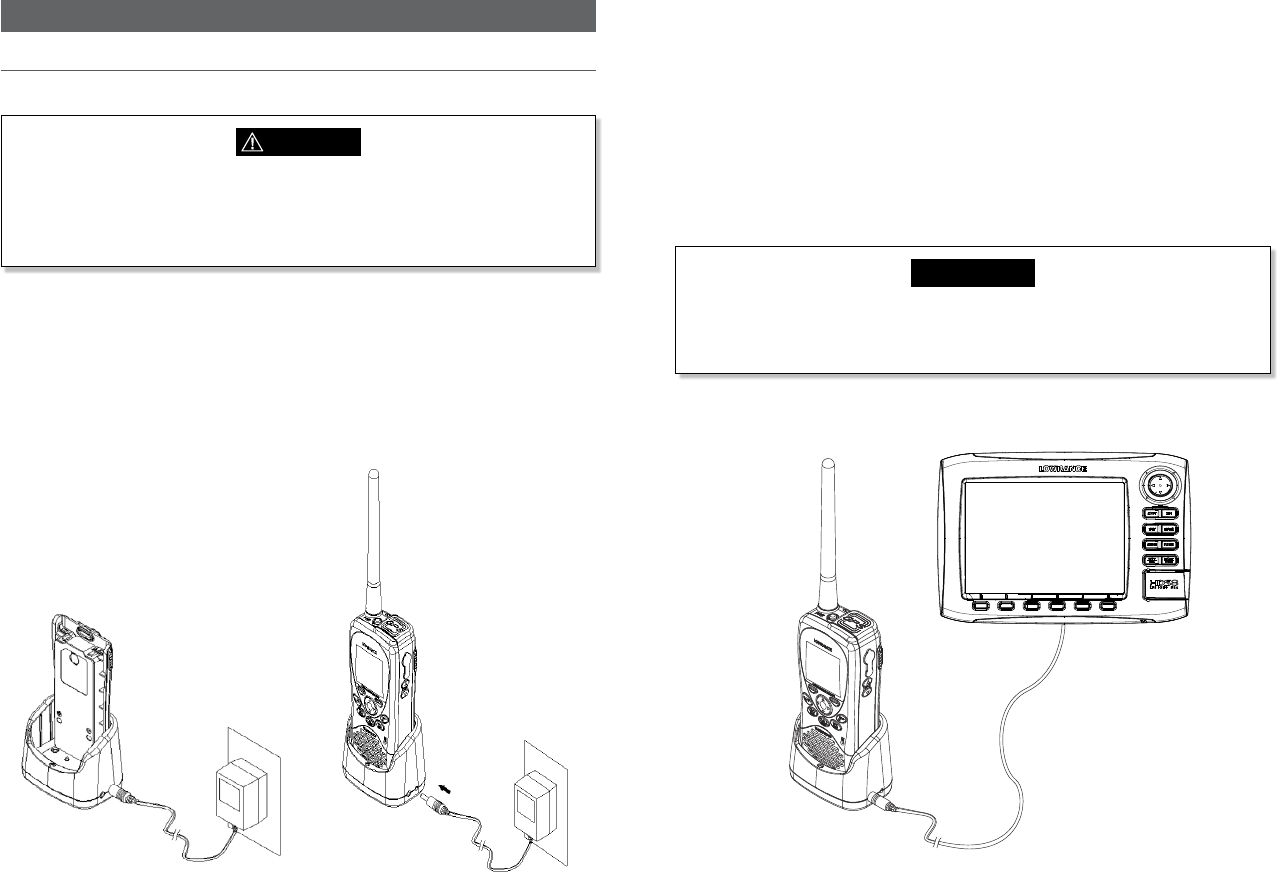
Lowrance - Link-2 Installation and Operation Instructions 65Lowrance - Link-2 Installation and Operation Instructions64
Section 7 - Installation Instructions
7-1 Batteries and charger
The radio is shipped with a sealed Li-Polymer battery pack that is rechargeable.
WARNING
The charger provided for this radio is only to be used to charge the battery pack
provided. Do not charge any other type of batteries in the charger as re, explosion
or battery damage could occur. Avoiding extreme room temperature will also help
prolong the life of the battery pack for the radio.
7-1-1 Installing the battery pack
1. Position the battery pack to line up the three external alignment tabs to the
alignment slots in the radio.
2. Engage the battery pack into the radio until battery pack is fully seated against the
radio housing.
3. Pivot the locking tab up until it snaps into place on the back of the battery pack.
7-1-2 Initial charge
You can either charge the Li-Polymer battery
pack when it is attached to the radio or separated:
1. Plug in the AC/DC wall charger- check the voltage is correct for your wall charger.
2. Connect the charging wire into the charging socket on the cradle charger.
3. Insert the entire radio or the separated battery pack into the cradle charger. The
metal charge contacts on the radio will contact the mating prongs in the charger to
transfer the charging current.
4. Observe that the red light on the front of the charger glows to indicate that the
battery pack is properly seated and the charger is operating.
5. Allow the battery to charge for about 2.5 to 3 hours before use. The light will change
back to green when the battery is fully charged.
CAUTION
To maximise battery life: remove the battery from the charger after approximately
3.5 hours. Overcharging batteries may result in damage to both the battery pack and
radio.
7-1-3 GPS connector
NMEA connector
Connect to NMEA0183
port on MFD
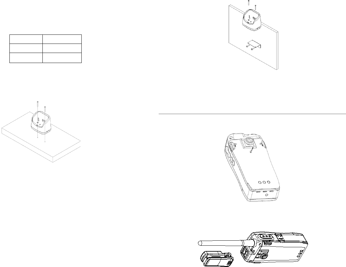
Lowrance - Link-2 Installation and Operation Instructions 67Lowrance - Link-2 Installation and Operation Instructions66
This radio supports NMEA 0183 for outputting the GPS signal. You can use the GPS con-
nector to connect the radio and some GPS navigation receiver, such as chart plotter.
1. Insert the GPS connector cord into the NMEA socket of the cradle charger.
2. Connect the chart plotter to the VHF using the following wiring code:
Wire color Function
Red NMEA OUT(+)
Black NMEA OUT(-)
7-1-4 Mounting battery charger to flat surface
You can mount the battery charger straight onto solid surface. Make sure that the surface
can be penetrated and is strong enough to hold permanantly in place.
7-1-5 Mounting battery charger and bracket onto wall
You can also mount the battery charger onto wall by using the provided bracket and
screws.
1. Mount the bracket as indicated in the diagram.
2. Attach the battery charger to the bracket using the screws provided.
To remove the battery from the radio:
1. Slide the two levers (simultaneously) in a downward motion.
2. Remove battery.
7-2 Installing the belt clip
1. Slide the clip (2) into the recess on the back of the radio battery.
2. The belt clip supplied with your radio allows you to attach the radio to your belt. To
install the belt clip: slide the belt clip to the back of your radio, make sure that the
tting Groove is aligned.
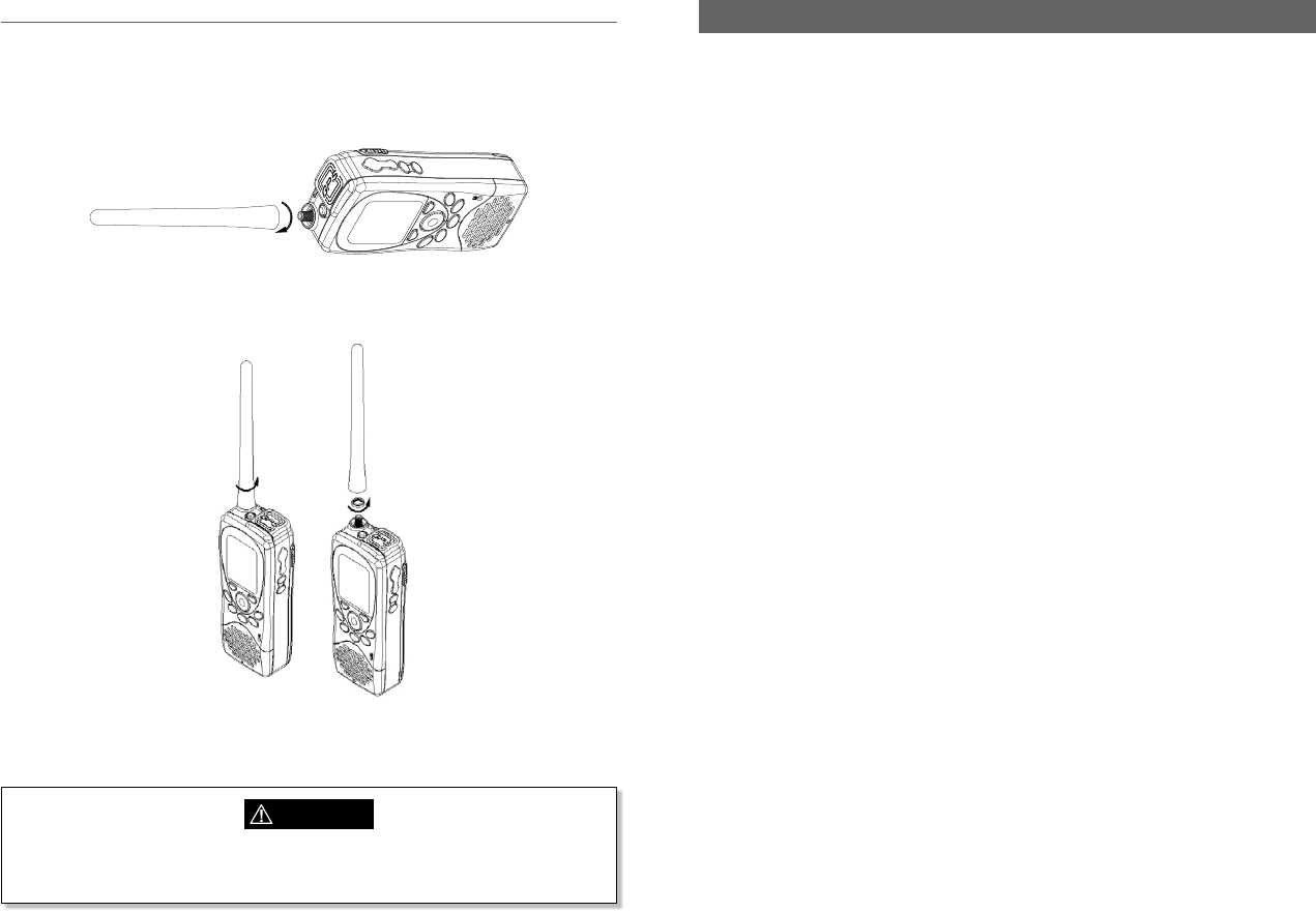
Lowrance - Link-2 Installation and Operation Instructions 69Lowrance - Link-2 Installation and Operation Instructions68
7-3 Installing and removing the antenna
Make sure that the exible antenna is attached to the radio. Ensure that the radio is
turned OFF anytime that the antenna is not connected.
Installing the antenna:
Screw the antenna in a clockwise motion until it is securely locked into place.
Removing the antenna:
Unscrew the antenna in a anti-clockwise motion until it is removed (as illustrated below).
Note: Do not operate the radio or press PTT key without the antenna being installed.
Appendix A - Technical specications
Lowrance Link-2
A-1 General:
Waterproof Floating and totally submersible to JIS-7
Channels All US, Canadian and International Channels
10 NOAA Weather Channels
Frequency Range Transmit -156.025 to 157.425 MHz
Receive - 156.025 to 163.275 MHz
Battery type BP-10
Battery details 7.4 V,1400 mAh (10.36Wh), sealed Li-Polymer
Battery Life 7 Hours (with GPS/DSC on and 5W 5/5/90% ratio)
Cradle charger type BC-10
Cradle charger dtails 12V DC, 800mA0
Cradle charging current 500±100 mA with 4 hour rapid charge time
Antenna Socket SMA
DSC CLASS-D
Display 128x128 pixel bit-mapped LCD with backlight
A-2 Receiver:
Sensitivity 12 dB SINAD ≤0.25 uV
Squelch sensitivity 0.20 uV
Adjacent Channel Selection 70 dB
Spurious Response Rejection 70 dB
Intermodulation Rejection 68 dB
Audio Power Output 250 mW at 5% THD, 700 mW max
A-3 Transmitter:
Power Output 1 or 5 Watts (selectable)
Modulation Type FM
Hum and Noise Attenuation 40 dB
Audio Distortion 5%
WARNING
Never leave your radio in a closed car or trunk; the extremely high temperatures
generated in hot weather can damage the electronics.
Lowrance - Link-2 Installation and Operation Instructions 71Lowrance - Link-2 Installation and Operation Instructions70
Adjacent Channel Power less than 70 dB
Spurious/Harmonic Emissions less than 0.25uW
Current drain Transmit (High) 1.75 A
Transmit (Low) 0.8 A
A-4 GPS and Navigation:
Satellites tracked 12
Navigation Great Circle navigation display with 300 waypoints
Plotter 12 range scales and 360 point of track history with
interval control
Units NM, SM, KM
NMEA Output RMC, GGA, GLL, GNS, GSV
A-5 Digital Selective Calling (DSC):
DSC type CLASS-D
MMSI and NAME directory 20 numbers & groups
Dedicated Distress key Yes
A-6 Standards:
DSC – US models ITU-R M.493-13
DSC – EU models EN 300338-5
Other EN 60950-1:2006 /A1:2010
Appendix B - Frequency charts
International marine channels
CH TX (MHz) RX (MHz) MODE TRAFFIC TYPE SHIP TO
SHIP
SHIP TO
SHORE
NAME TAG REMARK
01 156.050 160.650 D Public Correspondence No Yes TELEPHONE
02 156.100 160.700 D Public Correspondence No Yes TELEPHONE
03 156.150 160.750 D Public Correspondence No Yes TELEPHONE
04 156.200 160.800 D Port Operations No Yes PORT OP
05 156.250 160.850 D Port Operations, Selected VTS
Areas
No Yes PORT OPS/VTS
06 156.300 156.300 S Inter-ship Safety Yes No SAFETY
07 156.350 160.950 D Port Operations No Yes PORT OPS
08 156.400 156.400 S Commercial (inter-ship only) Yes No COMMERCIAL
09 156.450 156.450 S Recreational Calling Channel Yes Yes CALLING
10 156.500 156.500 S Commercial Yes Yes COMMERCIAL
11 156.550 156.550 S Commercial, VTS in Selected Areas Yes Yes VTS
12 156.600 156.600 S Port Operations, Selected VTS
Areas
Yes Yes PORT OPS/VTS
13 156.650 156.650 S Inter-ship Navigation Safety
(bridge-to bridge)
Yes No BRIDGE COM
14 156.700 156.700 S Port Operations, Selected VTS
Areas
Yes Yes PORT OPS/VTS
15 156.750 156.750 S Port Operations Yes Yes PORT OPS 1 1W only
16 156.800 156.800 S International Distress, Safety,
and Calling
Yes Yes DISTRESS
17 156.850 156.850 S State Controlled Yes Yes SAR 1 1W only
18 156.900 161.500 D Port Operations No Yes PORT OPS
19 156.950 161.550 D Commercial No Yes SHIP - SHORE
20 157.000 161.600 D Port Operations No Yes PORT OPS
21 157.050 161.650 D Port Operations No Yes PORT OPS
22 157.100 161.700 D Port Operations No Yes PORT OPS
23 157.150 161.750 D Public Correspondence No Yes TELEPHONE
24 157.200 161.800 D Public Correspondence No Yes TELEPHONE
25 157.250 161.850 D Public Correspondence No Yes TELEPHONE
26 157.300 161.900 D Public Correspondence No Yes TELEPHONE
27 157.350 161.950 D Public Correspondence No Yes TELEPHONE
28 157.400 162.000 D Public Correspondence No Yes TELEPHONE
60 156.025 160.625 D Public Correspondence No Yes TELEPHONE
61 156.075 160.675 D Port Operations No Yes PORT OPS
Lowrance - Link-2 Installation and Operation Instructions 73Lowrance - Link-2 Installation and Operation Instructions72
Special notes on international channel usage
1. LOW POWER (1 W) only.
2. LOW POWER (1 W) initially. Override to HIGH POWER by holding down H/L key
before transmitting. Used normally in bridge-to-bridge communications.
3. Channel 70 is designated for use exclusively for Digital Selective Calling (DSC), such
as Distress, Safety, and Ship Calls. No voice communication is allowed on CH70.
This channel is only available on DSC enabled radios.
Note: The INTERNATIONAL mode is not legal for use in US or Canada waters.
KEY: S = Simplex operating channel; D = Duplex operating channel.
62 156.125 160.725 D Port Operations No Yes PORT OPS
63 156.175 160.775 D Port Operations No Yes PORT OPS
64 156.225 160.825 D Public Correspondence No Yes TELEPHONE
65 156.275 160.875 D Port Operations No Yes PORT OPS
66 156.325 160.925 D Port Operations No Yes PORT OPS
67 156.375 156.375 S Commercial, bridge-to-bridge Yes No BRIDGE COM
68 156.425 156.425 S Boat Operations, Recreational Yes No SHIP - SHIP
69 156.475 156.475 S Port Operations Yes Yes PORT OPS
70 156.525 156.525 Digital Selective Calling - DSC ------ ------ DSC 3
71 156.575 156.575 S Port Operations Yes Yes PORT OPS
72 156.625 156.625 S Inter-ship Yes No SHIP - SHIP
73 156.675 156.675 S Port Operations Yes Yes PORT OPS
74 156.725 156.725 S Port Operations Yes Yes PORT OPS
77 156.875 156.875 S Inter-ship Yes No SHIP - SHIP
78 156.925 161.525 D Non-Commercial No Yes SHIP - SHORE
79 156.975 161.575 D Commercial No Yes SHIP - SHORE
80 157.025 161.625 D Commercial No Yes SHIP - SHORE
81 157.075 161.675 D Port Operations No Yes PORT OPS
82 157.125 161.725 D Port Operations No Yes PORT OPS
83 157.175 161.775 D Public Correspondence No Yes TELEPHONE
84 157.225 161.825 D Public Correspondence No Yes TELEPHONE
85 157.275 161.875 D Public Correspondence No Yes TELEPHONE
86 157.325 161.925 D Public Correspondence No Yes TELEPHONE
87 157.375 161.975 DPort Operations No Yes TELEPHONE
88 157.425 162.025 DPort Operations No Yes TELEPHONE
USA channel chart
CH TX (MHz) RX (MHz) MODE TRAFFIC TYPE SHIP TO
SHIP
SHIP TO
SHORE
NAME TAG REMARK
01A 156.050 156.050 S Port Operations, Selected VTS Areas Yes Yes PORT OPS/VTS
03A 156.150 156.150 S US Government, Coast Guard Yes Yes UNAUTHORIZED 4
05A 156.250 156.250 S Port Operations, Selected VTS Areas Yes Yes PORT OPS/VTS
06 156.300 156.300 S Inter-ship Safety Yes No SAFETY
07A 156.350 156.350 S Commercial Yes Yes COMMERCIAL
08 156.400 156.400 S Commercial (inter-ship only) Yes No COMMERCIAL
09 156.450 156.450 S Recreational Calling Channel Yes Yes CALLING
10 156.500 156.500 S Commercial Yes Yes COMMERCIAL
11 156.550 156.550 S Commercial, VTS in Selected Areas Yes Yes VTS
12 156.600 156.600 S Port Operations, Selected VTS Areas Yes Yes PORT OPS/VTS
13 156.650 156.650 S Inter-ship Navigation Safety (bridge-to
bridge), 1W with Power-up
Yes No BRIDGE COM 3 1W
14 156.700 156.700 S Port Operations, Selected VTS Areas Yes Yes PORT OPS/VTS
15 --- 156.750 S Environmental ------ ------ ENVIRONMEN-
TAL
2 RX only
16 156.800 156.800 S International Distress, Safety, and
Calling
Yes Yes DISTRESS
17 156.850 156.850 S State Controlled Yes Yes SAR 1 1W only
18A 156.900 156.900 S Commercial Yes Yes COMMERCIAL
19A 156.950 156.950 S Commercial Yes Yes COMMERCIAL
20 157.000 161.600 D Port Operations, Canadian Coast Guard No Yes PORT OPS
20A 157.000 157.000 S Port Operations Yes Yes PORT OPS
21A 157.050 157.050 S U.S. Government, Canadian Coast Guard Yes Yes UNAUTHORIZED 4
22A 157.100 157.100 S Coast Guard Liaison Yes Yes COAST GUARD
23A 157.150 157.150 S U.S. Government, Coast Guard Yes Yes UNAUTHORIZED 4
24 157.200 161.800 D Public Correspondence, Marine operator No Yes TELEPHONE
25 157.250 161.850 D Public Correspondence, Marine operator No Yes TELEPHONE
26 157.300 161.900 D Public Correspondence, Marine operator No Yes TELEPHONE
27 157.350 161.950 D Public Correspondence, Marine operator No Yes TELEPHONE
28 157.400 162.000 D Public Correspondence, Marine operator No Yes TELEPHONE
61A 156.075 156.075 S U.S. Government, Canadian Coast Guard Yes Yes UNAUTHORIZED 4
63A 156.175 156.175 S Port Operations, VTS in Selected Areas Yes Yes PORT OPS/VTS
64A 156.225 156.225 S U.S. Government, Canadian Commercial
Fishing
Yes Yes UNAUTHORIZED 4
65A 156.275 156.275 S Port Operations Yes Yes PORT OPS
66A 156.325 156.325 S Port Operations Yes Yes PORT OPS
67 156.375 156.375 S Commercial, bridge-to-bridge, 1W with
Power-up
Yes No BRIDGE COM 3 1W
Lowrance - Link-2 Installation and Operation Instructions 75Lowrance - Link-2 Installation and Operation Instructions74
Special notes on usa channel usage
1. LOW POWER (1 W) only.
2. Receive Only.
3. LOW POWER (1 W) initially. Override to HIGH POWER by holding down H/L key
before transmitting. Used normally in bridge-to-bridge communications.
4. Lightly shaded simplex channels 03A, 21A, 23A, 61A, 64A, 81A, 82A, and 83A cannot
be lawfully used in US waters unless special authorization is obtained from the US
Coast Guard. Not for use by the general public.
5. The letter “A” illuminated by the channel number indicates the USA channel is
simplex.
This same channel is always duplex when selecting International. There is no “A”
reference for International channels. The letter “B” is only used for some Canadian
“Receive only” channels.
6. Channel 70 is designated for use exclusively for Digital Selective Calling (DSC), such
as Distress, Safety, and Ship Calls. No voice communication is allowed on CH70.
This channel is only available on DSC enabled radios.
KEY: S = Simplex operating channel; D = Duplex operating channel.
68 156.425 156.425 S Boat Operations, Recreational Yes No SHIP - SHIP
69 156.475 156.475 S Boat Operations, Recreational Yes Yes PLEASURE
70 156.525 156.525 Digital Selective Calling - DSC ------ ------ DSC 6
71 156.575 156.575 S Boat Operations, Recreational Yes Yes PLEASURE
72 156.625 156.625 S Boat Operations, Recreational Yes No SHIP - SHIP
73 156.675 156.675 S Port Operations Yes Yes PORT OPS
74 156.725 156.725 S Port Operations Yes Yes PORT OPS
77 156.875 156.875 S Port Operations Yes Yes PORT OPS 1 1W only
78A 156.925 156.925 S Boat Operations, Recreational Yes No SHIP - SHIP
79A 156.975 156.975 S Commercial Yes Yes COMMERCIAL
80A 157.025 157.025 S Commercial Yes Yes COMMERCIAL
81A 157.075 157.075 S U.S. Government, Environmental Protec-
tion Agency Operations
Yes Yes UNAUTHORIZED 4
82A 157.125 157.125 S U.S. Government, Canadian Coast Guard Yes Yes UNAUTHORIZED 4
83A 157.175 157.175 S U.S. Government, Canadian Coast Guard Yes Yes UNAUTHORIZED 4
84 157.225 161.825 D Public Correspondence, Marine Operator No Yes TELEPHONE
85 157.275 161.875 D Public Correspondence, Marine Operator No Yes TELEPHONE
86 157.325 161.925 D Public Correspondence, Marine Operator No Yes TELEPHONE
87 157.375 161.975 DPort Operations No Yes TELEPHONE
88 157.425 162.025 DPort Operations No Yes TELEPHONE
88A 157.425 157.425 S Commercial, Inter-ship Only Yes No COMMERCIAL
CANADA channel chart
CH TX (MHz) RX (MHz) MODE TRAFFIC TYPE SHIP TO
SHIP
SHIP TO
SHORE
NAME TAG REMARK
01 156.050 160.650 D Public Correspondence No Yes TELEPHONE
02 156.100 160.700 D Public Correspondence No Yes TELEPHONE
03 156.150 160.750 D Public Correspondence No Yes TELEPHONE
04A 156.200 156.200 S Canadian Coast Guard, SAR Yes Yes CANADIAN CG
05A 156.250 156.250 S Port Operations, VTS in Selected Areas Yes Yes PORT OPS/VTS
06 156.300 156.300 S Inter-ship Safety Yes No SAFETY
07A 156.350 156.350 S Commercial Yes Yes COMMERCIAL
08 156.400 156.400 S Commercial (inter-ship only) Yes No COMMERCIAL
09 156.450 156.450 S Recreational Calling Channel Yes Yes CALLING
10 156.500 156.500 S Commercial Yes Yes COMMERCIAL
11 156.550 156.550 S Commercial, VTS in Selected Areas Yes Yes VTS
12 156.600 156.600 S Port Operations, VTS in Selected Areas Yes Yes PORT OPS/VTS
13 156.650 156.650 S Inter-ship Navigation Safety (bridge-to
bridge) 1W with power-up
Yes No BRIDGE COM 3 1W
14 156.700 156.700 S Port Operations, VTS in Selected Areas Yes Yes PORT OPS/VTS
15 156.750 156.750 S Commercial Yes Yes COMMERCIAL 1 1W only
16 156.800 156.800 S International Distress, Safety, and
Calling
Yes Yes DISTRESS
17 156.850 156.850 S State Controlled Yes Yes SAR 1 1W only
18A 156.900 156.900 S Commercial Yes Yes COMMERCIAL
19A 156.950 156.950 S Canadian Coast Guard Yes Yes CANADIAN CG
20 157.000 161.600 D Canadian Coast Guard No Yes CANADIAN CG 1 1W only
21 157.050 161.650 D Port Operations No Yes PORT OPS
21A 157.050 157.050 S U.S. Government, Canadian Coast Guard Yes Yes UNAUTHORIZED
21B --- 161.650 S Port Operations ------ ------ PORT OPS RX only
22A 157.100 157.100 S Canadian Coast Guard Liaison Yes Yes CANADIAN CG
23 157.150 161.750 D Public Correspondence No Yes TELEPHONE
24 157.200 161.800 D Public Correspondence No Yes TELEPHONE
25 157.250 161.850 D Public Correspondence No Yes TELEPHONE
25B --- 161.850 S Public Correspondence ------ ------ TELEPHONE RX only
26 157.300 161.900 D Public Correspondence No Yes TELEPHONE
27 157.350 161.950 D Public Correspondence No Yes TELEPHONE
28 157.400 162.000 D Public Correspondence No Yes TELEPHONE
28B --- 162.000 S Public Correspondence ------ ------ TELEPHONE RX only
60 156.025 160.625 D Public Correspondence No Yes TELEPHONE
61A 156.075 156.075 S U.S. Government, Canadian Coast Guard Yes Yes UNAUTHORIZED 4
Lowrance - Link-2 Installation and Operation Instructions 77Lowrance - Link-2 Installation and Operation Instructions76
Special notes on canada channel usage
1. LOW POWER (1 W) only.
2. Receive Only.
3. LOW POWER (1 W) initially. Override to HIGH POWER by holding down H/L key
before transmitting. Used normally in bridge-to-bridge communications.
4. Lightly shaded simplex channels 21A, 23A, 61A, 64A, 81A, 82A, and 83A cannot be
lawfully used in Canada waters unless special authorization is obtained from the
Canadian Coast Guard. Not for use by the general public.
62A 156.125 156.125 S Canadian Coast Guard Yes Yes CANADIAN CG
64 156.225 160.825 D Public Correspondence, Duplex No Yes TELEPHONE
64A 156.225 156.225 S U.S. Government, Canadian Commercial
Fishing
Yes Yes UNAUTHORIZED 4
65A 156.275 156.275 S Port Operations Yes Yes PORT OPS
66A 156.325 156.325 S Port Operations Yes Yes PORT OPS 1 1W only
67 156.375 156.375 S Commercial, SAR Yes No COMMERCIAL
68 156.425 156.425 S Boat Operations, Recreational Yes No SHIP - SHIP
69 156.475 156.475 S Commercial Fishing Only Yes Yes COMMERCIAL
70 156.525 156.525 S Digital Selective Calling - DSC ------ ------ DSC 6
71 156.575 156.575 S Boat Operations, Recreational Yes Yes PLEASURE
72 156.625 156.625 S Inter-ship Yes No SHIP - SHIP
73 156.675 156.675 S Commercial Fishing Only Yes Yes COMMERCIAL
74 156.725 156.725 S Commercial Fishing Only Yes Yes COMMERCIAL
77 156.875 156.875 S Port Operations Yes Yes PORT OPS 1 1W only
78A 156.925 156.925 S Boat Operations, Recreational Yes No SHIP - SHIP
79A 156.975 156.975 S Commercial Yes Yes COMMERCIAL
80A 157.025 157.025 S Commercial Yes Yes COMMERCIAL
81A 157.075 157.075 S U.S. Government Operations Yes Yes UNAUTHORIZED 4
82A 157.125 157.125 S U.S. Government, Canadian Coast Guard Yes Yes UNAUTHORIZED 4
83 157.175 161.775 D Canadian Coast Guard Yes Yes CANADIAN CG
83A 157.175 157.175 S U.S. Government, Canadian Coast Guard Yes Yes UNAUTHORIZED 4
83B --- 161.775 S Canadian Coast Guard, RX Only ------ ------ CANADIAN CG
84 157.225 161.825 D Public Correspondence, Marine Operator No Yes TELEPHONE
85 157.275 161.875 D Public Correspondence, Marine Operator No Yes TELEPHONE
86 157.325 161.925 D Public Correspondence, Marine Operator No Yes TELEPHONE
87 157.375 161.975 DPort Operations No Yes TELEPHONE
88 157.425 162.025 DPort Operations No Yes TELEPHONE
Weather channels
CH RX (MHz) TRAFFIC TYPE NAME REMARK
WX01 162.550 NOAA Weather Channel NOAA WX RX only
WX02 162.400 NOAA Weather Channel NOAA WX RX only
WX03 162.475 NOAA Weather Channel NOAA WX RX only
WX04 162.425 NOAA Weather Channel NOAA WX RX only
WX05 162.450 NOAA Weather Channel NOAA WX RX only
WX06 162.500 NOAA Weather Channel NOAA WX RX only
WX07 162.525 NOAA Weather Channel NOAA WX RX only
WX08 161.650 CANADIAN Weather Channel CANADA WX RX only
WX09 161.775 CANADIAN Weather Channel CANADA WX RX only
WX10 163.275 NOAA Weather Channel NOAA WX RX only
Lowrance - Link-2 Installation and Operation Instructions 79Lowrance - Link-2 Installation and Operation Instructions78
Appendix C - EU inland waterway channels
Country Specic table
For specic channel information for your country, please refer to local authorities.
CH SPECIFIC
FOOTNOTES
TRANSMITTING
FREQUENCY (MHZ)
SHIP-TO-SHIP SHIP-TO PORT NAUTICAL
INFORMATION
SHIP LAND
60 a) 156.025 160.625 x
01 a) 156.05 160.65 x
61 a) 156.075 160.675 x
02 a) 156.1 160.7 x
62 a) 156.125 160.725 x
03 a) 156.15 160.75 x
63 a) 156.175 160.775 x
04 a) 156.2 160.8 x
64 a) 156.225 160.825 x
05 a) 156.25 160.85 x
65 a) 156.275 160.875 x
06 a) b) 156.3 156.3 x
66 a) 156.325 160.925 x
07 a) 156.35 160.95 x
67 a) c) 156.375 156.375 x
08 a) q) 156.4 156.4 x
68 a) 156.425 156.425 x
09 a) b) c) 156.45 156.45 x
69 a) 156.475 156.475 x
10 e) 156.5 156.5 x
11 156.55 156.55 x
71 156.575 156.575 x
12 156.6 156.6 x
72 a) r) 156.625 156.625 x
13 f) 156.65 156.65 x
73 f) g) 156.675 156.675 x
14 q) 156.7 156.7 x
74 a) 156.725 156.725 x
15 h) j) 156.75 156.75 x
75 o) j) 156.775 156.775 x
16 i) 156.8 156.8 x
General remarks to Country Specic table:
1 The channels for service categories ship-to-ship and nautical information may
also be used for vessel trac -sys tems by trac centres.
2 In some countries, frequencies certain channels are used for an other service cat-
egory or other radio services. These countries are Austria, Bulgaria, Croatia, the
Federal Republic of Yugosla via, Hun gary, Moldova, Romania, the Russian Federa-
tion, the Slovak Republic, the Czech Republic (with exemption of channels 08, 09,
72, 74 and 86), Ukraine and the Federal Republic of Yugosla via. The Administra-
tions concerned should make any possible attempt to make these fre quencies
channels as soon as possible available for the radiotelephone service on Inland
Waterways and/or the required service catego ry.
76 j) d) o) 156.825 156.825 x
17 h) j) 156.85 156.85 x
77 a) k) 156.875 156.875 x
18 156.9 161.5 x
78 156.925 161.525 x
19 156.95 161.55 x
79 a) 156.975 161.575 x
20 157 161.6 x
80 157.025 161.625 x
21 a) 157.05 161.65 x
81 a) 157.075 161.675 x
22 157.1 161.7 x
82 l) m) 157.125 161.725 x
23 m) 157.15 161.75 x
83 a) m) 157.175 161.775 x
24 m) 157.2 161.8 x
84 m) 157.225 161.825 x
25 m) 157.25 161.85 x
85 a) m) 157.275 161.875 x
26 m) 157.3 161.9 x
86 a) m) 157.325 161.925 x
27 m) 157.35 161.95 x
87 a) d) 157.375 157.375 x
28 m) 157.4 162 x
88 a) p) 157.425 157.425 x
AIS 1 a) n) 161.975 161.975
AIS 2 a) n) 162.025 162.025

Lowrance - Link-2 Installation and Operation Instructions 81Lowrance - Link-2 Installation and Operation Instructions80
Explanation of specic footnotes in Country Specic table:
a. In the countries mentioned under remark 2, it is strictly prohibited to use this
channel.
b. This channel is not allowed to be used between Rhine km 150 and km 350.
c. In the Netherlands, this channel is used by for its on-scene communi cations during
safety operati ons on the North Sea, IJsselmeer, Wadden zee, Ooster- and Wester-
schelde.
d. This channel may also be used for piloting, mooring, tugging and for other nautical
purposes.
e. This channel is the rst ship-to-ship channel, unless the competent authority has
designated an other channel. In the countries mentioned under remark 2, it is
allowed that the output power is set to a value between 6 and 25 W until 1 January
2005.
f. In the countries mentioned under remark 2, this channel is used for service category
ship-to-port authorities.
g. In the Netherlands, this channel is used by its national coastgu ard for communicati-
ons during oil pollution operations on the North Sea and for safety messages for the
North Sea, Wadden zee, IJsselmeer, Ooster- and Westerschelde.
h. This channel may be used only for service category on-boardon board
communications.
i. This channel may be used only for communications between sea going vessels and
participating land stations in case of distress and safety communica ti ons within the
maritime sea-areas. In the countries mentioned under remark 2, this channel may
be used only for distress, safety and calling.
j. The output power shall be reduced automatically to a value between 0.5 and 1 W.
k. This channel may be used for communications with a social charac ter.
l. In the Netherlands and Belgium, this channel may be used for trans mit ting mes-
sages concerning bunkering and victualling. The output power has to be reduced
manually to a value between 0.5 and- 1 W.
m. This channel may also be used for public correspondence.
n. This channel will be used for an automatic ship identi cation and surveillance sys-
tem (AIS) capable of providing worldw ide operating on seas and Inland Waterways.
o. The availability of this channel is on a voluntary basis. All existing equipment shall
be capable to of operating on this channel within a ten-year period after the entry
into force of this Arrangement.
p. After permission of the competent authority, this channel may be used only for spe-
cial events on a temporary basis.
q. In the Czech Republic this channel is used for service category nautical information.
r. In the Czech Republic this channel is used for service category ship-to-port
authorities.
Note:
1. Lightly Shaded Simplex channel CH00 is only available in the UK to Coast Guard
users with written authorization.
2. The special channels above maybe tted to your radio. These are only licensed for
use in the country indicated. No attempt should be made to use them in any other
country.
Special channels 2
CH SEND
(MHz)
RECEIVE
(MHz)
TRAFFIC TYPE SHIP
TO SHIP
SHIP TO
SHORE
NAME TAG
C0 1156.000 156.000 UK Coast Guard Users Yes Yes UK COAST GRD
M1 157.850 157.850 UK Marina Channel M1 Yes Yes UK MARINA
M2 161.425 161.425 UK Marina Channel M2 Yes Yes UK MARINA
31 157.550 162.150 INT’L, Duplex (Holland) No Yes NL MARINA
96H 162.425 162.425 INT’L (Belgium) No Yes BEL G MARINA
L1 155.500 155.500 INT’L (Skandinavia) Yes No LEISURE 1
L2 155.525 155.525 INT’L (Skandinavia) Yes No LEISURE 2
L3 155.650 155.650 INT’L (Skandinavia– not in Denmark) Yes No LE ISURE3
F1 155.625 155.625 INT’L (Skandinavia) Yes No FISHING 1
F2 155.775 155.775 INT’L (Skandinavia) Yes No FISHING 2
F3 155.825 155.825 INT’L (Skandinavia) call back Yes No FISHING 3
AIS1 161.975 161.975 AIS1 ----- ----- -----
AIS2 162.025 162.025 AIS2 ----- ----- -----
AT - Austria
BE - Belgium
BG - Bulgaria
CY - Cyprus
CZ - Czech Republic
DK - Denmark
EE - Estonia
FI - Finland
FR - France
DE - Germany
GR - Greece
HU - Hungary
IS - Iceland
IE - Ireland
IT - Italy
LI - Liechtenstein
LV - Latvia
LT - Lithuania
LU - Luxembourg
MT - Malta
NL - Netherlands
NO - Norway
PL - Poland
PT - Portugal
RO - Romania
SK - Slovakia
SI - Slovenia
ES - Spain
SE - Sweden
CH - Switzerland
TR - Turkey
UK - United Kingdom
Countries of Intended use in the EU:

1177
*988-102xx-00A*