Navman Tracker Plotter 5600 Users Manual MN000192C_TRACKER5600_Eng_Sp_Po.pmd
tracker plotter TRACKER 5600 MN000192C_TRACKER5600_Eng
TRACKER 5600 to the manual 0cb1a346-443b-4b32-a66d-afc68c07a7a5
2015-02-05
: Navman Navman-Tracker-Plotter-Tracker-5600-Users-Manual-494137 navman-tracker-plotter-tracker-5600-users-manual-494137 navman pdf
Open the PDF directly: View PDF ![]() .
.
Page Count: 42
CHARTPLOTTERS
NAVMAN
Installation and
Operation Manual
www.navman.com
English ............. 2
Español .......... 41
Português ...... 79
TRACKER 5600

2TRACKER 5600 Installation and Operation Manual
NAVMAN
FCC Statement
Note: This equipment has been tested and found to comply with the limits for a Class
B digital device, pursuant to Part 15 of the FCC Rules. These limits are designed to
provide reasonable protection against harmful interference in a normal installation.
This equipment generates, uses and can radiate radio frequency energy and, if not
installed and used in accordance with the instructions, may cause harmful interference
to radio communications. However, there is no guarantee that interference will not
occur in a particular installation. If this equipment does cause harmful interference to
radio or television reception, which can be determined by turning the equipment off
and on, the user is encouraged to try to correct the interference by one or more of the
following measures:
Reorient or relocate the receiving antenna.
Increase the separation between the equipment and receiver.
Connect the equipment into an output on a circuit different from that to which
the receiver is connected.
Consult the dealer or an experienced technician for help.
A shielded cable must be used when connecting a peripheral to the serial ports.

3
TRACKER 5600 Installation and Operation Manual
NAVMAN
Contents
1 Introduction ..................................................................................................... 6
1-1 Care ............................................................................................................................ 6
1-2 Plug-in cards ...............................................................................................................6
1-3 Removing and replacing the display unit ...................................................................... 7
2 Basic operation ............................................................................................... 8
2-1 Turning on and off / auto power ................................................................................... 9
2-2 The main displays ........................................................................................................ 9
2-3 Adjusting the backlight ............................................................................................... 10
2-4 Man overboard (MOB) ............................................................................................... 10
2-5 Alarms ....................................................................................................................... 10
2-6 Simulate mode ........................................................................................................... 10
2-7 Navigating ................................................................................................................. 11
3 Chart ............................................................................................................... 12
3-1 Chart display ............................................................................................................. 12
3-1-1 Chart modes ..................................................................................................... 12
3-1-2 Latitude and longitude ....................................................................................... 13
3-1-3 Chart scale ........................................................................................................ 13
3-1-4 The compass .................................................................................................... 13
3-1-5 Chart symbols ................................................................................................... 13
3-1-6 Chart information ............................................................................................... 13
3-1-7 Find nearby services ......................................................................................... 13
3-1-8 Change the data display and compass display .................................................. 13
3-2 Distance and bearing calculator ................................................................................. 14
3-3 Goto .......................................................................................................................... 14
3-4 Projected course ....................................................................................................... 15
3-5 Tracks and tracking ................................................................................................... 15
4 Fuel display ................................................................................................... 16
5 Data display ................................................................................................... 16
6 Highway display ............................................................................................ 17
7 Satellites ........................................................................................................ 17
7-1 Satellite display .......................................................................................................... 18
8 Tides display.................................................................................................. 19
9 Waypoints ...................................................................................................... 20
9-1 Waypoints display ...................................................................................................... 20
9-2 Managing waypoints .................................................................................................. 20
9-2-1 Creating a new waypoint .................................................................................... 20
9-2-2 Moving a waypoint ............................................................................................. 21
9-2-3 Editing a waypoint ............................................................................................. 21
9-2-4 Displaying a waypoint on the chart ..................................................................... 21
9-2-5 Deleting a waypoint ........................................................................................... 21
9-2-6 Deleting all waypoints ........................................................................................ 21
9-2-7 Changing a waypoint’s data ............................................................................... 21
9-2-8 Sort waypoints ................................................................................................... 21
4TRACKER 5600 Installation and Operation Manual
NAVMAN
110 Routes ........................................................................................................ 22
10-1 Routes display ......................................................................................................... 22
10-2 Managing routes ...................................................................................................... 22
10-2-1 Creating a new route ....................................................................................... 22
10-2-2 Editing a route ................................................................................................. 23
10-2-3 Displaying a route on the chart ........................................................................ 23
10-2-4 Deleting a route ............................................................................................... 23
10-2-5 Deleting all routes ............................................................................................ 23
10-3 Navigating a route .................................................................................................... 23
10-3-1 Starting a route ................................................................................................ 23
10-3-2 Skipping a waypoint in a route ......................................................................... 23
10-3-3 Cancelling a route ........................................................................................... 23
11 User card display ......................................................................................... 24
12 About display ............................................................................................... 25
13 Setup menu .................................................................................................. 25
13-1 System setup ........................................................................................................... 25
13-2 Chart setup .............................................................................................................. 27
13-3 DGPS setup ............................................................................................................ 28
13-4 Fuel Setup ............................................................................................................... 28
13-5 Track setup ............................................................................................................. 29
13-6 Trip log(s) setup ...................................................................................................... 29
13-7 Alarms setup ........................................................................................................... 30
13-8 Units setup .............................................................................................................. 30
13-9 Comms setup .......................................................................................................... 30
13-10 Time setup ............................................................................................................. 31
13-11 Simulate setup ....................................................................................................... 31
14 Systems of several instruments ................................................................ 31
15 Installation ................................................................................................... 32
15-1 What comes with the TRACKER ............................................................................. 32
15-2 Options and accessories ......................................................................................... 32
15-3 Installation ...............................................................................................................33
Appendix A - Specifications ............................................................................ 36
Appendix B - Troubleshooting ........................................................................ 38
Appendix C - Glossary and navigation data .................................................. 39
Appendix D - How to contact us .................................................................... 119

5
TRACKER 5600 Installation and Operation Manual
NAVMAN
It is the owner’s sole responsibility to install and use the instrument in a manner that will not cause
accidents, personal injury or property damage. The user of this product is solely responsible for observing
safe boating practices.
Global Positioning System: The Global Positioning System (GPS) is operated by the US Government
which is solely responsible for its operation, accuracy and maintenance. The GPS system is subject to
changes which could affect the accuracy and performance of all GPS equipment anywhere in the world
including the TRACKER. Whilst the NAVMAN TRACKER is a precision navigation instrument, it can be
misused or misinterpreted, which can result in its use being unsafe. To reduce the risk of misusing or
misinterpreting the TRACKER, the user must read and understand all aspects of this Installation and
Operation manual. We also suggest that the user practice all operations using the built in simulator
before using the TRACKER at sea.
Electronic Chart: The electronic chart used by the TRACKER is an aid to navigation and is designed to
supplement the use of official government charts not replace them. Only official government charts
supplemented by notices to mariners contain the information required for safe and prudent navigation.
Always supplement the information provided by the TRACKER with other plotting sources such as
observations, depth soundings, radar and hand compass bearings. Should the information not agree
then the discrepancy must be resolved before proceeding any further.
Fuel Computer: Fuel economy can alter drastically depending on the boat loading and sea conditions.
The fuel computer should not be the sole source of information concerning available fuel onboard and
the electronic information should be supplemented by visual or other checks of the fuel load. This is
necessary due to possible operator induced errors such as forgetting to reset the fuel used when filling
the tank, running the engine with the fuel computer not switched on or other operator controlled actions
that may render the device inaccurate. Always ensure that adequate fuel is carried onboard for the intended
trip plus a reserve to allow for unforeseen circumstances.
NAVMAN NZ LIMITED DISCLAIMS ALL LIABILITY FOR ANY USE OF THIS PRODUCT IN A WAY THAT
MAY CAUSE ACCIDENTS, DAMAGE OR THAT MAY VIOLATE THE LAW.
Governing Language: This statement, any instruction manuals, user guides and other information
relating to the product (Documentation) may be translated to, or has been translated from, another language
(Translation). In the event of any conflict between any Translation of the Documentation, the English
language version of the Documentation will be the official version of the Documentation.
This manual represents the TRACKER as at the time of printing. Navman NZ Limited reserves the right
to make changes to specifications without notice.
Copyright © 2002 Navman NZ Limited, New Zealand, all rights reserved. NAVMAN is a registered trademark
of Navman NZ Limited.
Important

6TRACKER 5600 Installation and Operation Manual
NAVMAN
6
1-2 Plug-in cards
1 Introduction
TRACKER chartplotters
NAVMAN’s TRACKER chartplotters are compact,
ruggedly built, highly integrated navigation instruments.
They have been designed to be easy to use. Complex
navigation functions can be performed with a few key
presses, taking the hard work out of navigation.
This manual covers the NAVMAN TRACKER 5600
chartplotter, which has a large, easy to read colour
display and uses an external GPS antenna.
The TRACKER has a built-in chart of the world,
suitable for route planning and general interest. To
see chart details for a region, plug in a C-MAP™ chart
card (an electronic chart).
The TRACKER receives information from the GPS
system and displays the boat’s position and speed.
The TRACKER can navigate to a point or can navigate
along a route. When the boat is navigating to one of
these points, the TRACKER displays course
information for the helmsman to follow.
The TRACKER can control an autopilot and can
display depth information from a depth sounder. With
an optional fuel kit, the TRACKER becomes a
sophisticated yet easy to use fuel computer. Navigation
data can be saved to a plug-in user card so that it can
be easily transferred to another NAVMAN chartplotter.
The TRACKER is part of the NAVMAN family of
instruments, which includes instruments for speed,
depth, wind and repeaters. These instruments can be
connected together to form an integrated data system
(see section 14).
For maximum benefit, please read this manual
carefully before installing and using the unit. Special
terms are explained in Appendix C.
Cleaning and maintenance
Caution should be used when cleaning the TRACKER,
and especially the screen of the TRACKER. Only use
a clean sponge or chamois soaked in fresh water and
mild detergent. Never use a dry cloth as this may drag
dried salt crystals across the screen resulting in
scratching. Do not use any form of abrasive cleaner,
solvent, petrol or other chemical cleaner.
Push the dust cover over the display when the
TRACKER is turned off.
1-1 Care
Plug-in cards
Handle plug-in cards carefully. Keep them in their
protective cases when not plugged into the TRACKER.
If a card gets dirty or wet, clean it with a damp cloth
or mild detergent.
Keep the card holder in place in the display unit at all
times to prevent moisture from entering the card
compartment.
The TRACKER can use two kinds of plug-in cards:
C-MAP™ chart card have chart details required
for navigating in a particular region. When a chart
card is plugged in, the extra details automatically
appear on the TRACKER’s chart display.
C-MAP™ user cards are used to store navigation
data. Each user card expands the TRACKER’s
memory and allows the data to be transferred to
another TRACKER easily (see section 11).
Note: The older 5 volt cards are not supported.
When a card is inserted or removed it does not matter
if the TRACKER is turned on or off.
7
TRACKER 5600 Installation and Operation Manual
NAVMAN
1-3 Removing and replacing the display unit
If the display unit is bracket mounted then the display
unit can easily be removed and replaced for security
or protection.
Removing the display unit:
1 Turn the TRACKER off by holding until the
display turns off.
2 Push the dust cover over the display unit.
3 Hold the display unit with one hand. Loosen
the knob on the mounting bracket and carefully
lift the unit off the mounting bracket.
4 The display unit has some cables plugged into
the back.
Unplug each black plug by turning the locking
collar a quarter turn anticlockwise and pulling
the plug out.
If there is a gold plug, unscrew the locking
collar anticlockwise and pull the plug out.
5 Push the attached dust covers over the
exposed ends of the plugs to protect them.
6 Store the display unit in a safe place, such as
the optional NAVMAN carry bag.
Replacing the display unit
1 Remove the dust covers from the plugs. Plug
the black plugs into their sockets on the back
of the display unit:
Match the colour on the end of the plug to
the colour of the nut on the socket.
Hold the plug against the socket and rotate
the plug until it slides into the socket.
Lock the plug in place by pushing the
locking collar towards the socket and
turning it a quarter turn clockwise.
Nothing will be damaged if a cable is plugged
into the wrong socket by mistake.
2 If the unit has a gold plug:
Plug it into its socket on the back of the
display unit.
Hand tighten the locking collar
clockwise - do not overtighten.
3 Hold the display unit in place on the mounting
bracket shaft, with the rubber washer clamped
between the bracket and the display unit.
4 Adjust the tilt and rotation of the display for
best viewing and hand tighten the knob on the
mounting bracket. Remove the dust cover.
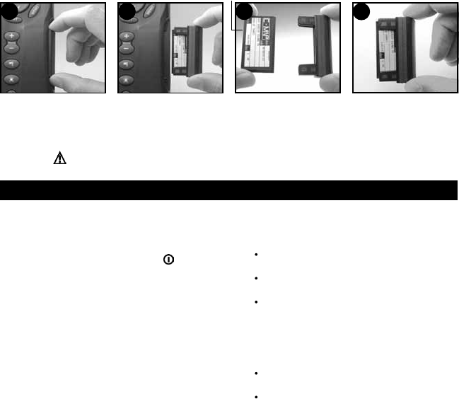
Pull card holder out of
TRACKER.
Pull any card out of holder.
Put card in case.
Card
Holder
Gold contacts under here
Push new card into holder.
Ensure the gold contacts
are on the outer edge and
underneath (see above).
Keep the card’s case.
Push card holder fully into
TRACKER.
Changing the plug-in card
4
31 2
Warning: Keep the holder in place in the TRACKER at all times to prevent
moisture from entering card compartment.

8TRACKER 5600 Installation and Operation Manual
NAVMAN
2 Basic operation
Overview of the keys
ESC Go back to an earlier menu or display. Any changes
are ignored.
DISP Show a menu of the main TRACKER displays. To go
to a display, select it from the menu (see section 2-2).
,,, Cursor keys, to move the cursor or the
selection highlight.
MENU Show a menu of the options for the current display.
Press MENU again to display the setup menu (see
section 13).
ENT Start an action or accept a change.
+ Zoom in and display a smaller area of the chart in more
detail.
- Zoom out and display a bigger area in less detail.
Create an instant waypoint at the boat position (see
section 9-2-1).
Man overboard (MOB, see section 2-4).
Turn TRACKER on and off (see section 2-1); adjust
the backlighting (see section 2-3).
Keys
In this manual:
Press means to push the key for less than a second.
Hold means to hold the key down.
The internal beeper beeps when a key is pressed (to disable
or enable the beep, see section 13-1).
To select an item in a menu
The TRACKER is operated by selecting items from menus
shown on the display.
1 Press or to move the highlight to the item.
2 Press ENT or to select the item.
Change a number or word
To change a number or word on the display:
1 Press or to move the highlight to the digit or
letter to change.
Press or to change the digit or letter.
2 Repeat the above step to change any other digits or
letters.
3 Press ENT to accept the change.
9
TRACKER 5600 Installation and Operation Manual
NAVMAN
2-1 Turning on and off / auto power
Auto power
If the TRACKER is wired for auto power (see section
15-3), then the TRACKER automatically turns on and
off with the boat power, and can not be turned on or
off manually.
Turning on manually
If the TRACKER is not wired for auto power, turn the
unit on by pressing .
Startup
After the TRACKER has been turned on:
1 The unit displays a title display for a few
seconds, then beeps again and displays a
navigation warning.
2 If necessary, adjust the display to be easy to
read (see section 2-3).
Read the warning and press ENT.
3 The satellite display is shown.
Either wait for the GPS receiver to start up
and the status to change from ‘acquiring’ to
‘GPS fix’ (see section 7-1).
Or press ESC.
4 The TRACKER chart is displayed (see
section 3).
Turning off manually
If the TRACKER is not wired for auto power, turn the
unit off by holding down until the display turns off.
After you have turned the TRACKER on, it shows
the satellite display until the GPS receiver gets a GPS
fix, then displays the Chart. The Chart is the display
that you will normally use for navigation.
2-2 The main displays
Fuel (fuel computer) Section 4
Waypoints Section 9
Tides (tide chart) Section 8
Satellite (GPS data) Section 7
Highway (boat path) Section 6
Data (numeric data) Section 5
User card Section 11
Routes Section 10
About Section 12
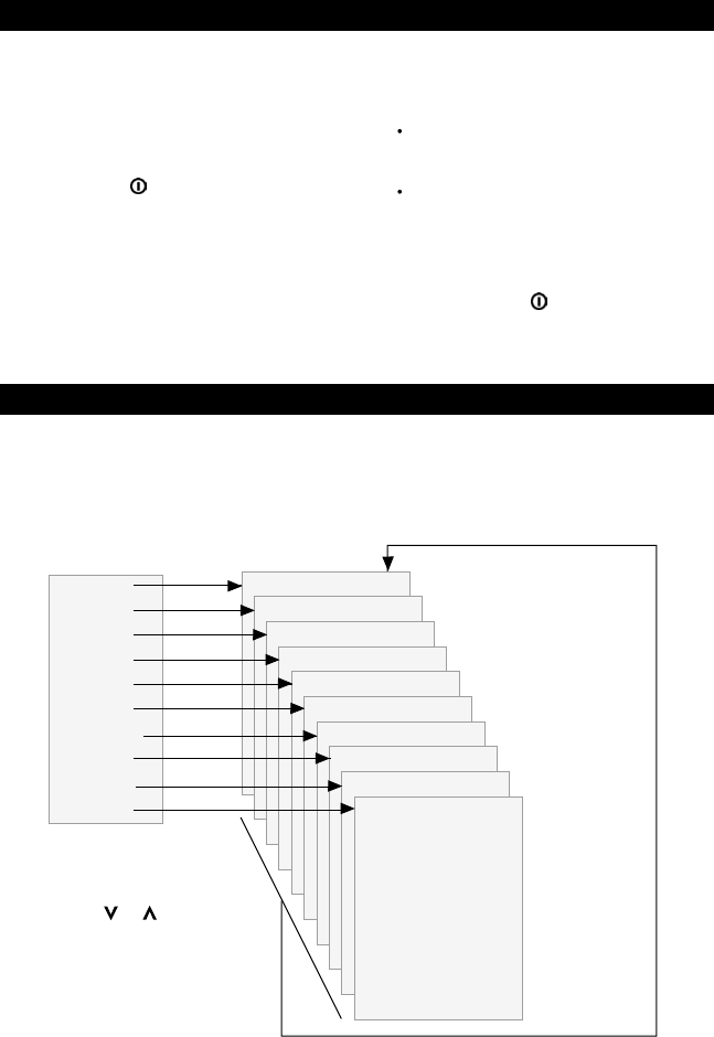
The main displays See:
Display menu
Chart
Fuel
Data
Highway
Satellite
Tides
Waypoints
Routes
Press ESC to
return to
chart display
To use one of the other main displays, press DISP
for the display menu and select a display to use.
To return to the chart display, press ESC.
Press DISP for
display menu
To select a display:
i press or to
highlight the display
ii press ENT to go to
the display
Chart (navigation) Section 3
C-MAP™
user card
About
10 TRACKER 5600 Installation and Operation Manual
NAVMAN
2-6 Simulate mode
Simulate mode allows a user to become familiar with
the TRACKER off the water. In Simulate mode, the
data from the GPS receiver and other sensors is
ignored and the TRACKER generates this data
internally to simulate the movement of the boat.
Otherwise, the TRACKER functions normally.
To see if the TRACKER is in Simulate mode, press
DISP and select
Satellite
. If it is in Simulate mode,
then it shows Simulate at the top left of the display.
To start and stop Simulate mode, (see section 13-10).
Warning: Never have Simulate mode on when
the TRACKER is navigating on the water.
2-5 Alarms
When the TRACKER detects an alarm condition, it
displays a warning message on the display, the
internal beeper sounds and any external beepers or
lights operate.
Press ESC to clear the alarm. The alarm will sound
again if the alarm condition occurs again.
The TRACKER has five user settable alarms: arrival
radius, anchor, XTE, danger and low fuel see section
13-6.
In addition, the TRACKER has a fixed alarm for loss
of GPS/DGPS fix.
The MOB feature saves the boat’s position and then
navigates back to this point. To do this:
1 Press .
The TRACKER beeps four times and stores
the boat’s position as a waypoint called MOB.
2 The TRACKER changes to the chart display,
with the MOB waypoint at the centre of the
chart.
The chart zooms in for accurate navigation. If
the chart can not show the required small
scale, the TRACKER changes to plotter mode
(a white display with crosshatching and no
chart details, see section 13-2).
3 If the autopilot output is off (see section 13-9)
the TRACKER immediately starts navigating
back to the MOB waypoint.
If the autopilot output is on, the TRACKER
asks if the autopilot is active.
Select:
No
: The TRACKER immediately starts
navigating back to the MOB waypoint.
2-4 Man overboard (MOB)
Yes
: The TRACKER asks if the boat is to go to
the MOB waypoint.
Select:
Yes
: to immediately start navigating to
the MOB waypoint.
Warning: This might result in a
sudden and dangerous turn.
No
: to allow time to disengage the
autopilot; then use Goto to navigate
back to the MOB waypoint
(see section 3-3).
To cancel MOB or set another MOB.
1 Press again to display a menu.
2 Select an option from the menu.
Tip: The MOB waypoint remains on the chart after
the MOB has been cancelled. To delete the MOB
waypoint, see section 9-2-5.
2-3 Backlight
1 Press briefly to show the display controls.
2 The display and keys are backlit, with sixteen
brightness levels.
To change the backlight, press (dimmer) or
(brighter).
3 Press ENT to accept the new values.

11
TRACKER 5600 Installation and Operation Manual
NAVMAN
2-7 Navigating
The TRACKER has two ways of navigating, going
straight to a point or following a route.
Enter waypoints at points of interest before starting
to navigate (see section 9-2-1).
Tip: Create a waypoint at the start of the trip to
navigate back to.
Goto: Going straight to a point
The TRACKER can navigate straight to a waypoint
or to any arbitrary point:
1 In the chart display, move the cursor to the
destination point to navigate to (see section 3-1-1).
2 Start navigating using the Goto function from
the chart menu (see section 3-3).
The chart, data and highway displays show
navigation data. The chart shows:
The boat position .
The destination point marked with a circle.
The boat’s plotted course to the destination.
Two CDI lines, parallel to the boat’s plotted
course (see Appendix C, CDI).
If the TRACKER is connected to an autopilot,
the TRACKER will send data to the autopilot to
steer the boat to the destination.
If the XTE alarm is enabled, an alarm will
sound if the boat deviates too much from its
intended course (to set the XTE alarm, see
section 13-7).
3 If the arrival radius alarm is enabled, then,
when the boat comes within the arrival radius
of the destination, an alarm will sound to show
that the boat has reached the destination (to
set the arrival radius alarm, see section 13-7).
4 To stop the Goto, see section 3-3.
Following a route
A route is a list of waypoints that the boat can follow
(see section 10).
1 To create waypoints before creating the route,
use the waypoints display (see section 9-2-1).
2 To create a route, go to the chart or routes
display (see section 10-2-1).
3 To start the route, see section 10-3-1.
The chart, data and highway displays show
navigation data. The chart shows:
The boat position .
The waypoint at the end of the current leg
marked with a circle.
The boat’s plotted course along the leg.
Two CDI lines, parallel to the boat’s plotted
course (see Appendix C, CDI).
If the TRACKER is connected to an autopilot,
the TRACKER will send data to the autopilot to
steer the boat to the destination.
If the XTE alarm is enabled, an alarm will
sound if the boat deviates too much from its
intended course (see section 13-7).
If the arrival radius alarm is enabled, then,
when the boat comes within the arrival radius
of the waypoint at the end of the current leg, an
alarm will sound (to set the arrival radius
alarm, see section 13-7).
4 The TRACKER stops navigating to the
waypoint at the end of the current leg and
starts the next leg of the route:
a When the boat comes within 0.025 nm of
the waypoint.
b Or when the boat passes the waypoint.
c Or if the waypoint is skipped (see section
10-3-2).
5 When the boat has reached the final waypoint,
or to stop the boat following the route at any
time, cancel the route (see section 10-3-3).
12 TRACKER 5600 Installation and Operation Manual
NAVMAN
3 Chart
3-1-1 Chart modes
The Chart has two modes, centre on boat mode and
cursor mode. These are explained below.
Centre on boat mode
To switch to centre on boat mode in the chart display,
press ESC. The boat is at the centre of the chart.
As the boat moves through the water, the chart
automatically scrolls to keep the boat in the centre
of the chart. The cursor (see below) is turned off.
Cursor mode
The keys ,, and are called cursor keys.
To switch to cursor mode in the chart display, hold
down a cursor key. The cursor appears and moves
away from the boat:
Press the key which points in the direction that
the cursor will move, for example press to
Press midway between two of the cursor keys
to make the cursor move diagonally.
Hold a cursor key down to make the cursor
move continuously across the display.
In Cursor mode:
The distance (+RNG) and bearing (+BRG) of
the cursor from the boat are displayed at the
bottom, left corner of the display.
The chart does not scroll as the boat moves.
If the cursor reaches the edge of the display,
the chart will scroll.
For example, hold down to move the cursor
to the right side of the display and the chart will
scroll to the left.
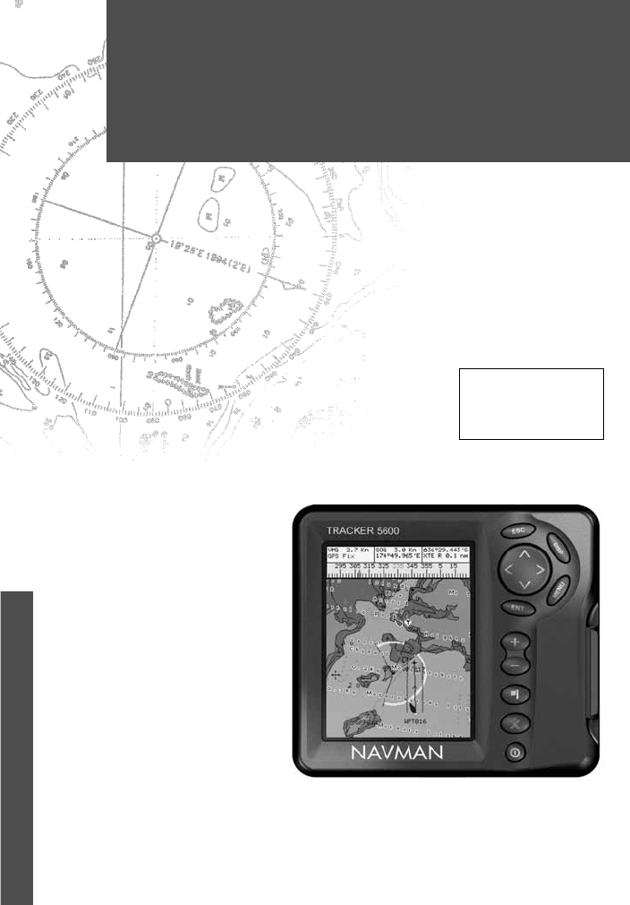
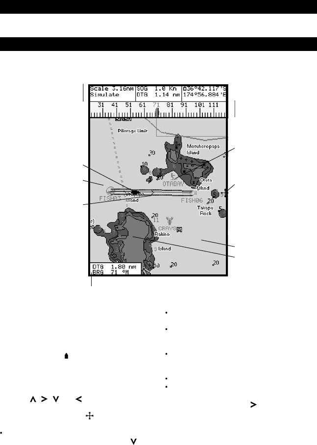
The chart. To change the
types of information
displayed, (see section
13-2).
Compass display
(see section 3-1-4).
To turn the compass off
or on, see section 3-1-8.
Boat course and CDI lines
(see Appendix C, CDI).
Boat is going to the
waypoint called FISH06.
Data display. To turn the
data off or on or to change
what data is displayed, see
section 3-1-8.
Boat position
(see section 3-1-1).
Boat track
(see section 3-5).
Typical waypoint
(see section 9).
A typical chart display shows:
Distance and bearing of
cursor from boat.
The cursor
(see section 3-1-1).
3-1 Chart display
The chart display is the most important of the TRACKER’s displays, showing the chart, the boat’s position
and course, and navigation data.
Sea
Land
Chart is in cursor mode, press ESC to return to
centre on boat mode (see section 3-1-1).
move the cursor down.
13
TRACKER 5600 Installation and Operation Manual
NAVMAN
3-1-2 Latitude and longitude
Latitude and longitude can be displayed at the top of
the chart. Normally the position is the boat’s position,
and the latitude has a boat symbol to show this:
If the cursor has been moved in the last ten seconds,
then the position is the cursor’s position, and the
latitude has a cursor symbol to show this:
Warning: When reading the boat position,
make sure the position is not the cursor position.
3-1-3 Chart scale
Press to zoom in and display a smaller area of
the chart in more detail. Press to zoom out and
display a bigger area in less detail.
The chart scale can be displayed (e.g. scale = 8 nm,
see below). The scale is the vertical distance across
the currently visible chart area. For example if the
scale is 8 nm then a portion of chart eight nautical
miles high is currently displayed.
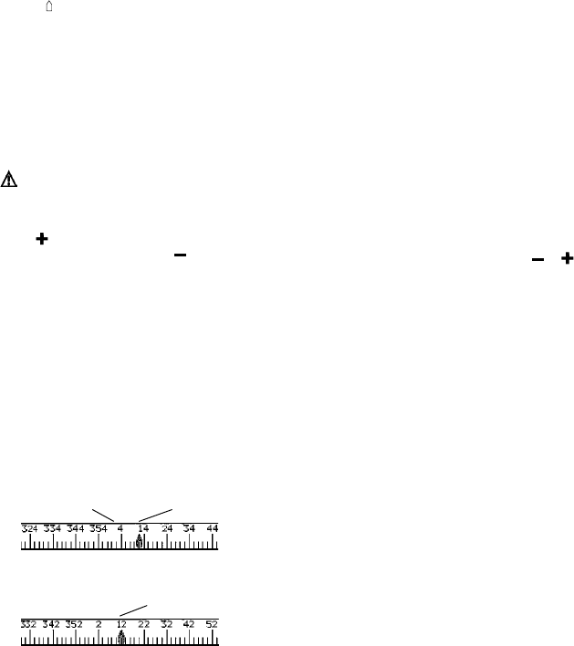
3-1-4 The compass
A compass can be displayed at the top of the chart
(see section 3-1-8).
When the boat is navigating to a point, the compass
shows the bearing to the destination (BRG) in the
middle and the boat’s course over ground (COG),
for example here BRG is 4° and COG is 12°:
Otherwise the compass shows the boat’s COG in
the middle, for example here COG is 12°:
3-1-5 Chart symbols
The chart will show symbols, such as waypoints and
chart symbols. When the cursor is placed over a
symbol for at least two seconds, a data window
appears at the bottom left of the display with
information about the symbol.
3-1-6 Chart information
To see stored data about a point on the chart (for
example, a chart symbol):
1 Move the cursor to that point on the chart.
2 Press MENU and select
Chart info
.
3 A menu of objects is displayed:
i Select an object to display.
ii Press ESC to return to the menu. Select
other objects.
iii Finally, press ESC to return to the chart.
3-1-7 Find nearby services
To find and display nearby services:
1 To see services near the boat’s position, press
ESC to switch to centre on boat mode. To see
services near a different point, move the cursor
to that point on the chart.
2 Press MENU and select
Find
.
3 Select the type of service. There are three
types of service:
Ports
A list of ports is displayed. Press or
to display any other ports. Select the port to
display. To search for a port:
i Press MENU and select
Find
.
ii Enter some or all of the letters of the
port name. Press ENT.
Port services
i Select the type of service to find.
ii A list of places with this service are
displayed. Select the place to display.
Tide stations
A list of tide stations is displayed. Select
the station to display. The chart redraws
with the tide station centred. To display a
tide chart (see section 8) for the station:
i Press MENU and select
Chart info
.
ii Select
Tide height
.
3-1-8 Change the data display and
compass display
Numeric data and a compass can be displayed at
the top of the chart display. To change these:
1 Press MENU and select
Data header
.
2 To turn the data display off or on:
i Select
Data
.
ii Select
Off
or
On
.
3 To choose the size of the numbers:
i Select
Size
.
ii Select:
Small
: displays three fields per line and
up to four lines.
Medium
: displays two fields per line
and up to four lines.
BRG (red) COG
COG
Minutes, to 3 decimal places
(about 2 m (6 ft) resolution)
Degrees
36° 29.637'S
175° 09.165'E
Latitude
Longitude
+ 36° 29.684'S
175° 09.201'E
14 TRACKER 5600 Installation and Operation Manual
NAVMAN
3-2 Distance and bearing calculator
The distance and bearing calculator can plot a course
of one or several legs and to show the bearing and
length of each leg, as well as the total distance along
the course. The completed course can be converted
into a route.
To use the distance and bearing calculator:
1 Press ESC until the chart display is displayed.
Press MENU and select
Distance
.
2 Move the cursor to the start of the first leg. It
does not matter if this point is a waypoint or not.
Press ENT.
3 To add a leg to the course, move the cursor to
the end of the leg. It does not matter if this point
is a waypoint or not. The display shows the
Large
: displays same amount of data
as medium but with a larger font.
4 To change the data display:
i Select
Data setup
.
ii Change a data field:
a Press the cursor keys to highlight the
field.
b Press ENT to display a menu of the
data that can be shown in the field.
c Select the data to show in the field;
select
None
to leave the field empty.
3-3 Goto
Goto is a simple way of navigating straight to one
point.
To start the Goto
1 Choose the point to go to:
To go to a waypoint or to any point on the
chart:
i Press ESC until the chart display is
displayed.
ii Move the cursor to the destination.
iii Press MENU and select Goto.
To go to a waypoint from the waypoints
display:
i Press DISP and select
Waypoints.
ii Press or to highlight the
destination waypoint.
iii Press MENU and select
Goto.
Warning: Make sure the course does not pass
over land or dangerous waters.
2 The TRACKER starts navigating to the
destination (see section 2-7). The chart shows:
The destination point marked with a circle.
The boat’s plotted course to the
destination.
Two CDI lines, parallel to the boat’s plotted
course (see Appendix C, CDI).
To cancel a Goto
1 Press ESC until the chart display is displayed.
2 Press MENU and select
Cancel goto
.
bearing and length of the leg, as well as the total
distance along the course. Press ENT.
4 To remove the last leg from the course, press
MENU and select
Remove
.
5 Repeat the above two steps to enter the whole
course.
6 To save the new course as a route, press
MENU and select
Save
. This also saves any
new points on the course as new waypoints,
with default names. If necessary, edit the route
later (see section 10-2-2) and edit any new
waypoints later (see section 9-2-3).
7 Finally, press ESC to return to the chart display.
Note: See section 13-6 for Log functions.
iii Repeat the above step to set the other data
fields. Press ESC.
Tip: If less than four lines are used, the
numeric data will take up less of the chart area.
5 To turn the compass display off or on:
i Select
Compass
.
ii Select
Off
or
On
.
6 Finally, press ESC to return to the chart display.
15
TRACKER 5600 Installation and Operation Manual
NAVMAN
If Projected course is turned on, then the TRACKER
will display the projected position based on the
course over ground (COG), speed and a specified
time. To turn Projected course on and off and to set
the time, see section 13-2.
3-4 Projected course
Tracking records the boat’s position to memory at
regular intervals, which can be:
Time intervals.
Or distance intervals.
The track of where the boat has been can be
displayed on the chart. The TRACKER can display
one track while recording another.
To work with tracks, (see section 13-5).
The TRACKER can store five tracks:
Track 1 can hold up to 2000 points and is intended
to record the normal progress of the boat.
Tracks 2, 3, 4 and 5 can hold up to 500 points
each and are intended to record sections to be
retraced accurately, for example entering a
river mouth.
Tip: Record the tracks in good conditions.
When recording is on and the track becomes full
then recording continues and the oldest points in the
track are deleted. The maximum length of a track
depends on the selected track interval: a small
interval will give a shorter, more detailed track and a
long interval will give a longer, less detailed track, as
shown in these examples:
3-5 Tracks and tracking
Time intervals
Interval Track 1 Track 2, 3, 4 or 5
1 sec 33 minutes 8 minutes
10 sec 5.5 hours 1.4 hours
1 min 33 hours 8 hours
Distance intervals
Interval Track 1 Track 2, 3, 4 or 5
0.01 20 5
1 2,000 500
10 20,000 5,000
The track lengths are in the current
distance units, for example nm.
Boat’s projected course
Boat position
Projected position
16 TRACKER 5600 Installation and Operation Manual
NAVMAN
To use the fuel display, the optional fuel kit must be
installed and the fuel data set up (see section 13-4).
To go to the fuel display, press DISP and select
Fuel
.
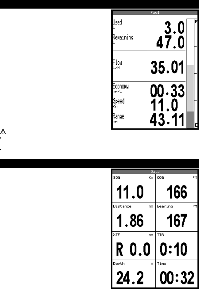
The fuel display shows:
Used: The total fuel used since it was reset to 0 by
the Clear Used command (see section 13-4).
Remaining: The amount of fuel remaining in the fuel
tank(s).
Flow: The fuel consumption. For twin engine
installations, the fuel flow for each engine is shown
separately. This is useful for checking that both
engines are under the same load.
Economy: The distance travelled per unit of fuel
used. The units are set by the units selected for speed
and fuel. Adjust throttle and trim for best economy.
The bigger the number the better the economy.
Speed: Boat speed over ground.
Range: The estimated distance that the boat is able
to travel, based on fuel remaining and current fuel
consumption.
4 Fuel display
The data display has eight large numeric data fields,
four lines with two fields per line.
To go to the data display, press DISP and select
Data
.
Change what data is displayed
1 Press MENU and select
Data setup
.
2 Change a data field:
i Press the cursor keys to highlight the field.
ii Press ENT to display a menu of the data
that can be shown in the field.
iii Select the data to show in the field; select
None
to leave the field empty.
3 Repeat the above step to change other fields.
4 Finally, press ESC to return to the data
display.
5 Data display
Warnings:
Fuel economy can change drastically depending on boat loading and sea conditions. Always
carry adequate fuel for the journey plus a sufficient reserve.
Each time fuel is added or removed use the fuel setup menu (see section 13-4) to record the
fuel or else fuel remaining and the low fuel alarm will be meaningless!
17
TRACKER 5600 Installation and Operation Manual
NAVMAN
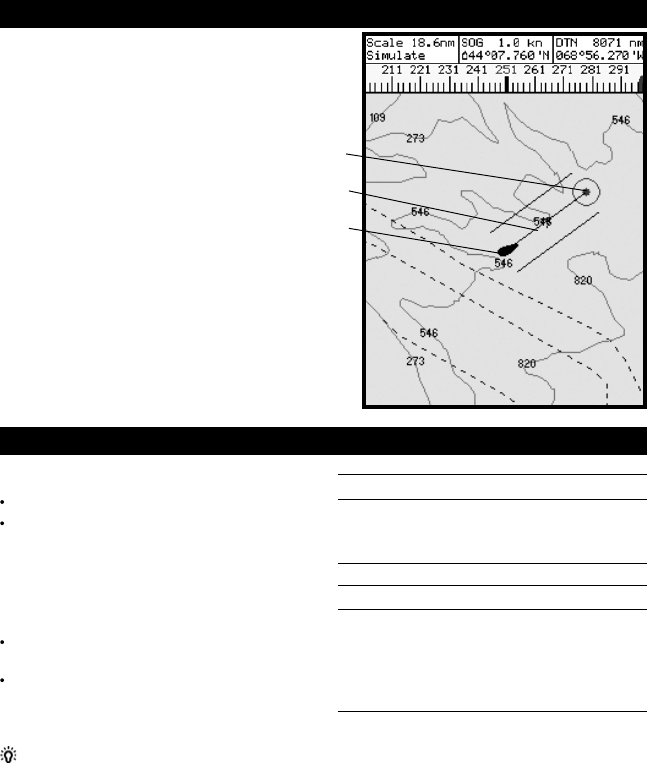
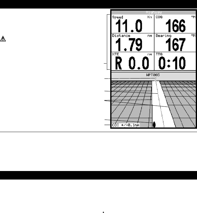
6 Highway display
The highway display has a bird’s eye view of the
boat’s course to a destination:
To go to the highway display, press DISP and select
Highway
.
Warning: The highway display does not show
land, dangerous waters or chart symbols.
CDI lines, parallel to the boat’s plotted course
(see Appendix C, CDI). The CDI lines are like a highway
over the water where the boat will move.
Six numeric data fields
To change what data is displayed, see below
Boat position is at the bottom, centre of the display
CDI scale
Boat’s plotted course to destination
The highway display shows:
Destination waypoint
Change the numeric data display
1 In the highway display, press MENU and select
Data setup
.
2 Change a data field:
i Press the cursor keys to highlight the field.
ii Press ENT to display a menu of the data
that can be shown in the field.
iii Select the data to show in the field; select
None
to leave the field empty.
3 Repeat the above step to change other fields.
4 Finally, press ESC to return to the highway
display.
GPS worldwide navigation
The US Government operates the GPS system.
Twenty-four satellites orbit the earth and broadcast
position and time signals. The positions of these
satellites are constantly changing. The GPS receiver
analyses the signals from the closest satellites and
calculates exactly where it is on earth. This is called
the GPS position.
The accuracy of the GPS position is typically better
than 10 m (33 ft) for 95% of the time. A GPS antenna
can receive signals from the GPS satellites when it
is almost anywhere on earth.
GPS antennas
The TRACKER must be used with the external GPS
antenna supplied. The TRACKER has a sensitive
12-channel receiver built in, which tracks signals from
all satellites visible above the horizon and uses
measurements from all satellites more than 5° above
the horizon to calculate the position.
7 Satellites
DGPS
A DGPS system uses correction signals to remove
some of the errors in the GPS position. The
TRACKER can use one of two types of DGPS
system:
WAAS and EGNOS DGPS
WAAS and EGNOS are two satellite based DGPS
systems. The correction signals are broadcast by
satellites and are received by the TRACKER’s
standard GPS antenna. The accuracy of the
corrected GPS position is typically better than 5 m
(16 ft) for 95% of the time.
WAAS covers all of the USA and most of
Canada. EGNOS will cover most of Western
Europe when it becomes operational about the
end of 2003. To enable WAAS and EGNOS
DGPS, (see section 13-3).
18 TRACKER 5600 Installation and Operation Manual
NAVMAN
Differential beacon DGPS
Differential beacons are land based radio
transmitters that broadcast correction signals
that can be received by a special receiver on
the boat. Differential beacons are usually only
installed near ports and important waterways,
and each beacon has a limited range. The
accuracy of the corrected GPS position is
typically better than 2 to 5 m (6 to 16 ft).
To use differential beacon DGPS, the
TRACKER must be installed with an external
DGPS antenna, such as the NAVMAN DGPS 1
(see section 15-3).
Startup
Each time a GPS receiver is turned on, it normally
takes about 50 seconds before it outputs the first
position. Under some circumstances it will take up
to two minutes or longer.
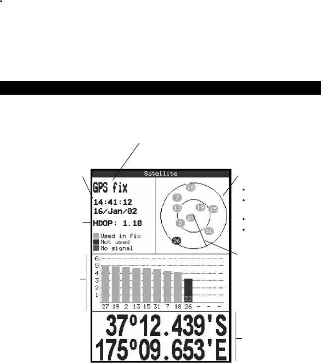
The satellite display has information about the GPS
satellites and GPS position.
To go to the satellite display, press DISP and select
Satellite
.
7-1 Satellite display
Time and date from GPS
satellites. Time is local
time (UTC [GMT] plus
local offset, see section
13-9)
Boat position
HDOP: The error in the
GPS position caused by
satellite geometry. A low
value indicates a more
precise fix, a high value a
less precise fix
Status of GPS antenna, for example Acquiring, GPS fix, No
GPS. If the unit is in Simulate mode it displays Simulate (see
section 2-6)
Positions of visible GPS
satellites:
Outer circle is horizon
Inner circle is 45°
elevation
Centre is directly above
North is at top of
display
If the boat is moving, COG
is a line from centre
Signal strengths of up to
twelve visible GPS
satellites. The higher the
bar the stronger the signal
The satellite display shows:
When the TRACKER is turned on, the satellite
display is shown automatically while the GPS
antenna starts up.
19
TRACKER 5600 Installation and Operation Manual
NAVMAN
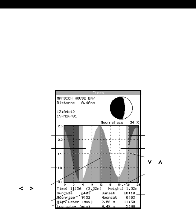
8 Tides display
The tides display shows tide information at a tide
station for the selected date.
To go to the tides display for the tide station nearest
to the boat, press DISP and select
Tides
.
To go to the tides display for any tide station:
1 From the chart display, press MENU and
select
Find
.
2 Select
Tide stations
.
3 A list of tide stations are displayed. Select the
tide station to display. The chart redraws with
the tide station centred.
Moon phase for moon at
the current time on the
chosen date
Height and time of highest high water and lowest
low water on tide chart.
Tide station name
Distance from boat
Tide chart
Current time
Chosen date for display
Times on selected date
Tide height cursor. Press
Time cursor
The tides display shows data for the chosen date:
4 Press MENU and select
Chart info
.
5 Select
Tide height
.
Choosing the date of the tide chart
1 Press MENU.
2 Select
Today
,
Next day
or
Prev day
.
To choose a different date from these, select
Set date
, edit the date, press ENT.
Tide height
Time of day, 0 to 24 hrs
Night
Dawn
Day
Night
Dusk
Day
or to move cursor up
and down. Height of cursor
Press or to move
cursor sideways
Time of cursor
Tide height at that time
20 TRACKER 5600 Installation and Operation Manual
NAVMAN
To go to the waypoints display, press DISP and select
Waypoints
(see right).
The waypoints display is a list of the waypoints that
have been entered, each with waypoint symbol,
name, latitude and longitude, distance and bearing
from the boat, type and display option.
9 Waypoints
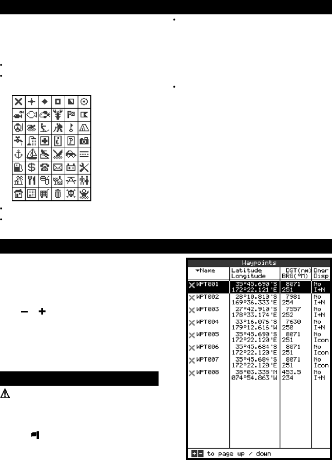
9-1 Waypoints display
A waypoint is a position of interest that is saved by
the TRACKER, for example a fishing spot or a point
on a route. The TRACKER can have up to 3000
waypoints. A waypoint can be created, changed or
deleted. A waypoint has:
A name (up to eight characters).
An icon showing what kind of waypoint it is.
The available icons are:
A position.
A colour for the waypoint symbol and name on
the chart.
A type:
Normal: A normal waypoint can be
navigated to or included in a route.
Danger: A danger waypoint is a point to
avoid. If the boat comes within the danger
radius of a danger waypoint the unit can
sound an alarm (see section 13-6).
A display option:
Controls how the waypoint is displayed when
the
Waypoints
setup option is set to
Selected
(see section 13-2):
Off
: The waypoint is not displayed.
Icon
: The waypoint icon is displayed.
I+N
(Icon and Name): The waypoint icon
and name are displayed.
If there are many waypoints, use this feature to
select which waypoints are displayed on the
chart.
Note: The other choices for the “Waypoints”
setup option are “Hide all” (no waypoints are
displayed on the chart) and “Show all” (all the
waypoints are displayed on the chart) (see
section 13-2).
Press or to display any other waypoints. To
change how the waypoints list is displayed:
1 Press MENU and select
Sort by
.
2 Select how to display the list:
Name
: In alphabetical order by name.
Icon
: Grouped by icon type.
Distance
: In order of distance from the boat.
9-2 Managing waypoints
Warning: Do not create a navigation waypoint
on land or in dangerous water.
9-2-1 Creating a new waypoint
Creating a new waypoint from any display
Press . A new waypoint is created at the boat
position with the default name and data. To
change the default data, (see section 9-2-3).

21
TRACKER 5600 Installation and Operation Manual
NAVMAN
Creating and editing a new waypoint from the
chart display
1 To create a waypoint at the boat position, press
ESC to switch the chart to centre on boat
mode (or press , see above).
Or, to create a waypoint at a different point,
move the cursor to that point on the chart.
2 Press MENU and select
New waypoint
.
3 A new waypoint, with the default name and
data is created.
4 Change the waypoint data if necessary (see
section 9-2-7). Select
Save
.
Creating a new waypoint from the waypoints display
1 In the waypoints display, press MENU and
select
Create
.
2 A new waypoint, with a default name and data,
is created at the boat position.
3 Change the waypoint data if necessary (see
section 9-2-7). Select
Save
.
Note: Waypoints can also be created when a route
is created (see section 10-2-1).
9-2-2 Moving a waypoint
Moving a waypoint from the chart display
1 In the chart display, move the cursor to the
waypoint to move.
2 Press MENU and select
Move
.
3 Move the cursor to the new position and press
ENT.
2 The TRACKER switches to the chart display, with
the selected waypoint at the centre of the chart.
9-2-5 Deleting a waypoint
A waypoint can not be deleted if the boat is navigating
to it or if the waypoint is used in more than one route.
A waypoint that is used in one route can be deleted.
Warning when a waypoint is deleted from a
route, check that the changed route does not
cross land or dangerous waters.
Deleting a waypoint from the chart display
1 In the chart display, move the cursor to the
waypoint to delete.
2 Press MENU and select
Delete
.
3 Select
Yes
to confirm.
Deleting a waypoint from the waypoints display
1 In the waypoints display, press or to
highlight the waypoint to delete. Press MENU
and select
Delete
.
2 Select
Yes
to confirm.
9-2-6 Deleting all waypoints
1 In the waypoints display and press MENU and
select
Delete all
.
2 Select
Yes
to confirm.
9-2-7 Changing a waypoint’s data
To change the waypoint data when it is displayed in
a window:
1 Select the data to change.
Press ENT.
Use the cursor keys to change the data.
Press ENT.
2 If necessary, repeat the above step to change
other data.
3 Select
Save
.
9-2-8 Sort Waypoints
To change the waypoint data when it is displayed in
a window:
1 In waypoint screen press MENU.
2 Select “Sort By”.
3 Choose to sort by Icon, Name or Distance. As
you change sort mode you will notice an arrow
at each column heading move to indicate the
selected method.
4Note: To fast scroll through complete screens
of waypoints use the range ± key to “Page
down” or “Page up”.
Moving a waypoint from the waypoints display
To move a waypoint from the waypoints display, edit
the waypoint (see section 9-2-3) and change the
latitude and longitude.
9-2-3 Editing a waypoint
Editing a waypoint from the chart display
1 In the chart display, move the cursor to the
waypoint to edit.
2 Press MENU and select
Edit
.
3 Change the waypoint data (see section 9-2-7).
Select
Save
.
Editing a waypoint from the waypoints display
1 In the waypoints display, press or to
highlight the waypoint to edit. Press MENU and
select
Edit
.
2 Change the waypoint data (see section 9-2-7).
Select
Save
.
9-2-4 Displaying a waypoint on the
chart
This goes to the chart display, and shows the
selected waypoint at the centre of the display.
1 In the waypoints display, press or to
highlight the waypoint to display. Press MENU
and select
Display
.
22 TRACKER 5600 Installation and Operation Manual
NAVMAN
Warning: After creating or changing a route,
display the route on the chart and check that it
does not cross land or dangerous water.
10-2-1 Creating a new route
A. Creating a new route from the chart display
While creating the route:
Press or to change the range; scroll the
chart by moving the cursor to the edge of the
chart.
A data box at the top, left of the display shows
the route name and total distance. If the cursor
is near a leg, it shows the length and bearing
of the leg as well.
The legs of a route must start and end at
waypoints. If a leg does not start or end at an
existing waypoint then a new waypoint will be
created automatically (to change the new
waypoint data, see section 9-2-7).
1 In the chart display, press MENU and select
New route
.
2 The route is given a default name:
i Change the name if necessary.
ii Select
Ok
.
3 To enter the first leg of the route:
i Move the cursor to the start of the route
and press ENT.
ii Move the cursor to the end of the first leg
and press ENT.
4 To add a waypoint at the end of the route:
i Press ENT.
ii Move the cursor to where the new route
waypoint will be.
iii Press ENT.
5 To insert a waypoint in the route:
i Move the cursor to the chosen leg to insert
the waypoint.
ii Press MENU and select
Insert
.
iii Move the cursor to where the new route
waypoint will be.
iv Press ENT.
6 To move a waypoint in the route:
i Move the cursor to the waypoint to move.
ii Press MENU and select
Move
.
iii Move the cursor to where the waypoint will be.
iv Press ENT.
7 To remove a waypoint from the route:
i Move the cursor to the waypoint to remove
from the route.
ii Press MENU and select
Remove
. The
waypoint is removed from the route, but the
waypoint is not deleted.
8 Repeat this process until the route is finished.
Review the route and check that the route does
not cross land or dangerous water.
Then press ESC.
Or, to delete the route that is being created:
i Press MENU and select
Delete
.
ii Select
Yes
to confirm.
Tip: The distance and bearing calculator can also
be used to enter a course and save it as a route (see
section 3-2).
10 Routes
10-2 Managing routes
A route is a list of waypoints that the boat can navigate
along. Routes can be created, changed and deleted.
The TRACKER can have up to 25 routes. Each route
can have up to 50 waypoints.
A route can:
Start and stop at the same waypoint .
Include waypoints more than once.
The TRACKER can navigate along a route in either
direction. Waypoints on the route can be skipped.
Routes are a powerful feature when the TRACKER
is connected to an autopilot, allowing the vessel to
be automatically guided along the route.
Warning: Make sure that routes do not cross
land or dangerous water.
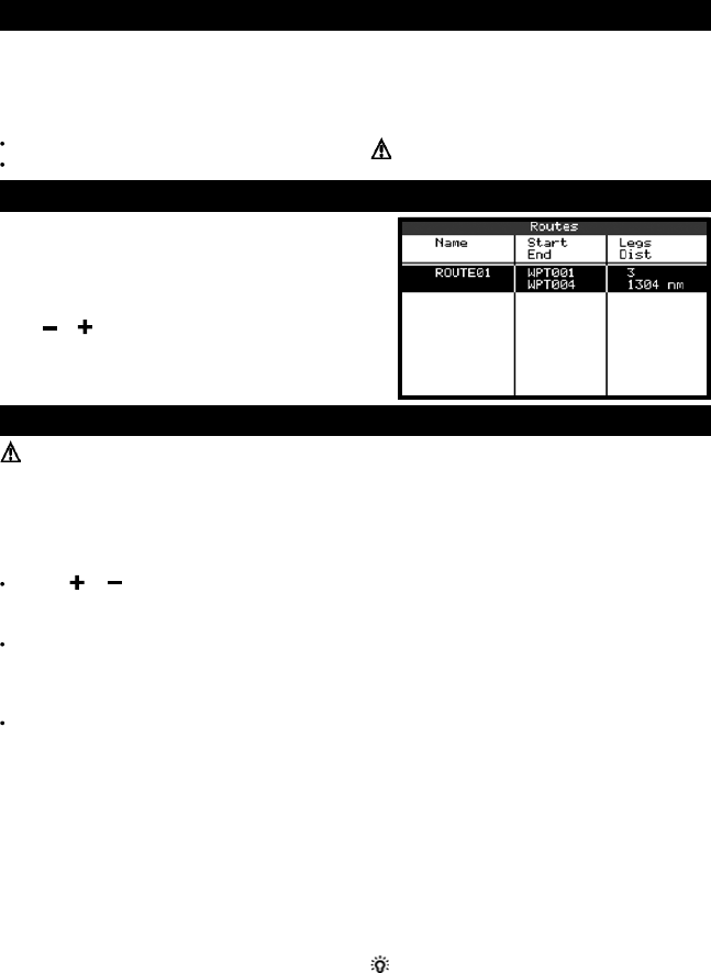
10-1 Routes display
The routes display is a list of the routes that have
been entered, each with route name, start waypoint,
end waypoint, number of legs and total distance.
To go to the routes display, press DISP and select
Routes
.
Press or to display any other routes.
23
TRACKER 5600 Installation and Operation Manual
NAVMAN
B. Creating a new route from the routes display
1 In the routes display, press MENU and select
Create
.
2 A new route, with a default name and no
waypoints, is displayed.
3 To change the route name:
i Select the route name at the top of the
display and press ENT.
ii Change the name if necessary.
iii Press ENT.
4 To insert a waypoint in the route:
i Select where the waypoint will be:
To insert the first waypoint in a new
route, select Leg 1.
To insert a waypoint at the end of the
route, select the unused leg at the end
of the list of waypoints.
Otherwise, select the waypoint to insert
the new waypoint in front of.
ii Press ENT. A list of waypoints is displayed.
Select the waypoint to use.
As waypoints are inserted, the distance and
bearing of each leg is shown automatically. If
the route has more waypoints than will fit on
the display, press or to see them.
5 To remove a waypoint from the route:
i Select the waypoint to remove.
ii Press MENU and select
Remove
.
6 Repeat this process until the route is finished.
7 Press ESC.
8 Display the route on the chart (see section 10-
2-3) and check that the route does not cross
land or dangerous water.
10-2-2 Editing a route
Editing a route from the chart
1 In the routes display, select the route to edit.
Press MENU and select
Edit on chart
.
2 The selected route is displayed on the chart,
with a circle around the first waypoint.
3 Edit the route as described in section 10-2-1 A,
starting at step 4.
Editing a route from the routes display
1 In the routes display, press or to
highlight the route to edit. Press MENU and
select
Edit
.
2 The selected route is displayed: the route
name and a list of the waypoints.
3 Edit the route as described in section 10-2-1 B,
starting at step 3.
10-2-3 Displaying a route on the
chart
To view the selected route at the centre of the
display
1 In the routes display, press or to
highlight the route to display. Press MENU and
select
Display
.
2 It returns to the chart display, with the selected
route displayed.
10-2-4 Deleting a route
1 In the routes display, press or to
highlight the route to delete. Press MENU and
select
Delete
.
2 Select
Yes
to confirm.
10-2-5 Deleting all routes
1 In the routes display, press MENU and select
Delete all
.
2 Select
Yes
to confirm.
10-3-1 Starting a route
To start the boat navigating along a route:
1 In the routes display, press or to
highlight the route to use. Press MENU and
select
Start
.
2 The TRACKER asks for the direction to
traverse the route.
Select
Forward
(the order the route was
created) or
Reverse
.
3 It displays a chart with the route marked and
starts navigating from the start of the route.
10-3 Navigating a route
10-3-2 Skipping a waypoint in a route
To skip a waypoint when the boat is navigating along
a route:
In the chart display, press MENU and select
Skip
.
The TRACKER starts navigating straight towards the
next waypoint on the route.
Warning: Skipping a waypoint with the
autopilot on might result in a sudden course
change.
10-3-3 Cancelling a route
To stop the boat navigating along a route:
In the chart display, press MENU and select
Cancel route
.
24 TRACKER 5600 Installation and Operation Manual
NAVMAN
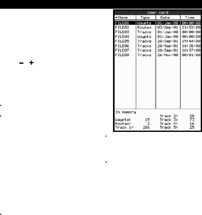
11 User card display
A C-MAP™ user card is an optional plug-in card that
can store data files (see section 1-2). There are three
types of files: waypoints, routes or a track.
To go to the user card display, press DISP and select
User card
.
Note: The older 5 volt cards are not supported.
The user card display has:
File list
A list of the files on any user card in the TRACKER.
Press or to display other files.
Waypts, Routes
The number of waypoints and routes currently
in the TRACKER.
Track 1 to Track 5
The number of points in tracks 1 to 5 currently
in the TRACKER.
Note:
To save TRACKER data onto the user card,
use the Save command (see below).
Data stored on the user card and shown on the
file list is not available to be used by the
TRACKER until loaded into the TRACKER with
the LOAD command (see below).
Saving data to the user card
This saves all the TRACKER’s waypoints, all the
TRACKER’s routes or one of the TRACKER’s tracks
to one file on the user card.
1 Press MENU and select
Save
.
2 Select
Waypts
,
Routes
or
Tracks
.
3 For
Tracks
, select the track number to save.
4 The new file is created. Change the name if
required. The new file appears in the file list.
Loading data from the user card to
the TRACKER
This loads one file from the user card to the
TRACKER:
A waypoints file: The new waypoints are added
to any existing waypoints in the TRACKER. If a
new waypoint has the same name as an
existing waypoint but has different data, the
TRACKER displays both waypoints. Select:
Skip
: Do not load the new waypoint.
Replace
: Load the new waypoint and
replace the existing one.
Skip all
: Do not load any new waypoints
which have the same names as existing
waypoints.
Rplc. all
: Load all new waypoints which
have the same names as existing
waypoints; the new waypoints replace the
existing waypoints.
A routes file: The new routes are added to any
existing routes in the TRACKER. If a new route
has the same name as an existing route but
has different data then the TRACKER asks
which route to keep.
A track file: The new track will replace the
existing track in the TRACKER.
To load a file to the TRACKER:
1 Select the file to load.
2 Press MENU and select
Load
.
Deleting a file from the user card
1 Select the file to delete.
2 Press MENU and select
Delete
.
3 Select
Yes
to confirm.
Reading the file information
This reads the file names from the user card and
displays them. Reading does not load any file data
into the TRACKER.
1 Press MENU and select
Card
.
2 Select
Read
.
Formatting the user card
Formatting prepares a user card for use. Format the
card if there is an error message saying that the card is
not formatted. Any data files on the card are deleted.
1 Press MENU and select
Card
.
2 Select
Format
.
3 Select
Yes
to confirm.
25
TRACKER 5600 Installation and Operation Manual
NAVMAN
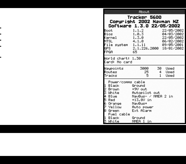
12 About display
To go to the about display, press DISP and select
About
.
The about display shows:
The software version and date.
The world chart version.
Any card fitted.
The number of waypoints, routes and tracks
in the TRACKER.
Wiring information for the TRACKER
connectors.
In the unlikely event of having to contact a NAVMAN
dealer for service, quote the software version
number and date.
Sorting the file names
This sorts the displayed file names.
1 Press MENU and select
Sort
.
2 Select sort by
Name
,
Type
or
Time
.
The TRACKER has a number of advanced
navigation features which are set up through the
setup menu. We recommend that you become
familiar with the operation of the unit using the
Language
Select the language for the displays. The options
are English, Italian, French, German, Spanish, Dutch,
Swedish, Portuguese, Finnish and Greek.
Colours
Select the colour scheme for the LCD display.
The options are:
Normal
Sunlight
: Brighter colours, more visible in
sunlight.
Night
: Reversed colours for night, to preserve
night vision.
Paper
: Simulates the colours of a paper chart.
13-1 System setup
Keybeep
Enable or disable the beep when a key is pressed.
Factory reset
Resets all the TRACKER setup menu data back to
the factory default settings as shown on the setup
menu map. Any waypoints, routes or tracks are not
deleted.
After the reset, the TRACKER displays an installation
menu of setup data:
1 Select the language to use.
2 Change the setup data if necessary:
i Select the data item to change.
ii Use the cursor keys to change the data.
iii Press ENT.
3 When the setup data is correct, press ESC.
default settings before making any changes to the
data in these menus.
To display the setup menu, press MENU until the
setup menu is displayed.
13 Setup menu

26 TRACKER 5600 Installation and Operation Manual
NAVMAN
System Language (English)
Rotation (North up) Colours (Normal)
Projected course (Off) Keybeep (On)
CDI scale (0.1 nm) Factory reset
Chart Plotter mode (Off)
Map datum (WGS84)
Map shift (None)
Waypoints (Selected)
Lat.Lon Grid (Off)
Boundaries (On) Bathymetric Lines (On)
Names (On) Spot soundings (On)
Attention Areas (On) Depth Area Limit 1: (6 m)
Water Features (On) Depth Area Limit 2: (51 m)
Water depth Bath & Sndgs Min: (0 m)
Lights (On) Bath & Sndgs Max: (15 m)
Nav-Aids (Int)
Land Features (On)
GPS Internal GPS (On)
Tank full DGPS Source (None)
Set remaining Restart GPS
Clear Used Static Navigation (Off)
Fuel Tank size (0) Position Filter (Off)
Num Engines (0) Speed Filter: (5)
Fuel cal Course Filter: (4)
Flow filter (5 seconds)
Track Record (1)
Arrival radius (Off) Display (1)
Anchor alarm (Off) Plotting Interval (Distance)
Alarms XTE alarm (Off) Distance (0.1 nm)
Danger alarm (Off) Time (10 seconds)
Low fuel (Off) Memory used
Delete track
Units Distance (nm)
Autopilot out (Off) Speed (kn)
Comms Autopilot data Depth (m)
NavBus (On) Fuel (litres)
NavBus group (0) Compass (°M)
Temperature (°C)
Wind (True)
Time Local offset (0)
Simulate (Off) Time format (24 hour)
Simulate Mode (Normal) Date format (dd/MMM/yy)
Speed (1 kn)
Heading
Route
Setup menu map, with factory default settings in brackets
Setup menu
27
TRACKER 5600 Installation and Operation Manual
NAVMAN
13-2 Chart setup
Rotation
The options for chart rotation are:
North up
: North is always at the top of the
chart display.
Track up
: The chart is rotated so that the boat
direction is to the top of the display. This option
is useful for navigating narrow harbours or
rivers. The TRACKER asks for a course
deviation; this is how much the boat direction
needs to change to make the chart redraw.
Tip: If the chart redraws too frequently,
increase the course deviation setting.
Course up
: This option is only available if the
boat is navigating to a destination. The chart is
rotated so that the plotted course to the
destination is vertical.
Projected course
The TRACKER can estimate the course after a given
time, based on the current speed and heading (see
section 3-4). The options are 2 minutes, 10 minutes,
30 minutes, 1 hour, 2 hours or Off.
CDI Scale
The CDI Scale is described in Appendix C, CDI. The
options are 0.05, 0.1, 0.2, 0.5, 1.0, 2.0, 4.0 and 10.0
distance units.
Plotter mode
Occasionally it is desirable to use a chart scale which
is not available on a chart card. Examples are:
To zoom in to a small scale to track very small
boat movements.
If there is no detailed chart for an area, for
example when crossing an ocean.
If
Plotter mode
is
On
, then if the chart zooms to a
scale which is not available, the TRACKER will enter
plotter mode and will only display the boat position
and track (if enabled). Chart and map information
will no longer be displayed and the display is white
with black crosshatch lines.
For normal use, turn
Plotter mode
to
Off
.
Map datum and map shift
Satellite derived positions on the TRACKER are
based on a worldwide reference (datum) known as
WGS84. Most paper charts are based on WGS84.
However, some paper charts are not based on
WGS84, which results in an offset between a position
on the TRACKER and the same position plotted on
the paper chart.
To match the TRACKER’s positions with a local chart
that is not based on WGS84:
Either select
Map datum
and select the datum
for the local chart. See Appendix A for a list of
the available datums. WGS84 is the default
datum, and the datum most commonly used on
paper charts.
Or, if the correct datum is not available, retain
the WGS84 datum and apply a map shift (see
below).
Map shift
Map shift is a correction applied to the TRACKER’s
positions so that they match a chart’s positions.
Warning: Map shift is for eliminating minor
offsets. It should not be used if the correct datum
is available. Use map shift with caution: incorrect
application will cause incorrect boat positions.
Set map shift
1 Move the boat to a known point on the chart,
for example a marina berth.
2 In the Chart setup menu, select
Map shift
.
3 Move the cursor to the position on the chart
where the boat actually is.
4 Press ENT to set the new map shift. The boat
will now be displayed at its actual location.
Clear map shift
Clearing the map shift removes any map shift from
the TRACKER’s positions.
1 In the Chart setup menu, select
Map shift
.
2 Press MENU and select
Clear
.
Waypoints
Controls how waypoints are displayed on the chart.
The options are:
Hide all
: No waypoints are displayed.
Show all
: All waypoints are displayed.
Selected
: Waypoints with their display option
set to Icon or I+N (Icon and Name) are
displayed (see section 9).
Chart display options
The other chart setup options allow an extensive
range of chart card features to be shown. Configure
the most useful display format.
Note:
Bathymetric Lines and soundings
Chart cards contain a large amount of spot sounding
and depth contour data. This can be selectively
displayed by turning Bathymetric Lines and Spot
Soundings on, then selecting the range to display
with Bath and Sndgs Min and Max.
Attention Areas
Areas of importance, such as restricted anchorages
and shallow areas, are highlighted as Attention Areas.

28 TRACKER 5600 Installation and Operation Manual
NAVMAN
13-3 GPS setup
GPS Source
Disable or enable the TRACKER’s internal GPS
receiver. Disable this if a non-standard GPS antenna
that sends NMEA data is installed.
DGPS Source
Enables or disables the satellite based DGPS
correction (see section 7). The options are None or
WAAS/EGNOS. Do not enable WAAS/EGNOS
outside their coverage areas or the accuracy of the
position might be degraded.
WAAS covers all of the USA and most of Canada.
EGNOS will cover most of Western Europe when it
becomes operational about the end of 2003.
Restart GPS
Restarts the internal GPS receiver for servicing or
troubleshooting. The GPS receiver takes up to three
minutes to restart. The satellite display shows the
status of the GPS receiver (see section 7).
The options are:
On
: displays attention area boundaries and
information icons .
Off
: does not display attention area boundaries
or information icons .
Note: In some early chart cards the information icons
are inactive.
Depth area limits
The depth area limits control the chart water colours
Static Navigation
The displayed speed and course become erratic
when the boat stops. Turn Static navigation On to
display speed and course as zero when the boat is
stopped.
Position, Speed and Course Filter
Waves and wind cause the boat position, speed and
course to fluctuate slightly. To give stable readings,
the TRACKER calculates these values by taking
several measurements and averaging them.
A lower value averages measurements over a
shorter period of time. This gives the most
accurate value but has the most fluctuations.
A higher value averages measurements over a
longer period of time. This gives the most
stable value but will ignore some true speed
changes.
Set the Position, Speed and Course filters to the
lowest values which give stable readings. The range
of each filter is 1 to 60 seconds or Off (0).
for different depths. There are three water colours:
Surface to Depth area limit 1:
Shallow water colour.
Depth area limit 1 to Depth area limit 2:
Medium water colour.
Below Depth area limit 2:
Deep water colour.
The actual water colours depend on the LCD colour
scheme in use (see section 13-1).
13-4 Fuel Setup
To use these fuel features first purchase and install
the optional single or twin engine fuel kit.
Whenever fuel is added or removed from the tank,
use this menu:
If the tank is filled, select Tank Full.
If the tank is partly filled or fuel removed:
1 Before adding or removing the fuel, go to
the fuel display and note how much fuel is
in the tank.
2 Note how much fuel is added or removed.
3 Calculate how much fuel is now in the tank
by adding or subtracting the two figures.
4 Select this menu and enter how much fuel
is now in the tank in Set Remaining.
Warning: Do this each time fuel is added or
removed or else fuel remaining and the low fuel
alarm will be meaningless!
Tank Full
Select
Tank full
each time the tank is filled full.
When asked for confirmation, Select
Yes
.
Set Remaining
Enter the amount of fuel now in the tank after it has
been partly filled or fuel has been removed.
Clear Used
Select
Clear Used
to set Used (the amount of fuel
used) to zero. Do this to restart measuring the amount
of fuel used.
When asked for confirmation, Select
Yes
.
Tank Size
Enter the capacity of the fuel tank.
Num Engines
Set the number of engines to
0
,
1
or
2
.
If
0
is selected the fuel features are turned off.
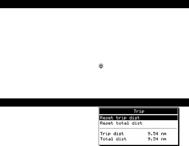
29
TRACKER 5600 Installation and Operation Manual
NAVMAN
13-5 Track setup
Tracking records and displays the boat’s course on
the chart (see section 3-5).
Record
Off
: The TRACKER stops recording a track.
1 to 5
(select a track number): The TRACKER
starts recording the boat’s course into the
selected track.
Display
Off
: No track is shown on the chart.
1 to 5
(select a track number): The selected
track is shown on the chart.
Plotting Interval
The options are
Distance
or
Time
.
Distance
Select the distance plotting interval: 0.01, 0.05, 0.1,
0.5, 1.0, 2.0, 5.0 or 10.0 distance units.
Time
Select the time plotting interval: 1, 5, 10 or 30 seconds
or 1 minute.
Memory used
The percentage of memory used in the track being
recorded.
Tip: Use the user card display to check the number
of points recorded in each track (see section 11).
Delete track
1 Select the track number to delete (1 to 5).
2 Select
Yes
to confirm.
The data in the selected track is deleted.
13-6 Trip log(s)
Fuel Cal
Without calibration the error in fuel measurements
can be up to ± 10%. Calibration can reduce the error
substantially. For twin engine installations calibration
of each transducer is required.
Calibrating the fuel transducer requires accurate
measurement of the fuel used. This is easiest with a
small portable tank. It should be noted that due to air
pockets, it is very difficult to fill underfloor tanks to
the same level twice. At least 15 litres (4 US gallons)
should be used to ensure an accurate calibration.
(The more fuel used, the more accurate the
calibration will be.) Each transducer in a twin engine
installation must be calibrated separately. This may
be done at the same time with two portable tanks, or
at different times using one tank at a time.
The procedure is:
1 Select
Clear Used
to set Used to zero.
2 Connect the measurement tank(s) to the
engine(s) via the fuel transducer(s).
3 Run the engine(s) at normal cruising speed until
at least 15 litres (4 US gallons) is indicated
(30 litres [8 US gallons] for twin engines).
4 Check the actual amount of fuel used per
engine. The easiest way to do this is to refill
the tank(s) to the original level(s) and record
the value(s) shown on the fuel dispenser.
5 Select
Fuel Cal
. The amount of fuel that the
TRACKER has measured is displayed.
Change the number to the actual fuel amount
used. (Repeat for the other engine in a twin
engine installation).
Flow Filter
Normally engines do not draw fuel from the tank at a
steady rate. To give a stable fuel flow reading, the
TRACKER calculates the flow values by taking several
measurements and averaging them. The flow filter
sets the period over which the fuel flow is averaged,
and can be set from 1 to 180 seconds or Off.
Set the flow filter to the lowest value which give a
stable flow. Usually a value of 10 to 15 seconds will
give a satisfactory result for carburettor engines. Fuel
injected engines may require a larger value.
This setting affects the Flow rate and Economy
displays. It does not affect the fuel used measurement.
For displaying the trip log(s) on the data header, see
section 3-1-8.
Press MENU twice, then select Trip to display the
trip.
Selecting Reset trip dist or Reset total dist then
pressing ENTER resets each to zero.
30 TRACKER 5600 Installation and Operation Manual
NAVMAN
13-8 Units setup
Distance units
Options are nm (nautical miles), mi (statute miles)
or km (kilometres).
Speed units
Options are kn (knots), mph (miles per hour) or kph
(kilometres per hour).
Depth units
Options are ft (feet), fm (fathoms) or m (metres).
Fuel units
Options are litres, US gal (US gallons) or Imp gal
(Imperial gallons).
Autopilot out
Disable or enable the NMEA output to an autopilot
or other instrument.
Autopilot data
Displays a list of the NMEA sentences that can be
sent to an autopilot. Turn each Off or On as required.
13-9 Comms setup
Compass
The options are °T (True north) or °M (Magnetic
north).
Temperature (optional)
The options for water temperature are °C or °F.
Wind (optional)
The options for wind speed and direction are True
or App (Apparent).
Note: that the units for wind speed
are the speed units.
NavBus
Off
: NavBus is disabled. One of the NavBus
connector pins becomes a NMEA input line
(see sections 14 and 15-3).
On
: NavBus is enabled.
NavBus group
Enter the NavBus backlight group number (the range
is 0 to 4, see section 14).
13-7 Alarms setup
For alarm operation, see section 2-5. To turn off an
alarm which is sounding, press ESC.
Arrival radius alarm
When the arrival radius alarm is enabled, an alarm
will sound:
a When the boat is going to a point and the boat
comes within the arrival radius of the
destination
b Or when the boat is navigating a route and the
boat comes within the arrival radius of a
waypoint in the route.
To enable the alarm, enter an arrival radius (up
to 9.99 distance units).
To disable the alarm, set the arrival radius to
Off
(0).
Anchor alarm
When the anchor alarm is enabled, an alarm will
sound when the boat moves by more than the anchor
alarm distance.
To enable the alarm, enter an anchor alarm
distance (up to 9.99 distance units). The
TRACKER saves the current boat position.
To disable the alarm, set the anchor alarm to
Off
(0).
The minimum usable setting of the alarm is
determined by the accuracy of the global positioning
system, typically within 10 m (33 ft).
Warning: Do not rely on the anchor alarm as
the only anchor watch.
XTE alarm
When the XTE alarm is enabled, an alarm will sound
when the boat is navigating to a point and the distance
from the boat to the plotted course (XTE) is more
than CDI (Course Deviation Indicator) scale (see
Appendix C, CDI).
To enable the alarm, set the XTE alarm to
On
.
To disable the alarm, set the XTE alarm to
Off
.
Danger alarm
When the danger alarm is enabled, an alarm will
sound when the boat comes within this distance of a
danger waypoint.
To enable the alarm, enter an danger alarm
distance (up to 9.99 distance units).
To disable the alarm, set the danger alarm to
Off
(0).
Low fuel alarm
When the low fuel alarm is enabled, an alarm will
sound when the fuel remaining in the tank is less
than the low fuel value.
To enable the alarm, enter a low fuel value.
To disable the alarm, set the low fuel value
to
Off
.
31
TRACKER 5600 Installation and Operation Manual
NAVMAN
Simulate mode is a way of becoming familiar with
the TRACKER (see section 2-6).
Warning: Never have simulate mode on when
the TRACKER is navigating on the water.
Simulate
Turn simulate mode
Off
or
On
.
Press MENU and select
simulate.
Select
On
or
Off.
Mode
There are two choices for
Mode
:
Normal
Simulates the boat moving from the selected
start point (see step 1 above) at the given
speed and heading. The options are:
Speed
: The simulated boat speed to use.
Heading
: The simulated bearing for the
boat to follow.
Tip: To calculate a heading, use the cursor
(see section 3-1-1).
Tip: As the boat moves, vary Heading to
simulate the boat moving off course.
13-11 Simulate setup
Demo
Simulates the boat moving along a route at a
given speed. When it reaches one end it
retraces the route in the other direction. Before
setting this mode enter at least one route (see
section 10-2-1). The options are:
Speed
: The simulated boat speed to use.
Route
: The route to follow.
To turn simulate mode on from this menu:
1 If turning Normal mode on, go to the chart
display. To start the simulation from the boat
position, press ESC to switch to centre on boat
mode. To start the simulation from a different
point, move the cursor to that point on the
chart.
2 In the Simulate setup menu, select
Simulate
and turn it on.
3 Select
Mode
and set it to
Normal
or
Demo
.
4 Select and enter the other data required for
simulate:
Normal requires
Speed
and
Heading
.
Demo requires
Speed
and
Route
.
14 Systems of several instruments
Several NAVMAN instruments can be connected
together to share data. There are two ways of
connecting instruments together, NavBus or NMEA.
NavBus
NavBus is a NAVMAN proprietary system that allows
systems of multiple instruments to be built using a
single set of transducers. When instruments are
connected by NavBus:
If the units, alarms or calibration are changed
in one instrument, then the values will
automatically change in all other instruments
of the same type.
Each instrument can be assigned to a group of
instruments (see section 13-8). If the backlight
is changed in an instrument in group 1, 2, 3 or
4 then the backlight will automatically change
in the other instruments in the same group.
If the backlight is changed in an instrument in
group 0 then no other instruments are affected.
If an alarm sounds, mute it by clearing the
alarm on any instrument which can display that
alarm.
NavBus and the TRACKER
The TRACKER can display data (e.g. depth,
speed, log and wind) from NAVMAN’s 3100
series instruments when connected.
NMEA
NMEA is an industry standard, but is not as flexible
as NavBus as it requires dedicated connections
between instruments. The TRACKER can:
Receive and display depth data.
Receive data from a GPS antenna.
Send GPS position and other navigation data
to an autopilot or other instrument.
Local offset
The difference between local time and UTC (GMT).
Change local offset when daylight saving time starts
and ends. The range is 0 to ± 13 hours, in 30 minute
steps.
13-10 Time setup
Time format
The options are 24 hour or 12 hour.
Date format
The options are dd/MMM/yy, MMM/dd/yy,
dd/MM/yy or MM/dd/yy.
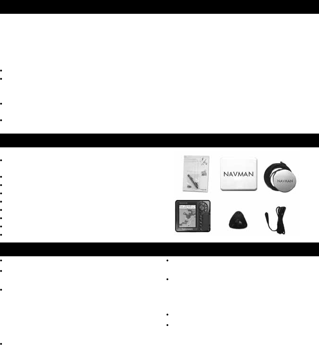
32 TRACKER 5600 Installation and Operation Manual
NAVMAN
15 Installation
15-1 What comes with the TRACKER
Standard configuration
TRACKER display unit, with a holder for plug-
in cards and blanking cap for fuel connector.
Dust cover for display unit.
Mounting bracket.
Flush mount kit.
Power/data cable.
NAVMAN 1300 GPS antenna.
Warranty card.
This Installation and Operation manual.
Screws.
Correct installation is critical to the performance of
the unit. There are two components to install, the
TRACKER and a GPS antenna. In addition, install
the optional fuel kit to use the TRACKER as a fuel
computer.
The TRACKER can:
Drive external beepers or lights for the alarm.
Send and receive data from other NAVMAN
instruments connected via NavBus. The
backlight setting is shared (see section 14).
Send NMEA data to an autopilot or other
instrument.
Accept and display NMEA data from a depth
sounder.
The TRACKER can be wired for auto power so that
it automatically turns on and off with the boat power
and can not be turned on or off manually. Wire auto
power if the fuel option is installed, so that the
TRACKER records all the fuel that is used (see
section 15-3).
It is vital to read the entire installation section of this
manual and the documentation that comes with the
antenna and any other units before starting
installation.
15-2 Options and accessories
C-MAP™ chart cards.
C-MAP™ user cards (3 V) for storing data.
Note: The older 5 volt cards are not supported.
Fuel kit for single or twin petrol/gasoline
engines.
If a fuel kit is installed, wire auto power on so
that the TRACKER is on all the time the engine
is on and no fuel consumption is missed (see
section 15-3).
Beepers with built-in drivers or lights. The
TRACKER output is switched to ground, 30 V DC
and 200 mA maximum. If the beepers and
lights require more than 200 mA, fit a relay.
5 m (16 ft) extension cable for NAVMAN 1300
GPS antenna.
Second station kit. Allows a bracket mounted
TRACKER to be used at another place in the
boat (contains second mounting bracket and
cables).
NAVMAN’s REPEAT 3100.
NAVMAN carry bag.

33
TRACKER 5600 Installation and Operation Manual
NAVMAN
15-3 Installation
Warning: Ensure that any cut holes will not
weaken the boat. If in doubt, consult a qualified
boat builder or marine engineer.
Display unit
1 Find a suitable location for the display unit:
There are two mounting arrangements:
Flush mounting requires a solid panel
with access behind for wiring and mounting
screws.
Bracket mounting requires a panel for
mounting the bracket. The bracket can be
rotated and tilted.
Choose a location that is easily seen and not
exposed to the direct sun or water. If possible,
mount the display unit in front of the navigator
or to the left of the navigator because the LCD
display is more readable from these positions.
Keep the unit away from any source of
electrical signals or noise.
2 For flush mounting:
i Cut a hole in the bulkhead for the display
unit using the flush mount template.
ii Drill four holes for the mounting studs
using the flush mount template.
iii Screw the four studs into the brass inserts
in the back of the display unit.
iv Sit the display unit in place and fit the
washers and nuts to the studs.
For bracket mounting:
i Hold the bracket in place and mark the
screw holes.
ii Drill the screw holes and screw the bracket
in place with the screws provided. Do not
overtighten the screws or the display unit
might not rotate.
Do not fit the display unit yet.
GPS antenna
1 Find a suitable location for the antenna:
Mount the antenna with a good view of the sky
and horizon. The view should not be blocked
by large parts of the superstructure.
The unit can be under glass, perspex,
fibreglass or fabric, but not under metal or
wood.
Mount the antenna away from any source
of electrical signals or noise. Do not mount
the antenna within 2 m (6 ft) of a radio
transmitter antenna or within 0.5 m (20") of
the plane of a radar antenna.
Do not fit the antenna too high, such as up
a mast, or rocking will cause errors in
speed and bearing.
Do not mount the antenna where it can be
used as a hand hold, where it will interfere
with the operation of the boat or where it
might be submerged.
The maximum antenna cable length is
15 m (49 ft).
If a location might not be suitable, follow the
installation instructions below but mount the
antenna and antenna cable temporarily,
without drilling any fixing holes. If the system
does not work properly, change the antenna
location until it works properly. Then install the
antenna and cable permanently.
2 Fit antenna in place.
3 Run the cable between the antenna and the
display unit:
Keep the cable away from sources of
electrical signals or noise.
Do not cut the antenna cable; if necessary,
fit one 5 m (16 ft) extension cable.
Do not crush or pinch the antenna cable.
Secure the cable at regular intervals.
Optional fuel kit
Fit the fuel kit following the instructions that come
with the kit.
Installation of a DGPS antenna
In areas where satellite differential (WAAS/EGNOS)
is not available an optional combined GPS/DGPS
antenna may be connected for enhanced accuracy
when in range of conventional land based differential
beacons. Please contact the nearest NAVMAN dealer
for further information.

34 TRACKER 5600 Installation and Operation Manual
NAVMAN
Power/data cable for display unit
Wire the cable as shown on the next page.
Note:
The unit requires 12 V DC power. This power
supply must be protected with a fuse or circuit
breaker of between 2 and 3 A. If it does not have
this, fit a 2 A fuse in the power supply line.
To enable auto power (see section 2-1),
connect the yellow Power/data cable wire to
the positive power supply as shown.
To disable auto power, leave the wire
disconnected; make sure it can not touch any
other conductor.
If the external beepers and lights require more
than 200 mA DC total, fit a relay.
For information on how to connect NavBus, refer
to the NavBus Installation and Operation manual.
Setup and test
1 Remove the dust covers from the connectors.
2 Plug the eight way connectors into their
sockets on the back of the display unit:
Match the colour on the end of the
connector to the colour of the nut on the
socket.
Hold the plug against the socket and rotate
the plug until it slides into the socket.
Lock the plug in place by pushing the
locking collar towards the socket and
turning it a quarter turn clockwise.
Nothing will be damaged if a cable is plugged
into the wrong socket by mistake.
3 If the unit has an external GPS antenna:
Plug the gold connector into its socket on
the back of the display unit.
Hand tighten the locking collar clockwise -
do not overtighten.
4 If the display unit is bracket mounted:
i Hold the display unit in place on the
mounting bracket shaft, with the rubber
washer clamped between the bracket and
the display unit.
ii Adjust the tilt and rotation of the display
unit for best viewing and hand tighten the
knob.
5 Remove the dust cover. Turn the TRACKER on
(see section 2-1).
6 Insert any required C-MAP™ chart card (see
section 1-2).
7 When the TRACKER is turned on for the first
time, the TRACKER displays an installation
menu of setup data:
i Select the language to use.
ii Change the setup data if necessary:
Select the data item to change.
Use the cursor keys to change the data.
Press ENT.
iii When the setup data is correct, press
ESC.
These installation options can be changed
later, through the setup menu (see section 13).
8 At the satellite display, check that it picks up
GPS satellites. Wait for the GPS receiver to
start up and the fix type to change from
‘Acquiring’ to ‘GPS fix’. This should take less
than two minutes (see section 7).
9 If the TRACKER is to send NMEA data to an
autopilot, set this up (see section 13-8).
10 If the TRACKER is part of a NavBus system,
set the backlight group. Otherwise turn NavBus
off (see section 13-8).
11 Go on a test run to check that the navigation
equipment works correctly, particularly when a
radio transmitter or radar is used.
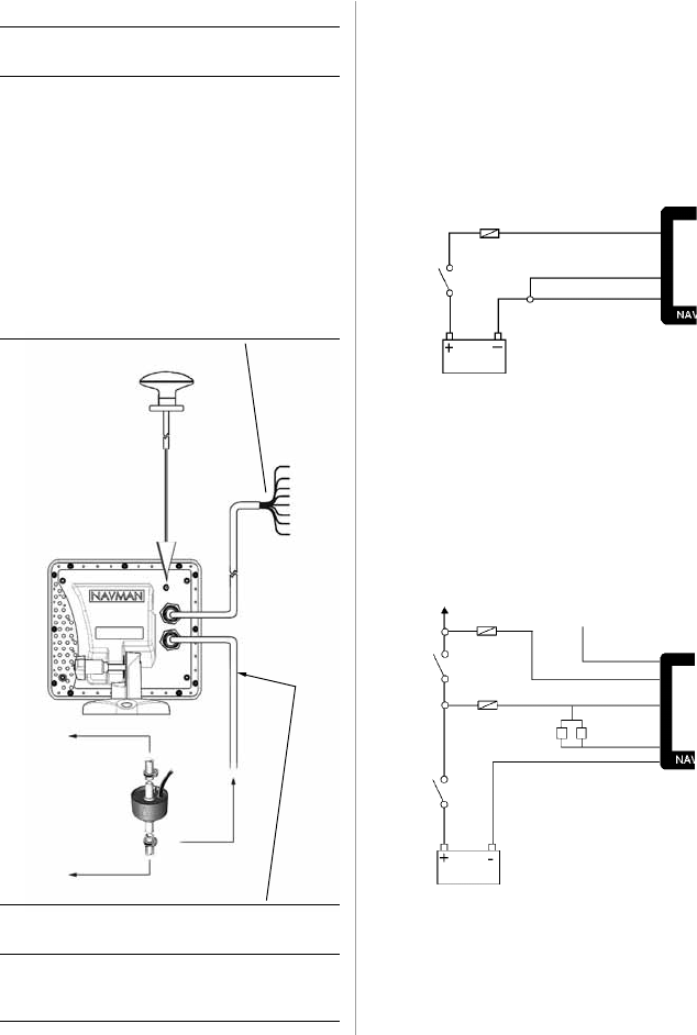
35
TRACKER 5600 Installation and Operation Manual
NAVMAN
External
GPS antenna
Fuel
transducer(s)
(optional)
Installation
To engine
From fuel tank
Auto Power Wiring
Black wire: Connect this to the negative battery
terminal.
Red Wire: Connect this to the 12 V positive battery
terminal after the main switch. Fit a 1 Amp fuse as
shown.
Yellow Wire: Connect to the ignition switch.
Fuse
Fuse
White (NMEA out)
Green
External Beeper
or Light
Red
Yellow
Black
Main
switch
12 V DC
Ignition
switch
To ignition system
Basic Wiring
Black wire: Connect this to the negative battery
terminal.
Red Wire: Connect this to the 12 V positive battery
terminal after the main switch. Fit a 1 Amp fuse as
shown.
Yellow wire: Connect this to the black wire.
Power on the TRACKER manually whenever the
main switch is on.
Power/data cable (black locking collar)
Pin Wire Signal
1 Black Ground (power negative, NMEA)
2 Brown Power out, 9 V DC
3 White NMEA out, to autopilot/radar
4 Blue NavBus - or NMEA 2 input
5 Red Positive power in, 11 to 16.6 V DC
6 Orange NavBus +
7 Yellow Auto power in (connect to positive
power in to enable auto power)
8 Green External beeper or light out,
switched to ground, 30 V DC,
200 mA maximum
Note: Shield is connected to pin 1, black wire
Fuse Red
Yellow
Black
Main
switch
12 V DC
Power/data
cable
Fuel cable (white locking collar)
Pin Wire Signal
1 Black Ground (NMEA)
3 White NMEA1 input
Note: Shield is connected to pin 1, black wire
Fuel
cable
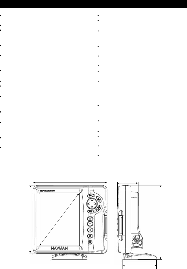
36 TRACKER 5600 Installation and Operation Manual
NAVMAN
Physical
Size 179.5 mm H x 195 mm W x 54 mm D
(7.06" x 7.6" x 2.1").
Weight, display unit 20 oz (600 g).
Display: 6.4" diagonal, TFT colour, 234 x 320
pixels.
Electrical
Power supply 11 to 18 V DC; current at 13.6 V
with full backlight: < 600 mA.
External beeper or light output, switched to
ground, 30 V DC, 200 mA maximum.
Operating Temperature
0°C to 50°C (32°F to 122°F).
Chart and user cards
C-MAP™ NT cards and NT+ cards.
3.3 V C-MAP™ user cards.
Waypoints
Up to 3000, with default or user-defined
alphanumeric names up to eight characters.
Routes
25 Routes, with up to 50 points each
Tracks
By time or distance, one track of 2000 points
and four of 500 points.
Alarms
Arrival radius, anchor, XTE, danger, low fuel
(optional); individually controlled
Loss of GPS/DGPS fix (fixed alarms).
Appendix A - Specifications
Chart datums
140 Chart datums (see below).
One user-defined map shift.
Chart scale
0.05 to 4096 nm for chart (chart dependent)
down to 0.01 nm in plotter mode.
Fuel Computer (Optional fuel transducer required)
Outboard carburetted two stroke petrol/gasoline
engines: 30 to 300 hp.
Outboard four stroke petrol/gasoline engines:
90 to 300 hp.
Inboard petrol/gasoline engines: 50 to 300 hp.
Minimum flow rate: 5 litres per hour.
Standards compliance
EMC compliance
USA (FCC): Part 15 Class B.
Europe (CE): EN50081-1, EN50082-1.
New Zealand and Australia (C Tick):
AS-NZS 3548.
Environment: IP67/CFR46 (with card holder and
connections in place).
NavBus
Connection to other NAVMAN instruments.
NMEA
NMEA 0183 ver 2.
Input, from GPS or DGPS receiver: GSA, GSV,
GTA, RMC.
Input, from a depth sounder: SDDPT (preferred)
or SDDBT.
Output, for autopilot or other instrument:
APA, APB, GGA, GLL, GSA, GSV, RMB, RMC,
BWR, VTG, XTE.
7.06" (179.5 mm)
2.1" (54 mm)
7.1" (195 mm)
7.6" (195.0 mm)
6.4" (163 mm)
7.6" (195.0 mm)
3.5" (88.5 mm)

37
TRACKER 5600 Installation and Operation Manual
NAVMAN
ADINDAN AFGOOYE AIN EL ABD 70 AM.SAMOA 1962 ANNA 1 AS. 65 ANTIGUA AS. 43
ARC 1950 ARC 1960 AS.BEACON 'E' AS.DOS 71/4 AS.STATION 52 AS.TERN ISL.
ASCENS.ISL.58 AUS.GEOD. 66 AUS.GEOD. 84 AYABELLE BELLEVUE (IGN) BERMUDA 1967
BISSAU BOGOTA OBS. BUKIT RIMPAH C. CANAVERAL CAMP AREA AS. CANTON AS. 66
CAPE CARTHAGE CHATHAM 1971 CHUA ASTRO CMP.INCHAUSPE CORR. ALEGRE
DABOLA DECEPTION IS DJAKARTA DOS 1968 EASTER ISL.67 ESTONIA 1937
EUROPEAN 1950 EUROPEAN 1979 F.THOMAS 1955 FINNISH (KKJ) GAN 1970 GEODETIC 1949
GRACIOSA BASE GUAM 1963 GUNUNGSEGARA GUX 1 ASTRO HERAT NORTH HERMANSKOGE
HJORSEY 1955 HONG KONG 63 HU-TZU-SHAN IGN 1954 IGN47 IGN47-51
IGN72 INDIAN INDIAN 1954 INDIAN 1960 INDIAN 1975 INDONES. 1974
IRELAND 1965 ISTS 73 AS.69 ISTS AS. 1968 JOHNSTON 1961 KANDEWALA KERGUELEN 1949
KERTAU 1948 KUSAIE AS. 51 L.C. 5 ASTRO LEIGON LIBERIA 1964 LISBOA
LUZON M. MERCURY 68 MAHE 1971 MASSAWA MERCHICH MERCURY 1960
MIDWAY AS. 61 MINNA MONTSERRAT 58 M’PORALOKO N. SAHARA 1959 NAD 1927
NAD 1983 NAHRWAN NANKING 1960 NAPARIMA, BWI NEW P. SANTO NORWEGIAN
O.S. IRELAND O.S.G.B. 1936 OBSERVAT.1996 OLD EGYPTIAN OLD HAWAIIAN OMAN
P.TE NOIRE 48 P.TO SANTO 36 PICO NIEVES PITCAIRN 1967 POINT 58 POLISH
POTSDAM PRV.S.AMER.56 PRV.S.CHIL.63 PUERTO RICO PULKOVO 1942 QATAR NATION.
QORNOQ REUNION REV. KERTAU REV. NAHRWAN ROME 1940 RT 90
S.LEONE 1960 S. AMERICAN 69 SANTO(DOS) 65 SAO BRAZ SAPPER H. 43 SCHWARZECK
SELVAGEM 1938 SGS 85 S-JTSK SOUTH ASIA SWEDISH SWISS CH-1903
TANANARIVE 25 TIMBALAI 1948 TOKYO TRISTAN 1968 VITI LEVU 16 VOIROL 1875
VOIROL 1960 WAKE ISL.1952 WAKE ISL.1952 WAKE-ENIWETOK WGS 1972 WGS 1984
YACARE ZANDERIJ
List of datums

38 TRACKER 5600 Installation and Operation Manual
NAVMAN
Appendix B - Troubleshooting
This troubleshooting guide assumes that you have
read and understood this manual.
It is possible in many cases to solve difficulties
without having to send the unit back to the
manufacturer for repair. Please follow this
troubleshooting section before contacting the
nearest NAVMAN dealer.
There are no user serviceable parts. Specialised
methods and testing equipment are required to
ensure that the unit is reassembled correctly and is
waterproof. Repairs to the unit must only be carried
out by a service centre approved by Navman NZ
Limited. Users who service the TRACKER
themselves will void the warranty.
When contacting a NAVMAN dealer for service, quote
the software version number and date which is given
on the about display (see section 12).
More information can be found on our Website:
www.navman.com
1 TRACKER will not switch on:
a Cables not connected or plugged into wrong
sockets in display unit. Match the plug colours.
b TRACKER wired for auto power. TRACKER
will turn on and off with boat power.
c Backlight too low. Turn on full (see section 2-3).
d Fuse blown or circuit breaker tripped.
e Faulty wiring.
2 TRACKER will not switch off:
TRACKER wired for auto power. TRACKER
will turn on and off with boat power.
3 TRACKER turns off unexpectedly:
a Power/data cable not plugged in properly.
b Loose or corroded connection in power/data
cable. Check cable.
4 The language on the display is wrong:
Choose the correct language (see section 13-1).
5 No GPS fix or long time to get fix at startup:
a May occur occasionally if the antenna does not
have a clear view of the sky. The satellite
positions are constantly changing.
b Antenna cable not connected to display unit.
c Restart GPS (see section 13-3).
6 TRACKER GPS position different from true
position by more than 10 m (33 ft):
a TRACKER in simulate mode. Turn simulate
mode off (see section 13-11).
b The normal error in GPS position will exceed
10 m (33 ft) for about 5% of the time.
c Under special circumstances the US
Department of Defence may introduce a
deliberate and changing error in the GPS
positions of up to 300 m (1000 ft).
7 TRACKER position different from same
position on local charts:
a TRACKER in simulate mode. Turn simulate
mode off (see section 13-10).
b Incorrect chart datum. Select the correct chart
datum (see section 13-2).
c Map shift has been applied wrongly. Clear map shift,
then reapply if necessary (see section 13-2).
8 Can not see boat on chart:
Press ESC to switch to centre on boat mode
(see section 3-1-1).
9 The time or date on satellite display is wrong
or off:
a No GPS fix.
b In simulate mode. Turn simulate mode off (see
section 13-10).
c Local time offset is wrong (see section 13-9).
The Local Time Offset must be changed when
daylight saving time starts or ends.
10 Autopilot not responding to TRACKER; no
NMEA output:
a NMEA output disabled or the required NMEA
sentences are not turned on. Check NMEA
settings (see section 13-8).
b Check that the instrument is connected
correctly.
11 Depth not displayed:
a Set a data field to Depth in chart, highway or
data displays.
b Check depth sounder is working and
connected properly.
12 No fuel functions available:
a Fuel kit not installed.
b Fuel functions not enabled. Set Num Engines
to 1 or 2 (see section 13-4).
c Cables not connected or plugged into wrong
sockets in display unit. Match the plug colours.
13 Fuel Used or Remaining seem wrong:
a The engine has been run while the TRACKER
is turned off and it has not recorded the fuel
use. Wire the auto power option (see section
15-3).
b Fuel may be surging back and forward through
a transducer in rough seas. Try installing a one
way valve between the fuel transducer and the
fuel tank.

39
TRACKER 5600 Installation and Operation Manual
NAVMAN
c Tank Full or Set Remaining has not been set
every refuelling.
d When refuelling, air pockets may have
prevented the tank filling completely.
e Fuel transducers wear out over time and
should be replaced every 5000 litres
(1316 US gallons) of fuel as a guide.
14 No or low fuel flow reading:
a Check the fuel cable connectors are securely
plugged in and the locking ring is locked in
place.
b Clogged fuel transducer. To clean a
transducer, remove it from the line and gently
blow through it in the opposite direction to the
fuel flow. Fit a fuel filter before the transducer.
c Inspect the fuel cable(s) for damage.
d Dirty fuel filter.
e Fuel transducer has been exposed to
excessive heat or vibration.
Appendix C - Glossary and navigation data
Attention Area - An important area on a chart, such
as a restricted anchorage or a shallow area (see
section 13-2).
Bathymetric line - A depth contour line on the
chart.
Chart card - A plug-in card that stores chart data for
a region (see section 1-2).
C-MAP™ chart card - See Chart card.
C-MAP™ user card - See User card.
Cursor - A symbol on the display (see section
3-1-1).
DGPS - Differential Global Positioning System. A
navigation tool based on GPS with some errors
corrected (see section 7).
Goto - A simple way of navigating straight to a
waypoint or to the cursor position (see section 3-3).
GPS - Global Positioning System. A satellite-based
navigation tool (see section 7).
Leg - The straight segments of a route between
waypoints. A route with four waypoints has three legs.
MOB - Man overboard.
MOB function - Starts navigating back to the place
where someone fell overboard (see section 2-4).
NavBus - A way of connecting NAVMAN instruments
together to share data (see section 14).
NMEA - National Marine Electronics Association.
NMEA 0183 - A standard for interfacing marine
electronic devices (see section 14).
Route: Two or more waypoints linked in sequence
to form a course for the boat (see section 10).
User card - A plug-in card that stores waypoints,
routes and tracks (see section 1-2).
UTC - Universal Time Coordinated or Coordinated
Universal Time, which is a standard world time,
formerly called Greenwich Mean Time (GMT).
Waypoint - A user-definable chart position (see
section 9).
Glossary
15 Only one flow rate value shown for a twin
engine installation:
Set Num Engines to 2 (see section 13-4).
16 Erratic fuel flow readings:
a The fuel transducer must not be mounted too
close to the fuel pump(s) and not subject to
excess vibration.
b Check for air leaks in the fuel hose(s) or fuel
pick-up(s) in the tank(s).
c The Flow Filter has not been set to suit the
engine(s) (see section 13-4). Increase the
Flow Filter value until a steady flow rate is
indicated.
17 TRACKER operates erratically or
unexpectedly:
Setup data incorrect. Reset to factory defaults
(see section 13-1).
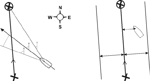
40 TRACKER 5600 Installation and Operation Manual
NAVMAN
Navigation data
The boat is sailing from the start to the destination and has moved off the plotted course from the start to the
destination.
BRG Bearing to Destination Bearing to the destination from the boat.
+BRG Bearing to cursor Bearing to cursor from boat (cursor mode, see section 3-1-1)
CDI Course Deviation Indicator When the boat is navigating to a point, the chart and highway displays
show a parallel line on either side of the plotted course. These two
lines are called the Course Deviation Indicator (CDI) lines. The distance
from the plotted course to a CDI line is the CDI scale.
Set the CDI scale (see section 13-2) to the maximum distance that the
boat should deviate from the plotted course. The chart and highway
displays show the CDI lines, which are like a highway over the water
where the boat will move. The displays show how far the boat has
deviated from the plotted course and if the boat is approaching a CDI
line. If the XTE alarm is enabled (see section 13-6) an alarm will sound
if the boat reaches a CDI line.
COG Course Over Ground Direction in which the boat is moving over the ground.
CTS Course To Steer Optimum course to steer to return to the plotted course.
DTG Distance To Go Distance from the boat to the destination.
ETA Expected Time of Arrival At the destination, assuming that SOG and COG remain constant.
+RNG Range to cursor Distance from boat to cursor (cursor mode, see section 3-1-1)
SOG Speed Over Ground Current boat speed over the ground. This is not necessarily the same
as the boat speed through the water nor the speed at which it is
approaching the destination.
STR Steering The difference between COG and CTS.
TTG Time To Go The estimated time to reach the destination.
XTE Cross Track Error The distance from the boat to the nearest point of the plotted course.
XTE may have a letter: R means steer to the right to return to the plotted
course, L means steer to the left.
VMG Velocity Made Good The speed at which the boat is approaching the destination.
CTS
SOG (speed) VMG (speed)
BRG
COG
Destination
Boat position
Start
STR
DTG (distance)
CDI scale
(distance)
Plotted
course
Start
Destination
XTE
(distance)
Boat
position
CDI scale
(distance)
CDI line
Plotted
course
CDI line

119
TRACKER 5600 Installation and Operation Manual
NAVMAN
Appendix D - How to contact us
NORTH AMERICA
NAVMAN USA INC.
18 Pine St. Ext.
Nashua, NH 03060.
Ph: +1 603 577 9600
e-mail: sales@navmanusa.com
OCEANIA
New Zealand
Absolute Marine Ltd.
Unit B, 138 Harris Road,
East Tamaki, Auckland.
Ph: +64 9 273 9273
e-mail:
navman@absolutemarine.co.nz
Australia
NAVMAN AUSTRALIA PTY
Limited
Unit 6 / 5-13 Parsons St,
Rozelle, NSW 2039, Australia.
Ph: +61 2 9818 8382
e-mail: sales@navman.com.au
SOUTH AMERICA
Argentina
Costanera UNO S.A.
Av Presidente R Castillo y
Calle 13
1425 Buenos Aires, Argentina.
Ph: +54 11 4312 4545
e-mail:
purchase@costanerauno.com.ar
Website:
www.costanerauno.ar
Brazil
REALMARINE
Estrada do Joa 3862,
CEP2611-020,
Barra da Tijuca, Rio de Janeiro,
Brasil.
Ph: +55 21 2483 9700
e-mail:
vendas@marinedepot.com.br
Equinautic Com Imp Exp de
Equip Nauticos Ltda.
Av. Diario de Noticias 1997 CEP
90810-080, Bairro Cristal, Porto
Alegre - RS, Brasil.
Ph: +55 51 3242 9972
Fax: +55 51 3241 1134
e-mail:
equinautic@equinautic.com.br
ASIA
China
Peaceful Marine Electronics Co. Ltd.
Hong Kong, Guangzhou,
Shanghai, Qindao, Dalian.
E210, Huang Hua Gang Ke Mao
Street, 81 Xian Lie Zhong Road,
510070 Guangzhou, China.
Ph: +86 20 3869 8784
e-mail:
sales@peaceful-marine.com
Website:
www.peaceful-marine.com
Korea
Kumho Marine Technology Co. Ltd.
# 604-816, 3F, 1117-34,
Koejung4-Dong, Saha-ku
Pusan, Korea
Ph: +82 51 293 8589
e-mail: info@kumhomarine.com
Website:
www.kumhomarine.com
Singapore and Malaysia
RIQ PTE Ltd.
Block 3007, Ubi Road 1
#02-440, Singapore 408701
Ph: +65 6741 3723
HP: +65 9679 5903
e-mail: riq@postone.com
Thailand
Thong Electronics (Thailand)
Company Ltd.
923/588 Thaprong Road,
Mahachai,
Muang, Samutsakhon 74000,
Thailand.
Ph: +66 34 411 919
e-mail: thonge@cscoms.com
Vietnam
Haidang Co. Ltd.
16A/A1E, Ba thang hai St.
District 10, Hochiminh City.
Ph: +84 8 86321 59
e-mail:
sales@haidangvn.com
Website: www.haidangvn.com
Taiwan
Seafirst International
Corporation
No.281, Hou-An Road
Chien-Chen Dist.
Kaohsiung, Taiwan
R.O.C.
Ph: +886 7 831 2688
e-mail:
seafirst@seed.net.tw
MIDDLE EAST
Lebanon and Syria
Letro, Balco Stores,
Moutran Street, Tripoli
VIA Beirut.
Ph: +961 6 624512
e-mail: balco@cyberia.net.lb
United Arab Emirates
Kuwait, Oman, Iran & Saudi Arabia
Abdullah Moh’d Ibrahim
Trading, opp Creak Rd.
Baniyas Road, Dubai.
Ph: +971 4 229 1195
e-mail: mksq99@email.com
AFRICA
South Africa
Pertec (Pty) Ltd Coastal,
Division No.16 Paarden Eiland Rd.
Paarden Eiland, 7405
Postal Address: PO Box 527,
Paarden Eiland 7420
Cape Town, South Africa.
Ph: +27 21 511 5055
e-mail: info@kfa.co.za
EUROPE
France, Belgium and
Switzerland
PLASTIMO INTERNATIONAL
15, rue Ingénieur Verrière,
BP435,
56325 Lorient Cedex.
Ph: +33 2 97 87 36 36
e-mail: plastimo@plastimo.fr
Website: www.plastimo.fr
Germany
PLASTIMO DEUTSCHLAND
15, rue Ingénieur Verrière
BP435
56325 Lorient Cedex.
Ph: +49 6105 92 10 09
+49 6105 92 10 10
+49 6105 92 10 12
e-mail:
plastimo.international@plastimo.fr
Website: www.plastimo.de
Italy
PLASTIMO ITALIA
Nuova Rade spa, Via del Pontasso 5
I-16015 CASELLA SCRIVIA (GE).
Ph: +39 1096 8011
e-mail: info@nuovarade.com
Website: www.plastimo.it
Holland
PLASTIMO HOLLAND BV.
Industrieweg 4-6,
2871 RP SCHOONHOVEN.
Ph: +31 182 320 522
e-mail: info@plastimo.nl
Website: www.plastimo.nl
United Kingdom
PLASTIMO Mfg. UK Ltd.
School Lane - Chandlers Ford
Industrial Estate,
EASTLEIGH - HANTS S053 ADG.
Ph: +44 23 8026 3311
e-mail: sales@plastimo.co.uk
Website: www.plastimo.co.uk
Sweden, Denmark or Finland
PLASTIMO NORDIC AB.
Box 28 - Lundenvägen 2,
47321 HENAN.
Ph: +46 304 360 60
e-mail: info@plastimo.se
Website: www.plastimo.se
Spain
PLASTIMO ESPAÑA, S.A.
Avenida Narcís Monturiol, 17
08339 VILASSAR DE DALT,
(Barcelona).
Ph: +34 93 750 75 04
e-mail: plastimo@plastimo.es
Website: www.plastimo.es
Portugal
PLASTIMO PORTUGAL
Avenida de India N°40
1300-299 Lisbon
Ph: +351 21 362 04 57
e-mail: email :
plastimo@siroco-nautica.pt
Other countries in Europe
PLASTIMO INTERNATIONAL
15, rue Ingénieur Verrière
BP435
56325 Lorient Cedex, France.
Ph: +33 2 97 87 36 59
e-mail:
plastimo.international@plastimo.fr
Website: www.plastimo.com
REST OF WORLD /
MANUFACTURERS
NAVMAN NZ Limited
13-17 Kawana St. Northcote.
P.O. Box 68 155 Newton,
Auckland, New Zealand.
Ph: +64 9 481 0500
e-mail:
marine.sales@navman.com
Website:
www.navman.com
www.navman.com.
80 NAVMAN MULTI 3100 Installation and Operation Manual
Lon 174° 44.535`E
Lat 36° 48.404`S
Made in New Zealand
MN000192C
NAVMAN
TRACKER 5600
