Navtech Radar AGS1600-001 AGS1600 Position Sensing Radar User Manual Hardware installation guide
Navtech Radar Ltd AGS1600 Position Sensing Radar Hardware installation guide
Hardware installation guide

AdvanceGuard
Hardware
Installation
Guide
Document version 1.2e

Hardware Installation Guide
1
Contents
2 Welcome
2 Essential items
3 Parts
4 Creating an installation
4 Mounting a radar sensor
4 Mounting the enclosure and power supply
5 Levelling a sensor
7 Connecting a radar sensor
8 Connecting other items
8 Connecting cameras
9 Connecting trigger inputs and alarm outputs
10 Confirming sensor operation
10 Preparing your computer
10 Connecting your computer
11 Testing a sensor
15 Appendices
15 Appendix 1 - FAQ
16 Appendix 2 - Radio frequency energy statement
Hardware Installation Guide
2
Welcome
The Navtech Radar AdvanceGuard system provides
high integrity detection, tracking and intelligent alarm
generation for wide area intrusion detection systems.
This guide concentrates on installing the key hardware
components: Radar sensors; cameras and external inputs/
outputs. As part of the installation process this guide also
covers how to test the radar sensor output and adjust
its positioning for optimum performance. For details
about the witness application group, please refer to the
companion Witness Commissioning Guide.
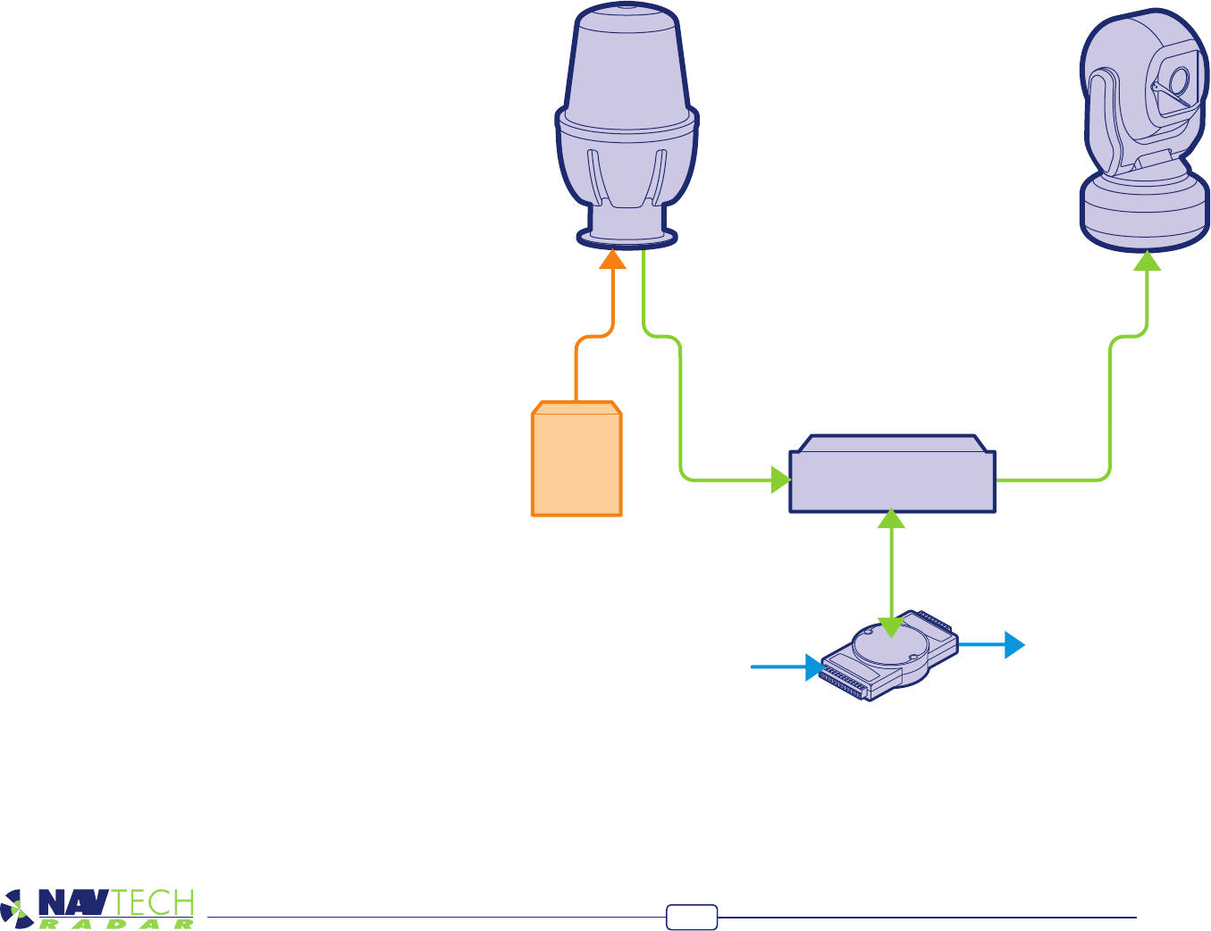
Power
Supply
Unit
Radar Processing
Unit
External
inputs
Alarm
outputs
Adam 6060
Essential items
The following are the essential additional items that
you will need to install a radar sensor:
• LaptopcomputerrunningRadarViewsoftware,
• ShieldedCat5Epatchlead,
• Digitallevel,
• 25m²radartargetandtripod,2off,
• 10mmspanner,
• Pairof2wayradios,
• Anassistant.
Radar & camera models may
differ from illustrations
Hardware Installation Guide
3
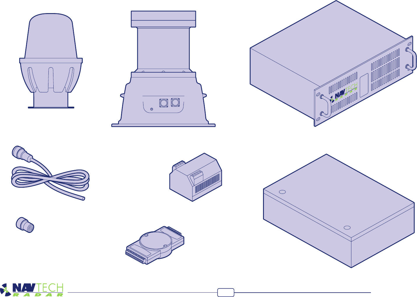
Parts
This page lists the main parts that are commonly used in most radar installations
(mount poles are not shown). Note that these images are for illustrative purposes only,
as items/casing shapes are subject to change.
W- Series radar sensor
I-Series radar sensor
RPU
(Radar Processing Unit)
IP-rated equipment
enclosure
Adam 6060 input/output unit
Radar sensor power cable
(bare ended at enclosure end)
Mil spec shroud for radar
sensor data connection
Radar sensor power supply
Hardware Installation Guide
4
Creating an installation
Mounting a radar sensor
Navtech Radar Limited supply a range of radar sensors and mounting posts to suit
various installation sites.
The two most common posts are:
• Standardmountpostwhichprovidesaheightadjustmentofbetween1.35mto
1.89m(measuredbeamheightforaW200/500/AGS800/1600sensor)andcan
optionally be tted with a CCTV camera arm.
• Telescopicmountpostwhichcanextendto4metresinheightandissuitableforthe
X variant sensor.
For the standard mount posts you should aim to initially position the sensor so that its
metalcollarisatroughly1.5metresabovegroundlevelsothatthepostisatthemid-
dle of its vertical adjustment range. During commissioning it may be necessary to raise
or lower the sensor to clear obstacles or allow for the local terrain.
Note: If you are creating your own mount post, you are recommended to include at
least 50 centimetres of vertical adjustment built into the post to allow for local topog-
raphy.
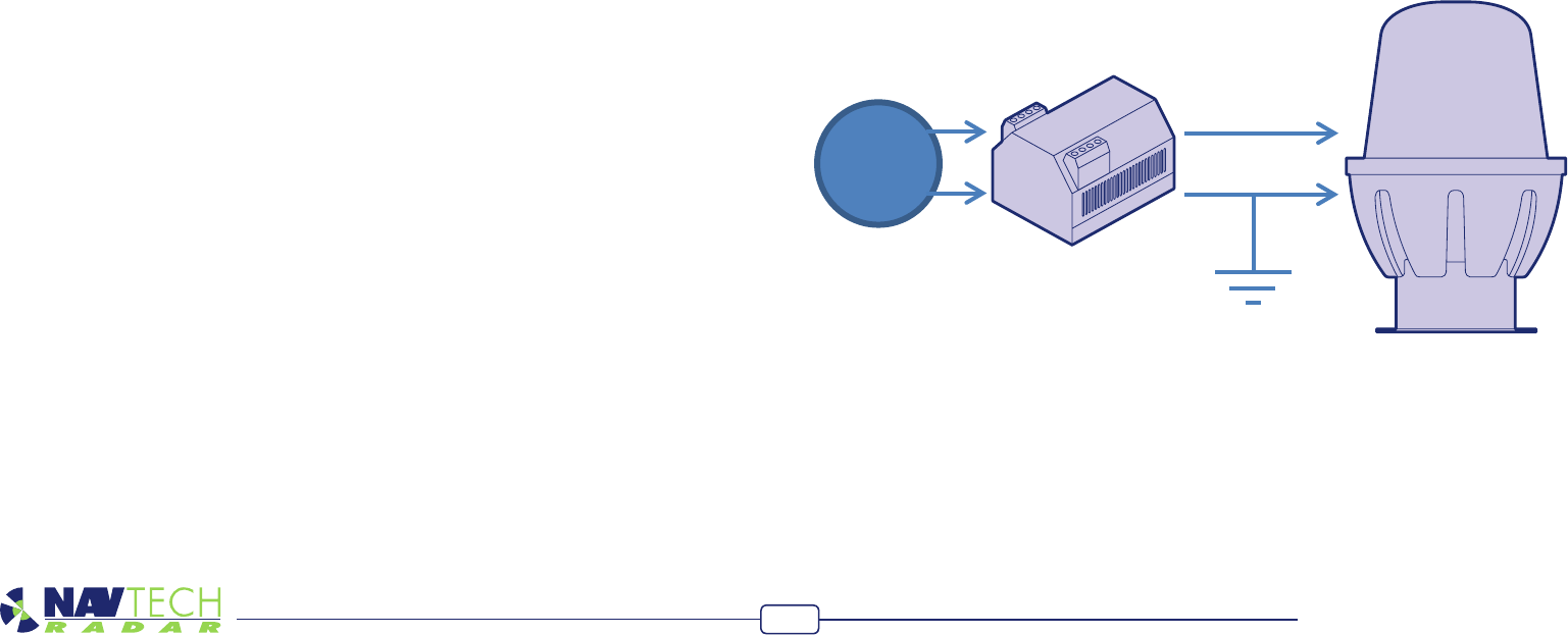
Mounting the enclosure and power supply
The IP-rated equipment enclosure is normally mounted at the base of the radar post
and is used to house the radar power supply unit, however, other items may also need
to be housed within the enclosure:
• Iftheradarismountedmorethan70metresfromtheRPUserverthenitisrecom-
mendedthatabreopticethernetlinkisused.Inthiscaseamediaconverterwould
alsoneedtobehousedwithintheenclosure.
• Ifthereisacameraoptiononthepostthenthecamerapowersupplyunitanda
possiblyavideoencoderwillalsoneedtobehoused.
IMPORTANT: To prevent oating voltage levels on the low output of the radar sensor
powersupplyunit,linkthe0voutputtoearth.
IMPORTANT: Note that each radar is supplied with a pressure plug, which is left loose
during freight. This plug should be reinserted at install time such that the radar is kept
pressurised and maintains its ingress protection. Failure to insert the pressure plug
could invalidate the warranty in the event of damage.
AC
Simplified wiring diagram
Hardware Installation Guide
5
Levelling a sensor
Duetotheverynarrowbeams(1or2degrees)usedbymostradarsensors,itisimpor-
tant that each sensor is level in relation to the area that it surveys. Level in this sense
may not mean absolutely horizontal. For instance, if the site has a continual slope it
may prove benecial to incline the sensor in line with the slope to ensure that targets
are correctly tracked.
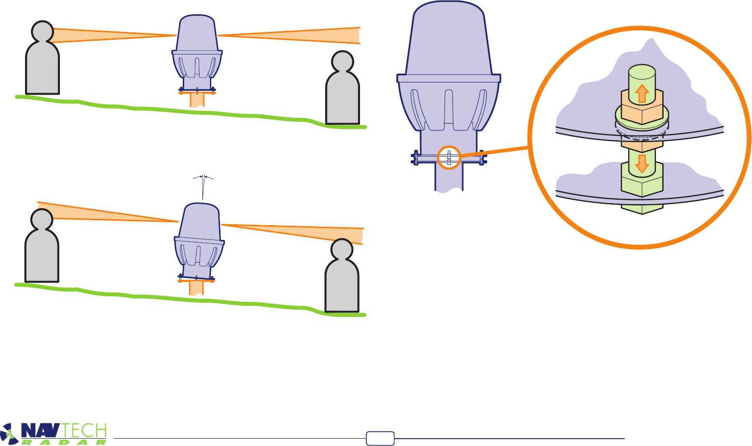
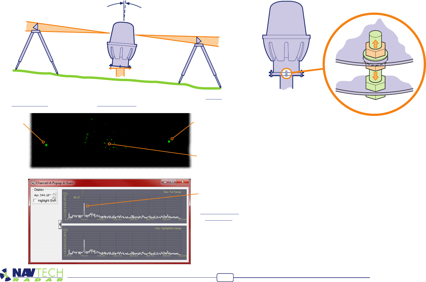
The exaggerated examples below show how a sensor with an incorrect incline could
miss targets which are lower down the slope:
A
B
A
B
The horizontal radar sensor misses target B.
The inclined radar sensor locates both targets.
To make sensor levelling adjustments
The sensor mounting plate allows for a simple yet effective method to ne tune the
incline of the sensor. For each of the mounting holes, the bolt is fed from underneath
and locked onto the mounting plate with a nut. Two more nuts and washers are then
used above and below the sensor plate so that the sensor can be positioned anywhere
up or down the bolt thread, as necessary.
Werecommendthatyoubeginwiththesensorcompletelyhorizontalandthen
carefully adjust it to suit the conditions using the method described next.
Hardware Installation Guide
6
Target BTarget A
Radar
sensor
To adjust the sensor level
The recommended procedure to check for the optimum incline is to use two radar
targets mounted on tripods.
1 Adjusteachtargettoaheightof1.3metresabovegroundlevelandlocatethemon
oppositessidesofthesensoratsuitabledistances(e.g.30morfurther).
2 ConnectaportablecomputertotheradarsensorandthenusetheprocedureTo use
SPxRadarView(withinthesectionTesting a sensor)toviewtheresultingscan:
Youraimistoensurethatbothtargetscanbeclearlyseenbytheradarsensor.If
necessary,carefullyadjusttheinclineofthesensoruntiltheyproducesimilartraces.
Itmaybenecessaryatthispointtoraiseorlowertheradarinadditiontochanging
theincline.
3 Repositionthetargetsinnewlocationsandrepeattheadjustmentprocedureuntil
targetsinvariouspositionscanbeseenbytheradarsensor.
Target response
shown in isolation
within the
SPx RadarView
application
Hardware Installation Guide
7
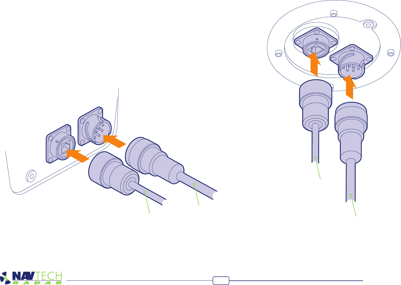
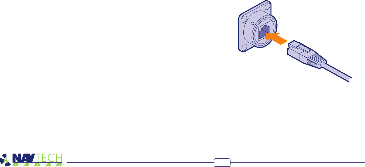
Connecting a radar sensor
Each radar sensor requires a power and a data connection. Both are made using
military specication connectors to ensure link integrity in the harshest environmental
conditions. In the majority of cases, the power and data connections run from the
sensor to the enclosure at the base of the mounting pole where the power supply is
situated.
Suppliedwitheachradarsensorisapowercablewithamil-specconnectorforthe
sensor connection and a bare end at the enclosure connection. A mil spec shroud
is also supplied for use with a suitable environmentally protected Ethernet network
cable. It is essential that the supplied shroud is correctly used to ensure that the data
connection is water tight.
IMPORTANT: Failure to correctly t the shroud can invalidate the warranty on sensors
that have been caused to fail through water ingress.
Connections to I-Series radars
OnradarsensorswithI-Seriesenclosures,theconnectionsaremadeonthesidepanel:
Data connection
Power connection
Data connection
Power connection
Connections to W and AGS-Series radars
OnradarsensorswithWandAGS-Seriesenclosures,theconnectionsaremade
underneath:
Hardware Installation Guide
8
Connecting other items
The modular nature of the AdvanceGuard system offers considerable opportunity for
customisation to suit a wide range of installations. This section discusses the broad
approach for connecting third party devices to the AdvanceGuard system.
Connecting cameras
The AdvanceGuard system communicates with cameras using either direct Ethernet,
RS422serialorVipX(aproprietaryEthernet-basedstandard),asrequired.Allcameras
within an installation are linked to a server system called an RPU (Radar Processing
Unit), which is a high specication industrial computer. In certain cases a single RPU will
control several radar sensors as well as the cameras. In larger installations there may be
separate RPU systems for the radar sensors and cameras. A software component called
Cyclops is used on the RPU for the purpose of controlling all of the cameras.
Depending on the nature of your installation, there are numerous ways to connect
cameras to an RPU.
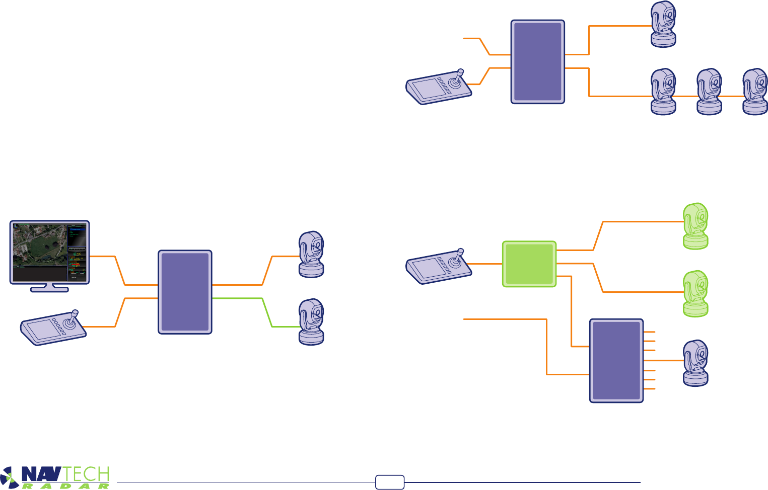
Basic Ethernet or serial links
The diagram shows two cameras connected by their own Ethernet and/or serial links
(different connection types can easily be mixed on the same RPU). The operator is pro-
videdwiththeAdvanceGuardSentineldisplaywhichallowsmanualcontrolofcameras
where necessary. Additionally, a standard CCTV camera controller can also be provided
and would be fed via the RPU, where its actions are interpreted by the AdvanceGuard
system before being directed to the cameras.
Controller
Cam 1
Cam 2
Cam 3
Matrix
RPU
Sentinel
Controller
ID 0
RPU
RS422 Line 1
RS422 Line 2
Sentinel
ID 1 ID 2 ID 3
Cam 1
Cam 2
RPU
Controller
Sentinel RS422
Ethernet
Note: For simplicity in these examples, the Sentinel display and CCTV controller are
shown connecting directly into the RPU. In reality they would not be connected in this
manner. For security reasons, these controls would be connected to their own com-
puter system which would indirectly link them to the RPU via an Ethernet connection.
Multiple serial links
This diagram indicates the two ways to link serial cameras to the RPU. As required,
cameras can either use their own dedicated links to the RPU. It is important that each
camera is given a unique ID number.
Adapting existing larger installations
WhenAdvanceGuardisintegratedintoanexistinglargeinstallation,itislikelythata
matrix will be employed to link multiple cameras to a single CCTV controller. It is also
possible that the AdvanceGuard system is not required to control all of the existing
cameras. In such situations it is important that the RPU is linked at the correct point.
InthediagramonlyCam3isrequiredtobecontrolledbyAdvanceGuard.TheRPU
islinkedtotheexistingoutputforCam3fromthematrixandinterpretsthecontrol
signals before sending them to the camera. In this way the CCTV controller can service
both the AdvanceGuard and non-AdvanceGuard sections of the installation.
Hardware Installation Guide
9
Connecting trigger inputs and alarm outputs
In addition to radars and cameras, the AdvanceGuard system can be integrated with
other sensors, such as simple PIR units, and also linked to external alarms. Connections
ofthistypearehandledbyoneormoreAdvantechAdam6060industrialI/Odevices
which are attached, via Ethernet, to the RPU (Radar Processing Unit) system.
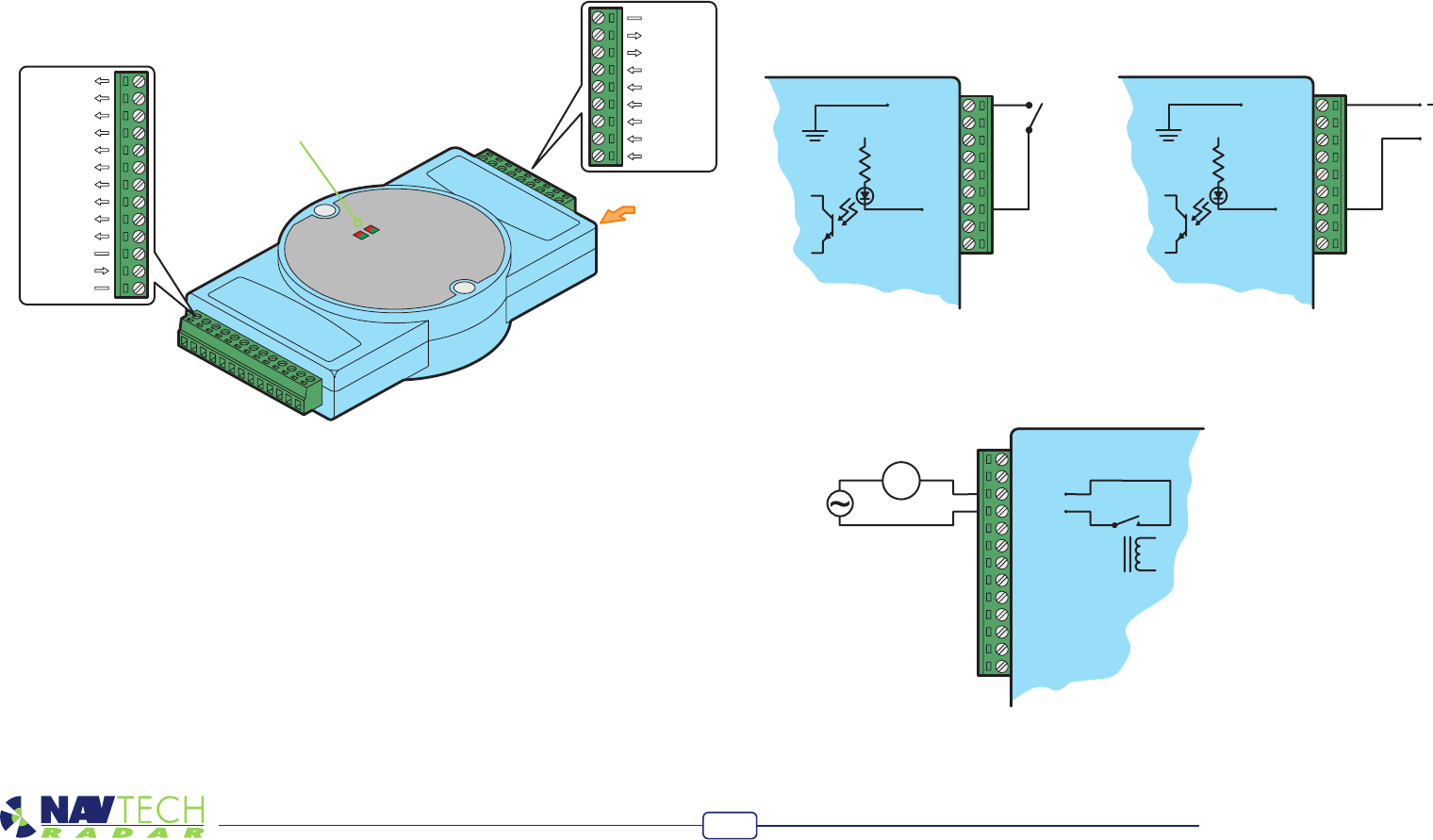
EachAdam6060unitprovidessixopto-isolatedinputs(labelledDI0toDI5)andsix
relay switched dry-contact outputs. Input and output connections are made using the
green blocks at each end, as shown below:
TheAdam6060unitrequiresapowerinputof10to30VDCwhichisappliedbetween
connections+VSandGND.At24VDCsupplyleveltheunitconsumesamaximumof2W.
Status indicators
There are four status indicators on the top panel. Their functions are as follows:
• Status(red)-Flasheswhenthemoduleispoweredon.
• Link(green)-OnwhenEthernetconnectionisvalid.
• Speed(red)-OnwhentheEthernetconnection100Mbps.
• COM(green)-FlasheswhentheEthernetlinkiscommunicating.
Addressing
EachAdam6060unitmustuseauniqueIPaddressthatiswithinthesamesubnetas
the RPU.
Iso. GND
RL 5-
Vcc
RL 5+
DI 5
DI 4
DI 3
DI 2
DI 1
DI 0
RL 0+
RL 0-
RL 1+
RL 1-
RL 2+
RL 2-
RL 3+
RL 3-
RL 4+
RL 4-
Not used
+VS
GND
LOAD
120/240Vac
or
30Vdc
Iso. GND
RL 5-
Vcc
RL 5+
DI 5
DI 4
DI 3
DI 2
DI 1
DI 0
0~30Vdc
+
Connecting inputs
TheAdam6060unitcanacceptinputsineitheroftwowaysbetweentheIsoGND.
andtheopto-isolatedinputsD0toD5:
Dry contact inputs
Also called ‘zero-volt’ switching, where
the input line is shorted by an external
switch to the Isolated GND terminal to
signal a change of state.
Wet contact inputs
Each input can also accept a DC voltage
to represent a logic state. An input of
0to3VDCistakentorepresentalogic
zero,whilealogic1istriggeredwhen
theinputlevelrisesabove10VDC.The
inputcanacceptvoltagesupto30VDC.
Connecting outputs
Each of the six outputs are relay driven with an internal contact being made between
the+and-terminalpairsofthechannelsRL0toRL5.Therelaycontactscanhandleup
to0.5Aat120/240VACorupto1Aat30VDC.
RL 0+
RL 0-
RL 1+
RL 1-
RL 2+
RL 2-
RL 3+
RL 3-
RL 4+
RL 4-
Not used
+VS
GND
Iso. GND
RL 5-
RL 5+
DI 5
DI 4
DI 3
DI 2
DI 1
DI 0
Ethernet
Status indicators
Hardware Installation Guide
10
Connecting your computer
You can connect your computer at any point along the signal link from the radar
sensor, either directly into the sensor mounted socket; at the pole mounted enclosure
(if the signal link is joined there) or at the far end of the link where it will join the RPU
(Radar Processing Unit) system. Note: The sensor can be powered on or off while
connecting and disconnecting the network link.
The network controller within the radar sensor is autosensing so that you can use
either straight through or crossover cables and it will adjust its operation accordingly.
To connect your computer
1 Connectalinkcablebetweenyourcomputerandthenetworkport,eitheronthe
sensororelsewherealongthesignalpath.
Confirming sensor operation
In order to test the output of the radar sensor, you will require:
• AportablecomputerrunningWindowsXP,Vista,Windows7orlater,
• TheSPxRadarViewapplication,whichcanbeobtainedfromthe‘tools’folderonthe
suppliedRPU.
• ACAT5,5eor6networkcable(straightorcrossoverwiring).
Preparing your computer
IMPORTANT: Ensure that your computer has its IP address set to operate within
the same subnet as the radar sensor:
• TheIPaddress(e.g.192.168.0.1)oftheradarsensorispresetbeforeleaving
NavtechRadarLimitedaccordingtoclientspecicationsandwillbedeclaredona
labelattachedtotheoutercasing.
• Thesubnetmaskoftheradarsensorisoftenpresetto255.255.255.0butcouldalso
besetwider(suchas255.255.0.0)ifrequested.
• Thus,ifthesensorIPaddressis192.168.0.1andthemaskis255.255.255.0,then
yourcomputermustuseanIPaddressintherange:192.168.0.2to192.168.0.254.
Note: If you are connecting to the radar via an Ethernet switch rather than making a di-
rect link, it is important that no other radar client software is already connected before
using radar view.
2 Ensurethattheradarsensorispoweredonandisrotating-youcanfaintlyhearthe
rotorwhenitisrunning.
Hardware Installation Guide
11
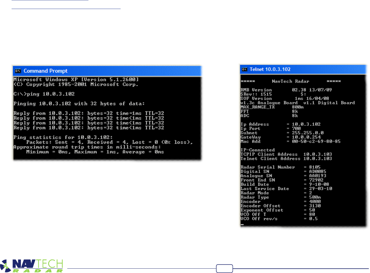
To telnet to a sensor
1 OpentheWindowsCommandPromptwindow(Start>Accessories>Command
Prompt).
2 Inthewindow,typetelnet a.b.c.d
where a.b.c.d is the IP address of the radar sensor.
Afterashortwhileyoushouldseearesponsefromthesensor:
Testing a sensor
Once your computer is connected to a sensor, there are four main tests that you can
carry out on the radar sensor:
• Pingthesensortocheckforabasicnetworkresponse.
• Telnettothesensortoviewfundamentalcongurationsettings.
• Runabaseleveldiagnostictest.
• UseSPxRadarViewtoviewtheradaroutput.
To ping a sensor
1 OpentheWindowscommandpromptwindow(Start>Accessories>Command
Prompt).
2 Inthewindow,typeping a.b.c.d
where a.b.c.d is the IP address of the radar sensor.
Afterashortwhileyoushouldseeseveralresponsesfromthesensor:
Thisshowsthatthenetworkinterfaceofthesensorisfunctioning(andconrms
connectivityofanyintermediateswitchingequipment).
Ifyoudonotreceivearesponse:
•Checkthepowersupplytothesensor.
•Listenfortherotorspinning.
•Doublecheckthenetworklinktothesensor.
•Conrmthatyoucanpingintermediateswitchingequipment.
•CheckthatyourcomputerisconguredwithanIPaddressthatiswithinthesame
subnetasthesensor. Theresponseshouldshowdetailsaboutvariousmoduleswithinthesensor.
Hardware Installation Guide
12
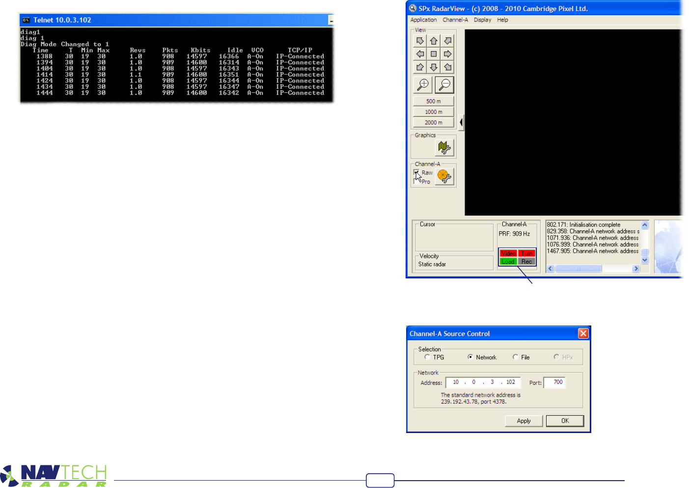
To run the diagnostic test
1 OpentheWindowsCommandPromptwindowandtelnettothesensorasdiscussed
intheprevioussection.
2 Whilststillwithinthetelnetsession,typediag 1
Aftertenseconds,resultsfromthediagnosticwillbegintobedisplayed:
Note:Theradarsensorwillreportincorrecttemperaturereadingsfortherst100
secondsofitsoperationafterrstbeingpoweredon.
Theresultswillbeappendedeverytenseconds.Thevariouseldsareasfollows:
•Time-Showsthetimewhenthediagnostictestwasrun.
•T-Showsthecurrenttemperaturereadingwithinthesensorhousing.
•Min/Max-Showstherecordedminimumandmaximumtemperatures.
•Revs-Showstherotorrevolutionspersecond.Shouldbe1.0*
•Pkts-ShowsthenumberofpacketsofIPdatasentinthelasttenseconds*
•Kbits-ShowsthesizeofIPdatasentinthelasttenseconds.
•Idle-N/A.
•VCO-ShowsthesettingoftheVoltageControlledOscillator-shouldbeA-On.
•TCP/IP-ShowsthestatusoftheIPconnection.
*Thesewillonlybenonzeroifaclientisconnectedtotheradar(RadarVieworwitness)
To use SPx RadarView
TheSPxRadarViewapplicationconsistsoftwoleswhichmustbelocatedinthesame
folder (any folder) on your computer: SPXRadarView.exe and SPXRadarView.rpi.
1 RunSPXRadarView.exe.Youshouldseeablankmainscreen:
Note: In the lower panel, the Video and Turn indicators will be
red to indicate that there is no communication with the sensor.
2 ClicktheChannel-AmenuandselecttheSource...option.
3 EnsurethattheSelection option is set to Networkandinthesectionbelow,
entertheIP Addressofthesensor.ThePortmustbesetto700.ClickOK.
Hardware Installation Guide
13
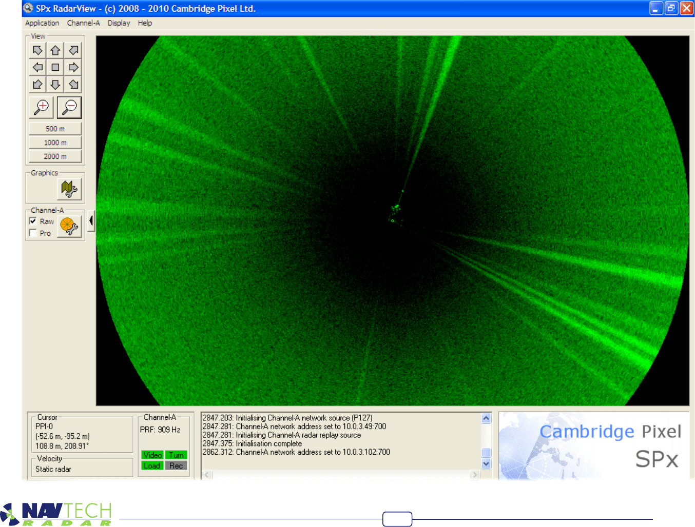
4 OncetheIPaddressandportarecorrectlysetandtheapplicationmakescontact
withthesensor,theVideo and Turnindicatorsshouldturngreen.Shortlyafter,you
shouldbegintoseeradarscaninformationwithinthemainwindow:
Hardware Installation Guide
14
5 Ontheleftsideofthescreen,ensurethattheRawoptionisticked.
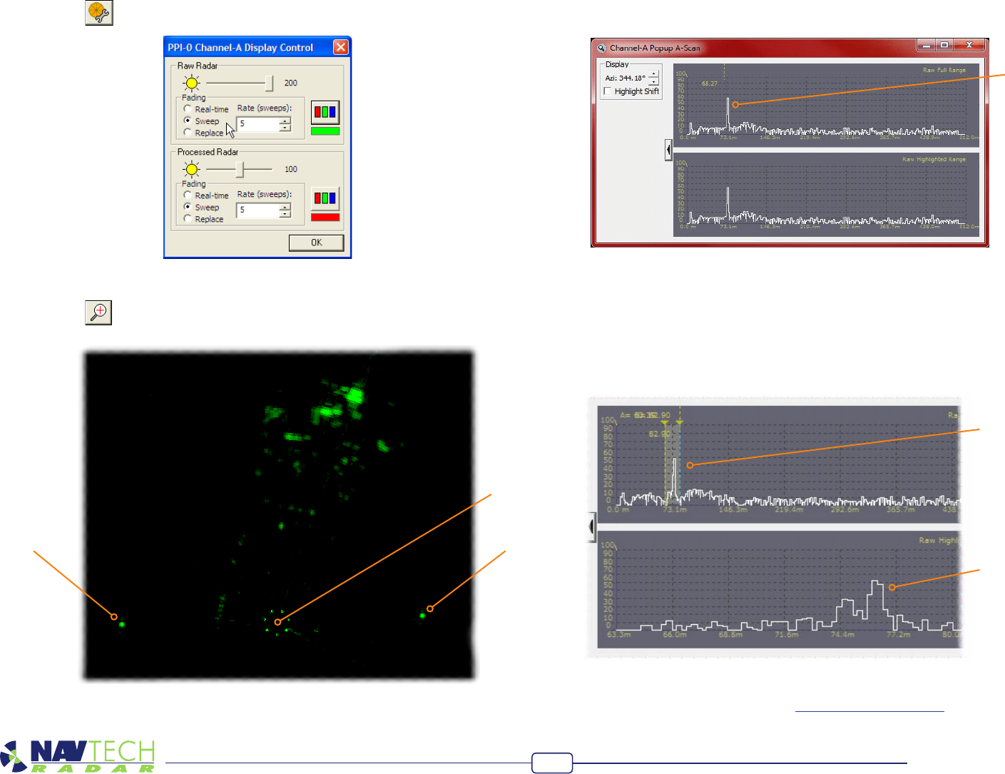
6 Clickthe buttontoshowtheDisplay Controldialogbox:
7 EnsurethatintheRaw Radarsection,theFading option is set to Sweepandthe
Rate (sweeps) is set to 5.ClickOK.
8 Clickthe buttontozoomintotheradarviewsothatyoucanclearlyseethe
bothofyourtesttargets:
Target BTarget A
Radar
sensor
9 Rightclickthemousepointerontheexactmiddlepointofoneofthetargetsto
displayapopupoptionsbox.Clicktheoption‘PopupChannel-AAScan...’todisplay
ascanwindow:
Thescanwindowprovideslivesignalstrengthdataconcentratingonlyonthe
angulardirectionofthechosentargetfromtheradarsensor.Ineachofthetwo
graphplots,thex-axisshowsthedistancefromthesensorwhilethey-axisindicates
thereturnedsignalstrength.Youshouldseeaspikerepresentingyourtargetatthe
relevantdistance.
10 Onthetopgraph,leftclickonbothsidesofthespiketocreateazoomedviewon
thelowergraph.Thiswillallowyoutoseesmallchangesinthereturnedsignal
strengthonthelowergraphwhenlevellingthesensor:
11 Repeatsteps9and10fortheothertargetsothatyoucanviewbothonscreenat
thesametime.
12 Adjusttheradarsensorlevel(seeToadjustthesensorlevelfordetails)whilechecking
thescangraphstoensurethebest(highestsignal)reponsefrombothtargets.
Target response
Define the zoom
area here
See the zoomed
view here

Hardware Installation Guide
15
What is the power consumption of the radar?
• Upto25wattsat24VDC.Pleaseseethedatasheetfortheexactgure.
What is the network bandwidth usage?
• Upto25megabytespersensor.PleasecontactNavtechforexactguresforyour
chosenradar.
What connectivity does the radar support?
• Connectiontotheradarisviaethernet.EachradarhasanRJ45socket.Werecom-
mendcat5cabletotheradar,nottoexceed70minlength.Longerlengthsshould
makeuseofswitchesorbreconverters.
What is the ideal mounting height?
• Theidealmountingheightcanvarydependingonthespecicsite,thetypeofradar
andifthebeamisangled.TheXunitshavebeendesignedtobemountedatabout
4m,thiswillgiveaminimumdetectionrangeofabout10mandforamanwalking
upright,withthemaximumaccordingtothesensordatasheet.
What is the beamwidth?
• Thebeamwidthvariesperradarsensor.Theazimuthbeamwidthiseither1or2de-
greeswiththemainelevationbeamwidthoftheradarsrangingfrom2to4degrees.
TheXradarinadditionhasacloserangeinllbeamofapproximately25degrees.
Pleaseseethedatasheetsforclarication.
At what ambient temperatures can the radar operate?
• Pleaserefertothedatasheetfortheexactmodel,butmostsensorswilloperate
over-20to+60degreesC.
Can the radar be used on the move?
• Notasanintruderdetectiondevice,astheradarhastobestaticinordertobeable
todetectmovement.Itcan,however,beusedasanobstacledetectiondeviceto
preventlargeplantequipmentfromhavingcollisions.
Appendices
Appendix 1 - FAQ
Can the radar sensor be inverted?
• PleasecontactNavtechRadarLtdtodiscusstheapplication.TheIndustrialseriesmay
beinverted,subjecttosomermwarechangesandadditionalcharge.
What is the operating frequency/band width of the radar?
• Allradarsoperatewithinthe76-77GHzbandasperETSIstandardEN301091-1
V1.3.3
What output power does the radar emit?
• Maximumoutputpoweriswithinthelimitof+55dBmEIRPasspeciedbyETSI
standardEN301091-1V1.3.3
Does the radar interfere with aviation systems?
• TheradarconformstoETSIstandardEN301091-1V1.3.3.Conrmationofcompli-
ancewithaviationsystemsistheresponsibilityofthesystemsintegrator/enduser.
Is the radar affected by adverse weather conditions?
• Theradarisunaffectedbyfog,rain,snowetc.
Does witness provide other interfaces?
• Witnesscaninterfacetomultipleethernetrelayunits,providingmultiplesof6digital
inputsand6relayoutputs.TheseI/Olinescanbelinkedtovariousactions/events
withinwitness.
Which cameras does Witness support?
• Witnesscurrentlysupportsaselectionofcameras,asdetailedintheapplicablesales
literature.Additionalcamerascanbeadded(atcost)iftheysupportabsoluteposi-
tioning.

Hardware Installation Guide
16
www.ctxd.com
Documentation by:
©2013NavtechRadarLimited Release1.2e
Appendix 2 - Radio frequency energy statement
FCC compliance statement (United States)
ThisdevicecomplieswithPart15oftheFCCRules.Operationissubjecttothe
following two conditions:
(1) Thisdevicemaynotcauseharmfulinterference,and
(2) Thisdevicemustacceptanyinterferencereceived,includinginterferencethatmay
cause undesired operation.
The operation of this device is limited to a xed position at airport locations for foreign
object debris detection on runways and for monitoring aircraft as well as service
vehicles on taxiways and other airport vehicle service areas that have no public vehicle
access. This equipment must be mounted in a xed location maintaining a minimum
separationdistanceof46cmfrompersonnelwheningeneraloperation.Thisrestriction
of operation is specic for use in North America. For use in other regions aligned to the
FCC regulations, specic country restrictions should be reviewed.
Changes or modications not expressly approved by the party responsible for
compliance could void the user’s authority to operate the equipment.