Nec Aspire Software Users Manual Aspire_Sftwr
Aspire Software Manual 500 Aspire Software Manual 500
5 to the manual 15d1b48b-3b3f-4496-bf75-6188a006499c
2015-01-24
: Nec Nec-Aspire-Software-Users-Manual-331894 nec-aspire-software-users-manual-331894 nec pdf
Open the PDF directly: View PDF ![]() .
.
Page Count: 1614 [warning: Documents this large are best viewed by clicking the View PDF Link!]
- Features
- About This Manual
- Section 1 - Features
- Before Reading This Section
- Using This Section
- Charts and Illustrations
- Abbreviated and Post Dialing Service Codes
- Single Digit Post Dialing Codes
- Service Codes by Number
- Service Codes by Feature
- Function Key Codes by Features
- Function Key Codes by Number
- System Number Plan/Capacities
- System Tones
- Multibutton Telephone Displays
- SUPER DISPLAY TELEPHONE
- MULTIBUTTON TELEPHONE
- 110-BUTTON DSS CONSOLE
- 24-BUTTON DSS CONSOLE
- Digital Two-Button Telephone
- Cordless Lite II (Spread Spectrum) Telephone
- Cordless II Telephone
- Aspire Wireless Telephone
- Abbreviated Dialing
- Description
- Programming
- Related Features
- Operation
- To store an Abbreviated Dialing number (display phones only):
- To dial a Common Abbreviated Dialing number:
- To store a Common Abbreviated Dialing number under a Programmable Function Key:
- To dial a Common Abbreviated Dialing number under a Programmable Function Key:
- To dial a Group Abbreviated Dialing number:
- To check your stored Abbreviated Dialing numbers (display phone only):
- Account Codes
- Description
- Programming
- Related Features
- Operation
- To enter an Account Code any time while on a trunk call:
- To enter an Account Code before dialing the outside number:
- To dial an outside number and let your system tell you when an Account Code is required:
- To enter an Account Code for an incoming call:
- To enter an Account Code while placing a trunk call:
- To enter an Account Code at a single line set:
- Alarm
- Alarm Reports
- Alphanumeric Display
- Analog Communications Interface (ACI)
- Aspire Wireless
- Description
- Related Features
- Operation
- Answering Calls
- Answering Outside Calls:
- Answering Intercom Calls:
- Answering a call ringing Paging after hours:
- When a call is ringing a co-worker’s phone:
- Placing Calls
- Placing an Outside Call:
- Calling a Co-Worker, Voice Mail and Paging
- Abbreviated Dialing: Common and Group (Speed Dial)
- Store Common or Group Abbreviated Dialing numbers:
- Dial your stored Abbreviated Dial number:
- Abbreviated Dial Search
- Store a number in the Telephone Book:
- Dial a number from the Telephone Book:
- Call Forwarding
- Forward your calls to a co-worker:
- Call Forwarding, Off-Premise
- Forward your calls to an outside telephone number:
- To cancel Call Forwarding Off-Premise
- Camp On / Callback
- If you heard a busy signal when calling a co-worker, use Camp On or Callback:
- To cancel your Callback:
- Conference
- Establishing a Conference Call:
- Do Not Disturb
- Using Do Not Disturb:
- Turning off your handset:
- Turning your handset on:
- Hold
- Placing a call on Hold:
- Retrieving a call from Hold:
- Last Number Redial
- Quickly redial your last outside call:
- Dial a number from the phone’s stored Redial and CLIP numbers:
- Message Waiting (Direct Messaging)
- Leave a Message Waiting:
- Answer a Message Waiting:
- Name Entry:
- Park
- Park a call in orbit:
- Pickup up a call in Park:
- Park and Page
- Use Park and Page to be paged for calls while away from your desk
- To Cancel:
- Answer Park and Page:
- Personal Greeting
- Use Personal Greeting to record a message for the caller and then forward the call:
- Registration
- Registering an Aspire Wireless Handset
- Unregistering an Aspire Wireless Handset
- Save
- Save your call for quick dialing later on:
- Quickly redial your saved number:
- Transfer
- Transferring your call to a co-worker:
- To Set the Transferring When Out of Range Option:
- To Clear the Transfer Destination:
- To Cancel the Transferring When Out of Range Option:
- Aspire XL
- Attendant Call Queuing
- Automatic Call Distribution (ACD)
- Description
- Programming
- Related Features
- Operation
- To Transfer a call to an ACD Group:
- Transferring Trunk Calls to the ACD Master (Program 15-02-21 = 0):
- To answer an outside call that rings your ACD Group:
- To log your extension into the ACD Group:
- To log your extension out of an ACD Group:
- To log in:
- To log out (for single or multiple agent log ins):
- To log in:
- To change your ACD Group Assignment:
- Using the Headset with Automatic Answer for ACD Agents:
- Answering Incoming ACD Calls with a Call Coverage Key:
- When Logged Into ACD Group
- When Logged Out of ACD Group
- To set the manual Rest Mode/Off-Duty Mode:
- To cancel the manual Rest Mode/Off-Duty Mode:
- Automatic Route Selection
- Background Music
- Barge In
- Call Coverage
- Call Duration Timer
- Call Forwarding
- Call Forwarding, Fixed
- Call Forwarding, Off-Premise
- Description
- Related Features
- Programming
- Operation
- To activate Call Forwarding Off-Premise
- To cancel Call Forwarding Off-Premise
- Off-Premise Call Forwarding for Door Boxes:
- To activate Call Forwarding Off-Premise by Door Box
- To cancel Call Forwarding Off-Premise
- Method 1: Set the Destination and Forward the Line:
- Cancel the Line Forwarding:
- Method 2 (follows the pre-defined destination in Program 24-04-01): Set Automatic Trunk Forwarding:
- Cancel Automatic Trunk Forwarding:
- Method 1: Set the Destination and Forward the Line:
- Cancel the Line Forwarding:
- Method 2 (follows the pre-defined destination in Program 24-05-01): Set Automatic Trunk Forwarding:
- Cancel Automatic Trunk Forwarding:
- Call Forwarding with Follow Me
- Call Forwarding/Do Not Disturb Override
- Call Pickup Group
- Call Redirect
- Call Waiting / Camp On
- Callback
- Caller ID
- Description
- Description (Cont’d)
- Programming
- Related Features
- Operation
- DISPLAYING THE INCOMING NUMBER
- To display the name/number of an incoming call only lamping your telephone:
- DISPLAYING CALLER ID FOR A CALL IN PARK
- STORING A NUMBER
- To store a Caller ID number in an Abbreviated Dial bin:
- To store a Caller ID number in a one-touch key:
- Temporary Memory / Call History
- CHECKING YOUR ANSWERED/UNANSWERED CALLER ID CALLS
- With software prior to 4.93: To review the last 16 outside calls your extension received:
- With software 4.93+: To review the last 50 outside calls your extension received:
- Center Telephone Book
- Description
- Programming
- Related Features
- Operation
- New Registration
- Name Search
- Group Search
- Telephone Number Search
- Search Memory
- Delete All Data
- Change the Telephone Book Data
- Delete an Entry in the Telephone Book
- Registering Caller ID to the Center Telephone Book
- Registering a LND to the Center Telephone Book
- SETTINGS
- Changing the Group Name
- Locking/Unlocking a Telephone Book
- Lock/Unlock a Telephone Book Using a Service Code
- Edit the Password for Locking/Unlocking a Telephone Book
- Central Office Calls, Answering
- Central Office Calls, Placing
- Class of Service
- Computer Telephony Integration (CTI) Applications
- Conference
- Description
- Programming
- Related Features
- Operation
- To establish a Conference:
- Keyset
- Single Line Set / 2-Button Telephone
- To Split (alternate) between the parties in Conference:
- Keyset
- Single Line Set
- To drop an outside call from the Conference:
- To exit a Conference without affecting the other parties:
- Keyset
- Single Line Set
- To Barge In to Conference Call:
- To Transfer a Call Into a Conference:
- Conference, Voice Call/Privacy Release
- Continued Dialing
- Cordless II/Cordless Lite II Telephones
- Description
- Programming
- Related Features
- Operation
- Programming the four function keys on the phone (additional key setup can also be done in the system programming):
- Programming the Redial Key to Activate the Cordless Phone:
- Switching the Extension Port from Cordless to Keyset or Vice Versa:
- Change channels if you’re experiencing interference while on a call:
- To dial your stored Abbreviated Dialing number:
- Answering a call ringing your phone:
- If a call is ringing over the Page after hours:
- When a call is ringing a co-worker’s phone:
- Forward (reroute) your calls to a co-worker:
- CAMP-ON AND CALLBACK
- When you hear system busy:
- To cancel your Callback:
- To flash the trunk you are on:
- Use Hold instead of leaving the call off-hook:
- Easily retrieve a call from Hold:
- Dial co-worker using the Intercom:
- Use Last Number Redial to quickly redial your last outside call:
- Leave a Message Waiting (flashing Message Wait LED) when your co-worker doesn’t answer:
- To answer a Message Waiting left for you:
- One Touch Calling
- Park a call in orbit so a co-worker can pick it up:
- Or pick up a call a co-worker parked for you:
- Press a line key for quick access:
- Dial codes for outside lines:
- Save your call for quick dialing later on:
- Then redial your saved number:
- Transfer the call you’re on to a co-worker:
- Change the ring tone and volume level while in an idle state:
- Change the ring tone and volume level while on a call:
- Department Calling
- Department Step Calling
- Dial Number Preview
- Dial Pad Confirmation Tone
- Dial Tone Detection
- Direct Inward Dialing (DID)
- Direct Inward Line (DIL)
- Direct Inward System Access (DISA)
- Direct Station Selection (DSS) Console
- Description
- Programming
- Related Features
- Operation
- Calling an extension from your DSS Console:
- Placing a trunk call from your 24-Button DLS Console:
- Answering a trunk call from your DSS Console:
- Parking an outside call when using a keyset as an operator’s phone (Program 20-17-02 set to “1”):
- Calling a Door Box from your DSS Console:
- Transferring a call using your DSS Console:
- Making a External Page using your DSS Console:
- Making an Internal Page using your DSS Console:
- Switching the Night Service mode from your DSS Console:
- Activating DSS Console Alternate Answer:
- Using a DSS Console key as a One-Touch or Programmable Function Key:
- Directed Call Pickup
- Directory Dialing
- Display Messaging, Selectable
- Distinctive Ringing, Tones and Flash Patterns
- Do Not Disturb
- Door Box
- Dual Line Appearance
- E911 Compatibility
- External Alarm Sensors
- Flash
- Flexible System Numbering
- Forced Trunk Disconnect
- Group Call Pickup
- Group Listen
- Handsfree and Monitor
- Handsfree Answerback/Forced Intercom Ringing
- Headset Operation
- Description
- Programming
- Related Features
- Operation
- To enable the headset:
- To use the headset:
- Using the Headset with Automatic Answer for ACD Agents:
- ANALOG SINGLE LINE TELEPHONES
- To enable the headset mode:
- To disable the headset mode:
- To be in an Off Hook Idle Condition (Waiting for incoming call):
- To answer an incoming call when the headset rings:
- To disconnect a call:
- To make an internal / outgoing call with off hook idle condition:
- Hold
- Description
- Programming
- Related Features
- Operation
- System Hold
- To place an outside call on System Hold (Keyset and 2-Button Telephone Only):
- To pick up an outside call on System Hold:
- Exclusive Hold
- To place an outside call on Exclusive Hold:
- To pick up an outside call on Exclusive Hold:
- Group Hold
- To place a call on Hold so anyone in your Department Group can pick it up:
- To pick up a call on Group Hold:
- Intercom Hold
- To place an Intercom call on Intercom Hold:
- To pick up an Intercom call on Intercom Hold:
- Hotline
- Hotline, External
- i-Series Telephones
- inDepth and inDepth+
- Intercom
- Intercom Abandoned Call Display
- ISDN Compatibility
- Last Number Redial
- Line Preference
- Long Conversation Cutoff
- Loop Keys
- Maintenance
- Meet Me Conference
- Meet Me Paging
- Meet Me Paging Transfer
- Memo Dial
- Message Waiting
- Microphone Cutoff
- Multiple Directory Numbers / Call Coverage
- Music on Hold
- Name Storing
- Networking
- Night Service
- Off Hook Signaling
- One-Touch Calling
- Description
- Programming
- Related Features
- Operation
- Direct Station Selection
- To program a One-Touch Key for Direct Station Selection (extension) calling:
- Personal Speed Dial
- To program a One-Touch Key for Personal Speed Dial:
- To program a One-Touch Key for Personal Speed Dial (if your phone doesn’t have One-Touch keys):
- To dial the stored number:
- Abbreviated Dialing
- To program a One-Touch Key for Abbreviated Dialing:
- Central Office Calls, Placing (Trunk Calling)
- To program a One-Touch Key for trunk calling:
- Service Codes
- To assign a Service Code to a One-Touch Key:
- Using One-Touch Keys
- To use a One-Touch Key:
- Clearing a One-Touch Key
- To clear a programmed One-Touch Key:
- Chaining One-Touch Keys
- To chain One-Touch Keys:
- Checking One-Touch Keys
- To check the function of a One-Touch Key:
- Programmable Function Keys
- To define a Programmable Function Key as a One-Touch Key:
- Operator
- OPX (Off Premise Extension)
- Paging, External
- Paging, Internal
- Paging, Privacy Release
- Park
- Description
- Programming
- Related Features
- Operation
- To Park a call in a system orbit:
- To pick up a parked call:
- To park a call at your extension:
- To Park an outside call at your extension after trying to call a co-worker:
- To pick up a call parked at your extension:
- To answer a call parked at a co-worker’s extension:
- To split between two parked calls (Keyset Only):
- To display Caller ID for a call in Park:
- PBX Compatibility
- Prime Line Selection
- Privacy Release
- Private Line
- Programmable Function Keys
- Pulse to Tone Conversion
- Repeat Redial
- Reverse Voice Over
- Ring Groups
- Ring Tones, Selectable
- Ringdown Extension, Internal/External
- Room Monitor
- Description
- Programming
- Programming (Cont’d)
- Programming (Cont’d)
- Related Features
- Operation
- Keysets:
- To activate Room Monitor (at the initiating extension):
- To activate Room Monitor (at the extension to be monitored):
- To cancel Room Monitor (at either extension):
- Single Line Telephones:
- To activate Room Monitor (at the extension to be monitored):
- To activate Room Monitor (at the initiating extension):
- To cancel Room Monitor (at either extension):
- Save Number Dialed
- Secretary Call (Buzzer)
- Secretary Call Pickup
- Secure Set Relocation
- Selectable Display Messaging
- Selectable Ring Tones
- Serial Call
- Single Line Telephones, Analog 500/2500 Sets
- Soft Keys
- Station Message Detail Recording
- T1 Trunking (with ANI/DNIS Compatibility)
- Tandem Ringing
- Tandem Trunking (Unsupervised Conference)
- Description
- Programming
- Related Features
- Operation
- Method A - Tandem Trunking from Conference
- To set up a Tandem/Multiple Trunk Conference Call:
- To end the Tandem Call:
- Method B - Tandem Trunking with Transfer Key
- To set up a Tandem Trunking Call with only 2 outside lines:
- To set up a Multiple Trunk Conference Call (3 or more outslide lines):
- Single Line Telephone
- To set up a Tandem Call:
- Method C - Tandem Trunking on Hang up
- To set up a Tandem Call (with only 2 outside lines):
- Single Line Telephone
- To set up a Tandem Call (with only 2 outside lines):
- Method D - Automatic Tandem Trunking Using Abbreviated Dialing
- To set Automatic Tandem Trunking:
- To cancel Automatic Tandem Trunking:
- To set and change the destination of the Automatic Tandem Trunk call:
- Continue/Disconnect Code
- To use the Continue code to extend a Tandem Trunk call:
- TAPI Compatibility
- Tie Lines
- Time and Date
- Toll Restriction
- Toll Restriction, Dial Block
- Toll Restriction Override
- Traffic Reports
- Transfer
- Description
- Programming
- Related Features
- Operation
- Transferring Trunk Calls
- To Transfer a trunk call to a co-worker’s extension:
- To answer a call transferred to your extension:
- Transferring Without Holding
- To Transfer without holding (keyset only):
- Transferring Intercom Calls
- To Transfer your Intercom call:
- Transferring a Call Into a Conference/Existing Call
- Transferring a Call to a Trunk Ring Group
- Trunk Group Routing
- Trunk Groups
- Trunk Queuing/Camp On
- Universal Answer
- Voice Mail
- Description
- In-Skin Voice Mail
- IntraMail for Aspire S
- IntraMail for Aspire M
- IntraMail: Ability to Select Voice Mail Port Selected for Message Notification/MW Lamps
- IntraMail: External Transfer Available
- IntraMail: Soft Key With Security Code Programming
- IntraMail: Internal Message Notification Timer Lengthened
- Conditions
- Default Setting
- Programming
- Related Features
- Operation
- To call your mailbox:
- (If 15-02-26 = 0 (Message Key))
- If 15-02-26 = 1 (Voice Mail Key)
- To leave a message in the mailbox of an unanswered extension: The extension you call can be busy, in DND or unanswered.
- To activate or cancel Call Forwarding:
- To Transfer your active call to a mailbox:
- To record your active call in your mailbox:
- To enable or cancel Personal Answering Machine Emulation:
- When Personal Answering Machine Emulation broadcasts your caller’s message, you can:
- To check your messages:
- Recording a Directory Dialing message:
- Using Directory Dialing
- Description
- Voice Over
- Voice Response System (VRS)
- Description
- Programming
- Related Features
- Operation
- To record a VRS message:
- To listen to a previously recorded VRS message:
- To erase a previously recorded VRS message:
- To record, listen to or erase a VRS message if you call in using DISA:
- To listen to the General Message:
- To record, listen to or erase the General Message:
- To enable a Personal Greeting:
- To cancel your Personal Greeting:
- To have the system Page you when you have a call:
- To pick up your Park and Page:
- To cancel your Park and Page:
- TIME, DATE AND STATION NUMBER CHECK
- To check the extension number of any keyset:
- To check the system time and date from any keyset extension:
- 900 PREAMBLE
- To answer a 900 Preamble call:
- VoIP
- Description
- Programming
- Programming - VoIP
- Programming - Static IP Address
- Programming - Aspire IP Keyset or Aspire Keyset with IP Adapter, Static IP Address
- Programming - H.323 Phone, Static IP Address
- Programming - Using the Aspire DHCP
- Programming, Aspire IP Keyset or Aspire Keyset with IP Adapter - DHCP
- Programming - H.323 Phone, Enabling DHCP
- Programming - Using an External DHCP
- Programming, Aspire IP Keyset or Aspire Keyset with IP Adapter - DHCP
- Programming - H.323 Phone, Enabling DHCP
- Programming - H.323 Phone, Setting H.323 Options
- LAN Connections
- Hardware:
- Port Assignment Improved
- LAN Connection Programming
- 911 Calls with Networked IP Phones
- Address Conversion Table
- Programming
- Calling Party Number Setup for Trunks and Extensions
- Programming
- CODEC Selection
- Deleting IP Phone Registration
- Echo Adjustment
- Enhanced Echo Adjustment
- Programming
- Fax Relay
- Required Items
- Basic Programming
- Firmware Download for Aspire Keyset with IP Adapter
- Programming
- H.323 Gatekeeper Connection
- H.323 Terminals
- Programming
- In-Band/Out-of-Band Signaling
- IP Extensions
- Assign Port/Extension Number
- Programming
- Simultaneous Calls
- VoIP Phones
- Programming
- Aspire IP and Aspire Keyset with IP Adapter
- IP Trunks
- Programming
- Bandwidth Setting for Aspire
- Programming
- Music on Hold for IP Terminals
- Networking Over IP
- Resource Release with Networked Calls
- Programming
- Peer-to-Peer Connection
- Programming
- RTP Forwarding Available
- Conditions
- Programming
- Tandem Connection
- Programming
- VLAN/QoS
- Programming - System, VLAN/QoS - Layer 2
- Programming - Aspire Keyset with IP Adapter, VLAN/QoS - Layer 2
- Programming - VLAN/QoS - Layer 3
- VOIPU DSP Resource Assignment
- Conditions
- Default Setting
- Related Features
- Operation
- Volume Controls
- Warning Tone For Long Conversation
- About This Manual
- Programming
- Introduction to Programming
- Before You Start Programming
- Section 2 - Programming
- Before Reading This Section
- How to Use This Section
- How to Enter the Programming Mode
- How to Exit the Programming Mode
- Using Keys to Move Around in the Programs
- Programming Names and Text Messages
- Using Soft Keys For Programming
- What the Soft Key Display Prompts Mean
- System Number Plan/Capacities - Aspire Comparisons
- Before You Start Programming
- Program 10 : System Configuration Setup
- 10-01 : Time and Date
- 10-02 : Location Setup
- 10-03 : PCB Setup
- 10-04 : Music on Hold Setup
- 10-05 : General Purpose Relay Setup
- 10-06 : ISDN BRI Setup
- 10-07 : Conversation Record Circuits
- 10-08 : Pre-Ringing Setup
- 10-09 : DTMF and Dial Tone Circuit Setup
- 10-12 : NTCPU Network Setup
- 10-13 : In-DHCP Server Setup
- 10-14 : Managed Network Setup
- 10-15 : Client Information Setup
- 10-16 : Option Information Setup
- 10-17 : H.323 Gatekeeper Setup
- 10-18 : H.323 Alias Address Setup
- 10-19 : VOIPU DSP Resource Selection
- 10-20 : LAN Setup for External Equipment
- 10-21 : NTCPU Hardware Setup
- 10-22 : Setting the Wake On LAN for APSU
- 10-23 : H.323 System Interconnection
- 10-24 : Daylight Savings Setup
- 10-25 : H.323 Gateway Prefix Setup
- 10-26 : IP System Operation Setup
- 10-27 : IP System ID
- 10-28 : SIP Trunk Basic Setup
- 10-29 : SIP Proxy Setup
- 10-30 : SIP Authentication Information
- 10-33 : SIP Registrar/Proxy Setup
- 10-31 : Networking Keep Alive Setup
- 10-32 : PRI Networking Channel Limitation
- 10-36 : SIP Trunk Registration Information Setup
- 10-37 : UPnP Setup
- Program 11 : System Numbering
- 11-01 : System Numbering
- 11-02 : Extension Numbering
- 11-04 : Virtual Extension Numbering
- 11-06 : ACI Extension Numbering
- 11-07 : Department Group Pilot Numbers
- 11-08 : ACI Group Pilot Number
- 11-09 : Trunk Access Code
- 11-10 : Service Code Setup (for System Administrator)
- 11-11 : Service Code Setup (for Setup/Entry Operation)
- 11-12 : Service Code Setup (for Service Access)
- 11-13 : Service Code Setup (for ACD)
- 11-14 : Service Code Setup (for Hotel)
- 11-15 : Service Code Setup, Administrative (for Special Access)
- 11-16 : Single Digit Service Code Setup
- 11-17 : ACD Group Pilot Number
- Program 12 : Night Mode Setup
- 12-01 : Night Mode Function Setup
- 12-02 : Automatic Night Service Patterns
- 12-03 : Weekly Night Service Switching
- 12-04 : Holiday Night Service Switching
- 12-05 : Night Mode Group Assignment for Extensions
- 12-06 : Night Mode Group Assignment for Trunks
- 12-07 : Text Data for Night Mode
- 12-08 : Night Mode Service Range
- Program 13 : Abbreviated Dialing
- 13-01 : Abbreviated Dialing Function Setup
- 13-02 : Group Abbreviated Dialing Bins
- 13-03 : Abbreviated Dialing Group Assignment for Extensions
- 13-04 : Abbreviated Dialing Number and Name
- 13-05 : Abbreviated Dialing Trunk Group
- 13-07 : Telephone Book Number and Name
- 13-08 : Telephone Book System Name
- 13-09 : Telephone Book Group Name
- 13-10 : Telephone Book Routing
- Program 14 : Trunk, Basic Setup
- 14-01 : Basic Trunk Data Setup
- 14-02 : Analog Trunk Data Setup
- 14-04 : Behind PBX Setup
- 14-05 : Trunk Group
- 14-06 : Trunk Group Routing
- 14-07 : Trunk Access Map Setup
- 14-08 : Music on Hold Source for Trunks
- 14-09 : ACI Conversation Recording Destination for Trunks
- 14-10 : Power Failure Telephone for Trunks
- 14-11 : ID Setup for IP Trunk
- 14-12 : SIP Register ID Setup for IP Trunk
- Program 15 : Extension, Basic Setup
- 15-01 : Basic Extension Data Setup
- 15-02 : Multi-Line Telephone Basic Data Setup
- 15-03 : Single Line Telephone Basic Data Setup
- 15-05 : IP Phone Terminal Basic Data Setup
- 15-06 : Trunk Access Map for Extensions
- 15-07 : Programmable Function Keys
- 15-08 : Incoming Virtual Extension Ring Tone Setup
- 15-09 : Virtual Extension Ring Assignment
- 15-10 : Incoming Virtual Extension Ring Tone Order Setup
- 15-11 : Virtual Extension Delayed Ring Assignment
- 15-12 : Conversation Recording Destination for Extensions
- 15-13 : Loop Keys
- 15-14 : Programmable One-Touch Keys
- 15-15 :Aspire Wireless Terminal Basic Data Setup
- 15-16 : SIP Register ID Setup for Extension
- 15-19 : System Telephone Book Setup for Extension
- Program 16 : Department Group Setup
- Program 20 : System Option Setup
- 20-01 : System Options
- 20-02 : System Options for Multi-Line Telephones
- 20-03 : System Options for Single Line Telephones
- 20-04 : System Options for Virtual Extensions
- 20-05 : Charging Cost Service
- 20-06 : Class of Service for Extensions
- 20-07 : Class of Service Options (Administrator Level)
- 20-08 : Class of Service Options (Outgoing Call Service)
- 20-09 : Class of Service Options (Incoming Call Service)
- 20-10 : Class of Service Options (Answer Service)
- 20-11 : Class of Service Options (Hold/Transfer Service)
- 20-12 : Class of Service Options (Charging Cost Service)
- 20-13 : Class of Service Options (Supplementary Service)
- 20-14 : Class of Service Options for DISA/E&M
- 20-15 : Ring Cycle Setup
- 20-16 : Selectable Display Messages
- 20-17 : Operator’s Extension
- 20-18 : Service Tone Timers
- 20-19 : System Options for Caller ID
- 20-20 : Message Setup for Non-Caller ID Data
- 20-21 : System Options for Long Conversation
- 20-22 : System Options for Aspire Wireless Service
- 20-23 : System Options for CTI
- 20-25 : ISDN Options
- 20-28 : System Option for Trunk to Trunk Conversations
- Program 21 : Outgoing Call Setup
- 21-01 : System Options for Outgoing Calls
- 21-02 : Trunk Group Routing for Extensions
- 21-03 : Trunk Group Routing for Trunks
- 21-04 : Toll Restriction Class for Extensions
- 21-05 : Toll Restriction Class
- 21-06 : Toll Restriction Table Data Setup
- 21-07 : Toll Restriction Override Password Setup
- 21-08 : Repeat Dial Setup
- 21-09 : Dial Block Setup
- 21-10 : Dial Block Restriction Class Per Extensions
- 21-11 : Extension Ringdown (Hotline) Assignment
- 21-12 : ISDN Calling Party Number Setup for Trunks
- 21-13 : ISDN Calling Party Number Setup for Extensions
- 21-14 : Walking Toll Restriction Password Setup
- 21-15 : Individual Trunk Group Routing for Extensions
- 21-16 : Trunk Group Routing for Networks
- 21-17 : IP (H.323/SIP) Trunk Calling Party Number Setup for Trunks
- 21-18 : IP (H.323) Trunk Calling Party Number Setup for Extensions
- 21-19 : IP (SIP) Trunk Calling Party Number Setup for Extensions
- 21-20 : SIP Trunk Call Discernment Setup for Extension
- Program 22 : Incoming Call Setup
- 22-01 : System Options for Incoming Calls
- 22-02 : Incoming Call Trunk Setup
- 22-03 : Trunk Ring Tone Range
- 22-04 : Incoming Extension Ring Group Assignment
- 22-05 : Incoming Trunk Ring Group Assignment
- 22-06 : Normal Incoming Ring Mode
- 22-07 : DIL Assignment
- 22-08 : DIL/IRG No Answer Destination
- 22-09 : DID Basic Data Setup
- 22-10 : DID Translation Table Setup
- 22-11 : DID Translation Number Conversion
- 22-12 : DID Intercept Ring Group
- 22-13 : DID Trunk Group to Translation Table Assignment
- 22-14 : VRS Delayed Message for IRG
- 22-15 : VRS Waiting Message for Department Group
- 22-17 : DID Conversion Table Area Setup for Time Pattern Mode
- 22-18 : Private Call Assignment
- 22-16 : Private Call Refuse Target Area Setup
- Program 23 : Answer Features Setup
- Program 24 : Hold/Transfer Setup
- Program 25 : VRS/DISA Setup
- 25-01 : VRS/DISA Line Basic Data Setup
- 25-02 : VRS/DISA VRS Message
- 25-03 : VRS/DISA Transfer Ring Group With Incorrect Dialing
- 25-04 : VRS/DISA Transfer Ring Group With No Answer/Busy
- 25-05 : VRS/DISA Error Message Assignment
- 25-06 : VRS/DISA One-Digit Code Attendant Setup
- 25-07 : System Timers for VRS/DISA
- 25-08 : DISA User ID Setup
- 25-09 : Class of Service for DISA Users
- 25-10 : Trunk Group Routing for DISA
- 25-11 : DISA Toll Restriction Class
- 25-12 : Alternate Trunk Group Routing for DISA
- 25-13 : System Option for DISA
- Program 26 : ARS Service
- 26-01 : Automatic Route Selection Service
- 26-02 : Dial Analysis Table for ARS/LCR
- 26-03 : ARS Dial Treatments
- 26-04 : ARS Class of Service
- 26-05 : LCR Carrier Table
- 26-06 : LCR Authorization Table
- 26-07 : LCR Cost Center Code Table
- 26-08 : LCR Manual Override Access Code Table
- 26-09 : LCR Manual Override Exemption Table
- 26-11 : Transit Network ID Table
- Program 30 : DSS/DLS Console Setup
- Program 31 : Paging Setup
- 31-01 : System Options for Internal/External Paging
- 31-02 : Internal Paging Group Assignment
- 31-03 : Internal Paging Group Settings
- 31-04 : External Paging Zone Group
- 31-05 : Universal Night Answer/Ring Over Page
- 31-06 : External Speaker Control
- 31-07 : Combined Paging Assignments
- 31-08 : BGM on External Paging
- Program 32 : Door Box and Sensor Setup
- Program 33 : CTA and ACI Setup
- Program 34 : Tie Line Setup
- 34-01 : E&M Tie Line Basic Setup
- 34-02 : E&M Tie Line Class of Service
- 34-03 : Trunk Group Routing for E&M Tie Lines
- 34-04 : E&M Tie Line Toll Restriction Class
- 34-05 : Tie Line Outgoing Call Restriction
- 34-06 : Add / Delete Digit for E&M Tie Line
- 34-07 : E&M Tie Line Timer
- 34-08 : Toll Restriction Data for E&M Tie Lines
- 34-09 : ANI/DNIS Service Options
- Program 35 : SMDR and Account Code Setup
- Program 40 : Voice Mail Setup
- 40-01 : Voice Mail Basic Setup
- 40-02 : Mailbox Setup
- 40-03 : Message Recording Setup
- 40-04 : Live Recording Setup
- 40-05 : Call Information Setup
- 40-06 : Voice Mail Automated Attendant Data Setup
- 40-07 : Voice Prompt Language Assignment for VRS
- 40-08 : Voice Prompt Language Assignment for Mailboxes
- 40-09 : Voice Mail Multiple Address Group Setup
- 40-10 : Voice Announcement Service Option
- 40-11 : Pre-Amble Message Assignment
- Program 41 : ACD Setup
- 41-01 : System Options for ACD
- 41-02 : ACD Group and Agent Assignments
- 41-03 : Incoming Ring Group Assignment for ACD Group
- 41-04 : ACD Group Supervisor
- 41-05 : ACD Agent Work Schedules
- 41-06 : Trunk Work Schedules
- 41-07 : ACD Weekly Schedule Setup
- 41-08 : ACD Overflow Options
- 41-09 : ACD Overflow Table Setting
- 41-10 : PGDAD Delay Announcement
- 41-11 : VRS Delay Announcement
- 41-12 : Night Announcement Setup
- 41-13 : VRS Message Number for Night Announcement
- 41-14 : ACD Options
- 41-15 : ACD Queue Alarm Information
- 41-16 : ACD Threshold Overflow
- 41-17 : ACD Login Mode Setup
- 41-18 : ACD Agent Identity Code Setup
- 41-19 : Voice Mail Delay Announcement
- 41-20 : ACD Queue Display Settings
- Program 42 : Hotel Setup
- Program 44 : ARS/F-Route Setup
- 44-01 : System Options for ARS/F-Route
- 44-02 : Dial Analysis Table for ARS/F-Route Access
- 44-03 : Dial Analysis Extension Table
- 44-04 : ARS/F-Route Selection for Time Schedule
- 44-05 : ARS/F-Route Table
- 44-06 : Additional Dial Table
- 44-07 : Gain Table for ARS/F-Route Access
- 44-08 : Time Schedule for ARS/F-Route
- 44-09 : Weekly Schedule for ARS/F-Route
- 44-10 : Holiday Schedule for ARS/F-Route
- Program 45 : Voice Mail Integration
- Program 47 : IntraMail
- 47-01 : IntraMail System Options
- 47-02: IntraMail Station Mailbox Options
- 47-03: IntraMail Master Mailbox Options
- 47-04: Master Call Routing Mailbox Options
- 47-05: Master Announcement Mailbox Options
- 47-06: Master Subscriber Mailbox Options
- 47-07: IntraMail Routing Mailbox Options
- 47-08: Call Routing Mailbox Options
- 47-09: Announcement Mailbox Options
- 47-10: IntraMail Trunk Options
- 47-11: IntraMail Answer Table Options
- 47-12: IntraMail Answer Schedules
- 47-13: IntraMail Dial Action Tables
- 47-14 : Master Directory Mailbox Options
- 47-15 : Routing Directory Mailbox Options
- Program 80 : Basic Hardware Setup for System
- Program 81 : Basic Hardware Setup for Trunk
- 81-01 : COIU Initial Data Setup
- 81-02 : DIOPU Initial Data Setup
- 81-03 : 4TLIU Initial Data Setup
- 81-04 : ISDN BRI Layer 1 (T-Point) Initial Data Setup
- 81-05 : ISDN BRI & PRI Layer 2 (T-Point) Initial Data Setup
- 81-06 : ISDN BRI & PRI Layer 3 (T-Point) Timer Setup
- 81-07 : CODEC Filter Setup for Analog Trunk Ports
- 81-08 : T1 Trunk Timer Setup
- 81-09 : COIU CODEC Filter Data Setup
- Program 82 : Basic Hardware Setup for Extension
- 82-01 : Incoming Ring Tone
- 82-03 : DSS Console LED Pattern Setup
- 82-04 : SLIU Initial Data Setup
- 82-05 : ISDN BRI & PRI Layer 2 (S-Point) Initial Data Setup
- 82-06 : ISDN BRI & PRI Layer 3 (S-Point) Timer Setup
- 82-07 : CODEC Filter Setup for Analog Station Ports
- 82-08 : Sidetone Volume Setup
- 82-09 : SLIU CODEC Filter Data Setup
- Program 83: Hardware Setup for Aspire Wireless
- Program 84 : Hardware Setup for VoIP
- 84-01 : CODEC Information Basic Setup
- 84-02 : H.225, H.245 Information Basic Setup
- 84-03 : NGT Information Basic Setup
- 84-04 : VOIPU PCB DHCP Server Mode Setup
- 84-05 : VOIPU IP Address Setup
- 84-06 : VOIPU Setup
- 84-07 : Firmware Download Setup
- 84-08 : Firmware Name Setup
- 84-09 : VLAN Setup
- 84-10 : ToS Setup
- 84-11 : Dterm IP CODEC Information Basic Setup
- 84-12 : H.323 Phone CODEC Information Basic Setup
- 84-13 : SIP Trunk CODEC Information Basic Setup
- 84-14 : SIP Trunk Basic Information Setup
- 84-15 : H.323 Keep Alive Setup
- 84-16 : VOIPU Limiter Control Gain Setup
- 84-17 : VOIPU Echo Canceller Control Setup
- 84-18 : VOIPU Echo Canceller Control Setup
- 84-19 : SIP Extension CODEC Information Basic Setup
- 84-20 : SIP Extension Basic Information Setup
- Program 85 : SHUBU LAN
- Program 90 : Maintenance Program
- 90-01 : Installation Date
- 90-02 : Setting the Programming Password
- 90-03 : Save Data
- 90-04 : Load Data
- 90-05 : Slot Control
- 90-06 : Trunk Control
- 90-07 : Extension Control
- 90-08 : System Reset
- 90-09 : Automatic System Reset Time
- 90-10 : System Alarm Setup
- 90-11 : System Alarm Report
- 90-12 : System Alarm Output
- 90-13 : System Information Output
- 90-16 : Main Software Information
- 90-17 : Firmware Information
- 90-18 : Password Initialization for Japanese Character Telephone
- 90-19 : Dial Block Release
- 90-20 : Traffic Report Data Setup
- 90-21 : Traffic Report Output
- 90-22 : NGT Terminal Version Information
- 90-23 : Deleting Registration of IP Telephones
- 90-24 : System Alarm Report Notification Time Setup
- 90-25 : System Alarm Report CC Mail Setup
- 90-26 : Program Access Level Setup
- 90-27 : Aspire Wireless System ID
- 90-30 : VOIPU Firmware Information
- 90-31 : DIM Over Ethernet
- Program 91 : Aspire Wireless Subscription
- Program 92 : Copy Program
- Program 99 : MF Options
- Introduction to Programming

Software Manual
05.00
Technical Support Web Site:
http://ws1.necii.com (registration is required)

This manual has been developed by NEC Unified Solutions, Inc. It is intended for the use of its customers and
service personnel, and should be read in its entirety before attempting to install or program the system. Any
comments or suggestions for improving this manual would be appreciated. Forward your remarks to:
NEC Unified Solutions, Inc.
4 Forest Parkway
Shelton, CT 06484
necunifiedsolutions.com
Nothing contained in this manual shall be deemed to be, and this manual does not constitute, a warranty of, or
representation with respect to, any of the equipment covered. This manual is subject to change without notice and
NEC Unified Solutions, Inc. has no obligation to provide any updates or corrections to this manual. Further, NEC
Unified Solutions, Inc. also reserves the right, without prior notice, to make changes in equipment design or
components as it deems appropriate. No representation is made that this manual is complete or accurate in all
respects and NEC Unified Solutions, Inc. shall not be liable for any errors or omissions. In no event shall NEC Unified
Solutions, Inc. be liable for any incidental or consequential damages in connection with the use of this manual. This
document contains proprietary information that is protected by copyright. All rights are reserved. No part of this
document may be photocopied or reproduced without prior written consent of NEC Unified Solutions, Inc.
©2006 by NEC Unified Solutions, Inc. All Rights Reserved.
Printed in U.S.A.

Table of Contents
Aspire Software Manual
◆
Table of Contents- 1
Features . . . . . . . . . . . . . . . . . . . . . . . . . . . . . . . . . . . . . . . . . . . . . . . . . . . . . . 1
About This Manual . . . . . . . . . . . . . . . . . . . . . . . . . . . . . . . . . . . . . . . . . . . . . . . . 3
Charts and Illustrations . . . . . . . . . . . . . . . . . . . . . . . . . . . . . . . . . . . . . . . . . . . . . 5
Abbreviated Dialing . . . . . . . . . . . . . . . . . . . . . . . . . . . . . . . . . . . . . . . . . . . . . . . 73
Account Codes . . . . . . . . . . . . . . . . . . . . . . . . . . . . . . . . . . . . . . . . . . . . . . . . . . . 79
Alarm . . . . . . . . . . . . . . . . . . . . . . . . . . . . . . . . . . . . . . . . . . . . . . . . . . . . . . . . . . 85
Alarm Reports . . . . . . . . . . . . . . . . . . . . . . . . . . . . . . . . . . . . . . . . . . . . . . . . . . . 87
Alphanumeric Display . . . . . . . . . . . . . . . . . . . . . . . . . . . . . . . . . . . . . . . . . . . . . 88
Analog Communications Interface (ACI) . . . . . . . . . . . . . . . . . . . . . . . . . . . . . . 89
Aspire Wireless . . . . . . . . . . . . . . . . . . . . . . . . . . . . . . . . . . . . . . . . . . . . . . . . . . 94
Aspire XL . . . . . . . . . . . . . . . . . . . . . . . . . . . . . . . . . . . . . . . . . . . . . . . . . . . . . . 109
Attendant Call Queuing . . . . . . . . . . . . . . . . . . . . . . . . . . . . . . . . . . . . . . . . . . . 113
Automatic Call Distribution (ACD) . . . . . . . . . . . . . . . . . . . . . . . . . . . . . . . . . . 114
Automatic Route Selection . . . . . . . . . . . . . . . . . . . . . . . . . . . . . . . . . . . . . . . . 138
Background Music . . . . . . . . . . . . . . . . . . . . . . . . . . . . . . . . . . . . . . . . . . . . . . . 147
Barge In . . . . . . . . . . . . . . . . . . . . . . . . . . . . . . . . . . . . . . . . . . . . . . . . . . . . . . . 148
Call Coverage . . . . . . . . . . . . . . . . . . . . . . . . . . . . . . . . . . . . . . . . . . . . . . . . . . . 151
Call Duration Timer . . . . . . . . . . . . . . . . . . . . . . . . . . . . . . . . . . . . . . . . . . . . . . 152
Call Forwarding . . . . . . . . . . . . . . . . . . . . . . . . . . . . . . . . . . . . . . . . . . . . . . . . . 153
Call Forwarding, Fixed . . . . . . . . . . . . . . . . . . . . . . . . . . . . . . . . . . . . . . . . . . . 158
Call Forwarding, Off-Premise . . . . . . . . . . . . . . . . . . . . . . . . . . . . . . . . . . . . . . 161
Call Forwarding with Follow Me . . . . . . . . . . . . . . . . . . . . . . . . . . . . . . . . . . . 169
Call Forwarding/Do Not Disturb Override . . . . . . . . . . . . . . . . . . . . . . . . . . . . 171
Call Pickup Group . . . . . . . . . . . . . . . . . . . . . . . . . . . . . . . . . . . . . . . . . . . . . . . 172
Call Redirect . . . . . . . . . . . . . . . . . . . . . . . . . . . . . . . . . . . . . . . . . . . . . . . . . . . 173
Call Waiting / Camp On . . . . . . . . . . . . . . . . . . . . . . . . . . . . . . . . . . . . . . . . . . 175
Callback . . . . . . . . . . . . . . . . . . . . . . . . . . . . . . . . . . . . . . . . . . . . . . . . . . . . . . . 177
Caller ID . . . . . . . . . . . . . . . . . . . . . . . . . . . . . . . . . . . . . . . . . . . . . . . . . . . . . . . 179
Center Telephone Book . . . . . . . . . . . . . . . . . . . . . . . . . . . . . . . . . . . . . . . . . . . 193
Central Office Calls, Answering . . . . . . . . . . . . . . . . . . . . . . . . . . . . . . . . . . . . 208
Central Office Calls, Placing . . . . . . . . . . . . . . . . . . . . . . . . . . . . . . . . . . . . . . . 218
Class of Service . . . . . . . . . . . . . . . . . . . . . . . . . . . . . . . . . . . . . . . . . . . . . . . . . 224
Computer Telephony Integration (CTI) Applications . . . . . . . . . . . . . . . . . . . . 239
Conference . . . . . . . . . . . . . . . . . . . . . . . . . . . . . . . . . . . . . . . . . . . . . . . . . . . . . 240
Conference, Voice Call/Privacy Release . . . . . . . . . . . . . . . . . . . . . . . . . . . . . . 247
Continued Dialing . . . . . . . . . . . . . . . . . . . . . . . . . . . . . . . . . . . . . . . . . . . . . . . 249
Cordless II/Cordless Lite II Telephones . . . . . . . . . . . . . . . . . . . . . . . . . . . . . . 251
Department Calling . . . . . . . . . . . . . . . . . . . . . . . . . . . . . . . . . . . . . . . . . . . . . . 265
Department Step Calling . . . . . . . . . . . . . . . . . . . . . . . . . . . . . . . . . . . . . . . . . . 273
Dial Number Preview . . . . . . . . . . . . . . . . . . . . . . . . . . . . . . . . . . . . . . . . . . . . 275
Dial Pad Confirmation Tone . . . . . . . . . . . . . . . . . . . . . . . . . . . . . . . . . . . . . . . 276
Dial Tone Detection . . . . . . . . . . . . . . . . . . . . . . . . . . . . . . . . . . . . . . . . . . . . . . 277

Table of Contents
Table of Contents - 2
◆
Aspire Software Manual
Direct Inward Dialing (DID) . . . . . . . . . . . . . . . . . . . . . . . . . . . . . . . . . . . . . . . 279
Direct Inward Line (DIL) . . . . . . . . . . . . . . . . . . . . . . . . . . . . . . . . . . . . . . . . . . 289
Direct Inward System Access (DISA) . . . . . . . . . . . . . . . . . . . . . . . . . . . . . . . . 293
Direct Station Selection (DSS) Console . . . . . . . . . . . . . . . . . . . . . . . . . . . . . . 305
Directed Call Pickup . . . . . . . . . . . . . . . . . . . . . . . . . . . . . . . . . . . . . . . . . . . . . 313
Directory Dialing . . . . . . . . . . . . . . . . . . . . . . . . . . . . . . . . . . . . . . . . . . . . . . . . 315
Display Messaging, Selectable . . . . . . . . . . . . . . . . . . . . . . . . . . . . . . . . . . . . . 317
Distinctive Ringing, Tones and Flash Patterns . . . . . . . . . . . . . . . . . . . . . . . . . 318
Do Not Disturb . . . . . . . . . . . . . . . . . . . . . . . . . . . . . . . . . . . . . . . . . . . . . . . . . . 320
Door Box . . . . . . . . . . . . . . . . . . . . . . . . . . . . . . . . . . . . . . . . . . . . . . . . . . . . . . 323
Dual Line Appearance . . . . . . . . . . . . . . . . . . . . . . . . . . . . . . . . . . . . . . . . . . . . 326
E911 Compatibility . . . . . . . . . . . . . . . . . . . . . . . . . . . . . . . . . . . . . . . . . . . . . . 327
External Alarm Sensors . . . . . . . . . . . . . . . . . . . . . . . . . . . . . . . . . . . . . . . . . . . 331
Flash . . . . . . . . . . . . . . . . . . . . . . . . . . . . . . . . . . . . . . . . . . . . . . . . . . . . . . . . . . 332
Flexible System Numbering . . . . . . . . . . . . . . . . . . . . . . . . . . . . . . . . . . . . . . . 334
Forced Trunk Disconnect . . . . . . . . . . . . . . . . . . . . . . . . . . . . . . . . . . . . . . . . . . 337
Group Call Pickup . . . . . . . . . . . . . . . . . . . . . . . . . . . . . . . . . . . . . . . . . . . . . . . 339
Group Listen . . . . . . . . . . . . . . . . . . . . . . . . . . . . . . . . . . . . . . . . . . . . . . . . . . . 342
Handsfree and Monitor . . . . . . . . . . . . . . . . . . . . . . . . . . . . . . . . . . . . . . . . . . . 344
Handsfree Answerback/Forced Intercom Ringing . . . . . . . . . . . . . . . . . . . . . . . 346
Headset Operation . . . . . . . . . . . . . . . . . . . . . . . . . . . . . . . . . . . . . . . . . . . . . . . 348
Hold . . . . . . . . . . . . . . . . . . . . . . . . . . . . . . . . . . . . . . . . . . . . . . . . . . . . . . . . . . 352
Hotline . . . . . . . . . . . . . . . . . . . . . . . . . . . . . . . . . . . . . . . . . . . . . . . . . . . . . . . . 357
Hotline, External . . . . . . . . . . . . . . . . . . . . . . . . . . . . . . . . . . . . . . . . . . . . . . . . 360
i-Series Telephones . . . . . . . . . . . . . . . . . . . . . . . . . . . . . . . . . . . . . . . . . . . . . . 361
inDepth and inDepth+ . . . . . . . . . . . . . . . . . . . . . . . . . . . . . . . . . . . . . . . . . . . . 364
Intercom . . . . . . . . . . . . . . . . . . . . . . . . . . . . . . . . . . . . . . . . . . . . . . . . . . . . . . . 366
Intercom Abandoned Call Display . . . . . . . . . . . . . . . . . . . . . . . . . . . . . . . . . . . 369
ISDN Compatibility . . . . . . . . . . . . . . . . . . . . . . . . . . . . . . . . . . . . . . . . . . . . . . 370
Last Number Redial . . . . . . . . . . . . . . . . . . . . . . . . . . . . . . . . . . . . . . . . . . . . . . 380
Line Preference . . . . . . . . . . . . . . . . . . . . . . . . . . . . . . . . . . . . . . . . . . . . . . . . . 383
Long Conversation Cutoff . . . . . . . . . . . . . . . . . . . . . . . . . . . . . . . . . . . . . . . . . 386
Loop Keys . . . . . . . . . . . . . . . . . . . . . . . . . . . . . . . . . . . . . . . . . . . . . . . . . . . . . 388
Maintenance . . . . . . . . . . . . . . . . . . . . . . . . . . . . . . . . . . . . . . . . . . . . . . . . . . . . 391
Meet Me Conference . . . . . . . . . . . . . . . . . . . . . . . . . . . . . . . . . . . . . . . . . . . . . 402
Meet Me Paging . . . . . . . . . . . . . . . . . . . . . . . . . . . . . . . . . . . . . . . . . . . . . . . . . 405
Meet Me Paging Transfer . . . . . . . . . . . . . . . . . . . . . . . . . . . . . . . . . . . . . . . . . 408
Memo Dial . . . . . . . . . . . . . . . . . . . . . . . . . . . . . . . . . . . . . . . . . . . . . . . . . . . . . 411
Message Waiting . . . . . . . . . . . . . . . . . . . . . . . . . . . . . . . . . . . . . . . . . . . . . . . . 413
Microphone Cutoff . . . . . . . . . . . . . . . . . . . . . . . . . . . . . . . . . . . . . . . . . . . . . . . 417
Multiple Directory Numbers / Call Coverage . . . . . . . . . . . . . . . . . . . . . . . . . . 419
Music on Hold . . . . . . . . . . . . . . . . . . . . . . . . . . . . . . . . . . . . . . . . . . . . . . . . . . 427

Table of Contents
Aspire Software Manual
◆
Table of Contents- 3
Name Storing . . . . . . . . . . . . . . . . . . . . . . . . . . . . . . . . . . . . . . . . . . . . . . . . . . . 432
Networking . . . . . . . . . . . . . . . . . . . . . . . . . . . . . . . . . . . . . . . . . . . . . . . . . . . . 436
Night Service . . . . . . . . . . . . . . . . . . . . . . . . . . . . . . . . . . . . . . . . . . . . . . . . . . . 443
Off Hook Signaling . . . . . . . . . . . . . . . . . . . . . . . . . . . . . . . . . . . . . . . . . . . . . . 448
One-Touch Calling . . . . . . . . . . . . . . . . . . . . . . . . . . . . . . . . . . . . . . . . . . . . . . . 451
Operator . . . . . . . . . . . . . . . . . . . . . . . . . . . . . . . . . . . . . . . . . . . . . . . . . . . . . . . 458
OPX (Off Premise Extension) . . . . . . . . . . . . . . . . . . . . . . . . . . . . . . . . . . . . . . 459
Paging, External . . . . . . . . . . . . . . . . . . . . . . . . . . . . . . . . . . . . . . . . . . . . . . . . . 460
Paging, Internal . . . . . . . . . . . . . . . . . . . . . . . . . . . . . . . . . . . . . . . . . . . . . . . . . 463
Paging, Privacy Release . . . . . . . . . . . . . . . . . . . . . . . . . . . . . . . . . . . . . . . . . . . 466
Park . . . . . . . . . . . . . . . . . . . . . . . . . . . . . . . . . . . . . . . . . . . . . . . . . . . . . . . . . . 467
PBX Compatibility . . . . . . . . . . . . . . . . . . . . . . . . . . . . . . . . . . . . . . . . . . . . . . 473
Prime Line Selection . . . . . . . . . . . . . . . . . . . . . . . . . . . . . . . . . . . . . . . . . . . . . 476
Privacy Release . . . . . . . . . . . . . . . . . . . . . . . . . . . . . . . . . . . . . . . . . . . . . . . . . 479
Private Line . . . . . . . . . . . . . . . . . . . . . . . . . . . . . . . . . . . . . . . . . . . . . . . . . . . . 480
Programmable Function Keys . . . . . . . . . . . . . . . . . . . . . . . . . . . . . . . . . . . . . . 482
Pulse to Tone Conversion . . . . . . . . . . . . . . . . . . . . . . . . . . . . . . . . . . . . . . . . . 484
Repeat Redial . . . . . . . . . . . . . . . . . . . . . . . . . . . . . . . . . . . . . . . . . . . . . . . . . . . 485
Reverse Voice Over . . . . . . . . . . . . . . . . . . . . . . . . . . . . . . . . . . . . . . . . . . . . . . 487
Ring Groups . . . . . . . . . . . . . . . . . . . . . . . . . . . . . . . . . . . . . . . . . . . . . . . . . . . . 490
Ring Tones, Selectable . . . . . . . . . . . . . . . . . . . . . . . . . . . . . . . . . . . . . . . . . . . . 493
Ringdown Extension, Internal/External . . . . . . . . . . . . . . . . . . . . . . . . . . . . . . . 494
Room Monitor . . . . . . . . . . . . . . . . . . . . . . . . . . . . . . . . . . . . . . . . . . . . . . . . . . 496
Save Number Dialed . . . . . . . . . . . . . . . . . . . . . . . . . . . . . . . . . . . . . . . . . . . . . 501
Secretary Call (Buzzer) . . . . . . . . . . . . . . . . . . . . . . . . . . . . . . . . . . . . . . . . . . . 504
Secretary Call Pickup . . . . . . . . . . . . . . . . . . . . . . . . . . . . . . . . . . . . . . . . . . . . . 506
Secure Set Relocation . . . . . . . . . . . . . . . . . . . . . . . . . . . . . . . . . . . . . . . . . . . . 508
Selectable Display Messaging . . . . . . . . . . . . . . . . . . . . . . . . . . . . . . . . . . . . . . 509
Selectable Ring Tones . . . . . . . . . . . . . . . . . . . . . . . . . . . . . . . . . . . . . . . . . . . . 512
Serial Call . . . . . . . . . . . . . . . . . . . . . . . . . . . . . . . . . . . . . . . . . . . . . . . . . . . . . . 514
Single Line Telephones, Analog 500/2500 Sets . . . . . . . . . . . . . . . . . . . . . . . . 515
Soft Keys . . . . . . . . . . . . . . . . . . . . . . . . . . . . . . . . . . . . . . . . . . . . . . . . . . . . . . 518
Station Message Detail Recording . . . . . . . . . . . . . . . . . . . . . . . . . . . . . . . . . . . 519
T1 Trunking (with ANI/DNIS Compatibility) . . . . . . . . . . . . . . . . . . . . . . . . . . 537
Tandem Ringing . . . . . . . . . . . . . . . . . . . . . . . . . . . . . . . . . . . . . . . . . . . . . . . . . 542
Tandem Trunking (Unsupervised Conference) . . . . . . . . . . . . . . . . . . . . . . . . . 544
TAPI Compatibility . . . . . . . . . . . . . . . . . . . . . . . . . . . . . . . . . . . . . . . . . . . . . . 557
Tie Lines . . . . . . . . . . . . . . . . . . . . . . . . . . . . . . . . . . . . . . . . . . . . . . . . . . . . . . 561
Time and Date . . . . . . . . . . . . . . . . . . . . . . . . . . . . . . . . . . . . . . . . . . . . . . . . . . 568
Toll Restriction . . . . . . . . . . . . . . . . . . . . . . . . . . . . . . . . . . . . . . . . . . . . . . . . . 571
Toll Restriction, Dial Block . . . . . . . . . . . . . . . . . . . . . . . . . . . . . . . . . . . . . . . . 577
Toll Restriction Override . . . . . . . . . . . . . . . . . . . . . . . . . . . . . . . . . . . . . . . . . . 580

Table of Contents
Table of Contents - 4
◆
Aspire Software Manual
Traffic Reports . . . . . . . . . . . . . . . . . . . . . . . . . . . . . . . . . . . . . . . . . . . . . . . . . . 585
Transfer . . . . . . . . . . . . . . . . . . . . . . . . . . . . . . . . . . . . . . . . . . . . . . . . . . . . . . . 587
Trunk Group Routing . . . . . . . . . . . . . . . . . . . . . . . . . . . . . . . . . . . . . . . . . . . . . 595
Trunk Groups . . . . . . . . . . . . . . . . . . . . . . . . . . . . . . . . . . . . . . . . . . . . . . . . . . . 598
Trunk Queuing/Camp On . . . . . . . . . . . . . . . . . . . . . . . . . . . . . . . . . . . . . . . . . 601
Universal Answer . . . . . . . . . . . . . . . . . . . . . . . . . . . . . . . . . . . . . . . . . . . . . . . . 603
Voice Mail . . . . . . . . . . . . . . . . . . . . . . . . . . . . . . . . . . . . . . . . . . . . . . . . . . . . . 604
Voice Over . . . . . . . . . . . . . . . . . . . . . . . . . . . . . . . . . . . . . . . . . . . . . . . . . . . . . 623
Voice Response System (VRS) . . . . . . . . . . . . . . . . . . . . . . . . . . . . . . . . . . . . . 626
VoIP . . . . . . . . . . . . . . . . . . . . . . . . . . . . . . . . . . . . . . . . . . . . . . . . . . . . . . . . . . 643
Volume Controls . . . . . . . . . . . . . . . . . . . . . . . . . . . . . . . . . . . . . . . . . . . . . . . . 700
Warning Tone For Long Conversation . . . . . . . . . . . . . . . . . . . . . . . . . . . . . . . 702
Programming. . . . . . . . . . . . . . . . . . . . . . . . . . . . . . . . . . . . . . . . . . . . . . . . 705
Introduction to Programming . . . . . . . . . . . . . . . . . . . . . . . . . . . . . . . . . . . . . . . . .707
Before You Start Programming . . . . . . . . . . . . . . . . . . . . . . . . . . . . . . . . . . . . . 707
Program 10 : System Configuration Setup . . . . . . . . . . . . . . . . . . . . . . . . . . . . . .721
10-01 : Time and Date . . . . . . . . . . . . . . . . . . . . . . . . . . . . . . . . . . . . . . . . . . . . 721
10-02 : Location Setup . . . . . . . . . . . . . . . . . . . . . . . . . . . . . . . . . . . . . . . . . . . . 723
10-03 : PCB Setup . . . . . . . . . . . . . . . . . . . . . . . . . . . . . . . . . . . . . . . . . . . . . . . 725
10-04 : Music on Hold Setup . . . . . . . . . . . . . . . . . . . . . . . . . . . . . . . . . . . . . . . 735
10-05 : General Purpose Relay Setup . . . . . . . . . . . . . . . . . . . . . . . . . . . . . . . . 737
10-06 : ISDN BRI Setup . . . . . . . . . . . . . . . . . . . . . . . . . . . . . . . . . . . . . . . . . . 739
10-07 : Conversation Record Circuits . . . . . . . . . . . . . . . . . . . . . . . . . . . . . . . . 741
10-08 : Pre-Ringing Setup . . . . . . . . . . . . . . . . . . . . . . . . . . . . . . . . . . . . . . . . . 743
10-09 : DTMF and Dial Tone Circuit Setup . . . . . . . . . . . . . . . . . . . . . . . . . . . 745
10-12 : NTCPU Network Setup . . . . . . . . . . . . . . . . . . . . . . . . . . . . . . . . . . . . . 747
10-13 : In-DHCP Server Setup . . . . . . . . . . . . . . . . . . . . . . . . . . . . . . . . . . . . . 750
10-14 : Managed Network Setup . . . . . . . . . . . . . . . . . . . . . . . . . . . . . . . . . . . . 752
10-15 : Client Information Setup . . . . . . . . . . . . . . . . . . . . . . . . . . . . . . . . . . . . 754
10-16 : Option Information Setup . . . . . . . . . . . . . . . . . . . . . . . . . . . . . . . . . . . 756
10-17 : H.323 Gatekeeper Setup . . . . . . . . . . . . . . . . . . . . . . . . . . . . . . . . . . . . 758
10-18 : H.323 Alias Address Setup . . . . . . . . . . . . . . . . . . . . . . . . . . . . . . . . . . 760
10-19 : VOIPU DSP Resource Selection . . . . . . . . . . . . . . . . . . . . . . . . . . . . . . 762
10-20 : LAN Setup for External Equipment . . . . . . . . . . . . . . . . . . . . . . . . . . . 764
10-21 : NTCPU Hardware Setup . . . . . . . . . . . . . . . . . . . . . . . . . . . . . . . . . . . . 766
10-22 : Setting the Wake On LAN for APSU . . . . . . . . . . . . . . . . . . . . . . . . . . 768
10-23 : H.323 System Interconnection . . . . . . . . . . . . . . . . . . . . . . . . . . . . . . . 770
10-24 : Daylight Savings Setup . . . . . . . . . . . . . . . . . . . . . . . . . . . . . . . . . . . . . 772

Table of Contents
Aspire Software Manual
◆
Table of Contents- 5
10-25 : H.323 Gateway Prefix Setup . . . . . . . . . . . . . . . . . . . . . . . . . . . . . . . . . 774
10-26 : IP System Operation Setup . . . . . . . . . . . . . . . . . . . . . . . . . . . . . . . . . . 775
10-27 : IP System ID . . . . . . . . . . . . . . . . . . . . . . . . . . . . . . . . . . . . . . . . . . . . . 777
10-28 : SIP Trunk Basic Setup . . . . . . . . . . . . . . . . . . . . . . . . . . . . . . . . . . . . . . 779
10-29 : SIP Proxy Setup . . . . . . . . . . . . . . . . . . . . . . . . . . . . . . . . . . . . . . . . . . . 781
10-30 : SIP Authentication Information . . . . . . . . . . . . . . . . . . . . . . . . . . . . . . 783
10-33 : SIP Registrar/Proxy Setup . . . . . . . . . . . . . . . . . . . . . . . . . . . . . . . . . . . 785
10-31 : Networking Keep Alive Setup . . . . . . . . . . . . . . . . . . . . . . . . . . . . . . . . 787
10-32 : PRI Networking Channel Limitation . . . . . . . . . . . . . . . . . . . . . . . . . . . 789
10-36 : SIP Trunk Registration Information Setup . . . . . . . . . . . . . . . . . . . . . . 791
10-37 : UPnP Setup . . . . . . . . . . . . . . . . . . . . . . . . . . . . . . . . . . . . . . . . . . . . . . 793
Program 11 : System Numbering . . . . . . . . . . . . . . . . . . . . . . . . . . . . . . . . . . . . . .795
11-01 : System Numbering . . . . . . . . . . . . . . . . . . . . . . . . . . . . . . . . . . . . . . . . 795
11-02 : Extension Numbering . . . . . . . . . . . . . . . . . . . . . . . . . . . . . . . . . . . . . . 804
11-04 : Virtual Extension Numbering . . . . . . . . . . . . . . . . . . . . . . . . . . . . . . . . 806
11-06 : ACI Extension Numbering . . . . . . . . . . . . . . . . . . . . . . . . . . . . . . . . . . 808
11-07 : Department Group Pilot Numbers . . . . . . . . . . . . . . . . . . . . . . . . . . . . . 810
11-08 : ACI Group Pilot Number . . . . . . . . . . . . . . . . . . . . . . . . . . . . . . . . . . . 812
11-09 : Trunk Access Code . . . . . . . . . . . . . . . . . . . . . . . . . . . . . . . . . . . . . . . . 814
11-10 : Service Code Setup (for System Administrator) . . . . . . . . . . . . . . . . . . 816
11-11 : Service Code Setup (for Setup/Entry Operation) . . . . . . . . . . . . . . . . . 819
11-12 : Service Code Setup (for Service Access) . . . . . . . . . . . . . . . . . . . . . . . 823
11-13 : Service Code Setup (for ACD) . . . . . . . . . . . . . . . . . . . . . . . . . . . . . . . 827
11-14 : Service Code Setup (for Hotel) . . . . . . . . . . . . . . . . . . . . . . . . . . . . . . . 829
11-15 : Service Code Setup, Administrative (for Special Access) . . . . . . . . . . 831
11-16 : Single Digit Service Code Setup . . . . . . . . . . . . . . . . . . . . . . . . . . . . . . 833
11-17 : ACD Group Pilot Number . . . . . . . . . . . . . . . . . . . . . . . . . . . . . . . . . . . 835
Program 12 : Night Mode Setup . . . . . . . . . . . . . . . . . . . . . . . . . . . . . . . . . . . . . .837
12-01 : Night Mode Function Setup . . . . . . . . . . . . . . . . . . . . . . . . . . . . . . . . . 837
12-02 : Automatic Night Service Patterns . . . . . . . . . . . . . . . . . . . . . . . . . . . . . 839
12-03 : Weekly Night Service Switching . . . . . . . . . . . . . . . . . . . . . . . . . . . . . 842
12-04 : Holiday Night Service Switching . . . . . . . . . . . . . . . . . . . . . . . . . . . . . 844
12-05 : Night Mode Group Assignment for Extensions . . . . . . . . . . . . . . . . . . 846
12-06 : Night Mode Group Assignment for Trunks . . . . . . . . . . . . . . . . . . . . . 848
12-07 : Text Data for Night Mode . . . . . . . . . . . . . . . . . . . . . . . . . . . . . . . . . . . 850
12-08 : Night Mode Service Range . . . . . . . . . . . . . . . . . . . . . . . . . . . . . . . . . . 852

Table of Contents
Table of Contents - 6
◆
Aspire Software Manual
Program 13 : Abbreviated Dialing . . . . . . . . . . . . . . . . . . . . . . . . . . . . . . . . . . . . .855
13-01 : Abbreviated Dialing Function Setup . . . . . . . . . . . . . . . . . . . . . . . . . . . 855
13-02 : Group Abbreviated Dialing Bins . . . . . . . . . . . . . . . . . . . . . . . . . . . . . . 857
13-03 : Abbreviated Dialing Group Assignment for Extensions . . . . . . . . . . . . 859
13-04 : Abbreviated Dialing Number and Name . . . . . . . . . . . . . . . . . . . . . . . . 861
13-05 : Abbreviated Dialing Trunk Group . . . . . . . . . . . . . . . . . . . . . . . . . . . . 863
13-07 : Telephone Book Number and Name . . . . . . . . . . . . . . . . . . . . . . . . . . . 865
13-08 : Telephone Book System Name . . . . . . . . . . . . . . . . . . . . . . . . . . . . . . . 867
13-09 : Telephone Book Group Name . . . . . . . . . . . . . . . . . . . . . . . . . . . . . . . . 869
13-10 : Telephone Book Routing . . . . . . . . . . . . . . . . . . . . . . . . . . . . . . . . . . . . 871
Program 14 : Trunk, Basic Setup . . . . . . . . . . . . . . . . . . . . . . . . . . . . . . . . . . . . . .873
14-01 : Basic Trunk Data Setup . . . . . . . . . . . . . . . . . . . . . . . . . . . . . . . . . . . . . 873
14-02 : Analog Trunk Data Setup . . . . . . . . . . . . . . . . . . . . . . . . . . . . . . . . . . . 878
14-04 : Behind PBX Setup . . . . . . . . . . . . . . . . . . . . . . . . . . . . . . . . . . . . . . . . . 881
14-05 : Trunk Group . . . . . . . . . . . . . . . . . . . . . . . . . . . . . . . . . . . . . . . . . . . . . 883
14-06 : Trunk Group Routing . . . . . . . . . . . . . . . . . . . . . . . . . . . . . . . . . . . . . . 885
14-07 : Trunk Access Map Setup . . . . . . . . . . . . . . . . . . . . . . . . . . . . . . . . . . . . 887
14-08 : Music on Hold Source for Trunks . . . . . . . . . . . . . . . . . . . . . . . . . . . . . 889
14-09 : ACI Conversation Recording Destination for Trunks . . . . . . . . . . . . . . 891
14-10 : Power Failure Telephone for Trunks . . . . . . . . . . . . . . . . . . . . . . . . . . . 893
14-11 : ID Setup for IP Trunk . . . . . . . . . . . . . . . . . . . . . . . . . . . . . . . . . . . . . . 894
14-12 : SIP Register ID Setup for IP Trunk . . . . . . . . . . . . . . . . . . . . . . . . . . . . 896
Program 15 : Extension, Basic Setup . . . . . . . . . . . . . . . . . . . . . . . . . . . . . . . . . .899
15-01 : Basic Extension Data Setup . . . . . . . . . . . . . . . . . . . . . . . . . . . . . . . . . 899
15-02 : Multi-Line Telephone Basic Data Setup . . . . . . . . . . . . . . . . . . . . . . . . 901
15-03 : Single Line Telephone Basic Data Setup . . . . . . . . . . . . . . . . . . . . . . . 907
15-05 : IP Phone Terminal Basic Data Setup . . . . . . . . . . . . . . . . . . . . . . . . . . 911
15-06 : Trunk Access Map for Extensions . . . . . . . . . . . . . . . . . . . . . . . . . . . . 915
15-07 : Programmable Function Keys . . . . . . . . . . . . . . . . . . . . . . . . . . . . . . . . 917
15-08 : Incoming Virtual Extension Ring Tone Setup . . . . . . . . . . . . . . . . . . . 925
15-09 : Virtual Extension Ring Assignment . . . . . . . . . . . . . . . . . . . . . . . . . . . 927
15-10 : Incoming Virtual Extension Ring Tone Order Setup . . . . . . . . . . . . . . 929
15-11 : Virtual Extension Delayed Ring Assignment . . . . . . . . . . . . . . . . . . . . 931
15-12 : Conversation Recording Destination for Extensions . . . . . . . . . . . . . . 933
15-13 : Loop Keys . . . . . . . . . . . . . . . . . . . . . . . . . . . . . . . . . . . . . . . . . . . . . . . 935
15-14 : Programmable One-Touch Keys . . . . . . . . . . . . . . . . . . . . . . . . . . . . . . 937
15-15 :Aspire Wireless Terminal Basic Data Setup . . . . . . . . . . . . . . . . . . . . . 939
15-16 : SIP Register ID Setup for Extension . . . . . . . . . . . . . . . . . . . . . . . . . . . 942
15-19 : System Telephone Book Setup for Extension . . . . . . . . . . . . . . . . . . . . 944

Table of Contents
Aspire Software Manual
◆
Table of Contents- 7
Program 16 : Department Group Setup . . . . . . . . . . . . . . . . . . . . . . . . . . . . . . . . .947
16-01 : Department Group Basic Data Setup . . . . . . . . . . . . . . . . . . . . . . . . . . 947
16-02 : Department Group Assignment for Extensions . . . . . . . . . . . . . . . . . . . 950
16-03 : Secondary Department Group . . . . . . . . . . . . . . . . . . . . . . . . . . . . . . . . 952
Program 20 : System Option Setup . . . . . . . . . . . . . . . . . . . . . . . . . . . . . . . . . . . .955
20-01 : System Options . . . . . . . . . . . . . . . . . . . . . . . . . . . . . . . . . . . . . . . . . . . 955
20-02 : System Options for Multi-Line Telephones . . . . . . . . . . . . . . . . . . . . . 957
20-03 : System Options for Single Line Telephones . . . . . . . . . . . . . . . . . . . . . 960
20-04 : System Options for Virtual Extensions . . . . . . . . . . . . . . . . . . . . . . . . . 963
20-05 : Charging Cost Service . . . . . . . . . . . . . . . . . . . . . . . . . . . . . . . . . . . . . . 965
20-06 : Class of Service for Extensions . . . . . . . . . . . . . . . . . . . . . . . . . . . . . . . 966
20-07 : Class of Service Options (Administrator Level) . . . . . . . . . . . . . . . . . . 968
20-08 : Class of Service Options (Outgoing Call Service) . . . . . . . . . . . . . . . . 971
20-09 : Class of Service Options (Incoming Call Service) . . . . . . . . . . . . . . . . 974
20-10 : Class of Service Options (Answer Service) . . . . . . . . . . . . . . . . . . . . . 976
20-11 : Class of Service Options (Hold/Transfer Service) . . . . . . . . . . . . . . . . 978
20-12 : Class of Service Options (Charging Cost Service) . . . . . . . . . . . . . . . . 981
20-13 : Class of Service Options (Supplementary Service) . . . . . . . . . . . . . . . . 982
20-14 : Class of Service Options for DISA/E&M . . . . . . . . . . . . . . . . . . . . . . . 986
20-15 : Ring Cycle Setup . . . . . . . . . . . . . . . . . . . . . . . . . . . . . . . . . . . . . . . . . . 988
20-16 : Selectable Display Messages . . . . . . . . . . . . . . . . . . . . . . . . . . . . . . . . . 990
20-17 : Operator’s Extension . . . . . . . . . . . . . . . . . . . . . . . . . . . . . . . . . . . . . . . 994
20-18 : Service Tone Timers . . . . . . . . . . . . . . . . . . . . . . . . . . . . . . . . . . . . . . . 996
20-19 : System Options for Caller ID . . . . . . . . . . . . . . . . . . . . . . . . . . . . . . . . 998
20-20 : Message Setup for Non-Caller ID Data . . . . . . . . . . . . . . . . . . . . . . . . 1000
20-21 : System Options for Long Conversation . . . . . . . . . . . . . . . . . . . . . . . 1001
20-22 : System Options for Aspire Wireless Service . . . . . . . . . . . . . . . . . . . 1003
20-23 : System Options for CTI . . . . . . . . . . . . . . . . . . . . . . . . . . . . . . . . . . . . 1005
20-25 : ISDN Options . . . . . . . . . . . . . . . . . . . . . . . . . . . . . . . . . . . . . . . . . . . 1007
20-28 : System Option for Trunk to Trunk Conversations . . . . . . . . . . . . . . . 1009
Program 21 : Outgoing Call Setup . . . . . . . . . . . . . . . . . . . . . . . . . . . . . . . . . . . .1011
21-01 : System Options for Outgoing Calls . . . . . . . . . . . . . . . . . . . . . . . . . . . 1011
21-02 : Trunk Group Routing for Extensions . . . . . . . . . . . . . . . . . . . . . . . . . 1014
21-03 : Trunk Group Routing for Trunks . . . . . . . . . . . . . . . . . . . . . . . . . . . . 1016
21-04 : Toll Restriction Class for Extensions . . . . . . . . . . . . . . . . . . . . . . . . . 1018
21-05 : Toll Restriction Class . . . . . . . . . . . . . . . . . . . . . . . . . . . . . . . . . . . . . 1020
21-06 : Toll Restriction Table Data Setup . . . . . . . . . . . . . . . . . . . . . . . . . . . . 1023
21-07 : Toll Restriction Override Password Setup . . . . . . . . . . . . . . . . . . . . . 1026
21-08 : Repeat Dial Setup . . . . . . . . . . . . . . . . . . . . . . . . . . . . . . . . . . . . . . . . 1028
21-09 : Dial Block Setup . . . . . . . . . . . . . . . . . . . . . . . . . . . . . . . . . . . . . . . . . 1030
21-10 : Dial Block Restriction Class Per Extensions . . . . . . . . . . . . . . . . . . . . 1032

Table of Contents
Table of Contents - 8
◆
Aspire Software Manual
21-11 : Extension Ringdown (Hotline) Assignment . . . . . . . . . . . . . . . . . . . . 1034
21-12 : ISDN Calling Party Number Setup for Trunks . . . . . . . . . . . . . . . . . . 1036
21-13 : ISDN Calling Party Number Setup for Extensions . . . . . . . . . . . . . . . 1038
21-14 : Walking Toll Restriction Password Setup . . . . . . . . . . . . . . . . . . . . . . 1040
21-15 : Individual Trunk Group Routing for Extensions . . . . . . . . . . . . . . . . . 1042
21-16 : Trunk Group Routing for Networks . . . . . . . . . . . . . . . . . . . . . . . . . . 1044
21-17 : IP (H.323/SIP) Trunk Calling Party Number Setup for Trunks . . . . . 1046
21-18 : IP (H.323) Trunk Calling Party Number Setup for Extensions . . . . . . 1048
21-19 : IP (SIP) Trunk Calling Party Number Setup for Extensions . . . . . . . . 1050
21-20 : SIP Trunk Call Discernment Setup for Extension . . . . . . . . . . . . . . . . 1052
Program 22 : Incoming Call Setup . . . . . . . . . . . . . . . . . . . . . . . . . . . . . . . . . . . .1053
22-01 : System Options for Incoming Calls . . . . . . . . . . . . . . . . . . . . . . . . . . 1053
22-02 : Incoming Call Trunk Setup . . . . . . . . . . . . . . . . . . . . . . . . . . . . . . . . 1055
22-03 : Trunk Ring Tone Range . . . . . . . . . . . . . . . . . . . . . . . . . . . . . . . . . . . 1057
22-04 : Incoming Extension Ring Group Assignment . . . . . . . . . . . . . . . . . . . 1059
22-05 : Incoming Trunk Ring Group Assignment . . . . . . . . . . . . . . . . . . . . . . 1061
22-06 : Normal Incoming Ring Mode . . . . . . . . . . . . . . . . . . . . . . . . . . . . . . . 1063
22-07 : DIL Assignment . . . . . . . . . . . . . . . . . . . . . . . . . . . . . . . . . . . . . . . . . 1065
22-08 : DIL/IRG No Answer Destination . . . . . . . . . . . . . . . . . . . . . . . . . . . . 1067
22-09 : DID Basic Data Setup . . . . . . . . . . . . . . . . . . . . . . . . . . . . . . . . . . . . . 1069
22-10 : DID Translation Table Setup . . . . . . . . . . . . . . . . . . . . . . . . . . . . . . . . 1071
22-11 : DID Translation Number Conversion . . . . . . . . . . . . . . . . . . . . . . . . . 1073
22-12 : DID Intercept Ring Group . . . . . . . . . . . . . . . . . . . . . . . . . . . . . . . . . . 1076
22-13 : DID Trunk Group to Translation Table Assignment . . . . . . . . . . . . . 1078
22-14 : VRS Delayed Message for IRG . . . . . . . . . . . . . . . . . . . . . . . . . . . . . 1080
22-15 : VRS Waiting Message for Department Group . . . . . . . . . . . . . . . . . . 1082
22-17 : DID Conversion Table Area Setup for Time Pattern Mode . . . . . . . . 1084
22-18 : Private Call Assignment . . . . . . . . . . . . . . . . . . . . . . . . . . . . . . . . . . . 1086
22-16 : Private Call Refuse Target Area Setup . . . . . . . . . . . . . . . . . . . . . . . . 1088
Program 23 : Answer Features Setup . . . . . . . . . . . . . . . . . . . . . . . . . . . . . . . . . 1091
23-01 : System Options for Group Call Pickup . . . . . . . . . . . . . . . . . . . . . . . . 1091
23-02 : Call Pickup Groups . . . . . . . . . . . . . . . . . . . . . . . . . . . . . . . . . . . . . . . 1092
23-03 : Universal Answer/Auto Answer . . . . . . . . . . . . . . . . . . . . . . . . . . . . . 1094
23-04 : Ringing Line Preference for Virtual Extensions . . . . . . . . . . . . . . . . . 1096

Table of Contents
Aspire Software Manual
◆
Table of Contents- 9
Program 24 : Hold/Transfer Setup . . . . . . . . . . . . . . . . . . . . . . . . . . . . . . . . . . . .1099
24-01 : System Options for Hold . . . . . . . . . . . . . . . . . . . . . . . . . . . . . . . . . . . 1099
24-02 : System Options for Transfer . . . . . . . . . . . . . . . . . . . . . . . . . . . . . . . . 1101
24-03 : Park Group . . . . . . . . . . . . . . . . . . . . . . . . . . . . . . . . . . . . . . . . . . . . . . 1104
24-04 : Automatic Trunk-to-Trunk Transfer Target Setup . . . . . . . . . . . . . . . 1106
24-05 : Department Group Transfer Target Setup . . . . . . . . . . . . . . . . . . . . . . 1108
24-06 : Fixed Call Forwarding . . . . . . . . . . . . . . . . . . . . . . . . . . . . . . . . . . . . . 1110
24-07 : Fixed Call Forwarding Off-Premise . . . . . . . . . . . . . . . . . . . . . . . . . . 1112
Program 25 : VRS/DISA Setup . . . . . . . . . . . . . . . . . . . . . . . . . . . . . . . . . . . . . .1115
25-01 : VRS/DISA Line Basic Data Setup . . . . . . . . . . . . . . . . . . . . . . . . . . . 1115
25-02 : VRS/DISA VRS Message . . . . . . . . . . . . . . . . . . . . . . . . . . . . . . . . . . 1117
25-03 : VRS/DISA Transfer Ring Group With Incorrect Dialing . . . . . . . . . . 1119
25-04 : VRS/DISA Transfer Ring Group With No Answer/Busy . . . . . . . . . . 1121
25-05 : VRS/DISA Error Message Assignment . . . . . . . . . . . . . . . . . . . . . . . 1123
25-06 : VRS/DISA One-Digit Code Attendant Setup . . . . . . . . . . . . . . . . . . . 1125
25-07 : System Timers for VRS/DISA . . . . . . . . . . . . . . . . . . . . . . . . . . . . . . 1127
25-08 : DISA User ID Setup . . . . . . . . . . . . . . . . . . . . . . . . . . . . . . . . . . . . . . 1130
25-09 : Class of Service for DISA Users . . . . . . . . . . . . . . . . . . . . . . . . . . . . . 1131
25-10 : Trunk Group Routing for DISA . . . . . . . . . . . . . . . . . . . . . . . . . . . . . 1133
25-11 : DISA Toll Restriction Class . . . . . . . . . . . . . . . . . . . . . . . . . . . . . . . . 1135
25-12 : Alternate Trunk Group Routing for DISA . . . . . . . . . . . . . . . . . . . . . 1137
25-13 : System Option for DISA . . . . . . . . . . . . . . . . . . . . . . . . . . . . . . . . . . . 1139
Program 26 : ARS Service . . . . . . . . . . . . . . . . . . . . . . . . . . . . . . . . . . . . . . . . . .1141
26-01 : Automatic Route Selection Service . . . . . . . . . . . . . . . . . . . . . . . . . . . 1141
26-02 : Dial Analysis Table for ARS/LCR . . . . . . . . . . . . . . . . . . . . . . . . . . . 1143
26-03 : ARS Dial Treatments . . . . . . . . . . . . . . . . . . . . . . . . . . . . . . . . . . . . . 1145
26-04 : ARS Class of Service . . . . . . . . . . . . . . . . . . . . . . . . . . . . . . . . . . . . . 1147
26-05 : LCR Carrier Table . . . . . . . . . . . . . . . . . . . . . . . . . . . . . . . . . . . . . . . . 1148
26-06 : LCR Authorization Table . . . . . . . . . . . . . . . . . . . . . . . . . . . . . . . . . . 1149
26-07 : LCR Cost Center Code Table . . . . . . . . . . . . . . . . . . . . . . . . . . . . . . . 1150
26-08 : LCR Manual Override Access Code Table . . . . . . . . . . . . . . . . . . . . . 1151
26-09 : LCR Manual Override Exemption Table . . . . . . . . . . . . . . . . . . . . . . 1152
26-11 : Transit Network ID Table . . . . . . . . . . . . . . . . . . . . . . . . . . . . . . . . . . 1153
Program 30 : DSS/DLS Console Setup . . . . . . . . . . . . . . . . . . . . . . . . . . . . . . . .1155
30-01 : DSS Console Operating Mode . . . . . . . . . . . . . . . . . . . . . . . . . . . . . . 1155
30-02 : DSS Console Extension Assignment . . . . . . . . . . . . . . . . . . . . . . . . . 1157
30-03 : DSS Console Key Assignment . . . . . . . . . . . . . . . . . . . . . . . . . . . . . . 1159
30-04 : Alternate DSS Console Extension Assignment . . . . . . . . . . . . . . . . . . 1166
30-05 : DSS Console Lamp Table . . . . . . . . . . . . . . . . . . . . . . . . . . . . . . . . . . 1168

Table of Contents
Table of Contents - 10
◆
Aspire Software Manual
Program 31 : Paging Setup . . . . . . . . . . . . . . . . . . . . . . . . . . . . . . . . . . . . . . . . .1171
31-01 : System Options for Internal/External Paging . . . . . . . . . . . . . . . . . . . 1171
31-02 : Internal Paging Group Assignment . . . . . . . . . . . . . . . . . . . . . . . . . . . 1173
31-03 : Internal Paging Group Settings . . . . . . . . . . . . . . . . . . . . . . . . . . . . . . 1175
31-04 : External Paging Zone Group . . . . . . . . . . . . . . . . . . . . . . . . . . . . . . . . 1178
31-05 : Universal Night Answer/Ring Over Page . . . . . . . . . . . . . . . . . . . . . . 1180
31-06 : External Speaker Control . . . . . . . . . . . . . . . . . . . . . . . . . . . . . . . . . . 1182
31-07 : Combined Paging Assignments . . . . . . . . . . . . . . . . . . . . . . . . . . . . . . 1184
31-08 : BGM on External Paging . . . . . . . . . . . . . . . . . . . . . . . . . . . . . . . . . . 1186
Program 32 : Door Box and Sensor Setup . . . . . . . . . . . . . . . . . . . . . . . . . . . . .1189
32-01 : Door Box Timers . . . . . . . . . . . . . . . . . . . . . . . . . . . . . . . . . . . . . . . . . 1189
32-02 : Door Box Ring Assignment . . . . . . . . . . . . . . . . . . . . . . . . . . . . . . . . 1191
32-03 : Door Box Basic Setup . . . . . . . . . . . . . . . . . . . . . . . . . . . . . . . . . . . . . 1193
Program 33 : CTA and ACI Setup . . . . . . . . . . . . . . . . . . . . . . . . . . . . . . . . . . . . 1195
33-01 : ACI Port Type Setup . . . . . . . . . . . . . . . . . . . . . . . . . . . . . . . . . . . . . . 1195
33-02 : ACI Department Calling Group . . . . . . . . . . . . . . . . . . . . . . . . . . . . . 1197
Program 34 : Tie Line Setup . . . . . . . . . . . . . . . . . . . . . . . . . . . . . . . . . . . . . . . .1199
34-01 : E&M Tie Line Basic Setup . . . . . . . . . . . . . . . . . . . . . . . . . . . . . . . . . 1199
34-02 : E&M Tie Line Class of Service . . . . . . . . . . . . . . . . . . . . . . . . . . . . . 1201
34-03 : Trunk Group Routing for E&M Tie Lines . . . . . . . . . . . . . . . . . . . . . 1203
34-04 : E&M Tie Line Toll Restriction Class . . . . . . . . . . . . . . . . . . . . . . . . . 1205
34-05 : Tie Line Outgoing Call Restriction . . . . . . . . . . . . . . . . . . . . . . . . . . . 1207
34-06 : Add / Delete Digit for E&M Tie Line . . . . . . . . . . . . . . . . . . . . . . . . . 1210
34-07 : E&M Tie Line Timer . . . . . . . . . . . . . . . . . . . . . . . . . . . . . . . . . . . . . . 1212
34-08 : Toll Restriction Data for E&M Tie Lines . . . . . . . . . . . . . . . . . . . . . . 1214
34-09 : ANI/DNIS Service Options . . . . . . . . . . . . . . . . . . . . . . . . . . . . . . . . . 1216
Program 35 : SMDR and Account Code Setup . . . . . . . . . . . . . . . . . . . . . . . . . .1219
35-01 : SMDR Options . . . . . . . . . . . . . . . . . . . . . . . . . . . . . . . . . . . . . . . . . . 1219
35-02 : SMDR Output Options . . . . . . . . . . . . . . . . . . . . . . . . . . . . . . . . . . . . 1221
35-03 : SMDR Port Assignment for Trunk Group . . . . . . . . . . . . . . . . . . . . . 1224
35-04 : SMDR Port Assignment for Department Groups . . . . . . . . . . . . . . . . 1226
35-05 : Account Code Setup . . . . . . . . . . . . . . . . . . . . . . . . . . . . . . . . . . . . . . 1228
35-06 : Verified Account Code Table . . . . . . . . . . . . . . . . . . . . . . . . . . . . . . . 1230
Program 40 : Voice Mail Setup . . . . . . . . . . . . . . . . . . . . . . . . . . . . . . . . . . . . . .1233
40-01 : Voice Mail Basic Setup . . . . . . . . . . . . . . . . . . . . . . . . . . . . . . . . . . . . 1233
40-02 : Mailbox Setup . . . . . . . . . . . . . . . . . . . . . . . . . . . . . . . . . . . . . . . . . . . 1235
40-03 : Message Recording Setup . . . . . . . . . . . . . . . . . . . . . . . . . . . . . . . . . . 1237
40-04 : Live Recording Setup . . . . . . . . . . . . . . . . . . . . . . . . . . . . . . . . . . . . . 1239
40-05 : Call Information Setup . . . . . . . . . . . . . . . . . . . . . . . . . . . . . . . . . . . . 1241

Table of Contents
Aspire Software Manual
◆
Table of Contents- 11
40-06 : Voice Mail Automated Attendant Data Setup . . . . . . . . . . . . . . . . . . . 1243
40-07 : Voice Prompt Language Assignment for VRS . . . . . . . . . . . . . . . . . . 1245
40-08 : Voice Prompt Language Assignment for Mailboxes . . . . . . . . . . . . . 1247
40-09 : Voice Mail Multiple Address Group Setup . . . . . . . . . . . . . . . . . . . . . 1249
40-10 : Voice Announcement Service Option . . . . . . . . . . . . . . . . . . . . . . . . . 1250
40-11 : Pre-Amble Message Assignment . . . . . . . . . . . . . . . . . . . . . . . . . . . . 1252
Program 41 : ACD Setup . . . . . . . . . . . . . . . . . . . . . . . . . . . . . . . . . . . . . . . . . . .1253
41-01 : System Options for ACD . . . . . . . . . . . . . . . . . . . . . . . . . . . . . . . . . . . 1253
41-02 : ACD Group and Agent Assignments . . . . . . . . . . . . . . . . . . . . . . . . . 1255
41-03 : Incoming Ring Group Assignment for ACD Group . . . . . . . . . . . . . . 1257
41-04 : ACD Group Supervisor . . . . . . . . . . . . . . . . . . . . . . . . . . . . . . . . . . . 1259
41-05 : ACD Agent Work Schedules . . . . . . . . . . . . . . . . . . . . . . . . . . . . . . . . 1261
41-06 : Trunk Work Schedules . . . . . . . . . . . . . . . . . . . . . . . . . . . . . . . . . . . . 1263
41-07 : ACD Weekly Schedule Setup . . . . . . . . . . . . . . . . . . . . . . . . . . . . . . . 1265
41-08 : ACD Overflow Options . . . . . . . . . . . . . . . . . . . . . . . . . . . . . . . . . . . . 1267
41-09 : ACD Overflow Table Setting . . . . . . . . . . . . . . . . . . . . . . . . . . . . . . . 1269
41-10 : PGDAD Delay Announcement . . . . . . . . . . . . . . . . . . . . . . . . . . . . . . 1271
41-11 : VRS Delay Announcement . . . . . . . . . . . . . . . . . . . . . . . . . . . . . . . . . 1273
41-12 : Night Announcement Setup . . . . . . . . . . . . . . . . . . . . . . . . . . . . . . . . 1275
41-13 : VRS Message Number for Night Announcement . . . . . . . . . . . . . . . . 1277
41-14 : ACD Options . . . . . . . . . . . . . . . . . . . . . . . . . . . . . . . . . . . . . . . . . . . . 1279
41-15 : ACD Queue Alarm Information . . . . . . . . . . . . . . . . . . . . . . . . . . . . . 1281
41-16 : ACD Threshold Overflow . . . . . . . . . . . . . . . . . . . . . . . . . . . . . . . . . . 1283
41-17 : ACD Login Mode Setup . . . . . . . . . . . . . . . . . . . . . . . . . . . . . . . . . . . 1285
41-18 : ACD Agent Identity Code Setup . . . . . . . . . . . . . . . . . . . . . . . . . . . . . 1287
41-19 : Voice Mail Delay Announcement . . . . . . . . . . . . . . . . . . . . . . . . . . . . 1289
41-20 : ACD Queue Display Settings . . . . . . . . . . . . . . . . . . . . . . . . . . . . . . . 1291
Program 42 : Hotel Setup . . . . . . . . . . . . . . . . . . . . . . . . . . . . . . . . . . . . . . . . . .1293
42-01 : System Options for Hotel/Motel . . . . . . . . . . . . . . . . . . . . . . . . . . . . . 1293
42-02 : Hotel/Motel Telephone Setup . . . . . . . . . . . . . . . . . . . . . . . . . . . . . . . 1295
42-03 : Class of Service Options (Hotel/Motel) . . . . . . . . . . . . . . . . . . . . . . . 1297
42-04 : Hotel Mode One-Digit Service Codes . . . . . . . . . . . . . . . . . . . . . . . . . 1299
42-05 : Hotel Room Status Printer . . . . . . . . . . . . . . . . . . . . . . . . . . . . . . . . . . 1301

Table of Contents
Table of Contents - 12
◆
Aspire Software Manual
Program 44 : ARS/F-Route Setup . . . . . . . . . . . . . . . . . . . . . . . . . . . . . . . . . . . .1303
44-01 : System Options for ARS/F-Route . . . . . . . . . . . . . . . . . . . . . . . . . . . . 1303
44-02 : Dial Analysis Table for ARS/F-Route Access . . . . . . . . . . . . . . . . . . 1304
44-03 : Dial Analysis Extension Table . . . . . . . . . . . . . . . . . . . . . . . . . . . . . . 1307
44-04 : ARS/F-Route Selection for Time Schedule . . . . . . . . . . . . . . . . . . . . 1309
44-05 : ARS/F-Route Table . . . . . . . . . . . . . . . . . . . . . . . . . . . . . . . . . . . . . . . 1310
44-06 : Additional Dial Table . . . . . . . . . . . . . . . . . . . . . . . . . . . . . . . . . . . . . 1312
44-07 : Gain Table for ARS/F-Route Access . . . . . . . . . . . . . . . . . . . . . . . . . 1313
44-08 : Time Schedule for ARS/F-Route . . . . . . . . . . . . . . . . . . . . . . . . . . . . 1315
44-09 : Weekly Schedule for ARS/F-Route . . . . . . . . . . . . . . . . . . . . . . . . . . 1317
44-10 : Holiday Schedule for ARS/F-Route . . . . . . . . . . . . . . . . . . . . . . . . . . 1319
Program 45 : Voice Mail Integration . . . . . . . . . . . . . . . . . . . . . . . . . . . . . . . . . . . 1321
45-01 : Voice Mail Integration Options . . . . . . . . . . . . . . . . . . . . . . . . . . . . . . 1321
45-02 : NSL Option Setup . . . . . . . . . . . . . . . . . . . . . . . . . . . . . . . . . . . . . . . . 1324
45-03 : NSL Timer Setup . . . . . . . . . . . . . . . . . . . . . . . . . . . . . . . . . . . . . . . . . 1326
Program 47 : IntraMail . . . . . . . . . . . . . . . . . . . . . . . . . . . . . . . . . . . . . . . . . . . . .1329
47-01 : IntraMail System Options . . . . . . . . . . . . . . . . . . . . . . . . . . . . . . . . . . 1329
47-02: IntraMail Station Mailbox Options . . . . . . . . . . . . . . . . . . . . . . . . . . . 1335
47-03: IntraMail Master Mailbox Options . . . . . . . . . . . . . . . . . . . . . . . . . . . . 1339
47-04: Master Call Routing Mailbox Options . . . . . . . . . . . . . . . . . . . . . . . . . 1341
47-05: Master Announcement Mailbox Options . . . . . . . . . . . . . . . . . . . . . . . 1343
47-06: Master Subscriber Mailbox Options . . . . . . . . . . . . . . . . . . . . . . . . . . . 1345
47-07: IntraMail Routing Mailbox Options . . . . . . . . . . . . . . . . . . . . . . . . . . . 1349
47-08: Call Routing Mailbox Options . . . . . . . . . . . . . . . . . . . . . . . . . . . . . . . 1351
47-09: Announcement Mailbox Options . . . . . . . . . . . . . . . . . . . . . . . . . . . . . 1353
47-10: IntraMail Trunk Options . . . . . . . . . . . . . . . . . . . . . . . . . . . . . . . . . . . . 1355
47-11: IntraMail Answer Table Options . . . . . . . . . . . . . . . . . . . . . . . . . . . . . 1357
47-12: IntraMail Answer Schedules . . . . . . . . . . . . . . . . . . . . . . . . . . . . . . . . 1360
47-13: IntraMail Dial Action Tables . . . . . . . . . . . . . . . . . . . . . . . . . . . . . . . . 1367
47-14 : Master Directory Mailbox Options . . . . . . . . . . . . . . . . . . . . . . . . . . . 1374
47-15 : Routing Directory Mailbox Options . . . . . . . . . . . . . . . . . . . . . . . . . . 1377
Program 80 : Basic Hardware Setup for System . . . . . . . . . . . . . . . . . . . . . . . . .1381
80-01 : Service Tone Setup . . . . . . . . . . . . . . . . . . . . . . . . . . . . . . . . . . . . . . . 1381
80-02 : DTMF Tone Setup . . . . . . . . . . . . . . . . . . . . . . . . . . . . . . . . . . . . . . . . 1388
80-03 : DTMF Tone Receiver Setup . . . . . . . . . . . . . . . . . . . . . . . . . . . . . . . . 1390
80-04 : Call Progress Tone Detector Setup . . . . . . . . . . . . . . . . . . . . . . . . . . . 1392
80-05 : Date Format for SMDR and System Reports . . . . . . . . . . . . . . . . . . . 1395

Table of Contents
Aspire Software Manual
◆
Table of Contents- 13
Program 81 : Basic Hardware Setup for Trunk . . . . . . . . . . . . . . . . . . . . . . . . . .1397
81-01 : COIU Initial Data Setup . . . . . . . . . . . . . . . . . . . . . . . . . . . . . . . . . . . 1397
81-02 : DIOPU Initial Data Setup . . . . . . . . . . . . . . . . . . . . . . . . . . . . . . . . . . 1400
81-03 : 4TLIU Initial Data Setup . . . . . . . . . . . . . . . . . . . . . . . . . . . . . . . . . . . 1402
81-04 : ISDN BRI Layer 1 (T-Point) Initial Data Setup . . . . . . . . . . . . . . . . . 1404
81-05 : ISDN BRI & PRI Layer 2 (T-Point) Initial Data Setup . . . . . . . . . . . 1405
81-06 : ISDN BRI & PRI Layer 3 (T-Point) Timer Setup . . . . . . . . . . . . . . . . 1407
81-07 : CODEC Filter Setup for Analog Trunk Ports . . . . . . . . . . . . . . . . . . . 1409
81-08 : T1 Trunk Timer Setup . . . . . . . . . . . . . . . . . . . . . . . . . . . . . . . . . . . . . 1411
81-09 : COIU CODEC Filter Data Setup . . . . . . . . . . . . . . . . . . . . . . . . . . . . 1415
Program 82 : Basic Hardware Setup for Extension . . . . . . . . . . . . . . . . . . . . . . .1417
82-01 : Incoming Ring Tone . . . . . . . . . . . . . . . . . . . . . . . . . . . . . . . . . . . . . . 1417
82-03 : DSS Console LED Pattern Setup . . . . . . . . . . . . . . . . . . . . . . . . . . . . 1420
82-04 : SLIU Initial Data Setup . . . . . . . . . . . . . . . . . . . . . . . . . . . . . . . . . . . . 1422
82-05 : ISDN BRI & PRI Layer 2 (S-Point) Initial Data Setup . . . . . . . . . . . . 1424
82-06 : ISDN BRI & PRI Layer 3 (S-Point) Timer Setup . . . . . . . . . . . . . . . . 1426
82-07 : CODEC Filter Setup for Analog Station Ports . . . . . . . . . . . . . . . . . . 1428
82-08 : Sidetone Volume Setup . . . . . . . . . . . . . . . . . . . . . . . . . . . . . . . . . . . . 1430
82-09 : SLIU CODEC Filter Data Setup . . . . . . . . . . . . . . . . . . . . . . . . . . . . . 1432
Program 83: Hardware Setup for Aspire Wireless . . . . . . . . . . . . . . . . . . . . . . . .1435
83-11 : Aspire Wireless Configuration . . . . . . . . . . . . . . . . . . . . . . . . . . . . . . 1435
83-12 : Aspire Wireless Measurement . . . . . . . . . . . . . . . . . . . . . . . . . . . . . . . 1437
Program 84 : Hardware Setup for VoIP . . . . . . . . . . . . . . . . . . . . . . . . . . . . . . . .1439
84-01 : CODEC Information Basic Setup . . . . . . . . . . . . . . . . . . . . . . . . . . . . 1439
84-02 : H.225, H.245 Information Basic Setup . . . . . . . . . . . . . . . . . . . . . . . . 1445
84-03 : NGT Information Basic Setup . . . . . . . . . . . . . . . . . . . . . . . . . . . . . . . 1448
84-04 : VOIPU PCB DHCP Server Mode Setup . . . . . . . . . . . . . . . . . . . . . . . 1450
84-05 : VOIPU IP Address Setup . . . . . . . . . . . . . . . . . . . . . . . . . . . . . . . . . . 1452
84-06 : VOIPU Setup . . . . . . . . . . . . . . . . . . . . . . . . . . . . . . . . . . . . . . . . . . . . 1454
84-07 : Firmware Download Setup . . . . . . . . . . . . . . . . . . . . . . . . . . . . . . . . . 1456
84-08 : Firmware Name Setup . . . . . . . . . . . . . . . . . . . . . . . . . . . . . . . . . . . . . 1458
84-09 : VLAN Setup . . . . . . . . . . . . . . . . . . . . . . . . . . . . . . . . . . . . . . . . . . . . 1460
84-10 : ToS Setup . . . . . . . . . . . . . . . . . . . . . . . . . . . . . . . . . . . . . . . . . . . . . . 1461
84-11 : Dterm IP CODEC Information Basic Setup . . . . . . . . . . . . . . . . . . . . 1463
84-12 : H.323 Phone CODEC Information Basic Setup . . . . . . . . . . . . . . . . . 1467
84-13 : SIP Trunk CODEC Information Basic Setup . . . . . . . . . . . . . . . . . . . 1471
84-14 : SIP Trunk Basic Information Setup . . . . . . . . . . . . . . . . . . . . . . . . . . 1475
84-15 : H.323 Keep Alive Setup . . . . . . . . . . . . . . . . . . . . . . . . . . . . . . . . . . . 1477

Table of Contents
Table of Contents - 14
◆
Aspire Software Manual
84-16 : VOIPU Limiter Control Gain Setup . . . . . . . . . . . . . . . . . . . . . . . . . . 1478
84-17 : VOIPU Echo Canceller Control Setup . . . . . . . . . . . . . . . . . . . . . . . . 1480
84-18 : VOIPU Echo Canceller Control Setup . . . . . . . . . . . . . . . . . . . . . . . . 1482
84-19 : SIP Extension CODEC Information Basic Setup . . . . . . . . . . . . . . . . 1484
84-20 : SIP Extension Basic Information Setup . . . . . . . . . . . . . . . . . . . . . . . 1488
Program 85 : SHUBU LAN . . . . . . . . . . . . . . . . . . . . . . . . . . . . . . . . . . . . . . . . . .1491
85-01 : SHUBU LAN Setup . . . . . . . . . . . . . . . . . . . . . . . . . . . . . . . . . . . . . . 1491
85-02 : VLAN Setup . . . . . . . . . . . . . . . . . . . . . . . . . . . . . . . . . . . . . . . . . . . . 1493
85-03 : Priority Setup . . . . . . . . . . . . . . . . . . . . . . . . . . . . . . . . . . . . . . . . . . . 1495
85-04 : Port Mirroring Setup . . . . . . . . . . . . . . . . . . . . . . . . . . . . . . . . . . . . . . 1497
85-05 : SHUBU VLAN Group Settings . . . . . . . . . . . . . . . . . . . . . . . . . . . . . 1499
Program 90 : Maintenance Program . . . . . . . . . . . . . . . . . . . . . . . . . . . . . . . . . .1501
90-01 : Installation Date . . . . . . . . . . . . . . . . . . . . . . . . . . . . . . . . . . . . . . . . . . 1501
90-02 : Setting the Programming Password . . . . . . . . . . . . . . . . . . . . . . . . . . . 1502
90-03 : Save Data . . . . . . . . . . . . . . . . . . . . . . . . . . . . . . . . . . . . . . . . . . . . . . . 1505
90-04 : Load Data . . . . . . . . . . . . . . . . . . . . . . . . . . . . . . . . . . . . . . . . . . . . . . 1506
90-05 : Slot Control . . . . . . . . . . . . . . . . . . . . . . . . . . . . . . . . . . . . . . . . . . . . . 1508
90-06 : Trunk Control . . . . . . . . . . . . . . . . . . . . . . . . . . . . . . . . . . . . . . . . . . . 1510
90-07 : Extension Control . . . . . . . . . . . . . . . . . . . . . . . . . . . . . . . . . . . . . . . . 1512
90-08 : System Reset . . . . . . . . . . . . . . . . . . . . . . . . . . . . . . . . . . . . . . . . . . . . 1513
90-09 : Automatic System Reset Time . . . . . . . . . . . . . . . . . . . . . . . . . . . . . . 1514
90-10 : System Alarm Setup . . . . . . . . . . . . . . . . . . . . . . . . . . . . . . . . . . . . . . 1516
90-11 : System Alarm Report . . . . . . . . . . . . . . . . . . . . . . . . . . . . . . . . . . . . . 1520
90-12 : System Alarm Output . . . . . . . . . . . . . . . . . . . . . . . . . . . . . . . . . . . . . 1522
90-13 : System Information Output . . . . . . . . . . . . . . . . . . . . . . . . . . . . . . . . . 1524
90-16 : Main Software Information . . . . . . . . . . . . . . . . . . . . . . . . . . . . . . . . . 1526
90-17 : Firmware Information . . . . . . . . . . . . . . . . . . . . . . . . . . . . . . . . . . . . . 1527
90-18 : Password Initialization for Japanese Character Telephone . . . . . . . . . 1529
90-19 : Dial Block Release . . . . . . . . . . . . . . . . . . . . . . . . . . . . . . . . . . . . . . . 1530
90-20 : Traffic Report Data Setup . . . . . . . . . . . . . . . . . . . . . . . . . . . . . . . . . . 1531
90-21 : Traffic Report Output . . . . . . . . . . . . . . . . . . . . . . . . . . . . . . . . . . . . . 1533
90-22 : NGT Terminal Version Information . . . . . . . . . . . . . . . . . . . . . . . . . . 1534
90-23 : Deleting Registration of IP Telephones . . . . . . . . . . . . . . . . . . . . . . . 1536
90-24 : System Alarm Report Notification Time Setup . . . . . . . . . . . . . . . . . 1537
90-25 : System Alarm Report CC Mail Setup . . . . . . . . . . . . . . . . . . . . . . . . . 1539
90-26 : Program Access Level Setup . . . . . . . . . . . . . . . . . . . . . . . . . . . . . . . . 1540
90-27 : Aspire Wireless System ID . . . . . . . . . . . . . . . . . . . . . . . . . . . . . . . . . 1542
90-30 : VOIPU Firmware Information . . . . . . . . . . . . . . . . . . . . . . . . . . . . . . 1543
90-31 : DIM Over Ethernet . . . . . . . . . . . . . . . . . . . . . . . . . . . . . . . . . . . . . . . 1544

Table of Contents
Aspire Software Manual
◆
Table of Contents- 15
Program 91 : Aspire Wireless Subscription . . . . . . . . . . . . . . . . . . . . . . . . . . . . .1547
91-06 : Aspire Wireless Subscription, New . . . . . . . . . . . . . . . . . . . . . . . . . . . 1547
91-07 : Aspire Wireless Subscription, Delete . . . . . . . . . . . . . . . . . . . . . . . . . 1549
Program 92 : Copy Program . . . . . . . . . . . . . . . . . . . . . . . . . . . . . . . . . . . . . . . .1551
92-01 : Copy by Extension Number . . . . . . . . . . . . . . . . . . . . . . . . . . . . . . . . 1551
92-03 : Copy by Port Number . . . . . . . . . . . . . . . . . . . . . . . . . . . . . . . . . . . . . 1555
92-04 : Extension Data Swap . . . . . . . . . . . . . . . . . . . . . . . . . . . . . . . . . . . . . . 1558
92-05 : Data Swap Password . . . . . . . . . . . . . . . . . . . . . . . . . . . . . . . . . . . . . . 1561
92-06 : Fill Extension Data . . . . . . . . . . . . . . . . . . . . . . . . . . . . . . . . . . . . . . . 1564
92-07 : Delete Port Data . . . . . . . . . . . . . . . . . . . . . . . . . . . . . . . . . . . . . . . . . 1566
Program 99 : MF Options . . . . . . . . . . . . . . . . . . . . . . . . . . . . . . . . . . . . . . . . . . .1569
99-01 : MF Options . . . . . . . . . . . . . . . . . . . . . . . . . . . . . . . . . . . . . . . . . . . . . 1569

Table of Contents
Table of Contents - 16
◆
Aspire Software Manual

Aspire Software Manual
Features
◆
1
Features

2
◆
Features
Aspire Software Manual

About This Manual
Aspire Software Manual
Features
◆3
About This Manual
Section 1 - Features
Before Reading This Section
This section provides detailed information on the system’s features. If you don’t know what the var-
ious features are, review the Table of Contents for this section and the manual’s Index. After
reviewing, turn back to this section for the specifics.
Using This Section
The features in this section are in alphabetical order, like a dictionary. This section subdivides each
feature definition into headings as follows:
Description tells what the feature is and describes its benefits. Along with the Description are the
Conditions and Default Setting. Conditions provides the feature’s operational limits (if any).
Default Setting outlines how the feature works with the default programming. When initially
installed, the system uses the default setting. For specific default settings on each program, refer to
the chart at the end of this book.
Programming explains the system programming that lets you customize the feature. Some features
require programming; other’s don’t. If you decide to customize a feature, use Section 2 to enter the
change into the system.
Related Features presents the feature interaction.
Operation consists of instructions on how to use each feature.
◆ Read These Notes ◆
Simplifying Keyset Operation with One-Touch Keys...
A keyset user can access many features through Service Codes (e.g., Service Code *16 leaves a
Message Waiting for a co-worker). To streamline the operation of their phone, a keyset user can
store these codes under One-Touch Keys. This provides one-button operation for almost any fea-
ture. To find out more, turn to the One-Touch Calling and One-Touch Serial Operation features.
Programmable Keys...
When reading an instruction using programmable keys, you will see a notation similar to (PGM 15-
07 or SC 89nn). This means that the key requires function code nnn, and you can program this code
through Program 15-07 or by dialing Service Code 851 or 852. Refer to the Programmable Func-
tion Keys feature for more information.
Using Handsfree...
The manual assumes each extension has Automatic Handsfree. This lets a user just press a line key
or CALL key to answer or place a call. For extensions without Automatic Handsfree, the user
must:
●Lift the handset or press SPK for Intercom dial tone
●Lift the handset or press SPK, then press a line key for trunk dial tone

About This Manual
4◆Features Aspire Software Manual
Port Assignments: How the System Assigns Ports to the PCBs
Port Calculation for Trunks:
With the 4COIU-LS1, 8 COIU-LS1, 4COIU-LG1, 8COIU-LG1, 4DIOPU-A1, 8DIOPU-A1,
2BRIU, 4BRIU, and 8BRIU PCBs, the system detects the type of PCB (trunk or extension)
and assigns the required extension or trunk ports to the slot. The system will use the next
available port numbers - it will not reserve any ports.
The T1/PRI PCB assigns the first 24 consecutive trunk ports.
The VoIP PCBs (4VOIPU, 4VOIPDB, 16VOIPU, and 16VOIPDB) are assigned trunks ports
appropriate to the PCB. For example, the 4VOIPU uses 4 trunk ports - the 16VOIPU uses 16
trunk ports. If all the ports for the PCB will not be used, they can be undefined in Program 10-
03-01, but the ports are still reserved for use by the VoIP PCB.
Port Calculation for Extensions:
With the 8/16/32ESIU or 8SLIU PCBs, the system detects the type of PCB (trunk or exten-
sion) and assigns the required number of extension ports for the PCB to the slot. For example,
the 8ESIU will have 8 station ports assigned - the 16ESIU will have 16 ports assigned.

Charts and Illustrations
Aspire Software Manual Features ◆5
Charts and Illustrations
Table 1: Abbreviated and Post Dialing Service Codes
Abbreviated Service Codes1
Code Starting with an asterisk (*) Starting with a pound sign (#)
For this feature. . . When you are. . . For this feature. . . When you are. . .
*
(+ ext. no.)
Directed Call Pickup Picking up a call ring-
ing or waiting at an
extension
System Programming
Password Protection Entering the telephone
programming mode
#Group Call Pickup Picking up a call ring-
ing an extension in
your own pickup
group
Account Codes Entering an Account
Code from an SLT
0Message Waiting Answering a Mes-
sage Waiting Request Central Office Calls,
Answering Using Universal Answer
to pick up a call ringing
over the paging system
1
(+ Zone 0-8)
Paging Making a Combined
Page Conference Adding a caller to a
Conference from an
SLT
2
(+ option)
Call Forwarding Enabling a Call For-
warding option Abbreviated Dialing Dialing a Common
Abbreviated dialing
number
3
(+ trunk no.)
Forced Trunk
Disconnect Disconnecting a call
in progress on a trunk Flash Flashing a trunk from an
SLT
4Call Forwarding, Off
Premise, Selectable
Display Messaging,
Voice Response Sys-
tem (VRS)
Setting up Selectable
Display Messaging,
Off Premise Call For-
warding or Personal
Greeting
Abbreviated Dialing Dialing a Group Abbre-
viated Dialing number
5Automatic Call Distri-
bution (ACD) Logging out of or on
to an ACD Group Last Number Redial Using Last Number
Redial
6
(+ orbit)
Park Picking up a call
parked in a system
Park orbit (01-64)
Park Parking a call in a sys-
tem Park orbit (01-64)
7Call Waiting / Camp On Splitting (switching)
between calls on an
SLT
Abbreviated Dialing Using Personal Abbre-
viated Dialing
8Voice Mail Calling your mailbox Tandem Trunking
(Unsupervised
Conference)
Setting up an Unsuper-
vised Conference
9Not Used Central Office Calls,
Placing Placing an outside call
over a specific trunk
1 Also see Tables 2 and 3.

Charts and Illustrations
6◆Features Aspire Software Manual
Table 2: Abbreviated and Post Dialing Service Codes
Single Digit Post Dialing Codes
For this feature. . . When you are. . .
1Handsfree Answerback / Forced intercom
Ringing Changing the signaling mode of your outgoing
Intercom call
2Call Waiting / Camp On / Callback / Trunk
Queuing Camping on to or leaving a Callback at a busy
extension or trunk
3-5 Not used
6Voice Over Sending a Voice Over to a busy extension after
hearing Busy/Ring tone
7Off Hook Signaling Sending off-hook signal tones to a busy extension
8Voice Mail Leaving a message in a co-worker’s mailbox after
calling their busy or unanswered extension
0Message Waiting Leaving a Message Waiting at a co-worker’s busy
or unanswered extension
# Department Step Calling Cycling to the next member of a Department Call-
ing Group

Charts and Illustrations
Aspire Software Manual Features ◆7
Table 3: Service Codes by Number
Dial this Service Code. . .1When you are. . . For this feature. . .
Also see
Function
Key. . .
1 Except where indicated, dial Service Code from Intercom dial tone
(e.g., press idle CALL key first).
* + Enter Account Code + * Entering an Account Code Account Codes -
** Picking up a call ringing or wait-
ing at another extension Directed Call Pickup
Voice Response System
(VRS)
-
*# Picking up a call ringing an
extension in your own pickup
group (except Ring Group calls)
Group Call Pickup 24
*0 Answering a Message Waiting
request Message Waiting 38
*1 Making a Combined Page Paging -
*2 + 0 Canceling Call Forwarding Call Forwarding 16
*2 + 1 + Type (2-4) Activating Personal Answering
Machine Emulation Voice Mail (Personal
Answering Machine
Emulation)
16
*2 + 2 + Destination + Type (2-
4) Activating Call Forwarding when
Busy/Not Answered Call Forwarding 16
*2 + 3 + Destination + Type (2-
4) Activating Call Forward Follow
Me at the destination extension Call Forwarding with
Follow Me 16
*2 + 4 + Destination + Type (2-
4) Activating Call Forwarding
Immediate Call Forwarding 16
*2 + 6 + Destination + Type (2-
4) Activating Call Forwarding when
Unanswered (delayed) Call Forwarding 16
*2 + 7 + Destination + Type (2-
4) Activating Call Forwarding
(Both Ringing) Call Forwarding 16
*3 (After #9 + 001-200 + busy) Disconnecting a call in progress
on a trunk Forced Trunk
Disconnect -
*4 + 3 + Message (01-20), or *4
+ 3 + Hang up to cancel Activating and canceling
Selectable Display Messaging Selectable Display
Messaging 17
*4 + 6 + Trunk access code +
Outside number, or *4 + 6 +
Hold + Hang up to cancel
Forwarding your calls to an off-
premise telephone number Call Forwarding Off-
Premise 17
*4 + 7 + Record message + # +
Condition (2, 4, 6 or 7) + Desti-
nation + Type (2 or 3) or *4 + 7
+ 3 to cancel
Recording, listening to or erasing
a Personal Greeting or Park and
Page
Voice Response System
(VRS) (Personal Greet-
ing)
17

Charts and Illustrations
8◆Features Aspire Software Manual
*5 Logging out of or in to an ACD
group Automatic Call Distri-
bution (ACD) *10
*6 + Orbit (01-64) Picking up a call parked in a sys-
tem Park orbit (01-64) Park *04 + orbit
*7 Splitting (switching) between
calls on an SLT Call Waiting / Camp On -
*8 Calling your mailbox Voice Mail 67
# Step Calling through a Depart-
ment Group Department Step
Calling 36
# * # * Entering the system program-
ming mode System Programming
Password Protection -
# * # 9 Backing up system data Maintenance -
Hookflash + ## + Enter Account
Code + Hookflash Entering an Account Code at an
SLT Account Codes -
#0 Using Universal Answer Code to
pick up a call ringing over the
paging system
Central Office Calls,
Answering -
Hookflash + #1 + extension +
hookflash twice Activating Conference from a
Single Line (500/2500) set Conference -
#2 + bin Dialing a Common Abbreviated
Dialing number Abbreviated Dialing 27
#3 Flashing a trunk from an SLT Flash -
#4 + bin Dialing a group Abbreviated
Dialing number Abbreviated Dialing 28
#5 Using Last Number Redial Last Number Redial -
#6 + orbit (01-64) Parking a call in a system Park
orbit (1-8, 01-32 or 01-64) Park *04 + orbit
(1-64)
#7 Using Personal Abbreviated
dialing Abbreviated Dialing -
#8 Setting up an Unsupervised
Conference Tandem Trunking
(Unsupervised Confer-
ence)
-
#9 + 001 -200 Placing a call over a specific
trunk Central Office Calls,
Placing *01 + trunk
(001-200)
Table 3: Service Codes by Number
Dial this Service Code. . .1When you are. . . For this feature. . .
Also see
Function
Key. . .
1 Except where indicated, dial Service Code from Intercom dial tone
(e.g., press idle CALL key first).

Charts and Illustrations
Aspire Software Manual Features ◆9
0 (Off-hook) Leaving a Message Waiting at a
co-worker’s busy or unanswered
extension
Message Waiting 38
1 (Off-hook) Changing the signaling mode of
your outgoing Intercom call Handsfree
Answerback/Forced
Intercom Ringing
-
2 (Off-hook) Camping On or leaving a Call-
back for a busy extension or
trunk
Callback/Camp On/
Trunk Queuing 35
4 (On-hook) Listening to the General Message Voice Response System
(VRS) -
6 (On-hook) Checking an extension’s number Voice Response System
(VRS) -
6 (Off-hook) Sending a Voice Over to a busy
extension after hearing Busy/
Ring Tone.
Voice Over 48
7 (Off-hook) Sending off-hook signal tones to
a busy extension Off Hook Signaling 33
8 (On-hook) Listening for the time Voice Response System
(VRS) -
9 Placing a call using ARS or
Trunk Group Routing Automatic Route
Selection
Trunk Group Routing
*02
100 + code + 0 Using Dial Block Toll Restriction, Dial
Block -
101 + code + 0 A supervisor using Dial Block Toll Restriction, Dial
Block -
102 + Group number
(1-8 or 01-64) Setting Automatic Transfer Setup
for each Department Group Transfer -
103 + Group number
(1-8 or 01-64) Cancelling Automatic Transfer
Setup Transfer -
104 + Group number
(1-8 or 01-64) + mode +
extension
Setting the destination for Auto-
matic Transfer Setup for each
Department Group
Transfer -
105 + Group number
(1-8 or 01-64) Setting Delayed Transfer for
each Department Group Transfer -
106 + Group number
(1-8 or 01-64) Cancelling Delayed Transfer Transfer -
Table 3: Service Codes by Number
Dial this Service Code. . .1When you are. . . For this feature. . .
Also see
Function
Key. . .
1 Except where indicated, dial Service Code from Intercom dial tone
(e.g., press idle CALL key first).

Charts and Illustrations
10 ◆Features Aspire Software Manual
107 + Group number
(1-8 or 01-64) Setting up DND for each Depart-
ment Group Transfer -
108 + Group number
(1-8 or 01-64) Cancelling DND for each
Department Group Transfer -
111 SLT Listening to the General
Message Voice Response System
(VRS) -
112 + 3 to erase, 5 to listen or 7
to record Recording, listening to or erasing
the General Message Voice Response System
(VRS) -
116 + 3 to erase, 5 to listen or 7
to record Recording, listening to or erasing
a VRS Message Voice Response System
(VRS) -
118 Night Mode Switching for other
group Night Answer
120 Common Cancelling Service
Code TBD -
121 Print the SMDR Extension Accu-
mulated printout Station Message Detail
Recording (SMDR) -
122 Print the SMDR Group Accumu-
lated printout Station Message Detail
Recording (SMDR) -
123 Print the SMDR Account Code
Accumulated printout Station Message Detail
Recording (SMDR) -
882 Transferring a call to the VRS.
This can also be used for routing
ANI/DNIS to the VRS.
Transfer -
126 Leaving a message at an exten-
sion, without first calling that
extension
Hotel/Motel
(Message Waiting) -
127 Enabling DND at a room
telephone Hotel/Motel
(Do Not Disturb) -
128 Canceling DND at a room
telephone Hotel/Motel
(Do Not Disturb) -
129 Enabling DND for another room
telephone Hotel/Motel
(Do Not Disturb) -
130 Canceling DND at another room
telephone Hotel/Motel
(Wake Up Call) -
131 Setting up a Wake Up call for
your own room telephone Hotel/Motel
(Wake Up Call) -
Table 3: Service Codes by Number
Dial this Service Code. . .1When you are. . . For this feature. . .
Also see
Function
Key. . .
1 Except where indicated, dial Service Code from Intercom dial tone
(e.g., press idle CALL key first).

Charts and Illustrations
Aspire Software Manual Features ◆11
132 Canceling a Wake Up Call for
your own room telephone Hotel/Motel
(Wake Up Call) -
133 Setting a Wake Up Call for
another guest’s room telephone Hotel/Motel
(Wake Up Call) -
134 Canceling a Wake Up Call for
another guest’s room telephone Hotel/Motel
(Wake Up Call) -
135 Enabling Room to Room Call
Restriction for a guest’s room
telephone
Hotel/Motel
(Room to Room Call
Restriction
-
136 Disabling Room to Room Call
Restriction for a guest’s room
telephone
Hotel/Motel
(Room to Room Call
Restriction)
-
137 Changing a room’s telephone
Toll Restriction (When Checked
In) level
Hotel/Motel (Toll
Restriction When
Checked In)
-
138 Setting a room as checked in Hotel/Motel
(Room Status) -
139 Setting a room as checked out Hotel/Motel
(Room Status) -
140 Setting a room as available
(clean) from the room’s tele-
phone
Hotel/Motel
(Room Status) -
141 Setting a room as available
(clean) from another telephone Hotel/Motel
(Room Status) -
142 Requesting a Room Status Print-
out Hotel/Motel
(Room Status Printouts) -
145 + trunk # + 1 (block)
145 + trunk # + 0 (enable) To block/busy out outbound
usage on a trunk with Trunk Port
Disable.
Central Office Calls,
Placing -
150 + 0 (install) or 1 (remove) Logging in (0) or logging out (1)
for your Department Calling
Group
Department Calling
154 Enabling Conversation Record at
an SLT set Voice Mail -
155 Logging out of or in to an ACD
Group from an SLT Automatic Call
Distribution (ACD) -
156 Activating Work Time from an
SLT Automatic Call
Distribution (ACD) *17
Table 3: Service Codes by Number
Dial this Service Code. . .1When you are. . . For this feature. . .
Also see
Function
Key. . .
1 Except where indicated, dial Service Code from Intercom dial tone
(e.g., press idle CALL key first).

Charts and Illustrations
12 ◆Features Aspire Software Manual
157 Canceling Work Time from an
SLT Automatic Call
Distribution (ACD *17
158 Activating Rest Mode from an
SLT Automatic Call
Distribution (ACD) *13
159 Canceling Rest Mode from an
SLT Automatic Call
Distribution (ACD) *13
Hookflash + 160 ACD Recording for SLT Automatic Call
Distribution (ACD) -
163 + 6-digit code + line +
phone number Overriding Toll Restriction Toll Restriction -
166 Changing Toll Restriction for a
checked in room Hotel/Motel (Toll
Restriction [Checked in]) -
167 Logging an agent into their ACD
Group Automatic Call
Distribution (ACD -
168 Logging an agent out of their
ACD Group Automatic Call
Distribution (ACD -
169 Supervisor assigning an agent
into another ACD Group or
changing an agent’s status
Automatic Call
Distribution (ACD -
170 + ACD Group Changing your ACD Group
assignment Automatic Call
Distribution (ACD) -
172 + Line number (001-200) Answering a call on a specific
trunk Central Office Calls,
Answering
Hold
175 Monitoring a room’s phone Hotel/Motel
(Room Monitor) -
177 Changing the COS of another
extension. Must be allowed in
Program 20-13-28.
Class of Service -
178 + 0-9 Changing the language of a dis-
play phone. Alphanumeric Display /
Maintenance -
179 + 1 (set) or 0 (cancel) Changing the ability for a second
call with DID/DISA/DIL Central Office Calls,
Answering -
189 Transferring an Aspire Wireless
call when out of range Aspire Wireless -
800 + extension # + enter name +
HOLD Programming extension names Name Storing 55
Table 3: Service Codes by Number
Dial this Service Code. . .1When you are. . . For this feature. . .
Also see
Function
Key. . .
1 Except where indicated, dial Service Code from Intercom dial tone
(e.g., press idle CALL key first).

Charts and Illustrations
Aspire Software Manual Features ◆13
801 + zone (1-9 or 01-64) 801 +
zone (0 or 00) Making an Internal Zone Page
Making an All Call Internal Page Paging, Internal 21 + zone
22
802 + Door Box (1-4 or 1-8) Placing a call to a Door Box Door Box -
803 + zone (1-4 or 1-8)
803 + zone (0) Making an External Zone page
Making an External All Call page External Paging 19 + zone
20
804 + trunk group (1-8 or
1-9 or 001-200) Placing an outside call over a
trunk group Central Office Calls,
Placing *02 + group
807 Overriding Do Not Disturb or
Call Forwarding Call Forwarding
Do Not Disturb 37
808 Stepping through a Department
Group Department Step
Calling 36
809 Sending a Call Waiting tone to a
busy extension Call Waiting 33
810 Breaking into another extension’s
call Barge In -
811 + 1 (ICM) or 2 (trk) + tone
(1-8) Listening to the incoming ring
choices Selectable Ring Tones -
812 Changing the signal type for call-
ing an extension Intercom -
815 Saving a number (from SLT) or
dialing a saved number Save Number Dialed 30
818 + 1
818 + 2
818 + 3
818 + 4
818 + 5
818 + 6
818 + 7
818 + 8
Activating Day 1 Mode
Activating Night 1 Mode
Activating Midnight 1 Mode
Activating Rest 1 Mode
Activating Day 2 Mode
Activating Night 2 Mode
Activating Midnight 2 Mode
Activating Rest 2 Mode
Night Service 09 + 1
09 + 2
09 + 3
09 + 4
09 + 5
09 + 6
09 + 7
09 + 8
820 + 1 (ICM) or 2 (trk) + tone
(1-8) Changing your extension’s
incoming ring tones Selectable Ring Tones -
821 Enabling Handsfree Answerback
for incoming Intercom calls Handsfree
Answerback/Forced
Intercom Ringing
-
822 Calling off-premise with a Door
Box Call Forwarding, Off-
Premise
Door Box
54
Table 3: Service Codes by Number
Dial this Service Code. . .1When you are. . . For this feature. . .
Also see
Function
Key. . .
1 Except where indicated, dial Service Code from Intercom dial tone
(e.g., press idle CALL key first).

Charts and Illustrations
14 ◆Features Aspire Software Manual
823 Enabling Forced Ringing for
incoming Intercom calls Handsfree Answerback/
Forced Intercom Ringing -
824 Enabling/disabling Dial Pad
Confirmation Tone Dialing Pad
Confirmation Tone -
825 Turning Background Music on
and off Background Music 04
827 + 1 or 2 + time, or 827 + 1 or
2 + 9999 to cancel Checking, setting or canceling an
alarm Alarm -
828 + hour + minutes Setting the system Time Time and Date -
829 Checking or changing ring
volume Volume Control
830 Remote maintenance - -
832 Placing a call on Group Hold Hold -
833 + Line number (001-200) Setting Automatic Trunk For-
warding (following Program 24-
04-01 destination).
Call Forwarding, Off-
Premise
Transfer,
Tandem Trunking
834 + Line number (001-200) Cancelling Automatic Trunk For-
warding when activated by ser-
vice code 833.
Call Forwarding, Off-
Premise
Transfer,
Tandem Trunking
835 + Line number (001-200) +
time mode (1-8) Setting and cancelling Auto-
matic Trunk Forwarding. Call Forwarding, Off-
Premise
Transfer,
Tandem Trunking
840 System alarm message delete - -
847 +
0 (Cancel)
1 (Trk calls)
2 (Paging, ICM, Call Forward
and transfers)
3 (All calls)
4 (Call Forwards)
Activating Do Not Disturb Do Not Disturb -
849 Placing a call on Exclusive Hold
at a SLT set. Hold -
850 Camping On to an extension
when calling into the system
through the VRS
Voice Response System
(VRS) 35
Table 3: Service Codes by Number
Dial this Service Code. . .1When you are. . . For this feature. . .
Also see
Function
Key. . .
1 Except where indicated, dial Service Code from Intercom dial tone
(e.g., press idle CALL key first).

Charts and Illustrations
Aspire Software Manual Features ◆15
851 + key + code Changing the function of a pro-
grammable key using 851 service
codes
Programmable
Function Keys -
852 + key + code Changing the function of a pro-
grammable key using 852 service
codes
One-Touch
Serial Operation -
853 + bin + number + HOLD +
Name + HOLD to store Storing Common Abbreviated
Dialing numbers Abbreviated Dialing -
854 + bin + number + HOLD +
Name + HOLD to store Storing Group Abbreviated
Dialing numbers Abbreviated Dialing -
855 + One Touch key + code Programming a One-Touch Key
or Personal Speed Dial One-Touch Dialing -
856 Answering a call ringing a phone
in your pickup group (except
Ring Group calls)
Group Call Pickup -
857 Parking a call or picking up a
parked call at an extension Park -
859 Retrieving a call from Exclusive
Hold at a SLT set. Hold -
860 DID ACD Access Code Automatic Call
Distribution (ACD) -
862 Picking up a call from Group
Hold Hold -
863 Joining a Meet Me Conference or
Meet Me Page on an Internal
Paging Zone (if your extension is
in the group called)
Meet Me Conference
Meet Me Paging 23 or 32
864 + zone paged
(0-9 or 00-64) Joining a Meet Me Conference or
Meet Me Page if your extension
is not in the group paged
Meet Me Paging 23 or 32
865 + zone (0-8) Joining a Meet Me Conference or
Meet Me Page on an External
Paging Zone
Meet Me Conference
Meet Me Paging 23 or 32
866 Using Network Message Lamp
Control Networking -
868 + pickup group
(1-8 or 1-9 or 01-64) Answering a call ringing a phone
in another pickup group (except
Ring Group calls)
Group Call Pickup 26 + group
Table 3: Service Codes by Number
Dial this Service Code. . .1When you are. . . For this feature. . .
Also see
Function
Key. . .
1 Except where indicated, dial Service Code from Intercom dial tone
(e.g., press idle CALL key first).

Charts and Illustrations
16 ◆Features Aspire Software Manual
869 Answering a call ringing a phone
in another pickup group if you
don’t know the group’s number
(except Ring Group Calls)
Group Call Pickup 25
870 Canceling a Callback request Callback -
871 + ext Canceling Messages Waiting you
have left at a specific extension Message Waiting -
873 Canceling all Messages Waiting
you have left at other extensions Message Waiting -
875 + pswd (0000) + place
outside call Temporarily overriding an
extension’s Toll Restriction Toll Restriction
Override -
876 Clearing number saved by Last
Number Redial Last Number Redial -
880 + Relay (0-8) Using the General Purpose Relay Paging, External
Night Service 51
881 + 00 (no tone), 01 (general)
or 02 (holiday) Changing the Music on Hold
Tone Music on Hold -
882 Routing ANI/DNIS to the VRS.
It can also be used when transfer-
ring to VRS.
Transfer
Voice Response Service
(VRS)
883 Enabling the data communica-
tion auto-answer mode Data Communications -
884 Accessing the VRS Voice Response Service
(VRS) -
885 Clearing the number saved by
Save Number Redial Save Number Redial -
886 Turning off the E911 alarm. E911
890 Using Voice Over after calling a
busy extension Voice Over 48
894 Splitting between two calls on an
SLT Call Waiting
899 Testing Callback operation for
SLT Callback -
Table 3: Service Codes by Number
Dial this Service Code. . .1When you are. . . For this feature. . .
Also see
Function
Key. . .
1 Except where indicated, dial Service Code from Intercom dial tone
(e.g., press idle CALL key first).

Charts and Illustrations
Aspire Software Manual Features ◆17
Table 4: Service Codes by Feature
For this feature... Dial this Service Code...1When you are... Also see
Function Key...
1 Except where indicated, dial Service code form Intercom dial tone (e.g., press idle CALL key first).
Abbreviated Dialing 853 + bin + number + HOLD
+ Name + HOLD to store Storing Common Abbreviated Dialing
numbers -
854 + bin + number + HOLD
+ Name + HOLD to store Storing Group Abbreviated Dialing
numbers -
#2 + bin Dialing a Common Abbreviated Dialing
number 27
#4 + bin Dialing a Group Abbreviated Dialing
number 28
#7 + bin Using Personal Abbreviated Dialing -
Account Codes * + Enter Account code + * Entering an Account Code -
Hookflash + ## + Enter
account code + Hookflash Entering an Account Code at an SLT -
Alarm 827 + 1 or 2 + time, or 827 +
1 or 2 + 9999 to cancel Checking, setting or canceling an alarm -
Alphanumeric Display 178 + 0-9 Selecting the language to be used on dis-
play keysets. -
Aspire Wireless 189 Transferring an Aspire Wireless call when
out of range -
Automatic Call
Distribution (ACD) *5 Logging out of or in to an ACD Group *10
155 Logging out of or in to an ACD Group
from an SLT
156 Activating Work Time from an SLT *17
157 Canceling Work Time from an SLT *17
158 Activating Rest Mode from an SLT *13
159 Canceling Rest Mode from an SLT *13
Hookflash + 160 ACD Recording for SLT -
167 Allowing ACD Agent to log into a group
168 Allowing ACD Agent to log out of a group
169 Allowing supervisor to change agent’s status
170 + ACD Group Changing your ACD Group assignment -
860 DID ACD Access Code -
Automatic Route
Selection or Trunk
Group Routing
9 Placing an call using Trunk Group
Routing or Automatic Route Selection *02

Charts and Illustrations
18 ◆Features Aspire Software Manual
Background Music 825 Turning Background Music on and off 04
Barge In 810 Barging in on a busy co-worker’s extension 34
Call Forwarding *2 + 0 Canceling Call Forwarding 16
*2 + 7 + Destination + Type
(2-4) Activating Call Forwarding
(Both Ringing) 16
*2 + 6 + Destination + Type
(2-4) Activating Call Forwarding when Busy 16
*2 + 2 + Destination + Type
(2-4) Activating Call Forwarding when Busy/
Not Answered 16
*2 + 6 + Destination + Type
(2-4) Activating Call Forwarding when
Unanswered (delayed) 16
*2 + 7 + Destination + Type
(2-4) Activating Call Forwarding Follow Me 16
*2 + 4 + Destination + Type
(2-4) Activating Call Forwarding Immediate 16
Call Forwarding
Off-Premise *4 + 6 + Trunk access code
+ Outside number, or
*4 + 6 + Hold + Hang up to
cancel
Forwarding your calls to an off-premise
telephone number 17
833 + Line number (001-200) Setting Automatic Trunk Forwarding (fol-
lowing Program 24-04-01 destination). -
834 + Line number (001-200) Cancelling Automatic Trunk Forwarding
when activated by service code 833. -
835 + Line number (001-200)
+ time mode (1-8) Setting and cancelling Automatic Trunk
Forwarding. -
Call Forwarding, Off-
Premise
Door Box
822 Calling off-premise with a Door Box 54
Call Forwarding/Do
Not Disturb Override 807 Overriding an extension’s Call Forward or
DND setting. 37
Call Forwarding with
Follow Me *2 + 3 + Destination + Type
(2-4) Activating Call Forward Follow Me at the
destination extension 16
Call Waiting / Camp On *7 or 894 Splitting (switching) between calls on an SLT -
Callback / Camp On /
Trunk Queuing 2 Camping On or leaving a Callback for a
busy extension or trunk 35
870 Canceling a Callback request -
899 Testing Callback operation for SLT -
Table 4: Service Codes by Feature
For this feature... Dial this Service Code...1When you are... Also see
Function Key...
1 Except where indicated, dial Service code form Intercom dial tone (e.g., press idle CALL key first).

Charts and Illustrations
Aspire Software Manual Features ◆19
Central Office Calls,
Answering /
Hold
#0 Using Universal Answer to pick up a call
ringing over the paging system -
172 + Line number (001-200) Answering a call on a specific trunk -
179 + 1 (set) or
0 (cancel) Changing the ability for a second call with
DID/DISA/DIL
Central Office Calls,
Placing #9 + 001-200 Placing a call over a specific trunk *01 + trunk
(100-200)
145 + trunk # + 1 (block)
145 + trunk # + 0 (enable) To block/busy out outbound usage on a
trunk with Trunk Port Disable. -
804 + trunk group (1-9 or
001-200) Placing an outside call over a trunk group *02 + group
Class of Service 177 Changing the COS of another extension.
Must be allowed in Program 20-13-28. -
Conference Hookflash + #1 + extension
+ hookflash twice Activating Conference from a Single Line
(500/2500) set 1016
Data Communications 883 Enabling the data connection auto-answer
mode -
884 Disconnecting an active data call -
Department Calling 150 + 0 (install) or
1 (remove) Logging in (0) or logging out (1) for your
Department Calling Group 46
Department Step
Calling # Step Calling through a Department Group 36
Dial Pad Confirmation
Tone 824 Enabling/disabling Dial Pad
Confirmation Tone -
Directed Call Pickup ** + ext. Picking up a call ringing or waiting at an
extension -
Do Not Disturb 847 +
0 (Cancel)
1 (Trk calls)
2 (Paging, ICM, Call
Forwards, and Transfers)
3 (All calls)
4 (Call Forwards)
Activating Do Not Disturb -
Door Box 802 + Door Box (1-4 or 1-8) Placing a call to a door Box -
822 A Door Box is forwarded off-premise -
E911 886 Turning off the E911 alarm -
Flash #3 Flashing a trunk from an SLT -
Table 4: Service Codes by Feature
For this feature... Dial this Service Code...1When you are... Also see
Function Key...
1 Except where indicated, dial Service code form Intercom dial tone (e.g., press idle CALL key first).

Charts and Illustrations
20 ◆Features Aspire Software Manual
Forced Trunk
Disconnect * 3 (after #9 + 1-8 or 001-
200 + busy) Disconnecting a call in progress on a trunk -
Group Call Pickup *# Picking up a call ringing an extension in
your own pickup group (except Ring
Group calls)
24
868 + pickup group (1-8 or
1-9 or 01-64) Answering a call ringing a phone in
another pickup group 26 + group
869 Answering a call ringing a phone in
another pickup group if you don’t know
the group’s number (except Ring Group
calls)
25
Handsfree
Answerback/Forced
Intercom Ringing
1 (Off-hook) Changing the signaling mode of your
outgoing Intercom call -
821 Enabling Handsfree Answerback for
incoming Intercom calls -
823 Enabling Forced Ringing for incoming
Intercom calls -
Hold 832 Placing a call on Group Hold -
849 Placing a call on Exclusive Hold at a SLT
set -
859 Retrieving a call from Exclusive Hold at a
2-Button telephone -
862 Picking up a call from Group Hold -
Hotel/Motel
(Message Waiting) 126 Leaving a message at an extension,
without first calling that extension -
Hotel/Motel
(Do Not Disturb) 127 Enabling DND at a room telephone -
Hotel/Motel
(Do Not Disturb) 128 Canceling DND at a room telephone -
Hotel/Motel
(Do Not Disturb) 129 Enabling DND for another room
telephone -
Hotel/Motel
(Do Not disturb) 130 Canceling DND at another room
telephone -
Hotel/Motel 175 Monitoring a room’s phone -
Hotel/Motel
(Wake Up Call) 131 Setting a Wake Up Call or your own room
telephone -
Hotel/Motel
(Wake Up Call) 132 Canceling a Wake Up Call for your own
room telephone -
Table 4: Service Codes by Feature
For this feature... Dial this Service Code...1When you are... Also see
Function Key...
1 Except where indicated, dial Service code form Intercom dial tone (e.g., press idle CALL key first).

Charts and Illustrations
Aspire Software Manual Features ◆21
Hotel/Motel
(Wake Up Call) 133 Setting a Wake Up Call for another guest’s
room telephone -
Hotel/Motel
(Wake Up Call) 134 Canceling a wake Up Call for another
guest’s room telephone -
Hotel/Motel
(Room to Room Call
Restriction)
135 Enabling Room to Room Call Restriction
for a guest’s room telephone -
Hotel/Motel
(Room to Room Call
Restriction)
136 Disabling Room to Room Call Restriction
for a guest’s room -
Hotel/Motel
(Toll restriction
[When Checked In])
137 Changing a room’s telephone Toll
Restriction (When Checked In) level -
Hotel/Motel
(Room Status) 138 Setting a room as checked in -
Hotel/Motel
(Room Status) 139 Setting room as checked out -
Hotel/Motel
(Room Status) 140 Setting a room as available (clean) from
the room’s telephone -
Hotel/Motel
(Room Status) 141 Setting a room as available (clean) from
another telephone -
Hotel/Motel
(Room Status
Printouts)
142 Requesting a Room Status Printout -
Hotel/Motel (Toll
Restriction [When
Checked In])
166 Changing a room’s telephone Toll Restric-
tion level (when checked in) -
Intercom 812 Changing the signal type for calling an
extension -
Last Number Redial #5 Using Last Number Redial -
876 Clearing number saved by Last Number
Redial -
Maintenance # * # 9 Backing up system data -
178 + 0-9 Displaying the language the phone is
using -
Table 4: Service Codes by Feature
For this feature... Dial this Service Code...1When you are... Also see
Function Key...
1 Except where indicated, dial Service code form Intercom dial tone (e.g., press idle CALL key first).

Charts and Illustrations
22 ◆Features Aspire Software Manual
Meet Me Conference
Meet Me Paging 863 Joining a Meet Me Conference or Meet
Me Page on an Internal Paging Zone (if
your extension is in the group called)
23 (Meet Me
Paging)
or 32 (Meet Me
Conference)
864 + zone paged
(0-9 or 00-64) Joining a Meet Me Conference or Meet
Me Page if your extension is not in the
group paged
-
865 + zone (0-8) Joining a Meet Me conference or Meet Me
Page on an External Paging Zone. -
Message Waiting 0 (Off-hook) Leaving a Message Waiting at a
co-worker’s busy or unanswered extension 38
*0 Answering a Message Waiting request 38
871 + ext Canceling Messages Waiting you have left
at a specific extension -
873 Canceling all Messages Waiting you have
left at other extensions -
Music on Hold 881 + 00 (no tone),
01 (general) or 02 (holiday) Changing the Music on Hold Tone -
Name Storing 800 + enter name + HOLD Programming extension names 55
Networking 866 Using Network Message Lamp Control -
Night Service 118 Night Mode Switching for other group
818 + 1
818 + 2
818 + 3
818 + 4
818 + 5
818 + 6
818 + 7
818 + 8
Activating Day 1 Mode
Activating Night 1 Mode
Activating Midnight 1 Mode
Activating Rest 1 Mode
Activating Day 2 Mode
Activating Night 2 Mode
Activating Midnight 2 Mode
Activating Rest 2 Mode
09 + 1
09 + 2
09 + 3
09 + 4
09 + 5
09 + 6
09 + 7
09 + 8
Off Hook Signaling 7 (Off-hook) or
809 Sending off-hook signal tones to a busy
extension 33
One-Touch Dialing 855 + One-Touch key + code Programming a One-Touch Key or
Personal Speed Dial -
Paging, Combined *1 + Zone (1-8)
*1 + Zone (0) Making a combined zone page.
Making a combined All Call page. 19 + zone
20
Paging, External 803 + zone (1-8)
803 + zone (0) Making an external zone page
Making an external All Call page 19 + zone
20
Paging, External
Night Service 880 + relay number (0-8) Activating the general purpose relay. 51
Table 4: Service Codes by Feature
For this feature... Dial this Service Code...1When you are... Also see
Function Key...
1 Except where indicated, dial Service code form Intercom dial tone (e.g., press idle CALL key first).

Charts and Illustrations
Aspire Software Manual Features ◆23
Paging, Internal 801 + zone (1-8, 1-9 or
01-64)
801 + zone (0 or 00)
Making an Internal Zone Page
Making an internal All Call Page
21 + zone or
22
Park #6 + orbit (01-64) Parking a call in a system Park orbit (01-
64) *04 + orbit
*6 + orbit (01-64) Picking up a call parked in a system Park
orbit (01-64) *04 + orbit
857 Parking a call or picking up a parked call
at an extension -
Programmable
Function Keys 851 + key + code Changing the function of a programmable
key using 851 service codes -
852 + key + code Changing the function of a programmable
key using 852 service codes -
Save Number Dialed 815 Saving a number (from SLT) or dialing a
saved number 30
885 Clearing the number saved by Save
Number Redial number -
Selectable Display
Messaging *4 + 3 + message (01-20), or
*4 + 3 + Hang up to cancel Activating and Canceling Selectable
Display Messaging 17
Selectable Ring Tones 811 + 1 (ICM) or 2 (Trk) +
tone (1-8) Listening to the incoming ring choices -
820 + 1 (ICM) + 2 (Trk) +
tone (1-8) Changing your extension’s incoming ring
tones -
System Programming
Password Protection # * # * Entering the system programming mode -
Station Message
Detail Recording 121 Print the SMDR Extension Accumulated
printout -
122 Print the SMDR Group Accumulated
printout -
123 Print the SMDR Account Code Accumu-
lated printout -
Tandem Trunking
(Unsupervised
Conference)
#8 Setting up an Unsupervised Conference -
Time and Date 828 + hour + minutes Setting the system Time -
Toll Restriction, Dial
Block 100 + code + 0 Using Dial Block -
101 + code + 0 A supervisor using Dial Block -
Table 4: Service Codes by Feature
For this feature... Dial this Service Code...1When you are... Also see
Function Key...
1 Except where indicated, dial Service code form Intercom dial tone (e.g., press idle CALL key first).

Charts and Illustrations
24 ◆Features Aspire Software Manual
Toll Restriction
Override 875 + pswd (0000) + place
outside call Temporarily overriding an extension’s Toll
Restriction -
163 + digit code + line +
telephone number Overriding Toll Restriction -
Transfer
Call Forwarding, Off-
Premise
Tandem Trunking
833 + Line number (001-200) Setting Automatic Trunk Forwarding (fol-
lowing Program 24-04-01 destination).
834 + Line number (001-200) Cancelling Automatic Trunk Forwarding
when activated by service code 833.
835 + Line number (001-200)
+ time mode (1-8) Setting and cancelling Automatic Trunk
Forwarding.
102 + Group number (1-8 or
01-64) Setting Automatic Transfer Setup for each
Department Group -
103 + Group number (1-8 or
01-64) Cancelling Automatic Transfer Setup -
104 + Group number (1-8 or
01-64) + mode + extension Setting the destination for Automatic
Transfer Setup for each Department
Group
-
105 + Group number (1-8 or
01-64) Setting Delayed Transfer for each Depart-
ment Group -
106 + Group number (1-8 or
01-64) Cancelling Delayed Transfer -
107 + Group number (1-8 or
01-64) Setting up DND for each Department
Group -
108 + Group number (1-8 or
01-64) Cancelling DND for each Department
Group -
124 + Extension number Transferring a call into an existing call. -
882 Transferring a call to the VRS. This can
also be used for routing ANI/DNIS to the
VRS.
Trunk Group Routing
or Automatic Route
Selection
9 Placing a call using Trunk Group Routing
or Automatic Route Selection *02
Trunk Queuing 2 (Off-hook) Camping on to or leaving a Callback at a
busy trunk 35
Voice Mail 8 (Off-hook) Leaving a message in a co-worker’s
mailbox after callback their busy or
unanswered extension
-
*2 + 1 + Type (2-4) Activating Personal Answering Machine
Emulation -
Table 4: Service Codes by Feature
For this feature... Dial this Service Code...1When you are... Also see
Function Key...
1 Except where indicated, dial Service code form Intercom dial tone (e.g., press idle CALL key first).

Charts and Illustrations
Aspire Software Manual Features ◆25
Voice Mail (Cont’d) *8 Calling your mailbox 67
154 Enabling Conversation Record at SLT set -
Voice Over 6 (Off-hook) or 890 Sending a Voice Over to a busy extension
after hearing Busy/Ring tone 48
Voice Response
System (VRS) ** + ringing ext. Picking up a call ringing another exten-
sion for Directed Call Pickup or VRS Park
and Page.
-
*4 + 7 + Record message + #
+ Condition (2, 4,6 or 7) +
Destination+ Type (2 or 3). or
*4 + 7 + 3 to cancel
Recording, listening to or erasing a
Personal Greeting or Park and Page 17
4 (On-hook) Listening to the General Message -
6 (On-hook) Checking an extension’s number -
8 (On-hook) Listening for the time -
111 SLT listening to the General Message -
112 + 3 to erase, 5 to listen or
7 to record Recording, listening to or erasing the
General Message -
116 + 3 to erase, 5 to listen or
7 to record Recording, listening to or erasing a VRS
Message -
850 Camping On to an extension when calling
into the system through the VRS -
882 Transferring a call to the VRS. This can
also be used for routing ANI/DNIS to the
VRS.
-
884 Accessing the VRS -
Volume Control 829 Checking or changing ring volume -
TBD 120 Common Cancelling Service Code -
Table 4: Service Codes by Feature
For this feature... Dial this Service Code...1When you are... Also see
Function Key...
1 Except where indicated, dial Service code form Intercom dial tone (e.g., press idle CALL key first).

Charts and Illustrations
26 ◆Features Aspire Software Manual
Table 5: Function Key Codes by Features
To program a key, press CALL, dial 851 (for 2-digit codes) or 852 (for 3-digit codes), press the key and enter the
code (e.g., 48 for Voice Over).
For this feature... Use this key... When your are... Key Lamp Status Also See
Srvc Code
Abbreviated Dialing Code: 27
Operation: Press key +
bin + Line or CALL
Dialing a stored Common
Abbreviated Dialing number None #2 + bin
Code: 28
Operation: Press key +
bin + Line or CALL key
Dialing a stored Group
Abbreviated Dialing number None # 4 + bin
Account Codes Code: 50
Operation: Press key +
Dial Account Code
Entering Account Codes None *
Automatic Call
Distribution (ACD) Code: *10
Operation: Press key to
log in
Press key + 1 to log out or
0 to cancel
Basic Operation
Logging in or out of an ACD
Group
On red when
logged in
Off when logged
out
*5
Code: *11
Operation: Press key Turning ACD Call Recording
on or off On red when
recording
Off when not
recording
160
Code: *12
Operation: Press key Emergency Call
Placing or receiving an Emer-
gency Call
On while calling
your supervisor or
after being answered
by your supervisor
Flashing fast at the
supervisor while
ringing
-
Code: *13
Operation: Press key Rest Mode
Enabling/disabling Rest
Mode
On red when Rest
Mode enabled Off
when Rest Mode
disabled
-
Code: *14
Operation: Press key +
Press 1 (Yes) or 2 (No)
Out of Service
Taking an ACD Group out of
Service (for Group Supervi-
sors only), or Taking all ACD
Groups out of service (for
System Supervisors only)
On red when the
group is out of
service.
-
Code: *15
Operation: Call busy
ACD agent + Press key
Terminal Monitor
Monitoring an ACD Agent’s
conversation
On red while
monitoring
Off when not
monitoring
-

Charts and Illustrations
Aspire Software Manual Features ◆27
Automatic Call
Distribution (ACD)
(cont.)
Code: *16
Operation: Press key to
put agent on hold.
Press key again + 1 to
hang up agent or 0 to
bring agent back into call.
Switching (splitting) between
an ACD Agent and their out-
side caller after answering an
emergency call
On red while the
agent is on hold -
Code: *17
Operation: Press key Working Time
Enabling/disabling Work
Time
On when Work Time
enabled, Flashing
while on a call if
Auto Work Time
enabled
Off when Work
Time disabled
-
Code: *18 + ACD Group
Operation: Press key ACD Overflow Control
Overflowing ACD calls to
another group
On when enabled,
Slow flash when dis-
abled
-
Code: *19
Operation: Press key
while on hook + Vol Up or
Vol Down to scroll
Queue Status Check
When in an ACD group,
check the status of the queue
groups
None -
Background Music Code: 04
Operation: Press key Turning Background Music
on or off None 825
Barge In Code: 34
Operation: Call ext +
Press key
Barging In on a co-worker’s
conversation None 810
Call Coverage Code: *03 + ext.
Operation: Press key Placing or answering a call to
your co-worker’s extension Slow Flash red when
ringing, On red
when busy
-
Call Forwarding,
Both Ring Code: 14
Operation: Press key +
Dest. Extension
Call Forwarding Both Ring to
extension Slowly flashes red *2 + 7
Call Forwarding,
Busy Code: 11
Operation: Press key +
Dest. Extension
Call Forwarding Busy to
extension or Voice Mail Slowly flashes red *2 + 2
Call Forwarding,
Busy/No Answer Code: 13
Operation: Press key +
Dest. Extension
Call Forwarding Busy/No
Answer to extension or Voice
Mail
Slowly flashes red *2 + 2
Call Forwarding,
Device Code: 17
Operation: Press key +
type
Call Forwarding Device to a
device or Voice Mail Slowly flashes red *4
Table 5: Function Key Codes by Features
To program a key, press CALL, dial 851 (for 2-digit codes) or 852 (for 3-digit codes), press the key and enter the
code (e.g., 48 for Voice Over).
For this feature... Use this key... When your are... Key Lamp Status Also See
Srvc Code

Charts and Illustrations
28 ◆Features Aspire Software Manual
Call Forwarding,
External by Door
Box
Code: 54
Operation: Press key +
Dest. Number
Externally Call Forwarding
Door Box calls Slowly flashes red *4
Call Forwarding,
Follow Me Code: 15
Operation: Press key +
Dest. Extension
Call Forwarding Follow Me
to extension or Voice Mail Slowly flashes red *2 + 3
Call Forwarding,
Immediate Code: 10
Operation: Press key +
Dest. Extension
Call Forwarding Immediate
to extension or Voice Mail Slowly flashes red *2 + 4
Call Forwarding, No
Answer Code: 12
Operation: Press key +
Dest. Extension
Call Forwarding No Answer
to extension or Voice Mail Slowly flashes red *2 + 6
Call Forwarding,
Off-Premise Code: 17
Operation: Press key +
device type code +
requested data (depends
on device selected).
Setting up Call Forwarding
Off-Premise, Selectable
Display Messaging, VRS
Park and Page and VRS
Personal Greeting
Slowly flashes red *4
Call Forwarding,
Station Code: 16
Operation: Press key +
Dest. Extension
Call Forwarding Station to
extension or Voice Mail Slowly flashes red *2
Call Forwarding /
Do Not Disturb
Override
Code: 37
Operation: Call
extension + Press key
Overriding an extension’s
Call Forwarding or Do Not
Disturb
None -
Callback / Camp
On/ Trunk Queuing Code: 35
Operation: Call busy
extension or access busy
trunk + Press key
Leaving a Call back request
at a busy extension, Camping
On to a busy extension, or
Queuing for a busy trunk
On red when
activated 2
Call Redirect Code: 49 + extension or
voice mail
Operation: Press key
Redirect a ringing call to the
predefined destination On red when acti-
vated -
Central Office Calls Code: *01 + Trunk num-
ber (001-200)
Operation: Press key
Pressing a line key to place or
answer a trunk call (where
trunks are 001-200)
On green when
seized, on red when
in use (by other
party), Slow Flash
green when ringing,
Hold flash when on
Hold
#9
Conference Code: 07
Operation: Set up call +
Press key + set up call to
add + Press key twice
Setting up a Conference or a
Meet Me Conference On red during setup #1
Table 5: Function Key Codes by Features
To program a key, press CALL, dial 851 (for 2-digit codes) or 852 (for 3-digit codes), press the key and enter the
code (e.g., 48 for Voice Over).
For this feature... Use this key... When your are... Key Lamp Status Also See
Srvc Code

Charts and Illustrations
Aspire Software Manual Features ◆29
Conference,
Voice Call Code: 32
Operation: Set up trunk
call + Press key
Setting up a Voice Call
Conference None -
Data
Communications Code: 66
Operation: Press key +
ext or outside number
Placing a data call On red when call
set up -
Department Calling Code: 46
Operation: Press Key Logging in or logging out of
your Department Calling
Group
On when removed,
Off when installed 150
Department Step
Calling Code: 36
Operation: Dial busy ext
+ Press key
Step Calling through a
Department Group for an idle
member
None #
Direct Station
Selection / One-
Touch Calling
Code: 01
Operation: Press key +
dest. ext. or outside tel. #
+ HOLD
Calling an extension or out-
side number using a DSS key Off = extension idle
On = extension busy
Flashing = DND
-
Do Not Disturb Code: 03
Operation: Press key +
code (0-4)
Setting your phone in DND DND key on red -
Do Not Disturb/Call
Forward Override Code: 37
Operation: Press key Calling an extension which is
in DND or Call Forwarded None -
General Purpose
Relay Code: 51 + relay number
Operation: Press key Activating the general pur-
pose relay On when active -
Group Call Pickup Code: 24
Operation: CALL +
Press key
Answering a call ringing
another phone in your Pickup
Group
None *#
Code: 25
Operation: CALL +
Press key
Answering a call ringing a
phone in another Pickup
Group - if you don’t know the
group number
None 869
Code: 26 + Pickup Group
(1-8 or 1-9 or 01-64)
Operation: CALL +
Press key + Pkup Group
Answering a call ringing a
phone in a specific Pickup
Group
None 868
Handset Cutoff Code: 40
Operation: Press key Cutting off the handset trans-
mission while on a call On when feature
active (no transmis-
sion on handset)
-
Headset Operation Code: 05
Operation: Press key Enabling or disabling
Headset Operation On red when
activated 834
Table 5: Function Key Codes by Features
To program a key, press CALL, dial 851 (for 2-digit codes) or 852 (for 3-digit codes), press the key and enter the
code (e.g., 48 for Voice Over).
For this feature... Use this key... When your are... Key Lamp Status Also See
Srvc Code

Charts and Illustrations
30 ◆Features Aspire Software Manual
Hold Code: 44
Operation: Place or
answer call + Press key
Putting a call on System Hold
(if your phone’s Hold key is
reassigned)
None -
Code: 45
Operation: Place or
answer call + Press key
Putting a call on Exclusive
Hold None -
Hotline Code: 01 + dest. ext
Operation: Press key Placing a call to your Hotline
partner Full BLF (red) for
covered ext. -
Loop Keys Code: *05 + 0
(Incoming), 1 (Outgoing)
or 2 (Both Ways) + 000
(All trunk groups incom-
ing or ARS outgoing) or
Trunk group (001-100).
Operation: Press Key
Placing or answering a trunk
call Flashing red when
ringing
On green when in
use
Flashing green when
on hold
-
Meet Me
Conference
(Also see
Conference)
Code: 32
Operation: Press key Joining a Meet Me
Conference None 863 or 864
Meet Me Paging Code: 23
Operation: Press key Joining a Meet Me Page None 863 or 864
Memo Dial Code: 31
Operation:
Store: While on call, press
key + number to store
Use: Press Key + Call or
line
Erase: CALL + Press key
Storing, using or checking a
Memo dial number None -
Message Waiting Code: 38
Operation: Leave mes-
sage: Call ext + Press key
OR Answer message:
Press key
Answering/Leaving a
Message Waiting None *0
Microphone Cutoff Code: 02
Operation: Set up call +
Press key
Using Microphone Cutoff On red when
activated -
Multiple Directory
Numbers Code: *03 + ext. or dept
group
Operation: Press key
Placing or answering a call to
your virtual (phantom)
extension
Slow Flash red when
ringing, On red
when busy
-
Name Storing Code: 55
Operation: Press key +
ext # + name + HOLD
Entering a name for the
extension to be displayed on
telephones
None 800
Table 5: Function Key Codes by Features
To program a key, press CALL, dial 851 (for 2-digit codes) or 852 (for 3-digit codes), press the key and enter the
code (e.g., 48 for Voice Over).
For this feature... Use this key... When your are... Key Lamp Status Also See
Srvc Code

Charts and Illustrations
Aspire Software Manual Features ◆31
Networking Code: *06 + network (01-
50)
Operation: Press key
Accessing a networked trunk None -
Night Service Code: 09 + mode (0, 1-4
or 1-8)
Operation: Press key
Activating the Day/Night
Mode On red when
activated 818 +
+ 0
Off Hook Signaling Code: 33
Operation: Call ext. and
receive busy + Press key
Signaling a busy extension None 7
Paging, External Code: 19 + zone (1-8)
Operation: Press Key Making an external zone page On red when
activated 803 + zone
Code: 20
Operation: Press key Making an external All Call
page On red when
activated 803 + 0
Paging, Internal Code: 21 + zone
(1-8, 1-9 or 01-64)
Operation: Press key
Broadcasting to an Internal
Paging Zone On red when
activated 801 + zone
Code: 2
Operation: Press key Broadcasting to all Internal
Paging zones On red when
activated 801 + 0 or 00
Park Code: *04 + orbit (1-9 or
01-64)
Operation: Place or
answer call + Press key
Placing a call into or
retrieving a call from a Park
Orbit
Fast flash when orbit
is busy (green at
originator, red at
others)
#6 (Park)
*6 (pickup)
Repeat Redial Code: 29
Operation: Place call and
press key
Activating Repeat Redial
while on a call Fast Flash while
system waits to
redial
-
Reverse Voice Over Code: 47 + dest. ext.
Operation: Press and
hold key
Initiating Reverse Voice Over Full BLF red -
Room Monitor Code: 39
Operation: Press key at
destination & source + ext
Activating Room Monitor Dest. Fast Flash red,
Source Hold Flash
red
-
Save Number Dialed Code: 30
Operation:
Save: Place call + Press
key
Redial: Line or CALL +
Press key
Saving, redialing or checking
a saved number None -
Secretary Call
(Buzzer) Code: 41 + sec. ext
Operation: Press key Calling your secretary (using
the buzzer) On red at source
Fast Flash red at
destination
-
Table 5: Function Key Codes by Features
To program a key, press CALL, dial 851 (for 2-digit codes) or 852 (for 3-digit codes), press the key and enter the
code (e.g., 48 for Voice Over).
For this feature... Use this key... When your are... Key Lamp Status Also See
Srvc Code

Charts and Illustrations
32 ◆Features Aspire Software Manual
Secretary Call
Pickup Code: 42 + boss ext
Operation: Press key A secretary picking up a call
ringing your boss’s extension On red when
activated -
Selectable Display
Messaging Code: 18
Operation: Press key +
additional data if needed
Setting up Call Forwarding
Off-Premise, Selectable
Display Messaging, VRS
Park and Page and VRS
Personal Greeting
Flashes red when
activated *4
Serial Call Code: 43
Operation: Trk call +
Hold + ext + Press key
Placing a Serial Call to a
co-worker None -
Station Message
Detail Recording Code: 08
Operation: Press key TBD Flashing when new
log created
On in call log
-
Step Call Code: 36
Operation: Press key Stepping through a depart-
ment group None #
Transfer Code: 06
Operation: Establish call
+ Hold + Ext + Press key
Transferring a call None -
Trunk Group
Routing Code: *05
Operation: Press key Accessing a trunk using
Trunk Group Routing On red when active 9
Trunk Groups Code: *02 + Trk group
(1-9 or 001-200)
Operation: Press key
Using a trunk group key to
access a Trunk Group On red when active 804
Trunk Queuing Code: 35
Operation: Hear busy
tone for Trk + Press key
Camping On or Queuing for a
trunk On red while
camped on 2
Voice Response Sys-
tem (VRS) (Park
and Page) (Personal
Greeting)
Code: 17
Operation: Press key +
device type code +
requested data (depends
on device selected).
Setting up Call Forwarding
Off-Premise, Selectable
Display Messaging, VRS
Park and Page and VRS
Personal Greeting
Flashes red *4
Voice Mail Code: 68 + code (0-2)
Operation: Press key Using Voice Mail Service Flashes slowly when
monitoring -
Code: 77 + extension or
Message Center number
Operation: Press key
Calling Voice Mail or
leaving a message Flashes green on
your key for your
messages or flashes
red for the Message
Center
*8 or 8
Code: 78 + 0
Operation: Set up call +
Press key
Using Voice Mail Record Slow Flash red when
active -
Table 5: Function Key Codes by Features
To program a key, press CALL, dial 851 (for 2-digit codes) or 852 (for 3-digit codes), press the key and enter the
code (e.g., 48 for Voice Over).
For this feature... Use this key... When your are... Key Lamp Status Also See
Srvc Code

Charts and Illustrations
Aspire Software Manual Features ◆33
Voice Over Code: 48
Operation: Hear Off-
Hook Signaling tone +
Press key
Initiating or responding to
Voice Over On red when
responding Hold
Flash red when
listening
6
Table 5: Function Key Codes by Features
To program a key, press CALL, dial 851 (for 2-digit codes) or 852 (for 3-digit codes), press the key and enter the
code (e.g., 48 for Voice Over).
For this feature... Use this key... When your are... Key Lamp Status Also See
Srvc Code

Charts and Illustrations
34 ◆Features Aspire Software Manual
Table 6: Function Key Codes by Number
To program a key, press CALL, dial 851 (for 2-digit codes) or 852 (for 3-digit codes), press the key and enter the
code (e.g., 48 for Voice Over).
Use this key... For this feature... When you are... Key Lamp Status Also see
Srvc Code
Code: 01 + dest. ext.
or outside tel # +
HOLD
Operation: Press
key
Direct Station Selection,
Hotline, One-Touch
Calling
Calling an extension or out-
side number using a DSS key Off = extension idle
On = extension busy
Flashing = DND
-
Code: 02
Operation: Set up
call + Press key
Microphone Cutoff Using Microphone Cutoff On red when
activated -
Code: 03
Operation: Press
key
Do Not Disturb Activating DND On red when
activated -
Code: 04
Operation: Press
key
Background Music Turning BGM on or off On red when
activated 825
Code: 05
Operation: Press
key
Headset Operation Enabling or disabling
Headset Operation On red when
activated 834
Code: 06
Operation: Estab-
lish call + Hold +
Ext + Press key
Transfer Transferring a call None -
Code: 07
Operation: Set up
call + Press key + set
up call to add +
Press key twice
Conference Setting up a conference or a
Meet Me Conference On red during setup #1
Code: 08
Operation: Press
key
SMDR TBD Flashing when new
log created
On in call log
-
Code: 09 + mode (0,
1-4 or 1-8)
Operation: Press
key
Night Service Activating the Day/Night
Mode On red when
activated 818 + mode
(1-4 or 1-8)
Code: 10
Operation: Press
key + Dest. Ext.
Call Forwarding,
Immediate Call Forwarding to extension
or Voice Mail Slowly flashes red *2 + 4
Code: 11
Operation: Press
key + Dest. Ext.
Call Forwarding,
Busy Call Forwarding to extension
or Voice Mail Slowly flashes red *2 + 2

Charts and Illustrations
Aspire Software Manual Features ◆35
Code: 12
Operation: Press
key + Dest. Ext.
Call Forwarding,
No Answer Call Forwarding to extension
or Voice Mail Slowly flashes red *2 + 6
Code: 13
Operation: Press
key + Dest. Ext.
Call Forwarding,
Busy/No Answer Call Forwarding to extension
or Voice Mail Slowly flashes red *2 + 2
Code: 14
Operation: Press
key + Dest. Ext.
Call Forwarding,
Both Ring Call Forwarding to extension Slowly flashes red *2 + 7
Code: 15
Operation: Press
key + Dest. Ext.
Call Forwarding,
Follow Me Call Forwarding to extension
or Voice Mail Slowly flashes red *2 + 3
Code: 16
Operation: Press
key + Dest. Ext.
Call Forwarding,
to Station Call Forwarding to extension
or Voice Mail Slowly flashes red *2
Code: 17
Operation: Press
key + device type
code + requested
data (depends on
device selected).
Call Forwarding,
to Device
Off-Premise
Selectable Display
Messaging
Voice Response System
(VRS)
(Park and Page)
Voice Response System
(VRS)
(Personal Greeting)
Setting up Call Forwarding
Off-Premise, Selectable
Display Messaging, VRS
Park and Page and VRS
Personal Greeting
Flashes red *4
Code: 19 + zone (1-
8)
Operation: Press
key
Paging, External Broadcasting to an External
Paging Zone On red when
activated 803 + zone
Code: 20
Operation: Press
key
Paging, External Broadcasting to all External
Paging Zones On red when
activated 803 + 0
Code: 21 + zone
(1-8, 1-9 or 01-32)
Operation: Press
Key
Paging, Internal Broadcasting to an Internal
Paging Zone On red when
activated 801 + zone
Code: 22
Operation: Press
key
Paging, Internal Broadcasting to all Internal
Paging Zone On red when
activated 801 + 0 or 00
Code: 23
Operation: Press
key
Meet Me Paging Joining a Meet Me Page None 863, 864, or
865
Table 6: Function Key Codes by Number
To program a key, press CALL, dial 851 (for 2-digit codes) or 852 (for 3-digit codes), press the key and enter the
code (e.g., 48 for Voice Over).
Use this key... For this feature... When you are... Key Lamp Status Also see
Srvc Code

Charts and Illustrations
36 ◆Features Aspire Software Manual
Code: 24
Operation: CALL +
Press Key
Group Call Pickup Answering a call ringing
another phone in your Pickup
Group
None *#
Code: 25
Operation: CALL +
Press key
Group Call Pickup Answering a call ringing a
phone in another Pickup
Group - if you don’t know the
group number
None 869
Code: 26 + Pickup
Group (1-8 or 1-9 or
01-64)
Operation: CALL +
Press key + Pickup
Group
Group Call Pickup Answering a call ringing a
phone in a specific Pickup
Group
None 868
Code: 27
Operation: Press
key + bin + Line or
CALL key
Abbreviated Dialing Dialing a stored Common
Abbreviated Dialing number None #2 + bin
Code: 28
Operation: Press
key + bin + Line or
CALL key
Dialing a stored Group
Abbreviated Dialing number None #4 + bin
Code: 29
Operation: Place
call + Press key
Repeat Redial Activating repeat redial while
on a call Fast Flash while
system waits to
redial
-
Code: 30
Operation:
Save: Place call +
Press key
Redial: Line or
CALL + Press key
Save Number Dialed Saving, redialing or checking
a saved number None 815
Code: 31
Operation:
Store: While on call,
Press key + number
to store
Use: Press key +
CALL or line
Erase: CALL +
Press key
Memo Dial Storing, using or checking a
Memo Dial number None -
Code: 32
Operation: Set up
trunk call + Press
key OR
Press key
Conference, Voice Call
OR
Meet Me Conference
(Also see Conference)
Setting up a Voice Call
Conference
OR
Joining a Meet Me
Conference
None 863, 864, or
865
Table 6: Function Key Codes by Number
To program a key, press CALL, dial 851 (for 2-digit codes) or 852 (for 3-digit codes), press the key and enter the
code (e.g., 48 for Voice Over).
Use this key... For this feature... When you are... Key Lamp Status Also see
Srvc Code

Charts and Illustrations
Aspire Software Manual Features ◆37
Code: 33
Operation: Call
ext. and receive busy
+ Press key
Off Hook Signaling Signaling a busy extension None 7 or
809
Code: 34
Operation: Call ext
+ Press key
Barge In Barging In on a co-worker’s
conversation None 810
Code: 35
Operation: Call
busy extension or
access busy trunk +
Press key
Callback / Camp On /
Trunk Queuing Leaving a Callback request at
a busy extension, Camping
On to a busy extension,
Queuing for a busy trunk
On red when
activated 2 or 850
Code: 36
Operation: Dial
busy ext + Press key
Department Step Calling Step Calling through a
Department Group for an idle
member
None # or 808
Code: 37
Operation: Call
extension + Press
key
Call Forwarding / Do Not
Disturb Override Overriding an extension’s
Call Forwarding or Do Not
Disturb
On red when
activated 807
Code: 38
Operation: Leave
message: Call ext +
Press key OR
Answer message:
Press key
Message Waiting Answering/Leaving a
Message Waiting None *0 or
0
Code: 39
Operation: Press
key at destination
and source + ext
Room Monitor Activating Room Monitor Fast Flash red at
destination, Hold
Flash red at source
-
Code: 40
Operation: Press
key
Handset Cutoff Cutting off the handset trans-
mission while on a call On when feature
active (no transmis-
sion on handset)
-
Code: 41 + sec. ext.
Operation: Press
key
Secretary Call Calling your secretary (using
the buzzer) On red at source
Fast Flash red at
destination
-
Code: 42 + boss ext.
Operation: Press
key
A secretary picking up a call
ringing your boss’s extension. On red when
activated -
Code: 43
Operation: TRK
call + Hold + ext +
Press key
Serial Call Placing a Serial Call to a
co-worker None -
Table 6: Function Key Codes by Number
To program a key, press CALL, dial 851 (for 2-digit codes) or 852 (for 3-digit codes), press the key and enter the
code (e.g., 48 for Voice Over).
Use this key... For this feature... When you are... Key Lamp Status Also see
Srvc Code

Charts and Illustrations
38 ◆Features Aspire Software Manual
Code: 44
Operation: Place or
answer call + Press
key
Hold Putting a call on System Hold
(if hold key is reassigned) None -
Code: 45
Operation: Place or
answer call + Press
key
Putting a call on Exclusive
Hold None -
Code: 46
Operation: Press
key
Department Calling Logging in or logging out of
your Department Calling
Group
On when removed,
Off when installed 150
Code: 47 + dest. ext.
Operation: Press
and hold key
Reverse Voice Over Initiating Reverse Voice Over Full BLF red -
Code: 48
Operation: Hear
Off-Hook Signaling
tones + Press key
Voice Over Initiating or responding to
Voice Over On red when
responding Hold
Flash red when
listening
6 or
890
Code: 49 + ext or
voice mail number
Operation: Press
key
Call Redirect Redirecting an incoming call
to an extension or voice mail On red when
activated
Flashes when in
DND/Call Forward
-
Code: 50
Operation: Press
key
Account Codes Entering Account Codes None * or ##
Code: 51 + relay
number
Operation: Press
key
General Purpose Relay Activating the general pur-
pose relay On when active 880
Code: 54
Operation: Press
key
Call Forward, Off-
Premise Forwarding a Door Box call
to an external phone number On red when
activated 822
Code: 55
Operation: Do not
lift handset + Press
key + Enter exten-
sion number + Enter
name + Press HOLD
Name Storing Changing the name dis-
played on your display phone None 800
Code: 66
Operation: Press
key + ext or outside
number
Data Communications Setting up a Data Call On red when call set
up -
Table 6: Function Key Codes by Number
To program a key, press CALL, dial 851 (for 2-digit codes) or 852 (for 3-digit codes), press the key and enter the
code (e.g., 48 for Voice Over).
Use this key... For this feature... When you are... Key Lamp Status Also see
Srvc Code

Charts and Illustrations
Aspire Software Manual Features ◆39
Code: 68 + 0-2
Operation: Press
key
Voice Mail Using Voice Mail Service Flashes slowly when
monitoring
Code: 77 + exten-
sion or Message
Center number
Operation: Press
key
Calling Voice Mail or
leaving a message Flashes green on
your key for your
messages or flashes
red for the Message
Center
*8 or 8
Code: 78 + Conver-
sation Record
Operation: Press
key
Using Conversation Record Flashes red when
recording
Code: *01 + Trunk
number (001-200)
Operation: Press
key
Central Office Calls Pressing a line key to place or
answer a trunk call (where
trunks are 001-200)
On green when
seized, on red when
in use (by other
party), Slow Flash
green when ringing,
Hold flash when on
Hold
#9
Code: *02 + Trk
group (1-9 or 001-
200)
Operation: Press
key
Trunk Groups Using a trunk group key to
access a Trunk Group On red when active 804
Code: *03 + ext. or
department group
Operation: Press
key
Multiple Directory
Numbers/Call Coverage Multiple Directory Number:
Placing or answering a call
from your virtual (phantom)
extension or Call Coverage:
Placing or answering a call to
your co-worker’s extension
Slow Flash red when
ringing, On red
when busy
-
Code: *04 + orbit
(01-64)
Operation: Place or
answer call + Press
key
Park Placing a call into or
retrieving a call from a Park
Orbit
Fast Flash when
orbit is busy (green
at originator, red at
others)
#6 (Park)
*6 (pickup)
Table 6: Function Key Codes by Number
To program a key, press CALL, dial 851 (for 2-digit codes) or 852 (for 3-digit codes), press the key and enter the
code (e.g., 48 for Voice Over).
Use this key... For this feature... When you are... Key Lamp Status Also see
Srvc Code

Charts and Illustrations
40 ◆Features Aspire Software Manual
Code: *05 + 0
(Incoming), 1
(Outgoing) or 2
(Both ways) + 000
(All trunk groups
incoming or ARS
outgoing) or Trunk
group (001-100)
Operation: Press
key
Loop Keys,
Trunk Group Routing Placing or answering a trunk
call Flash red when
ringing,
On green when in
use,
Flash green when on
hold
-
Code: *06 + Net-
work number (1-50)
Operation: Press
key
Networking Accessing a networked trunk None -
Code: *10
Operation: Press
key to log in
Press key + 1 to log
out or 0 to cancel
Automatic Call
Distribution (ACD) Basic Operation
Logging in or out of an ACD
Group
On red when logged
in Off when logged
out
*5
Code: *11
Operation: Press
key
Call Recording
Turning ACI Call Recording
on or off
On red while record-
ing, Off while not
recording
160
Code: *12
Operation: Press
key
Emergency Call
Placing or receiving an
Emergency Call
On while calling
your supervisor or
after being answered
by your supervisor
Flashing fast at the
supervisor while
ringing
-
Code: *13
Operation: Press
key
Rest Mode
Enabling/disabling Rest
Mode
On red when Rest
Mode enabled Off
when Rest Mode
disabled
-
Code: *14
Operation: Press
key + Press 1 (Yes)
or 2 (No)
Out of Service
Taking an ACD Group out of
service (for Group
Supervisors only), or Taking
all ACD Groups out of
service (for System
Supervisors only)
On red when a group
is out of service -
Code: *15
Operation: Call
busy ACD agent +
Press key
Terminal Monitor
Monitoring an ACD Agent’s
conversation
On red while moni-
toring, Off when not
monitoring
-
Table 6: Function Key Codes by Number
To program a key, press CALL, dial 851 (for 2-digit codes) or 852 (for 3-digit codes), press the key and enter the
code (e.g., 48 for Voice Over).
Use this key... For this feature... When you are... Key Lamp Status Also see
Srvc Code

Charts and Illustrations
Aspire Software Manual Features ◆41
Code: *16
Operation: Press
key to put agent on
hold.
Press key again + 1
to hang up agent or 0
to bring agent back
into call.
Automatic Call
Distribution (ACD)
(cont.)
Supervisor Split
Switching (splitting) between
an ACD Agent and their out-
side caller after answering an
emergency call
On while agent is on
hold -
Code: *17
Operation: Press
Key
Work Time
Enabling/disabling Work
Time
On when Work Time
enabled, Flashing
(while on a call) if
Auto Work time
enabled Off when
Work Time disabled
-
Code: *18 + ACD
Group Number
Operation: Press
key
Enabling ACD overflow On red when
activated
Slowly flashes red
when disabled
-
Code: *19
Operation: Press
key while on hook +
Vol Up or Vol Down
to scroll
Queue Status Check
Viewing the ACD Queue Sta-
tus of each ACD group
None -
Table 6: Function Key Codes by Number
To program a key, press CALL, dial 851 (for 2-digit codes) or 852 (for 3-digit codes), press the key and enter the
code (e.g., 48 for Voice Over).
Use this key... For this feature... When you are... Key Lamp Status Also see
Srvc Code

Charts and Illustrations
42 ◆Features Aspire Software Manual
Table 7: System Number Plan/Capacities
System Type: Aspire S Aspire M/L Aspire XL
System
Analog Caller ID Detector 24 64 64
Classes of Service 15 15 15
Day/Night Mode Numbers 4 8 8
Day/Night Service Patterns 4 32 32
Dial Tone Detector
DTMF Receiver 16 64 64
System Ports
(trunks and analog/digital extensions) •Software thru 2.21 =
8 trunks and
26 extensions
•Software 2.50+ =
8 trunks and
50 extensions
•NTCPU with Basic PAL =
64 trunks/extensions
•NTCPU with Feature
Upgrade PAL (software
01.00 - 03.10) =
64 trunks/extensions
•NTCPU with Feature
Upgrade PAL (software
04.00+) =
128 trunks/extensions
•NTCPU-B
200 trunks and
256 extensions
• 200 trunks and
384 extensions
Toll Restriction Classes 15 15 15
Verifiable Account Code Table 2000 2000 2000
Trunk
Trunk Port Number
1-8 1-200 11-200
1 With the basic NTCPU (P/N 0891002), trunks count toward the total number
of allowed hardware ports (64 or 128 ports depending on the PAL EPROM and
software installed)
Trunk Ports (Total)
• Analog Trunks
• BRI Trunk Ports
• T1/PRI Trunk Ports
• E&M Analog Trunk Ports
• DID Analog Trunk Ports
• VoIP Trunk Ports
8
8
4 (8B)
N/A
N/A
8
8
200
200
96 (192B)
192
60
120
200
200
200
96 (192B)
192
60
120
200
BRIU Logical Ports T-Bus: 1-8
S-Bus: 1-26 T-Bus: 1-200
S-Bus: 1-256 T-Bus: 1-200
S-Bus: 1-256
COIU:
• Physical Ports
• Logical Ports 01-04
0-8 01-08
0-200 01-08
0-200

Charts and Illustrations
Aspire Software Manual Features ◆43
DIOPU:
• Physical Ports
• Logical Ports 01-02
LD Trunk: 0-8
OPX: 0-8
01-08
LD Trunk: 0-200
OPX: 0-25
01-08
LD Trunk: 0-200
OPX: 0-25
PRIU Logical Ports N/A T-Bus: 1-200
S-Bus: 1-256 T-Bus: 1-200
S-Bus: 1-256
TLIU:
• Physical Ports
• Logical Ports N/A 01-08
0-200 01-08
0-200
VOIPU:
• Physical Ports
• Logical Ports 1-8
0-8 01-32
0-200 01-32
0-200
DID Translation Tables 20 20 20
DID Translation Table Entries 2000 2000 2000
DISA
• Classes of Service
• Users 15
1-15 15
1-15 15
1-15
Ring Groups 1-8 1-100 1-100
Tie Line Classes of Service N/A 15 15
Tie Line Toll Restriction Classes N/A 15 15
Trunk Access Maps 1-8 1-200 1-200
Trunk Group Numbers 1-8 1-100 1-100
Trunk Routes 1-8 1-100 1-100
Table 7: System Number Plan/Capacities
System Type: Aspire S Aspire M/L Aspire XL

Charts and Illustrations
44 ◆Features Aspire Software Manual
Extension
Telephone Extension Port Numbers
• Keysets
• Single Line Phones/Analog
Devices
• VoIP Extensions
• Aspire Wireless
1-50 3
(1-24)
(1-18)
(1-16) 2, 4
N/A
1-256
(1-256) 2
(1-256) 2
(1-512) 5
002-512 (manual select) 5
257-512 (auto select) 5
1-384
(1-384)
(1-384)
(1-512) 5
002-512 (manual select) 5
385-512 (auto select) 5
2 Counts toward total number of allowed hardware ports (Aspire S=26 ports with
software 2.08-2.21 or 50 ports with software 2.50+, Aspire M 64-Port NTCPU=64,
Aspire M/L 64-Port NTCPU w/Feature Upgrade PAL and software 4.00+=128,
Aspire M/L w/Enhanced NTCPU=256, Aspire XL=384).
3 The total number of ports available is determined by system software.
Software prior to 2.50 has 26 ports (24 digital and analog, 2 analog only - a maximum
of 16 IP extensions is included in this 26 ports)
Software 2.50 and higher provides 50 ports (Maximum Wired Terminals: 26 Includes
keysets, single line telephones, ISDN terminals (APRs NOT included),
Maximum IP Terminals: 16 Includes DtermIP and H.323 terminals,
Maximum Special Terminals: Reserved for IntraMail: 8 (fixed extension ports 43-50)).
4 If the APR-B2 mode is assigned in a system which already has 26 extensions, the
number of IP phones is reduced.
5 With the basic NTCPU (P/N 0891002), VoIP and Aspire Wireless extensions count
toward the total number of allowed hardware ports (64 or 128 ports depending on the
PAL EPROM and software installed).
With the Enhanced NTCPU (P/N 0891038), if the number of VoIP and Aspire Wireless
phones combined exceeds 256, the number of ports available for keysets or analog
devices is then reduced by for each additional IP or Aspire Wirelss phone.
ESIU
• Physical Ports
• Logical Ports
-Tone Ringer (2PGDAD)
-Door Box (2PGDAD)
-Analog I/F (2PGDAD)
-ACI (2PGDAD)
-APR for B2 Mode
1-8
1-4
1-4
1-8
1-8
1-42 (descending order)
01-16
1-8
1-8
1-96
1-96
193-256 (descending order)
With software 4.xx or higher:
193-512 (descending order)
01-32
1-8
1-8
1-96
1-96
193-512 (descending order)
SLIU
• Physical Ports
• Logical Ports 1-8
1-26 01-16
1-256 01-16
1-384
Telephone Extension Number Range 301-499
5000-5312 301-499
5000-5312 301-499
5000-5312
Virtual Extension Ports 24 256 256
Virtual Extension Port Numbers 01-24 001-256 001-256
Virtual Extension Number Range Undefined Undefined Undefined
Table 7: System Number Plan/Capacities
System Type: Aspire S Aspire M/L Aspire XL

Charts and Illustrations
Aspire Software Manual Features ◆45
2PGDAD Modules 10 56 56
ADA (Recording Jack) Adapters 24 192 192
Aspire Wireless Bases N/A 12 12
Aspire Wireless Phones N/A 120 120
Door Boxes 4 8 8
Door Box Numbers 1-4 1-8 1-8
DSS Consoles Numbers
• 24-Button DLS Consoles,
Maximum Installed
• 110-Button DSS Consoles,
Maximum Installed
8
24
4
8
256
32
8
384
32
Handsfree Adapter (HF-R) 24 192 192
Operator Access Number 0 0 0
Operator Extension 1 1 1
Ringdown Assignments 512 512 512
SLT Adapters 8 16 16
Voice Mail Master Numbers 301-499, 5000-5312 301-499, 5000-5312 301-499, 5000-5312
Abbreviated Dialing
Abbreviated Dialing Groups 8 64 64
Abbreviated Dialing Bins 0-1999 0-1999 0-1999
Abbreviated Dialing Table-Common 1000 1000 1000
ACD
ACD Groups N/A 64 64
ACD Agent Extensions N/A 512 512
ACI
ACI Groups 4 16 16
ACI Ports 8 96 96
Automated Attendant
VRS Message Numbers 1-48 1-48 1-48
Conference
Conference Circuits 32 - maximum
(32 Parties Per
Conference)
64 - maximum
(32 Parties Per
Conference)
64 - maximum
(32 Parties Per
Conference)
Table 7: System Number Plan/Capacities
System Type: Aspire S Aspire M/L Aspire XL

Charts and Illustrations
46 ◆Features Aspire Software Manual
Data Communication Interfaces
APR Software Port Numbers 193-256
With software 4.xx or
higher: 193-512
193-256
With software 4.xx or higher:
193-512
193-512
APA Adapters 24 192 192
APR Adapters B1 = 24
B2 = 8 prior to 2.50 or 16
with 2.50+
192 192
CTA or CTU Adapters 24 128 128
Module Extension Number Range 301-499, 5000-5312 301-499, 5000-5312 301-499, 5000-5312
Department and Pickup Groups
Department (Extension) Group
Numbers 1-8 1-64 1-64
Department (Extension) Group
Number Range 301-499, 5000-5312 301-499, 5000-5312 301-499, 5000-5312
Call Pickup Group Numbers 1-8 1-64 1-64
Hotline
Internal Hotline 512 512 512
External Hotline 512 512 512
Paging and Park
Internal Page Group Numbers 0, 1-8 0, 1-9 or 01-64 0, 1-9 or 01-64
External Page Group Numbers 0, 1-8 0, 1-8 0, 1-8
External Speakers
• NTCPU
• PGDAD Module
8
N/A
(1-8)
9
(1)
(1-8)
9
(1)
(1-8)
Park Group Numbers 1-64 1-64 1-64
Park Orbits 1-64 1-64 1-64
SMDR
SMDR Ports 1-2 1-8 1-8
VRS
VRS (on DSP Daughter Board) 1 1 1
VRS Channels 8 16 16
VRS Attendant Messages 3 3 3
VRS Recordable Messages 48 48 48
Table 7: System Number Plan/Capacities
System Type: Aspire S Aspire M/L Aspire XL

Charts and Illustrations
Aspire Software Manual Features ◆47
Voice Mail
Ports for IntraMail 8 (fixed extension ports
43-50) N/A N/A
Ports for External Voice Mail 72 672 72
6 Though this is the maximum available in the NVM-Series voice mail, as each voice
mail port requires an analog port, the total number is restricted by the Aspire S system
to a maximum of 16.
VoIP
VoIP Extensions 16 4•NTCPU with Basic or Fea-
ture Upgrade PAL (soft-
ware 01.00 - 03.10) = 64
•NTCPU with Feature
Upgrade PAL (software
04.00+) = 128
•NTCPU-B = 512
512
4 If the APR-B2 mode is assigned in a system which already has 26 extensions, the
number of IP phones is reduced.
ADA2 (Recording Jack) Adapters 16 192 192
IP Adapters 16 256 256
IP Phones 16 512 512
PSA (Power Failure) Adapters 16 192 192
RAS Unicast Ports 0-65535 0-65535 0-65535
Call Signaling Ports 0-65535 0-65535 0-65535
NGT Signal Receive Ports 0-65535 0-65535 0-65535
DRS Ports 0-65535 0-65535 0-65535
RTP Ports 0-65535 0-65535 0-65535
RTCP Ports 0-65535 0-65535 0-65535
H.245 Ports 0-65535 0-65535 0-65535
DSP Resources 01-32 01-32 01-32
H.323 Alias Addresses 1-6 1-6 1-6
Table 7: System Number Plan/Capacities
System Type: Aspire S Aspire M/L Aspire XL

Charts and Illustrations
48 ◆Features Aspire Software Manual
Passwords
User Password for setting Toll
Restriction Override and Changing
Class of Service using a service code
0000 0000 0000
Programming Passwords
Level 1 (MF)
PCPro/WebPro User Name: 374772
NEC-I 374772
NEC-I 374772
NEC-I
Level 2 (IN)
PCPro/WebPro User Name: 12345678
ASPIRE 12345678
ASPIRE 12345678
ASPIRE
Level 3 (SA)
PCPro/WebPro User Name: 0000
ADMIN1 0000
ADMIN1 0000
ADMIN1
Level 4 (SB)
PCPro/WebPro User Name: 9999
ADMIN2 9999
ADMIN2 9999
ADMIN2
Programming Password Users 8 8 8
Note:
Extension numbers can be three or four digits long. See Flexible System Numbering.
Table 7: System Number Plan/Capacities
System Type: Aspire S Aspire M/L Aspire XL

Charts and Illustrations
Aspire Software Manual Features ◆49
Table 8: System Tones
Tone Repetitions Frequency Level
Internal, Special and External Dial Tone Continuous 350 Hz + 440 Hz -16 dB
Internal Recall Dial Tone 3 350 Hz + 440 Hz -16 dB
Internal Busy Tone 1 Continuous 440 Hz + 480 Hz -16 dB
DND Busy Tone Continuous 400 Hz -13 dB
Internal Reorder Tone Continuous 480 Hz + 620 Hz -21 dB
Internal Intercept Tone Continuous 350 Hz + 440 Hz -16 dB
Internal Confirmation Tone 3 350 Hz + 440 Hz -16 dB
Internal Hold Tone Continuous MOH -
External Hold Tone Continuous BGM -
Internal Audible Ring
(Ringback) Tone
Continuous 440 Hz + 480 Hz -16 dB
Override Tone 1 440 Hz -16 dB
Lock-out Tone Continuous 800 Hz -13 dB
Clock Alarm Tone Continuous 800 Hz -13 dB
Background Music Continuous BGM -
Door Chime 1 3 650 Hz + 520 Hz -13 dB
Door Chime 2 3 880 Hz + 700 Hz -13 dB
Door Chime 3 3 1050 Hz at + 800 Hz -13 dB
Door Chime 4 3 650 Hz + 520 Hz -13 dB
Door Chime 5 3 880 Hz + 700 Hz -13 dB
Door Chime 6 3 1050 Hz at + 800 Hz -13 dB
Service Set Tone, Service Clear Tone 3 350 Hz + 440 Hz -16 dB
Talk Back Tone, Paging Tone, Splash
Tone 2
2 800 Hz -13 dB
Speaker Monitor Tone, Door Relay
Tone, Door Call Tone, Splash Tone 1
1 800 Hz -13 dB
Splash Tone 3 3 800 Hz -13 dB
1 Second Signal Tone 1 800 Hz -13 dB
Sensor Alarm Tone 1 Continuous 880 Hz -13 dB
Sensor Alarm Tone 2 Continuous 880 Hz -13 dB
Sensor Alarm Tone 3 Continuous 880 Hz -13 dB
Internal Call Waiting Tone 1 400 Hz -13 dB
Internal Executive Override Tone 1 400 Hz -13 dB
Conference Tone, Intrusion Tone 2, 1 800 Hz -13 dB
External Dial Tone Continuous 350 Hz + 440 Hz -16 dB
External Audible Ring Tone Continuous 520 Hz -13 dB
External Reorder Tone Continuous 520 Hz -13 dB

Charts and Illustrations
50 ◆Features Aspire Software Manual
External Busy Tone Continuous 400 Hz -13 dB
External Special Audible Ring Tone,
Voice Mail Message Waiting, Stutter
Dial Tone for SLT
Continuous 520 Hz -13 dB
Trunk Ring Tone Range 1
(Selected in Program 22-03-01 for
trunks and 15-02-02 for extensions)
Combination of...
High: 1100 Hz + 1400 Hz + 16 Hz
Med: 660 Hz + 760 Hz + 16 Hz
Low: 520 Hz + 660 Hz + 16 Hz
Trunk Ring Tone Range 2
(Selected in Program 22-03-01 for
trunks and 15-02-02 for extensions)
Combination of...
High: 1100 Hz + 1400 Hz + 8 Hz
Med: 660 Hz + 760 Hz +8 Hz
Low: 520 Hz + 660 Hz + 8 Hz
Trunk Ring Tone Range 3
(Selected in Program 22-03-01 for
trunks and 15-02-02 for extensions)
Combination of...
High 2000 Hz + 760 Hz + 16 Hz
Med: 1400 Hz + 660 Hz + 16 Hz
Low: 1100 Hz + 540 Hz + 16 Hz
Trunk Ring Tone Range 4
(Selected in Program 22-03-01 for
trunks and 15-02-02 for extensions)
Combination of...
High: 2000 Hz + 760 Hz + 8 Hz
Med: 1400 Hz + 660 Hz + 8 Hz
Low: 1100 Hz +540 Hz + 8 Hz
Extension Ring Tone Range
(Selected in Program 15-02-03 for
extensions)
Combination of...
High 1100 Hz + 1400 Hz +8 Hz
Med: 660 Hz + 760 Hz + 8 Hz
Low: 520 Hz + 660 Hz + 8 Hz
Sensor Ring Tone Range Combination of...
High: 760 Hz + 760 Hz
Med: 760 Hz + 760 Hz
Low: 760 Hz + 760 Hz
Table 8: System Tones
Tone Repetitions Frequency Level

Charts and Illustrations
Aspire Software Manual Features ◆51
Table 9: Multibutton Telephone Displays
With this feature... You’ll see this display... When...
(Idle telephone) Date, Day and Time
Ext (ext name)
Your extension is idle and on hook.
CHECK You press CHECK to check a function.
CHECK (ext) (ext name)
PORT nn GP-nn
You press CHECK and CALL1 to check extension
information, where (ext) is the extension number,
(ext name) is the extension name, PORT nn is the
port number and GP-nn is the Department Group.
Abbreviated Dialing SET ABB:COMMON You dial Service Code 853 to store a Common
Abbreviated Dialing number.
SET ABB: GROUP You dial Service Code 854 to store a Group Abbre-
viated Dialing number.
ABB (bin)
(digits)
You are storing Abbreviated Dialing numbers,
where (bin) is the bin number and (digits) is the
current stored number (if any).
Time and Date
ABB
You press CALL and DIAL to dial a Common
Abbreviated Dialing number.
Time and Date
ABB:GROUP
You press CALL and DIAL to dial a Group
Abbreviated Dialing number.
(trk name)
ABB DIAL (bin #) (digits)
You place a call using Abbreviated Dialing.
PREVIEW
ABB:(GROUP)
You press DIAL to preview an Abbreviated Dialing
entry, where GROUP displays based on the DIAL
key setting.
PREVIEW (bin name)
ABB:(bin) (digits)
You press DIAL and select a bin before outdialing
Abbreviated Dialing number, where (bin name) is
the programmed name, (bin) is the bin number and
(digits) is the stored number.
CHECK
ABB(GROUP)
You press CHECK and DIAL to check a stored
Abbreviated Dialing bin, GROUP is displayed
based on the DIAL key setup.
CHECK (name)
ABB (xxxx) (digits)
You press CHECK, DIAL and dial a bin number to
check an Abbreviated Dialing entry, where (name)
is the bin name, (xxxx) is the bin type/number and
(digits) is the stored number.
Account Codes (trk name)
ENTER ACCOUNT CODE
You place a call and the system has Forced Account
Codes enabled.

Charts and Illustrations
52 ◆Features Aspire Software Manual
Alarm SET n ALARM
DIAL TIME
You dial 827 to set an alarm, the dial 1 (to set
Alarm 1) or 2 (to set Alarm 2).
Date, Day and Time
EXT ALARM n
Your extension is idle, after setting Alarm n
(1 or 2).
SET n ALARM
TIME
You set an alarm time but do not hang up.
SET n ALARM
CANCEL
You dial 827, 1 or 2 to select an alarm type then
9999 to cancel.
SET ALARM
1:ALARM1 2:ALARM2
You dial 827 to set an alarm.
ALARM n HH:MM am/pm
(digits)
You press CHECK, dial 827, then 1 or 2 to check
your alarm setting.
Background Music Date, Day and Time
B.G.M. ON
You dial Service Code 825 to turn Background
Music on.
Date, Day and Time
B.G.M OFF
You dial Service Code 825 to turn Background
Music off.
Barge In BREAK IN
(ext name) (ext name)
You have Barged-In (speech mode) on a
co-worker’s Intercom call.
(Trk name) BREAK IN
(ext name)
You have Barged-In (speech mode) on a
co-worker’s outside call.
MONITOR
(ext name) (ext name)
You have Barged-In (monitor mode) on a
co-worker’s Intercom call.
(Trk name) MONITOR
(ext name)
You have Barged-In (monitor mode) on a
co-worker’s outside call.
Call Forwarding Date, Day and Time
FWD B/NA >> (ext name)
Your extension is idle and you have previously
activated Call Forwarding when Busy/Not
Answered (Code *22). Name shows destination
extension.
Date, Day and Time
FWD IMME >> (ext name)
Your extension is idle and you have previously
activated Call Forwarding Immediate (Service
Code *24). Name shows destination extension.
Date, Day and Time
FWD RNA >> (ext name)
Your extension is idle and you have previously
activated Call Forwarding when Unanswered
(Service Code *26). Name shows destination
extension.
Date, Day and Time
FWD BOTH >> (name)
Your extension is idle and you have previously
activated Call Forwarding with Both Ringing
(Service Code *27). Name shows destination
extension..
Date, Day and Time
FWD SCRN >> VOICE MAIL
Your extension is idle and you have previously
activated Call Forwarding with Both Ringing
(Service Code *21).
Table 9: Multibutton Telephone Displays
With this feature... You’ll see this display... When...

Charts and Illustrations
Aspire Software Manual Features ◆53
Call Forwarding (cont.) FWD Busy/no answer
Extension No?
You lift the handset and dial *22 for Call
Forwarding when Busy.
FWD Immediate
Extension No?
You lift the handset and dial *24 for Call
Forwarding Immediate.
FWD No answer
Extension No?
You lift the handset and dial *26 for Call
Forwarding when Unanswered.
FWD Both Ring
Extension No?
You lift the handset and dial Service Code *27 to
enable Call Forwarding with Both Ringing.
FWD SCRN >> VOICE MAIL
Type?
You lift the handset and dial Service Code *21 to
enable Call Forwarding with Answering Machine
Emulation..
FWD Busy/no answer
Extension No.?
You dial Service Code *22 to enable Call
Forwarding when Busy/No answered.
FWD No answer
Extension No.?
You dial Service Code *26 to enable Call
Forwarding when Unanswered.
FWD RNA (ext name)
(type)
You dial Service Code *26 + extension number +
Call Forwarding type to enable Call
Forwarding when Unanswered but don’t hang up.
FWD Immediate
Extension No.?
You dial Service Code *24 to enable Call
Forwarding Immediate.
FWD IMME >> (ext name)
(type)
You dial Service Code *24 + extension number +
Call Forwarding type to enable Call
Forwarding Immediate but do not hang up.
CALL FORWARD CANCEL You dial Call Forwarding Service Code *20 to
cancel Call Forwarding but do not hang up.
Call Forwarding
Off-Premise Date, Day and Time
CFW OFF-PREMISE
You dial Service Code *46, a trunk access code
and an outside phone number to enable Call
Forwarding Off-Premise.
Call Forwarding with Follow
Me Follow me
Extension No.?
You dial Service Code *23 to dial Call Forward
with Follow Me
FLW ME (ext name)
Type ?
You dial *23 + extension number to set Call
Forward with Follow Me
Follow me
CANCEL
You dial *23 to cancel Call Forwarding with
Follow Me
Date, Day and Time
FLW ME >> (ext name)
An extension is having its calls intercepted by Call
Forwarding with Follow Me, where (ext name) is
intercepting extension
Call Timer (Trk name) MM:SS
(digits)
You place an outside call and the Call Timer starts
(MM:SS)
Call Waiting/Camp On Date, Day and Time
CAMP-ON (ext name)
You have dialed 2 to camp-on to a busy extension.
Name shows the destination extension.
Table 9: Multibutton Telephone Displays
With this feature... You’ll see this display... When...

Charts and Illustrations
54 ◆Features Aspire Software Manual
Call Waiting/Camp On and
Callback Date, Day and Time
CAMP CANCEL
You have dialed 870 to cancel a Camp-On or Call
Waiting request.
Callback Date, Day and Time
CALL-BACK (ext name)
Extension at which you left a Callback (shown in
the name field) is calling you back.
Caller ID Date, Day and Time
NO CALLER INFO
You try to display the Caller ID data for an
incoming call and none is provided by Telco.
Date, Day and Time
UNAVAILABLE INFO
You try to display the Caller ID data for an
incoming call and the caller has blocked it.
(list number): (Caller ID name)
date time
You press List + CID to view Caller ID for previous
calls.
(list number): (Caller ID name)
* date time
OneT ABBc ABBg
You press the STORE soft key when viewing the
Caller ID information by pressing List + CID.
Store to (location)
ENTER BIN
You initiate the storing of Caller ID information for
the viewed call in a One Touch, Common Abbrevi-
ated Dial or Group Abbreviated Dial bin by press-
ing the STORE + (location) soft key. (location
being OneT, ABBc, or ABBg)
KEY (nn) (Caller ID name)
(number)
You store the viewed Caller ID information in an
One Touch bin pressing the STORE + entering the
bin number where the number will be stored.
ABB (bin) (Caller ID name)
(number)
You store the viewed Caller ID information in an
Abbreviated Dial bin pressing the STORE + enter-
ing the bin number where the number will be
stored.
(Trk name)
(Caller ID name) (Incoming #)
You display the Caller ID information for a Multiple
Message Format incoming call.
(Trk name)
(Incoming Number)
You display the Caller ID number for a Single
Message Format incoming call.
Date, Day and Time
Check List
Display indicates missed calls while you were
away from your phone.
Central Office Calls (Trk name)
BUSY
You have tried to place a call over a busy trunk.
(Trk name)
RINGING
All trunk call is ringing your extension.
(Trk name) You have seized a trunk for an outside call.
(Trk name) HH:MM
ANSWERED
You have answered an incoming trunk call (where
nn:nn indicates the Call Timer).
Conference CONF
ICM DIAL
You press the Conference key to initiate a
Conference.
(name) CONF
(name) (name)
You have set up a Conference, where (name) is
either an extension or trunk name.
Table 9: Multibutton Telephone Displays
With this feature... You’ll see this display... When...

Charts and Illustrations
Aspire Software Manual Features ◆55
Dial Number Preview PREVIEW DIAL
DIAL (digits)
You use Dial Number Preview to preview your call
before dialing it out.
Dial Pad Confirmation Tone Date, Day and Time
SET KEY TOUCH TN
You dial Service Code 824 to enable Dial Pad
Confirmation Tone.
Date, Day and Time
CANCEL KEY TOUCH TN
You dial Service Code 824 to cancel Dial Pad
Confirmation Tone.
Direct Station Selection
(DSS) Console Date, Day and Time
OFF DUTY
You press ALT to activate Alternate Answering.
Do Not Disturb Date, Day and Time
DND EXTERNAL
You press DND and dial 1 to activate DND for
incoming trunk calls.
Date, Day and Time
DND INTERCOM
You press DND and dial 2 to activate DND for
Intercom and transferred trunks.
Date, Day and Time
DND ALL
You press DND and dial 3 to activate DND for all
calls.
Date, Day and Time
DND TRANSFER
You press DND and dial 4 to activate DND for
incoming Call Forwards.
SET DND You press DND to start DND activation procedure.
SET DND
CANCEL
You press DND and dial 0 to cancel Do Not
Disturb.
Door Box Date, Day and Time
CALL <<< DOOR-n
You are receiving chimes from Door Box n.
Date, Day and Time
TALKING TO DOOR-n
You dial Service Code 802 and call a Door Box,
where n is the Door Box number.
Group Call Pickup Date, Day and Time
CALL P/U (ext name)
You have intercepted a call using Group Call
Pickup.
(Trk name) (HH:MM:SS)
CALL P/U (ext name)
You use Group Call Pickup to intercept a call
ringing a phone in a pickup group.
Group Listen Date, Day and Time
GROUP LISTEN
You press the SPK key twice while on a handset
call to active Group Listen.
Table 9: Multibutton Telephone Displays
With this feature... You’ll see this display... When...

Charts and Illustrations
56 ◆Features Aspire Software Manual
Hold Date, Day and Time
HOLD (ext name)
You place an Intercom call on Hold, where (ext
name) is the name of extension you placed on Hold.
Date, Day and Time
GROUP HOLD (ext name)
You dial Service Code 832 to place an Intercom
call on Group Hold, where (ext name) is the name
of your Intercom caller.
(Trk name)
GROUP HOLD
You dial Service Code 832 to place your trunk call
on Group Hold.
(ext name)
HLD RCALL
An Intercom call you left on Hold too long recalls
your extension, where (ext name) is the call you left
on Hold.
(Trk name)
HOLD RECALL
A call you have left on Hold too long is recalling
your extension.
(Trk name)
HOLD
You place a call on Hold.
Intercom Date, Day and Time
TALKING TO (ext name)
Your extension is busy on an Intercom call.
Date, Day and Time
DND (ext name)
You have placed an Intercom call to an extension in
DND.
Date, Day and Time
CALLING (ext name)
You have placed an Intercom call that has either
voice-announced or is ringing (but the user has not
lifted the handset).
Date, Day and Time
CALL FROM (name)
An Intercom call has voice-announced or is ringing
your extension.
Date, Day and Time
BUSY (ext name)
You have placed an Intercom call to a busy
extension.
Intercom Abandoned Call
Display (nnn) (ext name) You press CHECK and CALL2 to check the
Intercom Abandoned Call Display, where (nnn) is
the abandoned extension and (ext name) is that
extension’s name.
Last Number Redial (Trk name)
REDIAL (digits)
Last Number Redial is outdialing the last number
you dialed.
REDIAL-nn
(digits)
You press List and Redial soft keys to check the
stored Last Number Redial entry, where (digits) is
the stored entry.
REDIAL-nn
(digits)
You press LND to check your stored Last Number
Redial entry.
Date, Day and Time
CLEAR REDIAL
You dial Service Code 876 to clear the Last
Number Redial entry.
Memo Dial MEMO DIAL
(digits)
You press the Memo Dial key to check the Memo
Dial entry before dialing it out.
CHECK LINE KEY (nn)
MEMO DIAL
You press CHECK and the Memo Dial key.
Table 9: Multibutton Telephone Displays
With this feature... You’ll see this display... When...

Charts and Illustrations
Aspire Software Manual Features ◆57
Message Waiting Date, Day and Time
MSG >>> (ext name)
You dialed Service Code *0 and left a message at
the extension shown in (ext name).
Date, Day and Time
CANCEL MESSAGE
You dialed 871 to cancel a message you left at
another extension, continue by entering the
extension number to be cancelled.
Music on Hold SET HOLD TONE
SET nTONE
After you dial Service Code 881 you set the MOH
tone, where n is the MOH tone number (00-02).
Name Storing ENTER NAME
ICM DIAL
You dial Service Code 800 to program your name.
One-Touch Calling (trk name)
ONE TOUCHnn (digits)
You press a One-Touch Key after seizing a trunk to
outdial the number stored under the key, where nn
is the One-Touch Key number.
KEY PROG ONE TOUCH You dial Service Code 855 to program a
One-Touch key.
KEY nn (name)
(digits)
You program a One-Touch Key by dialing Service
Code 855 and pressing the One-Touch Key, where
(digits) displays current programming.
CHECK DSSnn
(digits)
You press CHECK and a One-Touch Key to check
the stored function, where nn is the key number and
(digits) is the stored code.
Paging, External Date, Day and Time
PAGE GROUP (nn)
You make an Combined Page.
Date, Day and Time
GROUP CALL GROUP (nn)
You make an External Zone Page, where (nn) is the
external zone number.
Date, Day and Time
GROUP NO.
You dial 801 to access an Internal Paging Zone.
Date, Day and Time
ZONE
You dial 803 to access an External Paging Zone.
Paging, Internal Date, Day and Time
GROUP CALL (name)
You dial 801 and an internal zone number, where
(name) is the Internal Paging Zone name.
Date, Day and Time
GROUP CALL (ext name)
Another extension makes an Internal Page to your
paging zone, where (ext name) is the name of the
extension that initiated the page.
Park (trk name) PARK
HOLD
You park a call (before you hang up).
PARK HOLD
PARK No. DIAL
You dial Service Code #6 to Park a call.
ANS HOLD
PARK No. DIAL
You dial Service Code *6 to pick up a parked call.
Table 9: Multibutton Telephone Displays
With this feature... You’ll see this display... When...

Charts and Illustrations
58 ◆Features Aspire Software Manual
Programmable Function Keys KEY PROGRAM KEY (nn)
(function)
You press a function key after dialing Service Code
851, where (function) is the currently programmed
function, as follows:
For this key function . . . You see this display . . .
01 DSS/ONE TOUCH nn
02 MIC KEY
03 DND KEY
04 BGM
05 HEADSET
06 TRANS KEY
07 CONFERENCE
08 CALL HISTORY
09 NIGHT SERVICE n
10 CALL FORWARD
11 TRANSFER-BUSY
12 TRANSFER-NO ANS
13 TRANSFER-BUSY/NO ANS
14 CALL FWD-DUAL RING
15 FOLLOW ME
16 CALL FORDWARD TO STA.
17 CALL FORWARD TO DEV.
18 TEXT MESSAGE nn
19 PAGE GROUP nn
20 PAGE EXT ALL
21 PAGE GROUP ICM nn
22 PAGE INT ALL
23 MEET ME PAGE
24 CALL PICK UP
25 OTHER GROUP PICK UP
26 GROUP PICK UP: n
27 COM/EXCABB nnn
28 ABB GROUP n
Table 9: Multibutton Telephone Displays
With this feature... You’ll see this display... When...

Charts and Illustrations
Aspire Software Manual Features ◆59
Programmable Function Keys
(cont) 29 REPEAT DIAL
30 SAVE NUMBER REDIAL
31 MEMO DIAL
32 MEET ME CONF
33 OVERRIDE
34 BREAK IN
35 CAMP ON
36 STEP CALL
37 DND/FWD OVERRIDE
38 MESSAGE WAITING
39 ROOOM MONITOR
40 TRANSMIT CUT OFF
41 BUZZER (extension name)
42 BOSS CALL FORWARD
43 SERIES CALL
44 HOLD
45 EXCLUSIVE HOLD
46 INT GROUP WITHDRAW
47 REV.VOICE OVER nnn
48 VOICE OVER
49 REDIRECT nnn
50 ACCOUNT CODE
51 GP RELAY NO.nn
52 VRS MESSAGE IRG nnn
53 WAIT MESSAGE
54 EXT FWD BY DPN
55 NAME CHANGE
56 PRESENCE:A nnn
57 PRESENCE:B nnn
58 FWD IMME STG NO.nn
59 FWD RNA STG NO.nn
60 FWD DND STG NO.nn
Table 9: Multibutton Telephone Displays
With this feature... You’ll see this display... When...

Charts and Illustrations
60 ◆Features Aspire Software Manual
Programmable Function Keys
(cont) 63 SEND NO. NON NOTICE
64 ------------
66 CTI TELECOM
67 MAIL BOX nnn
68 VM PLAY BACK SKIP,
VM PLAY BACK SKIP, or
AUTO ATTENDANT MONITOR
69 CONVERSATION RECORD
70 ANSWERING MACHINE
71 ANSWERING MESSAGE
77 VOICE MAIL MSG nnn
78 CONVERSATION RECORD
79 AUTO ATT.(PCVM)nnn
80 TANDEM RINGING
KEY PROGRAM KEY (nn)
(function)
You press a function key after dialing Service Code
852, where (function) is the currently programmed
function, as follows:
For this key function . . . You see this display . . .
*01 LINE PORT No.nnn
*02 LINE GRP ACCESS nn
*03 ICM nnnn
*04 PARK HOLD nn
*05 LOOP KEY n
*06 LINE ACCESS SYTEM nn
*10 ACD LOGIN/OUT
*12 ACD EMERGENCY CALL
*13 ACD OFF DUTY
*14 ACD FORCE WORK END
*15 ACD MONITOR
*16 ACD WAITING
*17 ACD WRAP UP
*18 ACD OVERFLOW nn
*19 ACD QUEUE CHECK
Table 9: Multibutton Telephone Displays
With this feature... You’ll see this display... When...

Charts and Illustrations
Aspire Software Manual Features ◆61
Programmable Function Keys
(cont) KEY PROGRAM You dial Service Code 851 or 852 to program your
function keys.
KEY PROGRAM KEY (nn)
(function
You press a function key after dialing Service Code
851 or 852, where (function) is the currently pro-
grammed function.
CHECK LINE KEY nn
(function)
You press CHECK and a function key while on
hook, where (function) is the stored function.
Repeat Redial PREVIEW
CANCEL REPEAT DAIL
You cancel Repeat Redial.
(Trk name)
REPEAT DIAL (digits)
Repeat Redial is automatically outdialing.
(Trk name)
REPEAT DIAL
You have activated Repeat Redial but have not
hung up.
Reverse Voice Over REV VO TO: (ext name) You press your reverse Voice Over key to place a
private call to your co-worker.
Room Monitor ROOM MONITOR
ICM DIAL
You press the Room Monitor key.
Date, Day and Time
MONITOR << (ext name)
You activate Room Monitor at the initiating
extension, where (ext name) is the name of the
extension being monitored.
Date, Day and Time
MONITORED >>
You activate Room Monitor at the extension to be
monitored.
Save Number Dialed (Trk name)
NUMBER SAVED
You saved the number you just dialed.
(Trk name)
SAVED (digits)
Save is outdialing your saved number.
PREVIEW SAVED NUMBER
(digits)
While on hook, you pressed your Save Number
Dialed key to preview your stored number.
CHECK LINE KEY nn
SAVE NUMBER REDIAL
You press CHECK and the SAVE Number Dialed
key while on hook.
Secretary Call Pickup Date, Day and Time
BOSS FWD << (ext name)
You have activated Secretary Call Pickup for the
indicated extension.
Date, Day and Time
CANCEL FWD (ext name)
You have canceled Secretary Call Pickup for the
indicated extension.
CHECK LINE KEYnn
BOSS CALL FORWARD
You press CHECK and the Secretary Call Pickup
key while on hook.
Selectable Display Messaging TEXT MESSAGE
DIAL MESSAGE No.
You dialed Service Code *43 to choose a Selectable
Display Message.
Table 9: Multibutton Telephone Displays
With this feature... You’ll see this display... When...

Charts and Illustrations
62 ◆Features Aspire Software Manual
Selectable Ring Tones SET INCOM RING
1:INT 2:EXT
You dial Service Code 820 to set Selectable Ring
Tones.
SET INT INCOM RING
INCOM RING1-8:?
You dial Service Code 820 plus 1 to set Intercom
Selectable Ring Tones.
SET EXT INCOM RING
INCOM RING1-8:?
You dial Service Code 820 plus 2 to set trunk
Selectable Ring Tones.
SET (type) INCOM RING
INCOM RING (n) SET
You set the incoming ring type, where (type) is INT
or EXT and n is the range (1-8).
CONFIRM INCOM RING
1:INT 2:EXT
You dial Service Code 811 to listen to your
Selectable Ring Tone Settings.
CONFIRM INT INCOM
INCOM RING1-8:?
You dial Service Code 811 plus 1 to listen to the
Intercom ring settings.
CONFRIM EXT INCOM
INCOM RING1-3,MELODY4-8
You dial Service Code 811 plus 2 to listen to the
trunk ring settings.
Serial Call (Trk name)
WAIT TRF (ext name)
You press the Serial Call key to set up a Serial Call,
where (Trk name) is the trunk transferred and (ext
name) is destination extension.
Transfer (Trk name)
TRANSFER << (ext name)
A transferred trunk is ringing your phone, where
(Trk name) is the trunk’s name and (ext name) is
the name of the extension that transferred the call.
(trk name)
TRF RCALL (ext name)
A trunk you transferred is recalling your phone,
where (trk name) is the recalling trunk and (ext
name) is extension from which the call is recalling.
Trunk Queuing (trk name)
CALL BACK
The trunk you queued for is calling you back.
Date, Day and Time
CAMP LINE
You have queued for a busy trunk.
Voice Mail CALL FORWARD OPTION
Condition?(0:Cancel)
You press your Personal Answering Machine
Emulation key.
Date, Day and Time
FWD SCRN >> VOICE MAIL
Press your Answer Machine Emulation key + 1 + 2,
3, or 4 to forward calls.
CALL FORWARD
CANCEL
Press your Answer Machine Emulation key and
dial 0 to cancel forwarding.
Date, Day and Time
FWD SCRN >> VOICE MAIL
You enable Answer Machine Emulation modes 1 or
2 and wait several seconds.
Voice Over VOICE OVER DENIED Your Voice Over to a busy co-worker cannot go
through.
V.O. TO: (ext name) You have placed a Voice Over to (ext name).
V.O. FROM (ext name) You have received a Voice Over from (ext name).
Table 9: Multibutton Telephone Displays
With this feature... You’ll see this display... When...

Charts and Illustrations
Aspire Software Manual Features ◆63
Voice Response System (VRS) VRS MESSAGE CONTROL
L:5 R:7 E:3 ?
You press CALL and dial 116 to record, listen to or
erase a VRS message.
PLAY VRS MSG
MESSAGE No.
You press CALL, dial 116 then 5 to listen to a
recorded VRS message.
RECORD VRS MSG
MESSAGE No.
You press CALL, dial 116 then 7 to record a VRS
message.
ERASE VRS MSG
MESSAGE No.
You press CALL, dial 116 then 3 to erase a VRS
message.
GENERAL MESSAGE CONTROL
L:5 R:7 E:3 ?
You press CALL and dial 112 to record, listen to or
erase the General Message.
PLAY GENERAL MESSAGE You press CALL, dial 112 then 5 to listen to the
General Message.
RECORD GENERAL MSG You press CALL, dial 112 then 7 to record the
General Message.
ERASE GENERAL MESSAGE You press CALL, dial 112 then 3 to erase the
General Message.
CF PERSONAL GREETING
speak greeting & ‘#’
You press CALL and dial *47 to record your
Personal Greeting (if none is currently recorded).
PERSONAL GREETING
R:7 L:5 E:3 ?
You press CALL and dial *47 if you have already
recorded a Personal Greeting
PLAY PERSONAL MSG You press CALL, dial *47 then 5 to listen to your
Personal Greeting.
RECORD PERSONAL MSG
speak greeting & ‘#’
You press CALL, dial *47 then 7 to rerecord your
Personal Greeting.
ERASE PERSONAL MSG You press CALL, dial *47 then 3 to erase your
Personal Greeting.
Date, Day and Time
VRS-NA (ext name)
You Enable Personal Greeting to forward calls to
(ext name) when your extension is not answered.
Date, Day and Time
VRS-BY/NA (ext name)
You enable Personal Greeting to forward calls to (ext
name) when your extension is busy or not answer.
Date, Day and Time
VRS-IMM (ext name)
You enable Personal Greeting to forward all your
calls immediately to (ext name).
CHECK (ext name) STA nnn
PORT-nnn GP-nn
You dial 6 while on hook to listen to your
extension’s name.
Date, Day and Time
PARK AND PAGE
You have activated Park and Page at your exten-
sion.
Date, Day and Time
LEAVE NUM npa-nnx-xxxx
An outside caller dialing through the VRS has left
their number on your phone for a recall.
Table 9: Multibutton Telephone Displays
With this feature... You’ll see this display... When...
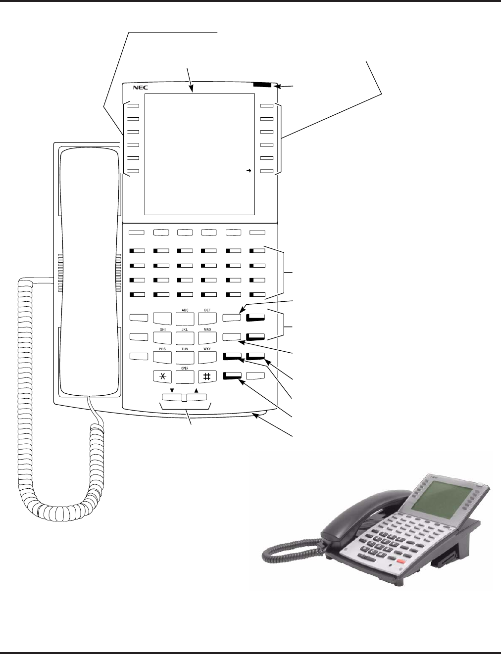
Charts and Illustrations
64 ◆Features Aspire Software Manual
Figure 1: SUPER DISPLAY TELEPHONE
Handsfree,
Handset,
Page and BGM
Volume Control
Alphanumeric
Soft Keys
Display
1234 56
78 9101112
13 14 15 16 17 18
19 20 21 22 23 24
2
5
8
0
4
7
3
6
9
CALL 2
CALL 1
DND
HOLD
LND
DIAL
MIC
FLASH
SPK
VOL
CONF
MSG
Programmable
Function Keys
Abbreviated
Dialing
Dual Line
Appearance Keys
Last Number
Redial
Do Not Disturb
Microphone Cutoff
Speakerphone
Microphone
0893200 - 2
CLEAR
CHECK
’03 MO TU WE TH FR SA SU
1
guide you through your
features. While your phone is
idle, the Soft Keys can be used
as One Touch Keys.
Message Waiting
Lamp
List Dir ICM Prog
1 | 30 31 1 2 3 4 5
2 | 6 7 8 9 10 11 12
3 | 13 14 15 16 17 18 19
4 | 20 21 22 23 24 25 26
OneT
5-22 THU 3:43PM
302 STA 302
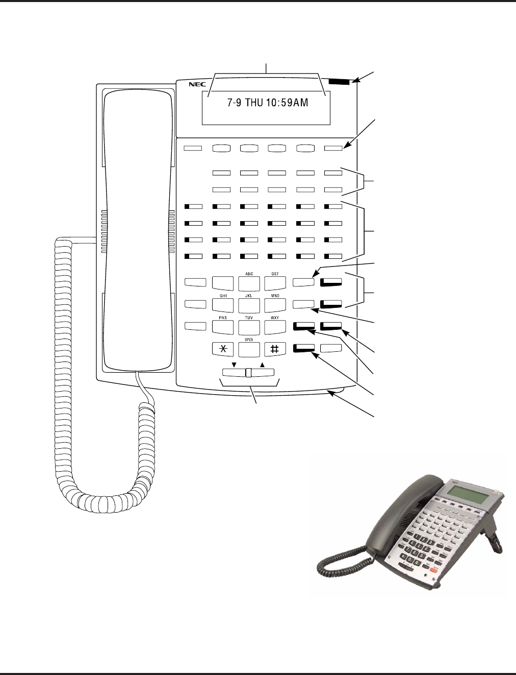
Charts and Illustrations
Aspire Software Manual Features ◆65
Figure 2: MULTIBUTTON TELEPHONE
Handsfree,
Handset,
Page and BGM
Volume Control
Soft Keys
(Not available on
all models)
Alphanumeric
Display
1234 56
78 9101112
13 14 15 16 17 18
19 20 21 22 23 24
2
5
8
0
4
7
3
6
9
CALL 2
CALL 1
DND
HOLD
LND
DIAL
MIC
FLASH
SPK
VOL
CONF
MSG
One Touch
Keys
Programmable
Function Keys
Abbreviated
Dialing
Dual Line
Appearance Keys
Last Number
Redial
Do Not Disturb
Microphone Cutoff
Speakerphone
Microphone
0893200 - 1
CLEAR
CHECK
302 STA 302
1
Message Waiting
Lamp
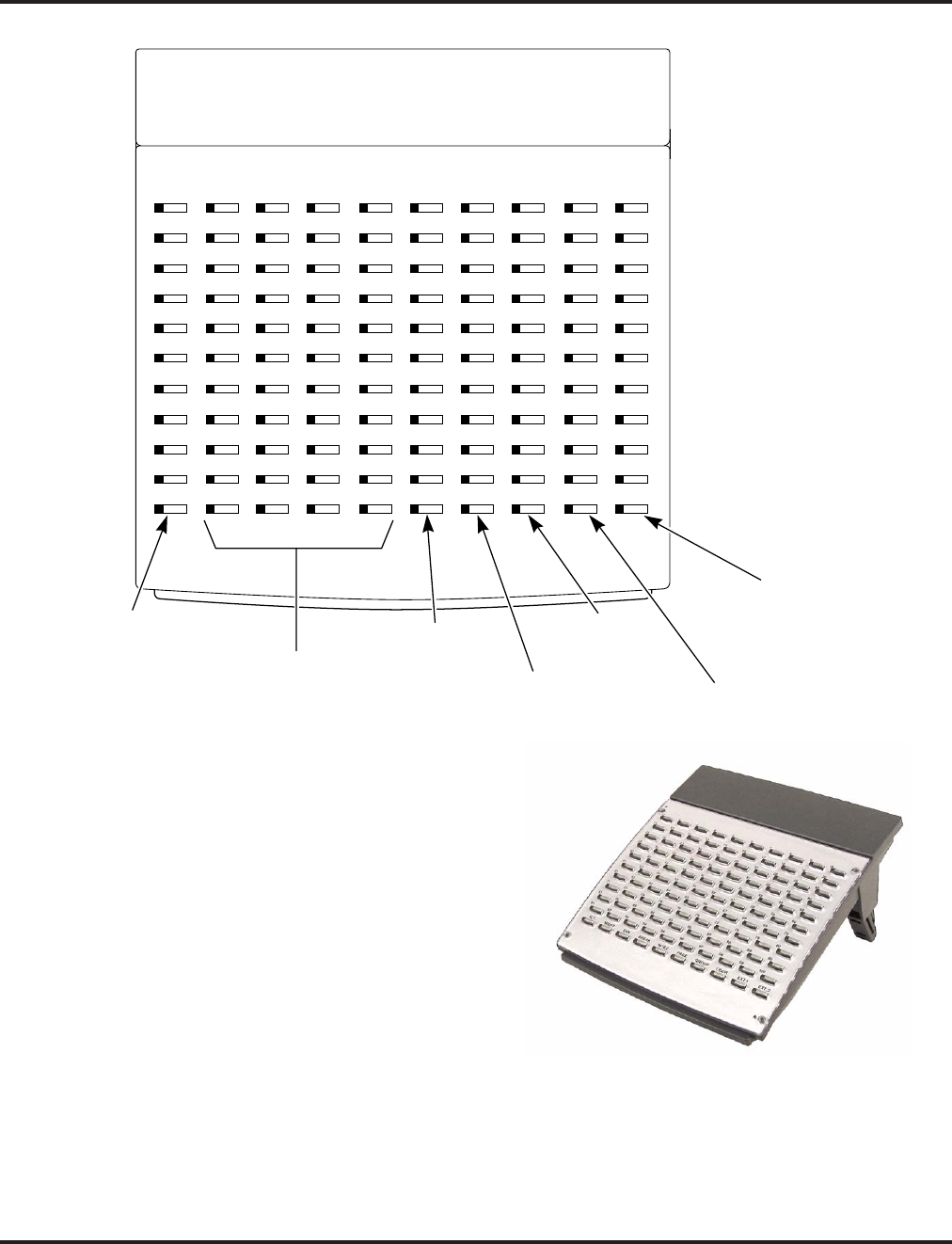
Charts and Illustrations
66 ◆Features Aspire Software Manual
Figure 3: 110-BUTTON DSS CONSOLE
N2IP-3
21 22 23 24 25 26
31 32 33 34 35 36
41 42 43 44 45 46
51 52 53 54 55 56
1234 56
11 12 13 14 15 16
27 28 29 30
37 38 39 40
47 48 49 50
57 58 59 60
78 910
17 18 19 20
71 72 73 74 75 76
81 82 83 84 85 86
91 92 93 94 95 96
61 62 63 64 65 66
77 78 79 80
87 88 89 90
97 98 99 100
67 68 69 70
Night
Service Keys
External
Page
Door
Boxes
1st 100
Extensions
2nd
100
Extensions
Internal
Page
Alternate
Answering Key
DAYALT. BREAKNIG HT NITE2 PAGE GRO UP DOO R EXT.1 EXT.2
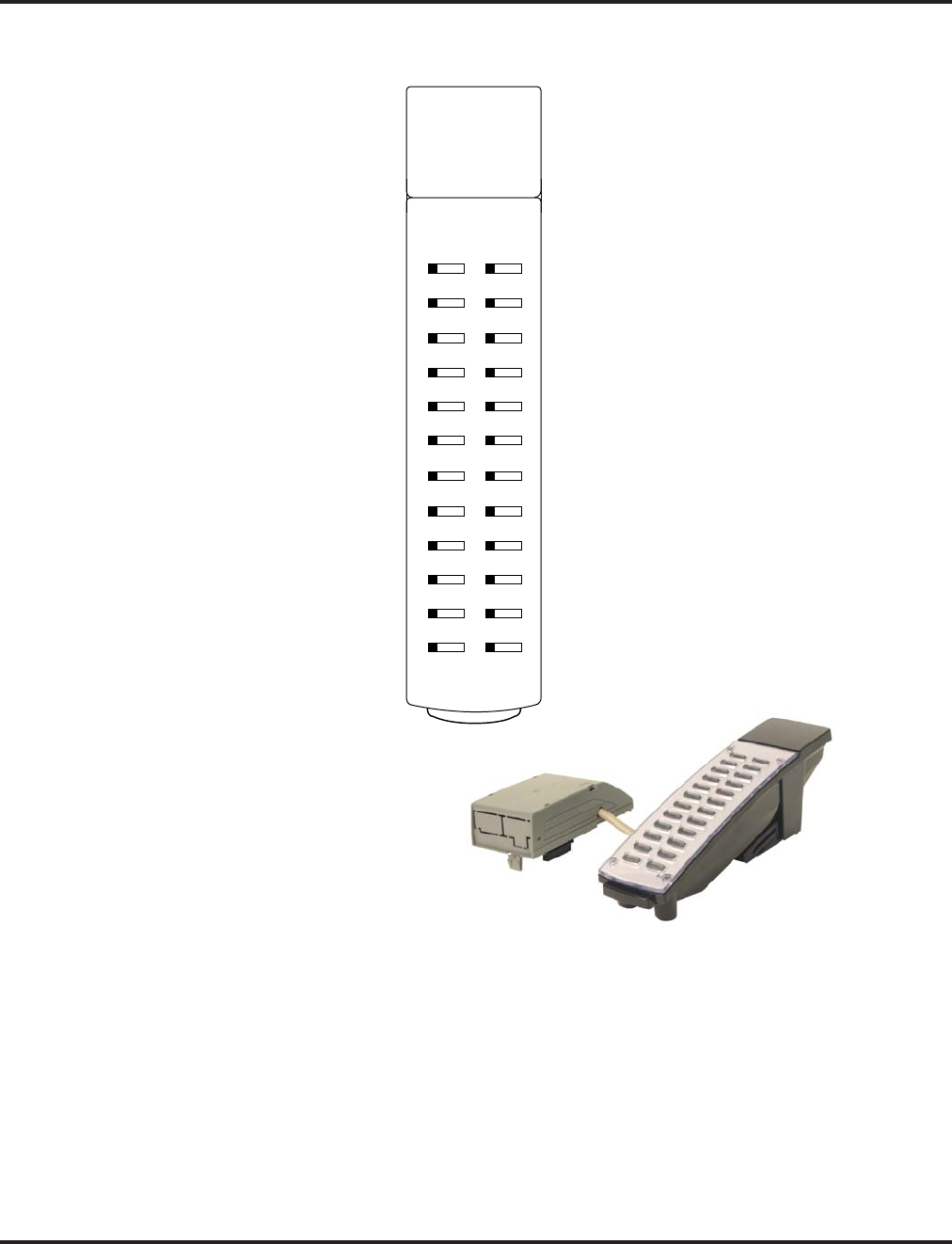
Charts and Illustrations
Aspire Software Manual Features ◆67
Figure 4: 24-BUTTON DSS CONSOLE
N2IP-7
3
4
5
6
1
2
8
9
10
11
12
7
15
16
17
18
13
14
20
21
22
23
24
19
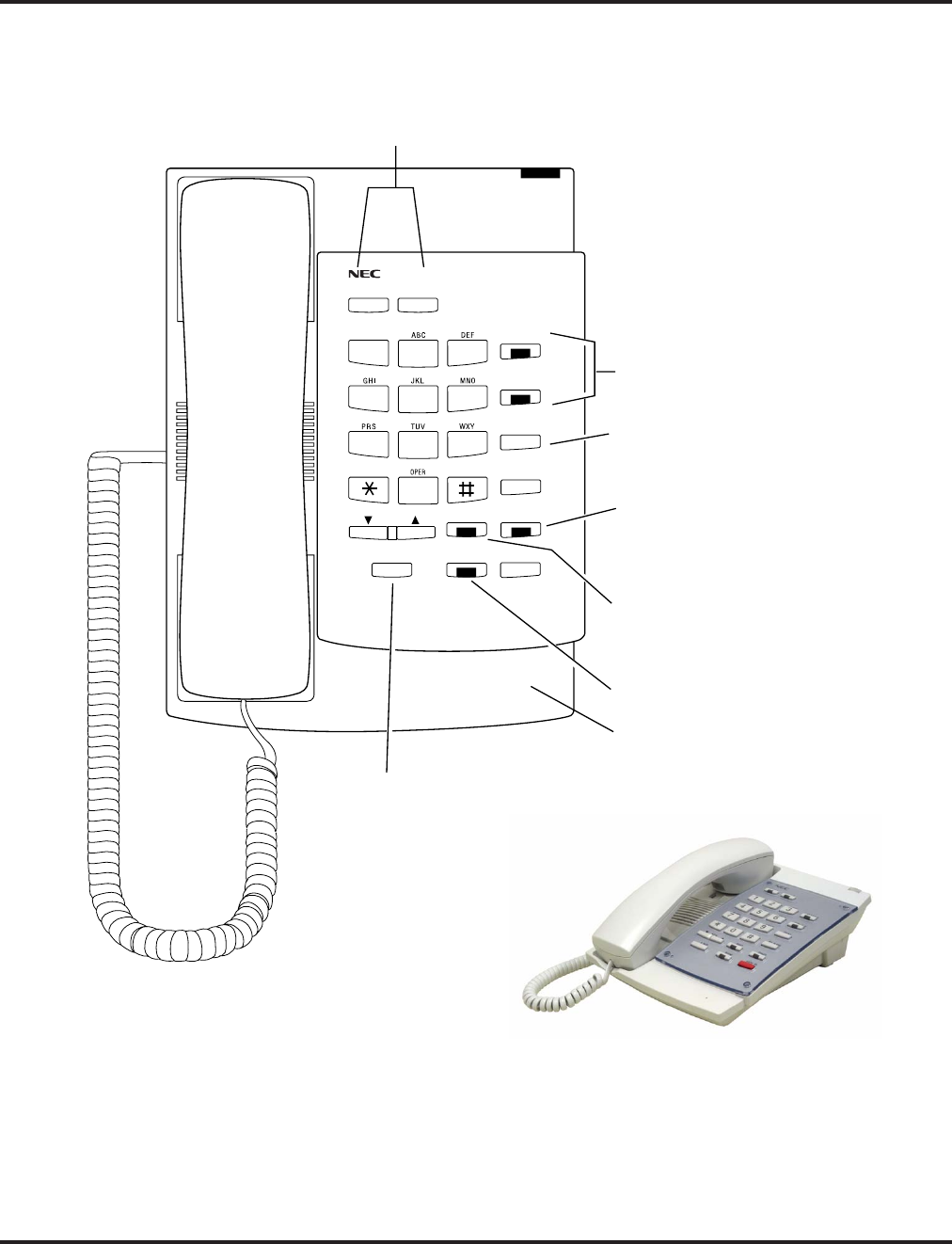
Charts and Illustrations
68 ◆Features Aspire Software Manual
Figure 5: Digital Two-Button Telephone
2
5
8
0
4
7
3
6
9
CALL 2
CALL 1
L1 L2
DND
HOLD
LND
DIAL
MIC
FLASH
SPK
VOL
0893200 - 3
1
Line Keys/
Programmable
Function Keys
Abbreviated
Dialing
Dual Line
Appearance Keys
Last Number
Redial
Do Not Disturb
Microphone Cutoff
Speakerphone
Microphone
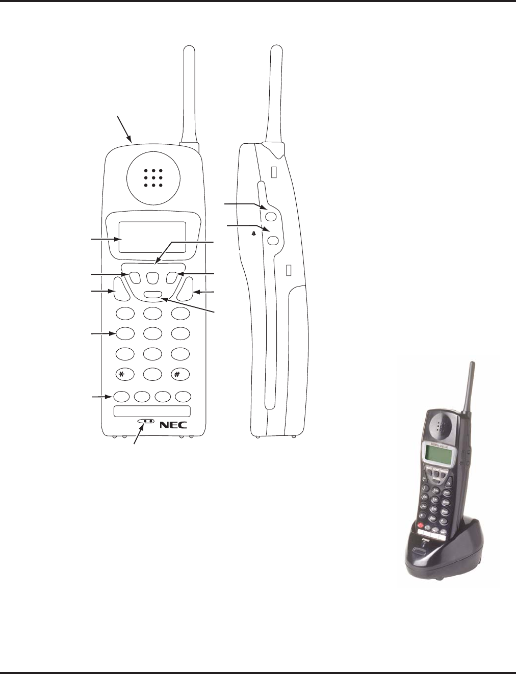
Charts and Illustrations
Aspire Software Manual Features ◆69
Figure 6: Cordless Lite II (Spread Spectrum) Telephone
0893408 - 1
900MHz DIGITAL
HOLD
TALK CH
CONF
REDIAL
TRANSFER
1
2
abc
3
def
4
ghi
5
jkl
6
mno
7
pqrs
8
tuv
0
oper
9
wxyz
RING
/VOL
ON/OFF
MUTE
8
9
10
11
12
13
2
1
3
4
5
6
7
1. Headset Jack
2. Message Display
3. Hold Key
4. Talk Key
5. Numeric Keypad
6. Function keys
(default: line keys 1-4)
7. Microphone
8. Volume (Ring/Vol) Key
9. Mute Key
10. Conference (CONF) Key
11. Transfer/Flash Key (defined in 15-02-05)
12. Last Number Redial (REDIAL)
OR
Desk/Cordless Switching Key
(requires program change)
13. Channel (CH) Key
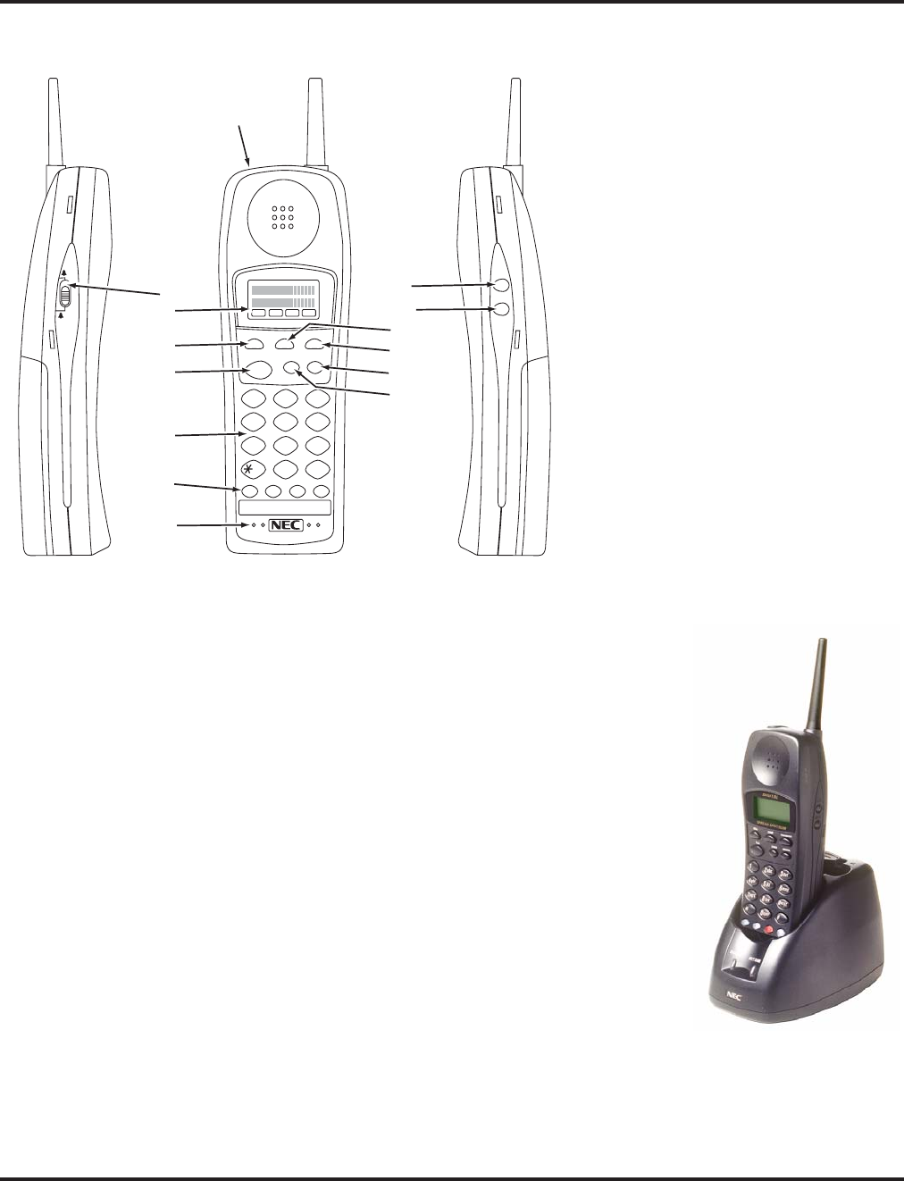
Charts and Illustrations
70 ◆Features Aspire Software Manual
Figure 7: Cordless II Telephone
9
10
11
12
13
14
1
2
3
4
5
6
7
2
abc
ON R/VOL
MUTE
OFF
5
jkl
6
mno
4
ghi
8
tuv
9
wxyz
7
pqrs
0
oper
#
3
def
1
0893408-2
1. Ringer ON/OFF switch
2. Message Display
3. Hold Key
4. Talk Key
5. Numeric Keypad
6. Function Keys
(default: line keys 1-4)
7. Microphone
8. Headset Jack
9. Volume (R/VOL) Key
10. Mute Key
11. Conference (CONF) Key
12. Transfer/Flash Key
(defined in Pgm 15-02-05)
13. Last Number Dial (REDIAL)
OR
Desk/Cordless Switching Key
(requires program change)
14. Channel (CHAN) Key
8
HOLD
CHAN REDIAL
TRANSFER
CONF
TALK
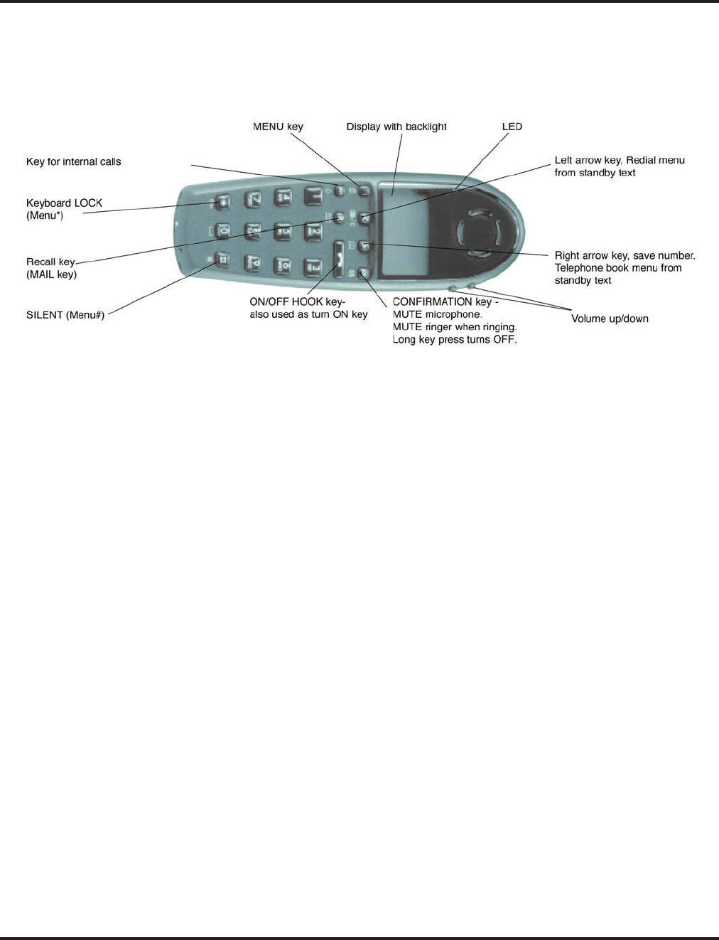
Charts and Illustrations
Aspire Software Manual Features ◆71
Figure 8: Aspire Wireless Telephone

Charts and Illustrations
72 ◆Features Aspire Software Manual
- For Your Notes -

Abbreviated Dialing
Aspire Software Manual Features ◆73
Abbreviated Dialing
Description
Abbreviated Dialing gives an extension user quick access to frequently called numbers. This saves
time, for example, when calling a client with whom they deal often. Instead of dialing a long tele-
phone number, the extension user just dials the Abbreviated Dialing code.
There are three types of Abbreviated Dialing: Common, Group and Personal. All co-workers can
share the Common Abbreviated Dialing numbers. All co-worker’s in the same Abbreviated Dialing
Group can share the Group Abbreviated Dialing numbers. Personal Abbreviated Dialing numbers
are available only at a user’s own extension. To set up Personal Abbreviated Dialing, refer to the
“One-Touch Calling” feature. The system has 2000 Abbreviated Dialing bins that you can allocate
between Common and Group Abbreviated Dialing. (The Group bins are assigned in groups of 10.)
Each Abbreviated Dialing bin can store a number up to 24 digits long.
When placing an Abbreviated Dialing call, the system normally routes the call through Trunk
Group Routing or ARS (whichever is enabled). Or, the user can preselect a specific trunk for the
call. In addition, the system can optionally force Common Abbreviated Dialing numbers to route
over a specific Trunk Group. User pre-selection always overrides the system routing.
Common Bins Limited to 1000 with Dial Key or #2 Service Code
Though there are 2000 Abbreviated Dialing bins available in the system, once programmed, these
bins can currently only be dialed using the Directory Dial feature (Press Directory Dialing Soft Key
+ ABBc Soft Key + Use arrow keys to locate number or enter the Abbreviated Dial bin name +
CALL or SPK to place call.)
The DIAL key and service code #2 operations are not available for any 4-digit Abbreviated Dial
common bin number.
DSS Console Chaining
DSS Console chaining allows an extension user with a DSS Console to chain to an Abbreviated
Dialing number stored under a DSS Console key. The stored number dials out (chains) to the initial
call. This can, for example, simplify dialing when calling a company with an Automated Attendant.
You can program the bin for the company number under one DSS Console key (e.g., #200) and the
client’s extension number under the other (e.g., #201). The DSS Console user presses the first key
to call the company, waits for the Automated Attendant to answer, then presses the second key to
call the client (extension 400). See Programming below for additional details.
The DSS Console user can also chain to an Abbreviated Dialing number dialed manually, from a
Programmable Function Key or a One-Touch Key.
Storing a Flash
To enhance compatibility with connected Centrex and PBX lines, an Abbreviated Dialing bin can
have a stored Flash command. For example, storing 9 Flash 926 5400 will cause the system to dial
9, flash the line and then dial 926 5400. The Flash can be stored by the user from their telephone or
by the system administrator during system programming.
Aspire S Aspire M/L/XL
• Available.
• 2000 bins available (0000-1999) for Common and
Group Abbreviated Dialing. Up to 8 Abbreviated Dial-
ing Groups available.
• Available.
• 2000 bins available (0000-1999) for Common and
Group Abbreviated Dialing. Up to 64 Abbreviated Dial-
ing Groups available.

Abbreviated Dialing
74 ◆Features Aspire Software Manual
Using a Programmable Function Key
To streamline frequently-called numbers, an Abbreviated Dialing Programmable Function Key can
also store an Abbreviated Dialing bin number. When the extension user presses the key, the phone
automatically dials out the stored number. This provides true one-touch calling via a phone’s func-
tion keys.
Conditions
None
Default Setting
Available. There are no Group Abbreviated Dialing bins assigned.
Programming
➻11-10-04 : Service Code Setup (for System Administrator) - Storing Common
Abbreviated Dialing Numbers
If required, change the service code (853) used to store Common Abbreviated Dialing numbers.
➻11-10-05 : Service Code Setup (for System Administrator) - Storing Group Abbreviated
Dialing Numbers
If required, change the service code (854) used to store Group Abbreviated Dialing numbers.
➻13-01-01 : Abbreviated Dialing Function Setup - Abbreviated Dialing Auto Outgoing
Call Mode
Determine if dialing an Abbreviated Dialing number will dial an outside number (seizing a
trunk as defined in Program 13-05) or an Intercom number (0=trunk dialing mode, 1=exten-
sion dialing mode).
➻13-01-03 : Abbreviated Dialing Function Setup - Common Abbreviated Dialing Bins
Designate the bins the system will use for Common Abbreviated Dialing. When using 4-digit
bins (1000-2000), remember that these must be dialed using the keyset’s Soft Keys.
➻13-02-01 : Group Abbreviated Dialing Bins
Designate the bins the system will use for Group Abbreviated Dialing. The system assigns the
group numbers in sets of 10 (start bin: xxx0 - end bin: xxx9).
➻13-03-01 : Abbreviated Dialing Groups for Extensions
For Group Abbreviated Dialing, assign extensions to Abbreviated Dialing groups.
➪Aspire S Abbreviated Dialing Groups: 1-8
➪Aspire Abbreviated Dialing Groups: 1-64
➻13-04-01 : Abbreviated Dialing Number and Name
Enter the Common and Group Abbreviated Dialing numbers and names.
➻13-05-01 : Abbreviated Dialing Trunk Group
For each Common Abbreviated Dialing number, enter the routing option. To use ARS or
Trunk Group Routing, enter 9. To use a specific Trunk Group, enter the group number.
➪Aspire S Trunk Groups: 1-8
➪Aspire Trunk Groups: 1-100
➻14-02-06 : Analog Trunk Data Setup - Pause Time
Enable/disable the systems ability to pause after dialing the first digit.
➻15-02-04 : Abbreviated Dialing DIAL Key Control
Assign the extensions’ DIAL key for either Common (0) or Group (1) Abbreviated Dialing.

Abbreviated Dialing
Aspire Software Manual Features ◆75
➻15-07-01 : Programming Function Keys
Assign a function key for Common Abbreviated Dialing (code 27 ) or Group Abbreviated
Dialing (code 28). You can program the key as either a general Abbreviated Dialing key or
you can choose to store a bin number with the function key. This key would then always dial
the associated bin number. If storing a bin number along with the code, do not store 0, 00 or
000. To bypass entering a bin number, press HOLD (HOLD is also required if programming
the function key using the service code 851).
➻20-06-01 : Class of Service for Extensions
Assign a Class of Service (1-15) to an extension.
➻20-07-04 : COS Options (Administrator Level) - Storing Abbreviated Dialing Entries
In an extension’s COS, allow (1) or prevent (0) the storing of Abbreviated Dialing entries (codes
853 and 854). Preventing this option will also prevent the user’s display from showing the tele-
phone number. This can be used when you want to prevent account codes from being displayed.
➻20-08-03 : COS Options (Outgoing Call Service) - Common Abbreviated Dialing
In an extension’s COS, enable (1) or disable (0) Common Abbreviated Dialing.
➻20-08-04 : COS Options (Outgoing Call Service) - Group Abbreviated Dialing
In an extension’s Class of Service, enable (1) or disable (0) Group Abbreviated Dialing.
➻30-03-01 : DSS Console Key Assignment
Assign an Abbreviated Dialing Service Code (27 or 28) plus a two-digit bin number to a DSS
Console key. For DSS Console Chaining, assign a DSS Console key as a DSS/One-Touch Key
(01) then add the additional data.
➻80-03-01 : DTMF Tone Receiver Setup
80-04-01 : Call Progress Tone Detector Setup
If required, modify the criteria for dial tone detection and call progress tone detection for out-
going Abbreviated Dialing calls.
➻81-01-16 : ATRU-LS Initial Data Setup - Pause Time
If Abbreviated Dialing numbers include a pause, the system uses this timer to determine the
length of the pause. This timer is enabled/disabled in 14-02-06.
Related Features
Account Codes
Abbreviated Dialing bins can contain stored Account Codes. Prevent them from being dis-
played using 20-07-04.
Automatic Route Selection
For systems with Automatic Route Selection, ARS selects the trunk for the call unless the user
preselects.
Central Office Calls, Placing
A user can implement Abbreviated Dialing only if their extension has outgoing access to trunks.
Dial Tone Detection
Refer to this feature for the specifics on how the system handles Dial Tone Detection.
One-Touch Calling
An extension can have a One-Touch Key for Abbreviated Dialing operation.
PBX Compatibility
If you enter a PBX trunk access code in an Abbreviated Dialing bin, the system automatically
inserts a pause after the bin.
Programmable Function Keys
Function keys simplify Abbreviated Dialing operation.
Single Line Telephones
Single line telephones can only dial Common and Group Abbreviated Dialing numbers.

Abbreviated Dialing
76 ◆Features Aspire Software Manual
Toll Restriction
Toll Restriction may prevent a user from using a stored Abbreviated Dialing number.
Trunk Group Routing
Unless a user preselects a trunk, Trunk Group Routing selects the trunk Abbreviated Dialing
uses for trunk calls.
Operation
To store an Abbreviated Dialing number (display phones only):
1. Press idle CALL key.
2. Dial 853 (for common) or 854 (for group).
3. Dial common or group storage code (000-999).
Initially, there are 1000 Common Abbreviated Dialing codes. There are Group Abbre-
viated Dialing codes only if you define them in programming.
When using 4-digit bins, the storage codes/bin numbers are 0000-1999.
4. Dial telephone number you want to store (up to 24 digits).
Valid entries are 0-9, # and *. To enter a pause, press MIC. To store a Flash, press FLASH.
5. Press HOLD.
6. Enter the name associated with the Abbreviated Dialing number.
7. Press HOLD
8. Press SPK to hang up.
With Software 2.05+:
Key for Entering Names
When entering names in the procedures below, refer to this chart. Names can be up to
12 digits long. For prior software or when using i-Series phones, refer to the charts in
the Name Storing feature (page 432).
Use this keypad digit . . . When you want to. . .
1 Enter characters:
1 @ [ ¥ ] ^ _ ` { | } →→
→→ ←←
←← Á À Â Ã Ç É Ê ì ó
2 Enter characters A-C, a-c, 2.
3 Enter characters D-F, d-f, 3.
4 Enter characters G-I, g-i, 4.
5 Enter characters J-L, j-l, 5.
6 Enter characters M-O, m-o, 6.
7 Enter characters P-S, p-s, 7.
8 Enter characters T-V, t-v, 8.
9 Enter characters W-Z, w-z, 9.
0 Enter characters:
0 ! “ # $ % & ’ ( ) ô Õ ú ä ö ü α ε θ
* Enter characters:
* + , - . / : ; < = > ? π ∑ σ Ω ∞ ¢ £
# # = Accepts an entry (only required if two letters on the same key are needed - ex: TOM).
Pressing # again = Space. (In system programming mode, use the right arrow soft key
instead to accept and/or add a space.)
CONF Clear the character entry one character at a time.
CLEAR Clear all the entries from the point of the flashing cursor and to the right.

Abbreviated Dialing
Aspire Software Manual Features ◆77
To dial a Common Abbreviated Dialing number:
Four-digit bin numbers must be dialed using the keyset’s Soft Keys.
3-Digit Bin Numbers Only
1. At keyset, press idle CALL key.
OR
At single line set, lift handset.
2. Dial #2 (000-999).
OR
Press DIAL key.
OR
Press Common Abbreviated Dialing key (PGM 15-07 or SC 851: 27).
To preselect, press a line key in step 1 (instead of CALL) before pressing the DIAL or
Abbreviated Dialing key).
3. Dial Common Abbreviated Dialing storage code (000-999).
The stored number dials out.
Unless you preselect, Trunk Group Routing selects the trunk for the call. The system
may optionally select a specific Trunk Group for the call.
If you have a DSS Console, you may be able to press a DSS Console key to chain to a
stored number.
4-Digit Bin Numbers
1. At keyset, press the DIR Soft Key.
2. Press the ABBc Soft Key.
3. Use the ↑↑
↑↑ or ↓↓
↓↓ to locate the number you wish to call.
4. Press the DIAL Soft Key.
The stored number dials out.
To store a Common Abbreviated Dialing number under a Programmable Function
Key:
1. At keyset, press idle CALL key.
2. Dial 851.
3. Press the key which is to store the number.
4. Dial 01.
5. Dial #2 + the 3-digit bin number (000-999) to be stored.
Four-digit bin numbers can not be stored with this function.
6. Press HOLD.
7. Press SPK to hang up.
To dial a Common Abbreviated Dialing number under a Programmable Function
Key:
1. At keyset, press idle CALL key.
2. Press the key which has the stored number to be dialed.
The number seizes an outside line and dials out.

Abbreviated Dialing
78 ◆Features Aspire Software Manual
To dial a Group Abbreviated Dialing number:
3-Digit Bin Numbers Only
1. At keyset, press idle CALL key.
OR
At single line set, lift handset.
2. Dial #4 (000-999).
OR
Press DIAL key.
OR
Press Group Abbreviated Dialing key (PGM 15-07 or SC 851: 28).
To preselect, press a line key in step 1 (instead of CALL) before pressing the DIAL or
Abbreviated Dialing key)
3. Dial the Group Abbreviated Dialing code (000-999).
The stored number dials out.
Unless you preselect, Trunk Group Routing selects the trunk for the call.
If you have a DSS Console, you may be able to press a DSS Console key to chain to a
stored number.
4-Digit Bin Numbers
1. At keyset, press the DIR Soft Key.
2. Press the ABBg Soft Key.
3. Use the ↑↑
↑↑ or ↓↓
↓↓ to locate the number you wish to call.
4. Press the DIAL Soft Key.
The stored number dials out.
To check your stored Abbreviated Dialing numbers (display phone only):
1. Press CHECK.
2. For Common Abbreviated Dialing, press DIAL.
Dial the Abbreviated Dialing Code (e.g., common code 001).
If the entire stored number is too long for your phone’s display, press * to see the rest
of it.
OR
For Group Abbreviated Dialing, press the Group Abbreviated Dialing key.
OR
For Common Abbreviated Dialing key, press the Common Abbreviated Dialing key.
3. Press CLEAR.
To display additional numbers, repeat from step 1.

Account Codes
Aspire Software Manual Features ◆79
Account Codes
Description
Account Codes are user-dialed codes that help the system administrator categorize and/or restrict
trunk calls. The system has three types of Account Codes:
●Optional Account Codes
Optional Account Codes allow a user to enter an Account Code while placing a trunk call or
anytime while on a call. This type of Account Code is optional; the system does not require
the user to enter it.
●Forced Account Codes
Forced Account Codes require an extension user to enter an Account Code every time they
place a trunk call. If the user doesn’t enter the code, the system prevents the call. As with
Optional Account Codes, the extension user can elect to enter an Account Code for an incom-
ing call. However, the system does not require it. Forced Account Codes does not block 1-
800, 1-888 and emergency assistance (911) calls.
Once set up in system programming, you can enable Forced Account Codes on a trunk-by-
trunk basis. In addition, Forced Account Codes can apply to all outside calls or just long dis-
tance calls. Forced Account Codes for Toll Calls restricts calls according to the following
chart:
Aspire S Aspire M/L/XL
• Available.
• Adjustable Forced Account Code interdigit timer
requires software 2.65+.
• Available.
• Adjustable Forced Account Code interdigit timer
requires software 2.65+.
Number of Digits Dialed If first digit is not 1 If first digit is 1
1-3 Not allowed Not allowed
4-7 Allowed - does not require
Account Code Allowed - requires Account
Code
More than 71Allowed - requires Account
Code Allowed - requires Account
Code
800 and 888 Allowed - requires Account
Code Allowed - does not require
Account Code
011 (International) Allowed - requires Account
Code N/A
911 Allowed - does not require
Account Code N/A
1 If you change the local call length in Toll Restriction, this value changes accordingly.

Account Codes
80 ◆Features Aspire Software Manual
Timer Modified to Allow for Forced Account Code Interdigit Timer
Programming has been changed which will allow the adjustment of the interdigit timer used
for Forced Account Codes. Previously, this was fixed at 3 seconds.
Depending on your software, the system will use the time set in Program 21-01-04 : System
Options for Outgoing Calls - Dial Tone Detection Time for the interval the system will wait
for a user to enter a Forced Account Code. By default, this option is set to 5 (Entries: 0-64800
seconds).
●Verified Account Codes
With Verified Account Codes, the system compares the Account Code the user dials to a list of
up to 1000 pre-programmed codes. If the Account Code is in the list, the call goes through. If
the code dialed is not in the list, the system prevents the call. Verified Account Codes can be
from 3-16 digits long using the characters 0-9 and #. During programming, you can use “wild
cards” to streamline entering codes into system memory. For example, the entry 123W lets
users dial Verified Account Codes from 1230 through 1239.
Operator Notification
To prevent Account Code abuse, the system can notify the operator each time an Account Code vio-
lation occurs. This can happen if the user fails to enter an Account Code (if Forced) or enters a Veri-
fied Account Code that is not in the list. The notification is an automatic Intercom call to the
attendant and a “RESTRICT” message in the operator’s display. (If the attendant fails to enter a valid
Account Code, the system drops the call.)
Account Codes for Incoming Calls
The system can control the ability of extension users to enter Account Codes for incoming calls.
When this option is enabled, a user can dial * while on an incoming call, enter an Account Code,
and then dial * to return to their caller. If the option is disabled, any digits the user dials after
answering an incoming call outdial on the connected trunk.
Hiding Account Codes
Account Codes can be optionally hidden from a telephone’s display. This would prevent, for exam-
ple, an unauthorized co-worker from obtaining a Verified Account Code by watching the display and
making note of the digits that dial out. When hidden, the Account Code digits show as the character
“*” on the telephone’s display.
Account Code Capacity
Account Codes print along with the other call data on the SMDR record after the call completes.
Account Codes can be 1-16 digits in length using 0-9 and #. Verified Account Codes can be from 3-
16 digits long.
Redialed Numbers Do Not Contain Account Codes
When using the Last Number Redial, Save or Repeat Dial features, the system will not retain
Account Code information. Any number redialed with these features, the user will need to reenter
an Account Code.
Note:
If a user enters *12345*203 926 5400*67890*, if the Last Number Redial feature is used, the sys-
tem dials the number as 203 926 5400*67890*. The *67890* is not treated as an Account Code.

Account Codes
Aspire Software Manual Features ◆81
Conditions
(A.) If a user enters a code that exceeds the 16 digit limit, the system ignores the Account Code
entry.
(B.) If the system has Account Codes disabled, the digits dialed (e.g., *1234*) appear on the
SMDR report as part of the number dialed.
(C.) Do not use an asterisk within a PBX access code when using Account Codes. Otherwise, after
the *, the trunk will stop sending digits to the central office.
Default Setting
Account Codes are disabled.
Programming
➻14-01-11 : Basic Trunk Data Setup - Account Code
Enable (1) or disable (0) Forced Account Codes for each trunk.
➻15-07-01 : Programming Function Keys
Assign a function key as an Account Code key (code 50). Use this key instead of the dial pad
to enter the * before and after the Account Code.
➻20-06-01 : Class of Service for Extensions
Assign a Class of Service (1-15) to an extension.
➻21-01-04 : System Options for Outgoing Calls - Forced Acount Code Inter-Digit Time
Adjust the interval the system will wait for a user to enter a Forced Account Code. By default,
this option is set to 3 (Entries: 0-64800 seconds).
➻21-04-01 : Toll Restriction Class
Use this option to assign a Toll Restriction Class (1-15) to an extension.
➻35-05-01 : Account Code Setup - Account Code Mode
For each Class of Service (1-15) use this option to select the Account Code Mode. The options
are: 0 Account Codes disabled. (Any codes you enter dial out as part of your initial
call.)
1 Account Codes optional (not required).
2 Account Codes required (forced) but not verifiable.
3 Account Codes required (forced) and verifiable.
➻35-05-02 : Account Code Setup - Forced Account Code Toll Call Setup
For each Class of Service (1-15), enter 1 in this option to enable Forced Account Codes for
just toll calls. Enter 0 to enable Forced Account Codes for local and toll calls. With this option
enabled, local calls will have Optional Account Codes. If a user needs to dial * as part of post-
dialing digits, The * must be pressed three times (twice for the expected account code entry
and the third as the post-dialing digit).
➻35-05-03 : Account Code Setup - Account Codes for Incoming Calls
For each Class of Service (1-15), enter 1 in this option to enable Account Codes for incoming
calls. Enter 0 to disable Account Codes for incoming calls. If disabled, any codes you enter
dial out on the connected trunk.
➻35-05-04 : Account Code Setup - Hiding Account Codes
For each Class of Service (1-15), enter 1 to have the system hide Account Codes on an exten-
sion’s display as they are entered. Enter 0 to have the Account Codes displayed.
➻35-06-01 : Verified Account Code Table
Use this option to enter data into the Verified Account Code Table. You can enter up to 2000
codes from 3-16 digits in length. For a wild card, press the FLASH key.

Account Codes
82 ◆Features Aspire Software Manual
Related Features
Abbreviated Dialing
Abbreviated Dialing bins can contain stored Account Codes. Prevent them from being dis-
played using 20-07-04.
Automatic Route Selection
ARS can force a user to enter an Authorization Code prior to using a certain route. The system
verifies the ARS Authorization Code dialed against the ARS Authorization Code list (Program
44-03).
One-Touch Calling
To simplify Account Code entry, store the Account Code (e.g., *1234*) in a One-Touch Key.
Just press the key instead of dialing the codes.
PBX Compatibility
When using Account Codes, do not use an asterisk within a PBX access code. Otherwise,
after the *, the trunk would stop sending digits to the central office.
Station Message Detail Recording
Account Codes appear on the SMDR report (even if they are hidden on the phone’s display).
Operation
To enter an Account Code any time while on a trunk call:
The outside caller cannot hear the Account Code digits you enter.
You can use this procedure if your system has Optional Account Codes enabled. You
may also be able to use this procedure for incoming calls.
This procedure is not available at SLTs.
1. Dial *.
OR
Press your Account Code key (PGM 15-07 or SC 851: code 50).
2. Dial your Account Code (1-16 digits, using 0-9 and #).
If Account Codes are hidden, each digit you dial will show an “*” character on the
telephone’s display.
3. Dial *.
OR
Press your Account Code key (PGM 15-07 or SC 851: code 50).

Account Codes
Aspire Software Manual Features ◆83
To enter an Account Code before dialing the outside number:
If your system has Forced Account Codes, you must use this procedure. If it has Veri-
fied Account Codes, you can use this procedure instead of letting the system prompt you
for your Account Code. You may also use this procedure if your system has Optional
Account Codes.
If your system has Verified Account Codes enabled, be sure to choose a code pro-
grammed into your Verified Account Code list.
1. Access trunk for outside call.
You can access a trunk by pressing a line key or dialing a code (except 9). Refer to
Central Office Calls, Placing (page 218) for more information.
2. Dial *
OR
Press your Account Code key (PGM 15-07 or SC 851: code 50)
3. Dial your Account Code (1-16 digits, using 0-9 and #).
If you make an incorrect entry, your system may automatically alert the operator. If
Account Codes are hidden, each digit you dial will show an “*” character on the tele-
phone’s display.
4. Dial *.
OR
Press your Account Code key (PGM 15-07 or SC 851: code 50)
5. Dial the number you want to call.
If you hear “stutter dial tone after dialing the number, ARS is requesting that you enter
an ARS Authorization Code. Refer to Automatic Route Selection (page 138) for more
information.
To dial an outside number and let your system tell you when an Account Code is
required:
1. Access a trunk and dial the number you want to call.
If you hear “stutter dial tone after dialing the number, ARS is requesting that you enter
an ARS Authorization Code. Refer to Automatic Route Selection (page 138) for more
information.
2. Wait for your call to go through.
OR
If you hear “Please enter an Account Code,” and your display shows ENTER ACCOUNT
CODE:
●Dial *.
OR
Press your Account Code key (PGM 15-07 or SC 851: code 50)
●Dial your Account Code (1-16 digits, using 0-9 and #).
If Account Codes are hidden, each digit you dial will show an “*” character on the
telephone’s display.
●Dial *.
OR
Press your Account Code key (PGM 15-07 or SC 851: code 50)

Account Codes
84 ◆Features Aspire Software Manual
To enter an Account Code for an incoming call:
This procedure is not available at SLTs.
1. Answer incoming call.
If Account Codes for Incoming Calls is disabled, the following steps will dial digits out
onto the connected trunk.
2. Dial *.
3. Enter the Account Code.
You can enter any code of the proper length. Incoming Account Codes cannot be
Forced or Verified.
4. Dial *.
To enter an Account Code while placing a trunk call:
If your system has Forced Account Codes, you must follow this procedure.
1. Access trunk for outside call.
You can access a trunk by pressing a line key or dialing a code. Refer to Central Office
Calls, Placing for more information.
With Forced Account Codes, you hear, “Please enter an Account Code.” Your display
shows: ENTER ACCOUNT CODE.
2. Dial *.
3. Dial your Account Code (1-16 digits, using 0-9 and #).
4. Dial *
If the system has Forced Account Codes and you don’t enter a code, your call cannot
go through. You can, however, dial ** to bypass Forced Account Code entry.
5. Dial number you want to call.
If you hear “stutter” dial tone after dialing the number, ARS is requesting you to enter
an ARS Authorization Code. Refer to the Automatic Route Selection feature for more infor-
mation on ARS Authorization Codes.
To enter an Account Code at a single line set:
1. Access trunk for outside call.
You can access a trunk by dialing a code. Refer to Central Office Calls, Placing for
more information.
With Forced Account Codes, you hear, “Please enter an Account Code.” Your display
shows: ENTER ACCOUNT CODE.
2. Dial *.
3. Enter Account Code (1-16 digits).
4. Dial *.
5. Dial number you want to call.
If you hear “stutter” dial tone after dialing the number, ARS is requesting you to enter
an ARS Authorization Code. Refer to the Automatic Route Selection feature for more infor-
mation on ARS Authorization Codes.

Alarm
Aspire Software Manual Features ◆85
Alarm
Description
Alarm lets a keyset extension work like an Alarm clock. An extension user can have Alarm remind
them of a meeting or an appointment. There are two types of Alarms:
●Alarm 1 (sounds only once at the preset time)
●Alarm 2 (sounds every day at the preset time)
Conditions
Single line sets will ring and Music on Hold will be heard when the alarm sounds.
Default Setting
Alarm is enabled.
Programming
➻20-01-06 : System Options - Alarm Duration
Set the duration of the Alarm signal (0-64800 seconds).
Related Features
None
Aspire S Aspire M/L/XL
• Available. • Available.

Alarm
86 ◆Features Aspire Software Manual
Operation
To set the alarm:
1. At keyset, press idle CALL key.
OR
At single line set, lift handset.
2. Dial 827.
3. Dial alarm type (1 or 2).
Alarm 1 sounds only once. Alarm 2 sounds each day at the preset time.
4. Dial the alarm time (24-hour clock).
For example, for 1:15 PM dial 1315.
A confirmation tone will be heard if the alarm has been set. If the alarm was not set, an
error tone will be heard instead.
5. At keyset, press SPK to hang up.
OR
At single line set, hang up.
To silence an alarm:
1. At keyset, press CLEAR.
OR
At single line set, lift handset.
The single line set user will hear Music on Hold when the handset is lifted.
To check the programmed alarm time:
1. Press CHECK.
2. Dial 827.
3. Dial alarm type (1 or 2).
The programmed time displays.
4. Press CLEAR.
To cancel an alarm:
1. At keyset, press idle CALL key.
OR
At single line set, lift handset.
2. Dial 827.
3. Dial alarm type (1 or 2).
4. Dial 9999.
5. At keyset, press SPK to hang up.
OR
At single line set, hang up.


Alphanumeric Display
88 ◆Features Aspire Software Manual
Alphanumeric Display
Description
Multibutton display telephones have a 3-line, 24 character per line alphanumeric display that pro-
vides various feature status messages. These messages help the display telephone user process
calls, identify callers and customize features.
Conditions
The contrast is not adjustable when the telephone has background music enabled.
Default Setting
Enabled for all display telephones.
Programming
➻11-11-13 : Service Code Setup (for Setup/Entry Operation) - Display Language Selection
for Keyset
If needed, redefine the service code used to select the language for display keysets (default: 178).
➻15-02-01 : Multi-Line Telephone Basic Data Setup - Display Language Selection
Select the language to be displayed on a keyset’s display (0 = Japanese, 1 = English, 2 = Ger-
man, 3 = French, 4 = Italian, 5 = Spanish, 6 = Dutch, 7 = Portuguese, 8 = Norwegian, 9 =
Danish, 10 = Swedish, 11 = Turkish, 12 = Latin American Spanish).
➻20-06-01 : Class of Service for Extensions
Assign a Class of Service (1-15) to an extension.
➻20-11-08 : Class of Service Options (Hold/Transfer Service) - Transfer Display
In an extension’s Class of Service, enable (1) or disable (0) an extension’s incoming Transfer
pre-answer display.
Related Features
None
Operation
Display is automatic if enabled in programming.
To Change Displayed Language:
1. At keyset, dial 178.
2. Enter the language number (00-12) which should be displayed.
3. Press SPK to hang up.
Aspire S Aspire M/L/XL
• Available.
• Additional language options (entries 10-12 in Program
15-02-01) require software 4.93+.
• Available.
• Additional language options (entries 10-12 in Program
15-02-01) require software 4.93+.

Analog Communications Interface (ACI)
Aspire Software Manual Features ◆89
Analog Communications Interface (ACI)
Description
The Analog Communications Interface (ACI) feature uses a PGDAD module to provide two analog
ports (with associated relays) for Music on Hold, External Paging or auxiliary devices such as tape
recorders and loud bells. The system allows up to 48 PGDAD modules (when used for ACI ports),
for a maximum of 96 analog ports. Each PGDAD module requires an unused port on an ESIU PCB.
●Music on Hold
You can connect up to two customer-provided Music on Hold music sources to a PGDAD
module. This lets you add additional music sources if the external source on the NTCPU PCB
or the internal source are not adequate. By using PGDAD modules, you could even have a dif-
ferent music source for each trunk.
When the system switches the ACI analog port to a trunk on Hold, the PGDAD relay associ-
ated with the ACI analog port closes. You can use this capability to switch on the music
source, if desired.
Extension users can dial the ACI analog port extension number and listen to the connected
music source. The PGDAD relay associated with the port closes when the call goes through.
For Music on Hold, connect the music source to the PGDAD module. Connect the music
source control leads to the CTL (control relay) jack. Refer to the Hardware Manual for addi-
tional details.
●External Paging
An ACI analog port can also be an External Page output. When connected to customer-pro-
vided External Paging equipment, the ACI port provides External Paging independent of the
Aspire NTCPU external paging input (the Aspire S CPU does not provide an external paging
input). To use the External Paging, an extension user just dials the ACI analog port extension
number and makes the announcement. The system broadcasts the announcement from the ACI
analog port and simultaneously closes the associated PGDAD relay. You can use the relay
closure to control the External Paging amplifier, if required.
This external paging zone is not included in external all call paging or combination paging
(internal and external).
For External Paging, connect the Paging amplifier to the PGDAD jack. Connect the amplifier
control leads to the CTL (control relay) jack. Refer to the Hardware Manual for additional
details.
●Auxiliary Device Control
The PGDAD module can control a customer-provided tape recorder. When an extension user
dials the ACI analog port extension number, they can automatically start the recorder and acti-
vate the record function. When the user hangs up, the recording stops and the tape recorder
turns off. For tape recording, connect the tape recorder AUX input jack to the PGDAD jack.
Connect the recorder control leads (if available) to the CTL (control relay) jack. Refer to the
Hardware Manual for additional details.
Aspire S Aspire M/L/XL
• Available - 8 ACI software ports (4 PGDAD modules
max. when used for ACI ports) and 4 ACI Department
Groups.
• Available - 96 ACI software ports (48 PGDAD modules
max. when used for ACI ports) and 16 ACI Department
Groups.

Analog Communications Interface (ACI)
90 ◆Features Aspire Software Manual
By using Department Calling, you can arrange multiple tape recorders into a pool. When an
extension user dials the Department Group pilot number, they reach the first available tape
recorder in the pool.
The relays in the PGDAD module can optionally control customer-provided external ringers
(loud bells) and buzzers. When an extension user dials the ACI analog port extension number,
the associated PGDAD relay closes and activates the ringer. You could use this capability to
control an emergency buzzer for a noisy machine shop floor, for example.
●ACI Call Recording
ACI Call Recording allows you to use a recording device connected to a PGDAD module to
manually or automatically record calls. The recording device is typically a customer-provided
tape recorder. You can set up ACI Call Recording to output to a single ACI port/recording
device or to a pool of ACI ports/devices. With a single device, all calls are stored in a central-
ized location. With a pool of devices, you’ll be sure to have a port available for recording -
even in peak traffic periods. You can set up automatic recording on a per trunk or manually on
a per extension basis.
When set up for manual recording, the user presses the ACI Conversation Record key (Service
Code 851 + 69 + 0) to begin recording the call from that point. When set up for automatic
recording, ACI Call Recording starts automatically as soon as the user places or answers their
call. The system can be programed to record all incoming trunk calls which ring an extension.
This includes the following trunk types:
●Central Office calls programmed to ring the extension.
●Direct Inward Dialing (DID)
●Direct Inward Line (DIL)
●Direct Inward System Access (DISA)
●Tie lines
The system can also be programmed to record outgoing trunk calls, however, this is only pos-
sible using E&M tie lines, PRI or BRI trunks.
ACI Call Recording is not available for intercom calls, transferred calls, or calls placed on
hold and answered by an extension with Call Recording enabled. To manually record any type
of call (transferred, ICM, outgoing CO trunk, etc.), use the Voice Mail Conversation Record
key (Service Code 851 + 78).
Physical Ports and Software Ports
Each PGDAD module consists of a physical port for connection to the phone system and two logical
ports. For programming purposes, the ports are also called software ports. The physical port connects
to a station position on a EISU PCB. During installation, the first PGDAD module you set up is phys-
ical port 1; the second PGDAD module is physical port 2, etc. Each PGDAD module has two soft-
ware ports, which are numbered independently of the physical ports. Normally, the first PGDAD
module set up has software ports 1-2; the second PGDAD module has software ports 3-4, etc. There
are a total of 96 software ports (48 PGDAD modules x 2 ports each). During programming, you
assign ACI extension numbers and Department Group options to PGDAD software ports, not physical
ports. During installation, you connect equipment to the jacks on the PGDAD module that correspond
to the software port. Refer to the system Hardware Manual for more installation details.
Conditions
The devices connected to the PGDAD module must be compatible with the specifications below.
Refer to the system Hardware Manual for additional details.

Analog Communications Interface (ACI)
Aspire Software Manual Features ◆91
Default Setting
No PGDAD modules programmed.
Programming
➻10-03-01 : PCB Setup - Terminal Type (Circuit 1)
10-03-06 : PCB Setup - Terminal Type (Circuit 2)
The circuit should be assigned a type “9” for ACI or type “7”for an external ringer.
➻10-05-01 : General Purpose Relay Setup
Define which relay circuits (5-8) on the 2PGDAD Module are used for General Purpose
Relays. Also refer to Program 10-21-01 for the NTCPU relay assignments.
➻10-07-01 : Conversation Record Circuits
Assign the number of conversation record circuits.
➻10-21-01 : NTCPU Hardware Setup - External Source Control Switch Selection on
NTCPU
Specify the function of the relay switch for external tone source control (0=external MOH
source, 1=BGM source, 2=external speaker (Aspire only), 3=general purpose relay). If this is
set to 2, service code 803+1 pages and the relay closes. The relay opens upon hang up. If this
option is set to ‘3’, service code 880+0 toggles the relay open or closed. Also refer to Program
10-05-01 for PGDAD Module relay assignments.
➻11-06-01 : ACI Extension Numbering
Assign extension numbers to ACI software ports. Select a number outside of the normal
extension number range.
Aspire S: ACI Ports 1-8
Aspire: ACI Ports 1-96
➻11-08-01 : ACI Group Pilot Number
Assign pilot numbers to ACI groups. When a user dials the pilot number, they reach an avail-
able ACI software port within the group.
Aspire S: ACI Groups 1-4
Aspire: ACI Groups 1-16
➻11-12-50 : Service Code Setup (For Service Access)
Specify the service code to be used for toggling the relay open and closed (Default: 880).
PGDAD/ACI Interface Specifications
Relay Contacts
Maximum Contact Ratings 30 V DC @ 60 mA
90 V AC @ 10 mA
Minimum Application Load 1 V DC @ 1 mA
Audio/Music Input
Input Impedance 47 K Ohms @ 1 KHz
Audio/Paging Output
Output Impedance 600 Ohms @ 1 KHz
Maximum Output + 8 dBm

Analog Communications Interface (ACI)
92 ◆Features Aspire Software Manual
➻14-09-01 : ACI Conversation Recording Destination for Trunks - ACI Recording
Destination Extension Number
Use this option to assign the ACI Call Recording destination on a per trunk basis. The destina-
tion can be an ACI port’s extension number (assigned in Program 11-06-01) or an ACI Depart-
ment Group pilot number (assigned in Program 11-08-01). If destinations are assigned in
Programs 14-09 and 15-12, the destination in Program 15-12 will be followed.
➻14-09-02 : ACI Conversation Recording Destination for Trunks - ACI Automatic
Recording for Incoming Call
Determine whether a trunk should be automatically recorded when an incoming call is
received (0=off, 1=on).
➻14-09-04 : ACI Conversation Recording Destination for Trunks - ACI Automatic
Recording for Outgoing Call
Determine whether a trunk should be automatically recorded when an outgoing call is
initiated (0=off, 1=on).
➻15-07-01 : Programmable Function Keys
If required, program an ACI Conversation Record Key (code 69 + 0). This key allows an
extension user to press the key to manually record a call to the ACI.
➻15-12-01 : Conversation Recording Destination for Extensions - ACI Recording
Destination Extension Number
Use this option to assign the ACI Call Recording destination on a per extension basis. The
destination can be an ACI port’s extension number (assigned in Program 11-06) or an ACI
Department Group pilot number (assigned in Program 11-08). If destinations are assigned in
Programs 14-09 and 15-12, the destination in Program 15-12 will be followed.
➻15-12-02 : Conversation Recording Destination for Extensions - ACI Automatic
Recording for Incoming Call
Determine whether an extension should be automatically recorded when an incoming call is
received (0=off, 1=on).
➻15-12-04 : Conversation Recording Destination for Extensions - ACI Automatic
Recording for Outgoing Call
Determine whether an extension should be automatically recorded when an outgoing call is
received (0=off, 1=on).
➻31-05-01 : Universal Night Answer
For trunks which ring an external ringer connected to a 2PGDAD module, set the trunks to
ring “1”. When programming, the zones on the PGDAD adapter are numbers 1-8. The
NTCPU’s zone is number 9.
➻33-01-01 : ACI Port Type Setup
Set each ACI software port for input (1) or input/output (2). Use input ports for Music on Hold
sources. Use output ports for External Paging/ringer control.
Aspire S: ACI Ports1-8
Aspire: ACI Ports 1-96
➻33-02-01 : ACI Department Calling Group
Assign ACI software ports to ACI Department Groups. This lets ACI callers connect to ACI
software ports by dialing the group’s pilot number (set in Program 11-08).
Aspire S: ACI Ports 1-8, ACI Groups 1-4
Aspire: ACI Ports 1-96, ACI Groups 1-16

Analog Communications Interface (ACI)
Aspire Software Manual Features ◆93
Related Features
Automatic Call Distribution (ACD)
ACD agents which are logged on can be recorded.
Background Music
ACI software ports cannot be Background Music music sources.
Door Box
If a 2PGDAD circuit is used for ACI, it can not be used for a Door Box.
Hotline
Music on Hold ACI software ports can be Music on Hold music sources.
One-Touch Calling
An extension can have One-Touch Keys for ACI software ports. The gives the extension user:
- One touch access to external music
- One touch External Paging
- One touch loud ringer control
Paging, External
ACI software ports can provide External Paging with control, independent of the External
Paging circuits on the NTCPU PCB. If a 2PGDAD circuit is used for ACI, it can not be used
for External Page.
Operation
To call an ACI software port:
1. Press idle CALL key.
2. Dial ACI software port extension number.
OR
Dial ACI Department Group extension number.
OR
Press One-Touch Key for ACI extension or Department Group.
After you call an ACI software port:
●If the port is set for input (Program 33-01-01=1) and a music source is connected, you hear
music.
OR
●If the port is set for output (Program 33-01-01=2) and External Paging is connected, you can
page into the external zone.
OR
●If the port is set for output (Program 33-01-01=2) and a loud ringer is connected, you activate
the loud ringer.
To manually record a call an ACI software port:
1. While on a call, press the ACI Conversation Record Key (PGM 15-07 or SC 851: 69 + 0).
The key’s LED will be lit when recording.
2. To stop recording, press the ACI Conversation Record Key once again.
The key’s LED will be off when recording has stopped.

Aspire Wireless
94 ◆Features Aspire Software Manual
Aspire Wireless
Description
The Aspire system provides the ability to use 2.4 GHz Aspire Wireless/DECT (Digital Enhanced
Cordless Telecommunication) phones. These phones provide you with the freedom and conve-
niences of a wireless phone, but in addition, you also have access to features provided by the Aspire
system.
The Aspire Wireless (DECT) phone provides additional options as well. Refer to the user guide
included with your phone for details on these features.
●12 Character Alphanumeric Display with Back Light
●LED Indication for Incoming and Unanswered Calls
●Telephone Book with 80 Number Memory Capacity
●Vibration
●Auto Log-In (roaming between different systems)
●14 Messages Stored
●Stack for 10 Caller ID
●Silent Mode (mute all sounds)
●Redial (last 10 numbers)
●Programming Pause
●Programming of 2 Different Setups (indoor and outdoor)
●Adjustable Volume
●Key Lock
●9 Different Ring Tones and Adjustable Ring Volume
●Microphone Mute
●Headset Connection
●Automatic Off-Hook (B-Answer)
●R-Key for Transfer and Special Services
●Detects other wireless devices and will temporarily block that frequency range until it
●becomes available (helps to prevent interference between devices)
Aspire S Aspire M/L/XL
• Not Available. • Available with software 2.16+ - 120 wireless phones
maximum
• Program options to adjust transmit and receive level of
Aspire Wireless available with 2.63+ software.
• Service Codes for registering/unregistering Aspire Wire-
less phones available with 2.63+ software.
• Enhanced Features requires software 4.93+, Aspire
Wireless handset version PP4+, and DSIU firmware
1.16+.

Aspire Wireless
Aspire Software Manual Features ◆95
Out-of-Range
When a Aspire Wireless phone receives an incoming call and the phone is considered out-of-range
(Program 20-22-05 timer expires), what the system does with the call and what the caller hears
depends on system programming.
●Extension callers will hear a lock-out tone and may see “Out of Range” on their display.
●DISA callers will following the programming set in Program 25-04-01 : VRS/DISA Transfer
Ring Group With No Answer/Busy.
●DID and DIL callers hear ringing and can then be transferred to voice mail or to another
extension based on the settings in Program 15-15-05 and 15-15-06.
●Tie line callers will hear the lock-out tone.
The Aspire Wireless requires the following hardware:
●4-Port Interface PCB (P/N 0891090), 8-Port Interface PCB (P/N 0891091), or 12-Port Inter-
face PCB (P/N 0891092)
●Handset with Battery (P/N 780004)
●Base Station (P/N 780136)
●Charging Cradle (P/N 780137)
Optional Equipment:
●Leather Cover w/Clip for Aspire Wireless (DECT) Handset (P/N 780148)
●Repeater (P/N 780138)
●AC Adapter (P/N 780139)
●Battery (NMh) (P/N 780140)
●Handset Belt Clip (P/N 780141)
●Repeater Programming Kit (P/N 780142)
●Service Tool Kit (P/N 780143)
●Deployment Tool (P/N 780144)
●External Antenna w/Cable for Repeater (P/N 780145)
Prior to deleting an Aspire Wireless (DECT) phone from the system using Program 91-07-01 :
DECT Subscription - Delete, make sure the DSIU PCB is installed in the system. If the DSIU is
removed when Program 91-07-01 is run, the system will retain the DECT setting. This will prevent
the Aspire Wireless phone(s) from being registered in the system again.
Programs Available for Gain Adjustment
With software 2.63 or higher, you can adjust the gain of the Aspire Wireless handsets using Pro-
gram 15-15-07 and 15-15-08.
Register/Unregister Handset by Service Code
The Aspire Wireless telephones can be registered or unregistered at a display keyset using a service
code. Note the following conditions when using this feature:
●As this feature uses extension numbers and not port number, it is not possible to have the sys-
tem select an available port as when using Program 91-06-01.
●This feature only supports the wild card subscription method. It is not possible to specify the
IPEI number.
●The wait timer for terminal registration is fixed at 600 seconds.
●This feature can only be used from a display keyset. Digital single line telephones and i-Series
phones cannot be used.
●This option is not available for Networked systems.

Aspire Wireless
96 ◆Features Aspire Software Manual
Enhanced Features Added
The features for the Aspire Wireless phones have been enhanced. Note: In order to enable these
enhancements, the Aspire Wireless phones must be updated to software version PP4 and the
DSIU PCB must be updated to 1.16 or higher. When both the handset and DSIU are updated to
the correct version, Program 90-17-15 will display the version as V01.07.
●Calling Party Information with Transfer
Previously, when a call is transferred to an Aspire Wireless phone, the Calling Party Number
displayed on the LCD was that of the transferring extension - not of the transferred caller.
With this release, the Calling Party Number of the transferred caller will now be displayed.
●Incoming and Outgoing Collision Operation (DSIU firmware changed)
When a call collision occurred (an outgoing and incoming call on an Aspire Wireless occurred
at the same time), the incoming call would be answered. This is determined by the DSIU PCB
firmware. However, previously, the display did not indicate the incoming caller’s number.
With this enhancement, the DSIU PCB firmware has been changed. Now, when a call colli-
sion occurs, the phone will not automatically answer the call, but it will suspend the outgoing
call operation and indicate the incoming call.
●Message Waiting Icon Display
Previously, the Aspire Wireless phones did not provide an icon display to indicate when a
Message Waiting (MW), voice mail message, or general message using the VRS had been left
for the Aspire Wireless phone. With this enhancement, when a MW, voice mail message, or
general message using the VRS is left, the envelope icon will be shown in the LCD display.
If the Aspire Wireless is out of range or if the phone is turned off, the message indication will
be delayed until the phone returns into range or is powered up.
●Stand-by Display
The Aspire Wireless display has been changed to allow the name and number of the extension
to be displayed while in stand-by/idle mode. The stand-by display for the phone is renewed by
powering ON/OFF.
The extension name and number will display even if the Aspire Wireless phone is set with
Call Forward.
●ABB Search
An Aspire Wireless user can search the Common and Group Abbreviated Dial numbers for a
programmed name by entering one or more characters of the name. Previously, the user
needed to know the ABB number to be dialed - it was not possible to search or scroll through
the list of numbers programmed in the system.
EXT 310
310

Aspire Wireless
Aspire Software Manual Features ◆97
Related Features
Caller ID
Aspire Wireless phones can provide Caller ID information if it is provided by telco.
Call Forwarding
●If the Transferring When Out of Range feature and a Call Forward option (such as No
Answer) are both programmed for the Aspire Wireless (DECT) phone, the call is sent to the
destination based on which option’s timer expires first.
●If an extension is set with Call Forward Both Ring, with the Aspire Wireless phone being the
second extension to ring, if the extensions have Fixed Call Forwarding to voice mail, any
transferred calls to the extension will not forward to voice mail. Use the Tandem Ringing fea-
ture instead.
HoldAspire Wireless phones provide an exclusive Hold feature. A call can be placed on Hold at the
phone, but the held call cannot be picked up by any other extension.
Networking
Networked extensions cannot use service codes to register or unregister an Aspire Wireless
handset.
Programmable Function Keys
Aspire Wireless phones cannot have any Programmable Function Keys. Due to this, Multiple
Directory Numbers, Call Coverage Keys, and Repeat Redial features are not available with
this phone.
Ringing Line Preference
Ringing Line Preference is not supported with Aspire Wireless phones.
Voice Mail
Aspire Wireless phones can provide Caller ID information if it is provided by telco.
Refer to the Aspire Wireless Installation Manual (P/N 0893103) for complete details.
Operation
Answering Calls
Answering Outside Calls:
1. Press the ON-HOOK/OFF-HOOK key.
If Caller ID has been enabled in the system, the display shows the calling party’s
information.
Answering Intercom Calls:
1. Press the ON-HOOK/OFF-HOOK key to speak.

Aspire Wireless
98 ◆Features Aspire Software Manual
Picking up calls not ringing your phone . . .
Answering a call ringing Paging after hours:
1. Press the ON-HOOK/OFF-HOOK key.
2. Dial # + 0.
When a call is ringing a co-worker’s phone:
1. Press the ON-HOOK/OFF-HOOK key.
2. Dial ** + Co-worker’s extension.
Placing Calls
Placing an Outside Call:
1. Press the ON-HOOK/OFF-HOOK key.
Listen for dial tone.
To preview the number first, press the ON-HOOK/OFF-HOOK key after step 2 instead
of pressing it first.
2. Dial 9 + Outside number.
When behind a PBX, you may have to dial another 9 before your number.
OR
Dial 804 + Line group number (1-9 or 001-200) + Outside number.
When behind a PBX, you may have to dial 9 before your number.
OR
Dial #9 + Line number (e.g., 005 for line 5) + Outside number.
When behind a PBX, you may have to dial 9 before your number.
Calling a Co-Worker, Voice Mail and Paging
1. Press the ON-HOOK/OFF-HOOK key.
2. Dial co-worker’s extension number.
Your call will ring or voice-announce. If you hear ringing, wait for an answer. If you
hear two beeps, begin speaking. Dialing 1 changes mode.
OR
2. For Paging, dial *1 + 0 for All Call or 1-64 for zones.
OR
2. To call your mailbox, dial the *8.
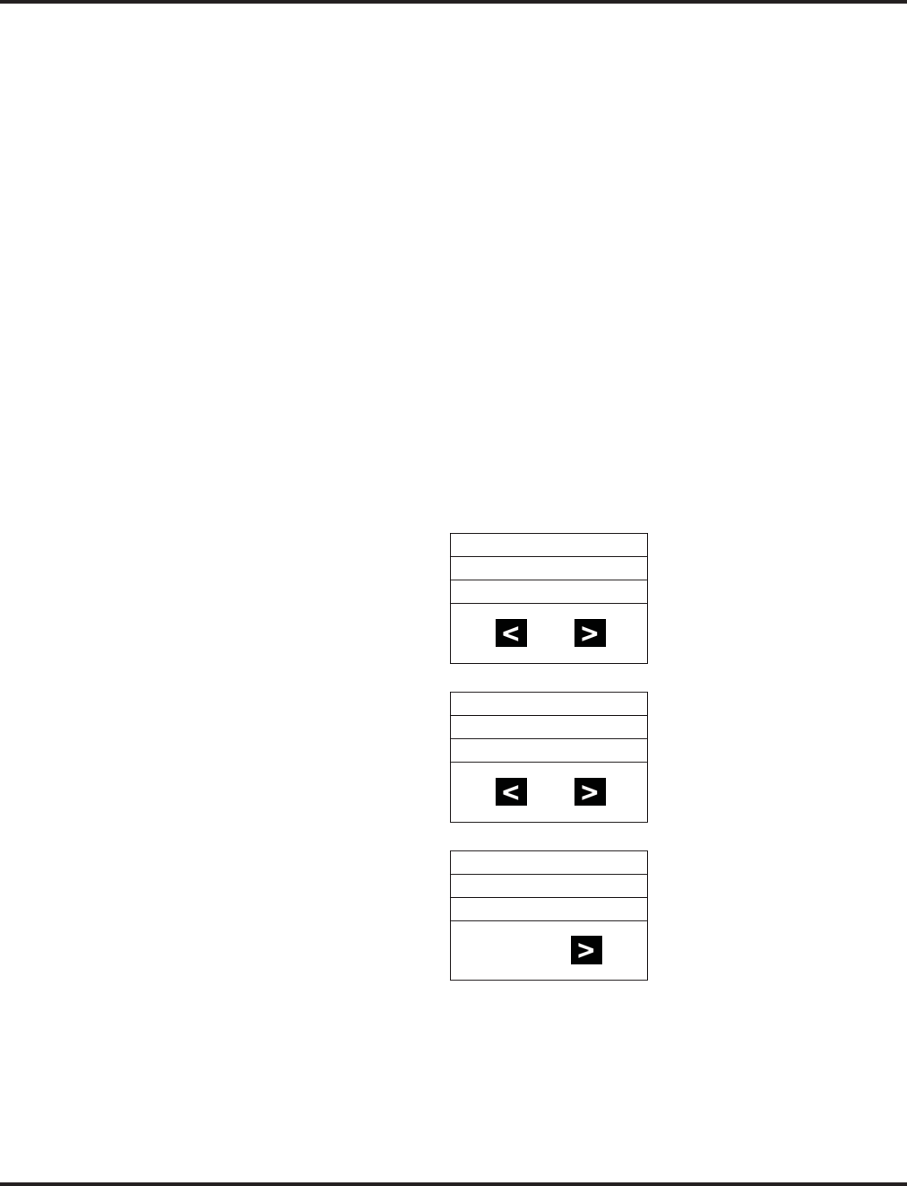
Aspire Wireless
Aspire Software Manual Features ◆99
Abbreviated Dialing: Common and Group (Speed Dial)
Store Common or Group Abbreviated Dialing numbers:
1. Press the ON-HOOK/OFF-HOOK key.
2. Dial 853 (for Common).
OR
Dial 854 (for Group).
3. Dial Abbreviated Dialing bin number.
Ask your Communications Manager for your bin numbers.
4. Dial phone number to store + the R (HOLD/RECALL) key.
The number can be up to 24 digits, using 0-9, # and *.
Dial your stored Abbreviated Dial number:
1. Press the ON-HOOK/OFF-HOOK key.
2. Dial #2 + Bin (for Common).
OR
#4 + Bin (for Group).
Abbreviated Dial Search
1. Press the MENU button.
2. Press the right arrow button.
3. Press the OK button.
4. Press the right arrow button to change the search mode from Common Abbreviated Dial
(COMMON), Group Abbreviated Dial (GROUP), or Extension name (EXTENSION).
PROFILE
SET UP
MENU
EXT. SERVICE
SELECT MENU
ABB:COMMON
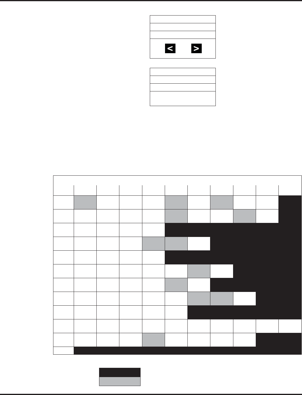
Aspire Wireless
100 ◆Features Aspire Software Manual
5. Press the OK button.
6. Input the character(s) by pressing dial pad.
While inputting characters, the cursor blinks. While scrolling through the characters,
you have approximately 1 second to move to the next character under the same key, other-
wise, the phone accepts the displayed character as an entry.
You can use the left and right arrows to move the cursor.
To delete a character, position the cursor over the character and hold the left arrow
key down for approximately 1 second. To delete all the characters, hold down the left
arrow key for approximately 5 seconds (the cursor position does not matter when deleting
all characters).
A search cannot be performed if more than 13 characters are entered.
INPUT DATA
ABB:COMMON
N
Character Entry in Aspire Wireless
Dial
1 Æ
(0xc6) 0
(0xd8) Â
(0xc5) @
(0x40) Ä
(0xc4) ö
(0xd6) ß
(0xdf) ü
(0xdc) 1
(0x31)
2A
(0x41) B
(0x42) C
(0x43) @
(0x40) Ä
(0xc4) Á
(0xc1) À
(0xc0) Å
(0xc2) 2
(0x32)
3D
(0x44) E
(0x45) F
(0x46) 3
(0x33)
4G
(0x47) H
(0x48) I
(0x49) Ï
(0xcf) Î
(0xce) 4
(0x34)
5J
(0x4a) K
(0x4b) L
(0x4c) 5
(0x35)
6M
(0x4d) N
(0x4e) O
(0x4f) ö
(0xd6) ó
(0xd3) ò
(0xd2) 6
(0x36)
7P
(0x50) Q
(0x51) R
(0x52) S
(0x53) ß
(0xdf) 7
(0x37)
8T
(0x54) U
(0x55) V
(0x56) ü
(0xdc) ú
(0xda) ù
(0xd9) û
(0xdb) 8
(0x38)
9W
(0x57) X
(0x58) Y
(0x59) Z
(0x5a) 9
(0x39)
0 space
(0x20) .
(0x2e) ,
(0x2c) _
(0x5f) -
(0x2d) +
(0x2b) :
(0x3a) ?
(0x3f) !
(0x21) 0
(0x30)
**
(0x2a) #
(0x23) /
(0x2f) \
(0x5c) (
(0x28) )
(0x29) =
(0x3d) &
(0x26)
#
Not used
Excepted character at search ( same as no input)
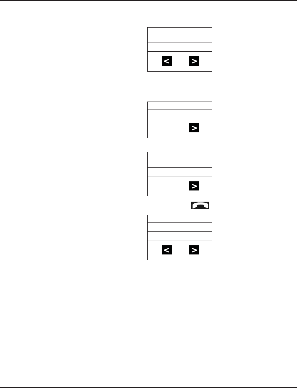
Aspire Wireless
Aspire Software Manual Features ◆101
7. Press the OK button to start the search.
The display shows the ABB/EXT name in the first line (Max. 12 characters).
The ABB/EXT number is shown in the second and third line (Max. 20 digits).
8. If there is no match for the search entry, the following display is shown:
9. Press the right arrow button to see the next entry in the search list.
10. To make an outgoing call, press the hook button .
OR, to cancel the search, press the MENU button.
NEC-ABC
0123451111
UNLISTED-
NEC-DEF
0123452222
0123452222

Aspire Wireless
102 ◆Features Aspire Software Manual
Use the Phone’s Telephone Book for Personal Numbers
Store a number in the Telephone Book:
1. While idle, dial the number to be stored.
2. Press the > key + the OK key.
3. Enter the name associated with the number + the OK key.
Up to 80 numbers with name can be stored in the Telephone Book. A name is required
with each number. A “Memory Full” message indicates that a number must be deleted
before making another entry.
Dial a number from the Telephone Book:
1. Press the > key.
2. Use the < or > keys to display the number to be called or press the first letter in the name using
digits 1-9.
3. Press the ON-HOOK/OFF-HOOK key to place the call.
Call Forwarding
Forward your calls to a co-worker:
1. Press the ON-HOOK/OFF-HOOK key + *2.
2. Dial Call Forwarding condition:
2 = Busy or not answered
4 = Immediate
6 = Not answered
7 = Immediate w/simultaneous ringing (not for Voice Mail)
0 = Cancel
3. Dial destination extension or Voice Mail master number.
4. Dial Call Forwarding Type:
2 = All calls
3 = Outside calls only
4 = Intercom calls only
Call Forwarding, Off-Premise
Forward your calls to an outside telephone number:
1. Press the ON-HOOK/OFF-HOOK key + *4.
2. Dial 6 and the trunk access code.
Trunk access codes are 9 (ARS/Trunk Group Routing), 804 + Line Group (1-9, 01-99
or 001- 100) or #9 + Line number (e.g., 05 or 005 for line 5).
3. Dial the outside number to which your calls should be forwarded.
4. Press the ON-HOOK/OFF-HOOK key.
Stutter dial tone is heard when the On-Hook/Off-Hook key is pressed.
To cancel Call Forwarding Off-Premise
1. Press the ON-HOOK/OFF-HOOK key + *4.
2. Dial 6.
3. Press the ON-HOOK/OFF-HOOK key.

Aspire Wireless
Aspire Software Manual Features ◆103
Camp On / Callback
If you heard a busy signal when calling a co-worker, use Camp On or Callback:
1. Dial 2 to Camp On (wait without hanging up).
(Intercom calls) If you hear two beeps, you can speak. If you hear busy/ring, dial 6 to
send a Voice Over.
(Outside calls) When you hear new dial tone, place your call again.
OR
Dial 2 and hang up to leave a Callback for a free line or extension.
Wait for the system to call you back.
2. Press the ON-HOOK/OFF-HOOK key when the system rings you back.
(Outside calls) Place your call again.
(Intercom calls) Speak to co-worker.
To cancel your Callback:
1. Press the ON-HOOK/OFF-HOOK key.
2. Dial 870 + Hang up.
Conference
Establishing a Conference Call:
1. Place or answer call + the R (HOLD/RECALL) key + #1.
2. Place/answer next call + the R (HOLD/RECALL) key + #1.
You may have up to 32 callers. Your software determines if there is any restriction on
the number of outside parties. Repeat this step to add more parties.
3. After adding all parties, press the R (HOLD/RECALL) key twice to set up the Conference.
Do Not Disturb
Using Do Not Disturb:
1. Press the ON-HOOK/OFF-HOOK key.
2. Dial 847.
3. Dial the DND option code (0-4).
1 = Blocks outside calls
2 = Blocks Paging, Intercom calls, Call Forwards and Transferred outside calls.
3 = Blocks all calls
4 = Blocks Call Forwards
0 = Cancels DND
Turning off your handset:
1. Press the OK key for 3 seconds.
The phone will beep and the display will go blank when the phone is off.

Aspire Wireless
104 ◆Features Aspire Software Manual
Turning your handset on:
1. Press the ON-HOOK/OFF-HOOK key.
When the handset is on, is shown in the lower left corner of the display if the
handset has been subscribed to a system.
Hold
Placing a call on Hold:
1. Do not hang up + press the R (HOLD/RECALL) key + Do not hang up.
This puts your call on Exclusive Hold.
To place the call on Group Hold (so only those in your Department can pick up the
call), dial 832 after pressing the R (Hold/Recall) key.
Intercom calls automatically go on Exclusive Hold when you press the R (Hold/Recall) key.
Retrieving a call from Hold:
1. Press the R (HOLD/RECALL) key.
To retrieve a call from Group Hold, dial 862 instead of pressing the R (Hold/Recall) key.
Last Number Redial
Quickly redial your last outside call:
1. Press the ON-HOOK/OFF-HOOK key + #5.
The system selects an outside line.
Dial a number from the phone’s stored Redial and CLIP numbers:
The handset stores up to 10 redial numbers and 10 Caller ID numbers in memory.
1. Press the Left Arrow key.
2. Press the Left Arrow key to scroll through the numbers.
Numbers are displayed newest to oldest.
Use the key to scroll forward if needed.
To delete a number, press OK twice. To store a number in the Phone Book, press OK +
> + OK + Enter name + OK.
3. Press the ON-HOOK/OFF-HOOK key to place the call.
Message Waiting (Direct Messaging)
Leave a Message Waiting:
1. Do not hang up + 0.
Your co-worker’s MW flashes fast.
Answer a Message Waiting:
1. Press the ON-HOOK/OFF-HOOK key + *0.
To cancel all your messages (those you left and those left for you), dial 873.
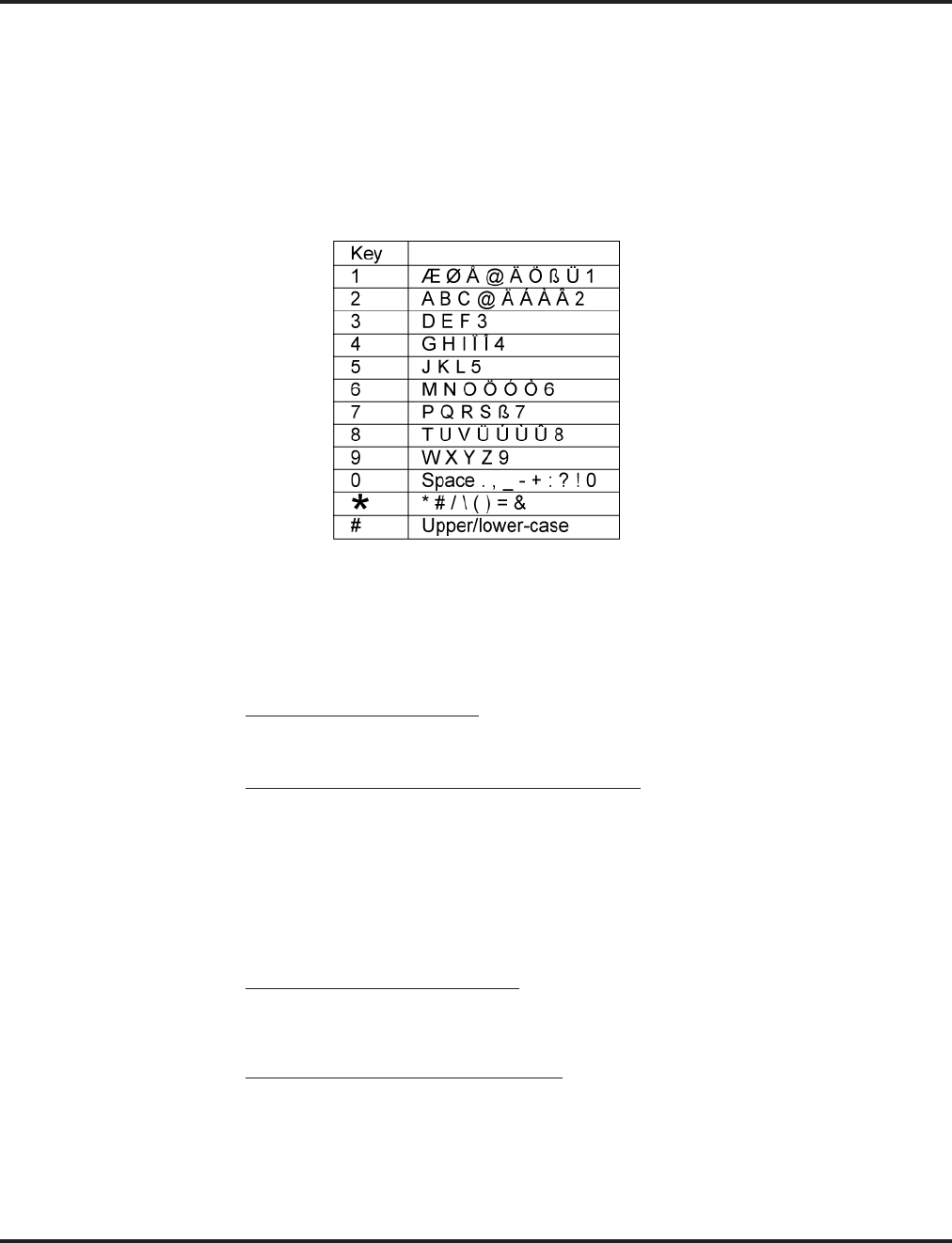
Aspire Wireless
Aspire Software Manual Features ◆105
Name Entry:
The dial pad digits are used for writing the name to be placed in the Phone Book. For example,
press the digit 2 key once for A, twice for B, three times for C, etc.
The arrow keys can be used to move the cursor left or right. The left arrow key can also be used for
deleting a character by holding it down for 1 second.
Pressing a new key or pausing for more than 1 second automatically moves the cursor to the next
position.
Park
Park a call in orbit:
1. Do not hang up.
Park a call in a System Orbit
2. Press the R (HOLD/RECALL) key + #6 + Park Orbit.
Park Orbits are 01-64.
Park a call at your extension using Personal Park
Dial 857.
3. Page your co-worker to pick up the call.
For Paging, dial *1 + 0 for All Call or *1 + 1-64 for zones.
4. Hang up.
Pickup up a call in Park:
1. Press the ON-HOOK/OFF-HOOK key.
2. For a Call Parked in a System Orbit:
Dial *6 + Park Orbit.
Park Orbits are 01-64.
OR
For a Call Parked in a Personal Park Orbit
When Parked at your phone:
Dial 857 + your extension number.
When Parked at a co-worker’s phone:
** + Announced extension.

Aspire Wireless
106 ◆Features Aspire Software Manual
Park and Page
Use Park and Page to be paged for calls while away from your desk
1. Press the ON-HOOK/OFF-HOOK key.
2. Press *47 + Record your Personal Greeting.
3. #7 + Record the Page.
For Personal Greeting only, press # then 2 (Busy/No Answer), 4 (Immediate), or 6 (No
Answer) + extension to receive calls + 2 (All) or 3 (CO) and hang up.
4. # + Dial the Page Zone (e.g. 801 + 1).
5. Press 2 (All calls) or 3 (CO calls).
To Cancel:
1. Press the ON-HOOK/OFF-HOOK key.
2. Press *47 3.
3. Press the ON-HOOK/OFF-HOOK key.
Answer Park and Page:
1. Press the ON-HOOK/OFF-HOOK key.
2. Press ** + Announced extension.
Personal Greeting
Use Personal Greeting to record a message for the caller and then forward the call:
1. Press the ON-HOOK/OFF-HOOK key.
2. Press *47 + Record your Personal Greeting.
3. Press # + 2 (Busy/No Answer), 4 (Immediate), or 6 (No Answer).
4. Dial the extension to receive calls + 2 (All calls) or 3 (CO calls).
5. Press the ON-HOOK/OFF-HOOK key.

Aspire Wireless
Aspire Software Manual Features ◆107
Registration
Registering an Aspire Wireless Handset
To cancel the registration process at any point, press the SPK or Headset key, or place
the handset on-hook.
1. From a keyset, press SPK key and dial the service code defined in Program 11-10-30.
2. Enter the extension number to be assigned.
If the DSIU is unavailable or if the extension number is invalid, the system displays an
error message and the phone is returned to an idle condition.
If another keyset is registering a phone, the system indicates "DSIU Busy" and the
phone is returned to an idle condition.
If the extension number entered is already subscribed, the system displays the follow-
ing message "Already Subscribed".
3. When a valid extension number is entered, the system displays the extension number and the
AC number and enters the registration mode.
4. Using the Aspire Wireless phone to be registered, press the Menu key then press the Left
Arrow key twice to display the Login option. Press OK.
5. Press the Right Arrow key once to display the Subscription Create option. Press OK.
6. The Aspire Wireless phone will search for the DSIU PCB and display the PCB’s ID number
once found.
This may take a few seconds. If the ID number does not appear, check Program 90-27-
01 to make sure the PCB is recognized.
7. Press OK.
8. Enter the 4-digit AC number displayed in Step 3 and press OK.
9. Once the phone has been registered, the phone will beep and (((.))) will appear in the lower
left-hand corner.
If the registration was successful, the display will indicate: "Completed".
If the registration failed, the display will indicate: "Failed".
If the registration was failed due to timeout, the display will indicate:
"No Response".
Unregistering an Aspire Wireless Handset
1. From a keyset, press SPK key and dial the service code defined in Program 11-10-31.
2. Enter the assigned extension number.
If the DSIU is unavailable or if the extension number is invalid, the system displays an
error message and the phone is returned to an idle condition.
If another keyset is registering a phone, the system indicates "DSIU Busy" and the
phone is returned to an idle condition.
If the extension number entered is already subscribed, the system displays the follow-
ing message "Already Subscribed".
3. When a valid extension number is entered, the system requests a confirmation that the phone
is to be unsubscribed.
"Delete DECTPP xxxxxxx
Ready (1: Yes)."
4. Press 1 to confirm or any other key to cancel the operation.
Once the phone has been unregistered, the phone displays "Completed".
If the Aspire Wireless phone was active on a call at the time it was unregistered, the
call will be dropped.

Aspire Wireless
108 ◆Features Aspire Software Manual
Save
Save your call for quick dialing later on:
1. While on a call, press the R (HOLD/RECALL) key + 815.
Quickly redial your saved number:
1. Press the ON-HOOK/OFF-HOOK key + 815.
When redialing, the system selects an outside line for you. To clear a saved number:
Press the ON-HOOK/OFF-HOOK key + 885.
Transfer
Transferring your call to a co-worker:
1. Press the R (HOLD/RECALL) key + Dial your co-worker’s extension.
To transfer the call to a co-worker’s mailbox, dial the *8 before their extension.
2. (Optional) Announce the call when your co-worker answers.
3. Press the ON-HOOK/OFF-HOOK key.
Transferring When Out of Range
To Set the Transferring When Out of Range Option:
1. Press the ON-HOOK/OFF-HOOK key.
2. Dial the Transfer When Out Of Range Service Code (by default: 189).
3. Skip this step if using the pre-defined destination from Program 15-14-01.
Enter the telephone number which should be the destination of the forwarded call
Make sure to include any required trunk access codes (ex: 9 or #9 + trunk number)
when transferring to an outside number.
Entering any new number overwrites the previously defined information entered manu-
ally or through system programming (15-14-01).
4. Press the ON-HOOK/OFF-HOOK key.
To Clear the Transfer Destination:
1. Press the ON-HOOK/OFF-HOOK key.
2. Dial the Transfer When Out Of Range Service Code (by default: 189).
3. Press the R (HOLD/RECALL) key.
4. Press the ON-HOOK/OFF-HOOK key.
To Cancel the Transferring When Out of Range Option:
1. Press the ON-HOOK/OFF-HOOK key.
2. Dial the Transfer When Out Of Range Service Code (by default: 189).
3. Press the ON-HOOK/OFF-HOOK key.

Aspire XL
Aspire Software Manual Features ◆109
Aspire XL
Description
To enhance the Aspire system, which previously only supported 256 digital/analog extensions (not
including IP and Wireless), the Aspire XL system is now available. The Aspire XL uses a new
power supply cabinet, new power supplies, and 32ESIU PCB to provide the ability to support up to
384 digital/analog extensions (TDM/legacy telephones). The total number of phones (legacy + IP/
Aspire Wireless) supported is still 512.
The Aspire XL uses the same hardware as the existing Aspire M/L system except for the new hard-
ware indicated below.
●Power Supply Set (IP1WW-XLPSU-A(SET) / New power supply) - Kit P/N 0890069
This kit includes the following:
●IP1WW-PSADU-A1 (AC/DC Unit for the XL Power Supply) - P/N 0892011
Two AC/DC Power Supplies maximum per Power Supply Cabinet.
When two AC/DC Power Supplies are installed, two separate AC cords
will each require an AC outlet connection from the bottom Power Supply Cabi-
net. Use the power cords included with the Aspire system cabinet(s) for con-
necting the power supplies to the AC outlet. The Aspire system cabinet is no
longer directly connected to an AC outlet with the AC/DC Power Supplies
installed.
●IP1WW-PSDDU-A1 (DC/DC Unit for the XL Power Supply) - P/N 0892012
Two DC/DC Converters maximum per system - one in each system cabinet.
A DC/DC Converter replaces the two power supplies used in the cabinet
of the Aspire M/L system (P/N 0891000).
If an Aspire M/L system is upgraded to an Aspire XL, the existing power sup-
plies will no longer be required as they are replaced by the DC/DC Converter.
●IP1WW-XLPS Cable for Power (connects the AC/DC Unit and DC/DC Unit) -
P/N 0892013
This cable allows for a power connection from one AC/DC Supply in the
bottom cabinet to one DC/DC Converter in the system cabinet.
Note: The power cord for the system cabinet (located on the back of the
cabinet) is no longer required with this cable connection.
●IP1WW-XLPS Cable for Signal (connects the AC/DC Unit and DC/DC Unit) -
P/N 0892010
This cable allows for a signal connection from one AC/DC Supply in the
bottom cabinet to one DC/DC Converter in the system cabinet.
Aspire S Aspire M/L/XL
• N/A • Aspire XL available with software 4.0E+.
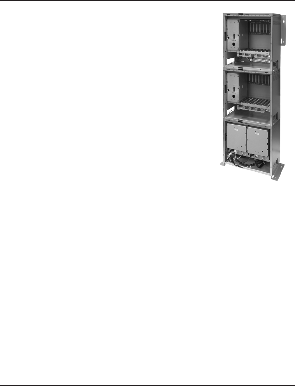
Aspire XL
110 ◆Features Aspire Software Manual
●Power Supply Cabinet (IP1WW-XLPS CABINET/
For the IP1WW-PSADU-A1) - P/N 0890068
IP1WW-XLPSU CABINET can contain maximum two
IP1WW-PASDU-A1s.
The cabinet accommodates up to two AC/DC
power supplies. This cabinet is to be installed as the
bottom cabinet of a 3-cabinet system (the top two
cabinets containing the NTCPU, DC/DC Converters,
and PCBs).
Refer to the Aspire XL Installation Instructions, P/N
0893113, for details on installing the power supplies and
cables.
●32ESIU (IP1WW-32ESIU-PR2 / 32-Port Digital Sta-
tion Interface) - P/N 0891058
The 32ESIU can be installed with a maximum of twelve
PCBs per Aspire XL system (8 maximum per cabinet).
Only the first 4 ports on each PCB allow the use of the B2
channel. This means that the APR(B2 mode) adapter or
PGDAD module must be installed on one of these first 4
ports.
Aspire XL systems can accommodate 384 TDM station
ports maximum for -48V with two power supplies (P/N
0890069) installed. The PCBs which require -48V are: ESIU, DSTU, SLIU, DSIU, BRIU,
DIOPU.
If the system has more than 256 ports, and both cabinets have more than 128 -48V ports each,
an additional AC/DC and DC/DC Converter is required in the power supply cabinet.
New AC/DC Supply + DC/DC Converter can accommodate 256 ports max. for -48V in one
cabinet.
If both new AC/DC +DC/DC Converters are installed, then 384 Ports max. (greater than 128
Ports in each cabinet) are supported by -48V output.
The 32ESIU can be installed in an Aspire M/L system, however, note the following
conditions:
●Up to four 32ESIU cards can be supported in one cabinet without the need to
change existing power supplies (P/N 0891000).
●The Aspire M/L system can accommodate 128 ports maximum for -48V with two
power supplies (P/N 0891000) in one cabinet.
If 4 32ESIU’s are used with two Aspire M/L power supplies, no other PCB which
requires -48V (ESIU, DSTU, SLIU, DSIU, BRIU, DIOPU) can be installed in that
cabinet.
●Using the 32ESIU PCBs does not increase the number of digital/analog ports - the
limit remains at 512 (256 analog/digital and 256 IP and Wireless).
●The 32ESIU can be used with any version of the NTCPU/PAL chip.

Aspire XL
Aspire Software Manual Features ◆111
The Aspire XL system can support mixed hardware configurations. With an Aspire XL AC/
DC power supply cabinet and DC/DC Converter, the second cabinet can contain up to two
Aspire M/L power supplies (P/N 0891000).
For installation details, refer to the Aspire 32ESIU PCB Installation Instructions, P/N
0893112.
Program Changes
The following programs are enhanced for the XL system.
➻10-03-01~07 (ESIU) : PCB Setup - Physical Port Number
Previous Entry: 1-16
New Entry: 1-32
➻10-03-01 (SLIU) : PCB Setup / Logical Port Number
Previous Entry: 0-256
New Entry: 0-384
➻10-03-01 (VMSU) : PCB Setup / Logical Port Number
Previous Entry: 0-256
New Entry: 0-384
➻10-03-02 : (ESIU) : PCB Setup
Terminal Type 1 (Keyset/DSLT) Logical Port
Previous Entry: 0-256
New Entry: 0-384
Terminal Type 2 (SLT Adapter) Logical Port
Previous Entry: 0-256
New Entry: 0-512
Terminal Type 3 and 4 - Not used in U.S. = 0-512
➻10-03-02 (DIOPU) : PCB Setup / Logical Port Number
Previous Entry: 0-256
New Entry: 0-384
➻10-03-02 (BRI) : PCB Setup / Logical Port Number
Previous Entry: 0-256
New Entry: 0-384
➻10-03-02 (PRI) : PCB Setup / Logical Port Number
Previous Entry: 0-256
New Entry: 0-384
➻82-07-01 : CODEC Filter Setup for Analog Station Ports/ CODEC Filter Type
Previous Entry: 1-256
New Entry: 1-384
➻91-06-01 : Aspire Wireless Subscription, New
When a user selects 0 (auto port assignment) in Program 91-06-01 to assign an Aspire Wire-
less port, the system previously had assigned an available port from 257. This is now changed
to 385.

Aspire XL
112 ◆Features Aspire Software Manual
Conditions
●Prior to updating system software, due to capacity differences, a database file must be made
in order to revert to any older version of software. The expanded database file from a 4.x
software cannot be used in older software once the new ports are recognized and used by
the system.
●APR(B2 mode) Port Assignment: With the XL system, the APR port is assigned from 512 in
descending order.
●The Aspire XL system can support mixed hardware configurations. With an Aspire XL AC/
DC power supply cabinet and DC/DC Converter, the second cabinet can contain up to two
Aspire M/L power supplies (P/N 0891000).
Default Setting
Refer to the individual features.
Programming
Refer to the individual features for programming specifics.
Operation
Refer to the individual features for programming specifics.

Attendant Call Queuing
Aspire Software Manual Features ◆113
Attendant Call Queuing
Description
Attendant extensions can have up to 32 incoming calls queued before additional callers hear busy
tone. This helps minimize call congestion in systems that use the attendant as the overflow destina-
tion for unanswered calls. For example, you can program Direct Inward Lines and Voice Mail calls
to route to the attendant when their primary destination is busy. With Attendant Call Queuing, these
unanswered calls would normally “stack up” for the attendant until they can be processed.
The 32 call queue total includes Intercom, DISA, DID, DIL, tie line and transferred calls. If the
attendant doesn’t have an appearance for the queued call, it waits in line on a CALL key. If the
attendant has more than 32 calls queued, an extension can Transfer a call to the attendant only if
they have Busy Transfer enabled.
Attendant Call Queuing is a permanent, non-programmable system feature.
Conditions
None
Default Setting
Enabled.
Programming
➻20-17-01 : Operator’s Extension
Assign the operator (attendant’s) extension.
➻24-02-01 : System Options for Transfer - Busy Transfer
Prevent (0) or allow (1) extensions to Transfer calls to an attendant that has more than 32 calls
is queue.
Related Features
Call Forwarding / Personal Greeting
Forwarding when unanswered or busy can only occur at the attendant if there are more than
32 calls in queue.
Operation
None
Aspire S Aspire M/L/XL
• Available. • Available.

Automatic Call Distribution (ACD)
114 ◆Features Aspire Software Manual
Automatic Call Distribution (ACD)
Description
Automatic Call Distribution (ACD) uniformly distributes calls among member agents of a pro-
grammed ACD Group. When a call rings into an ACD Group, the system automatically routes the
call to the agent that has been idle the longest. Automatic Call Distribution is much more sophisti-
cated and comprehensive than Department Calling and other group services - it can accurately
judge the work load at each agent and distribute calls accordingly. The system allows up to 64 ACD
Groups and 512 ACD agents.
You can put any agent in any group. In addition, an agent can be in more than one group. This allows,
for example, a Technical Service representation to answer Customer Service calls at lunch time when
many of the Customer Service reps are unavailable.
The ACD Master Number is the “extension number” of the whole group. Calls directly ringing or
transferred to the ACD Master number enter the group and are routed accordingly. Although the
master number can be any valid extension number, you should choose a number that is out of the
normal extension range.
Automatic Call Distribution operation is further enhanced by:
●ACD Call Queuing
When all agents in an ACD Group are unavailable, an incoming call will queue and cause the
Queue Status Display to occur on the ACD Group Supervisor’s display. The display helps the
supervisor keep track of the traffic load within their group. The Queue Status Displays shows:
- The number of calls queued for an available agent in the group.
- The trunk that has been waiting the longest, and how long it has been waiting.
Aspire S Aspire M/L/XL
• Not Available. • Available with the Basic NTCPU (P/N 0891002) with
the PAL upgrade or the Enhanced NTCPU (P/N
0891038)
- 64 ACD Groups and 512 ACD Agents.
• ACD Call Coverage keys supported with 1.06+ software.
• ACD Queue Status Display supported with 1.11+
software.
• ACD Hotline Key Shows Agent Status supported with
1.11+ software.
• ACD MIS software can count overflow calls with 2.63+
software.
• P command support for AIC log-in requires 4.0E+.
• Enhanced Overflow options requires 4.94+.
• For more information, refer to the ACD Manual (P/N
0893202).

Automatic Call Distribution (ACD)
Aspire Software Manual Features ◆115
For each ACD Group, you can set the following conditions:
- The number of trunks that can wait in queue before the Queue Status Display occurs.
- How often the time in queue portion of the display reoccurs.
- If the supervisor should hear a Queue Alarm whenever the time in queue portion reoccurs.
This alarm is a single beep tone that reminds the supervisor to check the condition of the
queue.
●ACD Overflow (With Announcements)
ACD offers extensive overflow options for each ACD Group. For example, a caller ringing in
when all agents are unavailable can hear an initial announcement (called the 1st Announce-
ment). This announcement can be a general greeting like, “Thank you for calling. All of our
agents are currently busy helping other customers. Please stay on the line and we will help
you shortly.” If the caller continues to wait, you can have them hear another announcement
(called the 2nd Announcement) such as, “Your business is important to us. Your call will be
automatically answered by the first available agent. Please stay on the line.” If all the ACD
Group’s agents still are unavailable, the call can automatically overflow to another ACD
Group or the Voice Mail Automated Attendant. If all agents in the overflow ACD Group are
busy, Lookback Routing automatically ensures that the waiting call will ring into the first
agent in either group that becomes free.
You can assign an ACD Group with any combination of 1st Announcement, 2nd Announce-
ment and overflow method. You can have, for example, a Technical Service group that plays
only the 2nd Announcement to callers and then immediately overflows to Voice Mail. At the
same time, you can have a Customer Service group that plays both announcements and does
not overflow.
●Agent Log In and Log Out Services
An ACD Agent can log in and log out of their ACD Group. While logged in, the agent is avail-
able to receive ACD Group calls. When logged out, the agent is excluded from the group’s
calls. The programmable keys and alphanumeric display on an agent’s phone show at a glance
when they are logged in or logged out.
●Agent Identity Code (AIC)
An Agent Identity Code (AIC) allows ACD agents to log in any extension without setting Program
41-02 (AIC Log In). Using AIC, ACD agents can also log in to multiple ACD groups at the same
time (up to 64 ACD Groups). The system will also allow all extensions (up to the system maxi-
mum) to log in using the same AIC code. AIC and ACD groups for each work period (mode pat-
tern number) can be set in Program 41-18 as shown in the following example.
With this example, ACD will work as follows:
Example 1: Log In with AIC 789
Table
#AIC Operation
Group
Mode Pattern Number
12345678
1 789 1 11------
2 789 1 21------
3 789 1 161------
4 567 10 10 10 10 10 10 10 10 10
5 678 2 22222222
6 678 2 33333333
7 678 2 55555555

Automatic Call Distribution (ACD)
116 ◆Features Aspire Software Manual
●During Mode Pattern 1, ACD agents will belong to ACD groups 1, 2, and 16 at the same
time.
●During Mode Pattern 2, ACD agents will belong to only ACD group 1.
●During Mode Pattern 3-8, ACD agents will not belong to any ACD group and the ACD
extensions will work as normal extensions.
Example 2: Log In with AIC 567
●During Mode Patterns 1-8, ACD agents will belong to only ACD group 10.
Example 3: Log In with AIC 678
●During Mode Patterns 1-8, ACD agents will belong to ACD groups 2, 3 and 5 at the same
time.
With older software, P commands are not supported for AIC log on/ log off. Because of this, it
is not possible for the inDepth MIS software to determine which ACD groups each extension
was a member of or to which ACD groups calls were presented.
However, with software 4.0E and higher, AIC log on/log off operations are supported. The
Aspire P Commands will indicate which ACD Group is being logged onto when an AIC code
is entered. Also when an agent logs off, there will be a multiple log of events, one log off event
for each previous ACD log on event.
This feature is not yet supported by the inDepth software.
●Multiple Agent Log In
ACD agents can log their extension in using multiple AICs (up to 3). The system will also
allow all extensions (up to the system maximum) to log in using the same AIC code. For example,
even if ACD agent “A” logs in extension 350 with AIC 789, ACD agent “B” can also log in to
extension 351 with AIC 789 at the same time. Using the example setup above, ACD will work
as follows:
Example 1: Log In with AIC 789 and 568
●During Mode Pattern 1, ACD agents will belong to ACD groups 1, 2, 10 and 16 at the
same time.
●During Mode Pattern 2, ACD agents will belong to ACD groups 1 and 10.
●During Mode Pattern 3-8, ACD agents will belong to only ACD group 10.
Example 2: Log In with AIC 789, 568 and 678
●During Mode Pattern 1, ACD agents will belong to ACD groups 1, 2, 3, 5, 10 and 16 at the
same time.
●During Mode Pattern 2, ACD agents will belong to ACD groups 1, 2, 3, 5 and 10.
●During Mode Pattern 3-8, ACD agents will belong to only ACD groups 2, 3, 5 and 10.
In addition to an agent logging in with multiple AIC codes, ACD agents can log in to multiple ACD
groups at the same time (up to 64 ACD Groups). AIC and ACD groups for each work period (mode
pattern number) can be set in Program 41-18.
Some conditions with Multiple Agent Log In:
●ACD agents cannot log in to the system supervisor or group supervisor’s extension.
●In order to log in with AIC, the extension should be set to AIC Log In mode in Program
41-17.
●If the extension is set to AIC log in mode in Program 41-17, the system will ignore the set-
ting of Program 41-02 for the extension.
●A supervisor cannot log out an agent logged in by an AIC code.

Automatic Call Distribution (ACD)
Aspire Software Manual Features ◆117
●Emergency Call
If an ACD Agent needs assistance with a caller, they can place an Emergency Call to their
ACD Group Supervisor. Once the supervisor answers the Emergency Call, they automatically
monitor both the ACD Agent and the caller. If the agent needs assistance, the supervisor can
join in the conversation. Emergency Call can be a big help to inexperienced ACD Agents that
need technical advise or assistance with a difficult caller. The supervisor can easily listen to
the conversation and then “jump in” if the situation gets out of hand.
●Enhanced DSS Operation
A programmed extension user can use their DSS Console to monitor the status of the ACD
Agents within a group. The DSS Console is an essential tool for supervisors. The console key
flash rates tell the supervisor at a glance which of the group’s agents are:
- Logged onto the group (i.e., in service)
- Logged out of the group (i.e., out of service)
- Busy on a call
- Placing an Emergency Call to the supervisor
- Not available or installed
The ACD Supervisor can also use their console for placing and transferring calls - just like
any other extension user.
●Flexible Time Schedules
An ACD Work Schedule lets you divide a day into segments (called Work Periods) for sched-
uling the activity in your ACD Groups. You can set up four distinct Work Schedules, with up
to eight Work Periods in each Work Schedule. Each day of the week has one Work Schedule,
but different days can share the same schedule. For example, your Monday through Friday
Work Schedule could consist of only two Work Periods. Work Period 1 could be from 8:00
AM to 5:00 PM - when your business is open. Work Period 2 could be from 5:00 PM to 8:00
AM - which covers those times when your business is closed.
●Headset Operation (With Automatic Answer)
An ACD Agent or ACD Group Supervisor can utilize a customer-provided headset in place of
the handset. The headset conveniently frees up the user’s hands for other work and provides
privacy while on the call. In addition, an ACD Agent with a headset can have Automatic
Answer. This allows an agent busy on a call to automatically connect to the next waiting call
when they hang up.
●Incoming Call Routing
Incoming trunk calls can automatically route to specific ACD Groups. These types of calls
ring directly into the ACD Group without being transferred by a co-worker or the Automated
Attendant.

Automatic Call Distribution (ACD)
118 ◆Features Aspire Software Manual
●Rest Mode
Rest Mode temporarily logs-out an ACD agent’s phone. There are two types of Rest Mode:-
- Manual Rest Mode
An ACD Agent can enable Manual Rest Mode anytime they want to temporarily log out of
the ACD Group. They might want to do this if they go to a meeting or get called away
from their work area. While logged out, calls to the ACD Group will not ring the agent’s
phone.
- Automatic Rest Mode
When an ACD Group has Automatic Rest Mode, the system will automatically put an
agent’s phone in Rest Mode if it is not answered. This ensures callers won’t have to wait
while ACD rings an extension that won’t be answered. For keysets, the system enables
Automatic Rest Mode for all phones with Rest Mode keys. For SLTs, you must set an
option in programming to enable Automatic Rest Mode. If an agent’s phone is placed into
Rest Mode because a call is not answered, the agent will need to manually cancel Rest
Mode in order to log back into the ACD group.
With a Rest Mode key programmed on an ACD agent’s phone, when the agent is in rest mode,
the key will be lit. If the Rest Mode key is pressed while an agent is on a call, the key will flash
to indicate a pre-Rest Mode status. When the current call is finished, the agent’s phone will be
in rest mode. The agent can place intercom calls or receive direct incoming calls while in Rest
Mode. The ability to receive incoming intercom calls is defined in system programming for
each ACD group. Note that an ACD System Supervisor cannot be placed in Rest Mode.
●Supervisor, ACD Group
You can designate an extension in an ACD Group to be the group’s supervisor. Once assigned
as an ACD Group Supervisor, the user can:
- Take the entire ACD Group out of service.
- Check the log out status of each agent after the group taken down.
- Restore the ACD Group to service.
During programming, you can choose one of three modes of operation for each ACD Group
supervisor:
- Supervisor’s extension cannot receive calls to the ACD Group.
- Supervisor’s extension can only receive ACD Group calls during overflow conditions.
- Supervisor’s extension receives calls just like any other ACD Group agent (mode 2).
An ACD Group can have only one supervisor. In addition, an extension can be a supervisor
for only one ACD Group.
●Supervisor, ACD System
You can designate an extension as an ACD System Supervisor. Once assigned as an ACD
System Supervisor, the user can:
- Take the all the system’s ACD Groups out of service simultaneously
- Check the log out status of each agent after the groups are taken down.
- Restore all the ACD Groups to service simultaneously.
The system can have only one ACD System Supervisor.

Automatic Call Distribution (ACD)
Aspire Software Manual Features ◆119
●Work Time
Work Time temporarily busies-out an ACD agent’s phone so they can work at their desk unin-
terrupted. This gives the agent time to fill out important logs and records as soon as they are
finished with their call. There are two types of Work Time:
- Manual Work Time
An ACD Agent can enable Manual Work Time any time they need to work at their desk
undisturbed. You might prefer this Work Time mode if an agent only occasionally has to
fill out follow-up paper work after they complete their call. When the agent is through
catching up with their work, they manually return themselves to the ACD Group.
- Automatic Work Time
The system implements Automatic Work Time for the agent as soon as they hang up their
current call. This is helpful in applications (such as Tech Service groups) where follow-up
paperwork is a requirement for every call. When the agent is done with their work, they
manually return themselves to the ACD Group.
- ACD Group Call Coverage Keys
To help cover calls during peak periods, a keyset can have Call Coverage keys for ACD
Groups by assigning the ACD master number to the Call Coverage key. When a call rings
into a covered ACD Group, it rings the appropriate ACD Group Call Coverage key, allow-
ing users to pick up incoming ACD calls. The key can ring immediately, after a delay or
just flash. The Call Coverage key also facilitates one-button Transfer for an ACD Group.
The covering extension does not have to be a member of the ACD Group.
- Hotline Key Shows Agent Status
An extension’s Hotline keys provide the “normal” Busy Lamp Field (BLF) for co-workers
and a unique BLF for ACD Agents. Similarly to the supervisor’s DSS Console BLF, the
unique BLF shows when the covered agent is in service, out of service or busy on a call.
This enhanced BLF gives a department manager, for example, ACD Group monitoring
capabilities without having to become a supervisor with a DSS Console.
Hotline gives a keyset user one-button calling and Transfer to another extension (the Hot-
line partner). Hotline helps co-workers that work closely together. The Hotline partners
can call or Transfer calls to each other just by pressing a single key. Enhanced for ACD
applications, Hotline provides a unique Busy Lamp Field for ACD agents as well as a BLF
for co-workers that are not ACD agents. The charts below show both sets of BLF
indications.
ACD Call Coverage
Key LED Pattern Status
Off There is no incoming call to the ACD group.
Flashing Red Incoming call(s) are ringing the ACD group.
BLF For ACD Agents
When the key is . . . The ACD Agent is . . .
Off Idle and is not an ACD Agent
On Busy
Double Wink Off Making an Emergency Call
Wink Off Logged off or not installed
Double Wink On Logged on

Automatic Call Distribution (ACD)
120 ◆Features Aspire Software Manual
- Enhanced Supervisor Options
An ACD supervisor can individually assign extensions to ACD Groups, and set an agent’s
status once assigned. This provides the supervisor with tremendous flexibility to reassign
agents as work loads vary.
- Queue Status Display with Scrolling
When all agents in an ACD Group are unavailable, an incoming call will queue and cause
the Queue Status Display to occur on the ACD Group Supervisor and/or agent’s display
(based on the Class of Service). The display helps the supervisor keep track of the traffic
load within their group. In addition, any display keyset can have a Queue Status Display
Check programmable function key. The keyset user can press this key any time while idle,
and using the VOL ▲ and VOL ▼, scroll through the Queue Status Displays of all the
ACD Groups. The Queue Status Displays shows (see the Queue Status Display illustration
below):
●The number of calls queued for an available agent in the group.
●The trunk that has been waiting the longest, and how long it has been waiting.
For each ACD Group, you can set the following conditions:
●The number of trunks that can wait in queue before the Queue Status Display occurs.
●How often the time in queue portion of the display reoccurs (see the Queue Status
display Timing illustration below).
●Queue Status Display holding time.
●Queue Status Alarm enable/disable.
●Queue Status Alarm sending time.
BLF For Co-Workers That Are Not ACD Agents
When the key is . . . Your co-worker is . . .
Off Idle
On Busy or ringing
Fast Flash In Do Not Disturb — All calls (option 3)
or Intercom calls (option 2)
2 LINE-001 01:30
The number of
calls in queue.
Name of trunk that has
been queued the longest.
How long the longest queued
call has been waiting.
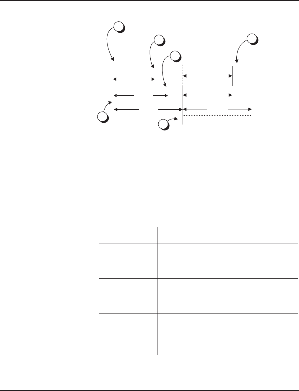
Automatic Call Distribution (ACD)
Aspire Software Manual Features ◆121
When Logged Out of ACD Group
When ACD agents are logged out and a call is placed into the ACD queue, the phones of
the logged out agents will display the Queue Status and hear the alarm according to the
settings defined in system programming. Pressing the Queue Status Display Programma-
ble Function key will return the phone to idle until the timer in Program 41-20-03 expires
again.
Notes:
(A.) Do not use both 41-15 and 41-20 to set the ACD queue alarm. Select either one or the
other for the system to follow.
(B.) If a telephone is not idle, it cannot use the Queue Status Display Programmable Func-
tion key.
(C.) The Queue Status Display is not shown and the Queue Alarm is not heard by ACD
agents those in Off-Duty mode.
Feature Available in Program
41-15
Available in Program
41-20
Queue Status Display --- Yes
Queue Status
Display Time --- Yes
Alarm Yes Yes
Alarm Send Time Program 41-15-02 deter-
mines the length/interval
of the alarm.
Yes
Interval Time of
Queue Status Display Yes
Class of Service --- Yes
Timing of alarm and
display queue status Alarm triggered after the
number of calls in Pro-
gram 41-15-01 is
exceeded.
Alarm triggered after the
number of calls in Pro-
gram 41-20-01 is
exceeded. Then follows
Program 41-20-03 timing
for displaying status.
41-20-05
41-20-02
41-20-05
41-20-03
Queue Status displays and
Alarm Send (41-20-05) starts.
Call queues and
41-20-03 starts.
Alarm ends.
Time in queue refreshes on
display and queue alarm
sounds (if enabled).
Pattern repeats.
2
1
3
5
6
41-20-03
41-20-02
Queue Status
Display ends.
4

Automatic Call Distribution (ACD)
122 ◆Features Aspire Software Manual
(D.) In order to scroll through the ACD groups queue status, the Queue Status Display
Programmable Function key must be used. You cannot scroll when the Queue Status
Display appears due to an alarm condition.
(E.) If the Queue Status display and alarm are active and the queued called is answered/
disconnected, the display and alarm will continue until the timers in Program 41-02-
02 and 41-20-05 expire.
(F.) When an overflowed call is in queue, the call will be included in its original ACD
group’s queue and not in the group’s queue to which it overflowed.
(G.) The Queue Status is not displayed on a supervisor’s phone based on the settings in
Programs 41-02-xx. The supervisor must use the Queue Status Display Programma-
ble Function key to view the queue.
- Overflow Announcements from Voice Mail
The NVM-Series Voice Mail system can provide the ACD overflow announcements in
systems that do not have a DSP daughter board installed for VRS. When a caller queues
for an available agent, designated Voice Mail ACD Announcement Mailboxes provide the
overflow messages.
- Escape from Queue with NVM-Series
Escape From Queue uses NVM-Series Call Routing Mailboxes for announcement mes-
sages to provide callers with enhanced options while in queue. After listening to this type
of announcement, they can either wait in queue or dial a digit for an alternate destination.
The destination is typically the operator, a mailbox or an extension.
- Programmable Wrap-up Timer
When an agent finishes their call, the system automatically starts a wrap-up timer and
blocks any ACD calls to the agent. This gives them time to complete important logs and
records before a new call comes in. When the timer expires, the system returns the agent to
the ACD Group to handle new callers.
- InDepth and inDepth+
InDepth and inDepth+ are Windows-based Management Information Systems that work
with the system’s built-in ACD. These ACD/MIS systems enhance the system with real
time statistics and reports on ACD Group traffic patterns and usage. Refer to the inDepth
and inDepth+ feature for more details.
ACD Group as Overflow Destination
The system can transfer an overflow call to a specific ACD Group or to voice mail using Program
41-09. When Program 41-08-02 : ACD Overflow Destination has the ACD Overflow Destination
set to '65', the system will overflow the call to the ACD Group programmed in Program 41-09. (The
system will not allow you to program an ACD group with that ACD group as the overflow.) If,
while the call is ringing, the extension to which the call was transferred becomes available, both the
extension and the overflow ACD group will ring.
Option Available for Counting Overflow Calls in ACD MIS Software
An option is available for use with ACD MIS (such as inDepth/inDepth+) software to count over-
flow calls. When the number of queued ACD overflow calls exceeds the limit and a busy tone is
sent to the caller, the system programming will determine if the call is counted in the ACD MIS
software.
Enhancement Provides Additional Overflow Destinations
This feature enhancement provides three new entries for ACD Overflow Transfer destinations. With
the older software, only the other ACD group or voice mail could be programmed for the ACD
Overflow Transfer destination.

Automatic Call Distribution (ACD)
Aspire Software Manual Features ◆123
The system can now allow either an off-premise number (using a programmed Abbreviated Dial
number) or incoming ring group for the ACD Overflow Transfer destination.
Notes:
●When using Off-Premise Overflow transfer and if all trunks are busy, the system will set the
ACD Overflow Timer again and wait to retry. When this occurs, the queue information of this
call will be set to the oldest queue.
●Once the Overflow call has successfully transferred to the Off-Premise or ring group, the call
is removed from the retry queue.
●Once the Overflow call has successfully transferred to the Off-Premise or ring group, the sys-
tem will notify the ACD-MIS that the call was abandoned by the caller.
●If the user programmed Overflow Transfer to the ring group which is used by the other ACD
group, the system will notify ACD-MIS with new call information. Therefore, the ACD-MIS
will count the transferred call as new call.
For more on Automatic Call Distribution, refer to the ACD Manual (P/N 0893202).
Conditions
Refer to the ACD Manual (P/N 0893202).
Default Setting
Refer to the ACD Manual (P/N 0893202).

Automatic Call Distribution (ACD)
124 ◆Features Aspire Software Manual
Programming
Refer to the ACD Manual (P/N 0893202) for complete programming details.
➻11-13-01 - 11-13-13 : Service Code Setup (For ACD)
If required, customize the service codes which are used with the ACD feature.
Note that when using service code 169 to change an agent’s ACD group, the supervisor must
enter a 2-digit number for the group. For example, to change to ACD group 4, the entry would
be ‘169 04’.
➻11-17-01 : ACD Group Pilot Number
Assign the ACD Master Number (up to 8 digits) for each ACD Group (1-8). This is the num-
ber users dial to transfer calls to the ACD Group. This will also be the number used for a Call
Coverage key.
➻15-02-21 : Multi-Line Telephone Basic Data Setup, Virtual Extension Access Mode
Determine whether an extension’s Virtual Extension/Call Coverage key should be as a DSS
key to the extension and for receiving calls (0), answering incoming calls and ability to place
outgoing ICM or CO calls (1), or just receiving incoming calls (2).
➻15-07-01 : Programmable Function Keys
Assign ACD Programmable Function Keys as required for each agent.
➻15-08-01 : Incoming Virtual Extension Ring Tone Setup
Assign a ring tone range to incoming ACD Call Coverage keys. Only pattern "1" can be used
for this feature. Patterns 2-4 are not checked.
➻15-09-01 : Virtual Extension Ring Assignment
Individually program an extension’s Multiple Directory Number function keys to either ring
(1) or not ring (0).
➻15-11-01 : Virtual Extension Delayed Ring Assignment
Individually program an extension’s Multiple Directory Number keys for Delayed Ringing (1)
or Immediate Ringing (0). Also see Program 20-04-03 below.
➻20-04-03 : System Options for Virtual Extensions - Call Coverage Delay Interval
Multiple Directory Number/Call Coverage keys set for Delayed Ringing (see Program 15-11
above) ring the covering extension after this interval.
➻20-06-01 : Class of Service for Extensions
Assign a Class of Service (1-15) to each extension.
➻20-13-06 : Class of Service Options (Supplementary Service) - Automatic Off Hook
Signaling
Disable (0) the ability for a busy extension to automatically receive off hook signals if the
ACD Monitor feature is to be used by an extension.
➻20-13-33 : Class of Service Options (Supplementary Service) - ACD Supervisor’s
Position Enhancement
This option must be enabled in order for the operator to use service codes in Program 11-13-
10 through 11-13-13.
➻20-13-39 : Class of Service Options (Supplementary Service), ACD Queue Status Display
Enable (1) or disable (0) the ACD Queue Status Display for an extension’s Class of Service.
Any extension which has this option enabled will also hear the queue alarm.
➻22-01-11 : System Options for Incoming Calls - VRS Waiting Message Interval Time
The Delayed Announcement Messages (1st and 2nd) repeat after this interval expires. For
each ACD group (01-64), set the timer for the interval between the Delayed Messages (0-
64800 seconds).

Automatic Call Distribution (ACD)
Aspire Software Manual Features ◆125
➻20-13-33 : Class of Service Options (Supplementary Service) - ACD Supervisor’s
Position Enhancement
This option must be enabled in order for the operator to use service codes in Program 11-13-
10 through 11-13-13.
➻30-01-01 : DSS Console Operating Mode
Set the mode of the system’s DSS Consoles. The available options are Regular (Business)
Mode (0), Hotel Mode (1), and ACD Monitor Mode (2). Lamping status for ACD agents and
non-ACD agents do not both appear on the same console type. For ACD agent’s lamping sta-
tus, a DSS Console must be programmed as an ACD console. For non-ACD agents, the con-
sole must be programmed as business console.
➻30-05-04 : DSS Console Lamp Table, ACD Agent Busy
30-05-05 : DSS Console Lamp Table, Out of Schedule
30-05-06 : DSS Console Lamp Table, ACD Agent Log Out
30-05-07 : DSS Console Lamp Table, ACD Agent Log In
30-05-08 : DSS Console Lamp Table, ACD Agent Emergency
The BLF for an ACD Agent’s Hotline key follow the lamping defined in these programs.
➻41-01-01 : System Options for ACD - System Supervisory Extension
41-01-03 : System Options for ACD - ACD MIS Connection Port
Define the system options for the ACD feature.
➻41-01-04 : System Options for ACD - P Command Output for Busy Status
When the number of queued ACD overflow calls exceeds the limit and a busy tone is sent to
the caller, determine if the call is counted in the ACD MIS software (0=Count, 1=Do Not
Count).
➻41-01-02 : System Options for ACD - Login ID Code Digit
Define the number of digits for the ID code when logging in (0-20, 0=no ID).
➻41-02-01 : ACD Group and Agent Assignments
For each ACD extension number, assign an ACD Group (1-64). An ACD Group number is
assigned to each Work Period number (1-8). Do not use this program when using the AIC log in
mode. Program 41-18-01 is used instead.
➻41-03-01 : Incoming Ring Group Assignments for ACD Group - ACD Group Number
For each incoming trunk ring group set up in Program 22-05, designate into which ACD
Group (1-64) the trunks should ring for each of the eight Work Periods.
➪Aspire Ring Groups: 1-100
➻41-03-02 : Incoming Ring Group Assignments for ACD Group - Night Announcement
Service
For each incoming trunk ring group set up in Program 22-05, determine if the Night
Announcement Service should be enabled (1) or disabled (0).
➪Aspire Trunk Groups: 1-100
➻41-03-03 : Incoming Ring Group Assignments for ACD Group - Priority Data
Determine whether an incoming call to a trunk ring group should follow a priority assignment
(0=normal, 1-7 [1=lowest priority, 7=highest priority]).
➻41-04-01 : ACD Group Supervisor - Group Supervisor Extension
For each ACD Group (1-64), assign the group’s supervisor extension. An ACD Group can
have only one supervisor. In addition, an extension can be a supervisor for only one ACD
Group.
➻41-04-02 : ACD Group Supervisor - Operating Type
For each ACD Group (1-64), assign the operating mode for the supervisor (0 = Supervisor’s
extension does not receive ACD Group calls, 1 = Supervisor’s extension receives ACD Group
overflow calls only, 2 = Supervisor’s extension receives ACD Group calls just like all other
agents).

Automatic Call Distribution (ACD)
126 ◆Features Aspire Software Manual
➻41-05-01 : ACD Agent Work Schedules
Set up the Work Schedules for ACD Agents and Groups. For each ACD Work Schedule (1-4),
designate the start and stop times for each of the eight Work Periods. Once you set up the
schedules in this program, assign them to days of the week in Program 41-07. (This is the
same program used by the Trunk Work Schedules.)
➻41-06-01 : Trunk Work Schedules
Set up the Work Schedules for trunks. For each Work Schedule (1-4), designate the start and
stop times for each of the eight Work Periods. Once you set up the schedules, assign them to
days of the week in Program 41-07. (This is the same program used by the ACD Agent Work
Schedules.)
➻41-07-01 : ACD Weekly Schedule Setup
Assign the four Work Schedules (1-4) to days of the week (1=Sunday, 7=Saturday). The
assignments you make in this program apply to both the ACD Agent Work Schedules (Pro-
gram 41-05) and the Trunk Work Schedules (Program 41-06).
➻41-08-01 : ACD Overflow Options - Overflow Operation Mode
For each ACD Group (1-64), assign the overflow mode (0-9). Each ACD Group can have
unique overflow options.
➻41-08-02 : ACD Overflow Options - ACD Overflow Destination
For each ACD Group (1-64), assign the destination ACD group (1-64) or option (65=overflow
table in Program 41-09, 66=Voice Mail Integration (in-skin voice mail), 67=Off Premise (see
Program 41-08-05), 68=Incoming Ring Group (see Program 41-08-06).
➻41-08-03 : ACD Overflow Options - Delay Announcement Source Type
For each ACD Group (1-64), assign the announcement message types. Delay announcement
functions are not available for ACD pilot number call. Each ACD Group can have unique
overflow options.
➻41-08-04 : ACD Overflow Options - ACD Overflow Transfer Time
For each ACD Group (1-64), assign the overflow transfer time (0-64800 seconds).
➻41-08-05 : ACD Overflow Options - Abbreviated Dial Area When Overflow)
This program defines which Abbreviated Dial dial to use when Program 41-08-02 is pro-
grammed with an entry of ’67’.
Entries: 0 – 1999 (Abbreviated dial areas)
➻41-08-06 : ACD Overflow Options - Incoming Ring Group When Overflow
This program defines which incoming Ring Group to use when Program 41-08-02 is pro-
grammed with an entry of ’68’.
Entries: 1 – 100 (Incoming Ring Group)
➻41-09-01 : ACD Overflow Table Setting
Define the ACD group (01-64) to which a call will be transferred when overflow occurs and its
priority (1-7). If, while the call is ringing, the extension to which the call was transferred
becomes available, both the extension and the overflow ACD group will ring.
➻41-10-01 : PGDAD Delay Announcement - 1st Delay Announcement PGDAD Port Number
For each ACD group (01-64), define the PGDAD port number (0-96) to be used for the first
delay announcement. This program is activated when the delay announcement source and
options are assigned as PGDAD in Program 41-08.
➻41-10-02 : PGDAD Delay Announcement - 2nd Delay Announcement PGDAD Port
Number
For each ACD group (01-64), define the PGDAD port number (0-96) to be used for the second
delay announcement. This program is activated when the delay announcement source and
options are assigned as PGDAD in Program 41-08.
➻41-10-03 : PGDAD Delay Announcement - 1st Delay Announcement Connection Timer
For each ACD group (01-64), set the timer the system waits before playing the first delay
announcement (0-64800 seconds).

Automatic Call Distribution (ACD)
Aspire Software Manual Features ◆127
➻41-10-04 : PGDAD Delay Announcement - 2nd Delay Announcement Connection Timer
For each ACD group (01-64), set the timer the system waits before playing the second delay
announcement (0-64800 seconds).
➻41-10-05 : PGDAD Delay Announcement - 2nd Delay Announcement Sending Duration
For each ACD group (01-64), set the timer for the 2nd Delay announcement (0-64800 sec-
onds). Once this timer expires, the call will disconnect. To keep the call in queue, set this
timer to “0”.
➻41-11-01 : VRS Delay Announcement - Delay Message Start Timer
For each ACD group (01-64), determine how long the system waits before playing the delay
Message. This program is activated when the delay announcement source and options are
assigned as VRS in Program 41-08.
➻41-11-02 : VRS Delay Announcement - 1st Delay Message Number
For each ACD group (01-64), assign the VRS message number to be used as the message
source for the 1st Delay Announcement Message (0-49). This program is activated when the
delay announcement source and options are assigned as VRS in Program 41-08.
➻41-11-03 : VRS Delay Announcement - 1st Delay Message Sending Count
For each ACD group (01-64), determine the 1st Delay Message Sending Count (0-255).
➻41-11-04 : VRS Delay Announcement - 2nd Delay Message Number
For each ACD group (01-64), assign the VRS message number to be used as the message
source for the 2nd Delay Announcement Message (0-49). This program is activated when the
delay announcement source and options are assigned as VRS in Program 41-08.
➻41-11-05 : VRS Delay Announcement - 2nd Delay Message Sending Count
For each ACD group (01-64), determine the 2nd Delay Message Sending Count (0-255)
➻41-11-06 : VRS Delay Announcement - Tone Kind at Message Interval
For each ACD group (01-64), determine what the caller should hear between messages
(0=ring back, 1=MOH, 2=BGM).
➻41-11-07 : VRS Delay Announcement - ACD Forced Disconnect Time After 2nd Delay
Message
For each ACD group (01-64), assign how long the system should wait after the end of the VRS
delay message before disconnecting (0-64800).
➻41-12-01 : Night Announcement Setup - Night Announcement Source Type
Define the night announce voice resource (0=ACI, 1=VRS [DSPDB]) for each ACD group
(01-64). Night announcement availability depends on the setting in Program 41-03-02. The
night announcement function is not available for ACD pilot number call.
➻41-12-02 : Night Announcement Setup - Night Announcement ACI Port Number
If Program 41-12-01 is set to ‘0’, define the port number for the ACI night announce voice
resource for each ACD group (01-64).
➻41-12-03 : Night Announcement Setup - ACD Night Announce Sending Time
Define the night announce sending time (0-64800) for each ACD group (01-64).
➻41-13-01 : VRS Night Announcement - VRS Message Number
For each ACD Group (01-64), define the VRS message number (0-48) to be used as the night
announcement. This program is activated when the night announcement source is assigned as
VRS in Program 41-12-01.
➻41-13-02 : VRS Night Announcement - Tone Kind at Message Interval
For each ACD Group (01-64), define what the caller will hear between the night announce-
ments (0=ring back tone, 1=MOH, 2=BGM).
➻41-14-01 : ACD Options - Emergency Call Operation Mode
Set the Emergency Call Operation Mode (0=Call system supervisory extension when group
supervisory extension is busy, 1=No call to system supervisory extension when group super-
visory extension is busy) for ACD Groups (01-64). Note that the supervisor must be logged in
and have an Emergency Key programmed. By pressing the key once, the supervisor can mon-
itor the call - pressing twice barges in on the call.

Automatic Call Distribution (ACD)
128 ◆Features Aspire Software Manual
➻41-14-02 : ACD Options - Wrap Up Mode
Set the Wrap Up Mode option (0=After wrap up mode key is pressed, 1=After call is finished
automatically) for ACD Groups (01-64). Use Program 15-07 to assign an ACD Wrap-Up
Mode key (*17) to ACD agents.
➻41-14-03 : ACD Options - ACD Priority for Overflow Calls
Set the priority for overflow calls (0=own group priority, 1=priority set by Program 41-03-03)
for ACD Groups (01-64).
➻41-14-04 : ACD Options - Automatic Answer in Headset Mode
Set the Automatic Answer option (0=off, 1=on) for the headset mode for ACD Groups (01-64).
➻41-14-06 : ACD Options - Transfer to ACD Extension With 2nd Delay Announcement
For each ACD Group (01-64), determine whether an outside caller should hear a final
announcement [ex: the company closed] (1) or whether the caller should be placed back into
queue for the ACD group (0).
➻41-14-07 : ACD Options - Automatic Off Duty
For each ACD Group (01-64), determine whether or not a keyset automatically changes to off-
duty mode (0=not changed, 1=changed automatically). The keyset must have an Off-Duty key
assigned (Program 15-07-01 or SC 852: *13).
➻41-14-08 : ACD Options - ACD Off Duty Mode
For each ACD Group (01-64), determine whether or not an agent can receive an internal call
in off-duty mode (0=can not receive, 1=can receive).
➻41-14-09 : ACD Options - Automatic Wrap Up End Time
For each ACD Group (01-64), set how long the system waits before automatically ending
wrap up time (0=disabled or 1-64800 seconds).
➻41-14-10 : ACD Options - ACD Answer of Incoming Call/No Answer Skip Time
For each ACD Group (01-64), set how long a call into the ACD Group will ring an idle exten-
sion before routing to the next agent (0=disabled or 1-64800 seconds). This timer must be
greater than Program 20-04-03 : Delay Ring Timer for the ACD Call Coverage Key with
delayed ringing to work.
➻41-14-12 : ACD Options - Start Headset Ear Piece Ringing (SLT)
For each ACD Group (01-64), set how long the system waits before starting headset ear piece
ringing for single line sets (0=disabled or 1-64800 seconds).
➻41-15-01 : ACD Queue Alarm Information - ACD Queue Alarm
For each ACD Group (01-64), determine the number of calls required in queue to activate the
alarm (0-200). Do not use this program if the alarm options are defined in Program 41-20-01
through 41-20-05.
➻41-15-02 : ACD Queue Alarm Information - Alarm Interval
For each ACD Group (01-64), determine the interval for displaying the alarm information (0-
64800 seconds). Do not use this program if the alarm options are defined in Program 41-20-
01 through 41-20-05.
➻41-16-01 : ACD Threshold Overflow - Number of Calls in Queue
For each ACD group (01-64), define the maximum number of calls in ACD queue (0=no limit,
1-200) before the call overflows.
➻41-16-02 : ACD Threshold Overflow - Operation Mode for ACD Queue
For each ACD group (01-64), determine how the system handles ACD calls when the maxi-
mum number of ACD calls in queue has been reached (0=longest waiting call is transferred,
1=last waiting call is transferred, 2=busy signal sent).

Automatic Call Distribution (ACD)
Aspire Software Manual Features ◆129
➻41-17-01 : ACD Login Mode Setup
Define the ACD login mode (0=normal, 1=AIC) for each extension.
If set to ‘1’:
- Program 41-02-01 is used.
- Note that a supervisor can not log in/out an AIC member as they are not normal ACD agents.
- Service codes for log-in/log-out must be defined in Programs 11-13-08 and 11-13-09.
If set to ‘2’:
- Program 41-18-01 is used.
- Agents log in/out using codes set in Program 11-13-08 and 11-13-09 or using the ACD Log
In/Out Programmable Function Key (Program 15-07-01 or SC 852: *10). Agents do not log
in or out using Program 11-13-01 code(*5 and *51).
➻41-18-01 : ACD Agent Identity Code Setup - ACD Agent Identity Code
For each AIC Table (001-512), define the ACD Agent Identity Code (AIC) (4 digits).
➻41-18-02 : ACD Agent Identity Code Setup - Default ACD Group Number
For each AIC Table (001-512), define the default ACD group number (0=no setting, 1-64).
➻41-18-03 : ACD Agent Identity Code Setup - ACD Group Number in Mode 1
For each AIC Table (001-512), define the ACD group number (0=no setting, 1-64) in mode 1.
➻41-18-04 : ACD Agent Identity Code Setup - ACD Group Number in Mode 2
For each AIC Table (001-512), define the ACD group number (0=no setting, 1-64) in mode 2.
➻41-18-05 : ACD Agent Identity Code Setup - ACD Group Number in Mode 3
For each AIC Table (001-512), define the ACD group number (0=no setting, 1-64) in mode 3.
➻41-18-06 : ACD Agent Identity Code Setup - ACD Group Number in Mode 4
For each AIC Table (001-512), define the ACD group number (0=no setting, 1-64) in mode 4.
➻41-18-07 : ACD Agent Identity Code Setup - ACD Group Number in Mode 5
For each AIC Table (001-512), define the ACD group number (0=no setting, 1-64) in mode 5.
➻41-18-08 : ACD Agent Identity Code Setup - ACD Group Number in Mode 6
For each AIC Table (001-512), define the ACD group number (0=no setting, 1-64) in mode 6.
➻41-18-09 : ACD Agent Identity Code Setup - ACD Group Number in Mode 7
For each AIC Table (001-512), define the ACD group number (0=no setting, 1-64) in mode 7.
➻41-18-10 : ACD Agent Identity Code Setup - ACD Group Number in Mode 8
For each AIC Table (001-512), define the ACD group number (0=no setting, 1-64) in mode 8.
➻41-19-01 : Voice Mail Delay Announcement - Delay Message Start Timer
For each ACD group (01-64), determine how long the system waits before playing the Delay
Message (0-64800 seconds).
➻41-19-02 : Voice Mail Delay Announcement - Mailbox for 1st Announcement Message
For each ACD group (01-64), assign voice mail ACD Announcement Mailbox as the message
source for the 1st Announcement Message. This option is only applicable to ACD Overflow
Modes 1, 4, 5 and 9 (source 0/type2). Use Program 41-08 to set up the ACD overflow options.
➻41-19-03 : Voice Mail Delay Announcement - 1st Delay Message Sending Count
For each ACD group (01-64), determine the 1st Delay Message Sending Count (0-255). This
entry must be set to 1 or higher in order for the message to play.
➻41-19-04 : Voice Mail Delay Announcement - Mailbox for 2nd Announcement Message
For each ACD group (01-64), assign voice mail ACD Announcement Mailboxes as the mes-
sage source for the 2nd Announcement Message. This option is only applicable to ACD Over-
flow Modes 1, 4, 5 and 9 (source 0/type2). Use Program 41-08 to set up the ACD overflow
options.
➻41-19-05 : Voice Mail Delay Announcement - 2nd Delay Message Sending Count
For each ACD group (01-64), determine the 2nd Delay Message Sending Count (0-255). This
entry must be set to 1 or higher in order for the message to play.

Automatic Call Distribution (ACD)
130 ◆Features Aspire Software Manual
➻41-19-06 : Voice Mail Delay Announcement - Tone Kind at Message Interval
For each ACD Group (01-64), define the what the caller will hear between the messages
(0=ring back tone, 1=MOH, 2=BGM). Currently, calls in the ACD queue will only hear MOH
if the music is from the NTCPU. It will not work if the MOH is connected to an ACI. Incom-
ing callers which have not been put into queue, however, can hear the MOH from any source.
➻41-19-07 : Voice Mail Delay Announcement - ACD Forced Disconnect Time After 2nd
Announcement
For each ACD group (01-64), assign how long the system should wait after the end of the
ACD delay message before disconnecting (0-64800).
➻41-19-08 : Voice Mail Delay Announcement - Delayed Message Interval Time
For each ACD group (01-64), set the timer for the interval between the Delayed Messages (0-
64800 seconds).
➻41-20-01 : ACD Queue Status Display Settings, Number of Calls in Queue
Set the number of calls that can accumulate in the ACD queue before the Queue Status Dis-
play (and optional queue alarm) occurs (0=no display, 1-200).
➻41-20-02 : ACD Queue Status Display Settings, Queue Status Display Time
Set how long a the Queue Status display remains on the telephone’s display (0-64800
seconds).
➻41-20-03 : ACD Queue Status Display Settings, Queue Status Display Interval
Set the interval that refreshes the Queue Status Alarm time in queue display and causes the
optional queue alarm to occur on phones active on a call, logged out, or in wrap-up (0-64800
seconds).
➻41-20-04 : ACD Queue Status Display Settings, ACD Call Waiting Alarm
Enable (1) or disable (0) the queue alarm (Default=0).
➻41-20-05 : ACD Queue Status Display Settings, ACD Call Waiting Alarm Send Time
Set how long the Call Waiting Alarm should sound (0-64800 seconds).
Related Features
Call Forwarding / Tandem Ringing
These features will not work for ACD extensions while the agent is logged in.
Direct Inward Dialing (DID)
If defined in Program 22-11-03, DID calls in queue will display the trunk name with the
Queue Status feature.
Direct Station Select (DSS) Console
Lamping status for ACD agents and non-ACD agents do not both appear on the same console
type. For ACD agent’s lamping status, a DSS Console must be programmed as an ACD con-
sole in Program 30-01-01. For non-ACD agents, the console must be programmed as business
console.
Networking
Calls cannot be transferred across a network to an ACD group.
Night Service
When Program 12-07-01 is customized, an agent’s display will not indicate the WAIT ACD
LOGIN status, however an agent may still log in.
Voice Mail
Conversation Recording is programmed on a system-wide basis - it is not ACD feature specific.
Refer to the ACD Manual (P/N 0893202).

Automatic Call Distribution (ACD)
Aspire Software Manual Features ◆131
Operation
Transferring Calls to an ACD Group
To Transfer a call to an ACD Group:
1. At keyset or DSL, press HOLD.
OR
At SLT, hookflash
You hear Transfer dial tone.
2. Dial ACD Group Master Number.
You can press a One-Touch Key for the master instead.
3. Hang up.
Transferring Trunk Calls to the ACD Master (Program 15-02-21 = 0):
Only analog, ISDN, or H.323 trunk calls can be transferred.
1. While on an outside call, press HOLD.
2. Press the ACD Call Coverage key.
The ACD Call Coverage key must be defined as a DSS key in Program 15-02-21.
The ACD Call Coverage key must be off (idle) in order to transfer the call.
3. Hang up.
The call is transferred to the ACD group.
Answering Outside Calls that Ring Your ACD Group
To answer an outside call that rings your ACD Group:
DISA, DID and tie trunks can ring an ACD master number directly. Other trunk types
can ring ACD Groups if set up in programming. Trunks can also be transferred to ACD
master numbers.
1. Lift handset.
2. If you don't automatically answer the call, press the flashing line key.

Automatic Call Distribution (ACD)
132 ◆Features Aspire Software Manual
Agent Log In and Log Out
To log your extension into the ACD Group:
Keyset
Your display shows: WAIT ACD LOGIN. If Program 12-07-01 has a customized Day/
Night mode message defined, the ACD agent’s display will not indicate the WAIT ACD
LOGIN status (however, the agent may still log in using the following procedure).
1. Press idle CALL key.
2. Dial *5.
You hear confirmation tone.
OR
Press ACD Log On/Off key (PGM 15-07-01 or SC 852: code *10).
You hear a single beep.
Your display will show the ACD Group to which you are logged in.
If your system has ACD Identification Codes enabled, enter it now.
DSL or SLT
1. Lift handset.
2. Dial *5.
You hear confirmation tone.
If your system has ACD Identification Codes enabled, enter it now.
To log your extension out of an ACD Group:
Keyset
Your display shows the ACD Group to which you are logged in.
1. Press idle CALL key.
2. Dial *5.
OR
Press ACD Log On/Off key (PGM 15-07-01 or SC 852: code *10).
Your display shows: ACD LOGOUT (1:Yes, 0:No)
3. Dial 1 to log out.
You hear confirmation tone (if you dialed *5) or a single beep (if you pressed the ACD
Log On/Log Off key.
OR
Dial 0 to cancel the log out and return to the group.
DSL
1. Lift handset.
2. Dial *5.
3. Dial 1 to log out.
You hear confirmation tone.
OR
Dial 0 to cancel the log out and return to the group.
SLT
1. Lift handset.
2. Dial 155.

Automatic Call Distribution (ACD)
Aspire Software Manual Features ◆133
AIC Agent Log In
To log in:
Keyset
1. Press the ACD Log In/Log Out key (Program 15-07 or SC 852: *10).
OR
1. Press CALL key and dial the AIC Log In service code (Program 11-13-08).
2. If the agent log in code is used (as with inDepth/inDepth+), enter the agent log in code (the
number of digits to be entered is determined by Program 41-01-02). Otherwise, skip to Step 3.
3. Dial the Agent Identity Code (AIC) (up to 4 digits) defined in Program 41-18-01.
The ACD Log In/Log Out key lights.
To log out (for single or multiple agent log ins):
Keyset
All AIC log ins become invalid.
1. Press the ACD Log In/Log Out key (Program 15-07 or SC 852: *10).
2. Dial 1 to accept.
OR
1. Press CALL key and dial the AIC Log Out service code (Program 11-13-09).
The ACD Log In/Log Out key goes out.
DSL/SLT
All AIC log ins become invalid.
1. Lift the handset.
2. Dial the AIC Log Out service code (Program 11-13-09).
OR
1. To log out of an ACD group without using AIC: Lift the handset.
2. Dial the ACD Log Out service code 155 (Program 11-13-02).

Automatic Call Distribution (ACD)
134 ◆Features Aspire Software Manual
Multiple Agent Log In
To log in:
Keyset
1. Press the ACD Log In/Log Out key (Program 15-07 or SC 852: *10).
2. Dial 0 to cancel the log out option.
3. Dial the Agent Identity Code (AIC) (up to 4 digits).
The ACD Log In/Log Out key lights.
OR
1. Press CALL key and dial the AIC Log In service code (Program 11-13-08).
2. Dial the Agent Identity Code (AIC) (up to 4 digits).
The ACD Log In/Log Out key lights.
DSL
1. Lift the handset and dial the AIC Log In service code (Program 11-13-08).
2. Dial the log in code (up to 20 digits).
This step is not required if the ID code is disabled in Program 41-01-02.
3. Dial the first Agent Identity Code (AIC) (up to 4 digits).
You will hear a confirmation tone.
4. Press HOLD.
5. For second agent log: Dial the second Agent Identity Code (AIC) (up to 4 digits).
You will hear a confirmation tone.
6. For third agent log: Dial the third Agent Identity Code (AIC) (up to 4 digits).
You will hear a confirmation tone.
SLT
Follow Steps 1-3 to log in with additional AICs (up to 3) at any time.
1. Lift the handset and dial the AIC Log In service code (Program 11-13-08).
2. Dial the log in code (up to 20 digits).
This step is not required if the ID code is disabled in Program 41-01-02.
3. Dial the first Agent Identity Code (AIC) (up to 4 digits).
You will hear a confirmation tone.
When immediately logging in with additional AICs.
4. For second agent log: Dial the second Agent Identity Code (AIC) (up to 4 digits).
You will hear a confirmation tone.
5. For third agent log: Dial the third Agent Identity Code (AIC) (up to 4 digits).
You will hear a confirmation tone.

Automatic Call Distribution (ACD)
Aspire Software Manual Features ◆135
Changing ACD Group Assignment
To change your ACD Group Assignment:
1. Log out of your ACD Group (see the instructions above).
2. Press idle CALL key.
3. Dial 170.
4. Dial the number of the ACD Group (1-64) into which you want to log.
You hear confirmation tone.
5. Log into the new ACD Group (see the instructions above).
Using the Headset with Automatic Answer for ACD Agents:
1. With the keyset in an idle state, press the Check key.
2. Press the Headset key (PGM 15-07 or SC 851: 05) twice.
3. Press the Clear key to return the display to idle.
The Headset key blinks when Automatic Headset is activated.
To cancel Automatic Headset, repeat these steps.
Answering Incoming ACD Calls with a Call Coverage Key:
1. Press the flashing ACD Call Coverage key (PGM 15-07 or SC 851: *03 + ACD Master number).
Ringing calls are answered in the following priority:
- Ringing call which has heard the ACD Delayed message.
- Ringing call which has not heard the ACD Delayed message.
- Calls in queue (follows ACD overflow priority set in Program 41-14-03).
A Supervisor can monitor an ACD call:
1. When an ACD agent is on an outside call, the supervisor presses the Monitor key (PGM 15-07
or SC 852: *15).
The call is heard by the supervisor, but cannot participate in the call. If participation is
required, use the Barge In feature instead.
2. To cancel the call monitoring, press the Monitor key again.

Automatic Call Distribution (ACD)
136 ◆Features Aspire Software Manual
Queue Status Display
When Logged Into ACD Group
1. With an idle keyset, press the Queue Status Display Programmable Function Key (Code: *19).
The display indicates the number of calls in queue, the trunk name, and the length of
time the call has been waiting.
When the Queue Status Display key is pressed, the queue status of the extension’s
group is displayed. When the extension is not in an ACD group, the Queue Status of
group 1 is displayed instead.
When an agent logs in using an AIC code, the Queue Status of the default ACD group
defined in Program 41-18-02 is displayed.
2. Press the VOL UP and VOL DOWN to scroll through the Queue Status Displays of all the
ACD Groups.
3. Press the CLEAR key to return the phone to an idle state.
When Logged Out of ACD Group
When ACD agents are logged out and a call is placed into the ACD queue, the phones of the logged
out agents will display the Queue Status and hear the alarm according to the settings defined in sys-
tem programming.
Pressing the Queue Status Display Programmable Function key will return the phone to idle until
the timer in Program 41-20-03 expires again.
Rest Mode/Off-Duty Mode
To set the manual Rest Mode/Off-Duty Mode:
Keyset
1. With the keyset in an idle state, press the ACD Rest Mode key (PGM 15-07 or SC 852: *13).
The ACD Rest Mode key lights. If the Rest Mode key is pressed while the agent is on an
active call, the key will flash until the agent hangs up.
This operation is not available for the System Supervisor.
Single Line Telephone
1. Lift the handset and dial 158.
A fast busy is heard.
To set Pre-Rest Mode (while on a call), press the hookflash and then dial 158. Press the
Hookflash again to return to the outside party. Rest Mode will begin once the call is com-
pleted.
2. Hang up.

Automatic Call Distribution (ACD)
Aspire Software Manual Features ◆137
To cancel the manual Rest Mode/Off-Duty Mode:
Keyset
1. Press the ACD Rest Mode key (PGM 15-07 or SC 852: *13).
The ACD Rest Mode key light goes off.
Single Line Telephone
1. Lift the handset.
A fast busy is heard.
2. Dial 159.
3. Hang up.
Refer to the ACD Manual (P/N 0893202) for additional operations.

Automatic Route Selection
138 ◆Features Aspire Software Manual
Automatic Route Selection
Description
Automatic Route Selection (ARS) provides call routing and call restriction based on the digits a user
dials. ARS gives the system the most cost-effective use of the connected long distance carriers.
ARS is an on-line call routing program that you can customize (like other system options) from a
display telephone. ARS accommodates 250 call routing choices - without a custom-ordered rate
structure database. With ARS, you can modify the system’s routing choices quickly and easily. This
is often necessary in today’s telecommunications world where the cost structure and service
choices frequently change.
The ARS feature can add or delete digits and route calls according to pre-determined levels. When
Aspire systems are networked together by a tie line, the networked systems can be called by a sys-
tem number and a user’s extension number, just an extension number, or by using a trunk access
code.
ARS Feature Summary
ARS provides:
●Call Routing
ARS can apply up to 24-digit analysis to every number dialed. For programming, ARS pro-
vides separate 8-digit and 24-digit tables. Each table can have up to 250 numbers.
●Dialing Translation (Special Dialing Instructions)
ARS can automatically execute stored dialing instructions (called Dial Treatments) when it
chooses a route for a call. The system allows up to 15 Dial Treatments. The Dial Treatments
can:
- Automatically insert or delete a leading 1
- Insert or delete an area code (NPA)
- Add digits (such as a dial-up OCC number), pauses and waits to the dialing sequence
●Time of Day Selection
For routing purposes, ARS provides ten different day selections (called Time Schedule Pat-
terns). Each Time Schedule Pattern can provide up to 20 time intervals which are assigned to
one of the eight day/night modes. The Time Schedule Patterns are then assigned to a day of
the week (Monday-Friday, Saturday, Sunday or Holiday).
Basic ARS Operation
When a user places an outside call, ARS analyzes the digits dialed and assigns one of 64 Selection
Numbers to the call. The Selection Number chosen depends on which digits the user dialed. ARS
then checks the time of day, the day of week and the extension’s ARS Class of Service. Based on
these call routing options, ARS selects a trunk group for the call and imposes the Dial Treatment
instructions (if any).
Aspire S Aspire M/L/XL
• Available.
• COS option for outgoing calls following access map is
available.
• COS Matching feature is available with 2.63+ software.
• Alternate Carrier Access for ISDN trunks requires soft-
ware 2.63+
• Available.
• COS option for outgoing calls following access map is
available in software 1.11+.
• COS Matching feature is available with 2.63+ software.
• Alternate Carrier Access for ISDN trunks requires soft-
ware 2.63+.

Automatic Route Selection
Aspire Software Manual Features ◆139
Class of Service Option Allows Outgoing Calls to Not Follow Access Map
Using this option allows an extension’s Class of Service to be set so that ARS does not follow the
trunk access map settings (Program 14-07-01 and 15-06-01). The feature allows an extension user
to have CO line keys on their phone which allow incoming access only. The user would only have
outgoing access on the CO lines when using ARS to place a call.
Class of Service Matching
With the ARS Class of Service Match Access feature, you can determine whether the system should
allow a call based on the COS assigned to the Dial Analysis Table (Program 26-02). This change
can be used to create a tenant-like application. It will then use the trunk group defined in the Addi-
tional Entry in Program 26-02-03 to place the outgoing call.
When this feature is enabled, the calls will be routed in sequential order, and will forward provided
the Class of Service for the trunk groups match.
For this feature a new system option, Program 26-01-06 : Automatic Route Selection Service,
COS Match Access, is added. In adding this feature, the ARS table is expanded from 200 to 400.
First 200 entries will be compatible with the previous software as well as the 2.63 software.
The examples below use the following system programming:
Program 26-02 for Dial Analysis Table for ARS set as:
Program 12-02 for Automatic Night Service Patterns as:
Program 26-04 for ARS Class of Service as:
Program 26-01-03 for ARS Misdialed Number Handling as: 1(Warning Tone)
Table No. Program 26-02-01
Dial Program 26-02-02
Service Type Program 26-02-03
Add Data Program 26-02-04
ARS COS
1 203@@@@@@@ 1: Route to trunk group 3 (Group 3) 5
2 214@@@@@@@ 1: Route to trunk group 1 (Group 1) 4
197 @@@@@@@@@@ 1: Route to trunk group 2 (Group 2) 4
198 @@@@@@@@@@ 1: Route to trunk group 3 (Group 3) 3
199 @@@@@@@@@@ 1: Route to trunk group 2 (Group 2) 2
200 @@@@@@@@@@ 1: Route to trunk group 1 (Group 1) 1
Time Pattern No. Program 12-02-01
Start Time Program 12-02-02
End Time Program 12-02-03
Operation Mode
1 00:00 08:30 2 (Night)
2 08:30 17:00 1 (Day)
3 17:00 00:00 2 (Night)
Ext. 301 Ext. 302 Ext. 401 Ext. 402
Mode 1(Day) 1 2 3 3
Mode 2(Night) 1 4 3 5

Automatic Route Selection
140 ◆Features Aspire Software Manual
With Program 26-01-06: ARS COS Match Access disabled (set to '0'):
●If at 9:00 AM, each extension dialed '9+(203)926-5400'
All Extension would use Trunk Group 3
●If at 9:00 AM, each extension dialed '9+(214)262-2000'
All Extension would use Trunk Group 1
●If at 6:00 PM, each extension dialed '9+(203)926-5400'
All Extension would use Trunk Group 3
●If at 6:00 PM, each extension dialed '9+(214)262-2000'
Extension 301, 302 and 401 would use Trunk Group 1
Extension 402 would not be able to dial out as the COS is lower
With Program 26-01-06: ARS COS Match Access enabled (set to '1'):
●If at 9:00 AM, each extension dialed '9+(203)926-5400'
Extension 301 would use Trunk Group 1
Extension 302 would use Trunk Group 2
Extension 401, 402 would use Trunk Group 3
●If at 9:00 AM, each extension dialed '9+(214)262-2000'
Extension 301 would use Trunk Group 1
Extension 302 would use Trunk Group 2
Extension 401, 402 would use Trunk Group 3
●If at 6:00 PM, each extension dialed '9+(203)926-5400'
Extension 301 would use Trunk Group 1
Extension 302 would use Trunk Group 2
Extension 401, 402 would use Trunk Group 3
●If at 6:00 PM, each extension dialed '9+(214)262-2000'
Extension 301, 302 would use Trunk Group 1
Extension 401 would use Trunk Group 3
Extension 402 would not be able to dial out as the COS does not match
Alternate Carrier Access Added for ISDN Trunks
An option is available which allows the system to provide a Transit Network Selection information
element for ARS calls using ISDN trunks. This information element identifies a requested transit
network. This function is valid only for outbound calls by ISDN trunk.
Local calls do not need Network Selection information since they will be handled by the local
exchange carrier (ILEC). If this is the case, ARS is able to distinguish between local and long dis-
tance calls and add the Transit Network Selection information element when required.
This option would apply to both PRI and BRI ISDN trunks. If the trunk in the used in Program 26-
02 : Dial Analysis Table for ARS/LCR is not an ISDN trunk, this code in the dial treatment will be
ignored.
The examples below use the following system programming:

Automatic Route Selection
Aspire Software Manual Features ◆141
➻Program 26-02 for Dial Analysis Table for ARS/LCR set as:
➻Program 26-03-01 for ARS Dial Treatments set as:
Table No. 1 - Dial Treatment: A1RE
➻Program 26-11-01 for Transit Network ID Table set as:
Table No. 1 - Transit Network ID: 0288
Example: If an extension dialed '9+(203)925-5400', the setup message will contain the Transit Net-
work Selection IE with Network ID 0288.
Example: If an extension dialed '9+(214)262-2000', the setup message will not contain the Transit
Network Selection IE.
Conditions
(A.) Do not use ARS behind a Centrex/PBX if Centrex features are used.
(B.) ARS is intended for areas that use the North American Number Plan (NANP).
(C.) Line keys, outgoing loop keys, outgoing trunk group keys, dialing 804+trunk group, dialing
#9+trunk number, and abbreviated dial numbers assigned to a certain trunk group can all be
used to by-pass ARS.
(D.) With software prior to 2.63, an entry of ’0’ in the ARS Table COS means it will ignore the
telephone’s Class of Service. With software 2.63 and higher, an entry of ’0’ in the ARS Table
COS will only match the telephone’s COS ‘0’.
Default Setting
ARS is not programmed.
Programming
➻11-01-01 : System Numbering
Set the system’s internal (Intercom) numbering plan. The numbering plan assigns the first and
second digits dialed and affects the digits an extension user must dial to access other exten-
sions and features, such as service codes and trunk codes. If the default numbering plan does
not meet the site requirements, use this program to tailor the system numbering to the site.
➻11-09-01 : Trunk Access Code
Specify the single digit code used to access ARS (normally 9).
➻14-05-01 : Trunk Groups
Program trunks of the same carrier type into the same trunk group.
➻14-07-01 : Trunk Access Map Setup
Set up the Trunk Access Maps. This sets the access options for trunks.
➪Aspire S: Trunk Access Maps 1-8
➪Aspire: Trunk Access Maps 1-200
➻15-06-01 : Trunk Access Map for Extensions
Assign Trunk Access Maps to extensions.
➪Aspire S: Trunk Access Maps 1-8
➪Aspire: Trunk Access Maps 1-200
Table
No.
Program 26-02-01
Dial
Program 26-02-02
Service Type
Program 26-02-03
Add Data
Program 26-02-04
ARS COS
Program 26-02-05
Dial Treatment
1 203@@@@@@@ 1:TRG 1(Group 1) 0 1
2 @@@@@@@@@@ 1:TRG 1(Group 1) 0 0

Automatic Route Selection
142 ◆Features Aspire Software Manual
➻20-03-04 : System Options for Single Line Telephones - Dial Sending Start Time for SLT
or ARS
When ARS or an analog extension user accesses a trunk and dials an outside call, the system
waits this interval before outdialing the first digit (0-64800 seconds).
➻20-06-01 : Class of Service for Extensions
Assign a Class of Service (1-15) to an extension.
➻20-08-17 : Class of Service Options (Outgoing Call Service), ARS Override of Trunk
Access Map
Enable (1) or disable (0) an extension’s ability to override the trunk access map programming
(Program 14-07-01 and 15-06-01) for outgoing calls.
➻26-01-01 : Automatic Route Selection Service - ARS Service
Enable (1) or disable (0) ARS.
➻26-01-02 : Automatic Route Selection Service - Network Outgoing Inter-Digit ARS
Timer
With Networking, this timer (0-64800 msec.) replaces 20-03-04 when determining if all net-
work protocol digits have been received. If ARS is enabled at Site B, this timer can be pro-
grammed for 5 (500 msec) at Site A. If ARS is disabled and Site B is using F-Route for
outbound dialing, this timer should be programmed for 30 (3 seconds) at Site A.
➻26-01-03 : Automatic Route Selection Service - ARS Misdialed Number Handling
If a user dials a number not programmed in ARS, this option determines if the system should
route over trunk group 1 (0) or play error tone (1).
➻26-01-06 : Automatic Route Selection Service - ARS COS Match Access
With the ARS Class of Service Match Access feature, you can determine whether the system
should allow a call based on the COS assigned to the Dial Analysis Table (Program 26-02).
This change can be used to create a tenant-like application. It will then use the trunk group
defined in the Additional Entry in Program 26-02-03 to place the outgoing call.
When this feature is enabled (1), the calls will be routed in sequential order, and will forward
provided the Class of Service for the trunk groups match (0 = Disabled, 1=Enabled).
➻26-02-01 : Dial Analysis Table for ARS/LCR - Dial
Enter the digits (16 digits maximum: 1-9, 0 * #, @; 400 separate entries) for the Dial Analysis
Table which will be analyzed by ARS/LCR. This table will be checked after any programmed
F-Route operations have completed. The system will then refer to Program 26-02-02 and 26-
02-03 to determine the routing for the call. To enter a wild card/don’t care digit, press Line
Key 1 to enter an @ symbol. It is important to remember that the system checks the table
numbers in numerical order. This means that entries for specific numbers should be entered
first (such as your local area codes), then enter the items containing wild card digits. If the
system sees an entry of “2@@” then any table entries which follow will be ignored.
For example, if 268, 269, and 270 are local exchanges, these would be the first three table
entries which would route according to the settings made in Program 26-02-02 and 26-02-03
for each of the table entries. If the next entry is “2@@”, then the system checks no further in
this program and routes all other “2xx” numbers according to the entries made in Program 26-
02-02 and 26-02-03 for this table entry.
➻26-02-02 : Dial Analysis Table for ARS - Service Type
For each Dial Analysis Table (1-200), select ‘0’ for no ARS, ‘1’ for Service Type 1 - Route to
Trunk Group Number to have the number route to a trunk group [Refer to Program 26-02-03]
or ‘2’ for Service Type 2 - F-Route Selected to have the dialed number controlled by the F-
Route table. If Service Type 2 is selected and F-Route operation is on, the F-Route table used
is determined by Program 44-04. If F-Route operation is off, the routing is determined by Pro-
gram 44-05.

Automatic Route Selection
Aspire Software Manual Features ◆143
➻26-02-03 : Dial Analysis Table for ARS - Additional Data / Service Number
For each Dial Analysis Table (1-200), if Service Type 1 was selected in Program 26-02-02,
enter the trunk group number (0-100, 0=no route).
➻26-02-04 : Dial Analysis Table for ARS - ARS Class of Service
For each Dial Analysis Table (1-200), set the Automatic Route Selection (ARS) Class of Ser-
vice (0-16).
➻26-02-05 : Dial Analysis Table for ARS - Dial Treatment
For each Dial Analysis Table (1-200), set the Automatic Route Selection (ARS) Dial Treat-
ment (0-15) to be used.
➻26-03-01 : ARS Dial Treatments
Assign the Dial Treatments (1-15) for automatic ARS dialing translation. Assign Dial Treat-
ments to Service Numbers (Trunk Groups) in Program 26-02. The ARS Dial Treatment
options are:
●3 - Delete the NPA if dialed as part of the initial call. This requires at least 8 digits in the
ARS table (Program 26-02-01).
●2 - Delete the leading digit if dialed as part of the initial call. This requires at least 8 digits
in the ARS table (Program 26-02-01).
●1 - Add a leading 1 if not dialed as part of the initial call. This requires at least 8 digits in
the ARS table (Program 26-02-01).
●INPA - Insert the NPA specified by NPA.
●DNN - Outdial the NN number of digits or execute the code that follows. For example,
D041234 out-dials 124. Valid entries are 0-9, #, *, Wnn (wait nn seconds) and P (pause).
Each digits code counts as a digit. So for example, if a P was added for a pause, the entry
would look like: D05P1234. This Dial Treatment can only be added from telephone pro-
gramming.
●Wnn - Wait nn seconds.
●P - Pause in analog trunk.
●R - Redial the initially dialed number, including any modifications
●E - End of Dial Treatment. All Dial Treatments must end with the E code.
●X - When ARS is enabled, X must be entered in the Dial Treatment in order for the system to
output the extension number of the call’s originator to the black box for the E911 feature.
●An - Alternate Carrier Access (n = 1 ~ 4). The numeric digit instructs the system to insert
a Transit Network Selection information element in the SETUP message and also identi-
fies which code in Program 26-11 will be included in the information element.
➻26-04-01 : ARS Class of Service
Set an extension’s ARS Class of Service (0-16). Automatic Route Selection uses ARS Class of
Service when determining how to route an extension’s calls.
➻26-11-01 : Transit Network ID Table
Enter up to four Transit Network ID Codes, each being 4 numbers long (Entries: 0-9).
➻44-01-01 : System Options for ARS/F-Route
Select whether the ARS/F-Route feature should use the time schedule (0=not used, 1=used). If
this option is set to ‘0’, the F-Route table selected is determined only by the digits dialed with-
out any relation to the day or time of the call. If this option is set to ‘1’, the system first refers
to Program 44-10. If there is a match, the pattern defined in that program is used. If not, the F-
Route pattern in Program 44-09 and time setting in 44-08 are used.
➻44-02-01 : Dial Analysis Table for ARS/F-Route Access - Dial
Set the Dial digits for the Pre-Transaction Table for selecting ARS/F-Route (8 digits max: 1-9,
0 * #, @). To enter a wild card/don’t care digit, press Line Key 1 to enter an @ symbol.
➻44-02-02 : Dial Analysis Table for ARS/F-Route Access - Service Type
Set the Service Type (0-3) for the Pre-Transaction Table for selecting ARS/F-Route (0=No
setting, 1=Extension Call, 2=ARS/F-Route Table, 3=Dial Extension Analyze Table).

Automatic Route Selection
144 ◆Features Aspire Software Manual
➻44-02-03 : Dial Analysis Table for ARS/F-Route Access - Additional Data
If a Service Type is selected in Program 44-02-02, set the additional data, if required, for the
Pre-Transaction Table for selecting ARS/F-Route (24 digits max: 1-9, 0 * #, @). To enter a
wild card/don’t care digit, press Line Key 1 to enter an @ symbol.
➻44-02-04 : Dial Analysis Table for ARS/F-Route Access - Dial Tone Simulation
Determine if the Dial Tone Simulation is on (1) or off (0) for the Pre-Transaction Table for
selecting ARS/F-Route. If enabled, this option sends dial tone to the calling party once the
routing is determined. This may be required if the central office at the destination does not
send dial tone.
➻44-03-01 : Dial Analysis Extension Table - Dial
Set the Dial digits (24 digits max: 1-9, 0 * #, @) to be used for the Dial Extension Analysis
Table. When Program 44-02-02 is set to type “3”, this program sets the dial extension analysis
table. These tables are used when the analyzed digits must be more than 8 digits. To enter a
wild card/don’t care digit, press Line Key 1 to enter an @ symbol.
➻44-03-02 : Dial Analysis Extension Table - Table Number
When dialed digits match the setting in Program 44-03-01, select the ARS/R-Route table
number (0-500) to be used for the Dial Extension Analysis Table.
➻44-03-03 : Dial Analysis Extension Table - Table Number (251)
If the received digits are not identified in tables 1-250, the F-Route selection table number (0-
500) defined in table 251 is used.
➻44-03-04 : Dial Analysis Extension Table - Next Table Number
If the received digits do not match the digits set in tables 1-250, table number 252 is used refer
to the next Extension Table Area (1-4) to be searched.
➻44-04-01 : ARS/F-Route Selection for Time Schedule
Assign each ARS/F-Route Selection number (1-500) to an ARS/F-Route table number for
each ARS/F-Route time mode. There are 8 time modes for ARS/F-Route Access.
➻44-05-01 : ARS/F-Route Table - Trunk Group Number
For each ARS/F-Route table (1-500) assign a priority number (1-4) and enter the trunk num-
ber to be used (0 = No setting, 101-150 = Networking, 255 = Extension Call).
➻44-05-02 : ARS/F-Route Table - Delete Digits
For each ARS/F-Route table (1-500) assign a priority number (1-4). Enter the number of dig-
its to be deleted (0-255) from the dialed number.
➻44-05-03 : ARS/F-Route Table - Additional Dial Number Table
For each ARS/F-Route table (1-500) assign a priority number (1-4). Enter the table number
(defined in Program 44-06) for additional digits to be dialed (0-1000).
➻44-05-04 : ARS/F-Route Table - Beep Tone
For each ARS/F-Route table (1-500) assign a priority number (1-4). Select whether or not a
beep is heard if a lower priority trunk group is used (0=no beep, 1=beep).
➻44-05-05 : ARS/F-Route Table - Gain Table Number for Internal Call
For each ARS/F-Route table (1-500) assign a priority number (1-4). Select the gain table num-
ber to be used for internal calls (0-500).
➻44-05-06 : ARS/F-Route Table - Gain Table Number for Tandem Connections
For each ARS/F-Route table (1-500) assign a priority number (1-4). Select the gain table num-
ber to be used for tandem connection (0-500).
➻44-05-07 : ARS/F-Route Table - ARS Class of Service
For each ARS/F-Route table (1-500) assign a priority number (1-4). Select the Class of Ser-
vice to be used for ARS (0-16). An extension’s ARS COS is determined in Program 26-04-01.
➻44-05-08 : ARS/F-Route Table - Dial Treatment
For each ARS/F-Route table (1-500) assign a priority number (1-4). Select the Dial Treatment
to be used (0-15). The Dial Treatments are defined in Program 26-03-01.

Automatic Route Selection
Aspire Software Manual Features ◆145
➻44-06-01 : Additional Dial Table
If an Additional Dial Number Table is entered in Program 44-05-03, define the additional dial table
(1-1000) to add digits in front of the dialed ARS/F-Route number (24 digits max: 1-9, 0 * #,
Pause). To enter a wild card/don’t care digit, press Line Key 1 to enter a P (pause) symbol.
➻44-07-01 : Gain Table for ARS/F-Route Access - Incoming Transmit
44-07-02 : Gain Table for ARS/F-Route Access - Incoming Receive
44-07-03 : Gain Table for ARS/F-Route Access - Outgoing Transmit
44-07-04 : Gain Table for ARS/F-Route Access - Outgoing Receive
Set the gain table to be used (1-500). If an extension dials ARS/F-Route number;
- The Extension Dial Gain Table is activated, which is assigned in Program 44-05.
- The Extension Dial Gain Table follows “Outgoing transmit” and “Outgoing receive” settings.
If the incoming call is transferred to another line using ARS/F-Route;
- The Tandem Gain Table is activated, which is assigned in Program 44-05.
- The Tandem Gain Table follows the “Incoming transmit” and “Incoming receive” settings
for incoming line, and “Outgoing transmit” and “Outgoing receive” settings for the outgoing
line.
For ARS/F-Route calls, the CODEC gains defined in Program 14-01-02 and 14-01-03 are not
activated.
➻44-08-01 : Time Schedule for ARS/F-Route
Define the daily pattern of the ARS/F-Route feature. ARS/F-Route has 10 time patterns. These pat-
terns are used in Program 44-09 and 44-10. The daily pattern consists of 20 time settings.
➻44-09-01 : Weekly Schedule for ARS/F-Route
Define a weekly schedule for using ARS/F-Route (day numbers 1-7 (1=Sun, 7=Sat), pattern
numbers 1-10). The pattern number is defined in Program 44-08-01.
➻44-10-01 : Holiday Schedule for ARS/F-Route
Define a yearly schedule for ARS/F-Route. This schedule is used for setting special days such as
national holidays (pattern numbers 1-10). The pattern number is defined in Program 44-08-01.
➻80-03-01 : DTMF Tone Receiver Setup
Use Items 11-32 to set the criteria for dial tone detection for outgoing ARS calls.
Related Features
Abbreviated Dialing
Abbreviated Dialing may bypass ARS routing.
Central Office Calls, Placing
Set up other options for outgoing calls (e.g., unassign line keys, adjust gains, ARS access key,
loop keys, etc.).
Dial Tone Detection
Refer to this feature for the specifics on how the system handles Dial Tone Detection.
E911 Compatibility
If there is no PBX access code is entered in the Dial Treatment, the system will still be able to
dial 911.
Networking
IP phones can use ARS COS Matching to call local authorities in case of an emergency (refer
to NEC Tech Tip NEC0092 or the Networking manual (P/N 0893207).
Toll Restriction
Toll Restriction overrides ARS.

Automatic Route Selection
146 ◆Features Aspire Software Manual
Trunk Group Routing
A system with Automatic Route Selection cannot also have Trunk Group Routing.
Trunk Queuing/Camp On
With ARS installed, Trunk Queuing automatically queues for the least costly route. The
system automatically redials the queued call when the extension user lifts the handset.
Operation
To place a call using ARS:
1. At keyset, press idle CALL key.
OR
At single line set, lift handset.
You’ll hear normal Intercom dial tone.
2. Dial 9.
You’ll hear a second, “stutter” dial tone.
3. Dial the outside number.
If you hear another “stutter” dial tone, you must enter your extension’s ARS
Authorization Code.

Background Music
Aspire Software Manual Features ◆147
Background Music
Description
Background Music (BGM) sends music from a customer-provided music source to speakers in key-
sets. If an extension user activates it, BGM plays whenever the user’s extension is idle.
Conditions
(A.) Background Music requires a customer-provided music source connected to the Aspire
NTCPU’s CN16 connector or the Aspire S CPU’s CN23 connector. Refer to the system Hard-
ware Manual.
(B.) The Aspire S Background Music is the same as the CPU’s Music on Hold.
Default Setting
Not installed.
Related Features
Music on Hold
The system can broadcast music to callers on Hold.
Single Line Telephones
Background Music is not available on single line telephones.
Programming
➻10-21-01 : NTCPU Hardware Setup - External Source Control Switch Selection
Specify the function of the relay switch for external tone source control (0=external MOH
source, 1=BGM source, 2=external speaker, 3=general purpose relay).
➻20-06-01 : Class of Service for Extensions
Assign a Class of Service (1-15) to an extension.
➻20-13-30 : Class of Service Options (Supplementary Service) - Background Music
In an extension’s Class of Service, allow (1) or prevent (0) an extension from turning
Background Music on and off.
➻31-08-01 : BGM on External Paging
Set the Background Music option for each External Page zone (1-9). If enabled, the system
will play BGM over the zone when it is idle (0=disable, 1=enable).
Operation
To turn Background Music on or off:
1. Press idle CALL key.
2. Dial 825.
3. Press SPK to hang up.
Aspire S Aspire M/L/XL
• Available. • Available.

Barge In
148 ◆Features Aspire Software Manual
Barge In
Description
Barge In permits an extension user to break into another extension user’s established call, including
Conference calls. This sets up a Conference-type conversation between the intruding extension and
the parties on the initial call. With Barge In, an extension user can get a message through to a busy
co-worker right away.
There are two Barge In modes: Monitor Mode (Silent Monitor) and Speech Mode. With Monitor
Mode, the caller Barging In can listen to another user’s conversation but cannot participate. With
Speech Mode, the caller Barging In can listen and join another user’s conversation.
Conditions
None
Default Setting
Disabled
Programming
➻11-12-08 : Service Code Setup (for Service Access) - Barge In
Determine what the service code should be for an internal party to use the Barge In feature
(default=810).
➻11-16-02 : One-Digit Service Code Setup - Barge In
Use this option to set up Item 02 for single digit Barge In. For example, you can assign Item
02 to use digit 5 for Barge In. This would allow you to program a function key with an exten-
sion number plus the Barge In code (i.e., 305 5). This allows one-touch access to the Barge In
feature for extension 305. If you undefine a service code, be careful when you change this
item that you don’t inadvertently disable any essential dialing function (such as Voice Mail
or Message Waiting).
➻15-07-01 : Programming Function Keys
Assign a function key for Barge In (code 34).
➻20-06-01 : Class of Service for Extensions
Assign a Class of Service (1-15) to an extension.
Aspire S Aspire M/L/XL
• Available. • Available.
CAUTION
The use of monitoring, recording, or listening devices to eavesdrop, monitor, retrieve, or
record telephone conversation or other sound activities, whether or not contemporaneous
with transmission, may be illegal in certain circumstances under federal or state laws. Legal
advice should be sought prior to implementing any practice that monitors or records any
telephone conversation. Some federal and state laws require some form of notification to all
parties to a telephone conversation, such as using a beep tone or other notification methods
or requiring the consent of all parties to the telephone conversation, prior to monitoring or
recording the telephone conversation. Some of these laws incorporate strict penalties.

Barge In
Aspire Software Manual Features ◆149
➻20-13-10 : Class of Service Options (Supplementary Service) - Barge In Mode
In an extension’s Class of Service, enable the Barge In Speech Mode (0) or Monitor Mode (1)
at the initiating extension (i.e., Barge In initiator).
➻20-13-15 : Class of Service Options (Supplementary Service) - Barge In, Initiate
In an extension’s Class of Service, enable (1) or disable (0) Barge In at the initiating extension
(i.e., Barge In initiator).
➻20-13-16 : Class of Service Options (Supplementary Service) - Barge In, Receive
In an extension’s Class of Service, enable (1) or disable (0) Barge In at the receiving extension
(i.e., Barge In receive).
➻20-13-17 : Class of Service Options (Supplementary Service) - Barge In Tone/Display
Enable (1) or disable (0) the Barge In Tone. If disabled, this also turns off the Barge In display
at the called extension.
➻20-13-32 : Class of Service Options (Supplementary Service) - Multiple Barge In
Enable (1) or disable (0) the extension’s ability to have multiple user’s Barge In to their
conversation.
➻20-14-11 : Class of Service Options for DISA/E&M - DISA/Tie Trunk Barge In
Use this option to enabled (1) or disable (0) a DISA or tie trunk user from using the Barge In
feature with the service code defined in Program 11-12-08.
➻20-18-07 : Service Tone Timer - Intrusion Tone Repeat Time
After a user Barges In, the system repeats the Barge In tone after this interval. Normally, you
should disable this timer by entering 0. (This timer also affect any other types of call interrup-
tion features, such as Voice Mail Conversation Recording, Voice Over, etc.)
➻21-01-03 : System Options for Outgoing Calls - Trunk Interdigit Time (External)
Program how long an extension must wait before using the Barge In feature can be used on a
call (this timer waits until this timer expires before putting a call in a talk state). This timer
also affects Voice Over.
Related Features
Conference
An extension user can Barge In on a Conference.
HoldWith Program 20-13-10 set to “0”, a call which has been barged into can be placed on Hold by
the originator of the outside call. Both the outside caller and the extension which barged into
the call are placed on Hold.
Intercom
An extension user cannot Barge In on an Intercom call if one of the Intercom callers is using
Handsfree Answerback. Both Intercom parties must have lifted the handset or pressed SPK.
Off Hook Signaling
If the system has Automatic Off Hook Signaling, an extension user can Barge In on an Inter-
com call only if the second extension appearance is busy or ringing.
ParkWith Program 20-13-10 set to “1”, a call which has been barged into can be placed on Park by
the originator of the outside call, but only the outside caller is placed in Park. The extension
which barged into the call is dropped.
Privacy (Data)
Privacy blocks Barge In attempts.
Programmable Function Keys
Function keys simplify Barge In operation.
Voice Mail
Conversation Record will not work for Barge In calls, but an ADA Adapter can be used with
Barge-In.

Barge In
150 ◆Features Aspire Software Manual
Operation
To Barge In after calling a busy extension:
The call must be set up for about 10 seconds before you can Barge In.
Listen for busy/ring or busy tone.
1. Call busy extension.
2. Press Barge In key (PGM 15-07 or SC 851: 34).
To Barge in without first calling the busy extension:
1. Press idle CALL key.
2. Dial 810.
OR
Press Barge In key (PGM 15-07 or SC 851: 34).
3. Dial busy extension.
To Barge In to a Conference call, dial the extension number of a user active on a Con-
ference call. When a new call is added to the conference, an intrusion tone is heard by all
parties, depending on system programming, and all display keysets show the joined party.
If Barge In is not possible:
- the extension user will hear a warning tone
- the DISA user will be rerouted to the defined ring group
OR
- the tie line user will hear a busy tone.
OR
Not available for DISA or tie line trunks:
1. Dial the extension number of the busy internal party.
2. Dial the single digit service code or the service code 810.
To Barge In to Conference Call:
1. Pick up the handset or press SPK and dial the service code (810=default).
If the telephone doesn’t have the proper COS, a warning tone is sent. After the user
hangs up, the system will automatically place a Callback to the extension.
2. Dial the extension number or press a DSS key of a telephone within a Conference call.
When a new call is added to the conference, an intrusion tone is heard by all parties in
the Conference, depending on system programming, and all display keysets show the
joined party. If a Conference is not possible:
- the extension user will hear a warning tone
- the DISA user will be rerouted to the defined ring group
OR
- the tie line user will hear a busy tone.
OR
Not available for DISA or tie line trunks:
1. Dial the extension number of the internal party.
2. Dial the single digit service code or the service code 810.


Call Duration Timer
152 ◆Features Aspire Software Manual
Call Duration Timer
Description
Call Duration Timer lets a keyset user time their trunk calls on the telephone display. This helps
users that must keep track of their time on the phone. For incoming trunk calls, the Call Timer
begins as soon as the user answers the call. For outgoing trunk calls, the Call Timer starts about 10
seconds after the user dials the last digit.
Conditions
None
Default Setting
Enabled.
Programming
➻20-13-36 : Class of Service Options (Supplementary Service) - Call Duration Timer
In an extension’s Class of Service, enable (1) or disable (0) an extension’s Call Timer.
➻20-06-01 : Class of Service for Extensions
Assign a Class Of Service (1-15) to an extension.
➻20-09-06 : Class of Service Options (Incoming Call Service) - Incoming Time
Information Display
If this option is set to “1”, the Incoming Call Time is displayed on the keyset’s LCD while the
phone is ringing.
➻21-01-03 : System Options for Outgoing Calls - Trunk Interdigit Time (External)
The system waits for this timer to expire before starting the Call Timer.
Related Features
Alphanumeric Display
Disabling the trunk name seize display also disables the Call Timer.
Operation
To time your trunk calls:
1. Place trunk call.
The timer starts automatically.
Aspire S Aspire M/L/XL
• Available.
• Program 20-09-06 requires software 2.67+.
• Available.
• Program 20-09-06 requires software 2.67+.

Call Forwarding
Aspire Software Manual Features ◆153
Call Forwarding
Description
Call Forwarding permits an extension user to redirect their calls to another extension. Call For-
warding ensures that the user’s calls are covered when they are away from their work area. The
types of Call Forwarding are:
●Call Forwarding when Busy or Not Answered
Calls to the extension forward when busy or not answered.
●Call Forwarding Immediate
All calls forward immediately to the destination, and only the destination rings.
●Call Forwarding with Both Ringing
All calls forward immediately to the destination, and both the destination and the forwarded
extension ring (not for Voice Mail).
●Call Forwarding when Unanswered
Calls forward only if they are unanswered (Ring No Answer).
●Call Forwarding Follow Me
Refer to Call Forwarding with Follow Me (page 169) for more.
●Personal Answering Machine Emulation
Allows the extension to emulate an answering machine. Refer to “Voice Mail” for more.
Call Forwarding will reroute calls ringing an extension, including calls transferred from another
extension. The extension user must enable Call Forwarding from their phone. To redirect calls
while a user is at another phone, use “Call Forwarding with Follow Me”. A periodic VRS
announcement may remind users that their calls are forwarded.
Activating Call Forwarding While On a Call
A keyset user can activate or deactivate Call Forwarding while on a call if the phone has a Call For-
ward Programmable Function Key programmed (15-07-01 or SC: 851 16). Activating Call For-
warding while on a call works only for Call Forward to Station key (Code: 16). Other Call Forward
keys (Code: 10-15, 17) do not work while on a call. This option cannot be enabled while the user is
hearing a confirmation or warning tone.
With older software, keyset user could only enable Call Forwarding when the phone was idle or
when dial tone was heard.
This option is not available for single line telephones.
Aspire S Aspire M/L/XL
• Available.
• Activating Call Forwarding while on a call available
with 2.63+ software.
• Available.
• Activating Call Forwarding while on a call available
with 2.63+ software.

Call Forwarding
154 ◆Features Aspire Software Manual
When Call Forward Follow Me is set up in a chain, forwarding cannot be canceled by the middle
keyset (as shown in the example below) while on a call.
Conditions
(A.) Normally, the system does not allow the chaining of Call Forwards. For example, extension
316 forwards to 318, and 318 in turn forwards to 320. Calls to 316 route to 318. Calls to 318
route to 320. The system does allow a single chain, however, if the second extension in the
chain is forwarded off- premise (*46 + trunk access code + destination telephone number).
(B.) Periodic reminder message requires a DSP daughter board for Voice Response System (VRS).
(C.) Call Forwarding an extension in a Department Group will prevent that extension from receiv-
ing Department Pilot Calls.
(D.) If a Programmable Function key is not defined for Call Forwarding (10 - 17), the DND key
flashes to indicate that the extension is call forwarded.
(E.) Ring Groups do not follow Call Forward to voice mail.
(F.) Multiple Directory and Call Coverage Key calls do not follow Call Forwarding.
(G.) When upgrading system software to 2.63, any users which previously had Call Forwarding
Busy/No Answer defined for the Call Forward to Station key will need to redefine the key’s
operation. Otherwise, the "no answer" forwarding will not function.
Default Setting
Enabled.
Keyset A Keyset B Keyset C
Keyset B sets
Follow Me forwarding
for Keyset C
Keyset A sets
Follow Me forwarding
for Keyset B

Call Forwarding
Aspire Software Manual Features ◆155
Programming
➻11-11-01 : Service Code Setup (for Service Access) - Call Forward, Immediate
11-11-02 : Service Code Setup (for Service Access) - Call Forward, Busy
11-11-03 : Service Code Setup (for Service Access) - Call Forward, No Answer
11-11-04 : Service Code Setup (for Service Access) - Call Forward, Busy/No Answer
11-11-05 : Service Code Setup (for Service Access) - Call Forward, Both Ring
11-11-06 : Service Code Setup (for Service Access) - Call Forward, Select Option
11-11-07 : Service Code Setup (for Service Access) - Call Forward, Follow-Me
Determine what service codes should be used for the different Call Forward options.
➻15-07-01 : Programming Function Keys
Assign a function key for Call Forwarding setup code (code 10 - 17).
➻20-06-01 : Class of Service for Extensions
Assign a Class Of Service (1-15) to an extension.
➻20-11-02 : Class of Service Options (Hold/Transfer Service) - Call Forwarding (When Busy)
In an extension’s Class of Service, enable (1) or disable (0) an extension’s ability to set Call
Forwarding when Busy.
➻20-11-03 : Class of Service Options (Hold/Transfer Service) - Call Forwarding (When
Unanswered)
In an extension’s Class of Service, enable (1) or disable (0) an extension’s ability to set Call
Forwarding when Unanswered.
➻20-11-04 : Class of Service Options (Hold/Transfer Service) - Call Forwarding (Both
Ringing)
In an extension’s Class of Service, enable (1) or disable (0) an extension’s ability to set Call
Forwarding with Both Ringing.
➻24-02-03 : System Options for Transfer - Delayed Call Forwarding Time
Set the Delayed Call Forwarding interval. For an unanswered call, Call Forwarding when
Unanswered occurs after this interval.
Related Features
Call Forwarding, Fixed
Fixed Call Forwarding is a permanent type of forwarding that automatically reroutes calls
under certain condition - without any user action. User entered Call Forwarding overrides
Fixed Call Forwarding.
Call Forwarding, Off-Premise
An extension user can forward their calls to an off-premise location.
Call Forwarding with Follow Me
While away from their desk, a user can redirect their calls to a co-worker’s extension.
Call Forwarding/Do Not Disturb Override
Override Call Forwarding or DND at another extension.
Central Office Calls, Answering
When a call is transferred because of Call Forwarding No Answer, Call Forwarding Busy, or
DND, the Reason for Transfer option can display to the transferred extension why the call is
ringing to their phone.
Department Calling
An extension user can forward their calls to a Department number.

Call Forwarding
156 ◆Features Aspire Software Manual
Direct Station Selection (DSS) Console
A DSS key will only indicate a Call Forwarding indication for extensions forwarded with Per-
sonal Answering Machine Emulation (*2 + 1) or Immediate Call Forwarding (*2 + 4).
Do Not Disturb
If an extension user activates DND option 4, the system prevents other extensions from for-
warding calls to them. If an extension already receiving forwarded calls activates DND option
4, callers to the forwarded extension hear DND tone.
Calls to extensions with DND active do not follow Call Forwarding programming. DIL calls will ring
an idle Department Group member, then follow 22-08 programming then 22-05 programming.
Programmable Function Keys
Function keys simplify Call Forwarding operation.
Voice Response System (VRS)
The periodic reminder message requires a Voice Response System (VRS).
Operation
To activate or cancel Call Forwarding:
1. Press idle CALL key (or lift handset) + Dial *2 .
OR
Press Call Forwarding key (PGM 15-07 or SC 851: code 16).
2. Dial Call Forwarding condition:
1 = Personal Answering Machine Emulation (then skip to step 4 - refer also to “Voice Mail”).
2 = Busy or not answered
4 = Immediate
6 = Not answered
7 = Immediate with simultaneous ringing (not for Voice Mail)
0 = Cancel
3. Dial destination extension, Voice Mail master number or press Voice Mail key.
4. Dial Call Forwarding type:
2 = All calls
3 = Outside calls only
4 = Intercom calls only
When you enable Call Forwarding, your Call Forwarding key flashes slowly. If you
don’t have a Call Forwarding key, DND flashes slowly.
Your DND or Call Forwarding (Station) Programmable Function Key flashes when
Call Forwarding is activated.
OR
1. Press Call Forwarding key.
PGM 15-07 or SC 851: code 10 for Forward All Calls Immediately
PGM 15-07 or SC 851: code 11 for Forward when Busy
PGM 15-07 or SC 851: code 12 for Forward when Unanswered
PGM 15-07 or SC 851: code 13 for Forward Busy/No Answer
PGM 15-07 or SC 851: code 14 for Forward with Both Ringing
PGM 15-07 or SC 851: code 15 for Follow Me
PGM 15-07 or SC 851: code 16 for Forward to Station (forward type is selected at the
time the option is set by the user)
PGM 15-07 or SC 851: code 17 for Forward to Device

Call Forwarding
Aspire Software Manual Features ◆157
2. Dial 1 plus extension to enable; dial 0 to disable.
Once you activate Call Forwarding, only your Call Forwarding destination can place
an Intercom call to you.
3. Dial destination extension, Voice Mail master number or press Voice Mail key.
You’ll hear stutter dial tone when placing a new call.
Your Call Forwarding Programmable Function Key flashes when Call Forwarding is
activated.
OR
1. For Selectable Display Messaging, press Call Forwarding to Device key (PGM 15-07 or SC
851: code 17 for Forward to Device).
2. Dial 3 + Message number (01-20).
Use VOL ▲ or VOL ▼ to scroll through the messages.
3. (Optional for messages 1-8 and 10)
Dial the digits you want to append to the message.
You can append messages 1-8 and 10 with digits (e.g., the time when you will be back).
You enter the time in 24-hour format, but it displays in 12-hour format.
4. Press SPK to hang up.
Intercom calls to extensions with Selectable Display Messaging set will receive a DND
signal and receive the display message on their telephone’s display instead of ringing the
extension based on the setting in Program 20-01-02.
To allow calls to ring through and have the message displayed on the calling exten-
sion’s display, cancel DND by pressing DND + 0.
To Activate/Cancel Call Forwarding While on a Call:
Prior to being on an active call:
1. Set Call Forwarding using the Call Forwarding key (PGM 15-07 or SC 851: code 16).
Call Forwarding key + Call Forward condition (1-0) + extension number + Call For-
warding type (2-4).
2. Cancel Call Forwarding using the Call Forwarding key.
Call Forwarding key + 0.
1. While on the call, press the Call Forwarding key.
Pressing the key will reactivate the Call Forwarding programming used in Step 1 above.
To Forward No Answer Calls:
1. While idle, press the Call Forward No Answer key (PGM 15-07 or SC 851: 12).
2. Press “1” to set forwarding or “0” to cancel if previously programmed.
3. Dial the extension number to which the unanswered calls should be transferred.

Call Forwarding, Fixed
158 ◆Features Aspire Software Manual
Call Forwarding, Fixed
Description
Fixed Call Forwarding is a type of forwarding that is permanently in force at an extension. Calls to
an extension with Fixed Call Forwarding enabled automatically reroute - without any user action.
Unlike normal Call Forwarding (which is turned on and off by extension users), Fixed Call For-
warding is set by the administrator in system programming. Fixed Call Forwarding complements
Voice Mail, for example. The administrator can program Fixed Call Forwarding to send a user’s
unanswered calls to their Voice Mail mailbox. Each individual user no longer has to manually set
this operation.
In system programming, the administrator can set the Fixed Call Forwarding destination and type
for each extension and virtual extension. The forwarding destination can be an on- or off-premise
extension or Voice Mail. The Fixed Call Forwarding types are:
●Fixed Call Forwarding with Both Ringing (Program 24-06 Option 1)
●Fixed Call Forwarding when Unanswered (Program 24-06 Option 2)
●Fixed Call Forwarding Immediate (Program 24-06 Option 3)
●Fixed Call Forwarding when Busy or Unanswered (Program 24-06 Option 4)
●Fixed Call Forwarding Off-Premise (Program 24-07)
Fixed Call Forwarding reroutes the following types of incoming calls:
●Ringing intercom calls from co-worker’s extensions
●Calls routed from the VRS or Voice Mail
●Direct Inward Lines
●DISA, DID and tie line calls to the forwarded extension
●Transferred calls
Aspire S Aspire M/L/XL
• Available. • Available.

Call Forwarding, Fixed
Aspire Software Manual Features ◆159
Description (Cont’d)
Fixed Call Forwarding Chaining
Fixed Call Forward Chaining allows Fixed Call Forwards to loop from one extension to the next.
For example, you could have the chain 301 ☞ 302 ☞ 303 ☞ 304 set up for Fixed Call Forwarding
when Busy. If extension 301 is busy, calls to 301 route to 302. If 302 is also busy, the calls route to
303 and so on. Chaining allows you to set up very basic hunting between co-workers.
Keep the following in mind when setting up Fixed Call Forwarding Chaining:
●If Fixed Call Forwarding Chaining forms a complete Call Forwarding loop (i.e., 301 ☞ 302
☞ 303 ☞ 301), the system rings the last extension in the chain (303). It does not complete the
loop.
●If Fixed Call Forwarding Chaining finds an extension with user-implemented Call Forwarding
in the middle of a chain, it rings that extension. It does not continue routing to the other exten-
sions in the chain.
●If one of the extensions in a Fixed Call Forwarding chain has its fixed option set for Both
Ringing (1), the system rings that extension. It does not continue routing to the other exten-
sions in the chain.
●The receiving extension’s display shows:
Conditions
(A.) Call Forwarding an extension in a Department Group will prevent that extension from receiv-
ing Department Pilot Calls.
(B.) Multiple Directory and Call Coverage Key calls follow Call Forwarding of the Multiple direc-
tory/Call Coverage key.
(C.) Ring Group calls do not follow Call Forward to voice mail.
Default Setting
Disabled.
STA AAA AAA is the extension that initially placed the call.
TRANSFER<< STA BBB BBB is the first extension in the Fixed Call Forwarding chain.

Call Forwarding, Fixed
160 ◆Features Aspire Software Manual
Programming
➻24-02-03 : System Options for Transfer - Delayed Call Forwarding Time
Set the Delayed Call Forwarding interval. For an unanswered call, Fixed Call Forwarding
When Unanswered occurs after this interval.
➻24-06-01 : Fixed Call Forwarding
For an extension, assign the Fixed Call Forwarding Type (0-4) and the destination
extension. Available types are:
0 = Fixed Call Forwarding off
1 = Fixed Call Forwarding with Both Ringing (do not use for Voice Mail ports)
2 = Fixed Call Forwarding when Unanswered
3 = Fixed Call Forwarding Immediate
4 = Fixed Call Forwarding when Busy or Not Answered
➻24-07-01 : Fixed Call Forwarding Off-Premise
For each extension, assign the Fixed Call Forwarding Off-Premise telephone number (up to
24 digits). Be sure to include the trunk access code.
Related Features
Alphanumeric Display
When a call is Fixed Call Forwarded, the display at the destination shows from which
extension the call was routed.
Call Forwarding
User entered Call Forwarding overrides Fixed Call Forwarding.
Call Forwarding, Off-Premise
An extension user can forward their calls to an outside telephone number.
Do Not Disturb
Calls to extensions with DND active do not follow Call Forwarding programming. DIL calls will ring
an idle Department Group member, then follow 22-08 programming then 22-05 programming.
Multiple Directory Numbers
Calls to virtual extension numbers follow the Fixed Call Forwarding assignment of their vir-
tual port.
Operation
None

Call Forwarding, Off-Premise
Aspire Software Manual Features ◆161
Call Forwarding, Off-Premise
Description
Off-Premise (OPX) Call Forwarding allows an extension user to forward their calls to an off-site
location. By enabling OPX Call Forwarding, the user can stay in touch by having the system for-
ward their calls while they are away from the office. The forwarding destination can be any phone
number the user enters, such as a car phone, home office, hotel or meeting room. Off-Premise Call
Forwarding can route the off-site phone number over a specific trunk or through a trunk group,
Automatic Route Selection or Trunk Group Routing.
Off-Premise Call Forwarding reroutes the following types of incoming calls:
●Ringing intercom calls from co-worker’s extensions
●Calls routed from the VRS or Voice Mail 1
●Direct Inward Lines 1
●DISA, DID and tie line calls to the forwarded extension 1
●Transferred calls 1
OPX Call Forwarding does not reroute Call Coverage keys, Multiple Directory Number keys, or
Ring Group calls (i.e., trunk ringing according to Ring Group assignments made in Programs 22-04
and 22-05). Ring Group calls may be forwarded off-premise using voice mail’s Call Routing, a dial
action table can be created to forward calls to an outside number or Abbreviated Dial number (enter
#2001PP with 001 being the # to which the call is forwarded) on timeout using UTRF.
Off-Premise Call Forward for Door Boxes
Off-Premise Call Forwarding allows Door Box callers to be transferred automatically to the pre-pro-
grammed external party. The destination telephone number is stored in the Common Abbreviated Dial
area. This feature may be used in case a co-worker is out of the office. All incoming calls for their exten-
sion will be automatically transferred to their external number (example: cell phone). Off-Premise Call
Forward for Door Boxes can be transferred to the external party through ISDN lines only.
Trunk-to-Trunk Off-Premise Call Forwarding
Use Trunk-to-Trunk Forwarding to automatically forward an incoming trunk call to an outside location.
The forwarding destination can be stored in an Abbreviated Dial bin. This feature can be used for trunks
which are defined as normal (0) or DID (3) in Program 22-02 : Incoming Call Trunk Setup.
Conditions
(A.) Call Forwarding Off-Premise requires either loop start trunks with disconnect supervision or
ground start trunks.
(B.) The trunk access code and the outside telephone number combined cannot exceed 24 digits.
(C.) Normally, the system does not allow the chaining of Call Forwards. For example, extension
316 forwards to 318, and 318 in turn forwards to 320. Calls to 316 route to 318. Calls to 318
route to 320. The system does allow a single chain, however, if the second extension in the
chain is forwarded off-premise (*46 + trunk access code + destination telephone number).
Aspire S Aspire M/L/XL
• Available.
• DSL sets can be used.
• Available.
• DSL sets can be used.
1. Off-Premise Call Forwarding can reroute an incoming trunk call only if the outgoing trunk selected has disconnect
supervision enabled (see Programming below).

Call Forwarding, Off-Premise
162 ◆Features Aspire Software Manual
(D.) Call Forwarding an extension in a Department Group will prevent that extension from receiv-
ing Department Pilot Calls.
(E.) If a Programmable Function key is not defined for Call Forwarding (10 - 17), the DND key
flashes to indicate that the extension is call forwarded.
Default Setting
Disabled.
Related Features
Call Forwarding, Fixed
Fixed Call Forwarding can automatically forward an extensions calls to an outside number.
Direct Inward Dial (DID)
DID calls to an extension with Off-Premise Call Forwarding set will not recall if there is no answer.
Do Not Disturb
Calls to extensions with DND active do not follow Call Forwarding programming. DIL calls will ring
an idle Department Group member, then follow 22-08 programming then 22-05 programming.
Door Box
Door Boxes must be programmed in order for the calls to be transferred off-premise.
Multiple Directory Numbers/Call Coverage Keys
Multiple Directory Numbers/Call Coverage Keys can be forwarded off-premise.
Networking
Call Forwarding Off-Premise does not currently work with Networking.
Ring Groups
Ring Group calls do not follow Off-Premise Call Forwarding programming. However, using
the voice mail’s Call Routing, a dial action table can be created to forward calls to an outside
number or Abbreviated Dial number (enter #2001PP with 001 being the # to which the call is
forwarded) on timeout using UTRF.
Toll Restriction
The outside number OPX Call Forwarding dials can only be a number normally allowed by
the forwarded extension’s Toll Restriction.
Voice Response System (VRS)
In systems with a DSP daughter board for VRS, callers to an extension forwarded off-premise
hear, “Please hold on, your call is being rerouted.”
Programming
➻10-09-01 : DTMF and Dial Tone Circuit Setup
Allocate the circuits on the NTCPU PCBs for either DTMF receiving or dial tone detection.
➻11-10-04 : Service Code Setup (for System Administrator) - Storing Common
Abbreviated Dialing Numbers
Assign the service code to be used for Common Abbreviated Dialing (853 by default).
➻11-10-18 : Service Code Setup (for System Administrator) - Off-Premise Call Forward
by Door Box
Assign the service code to be used for Off-Premise Calling Forwarding by a Door Box (822
by default).
➻14-01-13 : Basic Trunk Data Setup - Loop Supervision
Enable (1) loop supervision for each trunk that should be able to use Call Forwarding Off-Premise.

Call Forwarding, Off-Premise
Aspire Software Manual Features ◆163
➻15-07-01 : Programmable Function Keys
For one-touch access to the Call Forwarding Device setup code (*4 ), assign a function key for
Call Forwarding (Device).
For Off-Premise Call Forwarding by a Door Box, assign a function key (54) if required.
➻20-06-01 : Class of Service for Extensions
Assign Class of Service (1-15) to an extension.
➻20-11-12 : Class of Service Options (Hold/Transfer Service) - Call Forwarding Off-Premise
In an extensions Class of Service, enable (1) or disable (0) setting up Call Forwarding Off-
Premise at the extension.
➻24-02-07 : System Options for Transfer - Forced Release for Trunk-to-Trunk Transfer
This timer will start when a trunk begins talking with another trunk (for example: trunk-to-
trunk transfer, outgoing from trunk, Tandem Trunking) (0-64800).
➻25-07-07 : System Timers for VRS/DISA - DISA/Tandem Trunking Long Conversation
Warning Tone Time
Determine the length of time a DISA caller or any trunk-to-trunk (such as Tandem Trunking)
conversation can talk before the Long Conversation tone is heard (0-64800 seconds).
➻25-07-08 : System Timers for VRS/DISA - DISA/Tandem Trunking Long Conversation
Disconnect
This timer determines how long the system will wait before disconnecting a DISA or any
trunk-to-trunk (such as Tandem Trunking) call after the Long Conversation tone is heard (0-
64800 seconds).
➻32-01-03 : Door Box Timers - Off-Premise Call Forward by Door Box Disconnect Timer
Define the conversation period for an Off-Premise Call Forward by Door Box call. When this
timer expires, the caller will hear busy tone for 3 seconds (fixed timer) and the call will then
be disconnected (0-64800).
Trunk-to-Trunk Forwarding - Normal (0) Trunks (in addition to above programming)
➻11-10-06 : Service Code Setup (for System Administrator) - Setting the Automatic Trunk
Forwarding
Customize the service code to be used to set Automatic Trunk Forwarding (default: 833).
➻11-10-07 : Service Code Setup (for System Administrator) - Cancel the Automatic Trunk
Forwarding
Customize the service code to be used to cancel Automatic Trunk Forwarding (default: 834).
➻11-10-08 : Service Code Setup (for System Administrator) - Automatic Trunk Forwarding
Destination
Customize the service code to be used to set the destination for the Automatic Trunk Forward-
ing feature (default: 835).
➻13-04-01 : Abbreviated Dialing Number and Name
Enter the Common and Group Abbreviated Dialing numbers and names which are to be used
for Trunk-to-Trunk Forwarding.
➻20-06-01 : Class of Service for Extensions
Assign a Class Of Service (1-15) to an extension.
➻20-07-05 : Class of Service Options (Administrator Level) - Automatic Trunk-to-Trunk
Forwarding
Enable (1) or disable (0) an extension’s ability to use the Trunk-to-Trunk Forwarding service
codes.
➻24-04-01 : Automatic Trunk-to-Trunk Transfer Target Setup
Assign the Abbreviated Dialing number bin (0-1999) to a trunk and the time mode which
should be used as the destination of the Automatic Trunk-to-Trunk Forwarding.
➪Aspire S: Trunks 1-8, Time Mode 1-4
➪Aspire: Trunks 001-200, Time Mode 1-8

Call Forwarding, Off-Premise
164 ◆Features Aspire Software Manual
Trunk-to-Trunk Forwarding - DID (3) Trunk Forwarding by Department Groups (in
addition to above programming)
Refer to Department Calling for additional Department Group programming.
➻11-07-01 : Department Group Pilot Numbers
Assign pilot numbers to the Extension (Department) Groups you set up in Program 16-02.
➻11-11-25 : Service Code Setup (for Setup/Entry Operation) - Setting the Automatic Trunk
Forwarding for Department Groups
Customize the service code to be used to set the Automatic Trunk Forwarding feature for a
Department Group (default: 102).
➻11-11-26 : Service Code Setup (for System Administrator) - Cancel the Automatic Trunk
Forwarding for Department Groups
Customize the service code to be used to cancel the Automatic Trunk Forwarding feature for a
Department Group (default: 103).
➻11-11-27 : Service Code Setup (for System Administrator) - Automatic Trunk Forwarding
Destination for Department Groups
Customize the service code to be used to set the destination for the Automatic Trunk Forward-
ing feature for a Department Group (default: 104).
➻13-04-01 : Abbreviated Dialing Number and Name
Enter the Common and Group Abbreviated Dialing numbers and names which are to be used
for Trunk-to-Trunk Forwarding.
➻14-01-04 : Basic Trunk Data Setup - Transmit Gain Level for Conference and Transfer
Calls
CODEC gain set at 0 dB (14-01-04 = 32) can be used to set the transmit CODEC gain type for
multi-line Conference or transferred calls.
➻14-01-05 : Basic Trunk Data Setup - Receive Gain Level for Conference and Transfer
Calls
CODEC gain set at 0 dB (14-01-04 = 32) can be used to set the transmit CODEC gain type for
multi-line Conference or transferred calls.
➻14-06 : Trunk Group Routing
Set up an outbound routing table for the trunk groups you assign in Program 14-05. When
users dial 9, the system routes their calls in the order (priority) you specify.
➻15-07-01 : Programming Function Keys
Assign an Automatic Forwarding at Department Group key (58) or a Delayed Forwarding at
Department Group key (59) for an extension user.
➻16-02-01 : Department Group Assignment for Extensions
Assign extensions to Department Groups (1-64) and set the priority assignment.
➪Aspire S: Department Groups 1-8
➪Aspire: Department Groups 1-64
➻20-06-01 : Class of Service for Extensions
Assign a Class Of Service (1-15) to an extension.
➻20-11-17 : Class of Service Options (Hold/Transfer Service) - Department Group Trunk-
to-Trunk Forwarding
Enable (1) or disable (0) an extension within a Department Group’s ability to use the Trunk-
to-Trunk Forwarding service codes.
➻24-05-01 : Department Group Transfer Target Setup
Assign the Abbreviated Dialing number bin (0-1999) which should be used as the destination
of the Department Group’s Trunk-to-Trunk Forwarding.

Call Forwarding, Off-Premise
Aspire Software Manual Features ◆165
Trunk-to-Trunk Forwarding - DID (3) Trunk Forwarding Using DID Translation Table
(in addition to above programming)
Refer to Direct Inward Dialing (DID) for additional DID programming.
➻22-11-05 : DID Translation Table Number Conversion - Transfer Destination 1
22-11-06 : DID Translation Table Number Conversion - Transfer Destination 2
For each DID Translation Table entry (1-2000), specify the first and second Transfer Destina-
tions if the callers receives a busy or no answer (action defined in 22-11-04).
(Destination Options: 0 = No setting, Aspire S: 1-8, Aspire: 1-100 = Incoming Group, 102 =
In-Skin/External Voice Mail, 103=Centralized Voice Mail, 01-264 = Department Group, 400
= DID, 401 = DISA, 1000-1999 = Abbreviated Number (000-999))
If the Transfer Destinations are busy or receive no answer, those calls are transferred
to the final transfer destination (Program 22-10).
Operation
To activate Call Forwarding Off-Premise
1. At keyset, press idle CALL key + Dial *4 .
OR
Press Call Forward (Device) key (PGM 15-07 or SC 851: 17)
OR
At SLT, lift handset Dial *4 .
2. Dial 6 + trunk access code.
Trunk access codes are 9 (ARS/Trunk Group Routing), 804 + Line Group
(Aspire S: 1-8 or Aspire: 1-9, 01-99 or 001- 100) or #9 + Line number (e.g., 05 or 005 for
line 5.
3. Dial the outside number to which your calls should be forwarded.
4. (Keyset only) Press HOLD.
5. Press SPK (or hang up at SLT) to hang up if you dialed *4 in step 1.
Your DND or Call Forwarding (Device) Programmable Function Key flashes.
To cancel Call Forwarding Off-Premise
1. At keyset, press idle CALL key + Dial *4 .
OR
Press Call Forward (Device) key (PGM 15-07 or SC 851: 17)
OR
At SLT, lift handset and dial *4 .
2. Dial 6 + HOLD.
3. Press SPK (or hang up at SLT) to hang up if you dialed *4 in step 1.
Your DND or Call Forwarding (Device) Programmable Function Key stops flashing.

Call Forwarding, Off-Premise
166 ◆Features Aspire Software Manual
Off-Premise Call Forwarding for Door Boxes:
These operations are performed at the Door Box Ringing Extension only.
To activate Call Forwarding Off-Premise by Door Box
1. At keyset, press idle CALL key + Dial 822.
OR
Press Call Forward (Device) key (PGM 15-07 or SC 851: 54)
OR
At SLT, lift handset + Dial 822.
2. Dial the Door Box number (1-4 or 1-8).
3. Dial the Abbreviated Dialing number to which the calls should be forwarded.
4. Press SPK (or hang up at SLT) to hang up.
Your DND or Off-Premise Call Forwarding Programmable Function Key flashes.
To cancel Call Forwarding Off-Premise
1. At keyset, press idle CALL key + Dial 822.
OR
Press Call Forward (Device) key (PGM 15-07 or SC 851: 54)
OR
At SLT, lift handset and dial 822.
2. Dial 0.
3. Press SPK (or hang up at SLT) to hang up.
Your DND or Off-Premise Call Forwarding Programmable Function Key stops flashing.
Trunk-to-Trunk Forwarding
Method 1:
Set the Destination and Forward the Line:
1. Lift the handset.
2. Dial 835.
3. Dial trunk port number (1-8 or 001-200) to be defined.
4. Select the time mode (1-4 or 1-8) to be defined.
5. Enter the telephone number which should be the destination of the forwarded trunk.
The number will be stored in the Abbreviated Dial bin number assigned in Program
24-04-01. This entry will overwrite any existing number defined in the bin.
6. Press HOLD to accept the entry.
7. Repeat from Step 3 to define another time mode entry or press SPK to hang up.
Cancel the Line Forwarding:
1. Lift the handset.
2. Dial 835.
3. Dial trunk port number (1-8 or 001-200) to be defined.
4. Select the time mode (1-4 or 1-8) to be defined.
5. Press the CLEAR key.
6. Press SPK to hang up.

Call Forwarding, Off-Premise
Aspire Software Manual Features ◆167
Method 2 (follows the pre-defined destination in Program 24-04-01):
Set Automatic Trunk Forwarding:
The Abbreviated Dial bin must be defined in 13-04-01 in order for the line to forward.
1. Lift the handset.
2. Dial 833.
3. Dial trunk port number to be used (1-8 or 001-200).
4. Press SPK to hang up.
Cancel Automatic Trunk Forwarding:
1. Lift the handset.
2. Dial 834.
3. Dial trunk port number to be used (1-8 or 001-200).
4. Press SPK to hang up.
Department Group Line Forwarding
Method 1:
Set the Destination and Forward the Line:
1. Lift the handset.
2. Dial 104.
3. Dial the Department Group number (1-8 or 01-64) to be defined.
4. Select the time mode (1-4 or 1-8) to be defined.
5. Enter the telephone number which should be the destination of the forwarded trunk.
The number will be stored in the Abbreviated Dial bin number assigned in Program
24-04-01. This entry will overwrite any existing number defined in the bin.
6. Press HOLD to accept the entry.
7. Repeat from Step 3 to define another time mode entry or press SPK to hang up.
Cancel the Line Forwarding:
1. Lift the handset.
2. Dial 104.
3. Dial the Department Group number (1-8 or 01-64) to be defined.
4. Select the time mode (1-4 or 1-8) to be defined.
5. Press the CLEAR key.
6. Press SPK to hang up.

Call Forwarding, Off-Premise
168 ◆Features Aspire Software Manual
Method 2 (follows the pre-defined destination in Program 24-05-01):
Set Automatic Trunk Forwarding:
The Abbreviated Dial bin must be defined in 13-04-01 in order for the line to forward.
1. Lift the handset.
2. Dial 102.
3. Dial the Department Group number (1-8 or 01-64) to be defined.
4. Press SPK to hang up.
Cancel Automatic Trunk Forwarding:
1. Lift the handset.
2. Dial 103.
3. Dial the Department Group number (1-8 or 01-64) to be defined.
4. Press SPK to hang up.

Call Forwarding with Follow Me
Aspire Software Manual Features ◆169
Call Forwarding with Follow Me
Description
While at a co-worker’s desk, a user can have Call Forwarding with Follow Me redirect their calls to
the co-worker’s extension. This helps an employee who gets detained at a co-worker’s desk longer
than expected. To prevent losing important calls, the employee can activate Call Forwarding with
Follow Me from the co-worker’s phone.
Call Forwarding with Follow Me reroutes calls from the destination extension. To reroute calls
from the initiating (forwarding) extension, use Call Forwarding.
Conditions
(A.) Call Forwarding an extension in a Department Group will prevent that extension from receiv-
ing Department Pilot Calls.
(B.) If a Programmable Function key is not defined for Call Forwarding (10 - 17), the DND key
flashes to indicate that the extension is call forwarded.
Default Setting
Enabled.
Programming
➻15-07-01 : Programming Function Keys
Assign a function key for one-touch access to the Call Forwarding (Station) setup code (code
10 - 17).
➻20-06-01 : Class of Service for Extensions
Assign a Class of Service (1-15) to an extension.
➻20-11-01 : Class of Service Options (Hold/Transfer Service) - Call Forwarding with Follow
Me
In an extension’s Class of Service, allow (1) or prevent (0) the setting of Call Forwarding with
Follow Me.
Related Features
Do Not Disturb
Calls to extensions with DND active do not follow Call Forwarding programming. DIL calls will ring
an idle Department Group member, then follow 22-08 programming then 22-05 programming.
Programmable Function Keys
Function keys simplify Call Forwarding with Follow Me operation.
Aspire S Aspire M/L/XL
• Available. • Available.

Call Forwarding with Follow Me
170 ◆Features Aspire Software Manual
Operation
To activate Call Forward Follow Me:
1. At a keyset other than your own, press idle CALL key and dial *2 .
OR
Press Call Forward (Station) key (PGM 15-07 or SC 851: 15).
OR
At SLT other than your own, lift handset and dial *2 .
2. Dial 3 + Dial your own extension number (i.e., the source).
3. Dial Call Forwarding Type:
2 = All Calls
3 = Outside calls only
4 = Intercom calls only
4. SPK (or hang up at SLT) if you dialed *2 in step 1.
Your Call Forwarding (Station) Programmable Function Key flashes when Call For-
warding is activated.
To cancel Call Forward Follow Me:
1. At keyset, press idle CALL key and dial *2 .
OR
Press Call Forward (Station) key (PGM 15-07 or SC 851: 15).
OR
At SLT, lift handset and dial *2 .
2. Dial 0.
3. SPK (or hang up at SLT) if you dialed *2 in step 1.
Your Call Forwarding (Station) Programmable Function Key goes out.

Call Forwarding/Do Not Disturb Override
Aspire Software Manual Features ◆171
Call Forwarding/Do Not Disturb Override
Description
An extension user can override Call Forwarding or Do Not Disturb at another extension. This is
helpful, for example, to dispatchers and office managers that always need to get through.
Conditions
None
Default Setting
Disabled.
Programming
➻11-12-01 : Service Code Setup (for Service Access) - Call Forwarding / Do Not Disturb
Override
Customize the Service Code which is to be used for Call Forwarding/DND Override (default:
807). This code is only available if you disable the voice mail Single Digit dialing code in Pro-
gram 11-16-09.
➻11-16-06 : Single Digit Service Code Setup - DND/Call Forward Override
Customize the one-digit Service Code used for DND/Call Forward Override.
➻15-07-01 : Programming Function Keys
Assign a function key for Call Forwarding/Do Not Disturb Override (code 37).
➻20-06-01 : Class of Service for Extensions
Assign a Class of Service (1-15) to an extension.
➻20-13-04 : Class of Service Options (Supplementary Service) - Call Forwarding/DND
Override
In an extension’s Class of Service, enable (1) or disable (0) the ability to initiate Call Forward-
ing/DND Override.
Related Features
Programmable Function Keys
Function keys simplify Call Forwarding/DND Override operation.
Operation
To override an extension’s Call Forwarding or Do Not Disturb:
1. Call the forwarded or DND extension.
2. Press Override key (PGM 15-07 or SC 851: 37).
Aspire S Aspire M/L/XL
• Available. • Available.


Call Redirect
Aspire Software Manual Features ◆173
Call Redirect
Description
Call Redirect allows a keyset user to transfer a call to a pre-defined destination (such as an operator,
voice mail, or another extension) without answering the call. This can be useful if you are on a call
and another rings in to your extension. By pressing the Call Redirect key, the call is transferred,
allowing you to continue with your current call.
This feature works with the following types of calls:
●Normal trunk call
●DID
●DISA
●DIL
●E&M
●ICM
The following types of calls cannot be redirected with the feature:
●ACD
●Transferred
●Department Group (all ring mode)
●Door Box
●Virtual Extension
Conditions
(A.) After pressing the Call Redirect key, the call will not recall the extension.
(B.) The pre-defined destination has to be an extension number or voice mail pilot number.
Default Setting
Disabled.
Programming
➻15-07-01 : Programmable Function Keys
Assign a function key for Call Redirect (code 49 + destination extension number).
➻20-06-01 : Class of Service for Extensions
Assign a Class Of Service (1-15) to an extension.
➻20-11-16 : Class of Service Options (Hold/Transfer Service) - Call Redirect
Enable (1) or disable (0) a keyset user’s ability to transfer a call to a pre-defined destination
(such as an operator, voice mail, or another extension) without answering the call
Related Features
None
Aspire S Aspire M/L/XL
• Available. • Available.

Call Redirect
174 ◆Features Aspire Software Manual
Operation
To redirect a ringing call:
1. With an incoming call ringing your extension, press the Call Redirect key (Program 15-07 or
SC 851: 49 + Destination Extension Number) without lifting the handset or pressing the
CALL keys.

Call Waiting / Camp On
Aspire Software Manual Features ◆175
Call Waiting / Camp On
Description
With Call Waiting, an extension user may call a busy extension and wait in line (Camp-On) without
hanging up. When the user Camps-On, the system signals the busy extension with two beeps indi-
cating the waiting call. The call goes through when the busy extension becomes free. Call Waiting
helps busy extension users know when they have additional waiting calls. It also lets callers wait in
line for a busy extension without being forgotten.
Conditions
Multiple Directory Number (virtual extension) keys do not support Call Waiting/Camp On Programma-
ble Function keys (code 35).
Default Setting
Enabled.
Programming
➻11-12-04 : Service Code Setup (for Service Access) - Set Camp-On
Customize the Service Code which is to be used for setting Camp-On (default: 850).
➻11-12-05 : Service Code Setup (for Service Access) - Cancel Camp-On
Customize the Service Code which is to be used for cancelling Camp-On (default: 870).
➻11-12-47 : Service Code Setup (for Service Access) - Call Waiting Answer / Split Answer
for SLT
If required, use this program to change the code users dial to Split while on a call. This code is
normally 894.
➻11-16-05 : Single Digit Service Code Setup - Camp-On
Customize the one-digit Service Code used for setting Camp-On (default: 2).
➻15-07-01 : Programming Function Keys
Assign a function key for Camp-On (code 35). This key is also the Callback key.
➻20-01-08 : System Options - Trunk Queuing Callback Time
Set the Trunk Queuing callback time (default: 15). A Trunk Queuing Callback will ring an
extension for this interval.
➻20-01-09 : System Options - Callback/Trunk Queuing Cancel Time
The system cancels an extension’s Callback or Trunk Queueing request after this interval
(default: 64800 seconds).
➻20-03-01 : System Options for Single Line Telephones
Set the mode used to answer a camped-on trunk call (0=hookswitch, 1=hookswitch plus ser-
vice code 894, by default).
➻20-06-01 : Class of Service for Extensions
Assign a Class of Service to an extension (1-15).
Aspire S Aspire M/L/XL
• Available. • Available.

Call Waiting / Camp On
176 ◆Features Aspire Software Manual
➻20-13-35 : Class of Service Options (Supplementary Service) - Block Camp-On
Use this option to enable (1) or disable (0) an extension’s ability to block callers from dialing
2 to Camp On.
➻20-15-09 : Ring Cycle Setup
If required, change the ring cycle for Callback and Transferred calls.
➻20-18-06 : Service Tone Timer - Call Waiting Tone Timer
Use this option to set the interval between Call Waiting tones. This timer also sets the interval
between Off Hook Signaling alerts.
Related Features
Callback
If an extension user Camps-On and then hangs up, the system converts the Camp On to a Callback.
Dual Line Appearance/Off Hook Signaling
If an extension busy on a call has Off Hook Signaling, an incoming Intercom calls rings the
idle second line appearance.
Off Hook Signaling
The Off Hook Signaling Enhancements give an extension the ability to block a caller from
dialing 804 to Camp On and/or DID callers from automatically camping on.
Programmable Function Keys
Function keys simplify Call Waiting/Camp On operation.
Transfer
An extension user may be able to Transfer a call to a busy extension.
Trunk Queuing/Camp-On
Trunk Queuing lets an extension user Camp-On to a trunk.
Operation
To Camp-On to a busy extension:
1. Call busy extension.
2. Dial 2 or press Camp-On key (PGM 15-07 or SC 851: 35).
3. Do not hang up.
To Camp-On to a trunk, see Trunk Queuing.
To cancel a Camp-On request:
1. Hang up.
2. At keyset, press idle CALL key and dial 870.
OR
At keyset, press Camp-On key (PGM 15-07 or SC 851: 35).
OR
At single line set, lift handset and dial 870.
To Split (answer a waiting call) at a single line telephone:
Listen for Camp On beep.
1. Hookflash and dial 894.
To repeatedly split between the two calls.

Callback
Aspire Software Manual Features ◆177
Callback
Description
When an extension user calls a co-worker that doesn’t answer, they can leave a Callback request for
a return call. The user does not have to repeatedly call the unanswered extension back, hoping to
find it idle.
The system processes Callback requests as follows:
1. Caller at extension A leaves a Callback at extension B.
Caller can place or answer additional calls in the mean time.
2. When extension B becomes idle, the system rings extension A. This is the Callback ring.
3. Once caller A answers the Callback ring, the system rings (formerly busy) extension B.
If caller A doesn’t answer the Callback ring, the system cancels the Callback.
4. As soon as caller B answers, the system sets up an Intercom call between A and B.
Callback Automatic Answer determines how an extension user answers the Callback ring. When
Callback Automatic Answer is enabled, a user answers the Callback ring when they lift the handset.
When Callback Automatic Answer is disabled, the user must press the ringing line appearance to
answer the Callback ring.
Conditions
(A.) An extension can leave only one Callback request at a time.
(B.) Multiple Directory Number (virtual extension) keys do not support Call Waiting/Camp On Pro-
grammable Function keys (code 35).
Default Setting
Enabled.
Programming
➻15-02-11 : Multi-Line Telephone Basic Data Setup - Callback Automatic Answer
Enable (1) or disable (0) Callback Automatic Answer.
➻15-07-01 : Programming Function Keys
Assign a function key for Callback (code 35). This key is also the Camp-On key.
➻20-01-07 : System Options - Callback Ring Duration Time
Set the duration of the Callback ring (0-64800 seconds).
➻20-01-09 : System Options - Callback/Trunk Queuing Cancel Time
The system cancels Callback and Trunk Queuing requests after this interval (0-64800 seconds).
Aspire S Aspire M/L/XL
• Available. • Available.

Callback
178 ◆Features Aspire Software Manual
Related Features
Call Waiting (Camp-On)
If an extension user initiates a Callback but does not hang up, their extension Camps-On to the
busy extension.
Programmable Function Keys
Function Keys simplify Callback operation.
Operation
To place a Callback:
1. Call unavailable (busy or unanswered) extension.
2. Dial 2 or press Callback key (PGM 15-07 or SC 851: 35).
3. Hang up.
4. Lift handset when busy extension calls you back.
If the unavailable extension was unanswered (not busy), the Callback goes through
after your co-worker uses their phone for the first time.
If you have Callback Automatic Answer, you automatically place a call to the formerly
busy extension when you lift the handset. If you don’t have Callback Automatic Answer,
you must press the ringing line appearance to place the call.
To cancel a Callback:
1. At keyset, press idle CALL key and Dial 870.
OR
At keyset, press Camp-On key (PGM 15-07 or SC 851: 35).
OR
At single line set, lift handset and dial 870.
To test Callback at your single line phone:
1. Lift the handset.
2. Dial 899.
3. Hang up.
4. When the phone rings, lift the handset.
You hear synthesized Music on Hold.
5. Hang up.

Caller ID
Aspire Software Manual Features ◆179
Caller ID
Description
Caller ID allows a display keyset to show an incoming caller’s telephone number (called the Direc-
tory Number or DN) and optional name. The Caller ID information is available as pre-answer dis-
play. With the pre-answer display, the user previews the caller’s number before picking up the
ringing line. Refer to the table on the following page for the available Caller ID displays.
Second Call Display
While busy on a call, the telephone display can show the identity of an incoming trunk or Intercom
call. For incoming trunk calls, the display will show the Caller ID or ANI data or the trunk’s name
if Caller ID or ANI are not installed. (See the T1 Trunking feature for more on ANI compatibility.)
For incoming Intercom calls, the display will show the calling extension’s name.
Caller ID supports the telco’s Called Number Identification (CNI) and Called Number Delivery
(CND) service, when available. These services provide the Caller ID information (i.e., messages)
between the first and second ring burst of an incoming call. There are two types of Caller ID mes-
sage formats currently available: Single Message Format and Multiple Message Format. With Sin-
gle Message Format, the telco sends only the caller’s phone number (DN). The DN is either 7 or 10
Aspire S Aspire M/L/XL
• Available - 32 resources available on the CPU for Caller
ID (also used for DTMF receivers and Call Progress
Tone Detection). The DSPDB will NOT provide any
additional resources.
• Caller ID information is not available for Aspire Wire-
less (Aspire Wireless is not supported on Aspire S).
• Option for displaying Caller ID name for SLTs is
available.
• Adding trunk access code to Caller ID is available.
• Selecting FSK or DTMF for Caller ID requires software
2.63+.
• Caller ID Sender Queuing requires software 4.0E+.
• Selecting Caller ID FSK or DTMF signal from an ana-
log trunk requires software 4.0E+.
• Caller ID display changed for i-Series phones is not
available.
• Temporary storage of Caller ID numbers increased from
16 to 50 with software 4.93+.
• Caller ID Detection Time added with software 4.93+.
• Caller ID number deletion enhanced with 4.93+.
• Flexible Ringing by Caller ID requires software 4.93+.
• Available - 32 resources available on the NTCPU for
Caller ID (also used for DTMF receivers and Call
Progress Tone Detection). The DSPDB provides an
additional 32 resources.
• Caller ID information available for Aspire Wireless with
software 1.05+.
• Option for displaying Caller ID name for SLTs is avail-
able with software 1.11+.
• Adding trunk access code to Caller ID requires software
2.01+.
• Selecting FSK or DTMF for SLT Caller ID requires
software 2.63+.
• Caller ID Sender Queuing requires software 4.0E+.
• Selecting Caller ID FSK or DTMF signal from an ana-
log trunk requires software 4.0E+.
• Caller ID display changed for i-Series phones requires
software 4.0E+.
• Temporary storage of Caller ID numbers increased from
16 to 50 with software 4.93+.
• Caller ID Detection Time added with software 4.93+.
• Caller ID number deletion enhanced with 4.93+.
• Flexible Ringing by Caller ID requires software 4.93+.
Caller ID
180 ◆Features Aspire Software Manual
digits long. In Multiple Message Format, the telco sends the DN and the caller’s name. The DN for
this format is also 7 or 10 digits long, and the name provided consists of up to 15 ASCII characters.
Telephone’s display can show up to 12 Caller ID digits (for non-ACD calls).
Once installed and programmed, Caller ID is enabled for all types of trunk calls, including:
●Ring Group calls
●Calls transferred from another extension
●Calls transferred from the VRS
●Calls transferred from Voice Mail (unscreened)
●Direct Inward Lines (DILs)
Caller ID temporarily stores 16 or 50 calls (total of abandoned and answered/unanswered), depend-
ing on your software version. New calls replace old calls when the buffer fills.
Temporary Memory
An unanswered call will cause the Call History key (PGM 15-07 or SC 851: 08) to flash, indicating
a new call has been placed in the temporary memory. If enabled in programming, the telephone’s
display will show “CHECK LIST”.
This Caller ID data from the temporary memory can be saved in either Abbreviated Dial bins or in
One-Touch keys making them available for placing future calls.
Caller ID Displays
Abbreviation Description
Absence code Absence Reason Code P displays as PRIVATE
Absence Reason Code O displays as NO CALLER INFO
CID-num
CID-name
Trunk name
Caller ID number (Provided by telco)
Caller ID name (Provided by telco)
Trunk name provided by phone system (Program 14-01-01)
NN:NN:NN
HH:MM:SS
YY:MM:DD
System’s Call Timer display
System Time
System Date
Conditions Row Pre-Answer
Display
Post-Answer
Display
Display When
Reviewing
With Caller ID name and number 1 Trunk name Trunk name CID-name
2 CID-num CID-name CID-num CID-name YY:MM:DD HH:MM:SS
With Caller ID number
Without Caller ID name
With name absence code
1 Trunk name Trunk name CID-num
2 CID-num CID-num YY:MM:DD HH:MM:SS
Without Caller ID number
With Caller ID name
With number absence code
1 Trunk name Trunk name CID-name
2 CID-name CID-name YY:MM:DD HH:MM:SS
Without Caller ID number
Without Caller ID name
With number & name absence
codes
1 Trunk name Trunk name No Entry
2 Name Absence Code Name Absence Code
Without Caller ID number
Without Caller ID name
Without number absence code
1 Trunk name Trunk name No Entry
2 Ringing Ringing

Caller ID
Aspire Software Manual Features ◆181
Description (Cont’d)
Outputting Caller ID Data
The system includes the Caller ID data on the SMDR report. The report provides the incoming call’s
DN in the DIALED NUMBER field. The CLASS field shows PIN (just like all other incoming calls).
Caller ID Digits to Voice Mail
A Caller ID/ANI trunk can send Remote Log-On Protocol with Caller ID digits to the voice mail.
When a trunk ‘001’ receives the Caller ID as ‘12345’, the protocol becomes ‘***60001*12345*’.
Display Reason for No Caller ID Information
With Caller ID enabled, the system will provide information for analog calls that do not detect the
Caller ID information. If the Caller ID information is restricted, the telephone display will show
“PRIVATE”. If the system is not able to provide Caller ID information because telco information is
not detected, then the display will show “NO CALLER INFO”.
Calling Party Number Information
When using the Aspire Wireless telephone, the system can provide the Caller ID information for an
external call if it is provided by the telco.
Option to Enable Caller ID Name for SLT
System programming provides an option for single line telephones to display Caller ID.
Add Trunk Access Code to Caller ID with Aspire Wireless Phones
Aspire Wireless (DECT) phones on the Aspire can hold incoming call history. This history is cre-
ated based on the Caller ID information element contained in the call’s Setup message which is
transmitted from the Aspire. This information allows users to return calls dialing the number stored.
The stored number, however, does not contain the trunk access code. Without this code, the system
may not be able to seize an outside line to complete the call.
With this feature, when an Aspire Wireless user receives an incoming trunk call, the trunk access
code defined in programming can be added to the Caller ID. This will allow the system to seize an
outside line and then dial the stored number.
●This function is only applied to incoming analog trunks. It does not apply to incoming extension
calls.
●Caller ID must be available for this feature to work.
●Caller ID Edit Mode (Program 20-19-03) must be enabled.
●The maximum number of Caller ID digit is 20. If the total number of digits (trunk access code
(Program 10-02-05) and Caller ID) is over 20, the remaining Caller ID digits are not dialed.
For example:
Trunk Access Code (Program 10-02-05): 123456#* (8 digits)
Incoming Caller ID: 12345678901234567890 (20 digits)
Aspire Wireless Dials: 123456#*123456789012

Caller ID
182 ◆Features Aspire Software Manual
Caller ID Sender Queuing Added
The Aspire system can provide Caller ID (calling party number) to a single line telephone which
has a display.
With older software, if all Caller ID sender resources were busy in the system, the call would ring
the SLT without any Caller ID information displayed. With this enhancement, the system can queue
the incoming call to the single line telephone if the system Caller ID sender resources are busy.
With this option, Program 20-19-05 is added.
While an incoming call is waiting in queue, if the SLT user lifts their handset, they will hear silence
(no dial tone) and can not dial out. When the SLT user goes back on hook, the system immediately
sends the queued call to the SLT without Caller ID.
Option Available for FSK or DTMF Type for SLT
An option (Program 15-03-11) is available for the Caller ID which allows you to select either FSK
or DTMF as the Caller ID type to be received by a single line telephone.
Option Available for FSK or DTMF Type from Analog Trunk
An option (Program 14-02-16) is available for the Caller ID which allows you to select the type of
Caller ID signal from an analog trunk - FSK or DTMF.
Name and Number Limited Display with DSTU PCB
The Caller ID feature has been enhanced to provide better functionality with the i-Series telephones
when using a DSTU PCB.
Previously with the i-Series telephones, the Caller ID name was limited to the 10 left most charac-
ters and the Caller ID number was limited to 9 digits as both were included on the second line of the
display.
Example:
With software 4.0E or higher, the name and number will each appear on a separate line, allowing
for a maximum of 20 characters/digits per line.
●When there are more than 20 characters set in Program 20-20 : Message Setup for Non-Caller
ID Data, either the first or last character(s) will be missing (based on the entry in Program 20-
19-01).
●This feature option is available for i-Series telephones only - Aspire telephones will not follow
the setting in Program 20-02-15.
●The display of both Caller ID number and name is shown only while the call is ringing.
●The CO name/DID name is not displayed during ringing if Program 20-02-15 is set to "1" or
’2".
●If Program 20-09-06 : Class of Service Options (Incoming Call Service ) : Incoming Time
Information Display is set to "1" (call time displayed), the first line will display the time and
date.
Li ne 001
NEC- I nf r on 20392654-

Caller ID
Aspire Software Manual Features ◆183
Flexible Ringing by Caller ID
The Flexible Ringing by Caller ID feature provides several different options for rerouting calls
based on the Caller ID received.
●Reject/Reroute "Private" Caller ID Calls
When an analog or ISDN trunk call is received with “Private” Caller ID information, the sys-
tem can reject the call by playing a VRS message or it can route the call to an alternative
extension or incoming ring group programmed in Program 22-18-01.
●Reject/Reroute Based on Entry in ABB Table
When an analog, ISDN or IP trunk call is received with regular Caller ID information, the sys-
tem can reject the call by playing a VRS message if the Caller ID number matches the ABB
group number programmed in Program 22-16-01 and ABB entry in Programs 13-02-01 and
13-04-01.
The analog, ISDN or IP trunk call can also be routed to an alternative extension or incoming
ring group if the Caller ID number matches the common ABB table (Program 13-04).
Refer to Central Office Calls, Answering (page 208) for the required programming for this feature.
Conditions
●To have pre-answer Caller ID from the voice mail, the call must be an unscreened transfer.
●Caller ID is provided by the NTCPU. The DSP daughter board, which plugs onto the NTCPU,
can provide additional resources for Caller ID if needed.
Default Setting
Disabled.
Programming
➻10-02-05 : Location Setup - Trunk Access Code
For Aspire Wireless users, enter the trunk access code digits required to place an outgoing call
(8 digits maximum: 0-9, * #). This is the code which will be added to the Caller ID informa-
tion for incoming trunk calls to allow the call to dial out if allowed in 20-19-03.
IMPORTANT
Program 10-02-05 is only supported by telephone programming. PCPro and WebPro cannot
edit this option.
➻10-09-01 : DTMF and Dial Tone Circuit Setup
Allocate the circuits (1-16 or 1-64) on the NTCPU PCB for either DTMF receiving or dial
tone detection (0 = Common use, 1 = Extension only, 2 = Trunk only).
➻14-01-20 : Basic Trunk Data Setup - Block Outgoing Caller ID
Allow (1) or prevent (0) the system from automatically blocking outgoing Caller ID informa-
tion when a user places a call. If allowed (i.e., block enabled), the system automatically inserts
the Caller ID block code *67 (defined in Program 14-01-21) before the user dialed digits (this
requires Program 14-02-10 to be enabled). If prevented (i.e., block disabled), the system out-
dials the call just as it was dialed by the user.
➻14-01-21 : Caller ID Block Code
Enter the code, up to 8 digits, that should be used as the Caller ID Block Code. This code is
automatically inserted before dialed digits if Program 14-01-20 is set to ‘1’.
➻14-01-22 : Basic Trunk Data Setup - Caller ID to Voice Mail
Enable (1) or disable (0) the system’s ability to send the Caller ID digits to voice mail.

Caller ID
184 ◆Features Aspire Software Manual
➻14-02-10 : Analog Trunk Data Setup - Caller ID
Enable (1) or disable (0) a trunk’s ability to receive Caller ID name/number information. If
this option is set to ‘1’, the system will suppress ringing and lamping for trunk calls for the
first ring in order to receive the Caller ID information.
➻14-02-16 : Analog Trunk Data Setup - Caller ID Type
Select the type of Caller ID signal from an analog trunk - FSK (0) or DTMF (1). By default,
this option is set to "0" (FSK).
➻15-02-08 : Multi-Line Telephone Basic Data Setup - Automatic Handsfree
Use this option to set whether pressing a key access a One-Touch Key (1) or if it pre-selects
the key (0).
➻15-03-09 : Single Line Telephone Basic Data Setup - Caller ID Function-For External
Module
Enable (1) or disable (0) the Caller ID FSK signal for an external Caller ID module or a 3rd
party vendor phone with Caller ID display. If voice mail is used, this setting must be disabled
or the system integration codes for disconnect will be incorrect. For Caller ID Sender Queu-
ing, set this option to “1”.
➻15-03-10 : Single Line Telephone Basic Data Setup - Caller ID Name
Determine if a SLT extension user’s phone should display the Caller ID name (0 = Disable, 1
= Enable).
➻15-03-11 : Single Line Telephone Basic Data Setup - Caller ID Type
Select the type of Caller ID signal sent from an SLT extension port - FSK (0) or DTMF (1).
By default, this option is set to "0" (FSK).
➻15-07-01 : Programmable Function Keys
Assign an Outgoing Call Without Caller ID (ISDN) function key (63) or a Caller ID Log His-
tory key (08) if needed.
➻20-01-03 : System Options - DSP Sender Resource Selection
For the Aspire M/L/XL only, set the DSP Sender Resource Selection to "1" (Caller ID Sender)
when using the Caller ID Sender Queuing feature.
➻20-02-08 : System Options for Multi-Line Telephones - LCD Display Holding Time
This timer determines how long a user’s display will show Caller ID for a second incoming
call (0-64800 seconds).
➻20-02-15 : System Options for Multi-Line Telephones - Caller ID Display Mode
Determine how the Caller ID should be displayed for all i-Series telephones when an incom-
ing call is received. Once the call is answered, the first line will indicate the trunk number and
caller timer (if enabled).
0 = Displays the line number on line one and the Caller ID name and number
on line 2.
1 = Line 1 displays Caller ID number, Line 2 displays Caller ID name
2 = Line 1 displays Caller ID name, Line 2 displays Caller ID number
➻20-06-01 : Class of Service for Extensions
Assign Class of Service (1-15) to extensions.
➻20-08-15 : Class of Service (Outgoing Call Service) - Block Outgoing Caller ID
Allow (1) or prevent (0) a user’s Class of Service from automatically blocking outgoing Caller
ID information when a call is placed. If allowed (i.e., block enabled), the system automati-
cally inserts the Caller ID block code *67 (defined in Program 14-01-21) before the user
dialed digits (this requires Program 14-02-10 to be enabled). If prevented (i.e., block dis-
abled), the system outdials the call just as it was dialed by the user.
➻20-09-02 : Class of Service Options (Incoming Call Service) - Caller ID Display
In an extension’s Class of Service, enable (1) or disable (0) the extension’s ability to display
incoming Caller ID name/number information.

Caller ID
Aspire Software Manual Features ◆185
➻20-09-03 : Class of Service Options (Incoming Call Service) - Sub Address Identification
In an extension’s Class of Service, enable (1) or disable (0) the extension’s ability to display
the Caller Sub-Address.
➻20-09-04 : Class of Service Options (Incoming Call Service) - Notification of Incoming Call
List Existence
Determine whether or not the CHECK LIST message is displayed to indicate a missed call
(0=off, 1=on).
➻20-13-06 : Class of Service Options (Supplementary Service) Automatic Off-Hook Signal
In order for a display phone to show Caller ID information for a second incoming call, must
be enabled (1).
➻20-19-01 : System Options for Caller ID - Caller ID Display Formatting
Determine whether the first 10 digits (0) or last 10 digits (1) should be displayed when Caller
ID exceeds 12 digits.
➻20-19-02 : System Options for Caller ID - Caller ID Wait Timer
Determine how long an incoming CO call should wait for Caller ID information from telco
before the system connects the call.
➻20-19-03 : System Options for Caller ID - Edit Caller ID
Enable (1) or disable (0) the system’s ability to add the trunk access code to the stored Caller
ID information. If Caller ID Edit Mode is disabled (0), no trunk access code will be added to
the Caller ID. If this option is enabled (1), the trunk access code entered in Program 10-02-05
will be added to the beginning of the Caller ID.
➻20-19-05 : System ID Options for Caller ID - Caller ID Sender Queuing Timer
With the Caller ID Sender Queuing option, determine how long an incoming call will wait in
queue for a DSP resource to become available (0-64800 seconds). If a resource becomes
available during this time, the call will immediately ring the SLT with Caller ID. If the timer
expires before a resource becomes available, then system rings the single line telephone with-
out Caller ID (until the timer expires, the SLT will not ring). If the queuing timer is set to "0",
the system does not queue the incoming call.
➻20-20-01 : Message Setup for Non-Caller ID Data - Private Call
Enter the text (up to 24 alphanumeric characters) to be displayed for Caller ID when a user
receives a call which is classified as a private call.
➻20-20-02 : Message Setup for Non-Caller ID Data - Out of Service Area
Enter the text (up to 24 alphanumeric characters) to be displayed for Caller ID when a user
receives a call which is classified as a an out-of-service area call.
➻20-20-03 : Message Setup for Non-Caller ID Data - Call Information with Error
Enter the text (up to 24 alphanumeric characters) to be displayed for Caller ID when a user
receives a call which is classified as a call with a CID error.
➻80-02-01 : DTMF Tone Setup - Duration
80-02-02 : DTMF Tone Setup - Pause
With Program 14-01-20 set to 1 and Program 14-02-10 set to 1, if the Caller ID block code
*67 is being sent too quickly for the telco to recognize, lengthen the pause and duration time
for the DTMFs.
➻81-01-04 : COIU Initial Data Setup - Ringing Signal Detection Minimum Time
If trouble is experienced receiving Caller ID, try reducing the ringing signal detection timer
(for example, set it to 6). Note, however, that this may cause false ring detections.
➻81-01-12 : COIU Initial Data Setup - Caller ID Detection Time
Select the Caller ID detection time. If an entry other than "0" is made, the actual waiting time
is the value x 64ms. For example, if the timer is set to 46, the COIU waits 46 x 64ms =
2944ms). If a problem exists with Caller ID displaying, the recommended entry to try first
would be "46". (0 = COIU waits 500ms from end of first ring to beginning of FSK signal for
Caller ID, 1 - 255 = The COIU waits for the Caller ID FSK signal from when the first ring
pulse was detected.)

Caller ID
186 ◆Features Aspire Software Manual
Related Features
Abbreviated Dialing / One-Touch Calling
Caller ID information can be stored in Abbreviated Dialing or One-Touch bins.
Aspire Wireless
Caller ID can be displayed for incoming calls, as well as transferred calls.
Automatic Route Selection
ARS can block outgoing Caller ID information on a call-by-call basis. To do this, insert the
Caller ID block code (e.g., *67) in the ARS Dial Treatments.
Conference, Voice Call/Privacy Release
Trunks with Privacy Release enabled will display Caller ID until the call is answered. To view
it after the call has been picked up, press the line key, though this sets the call to private mode.
To keep the call on Privacy Release, press the CHECK + CLEAR key.
Cordless II/Cordless Lite II Telephones
Caller ID can be displayed for incoming calls, as well as transferred calls.
Multiple Directory Numbers / Call Coverage
Call Coverage keys can receive Caller ID.
ParkAn extension user can display the Caller ID information for a call in Park if Automatic Hands-
free in Program 15-02-08 is set to “0” (pre-select).
Station Message Detail Recording
Caller ID information outputs on the SMDR report.
T1 Trunking (with ANI/DNIS Compatibility)
ANI/DNIS can use the Caller ID tables for routing. Refer to T1 Trunking (with ANI/DNIS
Compatibility) (page 537) for more.
Voice Mail
The system can send Caller ID digits to the voice mail if allowed in Program 14-02-10.

Caller ID
Aspire Software Manual Features ◆187
Operation
DISPLAYING THE INCOMING NUMBER
To display the name/number of an incoming call only lamping your telephone:
Without Automatic Handsfree on Incoming Line/Loop Key Calls (Program 15-02-08=0)
1. Do not lift the handset.
2. Press line/loop key.
If the Caller ID data includes the name, you can scroll left and right by pressing * and #.
3. Lift handset or press SPK to answer the call.
OR
1. Do not lift the handset.
2. Press FLASH plus the flashing line key.
DISPLAYING CALLER ID FOR A CALL IN PARK
To display Caller ID for a call in Park:
With Program 15-02-08 set to “0” (pre-select) for this feature.
1. With Program 15-02-08 set to “0” (pre-select) : With a call in Park, press the PARK key.
(PGM 15-07 or SC 852: *04).
OR
With Program 15-02-08 set to “1” (one touch): With a call in Park, press FLASH then the
PARK key (PGM 15-07 or SC 852: *04).
STORING A NUMBER
To store a Caller ID number in an Abbreviated Dial bin:
1. With a keyset in an idle condition the display shows:
2. Press the LIST Soft Key. The display shows:
3. Press the CID Soft Key (Caller ID). The display shows:
## = List Number
xx = Caller ID number
mm-dd hh:mm = incoming date and time
↑↑
↑↑ = Preview List
↓↓
↓↓ = Next List
Store = Store in List
DEL = Delete from List
1-01 FRI 09:00AM
301 STA 301
LIST DIR ICM PROG
LIST●MENU
Redial CID
##: xxxxxxxxxxxxx
mm-dd hh:mm
↑↑
↑↑ ↓↓
↓↓ Store DEL
Caller ID
188 ◆Features Aspire Software Manual
4. Press the STORE Soft Key. The display shows:
## = List Number
xx = Caller ID number
mm-dd hh:mm = incoming date and time
OneT = Store in One-Touch key
ABBc = Store in Common Abbreviated Dial bin
ABBg = Store in Group Abbreviated Dial bin
5. Press the ABBC or ABBG Soft Key. The display shows:
6. Dial the Abbreviated Dial bin in which the number is to be stored. If you press HOLD, the
next available Abbreviated Dial bin will be used. The display shows:
If all Abbreviated Dial bins are used, the display shows “TABLE IS FULL”.
7. Press HOLD. The display shows:
8. Enter the name to be associated with the stored number.
##: xxxxxxxxxxxxx
mm-dd hh:mm
OneT AbbC ABBg
Store to ABB:xxxxxx
ENTER BIN
ABB ####:
xxxxxxxxxxxxx
ABB ####
-
With Software 2.05+:
Key for Entering Names
When entering names in the procedures below, refer to this chart. Names can be up to
12 digits long. For prior software or when using i-Series phones, refer to the charts in
the Name Storing feature (page 432).
Use this keypad digit . . . When you want to. . .
1 Enter characters:
1 @ [ ¥ ] ^ _ ` { | } →→
→→ ←←
←← Á À Â Ã Ç É Ê ì ó
2 Enter characters A-C, a-c, 2.
3 Enter characters D-F, d-f, 3.
4 Enter characters G-I, g-i, 4.
5 Enter characters J-L, j-l, 5.
6 Enter characters M-O, m-o, 6.
7 Enter characters P-S, p-s, 7.
8 Enter characters T-V, t-v, 8.
9 Enter characters W-Z, w-z, 9.
0 Enter characters:
0 ! “ # $ % & ’ ( ) ô Õ ú ä ö ü α ε θ
* Enter characters:
* + , - . / : ; < = > ? π ∑ σ Ω ∞ ¢ £
# # = Accepts an entry (only required if two letters on the same key are needed - ex: TOM).
Pressing # again = Space. (In system programming mode, use the right arrow soft key
instead to accept and/or add a space.)
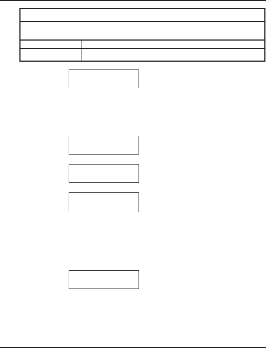
Caller ID
Aspire Software Manual Features ◆189
9. Press HOLD. The display shows:
10. Press SPK.
The telephone returns to an idle condition.
To store a Caller ID number in a one-touch key:
1. With a keyset in an idle condition the display shows:
2. Press the LIST Soft Key. The display shows:
3. Press the CID Soft Key (Caller ID). The display shows:
## = List Number
xx = Caller ID number
mm-dd hh:mm = incoming date and time
↑↑
↑↑ = Preview List
↓↓
↓↓ = Next List
Store = Store in List
DEL = Delete from List
4. Press the STORE Soft Key. The display shows:
## = List Number
xx = Caller ID number
mm-dd hh:mm = incoming date and time
OneT = Store in One-Touch key
ABBc = Store in Common Abbreviated Dial bin
ABBg = Store in Group Abbreviated Dial bin
CONF Clear the character entry one character at a time.
CLEAR Clear all the entries from the point of the flashing cursor and to the right.
SET ABB
1-01 FRI 09:00AM
301 STA 301
LIST DIR ICM PROG
LIST●MENU
Redial CID
##: xxxxxxxxxxxxx
mm-dd hh:mm
↑↑
↑↑ ↓↓
↓↓ Store DEL
##: xxxxxxxxxxxxx
mm-dd hh:mm
OneT AbbC ABBg
With Software 2.05+:
Key for Entering Names
When entering names in the procedures below, refer to this chart. Names can be up to
12 digits long. For prior software or when using i-Series phones, refer to the charts in
the Name Storing feature (page 432).
Use this keypad digit . . . When you want to. . .
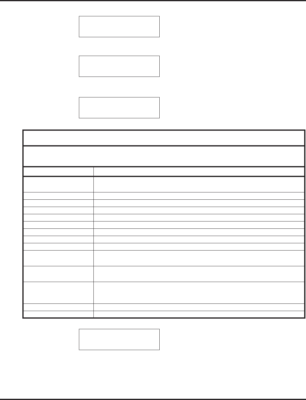
Caller ID
190 ◆Features Aspire Software Manual
5. Press the ONET Soft Key. The display shows:
6. Press the One-Touch key in which the number is to be stored or dial 1-9, 0. If you press
HOLD, the next available One-Touch key will be used. The display shows:
If all One-Touch keys are used, the display shows “TABLE IS FULL”.
7. Press HOLD. The display shows:
8. Enter the name to be associated with the stored number.
9. Press HOLD. The display shows:
10. Press SPK.
The telephone returns to an idle condition.
Store to ONE TOUCH
ENTER BIN
KEY ##:
xxxxxxxxxxxxx
KEY ##
-
With Software 2.05+:
Key for Entering Names
When entering names in the procedures below, refer to this chart. Names can be up to
12 digits long. For prior software or when using i-Series phones, refer to the charts in
the Name Storing feature (page 432).
Use this keypad digit . . . When you want to. . .
1 Enter characters:
1 @ [ ¥ ] ^ _ ` { | } →→
→→ ←←
←← Á À Â Ã Ç É Ê ì ó
2 Enter characters A-C, a-c, 2.
3 Enter characters D-F, d-f, 3.
4 Enter characters G-I, g-i, 4.
5 Enter characters J-L, j-l, 5.
6 Enter characters M-O, m-o, 6.
7 Enter characters P-S, p-s, 7.
8 Enter characters T-V, t-v, 8.
9 Enter characters W-Z, w-z, 9.
0 Enter characters:
0 ! “ # $ % & ’ ( ) ô Õ ú ä ö ü α ε θ
* Enter characters:
* + , - . / : ; < = > ? π ∑ σ Ω ∞ ¢ £
# # = Accepts an entry (only required if two letters on the same key are needed - ex: TOM).
Pressing # again = Space. (In system programming mode, use the right arrow soft key
instead to accept and/or add a space.)
CONF Clear the character entry one character at a time.
CLEAR Clear all the entries from the point of the flashing cursor and to the right.
KEY PROG ONE TOUCH

Caller ID
Aspire Software Manual Features ◆191
Temporary Memory / Call History
An unanswered call will cause the Call History key (PGM 15-07 or SC 851: 08) to flash, indicating
a new call has been placed in the temporary memory. If enabled in programming, the telephone’s
display will show “CHECK LIST”.
1. Press the Call History key (PGM 15-07 or SC 851: 08) or press the LIST Soft Key and CID.
The last addition to the list is displayed.
With i-Series phones, the Call History key is required - the LIST Soft key is not
available.
2. Press the ARROW DOWN Soft Key to scroll through the list of numbers in memory.
3. Press the DEL Soft Key to delete the entry and scroll to the next entry.
4. The Call History key will remain on as long as entries remain in memory.
5. To place a call back to a number in the temporary memory list, with the number to be dialed
displayed, press a line, loop or CALL key.
The outgoing call is placed.
With i-Series phones, to clear all the numbers in the list, press CHECK + 9. To abort
the clear function, press CHECK + 0.

Caller ID
192 ◆Features Aspire Software Manual
CHECKING YOUR ANSWERED/UNANSWERED CALLER ID CALLS
With software prior to 4.93:
To review the last 16 outside calls your extension received:
1. At a display keyset, press the LIST soft key.
2. Press CID.
The first row of your display shows the Caller ID number. If there is an “*” next to the
call record number in the left-hand corner, this indicates that it is a call you missed (unan-
swered). The second row shows the date and time of the call.
Press the up and down soft keys to see the list of calls available in the buffer.
If the Caller ID includes a name, you can press the CHECK key to view the number of
the caller.
3. To call the displayed number, press a line/loop key.
OR
To erase the displayed number without returning the call, the DEL soft key.
4. Press SPK to hang up.
With software 4.93+:
To review the last 50 outside calls your extension received:
1. From an idle keyset, press the LIST soft key.
2. Press the CID soft key.
3. If deleting just one number, scroll to the number.
If deleting all numbers in the Caller ID list, skip to Step 4.
4. Press the DEL soft key. The display shows:
5. If deleting just one number, press the ONE soft key.
If deleting all numbers in the LND list, press the ALL soft key.
6. When deleting all numbers in the Caller ID list, the display then prompts for a confirmation.
Press the YES soft key to delete all the numbers, or press the NO soft key to return to the pre-
vious display.
7. Press the CLEAR key to return the phone to an idle state, or it will return to an idle state after
approximately 10 seconds.
01: SMITH JOHN
* 11-14 13:45
One ALL

Center Telephone Book
Aspire Software Manual Features ◆193
Center Telephone Book
Description
The Center Telephone Book is a new feature providing each user up to two personal telephone
books which can be used to store numbers. The system allows multiple extensions to be assigned
the same telephone book - this allows users to share commonly used numbers.
●With the Aspire S, up to 50 numbers/names can be stored; with the Aspire M/L/XL, up to 100
numbers/names can be stored.
●The Telephone Books can be password protected.
●Numbers can be stored using Last Number Dialed and Caller ID
The following key operation can be used with the Telephone Book:
●HOLD button - User can enter the data. (same as the Abbreviated Dial input)
●LND button - User can input the character: @ (same as the Abbreviated Dial input)
●MIC button - User can input the character: P (same as the Abbreviated Dial input)
●FLASH button - User can change the input mode or input the character: R.
(same as the Abbreviated Dial input)
●CLEAR button - User can finish the telephone book operation.
●CONF button - User can delete the characters (same as the Abbreviated Dial input) or the user
returns back one page.
●VOL UP button - User can change the edit item or page OR the user can start a search.
●VOL DOWN button - User can change the edit item or page OR the user can start a search.
●SOFT KEY button - User can select the function.
●Dial pad - User can input the data or select list.
Conditions
None
Default Settings
Enabled
Programming
➻15-19-01 : System Telephone Book Setup for Extension - Telephone Book Number 1
Assign the first Telephone Book to each extension. The system allows multiple extensions to
be assigned the same telephone book - this allows users to share commonly used numbers.
➪Aspire S = 0-50
➪Aspire M/L/XL = 0-100
➻15-19-02 : System Telephone Book Setup for Extension - Telephone Book Number 2
Assign the second Telephone Book to each extension. The system allows multiple extensions
to be assigned the same telephone book - this allows users to share commonly used numbers.
➪Aspire S = 0-50
➪Aspire M/L/XL = 0-100
Aspire S Aspire M/L/XL
• Available - requires software 4.93+. • Available - requires software 4.93+.

Center Telephone Book
194 ◆Features Aspire Software Manual
➻15-19-06 : System Telephone Book Setup for Extension - Locking Telephone Book
For each extension, determine if the Telephone Book should be locked (1) or unlocked (0) by
default. A user can unlock the Telephone Book using the service code defined in Program 11-
11-56.
➻15-19-07 : System Telephone Book Setup for Extension - Telephone Book Password
For each extension, assign the 4-digit Telephone Book password (0000-9999 (must be 4 digits)).
➻13-07-01 : Telephone Book Number and Name - Dial Data
Use this program to store the dialing data for each Telephone Book. Up to 300 entries can be
made in each Telephone Book.
➪Aspire S = Telephone Books: 1-50, Memory Number: 0-299
➪Aspire M/L/XL = Telephone Books: 1-100, Memory Number: 0-299
➻13-07-02 : Telephone Book Number and Name - Name
Use this program to store a name to a memory number assigned in each Telephone Book. A
maximum of 12 characters is allowed (permitted entries: 1-9, 0, *, #, P,R,@). Up to 300
entries can be made in each Telephone Book.
➪Aspire S = Telephone Books: 1-50, Memory Number: 0-299
➪Aspire M/L/XL = Telephone Books: 1-100, Memory Number: 0-299
➻13-07-04 : Telephone Book Number and Name - Group Number
Use this program to assign each Telephone Book to a group number (1-20).
➻13-08-01 : Telephone Book System Name
Define the name of the system Telephone Book. This entry can be up to 6 characters.
➻13-09-01 : Telephone Book Group Name
Use this program to define the name of the system Telephone Book group. This entry can be
up to 8 characters.
➪Aspire S = Telephone Books: 1-50, Group Number: 1-20
➪Aspire M/L/XL = Telephone Books: 1-100, Group Number: 1-20
➻13-10-01 : Telephone Book Routing
This program defines the dial routing of the system Telephone Book group. When an outside
call is placed, the system follows Program 14-06-01.
➪Aspire S = Telephone Books: 1-50, Outgoing Mode: 0 = External Outgoing, 1 = Internal
Outgoing
➪Aspire M/L/XL = Telephone Books: 1-100, Outgoing Mode: 0 = External Outgoing, 1 =
Internal Outgoing
➻11-11-56 : Service Code Setup (for Setup/Entry Operation) - Telephone Book Lock Service
Using the service code defined in this option, users can change the system Telephone Book
lock status.
Related Features
Abbreviated Dialing
Each extension user can also store numbers in their Center Telephone Book for quick access
to outside numbers.

Center Telephone Book
Aspire Software Manual Features ◆195
Operation
New Registration
Registration allows the user to enter new data into the telephone book.
1. From an idle keyset, press the PROG Soft Key. then press the DOWN ARROW Soft Key twice.
TELBK is displayed on Soft Key 1.
2. Press the TELBK Soft Key. The display indicates the following:
3. Press Soft Key 1 for Registration.
Pressing the CONF key from this screen on will back up the view to the previous screen.
4. If 2 Telephone Books are defined in Program 15-19-01 and 15-19-02:
Press Soft Key 1 or 2 to select the Telephone Book to register new data.
By default, the user will search by name (indicated by the [A] in the upper right-hand
corner of the display. Soft Key 1 will step through the different search options (numbers,
Kana, alpha). To search by number, press the NUM soft key - the [A] changes to [1].
5. Input the name (up to 12 digits) and press the HOLD button.
6. Using the dial pad, select the Group number.
7. Enter the number to be stored and press HOLD.
8. Enter the bin number where the telephone number is to be stored and press HOLD.
The next available bin number is automatically displayed.
9. The display indicates the bin number as registered with the following display. This display
will remain for approximately 3 seconds or you can press the CONF button to continue.
1:REGIST 2:SEARCH
3:SETTING 4:DeleteAll
1: 2: 3: 4:
[REGIST DATA]
TLBK1 TLBK2
TLBK1:INPUT NAME [A]
<
NUM ← →
TLBK1:INPUT NAME [A]
ABC <
NUM ← →
TLBK1:SELECT GROUP
1:GROUP1 2:GROUP2
3:GROUP3 4:GROUP4
TLBK1:INPUT NUMBER
ABC
2035551234
TLBK1:REGIST MEMORY
>000
[0- 299]
MEMORY:000 REGISTERED
REGISTED DATA 1/300

Center Telephone Book
196 ◆Features Aspire Software Manual
Name Search
A user can search the Center Telephone Book by name.
1. From an idle keyset, press the PROG Soft Key. then press the DOWN ARROW Soft Key
twice.
TELBK is displayed on Soft Key 1.
2. Press the TELBK Soft Key. The display indicates the following:
3. Press Soft Key 2 for Search.
Pressing the CONF key from this screen on will back up the view to the previous
screen.
4. If 2 Telephone Books are defined in Program 15-19-01 and 15-19-02:
Press Soft Key 1 or 2 to select the Telephone Book to search.
By default, the user will search by name (indicated by the [A] in the upper right-hand
corner of the display. Soft Key 1 will step through the different search options (numbers,
Kana, alpha). To search by number, press the NUM soft key - the [A] changes to [1].
5. Enter the search characters.
6. Press the Volume Up or Volume Down keys to search.
7. To dial the selected name, press the CALL or SPK key. OR,
To view the detail of the flashing item, press the HOLD key. You can then press the CALL or
SPK key to dial the number.
Pressing the item number on the dial pad selects an item.
Pressing the CONF key will back up the view to the previous screen.
1:REGIST 2:SEARCH
3:SETTING 4:DeleteAll
1: 2: 3: 4:
[SEARCH TELBOOK]
TLBK1 TLBK2
TLBK1:SEARCH NAME [A]
<
NUM MENU ← →
TLBK1:SEARCH NAME [A]
ABC <
NUM MENU ← →
1:ABC 2:ABC2
3:ABC3 4:ABC4
92035551234
[ 0] TEL1
92035551234
G:Group 01 CHG DEL.

Center Telephone Book
Aspire Software Manual Features ◆197
Group Search
A user can search the Center Telephone Book by group name.
1. From an idle keyset, press the PROG Soft Key. then press the DOWN ARROW Soft Key twice.
TELBK is displayed on Soft Key 1.
2. Press the TELBK Soft Key. The display indicates the following:
3. Press Soft Key 2 for Search.
Pressing the CONF key from this screen on will back up the view to the previous screen.
4. If 2 Telephone Books are defined in Program 15-19-01 and 15-19-02:
Press Soft Key 1 or 2 to select the Telephone Book to search.
By default, the user will search by name (indicated by the [A] in the upper right-hand
corner of the display. Soft Key 1 will step through the different search options (numbers,
Kana, alpha). To search by number, press the NUM soft key - the [A] changes to [1].
5. Press Soft Key 2 for Menu.
6. Press Soft Key 2 for Group.
7. Using the dial pad, select the group to search, then press HOLD.
8. Press the Volume Up or Volume Down keys to search.
9. To dial the selected name, press the CALL or SPK key. OR,
To view the detail of the flashing item, press the HOLD key. You can then press the CALL or
SPK key to dial the number.
Pressing the item number on the dial pad selects an item.
Pressing the CONF key will back up the view to the previous screen.
1:REGIST 2:SEARCH
3:SETTING 4:DeleteAll
1: 2: 3: 4:
[SEARCH TELBOOK]
TLBK1 TLBK2
TLBK1:SEARCH NAME [A]
<
NUM MENU ← →
[SEARCH MENU]
NAME GRP NUM MEM
TLBK1:SEARCH GROUP
1:Group 01 2:Group 02
3:Group 03 4:Group 04
1:ABC 2:ABC2
3:ABC3 4:ABC4
92035551234
1:ABC 2:ABC2
3:ABC3 4:ABC4
92035551234
[ 0] TEL1
92035551234
G:Group 01 CHG DEL.

Center Telephone Book
198 ◆Features Aspire Software Manual
Telephone Number Search
A user can search the Center Telephone Book by number.
1. From an idle keyset, press the PROG Soft Key. then press the DOWN ARROW Soft Key twice.
TELBK is displayed on Soft Key 1.
2. Press the TELBK Soft Key. The display indicates the following:
3. Press Soft Key 2 for Search.
Pressing the CONF key from this screen on will back up the view to the previous screen.
4. If 2 Telephone Books are defined in Program 15-19-01 and 15-19-02:
Press Soft Key 1 or 2 to select the Telephone Book to search.
5. Press Soft Key 2 for Menu.
6. Press Soft Key 3 for Number.
7. Enter the search number(s).
At least one digit must be entered before the search can be done.
8. Press the Volume Up or Volume Down keys to search.
9. To dial the selected name, press the CALL or SPK key. OR,
To view the detail of the flashing item, press the HOLD key. You can then press the CALL or
SPK key to dial the number.
Pressing the item number on the dial pad selects an item.
Pressing the CONF key will back up the view to the previous screen.
1:REGIST 2:SEARCH
3:SETTING 4:DeleteAll
1: 2: 3: 4:
[SEARCH TELBOOK]
TLBK1 TLBK2
TLBK1:SEARCH NAME [A]
<
NUM MENU ← →
[SEARCH MENU]
NAME GRP NUM MEM
TLBK1:SEARCH NUMBER
MENU
TLBK1:SEARCH NUMBER
9203
MENU
1:ABC 2:ABC2
3:ABC3 4:ABC4
92035551234
[ 0] TEL1
92035551234
G:Group 01 CHG DEL.

Center Telephone Book
Aspire Software Manual Features ◆199
Search Memory
A user can search the Center Telephone Book by memory number.
1. From an idle keyset, press the PROG Soft Key. then press the DOWN ARROW Soft Key
twice.
TELBK is displayed on Soft Key 1.
2. Press the TELBK Soft Key. The display indicates the following:
3. Press Soft Key 2 for Search.
Pressing the CONF key from this screen on will back up the view to the previous
screen.
4. If 2 Telephone Books are defined in Program 15-19-01 and 15-19-02:
Press Soft Key 1 or 2 to select the Telephone Book to search.
5. Press Soft Key 2 for Menu.
6. Press Soft Key 4 for Memory.
7. Enter the memory number to be searched.
At least one digit must be entered before the search can be done.
8. Press the Volume Up or Volume Down keys to search.
9. To dial the selected name, press the CALL or SPK key.
Pressing the CONF key will back up the view to the previous screen.
1:REGIST 2:SEARCH
3:SETTING 4:DeleteAll
1: 2: 3: 4:
[SEARCH TELBOOK]
TLBK1 TLBK2
TLBK1:SEARCH NAME [A]
<
NUM MENU ← →
[SEARCH MENU]
NAME GRP NUM MEM
TLBK1:SEARCH MEMORY
>
MENU [0- 299]
TLBK1:SEARCH MEMORY
> 0
MENU [0- 299]
[ 0] TEL1
92035551234
G:Group 01 CHG DEL

Center Telephone Book
200 ◆Features Aspire Software Manual
Delete All Data
A user can delete all the Center Telephone Book information using the following steps.
1. From an idle keyset, press the PROG Soft Key. then press the DOWN ARROW Soft Key
twice.
TELBK is displayed on Soft Key 1.
2. Press the TELBK Soft Key. The display indicates the following:
3. Press Soft Key 4 for Delete All.
Pressing the CONF key from this screen on will back up the view to the previous
screen.
4. If 2 Telephone Books are defined in Program 15-19-01 and 15-19-02:
Press Soft Key 1 or 2 to select the Telephone Book to search.
5. Enter the 4-digit password assigned in Program 15-09-07 or through the "Setting" menu in the
Center Telephone Book Soft Key menu.
6. Press Soft Key 3 (Yes) to delete all the entered data, or press Soft Key 4 (No) to back up.
Pressing Soft Key 3 will then display the following:
7. Press the CONF key to back up the view to the previous screen.
1:REGIST 2:SEARCH
3:SETTING 4:DeleteAll
1: 2: 3: 4:
[DELETE DATA]
TLBK1 TLBK2
TLBK1:DELETE ALL DATA
INPUT PWD:4DIGIT
<
TLBK1:DELETE ALL DATA
DELETE ALL TELBOOK DATA?
Yes No
DELETED ALL TELBOOK DATA
[DELETE DATA]
TLBK1 TLBK2

Center Telephone Book
Aspire Software Manual Features ◆201
Change the Telephone Book Data
A user can change the Center Telephone Book data.
1. From an idle keyset, press the PROG Soft Key. then press the DOWN ARROW Soft Key twice.
TELBK is displayed on Soft Key 1.
2. Press the TELBK Soft Key. The display indicates the following:
3. Press Soft Key 2 for Search.
Pressing the CONF key from this screen on will back up the view to the previous screen.
4. If 2 Telephone Books are defined in Program 15-19-01 and 15-19-02:
Press Soft Key 1 or 2 to select the Telephone Book to search.
5. Press Soft Key 2 for Menu.
6. Press the appropriate Soft Key to search by Name, Group, Number, or Memory Number.
(Refer to the operations above for details on the specific steps for the option you select.)
7. Locate the entry to be changed and press HOLD to display the details of the entry.
8. Press Soft Key 3 for Change.
9. To change the name, press HOLD and enter the new name. Press HOLD. You can now
change the group or memory number or press CONF to exit.
To change the memory number, press the Volume Up key, at the ENTER REGIST MEM-
ORY display, press HOLD. Select the new memory number to be used for the number and
press HOLD. Press Soft Key 3 to overwrite the current information or press Soft Key 4 to can-
cel and allow you to select a new memory number. You can now select a new entry to edit or
press CONF to exit.
To change the group and memory number, press the Volume Down key, press HOLD, then
using the dial pad, select the group number to be assigned. The display flashes the saved tele-
phone number - press HOLD.You can now change the telephone number, then press HOLD.
At the ENTER REGIST MEMORY display, press HOLD. Select the new memory number to
be used for the number and press HOLD. Press Soft Key 3 to overwrite the current informa-
tion or press Soft Key 4 to cancel and allow you to select a new memory number. You can now
select a new entry to edit or press CONF to exit.
1:REGIST 2:SEARCH
3:SETTING 4:DeleteAll
1: 2: 3: 4:
[SEARCH TELBOOK]
TLBK1 TLBK2
TLBK1:SEARCH NAME [A]
<
NUM MENU ← →
[SEARCH MENU]
NAME GRP NUM MEM
[ 0] TEL1
92035551234
G:Group 01 CHG DEL
TLBK1 :CHANGE DATA
N:ABC
G:Group 01

Center Telephone Book
202 ◆Features Aspire Software Manual
Delete an Entry in the Telephone Book
A user can delete one entry in the Center Telephone Book.
1. From an idle keyset, press the PROG Soft Key. then press the DOWN ARROW Soft Key
twice.
TELBK is displayed on Soft Key 1.
2. Press the TELBK Soft Key. The display indicates the following:
3. Press Soft Key 2 for Search.
Pressing the CONF key from this screen on will back up the view to the previous
screen.
4. If 2 Telephone Books are defined in Program 15-19-01 and 15-19-02:
Press Soft Key 1 or 2 to select the Telephone Book to search.
5. Press Soft Key 2 for Menu.
6. Press the appropriate Soft Key to search by Name, Group, Number, or Memory Number.
(Refer to the operations above for details on the specific steps for the option you select.)
7. Locate the entry to be changed and press HOLD to display the details of the entry.
8. Press Soft Key 4 for Delete.
9. Press Soft Key 3 (Yes) to delete the record or press Soft Key 4 (No) to cancel the deletion pro-
cess. Pressing Yes displays the following:
10. Press CONF as needed to exit out of the displays or press CLEAR to return the phone to an
idle state.
1:REGIST 2:SEARCH
3:SETTING 4:DeleteAll
1: 2: 3: 4:
[SEARCH TELBOOK]
TLBK1 TLBK2
TLBK1:SEARCH NAME [A]
<
NUM MENU ← →
[SEARCH MENU]
NAME GRP NUM MEM
[ 0] TEL1
92035551234
G:Group 01 CHG DEL
TLBK1 :DELETE DATA
DELETE DATA?
Yes No
DELETE COMPLETE!

Center Telephone Book
Aspire Software Manual Features ◆203
Registering Caller ID to the Center Telephone Book
While reviewing the Caller ID list, a user can add a record into the Center Telephone Book with the
following operation. This function can only be performed if the Center Telephone Book is
unlocked.
1. From an idle keyset, press Soft Key 1 for List.
2. Press Soft Key 2 for CID.
3. Use the Arrow Up and Arrow Down Soft Keys to display the desired Caller ID record.
4. Press Soft Key 3 for Store.
5. Press Soft Key 3 for TELBK.
6. If 2 Telephone Books are defined in Program 15-19-01 and 15-19-02:
Press Soft Key 1 or 2 to select the Telephone Book in which the number should be stored.
7. To enter/change the name, press HOLD and enter the new name. Press HOLD.
8. Enter the group number. Press HOLD, then using the dial pad, select the group number to be
assigned. The display flashes the saved telephone number - press HOLD.You can now change
the telephone number, then press HOLD. At the ENTER REGIST MEMORY display, press
HOLD. Select the new memory number to be used for the number and press HOLD. If the
memory number selected was already defined, press Soft Key 3 to overwrite the current infor-
mation or press Soft Key 4 to cancel and allow you to select a new memory number. You can
now select a new entry to edit or press CONF to back up the displayed window.
01: ABC1
* MM-DD HH:TT
OneT ABB TELBK
01: ABC1
* MM-DD HH:TT
TLBK1 TLBK2
TLBK1 :NEW REGIST
N:ABC
G:

Center Telephone Book
204 ◆Features Aspire Software Manual
Registering a LND to the Center Telephone Book
While reviewing the Last Number Dialed (LND) list, a user can add a record into the Center Tele-
phone Book with the following operation. This function can only be performed if the Center Tele-
phone Book is unlocked.
1. From an idle keyset, press Soft Key 1 for List.
2. Press Soft Key 1 for Redial.
3. Use the Arrow Up and Arrow Down Soft Keys to display the desired LND record.
4. Press Soft Key 3 for Store.
5. Press Soft Key 3 for TELBK.
6. If 2 Telephone Books are defined in Program 15-19-01 and 15-19-02:
Press Soft Key 1 or 2 to select the Telephone Book in which the number should be stored.
7. To enter/change the name, press HOLD and enter the new name. Press HOLD.
8. Enter the group number. Press HOLD, then using the dial pad, select the group number to be
assigned. The display flashes the saved telephone number - press HOLD.You can now change
the telephone number, then press HOLD. At the ENTER REGIST MEMORY display, press
HOLD. Select the new memory number to be used for the number and press HOLD. If the
memory number selected was already defined, press Soft Key 3 to overwrite the current infor-
mation or press Soft Key 4 to cancel and allow you to select a new memory number. You can
now select a new entry to edit or press CONF to back up the displayed window.
REDIAL-01
* 2035551234
OneT ABB TELBK
REDIAL-01
* 2035551234
TLBK1 TLBK2
TLBK1 :NEW REGIST
N:ABC
G:

Center Telephone Book
Aspire Software Manual Features ◆205
SETTINGS
Changing the Group Name
1. From an idle keyset, press the PROG Soft Key. then press the DOWN ARROW Soft Key
twice.
TELBK is displayed on Soft Key 1.
2. Press the TELBK Soft Key. The display indicates the following:
3. Press Soft Key 3 for Setting.
Pressing the CONF key from this screen on will back up the view to the previous
screen.
4. If 2 Telephone Books are defined in Program 15-19-01 and 15-19-02:
Press Soft Key 1 or 2 to select the Telephone Book to edit.
5. Press Soft Key 1 for Group Name Edit.
6. Using the dial pad, select the Group number.
7. Enter the new name to be stored and press HOLD.
8. The display indicates "REGISTERED!" then returns to the Select Group display.
9. You can now edit another group name, press CONF to return to the previous menu display, or
press CLEAR to exit.
1:REGIST 2:SEARCH
3:SETTING 4:DeleteAll
1: 2: 3: 4:
[SETTING]
GrpNameEdit LOCK PWD
[SELECT TELBK]
TLBK1 TLBK2
TLBK1:SELECT GROUP
1:GROUP1 2:GROUP2
3:GROUP3 4:GROUP4
TLBK1:GRP NAME [A]
Group 01<
NUM ← →
TLBK1:SELECT GROUP
1:GROUP1 2:GROUP2
3:GROUP3 4:GROUP4

Center Telephone Book
206 ◆Features Aspire Software Manual
Locking/Unlocking a Telephone Book
Locking a Telephone Book will prevent any changes to it until the book is unlocked.
1. From an idle keyset, press the PROG Soft Key. then press the DOWN ARROW Soft Key
twice.
TELBK is displayed on Soft Key 1.
2. Press the TELBK Soft Key. The display indicates the following:
3. Press Soft Key 3 for Setting.
Pressing the CONF key from this screen on will back up the view to the previous
screen.
4. Press Soft Key 3 for Lock.
5. Using the dial pad, select the Group number.
If the Telephone Book is unlocked:
If the Telephone Book is locked:
6. Enter the password as defined Program 15-19-07 (default: 0000).
If the Telephone Book is locked:
If the Telephone Book is unlocked:
7. You can now press CONF to return to the previous menu display or press CLEAR to exit.
Lock/Unlock a Telephone Book Using a Service Code
1. Press the CALL key.
2. Enter the Lock Telephone Book service code (Program 11-11-56).
3. Enter the destination extension number.
4. Enter the extension’s password defined in Program 15-19-07.
1:REGIST 2:SEARCH
3:SETTING 4:DeleteAll
1: 2: 3: 4:
[SETTING]
GrpNameEdit LOCK PWD
[LOCK TELBOOK]
INPUT PWD:4DIGIT
<
[UNLOCK TELBOOK]
INPUT PWD:4DIGIT
<
THE TELBOOK IS LOCKED
THE TELBOOK IS UNLOCKED

Center Telephone Book
Aspire Software Manual Features ◆207
Edit the Password for Locking/Unlocking a Telephone Book
Locking a Telephone Book will prevent any changes to it until the book is unlocked. This operation
changes the password a user would enter to lock/unlock the Telephone Book.
1. From an idle keyset, press the PROG Soft Key. then press the DOWN ARROW Soft Key
twice.
TELBK is displayed on Soft Key 1.
2. Press the TELBK Soft Key. The display indicates the following:
3. Press Soft Key 3 for Setting.
Pressing the CONF key from this screen on will back up the view to the previous
screen.
4. Press Soft Key 4 for Password.
5. Using the dial pad, enter the current password as defined Program 15-19-07 (default: 0000).
6. Enter the new 4-digit password.
7. The display indicates NEW PASSWORD IS SET and then returns to the following display:
8. You can now press CONF to return to the previous menu display or press CLEAR to exit.
1:REGIST 2:SEARCH
3:SETTING 4:DeleteAll
1: 2: 3: 4:
[SETTING]
GrpNameEdit LOCK PWD
[CHANGE PWD]
INPUT PWD:4DIGIT
**** <
[CHANGE PWD]
INPUT NEW PWD:4DIGIT
**** <
[SETTING]
GrpNameEdit LOCK PWD

Central Office Calls, Answering
208 ◆Features Aspire Software Manual
Central Office Calls, Answering
Description
The system provides flexible routing of incoming CO (trunks) calls to meet the exact site require-
ments. This lets trunk calls ring and be answered at any combination of system extensions. For
additional information on making trunk ring, refer to the Ring Group feature.
Delayed Ringing
Extensions in a Ring Group can have delayed ringing for trunks. If the trunk is not answered at its
original destination, it rings the DIL No Answer Ring Group (this ring group applies to DIL or non-
DIL trunks). This could help a secretary that covers calls for their boss. If the boss doesn’t answer
the call, it rings the secretary’s phone after a programmable interval.
Universal Answer
Universal Answer allows an employee to answer a call by going to any keyset and dialing a unique
Universal Answer code. The employee doesn’t have to know the trunk number or dial any other
codes to pick up the ringing trunk. You’ll normally set up Universal Answer along with Universal
Night Answer (see “Night Service”). When a Universal Night Answer call rings the External Pag-
ing, an employee can answer the call from the first available phone. You might also want to use
Universal Answer in a noisy warehouse or machine shop where the volume of normal telephone
ringing is not adequate. After hearing the ringing over the Paging, an employee can then easily pick
up the call from a shop phone. See “Night Service” for more on Universal Night Answer.
The Automatic Answer of Universal Answer Calls option (Program 20-10-07) determines whether
or not the extension has the Auto Answer feature for ringing calls. This option allows a user to sim-
ply lift the handset to answer a ringing call; they no longer need to dial the service code.
Display Reason for Transfer
When incoming DID, DISA, DIL or ISDN calls are transferred to another extension or ring group
due to a Call Forward or DND setting, the reason for the transfer can be displayed on the phone
receiving the transferred call. The extension user can then recognize why they are receiving the call.
This feature requires a display telephone in order to view the message.
Additional Trunk Ring Tones
Additional options have been added for the ring tone patters for an incoming call. Previously, in
Program 22-03 the system provided ring tone patterns 1-4. With software 1.02 and higher, Melody
1 - Melody 5 are now available as well.
Aspire S Aspire M/L/XL
• Available - 8 trunks.
• Additional trunk ring tones available.
•Defining CODEC Filter settings available.
• Sidetone Volume Setup available.
• Flexible Ringing by Caller ID requires software 4.93+.
• Available - 200 trunks.
• Additional trunk ring tones added with software 1.02+.
•Defining CODEC Filter settings available with software
1.04+.
• Sidetone Volume Setup added in 1.04+ software.
• Flexible Ringing by Caller ID requires software 4.93+.

Central Office Calls, Answering
Aspire Software Manual Features ◆209
CODEC Filter Data Setup Program Added
When Program 81-07-01 : CODEC Filter Setup for Analog Trunk Ports is set to "4 - Specified
Data", the system will use the settings in Program 81-09 : COIU CODEC Filter Data Setup.
These values should not be changed from their default settings unless directed by NEC’S Technical
Service department.
The side tone of the COIU is adjusted using all 16 values, however, special software is required
in order to compute these values. The setting is not proportional to the gain level. To change
these values, contact NEC’s Technical Service department for assistance.
Sidetone Volume Setup
A new option has been added to allow the system programming for the keyset side tone volume.
There are two levels, based on whether the connected trunk is a digital trunk or analog trunk.
Flexible Ringing by Caller ID
The Flexible Ringing by Caller ID feature provides several different options for rerouting calls
based on the Caller ID received.
●Reject/Reroute "Private" Caller ID Calls
When an analog or ISDN trunk call is received with “Private” Caller ID information, the sys-
tem can reject the call by playing a VRS message or it can route the call to an alternative
extension or incoming ring group programmed in Program 22-18-01.
●Reject/Reroute Based on Entry in ABB Table
When an analog, ISDN or IP trunk call is received with regular Caller ID information, the sys-
tem can reject the call by playing a VRS message if the Caller ID number matches the ABB
group number programmed in Program 22-16-01 and ABB entry in Programs 13-02-01 and
13-04-01.
The analog, ISDN or IP trunk call can also be routed to an alternative extension or incoming
ring group if the Caller ID number matches the common ABB table (Program 13-04).
Programming Examples for Flexible Ringing by Caller ID:
●To refuse the “Private” Caller ID incoming call:
Program 14-01-27: 1 (reject)
Program 22-18-01: 0 (no transfer)
Program 40-10-06: 2 (VRS message 2)
Then turn on the Private Call Refuse mode using the service code (Program 11-10-32) or Pro-
grammable Function Key (code 86).
●To transfer the “Private” Caller ID incoming call to extension 301 as ring pattern 2:
Program 14-01-27: 1 (reject)
Program 22-18-01: 1 (extension number)
Program 22-18-02: 301 (extension 301)
Program 22-18-03: 2 (ring pattern 2)
Then turn on the Private Call Refuse mode using the service code (Program 11-10-32) or Pro-
grammable Function Key (code 86).

Central Office Calls, Answering
210 ◆Features Aspire Software Manual
●To transfer the “Private” Caller ID incoming call to incoming ring group 2 as ring pattern 3:
Program 14-01-27: 1 (reject)
Program 22-18-01: 2 (incoming ring group)
Program 22-18-02: 2 (group 2)
Program 22-18-03: 3 (ring pattern 3)
Then turn on the Private Call Refuse mode using the service code (Program 11-10-32) or Pro-
grammable Function Key (code 86).
●To reject the call with “2039261111” Caller ID incoming call:
Program 14-01-27: 1 (reject)
Program 22-16: 64 (ABB group 64)
Program 13-02; Group 64: 1000 - 1099
Program 13-04-01; Table 1000: 2039261111
Then turn on the Caller ID Refuse mode using the service code (Program 11-10-34) or Pro-
grammable Function Key (code 87).
●To transfer the call with “2039261111” Caller ID incoming call to extension 301 as ring pat-
tern 1:
Program 13-04-01: 2039261111
Program 13-04-03: 1 (extension number)
Program 13-04-04: 301 (extension 301)
Program 13-04-05: 1 (tone pattern 1)
●To transfer the call with “2039261111” Caller ID incoming call to incoming ring group 2 as
ring pattern 2:
Program 13-04-01: 2039261111
Program 13-04-03: 2 (incoming ring group)
Program 13-04-04: 2 (group 2)
Program 13-04-05: 2 (tone pattern 2)
Notes:
●Caller ID Matching
The system compares the Caller ID and programmed ABB dial and allows/denies as indicated
below.
●The ABB dial table is searched from the starting number and the first match result is used.
●The maximum number of VRS message channels that can be used simultaneously is 16
(Aspire M/L/XL) and 8 (Aspire S).
●With ISDN trunks, the unrestricted digital call can not use this feature.
●This feature does not work with incoming trunk calls via Networking (from the other system).
In this case, the refuse/routing program must be programmed in the system that has those
trunks. Routing to the other system’s extension is available.
Conditions
None
Caller ID ABB Dial Result
2039261111 2039261111 Matched
2039261111 20392611119 Matched
2039261111 203 Matched
9261111 2039261111 Unmatched
2039261111 9261111 Unmatched

Central Office Calls, Answering
Aspire Software Manual Features ◆211
Default Setting
Enabled.
Programming
➻10-03-03 : PCB Setup, For SLIU Unit - Transmit CODEC Gain Type
10-03-04 : PCB Setup, For SLIU Unit - Receive CODEC Gain Type
Customize the transmit and receive levels of the CODEC Gain Types for 500/2500 type single
line telephones.
➻10-08-01 : Pre-Ringing Setup
Enable (1) or disable (0) pre-ringing for outside calls. This setting affects all system trunks.
➻11-10-32 : Service Code Setup (for System Administrator) - Set Private Call Refuse
Define the service code to be used to set the “Private” call refusal for the trunks which are pro-
grammed in Program 14-01-27 to 1.
➻11-10-33 : Service Code Setup (for System Administrator) - Enter Caller ID Refuse
For keysets only, define the service code to be used to add or delete the Caller ID numbers to
be refused.
➻11-10-34 : Service Code Setup (for System Administrator) - Set Caller ID Refuse
Define the service code to be used to enable/disable the Caller ID call refusal for the trunks
which are programmed in Program 14-01-27 to 1.
➻11-11-13 : Service Code Setup (for Setup/Entry Operation) - Display Language Selection
for Keyset
Select the service code which can be used at an extension to change the displayed language on
a keyset’s display (default: 178).
➻11-11-37 : Service Code Setup (for Setup/Entry Operation) - Adjusting Ring Volume
If required, change the service code used to adjust the ringing volume for CO and ICM calls
(829).
➻11-12-30 : Service Code Setup (for Service Access) - Specified Trunk Answer
If required, redefine the service code used to answer a specific trunk which is either ringing or
on hold (default: 172).
➻13-04-03 : Abbreviated Dialing Number and Name - Transfer Mode/Deesintation Number
When using Flexible Ringing by Caller ID, use this program to determine how the incoming
call should be handled (0=not defined, 1=rings an internal number, or 2=rings an incoming
ring group).
If this option is set to 1 or 2, then determine the number or ring group to be dialed. With inter-
nal dial (1), enter the digits to be dialed (up to 24 including 0-9, *, #, P, R, @). With the ring
group (2), enter the ring group to which the call should be sent.
➪Aspire S Ring Groups: 1-8, 102=In-Skin/External Voice Mail, 103=Centralized Voice Mail
➪Aspire Ring Groups: 1-100, 102=In-Skin/External Voice Mail, 103=Centralized Voice Mail
➻13-04-05 : Abbreviated Dialing Number and Name - Incoming Ring Pattern
Determine the ring pattern to be used ( 0 = normal pattern, 1-4 = tone pattern 1-4, 5-9 = scale
pattern 1-5) for Caller ID Refusal. The definition of the tone pattern is the same as Program
22-03.
➻14-01-02 : Basic Trunk Data Setup - Transmit CODEC Gain Type
14-01-03 : Basic Trunk Data Setup - Receive CODEC Gain Type
Customize the transmit and receive levels of the CODEC Gain Types for each trunk.
➻14-02-02 : Analog Trunk Data Setup - Ring Detect Type
For each trunk, enable delayed ringing (0) or immediate ringing (1).

Central Office Calls, Answering
212 ◆Features Aspire Software Manual
➻14-05-01 : Trunk Groups
For Universal Answer, assign trunks to trunk groups then go to Program 14-06 below to set up
Trunk Group Routing.
➪Aspire S Trunk Groups: 1-8
➪Aspire Trunk Groups: 1-100
➻14-06-01 : Trunk Group Routing
For Universal Answer, set up trunk routes and then go to Program 23-03 below to assign the
trunk routes to extensions. An extension user can use Universal Answer to answer a call if the
ringing trunk is in its assigned route.
➪Aspire S Trunk Group Routes: 1-8
➪Aspire Trunk Group Routes: 1-100
➻14-07-01 : Trunk Access Map Setup
Set up the Trunk Access Maps. This sets the access options for trunks. Ring Group program-
ming overrides Access Map programming.
➪Aspire S: Trunk Access Maps 1-8
➪Aspire: Trunk Access Maps 1-200
➻14-01-27 : Basic Trunk Data Setup - Caller ID Refuse Setup
This program defines if the system rejects a trunk call (0=does not reject the call, 1 = rejects
the call) and plays a VRS message based on the Caller ID information received. This option is
set on a per trunk basis.
➪Aspire S Trunks: 1-8
➪Aspire M/L/XL Trunks: 1-200
➻15-01-05 : Basic Extension Data Setup - Restriction for Outgoing Disable on Incoming
Line
Enable (1) or disable (0) supervised dial detection for an extension.
➻15-02-01 : Multi-Line Telephone Basic Data Setup
Select the language which should be used on a keyset’s display (0 = Japanese, 1 = English, 2 =
German, 3 = French, 4 = Italian, 5 = Spanish, 6 = Dutch, 7 = Portuguese, 8 = Norwegian, 9 =
Danish).
➻15-02-02 : Multi-Line Telephone Basic Data Setup - Trunk Ring Tone
Trunks ring extensions according to the Ring Tone Range selected in 22-03 and the settings
made with either Service Code 820 or Program 15-02-02. Also see Program 22-03.
➻15-02-22 : Multi-Line Telephone Basic Data Setup, Multiple Incoming From Intercom
and Trunk
When this option is set to ‘0’ (disabled), incoming calls to an extension will indicate on any
Hotline keys for that extension as solid (busy). When this option is set to ‘1’ (enabled), lamp-
ing is determined by the setting of Program 22-01-01 Incoming Call Priority. If set to trunk
priority (1), the Hotline key will lamp solid when a trunk call rings in. If set to intercom prior-
ity (0), the Hotline key will not lamp for incoming trunk calls, but will lamp solid for intercom
calls.
➻15-02-10 : Multi-Line Telephone Basic Data Setup - Ringing Line Preference for Trunk
Calls
Use this option to select between Idle (0) and Ringing Line Preference (1) for trunk calls.
➻15-03-03 : Single Line Telephone Basic Data Setup - Terminal Type
Enter 1 for this option to allow a single line port to receive DTMF tones after the initial call
setup. Enter 0 to have the port ignore DTMF tones after the initial call setup. For Voice Mail,
always enter 1 (e.g., receive DTMF tones).
➻15-06-01 : Trunk Access Map for Extensions
Assign Trunk Access Maps to extensions.
➪Aspire S: Trunk Access Maps 1-8
➪Aspire: Trunk Access Maps 1-200

Central Office Calls, Answering
Aspire Software Manual Features ◆213
➻15-07-01 : Programming Function Keys
To have outside calls ring specific keys, assign trunks to line keys (code *01 + trunk). You can
also program function keys as trunk group or loop keys (*02 or *05). For additional loop key
data, enter 0 (incoming only), 1 (outgoing only) or 2 (both ways).Use a Call Redirect key (49)
to allow a user to transfer a call to another extension or voice mail without answering the call.
Also, if needed, define keys for Private Call Refuse (86) or Caller ID Refuse (87) keys. When
either of these keys is enabled by the user, “Private” or “Caller ID Number Refusal” will be
activated for the trunks set to “1” in Program 14-01-27.
➪Aspire S: Trunks 1-8
➪Aspire: Trunks 1-100
➻15-13-01 : Loop Keys - Outgoing
Assign trunk groups for outgoing loop keys (0=ARS, Aspire S Trunk Groups 1-8, or Aspire Trunk
Groups 1-100).
➻15-13-02 : Loop Keys - Incoming
Assign trunk groups for incoming loop keys (0=all Trunk Groups, Aspire S Trunk Groups 1-8, or
Aspire Trunk Groups 1-100).
➻20-02-09 : System Options for Multi-Line Telephones - Disconnect Supervision
Enable (1) disconnect supervision for the system.
➻20-06-01 : Class of Service for Extensions
For Universal Answer, assign a Class of Service (1-15) to an extension that enables Program
20-10-07.
➻20-07-24 : Class of Service Options - Set/Cancel Private Call Refuse
In an extension’s Class of Service, enable (1) or disable (0) the extension’s ability to use the
Private Call Refuse service code or function key.
➻20-07-25 : Class of Service Options - Set/Cancel Caller ID Refuse
In an extension’s Class of Service, enable (1) or disable (0) the extension’s ability to use the
Caller ID Refuse service code or function key.
➻20-10-07 : Class of Service Options (Answer Service) - Automatic Answer of Universal Calls
In an extension’s Class of Service, enable (1) or disable (0) the extension’s ability to use Auto-
Answer to pick up Universal Answer calls. This allows a user to simply pick up the handset
instead of dialing a service code.
➻20-13-13 : Class of Service Options (Supplementary Service) - Continued Dialing
In an extension’s Class of Service, enable (1) or disable (0) an extension’s ability to use Con-
tinued Dialing which allows DTMF signal sending while talking on extension.
➻20-13-23 : Class of Service Options (Supplementary Service) - Display the Reason for
Transfer
In an extension’s Class of Service, enable (1) or disable (0) an extension’s ability to display
the Reason for Transfer message.
➻21-01-15 : System Options for Outgoing Calls - Outgoing Disable on Incoming Line
Enable (1) or disable (0) the Outgoing Disable on Incoming Line feature.
➻21-01-16 : System Options for Outgoing Calls - Supervise Dial Detection Timer
With the Outgoing Disable on Incoming Line feature, if dial tone is not detected after the
extension answers an incoming line, the system determines the call is unable to complete and
releases the DTMF receiver (0-64800 Seconds).
➻21-01-17 : System Options for Outgoing Calls - Restriction Digit in Outgoing Disable on
Incoming Line
With the Outgoing Disable on Incoming Line feature, determine the number of digits (0-9) to
be dialed before the call should be disconnected.
➻22-01-01 : System Options for Incoming Calls, Incoming Call Priority
Use this option to determine if intercom calls or trunk calls have answer priority when both
are ringing simultaneously (0=intercom call priority, 1=trunk call priority). Refer to Program
15-02-22 for lamping conditions.

Central Office Calls, Answering
214 ◆Features Aspire Software Manual
➻22-01-02 : System Options for Incoming Calls - Incoming Call Ring No Answer Alarm
Enable (1) or disable (0) the Incoming Call RNA Alarm. If enabled, the ring cadence will
change for a call that rings longer than the interval set in 22-01-03.
➻22-01-03 : System Options for Incoming Calls - Ring No Answer Alarm Time
Set the Ring No Answer Alarm interval (0-64800 seconds). If a trunk rings a keyset longer
than this interval, the system changes the ring cadence.
➻22-01-04 : System Options for Incoming Calls - DIL No Answer Time
If an incoming trunk call rings longer than this interval, it reroutes to the Ring Group set in
Program 22-08.
➻22-02-01 : Incoming Call Trunk Setup
Select the trunk type (0=normal, 1=VRS, 2=DISA, 3=DID, 4=DIL, 5=E&M tie line,
6=delayed DID, 7=ANI/DNIS) for each trunk at each time mode (1-8).
➻22-03-01 : Trunk Ring Tone Range
Assign Ring Tone Ranges to trunks. Customize the tones within each Ring Tone Range in 82-
01. Trunks ring extensions according to the Ring Tone Range selected in 22-03 and the set-
tings made with either Service Code 820 or Program 15-02-02.
➻22-04-01 : Incoming Extension Ring Group Assignment
To have trunks ring extensions, assign extensions to ring groups. For each extension in the
Ring Group, indicate in Program 22-06 if trunks should ring (1) or not ring (0).
➪Aspire S Ring Groups: 1-8, 102=In-Skin/External Voice Mail, 103=Centralized Voice Mail
➪Aspire Ring Groups: 1-100, 102=In-Skin/External Voice Mail, 103=Centralized Voice Mail
➻22-05-01 : Incoming Trunk Ring Group Assignment
To have the trunks ring extensions, assign trunks to a Ring Group. The incoming ring group
assignment programmed in 41-03-01 overrides the setting in this program.
➻22-06-01 : Normal Incoming Ring Mode
Indicate whether the trunks in the Ring Group assigned in 22-04 should ring (1) or not ring
(0).
➻22-07-01 : DIL Assignment
Assign the destination extension or Department Call Group pilot number (as assigned in 11-
07-01) for each DIL incoming trunk (001-200).
➻22-08-01 : DIL/IRG No Answer Destination
If an incoming trunk call rings longer than the DIL No Answer Time (Program 22-01-04), it
routes to the destination you specify in this option. Determine if the destination should be a
Ring Group, In-Skin/External Voice Mail, or Central Voice Mail.
➪Aspire S Ring Groups: 1-8, 102=In-Skin/External Voice Mail, 103=Centralized Voice Mail
➪Aspire Ring Groups: 1-100, 102=In-Skin/External Voice Mail, 103=Centralized Voice Mail
➻22-16-01 : Private Call Refuse Target Area Setup
This program defines the ABB group number for Private Call Refuse (0 = No Setting or ABB
Group Number)
➪Aspire S: ABB Group Number 1 – 9
➪Aspire: ABB Group Number 1 – 64
➻22-18-01 : Private Call Assignment Setup - Transfer Mode
When using Flexible Ringing by Caller ID, use this program to determine whether the call
plays the VRS message (0), rings an internal number (1), or rings an incoming ring group (2).
➻22-18-02 : Private Call Assignment Setup - Transfer Mode
If Program 22-18-01 is set to 1 or 2, use this program to determine the number or ring group
to be dialed. With internal dial (1), enter the digits to be dialed (up to 24 including 0-9, *, #, P,
R, @). With the ring group (2), enter the ring group to which the call should be sent.
➪Aspire S Ring Groups: 1-8, 102=In-Skin/External Voice Mail, 103=Centralized Voice Mail
➪Aspire Ring Groups: 1-100, 102=In-Skin/External Voice Mail, 103=Centralized Voice Mail

Central Office Calls, Answering
Aspire Software Manual Features ◆215
➻22-18-03 : Private Call Assignment Setup - Incoming Ring Pattern
Determine the ring pattern to be used ( 0 = normal pattern, 1-4 = tone pattern 1-4, 5-9 = scale
pattern 1-5) for a “Private” Caller ID call. The definition of the tone pattern is the same as Pro-
gram 22-03.
➻23-03-01 : Universal Answer/Auto Answer
For Universal Answer, assign trunk routes set in Program 14-06 to extensions. An extension user
can use Universal Answer to answer a call if the ringing trunk is in its assigned route.
➪Aspire S Trunk Group Routes: 1-8
➪Aspire Trunk Group Routes: 1-100
➻40-10-06 : Voice Announcement Service Option - Set VRS Message for Private Call
Refuse
Use this option to assign the VRS message number to be played when Private Call Refuse is
enabled for a call with “Private” Caller ID information (0 = Does not play message, 1-49 =
VRS message number to play).
➻40-10-07 : Voice Announcement Service Option - Set VRS Message for Caller ID Refuse
This item assigns the VRS message number to be used as the Caller ID Refuse message when
the Caller ID number matches the entry in Program 22-16 (0 = Does not play message, 1-49 =
VRS message number to play).
➻81-09-01 : COIU CODEC Filter Data Setup
The system will use the settings in this program when Program 81-07-01 : CODEC Filter
Setup for Analog Trunk Ports is set to "4 - Specified Data". These values should not be
changed from their default settings unless directed by NEC’s Technical Service department.
The side tone of the COIU is adjusted using all 16 values, however, special software is
required in order to compute these values. The setting is not proportional to the gain level. To
change these values, contact NEC’s Technical Service department for assistance.
➻82-01-01 : Incoming Ring Tone
Customize the ring tones within each Ring Tone Range. Assign Ring Tone Ranges to trunks in
22-03. Trunks ring extensions according to the Ring Tone Range selected in 22-03 and the
user settings made with Service Code 820.
➻82-08-01 : Sidetone Volume Setup
Use this program to adjust of the keyset side tone volume. There are two levels, based on
whether the connected trunk is a digital trunk or analog trunk.
➻82-09-01 : SLIU CODEC Filter Data Setup
The system will use the settings in the new Program 82-09 : SLIU CODEC Filter Data
Setup when Program 82-07-01 : CODEC Filter Setup for Analog Station Ports is set to "4
- Specified Data". These values should not be changed from their default settings unless
directed by NEC’s Technical Service department.
The side tone of the COIU is adjusted using all 16 values, however, special software is
required in order to compute these values. The setting is not proportional to the gain level. To
change these values, contact NEC’s Technical Service department for assistance.

Central Office Calls, Answering
216 ◆Features Aspire Software Manual
Related Features
Automatic Call Distribution (ACD)
The incoming ring group assignment programmed in 41-03-01 overrides the setting in Pro-
gram 22-05-01.
Central Office Calls, Answering Call Forward/DID/DIL/DISA/Do Not Disturb/ISDN
The Reason for Transfer option should be set for each type of trunk which will use the Reason
for Transfer message.
Directed Call Pickup/Group Call Pickup
Using these features, ringing calls can be picked up regardless of access map programming.
Direct Inward Line
Direct Inward Lines ring an extension directly, without Ring Group or Access Map programming.
Line Preference
An extension user can answer an outside call just by lifting the handset.
Long Conversation Cutoff/Warning Tone for Long Conversation
Long Conversation Cutoff can disconnect incoming and outgoing CO calls after a set time
period. Using the Warning Tone for Long Conversation feature allows users on outgoing calls
to hear a warning tone prior to the call disconnecting.
Microphone Cutoff
In order to mute the handset transmitter, set up a Microphone Cutoff Programmable Function Key.
Night Service
Use Universal Answer to pick up Universal Night Answer calls.
Programmable Function Keys
Line keys and loop keys simplify answering outside calls.
Selectable Text Messaging
If the Absent text message has been set by the originating extension, the destination extension
will display the assigned text message instead of the Reason for Transfer message.

Central Office Calls, Answering
Aspire Software Manual Features ◆217
Operation
To answer an incoming trunk call:
1. Lift handset.
2. At keyset, press flashing line key.
If you don’t have a line or loop key for a trunk call ringing your phone, it rings an idle
CALL key.
If you have Ringing Line Preference, lifting the handset answers the call.
You can dial after answering the call. This allows you, for example, to respond to com-
puter-generated incoming calls.
OR
1. If you know the specific line number, dial 172 + Line number (001-200).
To use Universal Answer to answer a call ringing over the Paging system:
1. At keyset, press idle CALL key.
OR
At single line set, lift handset.
Depending on system programming, this may answer the call and you can skip Step 2.
2. Dial #0.
If you hear error tone, your extension’s Class of Service prevents Universal Answer.
To listen to the incoming trunk ring choices (keyset only):
1. Press idle CALL key.
2. Dial 811 + 2.
3. Select the ringing (1-8) and tone range (1-4) you want to check.
4. Go back to step 3 to listen to additional choices or press SPK to hang up.
To change the pitch of your incoming trunk ring (keyset only):
1. Press idle CALL key.
2. Dial 820 + 2.
3. Select the ringing (1-8).
4. Press SPK to hang up.

Central Office Calls, Placing
218 ◆Features Aspire Software Manual
Central Office Calls, Placing
Description
The system provides flexibility in the way each extension user can place outgoing trunk calls. This
lets you customize the call placing options to meet site requirements and each individual’s needs. A
user can place a call by:
●Pressing Line Keys or “Loop Keys”
●Pressing a Trunk Group (i.e., loop) key
●Pressing a Trunk Group Routing (dial 9) key
●Dialing a code for a specific trunk (#9 + the trunk number)
●Dialing a code for a Trunk Group (804 + group number)
●Dialing a code for Trunk Group Routing or ARS (9)
●Dialing an Alternate Trunk Route Access Code (which you must define)
Trunk Port Disable
The system provides a service code (Default: 145) which can be used by an extension user to block
a trunk for outgoing calls. The user which busied out the trunk will still have access to it. All other
users will be blocked from seizing it to place an outgoing call. The trunk, however, can still be
answered by any users programmed with the trunk access.
Additional Trunk Ring Tones
Additional options have been added for the ring tone patters for an incoming call. Previously, in
Program 22-03 the system provided ring tone patterns 1-4. With software 1.02 and higher, Melody
1 - Melody 5 are now available as well.
CODEC Filter Data Setup Program Added
When Program 81-07-01 : CODEC Filter Setup for Analog Trunk Ports is set to "4 - Specified
Data", the system will use the settings in Program 81-09 : COIU CODEC Filter Data Setup.
These values should not be changed from their default settings unless directed by NEC’S Technical
Service department.
The side tone of the COIU is adjusted using all 16 values, however, special software is required
in order to compute these values. The setting is not proportional to the gain level. To change
these values, contact NEC’s Technical Service department for assistance.
Sidetone Volume Setup
A new option has been added to allow the system programming for the keyset side tone volume.
There are two levels, based on whether the connected trunk is a digital trunk or analog trunk.
Aspire S Aspire M/L/XL
• Available - 8 trunks.
• Additional trunk ring tones added with 1.02+.
• Trunk Port Disable feature available.
•Defining CODEC Filter settings available.
• Sidetone Volume Setup available.
• Available - 200 trunks.
• Additional trunk ring tones added with 1.02+.
• Trunk Port Disable feature available with software
1.00+.
•Defining CODEC Filter settings available with software
1.04+.
• Sidetone Volume Setup added in 1.04+ software.

Central Office Calls, Placing
Aspire Software Manual Features ◆219
Conditions
(A.) The system provides analog trunk CO service via COIU PCBs. COIU PCBs can connect to
either loop start or ground start CO lines. Refer to the system hardware manual for additional
details.
(B.) Analog Trunk (COIU) PCBs do not require circuit type programming.
Default Setting
Enabled.
Programming
➻10-03-03 : PCB Setup, For SLIU Unit - Transmit CODEC Gain Type
10-03-04 : PCB Setup, For SLIU Unit - Receive CODEC Gain Type
Customize the transmit and receive levels of the CODEC Gain Types for 500/2500 type single
line telephones.
➻11-01-01 : System Numbering
Set up a Service Code for Alternate Trunk Route Access.
➻11-09-01 : Trunk Access Code
If required, change the single-digit Trunk Access Code (normally 9). If you change this code,
you must also review the settings in 11-01 for the new code selected.
➻11-09-02 : Trunk Access Code - Alternate Trunk Route Access Code
Assign the Service Code set up in 11-01 for Alternate Trunk Route Access.
➻11-10-27 : Service Code Setup (for System Administrator) - Trunk Port Disable
Define the service code which should be used by an extension user to block a trunk from
being used for outgoing calls (Default: 145).
➻11-11-13 : Service Code Setup (for Setup/Entry Operation) - Display Language Selection
for Keyset
Select the service code which can be used at an extension to change the displayed language on
a keyset’s display (default: 178).
➻11-12-01 : Service Code Setup (for Service Access)
To simplify placing calls, assign function keys for placing trunk calls: Trunk Group Routing/dial 9
keys (code 804).
➻14-01-01 : Basic Trunk Data Setup - Trunk Name
To make identifying calls easier, assign a name to each trunk.
➻14-01-02 : Basic Trunk Data Setup - Transmit CODEC Gain Type
14-01-03 : Basic Trunk Data Setup - Receive CODEC Gain Type
Assign a CODEC Gain Type to each trunk. This sets the amount of gain (amplification) for the
selected trunk.
➻14-01-07 : Basic Trunk Data Setup - Outgoing Calls
For each trunk, allow (1) or prevent (0) outgoing calls.
➻14-01-10 : Basic Trunk Data Setup - DTMF Tones for Outgoing Calls
For each trunk, enable (1) or disable (0) DTMF tones for outgoing trunk calls.
➻14-02-05 : Analog Trunk Data Setup - Dial Tone Detection for Directly Accessed Trunk
Use this option enable (1) or disable (0) dial tone detection for directly accessed trunks. If dis-
abled, the system outdials on the trunks without monitoring for dial tone.

Central Office Calls, Placing
220 ◆Features Aspire Software Manual
➻14-02-11 : Analog Trunk Data Setup - Next Trunk in Rotary if No Dial Tone
Use this option to enable (1) or disable (0) the system’s ability to skip over a trunk if dial tone
is not detected. This option pertains to calls placed using Loop Keys, Speed Dial, ARS, Last
Number Redial or Save Number dialed. It does not pertain to line key or Direct Trunk Access
calls.
➻14-02-14 : Analog Trunk Data Setup - Loop Start/Ground Start
Select loop start (0) or ground start (1) for the trunk.
➻14-05-01 : Trunk Groups
Assign trunks to Trunk Groups. You can also assign the outbound priority for trunks within
the group. When users dial up the trunk group, they seize the trunks in the order you specify in
the outbound priority entry.
➪Aspire S: Trunks 1-8, Trunk Groups 1-8
➪Aspire: Trunks 1-200, Trunk Groups 1-100
➻14-06-01 : Trunk Group Routing
Set up an outbound routing table for the trunk groups you assigned in Program 14-05. When
users dial 9, the system routes their calls in the order (priority) you specify.
➪Aspire S: Trunk Routing Table 1-8
➪Aspire: Trunk Routing Table 1-100
➻14-07-01 : Trunk Access Map Setup
Set up the Trunk Access Maps. This sets the access options for trunks.
➪Aspire S: Trunk Access Maps 1-8
➪Aspire: Trunk Access Maps 1-200
➻15-02-01 : Multi-Line Telephone Basic Data Setup
Select the language which should be used on a keyset’s display (0 = Japanese, 1 = English, 2 =
German, 3 = French, 4 = Italian, 5 = Spanish, 6 = Dutch, 7 = Portuguese, 8 = Norwegian, 9 =
Danish).
➻15-02-08 : Multi-Line Telephone Basic Setup - Automatic Handsfree
Determine whether or not an extension should have automatic handsfree by pressing a line or one-
touch key (1) or if this operation only preselects a line or one-touch key for use (0).
➻15-03-03 : Single Line Telephone Basic Data Setup - Terminal Type
Enter 1 for this option to allow a single line port to receive DTMF tones after the initial call
setup. Enter 0 to have the port ignore DTMF tones after the initial call setup. For Voice Mail,
always enter 1 (e.g., receive DTMF tones).
➻15-06-01 : Trunk Access Map for Extensions
Assign Trunk Access Maps to extensions.
➪Aspire S: Trunk Access Maps 1-8
➪Aspire: Trunk Access Maps 1-200
➻15-07-01 : Programming Function Keys
To simplify placing calls, assign function keys for placing trunk calls: Line keys (code *01 +
trunk), Trunk Group keys (code *02 + group), Loop keys (code *05 + enter 0 (incoming only), 1
(outgoing only) or 2 (both ways)).
➪Aspire S: Trunks 1-8
➪Aspire: Trunks 1-200
➻15-13-01 : Loop Keys - Outgoing
Assign trunk groups for outgoing loop keys (0=ARS, Aspire S Trunk Groups 1-8, or Aspire Trunk
Groups 1-100).
➻15-13-02 : Loop Keys - Incoming
Assign trunk groups for incoming loop keys (0=all Trunk Groups, Aspire S Trunk Groups 1-8, or
Aspire Trunk Groups 1-100).
➻20-02-06 : System Options for Multi-Line Telephones - Preselection Time
Set the preselection interval (0-64800 seconds). When a keyset user preselects a line key, the
system remembers the preselection for this interval.

Central Office Calls, Placing
Aspire Software Manual Features ◆221
➻20-02-09 : System Options for Multi-Line Telephones - Disconnect Supervision
Enable (1) disconnect supervision for the system.
➻20-06-01 : Class of Service for Extensions
Assign a Class Of Service (1-15) to extensions.
➻20-07-12 : Class of Service Options (Administrator Level) - Trunk Port Disable
For each Class of Service (1-15), enable (1) or disable (0) an extension’s ability to use the
Trunk Port Disable feature.
➻20-08-02 : Class of Service Options (Outgoing Call Service) - Trunk Calls
In an extension’s Class of Service, enable (1) or disable (0) trunk calling.
➻20-13-13 : Class of Service Options (Supplementary Service) - Continued Dialing
In an extension’s Class of Service, enable (1) or disable (0) an extension’s ability to use Con-
tinued Dialing which allows DTMF signal sending while talking on extension.
➻21-01-03 : System Options for Outgoing Calls - Trunk Interdigit Time (External)
The system waits for this timer to expire before placing the call in a talk state (Call Timer
starts after timer expires, Voice Over and Barge-In are not allowed until after timer expires). If
set to “0”, Voice Over and Barge In will not work for external calls. This timer affects CO and
PRI outdialing. (0-64800 Seconds)
➻21-01-15 : System Options for Outgoing Calls - Outgoing Disable on Incoming Line
Enable (1) or disable (0) the Outgoing Disable on Incoming Line feature.
➻21-01-16 : System Options for Outgoing Calls - Supervise Dial Detection Timer
With the Outgoing Disable on Incoming Line feature, if dial tone is not detected after the
extension answers an incoming line, the system determines the call is unable to complete and
releases the DTMF receiver (0-64800 Seconds).
➻21-01-17 : System Options for Outgoing Calls - Restriction Digit in Outgoing Disable on
Incoming Line
With the Outgoing Disable on Incoming Line feature, determine the number of digits (0-9) to
be dialed before the call should be disconnected.
➻21-02-01 : Trunk Group Routing for Extensions
Assign Program 14-06 routes to extensions.
➪Aspire S: Trunk Group Routes 1-8
➪Aspire: Trunk Group Routes 1-100
➻21-15-01 : Alternate Trunk Route for Extensions
Designate the trunk route accessed when a user dials the Alternate Trunk Route Access Code.
Refer to “Trunk Group Routing” to set up outbound routing.
➪Aspire S: Trunk Group Routes 1-8
➪Aspire: Trunk Group Routes 1-100
➻24-02-07 : System Options for Transfer - Forced Release for Trunk-to-Trunk Transfer
This timer will start when a trunk begins talking with another trunk (for example: trunk-to-
trunk transfer, outgoing from trunk, Tandem Trunking) (0-64800).
➻81-01-01 : Analog Trunk Data Setup
Review the Analog Trunk Timers for compatibility with the connected telco.
➻81-09-01 : COIU CODEC Filter Data Setup
The system will use the settings in this program when Program 81-07-01 : CODEC Filter
Setup for Analog Trunk Ports is set to "4 - Specified Data". These values should not be
changed from their default settings unless directed by NEC’S Technical Service department.
The side tone of the COIU is adjusted using all 16 values, however, special software is
required in order to compute these values. The setting is not proportional to the gain level. To
change these values, contact NEC’s Technical Service department for assistance.
➻82-08-01 : Sidetone Volume Setup
Use this program to adjust of the keyset side tone volume. There are two levels, based on
whether the connected trunk is a digital trunk or analog trunk.

Central Office Calls, Placing
222 ◆Features Aspire Software Manual
➻82-09-01 : SLIU CODEC Filter Data Setup
The system will use the settings in the new Program 82-09 : SLIU CODEC Filter Data
Setup when Program 82-07-01 : CODEC Filter Setup for Analog Station Ports is set to "4
- Specified Data". These values should not be changed from their default settings unless
directed by NEC’S Technical Service department.
The side tone of the COIU is adjusted using all 16 values, however, special software is
required in order to compute these values. The setting is not proportional to the gain level. To
change these values, contact NEC’s Technical Service department for assistance.
Related Features
Alphanumeric Display/Call Timer
If the trunk name seize display is enabled in programming, Call Timer starts automatically
after the user places a trunk call. Disabling the trunk name seize display also disables the Call
Timer.
Automatic Route Selection
The system can automatically select the correct type of line to use based on the number dialed
and the time.
Dial Tone Detection
Refer to this feature for the specifics on how the system handles Dial Tone Detection.
Handsfree
With Automatic Handsfree, an extension user can press a line key to place a trunk call without
first lifting the handset or pressing SPK. Users without Automatic Handsfree can preselect a
line key before lifting the handset or pressing SPK.
Long Conversation Cutoff/Warning Tone for Long Conversation
Long Conversation Cutoff can disconnect incoming and outgoing CO calls after a set time
period. Using the Warning Tone for Long Conversation feature allows users on outgoing calls
to hear a warning tone prior to the call disconnecting.
Loop Keys
Loop keys simplify placing Central Office Calls.
Microphone Cutoff
In order to mute the handset transmitter, set up a Microphone Cutoff Programmable Function Key.
The MIC key will only mute the handsfree microphone.
Programmable Function Keys
Line keys and loop keys simplify placing outside calls.
Toll Restriction
An extension’s Toll Class of Service may prevent them from dialing certain numbers.
Trunk Group Routing
Trunk Group Routing sets outbound call routing options for users that dial the Trunk Group
Routing code (9) for trunk calls.
Trunk Groups
Use trunk group programming to set the order in which users access trunks within a specific
trunk group.

Central Office Calls, Placing
Aspire Software Manual Features ◆223
Operation
To place a call over a trunk group:
1. At keyset, press idle CALL key.
OR
At single line set, lift handset.
2. Dial 804.
3. Dial line group number (Aspire S: 1-8, Aspire: 1-9 or 001-100).
4. Dial number.
OR
1. At keyset, press trunk group key (PGM 15-07 or SC 851: *02 + group).
Also see the “Loop Keys” feature.
2. Dial number.
To place a call using Trunk Group Routing:
1. At keyset, press idle CALL key.
OR
At single line set, lift handset.
2. Dial 9.
If your system has an Alternate Trunk Route Access code, you may dial that instead.
3. Dial number.
OR
1. At keyset, press Trunk Group Routing key (PGM 15-07 or SC 852: *05).
Also see the “Loop Keys” feature.
2. Dial number.
To place a call over a specific trunk:
1. At keyset, press idle CALL key.
OR
At single line set, lift handset.
2. Dial #9 .
3. Dial line number (e.g., 005 for line 5).
4. Dial number.
OR
1. At keyset, press line key (PGM 15-07 or SC 852: 001 to 200).
Also see the “Loop Keys” feature.
2. Dial number.
To Busy Out a Trunk from Outbound Usage:
1. CALL1 + 145 + trunk number (001-200) + 1.
The user which busied out the trunk will still have access to it. All other users will be
blocked from seizing it to place an outgoing call. The trunk, however, can still be answered
by any users programmed with the trunk access.
To Remove a Trunk from a Busied Out State:
1. CALL1 + 145 + trunk number (001-200) + 0.

Class of Service
224 ◆Features Aspire Software Manual
Class of Service
Description
Class of Service (COS) sets various features and dialing options (called items) for extensions. The
system allows any number of extensions to share the same Class of Service. An extension can have
a different Class of Service for each of the Night Service modes. This lets you program a different
set of dialing options for daytime operation, nighttime operation and even during lunch breaks. An
extension’s Class of Service can be changed in system programming or via a Service Code (nor-
mally 177).
Conditions
Before assigning a new COS, make sure the new COS matches the old COS or you may enable
options which the extension should not have to remove options which it should have.
Default Setting
●The attendant (extension 301) has Class of Service 15 in all Night Service modes. All other
extensions have Class of Service 1 in all Night Service modes.
●See the Charts and Illustrations (page 5) for the default settings of the individual options.
If changing Class of Service via Service Code:
●The password required to change Class of Service via Service Code 177 is 0000 (Program 90-
02-02 = 0000).
●An extension can use Service Code 177 to change another extension’s Class of Service (Pro-
gram 20-13-28 = 1).
●An extension automatically blocks another extension’s attempt to change their Class of Ser-
vice via Service Code 177 (Program 20-13-28 = 0).
●The default Service Code for this option is 177 (Program 11-11-24 = 177).
Programming
➻11-11-24 : Service Code Setup (for Setup/Entry Operation) - Change Extension Class of
Service
If required, use this option to change the Service Code a user dials to change an extension’s
Class of Service.
➻20-06-01 : Class of Service for Extensions
Assign a Class Of Service to extensions (1-15). Any Class of Service assignments you change
using Service Code 177 (see below) automatically update this program.
➻20-07 through 20-14 : Class of Service Options
Set the options in a Class of Service.
Aspire S Aspire M/L/XL
• Available - 15 Classes of Service.
• Aspire Wireless registration by service code option not
available (Pgm 20-07-21).
• Incoming Time Information Display (Pgm 20-09-06)
requires software 2.67+.
• Items 24 and 25 require software 4.93+ (Pgm 20-07).
• Available - 15 Classes of Service.
• Aspire Wireless registration by service code option
available with 2.63+ software (Pgm 20-07-21).
• Incoming Time Information Display (Pgm 20-09-06)
requires software 2.67+.
• Items 24 and 25 require software 4.93+ (Pgm 20-07).

Class of Service
Aspire Software Manual Features ◆225
If changing Class of Service via Service Code:
➻20-13-28 : Class of Service Options (Supplementary Service) - Allow Station COS to be
Changed
Use this option to permit (1) or block (0) another extension from changing this extension’s
Class of Service via Service Code 177.
Class of Service Options (Administrator Level), Program 20-07
Item
No. Item Input Data
Default
Related
Program
COS
01-14 COS 15
01 Manual Night Service Enabled
Turn off or on an extension’s ability to use manual Night Ser-
vice Switching
0 = Off
1 = On 0
COS 1
Prior to
01.03 = 1
1
Prior to
01.03 = 0
11-10-01
02 Changing the Music on Hold Tone
Turn off or on an extension’s ability to change the Music on
Hold tone
0 = Off
1 = On 0
COS 1
Prior to
01.03 = 1
1
Prior to
01.03 = 0
11-10-02
03 Time Setting
Turn off or on an extension’s ability to set the Time via Ser-
vice Code 828.
0 = Off
1 = On 11
Prior to
01.03 = 0
11-10-03
04 Storing Abbreviated Dialing Entries
Turn off or on an extension’s ability to store Common or
Group Abbreviated Dialing numbers.
0 = Off
1 = On 11
Prior to
01.03 = 0
11-10-04
05 Set/Cancel Automatic Trunk-to-Trunk Forwarding
Turn off or on an extension’s ability to use the
Trunk-to-Trunk Forwarding service codes.
0 = Off
1 = On 0
COS 1
Prior to
01.03 = 1
0 11-10-06
11-10-07
11-10-08
06 - Not Used -
07 - Not Used -
08 - Not Used -
09 - Not Used -
10 Programmable Function Key Programming
(Appearance Level)
Turn off or on an extension’s ability to program their Appear-
ance function keys using Service Code 852 (by default).
0 = Off
1 = On 11
Prior to
01.03 = 0
20-13-18
11 Forced Trunk Disconnect (analog trunk only)
Turn off or on an extension’s ability to use Forced Trunk Dis-
connect.
0 = Off
1 = On 0
COS 1
Prior to
01.03 = 1
1
Prior to
01.03 = 0

Class of Service
226 ◆Features Aspire Software Manual
12 Trunk Port Disable
Turn off or on an extension’s ability to busy out a trunk. using
Service Code 145. The user which busied out the trunk will
still have access to the trunk for placing outgoing calls. All
other users will be blocked from seizing the trunk to place an
outgoing call. The trunk, however, can still be answered by any
users programmed with the trunk access.
0 = Off
1 = On 0
COS 1
Prior to
01.03 = 1
1
Prior to
01.03 = 0
11-10-27
13 VRS Record
Turn off or on an extension’s ability to record, erase and lis-
ten to VRS messages.
0 = Off
1 = On 0
COS 1
Prior to
01.03 = 1
1
Prior to
01.03 = 0
14 VRS General Message Listen
Turn off or on an extension’s ability to dial 4 or Service Code
111 and listen to the General Message
0 = Off
1 = On 0
COS 1
Prior to
01.03 = 1
1
Prior to
01.03 = 0
11-10-21
15 VRS General Message Record
Turn off or on an extension’s ability to dial Service Code 112
and record, listen to or erase the General Message
0 = Off
1 = On 0
COS 1
Prior to
01.03 = 1
1
Prior to
01.03 = 0
11-10-22
16 - Not Used -
17 - Not Used -
18 SMDR printout accumulated extension data 0 = Off
1 = On 0
COS 1
Prior to
01.03 = 1
1
Prior to
01.03 = 0
11-10-23
19 SMDR printout accumulated STG data 0 = Off
1 = On 0
COS 1
Prior to
01.03 = 1
1
Prior to
01.03 = 0
11-10-24
20 SMDR printout accumulated account code data 0 = Off
1 = On 0
COS 1
Prior to
01.03 = 1
1
Prior to
01.03 = 0
11-10-25
21 Aspire Wireless Registration by Service Code
Turn off or on an extension’s ability to register or unregister
an Aspire Wireless handset using the service codes defined in
Program 11-10-30 and 11-10-31.
0 = Off
1 = On 0 0 11-10-30
11-10-31
24 Set/Cancel Private Call Refuse
Turn on (1) or off (0) an extension’s ability to use the Private
Call Refuse service code or function key.
0 = Off
1 = On 00
Class of Service Options (Administrator Level), Program 20-07
Item
No. Item Input Data
Default
Related
Program
COS
01-14 COS 15

Class of Service
Aspire Software Manual Features ◆227
25 Set/Cancel Caller ID Refuse
Turn on (1) or off (0) an extension’s ability to use the Caller
ID Refuse service code or function key.
0 = Off
1 = On 00
26 DID Mode Switching
Turn on (1) or off (0) an extension’s ability to manually
change the time pattern for a DID Conversion Table..
0 = Off
1 = On 0 0 11-10-35
Class of Service Options (Administrator Level), Program 20-07
Item
No. Item Input Data
Default
Related
Program
COS
01-14 COS 15

Class of Service
228 ◆Features Aspire Software Manual
Class of Service Options (Outgoing Call Service), Program 20-08
Item
No. Item Input
Data
Default
Related
Program
COS
01-14 COS 15
01 Intercom Calls
Turn off or on Intercom calling for the extension. 0 = Off
1 = On 11
02 Trunk Calls
Turn off or on outgoing trunk calling for the extension. 0 = Off
1 = On 11
03 Common Abbreviated Dialing 0 = Off
1 = On 11
04 Group Abbreviated Dialing 0 = Off
1 = On 11
05 Dial Number Preview
Turn off or on an extension’s ability to use Dial Number Pre-
view.
0 = Off
1 = On 11
06 Toll Restriction Override
Turn off or on Toll Restricting Override (Service Code 875). 0 = Off
1 = On 0 0 21-01-07,
21-07
07 Repeat Redial
Turn off or on an extension’s ability to use Repeat Redial. 0 = Off
1 = On 11
08 Toll Restriction Dial Block
Turn off or on an extension’s ability to use Dial Block. 0 = Off
1 = On 00
09 Hotline/Extension Ringdown
Turn off or on Ringdown Extension for extensions with this
COS.
0 = Off
1 = On 00
10 Switching from Handsfree Answerback to Forced Intercom
Ringing
Turn off or on an extension’s ability to force Handsfree Answer-
back or Forced Intercom Ringing for outgoing Intercom calls.
0 = Off
1 = On 11
11 Protect ICM Call Mode Switching by Caller
When an extension is set to ring mode for ICM calls, enabling
this option prevents callers from changing the call to voice
announce mode.
0 = Off
1 = On 00
12 Department Group Step Calling
Turn off or on an extension’s ability to use Department Group
Step Calling
0 = Off
1 = On 11
13 ISDN CLIP
Determine if the ISDN calling line identity presentation and
screening indicators are to be allowed.
0 = Off
1 = On 00
14 Call Address Information 0 = Off
1 = On 00

Class of Service
Aspire Software Manual Features ◆229
15 Block Outgoing Caller ID
Turn off or on the system’s ability to automatically block outgo-
ing Caller ID information when a user places a call. If this
option is on, the system automatically inserts the Caller ID
block code *67 (defined in Program 14-01-21) before the user’s
dialed digits.
0 = Off
1 = On 0 0 14-01-20
14-01-21
16 Display E911 Dialed Extension Name and Number
Turn off or on an extension’s ability to display the name and
number of the extension that dialed 911.
0 = Off
1 = On 00
17 ARS Override of Trunk Access Map
Turn off or on an extension’s ability to override the trunk access
map programming for outgoing calls.
0 = Off
1 = On 00
Class of Service Options (Outgoing Call Service), Program 20-09
Item
No. Item Input
data
Default
Related
Program
COS
01-14 COS 15
01 Second Call for DID/ DISA/ DIL/ E&M
Turn off or on the extension’s ability to receive a second call
from a DID, DISA, DIL, or tie line caller.
Note: With this option set to ‘1’, the destination extension must be
busy in order for a second DNIS caller to ring through. If the desti-
nation extension does not have a line or loop key available for the
second call and a previous call is ringing the extension but has not
yet been answered, the second caller will hear busy regardless of
this program’s setting.
0 = Off
1 = On 00
02 Caller ID Display
Turn off or on the Caller ID display at an extension. 0 = Off
1 = On 0 0 15-02-08
03 Sub Address Identification
Define whether an extension displays the Caller Sub-Address. 0 = Off
1 = On 00
04 Notification for Incoming Call List Existence
Determine whether an extension’s display will show “Check
List” when an incoming call has been missed by a user.
0 = Off
1 = On 0 0 20-09-02
05 Setting Handsfree Answerback or Forced Intercom Ringing
Turn off or on an extension’s ability to enable Handsfree
Answerback or Forced Intercom Ringing for their incoming
Intercom calls.
0 = Off
1 = On 1 1 11-11-15
11-11-16
Class of Service Options (Outgoing Call Service), Program 20-08
Item
No. Item Input
Data
Default
Related
Program
COS
01-14 COS 15

Class of Service
230 ◆Features Aspire Software Manual
06 Incoming Time Information Display
If this option is set to “1”, the Incoming Call Time is displayed
on the keyset’s LCD while the phone is ringing.
0 = Off
1 = On 00
Class of Service Options (Answer Service), Program 20-10
Item
No. Item Input
Data
Default
COS 01-14 COS 15
01 Group Call Pickup (Within Group)
Turn off or on Group Call Pickup for calls ringing an extension’s own
Pickup Group as well as ring group calls (Service Code *#).
0 = Off
1 = On 11
02 Group Call Pickup (Another Group)
Turn off or on Group Call Pickup for calls ringing outside a group
(Service Code 869).
0 = Off
1 = On 11
03 Group Call Pickup for Specific Group
Turn off or on Group Call Pickup for a specific group using service
code 868.
0 = Off
1 = On 11
04 Group Call Pickup
Turn off or on an extension’s ability to pick up a call ringing into a
Pickup Group (Service Codes *# and 856).
0 = Off
1 = On 11
05 Directed Call Pickup for Own Group
Turn off or on Directed Call Pickup for calls ringing an extension’s
own Pickup Group (Service Code 856).
0 = Off
1 = On 11
06 Meet Me Conference and Paging
Turn off or on an extension’s ability to use Meet Me Conference and
Paging.
0 = Off
1 = On 11
07 Automatic Answer of Universal Calls
Turn off or on an extension’s ability to use Universal Auto Answer (no
service code required).
0 = Off
1 = On 00
08 Auto Off-Hook Answer for Call Coverage Keys
Turn off or on an extension’s ability to answer an incoming call on a
Call Coverage Key simply by lifting the handset.
0 = Off
1 = On 00
Class of Service Options (Outgoing Call Service), Program 20-09

Class of Service
Aspire Software Manual Features ◆231
Class of Service Options (Answer Service), Program 20-11
Item
No. Item Input Data
Default
COS 01-14 COS 15
01 Call Forward Immediate
Turn off or on an extension’s ability to initiate Call Forwarding
Immediate.
0 = Off
1 = On 11
02 Call Forward When Busy
Turn off or on an extension’s ability to use Call Forward When Busy. 0 = Off
1 = On 11
03 Call Forwarding When Unanswered
Turn off or on an extension’s ability to use Call Forward When
Unanswered.
0 = Off
1 = On 11
04 Call Forwarding (Both Ringing)
Turn off or on an extension’s ability to activate Call Forwarding with
Both Ringing.
0 = Off
1 = On 11
05 Call Forwarding with Follow Me
Turn off or on an extension’s ability to initiate Call Forwarding with
Follow Me.
0 = Off
1 = On 11
06 Unscreened Transfer
Turn off or on an extension’s ability to use Unscreened Transfer. 0 = Off
1 = On 11
07 Transfer Without Holding
Turn off or on an extension’s ability to use Transfer Without Hold-
ing.
0 = Off
1 = On 00
08 Transfer Information Display
Turn off or on an extension’s incoming Transfer pre-answer display. 0 = Off
1 = On 11
09 Group Hold Initiate
Turn off or on an extension’s ability to initiate a Group Hold. 0 = Off
1 = On 11
10 Group Hold Answer
Turn off or on an extension’s ability to pick up a call on Group Hold 0 = Off
1 = On 11
11 Automatic On Hook Transfer
Turn off or on an extension’s ability to use Automatic On Hook
Transfer
0 = Off
1 = On 11
12 Call Forwarding Off-Premise
Turn off or on an extension’s ability to set up Call Forwarding Off-
Premise for their phone.
0 = Off
1 = On 00
13 Operator Transfer After Hold Callback
Turn off or on an extension’s ability to have a call which recalls from
hold transfer to the operator.
0 = Off
1 = On 00
14 Trunk to Trunk Transfer Restriction
Turn off or on the Trunk-to-Trunk Transfer Restriction option. If
enabled, trunk-to-trunk transfer is not possible.
0 = Off
1 = On 00

Class of Service
232 ◆Features Aspire Software Manual
15 VRS Personal Greeting
Turn off or on an extension’s ability to dial Service Code *4 7 to
record, listen to or erase the Personal Greeting Message.
0 = Off
1 = On 11
16 Call Redirect
Turn off or on a keyset user’s ability to transfer a call to a pre-defined
destination (such as an operator, voice mail, or another extension)
without answering the call.
0 = Off
1 = On 11
17 Set/Cancel Department Group Trunk-to-Trunk Forwarding
Turn off or on an extension user’s ability to set Trunk-to-Trunk For-
warding for a Department Group.
0 = Off
1 = On 11
18 No Recall
Allow (0) or deny (1) answered Transferred calls from recalling the
originating extension.
0 = Allow
1 = Deny 00
19 Normal/Extended Park
Determine if an extension’s Class of Service should allow either a
normal or extended Park.
0 = Normal
1 = Extended 00
20 No Callback
Turn off or on an extension’s ability to receive Callbacks. 0 = Off
1 = On 00
21 Restriction for Tandem Trunking on Hang Up
Allow (0) or deny (1) an extension users’s ability to set up a tandem/
conference call automatically when they hang up.
0 = Allow
1 = Deny 00
Class of Service Options (Supplementary Service), Program 20-13
Item
No. Item Input Data
Default
COS 01-14 COS 15
01 Long Conversation Alarm
Turn off or on the Warning Tone for Long Conversation (not for SLTs) 0 = Off
1 = On 00
02 Long Conversation Cutoff (Incoming)
Turn off or on an extension’s ability to use Long Conversation Cutoff
for incoming calls.
0 = Off
1 = On 00
03 Long Conversation Cutoff (Outgoing)
Turn off or on an extension’s ability to use Long Conversation Cutoff
for outgoing calls.
0 = Off
1 = On 00
04 Call Forwarding/DND Override
Turn off or on an extension’s ability to use Call Forwarding/DND
Override.
0 = Off
1 = On 11
Class of Service Options (Answer Service), Program 20-11
Item
No. Item Input Data
Default
COS 01-14 COS 15

Class of Service
Aspire Software Manual Features ◆233
05 Intercom Off Hook Signaling
Turn off or on an extension’s ability to receive off hook signals. 0 = Off
1 = On 11
06 Automatic Off Hook Signaling
Allows a busy extension to manually (0) or automatically (1) receive
off hook signals.
0=
Manually
1=
Automati-
cally
11
07 Message Waiting
Turn off or on an extension’s ability to leave Message Waiting. 0 = Off
1 = On 11
08 Conference
Turn off or on an extension’s ability to initiate a conference or Meet
Me Conference
0 = Off
1 = On 11
09 Privacy Release
Turn off or on an extension’s ability to initiate a Voice Call Confer-
ence
0 = Off
1 = On 11
10 Barge In Mode
Enables the extension’s Barge In to be speech mode (0) or Monitor
mode (1).
0=Speech
1=Monitor 00
11 Room Monitor, Initiating Extension
Turn off or on an extension’s ability to initiate Room Monitor 0 = Off
1 = On 00
12 Room Monitor, Extension Being Monitored
Turn off or on an extension’s ability to be monitored 0 = Off
1 = On 00
13 Continued Dialing
Turn off or on an extension’s ability to use Continued Dialing which
allows DTMF signal sending while talking on extension.
0 = Off
1 = On 11
14 Department Calling
Turn off or on an extension’s ability to call a Department Group. 0 = Off
1 = On 11
15 Barge In, Initiate
Turn off or on Barge In at the initiating extension. 0 = Off
1 = On 00
16 Barge In, Receive
Turn off or on Barge In at the receiving extension. 0 = Off
1 = On 00
17 Barge In Tone/Display
Use this option to turn off or on the Barge In tone. If on, callers hear
an alert tone and their display indicates the Barge In when another
extension barges into their conversation. If off, there is no alert tone or
display indication.
0 = Off
1 = On 11
Class of Service Options (Supplementary Service), Program 20-13
Item
No. Item Input Data
Default
COS 01-14 COS 15

Class of Service
234 ◆Features Aspire Software Manual
18 Programmable Function Key Programming (General Level)
Turn off or on an extension’s ability to program their General function
keys using Service Code 851 (by default). (Refer to Program 20-07-
10 for Service Code 852.)
0 = Off
1 = On 11
19 Selectable Display Messaging
Turn off or on an extension’s ability to use Selectable Display
Messaging.
0 = Off
1 = On 11
20 Account Code/Toll Restriction Operator Alert
Turn off or on operator alert when an extension improperly enters an
Account Code or violates Toll Restriction.
0 = Off
1 = On 00
21 Extension Name
Turn off or on an extension’s ability to program its name. 0 = Off
1 = On 11
22 Busy Status Display
Turn off or on the ability to display the detail state of called party. 0 = Off
1 = On 00
23 Display the Reason for Transfer
Select whether an extension should display the reason a call is being
transferred to their extension (Call Forward Busy, Call Forward No
Answer, DND).
0 = Off
1 = On 00
24 Privacy Release by Pressing Line Key
Turn off or on a user’s ability to press a line key to barge into an out-
side call. The Barge In feature must be enabled if this option is to be
used.
0 = Off
1 = On 00
25 Transmission is cut when privacy release is used during trunk to trunk
transfer. 0 = Off
1 = On 00
26 Group Listen
Turn off or on an extension’s ability to use Group Listen. 0 = Off
1 = On 11
27 Busy on Seizing Virtual Extension
If set to ‘1’, you can call a busy extension which is talking on a virtual
extension key. Program 20-13-06 (Call Waiting) must be set to off for
this option to work.
0 = Off
1 = On 11
28 Allow Class of Service to be Changed
Turn off or on the ability of an extension’s COS to be changed via
Service Code 177.
0 = Off
1 = On 00
29 Paging Display
Turn off or on an extension’s ability to display paging information. 0 = Off
1 = On 11
30 Background Music
In an extension’s Class of Service, turn off or on an extension from
turning Background Music on and off.
0 = Off
1 = On 11
Class of Service Options (Supplementary Service), Program 20-13
Item
No. Item Input Data
Default
COS 01-14 COS 15

Class of Service
Aspire Software Manual Features ◆235
31 Connected Line Identification (COLP) 0 = Off
1 = On 00
32 Deny Multiple Barge Ins
Turn off or on the extension’s ability to have multiple user’s Barge In
to their conversation.
0 = Off
1 = On 00
33 ACD Supervisor’s Position Enhancement
This option must be on in order for the operator to use service codes
in Program 11-13-10 through 11-13-13.
0 = Off
1 = On 00
34 Block Manual Off Hook Signaling
Turn off or on an extension’s ability to block off-hook signals manu-
ally sent from a co-worker.
0 = Off
1 = On 00
35 Block Camp On
Turn off or on an extension’s ability to block callers from dialing 2 to
Camp On.
0 = Off
1 = On 00
36 Call Duration Timer
In an extension’s Class of Service, turn off or on an extension’s Call
Timer. The system waits until the interdigit timer (Program 21-01-01)
expires before beginning this timer.
0 = Off
1 = On 00
38 Headset Ringing
In an extension’s Class of Service, turn off or on an extension’s abil-
ity to use the Headset ringing.
0 = Off
1 = On 00
39 ACD Queue Status Display
Turn off or on the ACD Queue Status Display for an extension’s Class
of Service. Any extension which has this option enabled will also hear
the queue alarm.
0 = Off
1 = On 00
40 Do Not Disturb
This option will allow or prevent the user from being able to use the
Do Not Disturb feature.
0 = Off
1 = On 11
Class of Service Options (Supplementary Service), Program 20-13
Item
No. Item Input Data
Default
COS 01-14 COS 15

Class of Service
236 ◆Features Aspire Software Manual
Class of Service Options (DISA/E&M Service), Program 20-14
Item
No. Item Input
Data
Default
COS 01-14 COS 15
01 First Digit Absorption
For tie lines, enable or disable the ability to absorb (ignore) the first
incoming digit. Use this to make the tie trunk compatible with 3-
and 4-digit tie line service. This option does not apply to DISA.
0 = Off
1 = On 00
02 Trunk Group Routing/ARS Access
This option enables or disables a DISA or tie trunk caller’s ability
to dial 9 for Trunk Group Routing or Automatic Route Selection
(ARS).
0 = Off
1 = On 00
03 Trunk Group Access
This option enables or disables a DISA or tie trunk caller’s ability
to access trunk groups for outside calls (Service Code 814).
0 = Off
1 = On 00
04 Common Abbreviated Dialing
This option enables or disables a DISA or tie trunk caller’s ability
to use the system’s Common Abbreviated Dialing.
0 = Off
1 = On 00
05 Operator Calling
This option enables or disables a DISA or tie trunk caller’s ability
to dial 0 for the telephone system operator.
0 = Off
1 = On 00
06 Internal Paging
This option enables or disables a DISA or tie trunk caller’s ability
to use the telephone system’s Internal Paging.
0 = Off
1 = On 00
07 External Paging
This option enables or disables a DISA or tie trunk caller’s ability
to use the telephone system’s External Paging.
0 = Off
1 = On 00
08 Direct Trunk Access
This option enables or disables a DISA or tie trunk caller’s ability
to use Direct Trunk Access (Service Code 815).
0 = Off
1 = On 00
09 Forced Trunk Disconnect <Not for ISDN T-point>
This option enables or disables a tie trunk caller’s ability to use
Forced Trunk Disconnect (Service Code *26). This option is not
available to DISA callers.
0 = Off
1 = On 00
10 Call Forward Setting by Remote Via DISA
Enable or disable a DISA callers ability to use the Call Forward
service codes (Programs 11-11-01 through 11-11-05).
0 = Off
1 = On 00
11 DISA/Tie Trunk Barge In
This option enables or disables a DISA or tie trunk caller’s ability
to use the Barge In feature.
0 = Off
1 = On 00

Class of Service
Aspire Software Manual Features ◆237
Related Features
Refer to specific features for desired Class of Service option.
Night Service
An extension can have a different Class of Service for each Night Service mode: Day 1, Night 1,
Midnight 1, Rest 1, Day 2, Night 2, Midnight 2, or Rest 2.
Operation
To change an extension’s Class of Service (via Service Code 177):
1. Press idle CALL key.
2. Dial 177.
3. Dial the extension number you want to change.
You see: MODE1:nn
Press HOLD to leave the current value unchanged.
The extension you dial may be set to block your attempt to change their Class of Service.
4. Enter the Day 1 Mode Class of Service for the extension you selected in step 3 and press
HOLD.
You see: MODE2:nn
Press HOLD to leave the current value unchanged.
5. Enter the Night 1 Mode Class of Service for the extension you selected in step 3 and press
HOLD.
You see: MODE3:nn
Press HOLD to leave the current value unchanged.
6. Enter the Midnight 1 Mode Class of Service for the extension you selected in step 3 and press
HOLD.
You see: MODE4:nn
Press HOLD to leave the current value unchanged.
7. Enter the Rest 1 Mode Class of Service for the extension you selected in step 3 and press
HOLD.
You see: MODE5:nn
Press HOLD to leave the current value unchanged.
8. Enter the Day 2 Mode Class of Service for the extension you selected in step 3 and press
HOLD.
You see: MODE6:nn
Press HOLD to leave the current value unchanged.
9. Enter the Night 2 Mode Class of Service for the extension you selected in step 3 and press
HOLD.
You see: MODE7:nn
Press HOLD to leave the current value unchanged.

Class of Service
238 ◆Features Aspire Software Manual
10. Enter the Midnight 2 Mode Class of Service for the extension you selected in step 3 and press
HOLD.
You see: MODE8:nn
Press HOLD to leave the current value unchanged.
11. Enter the Rest 2 Mode Class of Service for the extension you selected in step 3 and press
HOLD.
You see: Enter Station#-
12. Go to step 3 and enter another extension number.
OR
Press SPK to hang up.

Computer Telephony Integration (CTI) Applications
Aspire Software Manual Features ◆239
Computer Telephony Integration (CTI) Applications
Description
Computer Telephony Integration (CTI) applications automate your office with TAPI compatibility
and external PC control. CTI puts your telephone system on the cutting edge of modern office pro-
ductivity with:
Personal Computer Interface (PCI) / PC Dialing
Use a CTA or CTU Adapter installed in your keyset as a Personal Computer Interface. Install-
ing the TAPI software driver and TAPI compatible software in your personal computer will
allow your PC to operate your telephone. The TAPI software driver provides all TAPI Basic
Services and a host of TAPI Supplemental Services. See “TAPI Compatibility” for more.
Database Lookup
Provided through Caller ID and TAPI Compatible third-party software (such as ACT!), Data-
base Lookup displays your caller’s account information before their call is even answered.
Conditions
None
Default Setting
None
Programming
Refer to the Aspire Hardware Manual for details on connecting the CTA and CTU Adapters.
Related Features
TAPI Compatibility
See this feature for the details on TAPI services provided by the system and the TAPI driver.
Operation
None
Aspire S Aspire M/L/XL
• Available. • Available.

Conference
240 ◆Features Aspire Software Manual
Conference
Description
Conference lets an extension user add additional inside and outside callers to their conversation. With
Conference, a user may set up a multiple-party telephone meeting without leaving the office. The
NTCPU provides 2 blocks of 32 Conference circuits, allowing each block to have any number of
internal or external parties conferenced up to the block’s limit of 32. This means that one extension
can Conference up to 31 internal and/or external parties together (the originator would be the 32nd
party reaching the maximum of 32). While this Conference call is active, another user can use the
second block of Conference circuits to make the same type of call.
Each block of Conference circuits can have multiple Conference calls, providing there are Conference
circuits available. It is not restricted to one Conference per block.
Split (From Conference)
Split allows a user to alternate (i.e., switch) between their callers in Conference. This will allow a
dispatcher, for example, to control a telephone meeting between themselves, a customer and a ser-
vice technician. The dispatcher can meet together with all parties, privately set up a service strategy
with the technician and then meet again to set the schedule.
Split cycles through the Conference in the same order in which the Conference was initially set up.
If a user places an outside call, conferences extension 302 followed by extension 303, Split will
cycle from the trunk, to 302 and finally to 303. The Split cycle then repeats.
Barge Into Conference
If a user’s extension has Barge In capability enabled, they can also Barge In on an established Con-
ference. This permits, for example, an attendant or supervisor to join a Conference in an emer-
gency. It also allows a co-worker to leave a conference -- and then rejoin the telephone meeting
when it is convenient to do so.
Automatic Conference on Hang Up
A Class of Service option is available, depending on your software version, which will allow or
deny an extension user from automatically setting up a Conference/Tandem Trunking call upon
hanging up the phone.
Aspire S Aspire M/L/XL
• NTCPU provides 32 conference circuits, allowing each
block to have any number conferences with any number
of internal or external parties conferenced as long as the
total number of conference channels used does not
exceed the limit of 32.
• Automatic conference on Hang Up available with soft-
ware 2.10+.
• Transfer Call into Conference is available.
• Changing CONF to a Transfer key is available.
• Conference feature enhancements require software
2.63+.
• NTCPU provides 2 blocks of 32 conference circuits,
allowing each block to have any number conferences
with any number of internal or external parties confer-
enced as long as the total number of conference channels
used does not exceed the block’s limit of 32.
• Automatic conference on Hang Up available with soft-
ware 2.10+.
• Transfer Call into Conference requires software 1.11+.
• Changing CONF to a Transfer key requires software
1.12+.
• Conference feature enhancements require software
2.63+.

Conference
Aspire Software Manual Features ◆241
Transfer Call Into Conference
An extension with Barge In capability can Transfer a call into an existing Conference. This would
allow, for example, an attendant to locate co-workers and then Transfer them into an existing tele-
phone meeting. There is no need for the attendant to locate all the parties at the same time and
sequentially add them into the Conference.
Change CONF to a Transfer Key
An option is available which allows an extension’s CONF key to be programmed for Conference or
for Transfer. When set for Transfer, the user places a call on hold, dials the extension to which it
should be transferred, the presses the CONF key. The call is then transferred. When set for Confer-
ence, with an active call, the user presses the CONF key, places a second call, then presses the
CONF key twice. All the calls are then connected.
Conference Feature Enhanced
The Conference feature has been enhanced with the ability to:
●Allow a user in an active Conference call to add another party.
Older software would not allow a call to be added to an existing Conference unless the
call was put on hold or park and the Conference reestablished, then adding all parties into
the Conference at once.
●Break up a Conference call by pressing Hold.
With older software, using line keys, if you set up a 3-party (1 internal user and 2
trunks) Conference, if you placed the Conference on hold and pressed one of the line keys,
the conference would restart. You could not undo a Conference once it was set by simply
placing Hold.
●Drop a trunk or trunks from the Conference.
While in a Conference, with older software, you could not drop one of the parties.
Conditions
(A.) Each block assigned in Program 10-07 for Conversation Recording reduces the number of
blocks available for ADA Recording, ACD Agent Auto Call Recording, and ACD Supervisor
Monitor.
(B.) An ADA module is required for speech recording.
(C.) Multiple Directory Number (virtual extension) keys do not support Conference Programmable
Function keys nor can they be used to add a call to a Conference.
Default Setting
Enabled.
Programming
➻10-07-01 : Conversation Record Circuits
Determine if there are conference circuits available, that not all have been assigned as conver-
sation record circuits.
➻11-12-08 : Service Code Setup (for Service Access) - Barge In
If required, use this program to change the code users dial to Barge In to a Conference call.
This code is normally 810.
➻11-12-47 : Service Code Setup (for Service Access) - Call Waiting Answer / Split Answer
for SLT
If required, use this program to change the code users dial to Split while on a Conference call.
This code is normally 894.

Conference
242 ◆Features Aspire Software Manual
➻11-12-58 : Service Code Setup (for Service Access) - Transfer Into Conference
If required, change the service code used to transfer a call into a Conference call (default:
124).
➻11-16-02 : Program 11-16 : One-Digit Service Code Setup - Barge In
If required, use this program to define the single digit service code users dial to Barge In to a
Conference call.
➻14-01-04 : Basic Trunk Data Setup - Transmit Gain Level for Conference and Transfer
Calls
CODEC gain set at 0 dB (14-01-04 = 32) can be used to set the CODEC gain type for multi-
line Conference calls.
➻15-02-24 : Multi-Line Telephone Basic Data Setup, Conference Key Mode
This option allows an extension’s CONF key to be programmed for Conference or for Trans-
fer. When set for Transfer (1), the user places a call on hold, dials the extension to which it
should be transferred, the presses the CONF key. The call is then transferred. When set for
Conference (0), with an active call, the user presses the CONF key, places a second call, then
presses the CONF key twice. All the calls are then connected.
➻15-07-01 : Programming Function Keys
Assign a function key for Conference (code 07).
➻20-06-01 : Class of Service for Extensions
Assign a Class Of Service (1-15) to an extension.
➻20-11-21 : Class of Service Options (Hold/Transfer Service) - Restriction for Tandem
Trunking on Hang Up
Allow (0) or deny (1) an extension user’s ability to set up a tandem call automatically when
they hang up. By default, this option is allowed (0).
➻20-13-08 : Class of Service Options (Supplementary Service) - Conference
In an extension’s COS, enable (1) or disable (0) the extension’s ability to initiate a Conference.
➻20-13-15 : Class of Service Options (Supplementary Service) - Barge In Initiate
In an extension’s COS, enable (1) or disable (0) the extension’s ability to Barge In to a call.
➻20-13-16 : Class of Service Options (Supplementary Service) - Barge In Receive
In an extension’s COS, enable (1) or disable (0) the extension’s ability to receive a Barge In on a
call.
➻20-14-11 : Class of Service Options For DISA/E&M - DISA/Tie Trunk Barge In
Determine if DISA and tie trunk users should have the ability to dial a service code to Barge
In to a Conference call (0=disabled, 1=enabled).
Related Features
Barge In
Users can Barge In on a Conference call if allowed in programming.
Central Office Calls, Placing
Define the outgoing call options for each trunk and user.
Conference, Voice Call
Set up a Conference with a co-worker in your immediate work area.
Direct Inward System Access (DISA) / Tie Lines
DISA and tie line users may use the Barge In feature on a Conference call if they know the
service code and are permitted in their DISA/Tie Line Class of Service.
Meet Me Conference
Meet Me Conference lets an extension user set up a Conference via Paging.

Conference
Aspire Software Manual Features ◆243
Meet Me Paging
Meet Me Paging lets an extension user set up a two-party meeting via Paging.
Multiple Directory Numbers/Call Coverage
Multiple Directory Number (virtual extension) keys do not support Conference Programmable
Function keys nor can they be used to add a call to a Conference.
Programmable Function Keys
In order for keyset to have Conference, it must have a Conference function key.
Tandem Trunking
A user can set up an Unsupervised Trunk-to-Trunk Conference and then drop out of the call,
allowing the remaining parties to continue the conversation.
Transfer
You can optionally program the CONF (TRF) key for Transfer. In this case, the keyset must
have a Conference function key. The system also allows a call to be transferred into a Confer-
ence call.
Operation
To establish a Conference:
Keyset
1. Establish Intercom or trunk call.
2. Press CONF or Conference key (PGM 15-07 or SC 851: 07).
3. Dial extension you want to add.
OR
Access outside call
OR
Retrieve call from Park orbit.
To get the outside call, you can either press a line key or dial a trunk/trunk group code.
You can optionally go back to step 2 to add more parties to your Conference.
4. When called party answers, press CONF or Conference key twice.
If you cannot add additional parties to your Conference, you have exceeded the sys-
tem’s Conference limit.
With a Super Display keyset, the trunk name (for outgoing calls) or Caller ID (for
incoming calls, if available) will be displayed in the one-touch key display area for up to
10 calls.
If the call being added is busy/unanswered:
With an outside call and line keys: Press the line key for a call previously added to the
Conference. The unanswered call will drop and the initiator will be back into the Confer-
ence call.
With an outside call and loop keys: Press the loop key for a call previously added to the
Conference. Press CONF twice to re-establish the Conference call. The unwanted call is
dropped.
Adding an Intercom call to an outside Conference call: Press the CNCL soft key on the
display keyset then press the ANHD soft key or the CONF key to re-establish the Confer-
ence. If using a non-display phone, press the CONF key twice.
With only Intercom calls in the Conference: Press the CONF key to re-establish the Con-
ference. If the voice mail answers, there is no way to drop that extension out. You will need
to drop the Conference call.
5. Repeat steps 2-4 to add more parties.

Conference
244 ◆Features Aspire Software Manual
Single Line Set / 2-Button Telephone
1. Establish Intercom or trunk call.
2. Single Line Set
Hookflash and dial #1.
2-Button Telephone
Press HOLD and dial #1.
3. Dial extension you want to add.
OR
Access trunk call.
OR
Retrieve call from Park orbit.
4. Single Line Set
Hookflash and repeat step 3 to add more parties.
OR
Hookflash twice to set up the Conference.
2-Button Telephone
Press HOLD and repeat step 3 to add more parties.
OR
Press HOLD twice to set up the Conference.
If you cannot add additional parties to your Conference, you have exceeded the sys-
tem’s Conference limit.
To Split (alternate) between the parties in Conference:
Keyset
1. Press CONF (TRF) or Conference key (PGM 15-07 or SC 851: 07).
2. Dial Split service code (894).
Repeat this procedure to alternate between the remaining parties in the Conference.
Press CONF or Conference key twice to set up the Conference again.
Single Line Set
1. Hookflash and dial 894.
Repeat this procedure to alternate between the remaining parties in the Conference.
Hookflash twice to set up the Conference again.

Conference
Aspire Software Manual Features ◆245
To drop an outside call from the Conference:
1. Press HOLD to place the Conference call on Hold.
2. Hang up.
The lines involved in the Conference will ring back separately to the phone.
3. Answer and disconnect the unwanted outside call.
4. To re-establish the Conference, answer the remaining call pressing CONF after each call is
answered. Press CONF twice when all calls have been answered.
To exit a Conference without affecting the other parties:
Keyset
1. Hang up.
If you press Hold while on a call with two outside callers, the outside callers hear
Music on Hold.
If Program 20-11-21 is enabled, hanging up with multiple outside calls connected will
create a Tandem Trunk call.
Single Line Set
1. Hang up.
If you are not permitted to use Tandem Trunking, outside callers may hear Music on
Hold.
To Barge In to Conference Call:
1. Pick up the handset or press SPK and dial the service code (810=default).
If the telephone doesn’t have the proper COS, a warning tone is sent. After the user
hangs up, the system will automatically place a Callback to the extension.
2. Dial the extension number or press a DSS key of a telephone within a Conference call.
When a new call is added to the conference, an intrusion tone is heard by all parties in
the Conference, depending on system programming, and all display keysets show the
joined party. If a Conference is not possible:
- the extension user will hear a warning tone
- the DISA user will be rerouted to the defined ring group
OR
- the tie line user will hear a busy tone.
OR
Not available for DISA or tie line trunks:
1. Dial the extension number of the internal party.
2. Dial the single digit service code.
Instead of the single digit service code, the service code 810 can also be dialed at this
point.

Conference
246 ◆Features Aspire Software Manual
To Transfer a Call Into a Conference:
1. While on a call, press HOLD.
2. Dial the Transfer to Conference service code (default=124).
If the telephone doesn’t have the proper COS, a warning tone is sent. After the user
hangs up, the system will automatically place a Callback to the extension.
The display shows "Transfer to Conf. ICM Dial".
3. Dial the extension number or press a DSS key of a telephone within a Conference call.
If an error tone is heard, Barge In is not enabled for the extension and the call will not
go through. Retrieve the call by pressing the flashing line or CALL key or hang up and the
call will recall the extension.
When the call is transferred into the Conference, an intrusion tone is heard by all par-
ties in the conference, depending on the entries in Program 20-13-17 and Program 80-01,
and all display keysets will show the joined party.
To cancel the transfer, press the flashing line or CALL key to retrieve the call.
4. Hang up.
Break Up the Conference But Retain the Trunk Calls
1. While on an active Conference call, press HOLD.
2. Select the line or loop key of the caller you wish to talk to.
Any intercom calls which were involved in the Conference will be disconnected.
Dropping a Party From the Conference
1. While on an active Conference call, press the line/loop key of the party to retain. This action
will retain any intercom calls involved in the Conference.
OR
With a Super Display Telephone, press the one-touch key of the party to be dropped.
With a Super Display keyset, the trunk name (for outgoing calls) or Caller ID (for
incoming calls, if available) will be displayed in the one-touch key display area for up to
10 calls.

Conference, Voice Call/Privacy Release
Aspire Software Manual Features ◆247
Conference, Voice Call/Privacy Release
Description
Voice Call Conference lets extension user’s in the same work area join in a trunk Conference. To
initiate a Voice Call Conference, an extension user just presses the Voice Call Conference key and
tells their co-workers to join the call. The system releases the privacy on the trunk, and other users
can just press the trunk’s line key to join the call.
Voice Call Conference does not use the telephone system features to announce the call. The person
initiating the Voice Call Conference just announces it “through the air.”
Privacy Mode Toggle Option
The Privacy Mode Toggle option allows an extension user to quickly change an outside call from
the non-private mode to the private mode. This would help a workgroup supervisor, for example,
that needed to quickly monitor any group member’s call. If the supervisor wanted to make a
“secure” call, however, they could quickly switch the line’s mode and be assured that their call
would not be monitored. If the outside call is on a line key, the user just presses the line key to
switch modes. If the call is on a loop key, the user presses their Privacy Release function key
instead.
For systems using the Privacy Mode Toggle option, trunks initially have the privacy released. If pri-
vacy is desired for a trunk, use the toggle option or press the Privacy Release function key to switch
modes.
Conditions
(A.) Each block assigned in Program 10-07 for Conversation Recording reduces the number of
blocks available for Conference.
(B.) Multiple Directory Number (virtual extension) keys do not support Voice Call Conference
Programmable Function keys.
Default Setting
Disabled.
Aspire S Aspire M/L/XL
• NTCPU provides 32 conference circuits, allowing each
block to have any number conferences with any number
of internal or external parties conferenced as long as the
total number of conference channels used does not
exceed the limit of 32.
• NTCPU provides 2 blocks of 32 conference circuits,
allowing each block to have any number conferences
with any number of internal or external parties confer-
enced as long as the total number of conference channels
used does not exceed the block’s limit of 32.

Conference, Voice Call/Privacy Release
248 ◆Features Aspire Software Manual
Programming
➻10-07-01 : Conversation Record Circuits
Determine if there are conference circuits available, that not all have been assigned as conver-
sation record circuits.
➻14-01-19 : Basic Trunk Data Setup - Privacy Mode Toggle Option
Determine if a trunk should be able to be toggled to a private/non-private line (0=disabled,
1=enabled). This option is not required for Voice Call Conference.
➻15-07-01 : Programming Function Keys
Assign a function key for the users to set up Voice Call Conference (code 32) and line keys
(*01 + trunk number) on the phones of the invited co-workers.
➪Aspire S: Trunks 1-8
➪Aspire: Trunks 1-200
➻20-06-01 : Class of Service for Extensions
Assign a Class Of Service (1-15) to an extension.
➻20-13-09 : Class of Service Options (Supplementary Service), Privacy Release
In an extension’s COS, enable (1) or disable (0) an extension’s ability to use Privacy Release
allowing for a Voice Call Conference. The trunk must be programmed to allow this feature in
Program 14-01-19.
➻20-13-17 : Class of Service Options (Supplementary Service), Barge In Tone/Display
In an extension’s COS, enable (1) or disable (0) the tone the user hears when the Voice Call
Conference feature is used. The person on the call will not hear the barge-in tone if disabled
(the person intruding will hear a beep when barging in). If enabled, both extension users hear
the tone. (Note that this option is also used for Barge In.)
➻31-01-04 : System Options for Internal/External Paging - Privacy Release Time
Set the interval users have to join a Voice Call Conference after it is announced. (Note that this
interval is also used for Meet Me Conference.)
Related Features
Caller ID
With Caller ID enabled, a call with Privacy Release will show the Caller ID until the call is
answered. It can be viewed again by pressing the line key, though this sets the call to Private
mode. To keep the call on Privacy Release, press the CHECK + CLEAR key.
Conference
Set up a multiple-party telephone meeting without leaving the office.
Programmable Function Keys
Voice Call Conference requires a Voice Call Conference function key and line keys.
Single Line Telephones
This feature is not available at single line telephones.
Operation
To join a Voice Call Conference (if invited):
1. After Conference request, press indicated line key.
A “CONF” indication is displayed on both phones.
To exit a Voice Call Conference without affecting the other parties:
1. Press SPK to hang up.

Continued Dialing
Aspire Software Manual Features ◆249
Continued Dialing
Description
Continued Dialing allows an extension user to dial a call, wait for the called party to answer and
then dial additional digits. This helps users that need services like Voice Mail, automatic banking
and Other Common Carriers (OCCs).
There are two types of Continued Dialing:
●Continued Dialing for Intercom Calls
Depending on an extension’s Class of Service, a keyset user may be able to dial additional
digits after their Intercom call connects. In systems with Voice Mail, for example, Continued
Dialing lets extension users dial the different options after the Voice Mail answers. Without
Continued Dialing, extension users cannot access these Voice Mail options.
●Continued Dialing for Trunk Calls
Continued Dialing gives a user access to outside services like automatic banking, an outside
Automated Attendant, bulletin boards and Other Common Carriers (OCCs). After the outside
service answers, the user can dial digits for whatever options the services allow. Without Con-
tinued Dialing, the system’s Toll Restriction will cut off the call after a specific number of
dialed digits. See Programming below for additional information.
Conditions
None
Default Setting
Enabled.
Programming
➻20-06-01 : Class of Service for Extensions
Assign a Class Of Service (1-15) to an extension.
➻20-13-13 : Class of Service Options (Supplementary Service) - Continued Dialing
In an extension’s Class of Service, enable (1) or disable (0) an extension’s ability to use
Continued Dialing for Intercom calls to 2500 type devices.
➻21-04-01 : Toll Restriction Class
Assign a Toll Restriction Class (1-15) to an extension.
➻21-05-04 : Toll Restriction Class - Maximum Number of Digits Table Assignment
Assign Program 21-06-03 entries to each Toll Restriction class.
Aspire S Aspire M/L/XL
• Available. • Available.
NOTICE
Continued Dialing may make the system more susceptible to toll fraud.

Continued Dialing
250 ◆Features Aspire Software Manual
Related Features
Pulse to Tone Conversion
Users can place calls to services over Dial Pulse trunks - and then dial DTMF digits after the
service answers.
Toll Restriction
The ability to use Continued Dialing on trunk calls is set by Toll Restriction programming.
Operation
To use Continued Dialing:
1. Place Intercom or trunk call.
2. Continue dialing after call connects.
Toll Restriction and Class of Service programming may limit Continued Dialing.
Cordless II/Cordless Lite II Telephones
Aspire Software Manual Features ◆251
Cordless II/Cordless Lite II Telephones
Description
The Aspire System supports a Cordless Telephone. The DTR-4R-1
Cordless II (P/N 730088) is a 900 MHz spread-spectrum digital
cordless telephone that provides mobility, flexibility and conve-
nience for those who spend much of the workday away from their
desk. Fully integrated with the telephone system, the DTR-4R-1
Cordless II offers many standard features such as Park, Do Not
Disturb, Hotline, Voice Over and Voice Mail. Normally paired with
a companion keyset for improved 1-button call coverage capabili-
ties, the DTR-4R-1 Cordless II will also work as a stand-alone
telephone.
Complemented by 4 fully programmable function keys (with
LEDs), the DTR-4R-1 Cordless II achieves a whole new level
of convenience and mobility. An easy-to-read LCD display, vol-
ume controls, a rechargeable nickel-cadmium battery pack and
a handy belt clip round out the elegant and affordable DTR-4R-
1 Cordless II Phone. This phone provides 10 channels.
A second Cordless Phone is also available: the Cordless Lite II (P/N
730087). The Cordless Lite II offers the same features as the Cord-
less II except that it uses a NiMH battery and has FM modulation
(single channel) instead of the spread spectrum modulation. This
phone provides 30 channels.
The base unit provides a “Cordless” and “Desk” button which
allows the one extension port to switch from the Cordless to an
attached Aspire keyset. The phones must be in an idle state when the
button is pressed, otherwise any active call will be disconnected.
E911 Alarms
Prior to 4.0i software, if the system was set to display an E911 alarm
to telephones (Program 20-08-16), the cordless phones would also
indicate the display. There was no way for the users to clear the dis-
play of this alarm except by resetting the system. The system has now been changed to exclude the
Cordless II and Cordless Lite II phones from displaying the alarm.
Aspire S Aspire M/L/XL
• Available.
• Cordless phones do not display E911 Alarm with soft-
ware 4.0i or higher.
• The ability to press TALK after placing a CO call on
Hold without immediately recalling requires software
4.0W+.
• Available with software 1.06+.
• Cordless phones do not display E911 Alarm with soft-
ware 4.0i or higher.
• The ability to press TALK after placing a CO call on
Hold without immediately recalling requires software
4.0W+.

Cordless II/Cordless Lite II Telephones
252 ◆Features Aspire Software Manual
Privacy
Cordless telephones are radio devices. Communications between the handset and base of the cord-
less telephone are accomplished by means of radio waves which are broadcast over the open air-
ways. Because of the inherent physical properties of radio waves, communication can be received
by radio receiving devices other than your own telephone unit, consequently, any communications
using the cordless telephone may not be private.
Radio Interference
Radio interference may occasionally cause buzzing and humming in your cordless handset or click-
ing noises in the base unit. This interference is caused by external sources such as TV, fluorescent
lighting, or electrical storms. Your unit is not defective. If these noises continue and are too distract-
ing, check around the office to see what appliances may be causing the problem, In addition, it is
recommended that the base not be plugged into a circuit that also powers a major appliance because
of the potential of interference. For best performance, ensure that the antenna on the base unit is
fully extended.
In the unlikely event that other voices or distracting transmissions are heard on the phone, radio sig-
nals for another cordless telephone or other source of interference may be the problem. If this type
of interference cannot be eliminated, change the telephone to a different channel.
If should also be noted that some cordless telephones operate at frequencies that may cause inter-
ference to nearby TVs and VCRs. To minimize or prevent such interference, the base unit should
not be placed near or on top of a TV or VCR. If interference is experienced, moving the cordless
telephone farther away from the TV or VCR will often reduce or eliminate the interference.
Multiple Cordless Telephones
If you want to use more than one cordless telephone in the same office, they must operate on differ-
ent channels. Press the channel key to select a channel that provides the clearest communication.
In ideal conditions, multiple spread spectrum type cordless phones (Cordless II ) can be utilized in
the same environment. However, due to the possible interference problems caused by the bases
being placed in close proximity to each other, the following is recommended:
Spread Spectrum Phones (Cordless II P/N 730088)
Where users require greater range on the cordless phones and 3 or less cordless phones are being
used at a specific site, we recommend using the spread spectrum cordless phone.
FM Modulation Phones (Cordless Lite II P/N 730087)
Where more than 3 cordless phones are to be used at one specific site, we recommend using the FM
modulation cordless phones which have 30-channel capability.
* Note:
1. The range of the phones depends largely on the environmental factors, such as the building
structure, the size of the room, RF interference and other electronic equipment installed in the
same area. For optimum range and performance, the following is suggested:
2. Place the base units at least 15 feet apart. The performance of the phones become more stable
when the distance between the bases is greater.
3. Place the base unit in the center of the coverage area. If the phone will also be used in an out-
door area, like a parking lot, install the base unit in an area close to the window.
4. If a phone experiences interference and noise, press the channel key to select another channel.

Cordless II/Cordless Lite II Telephones
Aspire Software Manual Features ◆253
Hold on CO Calls No Longer Immediately Recalls
The operation of the Cordless II and Cordless Lite II phones have been enhanced when placing an
outside call on hold.
With older software, if an outside caller was placed on hold by a Cordless II/Cordless Lite II user
and the user then pressed the TALK button to hang up, the call would immediately recall the user.
With software 4.0V+, if the phone has a line key (Program 15-07-01 or SC 851: *01) or a loop key
(Program 15-07-01 or SC 851: *02 or *05) programmed, the call will remain on hold and recall
only after the hold recall timer has expired (Program 24-01-01). However, without these keys (with
software 4.0V only), when placing a call on hold and pressing the TALK button to hang up, the call
would immediately ring back.
Software 4.0W further enhances the operation so that a user without a line or loop key programmed
can place a caller on hold and press the TALK button. The call will remain on hold and recall only
after the hold recall timer has expired (Program 24-01-01).
Intercom calls will still recall immediately if the Cordless II/Cordless Lite II user presses TALK
after placing an internal call on hold.
Conditions
(A.) The Cordless phone must be set to ringing mode - not voice announce once it is installed using
service code 823.
(B.) Programs 15-02-02 : Multi-Line Telephone Basic Data Setup, Trunk Ring Tone and 15-02-
03 : Multi-Line Telephone Basic Data Setup, Extension Ring Tone are ignored as the
phone follows its programmed setting and not the system setting.
(C.) The Cordless phone can only display alphanumeric characters. Therefore, if any other lan-
guage other than English is selected in 15-02-01, the display may not function correctly.

Cordless II/Cordless Lite II Telephones
254 ◆Features Aspire Software Manual
(D.) The following Programmable Function Keys (Program 15-07-01) are not available with the
Cordless Phones or have special conditions.
Function
Number Feature Comment
02 Microphone Key (ON/OFF)
03 DND Key
04 BGM (ON/OFF)
05 Headset
08 Incoming Call Log
10 Call Forward - Immediate
11 Call Forward - Busy
12 Call Forward - No Answer
13 Call Forward - Busy/No
Answer
14 Call Forward – Both Ring
15 Follow Me
16 Call Forward to Station
17 Call Forward to Device
30 Saved Number Redial Cannot check number
31 Memo Dial Cannot check number
38 Message Waiting Cannot check number
39 Room Monitoring
47 Reverse Voice Over
48 Voice Over
50 Account Code Number not displayed
53 Queuing Message Starting
54 External Call Forward by Door
Box
55 Extension Name Edit
66 CTI
80 Tandem Ringing
*10 ACD Log – In / Log – Out Only Log-in is valid.
*14 ACD Start / End

Cordless II/Cordless Lite II Telephones
Aspire Software Manual Features ◆255
(E.) The following Service Codes are not available with the Cordless Phones or have special conditions.
Item
No.
Service
Code Feature Comment
Program 11-10 : Service Code Setup (for System Administrator)
04 853 Storing Common Abbreviated
Dialing Numbers
05 854 Storing Group Abbreviated
Dialing Numbers
08 835 Setting the Destination for Auto-
matic Trunk Forwarding
Program 11-11 : Service Code Setup (for Setup/Entry Operation)
06 *2 Call Forwarding - Select Option Except for Answering Machine
Emulation (AME)
13 178 Display Language Selection
15 821 Enable Handsfree Incoming
Intercom Calls Changing this setting affects
the desk phone - not the Cord-
less phone.
18 825 BGM On/Off
19 824 Key Touch Tone On/Off Changing this setting affects
the desk phone - not the Cord-
less phone.
20 820 Change Incoming CO and ICM
Ring Tones Changing this setting affects
the desk phone - not the Cord-
less phone.
21 811 Check Incoming Ring Tones
22 800 Extension Name Programming
24 177 Change Extension Class of Ser-
vice
27 104 Destination of Automatic Trans-
fer Each Department Group
37 829 Adjusting Ring Volume
39 855 One Touch Dial Number Entry Cannot enter name
Program 11-12 : Service Code Setup (for Service Access)
23 863 Meet Me Answer in Same Pag-
ing Group Cannot be paged, but can join
the call
42 #3 Flash on Trunk lines Used only for SLT phones
44 899 Callback Test for SLT Used only for SLT phones
45 849 Enabled On Hook When Hold-
ing (SLT) Used only for SLT phones
46 859 Answer On Hook When Hold-
ing (SLT) Used only for SLT phones
47 894 Call Waiting Answer / Split
Answer for SLT Used only for SLT phones
48 ## Account Code Used only for SLT phones

Cordless II/Cordless Lite II Telephones
256 ◆Features Aspire Software Manual
Default Setting
Disabled
Programming
➻10-03-01 : PCB Setup
The system automatically sets the circuit type for each extension (the cordless phone is identi-
fied as circuit type 1). If a previously used port is to be used for the Cordless phone, with the
station equipment disconnected from the system, undefine the port (00) and allow the system
to redefine the circuit type.
➻15-02-05 : Multi-Line Telephone Basic Data Setup - Transfer Key Operation Mode
In order for the Cordless Lite/Cordless Lite II phone user to be able to use the flash function
(ex: to use the Door Box relay), this option must be set to “2”. This changes the Transfer key
to a Flash key.
➻15-02-09 : Multi-Line Telephone Basic Data Setup - Ringing Line Preference for
Intercom Calls
15-02-10 : Multi-Line Telephone Basic Data Setup - Ringing Line Preference for Trunk Calls
These items should be set to ‘1’ to enable automatic answer for ringing calls.
53 154 Live Recording at SLT Used only for SLT phones
Program 11-13 : Service Code Setup (for ACD)
02 155 ACD Log Out (for SLT) Used only for SLT phones
03 156 Set ACD Temporary Release
(for SLT) Used only for SLT phones
04 157 Cancel ACD Temporary Release
(for SLT) Used only for SLT phones
05 158 Set ACD Off Duty (for SLT) Used only for SLT phones
06 159 Cancel ACD Off Duty (for SLT) Used only for SLT phones
07 160 ACD Conversation Recording
(for SLT) Used only for SLT phones
Program 11-14 : Service Code Setup (for Hotel)
17 175 Hotel Room Monitor Used only for SLT phones
Program 11-15 : Service Code Setup (for Special Access)
01 830 Remote Maintenance Used only for SLT phones
02 860 ACD Access in Dial-In
Conversion Table Used only for SLT phones
05 #*#* System Programming Mode,
Log-On
07 No
Setting Recording Destination in Dial-
In Conversion Table Used only for SLT phones
08 866 Network Message Lamp Control Used only for SLT phones
09 No
Setting Transfer to Trunk Ring Group
Code Used only for SLT phones
Item
No.
Service
Code Feature Comment

Cordless II/Cordless Lite II Telephones
Aspire Software Manual Features ◆257
➻15-02-11 : Multi-Line Telephone Basic Data Setup, Callback Automatic Answer
This item should be set to ‘1’ to enable automatic answer for Callbacks.
➻15-07-01 : Programmable Functions Keys
Assign a loop key to one of the function keys. The system default setting has the function keys
programmed for lines1 - 4 (code *01 + trunk number). By assigning a loop key, all required
lines can be accessed (enter code *05 + 0 [Incoming], 1 [Outgoing], or 2 [Both]).
➪Aspire S Trunk: 1-8
➪Aspire Trunk: 1-100
➻15-02-24 : Multi-Line Telephone Basic Data Setup - Conference Key Mode
This option allows an extension’s CONF key to be programmed for Conference or for Transfer.
➻15-13-01 : Loop Keys - Outgoing
Assign trunk groups for outgoing loop keys (0=ARS, Aspire S Trunk Groups 1-8, or Aspire Trunk
Groups 1-100).
➻15-13-02 : Loop Keys - Incoming
Assign trunk groups for incoming loop keys (0=all Trunk Groups, Aspire S Trunk Groups 1-8, or
Aspire Trunk Groups 1-100).
➻22-04-01 : Incoming Extension Ring Group Assignment
Assign the cordless phone’s extension to a Ring Group.
➪Aspire S Ring Groups: 1-8
➪Aspire Ring Groups: 1-100
➻31-02-01 : Internal Paging Group Assignment
Do not place a Cordless extension into a paging group, otherwise it will ring when a Page is
made by another user.
Related Features
Background Music
Do not set Background Music for the Cordless phone (Service Code 825). This made cause
the phone to ring when it is in an idle state.
Dial Number Preview
If the telephone number is not entered and dialed within 10 seconds, the phone returns to an
idle state.
Door Box
For a cordless phone use to use the relay, Program 15-02-05 must be set to “2”.
E911 Compatibility
The Cordless phone cannot receive E911 notification.
Intercom
Cordless phones should not have voice announce selected. Intercom calls should only ring the
extension. Use Service Code 823 to set an extension to ringing (Program 11-11-16).

Cordless II/Cordless Lite II Telephones
258 ◆Features Aspire Software Manual
Operation
Programming the four function keys on the phone (additional key setup can also be
done in the system programming):
1. At the same time, press and hold *# then press TALK.
‘F1=LK01’ shows in the display and the F1 LED flashes red.
2. Press MUTE to select the function/line key to program.
LK01 - LK04 and Off-Hook Ring.
3. Press R/VOL repeatedly to scroll options for each line key.
LK01 - LK16. Use the Aspire programming to define keys for any feature use.
4. Press TALK to exit programming mode.
When initially installed, the 4 function keys default to line keys 1-4 respectively and
off-hook ringing defaults to ON.
Programming the Redial Key to Activate the Cordless Phone:
This option can only be used on the Cordless II.
1. Make sure the Base Unit is in DESK mode. If the DESK LED is not lit, press DESK button on
the Base Unit.
2. Remove the battery.
3. Press and hold *# on the handset at the same time.
4. Install the battery while pressing these keys.
5. After the handset beeps, release the keys.
The phone is now in the setup mode.
6. Press HOLD to display the current mode.
The display shows ID 0BD1 DIGITAL (REDIAL).
7. Press F2 + HOLD.
The display shows DIGITIAL (F8).
8. Press TALK to restore the phone to standby mode.
Restore the Redial function by entering setup mode, pressing F3 and then HOLD.
Switching the Extension Port from Cordless to Keyset or Vice Versa:
This option can only be used on the Cordless II.
This must be done when the phones are idle otherwise an active call will be disconnected.
1. With the phone in an idle state, press either the CORDLESS or DESK button on the base unit.
Wait a few seconds for the phone to initialize before attempting to place a call.
The LED on the Base Unit indicates which phone is currently active.
If the Cordless phone is active, the time and date are indicated on its display. If the
Aspire keyset is active, the display shows “DESK TEL”.
If programmed, the REDIAL key can be used to switch from Desk to Cordless mode
only. By default, the REDIAL key performs the redial function.

Cordless II/Cordless Lite II Telephones
Aspire Software Manual Features ◆259
Changing Channels . . .
Change channels if you’re experiencing interference while on a call:
1. Press CHAN while on a call.
The TALK icon starts blinking and stops when the handset has completed the channel
change. Until this process is completed, no other functions are available.
The Cordless Lite II (P/N 780087) has 30 channels; the Cordless II (P/N 730088) has
10 channels.
ABBREVIATED DIALING
To dial your stored Abbreviated Dialing number:
1. Press TALK + #2 + Bin (for common).
OR
2. Press TALK + #4 + Bin (for group).
You may also have function keys for Abbreviated Dialing.
ANSWERING CALLS
Answering a call ringing your phone:
1. Listen for ringing and press TALK, any dial pad key, or press the flashing line key.
Press line or loop key if not connected to an outside call.
To mute a conversation, press the MUTE key. The TALK icon blinks. The caller cannot
hear you speak. Pressing the MUTE key again deactivates Mute.
While talking, if the handset cannot receive a signal from the base unit in approxi-
mately 35 seconds, it emits an error tone and goes to standby mode.
2. To disconnect, press TALK or place the handset back into the charging unit.
Picking up calls not ringing your phone . . .
If a call is ringing over the Page after hours:
1. Press TALK + #0.
When a call is ringing a co-worker’s phone:
1. Press TALK.
You can press a Group Call Pickup or Call Coverage function key instead of step 2.
2. ** + Co-worker’s extension.

Cordless II/Cordless Lite II Telephones
260 ◆Features Aspire Software Manual
CALL FORWARDING
Forward (reroute) your calls to a co-worker:
1. Press TALK + *2.
To forward off-premise: *46 + Line access code (e.g., 9) + Number + HOLD.
To cancel: *46 + HOLD + TALK.
2. Dial Call Forwarding condition:
1 = Personal Answering Machine Emulation (then skip to step 4)
2 = Busy or not answered
3 = Follow Me
4 = Immediate
6 = Not answered
7 = Immediate with both ringing (not for Voice Mail)
0 = Cancel
3. Dial destination extension, Voice Mail master number or press Voice Mail key.
4. Dial Call Forwarding type:
2 = All calls
3 = Outside calls only
4 = Intercom calls only
You hear stutter dial tone to remind you that your calls are forwarded.
5. Press TALK.
CAMP-ON AND CALLBACK
When you hear system busy:
1. To Camp-On (wait without hanging up), press 2.
(Intercom calls) When you hear ringing, wait for the called party to answer.
If you hear busy/ring instead of busy before camping on, you can optionally dial the Barge
In code to send a Voice Over. Check with your Communications Manager for the code.
(Outside calls) When you hear new dial tone, place your call again.
OR
1. To leave a Callback for a busy line or extension, press 2 + TALK.
Wait for the system to call you back.
2. Press TALK.
(Outside calls) Place your call again.
(Intercom calls) Speak to co-worker.
To cancel your Callback:
1. Press TALK + 870 + TALK.
CONFERENCE
Use Conference to have a telephone meeting:
1. Place/answer call + CONF.
2. Place/answer next call + CONF.
Repeat this step to add more parties. You may be able to have up to 32 callers.
3. After adding all parties, press CONF again to begin the Conference.

Cordless II/Cordless Lite II Telephones
Aspire Software Manual Features ◆261
FLASH
To flash the trunk you are on:
1. Press TRANSFER.
Program 15-02-05 must be set to “2” for Flash to work.
HOLD
Use Hold instead of leaving the call off-hook:
1. Do not hang up + HOLD.
This puts your outside call on System Hold. Your co-workers can take the call off Hold.
To place the call on Exclusive Hold, press your Exclusive HOLD function key.
Intercom calls automatically go on Exclusive Hold when you press HOLD.
Prior to software 4.0W, do not press TALK or the call will automatically recall imme-
diately unless Group Hold is used.
Easily retrieve a call from Hold:
1. Press TALK + flashing line key.
OR
2. If the call was not on a line key (or was an Intercom call) simply press TALK.
INTERCOM
Dial co-worker using the Intercom:
1. Press TALK + Co-worker’s extension number.
Your call will ring or voice-announce. If you hear ringing, wait for an answer. If you
hear a beep, begin speaking. Dialing 1 changes the mode.
For your Voice Mailbox, dial * 8.
For Paging, dial *1 + 0 for All Call or *1 + 1-64 for zones.
Do not press TALK or the call will automatically recall immediately unless Group
Hold is used.
LAST NUMBER REDIAL
Use Last Number Redial to quickly redial your last outside call:
1. Press TALK + a line key + REDIAL. If the Redial key has been reprogrammed, press a a pro-
grammed Redial function key instead.

Cordless II/Cordless Lite II Telephones
262 ◆Features Aspire Software Manual
MESSAGE WAITING
Leave a Message Waiting (flashing Message Wait LED) when your co-worker doesn’t
answer:
1. Do not hang up + 0.
Your co-worker’s Message Wait LED flashes fast. Your Envelope icon displays.
With Voice Mail, dial 8 to leave a message in your co-worker’s mailbox.
To answer a Message Waiting left for you:
1. Press TALK + *0.
To cancel Messages Waiting (those you left and those left for you): TALK + 873.
ONE TOUCH CALLING
Quickly dial co-workers and outside calls . . .
One Touch Calling
1. Press TALK + a programmable function key.
You can define the functions keys for one-touch features such as Hotline, Voice Mail.
See Programming Function Keys.
PARK
Park a call in orbit so a co-worker can pick it up:
1. Do not hang up.
2. HOLD + #6 + Park Orbit.
Park Orbits are 01-64. For Personal Park, dial 857 instead of #6.
3. Page your co-worker to pick up the call.
For Paging, dial *1 + 0 for All Call or *1 + 1-64 for zones.
4. Press TALK.
Or pick up a call a co-worker parked for you:
1. Press TALK + *6 + Park Orbit.
For Personal Park, dial 857 (if Parked at your phone) or ** + Extension number.

Cordless II/Cordless Lite II Telephones
Aspire Software Manual Features ◆263
PLACING AN OUTSIDE CALL
Press a line key for quick access:
1. Press TALK.
OR
1. Press a programmed line key.
“AQUIRING LINK” blinks in the display while trying to connect to the base unit. The
TALK icon appears and the line key lights when connected.
If there is no connection to the base unit, an error tone is heard and “NO SERVICE” is
temporarily displayed on the LCD.
2. Listen for dial tone + Outside number.
You can have function keys for lines or line groups.
If your system is behind a PBX, you may have to dial 9 before your number.
To mute a conversation, press the MUTE key. The TALK icon blinks. The caller cannot
hear you speak. Pressing the MUTE key again deactivates Mute.
While talking if the handset cannot receive a signal from the base unit in approxi-
mately 35 seconds, it emits an error tone and goes to standby mode.
3. To disconnect, press TALK or place the handset back into the charger.
Dial codes for outside lines:
1. Press TALK + 9 + Outside number.
OR
1. Press TALK + 804 + Line group (Aspire S: 1-8, Aspire: 1-9 or 001-100) + Outside number.
OR
1. Press TALK + #9 + Line number (e.g., 005 for line 5) + Outside number.
SAVE
Save your call for quick dialing later on:
1. Press the SAVE programmable function key.
Then redial your saved number:
1. Press TALK + SAVE programmable function key.
The system selects an outside line.
OR
2. Press TALK + a line key + SAVE programmable function key.
The call uses the line you select.

Cordless II/Cordless Lite II Telephones
264 ◆Features Aspire Software Manual
TRANSFER
Transfer the call you’re on to a co-worker:
1. Do not hang up + HOLD.
2. Dial your co-worker’s extension.
You can press a One-Touch key instead of dialing your co-worker.
To transfer the call to Voice Mail, press your Voice Mail key before dialing your co-
worker.
3. Press TALK to transfer the call.
OR
Press the TRF key to transfer the call.
VOLUME CONTROL
Controlling the volume . . .
Change the ring tone and volume level while in an idle state:
1. Press R/VOL while in an idle state.
The current tone and volume rings for approximately 2 seconds and the display indi-
cates the level.
2. Continue to press R/VOL until the desired volume level is reached.
The available levels are: Type A - High and Low, Type B - High and Low, Type C -
High and Low, Off - Vibrate.
If the Vibrate option is selected and the phone is placed in the charger, the phone will
ring using Type A Low.
When the Ringer On/Off slide switch (located on the side of the handset) is turned off,
the phone does not ring or vibrate and the OFF icon appears in the display.
Change the ring tone and volume level while on a call:
1. Press R/VOL while on a call.
2. Continue to press R/VOL until the desired volume level is reached.
The available levels are: Low, Medium, High, Maximum.

Department Calling
Aspire Software Manual Features ◆265
Department Calling
Description
With Department Calling, an extension user can call an idle extension within a preprogrammed
Department Group by dialing the group’s pilot number. The call would ring the first available
extension in the group. For example, this would let a caller dial the Sales department just by know-
ing the Sales department’s pilot number. The caller would not have to know any of the Sales depart-
ment’s extension numbers.
There are two types of routing available with Department Calling: Priority Routing and Circular
Routing. With Priority Routing, an incoming call routes to the highest priority extensions first.
Lower priority extensions ring only if all higher priority extensions are busy. With Circular Rout-
ing, each call rings a new extension (with circular routing, a new call will ring the extension which
has been idle the longest in the group). The ringing order is based on an extension’s priority. In a
Department Group with extensions 310 (Priority 1), 311 (Priority 2) and 312 (Priority 3)
●The first call rings 310.
●The second call rings 311.
●The third call rings 312.
●The fourth call rings 310 and the cycle repeats.
Note: When programming, the high priority extensions have low priority numbers. For example,
priority 1 has a higher priority than priority 10.
Overflow Routing
Department Calling also provides overflow routing for extensions within the group. If a user
directly dials a busy extension within a Department Group, the system can optionally route the call
to the first available group member. The system follows Program 22-15-03 and 22-15-05 timers for
playing the periodic VRS message.
User Log Out/Log In
An extension user can log out and log in to a Department Calling Group. By logging out, the user
removes their extension from the group. Once logged out, Department Calling bypasses their exten-
sion. When they log back in, Department Calling routes to their extension normally. All users can
dial a code to log in or log out of their Department Calling Group. A keyset can optionally have a
function key programmed for one-button log in and log out operation.
Enhanced Hunting
Department Calling is enhanced with expanded hunting capabilities. Hunting sets the conditions
under which calls to a Department Group pilot number will cycle through the members of the
group. The hunting choices are:
●Busy
A call to the pilot number will hunt past a busy group member to the first available extension.
●Not answered
A call to the pilot number will cycle through the idle members of a Department Calling group.
The call will continue to cycle until it is answered or the calling party hangs up. If the Depart-
ment Group has Priority Routing enabled, and the highest priority member is busy, the call
will not route.
Aspire S Aspire M/L/XL
• Available - 8 Department Groups. • Available - 64 Department Groups.

Department Calling
266 ◆Features Aspire Software Manual
●Busy or not answered
A call to the pilot number will cycle through the idle members of a Department Calling group.
The call will continue to cycle until it is answered or the calling party hangs up. Calls into
groups with Priority Routing and Circular Routing route identically.
●Simultaneous ringing
All idle members of the Department Group ring simultaneously. Calls do not cycle between
group members.
If all members of the Department Group are busy, an incoming or transferred call to the group’s
pilot number will queue for an available member. Each group has a queue that can hold any number
of waiting calls. If a display phone is waiting in queue, the user will see: WAITING (group name). If
a transferred call in queue is an outside call, and the system has DSP daughter board installed with
the VRS, the queued caller will hear, “Please hold on. All lines are busy. Your call will be answered
when a line becomes free.”
The VRS can also transfer calls to Department Groups. Refer to “Voice Response System (VRS)”
feature for more information on setting up the VRS.
The system prevents hunting to a Department Group extension if it is:
●Busy on a call
●In Do Not Disturb
●Call Forwarded
Conditions
(A.) When a DIL rings to a Department Group, the DIL may follow overflow programming (Pro-
grams 22-01-04 and 22-08).
(B.) If an extension has Call Forwarding set, the system will not hunt to the forwarded extension.
Default Setting
Disabled.
Department Calling
Aspire Software Manual Features ◆267
Description (Cont’d)
Call
Call
Call
Priority Routing
N2IP-11
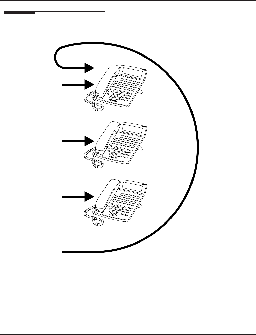
Department Calling
268 ◆Features Aspire Software Manual
Description (Cont’d)
Call 1
Call 2
Call 3
Call 4
Circular Routing
N2IP-10

Department Calling
Aspire Software Manual Features ◆269
Programming
➻11-07-01 : Department Group Pilot Numbers
Assign pilot numbers to the Extension (Department) Groups you set up in Program 16-02.
➻11-11-25 : Service Code Setup (for Setup/Entry Operation) - Automatic Transfer Setup
for Each Department Group
Use this option to set the service code (default=102) to activate immediate automatic transfer
for ICM and transferred calls to Department Groups.
➻11-11-26 : Service Code Setup (for Setup/Entry Operation) - Automatic Transfer Cancel-
lation for Each Department Group
Use this option to set the service code (default=103) to deactivate immediate automatic trans-
fer for ICM and transferred calls to Department Groups.
➻11-11-27 : Service Code Setup (for Setup/Entry Operation) - Destination of Automatic
Transfer for Each Department Group
Use this option to set the service code (default=104) for setting the destination for immediate
automatic transfer for ICM and transferred calls to Department Groups.
➻11-11-28 : Service Code Setup (for Setup/Entry Operation) - Delayed Transfer for Each
Department Group
Use this option to set the service code (default=105) for setting the delayed transfer destina-
tion Department Group.
➻11-11-29 : Service Code Setup (for Setup/Entry Operation) - Delayed Transfer Cancella-
tion for Each Department Group
Use this option to set the service code (default=106) for cancelling the delayed transfer desti-
nation Department Group.
➻11-12-09 : Service Code Setup (for Service Access) - Changed to STG All Ring
Use this option to set the service code for ringing all members of a Department Group.
➻11-16-10 : Single Digit Service Code Setup
Assign the Single Digit (post-dialing) Service Code for All Member Ring.
➻15-07-01 : Programming Function Keys
Assign a Department Calling key (46) so extension users can install or remove themselves
from the Department Calling Group. Additional keys can also be assigned for Department
Group features Automatic Transfer (56), immediate calling destination (58), delayed calling
destination (59), and DND destination (60).
➻16-01-01 : Department Group Basic Data Setup - Department Name
Assign a name to the Extension (Department) Groups you set up in Program 16-02.
➻16-01-02 : Department Group Basic Data Setup - Department Calling Cycle
Set the routing cycle for calls into a department (i.e., when a user dials the department pilot
number). The system can ring the highest priority extension available (Priority Routing, 0) or
cycle in circular order to a new idle extension for each new call (Circular Routing, 1).
➻16-01-03 : Department Group Basic Data Setup - Department Routing When Busy
Set how the system routes an Intercom call to a busy Department Group member. The caller
can hear busy tone (0) or overflow to the first available Department Group member (1). This
option is for Intercom calls to an extension, not a pilot number.
➻16-01-04 : Department Group Basic Data Setup - Hunting Mode
Set if an unanswered call should hunt once stopping at the last member tried (0) or continually
hunt through the idle members (1).

Department Calling
270 ◆Features Aspire Software Manual
➻16-01-05 : Department Group Basic Data Setup - Department Group All Ring Mode
Operation
Set if all members of the group should ring automatically (1) or through the use of the service
code defined in Program 11-12-09 (0). Selecting automatic will override the settings of Pro-
grams 16-01-03 and 16-01-04.
➻16-01-07 : Department Group Basic Data Setup - Call Recall Restriction for STG
Set if a transferred call to the pilot number should recall (0) or camp on (1) to the busy or idle
Department Group.
➻16-01-08 : Department Group Basic Data Setup - Queuing for Department Group Calls
To have Department Group calls queue when busy, set this entry to “1” (0=no queuing,
1=queuing) for a Department Group.
This program allows entries of 1-32, however, the system accepts any entry other than “0” as
to allow queuing.
➻16-01-09 : Department Group Basic Data Setup - Department Hunting No Answer Time
Set how long a call will ring a Department Group extension before hunting occurs.
➻16-01-10 : Department Group Basic Data Setup - Hunt Type
Set the type of hunting for each Department Group:
0- No queuing
1- Hunting When Busy
2- Hunting When Not Answered
3- Hunting When Busy or No Answer
➻16-02-01 : Department Group Assignment for Extensions
Assign extensions to Department Groups and set the priority assignment.
➪Aspire S: Department Groups 1-8
➪Aspire: Department Groups 1-64
➻16-03-01 : Secondary Department Group Assignment for Extensions
Use this program to assign extensions to multiple Department Groups and set the priority
assignment. Each Secondary Department Group can have up to 16 extensions assigned.
➪Aspire S: Department Groups 1-8
➪Aspire: Department Groups 1-64
➻20-06-01 : Class of Service for Extensions
Assign a Class Of Service (1-15) to an extension.
➻20-11-17 : Class of Service Options (Hold/Transfer Service) - Set/Cancel Department
Group Trunk-to-Trunk Forwarding
In an extension’s Class of Service, allow (1) or prevent (0) an extension from using the imme-
diate automatic transfer of ICM and transferred calls to the Department Groups feature.
➻20-13-14 : Class of Service Options (Supplementary Service) - Department Calling
In an extension’s Class of Service, allow (1) or prevent (0) extensions from receiving Depart-
ment Calls when the pilot number is dialed.
➻22-02-01 : Incoming Call Trunk Setup
If you want a trunk to be a DIL to a Department Group, assign Service Type 4 for each Night
Service Mode. Also see 22-07 below.
➻22-07-01 : DIL Assignment
For each trunk assigned Service Type 4 in 22-02 above, assign the DIL destination as the
Department Group pilot number (as assigned in Program 11-07-01).
➪Aspire S: Department Groups 1-8
➪Aspire: Department Groups 1-64
➻24-02-05 : System Options for Transfer - Transfer to Busy Department Group Recall
Timer
After a trunk is unscreen transferred to a busy Department Group, this timer will start. If the
call is not answered, it will recall the originator. Determine how long the call should ring
before recalling (0-64800 seconds).

Department Calling
Aspire Software Manual Features ◆271
➻24-02-08 : System Options for Transfer - Delayed Transfer Timer for All Department
Groups
Determine how long a call should ring a Department Group before transferring the call (0-
64800 seconds).
➻24-05-01 : Department Group Transfer Target Setup
Assign the Abbreviated Dialing bin to each Department Group to hold the destination for the
immediate automatic transfer of ICM and transferred calls to the Department Group feature.
Related Features
Automatic Call Distribution (ACD)
Set up hunting as required for ACD.
Call Forwarding
Extensions within a Department Group which have Call Forwarding enabled will not be
included in the call hunt. The extension to which the user is forwarded will not receive the
hunted calls.
Department Step Calling
Easily step call to an idle Department Group member if the member called is busy.
Multiple Directory Numbers / Call Coverage
A virtual extension can be programmed allowing a Call Coverage key to receive multiple calls
which can camp on to the extension - no analog port is required.
Transfer
An extension user can Transfer a call to a Department Group master number. If unanswered,
the call will recall the transferring extension after the Transfer Recall Time (Program 24-02-
04).
Voice Mail
Voice mail uses one Department Group for voice mail.
Voice Response System (VRS)
Refer to the VRS feature for details on using VRS overflow.

Department Calling
272 ◆Features Aspire Software Manual
Operation
To call a department:
1. At keyset, press idle CALL key.
OR
At single line set, lift handset.
2. Dial department’s extension number.
The system routes the call to the first free phone in the department.
3. Optional: To manually ring all members of the group, dial the single digit service code
assigned for All Member Ring (Program 11-16-10).
To log out of your Department Calling Group:
While you are logged out, Department Calling cannot route calls to your extension.
1. Press idle CALL key.
2. Dial 150 + 1.
OR
1. Press Department Calling Log In key (PGM 15-07 or SC 851: 46).
The key lights while you are logged out.
To log back in to your Department Calling Group:
While you log back in, Department Calling will route calls to your extension.
1. Press idle CALL key.
2. Dial 150 + 0.
OR
1. Press Department Calling Log In key (PGM 15-07 or SC 851: 46).
The key goes out when you log back in.

Department Step Calling
Aspire Software Manual Features ◆273
Department Step Calling
Description
After calling a busy Department Calling Group member, an extension user can have Department
Step Calling quickly call another member in the group. The caller does not have to hang up and
place another Intercom call if the first extension called is unavailable. Department Step Calling also
allows an extension user to cycle through the members of a Department Group.
Conditions
None
Default Setting
Enabled.
Programming
➻11-12-07 : Service Code Setup (for Service Access) - Step Call
If required, customize the Step Call service code to be used by an extension user (default:
808).
➻11-16-01 : Single Digit Service Code Setup
If required, use this option to change the Department Step Calling Single Digit Service Code.
➻15-07-01 : Programmable Function Keys
Assign a function key Department Step Calling (code 36).
➻20-06-01 : Class of Service for Extensions
Assign a Class Of Service (1-15) to an extension.
➻20-08-12 : Class of Service Options (Outgoing Call Service) - Department Step Calling
In an extension’s Class of Service, enable (1) or disable (0) an extension’s ability to use
Department Step Calling.
Related Features
Department Calling
An extension user can call an idle extension within a preprogrammed Department Group by
dialing the group’s pilot number. Department Calling also provides overflow routing for
extensions within the group - which simulates Step Calling.
Programmable Function Keys
Function keys simplify Department Step Calling operation.
Aspire S Aspire M/L/XL
• Available. • Available.

Department Step Calling
274 ◆Features Aspire Software Manual
Operation
To make a Step Call:
You step through Department Groups set in Program 16-02.
1. Place call to busy Department Group member.
OR
Place call to Department Group pilot number.
2. Dial #.
OR
Press Step Call key (PGM 15-07 or SC 851: 36).
3. Repeat step 2 to call other Department Group members.

Dial Number Preview
Aspire Software Manual Features ◆275
Dial Number Preview
Description
Dialing Number Preview lets a display keyset user dial and review a number before the system dials
it out. Dialing Number Preview helps the user avoid dialing errors.
Conditions
An extension user cannot edit the displayed number.
Default Setting
Enabled.
Programming
➻20-06-01 : Class of Service for Extensions
Assign a Class Of Service (1-15) to an extension.
➻20-08-05 : Class of Service Options (Outgoing Call Service) - Dial Number Preview
In an extension’s Class of Service, enable (1) or disable (0) an extension’s ability to use Dial
Number Preview.
Related Features
Central Office Calls, Placing
In order to place an outgoing call, an extension user must have outgoing access to a line, loop
or trunk group key.
Voice Response System (VRS)
If the system has VRS installed, you must first press * in order to preview a number.
Operation
To use Dial Number Preview to place a call (keyset only):
1. Do not lift the handset or press a CALL key.
2. To preview any number, dial the number you wish to call.
With VRS installed, you must first press * to preview a number.
To preview an Abbreviated Dial number, press DIAL and dial the Abbreviated Dial bin num-
ber you want to call.
The number displays.
3. To dial out the displayed trunk number, press a line/loop/trunk group key.
If the previewed number as a trunk access code (e.g., 9), you can press CALL instead.
OR
To dial out the displayed Intercom number, press a CALL key.
OR
To cancel the number without dialing it out, press HOLD.
Aspire S Aspire M/L/XL
• Available. • Available.

Dial Pad Confirmation Tone
276 ◆Features Aspire Software Manual
Dial Pad Confirmation Tone
Description
For an extension with Dial Pad Confirmation Tone enabled, the user hears a beep each time they
press a key. This is helpful for Intercom calls and Dial Pulse trunk calls, since these calls provide
no Call Progress tones.
Conditions
None
Default Setting
Disabled
Programming
➻11-11-19 : Service Code Setup (for Setup/Entry Operation) - Key Touch Tone On/Off
If required, change the service code enabling or disabling the Key Touch Tone (default: 824).
Related Features
Single Line Telephones
Dial Pad Confirmation Tone does not apply to single line telephones.
Operation
To enable/disable Dial Pad Confirmation Tone:
1. Press idle CALL key.
2. Dial 824.
Aspire S Aspire M/L/XL
• Available. • Available.

Dial Tone Detection
Aspire Software Manual Features ◆277
Dial Tone Detection
Description
If a trunk has Dial Tone Detection enabled, the system monitors for dial tone from the telco or PBX
when a user places a call on that trunk. If the user accesses the trunk directly (by pressing a line key
or dialing #9 and the trunk’s number), the system will drop the trunk if dial tone does not occur. If
the user access the trunk via a Trunk Group (by dialing a trunk group code or automatically through
a feature like Last Number Redial), the system can drop the trunk or optionally skip to the next
trunk in the group. Refer to the chart under Programming below for more.
Dial Tone Detection is available for the following features:
●Automatic Route Selection
●Abbreviated Dialing
●Central Office Calls, Placing
●Last Number Redial
●Loop Keys (outbound)
●Save Number Dialed
●T1 Trunking (with ANI/DNIS Compatibility)
●Tie Lines
●Trunk Group Routing
●Trunk Groups
Conditions
None
Default Setting
Disabled for manually dialed calls; enabled for automatically dialed calls.
Aspire S Aspire M/L/XL
• Available
• Tone Detection Setup is available.
• The Next Trunk in Rotary if No Dial Tone option is
available.
• Available.
• Tone Detection Setup is available.
• The Next Trunk in Rotary if No Dial Tone option is
available.
Dial Tone Detection
278 ◆Features Aspire Software Manual
Programming
➻10-09-01 : DTMF and Dial Tone Circuit Setup
If dial tone detection is enabled, be sure to allocate at least one circuit for dial tone detection
(type 0 or 2).
➻14-02-05 : Analog Trunk Data Setup - Dial Tone Detection for Directly Accessed Trunks
Enable (1) or disable (0) dial tone detection for manually dialed trunk calls. This option only
pertains to calls placed using line keys or Direct Trunk Access.
➻14-02-11 : Analog Trunk Data Setup - Next Trunk in Rotary if No Dial Tone
If enabled, the system will skip over a trunk if dial tone is not detected. This option pertains to
calls placed using Loop Keys, Abbreviated Dial, ARS, Last Number Redial or Save Number
Dialed. It does not pertain to line key or Direct Trunk Access calls.
➻21-01-05 : System Options for Outgoing Calls - Dial Tone Detection Timer
If dial tone detection is enabled, the system will wait this interval for the telco to return dial
tone. When this interval expires, the system assumes dial tone is not present. To disable this
timer (and have the system wait continuously), enter 0.
➻80-03-01 : DTMF Tone Receiver Setup
80-04-01 : Call Progress Tone Detector Setup
Use these programs to set the criteria for dial tone detection and call progress tone detection.
Related Features
See Description above.
Operation
Dial Tone Detection is automatic if enabled in programming.
Dial Tone Detection Program Interaction
Method 14-02-05 14-02-11 Result if dial tone
not present . . .
Press a line key
OR
Dial #9 + Trunk
number
0 0 Trunk hangs (does not disconnect)
0 1 Trunk hangs (does not disconnect)
1 0 Trunk drops
1 1 Trunk drops
Dial a Trunk Group
code
OR
Automatically
through a feature
0 0 Trunk hangs (does not disconnect)
0 1 Trunk reroutes after time-out
1 0 Trunk drops
1 1 Trunk reroutes after time-out

Direct Inward Dialing (DID)
Aspire Software Manual Features ◆279
Direct Inward Dialing (DID)
Description
Direct Inward Dialing (DID) lets outside callers directly dial system extensions. DID saves time for
callers who know the extension number they wish to reach. To place a DID call, the outside caller
dials the local exchange (NNX) and additional digits to ring the telephone system extension. For
example, DID number 926-5400 can directly dial extension 400. The caller does not have to rely on
attendant or secretary call screening to complete the call.
Note: Direct Inward Dialing requires DID service from telco.
In addition to direct dialing of system extensions, DID provides:
●DID Dialed Number Translation
●Flexible DID Service Compatibility
●DID Intercept
●DID Camp-On
DID Dialed Number Translation
DID allows different tables for DID number translation. This gives you more flexibility when buying
DID service from telco. If you can’t buy the exact block of numbers you need (e.g., 301-556), use the
translation tables to convert the digits received. For example, a translation table could convert digits 501-
756 to extension numbers 301-556.
The Aspire system has 2000 DID Translation Table entries that you can allocate among the 20 DID
Translation Tables. There is one translation made in each entry. For a simple installation, you can put all
2000 entries in the same table. For more flexibility, you can optionally distribute the 2000 entries among
the 20 tables.
In addition to number conversion, each DID Translation Table entry can have a name assigned to it.
When the DID call rings the destination extension, the programmed name displays.
Flexible DID Service Compatibility
You can program the system to be compatible with three and four digit DID service. With four
digit service, the telco sends four digits to the system for translation. With three digit service, the
telco sends three digits to the system for translation. Be sure to program your system for compati-
bility with the provided telco service. For example, if the telco sends four digits, make sure you set
up the translation tables to accept the four digits.
The system is compatible with Dial Pulse (DP) and DTMF DID signaling. DID trunks can be
either wink start or immediate start.
Aspire S Aspire M/L/XL
• Available with software 2.21+ - 20 DID Translation
Tables can be divided between 2000 entries.
• DID routing can follow ring group programming on
transfers for busy/no answer calls.
• Call by Time Schedule feature requires 4.93+.
• Available - 20 DID Translation Tables can be divided
between 2000 entries.
• DID routing can follow ring group programming on
transfers for busy/no answer calls with software 1.11+.
• Call by Time Schedule feature requires 4.93+.

Direct Inward Dialing (DID)
280 ◆Features Aspire Software Manual
DID Camp-On
DID Camp-On sets what happens to DID calls to busy extensions when you have Busy Intercept
disabled. With DID Camp-On enabled, a call to a busy extension camps-on for the DID Ring No
Answer Time interval. It then diverts to the programmed DID Intercept extension ring group or
Voice Mail. Without DID Camp-On, the caller to the busy extension just hears busy tone.
DID Routing Through the VRS
DID calls can optionally route through the VRS. The DID caller hears an initial Automated Atten-
dant Greeting explaining their dialing options. If the caller mis-dials, they can hear a second greet-
ing with additional instructions. For example, the first Automated Attendant Greeting can be,
“Thank you for calling. Please dial the extension number you wish to reach or dial 0 for the opera-
tor.” If the caller inadvertently dials an extension that doesn’t exist, they could hear, “The extension
you dialed is unavailable. Please dial 0 for assistance or dial # to leave a message so we can call you
back.”
You assign Automated Attendant greetings (i.e., VRS Messages) to the numbers in each Translation
Table. This provides you with extensive flexibility when determining which greetings the system
should play for which dialed numbers. You could, for example, set up 926 5401 through 926 5449
to route to extensions 301- 349, and have 926 5450 route to the automated attendant.
The system allows an extension to be defined as a 1-digit number which can be dialed by the out-
side caller on a DID/DISA trunk using the VRS. The outside caller is able to access to desired
extension/department group by dialing only 1 digit after the system answers the call. If the same
number is used as the first digit of an extension number as well as the 1-digit access code for DID/
DISA, the outside caller will not be able to access the extension.
Example: If ‘2’ is defined as a 1-digit access code to department group 300, outside
callers cannot access extensions 200-299 directly.
SMDR Includes Dialed Number
The SMDR report can optionally print the trunk’s name (entered in system programming) or the
number the incoming caller dialed (i.e., the dialed DID digits). This gives you the option of analyz-
ing the SMDR report based on the number your callers dial. (This option also applies to an ISDN
trunk as well.)
DID Intercept
DID Intercept automatically reroutes DID calls under certain conditions. There are three types of DID
Intercept:
●Vacant Number Intercept
If a caller dials an extension that does not exist or mis-dials, Vacant Number Intercept can
reroute the call to the programmed DID Intercept extension ring group or Voice Mail. Without
Vacant Number Intercept, the caller hears error tone after mis-dialing.
●Busy Intercept
Busy Intercept determines DID routing when a DID caller dials a busy extension. If Busy
Intercept is enabled, the call immediately routes to the programmed DID Intercept extension
ring group or Voice Mail. If Busy Intercept is disabled, the call follows DID Camp-On pro-
gramming (see below).
●Ring-No-Answer Intercept
Ring-No-Answer Intercept sets the routing options for DID calls that ring unanswered at the
destination extension. With Ring-No-Answer Intercept enabled, the unanswered call reroutes
to the DID Intercept extension ring group or Voice Mail after the DID Ring-No-Answer Time
interval. If Ring-No-Answer Intercept is disabled, the unanswered call rings the destination
until the outside caller hangs up.

Direct Inward Dialing (DID)
Aspire Software Manual Features ◆281
Delayed DID
Delayed DID allows a user a pre-programmed amount of time to answer a call. If the call is not
answered within this time period, the system automatically answers the call. An outside party will hear a
voice message, music, or dial tone according to the following conditions:
●If a VRS is installed, the system sends a pre-recorded message from the VRS.
●If a customer-provided audio system (example: tape recorder) is connected, an error message
or music can be played for the caller.
●If there is no equipment connected for an announcement, the system sends a unique dial tone
to the outside caller.
This feature is not available for the normal incoming call on ISDN trunks.
DID Intercept Destination for Each DID Number
With this feature the system allows you to program a DID Intercept destination for a DID number
which receives no answer or busy call. The system can be programmed to use a trunk ring group,
the VRS or the voice mail as the programmed destination. Each vacant number intercept for a DID
number can have two destinations. The first destination is for an invalid DID number, busy or no
answer extension. The second destination is for a no answer trunk ring group.
For busy or no answer intercept calls, a third destination can be defined in Program 22-12. If the
first and third destinations are programmed but the second destination is not, the incoming call goes
to the third destination after the first destination. If the first and second destinations are not pro-
grammed, but the third destination is, the call goes directly to the third destination.
This feature works for DID trunks with a trunk service type 1 in Program 22-02. Other types of
trunks may use the DID table, but the DID intercept feature is not yet supported.
With the DID Intercept for each DID number feature, when the primary destination (Program 22-
11-05) is set to Voice Mail, the Voice Mail protocol is:
1. Busy Intercept = Forward Busy
2. Ring-No-Answer Intercept = Forward RNA
When the secondary destination (Program 22-11-06) is set to Voice Mail, the Voice Mail protocol is
based on the first destination's routing. When the incoming call is forwarded to the first destination
by a busy intercept, the Voice Mail protocol will be that it forwards busy calls. When the incoming
call is routed to the first destination by a ring-no-answer intercept, the protocol will be that it for-
wards ring-no-answer. The Voice Mail will transfer the calls to the mailbox number defined in Pro-
gram 22-11-02.
Note: Any valid DID number must be entered in the DID table (Program 22-11). If a valid DID
number is not entered, there will be no ring destination for any incoming calls to that num-
ber (the calls will not ring any extension in the system).
Calls Can Follow Ring Group Programming for Transferring Calls
An option has been added to Program 22-11 which allows you to determine if the DID routing
should use the programmed ring group entry in Program 22-12-01 when transferring calls from a
busy or no answer number.

Direct Inward Dialing (DID)
282 ◆Features Aspire Software Manual
Call by Time Schedule Feature Added
For every DID number programmed, the DID Call by Time Schedule feature allows each of the 8
different time patterns (defined in Program 22-17) to be assigned a different destination, following
the DID conversation table in Program 22-11. This time pattern can also be selected manually,
using a service code. The time pattern used for this option is separate from the 8 day/night time
modes defined in Program 12-02.
Notes:
●When the time pattern is changed manually, the following conditions apply:
●Manually selecting the time pattern temporarily overrides the entries in Program 22-17.
However, when a time pattern changes with the time schedules in Program 22-17, the pat-
tern applied by the manual change is cancelled.
●If the time pattern is manually selected and the system is reset, once the system restarts,
the manually selected time pattern is still in affect.
●When a time pattern is set as 00:00 from 00:00 and Program 22-11 is defined, the system will
always follow the setting in Program 22-11. To prevent the system from using Program 22-11,
it must be undefined.
●If the destination defined in Program 22-17 is not found, the system then checks the setting in
Program 22-11.
●If an incoming DID call is unanswered/busy, it will follow the entries in Program 22-12 and
22-13 for the trunk group based on the time the no answer/busy indication was received.
Federal Communications Commission DID Requirements
Allowing this equipment to operate in a manner that does not provide proper answer supervision
signaling is in violation of Part 68 rules.
This equipment returns answer supervision to the Public Switched Telephone Network when the
DID trunk is:
●Answered by the called station
●Answered by the attendant
●Routed to a recorded announcement that can be administered by the CPE user
●Routed to a dial prompt
This equipment returns answer supervision on all DID calls forwarded back to the Public Switched
Telephone Network. Permissible exceptions are when:
●A call is unanswered
●A busy tone is received
●A reorder tone is received
When ordering DID service, provide the telco with the following information:
FCC Registration Number:
Aspire S: KF = US:NIFKF06BASPIRES
MF = US:NIFMF06BASPIRES
PF = US:NIFPF06BASPIRES
Aspire: KF = US:NIFKF07BASPIRE
MF = US:NIFMF07BASPIRE
PF = US:NIFPF07BASPIRE
DID Facility Interface Code . . . . . . . . 02RV2-T
DID Service Order Code . . . . . . . . . . . 9.0F
DID Answer Supervision Code . . . . . . A S.2
DID USOC Jack Type . . . . . . . . . . . . . RJ21X

Direct Inward Dialing (DID)
Aspire Software Manual Features ◆283
Conditions
(A.) Analog DID requires the installation of a 4DIOPU-A1 PCB (provides four DID ports) or
8DIOPU-A1 PCB (provides eight DID ports). Depending on programming, the system may
assign both trunk and extension ports (if OPX is selected in Program 10-03-01) when this
PCB is installed.
(B.) DID service must be purchased from your local telephone company.
(C.) DID Intercept for each DID number works for DID trunks with a trunk service type 3 in Pro-
gram 22-02. Other types of trunks may use the DID table, but the DID intercept feature for
each DID number is not yet supported.
(D.) T1 or PRI DID requires a T1/PRI PCB (1PRIU-T1).
Default Setting
Disabled.

Direct Inward Dialing (DID)
284 ◆Features Aspire Software Manual
Programming
➻10-03-01 : PCB Setup - LD/OPX Assignment
Set the function of the DIOPU PCB port for DID (0) or OPX trunk (1).
➻10-09-01 : DTMF and Dial Tone Circuit Setup
If the system has DTMF DID trunks, be sure to reserve at least one circuit for analog trunk
DTMF reception (type 0 or 2). There must be an available receiver for each DTMF DID
trunk.
● Use the following as a guide when allocating DTMF receivers:
- In light traffic sites, allocate one DTMF receiver for every 10 devices that use them.
- In heavy traffic sites, allocate one DTMF receiver for every five devices that use them.
➻11-10-35 : Service Code Setup (For Administrator) - DID Mode Switching
Assign the service code to be used by a keyset or SLT user to manually change the time pat-
tern for a DID number.
➻14-05-01 : Trunk Groups
Put DID trunks in the same trunk group (other than group 1). If you have several types of DID
trunks, put each type in a separate trunk group.
➻15-07-01 : Programmable Function Keys
You can assign line or loop keys for DID trunks. Without line keys, DID calls ring line appear-
ance (CALL) keys.
In addition, assign a key for DID Mode Switching (88 + Program 22-17 table number). This
key can be used to manually change the time pattern for a DID number. The following LED
indications are used with the key:
Pattern 1 = LED off, Pattern 2 = LED on, Pattern 3 = slow flash, Pattern 4 = fast flash, Patterns
5-8 = off
➪Aspire S: Trunk 1-8
➪Aspire: Trunk 1-200
➻20-06-01 : Class of Service for Extensions
Assign a Class of Service (1-15) to an extension.
➻20-07-26 : Class of Service Options (Administrator Level) - DID Mode Switching
For each Class of Service, enable (1) or disable (0) an extension’s ability to manually change
the time pattern for a DID Conversion Table.
➻20-09-01 : Class of Service Options (Incoming Call Service) - Second Call for DID/
DISA/ DIL/ E&M
Enable (1) or disable (0) an extension’s ability to receive a second call from a DID, DISA,
DIL, or tie line caller.
➻20-13-23 : Class of Service Options (Supplementary Service) - Display the Reason for
Transfer
Enable (1) or disable (0) an extension’s ability to display the reason (Call Forward, Busy, No
Answer or DND) a VRS, DID, DISA, or ISDN call is being transferred to their extension.
➻21-01-02 : System Options for Outgoing Calls - Intercom Interdigit Time
Set the time-out interval for DID callers that don’t dial. After this interval, the DID call routes
according to Vacant Number Intercept programming.
➻22-01-06 : System Options for Incoming Calls - DID Ring-No-Answer Time
Set the DID Ring-No-Answer (RNA) Intercept interval (0-64800 seconds). In systems with
RNA Intercept, the DID call rings the destination extension for this interval and then rings
Intercept Ring Group.
➻22-02-01 : Incoming Call Trunk Setup
For each Night Service Mode, enter service type 3 when the trunk should be a DID trunk.
When the DID Call by Time Schedule feature is to be used, enter the trunk type as "8" (Mode
DID).

Direct Inward Dialing (DID)
Aspire Software Manual Features ◆285
➻22-04-01 : Incoming Extension Ring Group Assignment
Assign extensions to Ring Groups. Calls ring the extensions according to programming in 22-06.
➻22-09-01 : DID Basic Data Setup - Expected Number of Digits
For each DID Translation Table (1-20), enter the number of digits the table expects to receive
from the CO (8 maximum). For example, for a table used with 3-digit DID service, enter 3.
➻22-09-02 : DID Basic Data Setup - Received Vacant Number Operation
Selectively enable (1) or disable (0) Vacant Number Intercept based on each DID Translation
Database (Program 22-11-01 and 22-11-02).
➻22-10-01 : DID Translation Table Setup
Assign the start and end range of DID Translation Table entries (1-2000) to each DID Transla-
tion Table (1-20).
➻22-11-01 : DID Translation Table Number Conversion - Received Number
For each DID Translation Table entry (1-2000), specify the digits received by the system
(eight max.).
➻22-11-02 : DID Translation Table Number Conversion - Target Number
For each DID Translation Table entry (1-2000), specify the extension the system dials after
translation (24 digits max.)
➻22-11-03 : DID Translation Table Number Conversion - Dial-In Name
For each DID Translation Table entry (1-2000), specify the name that should show on the
dialed extension’s display when it rings (twelve characters max.)
➻22-11-04 : DID Translation Table Number Conversion - Transfer Operation Mode
For each DID Translation Table entry (1-2000), specify the condition required to transfer to
the call to the destination defined in 22-11-05 and 22-11-06.
➻22-11-05 : DID Translation Table Number Conversion - Transfer Destination 1
22-11-06 : DID Translation Table Number Conversion - Transfer Destination 2
For each DID Translation Table entry (1-2000), specify the first and second Transfer Destina-
tions if the callers receives a busy or no answer (action defined in 22-11-04).
(Destination Options: 0 = No setting, 1-8 (Aspire S) or 1-100 (Aspire) = Incoming Group, 102
= In-Skin/External Voice Mail, 103=Centralized Voice Mail, 201-264 = Department Group,
400 = DID, 401 = DISA, 1000-1999 = Abbreviated Number (000-999))
If the Transfer Destinations are busy or receive no answer, those calls are transferred
to the final transfer destination (Program 22-10).
➻22-11-07 : DID Translation Table Number Conversion - Call Waiting
For each DID Translation Table entry (1-2000), specify whether Call Waiting should be
allowed (0=disable, 1=enable).
➻22-11-08 : DID Translation Table Number Conversion - Maximum Number of Calls
For each DID Translation Table entry (1-2000), specify the maximum number of DID calls
(0=unlimited, 1-200).
➻22-11-09 : DID Translation Table Number Conversion - MOH Source
For each DID Translation Table entry (1-2000), specify the source of music to be used for
DID trunks (0=IC/MOH port, 1=BGM port, 2=ACI port).
➻22-11-10 : DID Translation Table Number Conversion - ACI Music Source Port
For each DID Translation Table entry (1-2000), if item 2 is selected in 22-11-09, specify the
port to be used for the source of music heard on DID trunks.
➻22-11-11 : DID Translation Number Conversion, Ring Group Transfer
Enable (1) or disable (0) each conversation tables’ ability to follow the Ring Group program-
ming defined in Program 22-12-01 : DID Intercept Ring Group. If Program 22-11-05 :
DID Translation Number Conversion, Transfer Destination Number 1 and Program 22-
11-06 : DID Translation Number Conversion, Transfer Destination Number 2 are set, the
priority of transferring will be in this order: Program 22-11-05 then Program 22-11-06 then if
Program 22-11-11 is enabled, Program 22-12-01.

Direct Inward Dialing (DID)
286 ◆Features Aspire Software Manual
➻22-12-01 : DID Intercept Ring Group
For each DID Translation Table, program the DID Intercept destination. The destination can
be a Ring Group, In-Skin/External Voice Mail, or Centralized Voice Mail. This program is
used when there is no destination programmed in Program 22-11-05. It is unrelated to Pro-
gram 22-11-06 and 22-11-07.
➪Aspire S Ring Groups: 1-8, 102=In-Skin/External Voice Mail, 103=Centralized Voice Mail
➪Aspire Ring Groups: 1-100, 102=In-Skin/External Voice Mail, 103=Centralized Voice Mail
➻22-13-01 : DID Trunk Group to Translation Table Assignment
Assign the DID trunk groups to translation tables. If all the DID trunks use the same type of
DID service, you may have only one DID trunk group and one DID Translation Table (with
many entries).
➪Aspire S Trunk Groups: 1-8
➪Aspire Trunk Groups: 1-100
➻22-17-01 : DID Conversion Table Area Setup for Time Pattern Mode
This program is used to define the times and DID Conversion Table (Program 22-11) for each
DID time pattern (1-8) when using the Call by Time Schedule feature. Start from 00:00 and be
sure to set up the input so the last entry of the time pattern is set to end at 00:00 (Entries: Start
Time = 0000 - 2359, End Time = 0000 - 2359, DID Conversation Table Number: 0 - 2000).
➻25-01-01 : VRS/DISA Line Basic Data Setup - VRS/DISA Dial-In Mode
Determine whether the system should use option 0 (Extension number/Service code specify)
or option 1 (Use dial conversion table) for calls.
➻25-01-03 : VRS/DISA Line Basic Data Setup - VRS/DISA Transfer Alarm
Determine whether the system should use option 0 (Normal) or option 1 (Alarm) for calls.
➻25-02-01 : VRS/DISA VRS Message
For each trunk port and each night mode, select the message source (0=No Message, 1=VRS,
2=ACI, 3=SLT), assign the VRS message number to be used as the Automated Attendant
Message for each trunk which is assigned as a VRS/DISA (With VRS=01-48 [VRS message
number], With ACI=1-4 or 01-16 [ACI group number], With SLT=1-8 or 01-64 [Department
Group number]).
➪Aspire S: Trunk Ports 1-8, Night Service Time Mode 1-4
➪Aspire: Trunk Ports 001-200, Night Service Time Mode 1-8
➻25-03-01 : VRS/DISA Transfer Ring Group With Incorrect Dialing
For each trunk port, set what happens to a call when the DISA or Automated Attendant caller
dials incorrectly or waits too long to dial. The call can either disconnect (0) or Transfer to an
alternate destination (a ring group, In-Skin/External, Centralized). When setting the DISA and
DID Operating Mode, you make an entry for each Night Service mode .
➪Aspire S Ring Groups: 1-8, 102=In-Skin/External Voice Mail, 103=Centralized Voice Mail
➪Aspire S: Trunk Ports 1-8, Night Service Time Mode 1-4
➪Aspire Ring Groups: 1-100, 102=In-Skin/External Voice Mail, 103=Centralized Voice Mail
➪Aspire: Trunk Ports 001-200, Night Service Time Mode 1-8
➻25-04-01 : VRS/DISA Transfer Ring Group With No Answer/Busy
For each trunk port (001-200), set the operating mode of each DISA trunk. This sets what
happens to the call when the DISA or Automated Attendant caller calls a busy or unanswered
extension. The call can either disconnect (0) or Transfer to an alternate destination (a ring
group, In-Skin/External, Centralized). When setting the DISA and DID Operating Mode, you
make an entry for each Night Service mode.
➪Aspire S Ring Groups: 1-8, 102=In-Skin/External Voice Mail, 103=Centralized Voice Mail
➪Aspire S: Trunk Ports 1-8, Night Service Time Mode 1-4
➪Aspire Ring Groups: 1-100, 102=In-Skin/External Voice Mail, 103=Centralized Voice Mail
➪Aspire: Trunk Ports 001-200, Night Service Time Mode 1-8
➻25-05-01 : VRS/DISA Error Message Assignment
For each trunk that will be answered by the VRS, enter the VRS message (1-48) the outside
caller hears if they dial incorrectly after answer. If you enter 0, the call reroutes according to
Program 25-03 and Program 25-04. Make one entry for each Night Service mode.

Direct Inward Dialing (DID)
Aspire Software Manual Features ◆287
➻25-06-02 : VRS/DISA One-Digit Code Attendant Setup
Set up single digit dialing for Automated Attendant callers. For each VRS Message pro-
grammed to answer outside calls, specify
●The digit the Automated Attendant caller dials (1-12, where 10=0, 11=* and 12=#). (Keep
in mind that if you assign destinations to digits 3 and 4, outside callers will not be able to
dial system extensions.)
●The destination reached (four digits maximum) when the caller dials the single digit code.
➻25-07-01 : System Timers for VRS/DISA - VRS Dial Tone Time
After answering a VRS/DISA trunk, the system waits this interval for the caller to dial the first
digit of the DISA password. If the caller fails to dial within this interval, the system drops the
call (0-64800).
➻25-07-02 : System Timers for VRS/DISA - VRS/DISA No Answer Time
A VRS/DISA caller can ring an extension for this interval before the system sets the call as a
Ring No Answer. After this interval expires, the call follows the programmed Ring No Answer
routing (set in Program 25-03 and 25-04) (0-64800).
➻25-07-04 : System Timers for VRS/DISA - Calling Time to Automatic Answering Tele-
phone Set
Set the answering waiting time of the automatic answering extension when an incoming DID
trunk call is received (0-64800).
➻25-07-05 : System Timers for VRS/DISA - Duration Time for Guidance Message by
Automatic Answering Telephone Set
Set the announcement time of the automatic answering extension after which in incoming
DID trunk caller is disconnected (0-64800).
➻25-07-06 : System Timers for VRS/DISA - Duration Time for Guidance Message by ACI
Set the announcement time by the ACI after which an incoming DID trunk caller is discon-
nected (0-64800).
➻25-07-11 : System Timers for VRS/DISA - VRS/DISA Answer Delay Timer
Set up the interval time the system will wait after receiving an incoming VRS/DISA call until
the system will automatically answer the call (0-64800).
➻25-07-13 : System Timers for VRS/DISA - VRS/DISA Busy Tone Interval
If a DISA caller dials a busy extension (and Program 25-04-01 = 0), the system plays busy
tone for this interval before disconnecting (0-64800).
➻25-07-14 : System Timers for VRS/DISA - Delayed DID Answer Timer
Assign the delay time from switching from a normal incoming status to DID mode. If this
time is set to ‘0’, the call will switch to DID mode immediately (0-64800).
➻30-03-01 : DSS Key Assignment
For DSS Consoles, assign a key for DID Mode Switching (88 + Program 22-17 table num-
ber). This key can be used to manually change the time pattern for a DID number. The follow-
ing LED indications are used with the key:
Pattern 1 = LED off, Pattern 2 = LED on, Pattern 3 = slow flash, Pattern 4 = fast flash, Patterns
5-8 = off
➻34-01-01 : E&M Tie Line Basic Setup - DID/E&M Start Signaling
Set the start signaling mode for DID and tie trunks. DID and tie trunks can use either immedi-
ate start or wink start signaling (0=2nd dial tone, 1=Wink, 2=Immediate, 3=Delay).
➻34-01-02 : E&M Tie Line Basic Setup - DID/E&M Incoming Signaling Type
Enter 0 if DID trunk is Dial Pulse (DP). Enter 1 if DID trunk is DTMF.
➻80-03-01 : DTMF Tone Receiver Setup
80-04-01 : Call Progress Tone Detector Setup
If required, modify the criteria for dial tone detection and call progress tone detection to set
the DTMF criteria for DTMF DID calls.

Direct Inward Dialing (DID)
288 ◆Features Aspire Software Manual
➻81-02-01 : DIOPU Initial Data Setup
Make sure the DID Trunk Timer settings are compatible with your local telco.
Related Features
Central Office Calls, Answering
When a call is transferred because of Call Forwarding No Answer, Call Forwarding Busy, or
DND, the Reason for Transfer option can display to the transferred extension why the call is
ringing to their phone.
Direct Inward Line (DIL)
DILs also provide a way for outside callers to dial a system extension, virtual extension or
Department Group directly.
Direct Inward System Access (DISA)
DISA also allows outside callers to dial system extensions directly.
Off Hook Signaling
The Off Hook Signaling provide DID calls with signaling options. Refer to this feature for the
specifics.
Paging, External
DID trunks will not ring external page speakers. Only trunks defined as “normal” in Program
22-02-01 will ring external page speakers.
Programmable Function Keys
To simplify answering DID calls, assign function keys as line keys for the DID trunks.
Station Message Detail Recording
SMDR can print trunk port names or received dialed number for ANI/DNIS or DID trunks. If
enabled, DNIS digits can be printed on the SMDR reports instead of the trunk name.
Transfer
Transferred calls on DISA, DID, DIL, ISDN trunks, or from the VRS can display the reason a
call is being transferred (Call Forward, Busy, No Answer, or DND).
Operation
DID calls ring extensions like normal trunk calls.
Manually Changing a Time Pattern
1. Press DID Mode Switch key (PGM 15-07 or SC 851: 88) or dial the service code (defined in
Program 11-10-35).
2. Enter the DID Conversation Table Number (Aspire S: 1-8, Aspire M/L/XL: 1-100).
3. Enter the time pattern to be assigned (1-8).

Direct Inward Line (DIL)
Aspire Software Manual Features ◆289
Direct Inward Line (DIL)
Description
A Direct Inward Line (DIL) is a trunk that rings an extension, virtual extension or Department
Group directly. Since DILs only ring one extension or group (i.e., the DIL destination), employees
always know which calls are for them. For example, a company operator can have a Direct Inward
Line for International Sales Information. When outside callers dial the DIL’s phone number, the
call rings the operator on the International Sales line key. The DIL does not ring other extensions.
DIL Delayed Ringing
Extensions in a Ring Group can have delayed ringing for another extension’s DIL. If the DIL is not
answered at its original destination, it rings the DIL No Answer Ring Group. This could help a
Technical Service department, for example, that covers calls for an Inside Sales department. If the
Inside Sales calls are not answered, they ring into the Technical Service department.
Conditions
(A.) If unanswered, a DIL without delayed ringing rings an extension until the outside party hangs
up.
(B.) If a DIL rings a Department Group and all agents are busy, the system routes the call as follows:
1. The trunk rings the overflow destination assigned in 22-08.
2. If there is no 22-08 assignment, the call rings according to the Ring Group assignments in
22-04 and 22-05.
3. If none of the destinations in steps 1-2 above are available, the call continues to ring until a
destination becomes free.
(C.) The DIL follows call forwarding programming, even to voice mail.
Default Setting
Disabled.
Aspire S Aspire M/L/XL
• Available - 8 trunks and 8 Department Groups.
With software prior to 2.50 - 26 extensions and 24 vir-
tual extensions. With 2.50+, 50 extensions and 24 virtual
extensions.
• Available.
Aspire M/L: 200 trunks, 64 Department Groups, 256
extensions, and 256 virtual extensions.
Aspire XL: 200 trunks, 64 Department Groups, 384
extensions, and 256 virtual extensions.

Direct Inward Line (DIL)
290 ◆Features Aspire Software Manual
Programming
➻14-07-01 : Trunk Access Map Setup
Set up the Trunk Access Maps. All extensions should have at least Hold access to the DIL
(entry 3).
➻15-06-01 : Trunk Access Map for Extensions
Assign Trunk Access Maps to extensions.
➪Aspire S: Trunk Access Maps 1-8
➪Aspire: Trunk Access Maps 1-200
➻15-07-01 : Programmable Function Keys
To have the DIL ring a key, program a line key for the DIL trunk.
➻20-06-01 : Class of Service for Extensions
Assign a Class of Service (1-15) to an extension.
➻20-09-01 : Class of Service Options (Incoming Call Service) - Second Call for DID/
DISA/ DIL/ E&M
Enable (1) or disable (0) an extension’s ability to receive a second call from a DID, DISA,
DIL, or tie line caller.
➻20-13-23 : Class of Service Options (Supplementary Service) - Display the Reason for
Transfer
Enable (1) or disable (0) an extension’s ability to display the reason (Call Forward, Busy, No
Answer or DND) a VRS, DID, DISA, or ISDN call is being transferred to their extension.
➻22-01-04 : System Options for Incoming Calls - DIL No Answer Time
Set the DIL No Answer Time (0-64800 seconds). If DIL Delayed Ringing is set in program
22-08, this option sets the DIL Delayed Ring interval.
➻22-02-01 : Incoming Call Trunk Setup
Assign each DIL Service Type 4. Make an entry for each Night Service mode.
➻22-04-01 : Incoming Extension Ring Group Assignment
Assign the extensions that should receive the overflow to the ring group programmed in 22-
08. Set the ringing in Program 22-06 (0=trunks don’t ring [just flash line keys], 1=trunks
ring).
➻22-07-01 : DIL Assignment
Set the destination extension number for each DIL - for each Night Service mode. The desti-
nation can be an extension port, virtual extension number, or Department Group pilot number
(as assigned in 11-07-01).
➻22-08-01 : DIL/IRG No Answer Destination
For each DIL with delayed ringing, enter the DIL No Answer Ring Group. An unanswered
DIL rings this group after the DIL No Answer Time. Make an entry for each Night Service
mode.
➪Aspire S Ring Groups: 1-8, 102=In-Skin/External Voice Mail, 103=Centralized Voice Mail
➪Aspire Ring Groups: 1-100, 102=In-Skin/External Voice Mail, 103=Centralized Voice Mail

Direct Inward Line (DIL)
Aspire Software Manual Features ◆291
Related Features
Call Forwarding
Call Forwarding reroutes DILs.
Central Office Calls, Answering
When a call is transferred because of Call Forwarding No Answer, Call Forwarding Busy, or
DND, the Reason for Transfer option can display to the transferred extension why the call is
ringing to their phone.
Central Office Calls, Placing
You can place DILs in trunk groups to make outgoing DIL calls easier.
Department Calling
A DIL can have an Extension (Department) Group as its destination.
Do Not Disturb
If a DIL’s destination extension is in DND, an incoming call rings according to Ring Group
programming (22-08 then 22-05).
Group Call Pickup
A user can activate Group Call Pickup to intercept a DIL ringing another extension.
Name Storing
Program a name for a DIL. This makes it easier to identify the incoming call.
Off Hook Signaling
If a keyset’s first channel is busy, a DIL always signals the idle second channel if available. If
the second channel already has a call waiting, DIL waits in line for a channel to become free.
The outside caller hears ringback tone while this occurs.
Paging, External
DIL trunks will not ring external page speakers. Only trunks defined as “normal” in Program
22-02-01 will ring external page speakers.
Private Line
To simulate Private Line operation, create a unique Access Map for the DIL that allows full
access only for the destination. Give all other extensions only Hold access.
Programmable Function Keys
If an extension has a line key for a DIL, the call will ring the key. If not, the call rings an
available line appearance. For other extensions, the DIL indicates as busy.
Ring Groups
A DIL will ring its assigned extension without Ring Group programming. A DIL only rings its
assigned extension. It will not ring other extensions in a Ring Group.
Transfer
Transferred calls on DISA, DID, DIL, ISDN trunks, or from the VRS can display the reason a
call is being transferred (Call Forward, Busy, No Answer, or DND).

Direct Inward Line (DIL)
292 ◆Features Aspire Software Manual
Operation
To answer a call on your Direct Inward Line:
1. Lift handset.
2. At keyset, press flashing line key for DIL.
If you don’t have a line key for the DIL, the DIL rings an idle CALL key.
If you have Ringing Line Preference, lifting the handset answers the call.
If you don’t answer the call, it may ring other extensions (i.e., the DIL No Answer Ring
Group).
To place a call on your Direct Inward Line:
1. Lift handset.
2. At keyset, press line key for DIL
OR
Dial #9 and the DIL trunk number (e.g., 005).
OR
Dial 804 and the DIL trunk group number (e.g., 05).
OR
Dial 9 for Trunk Group Access
3. Dial number.

Direct Inward System Access (DISA)
Aspire Software Manual Features ◆293
Direct Inward System Access (DISA)
Description
DISA permits outside callers to directly dial system extensions, trunks and selected features. This
could help an employee away from the office that wants to directly dial co-workers or use the com-
pany’s trunks for long distance calls. To use DISA, the employee:
●Dials the telephone number that rings the DISA trunk
●Waits for the DISA trunk to automatically answer with a unique dial tone
●Dials the 6-digit DISA password (access code)
●Waits for a second unique dial tone
●Accesses a system trunk, uses a selected feature or dials a system extension
DISA calls ring system extensions like other outside calls. If an extension has a line key for the
DISA trunk, the call rings that key. If the extension does not have a line key, the call rings an idle
CALL key.
You can set DISA operation differently for each Night Service mode. For example, a trunk can be a
normal trunk during the day and a DISA trunk at night. You can also set the routing for DISA trunks
when the caller dials a busy or unanswered extension, dials incorrectly or forgets to dial.
DISA Class of Service
DISA Class of Service provides features and dialing restrictions for DISA callers. This allows you
to control the capabilities of the DISA callers dialing into your system. When a DISA caller first
accesses the system, they must enter a DISA password before proceeding. The system associates
the password entered with a specific user number, which in turn has a Class of Service. If the Class
of Service allows the action (such as making outgoing trunk calls), the call goes through. If the
DISA Class of Service doesn’t allow the action, the system prevents the call. The DISA Class of
Service options are:
●Trunk Group Routing/ARS Access
When a DISA caller dials into the system, they may be able to dial 9 and place outside calls.
Any toll charges are incurred by the system. The call follows the system’s Trunk Group
Access or Automatic Route Selection - whichever is enabled.
●Trunk Group Access
DISA callers may be able to access a specific trunk group for outgoing calls through the sys-
tem. To access a Trunk Group, the user dials Service Code 804 followed by the Trunk Group
number (e.g., 1). This allows the DISA caller to place an outgoing call over the selected
group. Trunk Group Access bypasses the system’s Trunk Group Routing/ARS/Trunk Access
Maps. As with dial 9 access, any toll charges are incurred by the system. Also see Direct
Trunk Access below.
●Common Abbreviated Dialing
The system’s Common Abbreviated Dialing bins may be available to DISA callers. This could
save the DISA caller time when dialing.
Aspire S Aspire M/L/XL
• Available - 15 users, 15 DISA Classes of Service and 8
trunks.
• Trunk Disconnect Continue and Disconnect Codes
require software 4.0E+.
• Remote Setup with DISA requires software 4.93+.
• Available - 15 users, 15 DISA Classes of Service and
200 trunks.
• Trunk Disconnect Continue and Disconnect Codes
require software 4.0E+.
• Remote Setup with DISA requires software 4.93+.

Direct Inward System Access (DISA)
294 ◆Features Aspire Software Manual
●Operator Calling
A DISA caller may be able to dial 0 for the system’s operator.
●Paging
Internal and External Paging may be available to DISA callers. This allows co-workers in
adjacent facilities, for example, to broadcast announcements to each other.
●Direct Trunk Access
DISA callers may be able to select a specific trunk for outgoing calls through the system. To
directly access a trunk, the user dials Service Code #9 followed by the trunk’s number (e.g.,
001). This allows the DISA caller to place an outgoing call over the selected trunk. Direct
Trunk Access bypasses the system’s Trunk Group Routing/ARS/Trunk Access Maps. As with
dial 9 access, any toll charges are incurred by the system. Also see Trunk Group Access above.
●Call Forward
DISA callers may be able to set Call Forwarding to redirect an extension’s calls to another
extension. Call Forwarding ensures that the user’s calls are covered when they are away from
their work area.
●DISA/Tie Trunk Barge In
The DISA/Tie Trunk Barge In option allows a tie line caller to break into another extension’s
established call. This sets up a three-way conversation between the intruding party and the
two parties on the initial call.
DISA Toll Restriction
The digits a DISA caller dials for an outgoing call may be subject to the system’s Toll Restriction.
For example, Toll Restriction can prevent users from dialing a 1-900 service. When an incoming
DISA caller tries to use system trunks to dial 1-900, Toll Restriction will deny the call.
DISA Operating Modes
The DISA Operating Modes determine what happens when a DISA caller forgets to dial, calls a
busy or unanswered extension or dials incorrectly. The system can either drop the call or send it to
a preset Ring Group (called a the DISA Transfer Destination).
Department Calling with Overflow Message
If a DISA caller dials a busy Department Calling Group, the system can periodically play the voice
prompt, “Please hold on. All lines are busy. Your call will be answered when a line becomes free.”
while the caller waits. The interval between the voice prompts is the DISA Overflow Message
Time. When an extension in the Department Group becomes available, the call automatically goes
through. If the Department Calling Group remains busy past the DISA No Answer Time, the DISA
call routes to the overflow destination or disconnects. (What happens to the unanswered call is set
by the DISA Operating Mode). The Overflow Message requires a VRS.
Warning Tone for Long DISA Calls
You can set up the system to provide a warning tone to DISA callers that have been on a call too
long. The warning tone can be just a reminder (which the caller can ignore) or can be followed by a
forced disconnect of the call. When the DISA caller hears the warning tone, they have the option of
dialing a code to continue the conversation or disconnect.
Trunk Disconnect Continue/Disconnect Codes Added
The software enhances the forced trunk release option with the Tandem Trunking and DISA fea-
tures. With older software, with Program 24-02-07 : System Options for Transfer - Forced
Release for Trunk-to-Trunk Transfer or Program 25-07-08 : System Timers for VRS/DISA -
DISA Long Conversation Disconnect enabled, users were not provided with an option to continue
the call, if required.

Direct Inward System Access (DISA)
Aspire Software Manual Features ◆295
With software 4.0E+, users can be provided with the option to use a Continue or Disconnect service
code. The Continue service code will extend the conversation a programmed length of time. If the
user enters the Disconnect service code, the call will be disconnected immediately.
Example:
The following example indicates how a call will be handled with the system programmed as follows:
●Program 14-01-25: 1
●Program 20-28-01: #
●Program 20-28-02: No setting
●Program 20-28-03: 180
●Program 24-02-07: 600 (Only used with Tandem Trunking)
●Program 24-02-10: 30 (Only used with Tandem Trunking)
●Program 25-07-07: 600 (Only used with DISA)
●Program 25-07-08: 30 (Only used with DISA)
1. An external call connects to an external number (either by transferring with Tandem Trunking
or by DISA caller).
2. After 10 minutes (Tandem Trunking = Program 24-02-07 or DISA = Program 25-07-07), a
warning tone is heard and the user dials "#" (Program 20-28-01) to extend the conversation.
3. After 3 minutes (Program 20-28-03), the warning tone is heard again. After 30 seconds (Tan-
dem Trunking = Program 24-02-10 or DISA = Program 25-07-08), the call is disconnected.
Remote Feature Setup with DTMF
An option may be available which can be used to remotely set various Aspire func-
tions for the specified extension by dialing the extension number and service code
using a DISA line. This option is available for keysets, single line telephones, and
IP telephones.
When the outside caller, using an analog or ISDN trunk, places a call to a DISA
line and dials the service code for this function, the system will respond with a
fixed message prompting the entry of the extension number ("Please dial the exten-
sion number."). After the outside caller dials the desired extension number, the sys-
tem will respond with another fixed message ("Please enter the required Service
Code."), then the outside caller dials the required service code to set/cancel the
function.

Direct Inward System Access (DISA)
296 ◆Features Aspire Software Manual
The following features can be set using service codes with this option:
The DISA feature must be enabled for this function.
Function Name
Default
Service
Code
Description
Day / Night Mode Switching for own Night
Group (Program 11-10-01) 818 Change the Operation Mode for each Night
Group
Setting the Automatic Trunk Transfer for each
Trunk (Program 11-10-06) 833 Set the Automatic Trunk Transfer for each Trunk
Canceling the Automatic Trunk Transfer for
each Trunk (Program 11-10-07) 834 Cancel the Automatic Trunk Transfer for each
Trunk
Setting the destination for Automatic Trunk
Transfer (Program 11-10-08) 835 Register the destination telephone number for
Automatic Trunk Transfer.
With the Remote Feature Setup, after dialing the
destination telephone number, *# must be
entered (ex: 2035551234 *#).
VRS - Record / Erase Message
(Program 11-10-20) 716 Record / Playback / Erase VRS Messages
VRS - General Message Playback
(Program 11-10-21) 711 Playback General Message
VRS - Record / Erase General Message (Pro-
gram 11-10-22) 712 Record / Playback / Erase General Message
Call Forward - Immediate
(Program 11-11-01) 848 Set/Cancel Call Forward Immediate
(Service Code + 1 <Set> / 0 <Cancel> + Trans-
ferred Destination Extension Number)
Call Forward - Busy
(Program 11-11-02) 843 Set/Cancel Call Forward when Busy
(Service Code + 1 <Set> / 0 <Cancel> + Trans-
ferred Destination Extension Number)
Call Forward - No Answer
(Program 11-11-03) 845 Set/Cancel Call Forward when No Answer dur-
ing pre-assigned period
(Service Code + 1 <Set> / 0 <Cancel> + Trans-
ferred Destination Extension Number)
Call Forward - Busy/No Answer
(Program 11-11-04) 844 Set/Cancel Call Forward when No Answer dur-
ing pre-assigned period
(Service Code + 1 <Set> / 0 <Cancel> + Trans-
ferred Destination Extension Number)
Call Forward - Both Ring
(Program 11-11-05) 842 Set/Cancel Call Forward Both Ring
(Service Code + 1 <Set> / 0 <Cancel> + Trans-
ferred Destination Extension Number)
Call Forward - Follow Me
(Program 11-11-07) 846 Set/Cancel Call Forward - Follow Me
(Service Code + 1 <Set> / 0 <Cancel> +
Appropriate Extension Number)
DND (Do Not Disturb)
(Program 11-11-08) 847 Set/Cancel DND
(Service Code + 0 <Cancel> / 1 <External
Call> / 2 <Internal Call> / 3 <All Call> / 4
<CFW Transferred Call>)

Direct Inward System Access (DISA)
Aspire Software Manual Features ◆297
Notes:
●While the outside caller is setting the function via DISA, no one can use the
extension which is being set.
●The outsider caller can not set/cancel a function via DISA when the selected
extension is being used except during incoming ringing (including incoming
ACD calls). If the extension is busy, the call will be terminated.
●The VRS is required to send the fixed messages heard during the feature setup.
Conditions
(A.) The DISA caller must use a 2500 type (DTMF) telephone. DISA is compatible with calling
devices that meet the DTMF signaling requirements of EIA Specification RS-464. DISA
trunks must be ground start or supervised loop start.
(B.) The Continue/Disconnect code must be DTMF.
(C.) With an analog trunk, the Continue/Disconnect code may work using DTMF sounds from the
opposite side trunk. With an ISDN trunk, Program 14-01-25 must be enabled to detect the
Continue/Disconnect code.
(D.) The Continue/Disconnect code is not accepted while dialing a trunk.
(E.) Continue/Disconnect codes will not work if all DTMF receivers are busy.
(F.) When used with the Networking feature, both systems must be programmed the same.
Default Setting
Disabled.

Direct Inward System Access (DISA)
298 ◆Features Aspire Software Manual
Programming
➻10-09-01 : DTMF and Dial Tone Circuit Setup
Reserve at least one circuit for DTMF reception (entry 0 or 2).
●Use the following as a guide when allocating DTMF receivers:
- In light traffic sites, allocate one DTMF receiver for every 10 devices that use them.
- In heavy traffic sites, allocate one DTMF receiver for every five devices that use them.
➻11-01-01 : System Numbering
Set up a Service Code for Alternate Trunk Route Access.
➻11-09-02 : Trunk Access Code - Alternate Trunk Route Access Code
Assign the Service Code set up in 11-01 for Alternate Trunk Route Access.
➻11-15-13 : Service Code Setup, Administrative (for Special Access) - Function Setting via
DISA
Define the service code (up to 8 digits) an outside caller dials when on a DISA line in order to
access certain Aspire features.
➻14-01-02 : Basic Trunk Data Setup - Transmit CODEC Gain Type
14-01-03 : Basic Trunk Data Setup - Receive CODEC Gain Type
Customize the CODEC gains (transmit and receive levels 1-63) for DISA trunks.
➻14-01-13 : Basic Trunk Setup - Loop Disconnect Supervision
If DISA caller can place outgoing calls through the system (see Program 20-14), enable loop
supervision (1) for the DISA trunk. If DISA caller cannot use the system’s trunks for outgo-
ing calls, enter 0 to disable loop supervision.
➻20-01-05 : System Options - DTMF Receiver Active Time
After answering the call, the system attaches a DTMF receiver to the DISA trunk for this
interval (0- 64800 seconds).
➻20-06-01 : Class of Service for Extensions
Assign a Class of Service (1-15) to an extension.
➻20-09-01 : Class of Service Options (Incoming Call Service) - Second Call for DID/
DISA/ DIL/ E&M
Enable (1) or disable (0) an extension’s ability to receive a second call from a DID, DISA,
DIL, or tie line caller.
➻20-13-23 : Class of Service Options (Supplementary Service) - Display the Reason for
Transfer
Enable (1) or disable (0) an extension’s ability to display the reason (Call Forward, Busy, No
Answer or DND) a VRS, DID, DISA, or ISDN call is being transferred to their extension.
➻20-14-01 - 20-14-11 : Class of Service Options for DISA/E&M
Enable (1) or disable (0) the following options for each DISA Class of Service (1-15).
●First Digit Absorption (Item 1)
●Trunk Group Routing/ARS Access (Item 2)
●Trunk Group Access (Item 3)
●Common Abbreviated Dialing (Item 4)
●Operator Calling (Item 5)
●Internal Paging (Item 6)
●External Paging (Item 7)
●Direct Trunk Access (Item 8)
●Forced Trunk Disconnect (Item 9)
●Call Forward Setting by Remote Via DISA (Item 10)
●DISA/Tie Trunk Barge In (Item 11)

Direct Inward System Access (DISA)
Aspire Software Manual Features ◆299
➻21-15-01 : Alternate Trunk Route for Extensions
Designate the trunk route accessed when a user dials the Alternate Trunk Route Access Code.
Refer to “Trunk Group Routing” to set up outbound routing.
➻22-01-11 : System Options for Incoming Calls - VRS Waiting Message Interval Time
Setup the sending duration time of the Auto - Attendant & Queuing. The message is repeat-
edly sent out within the specified time (0-64800 seconds).
➻22-02-01 : Incoming Call Trunk Setup
For DISA operation, set the trunk service type to 2. You can have a different service type for
each Night Service mode.
➻22-04-01 : Incoming Extension Ring Group Assignment
Assign the extensions that should receive the overflow. Set the ringing in Program 22-06
(0=trunks don’t ring [just flash line keys], 1=trunks ring).
➻25-01-01 : VRS/DISA Line Basic Data Setup - VRS/DISA Dial-In Mode
Select whether the DISA trunk will use the Extension number/Service code specify (0) or the
Dial Conversion Table (1).
➻25-01-02 : VRS/DISA Line Basic Data Setup - DISA User ID
Select whether or not the DISA User ID is to be used (0=disable, 1=enable).
➻25-01-03 : VRS/DISA Line Basic Data Setup - VRS/DISA Transfer Alarm
Select whether the DISA transfer alarm should be used (0=normal, 1=alarm).
➻25-02-01 : VRS/DISA VRS Message
Assign the source and VRS message number to be used as the Automated Attendant Message
for each trunk which is assigned as a VRS/DISA (0=No Message, 1=VRS [VRS Message
Number 01-48], 2=ACI [ACI Group Number=1-4 or 01-16], 3= SLT [Department Group
Number=1-8 or 01-64]).
➪Aspire S Trunks: 1-8
➪Aspire Trunks: 001-200
➻25-03-01 : VRS/DISA Transfer Ring Group With Incorrect Dialing
Set the operating mode of each DISA trunk. This sets what happens to the call when the DISA
caller dials incorrectly. The call can either disconnect (0), transfer to an alternate ring group
destination, or transfer to In-Skin/External Voice Mail, or Centralized Voice Mail.
➪Aspire S Ring Groups: 1-8, 102=In-Skin/External Voice Mail, 103=Centralized Voice Mail
➪Aspire Ring Groups: 1-100, 102=In-Skin/External Voice Mail, 103=Centralized Voice Mail
➻25-04-01 : VRS/DISA Transfer Ring Group With No Answer/Busy
Set the operating mode of each DISA trunk. This sets what happens to the call when the DISA
caller calls a busy or unanswered extension. The call can either disconnect (0), transfer to an
alternate ring group destination, In-Skin/External Voice Mail, or Centralized Voice Mail.
➪Aspire S Ring Groups: 1-8, 102=In-Skin/External Voice Mail, 103=Centralized Voice Mail
➪Aspire Ring Groups: 1-100, 102=In-Skin/External Voice Mail, 103=Centralized Voice Mail
➻25-05-01 : VRS/DISA Error Message Assignment
Assign the VRS message number to be used as the Automated Attendant error message. For
each VRS/DISA trunk that the VRS will answer, enter the VRS message (1-48) the outside
caller hears if they dial incorrectly. If you enter 0 (i.e., no error message), the call reroutes
according to Program 25-03 and 25-04. For each trunk, you make a separate entry for each
Night Service mode.

Direct Inward System Access (DISA)
300 ◆Features Aspire Software Manual
➻25-06-01 : VRS/DISA One-Digit Code Attendant Setup
Set up single digit dialing through the VRS. This gives VRS callers single key access to exten-
sions, the company operator, Department Calling Groups and Voice Mail. For each VRS mes-
sage set to answer outside calls (see Program 25-04 and 25-05), you specify:
●The digit the VRS caller dials (0-9, *, #). (Keep in mind that if you assign destinations to
digits, outside callers will not be able to dial system extensions.
●The destination reached (eight digits max.) when the caller dials the specified digit.
The destination can be an extension, a Department Calling pilot number or the Voice Mail
master number. A one-digit code can be assigned for each Automated Attendant message.
➻25-07-01 : System Timers for VRS/DISA - DISA Dial Tone Time
After answering the DISA trunk, the system waits this interval (0-64800 seconds) for the
caller to dial the first digit of the password. If the caller fails to dial within this interval, the
system drops the call.
➻25-07-02 : System Timers for VRS/DISA - VRS/DISA No Answer Time
A DISA caller can ring an extension for this interval (0-64800 seconds) before the system sets
the call as a Ring No Answer. After this interval expires, the call follows the programmed
Ring No Answer routing (see Program 25-04 below).
➻25-07-07 : System Timers for VRS/DISA - DISA/Tandem Trunking Long Conversation
Warning Tone Time
Determine the length of time a DISA caller or any trunk-to-trunk (such as Tandem Trunking)
conversation can talk before the Long Conversation tone is heard (0-64800 seconds).
➻25-07-08 : System Timers for VRS/DISA - DISA/Tandem Trunking Long Conversation
Disconnect
This timer determines how long the system will wait before disconnecting a a DISA or any
trunk-to-trunk (such as Tandem Trunking) call after the Long Conversation tone is heard (0-
64800 seconds).
➻25-07-09 : System Timers for VRS/DISA - DISA Internal Paging Time
This is the maximum length of an Internal Page placed by a DISA caller. If the Page contin-
ues longer than this interval (0-64800 seconds), the system terminates the DISA call.
➻25-07-10 : System Timers for VRS/DISA - DISA External Paging Time
This is the maximum length of an External Page placed by a DISA caller. If the Page contin-
ues longer than this interval (0-64800 seconds), the system terminates the DISA call.
➻25-07-13 : System Timers for VRS/DISA - VRS/DISA Busy Tone Interval
If a DISA caller dials a busy extension (and Program 25-04 = 0), the system plays busy tone
for this interval before disconnecting.
➻25-08-01 : DISA User ID Setup
For each DISA user, set the 6-digit password.
➻25-09-01 : Class of Service for DISA Users
Assign a DISA Class of Service for each user. The DISA Class of Service cannot be 0. You
cannot use the 20-xx-xx and 42-xx-xx programs to assign Class of Service to DISA trunks (15
users, with one password and DISA Class of Service (1-15) for each user).
➻25-10-01 : Trunk Group Routing for DISA
Use this program to assign the Trunk Group Route chosen when a user places a DISA call into
the system and dials 9. Set Trunk Group Routing in Program 14-06. If the system has ARS,
dialing 9 accesses ARS. The route chosen is based on the DISA Class of Service, which is
determined by the password the caller dials.
➪Aspire S Trunk Group Routes: 1-8
➪Aspire Trunk Group Routes: 1-100

Direct Inward System Access (DISA)
Aspire Software Manual Features ◆301
➻25-11-01 : DISA Toll Restriction Class
If the system uses Toll Restriction, enter a Toll Restriction Class (1-15) for each DISA user (1-
15). The system uses the Toll Restriction Class you enter in Program 21-05. The Toll Restric-
tion Class assigned to a DISA call is based on the DISA Class of Service, which is determined
by the password the caller dials. You cannot use Program 21-04 to assign Toll Restriction to
DISA trunks.
➻25-12-01 : Alternate Trunk Group Routing for DISA
Assign the trunk route that DISA Caller’s access if they dial the Alternate Trunk Route Access
Code. Refer to “Central Office Calls, Placing” for more on setting up Alternate Trunk Route
Access.
➻25-13-02 : System Option for DISA - Continue Code for DISA Trunk-to-Trunk
With software through 2.68, enter a single digit Continue Code for the DISA call to use to
immediately disconnect or continue their outside call. With software 4.0E+, use Program 20-
28-01.
➻25-13-03 : System Option for DISA - Disconnect Code for DISA Trunk-to-Trunk
With software through 2.68, enter a single digit Disconnect for the DISA call to use to imme-
diately disconnect or continue their outside call. With software 4.0E+, use Program 20-28-02.
➻80-03-01 : DTMF Tone Receiver Setup
80-04-01 : Call Progress Tone Detector Setup
If required, modify the criteria for dial tone detection and call progress tone detection for
DTMF tones for inbound DTMF DISA calls.
Trunk Disconnect Continue/Disconnect Codes (Requires software 4.0E+)
➻14-01-25 : Basic Trunk Data Setup - Continue/Disconnect Trunk-to-Trunk Conversation
When Program 24-02-10 is set to disconnect a trunk after the defined time, determine whether
or not a user should have the ability to use the continue/disconnect code (Entries: 0 = Dis-
abled, 1 = Enabled).
➻20-28-01 : System Option Setup - Conversation Continue Code
When Program 14-01-25 is enabled, determine the 1-digit code the user should dial (0 - 9, *,
#) to extend the conversation length for the time defined in 20-28-03. If the Continue and Dis-
connect codes are programmed the same (e.g., #), the system will follow the "Continue" oper-
ation. Using the Continue code before the warning tone is heard has no action.
➻20-28-02 : System Option Setup - Conversation Disconnect Code
When Program 14-01-25 is enabled, determine the 1-digit code the user should dial (0 - 9, *,
#) to immediately disconnect their call. Using the Disconnect code before the warning tone is
heard will disconnect the call.
➻20-28-03 : System Option Setup - Conversation Extend Time
When Program 14-01-25 is enabled, determine the length of time a call will be extended (0 -
64800 seconds) when the user dials the Continue code (defined in 20-28-01).
➻24-02-07 : System Options for Transfer - Forced Release for Trunk-to-Trunk Transfer
This timer will start when a trunk begins talking with another trunk (for example: trunk-to-
trunk transfer/Tandem Trunking). When this timer expires, a warning tone is heard. If Pro-
gram 24-02-10 is set, the conversation disconnects after that timer expires. This timer is set
again when the external digit timer expires. One of the trunks used must be an analog trunk
(or leased line). Entries: 0 - 64800 (seconds)
➻24-02-10 : System Options for Transfer - Trunk-to-Trunk Transfer Disconnect Timer
Determine how long a conversation will continue (0 - 64800 seconds) once the timer in Pro-
gram 24-02-07 expires. If this option is set to "0", the conversation will be disconnected
immediately. This program has no affect if Program 24-02-07 is set to "0". One of the trunks
used must be an analog trunk (or leased line).

Direct Inward System Access (DISA)
302 ◆Features Aspire Software Manual
➻25-07-07 : System Timers for VRS/DISA - DISA Long Conversation Warning Tone Time
Determine the length of time a DISA caller can talk before the Long Conversation tone is
heard (0-64800 seconds). If Program 25-07-08 is set to "0", the call is disconnected once the
timer expires. This timer is set again when the external digit timer expires.
Note: If this option is set to "0", the settings in Program 24-02-07 and 24-07-10 are followed -
not 25-07-07 and 25-07-08.
➻25-07-08 : System Timers for VRS/DISA - DISA Long Conversation Disconnect Timer
This timer determines how long the system will wait (0 - 64800 seconds) before disconnecting
a DISA call after the Long Conversation tone is heard. This program has no affect if Program
25-07-07 is set to "0".
➻80-01-35 : Service Tone Setup - 1 Second Signal Tone
If required, adjust the warning tone heard by the user when Program 24-02-07 or 25-07-07 expires.
Related Features
Automatic Route Selection
In a system with ARS enabled:
When a DISA caller dials 9 for an outside call (if allowed), the system routes the call via ARS.
In a system with ARS disabled:
When a DISA caller dials 9 for an outside call (if allowed), the system uses the routes pro-
grammed for Trunk Group Routing.
Central Office Calls, Answering
When a call is transferred because of Call Forwarding No Answer, Call Forwarding Busy, or
DND, the Reason for Transfer option can display to the transferred extension why the call is
ringing to their phone.
Direct Inward Dialing (DID) / Direct Inward Line (DIL) / Voice Response System (VRS)
These features also allow outside callers to directly access system extensions.
Long Conversation Cutoff
Long conversation cutoff is controlled separately for DISA and tie lines.
Tandem Trunking (Unsupervised Conferece)
Tandem Trunking also used the Continue/Disconnect codes DISA uses.
Transfer
Transferred calls on DISA, DID, DIL, ISDN trunks, or from the VRS can display the reason a
call is being transferred (Call Forward, Busy, No Answer, or DND).
Voice Response System (VRS)
Department Calling with Overflow Message requires a DSP daughter board for VRS.

Direct Inward System Access (DISA)
Aspire Software Manual Features ◆303
Operation
To place a DISA call into the system (from any 2500 type telephone):
1. Dial the telephone number that rings the DISA trunk.
2. Wait for the DISA trunk to automatically answer with a unique dial tone.
3. Dial the 6-digit DISA password (access code).
4. Wait for a second unique dial tone.
5. Dial an extension (301-556).
OR
Dial 9 for Trunk Group Routing or ARS.
OR
Dial Alternate Trunk Route Access Code (if enabled).
OR
Dial 804 + a trunk group number (Aspire S: 1-8, Aspire: 1-100) for an outside call.
OR
Dial #9 + a trunk number (Aspire S: 1-8, Aspire: 1-200) for an outside call.
OR
Dial #2 + Common Abbreviated Dialing bin number.
OR
Dial 0 for the operator.
OR
Dial 801 + an Internal Paging Zone number (Aspire S: 0, 1-8 or Aspire: 0, 1-9, 00, 01-64).
OR
Dial 803 + an External Paging Zone number (1-8 or 0 for All Call).
OR
Dial 810 + a busy extension number to barge in to a call.
OR
Dial 828 to set the time + two digits for two digits for hour (24 hour clock, 13=1:00 PM) +
two digits for minutes.
To forward an extension’s calls using a DISA call into the system (from any 2500
type telephone):
1. Dial the telephone number that rings the DISA trunk.
2. Wait for the DISA trunk to automatically answer with a unique dial tone.
3. Dial the 6-digit DISA password (access code).
4. Wait for a second unique dial tone.
5. Dial the Call Forward service code (as defined in Program 11-11-01 through 11-11-05).
6. Dial the number of the extension to be forwarded.
7. Dial “1” to set Call Forwarding or “0” to cancel Call Forwarding.
8. Dial the extension number to which the calls will be forwarded.
To use the Continue code to extend a DISA call:
1. An external call connects to an external number (either by transferring with Tandem Trunking
or by DISA caller).
2. After the programmed time (Program 25-07-07), a warning tone is heard and the user dials the
Continue code (Program 20-28-01) to extend the conversation.
3. After the programmed time (Program 20-28-03), the warning tone is heard again. After the
programmed time (Program 25-07-08), the call is disconnected.

Direct Inward System Access (DISA)
304 ◆Features Aspire Software Manual
Remote Feature Setup with DTMF
1. An outside caller dials in on an Aspire DISA trunk.
2. The system answers the call.
3. The outside caller dials the Remote Feature Setup service code defined in 11-15-13 (default:
800).
The caller hears "Please dial the extension number".
If an incorrect extension number is dialed, the caller hears "That is an invalid entry.
Please dial the extension number."
4. Dial the extension number for which a feature is to be activated/deactivated.
The caller hears "Please enter the required service code".
If an incorrect service code is dialed, the caller hears "That is an invalid entry. Please
enter the required service code."
5. The outside caller can now dial the service code for the feature to be activated/deactivated.
When the function setting via DISA has succeeded, the caller hears the fixed message
"The setting has been activated".
The LCD indication at the extension changes in accordance with the set function.
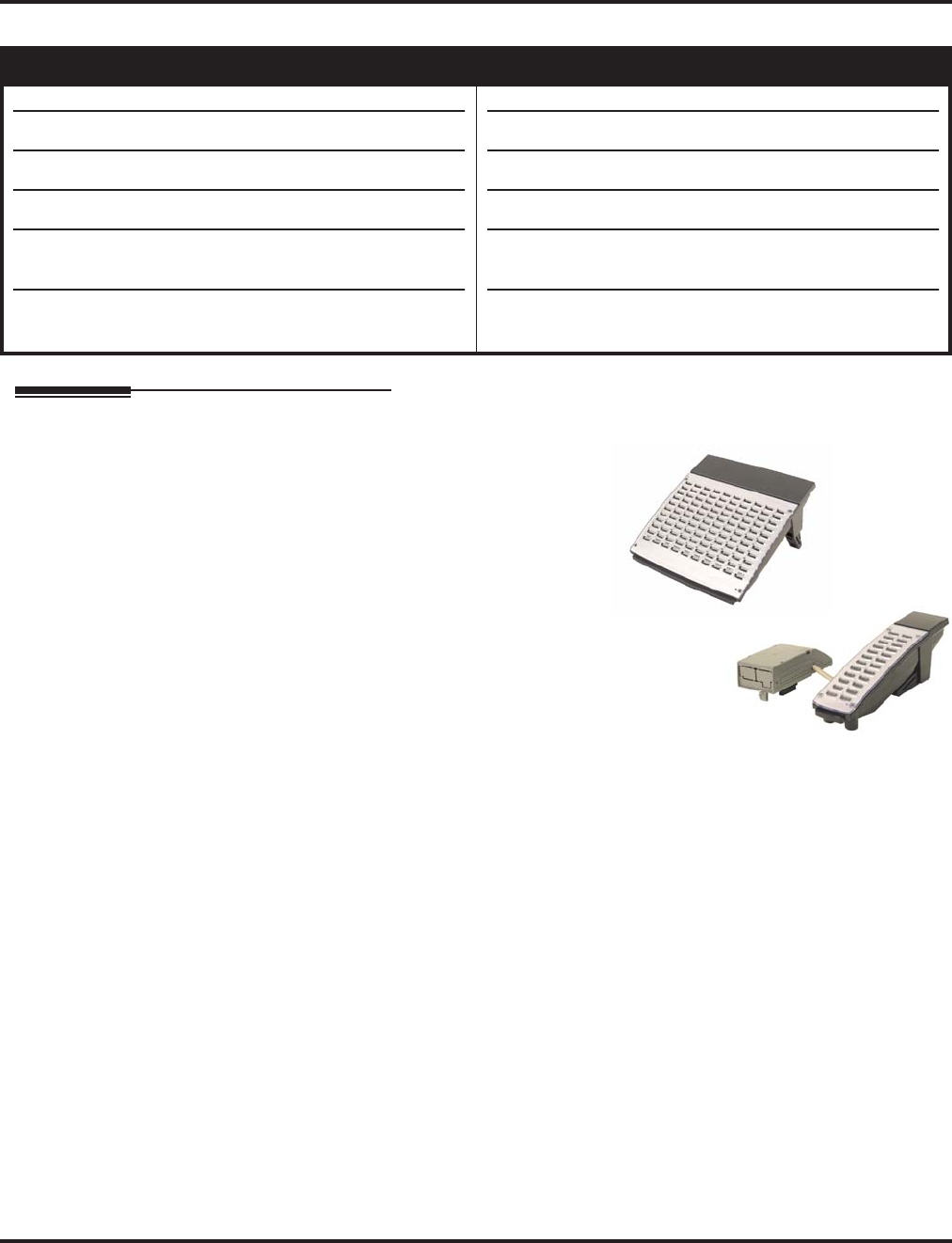
Direct Station Selection (DSS) Console
Aspire Software Manual Features ◆305
Direct Station Selection (DSS) Console
Description
The DSS Consoles (110-Button DSS: P/N 0890051
or 0890052; 24-Button DLS: P/N 0890053 or
0890054) gives a keyset user a Busy Lamp Field
(BLF) and one-button access to extensions, trunks
and system features. This saves time for users that
do a lot of call processing (e.g., operators or dis-
patchers). The DSS Console simplifies:
●Calling extensions and Door Boxes
●Placing, answering and transferring outside
calls
●Making an External or Internal Page
●Switching the Night Service mode
●Activating DSS Console Alternate Answer
The DSS Console also provides DSS Console Alternate Answer. This lets a keyset user with a DSS
Console quickly reroute their calls to a co-worker. When the user places their console off-duty (by
pressing the ALT. key), their calls route automatically to the programmed co-worker. Transferred
and dial “0” calls ring both DSS Consoles and, if the VRS is installed, the main operator hears the
message, “Your calls have been forwarded”. Central office calls ring both consoles and no message
is heard by the operator.
You can also program the DSS Console keys to store Service Codes codes (up to 29 digits long).
This provides the DSS Console user with many of the features available on One-Touch and Pro-
grammable Feature Keys. The DSS Console keys can optionally store additional associated digits
after the Service Code. For example, storing 8141 under a DSS Console key accesses Trunk Group
1 when the console user presses the key.
The maximum number of 110-Button DSS Consoles allowed per system is 4 (Aspire S) or 32
(Aspire). Up to 24 (Aspire S) or 256 (Aspire) 24-Button DSS Consoles are possible. Each exten-
sion can have up to 4 110-Button DSS Consoles and/or only one 24-button DLS console. An exten-
sion can, however, have both a 24-button DLS and 110-button DSS console(s) installed. The 110-
Button DSS Console requires an available extension port - the 24-Button DLS Console does not.
Aspire S Aspire M/L/XL
• Available.
• 4 110-Button DSS Consoles maximum (4 per extension).
• 24 24-Button DSS Consoles maximum (1 per extension).
• DSS Lamping programming is system wide.
• DSS Lamping affects DSS/Hotline keys for keysets with
software 4.0E+.
• ACD is not available on Aspire S so the ACD agent/non-
ACD agent lamping is not applicable.
• Available.
• 32 110-Button DSS Consoles maximum (4 per extension).
• 256 24-Button DSS Consoles maximum (1 per extension).
• DSS Lamping programming is system wide with 1.02+.
• DSS Lamping affects DSS/Hotline keys for keysets with
software 4.0E+.
• ACD agent and non-ACD agent lamping on a DSS Con-
sole requires software 4.0E+.

Direct Station Selection (DSS) Console
306 ◆Features Aspire Software Manual
24-Button DLS (Direct Line Select): DSS/DLS Service Code
Using Programming Function Keys, you can determine whether the keys on a 24-button DLS con-
sole (P/N 0890053 or 0890054) are used as DSS (direct station selection) or DLS (direct line selec-
tion) keys.
To prevent lamping problems when reassigning DLS Console keys, it is recommended that you
clear an extension's programmed key before reassigning it (Program 30-03: Enter key to be cleared
+ FLASH key [If using PCPro/WebPro, delete the entry and upload the change to the system before
proceeding]). Without clearing an extension's key first, your DSS Console may not show the correct
lamping, although the DSS function will work correctly.
If you are programming the system from the extension to which the DLS Console is connected,
either by phone or using the PC Program, you may need to unplug the DLS and plug it back in to
reset the console's lamping.
DSS Lamping Changed to Apply to All Consoles
Software has been changed to apply settings in Program 30-05 : DSS Console Lamp Table to all
system consoles. Previously, the settings in this program defined for each DSS Console.
DSS Lamping Table Changed to Apply to DSS/Hotline Keys for Keysets
Software has been changed to apply settings in Program 30-05 : DSS Console Lamp Table to
DSS and Hotline keys on keysets as well as DSS Consoles.
ACD/Non-ACD Agent DSS Lamping Available
With the Aspire M/L/XL system and software 4.0E+, a new option is available in Program 30-05-
01 which allows a non-ACD DSS console to lamp indicating the status of both non-ACD agents as
well as ACD agents. Previously, the console would only display one type or the other.
Conditions
(A.) Changing flash patterns for DSS Consoles will also change them for Hotline keys.
(B.) When installing a DSS, the system must auto-detect the console in order for the LEDs to func-
tion correctly. When connecting the DSS to an extension previously defined with another cir-
cuit type, undefine the circuit type (enter 00 in Program 10-03 for the extension number), then
connect the DSS Console.
(C.) To program the keys on a 24-Button DLS in Program 15-07, use the extension number to
which the DLS is installed and, regardless of the type of keyset connected, start programming
the DLS keys at key number 25.
(D.) An attendant does not have to have a DSS Console, but it must be programmed in Program 30-
02-01.
(E.) Programmable Function Keys for ACD codes (*10, *12, *13, *14, *15, *16, *17, *18, *19)
cannot be programmed on a DSS Console.
(F.) Programmable Function keys for Trunk Group/Loop Key (*02), Virtual Extension (*03), and
Loop Key (*05) cannot be programmed on a DSS Console as the system does not allow entry
of the additional data required for these keys.
Default Setting
●No DSS Consoles assigned (in Program 30-02).
●All DSS Console key ranges are ports 1-200.
●Once a DSS Console is enabled, the console's keys are DSS keys (Program 30-03).

Direct Station Selection (DSS) Console
Aspire Software Manual Features ◆307
Programming
➻10-03-01 : PCB Setup
The system automatically assigns the terminal type (10) for the port which has a DSS console
installed.
➻15-02-08 : Multi-Line Telephone Basic Setup, Automatic Handsfree
Set to ‘1’ in order for a DSS Console to have one-touch operation. If set to ‘0’, the user will
need to lift the handset before pressing a DSS key in order for the call to complete.
➻15-07-01 : Programmable Function Keys
Assign function keys to the DLS consoles. When programming a 24-Button DLS key, use the
extension number to which the DLS is installed and, regardless of the type of keyset con-
nected, start programming the DLS keys at key number 25 (Key 25=DLS key 1). Refer to
Program 30-03-01 to assign function keys to DSS consoles.
➻20-02-03 : System Options for Multi-Line Telephones - BLF Control and
20-13-06 : Class of Service Options (Supplementary Service) - Automatic Off Hook Signaling
These programs set the conditions under which a Hotline, Reverse Voice Over or DSS Con-
sole key indicates that an extension is busy. With condition 1 in the following chart, the BLF
LED is on only when both extension line appearances are busy. In conditions 2-4, the BLF
LED is on when one line appearance is busy.
➻20-06-01 : Class of Service for Extensions
Assign Class of Service (1-15) to extensions.
➻20-17-01 : Operator’s Extension - Operator’s Extension Number
Define the extension numbers which are to be used as operators.
➻20-17-02 : Operator’s Extension - Operator Console Mode
Determine if the operator’s keyset will act as a normal keyset (0) or if keys 13-24 will be used
for Personal Park of outside calls (1).
➻30-01-01 : DSS Console Operating Mode
Set the mode of the system’s DSS Consoles. The available options are Regular (Business)
Mode (0), Hotel Mode (1), ACD Monitor Mode (2), and Business/ACD Mode (3). Lamping
status for ACD agents and non-ACD agents require this option be set to “3” and requires soft-
ware 4.0E+ - otherwise, ACD agents and non-ACD agents do not both appear on the same
console type. For ACD agent’s lamping status, a DSS Console must be programmed as an
ACD console. For non-ACD agents, the console must be programmed as business console.
Options 2 and 3 are not available with the Aspire S.
➻30-02-01 : DSS Console Extension Assignment
Designate the DSS Console installations (i.e., the extensions that have DSS Consoles con-
nected to them).
Program 20-02-03 Program 20-13-06 BLF 1
Status
Busy
Status
11 0 OnYes
21 1 OnYes
30 0 OnYes
40 1 OffNo
1 BLF is on for extension receiving a voice announced Intercom call

Direct Station Selection (DSS) Console
308 ◆Features Aspire Software Manual
➻30-03-01 : DSS Console Key Assignment
Customize DSS Console keys to function as DSS keys, Service Code keys, Programmable
Function Keys, and One-Touch Calling keys. The key (when defined as a DSS/One-Touch key
[code 01] can have any function up to four digits long (e.g., extension number or Service
Code). The function information (such as extension number or Service Code) would then be
entered as the additional data.
➻30-04-01 : Alternate DSS Console Extension Assignment
If the console should have Alternate Answering, use this program to assign the Alternate
Answering Destination. That extension must be programmed with a DSS, but it does not actu-
ally need a DSS installed.
➻30-05-01 : DSS Console Lamp Table
If required, use this program to customize the system’s DSS Console flash rates. This table
also affects DSS/Hotline key lamping for keysets.
Related Features
Abbreviated Dialing
A user can use the One-Touch Programmable Function Key (code 01) to have DSS Console
keys for Personal Speed Dial as well as common and group Abbreviated Dialing.
Automatic Call Distribution (ACD)
Lamping status for ACD agents and non-ACD agents do not both appear on the same console
type. For ACD agent’s lamping status, a DSS Console must be programmed as an ACD con-
sole in Program 30-01-01. For non-ACD agents, the console must be programmed as business
console.
Call Forwarding
A DSS key will only indicate a Call Forwarding indication for extensions forwarded with Per-
sonal Answering Machine Emulation (*2 + 1) or Immediate Call Forwarding (*2 + 4).
Central Office Calls, Answering and Placing
A DSS Console can have line keys for placing and answering calls.
Door Box
The DSS Console provides one-touch calling and a Busy Lamp Field for Door Boxes. Refer
to the Door Box Feature when programming Door Boxes.
Night Service
The DSS Console provides one-touch Night Service switching. Refer to the Night Service
feature when programming Night Service options.
One-Touch Calling
Like a One-Touch Key, a user can have DSS Console keys for Direct Station Selection, Trunk
Calling, Personal Speed Dial, Abbreviated Dialing, and Service Code access.
Paging, External and Internal
The DSS Console provides one-touch External and Internal Page zone access. Refer the
External Paging and Internal Paging features when programming Paging.
Programmable Function Keys
You can program the DSS Console keys with service codes to provide the functions of many
of the Programmable Function keys. The stored service code can be up to three digits long,
but it can have additional option codes added (e.g. to set Immediate Call Forward for all calls,
*2 + 4 + ext # + 2). Trunk Group/Loop Key (*02), Virtual Extension (*03), and Loop Key
(*05) codes can not be programmed on a DSS Console as the system does not allow entry of
the additional data required.

Direct Station Selection (DSS) Console
Aspire Software Manual Features ◆309
Operation
Calling an extension from your DSS Console:
1. (Optional for 110-Button Consoles) Press EXT.1 or EXT.2 to select the range.
2. Press DSS Console key.
If the call voice-announces, you can make it ring by dialing 1.
If you don’t have Handsfree, you must lift handset to speak.
Placing a trunk call from your 24-Button DLS Console:
1. Press DLS Console key assigned to trunk.
2. Dial outside number.
If you don’t have Handsfree, you must lift the handset to speak.
Answering a trunk call from your DSS Console:
1. Press flashing DSS Console key assigned to trunk.
If you don’t have Handsfree, you must lift the handset to speak.
Extension Busy Lamp Field
When the DSS key is...
On
Off
Flashing Fast
The assigned extension is...
Busy on a call
Idle
In Do Not Disturb
Trunk Busy Lamp Field
When the DSS key is...
On
Off
Flashing slowly
The assigned trunk is...
Busy on a call
Idle
Ringing

Direct Station Selection (DSS) Console
310 ◆Features Aspire Software Manual
Parking an outside call when using a keyset as an operator’s phone
(Program 20-17-02 set to “1”):
1. Press the ringing line/loop key.
2. Place the call in Personal Park by pressing an available Park key (13-24).
To pick up the call, press the flashing Personal Park key.
With this program set to “1”, pressing CHECK and keys 13-24 to verify the keys pro-
gramming, the display will not indicate any function.
➻20-17-02 : Operator’s Extension - Operator Console Mode
Determine if the operator’s keyset will act as a normal keyset (0) or if keys 13-24 will be used
for Personal Park of outside calls (1).
Calling a Door Box from your DSS Console:
1. Press DOOR.
2. Press DSS Console key for Door Box you want to call (Aspire S: 1-4, Aspire: 1-8).
If you don’t have Handsfree, you must lift the handset to talk to the Door Box.
Transferring a call using your DSS Console:
1. Place or answer call.
If you are on an Intercom call, press HOLD before going to the next step.
2. Press DSS key for extension that will receive transfer.
You cannot Transfer to an extension that is busy or in Do Not Disturb.
3. (Optional) Announce call.
If called party doesn’t want the call, press flashing line or CALL key to retrieve it.
4. Press SPK to hang up.
Door Box Busy Lamp Field
When the DSS key is...
On
Off
The assigned Door Box is...
Busy or ringing in
Idle

Direct Station Selection (DSS) Console
Aspire Software Manual Features ◆311
Making a External Page using your DSS Console:
1. Press PAGE.
2. Press DSS Console External Page zone key (1-8).
If the zone you want is busy, try again later.
If you don’t have Handsfree, lift the handset to make your announcement.
Making an Internal Page using your DSS Console:
1. Press GROUP.
2. Press DSS Console Internal Page zone key (Group key 1-64).
If the zone you want is busy, try again later.
If you don’t have Handsfree, lift the handset to make your announcement.
Switching the Night Service mode from your DSS Console:
1. Press Night Service key (NIGHT, DAY, BREAK or NITE 2).
External Page Busy Lamp Field
When the DSS key is...
On
Off
The External Page zone is...
Busy
Idle
Internal Page Busy Lamp Field
When the DSS key is...
On
Off
The Internal Page zone is...
Busy
Idle
Night Service Busy Lamp Field
When this key is ON...
DAY
NIGHT
BREAK
NIGHT 2
The system is in the...
Day 1 Mode
Night 1 Mode
Break 1 Mode
Night 2 Mode

Direct Station Selection (DSS) Console
312 ◆Features Aspire Software Manual
Activating DSS Console Alternate Answer:
1. Press ALT.
You hear a short confirmation tone and “Off Duty” is displayed on the phone.
If you hear a long tone, you cannot enable Alternate Answer. Another user has already
enabled your console as their Alternate Answer destination.
Transferred and dial “0” calls ring both DSS Consoles and, if the VRS is installed, the
main operator hears the message, “Your calls have been forwarded”. Central office calls
ring both consoles and no message is heard by the operator.
Using a DSS Console key as a One-Touch or Programmable Function Key:
A user can have DSS Console keys programmed as One-Touch Keys. These keys can be
used for Direct Station Selection, Trunk Calling, Personal Speed Dial, Abbreviated Dial-
ing, and Service Code access. The stored service code cannot be longer than three digits.
Service Code 851 can be used to program the 24-Button DLS, but Program 30-03-01
must be used to define the keys on a 110-Button DSS Console.
1. Press DSS Console key for function.
For example, you can forward your calls by pressing DSS Key + 1 + destination. Your
DSS key must have been previously programmed for the Call Forward feature.
Alternate Answer Busy Lamp Field
When the ALT key is...
On
Off
Alternate Answer is...
Enabled
Disabled

Directed Call Pickup
Aspire Software Manual Features ◆313
Directed Call Pickup
Description
Directed Call Pickup permits an extension user to intercept a call ringing another extension. This
allows a user to conveniently answer a co-worker’s call from their own telephone. With Directed
Call Pickup, an extension user can pick up:
●Trunk calls (i.e., Ring Group calls)
●Direct Inward Lines
●Transferred trunk calls
●Transferred Intercom calls
●Ringing and voice-announced Intercom calls
Conditions
(A.) An extension can use Directed Call Pickup to intercept calls to which it is denied access in Pro-
grams 14-07 and 15-06.
Default Setting
Enabled.
Programming
➻11-12-30 : Service Code Setup (for Service Access) - Specified Trunk Answer
If required, redefine the service code used to answer a specific trunk which is either ringing or
on hold (default: 172).
➻20-10-05 : Class of Service Options (Answer Service) - Directed Call Pickup for Own
Group
Enable (1) or disable (0) an extension’s ability to use Directed Call Pickup for calls ringing
their own group.
Aspire S Aspire M/L/XL
• Available. • Available.

Directed Call Pickup
314 ◆Features Aspire Software Manual
Related Features
For other features which let you cover a co-worker’s calls, refer to:
●Department Calling
●Group Call Pickup
●Hotline
●Multiple Directory Numbers
●Secretary Call Pickup
Hold/Transfer
Calls which were on hold or transferred which recall the extension can be answered using
Directed Call Pickup.
ParkPersonal Park also uses the Directed Call Pickup code.
Voice Mail
Voice Mail Park and Page also uses the Directed Call Pickup code.
Operation
To use Directed Call Pickup to intercept a call to a co-worker’s extension:
1. At keyset, press idle CALL key.
OR
At single line set, lift handset.
2. Dial **.
3. Dial number of extension whose call you want to intercept.
If more than one call is coming in, the system sets the priority for which call it will answer
first.
If you know the specific line number which is ringing, you can dial 172 + Line number
(001-200).

Directory Dialing
Aspire Software Manual Features ◆315
Directory Dialing
Description
Directory Dialing allows a display or Super Display keyset user to select a co-worker or outside call
from a list of names, rather than dialing the phone number. There are four types of Directory Dialing:
●ABBc - Company (Common) Abbreviated Dialing
●ABBg - Department (Group) Abbreviated Dialing
●EXT. - Co-worker’s extensions
●OneT - Personal Abbreviated Dialing (One-Touch Keys)
Conditions
(A.) Directory Dialing sorts and searches directory names in alphabetical order (based on all of the char-
acters entered of the name) when the system starts up or reboots. In addition, the system will re-
sort extension names when:
- You change Program 15-01-01 (Extension Numbers and Names).
- Any user dials 800 and changes their extension’s name.
(B.) Directory Dialing follows all the programmed options and conditions for Abbreviated Dialing,
Intercom Calling and One-Touch Calling.
Default Setting
Enabled.
Programming
➻21-01-02 : System Options for Outgoing Calls - Intercom Interdigit Time
If a user waits longer than this interval between Directory Dialing steps, Directory Dialing auto-
matically cancels.
Related Features
i-Series Telephones
Directory Dialing is not available for i-Series phones on the Aspire system.
Soft Keys
Using the Directory Dialing Soft Keys, the FLASH key can toggle the language display from
English to Japanese.
Aspire S Aspire M/L/XL
• Available. • Available.

Directory Dialing
316 ◆Features Aspire Software Manual
Operation
To use Directory Dialing from a display keyset:
1. Do not lift handset or press SPK.
2. Press Directory Dialing Soft Key.
3. Press Soft Key for Directory Dialing type:
ABBc = Common Abbreviated Dialing.
ABBg = Group Abbreviated Dialing.
EXT. = Co-worker’s extension numbers.
OneT = Your One-Touch Keys (1-10).
Directory Dialing follows any feature restrictions that your system may have enabled.
For example, if your extension cannot normally use Common Abbreviated Dialing, Direc-
tory Dialing can’t access it either.
4. Dial letter/number range for the party you want to call (e.g., dial 2 for A, B, C or 2).
You can enter several letters to help narrow the search.
Press # to enter additional letters on the same key (ex: TOM = 8666#6).
5. Press the Down Arrow Soft Key to jump to that section.
6. Press Volume ▲ or ▼ to scroll through the list.
If you wait too long between your selections, Directory Dialing automatically cancels.
7. Lift handset or press DIAL, CALL1 or SPK to place the selected call.
If you selected an outside call, the call will route according to your system’s Trunk
Group Routing/ARS setup.
To cancel Directory Dialing:
1. Press CLEAR.

Distinctive Ringing, Tones and Flash Patterns
318 ◆Features Aspire Software Manual
Distinctive Ringing, Tones and Flash Patterns
Description
Distinctive Ringing, Tones and Flash Patterns provide extension users with audible and visual call
status signals. This lets users tell the types of calls by listening to the ringing/tones and watching
the keys. It also helps users monitor the progress of their calls. In addition, Distinctive Ringing lets
keyset users customize their Intercom and trunk call ringing. This is helpful for users that work
together closely. For example, if several co- workers set their keysets to ring at different pitches,
the co-workers can always tell which calls are for them. Refer to the following table at the begin-
ning of this section:
You can also customize the tones the system uses for splash tone, confirmation tone, trunk ring
tone, Intercom ring tone and Alarm ring tone. Refer to the chart below and the Programming sec-
tion for more details.
Conditions
None
Default Setting
Enabled.
Aspire S Aspire M/L/XL
• Available. • Available.
Table 1-7 System Tones
Distinctive Ringing, Tones and Flash Patterns
Program Description
80-01 : Service Tone Setup Set the frequency of the system’s splash tone. This is the
tone the system uses, for example, to alert the user of an
incoming voice-announced Intercom call.
82-01 : Incoming Ring Tone Set the trunk ring tones, which are the tones a user hears
when a trunk rings an extension.
82-01 : Intercom and Alarm Ring
Tone Set the Intercom and External Alarm Sensor ring tones.
82-03 : DSS Console LED Pattern
Setup
and
30-05 : DSS Console Lamp Table
Set the DSS and Hotline key flash rates for busy, idle,
DND, ACD Agent status, and hotel options.

Distinctive Ringing, Tones and Flash Patterns
Aspire Software Manual Features ◆319
Programming
➻15-02-02 : Multi-Line Telephone Basic Data Setup - Trunk Ring Tone
From the range specified in Program 22-03, select the keyset extension’s trunk ring tone.
➻15-02-03 : Multi-Line Telephone Basic Data Setup - Extension Ring Tone (Pitch)
Select the extension’s intercom ring tone.
➻22-03-01 : Trunk Ring Tone Range
Set the ring tone range (1-4) for each trunk.
➻80-01-01 : Service Tone Setup
Customize the system’s basic tones and system service tones.
➻82-01-01 : Incoming Ring Tone
Customize the trunk ring tones (i.e., the tones a user hears when a trunk rings an extension). If
desired, change the Intercom and External Alarm Sensor ring tones.
➻82-03-01 : DSS Console LED Pattern Setup
Customize the DSS and Hotline key flash patterns.
Related Features
Multiple Directory Numbers/Call Coverage
Set up ring tones for Multiple Directory Numbers and Call Coverage keys.
Single Line Telephones
Single line telephone users cannot listen to or change the pitch of their phone’s incoming ring.
Operation
To listen to the incoming ring choices (keyset only):
1. Press idle CALL key.
2. Dial 811.
3. Dial 1 to check ringing for Intercom calls.
OR
Dial 2 to check ringing for trunk calls.
4. For Intercom calls, select the pitch you want to check (1-8).
OR
For trunk calls, select the pitch (1-8) and the tone (1-4) you want to check.
Refer to Table 1-7 for the four Trunk Ring Tone Ranges and the selections within each
range.
5. Go back to step 4 to listen to additional choices or press SPK to hang up.
To change the pitch of your incoming ring (keyset only):
1. Press idle CALL key.
2. Dial 820.
3. Dial 1 to change ringing for Intercom calls.
OR
Dial 2 to change ringing for trunk calls.
4. Select the pitch (1-8).
5. Press SPK to hang up.

Do Not Disturb
320 ◆Features Aspire Software Manual
Do Not Disturb
Description
Do Not Disturb blocks incoming calls and Paging announcements. DND permits an extension user to
work by the phone undisturbed by incoming calls and announcements. The user can activate DND
while their phone is idle or while on a call. Once activated, incoming trunk calls still flash the line keys.
The user may use the phone in the normal manner for placing and processing calls.
There are five Do Not Disturb options available at each extension:
1 = Incoming trunk calls blocked
2 = Paging, incoming Intercom, Call Forwards and transferred trunk calls blocked
3 = All calls blocked
4 = Incoming Call Forwards blocked
0 = Do Not Disturbed canceled
Keyset users be able to activate or deactivate Do Not Disturb while on a call, depending on their
software version. With older software, the keyset user could only enable DND when the phone was
idle or when dial tone was heard. This option is not available for single line telephones.
Conditions
(A.) If there is no Call Forwarding key (Program 15-07: 10 - 17), the DND key will blink when the
extension is forwarded.
(B.) Multiple Directory Number (virtual extension) keys do not support DND Programmable Function
keys.
Default Settings
Enabled for all extensions.
Aspire S Aspire M/L/XL
• Available.
• Class of Service option for allowing DND requires soft-
ware 2.63+.
• DND activation while on a call is possible with 2.63+
software.
• Available.
• Class of Service option for allowing DND requires soft-
ware 2.63+.
• DND activation while on a call is possible with 2.63+
software.

Do Not Disturb
Aspire Software Manual Features ◆321
Programming
➻11-12-01 : Service Code Setup (for Service Access) - Call Forwarding/DND Override
In order to use the DND Override service code if voice mail is installed, the single digit ser-
vice code (11-16-09) must be deleted or changed as it conflicts with the DND Override code.
➻11-16-06 : Single Digit Service Code Setup - DND/Call Forward Override
If a single digit service code is to be used, assign an available code number.
➻20-06-01 : Class of Service for Extensions
Assign a Class Of Service (1-15) to an extension.
➻20-13-04 : Class of Service Options (Supplementary Service) - Call Forward/DND Override
Determine whether or not an extension should be able to override DND (0=denied,
1=allowed).
➻20-13-40 : Class of Service Options (Supplementary Service) - Do Not Disturb
This option will allow or prevent the user from being able to use the Do Not Disturb feature
(0=disabled, 1=enabled).
Related Features
Call Forwarding
Calls to extensions with DND active do not follow Call Forwarding programming. DIL calls will ring
an idle Department Group member, then follow 22-08 programming then 22-05 programming.
If an extension user activates DND option 4, the system prevents other extensions from for-
warding calls to them. If an extension already receiving forwarded calls activates DND option
4, callers to the forwarded extension hear DND tone.
Call Forwarding/Do Not Disturb Override
An extension user can override Call Forwarding or Do Not Disturb at another extension.
Central Office Calls, Answering
When a call is transferred because of Call Forwarding No Answer, Call Forwarding Busy, or
DND, the Reason for Transfer option can display to the transferred extension why the call is
ringing to their phone.
Direct Inward Line (DIL)
DND modes 1-3 will cause calls to follow 22-08 programming then 22-05 programming even if
the extension is forwarded.
Distinctive Ringing, Tones and Flash Patterns
Set up DND flash patterns for DSS and Hotline keys.

Do Not Disturb
322 ◆Features Aspire Software Manual
Operation
To activate or deactivate Do Not Disturb while your extension is idle:
Keyset
1. Do not lift the handset.
2. Press DND key.
OR
Press idle CALL key and dial 847.
3. Dial the DND option code.
0 = Cancel DND
1 = Incoming trunk calls blocked
2 = Paging, incoming Intercom, Call Forwards and transferred trunk calls blocked
3 = All calls blocked
4 = Call Forwards blocked
Single Line Telephone
1. Lift handset.
2. Dial 847.
3. Dial the DND option code.
0 = Cancel DND
1 = Incoming trunk calls blocked
2 = Paging, incoming Intercom, Call Forwards and transferred trunk calls blocked
3 = All calls blocked
4 = Call Forwards blocked

Door Box
Aspire Software Manual Features ◆323
Door Box
Description
The Door Box is a self-contained Intercom unit typically used to monitor an entrance door. A visi-
tor at the door can press the Door Box call button (like a door bell). The Door Box then sends chime
tones to all extensions programmed to receive chimes. To answer the chime, the called extension
user just lifts the handset. This lets the extension user talk to the visitor at the Door Box. The Door
Box is convenient to have at a delivery entrance, for example. It is not necessary to have company
personnel monitor the delivery entrance; they just answer the Door Box chimes instead. Any num-
ber of system extensions can receive Door Box chime tones.
Each Door Box has a pair of normally open relay contacts that can connect to an electric door
strike. Use these contacts to remotely control the entrance door. After answering the Door Box
chimes, a keyset user can press FLASH to activate the Door Box contacts. This in turn releases the
electric strike on the entrance door. The device connected to the Door Box contacts cannot exceed
the contact ratings shown in the table below:
The system can have up to eight Door Boxes.
Conditions
(A.) Each channel in the 2PGDAD has a jumper which must be set for Door Box operation. Refer
to the system hardware manual for additional details.
(B.) There is no off-hook ringing for Door Boxes. If an extension user is on the phone, the CALL2
key will flash, but no ringing will be heard.
Default Setting
Disabled.
Programming
➻10-03-01 : PCB Setup - Channel 1 Terminal Type
10-03-06 : PCB Setup - Channel 2 Terminal Type
The terminal type should be assigned type “8” for Door Box usage.
➻10-05-01 : General Purpose Relay Setup
Define which Relay circuits (5-8) on a 2PGDAD Adapter are used for General Purpose Relay.
Refer to Program 10-21-01 for the NTCPU relay.
Aspire S Aspire M/L/XL
• Available - 4 Door Boxes and 6 Chime Tones. • Available - 8 Door Boxes and 6 Chime Tones.
Door Box Specifications
Contact Configuration Normally Open
Maximum Load 60mA@30 VDC
10mA @90 VDC
Maximum Initial Contact Resistance 50mOhms

Door Box
324 ◆Features Aspire Software Manual
➻10-21-01 : NTCPU Hardware Setup - External Source Control Switch Selection on
NTCPU
Specify the function of the NTCPU’s relay switch for external tone source control (0=Exter-
nal MOH source, 1 = BGM source, 2 = External Speaker, 3 = General Purpose Relay). Refer
to Program 10-05-01 for PGDAD Module relay assignments
➻32-01-01 : Door Box Timers - Door Box Answer Time
Set the interval within which a user must answer the Door Box chimes.
➻32-01-02 : Door Box Timers - Door Lock Cancel Time
Set the length of time the Door Box strike stays open when the single line user hook flashes or
keyset user presses Flash.
➻32-02-01 : Door Box Ring Assignments
Determine which Door Boxes should ring which extensions by entering the extension number.
Each Door Box can be programmed to ring up to 32 extensions and an extension can be pro-
grammed to ring for multiple Door Boxes.
➪Aspire S: Door Boxes 1-4
➪Aspire: Door Boxes 1-8
➻32-03-01 : Door Box Basic Setup - Chime Pattern
Set the chime pattern (0-6) for each Door Box.
➻32-03-02 : Door Box Basic Setup - CODEC Transmit Gain Setup
32-03-03 : Door Box Basic Setup - CODEC Receive Gain Setup
Select the CODEC gain types (1-63) each Door Box.
➪Aspire S: Door Boxes 1-4
➪Aspire: Door Boxes 1-8
➻80-01-01 : Service Tone Setup - Tones 19-24
Adjust the Door Box chimes if necessary. After changing this program, a system restart is
required for any changes to take affect.
Related Features
Call Forwarding, Off-Premise
Off-Premise Call Forwarding will work for ISDN lines.
Cordless II/Cordless Lite II Telephones
Door Boxes can ring Cordless II and Cordless Lite II phones if allowed in programming.
Paging, External
If a 2PGDAD circuit has a Door Box connected, you cannot use that circuit for External Paging.
Single Line Telephones, Analog 500/2500 Sets
Door Boxes can ring 2500-type single line phones if allowed in programming.

Door Box
Aspire Software Manual Features ◆325
Operation
To call a Door Box:
Keyset
1. Press idle CALL key.
2. Dial 802.
3. Dial Door Box Number (Aspire S: 1-4, Aspire: 1-8).
Single Line Telephone
1. Lift handset.
2. Dial 802.
3. Dial Door Box Number (Aspire S: 1-4, Aspire: 1-8).
To activate the Door Box strike:
Keyset
1. While talking to the Door Box, press the Flash key.
Single Line 500/2500 Telephone
1. While talking to the Door Box, hookflash.
To answer a Door Box chime:
1. Lift handset.
If you are busy on a call, the CALL2 will flash, but there is no off-hook ringing. You can
place your active call on hold and answer the Door Box call.

Dual Line Appearance
326 ◆Features Aspire Software Manual
Dual Line Appearance
Description
Each keyset has two line appearance keys (CALL1 and CALL2) for placing and answering calls.
These line appearance keys, assigned to the extension’s number, simplify operations for busy users.
For example, the user can easily process a new call on one appearance with a call in progress on the
other.
Conditions
Normally, both line appearances must be busy to return a busy signal to the caller, however, check
any incoming features for specific interactions.
Default Setting
Enabled.
Programming
➻20-13-06 : Class of Service Options (Supplementary Service) - Automatic Off Hook Signaling
In an extension’s Class of Service, enable (1) or disable (0) the extension’s ability to automat-
ically send Off Hook Signals while busy on a handset call. Setting this option to “0” will pre-
vent Intercom calls from ringing the CALL2 key - instead the caller will hear a busy signal.
Related Features
Distinctive Ringing, Tones and Flash Patterns
Set up busy and idle extension flash patterns for DSS and Hotline keys.
Off Hook Signaling
Off Hook Signaling rings an extension’s second line appearance when the first appearance is busy.
Operation
None
Aspire S Aspire M/L/XL
• Available. • Available.

E911 Compatibility
Aspire Software Manual Features ◆327
E911 Compatibility
Description
E911 Compatibility ensures that emergency calls always get through. If an emergency occurs, a
user simply goes to any phone, lifts the handset and dials 911. The system’s built-in E911 compati-
bility places the emergency call even if the user forgets to dial an access code or press a line key.
The E911 capabilities include:
●Attendant Notification
The attendant receives a notification each time a co-worker dials an emergency 911 call. This
notification is the co-worker’s name and number display optionally accompanied by an audi-
ble alarm. Notification occurs regardless of whether the attendant is idle or busy on a call. You
can optionally extend this capability to other supervisory extensions as well.
Aspire S Aspire M/L/XL
• Available. • Available.
IMPORTANT - PLEASE NOTE THE FOLLOWING!
1. All local trunks or the trunk connected to external 911 equipment must be put into
the E911 route. By placing all the local trunks into the E911 route, this assures that any
user may make a call to 911.
2. When ARS is NOT enabled and the system allows trunk access by dialing ‘9’, single
line telephones will disregard Program 20-03-03 - System Options for Single Lines
Telephones - SLT DTMF Dial to Trunk Lines. This will prevent the system from con-
necting to a trunk until all the digits are dialed. This can be avoided by using either ‘8’
or ‘9x’ (but not ‘91’) as the trunk access code. Be aware that this change will require
additional programming changes.
3. When using external E911 equipment, do not allow analog single line telephones to
directly access trunks. When an analog SLT directly accesses a trunk (#9 xxx) and dials
911, the system will not follow the 911 routing. If your system is connected to external
E911 equipment, the system will not route the call to that equipment.
4. Do not use an asterisk within a PBX access code if the Account Code feature is used.
With the Account Code feature enabled, if an asterisk is used within the access code,
the trunk stops sending digits to the central office after the * is sent.
5. Finally, but most important, TEST - TEST - TEST!! Due to the nature of the E911
feature, it is imperative that when programming this, or any other feature, to be aware
of the consequences. Make sure to test the extensions with the E911 feature to confirm
that other features will not prevent the call from being completed. When using external
equipment, make sure the dial treatment tables are working properly.

E911 Compatibility
328 ◆Features Aspire Software Manual
Description (Cont’d)
●Emergency Routing
When an extension user dials 911, the system can automatically find a trunk for the call. The
system can choose a route to which the user normally does not have access. If all normal
routes are busy, the system can even disconnect an active call and place the emergency call.
E911 Compatibility uses the flexibility of the Automatic Route Selection Call Route Options
to route 911 emergency calls (even in systems in which ARS is not enabled).
●E911 Outgoing Dialing
The E911 calls follow the trunk group route programming. It is possible to use the flexibil-
ity of the Automatic Route Selection Call Route Options for additional routing options.
●Forced Disconnect Follows Timer to Disconnect Call
When all lines in the programmed route are busy and the system must drop a call in order
to place a 911 call, the system will wait the amount of time set in Program 81-01 before
disconnecting the call.
●Compatibility with Customer Provided E911 Equipment
The system can automatically send a 911 call to customer-provided E911 equipment (such as
the Proctor 911 ANI-LINK System II). The E911 equipment will dial emergency service and
provide the caller’s extension number to the emergency personnel. When using this type of
equipment, the system must be programmed to send E911 calls to the trunk connected to the
E911 box. This is done by assigning the trunk to the E911 trunk group and using ARS to route
all 911 calls to that port. The Dial Treatment must then be set to send the extension number
and ‘911’ to that port. This is usually accomplished using XRE in the Dial Treatment, but
check the requirements of your E911 box.
●Calling Party Identification
With ISDN installed, the system can provide the calling party’s telephone number and exten-
sion number. No additional customer-provided 911 equipment is required.
Uninstalled Trunks in Trunk Group Prevent Call from Dialing Out
By system default, all trunks in Program 14-05-01 : Trunk Group are in group 1. When placing a
911 call, the system will try to access the trunks defined in the group. If the trunks do not exist, the
call will not dial out. In order for E911 to function correctly, remove any uninstalled trunks from
the trunk group.
The system software will be changed in a future release to ignore trunks which have no voltage
present on the PCB.
If Program 21-01-12 : System Options for Outgoing Calls, Dial 911 Routing Without Trunk
Access is set to "0" (trunk access code required), when using the Dial Number Preview feature and
dialing 9+911, if all trunks are busy, the user will hear a busy signal and the call will not dial out.
If option 21-01-12 is set to "1" (trunk access code not required) and using Dial Number Preview,
911 is dialed, the system will disconnect a trunk and dial the call.
Dial Number Preview is when a telephone number is first dialed (previewing the number in the dis-
play) then pressing the CALL or line key to place the call.

E911 Compatibility
Aspire Software Manual Features ◆329
Conditions
If Program 21-01-10 is programmed with an entry other than “0”, a call will not have a talk path
unless the user dials at least the number of digits entered in this option when placing an out going
call. This means that an entry of 4 or higher in this program will cause a problem when dialing 911.
Since it is only a 3-digit number, the call will not have a talk path, preventing the emergency dis-
patcher from hearing the caller. It is recommended that this option be kept at its default setting of
“0” to prevent any problems with dialing 911.
Default Setting
Disabled.
Programming
➻11-12-56 : Service Code Setup (for Service Access) - E911 Alarm Shut Off
Select the Service Code (normally 886) that an extension user can dial to shut off the E911
Alarm Ring.
➻14-05-01 : Trunk Groups
Assign the outbound trunks you want to use for E911 service to the same Trunk Group. Remove
any uninstalled trunks from the trunk group in order to prevent an unused trunk from being seized
to place a 911 call.
➪Aspire S Trunk Groups: 1-8
➪Aspire Trunk Groups: 1-100
➻14-06-01 : Trunk Group Routing
Set up an outbound routing table for trunk groups assigned in Program 14-05. This program
and Program 21-02 are the minimum required if E911 must seize a line to dial.
➪Aspire S Trunk Group Routes: 1-8
➪Aspire Trunk Group Routes: 1-100
➻20-06-01 : Class of Service for Extensions
Assign a Class of Service to an extension (1-15).
➻20-08-16 : Class of Service Options (Outgoing Call Service - Display E911 Dialed Exten-
sion Name and Number
In an extension’s Class of Service, enable (1) or disable (0) the extension’s ability to display the
name and number of the extension that activated E911 service. If disabled (0), the E911 Alarm (set
in 21-01-13 below) will never occur.
➻21-01-10 : System Options for Outgoing Calls - Dial Digits for Toll Restriction Path
If this is programmed with an entry other than “0”, a call will not have a talk path unless the
user dials at least the number of digits entered in this option when placing an out going call.
This means that an entry of 4 or higher in this program will cause a problem when dialing
911. Since it is only a 3-digit number, the call will not have a talk path, preventing the emer-
gency dispatcher from hearing the caller. It is recommended that this option be kept at its
default setting of “0” to prevent any problems with dialing 911.
➻21-01-12 : System Options for Outgoing Calls - Dial 911 Routing Without Trunk Access
If enabled (1), an extension user can dial 911 without first dialing a trunk access code or press-
ing a line key. If disabled (0), an extension user must dial a trunk access code (e.g., 9) or press
a line key before dialing 911. If enabled, dialing 9+911 will still dial out.
➻21-01-13 : System Options for Outgoing Calls - Alarm Ring Timer (E911)
Use this option to set the duration of the E911 Alarm Ring Time (0-64800 seconds). If set for
0, the E911 Alarm will not ring.

E911 Compatibility
330 ◆Features Aspire Software Manual
➻21-02-01 : Trunk Group Routing for Extensions
Assign the routes set in Program 14-06 to extensions. This program and Program 14-06 are
the minimum required if E911 must seize a line to dial.
➪Aspire S Trunk Groups: 1-8
➪Aspire Trunk Groups: 1-100
➻81-01-14 : COIU Initial Data Setup - Hookflash 1
81-01-15 : COIU Initial Data Setup - Hookflash 2
Program the length of time the system should wait before disconnecting a call in an Emer-
gency Call forced trunk disconnect situation. The item to be programmed depends on the
entry in 14-02-04.
Related Features
Automatic Route Selection
Refer to the ARS feature for more information on setting up Selection Numbers, Dial Treat-
ments, Call Route Options and Work Periods.
Central Office Calls, Placing
If trunk access codes are not required in programming (21-01-12) for E911, if a user dials the
trunk access code prior to 911, the call will still go through.
Networking / VoIP
Networked IP phones can be programmed to follow ARS COS Matching in order for 911 calls
to seize a local line to call the site’s local authorities (and not the networked site’s).
T1 Trunking (with ANI/DNIS Compatibility)
With PRI trunks, set up the system so the caller’s extension number is sent to the 911 center.
Operation
To place an emergency 911 call:
When Dial 911 Routing Without Trunk Access is enabled . . .
1. Go to any phone.
2. Lift handset or press idle CALL key.
3. Dial 911.
When Dial 911 Routing Without Trunk Access is disabled . . .
1. Go to any phone.
2. Lift handset or press idle CALL key.
3. Dial a trunk access code (e.g., 9) or press a line key.
4. Dial 911.
To turn off the E911 Alarm at your telephone:
1. Lift handset or press idle CALL key.
2. Dial 886
The alarm goes off.
OR (if you have a display telephone)
1. Press CLEAR once to turn off the alarm.
2. Press CLEAR again to clear the alarm display.

External Alarm Sensors
Aspire Software Manual Features ◆331
External Alarm Sensors
Description
This is a future item and is not currently available.
Aspire S Aspire M/L/XL
•This is a future item and is not currently available. •This is a future item and is not currently available.

Flash
332 ◆Features Aspire Software Manual
Flash
Description
Flash allows an extension user to access certain CO and PBX features by interrupting trunk loop
current. Flash lets an extension user take full advantage of whatever features the connected telco or
PBX offers. You must set the Flash parameters for compatibility with the connected telco or PBX.
Conditions
The system does not provide a ground flash.
Default Setting
Enabled.
Programming
➻14-02-03 : Analog Trunk Data Setup - Flashing/Grounding
Make sure this item is set for open loop Flash (0).
➻14-02-04 : Analog Trunk Data Setup - Flash for Timed Flash or Disconnect
For each trunk, indicate if Flash is for Flash (0) or open loop disconnect (1).
➻15-02-05 : Multi-Line Telephone Basic Data Setup - Transfer Key Operation Mode
If the CONF key should access Flash, enter 2. Otherwise, enter 0 or 1.
In order for the Cordless Lite/Cordless Lite II phone user to be able to use the flash function
(ex: to use the Door Box relay), this option must be set to “2”. This changes the Transfer key
to a Flash key.
➻15-02-24 : Multi-Line Telephone Basic Data Setup - Conference Key Mode
This option allows an extension’s CONF key to be programmed for Conference or for Transfer.
➻15-03-04 : Single Line Telephone Basic Data Setup - Flashing
In a single line (500/2500 type) telephone’s Class of Service, enable (1) or disable (0) the abil-
ity to hookflash for system feature access.
➻81-01-14 : COIU Initial Data Setup - Hookflash 1
Set the Flash duration (16-4080mS) for analog trunk (COIU PCB) circuits.
➻81-01-15 : COIU Initial Data Setup - Hookflash 2
Set the open loop disconnect duration (16-4080mS) for analog trunk (COIU PCB) circuits.
Aspire S Aspire M/L/XL
• Available. • Available.

Flash
Aspire Software Manual Features ◆333
Related Features
PBX Compatibility
If the system is behind a PBX, Flash normally gives the extension user access to many PBX
features.
Toll Restriction
The system applies Toll Restriction (if applicable) to the number a user dials after flashing a
trunk.
Voice Mail
If voice mail ports are to flash outside calls, change the Single Line Flash Service Code (11-
12-42). Dialing “#” from voice mail ports lights the Message Waiting lamp.
Operation
To flash the trunk you are on:
Keyset
1. Press FLASH.
Single Line Set
1. Hookflash.
2. Dial #3.
Digital Single Line Set
1. HOLD.
2. Dial #3.

Flexible System Numbering
334 ◆Features Aspire Software Manual
Flexible System Numbering
Description
Flexible System Numbering lets you reassign the system’s port-to-extension assignments. This
allows an employee to retain their extension number if they move to a different office. In addition,
factory technicians can make comprehensive changes to your system’s number plan. You can have
factory technicians:
●Set the number of digits in internal (Intercom) functions. For example, extension numbers can
be up to eight digits long.
●Change your system’s Service Code numbers
●Assign single digit access to selected Service Codes
Talk to your sales representative to find out if this program is available to you.
You can also use Flexible System Numbering to change the system’s Trunk Group Routing code.
Although the default code of 9 is suitable for most applications, you can alter the code if needed.
For more information on the systems standard numbering, refer to Tables 1, 2, 3, 4 and 7 at the
beginning of this section.
The system provides a completely flexible system numbering plan. Refer to the chart below and the
Programming section for more details.
Aspire S Aspire M/L/XL
• Available. • Available.
Flexible System Numbering
Program Description
11-01 : System Numbering Set the system’s internal (Intercom) numbering plan. The num-
bering plan includes the digits an extension user must dial to
access features and other extensions.
11-09-01 : Trunk Access Code Assign the single-digit trunk access code (normally 9). This is
the code users dial to access Automatic Route Selection or
Trunk Group Routing.
11-10 : Service Code Setup (for System Administrator)
11-11 : Service Code Setup (for Setup/Entry Operation)
11-12 : Service Code Setup (for Service Access)
11-13 : Service Code Setup (for ACD)
11-14 : Service Code Setup (for Hotel)
11-15 : Service Code Setup, Administrative (for Hotel)
Customize the Service Codes.
11-16 : Single Digit Service Code Setup Assign the Single Digit Service Codes. these are the post-dial-
ing codes a user can dial after placing an Intercom call to a co-
worker.

Flexible System Numbering
Aspire Software Manual Features ◆335
Conditions
(A.) Programming follows a telephone’s extension number, not the port number in most cases. If
you relocate a phone, you may need to change additional programming.
(B.) If the extension numbering plan is changed from ‘3xx’ to ‘2xx’, and you would like to consec-
utively press two DSS keys without toggling the hookswitch, Program 11-16-05 must be
removed. If not, pressing the second DSS key will actually camp you on to the first extension.
(C.) Since making changes in Program 11-01 does not automatically make any other changes in
any other program, changing the number plan after the system is in operation may cause prob-
lems in the following programs:
(D.) Any feature which requires dialing a code or extension number can be affected.
Default Setting
Extensions are numbered consecutively (Program 11-02 and 11-04) from:
●301 (port 001) to 499 (port 199), 5000 (port 200) to 5312 (port 512)
Refer to Table 7, “System Number Plan/Capacities,” on page 42 for the system’s default numbering
plan.
Programming
➻11-01-01 : System Numbering
Customize the system’s internal (Intercom) numbering plan.
➻11-02-01 : Extension Numbering
Assign extension numbers to extension ports. The telephone’s programming identity follows
the port number - not the extension number.
➻11-09-01 : Trunk Access Code
Assign the single-digit trunk access code (normally 9) for ARS/Trunk Group Routing.
➻11-10-01 : Service Code Setup (for System Administrator)
11-11-01 : Service Code Setup (for Setup/Entry Operation)
11-12-01 : Service Code Setup (for Service Access)
11-13-01 : Service Code Setup (for ACD)
11-14-01 : Service Code Setup (for Hotel)
11-15-01 : Service Code Setup, Administrative (for Hotel)
Customize the Service Codes.
➻11-16-01 : Single Digit Service Code Setup
Assign the Single Digit (post-dialing) Service Codes.
11-01 Type 2 (Extension Number) 11-01 Type 1 (Service Codes)
11-02 11-08 15-12 22-11 11-10 11-14 21-11
11-04 11-17 16-01-01 25-06 11-11 11-15 30-03
11-06 15-01-01 15-14 30-03 11-12 15-07
11-07 15-07 21-11 11-13 15-14

Flexible System Numbering
336 ◆Features Aspire Software Manual
Related Features
None
Operation
Refer to Tables 1-6 at the beginning of this section.

Forced Trunk Disconnect
Aspire Software Manual Features ◆337
Forced Trunk Disconnect
Description
Forced Trunk Disconnect allows an extension user to disconnect (release) another extension’s
active outside call. The user can then place a call on the released trunk. Forced Trunk Disconnect
lets a user access a busy trunk in an emergency, when no other trunks are available. Maintenance
technicians can also use Forced Trunk Disconnect to release a trunk on which there is no conversa-
tion. This can happen if a trunk does not properly disconnect when the outside party hangs up.
Conditions
This feature only works on analog trunk. ISDN trunks do not have the Forced Trunk Disconnect
available.
Default Setting
COS1 = Enabled.
COS 2 - 15 = Disabled.
Programming
➻20-06-01 : Class of Service for Extensions
Assign a Class of Service (1-15) to an extension.
➻20-07-11 : Class of Service Options (Administrator Level) - Forced Trunk Disconnect
In an extension’s Class of Service, enable (1) or disable (0) the ability to use Forced Trunk
Disconnect.
Related Features
Central Office Calls, Placing
A user can use Forced Trunk Disconnect only for trunks to which it would normally have
access.
Aspire S Aspire M/L/XL
• Available. • Available.
CAUTION
Forced Trunk Disconnect abruptly terminates the active call on the line. Only use this
feature in an emergency and when no other lines are available.

Forced Trunk Disconnect
338 ◆Features Aspire Software Manual
Operation
To disconnect a busy trunk:
Keyset
1. Press line key for trunk.
OR
Dial trunk access code (#9 + trunk number).
You hear busy tone. Trunk numbers are 001-200.
2. Dial *3 .
You hear confirmation beeps as the system disconnects the trunk.
You can now place a call on the free trunk.
3. Press line key for the trunk disconnected in Step 2.
OR
Dial the trunk access code (#9 + trunk number) for the trunk disconnected in Step 2.
Single Line Telephone
1. Dial trunk access code (#9 + trunk number).
You hear busy tone. Trunk numbers are 001-200.
2. Dial *3 .
You hear confirmation beeps as the system disconnects the line.
3. Hookflash.
You can now place a call on the free line.
4. Dial the trunk access code (#9 + trunk number) for the trunk disconnected in Step 2.

Group Call Pickup
Aspire Software Manual Features ◆339
Group Call Pickup
Description
Group Call Pickup allows an extension user to answer a call ringing an extension in a Pickup
Group. This permits co-workers in the same work area to easily answer each other’s calls. The
user can intercept the ringing call by dialing a code or pressing a programmed Group Call Pickup
key. If several extensions within the group are ringing at the same time, Group Call Pickup inter-
cepts the call based on the extension’s priority within the Pickup Group.
With Group Call Pickup, a user can intercept the following types of calls:
●A call ringing the user’s own pickup group
●A call ringing another pickup group when the user knows the group number
●A call ringing another pickup group when the user doesn’t know the group number
Conditions
A Call Pickup Group cannot have an associated name.
Default Setting
Enabled.
Programming
➻15-07-01 : Programmable Function Keys
Assign Group Call Pickup keys:
Code 24 for an extension’s own Pickup Group and ring group calls (Service Code *#)
Code 25 for a phone ringing in another Pickup Group (Service Code 869)
- used when the caller doesn’t know the group number
Code 26 (+ group) for a phone ringing in another specific Pickup Group (Service Code 868)
➻20-06-01 : Class of Service for Extensions
Assign a Class Of Service to an extension (1-15).
➻20-10-01 : Class of Service Options (Answer Service) - Group Call Pickup Within Group
In an extension’s Class of Service, enable (1) or disable (0) an extension’s ability to pick up
calls ringing their pickup group (Service Code *#).
➻20-10-02 : Class of Service Options (Answer Service) - Group Call Pickup from Another
Group
In an extension’s Class of Service, enable (1) or disable (0) an extension’s ability to pick up
calls ringing telephones that are not in their pickup group (Service Code 869).
➻20-10-03 : Class of Service Options (Answer Service) - Group Call Pickup for Specific
Group
In an extension’s Class of Service, enable (1) or disable (0) an extension’s ability to pick up
calls ringing a specific group (Service Code 868).
➻20-10-04 : Class of Service Options (Answer Service) - Group Call Pickup
In an extension’s Class of Service, enable (1) or disable (0) an extension’s ability to use Group
Call Pickup.
Aspire S Aspire M/L/XL
• Available - 8 Call Pickup Groups. • Available - 64 Call Pickup Groups.

Group Call Pickup
340 ◆Features Aspire Software Manual
➻20-10-05 : Class of Service Options (Answer Service) - Directed Call Pickup for Own
Group
Enable (1) or disable (0) an extension’s ability to use Directed Call Pickup for calls ringing
their own group.
➻23-02-01 : Call Pickup Groups
Assign extensions to Pickup Groups. Also, use this option to assign an extension’s priority
within a Pickup Group (Priority Number 1-999).
➪Aspire S: Call Pickup Groups 1-8
➪Aspire: Call Pickup Groups 1-9 or 01-64
Related Features
Central Office Calls, Answering
Users can pickup of calls regardless of their access map programming.
Directed Call Pickup
Directed Call Pickup provides another way of answering a co-worker’s call.
Hold / Park
Group Call Pickup can not be used to answer calls recalling from Hold or Park.
Multiple Directory Numbers / Call Coverage
Group Call Pickup keys can not be used to answer calls ringing Multiple Directory Number or
Call Coverage keys.
Programmable Function Keys
Function keys simplify Group Call Pickup operation.

Group Call Pickup
Aspire Software Manual Features ◆341
Operation
To answer a call ringing another phone in your Pickup Group:
1. At keyset, press idle CALL key.
OR
At single line telephone, lift handset.
2. (Keyset only) Press Group Call Pickup key (PGM 15-07 or SC 851: 24).
OR
Dial 856 or *#.
Service Code *# can pick up any call in the group, plus any Ring Group calls. Service
Code 856 cannot pick up Ring Group calls.
To answer a call ringing a phone in another Pickup Group when you don’t know the
group number:
1. At keyset, press idle CALL key.
OR
At single line telephone, lift handset.
2. (Keyset only) Press Group Call Pickup key (PGM 15-07 or SC 851: 25).
OR
Dial 869.
To answer a call ringing a phone in another Pickup Group when you know the group
number:
1. At keyset, press idle CALL key.
OR
At single line telephone, lift handset.
2. (Keyset only)
Press Group Call Pickup key (PGM 15-07 or SC 851: 26 + group).
OR
Dial 868 and the group number (Aspire S: 1-8, Aspire: 1-9 or 01-64).

Group Listen
342 ◆Features Aspire Software Manual
Group Listen
Description
Group Listen permits a keyset user to talk on the handset and have their caller’s voice broadcast
over the telephone speaker. This lets the keyset user’s co-workers listen to the conversation. Group
Listen turns off the keyset’s Handsfree microphone so the caller does not pick the coworker’s
voices during a Group Listen.
Conditions
None
Default Setting
Disabled.
Programming
➻20-06-01 : Class of Service for Extensions
Assign a Class of Service (1-15) to an extension.
➻20-13-26 : Class of Service Options (Supplementary Service) - Group Listen
In an extension’s Class of Service, enable (1) or disable (0) the ability to activate Group Listen.
Related Features
Headset Operation
An extension in the headset mode cannot use Group Listen.
Single Line Telephones
Group Listen is not available to single line telephones.
Aspire S Aspire M/L/XL
• Available. • Available.

Group Listen
Aspire Software Manual Features ◆343
Operation
To initiate Group Listen:
1. Place or answer call using the handset.
2. Press SPK twice (but do not hang up).
SPK flashes slowly.
You can talk to the caller through your handset. Your co-workers hear your caller’s
voice over your phone’s speaker.
When you press SPK once, you turn your Speakerphone on and your handset off. The
second press turns on Group Listen. Pressing the SPK key a third time cancels the Group
Listen feature.
To Talk Handsfree after initiating Group Listen:
1. Hang up the handset.
To cancel Group Listen (without hanging up your call):
1. Do not hang up.
2. Press flashing SPK.
You can talk to your caller over your handset. Your co-workers can no longer hear
your caller’s voice.

Handsfree and Monitor
344 ◆Features Aspire Software Manual
Handsfree and Monitor
Description
Handsfree allows a keyset user to process calls using the speaker and microphone in the telephone
(instead of the handset). Handsfree is a convenience for workers who don’t have a free hand to pick
up the handset. For example, a terminal operator could continue to enter data with both hands while
talking on the phone.
The system provides three variations of Handsfree operation:
Conditions
(A.) DSLs can only use Handsfree Answerback to answer a voice-announced Intercom call. This
feature is not available for outside calls.
(B.) Telephones without Full Duplex Speakerphone modules are half-duplex which may cause the
speaker to turn off (clip) during conversations.
Default Setting
Enabled.
Aspire S Aspire M/L/XL
• Available. • Available.
Handsfree User can place and answer calls by pressing SPK instead
of using the handset.
Automatic Handsfree User can press a line or line appearance key without first
lifting the handset or pressing SPK. An extension can
have Automatic Handsfree for just outgoing calls or both
outgoing calls and incoming line/loop key calls. Auto-
matic Handsfree can also be used with the Call Coverage
or Park features. Normally, extensions without speaker-
phones should have Automatic Handsfree for outgoing
calls only.
Monitor User can place a call without lifting the handset, but
must lift the handset to speak.

Handsfree and Monitor
Aspire Software Manual Features ◆345
Programming
➻15-02-08 : Multi-Line Telephone Basic Data Setup - Automatic Handsfree
Use this option to set whether pressing a key access a One-Touch Key (1) or if it pre-selects
the key (0).
➻15-02-16 : Multi-Line Telephone Basic Data Setup - Handsfree Operation
Enable (1) or disable (0) an extensions ability to use the speakerphone on outside calls. Users
can hear the conversation, but cannot respond handsfree.
➻20-06-01 : Class of Service for Extensions
Assign Class of Service (1-15) to extensions.
➻20-02-12 : System Options for Multi-Line Telephones - Forced Intercom Ringing
Use this option to enable (1) or disable (0) Forced Intercom Ringing. If enabled, incoming
Intercom calls normally ring. If disabled, Intercom calls voice-announce.
➻20-09-05 : Class of Service Options (Incoming Call Service) - Setting Handsfree Answer-
back or Forced Intercom Ringing
Allow (1) or prevent (0) an extension from enabling Handsfree Answerback or Forced Inter-
com Ringing for their incoming Intercom calls
Related Features
Central Office Calls, Answering / Central Office Calls, Placing
Extensions should be programmed for incoming and outgoing access, ringing, etc.
Handsfree Answerback
Answer Intercom calls without lifting the handset - just speak toward the phone.
Microphone Cutoff
For privacy, mute the phones microphone while on a call.
Single Line Telephones
Handsfree and Monitor are not available to single line telephones.
Prime Line Selection
Prime Line Selection affects how incoming and outgoing calls are handled and thus deter-
mines what happens when the user presses the SPK key.
Operation
To talk Handsfree:
1. Press SPK, CALL key or line key.
2. Place call.
3. Speak toward phone when called party answers.
To change a handset call into a Handsfree call:
1. Press SPK.
2. Press SPK to hang up.
To change a Handsfree call into a handset call:
1. Lift handset.

Handsfree Answerback/Forced Intercom Ringing
346 ◆Features Aspire Software Manual
Handsfree Answerback/Forced Intercom Ringing
Description
Handsfree Answerback permits an extension user to respond to a voice-announced Intercom call by
speaking toward the phone, without lifting the handset. Like Handsfree, this is a convenience for
workers who don’t have a free hand to pick up the handset.
Conditions
Handsfree Answerback does not require a Speakerphone.
Default Setting
Enabled.
Programming
➻11-11-15 : Service Code Setup (for Setup/Entry Operation) - Enable Handsfree Incom-
ing Intercom Calls
If required, change the service code used for setting an extension to voice announce for
incoming ICM calls (default: 821).
➻11-11-16 : Service Code Setup (for Setup/Entry Operation) - Force Ringing of Incoming
Intercom Calls
If required, change the service code used for setting an extension to forced rining for incom-
ing ICM calls (default: 823).
➻11-12-06 : Service Code Setup (for Service Access) - Switching of Voice Call and Signal
Call
If required, change the service code used for toggling an outgoing ICM call between a voice
call and signal call (default: 812). Program 11-16-09 (Single Digit Voice Mail code) must be
deleted or changed from the default entry of “8” for this service code to work.
➻20-02-12 : System Options for Multi-Line Telephones - Forced Intercom Ringing
Enable (1) or disable (0) Forced Intercom Ringing. If disabled (0), Intercom calls voice-
announce.
➻20-06-01 : Class of Service for Extensions
Assign a Class Of Service (1-15) to an extension.
➻20-08-10 : Class of Service Options (Outgoing Call Service) - Switching from Handsfree
Answerback to Forced Intercom Ringing
In an extension’s Class of Service, enable (1) or disable (0) an extension’s ability to toggle
between Handsfree Answerback and Forced Intercom Ringing for outgoing Intercom calls
(dial 1 or Service Code 812).
➻20-09-05 : Class of Service Options (Incoming Call Service) - Setting Handsfree Answer-
back/Forced Intercom Ringing
In an extension’s Class of Service, enable (1) or disable (0) an extension’s ability to set
Handsfree Answerback (Service Code 821) and Forced Intercom Ringing (Service Code 823)
for incoming Intercom calls.
Aspire S Aspire M/L/XL
• Available. • Available.

Handsfree Answerback/Forced Intercom Ringing
Aspire Software Manual Features ◆347
Related Features
Handsfree and Monitor
A keyset user can process calls using the speaker and microphone in the telephone (instead of
the handset).
Microphone Cutoff
With Microphone Cutoff enabled, Handsfree Answerback callers to an extension hear a single
beep (instead of two).
Single Line Telephones
Incoming Intercom calls always ring single line telephones.
Operation
To enable Handsfree Answerback for your incoming Intercom calls:
1. Press idle CALL key.
2. Dial 821.
3. Press SPK to hang up.
This disables Forced Intercom Ringing.
To enable Forced Intercom Ringing for your incoming Intercom calls:
1. Press idle CALL key.
2. Dial 823.
3. Press SPK to hang up.
This disables Handsfree Answerback.
To change the way your Intercom call signals the extension you are calling:
1. Dial 1.
If ringing, your call voice-announces. If voice-announced, your call starts to ring the
destination. This option is also available at single line telephones.

Headset Operation
348 ◆Features Aspire Software Manual
Headset Operation
Description
A keyset user can utilize a customer-provided headset in place of the handset. Like using Hands-
free, using the headset frees up the user’s hands for other work. However, Headset Operation pro-
vides privacy not available from Handsfree.
An extension with a headset has two options for when it appears busy to incoming callers. The
headset extension can be:
●Busy to incoming callers when only one extension appearance is busy (i.e., Off-Hook Signal-
ing prevented)
OR
●Busy to incoming callers only when both extension appearances are busy (i.e., Off Hook Sig-
naling allowed)
As the headset plugs into a separate jack on the bottom of the phone, the handset can still be con-
nected to the phone. This provides you with the option to use the handset, headset or the speaker-
phone for calls.
Examples of compatible headsets are the:
●Polaris Supra Monaural Noise Cancelling, P/N 750036
●Polaris Supra Binaural Noise Cancelling, P/N 750033
●Polaris Encore Binaural Noise Cancelling, P/N 750035
Headset Operation for SLT Headset Operation
The ability for single line telephone users to use the Headset feature has been added. When a single
line telephone with a headset receives an incoming call, the system can let the SLT user know of the
incoming call by a notification tone in their headset.
Notes:
(A.) This feature is only applicable when the SLT is set in headset mode and the system allows the
headset ringing with their class of service.
(B.) If a SLT with headset ringing condition goes on hook, the SLT will ring normally.
(C.) If a SLT is set to automatically seize a trunk, this feature is NOT available for the SLT.
(D.) If a SLT is set for the Ringdown feature, the headset mode is NOT available. But, if the Ring-
down call start time is equal to or more than the headset ringing start time, the Headset fea-
ture, and not the Ringdown feature, is available.
(E.) Caller ID should be disabled for the SLT when then Headset feature is to be used (Program 15-
03-09 and 15-03-10 set to "0"). Otherwise, the phone will only beep twice with an incoming
call. In addition, the phone will not receive the Caller ID information when the Headset fea-
ture is used.
Aspire S Aspire M/L/XL
• Available.
• SLT Headset Operation available.
• Available.
• SLT Headset Operation available with 1.02+.

Headset Operation
Aspire Software Manual Features ◆349
Conditions
(A.) While using the headset, the Headset function key becomes a release (disconnect) key and no
dial tone is heard from the speaker.
(B.) While in the headset mode, the hook switch is not functional.
(C.) The Headset Programmable Function key (05) and Headset service code (188) are not
available for i-Series phones.
Default Setting
Disabled.
Programming
➻11-11-43 : Service Code Setup (for Setup/Entry Operation) - Headset Mode Switching
Assign the service code for headset mode switching (Default: 188).
➻15-07-01 : Programmable Function Keys
Assign a function key for Headset operation (code 05).
➻20-02-05 : System Options for Multi-Line Telephones - Headset Busy Mode
Set the conditions under which a headset extension is busy to incoming callers:
●The Headset extension is busy to incoming callers when only one extension appearance is
busy (0).
OR
●Headset extension is busy to incoming callers only when both extension appearances are busy
(1).
➻20-02-12 : System Options for Multi-Line Telephones - Forced Intercom Ringing
Determine whether intercom calls should ring or voice-announce extensions (0=voice,
1=ring).
➻20-02-14 : System Options for Multi-Line Telephones - Headset Ringing Cancel Timer
When a keyset is ringing in the headset mode and this timer expires, the ringing will switch to
regular ringing from the keyset ringer (Entries: 0-64800 seconds, Default: 30).
➻20-03-06 : System Options for Single Line Telephone - Headset Start Time (for SLT)
Define the headset ringing start time. After this timer expires from the time when a SLT is off
hook, the system will set the SLT to headset ringing mode (Default: 5 seconds, Entries: 0-
64800).
➻20-13-38 : Class of Service Options (Supplementary Service) - Headset Ringing
In an extension’s Class of Service, enable (1) or disable (0) an extension’s ability to use the
Headset (Default: 0 [disabled]).
➻41-14-04 : ACD Options - Automatic Answer in Headset Mode
With ACD, enable (1) or disable (0) a user’s ability to automatically answer calls as they ring
in while in headset mode.
➻80-01-57 : Service Tone Setup - Headset Ear Piece Ringing Tone
Customize the system’s basic tone for the headset ringing if required.

Headset Operation
350 ◆Features Aspire Software Manual
Related Features
Caller ID
Caller ID should be disabled for the SLT when then Headset feature is to be used. Otherwise,
the phone will only beep twice with an incoming call. In addition, the phone will not receive
the Caller ID information when the Headset feature is used.
Handsfree Answerback/Forced Intercom Ringing
An extension with a headset can still receive voice-announced Intercom calls and respond
Handsfree.
i-Series Telephones
Headset operation is not available for i-Series telephones on the Aspire system.
Programmable Function Keys
A Headset Function key is required to answer or place a call in headset mode.
Ringdown Extension, Internal/External
If a SLT is set for the Ringdown feature, the headset mode is NOT available. But, if the Ring-
down call start time is equal to or more than the headset ringing start time, the Headset fea-
ture, and not the Ringdown feature, is available.
Single Line Telephones
Single line telephones can use the Headset feature with software 1.20+.
Operation
To enable the headset:
1. Plug in the headset into the headset jack on the back of the phone.
2. Program a Headset key (PGM 15-07 or SC 851: 05).
You hear a confirmation beep.
To use the headset:
The Headset key lights when you’re on a call. To disconnect, press the Headset key
again.
You can still use the handset for calls or respond to voice-announced Intercom calls
with the headset plugged in. The headset only activates when the Headset key is pressed.
●Answer a ringing call by pressing the Headset key.
OR
●Press the Headset key and then a line key to make a trunk call.
OR
●Press the Headset key to get Intercom dial tone
OR
●If on a call, press the Headset key to hang up.
Using the Headset with Automatic Answer for ACD Agents:
1. With the keyset in an idle state, press the Check key.
2. Press the Headset key (PGM 15-07 or SC 851: 05) twice.
3. Press the Clear key to return the display to idle.
The Headset key blinks when Automatic Headset is activated.
To cancel Automatic Headset, repeat these steps.

Headset Operation
Aspire Software Manual Features ◆351
ANALOG SINGLE LINE TELEPHONES
To enable the headset mode:
1. Unplug the telephone handset.
2. Plug in the headset.
3. Off hook and dial the Headset service code (Program 11-11-43).
You will hear a single beep.
4. On hook.
To disable the headset mode:
1. Unplug the headset.
2. Plug in the telephone handset.
3. Off hook and dial the Headset service code (Program 11-11-43).
You will hear two beeps.
4. On hook.
To be in an Off Hook Idle Condition (Waiting for incoming call):
1. Off hook.
You hear internal dial tone then silence after Program 20-03-06 timer expires.
In this "Off Hook Idle Condition” condition, the SLT can receive an incoming call.
However, the SLT can NOT dial in this condition. The SLT will be indicated on a DSS con-
sole as being idle (LED lights off).
To answer an incoming call when the headset rings:
You hear ringing in the headset.
1. Hookflash (or press the Flash key if available) to answer the call.
OR
On hook and off hook to answer the call.
To disconnect a call:
1. While on a conversation, on hook to disconnect the call.
To make an internal / outgoing call with off hook idle condition:
1. Hookflash (or press the Flash key if available).
OR
On Hook and Off Hook.
You hear internal dial tone.
2. Dial the internal call number.
OR
Dial trunk access code and destination number.

Hold
352 ◆Features Aspire Software Manual
Hold
Description
Hold lets an extension user put a call in a temporary waiting state. The caller on Hold hears silence
or Music on Hold, not conversation in the extension user’s work area. While the call waits on Hold,
the extension user may process calls or use a system feature. Calls left on Hold too long recall the
extension that placed them on Hold. There are four types of Hold:
●System Hold
An outside call a user places on Hold flashes the line key (if programmed) at all other keysets.
Any keyset user with the flashing line key can pick up the call.
●Exclusive Hold
When a user places a call on Exclusive Hold, only that user can pick up the call from Hold.
The trunk appears busy to all other keysets that have a key for the trunk. Exclusive hold is
important if a user doesn’t want a co-worker picking up their call on Hold.
●Group Hold
If a user places a call on Group Hold, another user in the Department Group can dial a code to
pick up the call. This lets members of a department easily pick up each other’s calls.
●Intercom Hold
A user can place an Intercom call on Hold. The Intercom call on Hold does not indicate at any
other extension.
With Automatic Hold enabled (Program 15-02-07), when the user is on an outside call using the
handset, the user can press a flashing line/loop key to answer an incoming call without disconnect-
ing their first call. The first caller is automatically placed on hold. This feature does not work using
handsfree or when the user is on an ICM and presses a flashing line/loop key (the ICM call is
disconnected).
Hold Recall to Operator
Hold Recall to Operator enhances how the system handles calls that have been left on hold too
long. With Hold Recall to Operator:
●A trunk call recalls the extension that placed it on Hold after the Hold/Exclusive Hold Recall
time.
●The recalling trunk will ring the extension that placed it on Hold for the Hold/Exclusive Hold
Recall Callback Time.
●After the Hold/Exclusive Hold Recall Callback Time, the trunk call will ring the operator.
Hold Recall to Operator applies to trunk calls placed on System Hold, Exclusive Hold and Group
Hold. It does not apply to Intercom calls.
Conditions
The called extension must lift the handset or press the SPK key before the call can be placed on
hold.
Default Setting
Enabled.
Aspire S Aspire M/L/XL
• Available. • Available.

Hold
Aspire Software Manual Features ◆353
Programming
➻11-12-30 : Service Code Setup (for Service Access) - Specified Trunk Answer
If required, redefine the service code used to answer a specific trunk which is either ringing or
on hold (default: 172).
➻11-12-33 : Service Code Setup (for Service Access) - Group Hold
If required, redefine the service code used to answer a specific trunk which is either ringing or
on hold (default: 832).
➻11-12-34 : Service Code Setup (for Service Access) - Answer for Group Hold
If required, redefine the service code used to answer a specific trunk which is either ringing or
on hold (default: 862).
➻14-01-16 : Basic Trunk Data Setup - Forced Release of Held Call
Enable (1) or disable (0) Forced Release of Held Call.
➻14-07-01 : Trunk Access Map Setup
Set up the Trunk Access Maps. This sets the access options for trunks on Hold.
➪Aspire S: Trunk Access Maps 1-8
➪Aspire: Trunk Access Maps 1-200
➻15-02-06 : Multi-Line Telephone Basic Data Setup - Hold Key Operating Mode
Set the function of the extension’s HOLD key: System (0), Exclusive (1), or Park (2) Hold.
➻15-02-07 : Multi-Line Telephone Basic Data Setup - Automatic Hold for CO Line
Determine whether an extension will use Automatic Hold for CO calls (0) or if the call should
disconnect (1).
➻15-06-01 : Trunk Access Map for Extensions
Assign Trunk Access Maps to extensions.
➪Aspire S: Trunk Access Maps 1-8
➪Aspire: Trunk Access Maps 1-200
➻15-07-01 : Programmable Function Keys
Assign a function key for Exclusive Hold (code 45). If an extension has its fixed Hold key
reassigned (in Program 15-02-06), assign a function key for System Hold (code 44).
➻16-02-01 : Department Group Assignment for Extensions
Assign extensions to Department Groups.
➪Aspire S: Department Groups 1-8
➪Aspire: Department Groups 1-64
➻20-06-01 : Class of Service for Extensions
Assign a Class Of Service (1-15) to an extension.
➻20-11-09 : Class of Service Options (Hold/Transfer Service) - Group Hold Initiate
In an extension’s Class of Service, enable (1) or disable (0) an extension’s ability to initiate
Group Hold (Service Code 832).
➻20-11-10 : Class of Service Options (Hold/Transfer Service) - Group Hold Answer
In an extension’s Class of Service, enable (1) or disable (0) an extension’s ability to pick up a
call placed on Group Hold (Service Code 862).
➻20-11-13 : Class of Service Options (Hold/Transfer Service) - Hold Recall to Operator
Enable (1) or disable (0) Hold Recall to Operator. If enabled, a call recalling an extension
longer than the Hold/Exclusive Hold Recall Callback Time will recall the operator (normally
300). If disabled, the call will continually recall the extension that placed it on Hold.
➻20-17-01 : Operator’s Extension
Assign an operator’s extension number if Hold Recall to Operator will be used.
➻24-01-01 : System Options for Hold - Hold Recall Time
Set the Hold Recall Time (0-64800 seconds). A call on Hold recalls the extension that placed
it on Hold after this interval.

Hold
354 ◆Features Aspire Software Manual
➻24-01-02 : System Options for Hold - Hold Recall Callback Time
Set the Hold Recall Callback Time (0-64800 seconds). A trunk recalling from Hold rings an
extension for this interval.
➻24-01-03 : System Options for Hold - Exclusive Hold Recall Time
Set the Exclusive Hold Recall Time (0-64800 seconds). A call on Exclusive Hold recalls the
extension that placed it on Hold after this interval.
➻24-01-04 : System Options for Hold - Exclusive Hold Recall Callback Time
Set the Hold Recall Time (0-64800 seconds). A trunk recalling from Hold rings an extension
for this interval. If still unanswered, the call changes to System Hold.
➻24-01-05 : System Options for Hold - Forced Release of Held Calls Interval
Set the Forced Release of Held Calls interval (0-64800 seconds). If enabled in Program 14-
01-16, the system disconnects a call if on Hold longer than this interval.
Related Features
Music on Hold
Callers on Hold hear Music on Hold, if programmed.
Programmable Function Keys
An extension can have function keys for System Hold and Exclusive Hold.
Single Line Telephones
Analog single line telephones can only use Exclusive Hold and Group Hold. The 2-button
telephones can use System Hold as well.
Operation
System Hold
To place an outside call on System Hold (Keyset and 2-Button Telephone Only):
1. Press HOLD.
A line/loop/CALL key flashes slowly while on Hold; flashes fast when recalling.
To pick up an outside call on System Hold:
Keyset/2-Button Telephones
1. Press flashing line/loop/CALL key.
OR
1. If you know the specific line number, dial 172 + Line number (001-200).

Hold
Aspire Software Manual Features ◆355
Exclusive Hold
To place an outside call on Exclusive Hold:
Keyset/2-Button Telephones
1. Press Exclusive Hold key (PGM 15-07 or SC 851: 45).
A line/loop/CALL key flashes slowly while on Hold, flashes fast when recalling.
Single Line Telephone
1. Hookflash.
2. Dial 849.
To pick up an outside call on Exclusive Hold:
Keyset/2-Button Telephones
1. Press flashing line/loop/CALL key.
Single Line Set
1. Dial 859.
Group Hold
To place a call on Hold so anyone in your Department Group can pick it up:
Keyset /2-Button Telephones
1. Press HOLD.
2. Dial 832.
3. Press SPK to hang up.
Single Line Telephone
1. Hookflash.
2. Dial 832.
3. Hang up.
To pick up a call on Group Hold:
Keyset /2-Button Telephones
1. Press idle CALL key.
2. Dial 862.
Single Line Telephone
1. Lift handset.
2. Dial 862.

Hold
356 ◆Features Aspire Software Manual
Intercom Hold
To place an Intercom call on Intercom Hold:
1. Press HOLD.
The CALL key flashes.
2. Press SPK to hang up.
To pick up an Intercom call on Intercom Hold:
1. Press SPK.
2. Press flashing CALL key.

Hotline
Aspire Software Manual Features ◆357
Hotline
Description
Hotline gives a keyset user one-button calling and Transfer to another extension (the Hotline part-
ner). Hotline helps co-workers that work closely together. The Hotline partners can call or Trans-
fer calls to each other just by pressing a single key.
In addition, the Hotline key shows the status of the partner’s extension
Conditions
An extension user cannot use Hotline to pick up a call ringing their partner’s extension.
Default Setting
Disabled.
Programming
➻15-07-01 : Programmable Function Keys
Assign a function key for Hotline (code 01 + partner’s extension number).
➻15-02-22 : Multi-Line Telephone Basic Data Setup, Multiple Incoming From Intercom
and Trunk
When this option is set to ‘0’ (disabled), incoming calls to an extension will indicate on any
Hotline keys for that extension as solid (busy). When this option is set to ‘1’ (enabled), lamp-
ing is determined by the setting of Program 22-01-01 Incoming Call Priority. If set to trunk
priority (1), the Hotline key will lamp solid when a trunk call rings in. If set to intercom prior-
ity (0), the Hotline key will not lamp for incoming trunk calls, but will lamp solid for intercom
calls.
Aspire S Aspire M/L/XL
• Available - 512 Internal Hotline extensions.
• DSS Lamping (Program 30-05-01) applied to keysets
with 4.0E+ for DSS and Hotline keys.
• Available - 512 Internal Hotline extensions.
• DSS Lamping (Program 30-05-01) applied to keysets
with 4.0E+ for DSS and Hotline keys.
When the key is . . . The extension is . . .
Off Idle
On Busy or ringing
Fast Flash DND - All calls (option 3) or
Intercom calls (option 2)
Double Wink On ACD Agent logged onto the
group
Wink Off ACD Agent logged off

Hotline
358 ◆Features Aspire Software Manual
➻20-02-03 : System Options for Multi-Line Telephones - BLF Control and
20-13-06 : Class of Service Options (Supplementary Service) - Automatic Off Hook Signaling
Programs 20-02-03 and 20-13-06 set the conditions under which a Hotline, Reverse Voice
Over or DSS Console key indicates that an extension is busy. With condition 1 in the follow-
ing chart, the BLF LED is on only when both extension line appearances are busy. In condi-
tions 2-4, the BLF LED is on when one line appearance is busy.
➻20-06-01 : Class of Service for Extensions
Assign a Class of Service to an extension (1-15).
➻22-01-01 : System Options for Incoming Calls, Incoming Call Priority
Use this option to determine if intercom calls or trunk calls have answer priority when both
are ringing simultaneously (0=intercom call priority, 1=trunk call priority). Refer to Program
15-02-22 for lamping conditions.
➻30-05-01 : DSS Console Lamp Table
If required, use this program to customize the system’s DSS Console flash rates. This table
also affects DSS/Hotline key lamping for keysets.
Related Features
Automatic Call Distribution (ACD)
The Hotline key blinks to indicate the ACD agent’s status.
Distinctive Ringing, Tones and Flash Patterns
Set up flash patterns for DSS and Hotline keys.
Direct Station Selection
Assign Hotline keys to the DSS and DLS consoles.
Do Not Disturb
Hotline does not override Do Not Disturb.
Handsfree Answerback/Forced Intercom Ringing
Hotline always follows the Handsfree Answerback/Forced Intercom Ringing mode set at the
called extension. The Hotline caller can override the setting, if desired.
Hotline, External
External Hotline will automatically dial a telephone number or Common Abbreviated Dialing
number when the handset is lifted.
Off Hook Signaling
If the partner’s extension is busy, Hotline does not automatically activate Off Hook Signaling.
One-Touch Keys
Assign Hotline keys for service codes.
Programmable Function Keys
A Hotline is a uniquely programmed function key.
Program 20-13-06 Program 20-02-03 BLF 1
Status
Busy
Status
11 0OffNo
21 1OnYes
30 0OnYes
40 1OnYes
1 BLF is on for extension receiving a voice announced Intercom call.

Hotline
Aspire Software Manual Features ◆359
Operation
To place a call to your Hotline partner:
1. Press Hotline key (PGM 15-07 or SC 851: 01 + partner’s extension number + HOLD).
You can optionally lift handset after this step for privacy.
To transfer your outside call to your Hotline partner:
1. Press Hotline key.
2. Announce call and hang up.
OR
Hang up to have the call wait at your Hotline partner unannounced.
If unanswered, the call recalls like a regular transferred call.
To answer a call from your Hotline partner:
1. If you hear two beeps, speak toward phone.
OR
1. If your telephone rings, lift handset.


i-Series Telephones
Aspire Software Manual Features ◆361
i-Series Telephones
Description
Each 16DSTU PCB provides the Aspire system the ability to connect up to 16 i-Series telephones
with each port supporting 1 B-channel. The system allows up to 15 DSTU PCBs (limited by load
factor) to be installed, allowing up to 240 i-Series telephones to be connected. Each phone having a
load factor of “3”. The following i-Series phones are compatible with the Aspire system:
Model 2 922xx/926xx Series Keysets
32-Button Display Phone, P/N 92293B / 92293W / 92673
32-Button Standard Phone, P/N 92290B / 92290W / 92670
16-Button Display Phone, P/N 92373C / 92373W / 92573 / 92563
16-Button Standard Phone, P/N 92370B / 92370W / 92570 / 92560
Model 3 i-Series Keysets *
34-Button Display Phone, P/N 92783
28-Button Display Phone, P/N 92763
28-Button Standard Phone, P/N 92760
22-Button Display Phone, P/N 92753A / 92750A
* i-Series keysets do not have a gain setting database and will use the phone’s initial setting
In addition, the following hardware is also supported using DSTU ports:
●Remote Extender
The following i-Series hardware is NOT supported on the Aspire system:
●2OPX
●3ACI
●900/900i/910i Cordless Phone
●DCI-A/B
●DCI-L
●Digital VANGARD Voice Mail
●DSLT
●DSS Consoles (24-Button or 110-Button)
●VAU
●Analog Module
●Data Module
●Off-Hook Voice Announce Module
●Speakerphone Module
●Super Display Phones
Aspire S Aspire M/L/XL
• Not Available. • Available with software 1.06+.

i-Series Telephones
362 ◆Features Aspire Software Manual
When using i-Series phones on the Aspire system, the following features are NOT supported:
●Directory Dial
●Super Display Operation
●Soft Keys
●Headset Key
●Changing Incoming CO and ICM Ring Tones (Program 11-11-20)
●Telephone System Programming (#*#*)
●Program 10-03 : PCB Setup (DSTU PCB has no programmable options)
●Program 90-17-01 : Display Firmware Version
●Program 90-07-01 : Extension Control
In addition to the above, the 92290x, 92670, 92370x, 92570, 92560, and 92760 phones do NOT
support:
●Check Abandon Calls (CHECK + CALL2)
●Check Port/Name (CHECK + CALL1)
●Name Program (Service Code 800)
●Language Display (Program 15-02-01)
●Time and Display Modes (Program 20-02-07)
Call History/Caller ID Lists Do Not Provide Delete Function
With software 4.93-4.95, the display of the Call History/Caller ID list was enhanced to provide the
ability to delete one or all numbers currently displaying in the Caller ID list.
With this change, however, when reviewing the numbers in the list, when the last number in the list
was viewed, it would then scroll back to the first number - it did not stop. With this change, the
i-Series phones did not have the option to clear the list by pressing CHECK + 9 (CHECK + 0 aborts
the deletion).
This has been changed with this release so that the list will now stop at the last number when
reviewing using an i-Series phone.
Conditions:
●As the Aspire keysets provide 24-character displays and the i-Series keysets provide 20-char-
acter displays, the i-Series phones will not indicate any characters over the 20-character limit.
●Some languages are not supported by the i-Series phones (such as Norwegian and Danish)
due to the LCD controller differences between the i-Series and Aspire phones.
●The NSL is not supported with Aspire Mail.
●Using the Caller ID Check List feature requires an Incoming Call Log Programmable Func-
tion Key (15-07-01, code 08) in order to view the list.
Default Setting
Enabled
Refer to the DSTU PCB Installation Instructions, P/N 0893106, for details on installing the PCB.

i-Series Telephones
Aspire Software Manual Features ◆363
Programming
Programming is the same as the Aspire keysets. Refer to the particular feature for
details.
Operation
Operation is the same as the Aspire keysets with the exception to the following
operation. Refer to the particular feature for details.
Caller ID
Temporary Memory/Call History
An unanswered call will cause the Call History key (PGM 15-07 or SC 851: 08) to flash, indicating
a new call has been placed in the temporary memory. If enabled in programming, the telephone’s
display will show “CHECK LIST”.
1. Press the Call History key (PGM 15-07 or SC 851: 08).
The last addition to the list is displayed.
2. Press the ARROW DOWN Soft Key to scroll through the list of numbers in memory.
3. The Call History key will remain on as long as entries remain in memory.
4. To place a call back to a number in the temporary memory list, with the number to be dialed
displayed, press a line, loop or CALL key.
The outgoing call is placed.
To clear all the numbers in the list, press CHECK + 9. To abort the clear function,
press CHECK + 0.
To redial your last call on an i-Series phone:
1. Press LINE + LND + #.
OR
2. Press LND + CALL key or # to redial the displayed number or press the LND key until the
desired number is displayed, then press # or CALL key.
If a line key is not pressed, the system automatically selects a trunk from the same
group as the original call.
OR
3. Press CALL key + #5.
If a line key is not pressed, the system automatically selects a trunk from the same
group as the original call.
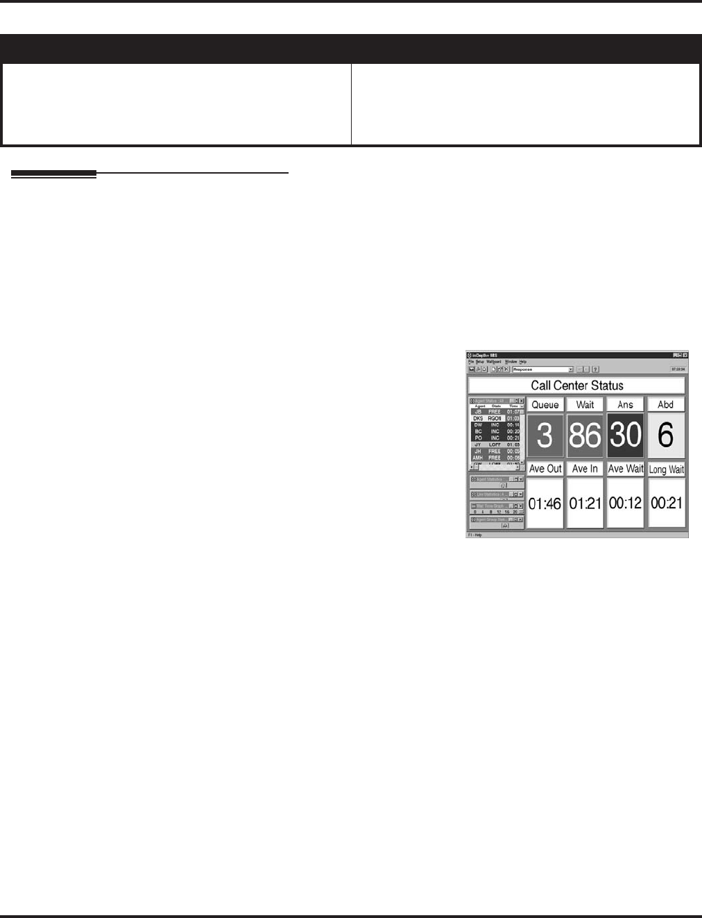
inDepth and inDepth+
364 ◆Features Aspire Software Manual
inDepth and inDepth+
Description
The inDepth and inDepth+ programs are Windows-based Management Information Systems that
work in conjunction with the built in Aspire ACD. These ACD/MIS systems enhance the system
ACD with real time statistics and reports on ACD group traffic patterns and usage. The inDepth and
inDepth+ applications have an extensive set of user-configurable Real Time Windows and Reporter
subsystems.
InDepth+ is the more comprehensive and capable of the ACD/MIS systems and offers:
●Real Time Status Window
This window displays ACD agent status, state
and connection state.
●Real Time Statistics Window
The statistics window provides a visual perfor-
mance summary for lines, agents and ACD
Groups.
●Call Queue and Wait Time Windows
These windows show the number of calls in
queue, the longest wait time, as well as the
number of calls answered and abandoned.
●Wallboard Template
Use the wallboard template display to motivate and inform ACD agents through a dynamic
display of real time statistics and messages.
●Reporter
ACD administrators can create fully-configurable reports for display and printing.
Similar in many respects to inDepth+, inDepth is streamlined for more modest ACD applications.
InDepth provides a single real time screen template, up to seven reports and can track report data
for up to one full month. InDepth includes ACD/MIS features like Report View/Print and Audible/
Visual Alarms, but excludes the Sub-Supervisor Positions and the Wallboard Support.
Aspire S Aspire M/L/XL
• Available, but not for ACD. Requires Aspire software
2.65+ and inDepth software 3.10.500.1 +. • Available (Optional feature) - Requires inDepth’s Aspire
software 3.10.500.1 or higher and the Feature Upgrade
PAL or Enhanced NTCPU when used with ACD. With
the Basic NTCPU and no ACD, software 2.65+ is
required.

inDepth and inDepth+
Aspire Software Manual Features ◆365
Hardware, Software and System Requirements
●PC 486 DX2-66 or higher with 8MByte RAM
●Windows 98SE, 2000, ME, NT or XP
●SVGA mode (800 x 600)
●4 Serial ports
●Network card for multiple MIS workstations
●Sound card
For more information, refer to the inDepth/inDepth+ Manual (P/N 0893230) for the specifics.
Conditions
(A.) The inDepth currently has a default setting for the phone system port of “4000”. As this is the
same port number used for the Aspire IP telephones, this must be changed to avoid any con-
flicts between the IP and inDepth program. A setting of “28000” is recommended. This
change is made in the Phone System Connection window under the inDepth Aspire Setup
option. When changing this port number in the inDepth, in order for the inDepth and Aspire
system to be able to communicate, it must also be changed in the Aspire Program 10-20-01,
External Equipment 2.
(B.) Uniden H.323 phones are not supported with the inDepth/inDepth+ application.
Refer to the inDepth/inDepth+ Manual (P/N 0893230) for additional information.
Default Setting
InDepth/inDepth+ not installed.
Programming
Refer to the inDepth/inDepth+ Manual (P/N 0893230) for the specifics.
Related Features
Refer to the inDepth/inDepth+ Manual (P/N 0893230) for the specifics.
Operation
Refer to the inDepth/inDepth+ Manual (P/N 0893230) for the specifics.

Intercom
366 ◆Features Aspire Software Manual
Intercom
Description
Intercom gives extension users access to other extensions. This provides the system with complete
internal calling capability.
Handsfree Answerback/Forced Intercom Ringing
Handsfree Answerback permits an extension user to respond to a voice-announced Intercom call by
speaking toward the phone, without lifting the handset. Like Handsfree, this is a convenience for
workers who don’t have a free hand to pick up the handset. Refer to Handsfree Answerback/
Forced Intercom Ringing (page 346) for more.
Busy Status Display
When a display keyset user places an Intercom call to a busy extension, the details of the busy sta-
tus (who it talking to the extension or which line is in use by the extension) can be displayed. The
details of the trunk’s busy status (the extension using the line) can be displayed after trying to
access the trunk. This feature provides a user information which can determine whether they should
use the Barge-In feature for the extension or trunk. This information automatically displays for a
keyset once programmed.
Conditions
Preventing ICM calls does not affect dialing other service codes, including 911.
Default Setting
Enabled.
Programming
For Intercom . . .
➻11-11-13 : Service Code Setup (for Setup/Entry Operation) - Display Language Selection
for Keyset
Select the service code which can be used at an extension to change the displayed language on
a keyset’s display (default: 178).
➻11-11-37 : Service Code Setup (for Setup/Entry Operation) - Adjusting Ring Volume
If required, change the service code used to adjust the ringing volume for CO and ICM calls
(829).
➻15-02-01 : Multi-Line Telephone Basic Data Setup - Display Language Selection
Select the language which should be used on a keyset’s display (0 = Japanese, 1 = English, 2 =
German, 3 = French, 4 = Italian, 5 = Spanish, 6 = Dutch, 7 = Portuguese, 8 = Norwegian, 9 =
Danish).
➻15-02-09 : Multi-Line Telephone Basic Data Setup - Ringing Line Preference for Inter-
com Calls
Use this option to select between Idle and Ringing Line Preference for Intercom calls. (0 =
Idle (off), 1 = Ringing (on)).
➻20-06-01 : Class of Service for Extensions
Assign a Class Of Service (1-15) to an extension.
Aspire S Aspire M/L/XL
• Available. • Available.

Intercom
Aspire Software Manual Features ◆367
➻20-08-01 : Class of Service Options (Outgoing Call Service) - Intercom Calls
In an extension’s Class of Service, enable (1) or disable (0) an extension’s ability to place
Intercom calls.
➻20-08-11 : Class of Service Options (Outgoing Call Service) - Protect ICM Call Mode
Switching by Caller
When an extension is set to ring mode for ICM calls, enabling this option prevents callers
from changing the call to voice announce mode (disable=0, enable=1).
➻20-11-07 : Class of Service Options (Hold/Transfer Service) - Transfer Without Holding
In an extension’s Class of Service, enable (1) or disable (0) an extension’s ability to Transfer a
call without holding. If the Busy Status Display feature is to be used, this option should be set
to “0”.
➻20-13-22 : Class of Service Options (Supplementary Service) - Busy Status Display
In an extension’s Class of Service, enable (1) or disable (0) an extension’s ability to use the
Busy Status Display feature.
➻20-17-01 : Operator’s Extension
Assign the operator’s extension.
➻20-18-01 : Service Tone Timer - Extension Dial Tone Time
Set the Extension Dial Tone Time (0-64800 seconds). After getting Intercom dial tone, a key-
set user has this interval to dial the first digit of the Intercom call.
➻21-01-02 : System Options for Outgoing Calls - Intercom Interdigit Time
Set the Intercom Interdigit Time (0-64800 seconds). When placing Intercom calls, users must
dial each digit within this interval.
➻82-01-01 : Incoming Ring Tone - Intercom Ring Tone
Customize the Intercom ring tone.
For Handsfree Answerback/Forced Intercom Ringing . . .
➻20-02-12 : System Options for Multi-Line Telephones - Forced Intercom Ringing
Determine if an extension’s ICM calls should be set as Forced Intercom Ringing (1). If dis-
abled (0), Intercom calls voice-announce. For all NEC Cordless phones (P/N 730082), this
option must be set to “1” as voice announce is not possible.
➻20-06-01 : Class of Service for Extensions
Assign a Class Of Service (1-15) to an extension.
➻20-08-10 : Class of Service Options (Outgoing Call Service) - Switching from Handsfree
Answerback to Forced Intercom Ringing
In an extension’s Class of Service, enable (1) or disable (0) an extension’s ability to toggle
between Handsfree Answerback and Forced Intercom Ringing for outgoing Intercom calls
(dial 1 or Service Code 812).
➻20-09-05 : Class of Service Options (Incoming Call Service) - Setting Handsfree Answer-
back/Forced Intercom Ringing
In an extension’s Class of Service, enable (1) or disable (0) an extension’s ability to set
Handsfree Answerback (Service Code 821) and Forced Intercom Ringing (Service Code 823)
for incoming Intercom calls.
➻20-13-06 : Class of Service Options (Supplementary Service) - Automatic Off Hook Signaling
In an extension’s Class of Service, enable (1) or disable (0) the extension’s ability to automat-
ically send Off Hook Signals while busy on a handset call. Setting this option to “0” will pre-
vent Intercom calls from ringing the CALL2 key - instead the caller will hear a busy signal.
➻80-01-01 : Service Tone Setup - Tone 28, Speaker Monitor Tone
This tone changes the tone the originator of an ICM call hears. (The tone cannot be changed
for what is heard by the user when receiving an ICM call.)

Intercom
368 ◆Features Aspire Software Manual
Related Features
Handsfree Answerback/Forced Intercom Ringing
Intercom calls can ring or be voice-announced at the called extension.
Intercom Abandoned Call Display
Intercom Abandoned Call Display remembers the last five Intercom calls to an extension.
Line Preference
Ringing Line Preference can automatically answer ringing Intercom or trunk calls when the
user lifts the handset.
Name Storing
An extension can have a name assigned that identifies the extension to callers.
Operation
To place an Intercom call:
1. At keyset, press idle CALL key.
OR
At single line telephone, lift handset.
2. Dial extension number (or 0 for your operator).
Your call may voice-announce or ring the called extension. Dial 1 to change the way
your call alerts the called extension.
If the extension you call is busy or doesn’t answer, you can dial another extension
without hanging up.
To answer an Intercom call:
1. If you hear two beeps, speak toward phone.
Your telephone picks up your voice.
OR
If your telephone rings, lift handset.
To check your extension’s data (Keyset Only):
1. Press CHECK.
2. Press CALL1.
You display shows your telephone’s extension number, port number and extension/
Department Group.
You can also check any other extension numbers information y pressing CHECK + the
extension number.
3. Press CLEAR to return the normal time/date display.
To change how Intercom calls ring your extension:
1. Press the CALL key or lift the handset.
2. Dial 823 to have calls ring your extension
OR
3. Dial 821 to have calls voice announce to your extension.

Intercom Abandoned Call Display
Aspire Software Manual Features ◆369
Intercom Abandoned Call Display
Description
Intercom Abandoned Call Display shows a display keyset user a list of Intercom calls placed to
them that they did not answer. This is a convenience if a user has to temporarily leave their desk.
When they return, they can display the list to find out who called while they were out.
Conditions
Intercom Abandon Call Display remembers the last five Intercom calls to an extension.
Default Setting
Enabled.
Programming
None
Related Features
Intercom
Intercom gives extension users access to other extensions.
Operation
To display the list of Intercom calls you did not answer.
1. Press CHECK.
2. Press CALL2.
Repeatedly press CALL2 until no more calls display.
3. Press CLEAR to return to the normal Time and Date display.
Aspire S Aspire M/L/XL
• Available. • Available.
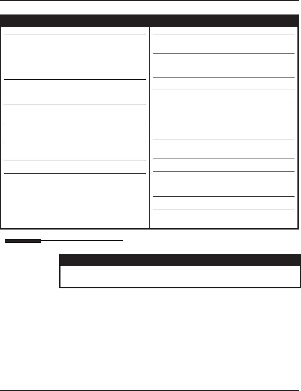
ISDN Compatibility
370 ◆Features Aspire Software Manual
ISDN Compatibility
Description
SMDR Includes Dialed Number
The SMDR report can optionally print the trunk’s name (entered in system programming) or the
number the incoming caller dialed (i.e., the dialed ISDN digits). This gives you the option of ana-
lyzing the SMDR report based on the number your callers dial. (This option also applies to a DID
trunk as well.)
Display Shows Why Caller ID is Not Available
With Caller ID enabled, the system will provide information for ISDN calls that do not contain the
Caller ID information. If the Caller ID information is restricted, the telephone display will show
“PRIVATE”. If the system is not able to provide Caller ID information because the telco informa-
tion is not available, then the display will show “OUT OF AREA”.
Aspire S Aspire M/L/XL
• PRI Not Available.
• BRI S-Bus Available.
BRI T-Bus Not Yet Available.
• CLIP display available with software 1.02+.
• Calling Party allowed for extension with software 1.04+.
• Option for alert tone for S-Bus terminals calling busy
extension available with 2.63+ software.
• T303 timer operation mode option available with 2.63+
software.
• Option for PB Back Tone Level available with 2.63+
software.
• Ringback tone for BRI trunks requires software 4.04+.
• Calling Party Number option to define type requires
software 4.08+.
• PRI Available.
• BRI S-Bus Available.
BRI T-Bus Not Yet Available.
• This feature requires the Basic NTCPU (P/N 0891002)
with the PAL upgrade or the Enhanced NTCPU (P/N
0891038) unless using software 4.0E or higher.
• CLIP display available with software 1.02+.
• Calling Party allowed for extension with software 1.04+.
• Option for alert tone for S-Bus terminals calling busy
extension available with 2.63+ software.
• T303 timer operation mode option available with 2.63+
software.
• Option for PB Back Tone Level available with 2.63+
software.
• 2 B-Channel Transfer for PRI requires software 2.63+.
• Alternate Carrier Access added to ISDN trunks with
ARS requires software 2.64+. Refer to the Automatic
Route Selection (page 138) for additional information.
• Ringback tone for BRI trunks requires software 4.04+.
• Calling Party Number option to define type requires
software 4.08+.
!! Important !!
ISDN is an emerging technology on the leading edge of international digital communication’s net-
working. Always check with your NEC’s Technical Service Representative before setting up your ISDN
application. Working together will ensure maximum compatibility and reliable ISDN performance.

ISDN Compatibility
Aspire Software Manual Features ◆371
Calling Party Number Notification
The system can provide calling party number notification for outgoing ISDN calls. When a call is
made on an ISDN line by an extension, the system will send the identification for the extension
placing the call, if it’s programmed. If there is no Extension Calling Number assigned, the system
will send the calling number for the ISDN trunk. If both the extension and trunk information is pro-
grammed, the extension information will be sent as it takes priority.
When the option for calling party subaddress is on, the extension number will be sent as the subad-
dress information. Both the calling party number and calling party subaddress are sent in a SETUP
message as the calling party information element and a calling party subaddress information ele-
ment. Allow the system to send the subaddress by setting the following programs: 10-03-05=1, 15-
01-04=1, 20-08-13=1, 21-13-01=enter number to be sent.
Calling Line Identification Presentation
A Class of Service option has been added which can be used to allow the Calling Party Number IE
in the Setup Message.
Calling Party Allowed or Prevented for Extension
The system now allows the Calling Party Number for outgoing ISDN calls based on the extension’s
set up in Program 15-01-04 : Basic Extension Data Setup - ISDN Caller ID. If this option is to
be enabled, then it must also be enabled for the BRI or PRI PCB in 10-03-05 : PCB Setup - CLIP
Information.
Alert Tone When S-Bus Terminal Calls Busy Extension
System software provides a program option for S-Bus terminals to determine what a user on an S-
Bus terminal will hear when a busy extension is called. The system can be programmed so the user
will hear an alert tone or be disconnected.
Release Message with Second T303 Timer
Depending on your software, the system can provide an program option for ISDN trunks can be
used to determine whether or not a release message is sent when the second T303 timer expires.
Option Added for PB Back Tone Level
An option is available in system software which can be used to adjust the PB Back Tone level when
calling an ISDN line.
Calling Party Number Option Added to Define Type
System software allows the number plan type to be defined in programming. Previously, this was
not selectable and, depending on your software, was either set for "Unknown" or "National number
in a ISDN numbering plan" to allow the calling party information to be passed to some telcos.
With software 4.08, this option was programmable using Programs 99-01-32 and 99-01-33, allow-
ing the system to be adjusted for this setting. With software 4.93+, these programs have been
replaced by 10-03-18 and 10-03-19.

ISDN Compatibility
372 ◆Features Aspire Software Manual
Primary Rate Interface (PRI)
The system is compatible with ISDN Primary Rate Interface (PRI) services. PRI services currently
supported include:
●Basic PRI Call Control (BCC)
●Display of incoming caller’s name and number when allowed by telco
●Routing in the system based on the number the caller dialed
●ISDN maintenance functions (such as In Service/Out of Service Messaging)
●Speech and 3.1 KHz audio
PRI capability requires the installation of T1/PRI Interface PCBs (0891009). Each PCB (also called a
PRI circuit) provides 24 PRI channels (23B + D) 1 with 64K Clear Channel response. The T1/PRI Inter-
face PCB uses a single slot.
When installed, the T1/PRI Interface PCB uses the first block of 24 consecutive trunks. For example, if
you have an 8COIU PCB installed for trunks 1-8, the T1/PRI Interface PCB will automatically use
trunks 9-32. If you have 8COIU PCBs installed for trunks 1-8 and 17-24, the T1/PRI PCB will use
trunks 25-48. The T1/PRI Interface cannot use trunks 9-16 (even if available) since they are not part of a
consecutive block of 24 trunks.
Trunk Number Translation for Channel ID Based on Trunk Group Number
The Channel ID of an incoming SETUP message on a PRI line is related to the trunk group number. The
system will create the trunk line number as the lowest trunk port number in the range of the same trunk
group related to the channel number of the Channel ID information element of an incoming call’s
SETUP message.
For example, referring to the chart below, the system translates the call as being trunk port 4.
Notes:
●In addition to T1/PRI Interface PCBs, PRI also requires a CSU/DSU Unit and interconnecting
cables to interface with the telco.
●Each T1/PRI Interface PCB is switch selectable between T1 and PRI operation. For more on
T1 Trunking, go to “T1 Trunking (with ANI/DNIS Compatibility)”.
1. Each T1/PRI Interface PCB provides 23 voice (B) and 1 data (D) channel.
Trunk
Number
Trunk
Group
Channel
Number
111
212
313
424
525
6 2 6 <--- Incoming Call
727
858
959
. . . 23 . . . 5 . . . 23

ISDN Compatibility
Aspire Software Manual Features ◆373
Two B-Channel Transfer for PRI
Depending on your software, the system may have the ability for a keyset or single line telephone
to use the optional “Two B-Channel Transfer for PRI” service provided by some National ISDN
carriers in the U.S. (comparable to an analog centrex).
This service supports trunk-to-trunk transfer on the telco side. With this option enabled, two trunk
calls on the Aspire system can be connected together by the telco, releasing the trunks from the
Aspire and connecting the outside parties together.
The Aspire can perform a trunk-to-trunk transfer in the following cases:
●Put a PRI trunk call on hold and call/answer another PRI trunk. Press the Transfer
(Program 15-07 or SC 851: 06) or CONF key.
The status and bearer capability of the two trunks both meet the service requirements.
●Put a PRI trunk call on hold and call/answer another PRI trunk, then go on-hook
(Program 20-11-21 must be enabled "0").
The status and bearer capability of the two trunks both meet the service requirements.
To use the ISDN Two B-Channel Transfer, the system sends a Facility Message to the currently
active PRI trunk and then sets the retry timer (Program 24-02-09). The system will resend the Facil-
ity timer based on the retry timer. If there is no response after the 3rd resend, the system considers
the transfer as failed and stops resending.
When the transfer has succeeded, the telco sends the information to the system in the Facility, Dis-
connect or Release Message. When the system receives a Facility Message, it sends back Discon-
nect or Release then releases the trunks. When the system receives a Disconnect or Release, the
system simply releases the trunks (the other trunk will also receive a Disconnect or Release).
If the transfer fails, the telco sends the system Facility message with the fail information (some tel-
cos may send an Alerting, Disconnect or Release Message). In this case, the trunks are not trans-
ferred and remain in the system.
With this feature, the following conditions apply:
●Only manual transfers (such as pressing the Transfer key or going on-hook) are supported
with this feature. Aspire PRI trunks cannot perform a trunk-to-trunk transfer in the following
cases:
A. Pressing the Transfer (Program 15-07 or SC 851: 06) or CONF key while in a Conference
call with two trunks (Unsupervised Conference feature).
B. The incoming trunk call is automatically transferred to another trunk by system program-
ming (such as Call Forward Off-Premise).
●The bearer capability of the two calls must be “Speech, 3.1-kHz Audio, Unrestricted Digital
information” or compatible.
●At least one call must have been answered. The other call must:
- have already received ALERT message if it is an outgoing call
OR
- already have been answered if it is an incoming call.
●The regular Tandem Trunking programming must also be set to enable this feature.
●This feature does not support S-Bus.
●When used with Aspire Networking, this feature will work only when the two trunks are in the
same system.

ISDN Compatibility
374 ◆Features Aspire Software Manual
Basic Rate Interface (BRI)
Your system also provides compatibility with ISDN Basic Rate (BRI) services, including:
●Basic BRI Call Control (BCC)
●Point-to-Point BRI Terminal Connection (no daisy-chaining)
●Multipoint BRI Terminal Connection (daisy-chaining)
●S-Bus (allows BRI PCB's to be used as either a trunk or station interface)
BRI services require the installation of BRI Interface PCBs (2BRIU P/N 0891050 (Aspire S) or
0891006 (Aspire), 4BRIU P/N 0891007, 8BRIU, P/N 0891008). Each 2BRI Interface PCB has two
BRI circuits. The 4BRI Interface PCB has four BRI circuits, while the 8BRI has eight BRI circuits.
The BRI Interface PCBs use a single universal slot.
●2BRI (Aspire S: P/N 0891050, Aspire: P/N 0891006):
●Provides 30 BRI circuits and 60 BRI channels.
Each PCB takes up 8 ports. If any circuits set for T-Bus, the next set of 4 trunk ports
are used. If any circuits are set up for S-Bus, the next 4 station ports are used.
●4BRI PCB (P/N 0891007)
●Provides 60 BRI circuits and 120 BRI channels.
Each PCB takes up 16 ports. If any circuits set for T-Bus, the next set of 8 trunk ports
are used. If any circuits are set up for S-Bus, the next 8 station ports are used.
●8BRI PCB (P/N 0891008)
●When used as T-Bus, provides 96 BRI circuits and 192 BRI channels. When used as S-
Bus, 120 BRI circuits and 240 S-Bus stations ports are provided.
Each PCB takes up 32 ports. If any circuits set for T-Bus, the next set of 16 trunk ports
are used. If any circuits are set up for S-Bus, the next 16 station ports are used.
Each BRI Has Two TEI’s
For each BRI line, two different TEI’s will be assigned to two different SPID’s.
The two different SPID’s for each BRI line, will be related to different trunk logical port numbers.
One BRI provides two trunk logical ports when it is connected to a CO line. Each SPID is assigned
to a different TEI. This relationship is made in the initialization of the BRI line when it is connected
to the CO.
This relationship between SPID and TEI’s are created as follows.
LOGICAL-PORT-NUMBER + 0 = SPID-1
LOGICAL-PORT-NUMBER + 1 = SPID-2
When using the SMDR reports for BRI, all incoming BRI calls will be displayed under the CLASS
column as “IVIN”.
Automatic Data Link Failure Recovery
If a data link error is detected by the BRI PCB, the system will try to recover the data link and send the
SPID to the central office. To provide this enhancement, the BRI PCB must be able to indicate to the sys-
tem when a data link error has occurred.
Note: In addition to BRI Interface PCBs, BRI Services require the installation of NT1 Network
Terminators and interconnecting cabling.

ISDN Compatibility
Aspire Software Manual Features ◆375
BRI and DID Callers with Non-Matching SPID Numbers
This feature allows you to determine whether the system will check the called party number with
the SETUP message and the SPID setup. Depending on the system programming, this can allow
DID calls to be received on BRI trunks and direct them according to the DID Translation Table
(Program 22-11-03).
Ringback Tone to Telco Now Possible with BRI Trunks
An option is available using Program 10-03-17 which can be used to determine whether or not the
system sends ringback tone to the telco.
Conditions
Refer to the ISDN-BRI Manual (P/N TBD) and ISDN-PRI Manual (P/N 0893212) for the specifics.
Default Setting
None
Programming
Refer to the ISDN-BRI Manual (P/N TBD) and ISDN-PRI Manual (P/N 0893212) for the specifics.
➻10-03-01 : PCB Setup - ISDN Line Mode
Setup and confirm the Basic Configuration data for each PCB. This program selects the ISDN
Line Mode: 0=Not set, 1=T-Bus, 2=S-Bus, 3=Network Mode (Leased Line), 4=Network
Mode (Interconnected Line), 5=Network Mode (Interconnected Line, Fixed Layer 1=NT),
6=S-Point (Leased Line). The option selected here determines the clock source for a net-
worked system. With option 3, telco sends the clock to the master and slave systems. With
option 4, the master system sends the clock to telco which then sends the clock to the slave
system (with no telco, the master system sends the clock directly to the slave system). With
option 5, the master and slave systems both send the clock to telco.
➻10-03-02 : PCB Setup - Logical Port Number
Setup and confirm the Basic Configuration data for each PCB. This program displays the start
port number of a PRI line. Thirty logic ports are automatically assigned to a PRI line (T-Bus =
1-200, S-Bus = 1-256).
➻10-03-03 : PCB Setup - CRC Multi-Frame (CRC4)
Setup and confirm the Basic Configuration data for each PCB. This program determines
whether or not the CRC Multi-Frame (CRC4) is used (0=off, 1=on).
➻10-03-04 : PCB Setup - Layer 3 Timer Type
Setup and confirm the Basic Configuration data for each PCB. This program selects the Layer
3 timer type (1-5). Each timer value of Layer 3 is set up for each type in Program 81-06 (T-
Bus) and Program 82-06 (S-Bus).
➻10-03-05 : PCB Setup - CLIP Information
Based on this setting, the system will include a “Presentation Allowed” (1) or “Presentation
Restricted” (0) in the Setup message to allow or deny the Calling Party Number. Program 15-
01-04 must also be set to a ‘1’ if this option is enabled.
➻10-03-06 : PCB Setup - Length of Cable
Setup and confirm the Basic Configuration data for each PCB. Select the length of cable to be
used (0=0-40m, 1=40 81m, 2=81-122m, 3=122-162m, 4=162-200m).
➻10-03-07 : PCB Setup - S-Point DID Digits
Setup and confirm the Basic Configuration data for each PCB. This program selects number
of DID digits to be received (0-4).

ISDN Compatibility
376 ◆Features Aspire Software Manual
➻10-03-08 : PCB Setup - Dial Sending Mode
Setup and confirm the Basic Configuration data for each PCB. Select either enblock or over-
lap sending (0=Enblock Sending, 1=Overlap Sending).
➻10-03-09 : PCB Setup - Dial Information Element
Setup and confirm the Basic Configuration data for each PCB. If Overlap Sending is selected
in Program 10-03-08, select either Keypad Facility (0) or Called Party Number (1) for the dial
information element.
➻10-03-10 : PCB Setup - Master/Slave System
Setup and confirm the Basic Configuration data for each PCB. If the system is networked, set
the system as either the slave (0) or master (1) system.
➻10-03-11 : PCB Setup - Networking System Number
Setup and confirm the Basic Configuration data for each PCB. If the system is networked,
define the system number (0-50).
➻10-03-12 : PCB Setup - Short/Long Haul
Setup and confirm the Basic Configuration data for each PCB. Select either short-haul (0) or
long-haul (1).
➻10-03-13 : PCB Setup - Loss-of-Signal Detection Limit
Setup and confirm the Basic Configuration data for each PCB. Select the loss-of-signal detec-
tion limit. In short-haul mode: 0=0.91V, 1=0.74V, 2=0.59V, 3=0.42V, 4=0.32V, 5=0.21V,
6=0.16V. 7=0.10V. In long-haul mode: 0=1.70V, 1=0.84V, 2=0.84V, 3=0.45V, 4=0.45V,
5=0.20V, 6=0.10V, 7=not defined
➻10-03-14 : PCB Setup - Service Protocol for S-Point
Setup and confirm the Basic Configuration data for each PCB. Select the service protocol to
be used (0=keypad facility, 1=specified protocol for Aspire).
➻10-03-15 : PCB Setup - Call Busy Mode for S-Bus
For S-Bus terminals, use this program to determine what a user on an S-Bus terminal will hear
when a busy extension is called. If this option is set to "0", the user will hear an alert tone. If
this option is set to "1", the user will be disconnected. By default, this option is set to "0".
➻10-03-16 : PCB Setup - ISDN 2 B-Channel Transfer
For PRI, enable (1) or disable (0) the 2 B-Channel Transfer function for a PRI PCB.
➻10-03-17 : PCB Setup - Ringback to Telco
For BRI trunks, this option can be used to determine whether or not the system sends ringback
tone to the telco (0 = Disable, 1 = Enable, Default Setting: 0).
➻10-03-18 : IN Options - Type of Number (software 4.93+)
Use this option to define the ISDN numbering plan to allow the calling party information to be
passed to some telcos. Note that with software 4.08-4.0W, Program 99-01-32 was used
instead. (0 = Unknown, 1 = International number, 2 = National number, 3 = Network Specific
number, 4 = Subscriber number, 5 = Abbreviated number - Default: 3 (National number))
➻10-03-19 : IN Options - Numbering Plan Identification (software 4.93+)
Use this option to define the ISDN numbering plan to allow the calling party information to be
passed to some telcos. Note that with software 4.08-4.0W, Program 99-01-33 was used
instead. (0 = Unknown, 1 = ISDN numbering plan, 2 = Data numbering plan, 3 = Telex num-
bering plan, 4 = National standard numbering plan, 5 = Private numbering plan - Default: 1
(ISDN numbering plan))
➻10-31-01 : Networking Keep Alive Setup - Keep Alive Interval
If this program is greater than “0”, networked PRI spans using Kentrox DSUs will not resync
when removed from serviced then placed back into service.
➻14-01-13 : Basic Trunk Data Setup - Loop Supervision
For each trunk that should be able to participate in a tandem call, enter 1. To disable a trunk
from Tandem Trunking, enter 0 (Default Setting: 1). Required for 2 B-Channel Transfer.

ISDN Compatibility
Aspire Software Manual Features ◆377
➻15-01-04 : Basic Extension Data Setup - ISDN Caller ID
If both Program 15-01-04 and 10-03-05 are enabled (1), the system includes Caller ID in the
Setup message as “Presentation Allowed”. If these options are disabled (0), it will be “Presen-
tation Restricted”.
➻15-02-29 : Multi-Line Telephone Basic Data Setup, ISDN Back Tone
This program option can be used to adjust the PB Back Tone level when calling an ISDN line.
(Entries: 1-63 [-15.5 to +15.5 db in 0.5 dB steps], Default Setting: 32)
➻15-07-01 : Programmable Function Keys
Assign a function key for Caller ID Block for ISDN (63) if required.
➻20-06-01 : Class of Service for Extensions
Assign a Class of Service (1-15) to an extension.
➻20-08-13 : Class of Service Options (Outgoing Call Service) - ISDN CLIP
Determine if the ISDN calling line identity presentation and screening indicators are to be
allowed (1) or disabled (0).
➻20-08-14 : Class of Service Options (Outgoing Call Service) - ISDN Call Address
Information
Determine whether the sub-address should be sent for outoing ISDN calls (0=disabled,
1=enabled).
➻20-09-02 : Class of Service Options (Incoming Call Service) - Caller ID Display
In an extension’s Class of Service, enable (1) or disable (0) the extension’s ability to display
incoming Caller ID name/number information.
➻20-09-03 : Class of Service Options (Incoming Call Service) - Sub Address Identification
In an extension’s Class of Service, enable (1) or disable (0) the extension’s ability to display
the Caller Sub-Address.
➻20-11-11 : Class of Service Options (Hold/Transfer Service) - Automatic On Hook Transfer
In an extension’s Class of Service, enable (1) or disable (0) the extension’s ability to use Auto-
matic On Hook Transfer. If enabled, user must press HOLD and dial the extension number to
Transfer the call. If disabled, a user must have a Transfer Programmable Function Key. Used
with 2 B-Channel Transfer.
➻20-11-14 : Class of Service Options (Hold/Transfer Service) - Trunk-to-Trunk Transfer
For each Class of Service, allow (0) or deny (1) Trunk-to-Trunk Transfer (Default Setting: 1).
Required for 2 B-Channel Transfer.
➻20-11-21 : Class of Service Options (Hold/Transfer Service) - Restriction for Tandem
Trunking on Hang Up
Allow (0) or deny (1) an extension user’s ability to set up a tandem call automatically when
they hang up. By default, this option is allowed (0). Required for 2 B-Channel Transfer.
➻20-13-23 : Class of Service Options (Supplementary Service) - Display the Reason for
Transfer
Enable (1) or disable (0) an extension’s ability to display the reason (Call Forward, Busy, No
Answer or DND) a VRS, DID, DISA, or ISDN call is being transferred to their extension.
➻20-08-13 : Class of Service Options (Outgoing Call Service) - ISDN CLIP
Determine if the ISDN calling line identity presentation and screening indicators are to be
allowed (0=disabled, 1=enabled).
➻20-25-14 : ISDN Options - Operation Mode When Second T303 Timer Expires
This option can be used to determine whether or not a release message is sent when the sec-
ond T303 timer expires. (Entries: 0=normal/off, 1=send release message, Default Setting: 0)

ISDN Compatibility
378 ◆Features Aspire Software Manual
➻21-12-01 : ISDN Calling Party Number Setup for Trunks
Assign Calling Party Numbers for each trunk (maximum 16 digits per entry). When a call is
made by an extension which does not have an Extension Calling Number assigned (Program
21-13), the system sends the calling number for the ISDN trunk defined in 21-12. If the Call-
ing Party Number is assigned in both Programs 21-12 and 21-13, the system sends the data in
Program 21-13.
➻21-13-01 : ISDN Calling Party Number Setup for Extensions
Assign each extension a Calling Party Number (maximum 16 digits per entry). The calling
number is the subscriber number of the dial-in number. When a call is made by an extension
which does not have an Extension Calling Number assigned (Program 21-12), the system sends
the calling number for the ISDN trunk defined in Program 21-13. If a Calling Party Number is
assigned in both Programs 21-12 and 21-13, the system sends the data in Program 21-13 if
allowed in Program 20-08-13.
➻22-02-01 : Incoming Call Trunk Setup
Assign the incoming trunk type for each trunk. There is one item for each Night Service
Mode.
➻22-11-01 : DID Translation Table Number Conversion
Specify for each Translation Table entry (2000):
●The digits received by the system (eight max.)
●The extension the system dials after translation (24 digits max.)
●The name that should show on the dialed extension’s display when it rings (twelve charac-
ters max.)
●The Transfer Target-1 and 2
●If the Transfer Targets are busy or receive no answer, those calls are transferred to the final
transfer destination (Program 22-10).
●Operation mode
➻24-02-09: System Options for Transfer - ISDN Transfer Resend Timer
Determine how long the system should resend a Facility Message to the currently active PRI
trunk when the 2 B-Channel Transfer feature is used. The system will resend the Facility timer
based on this timer. If there is no response after the 3rd resend, the system considers the trans-
fer as failed and stops resending. (Entries: 1-30 seconds, Default Setting: 10 seconds)
➻99-01-32 : MF Options - Type of Number (software 4.08-4.0W)
Use this option to define the ISDN numbering plan to allow the calling party information to be
passed to some telcos. Note that this program is changed to Program 10-03-18 with soft-
ware 4.93+. (1=Unknown, 2=International number, 3=National number, 4=Network Specific
number, 5=Subscriber number, 6=Abbreviated number - Default: National number)
➻99-01-33 : MF Options - Numbering Plan Identification (software 4.08-4.0W)
Use this option to define the ISDN numbering plan to allow the calling party information to be
passed to some telcos. Note that this program is changed to Program 10-03-19 with soft-
ware 4.93+. (1=Unknown, 2=International number, 3=National number, 4=Network Specific
number, 5=Subscriber number, 6=Abbreviated number - Default :ISDN numbering plan)

ISDN Compatibility
Aspire Software Manual Features ◆379
Related Features
Forced Trunk Disconnect
This feature only works on analog trunk. ISDN trunks do not have the Forced Trunk Discon-
nect available.
Transfer
Transferred calls on DISA, DID, ISDN trunks, or from the VRS can display the reason a call
is being transferred (Call Forward, Busy, No Answer, or DND).
Networking
Trunk-to-Trunk transfer of ISDN PRI calls will work only when the two trunks are in the
same system.
Refer to the ISDN-BRI Manual (P/N TBD) and ISDN-PRI Manual (P/N 0893212) for the specifics.
Operation
Refer to the ISDN-BRI Manual (P/N TBD) and ISDN-PRI Manual (P/N 0893212) for the specifics.
Two B-Channel Transfer
1. Establish a PRI trunk call.
2. Press HOLD.
3. Establish or answer a second PRI trunk call.
4. Press the Transfer key (PGM 15-07 or SC 851: 06) to perform the trunk-to-trunk transfer.
5. If the transfer is successful, the B-Channel is released.
If the transfer failed, the trunks remain active on the Aspire system.

Last Number Redial
380 ◆Features Aspire Software Manual
Last Number Redial
Description
Last Number Redial allows an extension user to quickly redial the last number dialed. For example,
a user may quickly recall a busy or unanswered number without manually dialing the digits.
Last Number Redial saves in system memory the last 24 digits a user dials. The number can be any
combination of digits 0-9, # and *. The system remembers the digits regardless of whether the call
was answered, unanswered or busy. The system normally uses the same trunk group as for the ini-
tial call. However, the extension user can preselect a specific trunk if desired.
Redial List
The system allows display telephones to have a Redial List. Up to 10 dialed numbers (both external
and internal destinations) are automatically stored in the Redial List. The user can display and
select one of the stored numbers and then redial it. If more than 10 destination numbers are dialed,
the oldest number is automatically erased to make room for the new number.
i-Series Phones Operation Different from Aspire Phones
When an i-Series telephone is connected to the Aspire system, the Last Number Redial operation is
slightly different.
When pressing the LND key, the display indicates "REDIAL [#] / ABB". The user can then press #
to redial the number displayed, or enter an Abbreviated Dialing bin number to be dialed. Pressing
the # key repeatedly will scroll through the last 10 numbers dialed.
Conditions
Redial List requires the use of a display telephone. Non-display and single line phones can not use
this feature.
Default Setting
Enabled.
Programming
➻11-12-12 : Service Code Setup (for Service Access) - Last Number Dial
Assign a service code (#5) to use Last Number Dial.
➻11-12-17 : Service Code Setup (for Service Access) - Clear Last Number Dialing Data
Assign a service code (876) to clear the Last Number Dial.
➻15-02-13 : Multi-Line Telephone Basic Data Setup - Redial List Mode
Select the type of numbers that will be stored in the Redial List - Internal and External num-
bers (0) or External only (1).
Aspire S Aspire M/L/XL
• Available.
• Number deletion operation enhanced with software
4.93+.
• Available.
• Number deletion operation enhanced with software
4.93+.

Last Number Redial
Aspire Software Manual Features ◆381
Related Features
Automatic Route Selection
When using Automatic Route Selection, ARS selects the trunk for the call unless the user preselects.
Repeat Redial
The system can periodically redial an unanswered trunk call.
Save
A user can save the number of an outgoing call to be accessed at a later time.
Operation
To redial your last call:
1. Without lifting the handset, press LND.
The last dialed number is displayed.
2. To redial the last number, press #.
OR
Search for the desired number from the Redial List by pressing the LND or VOLUME ▲ or
VOLUME ▼ keys.
3. Lift the handset or press SPK to place the call.
The system automatically selects a trunk from the same group as your original call and
dials the last number dialed.
OR
1. At keyset, press idle line key (optional).
The system automatically selects a trunk from the same group as your original call.
2. Press LND.
OR
1. At keyset, press idle CALL key.
OR
At single line telephone, lift handset.
2. Dial #5.
The system automatically selects a trunk from the same group as your original call and
dials the last number dialed.
To redial your last call on an i-Series phone:
1. Press LINE + LND + #.
OR
2. Press LND + CALL key or # to redial the displayed number or press the LND key until the
desired number is displayed, then press # or CALL key.
If a line key is not pressed, the system automatically selects a trunk from the same
group as the original call.
OR
3. Press CALL key + #5.
If a line key is not pressed, the system automatically selects a trunk from the same
group as the original call.

Last Number Redial
382 ◆Features Aspire Software Manual
To check the number saved for Last Number Redial:
1. Press LND.
The stored number displays for six seconds. The stored number dials out if you:
- Lift the handset,
- Press an idle line key,
- Press an idle CALL key, or
- Press SPK
2. Press CLEAR.
To erase all the stored numbers:
1. At keyset, press idle CALL key.
OR
At single line telephone, lift handset.
2. Dial 876.
To erase one or all LND numbers:
1. From an idle keyset, press the LIST soft key then press the REDIAL soft key.
OR
From an idle keyset, press LND.
2. If deleting just one number, scroll to the number.
If deleting all numbers in the LND list, skip to Step 3.
3. Press the DEL soft key. The display shows:
4. If deleting just one number, press the ONE soft key.
If deleting all numbers in the LND list, press the ALL soft key.
5. When deleting all numbers in the LND list, the display then prompts for a confirmation. Press
the YES soft key to delete all the numbers, or press the NO soft key to return to the previous
display.
6. Press the CLEAR key to return the phone to an idle state, or it will return to an idle state after
approximately 10 seconds.
REDIAL-01 2035551234
One All

Line Preference
Aspire Software Manual Features ◆383
Line Preference
Description
Line Preference determines how a keyset user places and answers calls. There are two types of
Line Preference: Incoming Line Preference and Outgoing Line Preference.
Incoming Line Preference
Incoming Line Preference establishes how a keyset user answers calls. When a call rings the keyset,
lifting the handset answers either the ringing call (for Ringing Line Preference) or seizes an idle
line (for Idle Line Preference). The idle line can provide either Intercom or trunk dial tone (see
Outgoing Line Preference below). Ringing Line Preference helps users whose primary function is
to answer calls (such as a receptionist). Idle Line Preference is an aid to users whose primary func-
tion is to place calls (such as a telemarketer).
Outgoing Line Preference
Outgoing Line Preference sets how a keyset user places calls. If a keyset has Outgoing Intercom
Line Preference, the user hears Intercom dial tone when they lift the handset. If a keyset has Out-
going Trunk Line Preference, the user hears trunk dial tone when they lift the handset. Outgoing
Line Preference also determines what happens at extensions with Idle Line Preference. The user
hears either trunk (“dial 9”) or Intercom dial tone.
Auto-Answer of Non-Ringing Lines
With Auto-Answer of Non-Ringing Lines, an extension user can automatically answer trunk calls
that ring other extensions (not their own). This would help a user that has to answer calls for co-
workers that are away from their desks. When the user lifts the handset, they automatically answer
the ringing calls based on Trunk Group Routing programming. The extension user’s own ringing
calls, however, always have priority over calls ringing other co-worker’s extensions.
Conditions
If a keyset extension has more than one call ringing its line keys, Ringing Line Preference answers
the calls on a first-in first-answered basis.
Default Setting
Enabled.
Programming
➻14-05-01 : Trunk Groups
For Auto-Answer of Non-Ringing Lines, assign trunks to trunk groups. This is part of Trunk
Group Routing programming.
➪Aspire S: Trunks 1-8
➪Aspire: Trunks 1-100
➻14-06-01 : Trunk Group Routing
For Auto Answer of Non-Ringing Lines, program the Trunk Group Routing table. Auto
Answer uses this table to determine the answer sequence for ringing calls.
➪Aspire S: Trunk Groups 1-8
➪Aspire: Trunk Groups 1-100
Aspire S Aspire M/L/XL
• Available. • Available.
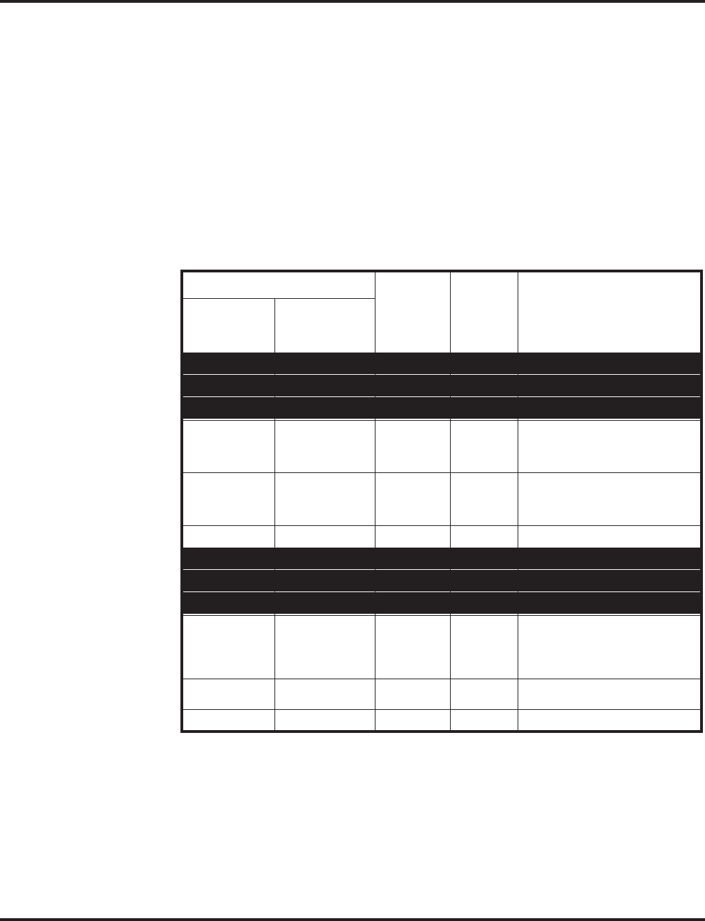
Line Preference
384 ◆Features Aspire Software Manual
➻14-07-01 : Trunk Access Map Setup
For Outgoing Line Preference and Auto-Answer of Non-Ringing Lines, set up the Trunk
Access Maps.
➪Aspire S: Trunk Access Maps 1-8
➪Aspire: Trunk Access Maps 1-200
➻15-01-02 : Basic Extension Data Setup - Outgoing Trunk Line Preference
Enable (1) or disable (0) Outgoing Trunk Line Preference for extensions.
➻15-02-09 : Multi-Line Telephone Basic Data Setup - Ringing Line Preference for
Intercom Calls
Enable Idle (0) or Ringing (1) Line Preference for Intercom calls. See the table below for
interaction.
➻15-02-10 : Multi-Line Telephone Basic Data Setup - Ringing Line Preference for Trunk
Calls
Enable Idle (0) or Ringing (1) Line Preference for trunk calls. See the table below for interaction.
Note: Program 22-01-01 sets Intercom (0) or trunk (1) call priority.
➻15-06-01 : Trunk Access Map for Extensions
For Outgoing Line Preference and Auto-Answer of Non-Ringing Lines, assign trunk Access
Maps to extensions.
➪Aspire S: Trunk Access Maps1-8
➪Aspire: Trunk Access Maps 1-200
Program
Ringing
Intercom
Call
Ringing
Trunk
Call Lifting the handset
15-02-09
(Intercom
Preference)
15-02-10
(Trunk
Preference)
0 0 X X Seizes idle line appearance.
0 0 X - Seizes idle line appearance.
0 0 - X Seizes idle line appearance.
01XX
If Program 22-01-01 is 1, answers
ringing trunk.
If Program 22-01-01 is 0, seizes idle
line appearance.
01X-
If Program 22-01-01 is 1, seizes idle
line appearance.
If program 22-01-01 is 0, seizes line
appearance,
01-X
Answers ringing trunk.
1 0 X X Seizes idle line appearance.
1 0 X - Answers ringing line appearance.
1 0 - X Seizes idle line appearance.
11XX
If Program 22-01-01 is 1, answers
ringing trunk.
Intercom call then rings second line
appearance. If Program 22-01-01 is
0, answers Ring line appearance.
11X-
Answers ringing Intercom call
(Line appearance).
11-X
Answers ringing trunks.

Line Preference
Aspire Software Manual Features ◆385
➻20-10-07 : Class of Service Options (Answer Service) - Automatic Answer of Universal
Calls
Enable (1) or disable (0) an extension’s ability to use Universal Auto Answer for non-ringing
lines.
➻22-01-01 : System Options for Incoming Calls - Incoming Call Priority
Determine if ringing Intercom calls (0) or ringing trunk calls (1) should have answer priority.
See the table below for interaction.
➻22-04-01 : Incoming Extension Ring Group Assignment
Assign extensions to ring groups. Auto-Answer for Non-Ringing Lines only works for trunks that
do not ring an extension.
➪Aspire S Ring Groups: 1-8, 102=In-Skin/External Voice Mail, 103=Centralized Voice Mail
➪Aspire Ring Groups: 1-100, 102=In-Skin/External Voice Mail, 103=Centralized Voice Mail
➻22-05-01 : Incoming Trunk Ring Group Assignment
Assign trunks to ring groups. Auto-Answer for Non-Ringing Lines only works for trunks that
do not ring an extension.
➪Aspire S Ring Groups: 1-8, 102=In-Skin/External Voice Mail, 103=Centralized Voice Mail
➪Aspire Ring Groups: 1-100, 102=In-Skin/External Voice Mail, 103=Centralized Voice Mail
➻23-03-01 : Universal Answer/Auto Answer
For each extension, select the route that it will use for Auto-Answer for Non-Ringing Lines.
The routes correspond to the Trunk Group Routing table set in Program 14-06.
➪Aspire S: Trunk Group Routes 1-8
➪Aspire: Trunk Group Routes 1-100
Related Features
Direct Inward Line
DILs do not affect Incoming Line Preference operation.
Ring Groups
Trunks ring extensions according to Ring Group programming.
Trunk Group Routing
If an extension gets trunk dial tone when the user lifts the handset, the system uses the “dial 9”
routing to select the trunk.
Operation
To answer a ringing call if your phone has Ringing Line Preference:
1. Refer to the chart on the previous page.
To place a call if your phone has Outgoing Line Preference:
1. Refer to the chart on the previous page.

Long Conversation Cutoff
386 ◆Features Aspire Software Manual
Long Conversation Cutoff
Description
For incoming and outgoing central office calls, each trunk can be programmed to disconnect after a
defined length of time. The timer begins when the trunk is seized and disconnects the call after the
timer expires.
When used with the Warning Tone for Long Conversation feature, the system can provide a warn-
ing tone on outgoing trunks calls before the call is disconnected. This tone is not available to analog
single line telephone users nor is it available for incoming calls.
Conditions
None
Default Setting
Disabled.
Programming
➻14-01-14 : Basic Trunk Data Setup - Long Conversation Cutoff
Enable (1) or disable (0) a trunk’s ability to disconnect incoming and outgoing central office
calls automatically.
➻14-01-15 : Basic Trunk Data Setup - Long Conversation Alarm Before Cut Off
Enable (1) or disable (0) the Long Conversation Alarm for each trunk.
➻20-06-01 : Class of Service for Extensions
Assign a Class of Service (1-15) to extensions.
➻20-13-02 : Class of Service Options (Supplementary Service) - Long Conversation Cutoff
(Incoming)
Enable (1) or disable (0) an extension’s class of service from using Long Conversation Cutoff
for incoming calls.
➻20-13-03 : Class of Service Options (Supplementary Service) - Long Conversation Cutoff
(Outgoing)
Enable (1) or disable (0) an extension’s class of service from using Long Conversation Cutoff
for outgoing calls.
➻20-21-03 : System Options for Long Conversation - Long Conversation Cutoff for
Incoming Calls
Enter the time the system will wait before disconnecting incoming trunks (0-64800 seconds).
➻20-21-04 : System Options for Long Conversation - Long Conversation Cutoff for
Outgoing Calls
Enter the time the system will wait before disconnecting outgoing trunks (0-64800 seconds).
Aspire S Aspire M/L/XL
• Available. • Available.

Long Conversation Cutoff
Aspire Software Manual Features ◆387
Related Features
Central Office Calls, Answering/Central Office Calls, Placing
Long Conversation Cutoff can disconnect incoming and outgoing CO calls after a set time
period.
Direct Inward System Access (DISA)/Tie Lines
Long conversation cutoff is controlled separately for DISA and tie lines.
Warning Tone for Long Conversation
Using the Warning Tone for Long Conversation feature allows users on outgoing calls to hear
a warning tone prior to the call disconnecting.
Operation
Feature is automatic once programmed.

Loop Keys
388 ◆Features Aspire Software Manual
Loop Keys
Description
Loop keys are uniquely programmed function keys that simplify placing and answering trunk calls.
There are three types of loop keys: Incoming Only, Outgoing Only and Both Ways.
●Incoming Only Loop Keys
Incoming Only loop keys are for answering trunk calls. An extension can have an incoming
loop key for a specific trunk group (fixed) or a “catch all” loop key for any trunk group
(switched). Fixed loop keys allow an extension user to tell the type of call by the ringing key.
Switched loop keys are ideal for an extension with a large number of feature keys. In addition,
switched loop keys are a destination for any trunk not on a line key or fixed loop key. Without
a switched loop key, calls not appearing on a line key or fixed loop key will ring only the
CALL key. Incoming Only loop keys also receive Transferred trunk calls.
●Outgoing Only Loop Keys
Outgoing Only loop keys are for placing trunk calls. An extension can have outgoing loop
keys for a specific trunk group or for ARS access. When a user presses the loop key, they get
dial tone from the first available trunk in the group (or from ARS if programmed). Outgoing
Only loop keys help ensure that an extension will always have a key available for placing
calls.
●Both Ways Loop Keys
Both Ways loop keys combine the functions of both Incoming Only and Outgoing Only loop
keys. Both Ways loop keys work well for extension users that handle a moderate amount of
calls and don’t separate keys for incoming and outgoing calls. Both Ways loop keys also
receive Transferred trunk calls.
An extension can have many loop keys - of any type. You can program an operator, for example,
with four loop keys for incoming calls and four for outgoing calls.
Once a loop key call is set up, the user can handle it like any other trunk call. For example, the user
can place the call on Hold, Transfer it to a co-worker or send it to a Park Orbit.
An incoming call will ring the first available loop key, beginning with the lowest numbered key. If
keys 1-3 are loop keys, for example, the first incoming call rings key 1. If key 1 is busy, the next call
rings key 2. If keys 1 and 2 are busy, the next call rings key 3. If all three keys are busy, additional
incoming calls queue for the first available key. The telephone display will show “WAITING -
LOOP KEY” if the user presses a loop key when there are additional calls waiting.
Conditions
None
Default Setting
Disabled.
Aspire S Aspire M/L/XL
• Available. • Available.

Loop Keys
Aspire Software Manual Features ◆389
Programming
➻14-05-01 : Trunk Groups
Assign trunks to trunk groups. In general, loop keys access trunks within specific trunk
groups.
➪Aspire S Trunk Groups: 1-8
➪Aspire Trunk Groups: 1-100
➻14-07-01 : Trunk Access Map Setup
Set up the Trunk Access Maps. For example, if an extension’s loop key is for incoming and
outgoing, make sure the Trunk Access Map allows incoming and outgoing access. Also see
Program 15-06 below.
➻15-06-01 : Trunk Access Map for Extensions
Assign Trunk Access Maps to extensions. Also see Program 14-07 above.
➻15-07-01 : Programmable Function Keys
Program function keys as trunk group/loop keys (*02 or *05). For additional data, enter 0
(incoming only), 1 (outgoing only) or 2 (both ways). Use Programs 15-13-01 or 15-13-02 to
define the trunk groups used.
➻15-13-01 : Loop Keys - Outgoing
Assign trunk groups for outgoing loop keys (0=ARS, Aspire S Trunk Groups 1-8, or Aspire Trunk
Groups 1-100). Selecting “0” for ARS should only be used when ARS is enabled in Program 26-
01-01 or it could cause the loop key to lock up.
➻15-13-02 : Loop Keys - Incoming
Assign trunk groups for incoming loop keys (0=all Trunk Groups, Aspire S Trunk Groups 1-8, or
Aspire Trunk Groups 1-100).
➻20-07-10 : Class of Service Options (Administrator Level), Programmable Function Key
Programming (Appearance Level)
If an extension should be able to use Programmable Functions Keys to program a loop key,
enable this option in the user’s Class of Service (1-15).
➻22-04-01 : Incoming Extension Ring Group Assignment
Assign extensions to Ring Groups. An incoming loop key will ring only for those trunks pro-
grammed to ring. Also see Program 22-05.
➪Aspire S Ring Groups: 1-8, 102=In-Skin/External Voice Mail, 103=Centralized Voice Mail
➪Aspire Ring Groups: 1-100, 102=In-Skin/External Voice Mail, 103=Centralized Voice Mail
➻22-05-01 : Incoming Trunk Ring Group Assignment
Assign trunks to Ring Groups. An incoming loop key will ring only for those trunks pro-
grammed to ring. Also see Program 22-04 above.
➪Aspire S Ring Groups: 1-8, 102=In-Skin/External Voice Mail, 103=Centralized Voice Mail
➪Aspire Ring Groups: 1-100, 102=In-Skin/External Voice Mail, 103=Centralized Voice Mail

Loop Keys
390 ◆Features Aspire Software Manual
Related Features
Automatic Route Selection (ARS) / Central Office Calls, Answering / Central Office
Calls, Placing
Program incoming and outgoing access and routing options.
Off Hook Signaling
If enabled, a user hears Call Waiting beeps if additional calls are waiting behind a loop key.
Programmable Function Keys
If you have a line and loop key for the same trunk, the line key has precedence. An incoming
call rings the line key, not the loop key. When you press the loop key for an outgoing call, the
line key lights.
Trunk Group/Loop Key (*02), Virtual Extension (*03), and Loop Key (*05) codes can not be pro-
grammed on a DSS Console as the system does not allow entry of the additional data required.
Ring Groups
Trunks ring telephones according to their Ring Group assignments (Programs 22-04 and 22-05).
Direct Inward Dialing (DID) / Direct Inward Line (DIL) / Direct Inward System Access
(DISA) / Tie Lines
Transferred DID, DIL, DISA and tie line calls do not require ring group programming.
Operation
To place a call on a loop key:
1. Press outgoing or both ways loop key.
You hear dial tone and the key lights green.
2. Dial number.
To answer a call on a loop key:
Listen for ringing a look for a flashing loop key.
1. Press loop key.
The key lights green and you connect to the call.
If there are additional calls waiting to be answered, your display shows:
WAITING - LOOP KEY
To program a loop key:
1. Press the SPK key.
2. Dial 852.
3. Press the key you want to program as a loop key.
4. Dial *05.
5. Dial the loop key type:
●0 = Incoming only
●1 = Outgoing only
●2 = Both ways (incoming and outgoing)
6. Dial the loop key routing option for incoming, outgoing, or incoming and outgoing calls:
●000 = Trunk Group Routing or ARS (if installed)
●001-200 = Trunk Groups
If you selected option 2 in step 5 above, enter the incoming Trunk Group followed by
the outgoing Trunk Group.
7. Press SPK to hang up.

Maintenance
Aspire Software Manual Features ◆391
Maintenance
Description
The Aspire system provides several features to help maintain the Aspire database, for backup, and
system analysis.
Database Maintenance
In addition to the keyset programming, the Aspire system provides the ability to use a PC to access
system programming. The Windows-based PCPro and the HTML-based WebPro allows you to:
●Edit the telephone system programming options from a remote location.
The PCPro application requires changes to be uploaded to the system before they take
affect. The WebPro application applies the changes as soon as the APPLY or OK icon is
clicked.
●Access system maintenance functions (like reports and tests) as well as:
●Slot Control (possible with telephone programming or WebPro access)
Allows the PCB slots to be deleted or reset
●Trunk Control (possible with telephone or PCPro programming or WebPro access)
Allows the trunks to be blocked so no new additional calls can be made on the PCB
●Extension Control (possible with telephone programming or WebPro access)
Allows hard or soft reset for each extension
●System Reset (possible with telephone programming or WebPro access)
Allows the system to be reset
In addition, PCPro allows you to:
●Save your programming to your PC’s hard disk - then upload it via a LAN (Local Area Net-
work), PPP, serial or USB connection.
PPP is a protocol that allows a computer to use a regular telephone line and a serial
interface (modem) to make TCP/IP connections.
●Download the existing programming in the telephone system via a LAN, PPP, serial or USB
connection - and save it to your PC’s hard disk.
●Set up a default database with the settings you use most often.
●Create a unique database for each phone system you have installed. Since you save the site-
specific data to your PC’s hard disk, you can easily retrieve a customer’s programming if
something goes wrong.
Refer to the PCPro/WebPro Installation Manual for additional details (P/N 0893201).
Aspire S Aspire M/L/XL
• Available.
• Extension Data Swap function requires software 2.65+.
Extension Data Swap with service code/Secure Set
Relocation requires software 4.0E+.
• Program 23-02-01 added to Extension Data Copy with
software 2.67+.
• Program 32-02-01 added to Extension Data Copy with
software 4.93+.
• Available.
• Extension Data Swap function requires software 2.65+.
Extension Data Swap with service code/Secure Set
Relocation requires software 4.0E+.
• Program 23-02-01 added to Extension Data Copy with
software 2.67+.
• Program 32-02-01 added to Extension Data Copy with
software 4.93+.

Maintenance
392 ◆Features Aspire Software Manual
Extension Data Swap Function Added
Depending on your software, the system can provide the ability to swap an extension’s program-
ming to another extension number. The following extension-based programs can be swapped:
Refere to Secure Set Relocation feature below for additional options.
Keep the following items in mind when using the Extension Data Swap function:
●Any user-defined programming stored in the SRAM will not be swapped (for example, Call
Forward set up, Selectable Display Messaging, etc.).
●The extensions to be swapped must be idle while the swap is performed, or an "Invalid" error
message will be received.
●Data for virtual extension’s cannot be swapped.
●When a swap is performed, the following actions are executed for the swapped extensions.
- Camp On Clear (Program 11-12-05)
- Common Cancel (Program 11-12-37)
- Last Number Redial Clear (Program 11-12-17)
- Saved Number Clear (Program 11-12-18)
- Incoming History data is deleted.
Program
No. Program Name
11-02 Extension Numbering
15-01 Extension Basic Data Setup (include Virtual Extension)
15-02 Multi-Line Telephone Basic Data Setup
15-03 Single Line Telephone Basic Data Setup
15-04 PHS Terminal Basic Data Setup
15-06 Trunk Access Map for Extension
15-07 Programmable Function Key
15-08 Incoming Virtual Extension Ring Tone Setup
15-09 Virtual Extension Ring Assignment
15-10 Incoming Virtual Extension Ring Tone Order Setup
15-11 Virtual Extension Delayed Ring Assignment
15-12 Conversation Recording Destination for Extension
20-06 Class of Service for Extension
21-02 Trunk Group Routing for Extensions
21-04 Toll Restriction Class for Extensions
21-07 Toll Restriction Override Password Setup
21-11 Hotline Assignment
23-02 Call Pickup Group
23-03 Ringing Line Preference
23-04 Ringing Line Preference for Virtual Extensions
24-03 Park Group Assignment
31-02 Internal Paging Group Assignment

Maintenance
Aspire Software Manual Features ◆393
●Using Program 92-04-01 will also swap the order in which these extensions are displayed in
all extension-related programs. This means that the system will no longer display all the
extension numbers from low to high. For example, if port 2 and 6 were swapped, when view-
ing the extensions in 15-02-01, the extensions will display in the following order: 301, 306,
303, 304, 305, 302.
Extension Data Swap by Service Code / Secure Set Relocation
The system previously provided the ability to swap an extension's programming to another exten-
sion number using Program 92-04-01 : Extension Data Swap. Depending on the software ver-
sion, the extension data can be swapped using a service code as well.
With this option, the user must enter a 4-digit password (fixed at 4 digits) in order to complete the
swap.
The following extension-based programs can be swapped:
Program
No. Program Name
11-02 Extension Numbering
12-05 Night Mode Group Assignment for Extensions
13-03 Abbreviated Dialing Group Assignment for Extensions
15-01 Extension Basic Data Setup (include Virtual Extension)
15-02 Multi-Line Telephone Basic Data Setup
15-03 Single Line Telephone Basic Data Setup
15-06 Trunk Access Map for Extension
15-07 Programmable Function Key
15-08 Incoming Virtual Extension Ring Tone Setup
15-09 Virtual Extension Ring Assignment
15-10 Incoming Virtual Extension Ring Tone Order Setup
15-11 Virtual Extension Delayed Ring Assignment
15-12 Conversation Recording Destination for Extension
15-13 Loop Keys
15-14 Programmable One-Touch Keys
16-02 Department Group Assignment for Extensions
20-06 Class of Service for Extension
21-02 Trunk Group Routing for Extensions
21-04 Toll Restriction Class for Extensions
21-07 Toll Restriction Override Password Setup
21-10 Dial Block Restriction Class Per Extensions
21-11 Hotline Assignment
21-13 ISDN Calling Party Number Setup for Extensions
21-15 Individual Trunk Group Routing for Extensions
21-18 IP Trunk Calling Party Number Setup for Extensions
21-19 IP Trunk (SIP) Calling Party Number Setup for Extensions

Maintenance
394 ◆Features Aspire Software Manual
Secure Set Relocation Conditions
●Any user-defined programming stored in the SRAM will not be swapped (for example, Call
Forward set up, Selectable Display Messaging, etc.).
●The extensions to be swapped must be idle while the swap is performed, or an "Invalid" error
message will be received.
●Data for virtual extension's cannot be swapped.
●When a swap is performed, the following actions are executed for the swapped extensions.
- Camp On Clear (Program 11-12-05)
- Common Cancel (Program 11-12-37)
- Last Number Redial Clear (Program 11-12-17)
- Saved Number Clear (Program 11-12-18)
- Incoming History data is deleted.
●Using this option will also swap the order in which these extensions are displayed in all exten-
sion-related programs . This means that the system will no longer display all the extension
numbers from low to high. For example, if port 2 and 6 were swapped, when viewing the
extensions in 15-02-01, the extensions will display in the following order: 301, 306, 303, 304,
305, 302.
21-20 SIP Trunk Call Discernment Setup for Extensions
22-04 Incoming Extension Ring Group Assignment
22-06 Normal Incoming Ring Mode
23-02 Call Pickup Group
23-03 Ringing Line Preference
23-04 Ringing Line Preference for Virtual Extensions
24-03 Park Group Assignment
24-06 Fixed Call Forwarding
24-07 Fixed Call Forwarding Off-Premise
26-04 ARS Class of Service
26-07 Not used in U.S.
31-02 Internal Paging Group Assignment
41-02 ACD Group and Agent Assignments
41-17 ACD Login Mode Setup
42-02 Hotel/Motel Telephone Setup
92-05 Password for Extension Data Swap

Maintenance
Aspire Software Manual Features ◆395
Extension Data Copy Function Enhanced to Provide Port Copy Option
Depending on your software, the system provides the ability to copy an extension’s programming
to another extension either by extension number or port number, depending on which program you
use. With older software, an extension’s information could only be copied based on the extension
number.
The following extension-based programs can be copied:
Keep the following items in mind when using the Extension Data Copy function:
●Using this program to copy a keyset’s Programmable Function Keys will copy all the keys
whether they exist on the phone to which the programming is being copied. This may cause
confusion when trying to define a key which is already defined but which doesn’t exist on the
phone (will display as “DUPLICATE DATA”). It is recommend to either clear these non-exis-
tent keys or to only copy from an extension which has the same or fewer number of keys than
the extension to which the programming is being copied.
Program
No. Program Name Note
15-01 Extension Basic Data Setup (include Virtual Extension) Copy all data except extension name
(item 01).
15-02 Multi-Line Telephone Basic Data Setup
15-03 Single Line Telephone Basic Data Setup
15-04 PHS Terminal Basic Data Setup Copy Item 11, 12 and 13.
15-06 Trunk Access Map for Extension
15-07 Programmable Function Key
15-08 Incoming Virtual Extension Ring Tone Setup
15-09 Virtual Extension Ring Assignment
15-10 Incoming Virtual Extension Ring Tone Order Setup
15-11 Virtual Extension Delayed Ring Assignment
15-12 Conversation Recording Destination for Extension
20-06 Class of Service for Extension
21-02 Trunk Group Routing for Extensions
21-04 Toll Restriction Class for Extensions
21-11 Hotline Assignment
23-02 Call Pickup Group Requires software 2.67+.
23-03 Ringing Line Preference
23-04 Ringing Line Preference for Virtual Extensions
24-03 Park Group Assignment
31-02 Internal Paging Group Assignment
32-02 Door Box Ring Assignment Requires software 4.93+.

Maintenance
396 ◆Features Aspire Software Manual
Fill and Delete Extension Data Functions Added
The software provides the ability to fill program entries for a range of extensions to the same as a
designated source extension. In addition, program data can be deleted for a range of ports.
The Fill and Delete programs can be used only with the following programs:
Fill and Delete Extension Data Conditions
●With the Fill function, if the data is out of range, the display will show
"Invalid Data" and allow you to reenter the range.
●If data to be filled is duplicate data, the display will show "Fail to fill" and
allow you to reenter the range.
●If the range of ports entered for the Delete function includes all ports, port 001
will not be deleted (to ensure phone programming can still be accessed).
Alarm Reports
The system logs various errors and information about the operation which can be used to determine
the cause of a problem (up to 100 individual alarms are stored, then oldest data is deleted to allow
for new information to be stored). The system can indicate the errors on a keyset’s display, send the
information to a printer at a programmed time, send the data via EMail. When an alarm report is
printed through PCPro, the system will not delete the report data after printing. If the system is set
up to EMail the report and the mail server is down, the report will not be sent.
The alarm reports indicate:
●System start-up/upgrade date and time
●PCB communication error with the date and time and the restoration date and time
●Date and time a PCB was removed from the system
●Date and time an extension was disconnected from the system
●Date and time of any interruption in system power
●Power brown-outs generate a Low Battery log
●Hard disk driver exchange time is logged (Future Item)
●Date and time of any system data change
Sample Report:
Program
No. Program Name
11-02 Extension Numbering
11-04 Virtual Extension Numbering
11-06 ACI Extension Numbering
11-07 Department Group Pilot Numbers
11-08 ACI Group Pilot Number
11-17 ACD Group Pilot Number
<< Alarm Report >> 06/16/2003 14:12 PAGE 001
LVL NO STAT DATE TIME ITEM UNIT SLT PRT PARAMETER
----------------------------------------------------------------------------------------------------------------------------
MIN 0002 ERR 06/09/03 11:34 PKG Installation VMSU 04 00
MIN 0002 ERR 06/09/03 11:34 PKG Installation VMSU 04 00

Maintenance
Aspire Software Manual Features ◆397
System Information
The system can print a report of the PCBs installed, the port assignments, and the port types. This
information is sent to the port defined in Program 90-13. This report includes:
●The version of system software
●PCB names
●Slot condition (working, blocked)
●Port assignment
●Port classification
Sample Report:
Reloading Customer Databases
When reloading a customer database, the system must be reset (either using Program 90-08 or
power down/power up) before all uploaded programming will take affect.
After uploading the programming, reset the system and wait a few minutes for the system to reset
completely before accessing any lines or special system features. Otherwise, some unusual LED
indications may be experienced.
Conditions
(A.) Aspire S and Aspire Customer Databases Not Interchangeable
Due to database differences, saved customer databases are not interchangeable between the
Aspire S and Aspire systems.
The PCPro will prevent the upload of an incorrect database by disabling the Upload button
when the system database does not match the system to which you are connected.
However, when using Program 90-04 : Load Data, the system will not be able to prevent an
incorrect upload. It is important to make sure you only load data saved from an Aspire S to an
Aspire S system and data saved from an Aspire to an Aspire system.
Default Setting
Enabled.
<< System Information >> 06/16/2003 13:57
slot location type assign port condition note
----------------------------------------------------------------------------------------------------
1 1-1 ESIU 1- 16 Running *******- -------- Connect:*
2 1-2 COIU 1- 4 Running
3 1-3 SLIU 17- 24 Running
4 1-4 VMSU 25- 28 Running
5 1-5 -none- -none-
6 1-6 -none- -none-
7 1-7 -none- -none-
8 1-8 -none- -none-
9 2-1 -none- -none-
10 2-2 -none- -none-
11 2-3 -none- -none-
12 2-4 -none- -none-
13 2-5 -none- -none-
14 2-6 -none- -none-
15 2-7 -none- -none-
16 2-8 -none- -none-

Maintenance
398 ◆Features Aspire Software Manual
Programming
System Maintenance
➻11-11-13 : Service Code Setup (for Setup/Entry Operation) - Display Language Selection
for Keyset
Define the service code to be used to change the language shown on display keysets (default:
178).
➻11-15-01 : Service Code Setup, Administrative (for Special Access) - Remote Maintenance
Set the service code used in the dial-up number when using the serial or USB port for PCPro
or WebPro (default: 830).
➻11-15-03 : Service Code Setup, Administrative (for Special Access) - Backup Data Save
This option will save the user’s soft key settings (extension’s programmed Call Forwards,
DND, etc.). It is recommended to use this feature before upgrading the system software.
➻90-03-01 : Save Data
Save the programmed data on the SRAM and Flash ROM to a compact flash memory card.
➻90-04-01 : Load Data
Load the saved system data from an inserted compact flash memory card to the SRAM and
Flash ROM in the system.
Note: Aspire S and Aspire Customer Databases Not Interchangeable!
The system will not be able to prevent an incorrect upload. It is important to make
sure you only load data saved from an Aspire S to an Aspire S system and data
saved from an Aspire to an Aspire system.
➻90-05-01 : Slot Control
Reset (Menu 1) or delete/uninstall (Menu 2) circuit boards (slots 1-16) as needed through
either telephone programming or WebPro access.
➻90-06-01 : Trunk Control
Busy Out (0) lets you block a PCB from placing outgoing calls (just like placing the PCB
switch down). Once busied out, none of the ports on the PCB can be used for new calls. Exist-
ing calls, however, are not disconnected. Release the Busy Out state by entering “1” for the
trunk. This option is available through telephone programming, PCPro or WebPro access.
➻90-07-01 : Extension Control
Perform a hardware (1) or software (2) reset on a particular extension as needed through either
telephone programming or WebPro access.
➻90-08-01 : System Reset
Perform a system reset as needed through either telephone programming or WebPro access.
➻90-09-01 : Automatic System Reset Time
Define the time and date the system should automatically reset. This option is available
through either telephone programming or WebPro access.
➻92-06-01: Fill Extension Data
Enter the 4-digit program number you would like to fill. For example, Program 11-02 would
be entered as "1102". Enter the source extension number (the extension which contains the
data to be used) and press HOLD. Next, enter the first extension number to be filled and press
HOLD. Enter the last extension number to be filled and press HOLD. The data from the
source extension for that program will then be entered into the range of extensions defined.
➻92-07-01 : Delete Port Data
Enter the 4-digit program number you would like to delete. For example, Program 11-02
would be entered as "1102". Enter the first port number to be deleted and press HOLD. Enter
the last port number to be deleted and press HOLD. The data for that program will then be
erased for the range of ports defined.

Maintenance
Aspire Software Manual Features ◆399
System Alarm Reports
Basic Programming
➻90-10-01 : System Alarm Setup - Alarm Type
Assign a status to system alarms (001-100). You can designate an alarm as Major or Minor
(0=no notification, 1=major alarms displayed, 2=minor alarms displayed).
➻90-10-02 : System Alarm Setup - Report
This program assigns whether or not the alarm is displayed to a key telephone and whether or
not the alarm information is reported to the pre-defined destination (0=no report, 1=report).
➻90-11-01 : System Alarm Report - System Alarm Display Telephone
Assign the display keyset’s extension number that should receive system alarms.
➻90-12-05 : System Alarm Output - Clear All Alarm Reports
Entering 1 will clear all alarm reports.
➻90-12-06 : System Alarm Output - Output Mode
Select either manual (0) or automatic (1) alarm reports.
➻90-24-01 - 90-24-04 : System Alarm Report Notification Time Setup
Set the month (00=disabled, 01-12), day (00-31), hour (00-23), and minute (00-59) that the
alarm report should print. Up to 12 time settings can be programmed (01-12). This report will
indicate both major and minor alarms.
Printing Reports - in addition to the Basic Programming above
➻90-12-01 : System Alarm Output - Output Port Type
Define the output port to be used as the output for system alarm report (0=no setting,
1=NTCPU COM port, 2=NTCPU USB port, 4=CTA/CTU adapter). Set the baud rate for the
COM port in Program 10-21-02. The system can have up to 50 reports.
➻90-12-02 : System Alarm Output - Destination Extension Number
If the output port (90-12-01) is a CTA or CTU, enter the extension number with the CTA/CTU
connection.
➻90-12-03 : System Alarm Output - Output All Alarm Reports
Entering 1 will print all the alarm reports.
➻90-12-04 : System Alarm Output - Printout New Alarm Reports
Entering 1 will print all new alarm reports.
EMailing Reports - in addition to the Basic Programming above
➻10-12-01 : NTCPU Network Setup - IP Address
Select the IP address for the IP connection (default: 172.16.0.10). A static IP address is
required by the NTCPU. The system must be reset in order for the change to take effect.
➻10-12-02 : NTCPU Network Setup - Subnet Mask
Select the Subnet Mask to be used by the IP server (default: 255.255.0.0).
➻10-12-03 : NTCPU Network Setup - Default Gateway
If required, select the default gateway IP address to be used when using a router
(default: 0.0.0.0).
➻90-11-02 : System Alarm Report - Report Method
When alarm reports are to be EMailed, set this option to “1”.
➻90-11-06 : System Alarm Report - SMTP Name
Set the SMTP name or IP address (up to 255 characters/numbers) (ex: smtp.yourisp.com).
Contact your ISP (internet service provider) for the correct entry if needed.

Maintenance
400 ◆Features Aspire Software Manual
➻90-11-07 : System Alarm Report - SMTP Host Port Number
Set the SMTP host port number (0-65535). Contact your ISP (internet service provider) for
the correct entry if needed. Usually, the default entry of 25 can be used.
➻90-11-08 : System Alarm Report - To Address
Set this EMail address to which the report should be sent (up to 255 characters).
➻90-11-09 : System Alarm Report - Reply Address
Set this EMail address to which any replies should be EMailed (up to 255 characters).
➻90-11-10 : System Alarm Report - From Address
Set this EMail address from which the report is being sent (up to 255 characters). This option
is required for the EMail function to work.
➻90-11-11 : System Alarm Report - DNS Primary Address
Set the DNS primary address (0.0.0.0-255.255.255.255).
➻90-11-12 : System Alarm Report - DNS Secondary Address
Set the DNS secondary address (0.0.0.0-255.255.255.255).
➻90-11-13 : System Alarm Report - Customer Name
Enter a name which will be used to identify the particular system (up to 255 characters).
➻90-25-01 : System Alarm Report CC Mail Setup
Set up to five additional destinations which can receive copies of the report.
System Information Reports
➻90-13-01 : System Information Output - Output Port Type
Define the output port to be used as the output for system information report (0=no setting,
1=NTCPU COM port, 2=NTCPU USB port, 4=CTA/CTU adapter). Set the baud rate for the
COM port in Program 10-21-02. The system can have up to 50 reports.
➻90-13-02 : System Information Output - Destination Extension Number
If the output port type (90-13-01) is a CTA, enter the extension number with the CTA connection.
➻90-13-03 : System Information Output - Output
Entering 1 will print the system report to the connected device.
Extension Data Swap/Secure Set Relocation
➻11-15-12 : Service Code Setup, Administrative (for Special Access) - Extension Data
Swap
Define the service code (up to 8 digits) to be used with the Extension Data Swap feature. By
default, there is no entry.
➻92-05-01 : Password for Extension Data Swap
This program defines the 4-digit password to be used by each extension when using the
Extension Data Swap feature using a service code (Entries: 0 - 9, *, # [Fixed at 4 digits])
➻92-04-01: Extension Data Swap
Enter the two extension numbers which should be swapped. After pressing HOLD, the system
data for the programs listed in the table above will be swapped. Any user-defined program-
ming stored in the SRAM will not be swapped (for example, Call Forward set up, Selectable
Display Messaging, etc.).
Related Features
Traffic Reports
Traffic Reports log system call data providing several reports which can be used to determine
adequate system resources (receivers, channels, trunks, etc.).

Maintenance
Aspire Software Manual Features ◆401
Operation
To check your extension’s data (Keyset Only):
1. Press CHECK.
2. Press CALL1.
You display shows your telephone’s extension number, port number and extension/
Department Group.
You can also check any other extension numbers information y pressing CHECK + the
extension number.
3. Press CLEAR to return the normal time/date display.
To perform an extension swap using Secure Set Relocation:
1. From one of the telephones which is to be swapped, dial the Extension Data Swap service
code (defined in Program 11-15-12).
If the password is not set in Program 92-05, a warning tone is heard.
If VRS is installed in the system, the message “The number you have dialed is not in
service” is heard.
2. Dial the 4 digit password.
The password is displayed as * (asterisk).
If an incorrect password is entered, a warning tone is heard.
3. Dial the extension number which is to be swapped.
If an incorrect number is dialed, a warning tone is heard.
4. A confirmation tone is heard if the swap is completed.
If it is not possible to swap the extension data, a warning tone is heard.

Meet Me Conference
402 ◆Features Aspire Software Manual
Meet Me Conference
Description
With Meet Me Conference, an extension user can set up a Conference with their current call and up
to 32 other internal or external parties. Each party joins the Conference by dialing a Meet Me Con-
ference code. Meet Me Conference lets extension users have a telephone meeting -- without leav-
ing the office.
Conditions
(A.) Each block assigned in Program 10-07 for Conversation Recording reduces the number of
blocks available for Conference, Recording, ACD Agent Auto Call Recording, and ACD
Supervisor Monitor.
Default Setting
Enabled.
Programming
Note: For additional programming for Paging, refer to the Paging External and Paging Internal
features.
➻10-07-01 : Conversation Record Circuits
The number of circuits assigned as Conversation Record circuits limits the number of avail-
able Conference circuits. Make sure there are circuits available for Conference.
➻15-07-01 : Programmable Function Keys
Assign function keys for Conference (code 07), External Zone Paging (code 19 + zone),
External All Call Paging (code 20), Internal Zone Paging (code 21 + zone) and Meet Me Con-
ference/Paging Pickup (code 23).
➻20-06-01 : Class of Service for Extensions
Assign a Class Of Service (1-15) to an extension.
➻20-10-06 : Class of Service Options (Answer Service) - Meet Me Conference and Paging
In an extension’s Class of Service, enable (1) or disable (0) an extension’s ability to initiate a
Meet Me Conference or Meet Me Page.
➻31-01-04 : System Options for Internal/External Paging - Privacy Release Time
Set the Privacy Release Time (0-64800 seconds). Once the user initiates Meet Me Confer-
ence, the system waits this interval for the Paged party to join the conversation.
Aspire S Aspire M/L/XL
• NTCPU provides 32 conference circuits, allowing any
number of internal or external parties conferenced up to
the limit of 32.
• NTCPU provides 2 blocks of 32 conference circuits,
allowing each block to have any number of internal or
external parties conferenced up to the block’s limit of 32.

Meet Me Conference
Aspire Software Manual Features ◆403
Related Features
Conference
An extension user can also use other types of Conferences to join callers together.
Meet Me Paging
An extension user can have a telephone meeting with a co-worker on a Page zone.
Programmable Function Keys
Meet Me Conference requires a Conference key. In addition, Internal and External Paging
keys simplify Meet Me Conference operation.
Operation
Meet Me External Conference
To make a Meet Me External Conference:
Keyset
1. While on a call, press Conference key (PGM 15-07 or SC 851: 07).
2. Dial 803 and the External Paging Zone code (1-8 or 0 for All Call)
OR
Dial *1 and the Combined Paging Zone code 1-8 (for Internal/External Zones 1-8) or 0 (for
Internal/External All Call).
OR
Press Page key (PGM 15-07 or SC 851: 19 + zone & 20).
3. Announce the zone.
4. When co-worker answers your page, press the Conference key twice.
5. Repeat steps 1-4 for each co-worker you want to add.
Single Line Telephone
1. While on a call, hookflash and dial #1.
2. Dial 803 and the External Paging zone code (1-8 or 0 for All Call).
OR
Dial *1 and the Combined Paging Zone code 1-8 (for Internal/External Zones 1-8) or 0 (for
Internal/External All Call).
3. Announce the zone.
4. When co-worker answers your page, press the hookflash twice.
5. Repeat steps 1-4 for each co-worker you want to add.
To join a Meet Me External Conference:
1. At keyset, press idle CALL key.
OR
At single line telephone, lift handset.
2. Dial 865.
3. Dial the announced External Paging Zone code (0-8).
You connect to the other parties.

Meet Me Conference
404 ◆Features Aspire Software Manual
Meet Me Internal Conference:
To make a Meet Me Internal Conference:
Keyset
1. While on a call, press Conference key (PGM 15-07 or SC 851: 07).
2. Dial 801 and the Internal Paging Zone code (0-9 or 00-64).
OR
Dial *1 and the Combined Paging Zone code 1-8 (for Internal/External Zones 1-8) or 0 (for
Internal/External All Call).
3. Announce the zone.
4. When co-worker answers your page, press the Conference key twice.
5. Repeat steps 1-4 for each co-worker you want to add.
Single Line Telephone
1. While on a call, hookflash and dial #1.
2. Dial 801 and the Internal Paging Zone code (0-9 or 00-64).
OR
Dial *1 and the Combined Paging Zone code 1-8 (for Internal/External Zones 1-8) or 0 (for
Internal/External All Call).
3. Announce the zone.
4. When co-worker answers your page, press the hookflash twice.
5. Repeat steps 1-4 for each co-worker you want to add.
To join a Meet Me Internal Conference:
1. At keyset, press idle CALL key.
OR
At single line telephone, lift handset.
2. Dial 863 (if your extension is in the zone called).
OR
Dial 864 and the zone number (if your extension is not in the zone called).
OR
Press the Meet Me Conference/Paging Pickup key (PGM 15-07 or SC 851: 23) if your exten-
sion is in the zone called.

Meet Me Paging
Aspire Software Manual Features ◆405
Meet Me Paging
Description
Meet Me Paging allows an extension user to Page a co-worker and privately meet with them on a
Page zone. The Paging zone is busy to other users while the meeting takes place. While the co-
workers meet on the zone, no one else can hear the conversation, join in or make an announcement
using that zone. Meet Me Paging is a good way to talk to a co-worker when their location is
unknown. If the co-worker can hear the Page, they can join in the conversation.
Conditions
(A.) External paging requires a 2PGDAD PCB be installed in the system.
Default Setting
Enabled.
Programming
Note: For additional programming information on Paging, refer to the Paging External and Paging
Internal features.
➻15-07-01 : Programmable Function Keys
Assign function keys for External Zone Paging (code 19 + zone), External All Call Paging
(code 20), Internal Zone Paging (code 21 + zone) or Meet Me Conference/Paging Pickup
(code 23).
➻20-06-01: Class of Service for Extensions
Assign a Class Of Service (1-15) to an extension.
➻20-10-06 : Class of Service Options (Answer Service) - Meet Me Conference and Paging
In an extension’s Class of Service, enable (1) or disable (0) an extension’s ability to initiate a
Meet Me Conference or Meet Me Page.
Related Features
Meet Me Conference
An extension user can set up a Conference with their current call and up to 31 other inside
parties.
Meet Me Paging Transfer
With Meet Me Paging Transfer, a user can page a co-worker and have the call automatically
transfer when the co-worker answers the page.
Paging, Internal / Paging, External
An extension’s access to internal and external page zones affects the Meet Me Paging feature.
Programmable Function Keys
Internal and External Paging keys simplify Meet Me Paging operation.
Aspire S Aspire M/L/XL
• Available. • Available.

Meet Me Paging
406 ◆Features Aspire Software Manual
Operation
Meet Me External Page
To make a Meet Me External Page:
1. At keyset, press idle CALL key.
OR
At single line telephone, lift handset.
2. Dial 803 and the External Paging Zone code (1-8 or 0 for All Call).
OR
Dial *1 and the Combined Paging Zone code 1-8 (for Internal/External Zones 1-8) or 0 (for
Internal/External All Call).
3. Announce the zone.
OR
1. At keyset, press the External Paging Zone key (PGM 15-07 or SC 851: 19 + zone & 20).
2. Announce the zone.
To join a Meet Me External Page:
1. At keyset, press idle CALL key.
OR
At single line telephone, lift handset.
2. Dial 865.
3. Dial the announced External Paging Zone (0-8).
You connect to the other party.

Meet Me Paging
Aspire Software Manual Features ◆407
Meet Me Internal Page
To make a Meet Me Internal Page:
1. At keyset, press idle CALL key.
OR
At single line telephone, lift handset.
2. Dial 801 and dial the Internal Paging Zone code (0-9, 00-32 or 00-64).
OR
Dial *1 and the Combined Paging Zone code 1-8 (for Internal/External Zones 1-8) or 0 (for
Internal/External All Call).
3. Announce the zone.
OR
1. At keyset, press the External Paging Zone key (PGM 15-07 or SC 851: 19 + zone & 20).
2. Announce the zone.
To join a Meet Me Internal Page:
1. At keyset, press idle CALL key.
OR
At single line telephone, lift handset.
2. Dial 863 (if your extension is in the zone called).
OR
Dial 864 and the zone number (if your extension is not in the zone called).
OR
Press the Meet Me Conference/Paging Pickup key (PGM 15-07 or SC 851: 23) if your exten-
sion is in the zone called.

Meet Me Paging Transfer
408 ◆Features Aspire Software Manual
Meet Me Paging Transfer
Description
If a user wants to Transfer a call to a co-worker but they don’t know where the co-worker is, they
can use Meet Me Paging Transfer. With Meet Me Paging Transfer, the user can Page the co-worker
and have the call automatically Transfer when the co-worker answers the Page. Since Meet Me
Paging Transfer works with both Internal and External Paging, a call can be quickly extended to a
co-worker anywhere in the facility.
Conditions
(A.) External paging requires a 2PGDAD module be installed in the system.
Default Setting
Enabled.
Programming
Note: For additional programming information on Paging, refer to the Paging External and Paging
Internal features.
➻15-07-01 : Programmable Function Keys
Assign function keys for External Zone Paging (code 19 + zone), External All Call Paging
(code 20), Internal Zone Paging (code 21 + zone) and Meet Me Conference/Paging Pickup
(code 23).
➻20-06-01 : Class of Service for Extensions
Assign a Class Of Service (1-15) to an extension.
➻20-10-06 : Class of Service Options (Answer Service) - Meet Me Conference and Paging
In an extension’s Class of Service, enable (1) or disable (0) an extension’s ability to initiate a
Meet Me Paging Transfer.
Aspire S Aspire M/L/XL
• Available. • Available.

Meet Me Paging Transfer
Aspire Software Manual Features ◆409
Related Features
Meet Me Conference
An extension user can set up a Conference with their current call and up to 31 other inside
parties.
Meet Me Paging
An extension user can Page a co-worker and meet with them on a Page zone.
Paging, External
With External Paging, an extension user can broadcast an announcement over Paging equip-
ment connected to external Paging zones.
Paging, Internal
Internal Paging lets extension users broadcast announcements to other keysets.
Programmable Function Keys
Function keys simplify Meet Me Paging Transfer operation.
Operation
Meet Me External Paging Transfer
To make a Meet Me External Paging Transfer:
1. At keyset, while on a call, press HOLD.
OR
At single line telephone, while on a call, hookflash.
2. Press the External Paging Zone key (PGM 15-07 or SC 851: 19 + zone & 20).
OR
Dial 803 and the External Paging Zone code (1-8 or 0 for All Call).
OR
Dial *1 and the Combined Paging Zone code 1-8 (for Internal/External Zones 1-8) or 0 (for
Internal/External All Call).
3. Announce the call.
4. When Paged party answers, hang up to Transfer the call to them.
To join a Meet Me External Paging Transfer:
1. At keyset, press idle CALL key.
OR
At single line telephone, lift handset.
2. Dial 865.
3. Dial the announced External Paging Zone (0-8).
You connect to the Paging party.
4. Stay on the line.
After the Paging party hangs up, you connect to the transferred call.

Meet Me Paging Transfer
410 ◆Features Aspire Software Manual
Meet Me Internal Paging Transfer
To make a Meet Me Internal Paging Transfer:
1. At keyset, while on a call, press HOLD.
OR
At single line telephone, while on a call, hookflash.
2. Press Internal Paging Zone key (PGM 15-07 or SC 851: 20 + zone).
OR
Dial 801 and the Internal Paging Zone code (0-9 or 00-64).
OR
Dial *1 and the Combined Paging Zone code 1-8 (for Internal/External Zones 1-8) or 0 (for
Internal/External All Call).
3. Announce the call.
4. When Paged party answers, hang up to Transfer the call to them.
The answering party connects to the trunk call when you hang up.
To join a Meet Me Internal Paging Transfer:
1. At keyset, press idle CALL key.
OR
At single line telephone, lift handset.
2. Dial 863 (if your extension is in the zone called).
OR
Dial 864 and the zone number (if your extension is not in the zone called).
OR
Press the Meet Me Conference/Paging Pickup key (PGM 15-07 or SC 851: 23) if your exten-
sion is in the zone called.
3. Stay on the line.
After the Paging party hangs up, you connect to the transferred call.

Memo Dial
Aspire Software Manual Features ◆411
Memo Dial
Description
While on an outside call, Memo Dial lets a display keyset user store an important number for easy
redialing later on. The telephone can be like a notepad. For example, a user could dial Directory
Assistance and ask for a client’s telephone number. When Directory Assistance plays back the
requested number, the caller can use Memo Dial to jot the number down in the telephone’s memory.
They can quickly call the Memo Dial number after hanging up.
When a user enters a Memo Dial number, the dialed digits do not output over the trunk. Dialing
Memo Dial digits does not interfere with a call in progress.
Conditions
When Memo Dial calls out, it outdials the entire stored number. Memo Dial does not automatically
strip out trunk or PBX access codes if entered as part of the stored number.
Default Setting
Disabled.
Programming
➻15-07-01 : Programmable Function Keys
Assign a function key for Memo Dial (code 31).
Related Features
Central Office Calls, Placing
A user’s outgoing dialing options affect how a Memo Dial call is placed.
Last Number Redial
Quickly redial the last outside number dialed.
Save Number Dialed
Save the last outside number dialed.
Single Line Telephones
Memo Dial is not available at single line telephones.
Aspire S Aspire M/L/XL
• Available. • Available.

Memo Dial
412 ◆Features Aspire Software Manual
Operation
To store a number while you are on a call:
1. While on a call, press Memo Dial key (PGM 15-07 or SC 851: 31).
2. Dial number you want to store.
3. Press Memo Dial key again and continue with conversation.
To call a stored Memo Dial number:
1. Do not lift the handset.
2. Press Memo Dial key (PGM 15-07 or SC 851: 31).
3. Press idle CALL key.
The stored number dials out only if you store a trunk access code before the number.
OR
Press line key.
The stored number dials out.
To check to see the stored Memo Dial number:
1. Do not lift handset.
2. Press Memo Dial key (PGM 15-07 or SC 851: 31).
The stored number displays.
To cancel (erase) a stored Memo Dial number:
1. Press idle CALL key.
2. Press Memo Dial key (PGM 15-07 or SC 851: 31).

Message Waiting
Aspire Software Manual Features ◆413
Message Waiting
Description
An extension user can leave a Message Waiting indication at a busy or unanswered extension
requesting a return call. The indication is a flashing MW lamp at the called extension and a steadily
lit MW lamp on the calling extension. Answering the Message Waiting automatically calls the
extension which left the indication. Message Waiting ensures that a user will not have to recall an
unanswered extension. It also ensures that a user will not miss calls when their extension is busy or
unattended. Additionally, Message Waiting lets extension users:
●View and selectively answer messages left at their extension (display keyset only)
●Cancel all messages left at their extension
●Cancel messages they left at other extensions
An extension user can leave Messages Waiting at any number of extensions. Also, any number of
extensions can leave a Message Waiting at the same extension. A periodic VRS announcement may
remind users that they have Messages Waiting. Up to 50 Message Waiting indications can be dis-
played in a system at one time.
MSG Key will Operate as Voice Mail Key
The system enhances a phone’s MSG key function when connected to a system which has voice
mail installed. When an extension receives a voice mail, the MSG key can be used to check the
number of messages in voice mail, as well as call the voice mail to listen to the messages. If there is
no Voice Mail Programmable Function Key defined (Program 15-07-01, code 77), the phone’s Mes-
sage Waiting LED will flash to indicate new messages.
This option is not available with a networked voice mail - the voice mail must be local.
Refer to the Voice Mail feature for the feature operation.
LED Color Indication
Depending on your software, the software provides an option allows you to select whether the Mes-
sage Wait LED located at the top of the keyset will flash green (0) or red (1) when a Message Wait
indication is flashing. By default, this option is set to flash red.
Note that if this LED is also used for voice mail indications (no Programmable Function Key pro-
grammed for voice mail), if there are both voice mail messages and Message Wait indications, the
color set for Message Wait will override the color used for voice mail indications (red).
Single Line Telephone MW Indication Option
An option is available for analog single line telephones which provide a display. When a user leaves
a Message Waiting for a SLT which has a display, Program 15-03-13 : Single Line Telephone
Basic Data Setup - MW Signal Type is used to determine whether the SLT user will see a MW
LED indication or if the Caller ID will be used to display the call.
Aspire S Aspire M/L/XL
• Available.
• The MSG key as Voice Mail key feature is available.
• LED Color Indication option requires software 2.63+.
• SLT MW Indication option requires software 2.63+.
• Available.
• The MSG key as Voice Mail key feature is available with
1.11+ software.
• LED Color Indication option requires software 2.63+.
• SLT MW Indication option requires software 2.63+.

Message Waiting
414 ◆Features Aspire Software Manual
Conditions
(A.) Reminder messages require a DSP daughter board for VRS messages.
(B.) Analog ports from APA or APR adapters do not provide Message Waiting lamping.
Default Setting
Enabled.
Programming
➻11-10-16 : Service Code Setup (for System Administrator) - Leaving Message Waiting
11-11-09 : Service Code Setup (for Setup/Entry Operation) - Answer Message Waiting
11-11-10 : Service Code Setup (for Setup/Entry Operation) - Cancel All Messages Waiting
11-11-11 : Service Code Setup (for Setup/Entry Operation) - Cancel Message Waiting
11-12-37 : Service Code Setup (for Service Access) - Common Canceling Service Code
11-16-07 : Single Digit Service Code Setup - Message Waiting
If necessary, customize the service codes used for these features.
➻15-02-28 : Multi-Line Telephone Basic Data Setup, Message Wait LED
This option allows you to select whether the Message Wait LED located at the top of the key-
set will flash green (0) or red (1) when a Message Wait indication is flashing. Note that if this
LED is also used for voice mail indications (no Programmable Function Key programmed for
voice mail), if there are both voice mail messages and Message Wait indications, the color set
for Message Wait will override the color used for voice mail indications (red).
➻15-03-13 : Single Line Telephone Basic Data Setup - MW Signal Type
An option is available for analog single line telephones which provide a display. When a user
leaves a Message Waiting for a SLT which has a display, this option is used to determine
whether the SLT user will see a MW LED indication (0) or if the Caller ID will be used to dis-
play the call (1).
➻15-07-01 : Programmable Function Keys
Assign a function key for Message Waiting (code 38).
➻20-06-01 : Class of Service for Extensions
Assign a Class Of Service (1-15) to an extension.
➻20-13-07 : Class of Service Options (Supplementary Service) - Message Waiting
In an extension’s Class of Service, enable (1) or disable (0) an extension’s ability to leave
Messages Waiting.
➻24-02-05 : System Options for Transfer - Message Wait Ring Interval Timer
For SLTs without message waiting lamps, this timer determines the amount of time between
intermittent ringing. If this timer is set to '0' then the system rings once.
➻80-01-01 : Service Tone Setup - Message Wait Dial Tone
If the default tone is not acceptable for the Message Wait Dial Tone, a new tone can be assigned.

Message Waiting
Aspire Software Manual Features ◆415
Related Features
Handsfree Answerback/Forced Intercom Ringing
When a user responds to a Message Waiting, the system does not cancel the Message Waiting
indication if the called party uses Handsfree Answerback. The system cancels the indication
only if the called party lifts the handset or presses SPK.
Hotel/Motel
With the Hotel/Motel set up, an employee with a keyset can send a Message Waiting to a room
telephone if allowed in system programming.
Programmable Function Key
A Message Waiting key simplifies this feature’s operation.
Voice Response System
Reminder messages require a DSP daughter board for Voice Response System (VRS).
Voice Mail
Telephone-to-telephone Message Waiting works when the voice mail is installed.
The MW LED may be used to indicate voice mail messages if there is no extension number
assigned to the voice mail key in system programming.
Operation
To leave a Message Waiting:
1. Call busy or unanswered extension.
2. Dial 0 or press Message Waiting key (PGM 15-07 or SC 851: 38)
3. Hang up.
With keyset phones, the MW LED lights.
To answer a Message Waiting:
When you have a message, your MW LED flashes fast for keysets.
1. At a keyset, press idle CALL key and dial *0 .
OR
Press Message Waiting key (PGM 15-07 or SC 851: 38).
OR
At single line telephones, lift the handset and dial *0 .
If the called extension doesn’t answer, dial 0 or press your Message Waiting key to
automatically leave them a message.
Normally, your MW LED goes out. If it continues to flash, you have new messages in your
“Voice Mail” mailbox or a new “General Message”. Go to “To check your messages” below.
To cancel all your Messages Waiting:
This includes messages you have left for other extensions and messages other exten-
sion have left for you.
1. At keyset, press idle CALL key.
OR
At single line telephone, lift handset.
2. Dial 873.
3. Hang up.

Message Waiting
416 ◆Features Aspire Software Manual
To cancel the Messages Waiting you have left at a specific extension:
1. At keyset, press idle CALL key.
OR
At single line telephone, lift handset.
2. Dial 871.
3. Dial number of extension you don’t want to have your messages.
4. Hang up.
To check your messages:
1. Press CHECK
2. Dial *0 .
You can have any combination of the message types in the table below on your phone.
3. Press VOL ▲ or VOL ▼ to scroll through your display.
4. When you find the message you want to answer, press CALL1. You’ll either:
●Go to your Voice Mail mailbox.
●Listen to the new General Message.
●Automatically call the extension that left you a Message Waiting.
If you see. . . You have. . .
VOICE MESSAGE
n MESSAGE
New messages in your Voice Mail
mailbox
CHECK MESSAGE
VRS GENERAL MESSAGE
A General message in Voice Mail that has
not been heard.
CHECK MESSAGE
(name)
Message Waiting requests left at your
phone by your co-workers.

Microphone Cutoff
Aspire Software Manual Features ◆417
Microphone Cutoff
Description
Microphone Cutoff lets a keyset user turn off their phone’s handsfree or handset microphone at any
time. When activated, Microphone Mute prevents the caller from hearing conversations in the
user’s work area. The user may turn off the microphone while their telephone is idle, busy on a call
or ringing. The microphone stays off until the user turns it back on.
Conditions
None
Default Setting
Enabled (using MIC key).
Programming
➻15-07-01 : Programmable Function Keys
If an extension needs handset microphone cutoff, program a Handset Transmission Cutoff key
(code 40). To program a Mic Cutoff key, use code 02 as the entry. The Mic Cutoff key will
mute conversation on a handsfree call, while the Handset Transmission Cutoff key will mute
the handset transmission on a non-handsfree call.
➻20-02-11 : System Options for Multi-Line Telephones - Handsfree Microphone Control
Use this option to set the default setting for a keyset’s Handsfree microphone. If set to 0, a
user can place a call Handsfree without lifting the handset. If set to 1, a user can place a call
Handsfree but must lift the handset to talk or press their MIC key.
Related Features
Handsfree Answerback/Forced Intercom Ringing
Microphone Cutoff does not operate if the user calls another extension and the called exten-
sion responds without lifting the handset or pressing SPK. With Microphone Cutoff enabled,
Handsfree Answerback callers to an extension hear a single beep (instead of two).
Programmable Function Keys
Handset Microphone Cutoff requires a uniquely programmed function key.
Single Line Telephones
Single line telephones cannot use Microphone Cutoff.
Aspire S Aspire M/L/XL
• Available. • Available.

Microphone Cutoff
418 ◆Features Aspire Software Manual
Operation
To mute your telephone’s handset or Handsfree microphone while on a call:
1. Press MIC.
This only turns off the Handsfree microphone.
OR
Press Microphone Cutoff key (PGM 15-07 or SC 851: 40).
This turns off both the handset and Handsfree microphone.
To turn your telephone’s microphone back on:
1. Press MIC.
Use MIC only if you pressed it initially to turn off your Handsfree microphone.
OR
Press Microphone Cutoff key (PGM 15-07 or SC 851: 40).
Use the Microphone Cutoff key only if you pressed it initially to turn off your handset
or Handsfree microphone.

Multiple Directory Numbers / Call Coverage
Aspire Software Manual Features ◆419
Multiple Directory Numbers / Call Coverage
Description
Multiple Directory Numbers let a keyset have more than one extension number. Calls can route to
the keyset’s installed number or to the keyset’s “virtual extension” Multiple Directory Number key.
This helps users identify incoming calls. For example, an extension installed at 304 (Sales) could
have a virtual extension for 460 (Service). Calls to 304 ring the extension normally. Calls to 460
ring the Multiple Directory Number key. This lets the user at extension 304 differentiate Sales calls
from Service calls.
Call Coverage
A keyset can have Multiple Directory Number keys set up as Call Coverage keys for co-worker’s
extensions. The Call Coverage key lights when the co-worker’s extension is busy and flashes slowly
when the co-worker has an incoming call. The Call Coverage key can ring immediately when a call
comes into the covered extension, ring after a delay or not ring at all. In addition, the keyset user
can press the Call Coverage key to intercept their co-worker’s incoming call. The user can also go
off hook and press the Call Coverage key to call the covered extension.
If the covered extension is busy and they receive a second call, the covering extension’s Call Cover-
age key will flash. The user just presses the flashing key to pick up the call.
The Call Coverage keys follow the extension’s Do Not Disturb and Off-Hook Signaling program-
ming. These keys do not, however, indicate the lamping for extensions in DND. If this is required, a
Hotline key can be used instead.
Place and Receive Calls on Call Coverage/Multiple Directory Number Keys
Multiple Directory Number keys/Call Coverage keys can be used three separate ways, depending
on how the key is defined in Program 15-02-21.
●a DSS key to the extension and for receiving incoming calls
●answering incoming calls with the ability to place outgoing ICM or CO calls
OR
●just for receiving incoming calls
A keyset can have Multiple Directory Number/Call Coverage keys for many different extensions
and virtual extensions. In addition, co-workers can share the same Multiple Directory Numbers.
For example, everyone in the Service Department could have a key for the Sales Department’s vir-
tual extension.
Auto Off-Hook Answer and Ringing Line Preference for Call Coverage Keys
An extension’s Call Coverage Keys can be programmed to allow the user to simply pick up the
handset to answer a ringing call. So as not to interfere with ringing trunk or Intercom calls, the sys-
tem automatically assigns Call Coverage Key ringing with the lowest answering priority. If multi-
ple Call Coverage Keys are ringing, answering priority is set first by the assigned ring pattern and
then by the key position.
Aspire S Aspire M/L/XL
• Available - Virtual ports 1-24.
• Virtual extensions can use Fixed Call Forward Off-
Premise with CO trunks with software 2.63+.
• Available - Virtual ports 1-256.
• Virtual extensions can use Fixed Call Forward Off-
Premise with CO trunks with software 2.63+.

Multiple Directory Numbers / Call Coverage
420 ◆Features Aspire Software Manual
Virtual Extension vs. Ring Groups
As the system does not allow voice mail calls to ring Ring Groups, a virtual extension can be cre-
ated which will allow you to direct more than one call to the extension. The system will allow up to
10 calls to be queued. When you program a Call Coverage Key for that extension to ring, the next
call can then be answered.
This could allow a voice mail caller to dial the virtual extension and have all the extensions with the
same virtual extension key ring. The system can be programmed as follows:
●Program 11-04, 15-01-01: Assign a virtual extension number and name (example: virtual
port 1, extension 5400, Sales, virtual port 2, extension 5401, Customer Service, etc.).
●Program 11-07: Assign a Department Group Pilot number for the virtual extension (exam-
ple: Department Group Number 2 = 5555).
●Program 15-07: Assign a Call Coverage key (*03) to an extension for the virtual extension
number assigned.
●Program 16-02: Department Group Assignment for Virtual Extensions (example: virtual
extension 5400 - group 2, virtual extension 5401 - group 2).
The end user can then simply transfer the call to the virtual extension number (example: 5555). The
call is in placed in queue and will be answered in turn as soon as the extension is available.
Call Forward Off-Premise From CO Trunk/Voice Mail Transfer Possible
The system allows virtual extensions to use Fixed Call Forward Off-Premise with normal central
office trunks. With some older software, this was only possible using DIL or DID trunks. This
enhancement allows a call transferred by the voice mail to a virtual extension to be forwarded
off-premise.
Conditions
(A.) More than one extension can share the same Multiple Directory Number.
(B.) An extension can have more than one Multiple Directory Number (limited only by the number
of available function keys).
(C.) The system follows either the Multiple Directory Number’s Class of Service or the keyset’s
Class of Service, depending on the program number.
Programs Which Follow The Multiple Directory Number COS
• 20-07-04 : Storing Abbreviated Dial • 20-10-03 : Group Call Pickup for
Specific Group
• 20-08-01 : Intercom Calls • 20-10-04 : Group Call Pickup
• 20-08-02 : Trunk Calls • 20-11-06 : Unscreened Transfer
• 20-08-03 : Common Abbreviated
Dial • 20-11-11 : Automatic On-Hook
Transfer
• 20-08-04 : Group Abbreviated Dial • 20-13-01 : Long Conversation Alarm
• 20-08-12 : Department Group Step
Calling • 20-13-04 : Call Forwarding / DND
Override
• 20-10-01 : Group Call Pickup
(within group) • 20-13-13 : Continued Dialing
• 20-10-02 : Call Pickup
(another group)

Multiple Directory Numbers / Call Coverage
Aspire Software Manual Features ◆421
Programs Not Supported by the Multiple Directory Number Key
• 20-07-03 : Time Setting • 20-11-09 : Group Hold Initiate
• 20-09-05 : Setting Handsfree Answer-
back/Forced Intercom Ringing • 20-11-10 : Group Hold Answer
• 20-11-02 : Call Forward When Busy • 20-11-11 : Automatic On-Hook
Transfer
• 20-11-03 : Call Forward When
Unanswered • 20-11-12 : Call Forwarding Off-
Premise
• 20-11-04 : Call Forward (Both
Ringing) • 20-11-15 : VRS Personal Greeting
• 20-11-05 : Call Forward with
Follow Me • 20-11-16 : Call Redirect
• 20-11-07 : Transfer Without Holding • 20-11-18 : No Recall
• 20-11-08 : Transfer Information
Display • 20-11-19 : Normal/Extended Park
For all other features, the COS for the keyset with the Multiple Directory Number is
followed.
Service Codes Supported by the Multiple Directory Number Key
Program 11-11
• Item 09 - Answer Message Waiting (*0)
• Item 10 - Cancel All Messages Waiting (873)
• Item 11 - Cancel Message Waiting (871)
• Item 18 - Background Music On/Off (825)
• Item 34 - Temporary Toll Restriction Override (875)
Program 11-12
• Item 01 - DND / Forward Override Call [Bypass Call] (807)
• Item 03 - Call Waiting [Off-Hook Signaling] (809)
• Item 05 - Cancel Camp-On (870)
• Item 06 - Switching Voice/Signal Call (812)
• Item 07 - Step Call (808)
• Item 09 - Change to STG All Ring (no setting)
• Item 10 - Common Abbreviated Dialing (#2)
• Item 11 - Group Abbreviated Dialing (#4)
• Item 12 - Last Number Dialing (#5)
• Item 13 - Saved Number Dialing (815)
• Item 14 - Trunk Group Access (804)
• Item 15 - Specified Trunk Access (#9)
• Item 19 - Internal Group Paging (801)
• Item 20 - External Paging (803)

Multiple Directory Numbers / Call Coverage
422 ◆Features Aspire Software Manual
Default Setting
Disabled.
• Item 21 - Meet-Me Answer to Specified Internal Page Group (864)
• Item 22 - Meet-Me Answer to External Paging (865)
• Item 23 - Meet-Me Answer in Same Paging Group (863)
• Item 26 - Call Pickup for Specified Group (868)
• Item 27 - Call Pickup (*#)
• Item 28 - Call Pickup for Another Group (869)
• Item 31 - Park Orbit (#6)
• Item 36 - Door Box Access (802)
Other service codes are not supported by the Multiple Directory Number key.
Programmable Function Keys Not Supported by the Multiple Directory
Number Key
• 03 - DND Key
• 07 - Conference Key
• 09 - Day/Night Mode Change
• 11 - Call Forward Busy
• 12 - Call Forward, No Answer
• 13 - Call Forward, Busy/No Answer
• 14 - Call Forward, Both Ringing
• 15 - Call Forward, Follow-Me
• 18 - Text Message Setup
• 32 - Meet-Me Conference
• 35 - Camp-On/Callback
• 39 - Room Monitoring
• 42 - Secretary Call Pickup (calls to manager)
Service Codes Supported by the Multiple Directory Number Key

Multiple Directory Numbers / Call Coverage
Aspire Software Manual Features ◆423
Programming
➻11-04-01 : Virtual Extension Numbering
Assign extension numbers to Multiple Directory Numbers.
➪Aspire S Virtual Extension Ports: 1-24
➪Aspire Virtual Extension Ports: 1-256
➻11-07-01 : Department Group Pilot Numbers
In order to queue multiple calls to a busy virtual extension key, assign a pilot number to each
Department Group set up in Program 16-02. The pilot number is the number users dial for the
Department Group when transferring a call. If the extensions in the group are busy, the call
will be placed in queue until an extension is available.
➻14-05-01 : Trunk Groups
Assign trunks to trunk groups.
➪Aspire S Trunk Groups: 1-8
➪Aspire Trunk Groups: 1-100
➻14-06-01 : Trunk Group Routing
Set up an outbound routing table for trunk groups assigned in Program 14-05.
➪Aspire S Trunk Group Routes: 1-8
➪Aspire Trunk Group Routes: 1-100
➻15-01-01 : Basic Extension Data Setup - Extension Name
Assign names to virtual extensions.
➻15-01-02 : Basic Extension Data Setup - Outgoing Trunk Line Preference
Set this option to determine if an extension user seizes Prime Line when they lift the handset
(0=disable, 1=enable).
➻15-01-05 : Basic Extension Data Setup - Restriction for Outgoing Disable on Incoming
Line
Enable (1) or disable (0) supervised dial detection for an extension.
➻15-02-21 : Multi-Line Telephone Basic Data Setup, Virtual Extension Access Mode
Determine whether an extension’s Virtual Extension/Call Coverage Key should be used as a
DSS key to the extension and for receiving calls (0), answering incoming calls and ability to
place outgoing ICM or CO calls (1), or just receiving incoming calls (2). If the key is to be
used for outgoing calls, the extension number of the key must be a real extension or virtual
extension number. When the extension number of the key is a real extension number, when
the key is pressed, the real extension cannot be used.
➻15-07-01 : Programmable Function Keys
Assign function keys for Multiple Directory Numbers (code *03 + extension number).
➻15-08-01 : Incoming Virtual Extension Ring Tone Setup
Assign a ring tone (0-4) to each extension port and virtual extension port assigned to a Multi-
ple Directory Number key. If ringing is enabled for the key in Program 15-09, the key rings
with the tone set in this program. Each port can have one of four different rings.
➻15-09-01 : Virtual Extension Ring Assignment
Individually program an extension’s Multiple Directory Number function keys to either ring
(1) or not ring (0).
➻15-10-01 : Incoming Virtual Extension Ring Tone Order Setup
Set the priority (1-4) for the Multiple Directory Number Ring Tones set in Program 15-08.
When Multiple Directory Number calls ring an extension simultaneously, the tone with the
highest priority (e.g., 1) rings. The other keys just flash.
➻15-11-01 : Virtual Extension Delayed Ring Assignment
Individually program an extension’s Multiple Directory Number keys for Delayed Ringing (1)
or Immediate Ringing (0). Also see Program 20-04-03 below.

Multiple Directory Numbers / Call Coverage
424 ◆Features Aspire Software Manual
➻16-01-08 : Department Group Basic Data Setup - Queuing for Department Group Calls
In order to queue multiple calls to a busy virtual extension key, set this option to an entry of
"1" - "0" is used for no queueing.
➻16-01-10 : Department Group Basic Data Setup - Hunt Type
In order to queue multiple calls to a busy virtual extension key, set the type of hunting for the
Department Group. This entry should be either "1" or "3" in order for the virtual extension to
receive calls when busy.
➻16-02-01 : Department Group Assignment for Extensions
In order to queue multiple calls to a busy virtual extension key, add the virtual extensions to
the Department Group defined in 11-07-01.
➻20-04-01 : System Options for Virtual Extensions - Virtual Extension Key Operation Mode
With an entry of “0”, after placing a call on hold which is on a virtual extension key, once the call is
picked up, the call comes off the virtual extension key and appears on the line or loop key.
With an entry of “1”, after placing a call on hold which is on a virtual extension key, once the
call is picked up, the call will remain on the virtual extension key.
➻20-04-03 : System Options for Virtual Extensions - Call Coverage Delay Interval
Multiple Directory Number/Call Coverage Keys set for Delayed Ringing (see Program 15-11
above) ring the covering extension after this interval.
➻20-06-01 : Class of Service for Extensions
Assign a COS to each virtual extension (1-15). A virtual extension can have a different COS
from the real extension number of the phone.
➻20-07-10 : Class of Service Options (Administrator Level) - Programmable Function
Key Programming (Appearance Level)
Determine whether an extension’s Class of Service allows a user to set up a Call Coverage key
using service code 852 (Enable=1, Disable=0).
➻20-10-08 : Class of Service Options (Answer Service) - Auto Off-Hook Answer for Call
Coverage Keys
Determine whether an extension’s Call Coverage Key should be automatically answered when
the handset is lifted (0=disabled, 1=enabled). With multiple ringing calls, Programs 15-08,
15-10 and 23-04 determine which call is answered first.
➻20-13-27 : Class of Service Options (Supplementary Service) - Busy on Seizing Virtual
Extension
If set to ‘1’, you can call a busy extension which is talking on a virtual extension key. Program
20-13-06 (Call Waiting) must be set to “0” for this option to work.
➻21-01-15 : System Options for Outgoing Calls - Outgoing Disable on Incoming Line
Enable (1) or disable (0) the Outgoing Disable on Incoming Line feature.
➻21-01-16 : System Options for Outgoing Calls - Supervise Dial Detection Timer
With the Outgoing Disable on Incoming Line feature, if dial tone is not detected after the
extension answers an incoming line, the system determines the call is unable to complete and
releases the DTMF receiver (0-64800 Seconds).
➻21-01-17 : System Options for Outgoing Calls - Restriction Digit in Outgoing Disable on
Incoming Line
With the Outgoing Disable on Incoming Line feature, determine the number of digits (0-9) to
be dialed before the call should be disconnected.
➻21-02-01 : Trunk Group Routing for Extensions
Assign the routes set in Program 14-06 to extensions.
➪Aspire S: Trunk Group Routing 1-8
➪Aspire: Trunk Group Routing 1-100
➻21-04-01 : Toll Restriction Class
For each virtual extension, assign a Toll Restriction Class for reach Night Service mode. A
virtual extension can have a different Toll Restriction Class from the real extension number of
the phone.

Multiple Directory Numbers / Call Coverage
Aspire Software Manual Features ◆425
➻21-13-01 : ISDN Calling Party Number Setup for Extensions
Assign each extension a Calling Party Number (maximum 16 digits per entry). The calling
number is the subscriber number of the dial-in number. When a call is made by an extension
which does not have an Extension Calling Number assigned (Program 21-12), the system
sends the calling number for the ISDN trunk defined in Program 21-13.
➻23-04-01 : Ringing Line Preference for Virtual Extensions
When an extension has a virtual extension assigned to a Programmable Function Key, this
program determines the priority (1-4) for a Ring Group for automatically answering the ring-
ing calls when the handset is lifted. If “00” is selected for the Ring Group, when the user lifts
the handset, the user will answer a ringing call from any group.
➪Aspire S: Ring Groups 1-8
➪Aspire: Ring Groups 1-64
Related Features
Automatic Call Distribution (ACD)
Extensions can have Call Coverage Keys for ACD Groups. Refer to Multiple Directory Numbers
/ Call Coverage for ACD Groups in the ACD Manual (P/N 0893202) for the specifics.
Call Forwarding, Off-Premise
Multiple Directory Numbers/Call Coverage Keys can be forwarded off-premise.
Caller ID
Call Coverage Keys can receive Caller ID.
Central Office Calls, Placing
If, for example, extension 301 dials a trunk access code while using the outgoing virtual
extension key, extension 301’s trunk access route is used for the call.
Class of Service
Class of Service options apply to Multiple Extension Appearances.
Conference
Multiple Directory Numbers/Call Coverage Keys cannot be used to add parties to a Confer-
ence call.
Department Calling
Multiple Extension Appearances can be in Department Calling Groups.
Do Not Disturb / Off-Hook Signaling
A Call Coverage Key follows DND and Off-Hook Signaling programming for an extension.
Group Call Pickup
Multiple Extension Appearances can be in Call Pickup Groups.
ISDN Compatibility
The Calling Party Number for the keyset or virtual port can be programmed.
Line Preference
An extension user can answer an outside call on a Call Coverage Key just by lifting the handset.
Programmable Function Keys
This feature requires uniquely programmed function keys.
Trunk Group/Loop Key (*02), Virtual Extension (*03), and Loop Key (*05) codes can not be
programmed on a DSS Console as the system does not allow entry of the additional data
required.
Station Message Detail Recording
If a keyset makes an outgoing call using the Multiple Directory Number/virtual extension key, the
SMDR indicates the name of the outgoing virtual extension port - not the name of the keyset.

Multiple Directory Numbers / Call Coverage
426 ◆Features Aspire Software Manual
Operation
To answer a call ringing a Multiple Directory Number:
1. Press flashing Multiple Directory Number key (PGM 15-07 or SC 852: *03 + ext.).
To place a call to a Multiple Directory Number (including a Call Coverage key):
1. Press idle CALL key.
2. Dial Multiple Directory Number number or press Multiple Directory Number key.
To place a call from a Multiple Directory Number (including a Call Coverage key):
1. Press the Multiple Directory Number key.
ICM dial tone is heard.
2. Place an intercom call or dial a trunk access code to seize an outside line and place your call.
To set up a Call Coverage Key:
1. Press idle CALL key or SPK key.
2. Dial 852.
3. Press the programmable key you want to program.
The previously programmed entry displays.
4. Dial *03.
5. Dial the number of the extension you want to cover.
6. Press HOLD once for Immediate Ring
To set for Delayed Ring, skip to Step 8.
7. Dial the Mode number(s) in which the key will be used.
1=Day 1
2=Night 1
3=Midnight 1
4=Rest 1
5=Day 2
6=Night 2
7=Midnight 2
8=Rest 2
8. Press HOLD to set up Delayed Ring
OR
Skip to Step 10.
9. Dial the Mode number(s) in which the key will be used.
1=Day 1
2=Night 1
3=Midnight 1
4=Rest 1
5=Day 2
6=Night 2
7=Midnight 2
8=Rest 2
10. Press SPK to hang up.

Music on Hold
Aspire Software Manual Features ◆427
Music on Hold
Description
Music on Hold (MOH) sends music to calls on Hold and parked calls. The music lets the caller know
that his call is waiting, not forgotten. Without Music on Hold, the system provides silence to these types
of calls. The Music on Hold source can be internal (synthesized) or from a customer-provided music
source (i.e., tape deck, receiver, etc.). The customer-provided source can connect to a PGDAD module
analog port or to a connector on the CPRU PCB.
Option Available for Using System Tone
The Music on Hold feature has been enhanced to allow callers to hears a system tone instead of
playing the internal or external music.
Note: In accordance with U.S. copyright law, a license may be required from the American Society of
Composers, Authors and Publishers (ASCAP) or other similar organizations, if radio, television
broadcasts or music other than material not in the public domain are transmitted through the
Music on Hold feature of telecommunications systems. NEC America hereby disclaims any lia-
bility arising out of the failure to obtain such a license.
Conditions
None.
Default Setting
Disabled.
Aspire S Aspire M/L/XL
• Available.
• Using a system tone for MOH requires software 2.63+.
• Available.
• Using a system tone for MOH requires software 2.63+.
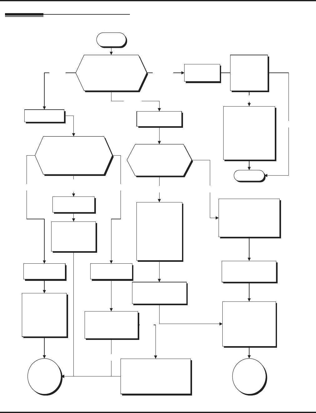
Music on Hold
428 ◆Features Aspire Software Manual
Programming
Note: Other ACI programming may be
necessary. Refer to the Analog
Communications Interface feature for more.
Start
Should a trunk use
the NTCPU, or the
external source
connected to the BGM
or ACI port for MOH?
In 14-08-01,
enter 0. In 14-08-01,
enter 2.
ACI Port
NTCPU In 14-08-01,
enter 1.
BGM Port
In 10-04-01,
enter 1.
Should the NTCPU use
the internal or external
music source or should it
provide an internal
service tone?
In 10-04-01,
enter 0.
In 10-03-01, confirm the
PGDAD module to be
used for external music
source is recognized and
has type "9" assigned.
In 11-06-01, assign
an extension number
to the ACI port.
Select a number
outside the normal
extension number
range (ex: 750).
Default Extension
Number Range:
301-499, 5000-5312
Is the system being
programmed an
Aspire or Aspire S?
In 10-21-01, set the external
relay to one of the following:
0=CPU MOH, 1=BGM,
2=CPU External Page,
3=General Purpose Relay
Aspire
Is the system
being
programmed
an Aspire or
Aspire S?
In 10-21-01, set the
external relay to one
of the following:
0=CPU MOH,
1=BGM, 2=CPU
External Page,
3=General Purpose
Relay
Aspire
On the 2PGDAD
module, should
circuit 1 or 2 be used
for external MOH?
Circuit 1
In 10-03-06,
confirm the
PGDAD module
to be used for
external music
source is
recognized and
has type "9"
assigned.
Circuit 2
In 10-03-07, note the
logical ACI port
number.
In 10-03-02, note the
logical ACI port
number.
Go to "A"
on the next
page.
In 10-04-02,
enter 0 for
silence or 1 or 2
for synthesized
music selections.
Stop
Go to "B"
on the next
page.
Aspire S
Internal External
In 10-04-01,
enter 2.
Internal Service
Tone
In 80-01-01,
adjust the tone
heard by the
user if required.
Aspire S
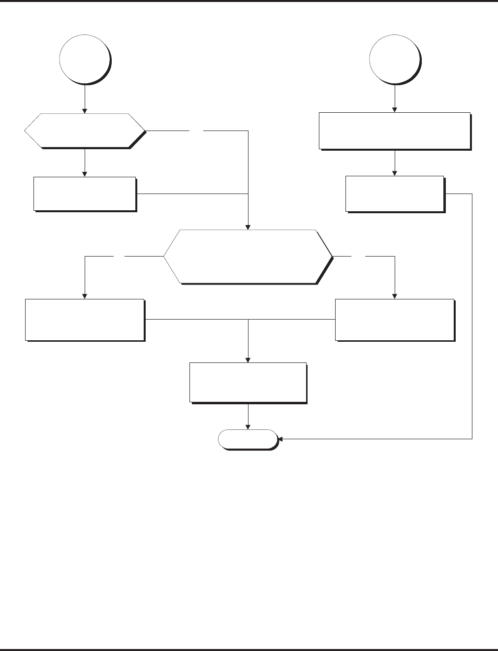
Music on Hold
Aspire Software Manual Features ◆429
Stop
In 14-08-02, enter the ACI source
port number (Aspire S: 1-8,
Aspire: 1-96) for each trunk.
Is the MOH gain
acceptable?
In 10-04-03, adjust
the audio gain
setting (1-63).
No
In 33-01-01, set the
ACI port to 1.
Should an extension user be
able to change the Music on
Hold tone (by dialing Service
Code 881)?
In 20-07-02, for the COS,
enter 0 to disable dialing
Service Code 881.
No
In 20-07-02, for the COS,
enter 0 to disable dialing
Service Code 881.
Yes
In 20-06-01, assign
Class of Service to
extensions.
Yes
"A" "B"

Music on Hold
430 ◆Features Aspire Software Manual
Programming (Cont’d)
➻10-04-01 : Music on Hold Setup - Music on Hold Source Selection
Determine whether the system should use internal (0), external (1) music source, or internal
service tone (2). If set to ‘1’, Program 14-08-01 must be set to ‘0’ or ‘1’.
➻10-04-02 : Music on Hold Setup - Music Selection for Internal Source
Set the Music on Hold selection. The options are 0 (silence), 1-2 (synthesized music selections).
➻10-04-03 : Music on Hold Setup - Audio Gain Setup
Set the Music on Hold audio gain (1-63).
➻10-21-01 : NTCPU Hardware Setup - External Source Control Switch Selection
Specify the function of the relay switch for external tone source control (0=external/internal
MOH source, 1=BGM source, 2=external speaker, 3=general purpose relay).
➻14-08-01 : Music on Hold Source for Trunks
For each trunk, set the Music on Hold source (0=NTCPU, 1=Customer-provided source connected
to BGM port, 2=Customer-provided source connected to ACI port).
➻14-08-02 : Music on Hold Source Port Number
If the MOH type is “2” in 14-08-01, for each trunk enter the ACI source port number (1 – 96).
➻20-06-01 : Class of Service for Extensions
Assign a Class Of Service (1-15) to an extension.
➻20-07-02 : Class of Service Options (Administrator Level) - Changing the Music on Hold
Tone
In an extension’s Class of Service, enable (1) or disable (0) an extension’s ability to change
the Music on Hold tone (Service Code 881).
➻33-01-01 : ACI Port Type Setup
If ACI software port is designated for MOH in 14-08-01, set port’s function to 1 (input).
➻80-01-01 : Service Tone Setup, Music On Hold Tone, Service Tone 64
If required, change the tone heard by the user when placed on hold when Program 10-04-01
set to "2".
When Using a PGDAD Module:
➻10-03-01 : PCB Setup - Terminal Type
If a PGDAD module is used for the external music source, the module will automatically be
assigned type ‘9’ if the jumper straps in the module have been set prior to connecting it to the
system. If another type has been assigned, disconnect the PGDAD from the system, delete the
type setting, and, with the jumper straps positioned correctly in the PGDAD module, recon-
nect the module to the system. Refer to the Aspire Hardware Manual (P/N 0893100) for the
jumper strap settings.
➻11-06-01 : ACI Extension Numbering
Each ACI port must be assigned an extension number. Use this program to assign the exten-
sion numbers to ACI software ports. Select a number outside of the normal extension number
range.
Aspire S: ACI Ports 1-8
Aspire: ACI Ports 1-96
➻11-08-01 : ACI Group Pilot Number
Assign pilot numbers to ACI groups. When a user dials the pilot number, they reach an avail-
able ACI software port within the group.
Aspire S: ACI Groups 1-4
Aspire: ACI Groups 1-16

Music on Hold
Aspire Software Manual Features ◆431
➻33-01-01 : ACI Port Type Setup
Set each ACI software ports for input (1) or input/output (2). Use input ports for Music on
Hold sources. Use output ports for External Paging/ringer control.
Aspire S: ACI Ports 1-8
Aspire: ACI Ports 1-96
➻33-02-01 : ACI Department Calling Group
Assign ACI software ports to an ACI Department Group. This lets ACI callers connect to ACI
software ports by dialing the group’s pilot number (set in Program 11-08).
Aspire S: ACI Ports 1-4, ACI Groups 1-4
Aspire: ACI Ports 1-8, ACI Groups 1-16
Note: Refer to the “Analog Communications Interface (ACI)” feature for additional information.
Related Features
Single Line Telephones
Single line telephones cannot change the Music on Hold tone.
Operation
To change the Music on Hold tone:
1. Press idle CALL key.
2. Dial 881.
3. Dial Music on Hold tone code:
00 No Tone
01 General
02 Holiday
4. Press SPK to hang up.

Name Storing
432 ◆Features Aspire Software Manual
Name Storing
Description
Extensions and trunks can have names instead of just circuit numbers. These names show on a key-
set’s display when the user places or answers calls. Extension and trunk names make it easier to
identify callers. The user does not have to refer to a directory when processing calls. A name can be
up to 12 digits long, consisting of alphanumeric characters, punctuation marks and spaces.
Additional Characters Available
When using the Name Storing feature, the system now provides additional characters which can be
used. These characters are available with any option which allows Name Storing - Abbreviated
Dialing, One-Touch Keys, Extension Name, Trunk Naming.
Under key 1:
Under key 0:
Under key *:
With this change, to enter a space or accept an entry, the # key is used. However, this key will only
work when performing user programming (such as Name Storing for an extension, service code
800). When in system programming, the right arrow soft key must be used to advance the cursor.
Conditions
None
Default Setting
Enabled.
Aspire S Aspire M/L/XL
• Available.
• Additional characters available.
• Available.
• Additional characters added in software 2.05+.
ÁÀÂÃÇÉÊ ì ó
ôÕúäöüaeθ
π ∑ σ Ω ∞ ¢£

Name Storing
Aspire Software Manual Features ◆433
Programming
➻14-01-01 : Basic Trunk Data Setup - Trunk Name
Program names for system trunks.
➻15-01-01 : Basic Extension Data Setup - Extension Name
Program name for system extensions (ports 001-499, 5000-5312).
➻15-07-01 : Programmable Function Keys
Assign an Extension Name Change key (55) to extensions:
➻20-06-01 : Class of Service for Extensions
Assign a Class Of Service (1-15) to an extension.
➻20-09-02 : Class of Service Options (Incoming Call Service) - Trunk Name Display, Incoming
In an extension’s Class of Service, enable (1) or disable (0) the displaying of a trunk’s name/
number when the trunk is ringing.
➻20-13-21 : Class of Service Options (Supplementary Service) - Extension Name
In an extension’s Class of Service, enable (1) or disable (0) an extension’s ability to program
their name.
Related Features
Directory Dialing
Display telephones use extension names for Directory Dialing.
Single Line Telephones
Single line extensions cannot program names.

Name Storing
434 ◆Features Aspire Software Manual
Operation
To program an extension’s name:
1. Press idle CALL key.
2. Dial 800
OR
Press Extension Name Change key (PGM 15-07 or SC 851: 55).
3. Enter the extension number to be named.
4. Enter name (see below).
Your name can be up to 12 digits maximum.
5. Press HOLD.
6. Press SPK to hang up.
With Software Prior to 2.05:
Key for Entering Names
Use this keypad digit . . . When you want to. . .
1 Enter characters:
1 @ [ ¥ ] ^ _ ‘ { | } ←←
←← →→
→→
Press repeatedly to scroll through the list. After selecting your entry, press the next
letter or use the left scroll or right scroll Soft Key to move the cursor.
2 Enter characters A-C, a-c, 2. After selecting your entry, press the next letter or use the
left scroll or right scroll Soft Key to move the cursor.
3 Enter characters D-F, d-f, 3. After selecting your entry, press the next letter or use the
left scroll or right scroll Soft Key to move the cursor.
4 Enter characters G-I, g-i, 4. After selecting your entry, press the next letter or use the
left scroll or right scroll Soft Key to move the cursor.
5 Enter characters J-L, j-l, 5. After selecting your entry, press the next letter or use the
left scroll or right scroll Soft Key to move the cursor.
6 Enter characters M-O, m-o, 6. After selecting your entry, press the next letter or use
the left scroll or right scroll Soft Key to move the cursor.
7 Enter characters P-S, p-s, 7. After selecting your entry, press the next letter or use the
left scroll or right scroll Soft Key to move the cursor.
8 Enter characters T-V, t-v, 8. After selecting your entry, press the next letter or use the
left scroll or right scroll Soft Key to move the cursor.
9 Enter characters W-Z, w-z, 9. After selecting your entry, press the next letter or use
the left scroll or right scroll Soft Key to move the cursor.
0 Enter characters:
0 ! “ # $ % & ‘ ( )
Press repeatedly to scroll through the list. After selecting your entry, press the next
letter or use the left scroll or right scroll Soft Key to move the cursor.
* Enter characters:
* + , - . / : ; < = > ?
Press repeatedly to scroll through the list. After selecting your entry, press the next
letter or use the left scroll or right scroll Soft Key to move the cursor.
Soft Key Left/Right
Arrows
Accepts an entry (only required if two letters on the same key are needed - ex: TOM) and
moves cursor in the arrows direction.
CONF Clear the character entry one character at a time.
CLEAR Clear all the entries from the point of the flashing cursor and to the right.

Name Storing
Aspire Software Manual Features ◆435
When using i-Series telephones on the Aspire system, not all the same characters are avail-
able. Refer to the following chart for the i-Series characters:
With Software 2.05+:
Key for Entering Names
Use this keypad digit . . . When you want to. . .
1 Enter characters:
1 @ [ ¥ ] ^ _ ` { | } →→
→→ ←←
←← Á À Â Ã Ç É Ê ì ó
2 Enter characters A-C, a-c, 2.
3 Enter characters D-F, d-f, 3.
4 Enter characters G-I, g-i, 4.
5 Enter characters J-L, j-l, 5.
6 Enter characters M-O, m-o, 6.
7 Enter characters P-S, p-s, 7.
8 Enter characters T-V, t-v, 8.
9 Enter characters W-Z, w-z, 9.
0 Enter characters:
0 ! “ # $ % & ’ ( ) ô Õ ú ä ö ü α ε θ
* Enter characters:
* + , - . / : ; < = > ? π ∑ σ Ω ∞ ¢ £
# # = Accepts an entry (only required if two letters on the same key are needed - ex: TOM).
Pressing # again = Space. (In system programming mode, use the right arrow soft key
instead to accept and/or add a space.)
CONF Clear the character entry one character at a time.
CLEAR Clear all the entries from the point of the flashing cursor and to the right.
With Software 2.05+ and i-Series Phones:
Key for Entering Names
Use this keypad digit . . . When you want to. . .
1 Enter characters:
1 @ [ ¥ ] ^ _ ` { | } →→
→→ ←←
←← å blank blank blank blank blank
blank blank blank
2 Enter characters A-C, a-c, 2.
3 Enter characters D-F, d-f, 3.
4 Enter characters G-I, g-i, 4.
5 Enter characters J-L, j-l, 5.
6 Enter characters M-O, m-o, 6.
7 Enter characters P-S, p-s, 7.
8 Enter characters T-V, t-v, 8.
9 Enter characters W-Z, w-z, 9.
0 Enter characters:
0 ! “ # $ % & ’ ( ) blank blank blank ä ö ü α ε θ
* Enter characters:
* + , - . / : ; < = > ? π ∑ σ Ω ∞ ¢ £
# # = Accepts an entry (only required if two letters on the same key are needed - ex: TOM).
Pressing # again = Space.
CONF Clear the character entry one character at a time.
CLEAR Clear all the entries from the point of the flashing cursor and to the right.
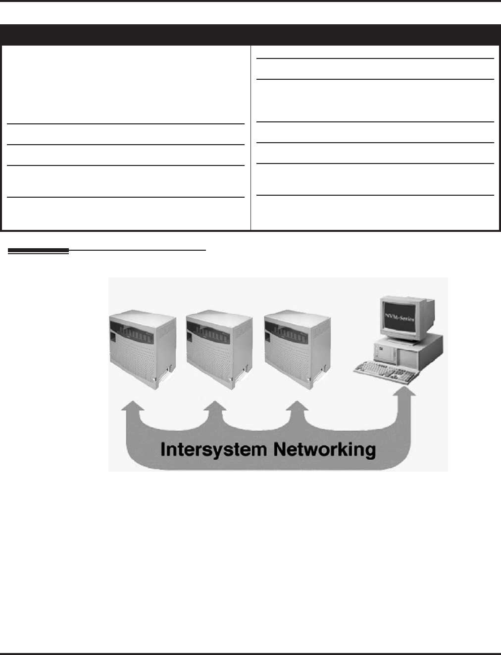
Networking
436 ◆Features Aspire Software Manual
Networking
Description
Use the built in networking feature to integrate multiple phone systems into a single “virtual” com-
munications system. Interconnected with ISDN PRI or BRI or VoIP, each phone system becomes a
node on the network that can communicate with any other phone system node.
●Centralized Network Attendant
Centralized Network Attendant allows multiple networked systems to share a single central-
ized attendant. This centralized attendant can receive calls from and transfer calls to any desti-
nation in any network node. Unanswered calls recall and route as if they were part of a single,
much larger system.
Aspire S Aspire M/L/XL
• Networking with VoIP or BRI available. PRI Network-
ing is not available.
• Keep Alive options added with software 1.11+.
• PRI Channel Limitation is not available.
• Transfer Network trunk to local voice mail using voice
mail key requires software 3.05+.
• Enhanced Fax Over Networking requires software
4.93+.
• Two System Networking available with software 1.07+.
• Multiple Site Networking available with software 2.08+.
• This feature requires the Basic NTCPU (P/N 0891002)
with the PAL upgrade or the Enhanced NTCPU (P/N
0891038).
• Keep Alive options added with software 1.11+.
• PRI Channel Limitation added with software 2.09+.
• Transfer Network trunk to local voice mail using voice
mail key requires software 3.05+.
• Enhanced Fax Over Networking requires software
4.93+.

Networking
Aspire Software Manual Features ◆437
●Flexible Network Routing
Use network routes to set up ISDN and VoIP networking between many separate systems - or
use mixed (ISDN or VoIP) networking per system for greater network performance. Data
tables in the system program define the routing for each network node. These tables are easily
customized to meet the requirements of each networking configuration.
Users may place an intercom call or transfer a call to any extension at any location by simply
dialing an extension number. The system analyzes each extension number received and deter-
mines how to route the call to its final destination. The feature which handles this route selec-
tion is called Flexible Routing (F-Routing). F-Routing also has the ability to select alternate
routes to the destination extension if the primary destination is busy. Up to 48 routes are avail-
able for networking. Once an extension number is dialed, the system checks the routing,
accesses the assigned trunk group and places the call. Each extension is assigned a route or
routes that decides which trunk group to access and any modified dialed data if required.
When an Aspire system is connected via a VoIP connection to an i-Series system in a tie-line
type setup, in order to transfer calls from the Aspire system to the i-Series, in addition to the
VoIP programs specified in the VoIP feature (page 643), set up the Flexible Routing Tables as
follows:
●Program 44-05-01 : ARS/F-Route Table ; Table Number 1 = 9 (Trunk Group for Aspire
VoIP Trunk)
●Program 10-23-02 : H.323 System Interconnection, IP Address ; System Number 3 =
172.16.9.10 (IP Address for i-Series System)
●Program 10-23-04 : H.323 System Interconnection, Alias Address ; System Number 3
= 4 (For Dial 4 Calls)
With this programming, the Aspire system will wait for the Trunk Interdigit Timer to expire
before dialing out after an i-Series extension (4xxx) is dialed.
If the F-Routing is set up with Program 44-05-01; Table Number 1 set to 103 (Networking)
and Program 10-27-01; System ID 3 = 172.16.9.10 (IP Address for i-Series), though the
i-Series system will be able to transfer calls to the Aspire, the Aspire system will not be able to
transfer to the i -Series.
PRI Networking With Two Local Voice Mails, Masters Must Have Different Numbering
When programming a PRI network with each system having their own local voice mail, the master
numbers for the voice mails must be defined in different series in Program 11-01. The second digit
of the extension number can not be the same. For example, 700 and 701 will not work, however 700
and 710 can be used.
Networking
438 ◆Features Aspire Software Manual
With Two Local Voice Mails, Network ID Must Match in Programming
With a networked system, with each system having their own voice mail, in order for users to prop-
erly connect to the correct voice mail when leaving a message, the programming must be set as
described below.
PRI Networking
Each node on a networked Aspire system is defined in Program 10-03-11 : PCB Setup - Net-
working System Number for the desired PRI slot. In the local system (Site 1), Program 11-
01-01 : System Numbering has a digit defined for networking (example: 7x=8 (network)).
The ID entry in Program 10-03-11 must match the ID set in Program 11-01-01. Otherwise,
callers could not press "8" to leave a message at a networked user’s voice mail. For example:
●In Site 1 in Program 10-03-11 = 1, Program 11-01-01 7X=8, ID = 2.
When Site 1’s extension 301 calls Site 2’s extension 401, then presses digit "8", the
user would hear a reorder tone.
●In Site 1 in Program 10-03-11 = 1, Program 11-01-01 7X=8, ID = 1.
When Site 1’s extension 301 calls Site 2’s extension 401, then presses digit "8", the
user will hear the voice mail message for extension 401.
Note that in order to assign a system ID, the "type" must temporarily be set to "8" (network-
ing). Once the system ID has been assigned, you can change the type to the required entry (2).
Programming
1. Set Program 11-01-01 to "8" (networking) for the local and remote voice mail master
numbers and define the ID number.
2. Set the local system ID in Program 10-03-11 to the same entry defined in Program 11-01-
01.
3. Change Program 11-01-01 for the local voice mail master number back to "2" (extension
number).
Refer to the example below:
Connected Via
PRI
Program 10-03-11 : PCB Setup,
Networking System Number
Program 10-03-11 : PCB Setup, Net-
working System Number
= 1 = 2
Program 11-01-01 : System Numbering Program 11-01-01 : System Numbering
Digit 7:
71 = 3 Digits
Type 8 (Networking)
System ID: 1
70 = 3 Digits
Type 2 (Extension)
System ID: 1 (must temporarily
change to Type 8 to be able to
enter the system ID)
Digit 7:
71 = 3 Digits
Type 2 (Extension)
System ID: 2 (must
temporarily change to
Type 8 to be able to enter
the system ID)
70 = 3 Digits
Type 8 (Networking)
System ID: 2
Voice Mail
700
System 1 System 2
Voice Mail
710
Networking
Aspire Software Manual Features ◆439
IP Networking
Each node on an IP networked Aspire system is defined in Program 10-27-01 : IP System
ID. For example, Site A has ID 1 and Site B system has ID 2 in Program 10-27-01. This must
be the same in every node.
In Program 11-01-01 : System Numbering, if Site 1 system (system ID 1) has 700 as the
master number, the entry for "70" would be "2".
Site 2 system (system ID 2) has 710 as the master number, the entry for "71" would also be
"2".
Note that in order to assign a system ID, the "type" must temporarily be set to "8" (network-
ing). Once the system ID has been assigned, you can change the type to the required entry (2).
The system ID defined in Program 11-01-01 is where the voice mail master number resides.
Refer to the example below:
Multiple Site Networking Available
IP Networking allows for a maximum of 50 nodes. With ISDN Networking, the maximum number
of nodes depends on the type of trunks used - PRI, BRI or a mixture of both. As the Aspire M/L is
limited to 8 PRI PCBs, when PRI trunks are used, the limit would be 8 systems, but each system
would require 8 PRI PCBs. PRI Networking is not available with the Aspire S.
The recommended connection for multiple system Networking is to interconnect all the systems
using hardware (required with ISDN Networking) and programming. This also allows such features
as Park to be used in a network.
With VoIP Networking, the system IDs for each networked system are defined in Program 10-27 :
IP System ID. An IP address is defined for each node, and using the Numbering Plan (Program 11-
01xx), the dialed digits are analyzed, the system ID is determined, and the call is routed to the net-
worked system.
Connected Via
IP
Program 10-23-01 : H.323 System
Interconnection
Program 10-23-01 : H.323 System
Interconnection
System 1: Interconnect=Yes (1)
IP Address: System 1 System 1: Interconnect=Yes (1)
IP Address: System 1
System 2: Interconnect=Yes (1)
IP Address: System 2 System 2: Interconnect=Yes (1)
IP Address: System 2
Program 11-01-01 : System Numbering Program 11-01-01 : System Numbering
Digit 7:
71 = 3 Digits
Type 8 (Networking)
System ID: 2
70 = 3 Digits
Type 2 (Extension)
System ID: 2 (must temporarily
change to Type 8 to be able to
enter the system ID)
Digit 7:
71 = 3 Digits
Type 2 (Extension)
System ID: 2 (must temporarily
change to Type 8 to be able to
enter the system ID)
70 = 3 Digits
Type 8 (Networking)
System ID: 1
Voice Mail
700
System 1 System 2
Voice Mail
710

Networking
440 ◆Features Aspire Software Manual
With ISDN Networking, interconnecting the systems is accomplished by defining a master PCB
and slave PCB between each system (Program 10-03-10 : PCB Setup - Master/Slave System).
Each system must have an ISDN PCB for each other system in the network.
The networked systems can be interconnected using a combination of PRI and VoIP trunks. In this
type of setup, the IP resources will received priority over the PRI resources. The PRI will be used
when the IP resources are busy. The following two graphics indicate correct networking layouts.
Each one provides connection between all three systems within the network.
ISDN Networking Clock Source
When using ISDN Networking (PRI or BRI) on the Aspire system, the option selected in Program
10-03-01 : PCB Setup - ISDN Line Mode determines the clock source for the networked connec-
tion. The following information indicates how, with each option, the clock source is obtained for
the networked systems.
Option 3: Network Mode (Leased Line)
Telco sends the clock to the Master System
Telco sends the clock to the Slave System
Option 4: Network Mode (Interconnected Line)
Master System sends the clock to the Telco (or direct connection without telco) which then sends
the clock to the Slave System
Option 5: (Interconnected Line, Fixed Layer 1=NT)
Master System sends the clock to the Telco
Slave System sends the clock to the Telco
Keep Alive Programs Added
Two options in Program 10-31 for use with the Networking feature are available to define the inter-
val of Keep Alive and how many times the system resends Keep Alive.
PRI Channel Limitation
The system provides an option which can be used to assign the number of B-channels to be used for
each ISDN PCB. This allows for fractional PRIs when used with multiple site networking. If this
program is limited to less than "23" on one side of the network, then it also limits both inbound and
outbound network calls. This also applies on the other side of the network as well.
Transfer Network Trunk to Local Voice Mail Using Voice Mail Key
With older software, IP or PRI network sites that had their own voice mail could not transfer a call
into voice mail using the following steps if the inbound call originated in another site (for example,
a call comes in to Site A and it translates to an extension at Site B):
●HOLD + the Voice Mail Programmable Function Key (Program 15-07 or SC 851 + 77) or
MSG key (Program 15-02-26=1) + the extension number.
Using software 3.05 or higher, this operation is now possible. Keep the following in mind when
using this option:
●Note that if you have a local and central voice mail, you can not have the same mailbox
number at each node. If both sites have the same mailbox, when transferring a call, it will be
transferred into the local voice mail and not across the network.
●As this software change allows transferring to a general message by a Single Line Set, the fol-
lowing two operations have different results between Networking Call Transfer and Internal
Call Transfer.
- Hold + Voice Mail Master Dial then hang up.
- Hold + Service Code (Own Mailbox Access - *8) then hang up.
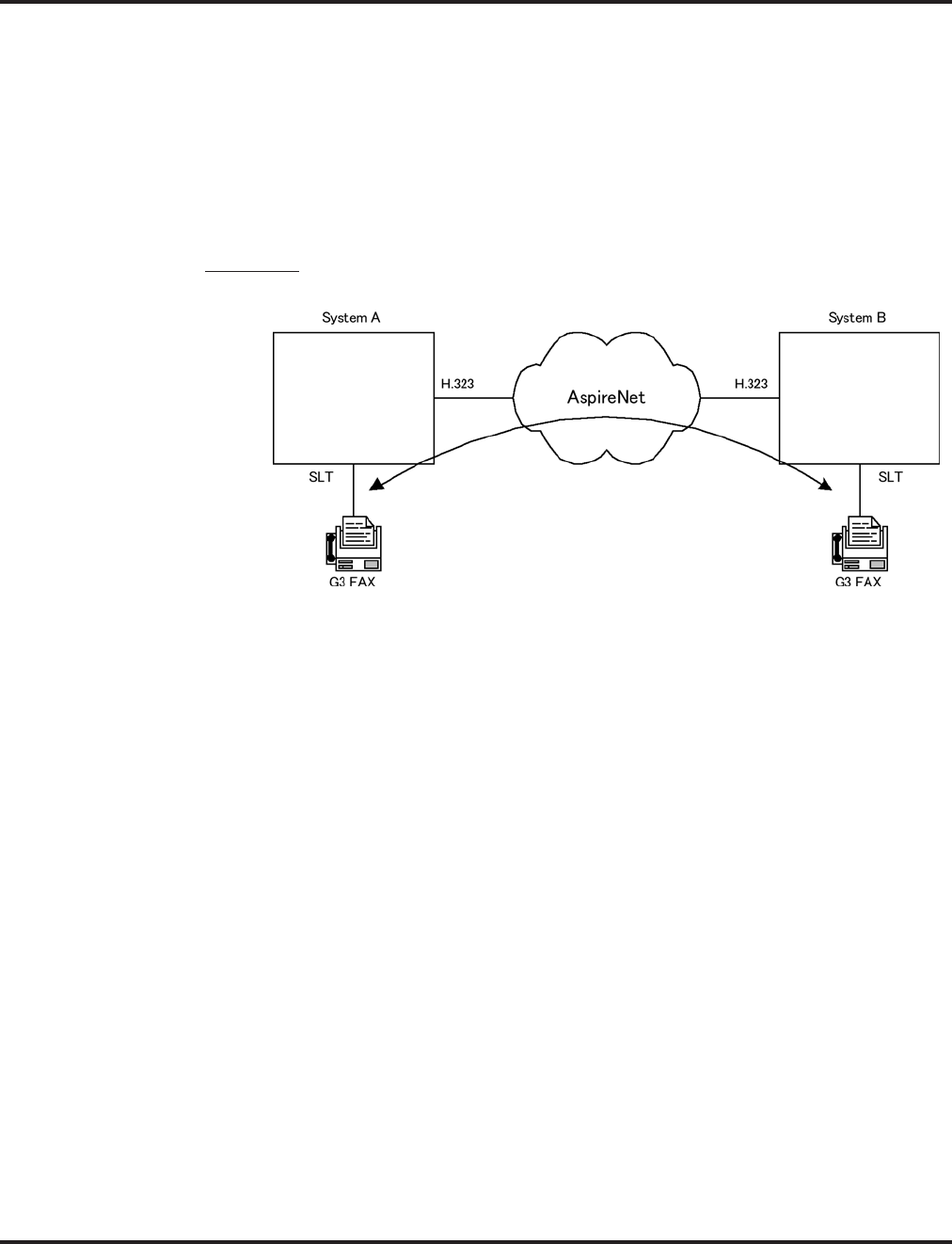
Networking
Aspire Software Manual Features ◆441
Fax Over Networking
The purpose of Aspire Networking is to be able to connect several systems and have them appear to
operate as one system. However, some restrictions still apply. With older software, with Fax Over
Networking using H.323 trunks, if a resource was busy, the operation could not be performed effi-
ciently. Although the operation would continue if there were no G.711 compression, there was no
resending procedure with RTP and reliability was a problem. The software now enhances this oper-
ation to provide better performance.
With IP networking, the modem signal of the fax relay now uses H.245. This enhancement only
applies to G3.
Examples:
FAX Relay with SLT Extension (G3)
Setup:
●System A
Program15-03-03 = G3 Fax 1 (special)
Program 84-12-32 = 2 (Each Port Mode)
●System B
Program 15-03-03 = G3 Fax 1 (special)
Program 84-12-32 = 2 (Each Port Mode)
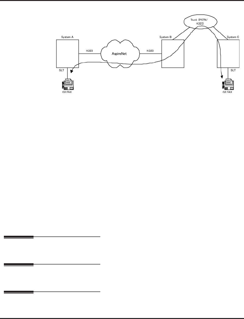
Networking
442 ◆Features Aspire Software Manual
FAX Relay with Trunks
Setup:
●System A
Program15-03-03 = G3 Fax 1 (special)
Program 84-12-32 = 2 Each Port Mode
●System B
Program 84-01-59 = 2 special
Program 84-12-32 = 2 Each Port Mode
●System C
Program15-03-03 = G3 Fax 1 (special)
Program 84-01-59 = 2 Each Port Mode
For additional information on Networking, refer to the Aspire Networking Guide (P/N 0893207).
Conditions
Refer to the Aspire Networking Guide (P/N 0893207).
Default Setting
Disabled.
Programming
Refer to the Aspire Networking Guide (P/N 0893207).
Related Features
Refer to the Aspire Networking Guide (P/N 0893207).
Operation
Refer to the Aspire Networking Guide (P/N 0893207).

Night Service
Aspire Software Manual Features ◆443
Night Service
Description
Night Service lets system users activate one of the Night Service modes. Night Service redirects
calls to their night mode destination, as determined by Assigned and Universal Night Answer pro-
gramming. The system allows Night Service to be enabled for each Night Service group, allowing
each group to determine when their calls should switch modes. A user typically activates Night
Service after normal working hours, when most employees are unavailable to answer calls. The
system also provides external contacts to enable Night Service.
There are four (Aspire S) or eight (Aspire M/L/XL) Night Service modes:
●Day 1 / Day 2 Modes - for normal working hours
●Night 1 / Night 2 Modes - after hours (usually evening)
●Midnight 1 / Midnight 2 Modes - late at night to early in the morning
●Rest 1 / Rest 2 Modes - interval usually used for lunch
Assigned Night Answer (ANA)
With Assigned Night Answer, Night Service has calls ring extensions directly. Assigned Night
Answer provides an answering point for Night Service calls. For certain applications, this may be
more appropriate than Universal Night Answer. For example, you could program trunks to ring the
security station telephone during off hours.
Universal Night Answer (UNA)
Universal Night Answer makes incoming calls ring over the External Paging speakers. With UNA,
an employee can go to a telephone and press the flashing line key or use “Universal Answer” to
pick up the call. Only ring groups calls can be used with Universal Night Answer. For more on set-
ting up Universal Answer, turn to the “Central Office Calls, Answering” feature.
You may also be able to use Transfer to UNA. An extension user can Transfer their call to UNA
(i.e., External Paging at night). Once transferred, the call will ring the External Paging speakers like
any other UNA call and can be picked up at any extension. You can also set up Transfer to UNA
through the VRS. This lets outside callers, answered by the VRS, dial a code to have their call ring
External Paging.
Automatic Night Service
The system will allow or deny Automatic Night Service based on the extension’s class of service pro-
gramming. If allowed, the calls will then route according to the service patterns programmed. The
Night Service programming is stored in the RAM memory. This means that if the system is not using
the Automatic Night Service, in the case of a power failure while in night mode, when the power is
restored, the system will continue to be in night mode.
Aspire S Aspire M/L/XL
• Available - 4 Night Service Patterns/Groups and 4 time
modes.
• Toggle night modes with Programmable Function Key
requires software 2.63+.
• Available - 32 Night Service Patterns/Groups and 8 time
modes.
• Toggle night modes with Programmable Function Key
requires software 2.63+.

Night Service
444 ◆Features Aspire Software Manual
Programmable Function Key Can Toggle Night Modes
The software allows a Night Service Programmable Function Key (PGM 15-07 or SC 851: 09 + 0)
to toggle night modes. You can determine in programming how many modes through which the
user will toggle. Note that the additional data for the Programmable Function Key must be set to
"0" for the toggle function to work.
Conditions
(A.) The NTCPU PCB has connections for a Night Mode switch. During installation, you connect
a mechanical switch to these contacts to provide an additional method of Night Mode switch-
ing. Refer to the system hardware manual for additional details.
(B.) If the Night Mode Relay is connected and there is any voltage present (pins 2 and 7 on the
NTCPU’s CN17 connector), the night mode cannot be toggled using the Night Mode
Programmable Function Keys.
(C.) The following programs are affected by Night Mode:
(D.) Almost all features are affected by Night Mode except for the following:
●Dial Tone Detection
●External Alarm Sensors
●Flexible System Numbering
●Labelmaker
●Pulse to Tone conversion
●SMDR
●Volume Control
(E.) Multiple Directory Number (virtual extension) keys do not support Day/Night Mode (09) Program-
mable Function keys.
Default Setting
System is always in the Day Mode.
Programming
➻10-05-01 : General Purpose Relay Setup
Define which relay circuits (5-8) on the 2PGDAD adapter are used for General Purpose
Relays.
➻10-21-01 : NTCPU Hardware Setup, External Source Control Switch Selection
Specify the function of the relay switch for the external tone source control (0=External MOH
source, 1=BGM source, 2=External Speaker, 3=General Purpose Relay).
➻11-10-01 : Service Code Setup (for System Administrator) - Day / Night Mode Switching
Customize the service code (818) to be used for day/night mode switching.
15-06 22-05 25-04 34-02
15-09 22-07 25-05 34-03
15-11 22-08 25-08 34-04
20-06 22-12 25-09
21-02 22-13 25-10
21-04 23-03 25-11
21-12 25-02 25-12
21-15 25-03 31-05

Night Service
Aspire Software Manual Features ◆445
➻11-12-50 : Service Code Setup (for Service Access) - General Purpose Relay
Define the service code to be used for turning the general purpose relay on and off
(default=880).
➻12-01-01 : Night Mode Function Setup - Manual Night Service Enable
Allow (1) or prevent (0) any extensions from activating Manual Night Service.
➻12-01-02 : Night Mode Function Setup - Automatic Night Service Enabled
Enable (1) or disable (0) Automatic Night Service for the system. Make sure to set the Service
Patterns in 12-02, 12-03, and 12-04.
➻12-01-03 : Night Mode Function Setup - Night Mode Switch Operating Mode
Set the function of the NTCPU Night Service Mode switch (Not Used = 0, Day 1 Mode = 1,
Night 1 Mode = 2, Midnight 1 Mode = 3, Rest 1 Mode = 4, Day 2 Mode = 5, Night 2 Mode =
6, Midnight 2 Mode = 7, Rest 2 Mode = 8).
➻12-02-01 : Automatic Night Service Patterns - Start Time
For each Night Service Group, enter up to 20 start times for each Time Pattern (1-10).
Pattern 1 should begin at 00:00 (midnight).
➪Aspire S: Night Service Groups 1-4
➪Aspire: Night Service Groups 1-32
➻12-02-02 : Automatic Night Service Patterns - End Time
For each Night Service Group, enter up to 20 end times (0000-2359) for each Automatic
Night Service pattern (1-10).
➪Aspire S: Night Service Groups 1-4
➪Aspire: Night Service Groups 1-32
➻12-02-03 : Automatic Night Service Patterns - Operation Mode
For each Night Service Group, define the time mode for up to 20 start/end times for each
Automatic Night Service pattern (1-10).
➪Aspire S: Night Service Time Modes 1-4 (Day 1, Night 1, Midnight 1, Rest 1),
Night Service Group: 1-4
➪Aspire: Night Service Time Modes 1-8 (Day 1, Night 1, Midnight 1, Rest 1, Day 2,
Night 2, Midnight 2, Rest 2), Night Service Group: 1-32
➻12-03-01 : Weekly Night Service Switching
Assign one of the five Automatic Night Service patterns programmed in 12-02 to each day of the
week.
➻12-04-01 : Holiday Night Service Switching
Assign one of the five Automatic Night Service patterns to holidays.
➻12-05-01 : Night Mode Group Assignment for Extensions
Assign a Day/Night Mode Group for each extension.
➪Aspire S: Night Service Groups 1-4
➪Aspire: Night Service Groups 1-32
➻12-06-01 : Night Mode Group Assignment for Trunks
Assign a Day/Night Mode Group for each trunk port.
➪Aspire S: Night Service Groups 1-4, Trunk Ports: 1-8
➪Aspire: Night Service Groups 1-32, Trunk Ports: 1-200
➻12-07-01 : Text Data for Night Mode
Create an original text message which will be displayed on an LCD of keyset telephone in
each Night Mode.
➻12-08-01 : Night Mode Service Range
For each night mode group, determine how many night modes a user will toggle through
when the Night Mode key is pressed (entries: 2-8).
➪Aspire S: 1-4
➪Aspire: 01-32

Night Service
446 ◆Features Aspire Software Manual
➻14-07-01 : Trunk Access Map Setup
To allow for UNA answering, set up the Trunk Access Maps. For UNA, extension must have
incoming access to trunk ringing the External Paging speakers.
➪Aspire S: Trunk Access Maps 1-8
➪Aspire: Trunk Access Maps 1-200
➻15-06-01 : Trunk Access Map for Extensions
For UNA answering, assign Trunk Access Maps to extensions. Make one entry for each Night
Service mode.
➪Aspire S: Trunk Access Maps 1-8
➪Aspire: Trunk Access Maps 1-200
➻15-07-01 : Programmable Function Keys
Assign Night Service function keys (09) to extensions. The additional data for this key must
be set to "0" in order for the toggle mode to function. Set the key for the proper mode (Day,
Night, Rest, etc.). Assign trunks to function keys (code *01 + 1-8 or 001-200). If required,
define a function key for a keyset to use the general purpose relay (51).
➻20-06-01 : Class of Service for Extensions
Assign a Class Of Service (1-15) to an extension.
➻20-07-01 : Class of Service Options (Administrator Level) - Manual Night Mode Switching
In an extension’s Class of Service, enable (1) or disable (0) an extension’s ability to manually
switch the Night Mode (Service Code 818). This option must be enabled for an extension to
be able to display the “Night” indication.
➻22-02-01 : Incoming Call Trunk Setup
Assign the incoming trunk type (0-7) for each trunk. There is one item for each Night Service
Mode.
➪Aspire S: Night Service Time Mode 1-4
➪Aspire: Night Service Time Mode 1-8
➻22-04-01 : Incoming Extension Ring Group Assignment
To have trunks ring extensions during the different Night Service modes (for ANA), assign
extensions to Ring Groups. For each extension in the Ring Group, indicate in Program 22-06
if trunk should ring (1) or not ring (0).
➪Aspire S Ring Groups: 1-8, 102=In-Skin/External Voice Mail, 103=Centralized Voice Mail
➪Aspire Ring Groups: 1-100, 102=In-Skin/External Voice Mail, 103=Centralized Voice Mail
➻22-05-01 : Incoming Trunk Ring Group Assignment
To have trunks ring extensions for ANA, assign trunks to Ring Groups. You make a different
entry for each Night Service mode.
➪Aspire S Ring Groups: 1-8, 102=In-Skin/External Voice Mail, 103=Centralized Voice Mail
➪Aspire Ring Groups: 1-100, 102=In-Skin/External Voice Mail, 103=Centralized Voice Mail
➻22-08-01 : DIL/IRG No Answer Destination
If a Universal Answer call rings longer than the DIL No Answer Time (Program 22-01-04), it
routes to the Ring Group specified in this option.
➪Aspire S Ring Groups: 1-8, 102=In-Skin/External Voice Mail, 103=Centralized Voice Mail
➪Aspire Ring Groups: 1-100, 102=In-Skin/External Voice Mail, 103=Centralized Voice Mail
➻31-05-01 : Universal Night Answer/Ring Over Page
For each Night Service Mode, assign which trunks should ring which External Paging Zones.

Night Service
Aspire Software Manual Features ◆447
Related Features
Central Office Calls, Answering and Placing/Ring Groups
There are separate Access Map and Ring Group programming entries for each Night Service
mode (Day 1, Night 1, Midnight 1, Rest 1, Day 2, Night 2, Midnight 2, Rest 2). Also, “Univer-
sal Answer” allows an extension user to pick up a UNA call.
Direct Station Selection (DSS) Console
Assign a Night Mode Key as required for DLS Consoles. The DSS Consoles provide Day and
Night keys.
Paging, External
With Universal Night Answer, outside calls can ring External Paging Zones.
Programmable Function Keys
Function keys simplify activating Night Service. Note: If the Night Mode Relay is connected
and there is any voltage present (pins 2 and 7 on the NTCPU’s CN17 connector), the night
mode cannot be toggled using the Night Mode Programmable Function Keys.
Operation
To activate Night Service by dialing codes:
1. At keyset, press idle CALL key.
OR
At single line telephone, lift handset.
2. Dial 818. To change a different group’s mode, dial 118 + the group number (1-4 or 01-32).
3. Dial Night Service code:
1 Day 1 mode
2 Night 1 mode
3 Midnight 1 mode
4 Rest 1 mode
5 Day 2 mode
6 Night 2 mode
7 Midnight 2 mode
8 Rest 2 mode
4. Press SPK to hang up.
To activate Night Service by using programmable keys:
1. Press Night Service key (PGM 15-07 or SC 851: 09) + Mode code number (below).
1 Day 1 mode
2 Night 1 mode
3 Midnight 1 mode
4 Rest 1 mode
5 Day 2 mode
6 Night 2 mode
7 Midnight 2 mode
8 Rest 2 mode
To transfer a call to the Universal Answer External Page zones:
1. Place the CO call on hold and dial the Transfer to Trunk Ring Group code.
You will hear a confirmation tone.
2. Hang up.
The call rings over the External Paging, enabling anyone to answer the call.

Off Hook Signaling
448 ◆Features Aspire Software Manual
Off Hook Signaling
Description
When a user calls an extension busy on a call, they can send an off hook signal through the handset
and through the telephone’s speaker indicating they are trying to get through. The signal is an off
hook ringing over the idle (second) line appearance. Off Hook Signaling helps important callers get
through, without waiting in line for the called extension to become free. The system provides the
following Off Hook Signaling options:
●Called Extension Block
The called extension’s Class of Service may block incoming Off Hook Signaling attempts.
This is beneficial to users that don’t want interruptions while on a call.
●Automatic Signaling
Calling a busy extension automatically initiates Off Hook Signaling. This option is useful to
receptionists, operators and others that must quickly process calls. This is set in the called
extension’s Class of Service.
●Manual Signaling
After reaching a busy extension, manual signaling gives the caller the choice of using Off
Hook Signaling or activating other features. Extension’s without automatic signaling have
manual signaling. The users can dial a service code or press a Programmable Function Key to
send Off Hook Signaling to the called phone.
●Selectable Off Hook Signaling Mode
The Off Hook Signal can be muted ringing, no off hook ringing or a beep in the handset -
based on the caller’s programming.
●Off Hook Ringing
Use this option to enable or disable an extension’s Off Hook Signaling for incoming calls. If
enabled, Off Hook Signaling occurs normally. If disabled, calls queue behind the extension’s
busy line appearance and the user gets no Off Hook Signaling indication. The second line
appearance stays idle. The caller hears ringback tone while their call waits. This is set in the
called extension’s Class of Service.
●DID Call Waiting
An extension can optionally have DID calls camp on with Off Hook/Call Wait signaling, with-
out Off Hook/Call Wait signaling or no signaling. This is set in the called extension’s Class of
Service.
●Block Manual Off Hook Signals
This Class of Service option enables/disables a busy extension’s ability to block off hook sig-
nals manually sent from a co-worker. If disabled (not blocked), callers can dial 7 at busy or
busy/ring to signal the extension. If enabled (blocked), nothing happens when the caller dials
7 to off hook signal.
●Block Camp On
If an extension has Block Camp On enabled, callers to the extension cannot dial 2 to Camp On
after hearing busy or busy/ring. If the extension has Block Camp On disabled, callers are not
prevented from dialing 2 to Camp on after hearing busy or busy/ring. This is set in the called
extension’s Class of Service.
Aspire S Aspire M/L/XL
• Available. • Available.

Off Hook Signaling
Aspire Software Manual Features ◆449
Conditions
None
Default Setting
Enabled
Programming
➻11-12-03 : Service Code Setup (for Service Access) - Override (Off Hook Signaling)
Assign a service code (809 by default) to be used for Off Hook Signaling Override.
➻11-16-04 : Single Digit Service Code Setup - Intercom Off Hook Signaling
Assign a one-digit service code to be used for Off Hook Signaling.
➻15-02-12 : Multi-Line Telephone Basic Data Setup - Off Hook Ringing
For each extension, set Off Hook Ringing type: 0 (muted), 1 (none), 3 (beep in speaker), 4
(beep in handset). DID, DNIS and DIL trunks can use any of the 4 options - normal/ring
group trunks can only use options “0” or “1”.
➻15-07-01 : Programmable Function Keys
Assign a function key for Off Hook Signaling (code 33).
➻20-06-01 : Class of Service for Extensions
Assign a Class Of Service (1-15) to an extension.
➻20-13-05 : Class of Service Options (Supplementary Service) - Off Hook Signaling
Receive
In an extension’s Class of Service, enable (1) or disable (0) the extension’s ability to receive
Off Hook Signaling.
➻20-13-06 : Class of Service Options (Supplementary Service) - Automatic Off Hook Signaling
In an extension’s Class of Service, enable (1) or disable (0) the extension’s ability to automat-
ically send Off Hook Signals while busy on a handset call.
➻20-13-34 : Class of Service Options (Supplementary Service) - Block Manual Off Hook
Signaling
Turn off (0) or on (1) an extension’s ability to block off-hook signals manually sent from a co-
worker.
➻20-18-06 : Service Tone Timer - Call Waiting Tone Timer
Use this timer to set the interval between Off Hook Signaling alerts.
Related Features
Call Waiting/Camp On and Callback
An extension user cannot Camp On to a busy extension or leave a Callback if Off Hook Sig-
naling has already gone through. Off Hook Signaling allows an extension to block a caller’s
ability to dial 2 to Camp On.
Direct Inward Dialing (DID)
Refer to the DID feature for interaction between Off Hook Signaling and other DID pro-
grammed options.
Handsfree and Monitor
You cannot send Off Hook Signals to an extension busy on a Handsfree (Speakerphone) call.
The called extension’s idle CALL key flashes fast, with no ringing.

Off Hook Signaling
450 ◆Features Aspire Software Manual
Hotline/Reverse Voice Over
The setting of Program 20-13-06 affects the BLF display for Hotline and Reverse Voice Over.
Refer to these features for additional information.
Intercom
You cannot send Off Hook Signals to an extension that is already receiving a voice announcement.
One-Touch Calling
An extension user can store the Off Hook Signaling Service Code (809) under a One-Touch
Key to provide quick Off Hook Signaling access.
Programmable Function Keys
Function keys simplify sending Off Hook Signals.
Single Line Telephones
Single line telephones can only send Off Hook Signals.
Operation
To send Off Hook Signals to an extension busy on a call:
Your extension may send Off Hook Signals automatically.
1. Dial 7.
OR
Press Off Hook Signaling key (PGM 15-07 or SC 851: 33).
You hear ringback.
To have your call voice-announce, dial 1.
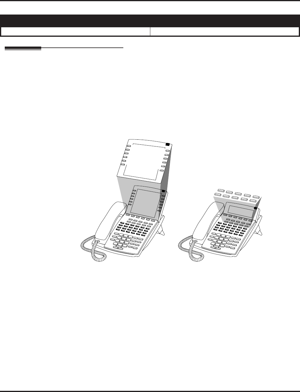
One-Touch Calling
Aspire Software Manual Features ◆451
One-Touch Calling
Description
One-Touch Calling gives a keyset user one button access to extensions, trunks and selected system
features. This saves users time when accessing co-workers, clients and features they use most often.
Instead of dialing a series of codes, the user need only press the One-Touch Key. An extension user
can have One-Touch Keys programmed for:
●Direct Station Selection - one button access to extensions
●Personal Speed Dial - one button access to stored numbers (up to 24 digits long)
●Abbreviated Dialing - one button access to stored Abbreviated Dialing numbers
●Trunk Calling - one button access to trunks or trunk groups
●Service Codes - one button access to specific Service Codes
An extension user can chain dial with One-Touch Keys. For example, a user can store the number for a
company’s Automated Attendant in key 1 and employee extension numbers in keys 2-5. The user presses
key 1 to call the company, then one of keys 2-5 to ring the employee to which they want to speak.
An extension user or system administrator can optionally store a Flash command under a One-Touch
Key. This is helpful for One-Touch Keys used as Personal Speed Dial bins. The stored Flash may be
helpful to access features of the connected telco, PBX or Centrex.
Conditions
One-Touch Keys do not provide a Busy Lamp Field (BLF).
Default Setting
One-Touch Keys have no assigned functions.
Aspire S Aspire M/L/XL
• Available. • Available.
0893200 - 5
1
2
3
4
5
6
7
8
9
10
12345
678910

One-Touch Calling
452 ◆Features Aspire Software Manual
Programming
➻15-07-01 : Programmable Function Keys
If required, define a Programmable Function Key for One-Touch Calling of an outside tele-
phone number by defining the key as a One-Touch key (01) + trunk access code + the tele-
phone number.
➻15-14-01 : Programmable One-Touch Keys
Set the functions of an extension’s One-Touch Keys. An extension user can also program their
One-Touch Keys.
➻30-03-01 : DSS Console Key Assignment
Customize DSS Console keys to function as DSS keys, Service Code keys, Programmable
Function Keys, and One-Touch Calling keys.
Note: When programming a feature within a One-Touch Key, refer to the feature’s description for
additional programming options.
Related Features
Programmable Function Keys
Function keys can also give an extension user one-touch access to selected system features.
Transfer
When transferring a call, an extension user can press a One-Touch Key instead of dialing the
extension number.

One-Touch Calling
Aspire Software Manual Features ◆453
Operation
Direct Station Selection
To program a One-Touch Key for Direct Station Selection (extension) calling:
1. Press idle CALL key and dial 855.
2. Press One-Touch Key you want to program.
3. Dial extension number you want assigned to that key.
4. Press HOLD.
5. Enter the name associated with the key you are programming.
6. Press HOLD.
7. Press SPK to hang up.
With Software 2.05+:
Key for Entering Names
When entering names in the procedures below, refer to this chart. Names can be up to 12 digits long.
For prior software or when using i-Series phones, refer to the charts in the Name Storing feature
(page 432).
Use this keypad digit . . . When you want to. . .
1 Enter characters:
1 @ [ ¥ ] ^ _ ` { | } →→
→→ ←←
←← Á À Â Ã Ç É Ê ì ó
2 Enter characters A-C, a-c, 2.
3 Enter characters D-F, d-f, 3.
4 Enter characters G-I, g-i, 4.
5 Enter characters J-L, j-l, 5.
6 Enter characters M-O, m-o, 6.
7 Enter characters P-S, p-s, 7.
8 Enter characters T-V, t-v, 8.
9 Enter characters W-Z, w-z, 9.
0 Enter characters:
0 ! “ # $ % & ’ ( ) ô Õ ú ä ö ü α ε θ
* Enter characters:
* + , - . / : ; < = > ? π ∑ σ Ω ∞ ¢ £
# # = Accepts an entry (only required if two letters on the same key are needed - ex: TOM).
Pressing # again = Space. (In system programming mode, use the right arrow soft key
instead to accept and/or add a space.)
CONF Clear the character entry one character at a time.
CLEAR Clear all the entries from the point of the flashing cursor and to the right.

One-Touch Calling
454 ◆Features Aspire Software Manual
Personal Speed Dial
To program a One-Touch Key for Personal Speed Dial:
1. Press idle CALL key and dial 855.
2. Press One-Touch Key you want to program.
3. Dial general trunk access code (9).
OR
Dial Specific Trunk Service Code (#9 ) plus the trunk number (e.g., 005).
OR
Dial Trunk Group Service Code (804) plus the trunk group number (e.g., 1).
4. Dial number you want to store.
The total of the digits stored in steps 3 and 4 cannot exceed 24.
Valid entries are 0-9, # and *. To enter a pause, press MIC. To store a Flash, press FLASH.
5. Press HOLD.
6. Enter the name associated with the key you are programming.
7. Press HOLD.
8. Press SPK to hang up.
To program a One-Touch Key for Personal Speed Dial (if your phone doesn’t have
One-Touch keys):
Use this procedure for 2-button and analog single line (SLT) sets.
1. Lift handset.
2. Dial 855.
3. Dial the Personal Abbreviated Dialing bin (0-9).
Bins 1-9 correspond to One-Touch keys 1-9; bin 0 corresponds to One-Touch key 10.
4. Dial the number you want to store and press HOLD twice.
Valid entries are 0-9, # and *. To enter a pause, press MIC. To store a Flash, press FLASH.
5. Hang up.
To dial the stored number:
1. Call (or lift handset).
2. Dial #7 + bin number (0-9).

One-Touch Calling
Aspire Software Manual Features ◆455
Abbreviated Dialing
To program a One-Touch Key for Abbreviated Dialing:
1. Press idle CALL key and dial 855.
2. Press One-Touch Key you want to program.
3. Dial #2 to store a Common Abbreviated Dialing number.
OR
Dial #4 to store a Group Abbreviated Dialing number.
4. Dial Abbreviated Dialing number storage code (e.g., 001).
5. Press HOLD.
6. Enter the name associated with the key you are programming.
7. Press HOLD.
8. Press SPK to hang up.
Central Office Calls, Placing (Trunk Calling)
To program a One-Touch Key for trunk calling:
1. Press idle CALL key and dial 855.
2. Press One-Touch Key you want to program.
3. Dial general trunk access code (9).
OR
Dial Specific Trunk Service Code (#9 ) plus the trunk number (e.g., 005).
OR
Dial Trunk Group Service Code (804) plus the trunk group number (e.g., 1).
4. Press HOLD.
5. Enter the name associated with the key you are programming.
6. Press HOLD.
7. Press SPK to hang up.
Service Codes
To assign a Service Code to a One-Touch Key:
This lets you make your own set of one-touch feature keys.
1. Press idle CALL key and dial 855.
2. Press One-Touch Key you want to program.
3. Dial Service Code you want stored.
For example, if you want a One-Touch Key to automatically clear your Last Number
Redial, enter 876.
4. Press HOLD.
5. Enter the name associated with the key you are programming.
6. Press HOLD.
7. Press SPK to hang up.

One-Touch Calling
456 ◆Features Aspire Software Manual
Using One-Touch Keys
To use a One-Touch Key:
1. Press One-Touch Key.
Clearing a One-Touch Key
To clear a programmed One-Touch Key:
1. Dial 855.
2. Press the One-Touch Key to be cleared.
3. Press CLEAR.
Chaining One-Touch Keys
To chain One-Touch Keys:
1. Press first One-Touch Key.
Let the stored function dial out.
2. Press another One-Touch Key.
The stored digits dial out.
Checking One-Touch Keys
To check the function of a One-Touch Key:
1. Press CHECK.
2. Press One-Touch Key.
The stored function displays.
Repeat this step to check additional keys. If you cannot see the entire number stored,
dial *.
3. Press CLEAR.

One-Touch Calling
Aspire Software Manual Features ◆457
Programmable Function Keys
When using Programmable Function Keys, note that names cannot be stored with
the key as with the One-Touch Key operation above.
To define a Programmable Function Key as a One-Touch Key:
1. Dial 851.
2. Press the key to be defined.
3. Dial 01 (DSS/One-Touch Key Operation).
4. For Direct Station Selection (Extension):
a. Dial extension number you want assigned to that key.
b. Press HOLD.
c. Press SPK.
For Personal Speed Dial:
a. Dial general trunk access code (9).
OR
Dial Specific Trunk Service Code (#9 ) plus the trunk number (e.g., 005).
OR
Dial Trunk Group Service Code (804) plus the trunk group number (e.g., 1).
b. Dial number you want to store.
The total of the digits stored in steps 3 and 4 cannot exceed 24.
Valid entries are 0-9, # and *. To enter a pause, press MIC. To store a Flash, press FLASH.
c. Press HOLD.
d. Press SPK.
For Abbreviated Dialing:
a. Dial #2 to store a Common Abbreviated Dialing number.
OR
Dial #4 to store a Group Abbreviated Dialing number.
b. Dial Abbreviated Dialing number storage code (e.g., 001).
c. Press HOLD.
d. Press SPK.
For Central Office Calls, Placing (Trunk Calling):
a. Dial general trunk access code (9).
OR
Dial Specific Trunk Service Code (#9 ) plus the trunk number (e.g., 005).
OR
Dial Trunk Group Service Code (804) plus the trunk group number (e.g., 1).
b. Dial the telephone number to be stored.
c. Press HOLD.
d. Press SPK.
For Service Codes:
a. Dial Service Code you want stored.
For example, if you want a One-Touch Key to automatically clear your Last Number
Redial, enter 876.
b. Press HOLD.
c. Press SPK.

Operator
458 ◆Features Aspire Software Manual
Operator
Description
When an extension user dials “0”, calls are routed to a main system operator. The operator can
answer and route outside calls or locate employees using the Page feature.
Conditions
None
Default Setting
Extension 301 is an operator.
Programming
➻20-01-01 : System Options - Operator Access Mode
Use this program to set up priority of a call when calling an operator telephone (0 = Step, 1 =
Circular).
➻20-17-01 : Operator’s Extension - Operator’s Extension Number
Designate an extension an operator. When an extension user dials “0” or “9” (defined by Pro-
gram 11-01 Type 5), calls go to the operator selected in this program.
If you don’t assign an extension in Program 90-11-01, system alarms appear on the extension
assigned in this option.
➻20-17-02 : Operator’s Extension - Operator Console
Determine if the console should be a normal keyset (0) or if it should be a special operator
console (1).
Related Features
Attendant Call Queuing
Attendant extensions can have up to 32 incoming calls queued before additional callers hear
busy tone.
Multiple Directory Numbers/Call Coverage
The operator extension cannot be a virtual extension key.
Operation
Refer to the individual features for operation.
Aspire S Aspire M/L/XL
• Available - up to 8 operators. • Available - up to 8 operators.


Paging, External
460 ◆Features Aspire Software Manual
Paging, External
Description
With External Paging, a user can broadcast announcements over paging equipment connected to
external Paging zones. When a user pages on of these external zones, the system broadcasts the
announcement over the speakers. Like Internal Paging, External Paging allows a user to locate
another employee or make an announcement without calling each extension individually.
The Aspire S system allows up to eight External Paging zones. The Aspire system allows up to nine
External Paging zones, with the additional zone (#9) provided on the NTCPU. All other zones (#1-
8) requires a port on a 2PGDAD module, with a maximum of two external paging circuits per mod-
ule. You must have four 2PGDAD modules to get the eight external zones. In addition, each exter-
nal zone has an associated relay contact. When a user pages to a zone, the corresponding contact
activates (closes). This provides for Paging amplifier control. Refer to the system hardware manual
for additional details.
Combined Paging
Use Combined Paging when you want to simultaneously Page into an internal and corresponding
external zone. For example, you can Page your company’s warehouse and outside loading dock at
the same time. Combined Paging is available for zones 1-8 and All Call. Refer to Paging, Internal
(page 463) for more on setting up Combined Paging. In addition, you can program a Function Key
as a Combined Paging key. Using the External Page Function Key, when an All Call External Page
Function Key is programmed, it will include both the external zones and the assigned internal
zone(s). If the internal page zone is busy or there are no extensions in a page group, the announce-
ment will be made on the external zones only.
Remove Paging Information from Display Phones
A Class of Service option is available in system programming to prevent display telephones from
showing incoming paging information. This allows the system to save processor time and speed up
system operation.
Conditions
(A.) The Aspire provides one external page zone on the NTCPU. For more than one external page
zone on the Aspire or when using the Aspire S, External Paging requires 2PGDAD modules
and customer-provided Paging equipment.
(B.) With Combined Paging, the system may not allow a page over just the external page zone if
the internal zone is busy or if there are no extensions in a page group.
(C.) Talkback paging requires the use of a PGDAD module or a CO trunk port (with the use of
external equipment, such as a Valcom page control device). The Aspire NTCPU’s external
page circuit does not allow talkback.
Default Setting
No External Paging defined.
Aspire S Aspire M/L/XL
• Available - 8 External Paging zones. • Available - 9 External Paging zones.

Paging, External
Aspire Software Manual Features ◆461
Programming
➻10-03-01 : PCB Setup - Terminal Type (Circuit 1)
10-03-06 : PCB Setup - Terminal Type (Circuit 2)
When a 2PGDAD module is used for external page, type “6” should be assigned for the
2PGDAD circuit.
➻10-05-01 : General Purpose Relay Setup
Define which relay circuits (5-8) on the 2PGDAD Module are used for General Purpose
Relays. Also refer to Program 10-21-01 for the NTCPU relay assignments.
➻10-21-01 : NTCPU Hardware Setup - External Source Control Switch Selection
Specify the function of the relay switch for external tone source control (0=external MOH
source, 1=BGM source, 2=external speaker (Aspire only), 3=general purpose relay). If this
option is set to “2”, 803+1 will page and close the NTCPU relay. Upon hanging up, the relay
opens. If this option is set to “3”, 880+0 (Program 11-12-50) toggles the relay on and off.
➻11-12-50 : Service Code Setup (For Service Access)
Specify the service code to be used for toggling the relay open and closed (Default: 880).
➻15-07-01 : Programmable Function Keys
Assign function keys for External Paging zones (19 + zone) and External All Call Page (20). If
required, define a function key for a keyset to use the general purpose relay (50).
➻20-06-01 : Class of Service for Extensions
Assign a Class Of Service (1-15) to an extension.
➻20-13-29 : Class of Service Options (Supplementary Service) - Paging Display
In an extension’s Class of Service, enable (1) or disable (0) an extension’s ability to display
incoming internal paging information on their display.
➻31-01-02 : System Options for Internal/External Paging - Page Announcement Duration
Set the maximum allowable duration for a Paging announcement.
➻31-04-01 : External Paging Zone Group
Assign each External Paging Speaker to an External Paging Group (1-8) used for accessing the
zone. If zones 1-8 are not connected to PGDAD modules, set these unused zones to External Pag-
ing Group “0”.
➪Aspire S External Paging Speaker/Zone: 1-8
➪Aspire External Paging Speaker/Zone: 1-9
➻31-05-01 : Universal Night Answer/Ring Over Page
Assign Universal Night Answer ringing to each External Paging zone. For each trunk port,
you make a separate entry for each External Paging Speaker.
➪Aspire S External Paging Speaker/Zone: 1-8
➪Aspire External Paging Speaker/Zone: 1-9
➻31-06-01 : External Speaker Control - Broadcast Splash Tone Before Paging
Use this option to enabled or disable splash tone before Paging over an external zone. If
enabled (1=Splash, 2=Chime), the system broadcasts a splash tone before the External Paging
announcement.
➻31-06-02 : External Speaker Control - Broadcast Splash Tone After Paging
Use this option to enabled or disable splash tone after Paging over an external zone. If enabled
(1=Splash, 2=Chime), the system broadcasts a splash tone at the end of an External Paging
announcement.
➻31-06-04 : External Speaker Control - CODEC Transmit Gain Setup
31-06-05 : External Speaker Control - CODEC Receive Gain Setup
Select the CODEC gain types (1-32) for each External Page Speaker.
➪Aspire S External Paging Speaker/Zone: 1-8
➪Aspire External Paging Speaker/Zone: 1-9

Paging, External
462 ◆Features Aspire Software Manual
➻31-07-01 : Combined Paging Assignments
Assign an External Paging Group (0-8) to an Internal Paging Zone (0=all call, zones 1-64) for
Combined Paging. When an extension user makes a Combined Page, they simultaneously
broadcast into both the External and Internal Zone.
➻31-08-01 : BGM on External Paging
Assign the Background Music option for each External Paging Speaker. If enabled (1), the
system will play Background Music over the zone when it is idle.
➪Aspire S External Paging Speaker/Zone: 1-8
➪Aspire External Paging Speaker/Zone: 1-9
Related Features
Central Office Callings, Placing
A trunk port may be used for a talkback external page with the use of proper external paging
equipment (ex: Valcom).
Direct Inward Dial (DID) / Direct Inward Line (DIL) / Transfer
DID and DIL trunks will not ring external page speakers. Only trunks defined as “normal” in
Program 22-02-01 will ring external page speakers.
Direct Station Selection
Assign Paging keys for DSS and DLS consoles.
Door Box
If a 2PGDAD circuit has a Door Box connected, you cannot use that circuit for External Paging.
Night Service (Universal Night Answer)
To have outside calls ring External Paging Zones at night, refer to the Night Service feature and
Program 31-05.
Paging, Internal
Internal Paging broadcasts announcements to extensions in programmed Internal Paging Zones.
Programmable Function Keys
Function keys simplify External Paging operation.
Operation
To Page into an external zone:
1. Press External Paging key (PGM 15-07 or SC 851: 19 + zone for External Paging zones or 20
for External All Call Paging).
2. Make Announcement.
OR
1. At keyset, press idle CALL key.
OR
At single line telephone, lift handset.
2. Dial 803 and the External Paging Zone code (1-8 or 0 for All Call).
OR
Dial *1 and the Combined Paging Group code 1-8 or 0 (for Internal/External All Call).
Display indicates the Combined Paging as an External Page.
If the Internal Page Zone is busy or if there are no extensions in a page group, the page
may be announced as an External Page only.
3. Make Announcement.

Paging, Internal
Aspire Software Manual Features ◆463
Paging, Internal
Description
Internal Paging lets extension users broadcast announcements to other keyset users. When a user
makes a Zone Paging announcement, the announcement broadcasts to all idle extensions in the
zone dialed. With All Call Paging, the announcement broadcasts to all idle extensions programmed
to receive All Call Paging. An extension can be a member of only one Internal Paging Zone. Like
External Paging, Internal Paging allows a user to locate another employee or make an announce-
ment without calling each extension individually.
Combined Paging
Use Combined Paging when you want to simultaneously Page into an internal and corresponding
external zone. For example, you can Page your company’s warehouse and outside loading dock at
the same time. Combined Paging is available for Paging zones 1-8 and All Call. Optionally, you can
change the Combined Paging assignments. For example, you can associate External Paging Zone 1
with Internal Paging Zone 4. You can program a Function Key as a Combined Paging key. When an
All Call External Page Function Key is programmed, it will include both the external zones and the
assigned internal zone(s). If the internal page zone is busy or there are no extensions in a page
group, the announcement will be made on the external zones only.
Remove Paging Information from Display Phones
A Class of Service option is available in system programming to prevent display telephones from
showing incoming internal paging information. This allows the system to save processor time and
speed up system operation.
Conditions
(A.) Internal Paging does not require a 2PGDAD module.
(B.) You can assign any number of extensions to an Internal or All Call Paging Zone.
(C.) A system must have at least one extension port idle in order to make an Internal Page. If no
extension port is idle, the extension performing the Page will hear a busy signal.
(D.) With Combined Paging, the system may not allow a page over just the external page zone if the
internal zone is busy or if there are no extensions in a page group.
Default Setting
Enabled.
Programming
➻15-07-01 : Programmable Function Keys
Assign function keys for Internal Paging Zones (code 21 + page zone) and Internal All Call
Paging (code 22).
➪Aspire S Internal Page Zones: 0, 1-8
➪Aspire Internal Page Zones: 0, 1-9, 00, 01-64
➻20-06-01 : Class of Service for Extensions
Assign a Class Of Service (1-15) to an extension.
Aspire S Aspire M/L/XL
• Available - 8 Internal Paging Groups (Zones). • Available - 64 Internal Paging Groups (Zones).

Paging, Internal
464 ◆Features Aspire Software Manual
➻20-13-29 : Class of Service Options (Supplementary Service) - Paging Display
In an extension’s Class of Service, enable (1) or disable (0) an extension’s ability to display
incoming internal paging information on their display.
➻31-01-01 : System Options for Internal/External Paging - All Call Paging Zone Name
Assign a name to the All Call Internal Paging Zone. The name shows on the display of the
telephone making the announcement.
➻31-01-02 : System Options for Internal/External Paging - Page Announcement Duration
Set the maximum allowable duration (0-64800 seconds) for a Paging announcement.
➻31-02-01 : Internal Paging Group Assignment - Internal Paging Group Number
Assign extensions to Internal Paging Zones. An extension must be assigned to a 2-digit zone
in order to access any of the 2-digit zones. Up to 50 extensions maximum can be in a page
group.
➪Aspire S Internal Page Zones: 0, 1-8
➪Aspire Internal Page Zones: 0, 1-9, 00, 01-64
➻31-02-02 : Internal Paging Group Assignment - Internal All Call Paging Receiving
Allow (1) or prevent (0) All Call Internal Paging for each extension. If allowed, extensions
can make and receive All Call Internal Paging announcements. If prevented, extension can
only make All Call Internal Paging announcements.
➻31-03-01 : Internal Paging Group Settings - Internal Paging Group Name
Program names for the Internal Paging Zones.
➻31-03-02 : Internal Paging Group Settings - Internal Paging Tone
For each Internal Paging Zone, have normal (0), muted (1) or no (2) Internal Paging alert
tones. If enabled (0 or 1), extensions hear two beeps before Paging announcements. If dis-
abled, the extensions hear the announcement without the beeps.
➪Aspire S Internal Page Zones: 0, 1-8
➪Aspire Internal Page Zones: 0, 1-9, 00, 01-64
➻31-07-01 : Combined Paging Assignments
For each External Paging Group (1-8 and 0 for All Call), assign a corresponding Internal Zone
for Combined Paging.
➪Aspire S Internal Page Zones: 0, 1-8
➪Aspire Internal Page Zones: 0, 1-9, 00, 01-64
Related Features
Meet Me Paging / Meet Me Paging Transfer
Preventing access to internal page also prevents these features.
Paging, External
An extension user can broadcast an announcement over an External Paging Zone.
Programmable Function Keys
Function keys simplify Internal Paging operation.

Paging, Internal
Aspire Software Manual Features ◆465
Operation
To make an Internal Page announcement:
Keyset
1. Press the zone’s Internal Paging key (PGM 15-07 or SC 851: 21 + 0 or 1-8 (Aspire S) OR 1-9
or 01-64 for zones (0 or 00 for All Call) (Aspire).
OR
1. Press idle CALL key.
2. Dial 801 and the Paging Zone number (Aspire S: 0-8 or Aspire: 0-9 or 00-64).
Dialing 0 or 00 calls All Call Internal Paging.
OR
Dial *1 and the Combined Paging Group code 1-8 or 0 (for Internal/External All Call).
Display indicates the Combined Paging as an External Page.
If the Internal Page Zone is busy or if there are no extensions in a page group, the page
will be announced as an External Page only.
3. Make announcement.
4. Press SPK to hang up.
Single Line Telephone
1. Lift handset.
2. Dial 801 and the Paging Zone number (Aspire S: 0-8 or Aspire: 0-9 or 00-64).
Dialing 0 or 00 calls All Call Internal Paging.
Dial *1 and the Combined Paging Group code 1-8 or 0 (for Internal/External All Call).
3. Make announcement.
4. Hang up.


Park
Aspire Software Manual Features ◆467
Park
Description
Park places a call in a waiting state (called a Park Orbit) so that an extension user may pick it up.
There are two types of Park: System and Personal. Use System Park when you want to have the call
wait in a system orbit. Personal Park allows a user to Park a call at their extension so a co-worker can
pick it up. After parking a call in orbit, a user can Page the person receiving the call and hang up. The
paged party dials a code or presses a programmed Park key to pick up the call. With Park, it is not nec-
essary to locate a person to handle their calls. A call parked for too long will recall the extension that
initially parked it, however the call remains in the park orbit until it’s answered. There are 64 Park
Orbits (1-64) available for use.
Splitting Between Parked Calls
A keyset user can retrieve two calls from Park Orbit (for which they don’t have line appearances)
and easily split (alternate) between them. The split operation brings the calls to the user’s telephone
and frees up the Park Orbits.
Extended Park
An extension’s Class of Service determines whether it will use the normal Park Orbit Recall time or
the Extended Park Orbit Recall time. The timers are set up in system programming. When an exten-
sion with Extended Park Recall Class of Service option parks a call, it recalls after the Extended
Park Orbit Recall time. When an extension with the Normal Park Orbit Recall Class of Service
option parks a call, it recalls after the normal Park Orbit Recall time, however the call remains in the
park orbit until it’s answered.
Programmable Function Key and Service Code Available for Personal Park
The Personal Park feature is enhanced with the ability to use a Programmable Function Key or ser-
vice code (3-digit or 1-digit) to place a call in Personal Park. Older software only provides the
option to place a call in Personal Park using a 3-digit service code. With this ability, two new pro-
gram options have been added to the system in Program 11-16-11 and 15-07-01. This option is
available for keysets, single line sets, and Aspire Wireless telephones and can be used for analog or
ISDN trunks.
With this feature, the following conditions apply:
●An extension can have only one Personal Park key.
●When the terminal that has a call in Personal Park is unplugged, the Personal Park will be
released and the held caller will receive busy tone.
Aspire S Aspire M/L/XL
• Available - 64 System Park orbits.
• Personal Park Programmable Function Key and Service
Code requires software 2.65+.
• Available - 64 System Park orbits.
• Personal Park Programmable Function Key and Service
Code requires software 2.65+.

Park
468 ◆Features Aspire Software Manual
The following table indicates what condition the service codes and Programmable Function key can
be used.
Conditions
(A.) An extension can park a call in any Park Orbit. However, an extension can only pick up a
call Parked by a member of its own Park group (see Program 24-03).
(B.) When a 2-Button telephone user parks a call, they must wait the Interdigit Time (normally 10
seconds) before trying to retrieve it.
(C.) If an extension is not allowed access to trunks in the Access Maps (Programs 14-07 and 15-
06), calls in Park and on Hold can be blocked.
Default Setting
Enabled.
Status Using 3-Digit
Service Code
Using 1-Digit
Service Code
Using
Personal
Park Key
Speaking Not Available Not Available Available
ICM Dial Tone or Busy Tone Available Not Available Available
Calling Another Extension Available Available
(with outside call
on hold and when
called extension
does not answer)
Available
Receiving a Personal Park Recall Available Not Available Available

Park
Aspire Software Manual Features ◆469
Programming
➻11-12-31 : Service Code Setup (for Service Access) - Park
Set the service code which should be used for placing a call in Park (default: #6).
➻11-12-32 : Service Code Setup (for Service Access) - Park Answer
Set the service code which should be used for answering a call in Park (default: *6).
➻11-12-35 : Service Code Setup (for Service Access) - Personal Park
Set the service code to be used for placing a call in a Personal Park (default: 857).
➻11-16-11 : Single Digit Service Code Setup - Personal Park
Customize the one-digit service code to be used when placing a call in Personal Park (default:
No setting).
➻15-07-01 : Programmable Function Keys
Assign a keys as a Park Orbit key (code *04 plus Park orbit number [01-64]) or as a Personal
Park key (code *07).
➻20-06-01 : Class of Service for Extensions
Assign a Class of Service (1-15) to extensions.
➻20-11-19 : Class of Service Options (Hold/Transfer Service) - Normal/Extended Park
Determine whether an extension’s Class of Service should allow normal or extended Park
(0=normal, 1=extended).
➻24-01-02 : System Options for Hold - Hold Recall Callback Time
A call left parked too long recalls the extension that initially parked it for this interval.
➻24-01-06 : System Options for Hold - Park Hold Time
Set the Park Hold Time (0-64800 seconds). A call left parked longer than this interval will
recall the extension that initially parked it.
➻24-01-07 : System Options for Hold - Extended Park Hold Time
Set the Extended Park Hold Time (0-64800 seconds). A call left parked longer than this inter-
val will recall the extension that initially parked it.
➻24-03-01 : Park Group
Assign an extension to a Park Group (01-64). An extension can only pick up a call Parked by
a member of its own Park Group.
Related Features
Caller ID
A user can display the Caller ID of a call in Park if Caller ID is enabled (1) in Program 20-09-
02.
Direct Station Selection
Assign park keys for DSS and DLS consoles.
Hold
A user can place a call in a temporary waiting state without putting it in orbit.
Multiple Directory Numbers/Call Coverage Keys
Calls on virtual extension keys can not be put in Personal Park.
Networking
Networked trunks or extensions can not be put in Personal Park.
Programmable Function Keys
Function keys simplify Park operation.

Park
470 ◆Features Aspire Software Manual
Operation
To Park a call in a system orbit:
You can Park Intercom or trunk calls.
1. Press Park key (PGM 15-07 or SC 852: *04 + orbit).
The Park key LED lights.
If you hear busy tone, the orbit is busy. Try another orbit.
2. Use Paging to announce call.
3. Press SPK to hang up.
If not picked up, the call will recall to you.
OR
1. At keyset or 2-Button telephone, press HOLD.
OR
At a 500/2500 single line telephone, hookflash.
2. Dial #6 and the Park orbit (1-64).
If you hear busy tone, the orbit is busy. Try another orbit.
3. Use Paging to announce call.
4. Press SPK to hang up.
If not picked up, the call will recall to you.
Note: The parked call recalls after the Park Hold Time (Program 24-01-06). The call
rings the extension to which it recalled for the Hold Recall Callback Time (Program 24-
01-02). The call then goes on Hold for the Park Hold Time - then recalls again for the
Hold Recall Callback Time. The call continues to cycle between Hold and recall until the
extension user answers the call or the outside party hangs up.
To pick up a parked call:
1. Lift handset.
2. Press Park key (PGM 15-07 or SC 852: *04 + orbit).
OR
1. At keyset or 2-Button telephone, press idle CALL key.
OR
At single line telephone, lift handset.
2. Dial *6 and the Park orbit (1-64).

Park
Aspire Software Manual Features ◆471
To park a call at your extension:
1. Do not hang up.
2. Press the Personal Park key (PGM 15-07 or SC 852: *07).
OR
Press HOLD and dial 857.
OR
Press HOLD + Press the Personal Park key (PGM 15-07 or SC 852: *07).
At a 500/2500 SLT, hookflash instead of pressing HOLD.
A confirmation tone is heard and the call is parked at your extension. If the extension
has a Personal Park key, the key will flash.
The Personal Park single-digit service code (PGM 11-16-11) cannot be used in this
operation.
3. Page your co-worker to pick up the call.
4. Press SPK to hang up (or hang up at SLT).
If not picked up, the call will recall to you.
To Park an outside call at your extension after trying to call a co-worker:
1. While on a call, press HOLD.
2. Dial a co-worker’s extension number.
The co-worker does not answer.
3. Press the Personal Park key (PGM 15-07 or SC 852: *07).
OR
Dial the Personal Park single digit code (PGM 11-16-11).
The Intercom call to the co-worker is dropped. A confirmation tone is heard and the
outside call is parked at your extension.
If the co-worker answers the call, the outside call will ring back once the intercom call
is completed. The call can then be placed in Personal park if desired.
To pick up a call parked at your extension:
1. Press the Personal Park key (PGM 15-07 or SC 852: *07).
OR
Press idle CALL key and dial 857.
At an SLT, skip pressing CALL.
The Personal Park single-digit service code (PGM 11-16-11) cannot be used in this
operation.
If it recalls the extension, pressing the Personal Park key or flashing CALL key will
answer the call.
The Personal Park single-digit service code (PGM 11-16-11) cannot be used in this
operation.
To answer a call parked at a co-worker’s extension:
1. Press the CALL key, dial ** plus the co-worker’s extension number.
At an SLT, skip pressing CALL.

Park
472 ◆Features Aspire Software Manual
To split between two parked calls (Keyset Only):
You must have Park Orbit keys for the parked in calls. In addition, your keyset cannot
have line keys defined for the parked calls.
1. Press CALL1.
2. Press Park Orbit key (PGM 15-07 or SC 852: *04 + orbit) to retrieve first parked call.
Call1 lights steadily. This moves the first parked call to your phone.
3. Press HOLD and press SPK.
CALL1 flashes.
4. Press another Park Orbit key (PGM 15-07 or SC 852: *04 + orbit) to retrieve the second
parked call.
CALL2 lights steadily. This moves the second parked call to your phone.
5. To switch between the two parked calls, press HOLD then the flashing CALL key.
You can only split between two active calls. To retrieve and split with a new call, you
must first hang up one of the initial calls.
To display Caller ID for a call in Park:
With Program 15-02-08 set to “0” (pre-select) for this feature.
1. With Program 15-02-08 set to “0” (pre-select) : With a call in Park, press the PARK key.
(PGM 15-07 or SC 852: *04).
OR
With Program 15-02-08 set to “1” (one touch): With a call in Park, press FLASH then the
PARK key (PGM 15-07 or SC 852: *04).

PBX Compatibility
Aspire Software Manual Features ◆473
PBX Compatibility
Description
You can connect your phone system trunks to Centrex/PBX lines, rather than to telco trunk circuits.
This makes the trunk inputs into the system 500/2500 type compatible Centrex/PBX extensions,
rather than telco circuits. PBX Compatibility lets the system be a node (i.e., satellite) in a larger
private telephone network. To place outside calls when the system is behind a PBX, phone system
users must first dial the PBX’s trunk access code (usually 9).
The system provides the following PBX Compatibility options:
●PBX Trunk Access Code Screening
The system can monitor the numbers users dial and screen for PBX trunk access codes. The
system can screen for up to 4 groups of trunk access codes. The codes can be one or two dig-
its long, consisting of the digits 0-9, # and *. (You use Line Key 1 as a wild card entry.)
●PBX Trunk Toll Restriction
The system can provide the Toll Restriction for the PBX trunk, or restriction can be handled
solely by the connected PBX. If the phone system provides the restriction, it restricts the dig-
its dialed after the PBX access code.
●PBX Call Restriction
When the phone system does the Toll Restriction, it can further restrict users from dialing PBX
extensions. In this case, the only valid numbers are those dialed after the PBX trunk access code.
The only PBX facility phone system users can access are the PBX’s outside trunks.
●Automatic Pause
The system automatically pauses when it sees a PBX trunk access code during manual dial-
ing, Abbreviated Dialing, Last Number Redial, Repeat Redial and Save Number Dialed. This
gives the connected PBX time to set up its trunk circuits.
Conditions
When using Account Codes, do not use an asterisk within a PBX access code. Otherwise, after the
*, the trunk would stop sending digits to the central office.
Default Setting
Disabled.
Programming
➻14-01-08 : Basic Trunk Data Setup - Toll Restriction
For each PBX trunk port, enable (0) or disable (1) Toll Restriction.
➻14-02-01 : Analog Trunk Data Setup - Signaling Type (DP/DTMF),
14-02-02 : Analog Trunk Data Setup - Ring Detect Type and
14-01-02 : Basic Trunk Data Setup - Transmit CODEC Gain Type
Set these options for compatibility with the connected PBX.
➻14-04-01 : Behind PBX Setup - Behind PBX
For each PBX trunk port, enter 1. You make a separate entry for each Night Service mode.
Aspire S Aspire M/L/XL
• Available. • Available.

PBX Compatibility
474 ◆Features Aspire Software Manual
➻21-04-01 : Toll Restriction Class
Assign a Toll Restriction Class (1-15) to each extension.
➻21-05-12 : Toll Restriction Class - PBX Call Restriction
For each Toll Restriction Class, enter 1 to restrict calls on the PBX trunk to outside calls only.
Enter 0 to allow users to dial PBX extensions.
➻21-06-08 : Toll Restriction Table Data Setup - PBX Access Code
Enter the system PBX access codes. The system can have up to 4 groups of codes. A code
can be one or two digits long. Valid entries are 0-9, # and *. Use Line Key 1 as a “don’t care”
digit. If using Account Codes, do not use the * within the PBX Access Code.
➻81-01-14 : COIU Initial Data Setup - Hookflash 1
If the CONF key is set for transfer (in Program15-02-05), use this program to set the duration
of the flash that occurs when a user presses the CONF key.
Related Features
Account Codes
When using Account Codes, do not use an asterisk within a PBX access code. Otherwise,
after the *, the trunk would stop sending digits to the central office.
Abbreviated Dialing
●The system automatically pauses after it finds a PBX access code in an Abbreviated Dialing bin.
●If Abbreviated Dialing routes a call to a PBX trunk, it does not automatically insert a PBX
access code. It outdials the digits just as they are stored.
Central Office Calls, Answering/ Ring Groups
Users answer incoming calls on PBX trunks just like other trunks. All of the relevant access
and Ring Group programming applies. Refer to these features for more details.
Central Office Calls, Placing
Except for dialing the PBX access code, users place calls on PBX trunks just like other trunks.
All of the relevant access programming applies. Refer to the Central Office Calls Placing fea-
ture for more details.
Direct Inward Lines
You can have DILs route from the connected PBX. Users can access these trunks for outgo-
ing PBX calls. All PBX Compatibility restrictions and programming apply.
Direct Inward System Access
You can program incoming DISA trunks to be outgoing PBX trunks. All PBX Compatibility
restrictions and programming apply.
Flash
Flash may allow access to certain PBX features - like Transfer. Make sure you program Flash
for compatibility with the connected PBX
Pulse to Tone Conversion
The system does not provide automatic Pulse to Tone Conversion after outdialing the PBX
trunk access code.
Toll Restriction
PBX trunks can follow normal system Toll Restriction.
Trunk Groups and Trunk Group Routing
●Users can get outbound access to PBX trunks through Trunk Groups and/or Trunk Group
Routing. All PBX Compatibility restrictions and programming apply.
●If the system routes a call to a PBX trunk, it does not automatically insert the PBX access
code. It outdials the call just as the user dialed it.

PBX Compatibility
Aspire Software Manual Features ◆475
Operation
To place a call over a PBX trunk:
1. At keyset, press idle CALL key and dial 804.
OR
At single line telephone, lift handset and dial 804.
2. Dial PBX trunk group number (Aspire S: 1-8, Aspire: 1-9 or 001-100).
3. Dial PBX access code and number
OR
1. (Keyset only) Press PBX trunk group key (PGM 15-07 or SC 852: *02 + group).
2. Dial PBX access code and number.
OR
1. At keyset, press idle CALL key and dial 9.
OR
At single line telephone, lift handset and dial 9.
2. Dial PBX access code and number.
OR
1. At keyset, press idle CALL key.
OR
At single line telephone, Lift handset.
2. Dial #9.
3. Dial PBX trunk number (e.g., 005 for line 5).
4. Dial PBX access code and number.
OR
1. Press PBX trunk key (PGM 15-07 or SC 851: 1 to 200).
2. Dial PBX access code and number.
Note: In all cases above, Toll Restriction may prevent your call.

Prime Line Selection
476 ◆Features Aspire Software Manual
Prime Line Selection
Description
Prime Line Selection allows a keyset user to place or answer a call over a specific trunk by just lift-
ing the handset. The user does not have to first press keys or dial codes. This simplifies handling
calls on a frequently used trunk.
Prime Line Selection has the following two modes of operation:
●Outgoing Prime Line Preference
Lifting the handset seizes the Prime Line. Outgoing Prime Line Preference would help a
telemarketer who always needs a free line to call prospective clients. The telemarketer just
lifts the handset and the Prime Line is always available. (Outgoing Prime Line Preference
may be affected by Incoming Prime Line Preference -- see Programming below.)
●Incoming Prime Line Preference
When the Prime Line rings the extension, lifting the handset answers the call. Incoming
Prime Line Preference could benefit the Service Department dispatcher who must quickly
answer customer’s service calls and then dispatch repair technicians. The dispatcher would
have the assurance than whenever a customer calls in, the dispatcher just lifts the handset get
their call. (Incoming Prime Line Preference can optionally seize an idle line appearance -- see
Programming below.)
Conditions
The Cordless II and Cordless Lite II telephones do not support Prime Line Preference.
Default Setting
Disabled.
Aspire S Aspire M/L/XL
• Available. • Available.

Prime Line Selection
Aspire Software Manual Features ◆477
Programming
➻14-05-01 : Trunk Groups
Assign Prime Line to a separate trunk group for outgoing Prime Line selection. (Also see 14-06
and 21-02.)
➻14-06-01 : Trunk Group Routing
Set up outbound route for trunk group that contains the Prime Line. (Also see 14-05 and 21-02.)
➪Aspire S: Trunk Group Routing 1-8
➪Aspire: Trunk Group Routing 1-100
➻14-07-01 : Trunk Access Map Setup
For outgoing Prime Line selection, assign each Prime Line trunk to a different Access Map and
deny outbound access to all trunks except the Prime Line trunk.
➪Aspire S: Trunks 1-8
➪Aspire: Trunks 1-200
➻15-01-02 : Basic Extension Data Setup - Outgoing Trunk Line Preference
Enter 1 for this option so extension user seizes Prime Line when they lift the handset.
➻15-02-10 : Multi-Line Telephone Basic Data Setup - Ringing Line Preference for Trunk Calls
Enter 1 if lifting the handset should answer ringing Prime Line; enter 0 to seize idle line
appearance.
➻15-06-01 : Trunk Access Map for Extensions
Set assignment so extension(s) can have access to Prime Line. Deny outbound access to
extensions that should not have Prime Line.
➪Aspire S: Trunks 1-8
➪Aspire: Trunks 1-200
➻21-02-01 : Trunk Group Routing for Extensions
Assign extension(s) to a Prime Line route for outgoing Prime Line access.
➪Aspire S Trunk Groups: 1-8
➪Aspire Trunk Groups: 1-100
➻22-01-01 : System Options for Incoming Calls - Incoming Call Priority
Set incoming Prime Line preference. Enter 1 to answer ringing Prime Line; enter 0 to answer
ringing Intercom call.
➻22-04-01 : Incoming Extension Ring Group Assignment
Assign extension(s) to a ring group that consists of a Prime Line.
➪Aspire S Ring Groups: 1-8
➪Aspire Ring Groups: 1-100
➻22-05-01 : Incoming Trunk Ring Group Assignment
Assign a Prime Line to a ring group.
➪Aspire S Ring Groups: 1-8
➪Aspire Ring Groups: 1-100

Prime Line Selection
478 ◆Features Aspire Software Manual
Related Features
Aspire Wireless / Single Line Telephone, Analog 500/2500 Sets
Though Prime Line Selection can be used for Aspire Wireless and SLTs, with this option pro-
grammed, the phones can not access ICM dial tone.
Central Office Calls, Placing
Other programmed options for outgoing calls also affect a Prime Line.
Direct Inward Lines/Direct Inward System Access
DILs and DISA calls also ring extensions directly, even if not allowed in ring group programming.
Line Preference
Prime Line Selection directly interacts with Line Preference.
Voice Mail
If Voice Mail is installed, calls can be directed to the Voice Mail Auto Attendant ring group
(102 or 103).
Operation
To place a call on your Prime Line:
1. Lift handset.
You hear dial tone on your Prime Line.
To answer a call on your Prime Line:
1. Lift handset.
Depending on your Line Preference programming, you’ll either answer the Prime Line
or get dial tone on the idle line appearance.


Private Line
480 ◆Features Aspire Software Manual
Private Line
Description
A Private Line is a trunk reserved for a keyset for placing and answering calls. A user with a Pri-
vate Line always knows when important calls are for them. Additionally, the user has their own
trunk for placing calls that is not available to others in the system.
●Incoming only
The keyset has a Private Line only for incoming calls. The user cannot place calls on the Pri-
vate Line.
●Outgoing only
The keyset has a Private Line only for outgoing calls. The Private Line does not ring for
incoming calls.
●Both ways
The keyset has a Private Line for both incoming and outgoing calls.
Conditions
None
Default Setting
Disabled.
Programming
➻14-07-01 : Trunk Access Map Setup
Assign Private Line to the Private Line Access Map (see Program 15-06 below). Use option 5
for Incoming, option 7 for Both Ways and option 4 for Outgoing. In all other Access Maps,
give option 3 to the Private Line.
➪Aspire S: Trunk Access Maps 1-8
➪Aspire: Trunk Access Maps 1-200
➻14-01-09 : Basic Trunk Data Setup - Private Line
Determine if a trunk should be used as a normal (0) or private (1) line.
➻15-06-01 : Trunk Access Map for Extensions
Assign extension to have Private Line to an unused “Private Line” Access Map.
➪Aspire S: Trunk Access Maps 1-8
➪Aspire: Trunk Access Maps 1-200
➻15-07-01 : Programmable Function Keys
Make sure extension has a line key (e.g., 012) for the Private Line.
➪Aspire S: Trunks 1-8
➪Aspire: Trunks 1-200
➻22-02-01 : Incoming Call Trunk Setup
Set the Trunk Service Type to 4 if routing unanswered Private Lines to voice mail or 0 if not
routing to voice mail.
➪Aspire S Ring Groups: 1-8
➪Aspire Ring Groups: 1-100
Aspire S Aspire M/L/XL
• Available. • Available.

Private Line
Aspire Software Manual Features ◆481
➻22-04-01 : Incoming Extension Ring Group Assignment
Assign extension to Private Line’s ring group. Set the ringing in Program 22-06 - use option 1
for Incoming or Both Ways Private Lines. Use option 0 for Outgoing Private Lines. Do not
assign any other extensions to the Private Line ring group.
➻22-05-01 : Incoming Trunk Ring Group Assignment
Assign Private Line to an unused “Private Line” ring group (i.e., a ring group just for the Pri-
vate Line).
➪Aspire S Ring Groups: 1-8
➪Aspire Ring Groups: 1-100
➻22-07-01 : DIL Assignment
If routing unanswered Private Lines to voice mail, assign DILs to the extensions.
Related Features
Call Forwarding
Private Lines do not follow Call Forwarding if not DIL.
Central Office Calls, Placing
Other programmed options for outgoing calls also affect a Prime Line.
Do Not Disturb
Calls to extensions with DND active do not follow Call Forwarding programming. DIL calls will ring
an idle Department Group member, then follow 22-08 programming then 22-05 programming.
Line Preference
An extension user can have Line Preference options applied to their Private Line.
Prime Line Selection
A Private Line can also be a Prime Line.
Programmable Function Keys
You should always program a line key for each Private Line.
Single Line Telephones
Private Lines are available on single line telephones.
Toll Restriction
Private Lines follow normal Toll Restriction.
Transfer
An extension user can Transfer their Private Line. Since other users have hold access (see
Programming), the destination can answer the transferred Private Line and place it on Hold.
Voice Mail
If the Voice Mail is installed, calls can be directed to the Voice Mail Auto Attendant ring group
(102 or 103).
Operation
To place a call on your Private Line:
1. Press Private Line key.
2. Dial number.
To answer a call on your Private Line:
1. Press Private Line key or lift the handset.

Programmable Function Keys
482 ◆Features Aspire Software Manual
Programmable Function Keys
Description
Each keyset has Programmable Function Keys. Programmable Function Keys simplify placing
calls, answering calls and using certain features. You can customize the function of a keyset’s pro-
grammable keys from your administration telephone, or the extension user can do it themselves.
Depending on your telephone style, you can have either 12 or 24 Programmable Function Keys.
Refer to Tables 4 and 5 in the beginning of this section for the Programmable Function Key functions.
Conditions
(A.) When a key is programmed using service code 852, that key cannot be programmed with a
function using the 851 code until the key is undefined (000). For example with a Park Key
programmed by dialing 852 + *04 must be undefined by dialing 000 before it can be pro-
grammed as a Voice Over key by dialing 851 + 48.
(B.) Using Program 92-01 to copy a keyset’s Programmable Function Keys will copy all the keys
whether they exist on the phone to which the programming is being copied. This may cause
confusion when trying to define a key which is already defined but which doesn’t exist on the
phone (will display as “DUPLICATE DATA”). It is recommend to either clear these non-exis-
tent keys or to only copy from an extension which has the same or fewer number of keys than
the extension to which the programming is being copied.
(C.) When using Program 15-07-01 to program 24-Button DLS Console keys, use the extension
number to which the DLS is installed and, regardless of the type of keyset connected, start
programming the DLS keys at key number 25. Service codes 851 and 852 can also be used to
program these keys.
Default Setting
The first 12 keys on a telephone are line keys (e.g., key 1 = line 001). The remaining keys are
unassigned.
Programming
➻15-07-01 : Programmable Function Keys
Assign the functions of a keyset’s Programmable Function Keys. Refer to Tables 4 and 5 at
the beginning of this manual. When using Program 15-07-01 to program 24-Button DLS Con-
sole keys, use the extension number to which the DLS is installed and, regardless of the type
of keyset connected, start programming the DLS keys at key number 25. Service codes 851
and 852 can also be used to program these keys.
➻20-06-01 : Class of Service for Extensions
Assign Class of Service (1-15) to extensions.
➻20-07-10 : Class of Service Options (Administrator Level) - Programmable Function
Key Programming (Appearance Level)
In an extension’s Class of Service, enable (1) or disable (0) an extension’s ability to program
their own function keys using service code 852.
Note: When programming a feature as a Programmable Function Key, refer to the feature’s
description for additional programming options.
Aspire S Aspire M/L/XL
• Available. • Available.

Programmable Function Keys
Aspire Software Manual Features ◆483
Related Features
Abbreviated Dialing/One-Touch Calling
Abbreviated Dialing and One-Touch Calling also offer quick access to calls and features.
Direct Station Selection (DSS) Console
Programming a 110-button console requires separate programming. Refer to this feature for
more details.
Operation
To change the function of a General Function programmable key:
1. Press idle CALL key.
2. Dial 851.
3. Press the key you want to program.
4. Enter the 2-digit key function, any additional information needed for the key and press HOLD.
Available functions are 00-99 (refer to chart) and line keys 001-200.
To undefine a key, enter 00.
To change the function of an Appearance Function programmable key:
1. Press idle CALL key.
2. Dial 852.
3. Press the key you want to program.
4. Enter the 3-digit key function and any additional information needed for the key.
Available functions are *00-*99 (refer to chart) and line keys 001-200.
To undefine a key, enter 000.
When a key is programmed using service code 852, that key cannot be programmed
with a function using the 851 code until the key is undefined (000). For example with a
Park Key programmed by dialing 852 + *04 must be undefined by dialing 000 before it
can be programmed as a Voice Over key by dialing 851 + 48.
To check the function of a programmable key:
1. Press CHECK.
2. Press the programmable key.
The programmed function displays.

Pulse to Tone Conversion
484 ◆Features Aspire Software Manual
Pulse to Tone Conversion
Description
An extension can use Pulse to Tone Conversion on trunk calls. Pulse to Tone Conversion lets a user
change their extension’s dialing mode while placing a call. For systems in a Dial Pulse area, this
permits users to access dial-up OCCs (such as MCI) from their DP area. The user can, for example:
●Place a call to an OCC over a DP trunk.
●Depending on programming:
Manually implement Pulse to Tone Conversion
OR
Wait 10 seconds.
●Dial the OCC security code and desired number. The system dials the digits after the conver-
sion as DTMF.
Conditions
Pulse to Tone Conversion is only valid for Dial Pulse trunks (Program14-02-01, options 0 or 1).
Default Setting
Enabled.
Programming
➻14-02-07 : Analog Trunk Data Setup - DP to DTMF Conversion Options
For each trunk, set the type of DP to DTMF Conversion required: automatic (0), automatic
and manual (1), or manual (2).
Related Features
Central Office Calls, Placing
Other programmed options for outgoing calls can affect how a call is placed. Check or pro-
gram these options as needed.
Operation
To convert your phone’s dialing to tone after placing your call on a pulse line:
1. Place call over pulse line.
2. Dial # to switch the DP trunk to DTMF dialing.
Aspire S Aspire M/L/XL
• Available. • Available.

Repeat Redial
Aspire Software Manual Features ◆485
Repeat Redial
Description
If a keyset user places a trunk call that is busy or unanswered, they can have Repeat Redial try it
again later on. The user doesn’t continually have to try the number again -- hoping it will go
through. Repeat Redial automatically retries it until the called party answers (the number of retries
is based on system programming).
Conditions
Lifting the handset during a callout cycle will cancel Repeat Redial.
Default Setting
Enabled.
Programming
➻15-07-01 : Programmable Function Keys
Assign a function key for Repeat Redial (code 29).
➻20-06-01 : Class of Service for Extensions
Assign a Class Of Service (1-15) to an extension.
➻20-08-07 : Class of Service Options (Outgoing Call Service) - Repeat Redial
In an extension’s Class of Service, enable (1) or disable (0) an extension’s ability to use
Repeat Redial.
➻21-08-01 : Repeat Dial Setup - Repeat Redial Count
Set how many times Repeat Redial will automatically repeat if the call does not go through.
➻21-08-02 : Repeat Dial Setup - Repeat Redial Interval Time
Set the interval between Repeat Redial attempts (0-64800 seconds).
➻21-08-03 : Repeat Dial Setup - Repeat Dial Calling Timer
Set how long the system waits (0-64800 seconds) for the called party to answer after a Repeat
Redial. If the called party doesn’t answer within this interval, the system hangs up and tries
again (after the Repeat Redial Interval Time). For unanswered calls, the total time between
retries is the sum of Items 21-08-02 and 21-08-03.
Aspire S Aspire M/L/XL
• Available. • Available.

Repeat Redial
486 ◆Features Aspire Software Manual
Related Features
Automatic Route Selection
For systems with Automatic Route Selection, ARS selects the trunk for the Repeat Redial call.
Central Office Calls, Placing
Other programmed options for outgoing calls can affect how a call is placed. Check or pro-
gram these options as needed.
Last Number Redial/Save Number Dialed
An extension user can quickly redial their last call.
Networking
Repeat Redial will not work across a network.
Single Line Telephones
Single line telephones cannot use Repeat Redial.
Operation
To use Repeat Redial (if the outside party you call is unavailable or busy):
1. Place trunk call.
Listen for busy tone or ring-no-answer.
2. Press DIAL + LND.
OR
Press Repeat Redial Key (PGM 15-07 or SC 851: 29).
Your Repeat Redial key flashes while you wait for the system to redial.
3. Press SPK to hang up.
The system periodically redials the call.
4. Lift handset when called party answers.
To cancel Repeat Redial:
1. Press DIAL.
2. Press LND.
OR
1. Press Repeat Redial Key (PGM 15-07 or SC 851: 29).
See also Last Number Redial.

Reverse Voice Over
Aspire Software Manual Features ◆487
Reverse Voice Over
Description
While on a handset call, Reverse Voice Over lets a busy keyset user make a private Intercom call to an
idle co-worker. The idle co-worker can be at a keyset or 500/2500 set. The busy user just presses and
holds down a programmed Reverse Voice Over key to make a private call to a specified co-worker. The
initial caller cannot hear the Reverse Voice Over conversation. The private Intercom call continues until
the Reverse Voice Over caller releases the key again. The initial call can be an outside call or an Intercom
call.
Reverse Voice Over could help a salesman, for example, when placing a call to an important client. The
salesman can talk with the client and give special instructions to a secretary - without interrupting the
initial call.
When the keyset is idle, the Reverse Voice Over key functions the same as a Hotline key. A keyset’s
Reverse Voice Over key also shows at a glance the status of the associated extension:
Note: When the keyset is idle, the Reverse Voice Over provides one button calling to the associated
extension (like a Hotline key). An extension user cannot, however, use the Reverse Voice Over key to
Transfer calls.
Conditions
(A.) An extension can have Reverse Voice Over keys for more than one extension (limited only by
the number of available function keys).
Default Setting
Disabled.
Aspire S Aspire M/L/XL
• Available. • Available.
When the key is. . . The associated extension is. . .
Off Idle
On Busy or call ringing
Fast Flash In Do Not Disturb

Reverse Voice Over
488 ◆Features Aspire Software Manual
Programming
➻15-07-01 : Programmable Function Keys
Assign a function key for Reverse Voice Over (code 47 + dest. ext.).
➻20-02-03 : System Options for Multi-Line Telephones - BLF Control and
20-13-06 : Class of Service Options (Supplementary Service) - Automatic Off Hook Signaling
Programs 20-02-03 and 20-13-06 set the conditions under which a Hotline, Reverse Voice
Over or DSS Console key indicates that an extension is busy.
➻20-06-01 : Class of Service for Extensions
Assign a COS to each extension (1-15).
Related Features
Do Not Disturb
A Reverse Voice Over placed to an extension always rings, regardless of how Handsfree
Answerback/Forced Intercom Ringing is set at the destination.
Handsfree Answerback/Forced Intercom Ringing
Reverse Voice Over follows Handsfree Answerback/Forced Intercom Ringing programming.
Hotline
Like Reverse Voice Over, Hotline also provides one-button calling to coworkers.
Intercom
Other programmed options can affect how the Intercom feature works. Program these options
as needed.
One-Touch Calling
One-Touch Calling provides one button access to co-workers, but without the Busy Lamp
Field provided by Reverse Voice Over.
Programmable Function Keys
Reverse Voice Over requires a uniquely programmed function key.
Single Line Telephones
Reverse Voice Over is not available at single line telephones.
Voice Over
If an extension user places a Reverse Voice Over to a busy destination extension, the system
sets up a Voice Over. The Voice Over continues as long as the initiating extension holds down
the Reverse Voice Over key.
Program 20-02-03 Program 20-13-06 BLF1
Status
Busy
Status
11 0 On Yes
21 1 On Yes
30 0 On Yes
40 1 Off
On
No - 1 CALL
key busy
Yes - Both
CALL keys
busy
1 BLF is on for extension receiving a voice announced Intercom call.

Reverse Voice Over
Aspire Software Manual Features ◆489
Operation
WHEN YOU’RE ON A CALL . . .
To place a Reverse Voice Over call:
1. Press and hold your Reverse Voice Over key (PGM 15-07 or SC 851: 47 + dest. ext.).
Your Reverse Voice Over key lights steadily (green) and you can talk with the pro-
grammed Reverse Voice Over destination.
To return to your initial caller:
1. Release the Reverse Voice Over key.
If the co-worker you call hangs up, you return to the initial call automatically.
WHEN YOUR PHONE IS IDLE . . .
To place a call to your Reverse Voice Over destination:
1. Press your Reverse Voice Over key (PGM 15-07 or SC 851: 47 + dest. ext.).
You can optionally lift handset after this step for privacy.

Ring Groups
490 ◆Features Aspire Software Manual
Ring Groups
Description
Ring Groups determine how trunks ring extensions. Generally, trunks ring extension’s only if Ring
Group programming allows. For example, to make a trunk ring an extension:
●Assign the trunk and the extension to the same Ring Group
●In the extension’s Ring Group programming, assign ringing for the trunk.
Any number of extensions and trunks can be in a specific group. The Aspire S system allows Ring
Groups=1-8, In-Skin Voice Mail (102), or Centralized Voice Mail (103). The Aspire system allows
Ring Groups=1-100, In-Skin Voice Mail (102), or Centralized Voice Mail (103).
If an extension has a line key for the trunk, Ring Group calls ring the line key. If the extension
doesn’t have a line key, the trunk rings the line appearance key. If an extension has a key for a trunk
that is not in its ring group, the trunk follows Access Map programming.
Conditions
DIL trunks disregard ring group programming until DIL overflow.
Default Setting
All trunks are in Ring Group 1, the first 16 extensions ring for trunk calls and all other extensions
only flash.
Programming
➻15-07-01 : Programmable Function Keys
Assign function keys as line (code *01 + trunk number) or loop keys (code *05 + enter 0
(incoming only), 1 (outgoing only) or 2 (both ways)).
➪Aspire S: Trunks 1-8
➪Aspire: Trunks 1-200
➻15-13-01 : Loop Keys - Outgoing
Assign trunk groups for outgoing loop keys (0=ARS, Aspire S Trunk Groups 1-8, or Aspire Trunk
Groups 1-100).
➻15-13-02 : Loop Keys - Incoming
Assign trunk groups for incoming loop keys (0=all Trunk Groups, Aspire S Trunk Groups 1-8, or
Aspire Trunk Groups 1-100).
➻22-02-01 : Incoming Call Trunk Setup
Assign the incoming trunk type (0) for each trunk. There is one item for each Night Service
Mode. Note: This option must be set to ‘0’ for Ring Groups to work.
➪Aspire S: Night Service Time Mode 1-4
➪Aspire: Night Service Time Mode 1-8
➻22-04-01 : Incoming Extension Ring Group Assignment
Assign extensions to ring groups.
➪Aspire S Ring Groups: 1-8, 102=In-Skin/External Voice Mail, 103=Centralized Voice Mail
➪Aspire Ring Groups: 1-100, 102=In-Skin/External Voice Mail, 103=Centralized Voice Mail
Aspire S Aspire M/L/XL
• Available - 8 Ring Groups. • Available - 100 Ring Groups.

Ring Groups
Aspire Software Manual Features ◆491
➻22-05-01 : Incoming Trunk Ring Group Assignment
Assign trunks to ring groups.
➪Aspire S Ring Groups: 1-8, 102=In-Skin/External Voice Mail, 103=Centralized Voice Mail
➪Aspire Ring Groups: 1-100, 102=In-Skin/External Voice Mail, 103=Centralized Voice Mail
➻22-08-01 : DIL/IRG No Answer Destination
For DIL Delayed Ringing, assign the DIL No Answer Ring Group. An unanswered DIL rings
this group after the DIL No Answer Time (Program 22-01-04) expires. DIL Delayed Ringing
can also reroute outside calls ringing a Ring Group, In-Skin/External Voice Mail, or Central-
ized Voice Mail.
➪Aspire S Ring Groups: 1-8, 102=In-Skin/External Voice Mail, 103=Centralized Voice Mail
➪Aspire Ring Groups: 1-100, 102=In-Skin/External Voice Mail, 103=Centralized Voice Mail
➻22-12-01 : DID Intercept Ring Group
For each DID Translation Table, assign the destination for DID Intercept. The destination can
be a Ring Group, In-Skin/External Voice Mail, or Centralized Voice Mail. For each table,
make a separate entry for each Night Service mode.
➪Aspire S Ring Groups: 1-8, 102=In-Skin/External Voice Mail, 103=Centralized Voice Mail
➪Aspire Ring Groups: 1-100, 102=In-Skin/External Voice Mail, 103=Centralized Voice Mail
➻25-03-01 : VRS/DISA Transfer Ring Group With Incorrect Dialing
Set the transfer destination for each DISA and Automated Attendant (OPA) trunk. The destination
can be a Ring Group or Voice Mail. Make a separate entry for each Night Service mode.
➪Aspire S Ring Groups: 1-8, 102=In-Skin/External Voice Mail, 103=Centralized Voice Mail
➪Aspire Ring Groups: 1-100, 102=In-Skin/External Voice Mail, 103=Centralized Voice Mail
Note: For incoming calls, Ring Group programming (22-04/22-05) overrides Access Map
programming (14-07/15-06).
Use the charts below to program the following example:
1 Trunks ring the same in the day as at night.
For this extension . . .1
301 Trunk 1 rings Trunk 2 flashes Trunk 3 flashes
302 Trunk 1 flashes Trunk 2 rings Trunk 3 flashes
303 Trunk 1 flashes Trunk 2 flashes Trunk 3 rings
Program 22-04 : Incoming Extension Ring Group Assignment
Ring Group1>123
Trunk 1 X - -
Trunk 2 - X -
Trunk 3 - - X
X = Trunk assigned to indicated Ring Group
1 Make the same 22-05 entry for all Night Service modes.
Program 22-05 : Incoming Trunk Ring Group Assignment
Ring Group >123
Ext. 301 1 0101
Ext. 302 01101
Ext. 303 01011
1 = Extension rings
0 = Extension doesn’t ring
1 To allow extension user to answer flashing line, be sure to give
extension incoming access to the trunk in Programs 14-07 and 15-06.

Ring Groups
492 ◆Features Aspire Software Manual
Related Features
Automatic Call Distribution
Ring Groups can be used to route trunks to ACD groups.
Automatic Route Selection
When ACD is enabled, Ring Groups are programmed to ring into ACD Groups for each of the
eight Work Periods.
Call Forwarding, Off-Premise
Ring Group calls do not follow Off-Premise Call Forwarding programming. However, using
the voice mail’s Call Routing, a dial action table can be created to forward calls to an outside
number or Abbreviated Dial number (enter #2001PP with 001 being the # to which the call is
forwarded) on timeout using UTRF.
Direct Inward Dial (DID) / Direct Inward System Access (DISA)
DID, DISA overflow options can be to a Ring Group.
Direct Inward Line (DIL)
DILs ring extensions without being in a Ring Group.
ISDN Compatibility
For ISDN 3.1 KHz audio calls, Ring Groups can be assigned as the destination. These calls
include G3 (ISDN) fax calls, modem calls and ISDN calls that are not “end-to-end” ISDN.
Night Service
Ring Group programming can be different for each Night Service mode.
Programmable Function Keys
Function keys simplify answering incoming calls.
Operation
Refer to Central Office Calls, Answering.


Ringdown Extension, Internal/External
494 ◆Features Aspire Software Manual
Ringdown Extension, Internal/External
Description
With a Ringdown Extension, a user can call another extension, outside number, or Abbreviated Dialing
number by just lifting the handset. The call automatically goes through - there is no need for the user to
dial digits or press additional keys. Ringdown Extensions are frequently used for lobby phones, where
the caller just lifts the handset to get the information desk or off-site Reservation Desk.
After the Ringdown Extension user lifts the handset, ringdown occurs after a programmable interval.
Depending on the setting of this interval, the extension user may be able to place other calls before the
ringdown goes through.
The system allows each extension in the system to have a Ringdown Extension. All extensions can share
the same dialing number, if desired.
Conditions
(A.) Ringdown extension has no effect on an extension’s current (active) call.
(B.) The Ringdown Extension user must lift the handset for ringdown to work.
Default Setting
Disabled.
Programming
➻20-06-01 : Class of Service for Extensions
Assign a Class Of Service (1-15) to an extension.
➻20-08-09 : Class of Service Options (Outgoing Call Service) - Hotline/Extension Ringdown
In an extension’s Class of Service, enable (1) or disable (0) ringdown. If disabled in Class of
Service, the settings in Program 21-11 below have no effect.
➻21-01-09 : System Options for Outgoing Calls - Ringdown Extension Timer
After the user lifts the handset, the extension automatically calls the ringdown destination
after this interval (0-64800 seconds). A setting of ‘0’ will immediately ring the programmed
extension. Any other setting will delay the ringdown the number of seconds programmed.
➻21-11-01 : Extension Ringdown (Hotline) Assignments
Program the ringdown (Hotline) source and destination (target) number, up to 24 digits (512
Hotline assignments). Remember to include the trunk access code (usually 9) in front of he
number when dialing outside numbers. When programming Common Abbreviated Dialing
numbers as the destination, the entry should be “853+bin number”.
Aspire S Aspire M/L/XL
• Available - 512 Hotline assignments and
50 extensions/virtual extensions with software 2.08-
2.21; 66 extensions/virtual extensions with software
2.50 and higher.
• Available - 512 extensions/virtual extensions and 512
Hotline assignments.

Ringdown Extension, Internal/External
Aspire Software Manual Features ◆495
Related Features
Abbreviated Dialing
Ringdown Extension can use Abbreviated Dialing numbers (and follow their trunk routing) as
the destination number.
Call Forwarding
Ringdown Extension follows Call Forwarding. For example, the ringdown destination can
forward their calls. When the Ringdown Extension user lifts the handset, ringdown automati-
cally calls the extension to which calls are forwarded.
Call Waiting/Camp On, Callback and Off Hook Signaling
If the Ringdown Extension user hears busy tone when they lift the handset, they can Camp On
to the destination, leave a Callback or activate Off Hook Signaling.
Do Not Disturb
The ringdown destination user can activate Do Not Disturb. When the Ringdown Extension
user lifts the handset, they hear DND. If enabled, the Ringdown Extension user can override
the destination’s DND.
Handsfree Answerback/Forced Intercom Ringing
If the destination extension has Handsfree Answerback enabled, the call will voice-announce.
If the destination extension has Forced Intercom Ringing enabled, the call will ring.
Multiple Directory Numbers/Call Coverage Keys
A Multiple Directory Number key can be a ringdown destination. This would allow a ‘front
door’ key to be programmed on every extension.
Operation
To place a call if your extension has ringdown programmed:
1. Lift handset.
If you want to place a trunk call, press a line key before lifting the handset.
Depending on the setting of your ringdown timer, you may be able to dial an Intercom
call before your ringdown goes through.
If the destination has Handsfree Answerback enabled, your call will voice announce.
If the destination has Forced Intercom Ringing enabled, your call will ring.
To bypass ringdown (if enabled for your keyset):
1. Do not lift handset.
2. Press CALL.
3. Place Intercom or trunk call.
To answer a call if you are another extension’s ringdown destination:
1. Speak toward phone to answer incoming voice-announcement.
OR
Lift handset to answer ringing Intercom call.

Room Monitor
496 ◆Features Aspire Software Manual
Room Monitor
Description
Room Monitor lets an extension user listen to the sounds in a co-workers area. For example, the
receptionist could listen for sounds in the warehouse when it’s left unattended. To use Room Moni-
tor, the initiating extension and the receiving extension must activate it.
When using keysets for monitoring, an extension user can only Monitor one extension at a time.
However, many extensions can Monitor the same extension at the same time.
With single line phones, multiple SLTs can be programmed to be monitored by the same SLT. How-
ever, only one SLT can monitor another SLT at a time.
Room Monitor for Single Lines
This option enables you to monitor the room status through your single line telephone. Between
keysets, the monitored room status is picked up by the phone’s microphone and the activity is heard
through the speaker of the monitoring keyset. Between single line phones, a user goes off hook on
the monitored phone and, from another single line phone, dials a service code and the extension
number. The activity of the area where the monitored phone is placed can then be heard at the mon-
itoring phone. This service is available until the handset of the monitored telephone is placed on
hook.
Conditions
(A.) Room Monitor is for listening only. It does not allow for conversation between the monitoring
and monitored extensions.
(B.) An extension user cannot monitor an Attendant.
(C.) The NEC cordless telephone (P/N 730082) does not support Room Monitor.
(D.) A keyset user cannot monitor a single line phone and a single line phone cannot monitor a
keyset.
(E.) Multiple Directory Number (virtual extension) keys do not support Room Monitor Programmable
Function keys (code 39).
Default Setting
Disabled.
Aspire S Aspire M/L/XL
• Available. • Available.
CAUTION
The use of monitoring, recording, or listening devices to eavesdrop, monitor, retrieve, or
record telephone conversation or other sound activities, whether or not contemporaneous
with transmission, may be illegal in certain circumstances under federal or state laws. Legal
advice should be sought prior to implementing any practice that monitors or records any
telephone conversation. Some federal and state laws require some form of notification to all
parties to a telephone conversation, such as using a beep tone or other notification methods
or requiring the consent of all parties to the telephone conversation, prior to monitoring or
recording the telephone conversation. Some of these laws incorporate strict penalties.
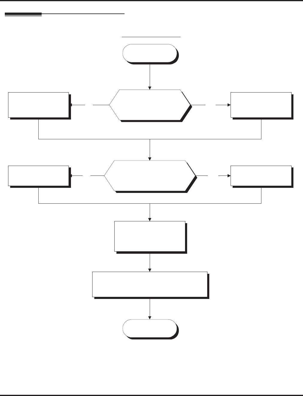
Room Monitor
Aspire Software Manual Features ◆497
Programming
Start
Stop
Should a keyset user
be able to initiate Room
Monitor?
In Program 20-13-11,
enter 0.
In Program 20-13-11,
enter 1.
Should a keyset user have
the ability to be monitored
by another extension?
In Program 20-13-12,
enter 0.
In Program 20-13-12,
enter 1.
In Program 20-06-01,
assign Class of
Service to extensions.
In Program 15-07-01, assign a Room
Monitor key (code 39) to both the
monitoring and monitored extension.
No Yes
YesNo
Keyset Room Monitor
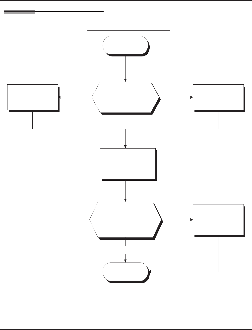
Room Monitor
498 ◆Features Aspire Software Manual
Programming (Cont’d)
Single Line Telephone Room Monitor
Start
Stop
Should a single line
telephone user be able
to initiate and receive
Room Monitor?
In Program 42-03-12,
enter 0.
In Program 42-03-12,
enter 1.
In Program 20-06-01,
assign Class of Service
to extensions.
YesNo
Should the Room Monitor
service code be changed
from the default setting of
175?
No
In 11-14-17, change
the service code to
the desired entry.
Yes

Room Monitor
Aspire Software Manual Features ◆499
Programming (Cont’d)
➻11-14-17 : Service Code Setup (for Hotel) - Hotel Room Monitor
Customize the service code (175 by default) to be used for Room Monitor.
➻15-07-01 : Programmable Function Keys
Assign a function key as a Room Monitor key (code 39) for both the extension being moni-
tored and the extension initiating Room Monitor.
➻20-06-01 : Class of Service for Extensions
Assign a Class Of Service (1-15) to an extension.
➻20-13-11 : Class of Service Options (Supplementary Service) - Room Monitor, Initiating
Extension
In an extension’s Class of Service, enable (1) or disable (0) an extension’s ability to initiate
Room Monitor.
➻20-13-12 : Class of Service Options (Supplementary Service) - Room Monitor, Extension
Being Monitored
In an extension’s Class of Service, enable (1) or disable (0) an extension’s ability to be monitored.
➻42-03-12 : Class of Service Options (Hotel) - SLT Room Monitor
Enable (1) or disable (0) a single line telephone’s ability to use Room Monitor.
Related Features
Hotel/Motel
Room Monitor for single line telephones can be used with the Hotel/Motel feature.
Programmable Function Keys
Room Monitor requires uniquely programmed function keys.

Room Monitor
500 ◆Features Aspire Software Manual
Operation
You must activate Room Monitor at the extension initiating the monitor and at the
extension you want to monitor. You can only listen to one extension at a time.
Keysets:
To activate Room Monitor (at the initiating extension):
1. Do not lift handset or press SPK.
2. Press Room Monitor key (PGM 15-07 or SC 851: 39).
3. Dial number of extension you want to monitor.
You can place and answer other calls while Room Monitor is active.
To activate Room Monitor (at the extension to be monitored):
1. Go to the extension you want to monitor.
2. Do not lift handset or press SPK.
3. Press Room Monitor key (PGM 15-07 or SC 851: 39).
4. Dial the number of the extension you are at.
For example, if you are at extension 306, dial 306.
You can place and answer other calls while Room Monitor is active.
To cancel Room Monitor (at either extension):
1. Press Room Monitor key at both the initiating extension and the monitored extension.
Single Line Telephones:
To activate Room Monitor (at the extension to be monitored):
1. Go to the extension you want to monitor.
2. Lift handset at the phone to be monitored.
3. Dial 175.
4. Dial 1.
5. Dial number of extension number which will be monitoring the phone.
6. Place the handset on the desk, placing the handset’s transmitter towards the room.
You cannot place or answer other calls while Room Monitor is active.
To activate Room Monitor (at the initiating extension):
1. Lift handset at the phone which will be monitoring another phone.
2. Dial 175.
3. Dial 2.
4. Dial number of extension number which will be monitored.
You cannot place or answer other calls while Room Monitor is active.
To cancel Room Monitor (at either extension):
1. Hang up the handsets for both the monitored and the monitoring phones.

Save Number Dialed
Aspire Software Manual Features ◆501
Save Number Dialed
Description
Save Number Dialed permits an extension user to save their last outside number and easily redial it
later on. For example, an extension user can recall a busy or unanswered number without manually
dialing the digits. The system retains the saved number until the user stores a new one in its place.
Save Number Dialed saves in system memory a dialed number up to 24 digits. The number can be
any combination of digits 0-9, # and *. The system remembers the digits regardless of whether the
call was answered, unanswered or busy. The system normally uses the same trunk group as for the
initial call. However, the extension user can preselect a specific trunk if desired.
Conditions
None
Default Setting
Enabled.
Programming
➻11-12-13 : Service Code Setup (for Service Access) - Saved Number Dialed
Customize the service code (815 by default) to be used for dialing a saved number.
➻15-07-01 : Programmable Function Keys
Assign a function key as a Save key (code 30).
Related Features
Automatic Route Selection
For systems with Automatic Route Selection, ARS selects the trunk for the call unless the user pre-
selects.
Central Office Calls, Placing
Other programmed options for outgoing calls can affect how a call is placed. Check or pro-
gram these options as needed.
Dial Tone Detection
Refer to this feature for the specifics on how the system handles Dial Tone Detection.
Last Number Redial
An extension user can quickly redial the last number placed.
Programmable Function Keys
Function keys simplify Save Number Dialed operation.
Repeat Redial
The system can automatically retry a trunk call that was unanswered or busy.
Aspire S Aspire M/L/XL
• Available. • Available.

Save Number Dialed
502 ◆Features Aspire Software Manual
Operation
To save the outside number you just dialed (up to 24 digits):
Use this feature before hanging up.
Keyset
1. Press Save Number Dialed key (PGM 15-07 or SC 851: 30).
500/2500 Single Line Telephone
1. Hookflash.
2. Dial 815.
To redial a saved number:
Keyset
1. (Optional) Press line key.
This selects a specific trunk for the call.
2. Press Save Number Dialed key (PGM 15-07 or SC 851: 30).
The stored number dials out.
OR
1. Press idle CALL key
2. Dial 815.
OR
Press Save Number Dialed key (PGM 15-07 or SC 851: 30).
Save Number Dialed automatically selects a trunk from the same group as your origi-
nal call.
The stored number dials out.
500/2500 Single Line Telephone
1. Hookflash.
2. Dial 815.

Save Number Dialed
Aspire Software Manual Features ◆503
To check to see the number you have saved:
1. Press Save Number Dialed key (PGM 15-07 or SC 851: 30).
The stored number displays for ten seconds.
The stored number dials out if you:
- Lift the handset,
- Press an idle line key,
- Press an idle CALL key, or
- Press SPK
2. Press CLEAR.
To clear your saved number:
Keyset
1. Press idle CALL key.
2. Dial 885.
3. Press SPK to hang up.
Single Line Telephone
1. Lift handset and dial 885.
2. Hang up.

Secretary Call (Buzzer)
504 ◆Features Aspire Software Manual
Secretary Call (Buzzer)
Description
Secretary Call lets two co-workers alert each other without disturbing their work. To have Secretary
Call, both co-workers must have keysets with Secretary Call buzzer keys. When a user presses their
buzzer key, the system alerts the called extension by sending a splash tone and flashing the called
extension’s buzzer key. The called user can respond by placing an Intercom call to the calling party.
The called extension’s buzzer key continues to flash and the splash tone is heard until either user can-
cels the Secretary Call. A secretary could use this feature, for example, to get a message through to
the boss in an important meeting. After being alerted, the boss could call the secretary when it’s most
convenient.
An extension can have Secretary Call keys for any number of extensions, limited only by the avail-
able number of programmable keys.
Conditions
(A.) Secretary Call is not available to single line telephone users.
(B.) Secretary Call does not set up an Intercom call.
(C.) When assigning Secretary Call, a user enters the associated extension numbers, not port numbers.
Default Setting
Disabled.
Programming
➻15-07-01 : Programmable Function Keys
Assign function keys for Secretary Call buzzer (code 41 + Hold + the destination extension
number). Both co-workers must have buzzer keys for each other.
Related Features
Programmable Function Keys
Secretary Call requires a uniquely programmed function key.
Single Line Telephones
Single line telephones cannot use Secretary Call.
Aspire S Aspire M/L/XL
• Available. • Available.

Secretary Call (Buzzer)
Aspire Software Manual Features ◆505
Operation
To buzz your secretary or boss:
1. Do not lift handset.
2. Press buzzer key (PGM 15-07 or SC 851: 41 + sec. ext.).
Your boss or secretary hears ringing.
Your buzzer key lights steadily.
Your boss’s or secretary’s buzzer key flashes fast.
The phone continues to ring until the Secretary Call key is pressed.
To check to see who left you a Secretary Call:
1. Do not lift handset.
2. Press CHECK.
3. Press flashing Secretary Call key.
4. Press CLEAR.
To answer your Secretary Call indication:
1. Place an Intercom call to the extension that called you.
To cancel a Secretary Call you left at another extension:
1. Press your lit Secretary Call key.
To cancel a Secretary Call left at your extension:
1. Do not lift handset.
2. Press flashing Secretary Call key.

Secretary Call Pickup
506 ◆Features Aspire Software Manual
Secretary Call Pickup
Description
Secretary Call Pickup lets a keyset user easily reroute calls intended for a co-worker to themselves. By
pressing a Secretary Call Pickup key, the user can have all calls to a co-worker’s phone ring or voice-
announce theirs instead. Secretary Call Pickup is a simplified type of Call Forward with Follow Me for
employees that work closely together. This feature could be helpful to customer service representatives
that must frequently cover each other’s clients. When a representative leaves their desk, an associate
could press the Secretary Call Pickup key to intercept all their calls.
An extension can have Secretary Call Pickup keys for any number of extensions, limited only by
the available number of programmable keys.
Conditions
(A.) Secretary Call Pickup is not available to single line telephone users.
(B.) A Multiple Directory Number (virtual extension) cannot be programmed as the boss’s extension.
Default Setting
Disabled.
Programming
➻15-07-01 : Programmable Function Keys
Assign function keys for Secretary Call Pickup (42 + boss ext). Unlike Secretary Call, you do
not have to program a corresponding key at the source and destination extensions.
Related Features
Call Forwarding with Follow Me
An extension user can also have Call Forwarding with Follow Me reroute a co-worker’s calls
to themselves.
Programmable Function Keys
Secretary Call pickup requires a uniquely programmed function key.
Secretary Call (Buzzer)
Co-workers can alert each other without disturbing their work.
Single Line Telephones
A keyset can have a Secretary Call Pickup key for a single line telephone.
Aspire S Aspire M/L/XL
• Available. • Available.

Secretary Call Pickup
Aspire Software Manual Features ◆507
Operation
To activate Secretary Call Pickup:
1. Press your Secretary Call Pickup key (PGM 15-07 or SC 851: 42 + boss ext.).
Your Secretary Call Pickup key lights and the Boss’s telephone display shows “BOSS
FWD>>”.
Calls intended for covered extension ring your phone instead.
To cancel Secretary Call Pickup:
1. Press your lit Secretary Call Pickup key (PGM 15-07 or SC 851: 42 + boss ext.).
To check a key’s Secretary Call Pickup assignment:
1. Press CHECK.
2. Press your Secretary Call Coverage key (PGM 15-07 or SC 851: 42 + boss ext.).
3. Press CLEAR.


Selectable Display Messaging
Aspire Software Manual Features ◆509
Selectable Display Messaging
Description
An extension user can select a preprogrammed Selectable Display Message for their extension.
Display keyset callers see the selected message when they call the user’s extension. Selectable Dis-
play Messaging provides personalized messaging. For example, an extension user could select the
message “GONE FOR THE DAY”. Any display keyset user calling the extension may hear a DND
signal and then see the message. See table below for a list of the standard messages.
An extension user can add digits for date, time or phone number after messages 1-8 and 10 (up to
24 characters). For example, an extension user could select the message “ON VACATION UNTIL”
and then enter the date. Callers see the original message followed by the appended date. They
would then be able to tell when the user was coming back from vacation. The system allows all
phones to use the Selectable Display Messaging feature at the same time.
The default messages are:
Conditions
None
Default Setting
Enabled.
Aspire S Aspire M/L/XL
• Available - all telephones are able to use Selectable Dis-
play Messaging at one time. • Available - all telephones are able to use Selectable Dis-
play Messaging at one time.
No. Message Change “#” to...
1
2
3
4
5
6
7
8
9
10
11-20
IN MEETING UNTIL ##:##
MEETING ROOM - ########
COME BACK ##:##
PLEASE CALL ###########
BUSY CALL AFTER ##:##
OUT FOR LUNCH BACK ##:##
BUSINESS TRIP BACK ##/##
BUSINESS TRIP ##########
GONE FOR THE DAY
ON VACATION UNTIL ##/##
MESSAGE 11-20
Time (when meeting done)
Room Name or extension
Time (when returning)
11 digits (phone number)
Time (when returning)
Time (when returning)
Date (when returning)
10 digits (where reached)
Date (when returning)

Selectable Display Messaging
510 ◆Features Aspire Software Manual
Programming
➻11-11-14 : Service Code Setup (for Setup/Entry Operation) - Text Message Setting
Define the service code to be used when setting a text message.
➻15-07-01 : Programmable Function Keys
Assign a function key for Call Forwarding (Device) (code 17) or Text Message (code 18). The Call
Forwarding Device key allows the user to select a message each time they activate the feature,
while the Text Message key automatically selects the message used when programming the key.
➻15-07-01 : Programmable Function Keys
Using the Text Message Setup key (18 + message number), a user can easily set the Selectable
Display Messaging feature with the preprogrammed message number.
➻20-01-02 : System Options - Text Message Mode
Select whether and intercom caller should hear busy (1) or ring through (0) for extensions
which have Selectable Display Messaging set. Note: Any extensions previously set with
Selectable Display Messaging must cancel the feature and reactivate in order for a change in
this option to take affect.
➻20-02-07 : System Options for Multi-Line Telephones - Time and Date Display Mode
Set the System Time and Date display mode. The time that displays in Selectable Display
Messages follows this setting.
➻20-06-01 : Class of Service for Extensions
Assign a Class Of Service (1-15) to an extension.
➻20-13-19 : Class of Service Options (Supplementary Service) - Selectable Display Messaging
In an extension’s Class of Service, enable (1) or disable (0) an extension’s ability to use
Selectable Display Messaging.
➻20-16-01 : Selectable Display Messages
Program the Selectable Display Messages (1-20). Refer to the chart below for character entry.
Use this keypad digit . . . When you want to. . .
1 Enter characters:
1 @ [ ¥ ] ^ _ ‘ { | } > <
2 Enter characters A-C, a-c, 2.
3 Enter characters D-F, a-f, 3.
4 Enter characters G-I, g-i, 4.
5 Enter characters J-L, j-l, 5.
6 Enter characters M-O, m-o, 6.
7 Enter characters P-S, p-s, 7.
8 Enter characters T-V, t-v, 8.
9 Enter characters W-Z, w-z, 9.
0 Enter characters:
0 ! “ # $ % & <space> ( )
* Enter characters:
* + , - . / : ; < = > ?
# # = Accepts an entry (only required if two letters on the
same key are needed - ex: STA)
CONF Clear the character entry one character at a time.
FLASH Clear all the entries from the point of the flashing cursor
and to the right.

Selectable Display Messaging
Aspire Software Manual Features ◆511
Related Features
Do Not Disturb
The DND key lights steady when Program 20-01-02 is set to “1” (no answer/busy mode) and
ICM callers may hear “Please do not disturb” or a DND signal. The message is displayed on
their phone. If this option is set to “0” (call mode), the DND is off allowing ICM callers to
ring through while the message is displayed on their phone.
Programmable Function Keys
Function keys simplify Selectable Display Messaging operation.
Operation
To select a message:
1. Press idle CALL key + dial *4 .
OR
Press Call Forward (Device) key (PGM 15-07 or SC 851: 17).
OR
Press idle CALL key + press Text Message key (PGM 15-07 or SC 851: 18) + enter digits to
append, if needed + SPK to hang up. Skip the remaining steps.
2. Dial 3 + Message number (01-20).
Use VOL ▲ or VOL ▼ to scroll through the messages.
3. (Optional for messages 1-8 and 10)
Dial the digits you want to append to the message.
You can append messages 1-8 and 10 with digits (e.g., the time when you will be back).
You enter the time in 24-hour format, but it displays in 12-hour format.
4. Press SPK to hang up.
Intercom calls to extensions with Selectable Display Messaging set will receive a DND
signal and receive the display message on their telephone’s display instead of ringing the
extension based on the setting in Program 20-01-02.
To allow calls to ring through and have the message displayed on the calling exten-
sion’s display, cancel DND by pressing DND + 0.
To cancel a message:
1. Press idle CALL key + dial *4 .
OR
Press Call Forward (Device) key (PGM 15-07 or SC 851: 17).
OR
Press idle CALL key + press Text Message key (PGM 15-07 or SC 851: 18) + SPK to hang
up.
2. Dial 3.
3. Press SPK to hang up.
Using the Text Message Service Code to select a message:
1. Press idle CALL key + dial the Text Message service code (Program 11-11-14).
2. Dial the Selectable Dsiplay Message number to be used (01-20).
3. Press SPK to hang up.
To cancel, repeat Step 1 and hang up.

Selectable Ring Tones
512 ◆Features Aspire Software Manual
Selectable Ring Tones
Description
An extension user can change the way trunks or ICM calls ring their phone. Selectable Ring Tones
allows an extension user to set up unique ringing for their calls. This is important in a crowded
work area where several phones are close together. Because their phone has a characteristic ring,
the user always can tell when it’s their phone ringing.
Conditions
None
Default Setting
Enabled
Programming
➻11-11-20 : Service Code Setup (for Setup/Entry Operation) - Change Incoming CO and
ICM Ring Tones
If required, change the service code used for changing the incoming ring tones heard for CO
and ICM calls (Default: 820).
➻15-02-02 : Multi-Line Telephone Basic Data Setup - Trunk Ring Tone
Use this option to set the tone (pitch) of the incoming trunk ring for the extension port you are
programming (1 = High, 2 = Mid range, 3 = Low, 4 = Ring Tone 1, 5 = Ring Tone 2, 6 = Ring
Tone 3, 7 = Ring Tone 4, 8 = Ring Tone 5).
➻15-02-03 : Multi-Line Telephone Basic Data Setup - Extension Ring Tone (Pitch)
Use this option to set the tone (pitch) of the incoming extension call ring for the extension port
you are programming (1 = High, 2 = Mid range, 3 = Low, 4 = Ring Tone 1, 5 = Ring Tone 2, 6
= Ring Tone 3, 7 = Ring Tone 4, 8 = Ring Tone 5). Also see program 15-08.
➻15-08-01 : Incoming Virtual Extension Ring Tone Setup
Assign a ring tone range (0-4) to incoming virtual extensions assigned to a Virtual Extension
key (Program 15-07). If you enable ringing for the key in Program 15-09, the key rings with
the tone you set in this program. Also see Program 22-03.
➻15-10-01 : Incoming Virtual Extension Ring Tone Order Setup
Set the priority (1-4) for the Virtual Extension Ring Tones set in Program 15-08. When Virtual
Extension calls ring an extension simultaneously, the tone with the highest order number (e.g.,
1) rings. The other keys just flash.
➻22-03-01 : Trunk Ring Tone Range
Select the ring tone range for the trunk. The trunk uses a ring tone within the range selected
when it rings an extension. There are four ring tones available. Customize the Trunk Ring
Tones in Program 82-01.
Aspire S Aspire M/L/XL
• Available. • Available.

Selectable Ring Tones
Aspire Software Manual Features ◆513
Related Features
Distinctive Ringing, Tones and Flash Patterns
This feature can be used to change the default ring tones.
i-Series Telephones
Selectable Ring Tones is not available for i-Series phones on the Aspire system.
Single Line Telephones
Single line telephones cannot use Selectable Ring Tones.
Transfer
Transferred calls on DISA, DID, ISDN trunks, or from the VRS can display the reason a call
is being transferred (Call Forward, Busy, No Answer, or DND) unless a Selectable Display
Message is enabled. If enabled, the message shall be displayed instead of the reason for the
call transfer.
Operation
To change your extension’s incoming ring tones:
1. Press idle CALL key.
2. Dial 820.
3. Dial 1 to set Intercom ring; 2 to set trunk ring.
4. Dial code for the desired ring pattern (1-8).
5. Press SPK to hang up.
To listen to the incoming ring choices:
1. Press idle CALL key.
2. Dial 811.
3. Dial 1 to listen to Intercom ring; 2 to listen to trunk ring.
For trunk ring, enter the tone to which you want to listen.
4. For Intercom Ring:
Dial code for the ring pattern you want to hear (1-8).
OR
For Trunk Ring:
Dial code for the ring pattern you want to hear (1-8) and then dial the tone for the ring pattern
(1-4).
5. Press SPK to hang up.

Serial Call
514 ◆Features Aspire Software Manual
Serial Call
Description
Serial Call is a method of transferring a call so it automatically returns to the transferring extension.
Serial Calling saves transferring steps between users. For example, a Customer Service Representative
(CSR) has a client on the phone who needs technical advice. The CSR wants to send the call to Tech
Service, but needs to advise the client of certain costs when Tech Service is done. Rather than transfer-
ring the call back and forth, the CSR can use Serial Call to Technical Service and announce, “I have Ted
on the phone. I need to talk to him again. Just hang up when you’re done and I’ll get him back.”
Conditions
The transferring extension can remain off-hook to auto-receive the callback or hang up and it will
ring back to them.
Default Setting
Disabled.
Programming
➻15-07-01 : Programmable Function Keys
Assign a programmable key as a Serial Call key (code 43).
Related Features
Programmable Function Keys
Serial Call requires a uniquely programmed function key.
Single Line Telephones
Serial Call is not available to single line telephones.
Transfer
An extension user can extend (send) a call to a co-worker.
Operation
To place a Serial Call to a co-worker:
1. Place or answer a call.
2. Press HOLD.
3. Dial co-worker’s extension number.
Co-worker must lift handset to respond to your announcement.
4. Press Serial Call key (PGM 15-07 or SC 851: 43) but do not hang up.
When your co-worker hangs up the call, the system makes an automatic live transfer
back to your extension.
Aspire S Aspire M/L/XL
• Available. • Available.

Single Line Telephones, Analog 500/2500 Sets
Aspire Software Manual Features ◆515
Single Line Telephones, Analog 500/2500 Sets
Description
The system is compatible with 500 type (Dial Pulse) and 2500 type (DTMF) analog single line tele-
phones (SLTs). You can install single line telephones as On-Premise or Off-Premise extensions.
Single line telephone users can dial codes to access many of the features available to keyset users.
With Single Line Telephones, you can have your system simulate PBX type operation.
When installing single line telephones, you must have:
●A port on an SLIU PCB for each single line telephone installed.
●(If you have 2500 sets) At least one block reserved on the NTCPU for analog extension
DTMF reception.
CODEC Filter Data Setup Program Added
When Program 82-07-01 : CODEC Filter Setup for Analog Station Ports is set to "4 - Specified
Data", the system will use the settings in Program 82-09 : SLIU CODEC Filter Data Setup.
These values should not be changed from their default settings unless directed by NEC’S Technical
Service department.
The side tone of the SLIU is adjusted using all 16 values, however, special software is required in
order to compute these values. The setting is not proportional to the gain level. To change these
values, contact NEC’s Technical Service department for assistance.
DTMF Dial Out Timer Added
A program is added for DTMF dialing, Program 20-03-07 : System Options for Single Line
Telephones. When Program 20-03-03 : System Options for Single Line Telephones - SLT
DTMF Dial to Trunk Lines is set to "0" (receive all digits before sending), the system will follow-
ing the timers in Program 20-03-04 and 23-03-07.
The timer in Program 20-03-04 : System Options for Single Line Telephones - Dial Sending
Start Time for SLT or ARS will reset when the user dials another digit.
The timer in Program 23-03-07 : System Options for Single Line Telephones - Forced Dial
Sending Start Time will not reset when a digit is dialed. The user must finish dialing all the digits
before this timer expires (Entries: 0-64800 seconds, Default: 0).
Conditions
(A.) Dial Pulse (500 type) single line telephones cannot access any features that require the user to
dial # or *.
Aspire S Aspire M/L/XL
• Available - 18 single line telephones maximum.
•Defining CODEC Filter settings available.
• DTMF Dial Out Timer requires software 4.0E+.
• Available - 256 single line telephones maximum (may
be restricted due to system power requirements).
•Defining CODEC Filter settings available with software
1.04+.
• DTMF Dial Out Timer requires software 4.0E+.

Single Line Telephones, Analog 500/2500 Sets
516 ◆Features Aspire Software Manual
Default Setting
●Single Line Telephones function as soon as they are installed and properly programmed.
Programming
➻10-03-01 : PCB Setup
Program all on-premise 500/2500 type single line telephones with circuit type ‘2’. Set the
DIOPU trunk to type ‘1’ when trunks should be defined for off-premise extension (OPX) use.
➻10-03-03 : PCB Setup, For SLIU Unit - Transmit CODEC Gain Type
10-03-04 : PCB Setup, For SLIU Unit - Receive CODEC Gain Type
Assign transmit and receive levels for 500/2500 type single line telephones.
➻10-09-01 : DTMF and Dial Tone Circuit Setup
If the system has 2500 type (DTMF) single line extensions, allocate at least one circuit for
analog extension DTMF reception (entry 0 or 1).
●Use the following as a guide when allocating DTMF receivers:
- In light traffic sites, allocate one DTMF receiver for every 10 devices that use them.
- In heavy traffic sites, allocate one DTMF receiver for every five devices that use them.
➻15-03-01 : Single Line Telephone Basic Data Setup - SLT Signaling Type
Enter 0 if single line phone is a 500 type (dial pulse). Enter 1 if single line telephone is a 2500
type (DTMF).
➻15-03-03 : Single Line Telephone Basic Data Setup - Terminal Type
Enter 0 for normal 500/2500 type telephones. Enter 1 if a Voice Mail port (refer to “Voice
Mail” for more).
➻20-03-02 : System Options for Single Line Telephones - Ignore Received DP Dial on
DTMF SLT Port
Use this option to define whether the system should receive dial pulse and DTMF signals (0)
or ignore dial pulse and only accept DTMF signals (1).
➻20-06-01 : Class of Service for Extensions
Assign a unique Class of Service for Dual OPX phones only when using Continued Dialing.
➻20-13-13 : Class of Service Options (Supplementary Service) - Continued Dialing
Set option to ‘0’ to prevent dual DTMF tones when using Continued Dialing.
➻20-15-01 : Ring Cycle Setup - Normal Incoming Call on Trunk
Define the ringing cycle (1-13) for normal incoming trunk calls (DIL, ring group, etc.).
➻20-15-03 : Ring Cycle Setup - Incoming Internal Calls
Define the ringing cycle (1-13) for ICM calls.
➻20-15-05 : Ring Cycle Setup - DID
Define the ringing cycle (1-13) for DID calls.
➻80-03-01 : DTMF Tone Receiver Setup
80-04-01 : Call Progress Tone Detector Setup
If required, modify the criteria for dial tone detection and call progress tone detection for the
DTMF tones received at a single line telephone.
➻82-04-01 - 82-04-14 : SLIU Initial Data Setup
Set various timing parameters for the analog station PCBs. The entries you make in this pro-
gram affect all SLIU PCBs installed (make time, break time, hookflash, etc.).
➻82-07-01 : CODEC Filter Setup for Analog Station Ports
Define the CODEC (QSLAC) Filter (0 = No filter, 1 = 0dB Loss, 2 = 4dB Loss, 3 = 8dB Loss,
4 = Specified Data from Program 82-09) for each analog extension port
➪Aspire S Analog Ports: 1-18
➪Aspire Analog Ports: 1-256

Single Line Telephones, Analog 500/2500 Sets
Aspire Software Manual Features ◆517
Related Features
Single line telephone users have access to the following features:
Data Communications
APA and APR modules can be used with keysets to provide an analog port.
Refer to the individual features for additional descriptive, programming and operational information.
Operation
Refer to the individual features listed in the Related Features chart above.
Abbreviated Dialing Department Step Calling Message Waiting
Account Codes Directed Call Pickup Night Service
Alarm Do Not Disturb Off Hook Signaling
Automatic Route Selection Door Box Paging
Barge In Flash PBX Compatibility
Call Forwarding Forced Trunk Disconnect Pulse to Tone Conversion
Call Forwarding with Follow Me Group Call Pickup Ringdown Extension
Call Forwarding/DND Override Hold Save Number Dialed
Call Waiting/Camp On with Split Intercom Selectable Display Messages
Callback Handsfree Answerback/Forced
Intercom Ringing Toll Restriction
Central Office Calls, Answering Last Number Redial Transfer
Central Office Calls, Placing Line Preference Trunk Queuing and Camp On
Conference Meet Me Conference Voice Mail
Department Calling Meet Me Paging Voice Over
Meet Me Paging Transfer Warning Tone for Long
Conversation
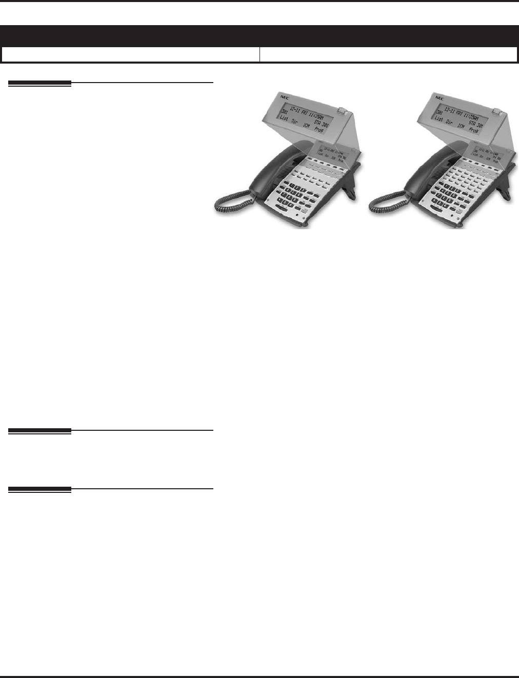
Soft Keys
518 ◆Features Aspire Software Manual
Soft Keys
Description
Each display tele-
phone provides
interactive soft keys
for intuitive feature
access. It is no
longer necessary to
remember feature
codes to access the
telephone’s
advanced features
because the function
of the soft keys change as the user processes calls. For example, just press a soft key to Page, Park a
call, leave a message or Camp On to a busy co-worker.
Additional options allow you to “fine tune” the keyset’s volume levels for handset receive and trans-
mit, speaker volume, ringer and handset volume, and headset volume levels. You can also customize
the point at which the built-in speakerphone switches from transmit to receive; a boon for noisy envi-
ronments. The display telephones also have a contrast control for the LCD display.
Conditions
If a feature is restricted by an extension’s Class of Service, though the Soft Key menu will still dis-
play the option, the user can not set the feature.
Default Setting
Display shows time/date/extension/Soft Key menu information.
Programming
None
Related Features
Directory Dialing
Using the Directory Dialing Soft Keys, the FLASH key can toggle the language display from
English to Japanese.
i-Series Telephones
Soft Keys are not available for i-Series phones on the Aspire system.
Volume Controls
The feature must be active to change the volume (ex: phone must be ringing, page being
heard, etc.). Pressing the volume keys when the phone is idle will adjust the display’s contrast.
Refer to the individual features for additional descriptive, programming and operational information.
Aspire S Aspire M/L/XL
• Available. • Available.

Station Message Detail Recording
Aspire Software Manual Features ◆519
Station Message Detail Recording
Description
Station Message Detail Recording (SMDR) provides a record of the system’s trunk calls. Typi-
cally, the record outputs to a customer-provided printer, terminal or SMDR data collection device.
SMDR allows you to monitor the usage at each extension and trunk. This makes charge-back and
traffic management easier.
SMDR provides the following options:
●Abandoned Call Reporting
The SMDR report includes calls that rang into the system but were unanswered (i.e., aban-
doned). SMDR can include all abandoned calls or only those abandoned calls that rang longer
than the specified duration. The Abandoned Call Report helps you keep track of lost business.
●Blocked Call Reporting
When Toll Restriction blocks a call, you can have SMDR print the blocked call information.
Or, you can have SMDR exclude these types of calls. With Blocked Call Reporting, you can
better customize Toll Restriction for the site’s application.
●Customized Date Format
The SMDR header can show the report date in one of three formats: American, European or
Japanese. Set the format for your preference.
●Transferred Call Tracking
SMDR shows each extension’s share of a transferred call. If an outside call is transferred
among four extensions, SMDR shows how long each of the callers stayed on the call.
●Data Call Tracking
Data Call Tracking can log the system’s internal data calls. Since SMDR normally logs exter-
nal (trunk) data calls, Data Call Tracking lets you get a complete picture of data terminal
activity.
●Digit Counting
With Digit Counting, SMDR can selectively keep track of toll calls. For example, if the digit
count is nine, SMDR won’t include toll calls within the home area code. Digit Counting per-
mits SMDR to include only the types of calls you want to monitor.
Aspire S Aspire M/L/XL
• Available.
• This feature requires a connection to the system using a
CTA or CTU adapter, or through the serial, or LAN port
on the Aspire ENTU. (The LAN port only provides
information through LAN-capable programs, such as
HyperTerminal. Printing of the SMDR information must
be done from within that program.)
• SMDR output includes Caller ID with software 4.0E+.
• Available.
• This feature requires a connection to the system using a
CTA or CTU adapter, or through the serial or USB port
on the Aspire NTCPU (requires the USB driver which
can be downloaded from the NEC Technical Support
web site - ws1.necii.com).
• The LAN port on the Aspire NTCPU can be used with
1.02+. (The LAN port only provides information
through LAN-capable programs, such as HyperTermi-
nal. Printing of the SMDR information must be done
from within that program.)
• SMDR output includes Caller ID with software 4.0E+.

Station Message Detail Recording
520 ◆Features Aspire Software Manual
●Digit Masking
Digit Masking lets you “X” out portions of the number dialed on the SMDR report. A digit
mask of seven, for example, masks out all exchange codes (NNXs) and local addresses. Digit
Masking makes it easier to keep track of calling patterns, without having to interpret each
individual number. You can also use Digit Masking to block out access and security codes.
●Duration Monitoring
SMDR can include calls of any duration, or only those that last longer than the interval you
specify. If you want to keep track of all trunk activity, use a short duration. To keep track of
only significant usage, use a longer duration.
●Extension Exclusion
You can selectively exclude extensions from the SMDR report. This ensures privacy for high-
profile callers. For example, the company attorney negotiating a merger may not want his
calls to show up on an in-house report.
●PBX Call Reporting
If you system is behind a PBX, you can have SMDR monitor all traffic into the PBX or just
calls placed over PBX trunks. The SMDR record can include all PBX calls (including calls to
PBX extensions) or just calls that include the PBX trunk access code.
●Serial and USB SMDR Communication
The system is compatible with both serial and USB SMDR devices. This gives you many
SMDR output options. For example, you can output the SMDR report to a high speed printer
or send it to disk through a PC’s serial or USB port (requires the USB driver which can be
downloaded from the NEC Technical Support web site - ws1.necii.com).
●Trunk Exclusion
Use Trunk Exclusion to exclude certain trunks not subject to per-call charges (like WATS
lines) from the SMDR report. This makes call accounting easier, since you review only those
calls with variable costs.
●Usage Summaries
SMDR can automatically print daily, weekly and monthly call activity summaries. Each sum-
mary includes the total number of regular trunk calls and ISDN trunk calls, and the costs for
each type. The daily report prints every day at midnight. The weekly report prints every Sun-
day night at midnight. The monthly report prints at midnight on the last day of the month.
●Extension Name or Number
The SMDR report can include an extension’s name or extension number. Choose the method
that makes it easier for you to track call usage.

Station Message Detail Recording
Aspire Software Manual Features ◆521
Sample SMDR Report Through Software 3.07
SMDR Enhanced for Caller ID
Depending on your software version, the SMDR output is enhanced to include up to 16 or 24 char-
acters of the Caller ID name information (depending on the view option selected in Program 35-02-
18). You can select to display the Caller ID number or name or the DID number. If you wish to dis-
play the Caller Name in the “DIALLED NO./CLI” and “ACCOUNT" area, select "2" in the
updated Program 35-02-15 and "1" in Program 35-02-17.
If the Caller ID name is not received, the area for Caller ID Name is left blank.
Sample SMDR Report Through Software 4.0E or Higher
For example, with Program 35-01-09 = 0 (Format for NA) and Program 35-02-17 = 1 (Caller ID
Name), if a call is received with the Caller ID Name of “NECinfrontia Corporation” (24 charac-
ters), the following SMDR record is displayed:
If Program 35-02-18 = 1 (Caller ID Name Output Method) is set to line feed, the SMDR will dis-
play as follows:
01/01/03 PAGE 001
CLASS TIME DATE LINE DURATION STATION DIALLED No./CLI ACCOUNT
POT 10:44 01/01/03 001 00:00:30 324 12039265400 8841
POT 10:46 01/01/03 001 00:00:45 324 18874521 0
POT 10:47 01/01/03 001 00:00:29 318 12039265441 0
PIN 10:48 01/01/03 002 00:01:39 NO ANSWER
ALB 10:50 01/01/03 02 00:01:40
POT 10:55 01/01/03 002 00:00:00 324 0
ALB 10:56 01/01/03 02 00:00:23
BRD 10:56 01/01/03 002 00:00:00 324 0
ALB 10:56 01/01/03 02 00:00:09
BRD 10:56 01/01/03 002 00:00:00 324 120366541233 0
ALB 10:56 01/01/03 02 00:00:09
BRD 10:56 01/01/03 002 00:00:00 324 181477445236 0
ALB 10:56 01/01/03 02 00:00:08
CLASS TIME DATE LINE DURATION STATION DIALLED No./CLI ACCOUNT
POT 10:52 12/09 002 00:00:10 2001 2142623801 08754
PIN 10:52 12/09 001 00:00:20 2017 2142623802 NECinfrontia Cor
PIN 10:53 12/09 002 2142623801 NO ANSWER
CLASS TIME DATE LINE DURATION STATION DIALLED No./CLI ACCOUNT
POT 10:52 12/09 002 00:00:10 2001 2142623801 08754
PIN 10:52 12/09 001 00:00:20 2017 2142623802 NECinfrontia Cor
NEXT NECinfrontia Corp.
PIN 10:53 12/09 002 2142623801 NO ANSWER

Station Message Detail Recording
522 ◆Features Aspire Software Manual
Definitions
Call Record Number SMDR record number (consecutive)
CLASS Type of call (see Class Definitions below)
TIME Time call placed or answered. (For Transferred calls, shows time
user picked up Transfer.)
DATE Date the call was made
LINE Trunk number used for call
DURATION How long call lasted. (For Transferred calls, shows how long user
was on call after answering the Transfer.)
STATION Extension number of call “owner” (i.e., extension that first placed
or answered call) (For Transferred calls, there can be more than one
owner - depending on how many extensions shared the call.)
DIALLED No./CLI For outgoing calls, the number dialed or, for incoming calls, the
Caller ID information
COST For system with ARS, indicates the call cost
OR
ACCOUNT Account Code number entered by extension user
Class Definitions
POT Outgoing trunk call
POTA Outgoing trunk call placed using Toll Restriction Override
PIN Incoming trunk calls
ALB All lines in group are busy (group number follows TIME field)
BRD Call blocked due to Toll Restriction
PTRS Transferred call
IVIN BRI trunk call

Station Message Detail Recording
Aspire Software Manual Features ◆523
Description (Cont’d)
SMDR Report Format with Program 35-02-14 Set to “0”
Character Position Field Definition
Header Line 1
1-60 Spaces
61-70 MM/DD/YYYY
71 Space
72-75 PAGE
76 Space
77-79 Report page number (e.g., 001)
CR & LF Carriage return and line feed
Header Line 2
1-5 CLASS
6 Space
7-10 TIME
11-14 Spaces
15-18 LINE
19-22 Spaces
23-30 DURATION
31-32 Spaces
33-39 STATION
40-44 Spaces
45-51 DIALLED
52 Space
53-59 No./CLI
60-63 Spaces
64-70 ACCOUNT
CR & LF Carriage return and line feed
LF Line feed
SMDR Record
1-4 Call type (e.g., POT for outgoing)
5 Space
6-10 Time in 24 hour clock (HH:MM)
11 Space
12-21 LINE
22 Space
23-30 Call Duration (HH:MM:SS)

Station Message Detail Recording
524 ◆Features Aspire Software Manual
31 Space
32-41 Station number or name
42 Space
43-62 Number dialed (20 digits maximum)
63 Space
64-79 Account number or NO ANSWER
SMDR Report Format with Program 35-02-14 Set to “1”
Character Position Field Definition
Header Line 1
1-60 Spaces
61-70 MM/DD/YYYY
71 Space
72-75 PAGE
76 Space
77-79 Report page number (e.g., 001)
CR & LF Carriage return and line feed
Header Line 2
1-5 CLASS
6 Space
7-10 TIME
11 Spaces
12-15 DATE
16-17 Spaces
18-21 LINE
22 Space
23-30 DURATION
31-32 Spaces
33-39 STATION
40-44 Spaces
45-51 DIALLED
52 Space
53-59 No./CLI
60-63 Spaces
64-70 ACCOUNT
CR & LF Carriage return and line feed
SMDR Report Format with Program 35-02-14 Set to “0”
Character Position Field Definition

Station Message Detail Recording
Aspire Software Manual Features ◆525
Summary Reports
OUTGOING CALL/COST SUMMARY
FOR DAY OF nn/nn/nn
TOTAL NO. OF OUTGOING PSTN CALLS:0
TOTAL NO. OF OUTGOING ISDN CALLS:0
NO. OF OUTGOING PSTN CALLS COSTED:0 COST:0
NO. OF OUTGOING ISDN CALLS COSTED:0 COST:0
OUTGOING CALL/COST
SUMMARY FOR WEEK ENDING nn/nn/nn
TOTAL NO. OF OUTGOING PSTN CALLS:49
TOTAL NO. OF OUTGOING ISDN CALLS:0
NO. OF OUTGOING PSTN CALLS COSTED:0 COST:0
NO. OF OUTGOING ISDN CALLS COSTED:0 COST:0
OUTGOING CALL/COST SUMMARY
FOR MONTH ENDING nn/nn/nn
TOTAL NO. OF OUTGOING PSTN CALLS:49
TOTAL NO. OF OUTGOING ISDN CALLS:0
NO. OF OUTGOING PSTN CALLS COSTED:0 COST:0
NO. OF OUTGOING ISDN CALLS COSTED:0 COST:0
LF Line feed
SMDR Record
1-4 Call type (e.g., POT for outgoing)
5 Space
6-10 Time in 24 hour clock (HH:MM)
11 Space
12-16 DATE
17 Space
18-21 LINE
22 Space
23-30 Call Duration (HH:MM:SS)
31 Space
32-41 Station number or name
42 Space
43-62 Number dialed (20 digits maximum)
63 Space
64-79 Account number or NO ANSWER
SMDR Report Format with Program 35-02-14 Set to “1”
Character Position Field Definition

Station Message Detail Recording
526 ◆Features Aspire Software Manual
Conditions
(A.) The SMDR report does not include Intercom calls.
(B.) The SMDR call buffer stores 500 calls. The buffer stores calls when the SMDR device is unavail-
able. When the buffer fills, the oldest record is deleted to allow the new record to be saved.
(C.) When SMDR reports are enabled using the same port as the Traffic Reporting feature (exam-
ple: 147), the SMDR blocks the Traffic reports. Unplugging the cable and plugging it back in
again will allow Traffic reports to print.
(D.) SMDR requires a connection to the NTCPU via a COM port, USB (Aspire only) or LAN con-
nection. A USB connection from the Aspire NTCPU requires the USB driver which can be
downloaded from the NEC Technical Support web site - ws1.necii.com.
The system can also use a connection to the system via a CTA/CTU adapter (the CTU adapter
also requires a USB driver which is also available on the web site). Once you designate a CTA
or CTU for SMDR, you cannot use that extension for placing and answering other data calls.
SMDR and the Traffic Reports should not use the same CTA/CTU.
(E.) If no answer is received, “NO ANSWER” is displayed regardless of the system programing for
the Caller ID display option.
(F.) The setting in Program 35-02-18 works regardless of the entry in Program 35-02-15 or 35-02-
17.
(G.) When Program 35-02-18 is set to "1", the first and second lines are sometimes separated.
When the buffer is full, the overflowed data may not be shown.
(H.) The special characters used in the Aspire system cannot be output to the SMDR - they are con-
verted to “_”.
Default Setting
Disabled.
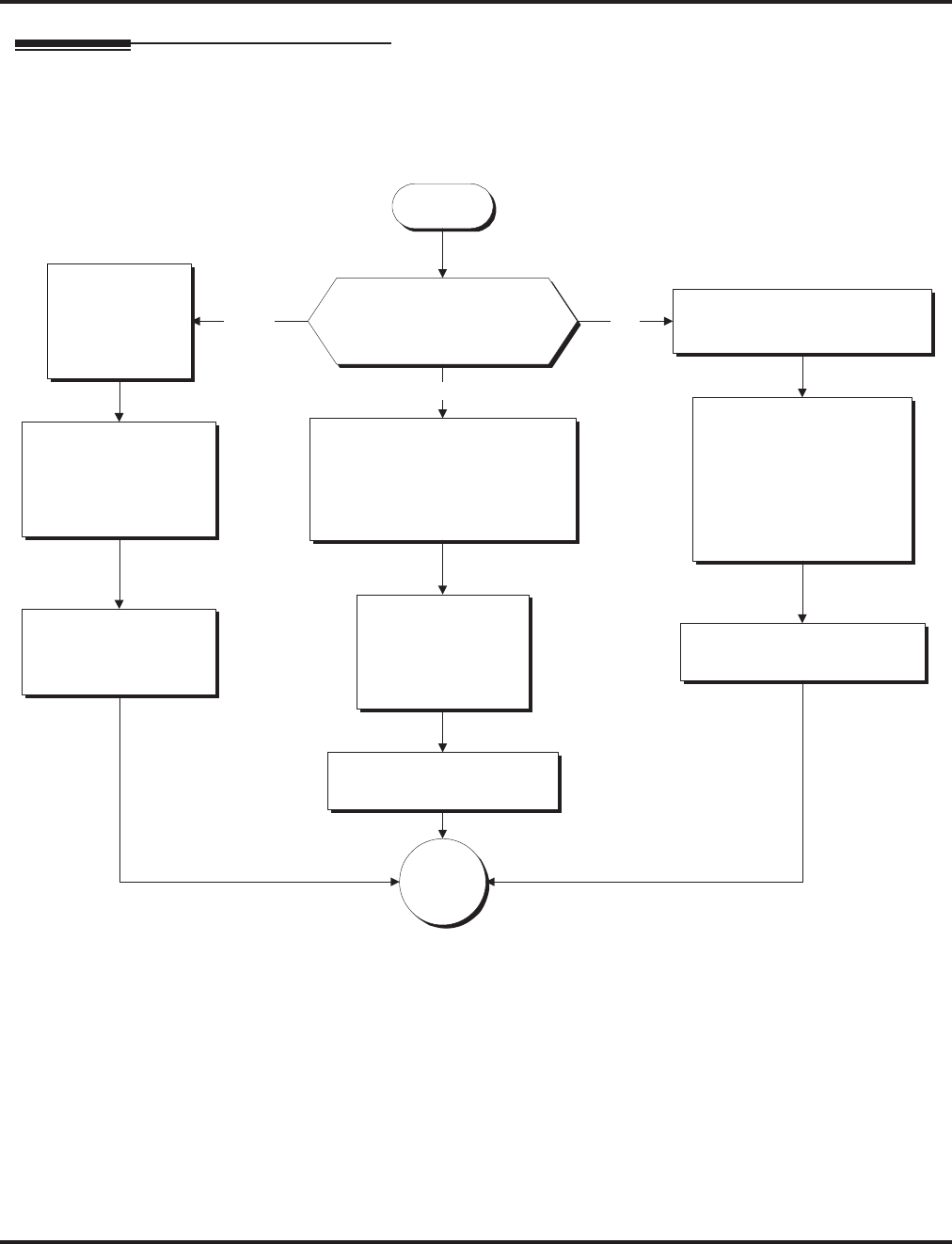
Station Message Detail Recording
Aspire Software Manual Features ◆527
Programming
Start
SMDR With a CPU Connection
(Serial / USB / Ethernet)
In 35-01-01 set the SMDR
output to "2" for NTCPU USB.
Aspire M/L/XL Only
Connect a USB cable to
the CPU and PC.
The PC will recognize the
new hardware and ask to
install the driver. Install the
CPU USB driver (available
from the NEC Technical
Support web site
(ws1.necii.com).
Which connection type will
be used to connect the CPU
for SMDR?
Connect a null modem cable
from the CPU to the PC to be
used for SMDR.
(Refer to the Aspire Hardware
Manual for pin-out details.)
Serial
Connect an
ethernet cable
from the CPU to
the PC to be used
for SMDR.
Ethernet USB
In 10-20-01, define
the TCP port when
communicating to the
SMDR (external
device 5).
In 10-21-02, set the
baud rate (0=4800,
1=9600, 2=19200,
3=38400).
In 35-01-01 set the
SMDR output to "3"
for LAN.
In 35-01-01 set the SMDR
output to "1" for COM port.
Go to
"A".
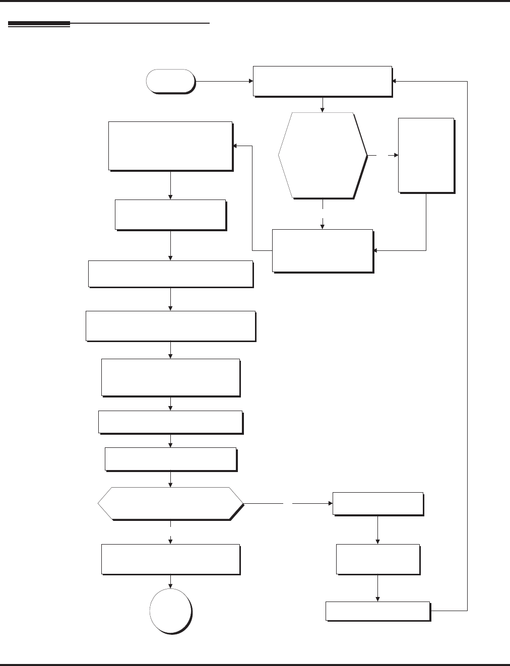
Station Message Detail Recording
528 ◆Features Aspire Software Manual
Programming (Cont’d)
Start
SMDR With a CTA Adapter
In 15-02-19, set the
extension with
the CTA Adapter to "1".
In 15-02-20, set the baud
rate to be used
for the CTA connection
(0=4800, 1=9600, 2=19200).
In 35-01-01 set the SMDR
output to "4" for CTA/CTU.
In 35-01-02, define the extension number
of the keyset with the CTA Adapter.
Set the dip switches on the CTA Adapter
to pins 1 and 2 on (up), 3-8 off (down).
Without
the line cord connected to
the keyset, install the CTA Adapter
onto the keyset.
You may wish to remove
the wall mount bracket to
allow easier installation.
Refer to the Aspire or Aspire S Hardware
Manual for further installation details on
the CTA Adapter.
Connect the line cord to the keyset.
Wait one minute for the system
to recognize the adapter.
Disconnect the phone.
Check 10-03-04 for the keyset.
Does it show the CTA installed?
The CTA Adapter
does NOT require
an AC/DC power
adapter.
No
Undefine the keyset's
port in 10-03-01.
Remove the CTA Adapter.
Connect an RS-232C straight-thru
cable to the adapter and PC.
Yes
Go to
"A".
Do Not
plug in the keyset with
the CTA Adapter.
Disconnect
the phone
and undefine
(set to 0)
the keyset's
port in
10-03-01.
Was the
extension on
which the CTA
Adapter is to be
installed
previously
connected to
the system?
Yes
No
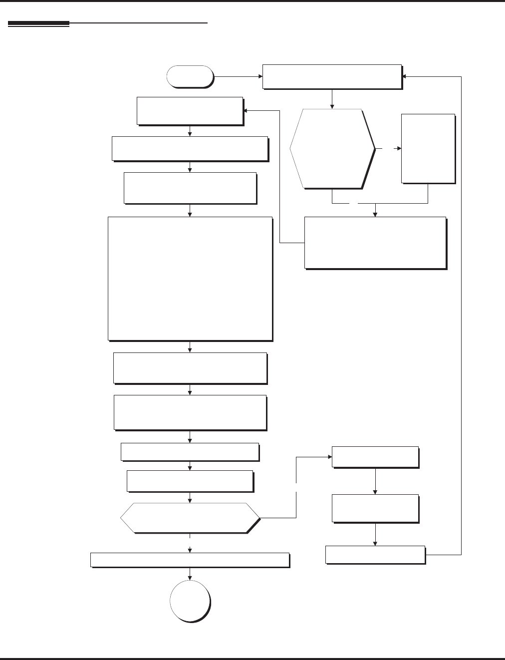
Station Message Detail Recording
Aspire Software Manual Features ◆529
Programming (Cont’d)
Start
SMDR With a CTU Adapter
In 35-01-01 set the SMDR
output to "4" for CTA/CTU.
In 35-01-02, define the extension number
of the keyset with the CTU Adapter.
Set the dip switches on the CTU
Adapter to pins 2, 5 and 6 on (up),
1, 3, 4, 7, 8 off (down).
Without
the line cord connected to the
keyset, install the CTU Adapter onto the
keyset and connect the AC/DC adapter.
You may wish to
remove the wall
mount bracket to
allow easier
installation.
Refer to the Aspire or
Aspire S Hardware
Manual for further
installation details on
the CTU Adapter.
Connect the line cord to the keyset. Disconnect the phone.
Check 10-03-04 for the keyset.
Does it show the CTU installed?
The CTU Adapter
requires an AC/DC
power adapter.
No
Undefine the keyset's
port in 10-03-01.
Remove the CTU Adapter.
Connect the USB cable to the adapter and PC.
Go to
"A".
Yes
Wait one minute for the system
to recognize the adapter.
Install the CTU USB driver (available from
the NEC Technical Support web site -
www.necii.com). Select "non-procedure"
service during the installation for SMDR.
When connecting to the USB port using a
communications program (such as
HyperTerminal), you can determine the
COM port used by checking the Ports listing
in the Device Manager (right-click on "My
Computer" and click on "Manage").
The baud rate selected in HyperTerminal
does not matter with the USB connection.
Do Not plug in the keyset
with the CTU Adapter.
Set 15-02-19 to "0" for the extension
which will have the CTU installed.
(With PCPro/WebPro, select
"Direct Print Mode".)
Disconnect
the phone
and undefine
(set to 0)
the keyset's
port in
10-03-01.
Was the
extension on
which the CTU
Adapter is to be
installed
previously
connected to
the system?
Yes
No
Attach ferrite beads to the AC-R power
cable and USB cables. (Install on the
ends closest to the adapter.)
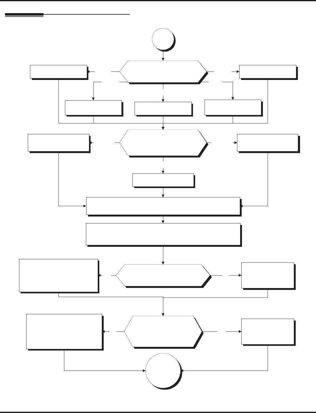
Station Message Detail Recording
530 ◆Features Aspire Software Manual
Programming (Cont’d)
Continued on
next page.
What language should be used
for the SMDR header?
In 35-01-03, enter 0. In 35-01-03, enter 4.
In 35-01-03, enter 1.
English
German
Spanish
In 35-01-03, enter 3.
In 35-01-03, enter 2.
French
Italian
Do you want to block (i.e., "X"
out) any of the digits on the
SMDR report?
In 35-01-04, enter the number
of digits you want to block.
If you enter 8, for example,
SMDR Xs out the last 8
digits dialed.
In 35-01-04, enter 0.NoYes
For example, you can use this feature to
block the printing of security codes.
"A".
Should all outgoing calls
print on the SMDR report,
regardless of the number
of digits dialed?
In 35-01-05, enter the
minimum number of digits
a user must dial (1-24)
before system will include
call on SMDR report.
In 35-01-05, enter 0.No Yes
To have only long distance calls print,
for example, enter 8.
Do you want American,
European or Japanese date
format in the SMDR header?
In 80-05-01, enter 0. In 80-05-01, enter 2.
In 80-05-01, enter 1.
American
Japanese
European
In 35-03-01, for each trunk group, select the SMDR port (1-8)
to which the incoming SMDR information should be sent.
In 35-04-01, for each Department group, select the SMDR
port (1-8) to which the outgoing SMDR information should
be sent.
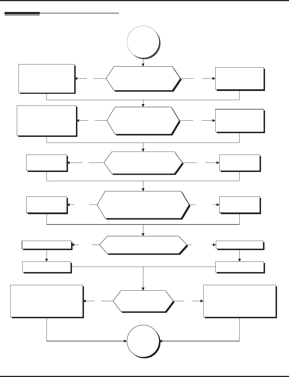
Station Message Detail Recording
Aspire Software Manual Features ◆531
Programming (Cont’d)
Continued
from
previous
page.
Do you want the SMDR
report to include calls
blocked by Toll Restriction?
In 35-02-01,
enter 1.
In 35-02-01,
enter 0.
If your system is behind a PBX, do
you want SMDR to include all calls
to the PBX or just calls using the
PBX trunk access code?
In 35-02-02,
enter 0.
In 35-02-02,
enter 1.
Should the SMDR report display
the trunk name or the date and
trunk number?
In 35-02-03, enter 1.In 35-02-03, enter 0.
Do you want to
print the SMDR
report summaries?
Enter 1 to enable the following
reports:
35-02-04: Daily Summary
35-02-05: Weekly Summary
35-02-06: Monthly Summary
Enter 0 to disable the following
reports:
35-02-04: Daily Summary
35-02-05: Weekly Summary
35-02-06: Monthly Summary
YesNo
All Calls
Access
Code
Calls
Date and
Trunk
Number
Trunk
Name
YesNo
In 35-02-14, enter 0.
Continued on
next page.
In 35-02-14, enter 1.
Should calls of any
duration print on the
SMDR report?
In 35-01-06, enter
minimum duration of call
that will print on the
SMDR report (1-65535
seconds).
In 35-01-06, enter 0.
Should all unanswered
(i.e., "NO ANSWER")
calls print on the SMDR
report?
In 35-01-07, enter how
long an unanswered call
must ring (1-65535
seconds) before SMDR
logs it as "NO ANSWER".
In 35-01-07, enter 0.
No
No
Yes
Yes
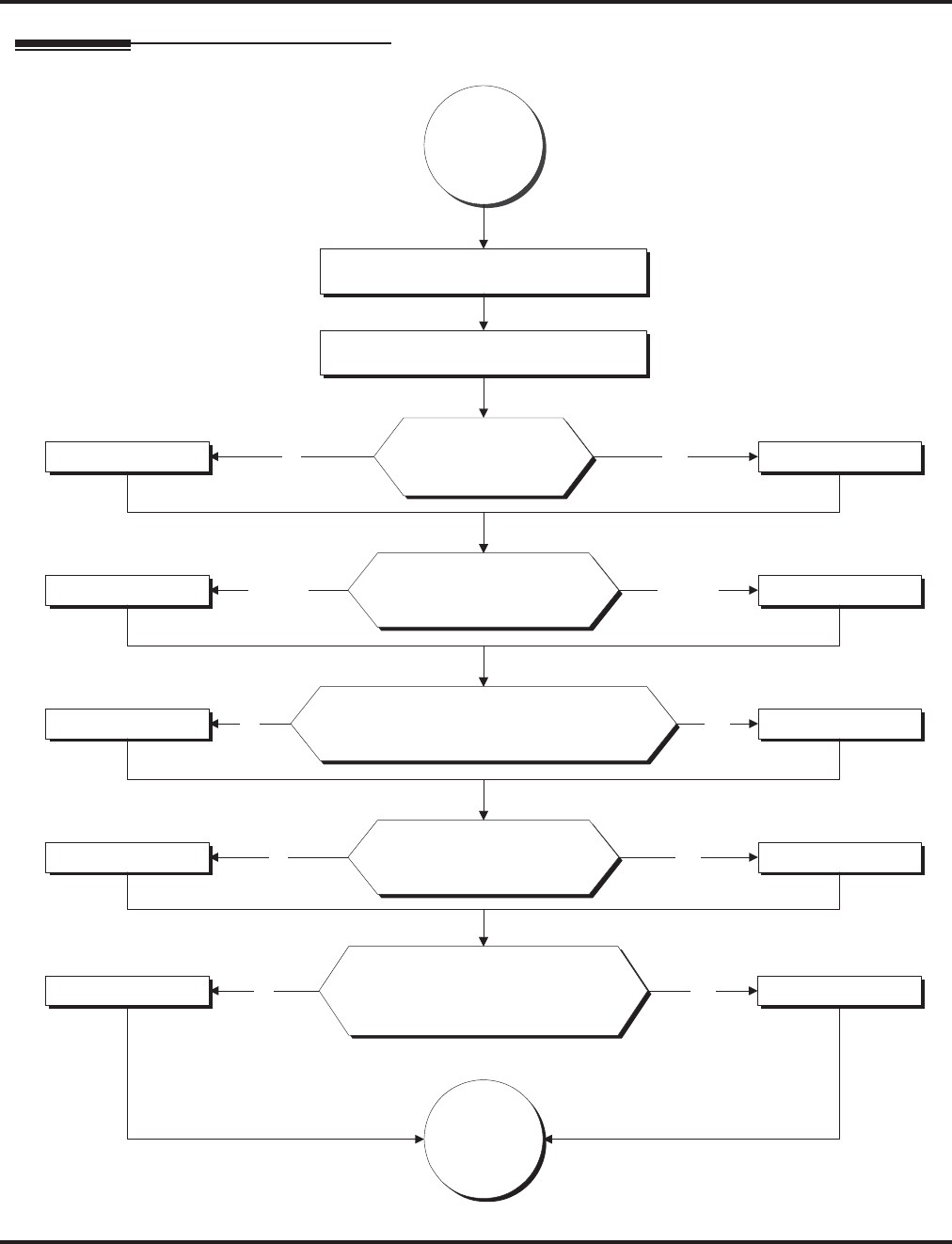
Station Message Detail Recording
532 ◆Features Aspire Software Manual
Programming (Cont’d)
Continued
from
previous
page.
Should the SMDR report include
information when all lines in a group are
busy and a user tries to access the group?
In 35-02-10, enter 0. In 35-02-10, enter 1.
No Yes
Should the DID table name
be displayed for incoming
DID calls?
In 35-02-12, enter 0. In 35-02-12, enter 1.
No Yes
Should the SMDR report display
the Caller ID when an incoming
DID number is transferred to an
outgoing trunk?
In 35-02-13, enter 0. In 35-02-13, enter 1.
No Yes
Should the SMDR
report include
incoming calls?
In 35-02-08, enter 1.In 35-02-08, enter 0.
Should the SMDR report
include extension names
or numbers?
In 35-02-09, enter 0. In 35-02-09, enter 1.
No Yes
Extension
name
Extension
number
Set 14-01-06 to "1" for each trunk
which should provide SMDR.
Set 15-01-03 to "1" for each extension
which should provide SMDR.
Continued on
next page.
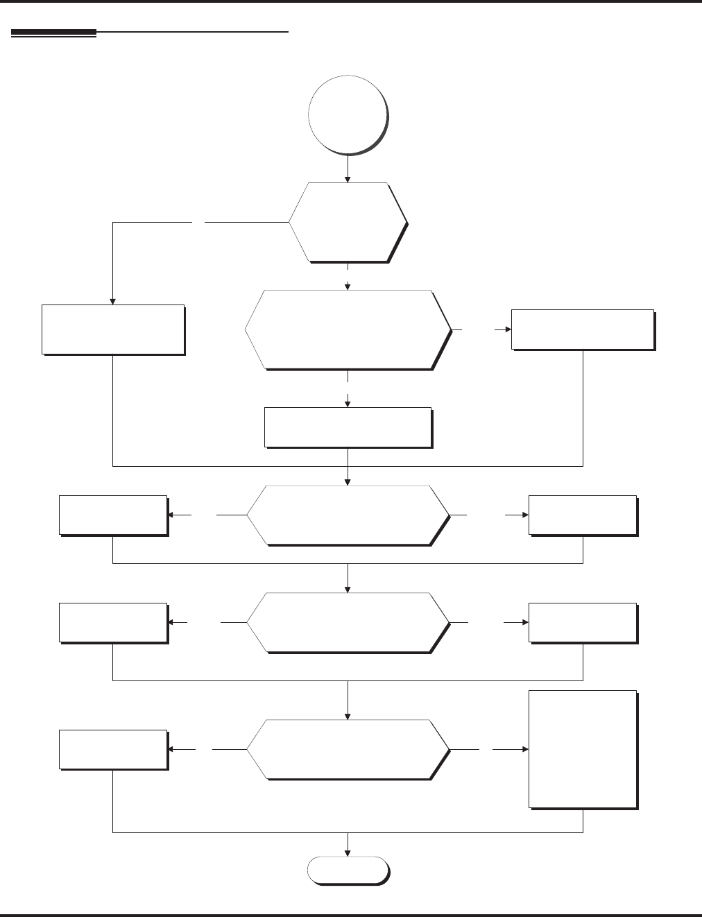
Station Message Detail Recording
Aspire Software Manual Features ◆533
Programming (Cont’d)
Stop
Should the SMDR report
include the trunk port names or
received number dialed for ANI/
DNIS and DID trunks?
In 35-02-16, enter
0.
In 35-02-16, enter
1.
Trunk
Name
Received
Number
Dialed
Continued
from
previous
page.
No
Yes
In 35-02-15, enter 0 to
display the Caller ID
number.
Is the system
software
version 4.0E
or higher?
In 35-02-15, enter 1 to
display the DID number.
Should the Caller ID
number, DID number, or
Caller ID name be displayed
in the SMDR output?
DID
Number
In 35-02-15, enter 2 to display
the Caller ID name.
Caller ID Name
Should the SMDR report
include the Account Code or
Caller ID name?
In 35-02-17, enter
0.
In 35-02-17, enter
1.
Account
Code
Caller ID
Name
Should the Caller ID Name
appear on the same line as the
call record?
In 35-02-18, enter
0.
In 35-02-18, enter
1.
Selecting this option
inserts a line feed
and up to 24
characters can be
displayed for the
Caller ID name.
Yes No

Station Message Detail Recording
534 ◆Features Aspire Software Manual
Programming (Cont’d)
➻10-20-01 : LAN Setup for External Equipment
Define the TCP port (0-65535) when communicating to the SMDR (type 5).
➻10-21-02 : NTCPU Hardware Setup - Baud Rate for COM Port
If the SMDR connection is made using the COM port on the NTCPU, define the baud rate
(0=4800, 1=9600, 2=19200, 3=38400).
➻14-01-06 : Basic Trunk Data Setup - SMDR Print Out
For each trunk, enter 1 if trunk’s calls should appear on SMDR report. Enter 0 if trunk’s calls
should not appear on SMDR report.
➻15-01-03 : Basic Extension Data Setup - SMDR Printout
For each extension, enter 1 if extension’s calls should appear on SMDR report. Enter 0 if
extension’s calls should not appear on SMDR report.
➻15-02-19 : Multi-Line Telephone Basic Data Setup - CTA/CTU Data Communication Mode
Select ‘0’ if the dip switch settings are set to PC connection or select ‘1’ if printer/SMDR con-
nection is selected on the CTA/CTU adapter.
➻15-02-20 : Multi-Line Telephone Basic Data Setup - Baud Rate for CTA Port
Set the baud rate to be used by the CTA (0=4800, 1=9600, 2=19200).
➻35-01-01 : SMDR Options - Output Port Type
Specify the type of connection used for SMDR (0=No setting, 1=COM(NTCPU), 2=USB
(NTCPU), 3=LAN (NTCPU), 4=CTA/CTU). The baud rate for the COM port should be set in
Program 10-21-02 or 15-02-20.
➻35-01-02 : SMDR Options - Output Destination Number
Specify the SMDR printer output port (CTA/CTU extension number).
➻35-01-03 : SMDR Options - Header Language
Specify the language in which the SMDR header should be printed (0 = English, 1 = German,
2 = French, 3 = Italian, 4 = Spanish).
➻35-01-04 : SMDR Options - Omit (Mask) Digits
Enter the number of digits (1-24) you want SMDR to block (i.e., “X” out). Enter 0 not to
block any digits.
➻35-01-05 : SMDR Options - Minimum Number of SMDR Digits
Enter the minimum number of digits a user must dial (1-24) before the system includes a call
on the SMDR report. Enter 0 to include all outgoing calls, regardless of the number of digits
dialed.
➻35-01-06 : SMDR Options - Minimum Call Duration
Enter the minimum duration of a call (1-65535) that will print on the SMDR report. Enter 0
to have calls of any duration print.
➻35-01-07 : SMDR Options - Minimum Ringing Time
Enter how long an unanswered call must ring (1-65535) before SMDR logs it as “No
Answer). Enter 0 to allow all “No Answer” calls to print.
➻35-01-08 : SMDR Options - SMDR Format
Do not change:
This option is added to allow an increased account code field from 8 to 16 when used in the
U.K. This allows 16 characters of the Caller ID name to be displayed. For the U.S., this option
is set to "0" and should remain at this setting as 16 characters are already provided for the
account code field.
➻35-02-01 : SMDR Output Options - Toll Restricted Call
Enter 1 if you want the SMDR report to include calls blocked by Toll Restriction. Enter 0 to
exclude blocked calls.

Station Message Detail Recording
Aspire Software Manual Features ◆535
➻35-02-02 : SMDR Output Options - PBX Calls
If system is behind a PBX, enter 1 to have SMDR include all calls to the PBX. Enter 0 to have
SMDR include only calls dialed using PBX trunk access code.
➻35-02-03 : SMDR Output Options - Display Trunk Name or Number
Select whether the system should display the trunk name (0) or the number (1) on SMDR
reports. If this option is set to “0”, Program 35-02-14 must be set to “0”.
➻35-02-04 : SMDR Output Options - Daily Summary
35-02-05 : Weekly Summary and
35-02-06 : Monthly Summary
Enter 1 to enable a summary report. Enter 0 to disable a summary report. The daily report
prints every day at midnight. The weekly report prints every Sunday night at midnight. The
monthly report prints at midnight on the last day of the month.
➻35-02-08 : SMDR Output Options - Incoming Calls
Enter 1 if you want the SMDR report to include incoming calls. Enter 0 if you want the
SMDR report to exclude incoming calls.
➻35-02-09 : SMDR Output Options - Print Name or Number
Enter 0 if you want the SMDR report to include the extension’s name. Enter 1 if you want the
SMDR report to include the extension’s number.
➻35-02-10 : SMDR Output Options - All Lines Busy (ALB) Output
Enter 1 to report information when all lines in a group are busy and an extension user tries to
access the group. Enter 0 if this information should not be included.
➻35-02-12 : SMDR Output Options - DID Table Name Output
Determine if the DID table name should be displayed for incoming DID calls (0=Not Dis-
played, 1=Displayed).
➻35-02-13 : SMDR Output Options - CLI Output When DID to Trunk
Determine if the Caller ID should be displayed when the incoming DID number is transferred
to an outgoing trunk (0=Not Displayed, 1=Displayed).
➻35-02-14 : SMDR Output Options - Date
Determine whether the date should be displayed on SMDR reports (0=not displayed, 1=dis-
played). This option must be set to “0” if the trunk name is set to be displayed in Program
35-02-03.
➻35-02-15 : SMDR Output Options - CLI/DID Number Switching
Enter 0 to display the Caller ID number. Currently, option “1” for the DID number is not
available.
With software 4.0E+, determine if the Caller ID number (0), DID number (1) or Caller ID
name (2) should be displayed in the SMDR output.
➻35-02-16 : SMDR Output Options - Print Trunk Name or Received Dialed Number
Determine how the SMDR should print incoming calls on ANI/DNIS or DID trunks. If set to
(1), ANI/DNIS trunks can print DNIS digits. For DID trunks, if the received number is not
defined in Program 22-11-01, then no number will be printed. If set to (0) trunk names are
printed instead (as assigned in Program 14-01-01).
➻35-02-17 : SMDR Output Options - Print Account Code or Caller ID Name
Determine whether the Account Code (0) or Caller ID name (1) should appear in the SMDR
record. By default, the Account Code will be displayed.
Note: Program 35-01-08 must be set to "0" for this entry to be followed.

Station Message Detail Recording
536 ◆Features Aspire Software Manual
➻35-02-18 : SMDR Output Options - Caller ID Name Output Method
Select whether to display up to 16 characters of the Caller ID Name on the same line as the
call record (0) or if a line feed should be added and up to 24 characters of the Caller ID Name
will be displayed on the following line (1). If the line feed option is selected, the Caller ID
Name will be displayed on the next line as : NEXT "Caller ID Name". The default entry for
this option is "0".
This setting will work regardless of the setting in Program 35-02-15.
Note: With this option set to "1", if your communications program (such as HyperTerminal)
has the line wrap option enabled in the ASCII setup, an additional line break may appear
above the Caller ID name line.
➻35-03-01 : SMDR Port Assignment for Trunk Group
Assign the SMDR port for each trunk group. For each Trunk Group, select the SMDR port to
which the incoming SMDR information should be sent.
➪Aspire S Trunk Groups: 1-8, SMDR Ports 1-2
➪Aspire Trunk Groups: 1-100, SMDR Ports 1-8
➻35-04-01 : SMDR Port Assignment for Department Groups
Assign the SMDR port for each Department Group. For each Department Group, select the
SMDR port to which the outgoing SMDR information should be sent.
➪Aspire S: Department Groups 1-8, SMDR Ports 1-2
➪Aspire: Department Groups 1-64, SMDR Ports 1-8
➻80-05-01 : Date Format for SMDR and System Reports
Set the date format for SMDR (0=American, 1=Japanese or 2=European).
Related Features
PBX Compatibility
To use the PBX Call Reporting option, program system for behind PBX operation.
Networking
Extensions across a network are not included in SMDR.
Traffic Reports
Traffic Management Reports and SMDR should not use the same CTA port.
Operation
Once installed and programmed, SMDR operation is automatic.

T1 Trunking (with ANI/DNIS Compatibility)
Aspire Software Manual Features ◆537
T1 Trunking (with ANI/DNIS Compatibility)
Description
The T1/PRI Interface PCB gives the system T1 trunking capability. This PCB uses a single univer-
sal slot and provides up to 24 trunk circuits. In additional to providing digital-quality trunking, the
T1/PRI Interface PCB allows you to have maximum trunking capability with fewer PCBs. This in
turn makes more universal slots available for other functions.
You can program each T1/PRI PCB for any combination of the following trunks:
●CO loop start
●CO ground start
●Direct Inward Dialing
●Tie lines 1
The T1/PRI Interface PCB uses the first block of 24 consecutive trunks. For example, if you have
an 8COIU PCB installed for trunks 1-8, the T1/PRI Interface PCB will automatically use trunks 9-
32. If you have 8COIU PCBs installed for trunks 1-8 and 17-24, the T1/PRI PCB will use trunks
25-48. The T1/PRI Interface cannot use trunks 9-16 (even if available) since they are not part of a
consecutive block of 24 trunks. Each T1/PRI PCB requires that 24 consecutive ports be available in
the system even if not all the ports will be used otherwise the PCB will not function.
ANI/DNIS Compatibility
The system is compatible with telco’s T1 Automatic Number Identification (ANI) and Dialed
Number Information Service (DNIS) services. This is only for T1 - not for PRI at this time). A
compliment to Caller ID service, ANI/DNIS Compatibility provides:
●Selectable Receive Format
You can set up the system for compatibility with any combination of ANI, DNIS and Dialed
Number (Address) data provided by the telco.
●Flexible Routing
Based on the data received, the system can route the incoming ANI/DNIS call to:
- An extension
- An ACD or Voice Mail master extension number
- The VRS and play a VRS message to the caller.
- A Department Group pilot number
- A trunk Ring Group
●Route According to DID Translation Table or Abbreviated Dial Bins
Calls can be routed based on either the number of digits defined in Program 22-09-01 (digits
1-8) or by digits entered in Abbreviated Dial bins in Program 13-04-01.
●ANI/DNIS Data Displayed as Caller ID Data
●Data Error and Unanswered Call Handling
If a call can’t be completed, send it to a predetermined Ring Group or play supervisory tones
to the caller.
Aspire S Aspire M/L/XL
• Not Available. • Available
• ANI/DNIS Compatibility is available.
• This feature requires the Basic NTCPU (P/N 0891002)
with the PAL upgrade or the Enhanced NTCPU (P/N
0891038) unless using software 4.0E or higher.
1. Two-wire (four-lead) type 1 tie lines (FIC TL11M) only.

T1 Trunking (with ANI/DNIS Compatibility)
538 ◆Features Aspire Software Manual
Conditions
(A.) T1 Trunking requires a T1/PRI Interface PCB and a customer-provided CSU/DSU to interface
with the telco. Consult your sales representative and the system Hardware Manual for addi-
tional details.
(B.) ANI/DNIS Compatibility requires the use of system DTMF receivers. When all receivers are
busy, the incoming ANI/DNIS call waits for a receiver to become available.
(C.) The ANI/DNIS/Address data received from the telco can be up to 10 digits long.
(D.) When connecting to T1 trunks, after changing Program 22-02-01 to match the telco’s con-
nected T1 service type, the T1 cable or the T1 PCB must be unplugged and then reconnected
in order for the T1 PCB to sync.
(E.) The Aspire S does not have T1 trunking ability.
Default Setting
Disabled.
Programming
➻10-03-01 : PCB Setup
Set various T1 trunk options for compatibility with the local telco. For ANI/DNIS, the follow-
ing settings in Program 10-03 are recommended:
●Item 02: Frame Type = 0 (D3/D4)
●Item 03: Zero Suppression = 1 (AMI/ZCS)
●Item 04: Distance Between PCB and SCU = 0 (0-133’)
●Item 05: Clock Select = 1 (Internal)
➻10-09-01 : DTMF and Dial Tone Circuit Setup
For ANI/DNIS, reserve at least one DTMF receiver for DTMF reception (entry 0 or 2).
●Use the following as a guide when allocating DTMF receivers:
- In light traffic sites, allocate one DTMF receiver for every 10 devices that use them.
- In heavy traffic sites, allocate one DTMF receiver for every 5 devices that use them.
➻14-01-02 : Basic Trunk Data Setup - Transmit CODEC Gain Type
14-01-03 : Basic Trunk Data Setup - Receive CODEC Gain Type
Assign a CODEC Gain Type to each trunk. This sets the amount of gain (amplification) for the
selected trunk.
➻14-01-07 : Basic Trunk Data Setup, Outgoing Calls
For ANI/DNIS, the following additional setting is recommended: Outgoing Calls = 1 (Allowed)
➻14-02-01 : Analog Trunk Data Setup - Additional ANI/DNIS Recommended Settings
For ANI/DNIS, the following additional settings in Program 14-02 are recommended:
●Item 1: Signaling Type (DP/DTMF) = 2 (DTMF)
●Item 2: Ring Detect Type = 1 (Immediate)
●Item 3: Flash Type = 0 (Open Loop Flash)
●Item 4: Flash for Time Flash or Disconnect = 0 (Timed Flash)
●Item 5: Dial Tone Detection for Manually Dialed Calls = 1 (Outgoing calls allowed)
➻14-02-02 : Analog Trunk Data Setup - Ring Detect Type
Set the trunks for Extended Ring Detect or Immediate Ring Detect. For T1 loop/ground start
trunks, this option must be set to ‘1’ in order for the trunks to ring and lamp correctly.
➻14-04-01 : Behind PBX Setup: Behind PBX
For ANI/DNIS, the following additional setting is recommended: Behind PBX = 0 (Stand alone)

T1 Trunking (with ANI/DNIS Compatibility)
Aspire Software Manual Features ◆539
➻14-05-01 : Trunk Groups
For ANI/DNIS, place all your ANI/DNIS trunks in Trunk Groups as required.
➻20-06-01 : Class of Service for Extensions
Assign a Class of Service (1-15) to an extension.
➻20-09-02 : Class of Service Options (Incoming Call Service) - Caller ID Display
Turn off (0) or on (1) the Caller ID display at an extension
➻20-09-01 : Class of Service Options (Incoming Call Service) - Second Call for DID/DISA/
DIL/E&M
Enable (1) or disable (0) an extension’s ability to receive a second call from a DID, DISA, DIL, or
tie line caller. With this option set to ‘1’, the destination extension must be busy in order for a sec-
ond DNIS caller to ring through. If the destination extension does not have a line or loop key avail-
able for the second call and a previous call is ringing the extension but has not yet been answered,
the second caller will hear busy regardless of this program’s setting.
➻20-14-01 : Class of Service Options for DISA/E&M
Enable/disable tie line Class of Service options. Assign tie line Classes of Service in 34-02.
Up to 15 DISA/E&M Classes of Service can be defined.
➻22-02-01 : Incoming Call Trunk Setup
For each T1 trunk, set the Trunk Service Type to match the telco’s connected T1 service. For each
T1 trunk that should support ANI/DNIS service, enter 7. (ANI/DNIS trunks must be immediate
start or wink start T1 trunks with E&M signaling.) After changing Program 22-02-01, in order to
allow the T1 PCB to resync, unplug then plug back in either the T1 cable or the PCB itself. For T1
loop/ground start trunks defined as “0”, Program 14-02-02 must be set to ‘1’ in order for the
trunks to ring and lamp correctly.
➻22-13-01 : DID Trunk Group to Translation Table Assignment
Assign DID translation tables to trunk groups.
➪Aspire DID Translation Tables: 1-20, Trunk Groups: 1-100
➻34-01-01 : E&M Tie Line Basic Setup - DID/E&M Start Signaling
For each ANI/DNIS trunk, set the start signaling mode to 1 (wink start).
➻34-01-02 : E&M Tie Line Basic Setup - Receive Dial Type for E&M Tie Line
For ANI/DNIS, the following additional setting in Program 34-01-02 is recommended:
●Receive Dial Type for E&M Tie Line = 1 (DTMF)
➻34-01-03 : E&M Tie Line Basic Setup - E&M Dial-In Mode
Determine if the incoming tie line call should be directed as an intercom call (0) or if it should
follow the DID Translation Table in Program 22-11 (1).
➻34-10-04 : E&M Tie Line Basic Setup - E&M Line Dial Tone
Determine whether the tie line should send dial tone to the calling system once the call is set
up (1) or not (0).
➻34-02-01 : E&M Tie Line Class of Service
Assign a Class of Service (1-15) to a tie line. The Class of Service options are defined in Pro-
gram 20-14. For each tie line, you make a separate entry for each Night Service mode.
➻34-09-01 : ANI/DNIS Service Options - Receive Format
Use this option to specify the format of the ANI/DNIS data received from the telco. Make sure
your entry is compatible with the service the telco provides (0 = Address, 1 = *ANI*, 2 =
*DNIS*, 3 = *ANI*Address*, 4 = *ANI*DNIS*, 5 = *DNIS*ANI* [* = Delimiter Code]).
➻34-09-02 : ANI/DNIS Service Options - Delimiter Dial
This option defines the character telco uses as a delimiter (see entries 1-5 in 34-09-01). Valid
entries are 0-9, #, and *.
➻34-09-03 : ANI/DNIS Service Options - Route Setup of Receive Dial
This option specifies the source of the data the system uses to route incoming ANI/DNIS
calls. If option ‘2’ is selected, refer to Program 34-09-04 (0 = Fixed Route (Item 08), 1 =
Routes on Received DNIS or Address Data, 2 = Routes on Received ANI Data).

T1 Trunking (with ANI/DNIS Compatibility)
540 ◆Features Aspire Software Manual
➻34-09-04 : ANI/DNIS Service Options - Route Table Setup of Target Dial
The option sets how the system uses the route data (gathered in Item 3) to route incoming
ANI/DNIS calls (0 = ABB Table [Program 13-04], 1 = DID Table [Program 22-11]).
If option ‘2’ is selected and the call is to be routed using the DID table (1), up to 8 digits can
be matched. The number of expected digits set in Program 22-09-01 must match the ANI dig-
its defined in Program 22-11-01. For example, if an ANI/DNIS number received was
*2035551234*3001* and Program 22-09-01=4, then the entry in 22-11-01 must be 1234 with
the defined target extension.
If the call is to be routed using the ABB table (0), up to 24 digits can be matched. Define the
range of the ABB table to be used in Program 34-09-06. The data is then compared to the
entries in Program 13-04-01 and then routed according to Program 13-04-03
➻34-09-05 : ANI/DNIS Service Options - ANI/DNIS Display as Target Dial Name
Use this option to set if ANI data should appear on telephone displays as part of Caller ID dis-
play (0 = Display Off, 1 = Display On).
➻34-09-06 : ANI/DNIS Service Options - Routing ABB Table Setup
Use this option to define which part of the ABB Table set up in Program 13-04 the system will
use for ANI/DNIS Caller ID look-ups and ANI/DNIS routing (Start = 0, 100-1900, End = 0,
99-1999). This is required if Items 4 and 5 above are 1 (Caller ID on). When you specify a
starting and end address, the system uses the part of the table for look-ups. When you specify
a starting address and length, the system uses that part of the table for routing. If the incoming
ANI/DNIS number data matches the Number entry in the table, the system routes according
to the associated Name data. That data can be an extension, Department Group pilot number,
the voice mail master number or a trunk ring group.
➻34-09-07 : ANI/DNIS Service Options - Routing on ANI/DNIS Error
This option lets you determine how the system will handle an ANI/DNIS call if a data error is
detected in the incoming data string (0 = Play busy tone to caller, 1 = Route the caller to the
ring group specified in Program 25-03).
➻34-09-08 : ANI/DNIS Service Options - Routing When Destination Busy or No Answer
This option lets you determine how the system will handle an ANI/DNIS call if destination is
busy or does not answer (0 = Play busy or ringback tone to caller, 1 = Route the caller to the
ring group specified in Program 25-04).
➻34-09-09 : ANI/DNIS Service Options - Calling Number Address Length
When Item 1=0 (ANI/DNIS receive format is address), use this option to specify the address
length. The choices are from 1 to 8 digits in length.

T1 Trunking (with ANI/DNIS Compatibility)
Aspire Software Manual Features ◆541
Related Features
Caller ID
An extension’s Class of Service (Program 20-09-02) determines whether ANI information is
displayed.
Central Office Calls, Answering and Central Office Calls, Placing
You can use T1 trunks in place of standard analog trunks. The procedures for placing and
answering calls are the same for both types of trunks.
Dial Tone Detection
Refer to this feature for the specifics on how the system handles Dial Tone Detection.
Direct Inward Dialing (DID)
The T1/PRI Interface PCB provides DID service. All programming parameters are the same
as those used for analog DID trunks (except for the additional T1/PRI Interface PCB settings).
ISDN
The T1/PRI Interface PCB is switch selectable between T1 and PRI operation. Refer to the
ISDN PRI Manual, P/N 0893212, for more details on PRI.
Networking
The T1 tie line can be used for Networking. Refer to the Networking Manual, P/N 0893207,
for more details.
Station Message Detail Recording
SMDR can print trunk port names or received dialed number for ANI/DNIS or DID trunks. If
enabled in programming, DNIS digits can be printed on the SMDR reports instead of the
trunk name.
Tie Lines
The T1/PRI Interface PCB provides tie line service. All programming parameters are the same
as those used for analog tie lines (except for the additional T1/PRI Interface PCB settings).
Toll Restriction
T1 trunks follow tie line toll restriction programming (34-01-05 and 34-08) unless using soft-
ware 2.65 or higher. A new operation is available in higher versions wich allow you to select
normal toll restriction for T1 trunks.
Operation
Refer to the following features:
Central Office Calls, Answering
Central Office Calls, Placing
Direct Inward Dialing (DID)
Tie Lines

Tandem Ringing
542 ◆Features Aspire Software Manual
Tandem Ringing
Description
Tandem Ringing allows an extension user to have two telephones with one phone number. For
example, extension 305 (the master phone) sets Tandem Ringing with extension 306. When exten-
sion 305 receives an incoming call, both extension 305 and 306 ring. Callers would dial the master
extension number (extension 305 in this example). When either the master phone or slave phone is
in use, the other phone cannot be used for outgoing calls - incoming calls, however, will ring the
available phone.
The keyset must be paired with either an analog single line telephone or Aspire Wireless extension.
It cannot be paired with another keyset or IP phone.
Conditions
(A.) The slave phone cannot call the master phone.
(B.) Extensions numbers up to 8 digits can be registered on the Tandem Ringing key. Extension
numbers over 9 digits cannot be registered.
(C.) If both phones are busy, no additional calls can be received.
(D.) Tandem Ringing can support up to 256 pairs of Tandem Ringing extensions.
(E.) The extension user which enables Tandem Ringing is the master, while the slave phone is the
extension entered by the user while setting up the feature.
Default Setting
Disabled.
Programming
➻15-07-01 : Programmable Function Keys
Assign a function key for Tandem Ringing (code 80).
➻30-03-01 : DSS Console Key Assignments
Assign a DSS function key for Tandem Ringing (code 80).
➻11-11-41 : Service Code Setup (for Setup/Entry Operation) - Tandem Ringing
Define a service code to be used to set up Tandem Ringing (default=no setting).
Related Features
Abbreviated Dial / Multiple Directory Numbers / Voice Mail
Abbreviated Dial, Multiple Directory Numbers/Virtual Extensions and Voice Mail cannot be
the target of the Tandem Ringing feature.
Call Forwarding
The slave phone cannot be set as the Call Forward target of the master phone.
A slave phone will ignore the settings for Call Forwarding and follow the master phone’s set-
tings instead.
Call Forwarding/Do Not Disturb Override
Call Forwarding/Do Not Disturb Override is not available for Tandem Ringing extensions.
Aspire S Aspire M/L/XL
• Available. • Available.

Tandem Ringing
Aspire Software Manual Features ◆543
Direct Station Selection (DSS) Console
When Tandem Ringing is active and one of the extensions is busy, a DSS console will indicate
both extensions as busy.
Do Not Disturb
A slave phone will ignore the settings for DND and follow the master phone’s settings
instead.
Intercom
Voice Call is not supported on a keyset with Tandem Ringing.
ISDN / Networking
Tandem Ringing does not support S-Bus or Networking.
HoldCalls placed on Hold while Tandem Ringing is active will immediately recall if the handset is
placed on hook.
Message Waiting
When an extension leaves a Message Waiting for a Tandem Ringing extension, both exten-
sions will indicate the message until one of the extensions return the call.
Ring Groups
A slave phone will ignore the settings for Ring Groups and follow the master phone’s settings
instead.
Tie Lines
E&M trunks are not supported.
Operation
To set up Tandem Ringing:
1. Press the CALL key on the extension to be considered the master phone.
2. Press the Tandem Ringing key (PGM 15-07 or SC 851: 80).
3. Dial “1” to set the feature.
4. Enter the extension number to be considered the slave phone (the phone that will ring when
the master extension rings).
A confirmation tone will be heard.
5. Press SPK to hang up.
While the feature is active, if either the master or slave phone has placed a call, the other
phone will only be able to answer incoming calls - no calls can be placed until the other exten-
sion has hung up. For keysets, this will be indicated by “TANDEM OTHER USED” displayed
on the phone - single line telephones will hear a busy signal when the handset is lifted.
To cancel Tandem Ringing:
1. Press the CALL key on the extension to be considered the master phone.
2. Press the Tandem Ringing key (PGM 15-07 or SC 851: 80).
3. Dial “0” to cancel the feature.
Tandem Trunking (Unsupervised Conference)
544 ◆Features Aspire Software Manual
Tandem Trunking (Unsupervised Conference)
Description
Tandem Trunking allows an extension user to join two outside callers in a trunk-to-trunk Confer-
ence. (Depending on your software level, it may be possible to conference 3 or more trunks with
Tandem Trunking.) The extension user can then drop out of the call, leaving the trunks in an Unsu-
pervised Conference. The extension user that established the Conference is not part of the conversa-
tion. The Conference continues until either outside party hangs up. In addition, the extension user
that set up the Conference can end the tandem call at any time.
The number of simultaneous Conference calls is limited by the number of Conference circuits in the sys-
tem. Due to this fact, the maximum number of Conference calls cannot exceed the limits defined in the
above table.
Tandem Trunking could help an office manager, for example, put two outside sales people in touch.
The office manager could:
●Answer a call from one salesperson
●Place a call to the second salesperson
●Set up the trunk-to-trunk Conference
●Drop out of the call
The office manager could terminate the Conference at any time.
There are four methods for Tandem Trunking:
●Method A - Set Up Without Transfer Key
An extension user can set up Tandem Trunking (Unsupervised Conference) by dialing a two-
digit service code (#8) or a uniquely programmed Transfer key.
●Method B - Tandem Trunking with Transfer Key
This method allows an extension user to easily set up an Unsupervised Conference with a call
they have placed on Hold. It uses a uniquely programmed Transfer key to set up a tandem call.
●Method C - Automatic Tandem Trunking on Hang Up
This method allows an extension user to easily set up an Unsupervised Conference without
having to place the conference call on Hold. A Class of Service option is available, depending
on your software version, which will allow or deny an extension user from automatically set-
ting up a Conference/Tandem Trunking call upon hanging up the phone.
Aspire S Aspire M/L/XL
• NTCPU provides 32 conference circuits, allowing each
block to have any number conferences with any number
of internal or external parties conferenced as long as the
total number of conference channels used does not
exceed the limit of 32.
• Automatic conference on Hang Up available with soft-
ware 2.10+.
• Trunk Disconnect Continue and Disconnect Codes
require software 4.0E+.
• Multiple Trunk Conference with 3 or more trunks
requires software 4.93+.
• NTCPU provides 2 blocks of 32 conference circuits,
allowing each block to have any number conferences
with any number of internal or external parties confer-
enced as long as the total number of conference channels
used does not exceed the block’s limit of 32.
• Automatic conference on Hang Up available with soft-
ware 2.10+.
• Trunk Disconnect Continue and Disconnect Codes
require software 4.0E+.
• Multiple Trunk Conference with 3 or more trunks
requires software 4.93+.

Tandem Trunking (Unsupervised Conference)
Aspire Software Manual Features ◆545
●Method D - Automatic Tandem Trunking Setup to Abbreviated Dial Number
This method allows an extension user to easily set up an Unsupervised Conference with a call
they have placed on Hold. A Class of Service option is available, depending on your software
version, which will allow or deny an extension user from automatically setting up a Confer-
ence/Tandem Trunking call upon hanging up the phone.
Trunk Disconnect Continue/Disconnect Codes Added
The software enhances the forced trunk release option with the Tandem Trunking and DISA fea-
tures. With older software, with Program 24-02-07 : System Options for Transfer - Forced
Release for Trunk-to-Trunk Transfer or Program 25-07-08 : System Timers for VRS/DISA -
DISA Long Conversation Disconnect enabled, users were not provided with an option to continue
the call, if required.
With software 4.0E+, users can be provided with the option to use a Continue or Disconnect service
code. The Continue service code will extend the conversation a programmed length of time. If the
user enters the Disconnect service code, the call will be disconnected immediately.
Example:
The following example indicates how a call will be handled with the system programmed as follows:
●Program 14-01-25: 1
●Program 20-28-01: #
●Program 20-28-02: No setting
●Program 20-28-03: 180
●Program 24-02-07: 600 (Only used with Tandem Trunking)
●Program 24-02-10: 30 (Only used with Tandem Trunking)
●Program 25-07-07: 600 (Only used with DISA)
●Program 25-07-08: 30 (Only used with DISA)
1. An external call connects to an external number (either by transferring with Tandem Trunking
or by DISA caller).
2. After 10 minutes (Tandem Trunking = Program 24-02-07 or DISA = Program 25-07-07), a
warning tone is heard and the user dials "#" (Program 20-28-01) to extend the conversation.
3. After 3 minutes (Program 20-28-03), the warning tone is heard again. After 30 seconds (Tan-
dem Trunking = Program 24-02-10 or DISA = Program 25-07-08), the call is disconnected.
Multiple Trunk Conference Allows 3 or More Trunks
The Tandem Trunking has been enhanced with the Multiple Trunk Conference feature. Previously,
only two outside trunks could be connected for a trunk-to-trunk conference. This enhancement
allows multiple trunks to be connected, the extension user can then drop out of the call, leaving the
outside calls connected in an unsupervised conference.
This enhancement also allows the user which established the unsupervised conference to reenter
the conversation. The user can then let the conversation continue or they can disconnect the trunks.
The number of simultaneous Conference calls is limited by the number of Conference circuits in
the system. Due to this fact, the maximum number of Conference calls cannot exceed the limits
defined in the above table.

Tandem Trunking (Unsupervised Conference)
546 ◆Features Aspire Software Manual
There are two methods for Multiple Trunk Conferencing:
●Method A - Set Up Without Transfer Key
An extension user can set up Multiple Trunk Conference (Unsupervised Conference) by dial-
ing a two-digit service code (#8).
●Method B - Multiple Trunk Conference with Transfer Key
This method allows an extension user to easily set up an Unsupervised Conference using a
uniquely programmed Transfer key.
Note: This operation is different than when only connecting 2 outside callers - the call
can be on hold and, after calling the second party, the Transfer key can be pressed. With
more than 2 outside calls, the CONF key must be pressed in order to connect the callers.
Notes:
●Multiple Trunk Conference requires either loop start trunks with disconnect supervision or
ground start for analog trunks. ISDN does not have this limitation.
●Only trunk keys can be used for re-entering a Multiple Trunk Conference. Trunk Group keys
and Loop keys are not supported.
●The maximum number of simultaneous trunk-to-trunk conferences allowed is determined by
the Conference feature setup. See Programming below.
Conditions
(A.) Tandem Trunking requires either loop start trunks with disconnect supervision or ground start
trunks.
(B.) The maximum number of simultaneous trunk-to-trunk conferences allowed is determined by
the Conference feature setup. See Programming below.
(C.) The Continue/Disconnect code must be DTMF.
(D.) With an analog trunk, the Continue/Disconnect code may work using DTMF sounds from the
opposite side trunk. With an ISDN trunk, Program 14-01-25 must be enabled to detect the
Continue/Disconnect code.
(E.) The Continue/Disconnect code is not accepted while dialing a trunk.
(F.) Continue/Disconnect codes will not work if all DTMF receivers are busy.
(G.) When used with the Networking feature, both systems must be programmed the same for the
Continue/Disconnect codes.
Default Setting
Disabled.
Programming
Tandem Trunking Method A - Tandem Trunking from Conference
➻10-07-01 : Conversation Record Circuits
The number of circuits assigned as Conversation Record circuits limits the number of avail-
able Conference circuits. Make sure there are circuits available for Conference.
➻11-12-57 : Service Code Setup (for Service Access) - Tandem Trunking/Unsupervised
Conference
If the default service code (#8) for Tandem Trunking is not acceptable, change the code as
required.
➻14-01-04 : Basic Trunk Data Setup - Transmit Gain Level for Conference and Transfer Calls
Select the CODEC gain type used by the trunk when it is part of an Unsupervised Conference.

Tandem Trunking (Unsupervised Conference)
Aspire Software Manual Features ◆547
➻14-01-05 : Basic Trunk Data Setup - Receive Gain Level for Conference and Transfer Calls
Select the CODEC gain type used by the trunk when it is part of an Unsupervised Conference.
➻14-01-13 : Basic Trunk Data Setup - Loop Supervision
For each trunk that should be able to participate in a tandem call, enter 1.
➻15-07-01 : Programmable Function Keys
(Optional) Assign a function key for Transfer (code 06).
➻20-06-01 : Class of Service for Extensions
Assign a Class of Service (1-15) to an extension.
➻20-07-11 : Class of Service Options (Administrator Level) - Forced Trunk Disconnect
In an extension’s Class of Service, enter 1 to enable Forced Trunk Disconnect. This allows the
extension to disconnect an Unsupervised Conference in progress.
➻20-11-14 : Class of Service Options (Hold/Transfer Service) - Trunk-to-Trunk Transfer
Disable (0) the Trunk-to-Trunk Transfer Restriction option.
➻20-11-21 : Class of Service Options (Hold/Transfer Service) - Restriction for Tandem
Trunking on Hang Up
Deny (1) an extension user’s ability to set up a tandem call automatically when they hang up.
➻20-13-08 : Class of Service Options (Supplementary Service) - Conference
In an extension’s Class of Service, enable (1) or disable (0) the extension’s ability to initiate a
Conference.
➻20-13-10 : Class of Service Options (Supplementary Service) - Barge In Mode
In an extension’s Class of Service, set whether an extension should be able to Barge In to a
call and talk (1) or just monitor the call (0).
➻24-02-07 : System Options for Transfer - Forced Release for Trunk-to-Trunk Transfer
This timer will start when a trunk begins talking with another trunk (for example: trunk-to-
trunk transfer, outgoing from trunk, Tandem Trunking) (0-64800).
➻25-07-07 : System Timers for VRS/DISA -DISA/Tandem Trunking Conversation
Warning Tone Time
Determine the length of time a DISA caller or a Tandem Trunking conversation can talk
before the Long Conversation tone is heard (0-64800 seconds).
➻25-07-08 : System Timers for VRS/DISA - DISA/Tandem Trunking Long Conversation
Disconnect
This timer determines how long the system will wait before disconnecting a call after the
Long Conversation tone is heard (0-64800 seconds).
Tandem Trunking Method B - Tandem Trunking with Transfer Key
➻10-07-01 : Conversation Record Circuits
The number of circuits assigned as Conversation Record circuits limits the number of avail-
able Conference circuits. Make sure there are circuits available for Conference.
➻14-01-04 : Basic Trunk Data Setup - Transmit Gain Level for Conference and Transfer Calls
Select the CODEC gain type used by the trunk when it is part of an Unsupervised Conference.
➻14-01-05 : Basic Trunk Data Setup - Receive Gain Level for Conference and Transfer Calls
Select the CODEC gain type used by the trunk when it is part of an Unsupervised Conference.
➻14-01-13 : Basic Trunk Data Setup - Loop Disconnect Supervision
For each trunk, enter 1 to enable loop supervision.
➻15-07-01 : Programmable Function Keys
Assign a function key for Transfer (code 06).
➻20-06-01 : Class of Service for Extensions
Assign a Class of Service (1-15) to an extension.

Tandem Trunking (Unsupervised Conference)
548 ◆Features Aspire Software Manual
➻20-07-11 : Class of Service Options (Administrator Level) - Forced Trunk Disconnect
In an extension’s Class of Service, enter 1 to enable Forced Trunk Disconnect. This allows the
extension to disconnect an Unsupervised Conference in progress (initially set up using Method B).
➻20-11-14 : Class of Service Options (Hold/Transfer Service) - Trunk-to-Trunk Transfer
Disable (0) the Trunk-to-Trunk Transfer Restriction option.
➻20-11-21 : Class of Service Options (Hold/Transfer Service) - Restriction for Tandem
Trunking on Hang Up
Deny (1) an extension user’s ability to set up a tandem call automatically when they hang up.
➻20-13-10 : Class of Service Options (Supplementary Service) - Barge In Mode
In an extension’s Class of Service, set whether an extension should be able to Barge In to a
call and talk (1) or just monitor the call (0).
➻24-02-07 : System Options for Transfer - Forced Release for Trunk-to-Trunk Transfer
This timer will start when a trunk begins talking with another trunk (for example: trunk-to-
trunk transfer, outgoing from trunk, Tandem Trunking) (0-64800).
➻25-07-07 : System Timers for VRS/DISA - DISA/Tandem Trunking Long Conversation
Warning Tone Time
Determine the length of time a DISA caller or any trunk-to-trunk (such as Tandem Trunking)
conversation can talk before the Long Conversation tone is heard (0-64800 seconds).
➻25-07-08 : System Timers for VRS/DISA - DISA/Tandem Trunking Long Conversation
Disconnect
This timer determines how long the system will wait before disconnecting a DISA or any
trunk-to-trunk (such as Tandem Trunking) call after the Long Conversation tone is heard (0-
64800 seconds).
Tandem Trunking Method C - Tandem Trunking on Hang up
➻10-07-01 : Conversation Record Circuits
The number of circuits assigned as Conversation Record circuits limits the number of avail-
able Conference circuits. Make sure there are circuits available for Conference.
➻14-01-04 : Basic Trunk Data Setup - Transmit Gain Level for Conference and Transfer Calls
Select the CODEC gain type used by the trunk when it is part of an Unsupervised Conference.
➻14-01-05 : Basic Trunk Data Setup - Receive Gain Level for Conference and Transfer Calls
Select the CODEC gain type used by the trunk when it is part of an Unsupervised Conference.
➻14-01-13 : Basic Trunk Data Setup - Loop Disconnect Supervision
For each trunk, enter 1 to enable loop supervision.
➻20-06-01 : Class of Service for Extensions
Assign a Class of Service (1-15) to an extension.
➻20-07-11 : Class of Service Options (Administrator Level) - Forced Trunk Disconnect
In an extension’s Class of Service, enter 1 to enable Forced Trunk Disconnect. This allows the
extension to disconnect an Unsupervised Conference in progress (initially set up using Method B).
➻20-11-14 : Class of Service Options (Hold/Transfer Service) - Trunk-to-Trunk Transfer
Disable (0) the Trunk-to-Trunk Transfer Restriction option.
➻20-11-21 : Class of Service Options (Hold/Transfer Service) - Restriction for Tandem
Trunking on Hang Up
Allow (0) an extension user’s ability to set up a tandem call automatically when they hang up.
➻24-02-07 : System Options for Transfer - Forced Release for Trunk-to-Trunk Transfer
This timer will start when a trunk begins talking with another trunk (for example: trunk-to-
trunk transfer, outgoing from trunk, Tandem Trunking) (0-64800).

Tandem Trunking (Unsupervised Conference)
Aspire Software Manual Features ◆549
➻25-07-07 : System Timers for VRS/DISA -DISA/Tandem Trunking Long Conversation
Warning Tone Time
Determine the length of time a DISA caller or any trunk-to-trunk (such as Tandem Trunking)
conversation can talk before the Long Conversation tone is heard (0-64800 seconds).
➻25-07-08 : System Timers for VRS/DISA - DISA/Tandem Trunking Long Conversation
Disconnect
This timer determines how long the system will wait before disconnecting a a DISA or any
trunk-to-trunk (such as Tandem Trunking) call after the Long Conversation tone is heard (0-
64800 seconds).
Tandem Trunking Method D - Tandem Trunking to Abbreviated Dial Number
➻10-07-01 : Conversation Record Circuits
The number of circuits assigned as Conversation Record circuits limits the number of avail-
able Conference circuits. Make sure there are circuits available for Conference.
➻11-10-06 : Service Code Setup (for System Administrator) - Setting the Automatic For-
warding for Each Trunk Line
If the default service code (833) for enabling Automatic Tandem Trunking feature is not
acceptable, change the code as required.
➻11-10-07 : Service Code Setup (for System Administrator) - Canceling the Automatic
Forwarding for Each Trunk Line
If the default service code (834) for canceling Automatic Tandem Trunking feature is not
acceptable, change the code as required.
➻11-10-08 : Service Code Setup (for System Administrator) - Setting the Destination for
Automatic Trunk Forwarding
If the default service code (835) for setting the destination of the Automatic Tandem Trunking
feature is not acceptable, change the code as required.
➻13-04-01 : Abbreviated Dialing Number and Name
Enter the number and names for the bins used to hold the Automatic Tandem Trunking destination.
➻14-01-04 : Basic Trunk Data Setup - Transmit Gain Level for Conference and Transfer Calls
Select the CODEC gain type used by the trunk when it is part of an Unsupervised Conference.
➻14-01-05 : Basic Trunk Data Setup - Receive Gain Level for Conference and Transfer Calls
Select the CODEC gain type used by the trunk when it is part of an Unsupervised Conference.
➻14-01-13 : Basic Trunk Data Setup - Loop Disconnect Supervision
For each trunk, enter 1 to enable loop supervision.
➻20-06-01 : Class of Service for Extensions
Assign a Class of Service (1-15) to an extension.
➻20-07-05 : Class of Service Options (Administrator Level) - Set/Cancel Automatic
Trunk-to-Trunk Forwarding
Enable (1) or disable (0) an extension’s ability to use the Trunk-to-Trunk Forwarding service
codes.
➻20-07-11 : Class of Service Options (Administrator Level) - Forced Trunk Disconnect
In an extension’s Class of Service, enter 1 to enable Forced Trunk Disconnect. This allows the
extension to disconnect an Unsupervised Conference in progress.
➻24-02-07 : System Options for Transfer - Forced Release for Trunk-to-Trunk Transfer
This timer will start when a trunk begins talking with another trunk (for example: trunk-to-
trunk transfer, outgoing from trunk, Tandem Trunking) (0-64800).

Tandem Trunking (Unsupervised Conference)
550 ◆Features Aspire Software Manual
➻24-04-01 : Automatic Trunk-to-Trunk Transfer Target Setup
Assign the Abbreviated Dialing number (0-1999) to be used as the destination for the trunk-
to-trunk transfer.
➪Aspire S: Trunks 1-8
➪Aspire: Trunks 1-200
➻25-07-07 : System Timers for VRS/DISA -DISA/Tandem Trunking Long Conversation
Warning Tone Time
Determine the length of time a DISA caller or any trunk-to-trunk (such as Tandem Trunking)
conversation can talk before the Long Conversation tone is heard (0-64800 seconds).
➻25-07-08 : System Timers for VRS/DISA - DISA/Tandem Trunking Long Conversation
Disconnect
This timer determines how long the system will wait before disconnecting a a DISA or any
trunk-to-trunk (such as Tandem Trunking) call after the Long Conversation tone is heard (0-
64800 seconds).
Trunk Disconnect Continue/Disconnect Codes (Requires software 4.0E+)
➻14-01-25 : Basic Trunk Data Setup - Continue/Disconnect Trunk-to-Trunk Conversation
When Program 24-02-10 is set to disconnect a trunk after the defined time, determine whether
or not a user should have the ability to use the continue/disconnect code (Entries: 0 = Dis-
abled, 1 = Enabled).
➻20-28-01 : System Option Setup - Conversation Continue Code
When Program 14-01-25 is enabled, determine the 1-digit code the user should dial (0 - 9, *,
#) to extend the conversation length for the time defined in 20-28-03. If the Continue and Dis-
connect codes are programmed the same (e.g., #), the system will follow the "Continue" oper-
ation. Using the Continue code before the warning tone is heard has no action.
➻20-28-02 : System Option Setup - Conversation Disconnect Code
When Program 14-01-25 is enabled, determine the 1-digit code the user should dial (0 - 9, *,
#) to immediately disconnect their call. Using the Disconnect code before the warning tone is
heard will disconnect the call.
➻20-28-03 : System Option Setup - Conversation Extend Time
When Program 14-01-25 is enabled, determine the length of time a call will be extended (0 -
64800 seconds) when the user dials the Continue code (defined in 20-28-01).
➻24-02-07 : System Options for Transfer - Forced Release for Trunk-to-Trunk Transfer
This timer will start when a trunk begins talking with another trunk (for example: trunk-to-
trunk transfer/Tandem Trunking). When this timer expires, a warning tone is heard. If Pro-
gram 24-02-10 is set, the conversation disconnects after that timer expires. This timer is set
again when the external digit timer expires. One of the trunks used must be an analog trunk
(or leased line). Entries: 0 - 64800 (seconds)
➻24-02-10 : System Options for Transfer - Trunk-to-Trunk Transfer Disconnect Timer
Determine how long a conversation will continue (0 - 64800 seconds) once the timer in Pro-
gram 24-02-07 expires. If this option is set to "0", the conversation will be disconnected
immediately. This program has no affect if Program 24-02-07 is set to "0". One of the trunks
used must be an analog trunk (or leased line).
➻25-07-07 : System Timers for VRS/DISA - DISA Long Conversation Warning Tone Time
Determine the length of time a DISA caller can talk before the Long Conversation tone is
heard (0-64800 seconds). If Program 25-07-08 is set to "0", the call is disconnected once the
timer expires. This timer is set again when the external digit timer expires.
Note: If this option is set to "0", the settings in Program 24-02-07 and 24-07-10 are followed -
not 25-07-07 and 25-07-08.

Tandem Trunking (Unsupervised Conference)
Aspire Software Manual Features ◆551
➻25-07-08 : System Timers for VRS/DISA - DISA Long Conversation Disconnect Timer
This timer determines how long the system will wait (0 - 64800 seconds) before disconnecting
a DISA call after the Long Conversation tone is heard. This program has no affect if Program
25-07-07 is set to "0".
➻80-01-35 : Service Tone Setup - 1 Second Signal Tone
If required, adjust the warning tone heard by the user when Program 24-02-07 or 25-07-07 expires.
Multiple Trunk Conference, Method A - From Conference
➻10-07-01 : Conversation Record Circuits
The number of circuits assigned as Conversation Record circuits limits the number of avail-
able Conference circuits. Make sure there are circuits available for Conference.
➻11-12-57 : Service Code Setup (for Service Access) - Tandem Trunking/Unsupervised
Conference
If the default service code (#8) for Tandem Trunking is not acceptable, change the code as
required.
➻14-01-04 : Basic Trunk Data Setup - Transmit Gain Level for Conference and Transfer
Calls
Select the CODEC gain type used by the trunk when it is part of an Unsupervised Conference.
➻14-01-05 : Basic Trunk Data Setup - Receive Gain Level for Conference and Transfer
Calls
Select the CODEC gain type used by the trunk when it is part of an Unsupervised Conference.
➻14-01-13 : Basic Trunk Data Setup - Loop Supervision
For each trunk that should be able to participate in a tandem call, enter 1.
➻14-02-09 : Analog Trunk Data Setup - Busy Tone Detector
If this option is enabled (1) for a trunk, if there is no DSP resource available, the Multiple
Trunk Conference cannot be completed.
➻15-07-01 : Programmable Function Keys
(Optional) Assign a function key for Transfer (code 06).
➻20-06-01 : Class of Service for Extensions
Assign a Class of Service (1-15) to an extension.
➻20-07-11 : Class of Service Options (Administrator Level) - Forced Trunk Disconnect
In an extension’s Class of Service, enter 1 to enable Forced Trunk Disconnect. This allows the
extension to disconnect an Unsupervised Conference in progress.
➻20-13-08 : Class of Service Options (Supplementary Service) - Conference
In an extension’s Class of Service, enable (1) or disable (0) the extension’s ability to initiate a
Conference.
➻20-13-10 : Class of Service Options (Supplementary Service) - Barge In Mode
In an extension’s Class of Service, set whether an extension should be able to Barge In to a
call and talk (1) or just monitor the call (0).
➻24-02-07 : System Options for Transfer - Forced Release for Trunk-to-Trunk Transfer
This timer will start when a trunk begins talking with another trunk (for example: trunk-to-
trunk transfer, outgoing from trunk, Tandem Trunking) (0-64800).

Tandem Trunking (Unsupervised Conference)
552 ◆Features Aspire Software Manual
Tandem Trunking Method B - Tandem Trunking with Transfer Key
➻10-07-01 : Conversation Record Circuits
The number of circuits assigned as Conversation Record circuits limits the number of avail-
able Conference circuits. Make sure there are circuits available for Conference.
➻14-01-04 : Basic Trunk Data Setup - Transmit Gain Level for Conference and Transfer
Calls
Select the CODEC gain type used by the trunk when it is part of an Unsupervised Conference.
➻14-01-05 : Basic Trunk Data Setup - Receive Gain Level for Conference and Transfer
Calls
Select the CODEC gain type used by the trunk when it is part of an Unsupervised Conference.
➻14-01-13 : Basic Trunk Data Setup - Loop Disconnect Supervision
For each trunk, enter 1 to enable loop supervision.
➻14-02-09 : Analog Trunk Data Setup - Busy Tone Detector
If this option is enabled (1) for a trunk, if there is no DSP resource available, the Multiple
Trunk Conference cannot be completed.
➻15-07-01 : Programmable Function Keys
Assign a function key for Transfer (code 06).
➻20-06-01 : Class of Service for Extensions
Assign a Class of Service (1-15) to an extension.
➻20-07-11 : Class of Service Options (Administrator Level) - Forced Trunk Disconnect
In an extension’s Class of Service, enter 1 to enable Forced Trunk Disconnect. This allows the
extension to disconnect an Unsupervised Conference in progress (initially set up using
Method B).
➻20-11-14 : Class of Service Options (Hold/Transfer Service) - Trunk-to-Trunk Transfer
Disable (0) the Trunk-to-Trunk Transfer Restriction option.
➻20-13-10 : Class of Service Options (Supplementary Service) - Barge In Mode
In an extension’s Class of Service, set whether an extension should be able to Barge In to a
call and talk (1) or just monitor the call (0).
➻24-02-07 : System Options for Transfer - Forced Release for Trunk-to-Trunk Transfer
This timer will start when a trunk begins talking with another trunk (for example: trunk-to-
trunk transfer, outgoing from trunk, Tandem Trunking) (0-64800).
Related Features
Call Forward, Off Premise
A trunk can be set up to automatically tandem trunk/forward to an outside telephone number
or Abbreviated Dialing bin.
Central Office Calls, Answering / Central Office Calls, Placing
Other programmed options for incoming and outgoing calls can affect how calls are handled.
Check or program these options as needed.
Conference, Voice Call
Set up a Conference with a co-worker in your immediate work area.
Direct Inward System Access (DISA)
DISA calls also use the same Continue/Disconnect codes.
Meet Me Conference
Meet Me Conference lets an extension user set up a Conference via Paging.
Meet Me Paging
Meet Me Paging lets an extension user set up a two-party meeting via Paging.

Tandem Trunking (Unsupervised Conference)
Aspire Software Manual Features ◆553
Operation
Method A - Tandem Trunking from Conference
To set up a Tandem/Multiple Trunk Conference Call:
1. Place or answer first trunk call.
2. Press CONF key.
3. Place or answer second trunk call.
When adding an answered call, the call must first be answered and placed on hold. A
call ringing in cannot be added.
4. With Multiple Trunk Conference, press CONF and place or answer a third trunk call.
When adding an answered call, the call must first be answered and placed on hold. A
call ringing in cannot be added.
5. To set up the tandem call, press CONF key twice.
This sets up a Conference between you and the outside parties.
6. Press HOLD and dial #8 and hang up.
OR
With Tandem Trunking (2 outside calls) Only: Press Transfer key (PGM 15-07 or SC 851:
06).
This sets up the conference between the outside parties and you drop out.
The line keys for the trunks blink green as long as the Unsupervised Conference continues.
To end the Tandem Call:
1. Press any of the flashing line keys.
The line keys light steadily (green). You can listen (i.e., monitor) to the call or rejoin
the conversation, based on the setting in Program 20-13-10.
Only trunk keys can be used for re-entering the call - trunk group keys and loop keys
will not work.
2. Press SPK or Hang up.
If Program 20-13-10 is set to “0”, the Conference ends and the line keys go out.
If Program 20-13-10 is set to “1”, to manually disconnect the Conference, Forced
Trunk Disconnect (i.e., Press the line key + *3) must be used by an extension other than
the originating extension.

Tandem Trunking (Unsupervised Conference)
554 ◆Features Aspire Software Manual
Method B - Tandem Trunking with Transfer Key
To set up a Tandem Trunking Call with only 2 outside lines:
1. Place or answer first trunk call.
2. Press HOLD to place the first trunk call on Hold.
3. Place or answer second trunk call.
4. Press Transfer key (PGM 15-07 or SC 851: 06).
This sets up an Unsupervised Conference with both outside parties.
The line keys for the trunks are lit solid red.
To disconnect the Conference, Forced Trunk Disconnect (i.e., Press the line key + *3)
must be used by an extension other than the originating extension.
To set up a Multiple Trunk Conference Call (3 or more outslide lines):
1. Place or answer first trunk call.
2. Press CONF key.
3. Place or answer second trunk call.
When adding an answered call, the call must first be answered and placed on hold. A
call ringing in cannot be added.
4. Press CONF key.
5. Place or answer third trunk call.
When adding an answered call, the call must first be answered and placed on hold. A
call ringing in cannot be added.
6. To set up the conference call, press CONF key twice.
This sets up a Conference between you and the outside parties.
7. Press Transfer key (PGM 15-07 or SC 851: 06).
This sets up the Multiple Trunk Conference between the outside parties.
The line keys for the trunks stutter flash green.
To disconnect the Conference, Forced Trunk Disconnect (i.e., Press the line key + *3)
must be used by an extension other than the originating extension.
Single Line Telephone
To set up a Tandem Call:
1. Place or answer first trunk call.
2. Press HOOKFLASH and dial #1.
3. Place or answer second trunk call.
4. To set up the tandem call, press HOOKFLASH and dial #8.
5. Hang up.
This sets up a Conference between both outside parties.

Tandem Trunking (Unsupervised Conference)
Aspire Software Manual Features ◆555
Method C - Tandem Trunking on Hang up
To set up a Tandem Call (with only 2 outside lines):
1. Place or answer first trunk call.
2. Press HOLD to place the first trunk call on Hold.
3. Place or answer second trunk call.
The second call cannot be a ringing call . It must first be answered, placed on hold,
then answer the other call and press HOLD, then hang up.
4. Hang up.
This sets up an Unsupervised Conference with both outside parties.
The line keys for the trunks light solid red.
To disconnect the Conference, use Forced Trunk Disconnect (i.e., Press line key + *3).
Single Line Telephone
To set up a Tandem Call (with only 2 outside lines):
1. Place or answer first trunk call.
2. Press HOOKFLASH.
3. Place or answer second trunk call.
4. To set up the tandem call, hang up.
This sets up a Conference between both outside parties.
To disconnect the Conference, use Forced Trunk Disconnect (i.e., Dial the trunk access
code [#9 + trunk number] + *3).

Tandem Trunking (Unsupervised Conference)
556 ◆Features Aspire Software Manual
Method D - Automatic Tandem Trunking Using Abbreviated Dialing
To set Automatic Tandem Trunking:
1. Dial service code 833.
2. Dial the desired trunk number (Aspire S: 1-8, Aspire: 001-200).
3. Hang up.
The line key for the trunk will be solid red as long as the Unsupervised Conference
continues.
To disconnect the Conference, Forced Trunk Disconnect (i.e., Press the line key or #9
plus the trunk number + *3).
To cancel Automatic Tandem Trunking:
1. Dial service code 834.
2. Dial the desired trunk number (Aspire S: 1-8, Aspire: 001-200).
3. Hang up.
To disconnect the Conference, Forced Trunk Disconnect (i.e., Press the line key or #9
plus the trunk number + *3).
To set and change the destination of the Automatic Tandem Trunk call:
1. Dial service code 835.
2. Dial the desired trunk number (Aspire S: 1-8, Aspire: 001-200).
3. Dial the desired time mode (Aspire S: 1-4, Aspire: 1-8).
4. Press HOLD.
5. Hang up.
To disconnect the Conference, Forced Trunk Disconnect (i.e., Press the line key or #9
plus the trunk number + *3).
Continue/Disconnect Code
To use the Continue code to extend a Tandem Trunk call:
1. An external call connects to an external number (either by transferring with Tandem Trunking
or by DISA caller).
2. After the programmed time (Program 24-02-07), a warning tone is heard and the user dials the
Continue code (Program 20-28-01) to extend the conversation.
3. After the programmed time (Program 20-28-03), the warning tone is heard again. After the
programmed time (Program 24-02-10), the call is disconnected.

TAPI Compatibility
Aspire Software Manual Features ◆557
TAPI Compatibility
Description
The system has Telephony Applications Programming Interface (TAPI) capability. TAPI capability
provides:
●Reduced TAPI Feature Set (see the Supported TAPI Commands chart below).
●Caller ID data to the PC for data base lookups and screen pops (see the Caller ID Data chart
below).
●Telephone control (off-hook, on-hook and dialing).
The CTA or CTU adapter provides an interface that allows the user personalized control of the tele-
phone system from a desktop or laptop PC when used in conjunction with a TAPI-compliant appli-
cation. The telephone system and PC are connected by installing an adapter on the telephone
keyset, allowing the PC user to access sophisticated communications services via the telephone
lines.
In addition to a compatible system software version, you must also have:
●Aspire keyset telephone containing an RS-232-C CTA Adapter (P/N 0890058) / CTU Adapter
(P/N 0890059) with TAPI compliant firmware.
●PC Driver for the CTA: PC running Windows 98 Second Edition or higher
●PC Driver for the CTU: PC running Windows 98 Second Edition, Windows 2000, or Windows XP
●A TAPI compatible Windows application
Aspire S Aspire M/L/XL
• Available.
• Third-party TAPI is available.
• Available with software 1.07 or higher.
• Third-party TAPI requires the Basic NTCPU (P/N
0891002) with the PAL upgrade or the Enhanced NTCPU
(P/N 0891038).
TAPI Compatibility
558 ◆Features Aspire Software Manual
When a CTA keyset answers a call, it provides the following data to the connected device:
If the incoming call data contains the Caller ID number . . .
NMBR=XXX (XXX = Caller ID number data)
If the incoming call data does not contain the Caller ID number . . .
NUMBR=
UNAVAILABLE, OUT OF AREA, or PRIVATE
TAPI Commands
TSPI_LINEANSWER TSPI_LINENEGOTIATETSPIVERSION
TSPI_LINEBLINDTRANSFER TSPI_LINEOPEN
TSPI_LINECLOSE TSPI_LINESETDEFAULTMEDIADETECTION
TSPI_LINECLOSECALL TSPI_LINEGETADDRESSCAPS
TSPI_LINECOMPLETETRANSFER TSPI_LINEPARK
TSPI_LINECONDITIONALMEDIADETECTION TSPI_LINEPICKUP
TSPI_LINECONFIGDIALOG TSPI_LINEPREPAREADDTOCONFERENCE
TSPI_LINEDIAL TSPI_LINEREDIRECT
TSPI_LINEDROP TSPI_LINESELECTEXTVERSION
TSPI_LINEFORWARD TSPI_LINESETAPPSPECIFIC
TSPI_LINEGETADDRESSID TSPI_LINESETMEDIAMODE
TSPI_LINEGETADDRESSSTATUS TSPI_LINESETSTATUSMESSAGES
TSPI_LINEGETCALLADDRESSID TSPI_LINESETUPCONFERENCE
TSPI_LINEGETCALLINFO TSPI_LINESETUPTRANSFER
TSPI_LINEGETCALLSTATUS TSPI_LINESWAPHOLD
TSPI_LINEGETDEVCAPS TSPI_LINEUNHOLD
TSPI_LINEGETEXTENSIONID TSPI_LINEUNPARK
TSPI_LINEGETID TSPI_PROVIDERCONFIG
TSPI_LINEGETLINEDEVSTATUS TSPI_PROVIDERINIT
TSPI_LINEGETNUMADDRESSIDS TSPI_PROVIDERINSTALL
TSPI_LINEHOLD TSPI_PROVIDERREMOVE
TSPI_LINEMAKECALL TSPI_PROVIDERSHUTDOWN
TSPI_LINENEGOTIATEEXTVERSION
Caller ID Data
Call Type Signaling Description
Trunk Call 1st Ring Signal
NMBR=XXX
XXXXXXX Caller’s number = XXX
XXXXXXX
2nd Ring Signal
Intercom Call 1st Ring Signal
NMBR=XXXX Caller’s number = XXXX
2nd Ring Signal

TAPI Compatibility
Aspire Software Manual Features ◆559
●To place a call on Hold, the CTA provides the following data to the connected device:
ATD!
●When the data keyset becomes busy, the CTA provides the following data to the connected
device:
BUSY
Refer to the Aspire CTI Driver Installation Manual, P/N 0893102, for complete installation
information.
Conditions
None
Default Setting
Disabled.
Programming
➻15-02-19 : Multi-Line Telephone Basic Data Setup - CTA Data Communications Mode
Set the extension to use TAPI to “0” for PC connection.
➻15-02-20 : Multi-Line Telephone Basic Data Setup - Baud Rate for CTA Port
Set the baud rate to be used by the CTA adapter (0=4800, 1=9600, 2=19200).
Related Features
Caller ID
An extension’s Class of Service setting determines if additional options (Caller ID display,
Caller ID for second incoming call, etc.).
Computer Telephony Integration (CTI) Applications and Caller ID
The system provides Database Lookup through Caller ID and TAPI compatible third-party
software (such as Interact Commerce Corporations ACT!).
Data Communications
For more information on setting up the CTA Module, turn to this feature.
Headset Operation
In order to use the headset for some TAPI features (such as dialing out from MS Outlook), use
the Automatic Answer feature and press the Headset programmable function key (PGM 15-07
or SC 851: 05) to redirect the call to the headset and disable the hookswitch detection.

TAPI Compatibility
560 ◆Features Aspire Software Manual
Operation
TAPI operation is automatic once programmed in the phone system and enabled in the PC’s TAPI
application, unless a headset is used.
Using the Headset with Automatic Answer:
1. With the keyset in an idle state, press the Check key.
2. Press the Headset key (PGM 15-07 or SC 851: 05) twice.
3. Press the Clear key to return the display to idle.
The Headset key blinks when Automatic Headset is activated.
To cancel Automatic Headset, repeat these steps.
To Redirect Calls to the Headset and Disable the Hookswitch
(required for some TAPI features):
1. With the keyset in an idle state, press the Check key.
2. Press the Headset key (PGM 15-07 or SC 851: 05) twice.
3. Press the Clear key to return the display to idle.
The Headset key blinks when Automatic Headset is activated.
To cancel Automatic Headset, repeat these steps.
4. Press the Headset key (PGM 15-07 or SC 851: 05) to go off hook.

Tie Lines
Aspire Software Manual Features ◆561
Tie Lines
Description
Tie lines directly link a local telephone system with one or more remote systems. The link is inde-
pendent of the telco’s switched network. When a local system user seizes a tie line, they hear Inter-
com dial tone from the remote system. The user may then be able to:
●Dial extensions in the remote system
●Use the remote system’s trunks for outgoing calls
●Access Common Abbreviated Dialing bins in the remote system
●Use the remote system’s Internal and External Paging
The system provides connection for 2-wire (four lead, tip/ring) or 4-wire (eight lead, tip/ring/tip 1/
ring 1) type tie line circuits. Using switches on the PCB, each circuit type can be set as Type I, II,
III, IV, or V. Refer to the Aspire M/L/XL Hardware Manual for the PCB switch settings.
Tie Line Class of Service
Tie Line Class of Service provides features and dialing restrictions for incoming tie lines. This
allows you to control the capabilities of callers dialing into your system. The tie line Class of Ser-
vice options are:
●First Digit Absorption
A tie line can ignore (absorb) the first digit received, which helps when setting up a tie line
network. For example, your system can have tie lines to two other systems with the same
extension numbering plan. Use the first digit to differentiate between the systems. Tie line
callers can dial 3200-3456 for the first system’s extensions and 4200-4456 for the second sys-
tem’s extensions. The receiving system ignores the first digit and routes calls correctly to the
extension dialed (i.e., 4301 is received as 301).
●Trunk Group Routing/ARS Access
When a tie line user calls the remote system, they may be able to dial 9 and place outside calls
through the remote system. Any toll charges are incurred by the remote system. The call follows
the remote system’s Trunk Group Access or Automatic Route Selection - whichever is enabled
●Trunk Group Access
Tie line callers may be able to access trunk groups in the remote system by dialing Program-
mable Function Key *02 and the trunk group number. This allows the callers to select a spe-
cific trunk group for an outgoing call. Trunk Group Access bypasses the remote system’s
Trunk Group Routing/ARS. As with dial 9 access, any toll charges are incurred by the remote
system.
●Common Abbreviated Dialing
The remote system’s Common Abbreviated Dialing bins may be available to tie line callers. Use
this capability to set up centralized Abbreviated Dialing control - or just save time when dialing.
Aspire S Aspire M/L/XL
• Not Available. • Available.
• This feature requires the Basic NTCPU (P/N 0891002)
with the PAL upgrade or the Enhanced NTCPU (P/N
0891038).

Tie Lines
562 ◆Features Aspire Software Manual
●Operator Calling
A tie line caller may be able to dial 0 for the remote system’s operator.
●Paging
Internal and External Paging may be available to tie line callers. This allows co-workers in adja-
cent facilities connected by tie lines, for example, to broadcast announcements to each other.
●Direct Trunk Access
This option allows tie line callers to directly access a trunk for an outside call by dialing #9
and the trunk’s number. Like Trunk Group Access, this bypasses the remote system’s Trunk
Group Routing/ARS. Any toll charges are incurred by the remote system.
●Forced Trunk Disconnect
The Forced Trunk Disconnect option allows a tie line caller to disconnect (release) another
extension’s active outside call. The tie line caller can then place a call on the released trunk.
Tie line callers should use Forced Trunk Disconnect only in an emergency, when no other
trunks are available.
●DISA/Tie Trunk Barge In
The DISA/Tie Trunk Barge In option allows a tie line caller to break into another extension’s
established call. This sets up a three-way conversation between the intruding party and the
two parties on the initial call.
Tie Line Outgoing Call Restriction
You can selectively deny incoming tie lines access to your system’s outgoing trunk groups. Incom-
ing tie line callers could be able to access your outgoing WATS lines, for example, but not your
DDD trunks. The system allows you to set up a restriction matrix for each of your incoming tie
lines - for each of your outgoing trunk groups.
Tie Line Toll Restriction Class
Incoming tie lines can have a Toll Restriction Class and be subject to the system’s toll restriction.
For example, Toll Restriction can prevent users from dialing 1-900 calls. When an incoming tie
line caller tries to use system trunks to dial a 1-900 service, Toll Restriction will deny the call.
Flexible Tie Line Service Compatibility
You can individually program tie lines for Dial Pulse (DP) or DTMF incoming or outgoing signal-
ing. Outgoing tie lines can be either wink start or immediate start.
Wink Start Mode Does Not Require a DTMF Receiver
E&M trunks in wink start mode do not require a DTMF receiver for dial tone detection. It is
detected with the wink. This frees the DTMF receivers for other use.
Conditions
(A.) Tie lines require the installation of a 4TLIU-A1 PCB. Each PCB provides four tie line ports.
(B.) Tie line service must be purchased from your local telephone company.
(C.) The Aspire S does not support tie lines.
Default Setting
Disabled.

Tie Lines
Aspire Software Manual Features ◆563
Programming
➻10-09-01 : DTMF and Dial Tone Circuit Setup
If the system has DTMF tie lines, be sure to reserve at least one circuit for analog trunk
DTMF reception (type 0 or 2).
●Use the following as a guide when allocating DTMF receivers:
- In light traffic sites, allocate one DTMF receiver for every 10 devices that use them.
- In heavy traffic sites, allocate one DTMF receiver for every five devices that use them.
➻14-01-02 : Basic Trunk Data Setup - Transmit CODEC Gain Type
14-01-03 : Basic Trunk Data Setup - Receive CODEC Gain Type
Customize the transmit and receive levels of the CODEC Gain Types for each trunk as
required.
➻14-01-13 : Basic Trunk Data Setup - Loop Disconnect Supervision
Enable (1) loop supervision for each tie line that should be able to place outgoing calls.
➻14-02-01 : Analog Trunk Data Setup - Signaling Type (DP/DTMF)
Set the outgoing signaling type for the tie trunk. The options are 0 (DP 10 pps), 1 (DP 20 pps)
and 2 (DTMF). To set incoming signaling, refer to Program 34-01-02.
➻14-05-01 : Trunk Groups
Program tie lines of similar type into the same trunk group. The system uses trunk groups for
outgoing access to tie lines (i.e., Service Code 804 + group). Also see Program 34-05.
➪Aspire Trunk Groups: 1-100
➻14-06-01 : Trunk Group Routing
When a tie line user dials 9, the system uses the routes defined in this program. Also see Pro-
gram 34-03. (If the system has ARS, the tie line user accesses ARS when they dial 9.)
➪Aspire Trunk Group Routes: 1-100
➻20-01-05 : System Options - DTMF Receiver Active Time
After answering the tie line call, the system attaches a DTMF receiver to the tie line for this
interval (0- 64800 seconds).
➻20-06-01 : Class of Service for Extensions
Assign a Class Of Service (1-15) to extensions.
➻20-09-01 : Class of Service Options (Incoming Call Service) - Second Call for DID/
DISA/ DIL/ E&M
Enable (1) or disable (0) an extension’s ability to receive a second call from a DID, DISA,
DIL, or tie line caller.
➻20-14-01 : Class of Service Options for DISA/E&M
Enable (1) or disable (0) the following options for each tie line Class of Service (1-15):
●First Digit Absorption (Item 1)
●Trunk Group Routing/ARS Access (Item 2)
●Trunk Group Access (Item 3)
●Common Abbreviated Dialing (Item 4)
●Operator Calling (Item 5)
●Internal Paging (Item 6)
●External Paging (Item 7)
●Direct Trunk Access (Item 8)
●Forced Trunk Disconnect (Item 9)
●Call Forward Setting by Remote Via DISA (Item 10)
●DISA/Tie Trunk Barge In (Item 11)

Tie Lines
564 ◆Features Aspire Software Manual
➻21-05-01 : Toll Restriction Class - International Call Restriction Table
21-05-02 : Toll Restriction Class - International Call Permit Table
21-05-04 : Toll Restriction Class - Maximum Number of Digits Table Assignments
21-05-05 : Toll Restriction Class - Common Permit Code Table
21-05-06 : Toll Restriction Class - Common Restrict Code Table
21-05-07 : Toll Restriction Class - Permit Code Table
21-05-08 : Toll Restriction Class - Restrict Code Table
21-05-09 : Toll Restriction Class - Restriction for Common Abbreviated Dialing
21-05-10 : Toll Restriction Class - Restriction for Group Abbreviated Dialing Numbers
21-05-11 : Toll Restriction Class - Intercom Call Restriction
21-05-12 : Toll Restriction Class - PBX Call Restriction
If Program 34-01-05 is set to “1”, define the toll restriction settings for tie lines.
➻21-05-13 : Toll Restriction Class - Restriction of Tie Line Calls
Enable (1) or disable (0) toll restriction for tie line calls (defined in Program 34-08-01).
➻22-02-01 : Incoming Call Trunk Setup
For each Night Service mode, enter service type 5 when the trunk should be a tie trunk.
➻34-01-01 : E&M Tie Line Basic Setup - DID/E&M Start Signaling
Enter 0 for 2nd dial tone, 1 for wink, 2 for immediate, or 3 for delay start signaling. To set out-
going signaling, refer to Program 14-02-01.
➻34-01-02 : E&M Tie Line Basic Setup - DID/E&M Start Signaling
Set the trunk signaling type to either dial pulse (0) or DTMF (1).
➻34-01-03 : E&M Tie Line Basic Setup - E&M Dial-In Mode
Determine if the incoming tie line call should be directed as an intercom call or if it should
follow the DID Translation Table in Program 22-11.
➻34-01-04 : E&M Tie Line Basic Setup - E&M Line Dial Tone
Enter 1 if the tie line should send dial tone to the calling system once the call is set up. Enter 0
if the tie line should not send dial tone.
➻34-01-05 : E&M Tie Line Basic Setup - System Toll Restriction
Enable (1) or disable (0) the ability for tie line calls to follow the system toll restriction entries
in Programs 21-05-01 through 21-05-13. If disabled, tie line toll restriction will be determined
by 21-05-13.
➻34-02-01 : E&M Tie Line Class of Service
Assign the tie line’s Class of Service (1-15). Use Program 20-14 to set the tie line Class of Service
options. You cannot use Programs 20-06 thru 20-17 to assign Class of Service to tie lines.
➻34-03-01 : Trunk Group Routing for E&M Tie Lines
Use this program to assign the trunk group route chosen when a user seizes a tie line and dials
9. Set Trunk Group Routing in program 14-06. If the system has ARS, dialing 9 accesses
ARS.
➪Aspire Trunk Group Routes: 1-100
➻34-04-01 : E&M Tie Line Toll Restriction Class
If the system uses Toll Restriction, enter a Toll Restriction Class (1-15) for each tie line. The
system uses the class you enter in Program 21-05. You cannot use Program 21-04 to assign
Toll Restriction to tie lines.
➻34-05-01 : Tie Line Outgoing Call Restriction
This program lets you build a restriction matrix for trunk calls placed over a tie line. For each
tie line trunk group, enable (0) or disable (1) outgoing access to each CO trunk group.
➪Aspire Trunk Groups: 1-100
➻34-06-01 : Add/Delete Digit for E&M Tie Line - Delete Digit
Some tie line networks pass the location number and extension number to the remote side. If
the system should ignore these digits, use this program to define the number of digits which
should be deleted (0-255, 255 deletes all digits) for a call.

Tie Lines
Aspire Software Manual Features ◆565
➻34-06-02 : Add/Delete Digit for E&M Tie Line - Additional Dial Digits
If a tie line network requires additional digits to reroute the call to a location, enter the digits
for the location which should be added to the received digits (up to 4 digits).
➻34-07 : E&M Tie Line Timers
Define the system timers as needed for use with the tie line trunks.
➻34-08-01 : Toll Restriction Data for E&M Tie Lines
Define the toll restriction data for E&M tie lines if required. This should be defined if toll
restriction is enabled in Program 21-05-13.
➻34-09-01 : ANI/DNIS Service Options - Receive Format
Use this option to specify the format of the ANI/DNIS data received from the telco. Make sure
your entry is compatible with the service the telco provides (0 = Address, 1 = *ANI*, 2 =
*DNIS*, 3 = *ANI*Address*, 4 = *ANI*DNIS*, 5 = *DNIS*ANI* [* = Delimiter Code]).
➻34-09-02 : ANI/DNIS Service Options - Delimiter Dial
This option defines the character telco uses as a delimiter (see entries 1-5 in Item 1 above).
Valid entries are 0-9, #, and *.
➻34-09-03 : ANI/DNIS Service Options - Route Setup of Receive Dial
This option specifies the source of the data the system uses to route incoming ANI/DNIS
calls. If option ‘2’ is selected, refer to Program 34-09-04 (0 = Fixed Route (Item 08), 1 =
Routes on Received DNIS or Address Data, 2 = Routes on Received ANI Data).
➻34-09-04 : ANI/DNIS Service Options - Route Table Setup of Target Dial
The option sets how the system uses the route data (gathered in Item 3) to route incoming
ANI/DNIS calls (0 = ABB Table [Program 13-03], 1 = DID Table [Program 22-11]).
If option ‘2’ is selected and the call is to be routed using the DID table (1), up to 8 digits can
be matched. The number of expected digits set in Program 22-09-01 must match the ANI dig-
its defined in Program 22-11-01. For example, if an ANI/DNIS number received was
*2035551234*3001* and Program 22-09-01=4, then the entry in 22-11-01 must be 1234 with
the defined target extension.
If the call is to be routed using the ABB table (0), up to 24 digits can be matched. Define the
range of the ABB table to be used in Program 34-09-06. The data is then compared to the
entries in Program 13-04-01 and then routed according to Program 13-04-03.
➻34-09-05 : ANI/DNIS Service Options - ANI/DNIS Display as Target Dial Name
Use this option to set if ANI data should appear on telephone displays as part of Caller ID dis-
play (0 = Display Off, 1 = Display On).
➻34-09-06 : ANI/DNIS Service Options - Routing ABB Table Setup
Use this option to define which part of the ABB Table set up in Program 13-04 the system will
use for ANI/DNIS Caller ID look-ups and ANI/DNIS routing (Start = 0, 100-1900, End = 0,
99-1999). This is required if Items 4 and 5 above are 1 (Caller ID on). When you specify a
starting and end address, the system uses the part of the table for look-ups. When you specify
a starting address and length, the system uses that part of the table for routing. If the incoming
ANI/DNIS number data matches the Number entry in the table, the system routes according
to the associated Name data. That data can be an extension, Department Group pilot number,
the voice mail master number or a trunk ring group.
➻34-09-07 : ANI/DNIS Service Options - Routing on ANI/DNIS Error
This option lets you determine how the system will handle an ANI/DNIS call if a data error is
detected in the incoming data string (0 = Play busy tone to caller, 1 = Route the caller to the
ring group specified in Program 25-03).
➻34-09-08 : ANI/DNIS Service Options - Routing When Destination Busy or No Answer
This option lets you determine how the system will handle an ANI/DNIS call if destination is
busy or does not answer (0 = Play busy or ringback tone to caller, 1 = Route the caller to the
ring group specified in Program 25-04).

Tie Lines
566 ◆Features Aspire Software Manual
➻34-09-09 : ANI/DNIS Service Options - Calling Number Address Length
When Item 1=0 (ANI/DNIS receive format is address), use this option to specify the address
length. The choices are from 1 to 8 digits in length.
➻80-03-01 : DTMF Tone Receiver Setup
80-04-01 : Call Progress Tone Detector Setup
If required, modify the criteria for dial tone detection and call progress tone detection for tie
line calls.
➻81-03-01 : 4TLIU Initial Data Setup
Make sure the Tie Line Timer settings are compatible with your local telco.
Related Features
Automatic Route Selection/Trunk Group Routing
In a system with ARS enabled:
When a tie line user dials 9 for an outside call, the system routes the call via ARS.
In a system with ARS disabled:
When a tie line user dials 9 for an outside call, the system uses the routes programmed for
Trunk Group Routing.
Central Office Calls, Placing
Depending on programming, you can seize a tie line by:
●Pressing a line key
●Pressing a One-Touch Key
●Dialing a trunk group code
●Dial codes which directly accessing a specific tie line
Dial Tone Detection
Refer to this feature for the specifics on how the system handles Dial Tone Detection.
Long Conversation Cutoff
Long conversation cutoff is controlled separately for DISA and tie lines.
Networking
The Networking feature can use tie lines to connect the different networking nodes.
Toll Restriction
Incoming tie line calls can have a Toll Restriction class and can be subject to the system’s toll
restriction.
Trunk Groups
To simplify placing calls over your tie lines, you can put the tie lines in a trunk group.

Tie Lines
Aspire Software Manual Features ◆567
Operation
To place a call over a tie line group:
1. Press idle CALL key and dial 804.
2. Dial tie line group number (Aspire S: 1-8, Aspire: 1-100).
3. Dial number.
OR
1. Press tie line group key (PGM 15-07 or SC 852: *02 + group).
2. Dial number.
To place a tie line call using Trunk Group Routing:
1. Press idle CALL key and dial 9.
2. Dial number.
To place a call over a specific tie line:
1. Press idle CALL key and dial #9.
2. Dial tie line number (e.g., 005 for line 5).
3. Dial number.
OR
1. Press tie line key (PGM 15-07 or SC 852: *01 + 1-200).
2. Dial number.
To Barge In after calling a busy extension:
The call must be set up for about 10 seconds before you can Barge In.
Listen for busy/ring or busy tone.
1. Call busy extension using tie line trunk.
2. Press Barge In key (PGM 15-07 or SC 851: 34).
After calling the remote system, you may be able to:
●Dial 9 to place an outside call through the remote system.
●Dial Service Code #9 + a trunk number to place outside calls over a specific trunk.
●Use the remote system’s Common Abbreviated Dialing.
●Call the remote system’s operator.
●Use the remote system’s Internal and/or External Paging.

Time and Date
568 ◆Features Aspire Software Manual
Time and Date
Description
The system uses Time and Date for:
Using the Daylight Savings Setup program, you can determine whether the system should automat-
ically adjust the system time for daylight savings time/standard time changes.
Clock Adjustment
The system can be programmed to automatically adjust the system clock on a nightly basis. This
feature allows you to make adjustments should the system cabinet regularly lose or gain time.
Conditions
The system retains the Time and Date after a power failure or system reset.
Default Setting
Enabled.
Programming
➻10-01-01 : Time and Date
Set the system Time and Date for the system.
➻10-24-01 : Daylight Savings Setup - Daylight Savings Mode
Enable (1) or disable (0) the system’s ability to adjust the time for daylight savings/standard
time.
➻10-24-02 : Daylight Savings Setup - Time for Daylight Savings
Enter the time of day the system should adjust for daylight savings time (0000 - 2359).
➻10-24-03 : Daylight Savings Setup - Start of Month (Summer Time)
Enter the month of system should adjust the time for daylight savings time (01 - 12).
Aspire S Aspire M/L/XL
• Available.
• Clock Adjustment program available with software
2.62+.
• Available.
• Clock Adjustment program available with software
2.62+.
• Central Office Calls (Access Maps) • Ring Groups
• Class of Service (Class) • Station Message Detail Recording
• Direct Inward Lines • System Reports
• Display Telephones • Toll Restriction (Class)
• Fax Machine Compatibility • Trunk Group Routing
• Night Service (Automatic) • Voice Mail
• Programmable Trunk Parameters • Voice Response System

Time and Date
Aspire Software Manual Features ◆569
➻10-24-04 : Daylight Savings Setup - Start of Week
Enter the week of the month the system should adjust the time for daylight savings time (0 =
last week of the month or 1-5).
➻10-24-05 : Daylight Savings Setup - Start of Week Day
Enter the day of the week the system should adjust the time for daylight savings time (01 =
Sunday, 02 = Monday, etc.).
➻10-24-06 : Daylight Savings Setup - End of Month
Enter the month of system should adjust the time for standard time (01 - 12).
➻10-24-07 : Daylight Savings Setup - End of Week
Enter the week of the month the system should adjust the time for standard time (0 = last week
of the month or 1-5).
➻10-24-08 : Daylight Savings Setup - End of Week Day
Enter the day of the week the system should adjust the time for daylight savings time (01 =
Sunday, 02 = Monday, etc.).
➻20-02-07 : System Options for Multi-Line Telephones - Time and Date Display Mode
Select the display mode (type 1-8) for Time and Date (i.e., Time and Date format).
➻20-06-01 : Class of Service for Extensions
Assign a Class Of Service (1-15) to an extension.
➻20-07-03 : Class of Service Options (Administrator Level) - Time
In an extension’s Class of Service, enable (1) or disable (0) the extension’s ability to set the
Time.
➻99-01-16 : System Clock Adjustment
The system clock of some Aspire S cabinets may not be accurate. For those cabinets, the sys-
tem is able to automatically adjust the system clock at every midnight using this program.
This program is only available through telephone programming.
No other programs in 99-01-xx should be adjusted. Leave all other entries at their default
setting.
(0 = No adjustment (default), 1 - 127 = seconds to be added to clock, 128 - 255 = seconds to
be backed up on the clock (-128 to -1 seconds).
Related Features
Class of Service
Changing the time may change the current COS service depending on the COS mode setup.
Night Service
You can program the system to automatically switch day/night modes.
Single Line Telephones
Single line telephones cannot set the Time and Date.
Voice Mail
Changing the system time automatically changes the Aspire Mail, Aspire Mail Plus, and the
IntraMail time.

Time and Date
570 ◆Features Aspire Software Manual
Operation
The date must be set in system programming (10-01).
To set the system Time:
1. Press idle CALL key.
2. Dial 828.
3. Dial two digits for the hour (24 hour clock, 13 = 1:00 PM).
4. Dial two digits for the minutes (00-59).
5. Press SPK to hang up.

Toll Restriction
Aspire Software Manual Features ◆571
Toll Restriction
Description
Toll Restriction limits the numbers an extension user may dial. By allowing extensions to place
only certain types of calls, you can better control long distance costs. The system applies Toll
Restriction according to an extension’s Toll Restriction Class. The system allows for up to 15 Toll
Restriction Classes.
Toll Restriction offers the following capabilities:
●Common Permit Code Table
Use the Common Permit Code Table when you have numbers you want all Toll Restriction
Classes to dial. To let all users dial 911, for example, put 911 in the Common Permit Code
Table. The Common Permit Code Table overrides the Restrict Code and Common Restrict
Code Tables. The system provides 10 tables, with 10 entries in each table. Each code is 4 dig-
its max., using 0-9, #, * and FLASH (as a wild card).
●Common Restrict Code Table
The Common Restrict Code Table lets you globally restrict certain numbers for all Toll
Restriction Classes. To prevent all users from dialing directory assistance (411), for example,
put 411 in the Common Restrict Code Table. Be sure you don’t allow the codes you want to
restrict in the Permit Code Table or the Common Permit Code Table. The system provides 10
tables, with 10 entries in each table. Each code is 4 digits max., using 0-9, #, * and FLASH (as
a wild card).
●Restrict Code Table
When you want Toll Restriction to allow most calls and restrict only selected calls, use the
Restrict Code Table. To block only 1-900 calls, for example, enter 1900 in the Restrict Code
Table. (If the same Toll Restriction Class has both Permit and Restrict Code Tables, the sys-
tem restricts calls that you enter only in the Restrict Code Table. Calls entered in both tables
are not restricted.) The system provides 4 tables, with 60 entries (restricted codes) in each
table. A restricted code is 12 digits maximum, using 0-9, #, * and FLASH (as a wild card).
●Permit Code Table
The Permit Code Table lets you set up Toll Restriction so that users can dial only selected
(permitted) telephone numbers. Use this table when you want to restrict most calls. To allow
all users to dial only area code 203, for example, enter 1203 in the Permit Code Table. 1 +
203 + NNX + nnnn are the only numbers users can dial. (If the same Toll Restriction Class
has both Permit and Restrict Code Tables, the system restricts calls that you enter only in the
Restrict Code Table. Calls entered in both tables are not restricted.) The system provides 4
tables, with 200 entries (permitted codes) in each table. A permitted code is 12 digits maxi-
mum, using 0-9, #, * and FLASH (as a wild card).
Aspire S Aspire M/L/XL
• Available- 15 Toll Restriction Classes and 26 extensions.
• Additional programming options available to restrict out-
going calls.
• Additional Common Permit Table default entries available.
• Enhanced tie line Toll Restriction requires software 2.65+.
• Available-15 Toll Restriction Classes and 512 extensions.
• Additional programming options added to restrict out-
going calls with 1.03+.
• Common Permit Table default entries changed with
1.03+.
• Enhanced tie line Toll Restriction requires software 2.65+.

Toll Restriction
572 ◆Features Aspire Software Manual
●International Call Restriction
International Call Restriction lets you limit the international calls an extension user may dial.
You can build a restrict table to prevent only certain calls, or you can build a permit table to
allow only certain calls. To allow most international calls, use the International Call Restrict
Table. To prevent most international calls, use the International Call Allow Table. The sys-
tem provides 10 International Call Restrict tables with up to 4 digits in each table entry and 20
International Call Allow tables, with up to 6 digits in each table entry. Valid entries are 0-9,
#,* and FLASH (for a wild card).
●Toll Restriction for Abbreviated Dialing
Abbreviated Dialing can bypass or follow Toll Restriction. If you allow many users to pro-
gram Abbreviated Dialing, consider Toll Restricting the numbers they dial. If only adminis-
trators can program Abbreviated Dialing, Toll Restriction may not be necessary. You can
separately restrict Group and Common Abbreviated Dialing.
●Call Digit Counting
Use Call Digit Counting to limit the number of digits local callers can dial. You can use this
option to prevent users from accessing local dial-up services. For example, set the Maximum
Number of Digits in Local Calls to 7 to limit local callers to dialing the exchange code (NNX)
and local address (nnnn) only. The system provides 4 tables in which you can make entries
for this option. The range is 4-30 digits.
●Toll Call Digit Counting
With Toll Call Digit Counting, you can limit the number of digits long distance callers can
dial. This lets you prevent callers from dialing extensively into long distance dial-up services.
You can make four entries (4-30 digits).
●Toll Free Trunks
Certain trunks can be completely unrestricted, such as the company president’s Private Line.
Users can place calls on Toll Free Trunks anytime -- to anywhere, without inadvertently being
toll restricted.
●PBX Call Restriction
Toll Restriction programming lets you enable/disable PBX Call Restriction and enter PBX
access codes. You only need to do this if your system is behind a PBX and you have trunks
programmed for behind PBX operation. Refer to PBX Compatibility feature for the specifics.
Additional Toll Restriction Programming
Prior to 1.03 software, it was possible for users to place a call unrestricted in the following instance:
1. An outside call rings the system, but the caller hangs up before the call is answered.
2. Telco detects the end of the call and returns to an idle status.
3. If a user seizes the trunk within a second or two after this status change, but before the tele-
phone stops ringing, the user is able to place an unrestricted call. This is because the system
still recognizes the trunk as an incoming call, but to the telco, this is a new outgoing call.
The system only provides Toll Restriction on outgoing calls.
To prevent this from occurring, the system now provides additional programming options. This
option is not available for ISDN, DID, or E&M trunks.

Toll Restriction
Aspire Software Manual Features ◆573
Additional Default Entries For Common Permit Code Table
Additional entries have been added to the default Common Permit Code Table. The default setting
is now as follows:
Tie Line Toll Restriction Enhanced
With older software, the system only provided the use of Program 34-08 to determine the toll
restriction a tie line trunk would follow. This table only allowed 20 entries.
With software 2.65 or higher, a new program is available, 34-01-05 : E&M Tie Line Basic Setup -
System Toll Restriction. If this option is set to ’0’, the system will follow the setting in 21-05-13 :
Toll Restriction Class - Restriction of Tie Line Calls to determine whether or not the toll restric-
tion setting in Program 34-08 is to be followed. If this option is set to ’1’, the system will follow the
system toll restriction settings defined in Program 21-05-01 through 21-05-13.
Conditions
(A.) If a Toll Restriction Class has the same entries in both a permit and restriction table, the sys-
tem does not restrict the call.
(B.) Toll Call Digit counting may prevent users from taking advantage of long distance automated
services like ACD and automated Technical Service.
(C.) Toll Restriction is applied when accessing ARS.
(D.) If Program 21-01-10 is programmed with an entry other than “0”, a call will not have a talk
path unless the user dials at least the number of digits entered in this option when placing an
out going call. This means that an entry of 4 or higher in this program will cause a problem
when dialing 911. Since it is only a 3-digit number, the call will not have a talk path, prevent-
ing the emergency dispatcher from hearing the caller. It is recommended that this option be
kept at its default setting of “0” to prevent any problems with dialing 911.
Default Setting
Disabled.
• Table 1: 911 • Table 4: 1822 (new) • Table 7: 1855 (new)
• Table 2: 1800 • Table 5: 1833 (new) • Table 8: 1866 (new)
• Table 3: 1888 • Table 6: 1844 (new) • Table 9: 1877 (new)

Toll Restriction
574 ◆Features Aspire Software Manual
Programming
➻14-01-08 : Basic Trunk Data Setup - Toll Restriction
For each trunk, enter 1 to enable Toll Restriction; enter 0 to disable Toll Restriction.
➻15-01-05 : Basic Extension Data Setup - Restriction for Outgoing Disable on Incoming
Line
Enable (1) or disable (0) supervised dial detection for an extension.
➻20-06-01 : Class of Service for Extensions
For each extension, assign a Class of Service (1-15).
➻20-08-02 : Class of Service Options (Outgoing Call Service) - Trunk Calls
For each Class of Service, decide whether to enable (1) or disable (0) an extension’s ability to
place an outgoing trunk call.
➻20-13-20 : Class of Service Options (Supplementary Service) - Account Code/Toll
Restriction Operator Alert
When toll restriction is violated, determine if the operator should be notified. (0=disable,
1=enable)
➻21-01-10 : System Options for Outgoing Calls - Dial Digits for Toll Restriction Path
If this option is programmed with an entry other than “0”, a call will not have a talk path
unless the user dials at least the number of digits entered in this option when placing an outgo-
ing call. This means that an entry of 4 or higher in this program will cause a problem when
dialing 911. Since it is only a 3-digit number, the call will not have a talk path, preventing the
emergency dispatcher from hearing the caller. It is recommended that this option be kept at its
default setting of “0” to prevent any problems with dialing 911.
➻21-01-15 : System Options for Outgoing Calls - Outgoing Disable on Incoming Line
Enable (1) or disable (0) the Outgoing Disable on Incoming Line feature.
➻21-01-16 : System Options for Outgoing Calls - Supervise Dial Detection Timer
With the Outgoing Disable on Incoming Line feature, if dial tone is not detected after the
extension answers an incoming line, the system determines the call is unable to complete and
releases the DTMF receiver (0-64800 seconds).
➻21-01-17 : System Options for Outgoing Calls - Restriction Digit in Outgoing Disable on
Incoming Line
With the Outgoing Disable on Incoming Line feature, determine the number of digits (0-9) to
be dialed before the call should be disconnected.
➻21-04-01 : Toll Restriction Class
For each extension, assign a Toll Restriction Class for reach Night Service mode.
➻21-05-01 : Toll Restriction Class - International Call Restriction Table
For the Toll Restriction Class you select, enable (1) or disable (0) the International Call
Restrict Table (Program 21-06-01).
➻21-05-02 : Toll Restriction Class - International Call Permit Table
For the Toll Restriction Class you select, enable (1) or disable (0) the International Call Permit
Table (Program 21-06-02).
➻21-05-04 : Toll Restriction Class - Maximum Number of Digits Table Assignments
For the Toll Restriction Class you select, disable (0) or enable (1) the dialing limit for calls.
When enabling, select from entries 1-4 in Program 21-06-03.
➻21-05-05 : Toll Restriction Class - Common Permit Code Table
For the Toll Restriction Class you select, enable (1) or disable (0) the Common Permit Code
Table (Program 21-06-04).
➻21-05-06 : Toll Restriction Class - Common Restrict Code Table
For the Toll Restriction Class you select, enable (1) or disable (0) the Common Restrict Code
Table (Program 21-06-05).

Toll Restriction
Aspire Software Manual Features ◆575
➻21-05-07 : Toll Restriction Class - Permit Code Table
For the Toll Restriction Class you select, disable (0) or enable (1) the Permit Code Table.
When enabling, select from tables 1-4 in Program 21-06-06.
➻21-05-08 : Toll Restriction Class - Restrict Code Table
For the Toll Restriction Class you select, disable (0) or enable (1) the Restrict Code Table.
When enabling, select from tables 1-4 in Program 21-06-07.
➻21-05-09 : Toll Restriction Class - Restriction for Common Abbreviated Dialing
For the Toll Restriction Class you select, enable (1) or disable (0) Toll Restriction for Com-
mon Abbreviated Dialing numbers.
➻21-05-10 : Toll Restriction Class - Restriction for Group Abbreviated Dialing Numbers
For the Toll Restriction Class you select, enable (1) or disable (0) Toll Restriction for Group
Abbreviated Dialing numbers.
➻21-05-11 : Toll Restriction Class - Intercom Call Restriction
For the Toll Restriction Class you select, enable (1) or disable (0) Intercom Call Restriction. If
enabled, extensions cannot place or receive Intercom calls.
➻21-05-12 : Toll Restriction Class - PBX Call Restriction
For the Toll Restriction Class you select, enable (1) or disable (0) PBX Call Restriction. Refer
to the PBX Compatibility Feature.
➻21-05-13 : Toll Restriction Class - Restriction of Tie Line Calls
Select whether or not the toll restriction set up in 34-08-01 is enabled (1) or disabled (0).
➻21-06-01 : Toll Restriction Table Data Setup - International Call Restrict Table
Enter the international dialing codes you want to restrict.
➻21-06-02 : Toll Restriction Table Data Setup - International Call Permit Table
Enter the international dialing codes you want to permit.
➻21-06-03 : Toll Restriction Table Data Setup - Maximum Number of Digits Table Assignment
Select the maximum number of digits allowed in outgoing calls for each table (4-30).
➻21-06-04 : Toll Restriction Table Data Setup - Common Permit Code Table
Program codes into the Common Permit Code Table.
➻21-06-05 : Toll Restriction Table Data Setup - Common Restrict Table
Program codes into the Common Restrict Code Table.
➻21-06-06 : Toll Restriction Table Data Setup - Permit Code Table
Program codes into the Permit Code Tables.
➻21-06-07 : Toll Restriction Table Data Setup - Restrict Code Table
Program codes into the Restrict Code Tables (200 codes per table maximum).
➻21-06-08 : Toll Restriction Table Data Setup - PBX Access Codes
The system allows up to 4 tables for PBX access codes. PBX Access Codes can be up to 2
digits, using 0-9, #, * and LINE KEY 1 (don’t care). Refer to the PBX Compatibility feature
for the specifics.
➻34-01-05 : E&M Tie Line Basic Setup - System Toll Restriction
Enable (1) or disable (0) the ability for tie line calls to follow the system toll restriction entries
in Programs 21-05-01 through 21-05-13. If disabled, tie line toll restriction will be determined
by 21-05-13.
➻34-08-01 : Toll Restriction Data for E&M Tie Lines
Define the toll restriction data for E&M tie lines. This data should be defined if Tie Line Toll
Restriction is enabled in Program 21-05-13.

Toll Restriction
576 ◆Features Aspire Software Manual
Related Features
Central Office Calls, Placing
The system will allow or deny outgoing access to trunks depending on Toll Restriction.
Direct Inward System Access (DISA) / Tie Lines
When using DISA or tie lines, additional programming is required for Toll Restriction (DISA,
see Program 25-10; tie lines, see Program 34-04).
PBX Compatibility
The system can provide Toll Restriction for the PBX trunks or the restriction can be handled
solely by the connected PBX. If the Aspire provides the restriction, it restricts the digits dialed
after the PBX access code.
Toll Restriction, Dial Block
A user can temporarily block their extension’s Toll Restriction access, preventing unwanted
calls from being placed on their phone while they are away from their desk.
Toll Restriction Override
A user can temporarily override an extension’s Toll Restriction.
Operation
To place a trunk call if your system is Toll Restricted:
1. Place call normally.
If your Toll Restriction Class does not allow the number you dial, your call will be cut
off.

Toll Restriction, Dial Block
Aspire Software Manual Features ◆577
Toll Restriction, Dial Block
Description
Toll Restriction Dial Block lets a user temporarily block an extension’s Toll Restriction. This helps
a user block his or her phone from being used by another person while they are away from their
desk. A user would need to enter a 4-digit personal code to enable/disable this feature.
Dial Block can also be set by the system administrator. If Dial Block has already been set by an
extension user, the supervisor can not release it. Additionally, if Dial Block has been set by the
supervisor, and extension user can not release it.
Important: This function works by password and Class of Service control (the supervisor is not an
assigned extension). If Dial Block is available for all Classes of Service, everyone may become a
supervisor if they know the Dial Block password.
Conditions
(A.) If the system is reset by a cold start, the Dial Block feature is cleared.
(B.) This feature is not available for ISDN S-Bus extensions.
(C.) Both Programs 21-09-01 and 21-10 can be set at the same time. The system gives priority to
the setting in Program 21-10.
Default Setting
Disabled.
Programming
➻11-10-17 : Service Code Setup (for System Administrator) - Dial Block by Supervisor
Assign a service code (101 by default) to be used by the supervisor to set Dial Block for
another extension.
➻11-11-33 : Service Code Setup (for Setup/Entry Operation) - Dial Block
Assign a service code (100 by default) to be used for Dial Block at a user’s extension.
➻20-06-01 : Class of Service for Extensions
Assign a COS to each extension (1-15).
➻20-08-08 : Class of Service Options (Outgoing Call Service) - Toll Restriction Dial Block
Enable (1) or disable (0) an extension’s ability to use Dial Block.
➻21-09-01 : Dial Block Setup - Toll Restriction Class With Dial Block
Assign a Toll Restriction Class of Service (1-15) when the Dial Block feature is used by the
supervisor extension.
➻21-09-02 : Dial Block Setup - Supervisor Password
Assign a 4-digit password to be used by the supervisor or extension user to enable or disable
Dial Block for extensions.
Aspire S Aspire M/L/XL
• Available. • Available.

Toll Restriction, Dial Block
578 ◆Features Aspire Software Manual
➻21-10-01 : Dial Block Restriction Class Per Extension
Assign the Toll Restriction class (1-15) to be used by an extension when the Dial Block fea-
ture is enabled. If this data is “0”, Toll Restriction Class follows Program 21-09-01.
➻90-19-01 : Dial Block Release
Enter the extension number to be released from the Dial Block restriction. This program can
be used when a password is forgotten by the user.
Related Features
Toll Restriction
Dial Block can temporarily block an extension’s Toll Restriction setting.
Operation
To set Dial Block at your extension:
1. At keyset, press idle CALL key.
OR
At single line telephone, lift handset.
2. Dial 100 .
3. Dial the 4-digit Dial Block code.
4. Dial 1.
A confirmation tone is heard.
5. Press SPK or replace the handset to hang up.
To release Dial Block:
1. At keyset, press idle CALL key.
OR
At single line telephone, lift handset.
2. Dial 100 .
3. Dial the 4-digit Dial Block code.
4. Dial 0.
A confirmation tone is heard.
5. Press SPK or replace the handset to hang up.
To set Dial Block from another extension:
1. At keyset, press idle CALL key.
OR
At single line telephone, lift handset.
2. Dial 101 .
3. Dial the 4-digit Dial Block code.
4. Dial the extension number to be blocked.
5. Dial 1.
A confirmation tone is heard.
6. Press SPK or replace the handset to hang up.

Toll Restriction, Dial Block
Aspire Software Manual Features ◆579
To release Dial Block from another extension:
1. At keyset, press idle CALL key.
OR
At single line telephone, lift handset.
2. Dial 101 .
3. Dial the 4-digit Dial Block code.
4. Dial the extension number to be released from Dial Block.
5. Dial 0.
A confirmation tone is heard.
6. Press SPK or replace the handset to hang up.

Toll Restriction Override
580 ◆Features Aspire Software Manual
Toll Restriction Override
Description
Toll Restriction Override lets a user temporarily bypass an extension’s Toll Restriction. This helps a
user that must place an important call that Toll Restriction normally prevents. For example, you
could set up Toll Restriction to block 900 calls and then provide a Toll Restriction Override code to
your attendant and executives. When the attendant or executive needs to place a 900 call, they just:
●Press CALL1, dial a service code and enter their override code.
●Press a line key or dial a trunk access code (e.g., 9 or #9 002).
●Place the 900 call without restriction.
You can assign a different Toll Restriction Override code to each extension. Or, extensions can
share the same override code.
Toll Restriction Override will override all Toll Restriction programming. Walking Toll Restriction
allows you to assign a Toll Restriction level for each user. When a call is placed using Walking Toll
Restriction, the restriction for the call is based on the Toll Restriction level defined in Programs
21-05-xx and 21-06-xx.
Conditions
None
Default Setting
Disabled.
Aspire S Aspire M/L/XL
• Available. • Available.
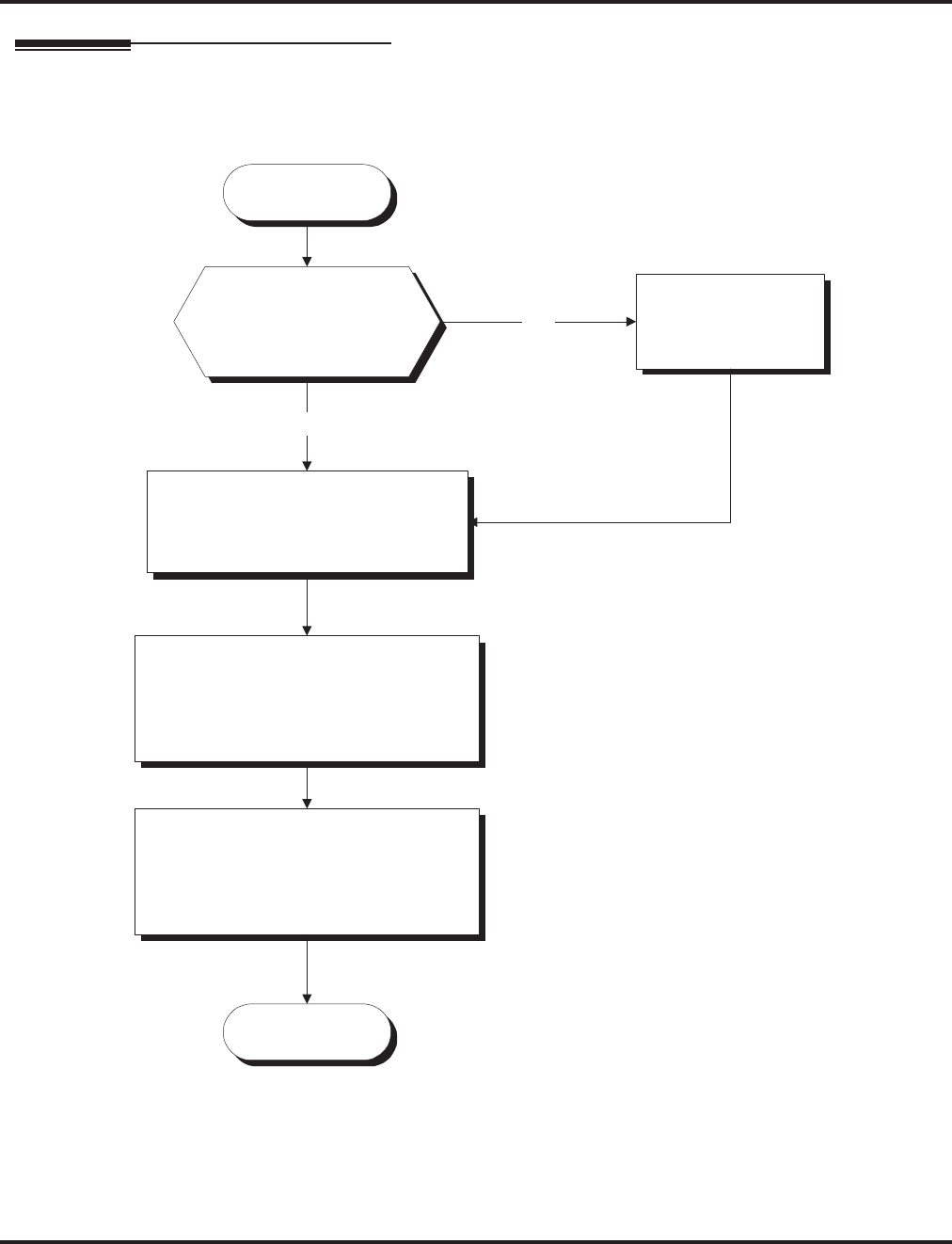
Toll Restriction Override
Aspire Software Manual Features ◆581
Programming
Start
Stop
In Program 21-14-01, assign a
table with the 6-digit user ID dialed
to override the Toll Restriction.
Should the Walking Toll
Restriction service code
be changed from the
default setting of 163?
No
In 11-11-36, change
the service code to
the desired entry.
Yes
Walking Toll Restriction
In Program 21-14-02, for each table,
assign the Toll Restriction Class of
Service to be used when a user dials
the 6-digit ID assigned in 21-14-01.
The Toll Restriction Class of
Service used is the same as those
used by Program 21-04-01. Refer
to the
Toll Restriction feature for
defining these classes.
Use Program 21-01-07 to determine
how long the system should remove
Toll Restriction from the extension.
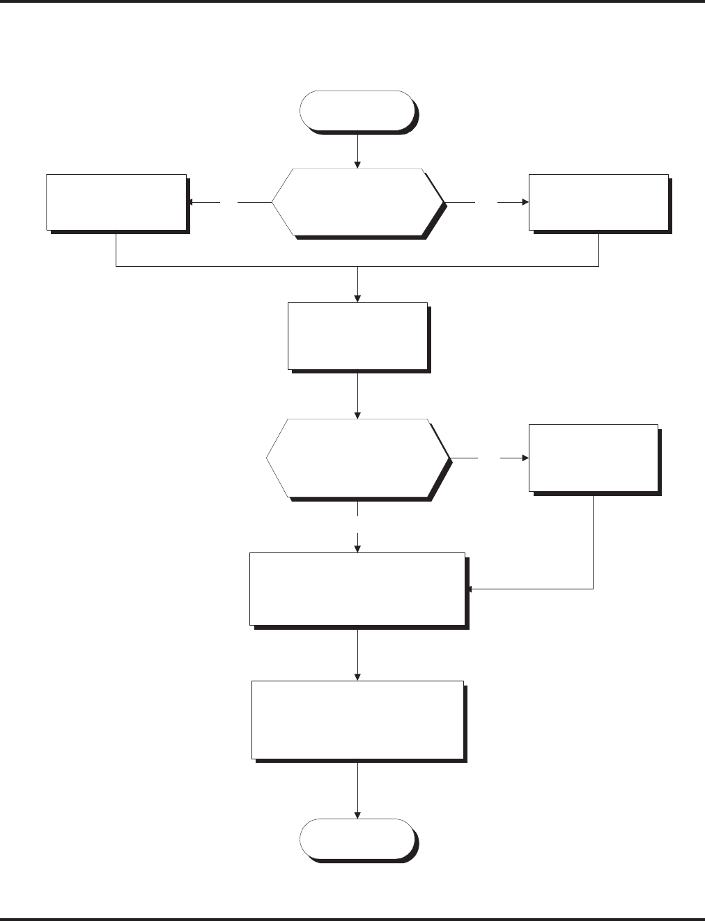
Toll Restriction Override
582 ◆Features Aspire Software Manual
Start
Stop
Should a user be able
to temporarily override
Toll Restriction
programming?
In Program 20-08-06,
enter 0.
In Program 20-08-06,
enter 1.
In Program 20-06-01,
assign Class of
Service to extensions.
In Program 21-07-01, for each
extension number, set the 4-digit
password a user dials to override
the Toll Restriction.
YesNo
Should the Temporary
Toll Restriction Override
service code be changed
from the default setting
of 875?
No
In 11-11-34, change
the service code to
the desired entry.
Yes
In 21-01-07, determine how long
the system should remove Toll
Restriction from the extension.
Temporary Toll Restriction Override

Toll Restriction Override
Aspire Software Manual Features ◆583
Programming (Cont’d)
➻11-11-34 : Service Code Setup (for Setup/Entry Operation) - Temporary Toll Restriction
Override
If required, change the service code (875) for Temporary Toll Restriction Override.
➻11-11-36 : Service Code Setup (for Setup/Entry Operation) - Walking Toll Restriction
If required, change the service code (163) for Toll Restriction Override.
➻20-06-01 : Class of Service for Extensions
When using Temporary Toll Restriction Override, assign a COS to each extension (1-15)
which will allow the feature.
➻20-08-06 : Class of Service Options (Outgoing Call Service) - Toll Restriction Override
In an extension’s Class of Service, enable (1) or disable (0) the ability to use Temporary Toll
Restriction Override.
➻21-01-07 : System Options for Outgoing Calls - Toll Restriction Override Time
Set the Toll Restriction Override Time (0-64800 seconds). After dialing the Toll Restriction
Override codes, the system removes Toll Restriction for this interval.
➻21-07-01 : Toll Restriction Override Password Setup
Assign Toll Restriction Override codes to extensions. Each code must be 4 digits long, using
any combination of 0-9, # and *. Each extension can have a separate code, or many extensions
can share the same override code.
➻21-14-01 : Walking Toll Restriction Password Setup - User ID
Enter the Walking Toll Restriction Override User ID codes (6 digits) into tables. Up to 500
different override codes can be entered.
➻21-14-02 : Walking Toll Restriction Password Setup - Walking Toll Restriction Class
Number
Enter the Walking Toll Restriction Class of Service (1-15) to be used for each table number
assigned in 21-14-01.
➻35-02-06 through 35-02-11 : SMDR Output Options
Assign the output condition for the printer or PC. If the data is set to “1” (output), the symbol
of the call will print as “POTW” and the password table number will be printed as “W/
@@@” (@@ equals the 3 digit table number) in the Account Code area.
Related Features
Central Office Calls, Placing
Off-premise notification and external extensions require access to outside lines.
Station Message Detail Recording
In the Class heading in the SMDR report, POTW indicates that the call was placed using Toll
Restriction Override.
Toll Restriction
Toll Restriction Override and Walking Toll Restriction temporarily overrides an extension’s
Toll Restriction.
Voice Response System (VRS)
If the system has VRS, users hear, “Your call cannot go through. Please call the operator”
when they dial a number that Toll Restriction prevents.

Toll Restriction Override
584 ◆Features Aspire Software Manual
Operation
To temporarily override a restricted extension’s Toll Restriction:
You can override restriction for only one call at a time.
1. At keyset, press idle CALL key.
OR
At single line telephone, lift handset.
2. Dial 875.
3. Dial the 4-digit Toll Restriction Override code.
If you wait too long before going to the next step, you may have to repeat the procedure.
After dialing the service code, the display will indicate the override codes as they are
being entered. As the last digit is entered, the display is cleared and ICM dial tone is
heard.
You’ll hear error tone if you dial your code incorrectly.
4. Press idle line key or dial trunk access code.
5. Dial the number without any restriction.
To use your Walking Toll Restriction level at an extension:
You can override restriction for only one call at a time.
1. At keyset, press idle CALL key.
OR
At single line telephone, lift handset.
2. Dial 163 and dial the 6-digit Walking Toll Restriction Class of Service code.
After dialing the service code, the display will indicate the override codes as they are
being entered. As the last digit is entered, the display is cleared and ICM dial tone is
heard.
You’ll hear error tone if you dial your code incorrectly.
3. Press idle line key or dial trunk access code.
4. Dial the number.
The call is allowed or denied based on the user’s Toll Restriction Class of Service
level.

Traffic Reports
Aspire Software Manual Features ◆585
Traffic Reports
Description
The system provides the ability to send data to a PC connected to the Aspire. The telephone call traffic data
for each extension is captured for use with the SMDR feature.
Call Traffic
The total of outgoing call frequency, outgoing call duration, call charge, incoming call frequency, answer
frequency, incoming call duration, ringing duration for each line and extension, and abandon call frequency
for each line is logged. The total of incoming calls, answer frequency, call duration for each line and exten-
sion, and abandon call frequency of each line is logged and the data is outputted to the PC. The system totals
the hour, day, week, and month for each terminal and trunk number. This information is used by the SMDR
feature. The extension which is totalled is determined by system programming. The system outputs this data
to the PC for the total period.
Conditions
●The SMDR call buffer stores 500 calls. The buffer stores calls when the SMDR device is unavail-
able. When the buffer fills, the oldest record is deleted to allow the new record to be saved.
●If connected to the output device, the reports will print hourly. If not connected and the data is
not outputted at the end of the hour, the traffic data will be overwritten by new incoming data.
●The traffic data is lost if a power failure occurs.
●The traffic data does not include ICM calls.
Default Setting
Disabled.
Aspire S Aspire M/L/XL
• Available. • Available.

Traffic Reports
586 ◆Features Aspire Software Manual
Traffic Total Report - Sample Report
Programming
➻90-20-01 : Traffic Report Data Setup - Call Traffic Output
Determine whether or not the Call Traffic Output should be measured (0=no, 1=yes).
➻90-21-01 : Traffic Report Output
Define the output port to be used for the traffic reports (0=no setting, 1=NTCPU COM port,
2=NTCPU USB port). The reports will print hourly when connected to the output device.
Related Features
Data Communications
TMS Reports require connection to the serial or USB connector on the NTCPU. Additional pro-
gramming and a customer-provided printer are also required. Refer to the system Hardware Man-
ual for more on setting up and connecting to the Aspire system.
Station Message Detail Recording
SMDR provides additional information about the system’s trunk calling patterns. Refer to Station
Message Detail Recording (page 519) for more.
<< CALL TRAFFIC INFORMATION >> 09/09/05 15:00 Page:01
Tel/Co OTG OTGtime Charge ICM ANS ICMtime Ringing Abandon
- - - - - - - - - - - - - - - - - - - - - - - - - - - - - - - - - - - - - - - - - - - - - - - - - - - - - - - - - - - - - - -
302 4 00:01:10 0 0 0 00:00:00 00:00:00 0
303 1 00:00:11 0 0 2 00:03:15 00:00:00 0
306 1 00:10:57 0 0 0 00:00:00 00:00:00 0
346 0 00:14:23 0 0 2 00:01:03 00:00:00 0
LINE 001 2 00:12:57 0 0 0 00:00:00 00:00:00 0
LINE 002 5 00:23:30 0 3 3 00:00:25 00:00:20 0
LINE 003 1 00:17:10 0 1 1 00:00:53 00:00:04 0
LINE 004 4 00:08:11 0 0 0 00:00:00 00:00:33 2
Definitions
Terminal Terminal Number/Called Party Number (maximum 24 digits)
OTG Outgoing Call Frequency/number of outgoing calls (maximum 65535 calls)
Duration Call Duration for an Outgoing Call
Cost Call Charge
ICM Incoming Call Frequency/number of incoming calls (maximum 65535 calls)
Answer Answer Frequency (maximum 65535 calls)
Duration Call Duration for an Incoming Call
Ringing Ringing Duration
Abandon Number of Abandoned Calls (maximum 65535 calls)

Transfer
Aspire Software Manual Features ◆587
Transfer
Description
Transfer permits an extension user to send (i.e., extend) an active Intercom or outside call to any
other extension in the system. With Transfer, any extension user can quickly send a call to the
desired co-worker. A call a user transfers automatically recalls if not picked up at the destination
extension. This assures that users do not lose or inadvertently abandon their transfers. While a
transferred call is ringing an extension the system can optionally play ringback tone or Music on
Hold to the caller.
The system allows the following types of transfers:
●Screened Transfer
The transferring user announces the call to the destination before hanging up
●Unscreened Transfer
The transferring party extends the call without an announcement.
●Extension (Department) Groups Transfer
The Transferring party sends the call to a Department instead of an extension.
●Transfer Without Holding
A user presses a busy line key and waits for the call to complete. The system automatically
sends them the call when the internal caller hangs up.
Automatic On-Hook Transfer Operation
With Automatic On-Hook Transfer, a Transfer goes through as soon as the transferring user hangs
up. For example, extension 304 can answer a trunk, press HOLD, dial 305 and hang up. The system
extends the call to extension 305. Without Automatic On-Hook Transfer, the call would stay on
Hold at extension 304 when the user hangs up. To extend the call, the user at extension 304 would
have to press CONF or a Transfer function key before hanging up.
Each method has advantages. Automatic On-Hook Transfer makes transferring calls easier. However,
users have to be more aware of how they handle their calls on Hold. Without Automatic On-Hook
Transfer, extending a call becomes a two-step operation - but separate from placing calls on Hold.
Prevent Recall of Transferred Call
The Class of Service program has an option that will allow you to prevent a Transferred call from
recalling the originating extension if the call is not answered.
Transfer Call into Conference/Existing Call
This feature allows either a keyset or single line telephone user with Barge In capability the ability
to transfer a call into an existing call. This call can be a 2-party call, a Conference call, or a Barge In
Conference. The system allows Intercom, analog trunk, ISDN trunk and H.323 trunk calls to be
Aspire S Aspire M/L/XL
• Available.
• Transfer into Conference available.
• Transfer to trunk ring group requires software 2.63+.
• Pressing Transfer key (15-07 or SC 851:06) places call
on hold requires 4.0E+.
• Step Transfer for Auto Trunk-to-Trunk Transfer requires
software 4.93+.
• Available.
• Transfer into Conference available with software 1.11+.
• Transfer to trunk ring group requires software 2.63+.
• Pressing Transfer key (15-07 or SC 851:06) places call
on hold requires 4.0E+.
• Step Transfer for Auto Trunk-to-Trunk Transfer requires
software 4.93+.

Transfer
588 ◆Features Aspire Software Manual
transferred into a Conference call. This would allow, for example, an attendant to locate co-workers
and then transfer them into an existing telephone meeting. There is no need for the attendant to
locate all the parties at the same time and sequentially add them into the Conference.
This feature is not supported across a network or with S-Bus ports (this includes transferring an S-
Bus call into a conference or transferring a call into a conference which includes an S-Bus port).
Transfer to Trunk Ring Group Available
Depending on your software version, it is possible to transfer a DID or trunk call to the trunk’s
defined ring group (defined in Program 22-05-01 : Incoming Trunk Ring Group Assignment).
The trunk will then ring the defined extensions for the ring group.
This also allows the transferred call to ring over the External Paging (Program 31-05 : Universal
Night Answer/Ring Over Page) so that an employee can answer the call from any available phone.
To enable this feature, the system has a program option, Program 11-15-09 : Service Code Setup
Administrative (for Special Access) - Transfer to Trunk Ring Group Code. When a call is trans-
ferred using this service code, it's transferred to the ring group destination for that incoming trunk.
For example, trunk 2 is in Ring Group 4. When the call is transferred using this service code, the
trunk will ring all extensions programmed for Ring Group 4 or ring the External Paging Group for
Ring Group 4, depending on how the system is programmed.
Program 22-04-01 : Extension Ring Group Assignment and Program 22-05-01 : Incoming
Trunk Ring Group Assignment must be programmed to allow an extension access to the ring
groups. If the call is not answered, it can overflow to the destination defined in Program 22-08-01 :
DIL/IRG No Answer Destination.
This service code can also be used with the VRS. This provides the caller listening to the VRS mes-
sage with the ability to transfer their call and have it ring the external page. The code the caller
would dial is defined in Program 25-06-02 : VRS/DISA One-Digit Code Attendant Setup.
Transfer Key Can Place Call on Hold
Depending on your software version, while on a call, if the Transfer key (Pgm 15-07 or SC 851: 06)
is pressed, the call will be placed on hold. With older software, pressing the Transfer key will not
place an existing call on hold.
Step Transfer for Automatic Trunk-to-Trunk Transfer Feature Added
The Aspire enhances the Automatic Trunk-to-Trunk Transfer feature. If the destination to which a
trunk has been transferred receives no answer (following the timer set in Program 24-02-12), the
system can then automatically Step Transfer the call to a new destination. Up to 8 different destina-
tion numbers can be defined (Program 14-01-26).
Notes:
●With DID trunks, if the DID Transfer Destination (Program 22-11-04) is allowed, if the Auto-
matic Trunk-to-Trunk Transfer programming is defined, the DID trunks will follow the Step
Transfer.
●If the Step Transfer reaches the last defined destination for a call and there is still no answer,
the call will continue to ring the last number - it will not restart dialing the first destination.
Conditions
None
Default Setting
Enabled.

Transfer
Aspire Software Manual Features ◆589
Programming
➻11-10-06 : Service Code Setup (for System Administrator) - Setting the Automatic For-
warding for Each Trunk Line
If the default service code (833) for enabling the Automatic Tandem Trunking feature is not
acceptable, change the code as required.
➻11-12-58 : Service Code Setup (for Service Access) - Transfer into Conference
Use this program to assign the code users dial to Transfer a call into a Conference call. This
code is normally 124.
➻11-15-09 : Service Code Setup Administrative (for Special Access) - Transfer to Trunk
Ring Group Code
When a call is transferred using this service code, it's transferred to the ring group destination
for that incoming trunk. For example, trunk 2 is in Ring Group 4. When the call is transferred
using this service code, the trunk will ring all extensions programmed for Ring Group 4 or ring
the External Paging Group for Ring Group 4, depending on how the system is programmed.
➻14-01-26 : Basic Trunk Data Setup - Automatic Trunk to Trunk Transfer Mode
For each trunk, enable (1) or disable (0) the Step Transfer function when using the Automatic
Trunk-to-Trunk Transfer feature. If this option is disabled, the call will be forwarded to the
first specified destination only.
➻15-02-05 : Multi-Line Telephone Basic Data Setup - Transfer Key Operation Mode
Use this option to set the operating mode of the extension’s CONF key. The keys can be for
Call Transfer (0), Serial Calling (1) or Flash (2). When selecting the Flash option, refer also to
Program 81-01-14.
➻15-02-24 : Multi-Line Telephone Basic Data Setup, Conference Key Mode
This option allows an extension’s CONF key to be programmed for Conference or for Trans-
fer. When set for Transfer (1), the user places a call on hold, dials the extension to which it
should be transferred, the presses the CONF key. The call is then transferred. When set for
Conference (0), with an active call, the user presses the CONF key, places a second call, then
presses the CONF key twice. All the calls are then connected.
➻15-07-01 : Programmable Function Keys
Extension users may want a function keys programmed for Transfer (code 06).
➻20-02-01 : System Options for Multi-Line Telephones - Retrieve the Line After Transfer
Enable (1) or disable (0) an extension’s ability to answer a call after it’s been transferred, but
before it’s answered.
➻20-03-01 : System Options for Single Line Telephones - SLT Call Waiting Answer Mode
For a busy single line (500/2500 type) telephones, set the mode used to answer a camped-on
trunk call:
●0 = Press and release hookswitch to pick up waiting call
●1 = Press and release hookswitch and dial Service Code 894 to answer waiting call
➻24-02-02 : System Options for Transfer - MOH or Ringback on Transferred Calls
Use these options to enable (0) or disable (1) MOH on Transfer. If enabled (0), a transferred
caller hears Music on Hold while their call rings the destination extension. If disabled (1), a
transferred caller hears ringback while their call rings the destination extension. For this
option to work with voice mail, the transferred call must be an unscreened transfer.
➻20-06-01 : Class of Service for Extensions
Assign a Class Of Service (1-15) to extensions.
➻20-11-06 : Class of Service Options (Hold/Transfer Service) - Unscreened Transfer
In an extension’s Class of Service, enable (1) or disable (0) the extension’s ability to use
Unscreened Transfer.

Transfer
590 ◆Features Aspire Software Manual
➻20-11-07 : Class of Service Options (Hold/Transfer Service) - Transfer Without Holding
In an extension’s Class of Service, enable (1) or disable (0) the extension’s ability to use
Transfer Without Holding.
➻20-11-08 : Class of Service Options (Hold/Transfer Service) - Transfer Display
In an extension’s Class of Service, enable (1) or disable (0) the extension’s incoming Transfer
pre-answer display.
➻20-11-11 : Class of Service Options (Hold/Transfer Service) - Automatic On Hook Transfer
In an extension’s Class of Service, enable (1) or disable (0) the extension’s ability to use Auto-
matic On Hook Transfer. If enabled, user must press HOLD and dial the extension number to
Transfer the call. If disabled, a user must have a Transfer Programmable Function Key. To
transfer the call, the user would press HOLD, dial the extension number, then press the Trans-
fer Programmable Function key to complete the transfer.
➻20-11-18 : Class of Service Options (Hold/Transfer Service) - Transfer Recall On Receiving
COS
Allow (0) or deny (1) unanswered Transferred calls to the COS from recalling the originating
extension.
For example, with this option set to ‘1’ for COS 1, calls transferred by any COS to any
extension with a COS of 1, will not recall.
➻20-11-20 : Class of Service Options (Hold/Transfer Service) - Transfer Recall On
Originating COS
Allow (0) or deny (1) unanswered Transferred calls from the COS from recalling the originat-
ing extension.
For example, with this option set to ‘1’ for COS 1, any call transferred by an extension
with COS 1, will not recall.
➻20-13-10 : Class of Service Options (Supplementary Service) - Barge In Mode
In an extension’s Class of Service, enable the Barge In Speech Mode (0) at the initiating
extension (i.e., Barge In initiator). This is required in order to transfer a call into a conference.
➻20-13-15 : Class of Service Options (Supplementary Service) - Barge In Initiate
In an extension’s COS, enable (1) or disable (0) the extension’s ability to Barge In to a call.
➻20-13-16 : Class of Service Options (Supplementary Service) - Barge In Receive
In an extension’s COS, enable (1) or disable (0) the extension’s ability to receive a Barge In on
a call.
➻20-13-17 : Class of Service Options (Supplementary Service) - Barge In Tone/Display
Enable (1) or disable (0) the Barge In Tone. If disabled, this also turns off the Barge In display
at the called extension. As this option is for extensions and trunks don’t have an option for a
Barge In Tone, the tone will be sent to the trunks based on the Class of Service of the transfer-
ring extension.
➻20-13-32 : Class of Service Options (Supplementary Service) - Multiple Barge In
Enable (1) or disable (0) the extension’s ability to have multiple user’s Barge In to their con-
versation.
➻20-14-11 : Class of Service Options For DISA/E&M - DISA/Tie Trunk Barge In
Determine if DISA and tie trunk users should have the ability to dial a service code to Barge
In to a Conference call (0=disabled, 1=enabled).
➻20-15-09 : Ring Cycle Setup - Callbacck/Transfer Ring
Define the ringing cycle for transferred and callbacks (ringing cycle 1-13).
➻20-18-07 : Service Tone Timer - Intrusion Tone Repeat Time
After a user Barges In, the system repeats the Barge In tone after this interval. Normally, you
should disable this timer by entering 0. (This timer also affect any other types of call interrup-
tion features, such as Voice Mail Conversation Recording, Voice Over, etc.)

Transfer
Aspire Software Manual Features ◆591
➻21-01-03 : System Options for Outgoing Calls - Trunk Interdigit Time (External)
Program how long an extension must wait before using the Barge In feature can be used on a
call (this timer waits until this timer expires before putting a call in a talk state). This timer
also affects Voice Over.
➻22-04-01 : Incoming Extension Ring Group Assignment
Assign extensions to ring groups.
➻22-05-01 : Incoming Trunk Ring Group Assignment
Define a trunk’s ring group. When transferring a DID or trunk call to the trunk’s defined ring
group, the trunk will then ring the defined extensions for the ring group.
➻22-08-01 : DIL/IRG No Answer Destination
Assign the DIL No Answer Ring Group (1-103) to which an unanswered call should overflow.
➻24-02-01 : System Options for Transfer - Busy Transfer
Prevent (0) or allow (1) extensions to transfer calls to busy extensions. If disabled, calls trans-
ferred to busy extensions recall immediately.
➻24-02-03 : System Options for Transfer - Delayed Call Forwarding Time
If activated at an extension, Delayed Call Forwarding occurs after this interval (0-64800 sec-
onds). This also sets how long a Transferred call waits at an extension forwarded to Voice
Mail before routing to the called extension’s mailbox.
➻24-02-04 : System Options for Transfer - Transfer Recall Time
Set the Transfer Recall Time (0-64800 seconds). An unanswered transferred call recalls to the
extension that initially transferred it after this interval. This interval also sets how long a
transferred call camps-on to a busy extension.
➻24-02-05 : System Options for Transfer - Transfer to Busy Department Group Recall
Timer
After a trunk is unscreen transferred to a busy Department Group, this timer will start. If the
call is not answered, it will recall the originator (0-64800 seconds).
➻24-02-11 : System Options for Transfer - No Answer Timer for Step Transfer
Define the length of time (0-64800 seconds) the system will wait before Step Transferring a
no-answer call to the next destination.
➻24-02-12 : System Options for Transfer - No Answer Timer for Automatic Trunk-to-
Trunk Transfer
Define the length of time (0-64800 seconds) the system will wait before Automatic Trunk-to-
Trunk Transfer occurs for a no-answer call.
➻24-04-01 : Automatic Trunk-to-Trunk Transfer Target Setup
Define the Abbreviated Dialing number bin(s) which are to be used as the destination of the
Automatic Trunk-to-Trunk Transfer.
➻25-06-02 : VRS/DISA One-Digit Code Attendant Setup
Define the digit to be used by a VRS caller which will allow their call to be transferred to the
external page.
➻31-05-01 : Universal Night Answer/Ring Over Page
For each trunk which should ring the external page, set the External Page zone (1-9) to allow
ringing (1).
➻81-01-14 : COIU Initial Data Setup - Flash (Hooking 1)
Set the flash duration for analog trunk calls (1-255 in 16ms steps).

Transfer
592 ◆Features Aspire Software Manual
Related Features
Barge-In
An existing call can be transferred into a call with Barge-In enabled.
Caller ID
Unscreened Transfers from voice mail will show pre-answer Caller ID information.
Call Forwarding
With Transfer to Busy Extensions enabled (Program 24-02-01=1), Call Forwarding with Both
Ringing offers a unique option. A transferred call will wait for either the forwarding or desti-
nation extension to become free. The call goes through to whichever extension becomes avail-
able first. If neither extension becomes free within the Transfer Recall Time, the call recalls
the transferring extension.
Conference
An existing call can be transferred into a Conference call.
Meet Me Paging Transfer
Page a co-worker and have the call automatically Transfer when the co-worker answers the
Page.
One-Touch Calling
When transferring, an extension user can press a One-Touch Key instead of dialing the exten-
sion number.
Serial Call
Serial Call is a method of transferring a call so it automatically returns to the transferring
extension.

Transfer
Aspire Software Manual Features ◆593
Operation
Transferring Trunk Calls
To Transfer a trunk call to a co-worker’s extension:
1. At keyset or 2-Button telephone, press HOLD.
OR
At 500/2500 single line telephone, hookflash.
You hear Transfer dial tone.
2. Dial co-worker’s extension number.
If the extension is busy or doesn’t answer, you can dial another extension number or
press the line key to return to the call. In addition, you may be able to hang up and have
the call Camp-On.
SLT users can retrieve the call by pressing hookflash. If a call has been transferred and
the 500/2500 user has hung up the handset, the call be can retrieved by dialing ** and the
extension number to which it had been transferred.
3. Announce call and press the Transfer key (PGM 15-07 or SC 851: 06) or hang up.
If you don’t have Automatic On Hook Transfer, you must press CONF (Program 15-02-
24=1) or your Transfer Programmable Function Key to Transfer the call.
If your co-worker doesn’t want the call, press the flashing line key to return to the call.
SLT users can retrieve the call by pressing hookflash. If a call has been transferred and
the 500/2500 user has hung up the handset, the call be can retrieved by dialing ** and the
extension number to which it had been transferred.
If you don’t want to screen the call, hang up without making an announcement.
To answer a call transferred to your extension:
1. Lift the handset when a co-worker announces the call.
Transferring Without Holding
To Transfer without holding (keyset only):
1. Lift handset.
2. Press busy line key.
3. When original caller hangs up, you are connected.

Transfer
594 ◆Features Aspire Software Manual
Transferring Intercom Calls
To Transfer your Intercom call:
1. At keyset, press HOLD.
OR
At single line telephone, hookflash.
2. Dial extension to receive your call.
If the extension is busy, doesn’t answer or does not want the call, you can dial another
extension number or press the lit CALL key to return to the call. In addition, you may be
able to hang up and have the call Camp-On.
SLT users can retrieve the call by pressing hookflash. If a call has been transferred and
the 500/2500 user has hung up the handset, the call be can retrieved by dialing ** and the
extension number to which it had been transferred.
3. Announce your call and press the Transfer key (PGM 15-07 or SC 851: 06) or hang up.
With Automatic On Hook Transfer
When you hang up, the call is automatically transferred.
Without Automatic On Hook Transfer
You must press your Transfer Programmable Function Key to Transfer the call.
To Transfer the call unscreened, press your Transfer Programmable Function Key and
hang up without making an announcement.
Transferring a Call Into a Conference/Existing Call
1. While on a call, press HOLD and dial service code 124.
The display shows "Transfer to Conf. ICM Dial".
2. Enter the extension number of the co-worker currently on a Conference call to which the call
should be transferred.
To cancel the transfer, press the flashing line or CALL key to retrieve the call.
If an error tone is heard, Barge In is not enabled for the extension and the call will not
go through. Retrieve the call by pressing the flashing line or CALL key or hang up and the
call will recall the extension.
3. The transferred call is incorporated into the Conference call.
The callers hear the Barge In tone if enabled in Program 20-13-17.
If a call is transferred into a Barge In Conference (an existing 2-party call into which
an extension user has used the Barge In feature to join), the Conference becomes a regular
4-party Conference call.
4. Hang up.
Transferring a Call to a Trunk Ring Group
1. While on a call, press HOLD.
2. Dial the Transfer to Ring Group service code defined in 11-15-09.
You will hear a confirmation tone.
3. Hang up.
The call is transferred to the trunk’s ring group defined in Program 22-05-01 and all
assigned extensions in the group (Program 22-04-01) ring or it will ring the External Pag-
ing, enabling anyone to answer the call.
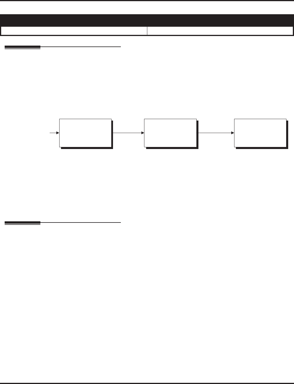
Trunk Group Routing
Aspire Software Manual Features ◆595
Trunk Group Routing
Description
Trunk Group Routing sets outbound call routing options for users that dial the Trunk Group Rout-
ing code (9) for trunk calls. Trunk Group Routing routes calls in the order specified by system pro-
gramming. If a user dials 9 and all trunks in the first group are busy, the system may route the call
to another group. When you’re setting up your system, Trunk Group Routing will help you mini-
mize the expense of toll calls. For example, if your system has outbound WATS lines, OCC lines
and DDD lines, use Trunk Group Routing to route calls to the WATS lines first.
Conditions
None
Default Setting
Enabled. All trunks are in Group 1.
Programming
➻11-01-01 : System Numbering
Set up a Service Code for Alternate Trunk Route Access.
➻11-09-01 : Trunk Access Code
If required, change the single-digit Trunk Access Code (normally 9). If you change this code,
you must also review the settings in 11-01 for the new code selected.
➻11-09-02 : Trunk Access Code - Alternate Trunk Route Access Code
Assign the Service Code set up in 11-01 for Alternate Trunk Route Access.
➻14-05-01 : Trunk Groups
Assign trunks to trunk groups.
➪Aspire S Trunk Groups: 1-8
➪Aspire Trunk Groups: 1-100
➻14-06-01 : Trunk Group Routing
Set up an outbound routing table for trunk groups assigned in Program 14-05.
➪Aspire S Trunk Group Routes: 1-8
➪Aspire Trunk Group Routes: 1-100
➻14-07-01 : Trunk Access Map Setup
Access Map programming may limit Trunk Group Routing options.
➪Aspire S: Trunk Access Maps 1-8
➪Aspire: Trunk Access Maps 1-200
Aspire S Aspire M/L/XL
• Available - 8 trunk groups and 8 routes. • Available - 100 trunk groups and 100 routes.
OCC
Moderately
Expensive
WATS
Least Expensive
DDD
Most Expensive
Third ChoiceSecond ChoiceFirst Choice
Outbound Call
Route 1 Route2 Route 3

Trunk Group Routing
596 ◆Features Aspire Software Manual
➻15-06-01 : Trunk Access Map for Extensions
Access Map programming may limit Trunk Group Routing options.
➪Aspire S: Trunk Access Maps 1-8
➪Aspire: Trunk Access Maps 1-200
➻15-07 : Programming Function Keys
Assign a function key for Trunk Group Routing access (code *02 + trunk group #).
➪Aspire S Trunk Groups: 1-8
➪Aspire Trunk Groups: 1-100
➻21-02-01 : Trunk Group Routing for Extensions
Assign the routes set in Program 14-06 to extensions.
➪Aspire S Trunk Group Routes: 1-8
➪Aspire Trunk Group Routes: 1-100
➻21-15-01 : Alternate Trunk Route for Extensions
Designate the trunk route accessed when a user dials the Alternate Trunk Route Access Code
assigned in Program 11-09-02. Trunk Group Routing is set up in Program 14-06.
➪Aspire S Trunk Group Routes: 1-8
➪Aspire Trunk Group Routes: 1-100
➻23-03-01 : Universal Answer/Auto Answer
Assign trunk routes set in Program 14-06 to extensions for Universal Answer. If the call ring-
ing the paging system is in an extension’s assigned route, the user can dial the Universal
Answer code (#0) to pick up the call. This program also allows an extension user to automati-
cally answer trunk calls ringing other extensions, based on Trunk Group Routing program-
ming (defined in Program 14-06).
➪Aspire S Trunk Group Routes: 1-8
➪Aspire Trunk Group Routes: 1-100
➻25-10-01 : Trunk Group Routing for DISA
Assign the Trunk Group Route chosen when a user places a DISA call into the system and
dials 9. The Trunk Group Routing is defined in Program 14-06. If the system has ARS, dialing
9 accesses ARS. The route chosen is based on the DISA Class of Service, which is determined
by the password the caller dials.
➪Aspire S Trunk Group Routes: 1-8
➪Aspire Trunk Group Routes: 1-100
➻25-12-01 : Alternate Trunk Group Routing for DISA
Define the trunk route selected when a DISA caller dials the Alternate Trunk Access Code
assigned in Program 11-09-02. The route selected is based on the DISA caller’s Class of Ser-
vice, which is in turn determined by the password the caller dial. Program 14-06 is used to set
up the Trunk Group Routing.
➪Aspire S Trunk Group Routes: 1-8
➪Aspire Trunk Group Routes: 1-100
➻34-03-01 : Trunk Group Routing for E&M Tie Lines
Use this program to assign the Trunk Group Route chosen when a user seizes a tie line and
dials 9. Set Trunk Group Routing in Program 14-06. If the system has ARS, dialing 9 accesses
ARS.
➪Aspire S Trunk Group Routes: 1-8
➪Aspire Trunk Group Routes: 1-100

Trunk Group Routing
Aspire Software Manual Features ◆597
Related Features
Automatic Route Selection (ARS)
Dialing 9 activates ARS, overriding trunk group routing.
Central Office Calls, Placing
Instead of using Trunk Group Routing, an extension user can place a trunk call by:
●Pressing a line key
●Dialing a trunk service code
●Pressing a trunk group key (refer to the Trunk Group feature)
●Dialing a trunk group service code (refer to the Trunk Group feature).
Data Communications / Direct Inward System Access (DISA) / Tie Lines
DISA (Program 25-10) and tie lines (Program 34-03) have separate Trunk Group Routing
programs.
Dial Tone Detection
Refer to this feature for the specifics on how the system handles Dial Tone Detection.
Programmable Function Keys
Programmable Function Keys simplify placing calls using Trunk Group Routing.
Ringing Line Preference
The system uses Trunk Group Routing programming (Program 14-06) when setting up Ring-
ing Line Preference.
Trunk Groups
Use trunk group programming to set the order in which users access trunks within a specific
trunk group.
Operation
To place a call using Trunk Group Routing:
1. At keyset, press idle CALL key.
OR
At single line telephone, lift handset.
2. Dial 9.
3. Dial number.
OR
1. At keyset, press Trunk Group Routing key (PGM 15-07 or SC 852: *05).
Also see the “Loop Keys” feature.
2. Dial number.

Trunk Groups
598 ◆Features Aspire Software Manual
Trunk Groups
Description
Trunk Groups let you optimize trunk usage for incoming and outgoing calls. With Trunk Groups,
users can have loop (rotary) keys for trunk calls. Incoming trunk group calls ring these loop keys.
For outgoing calls, the user presses a loop key to access the first available trunk within the group.
You set the access order in trunk group programming.
Loop keys give an extension user more available function keys, since the user doesn’t need a sepa-
rate line key for each trunk. The user only needs one loop key for each trunk group. This simplifies
placing and answering calls.
Like Trunk Group Routing, Trunk Groups help you minimize the expense of toll calls. For exam-
ple, if your system has outbound WATS lines, OCC lines and DDD lines, program the trunk group
to route to the WATS lines first.
Conditions
None
Default Setting
All trunks are in group 1.
Programming
➻10-09-01 : DTMF and Dial Tone Circuit Setup
Allocate the circuits on the NTCPU or DSPDB PCBs for either DTMF receiving or dial tone
detection.
➻14-02-11 : Analog Trunk Data Setup - Next Trunk in Rotary if No Dial Tone
Use this option to enable/disable the system’s ability to skip over a trunk if dial tone is not
detected. This pertains to calls using Loop Keys, Speed Dial, ARS, Last Number Redial, or
Save number Dialed (0=disabled, 1=enabled). It does not pertain to line keys or Direct Trunk
Access calls.
➻14-05-01 : Trunk Groups
Assign trunks to trunk groups.
➪Aspire S Trunk Groups: 1-8
➪Aspire Trunk Groups: 1-200
➻14-06-01 : Trunk Group Routing
Set up an outbound routing table for the trunk groups you assigned in Program 14-05. When
users dial 9, the system routes their calls in the order (priority) you specify.
➪Aspire S Trunk Groups: 1-8, Trunk Group Routes: 1-8
➪Aspire Trunk Groups: 1-200, Trunk Group Routes: 1-100
Aspire S Aspire M/L/XL
• Available - 8 trunk groups. • Available - 100 trunk groups.
Priority Type of Trunk
1WATS
2 OCC
3 DDD

Trunk Groups
Aspire Software Manual Features ◆599
➻14-07-01 : Trunk Access Map Setup
Assign trunks to Access Maps.
➪Aspire S: Trunk Access Maps 1-8
➪Aspire: Trunk Access Maps 1-200
➻15-06-01 : Trunk Access Map for Extensions
Assign Access Maps to extensions.
➪Aspire S: Trunk Access Maps 1-8
➪Aspire: Trunk Access Maps 1-200
➻15-07-01 : Programmable Function Keys
Assign function keys for trunk group access (code *02 + group) or loop keys (code *05 +
0=incoming, 1=outgoing, 2=both + trunk group. If loop keys are used, assign the loop key to a
trunk group in Program 15-13.
➪Aspire S Trunk Groups: 1-8
➪Aspire Trunk Groups: 1-100
➻15-13-01 : Loop Keys - Outgoing
Assign trunk groups for outgoing loop keys (0=ARS, Aspire S Trunk Groups 1-8, or Aspire Trunk
Groups 1-100).
➻15-13-02 : Loop Keys - Incoming
Assign trunk groups for incoming loop keys (0=all Trunk Groups, Aspire S Trunk Groups 1-8, or
Aspire Trunk Groups 1-100).
➻20-02-02 : System Options for Multi-Line Telephones - Trunk Loop Access Key Operat-
ing Mode
Set the operating mode of the extension’s trunk group keys (Incoming and Outgoing Access =
0, Outgoing Access =1, Incoming Access = 2).
➻21-01-02 : System Options for Outgoing Calls - Dial Tone Detection Timer
If dial tone detection is enabled, the system will wait this interval for the telco to return dial
tone. When the interval expires, the system assumes dial tone is not present. To disable this
timer (and have the system wait continuously), enter 0.
➻21-02-02 : Trunk Group Routing for Extensions
Assign the routes defined in Program 14-06 to extensions.
Related Features
Abbreviated Dialing
Unless a user preselects a trunk, Trunk Group programming selects the trunk Abbreviated
Dialing users for trunk calls.
Automatic Route Selection
If a user dials a number that is not programmed in ARS, the system can route the call to a
trunk group.
Central Office Calls, Placing
Instead of using Trunk Groups, an extension user can place a trunk call by:
● Pressing a line key
● Dialing a trunk access code
● Dialing a Trunk Group Routing code (9) - refer to the Trunk Group Routing feature
Dial Tone Detection
Refer to this feature for the specifics on how the system handles Dial Tone Detection.
Direct Inward Dialing (DID)
All DID trunks of the same type should be placed in the same trunk group. These trunk groups
must then be assigned to a DID Translation Table.

Trunk Groups
600 ◆Features Aspire Software Manual
Loop Keys
Program a function key as a Loop Key to allow an extension user to answer incoming trunks
within a trunk group.
Programmable Function Keys
Function keys simplify placing and answering trunk group calls.
Ring Groups
Trunks ring extensions according to Ring Group programming.
Tie Lines
To simply placing calls over your tie lines, you can put the tie lines in a trunk group.
Trunk Group Routing
Trunk Group Routing sets outbound call routing options for users that dial the Trunk Group
Routing code (9) for trunk calls.
Operation
To place a call over a trunk group:
1. At keyset, press idle CALL key.
OR
At single line telephone, lift handset.
2. Dial 804.
3. Dial trunk group number (Aspire S: 1-8, Aspire: 1-9 or 001-100).
4. Dial number.
OR
1. Press trunk group key (PGM 15-07 or SC 852: *02 + group)
2. Dial number.
To answer an incoming trunk group call:
1. Lift handset.
2. Press flashing trunk group key.

Trunk Queuing/Camp On
Aspire Software Manual Features ◆601
Trunk Queuing/Camp On
Description
Trunk Queuing permits an extension user to queue (wait in line) on hook for a busy trunk or trunk
group to become free. The system recalls the queued extension as soon as the trunk is available.
The user does not have to manually retry the trunk later. Trunk Queuing lets the caller know when
the call can go through. If the extension user does not answer the Trunk Queuing ring, the system
cancels the queue request.
With Trunk Camp On, an extension user can queue (wait in line) off hook for a busy trunk or trunk
group to become free. The caller connects to the trunk when the trunk becomes free. As with Trunk
Queuing, the user does not have to manually retry the trunk later.
Any number of extensions may simultaneously queue or Camp On for the same trunk or trunk
group. When a trunk becomes free, the system connects the extensions in the order that the requests
were left.
Conditions
None
Default Setting
Enabled.
Programming
➻15-07-01 : Programmable Function Keys
Assign a function key for Trunk Queuing and Trunk Camp On (code 35).
➻20-01-08 : System Options - Trunk Queuing Callback Time
Set the Trunk Queuing Callback Time (0-64800 seconds). Trunk Queuing Callback rings an
extension for this interval.
➻20-01-09 : System Options - Callback/Trunk Queuing Cancel Time
Set the Callback/Trunk Queuing Cancel Time (0-64800 seconds). The system cancels an
extension’s Callback or Trunk Queuing request after this interval.
➻20-06-01 : Class of Service for Extensions
Assign a Class Of Service (1-15) to an extension.
➻20-11-07 : Class of Service Options (Hold/Transfer Service) - Transfer Without Holding
Disable (0) an extension’s ability to use Transfer Without Holding.
Aspire S Aspire M/L/XL
• Available. • Available.

Trunk Queuing/Camp On
602 ◆Features Aspire Software Manual
Related Features
Automatic Route Selection
With Automatic Route Selection, Trunk Queuing automatically queues for the least costly
route.
Call Waiting/Camp On and Callback
A user can Camp On or leave a Callback request for an extension.
Central Office Calls, Placing
Other programmed options for outgoing calls can affect how a call is placed. Check or pro-
gram these options as needed (ex: access, line/loop keys, etc.).
Programmable Function Keys
Function keys simplify Trunk Queuing operation.
Operation
To queue for a busy trunk:
1. Try to access busy trunk.
2. Dial 2 or press Trunk Queuing/Camp On key (PGM 15-07 or SC 851: 35).
3. Hang up to leave a Trunk Queuing request.
OR
Wait off hook to Camp On to the trunk.
To answer when Trunk Queuing calls you back:
1. Lift handset.
To cancel a Trunk Queueing/Camp On request:
1. At keyset, press idle CALL key.
OR
At single line telephone, lift handset.
2. Dial 870.
3. At keyset, press SPK to hang up.
OR
At single line telephone, hang up.

Voice Mail
604 ◆Features Aspire Software Manual
Voice Mail
Description
The system is fully compatible with NEC’s analog NVM-Series Voice Mail with Automated Atten-
dant Systems. These systems provide telephone users with comprehensive Voice Mail and Auto-
mated Attendant features. Voice Mail ends the frustration and cost of missed calls, inaccurate
written messages and telephone tag. This frees a company’s busy receptionists and secretaries for
more productive work.
Automated Attendant automatically answers the system’s incoming calls. After listening to a cus-
tomized message, an outside caller can dial a system extension or use Voice Mail.
Integrated Voice Mail enhances the telephone system with the following features:
●Call Forwarding to Voice Mail
An extension user can forward their calls to Voice Mail. Once forwarded, calls to the exten-
sion connect to that extension’s mailbox. The caller can leave a message in the mailbox
instead of calling back later. Forwarding can occur for all calls immediately, for unanswered
calls or only when the extension is busy. When a user transfers a call to an extension for-
warded to Voice Mail, the call waits for the Delayed Call Forwarding time before routing to
the called extension’s mailbox. This gives the transferring party the option of retrieving the
call instead of having it go directly to the mailbox.
●Leaving a Message
Voice Mail lets a keyset extension user easily leave a message at an extension that is unan-
swered, busy or in Do Not Disturb. The caller just presses their Voice Mail key to leave a mes-
sage in the called extension’s mailbox. There is no need to call back later.
Aspire S Aspire M/L/XL
• Available - 72 NVM-Series voice mail ports available.
External voice mail requires available analog station
ports based on the number of voice mail ports con-
nected, so this voice mail maximum is limited to 16 by
the Aspire S.
- Aspire Mail is not available.
- 8 IntraMail ports (fixed ports 43-50) with software
2.50+.
• The MSG key as Voice Mail key available.
• IntraMail options added with software 2.51+.
- Ability to Select Voice Mail Port Selected for Message
Notification/MW Lamps
- External Transfer Available
- Soft Key With Security Code Programming
- Internal Message Notification Timer Lengthened
• Intramail Directory Dialing and Multiple Greeting fea-
tures requires software 2.64+.
• Centralized voice mail with IntraMail available with
software 4.94+.
• Available - 72 NVM-Series voice mail ports available.
External voice mail requires available analog station ports
based on the number of voice mail ports connected.
- The Aspire Mail port requirements are based on the
installed PCB (the 4VMSU requires 4 ports, 4VMDB
requires 4 ports, 16VMSU requires 16 ports (and
software 2.26+), 2FMSU requires 2 ports, 4FMSU
requires 4 ports, 4FMDB requires 4 ports).
• The MSG key as Voice Mail key feature is available with
1.11+ software.
• IntraMail for the Aspire M only requires software 4.93+
and incorporates all prior IntraMail options from the
Aspire S. IntraMail for the Aspire L/XL is not available.
• Centralized voice mail with Aspire Mail and IntraMail
available with software 4.94+.

Voice Mail
Aspire Software Manual Features ◆605
●Transferring to Voice Mail
By using Transfer to Voice Mail, a keyset extension user can Transfer a call to the user’s own
or a co-worker’s mailbox. After the Transfer goes through, the caller can leave a message in
the mailbox.
●Conversation Record
While on a call, an extension user can have Voice Mail record the conversation. The keyset
user just presses the Voice Mail Record key; the ESL user dials a code. Once recorded, the
Voice Messaging System stores the conversation as a new message in the user’s mailbox.
After calling their mailbox, a user can save, edit or delete the recorded conversation.
●Personal Answering Machine Emulation
A keyset user can have their idle extension emulate a personal answering machine. This lets
Voice Mail screen their calls, just like their answering machine at home. If activated, the exten-
sion’s incoming calls route to the user’s subscriber mailbox. Once the mailbox answers, the user
hears the caller’s incoming message. The keyset user can then:
- Let the call go through to their mailbox
- Intercept the call before it goes to their mailbox
- Reject the call before it goes to their mailbox
●Voice Mail Overflow
If Voice Mail automatically answers trunks, Voice Mail Overflow can reroute those trunks to
other extensions when all Voice Mail ports do not answer or, with certain software, are busy.
During periods of high traffic, this prevents the outside calls from ringing Voice Mail for an
inordinate amount of time. There are two types of Voice Mail Overflow: Immediate and
Delayed. With immediate overflow, calls immediately reroute to other extensions when all
Voice Mail ports do not answer or, with certain software, are busy. With delayed overflow,
calls reroute after a preset interval. Without any type of overflow, the outside calls ring Voice
Mail until a port becomes available or the outside caller hangs up.
●Message Center Mailbox
A Message Center Mailbox is a mailbox shared by more than one extension. Any keyset that
has a Message Center Key for the shared mailbox can:
- Listen to the messages stored in the shared mailbox.
- Transfer calls to the shared mailbox.
- Use many other Voice Mail features previously available only at an extension’s individual
mailbox.
A Message Center Mailbox helps co-workers that work together closely - such as members of
the same Department Hunt Group or ACD Group. For example, an ACD Group Supervisor
can send important messages to the shared Message Center Mailbox, to which any ACD
Group member can respond when time allows. Each ACD Agent’s Message Center Key
flashes when messages are waiting. (The Message Center Mailbox can be a mailbox for an
installed, uninstalled or virtual extension.)
●Voice Mail Caller ID
NVM-Series Voice Mail can use ANI/DNIS information to identify the outside caller that left
a message in a user’s mailbox. When the message recipient presses TI after hearing a mes-
sage, they hear the time the message was sent and the outside telephone number of the mes-
sage sender. Refer to ANI/DNIS Compatibility (page 537) for more information on setting
up this feature.

Voice Mail
606 ◆Features Aspire Software Manual
Voice Mail Queuing
When accessing the voice mail, the system provides a voice mail queue. If all the voice mail ports
are busy, any calls trying to get to the voice mail will be placed in queue. As the voice mail ports
become available, the calls will be connected to the voice mail in the order in which they were
received.
As the Voice Mail Queue follows Department Hunting programming, the queue can hold a maxi-
mum of 10 calls. If the queue is full or if the voice mail ports are not assigned to a Department
Group, the calls will be handled as though there were no voice mail queuing feature enabled. The
calls will either access voice mail if a port is available or they will receive a busy signal.
The Voice Mail Queuing feature does not work with the Conversation Record feature.
Park and Page
When an extension user is away from their phone, the voice mail provides a Park and Page feature
which can let them know when they have a call waiting to be answered. To activate Park and Page,
the subscriber records the Paging Message. To enable Park and Page, the user records a Paging
message. Park and Page will then answer an incoming call and the system broadcasts the prere-
corded Paging announcement. When the extension user hears the Page, they can go to any tele-
phone and use Directed Call Pickup to intercept the call. Depending on how the subscriber wants
Park and Page to operate, they can turn the Paging Message on or off. Refer to the Aspire Mail Sys-
tem Guide (P/N 17710SWGxx) for details on setting this feature.
MSG Key will Operate as Voice Mail Key
The system enhances a phone’s MSG key function when connected to a system which has voice
mail installed. When an extension receives a voice mail, the MSG key can be used to check the
number of messages in voice mail, as well as call the voice mail to listen to the messages. If there is
no Voice Mail Programmable Function Key defined (Program 15-07-01, code 77), the phone’s Mes-
sage Waiting LED will flash to indicate new messages.
This option is not available with a networked voice mail - the voice mail must be local.
In-Skin Voice Mail
The Aspire Mail/Aspire Mail Plus is an in-switch full-featured Voice Mail with Automated Attend-
dant for the Aspire M/L/XL.
Aspire Mail / Aspire Mail Plus Specifications
0891032
Aspire Mail
(Flash-based)
0891037
Aspire Mail
(Flash-based)
0891033
Aspire Mail Plus
(Hard disk)
0891056
Aspire Mail Plus
(Hard disk)
Ports: 2 4 4 8
Hours: 3 3 1400
(approximate) 1400
(approximate)
Mailboxes: 200 200 1000 1000
Messages
(max): 7000 7000 7000 7000
Voice Mail
Aspire Software Manual Features ◆607
The IntraMail is a plug-in “in-skin” full-featured, DSP-based integrated Voice Mail with Auto-
mated Attendant for the Aspire S.
These voice mails can answer incoming calls and route them quickly and efficiently. Integrated
Voice Mail features include Conversation Record, Answering Machine Emulation, and Caller ID
with Return Call. Interactive Soft Keys guide the display telephone user through the extensive voice
mail feature set.
Aspire IntraMail Part Numbers and Capacities
P/N 0892176 Aspire IntraMail 4 Port/4 Hour Kit
Includes:
■(1) P/N 0891003 DSPDBU (IntraMail PCB)
■(1) P/N 0892175 4 Port/4 Hour CompactFlash Card
with software.
■(1) 0893820 Aspire IntraMail Literature Kit
P/N 0892180 Aspire IntraMail 4 Port/8 Hour Kit
Includes:
■(1) P/N 0891003 DSPDBU (IntraMail PCB)
■(1) P/N 0892179 4 Port/8 Hour CompactFlash Card
with software.
■(1) 0893820 Aspire IntraMail Literature Kit
P/N 0892178 Aspire IntraMail 8 Port/8 Hour Kit
Includes:
■(1) P/N 0891003 DSPDBU (IntraMail PCB)
■(1) P/N 0892177 8 Port/8 Hour CompactFlash Card
with software.
■(1) 0893820 Aspire IntraMail Literature Kit
P/N 0892182 Aspire IntraMail 8 Port/16 Hour Kit
Includes:
■(1) P/N 0891003 DSPDBU (IntraMail PCB)
■(1) P/N 0892181 8 Port/16 Hour CompactFlash
Card with software.
■(1) 0893820 Aspire IntraMail Literature Kit
Mailboxes: Station Mailboxes = 128
Routing Mailboxes = 16
Master Mailboxes = 16 (Only 8 of the 16 Master mail-
boxes are accessible in Aspire S.)
Total Mailboxes = 160
Programming Interface: Aspire S telephone programming or Aspire PCPro soft-
ware 2.30 or higher.
Remote Programming: Access Via HTML-based Aspire WebPro or using cus-
tomer-provided modems with Aspire PCPro.
Voice Storage Media: Flash Card (on IntraMail PCB)
Languages: 1 (English Mnemonic)

Voice Mail
608 ◆Features Aspire Software Manual
IntraMail for Aspire S
The Aspire S IntraMail port assignments are fixed and should not be changed. The following is the
default IntraMail:
●Program 16-02-01 : Department Group Assignments for Extensions
IntraMail ports assigned to Department Group 8.
343=Order 43
344=Order 44
345=Order 45
346=Order 46
347=Order 47
348=Order 48
349=Order 49
350=Order 50
●Program 11-07-01 : Department Group Pilot Numbers
Master number is 700.
●Program 45-01-01 : Voice Mail Integration Options - Voice Mail Department Group
Number
IntraMail Department Group is Group 8.
●Program 15-03-01 : Single Line Telephone Basic Data Setup - SLT Signaling Type
Set for DP (0).
●Program 15-03-03 : Single Line Telephone Basic Data Setup - Terminal Type
Set to Special (1).
●Program 22-07-01 : DIL Assignment
Trunks terminate to 343.
IntraMail for Aspire M
The Aspire software now provides support for the IntraMail. Previously, this was only available for
the Aspire S system. With this change, the 47-xx programs used for IntraMail are now available
with the Aspire M. Refer to the IntraMail System Guide (P/N 0893240) for complete details on set-
ting up the IntraMail.
The boot code for the Aspire system must be at the current level of 1.20 for IntraMail to function.
Refer to the Boot Code Update Instructions, P/N 0893211 for details on updating. The current ver-
sion number can be displayed with history enabled (DIMU) after rebooting the system. The version
number will show on the first line of the display. Contact NEC’s Sales Support in order to obtain an
boot update card if needed.
If the IntraMail will not be used, make sure Program 47-01-17 : IntraMail System Options -
Start of IntraMail Port is set to "0" (this is the default setting). If there is an entry in this program,
8 ports will be reserved for IntraMail usage. This could prevent the system from reaching the full
port capacity. This could be important especially when using the 64-port CPU (P/N 0891002).
IntraMail System Requirements
●Aspire M System Software version 4.93 or higher.
●64-Port NTCPU (P/N 0891002) with basic factory-installed PAL chip or with the Feature
Upgrade PAL chip (P/N 0891039)
IntraMail will not work with the Enhanced NTCPU (P/N 0891038).
●8 Unassigned Ports in the Aspire System
Using IntraMail reduces the number of available ports in the system.
●IntraMail Kit

Voice Mail
Aspire Software Manual Features ◆609
Unlike the Aspire S, the IntraMail ports in the Aspire M must be defined in system programming.
Notes:
●The VRS cannot be used when the IntraMail CompactFlash card is installed.
●An external voice mail and the IntraMail cannot work simultaneously.
●The Aspire Mail (VMSU/FMSU PCBs) and IntraMail cannot work simultaneously.
●The IntraMail will not work automatically as with the Aspire S. Programs must be defined for
port usage.
●When the DSPDB is used for IntraMail, the daughter board does not provide any additional
DSP resources (for DTMF Receivers, Caller ID Receivers, or Call Progress Tone Detection).
●The IntraMail does not work with the Enhanced NTCPU (PAL-B). If switching from an
Enhanced NTCPU PAL chip to a Standard or Feature Upgrade for the IntraMail feature, the
system must be cold started due to the port number differences or the IntraMail will not
function correctly.
●PVMU stops when IntraMail is used. (The PVMU is not available in the U.S.)
IntraMail: Ability to Select Voice Mail Port Selected for Message Notification/MW
Lamps
The Aspire S can select an available voice mail port which can be used the Message Notification or
MW Lamp update routines.
IntraMail: External Transfer Available
The software provides the ability for the IntraMail to perform an external transfer. This allows the
IntraMail to route an incoming Automated Attendant call out of the Aspire system on a new trunk
based on an Abbreviated Dial number stored in a Dial Action Table.
IntraMail: Soft Key With Security Code Programming
The software provides a soft key when programming the security code. This soft key allows a user
to select OK/CANCEL following an entry of a new code.
IntraMail: Internal Message Notification Timer Lengthened
When Message Notification places a call out, the system will wait up to 30 seconds for ringback,
reorder, or busy tone from the trunk. If detected, notification call out processing begins normally. If
not detected, the system abandons the call and decrements the Ring No Answer (RNA) count. In
older software versions, the system would wait 15 seconds. This could cause notification callbacks
to be inadvertently abandoned.

Voice Mail
610 ◆Features Aspire Software Manual
IntraMail: Directory Dialing
This feature requires the IntraMail Utility 1.2. The utility and the instruction sheet for
updating the utility are available for downloading from the NEC Technical Support Site
(ws1.necii.com). This site requires user registration (contact NEC Sales Support for details).
Directory Dialing allows an Automated Attendant caller to reach an extension by dialing the first
few letters in the extension user’s name. With Directory Dialing, the caller does not have to remem-
ber the extension number of the person they wish to reach — just their name. Here’s how Directory
Dialing works:
1. When the Automated Attendant answers, it sends the call to a Directory Dialing Mailbox.
(Optionally, the caller may be asked to dial a digit to access Directory Dialing.)
2. The Directory Dialing Mailbox plays the Directory Dialing Message which asks the caller to
dial letters for the name of the person they wish to reach.
3. The caller dials the letters for the person’s name plus #. They can dial by first name or last
name, depending on how the Directory Dialing Message was recorded and the Directory Dial-
ing Mailbox was set up.
4. IntraMail searches the list of programmed extension names for a match of the caller-entered
letters.
5. Voice prompts announce the first three matches, and allow the caller to dial a digit (1-3) to
reach one of the announced matches. Additionally, the caller can dial 4 to hear additional
matches (if any).
6. The caller dials the digit for the extension they wish to reach, and IntraMail sends the call to
that extension. The call is sent as a Screened or Unscreened transfer, depending on program-
ming.
For callers to use Directory Dialing, the system must have a name programmed for each extension
(up to 15 characters, A-Z, using upper and lower case letters). Each extension should also have a
name recorded in their Subscriber Mailbox. In addition, each extension used by Directory Dialing
must be installed and must have their Subscriber Mailbox active (Personal or Group).
An outside caller can route to a Master Mailbox or Routing Mailbox programmed as a Directory
Dialing Mailbox from:
●The Answer Table’s Answer Schedule Override mailbox, Default mailbox, or Routing mail-
box.
●A GOTO action in the Dial Action Table of a Call Routing Mailbox.
IntraMail: Multiple Greetings
This feature requires the IntraMail Utility 1.2. The utility and the instruction sheet for
updating the utility are available for downloading from the NEC Technical Support Site
(ws1.necii.com). This site requires user registration (contact NEC Sales for details).
The mailbox subscriber can record up to three separate greetings and make any one of the three
active. When a caller leaves a message in the subscriber’s mailbox, they hear the active greeting.
This allows the subscriber, for example, to record separate greetings for work hours, after work, and
during vacation. Instead of rerecording their greeting when they leave the office, they can just acti-
vate the “after work” greeting instead.
If the active greeting has not been recorded, a caller leaving a message in the subscriber mailbox
will hear, “At the tone, you can leave your message for (extension number or name).”
Multiple Greetings requires IntraMail Voice Prompts version 1.2 or higher.

Voice Mail
Aspire Software Manual Features ◆611
Centralized Voice Mail Can Use Aspire Mail and IntraMail
With software 4.94 or higher, the Aspire Mail and IntraMail cards can be used with Centralized
Voice Mail. Previously, only external voice mails could be used with this feature.
For Centralized Voice Mail, the voice mail software must be version 11.08.05 or higher and all sys-
tems connected to the network must be updated to system software 4.94 or higher.
When the Aspire Mail is used for Centralized Voice Mail (CVM), the phones on the networked sys-
tem can also have their displays updated using the NSL protocol. This allows the users to press the
Soft Keys associated with the display to proceed through the voice mail menus. IntraMail does not
support this operation and will function like an external voice mail on the networked system.
In order to send NSL protocol over the network, Program 45-01-10 : Voice Mail Integration
Options - NSL Protocol Support must be enabled in order for the display to use the NSL protocol.
Currently, Program 45-01-01 : Voice Mail Integration Options - Voice Mail Department Group
Number and Program 45-01-08 : Voice Mail Integration Options - Networked Voice Mail
Department Group Number must both be programmed with the same group number. Otherwise,
the audio path may not connected properly.
Notes:
●When using the Aspire Mail for Centralized Voice Mail with an IP network, DTMF signaling
is required. Set Program 84-06-10 : VOIPU Setup : DTMF Behavior to "1" (In-Band). An
entry of "2" (Out-of-Band) can also be used when the signaling is supported by the VoIP pro-
tocol. Set Program 84-12-31 : H.323 Phone CODEC Information Basic Setup - DTMF
Relay Mode to "1" (RFC2833).
●When the Aspire Mail is used for Centralized Voice Mail, the transfer protocol should be
changed due to processing speed differences between the system and the Aspire Mail. In the
Aspire Mail programming for the Internal Transfer screen (Main Menu - Customize Data-
base - System Options), the Transfer String should be changed from the default entry of "F"
to "FS".
●Unscreened transfers from the voice mail over the network with Centralized Voice Mail do not
recall to the voice mail if not answered. This applies to internal or external voice mails.
Refer to the Aspire Networking Manual (P/N 0893207) for details on programming the Networking
feature.
Refer to the Aspire IntraMail System Guide-P/N 0893240 or the Aspire Mail System Guide-P/N
17710SWG05 for complete details on programming the voice mail.

Voice Mail
612 ◆Features Aspire Software Manual
Conditions
(A.) The periodic reminder message requires a DSP daughter board for Voice Response System
(VRS).
(B.) Ring Group calls do not follow extension call forwarding to voice mail.
(C.) NVM-2e does not accept Caller ID information.
(D.) Analog ports on the Aspire S CPU do not support Message Waiting lamping.
Default Setting
Disabled.
Programming
➻10-09-01 : DTMF and Dial Tone Circuit Setup
Assign at least one circuit for DTMF reception (type 0 or 1).
Use the following as a guide when allocating DTMF receivers:
- In light traffic sites, allocate one DTMF receiver for every 10 devices that use them.
- In heavy traffic sites, allocate one DTMF receiver for every five devices that use them.
➻11-07-01 : Department Group Pilot Numbers
Assign a Department Group pilot number for the Voice Mail (8 digits max). The extensions
are assigned to the group in Program 16-02-01.
➻15-02-26 : Multi-Line Telephone Basic Data Setup, MSG Key Operation Mode
Determine whether an extension’s MSG key should function as a Message key (0) or Voice
Mail key (1) (Default=0). If set as a Message key, the user will be able to press the key to call
the voice mail only when they have new messages. If set as a Voice Mail key, it will function
as a normal Voice Mail key (it will not be active if Centralized Voice Mail is used).
➻15-03-01 : Single Line Telephone Basic Data Setup - SLT Signaling Type
For each Aspire Mail extension, this option must be set to “0”.
➻15-03-03 : Single Line Telephone Basic Data Setup - Terminal Type
Set all SLIU ports used for Voice Mail as type 1.
➻15-03-05 : Single Line Telephone Basic Data Setup - External Reverse
This item is not used in the U.S. and should be left at (0) for the voice mail ports.
➻15-03-06 : Single Line Telephone Basic Data Setup - Extension Reverse
This item is not used in the U.S. and should be left at (0) for the voice mail ports.
➻15-03-09 : Single Line Telephone Basic Data Setup - Caller ID Function for External
Module
This option must be set to ‘0’ when voice mail is used or the integration code for the discon-
nect function will be incorrect.
➻15-07-01 : Programmable Function Keys
Assign a Voice Mail key to an extension. You must enter the Voice Mail key code (code 77) fol-
lowed by:
- Your own extension number if you are setting up your own Voice Mail key.
- A virtual extension number if you are setting up a Message Center key for a virtual extension.
- A co-worker’s extension number if you are setting up a Message Center key for an installed
extension.
- An uninstalled extension’s number if you are setting up a Message Center key for an unin-
stalled extension.
(Optional) Assign a Voice Mail Record key to an extension (code 78).
(Optional) Assign a Personal Answering Machine Emulation key (code 16).
(Optional) Use a Call Redirect key (49) to allow a user to transfer a call to another extension
or voice mail without answering the call.

Voice Mail
Aspire Software Manual Features ◆613
➻16-01-08 : Department Group Basic Data Setup - Queuing for Department Group Call
To have Department Group calls queue when busy, set this entry to “1” for an extension or
voice mail group. For no queuing, enter “0”.
➻16-02-01 : Department Group Assignment for Extensions
Put all the Voice Mail extensions in a unique Department Group (do not use Department
Group 1). No other extensions should be in this group. This allows DILs to Voice Mail to ring
other Voice Mail extensions when the DIL’s assigned port is busy. Only one Voice Mail group
is allowed per system. Be sure to set up the Department Group in order. (For example, the first
extension should be order 1, the second order 2, etc.)
With the Aspire M, this entry should contain the IntraMail ports (as defined in 47-01-17). Set
the priority number for these ports from 1-8.
➻20-02-09 : System Options for Multi-Line Telephones - Disconnect Supervision
Enable (1) disconnect supervision for the system.
➻20-03-01 : System Options for Single Line Telephones - SLT Call Waiting Answer Mode
Enter 1 for this option to enable Conversation Record (Service Code 154) at ESL sets.
➻20-06-01 : Class of Service for Extensions
Assign a Class of Service (1-15) to the voice mail extensions. It is recommended to use COS 14 for
all time modes.
➻20-11-01 : Class of Service Options (Hold/Transfer Service) - Call Forward Immediate
20-11-02 : Class of Service Options (Hold/Transfer Service) - Call Forward When Busy
20-11-03 : Class of Service Options (Hold/Transfer Service) - Call Forwarding When
Unanswered
20-11-04 : Class of Service Options (Hold/Transfer Service) - Call Forwarding (Both
Ringing)
20-11-05 : Class of Service Options (Hold/Transfer Service) - Call Forwarding with
Follow Me
20-11-12 : Class of Service Options (Hold/Transfer Service) - Call Forwarding
Off-Premise
It is recommended that these options be set to off (0) for the voice mail COS.
➻20-13-01 : Class of Service Options (Supplementary Service) - Long Conversation Alarm
20-13-05 : Class of Service Options (Supplementary Service) - Intercom Off Hook Signaling
20-13-06 : Class of Service Options (Supplementary Service) - Automatic Off Hook Signaling
20-13-07 : Class of Service Options (Supplementary Service) - Message Waiting
20-13-16 : Class of Service Options (Supplementary Service) - Barge In, Receive
20-13-28 : Class of Service Options (Supplementary Service) - Allow Class of Service to
be Changed
20-13-35 : Class of Service Options (Supplementary Service) - Block Camp On
It is recommended that these options be set to off (0) for the voice mail COS.
➻20-13-13 : Class of Service Options (Supplementary Service) - Continued Dialing
Enable Continued Dialing (1) for all extensions that will dial Voice Mail features.
➻22-01-04 : System Options for Incoming Calls - DIL No Answer Recall Time
If setting up Delayed Voice Mail Overflow, enter a timer value greater than 0. Overflow will
occur after this interval (provided the other related programming is correct). If setting up
Immediate Voice Mail Overflow, enter 0.
➻24-02-02 : System Options for Transfer - MOH or Ringback on Transferred Calls
Use this option to enable (0) or disable (1) MOH on Transfer. If enabled (0), a transferred
caller hears Music on Hold while their call rings the destination extension. If disabled (1), a
transferred caller hears ringback while their call rings the destination extension. For this
option to work with voice mail, the transferred call must be an unscreened transfer.

Voice Mail
614 ◆Features Aspire Software Manual
Assign Trunks As Automated Attendant Trunks - Method 1
➻22-02-01 : Incoming Call Trunk Setup
Assign Service Type 4 to each trunk you want to ring into Voice Mail as a Direct Inward Line
(DIL).
➻22-07-01 : DIL Assignment
Assign the master/pilot number of the voice mail group from Program 11-07-01 as the DIL
destination. If all Voice Mail ports are in the same unique Extension (Department) Group (see
Program 16-02 above), the DIL will ring another Voice Mail port if its assigned port is busy.
Assign Trunks As Automated Attendant Trunks - Method 2
➻22-02-01 : Incoming Call Trunk Setup
Assign Service Type 0 to each trunk you want to ring into Voice Mail as a normal line.
➻22-04-01 : Incoming Extension Ring Group Assignment
Assign Ring Group 102 for an In-Skin/External Voice Mail, or 103 for a Central Voice Mail as
the destination.
For Either Method:
➻22-04-01 : Incoming Extension Ring Group Assignment
To enable Voice Mail Overflow, assign selected extensions to a Ring Group that will ring for
unanswered DILs to Voice Mail ports. In Program 22-06, enter 1 to enable overflow ringing.
➻22-08-01 : DIL/IRG No Answer Destination
For Voice Mail Overflow, enter the Ring Group that unanswered DILs to Voice Mail will ring
after the DIL Call Waiting time (Program 22-01-04).
➻24-02-03 : System Options for Transfer - Delayed Call Forwarding Time
Set the interval a transferred call waits at a forwarded extension before routing to the called
extension’s mailbox.
➻40-03-01 : Message Recording Setup - Voice Mail Recording Time
Set the amount of time the voice mail can record a message (1-10 minutes).
➻40-03-02 : Message Recording Setup - Guidance Message
Select a guidance message in case recording is not allowed (0=fixed, 1=answer message mailbox).
➻40-03-03 : Message Recording Setup - Response Message
Determine if a response message is automatically sent out when busy (0=disable, 1=enable).
➻40-07-01 : Voice Prompt Language Assignment for Voice Mail
Specify the language to be used for the voice mail (default=1, English). Although the system
allows this option to be changed in programming, the language will only change if the
DSPDB has the firmware which provides the newly selected language.
➻45-01-01 : Voice Mail Integration Options, Voice Mail Department Group Number
Assign which Extension (Department) Group number is to be assigned as the voice mail group
(non-networked system). An entry of ‘0’ means there is no voice mail installed. When using
Centralized Voice Mail with Aspire Mail or IntraMail, this program and Program 45-01-08 must
both be programmed with the same group number. Otherwise, the audio path may not connected
properly.
➪Aspire S: Department Groups 0, 1-8
➪Aspire: Department Groups 0, 1-64
➻45-01-02 : Voice Mail Integration Options, Voice Mail Master Name
Enter the Voice Mail master name up to 12 characters.
➻45-01-03 : Voice Mail Integration Options, Voice Mail Screening
Enable (1) or disable (0) the system’s ability to process the Call Screening commands (1 +
extension number) sent from the Voice Mail. You should normally enable this option to allow
for Voice Mail Call Screening. Disable this option if your system has been modified so that
extensions begin with the digit 1 (e.g., 101, 102, etc.). Also see the Flexible System Number-
ing feature.

Voice Mail
Aspire Software Manual Features ◆615
➻45-01-04 : Voice Mail Integration Options, Park and Page
Enable (1) or disable (0) the system’s ability to process the Voice Mail’s Park and Page (*)
commands. You should normally enable this option.
➻45-01-05 : Voice Mail Integration Options, Message Wait
Enable (1) or disable (0) the system’s ability to process the Voice Mail’s Message Wait (#)
commands. You should normally enable this option. If enabled, be sure that the programmed
Message Notification strings don’t contain the code #9 for trunk access. When using an exter-
nal voice mail and centrex transfer, this option should be disabled or the service code #3 in
Program 11-12-42 will need to be changed.
➻45-01-06 : Voice Mail Integration Options, Record Alert Tone Interval Time
This timer sets the interval (0-64800 seconds) between Voice Mail Conversation Record alerts.
➻45-01-08 : Voice Mail Integration Options, Networked Voice Mail Department Group
Number
Assign which Extension (Department) Group number is to be assigned as the voice mail
group with a networked system. An entry of ‘0’ means there is no voice mail installed. When
using Centralized Voice Mail with Aspire Mail or IntraMail, this program and Program 45-01-
01 must both be programmed with the same group number. Otherwise, the audio path may not
connected properly.
➪Aspire S: Department Groups 0, 1-8
➪Aspire: Department Groups 0, 1-64
➻45-01-10 : Voice Mail Integration Options - NSL Protocol Support
This option must be enabled (1) in order for the display to use the NSL protocol. By default,
this option is disabled (0).
➻45-02-01 : NSL Option Setup - Send DTMF Tone or 6KD Message
Enable (1) the 6KD Message. With 6KD enabled, the system uses NSL messages to commu-
nicate with an Intramail voice mail port (rather than DTMF tones). This is required for Intra-
Mail operation.
➻45-02-03 : NSL Option Setup - Send 51A Message
Enable (1) the 51A Message. With 51A enabled, when an IntraMail port is placing a call, the
system will send NSL messages to Intramail that provide the call status. This typcially occurs
during Make Call and Message Notification callouts. This is required for IntraMail operation.
➻47-01-01 : IntraMail System Options - DSPDB Voice Mail Type
Define the type of voice mail to be used (0=IntraMail, 1=PVMU). This must be set to "0" for
IntraMail to work. When changing a system from using a VRS to IntraMail, the system must be
restarted after making this change.
➻47-01-17 : IntraMail System Options - Start of IntraMail Port
With the Aspire M, set the starting port number to be used for IntraMail (0-57 or 0-121
depending on the PAL chip installed). This must be a port which is currently unassigned to a
PCB. It is recommended to use the last 8 ports in the system or to start after the last possible
physical port to avoid possible numbering issues with future PCB installations. The system
will assign 8 ports beginning with the port number specified in this option. If a port within the
specified range has already been used or the port range is exceeded, the entry will not be
accepted. Due to the port assignment for the PCBs, the acceptable entries for this program
jump in groups of 4 - starting with 001. For example, acceptable entries would be: 001, 005,
009, 013, 017, 021, etc.
This program is not available in the Aspire S.
➻47-02-01 : IntraMail Station Mailbox Options -Mailbox Active
Enable (1) or disable (0) a mailbox for each extension. An extension is then assigned to this
mailbox in Program 47-02-02. Programs 47-02-01 and 47-02-02 are required in order for an
extension user to be able to access their voice mail mailbox.

Voice Mail
616 ◆Features Aspire Software Manual
➻47-02-02 : IntraMail Station Mailbox Options -Mailbox Number
For each mailbox enabled in Program 47-02-01, assign an extension number. Programs 47-02-
01 and 47-02-02 are required in order for an extension user to be able to access their voice
mail mailbox.
➻47-01-02- 47-01-15
47-02-01 - 47-01-14
47-03-01 - 47-03-03
47-04-01 - 47-04-04
47-05-01 - 47-05-03
47-06-01 - 47-06-12
47-07-01 - 47-07-02
47-08-01 - 47-08-04
47-09-01 - 47-09-03
47-10-01 - 47-10-01
47-11-01 - 47-11-04
47-12-01 - 47-12-08
47-13-01
Refer to the Aspire IntraMail System Guide, P/N 0893240, for complete programming details.
➻80-03-01 : DTMF Tone Receiver Setup
80-04-01 : Call Progress Tone Detector Setup
Use these programs to set the criteria for DTMF dial, ringback and busy tones.
➻84-06-10 : VOIPU Setup - DTMF Behavior
With IP Networking, set this option to “1” (RFC2833) in addition to changing Program 84-
12-31 in order for DTMF tones to be acknowledged by the voice mail.
➻84-12-31 : H.323 Phone CODEC Information Setup - DTMF Relay Mode
With IP Networking, set this option to “2” (out-of-band) in addition to changing Program 84-
06-10 in order for DTMF tones to be acknowledged by the voice mail.
Related Features
Barge In
Conversation Record will not work for monitored calls.
Call Forwarding, Fixed
Fixed Call Forwarding can be used to transfer a user’s unanswered calls to their voice mail.
Call Forwarding does not have to be programmed manually by every user.
Caller ID
Caller ID information will be passed from the Voice Mail to an extension for pre-answer dis-
play on an unscreened transfer from Voice Mail.
Central Office Calls, Placing
Off-premise notification and external extensions require access to outside lines.
Data Communications
With APA/APR modules installed, make sure to setup up other required programming.
Direct Inward Line
To have the Voice Mail Automated Attendant answer a trunk, program the trunk as a DIL to a
Voice Mail port.
HoldWhen the voice mail places a call on hold, it uses Group Hold. Any line appearances for the
trunk will show the hold flash rate, however, users will not be able to pick up these calls (a
busy signal will be heard).

Voice Mail
Aspire Software Manual Features ◆617
Message Waiting
Message Waiting functions normally with Voice Mail installed.
One-Touch Calling
An extension can have a One-Touch Key for the Voice Mail Master Number.
Programmable Function Keys
Function keys simplify calling the Voice Mail system.
Time and Date
Updating the system time will also update the voice mail time if either an Aspire Mail or NSL
with an external voice mail is used.
Transfer
When using an external voice mail and centrex transfer, option 45-01-05 should be disabled or
the service code #3 in Program 11-12-42 will need to be changed.
Voice Response System (VRS)
The periodic reminder message requires a DSP daughter board for VRS.
Operation
CALLING YOUR MAILBOX
To call your mailbox:
With a keyset, our Voice Mail key flashes green and your Message Center keys flash red
when they have messages waiting. If you don’t have a Voice Mail key, your MW LED
flashes instead.
Keyset
1. Press your Voice Mail key (PGM 15-07 or SC 851: 77).
OR
Press idle CALL key and dial the Voice Mail Master Number. After Voice Mail Answers, dial
your mailbox number.
Your mailbox number is normally the same as your extension number. You may option-
ally dial a co-worker’s mailbox - or use this procedure to call your mailbox from a co-
worker’s phone.
OR
Press idle CALL key and dial *8.
2. If requested by Voice Mail, enter your security code.
Ask your Voice Mail system administrator for your security code.
Normally, your MW LED goes out (if applicable). If it continues to flash, you have
unanswered “Message Waiting” requests or a new “General Message”. Go to “To check
your messages” below.
Single Line Telephone
1. Lift handset and dial *8.
If you are at a co-worker’s phone, you can dial the Voice Mail master number and your
mailbox number instead. You can also use this procedure from your own phone to call a
co-worker’s mailbox.
2. If requested by Voice Mail, enter your security code.

Voice Mail
618 ◆Features Aspire Software Manual
Checking Messages
(If 15-02-26 = 0 (Message Key))
1. Press the MSG key once.
The user can use the VOL UP and VOL DOWN
keys to view the new messages. If there
are both voice mail messages and Message Waiting calls, the display indicates the number
of new voice mail messages and then each Message Waiting call is shown.
When there are new messages, the MW LED on the phone will flash red.
2. To return a displayed Message Waiting, press the MSG key a second time, press the SPK
key or lift the handset.
To listen to the voice messages, with "Voice Message" displayed, press either the MSG key a
second time, press the SPK key or lift the handset.
The voice mail is called.
The voice mail is only called if there are new messages. If the display indicates "Check
Messages No Messages", then press the CLEAR key to return the phone to an idle condition.
If 15-02-26 = 1 (Voice Mail Key)
1. Press the MSG key once.
The voice mail is called.
When there are new messages, the MW LED on the phone will flash red.
With this option set, the MSG key can be used as a Voice Mail key for any function
(calling voice mail or transfer call a to voice mail [HOLD + MSG + Extension Number],
etc.).
LEAVING A MESSAGE (Keyset Only)
To leave a message in the mailbox of an unanswered extension: The extension you
call can be busy, in DND or unanswered.
1. Press Voice Mail key (PGM 15-07 or SC 851: code 77)
OR
Dial 8.
The Voice Mail system will prompt you to leave a message.

Voice Mail
Aspire Software Manual Features ◆619
FORWARDING CALLS TO YOUR MAILBOX
To activate or cancel Call Forwarding:
1. Press idle CALL key (or lift handset at SLT) and dial *2 .
OR
Press your Call Forward (Station) key (PGM 15-07 or SC 851: code 16).
2. Dial Call Forwarding condition:
2 = Busy or not answered
4 = Immediate
6 = Not answered
0 = Cancel
3. Dial Voice Mail master number or press Voice Mail key.
4. Dial Call Forwarding type:
2 = All calls
3 = Outside calls only
4 = Intercom calls only
5. Press SPK to hang up (or hang up at SLT) if you dialed *2 in step 1.
Your DND or Call Forwarding (Station) key flashes when Call Forwarding is activated.
TRANSFERRING CALLS TO A MAILBOX
To Transfer your active call to a mailbox:
Keyset
1. Press HOLD.
2. Press Voice Mail key (PGM 15-07 or SC 851: code 77).
3. Dial number of mailbox to receive Transfer.
This number can be your mailbox number or a co-worker’s mailbox number.
OR
Press DSS Console or One Touch key for extension who’s mailbox will receive the Transfer.
4. Hang up.
Voice Mail will prompt your caller to leave a message in the mailbox you selected.
OR
1. Dial extension number or press a DSS Console key for extension who’s mailbox will receive
the Transfer.
2. Press Voice Mail key (PGM 15-07 or SC 851: code 77).
3. Hang up.
Voice Mail will prompt your caller to leave a message in the mailbox you selected.
Single Line Telephone
1. Hookflash.
Dial Voice Mail master number followed by destination mailbox.
2. Hang up.

Voice Mail
620 ◆Features Aspire Software Manual
RECORDING YOUR CALL
To record your active call in your mailbox:
Keyset
1. Press Voice Mail Record key (PGM 15-07 or SC 851: code 78)
You hear two beeps and your Record key flashes. The beeps periodically repeat to
remind you that you are recording.
To stop recording, press the Voice Mail Record key again. You can restart and stop
recording as required.
OR
1. Place the call on hold by pressing HOLD.
2. Dial 154.
The system automatically reconnects you to your call.
To stop recording, place the call on hold then pick the call back up. You can restart and
stop recording as required.
Single Line Telephone
1. Hookflash.
2. Dial 154.
The system automatically reconnects you to your call.
To stop recording, hookflash twice. You can restart and stop recording as required.
PERSONAL ANSWERING MACHINE EMULATION (Keyset Only)
To enable or cancel Personal Answering Machine Emulation:
1. Press idle CALL key (or lift handset at SLT) and dial *2 .
OR
Press your Call Forward (Station) key (PGM 15-07 or SC 851: code 16).
2. Dial 1 and the Call Forwarding type:
2 = All calls
3 = Outside calls only
4 = Intercom calls only
3. Press SPK to hang up (or hang up at SLT) if you dialed *2 in step 1.
Your DND or Call Forwarding (Station) key flashes when Call Forwarding is activated.

Voice Mail
Aspire Software Manual Features ◆621
When Personal Answering Machine Emulation broadcasts your caller’s message,
you can:
Your telephone must be idle (not on a call).
1. Do nothing.
The message is automatically being recorded in your mailbox. The broadcast stops
when your caller hangs up.
OR
1. Lift the handset to listen in privacy.
You do not connect to the call. Use this mode for private listening.
OR
1. (Optional) Lift the handset.
2. Press the flashing CALL key to intercept the call.
You connect to the caller. The system records the first part of the message in your mail-
box. The line key changes from red to green.
OR
1. (Optional) Lift the handset.
2. Press a line key or idle CALL key for a new call.
The message is recorded in your mailbox.
OR
1. (If you have Automatic Handsfree) Press a line key or idle CALL key for a new call.
The message is recorded in your mailbox.
OR
1. Press SPK to cut off the message broadcast and send the call to your mailbox.
Voice Mail records the entire message in your mailbox.
CHECKING YOUR MESSAGES (Keyset Only)
To check your messages:
1. Press CHECK
2. Dial *0 .
You can have any combination of the message types in the table below on your phone.
3. Press VOL ▲ or VOL ▼ to scroll through your display.
4. When you find the message you want to answer, press CALL1. You’ll either:
- Go to your Voice Mail mailbox.
- Listen to the new General Message.
- Automatically call the extension that left you a Message Waiting.
If you see. . . You have. . .
VOICE MESSAGE
n MESSAGES New messages in your Voice Mail mailbox
CHECK MESSAGE VRS
GENERAL MESSAGE Not listened to the current General Message
CHECK MESSAGE
(name) Message Waiting requests left at your phone by
your co-workers

Voice Mail
622 ◆Features Aspire Software Manual
DIRECTORY DIALING
Recording a Directory Dialing message:
1. Log onto System Administrator’s mailbox: SA (72) or press 0 to play a Help message.
2. Select Instruction Menus: I (4).
3. Enter the Directory Dialing Mailbox number or press # to go back to the System Administra-
tor Options.
4. Select one of the following options:
L (5) = Listen to the current Directory Dialing Message (if any)
# = Exit listen mode
R (7) = Record a new Directory Dialing Message
* = Pause or restart recording
E (3) = Erase recording
# = Exit recording mode
E (3) = Erase the Directory Dialing Message
# = Go back to the System Administrator options
Using Directory Dialing
1. After the Automated Attendant answers, wait for the Directory Dialing Message.
The Automated Attendant may ask you to dial a digit for Directory Dialing.
2. Dial the letters that correspond to the name of the person you wish to reach + #.
- The Directory Dialing Message will tell you how many letters you need to dial, and whether
you should enter the person’s first name or last name.
- To exit Directory Dialing without selecting a name, just dial #.
3. The Automated Attendant will announce the name matches, and tell you which digit to dial
(1-3) to reach each of the announced names.
- To hear additional name matches (if any), dial 6 instead.
4. Once you make your selection, the Automated Attendant will route your call to the name you
select.
Voice Over
Aspire Software Manual Features ◆623
Voice Over
Description
Voice Over lets a user interrupt a keyset extension user busy on another call. With Voice Over, the
busy keyset extension user hears an alert tone followed by the voice of the interrupting party. The
keyset extension user can respond to the interrupting party without being heard by the original
caller. If desired, the keyset extension user can easily switch between their original caller and the
interrupting co-worker. The original caller and the interrupting party can never hear each other’s
conversation.
Voice Over could help a lawyer, for example, waiting for an urgent call. While on a call with
another client, the lawyer’s paralegal could announce the urgent call as soon as it comes in. The
lawyer could then give the paralegal instructions how to handle the situation - all without the origi-
nal client hearing the conversation.
Either a keyset or 500/2500 set user can initiate a Voice Over, but only a keyset user can receive a
Voice Over.
To enable Voice Over, a keyset should have a function key programmed for Voice Over. In addition
to one- touch Voice Over operation, the key shows the Voice Over status as follows:
Conditions
(A.) While active, Voice Over uses a Conference circuit on a NTCPU. Refer to the Conference fea-
ture for Conference circuit programming.
(B.) Voice Over can interrupt a trunk call only if the trunk has been set up for at least six seconds.
Default Setting
Disabled.
Aspire S Aspire M/L/XL
• Available. • Available.
- Important -
Do not use Voice Over to a user on speakerphone as the
conversation may be heard by the outside party.
When the key is . . . You are . . .
Off Not using Voice Over
Flashing Listening to the interrupting party
On Responding to the interrupting
party

Voice Over
624 ◆Features Aspire Software Manual
Programming
➻10-03-03 : PCB Setup, For SLIU Unit - Transmit CODEC Gain Type
10-03-04 : PCB Setup, For SLIU Unit - Receive CODEC Gain Type
Customize the transmit and receive levels of the CODEC Gain Types for 500/2500 type single
line telephones.
➻11-12-41 : Service Code Setup (for System Access) - Voice Over
If required, change the service code used for the Voice Over feature (default: 890).
➻15-07-01 : Programmable Function Keys
Assign a function key for Voice Over (code 48).
➻20-06-01 : Class of Service for Extensions
Assign a Class of Service (1-15) to an extension.
➻20-13-06 : Class of Service Options (Supplementary Service) - Automatic Off Hook Signaling
In an extension’s Class of Service, enter 1 if you want callers to a busy extension to hear Voice
Over (busy/ring) tone. Enter 0 if you want callers to hear busy tone. (The caller must then dial
7 to hear Voice/Over tone.
➻21-01-03 : System Options for Outgoing Calls - Trunk Interdigit Time (External)
Program how long an extension must wait before using the Voice Over feature can be used on
a call (this timer waits until this timer expires before putting a call in a talk state). This timer
also affects Barge In.
Related Features
Conference
An extension user cannot Voice Over to another extension user in a Conference.
Handsfree and Monitor
Do not use Voice Over to a user on speakerphone as the conversation may be heard by the out-
side party.
Off Hook Signaling
When a user calls an extension busy on a call, they can send an off hook signal indicating they
are trying to get through.
Programmable Function Keys
Answering a Voice Over requires a uniquely programmed Voice Over key.
Single Line Telephones
Single line telephones can only initiate Voice Over.
Transfer
If you place a call on Hold and then Voice Over to a busy extension, the call on Hold will not
Transfer to the busy party when you end the Voice Over.

Voice Over
Aspire Software Manual Features ◆625
Operation
To initiate a Voice Over to a busy extension:
If you hear busy instead, you may be able to dial 7 and hear Voice Over (busy/ring)
tone.
1. Press Voice Over key (PGM 15-07 or SC 851: 48)
OR
Dial 6.
OR
Dial 890.
You hear an alert tone and the Voice Over key flashes. You can talk to the called party
after the alert tone ends.
In order to use Service Code 890 for Voice Over, Program 11-16-09 (Voice Mail Ser-
vice Code) must be undefined.
To respond to a Voice Over alert tone to your extension:
You can only respond if you have a Voice Over key.
1. Press and hold flashing Voice Over key.
The Voice Over key lights steadily (green) and you can talk to the interrupting party.
You cannot respond by dialing the Voice Over Service Code (6).
To return to your original call:
1. Release Voice Over key.
Your Voice Over key flashes when you are talking to your original call.
To switch between your original call and the interrupting party, just keep pressing the
Voice Over key.

Voice Response System (VRS)
626 ◆Features Aspire Software Manual
Voice Response System (VRS)
Description
The DSP daughter board provides the option for Voice Response System (VRS) which gives the
system voice recording and playback capability. The VRS CompactFlash card provides up to 48
system messages (General Message, Automated Attendant greetings, ACD messages, and the 900
Preamble). In addition, the Personal Greeting and Park & Page options can have up to 200 mes-
sages (note that the Park & Page feature uses 2 messages). This enhances the system with:
●General Message - provides a prerecorded message to which any user can listen
●Personal Greeting - lets an extension user record a message and forward their calls. Callers
to the extension hear the recorded message and are then redirected.
●Park and Page - parks a call at an extension and automatically pages the user to pick it up
●Automated Attendant (Operator Assistance) - answers incoming calls, plays a greeting to
the caller and then lets the caller directly dial a system extension
●ACD Messages - provides announcement and overflow messages for ACD groups
●Transfer to the VRS - any extension user can Transfer their outside call to the VRS
●Voice Prompting Messages - plays call and feature status messages to users
●900 Preamble - alerts callers using 900 lines of the cost and features of the “pay-per-call” service
●Time, Date and Station Number Check - lets a keyset extension user quickly hear a record-
ing for the time, date, or the extension’s number.
VRS Messages
The VRS allows you to record up to 48 VRS messages. You allocate these messages for Automated
Attendant greetings, the General Message, ACD messages and the 900 Preamble message. The
total storage time for all VAU messages is approximately 45 minutes. The maximum duration for
any type of message is 2 minutes - this is not programmable. VRS messages are battery backed up.
Any on-premise extension caller can listen, record and erase VRS Messages (unless restricted in
programming). DISA and DID callers can listen and record VRS messages (unless restricted in pro-
gramming).
General Message
A General Message is a prerecorded message available to all callers. A General Message typically
contains important company information that all employees should hear. To hear the General Mes-
sage, an employee can go to any keyset and press 4 (for General Message). You can restrict the abil-
ity to record the General Message in an extension’s Class of Service. This allows you to give
recording capability to the System Administrator or Communications Manager, for example, but
not any employee. The MW LED at each telephone flashes when a new General Message is
recorded. Once the extension user listens to the message, the MW LED goes out.
Aspire S Aspire M/L/XL
• Available - 8 Channels. • Available - 16 Channels.
• VRS available with basic NTCPU requires software
2.00+.

Voice Response System (VRS)
Aspire Software Manual Features ◆627
Personal Greeting
Personal Greeting allows an extension user to record a message and forward their calls. Callers to
the extension hear the recorded message and are then forwarded to the new destination. The Per-
sonal Greeting and Park & Page options can have up to 200 messages total (note that the Park &
Page feature uses 2 messages). With Personal Greeting, an extension user can add a personal touch
to their Call Forwards. For example, a user can record:
“Hi. This is John Smith. I’ll be out of the office today. In my absence, Mary Jones can answer all
your questions. Please hold on for Mary.”
After they record their Personal Greeting, the extension user chooses the condition that will activate
Personal Greeting. Personal Greeting will activate for:
●Calls to the extension when it is busy or not answered
●All calls immediately
●Calls to the extension that are unanswered
The extension user then selects the destination for their calls. The choices are:
●A co-worker’s extension
●Personal Greeting only (without forwarding)
●The extension user’s own subscriber mailbox (if Voice Mail (DSP) is installed)
●Off-Premise via Common Abbreviated Dialing
In addition, the user can have Personal Greeting activate automatically for all calls, just CO (trunk)
calls or just Intercom calls. When the user implements Personal Greeting for all calls, the system
plays the greeting and reroutes:
●Calls transferred from the Automated Attendant (OPA)
●DISA calls ringing the extension
●DID calls ringing the extension
●Direct Inward Lines (DILs) ringing the extension
●Intercom calls
With Personal Greeting for only CO (trunk) calls, the system reroutes all of the calls listed above
except Intercom calls.
Park and Page
When an extension user is away from their phone, Park and Page can let them know when they have
a call waiting to be answered. The Personal Greeting and Park & Page options can have up to 200
messages total (note that the Park & Page feature uses 2 messages). To enable Park and Page, the
user records a Personal Greeting along with an additional Paging announcement. Park and Page
will then answer an incoming call and play the Personal Greeting to the caller. The caller then lis-
tens to Music on Hold (if available) while the system broadcasts the prerecorded Paging announce-
ment. When the extension user hears the Page, they can go to any telephone and use Directed Call
Pickup to intercept the call.
Unique Personal Greeting Conditions
If a call comes into the extension when there are no VRS ports available to play the Per-
sonal Greeting, the system forwards the call without playing the recorded message to
the caller.
If an extension has Personal Greeting (RNA) enabled, Intercom calls that voice
announce are not subject to Personal Greeting rerouting.
Personal Greeting does not reroute normal Ring Group calls. Calls transferred from a
co-worker or Voice Mail route to the forwarding destination without listening to the Per-
sonal Greeting.

Voice Response System (VRS)
628 ◆Features Aspire Software Manual
For example, John Smith could record a Personal Greeting that says:
“Hello, this is John Smith. I am away from my phone right now but please hold on while I am auto-
matically paged.”
The prerecorded Paging announcement could say:
“John Smith, you have a call waiting on your line.”
The incoming caller hears the first message and listens to Music on Hold while the system broad-
casts the second message. John Smith could then walk to any phone and pick up his call. If John
doesn’t pick up the call, the Page periodically repeats.
Park and Page follows the rules for Personal Greeting for All Calls, immediately rerouted. This
means that Park and Page will activate for ringing Intercom calls, DID calls and DISA calls. It will
also activate for calls transferred from the Automated Attendant. Additionally, calls from the Auto-
mated Attendant follow Automatic Overflow routing if not picked up. Park and Page will activate
for transferred outside calls but not play the Personal Greeting to the caller. If a call comes in when
the specified Page zone is busy, the system broadcasts the announcement when the zone becomes
free.
Automated Attendant (Operator Assistance)
Automated Attendant automatically answers outside calls, plays a prerecorded greeting and then
lets the outside callers directly dial system extensions, Department Calling Groups and Voice Mail.
Automated Attendant provides immediate answering and routing of outside calls without the need
for an operator or dispatcher. Automated Attendant provides:
●Single Digit Dialing
Single Digit Dialing allows Automated Attendant callers to dial extensions, Department Call-
ing Groups, and Voice Mail by pressing a single digit. For example, your Automated Atten-
dant can greet calls with, “Thank you for calling. To place an order, dial 1. To check on an
existing order, dial 2. To speak with an operator, dial 0.” You can set up single digit dialing
for each VRS Message programmed to answer outside calls via the Automated Attendant.
This allows you to set up day/night/holiday greetings or unique greetings for each incoming
trunk. (Keep in mind that, with a default system, if you assign destinations to digits 3, 4 and 5,
outside callers will not be able to dial system extensions.)
●Simultaneous Call Answering
With VRS installed, the Automated Attendant can answer up to 16 calls simultaneously.
●Flexible Routing
The outside caller can directly dial any system extension, Department Calling Group or Voice
Mail. If the caller dials a busy extension, Automated Attendant allows them to dial another
extension or wait for the busy extension to become free.
●Automatic Overflow
Automatic Overflow can automatically redirect a call if it can’t go through. This can happen if
all VRS ports are busy, if the called extension doesn’t answer, or if the caller misdials or waits
too long to dial. (This would occur if the caller is using a dial pulse telephone.) When the call
overflows, it rings a designated Ring Group or the Voice Mail system.
●Programmable Automated Attendant Greetings
You can record a different greeting for each trunk answered by the Automated Attendant. The
greetings can be different in the day, at night or on holidays or weekends. You can also have a
special greeting if the caller misdials. You record the greetings just the way you want. For
example, “Dial the three-digit extension number you wish to reach, dial 500 for Sales or dial
600 for Customer Service.” When assigning and recording Automated Attendant greetings,
you can choose among the 48 VRS messages.

Voice Response System (VRS)
Aspire Software Manual Features ◆629
VRS Waiting Message
Using VRS Waiting Message, the system can automatically answer an incoming trunk call
first (either a normal trunk or one designated for a department group) to let the outside caller
hear a recorded message when the call is not answered in a programmed period of time. With
this feature, the call keeps ringing at the same destination until it is answered or until other
programming, takes affect.
This feature can use up to two messages for an incoming call and the duration between the
messages is programmable. These messages will be repeated and, between these messages,
either ring back tone or Music on Hold can be played.
This feature has two different modes:
●Permanent Mode
This mode sets the feature using system programming and is available for the following
types of calls.
A. Normal Incoming Call
When the call is not answered or a user presses the VRS Waiting Message function key,
this feature will be initiated. The waiting message will be played until other no-answer
program (transfer to another incoming ring group, disconnect, etc.) takes affect.
B. Designated Call for the Department Group
When a department group receives a call from a DID, DIL, DISA or E&M trunk and all
terminals in the group are busy, the call will be put in a queue and VRS Waiting Message
will be also be initiated. The waiting message will be played until other no-answer pro-
gram (transfer to another incoming ring group, disconnect, etc.) takes affect or a terminal
becomes available to receive the department call.
●Manual Mode
This mode can be programmed by pressing the "VRS Waiting Message" function key from
a KST to set this feature for each incoming ring group. This mode can be used for normal
incoming calls only.
The following programs would be used to define the VRS Waiting Message feature and the
trunk overflow:
●11-10-20: Service Code Setup (for System Administrator), VRS - Record/Erase Message
●15-07: Programmable Function Keys
Incoming Call Queuing Setup (Function Number 52)
Queuing Message Starting (Function Number 53)
●16-01-08: Department Group Basic Data Setup, Queuing for Extension Group Call
●20-07-13: Class of Service Options (Administrator Level), VRS Record
●20-15-11: Ring Cycle Setup, VRS Waiting Message Incoming Call
●22-01-04: System Options for Incoming Calls, DIL No Answer Recall Time
●22-01-08: System Options for Incoming Calls, DID Pilot Call No Answer Timer
●22-01-10: System Options for Incoming Calls, VRS Waiting Message Operation
●22-01-11: System Options for Incoming Calls, VRS Waiting Message Interval Time
●22-08-01: DIL/IRG No Answer Destination
●22-14-xx: VRS Delayed Message for IRG
●22-15-xx: VRS Waiting Message for Department Group
●25-07-02: System Timers for VRS/DISA, VRS/DISA No Answer Time
●25-07-03: System Timers for VRS/DISA, Disconnect after VRS/DISA re-transfer to IRG

Voice Response System (VRS)
630 ◆Features Aspire Software Manual
Transfer to the VRS
Any extension user can Transfer their outside call to the VRS. This lets their caller take advantage
of the Automated Attendant’s extensive routing capabilities. To Transfer the call, the user simply
places the call on Hold, dials the unique VRS service code (set up in system programming) and
hangs up.
Voice Prompting Messages
The VRS feature provides the system with Voice Prompting Messages. These Voice Prompting
Messages tell the extension user the status or progress of their call. For example, if a user calls
extension 300 when it is busy, they hear, “Station 300 is busy. For Callback, dial 2.”
The following table shows the available Voice Prompting Messages.
Voice Prompting Messages
Message No. Message This message will play when . . .
1-00 This is station A user dials 6 for the extension number.
1-01 Station A user dials 6 for the extension number.
1-02 Is busy, for callback dial A user is calling a busy extension.
1-03 All lines are busy, for call-
back dial A user dials 9 or 804 (+ trunk group) and all trunks are busy.
1-04 Please do not disturb A user calls an extension that has enabled Do Not Disturb.
1-05 Please hold on, all lines are
busy, your call will be
answered when a line
becomes free.
ACD message - refer to the ACD Manual (P/N 0893202).
1-06 Please hold on, your call is
being rerouted Call Forwarding Off-Premise is rerouting your call.
1-07 The lowest cost line is busy,
please wait for the next one. ARS tries to reroute the user’s call and the least costly route is
busy.
1-08 The number you have dialed
is not in service. User dials a Service Code that Class of Service prevents.
1-09 You have a message. An extension user has a Message Waiting to which they have
not responded.
1-10 You have a message. An extension user has a Message Waiting to which they have
not responded.
1-11 Your calls have been for-
warded. An extension user has forwarded their calls.
1-12 Vacant number An extension user has dialed an extension that does not exist.
1-13 Is unavailable An outside caller dials an extension through the Automated
Attendant and the extension is busy.
1-14 Please dial a new station
1-15 Or dial
1-16 To wait
1-17 To leave your number
1-18 Dial # to call you back at
1-19 Enter your area code and
telephone number An outside caller dials an extension through the Automated
Attendant and the extension is busy.
1-20 Please enter your password
1-21 Please enter an account code A user tries to place a trunk call and Forced Account Codes are
enabled.

Voice Response System (VRS)
Aspire Software Manual Features ◆631
1-22 Please start recording A user has dialed the code to record a VRS message or Per-
sonal Greeting.
1-23 Recording finished A user is recording a VRS message or Personal Greeting and
they have exceeded the maximum allowed recording length.
1-24 Audio file is full There is no more space available in the VRS for storing mes-
sages.
1-25 To listen dial A user is trying to record a VRS message or Personal Greeting
and the recording already exists.
1-26 To erase dial
1-27 To re-record dial
1-28 To save dial
1-29 To leave a message
1-30 Just a moment
1-31 Hello
1-32 Thank you
1-33 Good-bye
2-00 Oh A user dials 6 for the extension number or 8 for the time, or as
part of a spoken code (e.g., 804).
2-01 Dial
2-02 Star
2-03 Pound
2-04 Zero
2-05 One A user dials 6 for the extension number, 8 for the time and date
or as part of a spoken code (e.g., 114).
2-06 Two
2-07 Three
2-08 Four
2-09 Five
2-10 Six
2-11 Seven
2-12 Eight
2-13 Nine
2-14 Ten A user dials 8 for the time and date.
2-15 Eleven
2-16 Twelve
2-17 Thirteen A user dials 3 for the date.
2-18 Fourteen
2-19 Fifteen
2-20 Sixteen
2-21 Seventeen
2-22 Eighteen
2-23 Nineteen
2-24 Twenty
2-25 Thirty
2-26 Forty
Voice Prompting Messages
Message No. Message This message will play when . . .

Voice Response System (VRS)
632 ◆Features Aspire Software Manual
900 Preamble
If the system has trunks that are part of a 900 (caller paid) service, the VRS can automatically play
a prerecorded message when a user answers the call. This prerecorded message should describe the
900 service features and cost. The 900 Preamble ensures that the caller is always aware that they
have accessed a 900 “pay- per-call” service. A system user cannot converse with the caller until the
preamble message ends. If the caller hangs up before the message completes, they are not charged
for the call. If the caller waits for the message to end, they can talk to a system user and call charg-
ing begins. The system will answer as many 900 calls as there are available VRS ports. If a 900
calls comes in when all VRS ports are busy, the call will not appear on an extension until a VRS
port is available.
2-27 Fifty
2-28 Sixty
2-29 Seventy
2-30 Eighty
2-31 Ninety
2-32 Hundred
2-33 Thousand
2-43 Message
2-44 Messages
2-64 January
2-65 February
2-66 March
2-67 April
2-68 May
2-69 June
2-70 July
2-71 August
2-72 September
2-73 October
2-74 November
2-75 December
2-76 Sunday A user dials 8 for the date.
2-77 Monday
2-78 Tuesday
2-79 Wednesday
2-80 Thursday
2-81 Friday
2-82 Saturday
2-83 The date is A user dials 8 for the date.
3-04 The time is A user dials 8 for the time.
3-05 AM
3-06 PM
Voice Prompting Messages
Message No. Message This message will play when . . .

Voice Response System (VRS)
Aspire Software Manual Features ◆633
You can also use the 900 Preamble message to set up an Auto-Answer with Greeting application.
When a receptionist answers a call, the VRS can play a preamble message such as, “Welcome to
ABC Company. How can I help you?” When the caller replies, the receptionist answers, “One
moment please,” and quickly extends the call to the desired party. This ensures that all incoming
calls are answered quickly, courteously and consistently.
Time, Date and Station Number Check
If the system has a DSP daughter board installed for VRS, any keyset user can find out the time,
date or the extension’s number while their phone is idle (on hook). The time and date check saves
the user time since they don’t have to look for a clock or calendar. Hearing the extension number
conveniently identifies non-display keysets. To find out their extension number, the user presses 6
(for Number). To listen to the time and date, the user presses 8 (for Time).
Available with 64-Port Basic NTCPU
Prior to 2.00 software, the VRS feature required the NTCPU to be either:
●The Feature Upgrade PAL chip (P/N 0891039) with the 64-Port Basic NTCPU (P/N 0891002)
OR
●The Enhanced NTCPU (P/N 0891038)
With software 2.00 or higher, and an update of the system’s boot code, the VRS feature is available
with the 64-port Basic NTCPU (no Feature Upgrade PAL chip required).
Note that the VRS feature requires a DSPDB be attached to the NTCPU with the optional VRS
flash card installed. Although the DSPDB is recognized for this feature, it will not provide any
additional tone resources (DTMF receivers, Caller ID receivers, or call progress tone detection).
Refer to the Boot Code Update Instructions, P/N 0893211, for details on installing the updated boot
code.
Conditions
(A.) Park and Page announcements will only repeat once.
(B.) VAU Record time is fixed at 2 minutes and it cannot be change.
Default Setting
Disabled.
Programming
➻11-10-20 : Service Code Setup (for System Administrator) - VRS Record/Erase Message
Define the service code to use to record or erase a VRS message (default: 116).
➻11-10-21 : Service Code Setup (for System Administrator) - VRS General Message
Playback
Define the service code to use to playback the general message (default: 111).
➻11-10-22 : Service Code Setup (for System Administrator) - VRS Record/Erase General
Message
Define the service code to use to record or erase a general message on the VRS (default: 112).
➻11-12-54 : Service Code Setup (for Service Access) - VRS Routing
Define the service code to use when setting up ANI/DNIS Routing to the VRS Automated
Attendant. Using the Transfer feature, this also allows a call to be transferred to the VRS
(default: 882).

Voice Response System (VRS)
634 ◆Features Aspire Software Manual
➻15-07-01 : Programmable Function Keys
For one-button access to the Call Forwarding (device) setup code (*4 ), assign a Call Forward-
ing (Device) key (code 17). For the VRS Waiting Message feature, assign the VRS Incoming
Call Queuing Setup key (code 52 + ring group #) to manually enable the feature.
➻16-01-08: Department Group Basic Data Setup - Queuing for Extension Group Call
For VRS Waiting Message, setting this to “1” allows calls to a busy Department Group to
queue for the next available extension.
➻20-06-01 : Class of Service for Extensions
Assign a Class of Service (1-15) to extensions.
➻20-07-13 : Class of Service Options (Administrator Level) - VRS Record
In an extension’s Class of Service, enable (1) or disable (0) the extension’s ability to record,
erase and listen to VRS messages.
➻20-07-14 : Class of Service Options (Administrator Level) - VRS General Message Listen
In an extension’s Class of Service, enable (1) or disable (0) the extension’s ability to dial 4 or
Service Code 111 and listen to their General Message.
➻20-07-15 : Class of Service Options (Administrator Level) - VRS General Message
Record
In an extension’s Class of Service, enable (1) or disable (0) the extension’s ability to dial Ser-
vice Code 112 and record, listen to and erase the General Message.
➻20-11-15 : Class of Service Options (Hold/Transfer Service) - VRS Personal Greeting
In an extension’s Class of Service, enable (1) or disable (0) the extension’s ability to dial Service
Code *4 7 to record, listen to or erase a Personal Greeting. This option also affects Park and Page.
➻20-13-23 : Class of Service Options (Supplementary Service) - Display the Reason for
Transfer
Enable (1) or disable (0) an extension’s ability to display the reason (Call Forward, Busy, No
Answer or DND) a VRS, DID, DISA, or ISDN call is being transferred to their extension.
➻20-15-11: Ring Cycle Setup, VRS Waiting Message Incoming Call
Set the ring cycle callers hear when the VRS Waiting Message feature is used.
➻21-01-02 : System Options for Outgoing Calls - Intercom Interdigit Time
Automated Attendant callers must dial digits within this interval. If the caller doesn’t, they
hear busy tone and must hang up and dial again.
➻22-01-10: System Options for Incoming Calls, VRS Waiting Message Operation
Determine whether the VRS Waiting Message is automatically (0) or manually (1) set.
➻22-01-11: System Options for Incoming Calls, VRS Waiting Message Interval Time
For VRS Waiting Message, determine the number of seconds between the VRS messages (0-
64800).
➻22-02-01 : Incoming Call Trunk Setup
For each Night Service mode, enter 1 if trunk should be automatically answered by VRS
Automated Attendant.
➻22-04-01 : Incoming Extension Ring Group Assignment
Assign extensions to the Ring Group programmed in 25-03 and 25-04 that should receive the
rerouted calls.
➻22-14-01 : VRS Delayed Message for IRG, 1st Waiting Message Start Time
For each Ring Group, set how long the system waits before playing the first message (0-64800
seconds). This timer is also used for VRS Waiting Message.
➻22-14-02 : VRS Delayed Message for IRG, 1st Waiting Message Number
For each Ring Group, select the message number to be played as the first message
(0-49). This program is also used for VRS Waiting Message.
➻22-14-03 : VRS Delayed Message for IRG, 1st Waiting Message Sending Count
For each Ring Group, set the number of times the first message will be played (0-255). This
program is also used for VRS Waiting Message.

Voice Response System (VRS)
Aspire Software Manual Features ◆635
➻22-14-04 : VRS Delayed Message for IRG, 2nd Waiting Message Number
For each Ring Group, select the message number to be played as the second message
(0-49). This program is also used for VRS Waiting Message.
➻22-14-05 : VRS Delayed Message for IRG, 2nd Waiting Message Sending Count
For each Ring Group, set the number of times the first message will be played (0-255). This
program is also used for VRS Waiting Message.
➻22-14-06 : VRS Delayed Message for IRG, Tone Kind at Message Interval
For each Ring Group, determine what the caller will hear between messages (0=ring back
tone, 1=MOH, 2=BGM). This program is also used for VRS Waiting Message.
➻22-14-07 : VRS Delayed Message for IRG, Disconnect Time
For each Ring Group, set how long the system will wait after playing the VRS message before
disconnecting the call. To prevent the call from disconnecting, set this option to “0”. This pro-
gram is also used for VRS Waiting Message.
➻22-15-01 : VRS Waiting Message for Department Group, 1st Waiting Message Start
Time
For each Department Group, set how long the system waits before playing the first message
(0-64800 seconds). This program is also used for VRS Waiting Message.
➻22-15-02 : VRS Waiting Message for Department Group, 1st Waiting Message Number
For each Department Group, select the message number to be played as the first message
(0-49). This program is also used for VRS Waiting Message.
➻22-15-03 : VRS Waiting Message for Department Group, 1st Waiting Message Sending
Count
For each Department Group, set the number of times the first message will be played (0-255).
This program is also used for VRS Waiting Message.
➻22-15-04 : VRS Waiting Message for Department Group, 2nd Waiting Message Number
For each Department Group, select the message number to be played as the second message
(0-49). This program is also used for VRS Waiting Message.
➻22-15-05 : VRS Waiting Message for Department Group, 2nd Waiting Message Sending
Count
For each Department Group, set the number of times the first message will be played (0-255).
This program is also used for VRS Waiting Message.
➻22-15-06 : VRS Waiting Message for Department Group, Tone Kind at Message Interval
For each Department Group, determine what the caller will hear between messages (0=ring
back tone, 1=MOH, 2=BGM). This program is also used for VRS Waiting Message.
➻22-15-07 : VRS Waiting Message for Department Group, Disconnect Time
For each Department Group, set how long the system will wait after playing the VRS message
before disconnecting the call (0-64800 seconds). To prevent the call from disconnecting, set
this option to “0”. This program is also used for VRS Waiting Message.
➻24-02-03 : System Options for Transfer - Delayed Call Forwarding Time
Set how long a telephone with Personal Greeting options 2 or 6 enabled will ring before the
call reroutes to the programmed destination.
➻25-02-01 : VRS/DISA VRS Message
For each Night Service mode, enter 1 at the “Talkie” prompt if trunk should be automatically
answered by VRS and the message number the caller should hear (1-48).
➻25-03-01 : VRS/DISA Transfer Ring Group With Incorrect Dialing
Set the destination that Automated Attendant (OPA) calls ring if the OPA caller dials an incor-
rect extension number. This also sets the options for DISA calls. The system allows Ring
Groups, In-Skin/External Voice Mail, Centralized Voice Mail or Disconnect=0.
➪Aspire S Ring Groups: 1-8, 102=In-Skin/External Voice Mail, 103=Centralized Voice Mail
➪Aspire Ring Groups: 1-100, 102=In-Skin/External Voice Mail, 103=Centralized Voice Mail

Voice Response System (VRS)
636 ◆Features Aspire Software Manual
➻25-04-01 : VRS/DISA Transfer Ring Group With No Answer/Busy
Set the destination that Automated Attendant (OPA) calls ring if the OPA caller dials an exten-
sion that doesn’t answer or is busy. This also sets the options for DISA calls. The system
allows Ring Groups, In-Skin/External Voice Mail, Centralized Voice Mail or Disconnect=0.
➪Aspire S Ring Groups: 1-8, 102=In-Skin/External Voice Mail, 103=Centralized Voice Mail
➪Aspire Ring Groups: 1-100, 102=In-Skin/External Voice Mail, 103=Centralized Voice Mail
➻25-05-01 : VRS/DISA Error Message Assignment
For each trunk that will be answered by the VRS, enter the VRS message (1-48) the outside
caller hears if they dial incorrectly after answer. If you enter 0, the call reroutes according to
Program 25-03 and Program 25-04. Make one entry for each Night Service mode.
➻25-06-01 : VRS/DISA One-Digit Code Attendant Setup - Next Attendant Message Number
Set up single digit dialing for Automated Attendant callers. For each VRS Message pro-
grammed to answer outside calls (see Program 25-02-01), specify the digit the Automated
Attendant caller dials (1-12, where 10=0, 11=* and 12=#). (Keep in mind that if you assign
destinations to digits 3 and 4, outside callers will not be able to dial system extensions.)
➻25-06-02 : VRS/DISA One-Digit Code Attendant Setup - Destination Number
Set up single digit dialing for Automated Attendant callers. For each VRS Message pro-
grammed to answer outside calls (see Program 25-02-01), specify the destination reached
(four digits maximum) when the caller dials the single digit code.
➻25-07-02 : System Timers for VRS/DISA - VRS/DISA No Answer Time
If an Automated Attendant caller dials an extension that doesn’t answer, the call will wait this
interval before rerouting to the Ring Group specified in Program 25-03 and 25-04. This set-
ting also affects unanswered DISA calls.
➻25-07-03: System Timers for VRS/DISA - Disconnect after VRS/DISA Re-Transfer to IRG
Set the timer for disconnecting a call after it is re-transferred to a ring group by VRS/DISA.
➻25-13-01 : System Option for DISA - VRS Password
Enter the password DISA callers must dial before the system will allow them to record, listen
to or erase VRS messages.
➻31-02-01 : Internal Paging Group Assignment - Internal Paging Group Number
When using Park and Page, assign extensions to Internal Paging Zones. An extension must be
assigned to a 2-digit zone in order to access any of the 2-digit zones.
➪Aspire S Internal Page Zones: 0, 1-8
➪Aspire Internal Page Zones: 0, 1-9, 00, 01-64
➻31-04-01 : External Paging Zone Group
When using Park and Page, assign each External Paging Zone to an External Paging Group (1-8)
used for accessing the zone.
➪Aspire S External Paging Zone: 1-8
➪Aspire External Paging Zone: 1-9
➻31-07-01 : Combined Paging Assignments
When using Park and Page, for each External Paging Zone, assign a corresponding Internal
Zone for Combined Paging.
➪Aspire S External Paging Zone: 1-8, 0 for All Call
➪Aspire External Paging Zone: 1-9, 0 for All Call
➻40-07-01 : Voice Prompt Language Assignment for VRS
Select the language to be used for the VRS (default=1, English). Although the system allows
this option to be changed in programming, the language will only change if the DSPDB has
the firmware which provides the newly selected language.
➻40-08-01 : Voice Prompt Language Assignment for Mailboxes
Select the language to be used for the mailboxes (default=1, English). Although the system
allows this option to be changed in programming, the language will only change if the
DSPDB has the firmware which provides the newly selected language.

Voice Response System (VRS)
Aspire Software Manual Features ◆637
➻40-10-01 : Voice Announcement Service Option - VAU Fixed Message
Enable (1) or disable (0) the system’s ability to play the fixed VRS messages (such as “You
have a message.”).
➻40-10-02 : Voice Announcement Service Option - General Message Number
Enter the number of the VRS message you want to use for the General Message (01-48). The
message you select should not be used as a VRS message.
➻40-10-03 : Voice Announcement Service Option - VRS No Answer Destination
When all VRS ports are busy, incoming DILs and DISA calls wait for the VRS No-Answer
Time (Program 40-10-04) and then ring the VRS No Answer Destination Ring Group.
➻40-10-04 : Voice Announcement Service Option - VRS No-Answer Time
If an extension has Personal Greeting enabled and all VRS ports are busy, a DIL or DISA call
to the extension will wait this interval for a VRS port to become free. If a VRS port is still not
available, the call will ring the VRS No Answer Destination set in Program 40-10-03.
➻40-10-05 : Voice Announcement Service Option - Park and Page Repeat Timer
If a Park and Page is not picked up within this interval, the Paging announcement repeats.
➻40-11-01 : Pre-Amble Message Assignment
For each trunk that should have the 900 Preamble option, enter the number of the VRS mes-
sage (1-48) that is your recorded preamble message. Enter 0 for no preamble.
Related Features
Transfer
Transferred calls on DISA, DID, DIL, ISDN trunks, or from the VRS can display the reason a
call is being transferred (Call Forward, Busy, No Answer, or DND).
Voice Mail
Park and Page and Personal Greeting can also be programmed in the VRS.
Operation
VRS MESSAGES
To record a VRS message:
1. Press idle CALL key.
OR
At a single line telephone, lift handset.
2. Dial 116.
3. Dial 7 (Record).
4. Dial the VRS message number you want to record (01-48).
5. When you hear, “Please start recording” followed by a beep, record your message.
Normally, your message cannot exceed 16 seconds. If you hear, “Recording finished,”
you have exceeded the allowed message length.
6. Press # to end recording
OR
Hang up to save the message.

Voice Response System (VRS)
638 ◆Features Aspire Software Manual
To listen to a previously recorded VRS message:
1. Press idle CALL key.
OR
At a single line telephone, lift handset.
2. Dial 116.
3. Dial 5 (Listen).
4. Dial the VRS message number to which you want to listen (01-48).
You’ll hear the previously recorded message. If you hear a beep instead, there is no
previous message recorded.
5. Press # to hear the message again.
OR
To hear another message, press 5 and then enter the message number (01-48).
OR
Hang up.
To erase a previously recorded VRS message:
1. Press idle CALL key.
OR
At a single line telephone, lift handset.
2. Dial 116.
3. Dial 3 (Erase).
4. Dial the number of the VRS message you want to erase (01-48).
5. Press HOLD (keyset only) to cancel the procedure without erasing (and return to step 3).
OR
Hang up to erase the message.
To record, listen to or erase a VRS message if you call in using DISA:
1. Place call to the system.
2. After the system answers, dial the DISA password (normally 000000).
3. Dial 116 and the VRS password.
4. Dial the function you want.
7 = Record
5 = Listen
3 = Erase
5. Dial the message number (01-48), record the message and press # to end recording.
If you dialed 7 to record, you can dial # to listen to the message you just recorded.
If you dialed 5 to listen, you can dial 5 and the message number to hear it again or if
you want to Record, listen to or erase another message, go back to step 4.

Voice Response System (VRS)
Aspire Software Manual Features ◆639
GENERAL MESSAGE
To listen to the General Message:
Keyset Only
Your MW LED flashes when there is a new General Message. A voice message period-
ically reminds you.
1. Do not lift the handset or press CALL.
2. Dial 4 (General).
OR
1. At lift the handset and dial 111.
You will hear the General Message.
Normally, your MW LED goes out. If it continues to flash, you have unanswered “Mes-
sage Waiting” requests or new messages in your “Voice Mail” mailbox.
To record, listen to or erase the General Message:
1. Press idle CALL key.
OR
At single line telephone, lift handset.
2. Dial 112.
3. Dial the function you want.
7 = Record
5 = Listen
3 = Erase
If you dialed 7 to record, press # to end the recording.
If you dialed 5 to listen, you can dial 5 to listen to the message again.
To Record the General Message again, go back to step 1.
If you dialed 3 to erase the General Message, you must go to step 4 (hang up). To
cancel without erasing on a keyset, press HOLD instead and go back to step 1.
4. Hang up when you are done.

Voice Response System (VRS)
640 ◆Features Aspire Software Manual
PERSONAL GREETING
To enable a Personal Greeting:
1. Press idle CALL key (or lift handset at SLT) and dial *4.
OR
Press Call Forwarding (Device) key (PGM 15-07 or SC 851: 54).
2. Dial 7 + When you hear, “Please start recording,” record your Personal Greeting.
If you already have Personal Greeting or Park and Page set up, you can dial:
7 to re-record
5 to listen (then # to listen again)
3 to erase (then optionally HOLD to cancel the erase)
3. Dial # + Personal Greeting condition:
2 = Busy or not answered
4 = Immediate
6 = Not answered
4. Dial the destination to receive your calls. The destination can be:
- A co-worker’s extension
- Your Voice Mailbox (by dialing the Voice Mail master number)
- Off-premise via Common Abbreviated Dialing (by entering #2 + bin)
- Greeting without forwarding so caller hears busy (by entering your extension number)
You cannot forward to a Department Group pilot number.
5. Dial Personal Greeting type:
2 = All calls
3 = Outside calls only
6. Press SPK to hang up (or hang up at SLT).
Your DND or Call Forwarding (Device) Programmable Function Key flashes when
Call Forwarding is activated.
To cancel your Personal Greeting:
1. Press idle CALL key (or lift handset at SLT).
2. Dial *4 7 + 3.
3. Press SPK to hang up (or hang up at SLT).

Voice Response System (VRS)
Aspire Software Manual Features ◆641
PARK AND PAGE
To have the system Page you when you have a call:
1. Press idle CALL key (or lift handset at SLT) and dial *4.
OR
Press Call Forwarding (Device) key (PGM15-07 or SC 851: 17).
2. Dial 7 + When you hear, “Please start recording,” record you Personal Greeting.
If you already have Park and Page or Personal Greeting set up, you can dial:
7 to re-record
5 to listen (then # again to listen again)
3 to erase (the optionally HOLD to cancel the erase)
3. Dial #7.
4. When you hear, “Please start recording,” record your Page.
5. Dial # + Dial the Page Zone that should broadcast your announcement.
For example, for Internal Zone 1 dial 801 + 1. Or, for Combined Paging Zone 1 dial *1
+ 1.
6. Dial Park and Page type:
2 = All calls
3 = Outside calls only
7. Press SPK to hang up (or hang up at SLT).
Your DND or Call Forwarding (Device) Programmable Function Key flashes when
Call Forwarding is activated.
To pick up your Park and Page:
1. Press idle CALL key (or lift handset at SLT).
2. Dial ** + your extension number.
To cancel your Park and Page:
1. Press idle CALL key (or lift handset at SLT).
2. Dial *4 73.
3. Press SPK to hang up (or hang up at SLT).

Voice Response System (VRS)
642 ◆Features Aspire Software Manual
TIME, DATE AND STATION NUMBER CHECK
To check the extension number of any keyset:
1. Do not lift the handset or press idle CALL key.
2. Dial 6 for extension Number.
To check the system time and date from any keyset extension:
1. Do not lift the handset or press idle CALL key.
2. Dial 8 for Time and date.
900 PREAMBLE
To answer a 900 Preamble call:
1. Answer the ringing call.
The line key turns solid red as the system plays the preamble to the caller.
2. When you hear two beeps and the line key turns green, converse with the caller.
VoIP
Aspire Software Manual Features ◆643
VoIP
Description
VoIP (voice over Internet protocol or voice over IP) allows the delivery of voice information using
the Internet protocol (sending data over the Internet using an IP address). This means that voice
information, in a digital form, can be sent in packets over the Internet rather than using the tradi-
tional public switch telephone network (CO lines). A major advantage of VoIP and Internet tele-
phony is that it avoids the tolls charged by ordinary telephone service.
Using VoIP equipment at a gateway (a network point that acts as an entrance to another network),
the packetized voice transmissions from users within the company are received and routed to other
parts of the company’s intranet (local area or wide area network) or they can be sent over the Inter-
net using CO lines to another gateway.1
The Aspire VoIP supports H.323, H.325, and H.245 trunks and compressions of G.711, G.723.1,
and G.729.
Note: The Aspire IP phones are not IEEE 802.3af compliant unless an ILPA adapter is used for
PoE. The ILPA, however, cannot be used on the Uniden H.323 telephones. Refer to the ILPA
Adapter Instructions, P/N 0893109 for details.
Program Available for Gain Setup of VOIPU PCB
The system software provides an option to adjust the gain setting for the VOIPU PCB.
Calling Party Number Setup for Trunks and Extensions
The system provides two programs which allow the programmed entry of the Calling Party Num-
ber. These entries determine the information displayed when VoIP trunks and extensions are used.
Aspire S Aspire M/L/XL
• Available - 16 IP extensions max.
• Gain Setup for VOIPU available.
• Enhanced Echo Adjustment available with software
1.18+.
• Calling Party Number available with software 2.09+.
• Out-of-band DTMF signaling requires software 2.63+.
• SIP requires software 2.63+.
• VoIP Port Assignment improved with 4.93+.
• RTP Forwarding available with 4.93+.
• Available with software 2.00 or higher.
64 IP extensions maximum with Basic CPU or with Fea-
ture Upgrade PAL chip - 512 IP extensions maximum
with enhanced CPU.
• Gain Setup for VOIPU available with software 1.11+.
• Enhanced Echo Adjustment available with software
1.18+.
• Calling Party Number available with software 2.09+.
• Out-of-band DTMF signaling requires software 2.63+.
• SIP requires software 2.63+.
• VoIP Port Assignment improved with 4.93+.
• RTP Forwarding available with 4.93+.
1. The voice quality of VoIP is dependent on variables such as available bandwidth, network latency and Quality of
Service (QoS) initiatives, all of which are controlled by the network and internet service providers. Because these
variables are not in NEC’s control, it cannot guarantee the performance of the user’s IP-based remote voice solu-
tion. Therefore, NEC recommends connecting VoIP equipment through a local area network using a Private IP
address.
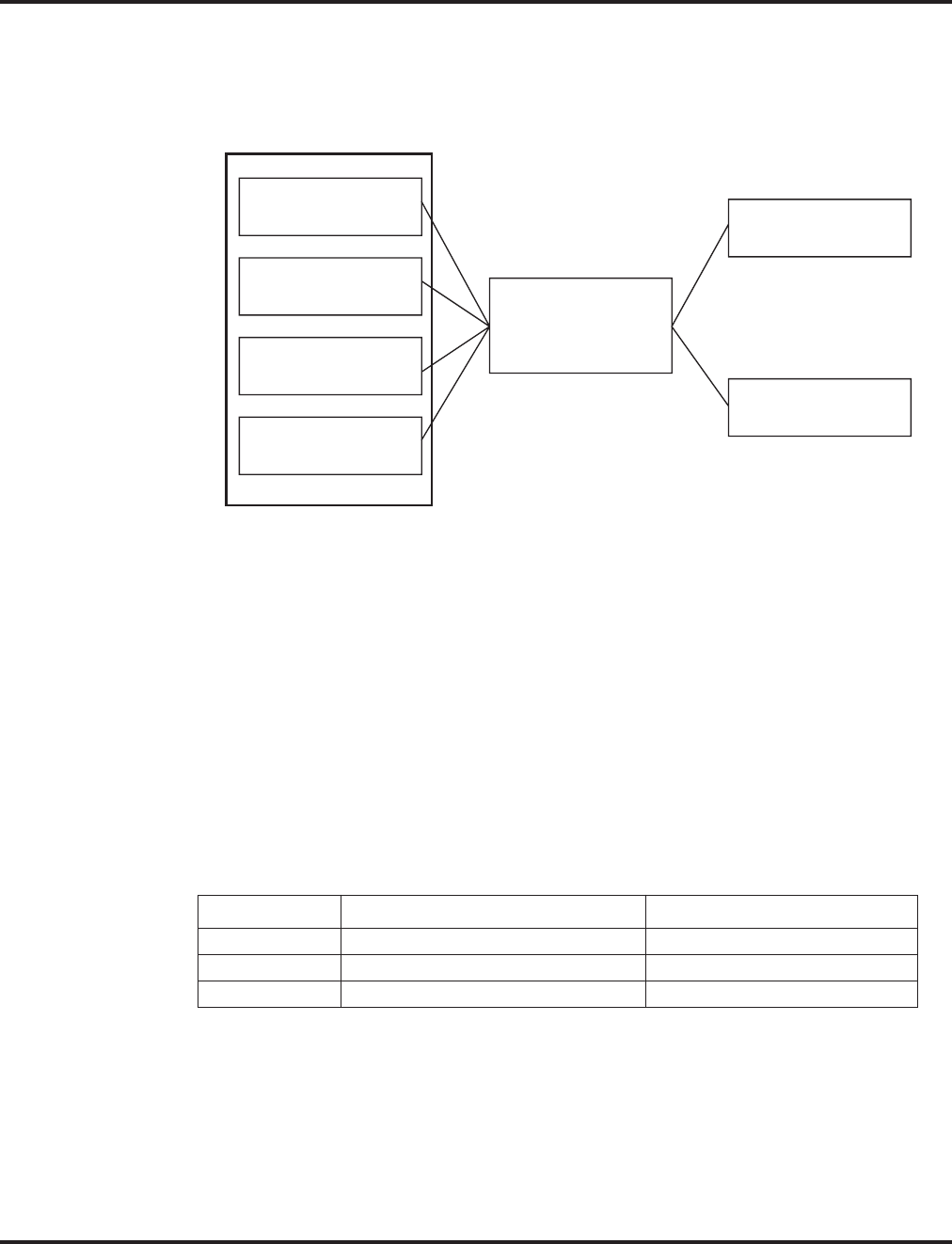
VoIP
644 ◆Features Aspire Software Manual
Using LANs
Using a LAN setup (local area network) with the Aspire system complies with the ethernet standard
(10Base-T/100Base-TX).
To connect a telephone to a LAN connection, the system allows the use of an Aspire digital IP 34-
button keyset (referred to as Aspire IPhone), an Aspire digital keyset with an IP Adapter installed or
an H.323 IP digital telephone. For details on installing the IP Adapter, refer to the Aspire Hardware
Manual (P/N 0893100).
If connecting a LAN to a WAN (wide area network), follow the instructions included with the
ADSL modem or gateway device.
IP Address
Equipment/devices used in the Aspire LAN setup must have an IP address assignment. An IP
address assigns a unique address for each device. There are two types of IP addresses: Private and
Global. A Private IP address is not accessible through the internet - a Global IP address can be
accessed through the internet.
With a Private IP address, with equipment that does not access the internet directly, addresses can
be assigned to the equipment within Class A, B or C by assigning a number within the class’s range
of numbers.
With a Global IP Address, connected equipment can be accessed through the internet, so each
address must be unique. To avoid a conflict, the addresses are controlled by ARIN (American Reg-
istry for Internet Numbers). To obtain a Global IP Address, contact ARIN or apply with your local
ISP (internet service provider).
The first one to three groups of numbers (depending on the subnet mask) identify the network on
which your computer is located. The remaining group(s) of numbers identify your computer on that
network.
Class Allowed IP Address Recommended Environment
A 10.0.0.0 ---10.22.255.255 Large Scale Network
B 172.16.0.0 --- 172.31.255.255 Mid Scale Network
C 192.168.0.0 --- 192.168.255.255 Small Scale Network
NTCPU
APSU (CTI Inskin Server)
VOIPU PCB
8SHUBU PCB
(Switching Hub)
Switch
10Base-T/100Base-TX
(100Base-TX is
recommended)
PC
IP Telephone
Aspire Cabinet
0893100-123

VoIP
Aspire Software Manual Features ◆645
Subnet Mask
As the IP Address includes information to identify both the network and the final destination, the
Subnet Mask is used to set apart the network and destination information.
The default subnet masks are:
In the above table, you’ll see that the Subnet Mask is made up of four groups of numbers. When a
group contains the number ‘255’, this is telling the router to ignore or mask that group of numbers
in the IP address as it is defining the network location of the final destination. So, for example, if the
IP Address were: 172.16.0.10 and the Subnet Mask used was Class B (255.255.0.0), the first two
groups of numbers (172.16) would be ignored once they reached the proper network location. The
next two groups (0.10) would be the final destination within the LAN to which the connection is to
be made.
DHCP
DHCP (Dynamic Host Configuration Protocol) is a protocol which assigns a dynamic IP Address.
Network control may be easier with DHCP as there is no need to assign and program individual IP
Addresses for the LAN equipment. To use a dynamic IP Address, a DHCP server must be provided.
The Aspire system provides the ability to use DHCP.
When equipment which is connected to the LAN (the DHCP client) is requesting an IP Address, it
searches the DHCP server. When the request for an address is recognized, the DHCP server assigns
an IP Address, Subnet definition, and the IP Address of the router, etc., based upon the system pro-
gramming.
Note that the NTCPU must always have a static IP address. This address is set in Program 10-12-01
: NTCPU Network Setup - IP Address (default: 172.16.0.10).
Gatekeeper
Whenever an H.323 terminal activates, a check is made of the network to see if there are any gate-
keepers available. When a gatekeeper is present, it provides users with:
●Address Translation
Users typically do not know the IP addresses of other terminals. When a user makes a call, the
gatekeeper translates an alias address (name or number) to the destination address.
●Admissions Control
Users will not all be able to access the network at the same time because of limited shared
resources. Gatekeepers may restrict network access based on call authorization, bandwidth
usage, or some other criteria. It is important to note that Admissions Control is a way to pre-
serve the integrity of the calls (provide QoS guarantees) that are already up and operating
when a user requests access.
●Bandwidth Control
Besides network access control, the gatekeeper offers network managers the ability to restrict or
assign bandwidth to different applications along certain protocol conventions. This is another place
network managers can enforce QoS guarantees and other enterprise-wide usage policies.
Class Default Subnet Mask
A 255.0.0.0
B 255.255.0.0
C 255.255.255.0

VoIP
646 ◆Features Aspire Software Manual
With the Aspire system, a separate external gatekeeper is not required unless connecting to an out-
side H.323 endpoint/gateway which requires an outer gatekeeper or if over 50 outer addresses must
be registered. Otherwise, the Aspire provides tables within the system programming for address
resolution.
Routers
When purchasing a router for use with the Aspire IP feature, the minimum requirements would be
that it provide VPN and QoS. Current VoIP protocols for the Aspire, NGT and H.323 telephones
can not communicate over NAT. Therefore, when communications is required over NAT, the router
must support VPN. Note that a router which supports ‘VPN Pass Through’ requires a VPN server.
The priority control feature is required to prevent RTP packet loss. If a WAN is used for VoIP only
and the bandwidth is wide enough for the VoIP channel, then the QoS feature might not be required.
The following are available routers which provide VPN and QoS:
●NEC IX1000 / 2000 Series
●Yamaha RT105, RTX1000 / 2000
●Cisco 800 Series
●Furukawa FITELnet - F40
●Fujitsu SiR-170, SiR-150
The following routers provide VPN but no priority control (QoS):
●Linksys BEFSX41, DEFVP41
●OMRON MR104DV, MR104FH
●Allied Telesis AR410
VoIP Bandwidth Calculation
A digital telephone system converts an analog voice signal into a stream of bits expressed in K bits
per second (where K is used to mean one thousand). For standard PCM digital encoding, this
stream of bits is 64 K bits per second. This is 64 K bps in each direction (transmit and receive).
To improve transmission efficiency, this bit stream is compressed using a standard compression
algorithm such as G.729. The result is still a bit stream, but with fewer bits per second. For exam-
ple, G.729 will reduce the 64 K bits per second to a bit stream of 8 K bits per second.
This bit stream is then divided into chunks (called Voice Samples or Voice Frames) that can be
placed in packets for transmission over a data network.
This reduced bit stream is examined repeatedly in fixed time intervals. This examination time is
called the Voice Frame Interval. This is the time used to collect the bits for one Voice Frame. The
Voice Frame Interval is expressed in milliseconds (ms). A millisecond is one thousandth of a second.
To help determine the bandwidth requirements for the system, the NEC Technical Support web site
(http://ws1.necii.com) provides a bandwidth calculator. This web site requires registration with the
NEC Sales Support. Contact them by phone (1-800-365-1928) or EMail (ubsdsupport@necinfron-
tia.com) in order to register. It is important to remember that the bandwidth calculator is based on a
single voice channel. It takes two voice channels (send and receive) for each telephone conversation.
Refer to Bandwidth Setting for Aspire (page 692) for additional information.

VoIP
Aspire Software Manual Features ◆647
IP Hardware
PCBs:
●NTCPU - Signals the gateway with VoIP communication
●4VOIPU - VoIP PCB provides a 4-channel voice packet gateway unit and works as a media
gateway for VoIP communication. This PCB is required for either VoIP trunks or when using
VoIP keysets which talk to non-IP keysets. VoIP keyset-to-VoIP keyset can talk without a
media gateway and without using any DSP resources using the Peer-to-Peer feature
(page 694). The 4VOIPU PCB requires 4 trunk ports.
●4VOIPDB - VoIP daughter board provides an additional 4 channels when attached to either
the 4VOIPU or 16VOIPU PCB. The 4VOIPDB requires 4 trunk ports.
●16VOIPU - VoIP PCB provides a 16-channel voice packet gateway unit and works as a media
gateway for VoIP communication. This PCB is required for either VoIP trunks or when using
VoIP keysets which talk to non-IP keysets. VoIP keyset-to-VoIP keyset can talk without a
media gateway and without using any DSP resources using the Peer-to-Peer feature
(page 694). The 16VOIPU PCB requires 16 trunk ports.
●16VOIPDB - VoIP daughter board provides an additional 16 channels when attached to the
16VOIPU PCB. The 16VOIPDB requires 16 trunk ports.
●8SHUBU - Provides an 8-port switching hub for use with the Aspire system. This PCB can
also be used to provide PoE for Aspire IP equipment.
When installing a VoIP PCB, the system allocates the maximum number of trunk ports for the PCB
being installed. For instance, the 4VOIPU PCB requires 4 ports, while the 16VOIPU PCB requires
16 ports. If the PCB is not going to be used for trunks, the logical trunk ports can be set to ‘0’ in
Program 10-03-01 : PCB Setup, but the physical trunk ports are still assigned to the PCB and can-
not be used for any other PCB. If the trunk ports will not be used and the trunk port usage is a con-
cern, plug the VOIPU PCBs into the system last. The system will allow extension ports to be
assigned even if there are no trunk ports available. A maximum of 512 IP extensions or 200 IP
trunks are possible with the Aspire. The VoIP PCBs can be plugged into any universal slot.
Terminals:
●IPhone - Aspire 34-button multi-line IP phone
●IP Adapter - IP adapter connects an Aspire keyset to the VoIP network
The phone with the adapter installed is also referred to as the Dterm IP phone.
●ITR-2D-1 - H.323 IP phone
H.323 phones do not support the ability to send digits after a call has been placed and
before it is answered. This means that features which use single digit service codes, such
as Voice Over and Barge-In, are not available with this type of phone. These phones do not
provide P-codes, and therefore, cannot be used with the inDepth application.
Power must be supplied to the IPhone or the Aspire keyset with IP adapter using either a local or
central power supply. The ITR-2D1 phone requires local power. If there is a power outage, the VoIP
phones will not work unless the phones are plugged into a UPS (uninterruptible power supply).
When the first IP phone is plugged in, the system automatically assigns the next three consecutive
station ports available as IP ports. The next three IP phones installed will use this group of ports.
When the fifth IP phone is connected, the next 3 consecutive station ports available will be assigned
as IP ports.

VoIP
648 ◆Features Aspire Software Manual
Switches/Hubs for PoE
Using a central power supply or the 8SHUBU PCB with the PoE jumpers set, power over category
5 network cables can be provided. This eliminates the need of installing separate power adapters for
each IP phone and it allows for centralized power backup. Note: The Aspire IP phones are not
IEEE 802.3af compliant unless an ILPA adapter is used for PoE. The ILPA, however, cannot be
used on the Uniden H.323 telephones. Refer to the ILPA Adapter Instructions, P/N 0893109 for
details.
If PoE (power over ethernet) is to be used to eliminate the separate power adapters, due to the
power requirements, a separate power source is suggested. It is recommended that you use one of
the central power supplies below:
●8SHUBU PCB - Provides 8-port switching hub and the ability to provide PoE for Aspire
equipment.
●802.1p/1q Support
●24-port power supply PoE-managed switch (NEC BlueFire 200/24)
●PoE (Power Over Ethernet) to Aspire IP/H.323 Phones
●Spare Pair (4/5, 7/8) / Signal Pair (1/2, 3/6) Selection
For systems which require layer 2 switching capability and PoE, the NEC BlueFire
200/24 switch is recommended. This unit provides layer 2 switch capability in addition to
being able to supply ethernet power to 24 NEC IP terminals.
●Cisco Data Switch - CDP Supported
Other manufacturer central power supplies may be usable, but the above items have been tested for
compatibility with the Aspire equipment.
Note: Each IP phone consumes one port. When automatically selected, the port number
ranges from 257-512. The port number can be manually assigned using the port range
001-512.
! CAUTION !
Only Aspire IP phones and Aspire IP Adapters and H.323 phones must
be connected to the 8SHUBU. The provided DC voltage provided
through the spare pairs (4/5, 7/8) may damage any other equipment.
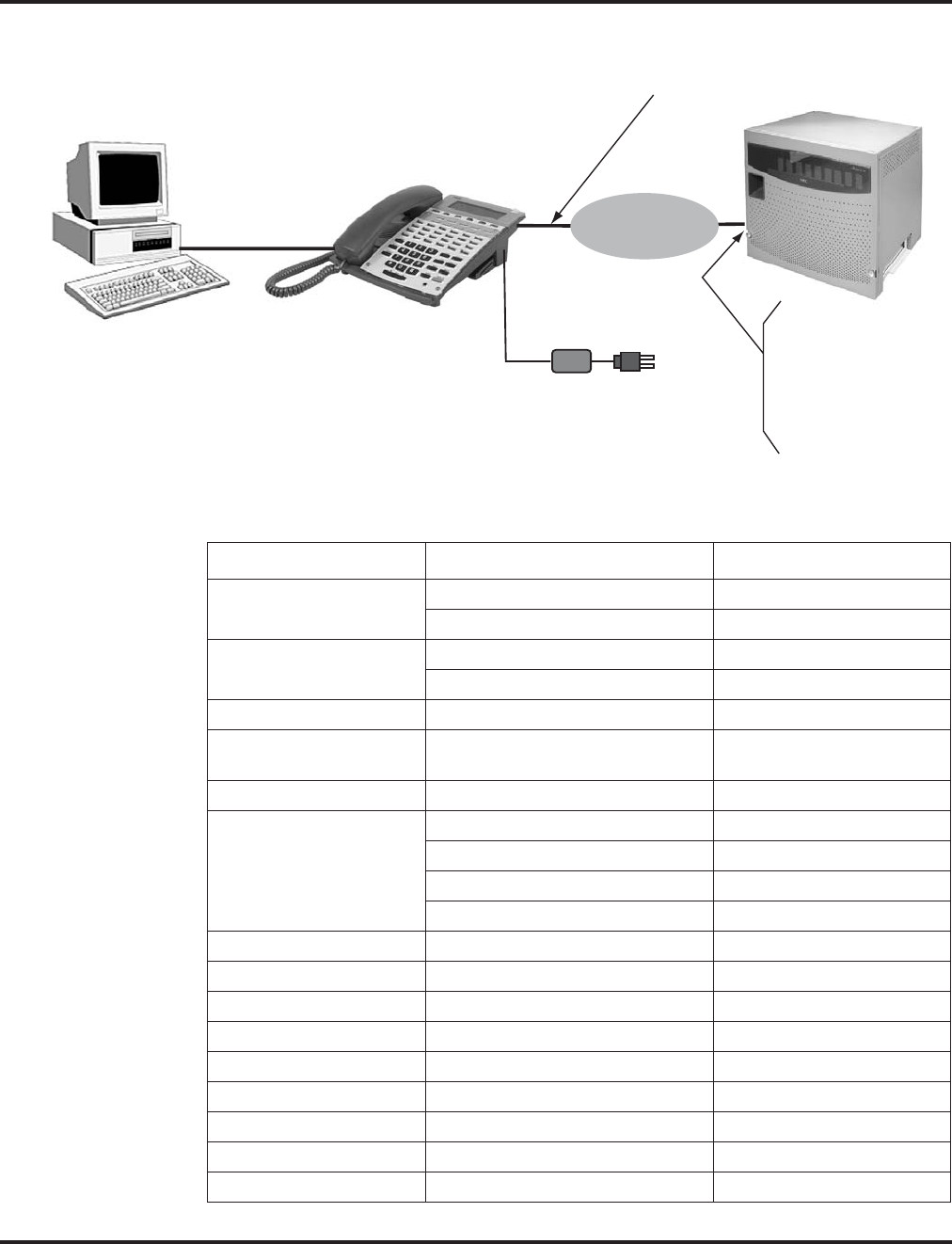
VoIP
Aspire Software Manual Features ◆649
Aspire VoIP Specifications
Category Feature Note
IP Address DHCP Server NTCPU
DHCP Client VOIPU PCB or IP Phone
QoS 802.1p/1q
L3 QoS (ToS) Diffserv/IP Precedence
Maintenance HTTP Server NTCPU
Server H.323 Gatekeeper For H.323 Phone
Registration and Routing
VLAN Tag and port-based VLAN
VoCoder G.711 μ-law/A-law
G.729a
G.723.1
Fax Relay
Jitter Buffer Size Set by system programming
RTP Length Set by system programming
Echo Canceller Tail Size Set by system programming
Level Adjustment Set by system programming
Protocol H.323
NGT (Next Generation Telephone)
IP Phone H.323 Phone H.323 Phone
NGT Phone Maximum 512 Phones
IP Trunk H.323 Trunk Maximum 200 Trunks
voip.eps
Ethernet PC
Aspire IP Keyset or
Aspire Legacy IP Keyset or
H.323 Terminal
AC Adaptor
(Not needed if power
supplied by LAN)
LAN
PC Connection
Straight-Thru
Cable
Ethernet
Straight-Thru
Cable Aspire Cabinet
NTCPU
4VOIPU
4VOIPDB
16VOIPU
16VOIPDB
8SHUBU

VoIP
650 ◆Features Aspire Software Manual
Programming
In addition to the required VoIP programming described under the Programming - VoIP
(page 651) heading, the following features and options have additional programming which may be
required. Refer to the section that applies to the applications required for your location.
●Programming - VoIP (page 651)
●Programming - Static IP Address (page 651)
●Programming - Using the Aspire DHCP (page 656)
●Programming - Using an External DHCP (page 658)
●Programming - H.323 Phone, Setting H.323 Options (page 661)
●LAN Connections (page 665)
●911 Calls with Networked IP Phones (page 667)
●Address Conversion Table (page 668)
●Calling Party Number Setup for Trunks and Extensions (page 668)
●CODEC Selection (page 668)
●Deleting IP Phone Registration (page 669)
●Echo Adjustment (page 669)
●Enhanced Echo Adjustment (page 679)
●Fax Relay (page 682)
●Firmware Download for Aspire Keyset with IP Adapter (page 682)
●H.323 Gatekeeper Connection (page 683)
●H.323 Terminals (page 684)
●In-Band/Out-of-Band Signaling (page 684)
●IP Extensions (page 685)
●IP Trunks (page 692)
●Music on Hold for IP Terminals (page 693)
●Networking Over IP (page 693)
●Peer-to-Peer Connection (page 694)
●RTP Forwarding Available (page 695)
●Tandem Connection (page 695)
●VLAN/QoS (page 696)
●VOIPU DSP Resource Assignment (page 698)

VoIP
Aspire Software Manual Features ◆651
Programming - VoIP
These programs are always required with the VoIP feature. Refer to the following feature options
for additional programming.
➻10-12-01 : NTCPU Network Setup - IP Address
Select the IP address for the IP connection (default: 172.16.0.10). A static IP address is
required by the NTCPU. The system must be reset in order for the change to take effect.
➻10-12-02 : NTCPU Network Setup - Subnet Mask
Select the Subnet Mask to be used by the IP server (default: 255.255.0.0).
➻10-12-03 : NTCPU Network Setup - Default Gateway
If required, select the default gateway IP address to be used when using a router
(default: 0.0.0.0).
Programming - Static IP Address
In addition to the system programming for the NTCPU or VOIPU PCB, the IP phone also has
options which must be programmed from the phone itself. Be sure to set both the system and phone
options.
➻10-13-01 : In-DHCP Server Setup - DHCP Server Mode
Disable (0) the system’s ability to use the built-in DHCP server.
➻84-04-01 : VOIPU PCB DHCP Server Mode Setup
Disable (0) the use of DHCP for the VOIPU PCB.
➻84-05-01 : VOIPU IP Address Setup - IP Address
For each VOIPU PCB, enter the IP address for the VOIPU PCB (default: slot 1=172.16.0.20,
slot 2 = 172.16.0.21, etc.). The IP address should be increased according to the number of
VOIPU PCBs. This entry becomes invalid if Program 84-04 is set to "1" (DHCP enabled).
➻84-06-01 : VOIPU Setup - RTP Port Number
For each VOIPU PCB, enter the RTP port number (default 10020).
Programming - Aspire IP Keyset or Aspire Keyset with IP Adapter, Static IP Address
Setting the IP Address on an Aspire IPhone or Aspire Keyset with IP Adapter Using a
Static IP Address
1. On the Aspire IP keyset, enter the phone’s program mode by pressing HOLD CONF * #.
This enters the IP User Menu program mode to select the settings for the individual
phone.
To enter the phone’s program mode, the display must show the time, error, or “Con-
necting” message prior to pressing HOLD CONF * #.
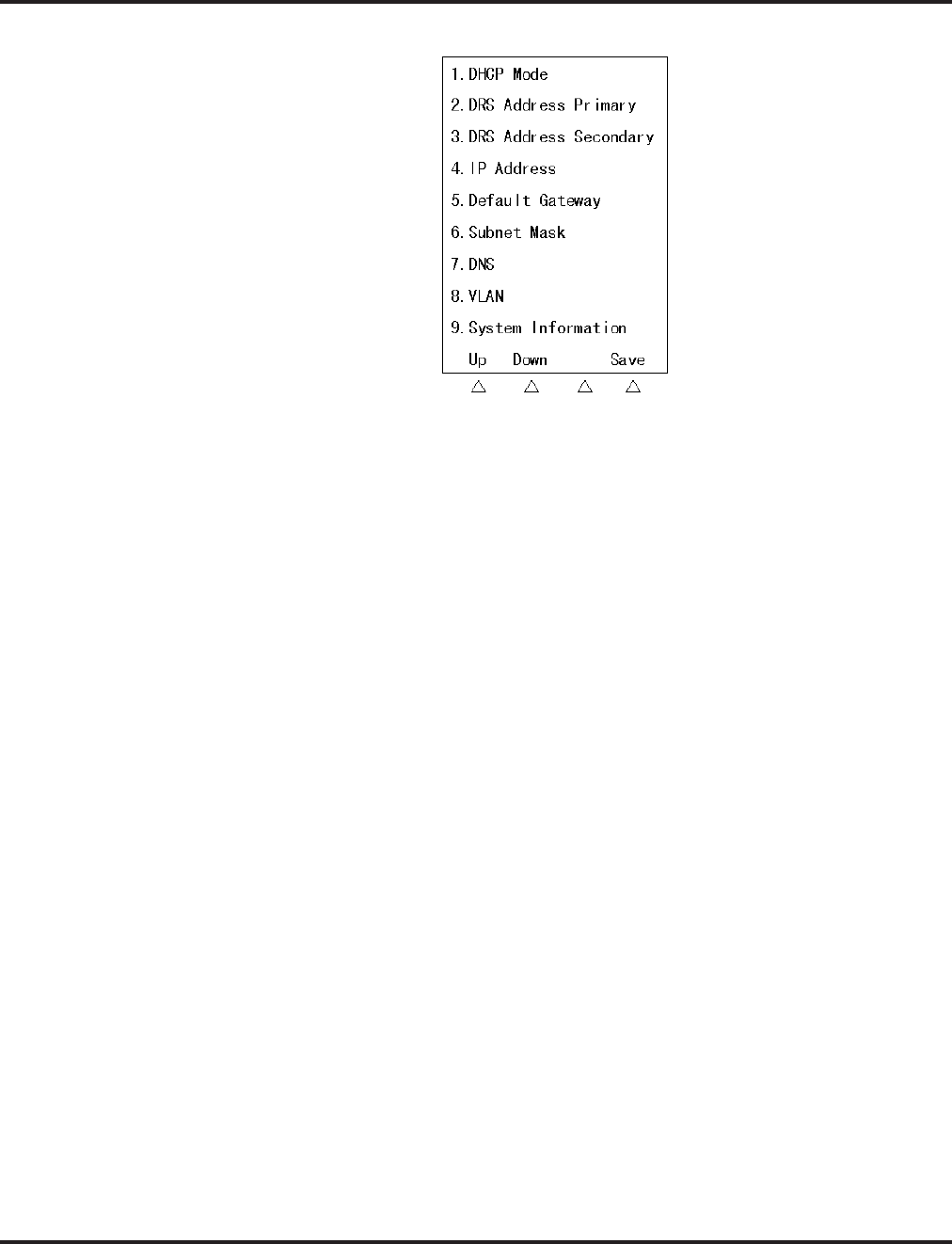
VoIP
652 ◆Features Aspire Software Manual
2. Press 1 to enter the DHCP mode. If not flashing, press "1" to disable the DHCP mode. Press
the Soft Key “OK”.
The flashing item is the current selection.
3. Press 2 to enter the Primary DRS (Device Registration Server). Enter the IP address used in
Program 10-12-01 (default: 172.16.0.10). The * key is used to move to the next set of 3 digits
(example: 172*16*0*10). Press the Soft Key “OK”.
The Soft Key “BK” backs up a character to correct an entry.
4. Press 4 to enter the IP address for the phone. The IP address must be unique to each phone but
the range is dependent upon system programming (example: IP Keyset 1 = 172.16.0.11, IP
Keyset 2 = 172.16.0.12, etc.). The * key is used to move to the next set of 3 digits (example:
172*16*0*10). Press the Soft Key “OK”.
For on-site LANs, the IP address must be unique to each phone but the range is depen-
dent upon system programming (example: IP Phone 1 = 172.16.0.11, IP Phone 2 =
172.16.0.12, etc.). When phones are off-site (remote LAN) , these settings are dependant
on the remote LAN settings - not the phone system settings.
The Soft Key “BK” backs up a character to correct an entry.
5. Press 5 to enter the Default Gateway address.
For on-site LANs this is the entry in Program 10-12-03. When phones are off-site
(remote LAN) , these settings are dependant on the remote LAN settings - not the phone
system settings.
6. Press 6 to enter the Subnet Mask.
For on-site LANs this is the entry in Program 10-12-02. When phones are off-site
(remote LAN) , these settings are dependant on the remote LAN settings - not the phone
system settings.
7. Press the Soft Key “SAVE” to save the entries and return the phone to an idle condition.
Pressing CANCEL instead will ignore the changes made and return the keyset to an
idle condition.
In this program entry mode, items "3. DTS Address Secondary" and "7. DNS" can be set as
required by the customer but are not required for the feature to function. Item "8. VLAN" is dis-
cussed below. Item "9. System Information" displays the entries and does not allow any changes.

VoIP
Aspire Software Manual Features ◆653
Programming - H.323 Phone, Static IP Address
Setting the IP Address on the ITR-2D-1 IP Phone Using a Static IP Address
1. Press the menu key.
The Setup Menu screen will be displayed with Call Logs as the first entry.
2. Go to the Configuration sub menu using the ▲ key.
3. Press the Select key. The Configuration Menu screen will be displayed showing the first entry
of Configuration Menu, which is Phone Configuration. Using the ▲ key go to the “Network
Menu” which is the second entry under the Configuration Menu.
4. Press the Select key. The display prompts you to enter the password. Enter the password and
press the Select key. The default administrator’s password is 654321.
If a wrong password is entered, the display indicates “Incorrect Password” and Step 4
can be repeated.
5. If a correct password is entered, the current DHCP setting (Enabled or Disabled) will be dis-
played on the LCD as the first setting of the Network Configuration. There are 6 network
related settings available under Network Configuration.
6. Press the Select key (▲ and ▼ keys can be used to move within the screen or to go to any one
of the 6 network related settings).
7. This screen allows you to either enable or disable the DHCP. Use ▲ and ▼ keys to select dis-
abled then press the Select key.
To cancel instead, press the Cancel/Del key repeatedly until returning to standby mode
or press the Menu key once to go to the standby mode.
8. The phone needs be restarted for the new settings to take effect. Press Select key to restart the
phone, press Del/Cancel to return to the previous menu or Menu to return to standby mode
without restarting the phone. If the Line 1, Line 2 or SPK/HS key is pressed or the handset is
picked up, the phone will go off and the restart will be cancelled. If the phone restart is can-
celled, the changed network setting will not be used until the phone is restarted. If the Select
key is pressed, “Initializing…\” will be displayed while the phone is resetting.
If there is an error in saving, “Cannot Save” will be displayed for 1 second.
9. Repeat Steps 1-6.
10. Use the ▲ and ▼ keys to move to “IP Address.”
11. Press the Select key to see the current terminal IP address. A screen will be displayed prompt-
ing user to change the value.
Press the Cancel/Del key to go the previous screen.
This menu is used to read or change the current value of the terminal IP address if DHCP
assignment is disabled. The format of the IP address is: xxx.xxx.xxx.xxx (use the * key to enter
the decimal between the numbers). Allowed entries for each set of three numbers are 0-255.
12. Press the Select key to change the IP address. Enter the correct IP address and press the Select key.
For on-site LANs, the IP address must be unique to each phone but the range is depen-
dent upon system programming (example: IP Phone 1 = 172.16.0.11, IP Phone 2 =
172.16.0.12, etc.). When phones are off-site (remote LAN) , these settings are dependant
on the remote LAN settings - not the phone system settings.
If the entered IP address is not valid, “Invalid Input” will be displayed for 1 second
before returning to the “IP Address” screen.
Press the Cancel/Del key to return to the previous screen without making any changes.

VoIP
654 ◆Features Aspire Software Manual
13. The phone needs be restarted for the new settings to take effect. Press Select key to restart the
phone, press Del/Cancel to return to the previous menu or Menu to return to standby mode
without restarting the phone.
If there is an error in saving, “Cannot Save” will be displayed for 1 second.
14. Repeat Steps 1-6.
15. Use the ▲ and ▼ keys to move to Subnet Mask.
16. Press the Select key to read the value. The next screen displayed prompts you to change the
value if needed.
If DHCP is enabled, subnet mask will be read only and user cannot change the subnet
mask address.
17. Press the Select key to change the Subnet Mask. Enter the correct Subnet Mask and press the
Select key.
For on-site LANs this is the entry in Program 10-12-02. When phones are off-site
(remote LAN) , these settings are dependant on the remote LAN settings - not the phone
system settings.
The format of the Subnet Mask is: xxx.xxx.xxx.xxx (use the * key to enter the decimal
between the numbers). Allowed entries for each set of three numbers are 0-255.
If the entered subnet mask is not valid, “Invalid Input” will be displayed for 1 second.
Press the Cancel/Del key to return to the previous screen without making any changes.
18. The phone needs be restarted for the new settings to take effect. Press Select key to restart the
phone, press Del/Cancel to return to the previous menu or Menu to return to standby mode
without restarting the phone.
If there is an error in saving, “Cannot Save” will be displayed for 1 second.
19. Repeat Steps 1-6.
20. Use the ▲ and ▼ keys to move to Default Gateway.
21. Press the Select key to read the value. The next screen displayed prompts you to change the
value if needed.
If DHCP is enabled, default gateway will be read only and user cannot change the address.
22. Press the Select key to change the Default Gateway. Enter the correct Default Gateway and
press the Select key.
For on-site LANs this is the entry in Program 10-12-03. When phones are off-site
(remote LAN) , these settings are dependant on the remote LAN settings - not the phone
system settings.
The format of the Default Gateway is: xxx.xxx.xxx.xxx (use the * key to enter the deci-
mal between the numbers). Allowed entries for each set of three numbers are 0-255.
If the entered subnet mask is not valid, “Invalid Input” will be displayed for 1 second.
Press the Cancel/Del key to return to the previous screen without making any changes.
23. The phone needs be restarted for the new settings to take effect. Press Select key to restart the
phone, press Del/Cancel to return to the previous menu or Menu to return to standby mode
without restarting the phone.
If there is an error in saving, “Cannot Save” will be displayed for 1 second.
24. Repeat Steps 1-6.
25. Use the ▲ and ▼ keys to move to VLAN Enable/Disable. Press the Select key.

VoIP
Aspire Software Manual Features ◆655
26. Use the ▲ and ▼ keys to change the selection and press the Select key.
Press the Cancel/Del key to return to the previous screen without making any changes.
27. The phone needs be restarted for the new settings to take effect. Press Select key to restart the
phone, press Del/Cancel to return to the previous menu or Menu to return to standby mode
without restarting the phone.
If there is an error in saving, “Cannot Save” will be displayed for 1 second.
28. Repeat Steps 1-6.
29. Use the ▲ and ▼ keys to move to VLAN ID.
30. Press the Select key to read the value. The next screen displayed prompts you to change the
value if needed.
31. Press the Select key to change the VLAN ID. Enter the correct VLAN ID and press the Select key.
The valid range of entries is 0-65535.
Press the Cancel/Del key to delete a digit of the existing VLAN ID. If no ID number is
displayed when the Cancel/Del key is pressed, it will return to the previous screen.
32. The phone needs be restarted for the new settings to take effect. Press Select key to restart the
phone, press Del/Cancel to return to the previous menu or Menu to return to standby mode
without restarting the phone.
If there is an error in saving, “Cannot Save” will be displayed for 1 second.

VoIP
656 ◆Features Aspire Software Manual
Programming - Using the Aspire DHCP
➻10-13-01 : In-DHCP Server Setup - DHCP Server Mode
Enable (1) the system’s ability to use the built-in DHCP server. The system must be reset in
order for the change to take effect.
➻10-13-02 : In-DHCP Server Setup - Lease Time
Enter the lease time of the IP address to a client (default: 0 days, 0 hours, 30 minutes). The
system must be reset in order for the change to take effect.
➻10-13-04 : In-DHCP Server Setup - Number of Networks
Select the number of networks in use on the system (default: 0, entries: 0=Single Network,
1=Divide Same Network). The system must be reset in order for the change to take effect.
➻10-14-01 : Managed Network Setup - Scope 1
Set the range of IP addresses available to be used by the DHCP server for Scope 1 (default:
Minimum = 172.16.0.100, Maximum = 172.16.5.254, Scopes 1-10).
➻10-15-01 : Client Information Setup
Set the IP and MAC addresses for each client (up to 10) when the DHCP server needs to
assign a fixed IP address to clients.
➻10-16-01 : Option Information Setup - Router
Set the router address for the DHCP server to the client.
➻10-16-02 : Option Information Setup - DNS Server
If required, set the DNS server address for the DHCP server to the client.
➻10-16-03 : Option Information Setup - TFTP Server
Set the TFTP server address for the DHCP server to the client.
➻10-16-04 : Option Information Setup - DRS
Set the NTCPU’s IP address for the DHCP server to the client.
➻84-04-01 : VOIPU PCB DHCP Server Mode Setup
Enable (1) the use of DHCP for the VOIPU PCB.
➻84-05-01 : VOIPU IP Address Setup - IP Address
For each VOIPU PCB, enter the IP address for the VOIPU PCB (default: slot 1=172.16.0.20,
slot 2 = 172.16.0.21, etc.). The IP address should be increased according to the number of
VOIPU PCBs. This entry becomes invalid if Program 84-04 is set to "1" (DHCP enabled).

VoIP
Aspire Software Manual Features ◆657
Programming, Aspire IP Keyset or Aspire Keyset with IP Adapter - DHCP
Setting the IP Address on an Aspire IP or Aspire Keyset with IP Adapter Using a
DHCP Server
1. On the Aspire IP keyset, enter the phone’s program mode by pressing HOLD CONF * #.
This enters the IP User Menu program mode to select the settings for the individual
phone.
2. Press 1 to enter the DHCP mode. If not flashing, press "2" to enable the DHCP mode. Press
the Soft Key “OK”.
The flashing item is the current selection.
3. The entries for items 2, 4, 5, and 6 are automatically set by the DCHP server.
4. Press the Soft Key “SAVE” to save the entries and return the phone to an idle condition.
In this program entry mode, items "3. DTS Address Secondary" and "7. DNS" can be set as
required by the customer but are not required for the feature to function. Item "8. VLAN" is dis-
cussed below. Item "9. System Information" displays the entries and does not allow any changes.
Note 1. If a user’s LAN is already operating with a DHCP server, disable the Aspire’s DHCP
server. Either DHCP server can be used, but not both.
Note 2. When a user’s DHCP server is operating, make sure to define Program 10-16.
Programming - H.323 Phone, Enabling DHCP
Setting the IP Address on the ITR-2D-1 IP Phone Using a DHCP Server
1. Press the menu key.
The Setup Menu screen will be displayed with Call Logs as the first entry.
2. Go to the Configuration sub menu using the ▲ key.
3. Press the Select key. The Configuration Menu screen will be displayed showing the first entry
of Configuration Menu, which is Phone Configuration. Using the ▲ key go to the “Network
Menu” which is the second entry under the Configuration Menu.
4. Press the Select key. The display prompts you to enter the password. Enter the password and
press the Select key. The default administrator’s password is 654321.
If a wrong password is entered, the display indicates “Incorrect Password” and Step 4
can be repeated.
5. If a correct password is entered, the current DHCP setting (Enabled or Disabled) will be dis-
played on the LCD as the first setting of the Network Configuration. There are 6 network
related settings available under Network Configuration.
6. Press the Select key (▲ and ▼ keys can be used to move within the screen or to go to any one
of the 6 network related settings).
7. This screen allows you to either enable or disable the DHCP. Use ▲ and ▼ keys to select
Enabled then press the Select key.
To cancel instead, press the Cancel/Del key repeatedly until returning to standby mode
or press the Menu key once to go to the standby mode.
8. The phone needs be restarted for the new settings to take effect. Press Select key to restart the
phone, press Del/Cancel to return to the previous menu or Menu to return to standby mode
without restarting the phone. If the Line 1, Line 2 or SPK/HS key is pressed or the handset is
picked up, the phone will go off and the restart will be cancelled. If the phone restart is can-
celled, the changed network setting will not be used until the phone is restarted. If the Select
key is pressed, “Initializing…\” will be displayed while the phone is resetting.
If there is an error in saving, “Cannot Save” will be displayed for 1 second.

VoIP
658 ◆Features Aspire Software Manual
9. Repeat Steps 1-6.
10. Use the ▲ and ▼ keys to move to “IP Address.”
11. Press the Select key to see the current terminal IP address.
With DHCP enabled, the IP address, subnet mask, default gateway will be read only
and user cannot change the address.
12. Use the ▲ and ▼ keys to move to VLAN Enable/Disable. Press the Select key.
13. Use the ▲ and ▼ keys to change the selection and press the Select key.
Press the Cancel/Del key to return to the previous screen without making any changes.
14. The phone needs be restarted for the new settings to take effect. Press Select key to restart the
phone, press Del/Cancel to return to the previous menu or Menu to return to standby mode
without restarting the phone.
If there is an error in saving, “Cannot Save” will be displayed for 1 second.
15. Repeat Steps 1-6.
16. Use the ▲ and ▼ keys to move to VLAN ID.
17. Press the Select key to read the value. The next screen displayed prompts you to change the
value if needed.
18. Press the Select key to change the VLAN ID. Enter the correct VLAN ID and press the Select
key.
The valid range of entries is 0-65535.
Press the Cancel/Del key to delete a digit of the existing VLAN ID. If no ID number is
displayed when the Cancel/Del key is pressed, it will return to the previous screen.
19. The phone needs be restarted for the new settings to take effect. Press Select key to restart the
phone, press Del/Cancel to return to the previous menu or Menu to return to standby mode
without restarting the phone. If the Line 1, Line 2 or SPK/HS key is pressed or the handset is
picked up, the phone will go off and the restart will be cancelled. If the phone restart is can-
celled, the changed network setting will not be used until the phone is restarted. If the Select
key is pressed, “Initializing…\” will be displayed while the phone is resetting.
If DHCP is enabled and after restarting the phone, if the phone cannot find the DHCP
server or it fails to retrieve the network information, the phone will go to the standby
mode.
If there is an error in saving, “Cannot Save” will be displayed for 1 second.
Programming - Using an External DHCP
Note 1. If a user’s LAN is already operating with a DHCP server, disable the Aspire’s DHCP
server. Either DHCP server can be used, but not both.
Note 2. When an external DHCP server is operating, make sure to define Program 10-16.
➻10-13-01 : In-DHCP Server Setup - DHCP Server Mode
Enable (1) the system’s ability to use the built-in DHCP server. The system must be reset in
order for the change to take effect.
➻10-16-01 : Option Information Setup - Router
Set the router address for the DHCP server to the client.
➻10-16-02 : Option Information Setup - DNS Server
If required, set the DNS server address for the DHCP server to the client.
➻10-16-03 : Option Information Setup - TFTP Server
Set the TFTP server address for the DHCP server to the client.

VoIP
Aspire Software Manual Features ◆659
➻10-16-04 : Option Information Setup - DRS
Set the NTCPU’s IP address for the DHCP server to the client.
➻84-04-01 : VOIPU PCB DHCP Server Mode Setup
Enable (1) the use of DHCP for the VOIPU PCB.
➻84-05-01 : VOIPU IP Address Setup - IP Address
For each VOIPU PCB, enter the IP address for the VOIPU PCB (default: slot 1=172.16.0.20,
slot 2 = 172.16.0.21, etc.). The IP address should be increased according to the number of
VOIPU PCBs. This entry becomes invalid if Program 84-04 is set to 1 (DHCP enabled).
Programming, Aspire IP Keyset or Aspire Keyset with IP Adapter - DHCP
Setting the IP Address on an Aspire IP or Aspire Keyset with IP Adapter Using a
DHCP Server
1. On the Aspire IP keyset, enter the phone’s program mode by pressing HOLD CONF * #.
This enters the IP User Menu program mode to select the settings for the individual
phone.
2. Press 1 to enter the DHCP mode. If not flashing, press "2" to enable the DHCP mode. Press
the Soft Key “OK”.
The flashing item is the current selection.
3. The entries for items 2, 4, 5, and 6 are automatically set by the DCHP server.
4. Press the Soft Key “SAVE” to save the entries and return the phone to an idle condition.
In this program entry mode, items "3. DTS Address Secondary" and "7. DNS" can be set as
required by the customer but are not required for the feature to function. Item "8. VLAN" is dis-
cussed below. Item "9. System Information" displays the entries and does not allow any changes.
Programming - H.323 Phone, Enabling DHCP
Setting the IP Address on the ITR-2D-1 IP Phone Using a DHCP Server
1. Press the menu key.
The Setup Menu screen will be displayed with Call Logs as the first entry.
2. Go to the Configuration sub menu using the ▲ key.
3. Press the Select key. The Configuration Menu screen will be displayed showing the first entry
of Configuration Menu, which is Phone Configuration. Using the ▲ key go to the “Network
Menu” which is the second entry under the Configuration Menu.
4. Press the Select key. The display prompts you to enter the password. Enter the password and
press the Select key. The default administrator’s password is 654321.
If a wrong password is entered, the display indicates “Incorrect Password” and Step 4
can be repeated.
5. If a correct password is entered, the current DHCP setting (Enabled or Disabled) will be dis-
played on the LCD as the first setting of the Network Configuration. There are 6 network
related settings available under Network Configuration.
6. Press the Select key (▲ and ▼ keys can be used to move within the screen or to go to any one
of the 6 network related settings).
7. This screen allows you to either enable or disable the DHCP. Use ▲ and ▼ keys to select
Enabled then press the Select key.
To cancel instead, press the Cancel/Del key repeatedly until returning to standby mode
or press the Menu key once to go to the standby mode.

VoIP
660 ◆Features Aspire Software Manual
8. The phone needs be restarted for the new settings to take effect. Press Select key to restart the
phone, press Del/Cancel to return to the previous menu or Menu to return to standby mode
without restarting the phone. If the Line 1, Line 2 or SPK/HS key is pressed or the handset is
picked up, the phone will go off and the restart will be cancelled. If the phone restart is can-
celled, the changed network setting will not be used until the phone is restarted. If the Select
key is pressed, “Initializing…\” will be displayed while the phone is resetting.
If there is an error in saving, “Cannot Save” will be displayed for 1 second.
9. Repeat Steps 1-6.
10. Use the ▲ and ▼ keys to move to “IP Address.”
11. Press the Select key to see the current terminal IP address.
With DHCP enabled, the IP address, subnet mask, default gateway will be read only
and user cannot change the address.
12. Use the ▲ and ▼ keys to move to VLAN Enable/Disable. Press the Select key.
13. Use the ▲ and ▼ keys to change the selection and press the Select key.
Press the Cancel/Del key to return to the previous screen without making any changes.
14. The phone needs be restarted for the new settings to take effect. Press Select key to restart the
phone, press Del/Cancel to return to the previous menu or Menu to return to standby mode
without restarting the phone.
If there is an error in saving, “Cannot Save” will be displayed for 1 second.
15. Repeat Steps 1-6.
16. Use the ▲ and ▼ keys to move to VLAN ID.
17. Press the Select key to read the value. The next screen displayed prompts you to change the
value if needed.
18. Press the Select key to change the VLAN ID. Enter the correct VLAN ID and press the Select
key.
The valid range of entries is 0-65535.
Press the Cancel/Del key to delete a digit of the existing VLAN ID. If no ID number is
displayed when the Cancel/Del key is pressed, it will return to the previous screen.
19. The phone needs be restarted for the new settings to take effect. Press Select key to restart the
phone, press Del/Cancel to return to the previous menu or Menu to return to standby mode
without restarting the phone. If the Line 1, Line 2 or SPK/HS key is pressed or the handset is
picked up, the phone will go off and the restart will be cancelled. If the phone restart is can-
celled, the changed network setting will not be used until the phone is restarted. If the Select
key is pressed, “Initializing…\” will be displayed while the phone is resetting.
If DHCP is enabled and after restarting the phone, if the phone cannot find the DHCP
server or it fails to retrieve the network information, the phone will go to the standby
mode.
If there is an error in saving, “Cannot Save” will be displayed for 1 second.
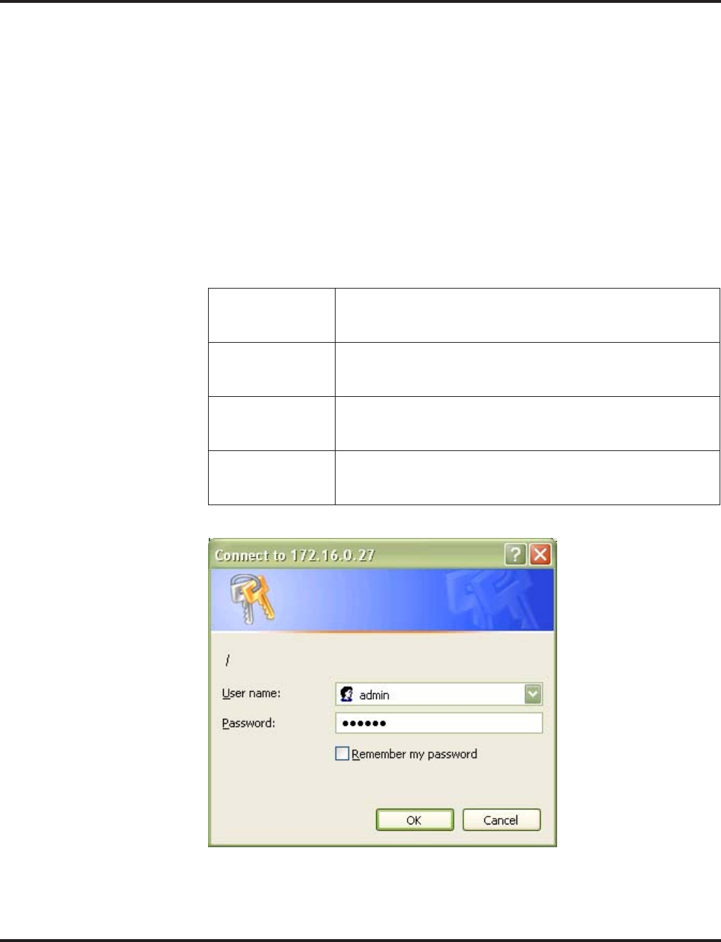
VoIP
Aspire Software Manual Features ◆661
Programming - H.323 Phone, Setting H.323 Options
To complete the H.323 phone programming, after connecting the phone to the LAN, you must con-
nect to the phone using an internet browser (such as Internet Explorer or Netscape Navigator).
1. From a PC which is connected to the same LAN as the VoIP phone, open the internet browser.
TCP/IP must be set up on the PC in order for the connection to work correctly. In the
Network Settings, under the properties of the Local Area Network setting, set the IP and
subnet mask address of the TCP/IP settings.
2. Enter the IP address for the phone to be programmed (assigned in the H.323 phone setup).
3. A screen appears requesting a user name and password. By default, the user name for the
Administrator’s level is “admin” and the password is “654321”. Enter the information and
click OK.
To enter the User level, the default user name is “user” and the password is
“123456”. The User level allows changes to:
Phone Settings The Phone Settings page allows users to read and modify gen-
eral call-related settings such as Call Duration Timer, Call Wait-
ing, and Ringer Tone Selection.
Function Keys The Function Keys page allows users to read and modify the
function key configurations (Speed Dial, Call Forward, Voice
Mail, Do Not Disturb).
Phone Book The Phone Book can be viewed and edited using the web
browser. However, if the Phone Book is opened by the user on
the phone itself, it cannot be edited through the browser.
Password Change The Password Change page allows modification of the User
password. If the browser’s Refresh button is clicked before Sub-
mit, the old password will be kept.
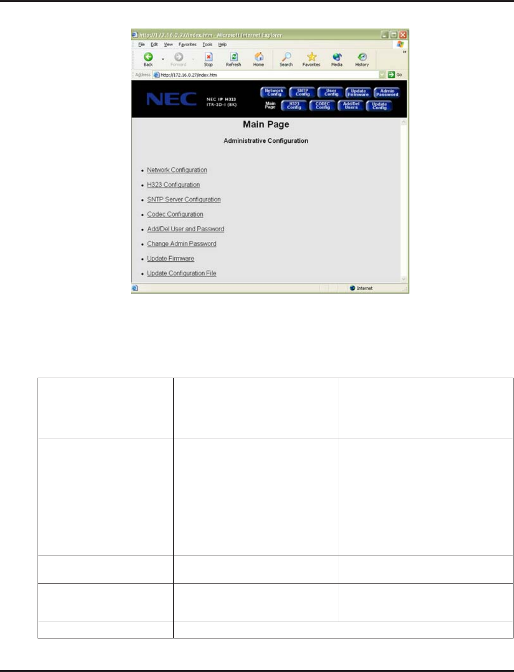
VoIP
662 ◆Features Aspire Software Manual
4. The following screen appears:
The H.323 Configuration screen requires changes be made in order for the phone to
function and display correctly. The Network Configuration also requires changes but these
changes can be made either through this menu or through the phone programming
described previously. The following options are available through the Administrator’s
Level programming.
Network Configuration DHCP
Phone IP Address
Subnet Mask
Default Gateway IP Address
VLAN
VLAN ID
VLAN Priority
Diffserv
DiffServ Flag
H.323 Configuration Display Name
LCD Display Type
Number of Lines
Extension 1
Extension 2
User Name
Use H.323 ID Alias
CID Display Type
Reset Indication Type
Hook Flash Code
Supplementary Service Type
GK Mode
Gatekeeper IP Address
Gatekeeper Port Number
Allow Calls Without Gatekeeper
Use Gateway
H.323 Gateway IP Address
H.323 Gateway Port Number
RTP Port Base
Use Fast Start
SNTP Server SNTP
Day Light Savings Time Zone Offset
SNTP Server IP Address
Codec Configuration Codec Name
Acoustic Echo Canceller
Packet Size
Nominal Jitter Depth
VAD
Add/Del User and Password Enter a 6-10 digit password
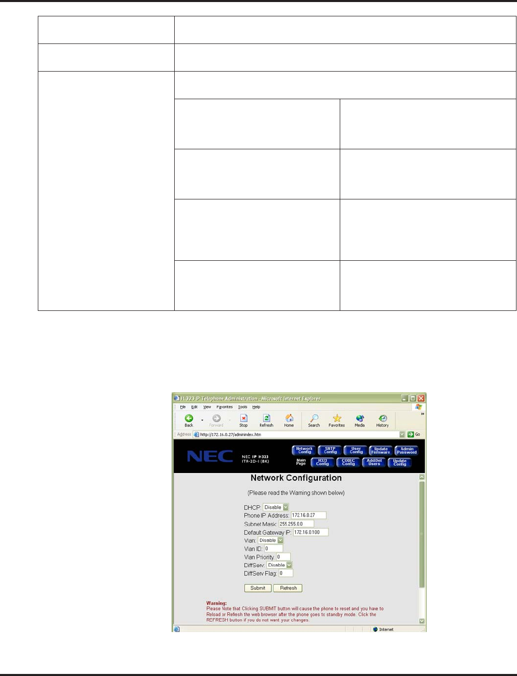
VoIP
Aspire Software Manual Features ◆663
5. Optionally, if the IP and subnet mask addresses were set up in the phone’s programming using the
previous programming procedure, you can use the Network Configuration window to define the
network settings for the phone. If these settings were made previously, skip to Step 6. If any
changes are made to this window, you must click SUBMIT in order for the changes to be sent
to the phone (this will cause the phone to reset).
Update Firmware Enter the TFTP Server Address, User ID (Optional), Password (Optional) and
the File Name and then click “Update” to start the firmware update.
Update Configuration Enter the TFTP Server Address, User ID (Optional), Password (Optional) and
the File Name and then click “Update” to start the firmware update.
User Configuration The User Configuration allows changes to the options available when signing in
at the User Level.
Phone Settings: The Phone Settings page allows users to
read and modify general call-related set-
tings such as Call Duration Timer, Call
Waiting, and Ringer Tone Selection.
Function Keys: The Function Keys page allows users to
read and modify the function key con-
figurations (Speed Dial, Call Forward,
Voice Mail, Do Not Disturb).
Phone Book: The Phone Book can be viewed and
edited using the web browser. However,
if the Phone Book is opened by the user
on the phone itself, it cannot be edited
through the browser.
Password Change: The Password Change page allows modi-
fication of the User password. If the
browser’s Refresh button is clicked before
Submit, the old password will be kept.
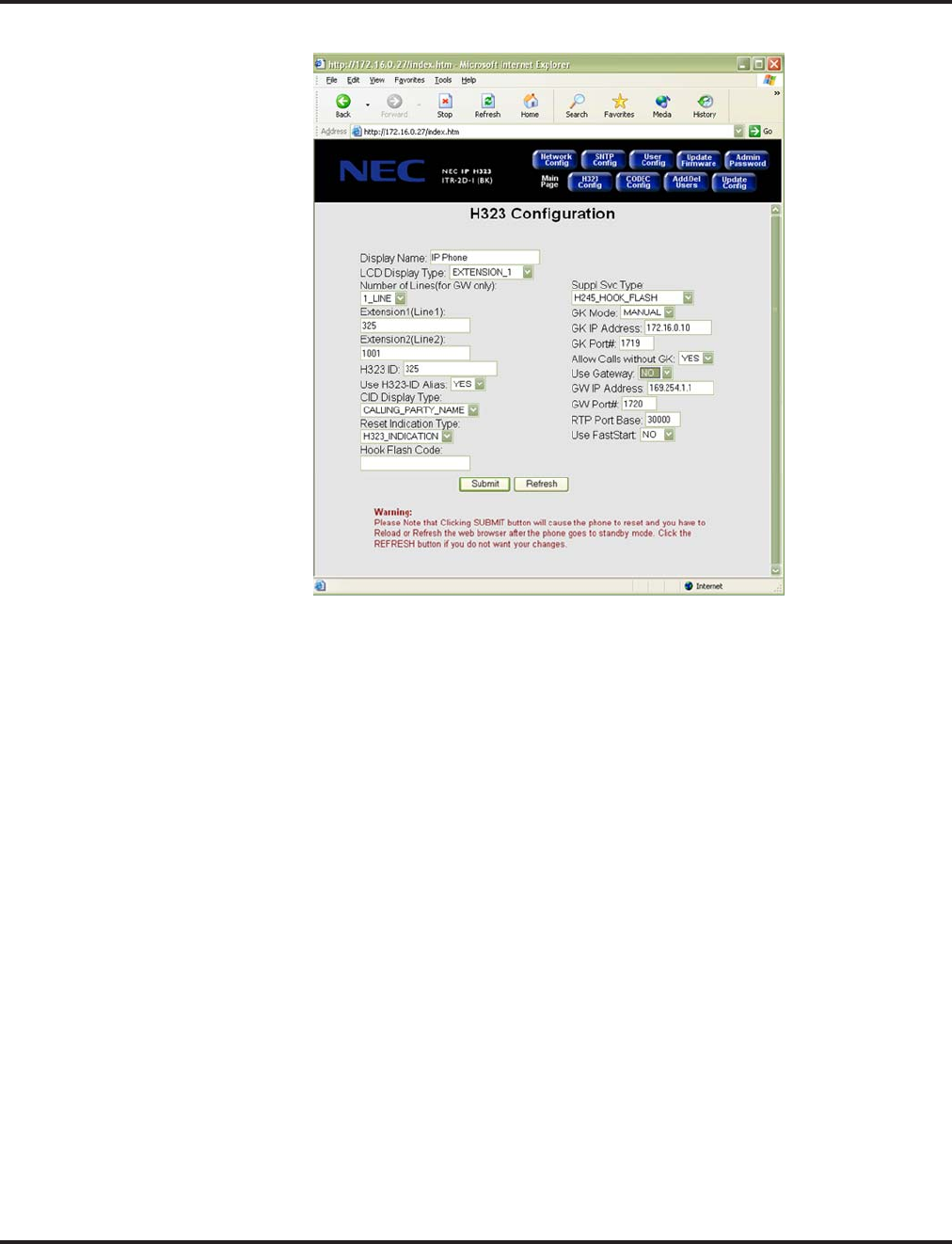
VoIP
664 ◆Features Aspire Software Manual
6. Click on the H.323 Configuration link or button.
7. Make the following changes:
●LCD Display Type = Extension_1
●Number of Lines = 1
●Extension Name = Enter the extension number to be used for the phone
●H.323 ID = Enter the extension number to be used for the phone
●CID Display Type = Select the Caller ID display mode to be used
●Suppl. Svc. Type = Select H245_Hook_Flash in order to use the Hold and Transfer features
●GK Mode = Manual
●GK IP Address = Enter the NTCPU IP address assigned in Program 10-12-01
(by default 172.16.0.10)
●Allow Calls Without GK = Yes
●Use Gateway = No
●Use Fast Start = No
Fast Start should only be used when both terminals (gateways) are using Fast Start
mode. The CODEC is then decided by the Fast Start negotiation flow. The Fast Start ele-
ments (CODEC type, VIF size, silent suppression) are compared, and based on the priority
set for each system, an option is chosen for each item. In order for a voice path to be
established, the CODEC, VIF size and silent suppression have to be the same value
between the two gateways.
8. Click the SUBMIT button to enter the changes.
The phone will reset with the new settings. Click RELOAD or REFRESH after the
phone goes to standby mode. If there are incorrect values entered in any of the fields, the
update will not be performed and the screen will be displayed again allowing for changes.
9. Close the internet browser.
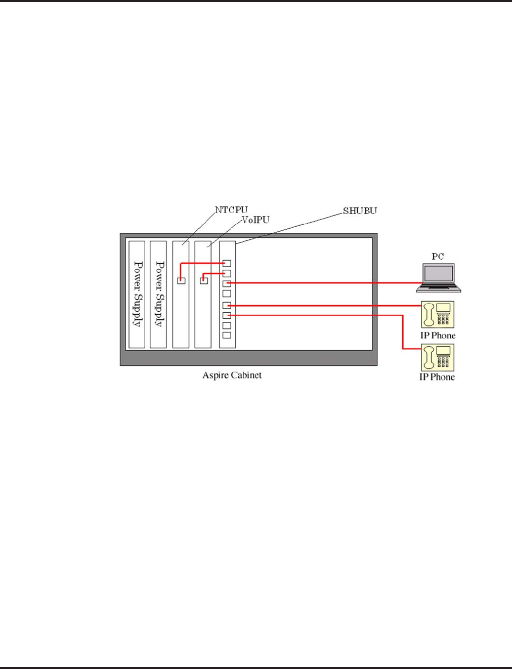
VoIP
Aspire Software Manual Features ◆665
LAN Connections
Hardware:
●8SHUBU PCB - Provides 8-port switching hub and the ability to provide PoE for Aspire
equipment.
●802.1p/1q Support
●24-Port Power Supply PoE-managed switch (NEC BlueFire 200/24)
●PoE (Power over Ethernet) to Aspire IP/H.323 Phone
●Spare Pair (4/5, 7/8) / Signal Pair (1/2, 3/6) Selection
●12-Port Power Supply Patch Panel (NEC SN1604 PWRMS)
●PoE (Power over Ethernet) to Aspire IP/H.323 Phone
●Add this patch to an existing switching hub
●Spare Pair (4/5, 7/8) / Signal Pair (1/2, 3/6) Selection
Port Assignment Improved
Prior to 4.93 software, if the system was cold started with the VOIPU PCB(s) pulled from the sys-
tem cabinet, but they were still connected to the LAN, the PCBs would still be assigned port num-
bers. This could provide unexpected extension numbering as the VOIPU PCB assigns ports as soon
as the card syncs, which is usually before the other PCBs. Using software 4.93 or higher, this pro-
cess is improved.

VoIP
666 ◆Features Aspire Software Manual
LAN Connection Programming
➻10-12-05 : NTCPU Network Setup - NIC
Select the ethernet interface for the NTCPU (0=Auto, 1=100M/Full, 2=100M/Half, 3=10M/
Full, 4=10M/Half).
➻84-05-02 : VOIPU IP Address Setup Network Setup - NIC
Select the ethernet interface for the VOIPU PCB (0=Auto, 1=100M/Full, 2=100M/Half,
3=10M/Full, 4=10M/Half).
➻85-01-01 : SHUBU LAN Setup - Link Speed/Duplex
85-01-02 : SHUBU LAN Setup - Link Speed
85-01-03 : SHUBU LAN Setup - Half Duplex/Full Duplex
85-01-04 : SHUBU LAN Setup - MDIX/MDI
85-01-05 : SHUBU LAN Setup - Back Pressure
85-01-06 : SHUBU LAN Setup - 802.3x
Define the LAN setup for each slot in which an 8SHUBU PCB is installed.
Note 1. Connect only NEC IP phones into the LAN network. Unsupported equipment may be
damaged if connected to the Aspire system.
Note 2. Use a 100Base/Full Duplex switch. In order to avoid network problems and to retain
voice quality, do not use a Repeater Hub/10Base.

VoIP
Aspire Software Manual Features ◆667
911 Calls with Networked IP Phones
When using IP telephones at a remote site (Site B) which are registered to the main system (Site A),
you can use the ARS Class of Service Matching feature added in software 2.63 to route 911 calls to
the local authorities at the remote location. Without this programming, since the phones are regis-
tered to the main site, when 911 calls are placed by IP phones, the local authorities at the main site
(Site A) would be called.
Programming at the Main System
➻10-27-01 : IP System ID
For each network node, assign an ID and corresponding IP address of the networked IP system.
➻26-01-01 : Automatic Route Selection Service - ARS Service
Enter “1” to enable ARS.
➻26-01-06 : Automatic Route Selection Service - COS Match Access
Enter “1” to enable COS Matching.
➻26-04-01 : ARS Class of Service
Assign the IP extension’s ARS Class of Service (0-16).
➻26-02-01 : Dial Analysis Table for ARS /LCR - Dial
Define the Dial Analysis Table. Enter “911” in a table.
➻26-02-02 : Dial Analysis Table for ARS /LCR - Service Type
For the 911 Dial Analysis Table, enter the “1” to route the call to a trunk group.
Note: With PCPro/WebPro, the option is displayed as “Incoming Ring Group”.
➻26-02-03 : Dial Analysis Table for ARS /LCR - Additional Data
Enter the network ID number which corresponds to the entry in Program 10-27 preceded by
“1”. (For example: ID 01 is entered as “101”, 02 is entered as “102”, etc.)
➻26-02-04 : Dial Analysis Table for ARS /LCR - ARS Class of Service
Assign the ARS COS to the 911 Dial Analysis Table.
Each remote site needs to have a different ARS Class of Service. If, for example, there were 50 IP
sets on one remote site, each would use the same ARS Class of Service.
It is important to remember that there must be a trunk available to make a call across the network
from the main system. Then, by default, the system will access the first available trunk in trunk
group 1 at the remote side to place the 911 call.

VoIP
668 ◆Features Aspire Software Manual
Address Conversion Table
Aspire provides an IP Conversion Table with which the system can recognize the IP address of
another system without the use of an outside Gatekeeper.
Programming
➻10-23-01 : H.323 System Interconnection - System Interconnection
For each system (50 max), specify whether the system interconnection is used (0=no, 1=yes).
➻10-23-02 : H.323 System Interconnection - IP Address
If Program 10-23-01 is set to "1", for each system (50 max), specify the destination IP
address. The address should not be duplicated within the system.
➻10-23-03 : H.323 System Interconnection - Call Control Port
If Program 10-23-01 is set to "1", for each system (50 max), specify the Call Control Port
(1-65535).
➻10-23-04 : H.323 System Interconnection Alias Address
If Program 10-23-01 is set to "1", for each system (50 max), specify the destination E.164
number as the Alias Address (12 digits max).
Calling Party Number Setup for Trunks and Extensions
The system has two programs which allow for the Calling Party Number to be displayed when the
VoIP feature is used:
Programming
➻21-17-01 : IP Trunk Calling Party Number Setup for Trunk
Enter the Calling Party Number to be displayed for each IP trunk used (Entry: 16 digits maxi-
mum).
➻21-18-01 : IP Trunk Calling Party Number Setup for Extension
Enter the Calling Party Number to be displayed for each IP extension used (Entry: 16 digits
maximum).
CODEC Selection
●For H.323 Trunk - Assign CODEC type in Program 84-01-33
For H.323 Terminal or VoIP Networking - Assign CODEC type in Program 84-12-28
For Aspire Keyset with IP Adapter or IPhone - Assign CODEC type in Program 84-11-28
●G.711, G.729, G.723.1
●VIF Size
Trunk:
G.711 -> 20ms, 30ms
G.729 -> 20ms-80ms
G.723 -> 30ms, 60ms
When using G.711 or G.729 with the VIF set at 20ms, the maximum number of simul-
taneous calls is 15 when using a 16-channel VOIPU PCB (no daughter board installed).
VIF 20ms is not supported with the daughter board.
Terminal:
G.711 -> 30ms
G.729 -> 30ms-80ms (H.323)
G.729 -> 30ms-40ms (Aspire keyset with IP adapter) or IPhone
G.723 -> 30ms, 60ms

VoIP
Aspire Software Manual Features ◆669
●Supports Silence Suppression
●Aspire provides 5 types of CODEC for the Aspire Keyset with IP Adapter (defined in Program
84-11, selected in Program 15-05-15).
Since the packet size of G711 is larger than the other compressions (G729, G723), there are some
limitations to reach the maximum number of channels. With the default settings, the following limi-
tations must be kept in mind.
Refer to Simultaneous Calls (page 685) for more information on CODEC settings.
Deleting IP Phone Registration
➻90-23-01 : Deleting Registration of IP Telephones
When removing an IP telephone from the system, the registration can be deleted using this
program. Enter the extension number to be deleted, press 1 and then HOLD.
Echo Adjustment
For Enhanced Echo Adjustment, refer to Enhanced Echo Adjustment (page 679).
Where echo (reflection of voice) is generated depends on how the network is configured. Typically,
however, echo is generated at the trunk PCB (COIU) or at the telephone’s microphone/speaker. The
transmit/receive data is separated at the analog trunk interface. Echo from the transmit data to the
receive data can be generated, and when the impedance is not set correctly, increased echo will
occur. This can also occur at an ISDN/analog trunk interface. In general, the nearer the transmit, the
more echo occurs as the signal level is greater.
The type of echo can also occur with non-IP phones, but the time difference between the transmit
and receive is so small, the user is hardly aware of it. As the IP terminals require voice packetiza-
tion, there is a longer delay. This delay causes the echo.
32VOIPU (16VOIPU + 16VOIPDB)
G711 - 20ms Not supported.
G711 - 30ms The system uses G711 (30ms) for the first 12
channels of calls. The CODEC then changes to
G729 for the last 20 channels.
20VOIPU (16VOIPU + 4VOIPDB or 4VOIPU + 16VOIPDB)
G711 - 20ms The system uses G711 (20ms) for the first 13
channels of calls then changes the CODEC type
to G729 for the last 7 channels.
G711 - 30ms There are no limitations.
16VOIPU (16VOIPU)
G711 - 20ms The system uses G711 (20ms) for the first 15
channels of calls then changes the CODEC type
to G729 for the last channel.
G711 - 30ms There are no limitations.

VoIP
670 ◆Features Aspire Software Manual
To reduce the echo:
●Suppress the echo from the Aspire system.
●Suppress the echo from outside the Aspire system.
●Remove the unsuppressed echo using the echo canceller in the VOIPU.
●Reduce the telephone’s volume.
On some calls, the echo and side tones can be increased if the telephone volume is set
to a midrange level or higher. Simply press the Volume Down button on the phone to
reduce the level.
A typical example of this adjustment process is as follows:
1. CODEC Packet Size/Jitter Buffer Configuration
The Voice Packet CODEC, packet size, jitter buffer size should be configured to minimize the
voice delay. This data is set in Program 84-xx-xx.
●Set the Audio Capability Priority.
●Set the packet size.
●Set jitter buffer type and adjust the size.
2. Gain Level
A transmit gain level with is set too high for a trunk may cause considerable echo depending
on the level of the voice path route. Adjust the echo controlling this data.
●Change the Trunk Voice Transmit Level in the system to adjust the voice transmit level of
the Aspire.
●Change the Trunk Voice Receive Level in the system to adjust the voice receive level of
the Aspire.
3. CODEC Filter
When connecting an analog trunk, adjust the CODEC filter depending on the damping of the
trunk side. If this is not properly adjusted, you may hear considerable echo depending on the
condition of the line.
●Set the Echo Canceller Mode (Program 84-17-01) to disabled (0) and check the condition
of the echo level by making an outgoing call.
●Set the CODEC Filter Setup for the analog trunk port (Program 81-07) to the configura-
tion which results in the least amount of echo.
4. Echo Canceller Adjustment
The echo canceller should be adjusted after reducing the echo using the previous steps.
●Set the Echo Canceller Mode to enabled (1) [Program 84-01-24 = H.323 trunk, 84-11-20 =
Aspire IP phone, 84-12-20 = H.323 extension], the Echo Canceller NLP Mode to disabled
(0) [Program 84-01-26 = H.323 trunk, 84-11-22 = Aspire IP phone, 84-12-22 = H.323
extension], and check the condition of the echo level by making an outgoing call.
●Adjust the VOIPU Limiter Control Gain Setup (Program 84-16) and choose the configura-
tion which results in the least amount of echo.
●The Echo Canceller NLP Mode should be set to the data which receives the best voice
quality.

VoIP
Aspire Software Manual Features ◆671
CODEC Packet Size/Jitter Buffer Configuration
Program Item Input Data Default How to Adjust
84-01-33 (H.323 Trunk)
84-11-28 (Aspire IP Phone)
84-12-28 (H.323 Extension)
Audio Capability
Priority 0: G.711
1: G.723.1
2: G.729
0 (G.711) This data should not be changed.
Voice Quality is the best with G.711
and lessens with G.729 and then
again with G.723.1.
If you need to select another band-
width, it is recommended that G.729
be selected.
84-01-02 (H.323 Trunk)
84-11-01 (Aspire IP Phone)
84-12-01 (H.323 Extension)
G.711 Audio Frame 2, 3 (20msec,
30msec) 3 (30msec) It is strongly recommended to use
option 2 (20ms) for H.323 trunks/
stations.
• This data will usually come into
affect when Audio Capability=0
(G.711) is selected.
• Aspire IP phones can only be set
to use 30ms.
84-01-05 (H.323 Trunk)
84-11-07 (Aspire IP Phone)
84-12-07 (H.323 Extension)
G.729 Audio Frame 2 - 8
(20msec -
80msec)
3 (30msec) It is strongly recommended to use
option 2 (20ms) for H.323 trunks/
stations.
• This data will usually come into
affect when Audio Capability = 2
(G.729) is selected.
• Aspire IP phones and IP adapters
only suport entries of 1-4 (10-
40ms).
84-01-05 (H.323 Trunk)
84-11-12 (Aspire IP Phone)
84-12-12 (H.323 Extension)
G.723.1 Audio Frame 1 - 2
(30 msec, 60
msec)
1 (30 msec) This data will not need to be
changed usually.
• This data will usually come into
affect when Audio Capability = 1
(G.723) is selected.
84-01-15 (H.323 Trunk)
84-11-17 (Aspire IP Phone)
84-12-17 (H.323 Extension)
Jitter Buffer Mode 1: static
2: adaptive
during silence
3: adaptive
immediately
3 (adaptive
immediately) This data should not be changed.
84-01-16 (H.323 Trunk)
84-11-04 (Aspire IP Phone)
84-12-04 (H.323 Extension)
G.711 Jitter Buffer
(min) 0 - 145
(msec) 30 Set the same time as selected in
G.711 Audio Frame.
84-01-17 (H.323 Trunk)
84-11-05 (Aspire IP Phone)
84-12-05 (H.323 Extension)
G.711 Jitter Buffer
(type) 0 - 145
(msec) 60 Set this option at two times the time
selected in G.711 Audio Frame.
84-01-18 (H.323 Trunk)
84-11-06 (Aspire IP Phone)
84-12-06 (H.323 Extension)
G.711 Jitter Buffer
(max) 0 - 145
(msec) 120 Set this option at four times the time
selected in G.711 Audio Frame.

VoIP
672 ◆Features Aspire Software Manual
84-01-07 (H.323 Trunk)
84-11-09 (Aspire IP Phone)
84-12-09 (H.323 Extension)
G.729 Jitter Buffer
(min) 0 - 145
(msec) 30 Set the same time as selected in
G.729 Audio Frame.
84-01-08 (H.323 Trunk)
84-11-10 (Aspire IP Phone)
84-12-10 (H.323 Extension)
G.729 Jitter Buffer
(type) 0 - 145
(msec) 60 Set this option at two times the time
selected in G.729 Audio Frame.
84-01-09 (H.323 Trunk)
84-11-11 (Aspire IP Phone)
84-12-11 (H.323 Extension)
G.729 Jitter Buffer
(max) 0 - 145
(msec) 120 Set this option at four times the time
selected in G.711 Audio Frame.
84-01-19 (H.323 Trunk)
84-11-14 (Aspire IP Phone)
84-12-14 (H.323 Extension)
G.723 Jitter Buffer
(min) 0 - 145
(msec) 30 Set the same time as selected in
G.723 Audio Frame.
84-01-20 (H.323 Trunk)
84-11-15 (Aspire IP Phone)
84-12-15 (H.323 Extension)
G.723 Jitter Buffer
(type) 0 - 145
(msec) 60 Set this option at two times the time
selected in G.723 Audio Frame.
84-01-21 (H.323 Trunk)
84-11-16 (Aspire IP Phone)
84-12-16 (H.323 Extension)
G.723 Jitter Buffer
(max) 0 - 145
(msec) 120 Set this option at four times the time
selected in G.723 Audio Frame.
Gain Level - Transmit/Receive
Program Item Input Data Default How to Adjust
14-01-02 Transmit Gain Level 1 - 63
(-15.5dB -
+15.5dB)
32 (0dB) High level of transmit gain may
generate a large echo depend-
ing on the environment or loca-
tion of the party called. Adjust
to the appropriate level. Lower
limits should be around 18
( -7db).
14-01-03 Receive Gain Level 1 - 63
(-15.5dB -
+15.5dB)
32 (0dB)
14-01-04 Transmit Gain level for
conference and Trans-
fer Calls
1 - 63
(-15.5dB -
+15.5dB)
22 (-5dB) High level of transmit gain may
generate a large echo depend-
ing on the environment or loca-
tion of the party called. Adjust
to the appropriate level. Lower
limits should be around 18
( -7db).
14-01-05 Receive Gain level for
conference and Trans-
fer Calls
1 - 63
(-15.5dB -
+15.5dB)
22 (-5dB)
CODEC Packet Size/Jitter Buffer Configuration
Program Item Input Data Default How to Adjust

VoIP
Aspire Software Manual Features ◆673
84-01-30 (H.323 Trunk)
84-11-26 (Aspire IP Phone)
84-12-26 (H.323 Extension)
Transmit Gain Level of
VOIPU 0 - 28
(-14dB - +14dB) 10 (-4dB) • Aspire IP phone TX gain
becomes congruent with the
Aspire IP phone when this
data is set to 10 (-4db).
• Before V3, 84-01-30 will
be applied to the H.323
extension and Aspire IP
phone as well.
84-01-31 (H.323 Trunk)
84-11-27 (Aspire IP Phone)
84-12-27 (H.323 Extension)
Receive Gain Level of
VOIPU. 0 - 28
(-14dB - +14dB) 10 (-4dB) • Aspire IP phone RX gain
become congruent with
Dterm when this data is set
to 10 (-4db).
• Before V3, 84-01-30 will
be applied to H.323 exten-
sion and Aspire IP phone as
well.
Gain Level - Transmit/Receive
Program Item Input Data Default How to Adjust
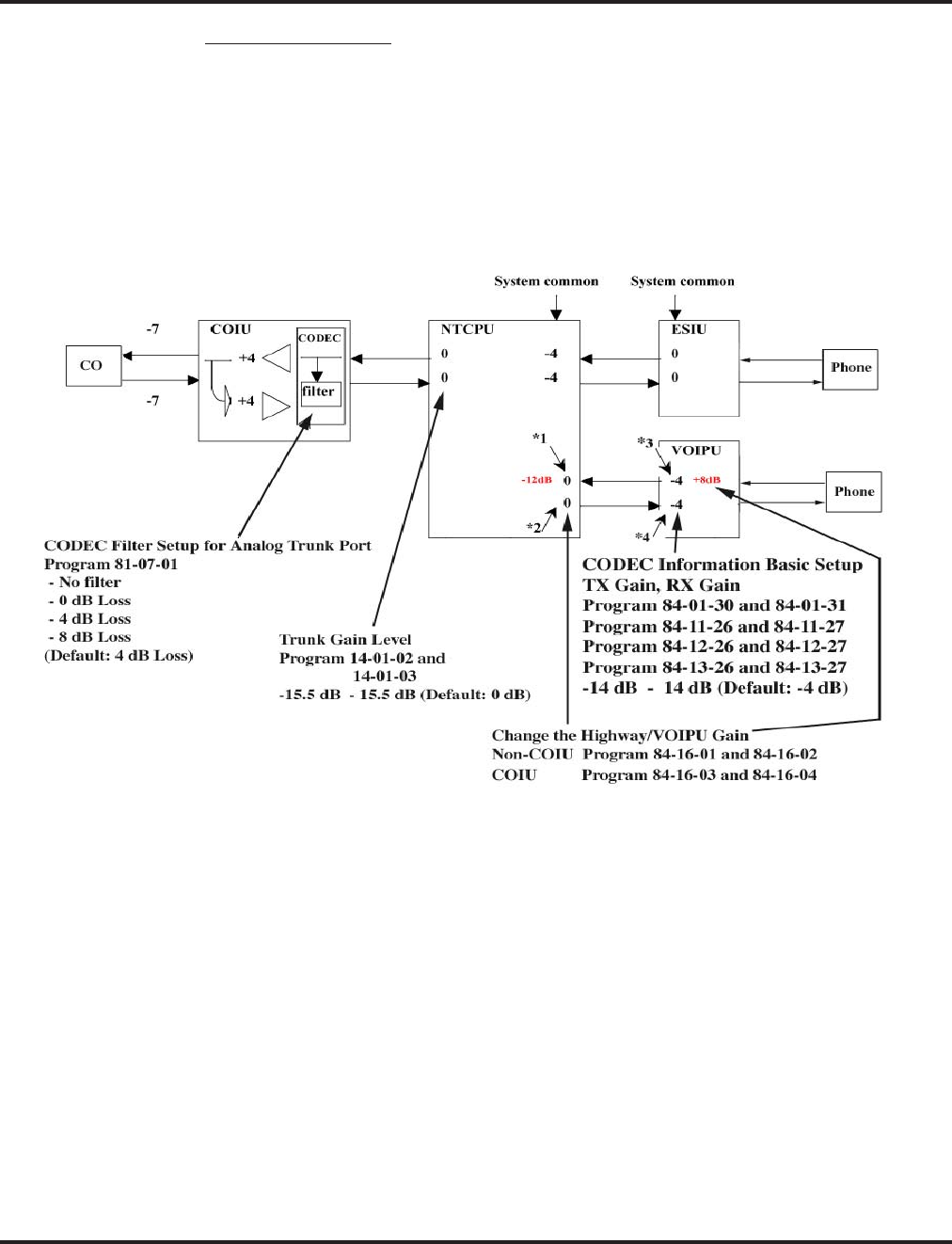
VoIP
674 ◆Features Aspire Software Manual
Internal Gain Control
Control the VOIPU PCB’s internal echo canceller input by setting the VOIPU RX gain higher and
the Highway Gain lower. (In the figure below set *1 to +12dB and *2 to –12dB.)
Not all the sidetone can be removed from the COIU by the VOIPU PCB. The remaining sidetone
may appear as echo when heard at the IP phone. Optimizing Program 81-07-01 : CODEC Filter
Setup for Analog Trunk Ports and suppressing sidetone as much as possible may still result in
some echo being heard. This becomes more apparent when the volume of the voice level on the IP
phone is louder. This may be resolved by setting the VOIPU RX Gain higher, the Highway gain
lower and by limiting the volume on the phone (in the figure below, set the *3 and *4 options to
+12dB [*3] and –12dB [*4]).

VoIP
Aspire Software Manual Features ◆675
Internal Gain Control
Program Item Input Data Default How to Adjust
84-16-01 VOIPU RX Limiter Control
Gain
This option controls the lim-
iter gain for IP to PCM direc-
tion. This option adds gain to
the voice input from the LAN
and removes it from the voice
output to highway.
0 - 30
(-15dB - +15dB) 25 (10dB) This setting is applied to the
call using the VOIPU and a
unit other than the COIU.
You may notice a small echo
remaining when using ISDN
trunks. If this is the case,
change this data to a smaller
value. Example: 15 (0db)
* This option is available with
software 1.11 or higher.
84-16-02 VOIPU TX Limiter Control
Gain
This option controls the lim-
iter gain for PCM to IP direc-
tion. This option adds the gain
to the voice input from high-
way and removes it from the
voice output to the LAN.
0 - 30
(-15dB - +15dB) 15 (0dB) This setting is applied to the
call using the VOIPU and a
unit other than the COIU.
You may notice a small echo
remaining when using ISDN
trunks. If this is the case,
change this data to larger
value. Example 0 (-15db)
* This option is available with
software 1.11 or higher.
84-16-03 VOIPU RX Limiter Control
Gain (COIU)
This option controls the lim-
iter gain for a COIU call in the
IP to PCM direction.
0 - 30
(-15dB - +15dB) 15 (0dB) This setting is applied to the
call using the VOIPU and a
COIU. Set this to a larger value
when the echo from the COIU
is too much.
* This option is available with
software 1.11 or higher.
84-16-04 VOIPU TX Limiter Control
Gain (COIU)
This option controls the lim-
iter gain for a COIU call in the
PCM to IP direction.
0 - 30
(-15dB - +15dB) 15 (0dB) This setting is applied to the
call using the VOIPU and
COIU.
* This option is available with
software 1.11 or higher.

VoIP
676 ◆Features Aspire Software Manual
CODEC Filter Configuration
Program Item Input Data Default How to Adjust
81-07-01 CODEC Filter Setup for Analog
Trunk Port 0: No Filter
1: 0dB Loss
2: 4dB Loss
3: 8dB Loss
4. Specified Data
2 Setting this data depends on the
loss of the analog line. This will
reduce the echo from the analog
hybrid circuit caused by the mis-
match of the impedance.
• When the signal loss is low
(ex. behind PBX connection),
set to 1.
• When the signal loss is high
(large distance from the cen-
tral office), set to 3.
• When the echo from the ana-
log line is too much, setting 4
(specified data) may help
improve the condition.
• Input data 1-4 is equivalent to
Types 1-4 in the Analog Port
CODEC Filter Setup table
below.
82-07-01 CODEC Filter Setup for Analog
Station Port 0: No Filter
1: 0dB Loss
2: 4dB Loss
3: 8dB Loss
4: Specified Data
1 Setting this data depends on the
loss of the analog line. This will
reduce the echo from the analog
hybrid circuit caused by the mis-
match of the impedance.
• When the signal loss is low
(ex. behind PBX connection),
set to 1.
• When the signal loss is high
(large distance from the cen-
tral office), set to 3.
• When the echo from the ana-
log line is too much, setting 4
(specified data) may help
improve the condition.
• Input data 1-4 is equivalent to
Types 1-4 in the Analog Port
CODEC Filter Setup table
below.

VoIP
Aspire Software Manual Features ◆677
Analog Port CODEC Filter Setup
Type 1 Type 2 Type 3
Filter Data 0dB Loss ø0.5 4dB Loss ø0.5 8dB Loss APEX3600 LC
HEX DEC HEX DEC HEX DEC HEX DEC
B1 D01 AA 170 5A 90 23 35 AA 170
D02 73 115 CB 203 DE 222 DB 219
D03 A3 163 2B 43 AA 170 3B 59
D04 6D 109 2A 42 A3 163 37 55
D05 33 51 1C 28 22 34 22 34
D06 A5 165 21 33 A0 160 61 97
D07 2A 42 22 34 FE 254 B4 180
D08 D4 212 22 34 1B 27 2C 44
D09 BD 189 A3 163 B2 178 C4 196
D10 2B 43 49 73 23 35 98 152
D11 DB 219 F3 243 4B 75 D3 211
D12 AD 173 2E 46 A6 166 2E 46
D13 E2 226 2A 42 52 82 4A 74
D14 E0 224 D0 208 E0 224 D0 208
B2 D01 22 34 22 34 57 87 2A 42
D02 C0 192 C0 192 C0 192 B0 176
Type 4
Filter Data ø0.4 4dB Loss ø0.4 8dB Loss ø0.65 4dB Loss ø0.65 8dB Loss
HEX DEC HEX DEC HEX DEC HEX DEC
B1 D01 24 36 AB 171 22 34 5A 90
D02 CA 202 DD 221 C2 194 C3 195
D03 AB 171 4C 76 2A 42 2A 42
D04 3A 58 2C 44 6A 106 AB 171
D05 1A 26 13 19 32 50 52 82
D06 B1 177 A0 160 31 49 21 33
D07 A2 162 BA 186 7A 122 B3 179
D08 3C 60 1A 26 1A 26 1C 28
D09 9F 159 33 51 B3 179 22 34
D10 3A 58 E2 226 A8 168 A2 162
D11 C2 194 6B 107 7B 123 35 53
D12 2D 45 BE 190 AD 173 C4 196
D13 A5 165 AA 170 25 37 B9 185
D14 D0 208 D0 208 D0 208 F0 240
B2 D01 FA 250 A2 162 AA 170 A3 163
D02 C0 192 C0 192 C0 192 D0 208

VoIP
678 ◆Features Aspire Software Manual
Echo Canceler Configuration
Program Item Input Data Default How to Adjust
84-01-24 (H.323 Trunk)
84-11-20 (Aspire IP Phone)
84-12-20 (H.323 Extension)
Echo Canceller Mode 0: Disable
1: Enable 1 • Echo canceler mode
• Prior to Version 3, Program
84-01-24 is applied to IP
phones (system common
data).
84-01-25 (H.323 Trunk)
84-11-21 (Aspire IP Phone)
84-12-21 (H.323 Extension)
Echo Canceller Tail Size 1: 8 ms
2: 16 ms
3: 32mS
3 • Only valid when 84-01-24
is enabled.
• Prior to Version 3, Program
84-01-25 is applied to IP
phones (system common
data).
84-01-26 (H.323 Trunk)
84-11-22 (Aspire IP Phone)
84-12-22 (H.323 Extension)
Echo Canceller NLP Mode 0: Disable
1: Enable 1 • NLP (Non-linear process-
ing) will remove the
remaining noise after sup-
pressing echo using the
echo canceler.
• Prior to Version 3, Program
84-01-26 is applied to IP
phones (system common
data).
84-01-27 (H.323 Trunk)
84-11-23 (Aspire IP Phone)
84-12-23 (H.323 Extension)
Echo Canceller NLP Noise 40-70
(-40 dBm -
-70dBm)
70 • When the NLP is enabled,
and silence/non-silence
boundary seems incorrect,
adjust this data (ex. 50).
• This is only valid when Pro-
gram 84-01-26 is enabled.
• Prior to Version 3, Program
84-01-27 is applied to IP
phones (system common
data).
84-01-28 (H.323 Trunk)
84-11-24 (Aspire IP Phone)
84-12-24 (H.323 Extension)
Echo Canceller Cng Cfg 0: Adaptive
1: Fixed 0• This is only valid when Pro-
gram 84-01-26 is enabled.
• Prior to Version 3, Program
84-01-28 is applied to IP
phones (system common
data).
84-01-29 (H.323 Trunk)
84-11-25 (Aspire IP Phone)
84-12-25 (H.323 Extension)
Echo Canceller 4w Detect 0: Disable
1: Enable 0 • Prior to Version 3, Program
84-01-29 is applied to IP
phones (system common
data).

VoIP
Aspire Software Manual Features ◆679
Enhanced Echo Adjustment
With software 1.18 or higher and VOIPU firmware 3.2 or later, the Echo Canceller option has been
enhanced. This enhancement supports the following features:
●Supports long echo tail size (max. 128 msec)
●Adds adjustment parameters for echo cancellation
System Data Changes
With enhanced echo canceller, additional programs have been added and the settings of others have
changed. With enhanced echo canceller, following system data is changed:
●Added settings for long echo tail size (Program 84-06-12/13/14)
●Changed settings:
84-01-24/26/27/28/29 settings are moved to 84-01-60 (H.323 Trunks)
84-11-20/21/22/23/24/25 settings are moved to 84-11-29 (DtermIP)
84-12-20/21/22/23/24/25 settings are moved to 84-12-29 (H.323 Phones)
For each of the IP devices above, select an echo canceller type (84-01-60, 84-11-29, 84-12-29). The
options are:
●0: Automatic If the call is analog (e.g. COIU or TLIU 2-wire) then this selects the echo
canceller profile configured in Program 84-17 Type 4 (“Analog Path
Setting”). Any other call selects the echo canceller profile configured in
Program 84-17 Type 5 (“Digital Path Setting”). Note that the TLIU 4-wire
is treated as digital.
●1: Type 1 This selects the echo canceller profile configured in Program 84-17 Type 1.
●2: Type 2 This selects the echo canceller profile configured in Program 84-17 Type 2.
●3: Type 3 This selects the echo canceller profile configured in Program 84-17 Type 3.
Note 1. PC programming software does not support the above changes. Please use WebPro or
keyset programming for these settings.
Note 2. For software prior to 1.18 or with VOIPU firmware prior to 3.2, please refer to “Echo
Adjustment (page 669) for the echo adjustment procedure.
Echo Canceller Feature of the VOIPU
Echo canceler of VOIPU support following features:
●Supports 8/16/32/64/128ms echo tail size
●NLP (Nonlinear processing)
Echo Tail Size
Longer echo tail size increases the echo cancellation ability to echo delay.
If you use above 32msec echo tail size, set Program 84-06-12 (long tail echo mode) to ON, then
select the codec type and echo tail size using Program 84-06-13/14.

VoIP
680 ◆Features Aspire Software Manual
The following limitations apply when you use long echo tail size (32msec or more) with the
enhanced Echo Canceller :
●Decreased VOIPU channels
If you choose a long echo tail size the number of available VOIPU channels is reduced to 3/4.
If you do not choose a long echo tail size, the number of available VOIPU channels is not
changed.
Example: Default VOIPU channels : 16ch -> Long echo tail size select : 12ch
●G.729/G.723.1 codec usage limitation
If you choose a long echo tail size, you should choose either G.729 or G.723.1.
* It is recommended to select G.729 for better voice quality.
NLP
If an echo problem is not resolved with the long echo tail size, NLP can be used to remove echo by
replacing low level voice to low level white noise (NLP noise).
By default, the adjustment of the NLP noise (white noise) level is automatically determined by Pro-
gram 84-17-04 (set to adaptive). If needed, the level between background noise and NLP noise can
be adjusted setting Program 84-17-04 to “fixed” and then adjust the NLP noise level using Program
84-17-05.
When sound continues from the remote side, as with Music on hold, the NLP can decrease voice
quality. In such cases, decrease the NLP Aggressiveness Control value in Program 84-17-06/07.
Please note if this is decreased, the echo level will be larger.
Programming
➻84-17-01 : VOIPU Echo Canceller Control Setup - Echo Canceller Mode
Enable (1) or disable (0) Echo Canceller mode.
➻84-17-02 : VOIPU Echo Canceller Control Setup - Echo Canceller Tail Size
Select the Echo Canceller Tail Size (1 = 8ms, 2 = 16ms). If 84-06-12 (Long Tail Echo Mode)
= on, this value is ignored – 84-06-14 is used instead. Only effective if 84-17-01 = enable.
➻84-17-03 : VOIPU Echo Canceller Control Setup - Echo Canceller NLP Mode
Enable (1) or disable (0) Echo Canceller NLP mode.
➻84-17-04 : VOIPU Echo Canceller Control Setup - Echo Canceller CNG CFG
Only effective if 84-17-03 = enabled. Select either Adaptive (0) or Fixed (1) for the NLP noise
adjustment. If set to Fixed, determine the level in Program 84-17-05.
➻84-17-05 : VOIPU Echo Canceller Control Setup - Echo Canceller NLP Noise
Adjust the NLP noise level (entries: 40 [-40dBm] - 70 [70dBm]). Only effective if 84-17-04 =
fixed.
➻84-17-06 : VOIPU Echo Canceller Control Setup - NLP Aggressiveness Control
Determines if value in 84-17-07 is + or -. Only effective if 84-17-03 = enabled (0 = +, 1 = -).
➻84-17-07 : VOIPU Echo Canceller Control Setup - NLP Aggressiveness Control Value
Setting of NLP strength. This entry is positive or negative based on the entry in 84-17-06. a
larger value provides a stronger NLP effect - a smaller value provides a weaker NLP effect.
(Entries: 0 - 32767)
➻84-17-08 : VOIPU Echo Canceller Control Setup - NLP Comfort Noise Configuration
Only effective if 84-17-03 = enabled. (Entries: 0 - 32767)
➻84-17-09 : VOIPU Echo Canceller Control Setup - Echo Canceller 4W Detect
(0=Disabled, 1=Enabled)
➻84-11-26 : Dterm IP CODEC Information Basic Setup - RX Gain
Adjust the receive gain as needed (0-28 [-14~+14]).

VoIP
Aspire Software Manual Features ◆681
➻84-11-27 : Dterm IP CODEC Information Basic Setup - TX Gain
Adjust the transmit gain as needed (0-28 [-14~+14]).
➻84-06-12 : VOIPU Setup - Long Tail Echo Mode
Turn off (0) or on (1) the Long Tail Echo Mode for each VOIPU slot.
➻84-16-01 : VOIPU Limiter Control Gain Setup - RX Limiter Control Gain
This option controls the limiter gain for IP to PCM direction. This option adds gain to the
voice input from the LAN and removes it from the voice output to highway (0-30 [-15 ~
+15]).
➻84-16-02 : VOIPU Limiter Control Gain Setup - TX Limiter Control Gain
This option controls the limiter gain for PCM to IP direction. This option adds the gain to the
voice input from highway and removes it from the voice output to the LAN (0-30 [-15 ~
+15]).
➻14-01-02 : Basic Trunk Data Setup - Transmit CODEC Gain Type
Use this option to select the CODEC gain for the trunk (1~63 in .5dB intervals [1= -15.5dB]).
The option sets the amount of gain (signal amplification) for the trunk you are programming.
➻14-01-03 : Basic Trunk Data Setup - Receive CODEC Gain Type
Use this option to select the CODEC gain for the trunk (1~63 in .5dB intervals [1= -15.5dB]).
The option sets the amount of gain (signal amplification) for the trunk you are programming.
➻81-07-01 : CODEC Filter Setup for Analog Trunk Ports
Define the CODEC (QSLAC) Filter for each analog trunk port (0 = No Filter, 1 = 0dB Loss,
2 = 4dB Loss, 3 = 8dB Loss, 4 = Specified Data - This option uses the entries defined in
Program 81-09.).
Note: Set the trunk TX/RX level to lower than 0dB to reduce hybrid echo level.

VoIP
682 ◆Features Aspire Software Manual
Fax Relay
Required Items
16VOIPU PCB
G3 Fax equipment (G4 Fax is not supported)
Basic Programming
All VOIPU programming required for the feature as well as the following:
➻15-03-03 : Single Line Telephone Basic Data Setup
Set the terminal type to “1” (Special Terminal) for the extension which has the fax connected.
➻84-01-59 : CODEC Information Basic Setup - Fax Relay Function
Enable (1) or disable (0) the Fax Relay function for the system.
When the voice CODEC to be used in a session is selected as G.711, fax signals may
be sent even when this option is disabled. This occurs as G.711 sends fax signals in voice
packets. Frequent packet loss on the network may cause the session to disconnect since the
connection is not established as a Fax Relay (T.38). To avoid this, set Program 84-01-33 to
a CODEC other than G.711 and the fax connection will then be established as T.38 (Fax
Relay).
➻84-01-36 through 84-01-58 : CODEC Information Basic Setup
These programs are also available for the Fax Relay feature, but it is recommended that they
remain at the system default.
The following fax machines require changes as noted below:
●NEFAX-490:
Set the VOIPU ECM to off (Program 84-01-55 = 0) for transmission on the VOIPU. The
NEFAX-490 must also have the ECM turned off and the auto-answer alerting time should be
increased.
●NEFAX-500:
The NEFAX-500 must have the ECM set to off.
Firmware Download for Aspire Keyset with IP Adapter
There are two types of downloads: Local (Aspire Keyset with IP Adapter) and Center (System).
When you select Center download, you need to set the hardware version and firmware version. If
the hardware version is the same and the firmware version is different, then the download will start.
A TFTP server or FTP server is required.
Programming
➻84-07-01 : Firmware Download Setup - Server Mode
Select the server mode (0=TFTP, 1=FTP).
➻84-07-02 : Firmware Download Setup - File Server
Enter the IP address for the file server.
➻84-07-03 : Firmware Download Setup - Log-In Name
Enter the log-in name to be used, up to 20 characters.
➻84-07-04 : Firmware Download Setup - Password
Enter the password to be used, up to 20 characters.
➻84-08-01 : Firmware Name Setup - Firmware Directory
Enter the firmware directory to be used, up to 64 characters maximum.

VoIP
Aspire Software Manual Features ◆683
➻84-08-02 : Firmware Name Setup - Firmware File Name
Enter the firmware file name to be used, up to 30 characters.
➻90-22-01 : NGT Terminal Version Information - Hardware Version
For each terminal type (1=Dterm IP/Aspire keyset with IP adapter, 2=Smart Phone, 3=Bandle
IP Phone, 4=ITR-32D-1D, IP1WW IP Adapter, 6=ITR-LC-1, 7=IP1NA-24TIXH, 8=IP1WW-
24TIXH), define the hardware version of the NGT terminal.
➻90-22-02 : NGT Terminal Version Information - Firmware Version
For each terminal type (1=Dterm IP/Aspire keyset with IP adapter, 2=Smart Phone, 3=Bandle
IP Phone, 4=ITR-32D-1D, IP1WW IP Adapter, 6=ITR-LC-1, 7=IP1NA-24TIXH, 8=IP1WW-
24TIXH), define the firmware version of the NGT terminal.
H.323 Gatekeeper Connection
With the Aspire system, a separate external gatekeeper is not required unless connecting to an out-
side H.323 endpoint/gateway which requires an outer gatekeeper or if over 50 outer addresses must
be registered. Otherwise, the Aspire provides tables within the system programming for address
resolution. Each VoIP PCB installed is considered a node when counting the number of addresses.
The following gatekeepers have been tested for use with the Aspire System:
➻10-17-01 : H.323 Gatekeeper Setup - Gatekeeper Mode
Set the Gatekeeper mode to be used (0=No Gatekeeper, 1=Automatic Gatekeeper, 2=Manual
Gatekeeper). If Automatic Gatekeeper is selected, the system searches for the gatekeeper. If Man-
ual Gatekeeper is selected, the IP address defined in 10-17-02 is used to locate the gatekeeper.
➻10-17-02 : H.323 Gatekeeper Setup - Gatekeeper IP Address
If 10-17-01 is set to "2", enter the IP address of the Gatekeeper. This should match the entry made
in 10-12-01 (default: 172.16.0.10).
➻10-17-04 : H.323 Gatekeeper Setup - Preferred Gatekeeper
If 10-17-01 is set to "1", enter the Gatekeeper’s ID. When registering with an external Gatekeeper
using Gatekeeper search, two or more GRQ’s may be assigned. In this case, if this ID is set up, it
will register with a Gatekeeper using the ID set up in this program (124 characters max).
➻10-18-01 : H.323 Alias Address Setup - Alias Address
Enter the Alias Address of the Aspire system registered into the external Gatekeeper. At this
time as restricted by Program 10-18-02, only the telephone number can be registered as an
alias address (12 digits max).
➻10-18-02 : H.323 Alias Address Setup - Type of Alias Address
Define the type of Alias Address registered to the external Gatekeeper. At this point, only
E.164 can be entered (0=E.164).
• NEC GK1000 • Radvision H.323 Gatekeeper
• NEC CX6800-GK • Melco VG-GK1000

VoIP
684 ◆Features Aspire Software Manual
H.323 Terminals
Hold and Transfer features are available when using the ITR-2D-1 H.323 terminal. The firmware in
this terminal should be version 2.08 or higher.
In order to use an H.323 phone as an Aspire extension, the H.323 phone needs to be registered with
the Aspire Gatekeeper. An extension number or alias should be assigned to the phone. If both are
assigned, the extension number is given priority.
H.323 phones do not support the ability to send digits after a call has been placed and before it is
answered. This means that features which use single digit service codes, such as Voice Over and
Barge-In, are not available with this type of phone. In addition, these phones doe not provide P-
codes, and therefore, cannot be used with the inDepth application.
Programming
➻15-05-01 : IP Phone Terminal Basic Data Setup - Terminal Type
When using an IP/H.323 terminal, the terminal type is defined in this program. The type is set
automatically and this program cannot be changed manually (0=Aspire NGT [new generation
telephones], 1=H.323, 2=SIP, 3=MEGACO).
➻15-05-03 : IP Phone Terminal Basic Data Setup - Default URL Address
Define the default URL address for a Smart phone.
➻15-05-04 : IP Phone Terminal Basic Data Setup - H.323 Fixed Port Assignment
Set the alias of an H.323 terminal (up to 48 characters in length). Each alias address must be
unique in the system.
In-Band/Out-of-Band Signaling
In-band signaling is the way to send DTMF tone just as audio (in band of the RTP packet). There is
no other message sent to the far end for the DTMF digits. Therefore, if this is used with G.729 pro-
tocol, the DTMF tone will not be received properly. At the level G.729 compresses the audio, it
affects the actual DTMF tone and it can not be interpreted by the far end. This is by the design of
VoIP and there is no way to correct it.
Out-of-band signaling sends a special message to the far end for the DTMF digits (out of band of
the RTP packet). The actual DTMF audio will be muted. There are two signaling types - RFC2833
and H.245. Both signaling types should work on every protocol (G.729, G.711, etc.).
Aspire software version 2.63 and higher supports out-of-band signaling, allowing DTMF digits to
be sent when using G.729 protocol. However, in-band signaling on G.729 will never work on any
phone system unless the defined compression rate is changed.
To enable the out-of-band signal function, you must have software 2.63 or higher, change Program
84-12-31 : H.323 Phone CODEC Information Setup - DTMF Relay Mode to RFC2833 (an entry of
"1"), and change 84-06-10 : VOIPU Setup - DTMF Behavior for the card slot of the VoIP card to
out of band (an entry of "2").

VoIP
Aspire Software Manual Features ◆685
IP Extensions
●When the first IP phone is plugged in, the system automatically assigns four consecutive sta-
tion ports available as IP ports (the system takes the next group of consecutive ports avail-
able). The next three IP phones installed will use this group of ports. When the fifth IP phone
is connected, the next 4 consecutive station ports available will be assigned as IP ports.
●After connecting an IP phone, there could be a delay of up to one minute until the system
checks for an IP connection.
●If there is no idle DSP resource or CODEC resource available, the terminal cannot be registered.
●If the same IP address already exists in the LAN, the last one assigned to the phone is considered
valid.
●If a MAC address is registered, but an intercom number is not (Program 11-02), then the DRS
rejects a registration and the IP phone display reads “Illegal Len”.
●If the same MAC address already exists, the lower port is assigned.
●Aspire keysets with an IP adapter/Dterm phones and Aspire IP keysets do not support silent
suppression.
Assign Port/Extension Number
The extension port of an IP terminal is assigned by default starting with port 01. Use Program 84-03-09
to redefine this starting port number. The extension number for the port is set in Program 11-02.
Programming
➻11-02-01 : Extension Numbering
If the default extension number is not acceptable for an IP terminal, change the extension
number associated with the port number (port 1-512).
➻84-03-09 : NGT Information Basic Setup
Set the starting port number to be used for IP terminals (default: 1, entries 1-512).
Simultaneous Calls
Each VoIP PCB provides resources which can be used for IP calls. The 4VOIPU provides 4
resources, the 4VOIPDB provides 4, the 16VOIPU provides 16, and the 16VOIPDB provides 16
resources. An IP phone uses 1 channel resource. At the time of an extension call (IP phone to IP
phone), it is possible to create 16 telephone calls if a 16VOIPU and 16VOIPDB are used and are
not set peer-to-peer. If peer-to-peer is on, a call between Aspire IP phones (Aspire keyset with IP
adapter or Aspire IPhone) will not use a resource from the VOIP PCB.
Refer to CODEC Selection (page 668) for additional information on CODEC settings.
Because of the performance that would be experienced with the maximum number of calls, it is
necessary to restrict the number of maximum number of simultaneous calls with a combination of
the type and the number of CODEC frames. The table below indicates the performance level which
can be achieved with the various settings.
Use the charts on the following pages to view how the different types of settings restrict the num-
ber of simultaneous calls within that range.

VoIP
686 ◆Features Aspire Software Manual
Group CODEC / Frame (VIF)
Number * Comments
Group 1 G.711 / 30ms • No compression
• Best voice performance
• Most restricted in the quantity of calls
• With a 32VOIPU, 12 channels are possible
with this setting. The remaining 20 channels
must use one of the Group 3 settings shown
below.
Group 2 G.723 / 30ms • Mid-range compression
• Good voice performance
• Some restrictions for the quantity of calls
• The maximum number of resources for a 16
or 32 VOIPU PCB is 16 using these settings.
With a 32VOIPU PCB, only 16 IP telephone
conversations are possible - the system can
not currently support 32 conversations. (Pro-
gram 84-11-07 indicates that VIF rates higher
than 50ms are possible, however, this will
only possible with a new release of the media
gateway card (which is not yet available).)
• As the default compression recommendation
for remote applications is to use G.729a, the
current 16-channel VoIP media gateway
daughter board provides no additional chan-
nels. It is recommended to use multiple 16-
channel media gateway PCBs rather than 16-
channel daughter boards when more than 16
channels of G.729a compression is required.
G.729 / 30ms
G.729 / 40ms
G.729 / 50ms
* VIF 20ms is supported only when there is no VOIPDB (daughter board) used.
VIF 20ms is applied by the H.323 trunk only.
VIF 20ms is supported for G.711 and G.729. It is not, however, supported with the 32VOIPU
PCB.
With G.711 or G.729 at VIF 20ms, the maximum number of simultaneous calls is 15 with a
16VOIPU.
VoIP
Aspire Software Manual Features ◆687
The following chart shows the maximum number of simultaneous calls based on the different group
settings and the type of VOIPU PCB being used. So, for example, with a 16VOIPU, 7 calls can use
the G.711/G.729 with 20ms VIF, which would then restrict the remaining 9 channels to use one of
the Group 2 settings (which have a higher compression and lower voice quality than the Group 1
settings).
16VOIPU PCB
CODEC VIF Number of Simultaneous Calls
Group
1
G.711/G.729 20ms 012345678910111213141414141415
max
Group
2
G.711 30ms 16 15 14 13 12 11 10 987654300011 0
G.729/G.723 30ms 01201
G.729 40ms
G.729 50ms
G.729 60ms 21010 1
G.729 70ms
G.729 80ms
32VOIPU PCB
CODEC VIF Number of Simultaneous Calls
Group
1
G.711 30ms 00123456789101112
max
Group
2
G.729/G.723 30ms 0 16
max 1413121098654210
G.729 40ms
G.729 50ms
Group
3
G.729/G.723 60ms 32 16 17 17 17 18 18 18 19 19 19 20 20 20
G.729 70ms
G.729 80ms
VoIP
688 ◆Features Aspire Software Manual
20VOIPU PCB (16VOIPU with 4VOIPDB)
CODEC VIF Number of Simultaneous Calls
Group
1
G.711/G729 20ms 01234 5 6 7
Group
2
G.711 30ms 20 19 18 17 15 14 13 12 --- 0 12 11 10 --- 0 10 98765
Group
3
G.729/G.723 30ms 0013---15024---14023467
G.729 40ms
G.729 50ms
Group
4
G.729/G.723 60ms 11100021000322211
G.729 70ms
G.729 80ms
Group
1
G.711/G729 20ms 7 (cont.) 8 9
Group
2
G.711 30ms 4 --- 08765432---076543210
Group
3
G.729/G.723 30ms 9 --- 13 02457810---12023457810
G.729 40ms
G.729 50ms
Group
4
G.729/G.723 60ms 00043221100043333221
G.729 70ms
G.729 80ms
Group
1
G.711/G729 20ms 10 11 12 13
Group
2
G.711 30ms 543210332102100
Group
3
G.729/G.723 30ms 023567012450130
G.729 40ms
G.729 50ms
Group
4
G.729/G.723 60ms 544333655446657
G.729 70ms
G.729 80ms

VoIP
Aspire Software Manual Features ◆689
VoIP Phones
When connecting an VoIP phone, the MAC address (ID) is automatically registered in Program 15-
05-02. If the registration in Program 15-05-02 is made manually, prior to connecting the phone,
when the phone is connected, it will use the extension number assigned. The MAC address is
printed on the barcode label on the bottom of the phone or adapter. It is a 12-digit alphanumeric
number, ranging from 0-9 and A-F.
Aspire keysets with an IP adapter do not use Program 80-01 : Service Tone Setup entries. The
tones, instead, are provided by the IP adapter. When a Door Box chime rings an Aspire keyset with
IP adapter, the system activates the chimes using a ring command. Because of this, if the volume is
adjusted while the door chime is sounding, the ringing volume of the Aspire keyset with IP adapter
will be adjusted.
In addition, Music on Hold is also provided by the IP adapter. The settings in Program 10-04 :
Music on Hold Setup are ignored except to determine whether or not music should be provided. If
10-04-02 is set to "0", no music on hold will be heard. If 10-04-02 is set to "1" or "2", music will be
provided by the IP adapter, but there is only one music selection.
Programming
➻15-05-02 : IP Phone Terminal Basic Data Setup - NGT Fixed Port Assignment
If a specific extension number is to be assigned to an Aspire keyset with an IP adapter, the
MAC Address of the IP adapter must be set for the extension. For the extension number which
has the IP adapter connected, enter the MAC Address of the IP adapter. This MAC Address is
printed on the IP adapter label (default: 00-00-00-00-00-00). If this is not set, the system will
automatically assign the next available extension number.
Use line keys 1-6 to enter letters A-F (key 1=A, key 2=B, etc.)
Use caution when entering in the MAC Address as the system will allow duplicate
entries to be made. If there are two duplicate entries, the lowest matching extension will be
assigned to the MAC Address.
Aspire IP and Aspire Keyset with IP Adapter
There are two program levels available for individual phone programming - the User Menu and the
Maintenance Menu. Each program mode is accessed differently.
Accessing the User Menu
1. On the Aspire IPhone or an Aspire keyset with an IP Adapter, enter the phone’s program mode
by pressing HOLD CONF * #. The following shows the menu items available in the phone’s
programming.
This enters the IP User Menu program mode to select the settings for the individual phone.
Default
1. DHCP Mode Enabled
Disable
Enable
2. DRS Address Primary 0.0.0.0
3. DRS Address Secondary 0.0.0.0
4. IP Address 0.0.0.0
5. Default Gateway 0.0.0.0
6. Subnet Mask 0.0.0.0

VoIP
690 ◆Features Aspire Software Manual
2. Press the Soft Key “SAVE” to save the entries and return the phone to an idle condition.
7. DNS
DNS Address 0.0.0.0
DNS Domain Name
DRS Name NECDRS1
8. VLAN Disable
VLAN Mode
VLAN ID
VLAN Priority
9. System Information (for viewing only)
DRS Address (Primary) 0.0.0.0
DRS Address (Secondary) 0.0.0.0
DRS Mate Port 3456
DRS Self Port 3455
IP Address 0.0.0.0
Default Gateway 0.0.0.0
Subnet Mask 0.0.0.0
Download Address 0.0.0.0
Area ID Automatic
Language Automatic
DHCP Mode Enable
DtermIP Modem Normal
VLAN Mode Disable
VLAN ID 7
VLAN Priority 5
DNS Address 0.0.0.0
DRS Name NECDRS1
DNS Access Domain
PROTIMS Self Port 3458
RTP Self Port 3462
Voice Control Self Port 4000
H245 Self Port Any Port
ToS DRS 0xC0
ToS PROTIMS 0xC0
ToS RTP 0xA0
ToS Voice Control 0xC0
MAC Address 00 60 b9 c1 23 5d
Firmware Version (P2PK) 00.21
Hardware Version 02.10

VoIP
Aspire Software Manual Features ◆691
Accessing the Maintenance Menu
1. On the Aspire keyset with an IP adapter, enter the phone’s program mode by pressing HOLD
CONF * #. This enters into the IP User Menu. Press HOLD # 0 to then enter the Maintenance
Menu. The following shows the menu items available in the phone’s programming.
This enters the IP Maintenance Menu program mode to select the settings for the
individual phone.
2. Press the Soft Key “EXIT” to save the entries and return to the IP User Program menu.
Default
0. Next Page (P1 >>P2) 1
0. Next Page (P2 >> P1)
1. Ping
1. Echo Request
2. Destination Address
3. Requests Count
4. Reply Timer
2. Music Select
1. DtermIP Mode Normal
2. Download Address 0.0.0.0
3. AreaID (select Area ID entry then press #) Automatic
0. Automatic
1. Japan
2. America
3. Others
4. Port
1. DRS Mate Port 3456
2. DRS Self Port 3455
3. PROTIMS Self Port 3458
4. RTP Self Port 3462
5. Voice Ctrl Self Port 4000
6. H245 Self Port 32826
5. Download
1. Program
2. Config
3. Input File Name
4. Boot & Program
5. Music 1
6. Soft Reset
7. Factory Value
8. Type of Service
1. DRS ToS (hex) 0xC0
2. PROTIMS ToS (hex) 0xC0
3. RTP ToS (hex) 0xC0
4. Voice Control ToS (hex) 0xC0
1 IP Adapter firmware version 0.10 is not supported.

VoIP
692 ◆Features Aspire Software Manual
IP Trunks
When installing a VoIP PCB, the system automatically assigns trunk ports to match the card’s port
capacity. For example, a 4VOIPU would take 4 trunk ports, the 4VOIPU with a 4VOIPDB would
take 8 trunk ports. Extension ports are not reserved until an IP phone is connected to the system.
When the first IP phone is plugged in, the system takes the next four consecutive extension ports
available and automatically assigns them as IP ports. The next three IP phones installed will use this
group of ports. When the fifth IP phone is connected, the next 4 consecutive extension ports avail-
able will be assigned as IP ports.
If the number of trunk ports reserved by the system is a concern (as it could be with the Aspire S
system), install the trunk cards first, then install the VOIPU PCB. This will allow the trunks to be
assigned to the COIU, DIOPU, etc. first. If there are not enough trunk ports available for the VoIP
PCB, the system will still recognize the card and allow it to be used for IP phones.
Once a VoIP PCB has been installed in the system and trunks have been reserved for the PCB, the
only way to release the trunks for use by other PCBs is to remove the VoIP PCB and delete the slot
(using Program 90-05). However, if there are IP trunks which are not used or if it is not necessary to
use all the ports as IP trunks, use Program 10-03-01 to cancel the trunk setting for the slot in which
the VOIPU PCB is installed.
Programming
➻10-03-01 : PCB Setup - Trunk Logical Port Number
For the slot assigned as a VOIPU slot, undefine (0) the assigned VoIP trunks, if they are not
needed. The unassigned port(s) will not be available for any other use as it is still reserved for
the VOIPU PCB.
Bandwidth Setting for Aspire
Setting the bandwidth limitation in the Aspire system restricts the amount of bandwidth the Aspire
uses for a call.
To help determine the bandwidth requirements for the system, the NEC Technical Support web site
(http://ws1.necii.com) provides a bandwidth calculator. This web site requires registration with the
NEC Sales Support. Contact them by phone (1-800-365-1928) or EMail (ubsdsupport@necinfron-
tia.com) in order to register. It is important to remember that the bandwidth calculator is based on a
single voice channel. It takes two voice channels (send and receive) for each telephone conversation.
Packet
Len.
(msec)
Required Voice Bandwidth (Kbps) Per Call (TX+RX RTP)
G711
No VLAN
G711
VLAN
G729
No VLAN
G729
VLAN
G723
No VLAN
G723
VLAN
10------
20 160 161.6 48 49.6 - -
30 149.4 150.4 37.4 38.4 32 33
40 - - 32 32.8 - -
50 - - 28.8 29.6 - -
60 - - 26.8 27.2 21.4 21.8
70 - - 25.2 25.6 - -
80 - - 24 24.4 - -

VoIP
Aspire Software Manual Features ◆693
Programming
➻84-01-34 : CODEC Information Basic Setup - Bandwidth Control
Enable (1) or disable (0) voice bandwidth control on H.323 trunks.
➻84-01-35 : CODEC Information Basic Setup - Maximum Bandwidth
Set the maximum total bandwidth limitation for voice packets (0-65535 kbps). Calls are
restricted which are above the maximum bandwidth. Only RTP packets are considered.
Music on Hold for IP Terminals
The Aspire IP Adapter (P/N 0890060) and Aspire IPhone (P/N 0890065) allow a user to download a
music file of their own to be used for their Music on Hold. Each IP Adapter or IPhone user must
download a file to their own terminal as the music file is only played on the terminal which has the
file stored. A maximum of 32 seconds is allowed for the music file. The firmware for the IP Adapter
and IPhone should be:
●IP Adapter Firmware 01.00 or higher
●IPhone Firmware 01.03 or higher
Refer to the NEC Technical Support web site (ws1.necii.com) for instructions on setting up Music
on Hold (P/N AN2900-05-001).
Networking Over IP
The Aspire system allows Networking connection between several different Aspire systems. Aspire
supports Networking using ISDN or VoIP (H.323). Out-of-band DTMF digits can be supported
using software 2.63+.
Resource Release with Networked Calls
When a trunk from site A rings an extension in site B, site B answers and transfers the call back to
an extension in site A, the following occurs:
●On the initial call, there is 1 media gateway channel used on each site.
●When site B puts the call on hold and transfers it to site A, another media gateway channel
is used in site B.
●When site A answers the call, ALL media gateway channels are released.
Programming
➻10-12-01 : NTCPU Network Setup - IP Address
Select the IP address of the master system (for example: 172.16.0.10). Set the IP address for
the slave system (for example: 172.16.0.11). The system must be reset in order for the change
to take effect.
➻10-12-02 : NTCPU Network Setup - Subnet Mask
Select the Subnet Mask to be used by the IP server (default: 255.255.0.0) for both the master
and slave systems.
➻10-27-01 : IP System ID
For each of the networked IP systems, define the IP addresses. (Using the examples shown in
Program 10-12-01 above, in the master system enter 172.16.0.11 - in the slave system enter
172.16.0.10.)
➻84-05-01 : VOIPU IP Address Setup - IP Address
For each VOIPU PCB, enter the IP address for the VOIPU PCB (for example: master system
set to 172.16.0.20 and the slave set to 172.16.0.21).

VoIP
694 ◆Features Aspire Software Manual
➻84-06-10 : VOIPU Setup - DTMF Behavior
Determine the operation of the DTMF relay for the VOIPU PCB. For out-of-band DTMF, set
this option to “2” - out-of-band DTMF relay, do not pass tones as voice.
➻84-05-01 : VOIPU IP Address Setup - IP Address
For each VOIPU PCB, enter the IP address for the VOIPU PCB (for example: master system
set to 172.16.0.20 and the slave set to 172.16.0.21).
➻84-12-31 : H.323 Phone CODEC Information Setup - DTMF Relay Mode
Define the DTMF Payload (Networking). For out-of-band DTMF, set this option to “1” -
RFC2833. (Entries: 0=Disable, 1=RFC2833, 2=VOIPU)
Example:
Peer-to-Peer Connection
An Aspire keyset with an IP adapter and Aspire IP keyset can send and receive RTP packets to/from
another IP keyset without using DSP resources on a VOIPU PCB. This operation only allows Inter-
com calls between the phones. If a non-IP Aspire keyset, H.323, SIP phone or outside CO line is
required, a DSP resource is needed and a VOIPU PCB must be installed - peer-to-peer will not
work. If, while on a peer-to-peer call, a Conference call is formed, the peer-to-peer connection is
released and a new non peer-to-peer connection is created using the VOIPU PCB. If the third party
drops out of the conversation, the call reverts to a peer-to-peer call (silence may be heard while this
conversion is made by the system).
●With Barge-In, a short silence may be heard if the following occurs:
- A peer-to-peer call receives a Barge-In without a Barge-In tone.
- A peer-to-peer call receives a Barge-In with Monitor mode.
- When the established Barge-In is disconnected.
Programming
➻10-26-01 : IP System Operation Setup
Enable (1) or disable (0) peer-to-peer operation.
Program Master System Slave System
10-12 IP Address: 172.16.0.10
Sub Address: 255.255.0.0 IP Address: 172.16.0.11
Sub Address: 255.255.0.0
84-05 IP Address: 172.16.0.20
Sub Address: 255.255.0.0 IP Address: 172.16.0.21
Sub Address: 255.255.0.0
10-27-01 System ID 1
IP Address: 172.16.0.11
Port: 1730
System ID 1
IP Address: 172.16.0.10
Port: 1730
11-01 Dial 3x
Digit 3
Type 2 (Intercom)
Dial 3x
Digit 3
Type 8 (Networking)
System ID 1
Dial 4x
Digit 3
Type 8 (Networking)
System ID 1
Dial 4x
Digit 3
Type 2 (Intercom)
11-02-01

VoIP
Aspire Software Manual Features ◆695
RTP Forwarding Available
With software 4.93+ the delay of the RTP packet is improved. Previously, the VOIPU PCB decoded
the RTP packet to voice. The voice returned to the VOIPU PCB through the backplane of the
Aspire. The VOIPU PCB would then encode the voice to the RTP packet to send it back out.
With RTP Forwarding now the VOIPU PCB does not decode the RTP packet, but instead just trans-
fers it. This decreases the delay necessary previously when the RTP packets were decoded.
This feature is supported with the following VOIPU PCB firmware:
●VOIPU-A1 - firmware 4.5 or later
●VOIPU-S1 - firmware 4.5 or later
●VOIPU-B2 - firmware 4.3 or later
RTP Forwarding will take affect when:
●Program 10-26-02 is enabled.
●IP call via VOIPU P CB.
●DSP channels on the same VOIPU PCB are used.
●The codec and payload size used RTP packet 1 and RTP packet 2 are the same.
●VAD mode is disabled.
Conditions
●RTP Forwarding does not work with RFC2833 DTMF relay.
●If a digit key on an IP phone is pressed, the RTP Forwarding is temporarily disabled. After a 5
second delay (Program 21-01-03 : Trunk Interdigit Timer), RTP Forwarding is automatically
enabled.
●If RTP Forwarding is enabled and RTP packets are not sent from the other phone, an error
tone is heard.
●If IP phones use G.723 codec, RTP Forwarding does not work between the IP phone and
another terminal/trunk.
Programming
➻10-26-02 : IP System Operation Setup - RTP Forwarding
Enable (1) or disable (0) RTP Forwarding for the system. If this option is disabled, the DSP is
used from the VOIPU which low load channel. If this option is enabled, the DSP is used from
the same VOIPU channel.
Tandem Connection
To call from one Aspire system to another, set the following programs.
Programming
➻15-05-12 : IP Phone Terminal Basic Data Setup - System Type
Define whether or not the Aspire system is interconnected (0=no system, 1=Second Aspire
system).
➻15-05-13 : IP Phone Terminal Basic Data Setup - IP Address for Other System
Define the IP address for the connected system.
➻15-05-14 : IP Phone Terminal Basic Data Setup - Call Control Port for Other System
The Call Control Port for the other system is defined in this program. This item is fixed at
1720 and it cannot be changed.
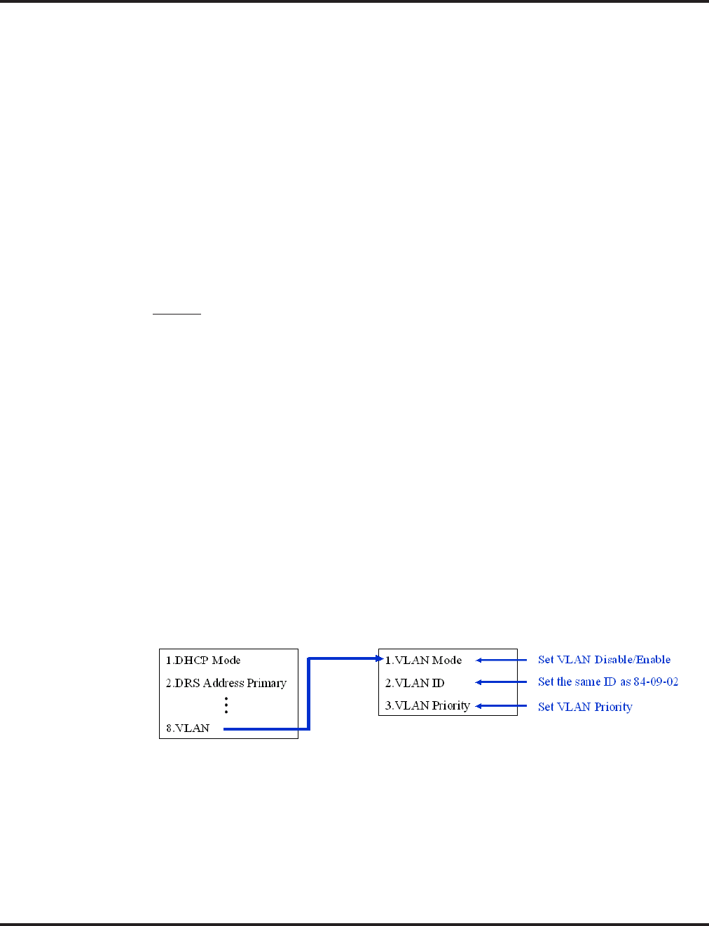
VoIP
696 ◆Features Aspire Software Manual
VLAN/QoS
The Aspire system supports:
●IEEE802.1q (VLAN Tagging)
●IEEE802.1p (Priority)
With the VLAN tagging mode, the Aspire can handle packets with or without a VLAN tag. If the
VLAN ID of a packet is different from the registered one, that packet will be dropped.
With the use of a switch which supports VLAN tagging, Layer 2 priority control is enabled. When
available, the 8SHUBU PCB can be used to provide this option.
Using a switch which supports 802.1p allows:
●priority control
●reduction of unnecessary packets (ex: broadcast packets) and provides circuitry by restricting
a broadcast domain
Layer 2
Programming - System, VLAN/QoS - Layer 2
➻84-09-01 : VLAN Setup - VLAN Mode
Enable the VLAN mode for the system (0=disable, 1=enable). The system must be reset in
order for the change to take effect. If the VLAN mode is enabled, the Aspire sends all packets
with a VLAN tag - if disabled, no VLAN tag is sent in the packets.
➻84-09-02 : VLAN Setup - VLAN ID
Enter the ID to be used for the VLAN (1-4094). The system must be reset in order for the
change to take effect.
➻84-09-03 : VLAN Setup - Priority
Enter the priority of the VLAN (0-7). The system must be reset in order for the change to take
effect.
Programming - Aspire Keyset with IP Adapter, VLAN/QoS - Layer 2
1. On the Aspire keyset connected as an IP telephone, enter the phone’s program mode by press-
ing HOLD CONF * #.
This enters the IP program mode to select the settings for the individual phone.
The flashing item is the current selection.
2. Press the Soft Key “SAVE” to save the entries and return the phone to an idle condition.

VoIP
Aspire Software Manual Features ◆697
Layer 3 (ToS)
The router-supported ToS controls routing priority of packets by following the ToS field. It is possi-
ble to give priority to the voice packet using the ToS field.
●There are two types of ToS formats: DiffServ and IP Precedence. Before programming your
router, make sure to check which type is supported by your router.
●Aspire can set the ToS value for each protocol, DTS, NGT, H.323 and Voice Control (H.245
for NGT). This setting allows flexible prioritization.
Programming - VLAN/QoS - Layer 3
➻84-03-07 : NGT Information Basic Setup - Type of Service Mode
For the terminal type (1=Dterm IP/Aspire keyset with IP adapter, 2=Smart Phone, 3=Bandle
IP Phone), set the service mode to be used (1=disable, 2=IP Precedence, 3=Diffserv).
➻84-03-08 : NGT Information Basic Setup - Type of Service
For the terminal type (1=Dterm IP/Aspire keyset with IP adapter, 2=Smart Phone, 3=Bandle IP
Phone), set the type of service to be used (0x00 to 0xff). This data will be sent to the NGT terminal
when it is registered. If Program 84-03-07 is "2", then enter "A0". If Program 84-03-07 is "3", then
enter 74.
Use line keys 1-6 to enter letters A-F (key 1=A, key 2=B, etc.)
➻84-10-01 : ToS Setup - ToS Mode
For the Protocol type (1=default, 2=DRS, 3=Protims, 4=Voice Control, 5=H.323, 6=RTP/
RTCP), select the ToS mode (0=disable, 1=IP Precedence, 2=Diffserv).
➻84-10-02 : ToS Setup - Precedence
For the Protocol type (1=default, 2=DRS, 3=Protims, 4=Voice Control, 5=H.323, 6=RTP/
RTCP), if Program 84-10-01 is set to "1", select the precedence (0=low, 7=high).
➻84-10-03 : ToS Setup - Low Delay
For the Protocol type (1=default, 2=DRS, 3=Protims, 4=Voice Control, 5=H.323, 6=RTP/
RTCP), if Program 84-10-01 is set to "1", select the delay (0=normal delay, 1=low delay).
➻84-10-04 : ToS Setup - Throughput
For the Protocol type (1=default, 2=DRS, 3=Protims, 4=Voice Control, 5=H.323, 6=RTP/RTCP),
if Program 84-10-01 is set to "1", select the throughput (0=normal throughput, 1=high throughput).
➻84-10-05 : ToS Setup - Reliability
For the Protocol type (1=default, 2=DRS, 3=Protims, 4=Voice Control, 5=H.323, 6=RTP/RTCP),
if Program 84-10-01 is set to "1", select the reliability (0=normal reliability, 1=high reliability).
➻84-10-06 : ToS Setup - Low Cost
For the Protocol type (1=default, 2=DRS, 3=Protims, 4=Voice Control, 5=H.323, 6=RTP/RTCP),
if Program 84-10-01 is set to "1", select the low cost mode (0=normal cost, 1=low cost).
➻84-10-07 : ToS Setup - Priority
For the Protocol type (1=default, 2=DRS, 3=Protims, 4=Voice Control, 5=H.323, 6=RTP/
RTCP), if Program 84-10-01 is set to "2", select the Diffserv priority (0-63).
Protocol Type Remarks
Default Not needed
DRS
(Device Registration Server) Protocol when an IP telephone or IP adapter is registered
PROTIMS Protocol to control the Aspire keyset with IP adapter
Voice Control H.245 protocol for the Aspire keyset with IP adapter
H.323 H.245 protocol for H.323 IP phones
RTP / RTCP Protocol for voice packet

VoIP
698 ◆Features Aspire Software Manual
VOIPU DSP Resource Assignment
➻10-19-01 : VOIPU DSP Resource Selection
Specify the operating mode of the DSP voice resource on the VOIPU PCB (DSP Resource:
01-32, 0=IP extensions and trunks, 1=IP extension only, 2=IP trunk only). If a user wants to
keep DSP voice channels only for trunks or extensions, then set this program to IP Extension
Only (1) or IP Trunk Only (2). Each VoIP call, unless it is a peer-to-peer call, requires a DSP
resource be available. One DSP resource can handle 4 VoIP channels. This program setting
has no affect on the terminal/trunk port assignment or usage.
●One DSP resource can handle 4 VOIP channels.
●This program setting has no affect on the terminal/trunk port assignments or usage.
Conditions
Changes to the following programs require the system be reset before the changes can take effect.
●Program 10-12
●Program 10-13
●Program 84-10
Changes to the following programs require that a programmer log out of the system programming
(phone programming, WebPro) before the changes can take effect.
●Program 84-01 Items: 39-41, 49-58
●Program 84-06
●Program 84-09
When changes are made to the following programs and there is an active call on the VOIPU PCB,
the system will not update until the VOIPU PCB is idle.
●Program 10-10
●Program 10-18
●Program 84-01-01
●Program 84-02-33
●Program 84-04
●Program 84-05
Default Setting
Disabled.

VoIP
Aspire Software Manual Features ◆699
Related Features
Networking
Aspire systems can be connected together through a LAN using VoIP. Networked IP phones
can be programmed to follow ARS COS Matching in order for 911 calls to seize a local line to
call the site’s local authorities (and not the networked site’s).
Paging, External / Paging, Internal
As the IP phones require a VOIPU resource when receiving a page, the number of IP phones
allowed to receive a page should be minimized to prevent a lack of resources.
Operation
Refer to the individual features for operation.
Volume Controls
700 ◆Features Aspire Software Manual
Volume Controls
Description
Each keyset user can control the volume of incoming ringing, splash tone, Paging, Background
Music, Handsfree and your handset. Keysets consolidate all adjustments into the volume buttons.
Pressing the VOLUME ▲ or VOLUME ▼ will adjust the volume level for whichever feature is
active (outside call, ICM, ICM ringing, paging, etc.). Pressing these keys when the phone is idle
will adjust the contrast level of the telephone’s display. The users should set the volumes for their
most comfortable levels.
Handset Volume Reset Option Available
Depending on your software, an option is available which allows the system to either reset the
handset volume back to the default setting after hanging up the handset or it can retain the user’s
setting.
Conditions
The contrast is not adjustable when the
phone has background music enabled or
if it is a super display telephone.
Default Setting
Enabled.
Programming
➻11-11-37 : Service Code Setup (for Setup/Entry Operation) - Adjusting Ring Volume
If required, change the service code used to adjust a keyset’s ring volume (829).
➻15-02-27 : Multi-Line Telephone Basic Data Setup, Retain Handset Volume
This option determines whether a keyset’s handset volume will change back to the system
default (0) or whether it will be retained at the user’s setting (1) after hanging up the handset.
Related Features
None
Aspire S Aspire M/L/XL
• Available.
• Handset volume reset option requires software 2.63+.
• Available.
• Handset volume reset option requires software 2.63+.
FLASH
VOL
CONF
MSG
Volume Down
Handsfree, Handset, Page and BGM Volume
Volume Up
N2IP-8

Volume Controls
Aspire Software Manual Features ◆701
Operation
To adjust the volume of incoming ringing and splash tone:
1. If the phone is idle, press the CALL key and dial 829. If the phone is ringing, skip to Step 2.
2. Press VOLUME ▲ or VOLUME ▼.
To adjust the volume of ringing incoming Paging announcements, Handsfree, the
handset or Background Music:
1. Press VOLUME ▲ or VOLUME ▼.
The feature must be active to change the volume. Pressing the volume keys when the
phone is idle will adjust the display’s contrast.

Warning Tone For Long Conversation
702 ◆Features Aspire Software Manual
Warning Tone For Long Conversation
Description
The system can broadcast warning tones to a trunk caller warning them that they have been on the
call too long. The tones are just a reminder -- the user may be able to disregard the tones and con-
tinue talking if they choose. The outside caller does not hear the warning tones. In addition, warn-
ing tones do not occur for Intercom calls and most incoming trunk calls. DISA trunks can also have
warning tones. Warning tones are not available to analog single line telephone (SLT) users.
There are two types of warning tones: Alarm Tone 1 and Alarm Tone 2. Alarm Tone 1 is the first
set of tones that occur after the user initially places a trunk call. Alarm Tone 2 broadcasts periodi-
cally after Alarm Tone 1 as a continued reminder. Each alarm tone consists of three short beeps.
If programmed, DISA calls will be disconnected unless the “continue” code is entered by the user.
With the Long Conversation Cutoff feature, incoming or outgoing central office calls can also be
disconnected.
Warning Tone for DISA Callers
For DISA callers, with this feature enabled, the warning tone timer begins when an incoming DISA
call places an outgoing call and either the inter-digit timer expires or the outgoing call is answered.
With this feature enabled, the warning tone timer begins when an incoming DISA call places an
outgoing call and either the inter-digit timer expires or the outgoing call is answered.
If an outside call is transferred to forwarded off-premise using an outside trunk, the warning tone
timer begins immediately. This will occur only if either trunk involved in the call is programmed
for this feature (Program 14-01-17). When transferring a trunk call off-premise, Program 14-01-13
must be enabled (set to ‘1’).
Conditions
None
Default Setting
Disabled.
Aspire S Aspire M/L/XL
• Available. • Available.

Warning Tone For Long Conversation
Aspire Software Manual Features ◆703
Programming
➻14-01-17 : Basic Trunk Data Setup - Trunk to Trunk Warning Tone for Long Conversation
Alarm
Determine whether DISA callers should hear the Warning Tone for Long Conversations
(0=disabled, 1=enabled).
➻20-06-01 : Class of Service for Extensions
Assign a Class Of Service (1-15) to an extension.
➻20-13-01 : Class of Service Options (Supplementary Service) - Long Conversation Alarm
In an extension’s Class of Service, enable (1) or disable (0) Warning Tone for Long
Conversation.
➻20-21-01 : System Options for Long Conversation - Long Conversation Alarm 1
After a user places a trunk call, the system sends the first warning tone to their extension after
this interval (0-64800 seconds).
➻20-21-02 : System Options for Long Conversation - Long Conversation Alarm 2
After hearing the first warning tone, the system sends additional warning tones after this inter-
val (0- 64800 seconds). The warning tones continue, spaced by this interval, until the user
hangs up.
➻21-01-01 : System Options for Outgoing Calls - Trunk Interdigit Time (External)
Determine the length of time the system should wait before starting the Warning Tone Timer.
➻25-07-07 : System Timers for VRS/DISA - DISA Conversation Warning Tone Time
Determine the length of time the system should wait before the Warning Tone is heard by
DISA callers (0-64800 seconds). If an outside call is transferred or forwarded off-premise
using an outside trunk, this timer starts immediately. This will occur if either trunk involved in
the call is programmed for the Warning Tone (Program 14-01-17).
➻25-07-08 : System Timers for VRS/DISA - DISA Long Conversation Disconnect
Determine how long after the Warning Tone is heard the system will wait before disconnect-
ing DISA calls - unless the Continue code is entered (Program 25-13-02).
➻25-13-02 : System Option for DISA - Continue Code for DISA Trunk-to-Trunk
With software through 2.68, enter a single digit Continue Code for the DISA call to use to
immediately disconnect or continue their outside call (0-9, * or # are accepted entries). With
software 4.0E+, use Program 20-28-01.
➻25-13-03 : System Option for DISA - Disconnect Code for DISA Trunk-to-Trunk
With software through 2.68, enter a single digit Disconnect for the DISA call to use to imme-
diately disconnect or continue their outside call (0-9, * or # are accepted entries). With soft-
ware 4.0E+, use Program 20-28-02.

Warning Tone For Long Conversation
704 ◆Features Aspire Software Manual
Related Features
Central Office Calls, Answering
Warning Tone for Long Conversation does not occur for incoming trunk calls.
Central Office Calls, Placing / Toll Restriction
Warning Tone for Long Conversation occurs for all outgoing trunk calls, regardless of how
they are placed or other outgoing restrictions.
Direct Inward System Access (DISA)
Warning Tone for Long Conversation can be enabled for DISA calls.
Intercom
Warning Tone for Long Conversation does not occur for Intercom calls.
Long Conversation Cutoff
Warning Tone for Long Conversation can be used with the Long Conversation Cutoff feature
for outgoing calls.
Single Line Telephones
Warning tones are not available to single line telephone (SLT) users.
Operation
Warning Tone for Long Conversation is automatic if programmed.
Warning Tone for Long Conversation for DISA Callers:
1. A DISA caller dials into the system and places a call.
2. Once the Warning Tone is heard,
To continue the call, the DISA caller presses the programmed Continue Code.
OR
To disconnect the call, the DISA caller presses the programmed Disconnect Code.

Aspire Software Manual Programming ◆705
Programming

706 ◆Programming Aspire Software Manual

Introduction to Programming
Before You Start Programming
Aspire Software Manual Programming ◆707
Introduction to Programming
Before You Start Programming
Section 2 - Programming
Before Reading This Section
This section provides you with detailed information about the system programs. By changing a pro-
gram, you change the way the feature associated with that program works. In this section, you find
out about each program, the features that the program affects and how to enter the program data
into system memory.
When you want to customize a feature, find it in Section 1 and learn about it. (If you have trouble
finding the feature, try cross-referencing it in the Index at the back of this book.) Section 1 will tell
you what programs you have to change to get the operation you want. Then, look the program up in
this section if you have any questions about how to enter the data.
How to Use This Section
This section lists each program in numerical order. For example, Program 10-01 is at the beginning
of the section and Program 92-01 is at the end. The information on each program is subdivided into
the following headings:
Description describes what the program options control. The Default Settings for each program are
also included. When you first install the system, it uses the Default Setting for all programs. Along
with the Description are the Conditions which describe any limits or special considerations that
may apply to the program.
The reverse type (white on black) just beneath the Description heading is the program’s access
level. You can only use the program if your access level meets or exceeds the level the program
requires. Refer to How to Enter the Programming Mode (page 708) for a list of the system’s
access levels and passwords.
Feature Cross Reference provides you with a table of all the features affected by the program.
You’ll want to keep the referenced features in mind when you change a program. Customizing a
feature may have an effect on another feature that you didn’t intend.
Telephone Programming Instructions shows you how to enter the program’s data into system
memory. For example:
1. Enter the programming mode.
2. 15-07-01
tells you to enter the programming mode, dial 150701 from the telephone dial pad. After you do,
you’ll see the message “15-07-01 TEL301” on the first line of the telephone display. This indicates
the program number (15-07), item number (01), and that the options are being set for extension
301. The second row of the display “KY01 = *01” indicates that Key 01 is being programmed with
the entry of *01. The third row allows you to move the cursor to the left or right, depending on
which arrow is pressed. To learn how to enter the programming mode, see How to Enter the Pro-
gramming Mode below.
Do not start customizing your system without first reading Section 1, Features.
15-07-01 TEL301
KY01 = *01
←←
←← →→
→→

Introduction to Programming
Before You Start Programming
708 ◆Programming Aspire Software Manual
How to Enter the Programming Mode
To enter the programming mode:
1. Go to any working display telephone.
In a newly installed system, use extension 301 (port 1).
2. Do not lift the handset.
3. Press CALL1.
4. # * # *
5. Dial the system password + HOLD.
Refer to the following table for the default system passwords. To change the pass-
words, use Program 90-02.
Note: When changes are made to the following programs, the Aspire system must be restarted.
Password
Password User Name Level Programs at this Level
374772 NEC-I 1 (MF) All programs
12345678 ASPIRE 2 (IN) All programs in this section not listed below for SA and SB
0000 ADMIN1 3 (SA) 10-01, 10-02, 10-12, 10-13, 10-14, 10-15, 10-16, 10-17, 10-18,
10-22, 12-02, 12-03, 12-04, 15-01, 15-07, 15-09, 15-10, 15-11,
20-16, 21-07, 21-14, 22-04, 22-11, 25-08, 30-03, 32-02, 40-02,
41-02, 41-03, 41-04, 41-05, 41-06, 41-07, 41-08, 41-09, 41-10,
41-11, 41-12, 41-13, 41-14, 41-15, 41-16, 41-17, 41-18, 90-03,
90-04, 90-06, 90-07, 90-18, 90-19
9999 ADMIN2 4 (SB) 13-04, 13-05, 13-06
10-12-01 10-14 80-01 84-03-01 84-05-02 84-06-07
10-12-02 10-15 80-02-01 84-03-02 84-06-01 84-06-08
10-12-03 10-16-01 80-02-02 84-03-06 84-06-02 84-06-09
10-12-04 10-16-02 80-02-03 84-03-07 84-06-03 84-06-10
10-13-01 10-16-03 80-02-04 84-03-08 84-06-04 84-06-11
10-13-02 10-16-04 80-03 84-04 84-06-05 84-09
10-13-03 20-01-03 80-04 84-05-01 84-06-06 84-10

Introduction to Programming
Before You Start Programming
Aspire Software Manual Programming ◆709
How to Exit the Programming Mode
To exit the programming mode:
When you are done programming, you must be out of a program’s options to exit (pressing the
MSG key will exit the program’s option).
1. Press MSG key to exit the program’s options, if needed.
2. Press SPK. You see, "Saving System Data" if changes to were to the system’s programming.
3. The display shows "Complete Data Save" when completed and will exit the phone to an idle
mode.
To save a customer’s database, a blank PC-ATA card or CompactFlash with PCMCIA
Adapter is required. Insert the card into the NTCPU and, using Program 90-03, save the
software to the PC-ATA/CompactFlash card. (Program 90-04 is used to reload the cus-
tomer data if necessary.) Note that a PC-ATA/CompactFlash card can only hold one cus-
tomer database. Each database to be saved will require its own separate card.
Program Mode
Base Service OP1 OP2

Introduction to Programming
Before You Start Programming
710 ◆Programming Aspire Software Manual
Using Keys to Move Around in the Programs
Once you enter the programming mode, use the keys in the following chart to enter data, edit data
and move around in the menus.
Keys for Entering Data
Use this key... When you want to . . .
0-9 and * Enter data into a program.
HOLD Complete the programming step you just made (like pressing Enter on a PC
keyboard). When a program entry displays, press HOLD to bypass the entry
without changing it.
CONF Delete the entry to the left (like pressing Backspace on a PC keyboard).
MSG Exit one step at a time from the program window currently being viewed.
For example, if you’re programming item 5 in 15-03, pressing MSG will
allow you to enter a new option in program 15-03. Pressing MSG again will
allow you to select a new program in the 15- series. Pressing MSG a third
time will allow you to enter a new program beginning with ‘1’. Pressing
MSG one last time will bring you to the beginning program display, allow-
ing you to enter any program number.
FLASH Switch extension, line, etc. being programmed by pressing FLASH. The
cursor moves up to the top row of the display. Pressing FLASH again moves
the cursor back to the middle row.
LINE KEYS Use pre-programmed settings to help with the program entry. These settings
vary between programs from LINE 1 = 0 (off) and LINE 2 = 1 (on) to preset
values for timers where LINE 1 = 5, LINE 2 = 10, LINE 3 = 15, etc.
For programs with this option, the line key which currently matches the pro-
grammed setting will light steady.
The display may also indicate Soft Keys which will allow you to select the
values as well (-1 and +1 will step through these pre-programmed settings.)
LINE KEY 1 Program a pause into an Abbreviated Dialing bin.
LINE KEY 2 Program a recall/flash into an Abbreviated Dialing bin.
LINE KEY 3 Program a @ into an Abbreviated Dialing bin.
VOL
▲
Scroll backward through a list of entry numbers (e.g., from extension 301 to
302, 303, etc.) or through entries in a table (e.g., Common Permit Table).
If you enter data and then press this key, the system accepts the data before
scrolling forward.
VOL
▼
Scroll forward through a list of entry numbers (e.g., from extension 301 to
302, 303, etc.) or through entries in a table (e.g., Common Permit Table).
If you enter data and then press this key, the system accepts the data before
scrolling backward

Introduction to Programming
Before You Start Programming
Aspire Software Manual Programming ◆711
Programming Names and Text Messages
Several programs (e.g., Program 20-16: Selectable Display Messages) require you to enter text. Use
the following chart when entering and editing text. When using the keypad digits, press the key once
for the first character, twice for the second character, etc. For example, to enter a C, press key “2”
three times. Press the key six times display the lower case letter. The name can be up to 12 digits
long.
With Software Prior to 2.05:
Key for Entering Names
Use this keypad digit . . . When you want to. . .
1 Enter characters:
1 @ [ ¥ ] ^ _ ‘ { | } ←←
←← →→
→→
Press repeatedly to scroll through the list. After selecting your entry, press the
next letter or use the left scroll or right scroll Soft Key to move the cursor.
2 Enter characters A-C, a-c, 2. After selecting your entry, press the next letter or
use the left scroll or right scroll Soft Key to move the cursor.
3 Enter characters D-F, d-f, 3. After selecting your entry, press the next letter or
use the left scroll or right scroll Soft Key to move the cursor.
4 Enter characters G-I, g-i, 4. After selecting your entry, press the next letter or use
the left scroll or right scroll Soft Key to move the cursor.
5 Enter characters J-L, j-l, 5. After selecting your entry, press the next letter or use
the left scroll or right scroll Soft Key to move the cursor.
6 Enter characters M-O, m-o, 6. After selecting your entry, press the next letter or
use the left scroll or right scroll Soft Key to move the cursor.
7 Enter characters P-S, p-s, 7. After selecting your entry, press the next letter or
use the left scroll or right scroll Soft Key to move the cursor.
8 Enter characters T-V, t-v, 8. After selecting your entry, press the next letter or use
the left scroll or right scroll Soft Key to move the cursor.
9 Enter characters W-Z, w-z, 9. After selecting your entry, press the next letter or
use the left scroll or right scroll Soft Key to move the cursor.
0 Enter characters:
0 ! “ # $ % & ‘ ( )
Press repeatedly to scroll through the list. After selecting your entry, press the
next letter or use the left scroll or right scroll Soft Key to move the cursor.
* Enter characters:
* + , - . / : ; < = > ?
Press repeatedly to scroll through the list. After selecting your entry, press the
next letter or use the left scroll or right scroll Soft Key to move the cursor.
Soft Key Left/Right
Arrows
Accepts an entry (only required if two letters on the same key are needed - ex: TOM)
and moves cursor in the arrows direction.
CONF Clear the character entry one character at a time.
CLEAR Clear all the entries from the point of the flashing cursor and to the right.

Introduction to Programming
Before You Start Programming
712 ◆Programming Aspire Software Manual
With Software 2.05+:
When using i-Series telephones on the Aspire system, not all the same characters are available.
Refer to the following chart for the i-Series characters:
Use this keypad
digit . . . When you want to. . .
1 Enter characters:
1 @ [ ¥ ] ^ _ ` { | } →→
→→ ←←
←← Á À Â Ã Ç É Ê ì ó
2 Enter characters A-C, a-c, 2.
3 Enter characters D-F, d-f, 3.
4 Enter characters G-I, g-i, 4.
5 Enter characters J-L, j-l, 5.
6 Enter characters M-O, m-o, 6.
7 Enter characters P-S, p-s, 7.
8 Enter characters T-V, t-v, 8.
9 Enter characters W-Z, w-z, 9.
0 Enter characters:
0 ! “ # $ % & ’ ( ) ô Õ ú ä ö ü α ε θ
* Enter characters:
* + , - . / : ; < = > ? π ∑ σ Ω ∞ ¢ £
# # = Accepts an entry (only required if two letters on the same key are needed - ex: TOM).
Pressing # again = Space. (In system programming mode, use the right arrow soft key
instead to accept and/or add a space.)
CONF Clear the character entry one character at a time.
CLEAR Clear all the entries from the point of the flashing cursor and to the right.
Use this keypad
digit . . . When you want to. . .
1 Enter characters:
1 @ [ ¥ ] ^ _ ` { | } →→
→→ ←←
←← å blank blank blank blank blank
blank blank blank
2 Enter characters A-C, a-c, 2.
3 Enter characters D-F, d-f, 3.
4 Enter characters G-I, g-i, 4.
5 Enter characters J-L, j-l, 5.
6 Enter characters M-O, m-o, 6.
7 Enter characters P-S, p-s, 7.
8 Enter characters T-V, t-v, 8.
9 Enter characters W-Z, w-z, 9.
0 Enter characters:
0 ! “ # $ % & ’ ( ) blank blank blank ä ö ü α ε θ
* Enter characters:
* + , - . / : ; < = > ? π ∑ σ Ω ∞ ¢ £
# # = Accepts an entry (only required if two letters on the same key are needed - ex: TOM).
Pressing # again = Space.
CONF Clear the character entry one character at a time.
CLEAR Clear all the entries from the point of the flashing cursor and to the right.

Introduction to Programming
Before You Start Programming
Aspire Software Manual Programming ◆713
Using Soft Keys For Programming
Each Aspire display telephone provides interactive soft keys for intuitive feature access. The
options for these keys will automatically change depending on where you are in the system pro-
gramming. Simply press the Soft Key located below the option you wish and the display will
change accordingly.
Pressing the VOLUME ▲ or VOLUME ▼ will scroll between the menus.
What the Soft Key Display Prompts Mean
When using a display phone in programming mode, you will see various Soft Key options dis-
played. These keys will allow you to easily select, scan, or move through the programs.
_
Program Mode
Base Service OP1 OP2
❍ ❍ ❍ ❍
_
Program Mode
Hard Mtnance
❍ ❍ ❍ ❍
Soft key Display Prompts
If you press this Soft Key . . . The system will. . .
back Go back one step in the program display.
You can press VOLUME ▲ or VOLUME ▼ to scroll
forwards or backwards through a list of Programs.
↑↑
↑↑ Scroll down through the available programs.
↓↓
↓↓ Scroll up through the available programs.
select Select the currently displayed program.
←←
←← Move the cursor to the left.
→→
→→ Move the cursor to the right.
−−
−−11
11 Move back through the available program options.
++
++11
11 Move forward through the available program options.

Introduction to Programming
Before You Start Programming
714 ◆Programming Aspire Software Manual
System Number Plan/Capacities - Aspire Comparisons
System Number Plan/Capacities
System Type: Aspire S Aspire M/L Aspire XL
System
Analog Caller ID Detector 24 64 64
Classes of Service 15 15 15
Day/Night Mode Numbers 4 8 8
Day/Night Service Patterns 4 32 32
Dial Tone Detector
DTMF Receiver 16 64 64
System Ports
(trunks and analog/digital extensions) •Software thru 2.21 =
8 trunks and
26 extensions
•Software 2.50+ =
8 trunks and
50 extensions
•NTCPU with Basic PAL =
64 trunks/extensions
•NTCPU with Feature
Upgrade PAL (software
01.00 - 03.10) =
64 trunks/extensions
•NTCPU with Feature
Upgrade PAL (software
04.00+) =
128 trunks/extensions
•NTCPU-B
200 trunks and
256 extensions
• 200 trunks and
384 extensions
Toll Restriction Classes 15 15 15
Verifiable Account Code Table 2000 2000 2000
Trunk
Trunk Port Number
1-8 1-200 11-200
1 With the basic NTCPU (P/N 0891002), trunks count toward the total number
of allowed hardware ports (64 or 128 ports depending on the PAL EPROM and
software installed)
Trunk Ports (Total)
• Analog Trunks
• BRI Trunk Ports
• T1/PRI Trunk Ports
• E&M Analog Trunk Ports
• DID Analog Trunk Ports
• VoIP Trunk Ports
8
8
4 (8B)
N/A
N/A
8
8
200
200
96 (192B)
192
60
120
200
200
200
96 (192B)
192
60
120
200
BRIU Logical Ports T-Bus: 1-8
S-Bus: 1-26 T-Bus: 1-200
S-Bus: 1-256 T-Bus: 1-200
S-Bus: 1-256
COIU:
• Physical Ports
• Logical Ports 01-04
0-8 01-08
0-200 01-08
0-200

Introduction to Programming
Before You Start Programming
Aspire Software Manual Programming ◆715
DIOPU:
• Physical Ports
• Logical Ports 01-02
LD Trunk: 0-8
OPX: 0-8
01-08
LD Trunk: 0-200
OPX: 0-25
01-08
LD Trunk: 0-200
OPX: 0-25
PRIU Logical Ports N/A T-Bus: 1-200
S-Bus: 1-256 T-Bus: 1-200
S-Bus: 1-256
TLIU:
• Physical Ports
• Logical Ports N/A 01-08
0-200 01-08
0-200
VOIPU:
• Physical Ports
• Logical Ports 1-8
0-8 01-32
0-200 01-32
0-200
DID Translation Tables 20 20 20
DID Translation Table Entries 2000 2000 2000
DISA
• Classes of Service
• Users 15
1-15 15
1-15 15
1-15
Ring Groups 1-8 1-100 1-100
Tie Line Classes of Service N/A 15 15
Tie Line Toll Restriction Classes N/A 15 15
Trunk Access Maps 1-8 1-200 1-200
Trunk Group Numbers 1-8 1-100 1-100
Trunk Routes 1-8 1-100 1-100
System Number Plan/Capacities
System Type: Aspire S Aspire M/L Aspire XL

Introduction to Programming
Before You Start Programming
716 ◆Programming Aspire Software Manual
Extension
Telephone Extension Port Numbers
• Keysets
• Single Line Phones/Analog
Devices
• VoIP Extensions
• Aspire Wireless
1-50 3
(1-24)
(1-18)
(1-16) 2, 4
N/A
1-256
(1-256) 2
(1-256) 2
(1-512) 5
002-512 (manual select) 5
257-512 (auto select) 5
1-384
(1-384)
(1-384)
(1-512) 5
002-512 (manual select) 5
385-512 (auto select) 5
2 Counts toward total number of allowed hardware ports (Aspire S=26 ports with
software 2.08-2.21 or 50 ports with software 2.50+, Aspire M 64-Port NTCPU=64,
Aspire M/L 64-Port NTCPU w/Feature Upgrade PAL and software 4.00+=128,
Aspire M/L w/Enhanced NTCPU=256, Aspire XL=384).
3 The total number of ports available is determined by system software.
Software prior to 2.50 has 26 ports (24 digital and analog, 2 analog only - a maximum
of 16 IP extensions is included in this 26 ports)
Software 2.50 and higher provides 50 ports (Maximum Wired Terminals: 26 Includes
keysets, single line telephones, ISDN terminals (APRs NOT included),
Maximum IP Terminals: 16 Includes DtermIP and H.323 terminals,
Maximum Special Terminals: Reserved for IntraMail: 8 (fixed extension ports 43-50)).
4 If the APR-B2 mode is assigned in a system which already has 26 extensions, the
number of IP phones is reduced.
5 With the basic NTCPU (P/N 0891002), VoIP and Aspire Wireless extensions count
toward the total number of allowed hardware ports (64 or 128 ports depending on the
PAL EPROM and software installed).
With the Enhanced NTCPU (P/N 0891038), if the number of VoIP and Aspire Wireless
phones combined exceeds 256, the number of ports available for keysets or analog
devices is then reduced by for each additional IP or Aspire Wireless phone.
ESIU
• Physical Ports
• Logical Ports
-Tone Ringer (2PGDAD)
-Door Box (2PGDAD)
-Analog I/F (2PGDAD)
-ACI (2PGDAD)
-APR for B2 Mode
1-8
1-4
1-4
1-8
1-8
1-42 (descending order)
01-16
1-8
1-8
1-96
1-96
193-256 (descending order)
With software 4.xx or higher:
193-512 (descending order)
01-32
1-8
1-8
1-96
1-96
193-512 (descending order)
SLIU
• Physical Ports
• Logical Ports 1-8
1-26 01-16
1-256 01-16
1-384
Telephone Extension Number Range 301-499
5000-5312 301-499
5000-5312 301-499
5000-5312
Virtual Extension Ports 24 256 256
Virtual Extension Port Numbers 01-24 001-256 001-256
Virtual Extension Number Range Undefined Undefined Undefined
System Number Plan/Capacities
System Type: Aspire S Aspire M/L Aspire XL

Introduction to Programming
Before You Start Programming
Aspire Software Manual Programming ◆717
2PGDAD Modules 10 56 56
ADA (Recording Jack) Adapters 24 192 192
Aspire Wireless Bases N/A 12 12
Aspire Wireless Phones N/A 120 120
Door Boxes 4 8 8
Door Box Numbers 1-4 1-8 1-8
DSS Consoles Numbers
• 24-Button DLS Consoles,
Maximum Installed
• 110-Button DSS Consoles,
Maximum Installed
8
24
4
8
256
32
8
384
32
Handsfree Adapter (HF-R) 24 192 192
Operator Access Number 0 0 0
Operator Extension 1 1 1
Ringdown Assignments 512 512 512
SLT Adapters 8 16 16
Voice Mail Master Numbers 301-499, 5000-5312 301-499, 5000-5312 301-499, 5000-5312
Abbreviated Dialing
Abbreviated Dialing Groups 8 64 64
Abbreviated Dialing Bins 0-1999 0-1999 0-1999
Abbreviated Dialing Table-Common 1000 1000 1000
ACD
ACD Groups N/A 64 64
ACD Agent Extensions N/A 512 512
ACI
ACI Groups 4 16 16
ACI Ports 8 96 96
Automated Attendant
VRS Message Numbers 1-48 1-48 1-48
Conference
Conference Circuits 32 - maximum
(32 Parties Per
Conference)
64 - maximum
(32 Parties Per
Conference)
64 - maximum
(32 Parties Per
Conference)
System Number Plan/Capacities
System Type: Aspire S Aspire M/L Aspire XL

Introduction to Programming
Before You Start Programming
718 ◆Programming Aspire Software Manual
Data Communication Interfaces
APR Software Port Numbers 193-256
With software 4.xx or
higher: 193-512
193-256
With software 4.xx or higher:
193-512
193-512
APA Adapters 24 192 192
APR Adapters B1 = 24
B2 = 8 prior to 2.50 or 16
with 2.50+
192 192
CTA or CTU Adapters 24 128 128
Module Extension Number Range 301-499, 5000-5312 301-499, 5000-5312 301-499, 5000-5312
Department and Pickup Groups
Department (Extension) Group
Numbers 1-8 1-64 1-64
Department (Extension) Group
Number Range 301-499, 5000-5312 301-499, 5000-5312 301-499, 5000-5312
Call Pickup Group Numbers 1-8 1-64 1-64
Hotline
Internal Hotline 512 512 512
External Hotline 512 512 512
Paging and Park
Internal Page Group Numbers 0, 1-8 0, 1-9 or 01-64 0, 1-9 or 01-64
External Page Group Numbers 0, 1-8 0, 1-8 0, 1-8
External Speakers
• NTCPU
• PGDAD Module
8
N/A
(1-8)
9
(1)
(1-8)
9
(1)
(1-8)
Park Group Numbers 1-64 1-64 1-64
Park Orbits 1-64 1-64 1-64
SMDR
SMDR Ports 1-2 1-8 1-8
VRS
VRS (on DSP Daughter Board) 1 1 1
VRS Channels 8 16 16
VRS Attendant Messages 3 3 3
VRS Recordable Messages 48 48 48
System Number Plan/Capacities
System Type: Aspire S Aspire M/L Aspire XL

Introduction to Programming
Before You Start Programming
Aspire Software Manual Programming ◆719
Voice Mail
Ports for IntraMail 8 (fixed extension ports
43-50) N/A N/A
Ports for External Voice Mail 72 672 72
6 Though this is the maximum available in the NVM-Series voice mail, as each voice
mail port requires an analog port, the total number is restricted by the Aspire S system
to a maximum of 16.
VoIP
VoIP Extensions 16 4•NTCPU with Basic or Fea-
ture Upgrade PAL (soft-
ware 01.00 - 03.10) = 64
•NTCPU with Feature
Upgrade PAL (software
04.00+) = 128
•NTCPU-B = 512
512
4 If the APR-B2 mode is assigned in a system which already has 26 extensions, the
number of IP phones is reduced.
ADA2 (Recording Jack) Adapters 16 192 192
IP Adapters 16 256 256
IP Phones 16 512 512
PSA (Power Failure) Adapters 16 192 192
RAS Unicast Ports 0-65535 0-65535 0-65535
Call Signaling Ports 0-65535 0-65535 0-65535
NGT Signal Receive Ports 0-65535 0-65535 0-65535
DRS Ports 0-65535 0-65535 0-65535
RTP Ports 0-65535 0-65535 0-65535
RTCP Ports 0-65535 0-65535 0-65535
H.245 Ports 0-65535 0-65535 0-65535
DSP Resources 01-32 01-32 01-32
H.323 Alias Addresses 1-6 1-6 1-6
System Number Plan/Capacities
System Type: Aspire S Aspire M/L Aspire XL

Introduction to Programming
Before You Start Programming
720 ◆Programming Aspire Software Manual
Passwords
User Password for setting Toll
Restriction Override and Changing
Class of Service using a service code
0000 0000 0000
Programming Passwords
Level 1 (MF)
PCPro/WebPro User Name: 374772
NEC-I 374772
NEC-I 374772
NEC-I
Level 2 (IN)
PCPro/WebPro User Name: 12345678
ASPIRE 12345678
ASPIRE 12345678
ASPIRE
Level 3 (SA)
PCPro/WebPro User Name: 0000
ADMIN1 0000
ADMIN1 0000
ADMIN1
Level 4 (SB)
PCPro/WebPro User Name: 9999
ADMIN2 9999
ADMIN2 9999
ADMIN2
Programming Password Users 8 8 8
Note:
Extension numbers can be three or four digits long. See Flexible System Numbering.
System Number Plan/Capacities
System Type: Aspire S Aspire M/L Aspire XL

Program 10 : System Configuration Setup
10-01 : Time and Date
Aspire Software Manual Programming ◆721
Program 10 : System Configuration Setup
10-01 : Time and Date
Description
Use Program 10-01 : Time and Date to change the system Time and Date through system pro-
gramming. Extension users can also dial Service Code 828 to change the Time if allowed by an
extension’s Class of Service.
Input Data
Conditions
None
Feature Cross Reference
●Time and Date
Level: Aspire S Aspire M/L/XL
SA • Available. • Available.
Item
No. Item Input data Default Description
01 Year 00-99 No setting Enter two digits for year (00-99).
02 Month 01-12 No setting Enter two digits (01-12) for the month.
03 Day 01-31 No setting Enter two digits (01-31) for the day.
04 Week 1-7
(Sun-Sat) No setting Enter digit for the day of the week
(1=Sunday, 7=Saturday).
05 Hour 00-23 No setting Enter two digits for the hour (00-23).
06 Minute 00-59 No setting Enter two digits for the minute (00-59).
07 Second 00-59 No setting Enter two digits for the second (00-59).

Program 10 : System Configuration Setup
10-01 : Time and Date
722 ◆Programming Aspire Software Manual
Telephone Programming Instructions
To enter data for Program 10-01 (Time and Date):
1. Enter the programming mode.
2. 10 01
3. Enter the number of the item you want to program.
4. Enter data for the item you selected + HOLD.
5. Enter data for the next item in the program.
OR
Press MSG once to enter a new item number.
OR
Press MSG until you’ve exited that series’s programming section.
10-01-01
Year
back ↑↑
↑↑ ↓↓
↓↓ select
10-02-nn
nnnnn
←←
←← →→
→→

Program 10 : System Configuration Setup
10-02 : Location Setup
Aspire Software Manual Programming ◆723
10-02 : Location Setup
Description
Use Program 10-02 : Location Setup to define the location of the installed system.
Input Data
Conditions
None
Feature Cross Reference
None
Level: Aspire S Aspire M/L/XL
SA • Available. • Available.
Item
No. Item Input data Default Description
01 Country Code Dial (up to 4 digits) 1 Enter the country code.
02 International
Access Code Dial (up to 4 digits) - Enter the international access code.
03 Other Area
Access Code Dial (up to 2 digits) 9 Enter the other area access code
04 Area Code Dial (up to 6 digits) - Enter the local area code.
05 Trunk Access
Code Dial (up to 8 digits):
0-9, *, # - Enter the trunk access code digits
required to place an outgoing call.
This is the code which will be added
to the Caller ID information for
incoming trunk calls to allow the
call to dial out if allowed in
20-19-03.
IMPORTANT
Program 10-02-05 is only support
by telephone programming. PCPro
and WebPro cannot edit this option.

Program 10 : System Configuration Setup
10-02 : Location Setup
724 ◆Programming Aspire Software Manual
Telephone Programming Instructions
To enter data for Program 10-02 (Location Setup):
1. Enter the programming mode.
2. 10 02
3. Enter the number of the item you want to program.
4. Enter data for the item you selected + HOLD.
5. Enter data for the next item in the program.
OR
Press MSG once to enter a new item number.
OR
Press MSG until you’ve exited that series’s programming section.
10-02-01
Country_Code
←←
←← →→
→→
10-02-nn
nnnnn
←←
←← →→
→→

Program 10 : System Configuration Setup
10-03 : PCB Setup
Aspire Software Manual Programming ◆725
10-03 : PCB Setup
Description
Use Program 10-03 : PCB Setup to setup and confirm the Basic Configuration data for each PCB.
When changing a defined terminal type, first set the type to ‘0’ and then plug the new device in to
have the system automatically define it or you may have to reseat the PCB.
Note: The items highlighted in gray are read only and cannot be changed.
Note: The item numbers indicated below are different when using PCPro/WebPro due to the win-
dow layout of the applications. Refer to the program within the PCPro/WebPro application
to determine the correct item number.
Level: Aspire S Aspire M/L/XL
IN • Available. • Available.
• Option 15 for S-Bus terminal alert tone
requires software 2.63+.
• Option 16 for PRI is not available.
• Option 5 for T1 is not available.
• Expanded entries for ESIU, SLIU, VMSU,
DIOPU, BRI and PRI PCBs is not
available.
• Option 17 for BRI available with software
4.04+.
• Options 18 and 19 for ISDN Numbering
Plan selection requires software 4.93+.
• Option 15 for S-Bus terminal alert tone
requires software 2.63+.
• Option 16 for PRI available with software
2.63+.
• Default changed for Option 5 for T1 with
software 2.65+.
• Expanded entries for Aspire XL and the
ESIU, SLIU, VMSU, DIOPU, BRI and
PRI PCBs requires software 4.0E+.
• Option 17 for BRI available with software
4.04+.
• Options 18 and 19 for ISDN Numbering
Plan selection requires software 4.93+.

Program 10 : System Configuration Setup
10-03 : PCB Setup
726 ◆Programming Aspire Software Manual
Input Data
For ESIU Unit
Physical Port Number Through Software 3.07: 01-16
From Software 4.0E+: 01-32
B-Channel 1
Item
No. Item Input Data Default
01 Terminal Type 0 = Not set
1 = Keyset/DSLT
2 = SLT Adapter
3 = -- Not used --
4 = -- Not used --
5 = -- Not used --
6 = PGD (Paging)
7 = PGD (Tone Ringer)
8 = PGD (Doorbox)
9 = PGD (ACI)
10 = DSS Console
11 = -- Not used --
0
02 Logical Port Number 0 = Not set
1 = Keyset
2 = SLT Adapter
3 = Not used
4 = Not used
5 = 2DCI Adapter 1 - 32
6 = PGD (Paging)
7 = PGD (for Tone Ringer) 1-4 or 1-8
8 = PGD (for Door Box) 1-4 or 1-8
9 = PGD (for Analog I/F) 1-8 or 1-96
10 = DSS
11 = Not used
0
03 Additional Data This option is reserved for future use.
3 = Not used
4 = Not used
01-16 (port number) A port number is automatically set as
the order which the terminal started.
0
04 Optional Installed Unit 1 0 = none
1 = APR Module
2 = APA Module
3 = ADA Module
4 = CTA Module
5 = CTU Module
0

Program 10 : System Configuration Setup
10-03 : PCB Setup
Aspire Software Manual Programming ◆727
05 Optional Installed Unit 2 0- none
1 = APR Module
2 = APA Module
3 = ADA Module
4 = CTA Module
5 = CTU Module
0
B-Channel 2
Item
No. Item Input Data Default
06 Terminal Type 0 = Not set
1 = -- Not used --
2 = -- Not used --
3 = -- Not used --
4 = -- Not used --
5 = -- Not used --
6 = PGD (Paging)
7 = PGD (Tone Ringer)
8 = PGD (Door Box)
9 = PGD (ACI)
10 = -- Not used --
11 = -- Not used --
12 = APR
0
07 Logical Port Number 0 = Not set
6 = PGD (Paging)
7 = PGD (for Tone Ringer) 1-4 or 1-8
8 = PGD (for Door Box) 1-4 or 1-8
9 = PGD (for ACI) 1-8 or 1-96
12:APR (for B2 mode) 19-50 or 193-512
0
Program 10 : System Configuration Setup
10-03 : PCB Setup
728 ◆Programming Aspire Software Manual
For SLIU Unit
For COIU Unit
For DIOPU Unit
For TLIU Unit
Physical Port Number 01-16
Item
No. Item Input Data Default
01 Logical Port Number Through Software 3.07: 0-256
From Software 4.0E+: 0-384 0
02 Not used
03 Transmit Gain Level (S-Level) 1-63 (-15.5 +15.5dB) 32 (0dB)
04 Receive Gain Level (R-Level) 1-63 (-15.5 +15.5dB) 32 (0dB)
Physical Port Number 01-08
Item
No. Item Input Data Default
01 Logical Port Number 0-200 0
Physical Port Number 01-08
Item
No. Item Input Data Default
01 LD/OPX assignment 0 = LD Trunk
1 = OPX Trunk 0
02 Logical Port Number 0 = For LD Trunk 0-200
1 = For OPX Through Software 3.07:
0-256
From Software 4.0E+:
0-384
0
Physical Port Number 01-08
Item
No. Item Input Data Default
01 Logical Port Number 0-200 0
02 2/4Wire 0 = 2Wire
1 = 4Wire 1

Program 10 : System Configuration Setup
10-03 : PCB Setup
Aspire Software Manual Programming ◆729
For BRIU Unit
ISDN Line Number 01-08
Item
No. Item Input Data Default
01 ISDN Line Mode 0 = Not set
1 = T-Bus
2 = S-Bus
Options 3-5 determines the clock source
for the networked connection.
3 = Network Mode (Leased Line)
Telco sends the clock to the Master System
Telco sends the clock to the Slave System
4 = Network Mode (Interconnected Line)
Master System sends the clock to the Telco (or direct
connection without telco) which then sends the clock
to the Slave System
5 = Network Mode (Interconnected Line, Fixed layer 1=NT)
Master System sends the clock to the Telco
Slave System sends the clock to the Telco
6 = S-Point (Leased Line)
1
02 Logical Port Number
(see Note 1) 0 = Net set
1 = For T-Bus (1-200)
2 = For S-Bus (Through Software 3.07: 0-256
From Software 4.0E+: 0-384)
0
03 Connection Type 0 = Point-to-Multipoint (not available for Networking)
1 = Point-to-Point 0
04 Layer 3 Timer Type (see Note 2) 1-5 1
05 CLIP Information Announcement
Based on this setting, the system will
include a “Presentation Allowed” (1)
or “Presentation Restricted” (0) in the
Setup message to allow or deny the
Calling Party Number. Program
15-01-04 must also be set to a ‘1’ if
this option is enabled.
0 = Disable
1 = Enable 1
06 Connection Bus Mode (S-point only) 0 = Extended Passive Bus
1 = Short Passive Bus 0
07 S-point DID digits 0-4 0
08 Dial sending Mode 0 = Enblock sending
1 = Overlap sending 1
09 Dial Information Element
(Only for Overlap Sending Mode) 0 = Keypad Facility
1 = Called Party Number 0
10 Master/Slave System (NW mode only) 0 = Slave System
1 = Master System 0

Program 10 : System Configuration Setup
10-03 : PCB Setup
730 ◆Programming Aspire Software Manual
Note 1. The start port number of a BRI line is displayed. Two logic ports are automatically
assigned to a BRI line.
Note 2. Each timer value of Layer3 are set up for every type of Program 81-06 (T-Bus) and Pro-
gram 82-06 (S-Bus).
11 Networking System Number (NW
mode only) 0-50 0
12 - Not Currently Used - 0
13 - Not Currently Used - 0
14 Service Protocol for S-Point 0 = Keypad Facility
1 = Specified Protocol for Aspire System 0
15 Alert Tone When S-Bus Terminal
Calls Busy Extension
This option determines for S-Bus ter-
minals what a user on an S-Bus termi-
nal will hear when a busy extension is
called. If this option is set to "0", the
user will hear an alert tone. If this
option is set to "1", the user will be
disconnected.
0 = Alert Tone
1 = Disconnected 0
17 Ringback Tone to Telco Now Possi-
ble with BRI Trunks
This option can be used to determine
whether or not the system sends ring-
back tone to the telco.
0 = Disable
1 = Enable 0
18 Type of Number
Use this option to define the ISDN
numbering plan to allow the calling
party information to be passed to some
telcos. Note that with software
4.08-4.0W, Program 99-01-32 was
used instead.
0 = Unknown
1 = International number
2 = National number
3 = Network Specific number
4 = Subscriber number
5 = Abbreviated number
3
19 Numbering Plan Identification
passed to some telcos. Note that with
software 4.08-4.0W, Program
99-01-33 was used instead.
0 = Unknown
1 = ISDN numbering plan
2 = Data numbering plan
3 = Telex numbering plan
4 = National standard numbering plan
5 = Private numbering plan
1

Program 10 : System Configuration Setup
10-03 : PCB Setup
Aspire Software Manual Programming ◆731
For PRIU Unit
Item
No. Item Input Data Default
01 ISDN Line Mode 0 = Not set
1 = T-Bus
2 = S-Bus
3 = Network Mode (Leased Line)
4 = Network Mode (Interconnected Line)
5 = Network Mode (Interconnected Line, Fixed Layer 1=NT)
6 = S-Point (Leased Line)
1
02 Logical Port Number
(see Note 1) 1 = for T-Bus 1-200
2 = for S-Bus Through Software 3.07: 1-256
From Software 4.0E+: 1-384
0
03 CRC Multi-frame(CRC4)
(Only E1[30B+D] Mode) 0 = off
1 = on 0
04 Layer 3 Timer Type (see Note 2) 1-5 1
05 CLIP Information
Based on this setting, the system will
include a “Presentation Allowed” (1)
or “Presentation Restricted” (0) in the
Setup message to allow or deny the
Calling Party Number. Program
15-01-04 must also be set to a ‘1’ if
this option is enabled.
0 = Disable
1 = Enable 1
06 Length of cable 0 = 0 40m
1 = 40 81m
2 = 81 122m
3 = 122 162m
4 = 162 200m
0
07 S-Point DID Digits 0-4 0
08 Dial Sending Mode 0 = Enblock Sending
1 = Overlap Sending 0
09 Dial Information Element
(Only for Overlap Sending Mode) 0 = Keypad Facility
1 = Called Party Number 0
10 Master/Slave System (Network Mode
only) 0 = Slave System
1 = Master System 0
11 Networking System Number
(Network Mode only) 0-50 0
12 Short / Long-haul 0 = short-haul
1 = long-haul 0

Program 10 : System Configuration Setup
10-03 : PCB Setup
732 ◆Programming Aspire Software Manual
Note 1. The start port number of a PRI line is displayed. Thirty logic ports are automatically
assigned to a PRI line.
Note 2. Each timer value of Layer3 is set up for each type in Program 81-06 (T-Bus) and Pro-
gram 82-06 (S-Bus).
13 Loss-Of-Signal detection limit In short-haul mode In long-haul mode
0 = 0.91V 0 = 1.70V
1 = 0.74V 1 = 0.84V
2 = 0.59V 2 = 0.84V
3 = 0.42V 3 = 0.45V
4 = 0.32V 4 = 0.45V
5 = 0.21V 5 = 0.20V
6 = 0.16V 6 = 0.10V
7 = 0.10V 7 = not defined
0
14 Service Protocol for S-Point 0 = Keypad Facility
1 = Specified Protocol for Aspire System 0
15 Alert Tone When S-Bus Terminal
Calls Busy Extension
This option determines for S-Bus ter-
minals what a user on an S-Bus ter-
minal will hear when a busy
extension is called. If this option is
set to "0", the user will hear an alert
tone. If this option is set to "1", the
user will be disconnected.
0 = Alert Tone
1 = Disconnected 0
16 ISDN 2 B-Channel Transfer
Enable or disable the 2 B-Channel
Transfer function for a PRI PCB.
0 = Off/Disable
1 = On/Enable 0
18 Type of Number
Use this option to define the ISDN
numbering plan to allow the calling
party information to be passed to
some telcos. Note that with soft-
ware 4.08-4.0W, Program 99-01-32
was used instead.
0 = Unknown
1 = International number
2 = National number
3 = Network Specific number
4 = Subscriber number
5 = Abbreviated number
3
19 Numbering Plan Identification
passed to some telcos. Note that
with software 4.08-4.0W, Program
99-01-33 was used instead.
0 = Unknown
1 = ISDN numbering plan
2 = Data numbering plan
3 = Telex numbering plan
4 = National standard numbering plan
5 = Private numbering plan
1
Item
No. Item Input Data Default
Program 10 : System Configuration Setup
10-03 : PCB Setup
Aspire Software Manual Programming ◆733
For T1 Unit
For VMSU Unit
For VOIPU Unit
Physical Port Number 01-32
Item
No. Item Input Data Default
01 Logical Port Number 0-200 0
02 Frame Type Setup 0 = D4 (12 Multi Frame)
1 = ESF (24 Multi Frame) 0
03 Zero Code Suppression Setup
ZCS_B8ZS 0 = B8ZS
1 = AMI/ZCS 0
04 DTI<->CSU Distance Setup 0= 0 feet – 133 feet
1= 133 feet – 266 feet
2= 266 feet – 399 feet
3= 399 feet – 533 feet
4= 533 feet – 655 feet
0
05 T1 Clock Source Master/Slave 0 = Internal
1 = External 1
Prior to 2.65 = 0
Item
No. Item Input Data Default
01 Logical Port Number Through Software 3.07: 0-256
From Software 4.0E+: 0-384 0
Physical Port Number 01-32
Item
No. Item Input Data Default
01 Trunk Logical Port Number 0-200 0
02 H.323 or SIP Trunk
Determine the IP trunk type setup.
Contact Your NEC Sales Representative
for information on the SIP feature
availability.
0 = H.323
1 = SIP 0

Program 10 : System Configuration Setup
10-03 : PCB Setup
734 ◆Programming Aspire Software Manual
Conditions
(A.) When changing a defined terminal type, first set the type to ‘0’ and then plug the new device in
to have the system automatically define it or redefine the type manually.
(B.) The system must have a PCB installed in order to view/change the options for that type of
PCB.
Feature Cross Reference
None
Telephone Programming Instructions
To enter data for Program 10-03 (PCB Setup):
1. Enter the programming mode.
2. 10 03
3. Enter the number of the item you want to program.
4. Select a slot number to be programmed by pressing the VOLUME ▲ or VOLUME ▼ keys.
Or, press FLASH once to select the slot number or press FLASH twice to select a port num-
ber. Enter the slot or port number.
5. Enter data for the item you selected + HOLD.
6. Enter data for the next item in the program.
OR
Press MSG once to enter a new item number.
OR
Press MSG until you’ve exited that series’s programming section.
10-02-01 Slot No 1
ESIport01 CH1 1 :TEL |1
back ↑↑
↑↑ ↓↓
↓↓ select
10-02-nn Slot No 1
nnnnn
back ↑↑
↑↑ ↓↓
↓↓ select

Program 10 : System Configuration Setup
10-04 : Music on Hold Setup
Aspire Software Manual Programming ◆735
10-04 : Music on Hold Setup
Description
Use Program 10-04 : Music on Hold Setup to set the Music on Hold selection. For MOH, the sys-
tem can provide silence to callers on Hold or one of eleven synthesized selections.
Input Data
Conditions
None
Feature Cross Reference
●Music on Hold
Level: Aspire S Aspire M/L/XL
IN • Available. • Available.
• Internal service tone in item 1 available
with software 2.63+. • Internal service tone in item 1 available
with software 2.63+.
Item
No. Item Input Data Default
01 Music on Hold Source Selection
The Music on Hold source can be internal
(synthesized), from a customer-provided
music source, or a service tone provided by
the system.
The customer-provided source can connect to
a 2PGDAD or the connector on the NTCPU.
Trunk MOH and Extension MOH music
source use the same Music on Hold source.
0=Internal source
1=External source
2=Internal service tone
0
02 Music Selection for Internal Source
Select the music which will be heard by users
on hold.
0 = Silence (no sound)
1 = Selection 1
2 = Selection 2
1
03 Audio Gain Setup
Adjust the audio gain used by the internal
MOH if required. External MOH is adjusted
at the MOH source.
1-63 (-15.5 +15.5dB) 32 (0dB)

Program 10 : System Configuration Setup
10-04 : Music on Hold Setup
736 ◆Programming Aspire Software Manual
Telephone Programming Instructions
To enter data for Program 10-04 (Music on Hold Setup):
1. Enter the programming mode.
2. 10 04
3. Enter the number of the item you want to program.
4. Enter data for the item you selected + HOLD.
5. Enter data for the next item in the program.
OR
Press MSG once to enter a new item number.
OR
Press MSG until you’ve exited that series’s programming section.
10-04-01
Hold_Tone_Set 0:Internal
back ↑↑
↑↑ ↓↓
↓↓ select
10-04-nn
nnnnn
←←
←← →→
→→

Program 10 : System Configuration Setup
10-05 : General Purpose Relay Setup
Aspire Software Manual Programming ◆737
10-05 : General Purpose Relay Setup
Description
Use Program 10-05 : General Purpose Relay Setup to define which Relay circuits (5-8) on
2PGDAD Adapter are used for General Purpose Relay.
Refer to Program 10-21-01 for the NTCPU relay.
Input Data
- INDEX-1 -
Conditions
None
Feature Cross Reference
●Music on Hold
Level: Aspire S Aspire M/L/XL
IN • Available. • Available.
General Purpose Relay No. 1-8
Item
No. Item Input Data Default
01 Slot No
Physical Port of ESIU
Sensor circuit No
Slot No: 0-16
ESIU Port: 0-16
Relay No: 0, 5-8
0 - 0 - 0

Program 10 : System Configuration Setup
10-05 : General Purpose Relay Setup
738 ◆Programming Aspire Software Manual
Telephone Programming Instructions
To enter data for Program 10-05 (General Purpose Relay Setup):
1. Enter the programming mode.
2. 10 05
3. Enter the number of the item you want to program.
4. Enter data for the item you selected + HOLD.
5. Enter data for the next item in the program.
OR
Press MSG once to enter a new item number.
OR
Press MSG until you’ve exited that series’s programming section.
10-06-01 Relay No1
Slot No =-
back ↑↑
↑↑ ↓↓
↓↓ select
10-05-nn
nnnnn
←←
←← →→
→→

Program 10 : System Configuration Setup
10-06 : ISDN BRI Setup
Aspire Software Manual Programming ◆739
10-06 : ISDN BRI Setup
Description
Use Program 10-06 : ISDN BRI Setup to define the TEI selection and DID mode for DID callers
when the BRI feature is used.
Enter the SPID (Service Profile ID) assigned to each of the system’s BRI ISDN lines. Each BRI
PCB has a maximum of two lines and each line can have a maximum of two SPIDs. To use both
channels of a BRI ISDN line, two directory numbers must be ordered from telco. A SPID is
assigned for each directory number.
Input Data
- INDEX-1 -
- INDEX-2 -
Conditions
None
Level: Aspire S Aspire M/L/XL
IN • Available. • Available.
Slot Number 01-16
ISDN Line Number 01-08
Item
No. Item Input Data Default
01 TEI Selection
Set the method the system
will use when assigning Ter-
minal Endpoint Identifier
(TEI) values to BRI ports.
0 = Select by SPID number
1 = Select by Channel ID number 0
02 DID Mode 0 = Route by Called Party Number
1 = Route by Redirecting Number 0
03 SPID 1 Dial (up to 20 digits) No Setting
04 SPID 2 Dial (up to 20 digits) No setting

Program 10 : System Configuration Setup
10-06 : ISDN BRI Setup
740 ◆Programming Aspire Software Manual
Feature Cross Reference
●ISDN Compatibility
Telephone Programming Instructions
To enter data for Program 10-06 (ISDN BRI Setup):
1. Enter the programming mode.
2. 10 06
3. Enter the number of the item you want to program.
4. Enter data for the item you selected + HOLD.
5. Enter data for the next item in the program.
OR
Press MSG once to enter a new item number.
OR
Press MSG until you’ve exited that series’s programming section.
10-06-01 Slot No 1
BRI 1 TEI 0:SPID
back ↑↑
↑↑ ↓↓
↓↓ select
10-06-nn
nnnnn
←←
←← →→
→→

Program 10 : System Configuration Setup
10-07 : Conversation Record Circuits
Aspire Software Manual Programming ◆741
10-07 : Conversation Record Circuits
Description
Use Program 10-07 : Conversation Record Circuits to select the number of Conference circuits
to be used for Conversation Recording.
Note: Even if this program is set to ‘0’, the telephone conversation recording function can be used.
In this case, 64 (32 x 2) circuits will be shared by conference and conversation recording.
The number of the conference circuits occupied by a conversation recording is two.
Input Data
Conditions
None
Feature Cross Reference
●Automatic Call Distribution (ACD)
●Conference
Level: Aspire S Aspire M/L/XL
IN • Available - 32 channels maximum (32 on
the NTCPU). • Available - 64 channels maximum (32 on
the NTCPU, 32 on the DSPDB).
Item No. Number of Conversation Recording Default
01 0-16
0:not set, 2 to 32 conference circuits 0

Program 10 : System Configuration Setup
10-07 : Conversation Record Circuits
742 ◆Programming Aspire Software Manual
Telephone Programming Instructions
To enter data for Program 10-07 (Conversation Record Circuits):
1. Enter the programming mode.
2. 10 07
3. Enter the number of the item you want to program.
4. Enter data for the item you selected + HOLD.
5. Enter data for the next item in the program.
OR
Press MSG once to enter a new item number.
OR
Press MSG until you’ve exited that series’s programming section.
10-07-01
No.of Record 0
back ↑↑
↑↑ ↓↓
↓↓ select
10-07-nn
nnnnn
←←
←← →→
→→

Program 10 : System Configuration Setup
10-08 : Pre-Ringing Setup
Aspire Software Manual Programming ◆743
10-08 : Pre-Ringing Setup
Description
Use Program 10-08 : Pre-Ringing Setup to enable or disable pre-ringing for trunk calls. This sets
how a trunk initially rings a telephone. With pre-ringing, a burst of ringing occurs as soon as the
trunk’s LED flashes. The call then continues ringing with the normal ring cadence cycle. Without
pre-ringing, the call starts ringing only when the normal ring cadence cycle occurs. This may cause
a ring delay, depending on when call detection occurs in reference to the ring cycle.
Input Data
Conditions
None
Feature Cross Reference
●Central Office Calls, Answering
Level: Aspire S Aspire M/L/XL
IN • Available. • Available.
Item No. Description Input Data Default
01 Pre-Ringing Setup 0 = disable
1 = enable Prior to 2.13 Software:
1
With 2.13+ Software:
0

Program 10 : System Configuration Setup
10-08 : Pre-Ringing Setup
744 ◆Programming Aspire Software Manual
Telephone Programming Instructions
To enter data for Program 10-08 (Pre-Ringing Setup):
1. Enter the programming mode.
2. 10 08
3. Enter the number of the item you want to program.
4. Enter data for the item you selected + HOLD.
5. Enter data for the next item in the program.
OR
Press MSG once to enter a new item number.
OR
Press MSG until you’ve exited that series’s programming section.
10-08-01
Pre-ringing 1:Yes
back ↑↑
↑↑ ↓↓
↓↓ select
10-08-nn
nnnnn
←←
←← −−
−−11
11 ++
++11
11 →→
→→

Program 10 : System Configuration Setup
10-09 : DTMF and Dial Tone Circuit Setup
Aspire Software Manual Programming ◆745
10-09 : DTMF and Dial Tone Circuit Setup
Description
Use Program 10-09 : DTMF and Dial Tone Circuit Setup to allocate the circuits on the NTCPU
PCBs for either DTMF receiving or dial tone detection. The NTCPU PCB has 16 circuits initially.
On the Aspire, with additional DSPDBs installed, the system can provide a total of 64 circuits (32 +
32). These are used as follows:
●Extension DTMF receiver for SLT
●Trunk DTMF receiver for analog trunks, dial tone & busy tone detection
for analog trunks
Input Data
Conditions
None
Feature Cross Reference
●Caller ID
●Central Office Calls, Placing
●Direct Inward Dialing (DID)
●Direct Inward System Access (DISA)
●Tie Lines
Level: Aspire S Aspire M/L/XL
IN • Available. • Available.
Circuit/Resource Number 01-64
Item No. Input Data Default Setting
01 0 = Common use
1 = Extension only
2 = Trunk only
Circuit/Resource 01-08: 1 (Extension only)
Circuit/Resource 09-32: 2 (Trunk only)
Circuit/Resource 33-64: 0 (Common use)

Program 10 : System Configuration Setup
10-09 : DTMF and Dial Tone Circuit Setup
746 ◆Programming Aspire Software Manual
Telephone Programming Instructions
To enter data for Program 10-09 (DTMF and Dial Tone Circuit Setup):
1. Enter the programming mode.
2. 10 09
3. Enter the number of the item you want to program.
4. Select a circuit/resource number to be programmed by pressing the FLASH or the VOLUME
▲ or VOLUME ▼ keys.
5. Enter data for the item you selected + HOLD.
6. Enter data for the next item in the program.
OR
Press MSG once to enter a new item number.
OR
Press MSG until you’ve exited that series’s programming section.
10-09-01 Rsouce1
DTMF/DT_Detect1:Intercom
back ↑↑
↑↑ ↓↓
↓↓ select
10-09-nn
nnnnn
←←
←← −−
−−11
11 ++
++11
11 →→
→→

Program 10 : System Configuration Setup
10-12 : NTCPU Network Setup
Aspire Software Manual Programming ◆747
10-12 : NTCPU Network Setup
Description
Use Program 10-12 : NTCPU Network Setup to setup the IP Address, Subnet-Mask, and Default
Gateway addresses.
Input Data
Level: Aspire S Aspire M/L/XL
SA • Available. • Available.
Item
No. Item Input Data Default Conditions
01 IP Address 1.0.0.1 ~ 126.255.255.254
128.1.0.1 -191.254.255.254
192.0.1.1 ~ 223.255.254.254
172.16.0.10
02 Subnet
Mask 128.0.0.0
240.0.0.0
254.0.0.0
255.192.0.0
255.252.0.0
255.255.128.0
255.255.248.0
255.255.255.0
255.255.255.224
255.255.255.252
192.0.0.0
248.0.0.0
255.0.0.0
255.224.0.0
255.254.0.0
255.255.192.0
255.255.252.0
255.255.255.128
255.255.255.240
255.255.255.254
224.0.0.0
252.0.0.0
255.128.0.0
255.248.0.0
255.255.0.0
255.255.224.0
255.255.254.0
255.255.255.192
255.255.255.248
255.255.255.255
255.255.0.0 The setting of Sub-
net-Mask is mistaken
when all Host Address
are 0.
If the network section
is:
0,
127
128.0
191.255
192.0.0
223.255.255
The setting of Sub-
net-Mask is mistaken.
03 Default
Gateway 1.0.0.1 ~ 126.255.255.254
128.1.0.1 ~ 191.254.255.254
192.0.1.1 ~ 223.255.254.254
0.0.0.0 IP Address for Router
04 Time Zone -12 thru +12 Hours +9 Hours Enter the difference for
standard time.
05 NIC 0 = Auto Detect
1 = 100Mbps, Full Duplex
2 = 100Mbps, Half Duplex
3 = 10Mbps, Full Duplex
4 = 10Mbps, Half Duplex
0 NIC Auto Negotiate

Program 10 : System Configuration Setup
10-12 : NTCPU Network Setup
748 ◆Programming Aspire Software Manual
Conditions
The system must be reset in order for these changes to take affect.
Feature Cross Reference
●VoIP
06 NAPT
Router
Setup
Enable or
disable the
NAPT
Router
Setup.
This item
is not used
in the U.S.
0=Disable, 1=Enable 0
07 NAPT
Router IP
Address
Set the
NAPT
Router IP
Address.
This item
is not used
in the U.S.
0.0.0.1 - 126.255.255.254
128.0.0.1 - 191.255.255.254
192.0.0.1 - 223.225.225.254
0.0.0.0
08 ICMP
Redirect 0=Enable, 1=Disable 0

Program 10 : System Configuration Setup
10-12 : NTCPU Network Setup
Aspire Software Manual Programming ◆749
Telephone Programming Instructions
To enter data for Program 10-12 (NTCPU Network Setup):
1. Enter the programming mode.
2. 10 12
3. Enter the number of the item you want to program.
4. Enter data for the item you selected + HOLD.
5. Enter data for the next item in the program.
OR
Press MSG once to enter a new item number.
OR
Press MSG until you’ve exited that series’s programming section.
10-12-01
IP_Add 172.16 .0 .10
back ↑↑
↑↑ ↓↓
↓↓ select
10-12-nn
nnnnn
←←
←← →→
→→

Program 10 : System Configuration Setup
10-13 : In-DHCP Server Setup
750 ◆Programming Aspire Software Manual
10-13 : In-DHCP Server Setup
Description
Use Program 10-13 : In-DHCP Server Setup to setup the DHCP Server built into the NTCPU.
Input Data
Conditions
The system must be reset in order for these changes to take affect.
Feature Cross Reference
●VoIP
Level: Aspire S Aspire M/L/XL
SA • Available. • Available.
Item
No. Item Input Data Default Description
01 DHCP Server Mode 0:Disabled
1:Enabled 0 Enable or disable the use of the
built-in DHCP Server.
02 Lease time Days 0-255 0 day Lease Time of the IP address to
a client.
Hour 0-23 0 hour
Minutes 1-59 30 minutes
03 Not used
04 Number of networks 0:Single
1:Divide same network 0 The number of networks to
manage.
With a single network, select
Single.
When dividing and managing
the same network as multiple
networks, select Divide.

Program 10 : System Configuration Setup
10-13 : In-DHCP Server Setup
Aspire Software Manual Programming ◆751
Telephone Programming Instructions
To enter data for Program 10-13 (In-DHCP Server Setup):
1. Enter the programming mode.
2. 10 13
3. Enter the number of the item you want to program.
4. Enter data for the item you selected + HOLD.
5. Enter data for the next item in the program.
OR
Press MSG once to enter a new item number.
OR
Press MSG until you’ve exited that series’s programming section.
10-13-01
DCHP-Serv_Mode0:Off
back ↑↑
↑↑ ↓↓
↓↓ select
10-13-nn
nnnnn
←←
←← →→
→→

Program 10 : System Configuration Setup
10-14 : Managed Network Setup
752 ◆Programming Aspire Software Manual
10-14 : Managed Network Setup
Description
Use Program 10-14 : Managed Network Setup to set up the range of the IP address which the
DHCP Server leases to a client.
Input Data
Conditions
None
Feature Cross Reference
●VoIP
Level: Aspire S Aspire M/L/XL
SA • Available. • Available.
Scope Number 1-10
Item No. Description Input Data Default Related
Program
01 The range of the IP address to lease.
When “Maximum” has not been entered, the
maximum value equals the minimum value.
When Single is selected in 10-13-04, only
one scope range can be entered.
When Divide Same Network is selected in
10-13-04, a maximum of ten scope ranges
can be entered.
Minimum:
1.0.0.1 ~ 126.255.255.254
128.1.0.1 ~ 191.254.255.254
192.0.1.1 ~ 223.255.254.254
Scope 1:
172.16.0.100
Scope 2-10:
0.0.0.0
10-13-04
Maximum:
1.0.0.1 ~ 126.255.255.254
128.1.0.1 ~ 191.254.255.254
192.0.1.1 ~ 223.255.254.254
Scope 1:
172.16.5.254
Scope 2-10:
0.0.0.0

Program 10 : System Configuration Setup
10-14 : Managed Network Setup
Aspire Software Manual Programming ◆753
Telephone Programming Instructions
To enter data for Program 10-14 (Managed Network Setup):
1. Enter the programming mode.
2. 10 14
3. Enter the number of the item you want to program.
4. Select the scope number to be programmed by pressing the FLASH or the VOLUME ▲ or
VOLUME ▼ keys.
5. Enter data for the item you selected + HOLD.
6. Enter data for the next item in the program.
OR
Press MSG once to enter a new item number.
OR
Press MSG until you’ve exited that series’s programming section.
10-14-01 Scope1
Min 172.16 .0 .100
back ↑↑
↑↑ ↓↓
↓↓ select
10-02-nn
nnnnn
←←
←← →→
→→

Program 10 : System Configuration Setup
10-15 : Client Information Setup
754 ◆Programming Aspire Software Manual
10-15 : Client Information Setup
Description
Use Program 10-15 : Client Information Setup to set up the client information when the DHCP
server needs to assign a fixed IP address to clients.
Input Data
Conditions
None
Feature Cross Reference
●VoIP
Level: Aspire S Aspire M/L/XL
SA • Available. • Available.
Client Number 1-10
Item No. Description Input Data Default
01 The IP address should be assigned
out of the scope range set up in
Program 10-14.
MAC: 00-00-00-00-00-00
FF-FF-FF-FF-FF-FF 00-00-00-00-00-00
IP address
1.0.0.1 ~ 126.255.255.254
128.1.0.1 ~ 191.254.255.254
192.0.1.1 ~ 223.255.254.254
0.0.0.0

Program 10 : System Configuration Setup
10-15 : Client Information Setup
Aspire Software Manual Programming ◆755
Telephone Programming Instructions
To enter data for Program 10-15 (Client Information Setup):
1. Enter the programming mode.
2. 10 15
3. Enter the number of the item you want to program.
4. Select the client number to be programmed by pressing the FLASH or the VOLUME ▲ or
VOLUME ▼ keys.
5. Enter data for the item you selected + HOLD.
6. Enter data for the next item in the program.
OR
Press MSG once to enter a new item number.
OR
Press MSG until you’ve exited that series’s programming section.
10-15-01 Client1
MAC 00-00-00-00-00-00
back ↑↑
↑↑ ↓↓
↓↓ select
10-15-nn
nnnnn
←←
←← →→
→→

Program 10 : System Configuration Setup
10-16 : Option Information Setup
756 ◆Programming Aspire Software Manual
10-16 : Option Information Setup
Description
Use Program 10-16 : Option Information Setup to set up the option given from the DHCP server
to each client.
Input Data
Conditions
None
Level: Aspire S Aspire M/L/XL
SA • Available. • Available.
Item
No. Item Input Data Default
01 Router Code number 0-255 3 (Fixed)
IP address
1.0.0.1 ~ 126.255.255.254
128.1.0.1 ~ 191.254.255.254
192.0.1.1 ~ 223.255.254.254
0.0.0.0
02 DNS
Server Code number 0-255 6 (Fixed)
IP address
1.0.0.1 ~ 126.255.255.254
128.1.0.1 ~ 191.254.255.254
192.0.1.1 ~ 223.255.254.254
0.0.0.0
03 TFTP
Server Code number 0-255 66 (Fixed)
IP address
1.0.0.1 ~ 126.255.255.254
128.1.0.1 ~ 191.254.255.254
192.0.1.1 ~ 223.255.254.254
0.0.0.0
04 DRS Code number 0-255 161 (Fixed)
IP address
1.0.0.1 ~ 126.255.255.254
128.1.0.1 ~ 191.254.255.254
192.0.1.1 ~ 223.255.254.254
172.16.0.10
05 Media
Gateway
Card
(MGC)
Code number 0-255 129 (Fixed)
IP address
1.0.0.1 ~ 126.255.255.254
128.1.0.1 ~ 191.254.255.254
192.0.1.1 ~ 223.255.254.254
172.16.0.10

Program 10 : System Configuration Setup
10-16 : Option Information Setup
Aspire Software Manual Programming ◆757
Feature Cross Reference
●VoIP
Telephone Programming Instructions
To enter data for Program 10-16 (Option Information Setup):
1. Enter the programming mode.
2. 10 16
3. Enter the number of the item you want to program.
4. Enter data for the item you selected + HOLD.
5. Enter data for the next item in the program.
OR
Press MSG once to enter a new item number.
OR
Press MSG until you’ve exited that series’s programming section.
10-16-01
Router_Code_No3
back ↑↑
↑↑ ↓↓
↓↓ select
10-16-nn
nnnnn
←←
←← →→
→→

Program 10 : System Configuration Setup
10-17 : H.323 Gatekeeper Setup
758 ◆Programming Aspire Software Manual
10-17 : H.323 Gatekeeper Setup
Description
Use Program 10-17 : H.323 Gatekeeper Setup to define the H.323 Gatekeeper.
Input Data
Conditions
None
Feature Cross Reference
●VoIP
Level: Aspire S Aspire M/L/XL
SA • Available. • Available.
Item
No. Item Input Data Default Description Related
Program
01 Gatekeeper
mode 0:No GK
1:Automatic
2:Manual
0 An external gatekeeper uses
proprietary set up.
1 = No GK: A gatekeeper is
not used
2 = Automatic: A gatekeeper
is searched and assigned
3 = Manual: A gatekeeper's
IP address is used (assigned in
10-17-02).
10-17-02
10-17-04
02 Gatekeeper
IP address IP address
1.0.0.1 ~ 126.255.255.254
128.1.0.1 -191.254.255.254
192.0.1.1 ~ 223.255.254.254
0.0.0.0 Unicast IP address of the
External GK. This item is
effective only
when Program
10-17-01 is set
to Manual (2).
03 Not used
04 Preferred
Gatekeeper Character line (Max 124) No
Setting When registering with an
external gatekeeper using
gatekeeper search, two or
more GRQ(s) may be
assigned.
In this case, if this ID is set up,
it will register with a gate-
keeper with this ID.
This item is
effective only
when Program
10-17-01 is set
to Automatic
(1).

Program 10 : System Configuration Setup
10-17 : H.323 Gatekeeper Setup
Aspire Software Manual Programming ◆759
Telephone Programming Instructions
To enter data for Program 10-17 (H.323 Gatekeeper Setup):
1. Enter the programming mode.
2. 10 17
3. Enter the number of the item you want to program.
4. Enter data for the item you selected + HOLD.
5. Enter data for the next item in the program.
OR
Press MSG once to enter a new item number.
OR
Press MSG until you’ve exited that series’s programming section.
10-17-01
GK_Mode 0:None
back ↑↑
↑↑ ↓↓
↓↓ select
10-17-nn
nnnnn
←←
←← →→
→→

Program 10 : System Configuration Setup
10-18 : H.323 Alias Address Setup
760 ◆Programming Aspire Software Manual
10-18 : H.323 Alias Address Setup
Description
Use Program 10-18 : H.323 Alias Address Setup to set up the Alias Address registered into the
External Gatekeeper.
Input Data
Conditions
None
Feature Cross Reference
●VoIP
Level: Aspire S Aspire M/L/XL
SA • Available. • Available.
The number of alias 1 - 6
Item
No. Item Input Data Default Description
01 Alias Address Maximum 12 digits No setup Define the Alias Address of the Aspire
system registered into the External
Gatekeeper.
At this time, it is only the telephone
number which can be registered as an
Alias Address. In the future, other types
of addresses will be available.
02 Type of Alias
Address 0 = E164 0 Define the type of Alias Address regis-
tered into the external gatekeeper.
Currently the only type is E.164. How-
ever, in the future, other types will also
be available.

Program 10 : System Configuration Setup
10-18 : H.323 Alias Address Setup
Aspire Software Manual Programming ◆761
Telephone Programming Instructions
To enter data for Program 10-18 (H.323 Alias Address Setup):
1. Enter the programming mode.
2. 10 18
3. Enter the number of the item you want to program.
4. Enter data for the item you selected + HOLD.
5. Enter data for the next item in the program.
OR
Press MSG once to enter a new item number.
OR
Press MSG until you’ve exited that series’s programming section.
10-18-01 Alias 1
Alias_Add
back ↑↑
↑↑ ↓↓
↓↓ select
10-18-nn
nnnnn
←←
←← →→
→→

Program 10 : System Configuration Setup
10-19 : VOIPU DSP Resource Selection
762 ◆Programming Aspire Software Manual
10-19 : VOIPU DSP Resource Selection
Description
Use Program 10-19 : VOIPU DSP Resource Selection to specify the operating mode of the DSP
resource on the VOIPU PCB. This program setting has no affect on the terminal/trunk port assign-
ments or usage.
Input Data
Conditions
One DSP resource can handle four IP channels.
Feature Cross Reference
●VoIP
Level: Aspire S Aspire M/L/XL
IN • Available. • Available.
SLOT Number 01-16
Item No. DSP Resource Number Input Data Default
01 01-32 0 = common use - for both IP extensions and trunks
1 = IP extension only
2 = IP trunk only
3 = NTW (network)/Telco
0

Program 10 : System Configuration Setup
10-19 : VOIPU DSP Resource Selection
Aspire Software Manual Programming ◆763
Telephone Programming Instructions
To enter data for Program 10-19 (VOIPU DSP Resource Selection):
1. Enter the programming mode.
2. 10 19
3. Enter the number of the item you want to program.
4. Select the slot number to be programmed by pressing the FLASH or the VOLUME ▲ or
VOLUME ▼ keys.
5. Enter data for the item you selected + HOLD.
6. Enter data for the next item in the program.
OR
Press MSG once to enter a new item number.
OR
Press MSG until you’ve exited that series’s programming section.
10-19-01 Slot No 1
DSP01_Oper.Mode0:ICM/TRK
back ↑↑
↑↑ ↓↓
↓↓ select
10-19-nn
nnnnn
←←
←← →→
→→

Program 10 : System Configuration Setup
10-20 : LAN Setup for External Equipment
764 ◆Programming Aspire Software Manual
10-20 : LAN Setup for External Equipment
Description
Use Program 10-20 : LAN Setup for External Equipment to define the TCP port/address/etc. for
communicating to external equipment.
Input Data
Conditions
None
Feature Cross Reference
None
Level: Aspire S Aspire M/L/XL
IN • Available. • Available.
Type of external equipment 1 = CTI Server
2 = ACD MIS
3 = - Reserve -
4 = Network Listener
5 = SMDR
6 = DIM Access
Item
No. Item Input Data Default
01 TCP Port
When using External Device 6
for DIM access, the port can-
not be set to 5963.
0-65535 External Device 1 and 2 = 0
External Device 3 = 0
External Device 4 = 30,000
External Device 5 = 0
External Device 6 = 0
02 Not used
03 Keep Alive Time 1-255 (Seconds) 30

Program 10 : System Configuration Setup
10-20 : LAN Setup for External Equipment
Aspire Software Manual Programming ◆765
Telephone Programming Instructions
To enter data for Program 10-20 (LAN Setup for External Equipment):
1. Enter the programming mode.
2. 10 20
3. Enter the number of the item you want to program.
4. Select the device number to be programmed by pressing the FLASH or the VOLUME ▲ or
VOLUME ▼ keys.
5. Enter data for the item you selected + HOLD.
6. Enter data for the next item in the program.
OR
Press MSG once to enter a new item number.
OR
Press MSG until you’ve exited that series’s programming section.
10-20-01 Ex-Device1
TCP_Port 0
back ↑↑
↑↑ ↓↓
↓↓ select
10-20-nn
nnnnn
←←
←← →→
→→

Program 10 : System Configuration Setup
10-21 : NTCPU Hardware Setup
766 ◆Programming Aspire Software Manual
10-21 : NTCPU Hardware Setup
Description
Use Program 10-21 : NTCPU Hardware Setup to set up various hardware, such as the baud rate
of COM port and the switch for control on NTCPU.
Input Data
Conditions
None
Feature Cross Reference
None
Level: Aspire S Aspire M/L/XL
IN • Available. • Available.
Item
No. Item Input Data Default
01 External Source Control Switch Selec-
tion on NTCPU
Specify the function of the relay switch for
external tone source control.
Refer to Program 10-05-01 for PGDAD
Module relay assignments.
0 = External MOH source
1 = BGM source
2 = External Speaker
3 = General Purpose Relay
0
02 Baud rate for COM Port
Define the baud rate of the COM port
within the NTCPU.
0 = 4800
1 = 9600
2 = 19200
3 = 38400
2
03 UPS 0 = Disable
1 = Enable 0

Program 10 : System Configuration Setup
10-21 : NTCPU Hardware Setup
Aspire Software Manual Programming ◆767
Telephone Programming Instructions
To enter data for Program 10-02 (Location Setup):
1. Enter the programming mode.
2. 10 02
3. Enter the number of the item you want to program.
4. Enter data for the item you selected + HOLD.
5. Enter data for the next item in the program.
OR
Press MSG once to enter a new item number.
OR
Press MSG until you’ve exited that series’s programming section.
10-21-01
NTCPU_Control 0:Hold
back ↑↑
↑↑ ↓↓
↓↓ select
10-21-nn
nnnnn
←←
←← →→
→→

Program 10 : System Configuration Setup
10-22 : Setting the Wake On LAN for APSU
768 ◆Programming Aspire Software Manual
10-22 : Setting the Wake On LAN for APSU
Description
Use Program 10-22 : Setting the Wake On LAN for APSU to set up the data required to start the
APSU unit (server) from a key telephone.
Input Data
Conditions
None
Feature Cross Reference
None
Level: Aspire S Aspire M/L/XL
SA • Available. • Available.
SLOT Number 01-16
Item
No. Item Input Data Default Description Related
Program
01 Server MAC
Address 00-00-00-00-00-00
FF-FF-FF-FF-FF-FF 00-00-00-00-00-00 Set up MAC address
for the APSU unit
(server).
11-15-06
02 Broadcast
address 0.0.0.0
255.255.255.255 0.0.0.0 Set up the Broad-
cast address for the
APSU unit (server).

Program 10 : System Configuration Setup
10-22 : Setting the Wake On LAN for APSU
Aspire Software Manual Programming ◆769
Telephone Programming Instructions
To enter data for Program 10-22 (Setting the Wake On LAN for APSU):
1. Enter the programming mode.
2. 10 22
3. Enter the number of the item you want to program.
4. Select the slot number to be programmed by pressing the FLASH or the VOLUME ▲ or
VOLUME ▼ keys.
5. Enter data for the item you selected + HOLD.
6. Enter data for the next item in the program.
OR
Press MSG once to enter a new item number.
OR
Press MSG until you’ve exited that series’s programming section.
10-22-01 Slot No 1
S.V_MAC00-00-00-00-00-00
back ↑↑
↑↑ ↓↓
↓↓ select
10-22-nn
nnnnn
←←
←← →→
→→

Program 10 : System Configuration Setup
10-23 : H.323 System Interconnection
770 ◆Programming Aspire Software Manual
10-23 : H.323 System Interconnection
Description
Use Program 10-23 : H.323 System Interconnection to define the IP address of another system,
call control port number and alias address for Aspire system inter-connection. This program is acti-
vated when Program 10-17-01 and 10-18 are registered. Depending on your system software, the
system allows for up to 50 or 1000 systems to be registered.
Input Data
Index 1
Conditions
None
Feature Cross Reference
None
Level: Aspire S Aspire M/L/XL
SA • Available. • Available.
• Expanded system number entry requires
software 2.63+. • System number entries expanded from 50
to 1000 with software 2.63+.
System Number 0001-1000
Item
No. Item Input Data Default Related
Program
01 System Interconnection 0 = No
1 = Yes 0
02 IP address 1.0.0.1_126.255.255.254
128.1.0.1 _191.254.255.254
192.0.1.1 _223.255.254.254
0.0.0.0 Activated
when
10-23-01=1
03 Call Control Port 1-65535 1720 Activated
when
10-23-01=1
04 Alias Address
If Program 10-28-04 is
used, its entry must be
numeric as 10-23-04 does
not permit text entry - only
numeric entries.
Max 12 addresses No Setting Activated
when
10-23-01=1
10-28-04

Program 10 : System Configuration Setup
10-23 : H.323 System Interconnection
Aspire Software Manual Programming ◆771
Telephone Programming Instructions
To enter data for Program 10-23 (H.323 System Interconnection):
1. Enter the programming mode.
2. 10 23
3. Enter the number of the item you want to program.
4. Select the slot number to be programmed by pressing the FLASH or the VOLUME ▲ or
VOLUME ▼ keys.
5. Enter data for the item you selected + HOLD.
6. Enter data for the next item in the program.
OR
Press MSG once to enter a new item number.
OR
Press MSG until you’ve exited that series’s programming section.
10-23-01 System No.1
Networking_Set 0:No
back ↑↑
↑↑ ↓↓
↓↓ select
10-23-nn
nnnnn
←←
←← →→
→→

Program 10 : System Configuration Setup
10-24 : Daylight Savings Setup
772 ◆Programming Aspire Software Manual
10-24 : Daylight Savings Setup
Description
Use Program 10-24 : Daylight Savings Setup to set the options for daylight savings. As the tele-
phone system is used globally, these settings define when the system should automatically adjust
for daylight savings as it applies to the region in which the system is installed.
Input Data
Level: Aspire S Aspire M/L/XL
IN • Available. • Available.
Item
No. Item Input Data Default Related
Program
01 Daylight Savings Mode
Enable (1) or disable (0) the system’s
ability to adjust the time for daylight
savings/standard time.
0 = Disable
1 = Enable 1
02 Time for Daylight Savings
Enter the time of day the system should
adjust for daylight savings time.
0000-2359 0200
03 Start of Month (Summer Time)
Enter the month of system should adjust
the time for daylight savings time (01 -
12).
1-12 4
04 Start of Week
Enter the week of the month the system
should adjust the time for daylight sav-
ings time (0 = last week of the month or
1-5).
0 = Last Week of Month
1-5 1
05 Start of Week Day
Enter the day of the week the system
should adjust the time for daylight sav-
ings time (01 = Sunday, 02 = Monday,
etc).
1-7 (Sun=1, Mon=2, etc.) 1
06 End of Month
Enter the month of system should adjust
the time for standard time (01 - 12).
1-12 10
07 End of Week
Enter the week of the month the system
should adjust the time for standard time
(0 = last week of the month or 1-5).
0 = Last Week of Month
1-5 0
08 End of Week Day
Enter the day of the week the system
should adjust the time for daylight sav-
ings time (01 = Sunday, 02 = Monday,
etc).
1-7 (Sun=1, Mon=2, etc.) 1

Program 10 : System Configuration Setup
10-24 : Daylight Savings Setup
Aspire Software Manual Programming ◆773
Conditions
None
Feature Cross Reference
Time and Date
Telephone Programming Instructions
To enter data for Program 10-24 (Daylight Savings Setup):
1. Enter the programming mode.
2. 10 24
3. Enter the number of the item you want to program.
4. Enter data for the item you selected + HOLD.
5. Enter data for the next item in the program.
OR
Press MSG once to enter a new item number.
OR
Press MSG until you’ve exited that series’s programming section.
10-24-01
Daylight Saving 1:On
back ↑↑
↑↑ ↓↓
↓↓ select
10-24-nn
nnnnn
←←
←← −−
−−11
11 ++
++11
11 →→
→→

Program 10 : System Configuration Setup
10-25 : H.323 Gateway Prefix Setup
774 ◆Programming Aspire Software Manual
10-25 : H.323 Gateway Prefix Setup
Description
Use Program 10-25 : H.323 Gateway Prefix Setup to set the gateway prefix registered to the out-
side gatekeeper.
Input Data
Conditions
None
Feature Cross Reference
None
Telephone Programming Instructions
To enter data for Program 10-25 (H.323 Gateway Prefix Setup):
1. Enter the programming mode.
2. 10 25
3. Enter the number of the item you want to program.
4. Select a circuit/resource number to be programmed by pressing the FLASH or the VOLUME
▲ or VOLUME ▼ keys.
5. Enter data for the item you selected + HOLD.
6. Enter data for the next item in the program.
OR
Press MSG once to enter a new item number.
OR
Press MSG until you’ve exited that series’s programming section.
Level: Aspire S Aspire M/L/XL
IN • Available. • Available.
Item
No. Item Input Data Default Related
Program
01 Gateway Prefix 0=Disabled, 1=Enabled 0
02 Gateway Prefix No Setting 10-24-01
10-25-01
Prefix Reg. 0:Disable
back ↑↑
↑↑ ↓↓
↓↓ select
10-25-nn
nnnnn
←←
←← −−
−−11
11 ++
++11
11 →→
→→

Program 10 : System Configuration Setup
10-26 : IP System Operation Setup
Aspire Software Manual Programming ◆775
10-26 : IP System Operation Setup
Description
Use Program 10-26 : IP System Operation Setup to set the operation mode of the IP system.
Input Data
Conditions
None
Feature Cross Reference
None
Level: Aspire S Aspire M/L/XL
IN • Available. • Available.
• Item 2 requires software 4.93+. • Item 2 requires software 4.93+.
Item
No. Item Input Data Default Related
Program
01 IP Peer-to-Peer
This options allows a IP telephone to call another IP tele-
phone user without using DSP resources on the VOIPU PCB.
0 = Disabled
1 = Enabled 1
02 RTP Forwarding
Enable or disable RTP Forwarding for the system. If this
option is disabled, the DSP is used from the VOIPU which
low load channel. If this option is enabled, the DSP is used
from the same VOIPU channel.
0 = Disabled
1 = Enabled 0

Program 10 : System Configuration Setup
10-26 : IP System Operation Setup
776 ◆Programming Aspire Software Manual
Telephone Programming Instructions
To enter data for Program 10-26 (IP System Operation Setup):
1. Enter the programming mode.
2. 10 26
3. Enter the number of the item you want to program.
4. Select a circuit/resource number to be programmed by pressing the FLASH or the VOLUME
▲ or VOLUME ▼ keys.
5. Enter data for the item you selected + HOLD.
6. Enter data for the next item in the program.
OR
Press MSG once to enter a new item number.
OR
Press MSG until you’ve exited that series’s programming section.
10-26-01
Peer to Peer 1:On
back ↑↑
↑↑ ↓↓
↓↓ select
10-26-nn
nnnnn
←←
←← −−
−−11
11 ++
++11
11 →→
→→

Program 10 : System Configuration Setup
10-27 : IP System ID
Aspire Software Manual Programming ◆777
10-27 : IP System ID
Description
Use Program 10-27 : IP System ID to set the IP address of the networked IP systems.
Input Data
Conditions
None
Feature Cross Reference
None
Level: Aspire S Aspire M/L/XL
IN • Available. • Available.
System ID 01-50
Item
No. Item Input Data Default Related
Program
01 IP Address
System ID is related with
the System ID in the
Numbering Plan (Pro-
gram 11-01-03). When the
digits are analyzed and the
system ID is determined
from the system data set in
the Numbering Plan, the
Networking call will be
sent to the IP Address set
in this program.
The IP Address should be
the IP Address of the peer
NTCPU (Program
10-12-01).
1.0.0.1_126.255.255.254
128.1.0.1 _191.254.255.254
192.0.1.1 _223.255.254.254
0.0.0.0 11-01-01
10-12-01
02 Call Procedure Port
The Port Number should
be set with the same value
as the H.225 setup port in
Program 84-02-33.
1-65535 1730 84-02-33

Program 10 : System Configuration Setup
10-27 : IP System ID
778 ◆Programming Aspire Software Manual
Telephone Programming Instructions
To enter data for Program 10-27 (IP System ID):
1. Enter the programming mode.
2. 10 27
3. Enter the number of the item you want to program.
4. Select a circuit/resource number to be programmed by pressing the FLASH or the VOLUME
▲ or VOLUME ▼ keys.
5. Enter data for the item you selected + HOLD.
6. Enter data for the next item in the program.
OR
Press MSG once to enter a new item number.
OR
Press MSG until you’ve exited that series’s programming section.
10-27-01 SysID1
IP Add 0 .0 .0 .0
back ↑↑
↑↑ ↓↓
↓↓ select
10-27-nn
nnnnn
←←
←← →→
→→

Program 10 : System Configuration Setup
10-28 : SIP Trunk Basic Setup
Aspire Software Manual Programming ◆779
10-28 : SIP Trunk Basic Setup
Description
Use Program 10-28 : SIP Trunk Basic Setup to set the basic options used for SIP trunks.
Contact Your NEC Sales Representative for information on the SIP feature availability.
Input Data
Conditions
None
Feature Cross Reference
VoIP
Level: Aspire S Aspire M/L/XL
IN • Available with software 2.63+. • Available with software 2.63+.
• Item 6 requires software 2.65+. • Item 6 requires software 2.65+.
Item
No. Item Input Data Default Related
Program
01 Domain Name
Define the Domain name. 64 characters maximum None
02 Host Name
Define the Host name. 48 characters maximum None
03 Transport Protocol
Define the Transport type. 0=UDP, 1=TCP 0
04 User ID
Define the User ID. Note: If
Program 10-23-04 for system
interconnection, this entry must
be numeric as 10-23-04 does
not allow text entry - only
numeric.
32 characters maximum No Entry
05 Domain Assignment
Define the Domain Assignment. 0=IP Address, 1=Domain name 0
06 IP Trunk Port Binding
If this entry is set to 0 (Disable),
an incoming call uses the lowest
port. If the entry is set to 1
(Enable), the incoming call uses
the port assigned in 10-36.
0 = Disable
1 = Enable 0 10-36-01

Program 10 : System Configuration Setup
10-28 : SIP Trunk Basic Setup
780 ◆Programming Aspire Software Manual
Telephone Programming Instructions
To enter data for Program 10-28 (SIP Trunk Basic Setup):
1. Enter the programming mode.
2. 10 28
3. Enter the number of the item you want to program.
4. Enter data for the item you selected + HOLD.
5. Enter data for the next item in the program.
OR
Press MSG once to enter a new item number.
OR
Press MSG until you’ve exited that series’s programming section.
10-28-01
Doman Name
back ↑↑
↑↑ ↓↓
↓↓ select
10-28-nn
nnnnn
←←
←← →→
→→

Program 10 : System Configuration Setup
10-29 : SIP Proxy Setup
Aspire Software Manual Programming ◆781
10-29 : SIP Proxy Setup
Description
Use Program 10-29 : SIP Proxy Setup to set the proxy options for SIP trunks.
Contact Your NEC Sales Representative for information on the SIP feature availability.
Input Data
Level: Aspire S Aspire M/L/XL
IN • Available with software 2.63+. • Available with software 2.63+.
Item
No. Item Input Data Default Related
Program
01 Outbound Proxy
Define the SIP Proxy setup,
Default Proxy (Outbound).
0=off, 1=on 0
02 SIP Proxy Setup - Default
Proxy
Define the Default Proxy
(inbound).
0=off, 1=on 0
03 Default Proxy IP Address
Enter the default Proxy IP
Address.
0.0.0.1-126.255.255.254
128.0.0.1 - 191.255.255.254
192.0.0.1 - 223.225.255.254
0.0.0.0
04 Default Proxy Trans. Port
Define the Proxy Trans. port. 0-65535 5060
05 Registrar Mode
Define the Registrar Mode. 0=none, 1=manual 0
06 Registrar IP Address
Define the Registrar IP Address 0.0.0.1-126.255.255.254
128.0.0.1 - 191.255.255.254
192.0.0.1 - 223.225.255.254
0.0.0.0
07 Registrar Trans Port
Define the Registrar Trans. port. 0-65535 5060
08 DNS Mode
Define the DNS Mode. 0=off, 1=on 0
09 DNS IP Address
Define the DNS IP Address. 0.0.0.1-126.255.255.254
128.0.0.1 - 191.255.255.254
192.0.0.1 - 223.225.255.254
0.0.0.0
10 DNS Trans. Port
Define the DNS Trans. port. 0-65535 53
11 Registrar Domain Name
Define the Registrar Domain
Name.
128 characters maximum No Entry

Program 10 : System Configuration Setup
10-29 : SIP Proxy Setup
782 ◆Programming Aspire Software Manual
Conditions
None
Feature Cross Reference
VoIP
Telephone Programming Instructions
To enter data for Program 10-29 (SIP Proxy Setup):
1. Enter the programming mode.
2. 10 29
3. Enter the number of the item you want to program.
4. Enter data for the item you selected + HOLD.
5. Enter data for the next item in the program.
OR
Press MSG once to enter a new item number.
OR
Press MSG until you’ve exited that series’s programming section.
12 Proxy Domain Name
Define the Proxy Domain
Name.
64 characters maximum No Entry
13 Proxy Host Name
Define the Proxy Host name. 48 characters maximum No Entry
14 SIP Carrier Choice
Define the SIP Carrier Choice. 0=Default, 1=Carrier A,
2=Carrier B, 3=Carrier C,
4=Carrier D, 5=Carrier E,
6=Carrier F, 7=Carrier G
0
15 Registration Expiry Time
Define the Registration Expiry
time.
120-65535 seconds 3600 seconds
10-29-01
Dflt.Proxy(0B) 0:OFF
back ↑↑
↑↑ ↓↓
↓↓ select
10-29-nn
nnnnn
←←
←← −−
−−11
11 ++
++11
11 →→
→→
Item
No. Item Input Data Default Related
Program

Program 10 : System Configuration Setup
10-30 : SIP Authentication Information
Aspire Software Manual Programming ◆783
10-30 : SIP Authentication Information
Description
Use Program 10-30 : SIP Authentication Information to set the authentication options for SIP
trunks.
Contact Your NEC Sales Representative for information on the SIP feature availability.
Input Data
Conditions
None
Feature Cross Reference
VoIP
Level: Aspire S Aspire M/L/XL
IN • Available with software 2.63+. • Available with software 2.63+.
Item
No. Item Input Data Default Related
Program
02 User ID
Define the User ID. 48 characters max None
03 Password
When the Aspire registers its own ID with the car-
rier SIP server or makes an outgoing call via the
carrier SIP server, the SIP server requests the
authentication. This data is used as "Register ID 0".
24 characters max None
04 Authorization Trial
Define the Authorization trial. 1-9 1 time

Program 10 : System Configuration Setup
10-30 : SIP Authentication Information
784 ◆Programming Aspire Software Manual
Telephone Programming Instructions
To enter data for Program 10-30 (SIP Authentication Information):
1. Enter the programming mode.
2. 10 30
3. Enter the number of the item you want to program.
4. Enter data for the item you selected + HOLD.
5. Enter data for the next item in the program.
OR
Press MSG once to enter a new item number.
OR
Press MSG until you’ve exited that series’s programming section.
10-30-02
User Name
back ↑↑
↑↑ ↓↓
↓↓ select
10-30-nn
nnnnn
←←
←← →→
→→

Program 10 : System Configuration Setup
10-33 : SIP Registrar/Proxy Setup
Aspire Software Manual Programming ◆785
10-33 : SIP Registrar/Proxy Setup
Description
Use Program 10-33 : SIP Registrar/Proxy Setup to set the registrar/proxy options for SIP
extensions.
Contact Your NEC Sales Representative for information on the SIP feature availability.
Input Data
Conditions
None
Feature Cross Reference
VoIP
Level: Aspire S Aspire M/L/XL
IN • Available with software 2.63+. • Available with software 2.63+.
Item
No. Item Input Data Default Related
Program
01 Registration Expire Time
Set the Registration Expire
Time.
60-300 seconds 120 seconds
02 Authentication Mode
Enable or disable the Authenti-
cation Mode.
0=Disable, 1=Enable 0
03 Registrar/Proxy Domain
Set the Registrar/Proxy Domain
name.
64 characters maximum None
04 Registrar/Proxy Host Name
Set the Registrar/Proxy Host
name.
48 characters maximum None

Program 10 : System Configuration Setup
10-33 : SIP Registrar/Proxy Setup
786 ◆Programming Aspire Software Manual
Telephone Programming Instructions
To enter data for Program 10-33 (SIP Registrar/Proxy Setup):
1. Enter the programming mode.
2. 10 33
3. Enter the number of the item you want to program.
4. Enter data for the item you selected + HOLD.
5. Enter data for the next item in the program.
OR
Press MSG once to enter a new item number.
OR
Press MSG until you’ve exited that series’s programming section.
10-33-01
Expire Time
back ↑↑
↑↑ ↓↓
↓↓ select
10-33-nn
nnnnn
←←
←← →→
→→

Program 10 : System Configuration Setup
10-31 : Networking Keep Alive Setup
Aspire Software Manual Programming ◆787
10-31 : Networking Keep Alive Setup
Description
Use Program 10-31 : Networking Keep Alive Setup to set the interval and retry count of the
Aspire Networking keep alive message. The keep alive is used for ISDN and IP networking.
The keep alive message is automatically responded to by the destination Aspire, if the response is
not received the retry count will start. If a response is not received within the number of retries the
networking link will be taken out of service. When the link is taken out of service:
●Any calls that are in progress will be released.
●Park Hold orbits will be released.
●No further Park Hold information will be sent until the link is active.
The link will automatically become active when the next keep alive response is received.
Input Data
Conditions
The keep alive message must be sent and a response not received for the retry count, for the link to
be taken out of service and the calls in progress and Park Hold orbits to be released.
For example: If an ISDN AspireNet link is disconnected at Layer 1 then the keep alive message can
not be sent, therefore the keep alive operation will not occur.
Feature Cross Reference
Networking
Level: Aspire S Aspire M/L/XL
IN • Available. • Available with software 1.11+.
Item
No. Item Input Data Default Related
Program
01 Keep Alive Interval
This program is used to set the inter-
val of Keep Alive. The system does
not send Keep alive when this item
is set to "0".
If this entry is greater than “0”, net-
worked PRI spans which are using
Kentrox DSUs will not re-sync
when removed from service then
returned to service.
0-65535 seconds 0
02 Keep Alive Retry Timer
Set how many times the system
resends Keep Alive.
1-255 5

Program 10 : System Configuration Setup
10-31 : Networking Keep Alive Setup
788 ◆Programming Aspire Software Manual
Telephone Programming Instructions
To enter data for Program 10-31 (Networking Keep Alive Setup):
1. Enter the programming mode.
2. 10 31
3. Enter the number of the item you want to program.
4. Enter data for the item you selected + HOLD.
5. Enter data for the next item in the program.
OR
Press MSG once to enter a new item number.
OR
Press MSG until you’ve exited that series’s programming section.
10-31-01
Interval 0 Sec.
back ↑↑
↑↑ ↓↓
↓↓ select
10-31-nn
nnnnn
←←
←← →→
→→

Program 10 : System Configuration Setup
10-32 : PRI Networking Channel Limitation
Aspire Software Manual Programming ◆789
10-32 : PRI Networking Channel Limitation
Description
Use Program 10-32 : PRI Networking Channel Limitation to assign the number of B-channels
to be used for each ISDN PCB. This allows for fractional PRIs when used with multiple site net-
working. If this program is limited to less than "23" on one side of the network, then it also limits
both inbound and outbound network calls. For example, when you select 10 channels then only
channels 1 to 10 will be available. If a call is attempted on channels 11 to 30 the caller will receive
busy tone. This also applies on the other side of the network as well.
The setting is for each slot within the Aspire system; ensure that you select the correct slot before
making any changes.
This program will not affect a PRI card set as Trunk or Station mode.
Input Data
Conditions
None
Feature Cross Reference
Networking
Level: Aspire S Aspire M/L/XL
IN • Not Available. • Available with software 2.09+.
Slot Number 1 - 16
Item
No. Item Input Data Default Related
Program
01 Maximum Channels 1 - 23 Slots 1-16 = 23

Program 10 : System Configuration Setup
10-32 : PRI Networking Channel Limitation
790 ◆Programming Aspire Software Manual
Telephone Programming Instructions
To enter data for Program 10-32 (PRI Networking Channel Limitation):
1. Enter the programming mode.
2. 10 32
3. Enter the number of the item you want to program.
4. Enter data for the item you selected + HOLD.
5. Enter data for the next item in the program.
OR
Press MSG once to enter a new item number.
OR
Press MSG until you’ve exited that series’s programming section.
10-32-01 Slot No 1
Max Chan. 23
back ↑↑
↑↑ ↓↓
↓↓ select
10-32-nn
nnnnn
←←
←← →→
→→

Program 10 : System Configuration Setup
10-36 : SIP Trunk Registration Information Setup
Aspire Software Manual Programming ◆791
10-36 : SIP Trunk Registration Information Setup
Description
Use Program 10-36 : SIP Trunk Registration Information Setup to set the SIP trunk registration
information. The Aspire can keep 32 Registrations. Data in programs 10-28-04, 10-30-02 and
10-30-03 are recognized as ID 0. This system data is for register ID 1 - ID 31.
Contact Your NEC Sales Representative for information on the SIP feature availability.
Input Data
Conditions
None
Feature Cross Reference
VoIP
Level: Aspire S Aspire M/L/XL
IN • Available with software 2.65+. • Available with software 2.65+.
Register ID 1 - 31
Item
No. Item Input Data Default Related
Program
01 Registration
Enable or disable the SIP trunk registration. 0 = Disable
1 = Enable 0
02 User ID
Define the user ID. 32 characters max None
03 Authentication User ID
Define the authentication user ID. 48 characters max None
04 Authentication Password
Define the authentication password. 24 characters max None

Program 10 : System Configuration Setup
10-36 : SIP Trunk Registration Information Setup
792 ◆Programming Aspire Software Manual
Telephone Programming Instructions
To enter data for Program 10-36 (SIP Trunk Registration Information Setup):
1. Enter the programming mode.
2. 10 36
3. Enter the number of the item you want to program.
4. Select a register ID number to be programmed by pressing the FLASH or the VOLUME ▲ or
VOLUME ▼ keys.
5. Enter data for the item you selected + HOLD.
6. Enter data for the next item in the program.
OR
Press MSG once to enter a new item number.
OR
Press MSG until you’ve exited that series’s programming section.
10-36-01 RegisterID1
Registration 0:Disable
back ↑↑
↑↑ ↓↓
↓↓ select
10-36-nn
nnnnn
←←
←← −−
−−11
11 ++
++11
11 →→
→→

Program 10 : System Configuration Setup
10-37 : UPnP Setup
Aspire Software Manual Programming ◆793
10-37 : UPnP Setup
Description
Use Program 10-37 : UPnP Setup to set the UPnP options for SIP trunks.
Contact Your NEC Sales Representative for information on the SIP feature availability.
Input Data
Conditions
None
Feature Cross Reference
VoIP
Level: Aspire S Aspire M/L/XL
IN • Available with software 2.65+. • Available with software 2.65+.
Item
No. Item Input Data Default Related
Program
01 UPnP Mode
Use this option to determine whether UPnP task
starts. If UPnP task starts, it obtains a NAPT router
WAN IP Address by using NAT traversal and saves
it in 10-12-07 automatically.
0 = Disable
1 = Enable 0 10-12-07
02 UPnP Interval
UPnP task will try to obtain the WAN IP Address of
NAPT router at the interval defined in this option.
0-3600 60

Program 10 : System Configuration Setup
10-37 : UPnP Setup
794 ◆Programming Aspire Software Manual
Telephone Programming Instructions
To enter data for Program 10-37 (UPnP Setup):
1. Enter the programming mode.
2. 10 37
3. Enter the number of the item you want to program.
4. Enter data for the item you selected + HOLD.
5. Enter data for the next item in the program.
OR
Press MSG once to enter a new item number.
OR
Press MSG until you’ve exited that series’s programming section.
10-37-01
UPnP Mode 0:Disable
back ↑↑
↑↑ ↓↓
↓↓ select
10-37-nn
nnnnn
←←
←← −−
−−11
11 ++
++11
11 →→
→→

Program 11 : System Numbering
11-01 : System Numbering
Aspire Software Manual Programming ◆795
Program 11 : System Numbering
11-01 : System Numbering
Description
Use Program 11-01 : System Numbering to set the system’s internal (Intercom) numbering plan.
The numbering plan assigns the first and second digits dialed and affects the digits an extension
user must dial to access other extensions and features, such as service codes and trunk codes. If the
default numbering plan does not meet the site requirements, use this program to tailor the system
numbering to the site.
Changing the numbering plan consists of three steps:
1. Enter the digits you want to change.
2. Specify the length of the code you select to change.
3. Assign a function to the code selected.
Step 1: Enter the digit(s) you want to change
You can make either single or two digit entries. In the Dialed Number column in the System
Numbering (page 797) table, the nX rows (e.g., 1X) are for single digit codes. The remaining
rows (e.g., 11, 12, etc.) are for two digit codes.
●Entering a single digit affects all the Dialed Number entries beginning with that digit. For
example, entering 6 affects all number plan entries beginning with 6. The entries you make
in step 2 and step 3 below affect the entire range of numbers beginning with 6. (For
example, if you enter 3 in step 2 the entries affected would be 600-699. If you enter 4 in
step 2 below, the entries affected would be 6000-6999.)
●Entering two digits lets you define codes based on the first two digits a user dials. For
example, entering 60 allows you to define the function of all codes beginning with 60. In
the default program, only * and # use two-digit codes. All the other codes are single digit.
If you enter a two digit code between 0 and 9, be sure to make separate entries for all the
other two digit codes within the range as well. This is because in the default program all
the two digit codes between 0 and 9 are undefined.
Level: Aspire S Aspire M/L/XL
IN • Available. • Available.
CAUTION
Improperly programming this option can adversely affect system operation. Make
sure you thoroughly understand the default numbering plan before proceeding. If you
must change the standard numbering, use the chart for System Numbering
(page 797) to keep careful and accurate records of your changes.
Before changing your numbering plan, use the PC Program or Web PC Program to
make a backup copy of your system’s data.

Program 11 : System Numbering
11-01 : System Numbering
796 ◆Programming Aspire Software Manual
Step 2: Specify the length of the code you want to change
After you specify a single or two digit code, you must tell the system how many digits com-
prise the code. This is the Number of Digits Required column in the System Numbering
(page 797) table. In the default program, all codes from 100-999 are three digits long. Codes
beginning with 0 are one digit long. Codes beginning with * are 3 digits long and codes begin-
ning with # are 4 digits long.
Step 3: Assign a function to the code selected
After entering a code and specifying its length, you must assign its function. This is the Dial
Type column in the System Numbering (page 797) table. The choices are:
●Changing the Dial Type for a range of codes can have a dramatic affect on how your sys-
tem operates. Assume, for example, the site is a hotel that has room numbers from
100-399. In order to make extension numbers correspond to room numbers, you should:
- In Program 11-02, reassign extension numbers on each floor from 100 to 399.
(Other applications might also require you to change entries in Program 11-10 through
11-16.)
Default
See the following tables.
Dial Types Dial Type Description Related Program
0 - Not Used -
1 Service Code 11-10 : Service Code Setup (for System Administrator)
11-11 : Service Code Setup (for Registration)
11-12 : Service Code Setup (for Service Access)
11-13 : Service Code Setup (for ACD)
11-14 : Service Code Setup (for HOTEL)
11-15 : Service Code Setup (Special access)
2 Extension Number 11-02 : Extension Numbers
11-04 : Virtual Extension Numbers
11-06 : 2PGDAD (ACI) Extension Numbers
11-07 : Department Calling Group Numbers
11-08 : 2PGDAD (ACI) Group Pilot Numbers
3 Trunk Access Code 11-09 : Trunk Access Code
4 Special Trunk Access 11-09 : Trunk Access Code
5 Operator Access 20-17 : Operator’s Extension
6 ARS/F-Route Access 44-xx
8 Networking 10-03 : PCB Setup
10-12 : NTCPU Network Setup
10-20 : LAN Setup for External Equipment
10-27 : IP System IP

Program 11 : System Numbering
11-01 : System Numbering
Aspire Software Manual Programming ◆797
System Numbering
Dial Types: 1=Service Code, 2=Extension Number, 3=Trunk Access, 4=Special Trunk
Access, 5=Operator Access, 6=Flexible Routing, 8=Networking, 0=Not Used
Dialed
Number
Number of Digits Required
Default New
Dial Type
Default New
Network
System ID [if
type 8] - 0-50
1X 3 1
11 0 0
12 0 0
13 0 0
14 0 0
15 0 0
16 0 0
17 0 0
18 0 0
19 0 0
10 0 0
1* 0 0
1# 0 0
2X 3 2
21 0 0
22 0 0
23 0 0
24 0 0
25 0 0
26 0 0
27 0 0
28 0 0
29 0 0
20 0 0
2* 0 0
2# 0 0

Program 11 : System Numbering
11-01 : System Numbering
798 ◆Programming Aspire Software Manual
System Numbering
Dial Types: 1=Service Code, 2=Extension Number, 3=Trunk Access, 4=Special Trunk
Access, 5=Operator Access, 6=Flexible Routing, 8=Networking, 0=Not Used
Dialed
Number
Number of Digits Required
Default New
Dial Type
Default New
Network
System ID [if
type 8] - 0-50
3X 3 2
31 0 0
32 0 0
33 0 0
34 0 0
35 0 0
36 0 0
37 0 0
38 0 0
39 0 0
30 0 0
3* 0 0
3# 0 0
4X 3 2
41 0 0
42 0 0
43 0 0
44 0 0
45 0 0
46 0 0
47 0 0
48 0 0
49 0 0
40 0 0
4* 0 0
4# 0 0

Program 11 : System Numbering
11-01 : System Numbering
Aspire Software Manual Programming ◆799
System Numbering
Dial Types: 1=Service Code, 2=Extension Number, 3=Trunk Access, 4=Special Trunk
Access, 5=Operator Access, 6=Flexible Routing, 8=Networking, 0=Not Used
Dialed
Number
Number of Digits Required
Default New
Dial Type
Default New
Network
System ID [if
type 8] - 0-50
5X 3 2
51 0 0
52 0 0
53 0 0
54 0 0
55 0 0
56 0 0
57 0 0
58 0 0
59 0 0
50 0 0
5* 0 0
5# 0 0
6X 3 2
61 0 0
62 0 0
63 0 0
64 0 0
65 0 0
66 0 0
67 0 0
68 0 0
69 0 0
60 0 0
6* 0 0
6# 0 0

Program 11 : System Numbering
11-01 : System Numbering
800 ◆Programming Aspire Software Manual
System Numbering
Dial Types: 1=Service Code, 2=Extension Number, 3=Trunk Access, 4=Special Trunk
Access, 5=Operator Access, 6=Flexible Routing, 8=Networking, 0=Not Used
Dialed
Number
Number of Digits Required
Default New
Dial Type
Default New
Network
System ID [if
type 8] - 0-50
7X 3 2
71 0 0
72 0 0
73 0 0
74 0 0
75 0 0
76 0 0
77 0 0
78 0 0
79 0 0
70 0 0
7* 0 0
7# 0 0
8X 3 1
81 0 0
82 0 0
83 0 0
84 0 0
85 0 0
86 0 0
87 0 0
88 0 0
89 0 0
80 0 0
8* 0 0
8# 0 0

Program 11 : System Numbering
11-01 : System Numbering
Aspire Software Manual Programming ◆801
System Numbering
Dial Types: 1=Service Code, 2=Extension Number, 3=Trunk Access, 4=Special Trunk
Access, 5=Operator Access, 6=Flexible Routing, 8=Networking, 0=Not Used
Dialed
Number
Number of Digits Required
Default New
Dial Type
Default New
Network
System ID [if
type 8] - 0-50
9X 1 3
91 0 0
92 0 0
93 0 0
94 0 0
95 0 0
96 0 0
97 0 0
98 0 0
99 0 0
90 0 0
9* 0 0
9# 0 0
0X 1 5
01 0 0
02 0 0
03 0 0
04 0 0
05 0 0
06 0 0
07 0 0
08 0 0
09 0 0
00 0 0
0* 0 0
0# 0 0

Program 11 : System Numbering
11-01 : System Numbering
802 ◆Programming Aspire Software Manual
System Numbering
Dial Types: 1=Service Code, 2=Extension Number, 3=Trunk Access, 4=Special Trunk
Access, 5=Operator Access, 6=Flexible Routing, 8=Networking, 0=Not Used
Dialed
Number
Number of Digits Required
Default New
Dial Type
Default New
Network
System ID [if
type 8] - 0-50
*X 2 1
*1 0 0
*2 0 0
*3 0 0
*4 0 0
*5 0 0
*6 0 0
*7 0 0
*8 0 0
*9 0 0
*0 0 0
** 0 0
*# 0 0
#X 0 0
#1 2 1
#2 2 1
#3 2 1
#4 2 1
#5 2 1
#6 2 1
#7 2 1
#8 2 1
#9 2 1
#0 2 1
#* 4 1
## 2 1

Program 11 : System Numbering
11-01 : System Numbering
Aspire Software Manual Programming ◆803
Conditions
None
Feature Cross Reference
●Flexible System Numbering
Telephone Programming Instructions
To enter data for Program 11-01 (System Numbering):
1. Enter the programming mode.
2. 11 01
3. Enter the number of the item you want to program.
4. Select the dial number to be programmed by pressing the FLASH or the VOLUME ▲ or
VOLUME ▼ keys.
5. Enter data for the item you selected + HOLD.
6. Enter data for the next item in the program.
OR
Press MSG once to enter a new item number.
OR
Press MSG until you’ve exited that series’s programming section.
11-01-01 Dial 1
1x Digit 3
back ↑↑
↑↑ ↓↓
↓↓ select
11-01-nn
nnnnn
←←
←← →→
→→
Program 11 : System Numbering
11-02 : Extension Numbering
804 ◆Programming Aspire Software Manual
11-02 : Extension Numbering
Description
Use Program 11-02 : Extension Numbering to set the extension number. The extension number
can be up to eight digits long. The first/second digit(s) of the number should be assigned in Pro-
gram 11-01. This lets an employee move to a new location (port) and retain the same extension
number.
Input Data
Default
Conditions
None
Feature Cross Reference
●Department Calling
●Flexible System Numbering
●Intercom
Level: Aspire S Aspire M/L/XL
IN • Available. • Available.
Extension Port Number 001-512
Item No. Extension Number Description
01 Dial (Up to 8 digits) • Set up extension numbers for Key Telephones, Single Line Telephones
(Including 1SLIA, APR), and IP Telephones.
• Extension number assignments cannot be duplicated,
Extension Port Number Extension Number
1 301
2 302
3 303
: :
199 499
200 5000
::
512 5312

Program 11 : System Numbering
11-02 : Extension Numbering
Aspire Software Manual Programming ◆805
Telephone Programming Instructions
To enter data for Program 11-02 (Extension Numbering):
1. Enter the programming mode.
2. 11 02
3. Enter the number of the item you want to program.
4. Select the extension port number to be programmed by pressing the FLASH or the VOLUME
▲ or VOLUME ▼ keys.
5. Enter data for the item you selected + HOLD.
6. Enter data for the next item in the program.
OR
Press MSG once to enter a new item number.
OR
Press MSG until you’ve exited that series’s programming section.
11-02-01 Extn Port1
Extension_No. 301
back ↑↑
↑↑ ↓↓
↓↓ select
11-02-nn Extn Portnnn
nnnnn
←←
←← →→
→→

Program 11 : System Numbering
11-04 : Virtual Extension Numbering
806 ◆Programming Aspire Software Manual
11-04 : Virtual Extension Numbering
Description
Use Program 11-04 : Virtual Extension Numbering to define the virtual extension numbers. The
extension number can be up to eight digits long. The first/second digit(s) of the number should be
assigned in Program 11-01.
Input Data
Default
Virtual Extension Numbers : No setting
Conditions
None
Feature Cross Reference
●Flexible System Numbering
●Multiple Directory Numbers / Call Coverage
Level: Aspire S Aspire M/L/XL
IN • Available. • Available.
Virtual Extension Port Numbers Aspire S: 01-24
Aspire: 001-256
Item No. Virtual Extension Number Description
01 Dial (Up to 8 digits) Set up Virtual Extension Numbers.
The extension number cannot be duplicated in Programs
11-02, 11-06, 11-07 and 11-08.

Program 11 : System Numbering
11-04 : Virtual Extension Numbering
Aspire Software Manual Programming ◆807
Telephone Programming Instructions
To enter data for Program 11-04 (Virtual Extension Numbering):
1. Enter the programming mode.
2. 11 04
3. Enter the number of the item you want to program.
4. Select the virtual port number to be programmed by pressing the FLASH or the VOLUME ▲
or VOLUME ▼ keys.
5. Enter data for the item you selected + HOLD.
6. Enter data for the next item in the program.
OR
Press MSG once to enter a new item number.
OR
Press MSG until you’ve exited that series’s programming section.
11-04-01 V-Port 1
Virtual_Ext_No.
back ↑↑
↑↑ ↓↓
↓↓ select
11-04-nn V-Port nnn
nnnnn
←←
←← →→
→→

Program 11 : System Numbering
11-06 : ACI Extension Numbering
808 ◆Programming Aspire Software Manual
11-06 : ACI Extension Numbering
Description
Use Program 11-06 : ACI Extension Numbering to define the virtual extension number to be
used for the ACI. The extension number can be up to eight digits long. The first/second digit(s) of
the number should be assigned in Program 11-01.
Input Data
Default
ACI Port Numbers have no extension number set.
Conditions
None
Feature Cross Reference
●Analog Communications Interface (ACI)
●Flexible System Numbering
Level: Aspire S Aspire M/L/XL
IN • Available. • Available.
ACI Port Number Aspire S: 1-8
Aspire: 01-96
Item No. ACI Extension
Number Description Related Program
01 Dial (Up to 8 digits) The extension number cannot be dupli-
cated in Programs 11-02, 11-04, 11-07 and
11-08.
•10-03 : Basic Configuration
for Each PCBs

Program 11 : System Numbering
11-06 : ACI Extension Numbering
Aspire Software Manual Programming ◆809
Telephone Programming Instructions
To enter data for Program 11-06 (ACI Extension Numbering):
1. Enter the programming mode.
2. 11 06
3. Enter the number of the item you want to program.
4. Select the ACI port number to be programmed by pressing the FLASH or the VOLUME ▲ or
VOLUME ▼ keys.
5. Enter data for the item you selected + HOLD.
6. Enter data for the next item in the program.
OR
Press MSG once to enter a new item number.
OR
Press MSG until you’ve exited that series’s programming section.
11-06-01 ACI Port1
ACI_Ext_No.
back ↑↑
↑↑ ↓↓
↓↓ select
11-06-nn ACI Portnnn
nnnnn
←←
←← →→
→→

Program 11 : System Numbering
11-07 : Department Group Pilot Numbers
810 ◆Programming Aspire Software Manual
11-07 : Department Group Pilot Numbers
Description
Use Program 11-07 : Department Group Pilot Numbers to assign pilot numbers to each Depart-
ment Group set up in Program 16-02. The pilot number is the number users dial for Department
Calling and Department Step Calling. The pilot number can be up to eight digits long. The first/
second digit(s) of the number should be assigned in Program 11-01 as type 2.
Input Data
Default
Group Numbers 1-8 or 01-64: No setting
Conditions
None
Feature Cross Reference
●Department Calling
●Department Step Calling
Level: Aspire S Aspire M/L/XL
IN • Available. • Available.
Department (Extension) Group Number Aspire S: 1-8
Aspire: 01-64
Item No.
Department
(Extension)
Group Pilot
Number
Description Related Program
01 Dial
(Up to 8 digits) Use this program to assign department group
pilot numbers.
The number set up by Program 11-02 (Extension
Numbering) cannot be used.
The extension number cannot be duplicated in
Programs 11-02, 11-04, 11-06 and 11-08.
• 16-01 : Department (Extension)
Group Basic Data Setup
• 16-02 : Department Group
Assignment for Extensions
• 16-03 : Secondary Department
Group

Program 11 : System Numbering
11-07 : Department Group Pilot Numbers
Aspire Software Manual Programming ◆811
Telephone Programming Instructions
To enter data for Program 11-07 (Department Group Pilot Numbers):
1. Enter the programming mode.
2. 11 07
3. Enter the number of the item you want to program.
4. Select the telephone group number to be programmed by pressing the FLASH or the VOL-
UME ▲ or VOLUME ▼ keys.
5. Enter data for the item you selected + HOLD.
6. Enter data for the next item in the program.
OR
Press MSG once to enter a new item number.
OR
Press MSG until you’ve exited that series’s programming section.
11-07-01 TEL Group1
Pilot_Call_No.
back ↑↑
↑↑ ↓↓
↓↓ select
11-07-nn TEL Groupnnn
nnnnn
←←
←← →→
→→

Program 11 : System Numbering
11-08 : ACI Group Pilot Number
812 ◆Programming Aspire Software Manual
11-08 : ACI Group Pilot Number
Description
Use Program 11-08 : ACI Group Pilot Number to assign the pilot number to the ACI Groups set
in Program 33-02. The pilot number can be up to four digits long. The first/second digit(s) of the
number should be assigned in Program 11-01 as type 2.
Input Data
Default
Group Numbers have no pilot numbers defined.
Conditions
None
Feature Cross Reference
●Analog Communications Interface (ACI)
Level: Aspire S Aspire M/L/XL
IN • Available. • Available.
ACI Group Number Aspire S: 1-4
Aspire: 01-16
Item No. ACI Group Pilot
Number Description Related Program
01 Dial
(Up to 8 digits) The extension number cannot be duplicated in Programs
11-02, 11-04, 11-06 and 11-07. 33-07

Program 11 : System Numbering
11-08 : ACI Group Pilot Number
Aspire Software Manual Programming ◆813
Telephone Programming Instructions
To enter data for Program 11-08 (ACI Group Pilot Number):
1. Enter the programming mode.
2. 11 08
3. Enter the number of the item you want to program.
4. Select the ACI group number to be programmed by pressing the FLASH or the VOLUME ▲
or VOLUME ▼ keys.
5. Enter data for the item you selected + HOLD.
6. Enter data for the next item in the program.
OR
Press MSG once to enter a new item number.
OR
Press MSG until you’ve exited that series’s programming section.
11-08-01 ACI Group1
ACI_Pilot_No.
back ↑↑
↑↑ ↓↓
↓↓ select
11-08-nn ACI Groupnnn
nnnnn
←←
←← →→
→→

Program 11 : System Numbering
11-09 : Trunk Access Code
814 ◆Programming Aspire Software Manual
11-09 : Trunk Access Code
Description
Use Program 11-09 : Trunk Access Code to assign the trunk access code (normally 9). The trunk
access code can be set from 1 to 8 digits which is defined to type 3 and 4 in Program 11-01. This is
the code extension users dial to access Automatic Route Selection. The Individual Trunk Access
Code is used when Trunk Group Routing is desired for an outgoing line.
Input Data
Conditions
None
Feature Cross Reference
●Automatic Route Selection
●Central Office Calls, Placing
●Trunk Group Routing
Level: Aspire S Aspire M/L/XL
IN • Available. • Available.
Caution
The digit 9 is defined in Program 11-01 as Dial Type 3 with the Number of Digits
Required set to 1. If you change the trunk access code in Program 11-09, you must
make the corresponding changes in Program 11-01.
Item
No. Item Input Data Default Description Related Program
01 Trunk
Access
Code
Dial
(Up to 4 digits) 9 Use this program to
assign the trunk access
code (normally 9). This
is the code extension
users dial to access Auto-
matic Route Selection.
• 11-01 : System Numbering
• 14-01 : Trunk Basic Data Setup
• 14-05 : Trunk Group
• 14-06 : Trunk Group Routing
02 Alternate
Trunk
Route
Access
Code
Dial
(Up to 4 digits) No setting Use this program to
define additional trunk
access codes.
When a user dials the
Alternate Trunk Route
Access Code, the system
routes their call to the
Alternate Trunk Route.
• 11-01 : System Numbering
• 14-01 : Trunk Basic Data Setup
• 14-05 : Trunk Group
• 14-06 : Trunk Group Routing
• 21-02 : Trunk Group Routing for
Extensions
• 21-15 : Alternate Trunk Group
Routing for Extensions

Program 11 : System Numbering
11-09 : Trunk Access Code
Aspire Software Manual Programming ◆815
Telephone Programming Instructions
To enter data for Program 11-09 (Trunk Access Code):
1. Enter the programming mode.
2. 11 09
3. Enter the number of the item you want to program.
4. Enter data for the item you selected + HOLD.
5. Enter data for the next item in the program.
OR
Press MSG once to enter a new item number.
OR
Press MSG until you’ve exited that series’s programming section.
11-09-01
Trunk_Access_Code0
back ↑↑
↑↑ ↓↓
↓↓ select
11-09-nn
nnnnn
←←
←← →→
→→
Program 11 : System Numbering
11-10 : Service Code Setup (for System Administrator)
816 ◆Programming Aspire Software Manual
11-10 : Service Code Setup (for System Administrator)
Description
Use Program 11-10 : Service Code Setup (for System Administrator) to customize the Service
Codes for the System Administrator. You can customize additional Service Codes in Programs 11-11
through 11-16. The following chart shows:
●The number of each code (01-27)
●The function of the Service Code.
●What type of telephones can use the Service Code
●The code’s default entry. For example, dialing *3 (item 26) allows users to force a trunk line
to disconnect.
●Programs that may be affected with the changing the code.
If you change a Service Code, be sure to record your entry in the “New” column.
Input Data
Level: Aspire S Aspire M/L/XL
IN • Available. • Available.
• Aspire Wireless service code items 30 and
31 are not available.
• Service Codes 32-34 available with soft-
ware 4.93+.
• Aspire Wireless service code items 30 and
31 are available with software 2.63+.
• Service Codes 32-34 available with soft-
ware 4.93+.
Item
No. Item Terminals Default New Related
Program
01 Day / Night Mode Switching KTS, SLT 818 12-xx
20-07-01
02 Changing the Music on Hold Tone KTS 881 10-04
03 Setting the System Time KTS 828
04 Storing Common Abbreviated Dialing Numbers KTS 853
05 Storing Group Abbreviated Dialing Numbers KTS 854
06 Setting the Automatic Forwarding for Each Trunk
Line KTS 833 24-04-01
07 Canceling the Automatic Forwarding for Each Trunk
Line KTS 834 24-04-01
08 Setting the Destination for Automatic Trunk Forwarding KTS 835 24-04-01
09 Not Used No Setting
10 Not Used - - - -
11 Entry of Credit for Toll Restriction - Not Used No Setting

Program 11 : System Numbering
11-10 : Service Code Setup (for System Administrator)
Aspire Software Manual Programming ◆817
12 Night Mode Switching for Other Group KTS 118 12-xx
20-07-01
13 Not Used - - - -
14 Not Used - - - -
15 Not Used - - - -
16 Leaving Message Waiting KTS 126 11-11-09
17 Dial Block by Supervisor KTS 101 90-19
18 Off-Premise Call Forward by Door Box KTS 822 13-05
19 Not Used - - -
20 VRS - Record/Erase Message KTS 116 20-07-13
21 VRS - General Message Playback KTS 111 20-07-14
22 VRS - Record or Erase General Message KTS 112 20-07-15
23 SMDR - Extension Accumulated Printout Code KTS 121 20-07-18
24 SMDR - Group Accumulated Printout Code KTS 122 20-07-19
25 Account Code Accumulated Printout Code KTS 123 20-07-20
26 Forced Trunk Disconnect KTS, SLT *3 20-07-11
27 Trunk Port Disable for Outgoing Calls KTS 145 20-07-12
28 Not Used - - -
29 Not Used - - -
30 Register Aspire Wireless Handset
Define the service code to be used to register an Aspire
Wireless handset.
KTS - 20-07-21
31 Unregister Aspire Wireless Handset
Define the service code to be used to unregister an
Aspire Wireless handset.
KTS - 20-07-21
32 Set Private Call Refuse
Define the service code to be used to set the “Private”
call refusal for the trunks which are programmed in
Program 14-01-27 to 1.
KTS, SLT No Setting 14-01-27
33 Enter Caller ID Refuse
For keysets only, define the service code to be used to
add or delete the Caller ID numbers to be refused.
KTS, SLT No Setting 14-01-27
Item
No. Item Terminals Default New Related
Program

Program 11 : System Numbering
11-10 : Service Code Setup (for System Administrator)
818 ◆Programming Aspire Software Manual
Conditions
None
Feature Cross Reference
Refer to chart above.
Telephone Programming Instructions
To enter data for Program 11-10 (Service Code Setup (for System Administrator)):
1. Enter the programming mode.
2. 11 10
3. Enter the number of the item you want to program.
4. Enter data for the item you selected + HOLD.
5. Enter data for the next item in the program.
OR
Press MSG once to enter a new item number.
OR
Press MSG until you’ve exited that series’s programming section.
34 Set Caller ID Refuse
Define the service code to be used to enable/disable
the Caller ID call refusal for the trunks which are pro-
grammed in Program 14-01-27 to 1.
No Setting 14-01-27
35 DID Mode Switching
Assign the service code to be used to manually change
the time pattern for a DID number.
KST, SLT No Setting
11-10-01
NT-Mode_Switch *01
back ↑↑
↑↑ ↓↓
↓↓ select
11-10-nn
nnnnn
←←
←← →→
→→
Item
No. Item Terminals Default New Related
Program

Program 11 : System Numbering
11-11 : Service Code Setup (for Setup/Entry Operation)
Aspire Software Manual Programming ◆819
11-11 : Service Code Setup (for Setup/Entry Operation)
Description
Use Program 11-11 : Service Code Setup (for Setup/Entry Operation) to customize the Service
Codes which are used for registration and setup. You can customize additional Service Codes in Pro-
grams 11-10, and 11-12 through 11-16. The following chart shows:
●The number of each code (01-38)
●The function of the Service Code.
●What type of telephones can use the Service Code
●The code’s default entry. For example, dialing 825 (item 18) allows users to turn on or turn off
Background Music.
●Programs that may be affected with the changing the code.
If you change a Service Code, be sure to record your entry in the “New” column.
Input Data
Level: Aspire S Aspire M/L/XL
IN • Available. • Available.
• Item 43 available. • Item 43 available with software 1.20+.
Item
No. Item Terminals Default New Related
Program
01 Call Forward - Immediate KTS, SLT No Setting
02 Call Forward - Busy KTS, SLT No Setting
03 Call Forward - No Answer KTS, SLT No Setting
04 Call Forward - Busy/No Answer KTS, SLT No Setting
05 Call Forward - Both Ring KTS, SLT No Setting
06 Call Forwarding - Select Option KTS, SLT *2
07 Call Forwarding - Follow-Me KTS, SLT No Setting
08 Do Not Disturb KTS, SLT 847
09 Answer Message Waiting KTS, SLT *0 11-10-16
10 Cancel All Messages Waiting KTS, SLT 873
11 Cancel Message Waiting KTS, SLT 871
12 Alarm Clock KTS, SLT 827 20-01-06
13 Display Language Selection for Keyset KTS 178 15-02
14 Text Message Setting KTS No Setting
15 Enable Handsfree Incoming Intercom Calls KTS 821 20-09-05
20-02-12

Program 11 : System Numbering
11-11 : Service Code Setup (for Setup/Entry Operation)
820 ◆Programming Aspire Software Manual
16 Force Ringing of Incoming Intercom Calls KTS 823 20-09-05
20-02-12
17 Programmable Function Key Programming (Dialing
851 Service Code) KTS 851 15-07
11-11-38
18 BGM On/Off KTS 825
19 Key Touch Tone On/Off KTS 824
20 Change Incoming CO and ICM Ring Tones KTS 820 15-02
21 Check Incoming Ring Tones KTS 811
22 Extension Name Programming KTS 800 15-01
23 Second Call for DID/DISA/DIL KTS 179
24 Change Extension Class of Service
Allows an extension user to change the COS of
another extension. Must be allowed in Program
20-13-28.
KTS 177 20-13-28
25 Automatic Transfer Setup for Each Department Group KTS, SLT 102 20-11-17
24-05
26 Automatic Transfer Cancellation for Each Department
Group KTS, SLT 103
27 Destination of Automatic Transfer Each Department
Group KTS 104 20-11-17
24-05
28 Delayed Transfer for Every Department Group KTS, SLT 105 20-11-17
24-05
24-02-08
29 Delayed Transfer Cancellation for Each Department
Group KTS, SLT 106 20-11-17
30 DND Setup for Each Department Group KTS, SLT 107
31 DND Cancellation for Each Department Group KTS, SLT 108
32 Not Used - - - -
33 Dial Block KTS, SLT 100
34 Temporary Toll Restriction Override KTS, SLT 875 21-07
35 Pilot Group Withdrawing KTS, SLT 150
36 Toll Restriction Override KTS, SLT 163 21-14
37 Adjusting Ring Volume KTS 829
38 Programmable Function Key Programming (Dialing
852 Service Code) KTS 852 15-07
11-11-17
Item
No. Item Terminals Default New Related
Program

Program 11 : System Numbering
11-11 : Service Code Setup (for Setup/Entry Operation)
Aspire Software Manual Programming ◆821
Conditions
None
Feature Cross Reference
Refer to chart above.
39 One Touch Dial Number Entry KTS 855
40 Off-Premise Call Forwarding KTS, SLT *4
41 Tandem Ringing KTS, SLT No Setting 15-07
30-03
42 Aspire Wireless Transferring When Out of Range
Customize the service code to be used when setting a
Aspire Wireless phone to transfer calls when out of
range.
Aspire
Wireless 189
43 Headset Mode Switching
This option determines how long after the hookswitch
is released the SLT will hear dial tone before the phone
goes into headset mode.
SLT 188
44 Automated Attendant (DSPDB)
- Not Used in U.S. - ----
56 Telephone Book Lock Service
Using the service code defined in this option, users can
change the system Telephone Book lock status.
KTS No Setting
Item
No. Item Terminals Default New Related
Program

Program 11 : System Numbering
11-11 : Service Code Setup (for Setup/Entry Operation)
822 ◆Programming Aspire Software Manual
Telephone Programming Instructions
To enter data for Program 11-11 (Service Code Setup (for Setup/Entry Operation)):
1. Enter the programming mode.
2. 11 11
3. Enter the number of the item you want to program.
4. Enter data for the item you selected + HOLD.
5. Enter data for the next item in the program.
OR
Press MSG once to enter a new item number.
OR
Press MSG until you’ve exited that series’s programming section.
11-11-01
Call_Forward-Imm901
back ↑↑
↑↑ ↓↓
↓↓ select
11-11-nn
nnnnn
←←
←← →→
→→

Program 11 : System Numbering
11-12 : Service Code Setup (for Service Access)
Aspire Software Manual Programming ◆823
11-12 : Service Code Setup (for Service Access)
Description
Use Program 11-12 : Service Code Setup (for Service Access) to customize the Service Codes
which are used for service access. You can customize additional Service Codes in Programs 11-10,
11-11, and 11-13 through 11-16. The following chart shows:
●The number of each code (01-48)
●The function of the Service Code.
●What type of telephones can use the Service Code
●The code’s default entry. For example, dialing 805 (code 05) will cancel a previously set
Camp-On.
●Programs that may be affected with the changing the code.
If you change a Service Code, be sure to record your entry in the “New” column.
For “8xx” service codes used after dialing an extension (post-dialing), Program 11-16-09 (Single
Digit Voice Mail code) must be deleted or changed from the default entry of “8” for the service
codes to work.
Input Data
Level: Aspire S Aspire M/L/XL
IN • Available. • Available.
• Item 58 available. • Item 58 available with software 1.11+.
Item
No. Item Terminals Default New Related
Program
01 Call Forwarding / Do Not Disturb Override
Activating Call Forwarding/Do Not Disturb Override.
This code is only available if you disable the voice
mail Single Digit dialing code in Program 11-16-09.
KTS, SLT 807 11-16-09
02 Conference KTS, SLT #1
03 Override (Off-Hook Signaling) KTS, SLT 809
04 Set Camp-On KTS, SLT 850
05 Cancel Camp-On KTS, SLT 870
06 Switching of Voice Call and Signal Call
Used to toggle an ICM call between Handsfree
Answerback and Forced Intercom Ringing for outgo-
ing Intercom calls.
KTS, SLT 812
07 Step Call KTS, SLT 808
08 Barge-In KTS, SLT 810
09 Change to STG All Ring KTS, SLT No Setting 16-02
10 Common/Extension Abbreviated Dialing KTS, SLT #2

Program 11 : System Numbering
11-12 : Service Code Setup (for Service Access)
824 ◆Programming Aspire Software Manual
11 Group Abbreviated Dialing KTS, SLT #4
12 Last Number Dial KTS, SLT #5
13 Saved Number Dial KTS, SLT 815
14 Trunk Group Access KTS, SLT 804
15 Specified Trunk Access KTS, SLT #9
16 Trunk Access Via Networking KTS No Setting
17 Clear Last Number Dialing Data KTS, SLT 876
18 Clear Saved Number Dialing Data KTS, SLT 885
19 Internal Group Paging KTS, SLT 801 31-01-01
20 External Paging KTS, SLT 803
21 Meet Me Answer to Specified Internal Paging Group KTS, SLT 864
22 Meet Me Answer to External Paging KTS, SLT 865
23 Meet Me Answer in Same Paging Group KTS, SLT 863
24 Combined Paging KTS, SLT *1 31-07
25 Direct Call Pickup - Own Group KTS, SLT 856
26 Call Pickup for Specified Group KTS, SLT 868
27 Call Pickup KTS, SLT *#
28 Call Pickup for Another Group KTS, SLT 869
29 Direct Extension Call Pickup KTS, SLT **
30 Specified Trunk Answer KTS, SLT 172
31 Park KTS, SLT #6 24-03
32 Answer for Park KTS, SLT *6 24-03
33 Group Hold KTS, SLT 832
34 Answer for Group Hold KTS, SLT 862
35 Personal (Extension) Park KTS, SLT 857
36 Door Box Access KTS, SLT 802
37 Common Canceling Service Code KTS, SLT 120
38 Not Used - 883 - -
39 VRS Access
- Not Used in U.S. - KTS, SLT 884
Item
No. Item Terminals Default New Related
Program

Program 11 : System Numbering
11-12 : Service Code Setup (for Service Access)
Aspire Software Manual Programming ◆825
Conditions
For “8xx” service codes used after dialing an extension (post-dialing), Program 11-16-09 (Single
Digit Voice Mail code) must be deleted or changed from the default entry of “8” for the service
codes to work.
Feature Cross Reference
Refer to chart above.
40 Personal Abbreviated Dialing KTS, SLT #7
41 Voice Over KTS 890 11-16-08
42 Flash on Trunk lines SLT #3
43 Universal Answer SLT #0 14-05
14-06
44 Callback Test for SLT SLT 899
45 Enabled On Hook When Holding (SLT) SLT 849 15-03-07
46 Answer On Hook When Holding (SLT) SLT 859 15-03-08
47 Call Waiting Answer / Split Answer
Splitting (switching) between calls KST/SLT 894 11-12-03
48 Account Code SLT ##
49 Not Used - - - -
50 General Purpose Relay KST 880
51 Call Own Mailbox *8
52 Live Monitoring (VRS) No Setting
53 Live Recording at SLT SLT 154
54 VRS Routing for ANI/DNIS
Use when setting up ANI/DNIS Routing to the VRS
Automated Attendant. Using the Transfer feature, this
also allows a call to be transferred to the VRS.
882
56 E911 Alarm Shut Off
Enter the Service Code that an extension user can dial
to shut off the E911 Alarm Ring.
886 - 20-08-16
21-01-13
57 Unsupervised Conference/Tandem Trunking KST/SLT #8
58 Transfer Into Conference
Assign the Service Code users dial to Transfer a call
into a Conference call.
KST/SLT 124 20-13-10
20-13-15
20-13-16
Item
No. Item Terminals Default New Related
Program

Program 11 : System Numbering
11-12 : Service Code Setup (for Service Access)
826 ◆Programming Aspire Software Manual
Telephone Programming Instructions
To enter data for Program 11-12 (Service Code Setup (for Service Access)):
1. Enter the programming mode.
2. 11 12
3. Enter the number of the item you want to program.
4. Enter data for the item you selected + HOLD.
5. Enter data for the next item in the program.
OR
Press MSG once to enter a new item number.
OR
Press MSG until you’ve exited that series’s programming section.
11-12-01
Bypass_Call 801
back ↑↑
↑↑ ↓↓
↓↓ select
11-12-nn
nnnnn
←←
←← →→
→→

Program 11 : System Numbering
11-13 : Service Code Setup (for ACD)
Aspire Software Manual Programming ◆827
11-13 : Service Code Setup (for ACD)
Description
Use Program 11-13 : Service Code Setup (for ACD) to customize the Service Codes which are used
with the Automatic Call Distribution (ACD) feature. You can customize additional Service Codes in Pro-
grams 11-10 through 11-12 and 11-14 through 11-16. The following chart shows:
●The number of each code (01-09)
●The function of the Service Code.
●What type of telephones can use the Service Code
●The code’s default entry.
If you change a Service Code, be sure to record your entry in the “New” column.
Input Data
Level: Aspire S Aspire M/L/XL
IN • Not Available. • Available.
Item
No. Item Terminals Default New
01 ACD Log In / Log Out (for KTS) KTS, SLT *5
02 ACD Log Out (for SLT) SLT 155
03 Set ACD Wrap-Up Time (for SLT) SLT 156
04 Cancel ACD Wrap-Up Time (for SLT) SLT 157
05 Set ACD Off Duty (for SLT) SLT 158
06 Cancel ACD Off Duty (for SLT) SLT 159
07 ACD Conversation Recording (for SLT) SLT 160
08 ACD AIC Login
Allows an AIC Agent to log into a group. KTS No setting
09 ACD AIC Logout
Allows an AIC Agent to log out of a group. KTS No setting
10 ACD Agent Login by Supervisor
Allows an ACD Supervisor to log into a group. KTS 167
11 ACD Agent Logout by Supervisor
Allows an ACD Supervisor to log out of a group. KTS 168
12 Change Agent ACD Group by Supervisor
When using service code 169 to change an agent’s ACD
group, the supervisor must enter a 2-digit number for the
group. For example, to change to ACD group 4, the entry
would be ‘169 04’.
KTS 169

Program 11 : System Numbering
11-13 : Service Code Setup (for ACD)
828 ◆Programming Aspire Software Manual
Conditions
None
Feature Cross Reference
●Automatic Call Distribution (ACD)
Telephone Programming Instructions
To enter data for Program 11-13 (Service Code Setup (for ACD)):
1. Enter the programming mode.
2. 11 13
3. Enter the number of the item you want to program.
4. Enter data for the item you selected + HOLD.
5. Enter data for the next item in the program.
OR
Press MSG once to enter a new item number.
OR
Press MSG until you’ve exited that series’s programming section.
13 ACD Agent Changing Own ACD Group
Using this service code, an ACD Agent can reassign them-
selves to another ACD Group.
KTS 170
11-13-01
KT_ACD_LogIn/Out
back ↑↑
↑↑ ↓↓
↓↓ select
11-13-nn
nnnnn
←←
←← →→
→→

Program 11 : System Numbering
11-14 : Service Code Setup (for Hotel)
Aspire Software Manual Programming ◆829
11-14 : Service Code Setup (for Hotel)
Description
Use Program 11-14 : Service Code Setup (for Hotel) to customize the Service Codes which are
used with the Hotel/Motel feature. You can customize additional Service Codes in Programs 11-10
through 11-13, 11-15 and 11-16. The Service Codes can only be used at telephones registered as
hotel terminals in Program 42-02. The following chart shows:
●The number of each code (01-17)
●The function of the Service Code.
●What type of telephones can use the Service Code
●The code’s default entry.
If you change a Service Code, be sure to record your entry in the “New” column.
Input Data
Level: Aspire S Aspire M/L/XL
IN • Available. • Available.
Item
No. Item Terminals Default
01 Set DND for Own Extension KTS, SLT 127
02 Cancel DND for Own Extension KTS, SLT 128
03 Set DND for Other Extension KTS, SLT 129
04 Cancel DND for Other Extension KTS, SLT 130
05 Set Wake Up Call for Own Extension KTS, SLT 131
06 Cancel Wake Up Call for Own Extension KTS, SLT 132
07 Set Wake Up Call for Other Extension KTS, SLT 133
08 Cancel Wake Up Call for Other Extension KTS, SLT 134
09 Set Room to Room Call Restriction KTS, SLT 135
10 Cancel Room to Room Call Restriction (Hotel) KTS, SLT 136
11 Change Toll Restriction Class for Other Extension KTS, SLT 137
12 Check-In KTS, SLT 138
13 Check-Out KTS, SLT 139
14 Room Status Change for Own Extension KTS, SLT 140

Program 11 : System Numbering
11-14 : Service Code Setup (for Hotel)
830 ◆Programming Aspire Software Manual
Conditions
None
Feature Cross Reference
●Hotel/Motel
Telephone Programming Instructions
To enter data for Program 11-14 (Service Code Setup (for Hotel)):
1. Enter the programming mode.
2. 11 14
3. Enter the number of the item you want to program.
4. Enter data for the item you selected + HOLD.
5. Enter data for the next item in the program.
OR
Press MSG once to enter a new item number.
OR
Press MSG until you’ve exited that series’s programming section.
15 Room Status Change for Other Extension KTS, SLT 141
16 Room Status Output KTS, SLT 142
17 Hotel Room Monitor KTS, SLT 175
18 Hotel PMS Toll Restriction Set KTS 166
11-14-01
DND Own-Ext.
back ↑↑
↑↑ ↓↓
↓↓ select
11-14-nn
nnnnn
←←
←← →→
→→
Item
No. Item Terminals Default

Program 11 : System Numbering
11-15 : Service Code Setup, Administrative (for Special Access)
Aspire Software Manual Programming ◆831
11-15 : Service Code Setup, Administrative (for Special Access)
Description
Use Program 11-15 : Service Code Setup, Administrative (for Special Access) to customize the
special access Service Codes which are used by the administrator in the Hotel/Motel feature. You can
customize additional Service Codes in Programs 11-10 through 11-14 and 11-16. The following chart
shows:
●The number of each code (01-07)
●The function of the Service Code.
●What type of telephones can use the Service Code
●The code’s default entry.
●Programs that may be affected with the changing the code.
If you change a Service Code, be sure to record your entry in the “New” column.
Input Data
Level: Aspire S Aspire M/L/XL
IN • Available. • Available.
• Item 9 requires software 2.63+.
• Item 12 requires software 4.0E+.
• Item 13 requires software 4.93+.
• Item 9 requires software 2.63+.
• Item 12 requires software 4.0E+.
• Item 13 requires software 4.93+.
Item
No. Item Terminals Default New Related
Program
01 Remote Maintenance
Set the service code used in the dial-up number when
using the serial or USB port for PCPro or WebPro
830
02 ACD Access in Dial-In Conversion Table 860 22-04
22-11
03 Backup Data Save
This option will save the user’s soft key settings
(extension’s programmed Call Forwards, DND, etc.).
It is recommended to use this feature before upgrad-
ing the system software.
KTS #*#9
04 Not Used
05 System Programming Mode, Log-On KTS #*#* 11-01
06 Wake on LAN to APSU Unit KTS No Setting 10-22
07 Recording Destination in Dial-In Conversion Table No Setting
08 Network Message Lamp Control 866

Program 11 : System Numbering
11-15 : Service Code Setup, Administrative (for Special Access)
832 ◆Programming Aspire Software Manual
Conditions
None
Feature Cross Reference
●Hotel/Motel
●Maintenance
Telephone Programming Instructions
To enter data for Program 11-15 (Service Code Setup, Administrative (for Hotel)):
1. Enter the programming mode.
2. 11 15
3. Enter the number of the item you want to program.
4. Enter data for the item you selected + HOLD.
5. Enter data for the next item in the program.
OR
Press MSG once to enter a new item number.
OR
Press MSG until you’ve exited that series’s programming section.
09 Transfer to Trunk Ring Group Code
Allows a call to be transferred to a trunk ring group
or External Paging zones.
KTS, SLT No Setting 22-05-01
25-06-02
31-05-01
12 Extension Data Swap
Define the service code (up to 8 digits) to be used
with the Extension Data Swap feature.
KTS, SLT No Setting 92-04-01
13 Function Setting via DISA
Define the service code an outside caller dials when
on a DISA line in order to access certain Aspire
features.
KTS, SLT 8 Digits
Max. No Setting
11-15-01
Remote_Mainte #*01
back ↑↑
↑↑ ↓↓
↓↓ select
11-15-nn
nnnnn
←←
←← →→
→→

Program 11 : System Numbering
11-16 : Single Digit Service Code Setup
Aspire Software Manual Programming ◆833
11-16 : Single Digit Service Code Setup
Description
Use Program 11-16 : Single Digit Service Code Setup to customize the one-digit Service Codes
used when a busy or ring back signal is heard. You can customize additional Service Codes in Programs
11-10 through 11-15. The following chart shows:
●The number of each code (01-10)
●The function of the Service Code.
●What type of telephones can use the Service Code
●The code’s default entry. For example, dialing 1 (code 03) when calling an extension will
switch the call from either a voice or signal call (depending on how it’s currently defined).
●Programs that may be affected by changing these codes.
If you change a Service Code, be sure to record your entry in the “New” column.
Input Data
Conditions
None
Feature Cross Reference
Refer to chart above.
Level: Aspire S Aspire M/L/XL
IN • Available. • Available.
• Item 11 requires software 2.64+. • Item 11 requires software 2.64+.
Item
No. Item Default New Related
Program
01 Step Call #
02 Barge In No Setting
03 Switching of Voice/Signal Call 1
04 Intercom Off Hook Signaling 7
05 Camp-On 2
06 DND/Call Forward Override No Setting
07 Message Waiting 0
08 Voice Over 6
09 Access to Voice Mail 8
10 STG All Ring Mode No Setting 16-01-05
11 Personal Park No Setting

Program 11 : System Numbering
11-16 : Single Digit Service Code Setup
834 ◆Programming Aspire Software Manual
Telephone Programming Instructions
To enter data for Program 11-16 (Single Digit Service Code Setup):
1. Enter the programming mode.
2. 11 16
3. Enter the number of the item you want to program.
4. Enter data for the item you selected + HOLD.
5. Enter data for the next item in the program.
OR
Press MSG once to enter a new item number.
OR
Press MSG until you’ve exited that series’s programming section.
11-16-01
Step Call
back ↑↑
↑↑ ↓↓
↓↓ select
11-16-nn
nnnnn
←←
←← →→
→→

Program 11 : System Numbering
11-17 : ACD Group Pilot Number
Aspire Software Manual Programming ◆835
11-17 : ACD Group Pilot Number
Description
Use Program 11-17 : ACD Group Pilot Number to assign the ACD Master Number for each
ACD Group. This is the number users dial to transfer calls to the ACD Group. Normally, you
should use unassigned extension numbers (e.g., 600) for the master number. If you want to use an
extension number which, by default, has a port number assigned (for example: in the 301-499,
5000-5312 ), first remove the default assignment. For example, to use extension number 325 as an
ACD Master Number, first give extension port 025 a different extension assignment.
Input Data
Default
No ACD Group Pilot Numbers assigned to any ACD Group (1-64).
Conditions
None
Feature Cross Reference
●Automatic Call Distribution (ACD)
●Multiple Directory Numbers/Call Coverage Keys
Level: Aspire S Aspire M/L/XL
IN • Not Available. • Available.
ACD Group Number 01-64
Item No. ACD Group Pilot Number
01 Dial (Up to 8 digits)

Program 11 : System Numbering
11-17 : ACD Group Pilot Number
836 ◆Programming Aspire Software Manual
Telephone Programming Instructions
To enter data for Program 11-17 (ACD Group Pilot Number):
1. Enter the programming mode.
2. 11 17
3. Enter the number of the item you want to program.
4. Select the ACD group number to be programmed by pressing the FLASH or the VOLUME ▲
or VOLUME ▼ keys.
5. Enter data for the item you selected + HOLD.
6. Enter data for the next item in the program.
OR
Press MSG once to enter a new item number.
OR
Press MSG until you’ve exited that series’s programming section.
11-17-01 ACD Group1
ACD-G_Pilot_No
back ↑↑
↑↑ ↓↓
↓↓ select
11-17-nn ACD Groupnnn
nnnnn
←←
←← →→
→→

Program 12 : Night Mode Setup
12-01 : Night Mode Function Setup
Aspire Software Manual Programming ◆837
Program 12 : Night Mode Setup
12-01 : Night Mode Function Setup
Description
Use Program 12-01 : Night Mode Function Setup to set up the Night Mode options. Refer to the
following chart for a description of each option, its range and default setting.
Input Data
Note: Even if the operation mode is changed manually, the operation mode changes according to
the schedule set up.
Conditions
None
Feature Cross Reference
●Night Service
Level: Aspire S Aspire M/L/XL
IN • Available. • Available.
Item
No. Item Input Data Default Description Related
Program
01 Manual Night Service
Enable 0-off
1-on 1 Allows/prevents users from activating
Night Service by dialing a service
code.
11-10-01
02 Automatic Night Service 0-off
1-on 0 According to a preset schedule, enable
or disable Automatic Night Service for
the system.
12-02
12-03
12-04
03 Night Mode Switch
Operating Mode
(Sensor switch on
NTCPU only)
0-disable
1-8
(operation mode)
0 Use this option to set the operation
mode of the NTCPU Night Service
mode switch sensors (external Night
Mode Selector Switch). The Night
Service mode affects trunk inbound
and outbound routing.
Note: Function keys 1-8 can be used
to select the input data 0-Mode 7, but
to select Mode 8, the digit ‘8’ on the
dial pad must be pressed instead.

Program 12 : Night Mode Setup
12-01 : Night Mode Function Setup
838 ◆Programming Aspire Software Manual
Telephone Programming Instructions
To enter data for Program 12-01 (Night Mode Function Setup):
1. Enter the programming mode.
2. 12 01
3. Enter the number of the item you want to program.
4. Enter data for the item you selected + HOLD.
5. Enter data for the next item in the program.
OR
Press MSG once to enter a new item number.
OR
Press MSG until you’ve exited that series’s programming section.
12-01-01
Manual_NT-Mode1:On
back ↑↑
↑↑ ↓↓
↓↓ select
12-01-nn
nnnnn
←←
←← →→
→→
Program 12 : Night Mode Setup
12-02 : Automatic Night Service Patterns
Aspire Software Manual Programming ◆839
12-02 : Automatic Night Service Patterns
Description
Use Program 12-02 : Automatic Night Service Patterns to define the daily pattern of the auto
night switch setting. Each Night Mode Group has 10 patterns. These patterns are used in Programs
12-03 and 12-04. The daily pattern consists of 20 timer settings.
Input Data
Example:
Time Pattern 1
To make the above schedule, it is necessary to set the data as follows:
Level: Aspire S Aspire M/L/XL
SA • Available. • Available.
Night Mode Service Group Number Aspire S: 1-4
Aspire: 01-32
Time Pattern Number 01-10
Set Time Number 01-20
Item Description Input Data
01 Start Time 0000-2359
02 End Time 0000-2359
03 Operation Mode Aspire S: 1-4
Aspire: 1-8
0:00 9:00 12:00 13:00 17:00 18:00 22:00 0:00
Mode 3 Mode 1 Mode 4 Mode 1 Mode 4 Mode 2 Mode 3
(midnight) (day) (rest) (day) (rest) (night) (midnight)
Time setting 01: 00:00 to 09:00 Mode 3 (midnight)
Time setting 02: 09:00 to 12:00 Mode 1 (day)
Time setting 03: 12:00 to 13:00 Mode 4 (rest)
Time setting 04: 13:00 to 17:00 Mode 1 (day)
Time setting 05: 17:00 to 18:00 Mode 4 (rest)
Time setting 06: 18:00 to 22:00 Mode 2 (night)
Time setting 07: 22:00 to 00:00 Mode 3 (midnight)

Program 12 : Night Mode Setup
12-02 : Automatic Night Service Patterns
840 ◆Programming Aspire Software Manual
Time Pattern 2
Default
All groups, all patterns : 00:00 to 00:00 = Mode 1
Time Pattern 1
Time Pattern 2
Time Pattern 3
Conditions
None
Feature Cross Reference
●Night Service
0:00 0:00
Mode 2
(night)
Time setting 01: 00:00 to 00:00 Mode 2 (night)
Set Time Number Start Time End Time Mode
01 0000 0800 2
02 0800 1700 1
03 1700 0000 2
04 0000 0000 1
::::
20 0000 0000 1
Set Time Number Start Time End Time Mode
01 0000 0000 2
02 0000 0000 1
::::
20 0000 0000 1
Set Time Number Start Time End Time Mode
01 0000 0000 1
::::
20 0000 0000 1

Program 12 : Night Mode Setup
12-02 : Automatic Night Service Patterns
Aspire Software Manual Programming ◆841
Telephone Programming Instructions
To enter data for Program 12-02 (Automatic Night Service Patterns):
1. Enter the programming mode.
2. 12 02
3. Enter the number of the item you want to program.
4. Enter data for the item you selected + HOLD.
5. Enter data for the next item in the program.
OR
Press MSG once to enter a new item number.
OR
Press MSG until you’ve exited that series’s programming section.
12-02-01
PTTN 01-01 STRT=00:00
back ↑↑
↑↑ ↓↓
↓↓ select
12-02-nn
nnnnn
←←
←← →→
→→
Program 12 : Night Mode Setup
12-03 : Weekly Night Service Switching
842 ◆Programming Aspire Software Manual
12-03 : Weekly Night Service Switching
Description
Use Program 12-03 : Weekly Night Service Switching to define a weekly schedule of
night-switch settings.
Input Data
Default
Conditions
None
Level: Aspire S Aspire M/L/XL
SA • Available. • Available.
Night Mode Service Group Number Aspire S: 1-4
Aspire: 01-32
Item No. Day of the Week Time Schedule Pattern Number
01 01=Sunday 0-10
02=Monday
03=Tuesday
04=Wednesday
05=Thursday
06=Friday
07=Saturday
Day of the Week Time Schedule Pattern Number
01=Sunday 2
02=Monday 1
03=Tuesday 1
04=Wednesday 1
05=Thursday 1
06=Friday 1
07=Saturday 2

Program 12 : Night Mode Setup
12-03 : Weekly Night Service Switching
Aspire Software Manual Programming ◆843
Feature Cross Reference
●Night Service
Telephone Programming Instructions
To enter data for Program 12-03 (Weekly Night Serv ice Switching):
1. Enter the programming mode.
2. Enter the number of the item you want to program.
3. Enter data for the item you selected + HOLD.
4. Enter data for the next item in the program.
OR
Press MSG once to enter a new item number.
OR
Press MSG until you’ve exited that series’s programming section.
12-03-nn
nnnnn
←←
←← →→
→→

Program 12 : Night Mode Setup
12-04 : Holiday Night Service Switching
844 ◆Programming Aspire Software Manual
12-04 : Holiday Night Service Switching
Description
Use Program 12-04 : Holiday Night Service Switching to define a yearly schedule of holiday
night-switch settings. This schedule is used for setting of special days which the company is
expected to be closed, such as national holiday.
Input Data
Default
No setting
Conditions
None
Feature Cross Reference
●Night Service
Level: Aspire S Aspire M/L/XL
SA • Available. • Available.
Night Mode Service Group Number Aspire S: 1-4
Aspire: 01-32
Item No. Days and Months Time Pattern Number
01 0101 ~ 1231
(ex: 0101 = Jan. 1, 1231 = Dec. 31) 0-10
(0 = no setting)

Program 12 : Night Mode Setup
12-04 : Holiday Night Service Switching
Aspire Software Manual Programming ◆845
Telephone Programming Instructions
To enter data for Program 12-04 (Holiday Night Service Switching):
1. Enter the programming mode.
2. 12 04
3. Enter the number of the item you want to program.
4. Enter data for the item you selected + HOLD.
5. Enter data for the next item in the program.
OR
Press MSG once to enter a new item number.
OR
Press MSG until you’ve exited that series’s programming section.
12-04-01
Date01/01 =PTTN0
back ↑↑
↑↑ ↓↓
↓↓ select
12-04-nn
nnnnn
←←
←← →→
→→

Program 12 : Night Mode Setup
12-05 : Night Mode Group Assignment for Extensions
846 ◆Programming Aspire Software Manual
12-05 : Night Mode Group Assignment for Extensions
Description
Use Program 12-05 : Night Mode Group Assignment for Extensions to a assign Day/Night
Mode Group for each extension.
Input Data
Conditions
None
Feature Cross Reference
●Night Service
Level: Aspire S Aspire M/L/XL
IN • Available. • Available.
Extension Number Max. 8 Digits
Item No. Night Mode Service Group Number Default
01 Aspire S: 1-4
Aspire: 01-32 1

Program 12 : Night Mode Setup
12-05 : Night Mode Group Assignment for Extensions
Aspire Software Manual Programming ◆847
Telephone Programming Instructions
To enter data for Program 12-05 (Night Mode Group Assignment for Extensions):
1. Enter the programming mode.
2. 12 05
3. Enter the number of the item you want to program.
4. Enter data for the item you selected + HOLD.
5. Enter data for the next item in the program.
OR
Press MSG once to enter a new item number.
OR
Press MSG until you’ve exited that series’s programming section.
12-05-01 TEL301
Night Mode Group 1
back ↑↑
↑↑ ↓↓
↓↓ select
12-05-nn
nnnnn
←←
←← →→
→→

Program 12 : Night Mode Setup
12-06 : Night Mode Group Assignment for Trunks
848 ◆Programming Aspire Software Manual
12-06 : Night Mode Group Assignment for Trunks
Description
Use Program 12-06 : Night Mode Group Assignment for Trunks to assign a Day/Night Mode
Group for each trunk port.
Input Data
Conditions
None
Feature Cross Reference
●Night Service
Level: Aspire S Aspire M/L/XL
IN • Available. • Available.
Trunk Port Number Aspire S: 1-8
Aspire: 001-200
Item No. Night Mode Service Group Number Default
01 Aspire S: 1-4
Aspire: 01-32 1

Program 12 : Night Mode Setup
12-06 : Night Mode Group Assignment for Trunks
Aspire Software Manual Programming ◆849
Telephone Programming Instructions
To enter data for Program 12-06 (Night Mode Group Assignment for Trunks):
1. Enter the programming mode.
2. 12 06
3. Enter the number of the item you want to program.
4. Enter data for the item you selected + HOLD.
5. Enter data for the next item in the program.
OR
Press MSG once to enter a new item number.
OR
Press MSG until you’ve exited that series’s programming section.
12-06-01 Trk Port 1
Night Mode Group 1
back ↑↑
↑↑ ↓↓
↓↓ select
12-06-nn
nnnnn
←←
←← →→
→→

Program 12 : Night Mode Setup
12-07 : Text Data for Night Mode
850 ◆Programming Aspire Software Manual
12-07 : Text Data for Night Mode
Description
Use Program 12-07 : Text Data for Night Mode to make an original text message which is dis-
played on an LCD of keyset telephone in each Night Mode.
Input Data
Default
Mode 1 = No setting
Mode 2 = <Night>
Mode 3 = <Mid-night>
Mode 4 = <Rest>
Mode 5 = <Day2>
Mode 6 = <Night2>
Mode 7 = <Midnight2>
Mode 8 = <Rest2>
Conditions
None
Feature Cross Reference
●Night Service
Level: Aspire S Aspire M/L/XL
IN • Available. • Available.
Night Mode Service Group Number Aspire S: 1-4
Aspire: 01-32
Day/Night Mode Aspire S: 1-4
Aspire: 1-8
Item No. Text Message
01 Maximum 12 characters (alphabetic or numeric)

Program 12 : Night Mode Setup
12-07 : Text Data for Night Mode
Aspire Software Manual Programming ◆851
Telephone Programming Instructions
To enter data for Program 12-07 (Text Data for Night Mode):
1. Enter the programming mode.
2. 12 07
3. Enter the number of the item you want to program.
4. Enter data for the item you selected + HOLD.
5. Enter data for the next item in the program.
OR
Press MSG once to enter a new item number.
OR
Press MSG until you’ve exited that series’s programming section.
12-07-01 Mode Group1
Mode1 Text=
back ↑↑
↑↑ ↓↓
↓↓ select
12-07-nn
nnnnn
←←
←← →→
→→

Program 12 : Night Mode Setup
12-08 : Night Mode Service Range
852 ◆Programming Aspire Software Manual
12-08 : Night Mode Service Range
Description
Use Program 12-08 : Night Mode Service Range to set the number of modes a user will toggle
through when using the Night Mode Programmable Function Key to toggle night modes.
The Aspire S provides 4 day/night modes - the Aspire provides 8.
Input Data
Default
Users will toggle through 2 Night Modes.
Conditions
The Programmable Function key (PGM 15-07-01 or SC 851: 09) must have the additional data
defined as “0” for the toggle function to work.
Feature Cross Reference
●Night Service
Level: Aspire S Aspire M/L/XL
IN • Available with software 2.63+. • Available with software 2.63+.
Night Mode Service Group Number Aspire S: 1-4
Aspire: 01-32
Item
No. Item Input Data Default Related Program
01 Night Mode Service Range
For each night mode group, deter-
mine how many night modes a user
will toggle through when the Night
Mode key is pressed.
2-8 2 15-07-01

Program 12 : Night Mode Setup
12-08 : Night Mode Service Range
Aspire Software Manual Programming ◆853
Telephone Programming Instructions
To enter data for Program 12-08 (Night Mode Service Range):
1. Enter the programming mode.
2. 12 08
3. Enter the number of the item you want to program.
4. Enter data for the item you selected + HOLD.
5. Enter data for the next item in the program.
OR
Press MSG once to enter a new item number.
OR
Press MSG until you’ve exited that series’s programming section.
12-08-01 Mode Group1
Range
back ↑↑
↑↑ ↓↓
↓↓ select
12-08-nn
nnnnn
←←
←← →→
→→

Program 12 : Night Mode Setup
12-08 : Night Mode Service Range
854 ◆Programming Aspire Software Manual
- For Your Notes -

Program 13 : Abbreviated Dialing
13-01 : Abbreviated Dialing Function Setup
Aspire Software Manual Programming ◆855
Program 13 : Abbreviated Dialing
13-01 : Abbreviated Dialing Function Setup
Description
Use Program 13-01 : Abbreviated Dialing Function Setup to define the Abbreviated Dialing
functions.
Input Data
Conditions
None
Feature Cross Reference
●Abbreviated Dialing
Level: Aspire S Aspire M/L/XL
SA • Available. • Available.
Item
No. Item Input Data Default Related Program
01 Abbreviated Dialing Auto Outgoing
Call Mode 0 = Trunk outgoing mode
1 = Extension outgoing
mode
0 13-05
02 Not Used
03 Number of Common Abbreviated
Dialing Bins 0-2000
0 = No Common Abbrevi-
ated Dialing
100 bins per 1 unit
1000 13-04

Program 13 : Abbreviated Dialing
13-01 : Abbreviated Dialing Function Setup
856 ◆Programming Aspire Software Manual
Telephone Programming Instructions
To enter data for Program 13-01 (Abbreviated Dialing Function Setup):
1. Enter the programming mode.
2. 13 01
3. Enter the number of the item you want to program.
4. Enter data for the item you selected + HOLD.
5. Enter data for the next item in the program.
OR
Press MSG once to enter a new item number.
OR
Press MSG until you’ve exited that series’s programming section.
13-01-01
Abb.Dial 0:Trunk OTG
back ↑↑
↑↑ ↓↓
↓↓ select
13-01-nn
nnnnn
←←
←← →→
→→

Program 13 : Abbreviated Dialing
13-02 : Group Abbreviated Dialing Bins
Aspire Software Manual Programming ◆857
13-02 : Group Abbreviated Dialing Bins
Description
Use Program 13-02 : Group Abbreviated Dialing Bins to define the range of bin numbers to be
used by each Abbreviated Dialing group (refer to Program 13-03).
Input Data
Default
No setting
Conditions
None
Feature Cross Reference
●Abbreviated Dialing
Level: Aspire S Aspire M/L/XL
IN • Available. • Available.
Item No. Abbreviated Dialing
Group Number
Start Address of Abbreviated
Dialing Bin
End Address of Abbreviated
Dialing Bin
01 Aspire S: 1-8
Aspire: 01-64 0-1990 0, 9 - 1999

Program 13 : Abbreviated Dialing
13-02 : Group Abbreviated Dialing Bins
858 ◆Programming Aspire Software Manual
Telephone Programming Instructions
To enter data for Program 13-02 (Group Abbreviated Dialing Bins):
1. Enter the programming mode.
2. 13 02
3. Enter the number of the item you want to program.
4. Select the Abbreviated Dialing group number to be programmed by pressing the FLASH or
the VOLUME ▲ or VOLUME ▼ keys.
5. Enter data for the item you selected + HOLD.
6. Enter data for the next item in the program.
OR
Press MSG once to enter a new item number.
OR
Press MSG until you’ve exited that series’s programming section.
13-02-01 Abb Group 1
Group Start Area 0
back ↑↑
↑↑ ↓↓
↓↓ select
13-02-nn Abb Group nnn
nnnnn
←←
←← →→
→→

Program 13 : Abbreviated Dialing
13-03 : Abbreviated Dialing Group Assignment for Extensions
Aspire Software Manual Programming ◆859
13-03 : Abbreviated Dialing Group Assignment for Extensions
Description
Use Program 13-03 : Abbreviated Dialing Group Assignment for Extensions to assign Abbrevi-
ated Dialing Group for each extension.
Input Data
Conditions
None
Feature Cross Reference
●Abbreviated Dialing
Level: Aspire S Aspire M/L/XL
IN • Available - 8 Abbreviated Dialing Groups. • Available - 64 Abbreviated Dialing
Groups.
Extension Number Up to 8 digits
Item No. Group Number Default Value
01 Aspire S: 1-8
Aspire: 01-64 1

Program 13 : Abbreviated Dialing
13-03 : Abbreviated Dialing Group Assignment for Extensions
860 ◆Programming Aspire Software Manual
Telephone Programming Instructions
To enter data for Program 13-03 (Abbreviated Dialing Group Assignment for
Extensions):
1. Enter the programming mode.
2. 13 03
3. Enter the number of the item you want to program.
4. Select the extension number to be programmed by pressing the FLASH or the VOLUME ▲
or VOLUME ▼ keys.
5. Enter data for the item you selected + HOLD.
6. Enter data for the next item in the program.
OR
Press MSG once to enter a new item number.
OR
Press MSG until you’ve exited that series’s programming section.
13-03-01 TEL301
Group 1
back ↑↑
↑↑ ↓↓
↓↓ select
13-03-nn TELnnn
nnnnn
←←
←← →→
→→

Program 13 : Abbreviated Dialing
13-04 : Abbreviated Dialing Number and Name
Aspire Software Manual Programming ◆861
13-04 : Abbreviated Dialing Number and Name
Description
Use Program 13-04 : Abbreviated Dialing Number and Name to store Abbreviated Dialing data
into the Abbreviated Dialing areas. This program is also used to define the names assigned to the
Abbreviated Dialing numbers.
Input Data
Conditions
None
Level: Aspire S Aspire M/L/XL
SB • Available. • Available.
• Item 5 requires software 4.93+. • Item 5 requires software 4.93+.
Abbreviated Dialing Bin Number 0-1999
Item
No. Item Input Data Default Related Program
01 Abbreviated Dialing Data 1-9, 0, *, #,
Pause (Press line key 1),
Recall/Flash (Press line key 2),
@ for Additional Digit for ISDN
Functionality (Press line key 3)
(max. 24 digits)
No Setting
02 Name Max. 12 Characters No Setting
03 Transfer Mode 0 = Not defined
1 = Internal dial
2 = Incoming Ring Group (IRG)
0
Destination Number If the Transfer mode is;
1 (Internal Dial Mode) =
1-9, 0, *, #, P, R, @
(Max 24 Characters)
If the Transfer mode is;
2:IRG
0-100 (IRG Number)
No Setting
05 Incoming Ring Pattern
The definition of the tone pat-
tern is the same as Program
22-03.
Incoming Ring Pattern (0-9)
0 = normal pattern
1-4 = tone pattern(1-4)
5-9 = scale pattern(1-5)
0 14-01-27
22-03

Program 13 : Abbreviated Dialing
13-04 : Abbreviated Dialing Number and Name
862 ◆Programming Aspire Software Manual
Feature Cross Reference
●Abbreviated Dialing
Telephone Programming Instructions
To enter data for Program 13-04 (Abbreviated Dialing Number and Name):
1. Enter the programming mode.
2. 13 04
3. Enter the number of the item you want to program.
4. Select the Abbreviated Dialing group number to be programmed by pressing the FLASH or
the VOLUME ▲ or VOLUME ▼ keys.
5. Enter data for the item you selected + HOLD.
6. Enter data for the next item in the program.
OR
Press MSG once to enter a new item number.
OR
Press MSG until you’ve exited that series’s programming section.
13-04-01 Abb Area0
Dial =
back ↑↑
↑↑ ↓↓
↓↓ select
13-02-nn Abb Area0
nnnnn
←←
←← →→
→→

Program 13 : Abbreviated Dialing
13-05 : Abbreviated Dialing Trunk Group
Aspire Software Manual Programming ◆863
13-05 : Abbreviated Dialing Trunk Group
Description
Use Program 13-05 : Abbreviated Dialing Trunk Group to define the trunk group to be seized
for each Abbreviated Dialing number (refer to Program 13-05).
If this program has an entry of ‘0’ (no setting), then seizing a line follows the trunk access group
routing of the caller’s extension (refer to Program 14-06). This setting is only available in External
Abbreviated Dialing Mode (Program 13-01-01).
Input Data
Default
No Setting
Conditions
None
Feature Cross Reference
●Abbreviated Dialing
Level: Aspire S Aspire M/L/XL
SB • Available. • Available.
Abbreviated Dialing Bin Number 0-1999
Item No. Trunk Group Number
01 0-100

Program 13 : Abbreviated Dialing
13-05 : Abbreviated Dialing Trunk Group
864 ◆Programming Aspire Software Manual
Telephone Programming Instructions
To enter data for Program 13-05 (Abbreviated Dialing Trunk Group):
1. Enter the programming mode.
2. 13 05
3. Enter the number of the item you want to program.
4. Select the Abbreviated Dialing Area number to be programmed by pressing the FLASH or the
VOLUME ▲ or VOLUME ▼ keys.
5. Enter data for the item you selected + HOLD.
6. Enter data for the next item in the program.
OR
Press MSG once to enter a new item number.
OR
Press MSG until you’ve exited that series’s programming section.
13-05-01 ABB Area0
TRK GP Number 0
back ↑↑
↑↑ ↓↓
↓↓ select
13-05-nn ABB Areannn
nnnnn
←←
←← →→
→→

Program 13 : Abbreviated Dialing
13-07 : Telephone Book Number and Name
Aspire Software Manual Programming ◆865
13-07 : Telephone Book Number and Name
Description
Use Program 13-07 : Telephone Book Numer and Name to define the Telephone Books.
Input Data
Conditions
None
Feature Cross Reference
●Center Telephone Book
Level: Aspire S Aspire M/L/XL
IN • Available with software 4.93+. • Available with software 4.93+.
Telephone Books Aspire S: 1-50
Aspire: 1-100
Memory Number 0-299
Item No. Item Entries Default
01 Dial Data
Use this program to store the dialing data for each
Telephone Book. Up to 300 entries can be made in
each Telephone Book.
Aspire S:
Telephone Books: 1-50,
Memory Number: 0-299
Aspire M/L/XL:
Telephone Books: 1-100,
Memory Number: 0-299
No Setting
02 Name
Use this program to store a name to a memory num-
ber assigned in each Telephone Book. A maximum
of 12 characters is allowed (permitted entries: 1-9, 0,
*, #, P,R,@). Up to 300 entries can be made in each
Telephone Book.
Aspire S:
Telephone Books: 1-50,
Memory Number: 0-299
Aspire M/L/XL:
Telephone Books: 1-100,
Memory Number: 0-299
No Setting
03 Group Number
Use this program to assign each Telephone Book to a
group number.
1-20 1

Program 13 : Abbreviated Dialing
13-07 : Telephone Book Number and Name
866 ◆Programming Aspire Software Manual
Telephone Programming Instructions
To enter data for Program 13-07 (Telephone Book Number and Name):
1. Enter the programming mode.
2. 13 07
3. Enter the number of the item you want to program.
4. Select the telephone number to be programmed by pressing the FLASH or the VOLUME ▲
or VOLUME ▼ keys.
5. Enter data for the item you selected + HOLD.
6. Enter data for the next item in the program.
OR
Press MSG once to enter a new item number.
OR
Press MSG until you’ve exited that series’s programming section.
13-07-01 TelBook1301
Mem000:Dial =
back ↑↑
↑↑ ↓↓
↓↓ select
13-07-nn TelBook1301
Mem000:nnnnnn =
←←
←← →→
→→

Program 13 : Abbreviated Dialing
13-08 : Telephone Book System Name
Aspire Software Manual Programming ◆867
13-08 : Telephone Book System Name
Description
Use Program 13-08 : Telephone Book System Name to define the nameTelephone Books.
Input Data
Conditions
None
Feature Cross Reference
●Center Telephone Book
Level: Aspire S Aspire M/L/XL
IN • Available with software 4.93+. • Available with software 4.93+.
Telephone Books Aspire S: 1-50
Aspire: 1-100
Item No. Item Entries Default
01 Name
Define the name of the system Telephone Book. 6 characters No Entry

Program 13 : Abbreviated Dialing
13-08 : Telephone Book System Name
868 ◆Programming Aspire Software Manual
Telephone Programming Instructions
To enter data for Program 13-08 (Telephone Book Name):
1. Enter the programming mode.
2. 13 08
3. Enter the number of the item you want to program.
4. Select the telephone number to be programmed by pressing the FLASH or the VOLUME ▲
or VOLUME ▼ keys.
5. Enter data for the item you selected + HOLD.
6. Enter data for the next item in the program.
OR
Press MSG once to enter a new item number.
OR
Press MSG until you’ve exited that series’s programming section.
13-08-01 TelBook1301
Name
←←
←← →→
→→
13-08-nn TelBook1301
Name
←←
←← →→
→→

Program 13 : Abbreviated Dialing
13-09 : Telephone Book Group Name
Aspire Software Manual Programming ◆869
13-09 : Telephone Book Group Name
Description
Use Program 13-09 : Telephone Book Group Name to define the name for the Telephone book
Group.
Input Data
Conditions
None
Feature Cross Reference
●Center Telephone Book
Level: Aspire S Aspire M/L/XL
IN • Available with software 4.93+. • Available with software 4.93+.
Telephone Books Aspire S: 1-50
Aspire: 1-100
Group Number 1-20
Item No. Item Entries Default
01 Group Name
Use this program to define the name of the system
Telephone Book group.
8 characters 01 = Group 01
02 = Group 02
:
20 = Group 20

Program 13 : Abbreviated Dialing
13-09 : Telephone Book Group Name
870 ◆Programming Aspire Software Manual
Telephone Programming Instructions
To enter data for Program 13-09 (Telephone Book Group Name):
1. Enter the programming mode.
2. 13 09
3. Enter the number of the item you want to program.
4. Select the telephone number to be programmed by pressing the FLASH or the VOLUME ▲
or VOLUME ▼ keys.
5. Enter data for the item you selected + HOLD.
6. Enter data for the next item in the program.
OR
Press MSG once to enter a new item number.
OR
Press MSG until you’ve exited that series’s programming section.
13-09-01 TelBook1301
Group01 = Group 01
back ↑↑
↑↑ ↓↓
↓↓ select
13-09-nn TelBook1301
Groupnn - nnnnnnnn
←←
←← →→
→→

Program 13 : Abbreviated Dialing
13-10 : Telephone Book Routing
Aspire Software Manual Programming ◆871
13-10 : Telephone Book Routing
Description
Use Program 13-10 : Telephone Book Routing to define the routing for the Telephone book
Group.
Input Data
Conditions
None
Feature Cross Reference
●Center Telephone Book
Level: Aspire S Aspire M/L/XL
IN • Available with software 4.93+. • Available with software 4.93+.
Telephone Books Aspire S: 1-50
Aspire: 1-100
Item No. Item Entries Default
01 Routing
This program defines the dial routing of the system
Telephone Book group. When an outside call is
placed, the system follows Program 14-06-01.
Aspire S:
Telephone Books: 1-50,
Outgoing Mode:
0 = External Outgoing,
1 = Internal Outgoing
Aspire M/L/XL:
Telephone Books: 1-100,
Outgoing Mode:
0 = External Outgoing,
1 = Internal Outgoing
0

Program 13 : Abbreviated Dialing
13-10 : Telephone Book Routing
872 ◆Programming Aspire Software Manual
Telephone Programming Instructions
To enter data for Program 13-10 (Telephone Book Routing):
1. Enter the programming mode.
2. 13 10
3. Enter the number of the item you want to program.
4. Select the telephone number to be programmed by pressing the FLASH or the VOLUME ▲
or VOLUME ▼ keys.
5. Enter data for the item you selected + HOLD.
6. Enter data for the next item in the program.
OR
Press MSG once to enter a new item number.
OR
Press MSG until you’ve exited that series’s programming section.
13-10-01 TelBook1301
Mode 0:Trunk OTG
back ↑↑
↑↑ ↓↓
↓↓ select
13-10-nn TelBook1301
Mode n:nnnnnnnn
←←
←← →→
→→

Program 14 : Trunk, Basic Setup
14-01 : Basic Trunk Data Setup
Aspire Software Manual Programming ◆873
Program 14 : Trunk, Basic Setup
14-01 : Basic Trunk Data Setup
Description
Use Program 14-01 : Basic Trunk Data Setup to set the basic options for each trunk port. Refer
to the chart below for a description of each option, its range and default setting.
Input Data
Level: Aspire S Aspire M/L/XL
IN • Available. • Available.
• Item 24 available with software 2.63+.
• Item 25 available with software 4.0E+.
• Item 26 available with software 4.93+.
• Item 27 available with software 4.93+.
• Item 24 available with software 2.63+.
• Item 25 available with software 4.0E+.
• Item 26 available with software 4.93+.
• Item 27 available with software 4.93+.
Trunk Port Number Aspire S: 1-8
Aspire: 001-200
Item
No. Item Input Data Default Related
Program
01 Trunk Name
Set the names for trunks. The trunk name
displays at display keysets for incoming
and outgoing calls.
Up to 12 characters 1 = Line 001
|
Line 200 = Line 200
02 Transmit CODEC Gain Type
Use this option to select the CODEC gain
for the trunk. The option sets the amount
of gain (signal amplification) for the trunk
you are programming.
1~63
(-15.5 ~ +15.5dB in
.5dB intervals)
32 (0dB)
03 Receive CODEC Gain Type
Use this option to select the CODEC gain
for the trunk. The option sets the amount
of gain (signal amplification) for the trunk
you are programming.
1~63
(-15.5 ~ +15.5dB in
.5dB intervals)
32 (0dB)
04 Transmit Gain Level for Conference
and Transfer Calls
Use this option to select the CODEC gain
type used by the trunk when it is part of an
Unsupervised Conference.
1~63
(-15.5 ~ +15.5dB in
.5dB intervals)
22 (-5dB)
05 Receive Gain Level for Conference and
Transfer Calls
Use this option to select the CODEC gain
type used by the trunk when it is part of an
Unsupervised Conference.
1~63
(-15.5 ~ +15.5dB in
.5dB intervals)
22 (-5dB)

Program 14 : Trunk, Basic Setup
14-01 : Basic Trunk Data Setup
874 ◆Programming Aspire Software Manual
06 SMDR Print Out
Use this option to have the system
include/exclude the trunk you are pro-
gramming from the SMDR printout. See
Program 35-01 and 35-02 for SMDR
printout options.
0 = No print out
1 = Prints out 0
07 Outgoing Calls
Use this option to allow/prevent outgoing
calls on the trunk you are programming.
0 = prevented
1 = allowed 1
08 Toll Restriction
Use this option to enable/disable Toll
Restriction for the trunk. If enabled, the
trunk follows Toll Restriction program-
ming (ex: Programs 21-05, 21-06). If dis-
abled, the trunk is a toll free line.
0 = Restriction disable
1 = Restriction enable 1 21-04
21-05
21-06
09 Private Line
Use this option to enable/disable a trunk’s
ability to be used as a Private Line.
0 = Private line disable
1 = Private line enable 0
10 DTMF Tones for Outgoing Calls
Use this option to enable (1) or disable (0)
DTMF tones for outgoing trunk calls.
0 = disable
1 = enable 0
11 Account Code Required
Use this option to enable (1) or disable (0)
Forced Account Codes.
0 = disable
1 = enable 1
12 - Not Used - 1
13 Loop Disconnect Supervision
Use this option to enable (1) or disable (0)
loop supervision for the trunk. This option
is required for Call Forwarding
Off-Premise and Tandem Trunking
(including 2 B-Channel Transfer with
PRI) only.
0 = disable
1 = enable 1
14 Long Conversation Cutoff
Use this option to enable or disable the
Long Conversation Cutoff feature for each
trunk.
0 = disable
1 = enable 0 20-21-03
20-21-04
15 Long Conversation Alarm Before Cut
Off
Use this option to enable or disable the
Long Conversation Alarm for each trunk.
0 = disable
1 = enable 0 20-21-01
20-21-02
Item
No. Item Input Data Default Related
Program

Program 14 : Trunk, Basic Setup
14-01 : Basic Trunk Data Setup
Aspire Software Manual Programming ◆875
16 Forced Release of Held Call
Use this option to enable/disable forced
release for calls on Hold. If enabled, the
system disconnects a call if it is on Hold
longer than a programmed interval (Pro-
gram 24-01-05). If disabled, forced dis-
connection does not occur. Program
24-01-01 also affects this option.
0 = disable
1 = enable 0 24-01-05
17 Trunk to Trunk Warning Tone for Long
Conversation Alarm
Use this option to enable or disable the
Warning Tone for Long Conversation fea-
ture for DISA callers.
0 = disable
1 = enable 0
18 Warning Beep Tone Signaling 0 = disable
1 = enable 0
19 Privacy Mode Toggle Option
Use this option to enable or disable a
trunk’s ability to be switched from private
to non-private mode by pressing the line
key or Privacy Release function key.
0 = disable
1 = enable 0
20 Block Outgoing Caller ID
Allow (1) or prevent (0) the system from
automatically blocking outgoing Caller ID
information when a user places a call. If
allowed (i.e. block, enabled), the system
automatically inserts the Caller ID block
code *67 (defined in 14-01-21) before the
user dialed digits.
0 = Allow
1 = Block 0
21 Caller ID Block Code
Enter the code, up to 8 digits, that should
be used as the Caller ID Block Code. This
code is automatically inserted before
dialed digits if Program 14-01-20 is set to
‘1’.
Dial (up to 8 digits) *67
22 Caller ID to Voice Mail
Enable or disable the system’s ability to
send the Caller ID digits (Remote Log-On
Protocol) to voice mail.
0 = disable
1 = enable 0
23 LCR - Not Used in U.S. 0
24 Trunk-to-Trunk Outgoing Caller ID
Through Mode
Enable or disable the Trunk-to-Trunk Out-
going Caller ID Through Mode. This
option allows Caller ID from the original
outside caller to be displayed when a
trunk is forwarded off premise.
This option can only be used with PRI and
SIP trunks.
0 = disable
1 = enable 0
Item
No. Item Input Data Default Related
Program

Program 14 : Trunk, Basic Setup
14-01 : Basic Trunk Data Setup
876 ◆Programming Aspire Software Manual
Default
Conditions
None
Feature Cross Reference
Refer to features in above chart.
25 Continue/Disconnect Trunk-to-Trunk
Conversation
When Program 24-02-10 is set to discon-
nect a trunk after the defined time, deter-
mine whether or not a user should have
the ability to use the continue/disconnect
code.
0 = disable
1 = enable 0 24-02-10
26 Automatic Trunk to Trunk Transfer
Mode
For each trunk, enable (1) or disable (0)
the Step Transfer function when using the
Automatic Trunk-to-Trunk Transfer fea-
ture. If this option is disabled, the call will
be forwarded to the first specified destina-
tion only.
0 = disable
1 = enable 0 24-04-01
27 Caller ID Refuse Setup
This program defines if the system rejects
a trunk call and plays a VRS message
based on the Caller ID information
received. This option is set on a per trunk
basis.
0 = Does not reject the
call
1 = Rejects the call
0
Trunk Port Number Name
001 LINE 001
002 LINE 002
: :
200 LINE 200
Item
No. Item Input Data Default Related
Program

Program 14 : Trunk, Basic Setup
14-01 : Basic Trunk Data Setup
Aspire Software Manual Programming ◆877
Telephone Programming Instructions
To enter data for Program 14-01 (Basic Trunk Data Setup):
1. Enter the programming mode.
2. 14 01
3. Enter the number of the item you want to program.
4. Select the trunk number to be programmed by pressing the FLASH or the VOLUME ▲ or
VOLUME ▼ keys.
5. Enter data for the item you selected + HOLD.
6. Enter data for the next item in the program.
OR
Press MSG once to enter a new item number.
OR
Press MSG until you’ve exited that series’s programming section.
14-01-01 Trunk1
TRK Name = LINE 001
back ↑↑
↑↑ ↓↓
↓↓ select
14-01-nn Trunknnn
nnnnn
←←
←← →→
→→

Program 14 : Trunk, Basic Setup
14-02 : Analog Trunk Data Setup
878 ◆Programming Aspire Software Manual
14-02 : Analog Trunk Data Setup
Description
Use Program 14-02 : Analog Trunk Data Setup to set the basic options for each analog trunk
port. Refer to the chart below for a description of each option, its range and default setting.
Input Data
Level: Aspire S Aspire M/L/XL
IN • Available. • Available.
• Item 16 requires software 4.0E+. • Item 16 requires software 4.0E+.
Trunk Port Number Aspire S: 1-8
Aspire: 001-200
Item
No. Item Input Data Default Related
Program
01 Signaling Type (DP/DTMF)
This option sets the signaling type for the trunk. 0 = Dial Pulse (10 PPS)
1 = Dial Pulse (20 PPS)
2 = DTMF
2
02 Ring Detect Type
This option sets Extended Ring Detect or Immediate
Ring Detect for the trunk. For T1 loop/ground start
trunks, this option must be set to ‘1’ in order for the
trunks to ring and lamp correctly.
0 = Normal/delayed
1 = Immediate ringing 0
03 Flash Types
This option to select the flash type (open loop flash
or ground). Always set this option for open loop
flash.
0 = Open Loop Flash
1 = Ground 0
04 Flash For Timed Flash or Disconnect
This option lets you use Flash for Timed Flash (Pro-
gram 81-01-14) or Disconnect (Program 81-01-15).
(A user implements Flash by pressing the FLASH
key while on a trunk call.)
0 = Timed flash/Hooking
1 = Disconnect 0 81-01-14
81-01-15
05 Dial Tone Detection for Directly Accessed Trunks
Use this option to enable/disable dial tone detection
for directly accessed trunks. If disabled, the system
outdials on the trunks without monitoring for dial
tone.
0 = Dial Tone Detection
not used
1 = Dial Tone Detection
used
0 21-01-04
06 Pause at 1st digit after line seize in manual dial
mode 0 = No Pause
1 = Pause 1 21-01-06

Program 14 : Trunk, Basic Setup
14-02 : Analog Trunk Data Setup
Aspire Software Manual Programming ◆879
07 DP to DTMF Conversion Options
Determine how a user can convert a Dial Pulse (DP)
call to a DTMF call. For each trunk, set the type of
DP to DTMF conversion required. There are three
conversion options: Automatic (0), Automatic and
Manual (1), or Manual (2).
Automatic:
DP to DTMF conversion occurs automatically if the
extension user waits more than 10 seconds before
dialing the next digit.
Automatic and Manual:
DP to DTMF conversion occurs automatically if the
extension user waits more than 10 seconds before
dialing the next digit. In addition, the user can dial #
to switch a DP trunk to DTMF dialing.
Manual:
User can dial # to switch a DP trunk to DTMF dial-
ing
0 = Automatic
1 = Automatic and Manual
2 = Manual
2 21-01-03
08 Answering condition 0 = Polarity reversing
1 = Polarity reversing
or timer
1 21-01-03
09 Busy Tone Detection
If this option is enabled (1) for a trunk, if there is no
DSP resource available, the Multiple Trunk Confer-
ence cannot be completed.
0 = disable
1 = enable 0
10 Caller ID
Enable or disable a trunk’s ability to receive Caller
ID information.
0 = disable
1 = enable 0
11 Next Trunk in Rotary if No Dial Tone
Use this option to enable/disable the system’s ability
to skip over a trunk if dial tone is not detected. This
option pertains to calls placed using Loop Keys,
Speed Dial, ARS, Last Number Redial or Save
Number dialed. It does not pertain to line key or
Direct Trunk Access calls.
0 = disable
1 = enable 0
12 Detect Network Disconnect Signal
- Not Used in U.S. -
0 = disable
1 = enable 1
13 Trunk-to-Trunk Limitation
- Not Used in U.S. -
0 = disable
1 = enable 0
14 Loop Start/Ground Start 0 = Loop Start
1 = Ground Start 0
16 Caller ID Type
Select the type of Caller ID signal from an analog
trunk - FSK or DTMF.
0 = FSK
1 = DTMF 0 15-03-11
Item
No. Item Input Data Default Related
Program

Program 14 : Trunk, Basic Setup
14-02 : Analog Trunk Data Setup
880 ◆Programming Aspire Software Manual
Conditions
None
Feature Cross Reference
None
Telephone Programming Instructions
To enter data for Program 14-02 (Analog Trunk Data Setup):
1. Enter the programming mode.
2. 14 02
3. Enter the number of the item you want to program.
4. Select the trunk number to be programmed by pressing the FLASH or the VOLUME ▲ or
VOLUME ▼ keys.
5. Enter data for the item you selected + HOLD.
6. Enter data for the next item in the program.
OR
Press MSG once to enter a new item number.
OR
Press MSG until you’ve exited that series’s programming section.
14-02-01 Trunk1
DP/DTMF 2:PB
back ↑↑
↑↑ ↓↓
↓↓ select
14-02-nn Trunknnn
nnnnn
←←
←← →→
→→

Program 14 : Trunk, Basic Setup
14-04 : Behind PBX Setup
Aspire Software Manual Programming ◆881
14-04 : Behind PBX Setup
Description
Use Program 14-04 : Behind PBX Setup to indicate if the trunk is installed behind a PBX. There
is one item for each of the Night Service Modes:
Input Data
Conditions
None
Feature Cross Reference
●Central Office Calls, Placing
Level: Aspire S Aspire M/L/XL
IN • Available. • Available.
Trunk Port Number Aspire S: 1-8
Aspire: 1-200
Item No. Day/Night
Mode Type of Connection Default Related Program
01 Aspire S: 1-4
Aspire: 1-8 0 = Stand alone
1 = Behind PBX 0 22-02

Program 14 : Trunk, Basic Setup
14-04 : Behind PBX Setup
882 ◆Programming Aspire Software Manual
Telephone Programming Instructions
To enter data for Program 14-04 (Behind PBX Setup):
1. Enter the programming mode.
2. 14 04
3. Enter the number of the item you want to program.
4. Select the trunk number to be programmed by pressing the FLASH or the VOLUME ▲ or
VOLUME ▼ keys.
5. Enter data for the item you selected + HOLD.
6. Enter data for the next item in the program.
OR
Press MSG once to enter a new item number.
OR
Press MSG until you’ve exited that series’s programming section.
14-04-01 Trunk1
Mode1 LN-Type=0:Trunk
back ↑↑
↑↑ ↓↓
↓↓ select
14-04-nn Trunknnn
nnnnn
←←
←← →→
→→
Program 14 : Trunk, Basic Setup
14-05 : Trunk Group
Aspire Software Manual Programming ◆883
14-05 : Trunk Group
Description
Use Program 14-05 : Trunk Groups to assign trunks to Trunk Groups. You can also assign the
outbound priority for trunks within the group. When users dial up the trunk group, they seize the
trunks in the order you specify in the outbound priority entry.
Input Data
Default
Conditions
None
Feature Cross Reference
●Trunk Groups
Level: Aspire S Aspire M/L/XL
IN • Available. • Available.
Trunk Port Number Aspire S: 1-8
Aspire: 001-200
Item No. Trunk Group Number Order Number
01 Aspire S: 0-8
Aspire: 0-100 1-200
Trunk Port Group Priority
11 1
:: :
200 1 200

Program 14 : Trunk, Basic Setup
14-05 : Trunk Group
884 ◆Programming Aspire Software Manual
Telephone Programming Instructions
To enter data for Program 14-05 (Trunk Group):
1. Enter the programming mode.
2. 14 05
3. Enter the number of the item you want to program.
4. Select the trunk number to be programmed by pressing the FLASH or the VOLUME ▲ or
VOLUME ▼ keys.
5. Enter data for the item you selected + HOLD.
6. Enter data for the next item in the program.
OR
Press MSG once to enter a new item number.
OR
Press MSG until you’ve exited that series’s programming section.
14-05-01 Trunk1
Group No. 1
back ↑↑
↑↑ ↓↓
↓↓ select
14-05-nn Trunknnn
nnnnn
←←
←← →→
→→

Program 14 : Trunk, Basic Setup
14-06 : Trunk Group Routing
Aspire Software Manual Programming ◆885
14-06 : Trunk Group Routing
Description
Use Program 14-06 : Trunk Group Routing to set up an outbound routing table for the trunk
groups you assigned in Program 14-05. When users dial 9, the system routes their calls in the order
(priority) you specify. For example, if a user dials 9 and all calls in the first group are busy, the sys-
tem may route the call to another group. Trunk Access Map programming (Programs 14-07) may
limit this option. The system contains 8 (Aspire S) or 100 (Aspire) routing tables for trunk access.
Each table has four priority orders for trunk access.
Input Data
Level: Aspire S Aspire M/L/XL
IN • Available - 8 Trunk Group Numbers. • Available - 100 Trunk Group Numbers.
Example for setting:
With less than 4 trunk groups,
Route number 1 : Order 1 – Trunk group 1
: Order 2 – Trunk group 2
For the above setting, if all the lines in trunk group 1 are busy, the system searches for an
idle line in trunk group 2.
With more than 4 trunk groups,
Route number 1 : Order 1 – Trunk group 1
: Order 2 – Trunk group 2
: Order 3 – Trunk group 3
: Order 4 – 1002 (Jump to Route number 2)
Route number 2 : Order 1 – Trunk group 4
: Order 2 – Trunk group 5
For the above setting, if all the lines in the trunk group 1, 2 and 3 are busy, the system
searches for an idle line in trunk group 4 and 5.
Route Table Number Aspire S: 1-8
Aspire: 001-100
Item No. Priority Order
Number Input Data Related Program
01 1-4 0 = not specify
1-8 or 001-100 : (Trunk Group Number)
101-150 : (100 + Network System Number)
1001-1100 : (1000 + Route Table Number)
14-01-07
14-05
15-01-02
21-02

Program 14 : Trunk, Basic Setup
14-06 : Trunk Group Routing
886 ◆Programming Aspire Software Manual
Default
Route 1, Order Number 1 = 1 (Trunk Group 1), Order Numbers 2, 3, 4 = 0 (not specified)
All Other Routes (2-100) and Order Numbers (1-4) = 0 (not specified)
Conditions
None
Feature Cross Reference
None
Telephone Programming Instructions
To enter data for Program 14-06 (Trunk Group Routing):
1. Enter the programming mode.
2. 14 06
3. Enter the number of the item you want to program.
4. Select the Trunk Group Routing Table number to be programmed by pressing the FLASH or
the VOLUME ▲ or VOLUME ▼ keys.
5. Enter data for the item you selected + HOLD.
6. Enter data for the next item in the program.
OR
Press MSG once to enter a new item number.
OR
Press MSG until you’ve exited that series’s programming section.
14-06-01 Route TBL1
Order1 Data1
back ↑↑
↑↑ ↓↓
↓↓ select
14-06-nn Route TBLnnn
nnnnn
←←
←← →→
→→

Program 14 : Trunk, Basic Setup
14-07 : Trunk Access Map Setup
Aspire Software Manual Programming ◆887
14-07 : Trunk Access Map Setup
Description
Use Program 14-07 : Trunk Access Map Setup to set up the Trunk Access Maps. This sets an
extension’s access options for trunks. For example, an extension can only place outgoing calls on
trunks to which it has outgoing access. There are 200 Access Maps with all 200 trunk ports pro-
grammed in Map 1 with full access.
An extension can use one of the maps you set up in this program. Use Program 15-06 to assign
Trunk Access Maps to extensions. Each trunk can have one of eight access options for each Access
Map.
Input Data
Default
●Aspire S:
Access Map 1 = Trunk Ports 1-8 assigned with option ‘7’ access (incoming and outgoing
access and access when trunk is on Hold).
Aspire:
Access Map 1 = Trunk Ports 1-200 assigned with option ‘7’ access (incoming and outgoing
access and access when trunk is on Hold).
●Aspire S:
Access Maps 2-8 - Trunk Ports 1-8 assigned with option ‘0’ access (no access).
Aspire:
Access Maps 2-200 - Trunk Ports 1-200 assigned with option ‘0’ access (no access).
Conditions
None
Level: Aspire S Aspire M/L/XL
IN • Available. • Available.
Access Map Number Aspire S: 1-8
Aspire: 001-200
Item No. Trunk Port Number Input Data
01 Aspire S: 1-8
Aspire: 001-200 0 = No access
1 = Outgoing access only
2 = Incoming access only
3 = Access only when trunk on Hold
4 = Outgoing access and access when trunk on Hold
5 = Incoming access and access when trunk on Hold
6 = Incoming and Outgoing access
7 = Incoming access, outgoing access and access when trunk on Hold

Program 14 : Trunk, Basic Setup
14-07 : Trunk Access Map Setup
888 ◆Programming Aspire Software Manual
Feature Cross Reference
●Central Office Calls, Answering
●Central Office Calls, Placing
Telephone Programming Instructions
To enter data for Program 14-07 (Trunk Access Map Setup):
1. Enter the programming mode.
2. 14 07
3. Enter the number of the item you want to program.
4. Select the Access Map number to be programmed by pressing the FLASH or the VOLUME
▲ or VOLUME ▼ keys.
5. Enter data for the item you selected + HOLD.
6. Enter data for the next item in the program.
OR
Press MSG once to enter a new item number.
OR
Press MSG until you’ve exited that series’s programming section.
14-07-01 Access Map1
TRK_ 001=7:OTG/INC/Hold
back ↑↑
↑↑ ↓↓
↓↓ select
14-07-nn Access Mapnnn
nnnnn
←←
←← →→
→→

Program 14 : Trunk, Basic Setup
14-08 : Music on Hold Source for Trunks
Aspire Software Manual Programming ◆889
14-08 : Music on Hold Source for Trunks
Description
Use Program 14-08 : Music on Hold Source for Trunks to define a trunk’s Music on Hold source
as either the ACI or COI port.
Note: If ACI is selected as the source in Item 1, the port number for the source must be selected in
Item 2.
Input Data
Conditions
None
Feature Cross Reference
●Music on Hold
Level: Aspire S Aspire M/L/XL
IN • Available. • Available.
Trunk Port Number 001-200
Item
No. Item Input Data Default
01 MOH Type
Select a trunk’s
Music on Hold
source.
0 = Internal synthesized/external MOH
1 = A customer-provided source connected to BGM port
2 = A customer-provided source connected to ACI port
0
02 Source Port
Number If the MOH Type is “2”, the source port number is 0 – 96. 0

Program 14 : Trunk, Basic Setup
14-08 : Music on Hold Source for Trunks
890 ◆Programming Aspire Software Manual
Telephone Programming Instructions
To enter data for Program 14-08 (Music on Hold Source for Trunks):
1. Enter the programming mode.
2. 14 08
3. Enter the number of the item you want to program.
4. Select the trunk number to be programmed by pressing the FLASH or the VOLUME ▲ or
VOLUME ▼ keys.
5. Enter data for the item you selected + HOLD.
6. Enter data for the next item in the program.
OR
Press MSG once to enter a new item number.
OR
Press MSG until you’ve exited that series’s programming section.
14-08-01 Trunk1
MOH Type 0:Internal
back ↑↑
↑↑ ↓↓
↓↓ select
14-08-nn Trunknnn
nnnnn
←←
←← →→
→→

Program 14 : Trunk, Basic Setup
14-09 : ACI Conversation Recording Destination for Trunks
Aspire Software Manual Programming ◆891
14-09 : ACI Conversation Recording Destination for Trunks
Description
Use Program 14-09 : ACI Conversation Recording Destination for Trunks to set the ACI Con-
versation Recording destination for each trunk.
Note: If both Programs 14-09 and 15-12 define a destination, the destination in Program 15-12
will be followed.
Input Data
Conditions
None
Feature Cross Reference
●Analog Communications Interface (ACI)
Level: Aspire S Aspire M/L/XL
IN • Available. • Available.
Trunk Port Number 001-200
Item
No. Item Input Data Default
01 ACI Recording Destination Extension Number
Enter the ACI’s extension number to which the
trunk calls should be recorded.
Max. 8 digits No setting
02 ACI Automatic Recording for Incoming Calls
Determine if a trunk’s incoming calls should be
automatically recorded to the ACI.
0 = off
1 = on 0
03 Recording Contents Storing Method (DSPDB)
- Not Used in U.S. -
0 = specifies by dialing
1 = own mailbox 0
04 ACI Automatic Recording for Outgoing Call
Determine if a trunk’s outgoing calls should be
automatically recorded to the ACI.
0 = off
1 = on 0

Program 14 : Trunk, Basic Setup
14-09 : ACI Conversation Recording Destination for Trunks
892 ◆Programming Aspire Software Manual
Telephone Programming Instructions
To enter data for Program 14-09 (ACI Conversation Recording Destination for
Trunks):
1. Enter the programming mode.
2. 14 09
3. Enter the number of the item you want to program.
4. Select the trunk number to be programmed by pressing the FLASH or the VOLUME ▲ or
VOLUME ▼ keys.
5. Enter data for the item you selected + HOLD.
6. Enter data for the next item in the program.
OR
Press MSG once to enter a new item number.
OR
Press MSG until you’ve exited that series’s programming section.
14-09-01 Trunk1
Rec.Distn.Ext
back ↑↑
↑↑ ↓↓
↓↓ select
14-09-nn Trunknnn
nnnnn
←←
←← →→
→→

Program 14 : Trunk, Basic Setup
14-10 : Power Failure Telephone for Trunks
Aspire Software Manual Programming ◆893
14-10 : Power Failure Telephone for Trunks
Description
This program is not used in U.S. software.
Level: Aspire S Aspire M/L/XL
IN • Not Available in USA. • Not Available in USA.

Program 14 : Trunk, Basic Setup
14-11 : ID Setup for IP Trunk
894 ◆Programming Aspire Software Manual
14-11 : ID Setup for IP Trunk
Description
Use Program 14-11 : ID Setup for IP Trunk to set the IP trunk ID.
Contact Your NEC Sales Representative for information on the SIP feature availability.
Input Data
Conditions
None
Feature Cross Reference
VoIP
Level: Aspire S Aspire M/L/XL
IN • Available with software 2.63+. • Available with software 2.63+.
Trunk Port Number 001-200
Item
No. Item Input Data Default Related
Program
01 IP Setup for IP Trunk
Set the ID for each IP trunk.
This data is referred to for
incoming and outgoing IP
trunkss. Incoming calls arrive to
the trunk port of the same ID as
the ID notified from the partner
system.
0 = not notified,
1-65535 0

Program 14 : Trunk, Basic Setup
14-11 : ID Setup for IP Trunk
Aspire Software Manual Programming ◆895
Telephone Programming Instructions
To enter data for Program 14-11 (ID Setup for IP Trunk):
1. Enter the programming mode.
2. 14 11
3. Enter the number of the item you want to program.
4. Enter data for the item you selected + HOLD.
5. Enter data for the next item in the program.
OR
Press MSG once to enter a new item number.
OR
Press MSG until you’ve exited that series’s programming section.
14-11-01 Trunkx
ID
back ↑↑
↑↑ ↓↓
↓↓ select
14-11-nn
nnnnn
←←
←← →→
→→

Program 14 : Trunk, Basic Setup
14-12 : SIP Register ID Setup for IP Trunk
896 ◆Programming Aspire Software Manual
14-12 : SIP Register ID Setup for IP Trunk
Description
Use Program 14-12 : SIP Register ID Setup for IP Trunk to set the Register ID options for SIP
trunks.
Contact Your NEC Sales Representative for information on the SIP feature availability.
Input Data
Conditions
None
Feature Cross Reference
VoIP
Level: Aspire S Aspire M/L/XL
IN • Available with software 2.65+. • Available with software 2.65+.
Item
No. Item Input Data Default Related
Program
01 Register ID
This program sets the SIP Register ID for each
trunk. If both 14-12 and 15-16 are assigned, then
the system uses the data in Program 15-16. Register
ID 0 is associated with Program 10-28 and 10-29
data. Other registered IDs (1-31) are associated
with Program 10-36 data.
0-31 0 10-28
10-29
10-36
14-12
15-16
02 Pilot Register ID
This program sets the SIP Pilot Register ID for
each trunk. If both 14-12 and 15-16 are assigned,
then the system uses the data in Program 15-16.
0-31 0 14-12
15-16

Program 14 : Trunk, Basic Setup
14-12 : SIP Register ID Setup for IP Trunk
Aspire Software Manual Programming ◆897
Telephone Programming Instructions
To enter data for Program 14-12 (SIP Register ID Setup for IP Trunk):
1. Enter the programming mode.
2. 14 12
3. Enter the number of the item you want to program.
4. Enter data for the item you selected + HOLD.
5. Enter data for the next item in the program.
OR
Press MSG once to enter a new item number.
OR
Press MSG until you’ve exited that series’s programming section.
14-12-01 Trunk1
Register ID 0
back ↑↑
↑↑ ↓↓
↓↓ select
14-12-nn
nnnnn
←←
←← −−
−−11
11 ++
++11
11 →→
→→

Program 14 : Trunk, Basic Setup
14-12 : SIP Register ID Setup for IP Trunk
898 ◆Programming Aspire Software Manual
- For Your Notes -

Program 15 : Extension, Basic Setup
15-01 : Basic Extension Data Setup
Aspire Software Manual Programming ◆899
Program 15 : Extension, Basic Setup
15-01 : Basic Extension Data Setup
Description
Use Program 15-01 : Basic Extension Data Setup to define the basic settings for each extension.
Note: The item numbers indicated below are different when using PCPro/WebPro. Refer to the
program within the PCPro/WebPro application to determine the correct item number.
Input Data
Level: Aspire S Aspire M/L/XL
SA • Available. • Available.
Extension Number Max. 8 digits
Item
No. Item Input Data Default Related
Program
01 Extension Name
Set the extension/virtual extension
name.
When entering names for use the Intr-
aMail’s Directory Dialing, do not use
non-alpha characters. To separate a
first name from a last name, enter a
space as a delimiter. By default, there
are no extension names entered. You
can enter names in any of the follow-
ing formats:
• First
• Last
• First (space) Last
• Last (space) First
Up to 12 Characters
(A-Z, upper and lower case letters
available)
301 = STA 301
302 = STA 302
|
499 = STA 499
5000 = STA 5000
|
5312 = STA 5312
02 Outgoing Trunk Line Preference
Use this option to set the extension’s
outgoing Trunk Line Preference. If
enabled, the extension user get trunk
dial tone when they lift the handset.
The user hears trunk dial tone only if
allowed by Trunk Access Map pro-
gramming (Programs 14-07 and
15-06). Refer to the Line Preference
feature for more details.
0 = Off
1 = On 0 14-06
21-02
03 SMDR Printout
Use this option to include or exclude
the extension you are programming in
the SMDR report.
0 = Do not print on SMDR report
1 = Include on SMDR report 1

Program 15 : Extension, Basic Setup
15-01 : Basic Extension Data Setup
900 ◆Programming Aspire Software Manual
Conditions
None
Feature Cross Reference
Refer to chart above.
Telephone Programming Instructions
To enter data for Program 15-01 (Basic Extension Data Setup):
1. Enter the programming mode.
2. 15 01
3. Enter the number of the item you want to program.
4. Select the telephone number to be programmed by pressing the FLASH or the VOLUME ▲
or VOLUME ▼ keys.
5. Enter data for the item you selected + HOLD.
6. Enter data for the next item in the program.
OR
Press MSG once to enter a new item number.
OR
Press MSG until you’ve exited that series’s programming section.
04 ISDN Caller ID
If both Program 15-01-04 and
10-03-05 are enabled, the system
includes Caller ID in the Setup mes-
sage as “Presentation Allowed”. If
these options are disabled, it will be
“Presentation Restricted”.
0 = Disable
1 = Enable 1 10-03-05
05 Restriction for Outgoing Disable on
Incoming Line
Enable or disable supervised dial
detection for an extension.
0 = Disable
1 = Enable 0 21-01-15
15-01-01 TEL301
Ext.Name = EXT 301
back ↑↑
↑↑ ↓↓
↓↓ select
15-01-nn TELnnn
nnnnn
←←
←← →→
→→

Program 15 : Extension, Basic Setup
15-02 : Multi-Line Telephone Basic Data Setup
Aspire Software Manual Programming ◆901
15-02 : Multi-Line Telephone Basic Data Setup
Description
Use Program 15-02 : Multi-Line Telephone Basic Data Setup to set up various keyset options.
Input Data
Level: Aspire S Aspire M/L/XL
IN • Available. • Available.
• Item 24 available.
• Item 26 available.
• Item 27 available with software 2.63+.
• Item 28 available with software 2.63+.
• Item 29 available with software 2.63+.
• Item 1 enhanced with options 10-12 with
software 4.93+.
• Item 24 available with software 1.11+.
• Item 26 available with software 1.11+.
• Item 27 available with software 2.63+.
• Item 28 available with software 2.63+.
• Item 29 available with software 2.63+.
• Item 1 enhanced with options 10-12 with
software 4.93+.
Extension Number Max. 8 digits
Item
No. Item Input Data Default Related
Program
01 Display Language Selection
(To select options 8-10, press CALL2,
then press line keys 1-3. Key 1 is
option 8, Key 2 is option 9, and Key 3
is option 10.)
After entering a 2-digit code (for
example: 12), if you wish to reenter a
single digit code (for example: 1), you
must press the Left Arrow Soft Key in
order to move the cursor back one
position.
To program entries 8-12 using the line
keys, press CALL2 then press line
keys 1-5 (Key 1 is option 8, Key 2 is
option 9, etc.).
0 = Japanese
1 = English
2 = German
3 = French
4 = Italian
5 = Spanish
6 = Dutch
7 = Portuguese
8 = Norwegian
9 = Danish
10 = Swedish
11 = Turkish
12 = Latin American Spanish
1 11-11-13

Program 15 : Extension, Basic Setup
15-02 : Multi-Line Telephone Basic Data Setup
902 ◆Programming Aspire Software Manual
02 Trunk Ring Tone
Use this option to set the tone (pitch)
of the incoming trunk ring for the
extension port you are programming.
1 = High
2 = Mid range
3 = Low
4 = Ring Tone 1
5 = Ring Tone 2
6 = Ring Tone 3
7 = Ring Tone 4
8 = Ring Tone 5
2 22-03
82.01
03 Extension Ring Tone (Pitch)
Use this option to set the tone (pitch)
of the incoming extension call ring for
the extension port you are program-
ming. Also see program 15-08.
1 = High
2 = Mid range
3 = Low
4 = Ring Tone 1
5 = Ring Tone 2
6 = Ring Tone 3
7 = Ring Tone 4
8 = Ring Tone 5
8 15-08
15-10
82-01
04 Abbreviated Dialing DIAL Key
Control
Use this option to control the function
of the extension’s DIAL key when
used with Abbreviated Dialing. The
DIAL key can access either the Com-
mon or Group Abbreviated Dialing
numbers.
0 = Common and individual
Abbreviated Dialing
1 = Group Abbreviated Dialing
0
05 Transfer Key Operation Mode
Use this option to set the operating
mode of the extension’s CONF key.
The keys can be for Call Transfer,
Serial Calling or Flash. When select-
ing the Flash option (selection 2), refer
also to Program 81-01-14.
0 = Transfer
1 = Series call
2 = Flash
0
06 Hold Key Operating Mode
Use this option to set the function of
the keyset Hold key. The Hold key can
activate normal Hold, Exclusive Hold
or Park.
0 = Normal Hold
1 = Exclusive Hold
2 = Park
0
07 Automatic Hold for CO Lines
Determine whether an extension will
use Automatic Hold for CO calls or if
the call should disconnect.
0 = Enable (Hold)
1 = Disable (Disconnect) 1
08 Automatic Handsfree
Use this option to set whether pressing
a key access a One-Touch Key or if it
pre-selects the key.
0 = Pre-select
1 = One-touch (Automatic
Handsfree)
1 20-09-02
Item
No. Item Input Data Default Related
Program

Program 15 : Extension, Basic Setup
15-02 : Multi-Line Telephone Basic Data Setup
Aspire Software Manual Programming ◆903
09 Ringing Line Preference for Inter-
com Calls
Use this option to select between Idle
and Ringing Line Preference for Inter-
com calls.
0 = Idle (off)
1 = Ringing (on) 1
10 Ringing Line Preference for Trunk
Calls
Use this option to select between Idle
and Ringing Line Preference for trunk
calls.
0 = Idle (off)
1 = Ringing (on) 1
11 Callback Automatic Answer
Use this option to enable or disable
automatic answer for Callbacks. If
enabled, extension automatically
answers Callback ring when user lifts
the handset. If disabled, use must press
line appearance key to answer Call-
back.
0 = off
1 = on 1
12 Off Hook Ringing
Use this option to set the keyset’s off
hook signaling. Off hook signaling
occurs when a keyset user receives a
second call while busy on a handset
call. DID, DNIS and DIL trunks can
use any of the 4 options - normal/ring
group trunks can only use options “0”
or “1”. To enable/disable Off Hook
Signaling for an extension’s Class of
Service, use Program 20-13-06.
0 = Muted Off Hook Ringing
1 = No Off Hook Ringing
2 = Not Used
3 = Beep in Speaker
4 = Beep in Handset
0
13 Redial List Mode
Select whether the Redial List feature
should store internal and external
numbers (0), or only external numbers
(1).
0 = Extension/Trunk Mode
1 = Trunk Mode 1
14 - Not Used - -
15 Storage of Caller-ID for answered call 0 = Disable
1 = Enable 1
16 Handsfree Operation
Enable or disable an extensions ability
to use the speakerphone on outside
calls. Users can hear the conversation,
but cannot respond handsfree.
0 = Disable
1 = Enable 1
17 - Not Used - -
18 Power-saving mode 0 = Normal mode
1 = Power-saving mode 1
Item
No. Item Input Data Default Related
Program

Program 15 : Extension, Basic Setup
15-02 : Multi-Line Telephone Basic Data Setup
904 ◆Programming Aspire Software Manual
19 CTA/CTU Data Communication
Mode
Select ‘0’ if the dip switch settings on
the CTA/CTU Adapter are set to PC
connection (1=on, 2-8=off) or select
‘1’ if the dip switches are set to printer
connection (1-2=on, 3-8=off).
0 = CTI mode
1 = non-procedural/SMDR
mode
0 15-02-20
20 Baud rate for CTA Port
Select the baud rate to be used by the
CTA Adapter.
0 = 4800
1 = 9600
2 = 19200
2 15-02-19
21 Virtual Extension Access Mode
(when idle Virtual Extension key
pressed)
Determine whether an extension’s Vir-
tual Extension/Call Coverage Key
should be as a DSS key to the exten-
sion and for receiving calls (0), for
placing and receiving calls (1),or just
receiving incoming calls (2).
0 = DSS (Inbound/Outbound)
1 = Outgoing
2 = Ignore Key (Inbound)
2
22 Multiple Incoming From Intercom
and Trunk
If enabled, this affects how a Hotline
key lamps, based on the setting in Pro-
gram 22-01-01. If set to 1 for trunk
priority, the Hotline key will lamp
solid when a trunk call rings in. If set
to 0 for intercom priority, the Hotline
key will not lamp for incoming trunk
calls, but will lamp solid for intercom
calls.
If this option is disabled, Hotline keys
will lamp solid for any incoming calls
regardless of the setting in Program
22-01-01.
0 = Disable
1 = Enable 1 22-01-01
Item
No. Item Input Data Default Related
Program

Program 15 : Extension, Basic Setup
15-02 : Multi-Line Telephone Basic Data Setup
Aspire Software Manual Programming ◆905
24 Conference Key Mode
This option allows an extension’s
CONF key to be programmed for Con-
ference or for Transfer. When set for
Transfer (1), the user places a call on
hold, dials the extension to which it
should be transferred, the presses the
CONF key. The call is then trans-
ferred. When set for Conference (0),
with an active call, the user presses the
CONF key, places a second call, then
presses the CONF key twice. All the
calls are then connected. In order for
Cordless II and Cordless Lite II users
to use a Flash key, this option must be
set to “1” for those extensions.
0 = Conference
1 = Transfer 0 15-02-05
26 MSG Key Operation Mode
Determine whether an extension’s
MSG key should function as a Mes-
sage key or Voice Mail key. If set as a
Message key, the user will be able to
press the key to call the voice mail
only when they have new messages.
0 = Message Key
1 = Voice Mail Key 0
27 Volume of Handset
This option determines whether a key-
set’s handset volume will change back
to the system default (0) or whether it
will be retained at the user’s setting (1)
after hanging up the handset.
0 = Revert to Default Volume
1 = Retain User’s Setting 1
28 Message Waiting LED Color
This option allows you to select
whether the Message Wait LED
located at the top of the keyset will
flash green (0) or red (1) when a Mes-
sage Wait indication is flashing. By
default, this option is set to "1" (red).
Note that if this LED is also used for
voice mail indications (no Program-
mable Function Key programmed for
voice mail), if there are both voice
mail messages and Message Wait indi-
cations, the color set for Message Wait
will override the color used for voice
mail indications (red).
0 = Flashes Green
1 = Flashes Red 1
29 ISDN Back Tone
This program option can be used to
adjust the PB Back Tone level when
calling an ISDN line.
1-63
(-15.5 to +15.5 db in 0.5 dB
steps)
32
Item
No. Item Input Data Default Related
Program

Program 15 : Extension, Basic Setup
15-02 : Multi-Line Telephone Basic Data Setup
906 ◆Programming Aspire Software Manual
Conditions
None
Feature Cross Reference
Refer to above chart.
Telephone Programming Instructions
To enter data for Program 15-02 (Multi-Line Telephone Basic Data Setup):
1. Enter the programming mode.
2. 15 02
3. Enter the number of the item you want to program.
4. Select the telephone number to be programmed by pressing the FLASH or the VOLUME ▲
or VOLUME ▼ keys.
5. Enter data for the item you selected + HOLD.
6. Enter data for the next item in the program.
OR
Press MSG once to enter a new item number.
OR
Press MSG until you’ve exited that series’s programming section.
Incoming Signal Frequency Pattern Type Frequency 1 Frequency 2 Modulation
External Incoming Signal Frequency (Pattern 1) High
Middle
Low
1100
660
520
1400
760
660
16Hz Modulation
16Hz Modulation
16Hz Modulation
External Incoming Signal Frequency (Pattern 2) High
Middle
Low
1100
660
520
1400
760
660
8Hz Modulation
8Hz Modulation
8Hz Modulation
External Incoming Signal Frequency (Pattern 3) High
Middle
Low
2000
1400
1100
760
660
540
16Hz Modulation
16Hz Modulation
16Hz Modulation
External Incoming Signal Frequency (Pattern 4) High
Middle
Low
2000
1400
1100
760
660
540
8Hz Modulation
8Hz Modulation
8Hz Modulation
Internal Incoming Signal Frequency High
Middle
Low
1100
660
520
1400
760
660
8Hz Modulation
8Hz Modulation
8Hz Modulation
15-02-01 TEL301
Language 1:English
back ↑↑
↑↑ ↓↓
↓↓ select
15-02-nn TELnnn
nnnnn
←←
←← →→
→→

Program 15 : Extension, Basic Setup
15-03 : Single Line Telephone Basic Data Setup
Aspire Software Manual Programming ◆907
15-03 : Single Line Telephone Basic Data Setup
Description
Use Program 15-03 : Single Line Telephone Basic Data Setup to set up various single line tele-
phone options.
Input Data
Level: Aspire S Aspire M/L/XL
IN • Available. • Available.
• Item 10 available.
• Item 11 available with software 2.63+.
• Item 13 available with software 2.63+.
• Item 14 and 15 added with software 4.0E+,
however, they are not used in the U.S.
• Item 10 available with software 1.11+.
• Item 11 available with software 2.63+.
• Item 13 available with software 2.63+.
• Item 14 and 15 added with software 4.0E+,
however, they are not used in the U.S.
Extension Number Max. 8 digits
Item
No. Item Input Data Default Related
Program
01 SLT Signaling Type
Use this option to tell the system the type of dial-
ing the connected telephone uses.
For each Aspire Mail extension, this option must
be set to “0”.
In order for the Aspire Wireless phones to func-
tion correctly, this must be set to ’0’ (dial pulse).
If this option is set for DTMF, after an outside call
is placed, the system will not dial any additional
digits.
This program change is automatically performed
when the Aspire Wireless phone is registered
when using system software 1.13+. When upgrad-
ing software from prior versions, the previous
default of ’1’ will be saved from the prior data-
base so this option must be changed manually.
0 = DP
1 = DTMF 1
02 Loop current
- Not Used in U.S. -
0 = 20mA
1 = 35mA 0

Program 15 : Extension, Basic Setup
15-03 : Single Line Telephone Basic Data Setup
908 ◆Programming Aspire Software Manual
03 Terminal Type
Enter 1 for this option to allow a single line port
to receive DTMF tones after the initial call setup.
Enter 0 to have the port ignore DTMF tones after
the initial call setup. For Voice Mail, always enter
1 (e.g., receive DTMF tones).
0 = Normal
1 = Special 0
04 Flashing
Enables/disables Flash for single line (500/2500
type) telephones.
0 = Disable
1 = Enable 1
05 External Reverse
Not Used in U.S. - Do Not Change Default Entry
as DTMF issues may arise with voice mail.
0 = Disable
1 = Enable 0
06 Extension Reverse
Not Used in U.S. - Do Not Change Default Entry
as DTMF issues may arise with voice mail.
0 = Disable
1 = Enable 0
07 Enabled on hook when holding (SLT) 0 = Disable
1 = Enable 1
08 Answer on hook when holding (SLT) 0 = Disable
1 = Enable 1 11-12-46
09 Caller ID Function - For External Module
Enable (1) or disable (0) the Caller ID FSK signal
for an external Caller ID module or a 3rd party
vendor phone with Caller ID display. With the
Caller ID Sender Queueing feature, set this option
to “1” for the extension.
Important: If voice mail is used, this setting must
be disabled or the system integration codes for
disconnect will be incorrect.
Note: With some earlier software, if a 2500 set
(no Caller ID) is installed, this must be set to “0”
or else incoming callers will not have a talkpath.
0 = Disable
1 = Enable 0
10 Caller ID Name
Determine if an extension user’s phone should
display the Caller ID name.
0 = Disable
1 = Enable 1 14-02-10
20-09-02
11 Caller ID Type
This option allows you to select either FSK or
DTMF as the Caller ID type to be received by a
single line telephone.
0 = FSK
1 = DTMF 0 14-02-16
12 - Not Available -
13 MW Signal Type
For analog single line telephones which provide a
display, when a user leaves a Message Waiting for
a SLT which has a display, this option is used to
determine whether the SLT user will see a MW
LED indication or if the Caller ID will be used to
display the call.
0 = Lamp
Indication
1 = Caller ID
Indication
0
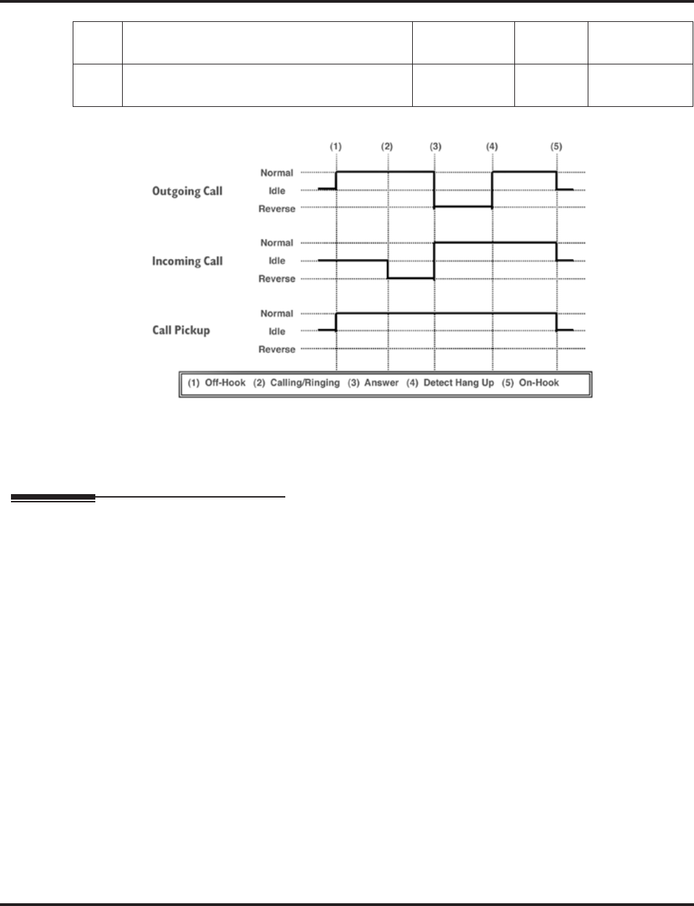
Program 15 : Extension, Basic Setup
15-03 : Single Line Telephone Basic Data Setup
Aspire Software Manual Programming ◆909
Conditions
None
Feature Cross Reference
●Single Line Telephone, Analog
●Single Line Telephone, Digital
14 Forwarded Caller ID Display Mode
Not Used in U.S. - Do Not Change Default Entry -0
15 Disconnect Without Dial After Hooking Hold
Not Used in U.S. - Do Not Change Default Entry -0

Program 15 : Extension, Basic Setup
15-03 : Single Line Telephone Basic Data Setup
910 ◆Programming Aspire Software Manual
Telephone Programming Instructions
To enter data for Program 15-03 (Single Line Telephone Basic Data Setup):
1. Enter the programming mode.
2. 15 03
3. Enter the number of the item you want to program.
4. Select the telephone number to be programmed by pressing the FLASH or the VOLUME ▲
or VOLUME ▼ keys.
5. Enter data for the item you selected + HOLD.
6. Enter data for the next item in the program.
OR
Press MSG once to enter a new item number.
OR
Press MSG until you’ve exited that series’s programming section.
15-03-01 TEL301
SLT Type 0:DP
back ↑↑
↑↑ ↓↓
↓↓ select
15-03-nn TELnnn
nnnnn
←←
←← →→
→→
Program 15 : Extension, Basic Setup
15-05 : IP Phone Terminal Basic Data Setup
Aspire Software Manual Programming ◆911
15-05 : IP Phone Terminal Basic Data Setup
Description
Use Program 15-05 : IP Phone Terminal Basic Data Setup to set up the basic settings for an IP
Phone.
Input Data
Level: Aspire S Aspire M/L/XL
IN • Available. • Available.
• Item 15: Entries are 1-5.
• Item 4 renamed from “H.323 Fixed Port
Assignment” to “Nickname” and Item 5
renamed from “H.323 Call Procedure
Port” to “Call Control Port” with 2.63+
software.
• Items 16, 17, and 18 available with soft-
ware 2.63+.
• Item 15: Entries changed from 0-4 to 1-5
with software 1.04+.
• Item 4 renamed from “H.323 Fixed Port
Assignment” to “Nickname” and Item 5
renamed from “H.323 Call Procedure
Port” to “Call Control Port” with 2.63+
software.
• Items 16, 17, and 18 available with soft-
ware 2.63+.
Extension Number Max. 8 digits
Item
No. Item Input Data Default Description Related
Program
01 Terminal Type 0 = NGT
1 = H.323
2 = SIP
3 = MEGACO
0 Viewing Only - No
changes permitted
02 NGT fixed port
assignment MAC address
00-00-00-00-00-00 to
FF-FF-FF-FF-FF-FF
00-00-00-00-00-00 For any IP telephone, the
MAC Address as indicated
on the phone/adapter’s
label to assign a specific
extension number.
Use caution when entering
in the MAC Address as the
system will allow duplicate
entries to be made. If there
are two duplicate entries,
the lowest matching exten-
sion will be assigned to the
MAC Address.
15-05-01
03 Default URL
address URL address No setting The default URL address
for Smart Phone 15-05-01
04 Nickname
Define the nick-
name for the IP
extension.
Up to 48 Character Length No setting The alias address of the
H.323/SIP terminal is set
up. Each alias address must
be unique in the system.
15-05-01

Program 15 : Extension, Basic Setup
15-05 : IP Phone Terminal Basic Data Setup
912 ◆Programming Aspire Software Manual
05-11 For viewing only - These items should not be changed.
05 H.323 Termi-
nal Type
1=Standard H.323 Ter-
minal
2=Net Meeting
0
06 NGT Terminal
Type
1=IP70
2=IP80
3=Smart Phone
0
07 Using IP
Address
0.0.0.0 ~ 255.255.255.255 0.0.0.0
08 H.323 RAS
Port
0-65535 0
09 Call Control
Port
0-65535 0
10 NGT Voice
Path Port
0-65535 0
11 NGT Call Pro-
cedure Port
0
12 System Type 0=No other system
1=Aspire 0 For system interconnection
13 Destination Sys-
tem’s IP
Address
1.0.0.1 ~ 126.255.255.254
128.1.0.1 ~
191.255.255.254
192.0.1.1 ~
223.255.255.254
0.0.0.0 Set the IP address of the
networked system.
14 Destination
System’s Call
Control Port
1-65535 1720 Set the call control port of
the networked system.
15 CODEC Type Software Prior to 1.4:
0-Type 1
1-Type 2
2-Type 3
3-Type 4
4-Type 5
Software 1.04+:
1-Type 1
2-Type 2
3-Type 3
4-Type 4
5-Type 5
0
16 Authentication
Password Maximum 24 characters None Define the Authentication
Password.
Item
No. Item Input Data Default Description Related
Program

Program 15 : Extension, Basic Setup
15-05 : IP Phone Terminal Basic Data Setup
Aspire Software Manual Programming ◆913
Conditions
None
Feature Cross Reference
●VoIP
17 Calling Party
Display Infor-
mation
0=nickname, 1=display,
2=user part, 3=extension Nickname Set the Calling Party
Display Information.
18 IP Duplication
Allowed in
Group
0=not used,
1-10=Groups 1-10 0 Some SIP equipment
allows multiple Register
messages to be sent from
the same IP address to dif-
ferent extension numbers.
This program allows the
system to avoid an IP
address conflict. The SIP
TA can connect two SLTs
to allow those phones to
work as SIP extensions.
These extension numbers
need to be programmed in
the same group in
15-05-18 to use the same
IP address. No other exten-
sion numbers should be in
this same group. Without
this program entry, the sec-
ond Register message from
an "already registered" IP
address will be ignored.
Item
No. Item Input Data Default Description Related
Program

Program 15 : Extension, Basic Setup
15-05 : IP Phone Terminal Basic Data Setup
914 ◆Programming Aspire Software Manual
Telephone Programming Instructions
To enter data for Program 15-05 (IP Phone Terminal Basic Data Setup):
1. Enter the programming mode.
2. 15 05
3. Enter the number of the item you want to program.
4. Select the telephone number to be programmed by pressing the FLASH or the VOLUME ▲
or VOLUME ▼ keys.
5. Enter data for the item you selected + HOLD.
6. Enter data for the next item in the program.
OR
Press MSG once to enter a new item number.
OR
Press MSG until you’ve exited that series’s programming section.
15-05-01 TEL301
IP-Phone Type 0:NGT
back ↑↑
↑↑ ↓↓
↓↓ select
15-05-nn TELnnn
nnnnn
←←
←← →→
→→

Program 15 : Extension, Basic Setup
15-06 : Trunk Access Map for Extensions
Aspire Software Manual Programming ◆915
15-06 : Trunk Access Map for Extensions
Description
Use Program 15-06 : Trunk Access Map for Extensions to define the trunk access map for each
extension. An extension can only place outgoing calls on trunks to which it has outgoing access.
Use Program 14-07 to define the available access maps.
Input Data
Conditions
None
Feature Cross Reference
●Central Office Calls, Answering
●Central Office Calls, Placing
Level: Aspire S Aspire M/L/XL
IN • Available. • Available.
Extension Number Max. 8 digits
Day/Night Mode Aspire S: 1-4
Aspire: 1-8
Item No. Trunk Access Map No. Default Related Program
01 Aspire S: 1-8
Aspire: 1-200 1 14-07

Program 15 : Extension, Basic Setup
15-06 : Trunk Access Map for Extensions
916 ◆Programming Aspire Software Manual
Telephone Programming Instructions
To enter data for Program 15-06 (Trunk Access Map for Extensions):
1. Enter the programming mode.
2. 15 06
3. Enter the number of the item you want to program.
4. Select the telephone number to be programmed by pressing the FLASH or the VOLUME ▲
or VOLUME ▼ keys.
5. Enter data for the item you selected + HOLD.
6. Enter data for the next item in the program.
OR
Press MSG once to enter a new item number.
OR
Press MSG until you’ve exited that series’s programming section.
15-06-01 TEL301
Mode1 Acc-Map 1
back ↑↑
↑↑ ↓↓
↓↓ select
15-06-nn TELnnn
nnnnn
←←
←← →→
→→

Program 15 : Extension, Basic Setup
15-07 : Programmable Function Keys
Aspire Software Manual Programming ◆917
15-07 : Programmable Function Keys
Description
Use Program 15-07 : Programmable Function Keys to set the functions of an extension’s Pro-
grammable Function Key.
For certain functions, you can append data to the key’s basic function. For example, the function 26
appended by data 1 makes a Group Call Pickup key for Pickup Group 1. You can also program
Function Keys using Service Codes.
In order to clear any previously programmed key, press the CLEAR key to erase any displayed
code.
Input Data
Default
Programmable keys 1-12 are line keys (key 1 = line 1, key 2 = line 2, etc.). All other programmable
keys are undefined.
Level: Aspire S Aspire M/L/XL
SA • Available. • Available.
• Code *07 for Personal Park requires soft-
ware 2.64+.
• Codes 86-88 requires software 4.93+.
• Code *07 for Personal Park requires soft-
ware 2.64+.
• Codes 86-88 requires software 4.93+.
Extension Number Max. 8 digits
Item No. Line Key
Number Function Number Additional Data
01 1-48 0-99 (General Function Level) (Service Code 851 by default)
* 00-* 99 (Appearance Function Level) (Service Code 852 by
default)
Refer to the function num-
ber list.

Program 15 : Extension, Basic Setup
15-07 : Programmable Function Keys
918 ◆Programming Aspire Software Manual
Function Number List
[1] General Function Level (00 – 99) (Service Code 851)
Function
Number Function Additional Data LED Indication
00 Not Defined
01 DSS / One-Touch Extension number or any num-
bers (Up to 24 digits) Red On: extension busy
Off: extension idle
Rapid Blink (Red): DND or Call
Forward
02 Microphone Key (ON/OFF) Red On: Mic Off
Off: Mic On
03 DND Key Red On: DND
04 BGM (ON/OFF) Red On: BGM On
Off: BGM Off
05 Headset Red On: Headset in use
06 Transfer Key None
07 Conference Key Red On: Conference call setup
occurring
08 Call History / Incoming Call
Log Rapid Blink (Red): New call log
Red On: Call log
Off: No call log
09 Day/Night Mode Switch Mode number:
• 0=toggles night mode
[Program 12-08-01],
• 1–8=modes night 1-8
Red On: Mode active
10 Call Forward - Immediate Slow Blink (Red): Forwarded
11 Call Forward - Busy Slow Blink (Red): Forwarded
12 Call Forward - No Answer Slow Blink (Red): Forwarded
13 Call Forward - Busy/No Answer Slow Blink (Red): Forwarded
14 Call Forward – Both Ring Slow Blink (Red): Forwarded
15 Follow Me Rapid Blink (Red): Forwarded
16 Call Forward to Station Slow Blink (Red): Forwarded
Rapid Blink (Red): Forwarded with
Follow Me
17 Call Forward to Device Slow Blink (Red): Forwarded
18 Text Message Setup Message Numbers (01-20) Red On: Feature activated by Function
Key

Program 15 : Extension, Basic Setup
15-07 : Programmable Function Keys
Aspire Software Manual Programming ◆919
19 External Group Paging External Paging Number
(1-8) Red On: Page Active
20 External All Call Paging Red On: Page Active
21 Internal Group Paging Internal Paging Number
(01-64) Red On: Page Active
22 Internal All Call Paging None
23 Meet-Me Answer to Internal
Paging None
24 Call Pickup None
25 Call Pickup for Another Group None
26 Call Pickup for Specified Group Call Pickup Group Number None
27 Abbreviated Dial –
Common/Private Abbreviated dial number
(Common / Private) None
28 Abbreviated Dial - Group Abbreviated dial number
(Group) None
29 Repeat Redial Red On: Waiting to redial
30 Saved Number Redial None
31 Memo Dial None
32 Meet – Me Conference None
33 Override (Off-Hook Signaling) None
34 Break - In None
35 Camp On Red On: While camp-on activated
36 Step Call None
37 DND / FWD Override Call None
38 Message Waiting None
39 Room Monitoring Rapid Blink (Red): While being
monitored
Slow Blink (Red): While monitoring
40 Handset Transmission Cutoff Red On: Transmission cut-off
41 Buzzer Extension Number Red On: Transmission side
Rapid Blink (Red): Receiver side
42 Boss – Secretary Call Extension Number Red On: Boss – Secretary mode
43 Series Call None
Function
Number Function Additional Data LED Indication

Program 15 : Extension, Basic Setup
15-07 : Programmable Function Keys
920 ◆Programming Aspire Software Manual
44 Common Hold None
45 Exclusive None
46 Department Group Log Out Red On: Logged Out
47 Reverse Voice Over Extension Number Red On: extension busy
Off: extension idle
Rapid Blink (Red): DND or Call
Forward
Green: Reverse Voice Over to
extension in progress
48 Voice Over Slow Blink (Red): Voice Over active
49 Call Redirect Extension Number or Voice
Mail Number None
50 Account Code Red On: While account code being
entered
51 General Purpose Relay Relay No (0, 1-8) Red On: Relay On
52 Incoming Call Queuing Setup Incoming Group Number Red On: Under setting
53 Queuing Message Starting Red On: Active
54 External Call Forward by Door
Box Red On: Active
55 Extension Name Edit None
56 Department Incoming Call -
Automatic Transfer Blink (Red): Active
57 Department Incoming Call -
Delayed Blink (Red): Active
58 Department Incoming Call -
Immediate Department Group Number
(1-8 or 01-64) Blink (Red): Active
59 Department Incoming Call -
Delay Department Group Number
(1-8 or 01-64) Blink (Red): Active
60 Department Incoming Call -
DND Department Group Number
(1-8 or 01-64) Blink (Red): Active
61 ID Entry
- Not Used -
63 Outgoing Call Without Caller
ID (ISDN) Red On: Active
64 Key Pad Facility Red On: Active
65 Not Used
Function
Number Function Additional Data LED Indication

Program 15 : Extension, Basic Setup
15-07 : Programmable Function Keys
Aspire Software Manual Programming ◆921
66 CTI Red On: CTI active
67 Mail Box Extension Number or Depart-
ment Group Number Rapid Blink (Green): New message
received
Red On: Listening to messages.
68 Voice Mail Service 0 = Skip
1 = Back Skip
2 = Monitor
2-In case of monitor mode
Slow Blink (Red): Monitor setting -
Automatic
Red On: Monitor setting - Manual
69 Conversation Record - ACI 0 = ACI as Record Destination
1 = Not Used in U.S.
2 = Not Used in U.S.
3 = Not Used in U.S.
Red On: Recording call.
70 Automated Attendant for
Extension Extension Number or
Department Group Number None
71 Message Change for Voice
Attendant Extension Number or
Department Group Number None
72 - Not Used -
73 - Not Used -
74 - Not Used -
75 - Not Used -
76 - Not Used -
77 Voice Mail (In-Skin) Extension Number or Pilot
Number Red On: Access to Voice Mail
Rapid Blink (Green): New Message
78 Conversation Recording - Voice
Mail Rapid Blink (Red): Recording
79 Automated Attendant (In-Skin) Extension Number or Pilot
Number Red On: Set Up for All Calls
Fast Blink (Red): Set Up for No
Answer Calls
Stutter Blink (Red): Set Up for
Busy Calls
Slow Blink (Red): Set Up for Busy/No
Answer Calls
80 Tandem Ringing 1=Set or 0=Cancel
Extension Number to Tandem
Ring
Red On: Active
86 Set Private Call Refuse
This key enables/disables the
“Private” call refusal for the
trunks set to "1" in Program
14-01-27.
Slow Blink (Red): Active
Function
Number Function Additional Data LED Indication

Program 15 : Extension, Basic Setup
15-07 : Programmable Function Keys
922 ◆Programming Aspire Software Manual
87 Set Caller ID Refuse
This key enables/disables the
Caller ID number refusal for the
trunks set to "1" in Program
14-01-27.
Slow Blink (Red): Active
88 DID Mode Switching
Assign a key for DID Mode
Switching. This key can be used
to manually change the time
pattern for a DID number.
Program 22-17 Table Number Pattern 1 = LED off
Pattern 2 = LED on
Pattern 3 = slow flash
Pattern 4 = fast flash
Patterns 5-8 = off
Function
Number Function Additional Data LED Indication

Program 15 : Extension, Basic Setup
15-07 : Programmable Function Keys
Aspire Software Manual Programming ◆923
[2] Appearance Function Level (*00 - *99) (Service Code 852)
Function
Number Function Additional Data LED Indication
*00 Not Used
*01 Trunk Key Trunk Number (1-8 or 001-200) Red On: Trunk busy by another user
Green On: Trunk busy by extension
*02 Trunk Group/Loop Key Trunk Group Number
(1-8 or 001-100) Red On: Trunk busy by another user
Green On: Trunk busy by extension
*03 Virtual Extension Key Extension Number or Depart-
ment Group Number Red On: Trunk busy by another user
Slow Blink (Red): Incoming call
*04 Park Key Park Number (01 – 64) Slow Blink (Red): Call placed in
Park by another user
Fast Blink (Green): Extension
placed call in Park
*05 Loop Keys
Use Programs 15-13-01 or
15-13-02 to assign the loop key
to a trunk group.
• 0=Incoming + Trunk Group
Number (1-8 or 001-100)
• 1=Outgoing + Trunk Group
Number (1 -8 or 001-100)
• 2=Both + Trunk Group
Number (1-8 or 001-100)
Green On: Extension on an active
call
*06 Trunk Access Via Networking Network System Number
(01-50)
*07 Personal Park Slow Blink (Green): Parked call
recalling extension user
Fast Blink (Green): Extension
placed call in Personal Park
*10 ACD Log – In / Log – Out Red On: Under log-on
Off: Under log-off
*11 -Not Used -
*12 ACD Emergency Call Red On: Under monitor, Override,
Standby
Fast Blink (Red): Supervisor phone
receiving Emergency Call
*13 ACD Off Duty Mode Red On: Under off duty
Slow Blink (Red): Under reservation
*14 ACD Start / End Red On: ACD operation end
*15 ACD Monitor Mode - Terminal Red On: Under monitor
*16 ACD Standby Mode Red On: Standby
*17 ACD Wrap-Up Mode Red On: Under work time
Slow Blink (Red): Under reservation

Program 15 : Extension, Basic Setup
15-07 : Programmable Function Keys
924 ◆Programming Aspire Software Manual
Conditions
When a key is programmed using service code 852, that key cannot be programmed with a function
using the 851 code until the key is undefined (000). For example with a Park Key programmed by
dialing 852 + *04 must be undefined by dialing 852 + 000 before it can be programmed as a Voice
Over key by dialing 851 + 48.
Feature Cross Reference
Refer to chart above.
Telephone Programming Instructions
To enter data for Program 15-07 (Programmable Function Keys):
1. Enter the programming mode.
2. 15 07
3. Enter the number of the item you want to program.
4. Select the telephone number to be programmed by pressing the FLASH or the VOLUME ▲
or VOLUME ▼ keys.
5. Enter data for the item you selected + HOLD.
6. Enter data for the next item in the program.
OR
Press MSG once to enter a new item number.
OR
Press MSG until you’ve exited that series’s programming section.
*18 ACD Overflow Control ACD Group Number Red On: Enable
Slow Blink (Red): Disable
*19 ACD Queue Status Display
Check
15-07-01 TEL301
KY01 = *01
back ↑↑
↑↑ ↓↓
↓↓ select
15-07-nn TELnnn
nnnnn
←←
←← →→
→→

Program 15 : Extension, Basic Setup
15-08 : Incoming Virtual Extension Ring Tone Setup
Aspire Software Manual Programming ◆925
15-08 : Incoming Virtual Extension Ring Tone Setup
Description
Use Program 15-08 : Incoming Virtual Extension Ring Tone Setup to assign a ring tone range
(0-4) to incoming virtual extensions assigned to a Virtual Extension key (Program 15-07). If you
enable ringing for the key in Program 15-09, the key rings with the tone you set in this program.
Also see Program 22-03. The chart below shows the available tones.
Input Data
Level: Aspire S Aspire M/L/XL
IN • Available - 24 virtual extension ports. • Available - 256 virtual extension ports.
Extension Number Max. 8 digits
Item
No. Incoming Ring Pattern Default Description
01 0 = Tone pattern 1
1 = Tone pattern 2
2 = Tone pattern 3
3 = Tone pattern 4
4 = Incoming extension ring tone
0: Tone pattern 1 When an extension or a virtual extension is
assigned to the function key on the key telephone,
select the ring tone when receiving a call on that
key.
For ACD Call Coverage Keys, only tone pattern 1
(entry 0) can be used. The remaining patterns are
not checked with this feature.
Incoming Signal
Frequency
Pattern
Type Frequency 1 Frequency 2 Modulation
Pattern 1 High
Middle
Low
1100
660
520
1400
760
660
16Hz
16Hz
16Hz
Pattern 2 High
Middle
Low
1100
660
520
1400
760
660
8Hz
8Hz
8Hz
Pattern 3 High
Middle
Low
1100
660
520
1100
660
520
Envelope
Envelope
Envelope
Pattern 4 High
Middle
Low
1100
660
520
1100
660
520
No modulation
No modulation
No modulation
Internal Incoming Signal
Frequency High
Middle
Low
1100
660
520
1400
760
660
8Hz
8Hz
8Hz

Program 15 : Extension, Basic Setup
15-08 : Incoming Virtual Extension Ring Tone Setup
926 ◆Programming Aspire Software Manual
Conditions
None
Feature Cross Reference
●Multiple Directory Number / Call Coverage
Telephone Programming Instructions
To enter data for Program 15-08 (Incoming Virtual Extension Ring Tone Setup):
1. Enter the programming mode.
2. 15 08
3. Enter the number of the item you want to program.
4. Select the telephone number to be programmed by pressing the FLASH or the VOLUME ▲
or VOLUME ▼ keys.
5. Enter data for the item you selected + HOLD.
6. Enter data for the next item in the program.
OR
Press MSG once to enter a new item number.
OR
Press MSG until you’ve exited that series’s programming section.
15-08-01 TEL301
V’Tual_Ext_Rng0:Pattern1
back ↑↑
↑↑ ↓↓
↓↓ select
15-08-nn TELnnn
nnnnn
←←
←← →→
→→

Program 15 : Extension, Basic Setup
15-09 : Virtual Extension Ring Assignment
Aspire Software Manual Programming ◆927
15-09 : Virtual Extension Ring Assignment
Description
Use Program 15-09 : Virtual Extension Ring Assignment to assign the ringing options for an
extension’s Virtual Extension Key or Virtual Department Group Answer Key which is defined in
Program 15-07. You make an assignment for each Night Service Mode.
Assign extension numbers and names to virtual extension ports in Program 15-01. Program Virtual
Extension keys in Program 15-07 (code *03).
Input Data
Conditions
Program the Multiple Directory Number function keys NOT to ring before removing the key from a
keyset’s programming.
Feature Cross Reference
●Multiple Directory Number / Call Coverage
Level: Aspire S Aspire M/L/XL
SA • Available - 24 virtual extension ports. • Available - 256 virtual extension ports.
Extension Number Up to 8 digits
Key Number 01-48
Item No. Day/Night Mode Ringing Default
01 Aspire S: 1-4
Aspire: 1-8 0 = No ringing
1 = Ring 0

Program 15 : Extension, Basic Setup
15-09 : Virtual Extension Ring Assignment
928 ◆Programming Aspire Software Manual
Telephone Programming Instructions
To enter data for Program 15-09 (Virtual Extension Ring Assignment):
1. Enter the programming mode.
2. 15 09
3. Enter the number of the item you want to program.
4. Select the telephone number to be programmed by pressing the FLASH or the VOLUME ▲
or VOLUME ▼ keys.
5. Enter data for the item you selected + HOLD.
6. Enter data for the next item in the program.
OR
Press MSG once to enter a new item number.
OR
Press MSG until you’ve exited that series’s programming section.
15-09-01 TEL301
KY01 Mode1 =0:No
←←
←← →→
→→
15-09-nn TELnnn
nnnnn
←←
←← →→
→→
Program 15 : Extension, Basic Setup
15-10 : Incoming Virtual Extension Ring Tone Order Setup
Aspire Software Manual Programming ◆929
15-10 : Incoming Virtual Extension Ring Tone Order Setup
Description
Use Program 15-10 : Incoming Virtual Extension Ring Tone Order Setup to set the priority
(1-4) for the Virtual Extension Ring Tones set in Program 15-08. When Virtual Extension calls ring
an extension simultaneously, the tone with the highest order number (e.g., 1) rings. The other keys
just flash.
Input Data
Default
By default, Virtual Extension ring tones have the following order.
Conditions
None
Feature Cross Reference
●Multiple Directory Number / Call Coverage
Level: Aspire S Aspire M/L/XL
SA • Available - 24 virtual extension ports. • Available - 256 virtual extension ports.
Extension Number Up to 8 digits
Item No. Order Data Description Related
Program
01 1-4 0 = Tone pattern 1
1 = Tone pattern 2
2 = Tone pattern 3
3 = Tone pattern 4
4 = Incoming extension ring tone
In the case of that two or more virtual exten-
sions are set on a function key on the keyset,
and the tone pattern by which the sound of
each extension differs, the priority of ring
sound is set up.
15-08
Order Ring Tone
(Set in Program 15-08)
10
21
32
43

Program 15 : Extension, Basic Setup
15-10 : Incoming Virtual Extension Ring Tone Order Setup
930 ◆Programming Aspire Software Manual
Telephone Programming Instructions
To enter data for Program 15-10 (Incoming Virtual Extension Ring Tone Order
Setup):
1. Enter the programming mode.
2. 15 10
3. Enter the number of the item you want to program.
4. Select the telephone number to be programmed by pressing the FLASH or the VOLUME ▲
or VOLUME ▼ keys.
5. Enter data for the item you selected + HOLD.
6. Enter data for the next item in the program.
OR
Press MSG once to enter a new item number.
OR
Press MSG until you’ve exited that series’s programming section.
15-10-01 TEL301
Order1 0:Pattern1
←←
←← →→
→→
15-10-nn TELnnn
nnnnn
←←
←← →→
→→
Program 15 : Extension, Basic Setup
15-11 : Virtual Extension Delayed Ring Assignment
Aspire Software Manual Programming ◆931
15-11 : Virtual Extension Delayed Ring Assignment
Description
Use Program 15-11 : Virtual Extension Delayed Ring Assignment to assign the delayed ringing
options for an extension’s Virtual Extension or Virtual Department Group Answer keys (defined in
Program 15-09). You make an assignment for each Night Service Mode.
Assign extension numbers (Program 11-04) and names (Program 15-01) to virtual extension ports.
Program Multiple Directory Number (virtual extension) keys in Program 15-07 (code *03).
Input Data
Conditions
Program the Multiple Directory Number keys NOT to ring before removing the key from a keyset’s
programming.
Feature Cross Reference
●Multiple Directory Number / Call Coverage
Level: Aspire S Aspire M/L/XL
SA • Available - 24 virtual extension ports. • Available - 256 virtual extension ports.
Extension Number Max. 8 digits
Key Number 01-48
Item No. Day/Night Mode Ringing Default Related Program
01 Aspire S: 1-4
Aspire: 1-8 0 = Immediate Ring
1 = Delayed Ring 0 20-04-03

Program 15 : Extension, Basic Setup
15-11 : Virtual Extension Delayed Ring Assignment
932 ◆Programming Aspire Software Manual
Telephone Programming Instructions
To enter data for Program 15-11 (Virtual Extension Delayed Ring Assignment):
1. Enter the programming mode.
2. 15 11
3. Enter the number of the item you want to program.
4. Select the telephone number to be programmed by pressing the FLASH or the VOLUME ▲
or VOLUME ▼ keys.
5. Enter data for the item you selected + HOLD.
6. Enter data for the next item in the program.
OR
Press MSG once to enter a new item number.
OR
Press MSG until you’ve exited that series’s programming section.
15-11-01 TEL301
KY01 Mode1 =0:No
back ↑↑
↑↑ ↓↓
↓↓ select
15-11-nn TELnnn
nnnnn
←←
←← →→
→→

Program 15 : Extension, Basic Setup
15-12 : Conversation Recording Destination for Extensions
Aspire Software Manual Programming ◆933
15-12 : Conversation Recording Destination for Extensions
Description
Use Program 15-12 : Conversation Recording Destination for Extensions to set the ACI
Conversation Recording destination for each extension.
Note: If both Programs 14-09 and 15-12 define a destination, the destination in Program 15-12
will be followed.
Input Data
Conditions
None
Feature Cross Reference
●Analog Communications Interface (ACI)
Level: Aspire S Aspire M/L/XL
IN • Available. • Available.
Extension Number Max. 8 digits
Item
Number Item Input Data Default
01 ACI Recording Destination Extension Number
Enter the ACI’s extension number to which the trunk calls
should be recorded.
Max. 8 digits No setting
02 ACI Automatic Recording for Incoming Calls
Determine if an extension’s incoming calls should be automati-
cally recorded to the ACI.
0 = Disable
1 = Enable 0
03 Recording Contents Storing Method (DSPDB)
- Not Used in U.S. -
0 = Specified
1 = Own box 0
04 ACI Automatic Recording for Outgoing Call
Determine if an extension’s outgoing calls should be automati-
cally recorded to the ACI.
0 = Disable
1 = Enable 0

Program 15 : Extension, Basic Setup
15-12 : Conversation Recording Destination for Extensions
934 ◆Programming Aspire Software Manual
Telephone Programming Instructions
To enter data for Program 15-12 (Conversation Recording Destination for
Extensions):
1. Enter the programming mode.
2. 15 12
3. Enter the number of the item you want to program.
4. Select the telephone number to be programmed by pressing the FLASH or the VOLUME ▲
or VOLUME ▼ keys.
5. Enter data for the item you selected + HOLD.
6. Enter data for the next item in the program.
OR
Press MSG once to enter a new item number.
OR
Press MSG until you’ve exited that series’s programming section.
15-12-01 TEL301
Rec.Destin.Ext
back ↑↑
↑↑ ↓↓
↓↓ select
15-12-nn TELnnn
nnnnn
←←
←← →→
→→
Program 15 : Extension, Basic Setup
15-13 : Loop Keys
Aspire Software Manual Programming ◆935
15-13 : Loop Keys
Description
Use Program 15-13 : Loop Keys to assign the Loop Key data for each keyset telephone. Loop
Keys can be incoming, outgoing or both ways. Outgoing Loop Keys use the entry in item 1. Incom-
ing Loop Keys use the entry in item 2. Both Way Loop Keys follow the entries in both item 1 and 2.
Input Data
Default
Programmable Function Key No. - 01-32
Outgoing Option - 0 (Assigns the Loop Key for ARS)
Incoming Options - 0 (Assigns the Loop Key to all trunk groups)
Conditions
None
Feature Cross Reference
●Loop Key
Level: Aspire S Aspire M/L/XL
IN • Available. • Available.
Extension Number Max. 8 digits
Key Number 01-48
Item
Number Item Input Data
01 Outgoing Option 0-8 or 0-100
(0 = Assigns the Loop Key for ARS,
1-8 or 1-100 = Assigns the Loop Key to the trunk
group specified)
02 Incoming Option 0-8 or 0-100
(0 = Assigns the Loop Key to all trunk groups,
1-8 or 1-100 = Assigns the Loop key to the trunk
group specified)

Program 15 : Extension, Basic Setup
15-13 : Loop Keys
936 ◆Programming Aspire Software Manual
Telephone Programming Instructions
To enter data for Program 15-13 (Loop Keys):
1. Enter the programming mode.
2. 15 13
3. Enter the number of the item you want to program.
4. Select the telephone number to be programmed by pressing the FLASH or the VOLUME ▲
or VOLUME ▼ keys.
5. Enter data for the item you selected + HOLD.
6. Enter data for the next item in the program.
OR
Press MSG once to enter a new item number.
OR
Press MSG until you’ve exited that series’s programming section.
15-13-01 TEL301
OUTGOING KY01 = 0
back ↑↑
↑↑ ↓↓
↓↓ select
15-12-nn TELnnn
nnnnn
←←
←← →→
→→
Program 15 : Extension, Basic Setup
15-14 : Programmable One-Touch Keys
Aspire Software Manual Programming ◆937
15-14 : Programmable One-Touch Keys
Description
Use Program 15-14 : Programmable One-Touch Keys to define the One-Touch key data for each
keyset telephone.
For each Aspire Wireless phone to use the Transfer When Out of Range feature, enter the destina-
tion number (up to 24 digits) and name (up to 12 characters) into One-Touch bin 10. Make sure to
add any required trunk access codes for outside numbers. If this bin information is changed either
through 15-14-01 or through user programming, the destination for the transferred calls is also
changed.
Input Data
Default
No entries for any extension.
Conditions
None
Feature Cross Reference
●One-Touch Keys
Level: Aspire S Aspire M/L/XL
IN • Available. • Available.
Extension Number Max. 8 digits
Key Number 01-10
Item No. Dial Data Name
01 1-0, *, #,
Pause [press Line Key 1],
Hookflash [press Line Key 2],
@ (Code for Answer-Wait) [press Line Key 3]
Up to 24 digits
Up to 12 Digits

Program 15 : Extension, Basic Setup
15-14 : Programmable One-Touch Keys
938 ◆Programming Aspire Software Manual
Telephone Programming Instructions
To enter data for Program 15-14 (Programmable One-Touch Keys):
1. Enter the programming mode.
2. 15 14
3. Enter the number of the item you want to program.
4. Select the telephone number to be programmed by pressing the FLASH or the VOLUME ▲
or VOLUME ▼ keys.
5. Enter data for the item you selected + HOLD.
6. Enter data for the next item in the program.
OR
Press MSG once to enter a new item number.
OR
Press MSG until you’ve exited that series’s programming section.
15-14-01 TEL301
KY01 Dial=
back ↑↑
↑↑ ↓↓
↓↓ select
15-14-nn TELnnn
nnnnn
←←
←← →→
→→

Program 15 : Extension, Basic Setup
15-15 :Aspire Wireless Terminal Basic Data Setup
Aspire Software Manual Programming ◆939
15-15 :Aspire Wireless Terminal Basic Data Setup
Description
Use Program 15-15 : Aspire Wireless Terminal Basic Data Setup to define the options for the
Aspire Wireless phones.
Input Data
Level: Aspire S Aspire M/L/XL
IN • Not Available. • Available.
• Gain adjustment programs available with
2.63+ software.
Extension Number Max. 8 digits
Item
No. Item Input Data Default Related
Program
01 DECT Terminal Basic Data Setup - IPEI
The IPEI (International Portable Equipment Identity) is a
unique number embedded into each Aspire Wireless
(DECT) phone. The IPEI number is the 13-digit serial
number which is located on the label in the phone’s battery
compartment. Use this program to display the IPEI num-
ber assigned to a Aspire Wireless phone during the phone
subscription. This program is read only.
This program is
read only.
-
02 DECT Terminal Basic Data Setup - Authentication Code
This program displays the 4-digit AC (Authentication
Code) assigned to the Aspire Wireless (DECT) phone dur-
ing the phone subscription. This program is read only.
This program is
read only.
-

Program 15 : Extension, Basic Setup
15-15 :Aspire Wireless Terminal Basic Data Setup
940 ◆Programming Aspire Software Manual
03 DECT Terminal Basic Data Setup - Terminal Capability
This program displays the capability of the Aspire Wireless
(DECT) phone displaying the options below. This program
is read only.
• Display Capabilities
• ISDN Support
• Tone Capabilities
• Data Services Profile E Class 2
• Echo Parameters
• Data Services Profile A/B Class 2
• Portable Part Ambient Noise Rejection (N-REJ)
• Multi-Bearers Support for Data Services Profile
• Adaptive Volume Control Provision (A-Vol)
• Data Services Profile C Class 2
• Slot Type Capability
• Data Services Profile D Class 2
• Number of Stored Display Characters
• Data Services Profile F Class 2
• Number of Lines in Display
• DECT/GSM Interworking - GSM Bearer Service
• Number of Characters Per Line
• DECT/GSM Interworking - GSM SMS Service
• Scrolling Behavior Field
• DECT/GSM Interworking - GSM Facsimile Service
• GAP/PAP Support
• Control Codes
• DECT/GSM Interworking Profile Supported
• ISO8859-1 Support
This program is
read only.
-
04 DECT Terminal Basic Data Setup - Model Identifier
This program shows the model identifier that the Aspire Wire-
less (DECT) terminal uses. The model identifier contains the
following items: Manufacturer Identification Code (MANIC)
and Model Identification Code (MODIC). This program is read
only.
This program is
read only. -
05 DECT Terminal Basic Data Setup - Voice Mail Answering
When Out of Range
This program enables (1) or disables (0) the ability for calls to
be transferred to voice mail if the Aspire Wireless (DECT)
phone is out of range. If Program 15-15-05 and 15-15-06 are
both enabled, Program 15-15-05 takes priority. If both pro-
grams are disabled, the caller hears a lock-out tone and they
may see “Out of Range” on their display.
0 = Disabled
1 = Enabled 0 15-15-05
15-15-06
06 DECT Terminal Basic Data Setup - Call Transferring
When Out of Range
This program enables (1) or disables (0) the ability for calls to
be transferred to another extension if the Aspire Wireless
(DECT) phone is out of range. If Program 15-15-05 and
15-15-06 are both enabled, Program 15-15-05 takes priority. If
both programs are disabled, the caller hears a lock-out tone and
the may see “Out of Range” on their display.
0 = Disabled
1 = Enabled 0 15-15-05
15-15-06
Item
No. Item Input Data Default Related
Program

Program 15 : Extension, Basic Setup
15-15 :Aspire Wireless Terminal Basic Data Setup
Aspire Software Manual Programming ◆941
Conditions
None
Feature Cross Reference
●Aspire Wireless
Telephone Programming Instructions
To enter data for Program 15-15 (Aspire Wireless Terminal Basic Data Setup):
1. Enter the programming mode.
2. 15 15
3. Enter the number of the item you want to program.
4. Select the telephone number to be programmed by pressing the FLASH or the VOLUME ▲
or VOLUME ▼ keys.
5. Enter data for the item you selected + HOLD.
6. Enter data for the next item in the program.
OR
Press MSG once to enter a new item number.
OR
Press MSG until you’ve exited that series’s programming section.
07 Transmit Level
This option will adjust the gain for transmitting when using an
Aspire Wireless handset.
01-63 32
08 Receive Level
This option will adjust the gain for receiving when using an
Aspire Wireless handset.
01-63 32
15-15-01 TEL301
IPEI
back ↑↑
↑↑ ↓↓
↓↓ select
15-15-nn TELnnn
nnnnn
←←
←← →→
→→
Item
No. Item Input Data Default Related
Program

Program 15 : Extension, Basic Setup
15-16 : SIP Register ID Setup for Extension
942 ◆Programming Aspire Software Manual
15-16 : SIP Register ID Setup for Extension
Description
Use Program 15-16 : SIP Register ID Setup for Extension to set the SIP Register ID to an exten-
sion port. If both 14-12 and 15-16 are assigned, then the system uses the data in Program 15-16.
Register ID 0 is associated with Program 10-28 and 10-29 data. Other registered IDs (1-31) are
associated with Program 10-36 data.
Contact Your NEC Sales Representative for information on the SIP feature availability.
Input Data
Conditions
None
Feature Cross Reference
●VoIP
Level: Aspire S Aspire M/L/XL
IN • Available. • Available.
Extension Number Max. 8 digits
Item No. Item Entries Default Related
Program
01 SIP Register ID Setup for
Extension
Set the SIP Register ID to an
extension port.
0-31 0 10-28
10-29
10-36
14-12

Program 15 : Extension, Basic Setup
15-16 : SIP Register ID Setup for Extension
Aspire Software Manual Programming ◆943
Telephone Programming Instructions
To enter data for Program 15-16 (SIP Register ID Setup for Extension):
1. Enter the programming mode.
2. 15 16
3. Enter the number of the item you want to program.
4. Select the telephone number to be programmed by pressing the FLASH or the VOLUME ▲
or VOLUME ▼ keys.
5. Enter data for the item you selected + HOLD.
6. Enter data for the next item in the program.
OR
Press MSG once to enter a new item number.
OR
Press MSG until you’ve exited that series’s programming section.
15-16-01 TEL301301
Register ID
back ↑↑
↑↑ ↓↓
↓↓ select
15-16-nn TELnnn
nnnnn
←←
←← →→
→→

Program 15 : Extension, Basic Setup
15-19 : System Telephone Book Setup for Extension
944 ◆Programming Aspire Software Manual
15-19 : System Telephone Book Setup for Extension
Description
Use Program 15-19 : System Telephone Book Setup for Extension to assign the Telephone
Books to each extension and the options for them.
Input Data
Conditions
None
Feature Cross Reference
●Center Telephone Book
Level: Aspire S Aspire M/L/XL
IN • Available with software 4.93+. • Available with software 4.93+.
Extension Number Max. 8 digits
Item No. Item Entries Default Related
Program
01 Telephone Book Number 1
Assign the first Telephone Book to each
extension. The system allows multiple
extensions to be assigned the same tele-
phone book - this allows users to share
commonly used numbers.
Aspire S =
0-50
Aspire M/L/XL =
0-100
Aspire S:
Telephone Books
1-50 assigned to
Extensions 301-350
Aspire M/L/XL:
Telephone Books
1-100 assigned to
Extensions 301-400
02 Telephone Book Number 2
Assign the second Telephone Book to each
extension. The system allows multiple
extensions to be assigned the same tele-
phone book - this allows users to share
commonly used numbers.
Aspire S =
0-50
Aspire M/L/XL =
0-100
No Telephone Books
assigned
06 Locking Telephone Book
For each extension, determine if the Tele-
phone Book should be locked by default. A
user can unlock the Telephone Book using
the service code defined in Program
11-11-56.
0 = Unlocked
1 = Locked 01 11-11-56
07 Telephone Book Password
For each extension, assign the 4-digit Tele-
phone Book password.
0000-9999
(must be 4 digits) 0000

Program 15 : Extension, Basic Setup
15-19 : System Telephone Book Setup for Extension
Aspire Software Manual Programming ◆945
Telephone Programming Instructions
To enter data for Program 15-19 (System Telephone Book Setup for Extension):
1. Enter the programming mode.
2. 15 19
3. Enter the number of the item you want to program.
4. Select the telephone number to be programmed by pressing the FLASH or the VOLUME ▲
or VOLUME ▼ keys.
5. Enter data for the item you selected + HOLD.
6. Enter data for the next item in the program.
OR
Press MSG once to enter a new item number.
OR
Press MSG until you’ve exited that series’s programming section.
15-19-01 TEL301301
TelBook1 1
←←
←← →→
→→
15-16-nn TELnnn
nnnnn
←←
←← →→
→→

Program 15 : Extension, Basic Setup
15-19 : System Telephone Book Setup for Extension
946 ◆Programming Aspire Software Manual
- For Your Notes -

Program 16 : Department Group Setup
16-01 : Department Group Basic Data Setup
Aspire Software Manual Programming ◆947
Program 16 : Department Group Setup
16-01 : Department Group Basic Data Setup
Description
Use Program 16-01 : Department Group Basic Data Setup to set the function mode for each
department group.
Input Data
Level: Aspire S Aspire M/L/XL
IN • Available - 8 Department Groups. • Available - 64 Department Groups.
Department Group Number Aspire S: 1-8
Aspire: 01-64
Item
No. Item Input Data Default Related
Program
01 Department Name Max. 12 characters No setting 11-07
02 Department Calling Cycle
Use this option to set the call routing
for Department Calling. Routing can
be either circular (cycles to all phones
in group) or priority (cycles to highest
priority extensions first).
0 = Priority Routing
1 = Circular Routing 0 16-02
03 Department Routing When Busy
Use this option to set how the system
routes an Intercom call to a busy
Department Group member. Intercom
callers to the extension can either hear
busy or route to the first available
department number. This only occurs
for calls to the extension directly, not
the department number assigned in
Program 11-07.
0 = Normal (Intercom caller to busy
department member hears busy)
1 = Circular (Intercom callers to busy
department member routes to idle
member)
0 16-02
04 Hunting Mode
Use this option to set the action taken
when a call reaches the last extension
in the Department Group (0=hunting
stopped, 1 =hunting repeats with circu-
lar routing through the Department
Group.
0 = Last extension is called and hunting
is stopped.
1 = Circular
0
05 Department Group All Ring Mode
Operation
Determine whether calls ringing a
Department Group should ring all
extensions in the group simultaneously
automatically or manually when using
the service code defined in Program
11-12-09.
0 = Manual
1 = Automatic 0 11-16-10

Program 16 : Department Group Setup
16-01 : Department Group Basic Data Setup
948 ◆Programming Aspire Software Manual
Conditions
None
Feature Cross Reference
●Department Calling
06 STG Withdraw Mode
- Not Used - 0 = Disable (Camp On)
1 = Enable (Overflow Mode) 0
07 Call Recall Restriction for STG
Determine whether a or not an unan-
swered call transferred to a Department
Group should recall the extension from
which it was transferred.
0 = Disable (Recall)
1 = Enable (No Recall) 0
08 Queuing for Department Group Call
To have Department Group calls queue
when busy, set this entry to “1” for an
extension or voice mail group.
0 = No Queuing
1 = Queuing
(This program allows entries of 1-32,
however, the system accepts any entry
other than “0” as to allow queuing.)
0
09 Department Hunting No Answer
Time
Set how long a call will ring a Depart-
ment group extension before hunting
occurs.
0-64800 seconds 15
10 Hunt Type
Set the type of hunting for each Exten-
sion (Department) Group:
0 = No queuing
1 = Hunting When Busy
2 = Hunting When Not Answered
3 = Hunting When Busy or No Answer
0
Item
No. Item Input Data Default Related
Program

Program 16 : Department Group Setup
16-01 : Department Group Basic Data Setup
Aspire Software Manual Programming ◆949
Telephone Programming Instructions
To enter data for Program 16-01 (Department Group Basic Data Setup):
1. Enter the programming mode.
2. 16 01
3. Enter the number of the item you want to program.
4. Select the Department Group number to be programmed by pressing the FLASH or the VOL-
UME ▲ or VOLUME ▼ keys.
5. Enter data for the item you selected + HOLD.
6. Enter data for the next item in the program.
OR
Press MSG once to enter a new item number.
OR
Press MSG until you’ve exited that series’s programming section.
16-01-01 TEL Group1
Dept.Name =
back ↑↑
↑↑ ↓↓
↓↓ select
16-01-nn TEL Groupnn
nnnnn
←←
←← →→
→→

Program 16 : Department Group Setup
16-02 : Department Group Assignment for Extensions
950 ◆Programming Aspire Software Manual
16-02 : Department Group Assignment for Extensions
Description
Use Program 16-02 : Department Group Assignment for Extensions to assign each extension to
a Department Group and to assign the extenion’s priority in the group. When a call comes into the
group, it may ring the extensions in order of their priority. The system uses these groups for Depart-
ment Calling. Assign pilot numbers to Department Groups in Program 11-07. This lets system users
place calls to the departments.
For voice mail, assign the voice mail ports to the same group. With IntraMail, these ports are
defined in Program 47-01-17.
Input Data
Note: The initial value of a priority becomes the ports numerical order assigned in Program 11-02
and 11-04. (Extension ports are 1-50 [Aspire S] or 1 to 256 [Aspire]. Virtual extension ports
are 1-24 [Aspire S] or 1-256 [Aspire].)
Conditions
None
Feature Cross Reference
●Department Calling
Level: Aspire S Aspire M/L/XL
IN • Available - 8 Department Groups. • Available - 64 Department Groups.
Extension Number Max. 8 digits
Item No. Group
Number Priority Default Description Related
Program
01 Aspire S:
1-8
Aspire:
1-64
1-999 1 – xxx
(See Note
Below)
Set up the Department Group called by the
pilot number and the extension priority
when a group is called.
Call Pickup Groups are set up in 23-02.
11-07
16-01

Program 16 : Department Group Setup
16-02 : Department Group Assignment for Extensions
Aspire Software Manual Programming ◆951
Telephone Programming Instructions
To enter data for Program 16-02 (Department Group Assignment for Extensions):
1. Enter the programming mode.
2. 16 02
3. Enter the number of the item you want to program.
4. Select the telephone number to be programmed by pressing the FLASH or the VOLUME ▲
or VOLUME ▼ keys.
5. Enter data for the item you selected + HOLD.
6. Enter data for the next item in the program.
OR
Press MSG once to enter a new item number.
OR
Press MSG until you’ve exited that series’s programming section.
16-02-01 TEL301
Extension Group1
back ↑↑
↑↑ ↓↓
↓↓ select
16-02-nn TELnnn
nnnnn
←←
←← →→
→→

Program 16 : Department Group Setup
16-03 : Secondary Department Group
952 ◆Programming Aspire Software Manual
16-03 : Secondary Department Group
Description
Use Program 16-03 : Secondary Department Group to set a second Department Group for
extensions. Each secondary Department Group can have up to 16 extensions assigned.
Input Data
Default
All Department Groups : No setting
Conditions
Department Group All Ring (Program 16-01-05) will not include any extensions assigned in this
program. It will only include those extensions which have the Department Group as their primary
group (assigned in Program 16-02-01).
Feature Cross Reference
●Department Calling
Level: Aspire S Aspire M/L/XL
IN • Available - 8 Department Groups. • Available - 64 Department Groups.
Secondary Department (Extension) Group Number Aspire S: 1-8
Aspire: 01-64
Item
No. Extension Entry Extension
Number
Priority
Order Description
01 01-16
(16 extensions num-
bers can be assigned
per Secondary
Department Group)
Max. 8 digits 0-999 This program is set up when placing extensions into two
or more groups.

Program 16 : Department Group Setup
16-03 : Secondary Department Group
Aspire Software Manual Programming ◆953
Telephone Programming Instructions
To enter data for Program 16-03 (Secondary Department Group):
1. Enter the programming mode.
2. 16 03
3. Enter the number of the item you want to program.
4. Select the Pilot extension number to be programmed by pressing the FLASH or the VOLUME
▲ or VOLUME ▼ keys.
5. Enter data for the item you selected + HOLD.
6. Enter data for the next item in the program.
OR
Press MSG once to enter a new item number.
OR
Press MSG until you’ve exited that series’s programming section.
16-03-01 Pilot Extn1
2ND_Group 01=
back ↑↑
↑↑ ↓↓
↓↓ select
16-03-nn Pilot Extnnn
nnnnn
←←
←← →→
→→

Program 16 : Department Group Setup
16-03 : Secondary Department Group
954 ◆Programming Aspire Software Manual
- For Your Notes -

Program 20 : System Option Setup
20-01 : System Options
Aspire Software Manual Programming ◆955
Program 20 : System Option Setup
20-01 : System Options
Description
Use Program 20-01 : System Options to set various system options.
Input Data
Level: Aspire S Aspire M/L/XL
IN • Available. • Available.
Item
No. Item Input Data Default Related
Program
01 Operator Access Mode
Use this program to set up priority of a call when calling an operator
telephone.
0 20-17
02 Selectable Text Message Mode
Use this program to select the mode when calling the telephone
which has enabled a Selectable Text Message.
Note: Any extensions previously set with Selectable Display Mes-
saging must cancel the feature and reactivate in order for a change
in this option to take affect.
0 = Call mode
1 = No Answer/
Busy mode
1 11-11-14
15-07-08
03 DSP Sender Resource Selection
Wth the Caller ID Sender Queuing feature, set the DSP Sender
Resource Selection to "1" (Caller ID Sender).
0 = Conference
1 = Caller ID
2 = MFC
0
04 Network BLF Indication
Used to determine how often the system updates the DSS key BLF
indications.
For Networking, the entry should be “30” in all systems.
0-64800 in 100
ms increments 0 30-05
05 DTMF Receive Active Time
For OPXs, analog telephones and certain analog trunks (like DISA),
the system attaches a DTMF receiver to the port for this interval.
The system releases the receiver after the interval expires.
0-64800 seconds 10 25-07-01
06 Alarm Duration
This interval sets the duration of the alarm signal. 0-64800 seconds 30
07 Callback Ring Duration Time
Callback rings an extension for this interval. 0-64800 seconds 15 11-12-05
15-07-35
08 Trunk Queuing Callback Time
Trunk Queuing callback rings an extension for this interval. 0-64800 seconds 15 11-12-05
15-07-35
09 Callback/Trunk Queuing Cancel Time
The system cancels an extension’s Callback or Trunk Queueing
request after this interval.
0-64800 seconds 64800 11-12-05
15-07-35
10 Trunk Guard Timer
- Not Used - 0-64800 seconds 1

Program 20 : System Option Setup
20-01 : System Options
956 ◆Programming Aspire Software Manual
Conditions
None
Feature Cross Reference
Refer to above chart.
Telephone Programming Instructions
To enter data for Program 20-01 (System Options):
1. Enter the programming mode.
2. 20 01
3. Enter the number of the item you want to program.
4. Enter data for the item you selected + HOLD.
5. Enter data for the next item in the program.
OR
Press MSG once to enter a new item number.
OR
Press MSG until you’ve exited that series’s programming section.
20-01-01
Operator_Access0:Step
back ↑↑
↑↑ ↓↓
↓↓ select
20-01-nn
nnnnn
←←
←← →→
→→

Program 20 : System Option Setup
20-02 : System Options for Multi-Line Telephones
Aspire Software Manual Programming ◆957
20-02 : System Options for Multi-Line Telephones
Description
Use Program 20-02 : System Options for Multi-Line Telephones to set various system options
for Multi-Line Telephones.
Input Data
Level: Aspire S Aspire M/L/XL
IN • Available. • Available.
• Item 15 not available. • Item 15 requires software 4.0E+.
Item
No. Item Input Data Default
01 Trunk Loop Key Operation Mode 0 = Indicate Using Loop Trunk
1 = Not indicated 0
Mode 0 = Keep
Lamp
1 = Extinction
Incoming: 300 IPM Red blink
Talking: Green Light-
ing (on Talk-
ing TEL)
Extinction
(LED off)
Holding: 60 IPM
Green blink
(on holding
TEL)
Extinction
(LED off)
02 Trunk Loop Access Key Operating
Mode
Use this option to set the operating mode
of the extension’s trunk group keys. The
keys can be for incoming access, outgo-
ing access or both.
0 = Outgoing / Incoming
1 = Outgoing
2 = Incoming
0
03 BLF Control
Set the conditions under which a Hot-
line, Reverse Voice Over or DSS Con-
sole key indicates that an extension is
busy. Refer to the Reverse Voice Over
feature for more information.
0 = Idle / Busy (ON/OFF)
1 = Busy / Idle (ON/OFF) 1
04 Retrieve the Line After Transfer
Enable (1) or disable (0) an extension’s
ability to answer a call after it’s been
transferred, but before it’s answered.
0 = Not Holding
1 = Holding 1
05 Headset Busy Mode
Set the conditions under which a headset
extension is busy to incoming callers.
0=Headset busy with one CALL key busy
1=Headset busy with both CALL keys busy 0

Program 20 : System Option Setup
20-02 : System Options for Multi-Line Telephones
958 ◆Programming Aspire Software Manual
06 Preselection Time
When a keyset user preselects a line key,
the system remembers the preselection
for this interval.
0-64800 seconds 5
07 Time and Date Display Mode
Set how the Time and Date appear on
display telephones. There are eight dis-
play modes.
1-8
Type 1: (12 hour) 10 MAR TUE 3:15PM
Type 2: (12 hour) 3:15PM MAR 10 TUE
Type 3: (12 hour) 3-10 TUE 3:15 PM
Type 4: (12 hour) 3:15PM TUE 10 MAR
Type 5: (24 hour) 10 MAR TUE 15:15
Type 6: (24 hour) 15:15 MAR 10 TUE
Type 7: (24 hour) 3-10 TUE 15:15
Type 8: (24 hour) 15:15 TUE 10 MAR
3
08 LCD Display Holding Time
This timer determines how long a user’s
display will show Caller ID for a second
incoming call.
0-64800 seconds 5
09 Disconnect Supervision
Use this option to enable or disable dis-
connect supervision for the system
trunks.
0 = Disable
1 = Enable 1
10 Time Before Shifting to Power-Saving
Mode 0 = Power-Saving Mode Off
1 = 1 minutes
2 = 2 minutes
3 = 4 minutes
4 = 8 minutes
5 = 16 minutes
6 = 32 minutes
7 = 64 minutes
0
11 Handsfree Microphone Control
Use this option to set the default setting
for a keyset’s Handsfree microphone on
system start up. If set to 0, a user can
place a call Handsfree without lifting the
handset. If set to 1, a user can initially
place a call Handsfree but must lift the
handset to talk or press their MIC key.
Changes to this option will take affect
when the system is reset.
0 = Off
1 = On 1
12 Forced Intercom Ringing
Use this option to enable or disable
Forced Intercom Ringing. If enabled,
incoming Intercom calls normally ring.
If disabled, Intercom calls
voice-announce.
0 = Disable (Voice)
1 = Enable (Ring) 0
13 - Not Used -
Item
No. Item Input Data Default

Program 20 : System Option Setup
20-02 : System Options for Multi-Line Telephones
Aspire Software Manual Programming ◆959
Conditions
None
Feature Cross Reference
None
Telephone Programming Instructions
To enter data for Program 20-02 (System Options for Multi-Line Telephones):
1. Enter the programming mode.
2. 20 02
3. Enter the number of the item you want to program.
4. Enter data for the item you selected + HOLD.
5. Enter data for the next item in the program.
OR
Press MSG once to enter a new item number.
OR
Press MSG until you’ve exited that series’s programming section.
14 Headset Ringing Cancel Timer
When a keyset is ringing in the headset
mode and this timer expires, the ringing
will switch to regular ringing from the
keyset ringer.
0-64800 seconds 30
15 Caller ID Display Mode
Determine how the Caller ID should be
displayed for all i-Series telephones
when an incoming call is received. Once
the call is answered, the first line will
indicate the trunk number and caller
timer (if enabled).
0 = Displays the line number on line one and the
Caller ID name and number on line 2.
1 = Line 1 displays Caller ID number, Line 2
displays Caller ID name
2 = Line 1 displays Caller ID name, Line 2
displays Caller ID number
0
20-02-01
TRK-GP_Key_OP 0:Display
back ↑↑
↑↑ ↓↓
↓↓ select
20-02-nn
nnnnn
←←
←← →→
→→
Item
No. Item Input Data Default

Program 20 : System Option Setup
20-03 : System Options for Single Line Telephones
960 ◆Programming Aspire Software Manual
20-03 : System Options for Single Line Telephones
Description
Use Program 20-03 : System Options for Single Line Telephones to set up various options for
Single Line Telephones.
Input Data
Level: Aspire S Aspire M/L/XL
IN • Available. • Available.
• Item 06 available.
• Item 07 rquires software 4.0E+.
• Item 06 available with software 1.20+.
• Item 07 rquires software 4.0E+.
Item
No. Item Input Data Default Related
Program
01 SLT Call Waiting Answer Mode
For a busy single line (500/2500 type) telephone, set the
mode used to answer a camped-on trunk call.
For ESL sets, enabling this option (1) allows the user to
dial Service Code 154 for Voice Mail Conversation
Record.
0 = Hook Flash
1 = Hook Flash + Service
code (894)
0 11-12-47
02 Ignore Received DP Dial on DTMF SLT Port
Use this option to define whether the system should
receive dial pulse and DTMF signals (0) or ignore dial
pulse and only accept DTMF signals (1).
0 = Do Not Ignore
1 = Ignore 0 15-03-01
03 SLT DTMF Dial to Trunk Lines
•Type 0 : The system keeps the digits dialed by the
SLT on a trunk in a buffer. After all the digits have
been received, the system sends all the digits to the
trunk. If the time space between digits is longer than
the timer in Item 4, the system considers all digits
received.
•Type 1 : The system passes the received digits from
the SLT to the trunk immediately. If the SLT has a
Last Number Dial key without a pause, this key may
not be able to use the Last Number Dial key with the
Type 1 setting.
When using a 3rd-party external paging device, set this
option to “1”. In addition, set Program 20-03-04 to “1”.
These programs must be set in order for Aspire Wireless
users to be able to break dial tone on an analog trunk that
is used for paging.
0 = Receive all dialed
data, before sending.
1 = Direct through out
0 20-03-04

Program 20 : System Option Setup
20-03 : System Options for Single Line Telephones
Aspire Software Manual Programming ◆961
Conditions
None
Feature Cross Reference
●Single Line Telephones, Analog
●Single Line Telephones, Digital
04 Dial Sending Start Time for SLT or ARS
When ARS or an analog extension user accesses a trunk
and dials an outside call, the system waits this interval
before outdialing the first digit. The timer will restart
when a user dials another digit.
When using a 3rd-party external paging device, set this
option to “1”. In addition, set Program 20-03-03 to “1”.
0-64800 seconds 3 20-03-03
20-03-07
05 SLT Operation Mode 0 = Normal Mode
1 = Extended Mode1
2 = Extended Mode2
0
06 Headset Ringing Start Time
Define the headset ringing start time. After this timer
expires from the time when a SLT is off hook, the system
will set the SLT to headset ringing mode.
0-64800 seconds 5 20-13-38
07 Forced Dial Sending Start Time
This option is used for SLT DTMF dialing. When Pro-
gram 20-03-03 (SLT DTMF Dial to Trunk Lines) is set
to "0" (receive all digits before sending), the system will
following the timers in Program 20-03-04 and 23-03-07.
The timer in Program 20-03-04 : System Options for
Single Line Telephones - Dial Sending Start Time for
SLT or ARS will reset when the user dials another digit.
This timer will not reset when a digit is dialed. The user
must finish dialing all the digits before this timer expires.
0-64800 seconds 0 20-03-03
20-03-04
Item
No. Item Input Data Default Related
Program

Program 20 : System Option Setup
20-03 : System Options for Single Line Telephones
962 ◆Programming Aspire Software Manual
Telephone Programming Instructions
To enter data for Program 20-03 (System Options for Single Line Telephones):
1. Enter the programming mode.
2. 20 03
3. Enter the number of the item you want to program.
4. Enter data for the item you selected + HOLD.
5. Enter data for the next item in the program.
OR
Press MSG once to enter a new item number.
OR
Press MSG until you’ve exited that series’s programming section.
20-03-01
Call_Wait_Ans 0:Hooking
←←
←← →→
→→
20-03-nn
nnnnn
←←
←← →→
→→

Program 20 : System Option Setup
20-04 : System Options for Virtual Extensions
Aspire Software Manual Programming ◆963
20-04 : System Options for Virtual Extensions
Description
Use Program 20-04 : System Options for Virtual Extensions to set up various system options for
Virtual Extensions.
Input Data
Conditions
None
Feature Cross Reference
●Multiple Directory Number / Call Coverage
Level: Aspire S Aspire M/L/XL
IN • Available - 24 virtual extension ports. • Available - 256 virtual extension ports.
Item
No. Item Input Data Default
01 Virtual Extension Key Operation Mode
With an entry of “0”, after placing a call
on hold which is on a virtual extension
key, once the call is picked up, the call
comes off the virtual extension key and
appears on the line or loop key.
With an entry of “1”, after placing a call
on hold which is on a virtual extension
key, once the call is picked up, the call
will remain on the virtual extension key.
0 = Release Virtual Extension Key
1 = Hold Virtual Extension Key 0
02 - Not Available - -
03 Call Coverage Delay Interval
Multiple Directory Number/Call Cover-
age Keys set for Delayed Ringing (see
Program 15-11) ring the covering exten-
sion after this interval.
0-64800 (Sec.) 10

Program 20 : System Option Setup
20-04 : System Options for Virtual Extensions
964 ◆Programming Aspire Software Manual
Telephone Programming Instructions
To enter data for Program 20-04 (System Options for Virtual Extensions):
1. Enter the programming mode.
2. 20 04
3. Enter the number of the item you want to program.
4. Enter data for the item you selected + HOLD.
5. Enter data for the next item in the program.
OR
Press MSG once to enter a new item number.
OR
Press MSG until you’ve exited that series’s programming section.
20-04-01
V-Ext.Answer 1:Keep
←←
←← →→
→→
20-04-nn
nnnnn
←←
←← →→
→→

Program 20 : System Option Setup
20-05 : Charging Cost Service
Aspire Software Manual Programming ◆965
20-05 : Charging Cost Service
Description
This program is not used.
Level: Aspire S Aspire M/L/XL
IN • Available. • Available.

Program 20 : System Option Setup
20-06 : Class of Service for Extensions
966 ◆Programming Aspire Software Manual
20-06 : Class of Service for Extensions
Description
Use Program 20-06 : Class of Service for Extensions to assign a Class of Service to an extension.
There are15 Classes of Service that can be assigned. To specify the options in each Class of Ser-
vice, refer to Programs 20-07 through 20-13. You make eight entries for Program 20-06, one for
each Night Service Mode.
Input Data
Default
●Extension number 301 is set as Class 15.
●All other extension numbers are set as Class 1.
Conditions
None
Feature Cross Reference
●Class of Service
Level: Aspire S Aspire M/L/XL
IN • Available. • Available.
Extension Number Max. 8 digits
Item No. Day/Night Mode Class of Service for Extensions
01 Aspire S: 1-4
Aspire: 1-8 1-15

Program 20 : System Option Setup
20-06 : Class of Service for Extensions
Aspire Software Manual Programming ◆967
Telephone Programming Instructions
To enter data for Program 20-06 (Class of Service for Extensions):
1. Enter the programming mode.
2. 20 06
3. Enter the number of the item you want to program.
4. Select the telephone number to be programmed by pressing the FLASH or the VOLUME ▲
or VOLUME ▼ keys.
5. Enter data for the item you selected + HOLD.
6. Enter data for the next item in the program.
OR
Press MSG once to enter a new item number.
OR
Press MSG until you’ve exited that series’s programming section.
20-06-01 TEL301
Mode1 Class_No.1
←←
←← →→
→→
20-06-nn TELnnn
nnnnn
←←
←← →→
→→
Program 20 : System Option Setup
20-07 : Class of Service Options (Administrator Level)
968 ◆Programming Aspire Software Manual
20-07 : Class of Service Options (Administrator Level)
Description
Use Program 20-07 : Class of Service Options (Administrator Level) to define the administrator
service availability for each extension’s Class of Service.
Input Data
Level: Aspire S Aspire M/L/XL
IN • Available. • Available.
• All Aspire S releases use the adjusted
Class of Service levels.
• Aspire Wireless registration by service
code option not available.
• Items 24 and 25 require software 4.93+.
• With software version 01.03, the Class of
Service for levels 1 and 15 were adjusted.
• Aspire Wireless registration by service
code option available with 2.63+ software.
• Items 24 and 25 require software 4.93+.
Class of Service Number 01-15
Item
No. Item Input
Data
Default
Related
Program
COS
1-14 COS 15
01 Manual Night Service Enabled
Turn off or on an extension’s ability to use manual Night Ser-
vice Switching
0 = Off
1 = On 0
COS 1
Prior to
01.03 = 1
1
Prior to
01.03 = 0
11-10-01
02 Changing the Music on Hold Tone
Turn off or on an extension’s ability to change the Music on
Hold tone
0 = Off
1 = On 0
COS 1
Prior to
01.03 = 1
1
Prior to
01.03 = 0
11-10-02
03 Time Setting
Turn off or on an extension’s ability to set the Time via Ser-
vice Code 828.
0 = Off
1 = On 11
Prior to
01.03 = 0
11-10-03
04 Storing Abbreviated Dialing Entries
Turn off or on an extension’s ability to store Common or
Group Abbreviated Dialing numbers.
0 = Off
1 = On 11
Prior to
01.03 = 0
11-10-04
05 Set/Cancel Automatic Trunk-to-Trunk Forwarding
Turn off or on an extension’s ability to use the
Trunk-to-Trunk Forwarding service codes.
0 = Off
1 = On 0
COS 1
Prior to
01.03 = 1
0 11-10-06
11-10-07
11-10-08
06 - Not Used -
07 - Not Used -
08 - Not Used -

Program 20 : System Option Setup
20-07 : Class of Service Options (Administrator Level)
Aspire Software Manual Programming ◆969
09 - Not Used -
10 Programmable Function Key Programming
(Appearance Level)
Turn off or on an extension’s ability to program their Appear-
ance function keys using Service Code 852 (by default).
0 = Off
1 = On 11
Prior to
01.03 = 0
20-13-18
11 Forced Trunk Disconnect (analog trunk only)
Turn off or on an extension’s ability to use Forced Trunk
Disconnect.
0 = Off
1 = On 0
COS 1
Prior to
01.03 = 1
1
Prior to
01.03 = 0
12 Trunk Port Disable
Turn off or on an extension’s ability to busy out a trunk. using
Service Code 145. The user which busied out the trunk will
still have access to the trunk for placing outgoing calls. All
other users will be blocked from seizing the trunk to place an
outgoing call. The trunk, however, can still be answered by
any users programmed with the trunk access.
0 = Off
1 = On 0
COS 1
Prior to
01.03 = 1
1
Prior to
01.03 = 0
11-10-27
13 VRS Record
Turn off or on an extension’s ability to record, erase and lis-
ten to VRS messages.
0 = Off
1 = On 0
COS 1
Prior to
01.03 = 1
1
Prior to
01.03 = 0
14 VRS General Message Listen
Turn off or on an extension’s ability to dial 4 or Service Code
111 and listen to the General Message
0 = Off
1 = On 0
COS 1
Prior to
01.03 = 1
1
Prior to
01.03 = 0
11-10-21
15 VRS General Message Record
Turn off or on an extension’s ability to dial Service Code 112
and record, listen to or erase the General Message
0 = Off
1 = On 0
COS 1
Prior to
01.03 = 1
1
Prior to
01.03 = 0
11-10-22
16 - Not Used -
17 - Not Used -
18 SMDR printout accumulated extension data 0 = Off
1 = On 0
COS 1
Prior to
01.03 = 1
1
Prior to
01.03 = 0
11-10-23
19 SMDR printout accumulated STG data 0 = Off
1 = On 0
COS 1
Prior to
01.03 = 1
1
Prior to
01.03 = 0
11-10-24
20 SMDR printout accumulated account code data 0 = Off
1 = On 0
COS 1
Prior to
01.03 = 1
1
Prior to
01.03 = 0
11-10-25
Item
No. Item Input
Data
Default
Related
Program
COS
1-14 COS 15

Program 20 : System Option Setup
20-07 : Class of Service Options (Administrator Level)
970 ◆Programming Aspire Software Manual
Conditions
None
Feature Cross Reference
●Class of Service
Telephone Programming Instructions
To enter data for Program 20-07 (Class of Service Options (Administrator Level)):
1. Enter the programming mode.
2. 20 07
3. Enter the number of the item you want to program.
4. Select the Class of Service number to be programmed by pressing the FLASH or the VOL-
UME ▲ or VOLUME ▼ keys.
5. Enter data for the item you selected + HOLD.
6. Enter data for the next item in the program.
OR
Press MSG once to enter a new item number.
OR
Press MSG until you’ve exited that series’s programming section.
21 Aspire Wireless Registration by Service Code
Turn off or on an extension’s ability to register or unregister
an Aspire Wireless handset using the service codes defined in
Program 11-10-30 and 11-10-31.
0 = Off
1 = On 0 0 11-10-30
11-10-31
24 Set/Cancel Private Call Refuse
Turn on (1) or off (0) an extension’s ability to use the Private
Call Refuse service code or function key.
0 = Off
1 = On 00
25 Set/Cancel Caller ID Refuse
Turn on (1) or off (0) an extension’s ability to use the Caller
ID Refuse service code or function key.
0 = Off
1 = On 00
26 DID Mode Switching
Turn on (1) or off (0) an extension’s ability to manually
change the time pattern for a DID Conversion Table..
0 = Off
1 = On 0 0 11-10-35
20-07-01 FCTN Cls1
NT_Service_SW 1:On
←←
←← →→
→→
20-07-nn FCTN Clsnn
nnnnn
←←
←← →→
→→
Item
No. Item Input
Data
Default
Related
Program
COS
1-14 COS 15

Program 20 : System Option Setup
20-08 : Class of Service Options (Outgoing Call Service)
Aspire Software Manual Programming ◆971
20-08 : Class of Service Options (Outgoing Call Service)
Description
Use Program 20-08 : Class of Service Options (Outgoing Call Service) to define the outgoing
call feature availability for each extension’s Class of Service.
Input Data
Level: Aspire S Aspire M/L/XL
IN • Available. • Available.
• Item 17 available. • Item 17 available with software 1.11+.
Class of Service Number 01-15
Item
No. Item Input
Data
Default
Related
Program
COS
01-14 COS 15
01 Intercom Calls
Turn off or on Intercom calling for the extension. 0 = Off
1 = On 11
02 Trunk Calls
Turn off or on outgoing trunk calling for the extension. 0 = Off
1 = On 11
03 Common Abbreviated Dialing 0 = Off
1 = On 11
04 Group Abbreviated Dialing 0 = Off
1 = On 11
05 Dial Number Preview
Turn off or on an extension’s ability to use Dial Number
Preview.
0 = Off
1 = On 11
06 Toll Restriction Override
Turn off or on Toll Restricting Override (Service Code
875).
0 = Off
1 = On 0 0 21-01-07,
21-07
07 Repeat Redial
Turn off or on an extension’s ability to use Repeat Redial. 0 = Off
1 = On 11
08 Toll Restriction Dial Block
Turn off or on an extension’s ability to use Dial Block. 0 = Off
1 = On 00
09 Hotline/Extension Ringdown
Turn off or on Ringdown Extension for extensions with
this COS.
0 = Off
1 = On 00

Program 20 : System Option Setup
20-08 : Class of Service Options (Outgoing Call Service)
972 ◆Programming Aspire Software Manual
Conditions
None
Feature Cross Reference
●Class of Service
10 Switching from Handsfree Answerback to Forced
Intercom Ringing
Turn off or on an extension’s ability to force Handsfree
Answerback or Forced Intercom Ringing for outgoing
Intercom calls.
0 = Off
1 = On 11
11 Protect ICM Call Mode Switching by Caller
When an extension is set to ring mode for ICM calls,
enabling this option prevents callers from changing the
call to voice announce mode.
0 = Off
1 = On 00
12 Department Group Step Calling
Turn off or on an extension’s ability to use Department
Group Step Calling
0 = Off
1 = On 11
13 ISDN CLIP
Determine if the ISDN calling line identity presentation
and screening indicators are to be allowed.
0 = Off
1 = On 00
14 ISDN Call Address Information
Determine if the sub-address should be sent for outoing
ISDN calls.
0 = Off
1 = On 0 0 21-13-01
15 Block Outgoing Caller ID
Turn off or on the system’s ability to automatically block
outgoing Caller ID information when a user places a call.
If this option is on, the system automatically inserts the
Caller ID block code *67 (defined in Program 14-01-21)
before the user’s dialed digits.
0 = Off
1 = On 0 0 14-01-20
14-01-21
16 Display E911 Dialed Extension Name and Number
Turn off or on an extension’s ability to display the name
and number of the extension that dialed 911.
0 = Off
1 = On 00
17 ARS Override of Trunk Access Map
Turn off or on an extension’s ability to override the trunk
access map programming for outgoing calls.
0 = Off
1 = On 00
Item
No. Item Input
Data
Default
Related
Program
COS
01-14 COS 15

Program 20 : System Option Setup
20-08 : Class of Service Options (Outgoing Call Service)
Aspire Software Manual Programming ◆973
Telephone Programming Instructions
To enter data for Program 20-08 (Class of Service Options (Outgoing Call Service)):
1. Enter the programming mode.
2. 20 08
3. Enter the number of the item you want to program.
4. Select the Class of Service number to be programmed by pressing the FLASH or the VOL-
UME ▲ or VOLUME ▼ keys.
5. Enter data for the item you selected + HOLD.
6. Enter data for the next item in the program.
OR
Press MSG once to enter a new item number.
OR
Press MSG until you’ve exited that series’s programming section.
20-08-01 FCTN Cls1
Intercom_Call 1:On
←←
←← →→
→→
20-08-nn FCTN Clsnn
nnnnn
←←
←← →→
→→

Program 20 : System Option Setup
20-09 : Class of Service Options (Incoming Call Service)
974 ◆Programming Aspire Software Manual
20-09 : Class of Service Options (Incoming Call Service)
Description
Use Program 20-09 : Class of Service Options (Incoming Call Service) to define the incoming
call feature availability for each extension’s Class of Service.
Input Data
Level: Aspire S Aspire M/L/XL
IN • Available. • Available.
• Item 6 requires software 2.67+. • Item 6 requires software 2.67+.
Class of Service Number 01-15
Item
No. Item Input
data
Default
Related
Program
COS
01-14 COS 15
01 Second Call for DID/ DISA/ DIL/ E&M
Turn off or on the extension’s ability to receive a second
call from a DID, DISA, DIL, or tie line caller.
Note: With this option set to ‘1’, the destination extension
must be busy in order for a second DNIS caller to ring
through. If the destination extension does not have a line or
loop key available for the second call and a previous call is
ringing the extension but has not yet been answered, the sec-
ond caller will hear busy regardless of this program’s setting.
0 = Off
1 = On 00
02 Caller ID Display
Turn off or on the Caller ID display at an extension. 0 = Off
1 = On 0 0 15-02-08
03 Sub Address Identification
Define whether an extension displays the Caller
Sub-Address.
0 = Off
1 = On 00
04 Notification for Incoming Call List Existence
Determine whether an extension’s display will show
“Check List” when an incoming call has been missed by a
user.
0 = Off
1 = On 0 0 20-09-02
05 Setting Handsfree Answerback or Forced Intercom
Ringing
Turn off or on an extension’s ability to enable Handsfree
Answerback or Forced Intercom Ringing for their incom-
ing Intercom calls.
0 = Off
1 = On 1 1 11-11-15,
11-11-16
06 Incoming Time Information Display
If this option is set to “1”, the Incoming Call Time is dis-
played on the keyset’s LCD while the phone is ringing.
0 = Off
1 = On 00

Program 20 : System Option Setup
20-09 : Class of Service Options (Incoming Call Service)
Aspire Software Manual Programming ◆975
Conditions
None
Feature Cross Reference
●Class of Service
Telephone Programming Instructions
To enter data for Program 20-09 (Class of Service Options (Incoming Call Service)):
1. Enter the programming mode.
2. 20 09
3. Enter the number of the item you want to program.
4. Select the Class of Service number to be programmed by pressing the FLASH or the VOL-
UME ▲ or VOLUME ▼ keys.
5. Enter data for the item you selected + HOLD.
6. Enter data for the next item in the program.
OR
Press MSG once to enter a new item number.
OR
Press MSG until you’ve exited that series’s programming section.
20-09-01 FCTN Cls1
2nd_Call_DDI-Ovrride0:Of
back ↑↑
↑↑ ↓↓
↓↓ select
20-09-nn FCTN Clsnn
nnnnn
←←
←← →→
→→

Program 20 : System Option Setup
20-10 : Class of Service Options (Answer Service)
976 ◆Programming Aspire Software Manual
20-10 : Class of Service Options (Answer Service)
Description
Use Program 20-10 : Class of Service Options (Answer Service) to define the answer feature
availability for each extension’s Class of Service.
Input Data
Level: Aspire S Aspire M/L/XL
IN • Available. • Available.
Class of Service Number 01-15
Item
No. Item Input
Data
Default
COS 01-14 COS 15
01 Group Call Pickup (Within Group)
Turn off or on Group Call Pickup for calls ringing an
extension’s own Pickup Group as well as ring group
calls (Service Code *#).
0 = Off
1 = On 11
02 Group Call Pickup (Another Group)
Turn off or on Group Call Pickup for calls ringing out-
side a group (Service Code 869).
0 = Off
1 = On 11
03 Group Call Pickup for Specific Group
Turn off or on Group Call Pickup for a specific group
using service code 868.
0 = Off
1 = On 11
04 Group Call Pickup
Turn off or on an extension’s ability to pick up a call
ringing into a Pickup Group (Service Codes *# and
856).
0 = Off
1 = On 11
05 Directed Call Pickup for Own Group
Turn off or on Directed Call Pickup for calls ringing an
extension’s own Pickup Group (Service Code 856).
0 = Off
1 = On 11
06 Meet Me Conference and Paging
Turn off or on an extension’s ability to use Meet Me
Conference and Paging.
0 = Off
1 = On 11
07 Automatic Answer of Universal Calls
Turn off or on an extension’s ability to use Universal
Auto Answer (no service code required).
0 = Off
1 = On 00
08 Auto Off-Hook Answer for Call Coverage Keys
Turn off or on an extension’s ability to answer an
incoming call on a Call Coverage Key simply by lifting
the handset.
0 = Off
1 = On 00

Program 20 : System Option Setup
20-10 : Class of Service Options (Answer Service)
Aspire Software Manual Programming ◆977
Conditions
None
Feature Cross Reference
●Class of Service
Telephone Programming Instructions
To enter data for Program 20-10 (Class of Service Options (Answer Service)):
1. Enter the programming mode.
2. 20 10
3. Enter the number of the item you want to program.
4. Select the Class of Service number to be programmed by pressing the FLASH or the VOL-
UME ▲ or VOLUME ▼ keys.
5. Enter data for the item you selected + HOLD.
6. Enter data for the next item in the program.
OR
Press MSG once to enter a new item number.
OR
Press MSG until you’ve exited that series’s programming section.
20-10-01 FCTN Cls1
Call_Pickup 1:On
back ↑↑
↑↑ ↓↓
↓↓ select
20-10-nn FCTN Clsnn
nnnnn
←←
←← →→
→→

Program 20 : System Option Setup
20-11 : Class of Service Options (Hold/Transfer Service)
978 ◆Programming Aspire Software Manual
20-11 : Class of Service Options (Hold/Transfer Service)
Description
Use Program 20-11 : Class of Service Options (Hold/Transfer Service) to define the Hold and
Transfer feature availability for each extension’s Class of Service.
Input Data
Level: Aspire S Aspire M/L/XL
IN • Available. • Available.
• Item 21 available with software 2.10+. • Item 21 available with software 2.10+.
Class of Service Number 01-15
Item
No. Item Input Data
Default
COS 01-14 COS 15
01 Call Forward Immediate
Turn off or on an extension’s ability to initiate Call Forwarding
Immediate.
0 = Off
1 = On 11
02 Call Forward When Busy
Turn off or on an extension’s ability to use Call Forward When
Busy.
0 = Off
1 = On 11
03 Call Forwarding When Unanswered
Turn off or on an extension’s ability to use Call Forward When
Unanswered.
0 = Off
1 = On 11
04 Call Forwarding (Both Ringing)
Turn off or on an extension’s ability to activate Call Forwarding
with Both Ringing.
0 = Off
1 = On 11
05 Call Forwarding with Follow Me
Turn off or on an extension’s ability to initiate Call Forwarding
with Follow Me.
0 = Off
1 = On 11
06 Unscreened Transfer
Turn off or on an extension’s ability to use Unscreened Transfer. 0 = Off
1 = On 11
07 Transfer Without Holding
Turn off or on an extension’s ability to use Transfer Without
Holding.
0 = Off
1 = On 00
08 Transfer Information Display
Turn off or on an extension’s incoming Transfer pre-answer
display.
0 = Off
1 = On 11
09 Group Hold Initiate
Turn off or on an extension’s ability to initiate a Group Hold. 0 = Off
1 = On 11

Program 20 : System Option Setup
20-11 : Class of Service Options (Hold/Transfer Service)
Aspire Software Manual Programming ◆979
10 Group Hold Answer
Turn off or on an extension’s ability to pick up a call on Group
Hold.
0 = Off
1 = On 11
11 Automatic On Hook Transfer
Turn off or on an extension’s ability to use Automatic On Hook
Transfer.
0 = Off
1 = On 11
12 Call Forwarding Off-Premise
Turn off or on an extension’s ability to set up Call Forwarding
Off-Premise for their phone.
0 = Off
1 = On 00
13 Operator Transfer After Hold Callback
Turn off or on an extension’s ability to have a call which recalls
from hold transfer to the operator.
0 = Off
1 = On 00
14 Trunk to Trunk Transfer Restriction
Turn off or on the Trunk-to-Trunk Transfer Restriction option. If
enabled, trunk-to-trunk transfer is not possible.
0 = Off
1 = On 00
15 VRS Personal Greeting
Turn off or on an extension’s ability to dial Service Code *4 7 to
record, listen to or erase the Personal Greeting Message.
0 = Off
1 = On 11
16 Call Redirect
Turn off or on a keyset user’s ability to transfer a call to a
pre-defined destination (such as an operator, voice mail, or another
extension) without answering the call.
0 = Off
1 = On 11
17 Set/Cancel Department Group Trunk-to-Trunk Forwarding
Turn off or on an extension user’s ability to set Trunk-to-Trunk
Forwarding for a Department Group.
0 = Off
1 = On 11
18 Transfer Recall On Receiving COS
Allow (0) or deny (1) unanswered Transferred calls to the COS
from recalling the originating extension.
For example, with this option set to ‘1’ for COS 1, calls transferred
by any COS to any extension with a COS of 1, will not recall.
0 = Allow
1 = Deny 00
19 Normal/Extended Park
Determine if an extension’s Class of Service should allow either a
normal or extended Park.
0 = Normal
1 = Extended 00
20 Transfer Recall On Originating COS
Allow (0) or deny (1) unanswered Transferred calls from the COS
from recalling the originating extension.
For example, with this option set to ‘1’ for COS 1, any call trans-
ferred by an extension with COS 1, will not recall.
0 = Off
1 = On 00
21 Restriction for Tandem Trunking on Hang Up
Allow (0) or deny (1) an extension user’s ability to set up a tandem/
conference call automatically when they hang up.
0 = Allow
1 = Deny 00
Item
No. Item Input Data
Default
COS 01-14 COS 15

Program 20 : System Option Setup
20-11 : Class of Service Options (Hold/Transfer Service)
980 ◆Programming Aspire Software Manual
Conditions
None
Feature Cross Reference
●Class of Service
Telephone Programming Instructions
To enter data for Program 20-11 (Class of Service Options (Hold/Transfer Service)):
1. Enter the programming mode.
2. 20 11
3. Enter the number of the item you want to program.
4. Select the Class of Service number to be programmed by pressing the FLASH or the VOL-
UME ▲ or VOLUME ▼ keys.
5. Enter data for the item you selected + HOLD.
6. Enter data for the next item in the program.
OR
Press MSG once to enter a new item number.
OR
Press MSG until you’ve exited that series’s programming section.
20-11-01 FCTN Cls1
Call_Forward 1:On
back ↑↑
↑↑ ↓↓
↓↓ select
20-11-nn FCTN Clsnn
nnnnn
←←
←← →→
→→

Program 20 : System Option Setup
20-12 : Class of Service Options (Charging Cost Service)
Aspire Software Manual Programming ◆981
20-12 : Class of Service Options (Charging Cost Service)
Description
This program is not used.
Level: Aspire S Aspire M/L/XL
IN • Not Available. • Not Available.

Program 20 : System Option Setup
20-13 : Class of Service Options (Supplementary Service)
982 ◆Programming Aspire Software Manual
20-13 : Class of Service Options (Supplementary Service)
Description
Use Program 20-13 : Class of Service Options (Supplementary Service) to define the supple-
mentary feature availability for each extension’s Class of Service.
Input Data
Level: Aspire S Aspire M/L/XL
IN • Available. • Available.
• Item 38 available.
• Item 40 available with software 2.63+.
• Item 38 available with software 1.20+.
• Item 40 available with software 2.63+.
Class of Service Number 01-15
Item
No. Item Input Data
Default
COS 01-14 COS 15
01 Long Conversation Alarm
Turn off or on the Warning Tone for Long Conversation (not for SLTs) 0 = Off
1 = On 00
02 Long Conversation Cutoff (Incoming)
Turn off or on an extension’s ability to use Long Conversation Cut-
off for incoming calls.
0 = Off
1 = On 00
03 Long Conversation Cutoff (Outgoing)
Turn off or on an extension’s ability to use Long Conversation Cut-
off for outgoing calls.
0 = Off
1 = On 00
04 Call Forwarding/DND Override
Turn off or on an extension’s ability to use Call Forwarding/DND
Override.
0 = Off
1 = On 11
05 Intercom Off Hook Signaling
Turn off or on an extension’s ability to receive off hook signals. 0 = Off
1 = On 11
06 Automatic Off Hook Signaling
Allows a busy extension to manually (0) or automatically (1)
receive off hook signals.
0=
Manually
1=
Automatically
11
07 Message Waiting
Turn off or on an extension’s ability to leave Message Waiting. 0 = Off
1 = On 11
08 Conference
Turn off or on an extension’s ability to initiate a conference or Meet
Me Conference
0 = Off
1 = On 11
09 Privacy Release
Turn off or on an extension’s ability to initiate a Voice Call
Conference
0 = Off
1 = On 11

Program 20 : System Option Setup
20-13 : Class of Service Options (Supplementary Service)
Aspire Software Manual Programming ◆983
10 Barge In Mode
Enables the extension’s Barge In to be speech mode (0) or Monitor
mode (1).
0=Speech
1=Monitor 00
11 Room Monitor, Initiating Extension
Turn off or on an extension’s ability to initiate Room Monitor 0 = Off
1 = On 00
12 Room Monitor, Extension Being Monitored
Turn off or on an extension’s ability to be monitored 0 = Off
1 = On 00
13 Continued Dialing
Turn off or on an extension’s ability to use Continued Dialing
which allows DTMF signal sending while talking on extension.
0 = Off
1 = On 11
14 Department Calling
Turn off or on an extension’s ability to receive a Department Group
call when the pilot number is dialed..
0 = Off
1 = On 11
15 Barge In, Initiate
Turn off or on Barge In at the initiating extension. 0 = Off
1 = On 00
16 Barge In, Receive
Turn off or on Barge In at the receiving extension. 0 = Off
1 = On 00
17 Barge In Tone/Display
Use this option to turn off or on the Barge In tone. If on, callers
hear an alert tone and their display indicates the Barge In when
another extension barges into their conversation. If off, there is no
alert tone or display indication.
0 = Off
1 = On 11
18 Programmable Function Key Programming (General Level)
Turn off or on an extension’s ability to program their General func-
tion keys using Service Code 851 (by default). (Refer to Program
20-07-10 for Service Code 852.)
0 = Off
1 = On 11
19 Selectable Display Messaging
Turn off or on an extension’s ability to use Selectable Display Mes-
saging
0 = Off
1 = On 11
20 Account Code/Toll Restriction Operator Alert
Turn off or on operator alert when an extension improperly enters
an Account Code or violates Toll Restriction.
0 = Off
1 = On 00
21 Extension Name
Turn off or on an extension’s ability to program its name. 0 = Off
1 = On 11
22 Busy Status Display
Turn off or on the ability to display the detail state of called party. 0 = Off
1 = On 00
23 Display the Reason for Transfer
Select whether an extension should display the reason a call is
being transferred to their extension (Call Forward Busy, Call For-
ward No Answer, DND).
0 = Off
1 = On 00
Item
No. Item Input Data
Default
COS 01-14 COS 15

Program 20 : System Option Setup
20-13 : Class of Service Options (Supplementary Service)
984 ◆Programming Aspire Software Manual
24 Privacy Release by Pressing Line Key
Turn off or on a user’s ability to press a line key to barge into an
outside call. The Barge In feature must be enabled if this option is
to be used.
0 = Off
1 = On 00
25 Transmission is cut when privacy release is used during trunk to
trunk transfer. 0 = Off
1 = On 00
26 Group Listen
Turn off or on an extension’s ability to use Group Listen. 0 = Off
1 = On 11
27 Busy on Seizing Virtual Extension
If set to ‘1’, you can call a busy extension which is talking on a vir-
tual extension key. Program 20-13-06 (Call Waiting) must be set to
off for this option to work.
0 = Off
1 = On 11
28 Allow Class of Service to be Changed
Turn off or on the ability of an extension’s COS to be changed via
Service Code 177.
0 = Off
1 = On 00
29 Paging Display
Turn off or on an extension’s ability to display paging information. 0 = Off
1 = On 11
30 Background Music
In an extension’s Class of Service, turn off or on an extension from
turning Background Music on and off.
0 = Off
1 = On 11
31 Connected Line Identification (COLP) 0 = Off
1 = On 00
32 Deny Multiple Barge Ins
Turn off or on the extension’s ability to have multiple user’s Barge
In to their conversation.
0 = Off
1 = On 00
33 ACD Supervisor’s Position Enhancement
This option must be on in order for the operator to use service
codes in Program 11-13-10 through 11-13-13.
0 = Off
1 = On 00
34 Block Manual Off Hook Signaling
Turn off or on an extension’s ability to block off-hook signals man-
ually sent from a co-worker.
0 = Off
1 = On 00
35 Block Camp On
Turn off or on an extension’s ability to block callers from dialing 2
to Camp On.
0 = Off
1 = On 00
36 Call Duration Timer
In an extension’s Class of Service, turn off or on an extension’s Call
Timer. The system waits until the interdigit timer (Program
21-01-01) expires before beginning this timer.
0 = Off
1 = On 00
38 Headset Ringing
In an extension’s Class of Service, turn off or on an extension’s
ability to use the Headset ringing.
0 = Off
1 = On 00
Item
No. Item Input Data
Default
COS 01-14 COS 15

Program 20 : System Option Setup
20-13 : Class of Service Options (Supplementary Service)
Aspire Software Manual Programming ◆985
Conditions
None
Feature Cross Reference
●Class of Service
Telephone Programming Instructions
To enter data for Program 20-13 (Class of Service Options (Supplementary Service)):
1. Enter the programming mode.
2. 20 13
3. Enter the number of the item you want to program.
4. Select the Class of Service number to be programmed by pressing the FLASH or the VOL-
UME ▲ or VOLUME ▼ keys.
5. Enter data for the item you selected + HOLD.
6. Enter data for the next item in the program.
OR
Press MSG once to enter a new item number.
OR
Press MSG until you’ve exited that series’s programming section.
39 ACD Queue Status Display
Turn off or on the ACD Queue Status Display for an extension’s
Class of Service. Any extension which has this option enabled will
also hear the queue alarm.
0 = Off
1 = On 00
40 Do Not Disturb
This option will allow or prevent the user from being able to use the
Do Not Disturb feature.
0 = Off
1 = On 11
20-13-01 FCTN Cls1
Long_Conv.Alarm 1:On
back ↑↑
↑↑ ↓↓
↓↓ select
20-13-nn FCTN Clsnn
nnnnn
←←
←← →→
→→
Item
No. Item Input Data
Default
COS 01-14 COS 15

Program 20 : System Option Setup
20-14 : Class of Service Options for DISA/E&M
986 ◆Programming Aspire Software Manual
20-14 : Class of Service Options for DISA/E&M
Description
Use Program 20-14 : Class of Service Options for DISA/E&M to enable/disable DISA and tie
line Class of Service options. You assign a DISA Class of Service to DISA users in Program 25-09.
Assign tie line Classes of Service in 34-02. Up to 15 DISA/E&M Classes of Service can be defined.
Note: Analog trunk-to-analog trunk and ISDN trunk-to-ISDN trunk calls are supported by this
program. However, analog trunk-to-ISDN trunk and ISDN trunk-to-analog trunk calls are
NOT supported by this program.
Input Data
Level: Aspire S Aspire M/L/XL
IN • Available. • Available.
Class of Service Number 01-15
Item
No. Item Input
Data
Default
COS 01-14 COS 15
01 First Digit Absorption
For tie lines, enable or disable the ability to absorb (ignore) the first
incoming digit. Use this to make the tie trunk compatible with 3- and
4-digit tie line service. This option does not apply to DISA.
0 = Off
1 = On 00
02 Trunk Group Routing/ARS Access
This option enables or disables a DISA or tie trunk caller’s ability to
dial 9 for Trunk Group Routing or Automatic Route Selection (ARS).
0 = Off
1 = On 00
03 Trunk Group Access
This option enables or disables a DISA or tie trunk caller’s ability to
access trunk groups for outside calls (Service Code 814).
0 = Off
1 = On 00
04 Common Abbreviated Dialing
This option enables or disables a DISA or tie trunk caller’s ability to
use the system’s Common Abbreviated Dialing.
0 = Off
1 = On 00
05 Operator Calling
This option enables or disables a DISA or tie trunk caller’s ability to
dial 0 for the telephone system operator.
0 = Off
1 = On 00
06 Internal Paging
This option enables or disables a DISA or tie trunk caller’s ability to
use the telephone system’s Internal Paging.
0 = Off
1 = On 00
07 External Paging
This option enables or disables a DISA or tie trunk caller’s ability to
use the telephone system’s External Paging.
0 = Off
1 = On 00
08 Direct Trunk Access
This option enables or disables a DISA or tie trunk caller’s ability to
use Direct Trunk Access (Service Code 815).
0 = Off
1 = On 00

Program 20 : System Option Setup
20-14 : Class of Service Options for DISA/E&M
Aspire Software Manual Programming ◆987
Conditions
None
Feature Cross Reference
●Class of Service
●Direct Inward System Access (DISA)
●Tie Lines
Telephone Programming Instructions
To enter data for Program 20-14 (Class of Service Options for DISA/E&M):
1. Enter the programming mode.
2. 20 14
3. Enter the number of the item you want to program.
4. Select the Class of Service number to be programmed by pressing the FLASH or the VOL-
UME ▲ or VOLUME ▼ keys.
5. Enter data for the item you selected + HOLD.
6. Enter data for the next item in the program.
OR
Press MSG once to enter a new item number.
OR
Press MSG until you’ve exited that series’s programming section.
09 Forced Trunk Disconnect <Not for ISDN T-point>
This option enables or disables a tie trunk caller’s ability to use
Forced Trunk Disconnect (Service Code *26). This option is not
available to DISA callers.
0 = Off
1 = On 00
10 Call Forward Setting by Remote Via DISA
Enable or disable a DISA callers ability to use the Call Forward ser-
vice codes (Programs 11-11-01 through 11-11-05).
0 = Off
1 = On 00
11 DISA/Tie Trunk Barge In
This option enables or disables a DISA or tie trunk caller’s ability to
use the Barge In feature.
0 = Off
1 = On 00
20-14-01 FCTN Cls1
Del._1digit_Dial O:Of
back ↑↑
↑↑ ↓↓
↓↓ select
20-14-nn FCTN Clsnn
nnnnn
←←
←← →→
→→
Item
No. Item Input
Data
Default
COS 01-14 COS 15
Program 20 : System Option Setup
20-15 : Ring Cycle Setup
988 ◆Programming Aspire Software Manual
20-15 : Ring Cycle Setup
Description
Use Program 20-15 : Ring Cycle Setup to define the ringing cycles for each ring type.
Input Data
Level: Aspire S Aspire M/L/XL
IN • Available. • Available.
Item
No. Incoming Signal Type Ringing Cycle Default
01 Normal Incoming Call on Trunk 1-13 3
02 PBX, CES Incoming Call 8
03 Incoming Internal Call 12
04 DID/DISA/VRS 8
05 DID 8
06 Dial-In in the E&M Tie Line 12
07 Door Box Ringing for SLT 8
08 Virtual Extension Ring 8
09 Callback/Transfer Ring 11
10 Alarm for SLT 5
11 VRS Waiting Message Incoming Call 6
Number Ringing Cycle
1On
2 On:2.0 / Off:4.0
3 On:1.0 / Off:2.0
4 On:0.5 / Off:0.5
5 On:0.25 / Off:0.25
6 On:0.5 / Off:0.5 / On:0.5 / Off:1.5
7 On:0.25 / Off:0.25 / On:0.25 / Off:5.25
8 On:0.375 / Off:0.25 / On:0.375 / Off:2.0
9 On:0.25 / Off:0.125 / On:0.25 / Off:0.125 / On:0.25 / Off:2.0
10 On:1.0 / Off:4.0

Program 20 : System Option Setup
20-15 : Ring Cycle Setup
Aspire Software Manual Programming ◆989
Conditions
None
Feature Cross Reference
None
Telephone Programming Instructions
To enter data for Program 20-15 (Ring Cycle Setup):
1. Enter the programming mode.
2. 20 15
3. Enter the number of the item you want to program.
4. Enter data for the item you selected + HOLD.
5. Enter data for the next item in the program.
OR
Press MSG once to enter a new item number.
OR
Press MSG until you’ve exited that series’s programming section.
11 On:0.25 / Off:0.25 / On:0.25 / Off:4.25
12 On:1.0 / Off:3.0
13 On:0.25 / Off:0.25 / On:0.25 / Off:2.25
20-15-01
TRK_INC_Ring_Cycle 3
back ↑↑
↑↑ ↓↓
↓↓ select
20-15-nn
nnnnn
←←
←← →→
→→
Number Ringing Cycle

Program 20 : System Option Setup
20-16 : Selectable Display Messages
990 ◆Programming Aspire Software Manual
20-16 : Selectable Display Messages
Description
Use Program 20-16 : Selectable Display Messages to enter the Selectable Display Messages.
There are 20 alphanumeric messages, up to 24 characters long. Use the following chart when pro-
gramming messages.
Level: Aspire S Aspire M/L/XL
SA • Available. • Available.
With Software Prior to 2.05:
Use this keypad digit . . . When you want to. . .
1 Enter characters:
1 @ [ ¥ ] ^ _ ‘ { | } ←←
←← →→
→→
Press repeatedly to scroll through the list. After selecting your entry, press the next
letter or use the left scroll or right scroll Soft Key to move the cursor.
2 Enter characters A-C, a-c, 2. After selecting your entry, press the next letter or use the
left scroll or right scroll Soft Key to move the cursor.
3 Enter characters D-F, d-f, 3. After selecting your entry, press the next letter or use the
left scroll or right scroll Soft Key to move the cursor.
4 Enter characters G-I, g-i, 4. After selecting your entry, press the next letter or use the
left scroll or right scroll Soft Key to move the cursor.
5 Enter characters J-L, j-l, 5. After selecting your entry, press the next letter or use the
left scroll or right scroll Soft Key to move the cursor.
6 Enter characters M-O, m-o, 6. After selecting your entry, press the next letter or use
the left scroll or right scroll Soft Key to move the cursor.
7 Enter characters P-S, p-s, 7. After selecting your entry, press the next letter or use the
left scroll or right scroll Soft Key to move the cursor.
8 Enter characters T-V, t-v, 8. After selecting your entry, press the next letter or use the
left scroll or right scroll Soft Key to move the cursor.
9 Enter characters W-Z, w-z, 9. After selecting your entry, press the next letter or use
the left scroll or right scroll Soft Key to move the cursor.
0 Enter characters:
0 ! “ # $ % & ‘ ( )
Press repeatedly to scroll through the list. After selecting your entry, press the next
letter or use the left scroll or right scroll Soft Key to move the cursor.
* Enter characters:
* + , - . / : ; < = > ?
Press repeatedly to scroll through the list. After selecting your entry, press the next
letter or use the left scroll or right scroll Soft Key to move the cursor.
Soft Key Left/Right
Arrows
Accepts an entry (only required if two letters on the same key are needed - ex: TOM) and
moves cursor in the arrows direction.
CONF Clear the character entry one character at a time.
CLEAR Clear all the entries from the point of the flashing cursor and to the right.

Program 20 : System Option Setup
20-16 : Selectable Display Messages
Aspire Software Manual Programming ◆991
When using i-Series telephones on the Aspire system, not all the same characters are available.
Refer to the following chart for the i-Series characters:
With Software 2.05+:
Use this keypad digit . . . When you want to. . .
1 Enter characters:
1 @ [ ¥ ] ^ _ ` { | } →→
→→ ←←
←← Á À Â Ã Ç É Ê ì ó
2 Enter characters A-C, a-c, 2.
3 Enter characters D-F, d-f, 3.
4 Enter characters G-I, g-i, 4.
5 Enter characters J-L, j-l, 5.
6 Enter characters M-O, m-o, 6.
7 Enter characters P-S, p-s, 7.
8 Enter characters T-V, t-v, 8.
9 Enter characters W-Z, w-z, 9.
0 Enter characters:
0 ! “ # $ % & ’ ( ) ô Õ ú ä ö ü α ε θ
* Enter characters:
* + , - . / : ; < = > ? π ∑ σ Ω ∞ ¢ £
# # = Accepts an entry (only required if two letters on the same key are needed - ex: TOM).
Pressing # again = Space. (In system programming mode, use the right arrow soft key
instead to accept and/or add a space.)
CONF Clear the character entry one character at a time.
CLEAR Clear all the entries from the point of the flashing cursor and to the right.
With Software 2.05+ and i-Series Phones:
Use this keypad digit . . . When you want to. . .
1 Enter characters:
1 @ [ ¥ ] ^ _ ` { | } →→
→→ ←←
←← å blank blank blank blank blank
blank blank blank
2 Enter characters A-C, a-c, 2.
3 Enter characters D-F, d-f, 3.
4 Enter characters G-I, g-i, 4.
5 Enter characters J-L, j-l, 5.
6 Enter characters M-O, m-o, 6.
7 Enter characters P-S, p-s, 7.
8 Enter characters T-V, t-v, 8.
9 Enter characters W-Z, w-z, 9.
0 Enter characters:
0 ! “ # $ % & ’ ( ) blank blank blank ä ö ü α ε θ
* Enter characters:
* + , - . / : ; < = > ? π ∑ σ Ω ∞ ¢ £
# # = Accepts an entry (only required if two letters on the same key are needed - ex: TOM).
Pressing # again = Space.
CONF Clear the character entry one character at a time.
CLEAR Clear all the entries from the point of the flashing cursor and to the right.

Program 20 : System Option Setup
20-16 : Selectable Display Messages
992 ◆Programming Aspire Software Manual
Input Data
Default
Conditions
Time value "## : ##" must be followed by two spaces.
Selectable Display Message Number 01-20
Item No. Text data
01 24 characters
Number Message
1 IN MEETING UNTIL ##:##
2 MEETING ROOM - ########
3 COME BACK ##:##
4 PLEASE CALL ###########
5 BUSY CALL AFTER ##:##
6 OUT FOR LUNCH BACK ##:##
7 BUSINESS TRIP BACK ##/##
8 BUSINESS TRIP ##########
9 GONE FOR THE DAY
10 ON VACATION UNTIL ##/##
11 MESSAGE 11
12 MESSAGE 12
13 MESSAGE 13
14 MESSAGE 14
15 MESSAGE 15
16 MESSAGE 16
17 MESSAGE 17
18 MESSAGE 18
19 MESSAGE 19
20 MESSAGE 20

Program 20 : System Option Setup
20-16 : Selectable Display Messages
Aspire Software Manual Programming ◆993
Feature Cross Reference
●Selectable Display Messages
Telephone Programming Instructions
To enter data for Program 20-16 (Selectable Display Messages):
1. Enter the programming mode.
2. 20 16
3. Enter the number of the item you want to program.
4. Select the text message number to be programmed by pressing the FLASH or the VOLUME
▲ or VOLUME ▼ keys.
5. Enter data for the item you selected + HOLD.
6. Enter data for the next item in the program.
OR
Press MSG once to enter a new item number.
OR
Press MSG until you’ve exited that series’s programming section.
20-16-01 Text Message1
IN MEETING UNTIL ##:##
back ↑↑
↑↑ ↓↓
↓↓ select
20-16-nn Text Messagenn
nnnnn
←←
←← →→
→→

Program 20 : System Option Setup
20-17 : Operator’s Extension
994 ◆Programming Aspire Software Manual
20-17 : Operator’s Extension
Description
Use Program 20-17 : Operator’s Extension to designate an operator. When an extension user dials
“0” or “9” (defined by Program 11-01 Type 5), calls go to the operator selected in this program.
If you don’t assign an extension in Program 90-11-01, system alarms appear on the extension
assigned in this option.
Input Data
Conditions
None
Feature Cross Reference
●Intercom
Level: Aspire S Aspire M/L/XL
IN • Available. • Available.
Operator Number 1-8
Item
No. Item Input Data Default Related
Program
01 Operator’s Extension
Number
Define the extension num-
bers which are to be used
as operators.
Up to 8 digits 301 11-01
20-01-01
02 Operator Console Mode
Determine if the operator’s
keyset will act as a normal
keyset (0) or if keys 13-24
will be used for Personal
Park of outside calls (1).
With this option, an opera-
tor may not need a DSS
Console.
0 = Normal keyset
1 = Special Operator Console 0

Program 20 : System Option Setup
20-17 : Operator’s Extension
Aspire Software Manual Programming ◆995
Telephone Programming Instructions
To enter data for Program 20-17 (Operator’s Extension):
1. Enter the programming mode.
2. 20 17
3. Enter the number of the item you want to program.
4. Select the operator number to be programmed by pressing the FLASH or the VOLUME ▲ or
VOLUME ▼ keys.
5. Enter data for the item you selected + HOLD.
6. Enter data for the next item in the program.
OR
Press MSG once to enter a new item number.
OR
Press MSG until you’ve exited that series’s programming section.
20-17-01 Operator1
Operator_No.
back ↑↑
↑↑ ↓↓
↓↓ select
20-17-nn Operatorn
nnnnn
←←
←← →→
→→

Program 20 : System Option Setup
20-18 : Service Tone Timers
996 ◆Programming Aspire Software Manual
20-18 : Service Tone Timers
Description
Use Program 20-18 : Service Tone Timer to set the values for the system service tone timers.
Refer to the following chart for a description of each option, its range and default setting.
Input Data
Conditions
None
Level: Aspire S Aspire M/L/XL
IN • Available. • Available.
Item
No. Item Input Data Default Description Related
Program
01 Extension Dial Tone
Time 0-64800 seconds 120 After getting Intercom dial
tone, a keyset user has this
interval to dial the first digit of
the Intercom call.
02 Busy tone timer 0-64800 seconds 15
03 Congestion tone 0-64800 seconds 10 A Busy Tone when system
resources run short. (such as
DTMF receiver resources)
04 Call Waiting Tone
Timer 0-64800 seconds 10 This option sets the interval
between Call Waiting tones.
This timer also sets the inter-
val between Off Hook Signal-
ing alerts.
05 Keyset Confirmation
Tone 0-64800 seconds 10
06 Interval of call wait-
ing tone 0-64800 seconds 10
07 Intrusion Tone
Repeat Time 0-64800 seconds 0 After a call is interrupted
(such as Barge In, Voice Mail
Conversation Recording,
Voice Over, etc), the system
repeats the Intrusion Tone
after this interval. Normally,
you should enter 0 to disable
this interval.
08 Conference Tone
Interval 0-64800 seconds 0
09 Warning Beep Tone
Signaling Interval 0-64800 seconds 60 14-01-18

Program 20 : System Option Setup
20-18 : Service Tone Timers
Aspire Software Manual Programming ◆997
Feature Cross Reference
●Distinctive Ringing, Tones, and Flash Patterns
Telephone Programming Instructions
To enter data for Program 20-18 (Service Tone Timers):
1. Enter the programming mode.
2. 20 18
3. Enter the number of the item you want to program.
4. Enter data for the item you selected + HOLD.
5. Enter data for the next item in the program.
OR
Press MSG once to enter a new item number.
OR
Press MSG until you’ve exited that series’s programming section.
20-18-01
Ext.DT_Time 1240 Sec.
back ↑↑
↑↑ ↓↓
↓↓ select
20-18-nn
nnnnn
←←
←← →→
→→

Program 20 : System Option Setup
20-19 : System Options for Caller ID
998 ◆Programming Aspire Software Manual
20-19 : System Options for Caller ID
Description
Use Program 20-19 : System Options for Caller ID to define the system options for the Caller ID
feature.
Input Data
Level: Aspire S Aspire M/L/XL
IN • Available. • Available.
• Item 5 requires software 4.0E+. • Item 5 requires software 4.0E+.
Item
No. Item Input Data Default
01 Caller ID Displaying Format if Displaying Dig-
its are more than 12 digits.
When Caller ID has more than 12 digits, deter-
mine which digits should be shown - the first 10
(0) or the last 10 (1).
0 = First 10 digits
1 = Last 10 digits 0
02 Caller ID Wait Timer
When an incoming CO call is received, the system
starts the timer. It will wait the programmed time
for Caller ID information from telco before con-
necting the CO call.
0-30 seconds 5
03 Caller ID Edit Mode
If Caller ID Edit Mode is disabled (0), no trunk
access code will be added to the Caller ID. If this
option is enabled (1), the trunk access code
entered in Program 10-02-05 will be added to the
beginning of the Caller ID.
0 = off
1 = on 0
04 Wait Facility IE Timer
This timer is used with ISDN trunks to determine
how long the system will wait for the Caller ID
name from the telco.
0-64800 seconds 10
05 Caller ID Sender Queuing Timer
With the Caller ID Sender Queuing feature, deter-
mine how long an incoming call will wait in
queue for a DSP resource to become available. If
a resource becomes available during this time, the
call will immediately ring the SLT with Caller ID.
If the timer expires before a resource becomes
available, then system rings the single line tele-
phone without Caller ID (until the timer expires,
the SLT will not ring).
If the queuing timer is set to "0", the system does
not queue the incoming call.
0-64800 seconds 0

Program 20 : System Option Setup
20-19 : System Options for Caller ID
Aspire Software Manual Programming ◆999
Conditions
None
Feature Cross Reference
●Caller ID
Telephone Programming Instructions
To enter data for Program 20-19 (System Options for Caller ID):
1. Enter the programming mode.
2. 20 19
3. Enter the number of the item you want to program.
4. Enter data for the item you selected + HOLD.
5. Enter data for the next item in the program.
OR
Press MSG once to enter a new item number.
OR
Press MSG until you’ve exited that series’s programming section.
20-19-01
Caller-ID Format 0:Upper
back ↑↑
↑↑ ↓↓
↓↓ select
20-19-nn
nnnnn
←←
←← →→
→→

Program 20 : System Option Setup
20-20 : Message Setup for Non-Caller ID Data
1000 ◆Programming Aspire Software Manual
20-20 : Message Setup for Non-Caller ID Data
Description
Use Program 20-20 : Message Setup for Non-Caller ID Data to define the messages which will
be displayed when no Caller ID information is received.
Input Data
Conditions
None
Feature Cross Reference
●Caller ID
Telephone Programming Instructions
To enter data for Program 20-20 (Message Setup for Non-Caller ID Data):
1. Enter the programming mode.
2. 20 20
3. Enter the number of the item you want to program.
4. Enter data for the item you selected + HOLD.
5. Enter data for the next item in the program.
OR
Press MSG once to enter a new item number.
OR
Press MSG until you’ve exited that series’s programming section.
Level: Aspire S Aspire M/L/XL
IN • Available. • Available.
Item No. Item Input Data Default
01 Private Call 24 Alphanumeric
Characters PRIVATE
02 Call from Out of Service Area 24 Alphanumeric
Characters OUT OF AREA
03 Call Information with Error 24 Alphanumeric
Characters NO CALL INFO
20-20-01
Private Call PRIVATE
back ↑↑
↑↑ ↓↓
↓↓ select
20-20-nn
←←
←← →→
→→

Program 20 : System Option Setup
20-21 : System Options for Long Conversation
Aspire Software Manual Programming ◆1001
20-21 : System Options for Long Conversation
Description
Use Program 20-21 : System Options for Long Conversation to define the system options for the
Long Conversation feature.
Input Data
Conditions
None
Feature Cross Reference
●Long Conversation Cutoff
Level: Aspire S Aspire M/L/XL
IN • Available. • Available.
Item No. Item Input Data Default Related
Program
01 Long Conversation Alarm 1
The warning tone for long toll calls sounds after
this interval.
0-64800 seconds 170 14-01-15
02 Long Conversation Alarm 2
After the initial long toll call warning tone, addi-
tional warning tones sound after this interval.
0-64800 seconds 180 14-01-15
03 Long Conversation Cutoff for Incoming Call
This timer determines how long the system will
wait before disconnecting an incoming call.
0-64800 seconds 0 14-01-14
04 Long Conversation Cutoff for Outgoing Call
This timer determines how long the system will
wait before disconnecting an outgoing call.
0-64800 seconds 0 14-01-14

Program 20 : System Option Setup
20-21 : System Options for Long Conversation
1002 ◆Programming Aspire Software Manual
Telephone Programming Instructions
To enter data for Program 20-21 (System Options for Long Conversation):
1. Enter the programming mode.
2. 20 21
3. Enter the number of the item you want to program.
4. Enter data for the item you selected + HOLD.
5. Enter data for the next item in the program.
OR
Press MSG once to enter a new item number.
OR
Press MSG until you’ve exited that series’s programming section.
20-21-01
Long_Conv.Al1 170 Sec.
back ↑↑
↑↑ ↓↓
↓↓ select
20-21-nn
nnnnn
←←
←← →→
→→

Program 20 : System Option Setup
20-22 : System Options for Aspire Wireless Service
Aspire Software Manual Programming ◆1003
20-22 : System Options for Aspire Wireless Service
Description
Use Program 20-22 : System Options for Aspire Wireless Service to define the time the system
waits before determining the Aspire Wireless (DECT) phone is out of range. For incoming calls, the
timer begins when the call is received. If the time defined here expires before the Aspire Wireless
phone starts to ring, the system determines the phone is out of range and provides the out-of-range
services (indicates out-of range, transfers the call to voice mail or to another extension).
Input Data
Conditions
None
Feature Cross Reference
●Aspire Wireless
Level: Aspire S Aspire M/L/XL
IN • Not Available. • Available.
Item No. Input Data Default Related
Program
05 0-64800 seconds 8

Program 20 : System Option Setup
20-22 : System Options for Aspire Wireless Service
1004 ◆Programming Aspire Software Manual
Telephone Programming Instructions
To enter data for Program 20-22 (System Options for Aspire Wireless Service):
1. Enter the programming mode.
2. 20 22
3. Enter the number of the item you want to program.
4. Enter data for the item you selected + HOLD.
5. Enter data for the next item in the program.
OR
Press MSG once to enter a new item number.
OR
Press MSG until you’ve exited that series’s programming section.
20-22-05
Time for judge8 Sec.
back ↑↑
↑↑ ↓↓
↓↓ select
20-22-05
Time for judge8 Sec.
←←
←← −−
−−11
11 ++
++11
11 →→
→→

Program 20 : System Option Setup
20-23 : System Options for CTI
Aspire Software Manual Programming ◆1005
20-23 : System Options for CTI
Description
Use Program 20-23 : System Options for CTI to define the system options for the CTI feature.
Input Data
Conditions
None
Feature Cross Reference
●Computer Telephony Integration (CTI) Applications
Level: Aspire S Aspire M/L/XL
IN • Available. • Available.
Item No. Item Input Data Default
01 Delayed ring timer for CTI 0-64800 seconds 30
02 ALERT replay time (CTI) 0-64800 seconds 8
03 Trunk Virtual Bridge - TSP Driver
Enable or disable the system’s ability to send
trunk or virtual extension information to the TSP
driver.
0 = Disable
1 = Enable 0
04 The timer which waits for an off-hook for SLT 0-64800 seconds 30

Program 20 : System Option Setup
20-23 : System Options for CTI
1006 ◆Programming Aspire Software Manual
Telephone Programming Instructions
To enter data for Program 20-23 (System Options for CTI Service):
1. Enter the programming mode.
2. 20 23
3. Enter the number of the item you want to program.
4. Enter data for the item you selected + HOLD.
5. Enter data for the next item in the program.
OR
Press MSG once to enter a new item number.
OR
Press MSG until you’ve exited that series’s programming section.
20-23-01
CTI_Serv.Ans. 30 Sec.
back ↑↑
↑↑ ↓↓
↓↓ select
20-23-nn
nnnnn
←←
←← →→
→→

Program 20 : System Option Setup
20-25 : ISDN Options
Aspire Software Manual Programming ◆1007
20-25 : ISDN Options
Description
Use Program 20-25 : ISDN Options to define the ISDN system options.
Input Data
Level: Aspire S Aspire M/L/XL
IN • Available. • Available.
• Option 14 available with 2.63+ software • Option 14 available with 2.63+ software.
Item No. Item Input Data Default
01 Send the Release Message After Subscriber
Hangs Up 0 = Service Off
1 = Service On 1
02 Progress Indicate Information Element Detect 0 = Service Off
1 = Service On 1
03 Bearer Capability Select from SLT Outgoing 0 = 3.1KHz Audio
1 = Speech 0
04 Send DT Until User Dials the First Digit
(Overlap Sending Mode)
With Overlap Sending Mode, if the network
side stops dial tone when CLI is included in the
SETUP message, the system sends dial tone
until the user dials the first digit instead of the
network.
0 = Service Off
1 = Service On 0
05 T305 Timer Start After Sending Disconnect
Message 0 = Service Off
1 = Service On 0
06 Call Proceeding Send Mode 0 = Service Off
1 = Service On 0
07 Local Busy Tone Mode Set When Disconnect
Message Received 0 = Local Busy
Tone Off
1 = Busy Tone from
NT (network side)
0
08 Use of Low Layer Compatibility (LLC) 0 = Disable
1 = Enable 1
09 Use of High Layer Compatibility (HLC) Send-
ing 0 = Disable
1 = Enable 1
10 S-Point Terminal Seizes Analog Trunk 0 = Disable
1 = Enable 0
11 Automatic Changing System Clock When
Date/Time Information Element Received 0 = Disable
1 = Enable 0

Program 20 : System Option Setup
20-25 : ISDN Options
1008 ◆Programming Aspire Software Manual
Conditions
None
Feature Cross Reference
●ISDN Compatibility
Telephone Programming Instructions
To enter data for Program 20-25 (ISDN Options):
1. Enter the programming mode.
2. 20 25
3. Enter the number of the item you want to program.
4. Enter data for the item you selected + HOLD.
5. Enter data for the next item in the program.
OR
Press MSG once to enter a new item number.
OR
Press MSG until you’ve exited that series’s programming section.
12 Incoming Calls Forwarded Out Automatically
Return Connect Message When Outgoing Call
Receives Alerting Message
0 = Disable
1 = Enable 0
13 Busy Tone Mode 0 = Disable
1 = Enable 0
14 Operation Mode When Second T303 Timer
Expires
This option can be used to determine whether
or not a release message is sent when the sec-
ond T303 timer expires.
0 = Normal
1 = Send Release
Message
0
20-25-01
Send Release Msg :Off.
back ↑↑
↑↑ ↓↓
↓↓ select
20-25-nn
nnnnn
←←
←← →→
→→

Program 20 : System Option Setup
20-28 : System Option for Trunk to Trunk Conversations
Aspire Software Manual Programming ◆1009
20-28 : System Option for Trunk to Trunk Conversations
Description
Use Program 20-28 : System Option for Trunk to Trunk Conversations to define the Iconversa-
tion continue/disconnection options.
Input Data
Conditions
None
Feature Cross Reference
●Direct Inward System Access (DISA)
●Tandem Trunking (Unsupervised Conference)
Level: Aspire S Aspire M/L/XL
IN • Available with software 4.0E+. • Available with software 4.0E+.
Item No. Item Input Data Default
01 Conversation Continue Code
When Program 14-01-25 is enabled, determine
the 1-digit code the user should dial to extend
the conversation length for the time defined in
20-28-03. If the Continue and Disconnect codes
are programmed the same (e.g., #), the system
will follow the "Continue" operation. Using the
Continue code before the warning tone is heard
has no action.
0 - 9, *, # No Setting
02 Conversation Disconnect Code
When Program 14-01-25 is enabled, determine
the 1-digit code the user should dial to immedi-
ately disconnect their call. Using the Discon-
nect code before the warning tone is heard will
disconnect the call.
0 - 9, *, # No Setting
03 Conversation Extend Time
When Program 14-01-25 is enabled, determine
the length of time a call will be extended when
the user dials the Continue code (defined in
20-28-01).
0 - 64800 (seconds) No Setting

Program 20 : System Option Setup
20-28 : System Option for Trunk to Trunk Conversations
1010 ◆Programming Aspire Software Manual
Telephone Programming Instructions
To enter data for Program 20-28 (System Option for Trunk to Trunk Conversations):
1. Enter the programming mode.
2. 20 28
3. Enter the number of the item you want to program.
4. Enter data for the item you selected + HOLD.
5. Enter data for the next item in the program.
OR
Press MSG once to enter a new item number.
OR
Press MSG until you’ve exited that series’s programming section.
20-28-01
Continue code
back ↑↑
↑↑ ↓↓
↓↓ select
20-28-nn
nnnnn
←←
←← →→
→→

Program 21 : Outgoing Call Setup
21-01 : System Options for Outgoing Calls
Aspire Software Manual Programming ◆1011
Program 21 : Outgoing Call Setup
21-01 : System Options for Outgoing Calls
Description
Use Program 21-01 : System Options for Outgoing Calls to set the system options for Outgoing
Call Service.
Input Data
Level: Aspire S Aspire M/L/XL
IN • Available. • Available.
Item
No. Item Input Data Default Related Program
01 Seizure Trunk Line Mode 0 = Priority route
1 = Circular route 0 14-05
14-06
02 Intercom Interdigit Time
When placing Intercom calls, extension users
must dial each digit within this interval.
0-64800 Seconds 10
03 Trunk Interdigit Time (External)
The system waits for this timer to expire
before placing the call in a talk state (Call
Timer starts after timer expires, Voice Over
and Barge-In are not allowed until after timer
expires). If set to “0”, Voice Over and Barge
In will not work for external calls.
This timer affects CO and PRI outdialing.
0 = Disabled
1-64800 Seconds 5 14-02-08
04 Dial Tone Detection Time
If dial tone detection is enabled, the system
will wait this interval for the Telco to return
dial tone. When the interval expires, the sys-
tem assumes dial tone is not present. To dis-
able this timer (and have the system wait
continuously), enter 0.
0-64800 Seconds 5 14-02-05
35-05-01
05 Disconnect Time
The system waits for this timer to expire
before disconnecting a call when dial tone is
not detected.
0-64800 Seconds 3
06 Dial pause at first digit 0-64800 Seconds 1
07 Toll Restriction Override Time
After dialing the Toll Restriction Override
codes, the system removes Toll Restriction
from the extension for this interval.
0-64800 Seconds 10 20-08-06
21-07
08 Preset dial display hold time 0-64800 Seconds 10

Program 21 : Outgoing Call Setup
21-01 : System Options for Outgoing Calls
1012 ◆Programming Aspire Software Manual
09 Ringdown Extension Timer
A Ringdown extension automatically calls its
programmed destination after this interval.
0-64800 Seconds 5 20-08-09
21-11
10 Dial Digits for Toll Restriction Path
If this option is programmed with an entry
other than “0”, a call will not have a talk path
unless the user dials at least the number of
digits entered in this option when placing an
outgoing call.
This means that an entry of 4 or higher in this
program will cause a problem when dialing
911. Since it is only a 3-digit number, the call
will not have a talk path, preventing the emer-
gency dispatcher from hearing the caller. It is
recommended that this option be kept at its
default setting of “0” to prevent any problems
with dialing 911.
0-24 0
11 Inter-Digit Time for Toll Restriction Path
Control 0-60 0
12 Dial 911 Routing Without Trunk Access
If enabled (1), an extension user can dial 911
without first dialing a trunk access code or
pressing a line key. If disabled (0), an exten-
sion user must dial a trunk access code (e.g.,
9) or press a line key before dialing 911.
0 = Trunk Access Code
Required
1 = Trunk Access Code
Not Required
1
13 Alarm Ring Timer (E911)
Use this option to set the duration of the E911
Alarm Ring Time. If set for 0, the E911
Alarm will not ring.
0, 1-64800 Seconds
(0 = Off) 0 11-12-56
20-08-16
14 Forced Account Code Inter-digit Timer
The system waits this interval for a user to
enter a Forced Account code.
0-64800 Seconds 3
15 Outgoing Disable on Incoming Line
Enable or disable the Outgoing Disable on
Incoming Line feature.
0 = Disable
1 = Enable 0
16 Supervise Dial Detection Timer
With the Outgoing Disable on Incoming Line
feature, if dial tone is not detected after the
extension answers an incoming line, the sys-
tem determines the call is unable to complete
and releases the DTMF receiver.
0-64800 Seconds 20
Item
No. Item Input Data Default Related Program

Program 21 : Outgoing Call Setup
21-01 : System Options for Outgoing Calls
Aspire Software Manual Programming ◆1013
Conditions
None
Feature Cross Reference
●Central Office Calls, Placing
Telephone Programming Instructions
To enter data for Program 21-01 (System Options for Outgoing Service):
1. Enter the programming mode.
2. 21 01
3. Enter the number of the item you want to program.
4. Enter data for the item you selected + HOLD.
5. Enter data for the next item in the program.
OR
Press MSG once to enter a new item number.
OR
Press MSG until you’ve exited that series’s programming section.
17 Restriction Digit in Outgoing Disable on
Incoming Line
With the Outgoing Disable on Incoming Line
feature, determine the number of digits to be
dialed before the call should be disconnected.
Digits 0-9 4
21-01-01
TRK_Routing 0:Prior
back ↑↑
↑↑ ↓↓
↓↓ select
21-01-nn
nnnnn
←←
←← →→
→→
Item
No. Item Input Data Default Related Program
Program 21 : Outgoing Call Setup
21-02 : Trunk Group Routing for Extensions
1014 ◆Programming Aspire Software Manual
21-02 : Trunk Group Routing for Extensions
Description
Use Program 21-02 : Trunk Group Routing for Extensions to assign Program 14-06 routes to
extensions.
Input Data
Conditions
None
Feature Cross Reference
None
Level: Aspire S Aspire M/L/XL
IN • Available. • Available.
Extension Number Max. 8 digits
Item No. Day/Night Mode Route Table
Number Default Related Program
01 Aspire S: 1-4
Aspire: 1-8 0-100
(0-No setting) 1 14-06
14-01-07

Program 21 : Outgoing Call Setup
21-02 : Trunk Group Routing for Extensions
Aspire Software Manual Programming ◆1015
Telephone Programming Instructions
To enter data for Program 21-02 (Trunk Group Routing for Extensions):
1. Enter the programming mode.
2. 21 02
3. Enter the number of the item you want to program.
4. Select the telephone number to be programmed by pressing the FLASH or the VOLUME ▲
or VOLUME ▼ keys.
5. Enter data for the item you selected + HOLD.
6. Enter data for the next item in the program.
OR
Press MSG once to enter a new item number.
OR
Press MSG until you’ve exited that series’s programming section.
21-02-01 TEL301
Mode1 =T.G.R. 1
back ↑↑
↑↑ ↓↓
↓↓ select
21-02-nn TELnnn
nnnnn
←←
←← →→
→→

Program 21 : Outgoing Call Setup
21-03 : Trunk Group Routing for Trunks
1016 ◆Programming Aspire Software Manual
21-03 : Trunk Group Routing for Trunks
Description
Use Program 21-03 : Trunk Group Routing for Trunks to set the Trunk Route Table for Auto-
matic External Call Forward. The Route Table is set in Program 14-06.
Input Data
Conditions
None
Feature Cross Reference
●Trunk Group Routing
Level: Aspire S Aspire M/L/XL
IN • Available. • Available.
Trunk Port Number Aspire S: 1-8
Aspire: 001-200
Item No. Day/Night Mode Route Table Number Default Related Program
01 Aspire S: 1-4
Aspire: 1-8 Aspire S: 0-8
Aspire: 0-100
(0 = No setting)
1 14-06
14-07-01

Program 21 : Outgoing Call Setup
21-03 : Trunk Group Routing for Trunks
Aspire Software Manual Programming ◆1017
Telephone Programming Instructions
To enter data for Program 21-03 (Trunk Group Routing for Trunks):
1. Enter the programming mode.
2. 21 03
3. Enter the number of the item you want to program.
4. Select the trunk number to be programmed by pressing the FLASH or the VOLUME ▲ or
VOLUME ▼ keys.
5. Enter data for the item you selected + HOLD.
6. Enter data for the next item in the program.
OR
Press MSG once to enter a new item number.
OR
Press MSG until you’ve exited that series’s programming section.
21-03-01 Trunk1
Mode1 =T.G.R. 1
back ↑↑
↑↑ ↓↓
↓↓ select
21-03-nn Trunknnn
nnnnn
←←
←← →→
→→
Program 21 : Outgoing Call Setup
21-04 : Toll Restriction Class for Extensions
1018 ◆Programming Aspire Software Manual
21-04 : Toll Restriction Class for Extensions
Description
Use Program 21-04 : Toll Restriction Class to assign a Toll Restriction class to an extension. The
details of Toll Restriction are defined in Program 21-05 and 21-06.
Input Data
Conditions
None
Feature Cross Reference
●Toll Restriction
Level: Aspire S Aspire M/L/XL
IN • Available. • Available.
Extension Number Max. 8 digits
Item No. Day/Night Mode Restriction
Class Default Related Program
01 1-9
9: (power failure mode) 1-15 2 14-01-08
21-05

Program 21 : Outgoing Call Setup
21-04 : Toll Restriction Class for Extensions
Aspire Software Manual Programming ◆1019
Telephone Programming Instructions
To enter data for Program 21-04 (Toll Restriction Class for Extensions):
1. Enter the programming mode.
2. 21 04
3. Enter the number of the item you want to program.
4. Select the telephone number to be programmed by pressing the FLASH or the VOLUME ▲
or VOLUME ▼ keys.
5. Enter data for the item you selected + HOLD.
6. Enter data for the next item in the program.
OR
Press MSG once to enter a new item number.
OR
Press MSG until you’ve exited that series’s programming section.
21-04-01 TEL301
Mode1 =T/R_Class 2
back ↑↑
↑↑ ↓↓
↓↓ select
21-04-nn TELnnn
nnnnn
←←
←← →→
→→

Program 21 : Outgoing Call Setup
21-05 : Toll Restriction Class
1020 ◆Programming Aspire Software Manual
21-05 : Toll Restriction Class
Description
Use Program 21-05 : Toll Restriction Class to set the system’s Toll Restriction classes (1-15).
Input Data
Level: Aspire S Aspire M/L/XL
IN • Available. • Available.
Toll Restriction Class Number 1-15
Item
No. Item Input Data Description Related
Program
01 International call restric-
tion table 0 = Unassigned
1 = Assigned This option assigns/unassigns the International
Call Restrict Table for the Toll Restriction Class
you are programming. Enter International Call
Restrict Table data in Program 21-06-01.
21-06-01
02 International call permit
code table 0 = Unassigned
1 = Assigned This option assigns/unassigns the International
Call Permit Table for the Toll Restriction Class
you are programming. Enter International Call
Permit Table data in Program 21-06-02.
21-06-02
03 Not Used
04 Maximum Number of
Digits Table Assignment 1-4 = Table
0 = Disable Select the table (defined in 21-06-03) to be used
to determine the maximum number of digits
allowed for outgoing calls.
21-06-03
05 Common permit code
table 0 = Unassigned
1 = Assigned It chooses whether the table set up by 21-06-04
is referred to, or not referred to. 21-06-04
06 Common restriction table 0 = Unassigned
1 = Assigned It chooses whether the table set up by 21-06-05
is referred to, or not referred to. 21-06-05
07 Permit code table 1-4 = Table
0 = Disable Set the tables 1-4 when referring to the table set
up by 21-06-06. 21-06-06
08 Restriction table 1-4 = Table
0 = Disable Set the tables 1-4 when referring to the table set
up by 21-06-07. 21-06-07
09 Restriction for common
abbreviated dials 0 = Does not
restrict
1 = Following
restriction check
Use this option to enable/disable Toll Restric-
tion for Common Abbreviated Dialing numbers.
If enabled, Common Abbreviated Dialing num-
bers have the same restrictions as manually
dialed numbers.
10 Restriction for group
abbreviated dials 0 = Does not
restrict
1 = Following
restriction check
Use this option to enable/disable Toll Restric-
tion for Group Abbreviated Dialing numbers. If
enabled, Group Abbreviated Dialing numbers
have the same restrictions as manually dialed
numbers.

Program 21 : Outgoing Call Setup
21-05 : Toll Restriction Class
Aspire Software Manual Programming ◆1021
Default
Conditions
None
11 Intercom Call Restriction 0 = Disable
1 = Enable This option determines whether an ICM incom-
ing call is restricted.
12 PBX Call Restriction 0 = Disable
1 = Enable Use this option to set how the system Toll
Restricts calls over PBX trunks. If you enable
PBX Toll Restriction, the system begins Toll
Restriction after the PBX access code. The user
cannot dial a PBX extension. If you disable
PBX Toll Restriction, the system only restricts
calls that contain the PBX access code. The sys-
tem does not restrict calls to PBX extensions.
Refer to the PBX compatibility feature. Make
sure Program 21-05-04 (Maximum Number of
Digits Table Assignment) allows for PBX Toll
Call Dialing (normally 12 digits).
13 Restriction of Tie Line
Calls 0 = Disable
1 = Enable It chooses whether the toll restriction of the dial
set up by 34-08 is enabled or disabled. 34-08
14 Restrict Trunk Transfer for
Incomplete Dial --- - Not Used in U.S. -
15 Restrict Common Hold for
Incomplete Dial --- - Not Used in U.S. -
Item No
123456789101112131415
Class No. 1 0 00000000 0 00000
Class No. 2 0 00011000 0 00000
Class No. 3 1 10011000 0 00000
Class No. 4 1 11011000 0 00000
Class No. 5 1 11011001 0 00000
Class No. 6 1 11011001 1 00000
Class No. 7 1 11011001 1 10000
Class No. 8 1 11111111 1 11000
: ::::::::: : :::00
Class No. 15 1 11111111 1 11000
Item
No. Item Input Data Description Related
Program

Program 21 : Outgoing Call Setup
21-05 : Toll Restriction Class
1022 ◆Programming Aspire Software Manual
Feature Cross Reference
●Toll Restriction
Telephone Programming Instructions
To enter data for Program 21-05 (Toll Restriction Class):
1. Enter the programming mode.
2. 21 05
3. Enter the number of the item you want to program.
4. Select the Deny Table number to be programmed by pressing the FLASH or the VOLUME ▲
or VOLUME ▼ keys.
5. Enter data for the item you selected + HOLD.
6. Enter data for the next item in the program.
OR
Press MSG once to enter a new item number.
OR
Press MSG until you’ve exited that series’s programming section.
21-05-01 Deny TBL1
Int’_Call_Rest.TB0:No
back ↑↑
↑↑ ↓↓
↓↓ select
21-05-nn Deny TBLnn
nnnnn
←←
←← →→
→→

Program 21 : Outgoing Call Setup
21-06 : Toll Restriction Table Data Setup
Aspire Software Manual Programming ◆1023
21-06 : Toll Restriction Table Data Setup
Description
Use Program 21-06 : Toll Restriction Table Data Setup to set the system’s Toll Restriction data.
Dial 1-9, 0, *, # can be entered in each table.
Input Data
Level: Aspire S Aspire M/L/XL
IN • Available. • Available.
• Item 04: Predefined entries in tables 4-9
available in the Common Permit Code
Table.
• Item 04: Predefined entries in tables 4-9
added to the Common Permit Code Table
with software 1.03+.
Item
No. Item Table Input Data Default
01 International Call Restriction Table
This option lets you program the Restrict Table for
international calls. The system has 10 International
Call Restrict Tables. Each entry can be up to four dig-
its long.
1-10 Dial
(Up to 4 digits) Table 1-10 = No Setting
02 International Call Permit Code Table
This option lets you program the Permit Table for
international calls. The system has 20 International
Call Permit Table. Each entry can be up to six digits
long, using.
1-20 Dial
(Up to 6 digits) No Setting
03 Maximum Number Digits Table Assignment
This option selects the maximum number of digits
allowed in outgoing calls for each table.
1-4 4-30 Tables 1 - 4 = 30
04 Common Permit Code Table
This option lets you program the Common Permit
Code Table. This table contains up to 10 codes you
commonly allow users to dial.
1-10 Dial
(Up to 4 digits) Table 1 = 911
Table 2 = 1800
Table 3 = 1888
Table 4 = 1822
Table 5 = 1833
Table 6 = 1844
Table 7 = 1855
Table 8 = 1866
Table 9 = 1877
Table 10 = No Setting
05 Common Restriction Table
This option lets you program the Common Restrict
Code Table. This table contains up to 10 codes you
commonly prevent users from dialing.
1-10 Dial
(Up to 12 digits) Table 1 = 900
Table 2 = 1900
Table 3 = 976
Tables 4 = 10 =
No Setting

Program 21 : Outgoing Call Setup
21-06 : Toll Restriction Table Data Setup
1024 ◆Programming Aspire Software Manual
06 Permit Code Table
This option lets you program the Permit Code Tables.
If the system has Toll Restriction enabled, users can
dial numbers only if permitted by these tables and the
Common Permit Table (21-06-04). There are four
Permit Code Tables, with up to 200 entries in each
table. The system permits calls exactly as you enter
the code.
1-4
(table)
1-60
(Entry)
Dial
(Up to 12 digits) Table 1 - 4 = No Setting
07 Restriction Table
This option lets you program the Restrict Code
Tables. If the system has Toll Restriction enabled,
users cannot dial numbers listed in these tables. There
are four Restrict Code Tables, with up to 200 entries
in each table. The system restricts calls exactly as you
enter the code.
1-4
(table)
1-60
(Entry)
Dial
(Up to 12 digits) Table 1 - 4 = No Setting
08 PBX Access Code
Use this option to enter the PBX Access Code. When
the system is behind a PBX, this is the code users dial
to access a PBX trunk. Toll Restriction begins after
the PBX access code. For PBX trunks (Program
14-04) the system only Toll Restricts calls that con-
tain the access code. Always program this option
when the system is behind a PBX, even if you don’t
want to use Toll Restriction. PBX Access Codes can
be up to 2 digits, using 0-9, #, * and LINE KEY 1
(don’t care). When using Account Codes, do not use
an asterisk within a PBX access code. Otherwise,
after the *, the trunk would stop sending digits to the
central office. Entries 1-4 correspond to the 4 PBX
Access Codes. Each code can have up to 2 digits.
1-4 Dial
(Up to 2 digits) Table 1 - 4 = No Setting
09 Specific Dial Outgoing Code
This option is not currently used
This option can be used to exempt digits from toll
restriction. The digits entered in this option will
bypass the toll restriction programming. The digits to
be exempt can be positioned before or after the entry
in Program 21-06-10.
1-20 Dial
(Up to 8 digits) No Setting
10 Outgoing Call Code Setup
This option is not currently used
This option can be used to exempt digits from toll
restriction. The digits entered in this option will
bypass the toll restriction programming. This is simi-
lar to Program 21-06-09, however, these digits must
be first.
For example, if a system restricts international dialing
(011), it could be possible to allow the system to dial
1010XXX + 011 or *67 + 011. In order to dial *67 +
1010XXX + 011, *67 would be entered in Program
21-06-10 and 1010XXX would be entered in Pro-
gram 21-06-09.
1-20 Dial
(Up to 4 digits) No Setting
Item
No. Item Table Input Data Default

Program 21 : Outgoing Call Setup
21-06 : Toll Restriction Table Data Setup
Aspire Software Manual Programming ◆1025
Conditions
None
Feature Cross Reference
●Toll Restriction
Telephone Programming Instructions
To enter data for Program 21-06 (Toll Restriction Table Data Setup):
1. Enter the programming mode.
2. 21 06
3. Enter the number of the item you want to program.
4. Select the International Table number to be programmed by pressing the FLASH or the VOL-
UME ▲ or VOLUME ▼ keys.
5. Enter data for the item you selected + HOLD.
6. Enter data for the next item in the program.
OR
Press MSG once to enter a new item number.
OR
Press MSG until you’ve exited that series’s programming section.
21-06-01 Int’l TBL 1
IDD_Dial_Rest. TB 001
back ↑↑
↑↑ ↓↓
↓↓ select
21-06-nn Int’l TBL nn
nnnnn
←←
←← →→
→→

Program 21 : Outgoing Call Setup
21-07 : Toll Restriction Override Password Setup
1026 ◆Programming Aspire Software Manual
21-07 : Toll Restriction Override Password Setup
Description
Use Program 21-07 : Toll Restriction Override Password Setup to assign Toll Restriction Over-
ride codes to extensions. Each code must be four digits long, using any combination of 0-9, # and *.
Each extension can have a separate code, or many extensions can share the same override code.
Input Data
Conditions
None
Feature Cross Reference
●Toll Restriction Override
Level: Aspire S Aspire M/L/XL
SA • Available. • Available.
Extension Number Max. 8 digits
Item No. Password Default Related Program
01 4 digits fixed No setting 11-11-34
21-01-07
20-08-06

Program 21 : Outgoing Call Setup
21-07 : Toll Restriction Override Password Setup
Aspire Software Manual Programming ◆1027
Telephone Programming Instructions
To enter data for Program 21-07 (Toll Restriction Override Password Setup):
1. Enter the programming mode.
2. 21 07
3. Enter the number of the item you want to program.
4. Select the telephone number to be programmed by pressing the FLASH or the VOLUME ▲
or VOLUME ▼ keys.
5. Enter data for the item you selected + HOLD.
6. Enter data for the next item in the program.
OR
Press MSG once to enter a new item number.
OR
Press MSG until you’ve exited that series’s programming section.
21-07-01 TEL301
T/R_Override_ID 1237
back ↑↑
↑↑ ↓↓
↓↓ select
21-07-nn TELnnn
nnnnn
←←
←← →→
→→

Program 21 : Outgoing Call Setup
21-08 : Repeat Dial Setup
1028 ◆Programming Aspire Software Manual
21-08 : Repeat Dial Setup
Description
Use Program 21-08 : Repeat Dial Setup to define the automatic Repeat Dial data.
Input Data
Conditions
None
Feature Cross Reference
None
Level: Aspire S Aspire M/L/XL
IN • Available. • Available.
Item
No. Item Input
Data Default Related
Program
01 Repeat Redial Count
Set how many times a Repeat Redial will automatically
repeat if the call does not go through.
0-255 3
02 Repeat Redial Interval Time
This timer sets the interval between Repeat Redial
attempts.
0-64800 60
03 Repeat Dial Calling Timer
After dialing the trunk call, Repeat Redial maintains the
call after this interval. After this interval, the system ter-
minates the call, waits the Repeat Redial Time (Timer 02)
and tries again.
0-64800 30
04 Time for Send Busy Tone for ISDN Trunk
Set the timer (sec) to send out Busy Tone with an ISDN
line, when called party is in busy.
0-64800 0

Program 21 : Outgoing Call Setup
21-08 : Repeat Dial Setup
Aspire Software Manual Programming ◆1029
Telephone Programming Instructions
To enter data for Program 21-08 (Repeat Dial Setup):
1. Enter the programming mode.
2. 21 08
3. Enter the number of the item you want to program.
4. Enter data for the item you selected + HOLD.
5. Enter data for the next item in the program.
OR
Press MSG once to enter a new item number.
OR
Press MSG until you’ve exited that series’s programming section.
21-08-01
Repeat_Times 3
back ↑↑
↑↑ ↓↓
↓↓ select
21-08-nn
nnnnn
←←
←← →→
→→

Program 21 : Outgoing Call Setup
21-09 : Dial Block Setup
1030 ◆Programming Aspire Software Manual
21-09 : Dial Block Setup
Description
Use Program 21-09 : Dial Block Setup to define the Dial Blocking Toll Restriction Class and Dial
Block Password to be used by the Supervisor extension.
Input Data
Conditions
This function works by password and Class of Service control (the supervisor is not an assigned
extension). If Dial Block is available for all Classes of Service, everyone may become a supervisor
if they know the Dial Block password.
Feature Cross Reference
●Toll Restriction
Level: Aspire S Aspire M/L/XL
IN • Available. • Available.
Item No. Item Input Data Default
01 Toll Restriction Class With Dial Block
Assign a Toll Restriction Class of Service when the Dial
Block feature is used.
1-15 15
02 Supervisor Password
Assign a 4-digit password to be used by the supervisor to
enable or disable Dial Block for other extensions.
0-9, *, # (4-digit fixed) No setting

Program 21 : Outgoing Call Setup
21-09 : Dial Block Setup
Aspire Software Manual Programming ◆1031
Telephone Programming Instructions
To enter data for Program 21-09 (Dial Block Setup):
1. Enter the programming mode.
2. 21 09
3. Enter the number of the item you want to program.
4. Enter data for the item you selected + HOLD.
5. Enter data for the next item in the program.
OR
Press MSG once to enter a new item number.
OR
Press MSG until you’ve exited that series’s programming section.
21-09-01
D-Block_Rest. 15
back ↑↑
↑↑ ↓↓
↓↓ select
21-09-nn
nnnnn
←←
←← →→
→→

Program 21 : Outgoing Call Setup
21-10 : Dial Block Restriction Class Per Extensions
1032 ◆Programming Aspire Software Manual
21-10 : Dial Block Restriction Class Per Extensions
Description
Use Program 21-10 : Dial Block Restriction Class Per Extensions to define the Toll Restriction
Class to each extension when the extension is set for Dial Block Restriction. If this data is “0”, Toll
Restriction Class follows Program 21-09-01.
Input Data
Conditions
None
Feature Cross Reference
●Toll Restriction
Level: Aspire S Aspire M/L/XL
IN • Available. • Available.
Extension Number Max. 8 digit
Item No. Toll Restriction Class Default
01 0,1-15 (0:No Setting) 0 (No Setting)

Program 21 : Outgoing Call Setup
21-10 : Dial Block Restriction Class Per Extensions
Aspire Software Manual Programming ◆1033
Telephone Programming Instructions
To enter data for Program 21-10 (Dial Block Restriction Class Per Extensions):
1. Enter the programming mode.
2. 21 10
3. Enter the number of the item you want to program.
4. Select the telephone number to be programmed by pressing the FLASH or the VOLUME ▲
or VOLUME ▼ keys.
5. Enter data for the item you selected + HOLD.
6. Enter data for the next item in the program.
OR
Press MSG once to enter a new item number.
OR
Press MSG until you’ve exited that series’s programming section.
21-10-01 TEL301
D-Block_Class 0
back ↑↑
↑↑ ↓↓
↓↓ select
21-10-nn TELnnn
nnnnn
←←
←← →→
→→

Program 21 : Outgoing Call Setup
21-11 : Extension Ringdown (Hotline) Assignment
1034 ◆Programming Aspire Software Manual
21-11 : Extension Ringdown (Hotline) Assignment
Description
Use Program 21-11 : Extension Ringdown (Hotline) Assignment to define the Hotline destina-
tion number for each extension number.
Input Data
Conditions
None
Feature Cross Reference
●Ringdown Extension
Level: Aspire S Aspire M/L/XL
IN • Available. • Available.
Extension Number Max. 8 digits
Item No. Hotline Destination Number Default Related Program
01 0, *, #, Pause, Hook Flash, @ (Code to wait for a response)
(Max. 24 digits) No setting 20-08-09
21-01-09

Program 21 : Outgoing Call Setup
21-11 : Extension Ringdown (Hotline) Assignment
Aspire Software Manual Programming ◆1035
Telephone Programming Instructions
To enter data for Program 21-11 (Extension Ringdown (Hotline) Assignment):
1. Enter the programming mode.
2. 21 11
3. Enter the number of the item you want to program.
4. Select the telephone number to be programmed by pressing the FLASH or the VOLUME ▲
or VOLUME ▼ keys.
5. Enter data for the item you selected + HOLD.
6. Enter data for the next item in the program.
OR
Press MSG once to enter a new item number.
OR
Press MSG until you’ve exited that series’s programming section.
21-11-01 TEL301
Hotline_No.
back ↑↑
↑↑ ↓↓
↓↓ select
21-11-nn TELnnn
nnnnn
←←
←← →→
→→

Program 21 : Outgoing Call Setup
21-12 : ISDN Calling Party Number Setup for Trunks
1036 ◆Programming Aspire Software Manual
21-12 : ISDN Calling Party Number Setup for Trunks
Description
Use Program 21-12 : ISDN Calling Party Number Setup for Trunks to assign Calling Party
Numbers for each trunk (maximum 16 digits per entry). When a call is made by an extension which
does not have an Extension Calling Number assigned (Program 21-13), the system sends the calling
number for the ISDN trunk defined in 21-12.
Note: If the Calling Party Number is assigned in both Programs 21-12 and 21-13, the system sends
the data in Program 21-13.
Input Data
Conditions
None
Feature Cross Reference
●ISDN Compatibility
Level: Aspire S Aspire M/L/XL
IN • Available. • Available.
Trunk Port Number 001-200
Item No. Calling Party Number Data Default
01 1-0, *, # (Max. 16 digits) No setting

Program 21 : Outgoing Call Setup
21-12 : ISDN Calling Party Number Setup for Trunks
Aspire Software Manual Programming ◆1037
Telephone Programming Instructions
To enter data for Program 21-12 (ISDN Calling Party Number Setup for Trunks):
1. Enter the programming mode.
2. 21 12
3. Enter the number of the item you want to program.
4. Select the trunk number to be programmed by pressing the FLASH or the VOLUME ▲ or
VOLUME ▼ keys.
5. Enter data for the item you selected + HOLD.
6. Enter data for the next item in the program.
OR
Press MSG once to enter a new item number.
OR
Press MSG until you’ve exited that series’s programming section.
21-12-01 Trunk1
CLIP_No.
back ↑↑
↑↑ ↓↓
↓↓ select
21-12-nn Trunknnn
nnnnn
←←
←← →→
→→

Program 21 : Outgoing Call Setup
21-13 : ISDN Calling Party Number Setup for Extensions
1038 ◆Programming Aspire Software Manual
21-13 : ISDN Calling Party Number Setup for Extensions
Description
Use Program 21-13 : ISDN Calling Party Number Setup for Extensions to assign each exten-
sion a Calling Party Number (maximum 16 digits per entry). The calling number is the subscriber
number of the dial-in number. When a call is made by an extension which does not have an Exten-
sion Calling Number assigned (Program 21-12), the system sends the calling number for the ISDN
trunk defined in Program 21-13.
Note: If a Calling Party Number is assigned in both Programs 21-12 and 21-13, the system sends
the data in Program 21-13.
Input Data
Conditions
None
Feature Cross Reference
●ISDN Compatibility
Level: Aspire S Aspire M/L/XL
IN • Available. • Available.
Extension Number Max. 8 digits
Item No. Calling Party Number Data Default
01 1-0, *, # (Max. 16 digits) No setting

Program 21 : Outgoing Call Setup
21-13 : ISDN Calling Party Number Setup for Extensions
Aspire Software Manual Programming ◆1039
Telephone Programming Instructions
To enter data for Program 21-13 (ISDN Calling Party Number Setup for Extensions):
1. Enter the programming mode.
2. 21 13
3. Enter the number of the item you want to program.
4. Select the telephone number to be programmed by pressing the FLASH or the VOLUME ▲
or VOLUME ▼ keys.
5. Enter data for the item you selected + HOLD.
6. Enter data for the next item in the program.
OR
Press MSG once to enter a new item number.
OR
Press MSG until you’ve exited that series’s programming section.
21-13-01 TEL301
CLIP_No.
back ↑↑
↑↑ ↓↓
↓↓ select
21-13-nn TELnnn
nnnnn
←←
←← →→
→→

Program 21 : Outgoing Call Setup
21-14 : Walking Toll Restriction Password Setup
1040 ◆Programming Aspire Software Manual
21-14 : Walking Toll Restriction Password Setup
Description
Use Program 21-14 : Walking Toll Restriction Password Setup to assign the password and Toll
Restriction Class for Walking Toll Restriction. Each code is six digits long, using any combination
of 0-9, # and *.
Input Data
Conditions
None
Feature Cross Reference
●Toll Restriction
Level: Aspire S Aspire M/L/XL
SA • Available. • Available.
ID Table Number 1-500
Item No. Item Input Data Default
01 User ID Dial (6 digits) No setting
02 Walking Toll Restriction Class
Number 1-15 1

Program 21 : Outgoing Call Setup
21-14 : Walking Toll Restriction Password Setup
Aspire Software Manual Programming ◆1041
Telephone Programming Instructions
To enter data for Program 21-14 (Walking Toll Restriction Password Setup):
1. Enter the programming mode.
2. 21 14
3. Enter the number of the item you want to program.
4. Select the ID Table number to be programmed by pressing the FLASH or the VOLUME ▲ or
VOLUME ▼ keys.
5. Enter data for the item you selected + HOLD.
6. Enter data for the next item in the program.
OR
Press MSG once to enter a new item number.
OR
Press MSG until you’ve exited that series’s programming section.
21-14-01 Table1
User_Password
back ↑↑
↑↑ ↓↓
↓↓ select
21-14-nn Tablennn
nnnnn
←←
←← →→
→→

Program 21 : Outgoing Call Setup
21-15 : Individual Trunk Group Routing for Extensions
1042 ◆Programming Aspire Software Manual
21-15 : Individual Trunk Group Routing for Extensions
Description
Use Program 21-15 : Individual Trunk Group Route for Extensions to designate the alternate
trunk access route accessed when a user dials the Alternate Trunk Route Access Code. Refer to Pro-
gram 11-09-02 : Alternate Trunk Access Code when setting up alternate trunk codes. Turn to Pro-
gram 14-06 : Trunk Group Routing to set up the trunk routes. When entering data for this option,
enter the route number or 0 to prevent routing.
Input Data
Conditions
None
Feature Cross Reference
●Central Office Calls, Placing
Level: Aspire S Aspire M/L/XL
IN • Available. • Available.
Extension Number Max. 8 digits
Item No. Day/Night Mode Route Table Number Default
01 Aspire S: 1-4
Aspire: 1-8 Aspire S: 0-8
Aspire: 0-100
(0 = no setting)
0

Program 21 : Outgoing Call Setup
21-15 : Individual Trunk Group Routing for Extensions
Aspire Software Manual Programming ◆1043
Telephone Programming Instructions
To enter data for Program 21-15 (Individual Trunk Group Routing for Extensions):
1. Enter the programming mode.
2. 21 15
3. Enter the number of the item you want to program.
4. Select the telephone number to be programmed by pressing the FLASH or the VOLUME ▲
or VOLUME ▼ keys.
5. Enter data for the item you selected + HOLD.
6. Enter data for the next item in the program.
OR
Press MSG once to enter a new item number.
OR
Press MSG until you’ve exited that series’s programming section.
21-15-01 TEL301
Mode1 -T.G.R. 0
back ↑↑
↑↑ ↓↓
↓↓ select
21-15-nn TELnnn
nnnnn
←←
←← →→
→→

Program 21 : Outgoing Call Setup
21-16 : Trunk Group Routing for Networks
1044 ◆Programming Aspire Software Manual
21-16 : Trunk Group Routing for Networks
Description
Use Program 21-16 : Trunk Group Routing for Networks to assign Program 14-06 routes for a
networked system. This is required to seize the trunk in a networked system (Extension in System
A tries to make an external call using a trunk in System B).
Input Data
Conditions
None
Feature Cross Reference
●Networking
Level: Aspire S Aspire M/L/XL
IN • Available. • Available.
System ID 01-50
Item No. Day/Night Mode Route Table
Number Default Related Program
01 Aspire S: 1-4
Aspire: 1-8 Aspire S: 0-8
Aspire: 0-100
(0=No setting)
1 14-06

Program 21 : Outgoing Call Setup
21-16 : Trunk Group Routing for Networks
Aspire Software Manual Programming ◆1045
Telephone Programming Instructions
To enter data for Program 21-16 (Trunk Group Routing for Networks):
1. Enter the programming mode.
2. 21 16
3. Enter the number of the item you want to program.
4. Select the telephone number to be programmed by pressing the FLASH or the VOLUME ▲
or VOLUME ▼ keys.
5. Enter data for the item you selected + HOLD.
6. Enter data for the next item in the program.
OR
Press MSG once to enter a new item number.
OR
Press MSG until you’ve exited that series’s programming section.
21-16-01 SysID1
Mode1 -RouteTbl1
back ↑↑
↑↑ ↓↓
↓↓ select
21-16-nn SysIDnn
nnnnn
←←
←← →→
→→

Program 21 : Outgoing Call Setup
21-17 : IP (H.323/SIP) Trunk Calling Party Number Setup for Trunks
1046 ◆Programming Aspire Software Manual
21-17 : IP (H.323/SIP) Trunk Calling Party Number Setup for Trunks
Description
Use Program 21-17 : IP (H.323/SIP) Trunk Calling Party Number Setup for Trunks to allow
for the Calling Party Number to be displayed for IP trunks when the VoIP feature is used:
Input Data
Conditions
None
Feature Cross Reference
●VoIP
Level: Aspire S Aspire M/L/XL
IN • Available with software 2.09+. • Available with software 2.09+.
Trunks Aspire S: 1-8
Aspire: 001-200
Item Description Input Data Default Related Program
01 Party Number
Enter the Calling Party
Number to be displayed
for each IP trunk used.
The assigned number is
sent to the central office
when the caller places an
outgoing call. If the call-
ing Party Number is
assigned by both 21-17
and 21-18/21-19, then the
system uses the entry in
21-18/21-19.
16 digits maximum
(1-9, *, #) No Entry 21-18
21-19

Program 21 : Outgoing Call Setup
21-17 : IP (H.323/SIP) Trunk Calling Party Number Setup for Trunks
Aspire Software Manual Programming ◆1047
Telephone Programming Instructions
To enter data for Program 21-17 (IP (H.323/SIP) Trunk Calling Party Number Setup
for Trunks):
1. Enter the programming mode.
2. 21 17
3. Enter the number of the item you want to program.
4. Select the trunk number to be programmed by pressing the FLASH or the VOLUME ▲ or
VOLUME ▼ keys.
5. Enter data for the item you selected + HOLD.
6. Enter data for the next item in the program.
OR
Press MSG once to enter a new item number.
OR
Press MSG until you’ve exited that series’s programming section.
21-17-01 Trunk1
PartyNo
back ↑↑
↑↑ ↓↓
↓↓ select
21-17-nn Trunk1
nnnnn
←←
←← →→
→→

Program 21 : Outgoing Call Setup
21-18 : IP (H.323) Trunk Calling Party Number Setup for Extensions
1048 ◆Programming Aspire Software Manual
21-18 : IP (H.323) Trunk Calling Party Number Setup for Extensions
Description
Use Program 21-18 : IP Trunk Calling Party Number Setup for Extensions to allow for the
Calling Party Number to be displayed for IP extensions when the VoIP feature is used:
Input Data
Conditions
None
Feature Cross Reference
●VoIP
Level: Aspire S Aspire M/L/XL
IN • Available with software 2.09+. • Available with software 2.09+.
Extensions 301 - 5312
Item Description Input Data Default Related Program
01 Party Number
Enter the Calling Party
Number to be displayed
for each IP extension
used. If the calling Party
Number is assigned by
both 21-17 and 21-18/
21-19, then the system
uses the entry in 21-18/
21-19.
16 digits maximum No Entry 21-17
21-19

Program 21 : Outgoing Call Setup
21-18 : IP (H.323) Trunk Calling Party Number Setup for Extensions
Aspire Software Manual Programming ◆1049
Telephone Programming Instructions
To enter data for Program 21-18 : IP (H.323) Trunk Calling Party Number Setup for
Extensions):
1. Enter the programming mode.
2. 21 18
3. Enter the number of the item you want to program.
4. Select the extension number to be programmed by pressing the FLASH or the VOLUME ▲
or VOLUME ▼ keys.
5. Enter data for the item you selected + HOLD.
6. Enter data for the next item in the program.
OR
Press MSG once to enter a new item number.
OR
Press MSG until you’ve exited that series’s programming section.
21-18-01 Tel301
PartyNo
back ↑↑
↑↑ ↓↓
↓↓ select
21-18-nn Tel301
nnnnn
←←
←← →→
→→

Program 21 : Outgoing Call Setup
21-19 : IP (SIP) Trunk Calling Party Number Setup for Extensions
1050 ◆Programming Aspire Software Manual
21-19 : IP (SIP) Trunk Calling Party Number Setup for Extensions
Description
Use Program 21-19 : IP (SIP) Trunk Calling Party Number Setup for Extensions to allow for
the Calling Party Number to be displayed for IP extensions when the VoIP feature is used:
Input Data
Conditions
None
Feature Cross Reference
●VoIP
Level: Aspire S Aspire M/L/XL
IN • Available with software 2.09+. • Available with software 2.09+.
Extensions 301 - 5312
Item Description Input Data Default Related Program
01 Party Number
Enter the Calling Party
Number to be displayed
for each IP extension
used. The assigned num-
ber is sent to the central
office when the caller
places an outgoing call. If
the Calling Party Number
is assigned by both Pro-
gram 21-17 and 21-18/
21-19, then the system
uses the data in Program
21-18/21-19.
16 digits maximum No Entry 21-17
21-18

Program 21 : Outgoing Call Setup
21-19 : IP (SIP) Trunk Calling Party Number Setup for Extensions
Aspire Software Manual Programming ◆1051
Telephone Programming Instructions
To enter data for Program 21-19 : IP (SIP) Trunk Calling Party Number Setup for
Extensions):
1. Enter the programming mode.
2. 21 19
3. Enter the number of the item you want to program.
4. Select the extension number to be programmed by pressing the FLASH or the VOLUME ▲
or VOLUME ▼ keys.
5. Enter data for the item you selected + HOLD.
6. Enter data for the next item in the program.
OR
Press MSG once to enter a new item number.
OR
Press MSG until you’ve exited that series’s programming section.
21-19-01 Tel301
PartyNo
back ↑↑
↑↑ ↓↓
↓↓ select
21-19-nn Tel301
nnnnn
←←
←← →→
→→

Program 21 : Outgoing Call Setup
21-20 : SIP Trunk Call Discernment Setup for Extension
1052 ◆Programming Aspire Software Manual
21-20 : SIP Trunk Call Discernment Setup for Extension
Description
This item is not currently used in the U.S.
Level: Aspire S Aspire M/L/XL
IN • Not Available. • Not Available.

Program 22 : Incoming Call Setup
22-01 : System Options for Incoming Calls
Aspire Software Manual Programming ◆1053
Program 22 : Incoming Call Setup
22-01 : System Options for Incoming Calls
Description
Use Program 22-01 : System Options for Incoming Calls to define the system options for incom-
ing calls.
Input Data
Level: Aspire S Aspire M/L/XL
IN • Available. • Available.
Item
No. Item Input Data Default Description Related
Program
01 Incoming Call
Priority 0 = Intercom Call
Priority
1 = Trunk Call
Priority
1 Use this option to determine if Intercom
calls or trunk calls have answer priority
when both are ringing simultaneously.
15-02-22
02 Incoming Call
Ring No Answer
Alarm
0 = Disable
1 = Enable 0 If enabled, an incoming call that rings
longer than the Ring No Answer Alarm
interval (22-01-03), will change to a
unique ring cadence to indicate that the
call has been ringing too long. If disabled,
this will not occur.
22-01-03
22-01-04
03 Ring No Answer
Alarm Time 0-64800 (Sec.) 60 If a trunk rings a key telephone longer than
this interval, the system changes the ring
cadence. This indicates to the user that the
call has been ringing too long.
22-01-02
04 DIL No Answer
Recall Time 0-64800 (Sec.) 0 A DIL that rings its programmed destina-
tion longer than this interval diverts to the
DIL No Answer Ring Group (set in Pro-
gram 22-08).
05 - Not Used
06 DID
Ring-No-Answer
Time
0-64800 (Sec.) 20 In systems with DID Ring-No-Answer
Intercept, this interval sets the
Ring-No-Answer time. This interval is
how long a DID call rings the destination
extension before rerouting to the intercept
ring group.
22-12
07 DID Incoming
Ring Group no
answer timer
0-64800 (Sec.) 20
08 DID Pilot Call No
answer timer 0-64800 (Sec.) 60
09 DID to Trunk to
Trunk no answer
timer
0-64800 (Sec.) 20

Program 22 : Incoming Call Setup
22-01 : System Options for Incoming Calls
1054 ◆Programming Aspire Software Manual
Conditions
None
Feature Cross Reference
●Central Office Calls, Answering
Telephone Programming Instructions
To enter data for Program 22-01 (System Options for Incoming Call Service):
1. Enter the programming mode.
2. 22 01
3. Enter the number of the item you want to program.
4. Enter data for the item you selected + HOLD.
5. Enter data for the next item in the program.
OR
Press MSG once to enter a new item number.
OR
Press MSG until you’ve exited that series’s programming section.
10 VRS Waiting
Message
Operation
0=Enable always
1=Change by
manual operation
0 This program sets up the operation mode
for Auto Attendant and Queuing Message. 22-14
22-15
22-08
22-04
22-01-04
20-15-11
15-07
11 VRS Waiting
Message Interval
Time
0-64800 (Sec.) 20 Setup the sending duration time of the
Auto - Attendant & Queuing.
The message is repeatedly sent out within
the specified time.
22-14-06
22-15-06
41-11-06
22-01-01
INC_Priority 1:Trunk
back ↑↑
↑↑ ↓↓
↓↓ select
22-01-nn
nnnnn
←←
←← →→
→→
Item
No. Item Input Data Default Description Related
Program

Program 22 : Incoming Call Setup
22-02 : Incoming Call Trunk Setup
Aspire Software Manual Programming ◆1055
22-02 : Incoming Call Trunk Setup
Description
Use Program 22-02 : Incoming Call Trunk Setup to assign the incoming trunk type for each
trunk. There is one item for each Night Service Mode.
Input Data
Conditions
(A.) When connecting to T1 trunks, after changing Program 22-02-01 to match the telco’s con-
nected T1 service type, the T1 cable or the T1 PCB must be unplugged and then reconnected
in order for the T1 PCB to sync.
Feature Cross Reference
●Central Office Calls, Answering
Level: Aspire S Aspire M/L/XL
IN • Available. • Available.
• Type 8 for DID Call by Time Schedule
requires software 4.93+. • Type 8 for DID Call by Time Schedule
requires software 4.93+.
Trunk Port Number Aspire S: 1-8
Aspire: 001-200
Item
No.
Day/Night
Mode Incoming Type Default Description Related
Program
01 Aspire S:
1-4
Aspire:
1-8
0 = Normal
1 = VRS (Second dial tone if no
VRS installed)
2 = DISA
3 = DID
4 = DIL
5 = E&M Tie line
6 = Delayed DID
7 = ANI/DNIS
8 = DID Call by Time Schedule
0 Use this option to set the feature
type for the trunk you are
programming.
14-04

Program 22 : Incoming Call Setup
22-02 : Incoming Call Trunk Setup
1056 ◆Programming Aspire Software Manual
Telephone Programming Instructions
To enter data for Program 22-02 (Incoming Service Type Setup):
1. Enter the programming mode.
2. 22 02
3. Enter the number of the item you want to program.
4. Enter data for the item you selected + HOLD.
5. Enter data for the next item in the program.
OR
Press MSG once to enter a new item number.
OR
Press MSG until you’ve exited that series’s programming section.
22-02-01
Mode1 =0:Normal
back ↑↑
↑↑ ↓↓
↓↓ select
22-02-nn
nnnnn
←←
←← →→
→→

Program 22 : Incoming Call Setup
22-03 : Trunk Ring Tone Range
Aspire Software Manual Programming ◆1057
22-03 : Trunk Ring Tone Range
Description
Use Program 22-03 : Trunk Ring Tone Range to select the ring tone range for the trunk. The
trunk uses a ring tone within the range selected when it rings an extension. There are four ring tones
available. Customize the Trunk Ring Tones in Program 82-01.
Input Data
Conditions
None
Level: Aspire S Aspire M/L/XL
IN • Available. • Available.
• Melody 1-5 available. • Melody 1-5 added with software 0.27+.
Trunk Port Number Aspire S: 1-8
Aspire: 001-200
Item No. Ring Tone Pattern Default Description Related
Program
01 0-8
(Ring Tone Pattern 1-4)
(Melody 1 - Melody 5)
0 Use this program to select the ring tone range
for the trunk. The trunk uses a ring tone within
the range selected when it rings an extension.
There are four ring tones available.
15-02
82-01
Incoming Signal
Frequency Pattern Type Frequency 1 Frequency 2 Modulation
Pattern 1 High
Middle
Low
1100
660
520
1400
760
660
16Hz Modulation
16Hz Modulation
16Hz Modulation
Pattern 2 High
Middle
Low
1100
660
520
1400
760
660
8Hz Modulation
8Hz Modulation
8Hz Modulation
Pattern 3 High
Middle
Low
2000
1400
1100
760
660
540
16Hz Modulation
16Hz Modulation
16Hz Modulation
Pattern 4 High
Middle
Low
2000
1400
1100
760
660
540
8Hz Modulation
8Hz Modulation
8Hz Modulation

Program 22 : Incoming Call Setup
22-03 : Trunk Ring Tone Range
1058 ◆Programming Aspire Software Manual
Feature Cross Reference
●Selectable Ring Tones
Telephone Programming Instructions
To enter data for Program 22-03 (Trunk Ring Tone Range):
1. Enter the programming mode.
2. 22 03
3. Enter the number of the item you want to program.
4. Select the trunk number to be programmed by pressing the FLASH or the VOLUME ▲ or
VOLUME ▼ keys.
5. Enter data for the item you selected + HOLD.
6. Enter data for the next item in the program.
OR
Press MSG once to enter a new item number.
OR
Press MSG until you’ve exited that series’s programming section.
22-03-01 Trunk1
TRK_Ring_Tone 0
back ↑↑
↑↑ ↓↓
↓↓ select
22-03-nn Trunknnn
nnnnn
←←
←← →→
→→

Program 22 : Incoming Call Setup
22-04 : Incoming Extension Ring Group Assignment
Aspire Software Manual Programming ◆1059
22-04 : Incoming Extension Ring Group Assignment
Description
Use Program 22-04 : Incoming Extension Ring Group Assignment to assign extensions to Ring
Groups. Calls ring extensions according to Ring Group programming. Use Program 22-05 to assign
trunks to Ring Groups and use Program 22-06 to set the ringing for the phones. IRG can have up to
32 extension numbers assigned.
Input Data
Default
Extension 301 rings for incoming Ring Group 1 calls. All other extensions do not ring for incoming
Ring Group 1 calls.
Conditions
None
Feature Cross Reference
●Ring Groups
Level: Aspire S Aspire M/L/XL
SA • Available - 8 Ring Groups. • Available - 100 Ring Groups.
Incoming Ring Group Number Aspire S: 1-8
Aspire: 1-100
Item No. Extension
Number Description Related
Program
01 Max. 8 digits Use this program to assign extensions (up to 32)
to Ring Groups. Calls ring extensions according
to Ring Group programming.
22-02
22-05
22-06

Program 22 : Incoming Call Setup
22-04 : Incoming Extension Ring Group Assignment
1060 ◆Programming Aspire Software Manual
Telephone Programming Instructions
To enter data for Program 22-04 (Incoming Extension Ring Group Assignment):
1. Enter the programming mode.
2. 22 04
3. Enter the number of the item you want to program.
4. Select the Incoming Ring Group number to be programmed by pressing the FLASH or the
VOLUME ▲ or VOLUME ▼ keys.
5. Enter data for the item you selected + HOLD.
6. Enter data for the next item in the program.
OR
Press MSG once to enter a new item number.
OR
Press MSG until you’ve exited that series’s programming section.
22-04-01 INC Group1
IRG 01=301
back ↑↑
↑↑ ↓↓
↓↓ select
22-04-nn INC Groupnnn
nnnnn
←←
←← →→
→→

Program 22 : Incoming Call Setup
22-05 : Incoming Trunk Ring Group Assignment
Aspire Software Manual Programming ◆1061
22-05 : Incoming Trunk Ring Group Assignment
Description
Use Program 22-05 : Incoming Trunk Ring Group Assignment to assign trunks to incoming
Ring Groups.
Input Data
Conditions
None
Feature Cross Reference
●Ring Groups
Level: Aspire S Aspire M/L/XL
IN • Available - 8 Ring Groups. • Available - 100 Ring Groups.
Trunk Port Number Aspire S: 1-8
Aspire: 001-200
Item No. Day/Night
Mode
Incoming Group
Number Default Description Related
Program
01 Aspire S:
1-4
Aspire: 1-8
• 0 (No setting)
• 1-8 or 001-100
(Incoming Group)
• 102 (In-Skin/
External Voice Mail)
• 103 (Centralized
Voice Mail)
1 Use this program to assign Normal
Ring Trunks (22-02) to Incoming
Ring Groups (22-04).
22-04
22-06

Program 22 : Incoming Call Setup
22-05 : Incoming Trunk Ring Group Assignment
1062 ◆Programming Aspire Software Manual
Telephone Programming Instructions
To enter data for Program 22-05 (Incoming Trunk Ring Group Assignment):
1. Enter the programming mode.
2. 22 05
3. Enter the number of the item you want to program.
4. Select the trunk number to be programmed by pressing the FLASH or the VOLUME ▲ or
VOLUME ▼ keys.
5. Enter data for the item you selected + HOLD.
6. Enter data for the next item in the program.
OR
Press MSG once to enter a new item number.
OR
Press MSG until you’ve exited that series’s programming section.
22-05-01 Trunk1
Mode1 =1
back ↑↑
↑↑ ↓↓
↓↓ select
22-05-nn Trunknnn
nnnnn
←←
←← →→
→→

Program 22 : Incoming Call Setup
22-06 : Normal Incoming Ring Mode
Aspire Software Manual Programming ◆1063
22-06 : Normal Incoming Ring Mode
Description
Use Program 22-06 : Normal Incoming Ring Mode to define whether or not an extension should
ring for the Normal Incoming Ring Mode.
Input Data
Conditions
None
Feature Cross Reference
●Central Office Calls, Answering
Level: Aspire S Aspire M/L/XL
IN • Available. • Available.
Extension Number Max. 8 digits
Item No. Day/Night
Mode Incoming Group Number Default Related
Program
01 Aspire S: 1-4
Aspire: 1-8 0 = No Ring
1 = Ring 1 22-04
22-05

Program 22 : Incoming Call Setup
22-06 : Normal Incoming Ring Mode
1064 ◆Programming Aspire Software Manual
Telephone Programming Instructions
To enter data for Program 22-06 (Normal Incoming Ring Mode):
1. Enter the programming mode.
2. 22 06
3. Enter the number of the item you want to program.
4. Select the telephone number to be programmed by pressing the FLASH or the VOLUME ▲
or VOLUME ▼ keys.
5. Enter data for the item you selected + HOLD.
6. Enter data for the next item in the program.
OR
Press MSG once to enter a new item number.
OR
Press MSG until you’ve exited that series’s programming section.
22-06-01 TEL301
Mode1 =1:Ring On
back ↑↑
↑↑ ↓↓
↓↓ select
22-06-nn TELnnn
nnnnn
←←
←← →→
→→

Program 22 : Incoming Call Setup
22-07 : DIL Assignment
Aspire Software Manual Programming ◆1065
22-07 : DIL Assignment
Description
Use Program 22-07 : DIL Assignment to assign the destination extension or Department Calling
Group pilot # (as assigned in Program 11-07) for each DIL Incoming trunk. A DIL rings an exten-
sion directly, without any other Access Map or Ring Group programming. If an extension has a line
key, the DIL rings the line key. If the extension does not have a line key, the DIL rings loop keys (if
programmed) or one of the CALL keys (CALL keys will always ring). Use Program 22-02 to des-
ignate a trunk as a DIL). You can make eight DIL assignments, one for each Night Service mode:
If trunks should be answered by the voice mail, enter the master/pilot number of the voice mail
group defined in Program 11-07-01.
Input Data
Conditions
Program 22-02 must be set to ‘4’ for the trunk.
Feature Cross Reference
●Direct Inward Line (DIL)
Level: Aspire S Aspire M/L/XL
IN • Available. • Available.
Trunk Port Number Aspire S: 1-8
Aspire: 001-200
Item No. Day/Night
Mode Number of Transferring Destination Default
01 Aspire S: 1-4
Aspire: 1-8 Extension number (Max. 8 digits)
Pilot number No setting

Program 22 : Incoming Call Setup
22-07 : DIL Assignment
1066 ◆Programming Aspire Software Manual
Telephone Programming Instructions
To enter data for Program 22-07 (DIL Assignment):
1. Enter the programming mode.
2. 22 07
3. Enter the number of the item you want to program.
4. Select the trunk number to be programmed by pressing the FLASH or the VOLUME ▲ or
VOLUME ▼ keys.
5. Enter data for the item you selected + HOLD.
6. Enter data for the next item in the program.
OR
Press MSG once to enter a new item number.
OR
Press MSG until you’ve exited that series’s programming section.
22-07-01 Trunk1
Mode1 =
back ↑↑
↑↑ ↓↓
↓↓ select
22-07-nn Trunknnn
nnnnn
←←
←← →→
→→

Program 22 : Incoming Call Setup
22-08 : DIL/IRG No Answer Destination
Aspire Software Manual Programming ◆1067
22-08 : DIL/IRG No Answer Destination
Description
For DIL Delayed Ringing, use Program 22-08 : DIL/IRG No Answer Destination to assign the
DIL No Answer Ring Group. An unanswered DIL rings this group after the DIL No Answer Time
expires (Program 22-01-04). DIL Delayed Ringing can also reroute outside calls ringing a Ring
Group.
You make eight assignments, one for each Night Service mode.
Input Data
Conditions
None
Feature Cross Reference
●Direct Inward Line (DIL)
●Ring Group
Level: Aspire S Aspire M/L/XL
IN • Available. • Available.
Trunk Port Number Aspire S: 1-8
Aspire: 001-200
Item No. Day/Night Mode Incoming Group Number Default
01 Aspire S: 1-4
Aspire: 1-8 0 (No setting)
1-8 or 001-100 (Incoming Group)
102 (In-Skin/External Voice Mail)
103 (Centralized Voice Mail)
1

Program 22 : Incoming Call Setup
22-08 : DIL/IRG No Answer Destination
1068 ◆Programming Aspire Software Manual
Telephone Programming Instructions
To enter data for Program 22-08 (DIL/IRG No Answer Destination):
1. Enter the programming mode.
2. 22 08
3. Enter the number of the item you want to program.
4. Select the trunk number to be programmed by pressing the FLASH or the VOLUME ▲ or
VOLUME ▼ keys.
5. Enter data for the item you selected + HOLD.
6. Enter data for the next item in the program.
OR
Press MSG once to enter a new item number.
OR
Press MSG until you’ve exited that series’s programming section.
22-08-01 Trunk1
Mode1 =1
back ↑↑
↑↑ ↓↓
↓↓ select
22-08-nn Trunknnn
nnnnn
←←
←← →→
→→

Program 22 : Incoming Call Setup
22-09 : DID Basic Data Setup
Aspire Software Manual Programming ◆1069
22-09 : DID Basic Data Setup
Description
Use Program 22-09 : DID Basic Data Setup to define the basic setting of Dial-In incoming calls
for each trunk group.
Input Data
Conditions
None
Feature Cross Reference
●Direct Inward Dialing (DID)
Level: Aspire S Aspire M/L/XL
IN • Available. • Available.
Trunk Group Number Aspire S: 1-8
Aspire: 001-100
Item
No. Item Input Data Default
01 Expected Number of Digits
Enter the number of digits the table
expects to receive from the telco. Use
this program to make the system com-
patible with three- and four-digit DID
service.
1-8 4
02 Received Vacant Number Operation
Use this option to enable or disable
Vacant Number Intercept.
0 = Disconnect
1 = Transfer (Program 22-12) 0
03 Sub-addressing Mode 0 = Extension number specify
1 = DID Conversion Table 0
04 DID Receiving Mode for ISDN 0 = Enbloc receiving
1 = Overlap receiving 0
05 Local Code Digits
(Only Overlap Receiving Mode) 0-15 (0 = No Local code) 0
06 Local Code
(Only Overlap Receiving Mode) Dial (Max. 16 digits) No setting
07 Pilot Code
(Only Overlap Receiving Mode) Dial (1 digit : 0-9) No setting
08 T302 Time-out Operation
(Only Overlap Receiving Mode) 0 = Disconnect
1 = Transfer (Program 22-12) 0

Program 22 : Incoming Call Setup
22-09 : DID Basic Data Setup
1070 ◆Programming Aspire Software Manual
Telephone Programming Instructions
To enter data for Program 22-09 (DID Basic Data Setup):
1. Enter the programming mode.
2. 22 09
3. Enter the number of the item you want to program.
4. Select the Trunk Group number to be programmed by pressing the FLASH or the VOLUME
▲ or VOLUME ▼ keys.
5. Enter data for the item you selected + HOLD.
6. Enter data for the next item in the program.
OR
Press MSG once to enter a new item number.
OR
Press MSG until you’ve exited that series’s programming section.
22-09-01 Trk Group 1
DDI_Rcv.Digit 4digit
back ↑↑
↑↑ ↓↓
↓↓ select
22-09-nn Trk Groupnnn
nnnnn
←←
←← →→
→→
Program 22 : Incoming Call Setup
22-10 : DID Translation Table Setup
Aspire Software Manual Programming ◆1071
22-10 : DID Translation Table Setup
Description
Use Program 22-10 : DID Translation Table Setup to specify the size of the DID Translation
Tables. There are 2000 Translation Table entries that you can allocate among 20 Translation Tables.
Conditions
None
Input Data
Default
Conditions
None
Feature Cross Reference
●Direct Inward Dialing (DID)
Level: Aspire S Aspire M/L/XL
IN • Available. • Available.
Conversion Table Area Number 01-20
Item No. Item Input data
01 1st Area Setup (Start Address) 0-2000
(0 = No setting)
1st Area Setup (End Address)
2nd Area Setup (Start Address)
2nd Area Setup (End Address)
Conversion Table Area 1st 2nd
Start Table End Table Start Table End Table
1 1 100 0 0
2 101 200 0 0
3 201 300 0 0
4 301 400 0 0
: ::::
20 0000

Program 22 : Incoming Call Setup
22-10 : DID Translation Table Setup
1072 ◆Programming Aspire Software Manual
Telephone Programming Instructions
To enter data for Program 22-10 (DID Translation Table Setup):
1. Enter the programming mode.
2. 22 10
3. Enter the number of the item you want to program.
4. Select the Conversion Table Area number to be programmed by pressing the FLASH or the
VOLUME ▲ or VOLUME ▼ keys.
5. Enter data for the item you selected + HOLD.
6. Enter data for the next item in the program.
OR
Press MSG once to enter a new item number.
OR
Press MSG until you’ve exited that series’s programming section.
22-10-01 Conv Area1
No.1_Start_Add1
back ↑↑
↑↑ ↓↓
↓↓ select
22-10-nn Conv Areann
nnnnn
←←
←← →→
→→
Program 22 : Incoming Call Setup
22-11 : DID Translation Number Conversion
Aspire Software Manual Programming ◆1073
22-11 : DID Translation Number Conversion
Description
Use Program 22-11 : DID Translation Table Number Conversion to specify for each Translation
Table entry (2000):
●The digits received by the system (eight max.)
●The extension the system dials after translation (24 digits max.)
●The name that should show on the dialed extension’s display when it rings (twelve characters
max.)
●The Transfer Target-1 and 2
If the Transfer Targets are busy or receive no answer, those calls are transferred to the
final transfer destination (Program 22-10).
●Operation mode
Use the following chart when entering and editing text for names. Press the key once for the first
character, twice for the second character, etc. For example, to enter a C, press “2” three times.
Note: The item numbers indicated below are different when using PCPro/WebPro. Refer to the
program within the PCPro/WebPro application to determine the correct item number.
Level: Aspire S Aspire M/L/XL
SA • Available. • Available.
• Option 11 available. • Option 11 available with software 1.11+.
With Software 2.05+:
Key for Entering Names
When entering names in the procedures below, refer to this chart. Names can be up to 12 digits long.
For prior software or when using i-Series phones, refer to the charts in the Name Storing feature
(page 432).
Use this keypad digit . . . When you want to. . .
1 Enter characters:
1 @ [ ¥ ] ^ _ ` { | } →→
→→ ←←
←← Á À Â Ã Ç É Ê ì ó
2 Enter characters A-C, a-c, 2.
3 Enter characters D-F, d-f, 3.
4 Enter characters G-I, g-i, 4.
5 Enter characters J-L, j-l, 5.
6 Enter characters M-O, m-o, 6.
7 Enter characters P-S, p-s, 7.
8 Enter characters T-V, t-v, 8.
9 Enter characters W-Z, w-z, 9.
0 Enter characters:
0 ! “ # $ % & ’ ( ) ô Õ ú ä ö ü α ε θ
* Enter characters:
* + , - . / : ; < = > ? π ∑ σ Ω ∞ ¢ £
# # = Accepts an entry (only required if two letters on the same key are needed - ex: TOM).
Pressing # again = Space. (In system programming mode, use the right arrow soft key
instead to accept and/or add a space.)
CONF Clear the character entry one character at a time.
CLEAR Clear all the entries from the point of the flashing cursor and to the right.

Program 22 : Incoming Call Setup
22-11 : DID Translation Number Conversion
1074 ◆Programming Aspire Software Manual
Input Data
Conversion Table Number 1-2000
Item
No. Item Input Data Default
01 Received Number Max. 8 digits No setting
02 Target Number Max. 24 digits No setting
03 DID Name Max. 12 characters No setting
04 Transfer Operation Mode 0 = No transfer
1 = Busy
2 = No answer
3 = Busy / No answer
0
05 Transfer Destination Number -1 0 = No setting
1-8 or 1-100 = Incoming Group
101 = DSPDB Voice Mail
102 = In-Skin/External Voice Mail
103 = Centralized Voice Mail
201-264 = Department Group (1-8
or 01-64)
400 = DID
401 = DISA
1000-1999 = Abbreviated
Number (000-999)
0
06 Transfer Destination Number -2
Input Data Details:
•400 = Allows the outside party to dial a different DID
number in the translation table (for example, ring no
answer to a dialed number, the caller then hears a dial
tone, allowing them to enter another DID #).
•401 = Provides the caller with DISA dialing options
(requires the use of the DISA password).
0
07 Call Waiting 0 = Disable
1 = Enabled 0
08 Maximum Number of DID Calls 0-200 (0 = no limit) 0
09 Music on Hold Source 0 = IC/MOH Port
1 = BGM Port
2 = ACI Port
0
10 ACI Music Source Port When a sound source type is 2 in
above : (0-96) 0
11 Ring Group Transfer
Enable (1) or disable (0) each conversation tables’ abil-
ity to follow the Ring Group programming defined in
Program 22-12-01 : DID Intercept Ring Group.
If Program 22-11-05 : DID Translation Number Con-
version, Transfer Destination Number 1 and Program
22-11-06 : DID Translation Number Conversion,
Transfer Destination Number 2 are set, the priority of
transferring will be in this order: Program 22-11-05 then
Program 22-11-06 then if Program 2-11-11 is enabled,
Program 22-12-01.
0 = Disable
1 = Enabled 1

Program 22 : Incoming Call Setup
22-11 : DID Translation Number Conversion
Aspire Software Manual Programming ◆1075
Conditions
None
Feature Cross Reference
●Direct Inward Dialing (DID)
Telephone Programming Instructions
To enter data for Program 22-11 (DID Translation Number Conversion):
1. Enter the programming mode.
2. 22 11
3. Enter the number of the item you want to program.
4. Select the Conversation Table number to be programmed by pressing the FLASH or the VOL-
UME ▲ or VOLUME ▼ keys.
5. Enter data for the item you selected + HOLD.
6. Enter data for the next item in the program.
OR
Press MSG once to enter a new item number.
OR
Press MSG until you’ve exited that series’s programming section.
22-11-01 Conv TBL 1
Received_Dial
back ↑↑
↑↑ ↓↓
↓↓ select
22-11-nn ConvTBLnnnn
nnnnn
←←
←← →→
→→

Program 22 : Incoming Call Setup
22-12 : DID Intercept Ring Group
1076 ◆Programming Aspire Software Manual
22-12 : DID Intercept Ring Group
Description
For each DID Translation Table, use Program 22-12 : DID Intercept Ring Group to define the
first destination group for DID calls.
Depending on the entry in Program 22-09-02 and 22-11-04, the incoming calls will route to the first
destination group by the following:
●Vacant number intercept (vacant number means that there is no phone connected, no station
card installed, or the extension number is not defined in Program 11-02)
●Busy intercept
●Ring-no-answer intercept
If the destination is '0', the calls will be forwarded to the trunk ring group defined in Program 22-11
based on the table assigned to the DID trunk.
Note: If Program 22-11-05 and 22-11-06 are set, the priority of transferring will be in this order:
Program 22-11-05 ☞ Program 22-11-06 ☞ Program 22-12.
For busy and no-answer calls, if the first and third destinations are programmed but the sec-
ond destination is not, the incoming call goes to the third destination after the first destina-
tion. If the first and second destinations are not defined, but the third destination is, the call
goes directly to the third destination (as defined in Program 22-12).
Input Data
Conditions
None
Feature Cross Reference
●Direct Inward Dialing (DID)
Level: Aspire S Aspire M/L/XL
IN • Available. • Available.
Conversion Table Area Number 01-20
Item No. Day/Night Mode Incoming Group Number Default
01 Aspire S: 1-4
Aspire: 1-8 0 (No Setting)
1-8 or 1-100 (Incoming Group)
101 (DSPDB Voice Mail)
102 (In-Skin/External Voice Mail)
103 (Centralized Voice Mail)
1

Program 22 : Incoming Call Setup
22-12 : DID Intercept Ring Group
Aspire Software Manual Programming ◆1077
Telephone Programming Instructions
To enter data for Program 22-12 (DID Intercept Ring Group):
1. Enter the programming mode.
2. 22 12
3. Enter the number of the item you want to program.
4. Select the Conversion Table Area number to be programmed by pressing the FLASH or the
VOLUME ▲ or VOLUME ▼ keys.
5. Enter data for the item you selected + HOLD.
6. Enter data for the next item in the program.
OR
Press MSG once to enter a new item number.
OR
Press MSG until you’ve exited that series’s programming section.
22-12-01 Conv Area1
Mode1 =1
back ↑↑
↑↑ ↓↓
↓↓ select
22-12-nn Conv Areann
nnnnn
←←
←← →→
→→

Program 22 : Incoming Call Setup
22-13 : DID Trunk Group to Translation Table Assignment
1078 ◆Programming Aspire Software Manual
22-13 : DID Trunk Group to Translation Table Assignment
Description
Use Program 22-13 : DID Trunk Group to Translation Table Assignment to assign the DID
Trunk Groups to DID Translation Tables. DID trunks should be in their own group. If you have
more than one type of DID trunk, put each type in a separate Trunk Group. For each Trunk Group,
you make a Translation Table entry for each Night Service mode.
Input Data
Conditions
None
Feature Cross Reference
●Direct Inward Dialing (DID)
Level: Aspire S Aspire M/L/XL
IN • Available. • Available.
Trunk Group Number Aspie: 1-8
Aspire: 1-100
Item
No. Day/Night Mode Conversion Table Area
Number Default
01 Aspire S: 1-4
Aspire: 1-8 0-20
(0 = No setting) 1

Program 22 : Incoming Call Setup
22-13 : DID Trunk Group to Translation Table Assignment
Aspire Software Manual Programming ◆1079
Telephone Programming Instructions
To enter data for Program 22-13 (DID Trunk Group to Translation Table Assignment):
1. Enter the programming mode.
2. 22 13
3. Enter the number of the item you want to program.
4. Select the Trunk Group number to be programmed by pressing the FLASH or the VOLUME
▲ or VOLUME ▼ keys.
5. Enter data for the item you selected + HOLD.
6. Enter data for the next item in the program.
OR
Press MSG once to enter a new item number.
OR
Press MSG until you’ve exited that series’s programming section.
22-13-01 Trk Group 1
Mode1 =1
back ↑↑
↑↑ ↓↓
↓↓ select
22-13-nn Trk Groupnnn
nnnnn
←←
←← →→
→→
Program 22 : Incoming Call Setup
22-14 : VRS Delayed Message for IRG
1080 ◆Programming Aspire Software Manual
22-14 : VRS Delayed Message for IRG
Description
Use Program 22-14 : VRS Delayed Message for IRG to define for each incoming ring group the
timers, VRS message number and tone kind for VRS Waiting Message.
Input Data
Conditions
None
Feature Cross Reference
None
Level: Aspire S Aspire M/L/XL
IN • Available. • Available.
Incoming Ring Group Number Aspire: 1-8
Aspire: 1-100
Item
No. Item Input Data Default
01 1st Waiting Message Start Timing 0-64800 Seconds 0
02 1st Waiting Message Number 0-49
(0 = No message,
49 = Fixed message)
0
03 1st Waiting Message Sending Count 0-255 0
04 2nd Waiting Message Number 0-49
(0 = No message,
49 = Fixed message)
0
05 2nd Waiting Message Sending Count 0-255 0
06 Tone Kind at Message Interval 0 = Ring Back Tone
1 = MOH Tone
2 = BGM Source
0
07 Disconnect Time After the End of VRS
Waiting Message 0 = No Disconnect
1-64800 Seconds 60

Program 22 : Incoming Call Setup
22-14 : VRS Delayed Message for IRG
Aspire Software Manual Programming ◆1081
Telephone Programming Instructions
To enter data for Program 22-14 (VRS Delayed Message for IRG):
1. Enter the programming mode.
2. 22 14
3. Enter the number of the item you want to program.
4. Select the Incoming Ring Group number to be programmed by pressing the FLASH or the
VOLUME ▲ or VOLUME ▼ keys.
5. Enter data for the item you selected + HOLD.
6. Enter data for the next item in the program.
OR
Press MSG once to enter a new item number.
OR
Press MSG until you’ve exited that series’s programming section.
22-14-01 INC Group1
MSG1_Str.Time 0 Sec.
back ↑↑
↑↑ ↓↓
↓↓ select
22-14-nn INC Groupnnn
nnnnn
←←
←← →→
→→

Program 22 : Incoming Call Setup
22-15 : VRS Waiting Message for Department Group
1082 ◆Programming Aspire Software Manual
22-15 : VRS Waiting Message for Department Group
Description
Use Program 22-15 : VRS Waiting Message for Department Group to define for each Depart-
ment (Extension) Group the timers, VRS message number and tone kind for VRS Waiting Message.
Input Data
Conditions
None
Feature Cross Reference
●Department Group
Level: Aspire S Aspire M/L/XL
IN • Available - 8 Department Groups. • Available - 64 Department Groups.
Extension (Department) Group Number Aspire S: 1-8
Aspire: 01-64
Item
No. Item Input Data Default
01 1st Waiting Message Start Timing 0-64800 Seconds 0
02 1st Waiting Message Number 0-49
(0 = No message,
49 = Fixed message)
0
03 1st Waiting Message Sending Count 0-255 0
04 2nd Waiting Message Number 0-49
(0 = No message,
49 = Fixed message)
0
05 2nd Waiting Message Sending Count 0-255 0
06 Tone Kind at Message Interval 0 = Ring Back Tone
1 = MOH Tone
2 = BGM Source
0
07 Disconnect Time After the End of VRS
Waiting Message 0 = No Disconnect
1-64800 Seconds 60

Program 22 : Incoming Call Setup
22-15 : VRS Waiting Message for Department Group
Aspire Software Manual Programming ◆1083
Telephone Programming Instructions
To enter data for Program 22-15 (VRS Waiting Message for Department Group):
1. Enter the programming mode.
2. 22 15
3. Enter the number of the item you want to program.
4. Select the Department Group number to be programmed by pressing the FLASH or the VOL-
UME ▲ or VOLUME ▼ keys.
5. Enter data for the item you selected + HOLD.
6. Enter data for the next item in the program.
OR
Press MSG once to enter a new item number.
OR
Press MSG until you’ve exited that series’s programming section.
22-15-01 Extn Group1
MSG1_Str.Time 0 Sec.
back ↑↑
↑↑ ↓↓
↓↓ select
22-15-nn Extn Groupnn
nnnnn
←←
←← →→
→→

Program 22 : Incoming Call Setup
22-17 : DID Conversion Table Area Setup for Time Pattern Mode
1084 ◆Programming Aspire Software Manual
22-17 : DID Conversion Table Area Setup for Time Pattern Mode
Description
Use Program 22-17 : DID Conversion Table Area Setup for Time Pattern Mode to define the
times and DID Conversion Table (Program 22-11) for each DID time pattern (1-8).
Input Data
Conditions
None
Feature Cross Reference
●Direct Inward Dial (DID)
Level: Aspire S Aspire M/L/XL
SA • Available with software 4.93+. • Available with software 4.93+.
Item
No. Item Input Data Default Related
Program
01 This program is used to define the times
and DID Conversion Table (Program
22-11) for each DID time pattern (1-8).
Start from 00:00 and be sure to set up the
input so the last entry of the time pattern
is set to end at 00:00.
Start Time = 0000 - 2359
End Time = 0000 - 2359
DID Conversation Table
Number: 0 - 2000
Start Time: 0000
End Time: 0000
DID Conversation
Table Number: 0
22-11

Program 22 : Incoming Call Setup
22-17 : DID Conversion Table Area Setup for Time Pattern Mode
Aspire Software Manual Programming ◆1085
Telephone Programming Instructions
To enter data for Program 22-17 (DID Conversion Table Area Setup for Time Pattern
Mode):
1. Enter the programming mode.
2. 22 17
3. Enter the number of the item you want to program.
4. Select the Conversion Table number to be programmed by pressing the FLASH or the VOL-
UME ▲ or VOLUME ▼ keys.
5. Enter data for the item you selected + HOLD.
6. Enter data for the next item in the program.
OR
Press MSG once to enter a new item number.
OR
Press MSG until you’ve exited that series’s programming section.
22-17-01 Conv TBL 1
Receive No
back ↑↑
↑↑ ↓↓
↓↓ select
22-17-nn Conv Tbl 1
Receive No nnnnn
←←
←← →→
→→

Program 22 : Incoming Call Setup
22-18 : Private Call Assignment
1086 ◆Programming Aspire Software Manual
22-18 : Private Call Assignment
Description
Use Program 22-18 : Private Call Assignment to defines assignments and incoming ring patterns
for a Private Call.
Input Data
Conditions
None
Feature Cross Reference
●Caller ID
●Central Office Calls, Answering
Level: Aspire S Aspire M/L/XL
IN • Available with software 4.93+. • Available with software 4.93+.
Item
No. Item Input Data Default Related
Program
01 Transfer Mode
If this program is set to 0, the VRS
message is played.
0 = Not defined
1 = Internal dial
2 = Incoming Ring Group
(IRG)
0 14-01-27
15-02-02
40-10-06
02 Destination Number
If option 01 is set to “1” or “2”, define
the destination in this option.
If Transfer Mode is set to:
1: Internal Dial
Dial Data (up to 24 digits)
0-9, *, #, P,R,@
2: Incoming Ring Group
Aspire S: 0-8
Aspire M/L/XL: 0-100)
No Setting
03 Incoming Ring Pattern
The definition of the tone pattern is the
same as Program 22-03.
Incoming Ring Pattern (0-9)
0 = normal pattern
1-4 = tone pattern(1-4)
5-9 = scale pattern(1-5)
0 14-01-27
22-03

Program 22 : Incoming Call Setup
22-18 : Private Call Assignment
Aspire Software Manual Programming ◆1087
Telephone Programming Instructions
To enter data for Program 22-18 (Private Call Assignment):
1. Enter the programming mode.
2. 22 18
3. Enter the number of the item you want to program.
4. Select the Department Group number to be programmed by pressing the FLASH or the VOL-
UME ▲ or VOLUME ▼ keys.
5. Enter data for the item you selected + HOLD.
6. Enter data for the next item in the program.
OR
Press MSG once to enter a new item number.
OR
Press MSG until you’ve exited that series’s programming section.
22-18-01
Trans mode 0:Not Used
back ↑↑
↑↑ ↓↓
↓↓ select
22-18-nn
nnnnn
←←
←← →→
→→

Program 22 : Incoming Call Setup
22-16 : Private Call Refuse Target Area Setup
1088 ◆Programming Aspire Software Manual
22-16 : Private Call Refuse Target Area Setup
Description
Use Program 22-16 : Private Call Refuse Target Area Setup to define the ABB group number
for Private Call Refuse.
Input Data
Conditions
None
Feature Cross Reference
●Caller ID
●Central Office Calls, Answering
Level: Aspire S Aspire M/L/XL
IN • Available with software 4.93+. • Available with software 4.93+.
Item
No. Item Input Data Default Related
Program
01 Abbreviated Dial Group Number
Define the ABB group number for Pri-
vate Call Refuse.
0 = No Setting or
ABB Group Number
Aspire S: 1 – 8
Aspire: 1 – 64
0 14-01-27
13-04-03
40-10-06

Program 22 : Incoming Call Setup
22-16 : Private Call Refuse Target Area Setup
Aspire Software Manual Programming ◆1089
Telephone Programming Instructions
To enter data for Program 22-18 (Private Call Assignment):
1. Enter the programming mode.
2. 22 18
3. Enter the number of the item you want to program.
4. Select the Department Group number to be programmed by pressing the FLASH or the VOL-
UME ▲ or VOLUME ▼ keys.
5. Enter data for the item you selected + HOLD.
6. Enter data for the next item in the program.
OR
Press MSG once to enter a new item number.
OR
Press MSG until you’ve exited that series’s programming section.
22-18-01
Trans mode 0:Not Used
back ↑↑
↑↑ ↓↓
↓↓ select
22-18-nn
nnnnn
←←
←← →→
→→

Program 22 : Incoming Call Setup
22-16 : Private Call Refuse Target Area Setup
1090 ◆Programming Aspire Software Manual
- For Your Notes -

Program 23 : Answer Features Setup
23-01 : System Options for Group Call Pickup
Aspire Software Manual Programming ◆1091
Program 23 : Answer Features Setup
23-01 : System Options for Group Call Pickup
Description
Not currently available.
Level: Aspire S Aspire M/L/XL
IN • Not Available. • Not Available.

Program 23 : Answer Features Setup
23-02 : Call Pickup Groups
1092 ◆Programming Aspire Software Manual
23-02 : Call Pickup Groups
Description
Use Program 23-02 : Call Pickup Groups to assign extensions to Call Pickup Groups. This pro-
gram also lets you assign an extension’s Call Pickup Group priority. If two extensions in a group
are ringing at the same time, Group Call Pickup intercepts the highest priority extension first.
Input Data
Conditions
None
Feature Cross Reference
●Group Call Pickup
Level: Aspire S Aspire M/L/XL
IN • Available - 8 Call Pickup Groups. • Available - 64 Call Pickup Groups.
Extension Number Max. 8 digits
Item No. Group
Number Priority Default Description Related
Program
01 Aspire S:
1-8
Aspire:
1-64
1-999 1 – xxx Use this program to assign extensions to Call
Pickup Groups other than the Department
Group set up by a Program 16-02.
11-12-26
11-12-27
11-12-28
15-07-24
15-07-25
15-07-26

Program 23 : Answer Features Setup
23-02 : Call Pickup Groups
Aspire Software Manual Programming ◆1093
Telephone Programming Instructions
To enter data for Program 23-02 (Call Pickup Groups):
1. Enter the programming mode.
2. 23 02
3. Enter the number of the item you want to program.
4. Select the telephone number to be programmed by pressing the FLASH or the VOLUME ▲
or VOLUME ▼ keys.
5. Enter data for the item you selected + HOLD.
6. Enter data for the next item in the program.
OR
Press MSG once to enter a new item number.
OR
Press MSG until you’ve exited that series’s programming section.
23-02-01 TEL301
Call_Pickup_GP1
back ↑↑
↑↑ ↓↓
↓↓ select
23-02-nn TELnnn
nnnnn
←←
←← →→
→→

Program 23 : Answer Features Setup
23-03 : Universal Answer/Auto Answer
1094 ◆Programming Aspire Software Manual
23-03 : Universal Answer/Auto Answer
Description
Use Program 23-03 : Universal Answer/Auto Answer to assign trunk routes (set in Program
14-06) to extensions for Universal Answer. If the call ringing the paging system is in an extension’s
assigned route, the user can dial the Universal Answer code (843) to pick up the call.
You can also use this program to let an extension user automatically answer trunk calls that ring
other extensions (not their own). When the user lifts the handset, they automatically answer the
ringing calls based on Trunk Group Routing programming (defined in Program 14-06). The exten-
sion user’s own ringing calls, however, always have priority over calls ringing other co-worker’s
extensions. Refer to the Line Preference feature for more information.
You make one entry for each Night Service mode.
Input Data
Conditions
None
Feature Cross Reference
●Line Preference
●Night Service
Level: Aspire S Aspire M/L/XL
IN • Available. • Available.
Extension Number Max. 8 digits
Item
No.
Day/Night
Mode
Route Table
Number Default Description Related
Program
01 Aspire S:
1-4
Aspire:
1-8
Aspire S: 0-8
Aspire: 0-100 0 Use this program to let an extension user automati-
cally answer trunk calls that ring other extensions.
When the user lifts the handset, they automatically
answer the ringing calls based on Trunk Group
Routing programming (defined in Program 14-06).
14-06

Program 23 : Answer Features Setup
23-03 : Universal Answer/Auto Answer
Aspire Software Manual Programming ◆1095
Telephone Programming Instructions
To enter data for Program 23-03 (Universal Answer/Auto Answer):
1. Enter the programming mode.
2. 23 03
3. Enter the number of the item you want to program.
4. Select the telephone number to be programmed by pressing the FLASH or the VOLUME ▲
or VOLUME ▼ keys.
5. Enter data for the item you selected + HOLD.
6. Enter data for the next item in the program.
OR
Press MSG once to enter a new item number.
OR
Press MSG until you’ve exited that series’s programming section.
23-03-01 TEL301
Mode1 Route=0
back ↑↑
↑↑ ↓↓
↓↓ select
23-03-nn TELnnn
nnnnn
←←
←← →→
→→

Program 23 : Answer Features Setup
23-04 : Ringing Line Preference for Virtual Extensions
1096 ◆Programming Aspire Software Manual
23-04 : Ringing Line Preference for Vir tual Extensions
Description
Use Program 23-04 : Ringing Line Preference for Virtual Extensions to set the off-hook auto-
matic response priority for calls ringing virtual extension keys on a telephone.
Input Data
Conditions
None
Feature Cross Reference
●Multiple Directory Numbers / Call Coverage
Level: Aspire S Aspire M/L/XL
IN • Available - 24 virtual extension ports. • Available - 256 virtual extension ports.
Extension Number Max. 8 digits
Item
No. Priority
Extension
(Department)
Group
Number
Default Description Related
Program
01 1-4 0-8 or 00-64
(0 or 00=
Don’t care)
00 When an extension has a virtual extension assigned
to a Programmable Function Key, this program
determines the priority for automatically answering
the ringing calls when the handset is lifted. If “0” or
“00” is selected, when the user lifts the handset, the
user will answer a ringing call from any group.
16-02
20-10-08

Program 23 : Answer Features Setup
23-04 : Ringing Line Preference for Virtual Extensions
Aspire Software Manual Programming ◆1097
Telephone Programming Instructions
To enter data for Program 23-04 (Ringing Line Preference for Virtual Extensions):
1. Enter the programming mode.
2. 23 04
3. Enter the number of the item you want to program.
4. Select the telephone number to be programmed by pressing the FLASH or the VOLUME ▲
or VOLUME ▼ keys.
5. Enter data for the item you selected + HOLD.
6. Enter data for the next item in the program.
OR
Press MSG once to enter a new item number.
OR
Press MSG until you’ve exited that series’s programming section.
23-04-01 TEL301
Order1 STG_Group =0
back ↑↑
↑↑ ↓↓
↓↓ select
23-04-nn TELnnn
nnnnn
←←
←← →→
→→

Program 23 : Answer Features Setup
23-04 : Ringing Line Preference for Virtual Extensions
1098 ◆Programming Aspire Software Manual
- For Your Notes -

Program 24 : Hold/Transfer Setup
24-01 : System Options for Hold
Aspire Software Manual Programming ◆1099
Program 24 : Hold/Transfer Setup
24-01 : System Options for Hold
Description
Use Program 24-01 : System Options for Hold to define the system options for the Hold feature.
Input Data
Conditions
None
Level: Aspire S Aspire M/L/XL
IN • Available. • Available.
Item No. Item Input Data Default Related Program
01 Hold Recall Time
A call on Hold recalls the extension that
placed it on Hold after this interval. This
timer works with the Hold Recall Callback
Timer (Item 2).
0-64800 (Sec.) 90
02 Hold Recall Callback Time
A trunk recalling from Hold or Park rings an
extension for this interval. This timer works
with timer 01 (Hold Recall Time) or timer 06
and 07 (Park Recall Time). After this interval,
the system invokes the Hold recall time again.
Cycling between timer 01 and 02 and 06 and
07 continues until a user answers the call.
0-64800 (Sec.) 30
03 Exclusive Hold Recall Time
A call left on Exclusive Hold recalls the
extension that placed it on Hold after this
interval.
0-64800 (Sec.) 90
04 Exclusive Hold Recall Callback Time
An Exclusive Hold Recall rings an extension
for this interval. If not picked up, the call goes
back on System Hold.
0-64800 (Sec.) 30
05 Forced Release of Held Call
Depending on the setting of Program
14-01-16, the system disconnects calls on
Hold longer than this interval.
0-64800 (Sec.) 1800 14-01-16
06 Park Hold Time - Normal
A call left parked longer than this interval
recalls the extension that initially parked it.
0-64800 (Sec.) 90 20-11-19
07 Park Hold Time - Extended
A call left parked longer than this interval
recalls the extension that initially parked it.
0-64800 (Sec.) 300 20-11-19

Program 24 : Hold/Transfer Setup
24-01 : System Options for Hold
1100 ◆Programming Aspire Software Manual
Feature Cross Reference
●Hold
●Park
Telephone Programming Instructions
To enter data for Program 24-01 (System Options for Hold):
1. Enter the programming mode.
2. 24 01
3. Enter the number of the item you want to program.
4. Enter data for the item you selected + HOLD.
5. Enter data for the next item in the program.
OR
Press MSG once to enter a new item number.
OR
Press MSG until you’ve exited that series’s programming section.
24-01-01
Hold_Recall 90 Sec.
back ↑↑
↑↑ ↓↓
↓↓ select
24-01-nn
nnnnn
←←
←← →→
→→

Program 24 : Hold/Transfer Setup
24-02 : System Options for Transfer
Aspire Software Manual Programming ◆1101
24-02 : System Options for Transfer
Description
Use Program 24-02 : System Options for Transfer to define the system options for Transfer feature.
Input Data
Level: Aspire S Aspire M/L/XL
IN • Available. • Available.
• Option 7 enhanced with software 4.0E+.
• Option 10 available with software 4.0E+.
• Options 11 and 12 available with software
4.93+.
• Option 7 enhanced with software 4.0E+.
• Option 10 available with software 4.0E+.
• Options 11 and 12 available with software
4.93+.
Item
No. Item Input Data Default Related
Program
01 Busy Transfer
Use this option to prevent or allow extensions to Transfer
calls to busy extensions.
0 = Disable
1 = Enable 0
02 MOH or Ringback on Transferred Calls
Use this option to enable or disable MOH on Transfer. If
enabled (0), a transferred caller hears MOH while their
call rings the destination extension. If disabled (1), a
transferred caller hears ringback while their call rings the
destination extension.
0 = Hold Tone
1 = Ring Back Tone 0 20-03-02
03 Delayed Call Forwarding Time
If activated at an extension, Delayed Call Forwarding
occurs after this interval. This also sets how long a Trans-
ferred call waits at an extension forwarded to Voice Mail
before routing to the called extension’s mailbox.
0-64800 (Seconds) 10
04 Transfer Recall Time
An unanswered transferred call recalls to the extension
that initially transferred it after this interval.
0-64800 (Seconds) 30
05 Transfer to Busy Department Group Reccall Timer
After a trunk is unscreen transferred to a busy Depart-
ment Group, this timer will start. If the call is not
answered, it will recall the originator.
0-64800 (Seconds) 25

Program 24 : Hold/Transfer Setup
24-02 : System Options for Transfer
1102 ◆Programming Aspire Software Manual
Conditions
None
Feature Cross Reference
●Transfer
07 Forced Release for Trunk-to-Trunk Transfer
This timer will start when a trunk begins talking with
another trunk (for example: trunk-to-trunk transfer, out-
going from trunk, Tandem Trunking).
With software 4.0E+, when this timer expires, a warning
tone is heard. If Program 24-02-10 is set, the conversa-
tion disconnects after that timer expires. This timer is set
again when the external digit timer expires. One of the
trunks used must be an analog trunk (or leased line)
0-64800 (Seconds) 1800 24-02-10
08 Delayed transfer timer for all Department Groups 0-64800 (Seconds) 10 11-11-28
11-11-29
15-07-01,
Key 59
09 ISDN Transfer Resend Timer
Determine how long the system should resend a Facility
Message to the currently active PRI trunk when the 2
B-Channel Transfer feature is used. The system will
resend the Facility timer based on this timer. If there is no
response after the 3rd resend, the system considers the
transfer as failed and stops resending.
1-30 seconds 10
10 Trunk-to-Trunk Transfer Disconnect Timer
Determine how long a conversation will continue once
the timer in Program 24-02-07 expires. If this option is
set to "0", the conversation will be disconnected immedi-
ately. This program has no affect if Program 24-02-07 is
set to "0". One of the trunks used must be an analog trunk
(or leased line).
0 - 64800 seconds No
Setting
11 No Answer Timer for Step Transfer
Define the length of time the system will wait before Step
Transferring a no-answer call to the next destination.
0 - 64800 seconds 10 14-01-26
24-04-01
12 No Answer Timer for Automatic Trunk-to-Trunk
Transfer
Define the length of time the system will wait before
Automatic Trunk-to-Trunk Transfer occurs for a
no-answer call.
0 - 64800 seconds 0 14-01-26
24-04-01

Program 24 : Hold/Transfer Setup
24-02 : System Options for Transfer
Aspire Software Manual Programming ◆1103
Telephone Programming Instructions
To enter data for Program 24-02 (System Options for Transfer):
1. Enter the programming mode.
2. 24 02
3. Enter the number of the item you want to program.
4. Enter data for the item you selected + HOLD.
5. Enter data for the next item in the program.
OR
Press MSG once to enter a new item number.
OR
Press MSG until you’ve exited that series’s programming section.
24-02-01
Busy_Ext.TRFR 0:No
back ↑↑
↑↑ ↓↓
↓↓ select
24-02-nn
nnnnn
←←
←← →→
→→

Program 24 : Hold/Transfer Setup
24-03 : Park Group
1104 ◆Programming Aspire Software Manual
24-03 : Park Group
Description
Use Program 24-03 : Park Group to assign an extension to a Park Group. The system allows a
total of 64 Park Groups. An extension can only pick up a call parked in orbit by an extension in its
own group.
Input Data
Conditions
None
Feature Cross Reference
●Park
Level: Aspire S Aspire M/L/XL
IN • Available. • Available.
Extension Number Max. 8 digits
Item
No.
Park Group
Number Default Description Related
Program
01 1-64 1 Assign an extension to a Park Group. The sys-
tem allows a total of 64 Park Groups. 15-07-01

Program 24 : Hold/Transfer Setup
24-03 : Park Group
Aspire Software Manual Programming ◆1105
Telephone Programming Instructions
To enter data for Program 24-03 (Park Group):
1. Enter the programming mode.
2. 24 03
3. Enter the number of the item you want to program.
4. Select the telephone number to be programmed by pressing the FLASH or the VOLUME ▲
or VOLUME ▼ keys.
5. Enter data for the item you selected + HOLD.
6. Enter data for the next item in the program.
OR
Press MSG once to enter a new item number.
OR
Press MSG until you’ve exited that series’s programming section.
24-03-01 TEL301
Park_Hold_Group 1
back ↑↑
↑↑ ↓↓
↓↓ select
24-03-nn TELnnn
nnnnn
←←
←← →→
→→

Program 24 : Hold/Transfer Setup
24-04 : Automatic Trunk-to-Trunk Transfer Target Setup
1106 ◆Programming Aspire Software Manual
24-04 : Automatic Trunk-to-Trunk Transfer Target Setup
Description
Use Program 24-04 : Automatic Trunk-to-Trunk Transfer Target Setup to assign the Abbrevi-
ated Dialing number bin which should be used as the destination of the Automatic Trunk-to-Trunk
Transfer.
Input Data
Conditions
None
Feature Cross Reference
●Call Forwarding, Off-Premise
Level: Aspire S Aspire M/L/XL
IN • Available. • Available.
Trunk Port Number 001-200
Item
No.
Day/
Night
Mode
Abbreviated
Dial Area
Number
Default Description Related
Program
01 Aspire S:
1-4
Aspire:
1-8
0-1999 1999 The destination telephone number of the
Trunk-to-Trunk Transfer uses the number regis-
tered into the Abbreviated Dial. Use this program
to setup the Abbreviated Dial area.
11-10-08
13-04
24-05

Program 24 : Hold/Transfer Setup
24-04 : Automatic Trunk-to-Trunk Transfer Target Setup
Aspire Software Manual Programming ◆1107
Telephone Programming Instructions
To enter data for Program 24-04 (Automatic Trunk-to-Trunk Transfer Target Setup):
1. Enter the programming mode.
2. 24 04
3. Enter the number of the item you want to program.
4. Select the Trunk Port number to be programmed by pressing the FLASH or the VOLUME ▲
or VOLUME ▼ keys.
5. Enter data for the item you selected + HOLD.
6. Enter data for the next item in the program.
OR
Press MSG once to enter a new item number.
OR
Press MSG until you’ve exited that series’s programming section.
24-04-01 Trk Port 1
Mode1 Abb.D_Area=1999
back ↑↑
↑↑ ↓↓
↓↓ select
24-04-nn Trk Port nnn
nnnnn
←←
←← →→
→→

Program 24 : Hold/Transfer Setup
24-05 : Department Group Transfer Target Setup
1108 ◆Programming Aspire Software Manual
24-05 : Department Group Transfer Target Setup
Description
Use Program 24-05 : Department Group Transfer Target Setup to assign the Abbreviated Dial-
ing bin which is used as the destination of the extension for the Department Group.
Input Data
Conditions
None
Feature Cross Reference
●Transfer
Level: Aspire S Aspire M/L/XL
IN • Available - 8 Department Groups. • Available - 64 Department Groups.
Department Group Number Aspire S: 1-8
Aspire: 01-64
Item
No.
Day/Night
Mode
Abbreviated
Dial Area
Number
Default Description Related
Program
01 Aspire S:
1-4
Aspire: 1-8
0-1999 1999 The Abbreviated Dialing area is used to pro-
gram the destination number of the transferred
telephone number when a Department Group’s
call is transferred using the Trunk-to-Trunk
Forwarding feature.
11-11-27
13-04
24-04

Program 24 : Hold/Transfer Setup
24-05 : Department Group Transfer Target Setup
Aspire Software Manual Programming ◆1109
Telephone Programming Instructions
To enter data for Program 24-05 (Department Group Transfer Target Setup):
1. Enter the programming mode.
2. 24 05
3. Enter the number of the item you want to program.
4. Select the Extension (Department) Group number to be programmed by pressing the FLASH
or the VOLUME ▲ or VOLUME ▼ keys.
5. Enter data for the item you selected + HOLD.
6. Enter data for the next item in the program.
OR
Press MSG once to enter a new item number.
OR
Press MSG until you’ve exited that series’s programming section.
24-05-01 Extn Group1
Mode1 Abb.D_Area=1999
back ↑↑
↑↑ ↓↓
↓↓ select
24-05-nn Extn Groupnn
nnnnn
←←
←← →→
→→

Program 24 : Hold/Transfer Setup
24-06 : Fixed Call Forwarding
1110 ◆Programming Aspire Software Manual
24-06 : Fixed Call Forwarding
Description
For each extension/virtual extension port, use Program 24-06 : Fixed Call Forwarding to assign
the Fixed Call Forwarding Type (0-4) and the destination extension/virtual extension. For extension
ports, the Fixed Call Forwarding destination can be an on- or off-premise extension or a Voice Mail
extension. For virtual extensions, the Fixed Call Forwarding destination can be an on-premise
extension or Voice Mail extension.
Input Data
Conditions
Do not use Fixed Call Forwarding Type 1 (Both Ringing) with Voice Mail ports.
Feature Cross Reference
●Call Forwarding, Fixed
Level: Aspire S Aspire M/L/XL
IN • Available. • Available.
Extension Number Max. 8 digits
Item
No. Description Input Data
Transferred
Telephone
Number
Default
01 Set the type of substitute call
receipt and specify the exten-
sion number transferred on
originated telephone.
0 = No setting (Fixed Call Forwarding disabled)
1 = Fixed Call Forwarding with both extensions
ringing
2 = Fixed Call Forwarding when unanswered
3 = Fixed Call Forwarding immediate
4 = Fixed Call Forwarding when busy or
unanswered
Max. 8 digits 0

Program 24 : Hold/Transfer Setup
24-06 : Fixed Call Forwarding
Aspire Software Manual Programming ◆1111
Telephone Programming Instructions
To enter data for Program 24-06 (Fixed Call Forwarding):
1. Enter the programming mode.
2. 24 06
3. Enter the number of the item you want to program.
4. Select the telephone number to be programmed by pressing the FLASH or the VOLUME ▲
or VOLUME ▼ keys.
5. Enter data for the item you selected + HOLD.
6. Enter data for the next item in the program.
OR
Press MSG once to enter a new item number.
OR
Press MSG until you’ve exited that series’s programming section.
24-06-01 TEL301
Fix_C/F_Type0:None
back ↑↑
↑↑ ↓↓
↓↓ select
24-06-nn TELnnn
nnnnn
←←
←← →→
→→

Program 24 : Hold/Transfer Setup
24-07 : Fixed Call Forwarding Off-Premise
1112 ◆Programming Aspire Software Manual
24-07 : Fixed Call Forwarding Off-Premise
Description
Use Program 24-07 : Fixed Call Forwarding Off Premise to assign the Fixed Call Forwarding
Off-Premise telephone number for each extension. The off-premise destination can be up to 24 digits
long, using 0-9, *, # and P (pause). Be sure to include the trunk access code (e.g., 9) in the number.
Input Data
Conditions
None
Feature Cross Reference
●Call Forwarding, Off-Premise
Level: Aspire S Aspire M/L/XL
IN • Available. • Available.
Extension Number Max. 8 digits
Item No. Off-Premise Destination Number Default
01 1-9, 0, *, #,
Pause (Press line key 1),
Recall/Flash (Press line key 2),
@ (Press line key 3)
(max. 24 digits)
No setting

Program 24 : Hold/Transfer Setup
24-07 : Fixed Call Forwarding Off-Premise
Aspire Software Manual Programming ◆1113
Telephone Programming Instructions
To enter data for Program 24-07 (Fixed Call Forwarding Off-Premise):
1. Enter the programming mode.
2. 24 07
3. Enter the number of the item you want to program.
4. Select the telephone number to be programmed by pressing the FLASH or the VOLUME ▲
or VOLUME ▼ keys.
5. Enter data for the item you selected + HOLD.
6. Enter data for the next item in the program.
OR
Press MSG once to enter a new item number.
OR
Press MSG until you’ve exited that series’s programming section.
24-07-01 TEL301
Dial =
back ↑↑
↑↑ ↓↓
↓↓ select
24-07-nn TELnnn
nnnnn
←←
←← →→
→→

Program 24 : Hold/Transfer Setup
24-07 : Fixed Call Forwarding Off-Premise
1114 ◆Programming Aspire Software Manual
- For Your Notes -

Program 25 : VRS/DISA Setup
25-01 : VRS/DISA Line Basic Data Setup
Aspire Software Manual Programming ◆1115
Program 25 : VRS/DISA Setup
25-01 : VRS/DISA Line Basic Data Setup
Description
Use Program 25-01 : VRS/DISA Line Basic Data Setup to define the basic setting of each VRS/
DISA line.
Input Data
Conditions
None
Feature Cross Reference
●Direct Inward System Access (DISA)
Level: Aspire S Aspire M/L/XL
IN • Available. • Available.
Trunk Port Number Aspire S: 1-8
Aspire: 001-200
Item No. Item Input Data Default Related
Program
01 VRS/DISA Dial-In Mode 0 = Extension number/Service code
specify
1 = Use dial conversion table
0 22-11
02 DISA User ID 0 = off
1 = on 0 25-08
03 VRS/DISA Transfer Alarm 0 = Normal
1 = Alarm 0

Program 25 : VRS/DISA Setup
25-01 : VRS/DISA Line Basic Data Setup
1116 ◆Programming Aspire Software Manual
Telephone Programming Instructions
To enter data for Program 25-01 (VRS/DISA Line Basic Data Setup):
1. Enter the programming mode.
2. 25 01
3. Enter the number of the item you want to program.
4. Select the Trunk Port number to be programmed by pressing the FLASH or the VOLUME ▲
or VOLUME ▼ keys.
5. Enter data for the item you selected + HOLD.
6. Enter data for the next item in the program.
OR
Press MSG once to enter a new item number.
OR
Press MSG until you’ve exited that series’s programming section.
25-01-01 Trk Port 1
Dial-In_Mode 0:Intercom
back ↑↑
↑↑ ↓↓
↓↓ select
25-01-nn Trk Portnnn
nnnnn
←←
←← →→
→→

Program 25 : VRS/DISA Setup
25-02 : VRS/DISA VRS Message
Aspire Software Manual Programming ◆1117
25-02 : VRS/DISA VRS Message
Description
Use Program 25-02 : VRS/DISA VRS Message to assign the VRS message number to be used as
the Automated Attendant Message for each trunk which is assigned as a VRS/DISA.
Input Data
Conditions
None
Feature Cross Reference
●Direct Inward System Access (DISA)
Level: Aspire S Aspire M/L/XL
IN • Available. • Available.
Trunk Port Number Aspire S: 1-8
Aspire: 001-200
Item No. Day/Night
Mode Message From Additional Data Default
01 Aspire S: 1-4
Aspire: 1-8 0 = No Message
1 = VRS
2 = ACI
3 = SLT
In case of 1:
01-48 (VRS message number)
In case of 2:
Aspire S: 1-4, Aspire: 01-16 (ACI group
number)
In case of 3:
1-8 or 01-64 (Department Group num-
ber)
0

Program 25 : VRS/DISA Setup
25-02 : VRS/DISA VRS Message
1118 ◆Programming Aspire Software Manual
Telephone Programming Instructions
To enter data for Program 25-02 (VRS/DISA VRS Message):
1. Enter the programming mode.
2. 25 02
3. Enter the number of the item you want to program.
4. Select the Trunk Port number to be programmed by pressing the FLASH or the VOLUME ▲
or VOLUME ▼ keys.
5. Enter data for the item you selected + HOLD.
6. Enter data for the next item in the program.
OR
Press MSG once to enter a new item number.
OR
Press MSG until you’ve exited that series’s programming section.
25-02-01 Trk Port 1
Mode1 Talkie=0
back ↑↑
↑↑ ↓↓
↓↓ select
25-02-nn Trk Portnnn
nnnnn
←←
←← →→
→→

Program 25 : VRS/DISA Setup
25-03 : VRS/DISA Transfer Ring Group With Incorrect Dialing
Aspire Software Manual Programming ◆1119
25-03 : VRS/DISA Transfer Ring Group With Incorrect Dialing
Description
Use Program 25-03 : VRS/DISA Transfer Ring Group With Incorrect Dialing to set what hap-
pens to a call when the DISA or Automated Attendant caller dials incorrectly or waits too long to
dial. The call can either disconnect (0) or Transfer to an alternate destination (a ring group or voice
mail). When setting the DISA and DID Operating Mode, you make an entry for each Night Service
mode.
Input Data
Conditions
None
Feature Cross Reference
●Direct Inward System Access (DISA)
Level: Aspire S Aspire M/L/XL
IN • Available. • Available.
Trunk Port Number Aspire S: 1-8
Aspire: 001-200
Item No. Day/Night
Mode Incoming Group Number Default Related Program
01 Aspire S: 1-4
Aspire: 1-8 0 (Disconnect)
1-8 or 1-100 (Incoming Group)
102 (In-Skin/External Voice Mail)
103 (Centralized Voice Mail)
0 22-04

Program 25 : VRS/DISA Setup
25-03 : VRS/DISA Transfer Ring Group With Incorrect Dialing
1120 ◆Programming Aspire Software Manual
Telephone Programming Instructions
To enter data for Program 25-03 (VRS/DISA Transfer Ring Group With Incorrect Dialing):
1. Enter the programming mode.
2. 25 03
3. Enter the number of the item you want to program.
4. Select the Trunk Port number to be programmed by pressing the FLASH or the VOLUME ▲
or VOLUME ▼ keys.
5. Enter data for the item you selected + HOLD.
6. Enter data for the next item in the program.
OR
Press MSG once to enter a new item number.
OR
Press MSG until you’ve exited that series’s programming section.
25-03-01 Trk Port 1
Mode1 Target_IRG=0
back ↑↑
↑↑ ↓↓
↓↓ select
25-03-nn Trk Portnnn
nnnnn
←←
←← →→
→→

Program 25 : VRS/DISA Setup
25-04 : VRS/DISA Transfer Ring Group With No Answer/Busy
Aspire Software Manual Programming ◆1121
25-04 : VRS/DISA Transfer Ring Group With No Answer/Busy
Description
Use Program 25-04 : VRS/DISA Transfer Ring Group With No Answer/Busy to set the operat-
ing mode of each DISA trunk. This sets what happens to the call when the DISA or Automated
Attendant caller calls a busy or unanswered extension. The call can either disconnect (0) or Trans-
fer to an alternate destination (a ring group or voice mail). When setting the DISA and DID Operat-
ing Mode, you make an entry for each Night Service mode.
Input Data
Conditions
None
Feature Cross Reference
●Direct Inward System Access (DISA)
Level: Aspire S Aspire M/L/XL
IN • Available. • Available.
Trunk Port Number Aspire S: 1-8
Aspire: 001-200
Item No. Day/Night
Mode Incoming Group Number Default Related Program
01 Aspire S: 1-4
Aspire: 1-8 0 (Disconnect)
1-8 or 1-100 (Incoming Ring Group)
102 (In-Skin/External Voice Mail)
103 (Centralized Voice Mail)
0 22-04

Program 25 : VRS/DISA Setup
25-04 : VRS/DISA Transfer Ring Group With No Answer/Busy
1122 ◆Programming Aspire Software Manual
Telephone Programming Instructions
To enter data for Program 25-04 (VRS/DISA Transfer Ring Group With No Answer/Busy):
1. Enter the programming mode.
2. 25 04
3. Enter the number of the item you want to program.
4. Select the Trunk Port number to be programmed by pressing the FLASH or the VOLUME ▲
or VOLUME ▼ keys.
5. Enter data for the item you selected + HOLD.
6. Enter data for the next item in the program.
OR
Press MSG once to enter a new item number.
OR
Press MSG until you’ve exited that series’s programming section.
25-04-01 Trk Port 1
Mode1 Target_IRG=0
back ↑↑
↑↑ ↓↓
↓↓ select
25-04-nn Trk Portnnn
nnnnn
←←
←← →→
→→

Program 25 : VRS/DISA Setup
25-05 : VRS/DISA Error Message Assignment
Aspire Software Manual Programming ◆1123
25-05 : VRS/DISA Error Message Assignment
Description
Use Program 25-05 : VRS/DISA Error Message Assignment to assign the VRS message number
to be used as the Automated Attendant error message. For each VRS/DISA trunk that the VRS will
answer, enter the VRS message (1-48) the outside caller hears if they dial incorrectly. If you enter 0
(i.e., no error message), the call reroutes according to Program 25-03 and 25-04.
For each trunk, you make a separate entry for each Night Service mode.
Input Data
Conditions
None
Feature Cross Reference
●Direct Inward System Access (DISA)
Level: Aspire S Aspire M/L/XL
IN • Available. • Available.
Trunk Port Number Aspire S: 1-8
Aspire: 001-200
Item No. Day/Night Mode VRS Message Number Default
01 Aspire S: 1-4
Aspire: 1-8 0-48 (0 = no setting) 0

Program 25 : VRS/DISA Setup
25-05 : VRS/DISA Error Message Assignment
1124 ◆Programming Aspire Software Manual
Telephone Programming Instructions
To enter data for Program 25-05 (VRS/DISA Error Message Assignment):
1. Enter the programming mode.
2. 25 05
3. Enter the number of the item you want to program.
4. Select the Trunk Port number to be programmed by pressing the FLASH or the VOLUME ▲
or VOLUME ▼ keys.
5. Enter data for the item you selected + HOLD.
6. Enter data for the next item in the program.
OR
Press MSG once to enter a new item number.
OR
Press MSG until you’ve exited that series’s programming section.
25-05-01 Trk Port 1
Mode1 Error_MSG=0
back ↑↑
↑↑ ↓↓
↓↓ select
25-05-nn Trk Port nnn
nnnnn
←←
←← →→
→→

Program 25 : VRS/DISA Setup
25-06 : VRS/DISA One-Digit Code Attendant Setup
Aspire Software Manual Programming ◆1125
25-06 : VRS/DISA One-Digit Code Attendant Setup
Description
Use Program 25-06 : VRS/DISA One-Digit Code Attendant Setup to set up single digit dialing
through the VRS. This gives VRS callers single key access to extensions, the company operator,
Department Calling Groups and Voice Mail. For each VRS message set to answer outside calls (see
Program 25-04 and 25-05), you specify:
●The digit the VRS caller dials (0-9, *, #). (Keep in mind that if you assign destinations to dig-
its, outside callers will not be able to dial system extensions.
●The destination reached (eight digits max.) when the caller dials the specified digit.
The destination can be an extension, a Department Calling pilot number or the Voice Mail master
number. A one-digit code can be assigned for each Automated Attendant message.
Example:
Message Number=01, Destination=2, Next Message Number=0, Dial=399
In this example, when “2” is dialed by an outside caller, the system transfers the call to “399”. This
means that ext 200-299 cannot receive calls from VRS/DISA users during/after VRS Message 01.
Input Data
Conditions
Outside caller may not be able to dial individual extensions or lines if the same first digit is defined
here.
Feature Cross Reference
●Direct Inward System Access (DISA)
●Voice Response System (VRS)
Level: Aspire S Aspire M/L/XL
IN • Available. • Available.
Attendant message number 01-48
Received dial 1-9,0,*,#
Item
No. Item Input Data Default
01 Next Attendant Message Number 0-48 (0 = no setting) 0
02 Destination Number Up to 8 digits No setting

Program 25 : VRS/DISA Setup
25-06 : VRS/DISA One-Digit Code Attendant Setup
1126 ◆Programming Aspire Software Manual
Telephone Programming Instructions
To enter data for Program 25-06 (VRS/DISA One-Digit Code Attendant Setup):
1. Enter the programming mode.
2. 25 06
3. Enter the number of the item you want to program.
4. Select the Guidance/Attendant Message number to be programmed by pressing the FLASH or
the VOLUME ▲ or VOLUME ▼ keys.
5. Enter data for the item you selected + HOLD.
6. Enter data for the next item in the program.
OR
Press MSG once to enter a new item number.
OR
Press MSG until you’ve exited that series’s programming section.
25-06-01 Guidance1
Rcv’d 1 MSG 1
back ↑↑
↑↑ ↓↓
↓↓ select
25-06-nn Guidancenn
nnnnn
←←
←← →→
→→

Program 25 : VRS/DISA Setup
25-07 : System Timers for VRS/DISA
Aspire Software Manual Programming ◆1127
25-07 : System Timers for VRS/DISA
Description
Use Program 25-07 : System Timers for VRS/DISA to set the value for the system timers which
affect DID and DISA. Refer to the following chart for a description of each option, its range and
default setting.
Input Data
Level: Aspire S Aspire M/L/XL
IN • Available. • Available.
• Options 07 and 08 enhanced with software
4.0E+. • Options 07 and 08 enhanced with software
4.0E+.
Item
No. Item Input Data Default Related
Program
01 DISA Dial Tone Time
After answering a DISA trunk, the system waits this interval for the
caller to dial the first digit of the DISA password. If the caller fails
to dial within this interval, the system drops the call.
0-64800
seconds 10 25-04
02 VRS/DISA No Answer Time
A VRS/DISA caller can ring an extension for this interval before
the system sets the call as a Ring No Answer. After this interval
expires, the call follows the programmed Ring No Answer routing
(set in Program 25-03 and 25-04).
0-64800
seconds 30 25-04
03 Disconnect after VRS/DISA re-transfer to IRG 0-64800
seconds 60
04 Calling Time to Automatic Answering Telephone Set
Set the answering waiting time of the automatic answering exten-
sion when an incoming DID trunk call is received.
0-64800
seconds 10
05 Duration Time for Guidance Message by Automatic Answering
Telephone Set
Set the announcement time of the automatic answering extension
after which in incoming DID trunk caller is disconnected.
0-64800
seconds 10
06 Duration Time for Guidance Message by ACI
Set the announcement time by the ACI after which an incoming
DID trunk caller is disconnected.
0-64800
seconds 10
07 Long Conversation Warning Tone Time
Determine the length of time a DISA caller or any trunk-to-trunk
(such as Tandem Trunking) conversation can talk before the Long
Conversation tone is heard.
With software 4.0E+, if Program 25-07-08 is set to "0", the call is
disconnected once the timer expires. This timer is set again when
the external digit timer expires.
Note: If this option is set to "0", the settings in Program 24-02-07
and 24-07-10 are followed - not 25-07-07 and 25-07-08.
0-64800
seconds 180 24-02-07
24-07-10
25-07-08

Program 25 : VRS/DISA Setup
25-07 : System Timers for VRS/DISA
1128 ◆Programming Aspire Software Manual
Conditions
None
Feature Cross Reference
●Direct Inward System Access (DISA)
08 Long Conversation Disconnect
This timer determines how long the system will wait before discon-
necting a DISA caller or any trunk-to-trunk (such as Tandem
Trunking) conversation call after the Long Conversation tone is
heard.
This program has no affect if Program 25-07-07 is set to "0".
0-64800
seconds 10 25-07-07
09 DISA Internal Paging Time
This is the maximum length of an Internal Page placed by a DISA
caller. If the Page continues longer than this interval, the system
terminates the DISA call.
0-64800
seconds 30
10 DISA External Paging Time
This is the maximum length of an External Page placed by a DISA
caller. If the Page continues longer than this interval, the system
terminates the DISA call.
0-64800
seconds 30
11 VRS/DISA Answer Delay Timer
Set up the interval time the system will wait after receiving an
incoming VRS/DISA call until the system will automatically
answer the call.
0-64800
seconds 0
13 VRS/DISA Busy Tone Interval
If a DISA caller dials a busy extension (and Program 25-04 = 0),
the system plays busy tone for this interval before disconnecting.
0-64800
seconds 5
14 Delayed DID Answer Timer
Assign the delay time from switching from a normal incoming sta-
tus to DID mode. If this time is set to ‘0’, the call will switch to
DID mode immediately.
0-64800
seconds 10
Item
No. Item Input Data Default Related
Program

Program 25 : VRS/DISA Setup
25-07 : System Timers for VRS/DISA
Aspire Software Manual Programming ◆1129
Telephone Programming Instructions
To enter data for Program 25-07 (System Timers for VRS/DISA):
1. Enter the programming mode.
2. 25 07
3. Enter the number of the item you want to program.
4. Enter data for the item you selected + HOLD.
5. Enter data for the next item in the program.
OR
Press MSG once to enter a new item number.
OR
Press MSG until you’ve exited that series’s programming section.
25-07-01
DISA_Dial_Tone10 Sec.
back ↑↑
↑↑ ↓↓
↓↓ select
25-07-nn
nnnnn
←←
←← →→
→→

Program 25 : VRS/DISA Setup
25-08 : DISA User ID Setup
1130 ◆Programming Aspire Software Manual
25-08 : DISA User ID Setup
Description
Use Program 25-08 : DISA User ID Setup to set the 6-digit DISA password for each user. There
are 15 users each with one 6-digit password.
Input Data
Conditions
None
Feature Cross Reference
●Direct Inward System Access (DISA)
Telephone Programming Instructions
To enter data for Program 25-08 (DISA User ID Setup):
1. Enter the programming mode.
2. 25 08
3. Enter the number of the item you want to program.
4. Select the DISA User number to be programmed by pressing the FLASH or the VOLUME ▲
or VOLUME ▼ keys.
5. Enter data for the item you selected + HOLD.
6. Enter data for the next item in the program.
OR
Press MSG once to enter a new item number.
OR
Press MSG until you’ve exited that series’s programming section.
Level: Aspire S Aspire M/L/XL
SA • Available. • Available.
DISA User Number 1-15
Item No. Password Default
01 Dial (Six digits fixed) No setting
25-08-01 DISA User1
DISA_User_ID
back ↑↑
↑↑ ↓↓
↓↓ select
25-08-nn DISA Usernn
nnnnn
←←
←← →→
→→

Program 25 : VRS/DISA Setup
25-09 : Class of Service for DISA Users
Aspire Software Manual Programming ◆1131
25-09 : Class of Service for DISA Users
Description
Use Program 25-09 : Class of Service for DISA Users to set the DISA Class of Service for each
user. When a DISA caller enters a password (defined in Program 25-08), the system identifies the
user and associates the appropriate DISA Class of Service with the call. Assign the DISA Class of
Service options in Program 20-14. When programming DISA Class of Service, you make one entry
for each Night Service mode.
Input Data
Conditions
(A.) The DISA Class of Service cannot be 0.
(B.) You cannot use Program 20-06 to assign Class of Service to DISA trunks.
Feature Cross Reference
●Direct Inward System Access (DISA)
Level: Aspire S Aspire M/L/XL
IN • Available. • Available.
DISA User Number 1-15
Item No. Day/Night Mode Function Class Default
01 Aspire S: 1-4
Aspire: 1-8 1-15 1

Program 25 : VRS/DISA Setup
25-09 : Class of Service for DISA Users
1132 ◆Programming Aspire Software Manual
Telephone Programming Instructions
To enter data for Program 25-09 (Class of Service for DISA Users):
1. Enter the programming mode.
2. 25 09
3. Enter the number of the item you want to program.
4. Select the DISA User number to be programmed by pressing the FLASH or the VOLUME ▲
or VOLUME ▼ keys.
5. Enter data for the item you selected + HOLD.
6. Enter data for the next item in the program.
OR
Press MSG once to enter a new item number.
OR
Press MSG until you’ve exited that series’s programming section.
25-09-01 DISA User1
Mode1 DISA_Class 1
back ↑↑
↑↑ ↓↓
↓↓ select
25-09-nn DISA Usernn
nnnnn
←←
←← →→
→→

Program 25 : VRS/DISA Setup
25-10 : Trunk Group Routing for DISA
Aspire Software Manual Programming ◆1133
25-10 : Trunk Group Routing for DISA
Description
Use Program 25-10 : Trunk Group Routing for DISA to assign the Trunk Group route chosen
when a user places a DISA call into the system and dials 9. Set Trunk Group Routing in Program
14-06. Enable or disable the DISA caller’s ability to dial 9 in Program 20-14-02. You assign a route
to each DISA Class of Service (1-15). The system assigns a DISA Class of Service to a call based
on the password the DISA caller dials.
When programming, you make a separate entry for each Night Service Mode.
Input Data
Conditions
None
Feature Cross Reference
●Direct Inward System Access (DISA)
Level: Aspire S Aspire M/L/XL
IN • Available. • Available.
DISA User Number 1-15
Item No. Day/Night Mode Route Table Number Default
01 Aspire S: 1-4
Aspire: 1-8 Aspire S: 0-8
Aspire: 0-100
(0 = no setting)
1

Program 25 : VRS/DISA Setup
25-10 : Trunk Group Routing for DISA
1134 ◆Programming Aspire Software Manual
Telephone Programming Instructions
To enter data for Program 25-10 (Trunk Group Routing for DISA):
1. Enter the programming mode.
2. 25 10
3. Enter the number of the item you want to program.
4. Select the DISA User number to be programmed by pressing the FLASH or the VOLUME ▲
or VOLUME ▼ keys.
5. Enter data for the item you selected + HOLD.
6. Enter data for the next item in the program.
OR
Press MSG once to enter a new item number.
OR
Press MSG until you’ve exited that series’s programming section.
25-10-01 DISA User1
Mode1 DISA_Route No.1
back ↑↑
↑↑ ↓↓
↓↓ select
25-10-nn DISA Usernn
nnnnn
←←
←← →→
→→

Program 25 : VRS/DISA Setup
25-11 : DISA Toll Restriction Class
Aspire Software Manual Programming ◆1135
25-11 : DISA Toll Restriction Class
Description
For systems that use Toll Restriction, use Program 25-11 : DISA Toll Restriction Class to assign
a Toll Restriction Class (1-15) to each DISA user (1-15). The system uses the Toll Restriction Class
you enter in Program 21-05 and 21-06. The Toll Restriction Class assigned to a DISA call is based
on the DISA Class of Service and user, which is determined by the password the caller dials.
When programming, you make a separate entry for each Night Service mode.
Input Data
Conditions
You cannot use Program 21-05 to assign Toll Restriction to DISA trunks.
Feature Cross Reference
●Direct Inward System Access (DISA)
●Toll Restriction
Level: Aspire S Aspire M/L/XL
IN • Available. • Available.
DISA User Number 1-15
Item No. Day/Night Mode Toll Restriction Class Default
01 Aspire S: 1-4
Aspire: 1-8 1-15 2

Program 25 : VRS/DISA Setup
25-11 : DISA Toll Restriction Class
1136 ◆Programming Aspire Software Manual
Telephone Programming Instructions
To enter data for Program 25-11 (DISA Toll Restriction Class):
1. Enter the programming mode.
2. 25 11
3. Enter the number of the item you want to program.
4. Select the DISA User number to be programmed by pressing the FLASH or the VOLUME ▲
or VOLUME ▼ keys.
5. Enter data for the item you selected + HOLD.
6. Enter data for the next item in the program.
OR
Press MSG once to enter a new item number.
OR
Press MSG until you’ve exited that series’s programming section.
25-11-01 DISA User1
Mode1 DISA_T/R_Class2
back ↑↑
↑↑ ↓↓
↓↓ select
25-11-nn DISA Usernn
nnnnn
←←
←← →→
→→

Program 25 : VRS/DISA Setup
25-12 : Alternate Trunk Group Routing for DISA
Aspire Software Manual Programming ◆1137
25-12 : Alternate Trunk Group Routing for DISA
Description
Use Program 25-12 : Alternate Trunk Group Routing for DISA to define the trunk route
selected when a DISA caller dials the Alternate Trunk Access Code. The route selected is based on
the DISA caller’s Class of Service, which is in turn determined by the password the caller dials.
When programming, you make a separate entry for each Night Service Mode.
Use Program 11-09-02 to set the Alternate Trunk Access Code. Use Program 14-06 to set trunk
routes.
Input Data
Conditions
You cannot use Program 21-15 to assign alternate trunk routing to DISA trunks.
Feature Cross Reference
●Direct Inward System Access (DISA)
●Trunk Group Routing
Level: Aspire S Aspire M/L/XL
IN • Available. • Available.
DISA User Number 1-15
Item No. Day/Night Mode Route Table Number Default
01 Aspire S: 1-4
Aspire: 1-8 Aspire S: 0-8
Aspire: 0-100
(0 = no setting)
1

Program 25 : VRS/DISA Setup
25-12 : Alternate Trunk Group Routing for DISA
1138 ◆Programming Aspire Software Manual
Telephone Programming Instructions
To enter data for Program 25-12 (Individual Trunk Group Routing for DISA):
1. Enter the programming mode.
2. 25 12
3. Enter the number of the item you want to program.
4. Select the DISA User number to be programmed by pressing the FLASH or the VOLUME ▲
or VOLUME ▼ keys.
5. Enter data for the item you selected + HOLD.
6. Enter data for the next item in the program.
OR
Press MSG once to enter a new item number.
OR
Press MSG until you’ve exited that series’s programming section.
25-12-01 DISA User1
Mode1 DISA_Route_No.1
back ↑↑
↑↑ ↓↓
↓↓ select
25-12-nn DISA Usernn
nnnnn
←←
←← →→
→→

Program 25 : VRS/DISA Setup
25-13 : System Option for DISA
Aspire Software Manual Programming ◆1139
25-13 : System Option for DISA
Description
Use Program 25-13 : System Option for DISA to enter the password DISA callers must dial
before the system will allow them to record, listen to and or erase the VRS messages. This program
also is used to define additional DISA call options.
Input Data
Conditions
None
Feature Cross Reference
●Direct Inward System Access (DISA)
●Voice Response System (VRS)
Level: Aspire S Aspire M/L/XL
IN • Available. • Available.
Item No. Item Input Data Default
01 VRS Password
Enter the password DISA callers must dial before the system will
allow them to record, listen to and or erase the VAU messages.
1-9, 0, *, #
6 digits fixed No setting
02 Continue Code for DISA Trunk to Trunk
With software through 2.68, program the Continue code. This code is
used with the Warning Tone for Long Conversation for DISA callers.
This allows the user to press the programmed code to continue the
conversation the call. If the Continue code is entered, this resets the
timer in Program 25-07-07.
With software 4.0E+, use Program 20-28-01.
1-9, 0, *, #
1 digit
03 Disconnect Code for DISA Trunk to Trunk
With software through 2.68, program the Disconnect code. This code
is used with the Warning Tone for Long Conversation for DISA call-
ers. This allows the user to press the programmed code to disconnect
the call. If the Disconnect code is entered, the call is disconnected
immediately.
With software 4.0E+, use Program 20-28-02.
1-9, 0, *, #
1 digit

Program 25 : VRS/DISA Setup
25-13 : System Option for DISA
1140 ◆Programming Aspire Software Manual
Telephone Programming Instructions
To enter data for Program 25-13 (System Option for DISA):
1. Enter the programming mode.
2. 25 13
3. Enter the number of the item you want to program.
4. Enter data for the item you selected + HOLD.
5. Enter data for the next item in the program.
OR
Press MSG once to enter a new item number.
OR
Press MSG until you’ve exited that series’s programming section.
25-13-01
VRS_MSG_Access_ID
back ↑↑
↑↑ ↓↓
↓↓ select
25-13-nn
nnnnn
←←
←← →→
→→

Program 26 : ARS Service
26-01 : Automatic Route Selection Service
Aspire Software Manual Programming ◆1141
Program 26 : ARS Service
26-01 : Automatic Route Selection Service
Description
Use Program 26-01 : Automatic Route Selection Service to define the system options for Auto-
matic Route Selection (ARS).
Input Data
Level: Aspire S Aspire M/L/XL
IN • Available. • Available.
• Option 6 available with 2.63+ software. • Option 6 available with 2.63+ software.
Item No. Item Input Data Default
01 ARS Service
Enable or disable ARS. 0 = Disable
1 = Enable 0
02 Network Outgoing Inter-Digit ARS Timer
With Networking, this timer replaces
20-03-04 when determining if all network
protocol digits have been received. If ARS is
enabled at Site B, this timer can be pro-
grammed for 5 (500 msec) at Site A. If ARS
is disabled and Site B is using F-Route for
outbound dialing, this timer should be pro-
grammed for 30 (3 seconds) at Site A.
0-64800 (msec.) 30
03 ARS Misdialed Number Handling
If a user dials a number not programmed in
ARS, this option determines if the system
should route over trunk group 1 or play error
tone.
0 = Route to Trunk
Group 1
1 = Play Warning
Tone to Dialer
1
04 LCR Mode - Not Used in the U.S. -0
06 ARS COS Match Access
With the ARS Class of Service Match
Access feature, you can determine whether
the system should allow a call based on the
COS assigned to the Dial Analysis Table
(Program 26-02). This change can be used to
create a tenant-like application. It will then
use the trunk group defined in the Additional
Entry in Program 26-02-03 to place the out-
going call.
When this feature is enabled, the calls will
be routed in sequential order, and will for-
ward provided the Class of Service for the
trunk groups match.
0 = Disabled (COS
not compared)
1 = Enabled (COS
Match Access)
0

Program 26 : ARS Service
26-01 : Automatic Route Selection Service
1142 ◆Programming Aspire Software Manual
Conditions
None
Feature Cross Reference
●Automatic Route Selection
Telephone Programming Instructions
To enter data for Program 26-01 (Automatic Route Selection Service):
1. Enter the programming mode.
2. 26 01
3. Enter the number of the item you want to program.
4. Enter data for the item you selected + HOLD.
5. Enter data for the next item in the program.
OR
Press MSG once to enter a new item number.
OR
Press MSG until you’ve exited that series’s programming section.
26-01-01
ARS Service 0:Off
back ↑↑
↑↑ ↓↓
↓↓ select
26-01-nn
nnnnn
←←
←← →→
→→

Program 26 : ARS Service
26-02 : Dial Analysis Table for ARS/LCR
Aspire Software Manual Programming ◆1143
26-02 : Dial Analysis Table for ARS/LCR
Description
Use Program 26-02 : Dial Analysis Table for ARS/LCR to set pre-transaction tables for selecting
Automatic Route Selection (ARS).
●Service Type 1 (Route to Trunk Group Number) - The number routes to a trunk group.
●Service Type 2 (F-Route Selected) - The number is controlled by the F-Route table.
Input Data
Level: Aspire S Aspire M/L/XL
IN • Available. • Available.
• Dial Analysis Tables increased from 200 to
400 with software 2.63+. • Dial Analysis Tables increased from 200 to
400 with software 2.63+.
Dial Analysis Table Number 1-400
Item No. Item Input Data Default
01 Dial Dial Digits (16 digits maximum)
1-9, 0, *, #, or @ for wild character
(Press line key 1)
No Setting
02 Service Type 0 = No ARS
1 = Route to Trunk Group
2 = Select F-Route Access
0
03 Additional Data / Service
Number In Service Type 1: Select Trunk
Group Number (0-100, 0=no route)
In Service Type 2:
F-Route Time Schedule Not Used =
0-500 (F-Route Table Number).
Refer to Program 44-05.
F-Route Time Schedule Used =
0-500 (F-Route Selection Number).
Refer to Program 44-04.
0
04 ARS Class of Service 0-16 10
05 Dial Treatment 0-15 0

Program 26 : ARS Service
26-02 : Dial Analysis Table for ARS/LCR
1144 ◆Programming Aspire Software Manual
Conditions
None
Feature Cross Reference
●Automatic Route Selection
Telephone Programming Instructions
To enter data for Program 26-02 (Dial Analysis Table for ARS/LCR):
1. Enter the programming mode.
2. 26 02
3. Enter the number of the item you want to program.
4. Enter data for the item you selected + HOLD.
5. Enter data for the next item in the program.
OR
Press MSG once to enter a new item number.
OR
Press MSG until you’ve exited that series’s programming section.
06 LCR Carrier Table
Select the Carrier Table to
be used for dial edit. Table 1
is a special table - this table
will be automatically used
for all numbers that begin
with “0” and which do not
correspond with the entry in
Program 26-02-01.
0-25 0
26-02-01 Analysis Tbl1
Dial
back ↑↑
↑↑ ↓↓
↓↓ select
26-02-nn
nnnnn
←←
←← →→
→→
Item No. Item Input Data Default

Program 26 : ARS Service
26-03 : ARS Dial Treatments
Aspire Software Manual Programming ◆1145
26-03 : ARS Dial Treatments
Description
Use Program 26-03 : ARS Dial Treatments to assign the 15 Dial Treatments for automatic ARS
dialing translation. Assign Dial Treatments to Service Numbers (Trunk Groups) in Program 26-02.
The ARS Dial Treatment options are:
●3 - Delete the NPA if dialed as part of the initial call.
Requires at least 8 digits in the ARS table (Program 26-02-01).
●2 - Delete the leading “1” if dialed as part of the initial call.
Requires at least 8 digits in the ARS table (Program 26-02-01).
●1 - Add a leading 1 if not dialed as part of the initial call.
Requires at least 8 digits in the ARS table (Program 26-02-01).
●INPA - Insert the NPA specified by NPA.
●DNN - Outdial the NN number of digits or execute the code that follows. For example,
D041234 out-dials 1234. Valid entries are 0-9, #, *, Wnn (wait nn seconds) and P (pause).
Each digits code counts as a digit. So for example, if a P was added for a pause, the entry
would look like: D05P1234. This Dial Treatment can only be added from telephone program-
ming.
●Wnn - Wait nn seconds.
●P - Pause in analog trunk.
●R - Redial the initially dialed number, including any modifications
●E - End of Dial Treatment. All Dial Treatments must end with the E code.
●X - When ARS is enabled, X must be entered in the Dial Treatment in order for the system to
output the extension number of the call’s originator to the black box for the E911 feature.
●An - For Alternate Carrier Access (n = 1 ~ 4). The numeric digit instructs the system to insert
a Transit Network Selection information element in the SETUP message and also identifies
which code in Program 26-11 will be included in the information element. This function is
valid only for outbound calls by ISDN trunks.
Input Data
Conditions
None
Level: Aspire S Aspire M/L/XL
IN • Available. • Available.
• “An” Dial Treatment available with 2.64+
software. • “An” Dial Treatment available with 2.64+
software.
Dial Treatment Table Number 1-15
Item No. Input Data Default
01 24 characters maximum No Setting

Program 26 : ARS Service
26-03 : ARS Dial Treatments
1146 ◆Programming Aspire Software Manual
Feature Cross Reference
●Automatic Route Selection
Telephone Programming Instructions
To enter data for Program 26-03 (ARS Dial Treatments):
1. Enter the programming mode.
2. 26 03
3. Enter the number of the item you want to program.
4. Enter data for the item you selected + HOLD.
5. Enter data for the next item in the program.
OR
Press MSG once to enter a new item number.
OR
Press MSG until you’ve exited that series’s programming section.
26-03-01 ARS Treatment1
back ↑↑
↑↑ ↓↓
↓↓ select
26-03-nn
nnnnn
←←
←← →→
→→

Program 26 : ARS Service
26-04 : ARS Class of Service
Aspire Software Manual Programming ◆1147
26-04 : ARS Class of Service
Description
Use Program 26-04 : ARS Class of Service to set an extension’s ARS Class of Service. Automatic
Route Selection uses ARS Class of Service when determining how to route an extension’s calls.
Input Data
Conditions
None
Feature Cross Reference
●Automatic Route Selection
Telephone Programming Instructions
To enter data for Program 26-04 (ARS Class of Service):
1. Enter the programming mode.
2. 26 04
3. Enter the number of the item you want to program.
4. Enter data for the item you selected + HOLD.
5. Enter data for the next item in the program.
OR
Press MSG once to enter a new item number.
OR
Press MSG until you’ve exited that series’s programming section.
Level: Aspire S Aspire M/L/XL
IN • Available. • Available.
Extension Number Up to 8 digits
Item No. Day/Night Mode Class Default
01 Aspire S: 1-4
Aspire: 1-8 0-16 0
26-04-01 TEL301
Mode1:COS 0
back ↑↑
↑↑ ↓↓
↓↓ select
26-04-nn
nnnnn
←←
←← →→
→→

Program 26 : ARS Service
26-05 : LCR Carrier Table
1148 ◆Programming Aspire Software Manual
26-05 : LCR Carrier Table
Description
This item is not currently used in the U.S.
Level: Aspire S Aspire M/L/XL
IN • Not Available. • Not Available.

Program 26 : ARS Service
26-06 : LCR Authorization Table
Aspire Software Manual Programming ◆1149
26-06 : LCR Authorization Table
Description
This item is not currently used in the U.S.
Level: Aspire S Aspire M/L/XL
IN • Not Available. • Not Available.

Program 26 : ARS Service
26-07 : LCR Cost Center Code Table
1150 ◆Programming Aspire Software Manual
26-07 : LCR Cost Center Code Table
Description
This item is not currently used in the U.S.
Level: Aspire S Aspire M/L/XL
IN • Not Available. • Not Available.

Program 26 : ARS Service
26-08 : LCR Manual Override Access Code Table
Aspire Software Manual Programming ◆1151
26-08 : LCR Manual Override Access Code Table
Description
This item is not currently used in the U.S.
Level: Aspire S Aspire M/L/XL
IN • Not Available. • Not Available.

Program 26 : ARS Service
26-09 : LCR Manual Override Exemption Table
1152 ◆Programming Aspire Software Manual
26-09 : LCR Manual Override Exemption Table
Description
This item is not currently used in the U.S.
Level: Aspire S Aspire M/L/XL
IN • Not Available. • Not Available.

Program 26 : ARS Service
26-11 : Transit Network ID Table
Aspire Software Manual Programming ◆1153
26-11 : Transit Network ID Table
Description
Use Program 26-11 : Transit Network ID Table to enter up to four Transit Network ID Codes,
each being 4 numbers long.
Input Data
Conditions
None
Feature Cross Reference
●Automatic Route Selection
●ISDN Compatibility
Level: Aspire S Aspire M/L/XL
IN • Available. • Available.
Transit Network ID Codes 1-4
Item
No. Item Input Data Default Related
Program
01 Carrier ID
Enter the Transit Network Selection
information element to be added to an
ARS call using an ISDN trunk. This
information element identifies a
requested transit network.
0-9
Maximum of 4
Digits
- 26-02-01
26-03-01

Program 26 : ARS Service
26-11 : Transit Network ID Table
1154 ◆Programming Aspire Software Manual
Telephone Programming Instructions
To enter data for Program 26-11 (Transit Network ID Table):
1. Enter the programming mode.
2. 26 11
3. Enter the number of the item you want to program.
4. Select the table number to be programmed by pressing the FLASH or the VOLUME ▲ or
VOLUME ▼ keys.
5. Enter data for the item you selected + HOLD.
6. Enter data for the next item in the program.
OR
Press MSG once to enter a new item number.
OR
Press MSG until you’ve exited that series’s programming section.
26-11-01 TBL 1301
Carrier ID
back ↑↑
↑↑ ↓↓
↓↓ select
26-11-nn
nnnnn
←←
←← →→
→→

Program 30 : DSS/DLS Console Setup
30-01 : DSS Console Operating Mode
Aspire Software Manual Programming ◆1155
Program 30 : DSS/DLS Console Setup
30-01 : DSS Console Operating Mode
Description
Use Program 30-01 : DSS Console Operating Mode to set the mode of the system’s DSS Con-
soles. The entry you make in this option applies to all the system’s DSS Consoles. The available
options are:
●Regular (Business) Mode (0)
This option indicates the status of normal keysets (not ACD agents).
●Hotel Mode (1)
●ACD Monitor Mode (2)
This option indicates the status of ACD agents (non-ACD agents are not included.
●Business/ACD Monitor Mode (3)
This option allows a non-ACD DSS console to lamp indicating the status of both
non-ACD agents as well as ACD agents.
Input Data
Conditions
None
Feature Cross Reference
●Direct Station Selection (DSS) Console
●Hotel/Motel
Level: Aspire S Aspire M/L/XL
IN • Available. • Available.
• Business/ACD mode (3) not available. • Business/ACD mode (3) requires software
4.0E+.
DSS Console Number Aspire S: 1-4
Aspire: 01-32
Item No. DSS Operation Mode Default
01 0 = Business mode
1 = Hotel mode
2 = ACD monitor mode (Aspire M/L/XL only)
3 = Business/ACD mode (Aspire M/L/XL only)
0

Program 30 : DSS/DLS Console Setup
30-01 : DSS Console Operating Mode
1156 ◆Programming Aspire Software Manual
Telephone Programming Instructions
To enter data for Program 30-01 (DSS Console Operating Mode):
1. Enter the programming mode.
2. 30 01
3. Enter the number of the item you want to program.
4. Enter data for the item you selected + HOLD.
5. Enter data for the next item in the program.
OR
Press MSG once to enter a new item number.
OR
Press MSG until you’ve exited that series’s programming section.
30-01-01
Operation_Mode0:Business
back ↑↑
↑↑ ↓↓
↓↓ select
30-01-nn
nnnnn
←←
←← →→
→→

Program 30 : DSS/DLS Console Setup
30-02 : DSS Console Extension Assignment
Aspire Software Manual Programming ◆1157
30-02 : DSS Console Extension Assignment
Description
Use Program 30-02 : DSS Console Extension Assignment to identify which extensions have DSS
Consoles connected.
●Aspire S:
You can have up to 4 different extensions with DSS Consoles. A single extension can have up
to 4 110-Button DSS Consoles.
Aspire:
You can have up to 32 different extensions with DSS Consoles. A single extension can have
up to 4 110-Button DSS Consoles (32 is the maximum allowed per system).
●Each extension in the system can have one 24-Button DLS Console (Aspire S: 24 maximum,
Aspire: 256 maximum). An extension can have a 24-Button DLS Console in addition to
110-Button DSS Consoles.
When programming, each extension/DSS Console(s) combination is called a Console Number.
There are 32 Console Numbers (1-32). You assign Console Numbers to extensions. When entering
data, you normally make the assignment for Console Number 1 first.
Input Data
Conditions
24-button DSS consoles cannot be daisy-chained.
Feature Cross Reference
●Direct Station Selection (DSS) Console
Level: Aspire S Aspire M/L/XL
IN • Available. • Available.
110-Button DSS Console Number Aspire S: 1-4
Aspire: 01-32
Item No. Description Default
01 The extension number for Key Telephone connected
with the DSS console (Up to 8 digits) No setting

Program 30 : DSS/DLS Console Setup
30-02 : DSS Console Extension Assignment
1158 ◆Programming Aspire Software Manual
Telephone Programming Instructions
To enter data for Program 30-02 (DSS Console Extension Assignment):
1. Enter the programming mode.
2. 30 02
3. Enter the number of the item you want to program.
4. Select the DSS number to be programmed by pressing the FLASH or the VOLUME ▲ or
VOLUME ▼ keys.
5. Enter data for the item you selected + HOLD.
6. Enter data for the next item in the program.
OR
Press MSG once to enter a new item number.
OR
Press MSG until you’ve exited that series’s programming section.
30-02-01 DSS1
Ext.Number
back ↑↑
↑↑ ↓↓
↓↓ select
30-02-nn DSSnn
nnnnn
←←
←← →→
→→

Program 30 : DSS/DLS Console Setup
30-03 : DSS Console Key Assignment
Aspire Software Manual Programming ◆1159
30-03 : DSS Console Key Assignment
Description
Use Program 30-03 : DSS Console Key Assignments to customize the key assignments for
110-Button DSS Consoles. The DSS Console keys can be programmed using any of the function
codes listed below. In addition, the key (when defined as a DSS/One-Touch key [code 01] can have
any function up to four digits long (e.g., extension number or Service Code). The function informa-
tion (such as extension number or Service Code) would then be entered as the additional data.
To prevent lamping problems when reassigning DSS Console keys, it is recommended that you
clear an extension's programmed key before reassigning it (Enter key to be cleared + 00 or *00 [If
using Web or PC Programming, delete the key assignments and upload the change to the system
before proceeding]). Without clearing an extension's key first, your DSS Console may not show the
correct lamping, although the DSS function will work correctly.
If you are programming the system from the extension to which the DSS Console is connected,
either by phone or using the Web or PC Program, you may need to unplug the DSS and plug it back
in to reset the console's lamping.
Input Data
Index 1
Index 2
Level: Aspire S Aspire M/L/XL
SA • Available. • Available.
• Item 88 requires software 4.93+. • Item 88 requires software 4.93+.
DSS Console Number Aspire S: 1-4
Aspire: 01-32
Item No. Key Number Function Number Additional Data
01 001-200 0-99 (General functional level)
* 00-* 99 (Appearance functional level) Refer to functional number list

Program 30 : DSS/DLS Console Setup
30-03 : DSS Console Key Assignment
1160 ◆Programming Aspire Software Manual
Function Number List
[1] General functional level (00 – 99)
Function
Number Function Additional Data LED Indication
00 Not Used
01 DSS / One-Touch Extension number or any
numbers (Up to 24 digits) Red On: extension busy
Off: extension idle
Rapid Blink (Red): DND or Call
Forward
02 Microphone Key (ON/OFF) Red On: Mic On
Off: Mic Off
03 DND Key Red On: DND
04 BGM (ON/OFF) Red On: BGM On
Off: BGM Off
05 Headset Red On: Under headset operation
06 Transfer Key None
07 Conference Key Red On: Under conference operation
08 Incoming Call Log Rapid Blink (Red): New call log
Red On: Call log
Off: No call log
09 Operation Mode Switch Mode number (1 – 8) Red On: On mode
10 Call Forward - Immediate Slow Blink (Red): Forwarding state
Rapid Blink (Red): Forwarded state
11 Call Forward - Busy Slow Blink (Red): Forwarding state
Rapid Blink (Red): Forwarded state
12 Call Forward - No Answer Slow Blink (Red): Forwarding state
Rapid Blink (Red): Forwarded state
13 Call Forward - Busy/No Answer Slow Blink (Red): Forwarding state
Rapid Blink (Red): Forwarded state
14 Call Forward – Both Ring Slow Blink (Red): Forwarding state
Rapid Blink (Red): Forwarded state
15 Follow Me Rapid Blink (Red): Setting state
Slow Blink (Red): Set-ed state
16 Call Forward to Station Slow Blink (Red): Forwarding state
Rapid Blink (Red): Forwarded state
17 Call Forward to Device Slow Blink (Red): Forwarding state
Rapid Blink (Red): Forwarded state

Program 30 : DSS/DLS Console Setup
30-03 : DSS Console Key Assignment
Aspire Software Manual Programming ◆1161
18 Text Message Setup Message Numbers (01-20) Red On: Feature active by Function
Key
19 External Group Paging External Paging Number
(1-8) Red On: Active
20 External All Call Paging Red On: Active
21 Internal Group Paging Internal Paging Number
(01-64) Red On: Active
22 Internal All Call Paging None
23 Meet-Me Answer to Internal
Paging None
24 Call Pickup None
25 Call Pickup for Another Group None
26 Call Pickup for Specified Group Call Pickup Group Number None
27 Abbreviated Dial –
Common/Private Abbreviated dial number
(Common / Private) None
28 Abbreviated Dial - Group Abbreviated dial number
(Group) None
29 Repeat Redial Rapid Blink (Red): Under a repeat
dial
30 Saved Number Redial None
31 Memo Dial None
32 Meet – Me Conference None
33 Override (Off-Hook Signaling) None
34 Break - In None
35 Camp On Red On: Under camp-on or
reservation
36 Step Call None
37 DND / FWD Override Call None
38 Message Waiting None
39 Room Monitoring Rapid Blink (Red): Under monitored
Slow Blink (Red): Under monitoring
40 Handset Transmission Cutoff Red On: Transmission cut-off
41 Buzzer Extension Number Red On: Transmission side
Rapid Blink (Red): Receiver side
Function
Number Function Additional Data LED Indication

Program 30 : DSS/DLS Console Setup
30-03 : DSS Console Key Assignment
1162 ◆Programming Aspire Software Manual
42 Boss – Secretary Call Extension Number Red On: Boss – Secretary mode
43 Series Call None
44 Common Hold None
45 Exclusive None
46 Department Group Log Out Red On: Logged Out
47 Reverse Voice Over Extension Number Red On: extension busy
Off: extension idle
Rapid Blink (Red): DND or Call
Forward
48 Voice Over Calling party - Slow Blink (Red):
Under a call, Under a response
Called party - Slow Blink (Red): Under
a call, Under a response
49 Call Redirect Extension Number or Voice
Mail Number None
50 Account Code None
51 General Purpose Relay Relay No (0, 1-8) Red On: Relay On
52 Incoming Call Queuing Setup Incoming Group Number Red On: Under setting
53 Queuing Message Starting Red On: Active
54 External Call Forward by Door
Box Red On: Active
55 Extension Name Edit None
56 Department Incoming Call -
Automatic Transfer
57 Department Incoming Call -
Delayed
58 Department Incoming Call -
Immediate Department Group Number
(1-8 or 01 – 64)
59 Department Incoming Call -
Delay Department Group Number
(1-8 or 01 – 64)
60 Department Incoming Call -
DND Department Group Number
(1-8 or 01 – 64)
61 ID Entry
- Not Used -
63 Outgoing Call Without Caller
ID (ISDN) Red On: Active
Function
Number Function Additional Data LED Indication

Program 30 : DSS/DLS Console Setup
30-03 : DSS Console Key Assignment
Aspire Software Manual Programming ◆1163
64 Key Pad Facility Red On: Active
65 Not Used
66 CTI Red On: CTI active
67 Mail Box Extension Number or Depart-
ment Group Number Rapid Blink (Green): New message
received
Red On: Listening to messages.
68 Voice Mail Service 0 = Skip
1 = Back Skip
2 = Monitor
2-In case of monitor mode
Slow Blink (Red): Monitor setting -
Automatic
Red On: Monitor setting - Manual
69 - Not Used -
70 Automated Attendant for
Extension Extension Number or
Department Group Number None
71 Message Change for Voice
Attendant Extension Number or
Department Group Number None
72 Keypad Facility Key
73 Keypad Hold Key
74 Keypad Retrieve Key
75 Keypad Conference Key
76 Toll Restriction in Credit
77 Voice Mail (In-Skin) Extension Number or Pilot
Number Red On: Access to Voice Mail
Rapid Blink (Green): New Message
78 Conversation Recording 0=Conversation recording
1=Delete, Re-recording
2=Delete
Rapid Blink (Red): Recording
79 Automated Attendant (In-Skin) Extension Number or Pilot
Number Red On: Set Up for All Calls
Slow Blink (Red): Set Up for Busy/No
Answer Calls
80 Tandem Ringing 1=Set or 0=Cancel
Extension Number to Tandem
Ring
Red On: Active
88 DID Mode Switching
Assign a key for DID Mode
Switching. This key can be used
to manually change the time
pattern for a DID number.
Program 22-17 Table Number Pattern 1 = LED off
Pattern 2 = LED on
Pattern 3 = slow flash
Pattern 4 = fast flash
Patterns 5-8 = off
Function
Number Function Additional Data LED Indication

Program 30 : DSS/DLS Console Setup
30-03 : DSS Console Key Assignment
1164 ◆Programming Aspire Software Manual
[2] Appearance Function Level (*00 - *99) (Service Code 852)
Default
The DSS keys 01-60 of all DSS consoles = DSS/One touch key 100-159.
Conditions
None
Function
Number Function Additional Data LED Indication
*00 Not Used
*01 Trunk Key Trunk Number (1-8 or 001-200)
*02 Trunk Group/Loop Key Trunk Group Number
(1-8 or 001-100)
*03 Virtual Extension Key Extension Number or Depart-
ment Group Number
*04 Park Key Park Number (01 – 64)
*05 Loop Keys • 0=Incoming + Trunk Group
Number (1-8 or 001-100)
• 1=Outgoing + Trunk Group
Number (1-8 or 001-100)
• 2=Both + Trunk Group
Number (1-8 or 001-100)
*06 Trunk Access Via Networking Network System Number
(01-50)
*10 ACD Log – In / Log – Out Red On: Under log-on
Off: Under log-off
*11 -Not Used -
*12 ACD Emergency Call Emergency call
Red On: Under monitor, Override,
Standby
*13 ACD Off Duty Mode Red On: Under off duty
Slow Blink (Red): Under reservation
*14 ACD Start / End Red On: ACD operation end
*15 ACD Monitor Mode Red On: Under monitor
*16 ACD Standby Mode Red On: Standby
*17 ACD Wrap-Up Mode Red On: Under work time
Slow Blink (Red): Under reservation
*18 ACD Overflow Control ACD Group Number Red On: Enable
Slow Blink (Red): Disable

Program 30 : DSS/DLS Console Setup
30-03 : DSS Console Key Assignment
Aspire Software Manual Programming ◆1165
Feature Cross Reference
●Direct Station Selection (DSS) Console
Telephone Programming Instructions
To enter data for Program 30-03 (DSS Console Key Assignment):
1. Enter the programming mode.
2. 30 03
3. Enter the number of the item you want to program.
4. Select the DSS number to be programmed by pressing the FLASH or the VOLUME ▲ or
VOLUME ▼ keys.
5. Enter data for the item you selected + HOLD.
6. Enter data for the next item in the program.
OR
Press MSG once to enter a new item number.
OR
Press MSG until you’ve exited that series’s programming section.
30-03-01 DSS1
KY01 = 01
back ↑↑
↑↑ ↓↓
↓↓ select
30-03-nn DSSnn
nnnnn
←←
←← →→
→→

Program 30 : DSS/DLS Console Setup
30-04 : Alternate DSS Console Extension Assignment
1166 ◆Programming Aspire Software Manual
30-04 : Alternate DSS Console Extension Assignment
Description
Use Program 30-04 : Alternate DSS Console Extension Assignment to identify the alternate
DSS console extension use when in off-duty mode (by pressing ALT key on the DSS console).
Input Data
Conditions
24-button DSS consoles cannot be daisy-chained.
Feature Cross Reference
●Direct Station Selection (DSS) Console
Level: Aspire S Aspire M/L/XL
IN • Available. • Available.
DSS Console Number Aspire S: 1-4
Aspire: 01-32
Item No. Alternate DSS Number Default
01 Aspire S: 0-4
Aspire: 0-32
(0 = Not Specified)
0

Program 30 : DSS/DLS Console Setup
30-04 : Alternate DSS Console Extension Assignment
Aspire Software Manual Programming ◆1167
Telephone Programming Instructions
To enter data for Program 30-04 (Alternate DSS Console Extension Assignment):
1. Enter the programming mode.
2. 30 04
3. Enter the number of the item you want to program.
4. Select the DSS number to be programmed by pressing the FLASH or the VOLUME ▲ or
VOLUME ▼ keys.
5. Enter data for the item you selected + HOLD.
6. Enter data for the next item in the program.
OR
Press MSG once to enter a new item number.
OR
Press MSG until you’ve exited that series’s programming section.
30-04-01 DSS1
TRANSFER DSS NO 0
back ↑↑
↑↑ ↓↓
↓↓ select
30-04-nn DSSnn
nnnnn
←←
←← →→
→→

Program 30 : DSS/DLS Console Setup
30-05 : DSS Console Lamp Table
1168 ◆Programming Aspire Software Manual
30-05 : DSS Console Lamp Table
Description
Use Program 30-05 : DSS Console Lamp Table to define the LED patterns for functions on the
DSS consoles. Depending on your software version, it will also affect the lamping for DSS/Hotline
keys on keysets.
Input Data
Level: Aspire S Aspire M/L/XL
IN • Available except for items 4-8. • Available.
• With software 4.0E+, this program also
affects keyset lamping for DSS/Hotline
keys.
• With software 4.0E+, this program also
affects keyset lamping for DSS/Hotline
keys.
Item No. Item Lamp Pattern Data Default
01 Idle Extension 0-7 0 (Off)
02 Busy Extension 0-7 7 (On)
03 DND Extension 0-7 3 (RW)
04 ACD Agent Busy 0-7 7 (On)
05 Out of Schedule (ACD DSS) 0-7 0 (Off)
06 ACD Agent Log Out (ACD DSS) 0-7 5 (IL)
07 ACD Agent Log In (ACD DSS) 0-7 4 (IR)
08 ACD Agent Emergency (ACD DSS) 0-7 6 (IW)
09 Hotel Status Code 1 (Hotel DSS) 0-7 7 (On)
10 Hotel Status Code 2 (Hotel DSS) 0-7 1 (FL)
11 Hotel Status Code 3 (Hotel DSS) 0-7 2 (WK)
12 Hotel Status Code 4 (Hotel DSS) 0-7 3 (RW)
13 Hotel Status Code 5 (Hotel DSS) 0-7 5 (IL)
14 Hotel Status Code 6 (Hotel DSS) 0-7 3 (RW)
15 Hotel Status Code 7 (Hotel DSS) 0-7 6 (IW)
16 Hotel Status Code 8 (Hotel DSS) 0-7 4 (IR)
17 Hotel Status Code 9 (Hotel DSS) 0-7 3 (RW)
18 Hotel Status Code 0 (Hotel DSS) 0-7 0 (Off)
19 Hotel Status Code * (Hotel DSS) 0-7 4 (IR)
20 Hotel Status Code # (Hotel DSS) 0-7 5 (IL)
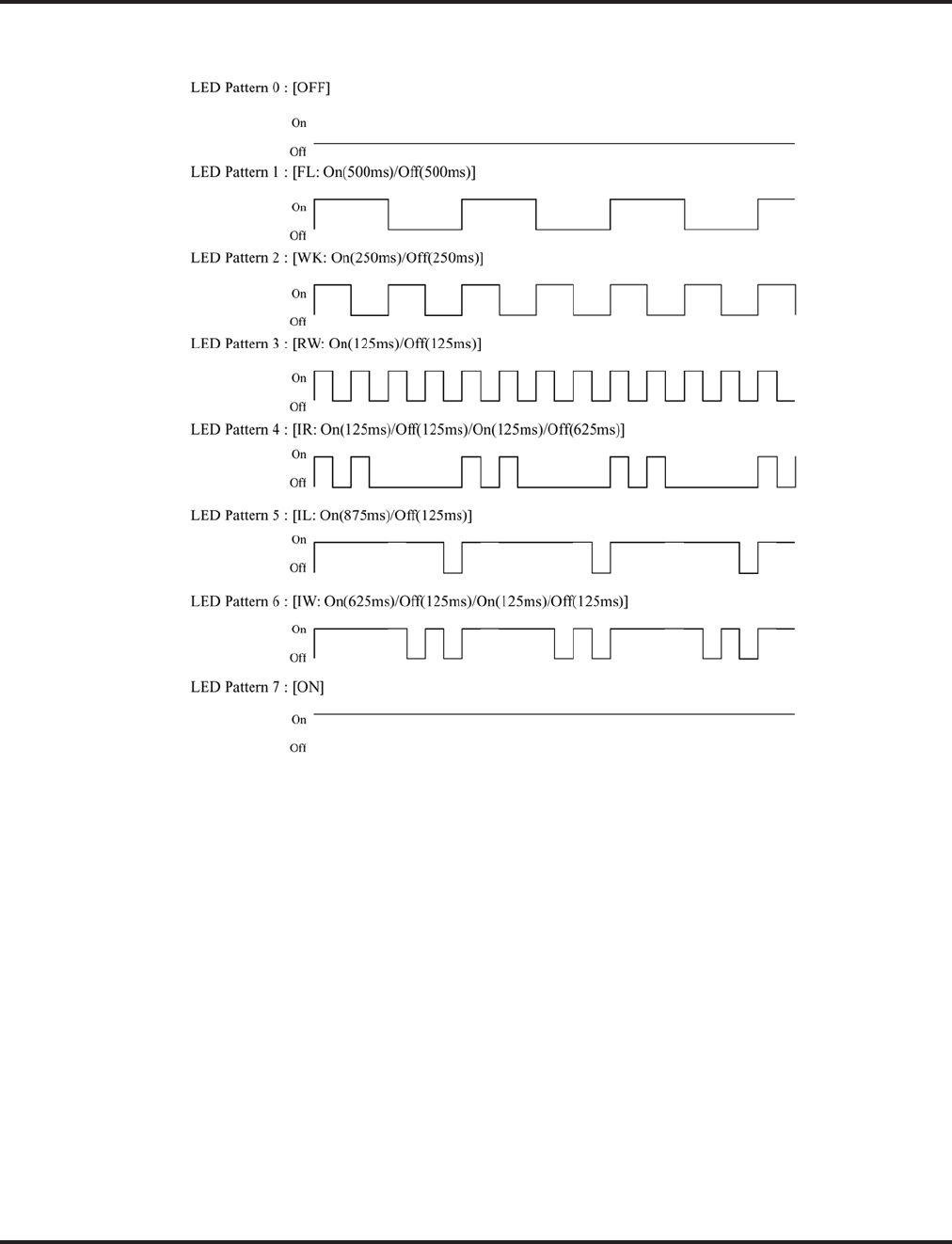
Program 30 : DSS/DLS Console Setup
30-05 : DSS Console Lamp Table
Aspire Software Manual Programming ◆1169
Conditions
24-button DSS consoles cannot be daisy-chained.

Program 30 : DSS/DLS Console Setup
30-05 : DSS Console Lamp Table
1170 ◆Programming Aspire Software Manual
Feature Cross Reference
●Direct Station Selection (DSS) Console
Telephone Programming Instructions
To enter data for Program 30-02 (DSS Console Extension Assignment):
1. Enter the programming mode.
2. 30 02
3. Enter the number of the item you want to program.
4. Select the DSS number to be programmed by pressing the FLASH or the VOLUME ▲ or
VOLUME ▼ keys.
5. Enter data for the item you selected + HOLD.
6. Enter data for the next item in the program.
OR
Press MSG once to enter a new item number.
OR
Press MSG until you’ve exited that series’s programming section.
30-02-01
Ext.Number
back ↑↑
↑↑ ↓↓
↓↓ select
30-02-nn
nnnnn
←←
←← →→
→→

Program 31 : Paging Setup
31-01 : System Options for Internal/External Paging
Aspire Software Manual Programming ◆1171
Program 31 : Paging Setup
31-01 : System Options for Internal/External Paging
Description
Use Program 31-01 : System Options for Internal/External Paging to define the system options
for Internal/External Paging.
The system shows the names you program on the telephone displays. Use the following chart when
entering and editing text. When using the keypad digits, press the key once for the first character,
twice for the second character, etc. For example, to enter a C, press key “2” three times. Press the
key six times display the lower case letter.
Level: Aspire S Aspire M/L/XL
IN • Available. • Available.
With Software 2.05+:
Key for Entering Names
When entering names in the procedures below, refer to this chart. Names can be up to 12 digits long.
For prior software or when using i-Series phones, refer to the charts in the Name Storing feature
(page 432).
Use this keypad digit . . . When you want to. . .
1 Enter characters:
1 @ [ ¥ ] ^ _ ` { | } →→
→→ ←←
←← Á À Â Ã Ç É Ê ì ó
2 Enter characters A-C, a-c, 2.
3 Enter characters D-F, d-f, 3.
4 Enter characters G-I, g-i, 4.
5 Enter characters J-L, j-l, 5.
6 Enter characters M-O, m-o, 6.
7 Enter characters P-S, p-s, 7.
8 Enter characters T-V, t-v, 8.
9 Enter characters W-Z, w-z, 9.
0 Enter characters:
0 ! “ # $ % & ’ ( ) ô Õ ú ä ö ü α ε θ
* Enter characters:
* + , - . / : ; < = > ? π ∑ σ Ω ∞ ¢ £
# # = Accepts an entry (only required if two letters on the same key are needed - ex: TOM).
Pressing # again = Space. (In system programming mode, use the right arrow soft key
instead to accept and/or add a space.)
CONF Clear the character entry one character at a time.
CLEAR Clear all the entries from the point of the flashing cursor and to the right.

Program 31 : Paging Setup
31-01 : System Options for Internal/External Paging
1172 ◆Programming Aspire Software Manual
Input Data
Conditions
None
Feature Cross Reference
●Paging, External
●Paging, Internal
Telephone Programming Instructions
To enter data for Program 31-01 (System Options for Internal/External Paging):
1. Enter the programming mode.
2. 31 01
3. Enter the number of the item you want to program.
4. Enter data for the item you selected + HOLD.
5. Enter data for the next item in the program.
OR
Press MSG once to enter a new item number.
OR
Press MSG until you’ve exited that series’s programming section.
Item
No. Item Input Data Default Description Related
Program
01 All Call Paging Zone
Name Up to 12
Characters Group
all Assign a name to each All Call Internal
Paging zone. The name shows on the dis-
play of the telephone making the
announcement.
11-12-19
31-02-02
02 Page Announcement
Duration 0-64800 (Sec.) 1200 This timer sets the maximum length of
Page announcements.
04 Privacy Release
Time 0-64800 (Sec.) 90 Once the user initiates a Meet Me Confer-
ence or Voice Call Conference, the system
waits this interval for the Paged party to
join the call.
31-01-01
All_PG_Name=ALL GROUP
back ↑↑
↑↑ ↓↓
↓↓ select
31-01-nn
nnnnn
←←
←← →→
→→

Program 31 : Paging Setup
31-02 : Internal Paging Group Assignment
Aspire Software Manual Programming ◆1173
31-02 : Internal Paging Group Assignment
Description
Use Program 31-02 : Internal Paging Group Assignment to assign extensions to Internal Paging
Groups (i.e., Page Zones). The setting in this program also determines if the Internal Page Group
can receive Internal All Call Paging. The system can have up to 64 paging groups. An extension can
be in only one Internal Paging Group.
Input Data
Conditions
None
Level: Aspire S Aspire M/L/XL
IN • Available. • Available.
• Default changed for item 1 with software
2.66+. • Default changed for item 1 with software
2.66+.
Extension Number Max. 8 digits
Item
No. Item Input Data Default
01 Internal Paging Group Number
Assign extensions to Internal Paging
Groups (i.e., Page Zones). The system
allows up to 64 Internal Paging Groups.
An extension can be in only one Inter-
nal Paging Group.
0-64
(0 = no setting) Aspire S: Extension
301-308 = Group 1
All Remaining
Extensions = 0
Aspire: Extension
301-316 = Group 1
All Remaining
Extensions = 0
Prior to 2.66 for
Aspire S/Aspire:
All Extensions = 0
02 Internal All Call Paging Receiving
Allow or prevent All Call Internal Pag-
ing for each extension. If allowed,
extension can place and receive All Call
Internal Paging announcements. If pre-
vented, extensions can only make (not
receive) All Call Internal Paging
announcements. If Combined Paging
zones should be restricted as well,
change the internal page zone group in
Program 31-07-01 to “0”.
0 = off
1 = on 0

Program 31 : Paging Setup
31-02 : Internal Paging Group Assignment
1174 ◆Programming Aspire Software Manual
Feature Cross Reference
●Paging, Internal
Telephone Programming Instructions
To enter data for Program 31-02 (Internal Paging Group Assignment):
1. Enter the programming mode.
2. 31 02
3. Enter the number of the item you want to program.
4. Select the telephone number to be programmed by pressing the FLASH or the VOLUME ▲
or VOLUME ▼ keys.
5. Enter data for the item you selected + HOLD.
6. Enter data for the next item in the program.
OR
Press MSG once to enter a new item number.
OR
Press MSG until you’ve exited that series’s programming section.
31-02-01 TEL301
INT_PG_GP_No. 0
back ↑↑
↑↑ ↓↓
↓↓ select
31-02-nn TELnnn
nnnnn
←←
←← →→
→→

Program 31 : Paging Setup
31-03 : Internal Paging Group Settings
Aspire Software Manual Programming ◆1175
31-03 : Internal Paging Group Settings
Description
Use Program 31-03 : Internal Paging Group Settings to assign names to Internal Paging Groups
(i.e., Page Zones) and to define the splash tone for Internal Paging.
The system shows the names you program on the telephone displays. Use the following chart when
entering and editing text. When using the keypad digits, press the key once for the first character,
twice for the second character, etc. For example, to enter a C, press key “2” three times. Press the
key six times display the lower case letter.
Level: Aspire S Aspire M/L/XL
IN • Available. • Available.
With Software 2.05+:
Key for Entering Names
When entering names in the procedures below, refer to this chart. Names can be up to 12 digits long.
For prior software or when using i-Series phones, refer to the charts in the Name Storing feature
(page 432).
Use this keypad digit . . . When you want to. . .
1 Enter characters:
1 @ [ ¥ ] ^ _ ` { | } →→
→→ ←←
←← Á À Â Ã Ç É Ê ì ó
2 Enter characters A-C, a-c, 2.
3 Enter characters D-F, d-f, 3.
4 Enter characters G-I, g-i, 4.
5 Enter characters J-L, j-l, 5.
6 Enter characters M-O, m-o, 6.
7 Enter characters P-S, p-s, 7.
8 Enter characters T-V, t-v, 8.
9 Enter characters W-Z, w-z, 9.
0 Enter characters:
0 ! “ # $ % & ’ ( ) ô Õ ú ä ö ü α ε θ
* Enter characters:
* + , - . / : ; < = > ? π ∑ σ Ω ∞ ¢ £
# # = Accepts an entry (only required if two letters on the same key are needed - ex: TOM).
Pressing # again = Space. (In system programming mode, use the right arrow soft key
instead to accept and/or add a space.)
CONF Clear the character entry one character at a time.
CLEAR Clear all the entries from the point of the flashing cursor and to the right.
Program 31 : Paging Setup
31-03 : Internal Paging Group Settings
1176 ◆Programming Aspire Software Manual
Input data
Default
Item 01 : Internal Paging Group Name
Conditions
None
Feature Cross Reference
●Paging, Internal
Internal Paging Group Number 01-64
Item
No. Item Input Data Default Description
01 Internal Paging
Group Name Up to 12 Characters Assign names to Internal Paging Groups (i.e.,
Page Zones). The system shows the names
you program on the telephone displays.
02 Internal Paging
Splash Tone 0 = Ordinary volume
1 = Mute
2 = No tone
0 Allow an extension to have normal (0), muted
(1) or no (2) Internal Paging alert beeps
before a Paging announcement.
Extension Paging
Group Name
01 Group 1
02 Group 2
::
64 Group 64

Program 31 : Paging Setup
31-03 : Internal Paging Group Settings
Aspire Software Manual Programming ◆1177
Telephone Programming Instructions
To enter data for Program 31-03 (Internal Paging Group Settings):
1. Enter the programming mode.
2. 10 03
3. Enter the number of the item you want to program.
4. Select the Internal Paging Group number to be programmed by pressing the FLASH or the
VOLUME ▲ or VOLUME ▼ keys.
5. Enter data for the item you selected + HOLD.
6. Enter data for the next item in the program.
OR
Press MSG once to enter a new item number.
OR
Press MSG until you’ve exited that series’s programming section.
10-03-01 Paging 1
PG_GP_Name =GROUP 1
back ↑↑
↑↑ ↓↓
↓↓ select
10-03-nn Paging nn
nnnnn
←←
←← →→
→→

Program 31 : Paging Setup
31-04 : External Paging Zone Group
1178 ◆Programming Aspire Software Manual
31-04 : External Paging Zone Group
Description
Use Program 31-04 : External Paging Zone Group to assign each External Paging zone to an
External Paging group. Users call the External Paging group when broadcasting announcements to
the external zone. When programming, the zones on the PGDAD adapter are numbers 1-8. On the
Aspire system, the NTCPU’s zone is number 9.
To simplify programming and troubleshooting, always make the External Paging Zone Group
the same number as the External Paging zone (i.e., 1 = 1, 2 = 2, etc.).
Input Data
Conditions
None
Feature Cross Reference
●Paging, External
Level: Aspire S Aspire M/L/XL
IN • Available. • Available.
External Speaker Number Aspire S: 1-8
Aspire: 1-9
Item No. Paging Group Number Default
01 0-8 (0 = no setting) Speaker 1 (PGDAD) = 1 (Group 1)
Speaker 2 (PGDAD) = 2 (Group 2)
Speaker 3 (PGDAD) = 3 (Group 3)
Speaker 4 (PGDAD) = 4 (Group 4)
Speaker 5 (PGDAD) = 5 (Group 5)
Speaker 6 (PGDAD) = 6 (Group 6)
Speaker 7 (PGDAD) = 7 (Group 7)
Speaker 8 (PGDAD) = 8 (Group 8)
Speaker 9 (NTCPU) = 1 (Group 1)

Program 31 : Paging Setup
31-04 : External Paging Zone Group
Aspire Software Manual Programming ◆1179
Telephone Programming Instructions
To enter data for Program 31-04 (External Paging Zone Group):
1. Enter the programming mode.
2. 31 04
3. Enter the number of the item you want to program.
4. Select the External Speaker number to be programmed by pressing the FLASH or the VOL-
UME ▲ or VOLUME ▼ keys.
5. Enter data for the item you selected + HOLD.
6. Enter data for the next item in the program.
OR
Press MSG once to enter a new item number.
OR
Press MSG until you’ve exited that series’s programming section.
31-04-01 SPK 1
Paging_Zone_GP1
back ↑↑
↑↑ ↓↓
↓↓ select
31-04-nn SPK n
nnnnn
←←
←← →→
→→

Program 31 : Paging Setup
31-05 : Universal Night Answer/Ring Over Page
1180 ◆Programming Aspire Software Manual
31-05 : Universal Night Answer/Ring Over Page
Description
Use Program 31-05 : Universal Night Answer to assign Universal Night Answer ringing to each
External Paging zone. For each trunk port, you make a separate entry for each External Paging
zone. When programming, the zones on the PGDAD adapter are numbers 1-8. The NTCPU’s zone
is number 9. For UNA ringing, you make a separate entry for each Night Service mode.
This program is also used for an external ringer connected to a 2PGDAD module.
Input Data
Conditions
None
Feature Cross Reference
●Night Service
●Paging, External
●Transfer
Level: Aspire S Aspire M/L/XL
IN • Available. • Available.
Trunk Port Number Aspire S: 1-8
Aspire: 1-200
External Speaker Number Aspire S: 1-8
Aspire: 1-9
Item No. Day/Night Mode Input Data Default
01 Aspire S: 1-4
Aspire: 1-8 0 = No Ringing
1 = Ringing 0

Program 31 : Paging Setup
31-05 : Universal Night Answer/Ring Over Page
Aspire Software Manual Programming ◆1181
Telephone Programming Instructions
To enter data for Program 31-05 (Universal Night Answer):
1. Enter the programming mode.
2. 31 05
3. Enter the number of the item you want to program.
4. Select the trunk number to be programmed by pressing the FLASH or the VOLUME ▲ or
VOLUME ▼ keys.
5. Enter data for the item you selected + HOLD.
6. Enter data for the next item in the program.
OR
Press MSG once to enter a new item number.
OR
Press MSG until you’ve exited that series’s programming section.
31-05-01 Trunk1
SPK 1Mod1 =0:No
back ↑↑
↑↑ ↓↓
↓↓ select
31-05-nn Trunknnn
nnnnn
←←
←← →→
→→

Program 31 : Paging Setup
31-06 : External Speaker Control
1182 ◆Programming Aspire Software Manual
31-06 : External Speaker Control
Description
Use Program 31-06 : External Speaker Control to define the settings for the external speaker
using an amplifier.
Input Data
Conditions
None
Level: Aspire S Aspire M/L/XL
IN • Available. • Available.
External Speaker Number Aspire S: 1-8
Aspire: 1-9
Item
No. Item Input Data Default
01 Broadcast Splash Tone Before
Paging
Use this option to enabled or
disable splash tone before Pag-
ing over an external zone. If
enabled, the system broadcasts a
splash tone before the External
Paging announcement.
0 = No tone
1 = Splash tone
2 = Chime tone
2
02 Broadcast Splash Tone After
Paging
Use this option to enabled or
disable splash tone after Paging
over an external zone. If
enabled, the system broadcasts a
splash tone at the end of an
External Paging announcement.
0 = No tone
1 = Splash tone
2 = Chime tone
2
03 Speech Path
Determine if the external
speaker will be used for talkback
(As this option is not available
with the NTCPU external page
zone, speaker 9 should be left at
“1”.
0 = Both way
1 = One way (PGD -> SPK) 1
04 CODEC Transmit Gain Setup 1-63
(-15.5 ~ +15.5dB) 32
05 CODEC Transmit Gain Setup 1-63
(-15.5 ~ +15.5dB) 32

Program 31 : Paging Setup
31-06 : External Speaker Control
Aspire Software Manual Programming ◆1183
Feature Cross Reference
●Paging, External
Telephone Programming Instructions
To enter data for Program 31-06 (External Speaker Control):
1. Enter the programming mode.
2. 31 06
3. Enter the number of the item you want to program.
4. Select the External Speaker number to be programmed by pressing the FLASH or the VOL-
UME ▲ or VOLUME ▼ keys.
5. Enter data for the item you selected + HOLD.
6. Enter data for the next item in the program.
OR
Press MSG once to enter a new item number.
OR
Press MSG until you’ve exited that series’s programming section.
31-06-01 SPK 1
PG_Start_Tone 2:Chime
back ↑↑
↑↑ ↓↓
↓↓ select
31-06-nn SPK n
nnnnn
←←
←← →→
→→

Program 31 : Paging Setup
31-07 : Combined Paging Assignments
1184 ◆Programming Aspire Software Manual
31-07 : Combined Paging Assignments
Description
Use Program 31-07 : Combined Paging Assignments to assign an External Paging Group (0-8) to
an Internal Paging Zone (0-64) for Combined Paging. When an extension user makes a Combined
Page, they simultaneously broadcast into both the External and Internal Zone.
Use Program 31-04-01 to assign an External Paging Zone (Aspire S: 1-8 or Aspire: 1-9) to an
External Page Group (1-8).
Input Data
Conditions
None
Feature Cross Reference
●Paging, External
●Paging, Internal
Level: Aspire S Aspire M/L/XL
IN • Available. • Available.
External Paging Group Number 0-8 (0 = All external paging)
Item No. Internal Paging Group Number Default
01 0-64
(0 = All Call [internal and external zones]) 1

Program 31 : Paging Setup
31-07 : Combined Paging Assignments
Aspire Software Manual Programming ◆1185
Telephone Programming Instructions
To enter data for Program 31-07 (Combined Paging Assignments):
1. Enter the programming mode.
2. 31 07
3. Enter the number of the item you want to program.
4. Select the Page Group number to be programmed by pressing the FLASH or the VOLUME
▲ or VOLUME ▼ keys.
5. Enter data for the item you selected + HOLD.
6. Enter data for the next item in the program.
OR
Press MSG once to enter a new item number.
OR
Press MSG until you’ve exited that series’s programming section.
31-07-01 PG Group 1
Internal_PG-GP_No. 1
back ↑↑
↑↑ ↓↓
↓↓ select
31-07-nn PG Group n
nnnnn
←←
←← →→
→→

Program 31 : Paging Setup
31-08 : BGM on External Paging
1186 ◆Programming Aspire Software Manual
31-08 : BGM on External Paging
Description
Use Program 31-08 : BGM on External Paging to set the Background Music option for each
External Paging zone. If enabled, the system will play Background Music over the zone when it is
idle.
When programming, the zones on the PGDAD adapter are numbers 1-8. For the Aspire system, the
NTCPU’s zone is number 9.
Input Data
Conditions
None
Feature Cross Reference
●Background Music
●Paging, External
Level: Aspire S Aspire M/L/XL
IN • Available. • Available.
External Speaker Number Aspire S: 1-8
Aspire: 1-9
Item No. Description Input Data Default
01 Use this option to allow or prevent the External
Paging zone you select from broadcasting Back-
ground Music when it is idle.
0 = Disable
1 = Enable 0

Program 31 : Paging Setup
31-08 : BGM on External Paging
Aspire Software Manual Programming ◆1187
Telephone Programming Instructions
To enter data for Program 31-08 (BGM on External Paging):
1. Enter the programming mode.
2. 31 08
3. Enter the number of the item you want to program.
4. Select the External Speaker number to be programmed by pressing the FLASH or the VOL-
UME ▲ or VOLUME ▼ keys.
5. Enter data for the item you selected + HOLD.
6. Enter data for the next item in the program.
OR
Press MSG once to enter a new item number.
OR
Press MSG until you’ve exited that series’s programming section.
31-08-01 SPK 1
BGM 0:No
back ↑↑
↑↑ ↓↓
↓↓ select
31-08-nn SPK n
nnnnn
←←
←← →→
→→

Program 31 : Paging Setup
31-08 : BGM on External Paging
1188 ◆Programming Aspire Software Manual
- For Your Notes -

Program 32 : Door Box and Sensor Setup
32-01 : Door Box Timers
Aspire Software Manual Programming ◆1189
Program 32 : Door Box and Sensor Setup
32-01 : Door Box Timers
Description
Use Program 32-01 : Door Box Timers to assign the timers used for the Door Box.
Input Data
Conditions
None
Feature Cross Reference
●Door Box
Level: Aspire S Aspire M/L/XL
IN • Available. • Available.
Item No. Item Input Data Default
01 Door Box Answer Time
A keyset user must answer Door Box chimes
within this interval.
0-64800 30
02 Door Lock Cancel Time
When a single line (2500 type) telephone user
hook flashes or a keyset user presses the FLASH
key while talking to a Door Box, the strike stays
open for this interval.
0-64800 10
03 Off-Premise Call Forward by Door Box Dis-
connect Timer
Define the conversation period for an
Off-Premise Call Forward by Door Box call.
When this timer expires, the caller will hear busy
tone for 3 seconds (fixed timer) and the call will
then be disconnected.
0-64800 60

Program 32 : Door Box and Sensor Setup
32-01 : Door Box Timers
1190 ◆Programming Aspire Software Manual
Telephone Programming Instructions
To enter data for Program 32-01 (Door Box Timers):
1. Enter the programming mode.
2. 32 01
3. Enter the number of the item you want to program.
4. Enter data for the item you selected + HOLD.
5. Enter data for the next item in the program.
OR
Press MSG once to enter a new item number.
OR
Press MSG until you’ve exited that series’s programming section.
32-01-01
DH_Ans. Time 30 Sec.
back ↑↑
↑↑ ↓↓
↓↓ select
32-01-nn
nnnnn
←←
←← →→
→→

Program 32 : Door Box and Sensor Setup
32-02 : Door Box Ring Assignment
Aspire Software Manual Programming ◆1191
32-02 : Door Box Ring Assignment
Description
Use Program 32-02 : Door Box Ring Assignments to assign the extension which will ring when a
caller presses the associated Door Box’s call button.
Input Data
Conditions
None
Feature Cross Reference
●Door Box
Level: Aspire S Aspire M/L/XL
SA • Available. • Available.
Door Box Number Aspire S: 1-4
Aspire: 1-8
Day/Night Mode Aspire S: 1-4
Aspire: 1-8
Item No. Door Box Ring Group Number Extension Number Default
01 01-32 Max. 8 digits No setting

Program 32 : Door Box and Sensor Setup
32-02 : Door Box Ring Assignment
1192 ◆Programming Aspire Software Manual
Telephone Programming Instructions
To enter data for Program 32-02 (Door Box Ring Assignment):
1. Enter the programming mode.
2. 32 02
3. Enter the number of the item you want to program.
4. Select the Door Box number to be programmed by pressing the FLASH or the VOLUME ▲
or VOLUME ▼ keys.
5. Enter data for the item you selected + HOLD.
6. Enter data for the next item in the program.
OR
Press MSG once to enter a new item number.
OR
Press MSG until you’ve exited that series’s programming section.
32-02-01 DOOR 1
Mode1 TEL 01=
back ↑↑
↑↑ ↓↓
↓↓ select
32-02-nn DOOR n
nnnnn
←←
←← →→
→→

Program 32 : Door Box and Sensor Setup
32-03 : Door Box Basic Setup
Aspire Software Manual Programming ◆1193
32-03 : Door Box Basic Setup
Description
Use Program 32-03 : Door Box Basic Setup to select the chime pattern and gain level for each
Door Box. There are six distinctive chime patterns. The chime tones are defined in Program 80-01.
Input Data
Conditions
None
Feature Cross Reference
●Door Box
Level: Aspire S Aspire M/L/XL
IN • Available. • Available.
Door Box Number Aspire S: 1-4
Aspire: 1-8
Item
No. Item Input Data Default
01 Chime Pattern 0 = No ringing tone
1 = Door Box ring 1
2 = Door Box ring 2
3 = Door Box ring 3
4 = Door Box ring 4
5 = Door Box ring 5
6 = Door Box ring 6
Door Box 1 = 1
Door Box 2 = 2
Door Box 3 = 3
Door Box 4 = 4
Door Box 5 = 5
Door Box 6 = 6
Door Box 7 = 1
Door Box 8 = 1
02 CODEC Transmit Gain
Setup
(PGD to Door Box)
1-63 (-15.5 ~= +15.5dB) 32
03 CODEC Receive Gain
Setup
(Door Box to PGD)
1-63 (-15.5 ~ +15.5dB) 32

Program 32 : Door Box and Sensor Setup
32-03 : Door Box Basic Setup
1194 ◆Programming Aspire Software Manual
Telephone Programming Instructions
To enter data for Program 32-03 (Door Box Basic Setup):
1. Enter the programming mode.
2. 32 03
3. Enter the number of the item you want to program.
4. Select the Door Box number to be programmed by pressing the FLASH or the VOLUME ▲
or VOLUME ▼ keys.
5. Enter data for the item you selected + HOLD.
6. Enter data for the next item in the program.
OR
Press MSG once to enter a new item number.
OR
Press MSG until you’ve exited that series’s programming section.
32-03-01 DOOR 1
Chime_Pattern 1:Ring1
back ↑↑
↑↑ ↓↓
↓↓ select
32-03-nn DOOR n
nnnnn
←←
←← →→
→→

Program 33 : CTA and ACI Setup
33-01 : ACI Port Type Setup
Aspire Software Manual Programming ◆1195
Program 33 : CTA and ACI Setup
33-01 : ACI Port Type Setup
Description
Use Program 33-01 : ACI Port Type Setup to set the function of each software port on an Analog
Communications Interface. Each ACI software port can have only one function (input, output or
none).
Input Data
Conditions
None
Feature Cross Reference
●Analog Communications Interface (ACI)
Level: Aspire S Aspire M/L/XL
IN • Available. • Available.
ACI Port Number Aspire S: 1-8
Aspire: 01-96
Item No. ACI Type Default
01 0 = No Setting
1 = Input
2 = Input/Output
2

Program 33 : CTA and ACI Setup
33-01 : ACI Port Type Setup
1196 ◆Programming Aspire Software Manual
Telephone Programming Instructions
To enter data for Program 33-01 (ACI Port Type Setup):
1. Enter the programming mode.
2. 33 01
3. Enter the number of the item you want to program.
4. Select the ACI port number to be programmed by pressing the FLASH or the VOLUME ▲ or
VOLUME ▼ keys.
5. Enter data for the item you selected + HOLD.
6. Enter data for the next item in the program.
OR
Press MSG once to enter a new item number.
OR
Press MSG until you’ve exited that series’s programming section.
33-01-01 ACI Port1
ACI_Type 2:In/Out
back ↑↑
↑↑ ↓↓
↓↓ select
33-01-nn ACI Portnn
nnnnn
←←
←← →→
→→
Program 33 : CTA and ACI Setup
33-02 : ACI Department Calling Group
Aspire Software Manual Programming ◆1197
33-02 : ACI Department Calling Group
Description
Use Program 33-02 : ACI Department Calling Group to assign ACI ports to Department Groups.
An ACI port can only be in one group.
Also use this program to set the ACI port’s priority. When a call comes into the ACI Department
Group, it connects to the ACI port in order of their priority. A higher priority port (e.g., 1) receives
calls before a lower priority port (e.g., 6).
Input Data
Default
Conditions
None
Feature Cross Reference
●Analog Communications Interface (ACI)
Level: Aspire S Aspire M/L/XL
IN • Available - 8 ACI Ports and 4 ACI
Department Groups. • Available - 8 ACI Ports and 16 ACI
Department Groups.
ACI Port Number Aspire S: 1-8
Aspire: 01-96
Item No. Group Number Priority
01 Aspire S: 1-4
Aspire: 01-16 Aspire S: 1-8
Aspire: 1-96
ACI Port Group Order
01 1 1
02 1 1
:::
96 1 96

Program 33 : CTA and ACI Setup
33-02 : ACI Department Calling Group
1198 ◆Programming Aspire Software Manual
Telephone Programming Instructions
To enter data for Program 33-02 (ACI Department Calling Group):
1. Enter the programming mode.
2. 33 02
3. Enter the number of the item you want to program.
4. Select the ACI port number to be programmed by pressing the FLASH or the VOLUME ▲ or
VOLUME ▼ keys.
5. Enter data for the item you selected + HOLD.
6. Enter data for the next item in the program.
OR
Press MSG once to enter a new item number.
OR
Press MSG until you’ve exited that series’s programming section.
33-02-01 ACI Port1
ACI_Group 1
back ↑↑
↑↑ ↓↓
↓↓ select
33-02-nn ACI Portnn
nnnnn
←←
←← →→
→→
Program 34 : Tie Line Setup
34-01 : E&M Tie Line Basic Setup
Aspire Software Manual Programming ◆1199
Program 34 : Tie Line Setup
34-01 : E&M Tie Line Basic Setup
Description
Use Program 34-01 : E&M Tie Line Basic Setup to defines the basic settings for each E&M tie
line.
Input Data
Conditions
None
Feature Cross Reference
●Tie Lines
Level: Aspire S Aspire M/L/XL
IN • Available. • Available.
Trunk Port Number Aspire S: 1-8
Aspire: 001-200
Item
No. Item Input Data Default Related
Program
01 DID/E&M Start Signaling
Set the start signaling mode for DID and tie trunks. DID and tie
trunks can use either immediate start or wink start signaling.
0 = 2nd dial tone
1 = Wink
2 = Immediate
3 = Delay
1 22-02
02 DID/E&M Incoming
Signaling Type
For DID and tie trunks, use this option to set the trunk’s signal-
ing type (Dial Pulse or DTMF)
0 = Dial Pulse
1 = PB (DTMF) 0 10-09
03 E&M Dial-In Mode
Determine if the incoming tie line call should be directed as an
intercom call or if it should follow the DID Translation Table in
Program 22-11.
0 = Specify
Extension number
1 = Use
conversion table
0 22-11
04 E&M Line Dial Tone
Enter 1 if the tie line should send dial tone to the calling system
once the call is set up. Enter 0 if the tie line should not send dial
tone.
0 = Disable
1 = Enable 1
05 System Toll Restriction
Enable (1) or disable (0) the ability for tie line calls to follow
the system toll restriction entries in Programs 21-05-01 through
21-05-13. If disabled, tie line toll restriction will be determined
by 21-05-13.
0 = Disable
1 = Enable 0 21-05-13
34-08-01

Program 34 : Tie Line Setup
34-01 : E&M Tie Line Basic Setup
1200 ◆Programming Aspire Software Manual
Telephone Programming Instructions
To enter data for Program 34-01 (E&M Tie Line Basic Setup):
1. Enter the programming mode.
2. 34 01
3. Enter the number of the item you want to program.
4. Select the trunk port number to be programmed by pressing the FLASH or the VOLUME ▲
or VOLUME ▼ keys.
5. Enter data for the item you selected + HOLD.
6. Enter data for the next item in the program.
OR
Press MSG once to enter a new item number.
OR
Press MSG until you’ve exited that series’s programming section.
34-01-01 Trk Port 1
Signal_Type 1:Wink
back ↑↑
↑↑ ↓↓
↓↓ select
34-01-nn Trk Port nnn
nnnnn
←←
←← →→
→→

Program 34 : Tie Line Setup
34-02 : E&M Tie Line Class of Service
Aspire Software Manual Programming ◆1201
34-02 : E&M Tie Line Class of Service
Description
Use Program 34-02 : E&M Tie Line Class of Service to assign a Class of Service to a tie line
(there are 15 tie line Classes of Service). The Class of Service options are defined in Program
20-14. For each tie line, you make a separate entry for each Night Service mode.
Input Data
Conditions
You cannot use Program 20-06 to assign Class of Service to tie lines.
Feature Cross Reference
●Tie Lines
Level: Aspire S Aspire M/L/XL
IN • Tie Lines not available. • Available.
Trunk Port Number 1-200
Item No. Day/Night Mode Class Default Related Program
01 1-8 1-15 1 20-14

Program 34 : Tie Line Setup
34-02 : E&M Tie Line Class of Service
1202 ◆Programming Aspire Software Manual
Telephone Programming Instructions
To enter data for Program 34-02 (E&M Tie Line Class of Service):
1. Enter the programming mode.
2. 34 02
3. Enter the number of the item you want to program.
4. Select the trunk port number to be programmed by pressing the FLASH or the VOLUME ▲
or VOLUME ▼ keys.
5. Enter data for the item you selected + HOLD.
6. Enter data for the next item in the program.
OR
Press MSG once to enter a new item number.
OR
Press MSG until you’ve exited that series’s programming section.
34-02-01 Trk Port 1
Mode1 Class_No. 1
back ↑↑
↑↑ ↓↓
↓↓ select
34-02-nn Trk Port nnn
nnnnn
←←
←← →→
→→

Program 34 : Tie Line Setup
34-03 : Trunk Group Routing for E&M Tie Lines
Aspire Software Manual Programming ◆1203
34-03 : Trunk Group Routing for E&M Tie Lines
Description
Use Program 34-03 : Trunk Group Routing for E&M Tie Lines to assign the trunk group route
1-8 or 1-100) chosen when a user seizes a tie line and dials 9. (Set Trunk Group Routing in Program
14-07.) If the system has Automatic Route Selection, dialing 9 accesses ARS. You make a separate
entry for each tie line - for each Night Service Mode.
Input Data
Conditions
None
Feature Cross Reference
●Tie Lines
Level: Aspire S Aspire M/L/XL
IN • Available. • Available.
Trunk Port Number Aspire S: 1-8
Aspire: 001-200
Item No. Day/Night Mode Route Table Number Default
01 Aspire S: 1-4
Aspire: 1-8 Aspire S: 0-8
Aspire: 0-100
(0 = setting)
1

Program 34 : Tie Line Setup
34-03 : Trunk Group Routing for E&M Tie Lines
1204 ◆Programming Aspire Software Manual
Telephone Programming Instructions
To enter data for Program 34-03 (Trunk Group Routing for E&M Tie Lines):
1. Enter the programming mode.
2. 34 03
3. Enter the number of the item you want to program.
4. Select the trunk port number to be programmed by pressing the FLASH or the VOLUME ▲
or VOLUME ▼ keys.
5. Enter data for the item you selected + HOLD.
6. Enter data for the next item in the program.
OR
Press MSG once to enter a new item number.
OR
Press MSG until you’ve exited that series’s programming section.
34-03-01 Trk Port 1
Mode1 Route_Table1
back ↑↑
↑↑ ↓↓
↓↓ select
34-03-nn Trk Port nnn
nnnnn
←←
←← →→
→→

Program 34 : Tie Line Setup
34-04 : E&M Tie Line Toll Restriction Class
Aspire Software Manual Programming ◆1205
34-04 : E&M Tie Line Toll Restriction Class
Description
Use Program 34-04 : E&M Tie Line Toll Restriction Class to enter a Toll Restriction Class for
each tie line. There are 15 Toll Restriction Classes which are defined in Programs 21-05 and 21-06.
For each tie line, you make a separate Toll Restriction Class entry for each Night Service mode.
Input Data
Conditions
You cannot use Program 20-06 to assign Toll Restriction to tie lines.
Feature Cross Reference
●Tie Lines
Level: Aspire S Aspire M/L/XL
IN • Tie Lines not available.. • Available.
Trunk Port Number 001-200
Item No. Day/Night Mode Toll Restriction Class Default Related Program
01 1-8 1-15 2 21-05
14-01-08

Program 34 : Tie Line Setup
34-04 : E&M Tie Line Toll Restriction Class
1206 ◆Programming Aspire Software Manual
Telephone Programming Instructions
To enter data for Program 34-04 (E&M Tie Line Toll Restriction Class):
1. Enter the programming mode.
2. 34 04
3. Enter the number of the item you want to program.
4. Select the trunk port number to be programmed by pressing the FLASH or the VOLUME ▲
or VOLUME ▼ keys.
5. Enter data for the item you selected + HOLD.
6. Enter data for the next item in the program.
OR
Press MSG once to enter a new item number.
OR
Press MSG until you’ve exited that series’s programming section.
34-04-01 Trk Port 1
Mode1 T/R_Class_No.2
back ↑↑
↑↑ ↓↓
↓↓ select
34-04-nn Trk Port nnn
nnnnn
←←
←← →→
→→

Program 34 : Tie Line Setup
34-05 : Tie Line Outgoing Call Restriction
Aspire Software Manual Programming ◆1207
34-05 : Tie Line Outgoing Call Restriction
Description
Use Program 34-05 : Tie Line Outgoing Call Restriction to build a restriction matrix for outgo-
ing trunk calls placed from an inbound trunk (e.g., dialed from a tie line). For each inbound trunk
group, enable or disable access to each CO trunk group.
With the default entry with software prior to 2.02, tandem trunking would not be allowed when a
call which originated in a trunk group tried to connect to another trunk in the same group. The
Aspire would allow a user to tandem trunk on inbound group 1, for example, to any trunk group
other than 1. This would prevent a user from using Off-Premise Call Forward on a T1 E&M trunk.
With software 2.02+, users will now be able to tandem trunk to any trunk group by default.
Input Data
Default
Level: Aspire S Aspire M/L/XL
IN • Available. • Available.
Incoming Trunk Group Number Aspire S: 1-8
Aspire: 001-100
Outgoing Trunk Group Number Input Data
Aspire S: 1-8
Aspire: 1-100 0 = Enable
1 = Disable
Outgoing
Trunk
Groups
Incoming Trunk Groups
1234- - - - -979899100
1
Prior to
2.02: 1
2.02+: 0
000 0000
2
0Prior to
2.02: 1
2.02+: 0
0 0 0000
3
00
Prior to
2.02: 1
2.02+: 0
0 0000
4
000
Prior to
2.02: 1
2.02+: 0
0000

Program 34 : Tie Line Setup
34-05 : Tie Line Outgoing Call Restriction
1208 ◆Programming Aspire Software Manual
Conditions
None
Feature Cross Reference
●Tie Lines
:
:
:
97
0000 Prior to
2.02: 1
2.02+:
0
000
98
0000 0
Prior to
2.02: 1
2.02+:
0
00
99
0000 00
Prior to
2.02: 1
2.02+:
0
0
100
0000 000
Prior to
2.02: 1
2.02+:
0

Program 34 : Tie Line Setup
34-05 : Tie Line Outgoing Call Restriction
Aspire Software Manual Programming ◆1209
Telephone Programming Instructions
To enter data for Program 34-05 (Tie Line Outgoing Call Restriction):
1. Enter the programming mode.
2. 34 05
3. Enter the number of the item you want to program.
4. Select the Incoming Trunk Group number to be programmed by pressing the FLASH or the
VOLUME ▲ or VOLUME ▼ keys.
5. Enter data for the item you selected + HOLD.
6. Enter data for the next item in the program.
OR
Press MSG once to enter a new item number.
OR
Press MSG until you’ve exited that series’s programming section.
34-05-01 INC Group 1
O.T.G. 001 1:No-Tande
back ↑↑
↑↑ ↓↓
↓↓ select
34-05-nn
nnnnn
←←
←← →→
→→

Program 34 : Tie Line Setup
34-06 : Add / Delete Digit for E&M Tie Line
1210 ◆Programming Aspire Software Manual
34-06 : Add / Delete Digit for E&M Tie Line
Description
Use Program 34-06 : Add / Delete Digit for E&M Tie Line to set digits that the system should
add or delete for tie lines.
●Delete Digit
Some tie line networks pass the location number and extension number to the remote side.
This program allows the system to ignore such numbers for a call.
If individual extensions do not want to receive an incoming call, you could delete all of the
digits including the extension number.
●Add Digit
If a tie line network requires additional digits to reroute the call to a location, the digits for the
location can be added to the received digits.
Input Data
Conditions
None
Feature Cross Reference
●Tie Lines
Level: Aspire S Aspire M/L/XL
IN • Available. • Available.
Incoming Trunk Group Number Aspire S: 1-8
Aspire: 001-100
Item
No. Item Input Data Default
01 Delete Digit 0-255 (255 = delete all digits) 0
02 Additional Dial Digits Up to 4 digits No setting

Program 34 : Tie Line Setup
34-06 : Add / Delete Digit for E&M Tie Line
Aspire Software Manual Programming ◆1211
Telephone Programming Instructions
To enter data for Program 34-06 (Add / Delete Digit for E&M Tie Line):
1. Enter the programming mode.
2. 34 06
3. Enter the number of the item you want to program.
4. Select the Incoming Trunk Group number to be programmed by pressing the FLASH or the
VOLUME ▲ or VOLUME ▼ keys.
5. Enter data for the item you selected + HOLD.
6. Enter data for the next item in the program.
OR
Press MSG once to enter a new item number.
OR
Press MSG until you’ve exited that series’s programming section.
34-06-01 INC Group 1
Delete_Digit 0
back ↑↑
↑↑ ↓↓
↓↓ select
34-06-nn INC Group nn
nnnnn
←←
←← →→
→→

Program 34 : Tie Line Setup
34-07 : E&M Tie Line Timer
1212 ◆Programming Aspire Software Manual
34-07 : E&M Tie Line Timer
Description
Use Program 34-07 : E&M Tie Line Timer to define the system service tone timers.
Input Data
Conditions
None
Feature Cross Reference
●Tie Lines
Level: Aspire S Aspire M/L/XL
IN • Available. • Available.
Item
No. Item Input Data Default
01 ODT/SRT Mark method 0-64800 3
02 ODT/SRT Wink start method 0-64800 0
03 1st digit Pause (LDT) 0-64800 3
04 Leased Line Guard (LDT) 0-64800 0
05 Trunk answer detect timer for E&M / E1 0-64800 30

Program 34 : Tie Line Setup
34-07 : E&M Tie Line Timer
Aspire Software Manual Programming ◆1213
Telephone Programming Instructions
To enter data for Program 34-07 (E&M Tie Line Timer):
1. Enter the programming mode.
2. 34 07
3. Enter the number of the item you want to program.
4. Enter data for the item you selected + HOLD.
5. Enter data for the next item in the program.
OR
Press MSG once to enter a new item number.
OR
Press MSG until you’ve exited that series’s programming section.
34-07-01
1st Digit_M/O 3 Sec.
back ↑↑
↑↑ ↓↓
↓↓ select
34-07-nn
nnnnn
←←
←← →→
→→

Program 34 : Tie Line Setup
34-08 : Toll Restriction Data for E&M Tie Lines
1214 ◆Programming Aspire Software Manual
34-08 : Toll Restriction Data for E&M Tie Lines
Description
Use Program 34-08 : Toll Restriction Data for E&M Tie Lines to define the toll restriction data
for E&M tie lines. This data should be defined if Tie Line Toll Restriction is enabled in Program
21-05-13.
Input Data
Conditions
None
Feature Cross Reference
●Tie Lines
Level: Aspire S Aspire M/L/XL
IN • Available. • Available.
Class of Service 01-15
Item No. Table No. Dial Data Default Related Program
01 01-20 Up to 10 digits No setting 21-05-13
34-01-05

Program 34 : Tie Line Setup
34-08 : Toll Restriction Data for E&M Tie Lines
Aspire Software Manual Programming ◆1215
Telephone Programming Instructions
To enter data for Program 34-08 (Toll Restriction Data for E&M Tie Lines):
1. Enter the programming mode.
2. 34 08
3. Enter the number of the item you want to program.
4. Select the Deny Table number to be programmed by pressing the FLASH or the VOLUME ▲
or VOLUME ▼ keys.
5. Enter data for the item you selected + HOLD.
6. Enter data for the next item in the program.
OR
Press MSG once to enter a new item number.
OR
Press MSG until you’ve exited that series’s programming section.
34-08-01 Deny TBL1
Dial_Data 01
back ↑↑
↑↑ ↓↓
↓↓ select
34-08-nn Deny TBLnn
nnnnn
←←
←← →→
→→

Program 34 : Tie Line Setup
34-09 : ANI/DNIS Service Options
1216 ◆Programming Aspire Software Manual
34-09 : ANI/DNIS Service Options
Description
Use Program 34-09 : ANI/DNIS Service Options to define the ANI//DNIS service option setup
for E&M Class of Service.
Input Data
Level: Aspire S Aspire M/L/XL
IN • Available. • Available.
Class of Service 01-15
Item
No. Name Input Data
Default Related
Program
COS 01-14 COS 15
01 Receive Format
Use this option to specify the format of the
ANI/DNIS data received from the telco. Make
sure your entry is compatible with the service
the telco provides. (The character * indicates a
delimiter.)
0 = Address
1 = *ANI*
2 = *DNIS*
3 = *ANI*Address*
4 = *ANI*DNIS*
5 = *DNIS*ANI*
(* = Delimiter Code)
0 0 34-09-02
02 Delimiter Dial Code
This option defines the character telco uses as
a delimiter (see entries 1-5 in Item 1 above).
Valid entries are 0-9, #, and *.
1-9, 0, *, # * * 34-09-01
03 Route Setup of Receive Dial
This option specifies the source of the data the
system uses to route incoming ANI/DNIS
calls. If option ‘2’ is selected, refer to Pro-
gram 34-09-04.
0 = Fixed Route (Item
08)
1 = Routes on
Received DNIS or
Address Data
2 = Routes on
Received ANI Data
0 0 22-09-01
22-11-01
34-09-04
34-09-08

Program 34 : Tie Line Setup
34-09 : ANI/DNIS Service Options
Aspire Software Manual Programming ◆1217
04 Route Table Setup of Target Dial
The option sets how the system uses the route
data (gathered in Item 3) to route incoming
ANI/DNIS calls).
If option ‘2’ is selected and the call is to be
routed using the DID table (1), up to 8 digits
can be matched. The number of expected dig-
its set in Program 22-09-01 must match the
ANI digits defined in Program 22-11-01. For
example, if an ANI/DNIS number received
was *2035551234*3001* and Program
22-09-01=4, then the entry in 22-11-01 must
be 1234 with the defined target extension.
If the call is to be routed using the ABB table
(0), up to 24 digits can be matched. Define the
range of the ABB table to be used in Program
34-09-06. The data is then compared to the
entries in Program 13-04-01 and then routed
according to Program 13-04-03.
0 = ABB Table
(Program 13-03)
1 = DID Table
(Program 22-11)
0 0 13-04-01
13-04-03
22-09-01
22-11
34-09-05
34-09-06
05 ANI/DNIS Display as Target Dial Name
Use this option to set if ANI data should
appear on telephone displays as part of Caller
ID display.
0 = Display Off
1 = Display On 1 0 13-04
20-09-02
22-11-03
23-09-04
06 Routing ABB Table Setup
Use this option to define which part of the
ABB Table set up in Program 13-04 the sys-
tem will use for ANI/DNIS Caller ID look-ups
and ANI/DNIS routing.
This is required if Items 4 and 5 above are 1
(Caller ID on). When you specify a starting
and end address, the system uses the part of
the table for look-ups.
When you specify a starting address and
length, the system uses that part of the table
for routing. If the incoming ANI/DNIS num-
ber data matches the Number entry in the
table, the system routes according to the asso-
ciated Name data. That data can be an exten-
sion, Department Group pilot number, the
voice mail master number or a trunk ring
group.
Start = 0, 100-1900
End = 0, 99-1999 Start = 1000
End = 1199 Start = 0
End = 0 13-04
07 Routing on ANI/DNIS Error
This option lets you determine how the sys-
tem will handle an ANI/DNIS call if a data
error is detected in the incoming data string.
0 = Play busy tone to
caller
1 = Route the caller to
the ring group speci-
fied in Program 25-03
1 0 25-03
Item
No. Name Input Data
Default Related
Program
COS 01-14 COS 15

Program 34 : Tie Line Setup
34-09 : ANI/DNIS Service Options
1218 ◆Programming Aspire Software Manual
Conditions
None
Feature Cross Reference
●T1 Trunking (with ANI/DNIS Compatibility)
●Tie Lines
Telephone Programming Instructions
To enter data for Program 34-09 (ANI/DNIS Service Options):
1. Enter the programming mode.
2. 34 09
3. Enter the number of the item you want to program.
4. Select the Class of Service number to be programmed by pressing the FLASH or the VOL-
UME ▲ or VOLUME ▼ keys.
5. Enter data for the item you selected + HOLD.
6. Enter data for the next item in the program.
OR
Press MSG once to enter a new item number.
OR
Press MSG until you’ve exited that series’s programming section.
08 Routing When Destination Busy or No
Answer
This option lets you determine how the sys-
tem will handle an ANI/DNIS call if destina-
tion is busy or does not answer.
0 = Play busy or ring-
back tone to caller
1 = Route the caller to
the ring group speci-
fied in Program 25-04
0 0 25-04
09 Calling Number Address Length
When Item 1=0 (ANI/DNIS receive format is
address), use this option to specify the address
length. The choices are from 1 to 8 digits in
length.
1-8 7 7 34-09-01
34-09-01 FCTN Cls1
Format 0:Address
back ↑↑
↑↑ ↓↓
↓↓ select
34-09-nn FCTN Cls1
nnnnn
←←
←← →→
→→
Item
No. Name Input Data
Default Related
Program
COS 01-14 COS 15

Program 35 : SMDR and Account Code Setup
35-01 : SMDR Options
Aspire Software Manual Programming ◆1219
Program 35 : SMDR and Account Code Setup
35-01 : SMDR Options
Description
Use Program 35-01 : SMDR Options to set the SMDR (Station Message Detail Recording)
options for each of the 8 SMDR ports. Refer to the following chart for a description of each option,
its range and default setting.
Input Data
Level: Aspire S Aspire M/L/XL
IN • Available. • Available.
• Item 01: LAN option available.
• Item 8 requires software 4.0E+.
• Item 01: LAN option added with software
1.02+.
• Item 8 requires software 4.0E+.
SMDR Port Number Aspire S: 1-2
Aspire: 1-8
Item
No. Item Input Data Default
01 Output Port Type
This option specifies the type of connection
used for SMDR. The baud rate for the COM
port should be set in Program 10-21-02 or
15-02-19.
0 = No setting
1 = COM(NTCPU)
2 = USB (NTCPU)
3 = LAN
4 = CTA/CTU
0
02 Output Destination Number
This option specifies the SMDR printer output
extension (CTA/CTU extension number).
Up to 8 digit No setting
03 Header Language
Specify the language in which the SMDR
header should be printed.
0 = English
1 = German
2 = French
3 = Italian
4 = Spanish
0
04 Omit Digits
The number of digits entered in this option do
not print on the SMDR report. For example, if
the entry is 10, the first 10 digits a user dials do
not appear on the SMDR report.
0-24 (0 = Not applied) 0
05 Min. Digits
Outgoing calls must be at least this number of
digits for inclusion in the SMDR report.
0-24 (0 = Not applied) 0
06 Min. Call Duration
The duration of a call must be at least this
interval to be included on the SMDR report.
0-65535 seconds
(0 = All) 0

Program 35 : SMDR and Account Code Setup
35-01 : SMDR Options
1220 ◆Programming Aspire Software Manual
Conditions
None
Feature Cross Reference
●Station Message Detail Recording
Telephone Programming Instructions
To enter data for Program 35-01 (SMDR Options):
1. Enter the programming mode.
2. 35 01
3. Enter the number of the item you want to program.
4. Select the SMDR port number to be programmed by pressing the FLASH or the VOLUME
▲ or VOLUME ▼ keys.
5. Enter data for the item you selected + HOLD.
6. Enter data for the next item in the program.
OR
Press MSG once to enter a new item number.
OR
Press MSG until you’ve exited that series’s programming section.
07 Min. Ring Time
A call must ring for at least this interval to be
included on the SMDR report.
0-65535 seconds
(0 = All) 0
08 SMDR Format
Do not change:
This option is added to allow an increased
account code field from 8 to 16 when used in
the U.K. This allows 16 characters of the
Caller ID name to be displayed. For the U.S.,
this option is set to "0" and should remain at
this setting as 16 characters are already pro-
vided for the account code field.
0: FORMAT 1
(Format for NA)
1: FORMAT 2
(Format for UK)
0
35-01-01 SMDR Port1
Output_Type 0:None
back ↑↑
↑↑ ↓↓
↓↓ select
35-01-nn SMDR Portn
nnnnn
←←
←← →→
→→
Item
No. Item Input Data Default

Program 35 : SMDR and Account Code Setup
35-02 : SMDR Output Options
Aspire Software Manual Programming ◆1221
35-02 : SMDR Output Options
Description
Use Program 35-02 : SMDR Output Options to set the SMDR (Station Message Detail Record-
ing) output options for each of the 8 SMDR ports. Refer to the following chart for a description of
each option, its range and default setting.
Input Data
Level: Aspire S Aspire M/L/XL
IN • Available. • Available.
• Option 15 enhanced with software 4.0E+.
• Options 17 and 18 require software 4.0E+.
• Option 15 enhanced with software 4.0E+.
• Options 17 and 18 require software 4.0E+.
SMDR Port Number Aspire S: 1-2
Aspire: 1-8
Item
No. Item Input Data Default
01 Toll Restricted Call
SMDR can include or exclude calls blocked by
Toll Restriction.
0=Not Displayed
1=Displayed 1
02 PBX Calls
When the system is behind a PBX, SMDR can
include all calls or just calls dialed using the
PBX trunk access code.
0=Not Displayed
1=Displayed 1
03 Trunk Number or Name
Select whether the system should display the
trunk name (0) or the number (1) on SMDR
reports. If this option is set to “0”, Program
35-02-14 must be set to “0”.
0=Name
1=Number 1
04 Summary (Daily)
Set this option to (1) to have the SMDR report
provide a daily summary (at midnight every
night).
0=Not Displayed
1=Displayed 1
05 Summary (Weekly)
Set this option to (1) to have the SMDR report
provide a weekly summary (every Saturday at
midnight).
0=Not Displayed
1=Displayed 1
06 Summary (Monthly)
Set this option to (1) to have the SMDR report
provide a monthly summary (at midnight on
the last day of the month).
0=Not Displayed
1=Displayed 1

Program 35 : SMDR and Account Code Setup
35-02 : SMDR Output Options
1222 ◆Programming Aspire Software Manual
07 Toll Charge Cost
Set this option to (1) have the SMDR report
include toll charges.
0=Not Displayed
1=Displayed 1
08 Incoming Call
Enable this option (1) to have the SMDR
report include incoming calls. If you disable
this option (0), incoming calls will not print.
0=Not Displayed
1=Displayed 1
09 Extension Number or Name
Set this option (1) to have the SMDR report
include extension numbers. Set this option (0)
to have the SMDR report include extension
names.
0=Name
1=Number 1
10 All Lines Busy (ALB) Output
Determine if the All Lines Busy (ALB) indica-
tion should be displayed.
0=Not Displayed
1=Displayed 0
11 Walking Toll Restriction Table Number
- Not Used - 0=Not Displayed
1=Displayed 1
12 DID Table Name Output
Determine if the DID table name should be
displayed.
0=Not Displayed
1=Displayed 0
13 CLI Output When DID to Trunk
Determine if the CLI output should be dis-
played for DID.
0=Not Displayed
1=Displayed
14 Date
Determine whether the date should be dis-
played on SMDR reports. This option must be
set to “0” if the trunk name is set to be dis-
played in Program 35-02-03.
0=Not Displayed
1=Displayed 0
15 CLI / DID Number
Determine if the CLI/DID Number should be
displayed.
Caller ID Name (2) requires software 4.0E+.
0=Caller ID Number
1=DID Calling
Number
2=Caller ID Name
0
16 Trunk Name or Received Dialed Number
Determine how the SMDR should print
incoming calls on ANI/DNIS or DID trunks. If
set to (1), ANI/DNIS trunks can print DNIS
digits. If set to (0) trunk names are printed
instead.
0=Trunk port name
1=Received dialed
number
0
17 Print Account Code or Caller ID Name
Determine whether the Account Code or
Caller ID name should appear in the SMDR
record.
Note: Program 35-01-08 must be set to "0" for
this entry to be followed.
0=Acount Code
1=Caller ID Name 0
Item
No. Item Input Data Default

Program 35 : SMDR and Account Code Setup
35-02 : SMDR Output Options
Aspire Software Manual Programming ◆1223
Conditions
None
Feature Cross Reference
●Station Message Detail Recording
Telephone Programming Instructions
To enter data for Program 35-02 (SMDR Output Options):
1. Enter the programming mode.
2. 35 02
3. Enter the number of the item you want to program.
4. Select the SMDR port number to be programmed by pressing the FLASH or the VOLUME
▲ or VOLUME ▼ keys.
5. Enter data for the item you selected + HOLD.
6. Enter data for the next item in the program.
OR
Press MSG once to enter a new item number.
OR
Press MSG until you’ve exited that series’s programming section.
18 Caller ID Name Output Method
Select whether to display up to 16 characters
of the Caller ID Name on the same line as the
call record or if a line feed should be added
and up to 24 characters of the Caller ID Name
will be displayed on the following line. If the
line feed option is selected, the Caller ID
Name will be displayed on the next line as :
NEXT "Caller ID Name".
This setting will work regardless of the setting
in Program 35-02-15.
Note: With this option set to "1", if your com-
munications program (such as HyperTerminal)
has the line wrap option enabled in the ASCII
setup, an additional line break may appear
above the Caller ID name line.
0=Same Line
1=Line Feed Prior to
Caller ID
0
35-02-01 SMDR Port1
T/R Call 1:Display
back ↑↑
↑↑ ↓↓
↓↓ select
35-02-nn SMDR Portn
nnnnn
←←
←← →→
→→
Item
No. Item Input Data Default

Program 35 : SMDR and Account Code Setup
35-03 : SMDR Port Assignment for Trunk Group
1224 ◆Programming Aspire Software Manual
35-03 : SMDR Port Assignment for Trunk Group
Description
Use Program 35-03 : SMDR Port Assignment for Trunk Group to assign the SMDR port for
each trunk group. For each Trunk Group, select the SMDR port to which the incoming SMDR
information should be sent.
Input Data
Conditions
None
Feature Cross Reference
●Station Message Detail Recording
●Trunk Group Routing
Level: Aspire S Aspire M/L/XL
IN • Available. • Available.
Trunk Group Number Aspire S: 1-8
Aspire: 1-100
Item No. SMDR Port No. Default
01 Aspire S: 1-2
Aspire: 1-8 1

Program 35 : SMDR and Account Code Setup
35-03 : SMDR Port Assignment for Trunk Group
Aspire Software Manual Programming ◆1225
Telephone Programming Instructions
To enter data for Program 35-03 (SMDR Port Assignment for Trunk Group):
1. Enter the programming mode.
2. 35 03
3. Enter the number of the item you want to program.
4. Select the Trunk Group number to be programmed by pressing the FLASH or the VOLUME
▲ or VOLUME ▼ keys.
5. Enter data for the item you selected + HOLD.
6. Enter data for the next item in the program.
OR
Press MSG once to enter a new item number.
OR
Press MSG until you’ve exited that series’s programming section.
35-03-01 TRK Group 1
SMDR Port 1
back ↑↑
↑↑ ↓↓
↓↓ select
35-03-nn TRK Group nnn
nnnnn
←←
←← →→
→→

Program 35 : SMDR and Account Code Setup
35-04 : SMDR Port Assignment for Department Groups
1226 ◆Programming Aspire Software Manual
35-04 : SMDR Port Assignment for Department Groups
Description
Use Program 35-04 : SMDR Port Assignment for Department Groups to assign the SMDR port
for each Department Group. For each Department Group, select the SMDR port to which the out-
going SMDR information should be sent.
Input Data
Conditions
None
Feature Cross Reference
●Station Message Detail Recording
Level: Aspire S Aspire M/L/XL
IN • Available - 8 Department Groups. • Available - 64 Department Groups.
Department Group Number Aspire S: 1-8
Aspire: 01-64
Item No. SMDR Port No. Default
01 Aspire S: 1-2
Aspire: 1-8 1

Program 35 : SMDR and Account Code Setup
35-04 : SMDR Port Assignment for Department Groups
Aspire Software Manual Programming ◆1227
Telephone Programming Instructions
To enter data for Program 35-04 (SMDR Port Assignment for Department Groups):
1. Enter the programming mode.
2. 35 04
3. Enter the number of the item you want to program.
4. Select the Extension (Department) Group number to be programmed by pressing the FLASH
or the VOLUME ▲ or VOLUME ▼ keys.
5. Enter data for the item you selected + HOLD.
6. Enter data for the next item in the program.
OR
Press MSG once to enter a new item number.
OR
Press MSG until you’ve exited that series’s programming section.
35-04-01 Extn Group1
SMDR Port 1
back ↑↑
↑↑ ↓↓
↓↓ select
35-04-nn Extn Groupnn
nnnnn
←←
←← →→
→→

Program 35 : SMDR and Account Code Setup
35-05 : Account Code Setup
1228 ◆Programming Aspire Software Manual
35-05 : Account Code Setup
Description
Use Program 35-01 : Account Code Setup to set various Account Code options for an extension’s
Class of Service. Assign a Class of Service to extensions in Program 20-06.
Input Data
Conditions
None
Feature Cross Reference
●Account Codes
Level: Aspire S Aspire M/L/XL
IN • Available. • Available.
Class of Service Number 01-15
Item
No. Item Input Data Default
01 Account Code Mode
Use this option to select the
Account Code Mode (0-3).
0 = Account Codes disabled
1 = Account Codes optional
2 = Account Codes required but not verified
3 = Account Codes required and verified
0
02 Forced Account Code Toll
Call Setup
Use this option enable
Account Codes for all calls or
just toll calls (for mode 2 or 3
in Item 01 above).
0 = Account Codes for toll and local calls
1 = Account Codes just for toll calls 0
03 Account Codes for Incom-
ing Calls
Use this option to allow users
to enter Account Codes for
incoming calls. If disabled,
any codes entered dial out on
the connected trunk.
0 = Account Codes for incoming calls disabled
1 = Account Codes for incoming calls enabled 0
04 Hiding Account Codes
Use this option to either hide
or show the Account codes on
a telephone’s display.
0 = Account Codes displayed
1 = Account Codes hidden 0

Program 35 : SMDR and Account Code Setup
35-05 : Account Code Setup
Aspire Software Manual Programming ◆1229
Telephone Programming Instructions
To enter data for Program 35-05 (Account Code Setup):
1. Enter the programming mode.
2. 35 05
3. Enter the number of the item you want to program.
4. Select the Class of Service number to be programmed by pressing the FLASH or the VOL-
UME ▲ or VOLUME ▼ keys.
5. Enter data for the item you selected + HOLD.
6. Enter data for the next item in the program.
OR
Press MSG once to enter a new item number.
OR
Press MSG until you’ve exited that series’s programming section.
35-05-01 FCTN Cls1
Account_Code 0:None
back ↑↑
↑↑ ↓↓
↓↓ select
35-05-nn FCTN Clsnn
nnnnn
←←
←← →→
→→

Program 35 : SMDR and Account Code Setup
35-06 : Verified Account Code Table
1230 ◆Programming Aspire Software Manual
35-06 : Verified Account Code Table
Description
Use Program 35-06 : Verified Account Code Table to enter Account Codes into the Verified
Account Code list. You can enter up to 2000 codes from 3-16 digits long, using the characters 0-9
or #. Use the FLASH key to enter a wild card. For example, the entry FLASH234 means the user
can enter 0234-9234.
Input Data
Conditions
None
Feature Cross Reference
●Account Codes
Level: Aspire S Aspire M/L/XL
IN • Available. • Available.
Verified Account Code Bin Number 1-2000
Item No. Verified Account Code Default
01 1-9, 0, #, @ (@ = Wild card)
(Up to 16 digits) No setting

Program 35 : SMDR and Account Code Setup
35-06 : Verified Account Code Table
Aspire Software Manual Programming ◆1231
Telephone Programming Instructions
To enter data for Program 35-06 (Verified Account Code Table):
1. Enter the programming mode.
2. 35 06
3. Enter the number of the item you want to program.
4. Select the Verified Account Code Table number to be programmed by pressing the FLASH or
the VOLUME ▲ or VOLUME ▼ keys.
5. Enter data for the item you selected + HOLD.
6. Enter data for the next item in the program.
OR
Press MSG once to enter a new item number.
OR
Press MSG until you’ve exited that series’s programming section.
35-06-01 Table1
Verified_A-Code
back ↑↑
↑↑ ↓↓
↓↓ select
35-06-nn Tablennnn
nnnnn
←←
←← →→
→→

Program 35 : SMDR and Account Code Setup
35-06 : Verified Account Code Table
1232 ◆Programming Aspire Software Manual
- For Your Notes -

Program 40 : Voice Mail Setup
40-01 : Voice Mail Basic Setup
Aspire Software Manual Programming ◆1233
Program 40 : Voice Mail Setup
40-01 : Voice Mail Basic Setup
Description
Use Program 40-01 : Voice Mail Basic Setup to define the basic operation of Voice Mail
(DSPDB).
Input Data
Conditions
None
Feature Cross Reference
●Voice Mail
Level: Aspire S Aspire M/L/XL
IN • Available. • Available.
Item
No. Item Input Data Default Description
01 Exclusive Channel for Voice Mail 0-16 0 Specify the number of channels of
DSPDB which voice mail occupies.
02 Time Stamp 0 = Disable
1 = Enable 1
03 Conversation Recording Mode for
After Transfer 0 = Not Continued
1 = Continue 1 Use this program to set up whether after
Hold Transfer continues recording,
when recording conversation.
04 Automated Attendant (Voice Mail)
for No Existing Extension 0 = Disable
1 = Enable 1
05 Maintenance Time 0000 - 2359
(0000 = no setting) 0000 Specify time to maintain for DSPDB
record media.
06 Automatically Erase Message 0-180 0
07 Escape from DSPDB Voice Mail
While Recording -0- Not Used in U.S. -

Program 40 : Voice Mail Setup
40-01 : Voice Mail Basic Setup
1234 ◆Programming Aspire Software Manual
Telephone Programming Instructions
To enter data for Program 40-01 (Voice Mail Basic Setup):
1. Enter the programming mode.
2. 40 01
3. Enter the number of the item you want to program.
4. Enter data for the item you selected + HOLD.
5. Enter data for the next item in the program.
OR
Press MSG once to enter a new item number.
OR
Press MSG until you’ve exited that series’s programming section.
40-01-01
VM_Channel 0
back ↑↑
↑↑ ↓↓
↓↓ select
40-01-nn
nnnnn
←←
←← →→
→→

Program 40 : Voice Mail Setup
40-02 : Mailbox Setup
Aspire Software Manual Programming ◆1235
40-02 : Mailbox Setup
Description
Use Program 40-02 : Mailbox Setup to define the mailbox of the Voice Mail (DSPDB).
There are a maximum of 300 mailboxes in the DSPDB. Use this program to set the box number and
password linked to the extension number (or pilot number) for each mailbox.
Input Data
Conditions
None
Feature Cross Reference
●Voice Mail
Level: Aspire S Aspire M/L/XL
SA • Available. • Available.
DSPDB Message Box Number 01-300
Item
No. Item Input Data Default Description
01 Mailbox Number Dial (Up to 8 digits) No setting A mailbox number should use the same
number of an extension.
02 Mailbox Password Dial (4 digits) No setting If not required, leave this option empty.

Program 40 : Voice Mail Setup
40-02 : Mailbox Setup
1236 ◆Programming Aspire Software Manual
Telephone Programming Instructions
To enter data for Program 40-02 (Mailbox Setup):
1. Enter the programming mode.
2. 40 02
3. Enter the number of the item you want to program.
4. Select the Message Box number to be programmed by pressing the FLASH or the VOLUME
▲ or VOLUME ▼ keys.
5. Enter data for the item you selected + HOLD.
6. Enter data for the next item in the program.
OR
Press MSG once to enter a new item number.
OR
Press MSG until you’ve exited that series’s programming section.
40-02-01 Message Box1
Mail_Box_No.
back ↑↑
↑↑ ↓↓
↓↓ select
40-02-nn Message Boxnnn
nnnnn
←←
←← →→
→→

Program 40 : Voice Mail Setup
40-03 : Message Recording Setup
Aspire Software Manual Programming ◆1237
40-03 : Message Recording Setup
Description
Use Program 40-03 : Message Recording Setup to define the auto-answering operation of the
Voice Mail (DSPDB).
Input Data
Conditions
None
Feature Cross Reference
●Voice Mail
Level: Aspire S Aspire M/L/XL
IN • Available. • Available.
Item
No. Item Input Data Default
01 Voice Mail Recording Time 1 to 10 minutes 1
02 A guidance message in case record-
ing is not allowed. 0 = Fixed Guidance Message
1 = Answer Message of Mailbox 0
03 A response message is automatically
sent out when busy. 0 = Disable
1 = Enable 0

Program 40 : Voice Mail Setup
40-03 : Message Recording Setup
1238 ◆Programming Aspire Software Manual
Telephone Programming Instructions
To enter data for Program 40-03 (Message Recording Setup):
1. Enter the programming mode.
2. 40 03
3. Enter the number of the item you want to program.
4. Enter data for the item you selected + HOLD.
5. Enter data for the next item in the program.
OR
Press MSG once to enter a new item number.
OR
Press MSG until you’ve exited that series’s programming section.
40-03-01
Recording_Time1
back ↑↑
↑↑ ↓↓
↓↓ select
40-03-nn
nnnnn
←←
←← →→
→→

Program 40 : Voice Mail Setup
40-04 : Live Recording Setup
Aspire Software Manual Programming ◆1239
40-04 : Live Recording Setup
Description
Use Program 40-04 : Live Recording Setup to define the conversation recording operation of the
Voice Mail (DSPDB).
Input Data
Conditions
None
Feature Cross Reference
●Voice Mail
Level: Aspire S Aspire M/L/XL
IN • Available. • Available.
Item No. Item Input Data Default Description
01 The operation mode when des-
tination is not defined 0 = Temporary Mailbox
1 = Callback operation 1
02 Temporary Mailbox Number 0 - 300 0 Set up the temporary mailbox
number.
03 Live Recording Display 0 = Enable
1 = Disable 0 Enables or disables the sys-
tem’s ability to display the
recording feature active
04 Recall Destination When Des-
tination Not Found 0 = Starting Extension of
Conversation Record
1 = Last Extension of
Converation Record
0- Not Used in U.S. -

Program 40 : Voice Mail Setup
40-04 : Live Recording Setup
1240 ◆Programming Aspire Software Manual
Telephone Programming Instructions
To enter data for Program 40-04 (Live Recording Setup):
1. Enter the programming mode.
2. 40 04
3. Enter the number of the item you want to program.
4. Enter data for the item you selected + HOLD.
5. Enter data for the next item in the program.
OR
Press MSG once to enter a new item number.
OR
Press MSG until you’ve exited that series’s programming section.
40-04-01
After_Rec.Mode 1:CallBk
back ↑↑
↑↑ ↓↓
↓↓ select
40-04-nn
nnnnn
←←
←← →→
→→

Program 40 : Voice Mail Setup
40-05 : Call Information Setup
Aspire Software Manual Programming ◆1241
40-05 : Call Information Setup
Description
Use Program 40-05 : Call Information Setup to define the incoming notice of the Voice Mail
(DSPDB).
Input Data
Conditions
None
Feature Cross Reference
●Voice Mail
Level: Aspire S Aspire M/L/XL
IN • Available. • Available.
Item
No. Item Input Data Default
01 Maximum number of outgoing call simultaneously 0 - 16 1
02 Trunk Route Number 0 - 100 1
03 ISDN Calling Party Number 1-0, *, # (max. 6 digits) No setting
04 Call interval for intercom call 1 - 30 minutes 10
05 Call interval for external call 1 - 30 minutes 10
06 Maximum number of intercom call 1 - 100 3
07 Maximum number of external call 1 - 100 3

Program 40 : Voice Mail Setup
40-05 : Call Information Setup
1242 ◆Programming Aspire Software Manual
Telephone Programming Instructions
To enter data for Program 40-05 (Call Information Setup):
1. Enter the programming mode.
2. 40 05
3. Enter the number of the item you want to program.
4. Enter data for the item you selected + HOLD.
5. Enter data for the next item in the program.
OR
Press MSG once to enter a new item number.
OR
Press MSG until you’ve exited that series’s programming section.
40-05-01
Max.OTG Call 1
back ↑↑
↑↑ ↓↓
↓↓ select
40-05-nn
nnnnn
←←
←← →→
→→
Program 40 : Voice Mail Setup
40-06 : Voice Mail Automated Attendant Data Setup
Aspire Software Manual Programming ◆1243
40-06 : Voice Mail Automated Attendant Data Setup
Description
Use Program 40-06 : Voice Mail Automated Attendant Data Setup to define the outside lines to
use the automated attendant recording operation of the Voice Mail (DSPDB).
Input Data
Conditions
None
Feature Cross Reference
●Voice Mail
Level: Aspire S Aspire M/L/XL
IN • Available. • Available.
Trunk Port Number Aspire S: 1-8
Aspire: 1-200
Day/Night Mode Aspire S: 1-4
Aspire: 1-8
Item
No. Item Input Data Default
01 Operation Mode 0 = Automated Attendant
1 = Not Used 0
02 Guidance Message Number 0 – 48 0
03 Message Box Number For Leaving a
Message 0 – 300 0

Program 40 : Voice Mail Setup
40-06 : Voice Mail Automated Attendant Data Setup
1244 ◆Programming Aspire Software Manual
Telephone Programming Instructions
To enter data for Program 40-06 (Voice Mail Automated Attendant Data Setup):
1. Enter the programming mode.
2. 40 06
3. Enter the number of the item you want to program.
4. Select the trunk number to be programmed by pressing the FLASH or the VOLUME ▲ or
VOLUME ▼ keys.
5. Enter data for the item you selected + HOLD.
6. Enter data for the next item in the program.
OR
Press MSG once to enter a new item number.
OR
Press MSG until you’ve exited that series’s programming section.
40-06-01 Trunk1
Mode1 OPR-Mode 0:AA
back ↑↑
↑↑ ↓↓
↓↓ select
40-06-nn Trunknnn
nnnnn
←←
←← →→
→→

Program 40 : Voice Mail Setup
40-07 : Voice Prompt Language Assignment for VRS
Aspire Software Manual Programming ◆1245
40-07 : Voice Prompt Language Assignment for VRS
Description
Use Program 40-07 : Voice Prompt Language Assignment for VRS to specify the language to be
used for the VRS prompts.
Input Data
Conditions
None
Feature Cross Reference
●Voice Mail
Level: Aspire S Aspire M/L/XL
IN • Available. • Available.
• Entries changed with software 4.0E+. • Entries changed with software 4.0E+.
Item
No. Item Input Data Default
01 Voice Prompt Language Assignment
for VRS
Although the system allows this option to
be changed in programming, the lan-
guage will only change if the DSPDB has
the firmware which provides the newly
selected language.
Software 3.07:
0 = Japanese
1 = English
2 = German
3 = Portuguese
4 = Netherlands
5 = British
6 = Chinese
7 = Not Used
8 = Not Used
1
Software 4.0E and
Higher:
0 = Japanese
1 = English
2 = German
3 = Norwegian
4 = Dutch
5 = French
6 = Italian
7 = Spanish
8 = Chinese
9 = Flexible

Program 40 : Voice Mail Setup
40-07 : Voice Prompt Language Assignment for VRS
1246 ◆Programming Aspire Software Manual
Telephone Programming Instructions
To enter data for Program 40-07 (Voice Prompt Language Assignment for System):
1. Enter the programming mode.
2. 40 07
3. Enter the number of the item you want to program.
4. Enter data for the item you selected + HOLD.
5. Enter data for the next item in the program.
OR
Press MSG once to enter a new item number.
OR
Press MSG until you’ve exited that series’s programming section.
40-07-01
SYS_Lang :Japanese |1
back ↑↑
↑↑ ↓↓
↓↓ select
40-07-nn
nnnnn
←←
←← →→
→→

Program 40 : Voice Mail Setup
40-08 : Voice Prompt Language Assignment for Mailboxes
Aspire Software Manual Programming ◆1247
40-08 : Voice Prompt Language Assignment for Mailboxes
Description
Use Program 40-08 : Voice Prompt Language Assignment for Mailboxes to select the language
to be used for the mailboxes.
Input Data
Conditions
None
Feature Cross Reference
●Voice Mail
Level: Aspire S Aspire M/L/XL
IN • Available. • Available.
• Entries changed with software 4.0E+. • Entries changed with software 4.0E+.
Item
No. Item Input Data Default
01 Voice Prompt Language Assignment
for Mailboxes
Although the system allows this option to
be changed in programming, the lan-
guage will only change if the DSPDB has
the firmware which provides the newly
selected language.
Software 3.07:
0 = Japanese
1 = English
2 = German
3 = Portuguese
4 = Netherlands
5 = British
6 = Chinese
7 = Not Used
8 = Not Used
1
Software 4.0E and
Higher:
0 = Japanese
1 = English
2 = German
3 = Norwegian
4 = Dutch
5 = French
6 = Italian
7 = Spanish
8 = Chinese
9 = Flexible

Program 40 : Voice Mail Setup
40-08 : Voice Prompt Language Assignment for Mailboxes
1248 ◆Programming Aspire Software Manual
Telephone Programming Instructions
To enter data for Program 40-08 (Voice Prompt Language Assignment for Mailboxes):
1. Enter the programming mode.
2. 40 08
3. Enter the number of the item you want to program.
4. Enter data for the item you selected + HOLD.
5. Enter data for the next item in the program.
OR
Press MSG once to enter a new item number.
OR
Press MSG until you’ve exited that series’s programming section.
40-08-01
MAIL_Lang : Japanese |1
back ↑↑
↑↑ ↓↓
↓↓ select
40-08-nn
nnnnn
←←
←← →→
→→

Program 40 : Voice Mail Setup
40-09 : Voice Mail Multiple Address Group Setup
Aspire Software Manual Programming ◆1249
40-09 : Voice Mail Multiple Address Group Setup
Description
Use Program 40-09 : Voice Mail Multiple Address Group Setup to define the broadcast group of
a Voice Mail (DSPDB) mailbox.
Input Data
Conditions
None
Feature Cross Reference
●Voice Mail
Telephone Programming Instructions
To enter data for Program 40-09 (Voice Mail Multiple Address Group Setup):
1. Enter the programming mode.
2. 40 09
3. Enter the number of the item you want to program.
4. Select the group number to be programmed by pressing the FLASH or the VOLUME ▲ or
VOLUME ▼ keys.
5. Enter data for the item you selected + HOLD.
6. Enter data for the next item in the program.
OR
Press MSG once to enter a new item number.
OR
Press MSG until you’ve exited that series’s programming section.
Level: Aspire S Aspire M/L/XL
IN • Available. • Available.
Multiple Address Group Number 1-10
Item No. Destination Box
Number Box Number Default
01 1-100 Dial (Up to 8 digits) No setting
40-09-01 GP-Page GP 1
Destin001 BoxNo.
back ↑↑
↑↑ ↓↓
↓↓ select
40-09-nn GP-Page GP nn
nnnnn
←←
←← →→
→→

Program 40 : Voice Mail Setup
40-10 : Voice Announcement Service Option
1250 ◆Programming Aspire Software Manual
40-10 : Voice Announcement Service Option
Description
In Program 40-10 : Voice Announcement Serv ice Option define the system options for the Voice
Announcement feature.
Input Data
Conditions
None
Level: Aspire S Aspire M/L/XL
IN • Available. • Available.
• Items 6 and 7 available with software
4.93+. • Items 6 and 7 available with software
4.93+.
Item
No. Item Input Data Default
01 VRS Fixed Message
Enable (1) or disable (0) the system’s ability to play the fixed
VRS messages (such as “You have a message.”).
0 = Not Used
1 = Used 1
02 General Message Number
This item assigns the VAU message number to be used as the
General Message.
0-48 (0=No General Mes-
sage Service) 0
03 VRS No Answer Destination
This item assigns the transferred Ring Group when the VRS is
unanswered after Call Forwarding with Personal Greeting
Message.
0-100 (Incoming Ring Group
Number) 0 (No Setting)
04 VRS No Answer Time
If an extension has Personal Greeting enabled and all VRS
ports are busy, a DIL or DISA call to the extension will wait
this interval for a VRS port to become free.
0-64800 0
05 Park and Page Repeat Timer
If a Park and Page is not picked up within this interval, the
Paging announcement repeats.
0-64800 0
06 Set VRS Message for Private Call Refuse
Use this option to assign the VRS message number to be
played when Private Call Refuse is enabled for a call with
“Private” Caller ID information.
0 = Does not play message
1-49 = VRS message
number to play)
0
07 Set VRS Message for Caller ID Refuse
This item assigns the VRS message number to be used as the
Caller ID Refuse message when the Caller ID number matches
the entry in Program 22-16.
0 = Does not play message
1-49 = VRS message
number to play)
0

Program 40 : Voice Mail Setup
40-10 : Voice Announcement Service Option
Aspire Software Manual Programming ◆1251
Feature Cross Reference
●Voice Response System (VRS)
Telephone Programming Instructions
To enter data for Program 40-10 (Voice Announcement Service Option):
1. Enter the programming mode.
2. 40 10
3. Enter the number of the item you want to program.
4. Enter data for the item you selected + HOLD.
5. Enter data for the next item in the program.
OR
Press MSG once to enter a new item number.
OR
Press MSG until you’ve exited that series’s programming section.
40-10-01
VAU Fixed Msg 1:Use
back ↑↑
↑↑ ↓↓
↓↓ select
40-10-nn
nnnnn
←←
←← →→
→→

Program 40 : Voice Mail Setup
40-11 : Pre-Amble Message Assignment
1252 ◆Programming Aspire Software Manual
40-11 : Pre-Amble Message Assignment
Description
In Program 40-11 : Pre-Amble Message Assignment to assign the VAU message number to be
used as the Pre-amble Message for each trunk. When the extension user answers the incoming call,
the assigned VAU message will be sent to the outside caller.
Input Data
Conditions
None
Feature Cross Reference
●Voice Response System (VRS)
Telephone Programming Instructions
To enter data for Program 40-11 (Pre-Amble Message Assignment):
1. Enter the programming mode.
2. 40 11
3. Enter the number of the item you want to program.
4. Enter data for the item you selected + HOLD.
5. Enter data for the next item in the program.
OR
Press MSG once to enter a new item number.
OR
Press MSG until you’ve exited that series’s programming section.
Level: Aspire S Aspire M/L/XL
IN • Available. • Available.
Trunk Port Number Aspire S: 1-8
Aspire: 001-200
Item No. Day/Night Mode VAU Message Number Default
01 Aspire S: 1-4
Aspire: 1-8 0-48 (0=No Service) 0
40-11-01 Trunk1
Mode1 Preamble MSG 0
back ↑↑
↑↑ ↓↓
↓↓ select
40-11-nn
nnnnn
←←
←← →→
→→

Program 41 : ACD Setup
41-01 : System Options for ACD
Aspire Software Manual Programming ◆1253
Program 41 : ACD Setup
41-01 : System Options for ACD
Description
In Program 41-01 : System Options for ACD define the system options for the ACD feature.
Input Data
Conditions
None
Feature Cross Reference
●Automatic Call Distribution (ACD)
Level: Aspire S Aspire M/L/XL
IN • Not Available. • Available.
• P Command Output for Busy Status avail-
able with 2.63+ software.
Item No. Item Input Data Default
01 System Supervisory Extension Up to 8 digits No setting
02 Login ID Code Digit
Define the digit of Login ID 0-20
(0 = No Login ID) 0
03 ACD MIS Connection Ports 0 = No setting
1 = -- Reserve --
2 = -- Reserve --
3 = LAN (NTCPU)
0
04 P Command Output for Busy Status
When the number of queued ACD overflow
calls exceeds the limit and a busy tone is sent to
the caller, determine if the call is counted in the
ACD MIS software.
0=Count
1=Do Not Count 0

Program 41 : ACD Setup
41-01 : System Options for ACD
1254 ◆Programming Aspire Software Manual
Telephone Programming Instructions
To enter data for Program 41-01 (System Options for ACD):
1. Enter the programming mode.
2. 41 10
3. Enter the number of the item you want to program.
4. Enter data for the item you selected + HOLD.
5. Enter data for the next item in the program.
OR
Press MSG once to enter a new item number.
OR
Press MSG until you’ve exited that series’s programming section.
41-01-01
Supervisor_Ext
back ↑↑
↑↑ ↓↓
↓↓ select
41-01-nn
nnnnn
←←
←← →→
→→

Program 41 : ACD Setup
41-02 : ACD Group and Agent Assignments
Aspire Software Manual Programming ◆1255
41-02 : ACD Group and Agent Assignments
Description
In Program 41-02 : ACD Group and Agent Assignments, for each ACD extension number, assign
an ACD Group (1-64). An ACD Group number is assigned to each Work Period number (1-8).
The assigned extension will work as an ACD agent extension in the following cases;
●The trunk belonging to an ACD group receives an incoming call while an ACD agent is
logged in.
●An extension calls or transfers a call to an ACD group using the ACD group pilot number.
●An incoming call is received with a DID/DISA number which is assigned as an ACD pilot
number.
Input Data
Conditions
None
Feature Cross Reference
●Automatic Call Distribution (ACD)
Level: Aspire S Aspire M/L/XL
SA • Not Available. • Available.
Extension Number Up to 8 digits
Item No. ACD Work Period Mode
Number ACD Group No Default
01 1-8 0-64 0

Program 41 : ACD Setup
41-02 : ACD Group and Agent Assignments
1256 ◆Programming Aspire Software Manual
Telephone Programming Instructions
To enter data for Program 41-02 (ACD Group and Agent Assignments):
1. Enter the programming mode.
2. 41 02
3. Enter the number of the item you want to program.
4. Select the telephone number to be programmed by pressing the FLASH or the VOLUME ▲
or VOLUME ▼ keys.
5. Enter data for the item you selected + HOLD.
6. Enter data for the next item in the program.
OR
Press MSG once to enter a new item number.
OR
Press MSG until you’ve exited that series’s programming section.
41-02-01 TEL301
Mode1 Group 0
back ↑↑
↑↑ ↓↓
↓↓ select
41-02-nn TELnnn
nnnnn
←←
←← →→
→→

Program 41 : ACD Setup
41-03 : Incoming Ring Group Assignment for ACD Group
Aspire Software Manual Programming ◆1257
41-03 : Incoming Ring Group Assignment for ACD Group
Description
In Program 41-03 : Incoming Ring Group Assignments for ACD Group, for each incoming
trunk group set up in Program 22-05, designate into which ACD Group (1-64) the trunks should
ring for each of the eight Work Periods. Also use this program to assign an Incoming Trunk Ring
Group as priority or normal. Use Program 41-05 and 41-06 to set up the Work Schedules and Work
Periods for trunks. Use Program 41-07 to assign the Work Schedules to the days of the week.
Input Data
Conditions
None
Feature Cross Reference
●Automatic Call Distribution (ACD)
●Ring Groups
Level: Aspire S Aspire M/L/XL
SA • Not Available. • Available.
Incoming Ring Group Number 1-100
ACD Work Period Mode Number 1-8
Item No. Item Input Data Default
01 ACD Group Number 0-64 0
02 Night Announcement Service 0 = No
1 = Yes 0
03 Priority
Determine whether an incoming call to a
trunk ring group should follow a priority
assignment (0=normal, 1-7 [1=lowest
priority, 7=highest priority]).
0, 1-7
(0 = No priority)
(7 = Highest priority)
0

Program 41 : ACD Setup
41-03 : Incoming Ring Group Assignment for ACD Group
1258 ◆Programming Aspire Software Manual
Telephone Programming Instructions
To enter data for Program 41-03 (Incoming Ring Group Assignment for ACD Group):
1. Enter the programming mode.
2. 41 03
3. Enter the number of the item you want to program.
4. Select the Incoming Ring Group number to be programmed by pressing the FLASH or the
VOLUME ▲ or VOLUME ▼ keys.
5. Enter data for the item you selected + HOLD.
6. Enter data for the next item in the program.
OR
Press MSG once to enter a new item number.
OR
Press MSG until you’ve exited that series’s programming section.
41-03-01 INC Group1
Mode1 Group 0
back ↑↑
↑↑ ↓↓
↓↓ select
41-03-nn INC Groupnnn
nnnnn
←←
←← →→
→→

Program 41 : ACD Setup
41-04 : ACD Group Supervisor
Aspire Software Manual Programming ◆1259
41-04 : ACD Group Supervisor
Description
For each ACD Group (1-64), use Program 41-04 : ACD Group Supervisor to assign the group’s
supervisor extension and operating mode. Operating modes are:
●0 = Supervisor’s extension does not receive ACD Group calls.
●1 = Supervisor’s extension receives ACD Group overflow calls only.
●2 = Supervisor’s extension receives ACD Group calls just like all other agents.
An ACD Group can have only one supervisor. In addition, an extension can be a supervisor for only
one ACD Group.
Input Data
Conditions
If you assign an extension as a ACD Group Supervisor in this program, you cannot program the
same extension as a System Supervisor in Program 41-01-01.
Feature Cross Reference
●Automatic Call Distribution (ACD)
Level: Aspire S Aspire M/L/XL
SA • Not Available. • Available.
ACD Group No 01-64
Item
No. Item Input Data Default
01 Group Supervisor Extension Extension Number (Up to 8 digits) No setting
02 Operation Type 0 = Not receive any ACD incoming calls
1 = Receive ACD incoming calls in case of
overflow
2 = Receive ACD incoming calls all the time
0

Program 41 : ACD Setup
41-04 : ACD Group Supervisor
1260 ◆Programming Aspire Software Manual
Telephone Programming Instructions
To enter data for Program 41-04 (ACD Group Supervisor):
1. Enter the programming mode.
2. 41 04
3. Enter the number of the item you want to program.
4. Select the ACD Group number to be programmed by pressing the FLASH or the VOLUME
▲ or VOLUME ▼ keys.
5. Enter data for the item you selected + HOLD.
6. Enter data for the next item in the program.
OR
Press MSG once to enter a new item number.
OR
Press MSG until you’ve exited that series’s programming section.
41-04-01 ACD Group1
GP_Supervisor
back ↑↑
↑↑ ↓↓
↓↓ select
41-04-nn ACD Groupnn
nnnnn
←←
←← →→
→→

Program 41 : ACD Setup
41-05 : ACD Agent Work Schedules
Aspire Software Manual Programming ◆1261
41-05 : ACD Agent Work Schedules
Description
Use Program 41-05 : ACD Agent Work Schedules to set up the Work Schedules for ACD Agents
and Groups. For each ACD Work Schedule (1-4), designate the start and stop times for each of the
eight Work Periods. Once you set up the schedules in this program, assign them to days of the week
in Program 41-07. (This is the same program used by the Trunk Work Schedules.)
ACD extensions can log in only during their work period. ACD extensions will receive the follow-
ing types of calls when they are logged in;
●ACD Call on a Trunk
If the incoming ring group is assigned in the operating time (Program 41-03 and 41-06).
●ACD Pilot Number Call
Any time if ACD extensions are available.
Input Data
Conditions
None
Feature Cross Reference
●Automatic Call Distribution (ACD)
Level: Aspire S Aspire M/L/XL
SA • Not Available. • Available.
ACD Work Schedule Time Pattern 1-4
Item No. Work Period
Mode Number Start Time End Time Default
01 1-8 0000-2359 0000-2359 (Start) 0000
(End) 0000

Program 41 : ACD Setup
41-05 : ACD Agent Work Schedules
1262 ◆Programming Aspire Software Manual
Telephone Programming Instructions
To enter data for Program 41-05 (ACD Agent Work Schedules):
1. Enter the programming mode.
2. 41 05
3. Enter the number of the item you want to program.
4. Select the Time Pattern number to be programmed by pressing the FLASH or the VOLUME
▲ or VOLUME ▼ keys.
5. Enter data for the item you selected + HOLD.
6. Enter data for the next item in the program.
OR
Press MSG once to enter a new item number.
OR
Press MSG until you’ve exited that series’s programming section.
41-05-01 Time Pttn 1
Mode1 Start_Time=00:00
back ↑↑
↑↑ ↓↓
↓↓ select
41-05-nn Time Pttn n
nnnnn
←←
←← →→
→→

Program 41 : ACD Setup
41-06 : Trunk Work Schedules
Aspire Software Manual Programming ◆1263
41-06 : Trunk Work Schedules
Description
Use Program 41-06 : Trunk Work Schedules to set up the Work Schedules for trunks. For each
Work Schedule (1-4), designate the start and stop times for each of the eight Work Periods. Once
you set up the schedules, assign them to days of the week in Program 41-07. (This is the same pro-
gram used by the ACD Agent Work Schedules.)
Input Data
Conditions
None
Feature Cross Reference
●Automatic Call Distribution (ACD)
Level: Aspire S Aspire M/L/XL
SA • Not Available. • Available.
ACD Work Schedule Time Pattern Number 1-4
Item No. Work Period
Mode Number Start Time End Time Default
01 1-8 0000-2359 0000-2359 (Start) 0000
(End) 0000

Program 41 : ACD Setup
41-06 : Trunk Work Schedules
1264 ◆Programming Aspire Software Manual
Telephone Programming Instructions
To enter data for Program 41-06 (Trunk Work Schedules):
1. Enter the programming mode.
2. 41 06
3. Enter the number of the item you want to program.
4. Select the Time Pattern number to be programmed by pressing the FLASH or the VOLUME
▲ or VOLUME ▼ keys.
5. Enter data for the item you selected + HOLD.
6. Enter data for the next item in the program.
OR
Press MSG once to enter a new item number.
OR
Press MSG until you’ve exited that series’s programming section.
41-06-01 Time Pttn 1
Mode1 Start_Time=00:00
back ↑↑
↑↑ ↓↓
↓↓ select
41-06-nn Time Pttn n
nnnnn
←←
←← →→
→→

Program 41 : ACD Setup
41-07 : ACD Weekly Schedule Setup
Aspire Software Manual Programming ◆1265
41-07 : ACD Weekly Schedule Setup
Description
Use Program 41-07 : ACD Weekly Schedule Setup to assign the four Work Schedules (1-4) to
days of the week. The assignments you make in this program apply to both the ACD Agent Work
Schedules (Program 41-05) and the Trunk Work Schedules (Program 41-06).
Input Data
Conditions
None
Feature Cross Reference
●Automatic Call Distribution (ACD)
Level: Aspire S Aspire M/L/XL
SA • Not Available. • Available.
Item No. Day Number Time Pattern Default
01 1 = Sunday 0-4
(0 = No ACD) 0
2 = Monday
3 = Tuesday
4 = Wednesday
5 = Thursday
6 = Friday
7 = Saturday

Program 41 : ACD Setup
41-07 : ACD Weekly Schedule Setup
1266 ◆Programming Aspire Software Manual
Telephone Programming Instructions
To enter data for Program 41-07 (ACD Weekly Schedule Setup):
1. Enter the programming mode.
2. 41 07
3. Enter the number of the item you want to program.
4. Enter data for the item you selected + HOLD.
5. Enter data for the next item in the program.
OR
Press MSG once to enter a new item number.
OR
Press MSG until you’ve exited that series’s programming section.
41-07-01
Sunday =Pattn0
back ↑↑
↑↑ ↓↓
↓↓ select
41-07-nn
nnnnn
←←
←← →→
→→

Program 41 : ACD Setup
41-08 : ACD Overflow Options
Aspire Software Manual Programming ◆1267
41-08 : ACD Overflow Options
Description
For each ACD Group (1-64), use Program 41-08 : ACD Overflow Options to assign the overflow
mode (0-9), destination and announcement message types. Delay announcement functions are not
available for ACD pilot number call. Each ACD Group can have unique overflow options. The table
below outlines the entry options.
Input Data
Level: Aspire S Aspire M/L/XL
SA • Not Available. • Available.
• Enhanced Overflow options 05 and 06
requires 4.94+.
ACD Group No 01-64
Item
No. Item Input Data Default
01 Overflow
Operation Mode 0 = No overflow
1 = Overflow with No Announcement
2 = No Overflow with First Announcement
Only
3 = No Overflow with First & Second
Announcements
4 = Overflow with First Announcement
Only
5 = Overflow with First & Second
Announcement
6 = -- Not used --
7 = -- Not used --
8 = No Overflow with Second
Announcement Only
9 = Overflow with Second Announcement
Only
0
02 ACD Overflow Destination
Specify the destination option
to which ACD Overflow calls
should be transferred
0 = No Setting
1-64 = ACD Group
65 = Overflow Table (Program 41-09)
66 = Voice Mail Integration
67 = Off-Premise via ABB Dial Bin
68 = Incoming Ring Group
0
03 Delay Announcement Source
Type 0 = ACI
1 = VRS (DSPDB)
2 = Voice Mail Integration
0
04 ACD Overflow Transfer Time 0-64800 (Sec.) 30

Program 41 : ACD Setup
41-08 : ACD Overflow Options
1268 ◆Programming Aspire Software Manual
Conditions
Delay announcement functions are not available for ACD pilot number call.
Feature Cross Reference
●Automatic Call Distribution (ACD)
Telephone Programming Instructions
To enter data for Program 41-08 (ACD Overflow Options):
1. Enter the programming mode.
2. 41 08
3. Enter the number of the item you want to program.
4. Select the ACD Group number to be programmed by pressing the FLASH or the VOLUME
▲ or VOLUME ▼ keys.
5. Enter data for the item you selected + HOLD.
6. Enter data for the next item in the program.
OR
Press MSG once to enter a new item number.
OR
Press MSG until you’ve exited that series’s programming section.
05 Abbreviated Dial Area
When Overflow)
This program defines which
Abbreviated Dial dial to use
when Program 41-08-02 is
programmed with an entry of
’67’.
0 – 1999 (Abbreviated dial areas) 1999
06 Incoming Ring Group When
Overflow
This program defines which
incoming Ring Group to use
when Program 41-08-02 is
programmed with an entry of
’68’.
1 – 100 (Incoming Ring Group) 1
41-08-01 ACD Group1
O-Flow_Mode 0:None |1
back ↑↑
↑↑ ↓↓
↓↓ select
41-08-nn ACD Groupnn
nnnnn
←←
←← →→
→→

Program 41 : ACD Setup
41-09 : ACD Overflow Table Setting
Aspire Software Manual Programming ◆1269
41-09 : ACD Overflow Table Setting
Description
Use Program 41-09 : ACD Overflow Table Setting to define the ACD group to which a call will
be transferred when overflow occurs.
Input Data
Conditions
If, while the call is ringing, the extension to which the call was transferred becomes available, both
the extension and the overflow ACD group will ring.
Feature Cross Reference
●Automatic Call Distribution (ACD)
Level: Aspire S Aspire M/L/XL
SA • Not Available. • Available.
ACD Group No 01-64
Item No. Priority Order
Number
Transfer ACD Group Number With
Overflow Default
01 1-7 0-65
(0 = No setting, 65 = In-Skin Voice Mail
Integration)
0

Program 41 : ACD Setup
41-09 : ACD Overflow Table Setting
1270 ◆Programming Aspire Software Manual
Telephone Programming Instructions
To enter data for Program 41-09 (ACD Overflow Table Setting):
1. Enter the programming mode.
2. 41 09
3. Enter the number of the item you want to program.
4. Select the ACD Group number to be programmed by pressing the FLASH or the VOLUME
▲ or VOLUME ▼ keys.
5. Enter data for the item you selected + HOLD.
6. Enter data for the next item in the program.
OR
Press MSG once to enter a new item number.
OR
Press MSG until you’ve exited that series’s programming section.
41-09-01 ACD Group1
Order1 ACD_Group 0
back ↑↑
↑↑ ↓↓
↓↓ select
41-09-nn ACD Groupnn
nnnnn
←←
←← →→
→→

Program 41 : ACD Setup
41-10 : PGDAD Delay Announcement
Aspire Software Manual Programming ◆1271
41-10 : PGDAD Delay Announcement
Description
Use Program 41-10 : PGDAD Delay Announcement to define the PGDAD port number to be
used for the delay announcement.
This program is activated when the delay announcement source and options are assigned as
PGDAD in Program 41-08.
Input Data
Conditions
None
Feature Cross Reference
●Automatic Call Distribution (ACD)
Level: Aspire S Aspire M/L/XL
SA • Not Available. • Available.
ACD Group No 01-64
Item
No. Item Input Data Default
01 1st Delay Announcement PGDAD Port Number 0-96
(0 = No setting) 0
02 2nd Delay Announcement PGDAD Port Number 0-96
(0 = No setting) 0
03 1st Delay Announcement Connection Timer 0-64800 4
04 2nd Delay Announcement Connection Timer 0-64800 60
05 2nd Delay Announcement Sending Duration
Set the timer for the 2nd Delay announcement. Once
this timer expires, the call will disconnect. To keep the
call in queue, set this timer to “0”.
0-64800 0

Program 41 : ACD Setup
41-10 : PGDAD Delay Announcement
1272 ◆Programming Aspire Software Manual
Telephone Programming Instructions
To enter data for Program 41-10 (PGDAD Delay Announcement):
1. Enter the programming mode.
2. 41 10
3. Enter the number of the item you want to program.
4. Select the ACD Group number to be programmed by pressing the FLASH or the VOLUME
▲ or VOLUME ▼ keys.
5. Enter data for the item you selected + HOLD.
6. Enter data for the next item in the program.
OR
Press MSG once to enter a new item number.
OR
Press MSG until you’ve exited that series’s programming section.
41-10-01 ACD Group1
No.1 ACI_Port 0
back ↑↑
↑↑ ↓↓
↓↓ select
41-10-nn ACD Groupnn
nnnnn
←←
←← →→
→→

Program 41 : ACD Setup
41-11 : VRS Delay Announcement
Aspire Software Manual Programming ◆1273
41-11 : VRS Delay Announcement
Description
Use Program 41-11 : VRS Delay Announcement to assign the VRS message number to be used
as the message source for the 1st and 2nd Delay Announcement Messages. Turn to Program 41-08
for more on setting up the ACD overflow options.
This program is activated when the delay announcement source and options are assigned as VRS in
Program 41-08.
Input Data
Conditions
None
Feature Cross Reference
●Automatic Call Distribution (ACD)
Level: Aspire S Aspire M/L/XL
SA • Not Available. • Available.
ACD Group No 01-64
Item
No. Item Input Data Default
01 Delay Message Start Timer 0-64800 0
02 1st Delay Message Number 0-49
(0 = No message,
49 = Fixed message)
0
03 1st Delay Message Sending Count 0-255 0
04 2nd Delay Message Number 0-49
(0 = No message,
49 = Fixed message)
0
05 2nd Waiting Message Sending Count 0-255 0
06 Tone Kind at Message Interval 0 = Ring Back Tone
1 = MOH Tone
2 = BGM Source
0
07 ACD Forced Disconnect Time After the After 2nd
Delay Message 0-64800 60

Program 41 : ACD Setup
41-11 : VRS Delay Announcement
1274 ◆Programming Aspire Software Manual
Telephone Programming Instructions
To enter data for Program 41-11 (VRS Delay Announcement):
1. Enter the programming mode.
2. 41 11
3. Enter the number of the item you want to program.
4. Select the ACD Group number to be programmed by pressing the FLASH or the VOLUME
▲ or VOLUME ▼ keys.
5. Enter data for the item you selected + HOLD.
6. Enter data for the next item in the program.
OR
Press MSG once to enter a new item number.
OR
Press MSG until you’ve exited that series’s programming section.
41-11-01 ACD Group1
Delay_Msg_Strt0 Sec.
back ↑↑
↑↑ ↓↓
↓↓ select
41-11-nn ACD Groupnn
nnnnn
←←
←← →→
→→

Program 41 : ACD Setup
41-12 : Night Announcement Setup
Aspire Software Manual Programming ◆1275
41-12 : Night Announcement Setup
Description
Use Program 41-12 : Night Announcement Setup to define the night announce voice resource
and sending time for each ACD group. Night announcement availability depends on the setting in
Program 41-03-02. The night announcement function is not available for ACD pilot number calls.
Input Data
Conditions
The night announcement function is not available for ACD pilot number call.
Feature Cross Reference
●Automatic Call Distribution (ACD)
Level: Aspire S Aspire M/L/XL
SA • Not Available. • Available.
ACD Group Number 01-64
Item
No. Item Input Data Default
01 Night Announcement Source Type 0 = ACI
1 = VRS (DSPDB) 0
02 Night Announcement ACI Port Number 0-96 (0 = No setting) 0
03 ACD Night Announce Sending Time 0-64800 30

Program 41 : ACD Setup
41-12 : Night Announcement Setup
1276 ◆Programming Aspire Software Manual
Telephone Programming Instructions
To enter data for Program 41-12 (Night Announcement Setup):
1. Enter the programming mode.
2. 41 12
3. Enter the number of the item you want to program.
4. Select the ACD Group number to be programmed by pressing the FLASH or the VOLUME
▲ or VOLUME ▼ keys.
5. Enter data for the item you selected + HOLD.
6. Enter data for the next item in the program.
OR
Press MSG once to enter a new item number.
OR
Press MSG until you’ve exited that series’s programming section.
41-12-01 ACD Group1
NT Source 0:ACI
back ↑↑
↑↑ ↓↓
↓↓ select
41-12-nn ACD Groupnn
nnnnn
←←
←← →→
→→

Program 41 : ACD Setup
41-13 : VRS Message Number for Night Announcement
Aspire Software Manual Programming ◆1277
41-13 : VRS Message Number for Night Announcement
Description
Use Program 41-13 : VRS Night Announcement to define the VRS message number to be used
as the night announcement. This program is activated when the night announcement source is
assigned as VRS in Program 41-12.
Input Data
Conditions
None
Feature Cross Reference
●Automatic Call Distribution (ACD)
Level: Aspire S Aspire M/L/XL
SA • Not Available. • Available.
ACD Group No 01-64
Item
No. Item Input Data Default
01 VRS Message Number 0-48 (0 = No message) 0
02 Tone Kind at Message Interval 0 = Ring Back Tone
1 = MOH Tone
2 = BGM Source
0

Program 41 : ACD Setup
41-13 : VRS Message Number for Night Announcement
1278 ◆Programming Aspire Software Manual
Telephone Programming Instructions
To enter data for Program 41-13 (VRS Night Announcement):
1. Enter the programming mode.
2. 41 13
3. Enter the number of the item you want to program.
4. Select the ACD Group number to be programmed by pressing the FLASH or the VOLUME
▲ or VOLUME ▼ keys.
5. Enter data for the item you selected + HOLD.
6. Enter data for the next item in the program.
OR
Press MSG once to enter a new item number.
OR
Press MSG until you’ve exited that series’s programming section.
41-13-01 ACD Group1
VRS Msg No 0
back ↑↑
↑↑ ↓↓
↓↓ select
41-13-nn ACD Groupnn
nnnnn
←←
←← →→
→→

Program 41 : ACD Setup
41-14 : ACD Options
Aspire Software Manual Programming ◆1279
41-14 : ACD Options
Description
Use Program 41-14 : ACD Options to set various options for ACD Groups. When you set an
option for an ACD Group, the setting is in force (if applicable) for all agents within the group. The
chart below shows each of the ACD options, the entries available, and the default entry.
Input Data
Level: Aspire S Aspire M/L/XL
SA • Not Available. • Available.
ACD Group No 01-64
Item
No. Item Input Data Default
01 Emergency Call Operation Mode
The supervisor must be logged in and have
an Emergency Key programmed for this
feature. By pressing the key once, the
supervisor monitors the call - pressing
twice barges in on the call.
0=Call to system supervisory extension when group
supervisory extension is busy.
1=No calls to system supervisory extension when group
supervisory extension is busy.
0
02 Automatic Wrap Up Mode
Enable/disable Automatic Wrap Up mode. 0=After wrap up mode key is pressed.
1=After call is finished automatically. 0
03 ACD Priority for Overflow Calls
Determine whether the ACD group should
use its own priority assignment or if it
should follow the priority assigned in Pro-
gram 41-03-03.
0=Own group’s priority
1=Priority order by Program 41-03-03 0
04 Automatic Answer
Enable/disable Automatic Answer for
agents using headsets.
0=Off
1=On 0
05 -- Not used --
06 Call Queuing after 2nd
Announcement
Use this option to determine whether an
outside caller should hear a final
announcement [ex: the company is closed]
(1) or whether the caller should be placed
back into queue for the ACD group (0).
0=Enable
1=Disable 0
07 Automatic Off Duty for SLT
Enable/disable Automatic Off Duty (rest)
mode for agents with SLT phones.
0=No change to off duty mode
1=Change to off duty mode automatically 0
08 ACD off duty mode 0=Can not receive internal call
1=Can receive internal call 0

Program 41 : ACD Setup
41-14 : ACD Options
1280 ◆Programming Aspire Software Manual
Conditions
None
Feature Cross Reference
●Automatic Call Distribution (ACD)
Telephone Programming Instructions
To enter data for Program 41-14 (ACD Options):
1. Enter the programming mode.
2. 41 14
3. Enter the number of the item you want to program.
4. Select the ACD Group number to be programmed by pressing the FLASH or the VOLUME
▲ or VOLUME ▼ keys.
5. Enter data for the item you selected + HOLD.
6. Enter data for the next item in the program.
OR
Press MSG once to enter a new item number.
OR
Press MSG until you’ve exited that series’s programming section.
09 Automatic Wrap Up End Time 0-64800 (Seconds) 0
10 ACD No Answer Skip Time
Set how long a call into the ACD Group
will ring an idle extension before routing
to the next agent. This timer must be
greater than Program 20-04-03 : Delay
Ring Timer for the ACD Call Coverage
Key with delayed ringing to work.
0-64800 (Seconds) 10
11 -- Not used --
12 Start Headset Ear Piece Ringing
(for SLT) 0-64800 (Seconds) 0
41-14-01 ACD Group1
EMG Call Mode 0:On
back ↑↑
↑↑ ↓↓
↓↓ select
41-14-nn ACD Groupnn
nnnnn
←←
←← →→
→→
Program 41 : ACD Setup
41-15 : ACD Queue Alarm Information
Aspire Software Manual Programming ◆1281
41-15 : ACD Queue Alarm Information
Description
Use Program 41-15 : ACD Queue Alarm Information to assign the options for “Audible Indica-
tion” for Log Out / Off Duty mode for each ACD group.
These program settings will provide an alarm to the agents, but no Queue Status Display is indi-
cated. Do not use these programs if the alarm options are defined in Program 41-20-01 through
41-20-05.
Input Data
Conditions
None
Feature Cross Reference
●Automatic Call Distribution (ACD)
Level: Aspire S Aspire M/L/XL
SA • Not Available. • Available.
Feature Available in Program 41-15 Available in Program 41-20
Queue Status Display --- Yes
Queue Status Display
Time --- Yes
Alarm Yes Yes
Alarm Send Time Program 41-15-02 determines
the length/interval of the alarm. Yes
Interval Time of Queue
Status Display Yes
Class of Service --- Yes
Timing of alarm and dis-
play queue status Alarm triggered after the num-
ber of calls in Program
41-15-01 is exceeded.
Alarm triggered after the num-
ber of calls in Program
41-20-01 is exceeded. Then fol-
lows Program 41-20-03 timing
for displaying status.
ACD Group No.. 01-64
Item
No. Item Input Data Default
01 The number of calls in ACD Queue to activate
Alarm information 0-200
(0 = No Alarm) 0
02 The interval time of Alarm information 0-64800 (Sec.) 0

Program 41 : ACD Setup
41-15 : ACD Queue Alarm Information
1282 ◆Programming Aspire Software Manual
Telephone Programming Instructions
To enter data for Program 41-15 (ACD Queue Alarm Information):
1. Enter the programming mode.
2. 41 15
3. Enter the number of the item you want to program.
4. Select the ACD Group number to be programmed by pressing the FLASH or the VOLUME
▲ or VOLUME ▼ keys.
5. Enter data for the item you selected + HOLD.
6. Enter data for the next item in the program.
OR
Press MSG once to enter a new item number.
OR
Press MSG until you’ve exited that series’s programming section.
41-15-01 ACD Group1
ACD Alarm 0
back ↑↑
↑↑ ↓↓
↓↓ select
41-15-nn ACD Groupnn
nnnnn
←←
←← →→
→→

Program 41 : ACD Setup
41-16 : ACD Threshold Overflow
Aspire Software Manual Programming ◆1283
41-16 : ACD Threshold Overflow
Description
Use Program 41-16 : ACD Threshold Overflow to define the value of the ACD threshold call
overflow and the mode for each ACD group.
Input Data
Conditions
None
Feature Cross Reference
●Automatic Call Distribution (ACD)
Level: Aspire S Aspire M/L/XL
SA • Not Available. • Available.
ACD Group No 01-64
Item
No. Item Input Data Default
01 Number of Calls in Queue
Define the maximum num-
ber of calls allowed in the
ACD queue before overflow
occurs.
0-200
(0 = No limitation) 0
02 Operation Mode for ACD
Queue
Define how the system
should handle calls when the
number of calls in queue
exceeds the threshold.
0 = The longest waiting call is transferred
1 = The last waiting call is transferred
2 = Send Busy Tone
0

Program 41 : ACD Setup
41-16 : ACD Threshold Overflow
1284 ◆Programming Aspire Software Manual
Telephone Programming Instructions
To enter data for Program 41-16 (ACD Threshold Overflow):
1. Enter the programming mode.
2. 41 16
3. Enter the number of the item you want to program.
4. Select the ACD Group number to be programmed by pressing the FLASH or the VOLUME
▲ or VOLUME ▼ keys.
5. Enter data for the item you selected + HOLD.
6. Enter data for the next item in the program.
OR
Press MSG once to enter a new item number.
OR
Press MSG until you’ve exited that series’s programming section.
41-16-01 ACD Group1
Queue Limit 0
back ↑↑
↑↑ ↓↓
↓↓ select
41-16-nn ACD Groupnn
nnnnn
←←
←← →→
→→

Program 41 : ACD Setup
41-17 : ACD Login Mode Setup
Aspire Software Manual Programming ◆1285
41-17 : ACD Login Mode Setup
Description
Use Program 41-17 : ACD Login Mode Setup to define the ACD login mode for each extension.
If the AIC Login Mode is enabled, set the AIC Login and AIC Logout service codes for the AIC
members in Program 11-13-08 and 11-13-09.
Input Data
Conditions
If set to ‘1’, note that a supervisor can not log in/out an AIC member as they are not normal ACD
agents.
Feature Cross Reference
●Automatic Call Distribution (ACD)
Level: Aspire S Aspire M/L/XL
SA • Not Available. • Available.
Extension Number Up to 8 digits
Item No. Login Mode Default
01 0 = Normal Login Mode
1 = AIC Login Mode 0

Program 41 : ACD Setup
41-17 : ACD Login Mode Setup
1286 ◆Programming Aspire Software Manual
Telephone Programming Instructions
To enter data for Program 41-17 (ACD Login Mode Setup):
1. Enter the programming mode.
2. 41 17
3. Enter the number of the item you want to program.
4. Select the telephone number to be programmed by pressing the FLASH or the VOLUME ▲
or VOLUME ▼ keys.
5. Enter data for the item you selected + HOLD.
6. Enter data for the next item in the program.
OR
Press MSG once to enter a new item number.
OR
Press MSG until you’ve exited that series’s programming section.
41-17-01 TEL301
Login Mode 0:Normal
back ↑↑
↑↑ ↓↓
↓↓ select
41-17-nn TELnnn
nnnnn
←←
←← →→
→→

Program 41 : ACD Setup
41-18 : ACD Agent Identity Code Setup
Aspire Software Manual Programming ◆1287
41-18 : ACD Agent Identity Code Setup
Description
Use Program 41-18 : ACD Agent Identity Code Setup to define the ACD Agent Identity Code
Table.
Input Data
Conditions
None
Feature Cross Reference
●Automatic Call Distribution (ACD)
Level: Aspire S Aspire M/L/XL
SA • Not Available. • Available.
AIC Table No 001-512
Item
No. Item Input Data Default
01 ACD Agent Identity Code Up to 4 digits No setting
02 Default ACD Group Number 0-64
(0 = No setting) 0
03 ACD Group Number in Mode 1 0-64
(0 = No setting) 0
04 ACD Group Number in Mode 2 0-64
(0 = No setting) 0
05 ACD Group Number in Mode 3 0-64
(0 = No setting) 0
06 ACD Group Number in Mode 4 0-64
(0 = No setting) 0
07 ACD Group Number in Mode 5 0-64
(0 = No setting) 0
08 ACD Group Number in Mode 6 0-64
(0 = No setting) 0
09 ACD Group Number in Mode 7 0-64
(0 = No setting) 0
10 ACD Group Number in Mode 8 0-64
(0 = No setting) 0

Program 41 : ACD Setup
41-18 : ACD Agent Identity Code Setup
1288 ◆Programming Aspire Software Manual
Telephone Programming Instructions
To enter data for Program 41-18 (ACD Agent Identity Code Setup):
1. Enter the programming mode.
2. 41 18
3. Enter the number of the item you want to program.
4. Select the Agent Identity Code (AIC) number to be programmed by pressing the FLASH or
the VOLUME ▲ or VOLUME ▼ keys.
5. Enter data for the item you selected + HOLD.
6. Enter data for the next item in the program.
OR
Press MSG once to enter a new item number.
OR
Press MSG until you’ve exited that series’s programming section.
41-18-01 AIC TBL 1
AIC Code
back ↑↑
↑↑ ↓↓
↓↓ select
41-18-nn AIC TBL nnn
nnnnn
←←
←← →→
→→

Program 41 : ACD Setup
41-19 : Voice Mail Delay Announcement
Aspire Software Manual Programming ◆1289
41-19 : Voice Mail Delay Announcement
Description
Use Program 41-19 : Voice Mail Delay Announcement to assign voice mail ACD Announcement
Mailboxes as the message source for the 1st and 2nd Announcement Messages. This option is only
applicable to ACD Overflow Modes 1, 4, 5 and 9 with announcement type 2 [Program 41-08-03]).
This can also work with modes 2, 3, and 8, but Program 41-08-03 must be set to “0”. Refer to Pro-
gram 41-08 for more on setting up the ACD overflow options.
Input Data
Level: Aspire S Aspire M/L/XL
SA • Not Available. • Available.
ACD Group No 01-64
Item
No. Item Input Data Default
01 Delay Message Start Timer
Determine how long the system waits before playing the Delay Message. 0-64800 0
02 Mailbox Number for 1st Announcement Message
Assign voice mail ACD Announcement Mailbox as the message source for
the 1st Announcement Message. This option is only applicable to ACD
Overflow Modes 1, 4, 5 and 9 (source 0/type2). Use Program 41-08 to set
up the ACD overflow options.
Dial (Up to 8 digits) No Setting
03 1st Delay Message Sending Count
Determine the 1st Delay Message Sending Count. This entry must be set to
1 or higher in order for the message to play.
0 = No Message
Played,
1-255
0
04 Mailbox Number for 2nd Announcement Message
Assign voice mail ACD Announcement Mailboxes as the message source
for the 2nd Announcement Message. This option is only applicable to ACD
Overflow Modes 1, 4, 5 and 9 (source 0/type2). Use Program 41-08 to set
up the ACD overflow options.
Dial (Up to 8 digits) No Setting
05 2nd Delay Message Sending Count
Determine the 2nd Delay Message Sending Count. This entry must be set
to 1 or higher in order for the message to play.
0 = No Message
Played,
1-255
0
06 Wait Tone Type at Message Interval
Define the what the caller will hear between the messages. 0 = Ring Back Tone
1 = MOH Tone
2 = BGM Source
0
07 ACD Forced Disconnect Time After 2nd Announcement
Assign how long the system should wait after the end of the ACD delay
message before disconnecting.
0-64800 60
08 Delayed Message Interval Time
Set the timer for the interval between the Delayed
Messages.
0-64800 20

Program 41 : ACD Setup
41-19 : Voice Mail Delay Announcement
1290 ◆Programming Aspire Software Manual
Conditions
None
Feature Cross Reference
●Automatic Call Distribution (ACD)
●Voice Response Service (VRS)
Telephone Programming Instructions
To enter data for Program 41-19 (Voice Mail Delay Announcement):
1. Enter the programming mode.
2. 41 19
3. Enter the number of the item you want to program.
4. Select the ACD Group number to be programmed by pressing the FLASH or the VOLUME
▲ or VOLUME ▼ keys.
5. Enter data for the item you selected + HOLD.
6. Enter data for the next item in the program.
OR
Press MSG once to enter a new item number.
OR
Press MSG until you’ve exited that series’s programming section.
41-19-01 ACD Group1
Delay_Msg_Strt0 Sec.
back ↑↑
↑↑ ↓↓
↓↓ select
41-19-nn ACD Groupnn
nnnnn
←←
←← →→
→→
Program 41 : ACD Setup
41-20 : ACD Queue Display Settings
Aspire Software Manual Programming ◆1291
41-20 : ACD Queue Display Settings
Description
Use Program 41-20 : ACD Queue Display Settings to assign the options for the ACD Queue Sta-
tus Display feature. This program allows the Queue Status Display, as well as an alarm to sound,
when the parameters in this program are met.
Program 41-15 can also provide a queue alarm to the agents. The options in Program 41-20 should
not be used if 41-15 is set.
Input Data
Level: Aspire S Aspire M/L/XL
SA • Not Available. • Available with software 1.11+.
Feature Available in Program 41-15 Available in Program 41-20
Queue Status Display --- Yes
Queue Status Display
Time --- Yes
Alarm Yes Yes
Alarm Send Time Program 41-15-02 determines
the length/interval of the alarm. Yes
Interval Time of Queue
Status Display Yes
Class of Service --- Yes
Timing of alarm and dis-
play queue status Alarm triggered after the num-
ber of calls in Program
41-15-01 is exceeded.
Alarm triggered after the num-
ber of calls in Program
41-20-01 is exceeded. Then fol-
lows Program 41-20-03 timing
for displaying status.
ACD Group No 01-64
Item
No. Item Input Data Default
01 Number of Calls in Queue
Set the number of calls that can accumulate in the
ACD queue before the Queue Status Display (and
optional queue alarm) occurs.
0=no display,
1-200 Prior to
1.12:
0
1.12+:
5
02 Queue Status Display Time
Set how long the Queue Status display remains on
the telephone’s display.
0-64800 seconds Prior to
1.12:
0
1.12+:
60

Program 41 : ACD Setup
41-20 : ACD Queue Display Settings
1292 ◆Programming Aspire Software Manual
Conditions
None
Feature Cross Reference
●Automatic Call Distribution (ACD)
Telephone Programming Instructions
To enter data for Program 41-20 (ACD Queue Display Settings):
1. Enter the programming mode.
2. 41 20
3. Enter the number of the item you want to program.
4. Select the ACD Group number to be programmed by pressing the FLASH or the VOLUME
▲ or VOLUME ▼ keys.
5. Enter data for the item you selected + HOLD.
6. Enter data for the next item in the program.
OR
Press MSG once to enter a new item number.
OR
Press MSG until you’ve exited that series’s programming section.
03 Queue Status Display Interval
Set the interval that refreshes the Queue Status
Alarm time in queue display and causes the
optional queue alarm to occur on phones active on
a call, logged out, or in wrap-up.
0-64800 seconds 0
04 ACD Call Waiting Alarm
Enable or disable the queue alarm. 0 = Disable
1 = Enable 0
05 ACD Call Waiting Alarm Send Time
Set how long the Call Waiting Alarm should
sound.
0-64800 seconds 0
41-20-01 ACD Group1
No of Queue (Disp.) 1
back ↑↑
↑↑ ↓↓
↓↓ select
41-15-nn ACD Groupnn
nnnnn
←←
←← →→
→→

Program 42 : Hotel Setup
42-01 : System Options for Hotel/Motel
Aspire Software Manual Programming ◆1293
Program 42 : Hotel Setup
42-01 : System Options for Hotel/Motel
Description
Use Program 42-01 : System Options for Hotel/Motel to assign the system options for Hotel/
Motel Service.
Input Data
Conditions
None
Feature Cross Reference
●Hotel/Motel
Level: Aspire S Aspire M/L/XL
IN • Available. • Available.
Item
No. Item Input Data Default
01 Answering Message Mode for Wake Up Call (Hotel
Mode)
0 = MOH
1 = VRS Message
2 = VRS Message + Time
0
02 Wake Up Call Message Assignment
VRS Message for Wake Up Calls. You’ll need to make an
entry for this program if you have selected option 2 or 3 in
Item 1 above.
0-48
(0 = No setting) 0
03 Wake Up Call No Answer 0 = No transfer
1 = Transfer to the Operator 0
04 Setup Message Mode for Wake Up Call (Hotel Mode) 0 = Only Confirmation Tone
1 = VRS Message
2 = Time Information and VRS
0
05 Wake Up Call Message Assignment 0-48 = VRS Message Number -

Program 42 : Hotel Setup
42-01 : System Options for Hotel/Motel
1294 ◆Programming Aspire Software Manual
Telephone Programming Instructions
To enter data for Program 42-01 (System Options for Hotel/Motel):
1. Enter the programming mode.
2. 42 01
3. Enter the number of the item you want to program.
4. Enter data for the item you selected + HOLD.
5. Enter data for the next item in the program.
OR
Press MSG once to enter a new item number.
OR
Press MSG until you’ve exited that series’s programming section.
42-01-01
Answer Message0:HoldTone
back ↑↑
↑↑ ↓↓
↓↓ select
42-01-nn
nnnnn
←←
←← →→
→→

Program 42 : Hotel Setup
42-02 : Hotel/Motel Telephone Setup
Aspire Software Manual Programming ◆1295
42-02 : Hotel/Motel Telephone Setup
Description
Use Program 42-02 : Hotel/Motel Telephone Setup to define the basic operation of the Hotel/
Motel extensions.
Input Data
Conditions
None
Feature Cross Reference
●Hotel/Motel
Level: Aspire S Aspire M/L/XL
IN • Available. • Available.
Extension Number Up to 8 digits
Item No. Item Input Data Default
01 Hotel Mode
If you want an extension to operate in the
Hotel/Motel mode, 1. If you want the tele-
phone to operate in the business mode, enter 0.
0 = Normal
1 = Hotel 0
02 Toll Restriction Class When Check In
Assign an extension’s Toll Restriction Class
when it is checked in. The system has 15
Toll Restriction Classes (1-15). The entry
you make in this option affects the telephone
in all Night Service modes. (Refer to Pro-
grams 21-05 and 21-06 to set up the Toll
Restriction dialing options.) When the
extension is checked out, it uses the Toll
Restriction Class set in Program 21-04.
1-15 1

Program 42 : Hotel Setup
42-02 : Hotel/Motel Telephone Setup
1296 ◆Programming Aspire Software Manual
Telephone Programming Instructions
To enter data for Program 42-02 (Hotel/Motel Telephone Setup):
1. Enter the programming mode.
2. 42 02
3. Enter the number of the item you want to program.
4. Select the telephone number to be programmed by pressing the FLASH or the VOLUME ▲
or VOLUME ▼ keys.
5. Enter data for the item you selected + HOLD.
6. Enter data for the next item in the program.
OR
Press MSG once to enter a new item number.
OR
Press MSG until you’ve exited that series’s programming section.
42-02-01 TEL301
Hotel Mode 0:Normal
back ↑↑
↑↑ ↓↓
↓↓ select
42-02-nn TELnnn
nnnnn
←←
←← →→
→→
Program 42 : Hotel Setup
42-03 : Class of Service Options (Hotel/Motel)
Aspire Software Manual Programming ◆1297
42-03 : Class of Service Options (Hotel/Motel)
Description
Use Program 42-03 : Class of Service Options (Hotel) to set the Hotel/Motel Class of Service
(COS) options. Assign Class of Service to extensions in Program 42-02 : Hotel/Motel Telephone
Setup. There are 15 Classes of Service. Refer to the following chart for a description of each COS
option, its range and default setting. For additional Class of Service options, refer to Programs
20-06 - 20-14.
Input Data
Level: Aspire S Aspire M/L/XL
IN • Available. • Available.
Class of Service Number 01-15
Item
No. Item Input
Data
Default
Class 01 Class 02-15
01 Check-In Operation 0 = Off
1 = On 00
02 Check-Out Operation 0 = Off
1 = On 00
03 Room Status Output 0 = Off
1 = On 00
04 DND Setting for Other Extension 0 = Off
1 = On 00
05 Wake up Call Setting for Other Extension 0 = Off
1 = On 00
06 Room Status Change for Other Extension 0 = Off
1 = On 00
07 Restriction Class Changing for Other Extension 0 = Off
1 = On 00
08 Room to Room Call Restriction 0 = Off
1 = On 00
09 DND Setting for Own Extension 0 = Off
1 = On 00
10 Wake Up Call Setting for Own Extension 0 = Off
1 = On 00
11 Room Status Change for Own Extension 0 = Off
1 = On 00

Program 42 : Hotel Setup
42-03 : Class of Service Options (Hotel/Motel)
1298 ◆Programming Aspire Software Manual
Conditions
None
Feature Cross Reference
●Class of Service
●Hotel/Motel
Telephone Programming Instructions
To enter data for Program 42-03 (Class of Service Options (Hotel/Motel)):
1. Enter the programming mode.
2. 42 03
3. Enter the number of the item you want to program.
4. Select the Class of Service number to be programmed by pressing the FLASH or the VOL-
UME ▲ or VOLUME ▼ keys.
5. Enter data for the item you selected + HOLD.
6. Enter data for the next item in the program.
OR
Press MSG once to enter a new item number.
OR
Press MSG until you’ve exited that series’s programming section.
12 SLT Room Monitor
Enable (1) or disable (0) a single line telephone’s
ability to use Room Monitor.
0 = Off
1 = On 00
13 PMS Restriction Level 0 = Off
1 = On 00
42-03-01 FCTN Cls1
Check-in 1:On
back ↑↑
↑↑ ↓↓
↓↓ select
42-03-nn FCTN Clsnn
nnnnn
←←
←← →→
→→
Item
No. Item Input
Data
Default
Class 01 Class 02-15

Program 42 : Hotel Setup
42-04 : Hotel Mode One-Digit Service Codes
Aspire Software Manual Programming ◆1299
42-04 : Hotel Mode One-Digit Service Codes
Description
Use Program 42-04 : Hotel Mode One-Digit Service Codes to set up the Hotel Mode one-digit
service codes which are assigned in 42-02-01. For each Department Calling Group (1-8 or 1-64),
you enter the destination for each single digit code (1-9, 0, *., #). The destination can be any code
up to four digits long, such as an extension number or access code.
Input Data
Conditions
The one-digit codes you assign in this program wait until the Interdigit timer expires before executing.
Feature Cross Reference
●Hotel/Motel
Level: Aspire S Aspire M/L/XL
IN • Available. • Available.
Department (Extension) Group Number Aspire S: 1-8
Aspire: 01-64
Item No. Received Dial Destination Number Default
01 1-9,0,*,# Up to 8 digits No setting

Program 42 : Hotel Setup
42-04 : Hotel Mode One-Digit Service Codes
1300 ◆Programming Aspire Software Manual
Telephone Programming Instructions
To enter data for Program 42-04 (Hotel Mode One-Digit Service Codes):
1. Enter the programming mode.
2. 42 04
3. Enter the number of the item you want to program.
4. Select the Department/Telephone Group number to be programmed by pressing the FLASH
or the VOLUME ▲ or VOLUME ▼ keys.
5. Enter data for the item you selected + HOLD.
6. Enter data for the next item in the program.
OR
Press MSG once to enter a new item number.
OR
Press MSG until you’ve exited that series’s programming section.
42-04-01 TEL Group1
1digit Accs 1=
back ↑↑
↑↑ ↓↓
↓↓ select
42-04-nn TEL Groupnn
nnnnn
←←
←← →→
→→

Program 42 : Hotel Setup
42-05 : Hotel Room Status Printer
Aspire Software Manual Programming ◆1301
42-05 : Hotel Room Status Printer
Description
Use Program 42-05 : Hotel Room Status Printer to set the CTA port to output the Hotel Data
(Check-Out sheet, Room Status etc...) and the output options for the Hotel/Motel feature.
Input Data
Conditions
Room Status Reports require a CTA and a compatible printer. Refer to Data Communications in the
feature section for information.
Feature Cross Reference
●Hotel/Motel
Level: Aspire S Aspire M/L/XL
IN • Available. • Available.
Item No. Item Input Data Default
01 Output Port Type 0 = No setting
1 = CTA 0
02 Output Destination Number Up to 8 digit
(Extension number which CTA/CTU is
equipped.)
No setting
03 Wake Up Call No Answer Data 0 = Not output
1 = Output 0
04 Check-Out Sheet 0 = Not output
1 = Output 0

Program 42 : Hotel Setup
42-05 : Hotel Room Status Printer
1302 ◆Programming Aspire Software Manual
Telephone Programming Instructions
To enter data for Program 42-05 (Hotel Room Status Printer):
1. Enter the programming mode.
2. 42 05
3. Enter the number of the item you want to program.
4. Enter data for the item you selected + HOLD.
5. Enter data for the next item in the program.
OR
Press MSG once to enter a new item number.
OR
Press MSG until you’ve exited that series’s programming section.
42-05-01
Output Port Type 0:No
back ↑↑
↑↑ ↓↓
↓↓ select
42-05-nn
nnnnn
←←
←← →→
→→

Program 44 : ARS/F-Route Setup
44-01 : System Options for ARS/F-Route
Aspire Software Manual Programming ◆1303
Program 44 : ARS/F-Route Setup
44-01 : System Options for ARS/F-Route
Description
Use Program 44-01 : System Options for ARS/F-Route to define the system options for the ARS/
F-Route feature.
Input Data
Conditions
None
Feature Cross Reference
●Automatic Route Selection (ARS)/F-Route
Telephone Programming Instructions
To enter data for Program 44-01 (System Options for ARS/F-Route):
1. Enter the programming mode.
2. 44 01
3. Enter the number of the item you want to program.
4. Enter data for the item you selected + HOLD.
5. Enter data for the next item in the program.
OR
Press MSG once to enter a new item number.
OR
Press MSG until you’ve exited that series’s programming section.
Level: Aspire S Aspire M/L/XL
IN • Available. • Available.
Item No. Item Input Data Default
01 ARS/F-Route Time Schedule
If this option is set to ‘0’, the F-Route table selected is determined only by the
digits dialed without any relation to the day or time of the call.
If this option is set to ‘1’, the system first refers to Program 44-10. If there is
a match, the pattern defined in that program is used. If not, the F-Route pat-
tern in Program 44-09 and time setting in 44-08 are used.
0 = Not Used
1 = Used 0
44-01-01
F-Route_Mode 0:No
back ↑↑
↑↑ ↓↓
↓↓ select
44-01-nn
nnnnn
←←
←← →→
→→

Program 44 : ARS/F-Route Setup
44-02 : Dial Analysis Table for ARS/F-Route Access
1304 ◆Programming Aspire Software Manual
44-02 : Dial Analysis Table for ARS/F-Route Access
Description
Use Program 44-02 : Dial Analysis Table for ARS/F-Route Access to set the Pre-Transaction
Table for selecting ARS/F-Route.
Input Data
Level: Aspire S Aspire M/L/XL
IN • Available. • Available.
Dial Analysis Table Number 1-120
Item No. Item Input Data Default
01 Dial
Set the number of digits to be analyzed by the
system for ARS routing.
Up to 8 digits
(Use line key 1 for a “Don’t Care”
digit, @)
No
setting
02 Service Type
•Service Type 1 (Extension number)
The number goes to an extension after delet-
ing the front digit(s).
Additional data
Assign the digit(s) to be deleted on top of the
number for extension number usage. There
must be at least one digit deleted.
•Service Type 2 (ARS/F-Route)
The number is controlled by ARS/F-Route
table.
Additional data
If the ARS/F-Route Time Schedule is not
used, assign the ARS/F-Route table number
for Program 44-05.
If the ARS/F-Route Time Schedule is used,
assign the ARS/F-Route selection number for
Program 44-04.
•Service Type 3 (Dial Extension Analyze
Table)
The total length of the number exceeds more
than 8 digits.
Additional data
Assign the Dial Extension Analysis Table
number to be used in Program 44-03.
0=No setting
1=Extension Call
2=ARS/F-Route Table
3=Dial Extension Analyze Table
0

Program 44 : ARS/F-Route Setup
44-02 : Dial Analysis Table for ARS/F-Route Access
Aspire Software Manual Programming ◆1305
Conditions
None
Feature Cross Reference
●Automatic Route Selection (ARS)/F-Route
03 Additional Data
For the Service Type selected in 44-02-02, enter
the additional data required.
• 1: Delete Digit = 0-255 (255=delete all digits)
• 2: [Program 44-01 : 0]
ARS/F-Route Table Number = 0-500 (0=No
setting)
Refer to Program 44-05.
[Program 44-01 : 1]
ARS/F-Route Select Table Number = 0-500
(0=No setting)
Refer to Program 44-04.
• 3: Dial Extension Analyze Table Number =
0-4 (0=No setting)
Refer to Program 44-03.
• 1: Delete Digit = 0-255
(255 : delete all digits)
• 2: 0-500 (0=No setting)
• 3: Dial Extension Analyze
Table Number = 0-4 (0=No
setting)
0
04 Dial Tone Simulation
If enabled, this option sends dial tone to the call-
ing party once the routing is determined. This
may be required if the central office at the desti-
nation does not send dial tone.
0=off
1=on 0
Item No. Item Input Data Default

Program 44 : ARS/F-Route Setup
44-02 : Dial Analysis Table for ARS/F-Route Access
1306 ◆Programming Aspire Software Manual
Telephone Programming Instructions
To enter data for Program 44-02 (Dial Analysis Table for ARS/F-Route Access):
1. Enter the programming mode.
2. 44 02
3. Enter the number of the item you want to program.
4. Select the Analyze Table number to be programmed by pressing the FLASH or the VOLUME
▲ or VOLUME ▼ keys.
5. Enter data for the item you selected + HOLD.
6. Enter data for the next item in the program.
OR
Press MSG once to enter a new item number.
OR
Press MSG until you’ve exited that series’s programming section.
44-02-01 Analyze TBL1
Dial
back ↑↑
↑↑ ↓↓
↓↓ select
44-02-nn Analyze TBLnnn
nnnnn
←←
←← →→
→→

Program 44 : ARS/F-Route Setup
44-03 : Dial Analysis Extension Table
Aspire Software Manual Programming ◆1307
44-03 : Dial Analysis Extension Table
Description
When Program 44-02-02 is set to type “3”, use Program 44-03 : Dial Analysis Extension Table to
set the dial extension analysis table. These tables are used when the analyzed digits must be more
than 8 digits. If the received digits do not match the digits set in tables 1-250, table number 252 is
used refer to the next Extension Table Area (1-4) to be searched. If the received digits are not iden-
tified in tables 1-250, the F-Route selection table number defined in table 251 is used.
Note: The item numbers indicated below are different when using PCPro/WebPro due to the win-
dow layout of the applications. Refer to the program within the PCPro/WebPro application
to determine the correct item number.
Input Data
Dial Analysis Table Number : 1-250
Dial Analysis Table Number : 251
Level: Aspire S Aspire M/L/XL
IN • Available. • Available.
Extension Table Area Number 1-4
Dial Analysis Table Number 1-252
Item
No. Item Input Data Default
01 Dial Up to 24 digits
Digits = 1-9, 0, *, #, @
(Press Line Key 1 for wild character @)
No setting
02 ARS/F-Route
Select Table
Number
0-500 (ARS/F-Route Table Number)
With Program 44-01 set to 0, Program 44-05 is then checked.
With Program 44-01 set to 1, Program 44-04 is then checked.
0
Item
No. Item Input Data Default
03 ARS/F-Route
Select table
Number
0-500 (ARS/F-Route Table Number)
With Program 44-01 set to 0, Program 44-05 is then checked.
With Program 44-01 set to 1, Program 44-04 is then checked.
0

Program 44 : ARS/F-Route Setup
44-03 : Dial Analysis Extension Table
1308 ◆Programming Aspire Software Manual
Dial Analysis Table Number : 252
Conditions
None
Feature Cross Reference
●Automatic Route Selection (ARS)/F-Route
Telephone Programming Instructions
To enter data for Program 44-03 (Dial Analysis Extension Table):
1. Enter the programming mode.
2. 44 03
3. Enter the number of the item you want to program.
4. Select the Extension Table number to be programmed by pressing the FLASH or the VOL-
UME ▲ or VOLUME ▼ keys.
5. Enter data for the item you selected + HOLD.
6. Enter data for the next item in the program.
OR
Press MSG once to enter a new item number.
OR
Press MSG until you’ve exited that series’s programming section.
Item
No. Item Input Data Default
04 Next Table Area Number 0-4 0
44-03-01 Exp-Table 1
001:Dial =
back ↑↑
↑↑ ↓↓
↓↓ select
44-03-nn Exp-Table n
nnnnn
←←
←← →→
→→

Program 44 : ARS/F-Route Setup
44-04 : ARS/F-Route Selection for Time Schedule
Aspire Software Manual Programming ◆1309
44-04 : ARS/F-Route Selection for Time Schedule
Description
Use Program 44-04 : ARS/F-Route Selection for Time Schedule to assign each ARS/F-Route
Selection number to an ARS/F-Route table number for each ARS/F-Route time mode. There are 8
time modes for ARS/F-Route Access.
Input Data
Conditions
None
Feature Cross Reference
●Automatic Route Selection (ARS)/F-Route
Telephone Programming Instructions
To enter data for Program 44-04 (ARS/F-Route Selection for Time Schedule):
1. Enter the programming mode.
2. 44 04
3. Enter the number of the item you want to program.
4. Select the ARS/F-Route Selection number to be programmed by pressing the FLASH or the
VOLUME ▲ or VOLUME ▼ keys.
5. Enter data for the item you selected + HOLD.
6. Enter data for the next item in the program.
OR
Press MSG once to enter a new item number.
OR
Press MSG until you’ve exited that series’s programming section.
Level: Aspire S Aspire M/L/XL
IN • Available. • Available.
ARS/F-Route Selection Number 1-500
Item No. ARS/F-Route Time Mode ARS/F-Route Table Number Default
01 1-8 0-500 0
44-04-01 Select No 1
F-Route Mode1=0
back ↑↑
↑↑ ↓↓
↓↓ select
44-04-nn Select No nnn
nnnnn
←←
←← →→
→→
Program 44 : ARS/F-Route Setup
44-05 : ARS/F-Route Table
1310 ◆Programming Aspire Software Manual
44-05 : ARS/F-Route Table
Description
Use Program 44-05 : ARS/F-Route Table to set the ARS/F-Route table. There are 4 kinds of
order. If the higher priority trunk groups are busy, the next order group will be used. If a lower pri-
ority route is selected, the caller may be notified with a beep tone.
Input Data
Level: Aspire S Aspire M/L/XL
IN • Available. • Available.
ARS/F-Route Table Number 1-500
Priority Number 1-4
Item No. Item Input Data Default
01 Trunk Group Number
Select the trunk group number to be used for the
outgoing ARS call.
0-100, 101-150, 255
(0 = No setting, 101-150 =
Networking,
255 = Extension Call)
0
02 Delete Digits
Enter the number of digits to be deleted from the
dialed number.
0-255
(255 = Delete all) 0
03 Additional Dial Number Table
Enter the table number (defined in Program
44-06) for additional digits to be dialed.
0-1000 0
04 Beep Tone
Select whether or not a beep is heard if a lower
priority trunk group is used to dial out.
0 = off
1 = on 0
05 Gain Table Number for Internal Calls
Select the gain table number to be used for the
internal call (defined in Program 44-07).
0-500
(0 = No setting) 0
06 Gain Table Number for Tandem Connections
Select the gain table number to be used for the
tandem call (defined in Program 44-07).
0-500
(0 = No setting) 0
07 ARS Class of Service
Select the ARS Class of Service to be used for
the table. An extension’s ARS COS is determined
in Program 26-04-01.
0-16 0

Program 44 : ARS/F-Route Setup
44-05 : ARS/F-Route Table
Aspire Software Manual Programming ◆1311
Conditions
None
Feature Cross Reference
●Automatic Route Selection (ARS)/F-Route
Telephone Programming Instructions
To enter data for Program 44-05 (ARS/F-Route Table):
1. Enter the programming mode.
2. 44 05
3. Enter the number of the item you want to program.
4. Select the ARS/F-Route Table number to be programmed by pressing the FLASH or the
VOLUME ▲ or VOLUME ▼ keys.
5. Enter data for the item you selected + HOLD.
6. Enter data for the next item in the program.
OR
Press MSG once to enter a new item number.
OR
Press MSG until you’ve exited that series’s programming section.
08 Dial Treatment
Select the Dial Treatment to be used for the table.
If a Dial Treatment is selected, Programs
44-05-02 and 44-05-03 are ignored and the Dial
Treatment defined in Program 26-03-01 is used
instead.
0-15 0
44-05-01 F-route TBL1
PRI1:TRK GP =0
back ↑↑
↑↑ ↓↓
↓↓ select
44-05-nn F-route TBLnnn
nnnnn
←←
←← →→
→→

Program 44 : ARS/F-Route Setup
44-06 : Additional Dial Table
1312 ◆Programming Aspire Software Manual
44-06 : Additional Dial Table
Description
Use Program 44-06 : Additional Dial Table to set the additional dial table to add prior to the
dialed ARS/F-Route number. The Additional Dial Table used is determined in Program 44-05-03.
Input Data
Conditions
None
Feature Cross Reference
●Automatic Route Selection (ARS)/F-Route
Telephone Programming Instructions
To enter data for Program 44-06 (Additional Dial Table):
1. Enter the programming mode.
2. 44 06
3. Enter the number of the item you want to program.
4. Select the Additional Dial Table number to be programmed by pressing the FLASH or the
VOLUME ▲ or VOLUME ▼ keys.
5. Enter data for the item you selected + HOLD.
6. Enter data for the next item in the program.
OR
Press MSG once to enter a new item number.
OR
Press MSG until you’ve exited that series’s programming section.
Level: Aspire S Aspire M/L/XL
IN • Available. • Available.
Additional Dial Table Number 1-1000
Item No. Additional Dial Default
01 Up to 24 digits
Enter: 1-9, 0, *, #, Pause (press line key 1 to enter a pause) No setting
4-06-01 Add TBL1
Dial =
back ↑↑
↑↑ ↓↓
↓↓ select
44-06-nn Add TBLnnnn
nnnnn
←←
←← →→
→→

Program 44 : ARS/F-Route Setup
44-07 : Gain Table for ARS/F-Route Access
Aspire Software Manual Programming ◆1313
44-07 : Gain Table for ARS/F-Route Access
Description
Use Program 44-07 : Gain Table for ARS/F-Route Access to set the gain/PAD table. If an exten-
sion dials ARS/F-Route number;
●The Extension Dial Gain Table is activated, which is assigned in Program 44-05.
●The Extension Dial Gain Table follows “Outgoing transmit” and “Outgoing receive” settings.
If the incoming call is transferred to another line using ARS/F-Route;
●The Tandem Gain Table is activated, which is assigned in Program 44-05.
●The Tandem Gain Table follows the “Incoming transmit” and “Incoming receive” settings for
incoming line, and “Outgoing transmit” and “Outgoing receive” settings for the outgoing line.
Note: For ARS/F-Route calls, the CODEC gains defined in Program 14-01-02 and 14-01-03 are
not activated.
Input Data
Conditions
None
Feature Cross Reference
●Automatic Route Selection (ARS)/F-Route
Level: Aspire S Aspire M/L/XL
IN • Available. • Available.
Gain Table Number 1-500
Item No. Item Input Data Default
01 Incoming Transmit 1-63
(-15.5 ~ +15.5dB) 32
02 Incoming Receive 1-63
(-15.5 ~ +15.5dB) 32
03 Outgoing Transmit 1-63
(-15.5 ~ +15.5dB) 32
04 Outgoing Receive 1-63
(-15.5 ~ +15.5dB) 32

Program 44 : ARS/F-Route Setup
44-07 : Gain Table for ARS/F-Route Access
1314 ◆Programming Aspire Software Manual
Telephone Programming Instructions
To enter data for Program 44-07 (Gain Table for ARS/F-Route Access):
1. Enter the programming mode.
2. 44 07
3. Enter the number of the item you want to program.
4. Select the Gain Table number to be programmed by pressing the FLASH or the VOLUME ▲
or VOLUME ▼ keys.
5. Enter data for the item you selected + HOLD.
6. Enter data for the next item in the program.
OR
Press MSG once to enter a new item number.
OR
Press MSG until you’ve exited that series’s programming section.
44-07-01 Gain TBL 1
INC Transmit 32
back ↑↑
↑↑ ↓↓
↓↓ select
44-07-nn Gain TBL nnn
nnnnn
←←
←← →→
→→

Program 44 : ARS/F-Route Setup
44-08 : Time Schedule for ARS/F-Route
Aspire Software Manual Programming ◆1315
44-08 : Time Schedule for ARS/F-Route
Description
Use Program 44-08 : Time Schedule for ARS/F-Route to define the daily pattern of the ARS/
F-Route feature. ARS/F-Route has 10 time patterns. These patterns are used in Program 44-09 and
44-10. The daily pattern consists of 20 time settings.
Input Data
Default
All Schedule Patterns : 0:00 – 0:00, Mode 1
Example:
Pattern 1
Time Number 01 : 00:00 – 08:00 Mode 3
Time Number 02 : 08:00 – 18:00 Mode 1
Time Number 03 : 18:00 – 22:00 Mode 2
Time Number 04 : 22:00 – 00:00 Mode 3
Pattern 2
Time Number 01 : 0:00 – 0:00 Mode 2
Conditions
None
Feature Cross Reference
●Automatic Route Selection (ARS)/F-Route
Level: Aspire S Aspire M/L/XL
IN • Available. • Available.
Schedule Pattern Number 01-10
Item No. Time Number Start Time End Time Mode
01 01-20 0000-2359 0000-2359 1-8
0:00 8:00 18:00 22:00 0:00
Mode 3 Mode 1 Mode 2 Mode 3
0:00 0:00
Mode 2

Program 44 : ARS/F-Route Setup
44-08 : Time Schedule for ARS/F-Route
1316 ◆Programming Aspire Software Manual
Telephone Programming Instructions
To enter data for Program 44-08 (Time Schedule for ARS/F-Route):
1. Enter the programming mode.
2. 44 08
3. Enter the number of the item you want to program.
4. Select the Time Pattern number to be programmed by pressing the FLASH or the VOLUME
▲ or VOLUME ▼ keys.
5. Enter data for the item you selected + HOLD.
6. Enter data for the next item in the program.
OR
Press MSG once to enter a new item number.
OR
Press MSG until you’ve exited that series’s programming section.
44-08-01 Time Pttn 1
T-Zone01:Start =00:00
back ↑↑
↑↑ ↓↓
↓↓ select
44-08-nn Time Pttn nn
nnnnn
←←
←← →→
→→

Program 44 : ARS/F-Route Setup
44-09 : Weekly Schedule for ARS/F-Route
Aspire Software Manual Programming ◆1317
44-09 : Weekly Schedule for ARS/F-Route
Description
Use Program 44-09 : Weekly Schedule for ARS/F-Route to define a weekly schedule for using
ARS/F-Route. The pattern number is defined in Program 44-08-01.
Input Data
Conditions
None
Feature Cross Reference
●Automatic Route Selection (ARS)/F-Route
Level: Aspire S Aspire M/L/XL
IN • Available. • Available.
Item No. Day Number Schedule Pattern Number Default
01 1 = Sunday 1-10 Pattern 1
2 = Monday 1-10 Pattern 1
3 = Tuesday 1-10 Pattern 1
4 = Wednesday 1-10 Pattern 1
5 = Thursday 1-10 Pattern 1
6 = Friday 1-10 Pattern 1
7 = Saturday 1-10 Pattern 1

Program 44 : ARS/F-Route Setup
44-09 : Weekly Schedule for ARS/F-Route
1318 ◆Programming Aspire Software Manual
Telephone Programming Instructions
To enter data for Program 44-09 (Weekly Schedule for ARS/F-Route):
1. Enter the programming mode.
2. 44 09
3. Enter the number of the item you want to program.
4. Enter data for the item you selected + HOLD.
5. Enter data for the next item in the program.
OR
Press MSG once to enter a new item number.
OR
Press MSG until you’ve exited that series’s programming section.
44-09-01
Sunday Pattern=1
back ↑↑
↑↑ ↓↓
↓↓ select
44-09-nn
nnnnn
←←
←← →→
→→

Program 44 : ARS/F-Route Setup
44-10 : Holiday Schedule for ARS/F-Route
Aspire Software Manual Programming ◆1319
44-10 : Holiday Schedule for ARS/F-Route
Description
Use Program 44-10 : Holiday Schedule for ARS/F-Route to define a yearly schedule for ARS/
F-Route. This schedule is used for setting special days such as national holidays. The pattern num-
ber is defined in Program 44-08-01.
Input Data
Conditions
None
Feature Cross Reference
●Automatic Route Selection (ARS)/F-Route
Telephone Programming Instructions
To enter data for Program 44-10 (Holiday Schedule for ARS/F-Route):
1. Enter the programming mode.
2. 44 10
3. Enter the number of the item you want to program.
4. Enter data for the item you selected + HOLD.
5. Enter data for the next item in the program.
OR
Press MSG once to enter a new item number.
OR
Press MSG until you’ve exited that series’s programming section.
Level: Aspire S Aspire M/L/XL
IN • Available. • Available.
Item No. Date Schedule Pattern Number Default
01 0101- 1231 0-10
(0 = No setting) No Setting
44-10-01
Date01/01 =PTTN_0
back ↑↑
↑↑ ↓↓
↓↓ select
44-10-nn
nnnnn
←←
←← →→
→→

Program 44 : ARS/F-Route Setup
44-10 : Holiday Schedule for ARS/F-Route
1320 ◆Programming Aspire Software Manual
- For Your Notes -

Program 45 : Voice Mail Integration
45-01 : Voice Mail Integration Options
Aspire Software Manual Programming ◆1321
Program 45 : Voice Mail Integration
45-01 : Voice Mail Integration Options
Description
Use Program 45-01 :Voice Mail Integration Options to customize certain voice mail integration
options.
Input Data
Level: Aspire S Aspire M/L/XL
IN • Available. • Available.
• Program 45-01-10 available with software
4.94+. • Program 45-01-10 available with software
4.94+.
Item No. Item Input Data Default
01 Voice Mail Department Group Number
Assign which Extension (Department)
Group number is to be assigned as the
voice mail group (non-networked system).
An entry of ‘0’ means there is no voice
mail installed. When using Centralized
Voice Mail with Aspire Mail or IntraMail,
this program and Program 45-01-08 must
both be programmed with the same group
number. Otherwise, the audio path may
not connected properly.
Aspire S: 0-8
Aspire: 0 - 64
(0=no voice mail)
0
02 Voice Mail Master Name
Enter the Voice Mail master name
(non-networked system).
Up to 12 Characters Voice Mail
03 Voice Mail Screening
Enable/disable the system’s ability to pro-
cess the Call Screening commands (1 +
extension number) sent from the Voice
Mail. You should normally enable this
option to allow for Voice Mail Call
Screening. Disable this option if your sys-
tem has been modified so that extensions
begin with the digit 1 (e.g., 101, 102, etc.).
Also see the Flexible System Numbering
feature.
0 = Off
1 = On 1
04 Park and Page
Enable/disable the system’s ability to pro-
cess the Voice Mail’s Park and Page (*)
commands. You should normally enable
this option.
0 = Off
1 = On 1

Program 45 : Voice Mail Integration
45-01 : Voice Mail Integration Options
1322 ◆Programming Aspire Software Manual
Conditions
None
Feature Cross Reference
●Voice Mail
05 Message Wait
Enable/disable the system’s ability to pro-
cess the Voice Mail’s Message Wait (#)
commands. You should normally enable
this option. If enabled, be sure that the
programmed Message Notification strings
don’t contain the code #9 for trunk
access.
0 = Off
1 = On 1
06 Record Alert Tone Interval Time
This timer sets the interval between voice
Mail Conversation Record alerts
0-64800 seconds 0
07 Mailbox Number
Enter the extension number of the voice
mail to be accessed as the centralized
voice mail unit when the Networking fea-
ture is used.
Up to 8 Digits -
08 Networked Voice Mail Department
Group Number
Assign which Extension (Department)
Assign which Extension (Department)
Group number is to be assigned as the
voice mail group with a networked sys-
tem. An entry of ‘0’ means there is no
voice mail installed. When using Central-
ized Voice Mail with Aspire Mail or Intra-
Mail, this program and Program 45-01-01
must both be programmed with the same
group number. Otherwise, the audio path
may not connected properly.
Aspire S: 0 - 8
Aspire: 0 - 64
(0=no voice mail)
0
09 Networked Voice Mail Master Name
Enter the Voice Mail master name
(networked system).
Up to 12 Characters C.V.M.
10 NSL Protocol Support
This option must be enabled (1) in order
for the display to use the NSL protocol.
0 = NSL Protocol Disabled
1 = NSL Protocol Enabled 0

Program 45 : Voice Mail Integration
45-01 : Voice Mail Integration Options
Aspire Software Manual Programming ◆1323
Telephone Programming Instructions
To enter data for Program 45-01 (Voice Mail Integration Options):
1. Enter the programming mode.
2. 45 01
3. Enter the number of the item you want to program.
4. Enter data for the item you selected + HOLD.
5. Enter data for the next item in the program.
OR
Press MSG once to enter a new item number.
OR
Press MSG until you’ve exited that series’s programming section.
45-01-01
STG No. of VM 0
back ↑↑
↑↑ ↓↓
↓↓ select
45-01-nn
nnnnn
←←
←← →→
→→

Program 45 : Voice Mail Integration
45-02 : NSL Option Setup
1324 ◆Programming Aspire Software Manual
45-02 : NSL Option Setup
Description
Use Program 45-02 : NSL Option Setup to customize the NSL options for Voice Mail integration.
Input Data
Conditions
None
Feature Cross Reference
●Voice Mail
Level: Aspire S Aspire M/L/XL
IN • Available. • Available.
Item No. Item Input Data Default
01 Send DTMF Tone or 6KD Message
With 6KD enabled, the system uses NSL
messages to communicate with an Intra-
mail voice mail port (rather than DTMF
tones). This is required for IntraMail
operation.
0 = Sending DTMF Tone to
SLT-VM Port
1 = Sending 6KD Message
to Serial Port
0
02 Forced Send Dial Tone 0 = Normal
1 = Forced 0
03 Send 5IA Message
With 51A enabled, when an IntraMail port
is placing a call, the system will send NSL
messages to Intramail that provide the call
status. This typcially occurs during Make
Call and Message Notification callouts.
This is required for IntraMail operation.
0 = Off
1 = On 0
04 NSL Over LAN
- Future Item - Not Yet Used - 0 = Off
1 = On 0

Program 45 : Voice Mail Integration
45-02 : NSL Option Setup
Aspire Software Manual Programming ◆1325
Telephone Programming Instructions
To enter data for Program 45-02 (NSL Option Setup):
1. Enter the programming mode.
2. 45 02
3. Enter the number of the item you want to program.
4. Enter data for the item you selected + HOLD.
5. Enter data for the next item in the program.
OR
Press MSG once to enter a new item number.
OR
Press MSG until you’ve exited that series’s programming section.
45-02-01
DTMF/6KD Msg. 0:DTMF
back ↑↑
↑↑ ↓↓
↓↓ select
45-02-nn
nnnnn
←←
←← →→
→→

Program 45 : Voice Mail Integration
45-03 : NSL Timer Setup
1326 ◆Programming Aspire Software Manual
45-03 : NSL Timer Setup
Description
Use Program 45-03 : NSL Timer Setup to customize the NSL timers for Voice Mail integration.
Input Data
Conditions
None
Feature Cross Reference
●Voice Mail
Level: Aspire S Aspire M/L/XL
IN • Available. • Available.
Item No. Item Input Data Default
01 Retry Timer 0-64800 4
02 Polling Interval 0-64800 20
03 1LS (Link Start Message) Interval 0-64800 20
04 Wait for 1LS Time 0-64800 30
05 Wait for 2ET Time 0-64800 60
06 Restart LVP Check Interval 0-64800 30
07 Wait for 1LR Time 0-64800 20

Program 45 : Voice Mail Integration
45-03 : NSL Timer Setup
Aspire Software Manual Programming ◆1327
Telephone Programming Instructions
To enter data for Program 45-03 (NSL Timer Setup):
1. Enter the programming mode.
2. 45 03
3. Enter the number of the item you want to program.
4. Enter data for the item you selected + HOLD.
5. Enter data for the next item in the program.
OR
Press MSG once to enter a new item number.
OR
Press MSG until you’ve exited that series’s programming section.
45-03-01
Retry Timer 4
back ↑↑
↑↑ ↓↓
↓↓ select
45-03-nn
nnnnn
←←
←← →→
→→

Program 45 : Voice Mail Integration
45-03 : NSL Timer Setup
1328 ◆Programming Aspire Software Manual
- For Your Notes -

Program 47 : IntraMail
47-01 : IntraMail System Options
Aspire Software Manual Programming ◆1329
Program 47 : IntraMail
47-01 : IntraMail System Options
Description
Use Program 47-01 : IntraMail System Options to set up the IntraMail system-wide options.
Input Data
Level: Aspire S Aspire M/L/XL
IN • Available. • Not Available for Aspire L/XL.
Aspire M requires software 4.93+.
• Item 16 requires software 2.64+.
• Item 17 is not available in Aspire S.
• Item 16 available for Aspire M with 4.93+.
• Item 17 requires software 4.93+.
Item No. Item Input Data Default
01 DSPDB Voice Mail Type
(DSPDB VM Type)
Use this option to enable the IntraMail PCB. Enter 0 for this
option when IntraMail is installed.
When changing a system from using a VRS to IntraMail, the
system must be restarted after making this change.
0 = IntraMail
1 = PVMU - Not available
in North America
0
(IntraMail)
02 IntraMail Master Name
(MasterName)
Use this option to modify the name for all IntraMail ports. The
system briefly displays this name when a display keyset user
calls a Voice Mail port (either by pressing MSG, their voice
mail key, or by dialing the master number). You should always
end the name with the ## characters. The system substitutes the
port number for the last #. Using the default name IntraMail ##
for example, the keyset display shows IntraMail #1 when call-
ing port 1.
Up to 12 Characters IntraMail ##
(The system
substitutes
the port num-
ber for the #
when calling
the port).

Program 47 : IntraMail
47-01 : IntraMail System Options
1330 ◆Programming Aspire Software Manual
03 Subscriber Message Length
(Subs Msg Length)
Use this option to set the maximum length of recorded
messages for:
• Subscriber Mailbox users dialing RS to record and send a
message.
• Extension users leaving a message in a Subscriber Mailbox.
• Outside Automated Attendant callers accessing a mailbox
via a GOTO command and then dialing RS to record and
send a message.
• Subscriber Mailbox Greetings.
• Announcement Messages.
• Call Routing Mailbox Instruction Menus.
Note: The length of a Conversation Record is 10 times the Sub-
scriber Message Length. Since the Conversation Record time
cannot exceed 4095 seconds, any settings in Subscriber Mes-
sage Length larger than 409 has no effect on the length of
recorded conversations.
1-4095 seconds 120 seconds
04 Non-Subscriber Message Length
(Mbox Msg Length)
Use this option to set the maximum length of recorded
messages for:
• Automated Attendant callers leaving a message or Quick
Message in a Subscriber Mailbox.
• Outside callers transferred by an extension user to a Sub-
scriber Mailbox.
1-4095 seconds 120 seconds
05 Message Backup/Go Ahead Time
(Msg Bkup/Adv Time)
Use this option to set the backup/go ahead interval. This inter-
val sets how far IntraMail backs up when a user dials B while
listening to a message. This interval also sets how far IntraMail
jumps ahead when a user dials G while listening to a message.
1-60 Seconds 5 Seconds
06 Fax Extension
(Fax Extension)
Use this option to specify which system extension is the fax
machine. When the Automated Attendant answers a call and
detects fax (CNG) tone, it automatically transfers the call to
this extension.
No entry (Press CLEAR).
Extension number (e.g.,
310)
No entry
(Press
CLEAR)

Program 47 : IntraMail
47-01 : IntraMail System Options
Aspire Software Manual Programming ◆1331
07 Digital Pager Callback Number
(Pager CBack)
Use this option to set the Digital Pager Callback Number por-
tion of the Message Notification callout number for a digital
pager. This is the portion of the callout number that is appended
to the pager service telephone number. Normally, this option
should be X*M#, where:
•X is the number of the extension that generated the
notification.
•* is a visual delimiter (to make the pager display easier to
read).
•M is the number of new messages in the extension’s
mailbox.
•# is the digit normally used by the pager service for positive
disconnect.
Digits (12 maximum, using
0-9, # and *)
M (Number of messages -
entered by pressing LK1)
No entry (Entered by
pressing CLEAR).
X (Extension number -
entered by pressing LK2)
IntraMail automatically
replaces the X command
with the number of the
extension that initially
received the message.
X*M#
08 Delay in Dialing Digital Pager Callback Number
(Pager Dial Delay)
Use this option to set the delay (0-99 seconds) that occurs just
before IntraMail dials the Digital Pager Callback Number portion
of the Message Notification callout number for a digital pager. Set
this delay so the pager service has enough time to connect to the
digital pager before sending the callback number. Your pager ser-
vice may be able to help you determine the best value for this
option (0-99 seconds). By default, this option is 9 seconds. When
placing a digital pager notification, the system:
1. Seizes the trunk specified.
2. Dials the user-entered notification number (in MSG + OP
+ N).
3. Waits the 47-01-08: Delay in Dialing Digital Pager Call-
back Number interval.
4. Dials the number entered in 47-01-07: Digital Pager Call-
back Number.
The system assumes that the notification number will complete
dialing approximately 4 seconds after trunk seizure. This
means that, by default, the Digital Pager Callback Number will
be dialed into the pager service about 13 seconds after trunk
seizure.
0-99 seconds 9 seconds
09 Wait Between Digital Pager Callout Attempts
(Notify Pager Intvl)
Use this option to set the minimum time (1-255 minutes)
between unacknowledged or unanswered digital pager Mes-
sage Notification callouts. (A subscriber acknowledges a digital
pager notification by logging onto their mailbox.) After this
interval expires, IntraMail will try the callout again (for up to
the number of times set in 47-01-14: Number of Callout
Attempts).
If the system dials the callout number and the pager service is
busy, it will retry the number in one minute.
1-255 minutes 15 minutes

Program 47 : IntraMail
47-01 : IntraMail System Options
1332 ◆Programming Aspire Software Manual
10 Wait Between Non-Pager Callout Attempts
(Notify N-Pgr Intvl)
Use this option to set the minimum time (1-255 minutes)
between non-pager Message Notification callouts in which the
destination answers, says “Hello,” dials 1 to acknowledge and
then enters the wrong security code.
1-255 minutes 20 minutes
11 Wait Between Busy Non-Pager Callout Attempts
(Notify Busy Intvl)
Use this option to set how long IntraMail will wait (1-255 min-
utes), after it dials a busy non-pager callout destination, before
retrying the callout number.
1-255 minutes 15 minutes
12 Wait Between RNA Non-Pager Callout Attempts
(Notify RNA Intvl)
Use this option to set how long IntraMail will wait (1-255 min-
utes), after it dials an unanswered non-pager callout destina-
tion, before retrying the callout number.
There are three types of unanswered non-pager callouts:
• If the callout rings the destination longer than the 47-01-13:
Wait for Answer Non-Pager Callout Attempts option.
• If the destination answers, says “Hello” (or the system
detects answer supervision) and then hangs up without dial-
ing 1 to log onto their mailbox. This typically happens if
someone unfamiliar with notification answers the callout, or
if the callout is picked up by an answering machine.
• If the destination answers and then hangs up without saying
“Hello.” This typically happens if someone unfamiliar with
the notification answers the callout (like the above exam-
ple), or if the call is picked up by an answering machine
with insufficient outgoing message volume.
1-255 minutes 30 minutes
13 Wait for Answer Non-Pager Callout Attempts
(Notify RNA Rings)
If a non-pager callout rings the destination longer than this
interval (1-99 rings), IntraMail marks the call as unanswered
(Ring No Answer) and hangs up.
1-99 rings 5 rings
14 Number of Callout Attempts
(Notify Call Attmpt)
Use this option to set how many times (1-99 attempts) Intra-
Mail will retry an incomplete Message Notification callout.
This total includes unacknowledged callouts, callouts to a busy
destination, and callouts to an unanswered destination. This
option applies to pager and non-pager callouts.
1-99 attempts 5 attempts

Program 47 : IntraMail
47-01 : IntraMail System Options
Aspire Software Manual Programming ◆1333
Conditions
None
Feature Cross Reference
●Voice Mail
15 Send Pager Callout Until Acknowledged
(Retry Until Ack)
When this option is enabled (1), IntraMail will continue to retry
a digital pager Message Notification callout until the notifica-
tion is acknowledged. If this option is disabled (0), IntraMail
will retry a digital pager Message Notification the number of
times specified in 8004-Number of Callout Attempts. This
option does not apply to Message Notification callouts to tele-
phone numbers.
A digital pager notification is considered acknowledged when
the recipient logs onto the mailbox.
1 = Enabled
0 = Disabled 0
(Disabled)
16 Name Format
Use this option to determine how extension names should be
entered in 15-01-01 : Basic Extension Data Setup - Extension
Name or via the telephone.
0 = First / Last
1 = Last / First 0
17 Start of IntraMail Port
Set the starting port number to be used for IntraMail. This must
be a port which is currently unassigned to a PCB. It is recom-
mended to use the last 8 ports in the system (an entry of ’505’)
or to start after the last possible physical port (an entry of
’129’) to avoid possible numbering issues with future PCB
installations. The system will assign 8 ports beginning with the
port number specified in this option. If a port within the speci-
fied range has already been used or the port range is exceeded,
the entry will not be accepted. Due to the port assignment for
the PCBs, the acceptable entries for this program jump in
groups of 4 - starting with 001. For example, acceptable entries
would be: 001, 005, 009, 013, 017, 021, etc.
This program is not available in the Aspire S.
Port Number
(Aspire software 4.93-4.96:
0 or 001-505
Aspire software 4.98+ with
Basic PAL: 0-57 or
Feature Upgrade PAL:
0-121)
0

Program 47 : IntraMail
47-01 : IntraMail System Options
1334 ◆Programming Aspire Software Manual
Telephone Programming Instructions
To enter data for Program 47-01 (IntraMail Basic Options):
1. Enter the programming mode.
2. 47 01
3. Enter the number of the item you want to program.
4. Enter data for the item you selected + HOLD.
5. Enter data for the next item in the program.
OR
Press MSG once to enter a new item number.
OR
Press MSG until you’ve exited that series’s programming section.
47-01-01
DSPDB VM Type 0:Intra
back ↑↑
↑↑ ↓↓
↓↓ select
47-01-nn
nnnnn
←←
←← →→
→→

Program 47 : IntraMail
47-02: IntraMail Station Mailbox Options
Aspire Software Manual Programming ◆1335
47-02: IntraMail Station Mailbox Options
Description
Use 47-02: IntraMail Station Mailbox Options to set up a station’s (extension’s) mailbox. Station
mailboxes are automatically assigned as Subscriber Mailboxes. Normally, IntraMail Station Mail-
box numbers 1-26 should correspond to extensions 301-326.
Station Mailboxes are one of three mailbox categories: Station, Routing, and Master.
You can also set up Master Mailboxes as Subscriber Mailboxes.
Input Data
Level: Aspire S Aspire M/L/XL
IN • Available with software 2.50+. • Not Available for Aspire L/XL.
Aspire M requires software 4.93+.
• Item 15 available with software 2.64+.
Item No. Item Input Data Default
01 Mailbox Active
(Mailbox Active)
Use this option to enable or disable the mailbox. An extension’s
mailbox is not accessible when it is disabled (even though its
stored messages and configuration are retained in memory.) If
disabled, a user pressing MSG will initiate a remote logon and
be asked to enter their mailbox number. A voice prompt then
announces, “That mailbox does not exist.”
To make programming easier, consider associating a mailbox
number with a station port. For example, mailbox 1 could cor-
respond to port 1, which in turn corresponds to extension 301.
1 (Yes - enabled)
0 (No - disabled) Mailboxes
1-8 = 1
(Enabled)
All other
mailboxes =
0 (Disabled)
02 Mailbox Number
(Mailbox Number)
Use this option to select the extension number associated with
the mailbox you are programming. Normally, mailbox 1 should
use Mailbox Number 301, mailbox 2 should use Mailbox Num-
ber 302, etc.
To make programming easier, consider associating a mailbox
number with a station port. For example, mailbox 1 could cor-
respond to port 1, which in turn corresponds to extension 301.
Digits (8 maximum, using
0-9) Mailboxes
1-8 =
301-308.
For all other
mailboxes,
there is no
entry.
03 Number of Messages
(Number of Messages)
Use this option to set the maximum number of messages that
can be left in the Subscriber Mailbox. If a caller tries to leave a
message once this limit is reached, they hear, “That mailbox is
full.” IntraMail then hangs up.
0-99 messages
• To conserve storage
space, enter 0 for all
unused mailboxes.
99 messages
for mailbox
1.
20 messages
for all other
mailboxes.

Program 47 : IntraMail
47-02: IntraMail Station Mailbox Options
1336 ◆Programming Aspire Software Manual
04 Message Playback
(Message Playback)
Use this option to set the Subscriber Mailbox message play-
back order. When a subscriber listens to their messages, Intra-
Mail can play the oldest messages first (first-in-first-out, or
FIFO), or the newest messages first (last-in-first-out, or LIFO).
0 (FIFO - first-in-first-out,
or oldest messages first).
1 (LIFO - last-in-first-out,
or newest messages first).
0 (FIFO -
first-in-first-o
ut, or oldest
messages
first)
05 Auto Erase/Save of Messages
(Auto Erase/Save)
Use this option to determine what happens when a Subscriber
Mailbox user completely listens to a new message and then
exits their mailbox without either saving (SA) or erasing (E)
the message. Depending on the setting of this option, IntraMail
will either automatically save or erase the message. If the mail-
box user hangs up before listening to the entire new message,
IntraMail retains the message as a new message.
0 (Erase)
• After the subscriber lis-
tens to the entire new
message and hangs up,
IntraMail erases the
message.
1 (Save)
• After the subscriber lis-
tens to the entire new
message and hangs up,
IntraMail saves the
message.
1 (Save)
06 Message Retention
(Message Retention)
Use this option to determine how long a Subscriber Mailbox
will retain held and saved messages. If a message is left in a
Subscriber Mailbox longer than this interval, IntraMail deletes
it.
1-90 days
0 (Indefinite) 0 (Indefinite)
07 Recording Conversation Beep
(Rec Conv Beep)
Use this option to enable or disable the Conversation Record
beep. If enabled, all parties on a call will hear the voice prompt
Recording followed by a single beep when the extension user
initiates Conversation Record. If disabled, the voice prompt
and beep will not occur. When you disable the Conversation
Record beep, the following voice prompts do not occur while
IntraMail records the conversation:
“Recording” (followed by a beep)
“That mailbox is full” (if the mailbox message storage capacity
is reached)
“You have reached the recording limit” (if the recorded mes-
sage is too long)
The Aspire telephone system software provides an additional
Conversation Record beep. This beep repeats according to the
setting of Program 45-01-06: Voice Mail Integration
Options: Record Alert Tone Interval Time (0-64800 sec-
onds). To disable the Aspire telephone system Conversation
Record beep, enter 0 for this option.
1 (Yes - enabled)
0 (No - disabled) 1 (Yes -
enabled)
08 Message Waiting Lamp
(Update MW Lamp)
Use this option to enable or disable Message Waiting lamping
at the extension associated with the Subscriber mailbox. For
Subscriber Mailboxes, you should leave this option enabled.
For Guest Mailboxes, you should leave this option disabled.
1 (Yes - enabled)
0 (No - disabled) 1 (Yes -
enabled)

Program 47 : IntraMail
47-02: IntraMail Station Mailbox Options
Aspire Software Manual Programming ◆1337
09 Auto Attendant Do Not Disturb
(Auto-ATT DND)
Use this option to enable or disable Auto Attendant Do Not
Disturb. When a subscriber enables Auto Attendant Do Not
Disturb, an Automated Attendant caller will route directly to
the mailbox, hear the greeting, and be asked to leave a message.
A subscriber can also enable Auto Attendant Do Not Disturb
while recording their mailbox greeting.
1 (Yes - enabled)
0 (No - disabled) 0 (No -
disabled)
10 Forced Unscreened Transfer
(Forced UTRF)
Use this option to enable or disable Automated Attendant Forced
Unscreened Transfer for the Subscriber Mailbox. If enabled, each
Screened Transfer (TRF) to the extension is converted to an
Unscreened Transfer (UTRF). If disabled, Screened Transfers
from the Automated Attendant occur normally.
1 (Yes - enabled)
0 (No - disabled) 0 (No -
disabled)
11 Auto Time Stamp
(Auto Time Stamp)
Use this option to enable or disable Auto Time Stamp for the
Subscriber Mailbox. If enabled, after the subscriber listens to a
message IntraMail will announce the time and date the message
was left. Auto Time Stamp will also announce the message
sender (if known).
A subscriber can also enable Auto Time Stamp from their mail-
box.
1 (Yes - enabled)
0 (No - disabled) 0 (No -
disabled)
12 System Administrator
(System Admin)
Use this option to designate the Subscriber Mailbox as a Sys-
tem Administrator. This allows the subscriber to use the SA
options after logging onto their mailbox.
1 (Yes - enabled)
0 (No - disabled) Mailbox 1
(301) =
Enabled (1)
All other
mailboxes =
Disabled (0)
13 Dialing Option
(Dialing Option)
Dialing Option provides additional dialing options for Next
Call Routing Mailbox calls (see Next Call Routing Mailbox
below). If enabled, a caller who accesses the Subscriber Mail-
box to leave a message can dial any of the options in the Next
Call Routing Mailbox’s Dial Action Table. If disabled, the
caller can only dial 0 (to use the Next Call Routing Mailbox’s 0
action).
1 (Yes - enabled)
0 (No - disabled) 0 (No -
disabled)
14 Next Call Routing Mailbox
(Next CR Mbox)
Use this option to assign a Next Call Routing Mailbox to the
Subscriber Mailbox. This provides callers with additional dial-
ing options while listening to a Subscriber Mailbox recorded or
default greeting. The digits the caller can dial depends on the
setting of the Next Call Routing Mailbox and Alternate Next
Call Routing Mailbox options.
Call Routing Mailbox
Number (1-3 digits,
01-016)
No entry (Entered by
pressing CLEAR)
1 (Call Rout-
ing Mailbox
01)
• By
default,
Call
Routing
Mailbox
numbers
are 01-08.

Program 47 : IntraMail
47-02: IntraMail Station Mailbox Options
1338 ◆Programming Aspire Software Manual
Conditions
None
Feature Cross Reference
●Voice Mail
Telephone Programming Instructions
To enter data for Program 47-02 (IntraMail Station Mailbox Options):
1. Enter the programming mode.
2. 47 02
3. Enter the number of the item you want to program.
4. Select the mailbox to be programmed by pressing the FLASH or the VOLUME ▲ or
VOLUME ▼ keys.
5. Enter data for the item you selected + HOLD.
6. Enter data for the next item in the program.
OR
Press MSG once to enter a new item number.
OR
Press MSG until you’ve exited that series’s programming section.
15 Directory List
Use this option to specify the Directory List to which the Sub-
scriber Mailbox belongs. When setting up Directory Dialing
Mailboxes, you must specify which Directory List you want the
Directory Dialing Mailbox to use. The Directory Dialing Mail-
box can only call Subscriber Mailboxes that belong to the list it
is programmed to use.
1-8 (lists 1-8)
0 (belongs to no lists)
* (belongs to all lists)
0 (No entry)
47-02-01 Mailbox1
Mailbox Active 1:Yes
back ↑↑
↑↑ ↓↓
↓↓ select
47-02-nn
nnnnn
←←
←← →→
→→

Program 47 : IntraMail
47-03: IntraMail Master Mailbox Options
Aspire Software Manual Programming ◆1339
47-03: IntraMail Master Mailbox Options
Description
Use 47-03: Master Mailbox Options to set up the 16 Master Mailboxes (01-16). A Master Mail-
box is used for Department Group overflow and can be a Subscriber, Call Routing, or Announce-
ment Mailbox.
Input Data
Level: Aspire S Aspire M/L/XL
IN • Available with software 2.50+. • Not Available for Aspire L/XL.
Aspire M requires software 4.93+.
Item No. Item Input Data Default
01 Master Mailbox Active
(Mailbox Active)
Use this option to enable or disable the Master Mailbox. A
Master Mailbox is not accessible when it is disabled.
IntraMail cannot use the Directory Dialing Mailbox unless it is
active. By default, all Master Mailboxes are inactive (0). If the
Directory Dialing Mailbox is not active, IntraMail routes the
call to the Default Mailbox.
1 (Yes - enabled)
0 (No - disabled) 0 (No -
disabled)
02 Master Mailbox Number
(Mailbox Number)
The Master Mailbox Number is the same as the Department
Group master (pilot) number. Use this option to select the
Department Group master (pilot) number associated with the
Master Mailbox you are programming.
Use this option to select the Master Mailbox (this is the Depart-
ment Group pilot number which is being overflowed) you want
to assign as a Directory Dialing Mailbox. By default, there are
no Master Mailboxes assigned as Directory Dialing Mailboxes.
• Digits (8 maximum,
using 0-9).
• No entry (Entered by
pressing CLEAR)
No entry

Program 47 : IntraMail
47-03: IntraMail Master Mailbox Options
1340 ◆Programming Aspire Software Manual
Conditions
None
Feature Cross Reference
●Voice Mail
Telephone Programming Instructions
To enter data for Program 47-03 (IntraMail Master Mailbox Options):
1. Enter the programming mode.
2. 47 03
3. Enter the number of the item you want to program.
4. Select the mailbox to be programmed by pressing the FLASH or the VOLUME ▲ or
VOLUME ▼ keys.
5. Enter data for the item you selected + HOLD.
6. Enter data for the next item in the program.
OR
Press MSG once to enter a new item number.
OR
Press MSG until you’ve exited that series’s programming section.
03 Master Mailbox Type
(Mailbox Type)
Use this option to set the Master Mailbox type. There are four
types of IntraMail mailboxes: Call Routing (1), Announcement
(2), Subscriber (3), and Directory Dialing (4).
If the Master Mailbox is a Call Routing Mailbox (1), go to
47-04: Master Call Routing Mailbox Options on page 1341 to
set up the Master Mailbox options.
If the Master Mailbox is an Announcement Mailbox (2), go to
47-05: Master Announcement Mailbox Options on page 1343
to set up the Master Mailbox options.
If the Master Mailbox is a Subscriber Mailbox (3), go to 47-06:
Master Subscriber Mailbox Options on page 1345 to set up the
Master Mailbox options.
If the Master mailbox is a Directory Dialing Mailbox (4), go to
47-14 : Master Directory Mailbox Options on page 1374 to set
the Master Mailbox options.
1 (Call Routing)
2 (Announcement)
3 (Subscriber)
4 (Directory Dialing)
0 (Undefined)
3
(Subscriber)
47-03-01 Mailbox1
Mailbox Active 0:No
back ↑↑
↑↑ ↓↓
↓↓ select
47-03-nn
nnnnn
←←
←← →→
→→

Program 47 : IntraMail
47-04: Master Call Routing Mailbox Options
Aspire Software Manual Programming ◆1341
47-04: Master Call Routing Mailbox Options
Description
Use 47-04: Master Call Routing Mailbox Options to set up a Master Mailbox (01-16) assigned as
a Call Routing Mailbox in 47-03-03: Master Mailbox Type.
Input Data
Level: Aspire S Aspire M/L/XL
IN • Available with software 2.50+. • Not Available for Aspire L/XL.
Aspire M requires software 4.93+.
Item No. Item Input Data Default
01 Dial Action Table
(Dial Action Table)
Use this option to assign the Dial Action Table to the Call Rout-
ing Mailbox. The Dial Action Table defines the dialing options
for the call Routing Mailbox.
1-16 (Dial Action
Table 1-16) 1
(Dial Action
Table 1)
02 Screened Transfer Timeout
(Scrn Trf Timeout
Use this option to set how long a Screened Transfer (TRF) from
the Automated Attendant will ring an unanswered extension
before recalling.
This option has a similar function as Customize: Mailbox
Options: Call Routing: [Call Handling] Options: Delay Rings
Before Redirect Transfer in Aspire Mail.
0-255 seconds
Entering 0 causes
immediate recall.
15 seconds
03 Time Limit for Dialing Commands
(Dialing Timeout)
This option determines how long IntraMail will wait for an
Automated Attendant caller to dial before routing the call to the
Timeout destination.
Be sure your Dial Action Tables have a Timeout action
programmed.
If the caller waits too long to dial:
When the associated Dial Action Table has a Timeout action
programmed, the caller routes to that destination.
When the associated Dial Action Table does not have a Timeout
action programmed, the Instruction Menu repeats 3 times and
then IntraMail hangs up.
0-99 seconds
Entering 0 causes the Auto-
mated Attendant to imme-
diately route callers to the
Timeout destination pro-
grammed in the active Dial
Action Table.
5 seconds
04 Fax Detection
(Fax Detection)
Use this option to enable or disable Fax Detection for the Call
Routing Mailbox. In enabled, the IntraMail Automated Atten-
dant (when using this Call Routing Mailbox) will detect incom-
ing fax CNG tone. The fax call will then route to the company
fax machine according to the setting of 47-01-06 : Fax Exten-
sion. If disabled, the Automated Attendant will not detect
incoming fax calls.
1 (Yes - enabled)
0 (No - disabled) 0 (No -
disabled)

Program 47 : IntraMail
47-04: Master Call Routing Mailbox Options
1342 ◆Programming Aspire Software Manual
Conditions
None
Feature Cross Reference
●Voice Mail
Telephone Programming Instructions
To enter data for Program 47-04 (Master Call Routing Mailbox Options):
1. Enter the programming mode.
2. 47 04
3. Enter the number of the item you want to program.
4. Select the mailbox to be programmed by pressing the FLASH or the VOLUME ▲ or
VOLUME ▼ keys.
5. Enter data for the item you selected + HOLD.
6. Enter data for the next item in the program.
OR
Press MSG once to enter a new item number.
OR
Press MSG until you’ve exited that series’s programming section.
47-04-01 Mailbox1
Dial Action Table 1
back ↑↑
↑↑ ↓↓
↓↓ select
47-04-nn
nnnnn
←←
←← →→
→→

Program 47 : IntraMail
47-05: Master Announcement Mailbox Options
Aspire Software Manual Programming ◆1343
47-05: Master Announcement Mailbox Options
Description
Use 47-05: Master Announcement Mailbox Options to set up a Master Mailbox (01-16) assigned
as an Announcement Mailbox in 47-03-03: Master Mailbox Type.
Input Data
Level: Aspire S Aspire M/L/XL
IN • Available with software 2.50+. • Not Available for Aspire L/XL.
Aspire M requires software 4.93+.
Item No. Item Input Data Default
01 Next Call Routing Mailbox
(Next CR Mbox)
If you set up an Announcement Mailbox to answer Automated
Attendant calls, use this option to provide additional routing
options to the Automated Attendant callers. This option inter-
acts with Repeat Count and Hang Up After below. For a
detailed explanation of the interaction of these options, turn to:
• Direct Announcement Mailbox Routing in the Aspire Intra-
Mail System Guide, P/N 0893240.
• Routed Announcement Mailbox Routing in the Aspire
IntraMail System Guide, P/N 0893240.
Call Routing Mailbox
Number (01-16)
Undefined (0)
Undefined
(0)
02 Repeat Count
(Repeat Count)
Enter the number of times you want the Announcement Mail-
box message to repeat to callers. After an Announcement Mail-
box caller initially listens to the message, it will repeat the
number of times specified in this option. This option interacts
with Next Call Routing Mailbox and Hang Up After when pro-
viding routing options. For a detailed explanation of the inter-
action of these options, turn to the following charts:
• Direct Announcement Mailbox Routing in the Aspire Intra-
Mail System Guide, P/N 0893240.
• Routed Announcement Mailbox Routing in the Aspire
IntraMail System Guide, P/N 0893240.
0 (No repeats)
1-10 (Announcement
repeats 1-10 times)
0 (No
repeats)
03 Hang Up After
(HangUp)
Use this option along with Next Call Routing Mailbox and
Repeat Count above to provide additional routing options to
Automated Attendant callers. For a detailed explanation of the
interaction of these options, turn to the following charts:
• Direct Announcement Mailbox Routing in the Aspire Intra-
Mail System Guide, P/N 0893240.
• Routed Announcement Mailbox Routing in the Aspire
IntraMail System Guide, P/N 0893240.
1 (Yes - enabled)
0 (No - disabled) 0 (No -
disabled)

Program 47 : IntraMail
47-05: Master Announcement Mailbox Options
1344 ◆Programming Aspire Software Manual
Conditions
None
Feature Cross Reference
●Voice Mail
Telephone Programming Instructions
To enter data for Program 47-05 (Master Announcement Mailbox Options):
1. Enter the programming mode.
2. 47 05
3. Enter the number of the item you want to program.
4. Select the mailbox to be programmed by pressing the FLASH or the VOLUME ▲ or
VOLUME ▼ keys.
5. Enter data for the item you selected + HOLD.
6. Enter data for the next item in the program.
OR
Press MSG once to enter a new item number.
OR
Press MSG until you’ve exited that series’s programming section.
47-05-01 Mailbox1
Next CR Mbox 0
back ↑↑
↑↑ ↓↓
↓↓ select
47-05-nn
nnnnn
←←
←← →→
→→

Program 47 : IntraMail
47-06: Master Subscriber Mailbox Options
Aspire Software Manual Programming ◆1345
47-06: Master Subscriber Mailbox Options
Description
Use 47-06: Master Subscriber Mailbox Options to set up a Master Mailbox assigned as a Sub-
scriber Mailbox in 47-03-03: Master Mailbox Type.
Input Data
Level: Aspire S Aspire M/L/XL
IN • Available. • Not Available for Aspire L/XL.
Aspire M requires software 4.93+.
• Item 13 available with software 2.64+.
Item No. Item Input Data Default
01 Number of Messages
(Number of Messages)
Use this option to set the maximum number of messages that can
be left in the Subscriber Mailbox. If a caller tries to leave a mes-
sage once this limit is reached, they hear, “That mailbox is full.”
IntraMail then hangs up.
0-99 messages
To conserve storage
space, enter 0 for all
unused mailboxes.
20
02 Message Playback
(Message Playback)
Use this option to set the Subscriber Mailbox message playback
order. When a subscriber listens to their messages, IntraMail can
play the oldest messages first (first-in-first-out, or FIFO), or the
newest messages first (last-in-first-out, or LIFO).
0 (FIFO -
first-in-first-out, or old-
est messages first).
1 (LIFO -
last-in-first-out, or
newest messages first).
0 (FIFO)
03 Auto Erase/Save of Messages
(Auto Erase/Save)
Use this option to determine what happens when a Subscriber
Mailbox user completely listens to a new message and then exits
their mailbox without either saving (SA) or erasing (E) the mes-
sage. Depending on the setting of this option, IntraMail will either
automatically save or erase the message. If the mailbox user
hangs up before listening to the entire new message, IntraMail
retains the message as a new message.
0 (Erase)
After the subscriber lis-
tens to the entire new
message and hangs up,
IntraMail erases the
message.
1 (Save)
After the subscriber
listens to the entire new
message and hangs up,
IntraMail saves the
message.
1 (Save)
04 Message Retention
(Message Retention)
Use this option to determine how long a Subscriber Mailbox will
retain held and saved messages. If a message is left in a Sub-
scriber Mailbox longer than this interval, IntraMail deletes it.
1-90 days
0 (Indefinite) 0 (Indefinite)

Program 47 : IntraMail
47-06: Master Subscriber Mailbox Options
1346 ◆Programming Aspire Software Manual
05 Recording Conversation Beep
(Rec Conv Beep)
Use this option to enable or disable the Conversation Record
beep. If enabled, all parties on a call will hear the voice prompt
Recording followed by a single beep when the extension user ini-
tiates Conversation Record. If disabled, the voice prompt and
beep will not occur. When you disable the Conversation Record
beep, the following voice prompts do not occur while IntraMail
records the conversation:
“Recording” (followed by a beep)
“That mailbox is full” (if the mailbox message storage capac-
ity is reached)
“You have reached the recording limit” (if the recorded mes-
sage is too long)
The Aspire telephone system software provides an additional
Conversation Record beep. This beep repeats according to the set-
ting of Program 45-01-06: Voice Mail Integration Options:
Record Alert Tone Interval Time (0-64800 seconds). To disable
the Aspire telephone system Conversation Record beep, enter 0
for this option.
1 (Yes - enabled)
0 (No - disabled) 1 (Yes -
enabled)
06 Message Waiting Lamp
(Update MW Lamp)
Use this option to enable or disable Message Waiting lamping at
the extension associated with the Subscriber mailbox. For Sub-
scriber Mailboxes, you should leave this option enabled. For
Guest Mailboxes, you should leave this option disabled.
1 (Yes - enabled)
0 (No - disabled) 1 (Yes -
enabled)
07 Auto Attendant Do Not Disturb
(Auto-ATT DND)
Use this option to enable or disable Auto Attendant Do Not Dis-
turb. When a subscriber enables Auto Attendant Do Not Disturb,
an Automated Attendant caller will route directly to the mailbox,
hear the greeting, and be asked to leave a message. A subscriber
can also enable Auto Attendant Do Not Disturb while recording
their mailbox greeting.
1 (Yes - enabled)
0 (No - disabled) 0 (No -
disabled)
08 Forced Unscreened Transfer
(Forced UTRF)
Use this option to enable or disable Automated Attendant Forced
Unscreened Transfer for the Subscriber Mailbox. If enabled, each
Screened Transfer (TRF) to the extension is converted to an
Unscreened Transfer (UTRF). If disabled, Screened Transfers
from the Automated Attendant occur normally.
1 (Yes - enabled)
0 (No - disabled) 0 (No - dis-
abled)
09 Auto Time Stamp
(Auto Time Stamp)
Use this option to enable or disable Auto Time Stamp for the Sub-
scriber Mailbox. If enabled, after the subscriber listens to a mes-
sage IntraMail will announce the time and date the message was
left. Auto Time Stamp will also announce the message sender (if
known).
A subscriber can also enable Auto Time Stamp from their mailbox.
1 (Yes - enabled)
0 (No - disabled) 0 (No -
disabled)

Program 47 : IntraMail
47-06: Master Subscriber Mailbox Options
Aspire Software Manual Programming ◆1347
Conditions
None
Feature Cross Reference
●Voice Mail
10 System Administrator
(System Admin)
Use this option to designate the Subscriber Mailbox as a System
Administrator. This allows the subscriber to use the SA options
after logging onto their mailbox.
1 (Yes - enabled)
0 (No - disabled) 0 (No -
disabled)
11 Dialing Option
(Dialing Option)
Dialing Option provides additional dialing options for Next Call
Routing Mailbox calls (see Next Call Routing Mailbox below). If
enabled, a caller who accesses the Subscriber Mailbox to leave a
message can dial any of the options in the Next Call Routing
Mailbox’s Dial Action Table. If disabled, the caller can only dial 0
(to use the Next Call Routing Mailbox’s 0 action).
1 (Yes - enabled)
0 (No - disabled) 0 (No -
disabled)
12 Next Call Routing Mailbox
(Next CR Mbox)
Use this option to assign a Next Call Routing Mailbox to the Sub-
scriber Mailbox. This provides callers with additional dialing
options while listening to a Subscriber Mailbox recorded or
default greeting. The digits the caller can dial depends on the set-
ting of the Next Call Routing Mailbox and Alternate Next Call
Routing Mailbox options.
Call Routing Mailbox
Number (1-3 digits)
No entry (Entered by
pressing CLEAR)
1 (Call Rout-
ing Mailbox
01)
By default,
Call Routing
Mailbox
numbers are
01=16.
13 Directory List
Use this option to specify the Directory List to which the Sub-
scriber Mailbox belongs. When setting up Directory Dialing
Mailboxes, you must specify which Directory List you want the
Directory Dialing Mailbox to use. The Directory Dialing Mailbox
can only call Subscriber Mailboxes that belong to the list it is pro-
grammed to use.
1-8 (lists 1-8)
0 (belongs to no lists)
* (belongs to all lists)
0 (No entry)

Program 47 : IntraMail
47-06: Master Subscriber Mailbox Options
1348 ◆Programming Aspire Software Manual
Telephone Programming Instructions
To enter data for Program 47-06 (Master Subscriber Mailbox Options):
1. Enter the programming mode.
2. 47 06
3. Enter the number of the item you want to program.
4. Select the mailbox to be programmed by pressing the FLASH or the VOLUME ▲ or
VOLUME ▼ keys.
5. Enter data for the item you selected + HOLD.
6. Enter data for the next item in the program.
OR
Press MSG once to enter a new item number.
OR
Press MSG until you’ve exited that series’s programming section.
47-06-01 Mailbox1
Number of Messages 20
back ↑↑
↑↑ ↓↓
↓↓ select
47-06-nn
nnnnn
←←
←← →→
→→

Program 47 : IntraMail
47-07: IntraMail Routing Mailbox Options
Aspire Software Manual Programming ◆1349
47-07: IntraMail Routing Mailbox Options
Description
Use 47-07: IntraMail Routing Mailbox Options to set up the 16 Routing. Routing Mailboxes can
be either Announcement or Call Routing Mailboxes.
Input Data
Conditions
None
Feature Cross Reference
●Voice Mail
Level: Aspire S Aspire M/L/XL
IN • Available with software 2.50+. • Not Available for Aspire L/XL.
Aspire M requires software 4.93+.
Item No. Item Input Data Default
01 Routing Mailbox Active
(Mailbox Active)
Use this option to enable or disable the mailbox. A Rout-
ing Mailbox is not accessible when it is disabled.
If the Directory Dialing Mailbox is not active (0), Intra-
Mail routes the call to the Default Mailbox.
1 (Yes - enabled)
0 (No - disabled) 1 (Yes - enabled)
02 Routing Mailbox Type
(Mailbox Type)
Use this option to set the Routing Mailbox type: Call
Routing (1) or Announcement (2).
1 (Call Routing)
2 (Announcement)
4 (Directory Dialing)
Mailboxes
01-08 = 1
(Call Routing).
Mailboxes
09-16 = 2
(Announcement)

Program 47 : IntraMail
47-07: IntraMail Routing Mailbox Options
1350 ◆Programming Aspire Software Manual
Telephone Programming Instructions
To enter data for Program 47-07 (IntraMail Routing Mailbox Options):
1. Enter the programming mode.
2. 47 07
3. Enter the number of the item you want to program.
4. Select the mailbox to be programmed by pressing the FLASH or the VOLUME ▲ or
VOLUME ▼ keys.
5. Enter data for the item you selected + HOLD.
6. Enter data for the next item in the program.
OR
Press MSG once to enter a new item number.
OR
Press MSG until you’ve exited that series’s programming section.
47-07-01 Mailbox1
Mailbox Active 1:Yes
back ↑↑
↑↑ ↓↓
↓↓ select
47-07-nn
nnnnn
←←
←← →→
→→

Program 47 : IntraMail
47-08: Call Routing Mailbox Options
Aspire Software Manual Programming ◆1351
47-08: Call Routing Mailbox Options
Description
Use 47-08: Call Routing Mailbox Options to set the options for mailboxes assigned as Call Rout-
ing Mailboxes in 47-07-02: Routing Mailbox Type.
Input Data
Level: Aspire S Aspire M/L/XL
IN • Available with software 2.50+. • Not Available for Aspire L/XL.
Aspire M requires software 4.93+.
Item No. Item Input Data Default
01 Dial Action Table
(Dial Action Table)
Use this option to assign the Dial Action Table to the Call Rout-
ing Mailbox. The Dial Action Table defines the dialing options
for the call Routing Mailbox
1-16 (Dial Action Table
1-16) 1
(Dial Action
Table 1)
02 Screened Transfer Timeout
(Scrn Trf Timeout
Use this option to set how long a Screened Transfer (TRF) from
the Automated Attendant will ring an unanswered extension
before recalling.
This option has a similar function as Customize: Mailbox
Options: Call Routing: [Call Handling] Options: Delay Rings
Before Redirect Transfer in Aspire Mail.
0-255 seconds
Entering 0 causes
immediate recall.
15 seconds
03 Time Limit for Dialing Commands
(Dialing Timeout)
This option determines how long IntraMail will wait for an
Automated Attendant caller to dial before routing the call to the
Timeout destination.
Be sure your Dial Action Tables have a Timeout action
programmed.
If the caller waits too long to dial:
When the associated Dial Action Table has a Timeout action
programmed, the caller routes to that destination.
When the associated Dial Action Table does not have a Timeout
action programmed, the Instruction Menu repeats 3 times and
then IntraMail hangs up.
0-99 seconds
Entering 0 causes the Auto-
mated Attendant to imme-
diately route callers to the
Timeout destination pro-
grammed in the active Dial
Action Table.
5 seconds
04 Fax Detection
(Fax Detection)
Use this option to enable or disable Fax Detection for the Call
Routing Mailbox. In enabled, the IntraMail Automated Atten-
dant (when using this Call Routing Mailbox) will detect incom-
ing fax CNG tone. The fax call will then route to the company
fax machine according to the setting of 47-01-06 : Fax Exten-
sion. If disabled, the Automated Attendant will not detect
incoming fax calls.
1 (Yes - enabled)
0 (No - disabled) 0 (No -
disabled)

Program 47 : IntraMail
47-08: Call Routing Mailbox Options
1352 ◆Programming Aspire Software Manual
Conditions
None
Feature Cross Reference
●Voice Mail
Telephone Programming Instructions
To enter data for Program 47-08 (Call Routing Mailbox Options):
1. Enter the programming mode.
2. 47 08
3. Enter the number of the item you want to program.
4. Select the mailbox to be programmed by pressing the FLASH or the VOLUME ▲ or
VOLUME ▼ keys.
5. Enter data for the item you selected + HOLD.
6. Enter data for the next item in the program.
OR
Press MSG once to enter a new item number.
OR
Press MSG until you’ve exited that series’s programming section.
47-08-01 Mailbox1
Dial Action Table 1
back ↑↑
↑↑ ↓↓
↓↓ select
47-08-nn
nnnnn
←←
←← →→
→→

Program 47 : IntraMail
47-09: Announcement Mailbox Options
Aspire Software Manual Programming ◆1353
47-09: Announcement Mailbox Options
Description
Use 47-09: Announcement Mailbox Options to set the options for mailboxes assigned as
Announcement Mailboxes in 47-07-02: Routing Mailbox Type.
Input Data
Level: Aspire S Aspire M/L/XL
IN • Available with software 2.50+. • Not Available for Aspire L/XL.
Aspire M requires software 4.93+.
Item No. Item Input Data Default
01 Next Call Routing Mailbox
(Next CR Mbox)
If you set up an Announcement Mailbox to answer Automated
Attendant calls, use this option to provide additional routing
options to the Automated Attendant callers. This option inter-
acts with Repeat Count and Hang Up After below. For a
detailed explanation of the interaction of these options, turn to:
• Direct Announcement Mailbox Routing in the Aspire Intra-
Mail System Guide, P/N 0893240.
• Routed Announcement Mailbox Routing in the Aspire
IntraMail System Guide, P/N 0893240.
Call Routing Mailbox
Number (1-16)
Undefined (0)
Undefined
(0)
02 Repeat Count
(Repeat Count)
Enter the number of times you want the Announcement Mail-
box message to repeat to callers. After an Announcement Mail-
box caller initially listens to the message, it will repeat the
number of times specified in this option. This option interacts
with Next Call Routing Mailbox and Hang Up After when pro-
viding routing options. For a detailed explanation of the inter-
action of these options, turn to:
• Direct Announcement Mailbox Routing in the Aspire Intra-
Mail System Guide, P/N 0893240.
• Routed Announcement Mailbox Routing in the Aspire
IntraMail System Guide, P/N 0893240.
0 (No repeats)
1-10 (Announcement
repeats 1-10 times)
0 (No
repeats)
03 Hang Up After
(HangUp)
Use this option along with Next Call Routing Mailbox and
Repeat Count above to provide additional routing options to
Automated Attendant callers. For a detailed explanation of the
interaction of these options, turn to:
• Direct Announcement Mailbox Routing in the Aspire Intra-
Mail System Guide, P/N 0893240.
• Routed Announcement Mailbox Routing in the Aspire
IntraMail System Guide, P/N 0893240.
1 (Yes - enabled)
0 (No - disabled) 0 (No -
disabled)

Program 47 : IntraMail
47-09: Announcement Mailbox Options
1354 ◆Programming Aspire Software Manual
Conditions
None
Feature Cross Reference
●Voice Mail
Telephone Programming Instructions
To enter data for Program 47-09 (Announcement Mailbox Options):
1. Enter the programming mode.
2. 47 09
3. Enter the number of the item you want to program.
4. Select the mailbox to be programmed by pressing the FLASH or the VOLUME ▲ or
VOLUME ▼ keys.
5. Enter data for the item you selected + HOLD.
6. Enter data for the next item in the program.
OR
Press MSG once to enter a new item number.
OR
Press MSG until you’ve exited that series’s programming section.
47-09-01 Mailbox1
Next CR Mbox 0
back ↑↑
↑↑ ↓↓
↓↓ select
47-09-nn
nnnnn
←←
←← →→
→→

Program 47 : IntraMail
47-10: IntraMail Trunk Options
Aspire Software Manual Programming ◆1355
47-10: IntraMail Trunk Options
Description
Use 47-10: IntraMail Trunk Options to assign IntraMail options for each trunk. Currently, only
47-10-01: Answer Table Assignment is available.
Input Data
Conditions
None
Feature Cross Reference
●Voice Mail
Level: Aspire S Aspire M/L/XL
IN • Available with software 2.50+. • Not Available for Aspire L/XL.
Aspire M requires software 4.93+.
Item No. Item Input Data Default
01 Answer Table Assignment
(Answer Table)
Use this option to assign an IntraMail Answer Table to each
Direct Inward Line (DIL) the Automated Attendant should
answer. The Automated Attendant follows the routing specified
by the selected Answer Table.
Answer Table (1-8) 1 (Answer
Table 1)

Program 47 : IntraMail
47-10: IntraMail Trunk Options
1356 ◆Programming Aspire Software Manual
Telephone Programming Instructions
To enter data for Program 47-10 (IntraMail Trunk Options):
1. Enter the programming mode.
2. 47 10
3. Enter the number of the item you want to program.
4. Select the trunk to be programmed by pressing the FLASH or the VOLUME ▲ or
VOLUME ▼ keys.
5. Enter data for the item you selected + HOLD.
6. Enter data for the next item in the program.
OR
Press MSG once to enter a new item number.
OR
Press MSG until you’ve exited that series’s programming section.
47-10-01 Trunk1
Answer Table 1
back ↑↑
↑↑ ↓↓
↓↓ select
47-10-nn
nnnnn
←←
←← →→
→→

Program 47 : IntraMail
47-11: IntraMail Answer Table Options
Aspire Software Manual Programming ◆1357
47-11: IntraMail Answer Table Options
Description
Use 47-11: IntraMail Answer Table Options to set options for the Answer Tables. IntraMail pro-
vides 8 Answer Tables (1-8). To set up the schedules for each Answer Table, go to 47-12: Intra-
Mail Answer Table Schedule.
Input Data
Level: Aspire S Aspire M/L/XL
IN • Available with software 2.50+. • Not Available for Aspire L/XL.
Aspire M requires software 4.93+.
Item No. Item Input Data Default
01 Answer Schedule Override
(Schedule Override)
Use this option to enable or disable Answer Schedule Override
for the selected Answer Table. If enabled (and you make an
entry for Override Mailbox below), the active Answer Table
will route calls to the Override Mailbox.
1 (Yes - enabled)
0 (No - disabled) 0 (No -
disabled)
02 Override Mailbox Category
(Override MB Ctg)
Use this option to specify the category of the mailbox to which
Automated Attendant calls should route when you enable
Answer Schedule Override. IntraMail mailbox categories are
Subscriber Mailbox, Master Mailbox, and Routing Mailbox.
IntraMail handles the routing according to the type of mailbox
(Subscriber, Call Routing, or Announcement) within the speci-
fied category:
If the Override Mailbox is a Subscriber Mailbox, the outside
caller hears the mailbox greeting (if recorded) and can leave a
message.
If the Override Mailbox is an Announcement Mailbox, the out-
side caller will hear the recorded announcement. Depending on
how the Announcement Mailbox is programmed, IntraMail will
then hang up, reroute the call, or provide additional dialing
options.
If the Override Mailbox is a Call Routing Mailbox, the outside
caller will hear the instruction menu and can dial any options
allowed by the associated Dial Action Table.
1 (Subscriber Mailbox)
2 (Master Mailbox)
3 (Routing Mailbox)
0 (Undefined)
0
(Undefined)
Override Mailbox Number
(Override MB Num)
Use this option to specify the mailbox to which Automated
Attendant calls should route when you when you enable
Answer Schedule Override. The mailbox number you select in
this option should match the mailbox category specified in
47-11-02: Override Mailbox Category above.
Digits (3 maximum, using
0-9) No entry

Program 47 : IntraMail
47-11: IntraMail Answer Table Options
1358 ◆Programming Aspire Software Manual
Conditions
None
Feature Cross Reference
●Voice Mail
03 Default Mailbox Category
(Default MB Ctg)
Use this option to specify the category of mailbox used as the
Default Mailbox. IntraMail mailbox categories are Subscriber
Mailbox, Master Mailbox, and Routing Mailbox. IntraMail
uses the Default Mailbox whenever an Answer Schedule is not
in effect.
IntraMail handles the routing according to the type of mailbox
(Subscriber, Call Routing, or Announcement) within the speci-
fied category:
If the Default Mailbox is a Subscriber Mailbox, the outside
caller hears the mailbox greeting (if recorded) and can leave a
message.
If the Default Mailbox is an Announcement Mailbox, the out-
side caller will hear the recorded announcement. Depending on
how the Announcement Mailbox is programmed, IntraMail will
then hang up, reroute the call, or provide additional dialing
options.
If the Default Mailbox is a Call Routing Mailbox, the outside
caller will hear the instruction menu and can dial any options
allowed by the associated Dial Action Table.
1 (Subscriber Mailbox)
2 (Master Mailbox)
3 (Routing Mailbox)
0 (Undefined)
Answer Table
1 = 3 (Rout-
ing Mailbox)
Answer Table
2-8 = 0
(Undefined)
Default Mailbox Number
(Default MB Num)
Use this option to set the Answer Table’s Default Mailbox num-
ber. IntraMail uses the Default Mailbox whenever an Answer
Schedule is not in effect. By default, this occurs at all times
other than Monday through Friday from 8:30 AM to 5:00 PM.
Digits (3 maximum, using
0-9) Answer Table
1 = 1
Answer Table
2-8 = No
entry
04 Next Answer Table
(Next Answer Table)
When 10 Answer Schedules within an Answer Table are not
sufficient, use this option to link two Answer Tables together.
IntraMail treats the two linked tables as a single 20 entry
Answer Table.
Answer Table (1-8)
0 (Undefined) 0 (Unde-
fined)

Program 47 : IntraMail
47-11: IntraMail Answer Table Options
Aspire Software Manual Programming ◆1359
Telephone Programming Instructions
To enter data for Program 47-11 (IntraMail Answer Table Options):
1. Enter the programming mode.
2. 47 11
3. Enter the number of the item you want to program.
4. Select the table to be programmed by pressing the FLASH or the VOLUME ▲ or
VOLUME ▼ keys.
5. Enter data for the item you selected + HOLD.
6. Enter data for the next item in the program.
OR
Press MSG once to enter a new item number.
OR
Press MSG until you’ve exited that series’s programming section.
47-11-01 Table1
Schedule Override 0:No
back ↑↑
↑↑ ↓↓
↓↓ select
47-11-nn
nnnnn
←←
←← →→
→→

Program 47 : IntraMail
47-12: IntraMail Answer Schedules
1360 ◆Programming Aspire Software Manual
47-12: IntraMail Answer Schedules
Description
Use 47-12: IntraMail Answer Schedules to set up the IntraMail Automated Attendant Answer
Schedules. There are eight Answer Tables, with up to 10 Answer Schedules in each Answer Table.
Note: The item numbers indicated below are different when using PCPro/WebPro due to the win-
dow layout of the applications. Refer to the program within the PCPro/WebPro application
to determine the correct item number.
Input Data
Level: Aspire S Aspire M/L/XL
IN • Available with software 2.50+. • Not Available for Aspire L/XL.
Aspire M requires software 4.93+.
Answer Schedule Table Number 01-16
Item No. Item Input Data Default
01 Schedule Type
(Entryxx Schedule Type)
Use this option to assign a Schedule Type to the selected
Answer Schedule. The Schedule Type determines how the
Answer Schedule answers calls.
The schedule can be one of the following types:
•1. Day of the Week
A Type 1 Answer Schedule runs on a specific day of the
week. For this type of schedule, you select:
- The day of the week the schedule should run:
- The schedule start time.
- The schedule end time.
- The Call Routing or Announcement Mailbox used to
answer calls.
•2. Range of Days
A Type 2 Answer Schedule runs for a range of days. For
this type of schedule, you select:
- The day of the week the schedule should start.
- The day of the week the schedule should stop.
- The time on the start day the schedule should start.
- The time on the stop day the schedule should stop.
- The Call Routing or Announcement Mailbox used to
answer the calls.
•3. Date
A type 3 Answer Schedule runs only on a specific day of the
year. For this type of schedule, you select:
- The specific date the schedule should run.
- On the selected date, the time the schedule should start.
- On the selected date, the time the schedule should stop.
- The Call Routing or Announcement Mailbox used to
answer the calls.
1 (Day of the Week)
2 (Range of Days)
3 (Date)
0 (Undefined)
Answer Table
1/Schedule 1
= 2 (Range of
Days)
All other
schedules = 0
(Undefined)

Program 47 : IntraMail
47-12: IntraMail Answer Schedules
Aspire Software Manual Programming ◆1361
02 Answering Mailbox Category
(Entryxx MB Ctg)
Use this option to specify the category of mailbox to which
Automated Attendant calls should route when the schedule is in
effect. IntraMail mailbox categories are Subscriber Mailbox,
Master Mailbox, or Routing Mailbox.
IntraMail handles the routing according to the exact type of
Subscriber, Master, or Routing Mailbox specified.
•If the Answering Mailbox is a Subscriber Mailbox, the out-
side caller hears the mailbox greeting (if recorded) and can
leave a message.
•If the Answering Mailbox is an Announcement Mailbox, the
outside caller will hear the recorded announcement.
Depending on how the Announcement Mailbox is pro-
grammed, IntraMail will then hang up, reroute the call, or
provide additional dialing options.
•If the Answering Mailbox is a Call Routing Mailbox, the
outside caller will hear the instruction menu and can dial
any options allowed by the associated Dial Action Table.
•If the Answering Mailbox is a Directory Dialing Mailbox,
the outside caller will hear the Directory Dialing Message
and can reach an extension by dialing the first few letters of
the person’s name.
1 (Subscriber Mailbox)
2 (Master Mailbox)
3 (Routing Mailbox)
0 (Undefined)
0
(Undefined)
Answering Mailbox Number
(Entryxx MB Num)
Use this option to set the number of the Answering Mailbox the
Automated Attendant uses when the selected schedule is in
effect. This mailbox is defined in 47-12-02: Answering Mail-
box Category.
Digits (3 maximum, using
0-9) Answer Table
1/Schedule 1
= 1
All other
Answer
Schedules =
No entry
03 Day of the Week
(Entryxx Day)
For Day of the Week (Type 1) Answer Schedules, use this
option to select the day of the week the Answer Schedule
should be active.
1 (Sunday)
2 (Monday)
3 (Tuesday)
4 (Wednesday)
5 (Thursday)
6 (Friday)
7 (Saturday)
1 (Sunday)
04 Start Day
(Entryxx Start Day)
For Range of Days (Type 2) Answer Schedules, use this option
to select the day of the week the Answer Schedule should start.
1 (Sunday)
2 (Monday)
3 (Tuesday)
4 (Wednesday)
5 (Thursday)
6 (Friday)
7 (Saturday)
1 (Sunday)
Answer
Table 1/
Schedule 1 =
2 (Monday)
All other
schedules = 1
(Sunday)
05 End Day
(Entryxx End Day)
For Range of Days (Type 2) Answer Schedules, use this option
to select the day of the week the Answer Schedule should end.
1 (Sunday)
2 (Monday)
3 (Tuesday)
4 (Wednesday)
5 (Thursday)
6 (Friday)
7 (Saturday)
Answer Table
1/Schedule 1
= 6 (Friday)
All other
Answer
Schedules =
1 (Sunday)

Program 47 : IntraMail
47-12: IntraMail Answer Schedules
1362 ◆Programming Aspire Software Manual
Type 1 (Day of the Week) Answer Schedule Options
Type 1 (Day of Week) Example
In this example, Answer Table 1 routes calls as follows:
Schedule 1 uses Routing Mailbox 2 and runs Sunday from 8:30AM to 5:00PM.
Schedule 2 uses Subscriber Mailbox 3 and runs Wednesday from 10:30AM to 5:00PM.
Schedule 3 uses Routing Mailbox 4 and runs Tuesday from 9:00AM to 10:00AM.
At all other times, routing is handled by the Default Mailbox specified in 47-11-03:
Default Mailbox Category and 47-11-03: Default Mailbox Number.
When setting up Answer Tables with multiple types, build the Answer Schedules in the following
order:
Range of Days
Day of Week
Date
06 Date
(Entryxx Date)
For Date (Type 3) Answer Schedules, use this option to select
the date the Answer Schedule should be active.
MMDD
For example:
- 0101 = January 1
- 1231 = December 31
- 0000 = No date set
0000 = No
date set
07 Schedule Start Time
(Entryxx Start Time)
Use this option to specify the time the Answer Schedule should
start. It applies to Day of the Week (Type 1), Range of Days
(Type 2), and Date (Type 3) schedules. (To make a schedule run
continuously, make the same entry for 47-12-07: Schedule
Start Time and 47-12-08: Schedule End Time.)
HHMM (24-hour clock)
For example:
- 0130 = 1:30AM
- 1700 = 5:00PM
Answer Table
1/Schedule 1
= 08:30
(8:30AM)
All other
schedules are
undefined.
08 Schedule End Time
(Entryxx End Time)
Use this option to specify the time the Answer Schedule should
end. It applies to Day of the Week (Type 1), Range of Days
(Type 2), and Date (Type 3) schedules. (To make a schedule run
continuously, make the same entry for 47-12-07: Schedule
Start Time and 47-12-08: Schedule End Time.)
HHMM (24-hour clock)
For example:
- 0130 = 1:30AM
- 1700 = 5:00PM
Answer Table
1/Schedule 1
= 1700
(5:00PM).
All other
schedules =
0000 (Unde-
fined).

Program 47 : IntraMail
47-12: IntraMail Answer Schedules
Aspire Software Manual Programming ◆1363
Type 1 (Day of Week) Example
Answer Table 1
Answer Schedule 1
Answer Schedule 1 is a Day of Week schedule that runs Sunday from 8:30AM to 5:00PM.
47-12-01: Entry01 Schedule Type = 1
47-12-02: Entry01 MB Ctg = 3
47-12-02: Entry01 MB Num = 2
47-12-03: Entry01 Day = 1
47-12-04: Entry01 Start Day = 1 (Entry doesn’t matter)
47-12-05: Entry01 End Day = 1 (Entry doesn’t matter)
47-12-06: Entry01 Date (MMDD) = 0000 (Entry doesn’t matter)
47-12-07: Entry01 Start Time = 0830 (8:30AM)
47-12-08: Entry01 End Time = 1700 (5:00PM)
Answer Schedule 2
Answer Schedule 2 is a Day of Week schedule that runs Wednesday from10:30AM to 5:00PM.
47-12-01: Entry01 Schedule Type = 1
47-12-02: Entry01 MB Ctg = 1
47-12-02: Entry01 MB Num = 3
47-12-03: Entry01 Day = 4
47-12-04: Entry01 Start Day = 1 (Entry doesn’t matter)
47-12-05: Entry01 End Day = 1 (Entry doesn’t matter)
47-12-06: Entry01 Date (MMDD) = 0000 (Entry doesn’t matter)
47-12-07: Entry01 Start Time = 1030 (10:30AM)
47-12-08: Entry01 End Time = 1700 (5:00PM)
Answer Schedule 3
Answer Schedule 3 is a Day of Week schedule that runs Tuesday from9:00AM to 10:00AM.
47-12-01: Entry01 Schedule Type = 1
47-12-02: Entry01 MB Ctg = 3
47-12-02: Entry01 MB num = 4
47-12-03: Entry01 Day = 3
47-12-04: Entry01 Start Day = 1 (Entry doesn’t matter)
47-12-05: Entry01 End Day = 1 (Entry doesn’t matter)
47-12-06: Entry01 Date (MMDD) = 0000 (Entry doesn’t matter)
47-12-07: Entry01 Start Time = 0900 (9:00AM)
47-12-08: Entry01 End Time = 1000 (10:00PM)

Program 47 : IntraMail
47-12: IntraMail Answer Schedules
1364 ◆Programming Aspire Software Manual
Type 2 (Range of Days) Answer Schedule Options
Type 2 (Range of Days) Example
In this example, Answer Table 1 routes calls as follows:
Schedule 1 uses Routing Mailbox 1 and runs Sunday through Wednesday from 8:30AM
to 5:00PM.
Schedule 2 uses Routing Mailbox 2 and runs Thursday and Friday from 11:00AM to
1:00PM.
At all other times, routing is handled by the Default Mailbox specified in 47-11-03:
Default Mailbox Category and 47-11-03: Default Mailbox Number.
When setting up Answer Tables with multiple types, build the Answer Schedules in the following
order:
Range of Days
Day of Week
Date
Type 2 (Range of Days) Example
Answer Table 1
Answer Schedule 1
Answer Schedule 1 is a Range of Days schedule that starts schedule that runs Sunday through Wednesday from
8:30AM to 5:00PM.
47-12-01: Entry01 Schedule Type = 2
47-12-02: Entry01 MB Ctg = 3
47-12-02: Entry01 MB Num = 1
47-12-03: Entry01 Day = 1 (Entry doesn’t matter)
47-12-04: Entry01 Start Day = 1 (Sunday)
47-12-05: Entry01 End Day = 4 (Wednesday)
47-12-06: Entry01 Date (MMDD) = 0000 (Entry doesn’t matter)
47-12-07: Entry01 Start Time = 0830 (8:30AM)
47-12-08: Entry01 End Time = 1700 (5:00PM)
Answer Schedule 2
Answer Schedule 2 is a Range of Days schedule that runs Thursday and Friday from 11:00AM to 1:00PM.
47-12-01: Entry01 Schedule Type = 2
47-12-02: Entry01 MB Ctg = 3
47-12-02: Entry01 MB Num = 2
47-12-03: Entry01 Day = 1 (Entry doesn’t matter)
47-12-04: Entry01 Start Day = 4 (Wednesday)
47-12-05: Entry01 End Day = 5 (Thursday)
47-12-06: Entry01 Date (MMDD) = 0000 (Entry doesn’t matter)
47-12-07: Entry01 Start Time = 1100 (11:00AM)
47-12-08: Entry01 End Time = 1300 (1:00PM)

Program 47 : IntraMail
47-12: IntraMail Answer Schedules
Aspire Software Manual Programming ◆1365
Type 3 (Date) Answer Schedule Options
Type 3 (Date) Example
In this example, Answer Table 1 routes calls as follows:
Schedule 1 uses Routing Mailbox 1 and runs every day from 8:30AM to 5:00PM.
Schedule 2 uses Routing Mailbox 9 and runs only on Christmas day from 8:30AM to
5:00PM.
At all other times, routing is handled by the Default Mailbox specified in 47-11-03:
Default Mailbox Category and 47-11-03: Default Mailbox Number.
When setting up Answer Tables with multiple types, build the Answer Schedules in the following
order:
Range of Days
Day of Week
Date
Conditions
None
Feature Cross Reference
●Voice Mail
Type 3 (Date) Example
Answer Table 1
Answer Schedule 1
Answer Schedule 1 is a Range of Days schedule that starts schedule that runs every day from 8:30AM to 5:00PM.
47-12-01: Entry01 Schedule Type = 2
47-12-02: Entry01 MB Ctg = 3
47-12-02: Entry01 MB Num = 1
47-12-03: Entry01 Day = 1 (Entry doesn’t matter)
47-12-04: Entry01 Start Day = 1 (Sunday)
47-12-05: Entry01 End Day = 1 (Sunday)
47-12-06: Entry01 Date (MMDD) = 0000 (Entry doesn’t matter)
47-12-07: Entry01 Start Time = 0830 (8:30AM)
47-12-08: Entry01 End Time = 1700 (5:00PM)
Answer Schedule 2
Answer Schedule 2 is a Date schedule that runs only on Christmas day from 8:30AM to 5:00PM.
47-12-01: Entry01 Schedule Type = 3
47-12-02: Entry01 MB Ctg = 3
47-12-02: Entry01 MB Num = 9
47-12-03: Entry01 Day = 1 (Entry doesn’t matter)
47-12-04: Entry01 Start Day = 1 (Entry doesn’t matter)
47-12-05: Entry01 End Day = 1 (Entry doesn’t matter)
47-12-06: Entry01 Date (MMDD) = 1225 (December 25, Christmas day)
47-12-07: Entry01 Start Time = 0830 (8:30AM)
47-12-08: Entry01 End Time = 1700 (5:00PM)

Program 47 : IntraMail
47-12: IntraMail Answer Schedules
1366 ◆Programming Aspire Software Manual
Telephone Programming Instructions
To enter data for Program 47-12 (IntraMail Answer Schedules):
1. Enter the programming mode.
2. 47 12
3. Enter the number of the item you want to program.
4. Select the table to be programmed by pressing the FLASH or the VOLUME ▲ or
VOLUME ▼ keys.
5. Enter data for the item you selected + HOLD.
6. Enter data for the next item in the program.
OR
Press MSG once to enter a new item number.
OR
Press MSG until you’ve exited that series’s programming section.
47-12-01 Table1
Entry01 Schedule Type 2
back ↑↑
↑↑ ↓↓
↓↓ select
47-12-nn
nnnnn
←←
←← →→
→→
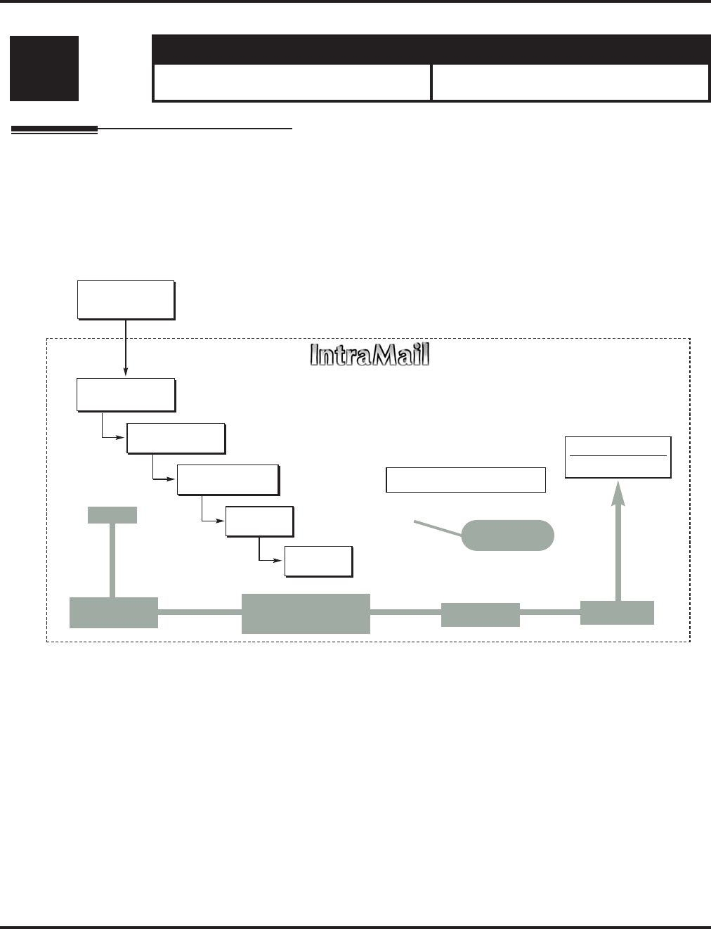
Program 47 : IntraMail
47-13: IntraMail Dial Action Tables
Aspire Software Manual Programming ◆1367
47-13: IntraMail Dial Action Tables
Description
Use 47-13: IntraMail Dial Action Tables to set up the IntraMail Dial Action Tables. The Dial
Action Table defines the options than an Automated Attendant caller can dial. A Dial Action Table
is associated with a Call Routing Mailbox, which is in turn associated with an Answer Table. When
an Answer Table is active, its associated Call Routing Mailbox selects the Dial Action Table which
provides dialing options to callers. The illustration below shows how this works in a default Intra-
Mail system. There are 16 Dial Action Tables.
Level: Aspire S Aspire M/L/XL
IN • Available with software 2.50+. • Not Available for Aspire L/XL.
Aspire M requires software 4.93+.
DIL to Voice Mail
Master (700)
Trunks Route to
Answer Table 1
Answer Table 1
Schedule 1 or
Default Mailbox
Dial Action
Table 1
Calls always route to Call Routing Mailbox 1
- Schedule 1 active M-F 8:30AM-5:00PM.
- Default Mailbox active all other times.
Dial Action Table 1
Dialing Options
Dial an extension number, or
0 for the operator
Default Automated Attendant Answering
All trunks
Use Answer
Table 1
Which chooses Call
Routing Mailbox 1.
And Dial Action
Table 1
With these
dialing options
From a System Administrator's
mailbox, record an Instruction
Menu (SA + I) for the active Call
Routing Mailbox.
Call Routing
Mailbox 1
G 22-02-01: Incoming Call Trunk Setup
G 47-10-01: Answer Table Assignment
G 22-07-01: DIL Setup
G 47-11: IntraMail Answer Table Options
G 47-12: IntraMail Answer
Schedules
G 47-11-03: Default Mailbox
G 47-08: Call Routing Mailbox
Options
G 47-13: IntraMail Dial Action Tables

Program 47 : IntraMail
47-13: IntraMail Dial Action Tables
1368 ◆Programming Aspire Software Manual
Dial Action Table Actions
●TRF Action - Screened Transfer (1)
(TRF)
Use this action to allow an Automated Attendant caller to place a Screened Transfer to an
extension. After an Automated Attendant caller dials an extension, IntraMail calls (screens)
the destination to see if the transfer can go through.
If the destination is available, the Automated Attendant rings it. If the destination
answers, the call goes through.
If the destination doesn’t answer within a preset interval, is busy, or is in Do Not Dis-
turb, the Automated Attendant doesn’t extend the call. It then provides the caller with
additional options.
Number Option
Normally, the corresponding Number option should be XXX. Note that the key you
choose for this action is the first digit of the called extension number.
- For example, to allow callers to place Screened Transfers to extensions 301-399, for key 3
enter TRF for the Action and XXX for the corresponding Number.
To have Screened Transfer call a specific extension, the corresponding Number option
should be that extension’s number. The caller then dials that single digit to reach the
extension.
- For example, to have caller’s dial 8 to reach extension 303, for key 8 enter TRF for the
Action and 303 for the corresponding Number.
●UTRF Action - Unscreened Transfer (2)
(UTRF)
Use this action to allow an Automated Attendant caller to place an Unscreened Transfer to an
extension. This is similar to telephone system unscreened transfers in which the transferring
party immediately extends the call. After an Automated Attendant caller dials an extension,
IntraMail transfers the call to the destination and hangs up. Any recalls or additional routing
are handled by the telephone system - just as with any other unscreened transfer.
Number Option
Normally, the corresponding Number option should be XXX. Note that the key you
choose for this action is the first digit of the called extension number.
- For example, to allow callers to place Unscreened Transfers to extensions 301-399, for key
3 enter UTRF for the Action and XXX for the corresponding Number.
To have Unscreened Transfer call a specific extension, the corresponding Number
option should be that extension’s number. The caller then dials that single digit to reach
the extension.
- For example, to have caller’s dial 8 to reach extension 303, for key 8 enter UTRF for the
Action and 303 for the corresponding Number.
●REC1 Action - Quick Message With Greeting (3)
(REC1)
Use this action to allow an Automated Attendant caller to leave a Quick Message at an exten-
sion. With this action, the caller will hear the extension’s greeting prior to leaving the mes-
sage.
Number Options
To have the caller leave a quick Message at a specific extension, the corresponding
Number option should be the extension number.
To have the caller leave a Quick Message at any caller-dialed extension, the corre-
sponding Number option should be IXXX.
To have the caller leave a Quick Message at a caller-dialed extension in a specific
range, the corresponding Number option should be XXX.
- For example, to allow callers to leave a Quick Message extensions 301-399, for key 3
enter REC1 for the Action and XXX for the corresponding Number.

Program 47 : IntraMail
47-13: IntraMail Dial Action Tables
Aspire Software Manual Programming ◆1369
●REC2 Action - Quick Message Without Greeting (4)
(REC2)
Use this action to allow an Automated Attendant caller to leave a Quick Message at an exten-
sion. With this action, the caller will not hear the extension’s greeting prior to leaving the mes-
sage. Instead, the caller hears the voice prompt “Recording” followed by a beep.
Number Option
To have the caller leave a quick Message at a specific extension, the corresponding
Number option should be the extension number.
To have the caller leave a Quick Message at any caller-dialed extension, the corre-
sponding Number option should be IXXX.
To have the caller leave a Quick Message at a caller-dialed extension in a specific
range, the corresponding Number option should be XXX.
- For example, to allow callers to leave a Quick Message extensions 301-399, for key 3
enter REC2 for the Action and XXX for the corresponding Number.
●LOGON Action - Log Onto Voice Mail (5)
(LOGON)
Use this key action to allow an Automated Attendant caller to log onto Voice Mail. Depending
on programming (see Number Option below), the caller is logged directly into a Subscriber
Mailbox or is prompted to enter a Subscriber Mailbox of their own choosing. You cannot use
the LOGON option with Call Routing and Announcement Mailboxes.
Number Option
To log directly into a specific Subscriber Mailbox, enter the
mailbox number
in the cor-
responding Number option.
- For example, to have key 4 log directly into
Subscriber Mailbox
305, for key 4 enter
LOGON for the Action and 305 for the corresponding Number.
To have IntraMail request Automated Attendant callers to select a Subscriber Mailbox to
log into, enter N in the corresponding Number option. The key you choose must represent
the first digit in the Subscriber Mailbox numbers.
- For example, to have the Automated Attendant request callers to enter the number of the
Subscriber Mailbox
into which they wish to log, for key 3 enter LOGON for the Action
and N for the corresponding Number. When callers dial 3, they hear, “Please enter your
mailbox number.”
To have IntraMail require Automated Attendant callers to enter a
Subscriber Mailbox
to log into (without playing an announcement), enter XXX in the corresponding Number
option.
The key you choose must represent the first digit in the Subscriber Mailbox numbers.
- For example, to allow callers to log onto mailboxes 301-399, for key 3 enter LOGON for
the Action and XXX for the corresponding Number.
To log into any valid Subscriber Mailbox, enter IXXX in the corresponding Number
option.
- For example, to allow callers to dial 1 plus any Subscriber Mailbox number to log on, for
key 1 enter LOGON for the Action and IXXX for the corresponding Number.
●Hang Up Action (6)
(HNGUP)
When an Automated Attendant caller presses a key assigned to this action, IntraMail says
“Goodbye” and immediately hangs up.
Number Option
There is no entry required in the corresponding Number option.

Program 47 : IntraMail
47-13: IntraMail Dial Action Tables
1370 ◆Programming Aspire Software Manual
●GOTO Action - Go to Mailbox (7)
(GOTO)
Use this option to provide Automated Attendant callers with the ability to route to Call Rout-
ing and Announcement Mailboxes. For example, a caller can dial a digit for Sales, and then go
to the Call Routing or Announcement Mailbox that provides the dialing options and instruc-
tions for Sales.
Number Option
To have Automated Attendant callers dial a single digit to go to a Call Routing or
Announcement Mailbox, enter the mailbox number in the corresponding Number option.
- For example, to have key 1 go to Call Routing Mailbox 01, for key 1 enter GOTO for the
Action and 01 for the corresponding Number.
To have IntraMail require Automated Attendant callers to enter a Call Routing or
Announcement Mailbox to go to, enter XXX in the corresponding Number option. The key
you choose must represent the first digit in the mailbox numbers.
- For example, to allow callers to go to mailboxes 000-015, for key 0 enter GOTO for the
Action and XXX for the corresponding Number.
To log into any valid Call Routing or Subscriber Mailbox, enter IXXX in the corre-
sponding Number option.
- For example, to allow callers to dial 1 plus any Call Routing or Announcement Mailbox
number to go to, for key 1 enter GOTO for the Action and IXXX for the corresponding
Number.
●UND Action - Undefined Routing (0)
(UND)
Use this key action if you want a key to have no routing (no operation). When an Automated
Attendant caller presses an undefined key, they hear, “That is an invalid entry.” The caller can
then dial another option.

Program 47 : IntraMail
47-13: IntraMail Dial Action Tables
Aspire Software Manual Programming ◆1371
Input Data
Conditions
None
Dial Action Table Number 01-16
Key No. Dial Action Table Action Additional Data
1 • TRF Action - Screened Transfer (1)
(TRF)
• UTRF Action - Unscreened Transfer (2)
(UTRF)
• REC1 Action - Quick Message With
Greeting (3)
(REC1)
• REC2 Action - Quick Message With-
out Greeting (4)
(REC2)
• LOGON Action - Log Onto Voice
Mail (5)
(LOGON)
• Hang Up Action (6)
(HNGUP)
• GOTO Action - Go to Mailbox (7)
(GOTO)
• UND Action - Undefined Routing (0)
(UND)
•Digits Entry : 0-9, #, and * (8 digits max.)
Use Dial Action Table digits to route an Automated Attendant
call to a specific location (such as an extension). For example, to
set up a TRF Action to route to extension 305, for digit 3 enter
TRF for the Action and 305 for the corresponding Number.
•Caller Dialed Digits Entry : X (Entered by pressing LK2)
Use the X option to route an Automated Attendant call based on
digits the caller dials. Each X entry represents one caller-dialed
digit. For example, to set up a TRF Action to route to any caller
dialed extension in the 301-399 range, for digit 3 enter TRF for
the Action and XXX for the corresponding Number.
•Ignore Digits Entry : I (Entered by pressing LK3)
Use the I option to represent any digit dialed by the Automated
Attendant caller that IntraMail ignores for routing. An example
of this is REC action assigned to the * key in Dial Action Table
1 by default. The Action is REC2 and the Number is IXXX. This
means that a caller can dial * + any mailbox number to leave a
Quick Message in that mailbox. IntraMail ignores the first digit
dialed by the caller (*), and routes according to the next 3 digits
dialed.
•No Routing Entry : N (Entered by pressing LK1)
Use the N option when you want no Automated Attendant rout-
ing to automatically occur. This can be used with the LOGON
action when you want to prompt the caller to enter a mailbox
number. To do this for the # key (for example), for the # key
enter LOGON for the Action and N for the corresponding Num-
ber. When the caller dials #, they hear, “Please enter the mail-
box number. Or, to exit, press the pound key.”
•Pause Entry : P (Entered by pressing LK4)
Use the P option when you want the Automated Attendant to
pause while dialing.
To set the duration of the pause, use 81-01-16: Pause Time. The
default for the pause is 75s mS.
2
3
4
5
6
7
8
9
0
*
#
TIME-
OUT

Program 47 : IntraMail
47-13: IntraMail Dial Action Tables
1372 ◆Programming Aspire Software Manual
Defaults
Note: TIMEOUT provides the routing for rotary dial callers.
Feature Cross Reference
●Voice Mail
Dial Action Table Default Settings
Key Dial Action Table 1 Dial Action Tables 2-16
1 UND
(Undefined)
UND
(Undefined)
2 UND
(Undefined)
UND
(Undefined)
3 UTRF to XXX
(Unscreened Transfer to user-dialed extension)
UND
(Undefined)
4 UTRF to XXX
(Unscreened Transfer to user-dialed extension)
UND
(Undefined)
5 UND
(Undefined)
UND
(Undefined)
6 UND
(Undefined)
UND
(Undefined)
7 UND
(Undefined)
UND
(Undefined)
8 UND
(Undefined)
UND
(Undefined)
9 HNGUP
(Hangup)
UND
(Undefined)
0 UTRF to 301
(Unscreened Transfer to 301)
UND
(Undefined)
* REC1 to IXXX
(Quick Message with greeting to
user-dialed extension)
UND
(Undefined)
# LOGON to IXXX
(Logon to user-dialed mailbox)
UND
(Undefined)
TIMEOUT UTRF to 301
(Unscreened Transfer to 301)
UND
(Undefined)

Program 47 : IntraMail
47-13: IntraMail Dial Action Tables
Aspire Software Manual Programming ◆1373
Telephone Programming Instructions
To enter data for Program 47-13 (IntraMail Dial Action Tables):
1. Enter the programming mode.
2. 47 13
3. Enter the number of the item you want to program.
4. Select the table to be programmed by pressing the FLASH or the VOLUME ▲ or
VOLUME ▼ keys.
5. Enter data for the item you selected + HOLD.
6. Enter data for the next item in the program.
OR
Press MSG once to enter a new item number.
OR
Press MSG until you’ve exited that series’s programming section.
47-13-01 Table1
Key 01 Action 0:UND
back ↑↑
↑↑ ↓↓
↓↓ select
47-13-nn
nnnnn
←←
←← →→
→→

Program 47 : IntraMail
47-14 : Master Directory Mailbox Options
1374 ◆Programming Aspire Software Manual
47-14 : Master Directory Mailbox Options
Description
Use 47-14: Master Directory Mailbox Options to set up the Master Mailbox assigned as a Direc-
tory Dialing Mailbox in 47-03-03: Master Mailbox Type.
Input Data
Level: Aspire S Aspire M/L/XL
IN • Available with software 2.64+. • Not Available for Aspire L/XL.
Aspire M requires software 4.93+.
Item No. Item Input Data Default
01 Minimum Number of Letters Required
Use this option to specify the minimum number of letters the
caller should dial in order to be routed by the Directory Dialing
Mailbox. Callers must dial this minimum number of letters, fol-
lowed by #.
1-3 1
02 Directory List Number to Use
Use this option to specify which Directory List the Directory
Dialing Mailbox should use. The Directory Dialing Mailbox
can only call Subscriber Mailboxes that are in the list specified
by this option.
1-8 (lists 1-8) 1 (list 1)
03 Extension Name Match
Use this option to determine which portion of the extension’s
programmed name Directory Dialing will be used to route the
call. The setting you choose in this option depends on how you
set up 47-01-16 : IntraMail Basic Options - Name Format.
For example, if 47-01-16 was set to last/first (2) and 47-14-03
was set to first (1), an entered name of “Mary Jones” would be
routed by “Jones”, not “Mary”. If 47-01-16 was set to first/last
(1) and 47-14-03 was set to first (1), Directory Dialing would
route by “Mary”.
1 (first) or 2 (last) 1 (first)
04 Unscreened or Screened Transfer
Use this option to define the action Directory Dialing uses
when routing a call.
0 = Screened Transfer
1 = Unscreened Transfer 0
05 Screened Transfer Timeout
Use this option to set how long a Screened Transfer (STRF)
from the Directory Dialing Mailbox will ring an unanswered
extension before recalling.
• The 24-02-04 : System options for Transfer - Transfer
Recall Time interval has no interaction with this timer.
0 = no recall
1-255 seconds 15 (seconds)

Program 47 : IntraMail
47-14 : Master Directory Mailbox Options
Aspire Software Manual Programming ◆1375
Conditions
None
Feature Cross Reference
●Voice Mail
06 Time Limit for Dialing Commands
This option determines how long IntraMail will wait for the
caller connected to the Directory Dialing Mailbox to dial
before repeating the Directory Dialing Message. If the caller
doesn’t dial within three repeats of the message, IntraMail
routes the call to the Next Call Routing Mailbox for the Direc-
tory Dialing Mailbox.
0 = no timeout
1-99 seconds 5 (seconds)
07 Fax Detection
Use this option to enable or disable Fax Detection for the
Directory Dialing Mailbox. If enabled (1), the Directory Dial-
ing Mailbox will detect incoming fax CNG tone. The fax will
then route to the company fax machine according to the set-
tings of 47-01-06 : IntraMail Basic Options - Fax Extension.
If disabled (0), the Directory Dialing Mailbox will not detect
incoming fax calls.
0 = Disabled
1 = Enabled 0
08 Next Call Routing Mailbox
Use this option to specify the Next Call Routing Mailbox for
the Directory Dialing Mailbox. If a Next Call Routing Mailbox
is specified, the following will occur:
• If the caller dials 0 while listening to the Directory Dialing
Message, they route to the 0 action programmed into the
Dial Action Table associated with the Next Call Routing
Mailbox.
• If the caller dials # while listening to the Directory Dialing
Message, they route immediately to the Next Call Routing
Mailbox and listen to the recorded Instruction Menu Mes-
sage for that mailbox.
1-16 0

Program 47 : IntraMail
47-14 : Master Directory Mailbox Options
1376 ◆Programming Aspire Software Manual
Telephone Programming Instructions
To enter data for Program 47-14 (Master Directory Mailbox Options):
1. Enter the programming mode.
2. 47 14
3. Enter the number of the item you want to program.
4. Select the mailbox to be programmed by pressing the FLASH or the VOLUME ▲ or
VOLUME ▼ keys.
5. Enter data for the item you selected + HOLD.
6. Enter data for the next item in the program.
OR
Press MSG once to enter a new item number.
OR
Press MSG until you’ve exited that series’s programming section.
47-14-01 Mailbox1
Min Num Letters 1
back ↑↑
↑↑ ↓↓
↓↓ select
47-14-nn
nnnnn
←←
←← →→
→→

Program 47 : IntraMail
47-15 : Routing Directory Mailbox Options
Aspire Software Manual Programming ◆1377
47-15 : Routing Directory Mailbox Options
Description
Use 47-15: Routing Directory Mailbox Options to set up the Routing Mailbox assigned as a
Directory Dialing Mailbox in 47-07-02: Routing Mailbox Type.
Input Data
Level: Aspire S Aspire M/L/XL
IN • Available with software 2.64+. • Not Available for Aspire L/XL.
Aspire M requires software 4.93+.
Item No. Item Input Data Default
01 Minimum Number of Letters Required
Use this option to specify the minimum number of letters the
caller should dial in order to be routed by the Directory Dialing
Mailbox. Callers must dial this minimum number of letters, fol-
lowed by #.
1-3 1
02 Directory List Number to Use
Use this option to specify which Directory List the Directory
Dialing Mailbox should use. The Directory Dialing Mailbox
can only call Subscriber Mailboxes that are in the list specified
by this option.
1-8 (lists 1-8) 1 (list 1)
03 Extension Name Match
Use this option to determine which portion of the extension’s
programmed name Directory Dialing will be used to route the
call. The setting you choose in this option depends on how you
set up 47-01-16 : IntraMail Basic Options - Name Format.
For example, if 47-01-16 was set to last/first (2) and 47-15-03
was set to first (1), an entered name of “Mary Jones” would be
routed by “Jones”, not “Mary”. If 47-01-16 was set to first/last
(1) and 47-15-03 was set to first (1), Directory Dialing would
route by “Mary”.
0 (first) or 1 (last) 0 (first)
04 Unscreened or Screened Transfer
Use this option to define the action Directory Dialing uses
when routing a call.
0 = Screened Transfer
1 = Unscreened Transfer 0
05 Screened Transfer Timeout
Use this option to set how long a Screened Transfer (STRF)
from the Directory Dialing Mailbox will ring an unanswered
extension before recalling.
• The 24-02-04 : System options for Transfer - Transfer
Recall Time interval has no interaction with this timer.
0 = no recall
1-255 seconds 15 (seconds)

Program 47 : IntraMail
47-15 : Routing Directory Mailbox Options
1378 ◆Programming Aspire Software Manual
06 Time Limit for Dialing Commands
This option determines how long IntraMail will wait for the
caller connected to the Directory Dialing Mailbox to dial
before repeating the Directory Dialing Message. If the caller
doesn’t dial within three repeats of the message, IntraMail
routes the call to the Next Call Routing Mailbox for the Direc-
tory Dialing Mailbox.
0 = no timeout
1-99 seconds 5 (seconds)
07 Fax Detection
Use this option to enable or disable Fax Detection for the
Directory Dialing Mailbox. If enabled (1), the Directory Dial-
ing Mailbox will detect incoming fax CNG tone. The fax will
then route to the company fax machine according to the set-
tings of 47-01-06 : IntraMail Basic Options - Fax Extension.
If disabled (0), the Directory Dialing Mailbox will not detect
incoming fax calls.
0 = Disabled
1 = Enabled 0
08 Next Call Routing Mailbox
Use this option to specify the Next Call Routing Mailbox for
the Directory Dialing Mailbox. If a Next Call Routing Mailbox
is specified, the following will occur:
• If the caller dials 0 while listening to the Directory Dialing
Message, they route to the 0 action programmed into the
Dial Action Table associated with the Next Call Routing
Mailbox.
• If the caller dials # while listening to the Directory Dialing
Message, they route immediately to the Next Call Routing
Mailbox and listen to the recorded Instruction Menu Mes-
sage for that mailbox.
1-16 0

Program 47 : IntraMail
47-15 : Routing Directory Mailbox Options
Aspire Software Manual Programming ◆1379
Conditions
None
Feature Cross Reference
●Voice Mail
47-15: Routing Directory Dialing Mailbox Options
(Entry Range) [Default Setting]
CALL1 + #*#* + Password (12345678) + HOLD + 4714 + Option.
■This selects the option chosen for Master Mailbox 1.
There are 16 available Master Mailboxes (1-16).
01 Min Num Letters (1-3) [1]
02 Directory List (1-8) [1]
03 Name Match (0=First portion of programmed name, 1=Second portion of programmed name) [0]
04 Transfer Option (0=Screened Transfer, 1=Unscreened Transfer) [0]
05 Scrn Trf Timeout (1-255 seconds, 0=No recall) [15]
06 Dialing Timeout (1-99 seconds, 0=No timeout) [5]
07 Fax Detection (0=Disabled, 1=Enabled) [0]
08 Next CR Mbox (1-16, 0-Entered by pressing CLEAR=Undefined) [0]
Press this: To do this:
Editing
HOLD Enter (accept) data you entered and advance to the next prompt, or advance to the next
prompt without changing your entry.
-1 +1 Scroll backwards (-1) or forwards (+1) through the list of available entries.
←←
←← →→
→→ When editing an entry, moves the cursor left or right.
CONF When editing an entry, delete the character to the left of the cursor.
CLEAR When editing an entry, CLEAR erases the entire entry from the display.
Line Keys (LK) Where indicated, press a line key to enter a specific value for the selected option.
Navigation
FLASH FLASH + Mailbox number + FLASH selects a new mailbox number
MSG or back Backs up to the previous level (e.g., from Option to Series, or from Series to Program).
➔
➔
Scroll consecutively backwards or forwards through selected Option or Series.
select Selects currently displayed Option or Series

Program 47 : IntraMail
47-15 : Routing Directory Mailbox Options
1380 ◆Programming Aspire Software Manual
Telephone Programming Instructions
To enter data for Program 47-15 (Routing Directory Mailbox Options):
1. Enter the programming mode.
2. 47 15
3. Enter the number of the item you want to program.
4. Select the mailbox to be programmed by pressing the FLASH or the VOLUME ▲ or
VOLUME ▼ keys.
5. Enter data for the item you selected + HOLD.
6. Enter data for the next item in the program.
OR
Press MSG once to enter a new item number.
OR
Press MSG until you’ve exited that series’s programming section.
47-15-01 Mailbox1
Min Num Letters 1
back ↑↑
↑↑ ↓↓
↓↓ select
47-15-nn
nnnnn
←←
←← →→
→→

Program 80 : Basic Hardware Setup for System
80-01 : Service Tone Setup
Aspire Software Manual Programming ◆1381
Program 80 : Basic Hardware Setup for System
80-01 : Service Tone Setup
Description
Use Program 80-01 : Service Tone Setup to define up to 64 Service Tones. Each service tone is
defined by the combination of 32 Basic Tones.
Input Data
Table-1A : Basic Tone
Level: Aspire S Aspire M/L/XL
IN • Available. • Available.
• Tone 64 available with 2.63+ software. • Tone 64 available with 2.63+ software.
Service Tone Number 01-64
Item No. Item Input Data
01 Repeat Count 0-255 (0 is endless)
Unit Number 1-8
Item No. Item Input Data
02 Basic Tone Number 1-33 (0=No Tone, 33=Default Time Slot)
03 Duration Count 1-255 (100-25500ms)
04 Gain Level (dB) 1-63 (-15.5 ~ +15.5)
Basic
Tone No. Frequency (Hz) Level (dB) Basic
Tone No. Frequency (Hz) Level (dB)
01 400 - 13 17 520 / 650 -13 / -19
02 520 -13 18 650 / 780 -13 / -19
03 580 -13 19 780 / 1040 -13 / -19
04 660 -13 20 1040 -13
05 700 -13 21 - reserve - -
06 800 -13 22 - reserve - -
07 880 -13 23 - reserve - -
08 1050 -13 24 - reserve - -
09 350 / 440 -16 / -16 25 - reserve - -

Program 80 : Basic Hardware Setup for System
80-01 : Service Tone Setup
1382 ◆Programming Aspire Software Manual
Default
10 440 / 480 -16 / -16 26 - reserve - -
11 480 / 620 -21 / -21 27 - reserve - -
12 440 -16 28 - reserve - -
13 - reserve - - 29 - reserve - -
14 520 / 650 -19 / -13 30 - reserve - -
15 650 / 780 -19 / -13 31 - reserve - -
16 780 / 1040 -19 / -13 32 - reserve - -
Service
Tone No. Service Tone Repeat
Count
Unit
Count
Basic
Tone No. Duration Gain Level
(dB)
1 No Tone 0 Basic 1
Basic 2 0
010
032 (0dB)
2 Intercom Dial Tone 0 Basic 1
Basic 2 9
010
032 (0dB)
3 Special Dial Tone 0 Basic 1
Basic 2
Basic 3
Basic 4
Basic 5
Basic 6
Basic 7
0
9
0
9
0
9
0
2
1
1
1
1
77
0
32 (0dB)
32 (0dB)
32 (0dB)
32 (0dB)
32 (0dB)
32 (0dB)
4 Internal Recall Dial Tone 2 Basic 1
Basic 2
Basic 3
9
0
0
1
1
0
32 (0dB)
32 (0dB)
5 Trunk Dial Tone 0 Basic 1
Basic 2 9
010
032 (0dB)
6 Busy Tone 0 Basic 1
Basic 2
Basic 3
0
11
0
5
5
0
20 (-6dB)
20 (-6dB)
7 DND Busy Tone and Select-
able Display Message Tone 0 Basic 1
Basic 2
Basic 3
0
1
0
2
2
0
32 (0dB)
32 (0dB)
8 Busy Tone 0 Basic 1
Basic 2
Basic 3
0
11
0
5
5
0
20 (-6dB)
20 (-6dB)
9 Internal Reorder Tone 0 Basic 1
Basic 2
Basic 3
11
0
0
3
2
0
20 (-6dB)
20 (-6dB)
Basic
Tone No. Frequency (Hz) Level (dB) Basic
Tone No. Frequency (Hz) Level (dB)

Program 80 : Basic Hardware Setup for System
80-01 : Service Tone Setup
Aspire Software Manual Programming ◆1383
10 Internal Interrupt Tone 0 Basic 1
Basic 2
Basic 3
11
0
0
3
2
0
20 (-6dB)
20 (-6dB)
11 Internal Confirmation Tone 3 Basic 1
Basic 2
Basic 3
0
9
0
1
1
0
32 (0dB)
32 (0dB)
12 Internal Hold Tone 0 Basic 1 0 0 -
13 External Hold Tone 0 Basic 1 0 0 -
14 Intercom Ringback Tone 0 Basic 1
Basic 2
Basic 3
10
0
0
10
30
0
20 (-6dB)
20 (-6dB)
15 Override Tone 1 Basic 1
Basic 2 12
05
032 (0dB)
16 Lock-Out Tone 0 Basic 1
Basic 2
Basic 3
0
6
0
1
1
0
32 (0dB)
32 (0dB)
17 Clock Alarm Tone 0 Basic 1
Basic 2
Basic 3
Basic 4
Basic 5
6
0
6
0
0
1
1
1
7
0
32 (0dB)
32 (0dB)
32 (0dB)
32 (0dB)
18 BGM 0 Basic 1 0 0 -
19 Door Box Chime 1 3 Basic 1
Basic 2
Basic 3
Basic 4
Basic 5
Basic 6
Basic 7
4
4
2
2
2
0
0
2
2
3
4
6
5
0
38 (+3dB)
26 (-3dB)
38 (+3dB)
26 (-3dB)
14 (-9dB)
32 (0dB)
20 Door Box Chime 2 3 Basic 1
Basic 2
Basic 3
Basic 4
Basic 5
Basic 6
Basic 7
7
7
5
5
5
0
0
2
2
3
4
6
5
0
38 (+3dB)
26 (-3dB)
38 (+3dB)
26 (-3dB)
14 (-9dB)
32 (0dB)
21 Door Box Chime 3 3 Basic 1
Basic 2
Basic 3
Basic 4
Basic 5
Basic 6
Basic 7
8
8
6
6
6
0
0
2
2
3
4
6
5
0
38 (+3dB)
26 (-3dB)
38 (+3dB)
26 (-3dB)
14 (-9dB)
32 (0dB)
Service
Tone No. Service Tone Repeat
Count
Unit
Count
Basic
Tone No. Duration Gain Level
(dB)

Program 80 : Basic Hardware Setup for System
80-01 : Service Tone Setup
1384 ◆Programming Aspire Software Manual
22 Door Box Chime 4 3 Basic 1
Basic 2
Basic 3
Basic 4
Basic 5
Basic 6
Basic 7
4
4
2
2
2
0
0
1
1
2
2
3
2
0
38 (+3dB)
26 (-3dB)
38 (+3dB)
26 (-3dB)
14 (-9dB)
32 (0dB)
23 Door Box Chime 5 3 Basic 1
Basic 2
Basic 3
Basic 4
Basic 5
Basic 6
Basic 7
7
7
5
5
5
0
0
1
1
2
2
3
2
0
38 (+3dB)
26 (-3dB)
38 (+3dB)
26 (-3dB)
14 (-9dB)
32 (0dB)
24 Door Box Chime 6 3 Basic 1
Basic 2
Basic 3
Basic 4
Basic 5
Basic 6
Basic 7
8
8
6
6
6
0
0
1
1
2
2
3
2
0
38 (+3dB)
26 (-3dB)
38 (+3dB)
26 (-3dB)
14 (-9dB)
32 (0dB)
25 Service Set Tone 3 Basic 1
Basic 2
Basic 3
0
9
0
1
1
0
32 (0dB)
32 (0dB)
26 Service Clear Tone 3 Basic 1
Basic 2
Basic 3
0
9
0
1
1
0
32 (0dB)
32 (0dB)
27 Talkback Tone 2 Basic 1
Basic 2
Basic 3
0
6
0
1
1
0
32 (0dB)
32 (0dB)
28 Speaker Monitor Tone
This tone is what the origina-
tor hears when placing a
handsfree speaker ICM call.
Note: The received ICM tone
can not be changed.
1 Basic 1
Basic 2
Basic 3
0
6
0
1
1
0
32 (0dB)
32 (0dB)
29 Door Relay Tone 1 Basic 1
Basic 2
Basic 3
0
6
0
1
1
0
32 (0dB)
32 (0dB)
30 Door Box Call Tone 1 Basic 1
Basic 2
Basic 3
0
6
0
1
1
0
32 (0dB)
32 (0dB)
31 Paging Tone 2 Basic 1
Basic 2
Basic 3
0
6
0
1
1
0
32 (0dB)
32 (0dB)
Service
Tone No. Service Tone Repeat
Count
Unit
Count
Basic
Tone No. Duration Gain Level
(dB)

Program 80 : Basic Hardware Setup for System
80-01 : Service Tone Setup
Aspire Software Manual Programming ◆1385
32 Splash Tone 1 1 Basic 1
Basic 2
Basic 3
0
6
0
1
1
0
32 (0dB)
32 (0dB)
33 Splash Tone 2 2 Basic 1
Basic 2
Basic 3
0
6
0
1
1
0
32 (0dB)
32 (0dB)
34 Splash Tone 3 3 Basic 1
Basic 2
Basic 3
0
6
0
1
1
0
32 (0dB)
32 (0dB)
35 1 Second Signal Tone
Used for Long Conversation
Warning Tone.
1 Basic 1
Basic 2 6
010
032 (0dB)
36 Sensor Alarm Tone 1 0 Basic 1
Basic 2
Basic 3
10
0
0
10
30
0
32 (0dB)
32 (0dB)
37 Sensor Alarm Tone 2 0 Basic 1
Basic 2
Basic 3
0
11
0
2
3
0
32 (0dB)
32 (0dB)
38 Sensor Alarm Tone 3 0 Basic 1
Basic 2
Basic 3
0
11
0
5
5
0
32 (0dB)
32 (0dB)
39 Ring Busy Tone 0 Basic 1
Basic 2
Basic 3
Basic 4
Basic 5
Basic 6
Basic 7
0
11
0
11
10
0
0
5
5
5
5
10
20
0
32 (0dB)
32 (0dB)
32 (0dB)
32 (0dB)
32 (0dB)
32 (0dB)
40 Internal Call Waiting Tone 1 Basic 1
Basic 2 12
02
032 (0dB)
41 Intrusion Tone 1 Basic 1
Basic 2 12
05
032 (0dB)
42 Conference Tone 0 Basic 1 0 0 32 (0dB)
43 Intrusion Tone 2 0 Basic 1 0 0 32 (0dB)
44 External Dial Tone 0 Basic 1
Basic 2 9
01
026 (-3dB)
45 External Ring Back Tone 0 Basic 1
Basic 2
Basic 3
10
0
0
10
30
0
32 (0dB)
32 (0dB)
46 DID Error Tone 0 Basic 1
Basic 2
Basic 3
0
10
0
5
5
0
32 (0dB)
32 (0dB)
47 External Busy Tone 0 Basic 1 11 0 -
Service
Tone No. Service Tone Repeat
Count
Unit
Count
Basic
Tone No. Duration Gain Level
(dB)

Program 80 : Basic Hardware Setup for System
80-01 : Service Tone Setup
1386 ◆Programming Aspire Software Manual
48 Voice Mail Message Waiting,
Special Dial
Stutter Dial Tone (analog sets)
0 Basic 1
Basic 2
Basic 3
9
0
0
1
1
0
32 (0dB)
32 (0dB)
49 -- Not Used -- 0 0 0 0 32 (0dB)
50 0 Basic 1
Basic 2
Basic 3
Basic 4
10
12
0
0
10
2
30
0
32 (0dB)
32 (0dB)
32 (0dB)
51 0 Basic 1
Basic 2
Basic 3
12
4
0
3
2
0
32 (0dB)
32 (0dB)
52 1 Basic 1
Basic 2 12
03
032 (0dB)
53 1 Basic 1
Basic 2 12
010
032 (0dB)
54 0 Basic 1 0 0 -
55 Generate tone for TAPI2.1 0 Basic 1 3 0 -
56 Warning Beep Tone Signaling 1 Basic 1
Basic 2 2
08
032 (0dB)
57 Headset Ringing Tone 0 Basic 1
Basic 2
Basic 3
Basic 4
Basic 5
Basic 6
0
2
0
2
0
0
2
1
1
1
20
0
32 (0dB)
32 (0dB)
32 (0dB)
32 (0dB)
32 (0dB)
58 Opening Chime Tone,
External Paging 1 Basic 1
Basic 2
Basic 3
Basic 4
Basic 5
Basic 6
Basic 7
Basic 8
2
2
14
14
15
15
16
16
2
2
2
2
2
2
6
4
32 (0dB)
26 (-3dB)
32 (0dB)
26 (-3dB)
32 (0dB)
26 (-3dB)
32 (0dB)
26 (-3dB)
59 Ending Chime Tone,
External Paging 1 Basic 1
Basic 2
Basic 3
Basic 4
Basic 5
Basic 6
Basic 7
Basic 8
20
20
19
19
18
18
17
17
2
2
2
2
2
2
6
4
32 (0dB)
26 (-3dB)
32 (0dB)
26 (-3dB)
32 (0dB)
26 (-3dB)
32 (0dB)
26 (-3dB)
60 Splash Tone 1 (Mute) 1 Basic 1
Basic 2
Basic 3
0
6
0
1
1
0
8 (-12dB)
8 (-12dB)
Service
Tone No. Service Tone Repeat
Count
Unit
Count
Basic
Tone No. Duration Gain Level
(dB)

Program 80 : Basic Hardware Setup for System
80-01 : Service Tone Setup
Aspire Software Manual Programming ◆1387
Conditions
The system must be reset in order for any changes to these items take affect.
Feature Cross Reference
●Selectable Ring Tones
Telephone Programming Instructions
To enter data for Program 80-01 (Service Tone Setup):
1. Enter the programming mode.
2. 80 01
3. Enter the number of the item you want to program.
4. Select the Service Tone to be programmed by pressing the FLASH or the VOLUME ▲ or
VOLUME ▼ keys.
5. Enter data for the item you selected + HOLD.
6. Enter data for the next item in the program.
OR
Press MSG once to enter a new item number.
OR
Press MSG until you’ve exited that series’s programming section.
61 Splash Tone 2 (Mute) 2 Basic 1
Basic 2
Basic 3
0
6
0
1
1
0
8 (-12dB)
8 (-12dB)
62 Splash Tone 3 (Mute) 3 Basic 1
Basic 2
Basic 3
0
6
0
1
1
0
8 (-12dB)
8 (-12dB)
63 Ring Over Page 0 Basic 1
Basic 2
Basic 3
10
0
0
10
30
0
32 (0dB)
32 (0dB)
64 Music On Hold System Tone
The tone heard by the user
when placed on hold when
Program 10-04-01 set to "2".
0 Basic 1
Basic 2
Basic 3
Basic 4
Basic 5
6
0
6
0
0
1
1
1
50
0
32 (0dB)
32 (0dB)
32 (0dB)
32 (0dB)
80-01-01 Svc Tone1
Repeat Count 0
back ↑↑
↑↑ ↓↓
↓↓ select
80-01-nn
nnnnn
←←
←← →→
→→
Service
Tone No. Service Tone Repeat
Count
Unit
Count
Basic
Tone No. Duration Gain Level
(dB)

Program 80 : Basic Hardware Setup for System
80-02 : DTMF Tone Setup
1388 ◆Programming Aspire Software Manual
80-02 : DTMF Tone Setup
Description
Use Program 80-02 : DTMF Tone Setup to define the duration (on time) and pause (off time) for
DTMF dialing. This option affects all trunk line calls system wide. You make separate entries for
duration and pause. It is also possible to adjust the level of both high and low frequency tone.
Input Data
Conditions
This program will not be displayed in PCPro until signing in with the MF level password.
Feature Cross Reference
●Selectable Ring Tones
Level: Aspire S Aspire M/L/XL
MF • Available. • Available.
Item No. Item Input Data Default
01 Duration 1-255 5 (100 ms)
02 Pause 1-255 5 (100 ms)
03 Tone Level (Low) (dB) 1-97 (-45.0 ~ +3) 69 (-11dB)
04 Tone Level (High) 1-97 (-45.0 ~ +3) 65 (-13dB)
Duration
Pause

Program 80 : Basic Hardware Setup for System
80-02 : DTMF Tone Setup
Aspire Software Manual Programming ◆1389
Telephone Programming Instructions
To enter data for Program 80-02 (DTMF Tone Setup):
1. Enter the programming mode.
2. 80 02
3. Enter the number of the item you want to program.
4. Enter data for the item you selected + HOLD.
5. Enter data for the next item in the program.
OR
Press MSG once to enter a new item number.
OR
Press MSG until you’ve exited that series’s programming section.
80-02-01
Duration Time 5
back ↑↑
↑↑ ↓↓
↓↓ select
80-02-nn
nnnnn
←←
←← →→
→→
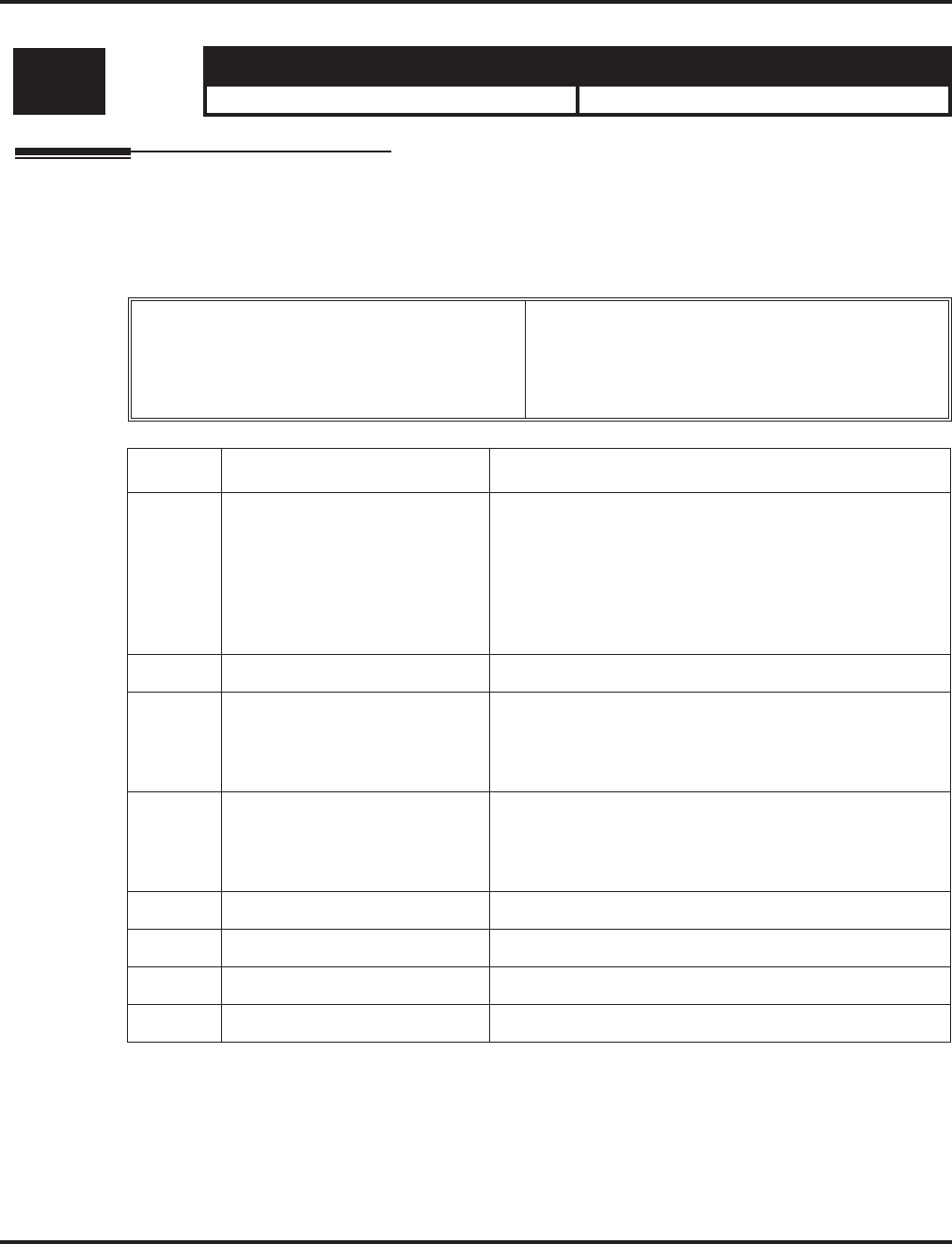
Program 80 : Basic Hardware Setup for System
80-03 : DTMF Tone Receiver Setup
1390 ◆Programming Aspire Software Manual
80-03 : DTMF Tone Receiver Setup
Description
Use Program 80-03 : DTMF Tone Receiver Setup to define the various levels and timers for the
DTMF Tone Receiver
Input Data
Level: Aspire S Aspire M/L/XL
MF • Available. • Available.
DTMF Tone Receiver Type Number 1 = DTMF Receiver for Extension
2 = DTMF Receive for Trunk
3 = - Reserve -
4 = - Reserve -
5 = - Reserve -
Item No. Item Input Data
01 Detect Level 0 = 0dBm ~ -25dBm
1 = -5dBm ~ -30dBm
2 = -10dBm ~ -35dBm
3 = -15dBm ~ -40dBm
4 = -20dBm ~ -45dBm
5 = -25dBm ~ -50dBm
6 = -30dBm ~ -55dBm
02 Start delay time 0-255 (0.25ms-64ms)
03 Min. detect level 0-15
detect level 0 : –15dBm(0) to –30dBm(15)
detect level 1 : –30dBm(0) to –45dBm(15)
detect level 2 : –40dBm(0) to –55dBm(15)
04 Max. detect level 0-15
detect level 0 : 0dBm(0) to –15dBm(15)
detect level 1 : –15dBm(0) to –30dBm(15)
detect level 2 : –30dBm(0) to –45dBm(15)
05 Forward twist level 0-9 (1dB ~ 10dB)
06 Backward twist level 0-9 (1dB ~ 10dB)
07 ON detect time 1-255 (15+15ms ~ 3825ms)
08 OFF detect time 1-255 (15+15ms ~ 3825ms)

Program 80 : Basic Hardware Setup for System
80-03 : DTMF Tone Receiver Setup
Aspire Software Manual Programming ◆1391
Default
Conditions
This program will not be displayed in PCPro until signing in with the MF level password.
Feature Cross Reference
●Selectable Ring Tones
Telephone Programming Instructions
To enter data for Program 80-03 (DTMF Tone Receiver Setup):
1. Enter the programming mode.
2. 80 03
3. Enter the number of the item you want to program.
4. Enter data for the item you selected + HOLD.
5. Enter data for the next item in the program.
OR
Press MSG once to enter a new item number.
OR
Press MSG until you’ve exited that series’s programming section.
Item
No. Item Type 1 Type 2 Type 3 Type 4 Type 5
01 Detect Level 00000
02 Start delay time 00000
03 Min. detect
level 10(-25dBm) 15(-30dBm) 10(-25dBm) 10(-25dBm) 10(-25dBm)
04 Max. detect
level 2 (-2dBm) 2 (-2dBm) 2 (-2dBm) 2 (-2dBm) 2 (-2dBm)
05 Forward twist
level 5 (6dBm) 5 (6dBm) 5 (6dBm) 5 (6dBm) 5 (6dBm)
06 Backward twist
level 0 (1dBm) 0 (1dBm) 0 (1dBm) 0 (1dBm) 0 (1dBm)
07 ON detect time 1 (30ms) 1 (30ms) 1 (30ms) 1 (30ms) 1 (30ms)
08 OFF detect time 1 (30ms) 1 (30ms) 1 (30ms) 1 (30ms) 1 (30ms)
80-03-01 PB Receiver 1
Detect level 0:0/-30
back ↑↑
↑↑ ↓↓
↓↓ select
80-03-nn PB Receiver 1
nnnnn
←←
←← →→
→→

Program 80 : Basic Hardware Setup for System
80-04 : Call Progress Tone Detector Setup
1392 ◆Programming Aspire Software Manual
80-04 : Call Progress Tone Detector Setup
Description
Use Program 80-04 : Call Progress Tone Detector Setup to define the various levels and timers
for the Call Progress Tone Detector
Input Data
Level: Aspire S Aspire M/L/XL
MF • Available. • Available.
Tone Detector Type No 1 = Dial Tone for Trunk
2 = Busy Tone for Trunk
3 = Ring Back Tone for Trunk
4 = - Reserve -
5 = - Reserve -
Item No. Item Input Data
01 Detect Level 0 = 0dBm ~ -25dBm
1 = -5dBm ~ -30dBm
2 = -10dBm ~ -35dBm
3 = -15dBm ~ -40dBm
4 = -20dBm ~ -45dBm
5 = -25dBm ~ -50dBm
6 = -30dBm ~ -55dBm
02 Min. detect level 0-15
detect level 0 : –15dBm(0) to –30dBm(15)
detect level 1 : –30dBm(0) to –45dBm(15)
detect level 2 : –40dBm(0) to –55dBm(15)
03 S/N ratio 0-4 (0dB ~ -20dB)
04 No tone time 1-255 (30+30-7650ms)
(0 = No detection)
05 Pulse Count 1-255
06 ON min. time 1-255 (30+30-7650ms)
07 ON max. time 0-255 (30+30-7650ms)
(0 = No detection)
08 OFF min. time 1-255 (30+30-7650ms)
09 OFF max. time 1-255 (30+30-7650ms)
(0 = No detection)
10 -- Reserve -- 0-8
11 -- Reserve -- 0-8

Program 80 : Basic Hardware Setup for System
80-04 : Call Progress Tone Detector Setup
Aspire Software Manual Programming ◆1393
Default
Conditions
This program will not be displayed in PCPro until signing in with the MF level password.
Feature Cross Reference
●Selectable Ring Tones
Item
No. Item Type1
(DT)
Type2
(BT)
Type3
(RBT) Type4 Type5
01 Detect Level 0
(0..-30dBm) 0
(0..-30dBm) 0
(0..-30dBm) 00
02 Min. detect
level 15
(-30dBm) 15
(-30dBm) 15
(-30dBm) 00
03 S/N ratio 4
(-20dB) 4
(-20dB) 4
(-20dB) 00
04 No tone time 132
(3990ms) 132
(3990ms) 132
(3990ms) 00
05 Pulse Count 11100
06 ON min. time 63
(1500ms) 12
(390ms) 25
(780ms) 00
07 ON max. time 0
(Not detect) 20
(630ms) 40
(1230ms) 00
08 OFF min. time 1
(60ms) 12
(390ms) 52
(1590ms) 00
09 OFF max. time 1
(60ms) 20
(630ms) 80
(2430ms) 00
10 -- Reserve -- 11100
11 -- Reserve -- 00000

Program 80 : Basic Hardware Setup for System
80-04 : Call Progress Tone Detector Setup
1394 ◆Programming Aspire Software Manual
Telephone Programming Instructions
To enter data for Program 80-04 (Call Progress Tone Detector Setup):
1. Enter the programming mode.
2. 80 04
3. Enter the number of the item you want to program.
4. Enter data for the item you selected + HOLD.
5. Enter data for the next item in the program.
OR
Press MSG once to enter a new item number.
OR
Press MSG until you’ve exited that series’s programming section.
80-04-01 Tone Rcv1
Detect level 0:0/-30
back ↑↑
↑↑ ↓↓
↓↓ select
80-04-nn Tone Rcv1
nnnnn
←←
←← →→
→→

Program 80 : Basic Hardware Setup for System
80-05 : Date Format for SMDR and System Reports
Aspire Software Manual Programming ◆1395
80-05 : Date Format for SMDR and System Reports
Description
Use Program 80-05 : Date Format for SMDR and System Reports to define the date format
when printing out the SMDR, alarm report, system information report, etc.
Input Data
Conditions
This program will not be displayed in PCPro until signing in with the MF level password.
Feature Cross Reference
●Station Message Detail Recording
●Time and Date
Telephone Programming Instructions
To enter data for Program 80-05 (Date Format for SMDR and System Reports):
1. Enter the programming mode.
2. 80 05
3. Enter the number of the item you want to program.
4. Enter data for the item you selected + HOLD.
5. Enter data for the next item in the program.
OR
Press MSG once to enter a new item number.
OR
Press MSG until you’ve exited that series’s programming section.
Level: Aspire S Aspire M/L/XL
MF • Available. • Available.
Item No. Date Format Default
01 0 = American Format (Month / Date / Year)
1 = Japanese Format (Year / Month / Date)
2 = European Format (Date/Month/Year)
0
80-05-01
Date Format 1:Japan
back ↑↑
↑↑ ↓↓
↓↓ select
80-05-nn
nnnnn
←←
←← →→
→→

Program 80 : Basic Hardware Setup for System
80-05 : Date Format for SMDR and System Reports
1396 ◆Programming Aspire Software Manual
- For Your Notes -

Program 81 : Basic Hardware Setup for Trunk
81-01 : COIU Initial Data Setup
Aspire Software Manual Programming ◆1397
Program 81 : Basic Hardware Setup for Trunk
81-01 : COIU Initial Data Setup
Description
Use Program 81-01 : COIU Initial Data Setup to define the various basic timers for COIU PCBs.
Input Data
Level: Aspire S Aspire M/L/XL
MF • Available. • Available.
• Item 12 renamed to Caller ID Detection
Time with software 4.93+. • Item 12 renamed to Caller ID Detection
Time with software 4.93+.
Item
No. Item Input Data Default
01 Companding Method Type 0 = u-law
1 = A-law 0 (u-law)
02 Loop Current Detection Time 1-255 (8-2040mS) 75 (600ms)
03 Clear Signal (Open Loop) Detection Time 1-255 (8-2040mS) 90 (720ms)
04 Ringing Signal Detection Minimum Time 1-255 (8-2040mS) 13 (104ms)
05 Single Ringing Detection Minimum Time 0-255 (0,8-2040mS) 82 (656ms)
06 Double Ringing Detection Minimum off Time 0-255 (0,8-2040mS) 13 (104ms)
07 Double Ringing Detection Maximum off Time 0-255 (0,8-2040mS) 50 (400ms)
08 Ringing Signal Not Detected Minimum 1-255 (8-2040mS) 88 (704ms)
09 Abandoned Call Detection Timer 1-255 (64-16320mS) 94 (6016ms)
10 Continuous Ringing Minimum Time 0-255 (0,8-2040mS) 38 (304ms)
11 Continuous Ringing Maximum Time 0-255 (0,8-2040mS) 88 (704ms)
12 Prior to 4.93 Software: AC Impedance Timer
Software 4.93+: Caller ID Detection Time
If an entry other than "0" is made, the actual waiting time is the value x
64ms. For example, if the timer is set to 46, the COIU waits 46 x 64ms
= 2944ms). If a problem exists with Caller ID displaying, the recom-
mended entry to try first would be "46".
Prior to 4.93 Soft-
ware: 1-255
(64-16320mS)
Software 4.93+:
0 = COIU waits
500ms from end of
first ring to begin-
ning of FSK signal
for Caller ID
1 - 255 = The COIU
waits for the Caller
ID FSK signal from
when the first ring
pulse was detected.
Prior to 4.93
Software: 4
(256ms)
Software
4.93+: 0
13 Grounding Time 1-255 (4-1020mS) 9 (36ms)

Program 81 : Basic Hardware Setup for Trunk
81-01 : COIU Initial Data Setup
1398 ◆Programming Aspire Software Manual
Conditions
This program will not be displayed in PCPro until signing in with the MF level password.
Feature Cross Reference
●Central Office Calls, Placing
14 Flash (Hooking 1)
This sets the flash (Hooking 1) duration for analog trunk calls. See Pro-
gram 14-02-04.
1-255 (16-4080mS) 50 (800ms)
15 Flash (Hooking 2)
This sets the flash (Hooking 2) duration for analog trunk calls. See Pro-
gram 14-02-04.
1-255 (16-4080mS) 156 (2496ms)
16 Pause Time 1-255 (16-4080mS) 16 (1024ms)
17 PFT Idle Detection Time 1-255 (64-16320mS) 47 (3008ms)
18 Grounding Start Time 1-255 (8-2040mS) 6 (48ms)
19 Grounding Start Give-Up Time 1-255 (64-16320mS) 47 (3008ms)
20 Loop Reverse Detect Minimum Time 1-255 (8-2040mS) 13 (104ms)
21 Loop Reverse Detect Maximum Time 1-255 (8-2040mS) 107 (856ms)
22 Loop Disconnect Detect Minimum Time 1-255 (8-2040mS) 50 (400ms)
23 Loop Disconnect Detect Maximum Time 1-255 (8-2040mS) 80 (640ms)
24 On Hook Normal Detect Time 1-255 (8-2040mS) 3 (24ms)
25 On Hook Reverse Detect Time 1-255 (8-2040mS) 2 (16ms)
26 On Hook Disconnect Detect Time 1-255 (16-4080mS) 188 (3008ms)
27 Pulse Dial Break Time (10pps) 1-255 (4-1020mS) 8 (32ms)
28 Pulse Dial Make Time (10pps) 1-255 (4-1020mS) 4 (16ms)
29 Inter-Digit Time (10pps) 1-255 (32-8160mS) 19 (608ms)
30 Pulse Dial Break Time (20pps) 1-255 (4-1020mS) 4 (16ms)
31 Pulse Dial Make Time (20pps) 1-255 (4-1020mS) 2 (8ms)
32 Inter-Digit Time (20pps) 1-255 (32-8160mS) 16 (512ms)
33 Charging Pulse Minimum Duration Time 1-255 (8-2040mS) 9 (72ms)
34 Charging Pulse Minimum Period Time 1-255 (8-2040mS) 29 (232ms)
35 Charging Pulse Minimum Interval Time 1-255 (8-2040mS) 6 (48ms)
Item
No. Item Input Data Default

Program 81 : Basic Hardware Setup for Trunk
81-01 : COIU Initial Data Setup
Aspire Software Manual Programming ◆1399
Telephone Programming Instructions
To enter data for Program 81-01 (COIU Initial Data Setup):
1. Enter the programming mode.
2. 81 01
3. Enter the number of the item you want to program.
4. Enter data for the item you selected + HOLD.
5. Enter data for the next item in the program.
OR
Press MSG once to enter a new item number.
OR
Press MSG until you’ve exited that series’s programming section.
81-01-01
Encoding Type 0: U-LAW
back ↑↑
↑↑ ↓↓
↓↓ select
81-01-nn
nnnnn
←←
←← →→
→→

Program 81 : Basic Hardware Setup for Trunk
81-02 : DIOPU Initial Data Setup
1400 ◆Programming Aspire Software Manual
81-02 : DIOPU Initial Data Setup
Description
Use Program 81-02 : DIOPU Initial Data Setup to define the various basic timers for the DIOPU
cards.
Input Data
Level: Aspire S Aspire M/L/XL
MF • Available. • Available.
Item
No. Item Input Data Default
01 Companding method type 0 = u-law
1 = A-law 0 (u-law)
02 Answer Signal Time 1-255 (4-1020mS) 6 (24ms)
03 Clear Signal (Open Loop) Detection Time 1-255 (100-25500mS) 7 (700ms)
04 Ringing Signal Detection Min. Time 1-255 (8-20240mS) 10 (80ms)
05 Hook Flash Time 1-255 (8-20240mS) 25 (200ms)
06 Pause Time 1-255 (1-255 Seconds) 94 (94 Sec)
07 WINK/DELAY Duration Time 1-255 (8-20240mS) 20 (160ms)
08 Incoming-WINK/DELAY Send Time 1-255 (100-25500mS) 3 (300ms)
09 Seizure-WINK/DELAY Receive Max. Time 1-255 (100-25500mS) 48 (4800ms)
10 Receive WINK/DELAY Duration Min. Time 1-255 (8-20240mS) 13 (104ms)
11 Receive WINK/DELAY Duration Max. Time 1-255 (8-20240mS) 31 (248ms)
12 Receive DP Make Min. Time 1-255 (4-1020mS) 5 (20ms)
13 Receive DP Make Max. Time 1-255 (4-1020mS) 50 (200ms)
14 Receive DP Break Min. Time 1-255 (4-1020mS) 5 (20ms)
15 Receive DP Break Max. Time 1-255 (4-1020mS) 50 (200ms)
16 Receive DP Inter-Digit Time 1-255 (8-20240mS) 6 (48ms)
17 Loop Off Guard Time 0-255 (0,100-25500mS) 20 (2000ms)
18 DP Break Time (10pps) 1-255 (4-1020mS) 16 (64ms)
19 DP Make Time (10pps) 1-255 (4-1020mS) 8 (32ms)
20 DP Inter-Digit Time (10pps) 1-255 (100-25500mS) 38 (3800ms)
21 DP Break Time (0pps) 1-255 (4-1020mS) 8 (32ms)
22 DP Make Time (20pps) 1-255 (4-1020mS) 4 (16ms)
23 DP Inter-Digit Time (20pps) 1-255 (100-25500mS) 29 (2900ms)

Program 81 : Basic Hardware Setup for Trunk
81-02 : DIOPU Initial Data Setup
Aspire Software Manual Programming ◆1401
Conditions
This program will not be displayed in PCPro until signing in with the MF level password.
Feature Cross Reference
●Central Office Calls, Placing
Telephone Programming Instructions
To enter data for Program 81-02 (DIOPU Initial Data Setup):
1. Enter the programming mode.
2. 81 02
3. Enter the number of the item you want to program.
4. Enter data for the item you selected + HOLD.
5. Enter data for the next item in the program.
OR
Press MSG once to enter a new item number.
OR
Press MSG until you’ve exited that series’s programming section.
81-02-01
Encoding Type 0: U-Law
back ↑↑
↑↑ ↓↓
↓↓ select
81-02-nn
nnnnn
←←
←← →→
→→

Program 81 : Basic Hardware Setup for Trunk
81-03 : 4TLIU Initial Data Setup
1402 ◆Programming Aspire Software Manual
81-03 : 4TLIU Initial Data Setup
Description
Use Program 81-03 : 4TLIU Initial Data Setup to define the various basic timers for the E&M tie
line PCB.
Input Data
Level: Aspire S Aspire M/L/XL
MF • Available. • Available.
Item No. Item Input Data Default
01 Companding method type 0 = u-law
1 = A-law 0 (u-law)
02 Answer Signal Time 1-255 (4-1020mS) 6 (60ms)
03 Clear Signal (Open Loop) Detection Time 1-255 (100-25500mS) 7 (700ms)
04 Ringing Signal Detection Min. Time 1-255 (8-20240mS) 10 (100ms)
05 Ringing Signal Stop Detection Time 1-255 (100-25500mS) 7 (700ms)
06 Hook Flash Time 1-255 (8-20240mS) 20 (200ms)
07 Pause Time 1-255 (1-255Sec) 50 (3000ms)
08 WINK/DELAY Duration Time 1-255 (8-20240mS) 20 (200ms)
09 Incoming-WINK/DELAY Send Time 1-255 (100-25500mS) 3 (300ms)
10 Seizure-WINK/DELAY Receive Max. Time 1-255 (100-25500mS) 48 (4800ms)
11 Receive WINK/DELAY Duration Min. Time 1-255 (8-20240mS) 13 (130ms)
12 Receive WINK/DELAY Duration Max. Time 1-255 (8-20240mS) 31 (310ms)
13 Receive DP Make Min. Time 1-255 (4-1020mS) 5 (10ms)
14 Receive DP Make Max. Time 1-255 (4-1020mS) 50 (100ms)
15 Receive DP Break Min. Time 1-255 (4-1020mS) 5 (10ms)
16 Receive DP Break Max. Time 1-255 (4-1020mS) 50 (100ms)
17 Pause Time After WINK/DELAY Receive 1-255 (8-20240mS) 13 (104ms)
18 Loop Off Guard Time 0-255 (0,100-25500mS) 20 (2000ms)
19 DP Break Time (10pps) 1-255 (4-1020mS) 32 (64ms)
20 DP Make Time (10pps) 1-255 (4-1020mS) 16 (32ms)
21 DP Inter-Digit Time (10pps) 1-255 (100-25500mS) 19 (608ms)
22 DP Break Time (0pps) 1-255 (4-1020mS) 16 (32ms)
23 DP Make Time (20pps) 1-255 (4-1020mS) 8 (16ms)
24 DP Inter-Digit Time (20pps) 1-255 (100-25500mS) 16 (512ms)

Program 81 : Basic Hardware Setup for Trunk
81-03 : 4TLIU Initial Data Setup
Aspire Software Manual Programming ◆1403
Conditions
This program will not be displayed in PCPro until signing in with the MF level password.
Feature Cross Reference
●Tie Lines
Telephone Programming Instructions
To enter data for Program 81-03 (4TLIU Initial Data Setup):
1. Enter the programming mode.
2. 81 03
3. Enter the number of the item you want to program.
4. Enter data for the item you selected + HOLD.
5. Enter data for the next item in the program.
OR
Press MSG once to enter a new item number.
OR
Press MSG until you’ve exited that series’s programming section.
81-03-01
Encoding Type 0: U-Law
back ↑↑
↑↑ ↓↓
↓↓ select
81-03-nn
nnnnn
←←
←← →→
→→

Program 81 : Basic Hardware Setup for Trunk
81-04 : ISDN BRI Layer 1 (T-Point) Initial Data Setup
1404 ◆Programming Aspire Software Manual
81-04 : ISDN BRI Layer 1 (T-Point) Initial Data Setup
Description
Use Program 81-04 : ISDN BRI Layer 1 (T-Point) Initial Data Setup to define the various basic
options for layer 1 of ISDN BRI.
Input Data
Conditions
This program will not be displayed in PCPro until signing in with the MF level password.
Feature Cross Reference
●ISDN Compatibility
Telephone Programming Instructions
To enter data for Program 81-04 (ISDN BRI Layer 1 (T-Point) Initial Data Setup):
1. Enter the programming mode.
2. 81 04
3. Enter the number of the item you want to program.
4. Enter data for the item you selected + HOLD.
5. Enter data for the next item in the program.
OR
Press MSG once to enter a new item number.
OR
Press MSG until you’ve exited that series’s programming section.
Level: Aspire S Aspire M/L/XL
MF • Available. • Available.
Item
No. Item Input Data Default
01 Wait Time for Physical Activation (Timer 3) 1-255 (200-5100ms) 100 (20 sec.)
02 Detection Time for Physical Deactivation 1-255 (200-5100ms) 5 (1 sec.)
81-04-01
L1 Connection 100
back ↑↑
↑↑ ↓↓
↓↓ select
81-04-nn
nnnnn
←←
←← →→
→→

Program 81 : Basic Hardware Setup for Trunk
81-05 : ISDN BRI & PRI Layer 2 (T-Point) Initial Data Setup
Aspire Software Manual Programming ◆1405
81-05 : ISDN BRI & PRI Layer 2 (T-Point) Initial Data Setup
Description
Use Program 81-05 : ISDN BRI & PRI Layer 2 (T-Point) Initial Data Setup to define the vari-
ous basic options for layer 2 of ISDN BRI/PRI.
Input Data
Conditions
This program will not be displayed in PCPro until signing in with the MF level password.
Feature Cross Reference
●ISDN Compatibility
Level: Aspire S Aspire M/L/XL
MF • Available. • Available.
Item
No. Item Input Data Default
01 Timer T200 1-255 (100-25500ms) 10 (1sec.)
02 Timer T201 1-255 (100-25500ms) 10 (1sec.)
03 Timer T202 1-255 (100-25500ms) 20 (2sec.)
04 Timer T203 1-255 (100-25500ms) 200 (20sec.)
05 N200 1-255 3
06 N201 1-65535 (Byte) 260
07 N202 1-255 3

Program 81 : Basic Hardware Setup for Trunk
81-05 : ISDN BRI & PRI Layer 2 (T-Point) Initial Data Setup
1406 ◆Programming Aspire Software Manual
Telephone Programming Instructions
To enter data for Program 81-05 (ISDN BRI & PRI Layer 2 (T-Point) Initial Data Setup):
1. Enter the programming mode.
2. 81 05
3. Enter the number of the item you want to program.
4. Enter data for the item you selected + HOLD.
5. Enter data for the next item in the program.
OR
Press MSG once to enter a new item number.
OR
Press MSG until you’ve exited that series’s programming section.
81-05-01
Timer T200 10
back ↑↑
↑↑ ↓↓
↓↓ select
81-05-nn
nnnnn
←←
←← →→
→→

Program 81 : Basic Hardware Setup for Trunk
81-06 : ISDN BRI & PRI Layer 3 (T-Point) Timer Setup
Aspire Software Manual Programming ◆1407
81-06 : ISDN BRI & PRI Layer 3 (T-Point) Timer Setup
Description
Use Program 81-06 : ISDN BRI & PRI Layer 3 (T-Point) Timer Setup to define the various
basic timers for layer 3 of ISDN BRI/PRI (defined in Program 10-03-04).
Input Data
Level: Aspire S Aspire M/L/XL
MF • Available. • Available.
Layer 3 Timer Type Number 1-5
Item No. Item Input Data Default
01 T301 0,180-254(sec) 180(sec)
02 T302 1-254(sec) 15(sec)
03 T303 1-254(sec) 4(sec)
04 T304 0-254(sec) 30(sec)
05 T305 1-254(sec) 30(sec)
06 T306 0-254(sec) 30(sec)
07 T307 1-254(sec) 180(sec)
08 T308 1-254(sec) 4(sec)
09 T309 1-254(sec) 90(sec)
10 T310 0-180(sec) 180(sec)
11 T312 1-254(sec) 6(sec)
12 T313 1-254(sec) 4(sec)
13 T314 1-254(sec) 4(sec)
14 T316 (T317+1)-254(sec) 120(sec)
15 T317 1-(T316-1) 60(sec)
16 T318 1-254(sec) 4(sec)
17 T319 1-254(sec) 4(sec)
18 T320 1-254(sec) 30(sec)
19 T321 1-254(sec) 30(sec)
20 T322 1-254(sec) 4(sec)

Program 81 : Basic Hardware Setup for Trunk
81-06 : ISDN BRI & PRI Layer 3 (T-Point) Timer Setup
1408 ◆Programming Aspire Software Manual
Conditions
This program will not be displayed in PCPro until signing in with the MF level password.
Feature Cross Reference
●ISDN Compatibility
Telephone Programming Instructions
To enter data for Program 81-06 (ISDN BRI & PRI Layer 3 (T-Point) Timer Setup):
1. Enter the programming mode.
2. 81 06
3. Enter the number of the item you want to program.
4. Select the Layer 3 Timer number to be programmed by pressing the FLASH or the VOLUME
▲ or VOLUME ▼ keys.
5. Enter data for the item you selected + HOLD.
6. Enter data for the next item in the program.
OR
Press MSG once to enter a new item number.
OR
Press MSG until you’ve exited that series’s programming section.
81-06-01 L3 Timer1
T301 180Sec.
back ↑↑
↑↑ ↓↓
↓↓ select
81-06-nn L3 Timernn
nnnnn
←←
←← →→
→→

Program 81 : Basic Hardware Setup for Trunk
81-07 : CODEC Filter Setup for Analog Trunk Ports
Aspire Software Manual Programming ◆1409
81-07 : CODEC Filter Setup for Analog Trunk Ports
Description
Use Program 81-07 : CODEC Filter Setup for Analog Trunk Ports to define the CODEC
(QSLAC) Filter for each analog trunk port.
Input Data
Conditions
None
Feature Cross Reference
●Central Office Calls, Answering
●Central Office Calls, Placing
Level: Aspire S Aspire M/L/XL
IN • Available. • Available.
• Option 4 (Specified Data) uses Program
81-09. • Option 4 (Specified Data) changed to use
Program 81-09 with software 1.04+.
Trunk Port Number 001-200
Item No. Item CODEC Filter Type Default
01 CODEC Filter Setup for
Analog Trunk Ports 0 = No filter
1 = 0dB Loss
2 = 4dB Loss
3 = 8dB Loss
4 = Specified Data - This option uses the
entries defined in Program 81-09.
2

Program 81 : Basic Hardware Setup for Trunk
81-07 : CODEC Filter Setup for Analog Trunk Ports
1410 ◆Programming Aspire Software Manual
Telephone Programming Instructions
To enter data for Program 81-07 (CODEC FilterSetup for Analog Trunk Ports):
1. Enter the programming mode.
2. 81 07
3. Enter the number of the item you want to program.
4. Select the trunk number to be programmed by pressing the FLASH or the VOLUME ▲ or
VOLUME ▼ keys.
5. Enter data for the item you selected + HOLD.
6. Enter data for the next item in the program.
OR
Press MSG once to enter a new item number.
OR
Press MSG until you’ve exited that series’s programming section.
81-07-01 Trunk1
CODEC Filter 2:4dB Loss
back ↑↑
↑↑ ↓↓
↓↓ select
81-07-nn Trunknnn
nnnnn
←←
←← →→
→→

Program 81 : Basic Hardware Setup for Trunk
81-08 : T1 Trunk Timer Setup
Aspire Software Manual Programming ◆1411
81-08 : T1 Trunk Timer Setup
Description
Use Program 81-08 : T1 Trunk Timer Setup to define the various basic timers for each T1 trunk
type.
Input Data
Level: Aspire S Aspire M/L/XL
IN • Available. • Available.
Layer 3 Timer Type Number 1-5
Item No. Item Input Data Default
01 Loop - Answer Signal Detection Time 1-250 (4msec - 1020msec) 15 (60msec)
02 Ground - Answer Signal Detection Time 1-250 (4msec - 1020msec) 15 (60msec)
03 DID - Answer Signal Detection Time 1-250 (4msec - 1020msec) 15 (60msec)
04 E&M - Answer Signal Detection Time 1-250 (4msec - 1020msec) 15 (60msec)
05 OPX - Answer Signal Detection Time 1-250 (4msec - 1020msec) 15 (60msec)
06 Loop - Clear Signal Detection Time 1-255 (100msec - 25500msec) 6 (600msec)
07 Ground - Clear Signal Detection Time 1-255 (100msec - 25500msec) 6 (600msec)
08 DID - Clear Signal Detection Time 1-255 (100msec - 25500msec) 6 (600msec)
09 E&M - Clear Signal Detection Time 1-255 (100msec - 25500msec) 6 (600msec)
10 OPX - Clear Signal Detection Time 1-255 (100msec - 25500msec) 6 (600msec)
11 Loop - Ringing Signal Detection Time 1-250 (8msec - 2040msec) 10 (80msec)
12 Ground - Ringing Signal Detection Time 1-250 (8msec - 2040msec) 10 (80msec)
13 DID - Ringing Signal Detection Time 1-250 (8msec - 2040msec) 10 (80msec)
14 E&M - Ringing Signal Detection Time 1-250 (8msec - 2040msec) 10 (80msec)
15 OPX - Ringing Signal Detection Time 1-250 (8msec - 2040msec) 10 (80msec)
16 Loop - Ringing Signal Stop Detection Time 1-255 (100msec - 25500msec) 50 (3200msec)
17 Ground - Ringing Signal Stop Detection Time 1-255 (100msec - 25500msec) 50 (3200msec)
18 DID - Ringing Signal Stop Detection Time 1-255 (100msec - 25500msec) 50 (3200msec)
19 E&M - Ringing Signal Stop Detection Time 1-255 (100msec - 25500msec) 50 (3200msec)
20 OPX - Ringing Signal Stop Detection Time 1-255 (100msec - 25500msec) 50 (3200msec)
21 Loop - Loop Current Detection Time 1-250 (4msec - 1020msec) 40 (200msec)
22 Ground - Loop Current Detection Time 1-250 (4msec - 1020msec) 40 (200msec)
23 DID - Loop Current Detection Time 1-250 (4msec - 1020msec) 40 (200msec)

Program 81 : Basic Hardware Setup for Trunk
81-08 : T1 Trunk Timer Setup
1412 ◆Programming Aspire Software Manual
24 E&M - Loop Current Detection Time 1-250 (4msec - 1020msec) 40 (200msec)
25 OPX - Loop Current Detection Time 1-250 (4msec - 1020msec) 40 (200msec)
26 All - DP Break Send Time 1-250 (4msec - 1020msec) 15 (60msec)
27 All - DP Make Send Time 1-250 (4msec - 1020msec) 10 (40msec)
28 All - DP Inter-digit Send Time 1-255 (100msec - 25500msec) 7 (700msec)
29 Loop - Hookflash Send Time 1-255 (100msec - 25500msec) 5 (500msec)
30 Ground - Hookflash Send Time 1-255 (100msec - 25500msec) 5 (500msec)
31 DID - Hookflash Send Time 1-255 (100msec - 25500msec) 5 (500msec)
32 E&M - Hookflash Send Time 1-255 (100msec - 25500msec) 5 (500msec)
33 OPX - Hookflash Send Time 1-255 (100msec - 25500msec) 5 (500msec)
34 All - Pause Send Time 1-255 (100sec - 25500sec) 3 (700sec)
35 DID - Wink Send Duration Time 1-250 (8msec - 2040msec) 25 (200msec)
36 DID - Delay Send Duration Time 1-250 (8msec - 2040msec) 25 (200msec)
37 DID - Incoming Wink Send Duration Time 1-255 (1100msec - 25500msec) 3 (300msec)
38 E&M - Wink Send Duration Time 1-250 (8msec - 2040msec) 25 (200msec)
39 E&M - Delay Send Duration Time 1-250 (8msec - 2040msec) 25 (200msec)
40 DID - Incoming Wink Send Duration Time 1-255 (100msec - 25500msec) 3 (300msec)
41 DID - Time Out Seizure-Wink/Delay Receive Maxi-
mum Time 1-255 (100msec - 25500msec) 48 (4800msec)
42 DID - Wink Signal, Receive Wink Duration Minimum
Time 1-250 (8msec - 2040msec) 12 (96msec)
43 DID - Wink Signal, Receive Wink Duration Maxi-
mum Time 1-250 (8msec - 2040msec) 45 (360msec)
44 E&M - Time Out Seizure-Wink/Delay Receive Maxi-
mum Time 1-255 (100msec - 25500msec) 48 (4800msec)
45 E&M - Wink Signal, Receive Wink Duration Mini-
mum Time 1-250 (8msec - 2040msec) 12 (96msec)
46 DID - Wink Signal, Receive Wink Duration Maxi-
mum Time 1-250 (8msec - 2040msec) 45 (360msec)
47 All - Receive DP Make Minimum Time 1-250 (4msec - 1020msec) 3 (12msec)
48 All - Receive DP Make Maximum Time 1-250 (4msec - 1020msec) 19 (76msec)
49 All - Receive DP Break Minimum Time 1-250 (4msec - 1020msec) 3 (12msec)
50 All - Receive DP Break Maximum Time 1-250 (4msec - 1020msec) 25 (100msec)
51 All - Receive DP Inter-digit Minimum Time 1-250 (4msec - 1020msec) 125 (500msec)
52 E&M - Receive Hookflash Duration Minimum Time 1-255 (100msec - 25500msec) 3 (300msec)
53 E&M - Receive Hookflash Duration Maximum Time 1-255 (100msec - 25500msec) 6 (600msec)
Item No. Item Input Data Default

Program 81 : Basic Hardware Setup for Trunk
81-08 : T1 Trunk Timer Setup
Aspire Software Manual Programming ◆1413
54 OPX - Receive Hookflash Duration Minimum Time 1-255 (100msec - 25500msec) 3 (300msec)
55 OPX - Receive Hookflash Duration Maximum Time 1-255 (100msec - 25500msec) 6 (600msec)
56 Loop - Loop Off Guard Time 1-255 (100msec - 25500msec) 20 (2000msec)
57 Ground - Loop Off Guard Time 1-255 (100msec - 25500msec) 20 (2000msec)
58 DID - Loop Off Guard Time 1-255 (100msec - 25500msec) 20 (2000msec)
59 E&M - Loop Off Guard Time 1-255 (100msec - 25500msec) 20 (2000msec)
60 OPX - Loop Off Guard Time 1-255 (100msec - 25500msec) 20 (2000msec)
61 OPX - Double Ringing Send Time 1 1-255 (100msec - 25500msec) 5 (500msec)
62 OPX - Double Between Ringing Send Time 1 1-255 (100msec - 25500msec) 5 (500msec)
63 OPX - Double Ringing Send Time 2 1-255 (100msec - 25500msec) 25 (2500msec)
64 OPX - Double Between Ringing Send Time 2 1-255 (100msec - 25500msec) 30 (3000msec)
65 OPX - Single Ringing Send Time 1 1-255 (100msec - 25500msec) 10 (1000msec)
66 OPX - Single Between Ringing Send Time 1 1-255 (100msec - 25500msec) 9 (900msec)
67 Loop - Guard Time 1 1-255 (100msec - 25500msec) 9 (900msec)
68 Ground - Guard Time 1 1-255 (100msec - 25500msec) 9 (900msec)
69 DID - Guard Time 1 1-255 (100msec - 25500msec) 9 (900msec)
70 E&M - Guard Time 1 1-255 (100msec - 25500msec) 9 (900msec)
71 OPX - Guard Time 1 1-255 (100msec - 25500msec) 9 (900msec)
72 All - Guard Time 2 1-250 (4msec - 1020msec) 3 (12msec)
73 All - Dial Sending Complete time 1-255 (100msec - 25500msec) 20 (2000msec)
74 All - On-Hook Bit Send Time 1-255 (100msec - 25500msec) 40 (4000msec)
75 Loop - Open Loop Time 1-255 (100msec - 25500msec) 6 (600msec)
76 Ground - Open Loop Time 1-255 (100msec - 25500msec) 6 (600msec)
77 DID - Open Loop Time 1-255 (100msec - 25500msec) 6 (600msec)
78 E&M - Open Loop Time 1-255 (100msec - 25500msec) 6 (600msec)
79 OPX - Open Loop Time 1-255 (100msec - 25500msec) 6 (600msec)
80 Loop - Close Loop Time 1-250 (4msec - 1020msec) 13 (52msec)
81 DID - Close Loop Time 1-250 (4msec - 1020msec) 13 (52msec)
82 Ground Loop - Close Loop Time 1-250 (4msec - 1020msec) 13 (52msec)
Item No. Item Input Data Default

Program 81 : Basic Hardware Setup for Trunk
81-08 : T1 Trunk Timer Setup
1414 ◆Programming Aspire Software Manual
Conditions
None
Feature Cross Reference
●T1 Trunking
Telephone Programming Instructions
To enter data for Program 81-08 (T1 Trunk Timer Setup):
1. Enter the programming mode.
2. 81 08
3. Enter the number of the item you want to program.
4. Enter data for the item you selected + HOLD.
5. Enter data for the next item in the program.
OR
Press MSG once to enter a new item number.
OR
Press MSG until you’ve exited that series’s programming section.
81-08-01
Ans Sig Detect LOOP 15
back ↑↑
↑↑ ↓↓
↓↓ select
81-08-nn
nnnnn
←←
←← →→
→→

Program 81 : Basic Hardware Setup for Trunk
81-09 : COIU CODEC Filter Data Setup
Aspire Software Manual Programming ◆1415
81-09 : COIU CODEC Filter Data Setup
Description
The system will use the settings in Program 81-09 : COIU CODEC Filter Data Setup when Pro-
gram 81-07-01 : CODEC Filter Setup for Analog Trunk Ports is set to "4 - Specified Data".
These values should not be changed from their default settings unless directed by NEC’S Technical
Service department.
The side tone of the COIU is adjusted using all 16 values, however, special software is required
in order to compute these values. The setting is not proportional to the gain level. To change
these values, contact NEC’s Technical Service department for assistance.
Input Data
Level: Aspire S Aspire M/L/XL
IN • Available. • Available with software 1.04+.
Item Description Range Default
01 B1 Filter (01) 0-255 171
02 B1 Filter (02) 0-255 221
03 B1 Filter (03) 0-255 76
04 B1 Filter (04) 0-255 44
05 B1 Filter (05) 0-255 19
06 B1 Filter (06) 0-255 160
07 B1 Filter (07) 0-255 186
08 B1 Filter (08) 0-255 26
09 B1 Filter (09) 0-255 51
10 B1 Filter (10) 0-255 226
11 B1 Filter (11) 0-255 107
12 B1 Filter (12) 0-255 190
13 B1 Filter (13) 0-255 170
14 B1 Filter (14) 0-255 208
15 B2 Filter (01) 0-255 162
16 B2 Filter (02) 0-255 192

Program 81 : Basic Hardware Setup for Trunk
81-09 : COIU CODEC Filter Data Setup
1416 ◆Programming Aspire Software Manual
Conditions
None
Feature Cross Reference
●Central Office Calls, Answering
●Central Office Calls, Placing
Telephone Programming Instructions
To enter data for Program 81-09 (COIU CODEC Filter Data Setup):
1. Enter the programming mode.
2. 81 09
3. Enter the number of the item you want to program.
4. Enter data for the item you selected + HOLD.
5. Enter data for the next item in the program.
OR
Press MSG once to enter a new item number.
OR
Press MSG until you’ve exited that series’s programming section.
81-09-01
B1 Filter(01) 171
back ↑↑
↑↑ ↓↓
↓↓ select
81-09-nn
nnnnn
←←
←← →→
→→

Program 82 : Basic Hardware Setup for Extension
82-01 : Incoming Ring Tone
Aspire Software Manual Programming ◆1417
Program 82 : Basic Hardware Setup for Extension
82-01 : Incoming Ring Tone
Description
Use Program 82-01 : Incoming Ring Tone to set the incoming ring tones, which are the tones a
user hears when a call rings an extension. These tones are grouped into four ring tone Ranges (1-4),
also called patterns, that consist of a combination of frequencies. (You assign a specific Range to
trunks in Program 22-03 and to extensions in Program 15-02.) Within each Range there are three
frequency Types: High, Middle and Low. (Service Code 820 allows users to choose the Type for
their incoming calls.) Each Type in turn consists of two frequencies and the modulation “played”
simultaneously to make up the tone. These frequencies are determined by their Frequency Number
selected in Items 1 and 2 (see below). In this program, you assign the two Frequency Numbers and
Modulation for each Type, for each of the four Ranges. The chart below shows the default Fre-
quency Numbers for each Type in each Range.
Input Data
Level: Aspire S Aspire M/L/XL
MF • Available. • Available.
Incoming Ringing Tone Number 1 = Pattern 1 (Trunk Incoming)
2 = Pattern 2 (Trunk Incoming)
3 = Pattern 3 (Trunk Incoming)
4 = Pattern 4 (Trunk Incoming)
5 = Intercom Incoming Pattern
Ringing Tone Type Number 1 = High
2 = Mid
3 = Low
Item
No. Item Input Data
01 Frequency 1 1 = 520Hz
2 = 540Hz
3 = 660Hz
4 = 760Hz
5 = 1100Hz
6 = 1400Hz
7 = 2000Hz
02 Frequency 2
03 Modulation 0 = No modulation
1 = 8Hz modulation
2 = 16Hz modulation
3 = envelope

Program 82 : Basic Hardware Setup for Extension
82-01 : Incoming Ring Tone
1418 ◆Programming Aspire Software Manual
Default
Conditions
This program will not be displayed in PCPro until signing in with the MF level password.
Feature Cross Reference
●Distinctive Ringing Tones and Flash Patterns
●Selectable Ring Tones
Incoming Ringing
Tone Number
Tone
Type Frequency 1 Frequency 2 Modulation
Pattern 1
(Trunk Incoming) High
Mid
Low
1100
660
520
1400
760
660
16Hz Modulation
16Hz Modulation
16Hz Modulation
Pattern 2
(Trunk Incoming) High
Mid
Low
1100
660
520
1400
760
660
8Hz Modulation
8Hz Modulation
8Hz Modulation
Pattern 3
(Trunk Incoming) High
Mid
Low
2000
1400
1100
760
660
540
16Hz Modulation
16Hz Modulation
16Hz Modulation
Pattern 4
(Trunk Incoming) High
Mid
Low
2000
1400
1100
760
660
540
8Hz Modulation
8Hz Modulation
8Hz Modulation
Intercom Incoming Pat-
tern High
Mid
Low
1100
660
520
1400
760
660
8Hz Modulation
8Hz Modulation
8Hz Modulation
Alarm Sensor Pattern High
Mid
Low
760
760
760
760
760
760
No Change
No Change
No Change

Program 82 : Basic Hardware Setup for Extension
82-01 : Incoming Ring Tone
Aspire Software Manual Programming ◆1419
Telephone Programming Instructions
To enter data for Program 82-01 (Incoming Ring Tone):
1. Enter the programming mode.
2. 82 01
3. Enter the number of the item you want to program.
4. Enter data for the item you selected + HOLD.
5. Enter data for the next item in the program.
OR
Press MSG once to enter a new item number.
OR
Press MSG until you’ve exited that series’s programming section.
82-01-01 INC Freq 1
INC-Rng1 Freq1:5:1100Hz
back ↑↑
↑↑ ↓↓
↓↓ select
82-01-nn
nnnnn
←←
←← →→
→→
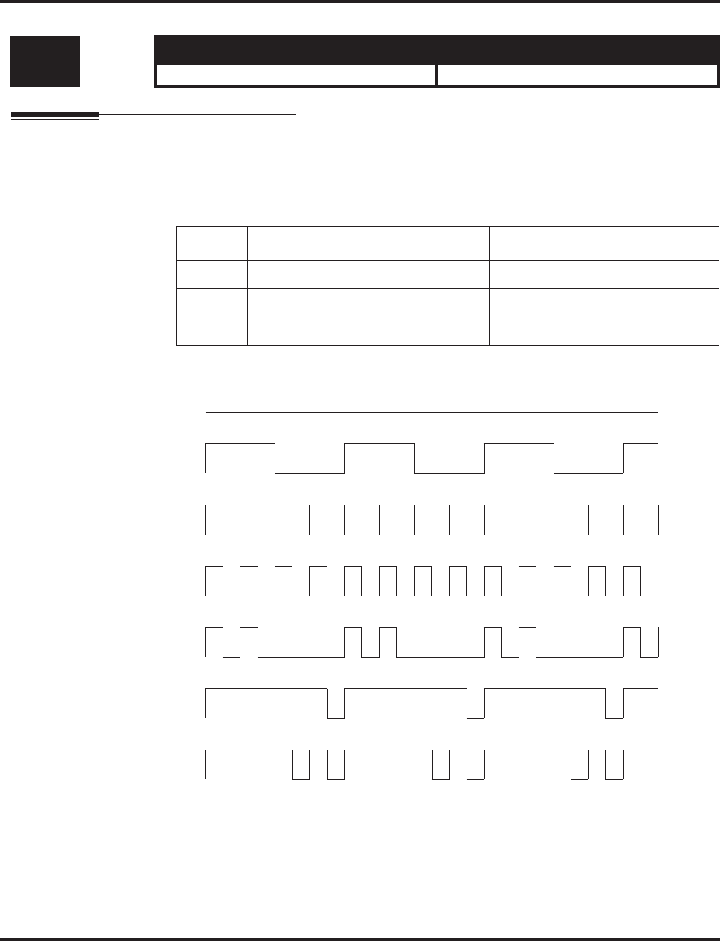
Program 82 : Basic Hardware Setup for Extension
82-03 : DSS Console LED Pattern Setup
1420 ◆Programming Aspire Software Manual
82-03 : DSS Console LED Pattern Setup
Description
Use Program 82-03 : DSS Console LED Pattern Setup to define the LED patterns for special
functions on a DSS console.
Input Data
LED Pattern 0 : [OFF]
LED Pattern 1 : [FL: On(500ms)/Off(500ms)]
LED Pattern 2 : [WK: On(250ms)/Off(250ms)]
LED Pattern 3 : [RW: On(125ms)/Off(125ms)]
LED Pattern 4 : [IR: On(125ms)/Off(125ms)/On(125ms)/Off(625ms)]
LED Pattern 5 : [IL: On(875ms)/Off(125ms)]
LED Pattern 6 : [IW: On(625ms)/Off(125ms)/On(125ms)/Off(125ms)]
LED Pattern 7 : [ON]
Level: Aspire S Aspire M/L/XL
MF • Available. • Available.
Item No. Item Input Data Default
01 ACD Log In 0-7 1
02 ACD Log Out 0-7 4
03 ACD Emergency Call 0-7 3
On
Off
On
Off
On
Off
On
Off
On
Off
On
Off
On
Off
On
Off

Program 82 : Basic Hardware Setup for Extension
82-03 : DSS Console LED Pattern Setup
Aspire Software Manual Programming ◆1421
Conditions
This program will not be displayed in PCPro until signing in with the MF level password.
Feature Cross Reference
●Direct Station Selection (DSS)
Telephone Programming Instructions
To enter data for Program 82-03 (DSS Console LED Pattern Setup):
1. Enter the programming mode.
2. 82 03
3. Enter the number of the item you want to program.
4. Enter data for the item you selected + HOLD.
5. Enter data for the next item in the program.
OR
Press MSG once to enter a new item number.
OR
Press MSG until you’ve exited that series’s programming section.
82-03-01
ACD Log-In 1:Pattern1
back ↑↑
↑↑ ↓↓
↓↓ select
82-03-nn
nnnnn
←←
←← →→
→→
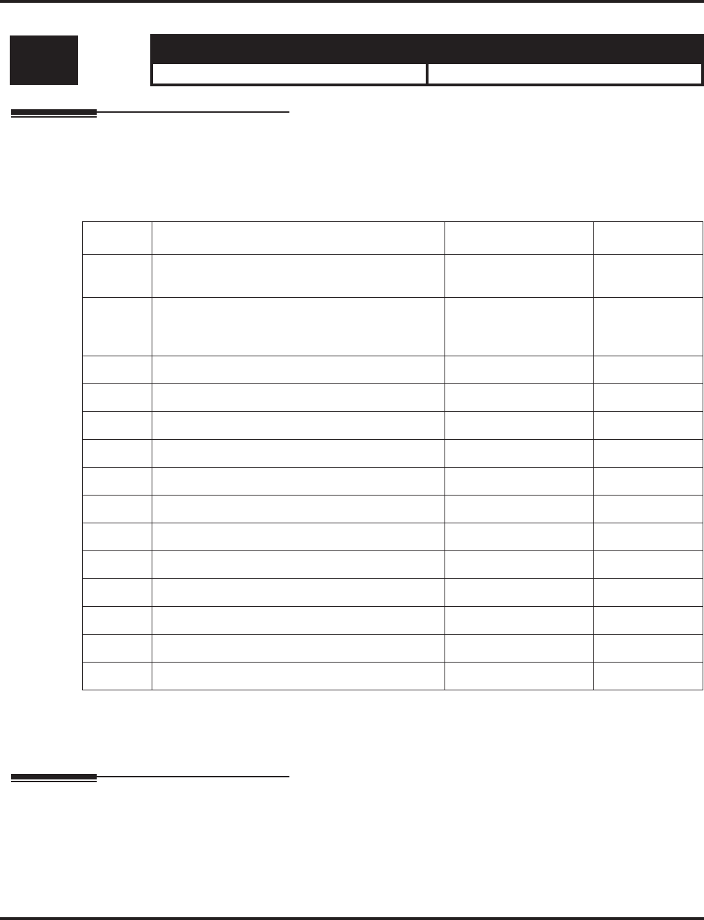
Program 82 : Basic Hardware Setup for Extension
82-04 : SLIU Initial Data Setup
1422 ◆Programming Aspire Software Manual
82-04 : SLIU Initial Data Setup
Description
Use Program 82-04 : SLIU Initial Data Setup to define the various basic timers for the ASTU
PCB.
Input Data
Conditions
This program will not be displayed in PCPro until signing in with the MF level password.
Feature Cross Reference
None
Level: Aspire S Aspire M/L/XL
MF • Available. • Available.
Item No. Item Input Data Default
01 Companding method type 0 = u-law
1 = A-law 0 (u-law)
02 Ringing frequency 0 = 25Hz
1 = 20Hz
2 = 16Hz
2 (16Hz)
03 Minimum break time 1-255 (5ms-1275ms) 2 (10ms)
04 Maximum break time 1-255 (5ms-1275ms) 20 (100ms)
05 Minimum make time 1-255 (5ms-1275ms) 2 (10ms)
06 Maximum make time 1-255 (5ms-1275ms) 20 (100ms)
07 Minimum hook flash time 1-255 (5ms-1275ms) 21 (105ms)
08 Maximum hook flash time 1-255 (5ms-1275ms) 200 (1000ms)
09 Minimum ground flash time 1-255 (5ms-1275ms) 21 (105ms)
10 Minimum off-hook time 1-255 (5ms-1275ms) 21 (105ms)
11 No detection time after off-hook 1-255 (5ms-1275ms) 60 (300ms)
12 No detection time after pulse dial detection 1-255 (5ms-1275ms) 70 (350ms)
13 Loop disconnect time, Reversal time 1-255 (10ms-2550ms) 60 (600ms)
14 Ring, Message wait period time 1-255 (5ms-1275ms) 150 (750ms)

Program 82 : Basic Hardware Setup for Extension
82-04 : SLIU Initial Data Setup
Aspire Software Manual Programming ◆1423
Telephone Programming Instructions
To enter data for Program 82-04 (SLIU Initial Data Setup):
1. Enter the programming mode.
2. 82 04
3. Enter the number of the item you want to program.
4. Enter data for the item you selected + HOLD.
5. Enter data for the next item in the program.
OR
Press MSG once to enter a new item number.
OR
Press MSG until you’ve exited that series’s programming section.
82-04-01
Encoding Type 0: U-Law
back ↑↑
↑↑ ↓↓
↓↓ select
82-04-nn
nnnnn
←←
←← →→
→→

Program 82 : Basic Hardware Setup for Extension
82-05 : ISDN BRI & PRI Layer 2 (S-Point) Initial Data Setup
1424 ◆Programming Aspire Software Manual
82-05 : ISDN BRI & PRI Layer 2 (S-Point) Initial Data Setup
Description
Use Program 82-05 : ISDN BRI & PRI Layer 2 (S-Point) Initial Data Setup to define the vari-
ous basic options for the layer 2 of ISDN BRI/PRI S-Point.
Input Data
Conditions
This program will not be displayed in PCPro until signing in with the MF level password.
Feature Cross Reference
●ISDN Compatibility
Level: Aspire S Aspire M/L/XL
MF • Available. • Available.
Item No. Item Input Data Default
01 Timer T200 1-255 (100-25500ms) 10 (1 sec.)
02 Timer T201 1-255 (100-25500ms) 10 (1 sec.)
03 Timer T202 1-255 (100-25500ms) 20 (2 sec.)
04 Timer T203 1-255 (100-25500ms) 100 (10 sec.)
05 N200 1-255 3
06 N201 1-65535 (Byte) 260
07 N202 1-255 3

Program 82 : Basic Hardware Setup for Extension
82-05 : ISDN BRI & PRI Layer 2 (S-Point) Initial Data Setup
Aspire Software Manual Programming ◆1425
Telephone Programming Instructions
To enter data for Program 82-05 (ISDN BRI & PRI Layer 2 (S-Point) Initial Data Setup):
1. Enter the programming mode.
2. 82 05
3. Enter the number of the item you want to program.
4. Enter data for the item you selected + HOLD.
5. Enter data for the next item in the program.
OR
Press MSG once to enter a new item number.
OR
Press MSG until you’ve exited that series’s programming section.
82-05-01
Timer T200 10
back ↑↑
↑↑ ↓↓
↓↓ select
82-05-nn
nnnnn
←←
←← →→
→→

Program 82 : Basic Hardware Setup for Extension
82-06 : ISDN BRI & PRI Layer 3 (S-Point) Timer Setup
1426 ◆Programming Aspire Software Manual
82-06 : ISDN BRI & PRI Layer 3 (S-Point) Timer Setup
Description
Use Program 82-06 : ISDN BRI & PRI Layer 3 (S-Point) Timer Setup to define the various
basic timers for layer 3 of ISDN BRI/PRI S-Point (defined in Program 10-03-04).
Input Data
Conditions
None
Level: Aspire S Aspire M/L/XL
IN • Available. • Available.
Layer 3 Timer Type Number 1-5
Item No. Item Input Data Default
01 T301 0,180-254 (sec) 180 (sec)
02 T302 1-254 (sec) 10 (sec)
03 T303 1-254 (sec) 4 (sec)
04 T304 0-254 (sec) 20 (sec)
05 T305 1-254 (sec) 30 (sec)
06 T306 0-254 (sec) 30 (sec)
07 T307 1-254 (sec) 180 (sec)
08 T308 1-254 (sec) 4 (sec)
09 T309 1-254 (sec) 90 (sec)
10 T310 0-180 (sec) 30 (sec)
11 T312 1-254 (sec) 6 (sec)
12 T313 1-254 (sec) 4 (sec)
13 T314 1-254 (sec) 4 (sec)
14 T316 (T317+1)-254 (sec) 120 (sec)
15 T317 1-(T316-1) 60 (sec)
16 T318 1-254 (sec) 4 (sec)
17 T319 1-254 (sec) 4 (sec)
18 T320 1-254 (sec) 30 (sec)
19 T321 1-254 (sec) 30 (sec)
20 T322 1-254 (sec) 4 (sec)

Program 82 : Basic Hardware Setup for Extension
82-06 : ISDN BRI & PRI Layer 3 (S-Point) Timer Setup
Aspire Software Manual Programming ◆1427
Feature Cross Reference
●ISDN Compatibility
Telephone Programming Instructions
To enter data for Program 82-06 (ISDN BRI & PRI Layer 3 (S-Point) Timer Setup):
1. Enter the programming mode.
2. 82 06
3. Enter the number of the item you want to program.
4. Select the Layer 3 Timer number to be programmed by pressing the FLASH or the VOLUME
▲ or VOLUME ▼ keys.
5. Enter data for the item you selected + HOLD.
6. Enter data for the next item in the program.
OR
Press MSG once to enter a new item number.
OR
Press MSG until you’ve exited that series’s programming section.
82-06-01 L3 Timer1
T301 180
back ↑↑
↑↑ ↓↓
↓↓ select
82-06-nn L3 Timernn
nnnnn
←←
←← →→
→→

Program 82 : Basic Hardware Setup for Extension
82-07 : CODEC Filter Setup for Analog Station Ports
1428 ◆Programming Aspire Software Manual
82-07 : CODEC Filter Setup for Analog Station Ports
Description
Use Program 82-07 : CODEC Filter Setup for Analog Station Ports to define the CODEC
(QSLAC) Filter for each analog extension port.
Input Data
Conditions
None
Feature Cross Reference
None
Level: Aspire S Aspire M/L/XL
IN • Available. • Available.
• Option 4 (Specified Data) uses Program
82-09.
• Expanded port capacity not available.
• Option 4 (Specified Data) changed to use
Program 82-09 with software 1.04+.
• Expanded port range requires software
4.0E+ and Aspire XL hardware.
Extension Port Number Aspire S: 01-50
Aspire M/L: 001-256
Aspire XL: 001-384
Item No. Item CODEC Filter Type Default
01 CODEC Filter Setup for
Analog Station Ports 0 = No filter
1 = 0dB Loss
2 = 4dB Loss
3 = 8dB Loss
4 = Specified Data - This option uses the
entries defined in Program 82-09.
1

Program 82 : Basic Hardware Setup for Extension
82-07 : CODEC Filter Setup for Analog Station Ports
Aspire Software Manual Programming ◆1429
Telephone Programming Instructions
To enter data for Program 82-07 (CODEC Filter Setup for Analog Station Ports):
1. Enter the programming mode.
2. 82 07
3. Enter the number of the item you want to program.
4. Select the extension port number to be programmed by pressing the FLASH or the VOLUME
▲ or VOLUME ▼ keys.
5. Enter data for the item you selected + HOLD.
6. Enter data for the next item in the program.
OR
Press MSG once to enter a new item number.
OR
Press MSG until you’ve exited that series’s programming section.
82-07-01 Extn Port1
CODEC Filter 1:00dB Loss
back ↑↑
↑↑ ↓↓
↓↓ select
82-07-nn Extn Portnnn
nnnnn
←←
←← →→
→→

Program 82 : Basic Hardware Setup for Extension
82-08 : Sidetone Volume Setup
1430 ◆Programming Aspire Software Manual
82-08 : Sidetone Volume Setup
Description
Program 82-08 : Sidetone Volume Setup allows adjust of the keyset sidetone volume.
There are two levels, based on whether the connected trunk is a digital trunk or analog trunk.
Input Data
Level: Aspire S Aspire M/L/XL
MF • Available. • Available with software 1.04+.
Item Description Input Digital Sidetone Level Analog Sidetone Level
01 Sidetone Volume 0 -54 (dB) -54 (dB)
1 -48 (dB) -54 (dB)
2 -42 (dB) -54 (dB)
3 -36 (dB) -48 (dB)
4 -30 (dB) -42 (dB)
5 -24 (dB) -36 (dB)
6 -18 (dB) -30 (dB)
7 12 (dB) -24 (dB)
8 -12 (dB) -18 (dB)
9 -12 (dB) -12 (dB)

Program 82 : Basic Hardware Setup for Extension
82-08 : Sidetone Volume Setup
Aspire Software Manual Programming ◆1431
Conditions
This program will not be displayed in PCPro until signing in with the MF level password.
Feature Cross Reference
●Central Office Calls, Answering
●Central Office Calls, Placing
Telephone Programming Instructions
To enter data for Program 82-08 (Sidetone Volume Setup):
1. Enter the programming mode.
2. 82 08
3. Enter the number of the item you want to program.
4. Enter data for the item you selected + HOLD.
5. Enter data for the next item in the program.
OR
Press MSG once to enter a new item number.
OR
Press MSG until you’ve exited that series’s programming section.
82-08-01
Sidetone Vol 5:-24/-36|1
back ↑↑
↑↑ ↓↓
↓↓ select
83-08-nn
nnnnn
←←
←← →→
→→

Program 82 : Basic Hardware Setup for Extension
82-09 : SLIU CODEC Filter Data Setup
1432 ◆Programming Aspire Software Manual
82-09 : SLIU CODEC Filter Data Setup
Description
The system will use the settings in the new Program 82-09 : SLIU CODEC Filter Data Setup
when Program 82-07-01 : CODEC Filter Setup for Analog Station Ports is set to "4 - Specified
Data".
These values should not be changed from their default settings unless directed by NEC’S Technical
Service department.
The side tone of the SLIU is adjusted using all 16 values, however, special software is required in
order to compute these values. The setting is not proportional to the gain level. To change these
values, contact NEC’s Technical Service department for assistance.
Input Data
Level: Aspire S Aspire M/L/XL
IN • Available. • Available with software 1.04+.
Item CODEC Filter Item Description Range Default
01 01 B1 Filter (01) 0-255 171
02 B1 Filter (02) 0-255 221
03 B1 Filter (03) 0-255 76
04 B1 Filter (04) 0-255 44
05 B1 Filter (05) 0-255 19
06 B1 Filter (06) 0-255 160
07 B1 Filter (07) 0-255 186
08 B1 Filter (08) 0-255 26
09 B1 Filter (09) 0-255 51
10 B1 Filter (10) 0-255 226
11 B1 Filter (11) 0-255 107
12 B1 Filter (12) 0-255 190
13 B1 Filter (13) 0-255 170
14 B1 Filter (14) 0-255 208
15 B2 Filter (01) 0-255 162
16 B2 Filter (02) 0-255 192

Program 82 : Basic Hardware Setup for Extension
82-09 : SLIU CODEC Filter Data Setup
Aspire Software Manual Programming ◆1433
Conditions
None
Feature Cross Reference
●Central Office Calls, Answering
●Central Office Calls, Placing
Telephone Programming Instructions
To enter data for Program 82-07 (SLIU CODEC Filter Data Setup):
1. Enter the programming mode.
2. 82 07
3. Enter the number of the item you want to program.
4. Enter data for the item you selected + HOLD.
5. Press MSG once to enter a new item number.
OR
Press MSG until you’ve exited that series’s programming section.
82-07-01 Extn Port1
CODEC Filter 1:0db Loss
back ↑↑
↑↑ ↓↓
↓↓ select
82-07-nn
nnnnn
←←
←← →→
→→

Program 82 : Basic Hardware Setup for Extension
82-09 : SLIU CODEC Filter Data Setup
1434 ◆Programming Aspire Software Manual
- For Your Notes -

Program 83: Hardware Setup for Aspire Wireless
83-11 : Aspire Wireless Configuration
Aspire Software Manual Programming ◆1435
Program 83: Hardware Setup for Aspire Wireless
83-11 : Aspire Wireless Configuration
Description
Use Program 83-11 : Aspire Wireless Configuration to define the Aspire Wireless (DECT)
options.
Input Data
Conditions
This program will not be displayed in PCPro until signing in with the MF level password.
Feature Cross Reference
●Aspire Wireless
Level: Aspire S Aspire M/L/XL
MF • Not Available. • Available.
Item No. Item Input Data Default
01 Location Area Level
Use this program to define the location
area - whether the Base Stations/RFPs
are all in the same area or whether each
Base Station in located in a different
area.
0=whole area
1=each different 0 [whole area]
02 Authentication
This program enables (1) or disables (0)
the authentication procedure for the
phone when placing and receiving calls.
0 = Disabled
1 = Enabled 1 (Enabled)
03 Encryption
This program enables (1) or disables (0)
encryption for the phone when placing
and receiving calls.
0 = Disabled
1 = Enabled 1 (Enabled)

Program 83: Hardware Setup for Aspire Wireless
83-11 : Aspire Wireless Configuration
1436 ◆Programming Aspire Software Manual
Telephone Programming Instructions
To enter data for Program 83-11 (Aspire Wireless Configuration):
1. Enter the programming mode.
2. 83 11
3. Enter the number of the item you want to program.
4. Enter data for the item you selected + HOLD.
5. Enter data for the next item in the program.
OR
Press MSG once to enter a new item number.
OR
Press MSG until you’ve exited that series’s programming section.
83-11-01
Location area 0:Whole
back ↑↑
↑↑ ↓↓
↓↓ select
83-11-nn
nnnnn
←←
←← →→
→→

Program 83: Hardware Setup for Aspire Wireless
83-12 : Aspire Wireless Measurement
Aspire Software Manual Programming ◆1437
83-12 : Aspire Wireless Measurement
Description
Use Program 83-12 : Aspire Wireless Measurement to define the Aspire Wireless (DECT) Base
Station measurement.
Input Data
Conditions
This program will not be displayed in PCPro until signing in with the MF level password.
Feature Cross Reference
●Aspire Wireless
Level: Aspire S Aspire M/L/XL
IN • Not Available. • Available.
Item No. Item Input Data Default
01 DECT Measurement
This program measures the length of
cables connecting the PCB and Base
Stations so that the system can find the
best signal transmitting timing for han-
dover. Enter Program 83-12-01, press 1
then HOLD. The system will then
restart all Base Stations/RFPs (this takes
3-5 minutes) and then they will use the
best timing possible. This program
should be used any time the Base Sta-
tion configuration is changed (adding or
deleting Base Stations or changing con-
necting cables).
--

Program 83: Hardware Setup for Aspire Wireless
83-12 : Aspire Wireless Measurement
1438 ◆Programming Aspire Software Manual
Telephone Programming Instructions
To enter data for Program 83-12 (Aspire Wireless Measurement):
1. Enter the programming mode.
2. 83 12
3. Enter “1” + HOLD.
The system will then restart all Base Stations/RFPs (this takes 3-5 minutes) and then
they will use the best timing possible.
4. Press MSG once to enter a new item number.
OR
Press MSG until you’ve exited that series’s programming section.
83-12-01
Start measuring(1)?
back ↑↑
↑↑ ↓↓
↓↓ select

Program 84 : Hardware Setup for VoIP
84-01 : CODEC Information Basic Setup
Aspire Software Manual Programming ◆1439
Program 84 : Hardware Setup for VoIP
84-01 : CODEC Information Basic Setup
Description
Use Program 84-01 : CODEC Information Basic Setup to define the data of H.323 trunks. These
settings apply to IP Networking and H.323 Trunks.
Note that the value of Item 33 (Audio Capability Priority) determines which CODEC settings to
use. This means, for example, that if G.711 is selected in Item 33, the settings in Items 5-12 and 19-
21 will be ignored.
Input Data
Level: Aspire S Aspire M/L/XL
IN • Available. • Available.
• Items 60 and 61 available.
• Item 62 available with software 2.63+.
• Items 60 and 61 available with software
1.18+. Requires VOIPU PCB firmware
3.2+.
• Item 62 available with software 2.63+.
Item
No. Item Input Data Default Description
01 -- Not Used --
02 Number of G711 Audio Frame 2 = 20 ms
3 = 30 ms 3 Maximum number of G711 Audio
Frame
03 G711 Silence Detection Mode 0:Disable
1:Enable 0Define whether the silence detection
enables on G711 or not
04 G711 type 0:A-law
1: u-law 1Set the type of G711
(A-law or u-law)
05 G729 Audio Frame 1 = 10 ms
2 = 20 ms
3 = 30 ms
4 = 40 ms
5 = 50 ms
6 = 60 ms
7 = 70 ms
8 = 80 ms
3 Maximum number of G729 Audio
Frame
06 G729 0:Disable
1:Enable 0
07 G.729 Jitter Buffer Minimum 0-500 ms 30
08 G.729 Jitter Buffer Type 0-500 ms 60
09 G.729 Jitter Buffer Maximum 0-500 ms 120
10 -- Not Used --

Program 84 : Hardware Setup for VoIP
84-01 : CODEC Information Basic Setup
1440 ◆Programming Aspire Software Manual
11 Number of G723 Audio Frame 1 = 30 msec
2 = 60 msec 1 Maximum number of G723 Audio
Frame
12 G723 0:Disable
1:Enable 0
13 Maximum value of Jitter Delay 0-65535 msec 60 msec Maximum value of Jitter Delay for
audio delay
14 -- Not Used --
15 Jitter Buffer Mode 1 = static
2 = adaptive during
silence
3 = adaptive immedi-
ately
1 Set the mode of Jitter Buffer
16 G.711 Jitter Buffer (min.) 0~145 ms 30 Set the minimum value of G.711 Jitter
Buffer
17 G.711 Jitter Buffer (typ) 0~145 ms 60 Set the average value of G.711 Jitter
Buffer
18 G.711 Jitter Buffer (max) 0~145 ms 120 Set the maximum value of G.711 Jitter
Buffer
19 G.723,G.729 Jitter Buffer (min.) 0~500 ms 30 Set the minimum value of G.723,
G.729
Jitter Buffer
20 G.723, G.729 Jitter Buffer (typ) 0~500 ms 60 Set the average value of G.723, G.729
Jitter Buffer
21 G.723,G.729 Jitter Buffer (max) 0~500 ms 120 Set the maximum value of G.723,
G.729
Jitter Buffer
22 VAD threshold 0-30
(-20db~+10db)
0:-20db (-50dbm)
1:-19db (-49dbm)
:
20 = 0db
(-30dbm)
:
29 = 9dbm
(-21dbm)
30:10dbm
(-20dbm)
20 Threshold of silence detection
Change value based –30
Become invalid item if item 03 is set
to Disable
Item
No. Item Input Data Default Description

Program 84 : Hardware Setup for VoIP
84-01 : CODEC Information Basic Setup
Aspire Software Manual Programming ◆1441
23 Idle Noise Level 5000-7000
(-5000 ~ -7000dbm)
5000 = -5000dbm
:
7000 = -7000dbm
7000 Noise level of silence
24 Echo canceler mode 0 = Disable
1 = Enable 1 Determine whether or not to use Echo
canceller.
25 Echo canceler tail size 1 = 8 ms
2 = 16 ms
3 = 32mS
2 Become invalid item if item 24 is set
to Disable
26 Echo canceler nlp mode 0 = Disable
1 = Enable 0 Non-linear processing mode
27 Echo canceler nlp noise 40-70 (-40~-70)
40 = -40 dbm
:
70 = -70 dbm
70 Become invalid item if item 26 is set
to Disable
28 Echo canceler cng cfg 0 = adaptive
1 = fixed 0 Become invalid item if item 26 is set
to Disable
29 Echo canceler 4w det 0 = Disable
1 = Enable 0
30 TX Gain 0-28 (-14~+14)
0 = -14 dbm
1 = -13 dbm
:
14 = 0 dbm
:
27 = 13 dbm
28 = 14 dbm
14
31 RX Gain 0-28 (-14~+14)
0 = -14 dbm
1 = -13 dbm
:
14 = 0 dbm
:
27 = 13 dbm
28 = 14 dbm
14
32 -- Not Used --
33 Audio Capability Priority 0:G711 PT
1:G723 PT
2:G729 PT
0 The option selected here determines
what other options are applied from
this program.
Item
No. Item Input Data Default Description

Program 84 : Hardware Setup for VoIP
84-01 : CODEC Information Basic Setup
1442 ◆Programming Aspire Software Manual
34 Bandwidth Control 0:Disable
1:Enable 0 Controls the voice bandwidth on an
H.323 trunk.
35 Maximum Bandwidth 0-65535kbps 0 The maximum total bandwidth limita-
tion for voice packets.
36 Fax Max Rate 24 = V.27ter, 2400 bps
48 = V.27ter, 4800 bps
72 = V.29, 7200 bps
96 = V.29, 9600 bps
120 = V17, 12000 bps
144 = V.17, 14400 bps
5
37 Fax Playout FIFO Nominal
Delay 0-600 ms 300 ms Increase the value for networks which
experience large packet losses.
38 Fax Packet Size 20-48 bytes 20
39 Fax Modem Transmit Level 0-13
0dBm -13dBm 6
(-6dBm)
40 Fax Modem CD Threshold 0 = -26dBm
1 = -33dBm
2 = -43dBm
1
41 Fax No Activity Timeout
Duration 10-32000 sec 30
42 Override Encapsulation Method 0 = Open Channel
Defined Packet Encap-
sulation
1 = T.38 UDP
2 = T.38/TRP UDP
1 T.38/TRP UDP
Voice-Fax
Close-Reopen
43 High Speed Data Packet Rate 10-80 ms 60
44 Low Speed Data Redundancy 0-8 0
45 High Speed Data Redundancy 0-2 0
46 TCF Handling Method 1 = TCF is Locally Gen-
erated and Checked
2 = TCF is Sent Over
the Network
1 For H.323 negotiation
47 Maximum Low Speed Data
Packetization 1
48 Transmit Network Timeout 10-32000 sec 150 sec
49 Eflag Start Timer 0-65535 2600 ms
50 Eflag Stop Timer 0-65535 2300 ms
51 Fax Relay: Scan Line Fix Up
Feature 0 = Disable
1 = Enable 1
Item
No. Item Input Data Default Description

Program 84 : Hardware Setup for VoIP
84-01 : CODEC Information Basic Setup
Aspire Software Manual Programming ◆1443
Conditions
You must log out of system programming in order for changes to the following items will take
affect: Item 39 Item 53
Item 40 Item 54
Item 41 Item 55
Item 49 Item 56
Item 50 Item 57
Item 51 Item 58
Item 52
Feature Cross Reference
●VoIP
52 Fax Relay: Eflags for First DIS 0 = Disable
1 = Enable 1
53 Fax Relay: FOP Protocol
Enhancement 0 = Disable
1 = Enable 1
54 Fax Relay: NSF Override 0 = Disable
1 = Enable 0
55 T30: ECM 0 = Disable
1 = Enable 1
56 T30: MR Page Compression 0 = Disable
1 = Enable 1
57 NSF Country Code 0-65535 Blank Fax Relay - NSF Override Disable
58 NSF Vendor Code 65535 Blank Fax Relay - NSF Override Disable
59 Fax Relay Function 0 = Disable
1 = Enable 0 Determine whether or not the Fax
Relay function should be used.
60 Echo Canceller Config Type 0 = Auto
1 = Type 1
2 = Type 2
3 = Type 3
1
61 Echo Auto Gain Control 0 - 5 0
62 H.323 DTMF Payload Number 0 = VOIPU
1 = RFC2833
2 = H.245
3 = Disable
0Define the H.323 DTMF Payload
Number.
Item
No. Item Input Data Default Description

Program 84 : Hardware Setup for VoIP
84-01 : CODEC Information Basic Setup
1444 ◆Programming Aspire Software Manual
Telephone Programming Instructions
To enter data for Program 84-01 (CODEC Information Basic Setup):
1. Enter the programming mode.
2. 84 01
3. Enter the number of the item you want to program.
4. Enter data for the item you selected + HOLD.
5. Enter data for the next item in the program.
OR
Press MSG once to enter a new item number.
OR
Press MSG until you’ve exited that series’s programming section.
84-01-01
RAS Ucast Port20001
back ↑↑
↑↑ ↓↓
↓↓ select
84-01-nn
nnnnn
←←
←← →→
→→

Program 84 : Hardware Setup for VoIP
84-02 : H.225, H.245 Information Basic Setup
Aspire Software Manual Programming ◆1445
84-02 : H.225, H.245 Information Basic Setup
Description
Use Program 84-02 : H.225, H.245 Information Basic Setup to define the data of H.225 and
H.245.
It is recommended that these settings are left at the default values unless you are advised to change
the values by NEC Infrontia.
Input Data
Level: Aspire S Aspire M/L/XL
IN • Available. • Available.
Item
No. Item Input Data Default Description
01 H.225 Alerting Timer 0-255 sec 180 sec
02 H.225 Setup Acknowledge Timer 0-255 sec 9 sec
03 H.225 Setup Timer 0-255 sec 4 sec
04 H.225 Info Ack Timer 0-255 sec 9 sec
05 H.225 Call Proceeding Timer 0-255 sec 10 sec
06 -- Not Used --
07 H.245 Master Slave Determination Timer 0-255 sec 5 sec
08 H.245 Master Slave Determination Retry
Count 0-255 sec 3 sec
09 H.245 Capability Exchange Timer 0-255 sec 5 sec
10 H.245 Logical Channel Establishment
Timer 0-255 sec 50 sec Unidirectional or bi-directional logi-
cal channel establishment timer
11 H.245 Mode Request Procedures Timer 0-255 sec 50 sec
12 H.245 Close Logical Channel Timer 0-255 sec 50 sec
13 H.245 Round Trip Delay Timer 0-255 sec 50 sec
14 H.245 Maintenance Loop 0-255 sec 50 sec
15 RAS GRQ Timer 0-255 sec 5 sec
16 GRQ Retry Count 0-255 2
17 RAS RRQ Timer 0-255 sec 5 sec
18 RRQ Retry Count 0-255 3
19 RAS URQ Timer 0-255 sec 3

Program 84 : Hardware Setup for VoIP
84-02 : H.225, H.245 Information Basic Setup
1446 ◆Programming Aspire Software Manual
Conditions
None
Feature Cross Reference
●VoIP
20 URQ Retry Count 0-255 1
21 RAS ARQ Timer 0-255 sec 5 sec
22 ARQ Retry Count 0-255 2
23 RAS BRQ Timer 0-255 sec 5 sec
24 BRQ Retry Count 0-255 2
25 RAS IRR Timer 0-255 sec 5 sec
26 IRR Retry Count 0-255 2
27 RAS DRQ Timer 0-255 sec 8 sec
28 DRQ Retry Count 0-255 2
29 RAS LRQ Timer 0-255 sec 5 sec
30 LRQ Retry Count 0-255 2
31 RAS RAI Timer 0-255 sec 3 sec
32 RAI Retry Count 0-255 2
33 Call Signaling Port Number 0-65535 1730 It is control port for IP Telephone
34 - Not Used -
35 Fast Start 0 = Disable
1 = Enable 1 If VoIP is used for networking, the
Fast Start option must be enabled.
36 RAS 0-65535 20001
37 Terminal Type 0-255 60 H.245 Terminal Type
Item
No. Item Input Data Default Description

Program 84 : Hardware Setup for VoIP
84-02 : H.225, H.245 Information Basic Setup
Aspire Software Manual Programming ◆1447
Telephone Programming Instructions
To enter data for Program 84-02 (H.225, H.245 Information Basic Setup):
1. Enter the programming mode.
2. 84 02
3. Enter the number of the item you want to program.
4. Enter data for the item you selected + HOLD.
5. Enter data for the next item in the program.
OR
Press MSG once to enter a new item number.
OR
Press MSG until you’ve exited that series’s programming section.
84-02-01
H225 Alert Time 180sec.
back ↑↑
↑↑ ↓↓
↓↓ select
84-02-nn
nnnnn
←←
←← →→
→→

Program 84 : Hardware Setup for VoIP
84-03 : NGT Information Basic Setup
1448 ◆Programming Aspire Software Manual
84-03 : NGT Information Basic Setup
Description
Use Program 84-03 : NGT Information Basic Setup to define the details of NGT (new genera-
tion telephone).
Input Data
Note: Only items 04 and 05 will be used.
Level: Aspire S Aspire M/L/XL
IN • Available. • Available.
Terminal Type 1 = Dterm IP / Aspire Keyset with IP Adapter
2 = Smart Phone
3 = Bandle IP Phone
Item
No. Item Input Data Default Description
01 NGT Signal Receive Port Number 0-65535 3001
02 DRS Port Number 0-65535 3000
03 - Not Used -
04 - Not Used -
05 - Not Used -
06 Area 0 = Japan
1 = USA
2 = Australia
3 = EU
4 = Asia
5 = Other Country
0
07 Type of Service Mode 1:Invalid
2:IP Precedence
3:Diffserve
1
08 Type of service 0x00-0xff
(use line keys 1-6 for let-
ters A-F)
C0 This data will be sent to NGT
Terminal when NGT Terminal is
registered.
09 Start Port 1-512 1 This entry indicates the starting
port number for IP terminals.

Program 84 : Hardware Setup for VoIP
84-03 : NGT Information Basic Setup
Aspire Software Manual Programming ◆1449
Conditions
None
Feature Cross Reference
●VoIP
Telephone Programming Instructions
To enter data for Program 84-03 (NGT Information Basic Setup):
1. Enter the programming mode.
2. 84 03
3. Enter the number of the item you want to program.
4. Enter data for the item you selected + HOLD.
5. Enter data for the next item in the program.
OR
Press MSG once to enter a new item number.
OR
Press MSG until you’ve exited that series’s programming section.
10 Local 0:
1:
2:
3:
4:
5:
6:
7:
8:
9:
0
84-03-01
NGT_Recv_Port
back ↑↑
↑↑ ↓↓
↓↓ select
84-03-nn
nnnnn
←←
←← →→
→→
Item
No. Item Input Data Default Description

Program 84 : Hardware Setup for VoIP
84-04 : VOIPU PCB DHCP Server Mode Setup
1450 ◆Programming Aspire Software Manual
84-04 : VOIPU PCB DHCP Server Mode Setup
Description
Use Program 84-04 : VOIPU PCB DHCP Server Mode Setup to determine whether the VOIPU
PCB should use a manually assigned IP Address or if it should obtain its IP Address from a DHCP
server.
Input Data
Conditions
●The system programming must be exited before this program option takes affect.
●This program will not be displayed in PCPro until signing in with the MF level password.
Feature Cross Reference
●VoIP
Level: Aspire S Aspire M/L/XL
MF • Available. • Available.
• With software 2.63+, this program requires
the manufacturer level password. • With software 2.63+, this program requires
the manufacturer level password.
Item No. Description Input Data Default
01 DHCP Server Mode
Define whether or not the DHCP Server is used.
If this item is set to 0:Disable, the values in Pro-
gram 84-05 will be used.
If this item is set to 1:Enable, the VoIPU will try
to obtain an IP address from a DHCP Server. The
DHCP server could be external (ie. on the LAN),
or could be the NTCPU (if Program 10-13-01 is
enabled)
0:Disable
1:Enable 0

Program 84 : Hardware Setup for VoIP
84-04 : VOIPU PCB DHCP Server Mode Setup
Aspire Software Manual Programming ◆1451
Telephone Programming Instructions
To enter data for Program 84-04 (VOIPU PCB DHCP Server Mode Setup):
1. Enter the programming mode.
2. 84 04
3. Enter the number of the item you want to program.
4. Enter data for the item you selected + HOLD.
5. Enter data for the next item in the program.
OR
Press MSG once to enter a new item number.
OR
Press MSG until you’ve exited that series’s programming section.
84-04-01
DHCP Serv.Mode0:Off
back ↑↑
↑↑ ↓↓
↓↓ select
84-04-nn
nnnnn
←←
←← →→
→→

Program 84 : Hardware Setup for VoIP
84-05 : VOIPU IP Address Setup
1452 ◆Programming Aspire Software Manual
84-05 : VOIPU IP Address Setup
Description
Use Program 84-05 : VOIPU IP Address Setup to define the IP Address of the VOIPU PCB.
Input Data
Conditions
The system programming must be exited before these program options to take affect.
Feature Cross Reference
●VoIP
Level: Aspire S Aspire M/L/XL
IN • Available. • Available.
Slot Number 01-16
Item Description Input Data Default Related Program
01 IP Address
Sets the IP Address of each
VoIPU PCB.
Each slot (1-16) on the
Aspire has a setting. The IP
Address will be increased in
accordance with the slot
number.
If Program 84-04 is enabled,
this setting will be ignored
1.0.0.1–126.255.255.254
128.1.0.1–191.254255.254
192.0.1.1–223.255.254.254
Slot 1: 172.16.0.20
Slot 2: 172.16.0.21
Slot 3: 172.16.0.22
Slot 4: 172.16.0.23
Slot 5: 172.16.0.24
Slot 6: 172.16.0.25
Slot 7: 172.16.0.26
Slot 8: 172.16.0.27
Slot 9: 172.16.0.28
Slot 10: 172.16.0.29
Slot 11: 172.16.0.30
Slot 12: 172.16.0.31
Slot 13: 172.16.0.32
Slot 14: 172.16.0.33
Slot 15: 172.16.0.34
Slot 16: 172.16.0.35
84-04
This become invalid
data if Program 84-04
is set to 1:Enable.
02 LAN Interface
This sets the mode for the
NIC (Network Interface
Card) on the VoIPU. This can
usually be set to Auto Detect.
0 = Auto Detect
1 = 100 Mbps, Full Duplex
2 = 100 Mbps, Half Duplex
3 = 10 Mbps, Full Duplex
4 = 10 Mbps, Half Duplex
0

Program 84 : Hardware Setup for VoIP
84-05 : VOIPU IP Address Setup
Aspire Software Manual Programming ◆1453
Telephone Programming Instructions
To enter data for Program 84-05 (VOIPU IP Address Setup):
1. Enter the programming mode.
2. 84 05
3. Enter the number of the item you want to program.
4. Select the slot number to be programmed by pressing the FLASH or the VOLUME ▲ or
VOLUME ▼ keys.
5. Enter data for the item you selected + HOLD.
6. Enter data for the next item in the program.
OR
Press MSG once to enter a new item number.
OR
Press MSG until you’ve exited that series’s programming section.
84-05-01 Slot1
IP Add 172.16 .0 .20
back ↑↑
↑↑ ↓↓
↓↓ select
84-05-nn Slotnn
nnnnn
←←
←← →→
→→

Program 84 : Hardware Setup for VoIP
84-06 : VOIPU Setup
1454 ◆Programming Aspire Software Manual
84-06 : VOIPU Setup
Description
Use Program 84-06 : VOIPU Setup to setup the details of VOIPU PCB.
Input Data
Level: Aspire S Aspire M/L/XL
IN • Available. • Available.
• Items 13 and 14 available. • Items 13 and 14 available with software
1.18+. Requires VOIPU PCB firmware
3.2+.
SLOT Number 01-16
Item
No. Item Input Data Default Description
01 RTP Port Number 0-65535 10020
02 RTCP Port Number RTP Port Number + 1 10021 It has to be RTP Port Number + 1.
03 H.245 Port Number 0-65535 10100
04 Fractlost Threshold 0-4294967295 ms 0 The data will be sent to the NTCPU if the
value exceeds the defined value.
05 Packets Lost Threshold 0-4294967295 0 The data will be sent to the NTCPU if the
value exceeds the defined value.
06 Ext High Sequence
Threshold 0-4294967295 0 The data will be sent to the NTCPU if the
value exceeds the defined value.
07 Jitter Threshold 0-4294967295 sec 0 The data will be sent to the NTCPU if the
value exceeds the defined value.
08 Last LSR Threshold 0-4294967295 0 The data will be sent to the NTCPU if the
value exceeds the defined value.
09 Delay LSR Threshold 0-4294967295 0 The data will be sent to the NTCPU if the
value exceeds the defined value.
10 DTMF Behavior 0 = DTMF Relay disabled
1 = In-Band DTMF relay,
do NOT report to Host
processor
2 = Out of Band DTMF
relay, do not pass tones as
voice
0 • Inbound - DTMF is transferred by
RTP packets.
• Outbound - DTMF is transferred by
H.245 protocol.
11 Ready/Ready-Answer
Port Number 0-65535 4000

Program 84 : Hardware Setup for VoIP
84-06 : VOIPU Setup
Aspire Software Manual Programming ◆1455
Conditions
The system programming must be exited before these program options to take affect.
Feature Cross Reference
●VoIP
Telephone Programming Instructions
To enter data for Program 84-06 (VOIPU Setup):
1. Enter the programming mode.
2. 84 06
3. Enter the number of the item you want to program.
4. Select the slot number to be programmed by pressing the FLASH or the VOLUME ▲ or
VOLUME ▼ keys.
5. Enter data for the item you selected + HOLD.
6. Enter data for the next item in the program.
OR
Press MSG once to enter a new item number.
OR
Press MSG until you’ve exited that series’s programming section.
12 Long Tail Echo Mode 0 = Off
1 = On 0
13 Long Tail Echo Code
Type 1 = G.729AB
2 = G.723.1 1
14 Long Tail Echo Tail Size 1 = 8msec
2 = 16msec
3 = 32msec
4 = 64msec
5 = 128msec
5
84-06-01 Slot1
RTP Port No. 10020
back ↑↑
↑↑ ↓↓
↓↓ select
84-06-nn Slotnn
nnnnn
←←
←← →→
→→

Program 84 : Hardware Setup for VoIP
84-07 : Firmware Download Setup
1456 ◆Programming Aspire Software Manual
84-07 : Firmware Download Setup
Description
Use Program 84-07 : Firmware Download Setup to setup the download data for the IP phone.
Input Data
Conditions
None
Feature Cross Reference
●VoIP
Level: Aspire S Aspire M/L/XL
IN • Available. • Available.
Item
No. Item Input Data Default Description
01 Server Mode 0 = TFTP
1 = FTP 0
02 File Server 1.0.0.1 ~ 126.255.255.254
128.1.0.1-191.254.255.254
192.0.1.1-223.255.254.254
0.0.0.0
03 Log-in Name 20 Characters Max. No Setting
04 Password 20 Characters Max. No Setting

Program 84 : Hardware Setup for VoIP
84-07 : Firmware Download Setup
Aspire Software Manual Programming ◆1457
Telephone Programming Instructions
To enter data for Program 84-07 (Firmware Download Setup):
1. Enter the programming mode.
2. 84 07
3. Enter the number of the item you want to program.
4. Enter data for the item you selected + HOLD.
5. Enter data for the next item in the program.
OR
Press MSG once to enter a new item number.
OR
Press MSG until you’ve exited that series’s programming section.
84-07-01
Server Mode 0:TFTP
back ↑↑
↑↑ ↓↓
↓↓ select
84-07-nn
nnnnn
←←
←← →→
→→

Program 84 : Hardware Setup for VoIP
84-08 : Firmware Name Setup
1458 ◆Programming Aspire Software Manual
84-08 : Firmware Name Setup
Description
Use Program 84-08 : Firmware Name Setup to setup the firmware name of the IP phone for
download.
Input Data
Conditions
None
Feature Cross Reference
●VoIP
Level: Aspire S Aspire M/L/XL
IN • Available. • Available.
Terminal Type 1 = ITR-16DK-1D
2 = IP-RD
3 = IP-R
4 = ITR-32D-1D
5 = IP1WW_IP_Adapter
6 = ITR-LC-1
7 = IP1NA-24TIXH
8 = IP1WW-24TIXH
Item
No. Item Input Data Default Description
01 Firmware Directory 64 Characters Maximum No Setting
02 Firmware File Name 30 Characters Maximum No Setting

Program 84 : Hardware Setup for VoIP
84-08 : Firmware Name Setup
Aspire Software Manual Programming ◆1459
Telephone Programming Instructions
To enter data for Program 84-08 (Firmware Download Setup):
1. Enter the programming mode.
2. 84 08
3. Enter the number of the item you want to program.
4. Enter data for the item you selected + HOLD.
5. Enter data for the next item in the program.
OR
Press MSG once to enter a new item number.
OR
Press MSG until you’ve exited that series’s programming section.
84-08-01
FirmWare Dir -
back ↑↑
↑↑ ↓↓
↓↓ select
84-08-nn
nnnnn
←←
←← →→
→→

Program 84 : Hardware Setup for VoIP
84-09 : VLAN Setup
1460 ◆Programming Aspire Software Manual
84-09 : VLAN Setup
Description
Use Program 84-09 : VLAN Setup to setup the VLAN data.
Input Data
Conditions
The system programming must be exited before these program options to take affect.
Feature Cross Reference
●VoIP
Telephone Programming Instructions
To enter data for Program 84-09 (VLAN Setup):
1. Enter the programming mode.
2. 84 09
3. Enter the number of the item you want to program.
4. Enter data for the item you selected + HOLD.
5. Enter data for the next item in the program.
OR
Press MSG once to enter a new item number.
OR
Press MSG until you’ve exited that series’s programming section.
Level: Aspire S Aspire M/L/XL
IN • Available. • Available.
Item
No. Item Input Data Default
01 VLAN 0 = Disable
1 = Enable 0
02 VLAN ID 1 - 4094 1
03 Priority 0 - 7 0
84-09-01
VLAN Mode 0:Off
back ↑↑
↑↑ ↓↓
↓↓ select
84-09-nn
nnnnn
←←
←← →→
→→
Program 84 : Hardware Setup for VoIP
84-10 : ToS Setup
Aspire Software Manual Programming ◆1461
84-10 : ToS Setup
Description
Use Program 84-10 : ToS Setup to setup the ToS data.
Input Data
Conditions
The system needs to be reset in order for these program options to take affect.
Level: Aspire S Aspire M/L/XL
IN • Available. • Available.
Protocol Type 1 = DRS
2 = Protims
3 = Voice Control
4 = H.323
5 = RTP_RTCP
6 = SIP
Item
No. Item Input Data Default Description
01 ToS Mode 0 = Disable
1 = IP Precedence
2 = Diffserv
0
02 Priority, IP Precedence 0-7 (0=low, 7-high) 0 01 ToS, 1:IP Precedence
03 Low Delay 0-1 (0=normal delay,
low delay) 0 01 ToS, 1:IP Precedence
04 Wide Band (throughout) 0-1 (0=normal through
put, 1=high through
put)
0 01 ToS, 1:IP Precedence
05 High Reliability 0-1 (0=normal reliabil-
ity, 1=low reliability) 0 01 ToS, 1:IP Precedence
06 Low Cost 0-1 (0=normal cost,
1=low cost) 0 01 ToS, 1:IP Precedence
07 Priority (Diffserv) 0-63 0 01 ToS, 2:Diffserv

Program 84 : Hardware Setup for VoIP
84-10 : ToS Setup
1462 ◆Programming Aspire Software Manual
Feature Cross Reference
●VoIP
Telephone Programming Instructions
To enter data for Program 84-10 (ToS Setup):
1. Enter the programming mode.
2. 84 10
3. Enter the number of the item you want to program.
4. Select the Protocol type to be programmed by pressing the FLASH or the VOLUME ▲ or
VOLUME ▼ keys.
5. Enter data for the item you selected + HOLD.
6. Enter data for the next item in the program.
OR
Press MSG once to enter a new item number.
OR
Press MSG until you’ve exited that series’s programming section.
84-10-01 Protocol Type1
ToS Mode 0:Invalid
back ↑↑
↑↑ ↓↓
↓↓ select
84-10-nn
nnnnn
←←
←← →→
→→

Program 84 : Hardware Setup for VoIP
84-11 : Dterm IP CODEC Information Basic Setup
Aspire Software Manual Programming ◆1463
84-11 : Dterm IP CODEC Information Basic Setup
Description
Use Program 84-11 : Dterm IP CODEC Information Basic Setup to setup the basic CODEC
options for the Dterm IP phone (IPhone or a keyset with an IP adapter).
Input Data
Level: Aspire S Aspire M/L/XL
IN • Available. • Available.
• Items 29 and 30 available.
• Item 1 and 7 entries increased with soft-
ware 2.63+.
• Items 29 and 30 available with software
1.18+. Requires VOIPU PCB firmware
3.2+.
• Item 1 and 7 entries increased with soft-
ware 2.63+.
Type 1 - 5
Item
No. Item Input Data Default
01 G711 Audio Frame
Prior to software 2.63, the only entry possible was “3”. With software
2.63+, additional entries are available.
Note: Currently, only the Aspire S system can use the 10ms setting.
Aspire will provide this option in the future
1 - 3
(1 = 10ms,
2 = 20 ms,
3 = 30ms)
3
02 G711 VAD Mode 0...Disable
1...Enable 0
03 G711 Type 0...A-law
1...u-law 1
04 G.711 Jitter Buffer Min 0~145 ms 30
05 G.711 Jitter Buffer Type 0~145 ms 60
06 G.711 Jitter Buffer Max 0~145 ms 120
07 G.729 Audio Frame
Prior to software 2.63, the only entry possible was “3” or “4”. With
software 2.63+, additional entries are available
The phone must be able to support 80 ms (the NEC IPhone and IP
adapter only support up to 40 ms).
Note: Currently, only the Aspire S system can use the 10ms setting.
Aspire will provide this option in the future.
1-8
(1 = 10ms,
2 = 20ms, etc.)
3
08 G.729 VAD Mode 0 = Disable
1 = Enable 0

Program 84 : Hardware Setup for VoIP
84-11 : Dterm IP CODEC Information Basic Setup
1464 ◆Programming Aspire Software Manual
09 G.729 Jitter Buffer Min 0~500 ms 30
10 G.729 Jitter Buffer Type 0~500 ms 60
11 G.729 Jitter Buffer Max 0~500 ms 120
12 G.723 Audio Frame 1-2 1
13 G.723 VAD Mode 0 = Disable
1 = Enable 0
14 G.723 Jitter Buffer Min 0~500 ms 30
15 G.723 Jitter Buffer Type 0~500 ms 60
16 G.723 Jitter Buffer Max 0~500 ms 120
17 Jitter Buffer Mode 1 = static
2 = adaptive during
silence
3 = adaptive immed
1
18 VAD Threshold 0-30 (19db~+10db,
Adaptec threshold)
0 = Adaptec threshold
1 = -19db(-49dbm)
:
20 = 0db (-30dbm)
:
29 = 9dbm(-21dbm)
30 = 10dbm(-20dbm)
20
19 Idle Noise Level 5000-7000 (-5000
thru -7000dbm)
5000:-5000dbm
:
7000:-7000dbm
7000
20 Echo Canceler Mode 0 = Disable
1 = Enable 1
21 Echo Canceler Tail Size
84-11-21 - Disable 1 = 8 ms
2 = 16 ms
3 = 32mS
2
22 Echo Canceler NLP Mode
Non-linear processing mode 0 = Disable
1 = Enable 0
23 Echo Canceler NLP Noise
84-11-22 - Disable 40-70 (-40~-70)
40 = -40 dbm
:
70 = -70 dbm
70
Item
No. Item Input Data Default

Program 84 : Hardware Setup for VoIP
84-11 : Dterm IP CODEC Information Basic Setup
Aspire Software Manual Programming ◆1465
Conditions
None
Feature Cross Reference
●VoIP
24 Echo Canceler CNG CFG
84-11-22 - Disable 0 = adaptive
1 = fixed 0
25 Echo Canceler 4w Det 0 = Disable
1 = Enable 0
26 RX Gain 0-28 (-14~+14)
0 = -14 dbm
1 = -13 dbm
:
14 = 0 dbm
:
27 = 13 dbm
28 = 14 dbm
14
27 TX Gain 0-28 (-14~+14)
0 = -14 dbm
1 = -13 dbm
:
14 = 0 dbm
:
27 = 13 dbm
28 = 14 dbm
14
28 Audio Capability Priority 0:G711_PT
1:G723_PT
2:G729_PT
0
29 Echo Canceller Config Type 0 = Auto
1 = Type 1
2 = Type 2
3 = Type 3
0
30 Echo Auto Gain Control 0 - 5 0
Item
No. Item Input Data Default

Program 84 : Hardware Setup for VoIP
84-11 : Dterm IP CODEC Information Basic Setup
1466 ◆Programming Aspire Software Manual
Telephone Programming Instructions
To enter data for Program 84-11 (Dterm IP CODEC Information Basic Setup):
1. Enter the programming mode.
2. 84 11
3. Enter the number of the item you want to program.
4. Select the type number to be programmed by pressing the FLASH or the VOLUME ▲ or
VOLUME ▼ keys.
5. Enter data for the item you selected + HOLD.
6. Enter data for the next item in the program.
OR
Press MSG once to enter a new item number.
OR
Press MSG until you’ve exited that series’s programming section.
84-11-01 Type1
G711 Audio Frame 3
back ↑↑
↑↑ ↓↓
↓↓ select
84-11-nn
nnnnn
←←
←← →→
→→
Program 84 : Hardware Setup for VoIP
84-12 : H.323 Phone CODEC Information Basic Setup
Aspire Software Manual Programming ◆1467
84-12 : H.323 Phone CODEC Information Basic Setup
Description
Use Program 84-12 : H.323 Phone CODEC Information Basic Setup to setup the CODEC
information of H.323 phones.
Input Data
Level: Aspire S Aspire M/L/XL
IN • Available. • Available.
• Items 29 and 30 available.
• Item 1 and 7 entries increased with soft-
ware 2.63+.
• Item 31 available with software 2.63+.
• Item 32 available with software 4.93+.
• Items 29 and 30 available with software
1.18+. Requires VOIPU PCB firmware
3.2+.
• Item 1 and 7 entries increased with soft-
ware 2.63+.
• Item 31 available with software 2.63+.
• Item 32 available with software 4.93+.
Item
No. Item Input Data Default
01 G711 Audio Frame
Prior to software 2.63, the only entry possible was “2”
or “3”. With software 2.63+, additional entries are
available.
Note: Currently, only the Aspire S system can use the
10ms setting. Aspire will provide this option in the
future.
1 - 3
(1 = 10ms,
2 = 20 ms,
3 = 30ms)
3
02 G711 VAD Mode 0 = Disable
1 = Enable 0
03 G711 Type 0 = A-law
1 = μ-law 1
04 G.711 Jitter Buffer Min 0~145 ms 30
05 G.711 Jitter Buffer Type 0~145 ms 60
06 G.711 Jitter Buffer Max 0~145 ms 120
07 G.729 Audio Frame
Prior to software 2.63, only entries 3-8 were available.
With software 2.63+, additional entries are available.
Note: Currently, only the Aspire S system can use the
10ms setting. Aspire will provide this option in the
future
1-8
(1 = 10ms,
2 = 20ms, etc.)
3
08 G.729 VAD Mode 0 = Disable
1 = Enable 0

Program 84 : Hardware Setup for VoIP
84-12 : H.323 Phone CODEC Information Basic Setup
1468 ◆Programming Aspire Software Manual
09 G.729 Jitter Buffer Min 0~500 ms 30
10 G.729 Jitter Buffer Type 0~500 ms 60
11 G.729 Jitter Buffer Max 0~500 ms 120
12 G.723 Audio Frame 1-2 1
13 G.723 VAD Mode 0 = Disable
1 = Enable 0
14 G.723 Jitter Buffer Min 0~500 ms 30
15 G.723 Jitter Buffer Type 0~500 ms 60
16 G.723 Jitter Buffer Max 0~500 ms 120
17 Jitter Buffer Mode 1 = static
2 = adaptive during
silence
3 = adaptive immed
1
18 VAD Threshold 0-30 (19db~+10db,
Adaptec threshold)
0 = Adaptec threshold
1 = -19db(-49dbm)
:
20 = 0db (-30dbm)
:
29 = 9dbm(-21dbm)
30 = 10dbm(-20dbm)
20
19 Idle Noise Level 5000-7000
(-5000_-7000dbm)
5000:-5000dbm
:
7000:-7000dbm
7000
20 Echo Canceler Mode 0 = Disable
1 = Enable 1
21 Echo Canceler Tail Size
84-12-20 - Disable 1 = 8 ms
2 = 16 ms
3 = 32mS
2
22 Echo Canceler NLP Mode
Non-linear processing mode 0 = Disable
1 = Enable 0
23 Echo Canceler NLP Noise
84-12-22 - Disable 40-70 (-40~-70)
40 = -40 dbm
:
70 = -70 dbm
70
Item
No. Item Input Data Default

Program 84 : Hardware Setup for VoIP
84-12 : H.323 Phone CODEC Information Basic Setup
Aspire Software Manual Programming ◆1469
Conditions
None
24 Echo Canceler CNG CFG
84-12-22 - Disable 0 = adaptive
1 = fixed 0
25 Echo Canceler 4w Det 0 = Disable
1 = Enable 0
26 TX Gain 0-28 (-14~+14)
0 = -14 dbm
1 = -13 dbm
:
14 = 0 dbm
:
27 = 13 dbm
28 = 14 dbm
14
27 RX Gain 0-28 (-14~+14)
0 = -14 dbm
1 = -13 dbm
:
14 = 0 dbm
:
27 = 13 dbm
28 = 14 dbm
14
28 Audio Capability Priority 0:G711_PT
1:G723_PT
2:G729_PT
0
29 Echo Canceller Config Type 0 = Auto
1 = Type 1
2 = Type 2
3 = Type 3
0
30 Echo Auto Gain Control 0 - 5 0
31 DTMF Relay Mode
Define the DTMF Payload
(Networking)
0 = Disable
1 = RFC2833
2 = VOIPU
2
32 FAX Relay
Select "2" for FAX Relay to SLT (Program
15-03-03:special), Trunk and networking.
Refer to Program 84-01-36 through 84-01-57 for FAX
Relay options.
0 = Disable
1 = Enable
2 = Each Port Mode
0
Item
No. Item Input Data Default

Program 84 : Hardware Setup for VoIP
84-12 : H.323 Phone CODEC Information Basic Setup
1470 ◆Programming Aspire Software Manual
Feature Cross Reference
●VoIP
Telephone Programming Instructions
To enter data for Program 84-12 (H.323 Phone CODEC Information Basic Setup):
1. Enter the programming mode.
2. 84 12
3. Enter the number of the item you want to program.
4. Enter data for the item you selected + HOLD.
5. Enter data for the next item in the program.
OR
Press MSG once to enter a new item number.
OR
Press MSG until you’ve exited that series’s programming section.
84-12-01
G711 Audio Frame 3
back ↑↑
↑↑ ↓↓
↓↓ select
84-12-nn
nnnnn
←←
←← →→
→→

Program 84 : Hardware Setup for VoIP
84-13 : SIP Trunk CODEC Information Basic Setup
Aspire Software Manual Programming ◆1471
84-13 : SIP Trunk CODEC Information Basic Setup
Description
Use Program 84-13 : SIP Trunk CODEC Information Basic Setup to setup the basic CODEC
options for SIP trunks.
Input Data
Level: Aspire S Aspire M/L/XL
IN • Available with software 2.63+. • Available with software 2.63+.
Item No. Item Input Data Default
01 84-13-01 : SIP Trunk CODEC Information
Basic Setup - G.711 Audio Frame Number
Set the G.711 Audio Frame Number.
1-3 2
02 84-13-02 : SIP Trunk CODEC Information
Basic Setup - G.711 VAD Detection Mode
Enable or disable the G.711 VAD Detection
Mode.
0 = Disable
1 = Enable 0
03 84-13-03 : SIP Trunk CODEC Information
Basic Setup - G.711 Type
Define the G.711 type.
0 = A-law
1 = μ-law 1
04 84-13-04 : SIP Trunk CODEC Information
Basic Setup - G.711 Jitter Buffer (Min)
Set the minimum G.711 Jitter Buffer.
0-145 ms 30 ms
05 84-13-05 : SIP Trunk CODEC Information
Basic Setup - G.711 Jitter Buffer (Type)
Set the G.711 Jitter Buffer type.
0-145 ms 60 ms
06 84-13-06 : SIP Trunk CODEC Information
Basic Setup - G.711 Jitter Buffer (Max)
Set the maximum G.711 Jitter Buffer.
0-145 ms 120 ms
07 84-13-07 : SIP Trunk CODEC Information
Basic Setup - G.729 Audio Frame Number
Set the G.729 Audio Frame Number.
1-8 3
08 84-13-08 : SIP Trunk CODEC Information
Basic Setup - G.729 VAD Detection Mode
Enable or disable the G.729 VAD Detection
Mode.
0 = Disable
1 = Enable 0
09 84-13-09 : SIP Trunk CODEC Information
Basic Setup - G.729 Jitter Buffer (Min)
Set the minimum G.729 Jitter Buffer.
0-500 ms 30 ms
10 84-13-10 : SIP Trunk CODEC Information
Basic Setup - G.729 Jitter Buffer (Type)
Set the G.729 Jitter Buffer type.
0-500 ms 60 ms

Program 84 : Hardware Setup for VoIP
84-13 : SIP Trunk CODEC Information Basic Setup
1472 ◆Programming Aspire Software Manual
11 84-13-11 : SIP Trunk CODEC Information
Basic Setup - G.729 Jitter Buffer (Max)
Set the maximum G.729 Jitter Buffer.
0-500 ms 120 ms
12 84-13-12 : SIP Trunk CODEC Information
Basic Setup - G.723 Audio Frame Number
Set the G.723 Audio Frame Number.
1-2 1
13 84-13-13 : SIP Trunk CODEC Information
Basic Setup - G.723 VAD Detection Mode
Enable or disable the G.723 VAD Detection
Mode.
0 = Disable
1 = Enable 0
14 84-13-14 : SIP Trunk CODEC Information
Basic Setup - G.723 Jitter Buffer (Min)
Set the minimum G.723 Jitter Buffer.
0-500 ms 30 ms
15 84-13-15 : SIP Trunk CODEC Information
Basic Setup - G.723 Jitter Buffer (Type)
Set the G.723 Jitter Buffer type.
0-500 ms 60 ms
16 84-13-16 : SIP Trunk CODEC Information
Basic Setup - G.723 Jitter Buffer (Max)
Set the maximum G.723 Jitter Buffer.
0-500 ms 120 ms
17 84-13-17 : SIP Trunk CODEC Information
Basic Setup - Jitter Buffer Mode
Set the Jitter Buffer Mode.
1 = Static
2 = Adaptive
during silence
3 = Adaptive
immediately
3
18 84-13-18 : SIP Trunk CODEC Information
Basic Setup - VAD Threshold
Set the VAD (voice activity detection) threshold.
0-30 (-19db~+10db)
1 = -19db (-49dbm)
:
20 = 0db (-30dbm)
:
29 = 9dbm (-21dbm)
30 =10dbm (-20dbm)
20
19 84-13-19 : SIP Trunk CODEC Information
Basic Setup - Idle Noise Level
Set the idle noise level.
5000-7000 (-5000dbm
~ -7000dbm) 7000
20 84-13-20 : SIP Trunk CODEC Information
Basic Setup - Echo Canceller Mode
Enable or disable the Echo Canceller Mode.
0 = Disable
1 = Enable 1
21 84-13-21 : SIP Trunk CODEC Information
Basic Setup - Echo Canceller Tail Size
Define the Echo Canceller Tail Size.
1 = 8ms
2 = 16ms
3 = 32ms
2
22 84-13-22 : SIP Trunk CODEC Information
Basic Setup - Echo Canceller NLP Mode
Enable or disable the Echo Canceller NLP
Mode.
0 = Disable
1 = Enable 0
Item No. Item Input Data Default

Program 84 : Hardware Setup for VoIP
84-13 : SIP Trunk CODEC Information Basic Setup
Aspire Software Manual Programming ◆1473
Conditions
None
23 84-13-23 : SIP Trunk CODEC Information
Basic Setup - Echo Canceller NLP Noise
Define the Echo Canceller NLP Noise level.
40-70
(-40dbm ~ -70dbm) 70
24 84-13-24 : SIP Trunk CODEC Information
Basic Setup - Echo Canceller CNG CFG
Set the Echo Canceller CNG CFG.
0 = Adaptive
1 = Fixed 0
25 84-13-25 : SIP Trunk CODEC Information
Basic Setup - Echo Canceller 4W DET
Enable or disable the Echo Canceller 4W DET.
0 = Disable
1 = Enable 0
26 84-13-26 : SIP Trunk CODEC Information
Basic Setup - TX Gain
Set the transmit gain.
0-28
(-14dbm ~ +14dbm)
0 = -14dbm
1 = -13 dbm
:
14 = 0dbm
:
27 = 13dbm
28 = 14dbm
10
27 84-13-27 : SIP Trunk CODEC Information
Basic Setup - RX Gain
Set the receive gain.
0-28
(-14dbm ~ +14dbm)
0 = -14dbm
1 = -13 dbm
:
14 = 0dbm
:
27 = 13dbm
28 = 14dbm
10
28 84-13-28 : SIP Trunk CODEC Information
Basic Setup - Audio Capability Priority
Define the CODEC Priority.
G711_PT
G723_PT
G729_PT
G711_PT
29 84-13-29 : SIP Trunk CODEC Information
Basic Setup - Echo Canceller Config. Type
Define the Echo Canceller Config. Type.
0-3 0
30 84-13-30 : SIP Trunk CODEC Information
Basic Setup - Auto Gain Control
Define the Auto Gain Control.
0-5 0
31 84-13-31 : SIP Trunk CODEC Information
Basic Setup - DTMF Payload Number
Define the DTMF Payload Number.
96-127 110
32 84-13-32 : SIP Trunk CODEC Information
Basic Setup - DTMF Relay Mode
Determine the DTMF setup.
0 = Disable
1 = Enable 0
Item No. Item Input Data Default

Program 84 : Hardware Setup for VoIP
84-13 : SIP Trunk CODEC Information Basic Setup
1474 ◆Programming Aspire Software Manual
Feature Cross Reference
●VoIP
Telephone Programming Instructions
To enter data for Program 84-13 (SIP Trunk CODEC Information Basic Setup):
1. Enter the programming mode.
2. 84 13
3. Enter the number of the item you want to program.
4. Enter data for the item you selected + HOLD.
5. Enter data for the next item in the program.
OR
Press MSG once to enter a new item number.
OR
Press MSG until you’ve exited that series’s programming section.
84-13-01
G711 Audio Frame
back ↑↑
↑↑ ↓↓
↓↓ select
84-13-nn
nnnnn
←←
←← →→
→→

Program 84 : Hardware Setup for VoIP
84-14 : SIP Trunk Basic Information Setup
Aspire Software Manual Programming ◆1475
84-14 : SIP Trunk Basic Information Setup
Description
Use Program 84-14 : SIP Trunk Basic Information Setup to define the basic setup for SIP
trunks.
Input Data
Conditions
None
Level: Aspire S Aspire M/L/XL
IN • Available with software 2.63+. • Available with software 2.63+.
• Item 10 requires software 2.65+. • Item 10 requires software 2.65+.
Item No. Item Input Data Default
01 INVITE ReTx Count
Set the INVITE Re TX Count. 0-255 7
02 Request ReTX Count
Set the Request Re TX Count. 0-255 11
03 Response ReTX Count
Set the Response Re TX Count. 0-255 7
04 Request ReTX Start Time
Set the Request Re TX Start Time. 0-65535
(0ms-6553.5 seconds) 5 (500ms)
05 Request MAX ReTX Interval
Set the Request MAX Re TX Interval. 0-65535
(0ms-6553.5 seconds) 40
(4000ms)
06 SIP Trunk Port
Set the SIP Trunk port number (Receiv-
ing Transport for Aspire SIP).
1-65535 5060
07 Session Timer Value
Set the Session Timer Value. 0-65535 seconds 0
(0 means
“session
timer is
OFF”)
08 Minimum Session Timer Value
Set the Minimum Session Timer Value. 0-65535 seconds 1800 seconds
09 Called Party Information
Set the Called Party Information. 0 = Request URI
1 = To header 0
10 URL Type
Select either SIP URL (0) or TEL URL
(1) for SIP Initial INVITE.
0 = SIP URL
1 = TEL URL 0

Program 84 : Hardware Setup for VoIP
84-14 : SIP Trunk Basic Information Setup
1476 ◆Programming Aspire Software Manual
Feature Cross Reference
●VoIP
Telephone Programming Instructions
To enter data for Program 84-14 (SIP Trunk Basic Information Setup):
1. Enter the programming mode.
2. 84 14
3. Enter the number of the item you want to program.
4. Enter data for the item you selected + HOLD.
5. Enter data for the next item in the program.
OR
Press MSG once to enter a new item number.
OR
Press MSG until you’ve exited that series’s programming section.
84-14-01
INVITE ReTX Count
back ↑↑
↑↑ ↓↓
↓↓ select
84-14-nn
nnnnn
←←
←← →→
→→

Program 84 : Hardware Setup for VoIP
84-15 : H.323 Keep Alive Setup
Aspire Software Manual Programming ◆1477
84-15 : H.323 Keep Alive Setup
Description
Use Program 84-15 : H.323 Keep Alive Setup to setup the conditions for keeping a call to an
H.323 phones alive when NetMeeting does not answer.
Input Data
Conditions
None
Feature Cross Reference
●VoIP
Telephone Programming Instructions
To enter data for Program 84-15 (H.323 Keep Alive Setup):
1. Enter the programming mode.
2. 84 15
3. Enter the number of the item you want to program.
4. Enter data for the item you selected + HOLD.
5. Enter data for the next item in the program.
OR
Press MSG once to enter a new item number.
OR
Press MSG until you’ve exited that series’s programming section.
Level: Aspire S Aspire M/L/XL
IN • Available. • Available.
Item No. Item Input Data Default Description
01 Automatic Deletion of
Registration Information 0 = Disable
1 = Enable 0
02 Keep Alive Message Interval 1-10 (minutes) 1
03 Keep Alive Message Timeout 1-10 (seconds) 5
04 Keep Alive Timeout 1-5 (minutes) 3
84-15-01
KeepAlive AutoDel 0:Off
back ↑↑
↑↑ ↓↓
↓↓ select
84-15-nn
nnnnn
←←
←← →→
→→

Program 84 : Hardware Setup for VoIP
84-16 : VOIPU Limiter Control Gain Setup
1478 ◆Programming Aspire Software Manual
84-16 : VOIPU Limiter Control Gain Setup
Description
Use Program 84-16 : VOIPU Limiter Control Gain Setup to set the gains for the VOIPU PCB.
Input Data
Conditions
None
Feature Cross Reference
●VoIP
Level: Aspire S Aspire M/L/XL
IN • Available. • Available with software 1.11+.
Item No. Item Input Data Default
01 RX Limiter Control Gain
This option controls the limiter gain for IP to
PCM direction. This option adds gain to the
voice input from the LAN and removes it from
the voice output to highway.
0-30 (-15 ~ +15)
0 = -15 dBM
1 = -14 dBm
:
15 = 0 dBm
:
29 = 14 dBm
30 = 15 dBm
25
(+10 dBm)
02 TX Limiter Control Gain
This option controls the limiter gain for PCM
to IP direction. This option adds the gain to the
voice input from highway and removes it from
the voice output to the LAN.
15 (0
dBm)
03 RX Limiter Control Gain - COIU
This option controls the limiter gain for a
COIU call in the IP to PCM direction.
15 (0
dBm)
04 TX Limiter Control Gain - COIU
This option controls the limiter gain for a
COIU call in the PCM to IP direction.
15 (0
dBm)

Program 84 : Hardware Setup for VoIP
84-16 : VOIPU Limiter Control Gain Setup
Aspire Software Manual Programming ◆1479
Telephone Programming Instructions
To enter data for Program 84-16 (VOIPU Limiter Control Gain Setup):
1. Enter the programming mode.
2. 84 16
3. Enter the number of the item you want to program.
4. Enter data for the item you selected + HOLD.
5. Enter data for the next item in the program.
OR
Press MSG once to enter a new item number.
OR
Press MSG until you’ve exited that series’s programming section.
84-16-01
RX Limiter Gain 15
back ↑↑
↑↑ ↓↓
↓↓ select
84-16-nn
nnnnn
←←
←← →→
→→

Program 84 : Hardware Setup for VoIP
84-17 : VOIPU Echo Canceller Control Setup
1480 ◆Programming Aspire Software Manual
84-17 : VOIPU Echo Canceller Control Setup
Description
Use Program 84-17 : VOIPU Echo Canceller Control Setup to set the enhanced Echo Canceller
function for the VOIPU PCB. The Type defined here is assigned in Program 84-01-60 (H.323
trunks), 84-11-29 (DtermIP), and 84-12-29 (H.323 phones).
Input Data
Conditions
None
Level: Aspire S Aspire M/L/XL
IN • Available. • Available with software 1.18+. Requires
VOIPU PCB firmware 3.2+.
Type 1 - 5
Item No. Item Input Data Default
01 Echo Canceller Mode 0 = Disable
1 = Enable 1 (Enabled)
02 Echo Canceller Tail Size
If 84-06-12 (Long Tail Echo Mode) = on, this
value is ignored – 84-06-14 is used instead.
Only effective if 84-17-01 = enable.
1 = 8ms
2 = 16ms 2 (16ms)
03 Echo Canceller NLP Mode 0 = Disable
1 = Enable 0 (Disabled)
04 Echo Canceller CNG CFG
Only effective if 84-17-03 = enable. 0 = Adaptive
1 = Fixed 0 (Adaptive)
05 Echo Canceller NLP Noise
Only effective if 84-17-04 = fixed. 40 - 70
(-40dBm -
70dBm)
60 (-60dBm)
06 NLP Aggressiveness Control
Determines if value in 84-17-07 is + or -. Only
effective if 84-17-03 = enabled.
0 = +
1 = - 1 (-)
07 NLP Aggressiveness Control Value
Setting of NLP strength. This entry is positive
or negative based on the entry in 84-17-06.
0 - 32767 11000
08 NLP Comfort Noise Configuration
Only effective if 84-17-03 = enabled. 0 - 32767 0
09 Echo Canceller 4W Detect 0 = Disable
1 = Enable 1 (Enabled)

Program 84 : Hardware Setup for VoIP
84-17 : VOIPU Echo Canceller Control Setup
Aspire Software Manual Programming ◆1481
Feature Cross Reference
●VoIP
Telephone Programming Instructions
To enter data for Program 84-17 (VOIPU Echo Canceller Control Setup):
1. Enter the programming mode.
2. 84 17
3. Enter the number of the item you want to program.
4. Enter data for the item you selected + HOLD.
5. Enter data for the next item in the program.
OR
Press MSG once to enter a new item number.
OR
Press MSG until you’ve exited that series’s programming section.
84-17-01 Type1
EC Mode 1:Enable
back ↑↑
↑↑ ↓↓
↓↓ select
84-17-nn
nnnnn
←←
←← →→
→→

Program 84 : Hardware Setup for VoIP
84-18 : VOIPU Echo Canceller Control Setup
1482 ◆Programming Aspire Software Manual
84-18 : VOIPU Echo Canceller Control Setup
Description
Use Program 84-18 : VOIPU Echo Canceller Control Setup to set the advanced Echo Canceller
functions for the VOIPU PCB. This function supports the following features:
●Supports long echo tail size (max. 128 msec)
●Adds adjustment parameters for echo cancellation
Input Data
Conditions
This program will not be displayed in PCPro until signing in with the MF level password.
Feature Cross Reference
●VoIP
Level: Aspire S Aspire M/L/XL
MF • Available. • Available with software 1.18+. Requires
VOIPU PCB firmware 3.2+.
Item No. Item Input Data Default
01 NLP Level Configuration 0 = Off
1 = On 0 (Off)
02 Coeff Control 0 = Keep
1 = Reset 0 (Keep)
03 Auto Update Control 0 = On
1 = Off 0 (On)
04 Search Freeze Control 0 = Freeze
1 = Execute 1 (Execute)
05 (Debug) MIPS Agent Control 0 = Execute
1 = Freeze 0 (Execute)

Program 84 : Hardware Setup for VoIP
84-18 : VOIPU Echo Canceller Control Setup
Aspire Software Manual Programming ◆1483
Telephone Programming Instructions
To enter data for Program 84-18 (VOIPU Echo Canceller Control Setup - MF):
1. Enter the programming mode.
2. 84 18
3. Enter the number of the item you want to program.
4. Enter data for the item you selected + HOLD.
5. Enter data for the next item in the program.
OR
Press MSG once to enter a new item number.
OR
Press MSG until you’ve exited that series’s programming section.
84-18-01 Type1
NLP Level cfg 0:Off
back ↑↑
↑↑ ↓↓
↓↓ select
84-18-nn
nnnnn
←←
←← →→
→→

Program 84 : Hardware Setup for VoIP
84-19 : SIP Extension CODEC Information Basic Setup
1484 ◆Programming Aspire Software Manual
84-19 : SIP Extension CODEC Information Basic Setup
Description
Use Program 84-19 : SIP Extension CODEC information Basic Setup to define the CODEC
information for the SIP extensions.
Input Data
Level: Aspire S Aspire M/L/XL
IN • Available with software 2.63+. • Available with software 2.63+.
Item No. Item Input Data Default
01 G.711 Audio Frame Number
Set the G.711 Audio Frame Number. 1-3 3
02 G.711 VAD Detection Mode
Enable or disable the G.711 VAD Detection
Mode.
0=Disable
1=Enable 0
03 G.711 Type
Define the G.711 type. 0=A-law
1=μ-law 1
04 G.711 Jitter Buffer (Min)
Set the minimum G.711 Jitter Buffer. 0-145 ms 30 ms
05 G.711 Jitter Buffer (Type)
Set the G.711 Jitter Buffer type. 0-145 ms 60 ms
06 G.711 Jitter Buffer (Max)
Set the maximum G.711 Jitter Buffer. 0-145 ms 120 ms
07 G.729 Audio Frame Number
Set the G.729 Audio Frame Number. 1-8 3
08 G.729 VAD Detection Mode
Enable or disable the G.729 VAD Detection
Mode.
0=Disable
1=Enable 0
09 G.729 Jitter Buffer (Min)
Set the minimum G.729 Jitter Buffer. 0-500 ms 30 ms
10 G.729 Jitter Buffer (Type)
Set the G.729 Jitter Buffer type. 0-500 ms 60 ms
11 G.729 Jitter Buffer (Max)
Set the maximum G.729 Jitter Buffer. 0-500 ms 120 ms
12 G.723 Audio Frame Number
Set the G.723 Audio Frame Number. 1-2 1
13 G.723 VAD Detection Mode
Enable or disable the G.723 VAD Detection
Mode.
0=Disable
1=Enable 0

Program 84 : Hardware Setup for VoIP
84-19 : SIP Extension CODEC Information Basic Setup
Aspire Software Manual Programming ◆1485
14 G.723 Jitter Buffer (Min)
Set the minimum G.723 Jitter Buffer. 0-500 ms 30 ms
15 G.723 Jitter Buffer (Type)
Set the G.723 Jitter Buffer type. 0-500 ms 60 ms
16 G.723 Jitter Buffer (Max)
Set the maximum G.723 Jitter Buffer. 0-500 ms 120 ms
17 Jitter Buffer Mode
Define the Jitter Buffer Mode. 1=Static
2=Adaptive During
Silence
3=Adaptive Immediately
3
18 VAD Threshold
Set the VAD (voice activity detection) thresh-
old.
0-30 (-19db~+10db)
1 = -19db (-49dbm)
:
20 = 0db (-30dbm)
:
29 = 9dbm (-21dbm)
30 =10dbm (-20dbm)
20
19 Idle Noise Level
Set the idle noise level. 5000-7000
(-5000dbm ~ -7000dbm) 7000
20 Echo Canceller Mode
Enable or disable the Echo Canceller Mode. 0=Disable
1=Enable 1
21 Echo Canceller Tail Size
Define the Echo Canceller Tail Size. 1=8ms
2=16ms
3=32ms
2
22 Echo Canceller NLP Mode
Enable or disable the Echo Canceller NLP
Mode.
0=Disable
1=Enable 0
23 Echo Canceller NLP Noise
Define the Echo Canceller NLP Noise level. 40-70
(-40dbm ~ -70dbm) 70
24 Echo Canceller CNG CFG
Set the Echo Canceller CNG CFG. 0=Adaptive
1=Fixed 0
25 Echo Canceller 4W DET
Enable or disable the Echo Canceller 4W
DET.
0=Disable
1=Enable 0
26 TX Gain
Set the transmit gain. 0-28
(-14dbm ~ +14dbm)
0 = -14dbm
1 = -13 dbm
:
14 = 0dbm
:
27 = 13dbm
28 = 14dbm
10
Item No. Item Input Data Default

Program 84 : Hardware Setup for VoIP
84-19 : SIP Extension CODEC Information Basic Setup
1486 ◆Programming Aspire Software Manual
Conditions
None
Feature Cross Reference
●VoIP
27 RX Gain
Set the receive gain. 0-28
(-14dbm ~ +14dbm)
0 = -14dbm
1 = -13 dbm
:
14 = 0dbm
:
27 = 13dbm
28 = 14dbm
10
28 Audio Capability Priority
Define the CODEC Priority. 0=G711PT
1=G723_PT
3=G723_PT
0
29 Echo Canceller Config. Type
Define the Echo Canceller Config. Type. 0-3 0
30 Auto Gain Control
Define the Auto Gain Control. 0-5 0
31 DTMF Payload Number
Set the DTMF setup (RFC2833). 96-127 96
Item No. Item Input Data Default

Program 84 : Hardware Setup for VoIP
84-19 : SIP Extension CODEC Information Basic Setup
Aspire Software Manual Programming ◆1487
Telephone Programming Instructions
To enter data for Program 84-19 (SIP Extension CODEC Information Setup):
1. Enter the programming mode.
2. 84 19
3. Enter the number of the item you want to program.
4. Enter data for the item you selected + HOLD.
5. Enter data for the next item in the program.
OR
Press MSG once to enter a new item number.
OR
Press MSG until you’ve exited that series’s programming section.
84-19-01
G711 Audio Frrame 3
back ↑↑
↑↑ ↓↓
↓↓ select
84-19-nn
nnnnn
←←
←← →→
→→

Program 84 : Hardware Setup for VoIP
84-20 : SIP Extension Basic Information Setup
1488 ◆Programming Aspire Software Manual
84-20 : SIP Extension Basic Information Setup
Description
Use Program 84-20 : SIP Extension Basic Information Setup to define the basic options for the
SIP extensions.
Input Data
Conditions
None
Feature Cross Reference
●VoIP
Level: Aspire S Aspire M/L/XL
IN • Available with software 2.63+. • Available with software 2.63+.
Item No. Item Input Data Default
01 Registrar/Proxy Port
Set the Registrar/Proxy Port. 1-65535 5070
02 Session Timer Value
Set the Session Timer Value. 0-65535
(0=session
timer is OFF)
180
03 Minimum Session Timer Value
Set the Minimum Session Timer. 0-180 seconds 180
04 Called Party Information
Set the Called Party Information. 0=Request URI
1=TO header 0
05 Expire Value of Invite
Set the Expire Value of Invite. 0-256 seconds 60

Program 84 : Hardware Setup for VoIP
84-20 : SIP Extension Basic Information Setup
Aspire Software Manual Programming ◆1489
Telephone Programming Instructions
To enter data for Program 84-20 (SIP Extension Basic Information Setup):
1. Enter the programming mode.
2. 84 20
3. Enter the number of the item you want to program.
4. Enter data for the item you selected + HOLD.
5. Enter data for the next item in the program.
OR
Press MSG once to enter a new item number.
OR
Press MSG until you’ve exited that series’s programming section.
84-20-01
Reg/Prx Port
back ↑↑
↑↑ ↓↓
↓↓ select
84-20-nn
nnnnn
←←
←← →→
→→

Program 84 : Hardware Setup for VoIP
84-20 : SIP Extension Basic Information Setup
1490 ◆Programming Aspire Software Manual
- For Your Notes -
Program 85 : SHUBU LAN
85-01 : SHUBU LAN Setup
Aspire Software Manual Programming ◆1491
Program 85 : SHUBU LAN
85-01 : SHUBU LAN Setup
Description
Use Program 85-01 : SHUBU LAN Setup to define the LAN setup for each slot.
Input Data
Conditions
None
Feature Cross Reference
●VoIP
Level: Aspire S Aspire M/L/XL
IN • Available. • Available.
Hub Slot 1-16
Hub Port 0-8
Item
No. Item Input Data Default Description
01 Auto Negotiation 0 = Enable
1 = Disable 0
02 Link Speed 0 = 10Mbps
1 = 100Mbps 1 85-01-01 - Disable
03 Half Duplex/Hull Duplex 0 = Half
1 = Full 1 85-01-01 - Disable
04 Auto MDI/MDIX 0 = MDIX
1 = MDI
2 = Auto
2 When 85-01-01 is enabled, Auto
MDI/MDIX will function.
05 Back Pressure 0 = Disable
1 = Enable 0 85-01-01 - Disable,
85-03-01 - Half
06 Flow Control 0 = Disable
1 = Enable 0 Full Duplex - 802.3x
85-01-01 - Disable
85-03-01 - Full

Program 85 : SHUBU LAN
85-01 : SHUBU LAN Setup
1492 ◆Programming Aspire Software Manual
Telephone Programming Instructions
To enter data for Program 85-01 (SHUBU LAN Setup):
1. Enter the programming mode.
2. 85 01
3. Enter the number of the item you want to program.
4. Select the slot number to be programmed by pressing the FLASH or the VOLUME ▲ or
VOLUME ▼ keys.
5. Enter data for the item you selected + HOLD.
6. Enter data for the next item in the program.
OR
Press MSG once to enter a new item number.
OR
Press MSG until you’ve exited that series’s programming section.
85-01-01 Slot No 1
Port1 AutoNego 0:Enable
back ↑↑
↑↑ ↓↓
↓↓ select
85-01-nn Slot No n
nnnnn
←←
←← →→
→→

Program 85 : SHUBU LAN
85-02 : VLAN Setup
Aspire Software Manual Programming ◆1493
85-02 : VLAN Setup
Description
Use Program 85-02 : VLAN Setup to define the VLAN setup for each SHUBU PCB.
Input Data
Conditions
None
Feature Cross Reference
●VoIP
Level: Aspire S Aspire M/L/XL
IN • Available. • Available.
Hub Slot 1-16
Item
No. Item Input Data Default
01 VLAN Mode 0 = Disable
1 = Enable 0
02 Port 1 VLAN ID 1 - 4095 1
03 Port 2 VLAN ID 1 - 4095 1
04 Port 3 VLAN ID 1 - 4095 1
05 Port 4 VLAN ID 1 - 4095 1
06 Port 5 VLAN ID 1 - 4095 1
07 Port 6 VLAN ID 1 - 4095 1
08 Port 7 VLAN ID 1 - 4095 1
09 Port 8 VLAN ID 1 - 4095 1

Program 85 : SHUBU LAN
85-02 : VLAN Setup
1494 ◆Programming Aspire Software Manual
Telephone Programming Instructions
To enter data for Program 85-02 (VLAN Setup):
1. Enter the programming mode.
2. 85 02
3. Enter the number of the item you want to program.
4. Select the slot number to be programmed by pressing the FLASH or the VOLUME ▲ or
VOLUME ▼ keys.
5. Enter data for the item you selected + HOLD.
6. Enter data for the next item in the program.
OR
Press MSG once to enter a new item number.
OR
Press MSG until you’ve exited that series’s programming section.
85-02-01 Slot No 1
Tag VLAN Mode 0:Disable
back ↑↑
↑↑ ↓↓
↓↓ select
85-02-nn Slot No n
nnnnn
←←
←← →→
→→

Program 85 : SHUBU LAN
85-03 : Priority Setup
Aspire Software Manual Programming ◆1495
85-03 : Priority Setup
Description
Use Program 85-03 : Priority Setup to set the priority of packet management for each SHUBU
PCB.
Input Data
Conditions
None
Feature Cross Reference
●VoIP
Level: Aspire S Aspire M/L/XL
IN • Available. • Available.
Hub Slot 1-16
Hub Port 0-8
Item
No. Item Input Data Default
01 Default Priority 0 = Disable
2 = Low
3 = High
0
02 RX High 0 - 7 1
03 TX High 0 - 7 7
04 TX Low 0 - 7 0

Program 85 : SHUBU LAN
85-03 : Priority Setup
1496 ◆Programming Aspire Software Manual
Telephone Programming Instructions
To enter data for Program 85-03 (Priority Setup):
1. Enter the programming mode.
2. 85 03
3. Enter the number of the item you want to program.
4. Select the slot number to be programmed by pressing the FLASH or the VOLUME ▲ or
VOLUME ▼ keys.
5. Enter data for the item you selected + HOLD.
6. Enter data for the next item in the program.
OR
Press MSG once to enter a new item number.
OR
Press MSG until you’ve exited that series’s programming section.
85-03-01 Slot No 1
Port1 Default 0:Disable
back ↑↑
↑↑ ↓↓
↓↓ select
85-03-nn Slot No n
nnnnn
←←
←← →→
→→
Program 85 : SHUBU LAN
85-04 : Port Mirroring Setup
Aspire Software Manual Programming ◆1497
85-04 : Port Mirroring Setup
Description
Use Program 85-04 : Port Mirroring Setup to define the port mirroring setup for each SHUBU
PCB.
Input Data
Conditions
None
Feature Cross Reference
●VoIP
Level: Aspire S Aspire M/L/XL
IN • Available. • Available.
Hub Slot 1-16
Item
No. Item Input Data Default Description
01 Port Mirroring 0 = Disable
1 = Enable 0
02 Source Port 1 - 8 1
03 Target Port 1 - 8 1

Program 85 : SHUBU LAN
85-04 : Port Mirroring Setup
1498 ◆Programming Aspire Software Manual
Telephone Programming Instructions
To enter data for Program 85-04 (Port Mirroring Setup):
1. Enter the programming mode.
2. 85 04
3. Enter the number of the item you want to program.
4. Select the slot number to be programmed by pressing the FLASH or the VOLUME ▲ or
VOLUME ▼ keys.
5. Enter data for the item you selected + HOLD.
6. Enter data for the next item in the program.
OR
Press MSG once to enter a new item number.
OR
Press MSG until you’ve exited that series’s programming section.
85-04-01 Slot No 1
Port Mirroring 0:Disable
back ↑↑
↑↑ ↓↓
↓↓ select
85-04-nn Slot No n
nnnnn
←←
←← →→
→→

Program 85 : SHUBU LAN
85-05 : SHUBU VLAN Group Settings
Aspire Software Manual Programming ◆1499
85-05 : SHUBU VLAN Group Settings
Description
Use Program 85-05 : SHUBU VLAN Group Settings to define the VLAN group setup for each
SHUBU PCB.
Input Data
Conditions
None
Feature Cross Reference
●VoIP
Level: Aspire S Aspire M/L/XL
IN • Available. • Available.
Slot 1-16
VLAN Group 00-15
Item
No. Item Input Data Default Description
01 VLAN ID 0 - 4095 0
02 Port 00000000 - 11111111 00000000
03 Tag Insert 00000000 - 11111111 00000000

Program 85 : SHUBU LAN
85-05 : SHUBU VLAN Group Settings
1500 ◆Programming Aspire Software Manual
Telephone Programming Instructions
To enter data for Program 85-05 (SSHUBU VLAN Group Settings):
1. Enter the programming mode.
2. 85 05
3. Enter the number of the item you want to program.
4. Select the slot number to be programmed by pressing the FLASH or the VOLUME ▲ or
VOLUME ▼ keys.
5. Enter data for the item you selected + HOLD.
6. Enter data for the next item in the program.
OR
Press MSG once to enter a new item number.
OR
Press MSG until you’ve exited that series’s programming section.
85-05-01 Slot No 1
Group 00 LAN ID 0
back ↑↑
↑↑ ↓↓
↓↓ select
85-05-nn Slot No n
nnnnn
←←
←← →→
→→

Program 90 : Maintenance Program
90-01 : Installation Date
Aspire Software Manual Programming ◆1501
Program 90 : Maintenance Program
90-01 : Installation Date
Description
Use Program 90-01 : Installation Date to define the installation date of system.
Input Data
Conditions
None
Feature Cross Reference
None
Telephone Programming Instructions
To enter data for Program 90-01 (Installation Date):
1. Enter the programming mode.
2. 90 01
3. Enter the number of the item you want to program.
4. Enter data for the item you selected + HOLD.
5. Enter data for the next item in the program.
OR
Press MSG once to enter a new item number.
OR
Press MSG until you’ve exited that series’s programming section.
Level: Aspire S Aspire M/L/XL
IN • Available. • Available.
Item No. Item Input Data Default
01 Year 00-99 00 (No Setting)
02 Month 01-12 00 (No Setting
03 Day 01-31 00 (No Setting
90-01-01
Install Year 0
back ↑↑
↑↑ ↓↓
↓↓ select
90-01-nn
nnnnn
←←
←← →→
→→

Program 90 : Maintenance Program
90-02 : Setting the Programming Password
1502 ◆Programming Aspire Software Manual
90-02 : Setting the Programming Password
Description
Use Program 90-02 : Setting the Programming Password to set the system passwords. For pass-
word entry purposes, the system allows 8 users to be defined. Each user can have a:
●Unique alphanumeric name (up to 10 alphanumeric characters long.
●Password entry of up to 8 digits (using 0-9, # and *)
●Password level
The “IN” level password is used by the “System Installer” for system programming purposes. The
“SA” or “SB” level password cannot access the “IN” level programs. The reverse type (white on
black) just beneath the Description heading is the program’s access level. You can only use the pro-
gram if your access level meets or exceeds the level the program requires. (“SA” level password
can access to “SA” or “SB” programs, and “SB” level password can access to “SB” programs only.)
!! Caution !!
It is NOT recommended to change this data unnecessarily. If the digits are changed and then forgot-
ten, there may be no normal way to enter the program mode again.
Input Data
Level: Aspire S Aspire M/L/XL
IN • Available. • Available.
User Number 1-8
Item No. Item Input Data
01 User Name Max. 10 characters
02 Password Up to 8 digits
03 User Level 0 = Prohibited user
1 = MF (Manufacturer level)
2 = IN (Installer level)
3 = SA (System administrator level 1)
4 = SB (System administrator level 2)

Program 90 : Maintenance Program
90-02 : Setting the Programming Password
Aspire Software Manual Programming ◆1503
Default
Conditions
More than one extension can be in the programming mode.
Feature Cross Reference
None
User No. User Name Password Level Level Description
1 NEC-I 374772 1 (MF) Manufacturer Level - Access
to all system programs
2 ASPIRE 12345678 2 (IN) Installer Level - Access to all
programs IN level programs
3 ADMIN1 0000 3 (SA) System Administrator Level
1 - Restricted access
4 ADMIN2 9999 4 (SB) System Administrator Level
2 - More restricted access
5 -- Not Used -- -- Not Used -- -
6 -- Not Used -- -- Not Used -- -
7 -- Not Used -- -- Not Used -- -
8 -- Not Used -- -- Not Used -- -

Program 90 : Maintenance Program
90-02 : Setting the Programming Password
1504 ◆Programming Aspire Software Manual
Telephone Programming Instructions
To enter data for Program 90-02 (Setting the Programming Password):
1. Enter the programming mode.
2. 90 02
3. Enter the number of the item you want to program.
4. Select the User number to be programmed by pressing the FLASH or the VOLUME ▲ or
VOLUME ▼ keys.
5. Enter data for the item you selected + HOLD.
6. Enter data for the next item in the program.
OR
Press MSG once to enter a new item number.
OR
Press MSG until you’ve exited that series’s programming section.
90-02-01 User1
User name -NEC-I
back ↑↑
↑↑ ↓↓
↓↓ select
90-02-nn Usern
nnnnn
←←
←← →→
→→

Program 90 : Maintenance Program
90-03 : Save Data
Aspire Software Manual Programming ◆1505
90-03 : Save Data
Description
Use Program 90-03 : Save Data to save the programmed data on the SRAM and Flash ROM to the
16M ATA Removable Compact Flash Memory card. This program should be used after changing
the programmed data.
Input Data
Conditions
(A.) When reloading a customer database, the system must be reset (either using Program 90-08 or
power down/power up) before all uploaded programming will take affect.
(B.) This program is only available in telephone programming.
Feature Cross Reference
None
Telephone Programming Instructions
To enter data for Program 90-03 (Save Data):
1. Enter the programming mode.
2. 90 03
3. Enter the number of the item you want to program.
4. Enter data for the item you selected + HOLD.
5. Enter data for the next item in the program.
OR
Press MSG once to enter a new item number.
OR
Press MSG until you’ve exited that series’s programming section.
Level: Aspire S Aspire M/L/XL
SA • Available. • Available.
Item No. Item Input Data
01 Save Data Dial 1 and HOLD (Press only HOLD key to cancel)
90-03-01
Data Save YES:1
back ↑↑
↑↑ ↓↓
↓↓ select
90-03-nn
nnnnn
←←
←← →→
→→

Program 90 : Maintenance Program
90-04 : Load Data
1506 ◆Programming Aspire Software Manual
90-04 : Load Data
Description
Use Program 90-04 : Load Data to load the system data from the inserted Compact Flash Mem-
ory to the SRAM and Flash ROM in the system.
Input Data
Conditions
(A.) After uploading the programming, reset the system and wait a few minutes for the system to
reset completely before accessing any lines or special system features. Otherwise, some
unusual LED indications may be experienced.
(B.) Aspire S and Aspire Customer Databases Not Interchangeable
Due to database differences, saved customer databases are not interchangeable between the
Aspire S and Aspire systems.
The PCPro will prevent the upload of an incorrect database by disabling the Upload button
when the system database does not match the system to which you are connected.
However, when using Program 90-04 : Load Data, the system will not be able to prevent an
incorrect upload. It is important to make sure you only load data saved from an Aspire S to an
Aspire S system and data saved from an Aspire to an Aspire system.
(C.) This program is only available in telephone programming.
Feature Cross Reference
None
Level: Aspire S Aspire M/L/XL
SA • Available. • Available.
Item No. Item Input Data
01 Load Data Dial 1 and HOLD (Press only HOLD key to cancel)

Program 90 : Maintenance Program
90-04 : Load Data
Aspire Software Manual Programming ◆1507
Telephone Programming Instructions
To enter data for Program 90-04 (Load Data):
1. Enter the programming mode.
2. 90 04
3. Enter the number of the item you want to program.
4. Enter data for the item you selected + HOLD.
5. Enter data for the next item in the program.
OR
Press MSG once to enter a new item number.
OR
Press MSG until you’ve exited that series’s programming section.
90-04-01
Data Load YES:1
back ↑↑
↑↑ ↓↓
↓↓ select
90-04-nn
nnnnn
←←
←← →→
→→

Program 90 : Maintenance Program
90-05 : Slot Control
1508 ◆Programming Aspire Software Manual
90-05 : Slot Control
Description
Use Program 90-05 : Slot Control to reset or delete (uninstall) circuit boards (slots 1-16).
Delete allows you to completely uninstall the PCB. You might want to do this if you want to remove
a PCB and plug it into a different slot - and still retain the port assignments. If a different type of
interface card is being installed into a slot previously used (example; changing from a ATRU to
DSTU PCB), the slot should be deleted (option 1) first before installing the new interface card.
Reset allows you to send a reset code.
Input Data
Conditions
(A.) When you delete or reset a PCB, you must first remove it from its slot then run Program
90-05. When reusing the slot for another PCB, you must plug the PCB in or reset the system
before the system will use the slot again.
(B.) This program is only available in telephone and WebPro programming.
Feature Cross Reference
None
Level: Aspire S Aspire M/L/XL
IN • Available. • Available.
Menu Number 1 = Delete
2 = Reset
Item No. Item Input Data
01 Slot Control Slot Number (1-16)

Program 90 : Maintenance Program
90-05 : Slot Control
Aspire Software Manual Programming ◆1509
Telephone Programming Instructions
To enter data for Program 90-05 (Slot Control):
1. Enter the programming mode.
2. 90 05
3. Enter the number of the item you want to program.
4. Select the Menu number to be programmed by pressing the FLASH or the VOLUME ▲ or
VOLUME ▼ keys.
5. Enter the slot number for the PCB + HOLD.
The slot is deleted or reset, depending on the menu option selected. If the PCB is
deleted, the display will advance to 90-06.
6. Press MSG once to enter a new item number.
OR
Press MSG until you’ve exited that series’s programming section.
90-05-01 Menu 1
Slot Number
back ↑↑
↑↑ ↓↓
↓↓ select
90-05-nn Menu n
nnnnn
←←
←← →→
→→

Program 90 : Maintenance Program
90-06 : Trunk Control
1510 ◆Programming Aspire Software Manual
90-06 : Trunk Control
Description
Use Program 90-06 : Trunk Control is used for the trunk maintenance. Busy Out lets you block a
PCB from placing outgoing calls (just like placing the PCB switch down). Once busied out, none of
the ports on the PCB can be used for new calls. Existing calls, however, are not torn down.
Input Data
Conditions
This program is only available in telephone and WebPro programming.
Feature Cross Reference
None
Level: Aspire S Aspire M/L/XL
SA • Available. • Available.
Menu Number 0 = Set Busy Out
1 = Reset/Release Busy Out
Item No. Item Input Data
01 Trunk Control Trunk Port Number:
Aspire S: 1-8
Aspire: 001-200

Program 90 : Maintenance Program
90-06 : Trunk Control
Aspire Software Manual Programming ◆1511
Telephone Programming Instructions
To enter data for Program 90-06 (Trunk Control):
1. Enter the programming mode.
2. 90 06
3. Enter the number of the item you want to program.
4. Select the Menu number to be programmed by pressing the FLASH or the VOLUME ▲ or
VOLUME ▼ keys.
5. Enter data for the item you selected + HOLD.
6. Enter data for the next item in the program.
OR
Press MSG once to enter a new item number.
OR
Press MSG until you’ve exited that series’s programming section.
90-06-01 Menu 1
TRK Port
back ↑↑
↑↑ ↓↓
↓↓ select
90-06-nn Menu n
nnnnn
←←
←← →→
→→

Program 90 : Maintenance Program
90-07 : Extension Control
1512 ◆Programming Aspire Software Manual
90-07 : Extension Control
Description
Use Program 90-07 : Extension Control is used for the extension maintenance.
Input Data
Conditions
This program is only available in telephone and WebPro programming.
Feature Cross Reference
None
Telephone Programming Instructions
To enter data for Program 90-07 (Extension Control):
1. Enter the programming mode.
2. 90 07
3. Enter the number of the item you want to program.
4. Select the Menu number to be programmed by pressing the FLASH or the VOLUME ▲ or
VOLUME ▼ keys.
5. Enter data for the item you selected + HOLD.
6. Enter data for the next item in the program.
OR
Press MSG once to enter a new item number.
OR
Press MSG until you’ve exited that series’s programming section.
Level: Aspire S Aspire M/L/XL
SA • Available. • Available.
Menu Number 1 = Hardware Reset
2 = Software Reset
Item No. Item Input Data
01 Extension Control Extension Number (up to 8 digits)
90-07-01 Menu 1
Ext number
back ↑↑
↑↑ ↓↓
↓↓ select
90-07-nn Menu n
nnnnn
←←
←← →→
→→

Program 90 : Maintenance Program
90-08 : System Reset
Aspire Software Manual Programming ◆1513
90-08 : System Reset
Description
Use Program 90-08 : System Reset is used to perform a system reset.
Input Data
Conditions
After restoring a customer database, the system must be reset using Program 90-08 or by powering
down/powering up before all the restored programming will take affect.
Feature Cross Reference
None
Telephone Programming Instructions
To enter data for Program 90-08 (System Reset):
1. Enter the programming mode.
2. 90 08
3. Enter the number of the item you want to program.
4. Dial 1 + HOLD to reset the system or press HOLD to cancel.
5. Press MSG until you’ve exited that series’s programming section.
Level: Aspire S Aspire M/L/XL
IN • Available. • Available.
Item No. Item Input Data
01 System Reset Dial 1 and HOLD (Press only
HOLD key for cancel)
90-08-01
SYS-Reset YES:1
back ↑↑
↑↑ ↓↓
↓↓ select
90-08-nn
nnnnn
←←
←← →→
→→

Program 90 : Maintenance Program
90-09 : Automatic System Reset Time
1514 ◆Programming Aspire Software Manual
90-09 : Automatic System Reset Time
Description
Use Program 90-09 : Automatic System Reset Time to define the time the system will automati-
cally reset.
Input Data
Note 1. If the Month is set to “00” and Day has been set, the system will automatically be reset
every month of defined day.
Note 2. If the Day is set to “00” and the Time (Hour and Minute) has been set, the system will
automatically be reset every day of defined time.
Conditions
None
Feature Cross Reference
None
Level: Aspire S Aspire M/L/XL
IN • Available. • Available.
Item No. Item Input Data Default
01 Month 00-12 (Note 1) 00
02 Day 00-31 (Note 2) 00
03 Hour 00-23 00
04 Minute 00-59 00

Program 90 : Maintenance Program
90-09 : Automatic System Reset Time
Aspire Software Manual Programming ◆1515
Telephone Programming Instructions
To enter data for Program 90-09 (Automatic System Reset Time):
1. Enter the programming mode.
2. 90 09
3. Enter the number of the item you want to program.
4. Enter data for the item you selected + HOLD.
5. Enter data for the next item in the program.
OR
Press MSG once to enter a new item number.
OR
Press MSG until you’ve exited that series’s programming section.
90-09-01
SysReset Month0
back ↑↑
↑↑ ↓↓
↓↓ select
90-09-nn
nnnnn
←←
←← →→
→→

Program 90 : Maintenance Program
90-10 : System Alarm Setup
1516 ◆Programming Aspire Software Manual
90-10 : System Alarm Setup
Description
Use Program 90-10 : System Alarm Setup to assign a status to system alarms. You can designate
an alarm as Major or Minor. This program also assigns whether or not the alarm is displayed to a
key telephone and whether or not the alarm information is reported to the pre-defined destination.
Input Data
Default
Level: Aspire S Aspire M/L/XL
IN • Available. • Available.
Alarm Number 001-100
Item No. Item Input Data
01 Alarm Type 0 = Not set
1 = Major Alarm
2 = Minor Alarm
02 Report 0 = Not report (No auto-dial)
1 = Report (auto-dial)
Alarm Type Report Note Is Used To
Advise of . . . Action
1 2 (MIN) 0 Board Initialization
Error Initialization failure or the
PCB is defective. Remove and reinstall the PCB.
If RECover message is received
in the alarm report, the PCB is
good. If not, replace with a new
PCB.
2 2 (MIN) 0 Board Initial Test Error PCB initial test failure or the
PCB is defective. Remove and reinstall the PCB.
If RECover message is received
in the alarm report, the PCB is
good. If not, replace with a new
PCB.
3 2 (MIN) 0 Board Installation
Error PCB was unplugged without
using the proper procedure. Check the PCB installation.
4 2 (MIN) 0 Communication Error
Between Board and
NTCPU
PCB communication failure
has occurred. Remove and reinstall the PCB.
If RECover message is received
in the alarm report, the PCB is
good. If not, replace with a new
PCB.

Program 90 : Maintenance Program
90-10 : System Alarm Setup
Aspire Software Manual Programming ◆1517
5 0 0 Download Error Download may have failed
because the PCB is blocked
(disabled) or the sub-pro-
gram does not exist on the
system flash card.
After unblocking the PCB, if
RECover message is received
in the alarm report, it is cor-
rected. If not, then replace the
system flash card.
6 0 0 PCB Blocking
7 1 (MAJ) 0 Power Failure System power supply may
be defective or commercial
power is off.
Check the system AC switch,
fuse and AC outlet. If still faulty,
replace the power supply.
8 1 (MAJ) 0 RAM Backup Battery
Error RAM backup battery on the
CPRU PCB is unplugged or
defective.
Check the battery connector. If
it is connected correctly, then
replace the battery.
9 0 0 Blocking (No default
setting) Failure may have occurred
because:
• Terminal blocking
detected.
• Terminal is unplugged.
• Wire is disconnected.
• DSTU card is defective.
Check the terminal wiring and
reconnect properly. Then
unplug and plug in the PCB. If
RECover message is received
in the alarm report, it is correct.
If not, replace the PCB and/or
terminal.
10 0 0 ISDN Link Error
11 0 0 CTI Link Error
12 0 0 ACD MIS Link Error
13 0 0 -- Not Used in U.S. --
14 0 0 NTCPU-LAN Link
Error
15 0 0 Networking Keep
Alive Error
: : : :
30 2 (MIN) 0 SMDR Buffer Full The SMDR buffer is full. Check the printer for the
SMDR.
: : : :
35 0 0 CS Blocking -- Not Used in U.S. --
36 0 0 CS Error Information 1 -- Not Used in U.S. --
37 0 0 CS Transmission Error -- Not Used in U.S. --
38 0 0 CSIU Dch Error -- Not Used in U.S. --
39 0 0 CSIU Transmission
Error -- Not Used in U.S. --
Alarm Type Report Note Is Used To
Advise of . . . Action

Program 90 : Maintenance Program
90-10 : System Alarm Setup
1518 ◆Programming Aspire Software Manual
Conditions
None
Feature Cross Reference
None
40 0 0 CS Error Information 2 -- Not Used in U.S. --
41 0 0
:: :
50 0 0 System Startup
Notification
51 0 0 System Data Revision
52 0 0 VM/HD Replacement
Request
60 0 0 SIP Registration Error
Notification
61 0 0 SIP Extension Error
Notification
62 0 0 DtermIP Error
Notification
:: :
100 0 0 -- Not Used --
Alarm Type Report Note Is Used To
Advise of . . . Action

Program 90 : Maintenance Program
90-10 : System Alarm Setup
Aspire Software Manual Programming ◆1519
Telephone Programming Instructions
To enter data for Program 90-10 (System Alarm Setup):
1. Enter the programming mode.
2. 90 10
3. Enter the number of the item you want to program.
4. Select the Alarm number to be programmed by pressing the FLASH or the VOLUME ▲ or
VOLUME ▼ keys.
5. Enter data for the item you selected + HOLD.
6. Enter data for the next item in the program.
OR
Press MSG once to enter a new item number.
OR
Press MSG until you’ve exited that series’s programming section.
90-10-01 Alarm No1
Alarm Type 2:MIN-alrm
back ↑↑
↑↑ ↓↓
↓↓ select
90-10-nn Alarm Nonn
nnnnn
←←
←← →→
→→

Program 90 : Maintenance Program
90-11 : System Alarm Report
1520 ◆Programming Aspire Software Manual
90-11 : System Alarm Report
Description
Use Program 90-11 : System Alarm Report to define the details of the system alarm report.
Input Data
Level: Aspire S Aspire M/L/XL
IN • Available. • Available.
Item No. Item Input Data Default
01 System Alarm Display Telephone
Assign the display keyset extension number
that should receive system alarms.
Extension Number
(Up to 8 digits) No setting
02 Report Method
When alarm reports are to be EMailed, set
this option to “1”.
0 = No report
1 = EMail Address 0
04 - Not Used - -0
06 SMTP Host Name
When alarm reports are to be EMailed, set
the SMTP name (ex: smtp.yourisp.com) or
IP address. Contact your ISP (internet ser-
vice provider) for the correct entry if
needed.
Up to 255 Characters No setting
07 SMTP Host Port Number
When alarm reports are to be EMailed, set
the SMTP host port number. Contact your
ISP (internet service provider) for the cor-
rect entry if needed.
0-65535 25
08 To EMail Address
When alarm reports are to be EMailed, set
this EMail address to which the report
should be sent.
Up to 255 Characters No setting
09 Reply Address
When alarm reports are to be EMailed, set
this EMail address to which any replies
should be EMailed.
Up to 255 Characters No setting
10 From Address
When alarm reports are to be EMailed, set
this EMail address from which the report is
being sent. This entry is required for EMail-
ing alarms.
Up to 255 Characters No setting
11 DNS Primary Address
When alarm reports are to be EMailed, set the
DNS primary address.
0.0.0.0-255.255.255.255 0.0.0.0

Program 90 : Maintenance Program
90-11 : System Alarm Report
Aspire Software Manual Programming ◆1521
Conditions
None
Feature Cross Reference
None
Telephone Programming Instructions
To enter data for Program 90-11 (System Alarm Setup):
1. Enter the programming mode.
2. 90 11
3. Enter the number of the item you want to program.
4. Enter data for the item you selected + HOLD.
5. Enter data for the next item in the program.
OR
Press MSG once to enter a new item number.
OR
Press MSG until you’ve exited that series’s programming section.
12 DNS Secondary Address
When alarm reports are to be EMailed, set the
DNS secondary address.
0.0.0.0-255.255.255.255 0.0.0.0
13 Customer Name
When alarm reports are to be EMailed, enter
a name which will be used to identify the
particular system.
Up to 255 Characters No setting
90-11-01
Alarm Disp TEL
back ↑↑
↑↑ ↓↓
↓↓ select
90-11-nn
nnnnn
←←
←← →→
→→

Program 90 : Maintenance Program
90-12 : System Alarm Output
1522 ◆Programming Aspire Software Manual
90-12 : System Alarm Output
Description
Use Program 90-12 : System Alarm Output to set the options for the alarm report. This program
has 6 separate menu options. Define the output port to be used as the output for system alarm report
and set the system alarm options. The system can have up to 50 reports.
Input Data
Conditions
None
Feature Cross Reference
None
Level: Aspire S Aspire M/L/XL
IN • Available. • Available.
Item No. Item Input Data Default
01 Output Port Type
Indicate the type of connection used
for the System Alarms. The baud
rate for the COM port should be set
in Program 10-21-02.
0 = No setting
1 = COM port (NTCPU)
2 = USB port (NTCPU)
3 = -- Reserve –
4 = CTA/CTU
0
02 Destination Extension Number
If the output port type (item 1) is set
to CTA/CTU, enter the extension
number with the CTA/CTU connec-
tion.
Extension Number
(Up to 8 digits) No setting
03 Output All Alarm Reports Print All? (Yes = 1) -
04 Printout New Alarm Reports Print New? (Yes = 1) -
05 Clear All Alarm Reports All Clear? (Yes = 1) -
06 Output Mode 0 = Manual
1 = Auto 0

Program 90 : Maintenance Program
90-12 : System Alarm Output
Aspire Software Manual Programming ◆1523
Telephone Programming Instructions
To enter data for Program 90-12 (System Alarm Output):
1. Enter the programming mode.
2. 90 12
3. Enter the number of the item you want to program.
4. Enter data for the item you selected + HOLD.
5. Enter data for the next item in the program.
OR
Press MSG once to enter a new item number.
OR
Press MSG until you’ve exited that series’s programming section.
90-12-01
Output Type 0:None
back ↑↑
↑↑ ↓↓
↓↓ select
90-12-nn
nnnnn
←←
←← →→
→→

Program 90 : Maintenance Program
90-13 : System Information Output
1524 ◆Programming Aspire Software Manual
90-13 : System Information Output
Description
Use Program 90-13 : System Information Output to define the output port to be used as the sys-
tem information output. The baud rate for the COM port should be set in Program 10-21-02.
Input Data
Conditions
None
Feature Cross Reference
None
Level: Aspire S Aspire M/L/XL
IN • Available. • Available.
Item No. Item Input Data Default
01 Output Port Type
Indicate the type of connection used
to print the system information.
0 = No setting
1 = COM port (NTCPU)
2 = USB port (NTCPU)
3 = -- Reserve –
4 = CTA/CTU
0
02 Destination Extension Number
If the output port type (item 1) is set
to CTA/CTU, enter the extension
number with the CTA/CTU connec-
tion.
Extension Number
(Up to 8 digits) No setting
03 Output Command
Dialing 1 from this program sends
the system report to the connected
device.
Dial 1 and press HOLD
(Press only HOLD key for cancel) -

Program 90 : Maintenance Program
90-13 : System Information Output
Aspire Software Manual Programming ◆1525
Telephone Programming Instructions
To enter data for Program 90-13 (System Information Output):
1. Enter the programming mode.
2. 90 13
3. Enter the number of the item you want to program.
4. Enter data for the item you selected + HOLD.
When outputting the data (item 3), press 1 then press HOLD to print.
5. Enter data for the next item in the program.
OR
Press MSG once to enter a new item number.
OR
Press MSG until you’ve exited that series’s programming section.
90-13-01
Output Type 0:None
back ↑↑
↑↑ ↓↓
↓↓ select
90-13-nn
nnnnn
←←
←← →→
→→

Program 90 : Maintenance Program
90-16 : Main Software Information
1526 ◆Programming Aspire Software Manual
90-16 : Main Software Information
Description
Use Program 90-16 : Main Software Information to display the main software information on
the NTCPU. This information can also be viewed outside of system programming by pressing
CHECK and then the HOLD key on any display keyset.
Input Data
Conditions
None
Feature Cross Reference
None
Telephone Programming Instructions
To enter data for Program 90-16 (Main Software Information):
1. Enter the programming mode.
2. 90 16
3. Enter the number of the item you want to program.
4. Enter data for the item you selected + HOLD.
5. Enter data for the next item in the program.
OR
Press MSG once to enter a new item number.
OR
Press MSG until you’ve exited that series’s programming section.
Level: Aspire S Aspire M/L/XL
IN • Available. • Available.
Item No. Item Data Component
01 Version Number 01.00~99.99 ASCII Code (5 Byte)
02 Software Release Date May 22 2002 17:53:46 ASCII Code (20 Byte)
90-16-01
Version No 00.18
back ↑↑
↑↑ ↓↓
↓↓ select
90-16-nn
nnnnn
←←
←← →→
→→

Program 90 : Maintenance Program
90-17 : Firmware Information
Aspire Software Manual Programming ◆1527
90-17 : Firmware Information
Description
Use Program 90-17 : Firmware Information to display the firmware information on the NTCPU
and other PCBs.
Input Data
Level: Aspire S Aspire M/L/XL
IN • Available.. • Available.
• With software 4.96+, items 10, 12-17 have
been removedas they are not used by the
Aspire S.
Item No. Item Data Component
01 DSP Firmware Version Number 00.00.00.00 - 15.15.15.15 BCD Code (2 Byte)
02 DSPDBU Firmware Version Number 00.00.00.00 - 15.15.15.15 BCD Code (2 Byte)
03 ESI Firmware Version Number 00.00 - 15.15 BCD Code (1 Byte)
04 SLI Firmware Version Number 00.00 - 15.15 BCD Code (1 Byte)
05 COI Firmware Version Number 00.00 - 5.15 BCD Code (1 Byte)
06 BRI Firmware Version Number 00.00 - 15.15 BCD Code (1 Byte)
07 PRI Firmware Version Number 00.00 - 15.15 BCD Code (1 Byte)
08 CSIU Firmware Version Number 00.00 - 15.15 BCD Code (1 Byte)
09 CS Firmware Version Number 00.00 - FF.FF BCD Code (1 Byte)
10 TLI Firmware Version Number
Not Available for Aspire S
00.00 - 15.15 BCD Code (1 Byte)
11 DIOP Firmware Version Number 00.00 - 15.15 BCD Code (1 Byte)
12 T1IU Firmware Version Number
Not Available for Aspire S
00.00 - 15.15 BCD Code (1 Byte)
13 VMSU Firmware Version Number
Not Available for Aspire S
00.00 - 15.15 BCD Code (1 Byte)
14 SHUBU Firmware Version Number
Not Available for Aspire S
00.00 - 15.15 BCD Code (1 Byte)
15 DSIU Firmware Version Number
Not Available for Aspire S
00.00 - 15.15 BCD Code (1 Byte)
16 APSU Firmware Version Number
Not Available for Aspire S
00.00 - 15.15 BCD Code (1 Byte)

Program 90 : Maintenance Program
90-17 : Firmware Information
1528 ◆Programming Aspire Software Manual
Conditions
None
Feature Cross Reference
None
Telephone Programming Instructions
To enter data for Program 90-17 (Firmware Information):
1. Enter the programming mode.
2. 90 17
3. Enter the number of the item you want to program.
4. Enter data for the item you selected + HOLD.
5. Enter data for the next item in the program.
OR
Press MSG once to enter a new item number.
OR
Press MSG until you’ve exited that series’s programming section.
17 VDHTU Firmware Version Number
Not Available for Aspire S
00.00 - 15.15 BCD Code (1 Byte)
19 32ESIU Firmware Version Number 00.00 - 15.15 BCD Code (1 Byte)
90-17-01
DSPDB Ver. 02.08.01.04
back ↑↑
↑↑ ↓↓
↓↓ select
90-17-nn
nnnnn
←←
←← →→
→→
Item No. Item Data Component

Program 90 : Maintenance Program
90-18 : Password Initialization for Japanese Character Telephone
Aspire Software Manual Programming ◆1529
90-18 : Password Initialization for Japanese Character Telephone
Description
This program is not used.
Level: Aspire S Aspire M/L/XL
SA • Not Available. • Not Available.

Program 90 : Maintenance Program
90-19 : Dial Block Release
1530 ◆Programming Aspire Software Manual
90-19 : Dial Block Release
Description
When the extension number is entered in Program 90-19 : Dial Block Release, the extension will
be released from the Dial Block restriction.
Input Data
Conditions
This program is only available in telephone and WebPro programming.
Feature Cross Reference
●Toll Restriction
Telephone Programming Instructions
To enter data for Program 90-19 (Dial Block Release):
1. Enter the programming mode.
2. 90 19
3. Enter the number of the item you want to program.
4. Select the telephone number to be programmed by pressing the FLASH or the VOLUME ▲
or VOLUME ▼ keys.
5. Enter data for the item you selected + HOLD.
6. Enter data for the next item in the program.
OR
Press MSG once to enter a new item number.
OR
Press MSG until you’ve exited that series’s programming section.
Level: Aspire S Aspire M/L/XL
SA • Available. • Available.
Extension Number Up to 8 digits
Item No. Item Input Data
01 Dial Block Release [Release?] : Dial 1 and press HOLD
(Press only HOLD key for cancel)
90-19-01 TEL301
CLR Dial Block
back ↑↑
↑↑ ↓↓
↓↓ select
90-19-nn TELnnn
nnnnn
←←
←← →→
→→
Program 90 : Maintenance Program
90-20 : Traffic Report Data Setup
Aspire Software Manual Programming ◆1531
90-20 : Traffic Report Data Setup
Description
Use Program 90-20 : Traffic Report Data Setup to define the details of the traffic report.
Input Data
Conditions
None
Feature Cross Reference
●Traffic Management Reporting (TMS)
Level: Aspire S Aspire M/L/XL
IN • Available. • Available.
Item No. Item Input Data Default
01 Call Traffic Output 0 = Not measured
1 = Measure 0
02 - Not Used - - 0
03 - Not Currently Available -
All Line Busy Output 0 = Not detected
1-256
(Report when the data is reached to
the defined value)
0
04 - Not Currently Available -
DTMF Receiver Busy Output 0
05 - Not Currently Available -
Dial Tone Detector Busy Output 0
06 - Not Currently Available -
Caller ID Receiver Busy Output 0
07 - Not Currently Available -
Voice Mail Channel All Busy Output 0
08 - Not Currently Available -
ACD Operator All Busy Output 0
09 - Not Currently Available -
Attendant Channel All Busy Output 0
10 - Not Currently Available -
Base Station All Busy Output 0

Program 90 : Maintenance Program
90-20 : Traffic Report Data Setup
1532 ◆Programming Aspire Software Manual
Telephone Programming Instructions
To enter data for Program 90-20 (Traffic Report Data Setup):
1. Enter the programming mode.
2. 90 20
3. Enter the number of the item you want to program.
4. Enter data for the item you selected + HOLD.
5. Enter data for the next item in the program.
OR
Press MSG once to enter a new item number.
OR
Press MSG until you’ve exited that series’s programming section.
90-20-01
Call Traffic 0:No
back ↑↑
↑↑ ↓↓
↓↓ select
90-20-nn
nnnnn
←←
←← →→
→→

Program 90 : Maintenance Program
90-21 : Traffic Report Output
Aspire Software Manual Programming ◆1533
90-21 : Traffic Report Output
Description
Use Program 90-21 : Traffic Report Output to define the output port to be used as the traffic
report output.
Input Data
Conditions
None
Feature Cross Reference
●Traffic Management Reporting (TMS)
Telephone Programming Instructions
To enter data for Program 90-21 (Traffic Report Output):
1. Enter the programming mode.
2. 90 21
3. Enter the number of the item you want to program.
4. Enter data for the item you selected + HOLD.
5. Enter data for the next item in the program.
OR
Press MSG once to enter a new item number.
OR
Press MSG until you’ve exited that series’s programming section.
Level: Aspire S Aspire M/L/XL
IN • Available. • Available.
Item No. Item Input Data Default
01 Output port type 0 = No setting
1 = COM port (NTCPU)
2 = USB port (NTCPU)
0
90-21-01
Output_Port 0:None
back ↑↑
↑↑ ↓↓
↓↓ select
90-21-nn
nnnnn
←←
←← →→
→→

Program 90 : Maintenance Program
90-22 : NGT Terminal Version Information
1534 ◆Programming Aspire Software Manual
90-22 : NGT Terminal Version Information
Description
Use Program 90-22 : NGT Terminal Version information to define the hardware and firmware
version of the NGT terminal.
Input Data
Conditions
None
Feature Cross Reference
None
Level: Aspire S Aspire M/L/XL
IN • Available. • Available.
Terminal Type 1:Dterm IP
2:Smart Phone
3:Bandle IP Phone
4:ITR-32D-1D
5:IP1WW_IP_Adapter
6:ITR-LC-1
7:IP1NA-24TIXH
8:IP1WW-24TIXH
Item No. Item Input Data Default
01 Hardware Version 00~FF 00
02 Firmware Version 00.00~FF.FF 00.00

Program 90 : Maintenance Program
90-22 : NGT Terminal Version Information
Aspire Software Manual Programming ◆1535
Telephone Programming Instructions
To enter data for Program 90-22 (NGT Terminal Version Information):
1. Enter the programming mode.
2. 90 22
3. Enter the number of the item you want to program.
4. Select the Telephone Type/Kind number to be programmed by pressing the FLASH or the
VOLUME ▲ or VOLUME ▼ keys.
5. Enter data for the item you selected + HOLD.
6. Enter data for the next item in the program.
OR
Press MSG once to enter a new item number.
OR
Press MSG until you’ve exited that series’s programming section.
90-22-01 Tel kind 1
Hardware Ver. 0
back ↑↑
↑↑ ↓↓
↓↓ select
90-22-nn Tel kind n
nnnnn
←←
←← →→
→→

Program 90 : Maintenance Program
90-23 : Deleting Registration of IP Telephones
1536 ◆Programming Aspire Software Manual
90-23 : Deleting Registration of IP Telephones
Description
Use Program 90-23 : Deleting Registration of IP Telephones to delete the registered IP tele-
phone from the system.
Input Data
Conditions
This program is only available in telephone and WebPro programming.
Feature Cross Reference
●VoIP
Telephone Programming Instructions
To enter data for Program 90-23 (Deleting Registration of IP Telephones):
1. Enter the programming mode.
2. 90 23
3. Enter the number of the item you want to program.
4. Select the telephone number to be programmed by pressing the FLASH or the VOLUME ▲
or VOLUME ▼ keys.
5. Enter data for the item you selected + HOLD.
6. Enter data for the next item in the program.
OR
Press MSG once to enter a new item number.
OR
Press MSG until you’ve exited that series’s programming section.
Level: Aspire S Aspire M/L/XL
IN • Available. • Available.
Extension Number Up to 8 digits
Item No. Item Input Data
01 Delete IP Telephone [Delete?] : Dial 1 and press HOLD
(Press only HOLD key for cancel)
90-23-01 TEL301
Del.IP-Phone
back ↑↑
↑↑ ↓↓
↓↓ select
90-23-nn TELnnn
nnnnn
←←
←← →→
→→

Program 90 : Maintenance Program
90-24 : System Alarm Report Notification Time Setup
Aspire Software Manual Programming ◆1537
90-24 : System Alarm Report Notification Time Setup
Description
Use Program 90-24 : System Alarm Report Notification Time Setup to set up when the alarm
report will print.
Input Data
Conditions
None
Feature Cross Reference
None
Level: Aspire S Aspire M/L/XL
IN • Available. • Available.
Notification Number 1-12
Item No. Item Input Data Default
01 Month 00-12 (00=disabled) 00
02 Day 00-31 00
03 Hour 00-23 00
04 Minute 00-59 00

Program 90 : Maintenance Program
90-24 : System Alarm Report Notification Time Setup
1538 ◆Programming Aspire Software Manual
Telephone Programming Instructions
To enter data for Program 90-24 (System Alarm Report Notification Time Setup):
1. Enter the programming mode.
2. 90 24
3. Enter the number of the item you want to program.
4. Select the Telephone Type/Kind number to be programmed by pressing the FLASH or the
VOLUME ▲ or VOLUME ▼ keys.
5. Enter data for the item you selected + HOLD.
6. Enter data for the next item in the program.
OR
Press MSG once to enter a new item number.
OR
Press MSG until you’ve exited that series’s programming section.
90-24-01 Noti1
Month 0
back ↑↑
↑↑ ↓↓
↓↓ select
90-24-nn Notin
nnnnn
←←
←← →→
→→

Program 90 : Maintenance Program
90-25 : System Alarm Report CC Mail Setup
Aspire Software Manual Programming ◆1539
90-25 : System Alarm Report CC Mail Setup
Description
Use Program 90-25 : System Alarm Report CC Mail Setup to define the mail address to receive
the system alarm report CC Mail setup.
Input Data
Conditions
None
Feature Cross Reference
None
Telephone Programming Instructions
To enter data for Program 90-25 (System Alarm Report CC Mail Setup):
1. Enter the programming mode.
2. 90 25
3. Enter the number of the item you want to program.
4. Select the Telephone Type/Kind number to be programmed by pressing the FLASH or the
VOLUME ▲ or VOLUME ▼ keys.
5. Enter data for the item you selected + HOLD.
6. Enter data for the next item in the program.
OR
Press MSG once to enter a new item number.
OR
Press MSG until you’ve exited that series’s programming section.
Level: Aspire S Aspire M/L/XL
IN • Available. • Available.
CC Number 1-5
Item No. Item Input Data Default
01 CC Mail Address Up to 255 Characters No Setting
90-25-01 CC No1
Address
back ↑↑
↑↑ ↓↓
↓↓ select
90-25-nn CC Non
nnnnn
←←
←← →→
→→

Program 90 : Maintenance Program
90-26 : Program Access Level Setup
1540 ◆Programming Aspire Software Manual
90-26 : Program Access Level Setup
Description
Use Program 90-26 : Program Access Level Setup to define the password access level required to
change a system program.
Input Data
Conditions
None
Feature Cross Reference
None
Level: Aspire S Aspire M/L/XL
IN • Available. • Available.
Program Numbers 1001 - 9201
Item No. Item Input Data Default
01 Maintenance Level 1 = MF Level
2 = IN Level
3 = SA Level
4 = SB Level
Refer to the
LEVEL indi-
cation for each
individual pro-
gram (located
in the upper
left-hand cor-
ner at the
beginning of
each program.

Program 90 : Maintenance Program
90-26 : Program Access Level Setup
Aspire Software Manual Programming ◆1541
Telephone Programming Instructions
To enter data for Program 90-26 (Program Access Level Setup):
1. Enter the programming mode.
2. 90 26
3. Enter the number of the item you want to program.
4. Select the program number to be set by pressing the FLASH or the VOLUME ▲ or VOL-
UME ▼ keys.
5. Enter data for the item you selected + HOLD.
6. Enter data for the next item in the program.
OR
Press MSG once to enter a new item number.
OR
Press MSG until you’ve exited that series’s programming section.
90-26-01 PRG No. 1001
Maintenance Level 3:SA
←←
←← −−
−−11
11 ++
++11
11 →→
→→
90-25-nn CC Non
nnnnn
←←
←← →→
→→

Program 90 : Maintenance Program
90-27 : Aspire Wireless System ID
1542 ◆Programming Aspire Software Manual
90-27 : Aspire Wireless System ID
Description
Use Program 90-27 : Aspire Wireless System ID to view or delete the ID number associated with
the DSIU PCB. The system ID is a unique number embedded into the DSIU PCBs. This program
data cannot be edited, but it can be viewed or deleted. After deleting the ID, the Aspire Wireless
(DECT) PCB will be reset by the system. When exchanging DSIU PCBs, the system ID for the first
PCB must first be deleted before installing the new PCB as each PCB has its own number.
Input Data
Conditions
None
Feature Cross Reference
Aspire Wireless
Telephone Programming Instructions
To enter data for Program 90-27 (Aspire Wireless System ID):
1. Enter the programming mode.
2. 90 27
3. Enter the number of the item you want to program.
4. Enter data for the item you selected + HOLD.
5. Press MSG once to enter a new item number.
OR
Press MSG until you’ve exited that series’s programming section.
Level: Aspire S Aspire M/L/XL
IN • Not Available. • Available.
Item No. Item Input Data Default
01 System ID - -
90-27-01
No Identity Value
back ↑↑
↑↑ ↓↓
↓↓ select
90-27-01
No Identity Value
←←
←← →→
→→
Program 90 : Maintenance Program
90-30 : VOIPU Firmware Information
Aspire Software Manual Programming ◆1543
90-30 : VOIPU Firmware Information
Description
Use Program 90-30 : VOIPOU Firmware Information to display the firmware information on
the VOIPU PCB.
Input Data
Conditions
None
Feature Cross Reference
None
Telephone Programming Instructions
To enter data for Program 90-30 (VOIPU Firmware Information):
1. Enter the programming mode.
2. 90 30
3. Enter the number of the item you want to program.
4. Enter data for the item you selected + HOLD.
5. Enter data for the next item in the program.
OR
Press MSG once to enter a new item number.
OR
Press MSG until you’ve exited that series’s programming section.
Level: Aspire S Aspire M/L/XL
IN • Available. • Available with software 1.18+. Requires
VOIPU PCB firmware 3.2+.
Item No. Item Data Default
01 Firmware Version Number 00.00.00.00 - 15.15.15.15 00.00
02 LTEC Mode 0 = Off
1 = On 0 (Off)
03 LTEC CODEC 0
90-30-01 Slot1
FW VersionNO 00.00
back ↑↑
↑↑ ↓↓
↓↓ select
90-30-nn
nnnnn
←←
←← →→
→→

Program 90 : Maintenance Program
90-31 : DIM Over Ethernet
1544 ◆Programming Aspire Software Manual
90-31 : DIM Over Ethernet
Description
Use Program 90-31 : DIM Over Ethernet to define the setup used for DIM access over an ether-
net connection.
Input Data
Conditions
None
Feature Cross Reference
None
Level: Aspire S Aspire M/L/XL
IN • Available. • Available.
Item
No. Item Input Data Default
01 Enable Access
Enable (1) or disable (0) the system’s
ability to allow DIM access via an eth-
ernet connection.
0 = Disable
1 = Enable 0
02 User Name
Enter the user name to be used when
opening the terminal software. This
entry is case-sensitive..
Up to 20 alphanumeric
characters ASPIRE
03 Password
Enter the password to be used when
opening the terminal software. This
entry is case-sensitive.
Up to 20 alphanumeric
characters 12345678

Program 90 : Maintenance Program
90-31 : DIM Over Ethernet
Aspire Software Manual Programming ◆1545
Telephone Programming Instructions
To enter data for Program 90-31 (DIM Over Ethernet):
1. Enter the programming mode.
2. 90 31
3. Enter the number of the item you want to program.
4. Enter data for the item you selected + HOLD.
5. Enter data for the next item in the program.
OR
Press MSG once to enter a new item number.
OR
Press MSG until you’ve exited that series’s programming section.
90-31-01
ACCESS ENABLE 0:Disable
←←
←← −−
−−11
11 ++
++11
11 →→
→→
90-31-nn
nnnnn
←←
←← →→
→→

Program 90 : Maintenance Program
90-31 : DIM Over Ethernet
1546 ◆Programming Aspire Software Manual
- For Your Notes -

Program 91 : Aspire Wireless Subscription
91-06 : Aspire Wireless Subscription, New
Aspire Software Manual Programming ◆1547
Program 91 : Aspire Wireless Subscription
91-06 : Aspire Wireless Subscription, New
Description
Program 91-06 : Aspire Wireless Subscription, New is used when registering an Aspire Wireless
(DECT) phone to the system. You can select the port number to which the new phone will be sub-
scribed, or you can enter “0” to have the system automatically assign an available port. This pro-
gram is also used to enter the IPEI number assigned to the phone. Possible error messages seen
while in this program are detailed below.
Refer to Phone Subscribing in the Aspire Wireless Manual (P/N 0893103) for complete details on
subscribing a phone.
Conditions
This program is only available in telephone programming.
Feature Cross Reference
●Aspire Wireless
Level: Aspire S Aspire M/L/XL
SA • Not Available. • Available.
• Port capacity for auto port assignment not
available. • Port range for auto port assignment
changed with software 4.0E+.
Prompt Meaning
Rejected The subscription procedure was rejected.
Canceled You stopped the subscription procedure before it com-
pleted by pressing HOLD.
Canceled by Timer The subscription procedure took longer than 10 minutes.
DECT has Not Worked The DSIU PCB is not working.
Already Subscribed The port number chosen it in use by another terminal.
No Port to Subscribe There are no available port numbers.
Used by Port xxx The Aspire Wireless (DECT) phone which has the IPEI
you entered is subscribed to another port.

Program 91 : Aspire Wireless Subscription
91-06 : Aspire Wireless Subscription, New
1548 ◆Programming Aspire Software Manual
Telephone Programming Instructions
To enter data for Program 91-06 (Aspire Wireless Subscription, New):
1. Enter the programming mode.
2. 90 27
3. To have the system automatically assign a port number to the phone, press “0” then HOLD.
This assigns an available port within the range of 385-512.
To manually select a port number, enter an available port number (002-512) then press
HOLD.
The display shows IPEI?. The IPEI (International Portable Equipment Identity) is a
unique number embedded into each Aspire Wireless phone.
4. Enter the IPEI number for the Aspire Wireless phone or enter * as a wild character and the
system will automatically retrieve the number for the phone being set up. Press HOLD. When
the display shows “Ready?(1:Yes)”, press 1 then HOLD.
The IPEI number is the 13-digit serial number which is located on the label in the
phone’s battery compartment.
5. The display shows the port number assigned to the phone and the 4-digit AC (Authentication
Code) number. DO NOT PRESS HOLD at this point or the subscription will be cancelled.
6. Using the Aspire Wireless phone to be registered, press the Menu key then press the Left
Arrow key twice to display the Login option. Press OK.
7. Press the Right Arrow key once to display the Subscription Create option. Press OK.
8. The Aspire Wireless phone will search for the DSIU PCB and display the PCB’s ID number
once found.
This may take a few seconds. If the ID number does not appear, check Program
90-27-01 to make sure the PCB is recognized.
9. Press OK.
10. Enter the 4-digit AC number displayed in Step 4 (Program 91-06-01) and press OK.
11. Once the phone has been registered, the phone will beep and (((.))) will appear in the lower
left-hand corner. Program 91-06-01 will now show COMPLETED. Press HOLD and register
another phone if required or continue with the next step.
Prior to deleting an Aspire Wireless (DECT) phone from the system using Program
91-07-01 : DECT Subscription - Delete, make sure the DSIU PCB is installed in the sys-
tem. If the DSIU is removed when Program 91-07-01 is run, the system will retain the
DECT setting. This will prevent the Aspire Wireless phone(s) from being registered in the
system again.
12. Press MSG until you’ve exited that series’s programming section.
90-27-01
Port(0:Auto)?
back ↑↑
↑↑ ↓↓
↓↓ select

Program 91 : Aspire Wireless Subscription
91-07 : Aspire Wireless Subscription, Delete
Aspire Software Manual Programming ◆1549
91-07 : Aspire Wireless Subscription, Delete
Description
Use Program 91-07 : Aspire Wireless Subscription, Delete to remove an Aspire Wireless
(DECT) phone from the system.
Prior to deleting an Aspire Wireless (DECT) phone from the system, make sure the
DSIU PCB is installed in the system. If the DSIU is removed when Program 91-07-01 is
run, the system will retain the DECT setting. This will prevent the Aspire Wireless phone(s)
from being registered in the system again.
Input Data
Conditions
This program is only available in telephone programming.
Feature Cross Reference
●Aspire Wireless
Level: Aspire S Aspire M/L/XL
SA • Not Available. • Available.
Item No. Item Input Data Default
01 Aspire Wireless Subscription, Delete
Delete one or all Aspire Wireless
phones on the system. You can delete
an individual phone by entering its port
number or you can remove all the
Aspire Wireless phones by entering
“0”.
Port Number or “0” to
remove all Aspire
Wireless phones.
-

Program 91 : Aspire Wireless Subscription
91-07 : Aspire Wireless Subscription, Delete
1550 ◆Programming Aspire Software Manual
Telephone Programming Instructions
To enter data for Program 90-27 (Aspire Wireless System ID):
1. Enter the programming mode.
2. 90 27
3. Enter the number of the item you want to program.
4. Enter data for the item you selected + HOLD.
5. Press MSG once to enter a new item number.
OR
Press MSG until you’ve exited that series’s programming section.
90-27-01
No Identity Value
back ↑↑
↑↑ ↓↓
↓↓ select
90-27-01
No Identity Value
←←
←← →→
→→

Program 92 : Copy Program
92-01 : Copy by Extension Number
Aspire Software Manual Programming ◆1551
Program 92 : Copy Program
92-01 : Copy by Extension Number
Description
Use Program 92-01 : Copy by Extension Number to copy the data for one program to another
keyset, trunk , group, etc. Refer to the following charts to see which programs which can be copied.
Input Data
Level: Aspire S Aspire M/L/XL
IN • Available. • Available.
• Copying Program 23-02 requires software
2.67+. • Copying Program 23-02 requires software
2.67+.
Program Number XX-XX
Item
No. Item Input Data
01 Source Number
Enter the extension, trunk, group, etc.
from which the data will be copied.
• In case of Trunk Base :
Trunk Port Number 1-8 or 1-200
• In case of Trunk Group Base :
Trunk Group Number 1-8 or 1-100
• In case of Extension Base :
Extension Number (up to 8 digits)
• In case of Department Group Base :
Department Group Number 1-8 or 1-64
• In case of DSS :
DSS Console Number 1-4 or 1-32
Destination Number (From)
Enter the first extension, trunk, group,
etc. number to which the information is
to be copied.
Destination Number (To)
Enter the last extension, trunk, group,
etc. number to which the information is
to be copied. If the information is only
be copied to one extension, trunk,
group, etc., enter the information
entered in the Destination Number
(From) entry.

Program 92 : Copy Program
92-01 : Copy by Extension Number
1552 ◆Programming Aspire Software Manual
Note: Copy Program is applicable only for the following programs.
Trunk Port Base
Trunk Group Base
Extension Base
(Refer to Program 92-03-01 to copy these programs by port number.)
Program No. Program Name Note
14-01 Trunk Basic Data Setup Copy all data except Trunk Name (Item 01).
14-02 Analog Trunk Data Setup
14-04 Behind PBX Setup
14-08 Music on Hold Source for Trunks
14-09 ACI Conversation Recording Destination for
Trunk
21-03 Trunk Group Routing for Trunks
21-12 ISDN Calling Party Number Setup for Trunk
22-02 Incoming Service Type Setup
22-03 Trunk Ring Tone Setup
22-05 IRG Assignment for Normal Ring Trunk
22-08 Second IRG Setup for unanswered DIL / IRG
31-05 Incoming Ring Tone Audible on External
Speaker
Program No. Program Name Note
35-03 SMDR Port Assignment for Trunk Group
Program No. Program Name Note
15-01 Extension Basic Data Setup (include Virtual
Extension) Copy all data except extension name (item 01).
15-02 Multi-Line Telephone Basic Data Setup
15-03 Single Line Telephone Basic Data Setup
15-04 PHS Terminal Basic Data Setup Copy Item 11, 12 and 13.
15-06 Trunk Access Map for Extension
15-07 Programmable Function Key

Program 92 : Copy Program
92-01 : Copy by Extension Number
Aspire Software Manual Programming ◆1553
Department Group Base
DSS Console Base
Conditions
Using this program to copy a keyset’s Programmable Function Keys will copy all the keys whether
they exist on the phone to which the programming is being copied. This may cause confusion when
trying to define a key which is already defined but which doesn’t exist on the phone (will display as
“DUPLICATE DATA”). It is recommend to either clear these non-existent keys or to only copy
from an extension which has the same or fewer number of keys than the extension to which the pro-
gramming is being copied.
15-08 Incoming Virtual Extension Ring Tone Setup
15-09 Virtual Extension Ring Assignment
15-10 Incoming Virtual Extension Ring Tone Order
Setup
15-11 Virtual Extension Delayed Ring Assignment
15-12 Conversation Recording Destination for
Extension
20-06 Class of Service for Extension
21-02 Trunk Group Routing for Extensions
21-04 Toll Restriction Class for Extensions
21-11 Hotline Assignment
23-02 Call Pickup Group
23-03 Ringing Line Preference
23-04 Ringing Line Preference for Virtual Extensions
24-03 Park Group Assignment
31-02 Internal Paging Group Assignment
Program No. Program Name Note
16-01 Department (Extension) Group Basic Data Setup Copy all data except Group Name (Item 01).
35-04 SMDR Port Assignment for Department Group
Program No. Program Name Note
30-01 DSS Console Operation Mode
30-03 DSS Key Assignment

Program 92 : Copy Program
92-01 : Copy by Extension Number
1554 ◆Programming Aspire Software Manual
Feature Cross Reference
None
Telephone Programming Instructions
To enter data for Program 92-01 (Copy by Extension Number):
1. Enter the programming mode.
2. 92 01
3. Enter the number of the item you want to program.
4. Enter data for the item you selected + HOLD.
5. Enter data for the next item in the program.
OR
Press MSG once to enter a new item number.
OR
Press MSG until you’ve exited that series’s programming section.
92-01-01
Copy Function
back ↑↑
↑↑ ↓↓
↓↓ select
92-01-nn
nnnnn
←←
←← →→
→→

Program 92 : Copy Program
92-03 : Copy by Port Number
Aspire Software Manual Programming ◆1555
92-03 : Copy by Port Number
Description
Use Program 92-03 : Copy by Port Number to copy the data for a keyset to another keyset based
on the port number. Refer to the following chart to see which programs which can be copied.
Copy Program is applicable only for the following programs.
(Refer to Program 92-01-01 to copy these programs by extension number.)
Level: Aspire S Aspire M/L/XL
IN • Available with software 2.65+. • Available with software 2.65+.
• Copying Program 23-02 requires software
2.67+. • Copying Program 23-02 requires software
2.67+.
Program No. Program Name Note
15-01 Extension Basic Data Setup (include Virtual
Extension) Copy all data except extension name (item 01).
15-02 Multi-Line Telephone Basic Data Setup
15-03 Single Line Telephone Basic Data Setup
15-04 PHS Terminal Basic Data Setup Copy Item 11, 12 and 13.
15-06 Trunk Access Map for Extension
15-07 Programmable Function Key
15-08 Incoming Virtual Extension Ring Tone Setup
15-09 Virtual Extension Ring Assignment
15-10 Incoming Virtual Extension Ring Tone Order
Setup
15-11 Virtual Extension Delayed Ring Assignment
15-12 Conversation Recording Destination for Exten-
sion
20-06 Class of Service for Extension
21-02 Trunk Group Routing for Extensions
21-04 Toll Restriction Class for Extensions
21-11 Hotline Assignment
23-02 Call Pickup Group
23-03 Ringing Line Preference
23-04 Ringing Line Preference for Virtual Extensions
24-03 Park Group Assignment
31-02 Internal Paging Group Assignment

Program 92 : Copy Program
92-03 : Copy by Port Number
1556 ◆Programming Aspire Software Manual
Input Data
Conditions
Using this program to copy a keyset’s Programmable Function Keys will copy all the keys whether
they exist on the phone to which the programming is being copied. This may cause confusion when
trying to define a key which is already defined but which doesn’t exist on the phone (will display as
“DUPLICATE DATA”). It is recommend to either clear these non-existent keys or to only copy
from an extension which has the same or fewer number of keys than the extension to which the pro-
gramming is being copied.
Feature Cross Reference
None
Item
No. Item Input Data
01 Copy Function
Enter the program from which the data
will be copied.
4-Digit Program Number
(ex: 15-07 = 1507)
Copy Source
Enter the extension port number from
which the information is to be copied.
Extension Number
(max. 8 digits)
Copy Start
Enter the first extension port number to
which the information is to be copied.
Extension Number
(max. 8 digits)
Copy End
Enter the last extension port number to
which the information is to be copied.
If the information is only be copied to
one port number, enter the information
entered in the Copy Start entry.
Extension Number
(max. 8 digits)

Program 92 : Copy Program
92-03 : Copy by Port Number
Aspire Software Manual Programming ◆1557
Telephone Programming Instructions
To enter data for Program 92-03 (Copy by Port Number Program):
1. Enter the programming mode.
2. 92 03
3. Enter the number of the item you want to program.
4. Enter data for the item you selected + HOLD.
5. Enter data for the next item in the program.
OR
Press MSG once to enter a new item number.
OR
Press MSG until you’ve exited that series’s programming section.
92-03-01
Copy Function
back ↑↑
↑↑ ↓↓
↓↓ select
92-03-nn
nnnnn
←←
←← →→
→→

Program 92 : Copy Program
92-04 : Extension Data Swap
1558 ◆Programming Aspire Software Manual
92-04 : Extension Data Swap
Description
Use Program 92-04 : Extension Data Swap to swap an extension’s programming to another
extension number.
The following extension-based programs can be swapped:
Level: Aspire S Aspire M/L/XL
IN • Available with software 2.65+. • Available with software 2.65+.
• Additional programs added for swapping
requires software 2.67+. • Additional programs added for swapping
requires software 2.67+.
Program
No. Program Name
11-02 Extension Numbering
12-05 Night Mode Group Assignment for Extensions 1
13-03 Abbreviated Dialing Group Assignment for Extensions 1
15-01 Extension Basic Data Setup (include Virtual Extension)
15-02 Multi-Line Telephone Basic Data Setup
15-03 Single Line Telephone Basic Data Setup
15-06 Trunk Access Map for Extension
15-07 Programmable Function Key
15-08 Incoming Virtual Extension Ring Tone Setup
15-09 Virtual Extension Ring Assignment
15-10 Incoming Virtual Extension Ring Tone Order Setup
15-11 Virtual Extension Delayed Ring Assignment
15-12 Conversation Recording Destination for Extension
15-13 Loop Keys 1
15-14 Programmable One-Touch Keys 1
16-02 Department Group Assignment for Extensions 1
20-06 Class of Service for Extension
21-02 Trunk Group Routing for Extensions
21-04 Toll Restriction Class for Extensions
21-07 Toll Restriction Override Password Setup
21-10 Dial Block Restriction Class Per Extensions 1
21-11 Hotline Assignment
21-13 ISDN Calling Party Number Setup for Extensions 1
21-15 Individual Trunk Group Routing for Extensions 1
21-18 IP Trunk Calling Party Number Setup for Extensions 1

Program 92 : Copy Program
92-04 : Extension Data Swap
Aspire Software Manual Programming ◆1559
Input Data
21-19 IP Trunk (SIP) Calling Party Number Setup for Extensions 1
21-20 SIP Trunk Call Discernment Setup for Extensions 1
22-04 Incoming Extension Ring Group Assignment 1
22-06 Normal Incoming Ring Mode 1
23-02 Call Pickup Group
23-03 Ringing Line Preference
23-04 Ringing Line Preference for Virtual Extensions
24-03 Park Group Assignment
24-06 Fixed Call Forwarding 1
24-07 Fixed Call Forwarding Off-Premise 1
26-04 ARS Class of Service 1
26-07 Not used in U.S. 1
31-02 Internal Paging Group Assignment
41-02 ACD Group and Agent Assignments 1
41-17 ACD Login Mode Setup 1
42-02 Hotel/Motel Telephone Setup 1
1 These items require software 2.67+.
Item No. Item Input Data
01 Extension Data Swap
Enter the two extension numbers which should
be swapped. After pressing HOLD, the system
data for the programs listed in the table above
will be swapped. Any user-defined program-
ming stored in the SRAM will not be swapped
(for example, Call Forward set up, Selectable
Display Messaging, etc.).
Extension Number 1:
Extension Number
(max. 8 digits)
Extension Number 2:
Extension Number
(max. 8 digits)

Program 92 : Copy Program
92-04 : Extension Data Swap
1560 ◆Programming Aspire Software Manual
Conditions
●Any user-defined programming stored in the SRAM will not be swapped (for example, Call
Forward set up, Selectable Display Messaging, etc.).
●The extensions to be swapped must be idle while the swap is performed, or an "Invalid" error
message will be received.
●Data for virtual extension’s cannot be swapped.
●When a swap is performed, the following actions are executed for the swapped extensions.
- Camp On Clear (Program 11-12-05)
- Common Cancel (Program 11-12-37)
- Last Number Redial Clear (Program 11-17-17)
- Saved Number Clear (Program 11-12-18)
- Incoming History data is deleted.
●Using Program 92-04-01 will also swap the order in which these extensions are displayed in
all extension-related programs. This means that the system will no longer display all the
extension numbers from low to high. For example, if port 2 and 6 were swapped, when view-
ing the extensions in 15-02-01, the extensions will display in the following order: 301, 306,
303, 304, 305, 302.
Feature Cross Reference
Maintenance
Telephone Programming Instructions
To enter data for Program 92-04 (Extension Data Swap):
1. Enter the programming mode.
2. 92 04
3. Enter the number of the item you want to program.
4. Enter data for the item you selected + HOLD.
5. Press MSG once to enter a new item number.
OR
Press MSG until you’ve exited that series’s programming section.
92-04-01
Ext. Number 1
back ↑↑
↑↑ ↓↓
↓↓ select
92-04-01
Ext. Number 1
←←
←← →→
→→

Program 92 : Copy Program
92-05 : Data Swap Password
Aspire Software Manual Programming ◆1561
92-05 : Data Swap Password
Description
Use Program 92-05 : Data Swap Password to define the password to be used by each extension
when using the Extension Data Swap feature using a service code.
Input Data
The following extension-based programs can be swapped:
Level: Aspire S Aspire M/L/XL
IN • Available with software 4.0E+. • Available with software 4.0E+.
Item No. Item Input Data Default
01 Password for Extension Data Swap
This program defines the password to be
used by each extension when using the
Extension Data Swap feature using a
service code.
0 - 9, *, # (Fixed 4 digits) No
Setting
Program
No. Program Name
11-02 Extension Numbering
12-05 Night Mode Group Assignment for Extensions
13-03 Abbreviated Dialing Group Assignment for Extensions
15-01 Extension Basic Data Setup (include Virtual Extension)
15-02 Multi-Line Telephone Basic Data Setup
15-03 Single Line Telephone Basic Data Setup
15-06 Trunk Access Map for Extension
15-07 Programmable Function Key
15-08 Incoming Virtual Extension Ring Tone Setup
15-09 Virtual Extension Ring Assignment
15-10 Incoming Virtual Extension Ring Tone Order Setup
15-11 Virtual Extension Delayed Ring Assignment
15-12 Conversation Recording Destination for Extension
15-13 Loop Keys
15-14 Programmable One-Touch Keys
16-02 Department Group Assignment for Extensions
20-06 Class of Service for Extension
21-02 Trunk Group Routing for Extensions
21-04 Toll Restriction Class for Extensions
21-07 Toll Restriction Override Password Setup
21-10 Dial Block Restriction Class Per Extensions

Program 92 : Copy Program
92-05 : Data Swap Password
1562 ◆Programming Aspire Software Manual
Conditions
(A.) Any user-defined programming stored in the SRAM will not be swapped (for example, Call
Forward set up, Selectable Display Messaging, etc.).
(B.) The extensions to be swapped must be idle while the swap is performed, or an "Invalid" error
message will be received.
(C.) Data for virtual extension's cannot be swapped.
(D.) When a swap is performed, the following actions are executed for the swapped extensions.
- Camp On Clear (Program 11-12-05)
- Common Cancel (Program 11-12-37)
- Last Number Redial Clear (Program 11-12-17)
- Saved Number Clear (Program 11-12-18)
- Incoming History data is deleted.
(E.) Using this option will also swap the order in which these extensions are displayed in all exten-
sion-related programs . This means that the system will no longer display all the extension
numbers from low to high. For example, if port 2 and 6 were swapped, when viewing the
extensions in 15-02-01, the extensions will display in the following order: 301, 306, 303, 304,
305, 302.
21-11 Hotline Assignment
21-13 ISDN Calling Party Number Setup for Extensions
21-15 Individual Trunk Group Routing for Extensions
21-18 IP Trunk Calling Party Number Setup for Extensions
21-19 IP Trunk (SIP) Calling Party Number Setup for Extensions
21-20 SIP Trunk Call Discernment Setup for Extensions
22-04 Incoming Extension Ring Group Assignment
22-06 Normal Incoming Ring Mode
23-02 Call Pickup Group
23-03 Ringing Line Preference
23-04 Ringing Line Preference for Virtual Extensions
24-03 Park Group Assignment
24-06 Fixed Call Forwarding
24-07 Fixed Call Forwarding Off-Premise
26-04 ARS Class of Service
26-07 Not used in U.S.
31-02 Internal Paging Group Assignment
41-02 ACD Group and Agent Assignments
41-17 ACD Login Mode Setup
42-02 Hotel/Motel Telephone Setup
92-05 Password for Extension Data Swap
Program
No. Program Name

Program 92 : Copy Program
92-05 : Data Swap Password
Aspire Software Manual Programming ◆1563
Feature Cross Reference
●Maintenance
Telephone Programming Instructions
To enter data for Program 92-05 (Data Swap Password):
1. Enter the programming mode.
2. 92 05
3. Enter the number of the item you want to program.
4. Enter data for the item you selected + HOLD.
5. Press MSG once to enter a new item number.
OR
Press MSG until you’ve exited that series’s programming section.
92-05-01 TEL301
Password
back ↑↑
↑↑ ↓↓
↓↓ select
92-05-xx
xxxxx
←←
←← →→
→→

Program 92 : Copy Program
92-06 : Fill Extension Data
1564 ◆Programming Aspire Software Manual
92-06 : Fill Extension Data
Description
Use Program 92-06 : Fill Extension Data to fill program entries for a range of extensions to the
same as a designated source extension. In addition, program data can be deleted for a range of ports
(see Program 92-07).
Input Data
The Fill program can be used only with the following programs:
Conditions
(A.) With the Fill function, if the data is out of range, the display will show "Invalid Data" and
allow you to reenter the range.
(B.) If data to be filled is duplicate data, the display will show "Fail to fill" and allow you to reenter
the range.
Feature Cross Reference
●Maintenance
Level: Aspire S Aspire M/L/XL
IN • Available with software 4.93+. • Available with software 4.93+.
Item No. Item Input Data
01 Fill Extension Data
Enter the 4-digit program number you would like
to fill. For example, Program 11-02 would be
entered as "1102". Enter the source extension
number (the extension which contains the data to
be used) and press HOLD. Next, enter the first
extension number to be filled and press HOLD.
Enter the last extension number to be filled and
press HOLD. The data from the source extension
for that program will then be entered into the
range of extensions defined.
• 4-Digit Program Number
(no hypens)
• Source Extension Number
• First Extension Number in
Destination
• Last Extension Number in
Destination
Program
No. Program Name
11-02 Extension Numbering
11-04 Virtual Extension Numbering
11-06 ACI Extension Numbering
11-07 Department Group Pilot Numbers
11-08 ACI Group Pilot Number
11-17 ACD Group Pilot Number

Program 92 : Copy Program
92-06 : Fill Extension Data
Aspire Software Manual Programming ◆1565
Telephone Programming Instructions
To enter data for Program 92-06 (Fill Extension Data):
1. Enter the programming mode.
2. 92 06
3. Enter the number of the item you want to program.
4. Enter the 4-digit program number you would like to fill (xxxx).
5. Enter the source extension number (which contains the data to be used) + HOLD.
6. Enter the first extension number to be filled + HOLD.
7. Enter the last extension number to be filled + HOLD.
8. Press MSG once to enter a new item number.
OR
Press MSG until you’ve exited that series’s programming section.
92-06-
Fill Function
back ↑↑
↑↑ ↓↓
↓↓ select
92-06-01
Fill Function
←←
←← →→
→→
92-06-01
1102
←←
←← →→
→→
92-06-01
Fill Source nnn
←←
←← →→
→→
92-06-01
Fill Start nnn
←←
←← →→
→→
92-06-01
Fill End nnn
←←
←← →→
→→

Program 92 : Copy Program
92-07 : Delete Port Data
1566 ◆Programming Aspire Software Manual
92-07 : Delete Port Data
Description
Use Program 92-07 : Delete Port Data to delete data for a range of ports.
Input Data
The Delete program can be used only with the following programs:
Conditions
(A.) If the range of ports entered for the Delete function includes all ports, port 001 will not be
deleted (to ensure phone programming can still be accessed).
Feature Cross Reference
●Maintenance
Level: Aspire S Aspire M/L/XL
IN • Available with software 4.93+. • Available with software 4.93+.
Item No. Item Input Data
01 Delete Port Data
Enter the 4-digit program number you would like
to delete. For example, Program 11-02 would be
entered as "1102". Enter the first port number to
be deleted and press HOLD. Enter the last port
number to be deleted and press HOLD. The data
for that program will then be erased for the range
of ports defined.
• 4-Digit Program Number
(no hypens)
• First Port Number to be
Deleted
• Last Port Number into be
Deleted
Program
No. Program Name
11-02 Extension Numbering
11-04 Virtual Extension Numbering
11-06 ACI Extension Numbering
11-07 Department Group Pilot Numbers
11-08 ACI Group Pilot Number
11-17 ACD Group Pilot Number

Program 92 : Copy Program
92-07 : Delete Port Data
Aspire Software Manual Programming ◆1567
Telephone Programming Instructions
To enter data for Program 92-07 (Delete Port Data):
1. Enter the programming mode.
2. 92 07
3. Enter the number of the item you want to program.
4. Enter the 4-digit program number you would like to delete (xxxx).
5. Enter the first port number to be deleted + HOLD.
6. Enter the last port number to be deleted + HOLD.
7. Press MSG once to enter a new item number.
OR
Press MSG until you’ve exited that series’s programming section.
92-07- 01
Del. Function
back ↑↑
↑↑ ↓↓
↓↓ select
92-07-01
Del Function
←←
←← →→
→→
92-07-01
1102
←←
←← →→
→→
92-07-01
Del. Start nnn
←←
←← →→
→→
92-07-01
Del. End nnn
←←
←← →→
→→

Program 92 : Copy Program
92-07 : Delete Port Data
1568 ◆Programming Aspire Software Manual
- For Your Notes -

Program 99 : MF Options
99-01 : MF Options
Aspire Software Manual Programming ◆1569
Program 99 : MF Options
99-01 : MF Options
Description
Use Program 99-01 : MF Options to adjust certain system functions.
Input Data
Conditions
None
Feature Cross Reference
●ISDN Compatibility
●Time and Date
Level: Aspire S Aspire M/L/XL
IN • Available with software 2.62+. • Available with software 2.62+..
Item No. Item Input Data Default
16 System Clock Adjustment
Automatically adjust the system clock
forward or backward at every midnight.
The system clock of some Aspire S cab-
inets may not be accurate. With this pro-
gram, the system is able to
automatically adjust the system clock at
every midnight.
This program is only available through
telephone programming.
No other programs in 99-01-xx should
be adjusted. Leave all other entries at
their default setting.
• 0 = No adjustment
• 1 - 127 = seconds to be
added to clock
• 128 - 255 = seconds to be
backed up on the clock
(-128 to -1 seconds).
0
32 Type of Number
Use this option to define the ISDN num-
bering plan to allow the calling party
information to be passed to some telcos.
Note that with software 4.93+, Pro-
gram 10-03-18 is used instead.
0 = Unknown
1 = International number
2 = National number
3 = Network Specific number
4 = Subscriber number
5 = Abbreviated number
3
33 Numbering Plan Identification
passed to some telcos. Note that with
software 4.93+, Program 10-03-19 is
used instead.
0 = Unknown
1 = ISDN numbering plan
2 = Data numbering plan
3 = Telex numbering plan
4 = National standard number-
ing plan
5 = Private numbering plan
1

Program 99 : MF Options
99-01 : MF Options
1570 ◆Programming Aspire Software Manual
Telephone Programming Instructions
To enter data for Program 99-01 (MF Options):
1. Enter the programming mode.
2. 99 01
3. Enter the number of the item you want to program.
4. Enter data for the item you selected + HOLD.
5. Press MSG once to enter a new item number.
OR
Press MSG until you’ve exited that series’s programming section.
99-01-01
Option1
back ↑↑
↑↑ ↓↓
↓↓ select
99-01-xx
Optionxx
←←
←← →→
→→

Revisions
Aspire Software Manual Software Manual Revisions ◆Revision-1
This list includes only the major changes/additions made to the manual. (items such as spelling corrections are not included).
Revision 5
ACD
ACD Queue Status ....114
Added Call Coverage Key Operation ....135
Added Call Coverage Key Programming ....124
Added Hotline Key Shows Agent Status ....119
Added Program 20-06-01 ....124
Added Queue Status Display Operation ....136
Added Queue Status Display with Scrolling ....120
AIC Agent-Max. # of ACD Groups ....114
DSS Key Shows Agent Status ....114
Ext. Max. with AIC ....114
Alphanumeric Display
Added Program 11-11-13 ....88
Added Program 15-01-01 ....88
ARS
Added COS Option to Not Follow Access Map
....139
Added Program 20-03-04 ....138
Removed LCR Reference ....146
Aspire Wireless
Added Feature Info ....94
Automatic Route Selection
Added Program 20-03-04 ....142
Added Program 20-06-01 ....142
Caller ID
Added Calling Party Number Information ....181
Added Option to Enable Caller ID Name for SLT
....181
Added Program 10-02-05 ....183
Added Program 10-09-01 ....183
Added Program 15-02-08 ....184
Added Trunk Access Code to Caller ID ....181
Central Office Calls, Answering
Add Program 21-01-15 ....213
Add Program 21-01-16 ....213
Add Program 21-01-17 ....213
Added Program 11-11-13 ....211
Added Program 15-01-05 ....212
Added Program 15-02-01 ....212
Added Program 22-02-01 ....214
Added Program 81-09-01 ....215
Added Program 82-08-01 ....215
Added Program 82-09-01 ....215
Added Sidetone Volume Setup ....209, ....218
Additional Trunk Ring Tones ....208
CODEC Filter Data Setup Program Added ....209
Central Office Calls, Placing
Add Program 15-06-01 ....220
Add Program 21-01-15 ....221
Add Program 21-01-16 ....221
Add Program 21-01-17 ....221
Added Program 11-10-27 ....219
Added Program 11-11-13 ....219
Added Program 14-02-05 ....219
Added Program 14-02-11 ....219, ....220
Added Program 14-02-14 ....219, ....220
Added Program 20-07-12 ....219
Added Program 81-09-01 ....221
Added Program 82-08-01 ....221
Added Program 82-09-01 ....222
Additional Trunk Ring Tones ....218
CODEC Filter Data Setup Program Added ....218
Conference
Added 15-02-24 ....242
Added Automatic Conference on Hang Up ....240
Added Changing CONF to a Transfer Key . . .241
Added Program 11-12-58 ....242
Added Split Operation ....244
Cordless II/Cordless Lite II Telephones
Added Detail to Multiple Cordless Phones Info
....252
Department Calling
Added Program 11-11-25 ....269
Added Program 11-11-26 ....269
Added Program 11-11-27 ....269
Added Program 11-16-10 ....269
Added Program 16-01-04 ....269
Added Program 16-01-05 ....270
Added Program 16-01-07 ....270
Added Program 16-03-01 ....270
Added Program 20-11-17 ....270
Added Program 24-05-01 ....271
Revised Entry for Program 16-01-08 for Queuing
....270
Dial Pad Confirmation Tone
Added Program 11-11-19 ....276
DIDAdded Info for Calls Following Ring Group Pro-
gramming for Transferring Calls ....281
Direct Station Selection (DSS) Console
Added Program 20-17-01 ....307
Added Program 20-17-02 ....307, ....310
DSS Lamping Changed to Apply to All Consoles
. . .306
E911
Added Info for Uninstalled Trunks in Trunk Group
Prevent Call from Dialing Out ....328
E911 Compatibility
Added Condition with Program 21-01-10 ....329
Added Program 21-01-12 ....329
Added Program 21-01-13 ....329

Revisions
Revision-2 ◆Software Manual Revisions Aspire Software Manual
This list includes only the major changes/additions made to the manual. (items such as spelling corrections are not included).
Handsfree and Monitor
Added Program 15-02-08 ....345
Added Program 15-02-16 ....345
Headset Operation
Added Info for Headset Operation for SLT Headset
Operation ....348
Added Notes for SLT Headset Operation ....348
Added Program 11-11-43 ....349
Added Program 20-03-06 ....349
Added Program 20-13-38 ....349
Added Program 80-01-57 ....349
Added SLT Headset Operation ....351
inDepth and inDepth+
Added Port Change Info ....365
Intercom
Added Program 11-11-13 ....366
Added Program 15-02-01 ....220, ....366
ISDN Compatibility
Added Calling Line Identification Presentation
....371
Added Info for Calling Party Allowed or Prevented
for Extension ....371
Added Info for ISDN Networking Clock Source
....375
Added Program 21-12-01 ....378
Added Program 21-13-01 ....378
i-Series Telephones
Added Feature ....361
Last Number Redial
Added Infor for i-Series Phones Operation Different
from Aspire Phones ....380
Added i-Series Operation ....381
Maintenance
Added Program 11-11-13 ....398
Added Program 11-15-01 ....398
Added Program 11-15-03 ....398
Message Waiting
Added Info for MSG Key will Operate as Voice
Mail Key ....413
Multiple Directory Numbers/Call Coverage
Add Program 21-01-15 ....424
Add Program 21-01-16 ....424
Add Program 21-01-17 ....424
Added Program 15-01-05 ....423
Added Program 16-01-08 ....424
Added Program 16-01-10 ....424
Added Program 16-02-01 ....424
Added Program 20-04-01 ....424
Added Programs For Call Queuing ....423
Name Storing
Added Info for Additional Characters ....432
Updated/Added Charts for New Characters ....434
Networking
Added Info for ISDN Networking Clock Source
....440
Added Info for Keep Alive Programs ....440
Added Info for Multiple Site Networking Available
....439
Added Info for PRI Channel Limitation ....440
Off Hook Signaling
Added Program 20-13-34 ....449
Program 10-02
Added Item 05 ....723
Program 10-08
Changed Default ....743
Program 10-31
Added ....787
Program 10-32
Added ....789
Program 11-11
Added Item 42 ....821
Added Item 43 ....821
Program 11-12
Added Item 58 ....825
Program 15-02
Added Item 26 ....905
Program 15-02-24
Added Item ....905
Program 15-05
Item 15 Entries Changed ....912
Program 15-15
Added ....939
Program 16-01
Changed Entry for Item 08 ....948
Program 20-03
Added Item 06 ....961
Program 20-11
Added Item 21 ....232, ....979
Program 20-22
Added ....1003
Program 21-17
Added ....1046
Program 21-18
Added ....1048
Program 22-11
Added Item 11 ....1074
Program 41-15
Added Table Comparing With 41-20 ....1281
Program 41-20
Added ....1291
Program 80-01
Changed Item 63 ....1387

Revisions
Aspire Software Manual Software Manual Revisions ◆Revision-3
This list includes only the major changes/additions made to the manual. (items such as spelling corrections are not included).
Program 81-09
Added ....1415
Program 82-08
Added ....1430
Program 82-09
Added ....1432
Program 83-11
Added ....1435, ....1437
Program 84-01
Added Item 60 ....1443
Added Item 61 ....1443
Program 84-06
Added Item 13 ....1455
Added Item 14 ....1455
Program 84-11
Added Item 29 ....1465
Added Item 30 ....1465
Program 84-12
Added Item 29 ....1469
Added Item 30 ....1469
Program 84-16
Added ....1478
Program 84-17
Added ....1480
Program 84-18
Added ....1482
Program 90-27
Added ....1542
Program 90-30
Added ....1543
Program 91-06
Added ....1547
Program 91-07
Added ....1549
Ring Groups
Added Program 22-02-01 ....490
Selectable Display Messaging
All Phones Can Use at the Same Time ....509
SLT, Analog 500/2500 Sets
Added CODEC Filter Data Setup Program ....515
SMDR
Added Program 35-01-03 ....534
Added Program 35-02-10 ....535
Added Program 35-02-12 ....535
Added Program 35-02-13 ....535
Added Program 35-02-15 ....535
Added Program 35-03-01 ....536
Added Program 35-04-01 ....536
T1 Trunking
Added Program 20-06-01 ....539
Added Program 20-09-02 ....539
Added Program 20-14-01 ....539
Added Program 34-02-01 ....539
Tandem Trunking
Added Info for Automatic Conference on Hang Up
....544, ....545
Added Program 20-11-21 ....242, ....547, ....548
Revised to Indicated Only Two Outside Callers Al-
lowed ....544
Toll Restriction
Added Program 15-01-05 ....574
Added Program 21-01-10 ....574
Added Program 21-01-15 ....574
Added Program 21-01-16 ....574
Added Program 21-01-17 ....574
Added Program 21-05-13 ....575
Added Program 34-08-01 ....575
Additional Default Entries For Common Permit
Code Table ....573
Additional Toll Restriction Programming ....572
Toll Restriction Override
Added Program 20-06-01 ....583
Transfer
Added 11-12-58 ....589
Added 15-02-24 ....589
Added 20-13-10 ....590
Added 20-13-15 ....590
Added 20-13-16 ....590
Added 20-13-17 ....590
Added 20-13-32 ....590
Added 20-14-11 ....590
Added 20-18-07 ....590
Added 21-01-03 ....591
Added Info for Transfer Call into Conference
....587
Added Program 15-02-05 ....589
Voice Mail
Added Availability with 64-Port Basic NTCPU
....633
Added Info for MSG Key will Operate as Voice
Mail Key ....606
Added IntraMail ....607
Added MSG Key Operation ....618
Voice Over
Added Program 11-12-41 ....624
VoIP
Added Calling Party Number Setup ....668
Added Calling Party Number Setup for Trunks and
Extensions ....643
Added Enhanced Echo Adjustment Feature ....679
Added Program for Gain Setup of VOIPU PCB
....643

Revisions
Revision-4 ◆Software Manual Revisions Aspire Software Manual
This list includes only the major changes/additions made to the manual. (items such as spelling corrections are not included).
Revision 6
Account Codes
Added Forced Account Codes Timer ....80
Added IntraMail Programs ....616
Added Program 47-01 ....1329
Added Program 47-02 ....1335
Analog Communications Interface (ACI)
Added Program 10-05-01 ....91
Added Program 10-21-01 ....91
Added Program 11-12-50 ....91
Added Programs 10-03-01 and 10-03-06 ....91
Aspire Wireless
Added Feature Operations ....97
Added Gain Adjustment ....95
Added Register/Unregister Handset by Service
Code ....95
Automatic Call Distribution (ACD)
Added Addition Operations ....131
Added DSS Console ACD Lamping Information
....130
Added Option for Counting Overflow Calls in ACD
MIS Software ....122
Automatic Route Selection
Added "An" Dial Treatment to Program 26-03-01
....143
Added Alternate Carrier Acced for ISDN Trunks
....140
Added Program 26-01-06 ....142
Added Program 26-11-01 ....143
AddedClass of Service Matching Feature ....139
C lass of Service
Added 20-09-06 ....230
Call Duration Timer
Added Program 20-09-06 ....152
Call Forwarding
Added 11-11-xx Programs ....155
Added Activating Call Forwarding While on a Call
....153
Caller ID
Added Option for FSK or DTMF ....182
Added Program 20-02-08 ....184
Added Program 81-01-04 ....185
Added Programs 20-20-xx ....185
Central Office Calls, Answering
Added Program 11-12-30 ....211
Added Program 15-13-01 ....213
Added Program 15-13-02 ....213
Added Program 22-07-01 ....214
Changed Wording on Program 22-02-01 ....214
Central Office Calls, Placing
Added Program 15-13-01 ....220
Added Program 15-13-02 ....220
Conference
Added Feature Enhancement ....241
Cordless II/Cordless Lite II Telephones
Added Program 15-02-24 ....257
Added Program 15-13-01 ....257
Added Program 15-13-02 ....257
Department Calling
Added Program 11-11-28 ....269
Added Program 11-11-29 ....269
Added Program 11-12-09 ....269
Added Program 24-02-05 ....270
Added Program 24-02-08 ....271
Direct Station Select (DSS) Console
Added ACD Lamping Information ....308
Directed Call Pickup
Added Program 11-12-30 ....313
Do Not Disturb
Added DND Activation While on a Call ....320
Program 20-13-40 Added ....321
Flash
Added Program 15-02-24 ....332
Hold
Added Program 11-12-30 ....353
Added Program 11-12-33 ....353
Added Program 11-12-34 ....353
Intercom
Added Program 15-02-09 ....366
Added Program 20-08-11 ....367
ISDN Compatibility
Added Program 10-03-15 ....376
Added Program 10-31-01 ....376
Added Program 15-02-29 ....377
Added Program 20-09-02 ....377
Added Program 20-25-14 ....377
Added Two B-Channel Transfer for PRI ....373
Alert Tone Option for S-Bus Added ....371
PC Back Tone Level Added ....371
Release Message Option Added for T303 Timer
....371
Maintenance
Added Program 10-12-01 ....399
Added Program 10-12-02 ....399
Added Program 10-12-03 ....399
Added Program 90-03-01 ....398
Added Program 90-04-01 ....398
Added Program 92-04-01 ....400
Extension Data Copy Function Enhanced ....395
Extension Data Swap Added ....392

Revisions
Aspire Software Manual Software Manual Revisions ◆Revision-5
This list includes only the major changes/additions made to the manual. (items such as spelling corrections are not included).
Message Waiting
Added LED Color Indication ....413
Added Program 15-02-28 ....414
Added Program 15-03-13 ....414
Added Single Line Telephone MW Indication Op-
tion ....413
Multiple Directory Numbers / Call Coverage
Added Call Forward Off-Premise with CO Trunks
....420
Music on Hold
Added Option 2 to Program 10-04-01 ....430
Added Program 80-01-01 ....430
Added System Tone as MOH ....427
Networking
Added Information on Network ID with Two Local
Voice Mails ....438
Added Information on PRI Networking With Two
Local Voice Mails ....437
Added i-Series Connection Information ....437
Night Service
Added Program 12-08-01 ....445
Added Programmable Function Key Can Toggle
Night Modes ....444
Paging, External
Added Program 10-05-01 ....461
Added Program 11-12-50 ....461
Park
Added Program 11-12-35 ....469
Added Program 11-16-11 ....469
Added Programmable Function Key and Service
Code for Personal Park ....467
Private Line
Added Program 14-01-09 ....480
Program 10-03
Added note of item # difference when using PCPro/
WebPro ....725, ....899, ....1073,
....1307, ....1360
Added Option 16 to PRI ....732
Added Program 10-03-02 for SIP ....733
Added Program 10-03-15 ....730, ....732
Added Program 10-03-16 ....376
Changed Wording for 10-03-05 Entries . . .733
Program 10-04
Added Option to Program 10-04-01 ....735
Program 10-12
Added Program 10-12-06 for SIP ....748
Added Program 10-12-07 for SIP ....748
Added Program 10-12-08 for SIP ....748
Program 10-20
Added Device 6 to 10-20-01 ....764
Program 10-23
Added Expanded System Number ....770
Program 10-28
Added ....779
Added Program 10-28-06 ....779
Program 10-29
Added ....781
Program 10-30
Added ....783, ....791
Program 10-32
Changed to "Not Available" for Aspire S ....789
Program 10-33
Added ....785
Program 10-37
Added ....793
Program 11-10
Added Program 11-10-30 ....817
Added Program 11-10-31 ....817
Program 11-11-43
Added Default Entry ....821
Program 11-13
Changed to "Not Available" for Aspire S ....827
Program 11-15
Added Program 11-15-09 ....832
Program 11-16
Added Item 11 ....833
Program 11-17
Changed to "Not Available" for Aspire S ....835
Program 12-08
Added ....852
Program 14-01
Added Program 14-01-13 ....376
Added Program 14-01-24 ....875
Program 14-11
Added ....894
Program 14-12
Added ....896
Program 15-02
Added 15-02-28 ....905
Added Program 15-02-27 ....905
Added Program 15-02-29 ....905
Changed Frequency Numbers for Patterns 3 and 4
....906
Program 15-03
Added Program 15-03-11 ....908
Added Program 15-03-13 ....908
Program 15-05
Added Program 15-05-16 ....912
Added Program 15-05-17 ....913
Added Program 15-05-18 ....913

Revisions
Revision-6 ◆Software Manual Revisions Aspire Software Manual
This list includes only the major changes/additions made to the manual. (items such as spelling corrections are not included).
Program 15-07
Added *07 for Personal Park ....923
Program 15-15
Added Program 15-15-07 ....941
Added Program 15-15-08 ....941
Changed to "Not Available" for Aspire S ....939
Program 15-16
Added ....942
Program 20-07
Added Program 20-07-21 ....226, ....970
Program 20-08
Added Item 11 Description ....972
Program 20-09
Added 20-09-06 ....974
Program 20-11
Added Program 20-11-11 ....377
Added Program 20-11-14 ....377
Added Program 20-11-21 ....377
Program 20-13
Added Item 40 ....985
Program 20-22
Changed to "Not Available" for Aspire S ....1003
Program 20-25
Added Program 20-25-14 ....1008
Program 21-19
Added ....1050
Program 22-03
Changed Frequencies for Patterns 1 and 2 ....1057
Program 24-02
Added Program 24-02-09 ....378, ....1102
Program 24-02-05
Changed Definition of Option ....1101
Program 26-01
Added Item 06 ....1141
Program 26-02
Number Dial Analysis Tables Increased ....1143
Program 26-03
Added "An" Dial Treatment ....1145
Program 26-11
Added ....1153
Program 31-02
Program 31-02-01 Default Changed ....1173
Program 34-01
Added Program 34-01-05 ....1199
Program 41-01
Added Program 41-01-04 . . .1253
Changed to "Not Available" for Aspire S ....1253
Program 41-02
Changed to "Not Available" for Aspire S ....1255
Program 41-03
Changed to "Not Available" for Aspire S ....1257
Program 41-04
Changed to "Not Available" for Aspire S ....1259
Program 41-05
Changed to "Not Available" for Aspire S ....1261
Program 41-06
Changed to "Not Available" for Aspire S ....1263
Program 41-07
Changed to "Not Available" for Aspire S ....1265
Program 41-08
Changed to "Not Available" for Aspire S ....1267
Program 41-09
Changed to "Not Available" for Aspire S ....1269
Program 41-10
Changed to "Not Available" for Aspire S ....1271
Program 41-11
Changed to "Not Available" for Aspire S ....1273
Program 41-12
Changed to "Not Available" for Aspire S ....1275
Program 41-13
Changed to "Not Available" for Aspire S ....1277
Program 41-14
Changed to "Not Available" for Aspire S ....1279
Removed Option 11 ....1280
Program 41-15
Changed to "Not Available" for Aspire S ....1281
Program 41-16
Changed to "Not Available" for Aspire S ....1283
Program 41-17
Changed to "Not Available" for Aspire S ....1285
Program 41-18
Changed to "Not Available" for Aspire S ....1287
Program 41-19
Changed to "Not Available" for Aspire S ....1289
Program 41-20
Changed to "Not Available" for Aspire S ....1291
Program 47-01
Added Item 16 ....1333
Program 47-02
Added Item 15 ....1338
Program 47-03
Added Option to Program 47-03-03 ....1340
Program 47-06
Added Item 13 ....1347
Program 47-07
Added Option to Program 47-07-02 ....1349
Program 47-14
Added ....1374
Program 47-15
Added ....1377
Program 80-01
Added Tone 64 ....1387

Revisions
Aspire Software Manual Software Manual Revisions ◆Revision-7
This list includes only the major changes/additions made to the manual. (items such as spelling corrections are not included).
Program 82-01
Corrected Default Entries ....1418
Program 83-11
Changed to "Not Available" for Aspire S ....1435
Program 83-12
Changed to "Not Available" for Aspire S ....1437
Program 84-01
Added Program 84-01-62 ....1443
Program 84-11
Added Additional Entries for Program 84-11-01
....1463, ....1467
Added Additional Entries for Program 84-11-07
....1463
Program 84-12
Added Additional Entries for Program 84-12-07
....1467
Added Program 84-12-31 ....1469
Program 84-13
Added ....1471
Program 84-14
Added ....1475
Added Program 84-14-10 ....1475
Program 84-19
Added ....1484
Program 84-20
Added ....1488
Program 90-11
Removed Remote Service Center Options ....1520
Program 90-27
Changed to "Not Available" for Aspire S ....1542
Program 90-31
Added ....1544
Program 91-06
Changed to "Not Available" for Aspire S ....1547
Program 91-07
Changed to "Not Available" for Aspire S ....1549
Program 92-01
Added Program 23-02 to List ....1553
Program 92-03
Added ....1555
Program 92-04
Added ....1558
Program 99-01
Added ....1569
Ring Groups
Added Program 15-13-01 ....490
Added Program 15-13-02 ....490
Selectable Ring Tones
Added Program 15-02-02 ....512
Added Program 15-02-03 ....512
Added Program 15-08-01 ....512
Added Program 15-10-01 ....512
Added Program 22-03-01 ....512
T1 Trunking (with ANI/DNIS Compatibility)
Added Program 22-13-01 ....539
Added Program 34-01-03 ....539
Added Program 34-01-04 ....539
Tandem Trunking (Unsupervised Conference)
Added Programs for Tandem Trunking to Abbrevi-
ated Dial Number ....549
Added Tandem Trunking Steps with Abbreviated
Dialing ....556
Added Tandem Trunking to ABB Number ....545
Reworded and Added Tandem Trunking Steps
....554
Tie Lines
Added Program 34-01-05 ....564
Time and Date
Added Program 99-01-16 ....569
Toll Restriction
Added Enhanced Toll Restriction for Tie Lines
....573
Added Program 34-01-05 ....575
Transfer
Added 20-13-20 ....590
Added Program 11-15-09 ....589
Added Program 22-04-01 ....591
Added Program 22-05-01 ....591
Added Program 22-08-01 ....591
Added Program 24-02-05 ....591
Added Program 25-06-02 ....591
Added Transfer to Trunk Ring Group ....588
Trunk Groups
Added Program 15-13-01 ....599
Added Program 15-13-02 ....599
Voice Mail
Added Directory Dialing for IntraMail ....610
Added Hold to Related Features ....616
Added Multiple Greetings for IntraMail ....610
Voice Response System (VRS)
Added Program 11-10-20 ....633
Added Program 11-10-21 ....633
Added Program 11-10-22 ....633
Added VRS Waiting Message ....629
VoIP
Added Out-of-Band DTMF Information ....693
Volume Controls
Added Program 15-02-27 ....700

Revisions
Revision-8 ◆Software Manual Revisions Aspire Software Manual
This list includes only the major changes/additions made to the manual. (items such as spelling corrections are not included).
Revision 7
Abbreviated Dialing
Added Program 13-01-01 ....74
ACD
Added Networking to Related Features ....130
P Command Support for AIC Added ....116
Aspire Comparision Chart
Updated for XL ....42, ....714
Aspire XL
Added Feature ....109
Barge In
Added Voice Mail to Related Features ....149
Caller ID
Added Caller ID Sender Queuing ....182
Added Option for FSK or DTMF from Analog
Trunk ....182
Added Program 14-02-16 ....184
Added Program 15-03-11 ....184
Added Program 20-01-03 ....184
Added Program 20-02-15 ....184
Added Program 20-19-05 ....185
Name and Number Limited Display with DSTU
PCB Added ....182
Updated CID Checking for Answered/Unanswered
Calls ....192
Class of Service
Added Program 20-08, Item 11 Description ....228
Added Program 20-13-40 ....235
Cordless II/Cordless Lite II Telephones
Added E911 Alarm Information ....251
Removed Storing Abbreviated Dialing Operation
....259
Direct Inward System Access (DISA)
Trunk Disconnect Continue/Disconnect Codes Add-
ed ....294
Directory Dialing
Added i-Series Telephones to Related Features
....315
Door Box
Added Call Forwarding Off-Premise to Related Fea-
tures ....324
Added Program 10-05-01 ....323
Added Program 10-21-01 ....324
DSS Console
Added DSS Lamping for Keyset Information
....306
Program 30-01-01 Enhanced ....307
Handsfree Answerback/Forced Intercom Ringing
Added Program 11-11-15 ....346
Added Program 11-11-16 ....346
Added Program 11-12-06 ....346
Headset Operation
Added i-Series Telephones to Related Features
....350
Added Program 20-02-14 ....349
Hotline
Added Program 30-05-01 ....358
Intercom
Added Program 80-01-01 ....367
Maintenance
Extension Data Swap by Service Code/Secure Set
Relocation Added ....393
One-Touch Calling
Added Operation for Clearing Key ....456
Program 10-03
Programs Expanded for Aspire XL ....725
Program 11-15
Added Item 12 ....832
Program 14-01
Added Item 25 ....876
Program 14-02
Added Program 14-02-16 ....879
Program 20-02
Added Item 14 ....959
Added Item 15 ....959
Program 20-03
Added Item 7 ....961
Program 20-19
Added Item 5 ....998
Program 20-28
Added ....1009
Program 24-02
Added Item 10 ....1102
Added to Item 07 ....1102
Program 25-07
Added to Item 7 ....1127
Added to Item 8 ....1128
Program 30-01
Added Mode 3 ....1155
Program 30-05
Added Keyset Lamping ....1168
Program 35-01
Added Item 8 ....1220
Program 35-02
Added Item 17 ....1222
Added Item 18 ....1223
Added to Item 15 ....1222
Program 40-07
Entries Changed ....1245, ....1247
Program 82-07
Expanded Extension Port Range ....1428

Revisions
Aspire Software Manual Software Manual Revisions ◆Revision-9
This list includes only the major changes/additions made to the manual. (items such as spelling corrections are not included).
Program 90-17
Added Item 19 ....1528
Program 91-06
Port Range Changed for Auto-Assignment ....1547
Program 92-05
Added ....1561
Selectable Display Messaging
Added Program 11-11-14 ....510
Added Text Message via Service Code Operation
....511
Selectable Ring Tones
Added i-Series Telephones to Related Features
....513
Added Program 11-11-20 ....512
Single Line Telephones
Added DTMF Dial Out Timer ....515
SMDR
Added Program 35-01-08 ....534
Added Program 35-02-17 ....535
Added Program 35-02-18 ....536
Added to Program 35-02-15 ....535
Soft Keys
Added i-Series Telephones to Related Features
....518
Station Message Detail Recording
Added Caller ID Information ....521
Tandem Trunking (Unsupervised Conference)
Trunk Disconnect Continue/Disconnect Codes Add-
ed ....545
Transfer
Added Details for Pressing Transfer Key Places Call
on Hold ....588
Voice Mail
Added Barge In to Related Features ....616
Added Program 15-03-01 ....612
VoIP
Added Resource Release Information ....693
Revision 8
Abbreviated Dialing
Added Operation for Changing Language Using
Service Code ....88
Added Program 11-10-04 ....74
Account Codes
Added Program 21-01-14 ....81
ACD
Added Options to Program 41-08-02 ....126
Added Program 41-08-05 ....126
Added Program 41-08-06 ....126
Enhanced Overflow Destinations Added ....122
ACIAdded Program 31-05-01 ....92
Changed Definition for Program 10-03-01/06 ....91
Alphanumeric Display
Added Entries in Program 15-02-01 ....88
Aspire Wireless
Enhanced Features Added ....96
Caller ID
Added Program 20-09-03 ....185
Added Program 81-01-12 ....185
Updated CID Checking for Answered/Unanswered
Calls ....192
Center Telephone Book
Added ....193
Central Office Calls, Answering
Added Flexible Ringing by Caller ID ....183,
....209
Added Program 11-10-32 ....211
Added Program 11-10-33 ....211
Added Program 11-10-34 ....211
Added Program 13-04-03 ....211
Added Program 13-04-05 ....211
Added Program 14-01-27 ....212
Added Program 15-02-10 ....212
Added Program 20-07-24 ....213
Added Program 20-07-25 ....213
Added Program 22-16-01 ....214
Added Program 22-18-01 ....214
Added Program 22-18-02 ....214
Added Program 22-18-03 ....215
Added Program 40-10-06 ....215
Added Program 40-10-07 ....215
Central Office Calls, Placing
Added Program 21-01-03 ....221
Cordless II/Cordless Lite II Telephones
Added Info on No Immediate Hold Recall ....253
Changed Phone P/Ns ....251

Revisions
Revision-10 ◆Software Manual Revisions Aspire Software Manual
This list includes only the major changes/additions made to the manual. (items such as spelling corrections are not included).
DIDAdded Program 11-10-35 ....284
Added Program 20-07-26 ....284
Added Program 22-17-01 ....286
Added Program 30-03-01 ....287
Call by Time Schedule Feature Added ....282
DISA
Added Program 11-15-13 ....298
Added Remote Feature Setup with DTMF ....295
Door Box
Added Program 80-01-01 ....324
E911 Compatibility
Added Program 21-01-10 ....329
Hold
Added Automatic Hold Info ....352
Intercom
Added Program 11-11-37 ....366
ISDN Compatibility
Add Program 20-08-13 ....377
Add Program 20-08-14 ....377
Added Program 20-09-03 ....377
Added Ringback Tone to Telco with BRI Trunks
....375
i-Series Telephones
Added Caller ID Operation ....363
Added LND Operation ....363
Last Number Redial
Added Operation for Deleting All/One Number
....382
Maintenance
Added Program 92-06-01 ....398
Added Program 92-07-01 ....398
Networking
Added Fax Over Networking Enhancement ....441
Paging, External
Added Programs 10-03-01 and 10-03-06 ....461
Paginging, Internal
Program 31-02-01 Added Maximum Extension
Limitation ....464
Program 10-03
Added Program 10-03-17 ....376, ....730
Added Program 10-03-18 ....376, ....730, ....732
Added Program 10-03-19 ....376, ....730, ....732
Program 10-26
Added Item 02 ....775
Program 11-10
Added Item 35 ....818
Added Program 11-10-32 ....817
Added Program 11-10-33 ....817
Added Program 11-10-34 ....818
Program 11-11
Added Item 56 ....821
Program 11-15
Added Program 11-15-13 ....832
Program 13-07
Added ....865
Program 13-08
Added ....867
Program 13-09
Added ....869
Program 13-10
Added ....871
Program 14-01
Added Program 14-01-26 ....876
Added Program 14-01-27 ....876
Program 15-02
Item 15-02-01 Enhanced ....901
Program 15-07
Added Item 85 ....921
Added Item 87 ....922
Added Item 88 ....922, ....1163
Program 15-19
Added ....944
Program 20-07
Added Program 20-07-24 ....226, ....970
Added Program 20-07-25 ....227, ....970
Added Program 20-07-26 ....227, ....970
Program 22-02
Added Incoming Type 8 ....1055
Program 22-16
Added ....1088
Program 22-17
Added ....1084
Program 24-02
Added Item 11 ....1102
Added Item 12 ....1102
Program 40-10
Added Program 40-10-06 ....1250
Added Program 40-10-07 ....1250
Program 41-08
Added Program 41-08-05 ....1268
Added Program 41-08-06 ....1268
Program 45-01
Added Program 45-01-10 ....1322
Program 47-01
Added Item 17 ....1333
Program 84-12
Added Program 84-12-32 ....1469
Program 92-06
Added ....1564

Revisions
Aspire Software Manual Software Manual Revisions ◆Revision-11
This list includes only the major changes/additions made to the manual. (items such as spelling corrections are not included).
Program 92-07
Added ....1566
Program 99-01
Added Program 99-01-32 ....378, ....1569
Added Program 99-01-33 ....378, ....1569
Tandem Trunking
Added Multiple Trunk Conference ....545
TAPI Compatibility
Added Program 15-02-20 ....559
Tie Lines
Added Switch Information for Tie Line Type
....561
Transfer
Added 20-15-09 ....590
Added Program 11-10-06 ....589
Added Program 14-01-26 ....589
Added Program 24-02-11 ....591
Added Program 24-02-12 ....591
Added Program 24-04-01 ....591
Step Transfer for Auto Trunk-to-Trunk Transfer
Added ....588
Voice Mail
Added Centralized Voice Mail with Aspire Mail/In-
traMail ....611
Added Detail for Program 47-01-01 ....615
Added Program 15-03-05 ....612
Added Program 15-03-06 ....612
Added Program 45-01-08 ....615
Added Program 45-01-10 ....615
Added Program 45-02-01 ....615
Added Program 45-02-03 ....615
Added Program 47-01-17 ....615
Added Program 47-02-01 ....615
Added Program 47-02-02 ....616
Added Program 84-06-10 ....616
Added Program 84-12-31 ....616
VoIP
Added 911 Calls with Networked IP Phones ....667
Added In-Band/Out-of-Band Signaling ....684
Added Music on Hold for IP Terminals ....693
RTP Forwarding Added ....695

Revisions
Revision-12 ◆Software Manual Revisions Aspire Software Manual
This list includes only the major changes/additions made to the manual. (items such as spelling corrections are not included).

Index
Aspire Software Manual Index ◆i
Numerics
24-Button DSS
DSS/DLS Service Code Added . . .306
2500 Phones . . .515
2PGDAD Module . . .89, . . .427, . . .460
500 Phones . . .515
900 Preamble . . .626, . . .632
A
Abandoned Call Reporting . . .519
Abbreviated and Post Dialing Service Codes . . .5
Abbreviated Dialing . . .73
Common Bins Limited to 1000 with Dial Key
or #2 Service Code . . .73
DSS Console Chaining . . .73
One-Touch Calling . . .451
Storing a Flash . . .73
Tie Line COS . . .561
Toll Restriction . . .572
Using a Programmable Function Key . . .74
Account Codes . . .79
Account Code Capacity . . .80
Forced Account Codes . . .79
Hiding . . .80
Operator Notification . . .80
Optional Account Codes . . .79
Redialed Numbers Do Not Contain Account
Codes . . .80
Verified Account Codes . . .80
Account Codes for Incoming Calls . . .80
ACD . . .114
ACD Call Queuing . . .114
ACD Group as Overflow Destination . . .122
ACD Overflow (With Announcements)
. . .115
Agent Log In and Log Out Services . . .115,
. . .116
Emergency Call . . .117
Enhanced DSS Operation . . .117
Flexible Time Schedules . . .117
Headset Operation (With Automatic Answer)
. . .117
Incoming Call Routing . . .117
Rest Mode . . .118
Supervisor, ACD Group . . .118
Supervisor, ACD System . . .118
Work Time . . .119
ACD MIS (inDepth) . . .364
ACD/Non-ACD Agent DSS Lamping Available
. . .306
ACI . . .89
ACI Interface Specifications . . .91
Auxiliary Device Control . . .89
Call Recording . . .90
External Paging . . .89
Music on Hold . . .89
Physical Ports and Software Ports . . .90
Additional Toll Restriction Programming . . .572
Add-On Conference . . .240
Alarm . . .85
Alarm Reports . . .396
Alarm Sensors, External . . .331
Alphanumeric Display . . .88
Alternate Answer . . .305
Analog Communications Interface (ACI) . . .89
Auxiliary Device Control . . .89
Call Recording . . .90
External Paging . . .89
Music on Hold . . .89
ANI/DNIS Compatibility (T1 Trunking) . . .537
Announced (Screened) Transfer . . .587
Answer a Message Waiting . . .415
Answering Central Office Calls . . .208
Answering Machine Emulation . . .605
ARS
Call Routing . . .138
Class of Service Option Allows Outgoing Calls
to Not Follow Access Map . . .139
Dialing Translation . . .138
Time of Day Selection . . .138
ARS Access, Tie Line COS . . .561
Aspire Wireless . . .94
Calling Party Number Information . . .181
Gain Adjustment . . .95
Register/Unregister Handset by Service Code
. . .95
Assigned Night Answer (ANA) . . .443
Attendant Call Queuing . . .113
Audible Ringing, CO . . .1059
Auto-Answer of Non-Ringing Lines . . .383
Automated Attendant . . .626, . . .628
Automated Attendant (VRS)
Automatic Overflow . . .628
Flexible Routing . . .628
Programmable Greetings . . .628
Simultaneous Call Answering . . .628
Single Digit Dialing . . .628
Automatic Answer . . .177
Automatic Call Distribution
Traffic Management Reports . . .585

Index
ii ◆Index Aspire Software Manual
Automatic Call Distribution (ACD) . . .114
ACD Call Queuing . . .114
ACD Group as Overflow Destination . . .122
ACD Overflow (With Announcements)
. . .115
Agent Log In and Log Out Services . . .115,
. . .116
Counting Overflow Calls in MIS Software
. . .122
Emergency Call . . .117
Enhanced DSS Operation . . .117
Flexible Time Schedules . . .117
Headset Operation (With Automatic Answer)
. . .117
Incoming Call Routing . . .117
Rest Mode . . .118
Supervisor, ACD Group . . .118
Supervisor, ACD System . . .118
Work Time . . .119
Automatic Extension Ringdown . . .494
Automatic Handsfree . . .344
Automatic Off Hook Signaling . . .448
Automatic On-Hook Transfer . . .587
Automatic Overflow (VRS Automated Attendant)
. . .628
Automatic Pause, PBX . . .473
Automatic Route Selection
Alternate Carrier Access Added for ISDN
Trunks . . .140
Call Routing . . .138
Class of Service Matching . . .139
Dialing Translation . . .138
See Also ARS
Time of Day Selection . . .138
Auxiliary Device Control
With ACI . . .89
B
Background Music . . .147
Barge In . . .148
Conference . . .240
DISA/Tie Line . . .294
Basic Rate Interface (BRI) . . .374
Before Reading The Feature Section . . .3
Behind a PBX . . .473
BGM . . .147
Block Camp On . . .448
Block Manual Off Hook Signals . . .448
Blocked Call Reporting . . .519
Blocking Incoming Calls
See Do Not Disturb
Both Ringing Call Forwarding . . .153
Both Ways Loop Keys . . .388
Both Ways Private Line . . .480
BRI . . .374
BRI - Basic Rate Interface
See ISDN Compatibility
Busy/Not Answered Call Forwarding . . .153
Buzzer (Secretary Call) . . .506
Bypassing Toll Restriction . . .577, . . .580
C
Call by Time Schedule Feature Added . . .282
Call Coverage
Auto Off-Hook Answer and Ringing Line Pref-
erence . . .419
Place and Receive Calls on Call Coverage/Mul-
tiple Directory Number Keys . . .419
See Multiple Directory Numbers / Call Cover-
age
Call Coverage Keys
Department Groups Using a Virtual Extension
as Master Allow Calls to Camp On . . .420
Call Digit Counting . . .572
Call Forward by DISA . . .294
Call Forwarding . . .153
Activating While on a Call . . .153
Both Ringing . . .153
Display Reason for Transfer . . .208
Fixed . . .158
Immediate . . .153
Override . . .171
Personal Answering Machine Emulation
. . .153, . . .605
To Voice Mail . . .604
Unanswered . . .153
Call Forwarding when Busy or Not Answered . . .153
Call Forwarding when Unanswered . . .153
Call Forwarding with Both Ringing . . .153
Call Forwarding with Follow Me . . .169
Call Forwarding, Fixed . . .158
Fixed Call Forwarding Chaining . . .159
Call Forwarding, Off-Premise . . .161
Call Forwarding/Do Not Disturb Override . . .171
Call Pickup, Directed . . .313
Call Pickup, Group . . .339
Call Pickup, Secretary . . .506

Index
Aspire Software Manual Index ◆iii
Call Queuing
See Call Waiting
Call Restriction, International . . .572
Call Restriction, Outgoing with Tie Lines . . .562
Call Restriction, PBX . . .473, . . .572
Call Routing . . .138
Call Timer . . .152, . . .173
Call Traffic . . .585
Call Waiting / Camp On . . .175
Callback . . .177
Callback Automatic Answer . . .177
Called Extension Block . . .448
Caller ID . . .179, . . .180
Add Trunk Access Code to Caller ID with As-
pire Wireless Phones . . .181
Caller ID Digits to Voice Mail . . .181
Calling Party Number Information . . .181
Display Reason for No Caller ID Information
. . .181
Flexible Ringing . . .183, . . .209
FSK or DTMF Type for SLT . . .182
FSK or DTMF Type from Analog Trunk
. . .182
Name and Number Limited Display with DSTU
PCB . . .182
Option to Enable Caller ID Name for SLT
. . .181
Outputting Caller ID Data . . .181
Reason for No Caller ID is Displayed with
ISDN . . .370
Second Call Display . . .179
Temporary Memory . . .180
Voice Mail . . .605
Caller ID Displays . . .180
Caller ID Sender Queuing Added . . .182
Camp On
Trunk Queuing . . .601
Camp On / Call Waiting . . .175
Camp-On
DID . . .280
Cancel Message Waiting . . .415
Capacities/System Number Plan . . .42, . . .714
Central Office Calls, Answering . . .208
Additional Trunk Ring Tones . . .208,
. . .218
Delayed Ringing . . .208
Flexible Ringing by Caller ID . . .183,
. . .209
Trunk Port Disable . . .218
Universal Answer . . .208
Central Office Calls, Placing . . .218
Charts
Class of Service Option (Administrator Level)
. . .225
Class of Service Option (Answer Service)
. . .230
Class of Service Option (DISA/E&M Service)
. . .236
Class of Service Option (Hold/Transfer Ser-
vice) . . .231
Class of Service Option (Incoming Call Ser-
vice) . . .229
Class of Service Option (Outgoing Call Ser-
vice) . . .228
Class of Service Option (Supplementary Ser-
vice) . . .232
Function Key Codes by Feature . . .26
Service Codes by Feature . . .17
System Number Plan/Capacities . . .42,
. . .714
System Numbering . . .797
System Tones . . .49
Voice Prompting Messages . . .630
Charts and Illustrations . . .5
Checking Date/Time/Extension Number . . .633
Checking Your Voice Mail Messages . . .621
Circular Routing (Department Calling) . . .265
Class of Service . . .224
Control Thru ARS
DISA . . .293
Options . . .225, . . .228, . . .229, . . .230,
. . .231, . . .232, . . .236
Tie Lines . . .561
CO Audible . . .1059
CO Ringing . . .1059
CODEC Filter Data Setup Program Added, COIU
. . .209, . . .218
CODEC Filter Data Setup Program Added, SLIU
. . .515
COIU CODEC
Filter Data Setup Program Added . . .209,
. . .218
Combined Paging . . .460, . . .463
Common Abbreviated Dialing and DISA . . .293
Common Permit Code Table . . .571
Additional Default Entries . . .573
Common Restrict Code Table . . .571

Index
iv ◆Index Aspire Software Manual
Computer Telephony Integration (CTI) Applications
. . .239
Database Lookup . . .239
Personal Computer Interface (PCI) . . .239
Conference . . .240
Barge In . . .240
Change CONF to a Transfer Key . . .241
Feature Enhanced . . .241
Split . . .240
Transfer . . .241
Transfer a Call into Conference . . .587
Voice Call/Privacy Release . . .247
Conference / Tandem Trunking
Automatic Conference on Hang Up . . .240,
. . .544
Automatic Conference to ABB Number
. . .545
Conference, Meet Me . . .391, . . .402
Conference, Voice Call/Privacy Release . . .247
Privacy Mode . . .247
Confirmation Tone
Dial Pad . . .276
Connecting to a PBX . . .473
Continued Dialing . . .249
Intercom Calls . . .249
Trunk Calls . . .249
Conversation Cutoff, Long . . .386
Conversation Record . . .605
Converting from Pulse to Tone Dialing . . .484
Cordless II/Cordless Lite II Telephones
Hold on CO Calls No Longer Immediately Re-
calls . . .253
CTI
TAPI Compatibility . . .557
CTI Applications . . .239
Database Lookup . . .239
Personal Computer Interface (PCI) . . .239
Customized Date Format . . .519
Cutting Off the Microphone . . .417
D
Data Call Tracking . . .519
Date and Time . . .568
Date, Time and Extension Number Check (VRS)
. . .633
Delayed Ringing
Call Coverage Keys . . .419
Delayed Ringing (Outside Calls) . . .208
Delayed Ringing with DILs . . .289
Department Calling . . .265
Circular Routing . . .265
Department Group Transfer . . .587
DISA Department Calling with Overflow Mes-
sage . . .294
Enhanced Hunting . . .265
Overflow Routing . . .265
Priority Routing . . .265
User Log Out/Log In . . .265
Department Step Calling . . .273
Dial Number Preview . . .275
Dial Pad Confirmation Tone . . .276
Dial Tone Detection . . .277
Dialed Number Translation (DID) . . .279
Dialing Translation . . .138
Dialing, Converting from pulse to Tone . . .484
DID . . .279
Automated Attendant Routing . . .280
Busy Intercept . . .280
Call by Time Schedule Feature . . .282
Call Routing Changed (1.11) . . .281
Calls Can Follow Ring Group Programming for
Transferred Calls . . .281
Delayed DID . . .281
Dialed Number Translation . . .279
DID Camp-On . . .280
DID Intercept . . .280
DID Intercept Destination for Each DID Num-
ber . . .281
DID Routing Through the VRS Automated At-
tendant . . .280
FCC DID Requirements . . .282
Flexible DID Service Compatibility . . .279
Ring-No-Answer Intercept . . .280
SMDR Includes Dialed Number . . .280
Vacant Number Intercept . . .280
DID (Direct Inward Dialing) . . .279
DID Intercept (DID) . . .279
DID Off Hook Call Waiting . . .448
Digit Counting . . .519, . . .572
Toll Call . . .572
Digit Masking . . .520
DIL . . .289
DIL Delayed Ringing . . .289
Direct Inward Dialing (DID) . . .279
Delayed DID . . .281
DID Camp-On . . .280
DID Dialed Number Translation . . .279
DID Intercept . . .280
DID Intercept Destination for Each DID Num-
ber . . .281

Index
Aspire Software Manual Index ◆v
DID Routing Through the VRS Automated At-
tendant . . .280
FCC DID Requirements . . .282
Flexible DID Service Compatibility . . .279
SMDR Includes Dialed Number . . .280
Direct Inward Line (DIL) . . .289
DIL Delayed Ringing . . .289
Direct Inward System Access (DISA) . . .293
Department Calling with Overflow Message
. . .294
DISA Class of Service . . .293
DISA Operating Modes . . .294
DISA Toll Restriction . . .294
Warning Tone for Long DISA Calls . . .294
Direct Messaging (Message Waiting) . . .413
Direct Station Selection
One-Touch Calling . . .451
Direct Station Selection (DSS) Console . . .305
DSS/DLS Service Code Added . . .306
Direct Trunk Access
Placing an Outside Call . . .223
Tie Line COS . . .562
Direct Trunk Access with DISA . . .294
Directed Call Pickup . . .313
Directory Dialing . . .315
DISA . . .293
Call Forward . . .294
Common Abbreviated Dialing . . .293
Department Calling with Overflow Message
. . .294
Direct Trunk Access . . .294
DISA Class of Service . . .293
DISA Operating Modes . . .294
DISA Toll Restriction . . .294
Operator Calling . . .294
Paging . . .294
Remote Feature Setup with DTMF . . .295
Trunk Group Access . . .293
Trunk Group Routing/ARS Access . . .293
Warning Tone for Long DISA Calls . . .294
DISA Long Conversation Tone . . .702
DISA/Tie Trunk Barge In
DISA COS . . .294
Tie Line COS . . .562
Disconnecting Trunks . . .337
Display
Intercom Abandoned Call Display . . .369
Display Messages
See Also Selectable Display Messages
Display Messaging, Selectable . . .509
Display Prompts While Programming . . .713
Display Reason for Transfer . . .208
Displays on Telephones . . .88
Displays-Multibutton Telephone . . .51
Distinctive Ringing, Tones and Flash Patterns . . .318
DND . . .320
Do Not Disturb . . .320
Display Reason for Transfer . . .208
Do Not Disturb/Call Forwarding Override . . .171
Door Box . . .323
Door Boxes
Off-Premise Call Forward . . .161
DSS Console . . .305
ACD/Non-ACD Agent DSS Lamping Avail-
able . . .306
Alternate Answer . . .305
Calling Extensions and Door Boxes . . .305
Night Service Switch . . .305
Paging . . .305
Placing/Answering/Transferring Outside Calls
. . .305
DSS Lamping Changed to Apply to All Consoles
. . .306
DSS Lamping Table Changed to Apply to DSS/Hotline
Keys for Keysets . . .306
Dual Line Appearance . . .326
Duration Monitoring . . .520
E
E911
911 Calls with IP Phones . . .667
E911 Compatibility . . .327
Attendant Notification . . .327
Calling Party Identification . . .328
Compatibility with Customer Provided E911
Equipment . . .328
Emergency Routing . . .328
Enhanced Hunting . . .265
Exclusive Hold . . .352
Executive Override
See Barge In
Exiting Programming Mode . . .709
Extended Park . . .467
Extension (Department) Groups Transfer . . .587
Extension Class of Service
See Class of Service
Extension Data Copy Function . . .395
Extension Data Swap by Service Code . . .393
Extension Data Swap Function . . .392

Index
vi ◆Index Aspire Software Manual
Extension Exclusion . . .520
Extension Hotline . . .357
Extension Hunting
Department Calling . . .265
Extension Name or Number . . .520
Extension Names . . .432
Extension Ring Group . . .490
Extension Ringdown
See Ringdown Extension
External Alarm Sensors . . .331
External Hotline . . .360
External Meet Me Conference . . .403
External Meet Me Page . . .406
External Paging . . .460
F
Fax Over Networking . . .441
FCC DID Requirements . . .282
First Digit Absorption . . .561
Fixed Call Forwarding . . .158
Flash . . .332
Flexible Ringing by Caller ID . . .183, . . .209
Flexible Routing (VRS) . . .628
Flexible System Numbering . . .334
Follow Me Call Forward . . .169
Forced Account Codes . . .79
Forced Intercom Ringing . . .346
Forced Trunk Disconnect . . .337
Tie Line COS . . .562
Forwarding Off-Premise . . .161
Forwarding to Voice Mail . . .604
Forwarding, Fixed . . .158
Function Key Codes by Features . . .26
Function Key Codes by Number . . .34
Function Keys, Programmable . . .482
G
General Message . . .626
Group Call Pickup . . .339
Group Hold . . .352
Group Listen . . .342
Groups, Ring . . .490
H
Handsfree and Monitor . . .344
Handsfree Answerback/Forced Intercom Ringing
. . .346
Hardware, IP . . .647
Headset Operation . . .348
Headset Operation for SLT Headset Operation . . .348
Hiding Account Codes . . .80
Hold . . .352
Exclusive Hold . . .352
Group Hold . . .352
Hold Recall to Operator . . .352
Intercom Hold . . .352
System Hold . . .352
Hotline . . .357
Hotline, External . . .360
Hunting
See Department Calling
I
Immediate Call Forwarding . . .153
In-Band/Out-of-Band Signaling . . .684
Incoming Calls
Account Codes . . .80
Incoming Only Loop Keys . . .388
Incoming Only Private Line . . .480
inDepth and inDepth+ . . .364
In-Skin Voice Mail . . .606
Intercom . . .366
Intercom Abandoned Call Display . . .369
Intercom Hold . . .352
Intercom Ringing, Forced . . .346
Internal Meet Me Conference . . .404
Internal Paging . . .463
International Call Restriction . . .572
IntraMail . . .607
Directory Dialing . . .610
Multiple Greetings . . .610
Intrusion . . .148
IP . . .643
IP Address . . .644
ISDN
Alternate Carrier Access Added for ISDN
Trunks . . .140
Calling Line Identification Presentation
. . .371
Calling Party Allowed or Prevented for Exten-
sion . . .371
Calling Party Number Notification Added
. . .371
Display Shows Why Caller ID is Not Available
. . .370
Trunk Number Translation for Channel ID
. . .372

Index
Aspire Software Manual Index ◆vii
ISDN Compatibiility
Calling Party Number Option Added to Define
Type . . .371
ISDN Compatibility . . .370
Alert Tone When S-Bus Terminal Calls Busy
Extension . . .371
Automatic Data Link Failure Recovery
. . .374
Basic Rate Interface (BRI) . . .374
BRI and DID Callers with Non-Matching SPID
Numbers . . .375
PB Back Tone Level . . .371
Primary Rate Interface (PRI) . . .372
Release Message with Second T303 Timer
. . .371
Ringback Tone to Telco Now Possible with
BRI Trunks . . .375
SMDR Includes Dialed Number . . .370
Two B-Channel Transfer for PRI . . .373
K
Key Layout - Super Display . . .64
Keysets
Sidetone Volume Setup . . .209, . . .218
L
Language, Change Display . . .88
LANs, Using . . .644
Last Number Redial . . .380
Redial List . . .380
Line Preference . . .383
Auto-Answer of Non-Ringing Lines . . .383
Incoming Line Preference . . .383
Outgoing Line Preference . . .383
Listening in a Group . . .342
Long Conversation Cutoff . . .386
Long Conversation Tone . . .702
Loop Keys . . .388
M
Mailbox
Calling Voice Mail . . .617
Maintenance
Extension Data Copy Function Enhanced to
Provide Port Copy Option . . .395
Extension Data Swap . . .392
Manual Off Hook Signaling . . .448
Meet Me Conference . . .391, . . .402
Meet Me External Conference . . .403
Meet Me Internal Conference . . .404
Meet Me Paging . . .405
Meet Me Paging Transfer . . .408
Memo Dial . . .411
Message Center Mailbox . . .605
Message Waiting . . .413
Answering . . .415
LED Color Indication . . .413
Single Line Telephone MW Indication Option
. . .413
Microphone Cutoff . . .417
MIS (inDepth) . . .364
MOH . . .427
Monitor and Handsfree . . .344
Monitor, Room . . .496
MSG Key will Operate as Voice Mail Key . . .606
Multibutton Telephone Displays . . .51
Multiple Directory Numbers
Department Groups Using a Virtual Extension
as Master Allow Calls to Camp On . . .420
Multiple Directory Numbers / Call Coverage . . .419
Multiple Directory Numbers/Call Coverage
Call Forward Off-Premise From CO Trunk/
Voice Mail Transfer Possible . . .420
Multiple Site Networking . . .439
Music
See Background Music
See Music on Hold
Music on Hold . . .427
IP Terminals . . .693
Using System Tone as MOH . . .427
N
Name Storing . . .432
Additional Characters Available . . .432
Networking . . .436
911 Calls with IP Phones . . .667
Fax Over Networking . . .441
Keep Alive Programs Added . . .440
Multiple Site Networking . . .439
Networking, PRI
Channel Limitation . . .440
Night Answer
See Night Service

Index
viii ◆Index Aspire Software Manual
Night Service . . .443
Assigned Night Answer (ANA) . . .443
Automatic Night Service . . .443
Programmable Function Key Can Toggle Night
Modes . . .444
Universal Night Answer (UNA) . . .443
Not Answered/Busy Call Forwarding . . .153
Notepad
See Memo Dial
Number Plan
See Flexible System Numbering
Number Preview . . .275
Number Redial . . .380
Number Redial, Repeat . . .485
O
Off Hook Ringing . . .448
Off Hook Signaling . . .448
Off-Premise Call Forward for Door Boxes . . .161
Off-Premise Call Forward for Trunk-to-Trunk . . .161
Off-Premise Extension (OPX)
See Single Line Telephones
Off-Premise Extensions
See Single Line Telephones
One-Touch Calling . . .451
Operating Modes in DISA . . .294
Operator Assistance . . .626, . . .628
Operator Calling
Tie Line COS . . .562
Operator Calling with DISA . . .294
Operator Notification . . .80
Optional Account Codes . . .79
OPX (Off-Premise Extension
See Single Line Telephones
Orbits, Park . . .467
Outgoing Only Loop Keys . . .388
Outgoing Only Private Line . . .480
P
Paging
Tie Line COS . . .562
Paging with DISA . . .294
Paging, External . . .460
Combined Paging . . .460
Remove Paging Information from Display
Phones . . .460
Paging, Internal . . .463
Combined Paging . . .463
Remove Paging Information from Display
Phones . . .463
Paging, Meet Me . . .405
Paging, Privacy Release
See Conference, Voice Call/Privacy Release
Park . . .467
Extended Park . . .467
Programmable Function Key and Service Code
Available for Personal Park . . .467
Splitting Between Parked Calls . . .467
Park and Page . . .626, . . .627
PBX Call Reporting . . .520
PBX Compatibility . . .473
Permit Code Table . . .571
Permit Code Table, Common . . .571
Personal Answering Machine Emulation . . .605
Personal Greeting . . .626, . . .627
Personal Speed Dial
One-Touch Calling . . .451
PGDAD Module . . .89, . . .427, . . .460
Placing Central Office Calls . . .218
PRI . . .372
Trunk Number Translation for Channel ID
. . .372
Primary Rate Interface (PRI) . . .372
Prime Line Selection . . .476
Priority Routing (Department Calling) . . .265
Privacy Release/Voice Call Conference . . .247
Privacy Mode . . .247
Private Line . . .480
Programmable Function Keys . . .482
Programmable Keys . . .3
Programming . . .705
Before Reading This Section . . .707
Before You Start Programming . . .707
How to Enter the Programming Mode . . .708
How to Exit the Programming Mode . . .709
How to Use This Section . . .707
Introduction to Programming . . .707
Programming Names and Text Messages
. . .711
System Number Plan/Capacities . . .714
Using Keys to Move Around in the Programs
. . .710
What the Soft Key Display Prompts Mean
. . .713
Pulse to Tone Conversion . . .484

Index
Aspire Software Manual Index ◆ix
R
Recording a Conversation . . .605
Redial List . . .380
Redial Saved Number . . .501
Redial, Last Number . . .380
Redial, Repeat . . .485
Reloading Customer Databases . . .397
Repeat Redial . . .485
Reports . . .519, . . .585
Restrict Code Table . . .571
Restrict Table, Common . . .571
Reverse Voice Over . . .487
Ring Groups . . .490
Ring Tones, Selectable . . .512
Ringdown Extension . . .494
Ringing, CO . . .1059
Room Monitor . . .496
RTP Forwarding . . .695
S
Save Number Dialed . . .501
Screened Transfer . . .587
Secretary Call (Buzzer) . . .504
Secretary Call Pickup . . .506
Section 1 - Features . . .3
Secure Set Relocation . . .393
Selectable Display Messaging . . .509
Selectable Off Hook Signaling Mode . . .448
Selectable Ring Tones . . .512
Serial and USB SMDR Communication . . .520
Serial Call . . .514
Service Codes
One-Touch Calling . . .451
Service Codes by Feature . . .17
Service Codes by Number . . .7
Service Codes, Abbreviated/Post Dialing . . .5
Sidetone Volume Setup . . .209, . . .218
Silent Monitor
See Barge In
Single Line Telephones . . .515
SLIU CODEC
Filter Data Setup Program Added . . .515
SLT . . .515
SMDR . . .519
Abandoned Call Reporting . . .519
Blocked Call Reporting . . .519
Customized Date Format . . .519
Data Call Tracking . . .519
Digit Counting . . .519
Digit Masking . . .520
Duration Monitoring . . .520
Extension Exclusion . . .520
Extension Name or Number . . .520
PBX Call Reporting . . .520
Serial and USB SMDR Communication
. . .520
Transferred Call Tracking . . .519
Trunk Exclusion . . .520
Usage Summaries . . .520
Soft Key Display Prompts While Programming . . .713
Soft Keys . . .518
Speakerphone
See Handsfree and Monitor
Speed Dial
See Abbreviated Dialing
Split . . .240
Between Parked Calls . . .467
Station Message Detail Recording . . .519
Abandoned Call Reporting . . .519
Blocked Call Reporting . . .519
Customized Date Format . . .519
Data Call Tracking . . .519
Digit Counting . . .519
Digit Masking . . .520
Duration Monitoring . . .520
Extension Exclusion . . .520
Extension Name or Number . . .520
PBX Call Reporting . . .520
Serial and USB SMDR Communication
. . .520
Transferred Call Tracking . . .519
Trunk Exclusion . . .520
Usage Summaries . . .520
Step Calling . . .273
Super Display Telephone Key Layout . . .64
System Hold . . .352
System Information . . .397
System Number Plan/Capacities . . .42, . . .714
System Numbering . . .334
System Park Orbits . . .467
System Tones . . .49
T
T1 Trunking (with ANI/DNIS Compatibility) . . .537
Tandem Trunking
Multiple Trunk Conference Allows 3 or More
Trunks . . .545

Index
x◆Index Aspire Software Manual
Tandem Trunking (Unsupervised Conference) . . .542,
. . .544
Tandem Trunking / Conference
Automatic Conference on Hang Up . . .544
Automatic Conference to ABB Number
. . .545
Tape Recording
With ACI . . .90
TAPI Compatibility . . .557
Telephone Key Layout
Key Layout - 110-Button DSS Console . . .66
Key Layout - 24-Button DSS Console . . .67
Key Layout - Aspire Wireless Telephone
. . .71
Key Layout - Cordless II Telephone . . .70
Key Layout - Cordless Lite II Telephone . . .69
Key Layout - Digital Two-Button Telephone
. . .68
Key Layout - Multibutton . . .65
Key Layout - Super Display . . .64
Tie Line
Tie Line Toll Restriction Enhanced . . .573
Tie Lines . . .561
First Digit Absorption . . .561
Flexible Tie Line Service Compatibility
. . .562
Tie Line Class of Service . . .561
Tie Line Outgoing Call Restriction . . .562
Tie Line Toll Restriction Class . . .562
Wink Start Mode Does Not Require a DTMF
Receiver . . .562
Tie/DISA Trunk Barge In
DISA COS . . .294
Tie Line COS . . .562
Time and Date . . .568
Clock Adjustment . . .568
Time of Day Selection . . .138
Time, Date and Station Number Check . . .626,
. . .633
TMS . . .585
Toll Call Digit Counting . . .572
Toll Free Trunks . . .572
Toll Restriction . . .571
Additional Common Permit Code Entries
. . .573
Call Digit Counting . . .572
Common Permit Code Table . . .571
Common Restrict Code Table . . .571
DISA Toll Restriction . . .294
For Abbreviated Dialing . . .572
International Call Restriction . . .572
Permit Code Table . . .571
Restrict Code Table . . .571
Tie Line Toll Restriction Enhanced . . .573
Tie Lines . . .562
Toll Call Digit Counting . . .572
Toll Free Trunks . . .572
Toll Restriction Class, Tie Lines . . .562
Toll Restriction Override . . .577, . . .580
Toll Restriction Programming, Additional . . .572
Toll Restriction with DISA . . .294
Traffic Management Report (TMS) . . .585
Transfer . . .587
Automatic On-Hook Transfer . . .587
Conference . . .241
Display Reason for Transfer . . .208
Extension (Department) Groups Transfer
. . .587
Meet Me Paging Transfer . . .408
Prevent Recall . . .587
Screened Transfer . . .587
Step Transfer for Automatic Trunk-to-Trunk
Transfer Feature Added . . .588
To Voice Mail . . .605
Transfer Call into Conference . . .587
Transfer to Trunk Ring Group Available
. . .588
Transfer Without Holding . . .587
Unscreened Transfer . . .587
Transfer Without Holding . . .587
Transfer, VRS Automated Attendant . . .626, . . .630
Transferred Call Tracking . . .519
Trunk
One-Touch Calling . . .451
Tie Line COS . . .561
Trunk Camp On . . .601
Trunk Exclusion . . .520
Trunk Group Access with DISA . . .293
Trunk Group Routing . . .595
Trunk Group Routing/ARS Access . . .561
Trunk Group Routing/ARS with DISA . . .293
Trunk Groups . . .598
Trunk Port Disable (Outside Calls) . . .218
Trunk Queuing/Camp On . . .601
Trunk Ring Group . . .490
Trunk Ring Tones (Outside Calls) . . .208, . . .218
Trunk Rotaries
SeeTrunk Groups
Trunks
Off-Premise Call Forward . . .161

Index
Aspire Software Manual Index ◆xi
U
UNA (Universal Night Answer) . . .443
Unanswered Call Forwarding . . .153
Universal Answer . . .208
See Central Office Calls, Answering
Universal Night Answer (UNA) . . .443
Unscreened Transfer . . .587
Unsupervised Conference . . .542, . . .544
Usage Summaries . . .520
Using LANs . . .644
Using The Feature Section . . .3
V
Verified Account Codes . . .80
Voice Call Conference . . .247
Voice Call/Privacy Release Conference . . .247
Privacy Mode . . .247
Voice Mail . . .604
Call Forwarding to Voice Mail . . .604
Calling Your Mailbox . . .617
Centralized Voice Mail Can Use Aspire Mail
and IntraMail . . .611
Checking Your Messages . . .621
Conversation Record . . .605
Directory Dialing . . .610
Forwarding Calls to Voice Mail . . .619
In-Skin . . .606
Leaving a Message . . .604
Message Center Mailbox . . .605
MSG Key will Operate as Voice Mail Key
. . .606
Multiple Greetings . . .610
Personal Answering Machine Emulation
. . .605
Transfer Calls to Voice Mail . . .619
Transferring to Voice Mail . . .605
Voice Mail Overflow . . .605
Voice Mail Queuing . . .606
Voice Mail Caller ID . . .605
Voice Mail Queuing . . .606
Voice Over . . .623
Voice Over, Reversed . . .487
Voice Prompting Messages . . .630
Voice Response System . . .626
900 Preamble . . .626, . . .632
ACD Messages . . .626
Automated Attendant (Operator Assistance)
. . .626, . . .628
General Message . . .626
Park and Page . . .626, . . .627
Personal Greeting . . .626, . . .627
Time, Date and Station Number Check
. . .626, . . .633
Transfer to the VRS Automated Attendant
. . .626, . . .630
Voice Prompting Messages . . .626, . . .630
VRS Messages . . .626
VoIP . . .643
911 Calls with Networked IP Phones . . .667
Calling Party Number Setup for Trunks and Ex-
tensions . . .643
In-Band/Out-of-Band Signaling . . .684
Music on Hold for IP Terminals . . .693
New Program Added for Gain Setup of VOIPU
PCB (1.11) . . .643
RTP Forwarding Available . . .695
VoIP Hardware . . .647
Volume Controls . . .700
VRS . . .626
900 Preamble . . .626, . . .632
ACD Messages . . .626
Automated Attendant (Operator Assistance)
. . .626, . . .628
Available with 64-Port Basic NTCPU . . .633
General Message . . .626
Park and Page . . .626, . . .627
Personal Greeting . . .626, . . .627
Time, Date and Station Number Check
. . .626, . . .633
Transfer to the VRS Automated Attendant
. . .626, . . .630
Voice Prompting Messages . . .626, . . .630
VRS Messages . . .626
VRS Messages . . .626
W
Walking Class of Service
See Toll Restriction Override
Warning Tone
DISA Calls . . .294
Warning Tone For Long Conversation . . .702
Warning Tone For Long DISA Conversation . . .702
Z
Zone Paging, Combined . . .460, . . .463
Zone Paging, External . . .460
Zone Paging, Internal . . .463

Index
xii ◆Index Aspire Software Manual

NEC Unified Solutions, Inc.
4 Forest Parkway, Shelton, CT 06484
Tel: 800-365-1928 Fax: 203-926-5458
www.necunifiedsolutions.com
Other Important Telephone Numbers
Sales: . . . . . . . . . . . . . . . . . . . . . . . . . . . . . . . . . . . .203-926-5450
Customer Service: . . . . . . . . . . . . . . . . . . . . . . . . . . .203-926-5444
Customer Service FAX: . . . . . . . . . . . . . . . . . . . . . . .203-926-5454
Technical Service: . . . . . . . . . . . . . . . . . . . . . . . . . . .203-925-8801
Discontinued Product Service: . . . . . . . . . . . . . . . . . .900-990-2541
Technical Training: . . . . . . . . . . . . . . . . . . . . . . . . . . .203-926-5430
Emergency Technical Service (After Hours) . . . . . . . .203-929-7920
(Excludes discontinued products)

(0893200) January 12, 2006
Printed in U.S.A.
NEC Unified Solutions, Inc.
4 Forest Parkway, Shelton, CT 06484
TEL: 800-365-1928 FAX: 203-926-5458
www.necunifiedsolutions.com
