Nec Express5800 320Ma Administrators Guide Express5800/320Ma
2015-05-18
: Nec Nec-Express5800-320Ma-Administrators-Guide-728692 nec-express5800-320ma-administrators-guide-728692 nec pdf
Open the PDF directly: View PDF ![]() .
.
Page Count: 122 [warning: Documents this large are best viewed by clicking the View PDF Link!]
- Contents
- Figures
- Tables
- Preface
- Introduction to System Administration
- Operating and Monitoring Your System
- System Startup and Shutdown
- Controlling the Modem
- Remote Access to Your System Desktop
- Using the VTM
- Windows System Event Logs
- Monitoring Stratus Services
- BIOS Settings
- Enabling IMAPI for Writing to CDs
- Floppy Disk Drive Volume Letter
- Serial Ports
- Uninterruptible Power Supplies
- SNMP Traps
- Installing Hotfixes and Security Updates
- Important Things to Avoid
- ftServer Management Console
- Disk Storage Management
- Data Fault Tolerance
- Guidelines for System Disks
- Using RDR for Fault Tolerance
- Automatic Virtual Disk Expansion
- Managing RDR Disks
- Notes on Using RDR to Mirror Disks in Internal Storage
- Setting the Active RDR Disk (Plex)
- Deleting the RDR Configuration on a Physical Disk
- Removing a Physical Disk from an RDR Virtual Disk
- Deporting a Physical Disk from an RDR Virtual Disk
- Creating a Spare Bootable RDR Disk
- Breaking a Physical Disk from an RDR Virtual Disk
- Setting or Clearing the MTBF for Disks
- Booting a System with a Backup RDR Boot Disk
- Reusing Data Disks
- Resynchronizing RDR Disks
- Recovering and Replacing RDR Disks
- Verifying RDR Disks
- Configuring the Priority of RDR Virtual Disk Resynchronization
- Using Volume Mirroring for Fault Tolerance
- ftSMC Interface for Storage Enclosures and Subsystems
- Mirroring Disks in Your Express5800/320Ma System
- Finding a Physical Disk
- Troubleshooting
- MTBF Statistics
- Taking Components Offline and Bringing Them Online
- Hard Disks
- Determining That a Component Has Failed
- Locating Components
- When Windows Does Not Respond
- Delayed System Restart
- Unresponsive Mouse and Keyboard
- Remote Event Notification and Service
- Making Dump Files
- Online Diagnostic Codes
- Disaster Recovery
- Advanced Topics
- Online Diagnostic Codes
- Index

NEC Solutions (America), Inc.
NR014W
Express5800/320Ma:
System Administrator’s Guide

Manual Name: Express5800/320Ma: System Administrator’s Guide
Part Number: NR014W
Express5800/320Ma Software Release Number: 4.1.0
Publication Date: January 2006
NEC Solutions (America), Inc.
10850 Gold Center Drive, Suite 200
Rancho Cordova, CA 95670
© 2006 NEC Solutions (America), Inc. All rights reserved.
Notice
The information contained in this document is subject to change without notice.
UNLESS EXPRESSLY SET FORTH IN A WRITTEN AGREEMENT SIGNED BY AN AUTHORIZED REPRESENTATIVE
OF NEC, NEC MAKES NO WARRANTY OR REPRESENTATION OF ANY KIND WITH RESPECT TO THE
INFORMATION CONTAINED HEREIN, INCLUDING WARRANTY OF MERCHANTABILITY AND FITNESS FOR A
PURPOSE. NEC assumes no responsibility or obligation of any kind for any errors contained herein or in connection with
the furnishing, performance, or use of this document.
Software described in NEC (a) is the property of NEC and/or its licensees, (b) is furnished only under license, and (c) may
be copied or used only as expressly permitted under the terms of the license.
NEC documentation describes all supported features of the user interfaces and the application programming interfaces
(API) developed by NEC and/or its licensees. Any undocumented features of these interfaces are intended solely for use
by NEC personnel and are subject to change without warning.
This document is protected by copyright. All rights are reserved. No part of this document may be copied, reproduced, or
translated, either mechanically or electronically, without the prior written consent of NEC Solutions (America), Inc.
VERITAS, VERITAS SOFTWARE, the VERITAS logo, Business Without Interruption, VERITAS The Data Availability
Company, and VERITAS Volume Manager are trademarks or registered trademarks of VERITAS Software Corporation in
the U.S. and/or other countries.
The NEC Solutions (America), Inc. logo, Express5800/320Ma, and the Express5800/320Ma logo, are trademarks of NEC
Solutions (America), Inc. ActiveService Network is a trademark of Stratus Technologies Bermuda, Ltd. All other
trademarks and trade names are the property of their respective owners.

Contents iii
Contents
Preface xi
1. Introduction to System Administration 1-1
System Administration Tools 1-1
Active Upgrade 1-1
ftServer Management Console 1-2
Software Availability Manager 1-2
ActiveService Network 1-2
Virtual Technician Module 1-3
VTM Console 1-3
Disk-Management Tools 1-4
System Software Features 1-4
Fail-Safe Software 1-4
Services 1-4
Open Driver Architecture 1-4
Rapid Disk Resync Disk Mirroring 1-5
Initial Configuration 1-6
Documentation 1-6
Express5800/320Ma Help System 1-6
Windows Documentation 1-7
2. Operating and Monitoring Your System 2-1
System Startup and Shutdown 2-1
Enabling the System Power Button 2-2
Managing CPU Element Resynchronization 2-3
Managing CPU Element Bringup 2-3
Connecting Serial Port 1 to the Modem 2-4
Controlling the Modem 2-5
Remote Access to Your System Desktop 2-5
Remote Desktop 2-5
Running ftSMC Remotely 2-6
Using VTM Console 2-6
Using the VTM 2-6

Contents
iv Express5800/320Ma: System Administrator’s Guide
Setting Up a VTM Administrator Account 2-6
Configuring VTM Administrator Email Paging 2-7
Configuring the SMTP and SNMP Settings 2-7
Setting Paging-Severity Levels 2-8
Windows System Event Logs 2-8
Setting the Size of Event Log Files 2-9
Archiving Event Log Files 2-9
Monitoring Stratus Services 2-9
BIOS Settings 2-10
Determining the BIOS Version 2-10
Enabling IMAPI for Writing to CDs 2-10
Floppy Disk Drive Volume Letter 2-11
Serial Ports 2-11
Uninterruptible Power Supplies 2-12
System Shutdown with UPS Battery Rundown 2-12
Changing the IP Address of Systems with a UPS 2-12
SNMP Traps 2-13
Installing Hotfixes and Security Updates 2-13
Important Things to Avoid 2-14
3. ftServer Management Console 3-1
CPU and I/O Enclosures and Elements 3-1
ftSMC Overview 3-2
Running ftSMC 3-2
Running ftSMC Directly on Your Express5800/320Ma
System 3-2
Running ftSMC on a Remote Computer 3-3
Adding the ftServer Management Console Snap-in to
MMC 3-3
Virtual Modems 3-4
Using VTMs to Troubleshoot Systems 3-5
Determining the Value of the Send Alarms
By Property 3-6
Opening a Previously Saved MMC Console 3-6
Running ftSMC by Remote Access 3-6
Performing ftSMC Tasks 3-6
ftSMC Interface 3-6
Details Pane 3-8
Icons Used in ftSMC 3-9
Refreshing the ftSMC Display 3-11
Viewing and Changing Properties 3-12
Required Operational States for Commands 3-13

Contents
Contents v
4. Disk Storage Management 4-1
Data Fault Tolerance 4-1
Guidelines for System Disks 4-2
Using RDR for Fault Tolerance 4-2
Automatic Virtual Disk Expansion 4-3
Managing RDR Disks 4-4
Notes on Using RDR to Mirror Disks in Internal Storage 4-5
Disk Failures during Resynchronization 4-5
Write Caching 4-6
Read-load Balancing 4-6
Mirroring Dynamic Disks with RDR 4-10
Setting the Active RDR Disk (Plex) 4-10
Deleting the RDR Configuration on a Physical Disk 4-11
Removing a Physical Disk from an RDR Virtual Disk 4-12
Deporting a Physical Disk from an RDR Virtual Disk 4-13
Creating a Spare Bootable RDR Disk 4-14
Breaking a Physical Disk from an RDR Virtual Disk 4-14
Setting or Clearing the MTBF for Disks 4-15
Setting the MTBF Faultcount Limit for Disks 4-15
Booting a System with a Backup RDR Boot Disk 4-16
Reusing Data Disks 4-16
Reusing a Stored-Data Disk 4-16
Removing the RDR Configuration from a
Stored-Data Disk 4-16
Resynchronizing RDR Disks 4-17
Resynchronizing a Backup Boot RDR Disk 4-18
Recovering and Replacing RDR Disks 4-18
Verifying RDR Disks 4-19
Configuring the Priority of RDR Virtual Disk
Resynchronization 4-20
Using Volume Mirroring for Fault Tolerance 4-20
Mirrored Volume Resynchronization 4-21
Volume Resynchronization After Rebooting 4-21
Inserting or Removing More Than One Disk at a Time 4-22
ftSMC Interface for Storage Enclosures and Subsystems 4-22
Storage Enclosure Node 4-23
Slot Node 4-23
Disk Node 4-23
Sensor Nodes 4-23
EMC Attached Storage 4-24
Mirroring Disks in Your Express5800/320Ma System 4-24
Mirroring Disks in Internal Storage 4-25
Configuring and Creating RDR Disks 4-25

Contents
vi Express5800/320Ma: System Administrator’s Guide
Finding a Physical Disk 4-25
Finding an Internal Physical Disk 4-25
Finding an External Physical Disk 4-27
5. Troubleshooting 5-1
MTBF Statistics 5-1
Clearing the MTBF 5-2
Changing the MTBF Threshold 5-2
Taking Components Offline and Bringing Them Online 5-2
Hard Disks 5-2
Recovering a Disk 5-2
Replacing a Failed Disk in Windows Disk Management 5-3
Replacing a Failed Disk with an Uninitialized Disk 5-4
Replacing a Failed Disk with an Initialized Disk 5-4
Hardware Installation Wizard 5-5
Determining That a Component Has Failed 5-5
Using LEDs to Troubleshoot Hardware 5-5
Using ftSMC to Troubleshoot Hardware 5-5
Locating Components 5-6
Device IDs and Device Paths 5-6
Diagrams of Component Locations 5-8
System Elements and Internal Storage Disk Locations 5-8
When Windows Does Not Respond 5-9
Delayed System Restart 5-9
Unresponsive Mouse and Keyboard 5-10
Remote Event Notification and Service 5-10
Remote Reporting of Events 5-10
Autonomous Call Home 5-10
System Inventory Reports 5-10
SNMP Traps 5-10
Event-Log Entries 5-11
Remote Service 5-11
Making Dump Files 5-11
Using the Dump Button 5-12
System Memory Dumps 5-12
Dump and Go 5-13
Online Diagnostic Codes 5-13
Disaster Recovery 5-14
Safe Mode 5-14
Booting From a Spare System Disk 5-14
WinPE 5-15
Windows Hotfixes Distributed by
NEC Solutions (America), Inc. 5-15

Contents
Contents vii
Appendix A. Advanced Topics A-1
Disabling Hyperthreading A-1
Using Windows Headless Mode and Console Redirection A-2
Security Configuration Wizard A-2
Appendix B. Online Diagnostic Codes B-1
Online Diagnostic Test Codes B-1
CPU Diagnostic Test Codes B-1
I2C Bus Diagnostic Test Codes B-3
Primary I/O Element Diagnostic Test Codes B-4
Secondary I/O Element Diagnostic Test Codes B-10
Index Index-1

viii Express5800/320Ma: System Administrator’s Guide
Figures
Figure 3-1. ftSMC Tree 3-4
Figure 3-2. Virtual Modems 3-5
Figure 3-3. ftSMC User Interface 3-7
Figure 3-4. Details Pane 3-8
Figure 3-5. System Inventory Icons 3-9
Figure 3-6. Simplexed Icon for Invalid Configuration 3-10
Figure 3-7. Warning and Error Icons 3-10
Figure 3-8. Warning and Inventory Error Icons 3-11
Figure 3-9. Threshold Warning Icon 3-11
Figure 3-10. ftSMC Details Pane Refresh Options 3-12
Figure 3-11. Properties Command in Shortcut Menu 3-12
Figure 4-1. Mirroring RDR Virtual Disks 4-8
Figure 5-1. Warning and Error Icons 5-6
Figure 5-2. Component Levels 5-7
Figure 5-3. CPU-I/O Enclosure, and Disk Slot Labeling 5-9

Tables ix
Tables
Table 3-1. ftSMC User Interface Key Elements 3-7
Table 3-2. ftSMC Warning and Error Icons 3-10
Table 3-3. Operational State for Associated Commands 3-13
Table 4-1. RDR Disk Numbering 4-7
Table 4-2. FC Host Bus Adapter State and Reason Property Values 4-24
Table 5-1. System Devices and Device IDs 5-7

Tables
xExpress5800/320Ma: System Administrator’s Guide

Preface xi
Preface
Purpose of This Manual
The Express5800/320Ma: System Administrator’s Guide documents tasks and
information for system administrators of Express5800/320Ma systems.
Audience
This manual is intended for anyone who administers or troubleshoots
Express5800/320Ma systems.
Notation Conventions
This document uses the notation conventions described in this section.
Warnings, Cautions, and Notes
Warnings, cautions, and notes provide special information and have the following
meanings:
WARNING
!A warning indicates a situation where failure to take
or avoid a specified action could cause bodily harm or
loss of life.
CAUTION
!A caution indicates a situation where failure to take or
avoid a specified action could damage a hardware device,
program, system, or data.
NOTE
A note provides important information about the operation
of an Express5800/320Ma system.
Typographical Conventions
The following typographical conventions are used in ftServer documents:

Preface
xii Express5800/320Ma: System Administrator’s Guide
•The bold font emphasizes words in text or indicates text that you type, the name of
a screen object, or the name of a programming element. For example:
Before handling or replacing system components, make sure that you are
properly grounded by using a grounded wrist strap.
In the System Properties dialog box, click the Hardware tab.
Call the RegisterDeviceNotification function.
•The italic font introduces new terms and indicates programming and command-line
arguments that the user defines. For example:
Many hardware components are customer-replaceable units (CRUs), which
can be replaced on-site by system administrators with minimal training or tools.
copy filename1 filename2
Pass a pointer for the NotificationFilter parameter
•The monospace font indicates sample program code and output, including
message text. For example:
#include <iostream.h>
The operation completed successfully.
Getting Help
If you have a technical question about Express5800/320Ma hardware or software, try
these online resources first:
•Online support from NEC Technical Support. You can find the latest technical
information about an Express5800/320Ma through online product support at the
NEC Technical Support Web site:
http://support.necsam.com/servers/
•Online product support for Microsoft® products. Your primary source for
support is the computer manufacturer who provided your software, or an
authorized Microsoft Support Provider. You can also find the latest technical
information about Microsoft Windows® and other Microsoft products through online
product support at the Microsoft Help and Support Web site:
http://support.microsoft.com/
If you are unable to resolve your questions with the help available at these online sites,
and the Express5800/320Ma system is covered by a service agreement, please
contact NEC Technical Support (866-269-1239).

Preface
Preface xiii
Notices
•All regulatory notices are provided in the site planning guide for your system.
•Although this guide documents modem functionality, modems are not available for
all systems. Ask your sales representative about modem availability.
•ActiveService Network (ASN) is not currently available, but may be ordered in the
future.

Preface
xiv Express5800/320Ma: System Administrator’s Guide

Introduction to System Administration 1-1
Chapter 1
Introduction to System Administration1-
The following topics provide an introduction to Express5800/320Ma system
administration.
•“System Administration Tools” on page 1-1
•“System Software Features” on page 1-4
•“Initial Configuration” on page 1-6
•“Documentation” on page 1-6
•“Windows Documentation” on page 1-7
Features of Express5800/320Ma system software further support system
fault-tolerance for properly configured systems.
If you have a service contract, NEC Solutions (America), Inc. or an authorized service
representative provides continuous, remote, system monitoring and diagnosis for
ActiveService Network (ASN) management.
Disk-management tools are also available on your Express5800/320Ma system.
System Administration Tools
System administration tools enable you to monitor system performance and
system-component status, diagnose errors, and identify failed components. Using the
tools, you can take failed components offline and put replacement components online.
These features include Active Upgrade, ftServer Management Console, Software
Availability Manager (SAM), ActiveService Network (ASN), Virtual Technician Module
(VTM), the VTM console, and disk-management tools.
Active Upgrade
Optional Active Upgrade™ technology enables you to upgrade your
Express5800/320Ma system and application software with minimal downtime.
Instead of taking your system offline to run upgrade procedures, you can use the Active
Upgrade process to split the system into two independently-running systems, one

System Administration Tools
1-2 Express5800/320Ma: System Administrator’s Guide
“side” of which you upgrade while the other side continues to run your applications
without interruption. See the Express5800/320Ma: Active Upgrade User’s Guide or the
Active Upgrade online help for more information.
To use Active Upgrade, your system requires a VTM.
ftServer Management Console
The ftServer Management Console (ftSMC) is a graphical user interface that enables
you to monitor and manage your system’s fault-tolerant software and hardware. See
Chapter 3 for details.
Software Availability Manager
The Software Availability Manager (SAM) performs predictive software availability
management. SAM monitors system activity to predict possible software failures and
to alert you to take action. SAM is a Microsoft Management Console (MMC) snap-in
supplied by NEC Solutions (America), Inc.
See the Express5800/320Ma Software Availability Manager User’s Guide for complete
information.
ActiveService Network
Your Express5800/320Ma systems offers an optional, secure network, the
ActiveService Network (ASN). ASN enables NEC Technical Support or your authorized
service representative to provide remote monitoring, diagnosis, troubleshooting, and
problem-resolution services to your systems 24 hours a day, 7 days a week. Access to
the ASN requires a service contract with NEC Solutions (America), Inc. or an
authorized service representative and is implemented across a modem or over the
Internet.
Having ASN connectivity enables:
•Your system to send alerts (call-home alarm messages) to NEC Technical Support
or your authorized service representative when unusual events occur on the
system
•NEC Technical Support or your authorized service representative to access the
system through a connection to the ASN
Your system can connect to the ASN through:
•A modem connected to the system
•The VTM or an ftGateway system (a system configured as a gateway for ASN
connectivity)
•The Internet

System Administration Tools
Introduction to System Administration 1-3
Internet-based ASN connects over a secure path to your authorized service
representative. Internet-based ASN does not support ftGateway.
After verifying a hardware problem, your authorized service representative can send
out a replacement CRU.
See the Express5800/320Ma ActiveService Network Configuration Guide for more
information.
Virtual Technician Module
The Virtual Technician Module (VTM) is a system-management module supported on
your Express5800/320Ma system. VTMs provide remote-management capabilities
using the VTM console (a Web-based console), including:
•Advanced Video Redirection (AVR)
•Access to attached storage
•Diagnosis of a system that is without power
•Power-cycling of a system
VTM is required for the use of Active Upgrade.
AVR enables you to manage the host computer remotely over the Web-based console.
Using AVR, you can view the remote system desktop and redirect its local keyboard
and mouse.
VTM supports Dynamic Host Configuration Protocol (DHCP). DHCP dynamically
assigns IP addresses to the VTMs, and also supports static IP addresses. The two
VTMs on each VTM-equipped system require a total of four IP addresses.
VTM Console
The VTM console is the Web-based interface for systems that support VTM. The VTM
console enables you, NEC Technical Support, or your authorized service
representative to control, monitor, and diagnose the system. You can access the VTM
console over a LAN or modem.
Because the VTM console is Web-based, you can use it in a Web browser from any
location. You can use the VTM console even if the host system’s operating system is
out of operation and its network connections are lost.

System Software Features
1-4 Express5800/320Ma: System Administrator’s Guide
Disk-Management Tools
Disk-management tools enable you to monitor disk status, mirror entire physical disks,
create logical volumes, mirror volumes across multiple disks, and perform other
data-storage operations. For information, see Chapter 4 and the Windows Server 2003
documentation.
See also “Rapid Disk Resync Disk Mirroring” on page 1-5.
System Software Features
Express5800/320Ma System Software has features designed to support fault-tolerant
operation and high availability. These features include fault-tolerant, fail-safe software,
services, open architecture drivers, and Rapid Disk Resync disk mirroring.
Fail-Safe Software
Express5800/320Ma System Software works in conjunction with lockstep technology
to prevent many software errors. Fail-safe software features capture issues and report
them to NEC Technical Support or your authorized service representative. Even data
in memory can be constantly protected and maintained.
NEC Solutions (America), Inc. also provides drivers that increase the fault tolerance
and manageability of third-party drivers for other adapters in the system.
Services
NEC Solutions (America), Inc. provides software fault-tolerant services that run on your
system as Windows-based services. These services constantly monitor for, and
respond to, hardware problems. Applications do not need customization to support the
services.
These services start automatically when the system boots and remain running during
normal operation. If a situation requires system administrator intervention, you can use
Computer Management to manually start and stop system services. See “Monitoring
Stratus Services” on page 2-9 for details.
See the Express5800/320Ma: Technical Reference Guide for descriptions of the
Stratus services.
Open Driver Architecture
Your Express5800/320Ma system supports both vendor-supplied drivers and
NEC-supplied drivers for PCI adapters. For PCI adapters that you supply, your
Express5800/320Ma system supports vendor-supplied drivers. For PCI adapters that
NEC Solutions (America), Inc. provides, NEC Solutions (America), Inc. supplies drivers
that it has enhanced with support for surprise removal.

System Software Features
Introduction to System Administration 1-5
In addition, your Express5800/320Ma system uses other drivers developed by NEC
Solutions (America), Inc. These drivers allow the system and all PCI devices to
integrate with the ASN, and provide management of all system devices and device
fault-tolerance.
ASN integration provides:
•Automatic reporting of device failures to the NEC Technical Support
•Notification to you by the NEC Technical Support when a device fails
•Inventory reporting to the NEC Technical Support that lists all PCI devices in the
system
•Comprehensive debug information about all devices in the system for use by the
NEC Technical Support in troubleshooting your system
Management of PCI devices includes:
•On your Express5800/320Ma system, hot-plug support alerts the plug-and-play
manager to bring a device into service or take it out of service. You can initiate
bring-up or bring-down from ftSMC. Hot-plug support also initiates discovery of
newly attached or removed devices.
NOTE
You must remove the CPU- I⁄O enclosure from the
system in order to remove a PCI adapter.
•Display of information so that you know whether removing a device will
compromise the system. The drivers can set LEDs and values in ftSMC that let you
know whether you can safely remove a component.
•Display of information about the device in ftSMC.
Device fault-tolerance includes:
•Automatic restart of failed devices. The device will be restarted after transient
faults, until it falls below its mean-time-between faults (MTBF) threshold.
•Tracking the MTBF of a device and management of the device when it experiences
faults. You can set parameters to take the device out of service when the device
experiences an unacceptable MTBF. You can configure the rules for MTBF
management.
Rapid Disk Resync Disk Mirroring
Rapid Disk Resync (RDR) disk-mirroring technology provides faster resynchronization
of mirrored disks than other mirroring methods after transient failures or when a single

Initial Configuration
1-6 Express5800/320Ma: System Administrator’s Guide
disk is briefly removed from service. For optimal performance, use RDR to mirror disks
in internal storage.
Initial Configuration
Configure the following items before you use your system:
•System Software. See the Express5800/320Ma: Software Installation and
Configuration Guide for software installation and configuration details.
•Disk storage. Create a backup system disk and mirror the disks in your system. If
you are implementing RDR disk mirroring, see the Express5800/320Ma: Software
Installation and Configuration Guide for details. If you are implementing volume
mirroring, see your disk-management tool documentation.
•Network connections. Configure Ethernet adapters in teams to achieve
increased throughput and fault tolerance. In a team, one adapter is primary and the
other adapters in the team are secondary. See the Express5800/320Ma: Software
Installation and Configuration Guide and the Express5800/320Ma: PCI Adapter
Guide for details about configuring Ethernet adapter teams.
•Uninterruptible power supply. See your system’s hardware installation guide for
information about connecting a UPS to a system. See the Express5800/320Ma:
Software Installation and Configuration Guide for information about how to
configure a UPS for use with your system.
Documentation
The Express5800/320Ma: Site Planning Guide provides lists of Express5800/320Ma
system documentation. You can find additional information in the online Help system.
Express5800/320Ma Help System
The Express5800/320Ma Help system consists of the following:
•General Help. You can access this help from the Help button on an application’s
menu bar, or by pressing F1.
•Context-Sensitive Help. This help is available for certain items within
help-enabled applications (such as the ftSMC snap-in). To access this help, select
an icon in the ftSMC system inventory tree and press F1. Alternatively, right-click
an ftSMC system inventory tree icon, and in the shortcut menu, click Help.
•What’s This? Help for ftSMC. This help is available for items in the details pane
of the ftSMC snap-in. To access this help, right-click the question mark (?) icon in
front of the item, and in the shortcut menu, click What’s this?. See Figure 3-4 for
an example. This help is also available from certain dialog boxes having the
What’s this? help icon (?) in their upper-right corner. For example, in a Properties

Windows Documentation
Introduction to System Administration 1-7
dialog box in ftSMC, click the help icon (?), then click a box, and a pop-up window
is displayed.
Windows Documentation
This manual does not document system administration tasks that you perform as an
administrator of a Windows-based server unless there are associated tasks that are
specific to your systems. System administration tasks include:
•Configuring networks and managing access to network resources
•Configuring Windows Server 2003 services
•Configuring domain controllers
•Implementing and managing Active Directory
•Setting up user accounts and managing users
•Setting up and configuring printers
•Managing server security
•Backing up and restoring data
For help with these kinds of tasks, see the associated Microsoft Help system and the
Microsoft documentation provided with Windows Server 2003.

Windows Documentation
1-8 Express5800/320Ma: System Administrator’s Guide

Operating and Monitoring Your System 2-1
Chapter 2
Operating and Monitoring Your System2-
For information about system operation, see the following topics:
•“System Startup and Shutdown” on page 2-1
•“Controlling the Modem” on page 2-5
•“Remote Access to Your System Desktop” on page 2-5
•“Using the VTM” on page 2-6
•“Windows System Event Logs” on page 2-8
•“Monitoring Stratus Services” on page 2-9
•“BIOS Settings” on page 2-10
•“Enabling IMAPI for Writing to CDs” on page 2-10
•“Floppy Disk Drive Volume Letter” on page 2-11
•“Serial Ports” on page 2-11
•“Uninterruptible Power Supplies” on page 2-12
•“SNMP Traps” on page 2-13
•“Installing Hotfixes and Security Updates” on page 2-13
•“Important Things to Avoid” on page 2-14
System Startup and Shutdown
For normal system startup and shutdown, and to completely remove power from the
system, see the operation and maintenance guide for your system.
CAUTION
!Always shut down the operating system before turning the
system power off.

System Startup and Shutdown
2-2 Express5800/320Ma: System Administrator’s Guide
NOTES
1. Give the system time to recover automatically
from problems. If the system hangs for any reason
while it is booting, wait at least ten minutes before
intervening manually.
2. If a system contains failed components, it may
attempt to boot for an extended period of time. This is
because the system makes up to six attempts to boot,
each time trying with a different combination of
components. You can monitor the boot process on the
screen or in a VTM console session.
You can accomplish an orderly shutdown of the system from a remote computer by
accessing the Windows desktop and choosing Shut Down from the Start menu.
You must physically be at the system to see the message indicating that it is safe to
power off the system. To turn off power, use the power button, the standby
circuit-breaker switches, or the VTM console. Note, however, that the Windows Shut
Down command automatically powers down the system.
Enabling the System Power Button
The system power button performs an orderly shutdown when pressed once. However,
if no one is currently logged onto the system, the power button may not work properly
on all versions of the Windows operating system. You may need to enable the system
power button to operate correctly in the event that no one is logged onto a system.
To enable the system power button to shut down a system onto which no one has yet
logged, enable the following Windows Security option:
Shutdown: Allow system to be shutdown without having to log on
For information about enabling this option, refer to the Windows Help topic To edit a
security setting on a Group Policy object and follow the instructions for a Local
computer or a Group Policy object.

System Startup and Shutdown
Operating and Monitoring Your System 2-3
Managing CPU Element Resynchronization
On systems running Windows Server 2003 Standard Edition, a CPU element returning
to service must resynchronize with the functioning CPU element. A CPU element
requires resynchronization:
•After bringing down and then bringing up a CPU element
•After a transient CPU element error
•After powering down a system and then powering it up
•During online BIOS upgrade
During the resynchronization period, the system will not respond to network
connections. Therefore, it is important to set the timeout period and/or number of retries
for network applications to be large enough to prevent timeouts during
resynchronization. The length of the resynchronization period is proportional to the
amount of system memory configured.
By default, resynchronization occurs as soon as the CPU element that was taken out
of service is determined to be operational or the failed enclosure is replaced. However,
you can defer resynchronization to a more convenient time, such as an off-peak period.
See the ftSMC help for information about scheduling CPU bringup.
Managing CPU Element Bringup
You can specify two times of day at which to enable, or to which to defer, the return to
service of CPU elements that have been removed from service (shot). You use two
commands—Enable CpuBoard Bringup and Defer CpuBoard Bringup—which the
Windows Scheduler executes. Along with the commands, you specify two times of day:
one time when an offline CPU element can be brought up, and another time to which
CPU Bringup is deferred. See the ftSMC snapin Help for instructions in setting these
commands.
When Scheduler executes the commands, Enable CpuBoard Bringup changes the
CpuBringUpPolicy property under the Srabid driver to Enable Bringup. This setting
enables CPU elements that were removed from service to come back into service. It
also brings up any CPUs that are in the Removed from Service state for a reason of
Deferred BringUp, as long as they don't exceed the MTBF threshold.
When Scheduler executes the Defer CpuBoard Bringup command, it changes the
CpuBringUpPolicy property under the Srabid driver to Defer Bringup. With this setting,
if a CPU element is removed from service, the CPU elements come back into service
at different times.
For example, consider the situation in which Defer CpuBoard Bringup is scheduled for
every day at 8 a.m., and Enable CpuBoard Bringup is scheduled for every day at 9 p.m.
In this case, if any CPU element gets removed from service after 8 a.m., it will not be

System Startup and Shutdown
2-4 Express5800/320Ma: System Administrator’s Guide
allowed to come back into service until after 9 p.m., when Scheduler executes Enable
CpuBoard Bringup. At that time, Enable CpuBoard Bringup will automatically bring up
any CPU element that has been deferred between 8 a.m. and 9 p.m.
Connecting Serial Port 1 to the Modem
On systems that have modems and no VTMs, you must change a BIOS setting to
enable Serial Port 1 (also known as Serial Port A) to connect to the modem. Without
this change in the BIOS settings, the system will not allow the internal modem to use
Serial Port 1, and the port will remain available for any other serial port connection.
When performing this procedure from the ftServer Setup utility, use the arrow keys to
navigate within the utility.
You can also change the BIOS setting from ftSMC while the system is running by
performing the procedure that follows this one.
To change the BIOS setting during a system reboot
1. Shutdown and reboot the system.
2. While the system is rebooting, press the F2 key to enter the ftServer Setup utility.
The system may take a minute or so to display the ftServer Setup utility Main menu.
3. On the ftServer Setup menu, select the Advanced tab.
4. On the Advanced tab, select I/O Device Configuration, then press Enter.
5. Select Serial PortA Connection, then press Enter.
6. Use the plus key (+) to toggle to Internal Modem, then press Enter.
7. Press Esc, then select Exit Saving Changes and press Enter.
8. At the Setup Confirmation dialog box (with “Yes” highlighted), press Enter to return
to the system boot process.
To change the BIOS setting from ftSMC with the system running
1. In ftSMC, expand ftServer (Local), ftServer Drivers, right-click the BIOS Setup
node, and select Properties.
2. In the BIOS Setup Properties page, set the ComAModem property to True, and
click OK.
3. Restart the system to enable the BIOS update to take effect.

Controlling the Modem
Operating and Monitoring Your System 2-5
Controlling the Modem
CAUTION
!When you replace or install a modem, you must turn
power to the modem connector off to prevent damage to
the modem and the system.
Use the following procedure to change the power state of the modem while the system
remains online. Otherwise, shut down the system and remove the power cords, as
described in the Express5800/320Ma: Operation and Maintenance Guide.
Powering the modem on or off while the system is online
1. In ftSMC, expand ftServer (Local) and ftServer Call Home Modem.
2. Refer to the PowerState property in the details pane, or the state of the power
(green) LED on the modem, to verify that the power is on or off.
3. If the modem power is on, select Initiate BringDown to turn it off. If the modem
power is off, select Initiate BringUp to turn it on.
Remote Access to Your System Desktop
You can remotely access your system’s Windows desktop in different ways, depending
on how your system is set up. Remote Desktop and VTM console enable remote
access to the Windows desktop from a remote computer.
Remote Desktop
Microsoft Remote Desktop is installed by default on your system. However, it is not
enabled by default.
To enable Remote Desktop
1. Right-click My Computer and select Properties.
2. In System Properties, click the Remote tab.
3. Select the check box under Remote Desktop to enable users to connect remotely
to the computer.
4. The Remote Sessions dialog box will appear, stating that some local accounts
might not have passwords. Click OK.

Using the VTM
2-6 Express5800/320Ma: System Administrator’s Guide
NOTE
Users must have passwords to access remote desktops
with the Remote Desktop application. See Microsoft
documentation for details.
Running ftSMC Remotely
See “Running ftSMC on a Remote Computer” on page 3-3 or “Running ftSMC by
Remote Access” on page 3-6 for details about running ftSMC on a remote system.
Using VTM Console
If your system has VTMs, you can use VTM console to remotely access the server
desktop to turn off system power and boot the host system. See the
Express5800/320Ma Virtual Technician Module User’s Guide for more details.
CAUTION
!Before using the VTM console to turn off system power,
always attempt to perform an orderly shutdown of the
operating system.
Using the VTM
Using the VTM includes the following major procedures:
•“Setting Up a VTM Administrator Account” on page 2-6
•“Configuring VTM Administrator Email Paging” on page 2-7
•“Configuring the SMTP and SNMP Settings” on page 2-7
•“Setting Paging-Severity Levels” on page 2-8
See “Using VTMs to Troubleshoot Systems” on page 3-5 for related information.
Setting Up a VTM Administrator Account
You set up a VTM administrator account, which enables you to log on to the VTM
Console, from the ftSMC. (Note that the VTM administrator account is separate from
your Windows administrator account.)

Using the VTM
Operating and Monitoring Your System 2-7
To set up a VTM administrator account
1. In ftSMC, expand ftServer (Local), ftServer Configuration, right-click
ActiveService Network, and select Properties.
2. On the dialog box, click the SMM tab.
3. Enter values into the following fields:
–SMM Admin ID. Your VTM administrator login name.
–SMM Admin Password. Your VTM administrator password.
–SMM Admin Dialback Number. The phone number you use to dial in to the
VTM adapter. After you dial in and are authenticated as the Admin, the VTM
hangs up the connection and dials the dialback number to reestablish the
connection.
4. Click OK.
Configuring VTM Administrator Email Paging
You can configure your VTM to email you VTM alerts. Verify that your SMTP server IP
address is correct if you are enabling email paging.
To configure VTM administrator email paging
1. In ftSMC, expand ftServer (Local), ftServer Configuration, right-click
ActiveService Network node, and select Properties.
2. In the properties page, click the SMM tab.
3. In the SMM Admin Enable Email box, set the value to False to disable or True to
enable the sending of VTM email alerts.
4. In the SMM Admin Email Address box, enter your email address.
5. Click OK.
Configuring the SMTP and SNMP Settings
Configure the Simple Mail Transfer Protocol (SMTP) and Simple Network Management
Protocol (SNMP) settings to indicate the IP addresses to use for VTM email notification
and for communication between the VTM and the SMTP/SNMP servers. Contact your
network administrator for the correct addresses.
To configure SMTP and SNMP settings
1. In ftSMC, expand ftServer (Local), ftServer Configuration, right-click VTM
Network Config node, and select Properties.
2. On the VTM Network Config Properties page, click the SMTP/SNMP tab.
3. Enter values for the following properties:

Windows System Event Logs
2-8 Express5800/320Ma: System Administrator’s Guide
–SMTP Server IP. A required value: The IP address of your email server.
–SNMP Community. A required value: A filter for incoming SNMP messages
and outgoing SNMP traps.
–SNMP Server 1–7 IP. The IP addresses of the SNMP servers that receive VTM
SNMP traps.
4. Click OK.
Setting Paging-Severity Levels
Set the paging-severity level to notify users when entries are made in the VTM system
event log (SEL). Use the settings to indicate how severe an error must be before you
receive a notification about it. These are errors that relate to a particular area of the
VTM adapter; for example, power, temperature sensors, and so on.
The available security levels are:
•None. The user notification for this group is inactive.
•Warning. The VTM notifies users when SEL entries in this group exceed warning
thresholds.
•Critical. The VTM notifies users when SEL entries of the group exceed critical
thresholds.
•All. The VTM notifies users of every SEL entry of events in the group.
After you set or change the paging-severity levels, the VTM reboots.
To set paging-severity levels
1. In ftSMC, expand ftServer (Local), ftServer Configuration, right-click VTM
Network Config, and select Properties.
2. On the VTM Network Config Properties page, click one of the Paging Severity
tabs and set values, as desired, for the displayed properties. Set values on the
other Paging Severity tab the same way.
3. Click OK.
Windows System Event Logs
The system maintains logs of application and system events. These event logs can
help you, or the NEC Technical Support, if problems occur on the system.
In the Windows Administrative Tools, you can use Event Viewer to view the different
logs and to set the size of the application and system event logs. To prevent loss of
event log data, maintain a regular schedule for manually archiving event log files or
obtain a third-party tool that performs automated event-log archiving.

Monitoring Stratus Services
Operating and Monitoring Your System 2-9
Setting the Size of Event Log Files
Specify the size of the event log files on your system.
To set the size of the application and system event logs
1. Right-click the log in Event Viewer and click Properties.
2. In the Log size section, set the maximum log size in KB. The system default size
for the application and system event logs is 2048 KB.
CAUTION
!Data will be overwritten if one of these event logs reaches
its maximum log size.
Archiving Event Log Files
In the unlikely event that your system experiences problems, take a snapshot of the
system event log and the application event log, and save each of these to a file in order
to capture important details relevant to the problem.
To save log files
1. Right-click the log file in Event Viewer.
2. Select Save Log File As.
3. In the Save “Log File” As dialog box:
•In the Save In: box, accept the default or enter a new path name.
•In the File name: box, enter the file name.
•In the Save as type: box, accept the default type, Event Log (*.evt). This allows
you to view the saved file in Event Viewer.
4. Click Save to save the file.
5. After you archive the log file, you can clear it. To clear the log, click Action, and
then click Clear all Events.
Archiving the log file has no effect on the current contents of the active log.
Monitoring Stratus Services
ftServer Manager includes a number of Stratus services that run on your system as
Windows services. If any of these services is not running, the system does not function
as designed. The Express5800/320Ma: Technical Reference Guide describes these
services.

BIOS Settings
2-10 Express5800/320Ma: System Administrator’s Guide
To check the status of a service
1. Click Start, point to Programs, point to Administrative Tools, and then click
Computer Management.
2. Double-click Services and Applications, and then click Services.
3. In the right-hand pane, in the Status column, the Stratus services should all be
listed as Started. In the Startup Type column, they should all be listed as
Automatic.
If a service’s status is Stopped or blank, attempt to start the service by right-clicking it,
and then clicking Start. If the service fails to start, check the event log for any
messages related to the service.
NOTE
The Sysmgt Startup service runs only when the system
first starts. This service starts the other system services.
After the other services have started, it stops running and
its status is blank.
BIOS Settings
To manage BIOS settings, your Express5800/320Ma system uses the ftServer Setup
utility.
To start the BIOS setup utilities
1. Turn on or reboot your system. When the logo screen appears, press F2 to enter
the BIOS setup utility.
2. After executing some power-on self-test (POST) procedures, the system displays
the setup utility’s Main menu.
See the Express5800/320Ma: Technical Reference Guide for cautions and details
about using the BIOS Setup utilities.
Determining the BIOS Version
Use ftSMC to determine the BIOS version. Click a CPU Enclosure node and look at
the value of the BIOS: Stratus Version property in the details pane.
Enabling IMAPI for Writing to CDs
Your Express5800/320Ma system supports optional DVD±RW drives. Before writing to
the DVD±RW drive, enable the Image Mastering Applications Programming Interface
(IMAPI), which is turned off by default.

Floppy Disk Drive Volume Letter
Operating and Monitoring Your System 2-11
To enable IMAPI
1. Right-click My Computer.
2. Click Manage, expand Services and Applications, and click Services.
3. In the Services window, double-click IMAPI CD-Burning COM Service.
The IMAPI CD-Burning COM Service Properties dialog box appears.
4. In the dialog box, under Service Status: Stopped, click the Start button.
A message stating that Windows is attempting to start the IMAPI service appears.
When the service is started, the Service Status value changes to Started.
5. On the General tab under Startup type, select Automatic.
6. Click OK.
Floppy Disk Drive Volume Letter
The operating system generally assigns the drive letter A to the optional floppy disk
drive when the drive is first connected to a USB port. If you subsequently connect the
drive to a different USB port or if the I/O element or element fails over, the operating
system may assign the drive letter B to the floppy disk drive.
Serial Ports
On your system:
•Serial Port 1 is generic if:
– The system uses VTMs. (In this case, the BIOS setting in the Advanced menu,
under I/O Device Configuration, Serial PortA Connection is set to Serial.)
– The system does not have VTMs, and you have set the Serial PortA
Connection to Serial and disabled the ASN. (The ASN is disabled when the
ASN Call-home Enable and Call-in Enable properties are both set to False.
See the ActiveService Network node properties in ftSMC under the ftServer
Configuration node.)
•Serial Port 1 is not generic if:
– The Serial PortA Connection setting is Internal Modem.
– There is no VTM in the system and the ASN is enabled.
•Serial Port 2 is always generic.
If you have configured Serial Port 1 or Serial Port 2 on your system to function as a
modem or as a communications cable between two computers, use Windows Device
Manager (see Figure 3-2) to verify that Serial Port 1 or Serial Port 2 functions as you

Uninterruptible Power Supplies
2-12 Express5800/320Ma: System Administrator’s Guide
expect after you install VTMs. You may need to reconfigure the COM port after
installing the VTMs.
See “Virtual Modems” and “Using VTMs to Troubleshoot Systems” on page 3-5 for
related information.
Uninterruptible Power Supplies
Your Express5800/320Ma system supports the use of uninterruptible power supplies
(UPSs) to power the system without interruption during short outages, and to gracefully
shut the system down during longer power outages. As part of your fault-tolerant
strategy, obtain and use a UPS qualified by NEC Solutions (America), Inc.
•For information about qualified UPS models, see the site planning guide for your
system.
•For UPS installation details, see the Express5800/320Ma: Software Installation
and Configuration Guide.
System Shutdown with UPS Battery Rundown
When you use a UPS qualified by NEC Solutions (America), Inc., you connect that UPS
to one half of the system. If a failure occurs in the UPS or in the UPS power source (for
example, if the UPS is unplugged) and the backup battery runs low, the system initiates
a shutdown, even if the power to the non-UPS half of the system is unaffected by the
failure.
If you have independent sources of AC power available for your system, you can
minimize the possibility of this kind of shutdown by connecting the UPS to the more
reliable power source. However, failure of the more reliable power source can shut
down the system even if the less reliable source is still operational.
Changing the IP Address of Systems with a UPS
If you change the IP address on the system, update the configuration on the UPS with
the new IP address. If you do not update the UPS, and power to the system is
automatically removed after a power failure, the system does not restart when power
is restored.
NOTE
Assign a static IP address to the network interface that
provides the connection to the UPS.

SNMP Traps
Operating and Monitoring Your System 2-13
To change the IP address of systems with a UPS
1. On your system, use Add or Remove Programs to remove PowerChute® Network
Shutdown (PCNS).
2. Remove the old IP address from the configuration on the UPS.
a. In a Web browser, enter http:// and the IP address of the UPS; for example,
http://xxx.xxx.xxx.
b. If prompted for a password, supply a valid password for the UPS.
c. In the left column of the Network Management Card page, click the name of
the UPS.
d. In the left column, click PowerChute.
e. In the right column, next to Configured Client IP Addresses, click the old IP
address and click Remove.
3. Install PCNS on the system again to register the new IP address of the system with
the UPS. See the instructions for installing PCNS in the Express5800/320Ma:
Software Installation and Configuration Guide.
SNMP Traps
Your Express5800/320Ma system supports the Microsoft SNMP Agent, which enables
third-party Enterprise Management consoles to remotely monitor the systems. The
ftServer SNMP Agent provides a standard mechanism for monitoring the status of
systems and for receiving alarms from the systems.
During instances of system malfunction or in response to a system event, such as a
firmware update, you may see multiple traps in third-party management consoles for
various devices. For instance, if a PCI adapter fails, the SNMP agent may send traps
not only for the adapter but also for its slot. You may safely disregard these traps.
See the Express5800/320Ma: Software Installation and Configuration Guide for SNMP
configuration information.
Installing Hotfixes and Security Updates
Use caution when applying hotfixes from any source. Applying updates indiscriminately
may introduce serious problems to your Express5800/320Ma system.
Refer to the following guidelines before updating your system:
•Do not install other types of hotfixes, such as Microsoft patches that fix a particular
problem, before obtaining validation from NEC Solutions (America), Inc.
•You can use Windows Automatic Update to download hotfixes, but do not allow
Windows to install them automatically.

Important Things to Avoid
2-14 Express5800/320Ma: System Administrator’s Guide
•You can greatly reduce application downtime when you upgrade software by
installing and using the optional Active Upgrade software. If you do plan to install
and use Active Upgrade software, be sure to keep system files on a separate disk
from data files. See the Express5800/320Ma: Active Upgrade User’s Guide for
more information.
For more information about evaluating hotfixes for Express5800/320Ma systems, see
the following web page:
http://support.necsam.com/servers/
Important Things to Avoid
To take full advantage of your system’s fault-tolerant features, observe the following
when setting up and operating your system:
•Do not attempt to boot the system from a network drive. Booting the system
from a network drive is not supported.
•Do not use Windows Device Manager to disable devices except in
documented special situations. Using Windows Device Manager to disable
devices can interfere with the proper operation of your system. The correct way to
take devices out of service and return them to service is through the ftSMC snap-in.
However, to handle special situations, the system documentation may instruct you
to use the Windows device manager.
•Do not enable hardware acceleration for your video adapter. For your system,
the Hardware acceleration is set to None. Do not change this setting. Enabling
hardware acceleration makes your video adapter non-fault-tolerant. (To verify the
setting, right-click the desktop and click Properties. On the Settings tab, click
Advanced and then click the Troubleshooting tab.)
•Do not install devices unless they have been tested and certified
ftServer-compatible. Installing devices that have not been tested and certified
ftServer-system-compatible can reduce the fault tolerance of your system. If you
want to install a device that has not been certified, contact your account team.

ftServer Management Console 3-1
Chapter 3
ftServer Management Console3-
For information about using ftServer Management Console (ftSMC), see the following
topics:
•“CPU and I/O Enclosures and Elements” on page 3-1
•“ftSMC Overview” on page 3-2
•“Running ftSMC” on page 3-2
•“Performing ftSMC Tasks” on page 3-6
For information about the Virtual Technician Module (VTM), see the
Express5800/320Ma Virtual Technician Module User’s Guide and ftSMC snapin help.
CPU and I/O Enclosures and Elements
Each system houses two CPU- I⁄O enclosures. Each enclosure contains a CPU
element and an I/O element joined to the same board. You can monitor each CPU
element and I/O element separately. ftSMC represents these elements in the following
nodes:
•CPU Enclosure - 0 and CPU Enclosure - 1
•I/O Enclosure - 10 and I/O Enclosure - 11
Discussions of CPU enclosures and I/O enclosures apply equally to the correspinding
parts of CPU- I⁄O enclosures, unless otherwise specified.

ftSMC Overview
3-2 Express5800/320Ma: System Administrator’s Guide
ftSMC Overview
ftSMC, an MMC snap-in, is the system management tool you use to monitor and control
the operation of your system. ftSMC works with ftServer Manager (ftSM) to present a
list of the system components in the console tree and properties of the component in
the details pane.
ftSM gathers information about the system hardware and software components. ftSMC
presents the information that ftSM gathers. ftSM runs only on Express5800/320Ma
systems. ftSMC runs on Express5800/320Ma systems and on systems running
Windows 2000, Windows Server 2003, or Windows XP.
NOTES
1. Use ftSMC to disable devices. Do not use Windows
Device Manager to disable devices except in
documented special situations.
2. MMC snap-ins, including ftSMC, do not lock edit
sessions to prevent simultaneous users from editing
the same parameters.
Running ftSMC
You can run ftSMC:
•Directly on Your Express5800/320Ma system
•On a remote computer
•From a remote computer by accessing your Express5800/320Ma system desktop
remotely
Running ftSMC Directly on Your Express5800/320Ma System
Click the ftServer Management Tools shortcut on your system’s desktop.
Or, do the following:
1. Click the Start button, and then click Run.
2. Click Browse, navigate to C:\Program Files\Stratus\management, and then click
ftServer.msc.
3. Click OK.

Running ftSMC
ftServer Management Console 3-3
Running ftSMC on a Remote Computer
You can manage your system by running ftSMC on a remote system or on any system
running Windows 2000, Windows Server 2003, or Windows XP.
1. Install ftSMC on a supported computer: Use the Remote Management Installation
(RMI) procedure described in the Express5800/320Ma: Software Installation and
Configuration Guide.
2. Add the ftSMC snap-in to MMC, specify a system to manage, and save the console
that contains the snap-in.
To manage systems you have added to a console, open a previously saved MMC
console that contains ftSMC.
Adding the ftServer Management Console Snap-in to MMC
1. From the Start menu of the remote computer, click Run, type mmc in the Open
box, and click OK.
2. In MMC, click the Console menu item, and click Add/Remove Snap-in.
3. In the Add/Remove Snap-in dialog box, click Add.
The Add Standalone Snap-in dialog box appears with a list of snap-ins.
4. Click ftServer Management Console and click Add.
The Connect dialog box appears.
5. Type the servername.domainname or the IP address of the server (for example,
usbos01.wtcus.com or 192.168.57.10), and select or clear the Connect as
current user check box. If you clear the check box, type the user name and
password that will be used to make the connection. Click Finish.
NOTES
1. The user name that you enter must be in the Windows
Administrators group for the computer that you want
to manage.
2. You can select any remote Express5800/320Ma 3.2
GHz, 3.6 GHz or Dual-Core system to manage, as
long as you have appropriate access to it.
6. Click Close in the Add Standalone Snap-in dialog box.
7. Click OK in the Add/Remove Snap-in dialog box.
The name of the system appears in MMC. The ftSMC snap-in displays information
about the system and you can use the ftSMC snap-in to manage the system.
Running ftSMC
3-4 Express5800/320Ma: System Administrator’s Guide
8. Save this console, with ftSMC added, for later use by clicking Save As in the
Console menu. In the Save As dialog box, type a file name in the File Name box,
and click Save.
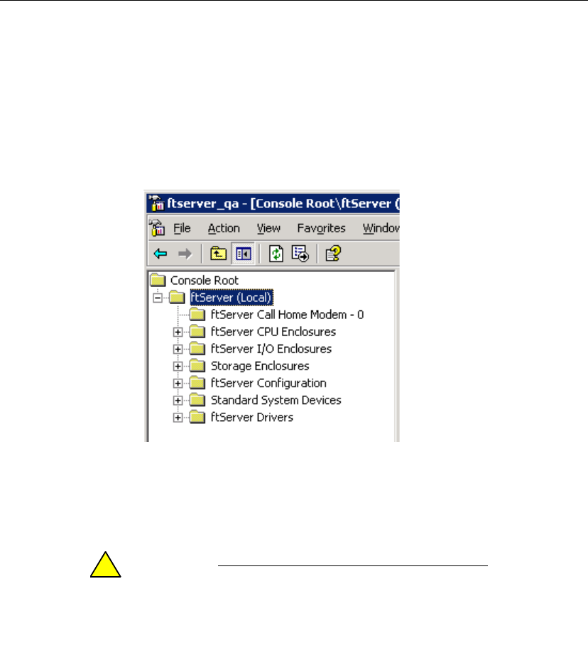
The ftSMC snap-in tree includes an ftServer Call Home Modem node (as shown in
Figure 3-1), which presents the operational status of the call-home modem.
Figure 3-1. ftSMC Tree
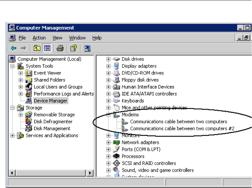
Virtual Modems
The two modems that appear in Windows Device Manager on your
Express5800/320Ma system (see Figure 3-2) represent virtual modems that the VTMs
use to communicate with the system.
CAUTION
!Do not use applications or devices that try to connect to
any modem involved in communicating with the ASN,
especially on systems that send alarms by phone only.
Running ftSMC
ftServer Management Console 3-5
Figure 3-2. Virtual Modems
Using VTMs to Troubleshoot Systems
Although you may dial in to the VTM to troubleshoot the system, be aware that
call-home support and alarm transmission through the ASN modem will be blocked for
the duration of the connection.
However, if your system is configured to send alerts by the following options (see
“Determining the Value of the Send Alarms By Property” on page 3-6), use of the ASN
modem will not block alarms or call-home support, which continue over the Internet:
•Internet with phone line as backup
•Phone line with Internet as backup
•Internet only
See the Express5800/320Ma ActiveService Network Configuration Guide for
configuration information.

Performing ftSMC Tasks
3-6 Express5800/320Ma: System Administrator’s Guide
Determining the Value of the Send Alarms By Property
1. In ftSMC, expand ftServer (Local) and ftServer Configuration.
2. Click ActiveService Network.
3. In the details pane, check the value of the Send Alarms By property.
Opening a Previously Saved MMC Console
1. Click Start, and then click Run.
2. In the Run window, type mmc in the Open box, and then click OK.
3. In the Console menu, click Open, and then click the name of the previously saved
MMC console.
4. In the Connect dialog box, click Finish.
Running ftSMC by Remote Access
You can run ftSMC from a remote computer by accessing a target system’s desktop
from the remote computer. See “Remote Access to Your System Desktop” on page 2-5
for methods you can use to access the system’s desktop remotely. Once you have
accessed the system’s desktop, perform the procedure described in “Running ftSMC
Directly on Your Express5800/320Ma System” on page 3-2 to run ftSMC.
Performing ftSMC Tasks
Detailed instructions for using ftSMC are available in the online Help for ftSMC. Before
interacting with ftSMC, observe the following cautions.
CAUTION
!Before using ftSMC to interact with the NEC Technical
Support, perform the tasks described in the
Express5800/320Ma ActiveService Network
Configuration Guide.
CAUTION
!When working in ftSMC, generally do not change the
configured values of properties unless directed to do so in
documentation or by the NEC Technical Support.
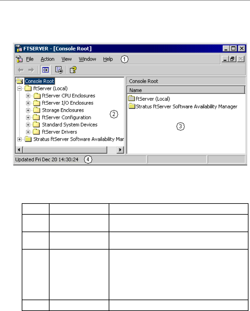
ftSMC Interface
The details pane, the icons used in ftSMC, and the ftSMC display refresh options are
features of the ftSMC interface. Figure 3-3 shows the ftSMC user interface.
Performing ftSMC Tasks
ftServer Management Console 3-7
To expand all nodes, press the asterisk (*) key on the number pad.
Figure 3-3. ftSMC User Interface
Table 3-1 describes the key elements in the ftSMC user interface.
Table 3-1. ftSMC User Interface Key Elements
Item Description Function
1 Action band The Action menu contains MMC snap-in commands.
The View menu contains console viewing options.
2 Console tree Lists all system component nodes. Each node
represents a manageable object.
3 Details pane Displays the properties related to the node selected in
the console tree. For an explanation of a property,
right-click the property and select What’s this? from
the shortcut menu. (Not all properties have
What’s this? help.) The Express5800/320Ma:
Technical Reference Guide includes information about
properties.
4 Status bar Displays ftSMC status messages.
Performing ftSMC Tasks
3-8 Express5800/320Ma: System Administrator’s Guide
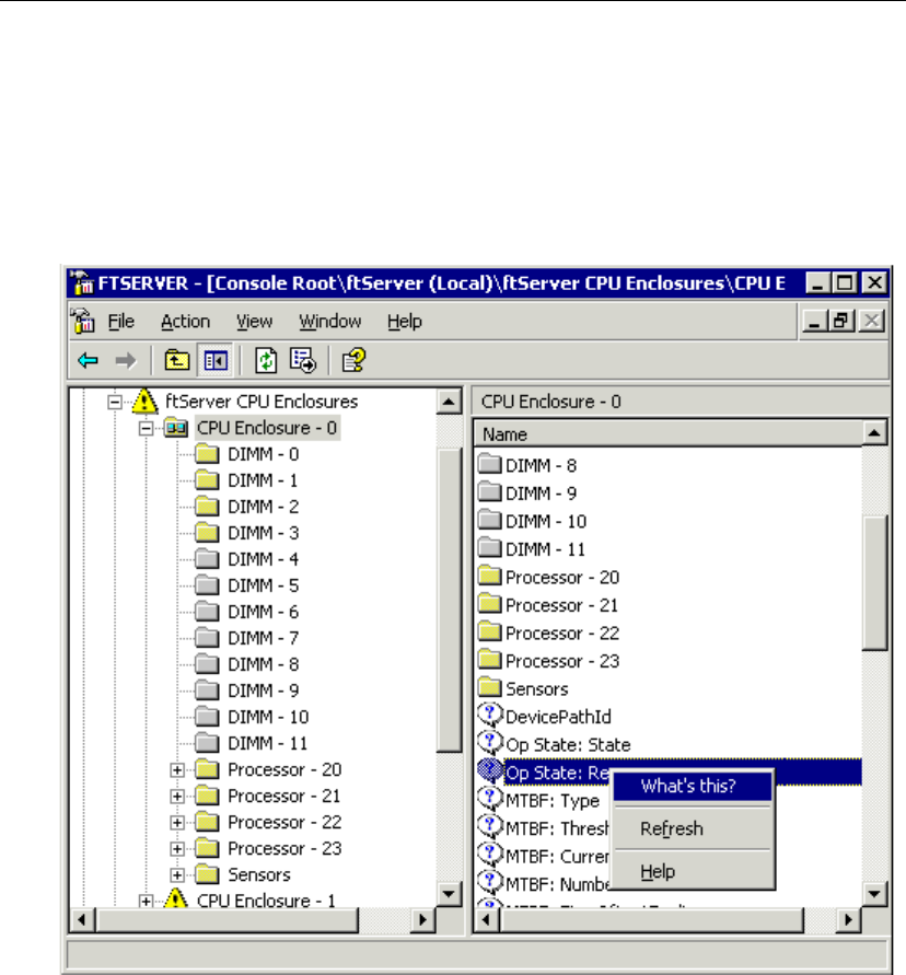
Details Pane
The names and values of the properties of the components in the ftSMC tree are
displayed in the details pane. A question mark (?) icon in front of a property name
indicates that What’s this? Help is available. Right-click the property name and click in
the shortcut menu that appears. See Figure 3-4.
Figure 3-4. Details Pane
Performing ftSMC Tasks
ftServer Management Console 3-9
Icons Used in ftSMC
Figure 3-5 shows and describes the icons used in the system inventory.
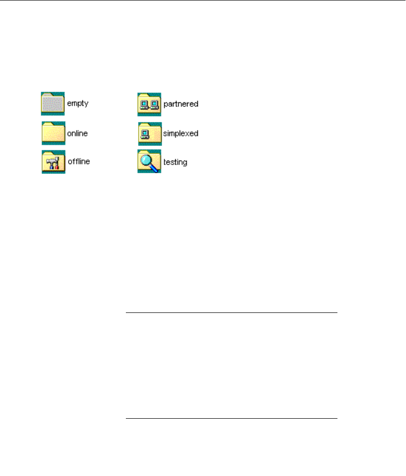
Figure 3-5. System Inventory Icons
•A dimmed folder icon indicates that the node does not contain any information. It
is empty.
•A plain, yellow folder icon indicates that the node is online and contains
information or child nodes. This icon indicates online simplex components.
•A tools icon indicates that the node is offline, possibly for maintenance.
•A dual-monitor icon indicates that the node is duplexed (partnered) with another
node (for example, two CPU elements).
NOTE
It is safe to remove a duplexed component.
•A magnifying glass icon indicates that the node is offline and undergoing diagnostic
testing.
•A single-monitor icon indicates that the component is operating simplexed
(unpartnered).
NOTE
It is unsafe to remove a simplexed component from the
system. Removing a simplexed component causes loss of
that component function to the system.
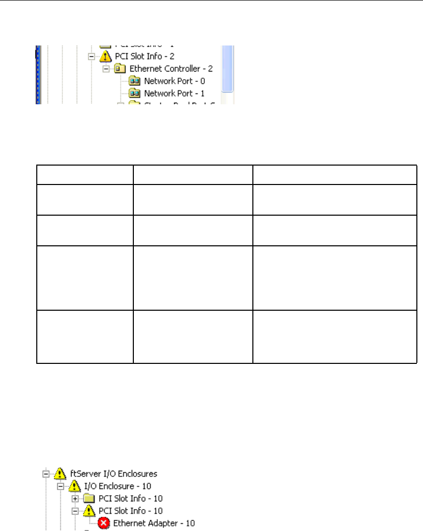
The simplexed icon can also indicate an invalid configuration. For instance, the
simplexed icon next to Ethernet Controller - 2, shown in Figure 3-6, indicates that
Network Port - 0 and Network Port - 1 beneath the Ethernet Controller - 2 are
duplexed, but that Ethernet Controller - 2 is simplexed, which makes it a single point
of failure, an illegal configuration.
Performing ftSMC Tasks
3-10 Express5800/320Ma: System Administrator’s Guide
Figure 3-6. Simplexed Icon for Invalid Configuration
ftSMC displays warning and error icons described in Table 3-2.
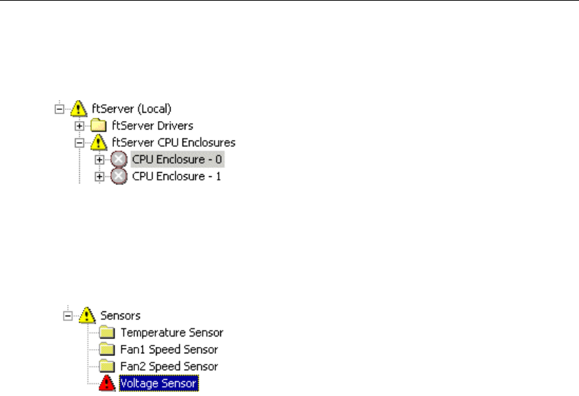
Figure 3-7 shows an error icon next to the Ethernet Adapter, indicating an error on that
node. Warning icons precede the names of all parent nodes that have nodes with an
error.
Figure 3-7. Warning and Error Icons
Table 3-2. ftSMC Warning and Error Icons
Icon Type Description Indication
Warning Exclamation point inside a
yellow triangle A node whose child node has an
error.
Error White X inside a red circle The node is offline, in testing, or has
failed.
No inventory found White X inside a gray
circle ftSMC cannot retrieve inventory
information for that device. The
ftSMC status bar displays a message
indicating that the properties cannot
be retrieved.
Threshold warning Exclamation point inside a
red triangle The current reading of a sensor value
exceeds the specified threshold.
Parent nodes display the yellow
warning icon.
Performing ftSMC Tasks
ftServer Management Console 3-11
Figure 3-8 shows a “no inventory found” icon next to the CPU Enclosure icons.
Figure 3-8. Warning and Inventory Error Icons
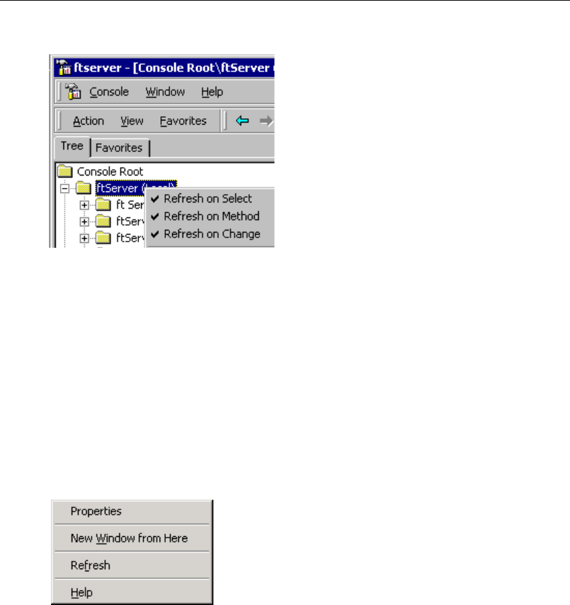
Figure 3-9 shows a threshold warning icon at the Voltage Sensor. Its parent nodes
display the yellow warning icon.
Figure 3-9. Threshold Warning Icon
Refreshing the ftSMC Display
You can right-click the ftServer (Local) root node to enable or disable each of three
refresh options. These options cause ftSMC to refresh, or update, the information in the
details pane when the specified event occurs. You should enable these options so that
the details pane and the node icons update when you complete an action or when a
state change occurs. When enabled, a check mark appears in front of the option, as
shown in Figure 3-10.
Performing ftSMC Tasks
3-12 Express5800/320Ma: System Administrator’s Guide
Figure 3-10. ftSMC Details Pane Refresh Options
Viewing and Changing Properties
To view the properties of a system inventory component, click the component’s node
in the console tree. The names and values of that component’s properties are
displayed in the details pane, as shown in Figure 3-4.
Some components’ properties are configurable. Components with configurable
properties have a Properties command in their shortcut menu. See Figure 3-11.
See the ftSMC online help for details.
Figure 3-11. Properties Command in Shortcut Menu

Performing ftSMC Tasks
ftServer Management Console 3-13
Required Operational States for Commands
Table 3-3 presents the operational state that a device must be in to carry out the
associated command.
Table 3-3. Operational State for Associated Commands
Command Valid States
CPU Element
Initiate BringUp Removed, Broken, Shot, Firmware update complete,
Diagnostics passed.
Initiate BringDown Broken, Firmware update complete, Diagnostics passed,
Duplex.
Initiate Diagnostics Removed, Broken, Firmware update complete,
Diagnostics passed.
Set Priority CPU element must be online and duplexed.
I/O Element
Initiate BringUp Removed, Broken, Shot, Diagnostics passed.
Initiate BringDown Broken, Diagnostics passed, Duplex.
Initiate Diagnostics Removed, Broken, Diagnostics passed.

Performing ftSMC Tasks
3-14 Express5800/320Ma: System Administrator’s Guide

Disk Storage Management 4-1
Chapter 4
Disk Storage Management4-
The following disk-management topics apply to your Express5800/320Ma system:
•“Data Fault Tolerance” on page 4-1
•“Guidelines for System Disks” on page 4-2
•“Using RDR for Fault Tolerance” on page 4-2
•“Using Volume Mirroring for Fault Tolerance” on page 4-20
•“Mirroring Disks in Your Express5800/320Ma System” on page 4-24
•“Finding a Physical Disk” on page 4-25
Data Fault Tolerance
Your Express5800/320Ma system offers two methods of ensuring data fault tolerance
and continuous availability of its disk media:
•Rapid Disk Resync (RDR), a disk-replicating technology, is supported only on the
internal disk drives.
To create striped volumes across the mirrored internal disks, refer to the
documentation for your disk-management tool.
You choose to implement RDR, for internal disk drives, or volume-mirroring, for all
disks, during the software installation and configuration procedure. However, you can
upgrade your disks to RDR after software installation.

Guidelines for System Disks
4-2 Express5800/320Ma: System Administrator’s Guide
NOTE
Create a backup of the system disk with which to restart
the system in the unlikely event of a system failure. See
the Express5800/320Ma: Software Installation and
Configuration Guide.
Guidelines for System Disks
Observe the following guidelines when configuring the system disks.
•On the system disk, the IPL procedure creates a boot partition, which contains the
operating system and all of its components.
•You can greatly reduce application downtime when you upgrade software by
installing and using the optional Active Upgrade software. If you do plan to install
and use Active Upgrade software, be sure to keep system files on a separate disk
from data files. See the Express5800/320Ma: Active Upgrade User’s Guide for
more information.
Using RDR for Fault Tolerance
Use RDR disk mirroring to configure and create managed disks in the internal storage.
With RDR disk mirroring, you can mirror pairs of physical disks to create RDR virtual
disks. Each pair of mirrored disks constitutes one RDR virtual disk. RDR offers faster
resynchronization of mirrored disks than other mirroring methods after transient failures
or when a single disk is briefly removed from service.
NOTE
In RDR terminology, an individual physical disk is also
called a plex, and an RDR virtual disk is also called a
LUN, for logical unit.
The data on one disk of the RDR virtual disk pair is replicated in full—that is, mirrored
or duplex—on its corresponding partner disk, irrespective of volume or partition layout.
However, an RDR virtual disk may also be simplex; that is, consisting of only one
physical disk. A simplex RDR virtual disk may contain mirrored volumes created using
third-party disk management facilities. If all volumes on a simplex RDR disk are
mirrored with other disks in the system, then the simplex RDR disk is effectively duplex
(mirrored).
If you are upgrading a system’s internal disks from a non-RDR to an RDR configuration,
the existing internal disks must provide adequate space for metadata. Metadata is

Using RDR for Fault Tolerance
Disk Storage Management 4-3
“data about data” that the RDR software stores on disks to implement disk
management. When you configure a disk for RDR, the system displays an error
message if the disk does not have adequate space. The disk being upgraded should
be a basic disk.
Use RDR to mirror internal disks. To create large striped volumes, use your
disk-management tool to create striped volumes across the mirrored internal disks.
Automatic Virtual Disk Expansion
An RDR virtual disk includes an automatic disk-capacity expansion feature. If you
replace the physical disks (plexes) of an RDR virtual disk with larger physical disks,
RDR automatically recognizes the resulting larger virtual disk, which enables the
system to use the added disk capacity.
Note, however, that a virtual disk cannot be larger than the smaller of its two physical
disks.
For example, if each physical disk of an RDR virtual disk is 80 gigabytes (GB), the
virtual disk is an 80-GB virtual disk. If you replace one 80-GB physical disk with a
160-GB physical disk, the virtual disk remains an 80-GB disk, the smaller of the two
physical disks. But if you replace the other 80-GB physical disk with another 160-GB
physical disk, the RDR virtual disk automatically updates to 160 GB.

Using RDR for Fault Tolerance
4-4 Express5800/320Ma: System Administrator’s Guide
ftSMC reports the capacity of physical disks and virtual disks in the Capacity property
in two different locations:
•The physical disk Capacity property appears in the ftSMC details pane under I/O
Enclosure - 10, Storage Enclosure - 40, Slot - n, Disk - n.
•The virtual disk Capacity property appears in the ftSMC details pane under
Logical Disk Information, RDR Virtual Disk - n. The virtual disk value is slightly
lower than the physical disk value because the virtual disk value is reduced by the
space reserved for metadata.
NOTE
Automatic virtual disk expansion does not work on
dynamic virtual disks; that is, RDR virtual disks that have
been converted to dynamic disks by Windows Disk
Management
Managing RDR Disks
Managing RDR-configured disks can include any of the following tasks:
•Using RDR to mirror disks in internal storage
•Enabling write caching and read-load balancing
•Setting the active RDR disk (plex)
•Deleting RDR configuration on a physical disk
•Removing a physical disk from and RDR virtual disk
•Deporting a physical disk from an RDR virtual disk
•Creating a Spare Bootable RDR Disk
•Breaking a Physical Disk from an RDR Virtual Disk
•Converting disks from dynamic to basic
•Setting or clearing the mean-time between failure (MTBF) threshold
•Resynchronizing a physical disk from the RDR virtual disk
•Setting the MTBF faultcount limit
•Making a backup of a boot disk
•Booting with a backup disk

Using RDR for Fault Tolerance
Disk Storage Management 4-5
•Reusing dynamic disks
•Recovering a disk
•Verifying disk integrity
•Prioritizing resynchronization
To use RDR to mirror dynamic disks, see the Express5800/320Ma: Software
Installation and Configuration Guide.
You can also set disk parameters from the SCSI Port Duplex Driver - Sradisk_Driver
node shortcut menu in the ftSMC.
Notes on Using RDR to Mirror Disks in Internal Storage
The procedure used to mirror disks with RDR is the same used to upgrade a disk to
RDR. If you are upgrading disks to use RDR, be sure that the disks are basic disks. If
the disks have been configured as dynamic disks, convert the disks to basic disks
before upgrading them to RDR.
Although you can only create RDR disks from basic disks, you can make RDR disks
dynamic if your policies require it.
If you insert a non-RDR-configured disk into a slot whose partner slot is occupied by
an RDR virtual disk, the system automatically adds the inserted disk to the RDR virtual
disk.
Not all RDR commands and procedures are valid on all physical disks. Error messages
appear if you attempt an invalid RDR command. Error messages also suggest possible
corrective actions, where applicable.
Some RDR configuration changes, especially those made on simplex RDR virtual
disks, may require the operating system to restart, in order to complete. When the
Windows restart warning appears, you can restart the system immediately or defer
restart until a more convenient time.
An RDR disk is brought online as Unconfigured if you insert it into a slot whose
companion slot contains an RDR configured disk that is not the inserted disk’s partner.
An RDR disk is brought online normally if you insert it into a slot whose companion slot
either is empty or contains an unconfigured disk.
Disk Failures during Resynchronization
In RDR resynchronization, the partnered RDR virtual disks relate as source and target
disks. The source is the disk from which the target disk is being resynchronized.
If a source disk fails or is removed from service during resynchronization, the target
disk is removed from the system and treated as a deported disk. If the target disk fails

Using RDR for Fault Tolerance
4-6 Express5800/320Ma: System Administrator’s Guide
or is removed from service during resynchronization, the source disk continues
operating in simplex mode.
If the system starts to shut down while an RDR virtual disk is resynchronizing, RDR
records the state of the resynchronization and, upon system reboot, resumes
resynchronization from that point.
Write Caching
To optimize system performance, you can enable write caching on RDR virtual disks.
By default, write caching is disabled, except during disk resynchronization, when it is
automatically enabled.
Write caching does not work on a simplex RDR virtual disk (except when it is
resynchronizing), even if it is enabled. However, if you enable write caching on a
simplex disk that is later duplexed, write caching will work.
To enable write caching
1. Right-click My Computer on the desktop, select Manage, select Device Manager,
and then expand Disk Drives.
2. Select the target disk, select Properties, and click the Policies tab.
3. Check Enable write caching on the disk, and click OK.
Read-load Balancing
When you enable read-load balancing, read operations on duplex RDR virtual disks
alternate between the two physical disks, which improves performance. By default,
read-load balancing is enabled on all RDR physical disks.
You can enable or disable read-load balancing either for each physical disk or globally,
for all RDR physical disks across the system.
To enable or disable read-load balancing for a single physical disk
1. In ftSMC, expand ftServer I/O Enclosures and Logical Disk Information.
2. Right-click the target RDR Virtual Disk.
3. Select Set Rdr Lun Load Balancing.
4. In the dialog box, set the Rdr Lun Load Balancing field to On or Off, and click
Finish.
NOTE
Global read-load balancing settings do not overwrite
read-load balancing settings on individual RDR physical
disks.

Using RDR for Fault Tolerance
Disk Storage Management 4-7
To enable or disable read-load balancing globally
1. In ftSMC, expand ftServer Drivers, right-click SCSI Port Duplex
Driver - Sradisk_Driver, and select Properties.
2. On the dialog box, click the right-most Properties tab.
3. In the GlobalRdrPlexLoadBalancing field, select On or Off, and click OK.
NOTE
Global settings do not overwrite settings made on
individual RDR physical disks.
To add a physical disk to an RDR virtual disk
1. Insert and latch disks (see Figure 4-1) into corresponding slots in the enclosures.
(See “Finding a Physical Disk” on page 4-25 for an explanation of the numeric
values in the figures.)
In your Express5800/320Ma system, the internal storage disks are numbered 3-2-1
from top to bottom in a rack-mounted system. See Table 4-1 and Figure 4-1.
Table 4-1. RDR Disk Numbering
ftSMC Console Pane
Node ftSMC Details Pane
ObjectName Property Location in System
Storage Enclosure - 40
Slot-1, Disk-0 Harddisk0 Bottom disk drive
Slot-2, Disk-1 Harddisk1 Middle disk drive
Slot-3, Disk-2 Harddisk2 Top disk drive
Logical Disk Information
RDR Virtual Disk 1 Harddisk0 Bottom disk drive
RDR Virtual Disk 2 Harddisk1 Middle disk drive
RDR Virtual Disk 3 Harddisk2 Top disk drive

Using RDR for Fault Tolerance
4-8 Express5800/320Ma: System Administrator’s Guide
Figure 4-1. Mirroring RDR Virtual Disks
2. Double-click ftServer Management Tools on the Windows desktop to start ftSMC.
3. In ftSMC, select the target disk in I/O element 10.
For example, expand ftServer I/O Enclosures, I/O Enclosure - 10,
Storage Enclosure - 40, Slot - 1, and then click Disk - 0.
4. Right-click the target disk, and click Add Physical Disk To RDR Virtual Disk.
sysad003a
Device ID: 11/40/1/0
RDR virtual disk 1
Device ID: 11/40/2/1
RDR virtual disk 2
Device ID: 11/40/3/2
RDR virtual disk 3
Device ID: 10/40/1/0
RDR virtual disk 1
Device ID: 10/40/2/1
RDR virtual disk 2
Device ID: 10/40/3/2
RDR virtual disk 3
Slot Number: 3
Slot Number: 2
Slot Number: 1
I/O Element 10
Slot Number: 3
Slot Number: 2
Slot Number: 1
I/O Element 11

Using RDR for Fault Tolerance
Disk Storage Management 4-9
NOTE
If you receive an error message when using the Add
Physical Disk To RDR Virtual Disk command, the disk
you are trying to add may not have sufficient free space for
the metadata. Be sure the disk has a minimum of 10MB
free space.
A System Shutdown message may appear, stating that the system will reboot in two
minutes. If the message appears, let the system restart.
NOTES
1. If you have added a system disk to an RDR virtual
disk, a message notifies you that the system will
reboot. The message gives you the option of
confirming or cancelling the request. The system also
restarts if you add a data disk to an RDR virtual disk
and the software cannot unmount all data volumes on
the disk.
2. You cannot add a physical disk to RDR if the disk is
dynamic or a nonblank data disk.
5. In the Device Configuration Change dialog box, click Yes.
6. Repeat steps 3–5 for the corresponding disk in I/O element 11.
For example, expand ftServer I/O Enclosures, I/O Enclosure - 11,
Storage Enclosure - 40, Slot - 1, and then click Disk - 0.
7. Allow time for the two disks to synchronize.
•While the disks are resynchronizing, LEDs blink to indicate read and write
operations and ftSMC displays a value of OpState: State Syncing in the details
pane for the disk.
To view the progress of the synchronization in ftSMC, expand Logical Disk
Information under ftServer I/O Enclosures, and select the virtual disk (for
example, RDR Virtual Disk 1). In the details pane, the progress is noted as a
percentage, as follows:
Status: Resync: 20 percent
When the disks are synchronized, the LEDs on both disks are lit steady green
and ftSMC displays a value of OpState: State: Duplex in the details pane for
the disk and for the virtual disk. The value next to Status for the virtual disk is
None.

Using RDR for Fault Tolerance
4-10 Express5800/320Ma: System Administrator’s Guide
8. For each additional virtual disk to be created, repeat steps 3–7, mirroring:
•The disk in slot 2 of I/O element 10 with the disk in slot 2 of I/O element 11 to
create virtual disk 2
•The disk in slot 3 of I/O element 10 with the disk in slot 3 of I/O element 11 to
create virtual disk 3
Mirroring Dynamic Disks with RDR
This procedure turns dynamic disks into basic disks before mirroring them with RDR.
To use RDR to mirror dynamic disks themselves, see Chapter 3 in the
Express5800/320Ma: Software Installation and Configuration Guide.
Mirroring a dynamic disk with RDR involves two steps:
•Converting the disk to basic
•Upgrading the disk to RDR
Converting a Dynamic Disk to a Basic Disk
CAUTION
!Converting a dynamic disk to a basic disk removes all
data from the disk. So that you can recover the data, back
it up to backup media before you convert the disk to a
basic disk.
1. Right-click My Computer, and click Manage.
2. Expand Computer Management and Storage.
3. Click Disk Management.
4. Right-click the icon of the target disk in the lower portion of the Disk Management
details pane.
5. Select Convert to Basic Disk.
6. If necessary, recover the information from backup media.
To upgrade the basic disks to RDR, see “Notes on Using RDR to Mirror Disks in
Internal Storage” on page 4-5.
Setting the Active RDR Disk (Plex)
The Set As Active RDR Plex command makes the physical disk on which this
command is issued the "active" disk. The active disk is the disk:
•From which data is read
•From which a partner disk is resynchronized

Using RDR for Fault Tolerance
Disk Storage Management 4-11
•That survives a failover (the failure of one of two, duplex components)
•To which the data traffic goes when disk utilities, like chkdsk, are run
You might use Set As Active RDR Plex, for example, when using the chkdsk
command to check the performance of a particular physical disk in an RDR virtual disk.
To do this, issue the Set As Active RDR Plex command for the physical disk you want
to check; this makes it the active disk. Then disable read-load balancing on the RDR
virtual disk, and run chkdsk on the active disk.
In the following procedure, n indicates a component number that appears in ftSMC.
1. In ftSMC, expand I/O Enclosure - 10 (or 11) , Storage Enclosure, Slot - n, and
then right-click on Disk - n.
2. Select Set As Active RDR Plex.
A message reports that the operation was successful.
Deleting the RDR Configuration on a Physical Disk
Deleting the RDR configuration removes a physical disk from the RDR virtual disk. You
delete one physical disk at a time.
After you delete the RDR configuration on a physical disk:
•The RDR metadata is deleted, but other data remains on the disk.
•The disk is no longer an RDR disk and is not part of an RDR virtual disk.
•You can reconfigure the disk as an RDR disk again, using the Add Physical Disk
To RDR Virtual Disk command.
You can delete the RDR configuration only from basic data disks, not from dynamic
disks, boot disks, or data disks with one or more paging files.
To delete the RDR configuration on a physical disk
1. In ftSMC, right-click the target disk.
2. Select Delete RDR Configuration on Physical Disk for disk 0 (or 1 or 2).
3. Optionally, repeat steps 1 and 2 on the disk with which the deleted disk was
mirrored.
When the second of the mirrored disks is removed from the RDR virtual disk, the
RDR virtual disk is removed.
4. If desired, repeat steps 1–3 for each physical disk to be removed.

Using RDR for Fault Tolerance
4-12 Express5800/320Ma: System Administrator’s Guide
NOTE
Disregard any “Unsafe Removal of Device” messages that
appear when you remove an internal physical disk from
the enclosure.
Removing a Physical Disk from an RDR Virtual Disk
CAUTION
!Removing a physical disk from an RDR virtual disk
deletes all of the data from the target disk.
Executing the Remove a Physical Disk from RDR Virtual Disk command on a
partnered (duplex) RDR virtual disk (comprising two physical disks):
•Erases all of the data on the disk, including all Windows Disk Management , and
all RDR metadata.
•Returns the physical disk to a basic, non-RDR-configured, blank disk.
The system does not warn you when you issue this command because the target disk
has a surviving partner physical disk that still contains all of the data. For that reason,
the system does not need to restart.
If you execute the Remove a Physical Disk from RDR Virtual Disk command on an
unpartnered (simplex) RDR virtual disk (comprising one physical disk), the system
prompts you to remove all partition and volume data on the disk before the command
can continue. The prompt alerts you that this operation may result in the loss of all data
on this virtual disk since there is only one physical disk.
You cannot remove:
•The only unmirrored boot disk
•The only unmirrored disk containing a paging file
•An unmirrored disk containing data
•A resynchronizing disk
To remove a physical disk from an RDR virtual disk
1. In ftSMC, right-click the target disk.
2. Select Remove Physical Disk from RDR Virtual Disk.

Using RDR for Fault Tolerance
Disk Storage Management 4-13
Deporting a Physical Disk from an RDR Virtual Disk
Deporting a physical disk from an RDR virtual disk makes the deported disk a clone of
its RDR virtual disk partner. You use the Deport Physical Disk from RDR Virtual Disk
command to create backup disks and spare, bootable, RDR virtual disks.
Once a disk is deported, it is hidden from the system and is inaccessible from ftSMC.
It does not become accessible again until it is removed from and reinserted into the
system. You can physically remove and then reinsert the disk, or you can issue the
InitiateBringdown and InitiateBringup commands for the disk slot.
If you insert a disk deported from one system into another system, the disk appears in
ftSMC as Active, Configured, Deported.
A deported disk inadvertently left in the system or reinserted into its original slot
remains an intact backup. It is not automatically resynchronized or overwritten by the
primary RDR virtual disk.
You cannot deport:
•The last physical disk of an RDR virtual disk if it is bootable or contains a paging file
•An unmirrored boot disk
•A dynamic disk
•A resynchronizing disk
The Deport a Physical Disk from an RDR Virtual Disk command should be grayed out
if the physical disk is not in the valid state (for example, if it is a dynamic disk or a
simplex boot disk) for this command to work properly. A valid deport operation should
rarely fail.
If the Deport a Physical Disk from an RDR Virtual Disk operation requires that the
system reboot, a system-restart dialog box appears, giving you the option to restart the
system immediately or later. If the operation succeeds without requiring a reboot, a
message box indicating success appears.
If Deport a Physical Disk from an RDR Virtual Disk fails, a dialog box indicating the
reason for the failure appears. In this case, the RDR virtual disk is not deported and the
system does not reboot.
After a successful Deport a Physical Disk from an RDR Virtual Disk command, no drive
letters or mount points associated with volumes on the deported disk are preserved.
To deport a physical disk from an RDR virtual disk
1. In ftSMC, right-click the target disk.
2. Select Deport Physical Disk from RDR Virtual Disk.

Using RDR for Fault Tolerance
4-14 Express5800/320Ma: System Administrator’s Guide
A message reports that you may have to reboot the system if you continue with this
command. You must restart only if the deport command fails. If it succeeds, a
message reports the successful operation.
3. Click OK.
A message appears, telling you to remove the deported disk.
4. Remove the deported disk.
The deported disk disappears from ftSMC.
Creating a Spare Bootable RDR Disk
1. Be sure that the system (boot) disk is mirrored.
2. Deport the disk that is the mirror of the system disk.
3. Physically remove the deported disk from the system.
Label and store this disk, which is now the spare bootable hard disk, in a safe place.
CAUTION
!If the original boot disk is still in a system into which you
insert a spare (deported) boot disk, the original boot disk
loses its RDR configuration and is no longer an
RDR-enabled disk.
For more details, see the discussion of creating a spare bootable disk in the
Express5800/320Ma: Software Installation and Configuration Guide.
Breaking a Physical Disk from an RDR Virtual Disk
The following procedure isolates an RDR virtual disk plex for backup, backs up the
volumes, and then resynchronizes the broken plex with its original partner, adding it
back to the RDR virtual disk.
You cannot perform this procedure on:
•dynamic disks
•simplex RDR virtual disks
•RDR virtual disks while they are resynchronizing
•RDR virtual disks if their verify interval is set to 0; that is, if RDR verify is disabled.

Using RDR for Fault Tolerance
Disk Storage Management 4-15
1. Verify the RDR virtual disk that you are going to backup to ensure that both plexes
of the RDR virtual disk are healthy.
2. In ftSMC, expand I/O Enclosure, Storage Enclosure, and then select Slot 1, 2, or
3 to access Disk 0, 1, or 2.
3. Right click on the target disk and select Break Physical Disk from RDR Virtual
Disk.
This command splits the plex from the RDR virtual disk, creates an exact copy of
its volumes, and adds them to Disk Management.
4. Use backup software to make a copy of these volumes created in Disk
Management; then remove the volumes from Disk Management.
5. To add the removed plex back to the RDR virtual disk, in ftSMC, right-click the disk
you broke in step 2, and select Add Physical Disk to RDR Virtual Disk.
The plex is now synchronized with its active partner and is again a partner in an
RDR virtual disk.
Setting or Clearing the MTBF for Disks
Clearing the MTBF resets the MTBF to infinity, the number of faults to 0, and the time
of last fault to never.
Setting the MTBF Threshold sets the MTBF threshold and views the current count
(seconds), number of faults, and date and time of last fault. NEC Solutions (America),
Inc. presets the MTBF threshold; you should not change it unless instructed to do so
by your support representative.
See “MTBF Statistics” on page 5-1 for an explanation of MTBF.
To set or clear the MTBF for disks
1. In ftSMC, right-click the target disk.
2. Select either Set MTBF Threshold or Clear MTBF.
•If you select Set MTBF Threshold, specify the desired threshold value in the
Threshold field of the dialog box that appears, and then click Finish.
A message appears, indicating a successful operation.
•If you select Clear MTBF, the MTBF is cleared and a message appears,
indicating a successful operation.
Setting the MTBF Faultcount Limit for Disks
The MTBF faultcount limit defines the number of times certain errors can occur before
the system sends threshold events that generate alarms.

Using RDR for Fault Tolerance
4-16 Express5800/320Ma: System Administrator’s Guide
CAUTION
!Do not change the MTBF faultcount limit value, except
when advised to by NEC Technical Support.
1. In ftSMC, right-click the target disk.
2. Select Set MTBF Faultcount Limit.
3. In the dialog box, enter the desired limit value and click Finish.
A message appears, indicating a successful operation.
Booting a System with a Backup RDR Boot Disk
1. Remove power from the system.
2. Remove all boot disks from the internal storage enclosure, if any are installed.
3. Insert the backup boot disk.
4. Press the system power button.
Reusing Data Disks
If you have stored a copy of a data disk that was created with RDR disk mirroring, use
the following procedures to reuse the disk in the system.
Reusing a Stored-Data Disk
After you perform this procedure:
•The data on the stored-data disk is overwritten with the data on the disk in its
companion slot.
•The stored-data disk remains an RDR disk.
To reuse a stored-data disk
1. Make sure the original partner of the stored disk is in the companion slot.
2. Insert the stored disk into its original slot. The system automatically resynchronizes
the stored disk with the partner disk.
Wait for the disk to be fully resynchronized before removing the stored disk or before
removing power from the system.
Removing the RDR Configuration from a Stored-Data Disk
This procedure removes the RDR configuration from a stored-data disk and deletes all
of its data.

Using RDR for Fault Tolerance
Disk Storage Management 4-17
NOTE
To delete the RDR configuration from a stored-data disk
but retains its data, see “Deleting the RDR Configuration
on a Physical Disk” on page 4-11.
1. Make sure no disk occupies the slot that is the partner slot to the disk whose RDR
configuration you are removing.
2. If your disk was a dynamic disk, use your disk-management tool to convert the disk
to basic, deleting all data on the disk.
If your disk was a basic disk, use your disk-management tool to delete all volumes
and partitions.
3. In ftSMC, select and right-click the disk, and click Remove Physical Disk From
RDR Virtual Disk.
CAUTION
!You must complete the final step. Otherwise, if the former
RDR virtual disk partner of the newly erased disk is
inserted into the partner slot of the erased (but not
deleted) disk, the newly inserted disk is mirrored to the
empty disk, deleting the data on the newly inserted disk.
Resynchronizing RDR Disks
The system automatically resynchronizes disks that are reinserted into the system and
when I/O elements are returned to service. You can also issue a command to
resynchronize a disk with its partner from the ftSMC.
When RDR disks are resynchronizing, the Logical to Physical Mapping details pane
shows the disk that is resynchronizing as SYNCING, and shows the partner disk as
SIMPLEX.
NOTE
If you insert a blank disk into the companion slot of an
RDR virtual disk, the blank disk is automatically
configured and synchronized to the existing RDR disk.
To resynchronize RDR data disks
1. In ftSMC, under the Logical Disk Information icon, right-click the target RDR virtual
disk; that is, the disk that might not be synchronized with its mirror disk.

Using RDR for Fault Tolerance
4-18 Express5800/320Ma: System Administrator’s Guide
2. Select Resynchronize This Physical Disk From RDR Virtual Disk.
A message appears, indicating a successful start of the command. See step 7 in
“Read-load Balancing” on page 4-7 for a description of how to verify completion of
the resynchronization process.
See “Disk Failures during Resynchronization” on page 4-5 for instructions on what to
do if the source RDR virtual disk fails during resynchronization.
Resynchronizing a Backup Boot RDR Disk
1. Verify that the original partner disk of the backup boot disk is inserted into its
original slot in the storage enclosure.
2. Reinsert the backup boot disk into its original slot in the storage enclosure.
The backup boot disk automatically resynchronizes with the original partner. The
command takes some time to run. See step 7 in “Read-load Balancing” on
page 4-7 for a description of how to verify completion of the resynchronization
process.
Recovering and Replacing RDR Disks
In your disk-management tool, if the status of an RDR disk appears as Offline,
Missing, or Online (Errors), you can try to recover the disk manually. Verify that the
disk is securely seated in the enclosure and that it has power. Perform the following
procedures to recover the disk.
To recover an RDR disk
1. Delete the RDR configuration on the disk, and then physically remove it from the
enclosure.
NOTE
Disregard any “Unsafe Removal of Device” messages that
appear when you remove an internal physical disk from
the enclosure.
2. Replace the defective disk and add the disk to an RDR virtual disk.
In the unlikely event of a system failure resulting from disk failures, restore the system
by performing one of the following procedures, as appropriate:
•Restore the system by using a backup system disk. See the discussion of creating
spare bootable hard disks in the Express5800/320Ma: Software Installation and
Configuration Guide for information.
•Reload the Express5800/320Ma System software, as described in the
Express5800/320Ma: Software Installation and Configuration Guide.

Using RDR for Fault Tolerance
Disk Storage Management 4-19
To replace a failed physical RDR disk
1. Remove the failed disk.
2. Insert a blank replacement disk.
Verifying RDR Disks
RDR disk verification verifies the integrity of RDR disk mirrors. Specifically, it:
1. Reads all sectors on both disks. If it detects a read error, it recovers the degraded
sector from the good partner disk. This safeguards the integrity of both disks.
2. Compares the data from each sector on both disks. If it detects a discrepancy, it
logs an error to the event log. In the unlikely event that this happens, contact NEC
Technical Support or your authorized service representative, or log an issue under
their maintenance contract.
To verify an RDR disk
1. In ftSMC, expand ftServer I/O Enclosures and click Logical Disk Information.
2. Right-click the appropriate RDR virtual disk.
3. Select Verify RDR Virtual Disk.
A message appears, stating that the operation completed successfully, meaning that
the command has been executed.
To stop verifying an RDR disk
Use the following procedure to stop RDR verification.
1. In ftSMC, expand ftServer I/O Enclosures and click Logical Disk Information.
2. Right-click the appropriate RDR virtual disk.
3. Select Stop Verify RDR Virtual Disk.
A message appears, stating that the operation completed successfully, meaning that
the command has been executed.
To set the interval for automatic RDR disk verification
1. In ftSMC, expand ftServer Drivers, right-click SCSI Port Duplex
Driver - Sradisk_Driver, and select Properties.
2. In the dialog box, click the third Properties tab from the left.
3. Set the LunVerifyInterval property to the desired value and click OK.
The default value is 10080 minutes (7 days), meaning 10080 minutes from the time
of the last verification command. The nonzero minimum value cannot be less than
60 minutes. A value of 0 disables automatic RDR disk verification.

Using Volume Mirroring for Fault Tolerance
4-20 Express5800/320Ma: System Administrator’s Guide
Configuring the Priority of RDR Virtual Disk Resynchronization
The resynchronization priority establishes the portion, expressed in megabytes per
second (Mbps) in the details pane, of I/O bandwidth that is used for the RDR disk
resynchronization operation.
To prioritize resynchronization for all RDR disks in the system
1. In ftSMC, expand ftServer Drivers, right-click SCSI Port Duplex
Driver - Sradisk_Driver, and select Properties.
2. In the dialog box, click the third Properties tab from the left.
3. Set GlobalResyncPriority to Low, Normal, or High and click OK.
To prioritize resynchronization for individual RDR disks
1. In ftSMC, expand the appropriate I/O Enclosure node and click Logical Disk
Information.
2. Right-click the target RDR virtual disk.
3. Select Set Resync Priority.
4. Select Low, Medium, or Normal and click OK.
Using Volume Mirroring for Fault Tolerance
When using Windows Disk Management to implement data fault tolerance, format
volumes as NTFS volumes.
•Configure disks as dynamic disks. Dynamic disks organize data within volumes on
a disk and support fault-tolerant operation and disk migration between systems.
•Mirror each volume (the boot volume on the system disk and all data volumes) on
two or more physical disks. See “Mirroring Disks in Your Express5800/320Ma
System” on page 4-24 for details.
•Assign system disks and data disks to the same disk group.
CAUTION
!Failure to set up your disk storage as required results in
storage that is not fault tolerant.
System disk usage topics include mirroring disks, mirror resynchronization, and
information about inserting more than one disk at time.
A mirror is an identical copy of data that you can access if your primary data becomes
unavailable. NEC Solutions (America), Inc. requires that you mirror the boot volume on
the system disk. The resulting mirrored pair of disks work together to provide a

Using Volume Mirroring for Fault Tolerance
Disk Storage Management 4-21
fault-tolerant volume. If one disk fails, the volume automatically uses the data from the
other disk.
Mirror all data volumes. Mirroring volumes as documented provides fault tolerance,
because volumes are mirrored on separate physical disks on separate FC buses.
When mirroring volumes, pair identical physical disks (same capacity, model, and
manufacturer) so that in the event of a disk failure, an entire physical disk can be
replaced without any data loss. See “Mirroring Disks in Your Express5800/320Ma
System” on page 4-24 for details.
Mirrored Volume Resynchronization
When a volume is mirrored across two physical disks, and one of the disks fails or is
brought offline for any reason, the remaining good disk continues to operate. However,
the data on the mirrored volumes is no longer synchronized.
After a disk is replaced or brought back online, the mirror between it and the disk that
remained in operation must be resynchronized. During resynchronization, the system
copies the format and the contents of the good mirrored volume(s) to their mirror(s) on
the disk most recently brought back online.
NOTE
Because mirror resynchronization can severely affect
performance, you should resynchronize mirrors when the
system is least busy.
Mirror resynchronization can occur automatically, or, in some cases, you must
resynchronize the mirror manually:
•If you insert a replacement disk without a disk signature into the same slot as the
failed disk, the system automatically attempts to resynchronize the disk.
•If you replace a failed disk with a blank basic or dynamic disk that contains a
signature, you must resynchronize the disks manually.
•The system automatically attempts to resynchronize the disks if:
– An I/O element is removed and inserted.
– An I/O element goes offline and returns online.
Volume Resynchronization After Rebooting
After rebooting the system, and depending on the circumstances under which the
system was shut down, you may need to explicitly reactivate a failed mirrored partner
to resynchronize a volume.

ftSMC Interface for Storage Enclosures and Subsystems
4-22 Express5800/320Ma: System Administrator’s Guide
For example, if the system was shut down normally, but it was shut down while
synchronization was in progress, you need to explicitly reactivate the mirror. On the
other hand, if the system shutdown was due to an unexpected event like a power
failure, the disks begin the remirroring process automatically after booting.
NOTE
Before mirroring system disks with a disk management
tool (such as Windows Disk Management, make sure
either that both disks are plexes of an RDR virtual disk or
that neither disk is. Do not partner RDR and non-RDR
system disks in a mirror. Otherwise, the disks will fully
resynchronize after every reboot.
The boot disks do not require resynchronization if the
RDR disk is the primary boot volume from which the
system is booted.
Inserting or Removing More Than One Disk at a Time
You may remove disks from or insert disks into the internal storage as needed.
ftSMC Interface for Storage Enclosures and Subsystems
The Storage Enclosure node represents the internal storage subsystem and the
EMC® attached storage systems are not directly represented in ftSMC. The Fibre
Channel Controller node represents the adapter associated with an attached EMC
storage subsystem.

ftSMC Interface for Storage Enclosures and Subsystems
Disk Storage Management 4-23
Storage Enclosure Node
The Storage Enclosure node contains some or all of the following nodes:
•Slot
•Disk
•Sensors
•Module
Slot Node
The Slot node represents the slots where disks reside. System disks must reside in
certain slots (see “Mirroring Disks in Your Express5800/320Ma System” on page 4-24
for details).
NOTE
In ftSMC, the storage Slot nodes display the Start Slot
Identification and Stop Slot Identification commands.
Although these commands appear in the context menu for
slots in internal storage, the driver for those slots does not
support them.
Disk Node
Each Disk node represents a hard disk that resides in a slot in a storage enclosure.
You use the DevicePathID property to locate a physical disk. See “Finding a Physical
Disk” on page 4-25 for details.
Sensor Nodes
The Sensor Node include the following subnodes:
•Temperature sensors monitor the ambient temperature within the enclosures.
•Fan Speed sensors monitor the rotational speed of the fans within the enclosures.
•Voltage sensors monitor the voltage level of power within the enclosures.
CAUTION
!NEC Solutions (America), Inc. presets the configurable
threshold property values of these sensors. Do not
change them unless instructed to do so by the NEC
Technical Support.

Mirroring Disks in Your Express5800/320Ma System
4-24 Express5800/320Ma: System Administrator’s Guide
EMC Attached Storage
If an optional EMC CLARiiON®, EMC Symmetrix®, or EMC CLARiiON AX100 Storage
System is installed in your system, Fibre Channel Controller nodes will appear
beneath the PCI Slot Info nodes in which the adapters are installed.
NOTE
System disks cannot reside in an EMC attached storage
system. See “Mirroring Disks in Your Express5800/320Ma
System” on page 4-24 for details.
The values that the Op State: State and Op State: Reason properties can take vary
depending on whether EMC PowerPath® software is running. See Table 4-2 for details.
When you reattach a cable between your EMC storage system and the PCI adapters
in your system, the connection state may not be immediately reflected in ftSMC. To
update ftSMC, issue the command powermnt restore in PowerPath, from Run on the
Start menu, or from a command prompt. The information in ftSMC should be updated
after about 15 seconds.
Mirroring Disks in Your Express5800/320Ma System
Your Express5800/320Ma system supports the following storage systems:
•Internal SATA disk drives
•EMC storage systems
The various disk-mirroring schemes are outlined in the following sections. See EMC
documentation for information about EMC disk-mirroring configurations.
Table 4-2. FC Host Bus Adapter State and Reason Property Values
Op State: State Op State: Reason
With PowerPath
software running
Simplex None
Duplex None
Broken Media Disconnect
Broken None
Without PowerPath
software running
Online None
Broken Media Disconnect

Finding a Physical Disk
Disk Storage Management 4-25
Mirroring Disks in Internal Storage
Your Express5800/320Ma system internal storage supports only SATA disks. Its disks
are located in a disk tray that connects to the system backplane.
For non-RDR disk-mirroring configurations, mirror the volumes on disks in two
separate disk trays.
For RDR disk mirroring, mirror the internal storage disks as shown in Figure 4-1. Only
internal storage enclosures support RDR disks.
NOTES
1. The system disk and its mirrored partner must both
reside in the same storage location.
2. The system disk and its mirrored partner are located
in slot 1 of each enclosure.
See “Finding a Physical Disk” on page 4-25 for details about physically locating a
volume’s hard drive.
Configuring and Creating RDR Disks
You can mirror disks in system internal storage enclosures as RDR disks.
Figure 4-1 shows how disks are mirrored in your Express5800/320Ma system. The
arrows in the figures indicate the required mirroring scheme.
Finding a Physical Disk
You find the location of internal physical disks by using the ftSMC. You find disks
located in external storage using both Windows Disk Management and ftSMC.
You can use the Logical to Physical Mapping node in ftSMC to physically locate the
disk members of RDR virtual disks, or the non-RDR disk on which a particular volume
resides.
Finding an Internal Physical Disk
System internal disks are identified in the Logical to Physical Mapping node details
pane. The information differs somewhat for RDR and non-RDR disks.
To use the Logical to Physical Mapping node
1. In ftSMC, expand ftServer I/O Enclosures and then Logical Disk Information.
2. Click Logical to Physical Mapping.

Finding a Physical Disk
4-26 Express5800/320Ma: System Administrator’s Guide
For RDR virtual disks, the detail pane presents information in the following format:The
information for non-RDR disks is the same, except that it does not include LUN (RDR
virtual disk) or PLEX (physical disk) information, which pertains only to RDR disks.
In the details pane:
•Harddisk0 refers to the Windows disk name.
•LUN1 refers to RDR virtual disk 1. (Your Express5800/320Ma system can support
a maximum of three RDR virtual disks: LUN 1, LUN 2, and LUN 3.)
•PLEX1 and PLEX2 refer to the two physical disks that together make up RDR virtual
disk 1 (LUN 1).
•Basic refers to type of disk. The other possible value is Dynamic.
•10/40/1 indicates the following:
–10 indicates I/O element 10.
NOTE
In rack-mounted systems, I/O element 10 is in the top
enclosure and I/O element 11 is in the bottom enclosure.
Pedestal systems (not available in Express5800/320Ma
Dual-Core systems) are rotated 90 degrees clockwise,
so that I/O element 11 is on the left side (from the front) of
the system and I/O element 10 is on the right side.
–40 indicates the internal storage enclosure within the I/O element.
–1 indicates the bottom disk slot in rack-mounted systems.
•For RDR disks, Duplex indicates that the two physical disks of the RDR virtual
disks are partnered. If the two physical disks were not partnered, the displayed
value would be Simplex.
For non-RDR disks, the values in this position indicate the disk’s operating status.
RDR virtual disks list DevicePath[1] and DevicePath[2] properties that indicate the
device ID of the disks that make up the virtual disk. However, the DevicePathID for an
RDR virtual disk does not indicate a hardware component, but instead identifies the
virtual disk to system-management software.
Harddisk0-LUN1-PLEX2 (Basic) 11/40/1 (DUPLEX)
Harddisk0-LUN1-PLEX1 (Basic) 10/40/1 (DUPLEX)

Finding a Physical Disk
Disk Storage Management 4-27
Finding an External Physical Disk
For disks in external storage systems, the operating system assigns letter designations
to the logical volumes on the physical disks. Windows Disk Management assigns a disk
name to each physical disk in an external storage system and displays which logical
volumes reside on each named disk. For a particular volume, you can use the disk
name in conjunction with ftSMC to identify the location of the physical disk that contains
that volume.
NOTE
The disks of EMC storage systems do not appear in
ftSMC.
To find a volume’s physical disk
1. In the Windows Disk Management tool (accessed from My Computer), find the
disk name that contains the volume in question. These disk names may or may not
be numeric; however, they do not correspond to disk locations. Volume information
is displayed along with the disk name.
2. Note the disk name that contains the volume you want to physically locate; for
example, Disk 3.
3. In ftSMC, expand Storage Enclosures, then Logical Disk Information, and then
click Logical to Physical Mapping.
4. In the Name column of the ftSMC details pane, find the disk name you noted in
step 2. Look up its corresponding device path ID in the Value column. This
identifies the physical location of the disk within the system. (See “Device IDs and
Device Paths” on page 5-6 for details.)
For example, Disk 3 may have the disk name Harddisk3 in ftSMC and have a
device path ID of 70/12/3. This disk would appear in ftSMC under the Storage
Enclosures node as Disk 3 in Slot 12 of Storage Enclosure - 70.
5. Use the device path ID determined in step 4 with the labels on the system to identify
the disk location. You can also use “Diagrams of Component Locations” on
page 5-8 to help locate the disk.
NOTE
When external disks are resynchronizing, the Logical to
Physical Mapping details pane shows the disk that is
resynchronizing as SIMPLEX and includes the
percentage of the disk that has resynchronized: for
example, SIMPLEX (%20).

Finding a Physical Disk
4-28 Express5800/320Ma: System Administrator’s Guide

Troubleshooting 5-1
Chapter 5
Troubleshooting5-
The following topics can help you troubleshoot your Express5800/320Ma system:
•“MTBF Statistics” on page 5-1
•“Taking Components Offline and Bringing Them Online” on page 5-2
•“Hard Disks” on page 5-2
•“Determining That a Component Has Failed” on page 5-5
•“Locating Components” on page 5-6
•“When Windows Does Not Respond” on page 5-9
•“Delayed System Restart” on page 5-9
•“Unresponsive Mouse and Keyboard” on page 5-10
•“Remote Event Notification and Service” on page 5-10
•“Making Dump Files” on page 5-11
•“Online Diagnostic Codes” on page 5-13
•“Disaster Recovery” on page 5-14
MTBF Statistics
The fault-tolerant services software automatically maintains
mean-time-between-failure (MTBF) statistics for many system components.
Administrators can view this information in ftSMC at any time and can reconfigure the
MTBF parameters that affect how the fault-tolerant services respond to component
problems.
The system stores the current MTBF values associated with each device in Windows
registry keys. Whenever any of the MTBF values change, the registry reflects the
change. Therefore, when the driver stops and restarts, or the system restarts, the
system retains the current MTBF information.
For procedures explaining how to set these settings, see the online ftSMC snap-in help.

Taking Components Offline and Bringing Them Online
5-2 Express5800/320Ma: System Administrator’s Guide
Clearing the MTBF
Clearing the MTBF sets the MTBF to 0 (Unknown) and erases the record of all faults.
NOTE
Clearing the MTBF does not bring a device back into
service automatically.
If the device that you cleared is in the Broken state, you must correct the state.
Changing the MTBF Threshold
The MTBF threshold is expressed in seconds. If a device’s MTBF falls beneath this
threshold, the system takes the device out of service and changes the device state to
Broken.
CAUTION
!NEC Solutions (America), Inc. presets the MTBF
thresholds. You should not modify them unless instructed
to do so by NEC Technical Support or your authorized
service representative.
Taking Components Offline and Bringing Them Online
You can use ftSMC to take a component offline or bring a component online. Before
you take a component offline, verify that it is safe to do so.
For a description of the procedures, see the online help for ftSMC.
Hard Disks
If a disk’s status is not healthy, you may be able to recover the disk, or you may need
to replace the disk.
Recovering a Disk
In your disk-management tool, try to recover the disk manually if:
•A failed volume (non-RDR only) appears as Failed Redundancy
•The RDR or non-RDR disks appear as Offline, Missing, or Online (Errors)

Hard Disks
Troubleshooting 5-3
Verify that the system does not have a problem that is causing the mirror to break on
an internal or external disk. Ensure that the disk is securely seated in the drive and that
it has power. Perform the following procedures to recover the disk.
To recover an RDR disk
1. Logically and then physically remove the physical disk from the RDR virtual disk.
NOTE
Disregard any “Unsafe Removal of Device” messages that
appear when you remove an internal physical disk from
the enclosure.
2. Replace the defective disk and make the disk an RDR disk.
In the unlikely event of a system failure resulting from disk failures, restore the system
by performing one of the following procedures, as appropriate:
•Restore the system by using a backup system disk. See the discussion of creating
spare bootable hard disks in the Express5800/320Ma: Software Installation and
Configuration Guide for information.
•Reload Express5800/320Ma System software, as described in the
Express5800/320Ma: Software Installation and Configuration Guide.
To recover a disk in Windows Disk Management
1. Go to Windows Disk Management in Computer Management.
2. Right-click the disk icon corresponding to the disk that has the Offline, Missing, or
Online (Errors) status, and in the option menu, click Reactivate Disk.
3. After the mirror regenerates (this may take several minutes), verify that the status
of the disk has returned to Healthy.
CAUTION
!If a disk continues to have the status of Online (Errors),
replace it as soon as possible.
If the recovery procedures fail to reactivate the disk, or if the status does not return to
Healthy, you must physically replace the failed disk.
Replacing a Failed Disk in Windows Disk Management
You can replace a failed disk with an uninitialized disk (a disk that has no signature
written on it). This is the quickest and easiest option. If your only spare disk is initialized
(it has a signature written on it), you can replace the failed disk with an initialized disk.

Hard Disks
5-4 Express5800/320Ma: System Administrator’s Guide
Replacing a Failed Disk with an Uninitialized Disk
Follow this procedure to replace a failed disk with an uninitialized disk. To physically
locate a disk, see “Finding a Physical Disk” on page 4-25.
To replace a failed disk with an uninitialized disk
1. Physically remove the failed disk and replace it with an uninitialized disk.
2. Disk-management software automatically resynchronizes the replacement disk
with the remaining good disk, creating volumes on the replacement disk and
mirroring the disks.
Replacing a Failed Disk with an Initialized Disk
Perform the following procedure to replace a failed disk with an initialized disk using
Windows Disk Management.
To physically locate a disk, see “Finding a Physical Disk” on page 4-25.
To use Windows Disk Management to replace a failed disk with an initialized disk
1. Physically remove the failed disk and replace it with an initialized disk. For details,
see the operation and maintenance guide for your system.
2. Examine the type of the initialized replacement disk:
•If the replacement disk’s type is Foreign Dynamic, go to step 3.
•If the replacement disk’s type is Basic, go to step 4.
3. In Disk Management, right-click the foreign dynamic replacement disk, and then
click Convert to Basic. The replacement disk should now appear as a basic disk.
4. If the basic replacement disk has any volumes, delete them. Right-click the volume
on the replacement disk, and then click Delete Partition. Repeat for each volume
on the replacement disk. Verify that the basic replacement disk now appears as a
single unallocated space.
5. Right-click the replacement disk and click Convert to Dynamic.
6. Remove the mirrors from the missing disk that was physically removed in step 1.
Right-click a volume on the missing disk and then click Remove Mirror. In the
Remove Mirror dialog box, select the missing disk and click the Remove Mirror
button.
CAUTION
!Be sure to select the missing disk, not the remaining good
disk. You will lose data if you select the remaining good
disk.
Repeat this step for each volume on the missing disk.

Determining That a Component Has Failed
Troubleshooting 5-5
7. Right-click the missing disk, and then click Remove Disk.
8. On the remaining good disk, right-click a volume and click Add Mirror. In the Add
Mirror dialog box, select the replacement disk and click the Add Mirror button.
Repeat this step for all other volumes on the remaining good disk.
Hardware Installation Wizard
Occasionally, after a system reboot or after hot-plugging an I/O element or a disk, a
hardware-installation wizard may appear, indicating that a “Express5800/320Ma disk
device” has been found. Continue through the wizard steps, but click Cancel at the end
rather than rebooting.
Determining That a Component Has Failed
Component LEDs and ftSMC provide indicators that a component has failed. See the
operation and maintenance guide for your system for general troubleshooting
information related to system hardware. ftSMC indicates a failed component by
showing a white X inside a red box next to the icon of a failed component.
Using LEDs to Troubleshoot Hardware
LEDs, where present, indicate the status of components. The LEDs can help you locate
a failing or failed component. The LED status is also shown by ftSMC in the details
pane of components that have LEDs.
The LED State properties indicate the state of an LED in the system. On your
Express5800/320Ma system, the LEDs are green, amber, and white.
For detailed information about LEDs and particular components, see the operation and
maintenance guide for your system.
Using ftSMC to Troubleshoot Hardware
You can view component icons in ftSMC to see if a component has failed.
To use ftSMC to determine that a component has failed
1. In ftSMC, expand the System Inventory by clicking the ftServer node in the console
tree and pressing the asterisk (*) key on the numeric keypad.
2. Look for Warning (an exclamation point inside a yellow triangle) or Error (a white
X inside a red circle) icons. If you see a Warning icon, click the plus sign (+) in front
of nodes that have a Warning icon until you see an Error icon.
For example, in Figure 5-1, Warning icons appear in three nodes, and the Error
icon appears beside the slot that has a problem.
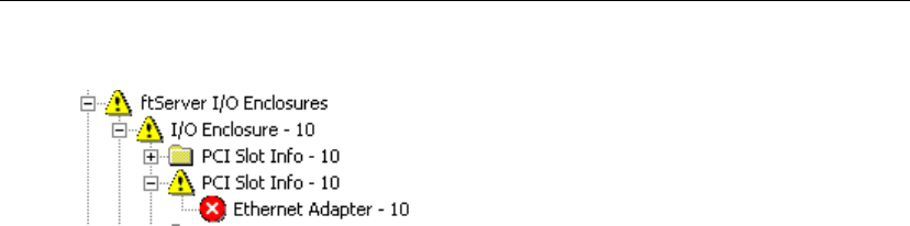
Locating Components
5-6 Express5800/320Ma: System Administrator’s Guide
Figure 5-1. Warning and Error Icons
3. Click the problem node and check the MTBF: Current value in the details pane. If
it is less than the MTBF: Threshold value, that node has failed and the system
removes it from service. For example:
MTBF: Time of Last Fault May 30, 2001 15:07:24
MTBF: Threshold 300 seconds
MTBF: Number of Faults 2
MTBF: Current 220 second
Locating Components
ftSMC displays device IDs and device paths for system components that it monitors.
Components that have a dual-initiated bus have dual device paths. Component
location diagrams show the device IDs of major elements, enclosures, and internal
disks.
Two commands assist you in locating select system components:
•Start Slot Identification. Causes the LEDs on the component to flash so that you
can physically locate it.
•Stop Slot Identification. Stops the LEDs on the component from flashing after you
have physically located it.
Disk slots on CPU-I⁄O enclosure slots, PCI adapter slots, and modems support these
slot identification commands.
Device IDs and Device Paths
Hardware components in the system inventory are organized hierarchically. Level 1
components (for example, CPU elements and I/O elements, represented by the
CPU Enclosure nodes and I/O Enclosure nodes, respectively) have Level 2 child
components, such as DIMMs and processors, which may have Level 3 and Level 4
components. For example, I/O enclosures (elements), which are Level 1, have storage
enclosures (Level 2), which have slots (Level 3), which have disks (Level 4).
Hardware devices in the system inventory have device ID numbers. For example, the
device ID of the I/O element in Figure 5-2 is 11. Figure 5-2 illustrates the following
hierarchically presented components and their device IDs:
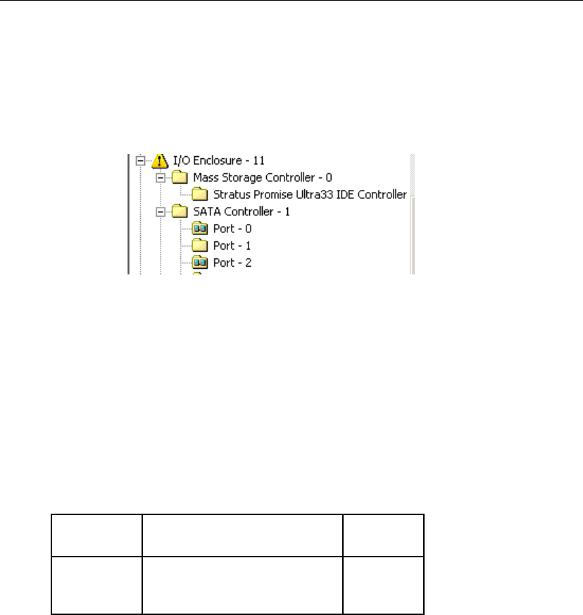
Locating Components
Troubleshooting 5-7
•Level 1: I/O Enclosure - 11
•Level 2: Mass Storage Controller - 0 and SATA Controller - 1
•Level 3: Ports 0 through 2
Figure 5-2. Component Levels
A device path is a slash-separated sequence of device IDs that identifies the location
of a component in the system. Device paths appear in the details pane of ftSMC. They
use the following syntax:
Level-1 device ID/Level-2 device ID/Level-3 device ID/Level-4 device ID
For example, referring to Figure 5-2, the device path 11/1/2 indicates:
I/O Enclosure - 11/SATA Controller - 1/Port - 2
Table 5-1 presents the system device IDs.
Table 5-1. System Devices and Device IDs
Component
Level Device Device
ID
1 Call-Home Modem
CPU Enclosure (element)
I/O Enclosure (element)
0
0, 1
10, 11

Locating Components
5-8 Express5800/320Ma: System Administrator’s Guide
Device IDs and device paths apply only to hardware components. Logical devices (for
example, two physical Ethernet ports partnered to provide a single fault-tolerant path
to the network) and software components do not have device IDs even if they appear
in the ftSMC interface.
Diagrams of Component Locations
See Figure 5-3 to locate I/O and CPU elements for your Express5800/320Ma system.
If a component is shown as failed or failing in ftSMC, note its device ID and then use
the following information to locate that component within the system. All top-level
components have a physical label that includes their device ID.
System Elements and Internal Storage Disk Locations
Figure 5-3 shows the locations of the CPU and I/O elements and disk slots. The
internal storage is housed in an enclosure located above the CPU-I⁄Oenclosure.
2DIMM
Processor
Storage Enclosure (internal)
BMC
Mass Storage Controller
SATA Controller
USB Controller
VGA Controller
VTM Adapter
Ethernet Controller
PCI to PCI Bridge
First PCI-X slot
on riser card
PCI Slot Info
0–7
20–23
40
120
0
1
2
3
4
5
6, 7
8
9–11
3Port
Network Port
Slot
0–2
0,1
1–3
4 Disk (internal) 0–2
Table 5-1. System Devices and Device IDs
Component
Level Device Device
ID

When Windows Does Not Respond
Troubleshooting 5-9
Figure 5-3. CPU-I/O Enclosure, and Disk Slot Labeling
When Windows Does Not Respond
If Windows does not respond (that is, if the system appears hung), use the VTM
console or the power button (for systems without VTM console) to restart the system.
Related information can be found in the Express5800/320Ma Virtual Technician
Module User’s Guide.
Delayed System Restart
When you restart a system that contains certain models of adapters, the system
appears to hang for approximately 10 seconds while the drivers for the adapter are
installed. Allow several seconds for restart to proceed.
Slot 3
Slot 2
Slot 1
Slot 3
Slot 2
Slot 1
CPU 0 — I/O 10
CPU 1 — I/O 11
Bottom
Top

Unresponsive Mouse and Keyboard
5-10 Express5800/320Ma: System Administrator’s Guide
Unresponsive Mouse and Keyboard
If your system contains VTMs, the mouse and keyboard may appear unresponsive at
some point after the system has restarted. This is normal behavior while the operating
system finds the virtual mouse and keyboard as new hardware. Responsiveness
returns after a short period of time.
Remote Event Notification and Service
The ASN provides the following features:
•Event reporting to your NEC Technical Support or your authorized service
representative (dial-out)
•Remote service to your system by service support personnel (dial-in)
You use the ASM Web site to configure all remote event reporting and remote service
features of the ASN. See the Express5800/320Ma ActiveService Network
Configuration Guide for details.
Remote Reporting of Events
When the system’s fault-tolerant software detects a hardware or software problem, the
system generates alarm messages that can be:
•Sent to NEC Technical Support or other authorized service representative
•Sent to a customer contact by way of email or pager
•Written to the Windows system event log
Autonomous Call Home
For systems with VTMs, the VTM can send an alarm when a fault-resilient boot fails to
bring up the Windows operating system.
System Inventory Reports
An alarm message can include a full system inventory, a partial system inventory, or
no inventory at all, depending on the message type. A system inventory consists of an
enumeration of all of the properties of the manageable hardware devices tracked by
the Inventory Service.
SNMP Traps
Most alarms can also generate SNMP traps. Device state alarms generate an SNMP
trap whenever a device state transitions to or from an online, broken, or offline state.
Sensor threshold alarms generate an SNMP trap whenever a sensor status improves
or worsens to normal, warning, and critical states.

Making Dump Files
Troubleshooting 5-11
Event-Log Entries
ftServer Manager may generate an alarm in response to a sequence of several events.
To indicate what these events are, an alarm message may include event-log entries.
These event-log entries contain items that represent an event from both the System
and Application event logs. The number of event-log entries included with an alarm
message is determined by specifying how many seconds of the event log to include.
ftServer Manager may configure this time differently for each type of alarm, or it may
exclude some event-log entries.
Remote Service
If you have a service contract with NEC Technical Support or your authorized service
representative, to connect to your system, your service representative first dials the
system. For systems with VTMs, the adapter validates that the call is from a permitted
source, disconnects the incoming call, and calls back to make a connection to the
validated NEC Technical Support. For systems without VTMs, the Windows RAS
service authenticates the call and allows NEC Technical Support user to log on.
NOTE
Do not change the SMM ASN Hub ID, SMM ASN Hub
Password, Dial-in User Name, Dial-in Password, or PPP
Password properties without first contacting NEC
Technical Support or your authorized service
representative.
You can configure the system to allow the NEC Technical Support to connect to your
system, either through a dialup modem or over the Internet, to diagnose problems and
perform data-transfer functions. These accesses are subject to validation by NEC
Technical Support database, by the VTMs on your system, and by you as the system
administrator.
NEC Technical Support or your authorized service representative may contact you to
determine the seriousness of the condition. If a CRU has failed, the NEC Technical
Support will ship a new part to your site.
On systems equipped with VTMs, ftServer Manager continuously copies a limited
number of Windows system event-log messages to a log on VTMs so that support
personnel can retrieve the log if your system fails.
Making Dump Files
Dump files are snapshots of either a system’s memory or a particular component’s
firmware memory. Dump files enable NEC Technical Support to diagnose system or
component problems. You can create dump files in the following ways.

Making Dump Files
5-12 Express5800/320Ma: System Administrator’s Guide
To create system memory dumps, you can:
•Press a button.
•Configure your system to create memory dumps.
•In ftSMC, right-click a CPU Enclosure, and select the Dump and Go command.
•In ftSMC, right-click a certain component, and select either the Dump and Go
command or the Dump command. (These commands are not available for all
components.)
The Dump command dumps a snapshot of the corresponding component. While
dumping, the component is not available. When the dump is complete, the component
returns to service.
You can also use Windows commands to configure the creation of memory dumps.
See Windows documentation.
Using the Dump Button
CAUTION
!Making a dump file of an entire system automatically
takes the operating system offline and then restarts it.
With a firm, fine-tipped object, like a pushpin, press the Dump button, which is actually
a small circular opening.
Press the Dump button on the primary enclosure. The primary enclosure is the
enclosure on which the power switch LED is lit. The Dump button is located at the
center rear panel of each enclosure. It is labeled DUMP.
System Memory Dumps
Memory dumps are enabled through the Board Instance driver’s DumpQuickEnabled
and DumpNumberOfFilesToSave properties.
To enable system memory dumps
1. In ftSMC, expand ftServer (Local), ftServer Drivers, and then
Board Instance Driver - srabid.
2. Right click Board Instance Driver - srabid, Properties, and set
DumpQuickEnabled to True.
3. Set DumpNumberOfFilesToSave to the number of dump files you want to save to
disk.

Online Diagnostic Codes
Troubleshooting 5-13
Dump files beyond this number overwrite the existing saved dump files. For
instance, if the value is 3, then the fourth saved dump file overwrites the first,
existing dump file.
If, at the time of a system crash, the DumpQuickEnabled property of the Board
Instance Driver node is True and the CPU element is duplex, the system creates a
memory dump and stores the dump in the memory of one CPU element. The system
restarts with the remaining CPU element. After the system restarts, the dump is
automatically copied to a disk file.
After a system reboot where a dump has been generated, do not attempt to read or
copy the Memory.dmp file created. After the system has completed writing the
Memory.dmp file, it renames the file Memoryn.dmp, where n is a numeral. You can
read or copy the Memoryn.dmp file. It may take up to five minutes after the reboot to
complete writing the Memory.dmp file before it is renamed and can be read.
CAUTION
!If you attempt to read or copy the Memory.dmp file while
the system is writing it, you may corrupt the file.
The normal Windows dump mechanism is used if the DumpQuickEnabled parameter
is False (disabled) or if the CPU element is in simplex mode.
Dump and Go
The Dump and Go command captures a snapshot dump of a running system or a
particular component without significantly interfering with the system’s or component’s
operation. The system must be running duplex in order to use this method. To capture
a snapshot dump, right-click the CPU Enclosure node of interest in the ftSMC console
tree and select Dump and Go from the Action menu. The system:
•Takes the selected CPU element offline with its memory intact
•Dumps a snapshot of the memory to C:\sradumps\Memoryn.dmp
•Displays the status of the operation
•Returns the CPU element back to online status
A Dump and Go command on a BMC controller dumps a snapshot of the BMC
firmware’s memory, and then restores the BMC to service.
Online Diagnostic Codes
The Virtual BMC LCD displays online diagnostic codes (described in Appendix B) only
when a diagnostic test is running on an operative system.

Disaster Recovery
5-14 Express5800/320Ma: System Administrator’s Guide
Disaster Recovery
To help you to log on and access system resources after a computer disaster has
occurred, you can restart the system in safe mode, boot from a spare disk, or use the
Windows WinPE command shell.
Safe Mode
You use the Safe Mode startup options to start the system with only the minimal
necessary services. Safe Mode options include Last Known Good Configuration, Safe
Mode, Safe Mode with Networking, and Safe Mode with Command Prompt. For more
information, see Safe Mode startup options in Windows Help.
CAUTION
!You must disable the Watchdog Timer by disabling boot
monitoring in the BIOS before attempting to boot in Safe
Mode. See the Express5800/320Ma: Software Installation
and Configuration Guide for a description of how to
disable boot monitoring.
Booting From a Spare System Disk
To boot from a spare system hard disk, you need a spare hard disk that was prepared
during your initial system configuration process. Refer to the Express5800/320Ma:
Software Installation and Configuration Guide for information about how to prepare this
hard disk. Typically, you boot from a backup hard disk only to recover from an unlikely
disaster situation where all redundant system disks suffered simultaneous failure.
To boot a system from an RDR boot disk, see “Booting a System with a Backup RDR
Boot Disk” on page 4-16.
The following procedure explains how to boot a system from a non-RDR system disk.
To boot from a previously prepared non-RDR spare system disk
1. Shut down the operating system.
2. Physically remove one of the original system disks.
3. Insert the spare system disk into the empty slot created in step 2.
4. Unlatch the other original system disk.
5. Power up the system.
6. After the system has booted, insert (latch) the original disk that you unlatched in
step 4.

Disaster Recovery
Troubleshooting 5-15
7. Use your disk-management tool’s Delete Volume command to delete the volume
on the original disk you inserted in step 6. When this step is complete, the disk is
set to Unallocated space.
8. Create a mirror of the spare system disk’s C: volume on the original disk you
inserted in step 6.
Using Windows Disk Management, right-click the spare system disk’s C: volume.
In the shortcut menu, click Add Mirror. A wizard prompts you through the rest of
the mirroring process.
9. When the disk is 100% resynchronized, verify that the original system disk and the
upgraded system disk are healthy, resynching, dynamic, mirrored volumes. Note
that the drives are not duplexed until the resynchronization activity is complete.
10. After all resynchronization activity has finished, verify that all dynamic disks are
healthy, dynamic, mirrored volumes.
11. Start all applications to verify that your system and applications are working
properly.
WinPE
WinPE (Windows Pre-Installation Environment) provides a command shell from which
you can perform system recovery using operating system commands.
To access the WinPE command shell, you must boot from the ExpressBuilder CD (1 of
2). Select the Use WinPE to repair a corrupted hard drive command when the
Express5800/320Ma System software presents that option.
WinPE is recommended for advanced users or administrators only. See Microsoft
documentation for information about WinPE.
Windows Hotfixes Distributed by NEC Solutions (America), Inc.
To create a file that lists the Windows hotfixes distributed with your
Express5800/320Ma System software release and installed on your system by an IPL
or upgrade to the release, use the following procedure.
To obtain a list of Windows hotfixes
1. Insert your ExpressBuilder CD (1 of 2) in the CD-ROM drive.
2. If the Express5800/320Ma System software installation wizard runs automatically
and asks if you want to install Express5800/320Ma System Software, click Cancel.
3. In a command-prompt window, change to a directory in which to save the file.
4. Enter a command in the following format:
dir cddrive:\Bin\Hotfix\*LG* > outputfile

Disaster Recovery
5-16 Express5800/320Ma: System Administrator’s Guide
In the command format:
•cddrive is the drive letter for your CD-ROM drive
•LG is the language code for your Windows version
•outputfile is the name of the file to hold the results. You can specify any name
for the file.
5. Eject the CD-ROM.
For example, the following command produces a file named hotfixlist.txt in the current
directory of your command prompt window. The file contains a list of all hotfixes for the
English versions of Windows Server 2003:
dir D:\Bin\Hotfix\*EN* > hotfixlist.txt

Advanced Topics A-1
Appendix A
Advanced TopicsA-
This appendix presents the following advanced topics:
•“Disabling Hyperthreading”
•“Using Windows Headless Mode and Console Redirection”
•“Security Configuration Wizard”
These procedures require that you change settings in the BIOS. For further information
about BIOS settings, see the Express5800/320Ma: Technical Reference Guide.
Disabling Hyperthreading
Some system installations may disable hyperthreading to facilitate application
execution.
CAUTION
!Disable hyperthreading only if your system satisfies the
minimum BIOS version requirements. Contact NEC
Technical Support or your authorized service
representative to confirm that you have the correct BIOS
version.
To disable hyperthreading, you enter the ftServer Setup utility.
To disable hyperthreading
1. Turn on or restart your system. When the logo screen appears, press F2 to enter
your system’s BIOS setup utility.
The BIOS setup utility’s Main menu appears after the system completes more of
the POST (power-on self-test) process.
2. On the Main menu, use the right-arrow key to select the Advanced tab.
3. Use the down-arrow key to select Advanced Processor Options and press Enter.
4. Select Hyper Threading Technology and press Enter.
5. Change the value from Enabled to Disabled and press Enter.

Using Windows Headless Mode and Console Redirection
A-2 Express5800/320Ma: System Administrator’s Guide
6. Press Esc, then select Exit Saving Changes and press Enter.
The system resumes booting.
Using Windows Headless Mode and Console Redirection
In headless mode, Windows Server 2003 can run without a keyboard, mouse, and
monitor. You can remotely manage and restart the system through a serial connection.
If your system is operating in headless mode, and if the port for both console redirection
and Windows headless are set to use the same Serial port, configure the BIOS to stop
console redirection when the power-on self-test (POST) has finished processing.
To configure the BIOS to stop console redirection after POST
1. When the system is booting and the progress bar has started to fill, press F2 to
enter the BIOS setup program and wait for the BIOS setup program to run.
2. Use the RIGHT ARROW key to select the Advanced tab.
3. On the Advanced menu, use the DOWN ARROW key to select Console
Redirection. Press ENTER.
4. On the Console Redirection menu, use the DOWN ARROW key to select
Continue C.R. after POST. Use the PLUS SIGN key (+) to change the value to
OFF.
5. Press F10.
6. In the Setup Confirmation dialog box, select Yes and press ENTER to save the
new settings and exit from the BIOS Setup program.
Security Configuration Wizard
If you use the Security Configuration Wizard (new in Windows Server 2003 Service
Pack 1) to create a security-configuration template on an Express5800/320Ma system,
perform the following steps to ensure that the template does not interfere with ftServer
services running on the system.
The following steps assume that you have selected all the defaults associated with the
ftServer services.
NOTE
The dialog boxes shown in the following steps do not
appear in the exact sequence shown. However, they
should all appear in the course of running the Security
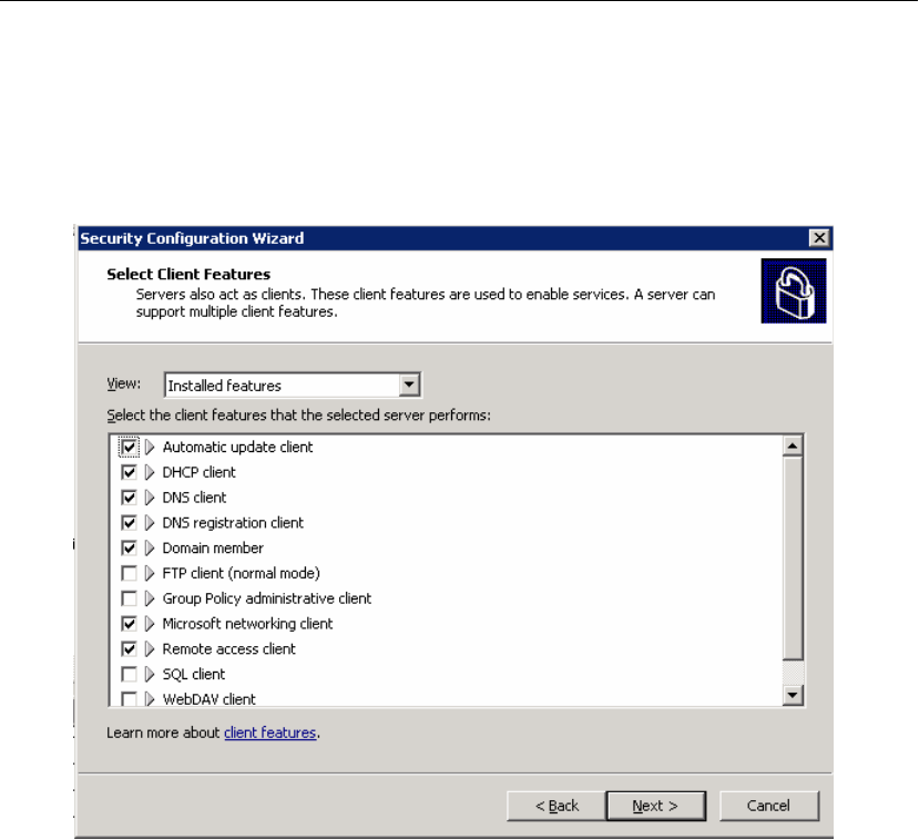
Security Configuration Wizard
Advanced Topics A-3
Configuration Wizard. See Windows documentation for
more information.
1. Check the Remote access client box in the Select Client Features dialog box, as
shown below.
2. In the Open Ports and Approve Application dialog (shown below), if the ftServer
SSN service (SRA_SSN.EXE) does not appear in the list, click Add.
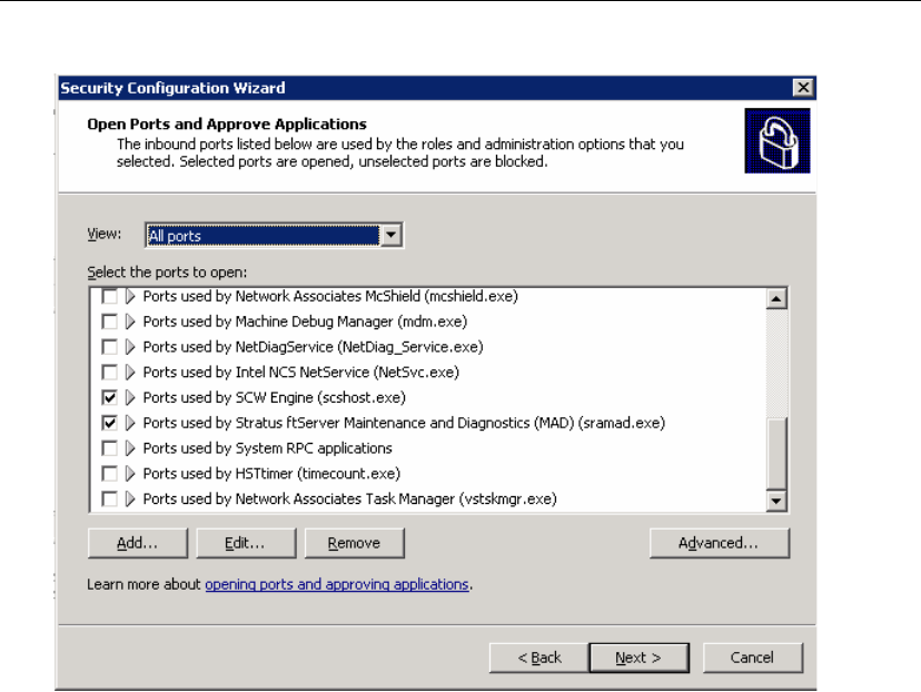
Security Configuration Wizard
A-4 Express5800/320Ma: System Administrator’s Guide
3. Browse to the location of the SRA_SSN.EXE service, as shown in the dialog box
below, and click OK.
The service name then appears checked in the list shown in the step 2.
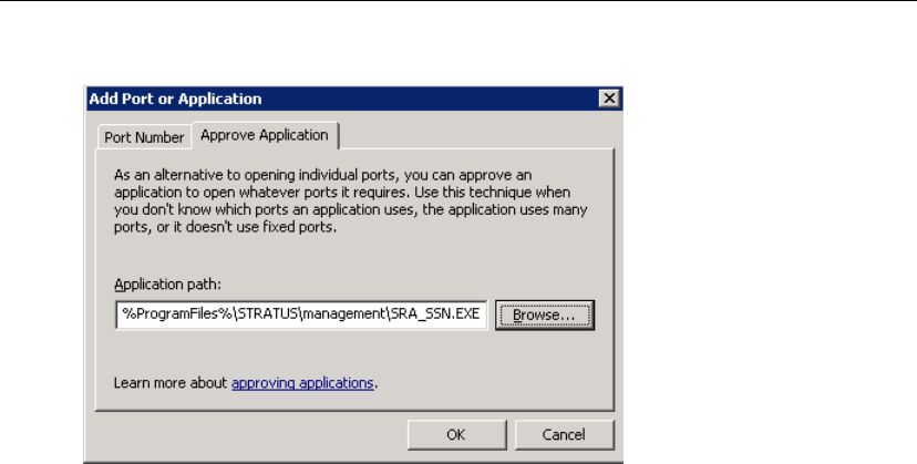
Security Configuration Wizard
Advanced Topics A-5
4. In the Open Ports and Approve Application dialog box (shown in step 2), click
Add, select SRA_RAS.EXE, and press OK.
The service name then appears checked in the list shown in the step 2.

Security Configuration Wizard
A-6 Express5800/320Ma: System Administrator’s Guide

Online Diagnostic Codes B-1
Appendix B
Online Diagnostic CodesB-
The following describes the online diagnostic codes for your Express5800/320Ma
systems. Online diagnostic codes are hexadecimal values that indicate a test or
initialization routine. The codes appear on the Server Info page of the Virtual
Technician Module (VTM) Console.
Online Diagnostic Test Codes
The following describe the codes for online diagnostic tests, which are performed when
the system boots, when a CPU or I/O element is brought back into service, and when
initiated by an administrator of the system.
•“CPU Diagnostic Test Codes”
•“I2C Bus Diagnostic Test Codes”
•“Primary I/O Element Diagnostic Test Codes”
•“Secondary I/O Element Diagnostic Test Codes”
CPU Diagnostic Test Codes
The following tests are performed on the CPU element.
D000
Verify successful completion of BIST (built-in self test).
D010
Test whether CPU 1 can arbitrate for control of the system bus.
D020
Test the processor stepping.
D030
Enable processor machine check architecture (MCA).
D031
Disable MCA.

Online Diagnostic Test Codes
B-2 Express5800/320Ma: System Administrator’s Guide
D032
Verify that no processor MCA errors were reported.
D040
Compare the QDF numbers (an Intel processor identifier) between the processors
in each CPU element.
D050
Verify that the processors are installed in a supported configuration.
D110
Test the registers in the configuration space on the PCI-to-PCI bus chipset.
D111
Test the ability of the PCI-to-PCI bus chipset to generate error-correction codes.
D130
Test write protection for Flash drives.
D170
Test for errors recorded by the chipset.
D221
Verify that there are no mixed size DIMMs per bank.
D223
Set and verify the Data Queue Strobing (DQS) timing settings.
D224
Verify that the timing settings are correct for the installed DIMM modules.
D230
Perform pattern tests on the memory.
D310
Test the registers of the PCI ASICs.
D330
Test for parity errors on the PCI-to-PCI bus.

Online Diagnostic Test Codes
Online Diagnostic Codes B-3
D340
Test the fault tolerant switch interface.
D341
Test the PCI Express channel status.
D342
Test the CPU side of the fault tolerant switch ASIC for errors.
D343
Enable the error registers on the CPU side of the fault tolerant switch ASIC.
I2C Bus Diagnostic Test Codes
The following tests are performed on the I2C bus.
D400
Verify the validity of the CPU’s IDPROM checksum.
D410
Test the I2C interface.
D430
Verify the validity of the IDPROM checksum.
D480
Test the validity of the contents of the IDPROM on an I/O element.
D481
Test whether the BMC can read the IDPROM, obtain the IDPROM from the BMC,
and checksum the contents.
D482
Verify the backplane IDPROM checksum.
D483
Invalid SROM format.
D484
Failed to read the backplane SROM.

Online Diagnostic Test Codes
B-4 Express5800/320Ma: System Administrator’s Guide
D485
MAC address check.
D497
Test the BMC interface.
D4E1
BMC retry failure.
D502
Test whether the CPU side of the fault tolerant switch ASIC to the primary I/O
element responds to all interrupts.
D503
Test whether the CPU side of the fault tolerant switch ASIC to the primary I/O
element responds to an interrupt.
DE01
On the primary I/O element, retry communication between the BIOS and the
baseboard-management controllers.
Primary I/O Element Diagnostic Test Codes
The following tests are performed on the booting I/O element.
D580
Test the system error-handling interrupt.
D581
Test the SMI interrupt.
D590
Test the NMI interrupt.
D591
Test the INTR interrupt.
D592
Test the A20 interrupt.
D593
Test the NMI.

Online Diagnostic Test Codes
Online Diagnostic Codes B-5
D595
Test whether the BMC can initiate an NMI interrupt.
D597
Test the BMC KCS interrupt.
D5A0
Test the IRQ0 interrupt (timer).
D5A1
Test the IRQ1 interrupt (keyboard).
D5A2
Test the IRQ4 interrupt (UART).
D5A3
Test the IRQ8 interrupt (RTC).
D5A4
Test the IRQ12 interrupt (mouse).
D5A5
Test the IRQ14 interrupt (IDE).
D5A6
Test the SCI interrupt.
D5A7
Test the IRQ3 interrupt (COM2).
D5B0
Test the PIRQ0 IRQ1 interrupt (USB).
D600
Test the interface between the PCI ASICs on the CPU element and the primary I/O
element.
D601
Verify that PCI-card ASIC has not generated break errors.

Online Diagnostic Test Codes
B-6 Express5800/320Ma: System Administrator’s Guide
D612
Test the PCI-card PCI bus.
D613
Test the PCI-card ASIC interrupt.
D614
Verify that PCI-card ASIC has not generated break errors.
D620
Test the ability to move data between PCI-card ASICs.
D630
Examine PCI-card ASIC error registers, to verify the ASIC is working correctly.
D632
Test the PCI ASIC for errors.
D650
Verify that the path to the I/O side of the fault tolerant switch ASIC is available.
D651
Test the I/O side of the fault tolerant switch ASIC on the primary I/O element for
errors.
D652
Test the fault tolerant switch data mover on the booting primary I/O element for
errors.
D653
Test the fault tolerant switch crosslink.
D660
Perform a sanity test on the fault tolerant switch HPC.
D700
Test the PIIX ISA registers.
D701
Test the PIIX IDE register.

Online Diagnostic Test Codes
Online Diagnostic Codes B-7
D702
Test the PIIX USB register.
D703
Test the PIIX PM register.
D704
Test the PCI bus.
D720
Test the timers.
D721
Test the real-time clock.
D722
Test the real-time clock crystal.
D730
Test direct memory access to the serial I/O port.
D740
Test the loopback interface to the serial I/O port.
D741
Test the SIO (super input-output) loopback from COM2.
D745
Test the SIO (super input-output) interface to the LPC (low-pin count) bus.
D750
Test the ISA bus.
D801
Test the PCI interface to the Ethernet port.
D802
On the primary I/O element, initiate the Ethernet port self-test.
D803
On the primary I/O element, initiate the Ethernet parity error test.

Online Diagnostic Test Codes
B-8 Express5800/320Ma: System Administrator’s Guide
D804
On the primary I/O element, initiate the Ethernet loopback test.
D805
On the primary I/O element, initiate the Ethernet interrupt test.
D806
On the primary I/O element, initiate the Ethernet BAR decoding test.
D807
On the primary I/O element, initiate the Ethernet CSMA/CD test.
D808
On the primary I/O element, initiate the Ethernet PHY OUI verification test.
D809
On the primary I/O element, initiate the Ethernet PROM checksum test.
D820
Test the Gigabit Ethernet interface to the PCI bus.
D821
On the primary I/O element, initiate the Gigabit Ethernet PHY OUI verification test.
D822
Test the Gigabit Ethernet loopback.
D823
Test the Gigabit Ethernet interrupt.
D824
Test the Gigabit Ethernet BAR decoding.
D825
On the primary I/O element, initiate the Gigabit Ethernet PROM checksum test.
D826
Test the interface to the Ethernet PHY identifier (function 1).
D827
Test the Ethernet interrupt (function 1).

Online Diagnostic Test Codes
Online Diagnostic Codes B-9
D828
Test the Ethernet loopback (function 1).
D830
Verify that reads and writes can be made to the PCI configuration space for the
video controller. Verify that reads and writes can be made to the memory-mapped
registers for the video controller.
D831
On the primary I/O element, fill the embedded video memory with a data pattern.
Verify the data pattern and perform binary inversion. Verify memory inversion.
D840
Test that reads and writes can be made to the PCI configuration space for the SATA
controller.
D841
On the primary I/O element, generate a SATA PHY interrupt.
D842
Verify that data can be sent between the SATA controller and a SATA disk.
D850
Perform error checking on the IDE controller
D851
Perform an internal diagnostics test on the IDE controller
D852
Perform an interrupt test on the IDE controller
D860
Perform error checking on the USB controller
D861
Perform an internal diagnostics test on the USB controller
D862
Perform an interrupt test on the USB controller

Online Diagnostic Test Codes
B-10 Express5800/320Ma: System Administrator’s Guide
D863
Perform a test of the USB DMA.
D900
Test the fault tolerant switch-to-PXH interface.
D901
Test the PXH PCI-X interface
D902
Perform error checking on the PXH HPC controller.
D910
Test the PCI-X-to-PCI bridge interface.
D920
Perform a sanity test on the PXH hot-plug controller.
D921
Test the PXH hot-plug controller interrupt.
D922
Test PXH hot-plug controller slot power.
DC00
Test PCI-card ASIC interface in the BIOS boot block.
DC04
Test the PCI bus interface.
DC06
On the primary I/O element, log early boot block errors.
DC50
Test the ISA bus.
Secondary I/O Element Diagnostic Test Codes
The following tests are performed on the secondary I/O element.
E481
Initiate the IDPROM checksum test on the secondary I/O element.

Online Diagnostic Test Codes
Online Diagnostic Codes B-11
E580
Initiate a diagnostic test of an interrupt that is specific to your Express5800/320Ma
system.
E581
Initiate the SMI interrupt diagnostic test.
E591
Initiate the INTR interrupt diagnostic test.
E597
Test the BMC interface.
E5A0
Initiate the IRQ0 interrupt (Timer) diagnostic test.
E5A1
Initiate the IRQ1 interrupt (KB) diagnostic test.
E5A2
Initiate the IRQ4 interrupt (COM1) diagnostic test.
E5A3
Initiate the IRQ8 interrupt (RTC) diagnostic test.
E5A6
Initiate the SCI interrupt diagnostic test.
E5A7
Initiate the IRQ3 interrupt (COM2) diagnostic test.
E5A8
Test the system error-handling interrupt.
E600
Initiate the PCI-card ASIC interface diagnostic test.
E620
Initiate the PCI-card ASIC Gsync diagnostic test.

Online Diagnostic Test Codes
B-12 Express5800/320Ma: System Administrator’s Guide
E650
Verify that the path to the fault tolerant switch ASIC is available.
E651
Test the I/O side of the fault tolerant switch ASIC element for errors.
E652
Test the fault tolerant switch data mover for errors.
E653
Test the fault tolerant switch crosslink.
E660
Perform a sanity test on the fault tolerant switch HPC.
E720
Initiate the timer diagnostic test.
E721
Initiate the RTC diagnostic test.
E740
Initiate the serial loopback (Port 1) diagnostic test.
E741
Initiate the Serial loopback (Port 2) diagnostic test.
E745
Test the SIO (super input-output) interface to the LPC (low-pin count) bus.
E801
Initiate the Ethernet controller PCI interface diagnostic test.
E805
Initiate the Ethernet controller interrupt diagnostic test.
E806
Initiate the Ethernet BAR decoding check diagnostic test.
E808
Initiate the Ethernet PHY OUI verification diagnostic test.

Online Diagnostic Test Codes
Online Diagnostic Codes B-13
E809
Initiate the Ethernet EEPROM diagnostic test.
E820
Initiate the Ethernet (Gigabit) PCI interface diagnostic test.
E821
Initiate the Ethernet (Gigabit) PHY OUI verification diagnostic test.
E823
Initiate the Ethernet (Gigabit) interrupt diagnostic test.
E824
Initiate the Ethernet (Gigabit) BAR decoding check diagnostic test.
E825
Initiate the Ethernet (Gigabit) EEPROM diagnostic test.
E826
Test the interface to the Ethernet PHY identifier (function 1).
E827
Test the Ethernet interrupt (function 1).
E828
Test the Ethernet loopback (function 1).
E830
Verify read/write to VGA PCI configuration space. Verify read/write to VGA
memory-mapped registers.
E831
Fill 4MB embedded video memory with data pattern. Verify data pattern and
perform binary inversion. Verify memory inversion.
E840
Test read/write to SATA PCI configuration space.
E841
Generate SATA PHY interrupt.

Online Diagnostic Test Codes
B-14 Express5800/320Ma: System Administrator’s Guide
E842
Verify that data can be sent between the SATA controller and the SATA disk.
E860
Perform error checking on the USB controller
E861
Perform an internal diagnostics test on the USB controller
E862
Perform an interrupt test on the USB controller
E900
Test the fault tolerant switch- to-PXH interface.
E901
Test the PXH PCI-X interface
E902
Perform error checking on the PXH HPC controller.
E910
Test the PCI-X-to-PCI bridge interface.
E920
Test the PXH hot-plug controller.
E921
Test the PXH hot-plug controller interrupt.
E922
Test the PXH hot-plug controller slot power.
EB02
Initiate the secondary I/O diagnostic test.
EB03
Finish secondary I/O diagnostic test.

Index-1
IndexIndex-
A
action band, 3-7
active RDR virtual disk (plex), 4-10
Active Upgrade, 1-1
ActiveService Network (ASN). See ASN
Add Physical Disk To RDR Virtual Disk, error
message, 4-9
administration. See system administration
Advanced Video Redirection (AVR), 1-3
alarm messages
email, 5-10
pager, 5-10
system inventory, 5-10
alarm transmission, 3-5
application event log files
archiving, 2-9
ASN, 1-2
features, 5-10
system and PCI adapter integration, 1-5
automatic system update, 2-13
B
basic disks
converting dynamic to, 4-10
BIOS
changing settings, A-2
determining version, 2-10
Serial and Internal Modem settings, 2-11
Setup menus
disabling boot monitoring, 5-14
setup utilities
starting, 2-10
booting
from backup system disk, 5-14
from network drive, 2-14
from spare system disk, 5-14
monitoring process, 2-2
bringup
CPU element, 2-3
C
cache, enabling write, 4-6
call-home
autonomous, 5-10
support, 3-5
call-home messages
email, 5-10
event reporting, 5-10
pager, 5-10
Capacity property, 4-4
cloning RDR disks, 4-13
codes
diagnostic, 5-13
commands
Clear MTBF
in RDR, 4-15
Delete RDR Configuration on Physical
Disk, 4-11
Deport Physical Disk from RDR Virtual
Disk, 4-13
operational states required for, 3-13
Properties, 3-12
Remove a Physical Disk from RDR Virtual
Disk, 4-12
Resynchronize This Physical Disk From
RDR Virtual Disk, 4-18
Set MTBF Threshold
in RDR, 4-15
Shut Down, 2-2
Start Slot Identification, 4-23
Stop Slot Identification, 4-23
Stop Verify RDR Virtual Disk, 4-19
Verify RDR Virtual Disk, 4-19
components
determining failures, 5-5
labels, 5-8
locating, 5-6
status LEDs, 5-5
configuring
properties, 3-12

Index
Index-2 Express5800/320Ma: System Administrator’s Guide
RDR disks, 4-25
VTM, 2-6
connection status of storage media in
ftSMC, 4-24
console tree of ftSMC, 3-7
context-sensitive help, 1-6
converting dynamic disks to basic RDR, 4-10
CPU elements, 5-8
bringing up, 2-3
bringup options, 2-3
Dump and Go command, 5-13
memory dumps, 5-13
resynchronization, 2-3
states and actions, 3-13
CPU Enclosure node, 4-23
CpuBringUpPolicy property, 2-3
CPU-I/O enclosures, 3-1
customer-replaceable unit failures, 5-11
D
D540 and D548 storage enclosures
removing disks safely, 4-22
data storage
dynamic disks, 4-21
fault tolerance, 4-1
debugging information files, 5-11
Defer CpuBoard Bringup, 2-3
Delete RDR Configuration on Physical Disk
command, 4-11
deleting RDR configurations
limitations, 4-11
Deport Physical Disk from RDR Virtual Disk
command, 4-13
deported disks, 4-13
desktop
enabling Remote Desktop, 2-5
Windows, 2-5
details pane of ftSMC, 3-7
device IDs, 5-7
limitations, 5-8
locating components, 5-6
software components, 5-8
device paths
See also device IDs
DevicePath property, 4-26
DevicePathID property, 4-26
devices
labels, 5-8
locating, 5-6
diagnostic codes, 5-13
disaster recovery
booting from spare disk, 5-14
Safe Mode, 5-14
WinPE, 5-15
disk management mirroring, 4-22
Disk node, 4-23
disks, 4-5
See also entries under RDR disk mirorring
and RDR virtual disks
active RDR, 4-10
backup, 4-13
converting dynamic to basic, 4-10
duplex RDR, 4-2
finding external in ftSMC, 4-27
finding internal in ftSMC, 4-26
locating by flashing LEDs, 4-23
replacing, 5-3
safe/unsafe to remove from D540 or D548
storage enclosure, 4-22
simplex, 4-2
status
Healthy, 5-3
Offline or Missing, 5-3
dual device paths
software components, 5-8
Dump and Go command
BMC controller, 5-13
CPU element, 5-13
Dump button, 5-12
dump command, 5-12
dump files, 5-11
recovering, 5-13
DumpNumberOfFilesToSave property, 5-12
DumpQuickEnabled property, 5-13
dumps
systems with no VTM, 5-12
DVD, writing to CD, 2-10
DVD±RW drives, 2-10
dynamic disks, 4-21
and RDR automatic disk expansion, 4-3
converting to basic, 4-10
Dynamic Host Configuration Protocol
(DHCP), 1-3
E
EMC storage enclosures

Index
Index-3
adapters in ftSMC, 4-24
Enable CpuBoard Bringup, 2-3
enabling write caching, 4-6
enclosures
primary, 5-12
error icons, 5-5
events
log entries, 2-8, 5-11
reporting, 5-10
expanding all nodes, 3-7
F
failed component identification, 5-5
failover, 4-11
failures
CRUs, 5-11
determining component, 5-5
disk, 4-18, 5-3
mean time between (MTBF), 5-1
mirrored disks, 4-21
mirrored volumes, 4-21
replacing disks, 5-3
services, 2-10
system, 5-5
UPS, 2-12
FaultCountLimit property, 4-15
fault-resilient boot failure, 5-10
files archiving event log, 2-9
debugging, 5-11
dump, 5-11
memory dump, 5-13
paging, 4-12, 4-13
paging and RDR, 4-11
saving log, 2-9
Windows hotfix, 5-15
finding components, 5-6
flashing LEDs, 5-6
ftGateway systems, 1-2
ftServer Management Console. See ftSMC
ftSMC
action band definition, 3-7
adding to MMC, 3-3
console tree definition, 3-7
details pane definition, 3-7
inventory icons, 3-9
running on ftServer, 3-2
running on remote computer, 3-3
status bar definition, 3-7
updating status of storage connection
state, 4-24
G
gateway system, 1-2
H
hanging system, 2-2
hardware installation wizard, 5-5
headless mode, A-2
Healthy disk status, 5-3
Help in ftSMC
context-sensitive, 1-6
overview, 1-6
What’s this?, 1-6
hotfixes
installing, 2-13
obtaining list, 5-15
hyperthreading
disabling, A-1
I
I/O elements, 3-1, 5-8
hot-plugging, 5-5
in details pane, 4-26
primary, 5-12
resynchronizing mirrored volumes, 4-21
resynchronizing RDR disks, 4-17
states and actions, 3-13
icons
dimmed folder, 3-9
dual monitor, 3-9
error, 3-10, 5-5
invalid configuration, 3-9
inventory, 3-9
magnifying glass, 3-9
no inventory found, 3-11
single monitor, 3-9
threshold warning, 3-11
tools, 3-9
warning, 5-5
yellow folder, 3-9
identifiers
device
limitations of device, 5-8
identifying components

Index
Index-4 Express5800/320Ma: System Administrator’s Guide
flashing LEDs, 5-6
IMAPI service, enabling, 2-10
Initiate BringDown command
Op State required, 3-13
Initiate BringUp command
Op State required, 3-13
Initiate Diagnostics command
Op State required, 3-13
internal disks
choosing configuration of, 4-1
configuration guidelines, 4-2
converting to RDR configuration, 4-2
in ftSMC, 4-22
mirroring, 4-25
system and mirrored partner, 4-25
unsafe removal error message, 4-12, 4-18,
5-3
Internal Modem setting, 2-11
internal storage enclosures
in details pane, 4-26
Internet only option, 3-5
Internet with phone line as backup option, 3-5
invalid component configurations, 3-9
IP address and UPS configuration, 2-12
L
labels
on components, 5-8
LEDs
component status, 5-5
flashing to find components, 5-6
flashing to locate disks, 4-23
locating components
flashing LEDs, 5-6
Logical to Physical Mapping node, 4-25
LUN, 4-2
LunVerifyInterval property, 4-19
M
memory
snapshot
Dump and Go feature, 5-13
metadata, 4-3
space requirement, 4-9
Microsoft Windows. See Windows
mirroring
and failed volumes, 4-21
basic disks for RDR, 4-8
disks in internal storage, 4-2
overview, 4-20
recovering non-RDR disk, 5-3
recovering RDR disk, 4-18, 5-3
status
Healthy, 5-3
Offline or Missing, 5-3
synchronizing, 4-21
volumes, 4-21, 4-25
MMC
adding snap-in to, 3-3
modems
in Device Manager, 3-4
powering while online, 2-5
troubleshooting by VTM, 3-5
virtual, 3-5
modules
Virtual Technician, 1-3
monitoring
services, 2-9
system
remotely, 1-2, 3-3
with SAM, 1-2
MTBF
faultcount limit, 4-15
managing, 5-1
statistics, 5-1
threshold
changing, 5-2
values, 5-1
N
nodes
Disk, 4-23
expanding, 3-7
Logical to Physical Mapping, 4-25
SCSI Port Duplex Driver -
Sradisk_Driver, 4-5
Sensor, 4-23
Slot, 4-23
Storage Enclosure, 4-23
O
offline component identification, 5-5
Offline or Missing disk status, 5-3
Op State status
Initiate BringDown command, 3-13
Initiate BringUp command, 3-13

Index
Index-5
Initiate Diagnostics command, 3-13
Set Priority, 3-13
optimizing system performance, 4-6
P
paging files, 4-12
paging-severity levels, 2-8
PCI adapters
Ethernet teams, 1-6
pedestal systems
locations of elements, 4-26
Phone line with Internet as backup option, 3-5
plexes, 4-2
active RDR, 4-10
power button
enabling, 2-2
powering down system, 2-2
primary enclosures, 5-12
procedures
adding ftSMC to MMC, 3-3
archiving log files, 2-9
booting from spare disk, 5-14
changing IP address for UPS, 2-12
checking service status, 2-10
configuring a UPS, 1-6
deleting RDR configuration on a physical
disk, 4-11
deporting physical disk from RDR virtual
disk, 4-13
determining component failure, 5-5
enabling IMAPI, 2-11
enabling IMAPI for DVD reading and
writing, 2-10
enabling read-load balancing
(globally), 4-7
enabling read-load balancing, single
disk, 4-6
enabling Remote Desktop, 2-5
enabling write caching, 4-6
obtaining list of Windows hotfixes, 5-15
prioritizing resynchronization for all RDR
disks, 4-20
prioritizing resynchronization for individual
RDR disks, 4-20
recovering
when Windows hangs, 5-9
recovering an offline non-RDR disk, 5-3
recovering an RDR Disk, 4-18
recovering an RDR disk, 5-3
removing physical disk from RDR virtual
disk, 4-12
replacing a failed disk, 5-4
replacing a failed disk with an uninitialized
disk, 5-4
replacing a failed physical RDR disk, 4-19
rsynchronizing RDR data disks, 4-17
running
ftSMC on ftServer, 3-2
ftSMC on remote computer, 3-3
MMC, 3-3, 3-6
saving log files, 2-9
setting size of application and system event
logs, 2-9
setting the interval for automatic RDR disk
verification, 4-19
starting BIOS setup utilities, 2-10
verifying an RDR disk, 4-19
properties
configuring, 3-12
Properties command, 3-12
R
rack-mounted systems
locations of elements, 4-26
Rapid Disk Resync. See RDR disk mirroring and
RDR virtual disks
RDR disk mirroring, 1-5, 4-5
adding a physical disk to an RDR virtual
disk, 4-8
automatic disk configuration, 4-5
basic disks, 4-8
boot volume with disk management
tool, 4-22
breaking a physical disk from a virtual
disk, 4-15
cloning, 4-13
converting disks, 4-10
deleting configuration, 4-11
deporting physical disks, 4-13
disk configuration, 4-25
disk resynchronization, 4-17
dynamic disks, 4-10
metadata, 4-3
mirroring disks, 4-8
recovering disk, 4-18, 5-3
removing physical disks, 4-12

Index
Index-6 Express5800/320Ma: System Administrator’s Guide
upgrading basic disks, 4-8
RDR virtual disks
active plex, 4-10
adding a physical disk to, error
message, 4-9
automatic expansion, 4-3
automatic verification, 4-19
backup, 4-13
booting from spare (deported), 4-14
breaking, 4-15
Capacity property, 4-4
cloning, 4-13
creating, 4-10
creating spare bootable, 4-14
deleting data from, 4-12
deleting RDR configuration, 4-11
deported, 4-13
duplexed, 4-2
failed during resynchronization, 4-6
finding in ftSMC, 4-26
invalid procedures and error
messages, 4-5
mirrored, 4-2
physical disk and virtual disk capacity, 4-4
read-load balancing, 4-6
replacing a failed, 4-19
resynchronization priority, 4-20
resynchronizing blanks, 4-17
reusing stored-data disks, 4-16
settings parameters, 4-5
simplex, 4-2
verifying mirror integrity, 4-19
volume mirroring, 4-2
write caching, 4-6
read-load balancing, 4-6
reboot
delayed, 5-9
remote desktop access
enabling Remote Desktop, 2-5
Remove a Physical Disk from RDR Virtual Disk
command, 4-12
replacing disks, 5-3
resynchronization
CPU elements, 2-3
external disks, 4-27
RDR disks, 4-17
Resynchronize This Physical Disk From RDR
Virtual Disk command, 4-18
S
Safe Mode disaster recovery, 5-14
SAM overview, 1-2
scheduling CPU bringup, 2-3
SCSI Port Duplex Driver - Sradisk_Driver
node, 4-5
setting disk parameters, 4-5
Security Configuration Wizard, A-2
Send Alarms By property, 3-6
Sensor node, 4-23
Serial PortA Connection, 2-11
Serial setting, 2-11
services
listing installed NEC, 2-9
monitoring, 2-9
status, 2-10
system, 1-4
starting and stopping, 1-4
Set MTBF Threshold command
in RDR, 4-15
Set Priority command
Op State required, 3-13
Shut Down command, 2-2
shutting down system, 2-2
enabling power button, 2-2
Slot node, 4-23
snap-ins
adding ftSMC to MMC, 3-3
SNMP traps, 2-13, 5-10
Software Availability Manager. See SAM
Start Slot Identification command, 4-23, 5-6
status bar
ftSMC, 3-7
status of disks
Healthy, 5-3
mirrors, 4-18, 5-2
Offline or Missing, 5-3
Stop Slot Identification command, 4-23, 5-6
Stop Verify RDR Virtual Disk command, 4-19
Storage Enclosure node, 4-23
storage enclosures
internal disk slots, 4-25
labels, 5-8
synchronizing mirrors, 4-21
system
delayed reboot, 5-9
enabling power button, 2-2
hang time, 2-2

Index
Index-7
inventory
alarm messages, 5-10
icons, 3-9
performance optimization, 4-6
powering down, 2-2
remote monitoring, 1-2
starting up, 2-1
system administration
tools, 1-1
system disks
mirroring required, 4-20
system event log, 2-9
setting maximum size, 2-9
VTM paging severity, 2-8
system event log files
archiving, 2-9
system power button, 2-2
system shutdown, 2-2
system updating, 2-13
T
thresholds
changing MTBF, 5-2
VTM related, 2-8
warning icon, 3-10
toolssystem administration, 1-1
traps, SNMP, 2-13
turning off system power, 2-2
U
uninterruptible power supply. See UPS
Unsafe removal of device message, 4-12, 4-18,
5-3
updating your system, 2-13
upgrading basic disks for RDR, 4-8
UPSconfiguring, 1-6, 2-12
connecting to, 2-13
Network Management Card page, 2-13
updating IP address, 2-12
V
Verify RDR Virtual Disk command, 4-19
viewing all nodes, 3-7
virtual modems, 3-5
Virtual Technician Module. See VTM
volume mirroring, 4-21
VTMadministrator email paging, 2-7
calling back to CAC, 5-11
COM ports after installing, 2-12
configuration, 2-6
configuring SMTP/SNMP, 2-7
managing Administrator account, 2-6
overview, 1-3
setting paging-severity levels, 2-8
system event logs, 2-8, 5-11
troubleshooting by dial-in, 3-5
VTM console
overview, 1-3
starting and stopping system, 2-6
W
warning icons, 5-5
What’s this? Help
accessing, 1-6
for details pane properties, 3-7
Windows
accessing desktop, 2-5
not responding, 5-9
obtaining list of hotfixes, 5-15
Windows Automatic Update, 2-13
Windows hotfixes
installing, 2-13
Windows updates
installing, 2-13
WinPE disaster recovery, 5-15
wizard
hardware installation, 5-5
security configuration, A-2
write caching on RDR virtual disks, 4-6
writing to CD, 2-10

Index
Index-8 Express5800/320Ma: System Administrator’s Guide
