Nec Lt240 Users Manual LT260.p65
LT260 to the manual a1fbd275-5e7c-42df-a405-e8389a1c4182
2015-01-24
: Nec Nec-Lt240-Users-Manual-331616 nec-lt240-users-manual-331616 nec pdf
Open the PDF directly: View PDF ![]() .
.
Page Count: 151 [warning: Documents this large are best viewed by clicking the View PDF Link!]
- INTRODUCTION
- INSTALLATION AND CONNECTIONS
- PROJECTING AN IMAGE
- CONVENIENT FEATURES
- USING THE VIEWER
- USING ON-SCREEN MENU
- Basic Menu Operation
- Menu Descriptions & Functions
- Source Select
- Picture (not available for Viewer and LAN)
- Volume
- Image Options
- Selecting Aspect Ratio (not available for Viewer and LAN)
- Masking Unwanted Area (Blanking)
- Adjusting Position and Clock
- Selecting Resolution
- Selecting Overscan Percentage
- Selecting Video Filter Level (not available for Video, Viewer and LAN)
- Selecting Noise Reduction Level (not available for RGB, Viewer and LAN)
- Picture Management
- Projector Options
- Tools
- Help
- Returning to Factory Default
- MAINTENANCE
- TROUBLESHOOTING
- SPECIFICATIONS
- APPENDIX
Portable Projector
LT260/LT240/LT220
User’s Manual
About this user's manual
The fastest way to get started is to take your time and do everything right the first time.
Take a few minutes now to review the user's manual. This may save you time later on. At
the beginning of each section of the manual you'll find an overview. If the section
doesn't apply, you can skip it.
CD-ROM version

E-2
Introduction to the Projector
INTRODUCTION
This section introduces you to your new LT260/LT240/LT220 Projector and
describes the features and controls.
Congratulations on Your Purchase of The LT260/LT240/
LT220 Projector
The LT260/LT240/LT220 is one of the very best projectors available today.
The LT260/LT240/LT220 enables you to project precise images up to 500
inches across (measured diagonally) from your PC or Macintosh com-
puter (desktop or notebook), VCR, DVD player, document camera, a laser
disc player or Viewer.
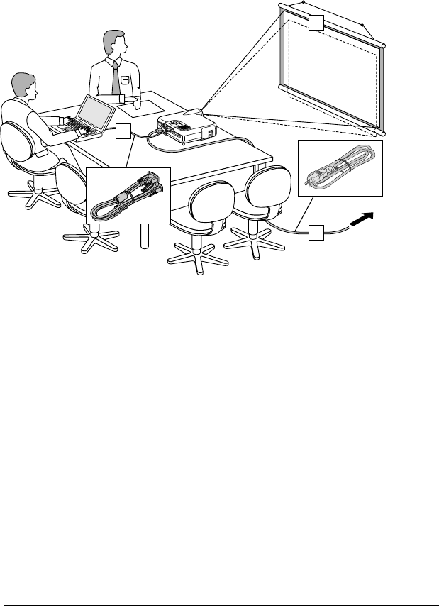
You can use the projector on a tabletop or cart, you can use the projector
to project images from behind the screen, and the projector can be per-
manently mounted on a ceiling*1. The remote control can be used wirelessly.
*1Do not attempt to mount the projector on a ceiling yourself.
The projector must be installed by qualified technicians in order to en-
sure proper operation and reduce the risk of bodily injury.
In addition, the ceiling must be strong enough to support the projector
and the installation must be in accordance with any local building codes.
Please consult your dealer for more information.
Features you'll enjoy:
•The newly developed 3D Reform function allows you to correct trap-
ezoidal distortion for both horizontally and vertically so that the im-
age is square even when projector is positioned off center of the
rooms screen.
•The LT260/LT240/LT220 projector provides wired and wireless net-
working. When using as a wireless LAN projector, no physical signal
cable connection to a PC is required.*2
*2A wireless LAN card is required. The NEC optional wireless LAN card is
available. (SWL-2100N-N∗)
E-3
INTRODUCTION
⬎
Introduction to the Projector
Safety protect by Passcode and Security functions
Passcode and Security features prevent the projector from being used by
unauthorized individuals.
Passcode prevents unauthorized individuals from changing projector set-
tings or adjustments Security offers complete protection by using your PC
card as a protect key so that the projector will not project a signal without
insertion of the registered PC card and unauthorized use can be discour-
aged.
•The built-in Viewer allows you to start your presentation even when a
PC is not available at the site.
•A high-bright 220 watt DC lamp.
•The Standby mode reduces standby power consumption significantly.
•The supplied wireless remote control that operates the projector from
the front side or rear.
•The image can be projected between 30 and 500 inches (measured
diagonally).
•The "Capture" enables you to capture the current projected image.
•An image can be projected from in front or behind a screen, and the
projector can even be installed on the ceiling.
•NEC’s exclusive Advanced AccuBlend intelligent pixel blending tech-
nology - an extremely accurate image compression technology - of-
fers a crisp image with UXGA (1600⳯1200) resolution*3.
•Supports most IBM VGA, SVGA, XGA , SXGA/UXGA(with Advanced
AccuBlend)*3, Macintosh, component signal (YCbCr/ YPbPr) or any
other RGB signals within a horizontal frequency range of 24 to 100
kHz and a vertical frequency range of 50 to 120 Hz. This includes
NTSC, PAL, PAL-N, PAL-M, PAL60, SECAM and NTSC4.43 stan-
dard video signals.
*3A UXGA (1600⳯1200) and SXGA image (1280⳯1024) are displayed
with NEC’s Advanced AccuBlend on LT260/LT240/LT220.
An XGA image (1024⳯768) is displayed with NEC’s Advanced
AccuBlend on LT220.

E-4
NOTE: Composite video standards are as follows:
NTSC: U.S. TV standard for video in U.S. and Canada.
PAL: TV standard used in Western Europe.
PAL-N: TV standard used in Argentine, Paraguay and Uruguay.
PAL-M: TV standard used in Brazil.
PAL60: TV standard used for NTSC playback on PAL TVs.
SECAM: TV standard used in France and Eastern Europe.
NTSC4.43: TV standard used in Middle East countries.
INTRODUCTION
⬎
Introduction to the Projector
E-5
•The supplied remote control can be used without a cable, and you
can even use the remote control to operate your PC's mouse wirelessly
from across the room with the built-in remote mouse function.
•You can control the projector with a PC using the PC Control port.
•USB port allows USB mouse operation*4.
*4The USB ports meet the USB1.1 specification.
•The contemporary cabinet design is light, compact, easy to carry,
and complements any office, boardroom or auditorium.
•Eight pointers are available for your presentation.
INTRODUCTION
⬎
Introduction to the Projector
E-6
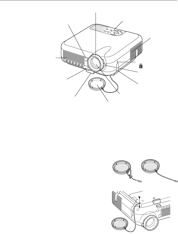
Part Names of the Projector
SELECT
C
N
A
C
E
L
T
E
R
N
E
E
M
N
U
SOURCEAUTO ADJUST
ON
STAND BY
STATUS
POWER
LAMP
ALIGNMENT
PC-CARD
INTRODUCTION
⬎
Part Names of the Projector
Ventilation (outlet)
Heated air is exhausted
from here
*This security slot supports the MicroSaver® Security System.
MicroSaver® is a registered trademark of Kensington Microware Inc.
The logo is trademarked and owned by Kensington Microware Inc.
Built-in Security Slot
( )*
Adjustable Tilt Foot Lever
(See page E-43)
Attaching the lens cap
1. Thread the string through the hole
on the lens cap and then tie a knot
in the string.
2. Use the rivet to attach the string to
the bottom of the projector.
To attach the lens cap to the bottom with the supplied string and rivet:
Remote Sensor
(See page E-20)
Focus Ring
(See page E-44)
Controls
(See page E-8)
Ventilation (inlet)
Zoom Lever
(See page E-44)
Carrying Handle
Lens Cap
Lens
Adjustable Tilt Foot
(See page E-43)
E-7
INTRODUCTION
⬎
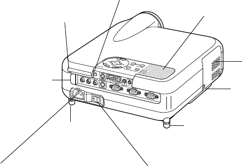
Part Names of the Projector
Monaural Speaker (2W)
AC Input
Connect the supplied power cable's three-pin
plug here, and plug the other end into an active
wall outlet.
(See page E-36)
Main Power Switch
When you plug the supplied power cable into an ac-
tive wall outlet and turn on the Main Power switch,
the POWER indicator turns orange and the projector
is in standby mode.
(See page E-37)
Remote Sensor
(See page E-20)
PC Card Slot
Rear Foot
Lamp cover
(See page E-118)
Lamp cover screw
Rear Foot
Rotate to make the projector level.
(See page E-44)
PC Card Eject Button
E-8
INTRODUCTION
⬎
Part Names of the Projector
910 45 11
678 121 3
2
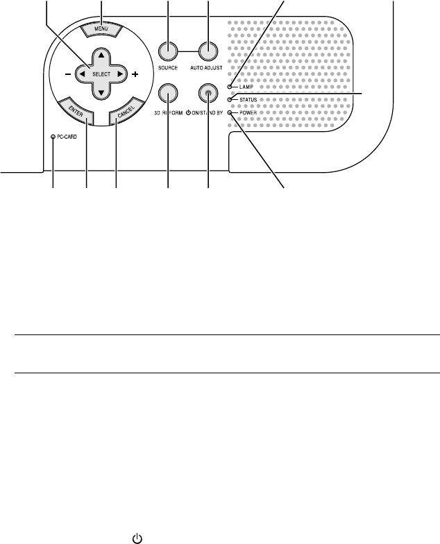
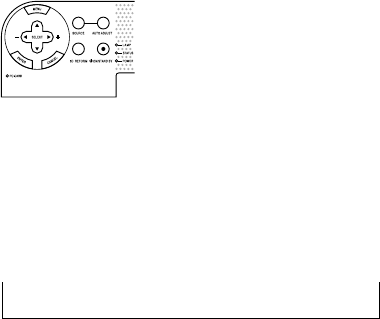
Top Features
1.POWER Button (ON / STAND BY)
Use this button to turn the power on and off when the main power is
supplied and the projector is in standby mode.
NOTE: To turn on or off the projector, press and hold this button for a mini-
mum of two seconds.
2. STATUS Indicator
If this light blinks red rapidly, it indicates that an error has occurred, the
lamp cover is not attached properly or the projector has overheated. If
this light remains orange, it indicates that you have pressed a cabinet
key while the Control Panel Key Lock is enabled. See the Status Indi-
cator section on page E-123 for more details.
3. POWER Indicator ( )
When this indicator is green, the projector is on; when this indicator is
orange, it is in standby or idle mode. See the Power Indicator section
on page E-123 for more details.
E-9
INTRODUCTION
⬎
Part Names of the Projector
⬎
Top Features
4. SOURCE Button
Use this button to select a video source such as a PC, VCR, DVD
player, Viewer (PC card), or LAN.
Press and release this button quickly to display the Source List.
Each time this button is pressed for a minimum of TWO seconds, the
input source will change as follows:
RGB1 → RGB2 → Video → S-Video → Viewer → RGB1 → ...
If no input signal is present, the input will be skipped.
5. AUTO ADJUST Button
Use this button to adjust Position-H/V and Pixel Clock/Phase for an
optimal picture. Some signals may not be displayed correctly or take
time to switch between sources.
6. PC CARD Access Indicator
Lights while accessing a PC card.
7. ENTER Button
Executes your menu selection and activates items selected from the
menu.
8. CANCEL Button
Press this button to exit "Menus". Press this button to return the adjust-
ments to the last condition while you are in the adjustment or setting
menu.
9. SELECT (+) (–) / Volume Buttons
: Use these buttons to select the menu of the item you wish to
adjust. When no menus appear, these buttons work as a volume
control.
E-10
: Use these buttons to change the level of a selected menu item.
A press of the button executes the selection. When the menus
or the Viewer tool bar is not displayed, these buttons can be
used to select a slide, or to move the cursor in Folder List or
Slide List.
When the pointer is displayed, these buttons move the pointer.
10. MENU Button
Displays the menu.
11. LAMP Indicator
If this light blinks red rapidly, it's warning you that the projection lamp
has exceeded 1500 hours (up to 2000 hours in Eco mode) of service.
After this light appears, replace the lamp as soon as possible. (See
page E-118). If this is lit green continually, it indicates that the lamp
mode is set to Eco. See the Lamp Indicator section on page E-124 for
more details.
12. 3D REFORM Button
Press this button to enter 3D Reform mode to correct the keystone
(trapezoidal) distortion, and make the image square.
INTRODUCTION
⬎
Part Names of the Projector
⬎
Top Features
E-11
INTRODUCTION
⬎
Part Names of the Projector
⬎
Terminal Panel Features
10 11 3 5
421678
91213
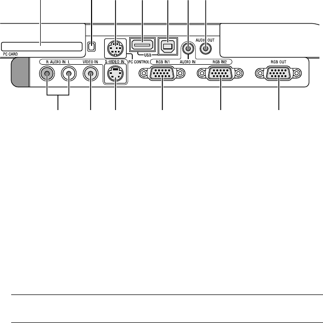
Terminal Panel Features
1. RGB IN 1 / Component Input Connector (Mini D-Sub 15 Pin)
Connect your computer or other analog RGB equipment such as IBM
compatible or Macintosh computers. Use the supplied RGB cable to
connect to your computer. This also serves as a component input con-
nector that allows you to connect a component video output of compo-
nent equipment such as a DVD player. This connector also supports
SCART output signal. See page E-29 for more details.
2. RGB IN 2 / Component Input Connector (Mini D-Sub 15 Pin)
This connector has the same function as the RGB IN 1 connector.
NOTE: The RGB IN 2 does not support SCART output signal and Plug &
Play.
3. RGB AUDIO IN Mini Jack (Stereo Mini)
This is where you connect audio output from your computer or DVD
player. A commercially available audio cable is required.
4. RGB OUT Connector (Mini D-Sub 15 Pin)
You can use this connector to loop your computer image to an external
monitor from the RGB 1 or 2 input source.
The RGB analog signal set on RGBOUT Terminal is output during idle
mode. See pages E-32 and 100.

E-12
INTRODUCTION
⬎
Part Names of the Projector
⬎
Terminal Panel Features
5. AUDIO OUT Mini Jack (Stereo Mini)
Connect an additional audio equipment here to listen to audio coming
from your computer, Video or S- Video input.
Note that there is no audio output from this jack during Standby and
Idle.
6 S-VIDEO IN Connector (Mini DIN 4 Pin)
Here is where you connect the S-Video input from an external source
like a VCR.
NOTE: S-Video provides more vivid color and higher resolution than the tra-
ditional composite video format.
7. VIDEO IN Connector (RCA)
Connect a VCR, DVD player, laser disc player, or document camera
here to project video.
8. VIDEO AUDIO IN Jacks (RCA)
L : This is your left channel audio input for stereo sound coming from
the VIDEO source.
R : This is your right channel audio input for stereo sound from the
VIDEO source.
9. PC CONTROL Port (Mini DIN 8 Pin)
Use this port to connect your PC to control your projector via a serial
cable. This enables you to use your PC and serial communication pro-
tocol to control the projector. The NEC optional serial cable (CA03D) is
required to use this port. You can also control the projector by using
Dynamic Image Utility 2.0 included on the supplied CD-ROM.
To do so you must first have Dynamic Image Utility 2.0 installed on your
PC. If you are writing your own program, typical PC control codes are
on page E-133. A cap is put on the port at the factory. Remove the cap
when using the port.
E-13
10. USB Port (Type A)
Connect a commercially available mouse that supports USB. You can
operate the menu or Viewer with the USB mouse via this port.
Note that this port should not be connected to a computer and that
there may be some brands of USB mouse that the projector does not
support.
11. USB Port (Type B)
Connect this port to the USB port (type A) of your PC using the sup-
plied USB cable. You can operate your computer's mouse functions
from the remote control.
12. PC CARD Eject Button
Press to eject a PC card partially.
13. PC CARD Slot
Insert a PC card, commercially available LAN card or NEC optional
wireless LAN card here.
INTRODUCTION
⬎
Part Names of the Projector
⬎
Terminal Panel Features
E-14
Part Names of the Remote Control
M
E
N
U
PJ
ASPECT
OFF
VIDEO
AUTO ADJ.
S-VIDEO RGB1 RGB2
LASER
ON
3D REFORM
HELP
POINTER
VOLUME MAGNIFY
PICTURE
PIC-MUTE
VIEWER
SLIDE
FOLDER
SLIDE
LIST
E
N
T
E
R
C
A
N
C
E
L
POWER
SELECT
FREEZE
16
21
19
26
27
28
29
17
20
22
24
25
23
1514
12
1110
96 8
7
4
5
3
18
13
INTRODUCTION
⬎
Part Names of the Remote Control
PJ
A
SPECT
FREEZE
3D REFORM
POINTER
NIF
Y
VIEWER
SLIDE
OFF
VIDEO
AUTO ADJ.
S-VIDEO RGB1 RGB2
LASER
ON
POWER
SELECT
2 1
NOTE: If you are using a Macintosh com-
puter, you can click either the right-click
or left-click button to activate the mouse.
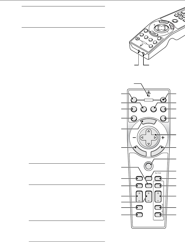
1. Infrared Transmitter
Direct the remote control toward
the remote sensor on the projector
cabinet.
2. LASER Pointer
Beams a laser light when the LA-
SER button is pressed.
3. LED
Flashes when any button is
pressed.
4. POWER ON Button
If the main power is applied, you
can use this button to turn your pro-
jector on.
NOTE: To turn on the projector, press
and hold the POWER ON button for a
minimum of two seconds.
5. POWER OFF Button
You can use this button to turn your
projector off.
NOTE: To turn off the projector, press
and hold the POWER OFF button for
a minimum of two seconds.
E-15
INTRODUCTION
⬎
Part Names of the Remote Control
6. VIDEO Button
Press this button to select an NTSC, PAL, PAL-N, PAL-M, PAL60,
SECAM or NTSC4.43 compatible video source from a VCR, DVD player,
or laser disc player.
7. S-VIDEO Button
Press this button to select an S-Video source from a VCR.
8. RGB 1 Button
Press this button to select a video source from computer or component
equipment connected to your RGB IN 1 port.
9. RGB 2 Button
Press this button to select a video source from computer or component
equipment connected to your RGB IN 2 port.
10. AUTO ADJ Button
Use this button to adjust an RGB source for an optimal picture. Some
signals may not be displayed correctly or take time to be displayed.
See page E-48.
11. LASER Button
Press and hold this button to activate the laser pointer. When lit, you
can use the laser to draw your audience's attention to a red dot that
you can place on any object.
12. MENU Button
Displays the menu for various settings and adjustments.
E-16
INTRODUCTION
⬎
Part Names of the Remote Control
13. SELECT (Mouse) Button
When you are in the Computer mode, these buttons work as a com-
puter mouse. When you are in the Projector mode, which is indicated
by lighting the PJ button. See page E-53.
:Use these buttons to select the menu of the item you wish to
adjust.
:Use these buttons to change the level of a selected menu item.
A press of the button executes the selection.
When the pointer is displayed, these buttons move the pointer.
When the pointer is not displayed, these buttons are for adjust-
ing the image.
14. ENTER (Left Click) Button
When you are in the Computer mode, this button works as the mouse
left button. When this button is pressed and held for a minimum of 2
seconds, the drag mode is set. When you are in the Projector mode,
which is indicated by lighting the PJ button:
Use this button to enter your menu selection. It works the same way as
the ENTER button on the cabinet. See page E-9.
15. CANCEL (Right Click) Button
When you are in the Computer mode, this button works as the mouse
right button. When you are in the Projector mode, which is indicated by
lighting the PJ button: Press this button to exit the Menus. It works the
same way as the CANCEL button on the cabinet.
16. PJ Button
Press this button to switch the SELECT, CANCEL, and ENTER but-
tons between the Projector mode (lit red) and the Computer mode.
Press this button or any one of the POWER ON/OFF, MENU, ASPECT,
3D REFORM, HELP, POINTER, MAGNIFY, PICTURE, VIEWER,
FOLDER LIST or SLIDE LIST buttons to switch to the Projector mode
and the PJ button lights red. To switch back to the Computer mode,
press the PJ button again. See page E-53.
E-17
INTRODUCTION
⬎
Part Names of the Remote Control
17. ASPECT Button
Press this button to display the Aspect Ratio select screen. See page
E-86.
18. FREEZE Button
This button will freeze a picture. Press again to resume motion.
19. 3D REFORM Button
Press this button to enter 3D Reform to correct the keystone (trapezoi-
dal) distortion, and make the image square. See page E-45.
20. HELP Button
Provides the online help or the set information.
21. POINTER Button
Press this button to display one of the eight pointers; press again to
hide the pointer. You can move your pointer icon to the area you want
on the screen using the Select button. See page E-55.
22. VOLUME (+) (–) Button
Press (+) to increase the volume and (–) to decrease it.
23. MAGNIFY (+) (–) Button
Use this button to adjust the image size up to 400%. When the pointer
is displayed, the image is magnified about the center of the pointer.
When the pointer is not displayed, the image is magnified about the
center of the screen. When the image is magnified, the pointer is
changed to the magnifying icon. See page E-56.
24. PICTURE Button
Press this button to display the Picture adjustement screen such as
Brightness, Contrast, Color, Hue, and Sharpness. See page E-85.

E-18
25. PICTURE MUTE Button
This button turns off the image and sound for a short period of time.
Press again to restore the image and sound.
NOTE: When the menu is displayed, a press of this button mutes an image and
sound without turning off the menu.
26. VIEWER Button
Press this button to select the Viewer source.
27. SLIDE (+) (–) Button
Press (+) to select the next folder or slide and (–) to select the previous
folder or slide. See page E-67.
28. FOLDER LIST Button
Press this button to select Viewer source to display a list of folders
included in a PC card. See page E-67.
29. SLIDE LIST Button
Press this button to select Viewer source to display a list of slides in-
cluded in a PC card. See page E-67.
NOTE: The default is the Computer mode, which allows you to use the SE-
LECT, CANCEL, and ENTER buttons as your computer mouse. When the
POWER ON/OFF, MENU, ASPECT, 3D REFORM, HELP, POINTER, MAG-
NIFY, PICTURE, VIEWER, FOLDER LIST, or SLIDE LIST button is pressed,
the PJ button lights red to indicate that you are in the Projector mode. If no
buttons are pressed within 60 seconds, the light goes out and the Projector
mode is canceled.
INTRODUCTION
⬎
Part Names of the Remote Control
E-19
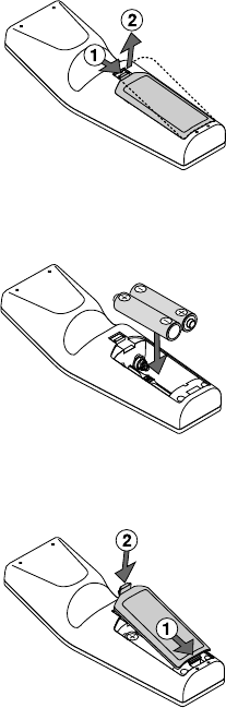
Battery Installation
1. Press firmly and slide the battery cover off.
2. Remove both old batteries and install new ones (AA). Ensure that you
have the batteries' polarity (+/-) aligned correctly.
3. Slip the cover back over the batteries until it snaps into place. Do not mix
different types of batteries or new and old batteries.
Note on Remote Control Operation:
If you press and hold the SELECT button while installing new
batteries, the remote control may fail to work properly.
Should this happen, remove the batteries and then install them again with-
out touching the SELECT button.
INTRODUCTION
⬎
Part Names of the Remote Control
E-20
Remote Control Precautions
• Handle the remote control carefully.
• If the remote control gets wet, wipe it dry immediately.
•Avoid excessive heat and humidity.
•If you will not be using the remote control for a long time, remove the
batteries.
•Do not place the batteries upside down.
•Do not use new and old batteries together, or use different types of
batteries together
INTRODUCTION
⬎
Part Names of the Remote Control
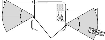
30
˚
30
˚
30
˚
30
˚
Operating Range
7m/22 feet
7m/22 feet
Remote control
Remote sensor on the
projector cabinet
•The infrared signal operates by line-of-sight up to a distance of about
22 feet/7 m and within a 60-degree angle of the remote sensor on the
projector cabinet.
•The projector will not respond if there are objects between the re-
mote control and the sensor, or if strong light falls on the sensor.
Weak batteries will also prevent the remote control from properly
operating the projector.
E-21
INSTALLATION AND CONNECTIONS
This section describes how to set up your projector and how to connect
video and audio sources.
3
1
2
Your projector is simple to set up and use. But before you get started, you
must first:
zSet up a screen and the projector.
xConnect your computer or video equipment to the projector. See page E-
28.
cConnect the supplied power cable. See page E-36.
NOTE: Ensure that the power cable and any other cables are disconnected
before moving the projector.
When moving the projector or when it is not in use, cover the lens with the lens
cap.
To the wall outlet.
E-22
INSTALLATION AND CONNECTIONS
⬎
Setting Up the Screen and theProjector
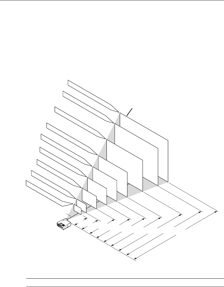
406.4(W) X 304.8(H)
365.8(W) X 274.3(H)
304.8(W) X 228.6(H)
243.8(W) X 182.9(H)
203.2(W) X 152.4(H)
162.6(W) X 121.9(H)
121.9(W) X 91.4(H)
81.3(W) X 61.0(H)
61.0(W) X 45.7(H)
Screen size (Unit: cm/inch)
Lens center
Screen size
Distance (Unit: m/feet)
1.7/5.6
(1.3/4.3)
2.6/8.5
(2.0/6.6)
3.5/11.5
(2.7/8.9)
4.4/14.4
(3.4/11.2)
5.3/17.4
(4.1/13.5)
6.6/21.7
(5.2/17.1)
7.9/25.9
(6.2/20.34)
8.8/28.9
(6.9/22.6)
1.3/4.3
(1.0/3.3)
200"
180"
150"
120"
100"
80"
60"
40"
30"
Selecting a Location
The further your projector is from the screen or wall, the larger the image.
The minimum size the image can be is approximately 30" (0.8 m) mea-
sured diagonally when the projector is roughly 4 feet (1.3 m) from the wall
or screen. The largest the image can be is 500" (12.7 m) when the projec-
tor is about 80.83 feet (24.64 m) from the wall or screen. Use the drawing
below as a guide.
Setting Up the Screen and the Projector
NOTE: Values in parentheses for LT240.
E-23
INSTALLATION AND CONNECTIONS
⬎
Setting Up the Screen and theProjector
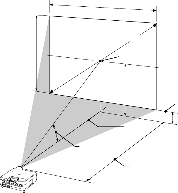
Distance Chart
B = Vertical distance between lens center and screen center
C = Throw distance
D = Vertical distance between lens center and bottom of screen
α = Throw angle
Lens Center
Throw Angle (움)
Throw Distance (C)
Screen center
Screen Diagonal
Screen Width
Screen Height
Screen Bottom
(B)
(D)
Throw Distance and Screen Size
The following shows the proper relative positions of the projector and screen.
Refer to the table to determine the position of installation.

E-24
INSTALLATION AND CONNECTIONS
⬎
Setting Up the Screen and theProjector
<LT260>
B = Vertical distance between lens center and screen center
C = Throw distance
D = Vertical distance between lens center and bottom of screen
α = Throw angle
NOTE: Distances may vary +/-5%.
α
Wide – Tele
inch
24
32
48
54
58
64
67
72
80
96
120
144
160
168
192
209
216
240
280
320
360
400
inch
18
24
36
40
43
48
50
54
60
72
90
108
120
126
144
157
162
180
210
240
270
300
Screen Size B C
Wide – Tele D
inch
30
40
60
67
72
80
84
90
100
120
150
180
200
210
240
261
270
300
350
400
450
500
Diagonal Width Height inch
46.4 – 57.0
62.4 – 76.4
94.5 – 115.3
105.8 – 128.9
113.8 – 138.6
126.6 – 154.1
133.0 – 161.9
142.7 – 173.6
158.7 – 193.0
190.8 – 231.8
239.0 – 290.1
287.1 – 348.4
319.2 – 387.2
335.3 – 406.7
383.4 – 464.9
417.1 – 505.7
431.6 – 523.2
479.7 – 581.5
560.0 – 678.6
640.2 – 775.7
720.5 – 872.9
800.7 – 970.0
inch
3.6
4.8
7.3
8.1
8.7
9.7
10.2
10.9
12.1
14.5
18.2
21.8
24.2
25.4
29.1
31.6
32.7
36.3
42.4
48.5
54.5
60.6
degree
15.2 - 12.5
15.1 - 12.4
15.0 - 12.4
14.9 - 12.3
14.9 - 12.3
14.9 - 12.3
14.9 - 12.3
14.9 - 12.3
14.9 - 12.3
14.8 - 12.3
14.8 - 12.3
14.8 - 12.3
14.8 - 12.3
14.8 - 12.3
14.8 - 12.3
14.8 - 12.3
14.8 - 12.3
14.8 - 12.3
14.7 - 12.3
14.7 - 12.3
14.7 - 12.2
14.7 - 12.2
inch
12.6
16.8
25.3
28.2
30.3
33.7
35.4
37.9
42.1
50.5
63.2
75.8
84.2
88.4
101.1
109.9
113.7
126.3
147.4
168.5
189.5
210.6
mm
762
1016
1524
1702
1829
2032
2134
2286
2540
3048
3810
4572
5080
5334
6096
6629
6858
7620
8890
10160
11430
12700
mm
610
813
1219
1361
1463
1626
1707
1829
2032
2438
3048
3658
4064
4267
4877
5304
5486
6096
7112
8128
9144
10160
mm
457
610
914
1021
1097
1219
1280
1372
1524
1829
2286
2743
3048
3200
3658
3978
4115
4572
5334
6096
6858
7620
Diagonal Width Height
Screen Size B C
Wide – Tele Dα
Wide – Tele
degree
15.2 - 12.5
15.1 - 12.4
15.0 - 12.4
14.9 - 12.3
14.9 - 12.3
14.9 - 12.3
14.9 - 12.3
14.9 - 12.3
14.9 - 12.3
14.8 - 12.3
14.8 - 12.3
14.8 - 12.3
14.8 - 12.3
14.8 - 12.3
14.8 - 12.3
14.8 - 12.3
14.8 - 12.3
14.8 - 12.3
14.7 - 12.3
14.7 - 12.3
14.7 - 12.2
14.7 - 12.2
mm
321
428
642
716
770
855
898
962
1069
1283
1604
1925
2139
2246
2567
2792
2888
3209
3744
4279
4814
5349
mm
1178 - 1448
1586 - 1942
2401 - 2928
2686 - 3274
2890 - 3520
3216 - 3915
3379 - 4113
3624 - 4409
4032 - 4902
4847 - 5889
6070 - 7369
7293 - 8849
8108 - 9836
8516 -10329
9739 -11810
10595 -12846
10962 -13290
12185 -14770
14223 -17237
16261 -19704
18299 -22171
20338 -24638
mm
92
123
184
206
221
246
258
277
307
369
461
554
615
646
738
803
831
923
1077
1231
1385
1539

E-25
INSTALLATION AND CONNECTIONS
⬎
Setting Up the Screen and theProjector
<LT240>
B = Vertical distance between lens center and screen center
C = Throw distance
D = Vertical distance between lens center and bottom of screen
α = Throw angle
NOTE: Distances may vary +/-5%.
α
Wide – Tele
inch
24
32
48
54
58
64
67
72
80
96
120
144
160
168
192
209
216
240
280
320
360
400
inch
18
24
36
40
43
48
50
54
60
72
90
108
120
126
144
157
162
180
210
240
270
300
Screen Size B C
Wide – Tele D
inch
30
40
60
67
72
80
84
90
100
120
150
180
200
210
240
261
270
300
350
400
450
500
Diagonal Width Height inch
12.6
16.8
25.2
28.1
30.2
33.6
35.3
37.8
42.0
50.4
63.0
75.6
84.0
88.2
100.8
109.7
113.4
126.1
147.1
168.1
189.1
210.1
inch
35.7 - 43.4
48.2 - 58.4
73.2 - 88.5
81.9 - 99.0
88.1 - 106.5
98.1 - 118.6
103.1 - 124.6
110.6 - 133.6
123.1 - 148.6
148.1 - 178.7
185.5 - 223.8
223.0 - 268.9
248.0 - 298.9
260.5 - 314.0
297.9 - 359.1
324.1 - 390.6
335.4 - 404.1
372.8 - 449.2
435.3 - 524.4
497.7 - 599.6
560.1 - 674.7
622.5 - 749.9
inch
3.6
4.8
7.2
8.0
8.6
9.6
10.1
10.8
12.0
14.4
18.0
21.6
24.0
25.2
28.8
31.4
32.4
36.1
42.1
48.1
54.1
60.1
degree
19.4 - 16.2
19.2 - 16.0
19.0 - 15.9
19.0 - 15.9
18.9 - 15.8
18.9 - 15.8
18.9 - 15.8
18.9 - 15.8
18.8 - 15.8
18.8 - 15.8
18.8 - 15.7
18.7 - 15.7
18.7 - 15.7
18.7 - 15.7
18.7 - 15.7
18.7 - 15.7
18.7 - 15.7
18.7 - 15.7
18.7 - 15.7
18.7 - 15.7
18.7 - 15.7
18.6 - 15.7
mm
762
1016
1524
1702
1829
2032
2134
2286
2540
3048
3810
4572
5080
5334
6096
6629
6858
7620
8890
10160
11430
12700
mm
610
813
1219
1361
1463
1626
1707
1829
2032
2438
3048
3658
4064
4267
4877
5304
5486
6096
7112
8128
9144
10160
mm
457
610
914
1021
1097
1219
1280
1372
1524
1829
2286
2743
3048
3200
3658
3978
4115
4572
5334
6096
6858
7620
Diagonal Width Height
Screen Size B C
Wide – Tele Dα
Wide – Tele
mm
320
426
640
715
768
853
896
960
1067
1280
1601
1921
2134
2241
2561
2785
2881
3202
3735
4269
4803
5336
mm
907 - 1102
1224 - 1484
1858 - 2248
2080 - 2515
2239 - 2706
2493 - 3011
2620 - 3164
2810 - 3393
3127 - 3775
3761 - 4538
4713 - 5684
5664 - 6829
6298 - 7593
6615 - 7975
7567 - 9120
8233 - 9922
8518 -10265
9470 -11411
11055 -13320
12641 -15229
14227 -17138
15813 -19046
mm
91
122
183
204
219
244
256
274
305
366
458
549
610
641
732
797
824
916
1068
1221
1374
1526
degree
19.4 - 16.2
19.2 - 16.0
19.0 - 15.9
19.0 - 15.9
18.9 - 15.8
18.9 - 15.8
18.9 - 15.8
18.9 - 15.8
18.8 - 15.8
18.8 - 15.8
18.8 - 15.7
18.7 - 15.7
18.7 - 15.7
18.7 - 15.7
18.7 - 15.7
18.7 - 15.7
18.7 - 15.7
18.7 - 15.7
18.7 - 15.7
18.7 - 15.7
18.7 - 15.7
18.6 - 15.7

E-26
INSTALLATION AND CONNECTIONS
⬎
Setting Up the Screen and theProjector
<LT220>
B = Vertical distance between lens center and screen center
C = Throw distance
D = Vertical distance between lens center and bottom of screen
α = Throw angle
NOTE: Distances may vary +/-5%.
α
Wide – Tele
inch
24
32
48
54
58
64
67
72
80
96
120
144
160
168
192
209
216
240
280
320
360
400
inch
18
24
36
40
43
48
50
54
60
72
90
108
120
126
144
157
162
180
210
240
270
300
Screen Size B C
Wide – Tele D
inch
30
40
60
67
72
80
84
90
100
120
150
180
200
210
240
261
270
300
350
400
450
500
Diagonal Width Height inch
13.0
17.4
26.0
29.1
31.2
34.7
36.4
39.0
43.4
52.1
65.1
78.1
86.8
91.1
104.1
113.2
117.1
130.1
151.8
173.5
195.2
216.9
inch
48.0 - 59.0
64.5 - 79.0
97.6 - 119.0
109.1 - 133.0
117.4 - 143.0
130.6 - 159.0
137.2 - 167.0
147.1 - 179.0
163.7 - 199.0
196.7 - 239.0
246.3 - 299.0
295.9 - 359.0
328.9 - 399.0
345.4 - 419.0
395.0 - 479.0
429.7 - 521.0
444.6 - 539.0
494.2 - 599.0
576.8 - 699.0
659.4 - 799.0
742.0 - 899.0
824.7 - 999.0
inch
4.0
5.4
8.0
9.0
9.6
10.7
11.2
12.0
13.4
16.1
20.1
24.1
26.8
28.1
32.1
34.9
36.1
40.1
46.8
53.5
60.2
66.9
degree
15.2 - 12.4
15.1 - 12.4
14.9 - 12.3
14.9 - 12.3
14.9 - 12.3
14.9 - 12.3
14.9 - 12.3
14.9 - 12.3
14.8 - 12.3
14.8 - 12.3
14.8 - 12.3
14.8 - 12.3
14.8 - 12.3
14.8 - 12.3
14.8 - 12.3
14.8 - 12.3
14.8 - 12.3
14.8 - 12.3
14.7 - 12.3
14.7 - 12.3
14.7 - 12.2
14.7 - 12.2
mm
762
1016
1524
1702
1829
2032
2134
2286
2540
3048
3810
4572
5080
5334
6096
6629
6858
7620
8890
10160
11430
12700
mm
610
813
1219
1361
1463
1626
1707
1829
2032
2438
3048
3658
4064
4267
4877
5304
5486
6096
7112
8128
9144
10160
mm
457
610
914
1021
1097
1219
1280
1372
1524
1829
2286
2743
3048
3200
3658
3978
4115
4572
5334
6096
6858
7620
Diagonal Width Height
Screen Size B C
Wide – Tele Dα
Wide – Tele
mm
331
441
661
738
793
882
926
992
1102
1322
1653
1983
2203
2314
2644
2875
2975
3305
3856
4407
4958
5508
mm
1219 - 1498
1639 - 2006
2478 - 3022
2772 - 3378
2982 - 3632
3318 - 4038
3485 - 4242
3737 - 4546
4157 - 5054
4996 - 6070
6256 - 7595
7515 - 9119
8354 -10135
8774 -10643
10033 -12167
10915 -13234
11292 -13691
12552 -15215
14650 -17755
16749 -20295
18848 -22835
20946 -25375
mm
102
136
204
228
245
272
286
306
340
408
510
612
679
713
815
887
917
1019
1189
1359
1529
1698
degree
15.2 - 12.4
15.1 - 12.4
14.9 - 12.3
14.9 - 12.3
14.9 - 12.3
14.9 - 12.3
14.9 - 12.3
14.9 - 12.3
14.8 - 12.3
14.8 - 12.3
14.8 - 12.3
14.8 - 12.3
14.8 - 12.3
14.8 - 12.3
14.8 - 12.3
14.8 - 12.3
14.8 - 12.3
14.8 - 12.3
14.7 - 12.3
14.7 - 12.3
14.7 - 12.2
14.7 - 12.2
E-27
WARNING
*Installing your projector on the ceiling must be done by a qualified tech-
nician. Contact your NEC dealer for more information.
*Do not attempt to install the projector yourself.
•Only use your projector on a solid, level surface. If the projector falls to
the ground, you can be injured and the projector severely damaged.
•Do not use the projector where temperatures vary greatly. The projector
must be used at temperatures between 41˚F (5˚C) and 95˚F (35˚C).
•Do not expose the projector to moisture, dust, or smoke. This will harm
the screen image.
•Ensure that you have adequate ventilation around your projector so
heat can dissipate. Do not cover the vents on the side or the front of the
projector.
Reflecting the Image
Using a mirror to reflect your projector's image enables you to enjoy a
much larger image. Contact your NEC dealer if you need a mirror. If you're
using a mirror and your image is inverted, use the MENU and SELECT
buttons on your projector cabinet or buttons on your remote control to
correct the orientation. (See page E-95.)
INSTALLATION AND CONNECTIONS
⬎
Setting Up the Screen and theProjector

E-28
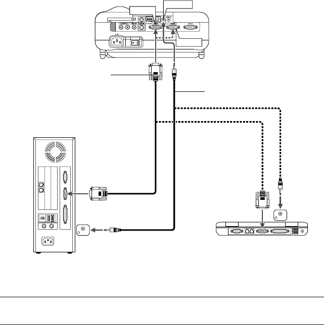
Making Connections
INSTALLATION AND CONNECTIONS
VCR, DVD Player or
LaserDisc Player
Macintosh
(Desktop type or notebook type)
IBM VGA or Compatibles
(Desktop type or notebook type)
DVD Player
(with component output)
Document Camera
To video, S-video, and au-
dio inputs on the projector.
Optional 15-pin-to-RCA
(female)⳯3 cable
(ADP-CV1)
RGB Signal cable (supplied)
To mini D-Sub 15-pin connector on the pro-
jector. It is recommended that you use a com-
mercially available distribution amplifier if con-
necting a signal cable longer than the sup-
plied cable.
Monitor
NOTE: When using with a notebook PC, be sure to connect between the projector
and the notebook PC before turning on the power to the notebook PC. In most
cases signal cannot be output from RGB output unless the notebook PC is turned
on after connecting with the projector.
*If the screen goes blank while using your remote control, it may be the result of
the computer's screen-saver or power management software.
*If you accidentally hit the POWER button on the remote control, wait 90 sec-
onds and then press the POWER button again to resume.
Wiring Diagram
E-29
INSTALLATION AND CONNECTIONS
⬎
Making Connections
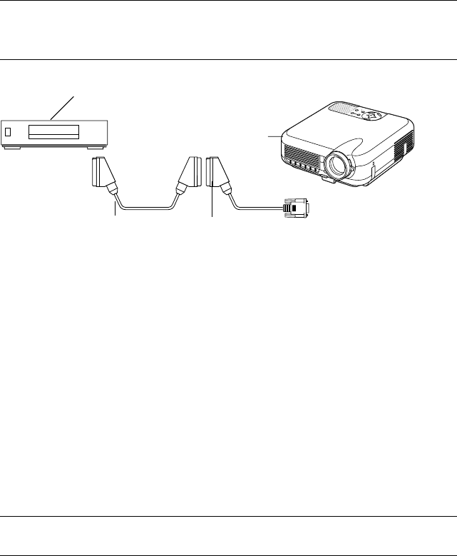
To connect SCART output (RGB)
Before connections: An exclusive SCART adapter (ADP-SC1) and a com-
mercially available SCART cable are required for this connection.
NOTE:
•Audio signal is not available for this connection.
•The RGB IN 2 connector does not support SCART signal and Plug & Play.
SELECT
C
N
A
C
E
L
T
E
R
N
E
E
M
N
U
SOURCEAUTO ADJUST
ON
STAND BY
STATUS
POWER
LAMP
ALIGNMENT
PC-CARD
Video equipment
such as DVD player
Projector
ADP-SC1
Commercially available SCART cable Female
1. Turn off the power to the projector and your video equipment.
2. Use the NEC ADP-SC1 SCART adapter and a commercially available
SCART cable to connect the RGB 1 input of your projector and a SCART
output (RGB) of your video equipment.
3. Turn on the power to the projector and your video equipment.
4. Use the RGB 1 button on the remote control to select the RGB 1 input.
5. Press the MENU button on the remote control to display the menu.
6. From the Advanced menu, select [Projector Options] → [Setup] → [Page
3] → [Signal Select RGB1] → [Scart].
SCART is a standard European audio-visual connector for TVs, VCRs
and DVD players. It is also referred to as Euro-connector.
NOTE: The ADP-SC1 SCART adapter is obtainable from your NEC dealer in
Europe. Contact your NEC dealer in Europe for more information.
To RGB IN 1
E-30
INSTALLATION AND CONNECTIONS
⬎
Making Connections
Connecting Your PC or Macintosh Computer
PHONE
RGB IN1
RGB IN2
AUDIO IN
PHONE
Audio cable (not supplied)
IBM VGA or Compatibles (Note-
book type) or Macintosh (Note-
book type)
IBM VGA or Compatibles (Desktop type)
or Macintosh (Desktop type)
RGB signal cable (supplied)
To mini D-Sub 15-pin connector on the
projector. It is recommended that you use
a commercially available distribution am-
plifier if connecting a signal cable longer
than the supplied one.
NOTE: For older Macintosh, use a commercially available pin adapter (not sup-
plied) to connect to your Mac's video port.

E-31
INSTALLATION AND CONNECTIONS
⬎
Making Connections
Connecting your PC or Macintosh computer to your projector will enable
you to project your computer's screen image for an impressive presenta-
tion.
To connect to a PC or Macintosh, simply:
1. Turn off the power to your projector and computer.
2. Use the supplied signal cable to connect your PC or Macintosh to the
projector.
3. Turn on the projector and the computer.
4. If the projector goes blank after a period of inactivity, it may be caused
by a screen saver installed on the computer you've connected to the pro-
jector.
NOTE: The LT260/LT240/LT220 is not compatible with video decoded outputs of
NEC ISS-6020 and ISS-6010.
E-32
INSTALLATION AND CONNECTIONS
⬎
Making Connections
RGB OUT
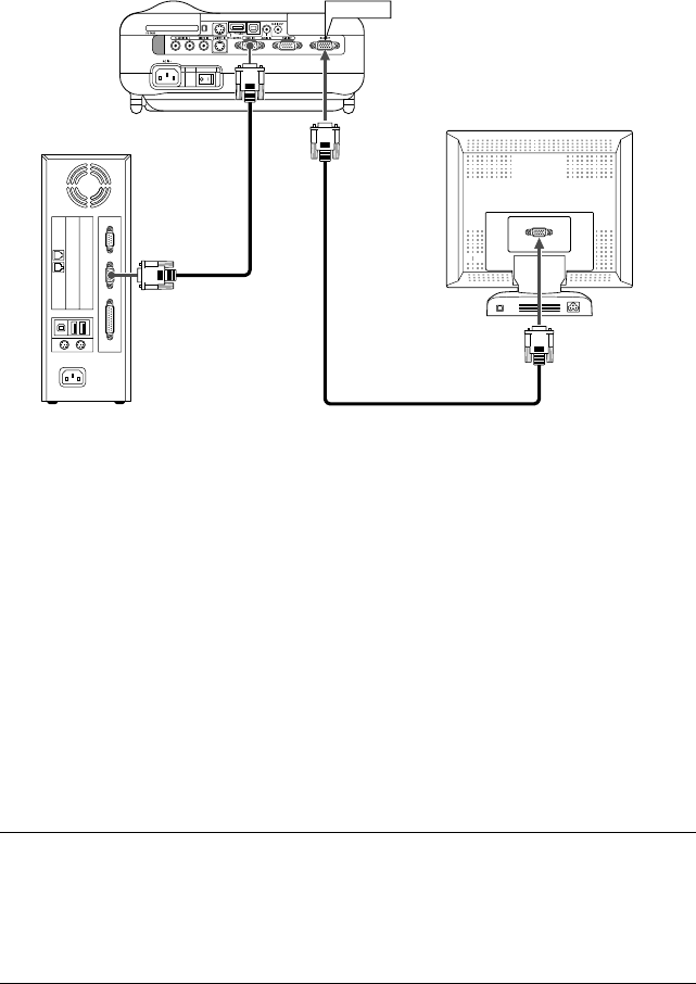
Connecting an External Monitor
You can connect a separate, external monitor to your projector to simulta-
neously view on a monitor the RGB analog image you're projecting. To do
so:
1. Turn off the power to your projector, monitor and computer.
2. Use a 15-pin cable to connect your monitor to the RGB OUT (Mini D-Sub
15 pin) connector on your projector.
3. Turn on the projector, monitor and the computer.
NOTE: The RGB OUT connector outputs RGB signal during idle mode (See page
E-100). When the projector goes into idle mode, the image on an external monitor
disappears for a moment. Note that the RGB OUT connector will not output RGB
signal during Stanby mode.
• Daisy chain connection is not possible.
E-33
INSTALLATION AND CONNECTIONS
⬎
Making Connections
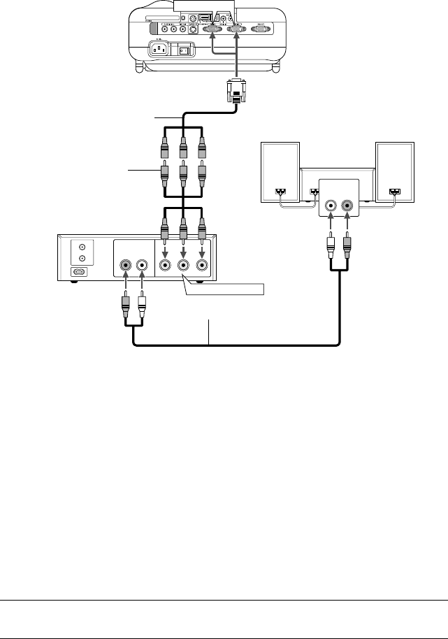
Connecting Your Video Equipment
RGB IN1 or IN2
AUDIO OUT
RL
COMPONENT OUT
AUDIO IN
LR
DVD player
Connecting Your DVD Player
Audio Equipment
Optional 15-pin-to-RCA
(female)⳯3 cable (ADP-CV1)
Audio cable (not supplied)
You can connect your projector to a DVD player with component output or
Video output. To do so, simply:
1. Turn off the power to your projector and DVD player.
2. If your DVD player has the component video (Y,Cb,Cr) output, use a com-
mercially available component video cable (RCA⳯3) and the optional
15-pin-to-RCA (female)⳯3 cable to connect your DVD player to the RGB
IN1 or IN2 connector on the projector.
For a DVD player without component video (Y,Cb,Cr) output, use com-
mon RCA cables (not provided) to connect a composite VIDEO output of
the DVD player to the Video Input of the projector.
3. Turn on the projector and DVD player.
NOTE: Refer to your DVD player's owner's manual for more information about
your DVD player's video output requirements,
Component video
RCA⳯3 cable
(not supplied)
E-34
INSTALLATION AND CONNECTIONS
⬎
Making Connections
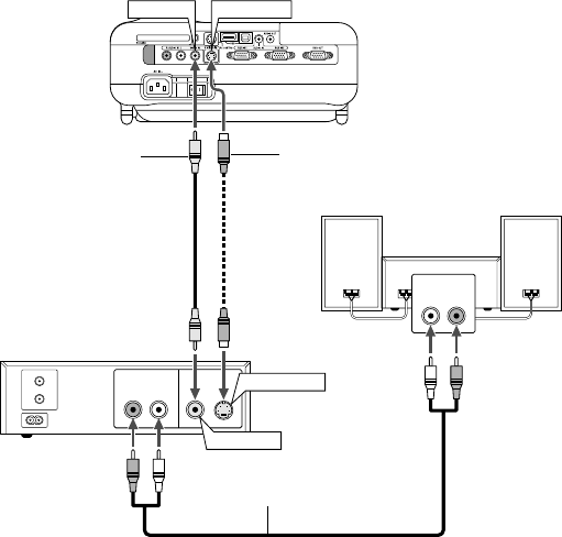
VCR/ Laser disc player
Connecting Your VCR or Laser Disc Player
VIDEO IN S-VIDEO IN
AUDIO OUT
RL
VIDEO OUT
S-VIDEO OUT
AUDIO IN
LR
Audio equipment
S-video cable (not supplied)
Video cable (not supplied)
Audio cable (not supplied)
Use common RCA cables (not provided) to connect your VCR, laser disc
player or document camera to your projector.
To make these connections, simply:
1. Turn off the power to the projector and VCR, laser disc player or docu-
ment camera.
2. Connect one end of your RCA cable to the video output connector on the
back of your VCR or laser disc player, connect the other end to the Video
input on your projector. Use an audio cable (not supplied) to connect the
audio from your VCR or laser disc player to your audio equipment (if
your VCR or laser disc player has this capability). Be careful to keep your
right and left channel connections correct for stereo sound.

E-35
3. Turn on the projector and the VCR or laser disc player.
NOTE: Refer to your VCR or laser disc player owner's manual for more informa-
tion about your equipment's video output requirements.
NOTE: An image may not be displayed correctly when a Video or S-Video source
is played back in fast-forward or fast-rewind via a scan converter.
INSTALLATION AND CONNECTIONS
⬎
Making Connections
E-36
INSTALLATION AND CONNECTIONS
⬎
Making Connections
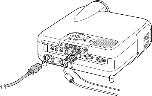
Connecting the Supplied Power Cable
Connect the supplied power cable to the projector.
First connect the supplied power cable's three-pin plug to the AC IN of the
projector, and then connect the other plug of the supplied power cable in
the wall outlet.

E-37
PROJECTING AN IMAGE
(BASIC OPERATION)
Tur ning on the Projector
This section describes how to turn on the projector and to project a picture
onto the screen.
NOTE:
•When plugging in or unplugging the supplied power cable, make sure that the
main power switch is pushed to the off[O] position. Failure to do so may
cause damage to the projector.
•The projector has two power switches: main power switch and POWER but-
ton (POWER ON and OFF on the remote control)
•The projector has a feature to prevent itself from being used by unauthorized
individuals. To use this feature, register your PC card as a protect key. See
"Security" in "Projector Options" on page E-111 for more details.
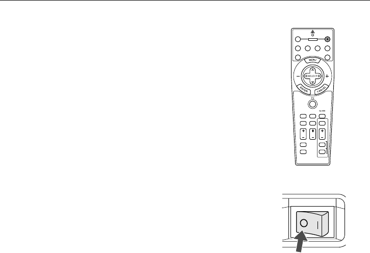
To turn on the main power to the projector, press the Main Power switch to
the ON position ( I ).
Before you turn on your projector, ensure that the computer or video source
is turned on and that your lens cap is removed.
Only after you press the ON/STAND BY button on the projector cabinet or
POWER ON button on the remote control for a minimum of 2 seconds will
the power indicator turn to green and the projector become ready to use.
E-38
PROJECTING AN IMAGE
⬎
Turning on the Projector
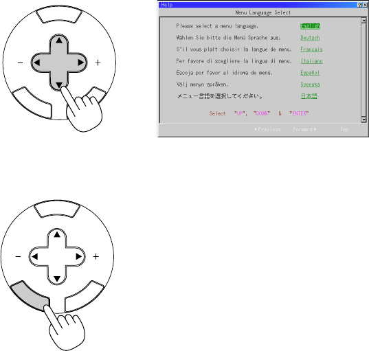
Note on Startup screen (Menu Language Select screen)
When you first turn on the projector, you will get the Startup screen. This
screen gives you the opportunity to select one of the seven menu lan-
guages: English, German, French, Italian, Spanish, Swedish and Japa-
nese.
To select a menu language, follow these steps:
1. Use the SELECT or button to select one of the seven languages for
the menu.
M
E
N
U
E
N
T
E
R
C
A
N
C
E
L
SELECT
2. Press the ENTER button to execute the selection.
M
E
N
U
E
N
T
E
R
C
A
N
C
E
L
SELECT
E-39
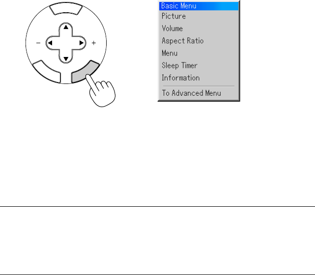
3. The Basic menu will be displayed in the language you have selected.
PROJECTING AN IMAGE
⬎
Turning on the Projector
M
E
N
U
E
N
T
E
R
C
A
N
C
E
L
SELECT
To close the menu, press the CANCEL button.
After this has been done, you can proceed to the advanced menu opera-
tion.
If you want, you can select the menu language later. See "Language" on
page E-93.
NOTE: To turn the projector on by plugging in the power cable, first turn on the
Main Power switch to ON and use the menu and enable the "Auto Start" feature.
(See page E-99.)
Immediately after turning on the projector, screen flicker may occur. This is not a
fault. Wait 3 to 5 minutes until the lamp lighting is stabilized.
When the Lamp mode is set to Eco, the Lamp indicator will light green.
If one of the following things happens, the projector will not turn on.
*If the internal temperature of the projector is too high, the projector
detects abnormal high temperature. In this condition the projector
will not turn on to protect the internal system. If this happens, wait for
the projector's internal components to cool down.
*When the lamp reaches its end of usable life, the projector will not
turn on. If this happens, replace the lamp.
*If the lamp fails to light, and if the STATUS indicator flashes on and
off in a cycle of six times, wait a full minute and then turn on the
power.
E-40
PROJECTING AN IMAGE
Selecting a Source
Selecting the computer or video source
Using the Remote Control
ASPECT
OFF
VIDEO
AUTO ADJ.
S-VIDEO RGB1 RGB2
LASER
ON
3D REFORM
HELP
POINTER
VOLUME MAGNIFY
PICTURE
PIC-MUTE
VIEWER
SLIDE
FOLDER
SLIDE
LIST
POWER
FREEZE
NOTE: If no input signal is available, the projector will display a blue back-
ground (factory preset).
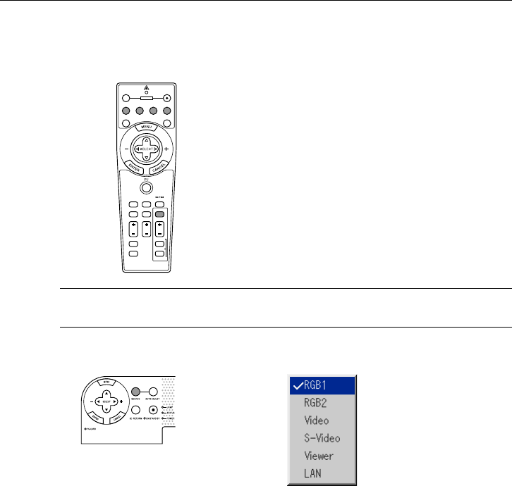
Selecting from Source List
Press any one of the RGB1,
RGB2, VIDEO, S-VIDEO or
VIEWER buttons.
Press and quickly release the SOURCE button on the projector cabi-
net to display the Source list. Each time the SOURCE button is pressed,
the input source will change as follows: "Video" (VCR, document cam-
era, or laser disc player), S-Video", "RGB1" or "RGB2" (computer or
DVD with component output) , "Viewer" (slides on a PC card), or "LAN"
(wired or wireless signal aired from a PC).
To display the selected source, press the SOURCE button a few times
to select the signal you wish to project.
Source List
E-41
Press and hold the SOURCE button for a minimum of 2 seconds, the
projector will search for the next available input source. Each time you
press and hold the SOURCE button, the input source will change as
follows:
→ RGB1 → RGB2 → Video → S-Video → Viewer
If no input signal is present, the input will be skipped. When the input
source you wish to project is displayed, release the button.
PROJECTING AN IMAGE
⬎
Selecting a Source
Detecting the Signal Automatically
E-42
PROJECTING AN IMAGE
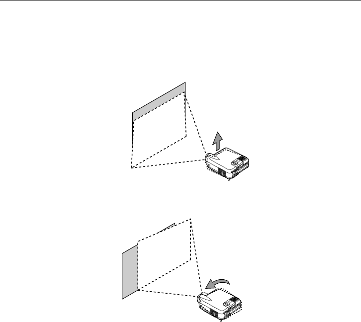
Adjusting the Picture Size and Position
Place your projector on a flat level surface and ensure that the projector is
square to the screen.
Lift the front edge of the projector to center the image vertically.
Move the projector left to center the image horizontally on the screen.
Use the 3D REFORM feature for proper adjustment. See page E-45.
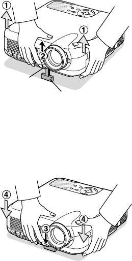
E-43
Adjust the Tilt Foot
qLift the front edge of the projector.
wPush up the Adjustable Tilt Foot Lever on the front of the projector to
extend the adjustable tilt foot (maximum height).
ePush down the Adjustable Tilt Foot Lever.
rLower the front of the projector to the desired height and release the
Adjustable Tilt Foot Lever to lock the Adjustable tilt foot. There is ap-
proximately 7 degrees of up and down adjustment for the front of the
projector.
PROJECTING AN IMAGE
⬎
Adjusting the Picture Size and Position
SELECT
C
N
A
C
E
L
T
E
R
N
E
E
M
N
U
SOURCEAUTO ADJUST
ON
STAND BY
STATUS
POWER
LAMP
ALIGNMENT
PC-CARD
Adjustable Tilt
Foot Lever Adjustable Tilt Foot
SELECT
C
N
A
C
E
L
T
E
R
N
E
E
M
N
U
SOURCEAUTO ADJUST
ON
STAND BY
STATUS
POWER
LAMP
ALIGNMENT
PC-CARD
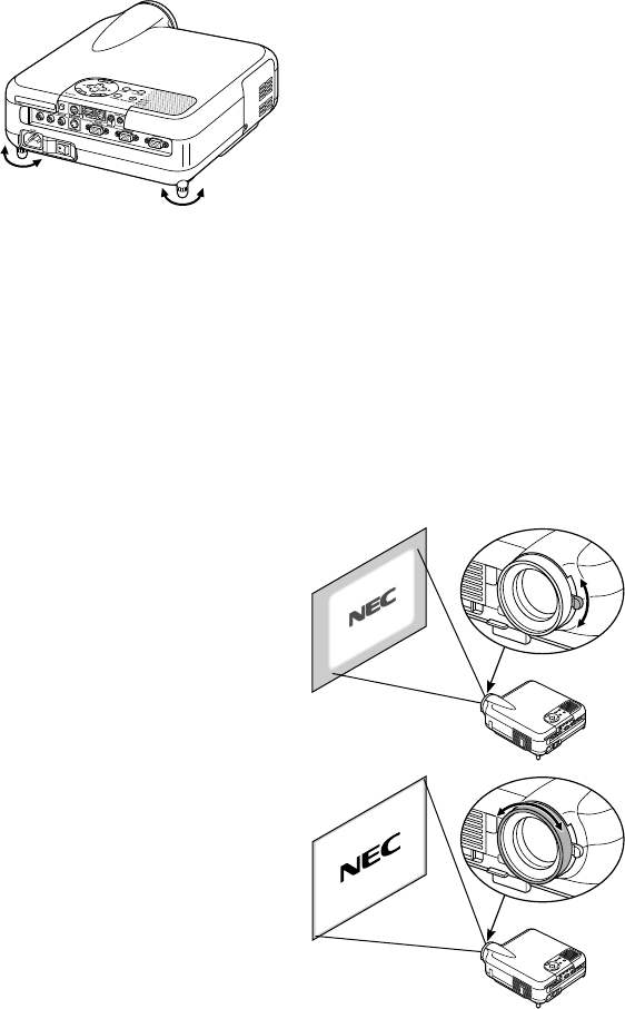
E-44
The rear foot height can be changed. Rotate the rear foot to the desired
height, but the vertical distance from the bottom to the desk or floor should
be 1" (25 mm) to make the projector horizontal on the flat surface.
*If the projected image does not appear square to the screen then
use the 3D Reform feature for proper adjustment. See page E-45.
CAUTION:
Do not use the tilt-foot for purposes other than originally intended. Mis-
uses such as gripping the tilt-foot or hanging on the wall can cause
damage to the projector.
Zoom
Use the Zoom lever to fine adjust
the image size on the screen
Focus
Use the Focus ring to obtain the
best focus.
PROJECTING AN IMAGE
⬎
Adjusting the Picture Size and Position
Up
Down Up Down
E-45
Correcting the Horizontal and Vertical Keystone Distortion (3D Reform)
PROJECTING AN IMAGE
Screen
Projected image
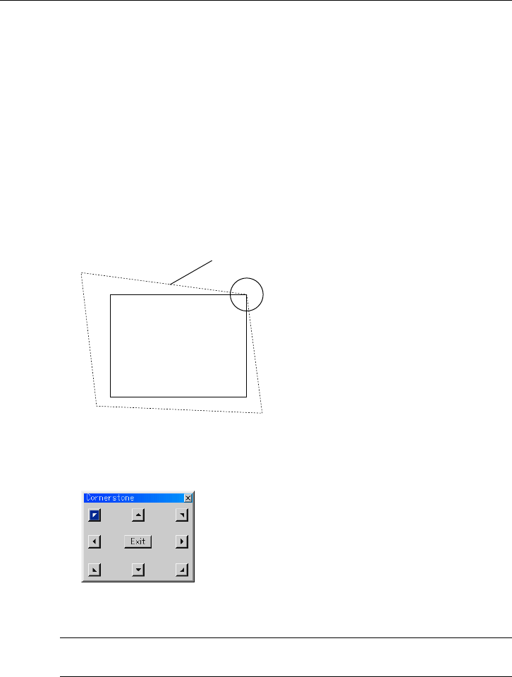
Use the 3D Reform feature to correct keystone (trapezoidal) distortion to
make the top or bottom and the left or right side of the screen longer or
shorter so that the projected image is rectangular.
You can also use a mouse to correct the Cornerstone distortion. To do so
with your mouse, pick and left-click on one corner of the image you want to
correct.
Do this for the remaining 3 corners. Right-click to display the confirmation
screen.
1. Project an image so that the screen is smaller than the area of the raster.
2. Pick up any one of the corners and align the corner of the screen with the
one of the image.
(The drawing shows the upper right corner.)
3. Press the 3D REFORM button on the remote control.
The CORNERSTONE adjustment screen is displayed.
NOTE: Press the 3D REFORM button to toggle between "Cornerstone" and "Key-
stone."
E-46
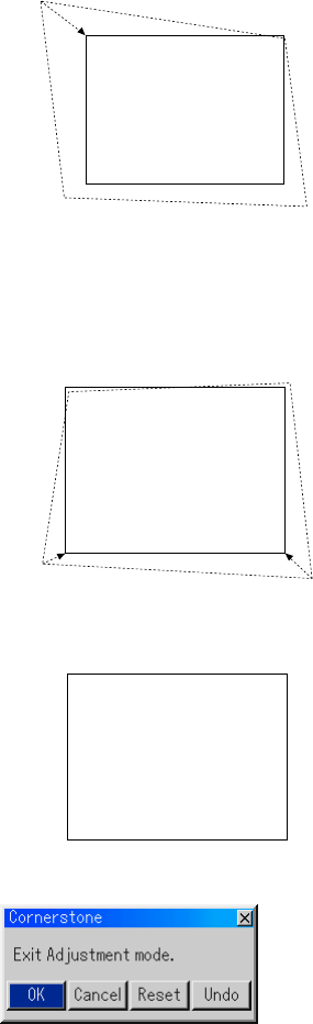
4. Use the SELECT button to select one icon which points in the
direction you wish to move the projected image frame.
PROJECTING AN IMAGE
Screen
5. Press the ENTER button.
6. Use the SELECT button to move the projected image frame as
shown on the example.
7. Press the ENTER button.
Screen
8. Use the SELECT button to select another icon which points in
the direction.
Screen
The confirmation screen is displayed.
On the Cornerstone adjustment screen,
select “Exit” and then “OK”, or press the
CANCEL button on the remote control.

E-47
PROJECTING AN IMAGE
9. Press the SELECT or button to highlight the [OK] and press the
ENTER button.
This completes the keystone correction.
Selecting “Cancel” will return to the adjustment screen without saving
changes (Step 3).
Selecting "Reset" will return to the factory default.
Selecting "Undo" will exit without saving changes.
NOTE: To return the 3D Reform correction setting values to the factory default,
press and hold the 3D REFORM button for a minimum of 2 seconds.
NOTE: During 3D Reform adjustment, "Aspect Ratio" and "Screen" may not be
available. Should this happen, first reset the 3D Reform data and then do each
setting. Second repeat the 3D Reform adjustment. Changing Aspect Ratio and/or
Screen setting can limit 3D Reform in its adjustable range.
The adjustable ranges for 3D Reform are as follows:
Horizontal ............. Max ±30° approx. (Max ±25° approx. on LT240)
Vertical ................. Max ±40° approx.
*The following are conditions at the above maximum angle when all of
the following are met
•Image is projected in Wide (Zoom)
•Resolution is XGA
Higher resolution than XGA limits 3D Reform in its adjustable range.
•Menu items should be set as follows:
Aspect Ratio........... 4:3
Screen Type ........... 4:3
Screen Position ...... 0
•Horizontal and Vertical are adjusted separately.
A combination of both adjustments limits 3D Reform in its adjustable
range.
E-48
PROJECTING AN IMAGE
Optimizing RGB Picture Automatically
Adjusting the Image Using Auto Adjust
Optimizing RGB image automatically
Press the Auto Adjust button to optimize an RGB image automatically.
[Poor picture]
[Normal picture]
AUTO ADJ.
Press the Auto Adjust button to fine-tune the computer image or to remove
any vertical banding that might appear and to reduce video noise, dot
interference or cross talk (this is evident when part of your image appears
to be shimmering). This function adjusts the clock frequencies that elimi-
nate the horizontal banding in the image. This function also adjusts the
clock phase to reduce video noise, dot interference or cross talk. (This is
evident when part of your image appears to be shimmering.)
This adjustment may be necessary when you connect your computer for
the first time.
NOTE:
•Some signals may not be displayed correctly or take time.
•The Auto Adjust function does not work for component and video signal.
•If the Auto Adjust operation cannot optimize the RGB signal, try to adjust
Clock and Phase manually. See page E-88.
E-49
PROJECTING AN IMAGE
Tur ning Up or Down Volume
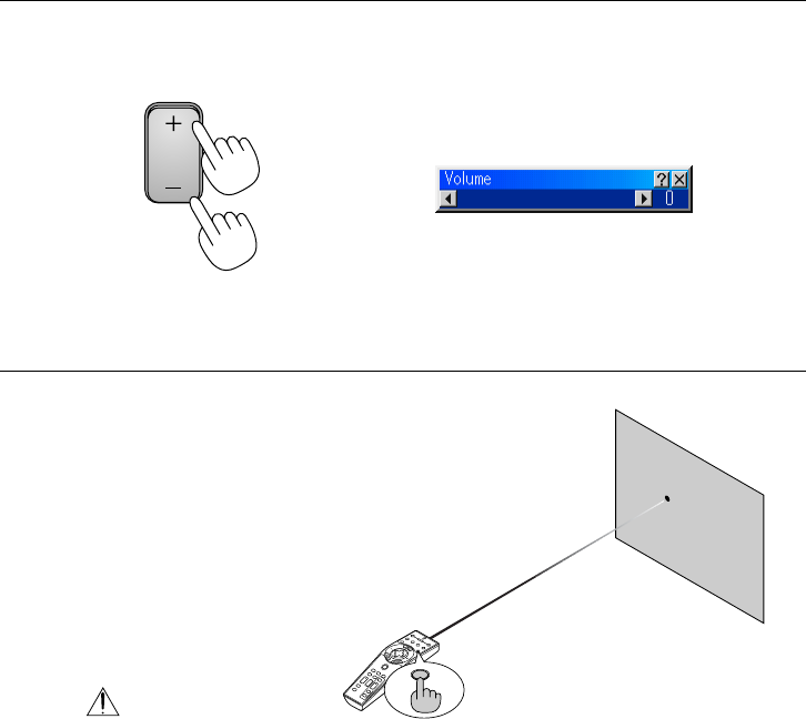
Sound level from the speaker and the AUDIO OUT mini jack on the projec-
tor can be adjusted.
increase volume Volume bar
decrease volume
VOLUME
Using the Laser Pointer
OFF
VIDEO
AUTO ADJ.
S-VIDEORGB1RGB2
LASER
POWER
ON
PJ
ASPECT
3D
REFORM
HELP
POINTER
VOLUME
MAGNIFY
PICTURE
PIC-MUTE
VIEWER
SLIDE
FOLDER
SLIDE
LIST
SELECT
FREEZE
LASER
You can use the laser to draw your
audience's attention to a red dot that you
can place on any object.
Press and hold the LASER button to acti-
vate the laser pointer.
CAUTION:
•Do not look into the laser pointer while it is on.
•Do not point the laser beam at a person.
E-50
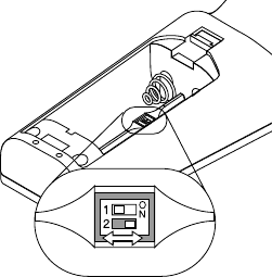
Setting the function switch
ON
OFF
There are two switches on the bottom of
the battery case: an applicable projector
selector switch (1) and laser enable/dis-
able switch (2). Check the projector be-
ing used and decide whether to enable
or disable laser, then set these switches
as necessary using the tip of a thin ball-
point pen. On this model, an applicable
projector selector switch (1) is not used.
Switch (2)
On: Enabled (the laser lights when the LASER button is pressed)
[Factory default]
Off: Disabled (the laser does not light even when the LASER button
is pressed)
Disable the laser when using in an environment in which the unit is acces-
sible to children.
PROJECTING AN IMAGE
E-51
PROJECTING AN IMAGE
Tur ning off the Projector
To turn off the projector:
First press the POWER (ON/STAND BY) but-
ton on the projector cabinet or the POWER OFF
button on the remote control for a minimum of
two seconds. The power indicator will glow or-
ange. After the projector turns off, the cooling
fans keep operating for 90 seconds (Cooling-
off time).
Second, turn off the Main Power switch. The
power indicator will go out. Last unplug the
power cable.
CAUTION
Do not unplug the power cable from the wall
outlet or do not turn off the main power under
any one of the following circumstances. Doing
so can cause damage to the projector:
•While the Hour Glass icon appears.
•While the message "Please wait a moment."
appears. This message will be displayed
after the projector is turned off.
•While the cooling fans are running. (The
cooling fans continue to work for 90 sec-
onds after the projector is turned off).
•While accessing a PC card. (The PC Card
Access indicator lights.)
ASPECT
OFF
VIDEO
AUTO ADJ.
S-VIDEO RGB1 RGB2
LASER
ON
3D REFORM
HELP
POINTER
VOLUME MAGNIFY
PICTURE
PIC-MUTE
VIEWER
SLIDE
FOLDER
SLIDE
LIST
POWER
FREEZE
E-52
CONVENIENT FEATURES
Using the Remote Mouse Function
The built-in remote mouse function enables you to operate your computer's
mouse functions from the remote control (Computer mode). It is a great
convenience for clicking through your computer-generated presentations.
To return to the projector operation mode (Projector mode), press the PJ
button (lit red).
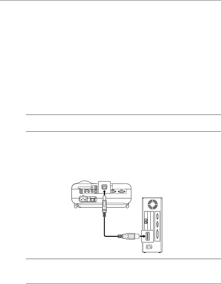
Connecting to your computer for the remote mouse
fuction
If you wish to use the remote mouse function, use the supplied USB cable
to connect the USB port (type B) of the projector and the USB port (type
A) of your computer.
NOTE: Depending on the type of connection or OS installed on your computer,
you may have to restart your computer or change you computer settings.
When using the USB Port
For PC, the mouse receiver function can only be used with a Windows 98,
Windows ME, Windows XP or Windows 2000 operating system.
NOTE: Wait at least 5 seconds after disconnecting the USB cable before recon-
necting it and vice versa. The computer may not identify the built-in mouse re-
ceiver if it is repeatedly connected and disconnected in rapid intervals.
Type B
Type A
E-53
CONVENIENT FEATURES
⬎
Using the Remote Mouse Function
Switching operation mode between computer and pro-
jector
The three shaded buttons shown on the drawing work as a computer mouse
in the Computer mode.
In the Computer mode the PJ button is not lit.
M
E
N
U
E
N
T
E
R
C
A
N
C
E
L
PJ
FOCUS ZOOM
OFF
VIDEO
AUTO ADJ.
S-VIDEO RGB1 RGB2
LASER
ON
VOLUME
SHIFT
HELP
POINTER
KEYSTONE
MAGNIFY
FREEZE
PIC-MUTE
PC CARD
SLIDE
FOLDER
SLIDE
LIST
SELECT
POWER
Not lit
Works as a mouse
for your computer.
Works as a right-
click button for
your computer.
Works as a left-click button
for your computer.
M
E
N
U
E
N
T
E
R
C
A
N
C
E
L
FOCUS ZOOM
OFF
VIDEO
AUTO ADJ.
S-VIDEO RGB1 RGB2
LASER
ON
VOLUME
SHIFT
HELP
POINTER
KEYSTONE
MAGNIFY
FREEZE
PIC-MUTE
PC CARD
SLIDE
FOLDER
SLIDE
LIST
SELECT
POWER
PJ
Works as the Select button
on the projector.
Lit red
Works as the Enter button
on the projector.
Works as the Cancel
button on the
projector.
E-54
•When the MENU button is pressed, the PJ button lights red to indi-
cate that you are in the Projector mode, which allows the projector
menu operation using the three buttons.
•When the POINTER button is pressed, the PJ button lights red to
indicate that you are in the Projector mode and that the SELECT
button works as a moving button for the POINTER or magni-
fied image.
•If no buttons are pressed within 60 seconds, the PJ button's light
goes out to indicate that you are in the Computer mode. To enable
the projector menu operation again, press the PJ button to light red.
To move the pointer or a magnified image again, turn off the pointer
and then turn on the pointer (press the POINTER button two times).
•When the PJ button is lit, if you want to use the mouse function im-
mediately, press the PJ button to return to the Computer mode (not
lit).
During Computer mode:
In Computer mode, by pressing the ENTER button for 2 seconds or more
then releasing, the drag mode is set and the drag operation can be per-
formed simply by pressing the SELECT (mouse) button. To cancel
the drag mode, press the ENTER (left click) button again or press the
CANCEL (right click) button.
CONVENIENT FEATURES
⬎
Using the Remote Mouse Function
E-55
CONVENIENT FEATURES
Tur ning Off the Image and Sound
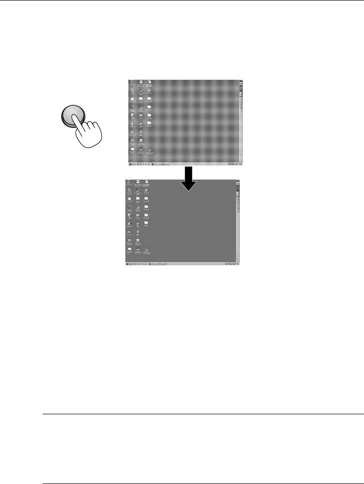
Press the Picture Mute button to turn off the image
and sound for a short period of time. Press again to
restore the image and sound.
PIC-MUTE
Freezing a Picture
Press the Freeze button to freeze a picture. Press
again to resume motion.
FREEZE
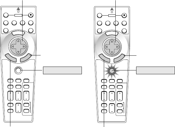
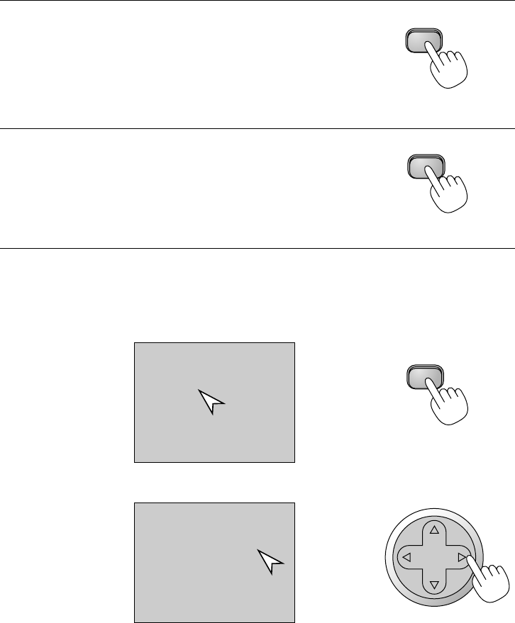
Using the Pointer
You can use one of eight pointers to draw your
audience's attention to the portion of a projected
image you want.
Press the Pointer button to
display the pointer.
POINTER
Press the Pointer button to display the pointer.
Use the Select button to
move the pointer.
SELECT
Use the Select button to move the pointer.
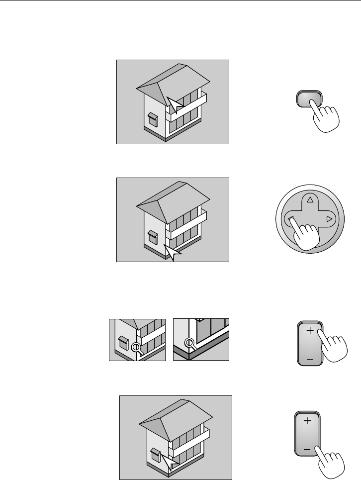
E-56
Enlarging and Moving a Picture
CONVENIENT FEATURES
You can enlarge the area you want up to 400 percent.
To do so:
1. Press the Pointer button to display the pointer.
2. Move the pointer to the area you want to enlarge.
3. Enlarge the selected area.
When the Magnify (+) button is pressed, the pointer is changed to a mag-
nifying glass. To move the magnifying glass, use the SELECT button.
4. Return the image to the original size.
POINTER
SELECT
MAGNIFY
MAGNIFY
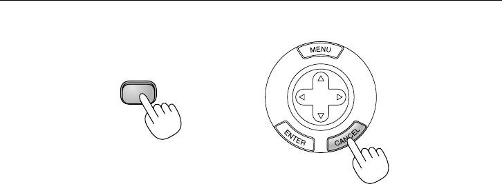
E-57
CONVENIENT FEATURES
Getting the On-line Help
You get the contents about Help.
Display Help
Exit Help
HELP
SELECT
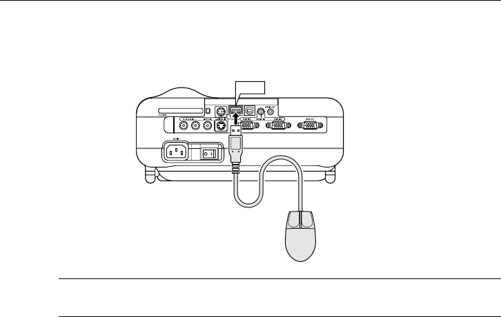
E-58
Using a USB Mouse
CONVENIENT FEATURES
Using a USB mouse gives you a smooth operation. A commercially avail-
able USB mouse is required.
USB
NOTE: There may be some brands of USB mouse that the projector does not
support.
Operate the Menus using the USB mouse
Mouse Cursor
When connecting a USB mouse to the projector, you get a mouse cur-
sor on the screen.
Unless you use your USB mouse within 10 seconds, the mouse cursor
disappears.
Menu Display
Clicking with a mouse button displays the menu.
Clicking displays the pull-down menu. To close the menu, click any-
where in the background.
Adjusting and Setting Display
You can select a menu item and click with a mouse button to make
adjustments and setting.
Type A
E-59
Examples
Click (or press and hold) the mouse button or to adjust the bright-
ness. Or click and drag the mouse button on the slide bar horizontally
to adjust it.
To save the adjustments, click . The display is closed. If you click
anywhere in the background while displaying adjustment and setting
menu or dialog box, you will get the main menu at the clicking point.
CONVENIENT FEATURES
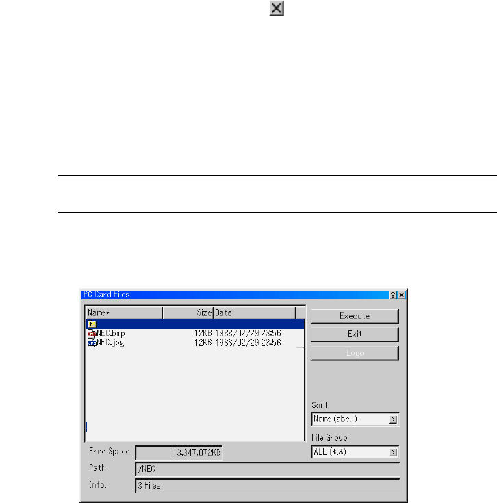
Changing Background Logo
You can change the default background logo using the PC Card Files fea-
ture.
NOTE: File size must be 256KB or less. Other file formats than JPEG and BMP
are not available.
1. From the menu, select [Tools] → [PC Card Files] to display a list of all the
files stored in the PC card so that you can select a file you want to use as a
background logo.
2. The Logo button allows you to select a background logo from graphic
files on a PC card and change to it as the background logo.
3. Use the SELECT or button to select a JPEG or BMP file for your
background logo.
E-60
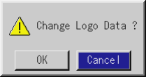
4. Use the SELECT and then button to select "Logo".
5. Press the ENTER on the remote control or the cabinet. You will get the
confirmation dialog box.
6. Select "OK" and press the ENTER button. This completes changing a
logo for the background.
*Once you have changed the background from the NEC logo to an-
other, you cannot return the logo to background even by using Factory
Default. To do so, repeat the above steps. The NEC logo file is included
on the supplied CD-ROM NEC Projector User Supportware (/Logo/
nec_b_x.jpg). (LT220 : /Logo/nec_b_s2.jpg)
CONVENIENT FEATURES
⬎
Changing Background Logo
E-61
CONVENIENT FEATURES
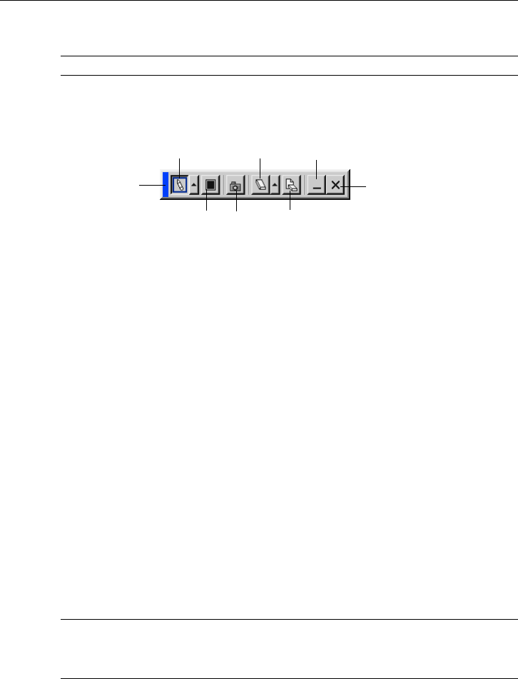
Making Freehand Drawings on a Projected Image (ChalkBoard)
The ChalkBoard feature allows you to write and draw messages on a pro-
jected image.
NOTE: The ChalkBoard feature is available only when a USB mouse is used.
From the menu, select [Tools] → [ChalkBoard] to display the ChalkBoard
tool bar that cotains the following icons.
Drag
Pen Eraser Hide
Exit
ClearColor
Drag ..... Drags to move the tool bar by clicking on the blue part. (for USB
mouse operation only)
Pen ....... Left-click and drag to draw. Left-click [] or right-click the pen
icon to display the pen palette containing four lines of different
thickness from which you can select a line you prefer by left-
clicking.
Color..... Selects a color. Left-click to display the color palette from which
you can select a color you prefer by left-clicking.
Capture Left click to capture and save freehand drawings in the PC card.
Eraser... Left-click and drag to erase part of a drawing. Left-click [] or
right-click the eraser icon to display the eraser palette contain-
ing four eraser of different thickness from which you can select
an eraser you prefer by left-clicking.
Clear..... Left-click to clear the drawing completely from the ChalkBoard
screen.
Hide ...... Hides the tool bar by left-clicking. Right-clicking anywhere on
the screen displays the ChalkBoard tool bar again.
Exit ....... Clears the complete drawing and exits the ChalkBoard.
NOTE:
•The menu is not available while you display the ChalkBoard screen.
• Switching slides clears a drawing completely.
Capture

E-62
USING THE VIEWER
NOTE: To use the Viewer, first you need to create presentation materials on your
PC using the Dynamic Image Utility 2.0 contained on the supplied NEC Projec-
tor User Supportware CD-ROM.
For installation, see the printed Application Guide. For creating presentation
materials, see the Slide show function on the on-line manual of the Dynamic Im-
age Utility 2.0.
Making the Most out of the Viewer Function
Features
You can view presentation data, capture, and play images on the projec-
tor. A PC card is used to view presentation data prepared on the computer
and to capture and play images projected with the projector.
The Viewer feature allows you to view slides stored on a PC memory card
(referred to as PC card in this manual) on the projector. Even if no com-
puter is available, presentations can be conducted simply with the projec-
tor. This feature is convenient for holding presentations at meetings and in
offices, as well as for playing images taken on digital cameras.
Easy to use
•Presentations can be started immediately simply by inserting a PC
card (not supplied)
•Easy slide switching
•Remote control operation
•Jumping to list of slides or any specific slide
High quality images
•High resolution up to 1024 x 768 dots (800 x 600 on LT220)
•24-bit full color playback
•Viewing of digital camera images
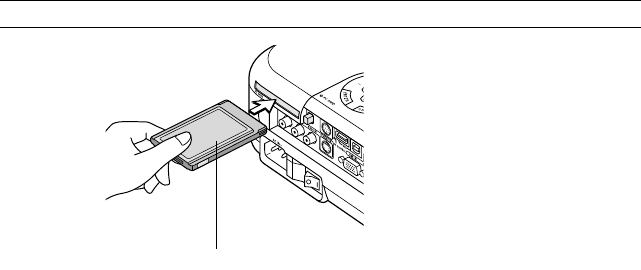
E-63
Simple utility software (for computer)
•Dynamic Image Utility 2.0 operable on Windows 95/98/Me/XP/
NT4.0(SP3 or later)/2000
•Slides can be created by capturing the currently displayed image
•Control screen for displaying lists of slides and editing
*Microsoft, Windows and PowerPoint are registered trademarks of
Microsoft Corporation.
Inserting and Removing a PC Card
Inserting the PC Card
•Hold the PC card horizontally and insert it slowly into card slot with
its top facing up.
•The eject button pops out once the PC card is fully inserted. Check
that the PC card is fully inserted.
NOTE: Do not try to force the PC card into the slot.
USING THE VIEWER
PC card (not supplied)
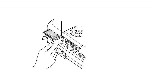
E-64
Removing the PC Card
Press the eject button. The PC card pops out a little. Grasp the edges
of the PC card and pull it out.
NOTE: Do not eject the PC card while its data is being accessed.
USING THE VIEWER
Direction for Inserting the PC Card
The PC card has a top and bottom and must be inserted into the PC card
slot in a specific direction. It cannot be inserted backwards or upside-down.
Attempting to force it into the slot in the wrong direction may break the
internal pin and damage the card slot. Refer to the PC card's operating
instructions for the proper direction of insertion.
PC Card Type
The PC Card slot accepts PCMCIA Type II only.
Eject button
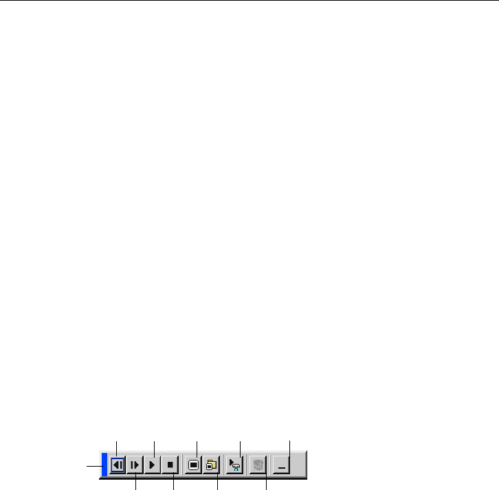
E-65
Operating the Viewer Function from the Projector (playback)
USING THE VIEWER
This section describes the operation for showing slides of presentation
documents created using the Viewer function with the projector. It is also
possible to make slides directly from the images projected with the projec-
tor.
Projecting slides (Viewer)
1. Insert a PC card into the PC card slot.
Insert the PC card with the side with the insertion direction arrow on the
top.
*Press the eject button to eject the card.
2. Select the "Viewer" from the Source Select menu.
3. Project slides.
Checking "Show Folder List", means that selecting Viewer input displays
a list of the folders in the PC card and if "Auto Play" is checked the pro-
jector automatically starts to play slides at the first slide of the folder you
have selected.
A tool bar will appear when you press the MENU button on the remote
control or the projector cabinet or clicking with the right button of a mouse.
Drag
Prev Play Jump Setup View
Next Stop Select Delete
The tool bar includes the following buttons:
Drag ...........Drags to move the tool bar. This is available for USB mouse
operation only.
Prev ............ Returns to the previous slide or folder. Or this lets you
play slides back in reverse.
Next ............ Advances to the next slide or folder. Or this lets you play
slides back.

E-66
Play ............Plays back automatically or manually depending on the
setting on Viewer Options of the menu. This allows you to
move on to the next slide when "Manual Play" is selected.
Stop............ This allows you to stop Auto Play while you are playing
back and to resume playing from the selected slide or folder
when "Auto Play" is selected.
Jump ..........Displays a list of slides while you are playing back.
Select .........Displays a list of folders while you are playing back.
Setup.......... Displays the Viewer Options dialog box on Page 2 of the
Setup dialog box.
Delete.........Deletes a captured slide(s) or all the captured slides in
the Capture - specific folder.
View ...........Hides the tool bar while you are playing back. Pressing
the MENU button or clicking with the right button of a
mouse shows it again.
NOTE: If no memory card is inserted in the PC CARD slot, there is no signal, and
a black, blue or logo background is displayed, depending on the setting.
Playback is stopped when SLIDE +/- button on the remote control or button
on the cabinet is pressed in Auto Play mode.
Up to 12 indexes can be displayed on the list of folders. The folder in the right
bottom is always a folder exclusively for captured images, but is only displayed
when images have been captured.
USING THE VIEWER
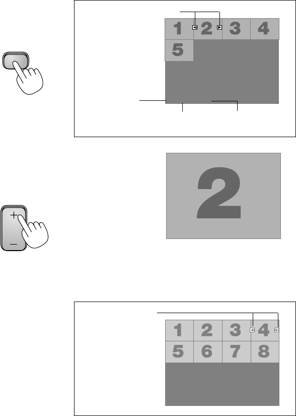
E-67
USING THE VIEWER
When the tool bar is not displayed:
Press the FOLDER LIST button or the SLIDE LIST button on the remote
control to display folders or from a PC card in the projector's PC Card slot.
SLIDE
Folder
02 : 0001 / 0008
Folder Folder Folder
Folder
Multi cursor (blue marks)
Current folder
number Current slide
number
Number of all slides
in folder
Use the SLIDE +/- button to advance to
the next folder or return to the previous
folder.
Slide Slide Slide Slide
Slide Slide Slide Slide
02 : 0004 / 0008
Slide(Table) cursor
(green marks)
Use the SLIDE +/- button to advance to the next slide or return to the
previous slide.
Folder
FOLDER

E-68
NOTE: You can also use the and button on the remote control to select
folders or slides.
If you use the and button on the remote control for Viewer operation, press
the PJ button to switch to the Projector mode and the PJ button lights red.
USING THE VIEWER
Lit red
Works as the Select button
on the projector.
E
N
T
E
R
C
A
N
C
E
L
SELECT
PJ
Auto Play Mode
If the "Auto Play" option is selected in "Viewer Options" of the menu, any
given slide will start to play automatically.
You can also specify Auto Play Interval between 5 and 300 seconds.
Switching to Slides Directly from Other Input Modes
With this function it is possible to switch directly to a slide when the picture
of a VCR or computer is being projected.
Example: When conducting presentations using a combination of slides
and moving pictures from a VCR, etc., it is possible to switch from a
Viewer slide to the video picture then back to the Viewer slide simply by
using the Viewer button.
NOTE: Even if you switch the current Viewer source to another source, the cur-
rent slide is retained. When you return back to the Viewer, you will get the slide
that has been retained.
The PC card editing operation cannot be performed from the projector. Do so
using the Dynamic Image Utility 2.0 software.
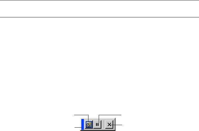
E-69
USING THE VIEWER
Viewing Digital Images
Digital images can be played with the Viewer if the following conditions are
met:
• If the image can be stored on an MS-DOS format PC card
•If the image can be stored in a format supported by the Viewer. With
the Viewer, images on the card are searched for in directories and
images in JPEG or BMP format are recognized as slides. Searchable
directories are directories within two steps from the root directory,
and searchable images are images within the first 12 files in the di-
rectory. Only file and slide switching are possible.
NOTE: The maximum number of images recognized as slides within one directory
is 128.
Storing Images Displayed on the Projector on the PC
card (Capture)
The Capture features allows you to capture an image from a source that is
currently being displayed. The image is saved as JPEG in the PC card.
When you select Capture from the menu, you will get a tool bar. You can
capture an image directly using the tool bar when the menu is not dis-
played.
The tool bar includes the following buttons:
Drag
Freeze
Exit
Capture
Drag ...........Drags to move the tool bar by clicking on the blue part.
(for USB mouse operation only)
Capture ......Captures an image and saves it as a JPEG file on a PC
card.
Freeze ........Freezes and unfreezes images.
Exit .............Exits the Capture function.
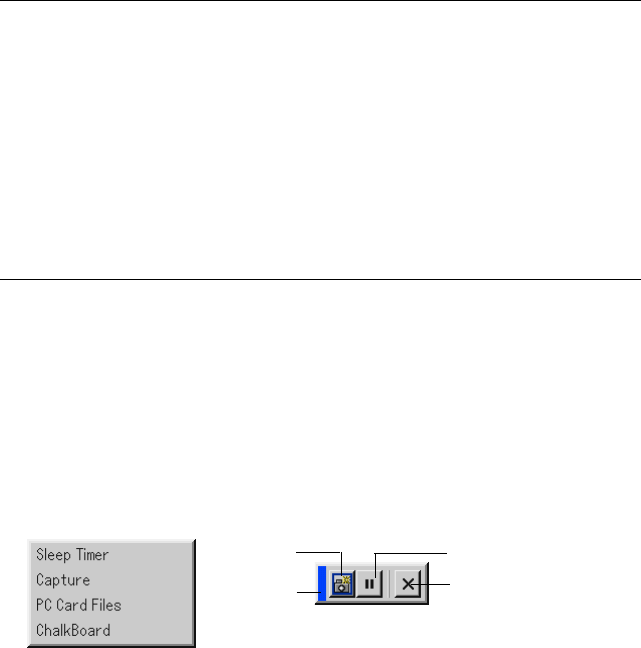
E-70
NOTE:
*Unless a PC card is inserted into the PC Card slot of the projector, the Cap-
ture feature is not available.
*The "Card Error" display means that the free space of the PC card is insuffi-
cient for saving images. Make more space available on the card by erasing
unwanted images with your PC. The number of images that can be captured
depends on the size of the PC card.
*Be sure not to turn off the power or remove the PC card while capturing an
image. Doing so could cause a loss of the data in the PC card or damage to
the card itself.
Preparations:
Insert the PC card into the card slot.
Insert the PC card so that the end with the insertion direction arrow on the
top goes in first.
* Press the eject button to eject the card.
1. Project the image you wish to store on the projector.
Drag
Freeze
Exit
Capture
2. Select the "Capture" from the Tools menu.
3. A tool bar will appear.
The tool bar includes the following buttons:
Drag ...........Drags to move the tool bar by clicking on the blue part (for
USB mouse operation only).
Capture ......Captures an image and save it as a JPEG file in a PC
card.
Freeze ........Freezes and unfreezes images.
USING THE VIEWER

E-71
Exit ............. Exits the Capture function. Another option to exit the Cap-
ture function is to press MENU or CANCEL button on the
remote control or projector cabinet.
NOTE:
You can compress a captured file (JPEG) using the Capture Options in the Setup
dialog. See page E-97.
Captured images with higher resolution than the projector's native resolution
cannot be displayed correctly.
•File size of the captured image varies depending on the resolution of an input
signal.
•An hourglass indicating that an image is being captured appears on the
projector's display. Do not eject the PC card or turn off the projector's power
while this icon is displayed. Doing so will damage the PC card data. If the PC
card data is damaged, use a computer to repair the data.
•Up to 12 indexes can be displayed on the list of folders. The folder in the right
bottom is always a folder exclusively for captured images, but is only dis-
played when images have been captured.
USING THE VIEWER
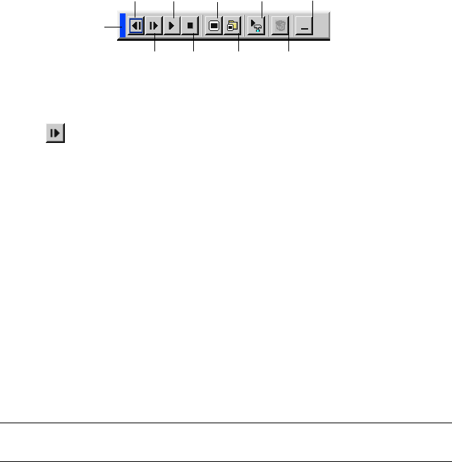
E-72
USING THE VIEWER
Deleting Captured Images
Using the Delete button on the tool bar for Viewer can delete captured
images.
Drag
Prev Play Jump Setup View
Next Stop Select Delete
To delete captured images:
1. Select Viewer and display a folder list of captured images.
2. Use button to select the Capture folder [Cap] in the right bottom of
the screen.
3. Press the MENU button to display the tool bar.
4. Use the or button to select the Delete icon and press the ENTER
button or click with a mouse button.
Using the PC Card Files Fucntion (PC Card Files)
The PC Card Files function allows you to display a list of all the files stored
in the PC card so that you can select a file you want to display. You can
also sort files by file name or date, or display the file. Although a list of all
the files in the PC card is displayed, you can view files in idx, text, HTML,
JPEG and BMP format only. Selecting BMP and JPEG files automatically
switches to the Viewer source. See also page E-81.
NOTE: This option is not available for selection unless a PC card is inserted
properly.
Selecting "Execute" displays the file you selected.
When you select a JPEG or BMP file and press the Enter button on the
remote or the cabinet, or "Execute" on the above, you will get a toolbar.
This toolbar is used to return to the PC Card Files screen.
Drag ...........Drags to move the tool bar. (for USB mouse operation only)
Return ........Returns to the PC Card Files screen.
Close .......... Close the toolbar.

E-73
USING ON-SCREEN MENU
Using the Menus
NOTE: The on-screen menu may not be displayed correctly while interlaced mo-
tion video image is projected.
1. Press the MENU button on the remote control or projector cabinet to
display the Basic, Advanced or Custom Menu.
NOTE: When using a USB mouse, click the mouse button to display the menu.
For other operations, do the same way as you use your PC mouse.
2. Press the SELECT buttons on the remote control or the projector
cabinet to highlight the menu for the item you want to adjust or set.
3. Press the SELECT button or the ENTER button on the remote control
or the projector cabinet to select a submenu or item.
4. Adjust the level or turn the selected item on or off by using SELECT or
buttons on the remote control or the projector cabinet.
The on-screen slide bar will show you the amount of increase or decrease.
5. Changes are stored until you adjust it again.
ENTER ....... Stores the setting or adjustments.
CANCEL ....Return to the previous screen without storing settings or
adjustments.
NOTE: You can close the main and sub menus simultaneously by pressing the
PJ button on the remote control to cancel the Projector mode.
6. Repeat steps 2-5 to adjust an additional item, or press the CANCEL but-
ton on the projector cabinet or the remote control to quit the menu dis-
play.
Basic Menu Operation

E-74
USING ON-SCREEN MENU
⬎
Basic Menu Operation
Customizing the Menu
The Custom menu can be customized to meet your requirements. Select-
ing a menu item from the "Custom Menu Edit" list, allows you to custom
tailor the menu items to your needs.
1. Select "Custom Menu Edit" to display the "Custom Menu Edit" screen.
2. Use the SELECT or buttons to highlight your selection and press the
Enter button to place a check mark next to an option.
This action enables that feature. Press the Enter button again to clear the
check box.
If you select an item with a solid triangle and press the Enter button on
the remote control or the projector cabinet, you can enable all the items
within that submenu. Also you can turn on an item within the submenu
without placing a check mark on the main menu item.
NOTE: Up to 12 main menu items (within Custom Menu Edit, not including
submenu items) can be selected.
3. In order for the changes to take effect, use the SELECT or button on
the remote control or the projector cabinet to highlight "OK", then press
the Enter button. To cancel the changes, use the SELECT or buttons
to highlight "Cancel" and press the ENTER button.
To return to the factory default, select "Reset" then press the ENTER
button.
The default Custom Menu items are:
Source Select (RGB 1/2, Video, S-Video, Viewer and LAN), Picture, Vol-
ume, Image Options (Aspect Ratio), Picture Management, Projector Op-
tions (3D Reform, Menu, Setup, Screen and LAN Mode), Tools (Sleep
Timer, Capture, PC Card Files and ChalkBoard) and Help (Contents and
Information).
NOTE: Once you have selected OK on the Custom Menu Edit screen, you cannot
cancel the changes on the Menu screen. However, you can reedit the menu items
over again as described in the steps above.

E-75
USING ON-SCREEN MENU
⬎
Basic Menu Operation
NOTE: If the "Advanced Menu" item has been selected on the Menu mode, you
get the "Confirmation Change Menu" upon completion of "Custom Menu" edit-
ing. In this case, selecting "Yes" then "Enter" will close all the menus and apply
the changes from the Advanced menu to the Custom Menu. If you select "No" then
"Enter" functions, then all menu items will return to the Advanced menu, but your
changes will still be available within the "Custom Menu" selection. To display the
previously tailored Custom Menu, select "Custom Menu" from the "Menu Mode".
An item "To Advanced Menu" will be added to the bottom of the Custom
Menu.
Selecting this item and pressing the ENTER button will display the "Ad-
vanced Menu" features.
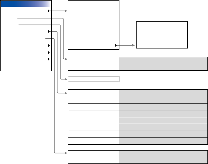
E-76
USING ON-SCREEN MENU
⬎
Basic Menu Operation
Menu tree
Brightness, Contrast, Color,
Hue, Sharpness
4:3, Letter Box, Wide Screen, Crop / 4:3
Window, Letter Box, Wide Screen, 4:3 Fill
Top, Bottom, Left, Right
Horizontal, Vertical, Clock, Phase
Auto, Native
0%, 5%, 10%, 25%
Off, Less, More
Off, Low, Medium, High
Advanced Menu
Source Select
Picture
Volume
Image Options
Picture Management
Projector Options
Tools
Help
Factory Default
RGB1
RGB2
Video
S-Video
Viewer
LAN
more
Aspect Ratio
Blanking
Position/Clock
Resolution
Overscan
Video Filter
Noise Reduction
Picture
Presentation, sRGB, Graphic, Video,
Movie, User 1, User 2, User 3, User 4
Picture Management
Volume
User1
User2
User3
Entry List
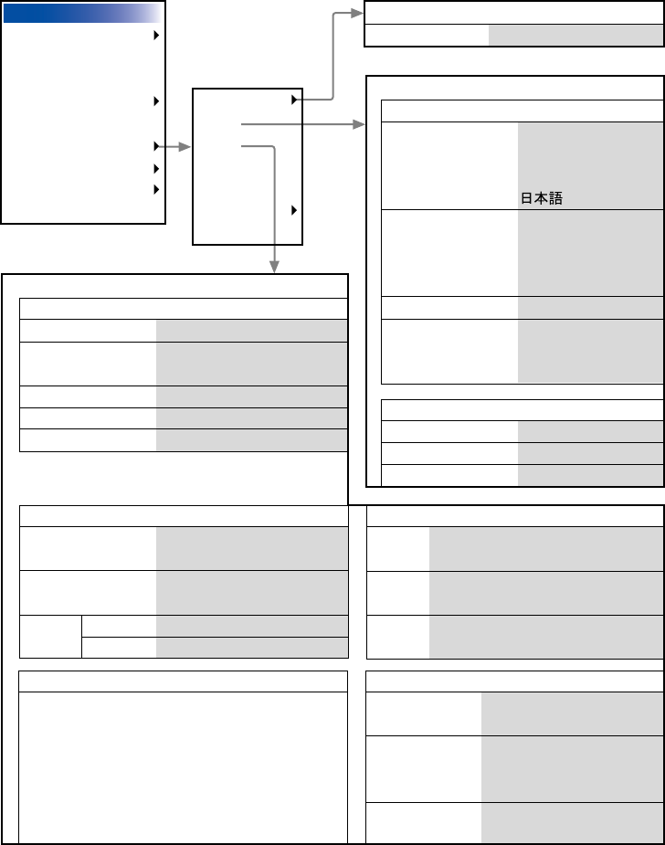
E-77
USING ON-SCREEN MENU
⬎
Basic Menu Operation
Advanced Menu
Source Select
Picture
Volume
Image Options
Picture Management
Projector Options
Tools
Help
Factory Default
3D Reform
Menu
Setup
Screen
LAN Mode
Passcode
Security
Menu
Setup
Cornerstone
Keystone
Page 1
Language
Menu Mode
Projector Pointer
Menu Display Time
English, Deutsch,
Français, Italiano,
Español, Svenska
Basic Menu,
Custom Menu,
Advanced Menu
Custom Menu Edit
Pointer 1-8
Manual, Auto 5sec,
Auto 15sec,
Auto 45sec
Horizontal, Vertical
Page 2
Source Display
Message
Menu Color Select
On, Off
On, Off
Color, Monochrome
Page 1
Lamp Mode
Orientation
Background
RGBOUT Terminal
Closed Caption
Normal, Eco
Desktop Front, Ceiling Rear,
Desktop Rear, Ceiling Front
Blue, Black, Logo
Last, RGB1, RGB2
Off, Caption1-4, Text1-4
Page 3 Signal Select
RGB1
RGB2
Video,
S-Video
RGB/Component, RGB,
Component, Scart
RGB/Component, RGB,
Component
Auto, NTSC3.58, NTSC4.43, PAL,
PAL-M, PAL-N, PAL60, SECAM
Page 5
Communication
Speed
Default Source
Select
Control Panel
Key Lock
4800, 9600, 19200,
38400
Last, Auto, Select (RGB1,
RGB2, Video, S-Video,
Viewer, LAN)
Enable, Disable
Page 4
Auto Adjust, Auto Start, Power Management,
Power Off Confirmation, 3D Reform Save,
Fan High Speed Mode, Idle Mode,
Clear Lamp Hour Meter
Page 2
Viewer Options
Capture Options
Mouse
Show Folder List
Auto Play, Manual Play, Interval
High Quality, Normal,
High Compression
Right Hand, Left Hand
Fast, Medium, Slow
Button
Sensitivity
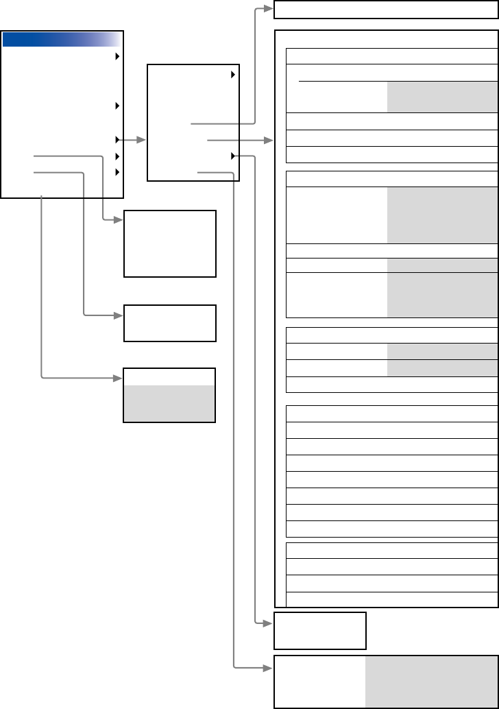
E-78
Advanced Menu
Source Select
Picture
Volume
Image Options
Picture Management
Projector Options
Tools
Help
Factory Default
3D Reform
Menu
Setup
Screen
LAN Mode
Passcode
Security
Sleep Timer
Capture
PC Card Files
ChalkBoard
Contents
Information
Menu
Logo
Security Enable, Disable, Keyword,
Use Protect key, Read,
Register, Delete
Screen Type 4:3, 16:9 / Position
LAN Mode
IP Address
Automatic
Manual
Projector Name
DNS Configuration
Domain Name
IP Address,
Subnet Mask,Gateway
Network Type
Mode
SSID
Channel
TX rate
Infrastructure,
802.11 Ad Hoc,
Ad Hoc
Easy Connection
1-14
Automatic, 11M,
5.5M, 2M, 1M,
1M-2M-Automatic
WEP
WEP
Key Select
Key1-4
Disable, 64bit, 128bit
Key1-4
Mail
Alert Mail
Sender's Address
SMTP Server Name
Recipient's Address 1
Recipient's Address 2
Recipient's Address 3
Test Mail
Status
IP Address
Subnet Mask
MAC Address
Factory Default
All Data,
Current Signal
USING ON-SCREEN MENU
⬎
Basic Menu Operation
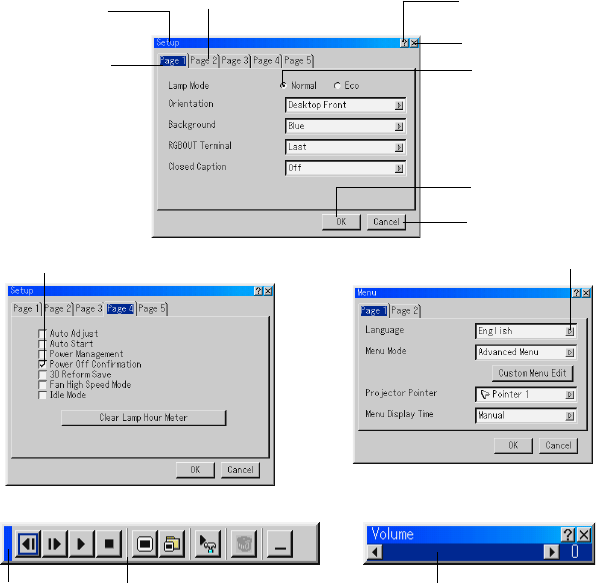
E-79
Menu windows or dialog boxes typically have the following elements:
Title bar ........... Indicates the menu title.
Highlight .......... Indicates the selected menu or item.
Solid triangle ... Indicates further choices are available. A highlighted
triangle indicates the item is active.
Tab .................. Indicates a group of features in a dialog box. Selecting
on any tab brings its page to the front.
Radio button .... Use this round button to select an option in a dialog
box.
Menu Elements
Title bar
Highlight
Check box
Drag Tool bar
Tab Help Button
Close Button
OK Button
Cancel Button
Solid triangle
Radio button
Slide bar
USING ON-SCREEN MENU
⬎
Basic Menu Operation
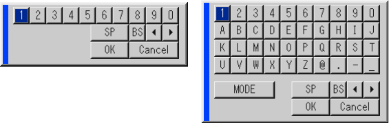
E-80
Check box ....... Place a checkmark in the square box to turn the option
On.
Slide bar .......... Indicates settings or the direction of adjustment.
OK button ........ Press to confirm your setting. You will return to the pre-
vious menu.
Cancel button .. Press to cancel your setting. You will return to the pre-
vious menu.
Close button .... Click to close the window with saving changes. (USB
mouse only)
Help button...... Indicates that help about that feature is available (USB
mouse only). Press the Help button on the remote con-
trol to display help.
Toolbar ............ Contains several icons for specific tasks. It is also re-
ferred to as “launcher”.
Drag ................ Point the mouse here, and click and drag to move a
toolbar.
USING ON-SCREEN MENU
⬎
Basic Menu Operation
Entering Alphanumeric Characters by Using the Menu
Alphabet or numeric characters are used for your IP address or projector
name. To enter IP Address or projector name, use the software keyboard.
For using the software keyboard, see page E-134.

E-81
USING ON-SCREEN MENU
Menu Descriptions & Functions
Source Select
Selecting a Source
Enables you to select a video source such as a VCR, DVD player, laser
disc player, computer or document camera depending on what is con-
nected to your inputs. Press the SELECT button on the projector
cabinet or on your remote control to highlight the menu for the source
you want to project.
RGB
Selects the computer connected to your RGB1, RGB2 or component
signal.
NOTE: An optional component cable (Component V or ADP-CV1 cable) is
needed for a component signal.
Video
Selects what is connected to your Video input-VCR, laser disc player,
DVD player or document camera.
S-Video
Selects what is connected to your S-Video input-VCR, DVD player, or
laser disc player.
NOTE: A frame may freeze for a brief period of time when a video is played
back in fast-forward or fast-rewind with a Video or S-Video source.
Viewer
This feature enables you to make presentations using a PC card that
contains captured images and slides created with the exclusive Dy-
namic Image Utility 2.0 contained in the CD-ROM. See the supplied
Application Guide for installing the Dynamic Image Utility 2.0. The start-
ing screen for the Viewer varies depending on the settings of the Setup's
Page 2. See Setup on page E-96.
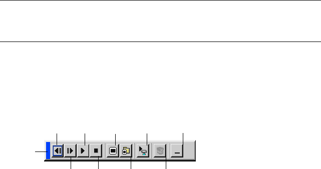
E-82
NOTE: Even if you switch the current Viewer source to another source, the cur-
rent slide is retained. When you return back to the Viewer, you will get the slide
that has been retained. A launcher will appear when you press the MENU button.
A press of the MENU button displays the toolbar; a press of the MENU
button again displays the Menu and hereafter each press of the MENU
button switches displaying between the Menu and the toolbar.
The launcher is a tool bar including the following buttons:
USING ON-SCREEN MENU
⬎
Menu Descriptions & Functions
Drag
Prev Play Jump Setup View
Next Stop Select Delete
Drag ................ Drags to move the tool bar. (for USB mouse operation
only)
Prev................. Returns to the previous slide or folder.
Next ................. Advances to the next slide or folder.
Play ................. Plays back automatically or manually depending on the
setting on Viewer Options of the menu. This allows you
to move on to the next slide when "Manual Play" is
selected.
Stop................. Stops Auto Play while you are playing back and to re-
sume playing from the selected slide or folder when
"Auto Play" is selected.
Jump ............... Displays a list of slides while you are playing back.
Select ..............Displays a list of folders while you are playing back.
Setup............... Displays the Viewer Options dialog box on Page 2 of
the Setup dialog box.
Delete.............. Deletes a captured slide(s) or all the captured slides in
the selected folder.
View ................ Hides the tool bar while you are playing back. Clicking
with the right button of a mouse shows it again.
Provides access to controls for your image. Use the
SELECT button on the projector cabinet or the remote
control to highlight the menu for the item you want to
adjust.

E-83
USING ON-SCREEN MENU
⬎
Menu Descriptions & Functions
LAN
Selects a signal from a LAN card plugged into the projector's card slot.
Entry List
Displays the list of the entry signals. Use the SELECT buttons on
your remote control or the projector cabinet to select the signal and
press the ENTER button on the remote control or the projector cabinet
to display the Entry Edit Command screen.
Using the Entry List
Making any ajustments to the current picture will automatically register
its adjustments to the Entry List. The registered signal can be loaded
any time from the Entry List.
NOTE: Up to 100 presets can be registered.
Entry Edit Command
You can edit signals on the Entry List.
Load: Enables you to select a signal from the list.
Store: Enables you to store the currently projected signal that currently
projected.
Cut: Enables you to remove a selected signal from the list and place it
on the "clipboard" in the projector.
Copy: Enables you to copy a selected signal from the list and place it
on the "clipboard" in the projector.
Paste: Enables you to paste the signal placed on the "clipboard" to any
other line of the list. To do this, select "Paste" and then select the line
number you want to paste to. Last press ENTER.
Edit: Enables you to change source names or add source names to
"More" in the Sorce Select.
Source Name: Enter a signal name. Up to 18 alphanumeric characters
can be used.

E-84
Input Terminal: Change the input terminal. RGB1 and RGB2 are avail-
able for RGB signal; Video and S-Video are available for composite
signal.
Source List: Set signal selection method.
Lock: Set so that the selected signal cannot be deleted when "All De-
lete" is executed.
Skip: Set so that the selected signal will be skipped during auto search.
When complete, select OK and press ENTER. To exit without storing set-
ting, select Cancel. Select "Source Name" and press ENTER to display
the Source Name Edit window. You can change source name on this win-
dow. Press [] to display the software keyboard, which you can enter al-
phanumeric characters. See page E-134 for the key function of the soft-
ware keyboard.
The following buttons are not available for the currently projecting signals:
1) The Cut and Paste buttons on the Entry Edit Command screen
2) The Input Terminal button on the Entry Edit screen
All Delete: This feature enables you to delete all the registered signals
in the Entry List.
NOTE: When all the signals in the Entry List are deleted, the currently pro-
jected signal will be also deleted except locked signals.
Select "Input Terminal" and press ENTER to display the Input Termi-
nal window.
USING ON-SCREEN MENU
⬎
Menu Descriptions & Functions
E-85
USING ON-SCREEN MENU
⬎
Menu Descriptions & Functions
Picture (not available for Viewer and LAN)
Adjusting Brightness, Contrast, Color, Hue, and Sharpness
Brightness ....... Adjusts the brightness level or the back raster inten-
sity.
Contrast .......... Adjusts the intensity of the image according to the in-
coming signal.
Color ............... Increases or decreases the color saturation level (not
valid for RGB).
Hue ................. Varies the color level from +/- green to +/-blue. The red
level is used as reference. This adjustment is only valid
for Video and Component inputs (not valid for RGB).
Sharpness ....... Controls the detail of the image for Video (Not valid for
RGB).
Volume
Controllling Volume
Adjusts the sound level of the projector speaker and AUDIO OUT.

E-86
USING ON-SCREEN MENU
⬎
Menu Descriptions & Functions
Image Options
Selecting Aspect Ratio (not available for Viewer and LAN)
Aspect Ratio allows you to select the best Aspect mode to display your
source image.
When screen size 4:3 is selected for the source, the following selec-
tions will display:
4:3 ................... Standard 4:3 aspect
Letter Box........ Reduced to display the true aspect with black borders
on top and bottom
Wide Screen ... Left & Right stretched with black borders on top and
bottom
Crop ................ Left & Right streched.
Left & Right sides cut. Available for 4:3 only.
When screen size 16:9 is selected for the source, the following selec-
tions will display:
4:3 Window ..... Reduced to display the true aspect with black borders
on right and left
Letter Box........ Standard 16:9 aspect
Wide Screen ... Left and right streched to display the true aspect
4:3 Fill ............. Stretched to display in 16:9 aspect ratio
NOTE: You can adjust image positions vertically for source with black borders.
See page E-101 for setting image positions.
Copyright
Please note that using this projector for the purpose of commercial gain or the
attraction of public attention in a venue such as a coffee shop or hotel and em-
ploying compression or expansion of the screen image with a "Aspect Ratio" or
"Screen" setting may raise concern about the infringement of copyrights which
are protected by copyright law.
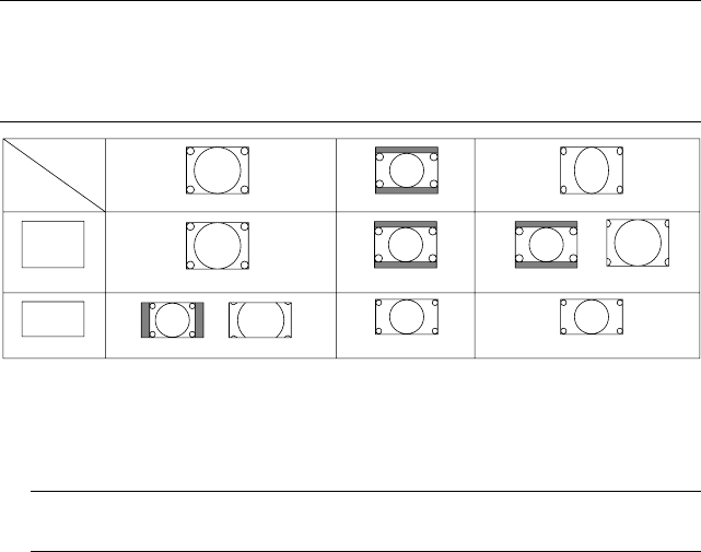
E-87
USING ON-SCREEN MENU
⬎
Menu Descriptions & Functions
Input
Signal
Screen
Type
4:3 Screen
16:9 Screen
4:3
4:3
4:3 Window 4:3 Fill
Letter Box
Letter Box
Letter Box
Squeeze
Wide Screen Crop
Wide Screen
NOTE: During 3D Reform adjustment, "Aspect Ratio" may not be available.
Should this happen, first reset the 3D Reform data and then do setting again.
Second repeat the 3D Reform adjustment.
Changing the aspect ratio can limit 3D Reform in its adjustable range.
Masking Unwanted Area (Blanking)
This feature allows you to mask any unwanted area of the screen im-
age.
NOTE: Adjustment of vertical display range
Adjust the Top, Bottom, Left or Right blanking with the SELECT or button.
Adjusting Position and Clock
This allows you to manually adjust the image horizontally and verti-
cally, and adjust Clock and Phase.
Horizontal/Vertical Position:
........................ Adjusts the image location horizontally and vertically
using the SELECT and buttons. This adjustment
is made automatically when the Auto Adjust is turned
on. See "Auto Adjust" on page E-98 for turning on or
off the Auto Adjust feature.
E-88
USING ON-SCREEN MENU
⬎
Menu Descriptions & Functions
Clock ............... Use this item to fine tune the computer image or to
remove any vertical banding that might appear. This
function adjusts the clock frequencies that eliminate
the horizontal banding in the image.
Press the SELECT and buttons until the banding
disappears. This adjustment may be necessary when
you connect your computer for the first time. This ad-
justment is made automatically when the Auto Adjust
is turned on.
Phase .............. Use this item to adjust the clock phase or to reduce
video noise, dot interference or cross talk. (This is evi-
dent when part of your image appears to be shimmer-
ing.) Use the SELECT and buttons to adjust the
image.
Use "Phase" only after the "Clock" is complete. This
adjustment is made automatically when the Auto Ad-
just is turned on.
Selecting Resolution
This allows you to activate or deactivate the Advanced AccuBlend fea-
ture.
Auto ................. Turns on the Advanced AccuBlend feature. The pro-
jector automatically reduces or enlarges the current
image to fit the full screen.
Native .............. Turns off the Advanced AccuBlend feature. The pro-
jector displays the current image in its true resolution.
See "Auto Adjust" on page E-98 for turning on or off
the Auto Adjust feature.

E-89
USING ON-SCREEN MENU
⬎
Menu Descriptions & Functions
NOTE:
*When "Resolution" is set to "Native", "3D Reform", "Aspect Ratio" and
"Screen" are not available.
*If you are displaying an image with a resolution higher than the projector's
native resolution (i.e. 1024⳯768 for LT260/240 and 800⳯600 for LT220)
and "Native" mode is selected in the menu system, the portion of the image
that lies off screen will be lost because of a change in the horizontal-to-
vertical ratio. This is due to the image having a larger horizontal resolu-
tion than the panels native resolution. This is not a malfunction and it can
be corrected using the 'Phase' adjustment in the menu system. After ad-
justing 'Phase', set the resolution mode to "Auto".
Selecting Overscan Percentage
Select overscan percentage (0%, 5%, 10% and 25%) for signal.
NOTE: When "Resolution" is set to "Native", this feature is not available, and
the stored settings and adjustments are invalid.
NOTE: When "4:3 Fill" or "Crop" is selected in "Aspect Ratio", this feature is
not available.
Selecting Video Filter Level (not available for Video, Viewer and LAN)
This function reduces video noise.
Off ................... The filter is removed.
Less ................ The low-pass filter is applied partially.
More ................ The low-pass filter is applied fully.
Selecting Noise Reduction Level (not available for RGB, Viewer and LAN)
Select one of the three levels for reducing video noise: Low, Medium or
High.
NOTE: The lower the Noise Reduction level, the better the image quality by
way of higher video bandwidth.

E-90
USING ON-SCREEN MENU
⬎
Menu Descriptions & Functions
Picture Management
This option allows you to adjust neutral tint for yellow, cyan or magenta.
There are 5 factory presets optimized for various types of images, or
you can set 4 user adjustable settings.
Presentation .... Recommended for making a presentation using a
PowerPoint file
sRGB .............. Standard color values (not available on LT220)
Graphic ........... Recommended for graphics
Video ............... Recommended for regular picture such as TV program
Movie .............. Recommended for movie
User 1-4 .......... User adjustable
NOTE: When "sRGB", "Graphic", "Video" or "Movie" is selected, the bright-
ness decreases slightly when compared to "Presentation." This is not a mal-
function.
User Adjust (when using User 1 to 4)
When selecting one of four user adjustable presettings (User 1 through 4),
the submenu will be displayed.
You can customize each gamma or color. To do so, first select [Setting]
and press the ENTER button, and then proceed the following steps.
Selecting Gamma Correction Mode
Use the or buttons to choose one mode from three options.
Each mode is recommended for :
Dynamic .......... For true color reproduction of natural tones
Black Detail ..... For dark portions of a picture
Natural ............ Normal settings

E-91
USING ON-SCREEN MENU
⬎
Menu Descriptions & Functions
Selecting Color Correction (not available on LT220)
Adjusts red, green, blue, yellow, magenta, cyan and color gain each
independently to correct the tint on whole screen.
Selecting White Peaking
Adjust the brightness of the white areas by using the slide bar. As the
picture becomes dim, it looks more natural.
Adjusting Color Temperature (not available on LT220) and White
Balance
This feature adjusts the color temperature using the slide bar.
Checking "Color Temperature" enables the color temperature slide bar
and disables the “White Balance” button.
Press the White Balance button to access the Contrast/Brightness ad-
justment for each R, G, and B.
NOTE: "Color Temperature" and "White Balance" are a trade-off.
The Color Correction, Color Temperature and Base Setting items are not avail-
able on LT220.
The White Balance is not available for Viewer and LAN.
NOTE: When "Presentation" is selected, the available items are "Gamma"
and "White Balance" only.
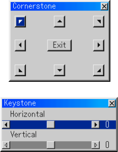
E-92
USING ON-SCREEN MENU
⬎
Menu Descriptions & Functions
Selecting Base Setting
This feature allows you to use color correction or gamma values as
reference data to optimize for various types of images. You can select
one of the following five settings.
• Presentation • Video • Movie
• Graphic • sRGB (not available on LT220)
Projector Options
Using 3D Reform
This feature corrects trapezoidal distortion so that the projected image
is rectangular.
Two options are available for correcting procedures.
You can save adjustment settings by using the 3D Reform Save option
on Setup (See page E-99).
Cornerstone
See page E-45
Keystone
1. Press the SELECT button to adjust the horizontal keystone.
2. Press the SELECT button to select "Vertical".
3. Press the SELECT button to adjust the vertical keystone.
4. After completing, press the ENTER button. This will return to the
menu screen.
*When "Resolution" is set to "Native", "Cornerstone" and "Keystone"
are not available.

E-93
USING ON-SCREEN MENU
⬎
Menu Descriptions & Functions
Menu
Allows you to set preferences for the on-screen menu. Press "OK" to
save your changes for all the features of Page 1 and Page 2.
[Page1]
Selecting Menu Language [Language]:
You can choose one of seven languages for on-screen instructions.
The options are: English, German, French, Italian, Spanish, Swed-
ish and Japanese.
Selecting Menu Mode [Menu Mode]:
This feature allows you to select 3 menu modes: Advanced Menu,
Custom Menu and Basic Menu.
Advanced Menu
........................ This is the menu that contains all the available menus
and commands.
Basic Menu ..... This is the basic menu that contains minimum essen-
tials of menus and commands.
Custom Menu.. This is the menu that you can customize using the
Custom Menu Edit to fit your needs.
Customizing the Menu:
See page E-74 for instructions about how to customize the Menu.
Selecting Projecting Pointer Icon [Projector Pointer]:
This enables you to select from eight different Pointer icons for the
"Pointer" button on your remote control.
After moving your Pointer icon to the area you want on the screen,
press the Magnify button on the remote control to enlarge the se-
lected area on the screen. See page E-55 for more details.
NOTE: There may be cases where the Pointer function is not available (ex.
a non-interlace signal at 15kHz such as video game.)
E-94
USING ON-SCREEN MENU
⬎
Menu Descriptions & Functions
Selecting Menu Display Time :
This option allows you to select how long the projector waits after
the last touch of a button to turn off the menu.
The preset choices are "Manual", "Auto 5 sec", "Auto 15 sec", and
"Auto 45 sec". The "Auto 45 sec" is the factory preset.
Manual ............ The menu can be turned off manually.
Auto 5 sec ....... The menu will automatically be turned off in 5 seconds
if no buttons are pressed within 5 seconds.
Auto 15 sec ..... The menu will automatically be turned off in 15 sec-
onds if no buttons are pressed within 15 seconds.
Auto 45 sec ..... The menu will automatically be turned off in 45 sec-
onds if no buttons are pressed within 45 seconds.
[Page 2]
Turning On / Off Source Display [Source Display]:
This option turns on or off input name display such as RGB1/2,
Video, and No Input to be displayed in the top right corner of the
screen.
Turning On / Off Message [Message]:
This option turns on and off messages for lamp life warning, 3-minute
before power off time and "This feature is not available."
Selecting Menu Color [Menu Color Select]:
You can choose between two color modes for menu color: color and
monochrome.
E-95
USING ON-SCREEN MENU
⬎
Menu Descriptions & Functions
Setup
Enables you to set operating options.
Press "OK" to save your changes for all the features of Page1, Page2,
Page3, Page 4 and Page 5.
[Page 1]
Setting Lamp Mode to Normal or Eco [Lamp Mode]:
This feature enables you to select two brightness mode of the lamp:
Normal and Eco modes. The lamp life can be extended up to 2000
hours by using the Eco mode.
Normal Mode .. This is the default setting (100% Brightness).
Eco Mode ........ Select this mode to increase the lamp life (80% Bright-
ness).
Selecting Projector Orientation [Orientation]:
This reorients your image for your type of projection. The options
are: desktop front projection, ceiling rear projection, desktop rear
projection, and ceiling front projection.
Selecting a Color or Logo for Background [Background]:
Use this feature to display a blue/ black screen or logo when no
signal is available. The default background is blue. You can change
the logo screen using the PC Card Files feature. See pages E-59
and 115.

E-96
USING ON-SCREEN MENU
⬎
Menu Descriptions & Functions
Setting RGB 1 or 2 for RGB OUT [RGBOUT Terminal]
This option allows you to determine which RGB source is output
from the RGBOUT connector during Idle mode.
Last ............ The signal from the last RGB input will be output to the
RGBOUT connector.
RGB 1 ........ The signal from RGB IN1 will be output to the RGBOUT
connector.
RGB 2 ........ The signal from RGB IN2 will be output to the RGBOUT
connector.
NOTE: The AUDIO OUT mini jack will not output sound during the Idle
mode.
Setting Closed Caption
This option sets several closed caption modes that allows text to be
superimposed on the projected image.
CAPTION 1-4 ....... Text is superimposed.
TEXT 1-4.............. Text is displayed in full screen.
OFF ...................... This exits the closed caption mode.
[Page 2]
Setting Viewer Options [Viewer Options]
Show Folder List:
If this option is checked, when the Viewer source is selected on the
projector, the folder lists will be displayed and allows you to select
the presentation from a PC card.
Auto Play:
If this option is checked, when the Viewer source is selected on the
projector any given slide will start to play automatically.

E-97
USING ON-SCREEN MENU
⬎
Menu Descriptions & Functions
Auto Play Interval:
You can specify interval time between 5 and 300 seconds.
NOTE: The Auto Play Interval time set on “Slide Show Settings” of the
Dynamic Image Utility 2.0 overrides the one set here.
Manual Play:
Views a slide manually when the Viewer source is selected.
Selecting Capture Options [Capture Option]: (available for JPEG only)
These options are used for the Capture function that you can select
from Tools. You have three options for JPEG compression quality:
High quality, Normal and High Compression.
High Quality ................... Gives quality of JPEG a priority.
Normal ........................... Gives normal JPEG quality.
High Compression ......... Gives compression a priority.
Setting Mouse Button and Sensitivity [Mouse]:
This option lets you to change your USB mouse settings. The mouse
settings feature is available for USB mouse only. Choose the set-
tings you want:
Mouse Button ................. "Right Hand" or "Left Hand"
Mouse Sensitivity ........... "Fast", "Medium" or "Slow"
E-98
USING ON-SCREEN MENU
⬎
Menu Descriptions & Functions
[Page 3]
Selecting Signal Format [Signal Select]
RGB1/2:
Allows you to choose "RGB" for an RGB source such as a com-
puter, or "Component" for a component video source such as a DVD
player. Normally select "RGB/Component" and the projector auto-
matically detects an either incoming signal. However there may be
some component signals that the projector is unable to detect. If
this is the case, select "Component". Select "Scart" in RGB 1 for the
European Scart.
VIDEO and S-VIDEO:
This feature enables you to select composite video standards manu-
ally. Normally select "Auto". Select the video standard from the pull-
down menu. This must be done for Video and S-Video separately.
[Page 4]
Enabling Auto Adjust [Auto Adjust]:
When "Auto Adjust" is set to "On", the projector automatically deter-
mines the best resolution for the current RGB input signal to project
an image using NEC's Advanced AccuBlend Intelligent Pixel Blend-
ing Technology.
The image can be automatically adjusted for position and stability;
"Horizontal Position", "Vertical Position", "Clock", "Phase", and
"Resolution".
On .............. Automatically adjusts image "Horizontal Position", "Ver-
tical Position", "Clock", "Phase" and "Resolution".
Off .............. User can adjust the image display functions ("Horizon-
tal Position", "Vertical Position", "Clock", "Phase" and
"Resolution") manually.

E-99
USING ON-SCREEN MENU
⬎
Menu Descriptions & Functions
Enabling Auto Start [Auto Start]:
Turns the projector on automatically when the power cable is in-
serted into an active power outlet and the main power switch is
turned on. This eliminates the need to always use the "Power" but-
ton on the remote control or projector cabinet.
Enabling Power Management [Power Management]:
When this option is on and there is no input for five minutes or more,
the projector will automatically turn itself off.
Enabling Power Off Confirmation [Power Off Confirmation]:
This option determines whether a confirmation dialog for turning off
the projector will appear or not.
NOTE: When the confirmation message is displayed, you must be in the
Projector mode to operate your projector using the remote control. If not,
press the PJ button on the remote control to change your projector to the
Projector mode. The button lights to indicate that you are in the Projector
mode.
Enabling Horizontal and Vertical Keystone Correction Save:
[3D Reform Save]
This option enables you to save your current 3D Reform settings.
Saving your change once affects all sources. The changes are saved
when you turn off the projector.
Enabling Fan High Speed Mode [Fan High Speed Mode]:
This option allows you to select two modes for fan speed:high-speed
mode and normal speed mode.
When you wish to cool down the temperature inside the projector
quickly, check this box.
NOTE: Enable Fan High-Speed mode if you continue to use the projector
for consecutive days.

E-100
USING ON-SCREEN MENU
⬎
Menu Descriptions & Functions
Enabling Idle Mode [Idle Mode]:
The projector has two standby modes: Standby and Idle.
Standby is the mode that allows you to put the projector in the standby
condition which consumes less power than the idle mode. The pro-
jector is preset for Standby at the factory.
When this check box is turned on, you allow the RGB OUT connec-
tor to output RGB signal during Idle mode.
NOTE:
*
The RGB OUT connector will not output signal during the Standby mode.
*Via the serial interface the projector can be turned on from your PC
using Dynamic Image Utility 2.0 during the Standby or Idle mode. On
the LAN connection the projector can be controlled or monitored
from your PC using Dynamic Image Utility 2.0 only in the Idle mode.
*The HTTP server functions are not available during Standby mode.
Clearing Lamp Hour Meter [Clear Lamp Hour Meter]:
Resets the lamp clock back to zero. Pressing this button appears a
confirmation dialog box. To reset the lamp usage hour, press "OK".
NOTE: The projector will turn off and go into standby mode after 1600
hours (up to 2100 hours in Eco mode) of service. In this condition you
cannot clear the lamp hour meter on the menu. If this happens, press the
"Help" button on the remote control for ten seconds to reset the lamp clock
back to zero. Do this only after replacing the lamp.
[Page 5]
Selecting Communication Speed [Communication Speed]:
This feature sets the baud rate of the PC Control port (Mini DIN 8
Pin). It supports data rates from 4800 to 38400 bps.
The default is 38400 bps. Select the appropriate baud rate for your
equipment to be connected (depending on the equipment, a lower
baud rate may be recommended for long cable runs).
Selecting Default Source [Default Source Select]:
You can set the projector to default to any one of its inputs each
time the projector is turned on.

E-101
USING ON-SCREEN MENU
⬎
Menu Descriptions & Functions
Last ............ Sets the projector to default to the previous or last ac-
tive input each time the projector is turned on.
Auto............ Searches for an active source in order of RGB1 →
RGB2 → Video → S-Video → Viewer → RGB1 and
displays the first found source.
Select .........
Displays the selected source input every time the projec-
tor is started up. Select an input from the pull-down menu.
Disabling the Cabinet Buttons [Control Panel Key Lock]:
This option turns on or off the Control Panel Key Lock function.
NOTE:
*This Control Panel Key Lock does not affect the remote control and the
PC Control functions.
*When the cabinet buttons are disabled, pressing and holding the CAN-
CEL button for about 10 seconds will change the setting to enabled.
Selecting Aspect Ratio and Position for Screen [Screen]
Screen Type:
Select either 4:3 Screen or 16:9 Screen for the screen to be used.
See also "Aspect Ratio" on page E-86.
NOTE: When "Resultion" is set to "Native", this selection is inactive.
Position:
This feature adjusts the vertical position of the image when viewing
video with an aspect ratio selected.
When some aspect ratios are selected in Image Options, the image
is displayed with black borders on the top and bottom.
You can adjust the vertical position between top and bottom.
NOTE:
This option is available only when "16:9" is selected in Screen Type.
NOTE:
During 3D Reform adjustment, "Screen Type" and "Screen Position"
may not be available. To make available, first reset the 3D Reform data and then
do settings again. Secondly repeat the 3D Reform adjustment. Changing "Screen
Type" and "Screen Position" can limit 3D Reform in its adjustable range.
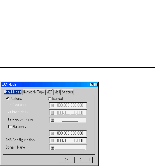
E-102
USING ON-SCREEN MENU
⬎
Menu Descriptions & Functions
Setting LAN Mode
This feature allows you to set various setting items when the projector is
used on your network.
Consult with your network administrator about these settings.
NOTE: A LAN card is required for LAN connection; NEC's optional wireless LAN
card is available. For more information on inserting or ejecting a LAN card, see
pages E-63 and 64.
CAUTION: Make sure that the LAN card is removed during Standby mode
(NOT Idle mode) or with the main power off.
Failure to do so may cause damage to the data on your PC card.
NOTE: LAN card is not available when a PC card is used for the Viewer function.
Viewer is not available when LAN card is used for LAN connection.
IP Address
An IP address can be automatically assigned to this projector by your
DHCP server. If your network does not automatically assign IP address,
ask your network administrator for an address, and then register it manu-
ally.
E-103
USING ON-SCREEN MENU
⬎
Menu Descriptions & Functions
Automatic ........ Automatically assigns an IP address to the projector
from a DHCP server.
Manual ............ Provides a space for you to register the IP address or
subnet mask number obtained from your network ad-
ministrator.
IP Address ...... Set your IP address. Press to display the software
keyboard and type in 12 numeric characters.
Subnet Mask ... Set your subnet mask number. Press to display the
software keyboard and type in 12 numeric characters.
Projector Name
........................ Specify a unique projector name. Press to display
the software keyboard and type in. Up to 16 alphanu-
meric characters can be used.
Gateway .......... Set the default gateway of the network connected to
the projector. Press to display the software keyboard
and type in 12 numeric characters.
Checking this box will make the set default route valid.
When data is sent from the LAN card, the transfer lo-
cation will be searched according to the previously set
routing information; however, when the transfer loca-
tion has not been found as a result of the search, the
data will be sent to the device that holds the IP ad-
dress set here. The IP address that is set here must be
one that can be identified by a search of the routing
information.
DNS Configuration
........................ Type in the IP address of DNS server on the network
connected to the projector. 12 numeric characters are
used.
Domain Name . Type in domain name of the network connected to the
projector. Up to 60 alphanumeric characters can be
used.
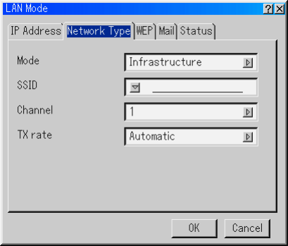
E-104
USING ON-SCREEN MENU
⬎
Menu Descriptions & Functions
Network Type (required for wireless only)
Mode:
Select communication method when using wireless LAN.
Infrastructure ... Select this option when communicating with one or
more equipment connected to the wireless or wired
LAN network via an access point.
802.11 Ad Hoc Select this option when using the wireless LAN to com-
municate with a computer in a one-to-one correspon-
dence. This is a method that meets the IEEE802.11
wireless standard.
Ad Hoc ............ Select this option when using the wireless LAN to com-
municate with a computer in a one-to-one correspon-
dence.
Easy Connection
........................ This allows you to easily set up wireless LAN connec-
tion. See the supplied Application Guide for more in-
formation.

E-105
USING ON-SCREEN MENU
⬎
Menu Descriptions & Functions
SSID (Network name):
Enter an identifier (SSID) for wireless LAN when selecting [Infrastruc-
ture] or [802.11 Ad Hoc] in [Mode]. Communication can be done only
with equipment whose SSID matches SSID for your wireless LAN. Up
to 16 alphanumeric characters can be used.
NOTE: To disable SSID, select a space (null) or "ANY"(All caps).
Channel:
Set this option when selecting [802.11 Ad Hoc] or [Ad Hoc] in [Mode].
Select a channel number from the pull-down list. The channel must
match for all wireless devices communicating on your wireless LAN.
NOTE: Channels in the pull-down list are different depending on which coun-
try you live in.
TX rate:
Select a wireless transmission speed. Normally leave it as Automatic.
Try another transmission speed when the connection fails.
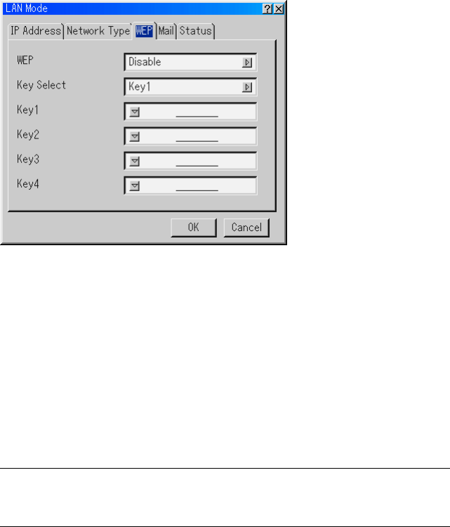
E-106
USING ON-SCREEN MENU
⬎
Menu Descriptions & Functions
WEP (for Wireless only)
Select this option whether using the WEP (Wired Equivalent Privacy)
key for encryption or not. To use encryption, specify WEP key.
Disable ............ Will not turn on the encryption feature. Your communi-
cations may be monitored by someone.
64bit ................ Uses 64-bit datalength for secure transmission.
128bit .............. Uses 128-bit datalength for secure transmission. This
option will increase privacy and security when com-
pared to use of 64bit datalength encryption.
NOTE: The WEP settings must be the same as communication devices such as PC
or access point in your wireless network. When you use WEP, your image trans-
mission speed will slow down.
Key Select:
Selects one key from the four keys below when selecing [64bit] or [128bit]
in [WEP].
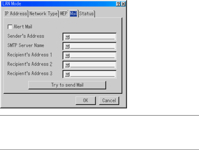
E-107
USING ON-SCREEN MENU
⬎
Menu Descriptions & Functions
Key1-4:
Enter encryption key when selecting [64bit] or [128bit] in [WEP].
The key can also be set in hexadecimal digit.
* Enter 0X(numeral and alphabet respectively) right in front of your key
code.
* Hexadecimal uses 0 to 9 and A to F.
* Up to 10 characters can be set in 64 bit and up to 26 characters in
128 bit.
Mail
NOTE: To the Mail Alert feature on wireless LAN connection, select "Infrastruc-
ture" for "Mode" in "Network Type."
"Test Mail" is available only when there is a LAN card in the PC card slot of the
projector.
Alert Mail:
Checking this box enables Alert Mail feature.
This option notifies your computer of an error message via e-mail when
using wireless or wired LAN. The error message will be notified when
the projector lamp has reached the end of its usable life or an error
occurs in the projector.

E-108
USING ON-SCREEN MENU
⬎
Menu Descriptions & Functions
Sample of a message sent from the projector:
The lamp is at the end of its usable life. Please replace the lamp.
Projector Name: X X X X
Lamp Hour Meter: xxxx [H]
Projector Usage: xxxxxx [H]
Sender's Address:
Specify the senders address. Use the Software keyboard. Up to 60
alphanumeric and symbols characters can be used. See "Using Soft-
ware Keyboard" in Appendix for more details.
SMTP Server Name:
Type in the SMTP server name to be connected to the projector. Up to
60 alphanumeric characters can be used.
Recipient's Address 1 to 3:
Type in your recipient's address. Up to 60 alphanumeric and symbols
characters can be used.
Test Mail:
Send a test mail to check if your settings are correct.
NOTE: If you entered an incorrect address in a test, you may not receive an
Alert mail. Should this happen, check if the Recipient's Address is correctly
set.
NOTE: Unless any one of the "Sender's Address", "SMTP Server's Name" or
"Recipient's Address 1-3" is selected, "Test Mail" is not available.
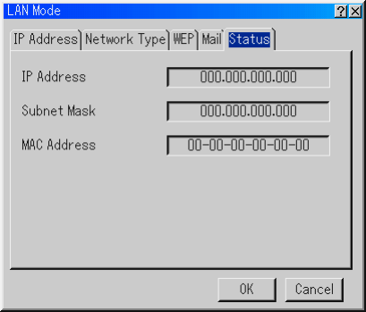
E-109
USING ON-SCREEN MENU
⬎
Menu Descriptions & Functions
Status
Displays the status of the LAN settings.
IP Address ...... Indicates the IP address of the projector.
Subnet Mask ... Indicates the subnet mask of the projector.
MAC Address .. Indicates the MAC address of the LAN card.
Setting a Passcode
A passcode can be set for your projector to avoid operation by an unau-
thorized.
There are two kinds of passcode: one for menu and the other for logo.
When a passcode is set, doing any one of the following four operations will
display the Passcode input screen.
For Menu:
*Changing the menu to Advanced
*Editing the custom menu
For Logo:
*Changing the background
*Changing the logo data in PC Card Files
Procedures for Passcode setting apply to both Menu and Logo.

E-110
USING ON-SCREEN MENU
⬎
Menu Descriptions & Functions
Entry
To assign your passcode:
NOTE: Up to 15 digits can be assigned.
1. Select [Entry] and press the ENTER button. The [Entry] screen will be
displayed.
2. Type in a combination of SELECT buttons and press the EN-
TER button.
The [Confirm Passcode] screen will be displayed.
3. Type in the same combination of SELECT buttons and press the
ENTER button.
Your passcode has been assigned.
Delete
To delete your passcode:
1. Select [Delete] and press the ENTER button. The [Delete] screen will be
displayed.
2. Type in your passcode and press the ENTER button.
Your passcode has been deleted.
In case you forget your passcode, follow the steps below to delete it.
1. Select the Advanced menu from the Basic/Custom menu. The Passcode
entry screen will be displayed.
2. Press the SELECT (up) button four times and then press the ENTER
button.
The "Warning Passcode!!" message will be displayed.
3. Press the SELECT (down) button four times and then press the EN-
TER button.
The "Warning Passcode!!" message will be displayed.
4. Press the SELECT (right) button four times and then press the EN-
TER button.
The "Delete Passcode / Are you sure?" message will be displayed.
Use the SELECT or button to select "Yes" and press the ENTER
button. Your passcode has been deleted.
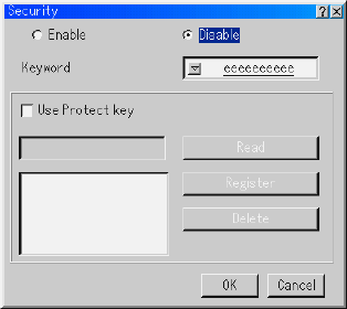
E-111
USING ON-SCREEN MENU
⬎
Menu Descriptions & Functions
Security
The Security function enables you to protect your projector so that the
projector will not project a signal unless you enter a keyword. There is also
an option to lock the projector by using a registered PC card as a protect
key. Once you have registered your PC card as a protect key, you are
required to insert the registered PC card into the PC card slot of the pro-
jector each time you turn on the projector. You can enable the Security
function by using a keyword only.
Enable/Disable .......... This turns the Security function on or off.
Keyword .................... Enter an appropriate keyword when you use the
Security function.
(Up to 10 characters can be used.)
The Security function is available only when your
keyword is entered.
Use Protect key ......... Check this box to lock your projector when us-
ing a PC card. To use a keyword without a PC
card, do not check this box.
Read ......................... Reads data of a PC card.
Register..................... Registers data of the PC card.
The Security function is not available unless at
least one PC card is registered. (if the “Use Pro-
tect key” check box is selected)
Up to 5 PC cards can be registered.
Delete........................ Deletes data of a registered PC card.

E-112
USING ON-SCREEN MENU
⬎
Menu Descriptions & Functions
To set up a keyword to enable the Security function without using a regis-
tered PC card
1. Use the SELECT button to select “Keyword” and use the software
keyboard to enter a keyword.
NOTE: Please make a note of your keyword.
2. Use the SELECT button to select “Enable” and use the SELECT
button to select “OK”, then the Security function will be enabled. An
“Are you sure?” message will appear. Use the SELECT button and
press the ENTER button.
The Security function takes effect.
To register a PC card as a protect key
1. Insert a PC card into the PC card slot of the projector.
2. Use the SELECT button to select "Read" and press the ENTER but-
ton.
Data of the PC card will be read into the projector.
3. Use the SELECT button to select "Register" and press the ENTER
button.
Downloaded data will be registered and be displayed in the list window.
4. Use the SELECT button to select "Keyword" and use the software
keyboard to enter a keyword.
NOTE: To use a PC card as a protect key, you must also set up a keyword. Please
make a note of your keyword.
This completes registration of your PC card.
To enable Security, use the SELECT button to select "Enable" and
use the SELECT button to select "OK" and "Security function will be
enabled. An “Are you sure?" message will appear. Use the SELECT
button and press the ENTER button.
The Security function takes effect.

E-113
USING ON-SCREEN MENU
⬎
Menu Descriptions & Functions
To turn on the projector when Security is enabled (when using your key-
word only)
1. Press and hold the POWER button for a minimum of two seconds.
The projector will be turned on and display a message to the effect that
the projector is security-protected.
2. Select [Projector Options] → [Security] from the menu and press the EN-
TER button.
The Release Code input screen will be displayed.
3. Enter your keyword in the Release Code input screen.
You can view the projected image.
NOTE: Do not forget your keyword. However, if you forget your keyword, NEC or
your dealer will provide you with your Release Code. See more information at the
end of this section.
To turn on the projector when Security is enabled (when using a PC card
as a protect key)
1. Insert your registered PC card into the PC card slot.
2. Press and hold the POWER button for a minimum of two seconds.
The projector will turn on and then recognize the PC card. Once the im-
age has been projected, it will stay on without the PC card.
To delete PC card data you registered
1. Use the SELECT button to select "Register" and use the SELECT
button to select the list window.
2. Use the SELECT button to select the PC card data you wish to de-
lete.
3. Press the SELECT button to select "Delete" and press the ENTER
button.
The PC card data will be deleted.

E-114
USING ON-SCREEN MENU
⬎
Menu Descriptions & Functions
If you've lost your registered PC card, proceed as follows:
NOTE: NEC or your dealer will provide you with your Release Code in ex-
change for your registered keyword and Request Code. See more information
at the end of this section.
1. Press and hold the POWER button for a minimum of two seconds.
The projector will be turned on and display a message to the effect that
the projector is security-protected.
2. Select [Projector Options] → [Security] from the menu and press hte EN-
TER button.
The Release Code input screen will be displayed as well as your Request
Code (24 alphanumeric characters).
3. Enter your Release Code in the Release Code Input screen.
The projector will turn on.
*If the projector is turned on by entering the Release Code, your Secu-
rity will be disabled.
NOTE:
*Some types of PC cards cannot be registered as your protect key.
*It is recommended that you register two or more PC cards in case you lose or
damage your registered PC card.
*Formatting your registered PC card will disable your protect key function.
NOTE:
For additional information visit:
US : http://www.necvisualsystems.com
Europe : http://www.nec-europe.com/
Global : http://www.nec-pj.com/

E-115
USING ON-SCREEN MENU
⬎
Menu Descriptions & Functions
Tools
Provides tools for setting sleep timer, capturing images, displaying files or
changing your background logo in a PC Card and drawing.
NOTE: The "Capture" and "PC Card Files" features are required for a PC card.
Using Sleep Timer
1. Select your desired time between 30 minutes and 16 hours: Off, 0:30, 1:00,
2:00, 4:00, 8:00, 12:00, 16:00.
2. Select “Set” and press the ENTER button on the remote control.
3. The remaining time starts counting down.
4. The projector will turn off after the countdown is complete.
NOTE:
•To cancel the preset time, set "Off" for the preset time or turn off the power.
•When the remaining time reaches 3 minutes before the projector is turned off,
the "Projector will turn off in 3 minutes" message will be displayed on the
bottom of the screen.
Using Capture
Allows you to capture an image from a source that is currently being dis-
played. The image is saved as JPEG in the PC card. When you select
Capture from the menu, you will get a tool bar. You can capture an image
directly using the tool bar when the menu is not displayed.
See page E-69.
Using PC Card Files
The PC Card Files feature allows you to display a list of all the files stored
in the PC card so that you can select a file you want to display. You can
also sort files by file name or date, or display the file. See page E-59.

E-116
USING ON-SCREEN MENU
⬎
Menu Descriptions & Functions
[Page 1]
Source Name
Input Terminal
Entry No.
Horizontal Frequency
Vertical Frequency
Sync Polarity
[Page 2]
Signal Type
Video Type
Sync Type
Interlace
[Page 3]
Remaining Lamp Time (%)
Lamp Hour Meter (H)
Projector Usage (H)
Changing Background Logo:
You can change the default background logo using the PC Card Files
feature.
NOTE: File size must be 256KB or less. Other file formats than JPEG and
BMP are not available. See page E-59.
Using ChalkBoard
The ChalkBoard feature allows you to write and draw messages on a pro-
jected image. See page E-61
NOTE: This feature is available only when using with USB mouse. See page E-58.
Help
Contents
Provides an online help about how to use the menus. An underlined link
means that you can move to an adjustment item directly.
Selecting the underlined link and pressing ENTER moves to the corre-
sponding adjustment item.
Information
Displays the status of the current signal, and the lamp and the projector
usage hours. This dialog box has three pages.
The information included are as follows:

E-117
NOTE: The progress indicator shows the percentage of remaining bulb life. The
value informs you of the amount of lamp and projector usage respectively.
Remaining Lamp Time Display:
When the remaining lamp time reaches 0, the Remaining Lamp Time
bar indicator changes from 0% to 100 Hours and starts counting down.
If the remaining lamp time reaches 0 hours, the projector will not turn
on regardless of whether the lamp mode is set to Normal or Eco.
Returning to Factory Default
The Factory Default feature allows you to change adjustments and setting
to the factory preset for source except the following:
All Data ........... Reset all the adjustments and settings for all the sig-
nals to the factory preset except Remaining Lamp Time,
Lamp Hour Meter, Projector Usage, Language, Back-
ground, Entry List, Communication Speed, Security and
Passcode. (To reset the lamp usage time, see “Clear
Lamp Hour Meter” on page E-100)
Current Signal . Resets the adjustments for the current signal to the
factory preset levels.
All the items in "Picture", "Volume", "Image Options"
and "Picture Management" can be reset.
USING ON-SCREEN MENU
⬎
Menu Descriptions & Functions

E-118
MAINTENANCE
This section describes the simple maintenance procedures you should
follow to replace the lamp, and to clean the cabinet and the lens.
Replacing the Lamp
After your lamp has been operating for 1500 hours (up to 2000 hours : Eco
mode) or longer, the "Lamp" indicator in the cabinet will blink red and the
message will appear. Even though the lamp may still be working, replace
it at 1500 hours (up to 2000 hours : Eco mode) to maintain optimal projec-
tor performance.
CAUTION
•DO NOT TOUCH THE LAMP immediately after it has been used. It
will be extremely hot. Turn the projector off, wait 90 seconds, turn off
the main power switch, and then disconnect the power cable. Allow
at least one hour for the lamp to cool before handling.
•DO NOT REMOVE ANY SCREWS except the lamp cover screw and
two lamp case screws. You could receive an electric shock.
•The projector will turn off and go into stand by mode after 1600 hours
(up to 2100 hours : Eco mode) of service. If this happens, be sure to
replace the lamp. If you continue to use the lamp after 1500 hours
(up to 2000 hours : Eco mode) of use, the lamp bulb may shatter, and
pieces of glass may be scattered in the lamp housing. Do not touch
them as the pieces of glass may cause injury.
If this happens, contact your NEC dealer for lamp replacement.
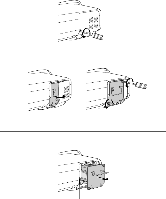
E-119
MAINTENANCE
Interlock
To replace the lamp:
1. Loosen the lamp cover screw until the screwdriver goes into a freewheel-
ing condition and remove the lamp cover. The lamp cover screw is not
removable.
2. Loosen the two screws securing the lamp housing until the screwdriver
goes into a freewheeling condition. The two screws are not removable.
3. Remove the lamp housing by pulling out the handle.
NOTE: There is an interlock on this case to prevent the risk of electrical shock.
Do not attempt to circumvent this interlock.
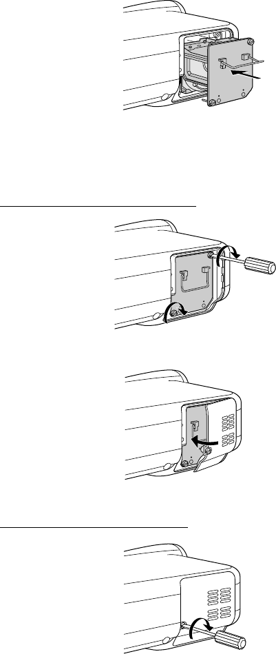
E-120
MAINTENANCE
4. Insert a new lamp housing until the lamp housing is plugged into the
socket.
CAUTION
Do not use a lamp other than the NEC replacement lamp (LT60LP).
5. Secure it in place with the two screws.
Be sure to tighten the screws.
6. Reattach the lamp cover.
7. Tighten the lamp cover screw.
Be sure to tighten the screw.
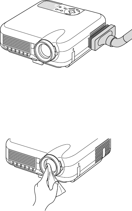
E-121
SELECT
C
N
A
C
E
L
T
E
R
N
E
E
M
N
U
SOURCEAUTO ADJUST
ON
STAND BY
STATUS
POWER
LAMP
ALIGNMENT
PC-CARD
8. After you install a new lamp, from the menu select [Projector Options] →
[Setup] → [Page 4] → [Clear Lamp Hour Meter] to reset the lamp usage
hours.
If the projector will not be turned on after using 1600 hours (up to 2100
hours : Eco mode) of service, press and hold the [Help] button on the
remote control for ten seconds or longer to reset the lamp time clock to
zero.
Cleaning
Cleaning the Cabinet and the Lens
SELECT
C
N
A
C
E
L
T
E
R
N
E
E
M
N
U
SOURCEAUTO ADJUST
ON
STAND BY
STATUS
POWER
LAMP
ALIGNMENT
PC-CARD
1. Turn off the projector before cleaning.
2. Clean the cabinet periodically with a damp cloth. If heavily soiled, use a
mild detergent. Never use strong detergents or solvents such as alcohol or
thinner.
3. Use a blower or lens paper to clean the lens, and be careful not to scratch
or mar the lens.
MAINTENANCE
E-122
Lens Protector
The lens barrel has threads on the outside for mounting a commercially
available lens protector (φ 62mm for LT260/LT220 and φ 72mm for LT240)
to protect the lens from dirt, dust, scratches and damage. Note that both a
lens protector and the supplied lens cap cannot be used at the same time.
CAUTION: Use only transparent lens protectors designed for lens protec-
tion. Use of filters for light reduction and special effects, such as ND (Neu-
tral Density) filters and color filters, can absorb heat, resulting in damage
to the filter and the projector.
MAINTENANCE
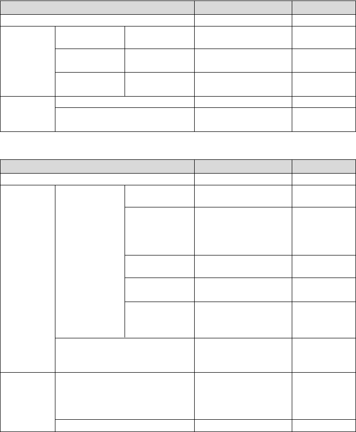
E-123
TROUBLESHOOTING
This section helps you resolve problems you may encounter while setting up or
using the projector.
Power Indicator
Indicator Condition Projector Condition Note
Off
Blinking light
Steady light
Green blinking
Green blinking
Orange blinking
0.5 sec ON,
0.5 sec OFF
2.5 sec ON,
0.5 sec OFF
0.5 sec ON,
0.5 sec OFF
The main power is off
The projector is getting ready
to turn on.
The projector is in Sleep mode.
The projector is cooling down.
The projector is turned on.
The projector is in Standby or
Idle.
Green
Orange
–
Wait for a moment.
–
Wait for a moment.
–
–
Indicator Condition Projector Condition Note
Off
Blinking light
Steady light
Red blinking
Green blinking
Orange
Green
1 cycle (0.5 sec ON,
2.5 sec OFF)
2 cycle (0.5 sec ON,
0.5 sec OFF)
3 cycle (0.5 sec ON,
0.5 sec OFF)
4 cycle (0.5 sec ON,
0.5 sec OFF)
6 cycle (0.5 sec ON,
0.5 sec OFF)
Normal
Lamp cover error
Temperature error
Power error
Fan error
Lamp error
Re-firing the lamp
Control key locked
Idle condition
–
Replace the lamp
cover correctly.
The projector is
overheated. Move
the projector to a
cooler location.
Power unit will not
work correctly.
Fans will not work
correctly.
Lamp fails to light.
Wait a full minute and
then turn on again.
The projector is re-
firing 3 times at an
interval of 15 sec.
You have pressed
control panel key
when Control Key
Lock is enabled.
–
Status Indicator

E-124
TROUBLESHOOTING
Indicator Condition Projector Condition Note
Off
Blinking light
Steady light
Normal
Lamp has reached its end of
life. Lamp replacement mes-
sage will be displayed.
Lamp has been used beyond
its limit. The projector will not
turn on until the lamp is re-
placed.
Lamp mode is set to Eco mode
Red
Red
Green
–
Replace the lamp.
Replace the lamp.
–
Lamp Indicator

E-125
Does not turn on
No picture
Image isn’t square to the
screen
Picture is blurred
Image is scrolling verti-
cally, horizontally or
both
Remote control does
not work
Indicator is lit or blink-
ing
Cross color in RGB
mode
USB mouse does not
work
•Check that the power cable is plugged in and that the power button on the projector
cabinet or the remote control is on. See pages E-36 and 37.
•Ensure that the lamp cover is installed correctly. See page E-120.
•Check to see if the projector has overheated or the lamp usage exceeds 1600 hours
(up to 2100 hours : Eco mode). If there is insufficient ventilation around the projec-
tor or if the room where you’re presenting is particularly warm, move the projector
to a cooler location.
•Use the menu to select your source (RGB 1/2, Video, S-Video, Viewer or LAN). See
page E-40.
•Ensure your cables are connected properly.
•Use menus to adjust the brightness and contrast. See page E-85.
•Remove the lens cap.
•Reset the settings or adjustments to factory preset levels using the Factory Default
in the Adjustment Menu. See page E-117.
•Reposition the projector to improve its angle to the screen. See page E-42 or 43.
•Use the 3DReform function to correct the trapezoid distortion. See page E-45.
•Adjust the focus. See page E-44.
•Reposition the projector to improve its angle to the screen. See page E-42 or 43.
•Ensure that the distance between the projector and screen is within the adjustment
range of the lens. See page E-22-26.
•Condensation may form on the lens if the projector is cold, brought into a warm
place and is then turned on. Should this happen, let the projector stand until there is
no condensation on the lens.
•Use menus or Source button on the remote control or the cabinet to select the
source you want to input.
•Install new batteries. See page E-19.
•Make sure there are no obstacles between you and the projector.
•Stand within 22 feet (7 m) of the projector. See page E-20.
•Make sure that you are in the Projector mode and the PJ button lights in red. If not,
press the PJ button. See page E-53.
•See the Status Indicator on pages E-123 and 124.
•If Auto Adjust is off, turn it on or adjust the image manually with the Position/Clock
in the Image Options. See pages E-87, 88 and 98.
•Make sure that your USB mouse is properly connected to the projector.
The projector may not support some brands of a USB mouse.
Problem Check These Items
Common Problems & Solutions
TROUBLESHOOTING

E-126
When using the Viewer function
TROUBLESHOOTING
•Is “Viewer” selected from the Source menu?
• Is the PC card seated in the PC Crad slot completely?
•Are slide data stored in the PC card?
•Have the contents of the PC card been destroyed?
•While an image with over 1024⳯768 dots (800⳯600 on
LT220) is projected, several lines of information will be lost.
Use the supplied software change the image to 1024⳯768
(800⳯600 on LT220) dots in size.
• Use a computer, etc., to repair the data.
Problem Check These Items
For more information contact your dealer.
No picture
Part of a slide is not dis-
played
Contents of PC Card are
damaged
E-127
SPECIFICATIONS
This section provides technical information about the LT260/LT240/LT220 Projector's
performance
Model Number LT260/LT240/LT220
Optical
DMD™ Single Chip Digital Micromirror Device(DMD™)
Resolution 1024⳯768 pixels (LT220: 800⳯600 pixels) up to UXGA
with Advanced AccuBlend
Lens Manual zoom and focus:
LT260/LT220: F2.2 - 2.5 f=28.4mm - 34.0mm
LT240: F2.5 - 2.8 f=22.4mm - 27.0mm
Lamp 220 W DC standard
(The lamp is warranted for 1500 hours of operation time
within 6 months.)
Image Size 30 inches - 500 inches (0.8 m - 12.7 m) diagonal
Projection Distance LT260: 3.8ft - 80.7ft / 1.18m - 24.6m
LT240: 2.95ft - 62.3ft / 0.90m - 19.0m
LT220: 4.0ft - 83.3ft / 1.22m - 25.4m
Projection Angle LT260/LT220: 14.7°-15.2°(wide) / 12.2°-12.4°(tele)
LT240: 18.6°-19.4°(wide) / 15.7°-16.2°(tele)
Electrical
Inputs 2 RGB, 1 S-Video, 1 Video, 1 PC Card, 1 Stereo Mini
Audio, 1 (L/R) RCA Audio, 1 PC Control
Outputs 1 RGB, 1 Stereo Mini Audio
USB Port 1 A Type, 1 B Type
Video Compatibility NTSC, NTSC4.43, PAL, PAL-60, PAL-N, PAL-M, SECAM,
HDTV:1080i, 720p, 480p, 480i (w/optional cable)
Scan Rate Horizontal: 15 kHz to 100 kHz (RGB: 24 kHz or over)
Vertical: 50 Hz to 120 Hz
Video Bandwidth RGB: 100 MHz (-3dB)
Pixel Clock Freq Less than 135 MHz
Color Reproduction 16.7 million colors simultaneously, Full color
Horizontal Resolution NTSC / NTSC4.43/PAL / YCbCr: 540 TV lines
SECAM: 300 TV lines
RGB:
LT260/LT240: 1024 dots (H)⳯768 dots (V),
LT220: 800 dots (H)⳯600 dots (V)

E-128
External Control RS232, IR, LAN (optional)
Sync Compatibility Separate Sync / Composite Sync / Sync on G
Built-in Speakers 2W⳯1 (monaural)
Power Requirement 100 - 120V AC / 200 - 240V AC, 50 / 60 Hz
Input Current 3.0A (100 - 120V AC) / 1.5A (200 - 240V AC)
Power Consumption 280W (0.6W at Standby)
Mechanical
Installation Orientation: Floor/Front, Floor/Rear, Ceiling/Front, Ceil-
ing/Rear
Dimensions 10.2" (W)⳯3.6" (H)⳯10.8" (D)
260mm (W)⳯92mm (H)⳯275mm (D)
(not including protrusions)
Net Weight LT260/LT220: 6.5 lbs / 2.9 kg
LT240: 7.1 lbs / 3.2 kg
Environmental Considerations
Operational Temperatures :
41° to 95°F (5° to 35°C), 20% to 80% humidity
(non-condensing)
Storage Temperatures :
14° to 122°F (-10° to 50°C), 20% to 80% humidity
(non-condensing)
Regulations UL Approved (UL 1950, CSA 950)
Meets DOC Canada Class B requirements
Meets FCC Class B requirements
Meets AS/NZS3548 Class B
Meets EMC Directive (EN55022:1998, EN55024-1998,
EN61000-3-2, EN61000-3-3)
Meets Low Voltage Directive (EN60950, TUV GS Ap-
proved)
For additional information visit:
US : http://www.necvisualsystems.com
Europe : http://www.nec-europe.com/
Global : http://www.nec-pj.com/
Digital Light Processing, DLP, Digital Micromirror Device and DMD are trademarks
of Texas Instruments.
The specifications are subject to change without notice.
SPECIFICATIONS
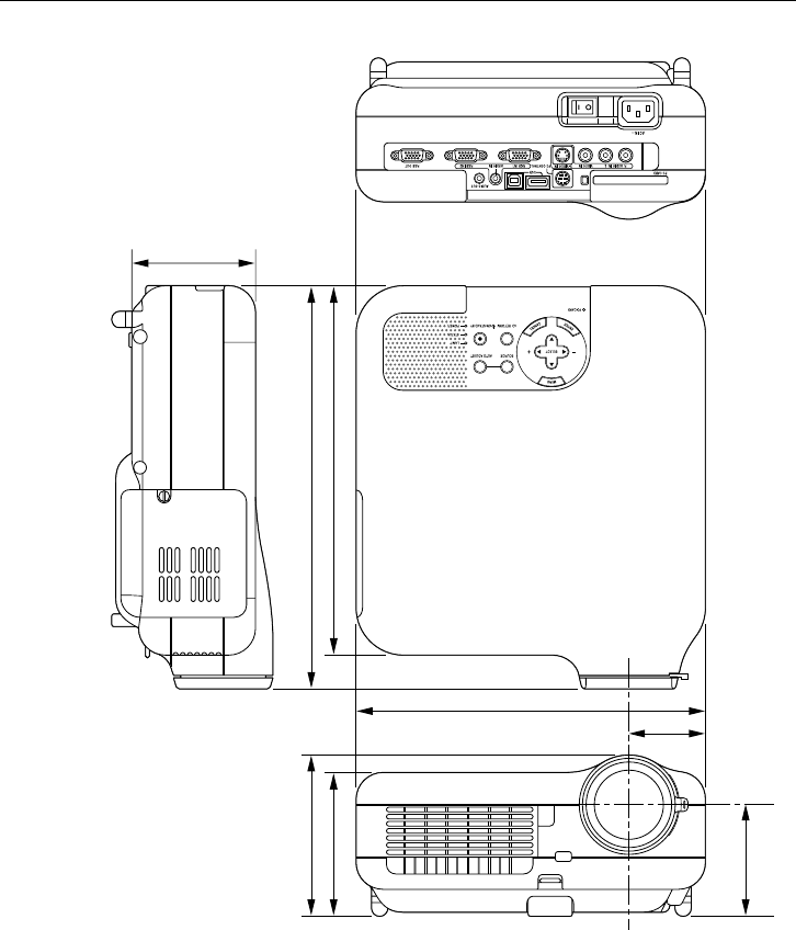
E-129
APPENDIX
Cabinet Dimensions
Unit = mm (inch)
260 (10.24")
57 (2.24")
275 (10.83")
300 (11.8") *
120 (4.7")
107 (4.2")
83 (3.27")
92 (3.6")
* LT240: 319mm (12.56”)
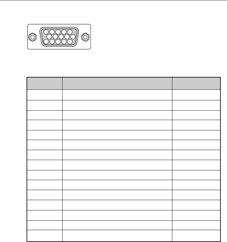
E-130
Mini D-Sub 15 Pin Connector
Pin Assignments of D-Sub RGB Input Connector
Pin No. RGB Signal (Analog) YCbCr Signal
1Red Cr
2Green or Sync on Green Y
3Blue Cb
4Ground
5Ground
6Red Ground Cr Ground
7Green Ground Y Ground
8Blue Ground Cb Ground
9No Connection
10 Sync Signal Ground
11 Ground
12 Bi-directional DATA (SDA)*
13 Horizontal Sync or Composite Sync
14 Vertical Sync
15 Data Clock*
Signal Level
Video signal : 0.7Vp-p (Analog)
Sync signal : TTL level
* RGB 1 Input only
51423
10
1112131415
6978
APPENDIX

E-131
Compatible Input Signal List
Signal Resolution Frequency H. Refresh Rate Dot Clock
( Dots ) ( kHz ) ( Hz ) ( MHz )
NTSC – 15.734 60 –
PAL–15.625 50 –
SECAM – 15.625 50 –
VESA 640 ⳯480 31.47 59.94 25.175
IBM 640 ⳯480 31.47 60 25.175
MAC 640 ⳯480 31.47 60 25.175
MAC 640 ⳯480 34.97 66.67 31.334
MAC 640 ⳯480 35 66.67 30.24
VESA 640 ⳯480 37.86 72.81 31.5
VESA 640 ⳯480 37.5 75 31.5
IBM 640 ⳯480 39.375 75 31.49
VESA 640 ⳯480 43.269 85.01 36
IBM 720 ⳯350 31.469 70.09 28.322
VESA 720 ⳯400 37.927 85.04 35.5
IBM 720 ⳯350 39.44 87.85 35.5
IBM 720 ⳯400 39.44 87.85 35.5
VESA 800 ⳯600 35.16 56.25 36
VESA 800 ⳯600 37.879 60.32 40
VESA 800 ⳯600 48.077 72.19 50
VESA 800 ⳯600 46.88 75 49.5
VESA 800 ⳯600 53.674 85.06 56.25
MAC 832 ⳯624 49.725 74.55 57.283
@VESA 1024 ⳯768 35.5 43 Interlaced 44.9
@VESA 1024 ⳯768 48.363 60 65
@VESA 1024 ⳯768 56.476 70.07 75
@MAC 1024 ⳯768 60.241 74.93 80
@VESA 1024 ⳯768 60.023 75.03 78.75
@VESA 1024 ⳯768 68.677 85 94.5
#@ VESA 1152 ⳯864 67.5 75 108
#@ MAC 1152 ⳯870 68.681 75.06 100
#@ SUN 1152 ⳯900 61.796 65.95 92.94
#@ SGI 1152 ⳯900 71.736 76.05 105.6
#@ VESA 1280 ⳯960 60 60 108
#@ VESA 1280 ⳯1024 63.981 60.02 108
APPENDIX

E-132
#@ MAC 1280 ⳯1024 69.89 65.2 118.5
#@ HP 1280 ⳯1024 78.125 72.01 135
#@ SUN 1280 ⳯1024 81.13 76.11 135
#@ VESA 1280 ⳯1024 79.976 75.03 135
#@ VESA 1280 ⳯1024 91.146 85.02 157.5
#@
HDTV
(1080i)(1125i)
1920 ⳯1080 33.75 60 Interlace 74.25
#@
HDTV
(1080i)(1125i)
1920 ⳯1080 28.13 50 Interlace 74.25
#@
HDTV (720p)(750p)
1280 ⳯720 45 60 Progressive 74.25
#@
SDTV (480p)(525p)
–31.47 59.94 Progressive 27
#@ VESA 1600 ⳯1200 75.0 60 162
#@ VESA 1600 ⳯1200 81.3 65 175.5
#@ VESA 1600 ⳯1200 87.5 70 189
#@ VESA 1600 ⳯1200 93.75 75 202.5
DVD YCbCr – 15.734 59.94 Interlaced –
DVD YCbCr – 15.625 50 Interlaced –
Signal Resolution Frequency H. Refresh Rate Dot Clock
( Dots ) ( kHz ) ( Hz ) ( MHz )
#:Images in above flagged with # are compressed with Advanced
AccuBlend on LT260 and LT240.
@:Images in above flagged with @ are compressed with Advanced
AccuBlend on LT220.
NOTE: Some composite sync signals may not be displayed correctly.
Signals other than those specified in the table above may not be displayed cor-
rectly. If this should happen, change the refresh rate or resolution on your PC.
Refer to Display Properties help section of your PC for procedures.
UXGA (1600⳯1200) is supported for separate sync signal only.
APPENDIX
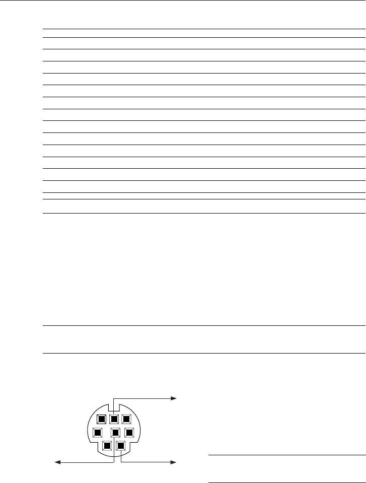
E-133
APPENDIX
Cable Connection
Communication Protocol
Baud rate : 38400 bps
Data length : 8 bits
Parity : No parity
Stop bit : One bit
X on/off : None
Communications procedure : Full duplex
NOTE: Depending on the equipment, a lower baud rate may be recommended for
long cable runs.
PC Control Codes and Cable Connection
PC Control Codes
Function Code Data
POWER ON 02H 00H 00H 00H 00H 02H
POWER OFF 02H 01H 00H 00H 00H 03H
INPUT SELECT RGB 1 02H 03H 00H 00H 02H 01H 01H 09H
INPUT SELECT RGB 2 02H 03H 00H 00H 02H 01H 02H 0AH
INPUT SELECT VIDEO 02H 03H 00H 00H 02H 01H 06H 0EH
INPUT SELECT S-VIDEO 02H 03H 00H 00H 02H 01H 0BH 13H
INPUT SELECT VIEWER 02H 03H 00H 00H 02H 01H 1FH 27H
PICTURE MUTE ON 02H 10H 00H 00H 00H 12H
PICTURE MUTE OFF 02H 11H 00H 00H 00H 13H
SOUND MUTE ON 02H 12H 00H 00H 00H 14H
SOUND MUTE OFF 02H 13H 00H 00H 00H 15H
ON SCREEN MUTE ON 02H 14H 00H 00H 00H 16H
ON SCREEN MUTE OFF 02H 15H 00H 00H 00H 17H
NOTE: Contact your local dealer for a full list of PC Control Codes if needed.
NOTE: Pins 2, 3, 5, 6 and 8 are used
inside the projector.
PC Control Connector (DIN-8P)
12
54 3
6
7
8
To RxD of PC
To TxD of PC
To GND of PC
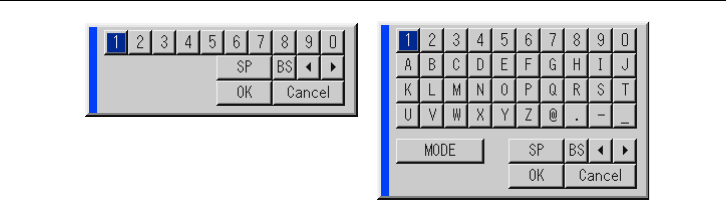
E-134
APPENDIX
Using Software Keyboard
1 to 0 and Characters ......... Use to type in IP address or projector
name
SP ....................................... Inserts a space
BS ....................................... Deletes one character backward
......................................... Returns to the previous
......................................... Advances to the next
OK ....................................... Executes the selection
Cancel ................................. Cancels the selection
Drag bar .............................. Use to move the software keyboard on the
screen.
MODE ................................. Selects one of three modes for alphabet
and special characters.

E-135
APPENDIX
Operation Using an HTTP Browser
Overview
The use of HTTP server functions will allow control of the projector from a
web browser without the installation of special software. Please be sure to
use “Microsoft Internet Explorer 4.x” or a higher version for the web browser.
(This device uses “JavaScript” and “Cookies” and the browser should be
set to accept these functions. The setting method will vary depending on
the version of browser. Please refer to the help files and the other informa-
tion provided in your software.)
NOTE:
* The use of HTTP server functions is not available during Standby mode.
*The display’s or button’s response can be slowed down or operation may not be
accepted depending the settings of your network. Should this happen, consult
your network administrator.
*The projector may not respond if its buttons are repeatedly pressed in rapid
intervals. Should this happen, wait a moment and repeat. If you still can’t get
any response, pull out and then re-insert the LAN card.
Access is gained to the HTTP server functions by specifying
http:// <the projector’s IP address> /index.html
in the entry column of the URL.
Preparation Before Use
Make network connections and set up the projector and confirm that it is
complete before engaging in browser operations. (See “Setting LAN Mode”
on page E-102.)
Operation with a browser that uses a proxy server may not be possible
depending on the type of proxy server and the setting method. Although
the type of proxy server will be a factor, it is possible that items that have
actually been set will not be displayed depending on the effectiveness of
the cache, and the contents set from the browser may not be reflected in
operation. It is recommended that a proxy server not be used unless it is
unavoidable.
E-136
APPENDIX
Handling of the Address for Operation via a Browser
Regarding the actual address that is entered for the address or entered to
the URL column when operation of the projector is via a browser, the host
name can be used as it is when the host name corresponding to the IP
address of the projector has been registered to the domain name server
by a network administrator, or the host name corresponding to the IP ad-
dress of the projector has been set in the “HOSTS” file of the computer
being used.
Example 1: When the host name of the projector has been set to
“pj.nec.co.jp”,
http://pj.nec.co.jp/index.html
is specified for the address or the entry column of the URL.
Example 2: When the IP address of the projector is “192.168.73.1”,
access is gained to the
HTTP server functions by specifying
http://192.168.73.1/index.html
for the address or the entry column of the URL.
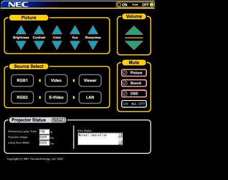
E-137
APPENDIX
Structure of the HTTP Server
Power: This controls the power of the projector.
On ................... Power is switched on.
Off ................... Power is switched off.
Volume: This controls the volume of the projector.
..................... Increments the volume adjustment value.
..................... Decrements the volume adjustment value.
Mute: This controls the mute function of the projector.
All On .............. Mutes each of the video, audio, and on-screen display
functions.
All Off .............. Cancels the muting of each of the video, audio, and
on-screen display functions.
Picture On .......Mutes the video.
Picture Off ....... Cancels the video muting.
Sound On ........ Mutes the audio.
Sound Off ........ Cancels the audio muting.
OSD On .......... Mutes the on-screen display.
OSD Off .......... Cancels the muting of the on-screen display.
E-138
Picture: Controls the video adjustment of the projector.
Brightness ... Increments the brightness adjustment value.
Brightness ... Decrements the brightness adjustment value.
Contrast ...... Increments the contrast adjustment value.
Contrast ...... Decrements the contrast adjustment value.
Color ........... Increments the color adjustment value.
Color ........... Decrements the color adjustment value.
Hue ............. Increments the hue adjustment value.
Hue ............. Decrements the hue adjustment value.
Sharpness ... Increments the sharpness adjustment value.
Sharpness ... Decrements the sharpness adjustment value.
*The functions that can be controlled will vary depending on the signal
being input to the projector.
Source Select: This switches the input connector of the projector.
RGB1 .............. Switches to the RGB 1 connector.
RGB2 .............. Switches to the RGB 2 connector.
Video ............... Switches to the Video connector.
S-Video ........... Switches to the S-Video connector.
Viewer ............. Switches to the Viewer.
LAN ................. Switches to a LAN signal.
Projector Status: This displays the condition of the projector.
Remaining Lamp Time
... Displays the remaining life of the lamp as a per-
centage.
Lamp Hour Meter ...... Displays how many hours the lamp has been
used.
Projector Usage ........ Displays how many hours the projector has been
used.
Error Status ............... Displays the status of errors occurring within the
projector.
Refresh ..................... Updates the display of the following conditions.
APPENDIX

E-139
APPENDIX
TravelCare - a service for international travelers
This product is eligible for "TravelCare", NEC's unique international war-
ranty.
Please note that TravelCare coverage differs in part from coverage under
the warranty included with the product.
Services offered with TravelCare
This warranty allows customers to receive service on their product at the
NEC and NEC-designated service stations in the countries listed herein
when temporarily traveling internationally for business or pleasure.
For details on services offered by the different service stations, please
refer to the "List of TravelCare Outlets" below.
1 Repair services
The product will be repaired and delivered within 10 business days, not
including shipping time.
During the term of warranty, the cost of maintenance parts, labor costs
for repairs and shipping costs within the service station's coverage area
are covered by the warranty.
2 Replacement product rental service
If the customer desires, he or she can rent a replacement product while
the original product is being repaired.
Fee: US$200 for 12 days
This fee must be paid at the local service station in cash or credit card.
The $200 rental fee is non-refundable even if the customer rents it less
than 12 days before returning.
The replacement product will be delivered within 3 business days.
If the customer did not return the replacement product within 12 days,
the customer will be charged the price of the unit.
If the customer returned the replacement product in a faulty or dam-
aged condition, the repair cost will be charged to the customer.
TravelCare Guide
E-140
Note that this service is not offered in all countries and regions. Please
refer to the "List of TravelCare Outlets".
In addition, this replacement product rental service is not offered after
the product's warranty has expired.
Term of warranty
1a.Upon presentation of the warranty or receipt received upon purchase:
Valid for the term indicated on the warranty or the normal term of war-
ranty for the country of purchase.
b. When only the product is brought in:
Valid for a period of within 14 months of the date of manufacture indi-
cated by the serial number attached to the product.
2When a product whose term of warranty is expired is brought in:
Repairs will be offered for a fee. In this case the customer is not eligible
for the replacement product rental service.
3In the following cases, repairs may be charged, even if the product's
warranty is still in effect:
1) If the term of warranty, model name, serial number and name of the
store of purchase are not indicated on the warranty or have been al-
tered.
2) Problems or damage caused by dropping or shocks during shipment or
movement by the customer or by improper handling by the customers.
3) Problems or damage caused by improper usage or unwarrantable al-
terations or repairs by the customer.
4) Problems or damage caused by fire, salt damage, gas damage, earth-
quakes, lightning damage, storm or flood damage or other natural di-
sasters or such external factors as dust, cigarette smoke, abnormal
voltage, etc.
5) Problems or damage caused by use in hot or humid places, in vehicles,
boats or ships, etc.
6) Problems or damage caused by expendable supplies or devices con-
nected to the product other than those designated by NEC.
APPENDIX
E-141
7) Problems caused by natural consumption, wear or deterioration of parts
under normal usage conditions.
8) Problems or damage to lamps and other expendable supplies, included
parts or optional parts.
9) Other conditions stipulated in the warranty included with the product
also apply.
The product can be used overseas with voltages of 100 to 120V and 200 to 240V
by using a power cable suited for the standards and power source voltage of the
country in which the product is being used.
List of TravelCare Outlets
This list applies as of June 1, 2002.
For the most up-to-date information, please refer to the websites of the
service stations in the various countries on the List of TravelCare Outlets
or to the NEC website at http://www.nec-pj.com.
List of TravelCare Outlets
In Europe
NEC Europe, Ltd. / European Technical Centre
Address: Unit G, Stafford Park 12, Telford TF3 3BJ, U.K.
Telephone: +44 1952 237000
Fax Line: +44 1952 237006
Email Address: AFR@uk.neceur.com
WEB Address: http://www.neceur.com
(Regions Covered)
EU: Austria*, Belgium*, Denmark*, Finland*, France*, Germany*,
Greece*, Ireland*, Italy*, Luxembourg*, The Netherlands*,
Portugal*, Spain*, Sweden* and the United Kingdom*
EEA: Norway*, Iceland and Liechtenstein
✍
APPENDIX
E-142
In North America
NEC Solutions (America), Inc.
Address: 1250 Arlington Heights Road, Itasca,
Illinois 60143, U.S.A.
Telephone: +1 800 836 0655
Fax Line: +1 800 356 2415
Email Address: vsd-tech-support@necsam.com
WEB Address: http://www.necvisualsystems.com
(Regions Covered)
U.S.A. *, Canada*
In Oceania
NEC Australia Pty., Ltd.
Address: New South Wales;
184 Milperra Road, Reversby 2212
Victoria;
480 Princess Hwy Noble Park 3174
South Australia;
84A Richmond Road, Keswick 5035
Queensland;
116 Ipswich Road, Woollongabba 4102
Western Australia;
45 Sarich Court Osborne Park 6017
Telephone: 131 632 (from domestic)
+61 8 8375 5706 (from overseas)
Fax Line: +61 8 8375 5757
Email Address: lee.gramola@nec.com.au
WEB Address: http://www.nec.com.au
(Regions Covered)
Australia*, New Zealand
APPENDIX
E-143
In Asia and Middle East
NEC Viewtechnology, Ltd.
Address: 686-1, Nishioi, Oi-Machi, Ashigarakami-Gun,
Kanagawa 258-0017, Japan
Telephone: +81 465 85 2369
Fax Line: +81 465 85 2393
Email Address: support_pjweb@nevt.nec.co.jp
WEB Address: http://www.nec-pj.com
(Regions Covered)
Japan*
NEC Hong Kong Ltd.
Address: 11th Floor, Tower B, New Mandarin Plaza, 14 Science
Museum Road,
Tsim Sha Tsui East, Kowloon, Hong Kong
Telephone: +852 2369 0335
Fax Line: +852 2795 6618
Email Address: esmond_au@nechk.nec.com.hk
WEB Address: http://www.nec.com.hk
(Regions Covered)
Hong Kong
NEC Taiwan Ltd.
Address: 7F, No.167, SEC.2, Nan King East Road, Taipei,
Taiwan, R.O.C.
Telephone: +886 2 8500 1734
Fax Line: +886 2 8500 1420
Email Address: nickliao@nec.com.tw
WEB Address: http://www.nec.com.tw
(Regions Covered)
Taiwan
APPENDIX
E-144
NEC Singapore Pte. Ltd
Address:
401 Commonwealth Drive, #07-02, Haw Par Technocentre,
Singapore 149598
Telephone: +65 6 273 8333
Fax Line: +65 6 274 2226
Email Address: daniel@rsc.necsin.nec.com.sg
WEB Address: http://www.nec.com.sg
(Regions Covered)
Singapore
Hyosung Data System, Ltd.
Address: 7th Floor, Cheongdam Building, 52, Cheongdam-Dong,
Kangnam-Ku, Seoul, Korea 135-100
Telephone: +82 2 510 0234
Fax Line: +82 2 540 3590
Email Address: hds-ykc@hyosung.com
(Regions Covered)
South Korea
Lenso Communication Co., Ltd.
Address: 292 Lenso House 4, 1st Floor, Srinakarin Road,
Huamark, Bangkapi, Bangkok 10240, Thailand
Telephone: +66 2 375 2425
Fax Line: +66 2 375 2434
Email Address: pattara@lenso.com
WEB Address: http://www.lenso.com
(Regions Covered)
Thailand
APPENDIX
E-145
ABBA Electronics L.L.C.
Address: Tariq Bin Ziyad Road, P.O.Box 327, Dubai,
United Arab Emirates
Telephone: +971 4 371800
Fax Line: +971 4 364283
Email Address: ABBA@emirates.net.ae
(Regions Covered)
United Arab Emirates
Samir Photographic Supplies
Address: P.O.Box 599, Jeddah 21421, Saudi Arabia
Telephone: +966 2 6828219
Fax Line: +966 2 6830820
Email Address: vartkes@samir-photo.com
(Regions Covered)
Saudi Arabia
In countries designated with an asterisk(*), replacement product rental service
are offered.
✍
APPENDIX

E-146
TO: NEC or NEC's Authorized Service Station:
FM:
(Company & Name with signature)
Dear Sir (s),
I would like to apply your TravelCare Service Program based on attached registration and qualification
sheet and agree with your following conditions, and also the Service fee will be charged to my credit card
account, if I don't return the Loan units within the specified period. I also confirm following information is
correct. Regards.
Application Sheet for TravelCare Service Program
Date: / / , P-1/ ,
Country,
product purchased :
User's Company Name :
User's Company Address :
Phone No., Fax NO. :
User's Name :
User's Name Address :
Phone No., Fax NO. :
Local Contact office :
Local Contact office Address :
Phone No., Fax NO. :
User's Model Name :
Date of Purchase :
Serial No. on rear panel :
P Problem of units per User :
Required Service : (1) Repair and Return (2) Loan unit
Requested period of Loan unit :
Payment method : (1) Credit Card (2) Travelers Cheque, (3) Cash
In Case of Credit Card :
Card No. w/Valid Date :
E-147
Enduser is requested to understand following condition of TravelCare Ser-
vice Program and fill necessary information into the application sheet.
1. Service Options:
There are 3 types of "Service" available. Enduser has to understand fol-
lowing condition and is required to fill in the Application Sheet.
1) Repair and Return:
The 'Faulty unit' is sent or collected from the customer. It is repaired
and returned within 10 days to the customer, excluding transport time.
There may have a case, repair and return can't be done by NEC Autho-
rized Service Station, because of shortage of spare parts due to same
model is not sold in the territory.
2) Repair and Return with Loan: (This service is limited to some Service
Stations)
This service is offered to the Enduser, who cannot wait until their unit is
repaired.
The customer can borrow a unit for $200 up to 12 days. Customer then
sends in inoperable unit to nearest NEC Authorized Service Station for
service. In order to prevent collection problem, Enduser is required to
fill in Application Sheet.
Enduser needs to confirm the availability of the Service to NEC Autho-
rized Service Stations.
3) Loan Only:
For this service, NEC Authorized Service Station supplies the customer
with a loan unit for US$200 up to 12 days. Customer keeps the inoper-
able unit and when customer returns home, customer arranges to have
the projector serviced in the home country.
Condition of your TravelCare Service Program
APPENDIX
E-148
2. Warranty Exclusions:
This program does not apply if the Projector's serial number has been
defaced, modified or removed.
If, in the judgement of NEC Authorized Service Station or its agent the
defects or failures result from any cause other than fair wear and tear or
NEC neglect, or fault including the following without limitation:
1) Accidents, transportation, neglect, misuse, abuse, water, dust, smoke
or default of or by the Customer its employees or agents or any third
party;
2) Failure or fluctuation of electrical power, electrical circuitry, air condi-
tioning, humidity control or other environmental conditions such as use
it in smoking area;
3) Any fault in the attachments or associated products or components
(whether or not supplied by NEC or its agents which do not form part of
the Product covered by this warranty);
4) Any act of God, fire, flood, war, act of violence or any similar occur-
rence;
5) Any attempt by any person other than any person authorized by NEC
to adjust, modify, repair, install or service the product.
6) Any Cross-border charges such as, duty, insurance, tax etc.
3. Charges for Warranty Exclusions and Out of Warranty Case:
In case faulty unit is under warranty exclusions case or under Out of War-
ranty period, NEC Authorized Service Station will Inform estimation of actual
service cost to the Enduser with reason.
4. Dead on Arrival (DOA):
Enduser must take this issue up with their original supplier in the country
of purchase.
NEC Authorized Service Station will repair the DOA unit as a Warranty
repair, but will not exchange DOA unit with new units.
APPENDIX
E-149
5. Loan Service Charges and Conditions:
Upon acceptance of this NEC Projector, Customer agrees to assume li-
ability for this loan unit.
The current cost of use of this loan unit is $200.00 USD for 12 calendar
days.
If Customer does not return the unit within the 12 calendar days, Cus-
tomer will be charged the next highest cost up to and including the full list
price to Credit Cards, which price will be informed by NEC Authorized
Service Stations. Please see the attached listing of contacts for each country
to arrange for pickup of the loan unit.
If you return to their country of origin with the loan unit, you will be charged
additional freight to return the unit to the loaning country.
Thank you for your understanding of this program.
APPENDIX
NEC SOLUTIONS’ PROJECTOR PRODUCTS
NEC Solutions (America), Inc. (hereafter NEC Solutions) warrants
this product to be free from defects in material and workmanship
under the following terms.
HOW LONG IS THE WARRANTY
NEC Solutions’ LT260, LT240 and LT220 projectors are covered
by a three (3) year limited parts and labor warranty from the date
of the first customer purchase. The lamp when used under normal
operationg conditions is warranted for 1000 hours or six months,
whichever comes first.
WHO IS PROTECTED
This warranty may be enforced only by the first purchaser, and is
not transferable.
WHAT IS COVERED AND WHAT IS NOT COVERED
Except as specified below, this warranty covers all defects in
material or workmanship in this product.
NEC SOLUTIONS’ LIABILITY FOR ANY DEFECTIVE PRODUCT IS
LIMITED TO THE REPAIR OR REPLACEMENT OF THE PRODUCT
AT NEC SOLUTIONS’ OPTION. REPLACEMENT PRODUCTS MAY
BE NEW OR ‘LIKE NEW’. The following are not covered by the
limited warranty and NEC Solutions shall not be liable for:
1. Any product which is not distributed in the U.S.A. or Canada
by NEC Solutions or which is not purchased, installed, and
operated in the U.S.A or Canada.
2. Any product on which the serial number has been defaced,
modified or removed.
3. Normal decrease in lamp light output over time.
4. Damage, deterioration or malfunction resulting from:
a. Accident, misuse, abuse, neglect, improper ventilation, fire,
dust, smoke, water, lightning or other acts of nature, unau-
thorized product modification, or failure to follow instruc-
tions supplied with the product.
b. Repair or attempted repair by anyone other than a NEC
Solutions authorized service center.
c. Any shipment of the product (claims must be presented to
the carrier).
d. Removal or installation of the product.
e. Any other cause which does not relate to a product defect.
f. Use of the product beyond normal operating conditions.
Normal operating conditions are defined as product use
not in excess of 8 hours per day and 260 days per year.
5. Cartons, carrying cases, shipping cases, batteries, external
cabinets, magnetic tapes, or any accessories used in connec-
tion with the product.
6. Service required as a result of third party components.
WHAT NEC SOLUTIONS WILL PAY FOR
NEC Solutions will pay labor and material expenses for covered
items, but NEC Solutions will not pay for the following:
1. Removal or installation charges.
2. Costs of technical adjustments, set-up, maintenance, or adjust-
ment of user controls.
3. Payment of shipping and related charges incurred in returning
the product for warranty repair.
LIMITED WARRANTY (USA and Canada only)
HOW YOU CAN GET WARRANTY SERVICE
1. To obtain service on your product, consult the dealer from whom
you purchased the product.
2.
Whenever warranty service is required, the original dated invoice
(or a copy) must be presented as proof of warranty coverage. In
order to obtain warranty service, you may be required to describe
and demonstrate the problem to your dealer or to NEC Solutions.
3. All products returned to NEC Solutions for service MUST have
prior approval. To receive approval or for the name of the
nearest NEC Solutions authorized service center, call NEC
Solutions at 800-836-0655.
4. It shall be your obligation and expense to ship the product,
freight prepaid, or to deliver it to a NEC Solutions authorized
service center, in either the original package or a similar pack-
age affording an equal degree of protection.
5.
In the event a product is returned to NEC Solutions for warranty
service, and it is determined that there is no product defect or that
the product condition is not covered by this limited warranty, a
diagnostic service fee may be charged to the customer.
LIMITATION OF IMPLIED WARRANTIES
EXCEPT AS EXPRESSLY SET FORTH IN THIS LIMITED WARRANTY,
NEC SOLUTIONS MAKES NO OTHER WARRANTIES, EXPRESS
OR IMPLIED, INCLUDING BUT NOT LIMITED TO ANY IMPLIED
WARRANTIES OR CONDITIONS OF MERCHANTABILITY AND
FITNESS FOR A PARTICULAR PURPOSE. ANY IMPLIED WARRAN-
TIES THAT MAY BE IMPOSED BY LAW ARE LIMITED TO THE TERMS
AND DURATION OF THIS LIMITED WARRANTY.
EXCLUSION OF DAMAGES
NEC SOLUTIONS’ LIABILITY FOR ANY DEFECTIVE PRODUCT IS
LIMITED TO THE REPAIR OR REPLACEMENT OF THE PRODUCT
AT NEC SOLUTIONS’ OPTION. NEC SOLUTIONS SHALL NOT
BE LIABLE FOR:
1. DAMAGE TO OTHER PROPERTY CAUSED BY ANY DEFECTS
IN THIS PRODUCT, DAMAGES BASED UPON INCONVE-
NIENCE, LOSS OF USE OF THE PRODUCT, LOSS OF TIME,
COMMERCIAL LOSS; OR
2. ANY OTHER DAMAGES, WHETHER INCIDENTAL, CONSE-
QUENTIAL OR OTHERWISE.
HOW STATE LAW RELATES TO THE WARRANTY
SOME STATES DO NOT ALLOW LIMITATIONS ON HOW LONG
AN IMPLIED WARRANTY LASTS AND/OR DO NOT ALLOW THE
EXCLUSION OR LIMITATION OF INCIDENTAL OR CONSEQUEN-
TIAL DAMAGES, SO THE ABOVE LIMITATIONS AND EXCLU-
SIONS MAY NOT APPLY TO YOU. THIS LIMITED WARRANTY
GIVES YOU SPECIFIC LEGAL RIGHTS, AND YOU MAY HAVE
OTHER RIGHTS WHICH VARY FROM STATE TO STATE.
FOR MORE INFORMATION, CONTACT:
NEC SOLUTIONS (AMERICA), INC.
1250 N. Arlington Heights Road, Suite 500
Itasca, Illinois 60143-1248
TELEPHONE 800-836-0655
www.necvisualsystems.com
Customers are cautioned that product performance is affected by
system configuration, software, the application, customer data,
and operator control, among other factors. While NEC Solutions’
products are considered to be compatible with many systems, the
specific functional implementation by the customers of the prod-
uct may vary. Therefore, the suitability of a product for a specific
purpose or application must be determined by the customer and
is not warranted by NEC Solutions.
Printed in Japan
7N8P1602
DECLARATION OF CONFORMITY
U.S. Responsible Party:
Address:
Tel. No.:
NEC Solutions (America), Inc.
1250 N. Arlington Heights Road
Itasca, Illinois 60143
(630) 467-5000
Type of Product:
Equipment Classification:
Models:
Projector
Class B Peripheral
LT260, LT240 and LT220
We hereby declare that the equipment specified above
conforms to the technical standards as specified in the FCC Rules.
This device complies with Part 15 of FCC Rules. Operation is subject to the following two conditions.
(1) This device may not cause harmful interference, and (2) this device must accept any interference
received, including interference that may cause undesired operation.
