Nec Nda 24298 Users Manual NEAX2400 IPX Office Data Specification
PDF NEC IPX Office Data Specification Issue 1 T E X T F I L E S
IPX Office Data Specification Iss 1(2429810w) IPX Office Data Specification Iss 1(2429810w)
NEC IPX Office Data Specification Issue 1 NEC_IPX_Office_Data_Specification_Issue_1 www.TelecomUserGuides.com Access User Guides, Manuals and Brochures
NDA-24298 to the manual 55b9cd9f-6a18-402c-8902-68781e004208
2015-01-24
: Nec Nec-Nda-24298-Users-Manual-331301 nec-nda-24298-users-manual-331301 nec pdf
Open the PDF directly: View PDF ![]() .
.
Page Count: 1020 [warning: Documents this large are best viewed by clicking the View PDF Link!]
- Table of Contents
- List of Figures
- List of Tables
- CHAPTER 1 INTRODUCTION
- CHAPTER 2 ASSIGNMENT
- CHAPTER 3 OFFICE DATA DESIGN SHEET
- CHAPTER 4 BUSINESS SYSTEM COMMAND DESCRIPTIONS AND DATA SHEETS
- ATIM
- ATIMN
- ASYD
- ASYDL
- AUNT
- AIOC
- ASTD
- AOFC
- AUIDL
- ANPD
- ANPDL
- ASPA
- ASPAL
- AMND
- ARNP
- ARNPL
- ANND
- ANNDL
- ASTP
- ASTPL
- ASTPN
- AOSP
- AOSPL
- AOSPN
- ACMO
- ATCP
- AFRS
- AFRSL
- AFRSN
- AOPR
- AOPRL
- AOPRN
- APIPL
- APIPN
- AADC
- AADCL
- AADCN
- ASDC
- ASDCL
- ASDCN
- AUNE
- AUNEL
- ALDN
- ALDNN
- AISP
- AISPL
- AISPN
- ARAC
- ARSC
- ARSCN
- ARRC
- ARRCN
- ATDP
- ATDPL
- ATDPN
- AARP
- AARPL
- AARPN
- APCR
- AEFR
- ASFC
- ACFR
- ATNR
- AABD
- ASDT
- ASTN
- ASCL
- ASCL_T
- APHN
- APHNL
- APHNN
- ANDD
- ANDD_T
- ALGNL
- ALGSL
- AKYD
- AKYD_T
- AFDD
- ADSL
- ADKS
- ADRTL
- ADRTN
- AICD
- AICD_T
- ADIM
- ADIM_T
- AIZP
- AIZPN
- AHLS
- AHLSN
- ADA1_T
- ADA2
- ADA2_T
- AFCD
- ARTD
- ARTDN
- ALRNN
- ATRK
- ARTKN
- AMAT
- ASAT
- ASATN
- ATGL
- ATGLL
- AAKP
- ACOC
- ACOC_LR
- ACID
- APAD
- APADN
- AAED
- AAEDL
- AAEDN
- AHMS
- ADPC
- ADPCL
- ACSC
- ACSCL
- ACIC1
- ACIC2
- ARTI
- ARTIN
- ASHP
- ASHPL
- ASHPN
- ASHC
- ASHCL
- ASHCN
- ASHU
- ASHUL
- ASHUN
- AUCD
- AUCDL
- AUCDN
- AUOG
- AUOGL
- AUOGN
- AUAD
- AUADL
- AUADN
- ACPG
- ACPGL
- ACPGN
- ACPE
- ACPEL
- ACPEN
- AISA
- AISA_T
- AISD
- AISD_T
- ASGD
- ASGD_T
- ASID
- ASID_T
- ATTD
- ACFS
- ACFS_T
- ACFCL
- ASLU1
- ASLU1_T
- ASLU2
- ACSA
- ACSAL
- ACSI
- ACSIL
- ANCD
- ANCD_LR
- ATAS
- AEKD
- AAND
- AAND_LR
- AANDE
- AANI
- ASPD
- AATC
- ACFO
- ACFO_T
- ACDN
- AARS
- AARSN
- ALPE:
- ARPC
- ARDN
- ACDD
- ACDD_LR
- ACNP
- ACNPN
- ACND
- ACNDN
- ACPNCL
- ACPNCN
- AFCP
- AFCP_T
- ACBC
- AREF
- AREF_LR
- AVTC
- AVTL
- AVTM
- AEVT
- AITD
- AITD_T
- ACRD
- AFPD
- ACTK
- ACTKC
- AFCH
- AFPC
- AETH
- ACAN
- AFRT
- AGIP
- AFIP
- ANSDL
- ANSDN
- AUIDN
- ASYDN
- AFMU
- ALRTN
- ANPDN
- ASPAN
- ALGNN
- ALGSN
- ATSTN
- APLNN
- ATDF
- AMWF
- AFRFL
- AFUGN
- AEXFN
- AEADN
- AELGN

NDA-24298
ISSUE 1
STOCK # 200779
Office Data Specification
OCTOBER, 2000
NEC America, Inc.
®
LIABILITY DISCLAIMER
The information contained in this document is specific to Dterm Series E only.
Throughout this document, references to “Console” or “Attendant Console”
imply a Hotel Console. Most features described in this manual require a Hotel
Console. However, some features (including A-57, A-73, I-23, P-34, and V-16)
can also be performed using a Business Console.
Minimum firmware may be required. Contact NEC Engineering for additional
information.
NEC America, Inc. reserves the right to change the specifications, functions, or
features, at any time, without notice.
NEC America, Inc. has prepared this document for use by its employees and
customers. The information contained herein is the property of NEC America,
Inc. and shall not be reproduced without prior written approval from NEC
America, Inc.
NEAX® and Dterm® are registered trademarks of NEC Corporation.
Copyright 2000
NEC America, Inc.
Printed in the U.S.A

ISSUE 1 ISSUE 2 ISSUE 3 ISSUE 4
DATE OCTOBER, 2000 DATE DATE DATE
ISSUE 5 ISSUE 6 ISSUE 7 ISSUE 8
DATE DATE DATE DATE
NEAX2400 IPX
Office Data Specification Revision Sheet 1/14
NDA-24298
PAGE No. ISSUE No.
12345678
i 1
ii 1
iii 1
iv 1
v 1
vi 1
vii 1
viii 1
ix 1
x 1
xi 1
xii 1
xiii 1
xiv 1
xv 1
xvi 1
xvii 1
xviii 1
1 1
21
3 1
4 1
5 1
61
7 1
8 1
9 1
10 1
11 1
12 1
13 1
14 1
15 1
16 1
17 1
18 1
19 1
20 1
21 1
22 1
23 1
24 1
25 1
26 1
27 1
28 1
29 1
30 1
31 1
32 1
33 1
34 1
35 1
36 1
37 1
38 1
39 1
40 1
41 1
42 1
43 1
44 1
45 1
46 1
47 1
48 1
49 1
50 1
51 1
52 1
53 1
54 1
55 1
56 1
57 1
58 1
PAGE N o. ISSUE No.
12345678

ISSUE 1 ISSUE 2 ISSUE 3 ISSUE 4
DATE OCTOBER, 2000 DATE DATE DATE
ISSUE 5 ISSUE 6 ISSUE 7 ISSUE 8
DATE DATE DATE DATE
NEAX2400 IPX
Office Data Specification Revision Sheet 2/14
NDA-24298
59 1
60 1
61 1
62 1
63 1
64 1
65 1
66 1
67 1
68 1
69 1
70 1
71 1
72 1
73 1
74 1
75 1
76 1
77 1
78 1
79 1
80 1
81 1
82 1
83 1
84 1
85 1
86 1
87 1
88 1
89 1
90 1
91 1
92 1
93 1
94 1
95 1
96 1
PAGE No. ISSUE No.
12345678
97 1
98 1
99 1
100 1
101 1
102 1
103 1
104 1
105 1
106 1
107 1
108 1
109 1
110 1
111 1
112 1
113 1
114 1
115 1
116 1
117 1
118 1
119 1
120 1
121 1
122 1
123 1
124 1
125 1
126 1
127 1
128 1
129 1
130 1
131 1
132 1
133 1
134 1
PAGE No. ISSUE No.
12345678

ISSUE 1 ISSUE 2 ISSUE 3 ISSUE 4
DATE OCTOBER, 2000 DATE DATE DATE
ISSUE 5 ISSUE 6 ISSUE 7 ISSUE 8
DATE DATE DATE DATE
NEAX2400 IPX
Office Data Specification Revision Sheet 3/14
NDA-24298
135 1
136 1
137 1
138 1
139 1
140 1
141 1
142 1
143 1
144 1
145 1
146 1
147 1
148 1
149 1
150 1
151 1
152 1
153 1
154 1
155 1
156 1
157 1
158 1
159 1
160 1
161 1
162 1
163 1
164 1
165 1
166 1
167 1
168 1
169 1
170 1
171 1
172 1
PAGE No. ISSUE No.
12345678
173 1
174 1
175 1
176 1
177 1
178 1
179 1
180 1
181 1
182 1
183 1
184 1
185 1
186 1
187 1
188 1
189 1
190 1
191 1
192 1
193 1
194 1
195 1
196 1
197 1
198 1
199 1
200 1
201 1
202 1
203 1
204 1
205 1
206 1
207 1
208 1
209 1
210 1
PAGE No. ISSUE No.
12345678

ISSUE 1 ISSUE 2 ISSUE 3 ISSUE 4
DATE OCTOBER, 2000 DATE DATE DATE
ISSUE 5 ISSUE 6 ISSUE 7 ISSUE 8
DATE DATE DATE DATE
NEAX2400 IPX
Office Data Specification Revision Sheet 4/14
NDA-24298
211 1
212 1
213 1
214 1
215 1
216 1
217 1
218 1
219 1
220 1
221 1
222 1
223 1
224 1
225 1
226 1
227 1
228 1
229 1
230 1
231 1
232 1
233 1
234 1
235 1
236 1
237 1
238 1
239 1
240 1
241 1
242 1
243 1
244 1
245 1
246 1
247 1
248 1
PAGE No. ISSUE No.
12345678
249 1
250 1
251 1
252 1
253 1
254 1
255 1
256 1
257 1
258 1
259 1
260 1
261 1
262 1
263 1
264 1
265 1
266 1
267 1
268 1
269 1
270 1
271 1
272 1
273 1
274 1
275 1
276 1
277 1
278 1
279 1
280 1
281 1
282 1
283 1
284 1
285 1
286 1
PAGE No. ISSUE No.
12345678

ISSUE 1 ISSUE 2 ISSUE 3 ISSUE 4
DATE OCTOBER, 2000 DATE DATE DATE
ISSUE 5 ISSUE 6 ISSUE 7 ISSUE 8
DATE DATE DATE DATE
NEAX2400 IPX
Office Data Specification Revision Sheet 5/14
NDA-24298
287 1
288 1
289 1
290 1
291 1
292 1
293 1
294 1
295 1
296 1
297 1
298 1
299 1
300 1
301 1
302 1
303 1
304 1
305 1
306 1
307 1
308 1
309 1
310 1
311 1
312 1
313 1
314 1
315 1
316 1
317 1
318 1
319 1
320 1
321 1
322 1
323 1
324 1
PAGE No. ISSUE No.
12345678
325 1
326 1
327 1
328 1
329 1
330 1
331 1
332 1
333 1
334 1
335 1
336 1
337 1
338 1
339 1
340 1
341 1
342 1
343 1
344 1
345 1
346 1
347 1
348 1
349 1
350 1
351 1
352 1
353 1
354 1
355 1
356 1
357 1
358 1
359 1
360 1
361 1
362 1
PAGE No. ISSUE No.
12345678

ISSUE 1 ISSUE 2 ISSUE 3 ISSUE 4
DATE OCTOBER, 2000 DATE DATE DATE
ISSUE 5 ISSUE 6 ISSUE 7 ISSUE 8
DATE DATE DATE DATE
NEAX2400 IPX
Office Data Specification Revision Sheet 6/14
NDA-24298
363 1
364 1
365 1
366 1
367 1
368 1
369 1
370 1
371 1
372 1
373 1
374 1
375 1
376 1
377 1
378 1
379 1
380 1
381 1
382 1
383 1
384 1
385 1
386 1
387 1
388 1
389 1
390 1
391 1
392 1
393 1
394 1
395 1
396 1
397 1
398 1
399 1
400 1
PAGE No. ISSUE No.
12345678
401 1
402 1
403 1
404 1
405 1
406 1
407 1
408 1
409 1
410 1
411 1
412 1
413 1
414 1
415 1
416 1
417 1
418 1
419 1
420 1
421 1
422 1
423 1
424 1
425 1
426 1
427 1
428 1
429 1
430 1
431 1
432 1
433 1
434 1
435 1
436 1
437 1
438 1
PAGE No. ISSUE No.
12345678

ISSUE 1 ISSUE 2 ISSUE 3 ISSUE 4
DATE OCTOBER, 2000 DATE DATE DATE
ISSUE 5 ISSUE 6 ISSUE 7 ISSUE 8
DATE DATE DATE DATE
NEAX2400 IPX
Office Data Specification Revision Sheet 7/14
NDA-24298
439 1
440 1
441 1
442 1
443 1
444 1
445 1
446 1
447 1
448 1
449 1
450 1
451 1
452 1
453 1
454 1
455 1
456 1
457 1
458 1
459 1
460 1
461 1
462 1
463 1
464 1
465 1
466 1
467 1
468 1
469 1
470 1
471 1
472 1
473 1
474 1
475 1
476 1
PAGE No. ISSUE No.
12345678
477 1
478 1
479 1
480 1
481 1
482 1
483 1
484 1
485 1
486 1
487 1
488 1
489 1
490 1
491 1
492 1
493 1
494 1
495 1
496 1
497 1
498 1
499 1
500 1
501 1
502 1
503 1
504 1
505 1
506 1
507 1
508 1
509 1
510 1
511 1
512 1
513 1
514 1
PAGE No. ISSUE No.
12345678

ISSUE 1 ISSUE 2 ISSUE 3 ISSUE 4
DATE OCTOBER, 2000 DATE DATE DATE
ISSUE 5 ISSUE 6 ISSUE 7 ISSUE 8
DATE DATE DATE DATE
NEAX2400 IPX
Office Data Specification Revision Sheet 8/14
NDA-24298
515 1
516 1
517 1
518 1
519 1
520 1
521 1
522 1
523 1
524 1
525 1
526 1
527 1
528 1
529 1
530 1
531 1
532 1
533 1
534 1
535 1
536 1
537 1
538 1
539 1
540 1
541 1
542 1
543 1
544 1
545 1
546 1
547 1
548 1
549 1
550 1
551 1
552 1
PAGE No. ISSUE No.
12345678
553 1
554 1
555 1
556 1
557 1
558 1
559 1
560 1
561 1
562 1
563 1
564 1
565 1
566 1
567 1
568 1
569 1
570 1
571 1
572 1
573 1
574 1
575 1
576 1
577 1
578 1
579 1
580 1
581 1
582 1
583 1
584 1
585 1
586 1
587 1
588 1
589 1
590 1
PAGE No. ISSUE No.
12345678

ISSUE 1 ISSUE 2 ISSUE 3 ISSUE 4
DATE OCTOBER, 2000 DATE DATE DATE
ISSUE 5 ISSUE 6 ISSUE 7 ISSUE 8
DATE DATE DATE DATE
NEAX2400 IPX
Office Data Specification Revision Sheet 9/14
NDA-24298
591 1
592 1
593 1
594 1
595 1
596 1
597 1
598 1
599 1
600 1
601 1
602 1
603 1
604 1
605 1
606 1
607 1
608 1
609 1
610 1
611 1
612 1
613 1
614 1
615 1
616 1
617 1
618 1
619 1
620 1
621 1
622 1
623 1
624 1
625 1
626 1
627 1
628 1
PAGE No. ISSUE No.
12345678
629 1
630 1
631 1
632 1
633 1
634 1
635 1
636 1
637 1
638 1
639 1
640 1
641 1
642 1
643 1
644 1
645 1
646 1
647 1
648 1
649 1
650 1
651 1
652 1
653 1
654 1
655 1
656 1
657 1
658 1
659 1
660 1
661 1
662 1
663 1
664 1
665 1
666 1
PAGE No. ISSUE No.
12345678

ISSUE 1 ISSUE 2 ISSUE 3 ISSUE 4
DATE OCTOBER, 2000 DATE DATE DATE
ISSUE 5 ISSUE 6 ISSUE 7 ISSUE 8
DATE DATE DATE DATE
NEAX2400 IPX
Office Data Specification Revision Sheet 10/14
NDA-24298
667 1
668 1
669 1
670 1
671 1
672 1
673 1
674 1
675 1
676 1
677 1
678 1
679 1
680 1
681 1
682 1
683 1
684 1
685 1
686 1
687 1
688 1
689 1
690 1
691 1
692 1
693 1
694 1
695 1
696 1
697 1
698 1
699 1
700 1
701 1
702 1
703 1
704 1
PAGE No. ISSUE No.
12345678
705 1
706 1
707 1
708 1
709 1
710 1
711 1
712 1
713 1
714 1
715 1
716 1
717 1
718 1
719 1
720 1
721 1
722 1
723 1
724 1
725 1
726 1
727 1
728 1
729 1
730 1
731 1
732 1
733 1
734 1
735 1
736 1
737 1
738 1
739 1
740 1
741 1
742 1
PAGE No. ISSUE No.
12345678

ISSUE 1 ISSUE 2 ISSUE 3 ISSUE 4
DATE OCTOBER, 2000 DATE DATE DATE
ISSUE 5 ISSUE 6 ISSUE 7 ISSUE 8
DATE DATE DATE DATE
NEAX2400 IPX
Office Data Specification Revision Sheet 11/14
NDA-24298
743 1
744 1
745 1
746 1
747 1
748 1
749 1
750 1
751 1
752 1
753 1
754 1
755 1
756 1
757 1
758 1
759 1
760 1
761 1
762 1
763 1
764 1
765 1
766 1
767 1
768 1
769 1
770 1
771 1
772 1
773 1
774 1
775 1
776 1
777 1
778 1
779 1
780 1
PAGE No. ISSUE No.
12345678
781 1
782 1
783 1
784 1
785 1
786 1
787 1
788 1
789 1
790 1
791 1
792 1
793 1
794 1
795 1
796 1
797 1
798 1
799 1
800 1
801 1
802 1
803 1
804 1
805 1
806 1
807 1
808 1
809 1
810 1
811 1
812 1
813 1
814 1
815 1
816 1
817 1
818 1
PAGE No. ISSUE No.
12345678

ISSUE 1 ISSUE 2 ISSUE 3 ISSUE 4
DATE OCTOBER, 2000 DATE DATE DATE
ISSUE 5 ISSUE 6 ISSUE 7 ISSUE 8
DATE DATE DATE DATE
NEAX2400 IPX
Office Data Specification Revision Sheet 12/14
NDA-24298
819 1
820 1
821 1
822 1
823 1
824 1
825 1
826 1
827 1
828 1
829 1
830 1
831 1
832 1
833 1
834 1
835 1
836 1
837 1
838 1
839 1
840 1
841 1
842 1
843 1
844 1
845 1
846 1
847 1
848 1
849 1
850 1
851 1
852 1
853 1
854 1
855 1
856 1
PAGE No. ISSUE No.
12345678
857 1
858 1
859 1
860 1
861 1
862 1
863 1
864 1
865 1
866 1
867 1
868 1
869 1
870 1
871 1
872 1
873 1
874 1
875 1
876 1
877 1
878 1
879 1
880 1
881 1
882 1
883 1
884 1
885 1
886 1
887 1
888 1
889 1
890 1
891 1
892 1
893 1
894 1
PAGE No. ISSUE No.
12345678

ISSUE 1 ISSUE 2 ISSUE 3 ISSUE 4
DATE OCTOBER, 2000 DATE DATE DATE
ISSUE 5 ISSUE 6 ISSUE 7 ISSUE 8
DATE DATE DATE DATE
NEAX2400 IPX
Office Data Specification Revision Sheet 13/14
NDA-24298
895 1
896 1
897 1
898 1
899 1
900 1
901 1
902 1
903 1
904 1
905 1
906 1
907 1
908 1
909 1
910 1
911 1
912 1
913 1
914 1
915 1
916 1
917 1
918 1
919 1
920 1
921 1
922 1
923 1
924 1
925 1
926 1
927 1
928 1
929 1
930 1
931 1
932 1
PAGE No. ISSUE No.
12345678
933 1
934 1
935 1
936 1
937 1
938 1
939 1
940 1
941 1
942 1
943 1
944 1
945 1
946 1
947 1
948 1
949 1
950 1
951 1
952 1
953 1
954 1
955 1
956 1
957 1
958 1
959 1
960 1
961 1
962 1
963 1
964 1
965 1
966 1
967 1
968 1
969 1
970 1
PAGE No. ISSUE No.
12345678

ISSUE 1 ISSUE 2 ISSUE 3 ISSUE 4
DATE OCTOBER, 2000 DATE DATE DATE
ISSUE 5 ISSUE 6 ISSUE 7 ISSUE 8
DATE DATE DATE DATE
NEAX2400 IPX
Office Data Specification Revision Sheet 14/14
NDA-24298
971 1
972 1
973 1
974 1
975 1
976 1
977 1
978 1
979 1
980 1
981 1
982 1
983 1
984 1
985 1
986 1
PAGE No. ISSUE No.
12345678 PAG E No. ISSUE No.
12345678

NDA-24298
ISSUE 1
OCTOBER, 2000
NEAX2400 IPX
Office Data Specification
TABLE OF CONTENTS
Page
List of Figures . . . . . . . . . . . . . . . . . . . . . . . . . . . . . . . . . . . . . . . . . . . . . . . . . . . . . . . . . . . . . . . . . . . . . . vii
List of Tables . . . . . . . . . . . . . . . . . . . . . . . . . . . . . . . . . . . . . . . . . . . . . . . . . . . . . . . . . . . . . . . . . . . . . . . ix
NDA-24298 TABLE OF CONTENTS
Page i
Issue 1
Business Command List in Alphanumeric Order . . . . . . . . . . . . . . . . . . . . . . . . . . . . . . . . . . . . . . . . . . . . xi
CHAPTER 1 INTRODUCTION . . . . . . . . . . . . . . . . . . . . . . . . . . . . . . . . . . . . . . . . . . . . . . . . . . . . . . . . . . 1
1. General . . . . . . . . . . . . . . . . . . . . . . . . . . . . . . . . . . . . . . . . . . . . . . . . . . . . . . . . . . . . . . . . . . . . . . . . 1
2. How to Follow This Manual . . . . . . . . . . . . . . . . . . . . . . . . . . . . . . . . . . . . . . . . . . . . . . . . . . . . . . . . . 1
3. Reference Manuals . . . . . . . . . . . . . . . . . . . . . . . . . . . . . . . . . . . . . . . . . . . . . . . . . . . . . . . . . . . . . . . 1
CHAPTER 2 ASSIGNMENT . . . . . . . . . . . . . . . . . . . . . . . . . . . . . . . . . . . . . . . . . . . . . . . . . . . . . . . . . . . . 3
1. General . . . . . . . . . . . . . . . . . . . . . . . . . . . . . . . . . . . . . . . . . . . . . . . . . . . . . . . . . . . . . . . . . . . . . . . . 3
2. Getting Started-Hardware . . . . . . . . . . . . . . . . . . . . . . . . . . . . . . . . . . . . . . . . . . . . . . . . . . . . . . . . . . 3
2.1 PC Specifications . . . . . . . . . . . . . . . . . . . . . . . . . . . . . . . . . . . . . . . . . . . . . . . . . . . . . . . . . . . . 3
2.2 IPX MAT and IPX Connection . . . . . . . . . . . . . . . . . . . . . . . . . . . . . . . . . . . . . . . . . . . . . . . . . . . 4
2.3 Serial/Dialup Connection to IPX . . . . . . . . . . . . . . . . . . . . . . . . . . . . . . . . . . . . . . . . . . . . . . . . . 5
3. TCP/IP Considerations . . . . . . . . . . . . . . . . . . . . . . . . . . . . . . . . . . . . . . . . . . . . . . . . . . . . . . . . . . . . 7
4. Installing IPX MAT Software . . . . . . . . . . . . . . . . . . . . . . . . . . . . . . . . . . . . . . . . . . . . . . . . . . . . . . . . 8
5. IPX MAT Commands . . . . . . . . . . . . . . . . . . . . . . . . . . . . . . . . . . . . . . . . . . . . . . . . . . . . . . . . . . . . . 17
6. Configuring IPX MAT . . . . . . . . . . . . . . . . . . . . . . . . . . . . . . . . . . . . . . . . . . . . . . . . . . . . . . . . . . . . . 17
6.1 Serial/Direct Connection . . . . . . . . . . . . . . . . . . . . . . . . . . . . . . . . . . . . . . . . . . . . . . . . . . . . . . . 18
6.2 TCP/IP Connection . . . . . . . . . . . . . . . . . . . . . . . . . . . . . . . . . . . . . . . . . . . . . . . . . . . . . . . . . . . 20
6.2.1 Modifying or Adding a PBX Alias . . . . . . . . . . . . . . . . . . . . . . . . . . . . . . . . . . . . . . . . . . . 21
6.2.2 Assigning Network Information in Windows . . . . . . . . . . . . . . . . . . . . . . . . . . . . . . . . . . . 21
6.2.3 Starting the PBX System . . . . . . . . . . . . . . . . . . . . . . . . . . . . . . . . . . . . . . . . . . . . . . . . .22
6.2.4 Logging in to IPX . . . . . . . . . . . . . . . . . . . . . . . . . . . . . . . . . . . . . . . . . . . . . . . . . . . . . . . . 22
6.2.5 Assigning System Data . . . . . . . . . . . . . . . . . . . . . . . . . . . . . . . . . . . . . . . . . . . . . . . . . . .23
6.2.6 IPX MAT File Operations . . . . . . . . . . . . . . . . . . . . . . . . . . . . . . . . . . . . . . . . . . . . . . . . .25
7. Data Assignment Flow Chart . . . . . . . . . . . . . . . . . . . . . . . . . . . . . . . . . . . . . . . . . . . . . . . . . . . . . . . 28
7.1 Local Node/Stand Alone . . . . . . . . . . . . . . . . . . . . . . . . . . . . . . . . . . . . . . . . . . . . . . . . . . . . . . . 28
CHAPTER 3 OFFICE DATA DESIGN SHEET . . . . . . . . . . . . . . . . . . . . . . . . . . . . . . . . . . . . . . . . . . . . . . 33
1. Trunking Diagram . . . . . . . . . . . . . . . . . . . . . . . . . . . . . . . . . . . . . . . . . . . . . . . . . . . . . . . . . . . . . . . . 33
2. Bay Face Layout . . . . . . . . . . . . . . . . . . . . . . . . . . . . . . . . . . . . . . . . . . . . . . . . . . . . . . . . . . . . . . . . . 33
3. Port Location Table . . . . . . . . . . . . . . . . . . . . . . . . . . . . . . . . . . . . . . . . . . . . . . . . . . . . . . . . . . . . . . . 33
4. Numbering Plan Table . . . . . . . . . . . . . . . . . . . . . . . . . . . . . . . . . . . . . . . . . . . . . . . . . . . . . . . . . . . . 33
5. Restriction Tables . . . . . . . . . . . . . . . . . . . . . . . . . . . . . . . . . . . . . . . . . . . . . . . . . . . . . . . . . . . . . . . . 33
6. Numbering Plan Table . . . . . . . . . . . . . . . . . . . . . . . . . . . . . . . . . . . . . . . . . . . . . . . . . . . . . . . . . . . . 48

TABLE OF CONTENTS NDA-24298
Page ii
Issue 1
TABLE OF CONTENTS (CONTINUED)
Page
CHAPTER 4 BUSINESS SYSTEM COMMAND DESCRIPTIONS AND DATA SHEETS . . . . . . . . . . . . . . 55
ATIM . . . . . . . . . . . . . . . . . . . . . . . . . . . . . . . . . . . . . . . . . . . . . . . . . . . . . . . . . . . . . . . . . . . . . . . . . . . . . 57
ATIMN . . . . . . . . . . . . . . . . . . . . . . . . . . . . . . . . . . . . . . . . . . . . . . . . . . . . . . . . . . . . . . . . . . . . . . . . . . . . 58
ASYD . . . . . . . . . . . . . . . . . . . . . . . . . . . . . . . . . . . . . . . . . . . . . . . . . . . . . . . . . . . . . . . . . . . . . . . . . . . . . 60
ASYDL . . . . . . . . . . . . . . . . . . . . . . . . . . . . . . . . . . . . . . . . . . . . . . . . . . . . . . . . . . . . . . . . . . . . . . . . . . . . 173
AUNT . . . . . . . . . . . . . . . . . . . . . . . . . . . . . . . . . . . . . . . . . . . . . . . . . . . . . . . . . . . . . . . . . . . . . . . . . . . . . 191
AIOC . . . . . . . . . . . . . . . . . . . . . . . . . . . . . . . . . . . . . . . . . . . . . . . . . . . . . . . . . . . . . . . . . . . . . . . . . . . . . 194
ASTD . . . . . . . . . . . . . . . . . . . . . . . . . . . . . . . . . . . . . . . . . . . . . . . . . . . . . . . . . . . . . . . . . . . . . . . . . . . . . 203
AOFC . . . . . . . . . . . . . . . . . . . . . . . . . . . . . . . . . . . . . . . . . . . . . . . . . . . . . . . . . . . . . . . . . . . . . . . . . . . . . 206
AUIDL . . . . . . . . . . . . . . . . . . . . . . . . . . . . . . . . . . . . . . . . . . . . . . . . . . . . . . . . . . . . . . . . . . . . . . . . . . . . 208
ANPD . . . . . . . . . . . . . . . . . . . . . . . . . . . . . . . . . . . . . . . . . . . . . . . . . . . . . . . . . . . . . . . . . . . . . . . . . . . . . 209
ANPDL . . . . . . . . . . . . . . . . . . . . . . . . . . . . . . . . . . . . . . . . . . . . . . . . . . . . . . . . . . . . . . . . . . . . . . . . . . . . 211
ASPA . . . . . . . . . . . . . . . . . . . . . . . . . . . . . . . . . . . . . . . . . . . . . . . . . . . . . . . . . . . . . . . . . . . . . . . . . . . . . 214
ASPAL . . . . . . . . . . . . . . . . . . . . . . . . . . . . . . . . . . . . . . . . . . . . . . . . . . . . . . . . . . . . . . . . . . . . . . . . . . . . 237
AMND . . . . . . . . . . . . . . . . . . . . . . . . . . . . . . . . . . . . . . . . . . . . . . . . . . . . . . . . . . . . . . . . . . . . . . . . . . . . 264
ARNP . . . . . . . . . . . . . . . . . . . . . . . . . . . . . . . . . . . . . . . . . . . . . . . . . . . . . . . . . . . . . . . . . . . . . . . . . . . . . 267
ARNPL . . . . . . . . . . . . . . . . . . . . . . . . . . . . . . . . . . . . . . . . . . . . . . . . . . . . . . . . . . . . . . . . . . . . . . . . . . . . 270
ANND . . . . . . . . . . . . . . . . . . . . . . . . . . . . . . . . . . . . . . . . . . . . . . . . . . . . . . . . . . . . . . . . . . . . . . . . . . . . 273
ANNDL . . . . . . . . . . . . . . . . . . . . . . . . . . . . . . . . . . . . . . . . . . . . . . . . . . . . . . . . . . . . . . . . . . . . . . . . . . . 276
ASTP . . . . . . . . . . . . . . . . . . . . . . . . . . . . . . . . . . . . . . . . . . . . . . . . . . . . . . . . . . . . . . . . . . . . . . . . . . . . . 278
ASTPL . . . . . . . . . . . . . . . . . . . . . . . . . . . . . . . . . . . . . . . . . . . . . . . . . . . . . . . . . . . . . . . . . . . . . . . . . . . . 282
ASTPN . . . . . . . . . . . . . . . . . . . . . . . . . . . . . . . . . . . . . . . . . . . . . . . . . . . . . . . . . . . . . . . . . . . . . . . . . . . . 285
AOSP . . . . . . . . . . . . . . . . . . . . . . . . . . . . . . . . . . . . . . . . . . . . . . . . . . . . . . . . . . . . . . . . . . . . . . . . . . . . . 289
AOSPL . . . . . . . . . . . . . . . . . . . . . . . . . . . . . . . . . . . . . . . . . . . . . . . . . . . . . . . . . . . . . . . . . . . . . . . . . . . . 291
AOSPN . . . . . . . . . . . . . . . . . . . . . . . . . . . . . . . . . . . . . . . . . . . . . . . . . . . . . . . . . . . . . . . . . . . . . . . . . . . 293
ACMO . . . . . . . . . . . . . . . . . . . . . . . . . . . . . . . . . . . . . . . . . . . . . . . . . . . . . . . . . . . . . . . . . . . . . . . . . . . . 295
ATCP . . . . . . . . . . . . . . . . . . . . . . . . . . . . . . . . . . . . . . . . . . . . . . . . . . . . . . . . . . . . . . . . . . . . . . . . . . . . . 297
AFRS . . . . . . . . . . . . . . . . . . . . . . . . . . . . . . . . . . . . . . . . . . . . . . . . . . . . . . . . . . . . . . . . . . . . . . . . . . . . . 299
AFRSL . . . . . . . . . . . . . . . . . . . . . . . . . . . . . . . . . . . . . . . . . . . . . . . . . . . . . . . . . . . . . . . . . . . . . . . . . . . . 302
AFRSN . . . . . . . . . . . . . . . . . . . . . . . . . . . . . . . . . . . . . . . . . . . . . . . . . . . . . . . . . . . . . . . . . . . . . . . . . . . 305
AOPR . . . . . . . . . . . . . . . . . . . . . . . . . . . . . . . . . . . . . . . . . . . . . . . . . . . . . . . . . . . . . . . . . . . . . . . . . . . . 308
AOPRL . . . . . . . . . . . . . . . . . . . . . . . . . . . . . . . . . . . . . . . . . . . . . . . . . . . . . . . . . . . . . . . . . . . . . . . . . . . 311
AOPRN . . . . . . . . . . . . . . . . . . . . . . . . . . . . . . . . . . . . . . . . . . . . . . . . . . . . . . . . . . . . . . . . . . . . . . . . . . . 314
APIPL . . . . . . . . . . . . . . . . . . . . . . . . . . . . . . . . . . . . . . . . . . . . . . . . . . . . . . . . . . . . . . . . . . . . . . . . . . . . 317
APIPN . . . . . . . . . . . . . . . . . . . . . . . . . . . . . . . . . . . . . . . . . . . . . . . . . . . . . . . . . . . . . . . . . . . . . . . . . . . . 319
AADC . . . . . . . . . . . . . . . . . . . . . . . . . . . . . . . . . . . . . . . . . . . . . . . . . . . . . . . . . . . . . . . . . . . . . . . . . . . . . 321
AADCL . . . . . . . . . . . . . . . . . . . . . . . . . . . . . . . . . . . . . . . . . . . . . . . . . . . . . . . . . . . . . . . . . . . . . . . . . . . . 323
AADCN . . . . . . . . . . . . . . . . . . . . . . . . . . . . . . . . . . . . . . . . . . . . . . . . . . . . . . . . . . . . . . . . . . . . . . . . . . . 325
ASDC . . . . . . . . . . . . . . . . . . . . . . . . . . . . . . . . . . . . . . . . . . . . . . . . . . . . . . . . . . . . . . . . . . . . . . . . . . . . . 327
ASDCL . . . . . . . . . . . . . . . . . . . . . . . . . . . . . . . . . . . . . . . . . . . . . . . . . . . . . . . . . . . . . . . . . . . . . . . . . . . . 331
ASDCN . . . . . . . . . . . . . . . . . . . . . . . . . . . . . . . . . . . . . . . . . . . . . . . . . . . . . . . . . . . . . . . . . . . . . . . . . . . 335
AUNE . . . . . . . . . . . . . . . . . . . . . . . . . . . . . . . . . . . . . . . . . . . . . . . . . . . . . . . . . . . . . . . . . . . . . . . . . . . . . 339
AUNEL . . . . . . . . . . . . . . . . . . . . . . . . . . . . . . . . . . . . . . . . . . . . . . . . . . . . . . . . . . . . . . . . . . . . . . . . . . . . 342
ALDN . . . . . . . . . . . . . . . . . . . . . . . . . . . . . . . . . . . . . . . . . . . . . . . . . . . . . . . . . . . . . . . . . . . . . . . . . . . . . 345
ALDNN . . . . . . . . . . . . . . . . . . . . . . . . . . . . . . . . . . . . . . . . . . . . . . . . . . . . . . . . . . . . . . . . . . . . . . . . . . . 347

NDA-24298 TABLE OF CONTENTS
Page iii
Issue 1
TABLE OF CONTENTS (CONTINUED)
Page
AISP . . . . . . . . . . . . . . . . . . . . . . . . . . . . . . . . . . . . . . . . . . . . . . . . . . . . . . . . . . . . . . . . . . . . . . . . . . . . . 352
AISPL . . . . . . . . . . . . . . . . . . . . . . . . . . . . . . . . . . . . . . . . . . . . . . . . . . . . . . . . . . . . . . . . . . . . . . . . . . . . 354
AISPN . . . . . . . . . . . . . . . . . . . . . . . . . . . . . . . . . . . . . . . . . . . . . . . . . . . . . . . . . . . . . . . . . . . . . . . . . . . . 356
ARAC . . . . . . . . . . . . . . . . . . . . . . . . . . . . . . . . . . . . . . . . . . . . . . . . . . . . . . . . . . . . . . . . . . . . . . . . . . . . . 358
ARSC . . . . . . . . . . . . . . . . . . . . . . . . . . . . . . . . . . . . . . . . . . . . . . . . . . . . . . . . . . . . . . . . . . . . . . . . . . . . . 361
ARSCN . . . . . . . . . . . . . . . . . . . . . . . . . . . . . . . . . . . . . . . . . . . . . . . . . . . . . . . . . . . . . . . . . . . . . . . . . . . 364
ARRC . . . . . . . . . . . . . . . . . . . . . . . . . . . . . . . . . . . . . . . . . . . . . . . . . . . . . . . . . . . . . . . . . . . . . . . . . . . . 367
ARRCN . . . . . . . . . . . . . . . . . . . . . . . . . . . . . . . . . . . . . . . . . . . . . . . . . . . . . . . . . . . . . . . . . . . . . . . . . . . 369
ATDP . . . . . . . . . . . . . . . . . . . . . . . . . . . . . . . . . . . . . . . . . . . . . . . . . . . . . . . . . . . . . . . . . . . . . . . . . . . . . 371
ATDPL . . . . . . . . . . . . . . . . . . . . . . . . . . . . . . . . . . . . . . . . . . . . . . . . . . . . . . . . . . . . . . . . . . . . . . . . . . . . 376
ATDPN . . . . . . . . . . . . . . . . . . . . . . . . . . . . . . . . . . . . . . . . . . . . . . . . . . . . . . . . . . . . . . . . . . . . . . . . . . . 379
AARP . . . . . . . . . . . . . . . . . . . . . . . . . . . . . . . . . . . . . . . . . . . . . . . . . . . . . . . . . . . . . . . . . . . . . . . . . . . . . 384
AARPL . . . . . . . . . . . . . . . . . . . . . . . . . . . . . . . . . . . . . . . . . . . . . . . . . . . . . . . . . . . . . . . . . . . . . . . . . . . . 386
AARPN . . . . . . . . . . . . . . . . . . . . . . . . . . . . . . . . . . . . . . . . . . . . . . . . . . . . . . . . . . . . . . . . . . . . . . . . . . . 388
APCR . . . . . . . . . . . . . . . . . . . . . . . . . . . . . . . . . . . . . . . . . . . . . . . . . . . . . . . . . . . . . . . . . . . . . . . . . . . . . 390
AEFR . . . . . . . . . . . . . . . . . . . . . . . . . . . . . . . . . . . . . . . . . . . . . . . . . . . . . . . . . . . . . . . . . . . . . . . . . . . . . 392
ASFC . . . . . . . . . . . . . . . . . . . . . . . . . . . . . . . . . . . . . . . . . . . . . . . . . . . . . . . . . . . . . . . . . . . . . . . . . . . . . 395
ACFR . . . . . . . . . . . . . . . . . . . . . . . . . . . . . . . . . . . . . . . . . . . . . . . . . . . . . . . . . . . . . . . . . . . . . . . . . . . . . 402
ATNR . . . . . . . . . . . . . . . . . . . . . . . . . . . . . . . . . . . . . . . . . . . . . . . . . . . . . . . . . . . . . . . . . . . . . . . . . . . . . 405
AABD . . . . . . . . . . . . . . . . . . . . . . . . . . . . . . . . . . . . . . . . . . . . . . . . . . . . . . . . . . . . . . . . . . . . . . . . . . . . . 408
ASDT . . . . . . . . . . . . . . . . . . . . . . . . . . . . . . . . . . . . . . . . . . . . . . . . . . . . . . . . . . . . . . . . . . . . . . . . . . . . . 410
ASTN . . . . . . . . . . . . . . . . . . . . . . . . . . . . . . . . . . . . . . . . . . . . . . . . . . . . . . . . . . . . . . . . . . . . . . . . . . . . . 414
ASCL . . . . . . . . . . . . . . . . . . . . . . . . . . . . . . . . . . . . . . . . . . . . . . . . . . . . . . . . . . . . . . . . . . . . . . . . . . . . . 415
ASCL_T . . . . . . . . . . . . . . . . . . . . . . . . . . . . . . . . . . . . . . . . . . . . . . . . . . . . . . . . . . . . . . . . . . . . . . . . . . . 417
APHN . . . . . . . . . . . . . . . . . . . . . . . . . . . . . . . . . . . . . . . . . . . . . . . . . . . . . . . . . . . . . . . . . . . . . . . . . . . . . 420
APHNL . . . . . . . . . . . . . . . . . . . . . . . . . . . . . . . . . . . . . . . . . . . . . . . . . . . . . . . . . . . . . . . . . . . . . . . . . . . . 423
APHNN . . . . . . . . . . . . . . . . . . . . . . . . . . . . . . . . . . . . . . . . . . . . . . . . . . . . . . . . . . . . . . . . . . . . . . . . . . . 425
ANDD . . . . . . . . . . . . . . . . . . . . . . . . . . . . . . . . . . . . . . . . . . . . . . . . . . . . . . . . . . . . . . . . . . . . . . . . . . . . 427
ANDD_T . . . . . . . . . . . . . . . . . . . . . . . . . . . . . . . . . . . . . . . . . . . . . . . . . . . . . . . . . . . . . . . . . . . . . . . . . . 429
ALGNL . . . . . . . . . . . . . . . . . . . . . . . . . . . . . . . . . . . . . . . . . . . . . . . . . . . . . . . . . . . . . . . . . . . . . . . . . . . . 431
ALGSL . . . . . . . . . . . . . . . . . . . . . . . . . . . . . . . . . . . . . . . . . . . . . . . . . . . . . . . . . . . . . . . . . . . . . . . . . . . . 433
AKYD . . . . . . . . . . . . . . . . . . . . . . . . . . . . . . . . . . . . . . . . . . . . . . . . . . . . . . . . . . . . . . . . . . . . . . . . . . . . . 437
AKYD_T . . . . . . . . . . . . . . . . . . . . . . . . . . . . . . . . . . . . . . . . . . . . . . . . . . . . . . . . . . . . . . . . . . . . . . . . . . . 453
AFDD . . . . . . . . . . . . . . . . . . . . . . . . . . . . . . . . . . . . . . . . . . . . . . . . . . . . . . . . . . . . . . . . . . . . . . . . . . . . . 463
ADSL . . . . . . . . . . . . . . . . . . . . . . . . . . . . . . . . . . . . . . . . . . . . . . . . . . . . . . . . . . . . . . . . . . . . . . . . . . . . . 466
ADKS . . . . . . . . . . . . . . . . . . . . . . . . . . . . . . . . . . . . . . . . . . . . . . . . . . . . . . . . . . . . . . . . . . . . . . . . . . . . . 470
ADRTL . . . . . . . . . . . . . . . . . . . . . . . . . . . . . . . . . . . . . . . . . . . . . . . . . . . . . . . . . . . . . . . . . . . . . . . . . . . . 476
ADRTN . . . . . . . . . . . . . . . . . . . . . . . . . . . . . . . . . . . . . . . . . . . . . . . . . . . . . . . . . . . . . . . . . . . . . . . . . . . 478
AICD . . . . . . . . . . . . . . . . . . . . . . . . . . . . . . . . . . . . . . . . . . . . . . . . . . . . . . . . . . . . . . . . . . . . . . . . . . . . . 480
AICD_T . . . . . . . . . . . . . . . . . . . . . . . . . . . . . . . . . . . . . . . . . . . . . . . . . . . . . . . . . . . . . . . . . . . . . . . . . . . 483
ADIM . . . . . . . . . . . . . . . . . . . . . . . . . . . . . . . . . . . . . . . . . . . . . . . . . . . . . . . . . . . . . . . . . . . . . . . . . . . . . 486
ADIM_T . . . . . . . . . . . . . . . . . . . . . . . . . . . . . . . . . . . . . . . . . . . . . . . . . . . . . . . . . . . . . . . . . . . . . . . . . . . 489
AIZP . . . . . . . . . . . . . . . . . . . . . . . . . . . . . . . . . . . . . . . . . . . . . . . . . . . . . . . . . . . . . . . . . . . . . . . . . . . . . . 493
AIZPN . . . . . . . . . . . . . . . . . . . . . . . . . . . . . . . . . . . . . . . . . . . . . . . . . . . . . . . . . . . . . . . . . . . . . . . . . . . . 495
AHLS . . . . . . . . . . . . . . . . . . . . . . . . . . . . . . . . . . . . . . . . . . . . . . . . . . . . . . . . . . . . . . . . . . . . . . . . . . . . . 497

TABLE OF CONTENTS NDA-24298
Page iv
Issue 1
TABLE OF CONTENTS (CONTINUED)
Page
AHLSN . . . . . . . . . . . . . . . . . . . . . . . . . . . . . . . . . . . . . . . . . . . . . . . . . . . . . . . . . . . . . . . . . . . . . . . . . . . . 501
ADA1_T . . . . . . . . . . . . . . . . . . . . . . . . . . . . . . . . . . . . . . . . . . . . . . . . . . . . . . . . . . . . . . . . . . . . . . . . . . . 505
ADA2 . . . . . . . . . . . . . . . . . . . . . . . . . . . . . . . . . . . . . . . . . . . . . . . . . . . . . . . . . . . . . . . . . . . . . . . . . . . . . 507
ADA2_T . . . . . . . . . . . . . . . . . . . . . . . . . . . . . . . . . . . . . . . . . . . . . . . . . . . . . . . . . . . . . . . . . . . . . . . . . . . 510
AFCD . . . . . . . . . . . . . . . . . . . . . . . . . . . . . . . . . . . . . . . . . . . . . . . . . . . . . . . . . . . . . . . . . . . . . . . . . . . . . 513
ARTD . . . . . . . . . . . . . . . . . . . . . . . . . . . . . . . . . . . . . . . . . . . . . . . . . . . . . . . . . . . . . . . . . . . . . . . . . . . . . 516
ARTDN . . . . . . . . . . . . . . . . . . . . . . . . . . . . . . . . . . . . . . . . . . . . . . . . . . . . . . . . . . . . . . . . . . . . . . . . . . . 535
ALRNN . . . . . . . . . . . . . . . . . . . . . . . . . . . . . . . . . . . . . . . . . . . . . . . . . . . . . . . . . . . . . . . . . . . . . . . . . . . 553
ATRK . . . . . . . . . . . . . . . . . . . . . . . . . . . . . . . . . . . . . . . . . . . . . . . . . . . . . . . . . . . . . . . . . . . . . . . . . . . . . 570
ARTKN . . . . . . . . . . . . . . . . . . . . . . . . . . . . . . . . . . . . . . . . . . . . . . . . . . . . . . . . . . . . . . . . . . . . . . . . . . . 586
AMAT . . . . . . . . . . . . . . . . . . . . . . . . . . . . . . . . . . . . . . . . . . . . . . . . . . . . . . . . . . . . . . . . . . . . . . . . . . . . . 588
ASAT . . . . . . . . . . . . . . . . . . . . . . . . . . . . . . . . . . . . . . . . . . . . . . . . . . . . . . . . . . . . . . . . . . . . . . . . . . . . . 590
ASATN . . . . . . . . . . . . . . . . . . . . . . . . . . . . . . . . . . . . . . . . . . . . . . . . . . . . . . . . . . . . . . . . . . . . . . . . . . . . 592
ATGL . . . . . . . . . . . . . . . . . . . . . . . . . . . . . . . . . . . . . . . . . . . . . . . . . . . . . . . . . . . . . . . . . . . . . . . . . . . . . 594
ATGLL . . . . . . . . . . . . . . . . . . . . . . . . . . . . . . . . . . . . . . . . . . . . . . . . . . . . . . . . . . . . . . . . . . . . . . . . . . . . 596
AAKP . . . . . . . . . . . . . . . . . . . . . . . . . . . . . . . . . . . . . . . . . . . . . . . . . . . . . . . . . . . . . . . . . . . . . . . . . . . . . 598
ACOC . . . . . . . . . . . . . . . . . . . . . . . . . . . . . . . . . . . . . . . . . . . . . . . . . . . . . . . . . . . . . . . . . . . . . . . . . . . . 602
ACOC_LR . . . . . . . . . . . . . . . . . . . . . . . . . . . . . . . . . . . . . . . . . . . . . . . . . . . . . . . . . . . . . . . . . . . . . . . . . 604
ACID . . . . . . . . . . . . . . . . . . . . . . . . . . . . . . . . . . . . . . . . . . . . . . . . . . . . . . . . . . . . . . . . . . . . . . . . . . . . . 606
APAD . . . . . . . . . . . . . . . . . . . . . . . . . . . . . . . . . . . . . . . . . . . . . . . . . . . . . . . . . . . . . . . . . . . . . . . . . . . . . 611
APADN . . . . . . . . . . . . . . . . . . . . . . . . . . . . . . . . . . . . . . . . . . . . . . . . . . . . . . . . . . . . . . . . . . . . . . . . . . . 613
AAED . . . . . . . . . . . . . . . . . . . . . . . . . . . . . . . . . . . . . . . . . . . . . . . . . . . . . . . . . . . . . . . . . . . . . . . . . . . . . 615
AAEDL . . . . . . . . . . . . . . . . . . . . . . . . . . . . . . . . . . . . . . . . . . . . . . . . . . . . . . . . . . . . . . . . . . . . . . . . . . . . 618
AAEDN . . . . . . . . . . . . . . . . . . . . . . . . . . . . . . . . . . . . . . . . . . . . . . . . . . . . . . . . . . . . . . . . . . . . . . . . . . . 621
AHMS . . . . . . . . . . . . . . . . . . . . . . . . . . . . . . . . . . . . . . . . . . . . . . . . . . . . . . . . . . . . . . . . . . . . . . . . . . . . 624
ADPC . . . . . . . . . . . . . . . . . . . . . . . . . . . . . . . . . . . . . . . . . . . . . . . . . . . . . . . . . . . . . . . . . . . . . . . . . . . . . 627
ADPCL . . . . . . . . . . . . . . . . . . . . . . . . . . . . . . . . . . . . . . . . . . . . . . . . . . . . . . . . . . . . . . . . . . . . . . . . . . . . 629
ACSC . . . . . . . . . . . . . . . . . . . . . . . . . . . . . . . . . . . . . . . . . . . . . . . . . . . . . . . . . . . . . . . . . . . . . . . . . . . . . 631
ACSCL . . . . . . . . . . . . . . . . . . . . . . . . . . . . . . . . . . . . . . . . . . . . . . . . . . . . . . . . . . . . . . . . . . . . . . . . . . . . 637
ACIC1 . . . . . . . . . . . . . . . . . . . . . . . . . . . . . . . . . . . . . . . . . . . . . . . . . . . . . . . . . . . . . . . . . . . . . . . . . . . . 642
ACIC2 . . . . . . . . . . . . . . . . . . . . . . . . . . . . . . . . . . . . . . . . . . . . . . . . . . . . . . . . . . . . . . . . . . . . . . . . . . . . 644
ARTI . . . . . . . . . . . . . . . . . . . . . . . . . . . . . . . . . . . . . . . . . . . . . . . . . . . . . . . . . . . . . . . . . . . . . . . . . . . . . 646
ARTIN . . . . . . . . . . . . . . . . . . . . . . . . . . . . . . . . . . . . . . . . . . . . . . . . . . . . . . . . . . . . . . . . . . . . . . . . . . . . 652
ASHP . . . . . . . . . . . . . . . . . . . . . . . . . . . . . . . . . . . . . . . . . . . . . . . . . . . . . . . . . . . . . . . . . . . . . . . . . . . . . 659
ASHPL . . . . . . . . . . . . . . . . . . . . . . . . . . . . . . . . . . . . . . . . . . . . . . . . . . . . . . . . . . . . . . . . . . . . . . . . . . . . 661
ASHPN . . . . . . . . . . . . . . . . . . . . . . . . . . . . . . . . . . . . . . . . . . . . . . . . . . . . . . . . . . . . . . . . . . . . . . . . . . . 663
ASHC . . . . . . . . . . . . . . . . . . . . . . . . . . . . . . . . . . . . . . . . . . . . . . . . . . . . . . . . . . . . . . . . . . . . . . . . . . . . . 665
ASHCL . . . . . . . . . . . . . . . . . . . . . . . . . . . . . . . . . . . . . . . . . . . . . . . . . . . . . . . . . . . . . . . . . . . . . . . . . . . . 668
ASHCN . . . . . . . . . . . . . . . . . . . . . . . . . . . . . . . . . . . . . . . . . . . . . . . . . . . . . . . . . . . . . . . . . . . . . . . . . . . 670
ASHU . . . . . . . . . . . . . . . . . . . . . . . . . . . . . . . . . . . . . . . . . . . . . . . . . . . . . . . . . . . . . . . . . . . . . . . . . . . . . 672
ASHUL . . . . . . . . . . . . . . . . . . . . . . . . . . . . . . . . . . . . . . . . . . . . . . . . . . . . . . . . . . . . . . . . . . . . . . . . . . . . 675
ASHUN . . . . . . . . . . . . . . . . . . . . . . . . . . . . . . . . . . . . . . . . . . . . . . . . . . . . . . . . . . . . . . . . . . . . . . . . . . . 678
AUCD . . . . . . . . . . . . . . . . . . . . . . . . . . . . . . . . . . . . . . . . . . . . . . . . . . . . . . . . . . . . . . . . . . . . . . . . . . . . 681
AUCDL . . . . . . . . . . . . . . . . . . . . . . . . . . . . . . . . . . . . . . . . . . . . . . . . . . . . . . . . . . . . . . . . . . . . . . . . . . . 684
AUCDN . . . . . . . . . . . . . . . . . . . . . . . . . . . . . . . . . . . . . . . . . . . . . . . . . . . . . . . . . . . . . . . . . . . . . . . . . . . 687

NDA-24298 TABLE OF CONTENTS
Page v
Issue 1
TABLE OF CONTENTS (CONTINUED)
Page
AUOG . . . . . . . . . . . . . . . . . . . . . . . . . . . . . . . . . . . . . . . . . . . . . . . . . . . . . . . . . . . . . . . . . . . . . . . . . . . . 690
AUOGL . . . . . . . . . . . . . . . . . . . . . . . . . . . . . . . . . . . . . . . . . . . . . . . . . . . . . . . . . . . . . . . . . . . . . . . . . . . 692
AUOGN . . . . . . . . . . . . . . . . . . . . . . . . . . . . . . . . . . . . . . . . . . . . . . . . . . . . . . . . . . . . . . . . . . . . . . . . . . . 694
AUAD . . . . . . . . . . . . . . . . . . . . . . . . . . . . . . . . . . . . . . . . . . . . . . . . . . . . . . . . . . . . . . . . . . . . . . . . . . . . . 696
AUADL . . . . . . . . . . . . . . . . . . . . . . . . . . . . . . . . . . . . . . . . . . . . . . . . . . . . . . . . . . . . . . . . . . . . . . . . . . . . 699
AUADN . . . . . . . . . . . . . . . . . . . . . . . . . . . . . . . . . . . . . . . . . . . . . . . . . . . . . . . . . . . . . . . . . . . . . . . . . . . 702
ACPG . . . . . . . . . . . . . . . . . . . . . . . . . . . . . . . . . . . . . . . . . . . . . . . . . . . . . . . . . . . . . . . . . . . . . . . . . . . . 705
ACPGL . . . . . . . . . . . . . . . . . . . . . . . . . . . . . . . . . . . . . . . . . . . . . . . . . . . . . . . . . . . . . . . . . . . . . . . . . . . 707
ACPGN . . . . . . . . . . . . . . . . . . . . . . . . . . . . . . . . . . . . . . . . . . . . . . . . . . . . . . . . . . . . . . . . . . . . . . . . . . . 709
ACPE . . . . . . . . . . . . . . . . . . . . . . . . . . . . . . . . . . . . . . . . . . . . . . . . . . . . . . . . . . . . . . . . . . . . . . . . . . . . . 711
ACPEL . . . . . . . . . . . . . . . . . . . . . . . . . . . . . . . . . . . . . . . . . . . . . . . . . . . . . . . . . . . . . . . . . . . . . . . . . . . . 713
ACPEN . . . . . . . . . . . . . . . . . . . . . . . . . . . . . . . . . . . . . . . . . . . . . . . . . . . . . . . . . . . . . . . . . . . . . . . . . . . 715
AISA . . . . . . . . . . . . . . . . . . . . . . . . . . . . . . . . . . . . . . . . . . . . . . . . . . . . . . . . . . . . . . . . . . . . . . . . . . . . . 717
AISA_T . . . . . . . . . . . . . . . . . . . . . . . . . . . . . . . . . . . . . . . . . . . . . . . . . . . . . . . . . . . . . . . . . . . . . . . . . . . 719
AISD . . . . . . . . . . . . . . . . . . . . . . . . . . . . . . . . . . . . . . . . . . . . . . . . . . . . . . . . . . . . . . . . . . . . . . . . . . . . . 722
AISD_T . . . . . . . . . . . . . . . . . . . . . . . . . . . . . . . . . . . . . . . . . . . . . . . . . . . . . . . . . . . . . . . . . . . . . . . . . . . 724
ASGD . . . . . . . . . . . . . . . . . . . . . . . . . . . . . . . . . . . . . . . . . . . . . . . . . . . . . . . . . . . . . . . . . . . . . . . . . . . . 727
ASGD_T . . . . . . . . . . . . . . . . . . . . . . . . . . . . . . . . . . . . . . . . . . . . . . . . . . . . . . . . . . . . . . . . . . . . . . . . . . 729
ASID . . . . . . . . . . . . . . . . . . . . . . . . . . . . . . . . . . . . . . . . . . . . . . . . . . . . . . . . . . . . . . . . . . . . . . . . . . . . . 732
ASID_T . . . . . . . . . . . . . . . . . . . . . . . . . . . . . . . . . . . . . . . . . . . . . . . . . . . . . . . . . . . . . . . . . . . . . . . . . . . 735
ATTD . . . . . . . . . . . . . . . . . . . . . . . . . . . . . . . . . . . . . . . . . . . . . . . . . . . . . . . . . . . . . . . . . . . . . . . . . . . . . 738
ACFS . . . . . . . . . . . . . . . . . . . . . . . . . . . . . . . . . . . . . . . . . . . . . . . . . . . . . . . . . . . . . . . . . . . . . . . . . . . . . 741
ACFS_T . . . . . . . . . . . . . . . . . . . . . . . . . . . . . . . . . . . . . . . . . . . . . . . . . . . . . . . . . . . . . . . . . . . . . . . . . . . 743
ACFCL . . . . . . . . . . . . . . . . . . . . . . . . . . . . . . . . . . . . . . . . . . . . . . . . . . . . . . . . . . . . . . . . . . . . . . . . . . . . 745
ASLU1 . . . . . . . . . . . . . . . . . . . . . . . . . . . . . . . . . . . . . . . . . . . . . . . . . . . . . . . . . . . . . . . . . . . . . . . . . . . . 749
ASLU1_T . . . . . . . . . . . . . . . . . . . . . . . . . . . . . . . . . . . . . . . . . . . . . . . . . . . . . . . . . . . . . . . . . . . . . . . . . . 751
ASLU2 . . . . . . . . . . . . . . . . . . . . . . . . . . . . . . . . . . . . . . . . . . . . . . . . . . . . . . . . . . . . . . . . . . . . . . . . . . . . 753
ACSA . . . . . . . . . . . . . . . . . . . . . . . . . . . . . . . . . . . . . . . . . . . . . . . . . . . . . . . . . . . . . . . . . . . . . . . . . . . . . 756
ACSAL . . . . . . . . . . . . . . . . . . . . . . . . . . . . . . . . . . . . . . . . . . . . . . . . . . . . . . . . . . . . . . . . . . . . . . . . . . . . 758
ACSI . . . . . . . . . . . . . . . . . . . . . . . . . . . . . . . . . . . . . . . . . . . . . . . . . . . . . . . . . . . . . . . . . . . . . . . . . . . . . 760
ACSIL . . . . . . . . . . . . . . . . . . . . . . . . . . . . . . . . . . . . . . . . . . . . . . . . . . . . . . . . . . . . . . . . . . . . . . . . . . . . 763
ANCD . . . . . . . . . . . . . . . . . . . . . . . . . . . . . . . . . . . . . . . . . . . . . . . . . . . . . . . . . . . . . . . . . . . . . . . . . . . . 766
ANCD_LR . . . . . . . . . . . . . . . . . . . . . . . . . . . . . . . . . . . . . . . . . . . . . . . . . . . . . . . . . . . . . . . . . . . . . . . . . 768
ATAS . . . . . . . . . . . . . . . . . . . . . . . . . . . . . . . . . . . . . . . . . . . . . . . . . . . . . . . . . . . . . . . . . . . . . . . . . . . . . 770
AEKD . . . . . . . . . . . . . . . . . . . . . . . . . . . . . . . . . . . . . . . . . . . . . . . . . . . . . . . . . . . . . . . . . . . . . . . . . . . . . 772
AAND . . . . . . . . . . . . . . . . . . . . . . . . . . . . . . . . . . . . . . . . . . . . . . . . . . . . . . . . . . . . . . . . . . . . . . . . . . . . . 774
AAND_LR . . . . . . . . . . . . . . . . . . . . . . . . . . . . . . . . . . . . . . . . . . . . . . . . . . . . . . . . . . . . . . . . . . . . . . . . . 778
AANDE . . . . . . . . . . . . . . . . . . . . . . . . . . . . . . . . . . . . . . . . . . . . . . . . . . . . . . . . . . . . . . . . . . . . . . . . . . . 782
AANI . . . . . . . . . . . . . . . . . . . . . . . . . . . . . . . . . . . . . . . . . . . . . . . . . . . . . . . . . . . . . . . . . . . . . . . . . . . . . 784
ASPD . . . . . . . . . . . . . . . . . . . . . . . . . . . . . . . . . . . . . . . . . . . . . . . . . . . . . . . . . . . . . . . . . . . . . . . . . . . . . 786
AATC . . . . . . . . . . . . . . . . . . . . . . . . . . . . . . . . . . . . . . . . . . . . . . . . . . . . . . . . . . . . . . . . . . . . . . . . . . . . . 788
ACFO . . . . . . . . . . . . . . . . . . . . . . . . . . . . . . . . . . . . . . . . . . . . . . . . . . . . . . . . . . . . . . . . . . . . . . . . . . . . . 791
ACFO_T . . . . . . . . . . . . . . . . . . . . . . . . . . . . . . . . . . . . . . . . . . . . . . . . . . . . . . . . . . . . . . . . . . . . . . . . . . 793
ACDN . . . . . . . . . . . . . . . . . . . . . . . . . . . . . . . . . . . . . . . . . . . . . . . . . . . . . . . . . . . . . . . . . . . . . . . . . . . . 795
AARS . . . . . . . . . . . . . . . . . . . . . . . . . . . . . . . . . . . . . . . . . . . . . . . . . . . . . . . . . . . . . . . . . . . . . . . . . . . . . 797

TABLE OF CONTENTS NDA-24298
Page vi
Issue 1
TABLE OF CONTENTS (CONTINUED)
Page
AARSN . . . . . . . . . . . . . . . . . . . . . . . . . . . . . . . . . . . . . . . . . . . . . . . . . . . . . . . . . . . . . . . . . . . . . . . . . . . 799
ALPE: . . . . . . . . . . . . . . . . . . . . . . . . . . . . . . . . . . . . . . . . . . . . . . . . . . . . . . . . . . . . . . . . . . . . . . . . . . . . 801
ARPC . . . . . . . . . . . . . . . . . . . . . . . . . . . . . . . . . . . . . . . . . . . . . . . . . . . . . . . . . . . . . . . . . . . . . . . . . . . . . 803
ARDN . . . . . . . . . . . . . . . . . . . . . . . . . . . . . . . . . . . . . . . . . . . . . . . . . . . . . . . . . . . . . . . . . . . . . . . . . . . . 805
ACDD . . . . . . . . . . . . . . . . . . . . . . . . . . . . . . . . . . . . . . . . . . . . . . . . . . . . . . . . . . . . . . . . . . . . . . . . . . . . 807
ACDD_LR . . . . . . . . . . . . . . . . . . . . . . . . . . . . . . . . . . . . . . . . . . . . . . . . . . . . . . . . . . . . . . . . . . . . . . . . . 809
ACNP . . . . . . . . . . . . . . . . . . . . . . . . . . . . . . . . . . . . . . . . . . . . . . . . . . . . . . . . . . . . . . . . . . . . . . . . . . . . . 811
ACNPN . . . . . . . . . . . . . . . . . . . . . . . . . . . . . . . . . . . . . . . . . . . . . . . . . . . . . . . . . . . . . . . . . . . . . . . . . . . 813
ACND . . . . . . . . . . . . . . . . . . . . . . . . . . . . . . . . . . . . . . . . . . . . . . . . . . . . . . . . . . . . . . . . . . . . . . . . . . . . 815
ACNDN . . . . . . . . . . . . . . . . . . . . . . . . . . . . . . . . . . . . . . . . . . . . . . . . . . . . . . . . . . . . . . . . . . . . . . . . . . . 817
ACPNCL . . . . . . . . . . . . . . . . . . . . . . . . . . . . . . . . . . . . . . . . . . . . . . . . . . . . . . . . . . . . . . . . . . . . . . . . . . 819
ACPNCN . . . . . . . . . . . . . . . . . . . . . . . . . . . . . . . . . . . . . . . . . . . . . . . . . . . . . . . . . . . . . . . . . . . . . . . . . . 821
AFCP . . . . . . . . . . . . . . . . . . . . . . . . . . . . . . . . . . . . . . . . . . . . . . . . . . . . . . . . . . . . . . . . . . . . . . . . . . . . . 823
AFCP_T . . . . . . . . . . . . . . . . . . . . . . . . . . . . . . . . . . . . . . . . . . . . . . . . . . . . . . . . . . . . . . . . . . . . . . . . . . . 827
ACBC . . . . . . . . . . . . . . . . . . . . . . . . . . . . . . . . . . . . . . . . . . . . . . . . . . . . . . . . . . . . . . . . . . . . . . . . . . . . . 831
AREF . . . . . . . . . . . . . . . . . . . . . . . . . . . . . . . . . . . . . . . . . . . . . . . . . . . . . . . . . . . . . . . . . . . . . . . . . . . . . 835
AREF_LR . . . . . . . . . . . . . . . . . . . . . . . . . . . . . . . . . . . . . . . . . . . . . . . . . . . . . . . . . . . . . . . . . . . . . . . . . 837
AVTC . . . . . . . . . . . . . . . . . . . . . . . . . . . . . . . . . . . . . . . . . . . . . . . . . . . . . . . . . . . . . . . . . . . . . . . . . . . . . 839
AVTL . . . . . . . . . . . . . . . . . . . . . . . . . . . . . . . . . . . . . . . . . . . . . . . . . . . . . . . . . . . . . . . . . . . . . . . . . . . . . 841
AVTM . . . . . . . . . . . . . . . . . . . . . . . . . . . . . . . . . . . . . . . . . . . . . . . . . . . . . . . . . . . . . . . . . . . . . . . . . . . . . 844
AEVT . . . . . . . . . . . . . . . . . . . . . . . . . . . . . . . . . . . . . . . . . . . . . . . . . . . . . . . . . . . . . . . . . . . . . . . . . . . . . 845
AITD . . . . . . . . . . . . . . . . . . . . . . . . . . . . . . . . . . . . . . . . . . . . . . . . . . . . . . . . . . . . . . . . . . . . . . . . . . . . . 851
AITD_T . . . . . . . . . . . . . . . . . . . . . . . . . . . . . . . . . . . . . . . . . . . . . . . . . . . . . . . . . . . . . . . . . . . . . . . . . . . 853
ACRD . . . . . . . . . . . . . . . . . . . . . . . . . . . . . . . . . . . . . . . . . . . . . . . . . . . . . . . . . . . . . . . . . . . . . . . . . . . . 855
AFPD . . . . . . . . . . . . . . . . . . . . . . . . . . . . . . . . . . . . . . . . . . . . . . . . . . . . . . . . . . . . . . . . . . . . . . . . . . . . . 858
ACTK . . . . . . . . . . . . . . . . . . . . . . . . . . . . . . . . . . . . . . . . . . . . . . . . . . . . . . . . . . . . . . . . . . . . . . . . . . . . . 865
ACTKC . . . . . . . . . . . . . . . . . . . . . . . . . . . . . . . . . . . . . . . . . . . . . . . . . . . . . . . . . . . . . . . . . . . . . . . . . . . 867
AFCH . . . . . . . . . . . . . . . . . . . . . . . . . . . . . . . . . . . . . . . . . . . . . . . . . . . . . . . . . . . . . . . . . . . . . . . . . . . . . 873
AFPC . . . . . . . . . . . . . . . . . . . . . . . . . . . . . . . . . . . . . . . . . . . . . . . . . . . . . . . . . . . . . . . . . . . . . . . . . . . . . 875
AETH . . . . . . . . . . . . . . . . . . . . . . . . . . . . . . . . . . . . . . . . . . . . . . . . . . . . . . . . . . . . . . . . . . . . . . . . . . . . . 878
ACAN . . . . . . . . . . . . . . . . . . . . . . . . . . . . . . . . . . . . . . . . . . . . . . . . . . . . . . . . . . . . . . . . . . . . . . . . . . . . . 880
AFRT . . . . . . . . . . . . . . . . . . . . . . . . . . . . . . . . . . . . . . . . . . . . . . . . . . . . . . . . . . . . . . . . . . . . . . . . . . . . . 882
AGIP . . . . . . . . . . . . . . . . . . . . . . . . . . . . . . . . . . . . . . . . . . . . . . . . . . . . . . . . . . . . . . . . . . . . . . . . . . . . . 884
AFIP . . . . . . . . . . . . . . . . . . . . . . . . . . . . . . . . . . . . . . . . . . . . . . . . . . . . . . . . . . . . . . . . . . . . . . . . . . . . . . 895
ANSDL . . . . . . . . . . . . . . . . . . . . . . . . . . . . . . . . . . . . . . . . . . . . . . . . . . . . . . . . . . . . . . . . . . . . . . . . . . . . 897
ANSDN . . . . . . . . . . . . . . . . . . . . . . . . . . . . . . . . . . . . . . . . . . . . . . . . . . . . . . . . . . . . . . . . . . . . . . . . . . . 900
AUIDN . . . . . . . . . . . . . . . . . . . . . . . . . . . . . . . . . . . . . . . . . . . . . . . . . . . . . . . . . . . . . . . . . . . . . . . . . . . . 903
ASYDN . . . . . . . . . . . . . . . . . . . . . . . . . . . . . . . . . . . . . . . . . . . . . . . . . . . . . . . . . . . . . . . . . . . . . . . . . . . 904
AFMU . . . . . . . . . . . . . . . . . . . . . . . . . . . . . . . . . . . . . . . . . . . . . . . . . . . . . . . . . . . . . . . . . . . . . . . . . . . . 921
ALRTN . . . . . . . . . . . . . . . . . . . . . . . . . . . . . . . . . . . . . . . . . . . . . . . . . . . . . . . . . . . . . . . . . . . . . . . . . . . . 923
ANPDN . . . . . . . . . . . . . . . . . . . . . . . . . . . . . . . . . . . . . . . . . . . . . . . . . . . . . . . . . . . . . . . . . . . . . . . . . . . 925
ASPAN . . . . . . . . . . . . . . . . . . . . . . . . . . . . . . . . . . . . . . . . . . . . . . . . . . . . . . . . . . . . . . . . . . . . . . . . . . . 927
ALGNN . . . . . . . . . . . . . . . . . . . . . . . . . . . . . . . . . . . . . . . . . . . . . . . . . . . . . . . . . . . . . . . . . . . . . . . . . . . 954
ALGSN . . . . . . . . . . . . . . . . . . . . . . . . . . . . . . . . . . . . . . . . . . . . . . . . . . . . . . . . . . . . . . . . . . . . . . . . . . . 956
ATSTN . . . . . . . . . . . . . . . . . . . . . . . . . . . . . . . . . . . . . . . . . . . . . . . . . . . . . . . . . . . . . . . . . . . . . . . . . . . . 960

NDA-24298 TABLE OF CONTENTS
Page vii
Issue 1
TABLE OF CONTENTS (CONTINUED)
Page
APLNN . . . . . . . . . . . . . . . . . . . . . . . . . . . . . . . . . . . . . . . . . . . . . . . . . . . . . . . . . . . . . . . . . . . . . . . . . . . . 964
ATDF . . . . . . . . . . . . . . . . . . . . . . . . . . . . . . . . . . . . . . . . . . . . . . . . . . . . . . . . . . . . . . . . . . . . . . . . . . . . . 970
AMWF . . . . . . . . . . . . . . . . . . . . . . . . . . . . . . . . . . . . . . . . . . . . . . . . . . . . . . . . . . . . . . . . . . . . . . . . . . . . 972
AFRFL . . . . . . . . . . . . . . . . . . . . . . . . . . . . . . . . . . . . . . . . . . . . . . . . . . . . . . . . . . . . . . . . . . . . . . . . . . . . 974
AFUGN . . . . . . . . . . . . . . . . . . . . . . . . . . . . . . . . . . . . . . . . . . . . . . . . . . . . . . . . . . . . . . . . . . . . . . . . . . . 976
AEXFN . . . . . . . . . . . . . . . . . . . . . . . . . . . . . . . . . . . . . . . . . . . . . . . . . . . . . . . . . . . . . . . . . . . . . . . . . . . . 978
AEADN . . . . . . . . . . . . . . . . . . . . . . . . . . . . . . . . . . . . . . . . . . . . . . . . . . . . . . . . . . . . . . . . . . . . . . . . . . . 980
AELGN . . . . . . . . . . . . . . . . . . . . . . . . . . . . . . . . . . . . . . . . . . . . . . . . . . . . . . . . . . . . . . . . . . . . . . . . . . . 982

LIST OF FIGURES
Figure Title Page
LIST OF FIGURES NDA-24298
Page viii
Issue 1
Figure 2-1 Serial/Direct Connection to IPX . . . . . . . . . . . . . . . . . . . . . . . . . . . . . . . . . . . . . . . . . . . . . . . 4
Figure 2-2 Serial/Dialup Connection to IPX . . . . . . . . . . . . . . . . . . . . . . . . . . . . . . . . . . . . . . . . . . . . . . . 5
Figure 2-3 TCP/IP Connection to Dual CPR of IPX . . . . . . . . . . . . . . . . . . . . . . . . . . . . . . . . . . . . . . . . .5
Figure 2-4 TCP/IP Connection (IP Address over the External LAN) . . . . . . . . . . . . . . . . . . . . . . . . . . . . 6
Figure 2-5 IPX MAT Welcome Screen . . . . . . . . . . . . . . . . . . . . . . . . . . . . . . . . . . . . . . . . . . . . . . . . . . 7
Figure 2-6 IPX MAT User Information Dialog . . . . . . . . . . . . . . . . . . . . . . . . . . . . . . . . . . . . . . . . . . . . . 8
Figure 2-7 Choose Location Destination Screen . . . . . . . . . . . . . . . . . . . . . . . . . . . . . . . . . . . . . . . . . . . 9
Figure 2-8 Winsock 2 Setup Message Dialog Box . . . . . . . . . . . . . . . . . . . . . . . . . . . . . . . . . . . . . . . . .9
Figure 2-9 IPX MAT Installation Screen . . . . . . . . . . . . . . . . . . . . . . . . . . . . . . . . . . . . . . . . . . . . . . . . . 10
Figure 2-10 IPX MAT Setup Complete Dialog . . . . . . . . . . . . . . . . . . . . . . . . . . . . . . . . . . . . . . . . . . . . . . 11
Figure 2-11 IPX MAT Installing Winsock2 Message Box . . . . . . . . . . . . . . . . . . . . . . . . . . . . . . . . . . . . . 12
Figure 2-12 Winsock2 Setup Message Dialog Box . . . . . . . . . . . . . . . . . . . . . . . . . . . . . . . . . . . . . . . . . .12
Figure 2-13 DAO Welcome Screen . . . . . . . . . . . . . . . . . . . . . . . . . . . . . . . . . . . . . . . . . . . . . . . . . . . . . . 13
Figure 2-14 DAO Select Components Screen . . . . . . . . . . . . . . . . . . . . . . . . . . . . . . . . . . . . . . . . . . . . . . 13
Figure 2-15 Select Components Screen . . . . . . . . . . . . . . . . . . . . . . . . . . . . . . . . . . . . . . . . . . . . . . . . . . 14
Figure 2-16 DAO Setup Screen . . . . . . . . . . . . . . . . . . . . . . . . . . . . . . . . . . . . . . . . . . . . . . . . . . . . . . . . . 14
Figure 2-17 DAO Information Message . . . . . . . . . . . . . . . . . . . . . . . . . . . . . . . . . . . . . . . . . . . . . . . . . . . 15
Figure 2-18 IPX MAT Main Menu . . . . . . . . . . . . . . . . . . . . . . . . . . . . . . . . . . . . . . . . . . . . . . . . . . . . . . . 15
Figure 2-19 IPX MAT Tool Bar . . . . . . . . . . . . . . . . . . . . . . . . . . . . . . . . . . . . . . . . . . . . . . . . . . . . . . . . . 16
Figure 2-20 PBX Administration . . . . . . . . . . . . . . . . . . . . . . . . . . . . . . . . . . . . . . . . . . . . . . . . . . . . . . . . 19
Figure 2-21 Local Node/Stand Alone Data Flow Assignment Flow Chart (1/2) . . . . . . . . . . . . . . . . . . . . . 29
Figure 2-22 Network Control Node Data Assignment Flow Chart (1/2) . . . . . . . . . . . . . . . . . . . . . . . . . . . 31
Figure 3-1 Trunking Diagram . . . . . . . . . . . . . . . . . . . . . . . . . . . . . . . . . . . . . . . . . . . . . . . . . . . . . . . . . . 34
Figure 3-2 Card Mounting Slot . . . . . . . . . . . . . . . . . . . . . . . . . . . . . . . . . . . . . . . . . . . . . . . . . . . . . . . . 36
Figure 3-3 Card Mounting Slot for 4-IMG System (1/4) . . . . . . . . . . . . . . . . . . . . . . . . . . . . . . . . . . . . . .37
Figure 3-4 Card Mounting Slot for IPX-U System (1/5) . . . . . . . . . . . . . . . . . . . . . . . . . . . . . . . . . . . . . .41
Figure 3-5 Port Location Table (1/2) . . . . . . . . . . . . . . . . . . . . . . . . . . . . . . . . . . . . . . . . . . . . . . . . . . . . 46
Figure 4-1 Command Descriptions . . . . . . . . . . . . . . . . . . . . . . . . . . . . . . . . . . . . . . . . . . . . . . . . . . . . . 56
Figure 4-2 LENS . . . . . . . . . . . . . . . . . . . . . . . . . . . . . . . . . . . . . . . . . . . . . . . . . . . . . . . . . . . . . . . . . . . 411
Figure 4-3 Dterm Series III (24-Button Type) . . . . . . . . . . . . . . . . . . . . . . . . . . . . . . . . . . . . . . . . . . . . . . 441
Figure 4-4 Dterm Series III (16-Button Type) . . . . . . . . . . . . . . . . . . . . . . . . . . . . . . . . . . . . . . . . . . . . . . 441
Figure 4-5 Dterm Series III (8-Button Type) . . . . . . . . . . . . . . . . . . . . . . . . . . . . . . . . . . . . . . . . . . . . . . . 442
Figure 4-6 Dterm Series E (8-Button Type without LCD) . . . . . . . . . . . . . . . . . . . . . . . . . . . . . . . . . . . . . 443
Figure 4-7 Dterm Series E (8-Button Type with LCD) . . . . . . . . . . . . . . . . . . . . . . . . . . . . . . . . . . . . . . . . 443
Figure 4-8 Dterm Series E (16-Button Type) . . . . . . . . . . . . . . . . . . . . . . . . . . . . . . . . . . . . . . . . . . . . . . 444
Figure 4-9 Dterm Series E (32-Button Type) . . . . . . . . . . . . . . . . . . . . . . . . . . . . . . . . . . . . . . . . . . . . . . 444
Figure 4-10 Key Number Appearance of Dterm Series E . . . . . . . . . . . . . . . . . . . . . . . . . . . . . . . . . . . . . . 445
Figure 4-11 Soft Key Indication . . . . . . . . . . . . . . . . . . . . . . . . . . . . . . . . . . . . . . . . . . . . . . . . . . . . . . . . . 463
Figure 4-12 Soft Key Pattern . . . . . . . . . . . . . . . . . . . . . . . . . . . . . . . . . . . . . . . . . . . . . . . . . . . . . . . . . . . 466
Figure 4-13 Dterm Series E Key Arrangement . . . . . . . . . . . . . . . . . . . . . . . . . . . . . . . . . . . . . . . . . . . . . . 470
Figure 4-14 Line/Feature Button and DSS Key Arrangement on Dterm Series E . . . . . . . . . . . . . . . . . . . 473
Figure 4-15 SMDR2 . . . . . . . . . . . . . . . . . . . . . . . . . . . . . . . . . . . . . . . . . . . . . . . . . . . . . . . . . . . . . . . . . . 518
Figure 4-16 SMDR2 (ARTDN) . . . . . . . . . . . . . . . . . . . . . . . . . . . . . . . . . . . . . . . . . . . . . . . . . . . . . . . . . . 539
Figure 4-17 SMDR2 (ALRNN) . . . . . . . . . . . . . . . . . . . . . . . . . . . . . . . . . . . . . . . . . . . . . . . . . . . . . . . . . . 557

NDA-24298 LIST OF FIGURES
Page ix
Issue 1
LIST OF FIGURES (CONTINUED)
Figure Title Page
Figure 4-18 Group Number of LENS . . . . . . . . . . . . . . . . . . . . . . . . . . . . . . . . . . . . . . . . . . . . . . . . . . . . . 571
Figure 4-19 ATRK for DTI (T1) . . . . . . . . . . . . . . . . . . . . . . . . . . . . . . . . . . . . . . . . . . . . . . . . . . . . . . . . . 572
Figure 4-20 ATRK for CCT (T1) . . . . . . . . . . . . . . . . . . . . . . . . . . . . . . . . . . . . . . . . . . . . . . . . . . . . . . . . 573
Figure 4-21 ATRK for PRT (23B+D) . . . . . . . . . . . . . . . . . . . . . . . . . . . . . . . . . . . . . . . . . . . . . . . . . . . . . 574
Figure 4-22 ATRK for 16 COT . . . . . . . . . . . . . . . . . . . . . . . . . . . . . . . . . . . . . . . . . . . . . . . . . . . . . . . . . . 575
Figure 4-23 ATRK for 8 COT . . . . . . . . . . . . . . . . . . . . . . . . . . . . . . . . . . . . . . . . . . . . . . . . . . . . . . . . . . . 576
Figure 4-24 ATRK for RST . . . . . . . . . . . . . . . . . . . . . . . . . . . . . . . . . . . . . . . . . . . . . . . . . . . . . . . . . . . . 577
Figure 4-25 ATRK for ATI . . . . . . . . . . . . . . . . . . . . . . . . . . . . . . . . . . . . . . . . . . . . . . . . . . . . . . . . . . . . . 578
Figure 4-26 ATRK for 4DAT . . . . . . . . . . . . . . . . . . . . . . . . . . . . . . . . . . . . . . . . . . . . . . . . . . . . . . . . . . . 579
Figure 4-27 ATRK for CFT (3-Party Conference) . . . . . . . . . . . . . . . . . . . . . . . . . . . . . . . . . . . . . . . . . . . 580
Figure 4-28 ATT Key Position (Desk Console - Business) . . . . . . . . . . . . . . . . . . . . . . . . . . . . . . . . . . . . 599
Figure 4-29 ACSC for CCT (E1) . . . . . . . . . . . . . . . . . . . . . . . . . . . . . . . . . . . . . . . . . . . . . . . . . . . . . . . . 632
Figure 4-30 ACSC for PRT (30B+D) . . . . . . . . . . . . . . . . . . . . . . . . . . . . . . . . . . . . . . . . . . . . . . . . . . . . . 633
Figure 4-31 ACSC for CCH/DCH . . . . . . . . . . . . . . . . . . . . . . . . . . . . . . . . . . . . . . . . . . . . . . . . . . . . . . . 634
Figure 4-32 ACSCL for CCT (E1) . . . . . . . . . . . . . . . . . . . . . . . . . . . . . . . . . . . . . . . . . . . . . . . . . . . . . . . 638
Figure 4-33 ACSCL for CCH . . . . . . . . . . . . . . . . . . . . . . . . . . . . . . . . . . . . . . . . . . . . . . . . . . . . . . . . . . . 639

LIST OF TABLES
Table Title Page
LIST OF TABLES NDA-24298
Page x
Issue 1
Table 2-1 PC Requirements to Run IPX MAT . . . . . . . . . . . . . . . . . . . . . . . . . . . . . . . . . . . . . . . . . . . .3
Table 2-2 IPX MAT Commands . . . . . . . . . . . . . . . . . . . . . . . . . . . . . . . . . . . . . . . . . . . . . . . . . . . . . . . 17
Table 2-3 PBX Administration Default Values . . . . . . . . . . . . . . . . . . . . . . . . . . . . . . . . . . . . . . . . . . . . 18
Table 3-1 Circuit Card Function Name . . . . . . . . . . . . . . . . . . . . . . . . . . . . . . . . . . . . . . . . . . . . . . . . . . 35
Table 3-2 Service Feature Restriction Class . . . . . . . . . . . . . . . . . . . . . . . . . . . . . . . . . . . . . . . . . . . . . 49
Table 4-1 Key Arrangements for Hotel Add-On Console . . . . . . . . . . . . . . . . . . . . . . . . . . . . . . . . . . . . 125
Table 4-2 Assigned Code in 1st Column . . . . . . . . . . . . . . . . . . . . . . . . . . . . . . . . . . . . . . . . . . . . . . . . 156
Table 4-3 List for Assignment of ASTD . . . . . . . . . . . . . . . . . . . . . . . . . . . . . . . . . . . . . . . . . . . . . . . . . 203
Table 4-4 SID . . . . . . . . . . . . . . . . . . . . . . . . . . . . . . . . . . . . . . . . . . . . . . . . . . . . . . . . . . . . . . . . . . . . . 216
Table 4-5 SIDA . . . . . . . . . . . . . . . . . . . . . . . . . . . . . . . . . . . . . . . . . . . . . . . . . . . . . . . . . . . . . . . . . . . . 217
Table 4-6 EQP Parameter . . . . . . . . . . . . . . . . . . . . . . . . . . . . . . . . . . . . . . . . . . . . . . . . . . . . . . . . . . . 219
Table 4-7 SID (ASPAL) . . . . . . . . . . . . . . . . . . . . . . . . . . . . . . . . . . . . . . . . . . . . . . . . . . . . . . . . . . . . . 239
Table 4-8 SFI . . . . . . . . . . . . . . . . . . . . . . . . . . . . . . . . . . . . . . . . . . . . . . . . . . . . . . . . . . . . . . . . . . . . . 396
Table 4-9 TRI . . . . . . . . . . . . . . . . . . . . . . . . . . . . . . . . . . . . . . . . . . . . . . . . . . . . . . . . . . . . . . . . . . . . . 405
Table 4-10 Data Assignment for the Dterm . . . . . . . . . . . . . . . . . . . . . . . . . . . . . . . . . . . . . . . . . . . . . . . . 437
Table 4-11 Default Data for Each Line/Feature Button . . . . . . . . . . . . . . . . . . . . . . . . . . . . . . . . . . . . . .438
Table 4-12 FKY . . . . . . . . . . . . . . . . . . . . . . . . . . . . . . . . . . . . . . . . . . . . . . . . . . . . . . . . . . . . . . . . . . . . 448
Table 4-13 RG . . . . . . . . . . . . . . . . . . . . . . . . . . . . . . . . . . . . . . . . . . . . . . . . . . . . . . . . . . . . . . . . . . . . . 449
Table 4-14 Data Assignment for the Dterm . . . . . . . . . . . . . . . . . . . . . . . . . . . . . . . . . . . . . . . . . . . . . . . . 453
Table 4-15 Default Data for Each Line/Feature Button . . . . . . . . . . . . . . . . . . . . . . . . . . . . . . . . . . . . . .454
Table 4-16 FKY . . . . . . . . . . . . . . . . . . . . . . . . . . . . . . . . . . . . . . . . . . . . . . . . . . . . . . . . . . . . . . . . . . . . 459
Table 4-17 RG . . . . . . . . . . . . . . . . . . . . . . . . . . . . . . . . . . . . . . . . . . . . . . . . . . . . . . . . . . . . . . . . . . . . . 459
Table 4-18 Default Key Pattern . . . . . . . . . . . . . . . . . . . . . . . . . . . . . . . . . . . . . . . . . . . . . . . . . . . . . . . . 471
Table 4-19 EAD-A and EAD-B Parameters . . . . . . . . . . . . . . . . . . . . . . . . . . . . . . . . . . . . . . . . . . . . . . . 513
Table 4-20 SMDR2 . . . . . . . . . . . . . . . . . . . . . . . . . . . . . . . . . . . . . . . . . . . . . . . . . . . . . . . . . . . . . . . . . . 521
Table 4-21 Examples of Route Class Settings . . . . . . . . . . . . . . . . . . . . . . . . . . . . . . . . . . . . . . . . . . . . . 531
Table 4-22 SMDR2 (ARTDN) . . . . . . . . . . . . . . . . . . . . . . . . . . . . . . . . . . . . . . . . . . . . . . . . . . . . . . . . . . 539
Table 4-23 Examples of Route Class Settings . . . . . . . . . . . . . . . . . . . . . . . . . . . . . . . . . . . . . . . . . . . . . 549
Table 4-24 SMDR2 (ALRNN) . . . . . . . . . . . . . . . . . . . . . . . . . . . . . . . . . . . . . . . . . . . . . . . . . . . . . . . . . . 557
Table 4-25 Examples of Route Class Settings . . . . . . . . . . . . . . . . . . . . . . . . . . . . . . . . . . . . . . . . . . . . . 566
Table 4-26 Relationships Between GROUP and CICs . . . . . . . . . . . . . . . . . . . . . . . . . . . . . . . . . . . . . . 631
Table 4-27 Relationships Between GROUP and CICs (ACSCL) . . . . . . . . . . . . . . . . . . . . . . . . . . . . . . . 637
Table 4-28 Data Assignments for ISDN Switch . . . . . . . . . . . . . . . . . . . . . . . . . . . . . . . . . . . . . . . . . . . . 831
Table 4-29 Code . . . . . . . . . . . . . . . . . . . . . . . . . . . . . . . . . . . . . . . . . . . . . . . . . . . . . . . . . . . . . . . . . . . . 833
Table 4-30 SID (ASPAN) . . . . . . . . . . . . . . . . . . . . . . . . . . . . . . . . . . . . . . . . . . . . . . . . . . . . . . . . . . . . . 929
Table 4-31 SIDA (ASPAN) . . . . . . . . . . . . . . . . . . . . . . . . . . . . . . . . . . . . . . . . . . . . . . . . . . . . . . . . . . . . 932

ND-70186 (E) COMMAND LIST
Page xi
Issue 1
BUSINESS COMMAND LIST IN ALPHANUMERIC ORDER
COMMAND
NAME FULL COMMAND NAME PAGE
AABD Assignment of Speed Calling Restriction Data 408
AADC Assignment of Additional Digit Translation Data 321
AADCL Assignment of Additional Digit Translation Data for LDM 323
AADCN Assignment of Additional Digit Translation Data for NDM 325
AAED Assignment of Announcement Equipment Data 615
AAEDL Assignment of Announcement Equipment Data for LDM 618
AAEDN Assignment of Announcement Equipment Data for NDM 621
AAKP Assignment of Attendant Console Key Pattern 598
AAND Assignment of Automatic Number Identification Data 774
AAND_LR Assignment of Automatic Number Identification Data – Logical Route Number 778
AANDE Assignment of Automatic Number Identification Expansion Data 782
AANI Assignment of ANI Data 784
AARP Assignment of Area Code Restriction Data 384
AARPL Assignment of Area Code Restriction Data for LDM 386
AARPN Assignment of Area Code Restriction Data for NDM 388
AARS Assignment of Alternative Route Service Restriction 797
AARSN Assignment of Alternative Route Service Restriction for NDM 799
AATC Assignment of Authorization Code Data 788
ACAN Assignment of CIC Number Between Adjacent Node for LDM 880
ACBC Assignment of Call by Call Service Data 831
ACDD Assignment of Change Digit Code for Dial In Service 807
ACDD_LR Assignment of Change Digit Code for Dial In Service – Logical Route Number 809
ACDN Assignment of Number of Digits for Consecutive Dialing 795
ACFCL Assignment of Call Forwarding by SFC for LDM 745
ACFO Assignment of Call Forwarding Data 791
ACFO_T Assignment of Call Forwarding Data – Telephone Number 793
ACFR Assignment of Call Forwarding Restriction 402
ACFS Assignment of Call Forwarding Station Data 741
ACFS_T Assignment of Call Forwarding Station Data – Telephone Number 743
ACIC1 Assignment of CIC Code Data 1 642
ACIC2 Assignment of CIC Code Data 2 644
ACID Assignment of Caller ID Data 606
ACMO Assignment of Clocked Manual Override 295
ACND Assignment of Calling Number Data 815

COMMAND LIST ND-70186 (E)
Page xii
Issue 1
ACNDN Assignment of Calling Number Data for NDM 817
ACNP Assignment of Calling Number Pattern Data 811
ACNPN Assignment of Calling Number Pattern Data for NDM 813
ACOC Assignment of Central Office Code 602
ACOC_LR Assignment of Central Office Code – Logical Route Number 604
ACPE Assignment of Call Pickup Expand Group Data 711
ACPEL Assignment of Call Pickup Expand Group Data for LDM 713
ACPEN Assignment of Call Pickup Expand Group Data for NDM 715
ACPG Assignment of Call Pickup Group 705
ACPGL Assignment of Call Pickup Group for LDM 707
ACPGN Assignment of Call Pickup Group for NDM 709
ACPNCL Assignment of Calling Party Number Conversion for LDM 819
ACPNCN Assignment of Calling Party Number Conversion for NDM 821
ACRD Assignment of Connection Route Class Data for LDM 855
ACSA Assignment of Connection Service Index A 756
ACSAL Assignment of Connection Service Index A for LDM 758
ACSC Assignment of CSC Data 631
ACSCL Assignment of CSC Data for LDM 637
ACSI Assignment of Connection Service Index Data 760
ACSIL Assignment of Connection Service Index Data for LDM 763
ACTK Assignment of Connection Trunk Data for LDM 865
ACTKC Continuous Assignment of Connection Trunk Data for LCM 867
ADA1_T Assignment of DTE Attribute Data1 – Telephone Number 505
ADA2 Assignment of DTE Attribute Data2 510
ADA2_T Assignment of DTE Attribute Data2 – Telephone Number 510
ADIM Assignment of Dial Intercom Data 486
ADIM_T Assignment of Dial Intercom Data – Telephone Number 489
ADKS Assignment of Dterm Key Status Data 470
ADPC Assignment of Determinate Point Code Data 627
ADPCL Assignment of Determinate Point Code Data for LDM 629
ADRTL Assignment of Dterm Display Route Data for LDM 476
ADRTN Assignment of Dterm Display Route Data for NDM 478
ADSL Assignment of Dterm Soft Key on LCD Data 466
AEADN Assignment of EX-FCCS ADC Data for NDM 980
BUSINESS COMMAND LIST IN ALPHANUMERIC ORDER (CONTINUED)
COMMAND
NAME FULL COMMAND NAME PAGE

ND-70186 (E) COMMAND LIST
Page xiii
Issue 1
AEFR Assignment of EPN Facility Restriction 392
AEKD Assignment of External Key Data 772
AELGN Allocation of EX-FCCS Telephone Number Data for NDM 982
AETH Assignment of External Router Connection Routing Data for LDM 878
AEVT Assignment of Virtual Tie Line Data for Event Based CCIS 845
AEXFN Assignment of EX-FCCS CCH Selection Data for NDM 978
AFCD Assignment of Fixed Connection (Nailed-Down Connection) Data 513
AFCH Assignment of FCCH Number for LDM 873
AFCP Assignment of Forwarding Service by Calling Number 823
AFCP_T Assignment of Forwarding Service by Calling Number – Telephone Number 827
AFDD Assignment of Function Display Data 463
AFIP Assignment of Fusion over IP Data for LDM 895
AFMU Assignment of FPC, MG and UNIT for NDM 921
AFPC Assignment of FCCH Routing Data for LDM 875
AFPD Assignment of Fusion Tandem PAD Data for LDM 858
AFRFL Assignment of Flexible Route Data for Fusion for LDM 974
AFRS Assignment of Flexible Route Selection Data 299
AFRSL Assignment of Flexible Route Selection Data for LDM 302
AFRSN Assignment of Flexible Route Selection Data for NDM 305
AFRT Assignment of FCCH Controlled Connection Route Data for LDM 882
AFUGN Assignment of EX-FCCS Fusion Group Data for NDM 976
AGIP Assignment of Default Gateway IP Address Data for LDM 884
AHLS Assignment of Hot Line Station 497
AHLSN Assignment of Hot Line Station for NDM 501
AHMS Assignment of Music on Hold Data 624
AICD Assignment of Intercom Data 480
AICD_T Assignment of Intercom Data – Telephone Number 483
AIOC Assignment of IOC Port Data 194
AISA Assignment of Individual Speed Calling Entry Area 717
AISA_T Assignment of Individual Speed Calling Entry Area – Telephone Number 719
AISD Assignment of Individual Speed Calling Data 722
AISD_T Assignment of Individual Speed Calling Data – Telephone Number 724
AISP Assignment of Incoming Selection Pattern 352
AISPL Assignment of Incoming Selection Pattern for LDM 354
BUSINESS COMMAND LIST IN ALPHANUMERIC ORDER (CONTINUED)
COMMAND
NAME FULL COMMAND NAME PAGE

COMMAND LIST ND-70186 (E)
Page xiv
Issue 1
AISPN Assignment of Incoming Selection Pattern for NDM 356
AITD Assignment of ISDN Terminal Data 851
AITD_T Assignment of ISDN Terminal Data – Telephone Number 853
AIZP Assignment of Internal Zone Paging Data 493
AIZPN Assignment of Internal Zone Paging Data for NDM 495
AKYD Assignment of Key Data for Dterm 437
ALDN Assignment of Listed Directory Number 345
ALDNN Assignment of Listed Directory Number for NDM 347
ALGNL Assignment of Telephone Number Data for LDM 431
ALGNN Assignment of Telephone Number Data for NDM 954
ALGSL Allocation of Telephone Station Data for LDM 433
ALGSN Allocation of Telephone Station Data for NDM 956
ALPE: Assignment of Line Privacy Expansion Data 801
ALRNN Assignment of Logical Route and Route Class Data for NDM 553
ALRTN Assignment of Logical Route for NDM 923
AMAT Assignment of Master Attendant Data 588
AMND Assignment of Maximum Necessary Digits Data 264
AMWF Assignment of Message Waiting Remote FPC for LDM 972
ANCD Assignment of Night Connection Data 766
ANCD_LR Assignment of Night Connection Data - Logical Route Number 768
ANDD Assignment of Name Display Data 427
ANDD_T Assignment of Name Display Data – Telephone Number 429
ANND Assignment of Necessary Digits Data 273
ANNDL Assignment of Necessary Digits Data for LDM 276
ANPD Assignment of Numbering Plan Data 209
ANPDL Assignment of Numbering Plan Data for LDM 211
ANPDN Assignment of Numbering Plan Data for NDM 925
ANSDL Assignment of Number Sharing Data for LDM 897
ANSDN Assignment of Number Sharing Data for NDM 900
AOFC Assignment of Office Name 206
AOPR Assignment of Outgoing Pattern Routing Data 308
AOPRL Assignment of Outgoing Pattern Routing Data for LDM 311
AOPRN Assignment of Outgoing Pattern Routing Data for NDM 314
AOSP Assignment of Outgoing Selection Pattern 289
BUSINESS COMMAND LIST IN ALPHANUMERIC ORDER (CONTINUED)
COMMAND
NAME FULL COMMAND NAME PAGE

ND-70186 (E) COMMAND LIST
Page xv
Issue 1
AOSPL Assignment of Outgoing Selection Pattern for LDM 291
AOSPN Assignment of Outgoing Selection Pattern for NDM 293
APAD Assignment of PAD Data 611
APADN Assignment of PAD Data for NDM 613
APCR Assignment of Primary Call Restriction Data 390
APHN Assignment of Phantom Station Number 420
APHNL Assignment of Phantom Station Number for LDM 423
APHNN Assignment of Phantom Station Number for NDM 425
APIPL Assignment of IP Address Data for LDM 317
APIPN Assignment of IP Address Data for NDM 319
APLNN Assignment of Physical LENS Number for NDM 964
ARAC Assignment of Remote Access Code 358
ARDN Assignment of Remote Control Day/Night 805
AREF Assignment of Reference Number Information Data 835
AREF_LR Assignment of Reference Number Information Data - Logical Route Number 837
ARNP Assignment of Reverse Numbering Plan Data 267
ARNPL Assignment of Reverse Numbering Plan Data for LDM 270
ARPC Assignment of Remote Point Code for Centralized Service 803
ARRC Assignment of Alternative Route Restriction 367
ARRCN Assignment of Alternative Route Restriction for NDM 369
ARSC Assignment of Route Restriction Class 361
ARSCN Assignment of Route Restriction Class for NDM 364
ARTD Assignment of Route Class Data 516
ARTDN Assignment of Route Class Data for NDM 535
ARTI Assignment of Trunk Application Data 646
ARTIN Assignment of Trunk Application Data for NDM 652
ARTKN Assignment of Route Trunk Data for NDM 586
ASAT Assignment of Specific Attendant Number Data 590
ASATN Assignment of Specific Attendant Number Data for NDM 592
ASCL Assignment of Station Class Data 415
ASCL_T Assignment of Station Class Data – Telephone Number 417
ASDC Assignment of Six-Digit Least Cost Routing Data 327
ASDCL Assignment of Six-Digit Least Cost Routing Data for LDM 331
ASDCN Assignment of Six-Digit Least Cost Routing Data for NDM 335
BUSINESS COMMAND LIST IN ALPHANUMERIC ORDER (CONTINUED)
COMMAND
NAME FULL COMMAND NAME PAGE

COMMAND LIST ND-70186 (E)
Page xvi
Issue 1
ASDT Assignment of Station Data 410
ASFC Assignment of Service Feature Restriction Class 395
ASGD Assignment of Special Group Data 727
ASGD_T Assignment of Special Group Data – Telephone Number 729
ASHC Assignment of Station Hunting – Circular 665
ASHCL Assignment of Station Hunting – Circular for LDM 668
ASHCN Assignment of Station Hunting – Circular for NDM 670
ASHP Assignment of Station Hunting – Pilot 659
ASHPL Assignment of Station Hunting – Pilot for LDM 661
ASHPN Assignment of Station Hunting – Pilot for NDM 663
ASHU Assignment of Station Hunting – UCD 672
ASHUL Assignment of Station Hunting – UCD for LDM 675
ASHUN Assignment of Station Hunting – UCD for NDM 678
ASID Assignment of Special Incoming 732
ASID_T Assignment of Special Incoming – Telephone Number 735
ASLU1 Assignment of Slumber Time Data 1 749
ASLU1_T Assignment of Slumber Time Data 1 – Telephone Number 751
ASLU2 Assignment of Slumber Time Data 2 753
ASPA Assignment of Special Access Code 214
ASPAL Assignment of Special Access Code for LDM 237
ASPAN Assignment of Special Access Code for NDM 927
ASPD Assignment of Speed Calling 786
ASTD Assignment of State Translation Data 203
ASTN Assignment of Station Number 414
ASTP Assignment of Selection Translation Pattern 278
ASTPL Assignment of Selection Translation Pattern for LDM 282
ASTPN Assignment of Selection Translation Pattern for NDM 285
ASYD Assignment of System Data 60
ASYDL Assignment of System Data for LDM 173
ASYDN Assignment of System Data for NDM 904
ATAS Assignment of TAS Service Data 770
ATCP Assignment of Time/Pattern Change Information 297
ATDF Assignment of Time Difference Data 970
ATDP Assignment of Toll Code Restriction 371
BUSINESS COMMAND LIST IN ALPHANUMERIC ORDER (CONTINUED)
COMMAND
NAME FULL COMMAND NAME PAGE

ND-70186 (E) COMMAND LIST
Page xvii
Issue 1
ATDPL Assignment of Toll Code Restriction for LDM 376
ATDPN Assignment of Toll Code Restriction for NDM 379
ATGL Assignment of Trunk Group Busy Lamp 594
ATGLL Assignment of Trunk Group Busy Lamp for LDM 596
ATIM Assignment of Date and Time 57
ATIMN Assignment of Date and Time for NDM 58
ATNR Assignment of Tenant Restriction Class Data 405
ATRK Assignment of Trunk Data 570
ATSTN Assignment of Telephone Number and Station Number for NDM 960
ATTD Assignment of Trunk Test Data 738
AUAD Assignment of UCD Delay Announcement Data 696
AUADL Assignment of UCD Delay Announcement Data for LDM 699
AUADN Assignment of UCD Delay Announcement Data for NDM 702
AUCD Assignment of UCD Control Data 681
AUCDL Assignment of UCD Control Data for LDM 684
AUCDN Assignment of UCD Control Data for NDM 687
AUIDL Assignment of User ID data for LDM 208
AUIDN Assignment of User ID data for NDM 903
AUNE Assignment of Uniform Numbering 339
AUNEL Assignment of Uniform Numbering for LDM 342
AUNT Assignment of Unit Data 191
AUOG Assignment of UCD Overflow Group 690
AUOGL Assignment of UCD Overflow Group for LDM 692
AUOGN Assignment of UCD Overflow Group for NDM 694
AVTC Assignment of Virtual Tie Line Call Data 839
AVTL Assignment of Virtual Tie Line Data 841
AVTM Assignment of Virtual Tie Line Manual 844
BUSINESS COMMAND LIST IN ALPHANUMERIC ORDER (CONTINUED)
COMMAND
NAME FULL COMMAND NAME PAGE

COMMAND LIST ND-70186 (E)
Page xviii
Issue 1
This page is for your notes.

NDA-24298 CHAPTER 1
Page 1
Issue 1
CHAPTER 1 INTRODUCTION
1. General
This manual describes how to operate the Maintenance Administration Terminal (MAT) and plan the office
data. It also contains descriptions of the parameters for the NEAX2400 IPX.
2. How to Follow This Manual
The contents of this manual are:
• CHAPTER 1 INTRODUCTION
This chapter explains how to use this manual.
•CHAPTER 2 ASSIGNMENT
This chapter explains the system configuration and system specifications required to install and run the
MAT. It contains installation instructions and information about accelerator keys and navigation keys used
by MAT.
•CHAPTER 3 OFFICE DATA DESIGN SHEET
This chapter contains the office design sheets used to design the configuration and specification of IPX.
•CHAPTER 4 BUSINESS SYSTEM COMMAND DESCRIPTIONS AND DATA SHEETS
This chapter explains the Business system command parameters of the NEAX2400 IPX.
3. Reference Manuals
When installing MAT and assigning the relevant system data, refer to the following manuals in addition to this
manual:
• Feature Programming Manual
• Fusion Network System Manual
• Hotel Office Data Specification (for Hotel system commands)

CHAPTER 1 NDA-24298
Page 2
Issue 1
This page is for your notes.

NDA-24298 CHAPTER 2
Page 3
Issue 1
CHAPTER 2 ASSIGNMENT
1. General
This chapter describes the information needed to install and operate the Maintenance Administration Terminal
(MAT) software.
The IPX MAT software has the following functions:
• Allows user-friendly Graphical User Interface (GUI) with Microsoft Windows 95/NT.
• Provides both an Ethernet interface and a RS232C interface.
• Allows access to a node within the Fusion Link network using a simple Login operation,
• Supports remote maintenance capabilities through a dialup connection.
• Dumps the PBX data into a data file using of the LIST UP command.
Note: The recorded log file is a simple text file that can be printed or edited using any Windows application that
supports text file editing.
Since the IPX MAT runs on Microsoft’s 32 bit Windows plug-and-play operating system, peripheral hardware
(network, remote access, modems, printers, etc.) is easy to configure. IPX MAT does not require a dedicated
printer. Any printer supported by the operating system, including shared LAN printers, can be used.
2. Getting Started-Hardware
The IPX MAT PC should conform to the specifications explained in this section. The cables, modems, and
HUBs required depend on the connection type.
The IPX MAT allows you to access IPX using the following connection types:
• Serial/direct
• Serial/dialup
•TCP/IP
2.1 PC Specifications
The IPX MAT software requires a PC with the following minimum specifications:
Table 2-1 PC Requirements to Run IPX MAT
CPU TYPE Pentium 166 or higher
Memory 32 MB or more for WIN 95 and NT
Hard Disk 500 MB of free space
Video Card and Monitor Any Microsoft Windows compatible video card
(256 colors or more, screen size 800 X 600 resolution

CHAPTER 2 NDA-24298
Page 4
Issue 1
ASSIGNMENT
2.2 IPX MAT and IPX Connection
Figure 2-1 shows a serial/direct connection to the IOC card of IPX. The serial/direct connection allows you
to access the IPX and the different nodes via the Fusion Link.
Figure 2-1 Serial/Direct Connection to IPX
IPX MAT software supports serial/direct connection to the target IPX. As seen in Figure 2-2, a modem is
required at both the remote maintenance center and the IPX site. The LINE port of the modem located at
the IPX site should be connected to the dedicated Line Circuit (LC), and the DATA port should be directly
connected to the IOC card. The serial/dialup connection allows you to access both the first node (IPX) of
the Fusion Link network and all other nodes within the Fusion Link network.
Modem Any OS supported device; Required when IPX MAT is
used for remote dialup access
CD-ROM Drive Any OS supported device
Network Any 10 BASE-T Network Interface Card when IPX
MAT is connected across TCP/IP
Communication Port COM1-COM4 when IPX MAT is connected across se-
rial RS-232C port.
Mouse Any Microsoft compatible mouse.
Operating System Microsoft Windows 95 or Microsoft Windows NT
Be sure to set “small fonts” in the property of the
screen.
Table 2-1 PC Requirements to Run IPX MAT (Continued)
FUSION LINK
IPX
IPX
NEAX 2400 TTY CABLE 1
IPX MAT IPX MAT PRINTER
IOC
68PH S 2 PORTS CA - A

NDA-24298 CHAPTER 2
Page 5
Issue 1
ASSIGNMENT
2.3 Serial/Dialup Connection to IPX
Figure 2-2 Serial/Dialup Connection to IPX
The IPX MAT software provides an advanced communication software for IPX. IPX is maintained via the
LAN, WAN, or TCP/IP network on which it is running. Figure 2-3 shows the simple configuration of the
TCP/IP connection. Using this connection, any node within the Fusion Link network can be accessed from
IPX MAT.
Figure 2-3 TCP/IP Connection to Dual CPR of IPX
FUSION LINK
IPX
IPX
IPX MAT IPX MAT PRINTER
IOC
NEAX2400 TTY CABLE 3
68PH S 2 PORTS CA - A
LC
TRK
MODEM
MODEM
TELECOMMUNICATION
NETWORK
FUSION LINK
10 BASE -T straight cable
HUB
IPX MAT IPX MAT PRINTER
LANI
LANI
IPX
IPX

CHAPTER 2 NDA-24298
Page 6
Issue 1
ASSIGNMENT
Figure 2-4 shows the configuration of the PBX and IPX MAT when connecting to an existing LAN. In most
cases you should use a network device such as a HUB or bridge to provide isolation from excessive network
traffic.
Figure 2-4 TCP/IP Connection (IP Address over the External LAN)
SERVER
PC
LAN
MAT
HUB
MAT PRINTER
10BASE-T straight cable
PC
IPX
LANI
LANI

NDA-24298 CHAPTER 2
Page 7
Issue 1
ASSIGNMENT
3. TCP/IP Considerations
The IPX MAT can communicate with the IPX via an Ethernet TCP/IP connection. In order for the IPX MAT to
communicate via TCP/IP, the PC must have its network software, including the TCP/IP drivers, installed and in
operation prior to installing the IPX MAT software.
If the PC does not have the network software installed and configured, a message indicating that the WINSOCK
2 setup has failed displays during the IPX MAT installation. This message is an expected response since the IPX
MAT installation program attempts to upgrade the TCP/IP WINSOCK drivers to the latest version. If these driv-
ers are not already installed, the upgrade process fails. The failure does not affect the successful installation and
operation of the IPX MAT, but the TCP/IP interface cannot be used.
It is always best to install the IPX MAT software after all network software is installed. Although it is not
recommended, it is possible to install the PC’s standard network software after the IPX MAT software has been
installed. If the IPX MAT software is installed prior to installing the network software, it will be necessary to
run the WINSOCK setup program from the IPX MAT CD after installing the network software.
To run the WINSOCK setup program:
1. Insert the IPX MAT CD into the CD-ROM drive.
2. The IPX MAT setup program starts automatically.
3. Terminate (Cancel) the IPX MAT setup program on the Welcome Screen.
Figure 2-5 IPX MAT Welcome Screen
4. Select the appropriate CD-ROM drive in Windows Explorer.
5. Double-click the file named WS2SETUP.EXE.
For more information about configuring TCP/IP connections, see Section 6.2, TCP/IP Connection.
NEAX2400IPX
NEAX2400IPX
NEAX2400IPX
NEAX2400IPX

CHAPTER 2 NDA-24298
Page 8
Issue 1
ASSIGNMENT
4. Installing IPX MAT Software
The following provides step-by-step instructions for installing the IPX MAT software for Windows 95/NT onto
your hard disk.
1. Terminate all applications, prior to starting the installation process.
2. Insert the CD-ROM into the CD-ROM drive. (The IPX MAT installation program starts automatically.)
3. Enter your name and your company name on the User Information dialog box. Then, click Next.
Figure 2-6 IPX MAT User Information Dialog

NDA-24298 CHAPTER 2
Page 9
Issue 1
ASSIGNMENT
4. Click Next on the Choose Destination Location dialog box to install the IPX MAT software in the default
directory.
Note: If you wish to install the software in another directory, you can click Browse to display a dialog box that
allows you to select or create another directory.
Figure 2-7 Choose Location Destination Screen
5. The dialog box, shown in Figure 2-8 (information on WINSOCK setup), appears. Click OK.
Figure 2-8 Winsock 2 Setup Message Dialog Box
IPXMAT
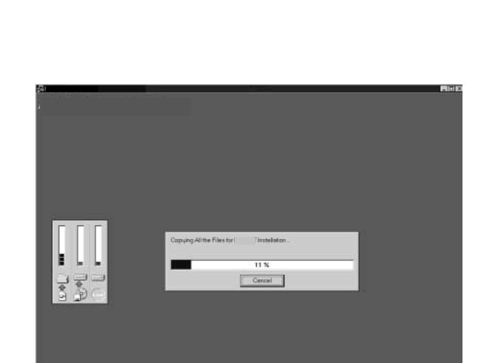

NDA-24298 CHAPTER 2
Page 11
Issue 1
ASSIGNMENT
7. If the Setup Complete dialog box appears on the screen, the file copies have finished successfully. Click
Finish to complete the IPX MAT software installation and restart your computer.
Note: You should always reboot your PC after installing the IPX MAT software. Any change made during the in-
stallation process does not take effect until the computer has been rebooted.
Figure 2-10 IPX MAT Setup Complete Dialog

CHAPTER 2 NDA-24298
Page 12
Issue 1
ASSIGNMENT
8. Review the settings you have chosen, and then click Next. The Winsock2 Setup message box displays.
Note: If you are installing IPX MAT on an NT 4.0 workstation, the Winsock2 Setup message box does not display.
NT 4.0 does not require Winsock2 in order to run.
Figure 2-11 IPX MAT Installing Winsock2 Message Box
9. After Winsock2 is installed, the Winsock2 Setup dialog box displays. This is an informational message
only. Click OK to continue installing the Data Access Objects (DAO) required to run IPX MAT.
Figure 2-12 Winsock2 Setup Message Dialog Box

NDA-24298 CHAPTER 2
Page 13
Issue 1
ASSIGNMENT
10. Click OK. The DAO Welcome Screen displays.
Figure 2-13 DAO Welcome Screen
11. Click Next. The Select Components dialog box displays.
Figure 2-14 DAO Select Components Screen
NEAX2400IPX
NEAX2400IPX

CHAPTER 2 NDA-24298
Page 14
Issue 1
ASSIGNMENT
12. Uncheck the ODBCDirect box and click Next. The Select Components dialog box displays.
Note: If you do not uncheck the ODBCDirect box, error messages display once the DAO Setup program
completes. IPX MAT will run properly even though these messages display.
Figure 2-15 Select Components Screen
13. Click Next. The DAO Setup Screen displays.
Figure 2-16 DAO Setup Screen

NDA-24298 CHAPTER 2
Page 15
Issue 1
ASSIGNMENT
14. After the DAO files are installed, the DAO Information message box displays. Click OK. The IPX MAT
Installation screen displays.
Figure 2-17 DAO Information Message
15. To run the IPX MAT software, click the IPX MAT icon on the desktop or select it from the Start/Program
menu. The IPX MAT menu displays as shown in Figure 2-18.
Figure 2-18 IPX MAT Main Menu
Command Folders
Tool Bar
Title Bar
Enter commands here
Status Bar
Menu Bar

CHAPTER 2 NDA-24298
Page 16
Issue 1
ASSIGNMENT
16. To configure the PBX Alias, use the instructions in Section 6.2, TCP/IP Connection.
Note: Once you have configured the IPX MAT, you can use the Run Command line to enter task commands, or
you can select the command from the Command Folders. You can also perform IPX MAT tasks using either
the menu items, or the icons equivalent to the menu items.
Figure 2-19 IPX MAT Tool Bar
Collect New Traffic
Scan New Alarms/Traffic
Collect New Alarms Abort Data Collection
View Scanning Log
Processes About
Log On
Configure
Log Out
Log Manager

NDA-24298 CHAPTER 2
Page 17
Issue 1
ASSIGNMENT
5. IPX MAT Commands
The IPX MAT’s operation is very similar to that of the NEAX2400 MS-DOS MAT, so you will find that many
of the key stroke operations have been carried over into IPX MAT. In addition, some standard MS Windows
operations and key strokes are used. Use the following keys, or in some instances the mouse, to select or enter
data.
6. Configuring IPX MAT
This section explains the PBX Alias parameters you may configure using the PBX Administration dialog
window. It also lists the default values of NEAX-IPX, the default PBX Alias delivered with the IPX MAT
software. Prior to running the IPX MAT, you should either define a new PBX Alias, configure the default PBX
to work with your system, or plan to use the NEAX-IPX default Alias. NEAX-IPX is ready for use once the IPX
MAT software has been successfully installed. Table 2-3 lists the default values displayed in the PBX
Administration dialog box when you select NEAX-IPX as your PBX Alias.
Table 2-2 IPX MAT Commands
Enter and Tab This key has two functions:
Writes the data to the IPX MAT memory and moves the cursor to the next text control
on the dialog window.
Y (y) Enter Y in the WRT? text control to write the data to the IPX.
N (n) Enter N in the WRT? text control if you do not want to write the data to the IPX.
Delete Deletes the selected characters in a text control.
Backspace Deletes the character immediately to the left of the cursor in a text control.
Right Arrow Moves the cursor to the right in the text control.
Left Arrow Moves the cursor to the left in the text control.
Up Arrow Moves the cursor to the left in the text control.
Down Arrow Moves the cursor to the right in the text control.
Alt + F4 Closes the screen without saving the changes.
Shift + Enter and Shift + Tab Moves the cursor from a text control to the previous text control.
Ctrl + C Copies selected text to Windows Clipboard.
Ctrl + V Pastes Windows Clipboard contents at the current cursor position.
Ctrl + Home
(When viewing the log file). Moves the cursor to the top of the log data file.
Ctrl + End
(When viewing the log file). Moves the cursor to the bottom of the log data file.
Page Up
(When viewing the log file). Moves the log file up one page at a time.
Page Down
(When viewing the log file). Moves the log file down one page at a time.
? or F1 Displays the Help text.

CHAPTER 2 NDA-24298
Page 18
Issue 1
ASSIGNMENT
6.1 Serial/Direct Connection
The following steps explain how to configure the PBX Alias for a serial/direct connection using the
recommended default data.
Note 1: The PBX Alias cannot have spaces in the name.
Note 2: You can use other data when configuring IPX MAT. However, it is recommended that you use the default
data as previously described when configuring a new PBX Alias.
Table 2-3 PBX Administration Default Values
PBX Alias NEAX-IPX
Connection Type Serial/Direct
FPC 1
Connect 120000
Response Timeout 120000
Pacing Timer 10000
Link Data Log Path blank
COM Port COM 1
Baud Rate 4800
Ignore CTR blank
Ignore DSR blank
Modem Name blank
Phone Number blank
Host Name blank
IP Address 172.16.253.0
TCP Port 60000
Inter-App Resource blank

NDA-24298 CHAPTER 2
Page 19
Issue 1
ASSIGNMENT
1. From the PBX menu, select Configuration to open the PBX Administration dialog box.
Figure 2-20 PBX Administration
2. Enter a name for the PBX Alias in the PBX Alias box.
Note: You can also define a PBX Alias by selecting the default NEXT-IPX or by modifying any other previously
defined Alias from the list in the PBX Alias box. If you select a PBX Alias from the list, its related
information displays in the additional fields on this dialog box. You can enter information in the Connect
Timeout, Response Timeout, Pacing Timer, and Link Data Log Path fields if necessary. However, the IPX
MAT software will run without changing the default data.
3. Select Serial/Direct as the Connection Type.
4. Enter the appropriate FPC (Fusion Link Point Code). 1 is the default value and should be used initially
for all new IPX systems. In a Fusion Network, this setting must match the FPC value entered into
System Data SYS 1 INDEX 512.
5. Enter 120000 in the Connection Timeout text box.
6. Enter 120000 in the Response Timeout text box.
7. Enter 10000 in the Pacing Timer text box.
8. Clear (Remove) any text from the Link Data Log Path text control.
9. Set COM1 Baud rate to 4800. This is the default PBX value on the initial power up.
10. Leave the Host Name text box blank.
11. Leave the IP Address text box blank.

CHAPTER 2 NDA-24298
Page 20
Issue 1
ASSIGNMENT
12. Leave the IP Port text box blank.
13. Leave the Inter-App Resource text box blank.
14. Click Add to write the data.
15. Click Close.
Note: The PBX Administration dialog box changes adapting to EX-FCCS Network. Enter the Fusion Group
Number (FUG) which the PBX to be logged-in belongs. “Connection Timeout”, “Response Timeout”, and
“Pacing Timer” text box is not provided. Others are the same as previous one. The PBX dialog box is as
shown below.
6.2 TCP/IP Connection
This section explains how to add or modify a PBX Alias in IPX MAT when it is connected to a PBX using
a TCP/IP connection through a Local Area Network (LAN).
Procedure Overview
1. Modify or add a PBX Alias.
2. Assign the network information in Windows.
3. Start the PBX system.
4. Log in to IPX MAT.
5. Assign the system data.
6. Set up the IPX MAT file operations for logging purposes.
PBX Administration
Add
Add
Modify
Modify
Clear
Close
PBX Alias Connection Type
FUG
COM Port Baud Rate
Modem Name Phone Number
Host Name IP Address TCP Port
TCP/IP Settings
Serial Settings
TCP/IP
bsc7200 10.41.207.207 60000
3
FPC
1Delete
TCP-IP134

NDA-24298 CHAPTER 2
Page 21
Issue 1
ASSIGNMENT
Note: If your IPX is to reside on your existing LAN, you will need to obtain an available IP address from your
System Administrator before you configure the PBX Alias.
6.2.1 Modifying or Adding a PBX Alias
Note: The PBX Alias cannot have spaces in its name.
The following steps explain how to create a PBX Alias in IPX MAT.
1. From the PBX menu, select Configuration to open the PBX Administration dialog box.
2. Enter a name for the PBX Alias in the PBX Alias box.
Note: You can also define a PBX Alias by selecting the default NEXT-PBX or by modifying any other previously
defined Alias from the list in the PBX Alias box. If you select a PBX Alias from the list, its related
information displays in the additional fields on this dialog box. You can enter information in the Connect
Timeout, Response Timeout, Pacing Timer, and Link Data Log Path fields if necessary.
3. Select TCP/IP as the Connection Type.
4. Enter the appropriate FPC (Fusion Link Point Code). 1 is the default value and should be used
initially for all new IPX systems. In a Fusion Network, this setting must follow the FPC value
entered into System Data SYS 1 INDEX 512.
5. Enter 120000 in the Connection Timeout text box.
6. Enter 120000 in the Response Timeout text box.
7. Enter 10000 in the Pacing Timer text box.
8. Leave the Link Data Log Path text box blank.
9. Enter the name of the host your system is using in the Host Name text box.
10. Enter 172.16.253.0 in the IP Address text box, or enter the IP Address supplied by your network
administrator.
11. Enter 60000 in the IP Port text box.
12. Leave the Inter-App Resource text box blank.
13. Click Add to write the data.
14. Click Close.
15. Exit IPX MAT.
6.2.2 Assigning Network Information in Windows
Before you can run the IPX MAT software, you have to configure your network information in the
Windows operating system. For information on configuring network information, see the Network
Circuit Card Installation Manual or talk to your network administrator. After configuring the network
information, you must restart the PC before you can log in to the IPX via the IPX MAT TCP/IP
connection.

CHAPTER 2 NDA-24298
Page 22
Issue 1
ASSIGNMENT
6.2.3 Starting the PBX System
Before you can log in to the PBX with your IPX MAT, you must start the PBX system. To start the PBX
system, please see the NEAX2400 IPX Installation Manual.
If you start up the system when the PBX is in DM Clear Restart mode, (the SENSE Switch is set to the
default value “1”), you must verify that the IPX MAT baud rate is set to 4800 to ensure that the system
runs properly.
6.2.4 Logging in to IPX
After you have defined the PBX Alias in IPX MAT and the TCP/IP network connection in Windows,
you are ready to Log in to IPX. The Login operation allows you to select the target IPX (node) with
which you are attempting to communicate. Once you log in to IPX, you may assign or delete office data,
monitor the status of IPX, obtain System Messages through the IPX’s self-diagnosis function, and
monitor the IPX traffic and Peg count data. Once you have completed the tasks you intended to perform,
you should log out to prevent accidental changes to the data. The following steps explain how to log in
to IPX.
Note: The maximum number of concurrent connections for the IPX is four.
1. From the IPX menu, select Log In.
2. Select the PBX you want to connect to by choosing the appropriate PBX Alias from the PBX Alias
box.
Note: When the User ID data is programmed in AUIDN command after the required office data assignment, enter
the proper user name and password to login to the NCN (Network Control Node) or each LN (Local Node)
in Fusion Network system. For the stand-alone system, User ID information for logging in to the PBX is
programmed in AUIDL command. Only the User ID in LDM data is effective in stand-alone system. Refer
to the AUIDN or AUIDL command in Chapter 4 for more detail explanations.
3. Click Login.
4. A successful log in displays the successful Login message box.
Note: If the Login message box does not display, the login process has failed. If the login process fails, you should
reopen the PBX Configuration dialog box and verify the PBX Alias configuration information. If the PBX
Alias has been correctly configured, you should then test the physical connections to the PBX.
5. Click OK on the Login message box.

NDA-24298 CHAPTER 2
Page 23
Issue 1
ASSIGNMENT
6.2.5 Assigning System Data
This section explains how to assign the IP Address and the SubNet Mask using the default IP Address
172.16.253.0 and the default SubNet Mask 00.00.00.00. Both fields must be entered using their
hexadecimal equivalents.
Note: You may find it convenient to use the Calculator in the Windows Accessories to find the hexadecimal
equivalent of the IP Address and the SubNet Mask. To convert from decimal to hexadecimal:
1. Select Calculator from the Accessories menu.
2. From the View menu, select Scientific.
3. Verify that Dec is selected.
4. Click the first three numbers of the IP Address on the Calculator key pad.
5. Select Hex.
6. The hexadecimal equivalent of the first three numbers of the IP Address display.
7. To perform additional decimal to hexadecimal conversions, make sure that Dec is selected
and repeat the previous steps.
1. Type ASYDL in the Run Command text box.
2. Press Enter.
3. Type 1 in the SYS text box and press Enter.
4. Type 513 in the INDEX text box and press Enter.
5. Type 01H in the DATA text box and press Enter.
6. Type Y in the WRT? text box and press Enter.
7. Type 1 in the SYS text box and press Enter.
8. Type 514 in the INDEX text box and press Enter.
9. Type 01H in the DATA text box and press Enter.
10. Type Y in the WRT? text box and press Enter.
Note: The following steps explain how to assign the default IP Address.
11. Type 1 in the SYS text box and press Enter.
12. Type 515 in the INDEX text box and press Enter.
13. Type AC (hexadecimal equivalent of 172) in the DATA text box and press Enter.
14. Type Y in the WRT? text box and press Enter.
15. Type 1 in the SYS text box and press Enter.

CHAPTER 2 NDA-24298
Page 24
Issue 1
ASSIGNMENT
16. Type 516 in the INDEX text box and press Enter.
17. Type 10 (hexadecimal equivalent of 16) in the DATA text box and press Enter.
18. Type Y in the WRT? text box and press Enter.
19. Type 1 in the SYS text box and press Enter.
20. Type 517 in the INDEX text box and press Enter.
21. Type FD (hexadecimal equivalent of 253) in the DATA text box and press Enter.
22. Type Y in the WRT? text box and press Enter.
23. Type 1 in the SYS text box and press Enter.
24. Type 518 in the INDEX text box and press Enter.
25. Type 0 (hexadecimal equivalent of 0) in the DATA text box and press Enter.
26. Type Y in the WRT? text box and press Enter.
Note: The following steps explain how to assign the default SubNet Mask.
27. Type 1 in the SYS text box and press Enter.
28. Type 519 in the INDEX text box and press Enter.
29. Type FF in the DATA text box and press Enter.
30. Type Y in the WRT? text box and press Enter.
31. Type 1 in the SYS text box and press Enter.
32. Type 520 in the INDEX text box and press Enter.
33. Type FF in the DATA text box and press Enter.
34. Type Y in the WRT? text box and press Enter.
35. Type 1 in the SYS text box and press Enter.
36. Type 521 in the INDEX text box and press Enter.
37. Type 00 in the DATA text box and press Enter.
38. Type Y in the WRT? text box and press Enter.
39. Type 1 in the SYS text box and press Enter.
40. Type 522 in the INDEX text box and press Enter.
41. Type 00 in the DATA text box and press Enter.
42. Type Y in the WRT? text box and press Enter.

NDA-24298 CHAPTER 2
Page 25
Issue 1
ASSIGNMENT
6.2.6 IPX MAT File Operations
The IPX MAT creates three types of files; Command Log files, Office Data Backup files, and List-up
Command Report data tables. Command Log files and List-up Command Report data tables are the only
files a user needs to view. The Office Data Backup files are used strictly for saving and storing the PBX
Office Data.
6.2.6.1 Office Data Backup
It is always a good idea to routinely backup the data from the IPX memory to its internal hard disk. This
data should then be saved from the IPX internal hard disk to the IPX MAT hard disk to ensure that no
data is lost.
Once the data has been saved from the IPX internal hard disk to the IPX MAT’s hard disk, you can use
standard operating functions to copy the saved data to floppy disks, zip drive disks, writable CD-ROM
drives, or any other type of external storage devices supported by the operating system. Doing a three
phase backup (save) ensures the IPX Office data is safe and always available for restoration in case of
an IPX data memory loss, hard disk failure, or any other IPX-related catastrophic failure that requires
data memory to be reloaded.
MEM_HDD and HDD_MAT are the two commands used for this three-phase backup. Once the data is
saved to the IPX MAT, you can use Explorer to copy the appropriate files to the external mass storage
device. To use Explorer, you must first determine where the IPX MAT copy of the numerous IPX Office
Data backup files resides.
As an example, assume the default drive and directory C:\IMXMAT were used when IPX MAT was
installed. Also assume that a PBX Alias was configured using the PBX Configuration dialog and
assigned the PBX Alias name MY_PBX.
The IPX MAT always uses the same data directory structure when backing up data from the IPX. It
creates a sub-directory under the IPX MAT home directory called DATA. Under the DATA directory
another sub-directory using the PBX Alias name is created. In our example, this sub-directory is named
MY_PBX. Under the PBX Alias directory, another sub-directory is created. The name of this directory
is BACKUP. This directory structure always holds true. The only variables are the name of the IPX MAT
home directory (default C:\IMXMAT) and the PBX Alias directory (in our example, MY_PBX). The
complete directory structure for our example is as follows: C:\IMXMAT\DATA\MY_PBX\BACKUP.
The bottom sub-directory (BACKUP) contains all files that have been backed up from the IPX using the
HDD_MAT command.
To save these files to an external storage device, open Explorer, navigate to the appropriate backup
directory (C:\IMXMAT\DATA\MY_PBX\BACKUP) and select ALL files and/or sub-directories and
copy them to your external device. You now have a safe backup of your IPX data memory that can be
stored at an offsite location.

CHAPTER 2 NDA-24298
Page 26
Issue 1
ASSIGNMENT
6.2.6.2 MEM_HDD
The following steps explain how to perform the backup and restore of PBX data to the PBX hard drive.
1. Enter MEM_HDD in the Run Command field on the IPX MAT main menu.
2. Press Enter.
3. The Backup and Restore dialog box displays.
4. Select Memory to Hard Disk in the Direction Select list.
5. Select Data Memory in the Data Type Selection list.
6. Select Auto Verify if you want to verify the data. This is an optional step.
7. Click Start.
Once you have made the appropriate selections and clicked Start, you can scroll down and view the data
being saved in the Processing Status Log window. This section of the window is divided into the sections
Action/Information, Direction, Data Type, and Time Stamp. The Action/Information column shows the
Action being taken (saving or restoring), or the Information being saved. The Direction column shows
where the data is being saved or restored (in this case, memory to PBX Hard Disk). The Data Type
column shows the type of data you selected in the Data Type Selection list. The Time Stamp column
shows the day, month, year, hour, minute, and second the data was backed up or restored.
6.2.6.3 HDD_MAT
The following steps explain how to backup and restore PBX data to the IPX MAT hard disk.
1. Enter HDD_MAT in the Run Command field on the IPX MAT main menu.
2. Press Enter.
3. The Backup and Restore dialog box displays.
4. Select PBX Hard Disk to MAT in the Direction Select list.
5. Select Data Memory in the Data Type Selection list.
6. Select Auto Verify if you want to verify the data. This is an optional step.
7. Click Start.
Once you have made the appropriate selections and clicked Start, you can scroll down and view the data
being saved in the Processing Status Log window. This section of the window is divided into the sections
Action/Information, Direction, Data Type, and Time Stamp. The Action/Information column shows the
Action being taken (saving or restoring), or the Information being saved. The Direction column shows
where the data is being saved or restored (in this case PBX Hard Disk to IPX MAT). The Data Type
column shows the type of data you selected in the Data Type Selection list. The Time Stamp column
shows the day, month, year, hour, minute, and second the data was backed up or restored.

NDA-24298 CHAPTER 2
Page 27
Issue 1
ASSIGNMENT
6.2.6.4 List-up Command Report Data Tables
These data files are tables assembled into an MS-Access Database format. The List-up commands create
the database and tables, populating them based on the information specified by the user. After the
database and tables are created, the report that automatically finds the correct data table and presents the
stored data in a format suitable for viewing is launched. These data tables are cleared and repopulated
each time the corresponding List-up command is run. These data tables require no user intervention.
6.2.6.5 Command Log Files
These files are simple text files that capture the results of the operations performed by every IPX MAT
command. These log files are functionally equivalent to the printed output log created by the old MS-
DOS MAT. The only difference is that these text files can easily be viewed from within any IPX MAT
command at any time so it is not necessary to have a printer available. These log files are also easy to
print if a printer is available.
The log file maintains a history trail of operations and actions requested by the user. This log file
continues to grow as each command is run and interactions with the IPX PBX are transacted. It doesn’t
matter whether the operation is a query, a change, a create, or a delete, the operation, its data, and its
status will always be logged (added to this log file).
The log file can be viewed any time by selecting it from the command’s view menu selection. Once the
log file viewing window is opened, the log file can be printed by selecting the print option from its File
menu selection. Pressing the CTRL+END key combination will quickly take you to the end of the file
where the latest changes have been appended.
Since the log file continually grows, you should regularly delete this file to conserve disk space. It also
makes the file much more manageable and useful if it is not full of log entries that are no longer of
interest. To delete and otherwise manage this file, the IPX MAT main menu contains menu selections
that will present a log file maintenance dialog. From here, the log file can be easily deleted.
6.2.6.6 Viewing the Log Data File
To view the log data file:
1. Display the Backup and Restore dialog box.
2. Select Operation Log from the View menu.
3. The log file FileViewer window displays.

CHAPTER 2 NDA-24298
Page 28
Issue 1
ASSIGNMENT
6.2.6.7 Printing the Log Data File
To print the log data file:
1. Display the log file in the FileViewer window.
2. Select Print from the File menu.
6.2.6.8 Copying Data from the Log File
To copy data from the log file:
1. Display the log file in the FileViewer window.
2. Highlight the data you want to copy.
3. Select Copy from the Edit menu.
6.2.6.9 Pasting Log File Data
To paste log file data into another text editing tool:
1. Open the text editing tool you want to paste the data into.
2. Select paste from the Edit menu.
Note: You cannot paste copied data from one location to another in the log file. The log file is a Read-Only file.
7. Data Assignment Flow Chart
This section shows the data assignment flow chart for IPX. The standard data assignment is illustrated on the
following flow charts.
• Local Node/Stand Alone
• Network Control Node
Note: For Hotel Command, see the NEAX2400 IPX Hotel Data Specification.
7.1 Local Node/Stand Alone
The following flow chart shows the data assignment for MAT when operated in a Local Node/Stand Alone
environment.

NDA-24298 CHAPTER 2
Page 29
Issue 1
ASSIGNMENT
1. Local Node/Stand Alone
Figure 2-21 Local Node/Stand Alone Data Flow Assignment Flow Chart (1/2)
ATIMSystem Base ASYD ASYDL AUNT AIOC ASTD AOFC
AMND ARNP
ANND ASTP AOSP ARNP
ACMO ATCP AFRS AOPR AADC
AFRSL AOPRL AADCL
ASDC
AMND ARNP
AUNE AMND
ARSC ARRC ATDP AARP APCR AEFR
ATDPL AARPL
ASFC ACFR ATNR AABD
ANPD ASPA
ANPDL ASPAL
SRV
SRV
STN
SSC/SSCA, etc.
SSC
TELN
Sys1 Index 512 - 1535
Sys1 Index 0 - 511 , Sys2 Index 0 - 15 & Sys3 Index 0 - 31
Station Number
Service / Network
Telephone Number available in the Self node only
Timing Start is available
Numbering Plan
Network Numbering
Restriction
2nd DT :
Sender
LCR / LCRS :
Uniform Numbering :
AUNEL
ALDN ASTP AISP ARAC
Incoming :
Trunk:
Service:
:
Operator Call / OGQ / Priority Call
OGC(A)/LCR(S) Outgoing Call
ASTPL AOSPL
ASTPL AISPL

CHAPTER 2 NDA-24298
Page 30
Issue 1
ASSIGNMENT
Figure 2-21 Local Node/Stand Alone Data Assignment Flow Chart (2/2)
Trunk ATRK MBTK AMAT ASAT ATGL AAKP
ATRK MBTK
Service
CCIS No. 7
ISDN
ASHP ASHC ASHU AUCD AUOG AUAD ACPG ACPE
AISA AISD ASGD ASID ACFS ASLU1 ASLU2
ACSA ACSI ANCD ATAS AEKD AAND AANDE
ASPD AATC ACFO
ARPC ARDN
ACDD ACNP ACND AFCP ACBC AVTC AVTL
ATT :
Internal Trunk
External Trunk
ORT / IRT / SND / CFT:
ACOC
APAD
AAED
ADPC
ADPC ACSC
ACSC
AAEDL
ACIC1
ACIC1
ARTI
ACIC2 ARTI
ARTD ATRK MBTK PSTN :
TIE LINE :
DAT :
CCIS No.7 :
ISDN :
Station:
PSTN :
Others:
Service:
Service:
AHMS
ACID
AEVT
ADPCL ACSCL
ASDT ASTN APHN APHNL ANDD
ASCL
AKYD AFDD ADSL ADKS ADRTL
AIZP
AICD ADIM
AHLS ASPD
ADA2 AFCD
ALGSL
Station Number
Service
For Station:
(Physical STA No.)
For Telephone Number:
For Dterm SeriesE:
For Service:
For Hot Line:
For Data:
See
(Calling available in the self node only)
ASHPL ASHCL
ACSAL ACSIL
ACPGL ACPEL

NDA-24298 CHAPTER 2
Page 31
Issue 1
ASSIGNMENT
2. Network Control Node
Figure 2-22 Network Control Node Data Assignment Flow Chart (1/2)
ATIMSystem Base ASYD ASYDL ASYDN AUNT AIOC ASTD AOFC AFMU ALRTN
AMND ARNP
ANND ASTP AOSP ARNP
ASTPL AOSPL
ASTPN AOSPN
ACMO ATCP AFRS AOPR AADC ASDC
AFRSN AOPRN AADCN
AMND ARNP
AUNE
AUNEL
AMND
ALDN ASTP AISP ARAC
ARSC ARRC ATDP
ATDPN
AARP
ATDPL AARPL
AARPN
APCR AEFR
ASFC
ARSCN ARRCN
ACFR ATNR AABD
ANPD ASPA
ANPDL ASPAL
SRV
SRV
STN
SSC
SSC/SSCA, etc.
TELN
Sys1 Index 512 - 1535
Sys1 Index 0 - 511 , Sys2 Index 0 - 15 & Sys3 Index 0 - 31
Station Number
OGC(A)/LCR(S) Outgoing Call
Service / Network
Telephone Number available in the
Self node only
ANPDN ASPAN
SRV
TELN Telephone Number available in all
nodes of Fusion Network
Timing Start is available
Numbering Plan
Network Numbering
Restriction
2nd DT :
Sender :
LCR / LCRS :
Uniform Numbering :
Incoming :
Trunk:
Service:
Sys1 Index 0 - 1535
Fusion Network
Numbering Plan:
Operator Call / OGQ / Priority Call
OGC(A)/LCR(S)
SSCA
Outgoing Call
Call Pickup Expand / UCD BUSY OUT
SSC Operator Call / Call Pickup Group / OGQ / Priority Call
ASTPL AISPL
ASTPN AISPN
AFRSL AOPRL AADCL
AUIDN

CHAPTER 2 NDA-24298
Page 32
Issue 1
ASSIGNMENT
Figure 2-22 Network Control Data Assignment Flow Chart (2/2)
Trunk ATRK MBTK AMAT ASAT ATGL AAKP
ATRK MBTK
Service
CCIS No. 7
ISDN
ASHP ASHC ASHU AUCD AUOG AUAD ACPG ACPE
AISA AISD ASGD ASID ACFS ASLU1 ASLU2
ACSA ACSI ANCD ATAS AEKD AAND AANDE
ASPD AATC ACFO
ARPC ARDN
ACDD ACNP ACND AFCP ACBC AVTC AVTL
ACNPN ACNDN
AEVT
Internal Trunk ATT
External Trunk
ORT / IRT / SND / CFT:
ACOC
APAD
AAED
ADPC
ADPC ACSC
ACSC
AAEDL
ACIC1
ACIC1
ARTI
ACIC2
ARTD ATRK MBTK PSTN :
TIE LINE :
DAT :
CCIS No.7 :
ISDN :
Station:
PSTN :
Others:
Service:
Service:
ACRD ACTK MBCT AFCH AFRT AFPC ACAN ATDF
ATDF
ACRD ACTK MBCT AFPC ACAN
Fusion Link FCCH:
Ether:
AAEDN AHMS
ACID
APADN
ADPCL ACSCL
ARTIN
:
ASDT ASTN APHN APHNL APHNN ANDD
ASCL
AKYD AFDD ADSL ADKS ADRTN
AIZP
AICD ADIM
AHLS ASPD
ADA2 AFCD
ALGSL
Station Number
Service
For Station:
(Physical STA No.)
For Telephone Number:
For Dterm SeriesE:
ALGSN ATSTN
For Service:
For Hot Line:
For Data:
See
(Available in the self node only)
(Available in all nodes of the Fusion network.)
ASHPN ASHCN ASHUN AUCDN AUOGN AUADN ACPGN ACPEN
ASHPL ASHCL ACPGL ACPEL
ADPCL

NDA-24298 CHAPTER 3
Page 33
Issue 1
CHAPTER 3 OFFICE DATA DESIGN SHEET
Office data design sheets are used to design the configuration and specification of IPX.
1. Trunking Diagram
The Trunking diagram shows the system configuration and the number of lines.
2. Bay Face Layout
The Bay Face layout shows the circuit card mounting slots.
3. Port Location Table
A Port Location table denotes the Line/Trunk circuit cards located in each Universal Slot of PIM.
4. Numbering Plan Table
Area Codes for various service features are determined according to the Dial Access Numbering Plan. There are
three types of Dial Access Numbers.
• Station Access Numbers
• Special Service Access Numbers
• Trunk Access Numbers
5. Restriction Tables
1. Service Feature Restriction Class
2. Trunk Restriction Class Table
3. Tenant Restriction Tables

CHAPTER 3 NDA-24298
Page 34
Issue 1
OFFICE DATA DESIGN SHEET
Figure 3-1 Trunking Diagram
PFT
LC
MDF
DLC/ELC
DLC
DTL
COT
COT
COT
DID
EMT
DID
TLT
DTI
RST
MFCT
DTI
CCH
MODEM
DTI (PRI)
DCH
ATI
RGU
HWU
LTST
1
HUB TO MAT
CCH
PRINTER
ATT/DESK CONSOLE
IOC
CPR OSC/PLO
MAINTENANCE
ADMINISTRATION
TERMINAL (MAT)
SUBSCRIBER
Dterm
W/O DATA ADAPTER
Dterm
WITH DATA ADAPTER
FROM/TO
CENTRAL OFFICE
FROM/TO TIE LINE
FROM/TO CCIS LINE
FROM/TO ISDN LINE
(PRI)
Note: Table 3-1 identifies the function name of each circuit card.
BWT
DOD
DIT
DID
MUX TSW

NDA-24298 CHAPTER 3
Page 35
Issue 1
OFFICE DATA DESIGN SHEET
Table 3-1 identifies the function name of each circuit card used for the system.
Table 3-1 Circuit Card Function Name
SYMBOL DESCRIPTION
ATI Attendant Console Interface
BWT Bothway Trunk
CCH Common Channel Handler
CFT Conference Trunk
COT Central Office Trunk
CPR Central Processing Rack
DCH D Channel Handler
DID Direct Inward Dialing
DIT Direct-In Termination
DLC Digital Line Circuit
DOD Direct Outward Dialing
Dterm Digital Multi-Function Telephone
DTI Digital Interface
DTL Data Terminal Line Circuit
ELC Electronic Line Circuit
EMT Equipment & Maintenance Trunk
HWU Howler Tone Unit
IOC Input/Output Controller
LC Line Circuit
LTST Line Test
MDF Main Distribution Frame
MFCT Multi-frequency Trunk
MUX Multiplexer
ODT Office Data Trunk
OSC Oscillator for 1-IMG
PFT Power Failure Transfer
PLO Phase Lock Oscillator for 4-IMG/IPX-U
RGU Ringing Generator Unit
RST Register Sender Trunk
TLT Tie Line Trunk
TSW Time Switch

CHAPTER 3 NDA-24298
Page 36
Issue 1
OFFICE DATA DESIGN SHEET
Figure 3-2 Card Mounting Slot
00 01 02 03 04 05 06 07 08 09 10 11 12 13 14 15 16 17 18 19 20 21 22 23
PA-PW55-A (PWR0)
PA-PW54-A (PWR1)
PH-PC36 (MUX)
PH-PC36 (MUX)
PH-SW10 (TSW)
PH-SW10 (TSW)
PIM3
00 01 02 03 04 05 06 07 08 09 10 11 12 13 14 15 16 17 18 19 20 21 22 23
PA-PW55-A (PWR0)
PA-PW54-A (PWR1)
PH-PC36 (MUX)
PH-PC36 (MUX)
PIM2
00 01 02 03 04 05 06 07 08 09 10 11 12 13 14 15 16 17 18 19 20 21 22 23
PA-PW55-A (PWR0)
PA-PW54-A (PWR1)
PH-PC36 (MUX)
PH-PC36 (MUX)
PIM1
00 01 02 03 04 05 06 07 08 09 10 11 12 13 14 15 16 17 18 19 20 21 22 23
PA-PW55-A (PWR0)
PA-PW54-A (PWR1)
PIM0
LPM
PH-IO24 (IOC)
PH-PC40 (EMA)
00 01 02 03 04
Note: The second IOC (PH-IO24) can be mounted in slot 02 of the LPM.

NDA-24298 CHAPTER 3
Page 37
Issue 1
OFFICE DATA DESIGN SHEET
Figure 3-3 Card Mounting Slot for 4-IMG System (1/4)
00 01 02 03 04 05 06 07 08 09 10 11 12 13 14 15 16 17 18 19 20 21 22 23
PA-PW55-A(PWR0)
PA-PW54-A(PWR1)
PH-PC36(MUX)
PH-PC36(MUX)
PH-PC36(MUX)
PH-PC36(MUX)
PIM3
00 01 02 03 04 05 06 07 08 09 10 11 12 13 14 15 16 17 18 19 20 21 22 23
PA-PW55-A(PWR0)
PA-PW54-A(PWR1)
PH-PC36(MUX)
PH-PC36(MUX)
PIM2
00 01 02 03 04 05 06 07 08 09 10 11 12 13 14 15 16 17 18 19 20 21 22 23
PA-PW55-A(PWR0)
PA-PW54-A(PWR1)
PH-PC36(MUX)
PH-PC36(MUX)
PIM1
00 01 02 03 04 05 06 07 08 09 10 11 12 13 14 15 16 17 18 19 20 21 22 23
PA-PW55-A(PWR0)
PA-PW54-A(PWR1)
PIM0
BSCM
LPM
PH-IO24(IOC)
PH-PC40(EMA)
00 01 02 03 04
(IOC/MISC)
(MISC)
(MISC)
PIM
PIM
PIM
PIM
IMG3
Dummy
PIM
PIM
PIM
PIM
IMG2
Dummy
PIM
PIM
PIM
PIM
IMG1
TSWM
PIM
PIM
PIM
PIM
IMG0
LPM
B
S
C
M
IMG0
4-IMG SYSTEM

CHAPTER 3 NDA-24298
Page 38
Issue 1
OFFICE DATA DESIGN SHEET
Figure 3-3 Card Mounting Slot for 4-IMG System (2/4)
00 01 02 03 04 05 06 07 08 09 10 11 12 13 14 15 16 17 18 19 20 21 22 23
PA-PW55-A(PWR0)
PA-PW54-A(PWR1)
PH-PC36(MUX)
PH-PC36(MUX)
PH-PC36(MUX)
PH-PC36(MUX)
PIM3
00 01 02 03 04 05 06 07 08 09 10 11 12 13 14 15 16 17 18 19 20 21 22 23
PA-PW55-A(PWR0)
PA-PW54-A(PWR1)
PH-PC36(MUX)
PH-PC36(MUX)
PIM2
00 01 02 03 04 05 06 07 08 09 10 11 12 13 14 15 16 17 18 19 20 21 22 23
PA-PW55-A(PWR0)
PA-PW54-A(PWR1)
PH-PC36(MUX)
PH-PC36(MUX)
PIM1
00 01 02 03 04 05 06 07 08 09 10 11 12 13 14 15 16 17 18 19 20 21 22 23
PA-PW55-A(PWR0)
PA-PW54-A(PWR1)
PIM0
00 01 02 03 04 05 06 07 08 09 10 11 12 13 14 15 16 17 18 19 20 21 22 23
PH-PW14(PWRSW)
PH-PW14(PWRSW)
PH-PC20(DLKC0)
PH-PC20(DLKC1)
PH-GT09(GT0)
PH-GT09(GT1)
PH-SW12(TSW00)
PH-SW12(TSW01)
PH-SW12(TSW02)
PH-SW12(TSW03)
PH-SW12(TSW10)
PH-SW12(TSW11)
PH-SW12(TSW12)
PH-SW12(TSW13)
PH-CK16/17(PLO0)
PH-CK16/17(PLO1)
(MISC)
(MISC)
(MISC)
(MISC)
(MISC)
(MISC)
TSWM
PIM
PIM
PIM
PIM
IMG3
Dummy
PIM
PIM
PIM
PIM
IMG2
Dummy
PIM
PIM
PIM
PIM
IMG1
TSWM
PIM
PIM
PIM
PIM
IMG0
LPM
B
S
C
M
IMG1
4-IMG SYSTEM

NDA-24298 CHAPTER 3
Page 39
Issue 1
OFFICE DATA DESIGN SHEET
Figure 3-3 Card Mounting Slot for 4-IMG System (3/4)
00 01 02 03 04 05 06 07 08 09 10 11 12 13 14 15 16 17 18 19 20 21 22 23
PA-PW55-A(PWR0)
PA-PW54-A(PWR1)
PH-PC36(MUX)
PH-PC36(MUX)
PH-PC36(MUX)
PH-PC36(MUX)
PIM3
00 01 02 03 04 05 06 07 08 09 10 11 12 13 14 15 16 17 18 19 20 21 22 23
PA-PW55-A(PWR0)
PA-PW54-A(PWR1)
PH-PC36(MUX)
PH-PC36(MUX)
PIM2
00 01 02 03 04 05 06 07 08 09 10 11 12 13 14 15 16 17 18 19 20 21 22 23
PA-PW55-A(PWR0)
PA-PW54-A(PWR1)
PH-PC36(MUX)
PH-PC36(MUX)
PIM1
00 01 02 03 04 05 06 07 08 09 10 11 12 13 14 15 16 17 18 19 20 21 22 23
PA-PW55-A(PWR0)
PA-PW54-A(PWR1)
PIM0
00 01 02 03 04 05 06 07 08 09 10 11 12 13 14 15 16 17 18 19 20 21 22 23
Dummy
PIM
PIM
PIM
PIM
IMG3
Dummy
PIM
PIM
PIM
PIM
IMG2
Dummy
PIM
PIM
PIM
PIM
IMG1
TSWM
PIM
PIM
PIM
PIM
IMG0
LPM
B
S
C
M
IMG2
4-IMG SYSTEM

CHAPTER 3 NDA-24298
Page 40
Issue 1
OFFICE DATA DESIGN SHEET
Figure 3-3 Card Mounting Slot for 4-IMG System (4/4)
00 01 02 03 04 05 06 07 08 09 10 11 12 13 14 15 16 17 18 19 20 21 22 23
PA-PW55-A(PWR0)
PA-PW54-A(PWR1)
PH-PC36(MUX)
PH-PC36(MUX)
PH-PC36(MUX)
PH-PC36(MUX)
PIM3
00 01 02 03 04 05 06 07 08 09 10 11 12 13 14 15 16 17 18 19 20 21 22 23
PA-PW55-A(PWR0)
PA-PW54-A(PWR1)
PH-PC36(MUX)
PH-PC36(MUX)
PIM2
00 01 02 03 04 05 06 07 08 09 10 11 12 13 14 15 16 17 18 19 20 21 22 23
PA-PW55-A(PWR0)
PA-PW54-A(PWR1)
PH-PC36(MUX)
PH-PC36(MUX)
PIM1
00 01 02 03 04 05 06 07 08 09 10 11 12 13 14 15 16 17 18 19 20 21 22 23
PA-PW55-A(PWR0)
PA-PW54-A(PWR1)
PIM0
00 01 02 03 04 05 06 07 08 09 10 11 12 13 14 15 16 17 18 19 20 21 22 23
Dummy
PIM
PIM
PIM
PIM
IMG3
Dummy
PIM
PIM
PIM
PIM
IMG2
Dummy
PIM
PIM
PIM
PIM
IMG1
TSWM
PIM
PIM
PIM
PIM
IMG0
LPM
B
S
C
M
IMG3
4-IMG SYSTEM

NDA-24298 CHAPTER 3
Page 41
Issue 1
OFFICE DATA DESIGN SHEET
Figure 3-4 Card Mounting Slot for IPX-U System (1/5)
PWR1 (PH-PW14)
PWR0 (PH-PW14)
HSW00 (PU-SW01)(RES)
HSW01 (PU-SW01)
HSW10 (PU-SW01)
HSW11 (PU-SW01)(RES)
TSW00 (PU-SW00)
TSW01 (PU-SW00)
IOGT0 (PH-GT10)
IOGT1 (PH-GT10)
TSW02 (PU-SW00)
TSW03 (PU-SW00)
TSW10 (PU-SW00)
TSW11 (PU-SW00)
TSW12 (PU-SW00)
TSW13 (PU-SW00)
PLO0
(PH-CK16-A/17-A)
PLO1
(PH-CK16-A/17-A)
TOPU
ISWM
BASEU PWR HFD DSP
ISW
LPM
IOC(PH-IO24)
Note 1
MMC(PH-M22)
EMA(PH-PC40)
LANI(PZ-PC19) LANI(PZ-PC19)
LANI(PZ-PC19) LANI(PZ-PC19)
PWR(PZ-PW106) PWR(PZ-PW106)
LANI(PZ-PC19) LANI(PZ-PC19)
ISAGT(PZ-GT13) ISAGT(PZ-GT13)
I
O
00 01 02 03 04 05 06 07 08 09 10 11 12 13 14 15 16 17 18 19
00 01 02 03 04
PIM
PIM
PIM
PIM
IMG3
Dummy
PIM
PIM
PIM
PIM
IMG2
TSWM1
PIM
PIM
PIM
PIM
IMG1
TSWM0
PIM
PIM
PIM
PIM
IMG0
LPM
ISW
IMX-U SYSTEM
ISWM
ISW
LPM
LN × 4 (0~3)
I
O
The 2nd IOC card (optional) may be mounted in the slot.
This system accommodates four LNs at the maximum.
PWR1 (PH-PW14)
PWR0 (PH-PW14)
HSW00 (PU-SW01)(RES)
HSW01 (PU-SW01)
HSW10 (PU-SW01)
HSW11 (PU-SW01)(RES)
TSW00 (PU-SW00)
TSW01 (PU-SW00)
IOGT0 (PH-GT10)
IOGT1 (PH-GT10)
TSW02 (PU-SW00)
TSW03 (PU-SW00)
TSW10 (PU-SW00)
TSW11 (PU-SW00)
TSW12 (PU-SW00)
TSW13 (PU-SW00)
PLO0
(PH-CK16-A/17-A)
PLO1
(PH-CK16-A/17-A)
TOPU
ISWM
BASEU PWR HFD DSP
ISW
LPM
IOC(PH-IO24)
Note 1
MMC(PH-M22)
EMA(PH-PC40)
LANI(PZ-PC19) LANI(PZ-PC19)
LANI(PZ-PC19) LANI(PZ-PC19)
PWR(PZ-PW106) PWR(PZ-PW106)
LANI(PZ-PC19) LANI(PZ-PC19)
ISAGT(PZ-GT13) ISAGT(PZ-GT13)
I
O
00 01 02 03 04 05 06 07 08 09 10 11 12 13 14 15 16 17 18 19
00 01 02 03 04
PIM
PIM
PIM
PIM
IMG3
Dummy
PIM
PIM
PIM
PIM
IMG2
TSWM1
PIM
PIM
PIM
PIM
IMG1
TSWM0
PIM
PIM
PIM
PIM
IMG0
LPM
ISW
IPX-U SYSTEM
ISWM
ISW
LPM
LN 4 (0~3)´
I
O

CHAPTER 3 NDA-24298
Page 42
Issue 1
OFFICE DATA DESIGN SHEET
Figure 3-4 Card Mounting Slot for IPX-U System (2/5)
PA-PW55-A (PWR0)
PA-PW54-A (PWR1)
PH-PC36 (MUX)
PH-PC36 (MUX)
PH-PC36 (MUX)
PH-PC36 (MUX)
PIM3
PA-PW55-A (PWR0)
PA-PW54-A (PWR1)
PH-PC36 (MUX)
PH-PC36 (MUX)
PIM2
PA-PW55-A (PWR0)
PA-PW54-A (PWR1)
PH-PC36 (MUX)
PH-PC36 (MUX)
PIM1
PA-PW55-A (PWR0)
PA-PW54-A (PWR1)
PIM0
BSCM
LPM
PH-IO24(IOC)
PH-M22(MMC)
PH-PC40(EMA)
(IOC/MISC)
(MISC)
00 01 02 03 04 05 06 07 08 09 10 11 12 13 14 15 16 17 18 19 20 21 22 23
00 01 02 03 04 05 06 07 08 09 10 11 12 13 14 15 16 17 18 19 20 21 22 23
00 01 02 03 04 05 06 07 08 09 10 11 12 13 14 15 16 17 18 19 20 21 22 23
00 01 02 03 04 05 06 07 08 09 10 11 12 13 14 15 16 17 18 19 20 21 22 23
00 01 02 03 04
PIM
PIM
PIM
PIM
IMG3
Dummy
PIM
PIM
PIM
PIM
IMG2
TSWM1
PIM
PIM
PIM
PIM
IMG1
TSWM0
PIM
PIM
PIM
PIM
IMG0
LPM
IMG0
IPX-U SYSTEM
ISWM
ISW
LPM
LN 4 (0~3)´

NDA-24298 CHAPTER 3
Page 43
Issue 1
OFFICE DATA DESIGN SHEET
Figure 3-4 Card Mounting Slot for IPX-U System (3/5)
PA-PW55-A (PWR0)
PA-PW54-A (PWR1)
PH-PC36 (MUX)
PH-PC36 (MUX)
PH-PC36 (MUX)
PH-PC36 (MUX)
PIM3
PA-PW55-A (PWR0)
PA-PW54-A (PWR1)
PH-PC36 (MUX)
PH-PC36 (MUX)
PIM2
PA-PW55-A (PWR0)
PA-PW54-A (PWR1)
PH-PC36 (MUX)
PH-PC36 (MUX)
PIM1
PA-PW55-A (PWR0)
PA-PW54-A (PWR1)
PIM0
PH-PW14 (PWRSW)
PH-PW14 (PWRSW)
PH-PC20 (DLKC0)
PH-PC20 (DLKC1)
PH-GT09 (GT0)
PH-GT09 (GT1)
PH-SW12 (TSW00)
PH-SW12 (TSW01)
PH-SW12 (TSW02)
PH-SW12 (TSW03)
PH-SW12 (TSW10)
PH-SW12 (TSW11)
PH-SW12 (TSW12)
PH-SW12 (TSW13)
PH-CK16-A/17-A (PLO1)
(MISC)
(MISC)
(MISC)
(MISC)
(MISC)
(MISC)
TSWM0
PIM
PIM
PIM
PIM
IMG3
Dummy
PIM
PIM
PIM
PIM
IMG2
TSWM1
PIM
PIM
PIM
PIM
IMG1
TSWM0
PIM
PIM
PIM
PIM
IMG0
LPM
IMG1
IPX-U SYSTEM
ISWM
ISW
LPM
PH-CK16-A/17-A (PLO0)
21 22 23201918171615141312111009080706050403020100
21 22 23201918171615141312111009080706050403020100
21 22 23201918171615141312111009080706050403020100
21 22 23201918171615141312111009080706050403020100
21 22 23201918171615141312111009080706050403020100
LN 4 (0~3)´

CHAPTER 3 NDA-24298
Page 44
Issue 1
OFFICE DATA DESIGN SHEET
Figure 3-4 Card Mounting Slot for IPX-U System (4/5)
PA-PW55-A(PWR0)
PA-PW54-A(PWR1)
PH-PC36(MUX)
PH-PC36(MUX)
PH-PC36(MUX)
PH-PC36(MUX)
PIM3
PA-PW55-A(PWR0)
PA-PW54-A(PWR1)
PH-PC36(MUX)
PH-PC36(MUX)
PIM2
PA-PW55-A(PWR0)
PA-PW54-A(PWR1)
PH-PC36(MUX)
PH-PC36(MUX)
PIM1
PA-PW55-A(PWR0)
PA-PW54-A(PWR1)
PIM0
PIM
PIM
PIM
PIM
IMG3
Dummy
PIM
PIM
PIM
PIM
IMG2
TSWM1
PIM
PIM
PIM
PIM
IMG1
TSWM0
PIM
PIM
PIM
PIM
IMG0
LPM
IMG2
IPX-U SYSTEM
PH-PW14 (PWRSW0)
PH-PW14 (PWRSW1)
PH-GT09 (GT0)
PH-GT09 (GT1)
PH-SW12 (TSW00)
PH-SW12 (TSW01)
PH-SW12 (TSW02)
PH-SW12 (TSW03)
PH-SW12 (TSW10)
PH-SW12 (TSW11)
PH-SW12 (TSW12)
PH-SW12 (TSW13)
PH-CK18 (CLK0)
PH-CK18 (CLK1)
TSWM1
ISWM
ISW
LPM
21 22 23201918171615141312111009080706050403020100
21 22 23201918171615141312111009080706050403020100
21 22 23201918171615141312111009080706050403020100
21 22 23201918171615141312111009080706050403020100
21 22 23201918171615141312111009080706050403020100
LN 4 (0~3)´

NDA-24298 CHAPTER 3
Page 45
Issue 1
OFFICE DATA DESIGN SHEET
Figure 3-4 Card Mounting Slot for IPX-U System (5/5)
PA-PW55-A(PWR0)
PA-PW54-A(PWR1)
PH-PC36(MUX)
PH-PC36(MUX)
PH-PC36(MUX)
PH-PC36(MUX)
PIM3
PA-PW55-A(PWR0)
PA-PW54-A(PWR1)
PH-PC36(MUX)
PH-PC36(MUX)
PIM2
PA-PW55-A(PWR0)
PA-PW54-A(PWR1)
PH-PC36(MUX)
PH-PC36(MUX)
PIM1
PA-PW55-A(PWR0)
PA-PW54-A(PWR1)
PIM0
Dummy
PIM
PIM
PIM
PIM
IMG3
Dummy
PIM
PIM
PIM
PIM
IMG2
TSWM1
PIM
PIM
PIM
PIM
IMG1
TSWM0
PIM
PIM
PIM
PIM
IMG0
LPM
IMG3
IPX-U SYSTEM
ISWM
ISW
LPM
21 22 23201918171615141312111009080706050403020100
21 22 23201918171615141312111009080706050403020100
21 22 23201918171615141312111009080706050403020100
21 22 23201918171615141312111009080706050403020100
LN 4 (0~3)´

CHAPTER 3 NDA-24298
Page 46
Issue 1
OFFICE DATA DESIGN SHEET
Figure 3-5 Port Location Table (1/2)
09 11 13 15 17 19 21 23
7
6
5
4
3
2
1
0
LVG01 03 05 31 09 11 13 15 17 19 21 23
7
6
5
4
3
2
1
0
LVG00 02 04 28 30 10 12 14 16 18 20 22
PIM
SLOT
C
A
R
D
Access Code
CIC for CCIS/DC for C.O
Tenant Number (TN)
Trunk Number (TRC)
Route Number (RT)
Destination
Station Number (STN)
User Name / Telephone Number
Service Class (SFC)
Restriction Class (RSC)
Telephone Class (TEC)
Tenant Number (TN)

NDA-24298 CHAPTER 3
Page 47
Issue 1
OFFICE DATA DESIGN SHEET
Figure 3-5 Port Location Table (2/2)
7
6
5
4
3
2
1
0
01 03 05 07 09 11 13 15 17 19 21 23
7
6
5
4
3
2
1
0
LVG00 02 04 06 08 10 12 14 16 18 20 22
PIM MG = 00 , U = 0
SLOT
C
A
R
D
LVG

CHAPTER 3 NDA-24298
Page 48
Issue 1
OFFICE DATA DESIGN SHEET
6. Numbering Plan Table
ACCESS NUMBER FUNCTION NAME REMARKS

NDA-24298 CHAPTER 3
Page 49
Issue 1
OFFICE DATA DESIGN SHEET
1. Service Feature Restriction Class
Table 3-2 Service Feature Restriction Class
0123456789101112131415
Account Code/Authorization Code/
Forced Account Code
Attendant Camp-On
(Data Line Security)
Boss Secretary Service (For Dterm)
Call Back Call
Forwarding-All Calls
Call Forwarding-Busy Line
Call Forwarding-Don’t Answer
Call Hold
Call Park Access & Answer
Call Park Called
Call Pickup-Direct
Call Waiting-Originating/
Terminating (Called)
Call Waiting-Originating/
Terminating (Calling)
Data Privacy on Demand; Cancel
Data Privacy on Demand; Set
Distinctive Ringing (FAX, OPX)
Executive Right of Way (Called Party)
Executive Right of Way (Calling Party)
Faulty Trunk Report
Intercom Group Individual Trunk Access
Line Circuit Reverse Relay Control
(Station)
RESTRICTION CLASS
SERVICE FEATURE NAME

CHAPTER 3 NDA-24298
Page 50
Issue 1
OFFICE DATA DESIGN SHEET
Line Load Control
Meet-Me Paging
Message Reminder (Dterm)
Message Waiting Lamp Setting from
ATTCON or Station (Called Party)
Message Waiting Lamp Setting from
Station (Calling Party)
Off-Hook Alarm
Off-Hook Queuing
OG Queuing Override
OG Trunk Queuing
OG Trunk Queuing-Deluxe
Periodic Time Indication Time
Priority Call 1
Priority Call 2
Priority Call 3
Priority Paging
Radio Paging Answer
Special Common Battery Telephone
Special Calling-Station/Group
Speed Calling-System
Station Message Detail System
(SMDS) for Station to Station Calls
TAS
Voice Call
Table 3-2 Service Feature Restriction Class (Continued)
0123456789101112131415
RESTRICTION CLASS
SERVICE FEATURE NAME

NDA-24298 CHAPTER 3
Page 51
Issue 1
OFFICE DATA DESIGN SHEET
2. Trunk Restriction Class Table
DESTINATION
[ACCESS
NUMBER]
RT
No. No. OF
TRK
ROUTE
RESTRICTION
INDEX
RESTRICTION CLASS NUMBER
0123456789101112131415
IC Via ATT
IC By DID
OG Via ATT
ACC: OG By DOD
IC Via ATT
IC By DID
OG Via ATT
ACC: OG By DOD
IC Via ATT
IC By DID
OG Via ATT
ACC: OG By DOD
IC Via ATT
IC By DID
OG Via ATT
ACC: OG By DOD
IC Via ATT
IC By DID
OG Via ATT
ACC: OG By DOD
IC Via ATT
IC By DID
OG Via ATT
ACC: OG By DOD
IC Via ATT
IC By DID
OG Via ATT
ACC: OG By DOD
IC Via ATT
IC By DID
OG Via ATT
ACC: OG By DOD
IC Via ATT
IC By DID
OG Via ATT
ACC: OG By DOD

CHAPTER 3 NDA-24298
Page 52
Issue 1
OFFICE DATA DESIGN SHEET
3. Tenant Restriction Table
1
2
3
4
5
6
7
8
9
10
11
12
13
14
15
123456789101112131415
(TMTN)
(OGTN)
Station-to-Station Call
1
2
3
4
5
6
7
8
9
10
11
12
13
14
15
123456789101112131415
(TMTN)
(OGTN)
Assignment of C.F.-All Calls
from a Station
1
2
3
4
5
6
7
8
9
10
11
12
13
14
15
123456789101112131415
(TMTN)
(OGTN)
1
2
3
4
5
6
7
8
9
10
11
12
13
14
15
123456789101112131415
(TMTN)
(OGTN)
Incoming Connection to
Night Attendant Console
Assignment of C.F.-All Calls
from an Attendant Console

NDA-24298 CHAPTER 3
Page 53
Issue 1
OFFICE DATA DESIGN SHEET
1
2
3
4
5
6
7
8
9
10
11
12
13
14
15
123456789101112131415
(TMTN)
(OGTN)
Incoming Connection to
Attendant Console
1
2
3
4
5
6
7
8
9
10
11
12
13
14
15
123456789101112131415
(TMTN)
(OGTN)
Day and Night Mode Change
1
2
3
4
5
6
7
8
9
10
11
12
13
14
15
123456789101112131415
(TMTN)
(OGTN)
Connection of Incoming
Trunk Call to Station

CHAPTER 3 NDA-24298
Page 54
Issue 1
This page is for your notes.

NDA-24298 CHAPTER 4
Page 55
Issue 1
CHAPTER 4 BUSINESS SYSTEM COMMAND DESCRIPTIONS AND DATA SHEETS
This chapter explains the parameters for the Business System commands of the NEAX2400 IPX. A data sheet
is provided for each command. The commands are listed in standard programming order as illustrated in the
Data Assignment Flow Chart.
If you know a command name, and you want quick access to the command’s description, you can refer to the
Business Command List in Alphanumeric Order to find the page on which the command is described.
The contents of each command description are shown in Figure 4-1. The data sheet is on the page following the
command description.
Note 1: Data for the most frequently used parameters are as follows (for the NEAX2400 IPX):
TN = 1-63
STN = Maximum 5 digits
LENS = 6 digits (Module Group, Unit, Group, Level)
MG = 00/01 for 1-IMG System/00-07 for 4-IMG, IPX-U System
RT = 1-255 (maximum number of routes is designated by the ASYD command, INDEX 65.)
TK = 1-255
Attendant Consoles = 1-16 for 1-IMG System/1-32 for 4-IMG System/1-60 for IPX-U System
Note 2: It is possible to readout/list-up the existing NDM data without logging in to the NCN (Network Control
Node) in Fusion Network. When assigning the NDM data, NCN log-in is required as before.
Note 3: The new commands for concealing physical station number (with “_T” in the command name), have the
function to assign the station data by using Telephone Number instead of Physical Station Number. These
new commands execute the data assignment/deletion for the Data Memory (DM) only, as the same as the
existing command.

CHAPTER 4 NDA-24298
Page 56
Issue 1
BUSINESS SYSTEM COMMAND DESCRIPTIONS AND DATA SHEETS
Figure 4-1 Command Descriptions
Command name The assigned data dump into the designated file by the
list up command shown here.
Command name (full name)
The purpose of the command and its service
features are explained here.
Information necessary to create the office data
which may include the following:
The related command and parameters
The related service feature
MAT operation instructions
The system hardware operation affecting the data
The data storage node within the fusion network
The required parameters, the applicable data range and
parameter descriptions are explained here.
AFDD List Up: LFDD
1. GENERAL
2. PRECAUTIONS
3.DATA ENTRY INSTRUCTIONS
DISP
DISPLAY MESSAGE ON LCD (DISP)FUNCTION KEY CODE (FKY)1-320
FKY FKY
Service name Service name
Default display Default display
AFDD: Assignment of Function Display Data
This command is used to assign the characters of software key indication on a D Series E.
When this command is not assigned, the default(which shows on FKY parameter description on this command)
are displayed.
The LCD is 24 digits wide, and there are four of software keys, hence a maximum of 6 characters can be assigned
for each software key indication.
Displayed characters (Max.6 characters of alphabet and numbers)
1 FWD-BY
FKY(1-320) Note:The default displayed characters are shown in the parenthesis
1
2
3
4
5
6
7
Call Forwarding-Busy Line
Call Forwarding-All Calls
Executive Right of Way
Call Waiting
CAll Back
-
Save and Repeat
FDB
FDA
BV
CW
CB
-
S&R
-
60
61-82
83
84
85
86
87
Manual Signaling Key
-
Retain Conference
Serial Call
Internal Zone Paging(Not released
for U.S.A.and Canada)
-
Wake Up Set
SIG
-
KEEP
S_CAL
IZP
-
WUS
term

NDA-24298 CHAPTER 4
Page 57
Issue 1
ATIM : Assignment of Date and Time
ATIM: Assignment of Date and Time
1. General
This command sets the clock information for the system. Clock information is executed when Y is entered in
the WRT? field and the Enter key pressed.
2. Precautions
1. The clock is assigned in military time.
2. Clock information assigned in this command is necessary for the following purposes:
(a) To indicate time for Dterm and ATT (Desk Console/Hotel Console)
(b) To specify the time for changing the route pattern for LCR
(c) To specify the time and date for changing the number development for LCR
(d) To specify the time for outgoing calls or for refusing incoming calls
(e) To specify the start time for the routing diagnosis
(f) To specify a length of time for Traffic Measurement
(g) SMDR
3. The system automatically takes the leap year into account.
3. Data Entry Instructions
Enter the digits with a range from 1 to 31.
Enter 4 digits as the year.
(For example:1999 or 2000) Enter the digits with a range from 1 to 60.
Enter the digits with a range from 1 to 60.
Enter the digits with a range from 1 to 24.
Enter the digits with a range from 1 to 12.
DAY
MINUTE
SECOND
HOUR
MONTH
YEAR
YEAR MONTH DAY HOUR MINUTE SECOND
DATE TIME

CHAPTER 4 NDA-24298
Page 58
Issue 1
ATIMN : Assignment of Date and Time for NDM
ATIMN: Assignment of Date and Time for NDM
1. General
This command sets the clock information for all systems within the Fusion network. The time data assigned by
this command is adjusted according to each LN’s time difference data assigned by the ATDF command, before
updating the NDM at each LN. The completion of time data assignment for each LN is displayed on the MAT.
2. Precautions
1. Prior to this command, the time difference data for all nodes must be assigned to the NCN using the ATDF
command.
2. The clock is assigned in military time.
3. Clock information assigned in this command is necessary for the following purposes:
(a) To indicate time for Dterm and ATT (Desk Console/Hotel Console)
(b) To specify the time for changing the route pattern for LCR
(c) To specify the time and date for changing the number development for LCR
(d) To specify the time for outgoing calls or for refusing incoming calls
(e) To specify the start time for the routing diagnosis
(f) To specify a length of time for Traffic Measurement
(g) SMDR
4. The system automatically takes the leap year into account.
5. Clock information is executed when “Y” is entered in WRT? field and the Enter key pressed.

NDA-24298 CHAPTER 4
Page 59
Issue 1
ATIMN : Assignment of Date and Time for NDM
3. Data Entry Instructions
YEAR
Enter the 4 digits of the year.
(For example: 1999 or 2000)
DATE TIME
YEAR MONTH DAY HOUR MINUTE SECOND
DAY
Enter the digits with a range from 1 to 31.
MINUTE
Enter the digits with a range from 1 to 60.
MONTH
Enter the digits with a range from 1 to 12.
HOUR
Enter the digits with a range from 1 to 24.
SECOND
Enter the digits with a range from 1 to 60.

CHAPTER 4 NDA-24298
Page 60
Issue 1
ASYD : Assignment of System Data
ASYD: Assignment of System Data
1. General
The ASYD/ASYDL command assigns the system data for the following node:
•Local Node (L/N)/Network Control Node (NCN) of the Fusion network.
•Stand-alone PBX
2. Precautions
1. The ASYD command contains the following indexes:
SYS 1, INDEX 0-511
SYS 2, INDEX 0-15
SYS 3, INDEX 0-31
2. The ASYDL command contains the following indexes:
SYS 1, INDEX 512-1535
SYS 2, INDEX 16-79 (Not used)
3. For detailed information, see the NEAX2400 IPX Fusion Network System Manual.

NDA-24298 CHAPTER 4
Page 61
Issue 1
ASYD : Assignment of System Data
3. Data Entry Instructions
Define each bit's corresponding
data referring to the SYSTEM
DATA CONTENTS
SYSTEM
DATA
TYPE
(SYS)
DATA
(DATA)
00-FF
(Hex)
SYSTEM
DATA
INDEX
(INDEX)
0-511
BIT CORRE-
SPONDING
DATA
DATA
0/1 BIT
SYSTEM DATA CONTENTS
DATA
DATA BIT
BIT
DATA
Hex
1
1b
0
b
1
b
2
b
3
b
4
b
5
b
6
b
7
1
0
0
0
0
0
0
n
n+1 FF
03
1
1
0
0
0
0
0
0
b
0
b
1
b
2
Not used
Not used
Not used
Not used
Not used
Not used
Number of zzz
b
3
b
4
b
5
b
6
b
7
xxx service 0/1 = Not to be provided/To be provided
yyy service 0/1 = Not to be provided/To be provided
Convert from Binary DATA
to Hexadecimal, and enter the
Hex. value at DATA text box.
00000011
b
7
b
6
b
5
b
4
b
3
b
2
b
1
b
0
03

CHAPTER 4 NDA-24298
Page 62
Issue 1
ASYD : Assignment of System Data
4. Data Sheet
SYSTEM
DATA
TYPE
(SYS)
SYSTEM
DATA
INDEX
(INDEX)
0 – 511
DATA
(DATA)
00 – FF
(Hex)
BIT
CORRESPONDING
DATA SYSTEM DATA CONTENTS
DATA
0/1 BIT
1
0
Number of Module Group (MG)
IPX = 01~08 (MG00~07)
(For IPX-UMG System)
01 Hex~20 Hex (MG00~MG32)
101 Number of Main Processor (fixed to “01”)
2b00/1 = Built-in ACDP is not provided/provided. Also number
of memory package.
3
b1-b7Not used
Configuration of Time Division System
01 = Single, 02 = Dual

NDA-24298 CHAPTER 4
Page 63
Issue 1
ASYD : Assignment of System Data
14
b0
Control of ORT all Busy Status
0/1 = ROT/Queue
b1
Recalling method when the caller has released with Emergency
Call service
0/1 = SHF or Depressing Ground Button/Unconditional Re-
calling
Note: The operation procedure for recall is different
depending on the Dterm Series III or Dterm Series E.
Dterm III user operates with SHF.
Dterm E user operates with transfer key.
b2Releasing Method for Station to Station Calling Service
b3b2
0 0 = Calling Party release
0 1 = Called Party release
1 0 = First Party release
1 1 = Both Party release
Normally assign “First Party release”
b3
b4
Temporary Class Conversion/OAI Free Location Memory
0/1 = Not Required/Required
Note: When setting outgoing restriction and toll restriction in
CCIS using the caller’s RSC transferred by a call
origination from the preceding office, data value “1” is
assigned. Destination restriction and number
restriction cannot be made using RSC. This data is
assigned “1” when the authorization code is provided.
b5
PAD Control of 16LC circuit card (for Station to Station Calling
only)
0/1: Required/Not Required
b6
One Burst of Ringing On Call Forwarding (C.F.) phone when
C.F. – All Calls service has been assigned (analog phones only).
0/1 = Not Required/Required
b7
Emergency Call Printout
0/1 = No Printout/Printout
SYSTEM
DATA
TYPE
(SYS)
SYSTEM
DATA
INDEX
(INDEX)
0 – 511
DATA
(DATA)
00 – FF
(Hex)
BIT
CORRESPONDING
DATA SYSTEM DATA CONTENTS
DATA
0/1 BIT

CHAPTER 4 NDA-24298
Page 64
Issue 1
ASYD : Assignment of System Data
1
5
b0
Access Code for C.F.-Busy Line and C.F. – Don’t Answer
Services
0/1 = Same/Separate
Note: If “0” is assigned, assign either SID: 10 or 12 in
command ASPA.
b1Maximum number of Multiple Call Forwarding – All Calls/
Busy Line occurrences:
b3b2b1b3b2b1
0 00: 100: four times
0 01: 101:
0 10: twice 110:
0 11: three times 111:
Note: This data is valid when SYS-1, INDEX 69, bit 7 is
assigned as “1.”
b2
b3
b4
Miscellaneous Timer
Counter (MTC)
(0-7)
Call Back – Delay Timer
Timer Value Setting is MTC × 2
sec.
When this data is “000,” Timer
value is 2 sec.
b5
b6
b7
Call Back – Delay Timer
0/1 = Ineffective/Effective
6
b0
Special Transmitting Tone When Using Sender (Station)
0/1 = Not Required/Required (used with LCR/Speed Calling,
etc.)
0b
1Not used
b2
Special Transmitting Tone When Using Sender (ATT)
0/1 = Not Required/Required (used with LCR/Speed Calling,
etc.)
0b
3Not used
b4Key pattern on the right side of Attendant Console
b6b5b4
b5
b6
0 00=pattern 1
1 00=pattern 4
Note: Do not set other pattern data.
0b
7Not used
SYSTEM
DATA
TYPE
(SYS)
SYSTEM
DATA
INDEX
(INDEX)
0 – 511
DATA
(DATA)
00 – FF
(Hex)
BIT
CORRESPONDING
DATA SYSTEM DATA CONTENTS
DATA
0/1 BIT
once
five times

NDA-24298 CHAPTER 4
Page 65
Issue 1
ASYD : Assignment of System Data
SYS1, INDEX 6, b4 ~ b6:
Note: Can change the key Function using the AAKP command.
1. Desk Console (Business) Key Pattern
(a) Add-on Console Key Pattern
2. Hotel Desk Console Key pattern
(a) Add-on Console Key pattern
TRKSL SVC SC SCRN
DND
Override HWS BV
WUS DDS RCS MWS Check In AUD
WUR DDR RCR MWR Check out STS
LDN
EMG
TIE
BV
BUSY
TRKSL
ATND NANS
SC
Recall
SVC
TF
(FRL)
(FX)
(ICPT)
PAGE
Start
REC
Mute
Pattern 4 (b4=0, b5=0, b6=1)
LDN
EMG
TIE
BV
BUSY
TRKSL
ATND NANS
SC
Recall
SVC
TF
(FRL)
(FX)
(ICPT)
PAGE
Start
REC
Mute
Call Park
Pattern 1 (b4=0, b5=0, b6=0)
Call Park
DEST
Answer
Cancel
Ta l k
Hold
SRC
Release
DEST
Answer
Cancel
Ta l k
Hold
SRC
Release
CAS CCSA WATS
Pattern 1 (b4=0, b5=0, b6=0) and pattern 4 (b4=0, b5=0, b6=1)
LDN
EMG
TIE
HP
Busy
DND
ADM NANS
OT
Recall
ICPT
TF
WATS
FX
CCSA
PAGE
Start
REC
Mute
GST
Pattern 1 (b4=0, b5=0, b6=0)

CHAPTER 4 NDA-24298
Page 66
Issue 1
ASYD : Assignment of System Data
(b) Add-on Console Key pattern
3. Desk Console (Business) Key pattern for Hotel application system
(a) Add-on Console Key pattern
(b) Add-on Console Key pattern
TRKSL SC FRL CP
DND
Override CAS BV
WUS DDS RCS MWS Check In AUD
WUR DDR RCR MWR Check out STS
CAS CCSA WATS
CAS CCSA WATS
LDN
EMG
TIE
HP
Busy
DND
ADM NANS
OT
Recall
ICPT
TF
WATS
FX
CCSA
PAGE
Start
REC
Mute
Pattern 4 (b4=0, b5=0, b6=1)
GST
LDN
EMG
TIE
BV
Busy
TRKSL
ATND NANS
SC
Recall
SVC
TF
HWS
FX
ICPT
PAGE
Start
REC
Mute
DDC
Pattern 1 (b4=0, b5=0, b6=0)
LDN
EMG
TIE
DDC
Busy
TRKSL
ATND NANS
SC
Recall
FRL
TF
Call Park
(FX)
(ICPT)
PAGE
Start
REC
Mute
BV
Pattern 4 (b4=0, b5=0, b6=1)

NDA-24298 CHAPTER 4
Page 67
Issue 1
ASYD : Assignment of System Data
SYSTEM
DATA
TYPE
(SYS)
SYSTEM
DATA
INDEX
(INDEX)
0 – 511
DATA
(DATA)
00 – FF
(Hex)
BIT
CORRESPONDING
DATA SYSTEM DATA CONTENTS
DATA
0/1 BIT
1
7
0b
0Not used
b1
Restriction in the number of outside parties who can participate
in the Station Controlled Conference.
0/1 = Not Required/Required
If “0” is set, the outside party who can participate in the Station-
Controlled Conference is as follows:
(a) For Tie Lines, it is possible to call a maximum of seven
lines, as long as the distant PBX returns the answer
signal and release signal.
(b) For C.O. Lines, answer signal and release signal are not
necessary. Only one C.O. LINE can attend the
conference.
If “1” is set, only one outside party can participate in the Station-
Controlled conference.
0b
2Not used
0b
3
0b
4
Ability to camp-on indication for Attendant Console
0/1 = Normal/Busy LED flashes and Attendant Console hears
ROT if unable to camp-on
b5
Processing of the following conditions in Automated Attendant
Service:
•When a trunk party has dialed an unused number or a dead
level
•When a trunk party has abandoned dialing a Station Number
•When a station is restricted from connection
•When the calling station does not answer
0/1 = Announcement is sent to the trunk party/Forced release
b6
Processing after PB Receiver Timeout in Automated Attendant
Service:
0/1 = Forced release/Transfer to ATT (Normally, assign “0.”)
0b
7Not used
8Number of Tenants: 1-63 (= 01-3F [HEX.])
9
Number of Attendant Consoles
1IMG: 1~16 (01Hex~10Hex)
4IMG: 1~60 (01Hex~3CHex)
IPX-U (16IMG): 1~60 (01Hex~3CHex)

CHAPTER 4 NDA-24298
Page 68
Issue 1
ASYD : Assignment of System Data
Note 1: Composition of Authorization Code, and its relation to Check Sum (related to INDEX 12~14).
Authorization Code consists of D0 D1 D2 D3 D4 D5 D6.
(When using Check Sum, a maximum of seven digits, including Check Digits, are available.)
There is a maximum of two Check Digits and eight Seek Digits.
•D5 is determined by Check Sum-1 and Check Code-1.
MOD10 (b4 × D0 + b3 × D1 + b2 × D2 + b1 × D3 + b0 × D4 + D5) = Check Code-1
•D6 is determined by Check Sum-2 and Check Code-2.
MOD10 (b4 × D0 + b3 × D1 + b2 × D2 + b1 × D3 + b0 × D4 + D6) = Check Code-2
Note 2: Only eight digits will print out on SMDR in the case of EPN – Authorization Code. Therefore, checks on authorization
codes should be limited to a total of eight digits.
1
10 00
0b
0
Not used0b
1
0b
2
0b
3Not used
0b
4Not used
0b
5Not used
0b
6Not used
0b
7
11 00
0b
0
Not used0b
1
0b
2
0b
3Not used
0b
4Not used
0b
5Not used
0b
6Not used
0b
7
12
b0Authorization Code Check Sum-1
b4= Check Sum of Digit 0
b3= Check Sum of Digit 1
b2= Check Sum of Digit 2
b1= Check Sum of Digit 3
b0= Check Sum of Digit 4
0/1 = No Check Sum/Check Sum
Note: When “00” Hex is entered, Check Sum is not used and
Authorization Codes can contain a maximum of 10
digits.
b1
b2
b3
b4
b5
b6
b7
SYSTEM
DATA
TYPE
(SYS)
SYSTEM
DATA
INDEX
(INDEX)
0 – 511
DATA
(DATA)
00 – FF
(Hex)
BIT
CORRESPONDING
DATA SYSTEM DATA CONTENTS
DATA
0/1 BIT
Seek Digits Check Digits

NDA-24298 CHAPTER 4
Page 69
Issue 1
ASYD : Assignment of System Data
SYSTEM
DATA
TYPE
(SYS)
SYSTEM
DATA
INDEX
(INDEX)
0 – 511
DATA
(DATA)
00 – FF
(Hex)
BIT
CORRESPONDING
DATA SYSTEM DATA CONTENTS
DATA
0/1 BIT
1
13
b0Authorization Code Check Sum-2
b4= Check Sum of Digit 0
b3= Check Sum of Digit 1
b2= Check Sum of Digit 2
b1= Check Sum of Digit 3
b0= Check Sum of Digit 4
0/1 = No Check Sum/Check Sum
b1
b2
b3
b4
b5
b6
b7
14
b0Authorization Code Check Code-1 (0~9 Hex.)
Check Code = MOD10
(b4 × D0 + b3 × D1 + b2 × D2 + b1 × D3 + b0 × D4 + D5)
(b0~b7 are indicated by INDEX 12)
b1
b2
b3
b4Authorization Code Check Code-2 (0~9 Hex.)
Check Code = MOD10
(b4 × D0 + b3 × D1 + b2 × D2 + b1 × D3 + b0 × D4 + D6)
(b0~b4 are indicated by INDEX 13)
b5
b6
b7
15
b0Number of Trunk Group (TG) Busy Lamps for Attendant
Console
0 (Hex):Out of Service
Assign 01(Hex) ~ 0A (Hex) for 1 ~ 10 busy lamps.
Note: Assign the lamps in the ATGL command.
b1
b2
b3
b4
Not used
b5
b6
b7

CHAPTER 4 NDA-24298
Page 70
Issue 1
ASYD : Assignment of System Data
1
16
b0
1-digit Station Number
0/1 = Out/In Service
b1
2-digit Station Number
0/1 = Out/In Service
b2
3-digit Station Number
0/1 = Out/In Service
b3
4-digit Station Number
0/1 = Out/In Service
b4
5-digit Station Number
0/1 = Out/In Service
0b
5
Not used0b
6
0b
7
17
b0
This bit (data “1”) allows single line stations to switch hook flash
and dial an access code while hearing RBT, to place a voice call
to a or activate the Dterm’s Message Reminder Key.
0/1 = Out/In Service
b1
This bit (data “1”) designates that EROW calls can be placed via
the Voice Button of a Dterm.
0/1 = Out/In Service
b2
Privacy Release Service for Dterm
0/1 = Out/In Service
b3
This bit (data “1”) activates Privacy Release Warning Tone.
0/1 = Not Send/Send
b4
Blind Transfer to Attendant
0/1 = Out/In Service
0b
5Not used
b6
Line Privacy Expansion service
0/1 = Out/n Service
Note: Effective when b2 = 1
b7
Bridge Call
0/1 = Privacy/Non-Privacy Operation
SYSTEM
DATA
TYPE
(SYS)
SYSTEM
DATA
INDEX
(INDEX)
0 – 511
DATA
(DATA)
00 – FF
(Hex)
BIT
CORRESPONDING
DATA SYSTEM DATA CONTENTS
DATA
0/1 BIT

NDA-24298 CHAPTER 4
Page 71
Issue 1
ASYD : Assignment of System Data
1
18
b0
Not used
b1
b2
b3
b4
b5
b6
Day/Night change of Satellite Office (for CCIS)
0/1 = Out/In Service
b7
Day/Night change is executed by the Main Office (for CCIS)
Note: If Day/Night change is executed at the Main Office when
INDEX b6 = 1 of the Main Office and b7 = 1 of the
Satellite Office, Day/Night change is executed at the
Satellite Office as per the Tenant of the Main Office.
0/1 = Out/In Service
19
b0n: Tenant (TN = 1 – 15) of the Main Office to which the
Satellite Office belongs (for CCIS)
b1
b2
b3
b4
Not used
b5
b6
b7
SYSTEM
DATA
TYPE
(SYS)
SYSTEM
DATA
INDEX
(INDEX)
0 – 511
DATA
(DATA)
00 – FF
(Hex)
BIT
CORRESPONDING
DATA SYSTEM DATA CONTENTS
DATA
0/1 BIT

CHAPTER 4 NDA-24298
Page 72
Issue 1
ASYD : Assignment of System Data
Note: When “1” has been assigned to b7, the station number of Station A (Called Party), as shown below, is provided to
the SMDS equipment.
120
b0
Not used
b1
b2
b3
b4
b5
b6
b7
Billing Party for a call transferred by Call Forwarding – Outside
Service
Note
0 = The Billing Party is the originator of the transferred call.
1 = The Billing Party is the station that has set Call Forwarding
– Outside service.
SYSTEM
DATA
TYPE
(SYS)
SYSTEM
DATA
INDEX
(INDEX)
0 – 511
DATA
(DATA)
00 – FF
(Hex)
BIT
CORRESPONDING
DATA SYSTEM DATA CONTENTS
DATA
0/1 BIT
STN A
STN A
STN B
TRK A
Outside Party
Calling Party
Outside Party
* STN A has set Call
Forwarding-Outside service.
Index 20 Bit 7 = 0 Station B or RT + TRK of Calling Party is provided as originator of call on SMDR output.
Index 20 b7 = 1 Station A is output as the originator in both cases.

NDA-24298 CHAPTER 4
Page 73
Issue 1
ASYD : Assignment of System Data
SYSTEM
DATA
TYPE
(SYS)
SYSTEM
DATA
INDEX
(INDEX)
0 – 511
DATA
(DATA)
00 – FF
(Hex)
BIT
CORRESPONDING
DATA SYSTEM DATA CONTENTS
DATA
0/1 BIT
1
21 00 Not used
22 00 Not used
23 00 Not used
24 00 Not used
25 00 Not used
26 00 Not used
27
0b
0
Not used
0b
1
0b
2
0b
3
0b
4
0b
5
0b
6
0b
7
Immediate Ring Back Tone Sending:
0/1 = Not Required/Required
128
b0
Miscellaneous Timer Counter
(MTC)
(00~1F Hex)
Message sending Guard Timer
for Message Center Interface.
Guard Time after sending data
to Message Center: Time Value
Setting is (MTC) × 128 msec.
(When this data is 00 Hex,
Timer value is 128 msec.)
b1
b2
b3
b4
b5
Message Waiting Lamp Control by Message Center Interface:
0/1 = Out/In Service
0b
6Not used
0b
7

CHAPTER 4 NDA-24298
Page 74
Issue 1
ASYD : Assignment of System Data
1
29
b0Message Center Interface Output Designation
“1” is to be assigned to each bit corresponding to the Port Number
of the IOC Circuit Card.
b0 = Port 0 b4 = Port 4
b1 = Port 1 b5 = Port 5
b2 = Port 2 b6 = Port 6
b3 = Port 3 b7 = Port 7
Note: In the case of dual output ports service, assign “1” to
both ports.
b1
b2
b3
b4
b5
b6
b7
30
Mounting capacity of Data Memory (DM)
For IPX, assign 02 Hex.
Note: Assign 04H for the extensive capacity and 06H for using
PCS.
31
Mounting capacity of Common Memory (CM) 1~4 Mbyte
(01~04)
For IPX, assign 02 Hex.
For IPX with OAI name display, assign 04H.
132
0b
0Not used
1b
1Record Tenant Data for SMDR
1b
2Record Selected Trunk type for SMDR
0b
3Not used
0b
4
b5
When Recording Called Numbers for SMDR:
0/1 = The ACC Code is not to be included/The ACC Code is to
be included.
b6
When Recording Abbreviated Digit Codes for SMDR:
0/1 = The Digits are Recorded/Digits Dialed are Recorded.
b7
SMDR
0/1 = Out/In Service
SYSTEM
DATA
TYPE
(SYS)
SYSTEM
DATA
INDEX
(INDEX)
0 – 511
DATA
(DATA)
00 – FF
(Hex)
BIT
CORRESPONDING
DATA SYSTEM DATA CONTENTS
DATA
0/1 BIT

NDA-24298 CHAPTER 4
Page 75
Issue 1
ASYD : Assignment of System Data
133
0b
0
Not used0b
1
0b
2
b3Telephone Subject to Total Billing (when b6 = 1)
0 0 = Telephone that called first
0 1 = Telephone that called last.
1 0 = First telephone after the call has been handled by
ATT.
1 1 = Last telephone after the call has been handled by
ATT.
b4
b5
Billing for Transferred Incoming Call
0/1 = Split/Total Billing
Note: Total Billing means “Telephone that called last.”
b6
Billing for Transferred Outgoing Call
0/1 = Split/Total Billing
Total Billing means “Telephone that called last.”
0b
7Not used
SYSTEM
DATA
TYPE
(SYS)
SYSTEM
DATA
INDEX
(INDEX)
0 – 511
DATA
(DATA)
00 – FF
(Hex)
BIT
CORRESPONDING
DATA SYSTEM DATA CONTENTS
DATA
0/1 BIT
b4b3

CHAPTER 4 NDA-24298
Page 76
Issue 1
ASYD : Assignment of System Data
134
b0
SMDR RS-232 C Output
0/1 = Out/In Service
b1RS-232C Output Code (SMDR) (When b0 = 1: SMDR)
b2b1
0 0 = No Parity (If parity bit 7 is 0)
01=Not used
10=Not used
11=Not used
b2
b3Number of RS-232C stop bits
b4b3b4b3
00=–1 0 = 1 + 1/2 bits
0 1 = 1 bit 1 1 = 2 bits
b4
b5
The converted number is sent to the SMDR.
0 = Original Number is sent.
1 = Converted Number is sent
0b
6Not used
0b
7
SYSTEM
DATA
TYPE
(SYS)
SYSTEM
DATA
INDEX
(INDEX)
0 – 511
DATA
(DATA)
00 – FF
(Hex)
BIT
CORRESPONDING
DATA SYSTEM DATA CONTENTS
DATA
0/1 BIT

NDA-24298 CHAPTER 4
Page 77
Issue 1
ASYD : Assignment of System Data
SYSTEM
DATA
TYPE
(SYS)
SYSTEM
DATA
INDEX
(INDEX)
0 – 511
DATA
(DATA)
00 – FF
(Hex)
BIT
CORRESPONDING
DATA SYSTEM DATA CONTENTS
DATA
0/1 BIT
1
35
b0
Not used
b1
b2
b3
b4
b5
b6
b7
36 00 Not used
37 00 Not used
38
b0Stand-Alone Fault Printer Accommodation Designation “1” is to
be assigned to each bit corresponding to the Port Number of the
IOC circuit card.
b0 = Port 0 b1 = Port 1
b2 = Port 2 b3 = Port 3
b4 = Port 4 b5 = Port 5
b6 = Port 6 b7 = Port 7
Note: Usually, Port 1 is used for System Message Printer.
b1
b2
b3
b4
b5
b6
b7
39
b0System Message Automatic Output Designation for Stand-Alone
Fault Printer
“1” is to be assigned to each bit corresponding to the Port Number
of the IOC circuit card.
b0 = Port 0 b1 = Port 1
b2 = Port 2 b3 = Port 3
b4 = Port 4 b5 = Port 5
b6 = Port 6 b7 = Port 7
Note: Usually, Port 1 is used for System Message Printer;
assign the same data as INDEX 38.
b1
b2
b3
b4
b5
b6
b7

CHAPTER 4 NDA-24298
Page 78
Issue 1
ASYD : Assignment of System Data
1
40 00
b0~b4Not used
b5
SMDR Buffer Overflow Alarm
0/1 = Fault @ 80%, Clear @ 50%/Use Indexes 249 and 250.
b6Not used
b7Not used
41 b0~b6
OG Queuing Override – DDD Seizing Timer
Timer Counter (TC) is to be assigned a value from 01 Hex to 7F
Hex.
Timer Value Setting is (TC) × 30 sec.
Note: When this data (TC) is 00 Hex, default data of 3 minutes
is set.
0b
7Not used
42
b0 ~ b1Not used
b2
System Message “5-Q”, ACD MIS Lock up, is to be output
0/1 = Invalid/Valid
b3Not used
b4Not used
b6Not used
b7
SST, SPDT Tone
0/1 = Continuous/Burst
SYSTEM
DATA
TYPE
(SYS)
SYSTEM
DATA
INDEX
(INDEX)
0 – 511
DATA
(DATA)
00 – FF
(Hex)
BIT
CORRESPONDING
DATA SYSTEM DATA CONTENTS
DATA
0/1 BIT

NDA-24298 CHAPTER 4
Page 79
Issue 1
ASYD : Assignment of System Data
1
43
b0
For Remote Access to System, is Forced Account (F/A) Code
Dialing required upon receiving RBT?
0/1 = Required/Not Required
0b
1Not used
b2
Send SST after ACC Code dialing for Authorization Code or F/A
code is dialed using LCR Access
0/1 = Out/In Service
0b
3Not used
b4
ATT Re-enters Loop on Serial Call
0/1 = Restriction/Allowed
b5
Send DT to the distant Office upon receiving Terminated Office
Code (Tandem)
0/1 = Not Required/Required
0b
6Not used
b7
Restriction for Dialing more than the max. of necessary digits (as
assigned via command AMND)
0/1 = Not Required/Required
Note: If a calling party dials more than the maximum
necessary digits, the calling party receives reorder tone.
44
b0
Automatic Circuit Assurance
0/1 = Out/In Service
0b
1
Not used
0b
2
0b
3
0b
4
0b
5
0b
6
0b
7
SYSTEM
DATA
TYPE
(SYS)
SYSTEM
DATA
INDEX
(INDEX)
0 – 511
DATA
(DATA)
00 – FF
(Hex)
BIT
CORRESPONDING
DATA SYSTEM DATA CONTENTS
DATA
0/1 BIT

CHAPTER 4 NDA-24298
Page 80
Issue 1
ASYD : Assignment of System Data
1
45
Abnormal Call, Short Duration Timer for Automatic Circuit
Assurance service (when INDEX = 44, b0 = 1)
Timer counter (TC) is to be assigned a value from 02 Hex to FF
Hex. (2 - 255 sec.)
Timer Value = TC × 1 sec.
Note: When TC = 00 Hex, this timer is not set.
46
Abnormal Call, Long Duration Timer for Automatic Circuit
Assurance service
(when INDEX = 44, b0 = 1)
TC is to be assigned a value from 01 Hex to FF Hex. (1 - 255
min.)
Timer Value = TC × 1 min.
Note: When TC = 00 Hex, this timer is not set.
47
b0
Traffic Measurement Indication
0/1 = CCS Indication/Erlang Indication
b2TCFI Timer (Timer Internal Between Messages)
b2b1b2b1
0 0 = 2 seconds 1 1 = Application Dependent
(Standard Assignment)
0 1 = 4 seconds
1 0 = 8 seconds
Display for TCFD
0/1 = MSG/Last input
0 = Normal assignment
b2
0b
3
0b
4
SCF (FN = 127) Tone Control
0/1 = Invalid/Valid
0b
5Not used
0b
6
b7
Traffic Measurement for Terminal and Route Traffic (ATRF)
0/1 = Out/In Service
SYSTEM
DATA
TYPE
(SYS)
SYSTEM
DATA
INDEX
(INDEX)
0 – 511
DATA
(DATA)
00 – FF
(Hex)
BIT
CORRESPONDING
DATA SYSTEM DATA CONTENTS
DATA
0/1 BIT

NDA-24298 CHAPTER 4
Page 81
Issue 1
ASYD : Assignment of System Data
Note: When assigning data for INDEXes 56 and 57, be sure to assign data in such a way that the data value of
INDEX 56 is larger than INDEX 57 (Value of INDEX 56>Value of INDEX57).
1
48
Do not assign these INDEXes.
(INDEXes 48 ~ 55 are used for the Grade 1 Password Code.)
49
50
51
52
53
54
55
56 FF
b0Set Line Load Control (Automatic) Execution Occupancy Rate.
Set execution of line load control (automatic) by the usage rate
(occupancy) rate of the CPU.
Example:
For executing line load control by CPU usage rate
(occupancy rate) 90%, assign 5AH.
To assign this Index, take the occupancy rate desired
and convert this value to Hex (e.g., 90 = 5AH).
b1
b2
b3
b4
b5
b6
b7
57 FF
b0Set Line Load Control (Automatic) Execution Cancel Occupancy
Rate.
Set cancellation of line load control (automatic) by the usage rate
(occupancy) rate of the CPU.
Example:
For cancelling line load control by CPU usage rate
(occupancy rate) 80%, assign 50H.
To assign this Index, take the occupancy rate desired
and convert this value to Hex (e.g., 80 = 50H).
b1
b2
b3
b4
b5
b6
b7
SYSTEM
DATA
TYPE
(SYS)
SYSTEM
DATA
INDEX
(INDEX)
0 – 511
DATA
(DATA)
00 – FF
(Hex)
BIT
CORRESPONDING
DATA SYSTEM DATA CONTENTS
DATA
0/1 BIT

CHAPTER 4 NDA-24298
Page 82
Issue 1
ASYD : Assignment of System Data
SYSTEM
DATA
TYPE
(SYS)
SYSTEM
DATA
INDEX
(INDEX)
0 – 511
DATA
(DATA)
00 – FF
(Hex)
BIT
CORRESPONDING
DATA SYSTEM DATA CONTENTS
DATA
0/1 BIT
1
58
b0
Configuration of CPU (for IPX)
0/1 = Single/Dual
For IPX, assign “0.”
0b1Not used
1b2Trunk Ineffective Hold Detect Processing Program Start
0/1 = Not Required/Required (Always assign “1.”)
1b3Send Forced Off-Hook Supervisory Command
0/1 = Not Required/Required (Always assign “1.”)
0b4Not used
0b5
b6
LP Residual Link Detect (for IPX-UMG system only)
0 = All LP per a day
1 = 1 LPG per a day (1LPG consists of four IMGs)
Note: As related to the total necessary time of Routine
Diagnosis, designate the number of LP to be executed
the LP Residual Link Detect per a day. This data is
effective when ASYD SYS1 INDEX90 bit3=1 (Residual
Link Detect is to be executed) is assigned.
0b7Not used
59
b0Incoming Call Restriction from TRK during Line Load Control
0/1 = Not Required/Required
b1
LCR – Controlled Alternate PRSC (FRLs) service (urgent mode
via AUNE)
0/1 = Out/In Service
Note: When “1” is assigned, the FRL key on the Attendant
Console is effective.
b2DID Busy Condition
0/1 = No Tone/Busy Tone
0b3Not used
0b4
0b5Number of Tones sent for Override services
0/1 = 2/3 Tones
0b6Send Tones for Attendant and Override services
0/1 = Yes/No
b7Intercom service for Dterm
0/1 = Out/In Service

NDA-24298 CHAPTER 4
Page 83
Issue 1
ASYD : Assignment of System Data
1
60
0b
0
Not used0b
1
0b
2
b3
UCD Queuing
0/1 = Required (RBT)/Not Required (BT)
(Most = 0 when the MCI is in service.)
b4
Nailed Down Connection (Fixed Connection) service
0/1 = Out/In service
b5
Send Warning Tone to interrupted parties when Attendant
Interruption service is operated.
0/1 = Required/Not Required
0b
6Not used
0b
7
61
0b
0
Not used
0b
1
0b
2
0b
3
0b
4
b5
Call Waiting Display – UCD/ACD Service
0/1 = Out/In Service
0b
6Not used
0b
7
SYSTEM
DATA
TYPE
(SYS)
SYSTEM
DATA
INDEX
(INDEX)
0 – 511
DATA
(DATA)
00 – FF
(Hex)
BIT
CORRESPONDING
DATA SYSTEM DATA CONTENTS
DATA
0/1 BIT

CHAPTER 4 NDA-24298
Page 84
Issue 1
ASYD : Assignment of System Data
1
62
0b
0
Not used
0b
1
0b
2
0b
3
0b
4
0b
5
b6ACT/ST – BY Change over at Routine Diagnosis
00=Every time
0 1 = Once a week (On Sunday)
1 0 = Once a month (On the 1st Sunday of the month)
11=–
Note: Assign the Routine Diagnosis Program start time in
SYS-1, INDEXes 87 and 88.
b7
63 00
b0
Blind Transfer for stations in service
0/1 = No/Yes
b1
Not usedb2
b3
b4Not used
b5
Exclusive Hold for stations
0/1 = Yes/No
b6Not used
b7
SYSTEM
DATA
TYPE
(SYS)
SYSTEM
DATA
INDEX
(INDEX)
0 – 511
DATA
(DATA)
00 – FF
(Hex)
BIT
CORRESPONDING
DATA SYSTEM DATA CONTENTS
DATA
0/1 BIT
b7 b
6

NDA-24298 CHAPTER 4
Page 85
Issue 1
ASYD : Assignment of System Data
1
64
b0
µ law/A law for TDSW
0 = µ law (Japan, North America, Canada, and Hong Kong)
1 = A law (Europe, other nations)
b1Display of Call Waiting Lamp (on Attendant Console) service
0 0 = When PA lamp illuminates
0 1 = When busy lamp field is not displayed
10=Always
11=–
b2
b3Howler Tone sending service
00=Out of Service
0 1 = Send one time only
1 0 = Repeat every 30 sec.
11=–
Note: The Sending Timer may be changed to a value other
than 30 sec. via SYS-1, INDEX = 146.
b4
0b
5Not used
0b
6
Type of Attendant Camp-On
0/1 = Automatic/Semi-Auto (Normally Assign “0.”)
b7
Music On Hold service
0/1 = Out/In Service
65 Maximum Number of Routes
IPX 1 ~ 255 = 01 ~ FF Hex
66 00 Not used
SYSTEM
DATA
TYPE
(SYS)
SYSTEM
DATA
INDEX
(INDEX)
0 – 511
DATA
(DATA)
00 – FF
(Hex)
BIT
CORRESPONDING
DATA SYSTEM DATA CONTENTS
DATA
0/1 BIT
b2 b
1
b4 b
3

CHAPTER 4 NDA-24298
Page 86
Issue 1
ASYD : Assignment of System Data
1
67 00
0b
0
Not used
0b
1
0b
2
0b
3
0b
4
0b
5
0b
6
SMDR Control Circuit Card Designation
0/1 = MRC/SMDC (Always assign “0.”)
0b
7
SMDR Sending Designation
0/1 = AP/SMDC (Always assign “0.”)
68
b0
Operating method for busy station service (Call back, Executive
Right of Way, etc.)
0/1 = SHF + Access Code/Last Digit + Access Code
b1
Operating method for Individual Trunk Access (ATT) service
0 = Route No. + Trunk No.
1 = C.O. Code (as assigned via command ACOC)
b2
Ringing Signal type for TAS indicator
0/1 = Interval/Continuous
b3
OG Trunk Queuing (On-Hook) Automatic Cancel
0/1 = Out/In Service
b4
TKSL key on the Attendant Console (for Individual Trunk Ac-
cess service)
0/1 = Out/In service
0b
5Not used
b6
Ground Button (GB) used for SHF
0/1 = Not Required/Required
Used only for
Special
Common
Battery
Telephones
b7
OG call operation
SYSTEM
DATA
TYPE
(SYS)
SYSTEM
DATA
INDEX
(INDEX)
0 – 511
DATA
(DATA)
00 – FF
(Hex)
BIT
CORRESPONDING
DATA SYSTEM DATA CONTENTS
DATA
0/1 BIT
via Attendant
Console Direct Dial
Access
0Off-Hook
Off-Hook by
pressing GB
1Off-Hook by
pressing GB Off-Hook
–
b7

NDA-24298 CHAPTER 4
Page 87
Issue 1
ASYD : Assignment of System Data
169
b0
Return transferred call to transferring party after Recall Timer
expires (Call Transfer – All Calls or Blind Transfer to Station
service)
0/1 = Recall/No Recall, or execution of Call Forwarding –
Don’t Answer (when C.F. – Don’t Answer is set at the
transfer destination station)
b1
Send short tone when a call forwarded via C.F. – All Calls service
is answered.
0/1 = Not Required/Required
b2
Send short tone when a recalled C.F. – All Calls call is answered.
0/1 = Not Required/Required
0b
3Not used
b4
b5
Hunting Group when transferred party is busy (Station Hunting
after C.F. – Busy Line):
0 = Hunt in Transferring Party’s Group
1 = Hunt in Transferred Party’s Group
b6
Send Warning Tone to indicate Intercom Bridge (Auto/Manual
and Dial Intercom service)
0/1 = Not Required/Required
b7
Multiple Call Forwarding – Busy Line/All Calls
0/1 = Out/In Service
SYSTEM
DATA
TYPE
(SYS)
SYSTEM
DATA
INDEX
(INDEX)
0 – 511
DATA
(DATA)
00 – FF
(Hex)
BIT
CORRESPONDING
DATA SYSTEM DATA CONTENTS
DATA
0/1 BIT

CHAPTER 4 NDA-24298
Page 88
Issue 1
ASYD : Assignment of System Data
1
70
b0
Called Number Display when forwarding to Attendant Console
0/1 = Out/In Service
b1
Flashing display of Line Lockout on Attendant Console BLF
0/1 = In Service/Out
b2Route No. Display on Attendant Console
b3
b4
One digit dialing instead of SHF (DP TEL only)
0/1 = Not Required/Required
b5
Priority order for answering via ANSWER key
0 = Priority according to Type of Call
1 = Priority according to the order call termination
b6
Announcement Trunks used for Delay Announcement – UCD
service
0/1 = Common/per UCD group
b7
Send Warning Tone to interrupted parties when Executive Right
of Way service is in operation
0/1 = Required/Not Required
71 00
b0Call Back Automatic Cancel Timer
Val ue = T× (X1H to XFH) × MTC (3.5 minutes)
This Timer can be assigned a value from 3.5 minutes to 52.5
minutes.
b1
b2
b3
b4
Not usedb5
b6
b7
Enable Call Back Automatic Cancel Timer
0/1 = No/Yes
SYSTEM
DATA
TYPE
(SYS)
SYSTEM
DATA
INDEX
(INDEX)
0 – 511
DATA
(DATA)
00 – FF
(Hex)
BIT
CORRESPONDING
DATA SYSTEM DATA CONTENTS
DATA
0/1 BIT
TN RT TRK
b3
0
b2
0:
RT TRK
b3
0
b2
1:

NDA-24298 CHAPTER 4
Page 89
Issue 1
ASYD : Assignment of System Data
1
72
0b
0
Not used
0b
1
0b
2
0b
3
0b
4
0b
5
b6
Distinctive Ringing (DR) only for Direct-In Termination (DIT),
Direct-In Dialing (DID) calls
Note: Assign “0” or “1” according to Table 4-2.
0b
7Not used
73
b0Type of Paging Service
b1b0b1b0
00=No Answer Note 10=Delay
0 1 = No Delay 1 1 = Delay with Paging
Transfer
Note: Ringback Tone when CDN6 = 8.
b1
b2
Radio Page Number
0/1 = 2 digits/3 digits
b3
Paging Cancel Code
0/1 = Individual Paging Route Codes/Common to all Paging
Routes
b4
Radio Paging – station number is automatically sent.
0/1 = Out/In Service
b5
Radio Paging – Automatic Re-Paging
0/1 = In/Out Service
b6
Attendant answers the Automatic Recall, the calling station
number is displayed on Attendant Console.
0/1 = Not Required/Required
b7
Attendant Console – Loop-to-Loop Connection (Meet-Me
Paging – Attendant service)
0/1= Out/In Service
SYSTEM
DATA
TYPE
(SYS)
SYSTEM
DATA
INDEX
(INDEX)
0 – 511
DATA
(DATA)
00 – FF
(Hex)
BIT
CORRESPONDING
DATA SYSTEM DATA CONTENTS
DATA
0/1 BIT

CHAPTER 4 NDA-24298
Page 90
Issue 1
ASYD : Assignment of System Data
b601
Parameter DR assigned via
command “ARTD” 0101
Direct-In Termination (DIT) Ringer Pattern 1 Ringer Pattern 0 Ringer Pattern 1 Ringer Pattern 0
Via Attendant Console Ringer Pattern 1 Ringer Pattern 0 Ringer Pattern 1 Ringer Pattern 1
Via other station Ringer Pattern 1 Ringer Pattern 0 Ringer Pattern 1 Ringer Pattern 1
Interoffice call Ringer Pattern 1 Ringer Pattern 1 Ringer Pattern 1 Ringer Pattern 1
SYSTEM
DATA
TYPE
(SYS)
SYSTEM
DATA
INDEX
(INDEX)
0 – 511
DATA
(DATA)
00 – FF
(Hex)
BIT
CORRESPONDING
DATA SYSTEM DATA CONTENTS
DATA
0/1 BIT
174
b0Cancel Timer for an Unanswered Radio Page
Time Counter (TC) is assigned a value from 0 Hex to F Hex (0
–15).
Timer Value is (TC+1) × 30 sec.
Note: If the set Timer Value elapses, Automatic Cancel is
activated.
b1
b2
b3
b4Recall and Cancel Timer for an Unanswered Radio Page
Timer Counter (TC) is assigned a value from 0 Hex to F Hex (0
– 15).
Timer Value is (TC+1) × 30 sec.
Note: If the set Timer Value elapses, Recall is activated. If the
Timer Value elapses once again, Automatic Cancel is
activated.
b5
b6
b7

NDA-24298 CHAPTER 4
Page 91
Issue 1
ASYD : Assignment of System Data
175
b0
Route Restriction Class Data (ARSC
command)
0/1 = Common/Separate
Table Development:
Common or Separate
Day/Night Data Ta-
bles.
Note: When data
tables are
designated as
“Common,”
the Day mode
designation
must be used
in the
respective
commands.
b1
Service Feature Restriction class Data
(ASFC command)
0/1 = Common/Separate
b2
Tenant Restriction Data
(ATNR command)
0/1 = Common/Separate
b3
Toll Code Restriction Data (ATDP
command)
0/1 = Common/Separate
b4EPN Facility Restriction Data (AEFR
command)
b5
Change Digit Code for Dial In Service
Data (ACDD command)
0/1 = Common/Separate
b6
Special Access Code for Floor Service
Data (ASPF command) (for Hotel
System)
0/1 = Common/Separate
b7
Station-to-Station Connection Re-
striction Data (ASCR, ATCR com-
mands (for Hotel System)
0/1 = Common/Separate
SYSTEM
DATA
TYPE
(SYS)
SYSTEM
DATA
INDEX
(INDEX)
0 – 511
DATA
(DATA)
00 – FF
(Hex)
BIT
CORRESPONDING
DATA SYSTEM DATA CONTENTS
DATA
0/1 BIT

CHAPTER 4 NDA-24298
Page 92
Issue 1
ASYD : Assignment of System Data
1
76
0b
0Not used
0b
1
Same Special Access Code Data
(ASPS command)
0/1 = Common/Separate
Table Development:
Common or Separate
Day/Night Data Ta-
bles.
Note: When data
tables are
designated as
“Common”,
the Day mode
designation
must be used
in the
respective
commands.
b2
Call Forwarding Service by Calling
Number Data (AFCP command)
0/1 = Common/Separate
0b
3
Not used
0b
4
0b
5
0b
6
0b
7
77
b0
Day/Night mode change via the Attendant Console handset jack
0/1 = Not Required/Required
0b
1Not used
b2
MW Refresh
0/1 = Required/Not Required
Note: When message Waiting Lamp is provided, this data
should be assigned “0."
1b
3
Service Module Interface
0/1 = Required/Not Required
1b
4Module in which PFT card is mounted
PIM (Always assign “11.")
1b
5
0b
6Not used
0b
7
SYSTEM
DATA
TYPE
(SYS)
SYSTEM
DATA
INDEX
(INDEX)
0 – 511
DATA
(DATA)
00 – FF
(Hex)
BIT
CORRESPONDING
DATA SYSTEM DATA CONTENTS
DATA
0/1 BIT

NDA-24298 CHAPTER 4
Page 93
Issue 1
ASYD : Assignment of System Data
1
78
1b
0
Display Station numbers on the Attendant Console and stations
0/1 = Out/In Service (Always assign “1.")
1b
1
Kind of Service Class indication (Dterm)
0/1 = Out/In Service (Always assign “1.")
0b
2Not used
0b
3
Station Number with Name Display
0/1 = Out/In Service
0b
4Not used
b5
Name Display Service
0/1 = Out/In Service
0b
6Not used
0b
7
79
0b
0Not used
0b
1
b2
Split Call Forwarding Service
0/1 = Out/In Service
0b
3Not used
0b
4
b5
Name Display Enhance Service
0/1 = Out/In Service
b6
OAI/ACD Service
0/1 = In Service/Out
Note: When OAI/ACD service is out of service, this data is
assigned “1."
0b
7Not used
SYSTEM
DATA
TYPE
(SYS)
SYSTEM
DATA
INDEX
(INDEX)
0 – 511
DATA
(DATA)
00 – FF
(Hex)
BIT
CORRESPONDING
DATA SYSTEM DATA CONTENTS
DATA
0/1 BIT

CHAPTER 4 NDA-24298
Page 94
Issue 1
ASYD : Assignment of System Data
1
80
0b
0Not used
b1
Call Block Service - Key used for canceling the Rejection
Number
0/1 = # key/* key
0b
2
Clear last input from LCD when in OAI Mode
0/1 = Yes/No
0b
3
Display static ACD messages (Break, Ready, etc.) on the second
line of the LCD.
0/1 = No/Yes
0b
4
Not used
0b
5
0b
6
0b
7
81 00 Not used
82
b0Station Number Display Pattern on the Attendant Console
b3 – b0 = Station Number Display Pattern
b7 – b4 = Station Number Display Pattern for CCIS
b1
b2
b3
b4
b5
b6
b7
83 00 Not used
SYSTEM
DATA
TYPE
(SYS)
SYSTEM
DATA
INDEX
(INDEX)
0 – 511
DATA
(DATA)
00 – FF
(Hex)
BIT
CORRESPONDING
DATA SYSTEM DATA CONTENTS
DATA
0/1 BIT
TN RSC STATION NUMBER
STATION NUMBER
STATION NUMBER
STATION NUMBER
STATION NUMBER
STATION NUMBER
TN
RSC
TN
RSC
b3/b7b2/b6b1/b5b0/b4
0000=
0001=
0010=
0011=
010 0=
0101=

NDA-24298 CHAPTER 4
Page 95
Issue 1
ASYD : Assignment of System Data
1
84 FF
1b
0
Data Memory Segment Location Designation
1b
1
1b
2
1b
3
1b
4
1b
5
1b
6
1b
7
85 FF
1b
0
1b
1
1b
2
1b
3
1b
4
1b
5
1b
6
1b
7
SYSTEM
DATA
TYPE
(SYS)
SYSTEM
DATA
INDEX
(INDEX)
0 – 511
DATA
(DATA)
00 – FF
(Hex)
BIT
CORRESPONDING
DATA SYSTEM DATA CONTENTS
DATA
0/1 BIT

CHAPTER 4 NDA-24298
Page 96
Issue 1
ASYD : Assignment of System Data
186
b0
System Message “7-0” is registered when no errors are detected
by the Routine Diagnosis Program (Refer to INDEX 89 and 90)
0/1 = Not Registered/Registered
b1
System Message “7-P” is registered when an error is detected by
the Routine Diagnosis Program (Refer to INDEX 89 and 90)
0/1 = Not Register/Register
b2Fault Recovery Pattern upon TRK Ineffective Hold Detection
0 0 = Release all calls other than basic calls (two-way
calls), and register all call status.
0 1 = Register all call status
1 0 = Release all calls and register all call status
11=Not used
b3
b4
System Message Automatic output to System printer
(SYS 1, INDEX = 38, 39)
0/1 = Not Required/Required
0b
5Not used
0b
6Not used
1b
7
System Message Contents
0/1 = Simplified/Detailed (Always assign “1.”)
SYSTEM
DATA
TYPE
(SYS)
SYSTEM
DATA
INDEX
(INDEX)
0 – 511
DATA
(DATA)
00 – FF
(Hex)
BIT
CORRESPONDING
DATA SYSTEM DATA CONTENTS
DATA
0/1 BIT
b3 b
2

NDA-24298 CHAPTER 4
Page 97
Issue 1
ASYD : Assignment of System Data
1
87
Hour data is assigned using a decimal
number (Military Time)
Example: 2:00 a.m. –
This data is
entered as 02.
Example: 2:30 p.m. –
This data is
entered as 14.
Routine Diagnosis
Program Start Time
Note: When both
Index 87 and
Index 88 are
assigned data
“FF” Hex,
the Routine
Diagnosis
Program is
not executed.
88
Minute data is assigned using a deci-
mal number (Military Time)
Example: 2:00 a.m. –
This data is
entered as 00.
Example: 2:30 p.m. –
This data is
entered as 30.
89
0b
0Main Memory Check (Generic Program Memory)
0/1 = No/Yes
b1DM Check (DM = Data Memory)
0/1 = No/Yes
b2TSW Active/Standby Changeover for Dual Systems
0/1 = No/Yes
b3
(For 1-IMG, 4-IMG, IPX-U system)
CPU Active/Standby Changeover for Dual Systems
0/1 = No/Yes
(For IPX-UMG system)
SP ACT/STBY Changeover
0/1 = No/Yes
b4Trunk Ineffective Hold Detect
0/1 = No/Yes
b5Trunk Ineffective Hold Release
0/1 = No/Yes
b6Call Forwarding Memory Clear
0/1 = No/Yes
b7Not used
SYSTEM
DATA
TYPE
(SYS)
SYSTEM
DATA
INDEX
(INDEX)
0 – 511
DATA
(DATA)
00 – FF
(Hex)
BIT
CORRESPONDING
DATA SYSTEM DATA CONTENTS
DATA
0/1 BIT

CHAPTER 4 NDA-24298
Page 98
Issue 1
ASYD : Assignment of System Data
1
90
b0Not used
b1
Backup Call Forwarding and Individual Speed Data to HDD
(See Index 304)
0/1 = No/Yes
b2Not used
b3
Residual link detect
0/1 = No/Yes
b4
LP ACT/STBY Changeover (for IPX-UMG system)
0/1 = No/Yes
b5
CMP ACT/STBY Changeover (for IPX-UMG system)
0/1 = No/Yes
b6Not used
b7
91
0b
0Not used
0b
1
b2Grades of System Message that can be Registered:
0 0 = Register All System Message Data
0 1 = Register System Message Data higher than grade 1
(SUP, MN, MJ)
1 0 = Register System Message Data higher than grade 2
(MN, MJ)
1 1 = Register System Message Data higher than grade 3
(MJ)
Note: This data is fixed to “00” when Alarm Grade data is
assigned by the ALMG command.
b3
b4External Supplied Clock to TSW
(12.352M-24CH System No. 0) When one PLO card is
to be mounted:
When two PLO cards
are to be mounted:
b5External Supplied Clock to TSW
(12.352M-24CH System No. 1)
b6External Supplied Clock to TSW
(12.288M-32CH System No. 0*)
b7External Supplied Clock to TSW
(12.288M-32CH System No. 1*)
SYSTEM
DATA
TYPE
(SYS)
SYSTEM
DATA
INDEX
(INDEX)
0 – 511
DATA
(DATA)
00 – FF
(Hex)
BIT
CORRESPONDING
DATA SYSTEM DATA CONTENTS
DATA
0/1 BIT
b3 b
2
b7b6b5b4
0101
b7b6b5b4
1111

NDA-24298 CHAPTER 4
Page 99
Issue 1
ASYD : Assignment of System Data
1
92
b0System Data-2 (ASYD command) Separate or Common
Tenant Data table de-
velopment for the re-
spective commands
0/1 = Separate/Com-
mon
Note: When data
“1” is
assigned,
data must be
assigned for
Tenant 1
(TN = 1) in
the respective
commands.
b1Special Access Code Data (ASPA,
AASP, AGSP command)
b2Numbering Plan Data (ANPD, AANP,
AGNP command)
b3Station Data (ASDT, AAST, AGST,
ALDN, ASAT commands)
b4Route Restriction Class Data (ARSC
command)
b5Call Forwarding Restriction Data
(ACFR command)
0b
6
Not used
0b
7
93
b0Service Feature Restriction class Data
(ASFC command) Separate or Common
Tenant Data table de-
velopment for the re-
spective commands
0/1 = Separate/Com-
mon
Note: When data
“1” is
assigned,
data must be
assigned for
Tenant 1
(TN = 1) in
the respective
commands.
b1Call Forwarding Data (ACFO com-
mand)
b2TAS Data (ATAS command)
b3Speed Calling Data (ASPD command)
b4
Route and Selection Translation Data
(OG, Tandem) (ASTP, AFRS, AUNE
commands)
b5Route and Selection Translation Data
(IC) (ASTP command)
b6
Maximum Necessary Digit Data
(AMND command)
Note: Assign “0,” when using
Authorization Code
b7Announcement Equipment Data
(AAED command)
SYSTEM
DATA
TYPE
(SYS)
SYSTEM
DATA
INDEX
(INDEX)
0 – 511
DATA
(DATA)
00 – FF
(Hex)
BIT
CORRESPONDING
DATA SYSTEM DATA CONTENTS
DATA
0/1 BIT

CHAPTER 4 NDA-24298
Page 100
Issue 1
ASYD : Assignment of System Data
1
94
b0Tenant Restriction Class Data (ATNR
command) Separate or Common
Tenant Data table de-
velopment for the re-
spective commands
0/1 = Separate/Com-
mon
Note: When data
“1” is
assigned,
data must be
assigned for
Tenant 1
(TN = 1) in
the respective
commands.
b1EPN Facility Restriction Data (AEFR
command)
b2Primary Call Restriction Data (APCR
command)
b3Authorization Code Data (AATC
command)
b4Special Access Code for Floor Data
(ASPF command) (for Hotel System)
b5
Day/Night Connection Restriction
Data (ADNR command) (for Hotel
System)
b6
Station-to-Station Connection
Restriction Data (ASCR command)
(for Hotel System)
b7Special Incoming Data (ASID com-
mand)
95
b0When billing data output failure has
occurred to SMDR/RS-232C, the unit
digit of the time in which the billing
data can be saved; 0-9 (10-minute
basis)
Data can be saved from
10 to 990 minutes (16
hours) by 10-minute
basis.
In the case of 00,
output billing data can
be saved for 3 hours.
In the case of FF,
output billing data can
be saved until data
output becomes
possible.
(Default is FF fixed)
b1
b2
b3
b4
When billing data output failure has
occurred to SMDR/RS-232C, the tens
digit of the time in which the billing
data can be saved; 0-9 (10-minute
basis)
b5
b6
b7
SYSTEM
DATA
TYPE
(SYS)
SYSTEM
DATA
INDEX
(INDEX)
0 – 511
DATA
(DATA)
00 – FF
(Hex)
BIT
CORRESPONDING
DATA SYSTEM DATA CONTENTS
DATA
0/1 BIT

NDA-24298 CHAPTER 4
Page 101
Issue 1
ASYD : Assignment of System Data
1
96 End User’s Office Name (INDEX 96-115)
Note 1: The End User’s Office Name must be less than 20
characters.
Note 2: A blank is assigned as data “20 Hex”.
Example: If the End User’s Office Name is “NEC CORP.
(TOKYO),” assignment is as follows:
97
98
99
100
101
102
103
104
105
106
107
108
109
110
111
112
113
114
115
SYSTEM
DATA
TYPE
(SYS)
SYSTEM
DATA
INDEX
(INDEX)
0 – 511
DATA
(DATA)
00 – FF
(Hex)
BIT
CORRESPONDING
DATA SYSTEM DATA CONTENTS
DATA
0/1 BIT
Hex
Char Hex
Char Hex
Char Hex
Char Hex
Char Hex
Char
20 30 0 40 @ 50 P 60 ` 70 p
21 ! 31 1 41 A 51 Q 61 a 71 q
22 !! 32 2 42 B 52 R 62 b 72 r
23 # 33 3 43 C 53 S 63 c 73 s
24 $ 34 4 44 D 54 T 64 d 74 t
25 % 35 5 45 E 55 U 65 e 75 u
26 & 36 6 46 F 56 V 66 f 76 v
27 ‘377 47G 57W 67g 77w
28 ( 38 8 48 H 58 X 68 h 78 x
29 ) 39 9 49 I 59 Y 69 i 79 y
2A * 3A : 4A J 5A Z 6A j 7A z
2B + 3B ; 4B K 5B [ 6B k 7B
2C , 3C < 4C L 5C 6C l 7C
2D - 3D = 4D M 5D ] 6D m 7D
2E . 3E > 4E N 5E 6E n 7E
2F / 3F ? 4F O 5F _ 6F o 7F
INDEX Set Hex Char INDEX Set Hex Char
96 4E N 106 28 (
97 45 E 107 54 T
98 43 C 108 4F O
99 20 blank 109 4B K
100 43 C 110 59 Y
101 4F O 111 4F O
102 52 R 112 29 )
103 50 P 113 20 blank
104 2E . 114 20 blank
105 20 blank 115 20 blank

CHAPTER 4 NDA-24298
Page 102
Issue 1
ASYD : Assignment of System Data
Note 1: When setting the data that designates Print/Message Center and MAT, be sure the data is not duplicated in
the Port number data to be assigned by SYS-1, INDEX 288, 290, 292, and 294. Also, when setting the data
that designates SMDR, it is necessary to assign the corresponding data to SYS-1, INDEX 288, 290, 292,
and 294.
Note 2: Bits 0 ~ 6 are assigned in the AIOC command. Only bit 7 may be changed using this index.
Note 3: When activating the Password function, assign “b7 = 1" ONLY after a Password Code has been assigned
using the command APSW.
1
116
0b
0
Not used
0b
1
0b
2
0b
3
0b
4
0b
5
0b
6
b7
Password Function (Effective only
with MAT)
0/1 = Out/In Service Note 1
Data for Port 0 of the
IOC Circuit Card
117
0b
0
Not used
0b
1
0b
2
0b
3
0b
4
0b
5
0b
6
0b
7
Password Function (Effective only
with MAT)
0/1 = Out/In Service Note 2
Data for Port 1 for the
IOC Circuit Card
SYSTEM
DATA
TYPE
(SYS)
SYSTEM
DATA
INDEX
(INDEX)
0 – 511
DATA
(DATA)
00 – FF
(Hex)
BIT
CORRESPONDING
DATA SYSTEM DATA CONTENTS
DATA
0/1 BIT

NDA-24298 CHAPTER 4
Page 103
Issue 1
ASYD : Assignment of System Data
Note 1: When setting the data that designates Print/Message Center and MAT, be sure the data is not duplicated in the Port
number data assigned by SYS-1, INDEX 288, 290, 292, and 294. When setting the data that designate SMDR, it is
necessary to assign the corresponding data to SYS-1, INDEX 288, 290, 292, and 294.
Note 2: Bits 0 ~ 6 are assigned in the AIOC Command. Only bit 7 may be changed using this index.
Note 3: When activating the Password function, assign “b7 = 1” ONLY after a Password Code has been assigned via
command APSW.
SYSTEM
DATA
TYPE
(SYS)
SYSTEM
DATA
INDEX
(INDEX)
0 – 511
DATA
(DATA)
00 – FF
(Hex)
BIT
CORRESPONDING
DATA SYSTEM DATA CONTENTS
DATA
0/1 BIT
1
118
0b0
Not used
0b1
0b2
0b3
0b4
0b5
0b6
b7
Password Function (Effective
only with MAT)
0/1 = Out/In Service Note 1
Data for Port 2 of the IOC
Circuit Card
119
0b0
Not used
0b1
0b2
0b3
0b4
0b5
0b6
0b7
Password Function (Effective
only with MAT)
0/1 = Out/In Service Note 2
Data for Port 3 for the IOC
Circuit Card

CHAPTER 4 NDA-24298
Page 104
Issue 1
ASYD : Assignment of System Data
Note 1: When setting the data that designates Print/Message Center and MAT, be sure the data is not duplicated in the Port
number data assigned by SYS-1, INDEX 288, 290, 292, and 294. When setting the data that designate SMDR, it is
necessary to assign the corresponding data to SYS-1, INDEX 288, 290, 292, and 294.
Note 2: Bits 0 ~ 6 are assigned in the AIOC Command. Only bit 7 may be changed using this index.
Note 3: When activating the Password function, assign “b7 = 1” ONLY after a Password Code has been assigned via
command APSW.
SYSTEM
DATA
TYPE
(SYS)
SYSTEM
DATA
INDEX
(INDEX)
0 – 511
DATA
(DATA)
00 – FF
(Hex)
BIT
CORRESPONDING
DATA SYSTEM DATA CONTENTS
DATA
0/1 BIT
1
120
0b0
Not used
0b1
0b2
0b3
0b4
0b5
0b6
b7
Password Function (Effective
only with MAT)
0/1 = Out/In Service Note 1
Data for Port 4 of the IOC
Circuit Card
121
0b0
0b1
Not used
0b2
0b3
0b4
0b5
0b6
0b7
Password Function (Effective
only with MAT)
0/1 = Out/In Service Note 2
Data for Port 5 for the IOC
Circuit Card

NDA-24298 CHAPTER 4
Page 105
Issue 1
ASYD : Assignment of System Data
Note: When activating the Password function, assign “b7 = 1” ONLY after a Password Code has been assigned via com-
mand APSW.
Note: When activating the Password function, assign “b7 = 1” ONLY after a Password Code has been assigned via
command APSW.
SYSTEM
DATA
TYPE
(SYS)
SYSTEM
DATA
INDEX
(INDEX)
0 - 511
DATA
(DATA)
00 - FF
HEX
BIT
CORRESPONDING
DATA SYSTEM DATA CONTENTS
DATA
0/1 BIT
1122
0b0
Not used
Data for Port 6 of
the IOC Circuit
Card
0b1
0b2
0b3
Not used0b4
0b5
0b6Not used
b7
Password Function (Effective only with
MAT)
0/1 = Out/In Service Note
SYSTEM
DATA
TYPE
(SYS)
SYSTEM
DATA
INDEX
(INDEX)
0 - 511
DATA
(DATA)
00 - FF
(Hex)
BIT
CORRESPONDING
DATA SYSTEM DATA CONTENTS
DATA
0/1 BIT
1123
0b0
Not used
Data for Port 7 for
the IOC Circuit
Card
0b1
0b2
0b3
Not used0b4
0b5
0b6Not used
0b7
Password function (effective only with MAT)
0/1 = Out/In Service Note

CHAPTER 4 NDA-24298
Page 106
Issue 1
ASYD : Assignment of System Data
SYSTEM
DATA
TYPE
(SYS)
SYSTEM
DATA
INDEX
(INDEX)
0 - 511
DATA
(DATA)
00 - FF
(Hex)
BIT
CORRESPONDING
DATA SYSTEM DATA CONTENTS
DATA
0/1 BIT
1
124 00 Not used
125
b0MFC Sender PAD Control
Note: Source Signal is -8 dBm
b3b2b1b0
0 000 =-0 dB
0 001 =-2 dB
0 010 =-4 dB
0 011 =-6 dB
0 100 =-8 dB
0 101 =-10 dB
0 1 1 0 = -11.5 dB
0 111 =-14 dB
1 000- 1111 =Not used
b1
b2
b3
b4MFC Signaling System
b3b2b1b0
0 000=NEC Standard (Complies with the CCITT
MFC-R2) (USA default)
0 001=Australia (Telecom Specification)
0 010=Thailand (TOT Specification)
0 011=Venezuela (Corpoven Specification)
0 100=Korea
0 101=Singapore (Telecom Specification)
0 110=Not used
0 111=Argentina
1 000=Indonesia
1 001=Mexico
1 010=Brazil
1 011=Chile
1 100=Columbia
1 101=India
1 110~1111=Not used
b5
b6
b7

NDA-24298 CHAPTER 4
Page 107
Issue 1
ASYD : Assignment of System Data
1
126
b0External Equipment Alarm Timer (0-127):
If external equipment continues to send alarm information for the
duration over this timer value, the system will regard it as a failure.
Example:
b6b5b4b3b2b1b0
0 011110=30 sec.
1 111000=120 sec.
b1
b2
b3
b4
b5
b6
b7
When MFC Public Exchange requests one more digit (GA-I):
0/1 = PBX sends GI-15 (end of digit) and waits a Backward Sig-
nal/PBX waits a Backward Signal
127 00 Not used
128
b0Miscellaneous Timer counter (MTC) is to
be assigned a value from 0 Hex to F Hex
(0–15).
The interval from
the time a register is
accessed until it re-
ceives the first digit.
Timer Value Setting
is MTC × 2 sec.
Note: When this
data is 00
Hex, default
data is
automatically
set to 12 sec.
b1
b2
b3
0b4
Not used
0b5
0b6
0b7
SYSTEM
DATA
TYPE
(SYS)
SYSTEM
DATA
INDEX
(INDEX)
0 - 511
DATA
(DATA)
00 - FF
(Hex)
BIT
CORRESPONDING
DATA SYSTEM DATA CONTENTS
DATA
0/1 BIT
ORT SEIZURE
DIAL PULSE
“3”

CHAPTER 4 NDA-24298
Page 108
Issue 1
ASYD : Assignment of System Data
1
129
b0Register Inter Digit Timer:
Miscellaneous Timer Counter (MTC) is to
be assigned a value from 0 Hex to F Hex
(0-15).
The interval
between dialed
digits.
Timer Value Setting
is MTC × 2 sec.
Note: When this
data is 00
Hex, default
data is
automatically
set to 6 sec.
b1
b2
b3
0b4
Not used
0b5
0b6
0b7
130
b0Sender Connection Acknowledgment
Timer:
Miscellaneous Timer Counter (MTC) is to
be assigned a value from 0 Hex to F Hex
(0-15).
For calls over
senderized Tie
Lines, the sender
requires an ACK
signal from the
distant PBX before
it can send digits.
This timer specifies
how long the sender
must wait.
Timer Value Setting
is MTC × 2 sec.
Note: When this
data is 00
Hex, default
data is
automatically
set to 4 sec.
b1
b2
b3
0b4
Not used
0b5
0b6
0b7
SYSTEM
DATA
TYPE
(SYS)
SYSTEM
DATA
INDEX
(INDEX)
0 - 511
DATA
(DATA)
00 - FF
(Hex)
BIT
CORRESPONDING
DATA SYSTEM DATA CONTENTS
DATA
0/1 BIT
ORT SEIZURE
DIAL PULSE
“3” “2”
OGT START
WINK SIGNAL

NDA-24298 CHAPTER 4
Page 109
Issue 1
ASYD : Assignment of System Data
1
131
0b0
Not used
For 2nd DT trunks,
the sender waits
until this timer
expires before
sending dialed
digits.
Timer Value Setting
is MTC × 512 msec.
Note: When this
data is 00
Hex, the
following
default data is
automatically
set:
DP=2.9 sec.
PB=2.5 sec.
0b1
0b2
0b3
b4
Sender Prepause Timer:
Miscellaneous Timer Counter (MTC) is to
be assigned a value from 0 Hex to F Hex
(0-15).
b5
b6
b7
132
0b0
Not used
The interval
between dialed
digits.
Timer Value Setting
is:
10 pps; MTC × 1
sec.
20 pps; MTC × 1
sec.
Note: When this
data is 00
Hex, 700
msec./10 pps
and 450
msec./20 pps
are
automatically
set.
0b1
0b2
0b3
b4
Sender Inter Digit Timer for DP:
Miscellaneous Timer Counter (MTC) is to
be assigned a value from 0 Hex to F Hex
(0-15).
b5
b6
b7
SYSTEM
DATA
TYPE
(SYS)
SYSTEM
DATA
INDEX
(INDEX)
0 - 511
DATA
(DATA)
00 - FF
(Hex)
BIT
CORRESPONDING
DATA SYSTEM DATA CONTENTS
DATA
0/1 BIT
OGT START
DIAL PULSE
“3”
OGT START “3” “2”
SENDING
DIAL PULSE

CHAPTER 4 NDA-24298
Page 110
Issue 1
ASYD : Assignment of System Data
1
133
0b0
Not used
The interval
between dialed
digits
Timer Value Setting
is 60 msec./120
msec. + MTC × 512
msec.
Note 1: When this
data is 00
Hex, timer
value is 60
msec/120
msec.
Note 2: 60/120
msec. is
decided by
parameter
ONSG of
the ARTD
command.
0b1
0b2
0b3
b4
Sender Inter Digit Timer for PB:
Miscellaneous Timer Counter (MTC) is to
be assigned a value from 0 Hex to F Hex
(0-15).
b5
b6
b7
134
b0ATT Sender Release Timer:
Miscellaneous Timer Counter (MTC) is to
be assigned a value from 0 Hex to F Hex
(0-15).
After connection to
2nd DT trunk. If this
timer expires before
the sender receives
an answer from the
2nd DT trunk, the
ATT display
changes to RT/TRK
and the sender is
released (false
answer).
Timer Value Setting
is MTC × TC sec.
Note: When this
data is 00
Hex, default
data is
automatically
set to 4 sec.
b1
b2
b3
b4Timer Class (TC) is to be assigned one of
the following values:
b6b5b4b6b5b4
0 01=–101=–
0 10=–110=–
0 11=2 sec.111=–
b5
b6
0b7Not used
SYSTEM
DATA
TYPE
(SYS)
SYSTEM
DATA
INDEX
(INDEX)
0 - 511
DATA
(DATA)
00 - FF
(Hex)
BIT
CORRESPONDING
DATA SYSTEM DATA CONTENTS
DATA
0/1 BIT
"2""3"
OGT START
SENDING PB SIGNAL

NDA-24298 CHAPTER 4
Page 111
Issue 1
ASYD : Assignment of System Data
1
135
b0Seizure Guard Timer:
Miscellaneous Timer Counter (MTC) is to
be assigned a value from 0 Hex to F Hex
(0-15).
After a trunk is
seized, it cannot be
dialed until this
timer expires. This
timer prevents
bypassing of Toll
Restriction.
Timer Value Setting
is MTC × TC msec.
Note: When this
data is 00
Hex, default
data is
automatically
set to 1 sec.
b1
b2
b3
b4Timer Class (TC) is to be assigned one of
the following values:
b6b5b4b6b5b4
0 00=–100=–
0 01=64 sec. 101=–
0 10=–110=–
0 11=–111=–
b5
b6
0b7Not used
136
b0Ground Button on Hold Timer for Special
Common Battery Telephone:
Miscellaneous Timer Counter (MTC) is to
be assigned a value from 0 Hex to F Hex
(0-15).
When a station with
a ground button goes
off-hook and
depresses the button
for the interval
specified by this
timer, the PBX
recognizes it as
being off-hook.
Timer Value Setting
is MTC × TC sec.
Note: When this
data is 00
Hex, default
data is
automatically
set to 4 sec.
b1
b2
b3
b4Timer Class (TC) is to be assigned one of
the following values:
b6b5b4b6b5b4
0 00=–100=–
0 01=–101=–
0 10=–110=–
0 11=2 sec.111=–
b5
b6
0b7Not used
SYSTEM
DATA
TYPE
(SYS)
SYSTEM
DATA
INDEX
(INDEX)
0 - 511
DATA
(DATA)
00 - FF
(Hex)
BIT
CORRESPONDING
DATA SYSTEM DATA CONTENTS
DATA
0/1 BIT

CHAPTER 4 NDA-24298
Page 112
Issue 1
ASYD : Assignment of System Data
1137
b0Start Timer for Periodic Indication Tone:
Miscellaneous Timer Counter (MTC) is
assigned a value from 0 Hex to F Hex
(0-15).
This timer specifies
the point in a
conversation at
which the first
Periodic Indication
Tone is to be sent.
This timer is only
valid for routes that
have been assigned
Periodic Indication
Tone service via
parameter TELP
(CDN 29) of
command ARTD.
Timer Value Setting
is MTC + 1 × TC.
Note: When this
data is 00
Hex, default
data is
automatically
set to 3 min
(±30 sec.).
b1
b2
b3
b4Timer Class (TC) is to be assigned one of
the following values:
b6b5b4b6b5b4
000=–100=30 sec.
001=64 msec101=–
010=–110=–
011=2 sec. 111=–
b5
b6
0b7Not used
SYSTEM
DATA
TYPE
(SYS)
SYSTEM
DATA
INDEX
(INDEX)
0 - 511
DATA
(DATA)
00 - FF
(Hex)
BIT
CORRESPONDING
DATA SYSTEM DATA CONTENTS
DATA
0/1 BIT
CALL
WARNING TONE
START
INDEX–138
INDEX
–137

NDA-24298 CHAPTER 4
Page 113
Issue 1
ASYD : Assignment of System Data
1138
b0Periodic Indication Tone Interval Timer:
Miscellaneous Timer Counter (MTC) is to
be assigned a value from 0 Hex to F Hex
(0-15).
This timer assigns
the interval between
Periodic Indication
Tones, after the first
tone has been sent.
Timer Value Setting
is MTC + 1 × TC.
Note: When this
data is 00
Hex, default
data is
automatically
set to 3 min
(±30 sec.).
b1
b2
b3
b4Timer Class (TC) is to be assigned one of
the following values:
b6b5b4b6b5b4
000=–100=30 sec.
001=64 msec101=–
010=–110=–
011=2 sec. 111=–
b5
b6
0b7Not used
SYSTEM
DATA
TYPE
(SYS)
SYSTEM
DATA
INDEX
(INDEX)
0 - 511
DATA
(DATA)
00 - FF
(Hex)
BIT
CORRESPONDING
DATA SYSTEM DATA CONTENTS
DATA
0/1 BIT

CHAPTER 4 NDA-24298
Page 114
Issue 1
ASYD : Assignment of System Data
1
139
b0No Answer Timer:
Miscellaneous Timer Counter (MTC) is to
be assigned a value from 0 Hex to F Hex
(0-15).
No Answer Timer
for Station to
Station, DID, and
Tie Line calls.
This timer applies to
C.F.-Don’t Answer,
Call Back, and Call
Hold.
Timer Value Setting
is MTC × TC sec.
Note: When this
data is 00
Hex, default
data is
automatically
set to 30 sec.
b1
b2
b3
b4Timer Class (TC) is to be assigned one of
the following values:
b6b5b4b6b5b4
0 00=–100=–
0 01=–101=–
0 10=–110=–
0 11=2 sec.111=8 sec.
b5
b6
0b7Not used
140
b0No Answer Timer for Recall on Call
Transfer:
Miscellaneous Timer Counter (MTC) is to
be assigned a value from 0 Hex to F Hex
(0-15).
The duration for
which a call will
ring at the transfer
destination before it
will recall to the
transferring party.
The timer value is
effective when
INDEX 69, b0 = “0”.
Timer Value Setting
is MTC × TC sec.
Note: When this
data is 00
Hex, default
data is
automatically
set to 30 sec.
b1
b2
b3
b4Timer Class (TC) is to be assigned one of
the following values:
b6b5b4b6b5b4
0 00=–100=–
0 01=–101=–
0 10=–110=–
0 11=2 sec.111=8 sec.
b5
b6
0b7Not used
SYSTEM
DATA
TYPE
(SYS)
SYSTEM
DATA
INDEX
(INDEX)
0 - 511
DATA
(DATA)
00 - FF
(Hex)
BIT
CORRESPONDING
DATA SYSTEM DATA CONTENTS
DATA
0/1 BIT

NDA-24298 CHAPTER 4
Page 115
Issue 1
ASYD : Assignment of System Data
1
141
b0No Answer Timer for Station Call from
ATT:
Miscellaneous Timer Counter (MTC) is to
be assigned a value from 0 Hex to F Hex
(0-15).
This timer applies to
stations for which
C.F.-Don’t Answer
has been set. This
timer assigns the
duration for which
calls being
transferred by the
attendant will ring at
the station before
being forwarded.
Timer Value Setting
is MTC × TC sec.
Note: When this
data is 00
Hex, default
data is
automatically
set to 10 sec.
b1
b2
b3
b4Timer Class (TC) is to be assigned one of
the following values:
b6b5b4b6b5b4
0 00=–100=–
0 01=–101=–
0 10=–110=–
0 11=2 sec.111=8 sec.
b5
b6
0b7Not used
142
b0Automatic Recall Timer for Call Park
service:
Miscellaneous Timer Counter (MTC) is to
be assigned a value from 0 Hex to F Hex
(0-15).
Timer Value Setting
is MTC × TC sec.
Note: When this
data is 00
Hex, default
data is
automatically
set to 450 sec.
b1
b2
b3
b4Timer Class (TC) is to be assigned one of
the following values:
b6b5b4b6b5b4
0 00=–100=–
0 01=–101=–
0 10=–110=–
0 11=2 sec111=8 sec.
b5
b6
0b7Not used
143 00 Not used
SYSTEM
DATA
TYPE
(SYS)
SYSTEM
DATA
INDEX
(INDEX)
0 - 511
DATA
(DATA)
00 - FF
(Hex)
BIT
CORRESPONDING
DATA SYSTEM DATA CONTENTS
DATA
0/1 BIT

CHAPTER 4 NDA-24298
Page 116
Issue 1
ASYD : Assignment of System Data
1
144
b0Automatic Hold Recall Timer for Dterm:
Miscellaneous Timer Counter (MTC) is to
be assigned a value from 0 Hex to F Hex
(0-15).
This timer is used
for Exclusive Hold
and Non-Exclusive
Hold. Timer Value
Setting is MTC ×
TC sec.
Note: When this
data is 00
Hex, default
data is
automatically
set to 30 sec.
b1
b2
b3
b4Timer Class (TC) is to be assigned one of
the following values:
b6b5b4b6b5b4
0 00=–100=–
0 01=–101=–
0 10=–110=–
0 11=2 sec.111=8 sec.
0 11=2 sec.111=–
b5
b6
0b7Not used This timer assigns
the duration for
which a call being
transferred to a
station from the
attendant will ring at
the station before
being recalled.
Timer Value Setting
is MTC × TC sec.
Note: When this
data is 00
Hex, default
data is
automatically
set to 32 sec.
145
b0Attendant Console Automatic Recall
Timer:
Miscellaneous Timer Counter (MTC) is to
be assigned a value from 0 Hex to F Hex
(0-15).
b1
b2
b3
1b4Timer Class (TC) must be assigned as
“001”
TC = 001 means 8 sec.
0b5
0b6
b7
Attendant Console Automatic Recall Timer
Val ue
0/1 = Ineffective/Effective
SYSTEM
DATA
TYPE
(SYS)
SYSTEM
DATA
INDEX
(INDEX)
0 - 511
DATA
(DATA)
00 - FF
(Hex)
BIT
CORRESPONDING
DATA SYSTEM DATA CONTENTS
DATA
0/1 BIT

NDA-24298 CHAPTER 4
Page 117
Issue 1
ASYD : Assignment of System Data
1
146
b0Howler Tone Timer:
Miscellaneous Timer Counter (MTC) is to
be assigned a value from 0 Hex to F Hex
(0-15).
This timer assigns
the duration
between tones when
Howler Tone is
being sent to a
station.
Timer Value Setting
is MTC × TC.
The Interval Pattern
is assigned in
INDEX 64, b3 and
b4
Note: When this
data is 00
Hex, default
data is
automatically
set to 30 sec.
b1
b2
b3
b4Timer Class (TC) is to be assigned one of
the following values:
b6b5b4b6b5b4
0 00=–100=–
0 01=–101=–
0 10=–110=–
0 11=2 sec.111=–
b5
b6
0b7Not used
147
b0Direct-In Termination Station Busy (DIT,
NC-Fix) Supervisory Timer:
Miscellaneous Timer Counter (MTC) is to
be assigned a value from 0 Hex to F Hex
(0-15).
The frequency with
which software will
check the idle/busy
status of a DIT
station or Night
Connection station
after an incoming
call encounters a
busy condition.
Timer Value Setting
is MTC × TC sec.
Note: When this
data is 00
Hex, default
data is
automatically
set to 2 sec.
b1
b2
b3
b4Timer Class (TC) is to be assigned one of
the following values:
b6b5b4b6b5b4
0 00=–100=–
0 01=–101=–
0 10=–110=–
0 11=2 sec.111=–
b5
b6
0b7Not used
148 00 Not used
SYSTEM
DATA
TYPE
(SYS)
SYSTEM
DATA
INDEX
(INDEX)
0 - 511
DATA
(DATA)
00 - FF
(Hex)
BIT
CORRESPONDING
DATA SYSTEM DATA CONTENTS
DATA
0/1 BIT
HOWLER TONE

CHAPTER 4 NDA-24298
Page 118
Issue 1
ASYD : Assignment of System Data
1
149
b0Camp-On Recall Timer for CAS-Satellite
Station:
Miscellaneous Timer Counter (MTC) is to
be assigned a value from 0 Hex to F Hex
(0-15).
The duration for
which a call will
remain Camped-On
to a station at the
Satellite PBX before
being recalled to the
attendant.
Timer Value Setting
is MTC × TC sec.
Note: When this
data is 00
Hex, default
data is
automatically
set to 30-32
sec.
b1
b2
b3
b4Timer Class (TC) is to be assigned one of
the following values:
b6b5b4b6b5b4
0 00=–100=–
0 01=–101=–
0 10=–110=–
0 11=2 sec. 111=–
b5
b6
0b7Not used
150
b0SHF Sending Guard Timer for CAS-Main
Station:
Miscellaneous Timer Counter (MTC) is to
be assigned a value from 0 Hex to F Hex
(0-15).
The length of time
the attendant must
wait before
transferring a call to
the Satellite PBX
after making a
switch hook flash.
Timer Value Setting
is MTC × TC sec.
Note: When this
data is 00
Hex, default
data is
automatically
set from 960-
1024 msec.
b1
b2
b3
b4Timer Class (TC) is to be assigned one of
the following values:
b6b5b4b6b5b4
0 00=–100=–
0 01=–101=–
0 10=–110=–
0 11=2 sec. 111=–
b5
b6
0b7Not used
SYSTEM
DATA
TYPE
(SYS)
SYSTEM
DATA
INDEX
(INDEX)
0 - 511
DATA
(DATA)
00 - FF
(Hex)
BIT
CORRESPONDING
DATA SYSTEM DATA CONTENTS
DATA
0/1 BIT

NDA-24298 CHAPTER 4
Page 119
Issue 1
ASYD : Assignment of System Data
1
151
b0SHF length for a CAS Main Station:
Miscellaneous Timer Counter (MTC) is to
be assigned a value from 00 Hex to 1F Hex
(0-31).
The length of an
SHF signal being
sent from the Main
to a Satellite PBX.
Timer Value Setting
is MTC × 32 msec.
(MTC+1) × 32
msec.
Note: When this
data is 00
Hex, default
data is
automatically
set from 448
msec.-480
msec.
b1
b2
b3
b4
b5
Not used
b6
b7
152
b0Interval for Call Waiting Indication Tone to
Busy Station:
Miscellaneous Timer Counter (MTC) is to
be assigned a value from 0 Hex to F Hex
(0-15). The interval
between tones when
CW Periodic
Indication Tone has
been enabled in
SYS-2, Index 10, b7.
Timer Value Setting
is MTC × TC sec.
Note: When this
data is 00
Hex, default
data is
automatically
set to 10 sec.
b1
b2
b3
b4Timer Class (TC) is to be assigned one of
the following values:
b6b5b4b6b5b4
0 00=–100=–
0 01=–101=–
0 10=–110=–
0 11=2 sec.111=8 sec.
b5
b6
0b7Not used
SYSTEM
DATA
TYPE
(SYS)
SYSTEM
DATA
INDEX
(INDEX)
0 - 511
DATA
(DATA)
00 - FF
(Hex)
BIT
CORRESPONDING
DATA SYSTEM DATA CONTENTS
DATA
0/1 BIT
LENGTH
SHF
TIMER VALUE
CALL WAITING
TONE
CALL WAITING SET

CHAPTER 4 NDA-24298
Page 120
Issue 1
ASYD : Assignment of System Data
1
153
b0Data Communication RS-232C RS-CS
Signal Control service:
This timer is to be assigned a value from 0
Hex to F Hex (0-15)
0 Hex = 60 msec.
1-7 Hex = –
8 Hex = 0 msec.
9 Hex = 30 msec.
A Hex = 60 msec.
B Hex = 120 msec.
C Hex = 240 msec.
D Hex = 360 msec.
E Hex = 720 msec.
F Hex = 1080 msec.
RS-232C Guard
Time after RS-ON
until CS-ON during
data
communications.
Note: When this
data is 00
Hex, default
data is
automatically
set to 60 msec.
b1
b2
b3
0b4
Not used
0b5
0b6
0b7
154 00 Not used
155
b0Attendant Console Sender Prepause Timer:
Miscellaneous Timer Counter (MTC) is to
be assigned a value from 0 Hex to F Hex
(0-15).
Allows time for the
C.O. to provide Dial
Tone when the ATT
accesses a Loop and a
2nd DT trunk.
Timer Value Setting
is MTC × TC sec.
Note: When this
data is 00
Hex, default
data is
automatically
set to 4 sec.
b1
b2
b3
b4Timer Class (TC) is to be assigned one of
the following values:
b6b5b4b6b5b4
0 00=–100=–
0 01=–101=–
0 11=–2 sec.111=–
b5
b6
b7
Attendant Console Sender Prepause Timer
0/1 = Ineffective/Effective
SYSTEM
DATA
TYPE
(SYS)
SYSTEM
DATA
INDEX
(INDEX)
0 - 511
DATA
(DATA)
00 - FF
(Hex)
BIT
CORRESPONDING
DATA SYSTEM DATA CONTENTS
DATA
0/1 BIT

NDA-24298 CHAPTER 4
Page 121
Issue 1
ASYD : Assignment of System Data
1
156
b0Trunk Soft Hold Timer A:
Miscellaneous Timer Counter (MTC) is to
be assigned a value from 0 Hex to F Hex
(0-15).
Timer Value Setting
is MTC × TC sec.
Note: When this
data is 00
Hex, default
data is
automatically
set to 30 sec.
b1
b2
b3
b4Timer Class (TC) is to be assigned one of
the following values:
b6b5b4b6b5b4
0 00=–100=–
0 01=–101=–
0 10=–110=–
0 11=2 sec.111=–
b5
b6
0b7Not used
157
b0Trunk Soft Hold Timer B:
Miscellaneous Timer Counter (MTC) is to
be assigned a value from 0 Hex to F Hex
(0-15).
Timer Value Setting
is MTC × TC sec.
Note
b1
b2
b3
b4Timer Class (TC) is to be assigned one of
the following values:
b6b5b4b6b5b4
0 00=–100=–
0 01=–101=–
0 10=–110=–
0 11=2 sec.111=–
b5
b6
0b7Not used
Note: When this data is 00 Hex, default data is automatically set to 18 sec. If Answer Signal is not received from
destination office in C.O./Tie Line originating calls via Sender (ARTD ANS = 0 is set), Answer Signal is
sent when this timer expires. (For tandem connection, assign the data at SYS1, INDEX 243.)
SYSTEM
DATA
TYPE
(SYS)
SYSTEM
DATA
INDEX
(INDEX)
0 - 511
DATA
(DATA)
00 - FF
(Hex)
BIT
CORRESPONDING
DATA SYSTEM DATA CONTENTS
DATA
0/1 BIT

CHAPTER 4 NDA-24298
Page 122
Issue 1
ASYD : Assignment of System Data
1
158
b0Attendant Console Busy Verification
Warning Tone Timer:
Miscellaneous Timer Counter (MTC) is to
be assigned a value from 0 Hex to F Hex
(0-15).
The interval between
BV tones.
Timer Value Setting
is MTC × TC sec.
Note: When this
data is 00
Hex, default
data is
automatically
set to 14 sec.
b1
b2
b3
b4Timer Class (TC) is to be assigned one of
the following values:
b6b5b4b6b5b4
0 00=–100=–
0 01=–101=–
0 10=–110=–
0 11=2 sec.111=–
b5
b6
b7Not used
159
b0
OG Trunk Queuing Automatic Cancel
Timer:
Miscellaneous Timer Counter (MTC) is to
be assigned a value from 0 Hex to 7F Hex
(0-127).
The duration before
the OG Queuing
memory becomes
cleared if no trunks
become idle.
Timer Value Setting
is MTC × 30 sec.
Note: When this
data is 00
Hex, default
data is
automatically
set to 30 min.
This timer is effective
when
SYS-1, INDEX 68,
b3 = “1."
b1
b2
b3
b4
b5
b6
0b7Not used
SYSTEM
DATA
TYPE
(SYS)
SYSTEM
DATA
INDEX
(INDEX)
0 - 511
DATA
(DATA)
00 - FF
(Hex)
BIT
CORRESPONDING
DATA SYSTEM DATA CONTENTS
DATA
0/1 BIT
1ST. 2ND.
TONE

NDA-24298 CHAPTER 4
Page 123
Issue 1
ASYD : Assignment of System Data
1160
1b
0Hotel Feature required (Fixed Data)
(for Hotel system)
1b
1Hotel Service kind (Fixed Data)
b2
Length of Room Status Memory
0/1 = 8 byte/24 byte
0b
3Pattern of Key Arrangement on Attendant
Console
(Refer to Table 4-1.) (Usually, 00)
0b
4
b5Guest Name Service 0/1 = Out/In Service
b6
Numbering Plan Data Table of Guest
Station and Admin. Stations
0/1 = Separate/Common
Note 1: If data is assigned as 1, only use
commands AANP and AASP to
assign Admin. and guest
numbering plan. If data 0 is
assigned, use AANP and AASP for
Admin. numbering plan and
AGNP and AGSP for guest
numbering plan.
Note 2: If this index is changed from
separate to common, data
memory will be fragmented. To
recover the system, change this
index to separate, delete all
AGNP; then, delete all guest
stations. Reassign this index as
common and delete all AASP data
for the Admin. Reassign data as
needed.
b7
Fixed to 0.
Note: This data is available in both
Business and Hotel applications.
Do not assign “*” or “#” as the
last digit of the feature access
code. No station may use “*” or
“#” in numbering.
SYSTEM
DATA
TYPE
(SYS)
SYSTEM
DATA
INDEX
(INDEX)
0 - 511
DATA
(DATA)
00 - FF
(Hex)
BIT
CORRESPONDING
DATA SYSTEM DATA CONTENTS
DATA
0/1 BIT

CHAPTER 4 NDA-24298
Page 124
Issue 1
ASYD : Assignment of System Data
1161
b0
Don’t Disturb Override key on the
Attendant Console
0/1 = Out/In Service
(for Hotel system)
b1
Message Waiting Service
0/1 = Out/In Service
b2
Language Service
0/1 = Out/In Service
b3
Split Hold Service
0/1 = Out/In Service
0b
4Not used
b5
DSS (Direct Station Select) Key on the
Attendant Console
0/1 = Ineffective/Effective
b6
Timing Start using “#” Code
0/1 = Ineffective/Effective
Note 1: This data is available in both Business and Hotel
applications. Do not assign “*” or “#” as last digit of
feature access code. No station may use “*” or “#” in
numbering.
b7
Timing Start using “*” Code
0/1 = Ineffective/Effective
Note 2: This data is available in both Business and Hotel
applications. Do not assign “*” or “#” as last digit of
feature access code. No station may use “*” or “#” in
numbering.
SYSTEM
DATA
TYPE
(SYS)
SYSTEM
DATA
INDEX
(INDEX)
0 - 511
DATA
(DATA)
00 - FF
(Hex)
BIT
CORRESPONDING
DATA SYSTEM DATA CONTENTS
DATA
0/1 BIT

NDA-24298 CHAPTER 4
Page 125
Issue 1
ASYD : Assignment of System Data
Table 4-1 Key Arrangements for Hotel Add-On Console
DATA KEY ARRANGEMENT REMARKS
b4b3
00 WUS: Wake-Up Set
WUR: Wake-Up Reset
DDS: Do Not Disturb Set
DDR: Do Not Disturb Reset
MWS: Message Waiting Set
MWR: Message Waiting Reset
RCS: Room Cut Off Set
RCR: Room Cut Off Reset
AUD: Audit Report
STS: Status Check
C/I: Check In
C/O: Check Out
SCS: Boss-Secretary Set
SCR: Boss-Secretary Reset
COC: Manual Switching of C.O. Incom-
ing Call
01
10
11
WUS MWSDDS RCS AUD
WUR MWRDDR RCR STS
WUS MWSDDS RCS COC
WUR MWRDDR RCR STS
WUS MWSDDS RCS AUD
WUR MWRDDR RCR STS
C/I
C/O
WUS MWSDDS RCS AUD
WUR MWRDDR RCR STS
SCS
SCR

CHAPTER 4 NDA-24298
Page 126
Issue 1
ASYD : Assignment of System Data
SYSTEM
DATA
TYPE
(SYS)
SYSTEM
DATA
INDEX
(INDEX)
0 - 511
DATA
(DATA)
00 - FF
(Hex.)
BIT
CORRESPONDING
DATA SYSTEM DATA CONTENTS
DATAea
0/1 BIT
1
162
0b0
Assign 00 for business
systems.
0b1
0b2
0b3
0b4
0b5
0b6
0b7
163
0b0
Assign 00 for business
systems.
0b1
0b2
0b3
0b4
0b5
0b6
0b7
164 00
0b0
0b1
0b2
0b3
0b4
0b5
0b6
0b7
165 00
0b0
0b1
0b2
0b3
0b4
0b5
0b6
0b7

NDA-24298 CHAPTER 4
Page 127
Issue 1
ASYD : Assignment of System Data
1
166 00
0b0
Assign 00 for business
systems.
0b1
0b2
0b3
0b4
0b5
0b6
0b7
167 00
0b0
b1
b2
b3
b4
b5
b6
b7
SYSTEM
DATA
TYPE
(SYS)
SYSTEM
DATA
INDEX
(INDEX)
0 - 511
DATA
(DATA)
00 - FF
(Hex.)
BIT
CORRESPONDING
DATA SYSTEM DATA CONTENTS
DATAea
0/1 BIT

CHAPTER 4 NDA-24298
Page 128
Issue 1
ASYD : Assignment of System Data
1
168
0b0Assign 00 for business
systems.
0b1
0b2Not used
0b3
b4
Off-hook Alarm (service)
0/1 = Out/In Service
b5
Destination for Off-Hook
Alarm Termination
0/1 = Attendant Console/
Station
b6
Destination for Priority Call
Termination
0/1 = Attendant Console/
Station
0b7Not used
169 00
0b0
Assign 00 for business
systems.
0b1
0b2
0b3
0b4
0b5
0b6
0b7
170
0b0
0b1
0b2
0b3
b4
Timing Start
0/1 = Not Required/Required
0b5
0b6
0b7
SYSTEM
DATA
TYPE
(SYS)
SYSTEM
DATA
INDEX
(INDEX)
0 - 511
DATA
(DATA)
00 - FF
(Hex.)
BIT
CORRESPONDING
DATA SYSTEM DATA CONTENTS
DATAea
0/1 BIT

NDA-24298 CHAPTER 4
Page 129
Issue 1
ASYD : Assignment of System Data
1
171 00
b0
Assign 00 for business
systems.
b1
b2
b3
b4
b5
b6
b7
172 00
b0
b1
b3
b4
b5
b6
0b7
173 00
b0
b1
b2
b3
b4
b5
b6
b7
174 00 Not used
175 00
0b0
Assign 00 for business
systems.
0b1
0b2
0b3
0b4
0b5
0b6
0b7
SYSTEM
DATA
TYPE
(SYS)
SYSTEM
DATA
INDEX
(INDEX)
0 - 511
DATA
(DATA)
00 - FF
(Hex.)
BIT
CORRESPONDING
DATA SYSTEM DATA CONTENTS
DATAea
0/1 BIT

CHAPTER 4 NDA-24298
Page 130
Issue 1
ASYD : Assignment of System Data
1
176 00
0b0
Assign 00 for business
systems.
0b1
0b2
0b3
Not used0b4
0b5
0b6
0b7Not used
177 00
0b0 ~ b5Not used
0b6
0b7
SYSTEM
DATA
TYPE
(SYS)
SYSTEM
DATA
INDEX
(INDEX)
0 - 511
DATA
(DATA)
00 - FF
(Hex)
BIT
CORRESPONDING
DATA SYSTEM DATA CONTENTS
DATA
0/1 BIT
1
178 Not used
179
0b0(for Hotel
System)
0b1
b2
Automatic Message Waiting Lamp Off service (for HP
types)
0/1 = Out/In Service
0b3Not used
0b4
Attendant Console Monitor Function
0/1 = Out/In Service
0b5
Not used0b6
0b7
SYSTEM
DATA
TYPE
(SYS)
SYSTEM
DATA
INDEX
(INDEX)
0 - 511
DATA
(DATA)
00 - FF
(Hex.)
BIT
CORRESPONDING
DATA SYSTEM DATA CONTENTS
DATAea
0/1 BIT

NDA-24298 CHAPTER 4
Page 131
Issue 1
ASYD : Assignment of System Data
1
180
b01
b12
b24
b38
b416
b532
b664
b7128
181
b0256 Note: OPC value is expressed by all bits. For example,
if OPC value is 16, bit values are entered as
shown below.
Enter the data into the DATA column in hexadecimal
numbers.
b1512
b21024
b32048
b44096
b58192
0b6
0b7
182
b01
Note: DPC0 value is expressed using all 14 bits. For
example, if DPC0 value is 12, bit values are
entered as shown below.
Enter the data into the DATA column in hexadecimal
numbers.
b12
b24
b38
b416
b532
b664
b7128
183
b0256
b1512
b21024
b32048
b44096
b58192
0b6
0b7
SYSTEM
DATA
TYPE
(SYS)
SYSTEM
DATA
INDEX
(INDEX)
0 - 511
DATA
(DATA)
00 - FF
(Hex)
BIT
CORRESPONDING
DATA SYSTEM DATA CONTENTS
DATA
0/1 BIT
0
SI180
SI181
b7b6b5b4b3b2b1b0
00010 000
000000
= 10 hex
= 00 hex
0
SI182
SI183
b7b6b5b4b3b2b1b0
00001 00
000000
= 0C hex
= 00 hex
1

CHAPTER 4 NDA-24298
Page 132
Issue 1
ASYD : Assignment of System Data
1
184
b01
Note: DPC1 value is expressed using all 14 bits. For
example, if DPC1 value is 10, bit values are
entered as shown below.
Enter the data into the DATA column in hexadecimal
numbers.
b12
b24
b38
b416
b532
b664
b7128
185
b0256
b1512
b21024
b32048
b44096
b58192
0b6
0b7
SYSTEM
DATA
TYPE
(SYS)
SYSTEM
DATA
INDEX
(INDEX)
0 - 511
DATA
(DATA)
00 - FF
(Hex)
BIT
CORRESPONDING
DATA SYSTEM DATA CONTENTS
DATA
0/1 BIT
0DPC 1
SI184
SI185
b7b6b5b4b3b2b1b0
DPC 1: Centralized management report Point Code 1
0
SI184
SI185
b7b6b5b4b3b2b1b0
00001 10
000000
= 0A hex
= 00 hex
0

NDA-24298 CHAPTER 4
Page 133
Issue 1
ASYD : Assignment of System Data
SYSTEM
DATA
TYPE
(SYS)
SYSTEM
DATA
INDEX
(INDEX)
0 - 511
DATA
(DATA)
00 - FF
(Hex)
BIT
CORRESPONDING
DATA SYSTEM DATA CONTENTS
DATA
0/1 BIT
1
186
b0
0/1 = Link Reconnection Not In Service/Link Reconnection In
Service
Note: An Interoffice transfer service is available. For example,
with No. 7 CCIS, a caller has called outside their own
office but is actually talking with somebody in their own
office. This bit is used to reconfigure links so they are not
wasted in call transfer service.
b1
Restriction check based on the caller’s restriction class when the
outgoing trunk is using the No. 7 CCIS in a tandem connection.
0/1 = No Check/Check
b2Not used
b3Not used
b4
Serial Call-Loop Release
0/1 = Out/In Service
b5
Clearing of the buffer memory for use in the centralized
management report (for CCIS).
0/1 = Not Necessary/Necessary
b6
CCIS or ISDN
0/1 = Out/In Service
b7
Centralized Billing Office Code
0/1 = Ineffective/Effective
187 00 Data Bus used for CCH/DCH cards
0/1 = PM Bus/ISDN Bus

CHAPTER 4 NDA-24298
Page 134
Issue 1
ASYD : Assignment of System Data
1
188
b0
No. 7 CCIS Control System Interoffice Audit Test
0/1 = Required/Not Required
Note 1: This system data becomes valid only when activating
TRK Ineffective Hold Check function of the periodic test.
Note 2: In No. 7 CCIS service, IAI signal is sent out to the called
side office in an outgoing connection.
b1
MJ/MN lamp on a display panel in the Main office is controlled by
error information from Satellite office.
0/1 = Not Required/Required
b2
Not used
b3
b4
b5
b6
b7
189
0b0
Not used
0b1
0b2
0b3
b4ACM, UMB Signal “No-Receiving” Timer
MTC: MISC TIMER COUNTER
Timer Value = 2 sec × MTC
(The timer value is the default value 4 seconds when MTC = 0.)
Note 3: If the IAI signal reaches the called side office, the ACM
signal is received from the called side office. This timer is
to be set when the arrival of the ACM signal may be
delayed in a tandem connection, etc. (Standard
Assignment = “50 HEX”)
b5
b6
b7
SYSTEM
DATA
TYPE
(SYS)
SYSTEM
DATA
INDEX
(INDEX)
0 - 511
DATA
(DATA)
00 - FF
(Hex)
BIT
CORRESPONDING
DATA SYSTEM DATA CONTENTS
DATA
0/1 BIT
b7b6b5b4b3b2b1b0
MTC SY189

NDA-24298 CHAPTER 4
Page 135
Issue 1
ASYD : Assignment of System Data
1
190
b0I/O = Port designation to Host Computer
ATT0 Port
(for Hotel
system)
b1
b2
0b3
Not used0b4
0b5
0b6b7b6
0 0 : Port is not used.
0 1 : Port is used.
0b7
191
0b0I/O = Port designation to Host Computer
ATT1 Port
(for Hotel system)
0b1
0b2
0b3
Not used0b4
0b5
0b6
0b7
192
0b0Not used
0b1
b20/1 = -/SP #0 is mounted on the CMG for IPX-UMG system
b30/1 = -/SP #1 is mounted on the CMG for IPX-UMG system
b40/1 = -/CMP #0 is mounted on the CMG for IPX-UMG system
b50/1 = -/CMP #1 is mounted on the CMG for IPX-UMG system
0b6Not used
0b7
193 00 Not used
SYSTEM
DATA
TYPE
(SYS)
SYSTEM
DATA
INDEX
(INDEX)
0 - 511
DATA
(DATA)
00 - FF
(Hex)
BIT
CORRESPONDING
DATA SYSTEM DATA CONTENTS
DATA
0/1 BIT
b2b1b0b2b1b0
0 0 0 = Port 0 0 1 1 = Port 3
0 0 1 = Port 1 1 0 0 = Port 4
0 1 0 = Port 2 1 0 1 = Port 5
110 =Port 6
111 =Port 7
b2b1b0b2b1b0
0 0 0 = Port 0 0 1 1 = Port 3
0 0 1 = Port 1 1 0 0 = Port 4
0 1 0 = Port 2 1 0 1 = Port 5
110 =Port 6
111 =Port 7
b7b6
0 0 = Port is not used.
0 1 = Port is used.

CHAPTER 4 NDA-24298
Page 136
Issue 1
ASYD : Assignment of System Data
1
194 01
1b0For IPX, assign 01 Hex.
0b1Not used
0b2Not used
0b3Not used
0b4Not used
0b5Not used
0b6Not used
0b7Not used
195 00 Not used
196 00 Not used
197 00 Not used
198
1b0
For IPX, Module Group 0 Side 0.
(For IPX-UMG system)
LP00 #0 is mounted on PBI 30 Module (fixed to “1”)
b1
For IPX, Module Group 0 Side 1.
(For IPX-UMG system)
LP00 #1 is mounted on PBI 30 Module
0b2Not used
0b3
b4
For IPX, Module Group 2 Side 0.
(For IPX-UMG system)
LP02 #0 is mounted on PBI 34 Module
0b5
For IPX, Module Group 2 Side 1.
(For IPX-UMG system)
LP02 #1 is mounted on PBI 34 Module
0b6Not used
0b7
199
b0
For IPX, Module Group 4 Side 0.
(For IPX-UMG system)
LP04 #0 is mounted on PBI 38 Module
b1
For IPX, Module Group 4 Side 1.
(For IPX-UMG system)
LP04 #1 is mounted on PBI 38 Module
0b2Not used
0b3
b4
For IPX, Module Group 6 Side 0.
(For IPX-UMG system)
LP06 #0 is mounted on PBI 3C Module
b5
For IPX, Module Group 6 Side 1.
(For IPX-UMG system)
LP06 #1 is mounted on PBI 3C Module
0b6Not used
0b7
SYSTEM
DATA
TYPE
(SYS)
SYSTEM
DATA
INDEX
(INDEX)
0 - 511
DATA
(DATA)
00 - FF
(Hex)
BIT
CORRESPONDING
DATA SYSTEM DATA CONTENTS
DATA
0/1 BIT

NDA-24298 CHAPTER 4
Page 137
Issue 1
ASYD : Assignment of System Data
1
200
b0LP08 #0 is mounted on PBI40 Module for IPX-UMG system
b1LP08 #1 is mounted on PBI40 Module for IPX-UMG system
0b2Not used
0b3
b4LP10 #0 is mounted on PBI44 Module for IPX-UMG system
b5LP10 #1 is mounted on PBI44 Module for IPX-UMG system
0b6Not used
0b7
201
b0LP12 #0 is mounted on PBI48 Module for IPX-UMG system
b1LP12 #1 is mounted on PBI48 Module for IPX-UMG system
0b2Not used
0b3
b4LP14 #0 is mounted on PBI4C Module for IPX-UMG system
b5LP14 #1 is mounted on PBI4C Module for IPX-UMG system
0b6Not used
0b7
202
b0LP16 #0 is mounted on PBI50 Module for IPX-UMG system
b1LP16 #1 is mounted on PBI50 Module for IPX-UMG system
0b2Not used
0b3
b4LP18 #0 is mounted on PBI54 Module for IPX-UMG system
b5LP18 #1 is mounted on PBI54 Module for IPX-UMG system
0b6Not used
0b7
203
b0LP20 #0 is mounted on PBI58 Module for IPX-UMG system
b1LP20 #1 is mounted on PBI58 Module for IPX-UMG system
0b2Not used
0b3
b4LP22 #0 is mounted on PBI5C Module for IPX-UMG system
b5LP22 #1 is mounted on PBI5C Module for IPX-UMG system
0b6Not used
0b7
204
b0LP24 #0 is mounted on PBI60 Module for IPX-UMG system
b1LP24 #1 is mounted on PBI60 Module for IPX-UMG system
0b2Not used
0b3
b4LP26 #0 is mounted on PBI64 Module for IPX-UMG system
b5LP26 #1 is mounted on PBI64 Module for IPX-UMG system
0b6Not used
0b7
SYSTEM
DATA
TYPE
(SYS)
SYSTEM
DATA
INDEX
(INDEX)
0 - 511
DATA
(DATA)
00 - FF
(Hex)
BIT
CORRESPONDING
DATA SYSTEM DATA CONTENTS
DATA
0/1 BIT

CHAPTER 4 NDA-24298
Page 138
Issue 1
ASYD : Assignment of System Data
1
205
b0LP28 #0 is mounted on PBI68 Module for IPX-UMG system
b1LP28 #1 is mounted on PBI68 Module for IPX-UMG system
0b2Not used
0b3
b4LP30 #0 is mounted on PBI6C Module for IPX-UMG system
b5LP30 #1 is mounted on PBI6C Module for IPX-UMG system
0b6Not used
0b7
206 00 Not used
207
b0IP00 System #0
0/1 = Not mounted/Mounted
b1IP00 System #1
0/1 = Not mounted/Mounted
b2IP01 System #0
0/1 = Not mounted/Mounted
b3IP01 System #1
0/1 = Not mounted/Mounted
b4IP02 System #0
0/1 = Not mounted/Mounted
b5IP02 System #1
0/1 = Not mounted/Mounted
b6Not used
b7Not used
208 00 Not used
209
b0Processor Bus No. 0
(Usually assign as “1”.) Processor Bus
Indication (for
IPX-UMG
system).
0 = Not Mounted
1 = Mounted
b1Processor Bus No. 1
(Usually assign as “1”.)
0b2~b6Not used
1b7
If both TSWs in MG are defective, the following functions are
activated:
•PFT service
•TSW Fault Message Output
•Automatic Recover of TSW
0/1 = Not Required/Required
SYSTEM
DATA
TYPE
(SYS)
SYSTEM
DATA
INDEX
(INDEX)
0 - 511
DATA
(DATA)
00 - FF
(Hex)
BIT
CORRESPONDING
DATA SYSTEM DATA CONTENTS
DATA
0/1 BIT

NDA-24298 CHAPTER 4
Page 139
Issue 1
ASYD : Assignment of System Data
1
210 00 Not used
213 00 Not used
214 00
b0
Not used
b1
b2
b3
b4
b5
Node Suppression - Centralized Billing CCIS
0/1 = Out/In Service
b6Not used
b7
215 00 Not used
219 00 Not used
220
b0Protocol of ISDN Terminal (BRI station)
0:Japan (INS64)
1:U.S.A. (5ESS)
2:Australia (TPH 1962)
3:Not used
4:Not used
5:N-ISDN1
6-15:Not used
b1
b2
b3
b4Rate Adaption (RA) for ISDN Terminal
0: RA designated by ADA2 command
1: V.110/X.30
2: Not used
3: Not used
b5
0b6ISDN service (When Index 186 bit6 = 1)
0/1 = In Service/Out of Service
b7
ISDN Trunk Layer3 Timer
0/1 = Stop/Activate
Note: Normally assign “0." (Only specific service needs data
“1” in this bit.) Related Layer3 Timer: T303, T310,
T313.
221 00 Not used
228 00 Not used
SYSTEM
DATA
TYPE
(SYS)
SYSTEM
DATA
INDEX
(INDEX)
0 - 511
DATA
(DATA)
00 - FF
(Hex)
BIT
CORRESPONDING
DATA SYSTEM DATA CONTENTS
DATA
0/1 BIT
~
~
~
~
~
~
~
~
~

CHAPTER 4 NDA-24298
Page 140
Issue 1
ASYD : Assignment of System Data
1
229 00
0b0
Disable Attendant Console Loop keys when that console is in
Night Mode (Nite Key engaged)
0/1 = No/Yes
0b1Not used
b2
With the key pad pressed by the Attendant while talking with the
incoming call, DTMF (PB) signal is sent out to the incoming call.
0/1 = Not Required/Required
b3
Day/Night Change Message Automatic Output.
0/1 = Out/In Service
0b4
Not used
b5
b6
b7
230 b0~b6Not used
b7
Receive/Send timing for ISDN/CCIS message
0/1 = 32ms/128ms
231 00 Not used
232
b0
Call Forward All Clear
0/1 = No/Yes Used in
conjunction with
Indexes 89 and 90
b1
Call Forward Busy Clear
0/1 = No/Yes
b2
Call Forward No Answer Clear
0/1 = No/Yes
b3
Not used
b4
b5
b6
b7
233 00 Not used
SYSTEM
DATA
TYPE
(SYS)
SYSTEM
DATA
INDEX
(INDEX)
0 - 511
DATA
(DATA)
00 - FF
(Hex)
BIT
CORRESPONDING
DATA SYSTEM DATA CONTENTS
DATA
0/1 BIT

NDA-24298 CHAPTER 4
Page 141
Issue 1
ASYD : Assignment of System Data
1
234
b0
Connection acknowledge polarity reversal signal
0/1 = Not Required/Required (Multi-Frequency)
0b1
Not used
b2
b3
b4
b5
b6
b7
235 00 Not used
236 00 Not used
237
0b0-b6Not used
b7
When a call terminated to vacant number by Direct Inward Dialing
0/1 = Send Busy Tone/Reorder Tone
238 00 Not used
239 00 Not used
SYSTEM
DATA
TYPE
(SYS)
SYSTEM
DATA
INDEX
(INDEX)
0 - 511
DATA
(DATA)
00 - FF
(Hex)
BIT
CORRESPONDING
DATA SYSTEM DATA CONTENTS
DATA
0/1 BIT

CHAPTER 4 NDA-24298
Page 142
Issue 1
ASYD : Assignment of System Data
1 240
0b0
Not used
0b1
0b2
0b3
b4
This bit defines the meaning of the “Station Information” in the
office that has VMS/Host Computer within the CCIS No. 7
Network.
0 = Station Information = Office Code + Station Number
1 = Station Information = Station Number
Note: Station Information corresponds to Mail Box in VMS
Office Code indicates the self office code assigned by
ARNP.
Example:
Pattern 1STAMail Box Number
1000
2000
3000
In case of pattern 1, b4 is 1
Pattern 2STAMail Box Number
61000
72000
83000
In case of pattern 2, b4 is 0.
b5-b6Not used
b7
The Kind of tone after dialing Remote Access number for Remote
Access to System
0/1: SST /SPDT
SYSTEM
DATA
TYPE
(SYS)
SYSTEM
DATA
INDEX
(INDEX)
0 - 511
DATA
(DATA)
00 - FF
(Hex)
BIT
CORRESPONDING
DATA SYSTEM DATA CONTENTS
DATA
0/1 BIT
Office Code: 8 Office Code: 6
Office Code: 7
PBX
PBX
PBX
VMS
CCIS
CCIS
STN
3000
STN
2000
STN
1000

NDA-24298 CHAPTER 4
Page 143
Issue 1
ASYD : Assignment of System Data
1
241
b0Data Port Chime Control by SCF
0/1 = To be controlled/Not to be controlled
b1The number of digits displayed in Name Display Service
0/1 = 8 digits/16 digits
b2OAI Call Event Process
0/1 = No/Yes
b3Detail Information on SCG error
0/1 = No/Yes
b4MF ANI on SMDR
0/1 = No/Yes
b5Privacy Release for single line
0/1 = No/Yes
b6When the length of Caller ID exceeds the limit:
0/1 = Only the former/latter part of data appears on the LCD
b7Not used
242
b0Miscellaneous Timer Counter (MTC) is to
be assigned a value from 0 Hex to F Hex
(0 – 15).
Timer for Delay
Announcement –
Attendant
(Duration of RBT)
Timer Value
Setting is MTC ×
TC sec.
Note: When this
data is 00
Hex, default
data is auto-
matically
set to 30 sec.
b1
b2
b3
b4Timer Class (TC) is to be assigned one of the
following values:
b6b5b4b6b5b4
0 00=–100=–
0 01=–101=–
0 10=–110=–
0 11=2 sec. 111=–
b5
b6
b7Not used
243 00 Ans. timer for transfer trunk.
Same format as 242. The default is 64 sec
SYSTEM
DATA
TYPE
(SYS)
SYSTEM
DATA
INDEX
(INDEX)
0 - 511
DATA
(DATA)
00 - FF
(Hex)
BIT
CORRESPONDING
DATA SYSTEM DATA CONTENTS
DATA
0/1 BIT

CHAPTER 4 NDA-24298
Page 144
Issue 1
ASYD : Assignment of System Data
1
244
b0
Answer by Radio Paging answer code.
0/1 = Out/In Service
Note: This bit is valid when SYS-1, INDEX 73, Bit 4 is 1 (=
Station Number is Automatically sent).
0b1 Not used
b2MCI-CCIS output packet change when the last digit is “*.”
0/1 = -/route number and trunk number are output
0b3 , b4Not used
b5
Timing of providing the announcement for Delay Announcement
-Attendant
0 = immediately after the call termination
1 = after the ring back tone (SYS1, INDEX242)
b6
Hooking operation during 3-party conference call;
0 = -
1 = Hooking operation is invalid
Note: This data is available since Release 9 software.
0b7Not used
245
b0Miscellaneous Timer Counter (MTC) is to
be assigned a value from 0 Hex to F Hex (0–
15). Timer for Delay
Announcement –
Attendant
(Duration of Music
on Hold)
Note: When this
data is 00
Hex, default
data is auto-
matically
set to 30 sec.
b1
b2
b3
b4Timer Class (TC) is to be assigned one of the
following values:
b6b5b4b6b5b4
0 00=–100=–
0 01=–101=–
0 10=–110=–
0 11=2 sec.111=–
b5
b6
b7Not used
SYSTEM
DATA
TYPE
(SYS)
SYSTEM
DATA
INDEX
(INDEX)
0 - 511
DATA
(DATA)
00 - FF
(Hex)
BIT
CORRESPONDING
DATA SYSTEM DATA CONTENTS
DATA
0/1 BIT
1ST. 2ND.
ONE

NDA-24298 CHAPTER 4
Page 145
Issue 1
ASYD : Assignment of System Data
1
246
b0
While engaging in a two-party call with a station/trunk, the
Attendant places the call on hold by pressing either the ANSWER
key or the Incoming Call Identification (ICI) key and answers the
next call.
0/1 = Not Available/Available
b1
While engaging in a three-way call with station/trunks, the
Attendant exits from the call by depressing either ANSWER key
or ICI key and answers an incoming call terminated next.
0/1 = Not Available/Available
0b2
Attendant Delay Announcement
0/1= Multiple Playback/Single Playback
b3
MCI Expansion
0/1 = Normal/Expanded
b4
Process of incoming calls (Ring Down), after they encounter their
1st and 2nd receiver time-out, in a sequence of Automated
Attendant
0/1 = Forced Release/Transfer to ATT
b5
Expanded 911 service
0/1 = No/Yes
b6OAS Message Type
0/1 = Normal/IBM Call Path
b7
247
b0 ~ b3
Miscellaneous Timer Counter (MTC) is to
be assigned a value from 0 Hex to F Hex
(0~15)
No Answer Timer
for Blind Transfer-
station
Timer Value
Setting is MTC ×
TC sec.
Note: When this
data is 00
hex, default
data is auto-
matically
set to 30 sec.
b4 ~ b7
Timer Class (TC) is to be assigned one of the
following values:
b6b5b4b6b5b4
0 00=–100=–
0 01=–101=–
0 10=–110=–
0 11=2 sec.111=8 sec.
SYSTEM
DATA
TYPE
(SYS)
SYSTEM
DATA
INDEX
(INDEX)
0 - 511
DATA
(DATA)
00 - FF
(Hex)
BIT
CORRESPONDING
DATA SYSTEM DATA CONTENTS
DATA
0/1 BIT

CHAPTER 4 NDA-24298
Page 146
Issue 1
ASYD : Assignment of System Data
Note 1: When this data has been set as specified below, the alarm message output value becomes 80% and the alarm message
output clear message output value becomes 50% regardless of the data.
•When the data of INDEX 249 is smaller than or equal to the data of INDEX 250
•When these data values are not valid.
1
248
0b0 ~ b3Not used
b4
Call Forward Don’t Answer After Attendant Camp-On
0/1 = No/Yes
b5Not used
b6
When the destination station has been set Call Forwarding - Don’t
Answer
0 = Recall to the station
1 = C.F. – Don’t Answer is activated.
Note: Available for software Release 9 or later.
b7
Tone to be sent out when the handset is off-hook at the station on
which C.F. – All Calls service is set.
0/1 = Dial Tone (DT)/Special Dial Tone (SPDT)
249 b0 ~ b7
SMDR output buffer usage rate (01–99%) at the time of output of
SMDR Buffer Overflow Alarm message (System Message 6-O)
Note 1
Example:
Indicates that the usage rate has been set to 80%.
SYSTEM
DATA
TYPE
(SYS)
SYSTEM
DATA
INDEX
(INDEX)
0 - 511
DATA
(DATA)
00 - FF
(Hex)
BIT
CORRESPONDING
DATA SYSTEM DATA CONTENTS
DATA
0/1 BIT
b7b6b5b4b3b2b1b0
Unit
Tens
b7b6b5b4b3b2b1b0
80
10 000 000

NDA-24298 CHAPTER 4
Page 147
Issue 1
ASYD : Assignment of System Data
SYSTEM
DATA
TYPE
(SYS)
SYSTEM
DATA
INDEX
(INDEX)
0 - 511
DATA
(DATA)
00 - FF
(Hex)
BIT
CORRESPONDING
DATA SYSTEM DATA CONTENTS
DATA
0/1 BIT
1
250 b0 ~ b7
SMDR output buffer usage rate (00~98%) at the time of output of
SMDR Buffer Overflow Alarm Clear message (System Message
6-P)
Note: When this data has been set as specified below, the
alarm message output value becomes 80% and the
alarm message clear message output value becomes
50% regardless of the data.
•When the data of INDEX 249 is smaller than or
equal to the data of INDEX 250.
•When these data values are not valid.
251 00
Not used
252 0 b0 ~ b7
253 0 b0 ~ b7
254 0 b0 ~ b7
255 0 b0 ~ b7
256
0b0
0b1
1b2HDD Mounted = 1 (fixed)
0b3Not used
b4
IOC0
0/1 = Not Mounted/Mounted
b5
IOC1
0/1 = Not Mounted/Mounted
0b6Not used
0b7
b7b6b5b4b3b2b1b0
Unit
Tens

CHAPTER 4 NDA-24298
Page 148
Issue 1
ASYD : Assignment of System Data
1
257
b0DLKC Circuit Card for Attendant Console (ATTCON)
0/1 = Not Exist in system/Exist in system Note 1, Note 2
0b1
Not used
0b2
0b3
0b4
0b5
0b6
0b7
258 00 Not used
260 00 Not used
261
b0
Not used
0b1
0b2
0b3
0b4
0b5
0b6
0b7
262 00 Not used
287 00 Not used
Note 1: Fixed to data “0” for 1-IMG system, whether the ATTCON is used or not.
Note 2: This data won’t be valid unless it has been assigned before the system initialization.
SYSTEM
DATA
TYPE
(SYS)
SYSTEM
DATA
INDEX
(INDEX)
0 - 511
DATA
(DATA)
00 - FF
(Hex)
BIT
CORRESPONDING
DATA SYSTEM DATA CONTENTS
DATA
0/1 BIT
~
~
~
~
~
~

NDA-24298 CHAPTER 4
Page 149
Issue 1
ASYD : Assignment of System Data
1
288
b0Output Port for SMDR A Apparatus
•When b4 = 0 (IOC equipment No. 0)
•b0 = Port 0 b1 = Port 1 b2 = Port 2b3 = Port 3
•When b4 = 1 (IOC equipment No. 1)
•b0 = Port 4 b1 = Port 5 b2 = Port 6 b3 = Port 7
•“1” is to be assigned to each bit corresponding to the Port No.
Note 1, Note 2, Note 3
b1
b2
b3
b4
0b5Expanded SMDR for “A” apparatus.
0b6Not used
0b7
289
b0Fault detection timer of SMDR A
Value for the first digit (min):
(0~9) Hex
A~F Hex: Not used
•Timer value ranges
from 1 to 99 min-
utes.
•00 Hex: Without
fault detection
Normally, Assign 00
Hex.
b1
b2
b3
b4Fault detection timer of SMDR A
Value for the second digit (min):
(0~9) Hex
A~F Hex: Not used
b5
b6
b7
290
b0Output Port for SMDR B Apparatus
•When b4 = 0 (IOC equipment No. 0)
•b0 = Port 0 b1 = Port 1 b2 = Port 2 b3 = Port 3
•When b4 = 1 (IOC equipment No. 1)
•b0 = Port 4 b1 = Port 5 b2 = Port 6b3 = Port 7
•“1” is to be assigned to each bit corresponding to the Port No.
Note 1, Note 2, Note 3
b1
b2
b3
b4
b5Expanded SMDR for “B” apparatus.
b6Not used
b7
Note 1: Among the SMDR equipment that has the same IOC equipment number, double assignment of the port is
rejected.
Note 2: The ports to be designated by SYS-1, INDEX 288, 290, 292, and 294 are limited to those designated as
SMDR by AIOC.
Note 3: This data is assigned at the node to which SMDR with IOC interface is connected. In case SMDR is not connected
to the node, this data setting is fixed to “0”.
SYSTEM
DATA
TYPE
(SYS)
SYSTEM
DATA
INDEX
(INDEX)
0 - 511
DATA
(DATA)
00 - FF
(Hex)
BIT
CORRESPONDING
DATA SYSTEM DATA CONTENTS
DATA
0/1 BIT

CHAPTER 4 NDA-24298
Page 150
Issue 1
ASYD : Assignment of System Data
1
291
b0Fault detection timer of SMDR B
Value for the first digit (min):
(0~9) Hex
A~F Hex: Not used
•Timer value ranges
from 1 to 99 min-
utes.
•00 Hex: Without
fault detection
Normally, Assign 00
Hex.
b1
b2
b3
b4Fault Detection timer of SMDR B
Value for the second digit (min):
(0~9) Hex
A~F Hex: Not used
b5
b6
b7
292
b0Output Port for SMDR C Apparatus
•When b4 = 0 (IOC equipment No. 0)
•b0 = Port 0 b1 = Port 1 b2 = Port 2 b3 = Port 3
•When b4 = 1 (IOC equipment No. 1)
•b0 = Port 4 b1 = Port 5 b2 = Port 6b3 = Port 7
“1” is to be assigned to each bit corresponding to the Port No.
Note 1: Among the SMDR equipment that has the same IOC
equipment number, double assignment of port is
rejected.
Note 2: The ports to be designated by SYS-1, INDEX 288, 290,
292, and 294 are limited to those designated as SMDR
by AIOC.
Note 3: This data is assigned at the node to which SMDR with
IOC interface is connected. In case SMDR is not
connected to the node, this data setting is fixed to “0”.
b1
b2
b3
b4
b5Expanded SMDR for “C” apparatus.
b6Not used
b7
293
b0Fault detection timer of SMDR C
Value for the first digit (min):
(0~9) Hex
A~F Hex: Not used
•Timer value ranges
from 1 to 99 min-
utes.
•00 Hex: Without
fault detection
Normally, Assign 00
Hex.
b1
b2
b3
b4Fault detection timer of SMDR C
Value for the second digit (min):
(0~9) Hex
A~F Hex: Not used
b5
b6
b7
SYSTEM
DATA
TYPE
(SYS)
SYSTEM
DATA
INDEX
(INDEX)
0 - 511
DATA
(DATA)
00 - FF
(Hex)
BIT
CORRESPONDING
DATA SYSTEM DATA CONTENTS
DATA
0/1 BIT

NDA-24298 CHAPTER 4
Page 151
Issue 1
ASYD : Assignment of System Data
1
294
b0Output Port for SMDR D Apparatus
•When b4 = 0 (IOC equipment No. 0)
•b0 = Port 0 b1 = Port 1 b2 = Port 2 b3 = Port 3
•When b4 = 1 (IOC equipment No. 1)
•b0 = Port 4 b1 = Port 5 b2 = Port 6 b3 = Port 7
“1” is to be assigned to each bit corresponding to the Port No.
Note 1: Among the SMDR equipment that has the same IOC
equipment number, double assignment of port is
rejected.
Note 2: The ports to be designated by SYS-1, INDEX 288, 290,
292, and 294 are limited to those designated as SMDR
by AIOC.
Note 3: This data is assigned at the node to which SMDR with
IOC interface is connected. In case SMDR is not
connected to the node, this data setting is fixed to “0”.
b1
b2
b3
b4
b5Expanded SMDR for “D” apparatus.
b6Not used
b7
295
b0Fault detection timer of SMDR D
Value for the first digit (min):
(0~9) Hex
A~F Hex: Not used
•Timer value ranges
from 1 to 99 min-
utes.
•00 Hex: Without
fault detection
Normally, Assign 00
Hex.
b1
b2
b3
b4Fault detection timer of SMDR D
Value for the second digit (min):
(0~9) Hex
A~F Hex: Not used
b5
b6
b7
296 00 Not used
303 00 Not used
SYSTEM
DATA
TYPE
(SYS)
SYSTEM
DATA
INDEX
(INDEX)
0 - 511
DATA
(DATA)
00 - FF
(Hex)
BIT
CORRESPONDING
DATA SYSTEM DATA CONTENTS
DATA
0/1 BIT
~
~
~

CHAPTER 4 NDA-24298
Page 152
Issue 1
ASYD : Assignment of System Data
1
304
b0
Individual Speed Calling Data Save
0/1 = Out/In Service
(This data is valid when SYS1, INDEX 90, b1 = 1)
b1
Call Forwarding Data Save
0/1 = Out/In Service
(This data is valid when SYS1, INDEX 90, b1 = 1)
b2
PCS Data Save
0/1 = Out/In Service
b3
Name Display Data Save
0/1 = Out/In Service
(This data is valid when SYS1, INDEX 90, b1 = 1)
b4
User Assign Soft Key Data Save
0/1 = Out/In Service
(This data is valid when SYS1, INDEX 90, b1 = 1)
b5
Number Sharing Data Save
0/1 = Out/In Service
(This data is valid when SYS1, INDEX 90, b1 = 1)
b6
Call Block Data Save
0/1 = Out/In Service
(This data is valid when SYS1, INDEX 90, b1 = 1)
0b7Not used
305 00 Not used
320 00 Not used
321
b0
Inter-Module Group Key Data
0/1 = No/Yes
b1
Step Call While Transfer to Busy Station
0/1 = No/Yes
b2
Termination on My Line
0/1: Not Restricted/Restricted
0b3
Not used
0b4
0b5
0b6
b7
Voice Call Chime
0/1 = 4/1 Chime
SYSTEM
DATA
TYPE
(SYS)
SYSTEM
DATA
INDEX
(INDEX)
0 - 511
DATA
(DATA)
00 - FF
(Hex)
BIT
CORRESPONDING
DATA SYSTEM DATA CONTENTS
DATA
0/1 BIT
~
~
~

NDA-24298 CHAPTER 4
Page 153
Issue 1
ASYD : Assignment of System Data
1
322
b0Timing start to dial Attendant
Console Assign digit used
Note: When SYS-1, INDEX 92,
b0 = “0” (Individual SYS-2
Table Development), prepare
separate SYS-2 Programming
Sheets for each Tenant (TN).
Note: Digits 0-9 are
used with Index
17, b5
b1
0b2
0b3
0b4Not used
b5
Tone to be sent when the handset has been lifted via the Station
on which CALL BLOCK service is set.
0/1 = DT/SPDT
Note: Valid since the release 5 software.
b6
Tone to be heard after the access code for Tone Block is dialed
0/1 = SPDT/DT
Note: Valid since release 5 software.
b7
Call Return in case of station-to-station call
0/1 = Out/In Service
323 00 Not used
369 00 Not used
370
b0
Expanded SMFN service
0/1 = No/Yes
b1
Delete ARNP RTO on MCI
0/1 = No/Yes
b2
Non-CCIS originated RT/TK number in SMDR
0/1 = No/Yes
b3
Att. outbound loop to loop
0/1 = No/Yes
b4Release guard timer for S/L
b5MTC = 0 × 15 milliseconds
b6MTC × 64 milliseconds
b7Default 384 milliseconds
371 00 Not used
387 00 Not used
SYSTEM
DATA
TYPE
(SYS)
SYSTEM
DATA
INDEX
(INDEX)
0 - 511
DATA
(DATA)
00 - FF
(Hex)
BIT
CORRESPONDING
DATA SYSTEM DATA CONTENTS
DATA
0/1 BIT
~
~
~
~
~
~

CHAPTER 4 NDA-24298
Page 154
Issue 1
ASYD : Assignment of System Data
1
388
0b0 - b3Not used
b4
The way to answer the Internal Zone Paging call;
0 = Press the Prime Line key after Off-Hook
1 = Off-Hook
Note: Valid for software Release 9 or later.
0b5 - b7Not used
389 b0 - b4
Display Language on Dterm LCD Note
0: English
1: Portuguese
2: Spanish
3: French (For Release 9 software)
4-31: Not used
Note: When assigning language, data “0” must be set in
INDEX78, b4.
0b5 - b7Not used
390
b0Caller ID display pattern on the LCD
0/1 = Calling Name/Calling Number has priority.
b1Displayed information on the Top line of the LCD of the Dterm
0/1 = Caller ID/Call type or sub address
b2
Display the Caller ID information on the Dterm that assigned the
called number as a sub line.
0/1 = Out/In Service
b3Display of Soft key to be pressed when the station is idle or is in
DT connection.
b4b3
00:blink
0 1 : steady-lights
1 0 : Displays the assigned code on 1st column (*1)
1 1 : No Indication
b4
b5Display of Soft key to be pressed when the station is in
communication.
b6b5
00:blink
01:–
1 0 : Displays the assigned code on 1st column (*1)
1 1 : No Indication
b6
0b7Not used
391 Assign the first character to indicate the soft key in use. (See
Table 4-2.)
392 - 438 00 Not used
SYSTEM
DATA
TYPE
(SYS)
SYSTEM
DATA
INDEX
(INDEX)
0 - 511
DATA
(DATA)
00 - FF
(Hex)
BIT
CORRESPONDING
DATA SYSTEM DATA CONTENTS
DATA
0/1 BIT

NDA-24298 CHAPTER 4
Page 155
Issue 1
ASYD : Assignment of System Data
1
439
b0 - b6Not used
b7
Station Hunting by call kind
0/1 = Invalid/Valid
Note: Available for software Release 9 or later.
440-485 00 Not used
486 b0 ~ b2
Maximum number of transfer for Multiple Call Forwarding -
CCIS occurrences
b2b1b0b2b1b0
0 00=This service is invalid 100=
four times
0 01=once 101=
five times
0 10=twice 110=
six times
0 11=three times 111=
seven times
Note: Valid when the node is “Call Forwarding-CCIS” start
node. The number of call forwarding within a node is
not counted.
b3 ~ b7Not used
487 - 511 00 Not used
SYSTEM
DATA
TYPE
(SYS)
SYSTEM
DATA
INDEX
(INDEX)
0 - 511
DATA
(DATA)
00 - FF
(Hex)
BIT
CORRESPONDING
DATA SYSTEM DATA CONTENTS
DATA
0/1 BIT

CHAPTER 4 NDA-24298
Page 156
Issue 1
ASYD : Assignment of System Data
Table 4-2 Assigned Code in 1st Column
0 1 2 3 4 5 6 7 8 9
0
1
2
3
4
5
6
7
8
9
A
B
C
D
E
F
A B C D E F
*
Upper 4bit
Lower 4bit

NDA-24298 CHAPTER 4
Page 157
Issue 1
ASYD : Assignment of System Data
SYSTEM
DATA
TYPE
(SYS)
TENANT
NUMBER
(TN)
1 - 63
SYSTEM
DATA
INDEX
(INDEX)
0 - 15
DATA
(DATA)
00 - FF
(Hex)
BIT
CORRESPONDING
DATA SYSTEM DATA CONTENTS
DATA
0/1 BIT
20
b0Restriction Data of Station Busy Services can be
designated as in the table below:
R: RestrictedA: Allowed
b1
0b2Not used
b3
Attendant Override service
0/1 = Out/In Service
b4
Busy Verification for Attendant Console service
0/1 = Out/In Service
0b5
Not used0b6
0b7
SYSTEM TN
IPX 1 ~ 63
b1b0Call
Back
Executive
Right
of Way
Call
Waiting-
Originating
Voice
call
(Dterm)
Message
Reminder
(Dterm)
00 R R R R R
01 A R A A A
10 R A A A A
11 A A A A A

CHAPTER 4 NDA-24298
Page 158
Issue 1
ASYD : Assignment of System Data
Note: b0, b1, and b7 designate the type of sender signal for outgoing calls placed over routes programmed as “DP/PB” via
parameter ONSG (CDN: 2) of command ARTD (Route Class Data).
SYSTEM
DATA
TYPE
(SYS)
TENANT
NUMBER
(TN)
1 - 63
SYSTEM
DATA
INDEX
(INDEX)
0 - 15
DATA
(DATA)
00 - FF
BIT
CORRESPONDING
DATA SYSTEM DATA CONTENTS
DATA
0/1 BIT
2
1
b0Call Transfer service
b1b0
0 0 = Out of service
0 1 = In service - except Tandem Connection
1 0 = In service - only Terminating calls
11=In service
b1
0b2Not used
b3Toll Restriction for Speed Calling Station/Group services
0/1 = Required/Not Required
b4Toll Restriction (disposition of Restricted Call)
b5b4
0 0=Toll Denial (ROT connection)
0 1=Toll Diversion (Terminated to Attendant Console)
10=–
11=–
b5
b6Speed Calling Override Service via (AABD)
0/1 = Out/In Service
b7Speed Calling Override Service (System basis)
0/1 = Follow RSC of Phone/Allowed
2
b0Sender Signal to DP/PB Route (Station) Note
0/1 = DP/PB
b1Sender Signal to DP/PB Route (Attendant Console) Note
0/1 = DP/PB
b2Attendant Console Day/Night Mode Change
b3b2
0 0 = Not Required (External Switch effective)
0 1 = Master Attendant Console
1 0 = All Attendant Consoles
11=–
b3
0b4Not used
b5Attendant Loop Release service
0/1 = Out/In Service
0b6Not used
b7Kind of DP sender (when b0 = 0) Note
0/1 = 10 PPS/20 PPS
SYSTEM TN
IPX 1 ~ 63

NDA-24298 CHAPTER 4
Page 159
Issue 1
ASYD : Assignment of System Data
SYSTEM
DATA
TYPE
(SYS)
TENANT
NUMBER
(TN)
1 - 63
SYSTEM
DATA
INDEX
(INDEX)
0 - 15
DATA
(DATA)
00 - FF
(Hex)
BIT
CORRESPONDING
DATA SYSTEM DATA CONTENTS
DATA
0/1 BIT
23
b0
SMDR service
0/1 = Out/In Service
0b1
Not used0b2
0b3
b4
Account Code when Authorization Code is in service
0/1 = Not Required/Required
b5
Code type
0/1 = Authorization Code/Forced Account Code
0b6Not used
b7
Output of SMDR Station-to-Station Connection Data
0/1 = Not Required/Required
SYSTEM TN
IPX 1 ~ 63

CHAPTER 4 NDA-24298
Page 160
Issue 1
ASYD : Assignment of System Data
Note: When data “1” is assigned, either SID = 3 or 19 may be assigned via command ASPA.
SYSTEM
DATA
TYPE
(SYS)
TENANT
NUMBER
(TN)
0 - 63
SYSTEM
DATA
INDEX
(INDEX)
DATA
(DATA)
00 - FF
(Hex)
BIT
CORRESPONDING
DATA SYSTEM DATA CONTENTS
DATA
0/1 BIT
2
4
b0
Call Back and OG Trunk Queuing Access Code Note
0/1 = Separate/Common
b1
Automatic setting of OG Trunk Queuing service Note
When receiving BT, OG Trunk Queuing is set automatically
by going on-hook.
0/1 = Not Required/Required
b2
Off-Hook Queuing service for Attendant Console
0/1 = Out/In Service
0b3
Not used
0b4
0b5
0b6
0b7
5
0b0, b1Not used
b2
When the destination station is busy, Call Back is
automatically set after the operating station is released from
the connection in Call Transfer - All Calls procedure.
0 = Recall to the mediate station
1 = Camp On Service is set
Note: Available for software Release 9 or later.
0b3 - b7Not used
SYSTEM TN
IPX 1 ~ 63

NDA-24298 CHAPTER 4
Page 161
Issue 1
ASYD : Assignment of System Data
SYSTEM
DATA
TYPE
(SYS)
TENANT
NUMBER
(TN)
1 - 63
SYSTEM
DATA
INDEX
(INDEX)
0 -15
DATA
(DATA)
00 - FF
(Hex)
BIT
CORRESPONDING
DATA SYSTEM DATA CONTENTS
DATA
0/1 BIT
26
b0
Message Center Interface service when terminating to a
UCD Group
0/1 = Out/In Service
0b1
Not used0b2
0b3
b4
Call Origination Restriction of Station upon Setting C.F.-
All Calls
0/1 = Required/Not Required
b5
Inter-Position Transfer service
0/1 = Out/In Service
0b6Not used
b7
C.F.-Don’t Answer service when Attendant Console
transfers call before called station answers
0/1 = Out Service (Recall to Attendant Console)/In Service
SYSTEM TN
IPX 1 ~ 63

CHAPTER 4 NDA-24298
Page 162
Issue 1
ASYD : Assignment of System Data
SYSTEM
DATA
TYPE
(SYS)
TENANT
NUMBER
(TN)
1 - 63
SYSTEM
DATA
INDEX
(INDEX)
DATA
(DATA)
00 - FF
(Hex)
BIT
CORRESPONDING
DATA SYSTEM DATA CONTENTS
DATA
0/1 BIT
27
b0
Busy Lamp Field-Flexible service
0/1 = Out/In Service
b1
Message Center Interface service when terminating
Attendant Console
0/1 = Out/In Service
b2
Serial Call service
0/1 = Out/In Service
b3
Supervisory Call service
0/1 = Out/In Service
b4
First Digit of Phantom Station Number for Privacy
Expansion
b5
b6
b7
SYSTEM TN
IPX 1 ~ 63

NDA-24298 CHAPTER 4
Page 163
Issue 1
ASYD : Assignment of System Data
SYSTEM
DATA
TYPE
(SYS)
TENANT
NUMBER
(TN)
1 - 63
SYSTEM
DATA
(INDEX)
INDEX
0 - 15
DATA
(DATA)
00 - FF
(Hex)
BIT
CORRESPONDING
DATA SYSTEM DATA CONTENTS
DATA
0/1 BIT
2
8
b0
Listed Directory Number (LDN)
0/1 = Exclude/Include
Waiting Call Display
(Attendant Console)
0/1 = Exclude/Include
Note 1: When an
Attendant
Console is
shared by
multiple
tenants,
Waiting calls
are displayed
according to
the SYS-2 data
(INDEXES 8, 9)
of the Tenant –
accesses the
Attendant
Console first.
(Refer to
command
ATRK).
Note 2: When FCCS
Service is
applied to the
system, the
common SYS-2
data (INDEX 8,
9) must be
assigned to all
the Nodes.
b1
Operator Call (ATND)
0/1 = Exclude/Include
b2
Attendant Recall (RCL)
0/1 = Exclude/Include
b3
Not used
b4
b5
b6
Tie Line (TIE)
0/1 = Exclude/Include
b7
Call Forwarding-Busy Line (BUSY)
0/1 = Exclude/Include
9
b0
Call Forwarding – Don’t Answer
(NANS)
0/1 = Exclude/Include
b1
Call Forwarding-Intercept (ICPT)
0/1 = Exclude/Include
b2
Interposition Transfer (TF)
0/1 = Exclude/Include
b3
Supervisory Call (SP)
0/1 = Exclude/Include
b4Do Not Disturb (DND)
0/1 = Exclude/Include
b5Guest Call (GST)
0/1 = Exclude/Include
b6Emergency Call (EMG)
0/1 = Exclude/Include
b7Overtime Call (OT)
0/1 = Exclude/Include
SYSTEM TN
IPX 1 ~ 63

CHAPTER 4 NDA-24298
Page 164
Issue 1
ASYD : Assignment of System Data
SYSTEM
DATA
TYPE
(SYS)
TENANT
NUMBER
(TN)
1 - 63
SYSTEM
DATA
INDEX
(INDEX)
0 - 15
DATA
(DATA)
00 - FF
(Hex)
BIT
CORRESPONDING
DATA SYSTEM DATA CONTENTS
DATA
0/1 BIT
210
0b0
Not used
0b1
0b2
0b3
b4
Procedure for activating Call Waiting – Originating
0 = After hearing BT (SHF + ACC Code) only.
1 = After hearing BT (SHF + ACC Code) and upon
going Off-Hook (ACC Code + Station No.)
When activating this feature via dialing ACC Code +
Station No., assign the access code of Call waiting -
Originating by ASPA, CI = N.
0b5Not used
b6
Call Waiting-Terminating service (Automatic setting of
Call Waiting)
0/1 = Out/In Service
b7
Call Waiting Tone
0/1 = Once/At Intervals
Note: When “1” is assigned, the interval of this tone is
assigned in SYS-1, INDEX 152.
SYSTEM TN
IPX 1 ~ 63

NDA-24298 CHAPTER 4
Page 165
Issue 1
ASYD : Assignment of System Data
SYSTEM
DATA
TYPE
(SYS)
TENANT
NUMBER
(TN)
1 - 63
SYSTEM
DATA
INDEX
(INDEX)
0 - 15
DATA
(DATA)
00 - FF
(Hex)
BIT
CORRESPONDING
DATA SYSTEM DATA CONTENTS
DATA
0/1 BIT
211
0b0
Not used
0b1
0b2
0b3
0b4Method of Day/Night mode change
b5b4
0 0 = Via ATT Mode change
01=–
1 0 = Via External Switch
11=–
(Usually assign “00”)
0b5
0b6Not used
0b7
Disposition of DIT Call when the Station is Busy
0/1 = To Attendant Console/Waiting
Note: In Direct-In Termination – CCIS service, the
disposition of DIT call is not when the terminated
station is busy but when the connected CCIS trunk
is busy.
When tandem connection is established during the
CCIS trunk is in idle state, the call is not
terminated to Attendant Console even if the
destination station is busy. In this case, the call
shall wait until the target station becomes idle.
(The C.O. Line call terminated via ISDN network
is to be released.)
SYSTEM TN
IPX 1 ~ 63

CHAPTER 4 NDA-24298
Page 166
Issue 1
ASYD : Assignment of System Data
SYSTEM
DATA
TYPE
(SYS)
TENANT
NUMBER
(TN)
1 - 63
SYSTEM
DATA
INDEX
(INDEX)
0 - 15
DATA
(DATA)
00 - FF
(Hex)
BIT
CORRESPONDING
DATA SYSTEM DATA CONTENTS
DATA
0/1 BIT
2
12
b0
Automatic Recall Ringer (Dterm)-Non-Exclusive Hold
0/1 = Required/Not Required
b1
Automatic Recall Ringer (Dterm)-Exclusive Hold
0/1 = Required/Not Required
0b2
Not used
0b3
0b4
0b5
0b6
0b7
13
b0
Sending SHF Signal from CAS Attendant Console to
Satellite office
0/1 = SHF key/SHF key, 1st key Pad, or START key
b1
ATT Status check when Day/Night Mode is changed via
External Switch.
0/1 = Required/Not Required
Note: When Day/Night Mode is changed via CAS-
Satellite, assign data “1”.
0b2
Not used
0b3
0b4
0b5
0b6
0b7
SYSTEM TN
IPX 1 ~ 63

NDA-24298 CHAPTER 4
Page 167
Issue 1
ASYD : Assignment of System Data
SYSTEM
DATA
TYPE
(SYS)
TENANT
NUMBER
SYSTEM
DATA
INDEX
(INDEX)
1 - 15
DATA
(DATA)
00 - FF
(Hex)
BIT
CORRESPONDING
DATA SYSTEM DATA CONTENTS
DATA
0/1 BIT
214
b0CW Lamp on Attendant Console - Threshold CW Lamp flashes
when the number of Calls Waiting is greater than or equal to
this data.
b3b2b1b0b3b2b1b0
0 000=No flash1000=8 calls
0 001=1 call 1001=9 calls
0 010=2 calls 1010=10 calls
0 011=3 calls 1011=11 calls
0 100=4 calls 1100=12 calls
0 101=5 calls 1101=13 calls
0 110=6 calls 1110=14 calls
0 111=7 calls 1111=15 calls
b1
b2
b3
b4
Calls that activate CW Lamp Flash
0/1 = All Calls/Only the types of Calls specified in SYS-2,
INDEXes 8 and 9
0b5
Not used0b6
0b7
SYSTEM TN
IPX 1 - 63

CHAPTER 4 NDA-24298
Page 168
Issue 1
ASYD : Assignment of System Data
Note: When the numbering plans within the CCIS Network are unified, assign “0” to this data; otherwise assign
“1.”
SYSTEM
DATA
TYPE
(SYS)
TENANT
NUMBER
(TN)
1 - 63
SYSTEM
DATA
INDEX
(INDEX)
0 - 15
DATA
(DATA)
00 - FF
(Hex)
BIT
CORRESPONDING
DATA SYSTEM DATA CONTENTS
DATA
0/1 BIT
215
0b0Not used
0b1
Attendant Overflow Service
0/1 = No/Yes
0b2Not used
b3
Destination restriction for an outgoing trunk call originated
by Passing Dial Tone service
0/1 = Effective/Ineffective
b4
The office that determines the transfer destination number
in Call Forwarding Assignment-Attendant Service.
0/1 = Office that sets this service/Office in which the
transferring station is located. Note
0b5
Not used0b6
0b7
SYSTEM TN
IPX 1 ~ 63

NDA-24298 CHAPTER 4
Page 169
Issue 1
ASYD : Assignment of System Data
SYSTEM
DATA
TYPE
(SYS)
SYSTEM
DATA
INDEX
(INDEX)
0 - 31
DATA
(DATA)
00 - FF
(Hex)
BIT
CORRESPONDING
DATA SYSTEM DATA CONTENTS
DATA
0/1 BIT
3
0
b0ON Time is to be assigned a value from
1 Hex to F Hex (1~15). (Unit of Time is
Second.)
Timer Value for Ringer
used for Incoming Trunk
Calls (Ringer Pattern 0)
Note: Normally, this
Index is assigned
data 21 Hex.
(1 sec.-ON,
2 sec.-OFF)
b1
b2
b3
b4
OFF Time is to be assigned a value
from 1 Hex to F Hex (1~15). (Unit of
Time is Second.)
b5
b6
b7
1
b0
ON Time is to be assigned a value from
1 Hex to F Hex (1~15). (Unit of Time is
Second.)
Timer Value for Ringer
used for Station Calls
(Ringer Pattern 1)
Note: Normally, this
Index is assigned
data 42 Hex.
(2 sec.-ON,
4 sec.-OFF)
b1
b2
b3
b4
OFF Time is to be assigned a value
from 1 Hex to F Hex (1~15). (Unit of
Time is Second.)
b5
b6
b7
2
b0Station Release Timer (TS) is to be
assigned a value from 1 Hex to F Hex
(1~15). (Release timing when
connected to an ORT)
Timer Value Setting is (TS) × 120 msec.
Note: Normally, this
Index is assigned
data 91 Hex.
(TS = 120 msec.,
TL = 1080 msec.)
b1
b2
b3
b4Hooking Timer (TL) is to be assigned a
value from 1 Hex to F Hex (1~15).
(SHF maximum timing)
Timer Value Setting is (TL) × 120
msec.
b5
b6
b7

CHAPTER 4 NDA-24298
Page 170
Issue 1
ASYD : Assignment of System Data
3
3
b0
2 Burst (0.4 sec.–ON, 0.2 sec.-OFF, 0.4 sec.–ON) on the ON Time for
Ringer Pattern 0
0/1 = Not Required/Required
b1
2 Burst (0.4 sec.–ON, 0.2 sec.–OFF, 0.4 sec.–ON) on the ON Time
for Ringer Pattern 1
0/1 = Not Required/Required
0b2
Not used0b3
0b4
b5
3 Burst (0.4 sec.–ON, 0.2 sec.–OFF, 0.8 sec.–ON, 0.2 sec.–OFF, 0.4
sec.-ON) on the ON Time for Ringer Pattern 5
0/1 = Not Required/Required
0b6Not used
0b7
Allow Bit 0 to be reset to 0
0/1 = No/Yes
400 Not used
500 Not used
600 Not used
7
b0ON time is to be assigned a value from
1 Hex to F Hex (1–15). (Unit of Time is
Second.)
Timer Value for Ringer
used for Call Back, OG
Trunk Queuing, Call
Waiting, and Auto/Dial
Intercom (Ringer Pattern
5).
Note: When this data is
00 Hex, ROM
data (2 sec.-ON,
4 sec.-OFF) is
automatically set.
b1
b2
b3
b4
OFF time is to be assigned a value from
1 Hex to F Hex (1–15). (Unit of Time is
Second.)
b5
b6
b7
800 Not used
900 Not used
10 00 Not used
SYSTEM
DATA
TYPE
(SYS)
SYSTEM
DATA
INDEX
(INDEX)
0 - 31
DATA
(DATA)
00 - FF
(Hex)
BIT
CORRESPONDING
DATA SYSTEM DATA CONTENTS
DATA
0/1 BIT

NDA-24298 CHAPTER 4
Page 171
Issue 1
ASYD : Assignment of System Data
3
11
b0
PBST: PB signal (DTMF) timer for Dterm and desk console.
This data is to be assigned from 0 Hex to F Hex (0~15).
Timer Value setting is (PBST + 1) × 128 msec.
b1
b2
b3
0b4
Not used
0b5
0b6
0b7
12
b0
ON Time is to be assigned a value from
1 Hex to F Hex (1~15). (Unit of Time is
Seconds.)
Timer Value for Data
Communication RS-232C
CI (Call Indicator; same as
RI: Ring Indicator) Signal
Note: When this data is
00 Hex, Default
data is
automatically set
to 2 sec.–ON, 4
sec.–OFF
b1
b2
b3
b4
OFF Time is to be assigned a value
from 1 Hex to F Hex (1-15). (Unit of
Time is Seconds.)
b5
b6
b7
13 00 Not used
14 00 Not used
15 00 Not used
16 00 Not used
17 00 Not used
18 00 Not used
19 00 Not used
20 00 Not used
21 00 Not used
22 00 Not used
23 00 Not used
24 00 Not used
25 00 Not used
26 00 Not used
27 00 Not used
SYSTEM
DATA
TYPE
(SYS)
SYSTEM
DATA
INDEX
(INDEX)
0 - 31
DATA
(DATA)
00 - FF
(Hex)
BIT
CORRESPONDING
DATA SYSTEM DATA CONTENTS
DATA
0/1 BIT
ON
TIME OFF
TIME
CI
SIGNAL

CHAPTER 4 NDA-24298
Page 172
Issue 1
ASYD : Assignment of System Data
3
28 00 Not used
29 00 Not used
30 00 Not used
31 00 Not used
SYSTEM
DATA
TYPE
(SYS)
SYSTEM
DATA
INDEX
(INDEX)
0 - 31
DATA
(DATA)
00 - FF
(Hex)
BIT
CORRESPONDING
DATA SYSTEM DATA CONTENTS
DATA
0/1 BIT

NDA-24298 CHAPTER 4
Page 173
Issue 1
ASYDL : Assignment of System Data into Local DM (LDM)
ASYDL: Assignment of System Data into Local DM (LDM)
SYSTEM
DATA
TYPE
(SYS)
SYSTEM
DATA
INDEX
(INDEX)
512 - 1535
DATA
(DATA)
00 - FF
(Hex)
BIT
CORRESPONDING
DATA SYSTEM DATA CONTENTS
DATA
0/1 BIT
1
512
b0
Fusion Point Code (FPC) of self node in hexadecimal.
FPC 1-253 (01 Hex-FD Hex)
Note: After assigning/changing the FPC, System
Initialization (Non-Load Initialization) is
required. Assign only for Fusion Network.
b1
b2
b3
b4
b5
b6
b7
513 01
b0Local Data Memory (LDM) usage. Assign “1 (the
memory block is used)” to the corresponding bit.
b1
b2
b3
b4
b5
b6
b7
514 01
b0Network Data Memory (NDM) usage. Assign “1 (the
memory block is used)” to the corresponding bit.
b1
b2
b3
b4
b5
b6
b7
Note 1: Necessary data for the programming using commands for LDM. Usually 01H is assigned.
When the Local Data Memory is not enough, change the value from 03H to 07H.
Note 2: Necessary data for the programming commands for NDM. Usually 01H is assigned.
When the Network Data Memory is not enough, change the value from 03H
→
07H
→
0FH
→
1F.
bit Memory
b0Memory Block #0
b1Memory Block #1
b2Memory Block #2
bit Memory
b0Memory Block #0
b1Memory Block #1
b2Memory Block #2
b3Memory Block #3
b4Memory Block #4
b5Memory Block #5
b6Memory Block #6

CHAPTER 4 NDA-24298
Page 174
Issue 1
ASYDL : Assignment of System Data into Local DM (LDM)
1
515 IP Address (Hex) for PBX over External LAN
Note: This data is valid when the PBX is connected
to the external PC.
When default IP address (172. 16. 253. 0) for the PBX
is used, this data setting is not necessary.
Example: IP Address: 133. 206. 8. 1
516
517
518
519 Subnet Mask (Hex) for PBX over External LAN
Note: This data is valid when the PBX is connected
to the external PC.
When default IP address (172. 16. 253. 0) for the PBX
is used, this data setting is not necessary.
Example: Subnet Mask: 255.255.0.0
520
521
522
SYSTEM
DATA
TYPE
(SYS)
SYSTEM
DATA
INDEX
(INDEX)
512 - 1535
DATA
(DATA)
00 - FF
(Hex)
BIT
CORRESPONDING
DATA SYSTEM DATA CONTENTS
DATA
0/1 BIT
INDEX Set Hex
515 85
516 CE
517 08
518 01
INDEX Set Hex
519 FF
520 FF
521 00
522 00

NDA-24298 CHAPTER 4
Page 175
Issue 1
ASYDL : Assignment of System Data into Local DM (LDM)
1
523 Default Gateway Address of External LAN
Gateway Address (IP address of Router) of Network
connecting PBX.
Note: This data is valid when the PBX is connected
to the external PC LAN.
In the case of no Network Gateway,
assignment data is 00 Hex. in Index 523
through 526.
Example: Default Gateway Address:
133. 206. 8. 254
524
525
526
527
b0 ~ b3
Designate the maximum number of the tandem node
for Fusion connection.
b4
DP (Dial Pulse) relay broadcasting to Fusion Link
0/1 = Invalid/Valid
b5 ~ b7Not used
SYSTEM
DATA
TYPE
(SYS)
SYSTEM
DATA
INDEX
(INDEX)
512 - 1535
DATA
(DATA)
00 - FF
(Hex)
BIT
CORRESPONDING
DATA SYSTEM DATA CONTENTS
DATA
0/1 BIT
INDEX Set Hex
523 85
524 CE
525 08
526 FE
xample: FCCS
to B : 2 (two) tandem nodes
to C : 3 (three) tandem nodes
1
ABC
23

CHAPTER 4 NDA-24298
Page 176
Issue 1
ASYDL : Assignment of System Data into Local DM (LDM)
1
528
b0Voice Recognition Services Timer
MTC = 0 - 15 (0h to Fh) seconds
Timer value = MTC × TC
This timer defaults to 30 seconds when 00h is
assigned.
b1
b2
b3
b4Timer Class (TC)
b6b5b4b6b5b4b6b5b4
0 0 0= -----011=2 sec.110=-----
0 0 1 1 00 =30 sec.111=-----
0 1 0= -----101=------
b5
b6
b7
529
b0Parity Check Method for SMDR/MCI with LAN
Interface
b0b1
0 0 = Non-Parity Check
1 0 = Odd Parity Check
0 1 = Even Parity Check
b1
b2 ~ b7Not used
530
b0FCCS Health Check Timer
MTC = 0 - 15 (0h to Fh) Seconds
Timer Value = MTC × TC
This timer defaults to 30 seconds when 00h is
assigned.
b1
b2
b3
b4Timer Class (TC)
b6b5b4b6b5b4b6b5b4
0 0 0= -----011=2 sec.110=-----
0 0 1= 1 00 =30 sec.111=8 sec.
0 1 0= -----101=5 sec.
b5
b6
b7
Is this timer in service?
0/1 = No/Yes
SYSTEM
DATA
TYPE
(SYS)
SYSTEM
DATA
INDEX
(INDEX)
512 - 1535
DATA
(DATA)
00 - FF
(Hex)
BIT
CORRESPONDING
DATA SYSTEM DATA CONTENTS
DATA
0/1 BIT

NDA-24298 CHAPTER 4
Page 177
Issue 1
ASYDL : Assignment of System Data into Local DM (LDM)
1
531
SDT card accommodation
0/1 = Not accommodated/Accommodated
b1 → MG1, b3 → MG3, b5 → MG5, b7 → MG7
Note 1: The SDT card can be mounted in the odd MG
only.
532 Fusion Point Code (FPC) of the Center Node (CN) for
the Centralized Management Report-Fusion
533 00 Not used
534
b0
Stop Network Data Memory Broadcasting to LCNs
from NCN
0/1 = No/Yes
Note: This bit stops the automatic broadcasting of
Network Data Memory from NCN while
network commands are being programmed.
This does not stop the NCN from verifying
data at the LCN, but stops the data
automatically downloading to the LCNs.
(For IPX-UMG system)
0 = No Retry (no data retransmission) for data
copy error
1 = Retry in service (for dual LAN system)
b1
0 = Data broadcasting at every NDM command
execution
1 = Broadcasting by CBCN command execution
Note
b20 = Data Broadcasting via CMP
1 = Data Broadcasting via SP Note
b3
0 = System Message unnecessary for error during
"Periodic Refresh"
1 = System message necessary for error during
"Periodic Refresh" Note
b4System Message Output
0/1 = Out of service/In service Note
b5
b6
b7
0 = NDM Data en bloc broadcasting (from NCN to
All LNs)
1 = NDM Data individual broadcasting
(from NDN to the LN)
535-575 00 Not used
Note: This data is valid for IPX-UMG system.
SYSTEM
DATA
TYPE
(SYS)
SYSTEM
DATA
INDEX
(INDEX)
512 - 1535
DATA
(DATA)
00 - FF
(Hex)
BIT
CORRESPONDING
DATA SYSTEM DATA CONTENTS
DATA
0/1 BIT

CHAPTER 4 NDA-24298
Page 178
Issue 1
ASYDL : Assignment of System Data into Local DM (LDM)
1
576
b0
Fusion Centralized SMDR Service (Polling Method)
0/1 = No/Yes
b1
SMDR for Fusion Network station-to-station calls
0/1 = All Station Calls/Fusion Station Calls only
Note: Data valid only when ASYDL Index 512 is set.
Valid for IPX Version 2 software or higher.
b2
SMDR Interface Type
0/1 = RS232C/LANI
b3
Output the System Message related to connection
down when the system changeover occurs on LAN
Interface for SMDR.
0/1 = Invalid/Valid
b4 ~ b7Not used
577 b0~ b7
FPC (Fusion Point Code) of the Center node (CN) for
the Centralized SMDR (Centralized Billing-Fusion).
FPC: 1-253 (01 Hex-FD Hex.)
Note: Data 01 Hex-FD Hex should be assigned at
the Local Node (LN) for the Centralized
Billing-Fusion. Data “00” must be fixedly
assigned at the Center Node (CN) of
Centralized Billing-Fusion.
578
b0
Centralized Billing-Fusion output text format of
SMDR A
0/1 = ICS format/IPX format
b1 ~ b3Not used
b40/1 = SMDR A Apparatus with LAN interface is not
used/used. Note
b5 ~ b7 Not used
579
b0
Centralized Billing-Fusion output text format of
SMDR B
0/1 = ICS format/IPX format
b1 ~ b3Not used
b40/1= SMDR B Apparatus with LAN interface is not
used/used. Note
b5 ~ b7Not used
Note: Assign “1” at the node to which SMDR with LAN interface is connected. If not connected, this data setting
is fixed to “0.”
SYSTEM
DATA
TYPE
(SYS)
SYSTEM
DATA
INDEX
(INDEX)
512 - 1535
DATA
(DATA)
00 - FF
(Hex)
BIT
CORRESPONDING
DATA SYSTEM DATA CONTENTS
DATA
0/1 BIT

NDA-24298 CHAPTER 4
Page 179
Issue 1
ASYDL : Assignment of System Data into Local DM (LDM)
1
580
b0
Centralized Billing-Fusion output text format of
SMDR C
0/1 = IMS (ICS) format/IPX format
b1 ~ b3Not used
b40/1 = SMDR C Apparatus with LAN interface is not
used/used. Note
b5 ~ b7Not used
581
b0
Centralized Billing-Fusion output text format of
SMDR D
0/1 = ICS format/IPX format
b1 ~ b3Not used
b40/1 = SMDR D Apparatus with LAN interface is
not used/used. Note
b5 ~ b7Not used
582 b0 ~ b3
The number of the node to be polled in a polling
0000 = 1 0001 = 1 0010 = 2 0011 = 3
0100 = 4 0101 = 5 0110 = 6 0111 = 7
1000 = 8 ~ 1111 = 8
Note 1: For numbers more than 8, assign the data
value as 8.
b4 ~ b7Not used
583
b0 ~ b2
The timing for transmitting the billing data of SMDR-
Netfusing from the node that accommodates the
outgoing trunk to the node that accommodates the
called station.
b2b1b0b2b1b0
0 0 0 = 8 sec. 1 0 0 = 8 sec.
0 0 1 = 2 sec. 1 0 1 = 10 sec.
0 1 0 = 4 sec. 1 1 0 = 12 sec.
0 1 1 = 6 sec. 1 1 1 = 14 sec.
b3 ~ b6Not used
b7
The timing for transmitting the polled billing data
assigned at b0 ~ b2 is
0= In Service
Note: Assign “1” at the node to which SMDR with LAN interface is connected. If not connected, this data setting
is fixed to “0”.
SYSTEM
DATA
TYPE
(SYS)
SYSTEM
DATA
INDEX
(INDEX)
512 - 1535
DATA
(DATA)
00 - FF
(Hex)
BIT
CORRESPONDING
DATA SYSTEM DATA CONTENTS
DATA
0/1 BIT

CHAPTER 4 NDA-24298
Page 180
Issue 1
ASYDL : Assignment of System Data into Local DM (LDM)
1
584 b0 ~ b7
Designate the Polling cycle within the Self Node (for IPX-
UMG system only) by the number of calls intended for Poll-
ing of the system. Assign this data to default value “0” or “8”
in case the number of calls is within 675,000 calls per a day.
Actual setting is measured declining 30% of calls in the fol-
lowing values on the list:
585 b0 ~ b7
Designate the Polling cycle between the Nodes (for Center
Node only). When a LN among multiple LNs is set as the
Center Node of CCIS Centralized Billing, Polling cycle is to
be changed to prevent from Buffer Overflow in LNs. Usual-
ly assign the default value “0 (2 seconds cycle)”.
586 b0 ~ b7
Set the upper limit of polling buffer rate (01%-99%)
at Centralized Billing Node.
Example:
Note: If the value exceeds the assigned limit,
polling is not activated. In case 00Hex is
assigned to b0 ~ b7, the data is to be
assigned to the standard rate 50%.
587-607 Not used
SYSTEM
DATA
TYPE
(SYS)
SYSTEM
DATA
INDEX
(INDEX)
512 - 1535
DATA
(DATA)
00 - FF
(Hex)
BIT
CORRESPONDING
DATA SYSTEM DATA CONTENTS
DATA
0/1 BIT
Call/day System Data
~5,400,000 1
~2,700,000 2
~1,800,000 3
~1,350,000 4
~1,080,000 5
~900,000 6
~770,000 7
~675,000 8
Call/day System Data
~600,000 9
~540,000 10
~490,000 11
~450,000 12
~400,000 13
~385,000 14
~360,000 15
~337,000 16
Polling Cycle System Data
0.25s 1
0.50s 2
0.75s 3
1.00s 4
1.25s 5
1.50s 6
1.75s 7
2.00s 8
Polling Cycle System Data
2.25s 9
2.50s 10
2.75s 11
3.00s 12
3.25s 13
3.50s 14
3.75s 15
4.00s 16
b7b6b5b4b3b2b1b0
Unit
Te n s
80
10 000 000
b7b6b5b4b3b2b1b0

NDA-24298 CHAPTER 4
Page 181
Issue 1
ASYDL : Assignment of System Data into Local DM (LDM)
1
608 The Fusion Point Code (FPC) of the polling destination.
FPCs range from 1 to 253 as shown in the table below. Assign data “1 (Polling
destination of Centralized Billing-Fusion)” for the corresponding FPC node.
Note: This data should be assigned at the Center node for the Centralized
Billing-Fusion.
609
610
611
612
613
614
615
616
617
618
619
620
621
622
623
624
625
626
627
628
629
630
631
632
633
634
635
636
637
638
639
SYSTEM
DATA
TYPE
(SYS)
SYSTEM
DATA
INDEX
(INDEX)
512 - 1535
DATA
(DATA)
00 - FF
(Hex)
BIT
CORRESPONDING
DATA SYSTEM DATA CONTENTS
DATA
0/1 BIT
INDEX b7b6b5b4b3b2b1b0
608 7654321-
609 151413121110 9 8
610 2322212019181716
611 3130292827262524
612 3938373635343332
613 4746454443424140
614 5554535251504948
615 6362616059585756
616 7170696867666564
617 7978777675747372
618 8786858483828180
619 9594939291908988
620 103 102 101 100 99 98 97 96
621 111 110 109 108 107 106 105 104
622 119 118 117 116 115 114 113 112
623 127 126 125 124 123 122 121 120
624 135 134 133 132 131 130 129 128
625 143 142 141 140 139 138 137 136
626 151 150 149 148 147 146 145 144
627 159 158 157 156 155 154 153 152
628 167 166 165 164 163 162 161 160
629 175 174 173 172 171 170 169 168
630 183 182 181 180 179 178 177 176
631 191 190 189 188 187 186 185 184
632 199 198 197 196 195 194 193 192
633 207 206 205 204 203 202 201 200
634 215 214 213 212 211 210 209 208
635 223 222 221 220 219 218 217 216
636 231 230 229 228 227 226 225 224
637 239 238 237 236 235 234 233 232
638 247 246 245 244 243 242 241 240
639 - - 253 252 251 250 249 248

CHAPTER 4 NDA-24298
Page 182
Issue 1
ASYDL : Assignment of System Data into Local DM (LDM)
1
640
b0Fusion Point Code (FPC) of the node providing ATT-
CON.
Assign FPC of a terminating node for operator calls
from other nodes and Ring Down (IC) calls from
PSTN.
FPC: 1-253 (01 Hex-FD Hex)
Note: This data is necessary at all nodes. Assign
the self FPC at the terminating node.
b1
b2
b3
b4
b5
b6
b7
641
b0
Designation of output numbers for SMDR ICS
format.
0/1 = Physical (station) number/Telephone number
Note: This data is valid when the text format of
SMDR is “ICS format,” and the number of
digits for Telephone number is 6 or less.
b1
Designation of output numbers for MCI ICS format.
0/1=Physical (station) number/Telephone number
Note: This data is valid when the text format of
MCI is “ICS format,” and the number of
digits for Telephone number is 6 or less.
0b2Not used
b3
Designation of output routes for SMDR ICS format.
0/1 = Physical route/Logical route
Note: This data is valid when the text format of
SMDR is “ICS format.”
0b4~b7Not used
SYSTEM
DATA
TYPE
(SYS)
SYSTEM
DATA
INDEX
(INDEX)
512 - 1535
DATA
(DATA)
00 - FF
(Hex)
BIT
CORRESPONDING
DATA SYSTEM DATA CONTENTS
DATA
0/1 BIT

NDA-24298 CHAPTER 4
Page 183
Issue 1
ASYDL : Assignment of System Data into Local DM (LDM)
1
642 Speech Path Memory of TONE ROM source selection for Voice Prompt
Service.
0/1 = TONE ROM/Speech Path Memory
643
644
645
646 Speech Path Memory of MUSIC ROM source selections for Voice Prompt
Service.
0/1 = MUSIC ROM/Speech Path Memory
647
648
649
650~671 Not used
672
b0
Telephone number display location on Dterm
Note: See the example on the next page.
b1
Not used
b2
b3
b4
b5
b6
b7
673 - 703 Not used
SYSTEM
DATA
TYPE
(SYS)
SYSTEM
DATA
INDEX
(INDEX)
512 - 1535
DATA
(DATA)
00 - FF
(Hex)
BIT
CORRESPONDING
DATA SYSTEM DATA CONTENTS
DATA
0/1 BIT
INDEX b7b6b5b4b3b2b1b0
642 ch7 ch6 ch5 ch4 ch3 ch2 ch1 ch0
643 ch15 ch14 ch13 ch12 ch11 ch10 ch9 ch8
644 ch23 ch22 ch21 ch20 ch19 ch18 ch17 ch16
645 ch31 ch30 ch29 ch28 ch27 ch26 ch25 ch24
INDEX b7b6b5b4b3b2b1b0
646 ch7 ch6 ch5 ch4 ch3 ch2 ch1 ch0
647 ch15 ch14 ch13 ch12 ch11 ch10 ch9 ch8
648 ch23 ch22 ch21 ch20 ch19 ch18 ch17 ch16
649 ch29 ch28 ch27 ch26 ch25 ch24

CHAPTER 4 NDA-24298
Page 184
Issue 1
ASYDL : Assignment of System Data into Local DM (LDM)
Example: When a call terminates on a Dterm from Telephone number 123456789, the Dterm displays as follows
depending on the data settings.
23456789
11:20 AM WED 16 APR 1997
MIC DND >>>
123456789
MIC DND >>>
ASYDL SYS1,INDEX672,Bit0=0
8 digits long maximum when Telephone
Number is displayed on top line.
ASYDL SYS1,INDEX672,Bit0=1

NDA-24298 CHAPTER 4
Page 185
Issue 1
ASYDL : Assignment of System Data into Local DM (LDM)
SYSTEM
DATA
TYPE
(SYS)
SYSTEM
DATA
INDEX
(INDEX)
512 - 1535
DATA
(DATA)
00 - FF
(Hex)
BIT
CORRESPONDING
DATA SYSTEM DATA CONTENTS
DATA
0/1 BIT
1
704 Fusion Point Code (FPC) of the node to which ATT-CON transfers the Day/
Night changeover information.
FPCs range from 1 to 253 as shown in the table below. Assign data “1 (D/N
changeover information is transferred)” for the corresponding node.
Note: This data is necessary at the node providing ATT-CON.
705
706
707
708
709
710
711
712
713
714
715
716
717
718
719
720
721
722
723
724
725
726
727
728
729
730
731
732
733
734
735
736 - 799 Not used
INDEX b7b6b5b4b3b2b1b0
704 76543210
705 151413121110 9 8
706 2322212019181716
707 3130292827262524
708 3938373635343332
709 4746454443424140
710 5554535251504948
711 6362616059585756
712 7170696867666564
713 7978777675747372
714 8786858483828180
715 9594939291908988
716 103 102 101 100 99 98 97 96
717 111 110 109 108 107 106 105 104
718 119 118 117 116 115 114 113 112
719 127 126 125 124 123 122 121 120
720 135 134 133 132 131 130 129 128
721 143 142 141 140 139 138 137 136
722 151 150 149 148 147 146 145 144
723 159 158 157 156 155 154 153 152
724 167 166 165 164 163 162 161 160
725 175 174 173 172 171 170 169 168
726 183 182 181 180 179 178 177 176
727 191 190 189 188 187 186 185 184
728 199 198 197 196 195 194 193 192
729 207 206 205 204 203 202 201 200
730 215 214 213 212 211 210 209 208
731 223 222 221 220 219 218 217 216
732 231 230 229 228 227 226 225 224
733 239 238 237 236 235 234 233 232
734 247 246 245 244 243 242 241 240
735 - - 253 252 251 250 249 248

CHAPTER 4 NDA-24298
Page 186
Issue 1
ASYDL : Assignment of System Data into Local DM (LDM)
1
800
b0
ALGNL/ALGSL command tenant User Group Number
(UGN) table development of Local Data Memory
(LDM)
0/1 = Separate/Common
b1
ASPAL command tenant table development of Local
Data Memory (LDM)
0/1 = Separate/Common
b2
ANPDL command tenant data table development of
Local Data Memory (LDM)
0/1 = Separate/Common
b3
APCNL command tenant data table development of
Local Data Memory (LDM)
0/1 = Separate/Common
b4
AFRSL, ASTPL, AUNEL command tenant data table
development of Local Data Memory (LDM)
0/1 = Separate/Common
b5
ASTPL command tenant data table development of
Local Data Memory (LDM)
0/1 = Separate/Common
b6Not used
b7
AAEDL command tenant data table development of
Local Data Memory (LDM)
0/1 = Separate/Common
801-802 00 Not used
803
b0Not used
b1Consultation Hold Release
0/1 = Out of service/In service
b2
Operation from the stations in Add On Conference - 8
Party Service
0/1 = Operation is invalid/Valid
b3 - b7Not used
804
b0
Kind of tone when a call is transferred from Attendant
Console in case all the stations in a UCD group are busy;
0/1 = BT/RBT
b1Transferring the busy information of Logical Route
0/1 = Out of service/In service
b2Not used
b3The number of digit for Internal Zone Paging group ID
0/1 = 2 digits/3 digits
b4
UCD Announcement Information
0 = Individual setting for each UCD group
1 = Common in all the UCD groups
0b5 ~ b7Not used
SYSTEM
DATA
TYPE
(SYS)
SYSTEM
DATA
INDEX
(INDEX)
512 - 1535
DATA
(DATA)
00 - FF
(Hex)
BIT
CORRESPONDING
DATA SYSTEM DATA CONTENTS
DATA
0/1 BIT

NDA-24298 CHAPTER 4
Page 187
Issue 1
ASYDL : Assignment of System Data into Local DM (LDM)
1
805
b0
(For IPX-UMG system)
Periodic Refresh for office data copy Note 1
0/1 = Execute/Stop
b1
(For IPX-UMG system)
Partial copy every time office data is assigned
0 = Execute Note 1
1 = Not execute (data copy is executed by CBCD
command
b2
(For IPX-UMG system)
Information of office data copy condition Note 1
0/1 = -/Output System Message
0b3 ~ b7Not used
806-831 Not used
832
Fusion Point Code (FPC) of the node connected with
Message Center (MC) in the same MC group
FPC: 1 ~ 253 (01 Hex. ~ FD Hex)
Note: Valid for software version 2 or later.
833
b0Interface type for MCI (Message Center Interface)
0/1 = RS-232C interface/LAN interface Note 2
b1MCI output text format
0/1 = IMS (ICS) format/IPX format Note 2
b2
The way to output the call information of LAN
Interface for MCI (when Max. 2 MCs are normally
connected).
0/1 = Dual Output/Single Output
b3
Output the System Message related to connection
down when the system changeover occurs on LAN
Interface for MCI.
0/1 = Invalid/Valid
b4 ~ b7Not used
Note 1: When office data is assigned by the MAT during IPX-UMG system is in operation, office data (DM/LDM/NDM) copy
is executed from ACT side SP to ST-BY side SP/LP.
Every time office data is assigned by the MAT, the part of the data is copied to ST-BY side SP and each LP when
ASYDL, INDEX805, b1=0. Also office data copy is to be executed when the following operation is performed:
•System Initialization
•Initialization for each Processor
•Execution of the CBCD command
Note 2: When ASYDL SYS1 INDEX833 b0 = 0 (RS-232C interface for MCI) is assigned, either ICS or IPX text format for
MCI output can be selected in b1. When b0 = 1 (LAN interface for MCI) is assigned, b1 data must be fixed to data
“1 = IPX format.”
SYSTEM
DATA
TYPE
(SYS)
SYSTEM
DATA
INDEX
(INDEX)
512 - 1535
DATA
(DATA)
00 - FF
(Hex)
BIT
CORRESPONDING
DATA SYSTEM DATA CONTENTS
DATA
0/1 BIT

CHAPTER 4 NDA-24298
Page 188
Issue 1
ASYDL : Assignment of System Data into Local DM (LDM)
1
834
b00/1 = -/MC0 with LAN interface is used
b10/1 = -/MC1 with LAN interface is used
b3 ~ b7Not used
835 ~ 863 Not used
864
b00/1 = Built-in IP, ACDP is not used/used
b1
Output the system message when TCP-IP connection
is disconnected.
0/1 = Effective/Ineffective
b2
AGENT ANYWHERE
0/1=Out of Service/In Service
Note: This data is effective only when Multiple
ACDP Service is used.
b3Multiple ACDP
0/1 = Out of service/In service
b4, b5
Maximum number of SMFN port
00 = 2 port (standard)
01 = 8 port
b6FLF error detail indication
0/1 = Out of service/In service
b7Not used
865
b0
Fusion Point Code (FPC) of the node providing IP.
(Assign 0 when the ACD service is activated in the
self node only)
FPC: 1 ~ 253 (01 Hex. - FD Hex)
Note: This data is necessary at all nodes. Assign
the self FPC at the terminating node.
b1
b2
b3
b4
b5
b6
b7
866
b0
Fusion Point Code for Centralized ACDP
Valid entries 1 - 253 (1h - FDh)
This index assigns the Centralized Fusion Point Code
for ACDP.
(For non-Fusion ACDP, assign 00.)
Note 1, Note 2
b1
b2
b3
b4
b5
b6
b7
Note 1: This data is necessary at all nodes. Assign the self FPC at the terminating node.
Note 2: When OAI and ACD functions are used together in a Netfusing network, enter the same FPC value in INDEXes 865
and 866.
SYSTEM
DATA
TYPE
(SYS)
SYSTEM
DATA
INDEX
(INDEX)
512 - 1535
DATA
(DATA)
00 - FF
(Hex)
BIT
CORRESPONDING
DATA SYSTEM DATA CONTENTS
DATA
0/1 BIT

NDA-24298 CHAPTER 4
Page 189
Issue 1
ASYDL : Assignment of System Data into Local DM (LDM)
1
867 ~ 927 Not used
928
(For IPX-U system)
Fusion Point Code (FPC) of the connecting ISW.
(For IPX-UMG system)
Fixed to “0”.
Note
929 b0 ~ b3
TSW card accommodation on ISW in IPX-U system
or on ISWR in IPX-UMG system.
0/1 = Not accommodated/Accommodated
b0: TSW0 b2: TSW2
b1: TSW1 b3: TSW3
Note
b4 ~ b7Not used
930 ~ 933
FPC of the LN connected to TSW0 in the ISW.
(For IPX-UMG system)
Logical PBI Number of LMG connected to TSW0 in
the ISWR.
Note 1: This data is available when SYS1,
INDEX929, b0=1 is assigned.
Note 2: The different FPC can be assigned for
2 Kbps PCM data transmission at each
INDEX.
934 ~ 937
FPC of the LN connected to TSW1 in the ISW.
(For IPX-UMG system)
Logical PBI Number of LMG connected to TSW1 in
the ISWR.
Note 1: This data is available when SYS1,
INDEX929, b1=1 is assigned.
Note 2: The different FPC can be assigned for
2 Kbps PCM data transmission at each
INDEX.
Note: This data is necessary for the IPX-U (16-IMG type) or IPX-UMG system.
SYSTEM
DATA
TYPE
(SYS)
SYSTEM
DATA
INDEX
(INDEX)
512 - 1535
DATA
(DATA)
00 - FF
(Hex)
BIT
CORRESPONDING
DATA SYSTEM DATA CONTENTS
DATA
0/1 BIT

CHAPTER 4 NDA-24298
Page 190
Issue 1
ASYDL : Assignment of System Data into Local DM (LDM)
1
938 ~ 941
FPC of the LN connected to TSW2 in the ISW.
(For IPX-UMG system)
Logical PBI Number of LMG connected to TSW2 in
the ISWR.
Note 1: This data is available when SYS1,
INDEX929, b2=1 is assigned.
Note 2: The different FPC can be assigned for
2 Kbps PCM data transmission at each
INDEX.
942 ~ 945
FPC of the LN connected to TSW3 in the ISW.
(For IPX-UMG system)
Logical PBI Number of LMG connected to TSW3 in
the ISWR.
Note 1: This data is available when SYS1,
INDEX929, b3=1 is assigned.
Note 2: The different FPC can be assigned for
2 Kbps PCM data transmission at each
INDEX.
946
(For IPX-U system)
FPC of the LN on which DLMX card is mounted.
(For IPX-UMG system)
LP PBI No. of the LMG where DLMX card is
mounted.
947 ~ 960 Not used
961 b0 ~ b3
Message sending cycle to request the state of each
IMG.
0 = 2 sec. 1 = 5 sec.
2 = 10 sec. 3 = 30 sec.
4 = 1 min. 5 = 3 min.
6 = 5 min. 7 = 10 min.
8-15 = 2 sec.
b4 ~ b7Not used
962 ~ 1535 Not used
SYSTEM
DATA
TYPE
(SYS)
SYSTEM
DATA
INDEX
(INDEX)
512 - 1535
DATA
(DATA)
00 - FF
(Hex)
BIT
CORRESPONDING
DATA SYSTEM DATA CONTENTS
DATA
0/1 BIT

NDA-24298 CHAPTER 4
Page 191
Issue 1
AUNT : Assignment of Unit Data
AUNT: Assignment of Unit Data
1. General
This command assigns the Unit data. It also assigns miscellaneous circuit cards to be mounted in LPM.
2. Precautions
•Prior to assigning the number of the unit data using this command, the ASYD command should be properly
assigned.
•The applicable data range in the Module Group Number (MG) parameter is designated by the ASYD
command, SYS1, INDEX 0.
•Since the PFT is a mechanical action circuit, the PFT operates properly without any data assignment.
However, if the “PFT control by external key” is required, the following data assignments are needed:
(a) AUNT command, TYPE=2 (PFT)
(b) AEKD command
(c) ANCD command
•If the number of the unit’s data deletion is required, you should clear all the station/trunk data within the
unit using the ASDT/ATRK commands.

CHAPTER 4 NDA-24298
Page 192
Issue 1
AUNT : Assignment of Unit Data
3. Data Entry Instructions
1 = Port Interface Module (PIM)
2 = Power Failure Transfer (PFT) Circuit Card
3 = Not used
4 = Line Test Circuit Card
TYPE
UNIT TYPE
INDICATION
(TYPE)
1-4
MODULE
GROUP
NUMBER
(MG)
DATA OF UNIT
(UNIT)
1/2
DATA OF CIRCUIT
CARD
(PKG)
1/2
DATA OF LINE TEST
(ON/OFF)
1/2
This parameter appears when TYPE = 1.
1 = Mounted
2 = Not mounted
UNIT
This parameter appears when TYPE = 2-4
1 = Mounted
2 = Not mounted
0
1
2
01
1
1
1
0
1
2
PKG
Enter the MG number to be
accommodated in the PIM
(or the circuit card)
MG
This parameter appears when TYPE = 4
1 = ON 2 = OFF
ON/OFF
No. DATA No. DATA

NDA-24298 CHAPTER 4
Page 193
Issue 1
AUNT : Assignment of Unit Data
4. Data Sheet
(a) Port Interface Module (PIM) (TYPE = 1)
(b) Power Failure Transfer Circuit Card (PFT) (TYPE = 2)
(c) Line Test Circuit Card (TYPE = 4)
MODULE GROUP
NUMBER
(MG)
UNIT TYPE INDICATION
(TYPE) 1 – 4
DATA OF UNIT
1/2
NO. DATA
1
0
1
2
3
MODULE GROUP
NUMBER
(MG)
UNIT TYPE INDICATION
(TYPE) 1 – 4
DATA OF CIRCUIT CARD (PKG)
1/2
NO. DATA
0
2
1
2
3
MODULE GROUP
NUMBER
(MG)
UNIT TYPE INDICATION
(TYPE) 1 – 4 REMARKS
Mounted/Not Mounted4

CHAPTER 4 NDA-24298
Page 194
Issue 1
AIOC : Assignment of IOC Port Data
AIOC: Assignment of IOC Port Data
1. General
This command assigns the I/O port attribution data.
2. Precautions
1. When the I/O port attribution is changed, the IOC card is initialized.
2. Various parameters appear on the display according to the data in the TERMINAL parameter.

NDA-24298 CHAPTER 4
Page 195
Issue 1
AIOC : Assignment of IOC Port Data
3. Data Entry Instructions
IOC port number (#0 or #1 card is specified by IOC switch settings,
#0 IOC card has port numbers 0 through 3, #1 has 4 through 7)
IOC PORT
NUMBER
(IOC)
0-7
TERMINAL KIND
(TERMINAL)
0-6
IOC
TERMINAL
(SPEED)
0-6 (PARITY BIT)
0-3 (STOP BIT)
0-3 (CHARACTER BIT)
0/1
SPEED PARITY BIT STOP BIT CHARACTER BIT
SYSTEM MESSAGE
SCAN SERVICE
(SYMSCAN)
0/1
TYPE OF MAT
INTERFACE
(MTYPE)
0
(SPEED)
0-6
SYMSCAN SPEED MTYPE
0 = Not used
2 = MAT
4 = SMDR (Free wheeling)
5 = SMDR (BSC)
0 = Default (4800bps)
1 = 300 bps
3 = 1200 bps
5 = 4800 bps
0 = Non Parity
1 = Odd Parity
2 = Even Parity
3 = Non Parity
0 = 2 bits
1 = 1 bit
0 = 8 bits
1 = 7 bits
0 = Out of service
1 = In service
0 = MS-Windows based MAT
2 = 1+1/2 bits
3 = 2 bits
2 = 600 bps
4 = 2400 bps
6 = 9600 bps
0 = Default (4800bps)
1 = 300 bps
3 = 1200 bps
5 = 4800 bps
2 = 600 bps
4 = 2400 bps
6 = 9600 bps
1 = Printer/MCI
3 = CMAT
6 = ATM module
7 = PMS 8 = H/M Printer
9 = ATT0
Note : 7~10 is available for Hotel System.
10 = ATT1
TERMINAL=1 (Printer/MCI)
TERMINAL=2 (MAT)/3 (CMAT)

CHAPTER 4 NDA-24298
Page 196
Issue 1
AIOC : Assignment of IOC Port Data
PROTOCOL
0 = Free Wheeling
PARITY BIT
0 = Non Parity
SPEED
0 = Default (4800bps)
1 = 300 bps
3 = 1200 bps
5 = 4800 bps
2 = 600 bps
4 = 2400 bps
6 = 9600 bps
STOP BIT
0 = 2 bits
1 = 1 bit
2 = 1+1/2 bits
3 = 2 bits
CHARACTER BIT
0 = 8 bits
CHARACTER BIT
0 = 8 bits
1 = 7 bit
BUSY SIGNAL
0 = (+) 1 = (-)
SYNC CHARACTER
0 = Bi-sync
1 = Mono-sync
SYNC
0 = ST1
1 = ST2
CHARACTER BIT
0 = 8 bits
1 = 7 bit
ATM
0 = #1
1 = #2
1 = #3
(SPEED)
0-6
(SPEED)
0-6
(PROTOCOL)
0-3
(PROTOCOL)
0-3
(PARITY BIT)
0-3
(PARITY BIT)
0-3
(STOP BIT)
0-3
(STOP BIT)
0-3 (SYNC)
0/1
(CHARACTER BIT)
0/1
(CHARACTER
BIT) 0/1 (SYNC CHAR-
ACTER) 0/1 (BUSY SIGNAL)
0/1
SPEED
0 = Default (4800 bps)
1 = 300 bps
3 = 1200 bps
5 = 4800 bps
2 = 600 bps
4 = 2400 bps
6 = 9600 bps
SPEED
0 = Default (4800 bps)
1 = 300 bps
3 = 1200 bps
5 = 4800 bps
2 = 600 bps
4 = 2400 bps
6 = 9600 bps
PARITY BIT
0 = Non Parity
1 = Odd Parity
2 = Even Parity
3 = Non Parity
STOP BIT
0 = 2 bits
1 = 1 bit
2 = 1+1/2 bits
3 = 2 bits
PARITY BIT
0 = Non Parity
1 = Odd Parity
2 = Even Parity
3 = Non Parity
STOP BIT
0 = 2 bits
1 = 1 bit
2 = 1+1/2 bits
3 = 2 bits
(SPEED)
0-6 (PARITY BIT)
0-3 (STOP BIT)
0-3 (CHARACTER BIT)
0/1 ATM MODLE
NUMBER (ATM) 0-2
TERMINAL=4 (SMDR FREE WHEELING)
TERMINAL=5 (SMDR BSC)
TERMINAL=6 (ATM Module)
PROTOCOL
0 = Free wheeling
1 = BSC Pooling
2 = BSC Contention

NDA-24298 CHAPTER 4
Page 197
Issue 1
AIOC : Assignment of IOC Port Data
CHARACTER BIT
0=8bits
1=7bits
BUSY SIGNAL
0=(+) 1=(-)
SYNC CHARACTER
0=Bi-sync
1=Mono-sync
PB SIGNAL
0=No PB signal
1=PB signal is required
ENH
(Extended block parameter)
0=Invalid Note
1=Valid (Continue to following attribution data assignment.)
Note: Standard data is "0".
SYNC
0=ST1
1=ST2
(SPEED)
0-6
(PROTOCOL)
0-2 (PARITY BIT)
0-3 (STOP BIT)
0-3 (SYNC)
0/1 (CHARACTER
BIT) 0/1 (SYNC CHAR-
ACTER) 0/1 (BUSY SIGNAL)
0/1
SPEED
0=Default(4800bps)
1=300bps
3=1200bps
5=4800bps
2=600bps
4=2400bps
6=9600bps
PARITY BIT
0=Non Parity
1=Odd Parity
2=Even Parity
3=Non Parity STOP BIT
0=2bits
1=1bit
2=1+1/2bits
3=2bits
TERMINAL=7 (PMS) / 8 (Hotel Printer)
PROTOCOL
0=Free Wheeling
1=BSC Pooling
2=BSC Contention
3=Level 2A
4=Level 2B
(ENH)
0/1
(PB SIGNAL)
0/1
WR
(Transmission method)
0 Fixed. (RS ON always)
ET
(EOT on reset)
0=Invalid
1=Valid
(PM)
0/1
(CLASS)
0-3 (CN)
0-3 (FL)
0/1 (ET)
0/1 (KJ)
0/1 (WR) (DR)
0/1
PM
(Priority Point specification)
0=First Priority Point
1=Second Priority Point
CN
(Continuous
Transmission)
0=Invalid
1=Valid
FL
(Reception
buffer shortage)
0=NAK
1=WABT
KJ
(Kanji Character code)
0=Invalid
1=Valid
DR
(DR signal disregard)
0=Invalid
1=Valid
Following optional parameters appear when ENH (Extended block parameter) = 1.
CLASS
0=-CR/LF
1=-CR
2=STX-ETX
3=STX-ETX/BCC

CHAPTER 4 NDA-24298
Page 198
Issue 1
AIOC : Assignment of IOC Port Data
Example: Standard data for PMS and Hotel printer.
•PMS (Level 2A): PROTOCOL = 3 (Level 2A)
SPEED = 3 (1200bps)
PARITY BIT = 2 (Even Parity)
STOP BIT = 0 (2bits)
SYNC = 0 (Not used)
CHARACTER BIT = 0 (8bits)
SYNC CHARACTER = 0 (Not used)
BUSY SIGNAL = 0 (Not used)
PB SIGNAL = 0 (No PB signal)
ENH = 0 (Invalid)
•Hotel Printer: PROTOCOL = 0 (Free Wheeling)
SPEED = 3 (1200bps)
PARITY BIT = 0 (No Parity)
STOP BIT = 0 (2bits)
CHARACTER BIT = 0 (8bits)
Others = 0 (Not used)
(XO)
0/1
(CD)
0/1 (SN)
0/1 (SA)
20-7E Hex. (TUA)
20-7E Hex. (RUA)
20-7E Hex.
X0
(X-ON / OFF Control)
0=Invalid
1=Valid
SN
(Transmission address
number control)
0=Invalid
1=Valid
CD
(CD Signal disregard)
0=Invalid
1=Valid
SA
(Station address)
20 Hex. - 7E Hex.
RUA
(Unit address for reception)
20 Hex. - 7E Hex.
TUA
(Unit address for transmission)
20 Hex. - 7E Hex.

NDA-24298 CHAPTER 4
Page 199
Issue 1
AIOC : Assignment of IOC Port Data
4. Data Sheet
(a) TERMINAL=1 (Printer/MCI)
(b) TERMINAL=2 (MAT)
(c) TERMINAL=3 (CMAT)
IOC PORT
NUMBER
(IOC)
TERMINAL KIND
(TERMINAL)
1
(SPEED) (PARITY BIT) (STOP BIT) (CHARACTER BIT) REMARKS
IOC PORT
NUMBER
(IOC)
TERMINAL KIND
(TERMINAL)
2
(SYMSCAN) (SPEED) (MTYPE) REMARKS
IOC PORT
NUMBER
(IOC)
TERMINAL KIND
(TERMINAL)
3
(SYMSCAN) (SPEED) (MTYPE) REMARKS

CHAPTER 4 NDA-24298
Page 200
Issue 1
AIOC : Assignment of IOC Port Data
(d) TERMINAL=4 (SMDR FREE WHEELING)
(e) TERMINAL=5 (SMDR BSC)
(f) TERMINAL=6 (ATM Module)
IOC PORT
NUMBER
(IOC)
TERMINAL KIND
(TERMINAL)
4
(PROTOCOL) (SPEED) (PARITY BIT) (STOP BIT) (CHARACTER BIT)
00 0
IOC PORT
NUMBER
(IOC)
TERMINAL
KIND
(TERMINAL)
5
(PROTOCOL) (SPEED) (PARITY
BIT) (STOP
BIT) (SYNC) (CHARACTER BIT) (SYNC
CHARACTER) (BUSY
SIGNAL)
IOC PORT
NUMBER
(IOC)
TERMINAL KIND
(TERMINAL)
6
(SPEED) (PARITY BIT) (STOP BIT) (CHARACTER BIT) (ATM)

NDA-24298 CHAPTER 4
Page 201
Issue 1
AIOC : Assignment of IOC Port Data
(g) TERMINAL=7 (PMS)
When ENH=1 (Option),
IOC
PORT NUMBER
(IOC)
TERMINAL
KIND
(TERMINAL)
7
(PROTOCOL) (SPEED) (PARITY BIT) (STOP BIT) (SYNC) (CHARACTER BIT) (SYNC
CHARACTER) (BUSY
SIGNAL)
(PB SIGNAL)
0/1 (ENH)
0/1
(CLASS)
0-3 (PM)
0/1 (CN)
0-3 (FL)
0/1 (ET)
0/1 (KJ)
0/1 (WR) (DR)
0/1
(CD)
0/1 (XO)
0/1 (SN)
0/1 (SA)
20-7E Hex. (TUA)
20-7E Hex. (RUA)
20-7E Hex.

CHAPTER 4 NDA-24298
Page 202
Issue 1
AIOC : Assignment of IOC Port Data
(h) TERMINAL=8 (Hotel Printer)
IOC
PORT NUMBER
(IOC)
TERMINAL
KIND
(TERMINAL)
10
(PROTOCOL) (SPEED) (PARITY BIT) (STOP BIT) (SYNC) (CHARACTER BIT) (SYNC
CHARACTER) (BUSY
SIGNAL)
(PB SIGNAL)
0/1 (ENH)
0/1

NDA-24298 CHAPTER 4
Page 203
Issue 1
ASTD : Assignment of State Translation Data
ASTD: Assignment of State Translation Data
1. General
This command translates the system attributes.
2. Precautions
One STM contains multiple numbers of STS(s), and the combination of the STM”n” and STS”n” has one kind
of (or multiple kinds of) purpose(s) to be designated. The data zero (0) or one (1) assigned in ST designates how
the system works. See Table 4-3 for Assignment of ASTD.
3. Data Assignment Instructions
See Table 4-3.
Table 4-3 List for Assignment of ASTD
STM STS ST
* = standard settings
0
0
Processing at the time of originating an outgoing
C.O. line call
0If the calling station is that of RSC = 1, 3, the call
is outgoing via LCR
1* The call is processed by second dial tone system.
Processing for an override from a station into a
connection between COT and another station
0 Override not allowed
1* Override allowed
Passing dial tone 0 Invalid
1* Valid
Processing for warning tone sending at the
moment when ATT has overridden into a
connection between COT and a station (Busy
Verification)
0Warning tone is sent out to both the ATT and the
station.
1* Warning tone is sent out to both the station, ATT,
and C.O. side.
Processing for a warning tone sending at the
moment when ATT has overridden into busy
COT (Attendant Override)
0 Warning tone is not sent out the C.O. side.
1* Warning tone is also sent out to the C.O. side.
1Kind of trunk to be seized for an outgoing C.O.
line call from ATT
0BWT only
1* Either BWT or OGT as the case may be
2 Tandem connection with COT included 0 Restricted
1* Allowed (depending on ARRC)
3 Enable Passing Dial Tone 0*
4 Busy Verification Tone for Att. and Sta. only 0*

CHAPTER 4 NDA-24298
Page 204
Issue 1
ASTD : Assignment of State Translation Data
1
0 Trunk Release 0 Station (Calling Party Release)
1 Trunk Note 1
1
2
3
4
* = standard settings
Note 2: One setting applies to five items. (STM=0, STS 0)
2
0 Three-way calling with COT included 0 Restricted
1* Allowed
1Three-way calling with COT included in Execu-
tive Right of Way service
0 Restricted
1* Allowed
2Outgoing call to a C.O. Line or a Tie Line after
holding the COT
0 Restricted
1* Allowed
3Outgoing call to a C.O. Line after holding a sta-
tion or a Tie Line
0 Restricted
1* Allowed
4Processing for calling a fully-restricted station
after holding the COT
0 Restricted
1* Allowed
Note: The call can be transferred.
5
Processing in which ATT overrides to the con-
nection between the COT and a station (Busy
Verification) and then the Busy Verification
Warning Tone is sent out periodically
0* Warning tone is sent out to both the station and
the ATT
1Warning tone is sent out to the station, ATT, and
C.O. side.
6Step call when a Tie Line incoming call encoun-
ters busy
0Allowed
1 Restricted
4 0 Remote Access to PBX/Automated Attendant 0 Not provided
1* In service
6
0 DAY/NIGHT mode changeover system 0 Not used.
1* Fixed to “1”.
10*
20*
30*
Note 1: Valid when C.O. line has a release signal.
(Standard Setting is “1”.)
Table 4-3 List for Assignment of ASTD (Continued)
STM STS ST
* = standard settings

NDA-24298 CHAPTER 4
Page 205
Issue 1
ASTD : Assignment of State Translation Data
4. Data Assignment Sheet
STATE TRANSLATION
MAIN CATEGORY NUMBER
(STM)
0 - 31
STATE TRANSLATION
CATEGORY NUMBER
(STS)
0 - 31
STATE TRANSLATION
INFORMATION
(ST)
0/1
REMARKS

CHAPTER 4 NDA-24298
Page 206
Issue 1
AOFC : Assignment of Office Name
AOFC: Assignment of Office Name
1. General
This command assigns the office name.
2. Precautions
1. The data assignment of this command is the same as the ASYD command SYS1, INDEX96 through 115.
2. The office name is also included in the dump files of LIST UP, Traffic Measurement, and System
Message.
3. Data Entry Instructions
Maximum 20 characters of office name.
OFFICE NAME
MAXIMUM 20 CHARACTERS
(OFFICE NAME) REMARKS

NDA-24298 CHAPTER 4
Page 207
Issue 1
AOFC : Assignment of Office Name
4. Data Sheet
OFFICE NAME
MAXIMUM 20 CHARACTERS REMARKS

CHAPTER 4 NDA-24298
Page 208
Issue 1
AUIDL : Assignment of User ID Data for LDM
AUIDL: Assignment of User ID Data for LDM
1. General
This command is used to assign the User ID data such as user name and password for the purpose of logging in
to the PBX from the MAT in stand-alone system, or logging in to each Local Node (LN) in Fusion network.
Once programming the login information, User ID entry is necessary to login from the next time. This data is
written in Local Data Memory (LDM).
2. Precautions
1. Prior to this command, LDM block is assigned by ASYDL, SYS1, INDEX 513.
2. ASCII code is available for “User ID”
3. User information only in LDM data is effective for stand-alone system. In case the login information is
assigned in LDM data in Fusion network, the data is valid only in the Local Node to which the login infor-
mation is registered.
4. A maximum of 127 User ID data can be assigned per a LN in LDM data.
5. Error message is indicated when the specified User ID duplicates to the existing User ID in LDM/NDM
data. If you want to use this User ID in LDM data, it must be deleted from NDM data beforehand.
3. Data Entry Instructions
PASSWORD
Enter the password two times for sure in the MAT display.
The assigned password is displayed as “∗∗∗∗∗∗” on the MAT.
USER ID
USER ID
MAX. 16 DIGITS PASSWORD
MAX. 8 DIGITS GRADE YEAR MONTH DAY REMARKS
Assign the User ID via
16 bytes ASCII code.
GRADE
Not used.
YEAR, MONTH, DAY
Enter the date when login
information is assigned.

NDA-24298 CHAPTER 4
Page 209
Issue 1
ANPD : Assignment of Numbering Plan Data
ANPD: Assignment of Numbering Plan Data
1. General
This command assigns the minimum number of digits needed to determine the service required to the first digit
received (pre-translation).
2. Precautions
1. This command is used for the Business Application. AANP/AGNP commands are used for Hotel
Applications.
2. The applicable tenant number (TN) range is designated by the ASYD command, SYS1, INDEX8. Enter
the tenant number this command effects. If data for this command is common for all tenants (ASYD
command, SYS1, INDEX92, bit2=1), assign the TN parameter as data “1” for all tenants.
3. Use the ANPD command to assign the numbering data for physical station numbers, service access code,
and/or trunk access code, etc.
3. Data Entry Instructions
The first digit of service access code, etc.
(0-9, *, #)
1st DC
CI BLF
1st DIGIT CODE
(1st DC)
TENANT
NUMBER
(TN)
Whether the station busy status is monitored by the system or not.
This parameter assignment is required when the Busy Lamp Field
is installed.
NND
CONNECTION STATUS INDEX
(CI)
1-3
NUMBER OF NECESSARY DIGITS
(NND)
MAXIMUM 6 DIGITS
BUSY LAMP FIELD
(BLF)
0/1
N = Nomal (Idle)
H = Hooking
B = Busy 0 = Out of Service 1 = In service
The status of the “1st DC” dialed
The primarily analyzed digits, prior to the ASPAL command.
Assign the necessary (Minimum) number of digits for each
Access Code basically.
To assign different number of digits (such as "Timing Start" for
Telephone number), assign maximum number of digits in this
parameter.

CHAPTER 4 NDA-24298
Page 210
Issue 1
ANPD : Assignment of Numbering Plan Data
4. Data Sheet
TENANT
NUMBER
(TN)
1ST DIGIT
(1ST DC)
CONNECTION
STATUS INDEX
(CI)
NUMBER OF
NECESSARY DIGITS
(NND)
BUSY LAMP
FIELD
(BLF) REMARKS
1
NNormal
H Hooking
BBusy
2
NNormal
H Hooking
BBusy
3
NNormal
H Hooking
BBusy
4
NNormal
H Hooking
BBusy
5
NNormal
H Hooking
BBusy
6
NNormal
H Hooking
BBusy
7
NNormal
H Hooking
BBusy
8
NNormal
H Hooking
BBusy
9
NNormal
H Hooking
BBusy
0
NNormal
H Hooking
BBusy
*
NNormal
H Hooking
BBusy
#
NNormal
H Hooking
BBusy

NDA-24298 CHAPTER 4
Page 211
Issue 1
ANPDL : Assignment of Numbering Plan Data for Local Data Memory
ANPDL: Assignment of Numbering Plan Data for Local Data Memory
1. General
This command assigns the minimum number of digits needed to determine the service which is required to the
first digit received (pre-translation).
2. Precautions
1. This command is used for the Business Application.
2. The applicable tenant number (TN) range is designated by the ASYD command, SYS1, INDEX8.
Enter the tenant number this command effects.
If data in this command is common for all tenants (ASYDL command, SYS1, INDEX800, bit2=1), assign
TN parameter as data “1” for all tenants.
3. Use this command to assign the numbering data for the operator call and the priority call (terminating to
ATT) in the Fusion network.
4. The numbering data for Telephone numbers may be programmed by this command, however, those
Telephone numbers are available in the self node only.
Telephone numbers available within the Fusion network are to be programmed at Network Control Node
(NCN) using the ANPDN and ASPAN commands. For more details, see the NEAX2400 IPX Fusion
Network System Manual.
5. The system data assignment (ASYDL, SYS1, INDEX 514, bit0=1) is necessary when using the ANPDL
command.

CHAPTER 4 NDA-24298
Page 212
Issue 1
ANPDL : Assignment of Numbering Plan Data for Local Data Memory
3. Data Entry Instructions
The first digit of service access code, etc.
(0-9, *, #)
1st DC
CI BLF
1st DIGIT CODE
(1st DC)
TENANT
NUMBER
(TN)
Whether the station busy status is monitored by the system or not.
This parameter assignment is required when the Busy Lamp Field
is installed.
NND
CONNECTION STATUS INDEX
(CI)
1-3
NUMBER OF NECESSARY DIGITS
(NND)
MAXIMUM 6 DIGITS
BUSY LAMP FIELD
(BLF)
0/1
N = Normal(Idle)
H = Hooking
B = Busy 0 = Out of Service 1 = In service
The status of the “1st DC” dialed
The primarily analyzed digits, prior to the ASPAL command.
Assign necessary (minimum) number of digits for each Access
Code Basically.
To assign different number of digits (such as “Timing Start” for
logical numbers), assign maximum number of digits in this
parameter.

NDA-24298 CHAPTER 4
Page 213
Issue 1
ANPDL : Assignment of Numbering Plan Data for Local Data Memory
4. Data Sheet
TENANT
NUMBER
(TN)
1ST DIGIT
(1ST DC)
CONNECTION
STATUS INDEX
(CI)
NUMBER OF
NECESSARY DIGITS
(NND)
BUSY LAMP
FIELD
(BLF) REMARKS
1
NNormal
H Hooking
BBusy
2
NNormal
H Hooking
BBusy
3
NNormal
H Hooking
BBusy
4
NNormal
H Hooking
BBusy
5
NNormal
H Hooking
BBusy
6
NNormal
H Hooking
BBusy
7
NNormal
H Hooking
BBusy
8
NNormal
H Hooking
BBusy
9
NNormal
H Hooking
BBusy
0
NNormal
H Hooking
BBusy
*
NNormal
H Hooking
BBusy
#
NNormal
H Hooking
BBusy

CHAPTER 4 NDA-24298
Page 214
Issue 1
ASPA : Assignment of Special Access Code
ASPA: Assignment of Special Access Code
1. General
This command determines the kind of service and Access Code to execute.
2. Precautions
1. This command is used for the Business Application. AASP/AGSP commands are used for Hotel
Applications.
2. The applicable Tenant Number (TN) range is designated by the ASYD command, SYS1, INDEX8. Enter
the tenant number which is affected by this command.
If data for this command is common for all tenants (ASYD command, SYS1, INDEX92, bit1 = 1), assign
the TN parameter as data “1” for all tenants.
3. The access code for C.F.-Busy Line and C.F.-Don’t answer service should be assigned by the ASYD
command, SYS1 INDEX5, bit0=0 (Same) or 1 (Separate).
4. The access code for Call Back and OG Trunk Queuing service should be assigned by the ASYD
command, SYS2, INDEX4, bit0=0 (Separate) or 1 (Same).
5. When assigning the station number, use the command ASPA to assign the access code for stations.
Note: For the station number (ex. 3xxx)
6. The following shows the rules of NND/NND1 data for Speed Calling-System and Call Park Remote
Retrieval.
7. For the following service features, the maximum number of digits is to be assigned in the parameter NDD.
8. The variable parameter appears on the MAT depending on the data in the parameter SRV.
ANPD 1st.: 3 CI: 1 (N) & 2 (H) NND: 4
ASPA ACC: 3 CI: 1 (N) & 2 (H) SRV: 1 (STN) NND: 4
SERVICE FEATURE SRV SID NND NND1
Speed Calling-System 2 15 NND is the number of digits of
the access code (ACC) NND1 is the number of digits
abbreviated digits code (ADC)
Call Park Remote
Retrieval Code 263
NND is the number of digits of
the access code (ACC)
SERVICE FEATURE SRV SID MAX. NND
Account Dial Code 0 41 15
Authorization Code/Forced Account Code 2 42 15
Attendant Manual Override 2 60 5

NDA-24298 CHAPTER 4
Page 215
Issue 1
ASPA : Assignment of Special Access Code
3. Data Entry Instructions
Access code (Max. 6 digits)
Assign the number of digits for Station number.
(1-5 digits)
15 (Speed Calling-System;
Access)
42 (Authorization Code/Forced
Account Code/Pad Lock)
41 (Account Code Dial)
60 (Attendant Manual Override)
63 (Call Park; Retrieve)
NND appears when the following SID is entered.
NND data is variable depending on SID
NND1 appears when SID =15.The number of ADC
(Abbreviation Digit Code) digits should be assigned in NND1.
TENANT
NUMBER
(TN)
ACCESS CODE
(ACC)
MAX. 6 DIGITS
CONNECTION STATUS
INDEX
(CI) 1-3
KIND OF
SERVICE (SRV)
0-16
ACC
CI
SRV
NECESSARY DIGIT
(NND) NND
NND1
SERVICE INDEX
(SID) 1-63 NECESSARY DIGIT
(NND) NECESSARY DIGIT FOR SPEED
CALLING (NND1) 1-24
SID
NND
SID Number of digits for NND
STN
SSCA
OGCA
LCR
N = Normal service
H = Hooking service
UNIF
ANNC
ANNCM
PAGA
13-16
B = Busy service
Access Code (1-24)
Access Code + Account code
(1-15)
Access Code + Auth. code (1-15)
Access Code (1-5)
Access Code (1-3)
See Table 4-4
When SRV = 2 (Service code, SSC) is assigned:
When SRV = 1 (Station, STN) is assigned:
= Station SSC
= Service code appendix
= Outgoing call with route advance
= Least cost routing
= Office termination
= Announcement service
= Announcement service-multiple announcement
= Paging answer (PAGA)
= Not used
SSC
OGC
LCRS
PAGC
= Service code
= Outgoing call
= Register sender LCR
= Paging cancel

CHAPTER 4 NDA-24298
Page 216
Issue 1
ASPA : Assignment of Special Access Code
Note: When Split Call Forwarding is in service (the command ASYD, SYS1, INDEX79, bit2=1), this access code
is used for Split Call Forwarding service. The access codes for Call Forwarding service are specified by
SRV=3 (SSCA), SIDA 86-89.
Table 4-4 SID
SID SERVICE NAME SID SERVICE NAME
1 Call Hold 28 Call Forwarding I’m here; Set
2 Dial Access to Attendant (Operator Call) 29 Call Forwarding I’m here; Cancel
3Call Back; Entry/
Camp on By Station 30-34 -
4 Executive Right of Way 35 Call Pickup - Direct
5 Call Waiting - Originating 36 -
6 Call Back; Cancel 37 Priority Call 1
7 Call Pickup - Group 38 Priority Call 2
8Call Forwarding - All Calls/Split Call Forwarding
- All Calls (for trunk); Entry Note 39 Priority Call 3
9Call Forwarding - All Calls/Split Call Forwarding
- All Calls (for trunk); Cancel Note 40 Priority Paging
10 Call Forwarding - Busy Line/Split Call Forward-
ing - Busy Line (for trunk); Entry Note 41 Account Code Dial
11 Call Forwarding - Busy Line/Split Call Forward-
ing - Busy Line (for trunk); Cancel Note 42 Authorization Code/Forced Account Code/Pad
Lock; Set
12 Call Forwarding - Don’t Answer/Split Call For-
warding - Don’t Answer (for trunk); Entry Note 43 Flash Signal Sending to Main office across
CAS line
13 Call Forwarding - Don’t Answer/Split Call For-
warding - Don’t Answer (for trunk);
Cancel Note 44 Last Number Call
14 Speed Calling - Station; Entry 45 Station Telephone Test
15 Speed Calling - System; Access 46 Faulty Trunk Report
16 Trunk Answer from Any Station (TAS) 47 -
17 Individual trunk access 48 Timed Reminder/Automatic Wake-up; Entry
18 - 49 Timed Reminder/Automatic Wake-up; Cancel
19 Out Going Trunk Queuing; Entry 50-59 -
20 Out Going Trunk Queuing; Cancel 60 Attendant Manual Override
21 Speed Calling - Station, Group; Access 62 Call Park; Local Retrieve
22-27 - 63 Call Park; Remote Retrieve

NDA-24298 CHAPTER 4
Page 217
Issue 1
ASPA : Assignment of Special Access Code
Note 1: This data is valid for Call Forwarding service when Split Call Forwarding is in service. (The command ASYD, SYS 1,
INDEX 79, bit2 = 1.)
Note 2: This data can be set when the connection Status Index (CI) = Normal (N).
Table 4-5 SIDA
SIDA SERVICE NAME SIDA SERVICE NAME
1-40 - 86 Call Forwarding - All Calls; Entry Note 1
41 Voice Call 87 Call Forwarding - Busy Line; Entry Note 1
42 Message Reminder Dterm 88 Call Forwarding - Don’t Answer; Entry Note 1
43-45 - 89 Call Forwarding - All Calls; Cancel Note 1
46 Line Load Control from ATTCON; Entry 90 Call Forwarding - Busy Line; Cancel Note 1
47 Line Load Control from ATTCON; Cancel 91 Call Forwarding - Don’t Answer; Cancel Note 1
48 Data Privacy on Demand; Entry Note 2 92-95 -
49 Data Privacy on Demand; Cancel 96 Follow Phone
50 UCD Busy out; Entry 97 Call Hold Conference
51 UCD Busy out; Cancel 98 Internal Zone Page Acc.
52 - 99-105 -
53 Boss Secretary Override 106 Call Return
54 Message Waiting Lamp Setting from ATTCON;
Set 107 -
55 Message Waiting Lamp Setting from ATTCON;
Cancel 108 Number Sharing; Entry
56-62 - 109 Number Sharing; Cancel
63 Call Pickup Expand 110 -
64-65 - 111 Call Block (Restricts the last calling party’s
number; Entry)
66 Digital Announcement Card Multi-channel
Recording; Record 112 Call Block (Restricts dialed number; Entry)
67 - 113 Call Block; Cancel
68 Digital Announcement Card Multi-channel
Recording; Retrieve 114-115 -
69-84 - 116 Call Trace
85 Pad Lock; Cancel 117-225 -
NND appears when SIDA=97 (Call Hold Conference).
The number of digits for an access code should be assigned in NND.
NND
SERVICE INDEX A (SIDA) 1-255 NECESSARY DIGIT (NND) 1-6
When SRV=SSCA (Service code appendix) is assigned

CHAPTER 4 NDA-24298
Page 218
Issue 1
ASPA : Assignment of Special Access Code
Assign the number of advanced trunk routes.
ROUTE NUMBER
(RT)
COUNT
Assign a dummy route number.
RT
Second dial tone sending (which is sent when a station has
dialed the digits specfied in NND of the ANPD command)
0 = Second DT is not sent
1 = Second DT is sent
2nd DT
Authorization code after dialing
ACC (LCR) + Destination number
0 = Out of Service
1 = In Service
AH
ISDN-Sub Address Dialing
0 = Out of Service
1 = In Service
SUB
ROUTE NUMBER
(RT) SECOND DIAL TONE
(2nd DT) 0/1 AUTHORIZATION CODE
(AH) 0/1 SUB ADDRESS DIALING
(SUB) 0/1
INDEX COUNTER (COUNT) INDEX ROUTE NUMBER (RT)
When SRV = 4 (Outgoing call, OGC) is assigned
When SRV = 11 (Paging answer, PAGA) is assigned
When SRV = 12 (Paging cancel, PAGC) is assigned
When SRV = 5 (Outgoing call with route advance, OGCA) is assigned
When SRV = 6 (Least cost routing, LCR) is assigned
When SRV = 7 (Register sender LCR, LCRS) is assigned
INDEX
INDEX is the route advance order.
1
2
3

NDA-24298 CHAPTER 4
Page 219
Issue 1
ASPA : Assignment of Special Access Code
Table 4-6 EQP Parameter
DATA MEANING DATA MEANING
0 Dead Level Number 33 Not Used
1 Unused Number 34 Automated Attendant (1st Announcement)
2 Remote Access to PBX 35 Automated Attendant (2nd Announcement)
3 May be used for other purposes 36 Slumber Time - Do Not Disturb
(for Slumber Time Group 1)
4 Outgoing Trunk Busy Announcement 37 Slumber Time - Do Not Disturb
(for Slumber Time Group 2)
5-14 May be used for other purposes Note 38 Slumber Time - Do Not Disturb
(for Slumber Time Group 3)
15 Alert Service (for Hotel system) 39 Slumber Time - Do Not Disturb
(for Slumber Time Group 4)
16 Timed Reminder Set Message
(for Business system) 40 Slumber Time - Do Not Disturb
(for Slumber Time Group 5)
17 Service Set-up Failure Message
(for Hotel system) 41 Slumber Time - Do Not Disturb
(for Slumber Time Group 6)
Assign the skip digits to terminate the call
Assign the announce equipment number.
See Table 4-6.
SKIP DIGITS
(SKIP) 0-5
When SRV = UNIF (Office termination, UNIF) is assigned Note
When SRV = ANNC (Announcement service, ANNC) is assigned
SKIP
ANNOUNCEMENT EQUIPMENT NUMBER
(EQP) 0-127
EQP
Note: UNIF is available for ACIS only. For CCIS, use the AUNE command.

CHAPTER 4 NDA-24298
Page 220
Issue 1
ASPA : Assignment of Special Access Code
Note: EQP3 and 5-14 can be used for SRV = ANNC (Announcement Service).
18 Timed Reminder Cancel Message (for Business
system)/Service Cancel Message
(for Hotel Message) 42 Slumber Time - Do Not Disturb
(for Slumber Time Group 7)
19 Service Cancel Failure Message (for Hotel system) 43-48 Not Used
20 Room Cut-Off Announcement (for Hotel system) 49-53 Delay Announcement Attendant
(1st Announcement)
21 Do Not Disturb Announcement (for Hotel system) 54-58 Delay Announcement Attendant
(2nd Announcement)
22 Timed Reminder/Wake up Call Message for
Announcement Trunk 59-121 Not Used
23-31 Group Announcement (for Hotel system) 122-125 Multiple Announcement
32 Delay Announcement-Attendant
(for U.S.A./Canada only) 126-127 Not Used
Table 4-6 EQP Parameter (Continued)
DATA MEANING DATA MEANING

NDA-24298 CHAPTER 4
Page 221
Issue 1
ASPA : Assignment of Special Access Code
4. Data Sheet
(a) Station (SRV = STN)
Note: Max. number of digits for station is 5.
TENANT
NUMBER
(TN)
ACCESS CODE
(ACC)
MAXIMUM
6 DIGITS
Note
CONNECTION
STATUS INDEX
(CI)
N/H
KIND OF
SERVICE
(SRV)
NUMBER OF
NECESSARY DIGITS
(NND)
1 – 5
REMARKS
NNormal (STN)
H Hooking
NNormal (STN)
H Hooking
NNormal (STN)
H Hooking
NNormal (STN)
H Hooking
NNormal (STN)
H Hooking
NNormal (STN)
H Hooking
NNormal (STN)
H Hooking
NNormal (STN)
H Hooking
NNormal (STN)
H Hooking
NNormal (STN)
H Hooking
NNormal (STN)
H Hooking
NNormal (STN)
H Hooking
NNormal (STN)
H Hooking
Assign the tenant number of
the announcement trunk.
When SRV = 10 (Announcement service-Multiple announcement, ANNC) is assigned
TN
TENANT NUMBER
(TN) 1-63
Assign the announcement equipment number with a
range from 122 to 125 (Multi announcement).
EQP
A N N O U N C E M E N T E Q U I P M E N T N U M B E R
( E Q P ) 1 2 2 - 1 2 5

CHAPTER 4 NDA-24298
Page 222
Issue 1
ASPA : Assignment of Special Access Code
(b) Service code (SRV = SSC)
Note 1: When Split Call Forwarding is in service (the command ASYD, SYS1, INDEX79, bit2=1), this access code
is used for Split Call Forwarding.
TENANT
NUMBER
(TN)
ACCESS CODE
(ACC)
MAXIMUM
6 DIGITS
CONNECTION
STATUS INDEX
(CI)
1–3
KIND OF
SERVICE
(SRV)
SERVICE
FEATURE
INDEX
(SID)
1–63
NUMBER OF
NECESSARY
DIGITS
(NND)
Note 1
SERVICE CONTENTS
H Hooking SSC 1 Call Hold
NNormal SSC 2 Dial Access to Attendant
(Information Service Call)
H Hooking
BBusy SSC 3 Call Back; Entry
H Hooking Camp on By Station
B Busy SSC 4 Executive Right of Way
NNormal SSC 5 Call Waiting – Originating
BBusy
N Normal SSC 6 Call Back; Cancel
N Normal SSC 7 Call Pickup – Group
N Normal SSC 8 C.F. – All Calls/Split C.F. –
All Calls; Entry Note 1
N Normal SSC 9 C.F. – All Calls/Split C.F. –
All Calls; Cancel Note 1
N Normal SSC 10 C.F. – Busy Line/Split C.F.
– Busy Line; Entry
Note 1
N Normal SSC 11 C.F. – Busy Line/Split C.F.
– Busy Line; Cancel
Note 1
N Normal SSC 12 C.F. – Don’t Answer/Split
C.F. – Don’t Answer; Entry
Note 1
N Normal SSC 13 C.F. – Don’t Answer/Split
C.F. – Don’t Answer;
Cancel Note 1
N Normal SSC 14 Speed Calling – Station;
Entry
N Normal SSC 15 Speed Calling – System;
Access
N Normal SSC 16 Trunk Answer from Any
Station (TAS)
N Normal SSC 17 Individual Trunk Access
18 Not used

NDA-24298 CHAPTER 4
Page 223
Issue 1
ASPA : Assignment of Special Access Code
(b) Service code (SRV = SSC) (Continued)
TENANT
NUMBER
(TN)
ACCESS CODE
(ACC)
MAXIMUM
6 DIGITS
CONNECTION
STATUS INDEX
(CI)
1–3
KIND OF
SERVICE
(SRV)
SERVICE
FEATURE
INDEX
(SID)
1–63
NUMBER OF
NECESSARY
DIGITS
(NND)
Note
SERVICE CONTENTS
B Busy SSC 19 OG Trunk Queuing; Entry
N Normal SSC 20 OG Trunk Queuing; Cancel
N Normal SSC 21 Speed Calling – Station,
Group; Access
22
27 Not used
N Normal SSC 28 Call Forwarding I’m Here;
Set
N Normal SSC 29 Call Forwarding I’m Here;
Cancel
30
34 Not used
N Normal SSC 35 Call Pickup – Direct
36 Not Used
NNormal SSC 37 Priority Call 1
H Hooking
NNormal SSC 38 Priority Call 2
H Hooking
NNormal SSC 39 Priority Call 3
H Hooking
N Normal SSC 40 Priority Paging
NNormal SSC 41 Account Code Dial
H Hooking
NNormal SSC 42 Authorization Code/Forced
Account Code/Pad Lock; Set
H Hooking
H Hooking SSC 43 Flash Signal Sending to Main
office across CAS Line
N Normal SSC 44 Last Number Call
45 Not Used
H Hooking SSC 46 Faulty Trunk Report
~~

CHAPTER 4 NDA-24298
Page 224
Issue 1
ASPA : Assignment of Special Access Code
Note: The available numbers of necessary digits vary depending on the parameter SID.
47 Not used
N Normal SSC 48 Timed Reminder/Automatic
Wake-Up; Entry
N Normal SSC 49 Timed Reminder/Automatic
Wake-Up; Cancel
50
59 Not used
N Normal SSC 60 Attendant Manual Override
H Hooking SSC 61 Call Park; Entry
N Normal SSC 62 Call Park; Local Retrieve
N Normal SSC 63 Call Park; Remote Retrieve
TENANT
NUMBER
(TN)
ACCESS CODE
(ACC)
MAXIMUM
6 DIGITS
CONNECTION
STATUS INDEX
(CI)
1–3
KIND OF
SERVICE
(SRV)
SERVICE
FEATURE
INDEX
(SID)
1–63
NUMBER OF
NECESSARY
DIGITS
(NND)
Note
SERVICE CONTENTS
~

NDA-24298 CHAPTER 4
Page 225
Issue 1
ASPA : Assignment of Special Access Code
(c) Service code Appendix (SRV = SSCA)
TENANT
NUMBER
(TN)
ACCESS CODE
(ACC)
MAXIMUM
6 DIGITS
CONNECTION
STATUS
INDEX
(CI)
1 – 3
KIND OF
SERVICE
(SRV)
SERVICE
FEATURE
INDEX
(SIDA)
1 – 255
NUMBER
OF
NECESSARY
DIGITS
(NND)
SERVICE CONTENTS
1
40 Not used
H Hooking SSCA 41 Voice Call
BBusy SSCA 42 Message Reminder (Dterm)
H Hooking
43
45 Not used
NNormal SSCA 46 Line Load Control from the
ATTCON; Entry
NNormal SSCA 47 Line Load Control from the
ATTCON; Cancel
NNormal
SSCA 48
Data Privacy on Demand;
Entry
Note: This data can be
set for CI=N
(Normal).
H Hooking
H Hooking SSCA 49 Data Privacy on Demand;
Cancel
NNormal SSCA 50 UCD Busy Out; Entry
H Hooking
NNormal SSCA 51 UCD Busy Out; Cancel
H Hooking
52 Not Used
NNormal SSCA 53 Boss Secretary Override
NNormal SSCA 54 Message Waiting Lamp
Setting from ATTCON; Set
NNormal SSCA 55 Message Waiting Lamp
Setting from ATTCON;
Cancel
56
62 Not used
NNormal SSCA 63 Call Pickup Expand
64 Not used
65
~~~

CHAPTER 4 NDA-24298
Page 226
Issue 1
ASPA : Assignment of Special Access Code
NNormal SSCA 66 Digital Announcement
Card Multi-channel
Recording: Record
67 Not used
NNormal SSCA 68
Digital Announcement
Card
Multi-channel Recording:
Retrieve
69
84 Not used
NNormal SSCA 85 Pad Lock; Cancel
NNormal SSCA 86 C.F. – All Calls; Entry
Note
NNormal SSCA 87 C.F. – Busy Line; Entry
Note
NNormal SSCA 88 C.F. – Don’t Answer; Entry
Note
NNormal SSCA 89 C.F. – All Calls; Cancel
Note
NNormal SSCA 90 C.F. – Busy Line; Cancel
Note
NNormal SSCA 91 C.F. – Don’t Answer;
Cancel Note
92
95 Not used
NNormal SSCA 96 Follow Phone
H Hooking SSCA 97 Call Hold Conference
NNormal SSCA 98 Internal Zone Page
H Hooking SSCA
99
105 Not used
N Normal SSCA 106 Call Return
107 Not used
N Normal SSCA 108 Number Sharing; Entry
N Normal SSCA 109 Number Sharing; Cancel
110 Not used
TENANT
NUMBER
(TN)
ACCESS CODE
(ACC)
MAXIMUM
6 DIGITS
CONNECTION
STATUS
INDEX
(CI)
1 – 3
KIND OF
SERVICE
(SRV)
SERVICE
FEATURE
INDEX
(SIDA)
1 – 255
NUMBER
OF
NECESSARY
DIGITS
(NND)
SERVICE CONTENTS
~~~

NDA-24298 CHAPTER 4
Page 227
Issue 1
ASPA : Assignment of Special Access Code
Note: When Split Call Forwarding is in service (the command ASYD, SYS1, INDEX79, bit2=1), this access code
is used for Call Forwarding.
N Normal SSCA 111 Call Block (restricts the last
Calling party’s number);
Entry
N Normal SSCA 112 Call Block (restricts the
dialed number); Entry
N Normal SSCA 113 Call Block; Cancel
114
115 Not used
N Normal 116 Call Trace
117
255 Not used
TENANT
NUMBER
(TN)
ACCESS CODE
(ACC)
MAXIMUM
6 DIGITS
CONNECTION
STATUS
INDEX
(CI)
1 – 3
KIND OF
SERVICE
(SRV)
SERVICE
FEATURE
INDEX
(SIDA)
1 – 255
NUMBER
OF
NECESSARY
DIGITS
(NND)
SERVICE CONTENTS
~~

CHAPTER 4 NDA-24298
Page 228
Issue 1
ASPA : Assignment of Special Access Code
(d) Outgoing Call (SRV = OGC)
TENANT
NUMBER
(TN)
ACCESS CODE
(ACC)
MAXIMUM
6 DIGITS
CONNECTION
STATUS INDEX
(CI)
1/2
KIND OF
SERVICE
(SRV)
ROUTE
NUMBER
(RT) REMARKS
NNormal OGC
H Hooking
NNormal OGC
H Hooking
NNormal OGC
H Hooking
NNormal OGC
H Hooking
NNormal OGC
H Hooking
NNormal OGC
H Hooking
NNormal OGC
H Hooking
NNormal OGC
H Hooking
NNormal OGC
H Hooking
NNormal OGC
H Hooking
NNormal OGC
H Hooking
NNormal OGC
H Hooking
NNormal OGC
H Hooking
NNormal OGC
H Hooking
NNormal OGC
H Hooking

NDA-24298 CHAPTER 4
Page 229
Issue 1
ASPA : Assignment of Special Access Code
(e) Outgoing Call With Route Advance (SRV = OGCA)
TENANT
NUMBER
(TN)
ACCESS CODE
(ACC)
MAXIMUM
6 DIGITS
CONNECTION
STATUS INDEX
(CI)
1/2
KIND OF
SERVICE
(SRV)
INDEX
COUNTER
(COUNT)
ROUTE NUMBER (RT)
1st 2nd 3rd 4th 5th 6th 7th 8th
9th 10th 11th 12th 13th 14th 15th
NNormal OGCA
H Hooking
NNormal OGCA
H Hooking
NNormal OGCA
H Hooking
NNormal OGCA
H Hooking
NNormal OGCA
H Hooking
NNormal OGCA
H Hooking
NNormal OGCA
H Hooking
NNormal OGCA
H Hooking
NNormal OGCA
H Hooking
NNormal OGCA
H Hooking
NNormal OGCA
H Hooking
NNormal OGCA
H Hooking
NNormal OGCA
H Hooking
NNormal OGCA
H Hooking
NNormal OGCA
H Hooking

CHAPTER 4 NDA-24298
Page 230
Issue 1
ASPA : Assignment of Special Access Code
(f) Least Cost Routing (SRV = LCR)
TENANT
NUMBER
(TN)
ACCESS CODE
(ACC)
MAXIMUM
6 DIGITS
CONNECTION
STATUS INDEX
(CI) 1/2
KIND OF
SERVICE
(SRV)
FLEXIBLE
ROUTE
NUMBER
(RT)
SECOND
DIAL TONE
(2nd. DT)
0/1
AUTHORIZATION
CODE
(AH)
0/1
SUB
ADDRESS
DIALING
(SUB)
0/1
NNormal LCR
H Hooking
NNormal LCR
H Hooking
NNormal LCR
H Hooking
NNormal LCR
H Hooking
NNormal LCR
H Hooking
NNormal LCR
H Hooking
NNormal LCR
H Hooking
NNormal LCR
H Hooking
NNormal LCR
H Hooking
NNormal LCR
H Hooking
NNormal LCR
H Hooking
NNormal LCR
H Hooking
NNormal LCR
H Hooking
NNormal LCR
H Hooking
NNormal LCR
H Hooking

NDA-24298 CHAPTER 4
Page 231
Issue 1
ASPA : Assignment of Special Access Code
(g) Register Sender LCR (SRV=LCRS)
TENANT
NUMBER
(TN)
ACCESS CODE
(ACC)
MAXIMUM
6 DIGITS
CONNECTION
STATUS INDEX
(CI)
1/2
KIND OF
SERVICE
(SRV)
FLEXIBLE
ROUTE
NUMBER
(RT)
SECOND
DIAL TONE
(2nd DT)
0/1
AUTHORIZATION
CODE
(AH)
0/1
SUB
ADDRESS
DIALING
(SUB)
0/1
NNormal LCRS
H Hooking
NNormal LCRS
H Hooking
NNormal LCRS
H Hooking
NNormal LCRS
H Hooking
NNormal LCRS
H Hooking
NNormal LCRS
H Hooking
NNormal LCRS
H Hooking
NNormal LCRS
H Hooking
NNormal LCRS
H Hooking
NNormal LCRS
H Hooking
NNormal LCRS
H Hooking
NNormal LCRS
H Hooking
NNormal LCRS
H Hooking
NNormal LCRS
H Hooking
NNormal LCRS
H Hooking

CHAPTER 4 NDA-24298
Page 232
Issue 1
ASPA : Assignment of Special Access Code
(h) Office Termination (SRV = UNIF)
TENANT
NUMBER
(TN)
ACCESS CODE
(ACC)
MAXIMUM
6 DIGITS
CONNECTION
STATUS INDEX
(CI)
1/2
KIND OF
SERVICE
(SRV)
SKIP DIGITS
(SKIP)
0 – 5 REMARKS
NNormal UNIF
H Hooking
NNormal UNIF
H Hooking
NNormal UNIF
H Hooking
NNormal UNIF
H Hooking
NNormal UNIF
H Hooking
NNormal UNIF
H Hooking
NNormal UNIF
H Hooking
NNormal UNIF
H Hooking
NNormal UNIF
H Hooking
NNormal UNIF
H Hooking
NNormal UNIF
H Hooking
NNormal UNIF
H Hooking
NNormal UNIF
H Hooking
NNormal UNIF
H Hooking
NNormal UNIF
H Hooking

NDA-24298 CHAPTER 4
Page 233
Issue 1
ASPA : Assignment of Special Access Code
(i) Announcement Service (SRV = ANNC)
TENANT
NUMBER
(TN)
ACCESS CODE
(ACC)
MAXIMUM
6 DIGITS
CONNECTION
STATUS INDEX
(CI)
1/2
KIND OF
SERVICE
(SRV)
ANNOUNCEMENT
EQUIPMENT
NUMBER
(EQP)
1 – 127
REMARKS
NNormal ANNC
H Hooking
NNormal ANNC
H Hooking
NNormal ANNC
H Hooking
NNormal ANNC
H Hooking
NNormal ANNC
H Hooking
NNormal ANNC
H Hooking
NNormal ANNC
H Hooking
NNormal ANNC
H Hooking
NNormal ANNC
H Hooking
NNormal ANNC
H Hooking
NNormal ANNC
H Hooking
NNormal ANNC
H Hooking
NNormal ANNC
H Hooking
NNormal ANNC
H Hooking
NNormal ANNC
H Hooking

CHAPTER 4 NDA-24298
Page 234
Issue 1
ASPA : Assignment of Special Access Code
(j) Announcement Service-Multiple Announcement (SRV = ANNCM)
TENANT
NUMBER
(TN)
ACCESS CODE
(ACC)
MAX. 6 DIGITS
CONNECTION
STATUS
INDEX
(CI)
1/2
KIND OF
SERVICE
(SRV)
ANNOUNCEMENT
TENANT
NUMBER
(TN)
ANNOUNCEMENT
EQUIPMENT
NUMBER
(EQP)
122 – 125
REMARKS
NNormal ANNCM
H Hooking
NNormal ANNCM
H Hooking
NNormal ANNCM
H Hooking
NNormal ANNCM
H Hooking
NNormal ANNCM
H Hooking
NNormal ANNCM
H Hooking
NNormal ANNCM
H Hooking
NNormal ANNCM
H Hooking
NNormal ANNCM
H Hooking
NNormal ANNCM
H Hooking
NNormal ANNCM
H Hooking
NNormal ANNCM
H Hooking
NNormal ANNCM
H Hooking
NNormal ANNCM
H Hooking
NNormal ANNCM
H Hooking
NNormal ANNCM
H Hooking
NNormal ANNCM
H Hooking
NNormal ANNCM
H Hooking

NDA-24298 CHAPTER 4
Page 235
Issue 1
ASPA : Assignment of Special Access Code
(k) Paging Answer (SRV = PAGA)
TENANT
NUMBER
(TN)
ACCESS CODE
(ACC)
MAXIMUM
6 DIGITS
CONNECTION
STATUS INDEX
(CI)
1/2
KIND OF
SERVICE
(SRV)
ROUTE
NUMBER
(RT) REMARKS
NNormal PAGA
H Hooking
NNormal PAGA
H Hooking
NNormal PAGA
H Hooking
NNormal PAGA
H Hooking
NNormal PAGA
H Hooking
NNormal PAGA
H Hooking
NNormal PAGA
H Hooking
NNormal PAGA
H Hooking
NNormal PAGA
H Hooking
NNormal PAGA
H Hooking
NNormal PAGA
H Hooking
NNormal PAGA
H Hooking
NNormal PAGA
H Hooking
NNormal PAGA
H Hooking
NNormal PAGA
H Hooking

CHAPTER 4 NDA-24298
Page 236
Issue 1
ASPA : Assignment of Special Access Code
(l) Paging Cancel (SRV = PAGC)
TENANT
NUMBER
(TN)
ACCESS CODE
(ACC)
MAXIMUM
6 DIGITS
CONNECTION
STATUS INDEX
(CI)
1/2
KIND OF
SERVICE
(SRV)
ROUTE
NUMBER
(RT) REMARKS
HNormal PAGC
N Hooking
HNormal PAGC
N Hooking
HNormal PAGC
N Hooking
HNormal PAGC
N Hooking
HNormal PAGC
N Hooking
HNormal PAGC
N Hooking
HNormal PAGC
N Hooking
HNormal PAGC
N Hooking
HNormal PAGC
N Hooking
HNormal PAGC
N Hooking
HNormal PAGC
N Hooking
HNormal PAGC
N Hooking
HNormal PAGC
N Hooking
HNormal PAGC
N Hooking
HNormal PAGC
N Hooking

NDA-24298 CHAPTER 4
Page 237
Issue 1
ASPAL : Assignment of Special Access Code for LDM
ASPAL: Assignment of Special Access Code for LDM
1. General
This command determines the kind of service and the service Access Code to be executed on the Local Node
(LN) in the Fusion network.
2. Precautions
1. This command is used for the Business/Hotel (for Admin. station only) Application.
2. Use this command to assign the operator call and the priority call (terminating to ATT) in the FCCS
network.
3. Access Code for Telephone numbers may be programmed by this command, however, those Telephone
numbers are available in the self node only.
Telephone numbers available within the Fusion network are to be programmed at Network Control Node
(NCN) using the ANPDN and ASPAN commands. For more details, see NEAX2400 IPX Fusion Network
System Manual.
4. The applicable Tenant Number (TN) range is designated by the ASYD command, SYS1, INDEX8. Enter
the tenant number this command affects.
If data for this command is common for all tenants (ASYDL command, SYS1, INDEX800, bit1=1), assign
TN parameter as data “1” for all tenants.

CHAPTER 4 NDA-24298
Page 238
Issue 1
ASPAL : Assignment of Special Access Code for LDM
3. Data Entry Instructions
Access code (Max. 6 digits)
TENANT
NUMBER
(TN)
ACCESS CODE
(ACC)
MAX. 6 DIGITS
CONNECTION STATUS
INDEX
(CI) N/H/B
KIND OF
SERVICE
(SRV)
ACC
CI
SRV
OGCA
LCR
N = Normal service
H = Hooking service
SSC
OGC SSCA
TELN
LCRS
PAGA
ANNC
ANNCM
PAGC
B = Busy service
Note: Telephone Number available in the self node only.
NND1 appears when SID=15.The number of ADC
(Abbreviation Digit Code) digits should be assigned in NND1.
NND1
SERVICE INDEX
(SID) 1-63 NECESSARY DIGIT
(NND)
FUSION POINT CODE
(FPC) NECESSARY DIGIT FOR SPEED
CALLING (NND1) 1-24
SID
See Table 4-7
When SRV=SSC (Service code) is assigned;
15 (Speed Calling-System;
Access)
42 (Authorization Code/Forced
Account Code/Pad Lock)
41 (Account Code Dial)
60 (Attendant Manual Override)
63 (Call Park ; Retrieve)
NND appears when the following SID is entered.
NND data is variable depending on SID
NND
SID Number of digits for NND
Access Code (1-24)
Access Code+Account
code (1-15)
Access Code+Auth. code
(1-15)
Access Code (1-5)
Access Code (1-3)
2 (Dial Access to Attendant;
Operator Call)
38 (Priority Call 2)
37 (Priority Call 1)
39 (Priority Call 3)
FPC appears when the following SID is entered.
FPC
SID Number of FPC
1-253
1-253
1-253
1-253
= Outgoing call with route advance
= Least cost routing
= Service code
= Outgoing call = Service Code Appendix
= Telephone Number Note
= Register sender LCR
= Paging Answer
= Announcement Service
= Announcement Service (Multiple Announcement)
= Paging Cancel
Note: This Telephone number is available to make a call and receive a call within the self node only.
If the Telephone number is to be used within the Fusion network, assign it at the Network Control Node
(NCN) using the ASPAN command.

NDA-24298 CHAPTER 4
Page 239
Issue 1
ASPAL : Assignment of Special Access Code for LDM
Note 1: When Split Call Forwarding is in service (the command ASYDN, SYS1, INDEX79, bit2=1), this access code
is used for Split Call Forwarding service. The access codes for Call Forwarding service are specified by
SRV = SSCA SIDA 86-89.
Note 2: The access code for the services marked * must be assigned with the same number of digit if the access
code begins using the same number. It is not available to assign different number of digit for the access
codes (i.e. access code “100” and “10” cannot coexist) in these services.
Table 4-7 SID (ASPAL)
SID SERVICE NAME SID SERVICE NAME
1 Call Hold 30-34 -
2 Dial Access to Attendant (Operator Call) 35* Call Pickup - Direct
3Call Back; Entry/
Camp on By Station 36 Hotel Service Note 3
4 Executive Right of Way 37* Priority Call 1
5 Call Waiting - Originating 38* Priority Call 2
6 Call Back; Cancel 39* Priority Call 3
7 Call Pickup 40 -
8* Call Forwarding - All Calls/Split Call Forwarding -
All Calls (for trunk); Entry Note 1 41* Account Code Dial
9Call Forwarding - All Calls/Split Call Forwarding -
All Calls (for trunk); Cancel Note 1 42* Authorization Code/Forced Account Code/Pad
Lock; Set
10* Call Forwarding - Busy Line/Split Call Forwarding
- Busy Line (for trunk); Entry Note 1 43 Flash Signal Sending to Main office across CAS
line
11 Call Forwarding - Busy Line/Split Call Forwarding
- Busy Line (for trunk); Cancel Note 1 44 Last Number Call
12* Call Forwarding - Don’t Answer/Split Call
Forwarding - Don’t Answer (for trunk); Entry
Note 1 45 -
13 Call Forwarding - Don’t Answer/Split Call
Forwarding - Don’t Answer (for trunk);
Cancel Note 1 46 Faulty Trunk Report
14* Speed Calling - Station; Entry 47 -
15* Speed Calling - System; Access 48 Timed Reminder/Automatic Wake-up; Entry
16 - 49 Timed Reminder/Automatic Wake-up; Cancel
17* Individual trunk access 50-55 -
18 - 56 Floor Service Note 4
19 Out Going Trunk Queuing; Entry 57 Split Access (Same Number Access) Note 5
20 Out Going Trunk Queuing; Cancel 58, 59 Not used
21* Speed Calling - Station, Group; Access 60* Attendant Manual Override
22-27 - 61 Call Park; Entry

CHAPTER 4 NDA-24298
Page 240
Issue 1
ASPAL : Assignment of Special Access Code for LDM
Note 3: When SRV = SSC (Service code), SID36 (Hotel Service) is assigned
For detailed information on Hotel Service, refer to the AASP command.
STATE
(Hotel Service Code)
1 To be cleaned without ID code
2 Cleaning Completed without ID code
3 Ready for Occupancy without ID code
4 Use Not Allowed without ID code
5-8 -
9 Maid Dial Answer Back without ID code-1
10 Maid Dial Answer Back without ID code-2
11 Maid Dial Answer Back without ID code-3
12 Maid Dial Answer Back without ID code-4
13 Maid Dial Answer Back without ID code-5
14 Maid Dial Answer Back without ID code-6
15 Maid Dial Answer Back without ID code-7
16 -
17 To be cleaned with ID code
18 Cleaning Completed with ID code
19 Ready for Occupancy with ID code
20 Use Not Allowed with ID code
21-24 -
25 Maid Dial Answer Back with ID code-1
26 Maid Dial Answer Back with ID code-2
27 Maid Dial Answer Back with ID code-3
28 Maid Dial Answer Back with ID code-4
29 Maid Dial Answer Back with ID code-5
30 Maid Dial Answer Back with ID code-6
31 Maid Dial Answer Back with ID code-7
32 -
33 Automatic Wake Up Setting, Cancel; Same Special code
34 For Guest Station Secretary Telephone; Boss/Secretary Calling
35 Boss/Secretary Busy out; Set
36 Boss/Secretary Busy out; Cancel
37 -
38 Automatic Wake-Up-Hotel Attendant Assistance Stop
39 Automatic Wake-Up-Hotel Attendant Assistance Stop Cancel
40 Alert Service Start (Hotel ATT)
41 Alert Service Stop (Hotel ATT)
42 Guest Service Telephone Screen Initialized
43 Guest Service Telephone Guest Room Information Retrieval
44 Direct Data Entry-Station (via Guest Station)
45 Alert Service Start (Special Admin. Station)
46 Alert Service Stop (Special Admin. Station)
47 -
48 2nd Wake-Up Call (Automatic) Set
49 2nd Wake-Up Call (Semi-Automatic) Set
50 2nd Wake-Up Call Cancel
51 Same Special Code Time Zone Connection Change
52 Same Special Code Time Zone Connection Change
53 Same Special Code Time Zone Connection Change
54 Same Special Code Time Zone Connection Change
55 Same Special Code Time Zone Connection Change
56-62 -
63 Dummy Number
Note: STATE=1-15 are used at the time of Maid ID Code Service is not provided;
(ASYD SYS1 INDEX 164, bit3=0)
STATE=17-31 are used at the time of Maid ID Code Service is provided;
(ASYD SYS1 INDEX 164, bit3=1)
SERVICE INDEX
(SID) 1-63
STATE
36

NDA-24298 CHAPTER 4
Page 241
Issue 1
ASPAL : Assignment of Special Access Code for LDM
Note 4: When SRV = SSC (Service code), SID56 (Floor Service) is assigned
Note 5: When SRV = SSC (Service code), SID57 (Split Access) is assigned
For detailed information on Hotel Service, refer to the AASP command.
SERVICE INDEX
(SID) 1-63
NO.1
56
NO.1
(Kind of Assignment Number)
Available numbers are 0-15.
This data is used to assign Floor Service data by the ASPF
command.
Note: When programming Floor Service data, ASYD SYS1
INDEX 165, bit7=1 must have been assigned.
SERVICE INDEX
(SID) 1-63 NO.2 KIND
57
NO.2
This parameter specifies the number (0-63) of the
access code being assigned for mutual access.
This parameter serves as a counter for the access
codes being assigned.
Note: This parameter is used when assigning the
details of the service by the ASPS command.
KIND: (0-3)
This parameter specifies the Split Access Parameter Classification. The data to
be assigned here depends on how the Guest and Administration stations are
differentiated.
The Guest and Administration stations may be assigned to separate TNs, RSCs,
and/or SFCs, or they may only be differentiated by their respective designations
as Administration or Guest.
0: Administration/Guest
(Assign this if the access code is to be shared between Guest
and Administration with no correspondence to TN, RSC or SFC.)
1: TN
(Assign this if the access code is to be shared among specified TNs)
2: RSC
(Assign this if the access code is to be shared among specified RSCs)
3: SFC
(Assign this if the access code is to be shared among specified SFCs)

CHAPTER 4 NDA-24298
Page 242
Issue 1
ASPAL : Assignment of Special Access Code for LDM
SERVICE INDEX A (SIDA) 1-255
SIDA
When SRV=SSCA (Service Code Appendix) is assigned:
Note 1 : For more detail information about Hotel Service, refer to the AASP command.
Note 2 : This data is valid for Call Forwarding service when Split Call Forwarding is in service (The
command ASYD, SYS 1, INDEX 79, bit2=1.)
Note 3 : This data can be set when the Connection Status Index (CI) = Normal (N) since Release 5.
Note 4 : The access code for the services marked * on the table must be assigned with the same number of
digit if the access code begins using the same number. It is not available to assign different number
of digit for the access codes (i.e. access code "100" and "10" cannot coexist) in these Services.
1-40
41
42
43-45
46
47
48
49
50-52
53
54*
55*
56
64, 65
66
-
Voice Call
Message Reminder (Dterm)
-
Line Load Control from ATTCON; Entry
Line Load Control from ATTCON; Cancel
Data Privacy on Demand; Entry Note 3
Data Privacy on Demand; Cancel
-
Boss Secretary Override
Message Waiting Lamp Setting from
ATTCON; Set
Message Waiting Lamp Setting from
ATTCON; Cancel
Guest/Admin. Service Note 1
-
63 Call Pickup Expand
57-62 -
-
Digital Announcement Card Multi-channel
Recording; Record
67
68*
85*
86*
87*
88*
89
90
91
97*
92-96
99 -105
106
107
Digital Announcement Card Multi-channel
Recording; Retrieve
Call Forwarding-All Calls; Entry Note 2
Call Forwarding-Busy Line; Entry Note 2
Call Forwarding-Don't Answer; Entry Note 2
Call Forwarding-All Calls; Cancel Note 2
Call Forwarding-Busy Line; Cancel Note 2
Call Forwarding-Don't Answer; Cancel
-
98 Internal Zone Paging; Originate
-
Call Hold Conference
Call Return
109 Number Sharing; Cancel
Call Block (restricts the dialed number); Entry
Call Block; Cancel
111
112
113
-
Call Trace
114, 115
116
-117-255
Call Block (restricts the last calling party's
number); Entry
110 -
-
108 Number Sharing; Entry
SIDA SIDA
Service Name Service Name
Pad Lock; Cancel
Note 2
NECESSARY DIGIT (NND) 1-6
NND appears when SIDA = 97 (Call Hold Conference).
The number of digits for an access code should be
assigned NND.
69-84 -
NND

NDA-24298 CHAPTER 4
Page 243
Issue 1
ASPAL : Assignment of Special Access Code for LDM
Assign the number of advanced trunk Route.
LOGICAL ROUTE NUMBER
(LGRT)
Count
Assign a dummy route number.
LGRT
Second dial tone sending (which is sent when a station has
dialed the digits specified in NND of the ANPDL command)
0 = Second DT is not sent
1 = Second DT is sent
2nd DT
Authorization code after dialing
ACC (LCR) + Destination number
0 = Out of Service
1 = In Service
AH
ISDN-Sub Address Dialing
0 = Out of Service
1 = In Service
SUB
LOGICAL ROUTE
NUMBER (LGRT) SECOND DIAL TONE
(2nd DT) 0/1 AUTHORIZATION CODE
(AH) 0/1 SUB ADDRESS DIALING
(SUB) 0/1
Index counter (Count) INDEX LOGICAL ROUTE NUMBER (LGRT)
When SRV = OGC (Outgoing call) is assigned
When SRV = OGCA (Outgoing call with route advance) is assigned
When SRV = LCR (Least cost routing) is assigned
When SRV = LCRS (Register sender LCR) is assigned
INDEX
INDEX is the route advance order.
1
2
3

CHAPTER 4 NDA-24298
Page 244
Issue 1
ASPAL : Assignment of Special Access Code for LDM
Note: This Telephone Number is available to make a call and receive a call within the self node only. If the
Telephone Number is to be used within the Fusion Network, assign it at Network Control Node (NCN) using
the ASPAN command.
Assign the announce equipment number.
See Table 4-6.
When SRV=ANNC (Announcement service-Single announcement) is assigned
ANNOUNCEMENT EQUIPMENT NUMBER
(EQP) 0-127
EQP
Assign the tenant number of
the announcement trunk.
When SRV=ANNCM (Announcement service-Multiple announcement) is assigned
TN
TENANT NUMBER
(TN) 1-63
ANNOUNCEMENT EQUIPMENT NUMBER
(EQP) 122-125
Assign the announcement equipment number with a
range from 122 to 125 (Multi announcement).
EQP
When SRV=PAGC (Paging Cancel) is assigned
When SRV=PAGA (Paging Answer) is assigned
LOGICAL ROUTE NUMBER
(LGRT) 1-899
LGRT
Enter the Logical Route Number
of Paging Trunk.
When SRV=TELN (Telephone Number)
MAXIMUM NUMBER OF DIGIT
(NND) 1-16

NDA-24298 CHAPTER 4
Page 245
Issue 1
ASPAL : Assignment of Special Access Code for LDM
4. Data Sheet
(a) Service Code (SRV = SSC)
Note 1: The parameter may vary depending on the service.
Note 2: When Split Call Forwarding is in service (the command ASYD, SYS1, INDEX79, bit2=1), this access code
is used for Split Call Forwarding.
Note 3: When Speed Calling-System; Access is assigned, NND1 parameter assignment is required in addition to
the NND parameter.
Note 4: Fill in the FPC in place of the parameter NND.
TENANT
NUMBER
(TN)
ACCESS CODE
(ACC)
MAXIMUM
6 DIGITS
CONNECTION
STATUS INDEX
(CI) N/H/B
KIND OF
SERVICE
(SRV)
SERVICE
FEATURE
INDEX
(SID) 1–63
NUMBER OF
NECESSARY
DIGITS
(NND) Note 1
SERVICE CONTENTS
H Hooking SSC 1 Call Hold
NNormal SSC 2 Dial Access to Attendant
(Operator Call) Note 4
H Hooking
BBusy SSC 3 Call Back; Entry
H Hooking Camp on By Station
BBusy SSC 4 Executive Right of Way
NNormal SSC 5 Call Waiting – Originating
BBusy
NNormal SSC 6 Call Back; Cancel
7Not used
NNormal SSC 8 C.F. – All Calls/Split C.F. –
All Calls; Entry Note 2
NNormal SSC 9 C.F. – All Calls/Split C.F. –
All Calls; Cancel Note 2
NNormal SSC 10 C.F. – Busy Line/Split C.F.
– Busy Line; Entry Note 2
NNormal SSC 11 C.F. – Busy Line/Split C.F.
– Busy Line; Cancel
Note 2
NNormal SSC 12 C.F. – Don’t Answer/Split
C.F. – Don’t Answer; Entry
Note 2
NNormal SSC 13 C.F. – Don’t Answer/Split
C.F. – Don’t Answer;
Cancel Note 2
NNormal SSC 14 Speed Calling – Station;
Entry
NNormal SSC 15 Speed Calling – System;
Access Note 3
16 Not used
N Normal SSC 17 Individual Trunk Access
18 Not used

CHAPTER 4 NDA-24298
Page 246
Issue 1
ASPAL : Assignment of Special Access Code for LDM
(a) Service code (SRV = SSC) (Continued)
Note 1: The parameter may vary depending on the service.
Note 2: The available numbers of necessary digits vary depending on the parameter SID.
Note 3: For more detail information about Hotel Service, refer to the AASP command.
Note 4: Fill in the FPC in place of the parameter NND.
TENANT
NUMBER
(TN)
ACCESS CODE
(ACC)
MAXIMUM
6 DIGITS
CONNECTION
STATUS INDEX
(CI) N/H/B
KIND OF
SERVICE
(SRV)
SERVICE
FEATURE
INDEX
(SID) 1–63
NUMBER OF
NECESSARY
DIGITS
(NND)
Note 1, Note 2
SERVICE CONTENTS
B Busy SSC 19 OG Trunk Queuing; Entry
N Normal SSC 20 OG Trunk Queuing; Cancel
N Normal SSC 21 Speed Calling – Station,
Group; Access
22
27
Not used
N Normal SSC 28 Call Forwarding I’m Here;
Set
N Normal SSC 29 Call Forwarding I’m Here;
Cancel
30
34
Not used
N Normal SSC 35 Call Pickup – Direct
N Normal SSC 36 Hotel Service Note 3
NNormal SSC 37 Priority Call 1 Note 4
H Hooking
NNormal SSC 38 Priority Call 2 Note 4
H Hooking
NNormal SSC 39 Priority Call 3 Note 4
H Hooking
40 Not used
NNormal SSC 41 Account Code Dial
H Hooking
NNormal SSC 42 Authorization Code/Forced
Account Code/Pad Lock; Set
H Hooking
H Hooking SSC 43 Flash Signal Sending to
Main office across CAS Line
N Normal SSC 44 Last Number Call
45 Not Used
H Hooking SSC 46 Faulty Trunk Report
~~

NDA-24298 CHAPTER 4
Page 247
Issue 1
ASPAL : Assignment of Special Access Code for LDM
(a) Service code (SRV = SSC) (Continued)
Note 1: The parameter may vary depending on the service.
Note 2: The available numbers of necessary digits vary depending on the parameter SID.
Note 3: For more detail information about Hotel Service, refer to the AASP command.
TENANT
NUMBER
(TN)
ACCESS CODE
(ACC)
MAXIMUM
6 DIGITS
CONNECTION
STATUS INDEX
(CI) N/H/B
KIND OF
SERVICE
(SRV)
SERVICE
FEATURE
INDEX
(SID) 1–63
NUMBER OF
NECESSARY
DIGITS
(NND)
Note 1, Note 2
SERVICE CONTENTS
47 Not used
NNormal SSC 48 Timed Reminder/Automatic
Wake-Up; Entry
NNormal SSC 49 Timed Reminder/Automatic
Wake-Up; Cancel
50
55
Not used
N Normal SSC 56 Floor Service Note 3
NNormal SSC 57 Split Access (Same Number
Access) Note 3
58, 59 Not used
N Normal SSC 60 Attendant Manual Override
H Hooking SSC 61 Call Park; Entry
NNormal SSC 62 Call Park; Local Retrieve
N Normal SSC 63 Call Park; Remote Retrieve
~

CHAPTER 4 NDA-24298
Page 248
Issue 1
ASPAL : Assignment of Special Access Code for LDM
(a) Service Code (SRV = SSC) (Continued)
TENANT
NUMBER
(TN)
ACCESS CODE
(ACC)
MAXIMUM
6 DIGITS
CONNECTION
STATUS INDEX
(CI) N/H/B
KIND OF
SERVICE
(SRV)
SERVICE
INDEX
(SID)
1 – 63
MAID
STATUS
(STATE)
1 – 63
SERVICE CONTENTS
N Normal SSC 36
1 To be cleaned without ID Code
2 Cleaned without ID Code
3Ready for Occupancy without ID
Code
4 Use Not Allowed without ID Code
5
8
Not used
9Maid Dial Answer Back without
ID Code-1
10 Maid Dial Answer Back without
ID Code-2
11 Maid Dial Answer Back without
ID Code-3
12 Maid Dial Answer Back without
ID Code-4
13 Maid Dial Answer Back without
ID Code-5
14 Maid Dial Answer Back without
ID Code-6
15 Maid Dial Answer Back without
ID Code-7
16 Not used
17 To be cleaned with ID code
18 Cleaned with ID Code
19 Ready for Occupancy with ID
Code
20 Use Not Allowed with ID Code
~

NDA-24298 CHAPTER 4
Page 249
Issue 1
ASPAL : Assignment of Special Access Code for LDM
(a) Service Code (SRV = SSC) (Continued)
TENANT
NUMBER
(TN)
ACCESS CODE
(ACC)
MAXIMUM
6 DIGITS
CONNECTION
STATUS INDEX
(CI) N/H/B
KIND OF
SERVICE
(SRV)
SERVICE
INDEX
(SID)
1 – 63
MAID
STATUS
(STATE)
1 – 63
SERVICE CONTENTS
N Normal SSC 36
21
24
Not used
25 Maid Dial Answer Back with
ID Code-1
26 Maid Dial Answer Back with
ID Code-2
27 Maid Dial Answer Back with
ID Code-3
28 Maid Dial Answer Back with
ID Code-4
29 Maid Dial Answer Back with
ID Code-5
30 Maid Dial Answer Back with
ID Code-6
31 Maid Dial Answer Back with
ID Code-7
32 Not used
33 Automatic Wake-Up Setting,
Cancel; Same Special Code
34 For Guest Station Secretary
Telephone; Boss/Secretary
35 Not used
36
37
38 Automatic Wake-Up – Hotel
Attendant Assistance Stop; Set
39 Automatic Wake-Up – Hotel
Attendant Assistance Stop; Cancel
~

CHAPTER 4 NDA-24298
Page 250
Issue 1
ASPAL : Assignment of Special Access Code for LDM
(a) Service Code (SRV = SSC) (Continued)
TENANT
NUMBER
(TN)
ACCESS CODE
(ACC)
MAXIMUM
6 DIGITS
CONNECTION
STATUS INDEX
(CI) N/H/B
KIND OF
SERVICE
(SRV)
SERVICE
INDEX
(SID)
1 – 63
MAID
STATUS
(STATE)
1 – 63
SERVICE CONTENTS
N Normal SSC 36
40 Alert Service Start (Hotel ATT)
41 Alert Service Stop (Hotel ATT)
42 Guest Service Telephone Screen
Initialization
43 Guest Service Telephone
Guest Room Information
Retrieval
44 Direct Data Entry – STA
45 Alert Service Start (Special
Admin. Station)
46 Alert Service Stop (Special
Admin. Station)
47 Not used
48 2nd Wake-Up Call (Automatic);
Set
49 2nd Wake-Up Call (Semi-
Automatic); Set
50 2nd Wake-Up Call; Cancel
51 Same Special Code Time Zone
Connection Change
52 Same Special Code Time Zone
Connection Change
53 Same Special Code Time Zone
Connection Change
54 Same Special Code Time Zone
Connection Change
55 Same Special Code Time Zone
Connection Change
56
62
Not used
63 Dummy Number

NDA-24298 CHAPTER 4
Page 251
Issue 1
ASPAL : Assignment of Special Access Code for LDM
(a) Service Code (SRV = SSC) (Continued)
TENANT
NUMBER
(TN)
ACCESS CODE
(ACC)
MAXIMUM
6 DIGITS
CONNECTION
STATUS INDEX
(CI)
N/H/B
KIND OF
SERVICE
(SRV)
SERVICE
INDEX
(SID)
SERVICE
INDEX
NUMBER
(No.)
0 – 15
SERVICE CONTENTS
N Normal SSC 56 0
N Normal SSC 56 1
N Normal SSC 56 2
N Normal SSC 56 3
N Normal SSC 56 4
N Normal SSC 56 5
N Normal SSC 56 6
N Normal SSC 56 7
N Normal SSC 56 8
N Normal SSC 56 9
N Normal SSC 56 10
N Normal SSC 56 11
N Normal SSC 56 12
N Normal SSC 56 13
N Normal SSC 56 14
N Normal SSC 56 15

CHAPTER 4 NDA-24298
Page 252
Issue 1
ASPAL : Assignment of Special Access Code for LDM
(a) Service Code (SRV = SSC) (Continued)
Note: Split Access (Same Number Access) (SID = 57)
TENANT
NUMBER
(TN)
ACCESS CODE
(ACC)
MAXIMUM
6 DIGITS
CONNECTION
STATUS INDEX
(CI)
N/H/B
KIND OF
SERVICE
(SRV)
SERVICE
INDEX
(SID)
ASSIGN
NUMBER
(NO.)
0 – 63
KIND OF
FUNCTION
(KIND)
0 – 3
SERVICE
CONTENTS
NNormal SSC 57

NDA-24298 CHAPTER 4
Page 253
Issue 1
ASPAL : Assignment of Special Access Code for LDM
(b) Service Code Appendix (SRV = SSCA)
Note 1: The parameter may vary depending on the service.
Note 2: For detailed information about Hotel Service, refer to the AASP command.
TENANT
NUMBER
(TN)
ACCESS CODE
(ACC)
MAXIMUM
6 DIGITS
CONNECTION
STATUS
INDEX
(CI) N/H/B
KIND OF
SERVICE
(SRV)
SERVICE
FEATURE
INDEX
(SIDA)
1 – 255
SERVICE CONTENTS
1
40
Not used
H Hooking SSCA 41 Voice Call
BBusy SSCA 42 Message Reminder (Dterm)
H Hooking
43
45
Not used
N Normal SSCA 46 Line Load Control from ATTCON; Entry
N Normal SSCA 47 Line Load Control from ATTCON; Cancel
NNormal SSCA 48 Data Privacy on Demand; Entry
H Hooking
H Hooking SSCA 49 Data Privacy on Demand; Cancel
NNormal SSCA 50 UCD Busy Out; Entry
H Hooking
NNormal SSCA 51 UCD Busy Out; Cancel
H Hooking
52 Not Used
N Normal SSCA 53 Boss Secretary Override
NNormal SSCA 54 Message Waiting Lamp Setting from
ATTCON; Set
NNormal SSCA 55 Message Waiting Lamp Setting from
ATTCON; Cancel
NNormal
SSCA 56
Guest/Admin. Service
Note 2
H Hooking
BBusy
57
62
Not used
N Normal SSCA 63 Call Pickup Expand
64, 65 Not used
NNormal SSCA 66 Digital Announcement Card Multi-channel
Recording: Record
67 Not used
~~~

CHAPTER 4 NDA-24298
Page 254
Issue 1
ASPAL : Assignment of Special Access Code for LDM
(b) Service Code Appendix (SRV = SSCA) (Continued)
Note: When Split Call Forwarding is in service (the command ASYD, SYS1, INDEX79, bit2=1), this access code
is used for Call Forwarding.
TENANT
NUMBER
(TN)
ACCESS CODE
(ACC)
MAXIMUM
6 DIGITS
CONNECTION
STATUS
INDEX
(CI) N/H/B
KIND OF
SERVICE
(SRV)
SERVICE
FEATURE
INDEX
(SIDA)
1 – 255
NECESSARY
DIGIT
(NND)
1 - 6
SERVICE CONTENTS
NNormal SSCA 68 Digital Announcement Card
Multi-channel Recording: Retrieve
69
84
Not used
NNormalSSCA 85 Pad Lock; Cancel
NNormalSSCA 86 C.F. – All Calls; Entry Note
NNormalSSCA 87 C.F. – Busy Line; Entry Note
NNormalSSCA 88 C.F. – Don’t Answer; Entry Note
NNormalSSCA 89 C.F. – All Calls; Cancel Note
NNormalSSCA 90 C.F. – Busy Line; Cancel Note
NNormalSSCA 91 C.F. – Don’t Answer; Cancel Note
92
96
Not used
N Normal SSCA 97 Call Hold Conference
NNormal SSCA 98 Internal Zone Paging; Originate
H Hooking SSCA
99
105
Not used
NNormalSSCA 106 Call Return
107 Not used
NNormalSSCA 108 Number Sharing; Entry
NNormalSSCA 109 Number Sharing; Cancel
110 Not used
NNormal SSCA 111 Call Block (restricts the last calling party’s
number); Entry
NNormal SSCA 112 Call Block (restricts the dialed number);
Entry
NNormalSSCA 113 Call Block; Cancel
114
115
Not used
NNormalSSCA 116 Call Trace
117
255
Not used
~~~~~

NDA-24298 CHAPTER 4
Page 255
Issue 1
ASPAL : Assignment of Special Access Code for LDM
(c) Outgoing Call (SRV = OGC)
TENANT
NUMBER
(TN)
ACCESS CODE
(ACC)
MAXIMUM
6 DIGITS
CONNECTION
STATUS INDEX
(CI)
N/H
KIND OF
SERVICE
(SRV)
LOGICAL
ROUTE
NUMBER
(LGRT)
REMARKS
NNormal OGC
H Hooking
NNormal OGC
H Hooking
NNormal OGC
H Hooking
NNormal OGC
H Hooking
NNormal OGC
H Hooking
NNormal OGC
H Hooking
NNormal OGC
H Hooking
NNormal OGC
H Hooking
NNormal OGC
H Hooking
NNormal OGC
H Hooking
NNormal OGC
H Hooking
NNormal OGC
H Hooking
NNormal OGC
H Hooking
NNormal OGC
H Hooking
NNormal OGC
H Hooking

CHAPTER 4 NDA-24298
Page 256
Issue 1
ASPAL : Assignment of Special Access Code for LDM
(d) Outgoing Call With Route Advance (SRV = OGCA)
TENANT
NUMBER
(TN)
ACCESS CODE
(ACC)
MAXIMUM
6 DIGITS
CONNECTION
STATUS INDEX
(CI)
N/H
KIND OF
SERVICE
(SRV)
INDEX
COUNTER
(COUNT)
LOGICAL ROUTE NUMBER (LGRT)
1st 2nd 3rd 4th 5th 6th 7th 8th
9th 10th 11th 12th 13th 14th 15th
NNormal OGCA
H Hooking
NNormal OGCA
H Hooking
NNormal OGCA
H Hooking
NNormal OGCA
H Hooking
NNormal OGCA
H Hooking
NNormal OGCA
H Hooking
NNormal OGCA
H Hooking
NNormal OGCA
H Hooking
NNormal OGCA
H Hooking
NNormal OGCA
H Hooking
NNormal OGCA
H Hooking
NNormal OGCA
H Hooking
NNormal OGCA
H Hooking
NNormal OGCA
H Hooking
NNormal OGCA
H Hooking

NDA-24298 CHAPTER 4
Page 257
Issue 1
ASPAL : Assignment of Special Access Code for LDM
(e) Least Cost Routing (SRV = LCR)
TENANT
NUMBER
(TN)
ACCESS CODE
(ACC)
MAXIMUM
6 DIGITS
CONNECTION
STATUS INDEX
(CI) N/H
KIND OF
SERVICE
(SRV)
LOGICAL
ROUTE
NUMBER
(LGRT)
SECOND
DIAL TONE
(2nd. DT)
0/1
AUTHORIZATION
CODE
(AH)
0/1
SUB
ADDRESS
DIALING
(SUB)
0/1
NNormal LCR
H Hooking
NNormal LCR
H Hooking
NNormal LCR
H Hooking
NNormal LCR
H Hooking
NNormal LCR
H Hooking
NNormal LCR
H Hooking
NNormal LCR
H Hooking
NNormal LCR
H Hooking
NNormal LCR
H Hooking
NNormal LCR
H Hooking
NNormal LCR
H Hooking
NNormal LCR
H Hooking
NNormal LCR
H Hooking
NNormal LCR
H Hooking
NNormal LCR
H Hooking

CHAPTER 4 NDA-24298
Page 258
Issue 1
ASPAL : Assignment of Special Access Code for LDM
(f) Register Sender LCR (SRV = LCRS)
TENANT
NUMBER
(TN)
ACCESS CODE
(ACC)
MAXIMUM
6 DIGITS
CONNECTION
STATUS INDEX
(CI)
N/H
KIND OF
SERVICE
(SRV)
LOGICAL
ROUTE
NUMBER
(LGRT)
SECOND
DIAL TONE
(2nd DT)
0/1
AUTHORIZATION
CODE
(AH)
0/1
SUB
ADDRESS
DIALING
(SUB)
0/1
NNormal LCRS
H Hooking
NNormal LCRS
H Hooking
NNormal LCRS
H Hooking
NNormal LCRS
H Hooking
NNormal LCRS
H Hooking
NNormal LCRS
H Hooking
NNormal LCRS
H Hooking
NNormal LCRS
H Hooking
NNormal LCRS
H Hooking
NNormal LCRS
H Hooking
NNormal LCRS
H Hooking
NNormal LCRS
H Hooking
NNormal LCRS
H Hooking
NNormal LCRS
H Hooking
NNormal LCRS
H Hooking

NDA-24298 CHAPTER 4
Page 259
Issue 1
ASPAL : Assignment of Special Access Code for LDM
(g) Announcement Service (SRV = ANNC)
TENANT
NUMBER
(TN)
ACCESS CODE
(ACC)
MAXIMUM
6 DIGITS
CONNECTION
STATUS INDEX
(CI)
1/2
KIND OF
SERVICE
(SRV)
ANNOUNCEMENT
EQUIPMENT
NUMBER
(EQP)
1 – 127
REMARKS
NNormal ANNC
H Hooking
NNormal ANNC
H Hooking
NNormal ANNC
H Hooking
NNormal ANNC
H Hooking
NNormal ANNC
H Hooking
NNormal ANNC
H Hooking
NNormal ANNC
H Hooking
NNormal ANNC
H Hooking
NNormal ANNC
H Hooking
NNormal ANNC
H Hooking
NNormal ANNC
H Hooking
NNormal ANNC
H Hooking
NNormal ANNC
H Hooking
NNormal ANNC
H Hooking
NNormal ANNC
H Hooking

CHAPTER 4 NDA-24298
Page 260
Issue 1
ASPAL : Assignment of Special Access Code for LDM
(h) Announcement Service-Multiple Announcement (SRV = ANNCM)
TENANT
NUMBER
(TN)
ACCESS CODE
(ACC)
MAX. 6 DIGITS
CONNECTION
STATUS
INDEX
(CI)
1/2
KIND OF
SERVICE
(SRV)
ANNOUNCEMENT
TENANT
NUMBER
(TN)
ANNOUNCEMENT
EQUIPMENT
NUMBER
(EQP)
122 – 125
REMARKS
NNormal ANNCM
H Hooking
NNormal ANNCM
H Hooking
NNormal ANNCM
H Hooking
NNormal ANNCM
H Hooking
NNormal ANNCM
H Hooking
NNormal ANNCM
H Hooking
NNormal ANNCM
H Hooking
NNormal ANNCM
H Hooking
NNormal ANNCM
H Hooking
NNormal ANNCM
H Hooking
NNormal ANNCM
H Hooking
NNormal ANNCM
H Hooking
NNormal ANNCM
H Hooking
NNormal ANNCM
H Hooking
NNormal ANNCM
H Hooking
NNormal ANNCM
H Hooking
NNormal ANNCM
H Hooking
NNormal ANNCM
H Hooking

NDA-24298 CHAPTER 4
Page 261
Issue 1
ASPAL : Assignment of Special Access Code for LDM
(i) Paging Answer (SRV = PAGA)
TENANT
NUMBER
(TN)
ACCESS CODE
(ACC)
MAXIMUM
6 DIGITS
CONNECTION
STATUS INDEX
(CI)
1/2
KIND OF
SERVICE
(SRV)
ROUTE
NUMBER
(RT) REMARKS
NNormal PAGA
H Hooking
NNormal PAGA
H Hooking
NNormal PAGA
H Hooking
NNormal PAGA
H Hooking
NNormal PAGA
H Hooking
NNormal PAGA
H Hooking
NNormal PAGA
H Hooking
NNormal PAGA
H Hooking
NNormal PAGA
H Hooking
NNormal PAGA
H Hooking
NNormal PAGA
H Hooking
NNormal PAGA
H Hooking
NNormal PAGA
H Hooking
NNormal PAGA
H Hooking
NNormal PAGA
H Hooking

CHAPTER 4 NDA-24298
Page 262
Issue 1
ASPAL : Assignment of Special Access Code for LDM
(j) Paging Cancel (SRV = PAGC)
TENANT
NUMBER
(TN)
ACCESS CODE
(ACC)
MAXIMUM
6 DIGITS
CONNECTION
STATUS INDEX
(CI)
1/2
KIND OF
SERVICE
(SRV)
ROUTE
NUMBER
(RT) REMARKS
HNormal PAGC
N Hooking
HNormal PAGC
N Hooking
HNormal PAGC
N Hooking
HNormal PAGC
N Hooking
HNormal PAGC
N Hooking
HNormal PAGC
N Hooking
HNormal PAGC
N Hooking
HNormal PAGC
N Hooking
HNormal PAGC
N Hooking
HNormal PAGC
N Hooking
HNormal PAGC
N Hooking
HNormal PAGC
N Hooking
HNormal PAGC
N Hooking
HNormal PAGC
N Hooking
HNormal PAGC
N Hooking

NDA-24298 CHAPTER 4
Page 263
Issue 1
ASPAL : Assignment of Special Access Code for LDM
(k) Telephone Number (SRV = TELN)
TENANT
NUMBER
(TN)
ACCESS CODE
(ACC)
MAXIMUM
6 DIGITS
CONNECTION
STATUS INDEX
(CI)
N/H
KIND OF
SERVICE
(SRV)
NUMBER OF
NECESSARY
DIGITS
(NND)
1-24
REMARKS
NNormal TELN
H Hooking
NNormal TELN
H Hooking
NNormal TELN
H Hooking
NNormal TELN
H Hooking
NNormal TELN
H Hooking
NNormal TELN
H Hooking
NNormal TELN
H Hooking
NNormal TELN
H Hooking
NNormal TELN
H Hooking
NNormal TELN
H Hooking
NNormal TELN
H Hooking
NNormal TELN
H Hooking
NNormal TELN
H Hooking
NNormal TELN
H Hooking

CHAPTER 4 NDA-24298
Page 264
Issue 1
AMND : Assignment of Maximum Necessary Digits Data
AMND: Assignment of Maximum Necessary Digits Data
1. General
This command assigns the number of necessary digits to be received by the Register (ORT/IRT) circuit.
2. Precautions
1. When the dialed number for the outgoing call is started as assigned by the DC parameter, and when the
digits specified by the MND parameter have been dialed, the following happen simultaneously.
(a) The SND circuit starts to transmit the number information to the external trunk route.
(b) The Originating Register (ORT) circuit is released.
If the originating party dials more digits after the MND, and the data in the ASYD command is SYS1,
INDEX43, bit7 = 1, the call is restricted.
2. The applicable Tenant Number (TN) range is designated by the ASYD command, SYS1, INDEX8. If data
for this command is common for all tenants (ASYD command, SYS1, INDEX93, bit6=1), assign the TN
parameter as data “1” for all tenants.
3. If the Authorization Code service is used, split tenants using the ASYD command. (SYS1, INDEX93,
bit6=0)
4. For the Authorization Code service feature, enter the following:
TN = 0 (Tenant number zero)
DC = Enter the first digit of the Authorization Code (assigned by the AATC command).
MND = Enter the number of “Authorization Code digits + Check Sum 2 digits (if the checksum method
is applied by the ASYD command, SYS1 INDEX12 -14)”
TOLL = 0
AN = 0
RATE = 0
A/D = 0

NDA-24298 CHAPTER 4
Page 265
Issue 1
AMND : Assignment of Maximum Necessary Digits Data
3. Data Entry Instructions
Enter the tenant number of the necessary digits data to be applied.
Enter desired maximum necessary digits.
Enter the kind of the destination party
0 = Analog
1 = Digital
Enter the access code + area/office code (or its
element) to be specified the necessary digits.
TN
TENANT
NUMBER
(TN)
DESTINATION CODE
(DC)
MAXIMUM 10 DIGITS
TOLL CODE
IDENTIFICATION
(TOLL)
0/1
ACCOUNT
NUMBER
(AN)
0/1
OPTION
SERVICE
DATA
(RATE)
ANALOG LINE/
DIGITAL LINE
(A/D)
0/1
MAXIMUM
NECESSARY
DIGITS
(MND) 1-24
DC
A/D
MND
TOLL CODE IDENTIFICATION may be
used for SMDR.
0 = Local Code
1 = Toll Code
TOLL
Account Code
0 = Out of Service
1 = Account Code
Always enter “0” at RATE paramenter.
This parameter is used for Japan only.
AN RATE

CHAPTER 4 NDA-24298
Page 266
Issue 1
AMND : Assignment of Maximum Necessary Digits Data
4. Data Sheet
TENANT
NUMBER
(TN)
DESTINATION CODE (DC)
MAXIMUM
10 DIGITS
MAXIMUM
NECESSARY
DIGITS (MND)
1 – 24
TOLL CODE
IDENTIFICATION
(TOLL)
0/1
ACCOUNT
NUMBER
(AN)
0/1
OPTION
SERVICE
DATA
(RATE)
ANALOG/
DIGITAL
LINE DATA
(A/D)
0/1
0
0
0
0
0
0
0
0
0
0
0
0
0
0
0
0
0
0
0
0
0
0
0
0
0
0
0
0
0
0

NDA-24298 CHAPTER 4
Page 267
Issue 1
ARNP : Assignment of Reverse Numbering Plan Data
ARNP: Assignment of Reverse Numbering Plan Data
1. General
This command assigns the access code for each individual route in accordance with the ARTD command.
2. Precautions
1. The ARNP command assignment is required in either of the following cases:
(a) ASPA command SRV = LCR or SRV = LCRS
(b) ARTD command SMDR = 1 (SMDR is provided)
2. The reversed number (ACC) assigned in this command is output to the SMDR as an access code for the
originating call.
3. The one access code can be entered to different routes; however, multiple access codes cannot be entered
to one route.
4. If Centralized Billing-CCIS, Call Back-CCIS, and Calling/Called Number Display-CCIS service is
provided in the Open Numbering Network, the following data should be assigned:
RT = 0
ACC = The Office Code of the self office (including ACC for the orginating call)
5. When programming the reverse numbering plan data for ISDN/CCIS, assign the B-channel/voice channel
trunk route in the RT parameter.

CHAPTER 4 NDA-24298
Page 268
Issue 1
ARNP : Assignment of Reverse Numbering Plan Data
3. Data Entry Instructions
The external trunk route number.
Enter the ACC.
RT
ROUTE
NUMBER
(RT)
ACCESS CODE
(ACC)
MAXIMUM
4 DIGITS
ACC
REMARKS

NDA-24298 CHAPTER 4
Page 269
Issue 1
ARNP : Assignment of Reverse Numbering Plan Data
4. Data Sheet
ROUTE
NUMBER
(RT)
ACCESS CODE
(ACC)
MAXIMUM
4 DIGITS
REMARKS
0 Self Office Identification Code (for No.7 CCIS)

CHAPTER 4 NDA-24298
Page 270
Issue 1
ARNPL : Assignment of Reverse Numbering Plan Data for LDM
ARNPL: Assignment of Reverse Numbering Plan Data for LDM
1. General
This command assigns the access code for each individual logical route in accordance with the ARTDN com-
mand.
2. Precautions
1. The ARNPL command assignment is required in either of the following cases:
(a) ASPAL/ASPAN command SRV = LCR or SRV= LCRS
(b) ARTD/ARTDN command SMDR = 1 (SMDR is provided)
2. The reversed number (ACC) assigned in this command is output to the SMDR as an access code for the
originating call.
3. The one access code can be entered to different logical routes; however, multiple access codes cannot be
entered to one logical route.
When programming the reverse numbering plan data for ISDN/CCIS, assign the B-channel/voice channel
trunk route in the LGRT parameter.
4. When programming the reverse numbering plan data for ISDN/CCIS, assign the B-channel/voice channel
trunk route in the RT parameter.

NDA-24298 CHAPTER 4
Page 271
Issue 1
ARNPL : Assignment of Reverse Numbering Plan Data for LDM
3. Data Entry Instructions
The external trunk route number.
Enter the ACC.
LGRT
LOGICAL
ROUTE
NUMBER
(LGRT)
ACCESS CODE
(ACC)
MAXIMUM
4 DIGITS
ACC
REMARKS

CHAPTER 4 NDA-24298
Page 272
Issue 1
ARNPL : Assignment of Reverse Numbering Plan Data for LDM
4. Data Sheet
LOGICAL
ROUTE
NUMBER
(LGRT)
ACCESS CODE
(ACC)
MAXIMUM
4 DIGITS
REMARKS
0 Self Office Identification Code (for No.7 CCIS)

NDA-24298 CHAPTER 4
Page 273
Issue 1
ANND : Assignment of Necessary Digits Data
ANND: Assignment of Necessary Digits Data
1. General
This command assigns the necessary number of digits for a particular trunk route.
2. Precautions
1. This command is needed when the originating call uses both OG mode and signaling as follows:
(a) ASPA command SRV = 4/5 (OGC/OGCA)
(b) ARTD command OSGS = 4/6/7 (Sender Immediate Start/Sender Delay Dial Start/Sender Wink Start)
2. When the number of the digits for an originating call specified by the NND parameter is dialed, the
following occur at the same time.
(a) The SND circuit starts to transmit the number information to the external trunk route.
(b) The Originating Register (ORT) circuit is released.
3. The NND parameter assigned by this command determines the number of necessary digits to be received
by the originating register (ORT) circuit.
4. The data entered in the NND parameter should include the number of digits of the trunk access code.

CHAPTER 4 NDA-24298
Page 274
Issue 1
ANND : Assignment of Necessary Digits Data
3. Data Entry Instructions
I = Incoming (Not used)
O = Outgoing
IC/OG
ROUTE
NUMBER
(RT)
INCOMING/
OUTGOING
CALL
(IC/OG) I/O
NUMBER OF
NECESSARY
DIGITS
(NND) 1-24
REMARKS
Enter desired number of necessary
digits.
NND

NDA-24298 CHAPTER 4
Page 275
Issue 1
ANND : Assignment of Necessary Digits Data
4. Data Sheet
ROUTE
NUMBER
(RT)
INCOMING/
OUTGOING
CALL
(IC/OG)
1/2
NUMBER OF
NECESSARY
DIGITS
(NND)
1 – 24
REMARKS ROUTE
NUMBER
(RT)
INCOMING/
OUTGOING
CALL
(IC/OG)
1/2
NUMBER OF
NECESSARY
DIGITS
(NND)
1 – 24
REMARKS

CHAPTER 4 NDA-24298
Page 276
Issue 1
ANNDL : Assignment of Necessary Digits Data for LDM
ANNDL: Assignment of Necessary Digits Data for LDM
1. General
This command assigns the necessary number of digits for a particular logical trunk route.
2. Precautions
1. This command is needed when the originating call uses both OG mode and signaling as follows:
(a) ASPAL/ASPAN command SRV = OGC/OGCA
(b) ARTD/ARTDN command OSGS = 4/6/7 (Sender Immediate Start/Sender Delay Dial Start/Sender
Wink Start)
2. When the number of the digits for an originating call specified by the NND parameter is dialed, the
following occurs at the same time.
(a) The SND circuit starts to transmit the number information to the external trunk route.
(b) The Originating Register (ORT) circuit is released.
3. The NND parameter assigned by this command determines the number of necessary digits to be received
by the originating register (ORT) circuit.
4. The data entered in NND parameter should include the number of digits of the trunk access code.
3. Data Entry Instructions
I = Incoming (Not used)
O = Outgoing
IC/OG
LOGICAL ROUTE
NUMBER
(LGRT)
1-899
INCOMING/
OUTGOING
CALL
(IC/OG) I/O
NUMBER OF
NECESSARY
DIGITS
(NND) 1-24
REMARKS
Enter desired number of necessary
digits.
NND

NDA-24298 CHAPTER 4
Page 277
Issue 1
ANNDL : Assignment of Necessary Digits Data for LDM
4. Data Sheet
LOGICAL
ROUTE
NUMBER
(LGRT)
INCOMING/
OUTGOING
CALL
(IC/OG)
I/O
NUMBER OF
NECESSARY
DIGITS
(NND)
1 – 24
REMARKS
LOGICAL
ROUTE
NUMBER
(LGRT)
INCOMING/
OUTGOING
CALL
(IC/OG)
I/O
NUMBER OF
NECESSARY
DIGITS
(NND)
1 – 24
REMARKS

CHAPTER 4 NDA-24298
Page 278
Issue 1
ASTP : Assignment of Signal Translation Pattern
ASTP: Assignment of Signal Translation Pattern
1. General
This command assigns the Incoming/Outgoing Selection Translation Pattern Number (PNI/PNO) for the
incoming or outgoing trunk route.
2. Precautions
1. The PNI/PNO is an intermediate parameter to assign an additional number (and skip digits) by the AISP/
AOSP command.
(a) When IC/OG = 1 (Incoming) is entered, the additional number is assigned by the AISP command.
(b) When IC/OG = 2 (Outgoing) is entered, the additional number and skip digits are assigned by the
AOSP command.
2. The transmit number translation of the OGC/OGCA method outgoing calls are done by ASTP/AOSP
command. Since the additional number and skip digits can be assigned by the AOPR/AADC command for
LCR/LCRS method, the ASTP/AOSP command may not be required.
3. The system processes ASTP/AISP commands prior to processing the numbering plan data. If the LCR
access code is added to the received numbers by the ASTP/AISP command, the system processes the LCR
related commands such as ASPA/AFRS /AOPR.
4. The applicable tenant number (TN) range is designated by the ASYD command, SYS1, INDEX8. Enter
the tenant number this command affects. If data for this command is common for all tenants (ASYD
command, SYS1, INDEX93, bit4,5=1), assign the TN parameter as data “1” for all tenants.

NDA-24298 CHAPTER 4
Page 279
Issue 1
ASTP : Assignment of Signal Translation Pattern
3. Data Entry Instructions
PNI appears when IC/OG=I is entered. Enter any number with
a range from 1 to 15.
I=Incoming
O=Outgoing
PNI
IC/OG
KIND OF
ASSIGNMENT
(IC/OG)
I/O
TENANT
NUMBER
(TN)
ROUTE
NUMBER
(RT)
INCOMING SELECTION
TRANSLATION
PATTERN NUMBER
(PNI)
1-15
OUTGOING SELECTION
TRANSLATION
PATTERN NUMBER
(PNO)
1-15
pnip
PNO
I1001 1
PNO is appeared when IC/OG=O is entered. Enter any number
with a range from 1 to 15.
PNO

CHAPTER 4 NDA-24298
Page 280
Issue 1
ASTP : Assignment of Signal Translation Pattern
4. Data Sheet
(a) Incoming
KIND OF
ASSIGNMENT
(IC/OG)
1/2
TENANT
NUMBER
(TN)
ROUTE
NUMBER
(RT)
INCOMING
SELECTION
TRANSLATION
PATTERN
NUMBER
(PNI)
1 – 15
REMARKS
1

NDA-24298 CHAPTER 4
Page 281
Issue 1
ASTP : Assignment of Signal Translation Pattern
(b) Outgoing
KIND OF
ASSIGNMENT
(IC/OG)
1/2
TENANT
NUMBER
(TN)
ROUTE
NUMBER
(RT)
OUTGOING
SELECTION
TRANSLATION
PATTERN
NUMBER
(PNO)
1 – 15
REMARKS
2

CHAPTER 4 NDA-24298
Page 282
Issue 1
ASTPL : Assignment of Signal Translation Pattern for LDM
ASTPL: Assignment of Signal Translation Pattern for LDM
1. General
This command assigns the Incoming/Outgoing Selection Translation Pattern Number (PNI/PNO) for incoming
or outgoing trunk route. This data is written in Local Data Memory (LDM).
2. Precautions
1. The PNI/PNO is an intermediate parameter to assign additional number (and skip digits) by the AISPL/
AOSPL command.
(a) When IC/OG=I (Incoming) is entered, the additional number is assigned by the AISPL command.
(b) When IC/OG=O (Outgoing) is entered, the additional number and skip digits are assigned by the
AOSPL command.
2. The transmit number translation of the OGC/OGCA method outgoing calls are done by ASTPL/AOSPL
command. Since the additional number and skip digits can be assigned by the AOPRL /AADCL command
for LCR/LCRS method, the ASTPL/AOSPL command may not be required.
3. The system processes ASTPL/AISPL command prior to the numbering plan data. Thus, if the LCR access
code is added to the received numbers by the ASTPL/AISPL command, the system processes the LCR
related command such as ASPAL/AFRSL /AOPRL.
4. The applicable Tenant Number (TN) range is designated by the ASYD command, SYS1, INDEX8. Enter
the tenant number in which this command effects. If data of this command is common for all tenants
(ASYDL command, SYS1, INDEX800, bit4,5=1), assign TN parameter as data “1” for all tenants.
3. Data Entry Instructions
PNI appears when IC/OG=I is entered. Enter any number with
a range from 1 to 15.
I=Incoming
O=Outgoing
PNI
IC/OG
KIND OF
ASSIGNMENT
(IC/OG)
I/O
TENANT
NUMBER
(TN)
1-63
LOGICAL
ROUTE
NUMBER
(LGRT)
1-899
INCOMING SELECTION
TRANSLATION
PATTERN NUMBER
(PNI)
1-15
OUTGOING SELECTION
TRANSLATION
PATTERN NUMBER
(PNO)
1-15
pnip
PNO
I1001 1
PNO appears when IC/OG=O is entered. Enter any number
with a range from 1 to 15.
PNO

NDA-24298 CHAPTER 4
Page 283
Issue 1
ASTPL : Assignment of Signal Translation Pattern for LDM
4. Data Sheet
(a) Incoming
KIND OF
ASSIGNMENT
(IC/OG)
I/O
TENANT
NUMBER
(TN)
LOGICAL
ROUTE
NUMBER
(LGRT)
1-899
INCOMING
SELECTION
TRANSLATION
PATTERN
NUMBER (PNI)
1 – 15
REMARKS
I

CHAPTER 4 NDA-24298
Page 284
Issue 1
ASTPL : Assignment of Signal Translation Pattern for LDM
(b) Outgoing
KIND OF
ASSIGNMENT
(IC/OG)
I/O
TENANT
NUMBER
(TN)
LOGICAL
ROUTE
NUMBER
(LGRT)
1-899
OUTGOING
SELECTION
TRANSLATION
PATTERN
NUMBER (PNO)
1 – 15
REMARKS
O

NDA-24298 CHAPTER 4
Page 285
Issue 1
ASTPN : Assignment of Signal Translation Pattern for NDM
ASTPN: Assignment of Signal Translation Pattern for NDM
1. General
This command assigns the Incoming/Outgoing Selection Translation Pattern Number (PNI/PNO) for incoming
or outgoing trunk route in Fusion Network. The data assigned by this command is written in the Network Data
Memory (NDM) of the Network Control Node (NCN), updating the NDM at each Local Node (LN).
2. Precautions
1. The PNI/PNO is an intermediate parameter to assign additional number (and skip digits) by the AISPN/
AOSPN command.
(a) When IC/OG=I (Incoming) is entered, the additional number is assigned by the AISPN command.
(b) When IC/OG=O (Outgoing) is entered, the additional number and skip digits are assigned by the
AOSPN command.
2. The transmit number translation of the OGC/OGCA method outgoing calls are done by ASTPN/AOSPN
command. Since the additional number and skip digits can be assigned by the AOPRN /AADCN
command for LCR/LCRS method, the ASTPN/AOSPN command may not be required.
3. The system processes ASTPN/AISPN command prior to the numbering plan data. Thus, if the LCR
access code is added to the received numbers by the ASTPN/AISPN command, the system processes the
LCR related command such as ASPAN/AFRSN /AOPRN.
4. The applicable Tenant Number (TN) range is designated by the ASYD command, SYS1, INDEX8. Enter
the tenant number in which this command effects. If data of this command is common for all tenants
(ASYDN command, SYS1, INDEX800, bit4,5=1), assign TN parameter as data “1” for all tenants.

CHAPTER 4 NDA-24298
Page 286
Issue 1
ASTPN : Assignment of Signal Translation Pattern for NDM
3. Data Entry Instructions
PNI appears when IC/OG=I is entered. Enter any number with
a range from 1 to 15.
I=Incoming
O=Outgoing
PNI
IC/OG
KIND OF
ASSIGNMENT
(IC/OG)
I/O
TENANT
NUMBER
(TN)
LOGICAL
ROUTE
NUMBER
(LGRT)
1-899
INCOMING SELECTION
TRANSLATION
PATTERN NUMBER
(PNI)
1-15
OUTGOING SELECTION
TRANSLATION
PATTERN NUMBER
(PNO)
1-15
pnip
PNO
I1001 1
PNO appears when IC/OG=O is entered. Enter any number
with a range from 1 to 15.
PNO

NDA-24298 CHAPTER 4
Page 287
Issue 1
ASTPN : Assignment of Signal Translation Pattern for NDM
4. Data Sheet
(a) Incoming
KIND OF
ASSIGNMENT
(IC/OG)
I/O
TENANT
NUMBER
(TN)
LOGICAL
ROUTE
NUMBER
(LGRT)
1-899
INCOMING
SELECTION
TRANSLATION
PATTERN
NUMBER (PNI)
1 – 15
REMARKS
I

CHAPTER 4 NDA-24298
Page 288
Issue 1
ASTPN : Assignment of Signal Translation Pattern for NDM
(b) Outgoing
KIND OF
ASSIGNMENT
(IC/OG)
I/O
TENANT
NUMBER
(TN)
LOGICAL
ROUTE
NUMBER
(LGRT)
1-899
OUTGOING
SELECTION
TRANSLATION
PATTERN
NUMBER (PNO)
1 – 15
REMARKS
O

NDA-24298 CHAPTER 4
Page 289
Issue 1
AOSP : Assignment of Outgoing Selection Pattern
AOSP: Assignment of Outgoing Selection Pattern
1. General
This command assigns skip and additional digits information for Outgoing Selection Translation Pattern
Number (PNO).
2. Precautions
1. Before using this command, make sure that an Outgoing Selection Translation Pattern Number (PNO) has
been assigned in the ASTP command.
2. The transmit number translation of the OGC/OGCA method outgoing calls are done by ASTP/AOSP
command. Since the additional number and skip digits can be assigned by the AOPR/AADC command for
LCR/LCRS method, the ASTP/AOSP command may not be required.
3. Data Entry Instructions
Enter the PNO assigned by the ASTP command.
PNO
NUMBER OF DIGITS
SKIPPED
(SKIP)
0-24
NUMBER OF ADDITIONAL
DIGITS
(ADD)
0-4
ADDITIONAL DIGIT INFORMATION
(DC)
MAXIMUM 4 DIGITS
OUTGOING SELECTION
TRANSLATION PATTERN NUMBER
(PNO)
1-15
Enter the number of digits to be entered in DC parameter.
ADD
SKIP DC
Enter desired skip digits if required. Enter desired additonal numbers (maximum 4 digits).

CHAPTER 4 NDA-24298
Page 290
Issue 1
AOSP : Assignment of Outgoing Selection Pattern
4. Data Sheet
OUTGOING SELECTION
TRANSLATION
PATTERN NUMBER
(PNO)
1 – 15
NUMBER OF
DIGITS
SKIPPED
(SKIP)
0 – 24
NUMBER OF
ADDITIONAL
DIGITS
(ADD)
0 – 4
ADDITIONAL DIGIT
INFORMATION
(DC)
MAXIMUM
4 DIGITS
REMARKS
1
2
3
4
5
6
7
8
9
10
11
12
13
14
15

NDA-24298 CHAPTER 4
Page 291
Issue 1
AOSPL : Assignment of Outgoing Selection Pattern for LDM
AOSPL: Assignment of Outgoing Selection Pattern for LDM
1. General
This command assigns skip and additional digits information for Outgoing Selection Translation Pattern
Number (PNO). This data is written in Local Data Memory (LDM).
2. Precautions
1. Before using this command, make sure that an Outgoing Selection Translation Pattern Number (PNO) has
been assigned in the ASTPL command.
2. The transmit number translation of the OGC/OGCA method outgoing calls are done by ASTPL/AOSPL
command. Since the additional number and skip digits can be assigned by the AOPRL/AADCL command
for LCR/LCRS method, the ASTPL/AOSPL command may not be required.
3. Data Entry Instructions
Enter the PNO assigned by the ASTPL command.
PNO
NUMBER
OF
DIGITS
SKIPPED
(SKIP)
0-24
NUMBER
OF
ADDITIONAL
DIGITS
(ADD)
0-4
ADDITIONAL
DIGIT
INFORMATION
(DC)
MAXIMUM
4
DIGITS
OUTGOING
SELECTION
TRANSLATION
PATTERN
NUMBER
(PNO)
1-15
Enter the number of digits to be entered in DC parameter.
If SKIP=0, ADD must be assigned to 1-4.
ADD
SKIP DC
Enter desired skip digits if required Enter desired additonal numbers within 4 digits.

CHAPTER 4 NDA-24298
Page 292
Issue 1
AOSPL : Assignment of Outgoing Selection Pattern for LDM
4. Data Sheet
OUTGOING SELECTION
TRANSLATION
PATTERN NUMBER
(PNO) 1 – 15
NUMBER OF
DIGITS
SKIPPED
(SKIP) 0 – 24
NUMBER OF
ADDITIONAL
DIGITS
(ADD) 0 – 4
ADDITIONAL DIGIT
INFORMATION
(DC)
MAXIMUM
4 DIGITS
REMARKS
1
2
3
4
5
6
7
8
9
10
11
12
13
14
15

NDA-24298 CHAPTER 4
Page 293
Issue 1
AOSPN : Assignment of Outgoing Selection Pattern for NDM
AOSPN: Assignment of Outgoing Selection Pattern for NDM
1. General
This command assigns skip and additional digits information for Outgoing Selection Translation Pattern
Number (PNO) in Fusion Network. The data assigned by this command is written in the Network Data Memory
(NDM) of the Network Control Node (NCN), updating the NDM at each Local Node (LN).
2. Precautions
1. Before using this command, make sure that an Outgoing Selection Translation Pattern Number (PNO) has
been assigned in the ASTPN command.
2. The transmit number translation of the OGC/OGCA method outgoing calls are done by ASTPN/AOSPN
command. Since the additional number and skip digits can be assigned by the AOPRN/AADCN command
for LCR/LCRS method, the ASTPN/AOSPN command may not be required.
3. Data Entry Instructions
Enter the PNO assigned by the ASTPN command.
PNO
NUMBER
OF
DIGITS
SKIPPED
(SKIP)
0-24
NUMBER
OF
ADDITIONAL
DIGITS
(ADD)
0-4
ADDITIONAL
DIGIT
INFORMATION
(DC)
MAXIMUM
4
DIGITS
OUTGOING
SELECTION
TRANSLATION
PATTERN
NUMBER
(PNO)
1-15
Enter the number of digits to be entered in DC parameter.
If SKIP=0, ADD must be assigned to 1-4.
ADD
SKIP DC
Enter desired skip digits if required Enter desired additonal numbers within 4 digits.

CHAPTER 4 NDA-24298
Page 294
Issue 1
AOSPN : Assignment of Outgoing Selection Pattern for NDM
4. Data Sheet
OUTGOING SELECTION
TRANSLATION
PATTERN NUMBER
(PNO) 1 – 15
NUMBER OF
DIGITS
SKIPPED
(SKIP) 0 – 24
NUMBER OF
ADDITIONAL
DIGITS
(ADD) 0 – 4
ADDITIONAL DIGIT
INFORMATION
(DC)
MAXIMUM
4 DIGITS
REMARKS
1
2
3
4
5
6
7
8
9
10
11
12
13
14
15

NDA-24298 CHAPTER 4
Page 295
Issue 1
ACMO : Assignment of Clocked Manual Override
ACMO: Assignment of Clocked Manual Override
1. General
This command assigns the Clocked Manual Override data, which is used for changing routes during a specific
day and specific time period, such as a holiday (Month/Day/Hour/Minute).
2. Precautions
1. The BLOCK parameter is a data index (0-7). A maximum of eight kinds of Clocked Manual Override
Data can be assigned.
2. The PTN parameter corresponds to the TDPTN parameter assigned by the AOPR/ASDC command.
3. The Clocked Manual Override data assigned by ACMO command has priority over the Time Pattern data
assigned by the ATCP command.
4. Time is designated in Military Time. 24 cannot be used as Hour designation.
5. A single set of PTN (Pattern Number) and START/END date and time is to be assigned to a BLOCK
Number. Also the same PTN can be specified to multiple BLOCK Numbers.
6. “PTN = 0” is also used in default setting (in unspecified time period). Thus the assignment “PTN = 0”
means nothing in this command.
3. Data Entry Instructions
Enter a block number for a Clocked Manual Override data
Month/Day
ex.) 09/20 = September 20
BLOCK
BLOCK NUMBER
(BLOCK)
0-7
PATTERN NUMBER
(PTN)
0-7
Pattern number (0-7) assigned by the AOPR/AOPRL/ASDC command.
PTN
Hour/Minute
TIME
DATE
START END
DATE TIME DATE TIME REMARKS
09 20 17 00 09 21 09 00

CHAPTER 4 NDA-24298
Page 296
Issue 1
ACMO : Assignment of Clocked Manual Override
4. Data Sheet
BLOCK NUMBER
(BLOCK)
0 – 7
PATTERN NUMBER
(PTN)
0 – 7
START END
REMARKS
DATE TIME DATE TIME
////
////
////
////
////
////
////
////

NDA-24298 CHAPTER 4
Page 297
Issue 1
ATCP : Assignment of Time/Pattern Change Information Data
ATCP: Assignment of Time/Pattern Change Information Data
1. General
This command assigns the time period corresponding to each Time of Day Change Pattern Number (TDPTN).
These Time of Day Change Patterns are used to change the routes to be used during a specific time period so
that trunks can be used effectively and call charges can be kept to a minimum.
2. Precautions
1. The data assigned by this command is required for the ACBC/AOPR/ASDC commands. However, when
the Clocked Manual Override data is assigned by the ACMO command (used for changing routes during a
specific time period), the ACMO data has priority over data assigned by the ATCP command to the
ACBC/AOPR/ASDC commands.
2. Assignment intervals must be at least 30 minutes.
3. If the time data is assigned in duplicate, the latter assignment shall take effect. For example, “9:00 ~ 12:00
= TDPTN 1” is set then “11:00 ~ 15:00 = TDPTN 2” is specified, the time setting “9:00 ~ 11:00 = TDPTN
1”/“11:00 ~ 15:00 = TDPTN” is to be executed.
3. Data Entry Instructions
The time period TDPTN is
effective.
09
20
00:
00
TIME DATA FOR TDPTN
TIME DATA FOR TDPTN
:
:
:
20
09
00:
00
:
:
(FROM) (TO)
HOUR MINUTE HOUR MINUTE
TIME OF DAY
CHANGE
PATTERN
(TDPTN)
0-7
REMARKS
0
1
2
3
Enter the pattern number corresponding to the
TDPTN assigned at AOPR/AOPRL/ASDC
commands. Note
TDPTN
Note: “TDPTN = 0” is also used in default setting (in unspecified time period). Thus the assignment “TDPTN = 0” means
nothing in this command.

CHAPTER 4 NDA-24298
Page 298
Issue 1
ATCP : Assignment of Time/Pattern Change Information Data
4. Data Sheet
Note 1: Assignment intervals must be at least 30 minutes.
Note 2: The system fills in any unassigned time patterns for a 24-hour period.
TIME DATA FOR TDPTN TIME OF DAY
CHANGE
PATTERN
(TDPTN)
0 – 7
REMARKS
(FROM) (TO)
HOUR MINUTE HOUR MINUTE
::0
::1
::2
::3
::4
::5
::6
::7

NDA-24298 CHAPTER 4
Page 299
Issue 1
AFRS : Assignment of Flexible Route Selection Data
AFRS: Assignment of Flexible Route Selection Data
1. General
This command assigns the area and/or office code data for the related OPR.
2. Precautions
1. The applicable Tenant Number (TN) range is designated by the ASYD command, SYS1, INDEX8. If data
in this command is common for all tenants (ASYD command, SYS1, INDEX93, bit4=1), assign TN
parameter as data “1” for all tenants.
2. After an Outgoing Route Selection Pattern Number (OPR) has been assigned in this command, it is
necessary to assign the LCR routing pattern/six (6) digits routing pattern by the AOPR/ASDC command
respectively.
3. It should be noted that the access code may or may not be included in the Number Pattern Code (NPC)
depending upon the assignment of the AC parameter by the ARTD command. If zero (0) is assigned, the
access code is not included. If one (1) is assigned, the access code must be included.
4. Assign the dummy route number in the RT parameter.
5. When assigning such a number as shown below to parameter “NPC”, enter “T” code to the end digit of
“NPC.”
Example:
When assigning 90 and 900 to NPC:
Number Input Number for NPC OPR
90 90T X
900 900 Y

CHAPTER 4 NDA-24298
Page 300
Issue 1
AFRS : Assignment of Flexible Route Selection Data
3. Data Entry Instructions
NPC is the Toll Distinctive Code (TDC), NPA and or NXX. This data
can be a maximum of sixteen (16) digits. This data may include the access
code for LCR/LCRS.
NPC
Since the OPR is an intermediate to assign the AOPR command, an arbitrary
number may be entered ranging from 1 to 4000. (OPR0 is used for
number not to be dialed in the network.)
OPR
Dummy route number assigned by the ASPA command.
RT
TENANT
NUMBER
(TN)
ROUTE NUMBER
(RT) NUMBER PATTERN CODE
(NPC)
MAX. 16 DIGITS
OUTGOING
ROUTE
SELECTION
NUMBER
(OPR)
0-4000
REMARKS
11 912132563

NDA-24298 CHAPTER 4
Page 301
Issue 1
AFRS : Assignment of Flexible Route Selection Data
4. Data Sheet
TENANT
NUMBER
(TN)
ROUTE
NUMBER
(RT)
NUMBER PATTERN CODE
(NPC)
MAX. 16 DIGITS
OUTGOING ROUTE
SELECTION NUMBER
(OPR)
0 – 4000
REMARKS

CHAPTER 4 NDA-24298
Page 302
Issue 1
AFRSL : Assignment of Flexible Route Selection Data for LDM
AFRSL: Assignment of Flexible Route Selection Data for LDM
1. General
This command assigns the area and/or office code data for the OPR assigned by the AOPRL command. This
data is written in Local Data Memory (LDM).
2. Precautions
1. The applicable Tenant Number (TN) range is designated by the ASYD command, SYS1, INDEX8. If data
of this command is common for all tenants (ASYDL command, SYS1, INDEX800, bit4=1), assign TN
parameter as data “1” for all tenants.
2. After an Outgoing Route Selection Pattern Number (OPR) has been assigned in this command, it is
necessary to assign the LCR routing pattern/six (6) digits routing pattern by the AOPRL/ASDCL
command respectively.
3. The access code may or may not be included in the Number Pattern Code (NPC) depending upon the
assignment of the AC parameter by the ARTD command. If zero (0) is assigned, the access code is not
included. If one (1) is assigned, the access code must be included.
4. Assign the dummy route number in the LGRT parameter.
5. When assigning such a number as shown below to parameter “NPC”, enter “T” code to the end digit of
“NPC.”
Example:
When assigning 90 and 900 to NPC:
Number Input Number for NPC OPR
90 90T X
900 900 Y

NDA-24298 CHAPTER 4
Page 303
Issue 1
AFRSL : Assignment of Flexible Route Selection Data for LDM
3. Data Entry Instructions
NPC is the Toll Distinctive Code (TDC), NPA and or NXX. This data
can be a maximum of sixteen (16) digits. This data may include the access
code for LCR/LCRS.
NPC
Since the OPR is an intermediate to assign the AOPRL command, an arbitrary
number may be entered ranging from 1 to 4000. (OPR0 is used for
number not to be dialed in the network.)
OPR
Dummy route number assigned by the ASPAL/ASPAN command.
LGRT
TENANT
NUMBER
(TN)
LOGICAL
ROUTE NUMBER
(LGRT)
1-899
NUMBER PATTERN CODE
(NPC)
MAX. 16 DIGITS
OUTGOING
ROUTE
SELECTION
NUMBER
(OPR)
0-4000
REMARKS
11 912132563

CHAPTER 4 NDA-24298
Page 304
Issue 1
AFRSL : Assignment of Flexible Route Selection Data for LDM
4. Data Sheet
TENANT
NUMBER
(TN)
LOGICAL
ROUTE
NUMBER
(LGRT)
NUMBER PATTERN CODE
(NPC)
MAX. 16 DIGITS
OUTGOING ROUTE
SELECTION NUMBER
(OPR)
0 – 4000
REMARKS

NDA-24298 CHAPTER 4
Page 305
Issue 1
AFRSN : Assignment of Flexible Route Selection Data for NDM
AFRSN: Assignment of Flexible Route Selection Data for NDM
1. General
This command assigns the area and/or office code data for the OPR assigned by the AOPRN command. The
data assigned by this command is written in the Network Data Memory (NDM) of the Network Control Node
(NCN), updating the NDM at each Local Node (LN).
2. Precautions
1. The applicable Tenant Number (TN) range is designated by the ASYDN command, SYS1, INDEX8. If
data of this command is common for all tenants (ASYDN command, SYS1, INDEX800, bit4=1), assign
TN parameter as data “1” for all tenants.
2. After an Outgoing Route Selection Pattern Number (OPR) has been assigned in this command, it is
necessary to assign the LCR routing pattern/six (6) digits routing pattern by the AOPRN/ASDCN
command respectively.
3. It should be noted that the access code may or may not be included in the Number Pattern Code (NPC)
depending upon the assignment of AC parameter by the ARTDN command. If zero (0) is assigned, the
access code is not included. If one (1) is assigned, the access code must be included.
4. Assign the dummy route number in the LGRT parameter.
5. When assigning such a number as shown below to parameter “NPC”, enter “T” code to the end digit of
“NPC.”
Example:
When assigning 90 and 900 to NPC:
Number Input Number for NPC OPR
90 90T X
900 900 Y

CHAPTER 4 NDA-24298
Page 306
Issue 1
AFRSN : Assignment of Flexible Route Selection Data for NDM
3. Data Entry Instructions
NPC is the Toll Distinctive Code (TDC), NPA and or NXX. This data
can be a maximum of sixteen (16) digits.This data may include the access
code for LCR/LCRS.
NPC
Since the OPR is an intermediate to assign the AOPRN command,arbitrary
number may be entered with a range from 1 to 4000. (OPR0 is used for
number not to be dialed in the network.)
OPR
Dummy route number assigned by the ASPAL/ASPAN command.
LGRT
TENANT
NUMBER
(TN)
LOGICAL
ROUTE NUMBER
(LGRT)
1-899
NUMBER PATTERN CODE
(NPC)
MAX. 16 DIGITS
OUTGOING
ROUTE
SELECTION
NUMBER
(OPR)
0-4000
REMARKS
11 912132563

NDA-24298 CHAPTER 4
Page 307
Issue 1
AFRSN : Assignment of Flexible Route Selection Data for NDM
4. Data Sheet
TENANT
NUMBER
(TN)
LOGICAL
ROUTE
NUMBER
(LGRT)
1-899
NUMBER PATTERN CODE
(NPC)
MAX. 16 DIGITS
OUTGOING ROUTE
SELECTION NUMBER
(OPR)
0 – 4000
REMARKS

CHAPTER 4 NDA-24298
Page 308
Issue 1
AOPR : Assignment of Outgoing Pattern Routing Data
AOPR: Assignment of Outgoing Pattern Routing Data
1. General
This command assigns the LCR/LCRS routing pattern for each Outgoing Route Selection Pattern Routing
(OPR) number.
2. Precautions
1. The OPR parameter corresponds to the one assigned by the AFRS command.
2. The TDPTN parameter is intermediate data to assign the ATCP command. The ATCP command is used to
assign the time pattern.
3. The PNL parameter is intermediate data to assign the AADC command. The AADC command is used to
assign the additional numbers to transmit.
4. The applicable number of additional digits (DC) by the AADC command varies depending on the PNL
data. A maximum of 4 digits of DC is available when the PNL is assigned the range from 1 to 127, and the
maximum of 24 digits of DC is available when the PNL is assigned the range from 128 to 999.
5. The E parameter is an indicator label of the RA. When E=1 is assigned, more RA assignments are
required until E=0 has been assigned.
6. The overflow tone can be applied to the originating party if an alternate trunk route has been seized. The
OVFT parameter designates whether the overflow tone is or is not provided.
7. The PRSC parameter is referred to as RSC2 of the AEFR command if the LCR-Controlled Alternate
PRSC service is provided. Enter 0 (leave it blank) when the service is not required.

NDA-24298 CHAPTER 4
Page 309
Issue 1
AOPR : Assignment of Outgoing Pattern Routing Data
3. Data Entry Instructions
Enter OPR assigned by the AFRS command.
OPR
Enter the trunk route seizure order.
RA
0 = Route advance ends (Last route)
1 = -
E
Enter the number of digits to be
skipped from dialed numbers.
SKIP
0 = Overflow Tone is not provided
1 = Overflow Tone is provided
0 = LCR-Controlled Alternate PRSC service is not required
1-15 = The restriction class referred by the AEFR command.
OVFT
PRSC
Enter data with a range from 0 to 7 if the Time Pattern
assignment is required by the ATCP command, or the
Clocked Manual Override data assigned by
the ACMO command. Different TDPTN data can be
assigned to a single OPR.
00
0
0
0
0
0
0
0
0
0
0
0
0
0
0
Enter data with a range from 1 to 999 if the digit addition is required by the AADC
command. Otherwise, enter 0. A maximum of 4 digits of DC can be added when the
PNL is assigned with a range from 1 to 127, and a maximum of 24 digits of DC can
be added when the PNL data with a range from 128 to 999.
TDPTN
TIME OF
DAY
CHANGE
PATTERN
(TDPTN)
0-7
OUTGOING
ROUTE
SELECTION
PATTERN
NUMBER
(OPR)
0-4000
ORDER OF
ROUTE
ADVANCING
(RA)
0-7
ROUTE
ADVANCING
END
INDICATION
(E)
0/1
OUTSIDE
ROUTE
NUMBER
(RT)
NUMBER
OF
SKIPPED
DIGITS
(SKIP)
0-24
PATTERN
NUMBER
LOCATION
(PNL)
0-999
OVERFLOW
TONE
(OVFT)
0/1
PRIORITY
RESTRICTION
CLASS
(PRSC)
0-15
PNL
Enter the external trunk route number which is seized in the RA.
The B-channel/voice channel route number should be entered
in the case of ISDN/CCIS interface.
RT
REMARKS
111
1
11
2
2
1
1

CHAPTER 4 NDA-24298
Page 310
Issue 1
AOPR : Assignment of Outgoing Pattern Routing Data
4. Data Sheet
TIME OF
DAY
CHANGE
PATTERN
(TDPTN)
0 – 7
OUTGOING
ROUTE
SELECTION
PATTERN
NUMBER
(OPR)
0 – 4000
ORDER OF
ROUTE
ADVANCING
(RA)
ROUTE
ADVANCING
END
INDICATION
(E)
0/1
OUTSIDE
ROUTE
NUMBER
(RT)
NUMBER
OF
SKIPPED
DIGITS
(SKIP)
0 – 24
PATTERN
NUMBER
LOCATION
(PNL)
0 – 999
OVERFLOW
TONE
(OVFT)
0/1
PRIORITY
RESTRICTION
CLASS
(PRSC)
0 – 15
REMARKS
0
1
2
3
4
5
6
7
0
1
2
3
4
5
6
7
0
1
2
3
4
5
6
7

NDA-24298 CHAPTER 4
Page 311
Issue 1
AOPRL : Assignment of Outgoing Pattern Routing Data for LDM
AOPRL: Assignment of Outgoing Pattern Routing Data for LDM
1. General
This command assigns the LCR/LCRS routing pattern for each Outgoing Route Selection Pattern Routing
(OPR) number. This command is required when LCR/LCRS activates via Fusion Link.
2. Precautions
1. The OPR parameter corresponds to the one assigned by the AFRSL command.
2. The TDPTN parameter is intermediate data to assign the ATCP command. The ATCP command is used to
assign the time pattern.
3. The PNL parameter is intermediate data to assign the AADCL command. The AADCL command is used
to assign the additional numbers to transmit.
4. The applicable number of additional digits (DC) by the AADCL command varies depending on the PNL
data. A maximum of 4 digits of DC is available when the PNL is assigned the range from 1 to 127, and a
maximum of 24 digits of DC is available when the PNL is assigned the range from 128 to 999.
5. The E parameter is an indicator label of the RA. When E=1 is assigned, more RA assignments are
required until E=0 has been assigned.
6. The overflow tone can be applied to the originating party if an alternate trunk route has been seized. The
OVFT parameter designates whether the overflow tone is or is not provided.
7. The PRSC parameter is referred to as RSC2 of the AEFR command if the LCR-Controlled Alternate
PRSC service is provided. Enter 0 (leave it blank) when the service is not required.

CHAPTER 4 NDA-24298
Page 312
Issue 1
AOPRL : Assignment of Outgoing Pattern Routing Data for LDM
3. Data Entry Instructions
Enter OPR assigned by the AFRSL command.
OPR
Enter the trunk route seizure order.
RA
0 = Route advance ends (Last route)
1 = -
E
Enter the number of digits to be
skipped from dialed numbers.
SKIP
0 = Overflow Tone is not provided
1 = Overflow Tone is provided
0 = LCR-Controlled Alternate PRSC service
is not required
1-15 = The restriction class referred by the
AEFR command
OVFT
PRSC
Enter the Point Code of Destination
Node only when data “1” is set in
IPTRK parameter.
PC
Enter data with a range from 0 to 7 if the Time Pattern
assignment is required by the ATCP command, or the
Clocked Manual Override data assigned by
the ACMO command. Different TDPTN data can be
assigned to a single OPR.
00
0
0
0
0
0
0
0
0
0
0
0
0
0
0
Enter data with a range from 1 to 999 if the digit addition is required by the AADCL
command. Otherwise, enter 0. A maximum of 4 digits of DC can be added when the
PNL is assigned with a range from 1 to 127, and a maximum of 24 digits of DC can
be added when the PNL data with a range from 128 to 999.
TDPTN
TIME OF
DAY
CHANGE
PATTERN
(TDPTN)
0-7
OUTGOING
ROUTE
SELECTION
PATTERN
NUMBER
(OPR)
0-4000
ORDER OF
ROUTE
ADVANCING
(RA)
0-7
ROUTE
ADVANCING
END
INDICATION
(E)
0/1
LOGICAL
ROUTE
NUMBER
(LGRT)
1-899
NUMBER
OF
SKIPPED
DIGITS
(SKIP)
0-24
IP
TRUNK
(IPTRK)
0/1
Note
POINT
CODE
(PC)
1-16367
Note
PATTERN
NUMBER
LOCATION
(PNL)
0-999
OVERFLOW
TONE
(OVFT)
0/1
PRIORITY
RESTRICTION
CLASS
(PRSC)
0-15
PNL
Enter the Logical Route number which is seized in the RA.
The B-channel/voice channel route number should be entered
in the case of ISDN/CCIS interface.
LGRT
111
1
11
2
2
1
1
0 = IP network is not used
1 = IP network is used
IPTRK
Note: Parameters IPTRK and PC are available since Release 9 software enhancement.

NDA-24298 CHAPTER 4
Page 313
Issue 1
AOPRL : Assignment of Outgoing Pattern Routing Data for LDM
4. Data Sheet
TIME OF
DAY
CHANGE
PATTERN
(TDPTN)
0 – 7
OUTGOING
ROUTE
SELECTION
PATTERN
NUMBER
(OPR)
0 – 4000
ORDER OF
ROUTE
ADVANCING
(RA)
ROUTE
ADVANCING
END
INDICATION
(E)
0/1
LOGICAL
ROUTE
NUMBER
(LGRT)
1-899
NUMBER
OF
SKIPPED
DIGITS
(SKIP)
0 – 24
PATTERN
NUMBER
LOCATION
(PNL)
0 – 999
OVERFLOW
TONE
(OVFT)
0/1
PRIORITY
RESTRICTION
CLASS
(PRSC)
0 – 15
IP TRUNK
(IPTRK)
0/1
POINT
CODE
(PC)
1-16367
0
1
2
3
4
5
6
7
0
1
2
3
4
5
6
7
0
1
2
3
4
5
6
7

CHAPTER 4 NDA-24298
Page 314
Issue 1
AOPRN : Assignment of Outgoing Pattern Routing Data for NDM
AOPRN: Assignment of Outgoing Pattern Routing Data for NDM
1. General
This command assigns the LCR/LCRS routing pattern for each Outgoing Route Selection Pattern Routing
(OPR) number. This command is required when LCR/LCRS activates via Fusion Networking link. The data as-
signed by this command is written in the Network Data Memory (NDM) of the Network Control Node (NCN),
updating the NDM at each Local Node (LN).
2. Precautions
1. The OPR parameter corresponds to the one assigned by the AFRSN command.
2. The TDPTN parameter is intermediate data to assign the ATCP command. The ATCP command is used to
assign the time pattern.
3. The PNL parameter is intermediate data to assign the AADCN command. The AADCN command is used
to assign the additional numbers to transmit.
4. The applicable number of additional digits (DC) by the AADCN command varies depending on the PNL
data. A maximum of 4 digits of DC is available when the PNL is assigned the range from 1 to127, and a
maximum of 24 digits of DC is available when the PNL is assigned the range from 128 to 999.
5. The E parameter is an indicator label of the RA. When E=1 is assigned, more RA assignments are
required until E=0 has assigned.
6. The overflow tone can be applied to the originating party if an alternate trunk route has been seized. The
OVFT parameter designates whether the overflow tone is or is not provided.
7. The PRSC parameter is referred to as RSC2 of the AEFR command if the “LCR-Controlled Alternate
PRSC service is provided. Enter 0 (leave it blank) when the service is not required.

NDA-24298 CHAPTER 4
Page 315
Issue 1
AOPRN : Assignment of Outgoing Pattern Routing Data for NDM
3. Data Entry Instructions
Enter OPR assigned by the AFRSN command.
OPR
Enter the trunk route seizure order.
RA
0 = Route advance ends (Last route)
1 = -
E
Enter the number of digits to be
skipped from dialed numbers.
SKIP
0 = Overflow Tone is not provided
1 = Overflow Tone is provided
0 = LCR-Controlled Alternate PRSC service
is not required
1-15 = The restriction class referred by the
AEFR command
OVFT
PRSC
Enter the Point Code of Destination
Node only when data “1” is set in
IPTRK parameter.
PC
Enter data with a range from 0 to 7 if the Time Pattern
assignment is required by the ATCP command, or the
Clocked Manual Override data assigned by the ACMO
command.
00
0
0
0
0
0
0
0
0
0
0
0
0
0
0
Enter data with a range from 1 to 999 if the digits addition is required by the AADCN
command. Otherwise, enter 0. A maximum of 4 digits of DC can be added when the
PNL is assigned with a range from 1 to 127, and a maximum of 24 digits of DC can
be added when the PNL data with a range from 128 to 999.
TDPTN
TIME OF
DAY
CHANGE
PATTERN
(TDPTN)
0-7
OUTGOING
ROUTE
SELECTION
PATTERN
NUMBER
(OPR)
0-4000
ORDER OF
ROUTE
ADVANCING
(RA)
0-7
ROUTE
ADVANCING
END
INDICATION
(E)
0/1
LOGICAL
ROUTE
NUMBER
(LGRT)
1-899
NUMBER
OF
SKIPPED
DIGITS
(SKIP)
0-24
IP
TRUNK
(IPTRK)
0/1
Note
POINT
CODE
(PC)
1-16367
PATTERN
NUMBER
LOCATION
(PNL)
0-999
OVERFLOW
TONE
(OVFT)
0/1
PRIORITY
RESTRICTION
CLASS
(PRSC)
0-15
PNL
Enter the Logical Route number which is seized in the RA.
The B-channel/voice channel route number should be entered
in the case of ISDN/CCIS interface.
LGRT
111
1
11
2
2
1
1
0 = IP network is not used
1 = IP network is used
IPTRK
Note: Parameters IPTRK and PC are available since Release 9 software enhancement.
Note

CHAPTER 4 NDA-24298
Page 316
Issue 1
AOPRN : Assignment of Outgoing Pattern Routing Data for NDM
4. Data Sheet
TIME OF
DAY
CHANGE
PATTERN
(TDPTN)
0 – 7
OUTGOING
ROUTE
SELECTION
PATTERN
NUMBER
(OPR)
0 – 4000
ORDER OF
ROUTE
ADVANCING
(RA)
ROUTE
ADVANCING
END
INDICATION
(E)
0/1
LOGICAL
ROUTE
NUMBER
(LGRT)
1-899
NUMBER
OF
SKIPPED
DIGITS
(SKIP)
0 – 24
PATTERN
NUMBER
LOCATION
(PNL)
0 – 999
OVERFLOW
TONE
(OVFT)
0/1
PRIORITY
RESTRICTION
CLASS
(PRSC)
0 – 15
IP TRUNK
(IPTRK)
0/1
POINT
CODE
(PC)
1-16367
0
1
2
3
4
5
6
7
0
1
2
3
4
5
6
7
0
1
2
3
4
5
6
7

NDA-24298 CHAPTER 4
Page 317
Issue 1
APIPL : Assignment of IP Address Data for LDM
APIPL: Assignment of IP Address Data for LDM
1. General
This command is used to assign the IP address to Point Code. This data is written in the Local Data Memory
(LDM).
2. Precautions
1. This command is available.
3. Data Entry Instructions
Enter the IP address of the IPTRK card in the
Destination Node. Maximum of 8 IP addresses
of the IPTRK card can be assigned per a Node.
IP ADDRESS
Enter the Point Code of Destination Node.
PC
DESTINATION
POINT CODE
(PC)
1-16367
P/S
0/1 IP ADDRESS
MAX. 8 ADDRESSES
TIMER
0-127 REMARKS

CHAPTER 4 NDA-24298
Page 318
Issue 1
APIPL : Assignment of IP Address Data for LDM
4. Data Sheet
DESTINATION
POINT CODE
(PC)
1-16367
P/S
0/1 TIMER
0-127 IP ADDRESS
MAX. 8 ADDRESSES REMARKS

NDA-24298 CHAPTER 4
Page 319
Issue 1
APIPN : Assignment of IP Address Data for NDM
APIPN: Assignment of IP Address Data for NDM
1. General
This command is used to assign the IP address to Point Code. This data assigned by this command is written in
the Network Data Memory (NDM) of the Network Control Node (NCN), updating the NDM at each Local Node
(LN).
2. Precautions
1. This command is available.
3. Data Entry Instructions
Enter the IP address of the IPTRK card in the
Destination Node. Maximum of 8 IP addresses
of the IPTRK card can be assigned per a Node.
IP ADDRESS
Enter the Point Code of Destination Node.
PC
DESTINATION
POINT CODE
(PC)
1-16367
P/S
0/1 IP ADDRESS
MAX. 8 ADDRESSES
TIMER
0-127 REMARKS

CHAPTER 4 NDA-24298
Page 320
Issue 1
APIPN : Assignment of IP Address Data for NDM
4. Data Sheet
DESTINATION
POINT CODE
(PC)
1-16367
P/S
0/1 TIMER
0-127 IP ADDRESS
MAX. 8 ADDRESSES REMARKS

NDA-24298 CHAPTER 4
Page 321
Issue 1
AADC : Assignment of Additional Digit Translation Data
AADC: Assignment of Additional Digit Translation Data
1. General
This command assigns additional digit information for Least Cost Routing (LCR).
2. Precautions
1. Before using this command, confirm that a Pattern Number Location (PNL) has been assigned in the
AOPR command.
2. The applicable number of additional digit (DC) varies depending on the PNL data assigned by the AOPR/
AUNE command. When the AOPR command is assigned, and additional digit is sent to outside of the
Node, a maximum of 4 digits of DC is available when the PNL is assigned with a range from 1 to 127, and
a maximum of 24 digits of DC is available when the PNL is assigned with a range from 128 to 999. When
the AUNE command is assigned, a maximum of 4 digits of DC is available.
3. Data Entry Instructions
Enter DC additional numbers (not including the
access code for LCR) to be applied to the transmitted
number.
DC
Enter the PNL assigned by theAOPR command with
a range 1-999, or by the AUNE command with a
range 1-127.
PNL
PATTERN NUMBER
LOCATION
(PNL)
1-999
ADDITIONAL DIGIT INFORMATION
(DC)
MAX. 24 DIGITS REMARKS

CHAPTER 4 NDA-24298
Page 322
Issue 1
AADC : Assignment of Additional Digit Translation Data
4. Data Sheet
PATTERN NUMBER
LOCATION (PNL)
1 – 999
ADDITIONAL DIGIT INFORMATION
(DC)
MAX. 24 DIGITS REMARKS

NDA-24298 CHAPTER 4
Page 323
Issue 1
AADCL : Assignment of Additional Digit Translation Data for LDM
AADCL: Assignment of Additional Digit Translation Data for LDM
1. General
This command assigns additional digit information for Least Cost Routing (LCR) activating via Fusion Link.
This data is written in Local Data Memory (LDM).
2. Precautions
1. Before using this command, confirm that a Pattern Number Location (PNL) has been assigned in the
AOPRL command.
2. The applicable number of additional digit (DC) varies depending on the PNL data assigned by the
AOPRL/AUNEL command. When the AOPRL command is assigned, and additional digit is sent to out-
side of the Node, a maximum of 24 digits of DC is available. When the AUNEL command is assigned, a
maximum of 4 digits of DC is available.
3. Data Entry Instructions
Enter DC additional numbers (not including the
access code for LCR) to be applied to the transmitted
number.
DC
Enter the PNL assigned by the AOPRL command
with a range 1-999, or by the AUNEL command with
a range 1-127.
PNL
PATTERN NUMBER
LOCATION
(PNL)
1-999
ADDITIONAL DIGIT INFORMATION
(DC)
MAX. 24 DIGITS REMARKS

CHAPTER 4 NDA-24298
Page 324
Issue 1
AADCL : Assignment of Additional Digit Translation Data for LDM
4. Data Sheet
PATTERN NUMBER
LOCATION (PNL)
1 – 999
ADDITIONAL DIGIT INFORMATION
(DC)
MAX. 24 DIGITS REMARKS

NDA-24298 CHAPTER 4
Page 325
Issue 1
AADCN : Assignment of Additional Digit Translation Data for NDM
AADCN: Assignment of Additional Digit Translation Data for NDM
1. General
This command assigns additional digit information for LCR (Least Cost Routing) activating via Fusion Link.
The data assigned by this command is written in the Network Data Memory (NDM) of the Network Control
Node (NCN), updating the NDM at each Local Node (LN).
2. Precautions
1. This command can be used only when logging in to NCN.
2. Before using this command, it must be confirmed that a Pattern Number Location (PNL) has been
assigned in the AOPRN command.
3. Data Entry Instructions
Enter DC additional numbers (not including the
access code for LCR) to be applied to the transmitted
number.
DC
Enter the PNL assigned by the
AOPRN command.
PNL
PATTERN NUMBER
LOCATION
(PNL)
1-999
ADDITIONAL DIGIT INFORMATION
(DC)
MAX. 24 DIGITS REMARKS

CHAPTER 4 NDA-24298
Page 326
Issue 1
AADCN : Assignment of Additional Digit Translation Data for NDM
4. Data Sheet
PATTERN NUMBER
LOCATION (PNL)
1 – 999
ADDITIONAL DIGIT INFORMATION
(DC)
MAX. 24 DIGITS REMARKS

NDA-24298 CHAPTER 4
Page 327
Issue 1
ASDC : Assignment of Six Digit Least Cost Routing Data
ASDC: Assignment of Six Digit Least Cost Routing Data
1. General
This command is necessary when LCR six (6) digit translation is required for FX Prefix Codes, MCI, SPRINT
and other applications. This command assigns, deletes, and displays this information.
2. Precautions
1. Before using this command, the following must be confirmed:
- An Outgoing Route Selection Pattern Number (OPR) has been assigned in the AFRS (Assignment of
Flexible Route Selection) command.
- Outgoing Pattern Routing Data has been already assigned in the AOPR command.
2. When the Translation Pattern is for an FX line, designate the KIND parameter as “PFX.”
3. When the Translation Pattern is for a Special Common Carrier (MCI, SPRINT, etc.), designate the KIND
parameter as “SCC.”
4. When the route to be used is changed according to the time of day, a Time of Day Change Pattern Number
(TDPTN) from 1 to 7 is assigned, in accordance with the ATCP command.
5. When assigning data to the EFFECT parameter, the following must be noted:
(a) When the KIND parameter is assigned “PFX,” 0/1 assigned to the EFFECT parameter has the
following meaning:
EFFECT = 0: means that an additional digit is not required for access to an FX line.
EFFECT = 1: means that the digit “1” is required as a prefix for access to an FX line.
(b) When KIND parameter is assigned “SCC,” 0/1 assigned to parameter EFFECT has the following
meaning:
EFFECT = 0: means that the office code is not allowed for the area code dialed.
EFFECT = 1: means that the office code is allowed for the area code dialed.
6. When the EFFECT parameter is “2,” 6-digit translation is not required for the area code designated.
7. When deleting the AOPR command, this also deletes the ASDC table using the OPR pattern.

CHAPTER 4 NDA-24298
Page 328
Issue 1
ASDC : Assignment of Six Digit Least Cost Routing Data
3. Data Entry Instructions
0 = PFX (Prefix)
1 = SCC (MCI, SPRINT)
KIND Enter RA as the route advancing order
Enter the office code
RA
OFFICE The details of this parameter are shown
below.
INPUT = Input office code can be assigned.
ALL = All office code can be assigned.
OFLG
Enter the OPR assigned
by the AFRS command
OPR
KIND OF
SELECTION
(KIND)
TIME OF DAY
CHANGE
PATTERN
NUMBER
(TDPTN) 0-7
SELECTION
PATTERN
NUMBER
(OPR)
0-4000
ROUTE
ADVANCING
ORDER
(RA)
0-7
OFFICE CODE
(OFFICE)
200-999
DESIGNATING
DATA
(EFFECT)
OFFICE CODE
FLAG (OFLG)
INPUT/ALL
Enter data “1-7” if TDPTN/PTN is assigned by the ATCP/ACMO
command, otherwise “0”. Different TDPTN data can be assigned
to a single OPR.
Enter the data (EFFECT) in the space of the corresponding office code. The meaning
of data varies depending on the KIND parameter.
· When parameter KIND is assigned as PFX:
0 = an additional digit is not required for access to an FX line.
1 = the digit “1” is required as a prefix for access to an FX line.
2 = the digit “1” is required as a prefix for access to an FX line (display only).
· When parameter KIND is assigned as SCC:
0 = the office code is not allowed for the area code dialed.
1 = the office code is allowed for the area code dialed.
TDPTN
EFFECT

NDA-24298 CHAPTER 4
Page 329
Issue 1
ASDC : Assignment of Six Digit Least Cost Routing Data
4. Data Sheet
KIND OF
SELECTION
(KIND)
PFX/SCC
TIME OF DAY
CHANGE
PATTERN
NUMBER
(TDPTN)
0 – 7
OUTGOING ROUTE
OFFICE CODE
FLAG
(OFLG)
INPUT/ALL
SELECTION
PATTERN
NUMBER
(OPR)
0 – 4000
ROUTE
ADVANCING
ORDER
(RA)
0 – 7
OFFICE CODE (OFFICE) 200 – 999
0123456789 0123456789
20X 21X
22X 23X
24X 25X
26X 27X
28X 29X
30X 31X
32X 33X
34X 35X
36X 37X
38X 39X
40X 41X
42X 43X
44X 45X
46X 47X
48X 49X
50X 51X
52X 53X
54X 55X
56X 57X
58X 59X
60X 61X
62X 63X
64X 65X
66X 67X
68X 69X
70X 71X
72X 73X
74X 75X
76X 77X
78X 79X
X
NX X
NX

CHAPTER 4 NDA-24298
Page 330
Issue 1
ASDC : Assignment of Six Digit Least Cost Routing Data
Note: Designating Data (EFFECT) is assigned in the square of the corresponding office code. When Designating
Data is not assigned, the data is “0."
80X 81X
82X 83X
84X 85X
86X 87X
88X 89X
90X 91X
92X 93X
94X 95X
96X 97X
98X 99X
KIND OF
SELECTION
(KIND)
PFX/SCC
TIME OF DAY
CHANGE
PATTERN
NUMBER
(TDPTN)
0 – 7
OUTGOING ROUTE
OFFICE CODE
FLAG
(OFLG)
INPUT/ALL
SELECTION
PATTERN
NUMBER
(OPR)
0 – 4000
ROUTE
ADVANCING
ORDER
(RA)
0 – 7
OFFICE CODE (OFFICE) 200 – 999
0123456789 0123456789
X
NX X
NX

NDA-24298 CHAPTER 4
Page 331
Issue 1
ASDCL : Assignment of Six Digit Least Cost Routing Data for LDM
ASDCL: Assignment of Six Digit Least Cost Routing Data for LDM
1. General
This command is necessary when LCR six (6) digit translation is required for FX Prefix Codes, MCI, SPRINT
and other applications. This command assigns, deletes, and displays this information. This data is written in
Local Data Memory (LDM).
2. Precautions
1. Before using this command, the following must be confirmed:
- An Outgoing Route Selection Pattern Number (OPR) has been assigned in the AFRSL (Assignment of
Flexible Route Selection) command.
- Outgoing Pattern Routing Data has been assigned in the AOPRL command.
2. When the Translation Pattern is for an FX line, designate the KIND parameter as “PFX.”
3. When the Translation Pattern is for a Special Common Carrier (MCI, SPRINT, etc.), designate the KIND
parameter as “SCC.”
4. When the route to be used is changed according to the time of day, a Time of Day Change Pattern Number
(TDPTN) from 1 to 7 is assigned, in accordance with the ATCP command.
5. When assigning data to the EFFECT parameter, the following must be noted:
(a) When the KIND parameter is assigned “PFX,” 0/1 assigned to the EFFECT parameter has the
following meaning:
EFFECT = 0: means that an additional digit is not required for access to an FX line.
EFFECT = 1: means that the digit “1” is required as a prefix for access to an FX line.
(b) When KIND parameter is assigned “SCC,” 0/1 assigned to parameter EFFECT has the following
meaning:
EFFECT = 0: means that the office code is not allowed for the area code dialed.
EFFECT = 1: means that the office code is allowed for the area code dialed.
6. When the EFFECT parameter is “2,” 6-digit translation is not required for the area code designated.
7. When deleting the AOPRL command, this also deletes the ASDCL table using the OPR pattern.

CHAPTER 4 NDA-24298
Page 332
Issue 1
ASDCL : Assignment of Six Digit Least Cost Routing Data for LDM
3. Data Entry Instructions
0 = PFX (Prefix)
1 = SCC (MCI, SPRINT)
KIND Enter RA as the route advancing order
Enter the office code
RA
OFFICE The details of this parameter are shown
below.
INPUT = Input office code can be assigned.
ALL = All office code can be assigned.
OFLG
Enter the OPR assigned
by the AFRS command
OPR
KIND OF
SELECTION
(KIND)
TIME OF DAY
CHANGE
PATTERN
NUMBER
(TDPTN) 0-7
SELECTION
PATTERN
NUMBER
(OPR)
0-4000
ROUTE
ADVANCING
ORDER
(RA)
0-7
OFFICE CODE
(OFFICE)
200-999
DESIGNATING
DATA
(EFFECT)
OFFICE CODE
FLAG (OFLG)
INPUT/ALL
Enter data “1-7” if TDPTN/PTN is assigned by the ATCP/ACMO
command, otherwise “0”. Different TDPTN data can be assigned
to a single OPR.
Enter the data (EFFECT) in the space of the corresponding office code. The meaning
of data varies depending on the KIND parameter.
· When parameter KIND is assigned as PFX:
0 = an additional digit is not required for access to an FX line.
1 = the digit “1” is required as a prefix for access to an FX line.
2 = the digit “1” is required as a prefix for access to an FX line (display only).
· When parameter KIND is assigned as SCC:
0 = the office code is not allowed for the area code dialed.
1 = the office code is allowed for the area code dialed.
TDPTN
EFFECT

NDA-24298 CHAPTER 4
Page 333
Issue 1
ASDCL : Assignment of Six Digit Least Cost Routing Data for LDM
4. Data Sheet
KIND OF
SELECTION
(KIND)
PFX/SCC
TIME OF DAY
CHANGE
PATTERN
NUMBER
(TDPTN)
0 – 7
OUTGOING ROUTE
OFFICE CODE
FLAG
(OFLG)
INPUT/ALL
SELECTION
PATTERN
NUMBER
(OPR)
0 – 4000
ROUTE
ADVANCING
ORDER
(RA)
0 – 7
OFFICE CODE (OFFICE) 200 – 999
0123456789 0123456789
20X 21X
22X 23X
24X 25X
26X 27X
28X 29X
30X 31X
32X 33X
34X 35X
36X 37X
38X 39X
40X 41X
42X 43X
44X 45X
46X 47X
48X 49X
50X 51X
52X 53X
54X 55X
56X 57X
58X 59X
60X 61X
62X 63X
64X 65X
66X 67X
68X 69X
70X 71X
72X 73X
74X 75X
76X 77X
78X 79X
X
NX X
NX

CHAPTER 4 NDA-24298
Page 334
Issue 1
ASDCL : Assignment of Six Digit Least Cost Routing Data for LDM
Note: Designating Data (EFFECT) is assigned in the square of the corresponding office code. When Designating
Data is not assigned, the data is “0."
80X 81X
82X 83X
84X 85X
86X 87X
88X 89X
90X 91X
92X 93X
94X 95X
96X 97X
98X 99X
KIND OF
SELECTION
(KIND)
PFX/SCC
TIME OF DAY
CHANGE
PATTERN
NUMBER
(TDPTN)
0 – 7
OUTGOING ROUTE
OFFICE CODE
FLAG
(OFLG)
INPUT/ALL
SELECTION
PATTERN
NUMBER
(OPR)
0 – 4000
ROUTE
ADVANCING
ORDER
(RA)
0 – 7
OFFICE CODE (OFFICE) 200 – 999
0123456789 0123456789
X
NX X
NX

NDA-24298 CHAPTER 4
Page 335
Issue 1
ASDCN : Assignment of Six Digit Least Cost Routing Data for NDM
ASDCN: Assignment of Six Digit Least Cost Routing Data for NDM
1. General
This command is necessary when LCR six (6) digit translation is required for FX Prefix Codes, MCI, SPRINT
and other applications. This command assigns, deletes, and displays this information. The data assigned by this
command is written in the Network Data Memory (NDM) of the Network Control Node (NCN), updating the
NDM at each Local Node (LN).
2. Precautions
1. Before using this command, the following must be confirmed:
- An Outgoing Route Selection Pattern Number (OPR) has been assigned in the AFRSN (Assignment of
Flexible Route Selection) command.
- Outgoing Pattern Routing Data has been assigned in the AOPRN command.
2. When the Translation Pattern is for an FX line, designate the KIND parameter as “PFX.”
3. When the Translation Pattern is for a Special Common Carrier (MCI, SPRINT, etc.), designate the KIND
parameter as “SCC.”
4. When the route to be used is changed according to the time of day, a Time of Day Change Pattern Number
(TDPTN) from 1 to 7 is assigned, in accordance with the ATCP command.
5. When assigning data to the EFFECT parameter, the following must be noted:
(a) When the KIND parameter is assigned “PFX,” 0/1 assigned to the EFFECT parameter has the
following meaning:
EFFECT = 0: means that an additional digit is not required for access to an FX line.
EFFECT = 1: means that the digit “1” is required as a prefix for access to an FX line.
(b) When KIND parameter is assigned “SCC,” 0/1 assigned to parameter EFFECT has the following
meaning:
EFFECT = 0: means that the office code is not allowed for the area code dialed.
EFFECT = 1: means that the office code is allowed for the area code dialed.
6. When the EFFECT parameter is “2,” 6-digit translation is not required for the area code designated.
7. When deleting the AOPRN command, this also deletes the ASDCN table using the OPR pattern.

CHAPTER 4 NDA-24298
Page 336
Issue 1
ASDCN : Assignment of Six Digit Least Cost Routing Data for NDM
3. Data Entry Instructions
0 = PFX (Prefix)
1 = SCC (MCI, SPRINT)
KIND Enter RA as the route advancing order
Enter the office code
RA
OFFICE The details of this parameter are shown
below.
INPUT = Input office code can be assigned.
ALL = All office code can be assigned.
OFLG
Enter the OPR assigned
by the AFRS command
OPR
KIND OF
SELECTION
(KIND)
TIME OF DAY
CHANGE
PATTERN
NUMBER
(TDPTN) 0-7
SELECTION
PATTERN
NUMBER
(OPR)
0-4000
ROUTE
ADVANCING
ORDER
(RA)
0-7
OFFICE CODE
(OFFICE)
200-999
DESIGNATING
DATA
(EFFECT)
OFFICE CODE
FLAG (OFLG)
INPUT/ALL
Enter data “1-7” if TDPTN/PTN is assigned by the ATCP/ACMO
command, otherwise “0”. Different TDPTN data can be assigned
to a single OPR.
Enter the data (EFFECT) in the space of the corresponding office code. The meaning
of data varies depending on the KIND parameter.
· When parameter KIND is assigned as PFX:
0 = an additional digit is not required for access to an FX line.
1 = the digit “1” is required as a prefix for access to an FX line.
2 = the digit “1” is required as a prefix for access to an FX line (display only).
· When parameter KIND is assigned as SCC:
0 = the office code is not allowed for the area code dialed.
1 = the office code is allowed for the area code dialed.
TDPTN
EFFECT

NDA-24298 CHAPTER 4
Page 337
Issue 1
ASDCN : Assignment of Six Digit Least Cost Routing Data for NDM
4. Data Sheet
KIND OF
SELECTION
(KIND)
PFX/SCC
TIME OF DAY
CHANGE
PATTERN
NUMBER
(TDPTN)
0 – 7
OUTGOING ROUTE
OFFICE CODE
FLAG
(OFLG)
INPUT/ALL
SELECTION
PATTERN
NUMBER
(OPR)
0 – 4000
ROUTE
ADVANCING
ORDER
(RA)
0 – 7
OFFICE CODE (OFFICE) 200 – 999
0123456789 0123456789
20X 21X
22X 23X
24X 25X
26X 27X
28X 29X
30X 31X
32X 33X
34X 35X
36X 37X
38X 39X
40X 41X
42X 43X
44X 45X
46X 47X
48X 49X
50X 51X
52X 53X
54X 55X
56X 57X
58X 59X
60X 61X
62X 63X
64X 65X
66X 67X
68X 69X
70X 71X
72X 73X
74X 75X
76X 77X
78X 79X
X
NX X
NX

CHAPTER 4 NDA-24298
Page 338
Issue 1
ASDCN : Assignment of Six Digit Least Cost Routing Data for NDM
Note: Designating Data (EFFECT) is assigned in the square of the corresponding office code. When Designating
Data is not assigned, the data is “0."
80X 81X
82X 83X
84X 85X
86X 87X
88X 89X
90X 91X
92X 93X
94X 95X
96X 97X
98X 99X
KIND OF
SELECTION
(KIND)
PFX/SCC
TIME OF DAY
CHANGE
PATTERN
NUMBER
(TDPTN)
0 – 7
OUTGOING ROUTE
OFFICE CODE
FLAG
(OFLG)
INPUT/ALL
SELECTION
PATTERN
NUMBER
(OPR)
0 – 4000
ROUTE
ADVANCING
ORDER
(RA)
0 – 7
OFFICE CODE (OFFICE) 200 – 999
0123456789 0123456789
X
NX X
NX

NDA-24298 CHAPTER 4
Page 339
Issue 1
AUNE : Assignment of Uniform Numbering
AUNE: Assignment of Uniform Numbering
1. General
This command assigns the data for an inter-network call termination.
2. Precautions
1. This command is available for both ACIS and CCIS. The call termination from CCIS requiring the office
code skip needs this data.
Example: When the network numberings are as follows, example office data is listed in the table.
Node A 8 - 26 - xxxxx
Node B 8 - 10 - xxxxx
2. The applicable tenant number (TN) range is designated by the ASYD command, SYS1, INDEX8. If data
in this command is common for all tenants (ASYD command, SYS1, INDEX93, bit4=1), assign TN
parameter as data “1” for all tenants.
3. Assign the dummy route number in the RT parameter.
4. The data assigned in the NPC should include its access code, and should be different from the NPC
assigned by the AFRS command.
5. The PNL parameter (which is intermediate data to assign the AADC command) appears when ASYD
command is SYS1, INDEX42, bit4=1.
6. Assign the PNL data if additional digit (DC) is required. A maximum of 4 digits of DC is set by the
AADC command. Enter the PNL with a range from 1 to 127. If additional digit is not required, data “0” is
to be set to the PNL parameter.
Node A Node B
ARTD RT = dummy, AC = 1 ARTD RT = dummy, AC = 1
ASPA ACC = 8, SRV = LCR, RT = dummy ASPA ACC = 8, SRV = LCR, RT = dummy
AUNE RT = dummy, NPC = 826, SKIP = 3 AUNE RT = dummy, NPC = 810, SKIP = 3
AMND DC = 826, MND = 8 AMND DC = 810, MND = 8
ARRC Allow the connection between ICRT
(Voice route in the case of CCIS) and
OGRT (Dummy route). ARRC Allow the connection between ICRT
(Voice route in the case of CCIS) and
OGRT (Dummy route).

CHAPTER 4 NDA-24298
Page 340
Issue 1
AUNE : Assignment of Uniform Numbering
3. Data Entry Instructions
Enter the dummy route number assigned
by the ASPA command. Enter the appropriate number of digits to be omitted.
Enter the office code of self node
including LCR access code.
RT
TENANT
NUMBER
(TN)
SKIP DATA
DIGITS
(SKIP)
0-12
PATTERN
NUMBER
LOCATION
(PNL)
0-127
OUTSIDE
ROUTE
NUMBER
(RT)
NUMBER PATTERN CODE
(NPC)
MAXIMUM 12 DIGITS
SKIP
NPC
Enter the PNL assigned by the AADC command
with a range 1-127. If additional digit (DC) is not
required, set this parameter to "0".
PNL

NDA-24298 CHAPTER 4
Page 341
Issue 1
AUNE : Assignment of Uniform Numbering
4. Data Sheet
TENANT
NUMBER
(TN)
OUTSIDE
ROUTE
NUMBER
(RT)
NUMBER PATTERN CODE
(NPC)
MAXIMUM 12 DIGITS
SKIP DATA
DIGITS
(SKIP)
0 – 12
PATTERN
NUMBER
LOCATION
(PNL)
0 - 127

CHAPTER 4 NDA-24298
Page 342
Issue 1
AUNEL : Assignment of Uniform Numbering for LDM
AUNEL: Assignment of Uniform Numbering for LDM
1. General
This command assigns the data for an inter-network call termination.
2. Precautions
This command is available for both ACIS and CCIS. The call termination from CCIS requiring the office code
skip needs this data.
Example: When the network numberings are as follows, example office data is listed in the table.
Node A 8 - 26 - xxxxx
Node B 8 - 10 - xxxxx
1. The applicable tenant number (TN) range is designated by the ASYD command, SYS1, INDEX8. If data
in this command is common for all tenants (ASYDL command, SYS1, INDEX800, bit4=1), assign TN
parameter as data “1” for all tenants.
2. Assign the dummy route number in the LGRT parameter.
3. The data assigned in the NPC should include its access code, and should be different from the NPC
assigned by the AFRSL command.
4. The PNL parameter (which is intermediate data to assign the AADCL command) appears when ASYD
command SYS1, INDEX42, bit4=1.
5. Enter the PNL data if additional digit (DC) is required. A maximum of 24 digits of DC is set by the
AADCL command. Enter the PNL with a range from 1 to 127. If additional digit is not required, data “0”
is to be set to the PNL parameter.
Node A Node B
ARTD RT = dummy, AC = 1 ARTD RT = dummy, AC = 1
ASPAL/N ACC = 8, SRV = LCR, RT = dummy ASPAL/N ACC = 8, SRV = LCR, RT = dummy
AUNEL RT = dummy, NPC = 826, SKIP = 3 AUNEL RT = dummy, NPC = 810, SKIP = 3
AMND DC = 826, MND = 8 AMND DC = 810, MND = 8
ARRCN Allow the connection between ICRT
(Voice route in the case of CCIS) and
OGRT (Dummy route).
ARRCN Allow the connection between ICRT
(Voice route in the case of CCIS) and
OGRT (Dummy route).

NDA-24298 CHAPTER 4
Page 343
Issue 1
AUNEL : Assignment of Uniform Numbering for LDM
3. Data Entry Instructions
Enter the dummy route number assigned
by the ASPAL command. Enter the appropriate number of digits to be omitted.
Enter the office code of self node
including LCR access code.
LGRT
TENANT
NUMBER
(TN)
SKIP DATA
DIGITS
(SKIP)
0-12
PATTERN
NUMBER
LOCATION
(PNL)
0-127
LOGICAL
ROUTE
NUMBER
(LGRT)
1-899
NUMBER PATTERN CODE
(NPC)
MAXIMUM 16 DIGITS
SKIP
NPC
Enter the PNL assigned by the AADCL command
with a range 1-127. If additional digit (DC) is not
required, set this parameter to “0”.
PNL

CHAPTER 4 NDA-24298
Page 344
Issue 1
AUNEL : Assignment of Uniform Numbering for LDM
4. Data Sheet
TENANT
NUMBER
(TN)
LOGICAL
ROUTE
NUMBER
(LGRT)
NUMBER PATTERN CODE
(NPC)
MAXIMUM 16 DIGITS
SKIP DATA
DIGITS
(SKIP)
0 – 12
PATTERN
NUMBER
LOCATION
(PNL)
0 - 127

NDA-24298 CHAPTER 4
Page 345
Issue 1
ALDN : Assignment of Listed Directory Number
ALDN: Assignment of Listed Directory Number
1. General
This command assigns the Listed Directory Number (LDN) which allows a Direct Inward Dialing (DID) call to
terminate to Attendant Consoles.
2. Precautions
1. When the LDN number assigned by this command is dialed from PSTN, the call terminates to Attendant
Consoles during the Day mode, and redirects to a station or outside party in the Night mode.
2. The numbering of the LDN assigned by this command must conform to the numbering plan data.
The ANPD command and the ASPA command (SRV=STN)
3. The applicable tenant number (TN) range is designated by the ASYD command, SYS1, INDEX8. If data
of this command is common for all tenants (ASYD command, SYS1, INDEX92, bit3=1), assign TN
parameter as data “1” for all tenants.
The number of station number (STN) digits is designated by the ASYD command, SYS1, INDEX16.
3. Data Entry Instructions
Enter desired DID number to terminate the call to Attendant Console in the Day mode.
The Night mode destination of the LDN
0 = No night transfer
1 = STN
2 = DC (Destination Number including access code.)
3 = ADC
LDN
This parameter appears when TYPE = 1 (STN).
Enter station number. (Specific ATTCON number assigned by the ASAT
command cannot be set.)
This parameter appears when TYPE = 2 (DC).
Enter the outside party number.
This parameter appears when TYPE = 3 (ADC).
Enter the Abbreviated Digit Code assigned by the ASPD command.
STN
TENANT
NUMBER
(TN)
LISTED DIRECTORY
NUMBER (LDN)
MAXIMUM 5 DIGITS
DC
ADC
TYPE
TYPE STN DC
MAXIMUM 8 DIGITS ADC
4 DIGITS

CHAPTER 4 NDA-24298
Page 346
Issue 1
ALDN : Assignment of Listed Directory Number
4. Data Sheet
TENANT
NUMBER
(TN)
LISTED DIRECTORY
NUMBER
(LDN)
MAXIMUM 5 DIGITS
TYPE STN DC MAXIMUM
8 DIGITS ADC
4 DIGITS

NDA-24298 CHAPTER 4
Page 347
Issue 1
ALDNN : Assignment of Listed Directory Number for NDM
ALDNN: Assignment of Listed Directory Number for NDM
1. General
This command is used to assign the Listed Directory Number (LDN) which allows a Direct Inward Dialing
(DID) call to terminate to Attendant Consoles within the Fusion Network. The data assigned by this command
is written in Network Data Memory (NDM) of the Network Control Node (NCN), updating the NDM at each
Local Node (LN).
2. Precautions
1. When the LDN number assigned by this command is dialed from PSTN, the call terminates to Attendant
Consoles during the Day mode, and redirects to a station or outside party in the Night mode. Any
ATTCON or station within the Fusion Network can be designated as the destination the call to be
terminated.
2. The numbering of the LDN assigned by this command must conform to the numbering plan data. (The
ANPDN command and the ASPAN command (SRV = TELN))
3. This command is an available software enhancement.
3. Data Entry Instructions
(a) TYPE = 0 (No Night Transfer) is selected;
0 = No Night Transfer
1 = TELN
2 = To Outside
3 = ADC
Enter desired DID number to terminate the call to
Attendant Console in Day mode.
USER
GROUP
NUMBER
OF LDN
(L-UGN)
FUSION
POINT CODE
(FPC)
1-253
TENANT
NUMBER
(TN)
TELEPHONE NUMBER OF
LISTED DIRECTORY NUMBER
(L-TELN)
MAX. 16 DIGITS
L-TELN
Enter the FPC of the Node accommodating the
Attendant Console to which DID call to be
terminated.
FPC
TYPE
TYPE REMARKS
0

CHAPTER 4 NDA-24298
Page 348
Issue 1
ALDNN : Assignment of Listed Directory Number for NDM
(b) TYPE = 1 (TELN) is selected;
(c) TYPE = 2 (To Outside) is selected;
0 = No Night Transfer
1 = TELN
2 = To Outside
3 = ADC
Enter desired DID number to terminate the call to
Attendant Console in Day mode.
USER
GROUP
NUMBER
OF LDN
(L-UGN)
FUSION
POINT CODE
(FPC)
1-253
TENANT
NUMBER
(TN)
TELEPHONE NUMBER OF
LISTED DIRECTORY NUMBER
(L-TELN)
MAX. 16 DIGITS
L-TELN
Enter the FPC of the Node accommodating the
Attendant Console to which DID call to be
terminated.
FPC
TYPE
TYPE TELEPHONE NUMBER
(TELN)
MAX. 16 DIGITS
Enter the Telephone Number of the destination station to
which the call to be transferred during Night mode.
(Specific ATTCON Number assigned by the ASATN
command cannot be set.)
TELN
1
0 = No Night Transfer
1 = TELN
2 = To Outside
3 = ADC
Enter desired DID number to terminate the call to
Attendant Console in Day mode.
USER
GROUP
NUMBER
OF LDN
(L-UGN)
FUSION
POINT CODE
(FPC)
1-253
TELEPHONE NUMBER OF
LISTED DIRECTORY NUMBER
(L-TELN)
MAX. 16 DIGITS
L-TELN
Enter the FPC of the Node accommodating the
Attendant Console to which DID call to be
terminated.
FPC
TYPE
TYPE TELEPHONE NUMBER
(DC)
MAX. 16 DIGITS
Enter the outside party number to which the DID call to
be transferred during Night mode.
DC
2
TENANT
NUMBER
(TN)

NDA-24298 CHAPTER 4
Page 349
Issue 1
ALDNN : Assignment of Listed Directory Number for NDM
(d) TYPE = 3 (ADC) is selected;
0 = No Night Transfer
1 = TELN
2 = To Outside
3 = ADC
Enter desired DID number to terminate the call to
Attendant Console in Day mode.
USER
GROUP
NUMBER
OF LDN
(L-UGN)
FUSION
POINT CODE
(FPC)
1-253
TENANT
NUMBER
(TN)
TELEPHONE NUMBER OF
LISTED DIRECTORY NUMBER
(L-TELN)
MAX. 16 DIGITS
L-TELN
Enter the FPC of the Node accommodating the
Attendant Console to which DID call to be
terminated.
FPC
TYPE
TYPE REMARKS
ABBREVIATED
DIGIT CODE
(ADC)
4 DIGITS
Enter the Abbreviated Digit Code assigned
by the ASPD command.
ADC
3

CHAPTER 4 NDA-24298
Page 350
Issue 1
ALDNN : Assignment of Listed Directory Number for NDM
4. Data Sheet
(a) TYPE = 0 (No Night Transfer) is selected;
(b) TYPE = 1 (TELN) is selected;
USER
GROUP
NUMBER
OF LDN
(L-UGN)
TELEPHONE NUMBER OF
LISTED DIRECTORY NUMBER
(L-TELN)
MAX. 16 DIGITS
FUSION
POINT CODE
(FPC)
1-253
TENANT
NUMBER
(TN) TYPE REMARKS
USER
GROUP
NUMBER
OF LDN
(L-UGN)
TELEPHONE NUMBER OF
LISTED DIRECTORY NUMBER
(L-TELN)
MAX. 16 DIGITS
FUSION
POINT CODE
(FPC)
1-253
TENANT
NUMBER
(TN) TYPE TELEPHONE NUMBER
(TELN)
MAX. 16 DIGITS

NDA-24298 CHAPTER 4
Page 351
Issue 1
ALDNN : Assignment of Listed Directory Number for NDM
(c) TYPE = 2 (To Outside) is selected;
(d) TYPE = 3 (ADC) is selected;
USER
GROUP
NUMBER
OF LDN
(L-UGN)
TELEPHONE NUMBER OF
LISTED DIRECTORY NUMBER
(L-TELN)
MAX. 16 DIGITS
FUSION
POINT CODE
(FPC)
1-253
TENANT
NUMBER
(TN) TYPE DESTINATION NUMBER
(DC)
MAX. 16 DIGITS
USER
GROUP
NUMBER
OF LDN
(L-UGN)
TELEPHONE NUMBER OF
LISTED DIRECTORY NUMBER
(L-TELN)
MAX. 16 DIGITS
FUSION
POINT CODE
(FPC)
1-253
TENANT
NUMBER
(TN) TYPE
ABBREVIATED
DIGIT CODE
(ADC)
4 DIGITS
REMARKS

CHAPTER 4 NDA-24298
Page 352
Issue 1
AISP : Assignment of Incoming Selection Pattern
AISP: Assignment of Incoming Selection Pattern
1. General
This command assigns additional digits information with respect to the Incoming Selection Translation Pattern
Number (PNI).
2. Precautions
1. Since the PNI is an intermediate parameter to the ASTP command, assign the PNI for the incoming route
number by the ASTP command before assigning the AISP command.
2. The system processes the ASTP/AISP command prior to the numbering plan data. If the LCR access code
is added to the received numbers by the ASTP/AISP command, the system processes the LCR related
command such as ASPA/AFRS/AOPR.
3. Data Entry Instructions
Enter the PNI assigned by the ASTP command.
1
PNI
INCOMING SELECTION TRANSLATION PATTERN NUMBER
(PNI)
1-15
ADDITIONAL DIGIT INFORMATION
(DC)
MAXIMUM 4 DIGITS
Enter desired additional numbers within 4 digits.
DC
REMARKS

NDA-24298 CHAPTER 4
Page 353
Issue 1
AISP : Assignment of Incoming Selection Pattern
4. Data Sheet
INCOMING SELECTION
TRANSLATION PATTERN
NUMBER
(PNI)
1 – 15
ADDITIONAL DIGIT
INFORMATION
(DC)
MAXIMUM 4 DIGITS
REMARKS
1
2
3
4
5
6
7
8
9
10
11
12
13
14
15

CHAPTER 4 NDA-24298
Page 354
Issue 1
AISPL : Assignment of Incoming Selection Pattern Data for LDM
AISPL: Assignment of Incoming Selection Pattern Data for LDM
1. General
This command is used to assign additional digits information with respect to the Incoming Selection Translation
Pattern Number (PNI). This data is written in Local Data Memory (LDM).
2. Precautions
1. Since the PNI is an intermediate parameter to the ASTPL command, assign the PNI for the incoming
route number by the ASTPL command before assigning the AISPL command.
2. The system processes the ASTPL/AISPL command prior to the numbering plan data. Thus, if the LCR
access code is added to the received numbers by the ASTPL/AISPL command, the system processes the
LCR related command such as ASPAL/AFRSL/AOPRL.
3. Data Entry Instructions
Enter the PNI assigned by the ASTPL command.
1
PNI
INCOMING SELECTION TRANSLATION PATTERN NUMBER
(PNI)
1-15
ADDITIONAL DIGIT INFORMATION
(DC)
MAXIMUM 4 DIGITS
Enter desired additional numbers within 4 digits.
DC
REMARKS

NDA-24298 CHAPTER 4
Page 355
Issue 1
AISPL : Assignment of Incoming Selection Pattern Data for LDM
4. Data Sheet
INCOMING SELECTION
TRANSLATION PATTERN
NUMBER (PNI) 1 – 15
ADDITIONAL DIGIT
INFORMATION (DC)
MAXIMUM 4 DIGITS REMARKS
1
2
3
4
5
6
7
8
9
10
11
12
13
14
15

CHAPTER 4 NDA-24298
Page 356
Issue 1
AISPN : Assignment of Incoming Selection Pattern Data for NDM
AISPN: Assignment of Incoming Selection Pattern Data for NDM
1. General
This command is used to assign additional digits information with respect to the Incoming Selection Translation
Pattern Number (PNI). The data assigned by this command is written in the Network Data Memory (NDM) of
the Network Control Node (NCN), updating the NDM at each Local Node (LN).
2. Precautions
1. Since the PNI is an intermediate parameter to the ASTPN command, assign the PNI for the incoming
route number by the ASTPN command before assigning the AISPN command.
2. The system processes the ASTPN/AISPN command prior to the numbering plan data. Thus, if the LCR
access code is added to the received numbers by the ASTPN/AISPN command, the system processes the
LCR related command such as ASPAN/AFRSN/AOPRN.
3. Data Entry Instructions
Enter the PNI assigned by the ASTPN command.
1
PNI
INCOMING SELECTION TRANSLATION PATTERN NUMBER
(PNI)
1-15
ADDITIONAL DIGIT INFORMATION
(DC)
MAXIMUM 4 DIGITS
Enter desired additional numbers within 4 digits.
DC
REMARKS

NDA-24298 CHAPTER 4
Page 357
Issue 1
AISPN : Assignment of Incoming Selection Pattern Data for NDM
4. Data Sheet
INCOMING SELECTION
TRANSLATION PATTERN
NUMBER (PNI) 1 – 15
ADDITIONAL DIGIT
INFORMATION (DC)
MAXIMUM 4 DIGITS REMARKS
1
2
3
4
5
6
7
8
9
10
11
12
13
14
15

CHAPTER 4 NDA-24298
Page 358
Issue 1
ARAC : Assignment of Remote Access Code
ARAC: Assignment of Remote Access Code
1. General
This command is used when the system provides the Remote Access to System service feature for a TIE line or
DID line.
2. Precautions
1. The Remote Access to System service feature is activated when the access code (assigned at ACC
parameter of this command) is called from a TIE line or a DID line. This command assignment is not
required when the Ring Down method incoming route is applied to the Remote Access to System service
feature.
2. The tenant number of the Incoming Trunk (ICTK) is assigned by the ATRK command.
3. The ACC should be assigned a unique number conformable to the station number (STN) assigned by the
numbering plan data.
4. When the ASYD command, INDEX43, bit0=0 (Authorization Code required with Remote Access to
System service feature) is assigned, the AATC/AMND command should also be assigned. In this case, the
TN parameter of this command should correspond to the tenant number assigned by the AATC command.
5. To accomplish the Remote Access to System service feature, the following commands should also be
assigned:
•ARTD command, FA = 1
•ASTD command, STM = 4, SYS = 0, ST = 1
•ACSI command
•ACFR command
•ARRC command

NDA-24298 CHAPTER 4
Page 359
Issue 1
ARAC : Assignment of Remote Access Code
3. Data Entry Instructions
TENANT NUMBER
IC TRUNK
(ICTN)
KIND OF R/M
(RM)
ACCESS CODE
(ACC)
MAXIMUM 5 DIGITS
TENANT NUMBER FOR
AUTHORIZATION CODE
(TN)
REMARKS
TN
Enter the tenant number assigned by the AATC command.
ACC
Enter an in dial number to begin the Remote
Access to System service feature.
ICTN
Enter the tenant number assigned
by the ATRK command.
RM
R = Remote Access Code
M = Manual Roaming (Not used)

CHAPTER 4 NDA-24298
Page 360
Issue 1
ARAC : Assignment of Remote Access Code
4. Data Sheet
TENANT NUMBER OF IC
TRUNK
(ICTN)
ACCESS CODE
(ACC)
MAXIMUM 5 DIGITS
KIND OF R/M
(RM)
TENANT NUMBER FOR
AUTHORIZATION CODE
(TN) REMARKS

NDA-24298 CHAPTER 4
Page 361
Issue 1
ARSC : Assignment of Route Restriction Class
ARSC: Assignment of Route Restriction Class
1. General
This command assigns route restriction information according to the Route Restriction Class (RSC) of the
station and the Route Number (RT).
2. Precautions
1. Data can be entered on a Day/Night basis, if specified in ASYD command, SYS1, INDEX75, bit 0=1.
2. The applicable Tenant Number (TN) range is designated by the ASYD command, SYS1, INDEX8. If data
of this command is common for all tenants (ASYD command, SYS1, INDEX92, bit4=1), assign TN
parameter as data “1” for all tenants.
3. The displayed Route Restriction Class (RSC) corresponds to the one assigned by the ASDT command.
4. The details of each RRI are as follows:
5. The restriction data (RES) is entered in the text box where RSC and RRI cross.
6. When RES=2 is assigned in RRI=3, ATDP/AARP (Toll Restriction 3/6 digits) should be assigned to
specify the connection allowed area.
7. The parameter RES = “2” (Toll Restriction is allowed) is valid only when the parameter RRI = “3” (OG
Restriction Directly) is assigned.
RRI Descriptions
RRI-0 Trunk incoming connection with an Attendant Console (or a station) assistance.
RRI-1 Trunk incoming connection without assistance.
RRI-2 Trunk outgoing connection with an Attendant Console (or a station) assistance.
RRI-3 Trunk outgoing connection without assistance.
Note: For the dummy route, assign the data to RRI3 only.

CHAPTER 4 NDA-24298
Page 362
Issue 1
ARSC : Assignment of Route Restriction Class
3. Data Entry Instructions
111
0 1 2 3 4 5 6 7 8 9 10 11 12 13 14 15
RRI-0
RRI-1
RRI-2
RRI-3
0 = IC Restriction via ATT/STA
1 = IC Restriction Directly
2 = OG Restriction via ATT/STA
3 = OG Restriction Directly
See Precaution (4) for more details
RESTRICTION DATA (RES) is assigned in the
squares where RRI and RT cross. When unassigned,
RES for the corresponding item is recognized as “0”
(Restriction Status).
0 = Restricted
1 = Connection is allowed
2 = Toll (Conditional) Restriction
TN
Enter the tenant number which affects this restriction table
RT
Enter the trunk route number assigned by the
ARTD/ATRK commands.
D/N
D = Day mode
N = Night mode
DAY/NIGHT
MODE
(D/N)
1/2
TENANT
NUMBER
(TN)
ROUTE
NUMBER
(RT)
ROUTE
RESTRICTION
INDEX ROUTE RESTRICTION CLASS

NDA-24298 CHAPTER 4
Page 363
Issue 1
ARSC : Assignment of Route Restriction Class
4. Data Sheet
DAY/NIGHT
MODE
D/N
TENANT
NUMBER
(TN)
ROUTE
NUMBER
(RT)
ROUTE
RESTRICTION
INDEX
ROUTE RESTRICTION CLASS
01234567891011
12 13 14 15
RRI-0
RRI-1
RRI-2
RRI-3
RRI-0
RRI-1
RRI-2
RRI-3
RRI-0
RRI-1
RRI-2
RRI-3
RRI-0
RRI-1
RRI-2
RRI-3
RRI-0
RRI-1
RRI-2
RRI-3
RRI-0
RRI-1
RRI-2
RRI-3
RRI-0
RRI-1
RRI-2
RRI-3
RRI-0
RRI-1
RRI-2
RRI-3
RRI-0
RRI-1
RRI-2
RRI-3

CHAPTER 4 NDA-24298
Page 364
Issue 1
ARSCN : Assignment of Route Restriction Class for NDM
ARSCN: Assignment of Route Restriction Class for NDM
1. General
This command assigns route restriction information according to the Route Restriction Class (RSC) of the
station and the Logical Route Number in the Fusion network.
2. Precautions
1. Data can be entered on a Day/Night basis, if specified in ASYDN command, SYS1, INDEX75, bit 0=1.
2. The applicable Tenant Number (TN) range is designated by the ASYDN command, SYS1, INDEX8. If
data in this command is common for all tenants (ASYDN command, SYS1, INDEX800, bit6=1), assign
the TN parameter as data “1” for all tenants.
3. The displayed Route Restriction Class (RSC) corresponds to the one assigned by the ASDT command.
4. The details of each RRI are as follows:
5. The restriction data (RES) is entered in the text box where RSC and RRI cross.
6. When RES = 2 is assigned in RRI = 3, ATDPN/AARPN (Toll Restriction 3/6 digits) should be assigned to
specify the connection allowed area.
7. The parameter RES = “2” (Toll Restriction is allowed) is valid only when the parameter RRI = “3” (OG
Restriction Directly) is assigned.
RRI Descriptions
RRI-0 Trunk incoming connection with an Attendant Console (or a station) assistance.
RRI-1 Trunk incoming connection without assistance.
RRI-2 Trunk outgoing connection with an Attendant Console (or a station) assistance.
RRI-3 Trunk outgoing connection without assistance.
Note: For the dummy route, assign the data to RRI3 only.

NDA-24298 CHAPTER 4
Page 365
Issue 1
ARSCN : Assignment of Route Restriction Class for NDM
3. Data Entry Instructions
111
0 1 2 3 4 5 6 7 8 9 10 11 12 13 14 15
RRI-0
RRI-1
RRI-2
RRI-3
0 = IC Restriction via ATT/STA
1 = IC Restriction Directly
2 = OG Restriction via ATT/STA
3 = OG Restriction Directly
See Precaution 4 for more details.
RESTRICTION DATA (RES) is assigned in the
squares where RRI and RT cross. When unassigned,
RES for the corresponding item is recognized as "0"
(Restriction Status).
0 = Restricted
1 = Connection is allowed
2 = Toll (Conditional) Restriction
Note:
RES=2 can be set only when PRI-3.
TN
RRI
Enter the tenant number which affects this restriction table.
LGRT
Enter the unique Logical Route number in the
Fusion network.
D/N
D = Day mode
N = Night mode
DAY/NIGHT
MODE
(D/N)
D/N
TENANT
NUMBER
(TN)
LOGICAL
ROUTE
NUMBER
(LGRT)
1-899
ROUTE
RESTRICTION
INDEX ROUTE RESTRICTION CLASS

CHAPTER 4 NDA-24298
Page 366
Issue 1
ARSCN : Assignment of Route Restriction Class for NDM
4. Data Sheet
DAY/NIGHT
MODE
D/N
TENANT
NUMBER
(TN)
LOGICAL
ROUTE
NUMBER
(LGRT)
1-899
ROUTE
RESTRICTION
INDEX
ROUTE RESTRICTION CLASS
0123456789101112131415
RRI-0
RRI-1
RRI-2
RRI-3
RRI-0
RRI-1
RRI-2
RRI-3
RRI-0
RRI-1
RRI-2
RRI-3
RRI-0
RRI-1
RRI-2
RRI-3
RRI-0
RRI-1
RRI-2
RRI-3
RRI-0
RRI-1
RRI-2
RRI-3
RRI-0
RRI-1
RRI-2
RRI-3
RRI-0
RRI-1
RRI-2
RRI-3
RRI-0
RRI-1
RRI-2
RRI-3

NDA-24298 CHAPTER 4
Page 367
Issue 1
ARRC : Assignment of Alternative Route Restriction
ARRC: Assignment of Alternative Route Restriction
1. General
This command is used to accomplish trunk tandem connection.
2. Precautions
1. The ASTD command is also required to access trunk tandem connections including C.O. Line.
2. When data “2 (Toll Restriction is required)” is assigned at the ARI-D_RES parameter, the ATDP
command designates the connection allowed area (office) code.
3. The following table shows the applicable data assignment of ARI-A_RES and ARI-D_RES parameter.
3. Data Entry Instructions
ARI-A_RES ARI-D_RES Tandem connection
with operator assistance Tandem connection
without operator assistance
0 0 Restricted Restricted
1 0 Allowed Restricted
1 1 Allowed Allowed
1 2 Allowed Depend on ATDP/AARP
assignment
01 This data assignment is not applicable.
02
INCOMING LOGICAL
ROUTE NUMBER
(ICRT)
1-255
OUTGOING LOGICAL
ROUTE NUMBER
(OGRT)
1-255
ARI-A_RES
0/1
ARI-D_RES
0-2 REMARKS
Tandem connection with an operator/station
assistance
0 = Restricted 1 = Allowed
ARI-A_RES Tandem connection without an operator/station
assistance
0 = Restricted 1 = Allowed
2 = Toll (Conditional) restriction is required
ARI-D_RES

CHAPTER 4 NDA-24298
Page 368
Issue 1
ARRC : Assignment of Alternative Route Restriction
4. Data Sheet
INCOMING ROUTE
NUMBER
(ICRT)
OUTGOING ROUTE
NUMBER (OGRT) (ARI-A_RES)
0/1 (ARI-D_RES)
0 - 2 REMARKS

NDA-24298 CHAPTER 4
Page 369
Issue 1
ARRCN : Assignment of Alternative Route Restriction for NDM
ARRCN: Assignment of Alternative Route Restriction for NDM
1. General
This command establishes trunk tandem connection (Logical route to Logical route via the Fusion network).
This data is written in the NDM of the NCN.
2. Precautions
1. The ASTD command is also required to access trunk tandem connections including C.O. Line.
2. When data “2 (Toll Restriction is required)” is assigned at the ARI-D_RES parameter, the ATDPN
command designates the connection allowed area (office) code.
3. The following table shows the applicable data assignment of ARI-A_RES and ARI-D_RES parameter.
3. Data Entry Instructions
ARI-A_RES ARI-D_RES Tandem connection
with operator assistance Tandem connection
without operator assistance
0 0 Restricted Restricted
1 0 Allowed Restricted
1 1 Allowed Allowed
1 2 Allowed Depend on ATDPN/AARPN
assignment
01 This data assignment is not applicable.
02
INCOMING LOGICAL
ROUTE NUMBER
(ICRT)
1-255
OUTGOING LOGICAL
ROUTE NUMBER
(OGRT)
1-255
ARI-A_RES
0/1
ARI-D_RES
0-2 REMARKS
Tandem connection with an operator/station
assistance
0 = Restricted 1 = Allowed
ARI-A_RES Tandem connection without an operator/station
assistance
0 = Restricted 1 = Allowed
2 = Toll (Conditional) restriction is required
ARI-D_RES

CHAPTER 4 NDA-24298
Page 370
Issue 1
ARRCN : Assignment of Alternative Route Restriction for NDM
4. Data Sheet
INCOMING LOGICAL
ROUTE NUMBER
(ICLGRT)
1-899
OUTGOING LOGICAL
ROUTE NUMBER
(OGLGRT)
1-899
(ARI-A_RES)
0/1 (ARI-D_RES)
0 - 2 REMARKS

NDA-24298 CHAPTER 4
Page 371
Issue 1
ATDP : Assignment of Toll Code Restriction Data
ATDP: Assignment of Toll Code Restriction Data
1. General
This command assigns the area code of Toll Restriction - 3/6 digits for both an outgoing connection and a
tandem connection.
2. Precautions
1. This command is used when restriction data is assigned to RES = 2 (Toll Restriction is required) in the
ARSC command or in the ARRC command.
2. The office code following the area code assigned on this command can also be specified by AARP
command.
3. Setting Method of Area and Office Code Restriction
In case the number to be dialed is as shown above.
(a) 3-Digit Toll Restriction
9 - 1 - NPA - Nxx - xxxx
A 3-digit toll restriction is a restriction that is to be executed by developing the contents (NPA in this
case) of the digits that follow the toll code.
If the data is set as follows, a toll call can be restricted by developing NPA.
•At Toll Code Restriction Data (ATDP)
DC = 9-1, TDI = 2, NND = 3 (NPA)
•At Area & Office Code Data (AARP)
DC = NPA (Only 3 digits)
TRK
ACC
CODE TOLL
CODE AREA
CODE OFFICE
CODE STATION
NUMBER
9–1–NPA –Nxx –xxxx

CHAPTER 4 NDA-24298
Page 372
Issue 1
ATDP : Assignment of Toll Code Restriction Data
(b) 6-Digit Toll Restriction
9 - 1 - NPA - Nxx - xxxx
A 6-digit toll restriction is a restriction that is to be executed by developing the contents (NPA - Nxx
in this case) of the 6 digits that follow the toll code.
If data is set as follows, a toll call can be restricted by developing NAP - Nxx.
•At Toll Code Restriction Data (ATDP)
DC = 9-1, TDI = 2, NND = 6 (NPA - Nxx)
•At Area & Office Code Data (AARP)
DC = NAP - Nxx (6 digits)
4. Data can be entered on a Day/Night basis, if specified in ASYD command, SYS 1, INDEX 75, Bit 3=1.
5. The rest of the parameter appearance depends on the data entered in TDM/OG parameter.

NDA-24298 CHAPTER 4
Page 373
Issue 1
ATDP : Assignment of Toll Code Restriction Data
3. Data Entry Instructions
♦ Tandem Switching
TANDEM/
OUTGOING
CONNECTION
(TDM/OG)
DAY/NIGHT
MODE
(DAY/NIGHT)
INCOMING
ROUTE
NUMBER
(ICRT)
OUTGOING
ROUTE
NUMBER
(OGRT)
DESTINATION (AREA) CODE
(DC)
MAX. 11 DIGITS
NECESSARY
DIGIT
(NND)
1-12
RESTRICTION
DATA
(TDI)
0-3
1 = Tandem Connection
2 = Outgoing Connection
TDM/OG DAY/NIGHT
D = Day Mode
N = Night Mode
TDI
Restriction Data
0 = Connection is Restricted
1 = Connection is Allowed
2 = 3/6 Digit Toll Restriction
3 = C.O. Operator Call (9+0)
When assigning DC, the digits including
the access code must be assigned.
NND
This parameter is
available only when
TDI=2
NND
This parameter is
available only when
TDI=2
1
TANDEM/
OUTGOING
CONNECTION
(TDM/OG)
DAY/NIGHT
MODE
(DAY/NIGHT)
RESTRICTION
CLASS
(RSC)
0-15
OUTGOING
ROUTE
NUMBER
(OGRT)
DESTINATION (AREA) CODE
(DC)
MAX. 11 DIGITS
NECESSARY
DIGIT
(NND)
1-12
RESTRICTION
DATA
(TDI)
0-3
2
♦ Outgoing Connection
1 = Tandem Connection
2 = Outgoing Connection
TDM/OG DAY/NIGHT
D = Day Mode
N = Night Mode
TDI
0 = Connection is Restricted
1 = Connection is Allowed
2 = 3/6 Digit Toll Restriction
3 = C.O. Operator Call (9+0)
When assigning DC, the digits including
the access code must be assigned.
Refer to the ARSC command.

CHAPTER 4 NDA-24298
Page 374
Issue 1
ATDP : Assignment of Toll Code Restriction Data
4. Data Sheet
(a) Tandem Connection (TDM/OG = T/O)
TANDEM/
OUTGOING
T/O
DAY/NIGHT
MODE
(DAY/NIGHT)
D/N
INCOMING
ROUTE
NUMBER
(ICRT)
OUTGOING
ROUTE
NUMBER
(OGRT)
DESTINATION (AREA) CODE
(DC)
MAXIMUM 11 DIGITS
RESTRICTION
DATA
(TDI)
0 – 3
1

NDA-24298 CHAPTER 4
Page 375
Issue 1
ATDP : Assignment of Toll Code Restriction Data
(b) Outgoing Connection (TDM/OG = 2)
TANDEM/
OUTGOING
(TDM/OG)
DAY/NIGHT
MODE
(DAY/NIGHT)
1/2
ROUTE
RESTRICTION
NUMBER
(RSC)
0 – 15
OUTGOING
ROUTE
NUMBER
(OGRT)
DESTINATION (AREA) CODE
(DC)
MAX. 11 DIGITS
RESTRICTION
DATA
(TDI)
0 – 3
2

CHAPTER 4 NDA-24298
Page 376
Issue 1
ATDPL : Assignment of Toll Code Restriction Data for LDM
ATDPL: Assignment of Toll Code Restriction Data for LDM
1. General
This command assigns the area code of Toll Restriction - 3/6 digits for an outgoing connection. This data is
written in Local Data Memory (LDM). When using common Toll Code Restriction data in Fusion Network,
assign this data via the ATDPN command.
2. Precautions
1. This command is used when restriction data is assigned to RES = 2 (Toll Restriction is required) in the
ARSCL command or in the ARRCL command.
2. The office code following the area code assigned on this command can also be specified by the AARPL
(LDM)/AARPN (NDM) command.
3. Setting Method of Area and Office Code Restriction
In case the number to be dialed is as shown above.
(a) 3-Digit Toll Restriction
9 - 1 - NPA - Nxx - xxxx
A 3-digit toll restriction is a restriction that is to be executed by developing the contents (NPA in this
case) of the digits that follow the toll code.
If the data is set as follows, a toll call can be restricted by developing NPA.
•At Toll Code Restriction Data for LDM (ATDPL)
DC = 9-1, TDI = 2, NND = 3 (NPA)
•At Area & Office Code Data (AARPL)
DC = NPA (Only 3 digits)
(b) 6-Digit Toll Restriction
9 - 1 - NPA - Nxx - xxxx
A 6-digit toll restriction is a restriction that is to be executed by developing the contents (NPA - Nxx
in this case) of the 6 digits that follow the toll code.
TRK
ACC
CODE TOLL
CODE AREA
CODE OFFICE
CODE STATION
NUMBER
9–1–NPA –Nxx –xxxx

NDA-24298 CHAPTER 4
Page 377
Issue 1
ATDPL : Assignment of Toll Code Restriction Data for LDM
If data is set as follows, a toll call can be restricted by developing NPA - Nxx.
•At Toll Code Restriction Data for LDM (ATDPL)
DC = 9-1, TDI = 2, NND = 6 (NPA - Nxx)
•At Area & Office Code Data (AARPL)
DC = NAP - Nxx (6 digits)
4. Data can be entered on a Day/Night basis, if specified in ASYD command, SYS 1, INDEX 75, Bit 3=1.
3. Data Entry Instructions
NND
This parameter is
available only when
TDI=2
DAY/NIGHT
MODE
(DAY/NIGHT)
ROUTE
RESTRICTION
NUMBER
(RSC) 0-15
OUTGOING
LOGICAL ROUTE
NUMBER
(OGLGRT) 1-899
DESTINATION (AREA) CODE
(DC)
MAX. 11 DIGITS
NECESSARY
DIGIT
(NND)
1-12
RESTRICTION
DATA
(TDI)
0-3
Outgoing Connection
DAY/NIGHT
D = Day Mode
N = Night Mode
TDI
0 = Connection is Restricted
1 = Connection is Allowed
2 = 3/6 Digit Toll Restriction
3 = C.O. Operator Call (9+0)
When assigning DC, the digits including
the access code must be assigned.
Refer to the ARSCN command.

CHAPTER 4 NDA-24298
Page 378
Issue 1
ATDPL : Assignment of Toll Code Restriction Data for LDM
4. Data Sheet
DAY/NIGHT
MODE
(DAY/NIGHT)
D/N
ROUTE
RESTRICTION
NUMBER
(RSC)
0-15
OUTGOING
LOGICAL
ROUTE
NUMBER
(OGLGRT)
1-899
DESTINATION (AREA) CODE
(DC)
MAX. 11 DIGITS
RESTRICTION
DATA
(TDI)
0-3
NECESSARY
DIGIT
(NND)
1-12

NDA-24298 CHAPTER 4
Page 379
Issue 1
ATDPN : Assignment of Toll Code Restriction Data for NDM
ATDPN: Assignment of Toll Code Restriction Data for NDM
1. General
This command assigns the area code of Toll Restriction - 3/6 digits for both an outgoing connection and a
tandem connection. This data is written in the Network Data Memory (NDM) of the Network Control Node
(NCN). The data assigned by this command is used in common within the Fusion Network.
2. Precautions
1. This command is used when restriction data is assigned to RES = 2 (Toll Restriction is required) in the
ARSCN command or in the ARRCN command.
2. The office code following the area code assigned on this command can also be specified by the AARPN
command.
3. Setting Method of Area and Office Code Restriction
In case the number to be dialed is as shown above.
(a) 3-Digit Toll Restriction
9 - 1 - NPA - Nxx - xxxx
A 3-digit toll restriction is a restriction that is to be executed by developing the contents (NPA in this
case) of the digits that follow the toll code.
If the data is set as follows, a toll call can be restricted by developing NPA.
•At Toll Code Restriction Data (ATDPN)
DC = 9-1, TDI = 2, NND = 3 (NPA)
•At Area & Office Code Data (AARPN)
DC = NPA (Only 3 digits)
(b) 6-Digit Toll Restriction
9 - 1 - NPA - Nxx - xxxx
A 6-digit toll restriction is a restriction that is to be executed by developing the contents (NPA - Nxx
in this case) of the 6 digits that follow the toll code.
TRK
ACC
CODE TOLL
CODE AREA
CODE OFFICE
CODE STATION
NUMBER
9–1–NPA –Nxx –xxxx

CHAPTER 4 NDA-24298
Page 380
Issue 1
ATDPN : Assignment of Toll Code Restriction Data for NDM
If data is set as follows, a toll call can be restricted by developing NPA - Nxx.
•At Toll Code Restriction Data (ATDPN)
DC = 9-1, TDI = 2, NND = 6 (NPA - Nxx)
•At Area & Office Code Data (AARPN)
DC = NAP - Nxx (6 digits)
4. Data can be entered on a Day/Night basis, if specified by the ASYDN command, SYS 1, INDEX 75, Bit 3
= 1.
5. The rest of the parameter appearance depends on the data entered in TDM/OG parameter.

NDA-24298 CHAPTER 4
Page 381
Issue 1
ATDPN : Assignment of Toll Code Restriction Data for NDM
3. Data Entry Instructions
Tandem Switching
TANDEM/
OUTGOING
CONNECTION
(TDM/OG)
DAY/NIGHT
MODE
(DAY/NIGHT)
INCOMING
LOGICAL
ROUTE
NUMBER
(ICLGRT)
1-899
OUTGOING
LOGICAL
ROUTE
NUMBER
(OGLGRT)
1-899
RESTRICTION
CLASS
(RSC)
0-15
OUTGOING
LOGICAL
ROUTE
NUMBER
(OGLGRT)
1-899
DESTINATION (AREA) CODE
(DC)
MAX. 11 DIGITS
NECESSARY
DIGIT
(NND)
1-12
RESTRICTION
DATA
(TDI)
0-3
T = Tandem Connection
O = Outgoing Connection
TDM/OG DAY/NIGHT
D = Day Mode
N = Night Mode
TDI
Restriction Data
0 = Connection is Restricted
1 = Connection is Allowed
2 = 3/6 Digit Toll Restriction
3 = C.O. Operator Call (9+0)
When assigning DC, the digits including
the access code must be assigned.
NND
This parameter is
available only when
TDI=2
NND
This parameter is
available only when
TDI=2
T
TANDEM/
OUTGOING
CONNECTION
(TDM/OG)
DAY/NIGHT
MODE
(DAY/NIGHT)
DESTINATION (AREA) CODE
(DC)
MAX. 11 DIGITS
NECESSARY
DIGIT
(NND)
1-12
RESTRICTION
DATA
(TDI)
0-3
O
Outgoing Connection
T = Tandem Connection
O = Outgoing Connection
TDM/OG DAY/NIGHT
D = Day Mode
N = Night Mode
TDI
0 = Connection is Restricted
1 = Connection is Allowed
2 = 3/6 Digit Toll Restriction
3 = C.O. Operator Call (9+0)
When assigning DC, the digits including
the access code must be assigned.
Refer to the ARSCN command.

CHAPTER 4 NDA-24298
Page 382
Issue 1
ATDPN : Assignment of Toll Code Restriction Data for NDM
4. Data Sheet
(a) Tandem Connection (TDM/OG = T)
TANDEM/
OUTGOING
T/O
DAY/NIGHT
MODE
(DAY/NIGHT)
D/N
INCOMING
LOGICAL
ROUTE
NUMBER
(ICLGRT)
1-899
OUTGOING
LOGICAL
ROUTE
NUMBER
(OGLGRT)
1-899
DESTINATION (AREA) CODE
(DC)
MAXIMUM 11 DIGITS
RESTRICTION
DATA
(TDI)
0-3
NECESSARY
DIGIT
(NND)
1-12
T

NDA-24298 CHAPTER 4
Page 383
Issue 1
ATDPN : Assignment of Toll Code Restriction Data for NDM
(b) Outgoing Connection (TDM/OG = O)
TANDEM/
OUTGOING
(TDM/OG)
DAY/NIGHT
MODE
(DAY/NIGHT)
D/N
ROUTE
RESTRICTION
NUMBER
(RSC)
0-15
OUTGOING
LOGICAL
ROUTE
NUMBER
(OGLGRT)
1-899
DESTINATION (AREA) CODE
(DC)
MAX. 11 DIGITS
RESTRICTION
DATA
(TDI)
0-3
NECESSARY
DIGIT
(NND)
1-12
O

CHAPTER 4 NDA-24298
Page 384
Issue 1
AARP : Assignment of Area Code Restriction
AARP: Assignment of Area Code Restriction
1. General
This command assigns the area/office code of Toll Restriction - 3/6 digits in conjunction with ATDP command.
2. Precautions
1. This command is used when restriction data is assigned to RES E 2 (Toll Restriction is required) in the
ARSC command or in the ARRC command.
3. Data Entry Instructions
Note: In case the data has already been assigned when “Get” button is executed after checking “6 Digits”
parameter and entering DC E 000000, “Del” button is not valid while “Set” button is to be effective. Then
the Restriction data can be changed (overwritten) by “Set” button.
OUTGOING
ROUTE
NUMBER
(OGRT)
ROUTE
RESTRICTION
CLASS (RSC)
0-15
FLAG OF 3 OR
6 DIGITS
(FLAG)
3 Digits/6 Digits
DESTINATION
(AREA/OFFICE)
CODE (DC)
MAX. 6 DIGITS
RESTRICTION
DATA (RES) 0/1 REMARKS
FLAG
Select either 3 Digits or
6 Digits check box.
RES
0 = Area/Office code is restricted.
1 = Area/Office code is allowed.
DC should not include the access code.
DC
RSC assigned by the ARSC command.
RSC

NDA-24298 CHAPTER 4
Page 385
Issue 1
AARP : Assignment of Area Code Restriction
4. Data Sheet
OUTGOING
ROUTE NUMBER
(OGRT)
ROUTE
RESTRICTION
CLASS
(RSC)
0 -15
FLAG OF
3 OR 6 DIGITS
(FLAG)
3 Digits/6 Digits
DESTINATION
(AREA/OFFICE)
CODE
(DC)
MAX. 6 DIGITS
RESTRICTION DATA
(RES)
0/1 REMARKS

CHAPTER 4 NDA-24298
Page 386
Issue 1
AARPL : Assignment of Area Code Restriction for LDM
AARPL: Assignment of Area Code Restriction for LDM
1. General
This command assigns the area/office code of Toll Restriction - 3/6 digits for Fusion service in conjunction with
ATDPL (for LDM)/ATDPN (for NDM) command. This data is written in Local Data Memory (LDM). When
common data is needed in the Fusion Network, assign the data by the AARPN command.
2. Precautions
1. This command is used when restriction data is assigned to RES E 2 (Toll Restriction is required) in the
ARSCN (NDM) command or in the ARRCN command.
3. Data Entry Instructions
Note: In case the data has already been assigned when “Get” button is executed after checking “6 Digits”
parameter and entering DC E 000000, “Del” button is not valid while “Set” button is to be effective. Then
the Restriction data can be changed (overwritten) by “Set” button.
OUTGOING
LOGICAL
ROUTE
NUMBER
(OG-LGRT)
1-899
ROUTE
RESTRICTION
CLASS
(RSC)
0-15
FLAG OF 3 OR
6 DIGITS
(FLAG)
3 Digits/6 Digits
DESTINATION
(AREA/OFFICE)
CODE (DC)
MAX. 6 DIGITS
RESTRICTION
DATA
(RES)
0/1
REMARKS
FLAG
Select either 3 Digits or
6 Digits check box.
RES
0 = Area/Office code is restricted.
1 = Area/Office code is allowed.
OG-LGRT
Assign a unique LGRT No.
in the Fusion network.
DC should not include the access code.
DC
RSC assigned by the ARSCN command.
RSC

NDA-24298 CHAPTER 4
Page 387
Issue 1
AARPL : Assignment of Area Code Restriction for LDM
4. Data Sheet
OUTGOING
LOGICAL
ROUTE NUMBER
(OG-LGRT)
1-899
ROUTE
RESTRICTION
CLASS
(RSC)
0 -15
FLAG OF
3 OR 6 DIGITS
(FLAG)
3 Digits/6 Digits
DESTINATION
(AREA/OFFICE)
CODE
(DC)
MAX. 6 DIGITS
RESTRICTION DATA
(RES)
0/1 REMARKS

CHAPTER 4 NDA-24298
Page 388
Issue 1
AARPN : Assignment of Area Code Restriction for NDM
AARPN: Assignment of Area Code Restriction for NDM
1. General
This command assigns the area/office code of Toll Restriction - 3/6 digits for Fusion service in conjunction with
ATDPL (for LDM)/ATDPN (for NDM) command. This data is written in Network Data Memory (NDM) of the
Network Control Node (NCN).
2. Precautions
1. This command is used when restriction data is assigned to RES E 2 (Toll Restriction is required) in the
ARSCN (NDM) command or in the ARRCN command.
3. Data Entry Instructions
Note: In case the data has already been assigned when “Get” button is executed after checking “6 Digits”
parameter and entering DC E 000000, “Del” button is not valid while “Set” button is to be effective. Then
the Restriction data can be changed (overwritten) by “Set” button.
OUTGOING
LOGICAL
ROUTE
NUMBER
(OGLGRT)
1-899
ROUTE
RESTRICTION
CLASS
(RSC)
0-15
FLAG OF 3 OR
6 DIGITS
(FLAG)
3 Digits/6 Digits
DESTINATION
(AREA/OFFICE)
CODE
(DC)
MAX. 6 DIGITS
RESTRICTION
DATA
(RES)
0/1
REMARKS
FLAG
Select either 3 Digits or
6 Digits check box.
RES
0 = Area/Office code is restricted.
1 = Area/Office code is allowed.
OGLGRT
Assign a unique LGRT No.
in the Fusion network.
DC should not include the access code.
DC
RSC assigned by the ARSCN command.
RSC

NDA-24298 CHAPTER 4
Page 389
Issue 1
AARPN : Assignment of Area Code Restriction for NDM
4. Data Sheet
OUTGOING
LOGICAL
ROUTE NUMBER
(OGLGRT)
1-899
ROUTE
RESTRICTION
CLASS
(RSC)
0 -15
FLAG OF
3 OR 6 DIGITS
(FLAG)
3 Digits/6 Digits
DESTINATION
(AREA/OFFICE)
CODE
(DC)
MAX. 6 DIGITS
RESTRICTION DATA
(RES)
0/1 REMARKS

CHAPTER 4 NDA-24298
Page 390
Issue 1
APCR : Assignment of Primary Call Restriction Data
APCR: Assignment of Primary Call Restriction Data
1. General
This command assigns the restricted area code for LCR outgoing call.
2. Precautions
1. The restriction check by this command is to be executed prior to the ARSC/ATDP/AARP commands.
2. The restricted area code assigned in the PDC parameter can be numbers (0 - 9, * and #), the mask code
“X” which represents all kind of numbers (0 - 9, * and #), or “P” for a pause.
3. The applicable tenant number (TN) range is designated by the ASYD command, SYS1, INDEX8. If data
for this command is common for all tenants (ASYD command, SYS1, INDEX94, bit2=1), assign the TN
parameter as data “1” for all tenants.
3. Data Entry Instructions
0 1 2 3 4 5 6 7 8 9 10 11 12 13 14 15
RESTRICTION DATA (RES) is assigned in the squares where RSC and
PDC cross. When unassigned allowed Status.
0 = Restricted
1 = Connection is allowed
PDC
RES
PDC should include the Access Code.
BLOCK
Unique Block Number should be assigned.
TENANT
NUMBER
(TN)
BLOCK
NUMBER
(BLOCK)
0-49
PRIMARY CALL
DIGIT CODE
(PDC)
MAX. 24 DIGITS
ROUTE RESTRICTION CLASS (RSC) 0-15

NDA-24298 CHAPTER 4
Page 391
Issue 1
APCR : Assignment of Primary Call Restriction Data
4. Data Sheet
Note: Restriction Data (RES) is assigned in the squares where BLOCK and RSC cross. When unassigned,
Restriction Data is set as “0” (Restricted Status). Allowed Status Data is “1,” and must be assigned to
allow the PDC to be dialed.
TENANT
NUMBER
(TN)
BLOCK
NUMBER
(BLOCK)
0 – 49
PRIMARY CALL DIGIT CODE
(PDC)
MAXIMUM 24 DIGITS
ROUTE RESTRICTION CLASS (RSC) 0 – 15
1234567891011111

CHAPTER 4 NDA-24298
Page 392
Issue 1
AEFR : Assignment of EPN Facility Restriction Data
AEFR: Assignment of EPN Facility Restriction Data
1. General
This command assigns the allowable connections among the RSC1 (Calling Party’s Restriction Class) and
RSC2 (Called Party’s Restriction Class).
2. Precautions
1. Data can be entered on a Day/Night basis, if specified in ASYD command, SYS1, INDEX75, Bit 4=1.
2. The applicable tenant number (TN) range is designated by the ASYD command, SYS1, INDEX8. If data
for this command is common for all tenants (ASYD command, SYS1, INDEX94, bit1=1), assign the TN
parameter as data “1” for all tenants.
3. The RSC1 (Calling Party’s Restriction Class) and RSC2 (Called Party’s Restriction Class) of each station
is assigned by the RSC parameter of the ASDT command.
4. The RSC1 (Calling Party’s Restriction Class) and RSC2 (Called Party’s Restriction Class) of each trunk
route (RT) is assigned by the trunk restriction class (TRSC) parameter of the ARTD command.
5. Before this command is assigned, connections for RSC1 (Calling Party’s Restriction Class) and RSC2
(Called Party’s Restriction Class) are not restricted.
6. Enter data “1 (Connection is allowed)” at the allowable connection of RES parameter. Once data has been
assigned on this command, the rest of connections become “0 (Restricted).”
7. If you want to recover the RSC1 (Calling Party’s Restriction Class) and RSC2 (Called Party’s Restriction
Class) connections, enter data “0 (Restricted)” for all connections.
8. The DNU = 3 (Urgent Mode) is used for LCR - Controlled Alternate PRSC service which works with the
ASYD command SYS1, INDEX59, bit1=1. The RSC2 of this command is referred to as the Priority
Restriction Class (PRSC) which is assigned by the AOPR command, or the TRSC parameter of the ARTD
command, depending on the system mode. When the urgent mode is launched by either the FRL key of an
Attendant Console or the CPRS command, the PRSC parameter of the AOPR command is carried out as
the outgoing call restriction matrix assigned by the AEFR command. When the urgent mode has
terminated (meaning that either the Day or Night mode has resumed), the outgoing call restriction is
referred to by the TRSC parameter of the ARTD command.

NDA-24298 CHAPTER 4
Page 393
Issue 1
AEFR : Assignment of EPN Facility Restriction Data
3. Data Entry Instructions
0 1 2 3 4 5 6 7 8 9 10 11 12 13 14 15
0
1
2
3
4
Restriction Data (RES) is assigned in the squares
where RSC1 and RSC2 cross.
0 = Restricted 1 = Connection is allowed
RES
DNU
D = Day Mode N = Night Mode
U = Urgent Mode
FRI
0 = Station-to-station call without a station/ATT assistance
1 = Station-to-station call with a station/ATT assistance
2 = Station-to-trunk route access without a station/ATT assistance
3 = Station-to-trunk route with a station/ATT assistance
4 = Trunk incoming call to a station without a station/ATT assistance
5 = Trunk incoming call to a station with a station/ATT assistance
6 = Trunk incoming call to trunk outgoing call (Tandem connection without a station/ATT assistance)
7 = Trunk incoming call to trunk outgoing call (Tandem connection with a station/ATT assistance)
8-31 = Not used
DAY/NIGHT/URGENT
MODE
D/N/U
TENANT
NUMBER
(TN)
FACILITY
RESTRICTION
INDEX
(FRI)
0-31
CALLED ROUTE RESTRICTION CLASS (RSC2) 0-15
CALLING ROUTE
RESTRICTION
CLASS (RSC1)
0-15
Note: Default data is all "1".

CHAPTER 4 NDA-24298
Page 394
Issue 1
AEFR : Assignment of EPN Facility Restriction Data
4. Data Sheet
DAY/NIGHT/
URGENT MODE
D/N/U
TENANT
NUMBER
(TN)
FACILITY
RESTRICTION
INDEX
(FRI)
0 - 31
CALLED ROUTE RESTRICTION CLASS (RSC2) 0 – 15
0123456789101112131415
Calling
Route
Restriction
Class
(RSC1)
0 - 15
0
1
2
3
4
5
6
7
8
9
10
11
12
13
14
15

NDA-24298 CHAPTER 4
Page 395
Issue 1
ASFC : Assignment of Service Feature Restriction Class
ASFC: Assignment of Service Feature Restriction Class
1. General
This command assigns the Service Feature Restriction Class (SFC) for the Service Feature Index (SFI).
2. Precautions
1. Table 4-8 provides the service feature name that corresponds to the SFI. Since the service feature indicated
“-” in the table may not always be “Not used” index, do not enter RES = 1 for “-” for the indicated SFI to
prevent unexpected service feature effects.
2. Data can be entered on a Day/Night basis if specified in ASYD command, SYS1, INDEX75, Bit 1=1.
3. The applicable Tenant Number (TN) range is designated by the ASYD command, SYS1, INDEX8. If data
for this command is common for all tenants (ASYD command, SYS1, INDEX93, bit0=1), assign the TN
parameter as data “1” for all tenants.
4. The displayed Service Feature Class (SFC) corresponds to the one assigned by the ASDT command.
5. The restriction data (RES) is entered in the text box where RSC and RRI cross.

CHAPTER 4 NDA-24298
Page 396
Issue 1
ASFC : Assignment of Service Feature Restriction Class
3. Data Entry Instructions
Table 4-8 SFI
SFI SERVICE FEATURE
1 Outgoing Trunk Queuing
2 Call Back
3 Executive right-of-way (Calling)
4 Executive right-of-way (Called)
5 Call Waiting-Originating (Calling)
6 Call Waiting-Originating (Called)
7 Call Forwarding-All Calls
8 Call Forwarding-Don’t Answer
9 Call Forwarding-Busy Line
10 Call Hold
11 Data Line Privacy/Attendant Camp On (Data Line Security; 0 = Privacy / 1 = Camp On)
12 Speed Calling System
13 Trunk Answer (TAS)
0 1 2 3 4 5
6
7 8 9 10 11 12
13 14 15
RESTRICTION DATA (RES) is assigned in the squares where SFI and SFC
cross. When unassigned, Restriction Data corresponding SFI recognized “0”
(Restriction status).
0 = Restricted 1 = Allowed
SFI
Enter the SFI. Refer to Table 4-8.
D/N
D = Day
N = Night
TENANT
NUMBER
(TN)
DAY/NIGHT
MODE
D/N
SERVICE
FEATURE
INDEX
(SFI)
1-255
SERVICE RESTRICTION CLASS (SFC)

NDA-24298 CHAPTER 4
Page 397
Issue 1
ASFC : Assignment of Service Feature Restriction Class
14 System Message Detail Recording (SMDR) - Trunk Basis
15 -
16 Line Load Control
17-18 -
19 Individual Speed Calling (Speed Calling - Station/Group)
20 -
21 Off-Hook OG Queuing
22 -
23 Voice Mail Password Display Elimination
24 Emergency Call
25 Call Forward Outside - Local (0 = Restricted, 1 = Allowed)
26 Call Forward Outside - Long Distance (0 = Restricted, 1 = Allowed)
27 Account Codes/Authorization Codes/Forced Account Codes
28 -
29 Direct Call Pickup
30 Off-Hook Alarm
31 SID to Terminating user DTE
32 Line Circuit Reverse Relay Control (for 16LC)
33 Periodic Time Indication Tone
34-35 -
36 Special Common Battery Station / Brokerage Hot Line (Dterm)
37 Radio Paging Answer
38 Meet-Me Paging
39 Individual Trunk Access
40 -
41 Timed Reminder (for Business System)/Automatic Wake Up (for Hotel System)
42 Group Announcement (for Hotel System)
43 Maid Dial (for Hotel System)
44 Last Number Call Redial
45 Special Admin. Station (for Hotel System)
46 Bad Call Notify (Faulty Trunk Report)
47 Guest Information Display Terminal (for Hotel System)
48 Disable Distinctive Ringing for analog ports (0/1:No/Yes)/Bearer service (0/1:Speech/3.1 kHz Audio)
49 -
50 Off-Premise Extension (Long Line Telephone - No Howler, No Pad Control)
Table 4-8 SFI (Continued)
SFI SERVICE FEATURE

CHAPTER 4 NDA-24298
Page 398
Issue 1
ASFC : Assignment of Service Feature Restriction Class
51 Boss-Secretary Features
52 Voice Call using an Access Code
53 Message Reminder using an Access Code
54 Priority Call 1
55 Priority Call 2
56 Priority Call 3
57 Priority Paging
58 Station-to-Station Station Message Detail Recording (SMDR) Call
59-61 -
62 Priority Outgoing Queue
63 Outgoing Queue Override
64-66 -
67 Call Park-Access and Answer
68 Call Park-Called
69 Automatic Message Waiting Lamp Off (for Hotel System)
70 Intercom Group
71 Distinctive Dial tone
72 Called Station Switch Hook Flash Restriction
73 -
74 Message Waiting Lamp Setting from the ATT or Station (Called)
75 Call Hold Conference
76 Trunk Override Inhibit
77 Trunk Override
78 Station Barge in From a Tie Line
79 Hold on Queuing From a Tie Line
80 8-Party Conference Terminal
81 Recording for an Internal Call
82 Message Waiting Lamp Setting from the Station (Calling)
83-86 -
87 Multi Channel Recording <REC>
88-89 -
90 Multi Channel Recording <REPLAY>
91 Subscriber with Priority / without Priority
92 -
93 Voice Call Restrict (0 = No/1 = Yes)
Table 4-8 SFI (Continued)
SFI SERVICE FEATURE

NDA-24298 CHAPTER 4
Page 399
Issue 1
ASFC : Assignment of Service Feature Restriction Class
94 Calling Party’s Number Display Reject to ISDN Line
95 Direct IC Call Restriction (for ACD only)
96 -
97 Send facility Message Requesting SID Information
98 Send facility Message Requesting ANI Information
99 Call Forward I’m Here (Destination)
100 Call Forward I’m Here (Origination)
101-102 -
103 Assignment of No Answer Timer for Blind Transfer to Station/Blind Transfer to Attendant
104 Blind Transfer (Processing when the transfer destination station does not answer for a predetermined period of
time in Blind Transfer to station service.)
105-106 -
107 Slumber Time Override
108 -
109 Advice of Charge Supplementary Service for ISDN
110-111 -
112 Voice Call during Dial Intercom
113 -
114 Display on Dterm when a station is in DND (0/1 = RST/DND)
115-121 -
122 Call Forward with ATT Camp-On
123-124 -
125 Pad Lock
126-127 -
128 Call Forwarding - Busy Line Override
129-130 -
131 Add on Conference - 8 Party
132-133 -
134 Internal Zone Page Calling
135 Internal Zone Page Called
136 Automatic Idle Return
137 Authorization Code Display Elimination
138 Consultation Hold Enhancement
139 -
Table 4-8 SFI (Continued)
SFI SERVICE FEATURE

CHAPTER 4 NDA-24298
Page 400
Issue 1
ASFC : Assignment of Service Feature Restriction Class
140 Send Warning Tone to interrupted parties when THREE-WAY CALLING is established using
Consultation Hold Enhancement
141-144 -
145 Internal Zone Page Answer
146 Analog Caller ID-Station
147 -
148 Personal Ringer
149-150 -
151 When CF-OUT SIDE is performed, Route Restriction Class of the station which has set CF-OUT SIDE is used
152 -
153 Analog Caller ID-Station (Single Mode)
154 -
155 Call Return
156-164 -
165 Call Block
166-167 -
168 Analog Caller ID – Station by Modem Sender
169 -
170 Call Trace
171-173 -
174 Camp On by Station
175 Advice of Charge Supplementary Service in Q.SIG Network
176-180 -
181 Station Hunting by call kind
182-255 -
Table 4-8 SFI (Continued)
SFI SERVICE FEATURE

NDA-24298 CHAPTER 4
Page 401
Issue 1
ASFC : Assignment of Service Feature Restriction Class
4. Data Sheet
DAY/NIGHT
MODE
D/N
TENANT
NUMBER
(TN)
SERVICE
FEATURE
INDEX
(SFI)
1-255
SERVICE RESTRICTION CLASS
0123456789101112131415

CHAPTER 4 NDA-24298
Page 402
Issue 1
ACFR : Assignment of Call Forwarding Restriction
ACFR: Assignment of Call Forwarding Restriction
1. General
This command assigns various kinds of trunk call forwarding restriction data on a tenant basis.
2. Precautions
The applicable Tenant Number (TN) range is designated by the ASYD command, SYS1, INDEX8.
If data for this command is common for all tenants (ASYD command, SYS1, INDEX92, bit5=1), assign TN
parameter as data “1” for all tenants.

NDA-24298 CHAPTER 4
Page 403
Issue 1
ACFR : Assignment of Call Forwarding Restriction
3. Data Entry Instructions
0 1 2 3 4 5 6 7 8 9 10 11 12 13 14 15
1
2
3
4
5
1
RESTRICTION DATA (RES) is assigned in the squares where CCI
and TSFI cross.
0 = Transfer service is restricted.
1 = Transfer service is allowed.
RES
CCI
0 = Attendant Call 1 = LDN (C.O. Line)
2 = FX 3 = WATS
4 = Tie Line 5 = CCSA
6 = Recall
7 = Call Forwarding-Busy Line
8 = Call Forwarding-Don't Answer
9 = Not used
10 = Special common Battery
11 = Inter Position Transfer
12 = Priority call
13 = Off Hook Alarm 14 = CAS (Main)
15 = Not used
TRANSFER
SERVICE
FEATURE
INDEX
(TSFI) 1-15
TENANT
NUMBER
(TN)
CALL CATEGORY INDEX (CCI) 0-15
TSFI
1 = Call Forwarding (-All Calls/-Don't Answer/
-Busy Line/Unused Number/Dead Level)
2 = Direct in Termination (Night only)
3 = Direct in Termination (Day and Night)
4 = Direct Inward Dialing (DID)
5 = TAS 6 = Night ATT
7 = Remote Access to System
8-14 = Not used
15 = CAS Line connection (Satellite)

CHAPTER 4 NDA-24298
Page 404
Issue 1
ACFR : Assignment of Call Forwarding Restriction
4. Data Sheet
TENANT
NUMBER
(TN)
TRANSFER
SERVICE
FEATURE
INDEX
(TSFI)
1 – 15
CALL CATEGORY INDEX
(CCI)
0 – 15
0123456789101112131415
1
2
3
4
5
6
7
8
9
10
11
12
13
14
15

NDA-24298 CHAPTER 4
Page 405
Issue 1
ATNR : Assignment of Tenant Restriction Class Data
ATNR: Assignment of Tenant Restriction Class Data
1. General
This command assigns the tenant restriction data for each objective situation.
2. Precautions
1. Data can be entered on a Day/Night basis, if specified in ASYD command, SYS1, INDEX75, bit 2=1.
2. The applicable Tenant Number (TN) range is designated by the ASYD command, SYS1, INDEX8.
If data for this command is common for all tenants (ASYD command, SYS1, INDEX 94, bit0=1), assign
TN parameter as data “1” for all tenants.
3. Table 4-9 provides the Tenant Restriction Index (TRI) data. Since the OBJECTIVE SITUATION indi-
cated as “-” may not always be the “Not used” index, do not enter RES=1 for “-” to prevent unexpected
effects.
Table 4-9 TRI
TRI OBJECTIVE SITUATION
0 Station within OGTN calls to a station within TMTN
1 Station within OGTN sets Call Forwarding-All Calls / Busy Line / Don’t Answer to a station within TMTN
2–
3Attendant Console within OGTN sets Call Forwarding-All Calls for a station within TMTN (Call Forwarding -
All Calls set/Cancel by ATT)
4Station within OGTN call to an Attendant Console within TMTN by dialing individual ATT number assigned by
the ASAT command
5 External Key within OGTN changes the Day/Night Mode of TMTN
6–
7 Incoming call of the trunk within OGTN terminates to a station within TMTN (In the case of MFC signaling only)
8 - 15 –

CHAPTER 4 NDA-24298
Page 406
Issue 1
ATNR : Assignment of Tenant Restriction Class Data
3. Data Entry Instructions
1 2 3 4 5 6 7 8 9 101112131415
OGTN
Enter the OGTN
DAY/NIGHT
MODE
D/N
TENANT
RESTRICTION
INDEX (TRI)
0-15
ORIGINATING
TENANT
(OGTN)
TERMINATING TENANT (TMTN)
0
1
2
3
4
DN
D = Day Mode
N = Night Mode
TMTN
Enter the TMTN
0 = Restricted
1 = Allowed
RES
TENANT RESTRICTION
INDEX (TRI)
See Table 4-9

NDA-24298 CHAPTER 4
Page 407
Issue 1
ATNR : Assignment of Tenant Restriction Class Data
4. Data Sheet
DAY/NIGHT MODE
D/N
ORIGINATING
TENANT
(OGTN)
TENANT
RESTRICTION
INDEX
(TRI)
0 - 15
TERMINATING TENANT
(TMTN)
123456789101112131415
0
1
2
3
4
5
6
7
8-15

CHAPTER 4 NDA-24298
Page 408
Issue 1
AABD : Assignment of Speed Calling Restriction Data
AABD: Assignment of Speed Calling Restriction Data
1. General
This command assigns the Speed Calling system Restriction Data. This data is added to the Service Feature
Class of an individual station assigned to the Speed Calling system in order to restrict it from originating calls.
2. Precautions
1. The Abbreviated Digit Codes (ADC) should already be assigned by the ASPD command.
2. The Speed Calling Override Service must be assigned by the ASYD command, SYS2, Index1, b6=1.
3. The applicable Tenant Number (TN) range is designated by the ASYD command, SYS1, INDEX8.
3. Data Entry Instructions
0 1 2 3 4 5 6 7 8 9 10 11 12 13 14 15
RESTRICTION DATA (RES) is assigned in the
squares where ADC and SFC cross. When
unassigned, RES or the corresponding item is
recognized as “0”(Restricted).
0 = Connection is restricted
1 = Connection is allowed
RES
SPEED
CALLING
CODE (ADC)
MAX. 4
DIGITS
TENANT
NUMBER
(TN)
SERVICE FEATURE CLASS (SFC)
ADC
The Abbreviated Digit Codes (ADC) corresponds
to the data assigned by the ASPD command.

NDA-24298 CHAPTER 4
Page 409
Issue 1
AABD : Assignment of Speed Calling Restriction Data
4. Data Sheet
Note: Restriction Data (RES) is assigned in the squares where SFC and ADC cross.
TENANT
NUMBER
(TN)
SPEED
CALLING CODE
(ADC)
MAX. 4 DIGITS
SERVICE FEATURE CLASS
(SFC)
0123456789101112131415

CHAPTER 4 NDA-24298
Page 410
Issue 1
ASDT : Assignment of Station Data
ASDT: Assignment of Station Data
1. General
This command assigns/deletes the physical station data.
2. Precautions
1. This command is used for Business application. The AAST/AGST commands are used for Hotel applica-
tion.
2. The ASTN command may be used to change the station number.
3. The ASCL command may be used to change the Class (TEC, RSC, and/or SFC) of the station.
4. The applicable tenant number (TN) range is designated by the ASYD command, SYS1, INDEX8.
5. The number of station number (STN) digits is designated by the ASYD command, SYS1, INDEX16.
6. The first digit of the station number (STN) is designated by the ANPD command.
7. The RSC and SFC parameter works in conjunction with the ARSC and ASFC commands respectively.
8. TEC 3 (DP/PB) is to be used in the installation test only. Give the proper TEC to each station before ser-
vice-in.
Note: If the PB (DTMF) station given TEC 3 tries to make a call to the PB (DTMF) route with the 2nd DT mode,
the call will not be successful.
9. An example of the LENS allocation is shown in Figure 4-2.
10. LSDT (Listup of Station Data) command is used to print out the station data. At this time, ETN (Executive
Tenant Number) data is also printed out.
While some commands share the common TN in office data, others develop separate TN table respec-
tively. In case of adapting common TN for all the commands, the TN actually assigned by the ASDT com-
mand is to be executed.

NDA-24298 CHAPTER 4
Page 411
Issue 1
ASDT : Assignment of Station Data
Figure 4-2 LENS
LV7
6
5
4
3
2
1
LV0
LV7
6
5
4
3
2
1
LV0
LV7
6
5
4
3
2
1
LV0
LV7
6
5
4
3
2
1
LV0
LV7
6
5
4
3
2
1
LV0
LV7
6
5
4
3
2
1
LV0
Level
Level
LINE16
LINE15
LINE14
LINE13
LINE12
LINE11
LINE10
LINE9
LINE8
LINE7
LINE6
LINE5
LINE4
LINE3
LINE2
LINE1
The card
mounted
slot
LINE16
LINE15
LINE14
LINE13
LINE12
LINE11
LINE10
LINE9
LINE8
LINE7
LINE6
LINE5
LINE4
LINE3
LINE2
LINE1
The card
mounted slot
Odd
Number
Group
Even
Number
Group Group
n
Group
n+2
Group
n+1
Group
n+3
IN CASE OF 16 PORT/SLOT IN CASE OF 32 PORT/SLOT
Note: When assigning Dterm, TEC parameters should be as follows:
16ELC MODE 8DLC MODE
LINE TEC LINE TEC
1 - 16 12 (Voice)
1 - 4 12 (Voice)
5 - 8 13 (Data)
9 - 12 12 (Voice)
13 - 16 13 (Data)

CHAPTER 4 NDA-24298
Page 412
Issue 1
ASDT : Assignment of Station Data
3. Data Entry Instructions
1 3 0 0 0 0 0 0 1 2 0 12 1 1
Enter the station number with regard to the following:
• The number of station number (STN) digits is
designated by the ASYD command, SYS 1, INDEX 16.
STN
Enter the RSC defined by the ARSC command. Since RSC = 0 is preserved
for ATTCON, a station can use the RSC range of 1 to 15.
RSC
Enter the SFC defined by the ASFC command. Since SFC = 0 is preserved
for ATTCON, a station can use the SFC range of 1 to 15.
SFC
STATION
NUMBER
(STN)
LINE EQUIPMENT
NUMBER
(LENS)
TELEPHONE
EQUIPMENT
CLASS
(TEC)
1-31
ROUTE
RESTRICTION
CLASS
(RSC)
0-15
SERVICE
FEATURE
CLASS
(SFC)
0-15
REMARKS
TENANT
NUMBER
(TN)
LENS
Enter the LENS of the circuit
card. Refer to Figure 4-2.
TN
The applicable TN is designated by the ASYD
command, SYS1, INDEX 8.
MG U G LV
TEC
1 = DP (10 pps) 2 = PB
3 = DP/PB 4 = DP (20 pps)
5-11 = Not Used 12 = Dterm
13 = Data Terminal via Dterm
14 = Hot Line 15 = CAS Line
16 = Data Terminal via Data Module
17 = Not Used
18 = Virtual Line Appearance (for Dterm Multi-Line)
19 = TMM 20 = PSM
21 = ACD 22 = EMM
23 = ISDN Terminal 24-26 = Not Used
27 = Eight Conference Equipment
28-31 = Not Used

NDA-24298 CHAPTER 4
Page 413
Issue 1
ASDT : Assignment of Station Data
4. Data Sheet
TENANT
NUMBER
(TN)
STATION
NUMBER
(STN)
LINE EQUIPMENT
NUMBER
(LENS)
TELEPHONE
EQUIPMENT
CLASS
(TEC)
1 – 31
ROUTE
RESTRICTION
CLASS
(RSC)
0 – 15
SERVICE
FEATURE
CLASS
(SFC)
0 – 15
REMARKS
MG U G LV

CHAPTER 4 NDA-24298
Page 414
Issue 1
ASTN : Assignment of Station Number
ASTN: Assignment of Station Number
1. General
This command changes the physical station number assigned to a particular LEN.
2. Precautions
1. The primary digit, the number of digits, and the kind of service (SRV = 1) which is designated by the
ANPD and ASPA command affect the new station number. The new station number must be assigned
according to the numbering plan data.
2. The number of Station Number (STN) digits is designated by the ASYD command, SYS1, INDEX16.
3. This command can be used only when the number of the station to be changed is in idle status.
4. Update the station number changed in this command on the data sheet in the ASDT command.
3. Data Entry Instructions
OLD STATION NUMBER
(STN) NEW STATION NUMBER
(NEW STN) REMARKS
TENANT
NUMBER
(TN)
NEW STN
Enter the new station number corresponding
to the existing numbering plan.
STN
The station number has been
assigned by the ASDT command.

NDA-24298 CHAPTER 4
Page 415
Issue 1
ASCL : Assignment of Station Class Data
ASCL: Assignment of Station Class Data
1. General
This command changes the Telephone Equipment Class (TEC), Route Restriction Class (RSC), and Service
Feature Restriction Class (SFC), without changing the station number.
2. Precautions
1. The station class data (TEC, RSC and SFC) can be changed by the ASCL command, even if the station to
be changed is in busy status. (Conversation is in progress.) When the station becomes idle, the new class
becomes effective.
2. The applicable Tenant Number (TN) range is designated by the ASYD command, SYS1, INDEX8.
3. The TEC cannot be changed from a Dterm Class (TEC = 12) to any other Telephone Class, or vice versa.
When it is necessary to change the current TEC to another type of TEC, use the ASDT command to delete
the current station data and assign new station data.
4. The RSC corresponds to the ARSC command, and the SFC corresponds to the ASFC command as well.
5. Update the new class data on the data sheet in the ASDT command.

CHAPTER 4 NDA-24298
Page 416
Issue 1
ASCL : Assignment of Station Class Data
3. Data Entry Instructions
1 3 1 1 3 3 1 1
Enter RSC referring to the ARSC command.
RSC
Enter SFC referring to the ASFC command
SFC
STATION NUMBER
(STN)
TELEPHONE
EQUIPMENT
CLASS
(TEC)
1-31
ROUTE
RESTRICTION
(RSC)
0-15
SERVICE
FEATURE
CLASS
(SFC)
0-15
REMARKS
TENANT
NUMBER
(TN)
TEC
1 = DP (10pps) 2 = PB 3 = DP/PB 4 = DP (20 pps) 5-11 = Not used
12 = Dterm 13 = Data Terminal via Dterm 14 = Hot Line
15 = CAS Line 16 = Data Terminal via Data Module
17 = Not used 18 = Virtual Line Appearance 19-22 = Not used
23 = ISDN Terminal 24-25 = Not used 26 = Not used
27 = Eight Conference Equipment 28-31 = Not used
(Add-on Conferencing)

NDA-24298 CHAPTER 4
Page 417
Issue 1
ASCL_T : Assignment of Station Class Data – Telephone Number
ASCL_T : Assignment of Station Class Data – Telephone Number
1. General
This command is used to change the Telephone Equipment Class (TEC), Route Restriction Class (RSC), and
Service Feature Restriction Class (SFC), without changing the station number. The station data of ASCL com-
mand can be assigned by using Telephone Number.
2. Precautions
1. Only the Telephone Numbers assigned by the ALGSN command can be used. Telephone Numbers by the
ALGSL command is not available in this command.
2. In case logging in to a LN, only the Telephone Numbers allocated to the stations within the logged-in
node can be used in this command. Also, when logging in to the NCN, the data memory of the whole
nodes in the network can be written.
3. The station class data (TEC, RSC and SFC) can be changed by ASCL_N command, even if the station to
be changed is in busy status (conversation is in progress). When the station becomes idle, the new class
data becomes effective.
4. The applicable tenant number (TN) range is designated by the ASYD command, SYS1, INDEX8.
5. The TEC cannot be changed from a Dterm Class (TEC=12) to any other Telephone Class, and vice versa.
When it is necessary to change the current TEC to another type of TEC, use the ASDT command to delete
the current station data and assign new station data.
6. The RSC corresponds to the ARSC command, and the SFC corresponds to the ASFC command as well.
7. Update the new class data on the data sheet in the ASDT command.
8. This command is an available software enhancement.

CHAPTER 4 NDA-24298
Page 418
Issue 1
ASCL_T : Assignment of Station Class Data – Telephone Number
3. Data Entry Instruction
Note: The existing data can be readout by pressing “Get” button after UGN and TELN is entered.
USER
GROUP
NUMBER
(UGN)
TELEPHONE NUMBER
(TELN)
Max. 16 digits
TELEPHONE
EQUIPMENT
CLASS
(TEC)
1-31
ROUTE
RESTRICTION
CLASS
(RSC)
0-15
SERVICE
FEATURE
CLASS
(SFC)
0-15
RSC
Enter the Route Restriction Class
referring to the ARSC command.
TELN
Enter the Telephone Number of the station
which the station class data to be changed.
SFC
Enter the Service Feature
Class referring to the ASFC
command.
TEC
1 = DP (10 pps) 2 = PB
12 = D
15 = CAS Line
17 = Not used
23 = ISDN Terminal
27 = Eight Conference Equipment (Add-on Conferencing)
3 = DP/PB 4 = DP (20 pps)
13 = Data Terminal via D
16 = Data Terminal via Data Module
18 = Virtual Line Appearance
24-26 = Not used
5-11 = Not used
14 = Hot Line
19-22 = Not used
28-31 = Not used
term term

NDA-24298 CHAPTER 4
Page 419
Issue 1
ASCL_T : Assignment of Station Class Data – Telephone Number
4. Data Sheet
USER
GROUP
NUMBER
(UGN)
TELEPHONE NUMBER
(TELN)
Max. 16 digits
TELEPHONE
EQUIPMENT
CLASS
(TEC)
1-31
ROUTE
RESTRICTION
CLASS
(RSC)
0-15
SERVICE
FEATURE
CLASS
(SFC)
0-15

CHAPTER 4 NDA-24298
Page 420
Issue 1
APHN : Assignment of Phantom Station Number Data
APHN: Assignment of Phantom Station Number Data
1. General
This command assigns a phantom number for a station.
2. Precautions
1. Numbers that are being used as station or LDN numbers cannot be used as phantom numbers.
2. When an incoming call is terminated to a phantom number, either no station hunting or station hunting
depending on the data in the PH parameter is performed if the called station is a member station of a hunt
group.
3. A maximum of five phantom numbers can be assigned to a station. (Including individual phantom number
and phantom number in a hunting group.)
4. The applicable Tenant Number (TN) range is designated by the ASYD command, SYS1, INDEX8.
5. Data entry is not required in the parameters MODE and STN, since data that has already been assigned is
displayed.

NDA-24298 CHAPTER 4
Page 421
Issue 1
APHN : Assignment of Phantom Station Number Data
3. Data Entry Instructions
REAL
STATION
NUMBER
(REAL
STN)
HUNTING
CONDITION
OF
PHANTOM
NUMBER
(PH) 0/1
TENANT
NUMBER
(TN)
PHANTOM STATION NUMBER (PHSTN)
REAL STN
Enter a station number
PHSTN
A maximum of 5 phantom
station numbers can be
assigned for a real station.
PH
0 = Individual Phantom Number
1 = Phantom Number in a Hunting Group
REAL STN
The station number of the group
designated in the parameter MODE 0 = Individual Phantom Number
1= Phantom Number in a Hunting Group
CNT = 1 PH CNT = 2 PH CNT = 3 PH CNT = 4 PH CNT = 5
1 25645 1 300 1 301 1 302 0 303 0 304
REAL
STATION
NUMBER
(REAL STN)
MODE OF
REAL OR
PHANTOM
(MODE) 1/2
TENANT
NIMBER
(TN)
STATION
NUMBER
(STN)
HUNTING
CONDITION OF
PHANTOM
NUMBER
(PH) 0/1
PHANTOM STATION NUMBER (PHSTN)
MODE
This data determines how to develop the
station + phantom station group.
1 = Real Mode 2 = Phantom Mode
STN
The station number which is designated in the parameter MODE.
This data is required to specify the group.
Example:
When MODE = 1 is designated, assign the real station number.
When MODE = 2 is designated, assign the phantom station number.
PHSTN
A maximum of 5 phantom stations can be
assigned for a real station number.
CNT = 1 PH CNT = 2 PH CNT = 3 PH CNT = 4 PH CNT = 5
25645 1 300 1 301 1 302 0 303 0 304
♦ Assignment
♦ Display
1 1 25645
PH

CHAPTER 4 NDA-24298
Page 422
Issue 1
APHN : Assignment of Phantom Station Number Data
4. Data Sheet
TENANT
NUMBER
(TN)
REAL
STATION
NUMBER
(REAL STN)
PHANTOM STATION NUMBER
(PHSTN)
HUNTING
CONDITION OF
PHANTOM
NUMBER
(PH)
0/1
CNT=1 PH CTN=2 PH CNT=3 PH CTN=4 PH CTN=5

NDA-24298 CHAPTER 4
Page 423
Issue 1
APHNL : Assignment of Phantom Station Number for LDM
APHNL: Assignment of Phantom Station Number for LDM
1. General
This command assigns Phantom Telephone Number (PHTELN) to Telephone Number of stations (TELN).
2. Precautions
1. The total number of Phantom Telephone Number (PHTELN) and Telephone Number for station (TELN)
can not exceeds 60,000 in a system.
2. Maximum 16 Phantom Telephone Numbers can be assigned to a Telephone Number of a station.
3. Data Entry Instructions
This parameter determines how to develop the Telephone
Number + Phantom Telephone Number group.
1 = Telephone Number
2 = Phantom Telephone Number
MODE
Kind of Phantom Telephone Number
0=Individual Phantom Telephone Number
1=Phantom Telephone Number in Hunting Group
PH
MODE OF TELN
OR PHTELN
(MODE)
UGN TELN PH PHTELN 1 PH PHTELN 2 PH PHTELN 3 PH PHTELN 4
PH PHTELN 5 PH PHTELN 6 PH PHTELN 7 PH PHTELN 8
PH PHTELN 9 PH PHTELN 10 PH PHTELN 11 PH PHTELN 12
PH PHTELN 13 PH PHTELN 14 PH PHTELN 15 PH PHTELN 16
USER
GROUP
NUMBER
(UGN)
TELEPHONE NUMBER OR
PHANTOM TELEPHONE NUMBER
(TELN/PHTELN)
1
256451
1
Maximum of 16 Phantom Telephone Numbers can be
assigned to a Telephone Number.
PHTELN
Fixed to 1.
UGN
The station number which is designated in the MODE
parameter. The data is required to specify the group.
• When MODE = 1 is designated, assign the Telephone
Number of a station.
• When MODE = 2 is designated, assign a Phantom
Telephone Number.
TELN/PHTELN

CHAPTER 4 NDA-24298
Page 424
Issue 1
APHNL : Assignment of Phantom Station Number for LDM
4. Data Sheet
MODE OF TELN
OR PHTELN
(MODE)
UGN TELN PH PHTELN 1 PH PHTELN 2 PH PHTELN 3 PH PHTELN 4
PH PHTELN 5 PH PHTELN 6 PH PHTELN 7 PH PHTELN 8
PH PHTELN 9 PH PHTELN 10 PH PHTELN 11 PH PHTELN 12
PH PHTELN 13 PH PHTELN 14 PH PHTELN 15 PH PHTELN 16
USER
GROUP
NUMBER
(UGN)
TELEPHONE NUMBER OR
PHANTOM TELEPHONE NUMBER
(TELN/PHTELN)
1
1
1
UGN TELN PH PHTELN 1 PH PHTELN 2 PH PHTELN 3 PH PHTELN 4
PH PHTELN 5 PH PHTELN 6 PH PHTELN 7 PH PHTELN 8
PH PHTELN 9 PH PHTELN 10 PH PHTELN 11 PH PHTELN 12
PH PHTELN 13 PH PHTELN 14 PH PHTELN 15 PH PHTELN 16
1
UGN TELN PH PHTELN 1 PH PHTELN 2 PH PHTELN 3 PH PHTELN 4
PH PHTELN 5 PH PHTELN 6 PH PHTELN 7 PH PHTELN 8
PH PHTELN 9 PH PHTELN 10 PH PHTELN 11 PH PHTELN 12
PH PHTELN 13 PH PHTELN 14 PH PHTELN 15 PH PHTELN 16
1
MODE UGN TELN/PHTELN
11
MODE UGN TELN/PHTELN
11
UGN TELN PH PHTELN 1 PH PHTELN 2 PH PHTELN 3 PH PHTELN 4
PH PHTELN 5 PH PHTELN 6 PH PHTELN 7 PH PHTELN 8
PH PHTELN 9 PH PHTELN 10 PH PHTELN 11 PH PHTELN 12
PH PHTELN 13 PH PHTELN 14 PH PHTELN 15 PH PHTELN 16
1
MODE UGN TELN/PHTELN
11

NDA-24298 CHAPTER 4
Page 425
Issue 1
APHNN : Assignment of Phantom Station Number for NDM
APHNN: Assignment of Phantom Station Number for NDM
1. General
This command assigns Phantom Telephone Number (PHTELN) to Telephone Number of stations (TELN) in
Fusion Network. This data assigned by this command is written in Network Data Memory (NDM) of the Net-
work Control Node (NCN), updating the NDM at each Local Node (LN).
2. Precautions
1. The total number of Phantom Telephone Number (PHTELN) and Telephone Number for station (TELN)
cannot exceeds 60,000 in a system.
2. Maximum 16 Phantom Telephone Numbers can be assigned to a Telephone Number of a station.
3. Data Entry Instructions
This parameter determines how to develop the Telephone
Number + Phantom Telephone Number group.
1 = Telephone Number
2 = Phantom Telephone Number
MODE
Kind of Phantom Telephone Number
0=Individual Phantom Telephone Number
1=Phantom Telephone Number in Hunting Group
PH
MODE OF TELN
OR PHTELN
(MODE)
UGN TELN PH PHTELN 1 PH PHTELN 2 PH PHTELN 3 PH PHTELN 4
PH PHTELN 5 PH PHTELN 6 PH PHTELN 7 PH PHTELN 8
PH PHTELN 9 PH PHTELN 10 PH PHTELN 11 PH PHTELN 12
PH PHTELN 13 PH PHTELN 14 PH PHTELN 15 PH PHTELN 16
USER
GROUP
NUMBER
(UGN)
TELEPHONE NUMBER OR
PHANTOM TELEPHONE NUMBER
(TELN/PHTELN)
1
256451
1
Maximum of 16 Phantom Telephone Numbers can be
assigned to a Telephone Number.
PHTELN
Fixed to 1.
UGN
The station number which is designated in the MODE
parameter. The data is required to specify the group.
• When MODE = 1 is designated, assign the Telephone
Number of a station.
• When MODE = 2 is designated, assign a Phantom
Telephone Number.
TELN/PHTELN

CHAPTER 4 NDA-24298
Page 426
Issue 1
APHNN : Assignment of Phantom Station Number for NDM
4. Data Sheet
MODE OF TELN
OR PHTELN
(MODE)
UGN TELN PH PHTELN 1 PH PHTELN 2 PH PHTELN 3 PH PHTELN 4
PH PHTELN 5 PH PHTELN 6 PH PHTELN 7 PH PHTELN 8
PH PHTELN 9 PH PHTELN 10 PH PHTELN 11 PH PHTELN 12
PH PHTELN 13 PH PHTELN 14 PH PHTELN 15 PH PHTELN 16
USER
GROUP
NUMBER
(UGN)
TELEPHONE NUMBER OR
PHANTOM TELEPHONE NUMBER
(TELN/PHTELN)
1
1
1
UGN TELN PH PHTELN 1 PH PHTELN 2 PH PHTELN 3 PH PHTELN 4
PH PHTELN 5 PH PHTELN 6 PH PHTELN 7 PH PHTELN 8
PH PHTELN 9 PH PHTELN 10 PH PHTELN 11 PH PHTELN 12
PH PHTELN 13 PH PHTELN 14 PH PHTELN 15 PH PHTELN 16
1
UGN TELN PH PHTELN 1 PH PHTELN 2 PH PHTELN 3 PH PHTELN 4
PH PHTELN 5 PH PHTELN 6 PH PHTELN 7 PH PHTELN 8
PH PHTELN 9 PH PHTELN 10 PH PHTELN 11 PH PHTELN 12
PH PHTELN 13 PH PHTELN 14 PH PHTELN 15 PH PHTELN 16
1
MODE UGN TELN/PHTELN
11
MODE UGN TELN/PHTELN
11
UGN TELN PH PHTELN 1 PH PHTELN 2 PH PHTELN 3 PH PHTELN 4
PH PHTELN 5 PH PHTELN 6 PH PHTELN 7 PH PHTELN 8
PH PHTELN 9 PH PHTELN 10 PH PHTELN 11 PH PHTELN 12
PH PHTELN 13 PH PHTELN 14 PH PHTELN 15 PH PHTELN 16
1
MODE UGN TELN/PHTELN
11

NDA-24298 CHAPTER 4
Page 427
Issue 1
ANDD : Assignment of Name Display Data
ANDD: Assignment of Name Display Data
1. General
This command assigns user information (user’s name) onto a Station to program the Name Display - System
service feature.
2. Precautions
1. The Name Display - System service feature allows a Dterm with LCD to show the user information that
corresponds to the calling station number while it is engaged in a station-to-station call.
2. The following must be set in the ASYD command SYS1, INDEX78, b5 = 1 (Name Display service).
3. The number of digits to be assigned to the parameter NAME is determined by ASYD command, SYS1,
INDEX241, b1=0/1: 8 characters/16 characters. Multi-Line service is not available if “16 characters” is
selected.
4. This command cannot be used for Name Display - OAI service.
5. The applicable tenant number (TN) range is designated by the ASYD command, SYS1, INDEX8.
3. Data Entry Instructions
TENANT
NUMBER
(TN)
STATION NUMBER
(STN)
IDENTIFYING
INFORMATION
(NAME)
8 or 16 CHARACTERS
REMARKS
Enter desired alphanumeric character.
NAME

CHAPTER 4 NDA-24298
Page 428
Issue 1
ANDD : Assignment of Name Display Data
4. Data Sheet
TENANT
NUMBER
(TN)
STATION NUMBER
(STN)
IDENTIFYING INFORMATION
(NAME)
8 or 16 CHARACTERS REMARKS

NDA-24298 CHAPTER 4
Page 429
Issue 1
ANDD_T : Assignment of Name Display Data – Telephone Number
ANDD_T : Assignment of Name Display Data – Telephone Number
1. General
This command is used to assign user information (user’s name) onto a Station to program the Name Display -
System service feature. The station data of ANDD command can be assigned by using Telephone Number.
2. Precautions
1. Only the Telephone Numbers assigned by the ALGSN command can be used. Telephone Numbers by the
ALGSL command is not available in this command.
2. In case logging in to a LN, only the Telephone Numbers allocated to the stations within the logged-in
node can be used in this command. Also, when logging in to the NCN, the data memory of the whole
nodes in the network can be written.
3. The Name Display - System service feature allows a Dterm with LCD to show the user information that
corresponds to the calling station number while it is engaged in a station-to-station call.
4. The ASYD command SYS1, INDEX78, b5=1 (Name Display service) must be set.
5. The number of digit to be assigned to the parameter NAME is determined by the ASYD command, SYS1,
INDEX241, b1=0/1: 8 characters/16 characters. Multi-Line service is not available if “16 characters” is
selected.
6. This command cannot be used for Name Display - OAI service.
7. The applicable tenant number (TN) range is designated by the ASYD command, SYS1, INDEX 8.
8. This command is an available software enhancement.
3. Data Entry Instruction
Note: The existing data can be readout by pressing “Get” button after UGN and TELN data is entered.
USER
GROUP
NUMBER
(UGN)
TELEPHONE NUMBER
(TELN)
Max. 16 digits
NAME DISPLAY INFORMATION
(NAME)
8 or 16 characters
REMARKS
TELN
Enter the Telephone Number of the station to
which Name Display service is to be applied.
NAME
Enter desired alphanumeric
characters.

CHAPTER 4 NDA-24298
Page 430
Issue 1
ANDD_T : Assignment of Name Display Data – Telephone Number
4. Data Sheet
USER
GROUP
NUMBER
(UGN)
TELEPHONE NUMBER
(TELN)
Max. 16 digits
IDENTIFYING INFORMATION
(NAME)
8 or 16 characters REMARKS

NDA-24298 CHAPTER 4
Page 431
Issue 1
ALGNL : Assignment of Telephone Number Data for LDM
ALGNL: Assignment of Telephone Number Data for LDM
1. General
This command assigns the individual attendant identification number (Telephone Number) available in the self
(local) node only.
2. Precautions
1. This individual attendant identification number is available in the self (local) node only. If the individual
attendant identification number for the Fusion network is required, use the ALGNN command.
2. The system data assignment (ASYDL, SYS1, INDEX513 Data 01hex) is needed to provide the Local
Data Memory (LDM).
3. Before assigning this command, the ANPDL/ASPAL commands are required for the numbering plan of
Telephone Number.
4. A unique Telephone Number (TELN) should be given within a User Group Number (UGN).
3. Data Entry Instructions
TELEPHONE STATION NUMBER
(TELN)
MAX. 16 DIGITS REMARKS
USER GROUP NUMBER
(UGN)
TELN
Assign Telephone Number (Unique TELN
should be given within a UGN)
UGN
1 = User Group Number 1 (Fixed)
1
1
1
1

CHAPTER 4 NDA-24298
Page 432
Issue 1
ALGNL : Assignment of Telephone Number Data for LDM
4. Data Sheet
USER GROUP NUMBER
(UGN)
TELEPHONE STATION NUMBER
(TELN)
MAX. 16 DIGITS REMARKS

NDA-24298 CHAPTER 4
Page 433
Issue 1
ALGSL : Allocation of Telephone Station Data for LDM
ALGSL: Allocation of Telephone Station Data for LDM
1. General
This command assigns the data pertaining to the relationship between Telephone Station Number (TELN) and
the physical station.
2. Precautions
1. This Telephone Number can be used in the self (local) node only. Use the ALGSN command if the
Telephone Number for the Fusion network is required.
2. The TYPE parameter designates the programming method of the physical station. (The result is the same
whichever method is selected.) When TYPE = 1 (LENS) is selected, the physical station which
accommodates the Telephone Station Number (TELN) is specified by the LENS. When TYPE = 2 (STN)
is selected, the physical station number (STN) is used.
3. The system data assignment (ASYDL, SYS1, INDEX513 Data 01 Hex) is needed to provide the Local
Data Memory (LDM).
4. The applicable Tenant Number (TN) range is designated by the ASYD command, SYS1, INDEX8. If data
in this command is common for all tenants (ASYDL command, SYS 1, INDEX 800, bit0 = 1), assign TN
parameter as data “1” for all tenants.

CHAPTER 4 NDA-24298
Page 434
Issue 1
ALGSL : Allocation of Telephone Station Data for LDM
3. Data Entry Instructions
TELEPHONE STATION NUMBER
(TELN) MAX. 16 DIGITS LINE EQUIPMENT NUMBER
(LENS)
USER GROUP
NUMBER
(UGN)
UGN
TYPE
1 = User Group Number 1 (Fixed)
LENS
LENS of the physical station
TYPE
1 = LENS is used to specify the Telephone station number
2 = STN is used to specify the Telephone station number
1
1
1
1
1
1
LSTN
Telephone station number assigned by the
ALGNL command
♦ TYPE = 1 (LENS is used to specify the Telephone station number.)
TELEPHONE STATION NUMBER
(TELN) MAX. 16 DIGITS
STATION
NUMBER
(STN)
TENANT
NUMBER
(TN)
USER GROUP
NUMBER
(UGN)
UGN
TYPE
1 = User Group Number 1 (Fixed)
STN
Station number of the
physical station
TYPE
1 = LENS is used to specify the Telephone station number
2 = STN is used to specify the Telephone station number
1
1
2
2
TN
TELN
Telephone station number assigned by the ALGNL
♦ TYPE = 2 (STN is used to specify the Telephone station number.)
Tenant number of the physical station

NDA-24298 CHAPTER 4
Page 435
Issue 1
ALGSL : Allocation of Telephone Station Data for LDM
4. Data Sheet
(a) TYPE = 1 (LENS is used to specify the physical station number.)
TYPE
USER
GROUP
NUMBER
(UGN)
TELEPHONE NUMBER
(TELN)
LINE EQUIPMENT
NUMBER
(LENS) REMARKS
11
11
11
11
11
11
11
11
11
11
11
11
11
11
11
11
11
11
11
11
11
11
11
11
11
11
11
11
11
11
11
11
11
11

CHAPTER 4 NDA-24298
Page 436
Issue 1
ALGSL : Allocation of Telephone Station Data for LDM
(b) TYPE = 2 (STN is used to specify the physical station number.)
TYPE
USER
GROUP
NUMBER
(UGN)
TELEPHONE NUMBER
(TELN)
TENANT
NUMBER
(TN)
STATION
NUMBER
(STN) REMARKS
21
21
21
21
21
21
21
21
21
21
21
21
21
21
21
21
21
21
21
21
21
21
21
21
21
21
21
21
21
21
21
21
21
21
21
21

NDA-24298 CHAPTER 4
Page 437
Issue 1
AKYD : Assignment of Key Data for Dterm
AKYD: Assignment of Key Data for Dterm
1. General
This command assigns the following key data corresponding to each line/feature button on a Dterm.
•Line Key Data
•Function Key Data
•Intercom Key Data
•DSS Key Data
2. Precautions
1. The Dterm Series III (16-button type) and Dterm Series E have the default key data. (Refer to Precautions
6.) If the default data is to be used, assignment in AKYD is not necessary. Table 4-10 shows the specifica-
tion pertaining to data assignment for the Dterm.
2. Before assigning the key data for a Dterm using this command, be sure to assign the station data of the
Dterm using the ASDT command (TN, STN, TEC = 12 (Dterm)). The station number assigned by the
ASDT command is referred to as “MY LINE”.
Note: This “MY LINE” corresponds to the physical port associated with the LENS of a ELC card.
3. By assigning another station line to a feature button using this command, an incoming call terminated to a
station line other than My Line can be answered or can be transferred to elsewhere as in the case of the My
Line. A station line other than My Line is referred to as a “Sub Line.” A “Sub Line” can be assigned not
only to a Dterm but to any conventional telephone. In addition, the station data for My Line and Sub Line
must be assigned by the ASDT command before the key data is assigned. When the Sub Line and the My
Line belong to different tenants, use the ATNR command and clear the “Tenant-to-Tenant Restriction.”
4. A Multi-Line key (the key for My Line and Sub Line) on the Dterm can be assigned as Prime Line. If the
Prime Line is not assigned, the My Line serves as the Prime Line. When the user goes off-hook, the Prime
Line is automatically selected on the Dterm.
Table 4-10 Data Assignment for the Dterm
TYPE OF Dterm LINE/FEATURE BUTTON NUMBER OF BUTTONS
Series III
8-button type KYN = 1-8 8
16-button type KYN = 1-16 16
24-button type KYN = 1-24 24
Series E
8-button type KYN = 1-8 8
16-button type KYN = 1-16 16
32-button type See Figure 4-7 32

CHAPTER 4 NDA-24298
Page 438
Issue 1
AKYD : Assignment of Key Data for Dterm
5. A virtual line can be assigned as a Sub Line of the Dterm. The virtual line can be used the same way as the
My Line for outgoing calls and other service operations.
Note: Virtual Line --- A virtual LENS exists only in memory, but does not exist physically. Data can be assigned
but no hardware is required:
Example: LENS = 000311. The virtual LENS is assigned by the ASDT command in the same way as an ordinary
line. (The telephone class is TEC = 18: Virtual Line)
6. If the station user accepts the default settings, the data assignment of this command is not required. The
default data for each line/feature button is shown in Table 4-11.
7. The ability to assign Sub Line appearances across module groups is available when ASYD command
SYS1, INDEX321, bit0 = 1 is assigned. Stations can appear on Dterm which accommodated the different
module group within the same IMG.
8. When assigning the line/feature buttons as function keys, take the following precautions:
(a) My Line key must be programmed.
(b) Not used line/feature buttons should be assigned as KYI = 0 (Not used)
(c) The following function keys are basically fixed:
FKY = 13: CONF (Three - Way Calling)
FKY = 18: TRANSFER (Call Transfer - All Calls)
FKY = 20: HOLD (Non - Exclusive Hold/Exclusive Hold)
FKY = 28: ANSWER
FKY = 51: MIC
FKY = 52: SPEAKER
FKY = 57: RECALL
Table 4-11 Default Data for Each Line/Feature Button
KEY
NO. DEFAULT DATA KEY
NO. DEFAULT DATA
1 CALL PICKUP 9 PRIME LINE
2 CALL FORWARDING - BUSY LINE 10 SPEED CALLING ONE-TOUCH
3CALL FORWARDING - ALL CALLS
CALL FORWARDING - DON’T ANSWER 11 SPEED CALLING ONE-TOUCH
4 EXECUTIVE RIGHT OF WAY 12 SPEED CALLING ONE-TOUCH
5 VOICE CALL 13 SPEED CALLING ONE-TOUCH
6 MESSAGE REMINDER 14 SPEED CALLING ONE-TOUCH
7 SAVE AND REPEAT 15 SPEED CALLING ONE-TOUCH
8 LAST NUMBER CALL 16 SPEED CALLING - SYSTEM

NDA-24298 CHAPTER 4
Page 439
Issue 1
AKYD : Assignment of Key Data for Dterm
9. The applicable tenant number (TN) range is designated by the ASYD command, SYS1, INDEX8.
10. There is no default key data provided for Dterm (8-button type). The key data for all the line/feature
buttons must be programmed. When assigning the key data of the line/feature button, take the following
precautions:
(a) My Line Key must be assigned in KYN = 1-8, and KYN = 9-16 should be assigned KYI = 0 (Not
used).
(b) The following function keys are basically fixed:
FKY = 13:CONF (Three-Way Calling)
FKY = 18:TRANSFER (Call Transfer-All Calls)
FKY =20: HOLD (Non-Exclusive Hold/Exclusive Hold)
FKY = 28:ANSWER
FKY = 51:MIC
FKY = 52:SPEAKER
FKY = 57:RECALL
(c) Not used line/feature buttons should be assigned KYI = 0 (Not used).
11. There is no default key data provided for Dterm (24-button type/32-button type). The key data for all of the
line/feature buttons must be programmed. When assigning the key data of the line/feature button, take the
following precautions:
(a) My Line Key must be assigned in KYN = 1-24, and KYN = 25-40 should be assigned KYI = 0 (Not
used).
My Line in KYN = 17-24 cannot be assigned without assigning any Line Key or any Function Key in
KYN = 1-16.
(b) The following function keys are basically fixed.
FKY = 13:CONF (Three-Way Calling)
FKY = 18:TRANSFER (Call Transfer-All Calls)
FKY = 20:HOLD (Non-Exclusive Hold/Exclusive Hold)
FKY = 28:ANSWER
FKY = 51:MIC
FKY = 52:SPEAKER
FKY = 57:RECALL
(c) Not used line/feature buttons should be assigned KYI = 0 (Not used).

CHAPTER 4 NDA-24298
Page 440
Issue 1
AKYD : Assignment of Key Data for Dterm
12. When using 16 ELCJ (SR 3295, PROG-B or later), the FKY = 49: Speed Calling-One Touch can be
assigned to a maximum of 16 Key Numbers (KYNS).
Note 1: Speed Calling-One Touch data can be saved by the BOSD command.
Note 2: Assign the data to the Key Numbers (KYN) in the consecutive order.
13. For Call Forwarding-Busy Line and Call Forwarding-Don’t Answer, refer to ASYD SYS1 Index5
(separate/common access for C.F.-Busy Line and C.F.-Don’t Answer). If common access codes are
assigned, only one key is required to activate the features. If separate access codes are assigned, separate
function keys must be assigned.
14. <Dterm Series III> The FKY = 55: One-Touch changeover (PAGE) should be assigned when registering
destination numbers greater than 20 as one-touch speed calling codes.
<Dterm Series E> The FKY = 55: One-Touch changeover (PAGE) should be assigned when registering
destination numbers greater than 16 as one-touch speed calling codes.
Note: Each one-touch button is assigned a 2-page memory (Page 0 and Page 1). One destination number can be
assigned on a page basis. When originating an outgoing call, the page of one-touch button can be
designated by this function key.
15. In conjunction with intercom service, take the following precautions:
(a) Before assigning the Intercom Key Data using this command, assign the Intercom Group Data using
the command AICD/ADIM.
(b) When providing the Intercom service, assign “The response priority when the SPEAKER button is
pressed or the station goes off-hook” in the parameter PRI. When not providing the Intercom service,
assign PRI = 0.
16. When this command is used, the ELC card must be reinitialized (MB switch UP-DOWN).
17. A maximum of 8 soft keys can be assigned via the function key (FKY=122).
Note: 6 soft keys available at the maximum when page scroll key soft key is displayed on the LCD.
18. Soft key data to be assigned via the function key (FKY=122) is not available for having the different
function per each condition on the Dterm.
19. The same function data can not be assigned to both function key and soft key.
20. Expanded Multiple Line Operation - Dterm [E-26] service is available only when “KD = 0 (Line)” is
entered. This service is not available when “KD = 1 (Intercom)” or “KD = 2 (DSS Key)” is assigned.

NDA-24298 CHAPTER 4
Page 441
Issue 1
AKYD : Assignment of Key Data for Dterm
Figure 4-3 Dterm Series III (24-Button Type)
Figure 4-4 Dterm Series III (16-Button Type)
HOLD TRF ANS SPKR
0
OPER # LINE
/SPD
7
PQRS 8
TUV 9
WXYD CNF
4
GHI 5
JKL 6
MNO FNC
12
ABC 3
DEF
RECALL
MIC O
01 02 03 04 05 06
07 08 09 10 11 12
13 14 15 16 17 18
19 20 21 22 23
1
24
7
2 8
3 9
4 10
5 11
6 12
Line/Feature
Buttons
HOLD TRF ANS SPKR
0
OPER # LINE
/SPD
7
PQRS 8
TUV 9
WXYD CNF
4
GHI 5
JKL 6
MNO FNC
12
ABC 3
DEF
RECALL
MIC O
01 02 03 04
09 010
011
012
07
08
05
06
013 014 015 016
Line/Feature
Buttons

CHAPTER 4 NDA-24298
Page 442
Issue 1
AKYD : Assignment of Key Data for Dterm
Figure 4-5 Dterm Series III (8-Button Type)
HOLD TRF ANS SPKR
0
OPER # LINE
/SPD
7
PQRS 8
TUV 9
WXYD CNF
4
GHI 5
JKL 6
MNO FNC
12
ABC 3
DEF
RECALL
MIC O
01 02 03 04
07
08
05
06
Line/Feature
Buttons

NDA-24298 CHAPTER 4
Page 443
Issue 1
AKYD : Assignment of Key Data for Dterm
Figure 4-6 Dterm Series E (8-Button Type without LCD)
Figure 4-7 Dterm Series E (8-Button Type with LCD)
123
456
789
0#
4
Feature
Key No. 1 2 3 4
5 6 7 8
6
Recall
1
Conf
2
Redial
8
Speaker
3
Answer
5
Transfer
7
Hold
FLEX KEY
123
456
789
0#
4
Feature
Key No. 1 2 3 4
5 6 7 8
6
Recall
1
Conf
2
Redial
8
Speaker
3
Answer
5
Transfer
7
Hold
FLEX KEY

CHAPTER 4 NDA-24298
Page 444
Issue 1
AKYD : Assignment of Key Data for Dterm
Figure 4-8 Dterm Series E (16-Button Type)
Figure 4-9 Dterm Series E (32-Button Type)
123
456
789
0#
4
Feature
1Key No. 2 3 4
5 6 7 8
9 10 11 12
13 14 15 16
6
Recall
1
Conf
2
Redial
8
Speaker
3
Answer
5
Transfer
7
Hold
FLEX KEY
1 2 3
4 5 6
7 8 9
0 #
4
Feature
6
Recall
1
Conf
2
Redial
8
Speaker
3
Answer
5
Transfer
7
Hold
Note
FLEX KEY
Note: These keys can be used as either Line/Trunk/Feature key or DSS key (See Figure 4-10).

NDA-24298 CHAPTER 4
Page 445
Issue 1
AKYD : Assignment of Key Data for Dterm
Figure 4-10 Key Number Appearance of Dterm Series E
32
2625
2827
3029
31
EXIT HELP
16
12
5432
7111098
1813 17161514
2419 23222120
KEY NUMBER appearance
Line / Trunk / Feature Key
EXIT HELP
16
12
32
5432
7111098
1813 17161514
2419 23
2625
2827
3029
31
222120
KEY NUMBER appearance
Dss Key
EXIT HELP
16
12
32
5432
511876
18917121110
2413 23
2625
2827
3029
31
161514
KEY NUMBER appearance
(1)
(2) (3)
The Key arrangement designated by the ADKS command.
(1) Line/Trunk key, Feature key X 16 + DSS key X 16
(2) Line/Trunk key, Feature key X 24 + DSS key X 8
(3) Line/Trunk key, Feature key X 32
Note: When the Add-On Module is used, a maximum number of assignable Line/Feature keys is 16 even if
Pattern (2) or (3) is adopted.

CHAPTER 4 NDA-24298
Page 446
Issue 1
AKYD : Assignment of Key Data for Dterm
3. Data Entry Instructions
LN PRE
0 = Prime Line pickup
1 = Customize (Line
Preference data are to
be set for the other
buttons)
TP
DATA MEANING
Dterm Series III Dterm Series E
0
1
2
3
Note 2
Note 1
8-button or 16-button type
24-button type or 16-button type
with Add on Module
8/16-button type + FLEX keys
24-button type + FLEX keys or
16-button type with Add on Module
+ FLEX keys
8-button or 16-button type
32-button type (with Add on Module)
8/16-button type + FLEX keys
32-button type (with Add on Module)
+ FLEX Keys
MY LINE
PRIME LINE
TENANT NUMBER
(TN)
TENANT
NUMBER
(PL TN)
PRIORITY
OF
ANSWERING
CALL
(PRI)
0~4
ALLOW OG
FROM
PRIME
LINE
(S)
0/1
MESSAGE
WAITING
DATA
DISPLAY
SELECTION
(MWD)
0/1
STATION NUMBER
(STN)
STATION
NUMBER
(PL STN)
LINE
PREFERENCE
(LN PRE)
0/1
TYPE OF
DTERM
(TP)
0~3
LINE
PREFERENCE
FOR SPEAKER
BUTTON
(SPK)
0~3
LINE
PREFERENCE
FOR ANSWER
BUTTON
(ANS)
0~2
LINE
PREFERENCE
FOR
OUT GOING
BUTTON
(ORG)
0/1
S
OFF-HOOK suppression
0=NO 1=Yes
PRI
L: As per Preference pattern when
the SPEAKER button is pressed.
D: Dial Intercom Line (Ringing
Station)
A: Automatic Intercom Line
(Ringing Station)
M: Manual Intercom Line
(Signaling Station)
PRI LINE PREFERENCE
1
L
D
A
M
A
2
-
L
L
L
M
3
-
-
-
-
L
0
1
2
3
4
ANS
This data is only available in case
of LN PRE=Customize.
0 = Prime Line Preference
1 = Incoming Line Preference
2 = Ringing Line Preference
SPK
This data is only available in
the case of LN PRE=Customize.
0 = Prime Line Preference
1 = Idle Line Preference
2 = Incoming Line Preference
3 = Ringing Line Preference
MWD
0 = MW data display on the top line
1 = MW data display on the bottom line
ORG
This data is only available in case of
LN PRE=1.
0 = Prime Line Preference
1 = Idle Line Preference
The data assigned to the parameter "TP" may
differ depending on the parameter "KYI", or
"KYI2".
Note 1: When no data is assigned to KYN2,
the system recognizes as TP=0.
Note 2: (1) When no data is assigned to
KYN=17 or later/KYN2, the sys-
tem recognizes as TP=0.
(2) When data is assigned to KYN=17
or later and no data is assigned to
KYN2, the system recognizes as
TP=1.

NDA-24298 CHAPTER 4
Page 447
Issue 1
AKYD : Assignment of Key Data for Dterm
FKY
KEY
NUMBER
(KYN)
SERVICE
CONDITION
(KYI)
0-2
MULTI LINE
RING
INFORMATION FOR
EACH LINE (RG)
INTERCOM
KIND OF
INCOM
(ICM)
0-2
GROUP ID
NUMBER
(G-ID)
1-50
FEATURE KEY
CODE
(FKY)
KIND
OF LINE
(KD)
0-2 STATION
NUMBER
(STN)
TENANT
NUMBER
(TN)
See the Table 4-12.
G-ID
KD
0 = Line
1 = Intercom
2 = DSS Key
RG
See the Table 4-13 for RG data 0-7.
ICM
0 = Automatic
1 = Manual
2 = Dial
Enter unique number
for each Intercom group
within the range from 1
to 50.
KYI
Enter the type of keys.
0 = Key is not used
1 = Function Key
2 = Multi-Line
KEY
NUMBER
(KYN)
SERVICE CONDITION
for FLEX KEYS
(KYI 2)
0/1
1
2
KYI 2
Enter the type of keys.
0 = Key is not used 1 = Function Key
FEATURE KEY CODE for
FLEX KEYS
(FKY2)
FKY 2
See the Table 4-12.
1
2
• For the Line/Feature keys
• For the Flex keys

CHAPTER 4 NDA-24298
Page 448
Issue 1
AKYD : Assignment of Key Data for Dterm
Table 4-12 FKY
1
2
3
4
5
6
7
8
10
11
12
13
14
15
16
17
18
19
20
21
22
23-25
Call Forwarding-Busy Line
Call Forwarding-All Calls
Executive Right of Way
Call Waiting
Call Back
Message Reminder
Save and Repeat
Last number call
Boss-Secretary-Message
Waiting Lamp Control; Set
Call Hold
Boss-Secretary-Message
Waiting Lamp Control; Cancel
Call Pickup-Group
Three-way Calling
Voice Call
Speed Calling-System
Function
CAS SHF
Call Transfer - All Calls
UCD Busy Out
Non-Exclusive
Hold/Exclusive Hold (Hold)
Flash Button
Call Forwarding-Don't Answer
-
FKY Service name FKY Service nameFKY Service name
FKY(1-320)
35
36
37
38
39
40
41
42
43
44
45
46
47
48
49
50
51
52
53-54
55
56
57
58
59
60
61-82
83
84
85
86
87
88
89
OAI Key Code 2
OAI Key Code 3
OAI Key Code 4
OAI Key Code 5
OAI Key Code 6
OAI Key Code 7
OAI Key Code 8
OAI Key Code 9
OAI Key Code 10
OAI Key Code 11
OAI Key Code 12
OAI Key Code 13
UCD Call Waiting Lamp
(In case Business Application)/END
(END)/(In case Hotel Application)
/OAI Key Code 14
Privacy Release
Speed Calling - One Touch
Do Not Disturb
Microphone
Speaker
-
PAGE
OFF/ON HOOK FOR HEADSET
Recall
-
Release Key
Manual Signaling Key
-
Retain Conference
Serial Call
Internal Zone Paging
-
Wake Up Set (Note 1)
Wake Up Reset
Do Not Disturb Set (Note 2)
26
27
28
29
30
Speed Calling-Station
Originate (ORG)
Answer (ANS)
Data (DATA)
Display/Auto (DSPY/AUTO)
90
91
92
93
94
95
96
97
98
99
100
101
102-112
113
114
115
116
117
118
119
120
121
122
Do Not Disturb Reset
Room Cut Off Set (Note 3)
Room Cut Off Reset
Message Waiting Set (Note 4)
Message Waiting Reset
Check In
Check Out
Status
Audit
Enter
Clear Enter
END
-
Call ID change display
-
Call pickup expand
-
Ringer mute
Call Return
-
Next page of software keys
(Scroll key)
Previous page of software keys
(Back Scroll Key)
Soft Key Assignment
123
124
125
126
127
128
129
130
131
132-320
Off Hook Ringing (OFR)
Mute (MUTE)
Head Set (HSET)
PS key
Boss Move
Call Block
Call Trace
-
Disconnect Key
-
**
********
******
**
9
31
32
33
34
Data Transfer (DTX)
-
Message Waiting Lamp (MW)
OAI Key Code 1
This service is activated without releasing service restriction by ASFC. (Whether the service is re-
stricted or not, this feature is activated.)
Note 1: For Guest Dterm in the Hotel application, this FKY is used for the WU status lamp.
Note 2: For Guest Dterm in the Hotel application, this FKY is used for the DND status lamp.
Note 3: For Guest Dterm in the Hotel application, this FKY is used for the RC status lamp.
Note 4: For Guest Dterm in the Hotel application, this FKY is used for the MW status lamp.

NDA-24298 CHAPTER 4
Page 449
Issue 1
AKYD : Assignment of Key Data for Dterm
4. Data Sheet
(a) When KD = 0/1 (for key assignment of Line key/Intercom key)
Table 4-13 RG
RG (0-7) RINGING DELAY TIME
DAY NIGHT
0 NO (No Ringing) No Ringing
1 YES (Ringing) No Ringing 0 sec.
2 NO (No Ringing) Ringing 0 sec.
3 Not used Not used
4 YES (Ringing) Ringing 30 sec.
5 YES (Ringing) Ringing 20 sec.
6 YES (Ringing) Ringing 10 sec.
MY LINE
TENANT
NUMBER
(TN)
STATION NUMBER
(STN)
PRIORITY
OF
ANSWERING
CALL
(PRI)
0-4
PRIME LINE ALLOW
OG
FROM
PRIME
LINE
(S)
0/1
MESSAGE
WAITING
DATA
DISPLAY
SELECTION
(MWD)
0/1
LINE
PREFERENCE
(LN PRE)
0/1
LINE
PREFERENCE
FOR SPEAKER
BUTTON
(SPK)
0-3
LINE
PREFERENCE
FOR ANSWER
BUTTON
(ANS)
0-2
LINE
PREFERENCE
FOR
OUTGOING
BUTTON
(ORG)
0/1
TYPE OF
DTERM
(TP)
0-3
TENANT
NUMBER
(PL TN)
STATION
NUMBER
(PL STN)
KEY
NUM-
BER
(KYN)
SERVICE
CONDITION
(KYI)
0 – 2
FEATURE
KEY CODE
(FKY)
1-320
KIND OF
LINE
(KD)
0-2
MULTI LINE INTERCOM
TENANT
NUMBER
(TN)
STATION
NUMBER
(STN)
RING
INFORMATION
FOR
EACH LINE
(RG)
0-7
KIND OF
INCOM
(ICM)
0-2
GROUP
ID
NUM-
BER
(G-ID)
1-50
1
2
3
4
5
6
7
8
9
10
11
12
13

CHAPTER 4 NDA-24298
Page 450
Issue 1
AKYD : Assignment of Key Data for Dterm
14
15
16
17
18
19
20
21
22
23
24
25
26
MY LINE
TENANT
NUMBER
(TN)
STATION NUMBER
(STN)
PRIORITY
OF
ANSWERING
CALL
(PRI)
0-4
PRIME LINE ALLOW
OG
FROM
PRIME
LINE
(S)
0/1
MESSAGE
WAITING
DATA
DISPLAY
SELECTION
(MWD)
0/1
LINE
PREFERENCE
(LN PRE)
0/1
LINE
PREFERENCE
FOR SPEAKER
BUTTON
(SPK)
0-3
LINE
PREFERENCE
FOR ANSWER
BUTTON
(ANS)
0-2
LINE
PREFERENCE
FOR
OUTGOING
BUTTON
(ORG)
0/1
TYPE OF
DTERM
(TP)
0-3
TENANT
NUMBER
(PL TN)
STATION
NUMBER
(PL STN)
KEY
NUM-
BER
(KYN)
SERVICE
CONDITION
(KYI)
0 – 2
FEATURE
KEY CODE
(FKY)
1-320
KIND OF
LINE
(KD)
0-2
MULTI LINE INTERCOM
TENANT
NUMBER
(TN)
STATION
NUMBER
(STN)
RING
INFORMATION
FOR
EACH LINE
(RG)
0-7
KIND OF
INCOM
(ICM)
0-2
GROUP
ID
NUM-
BER
(G-ID)
1-50

NDA-24298 CHAPTER 4
Page 451
Issue 1
AKYD : Assignment of Key Data for Dterm
Note 1: When KYI = None, it is not necessary to assign any data.
Note 2: When KYI = FUNCTION, assign data for FKY only.
Note 3: When KYI = Multi-Line, assign data for multiple telephone only.
KEY
NUM-
BER
(KYN)
SERVICE
CONDITION
(KYI)
0 – 2
FEATURE
KEY CODE
(FKY)
1-320
KIND OF
LINE
(KD)
0-2
MULTI LINE INTERCOM
TENANT
NUMBER
(TN)
STATION
NUMBER
(STN)
RING
INFORMATION
FOR
EACH LINE
(RG)
0-7
KIND OF
INCOM
(ICM)
0-2
GROUP
ID
NUM-
BER
(G-ID)
1-50
27
28
29
30
31
32
33
34
35
36
37
38
39
40
F1
F2
F3
F4
F5
F6
F7
F8

CHAPTER 4 NDA-24298
Page 452
Issue 1
AKYD : Assignment of Key Data for Dterm
(b) When KD = 2 (for key assignment of DSS Console).
KEY NUMBER TENANT NUMBER
(TN) STATION NUMBER
(STN)
1
2
3
4
5
6
7
8
9
10
11
12
13
14
15
16
17
18
19
20

NDA-24298 CHAPTER 4
Page 453
Issue 1
AKYD_T : Assignment of Key Data for Dterm – Telephone Number
AKYD_T: Assignment of Key Data for Dterm – Telephone Number
1. General
This command assigns the Line Key, Function Key, Intercom Key, and DSS Key data corresponding to each
line/feature button on a Dterm. The station data of AKYD command can be assigned by using Telephone
Number.
2. Precautions
1. Only the Telephone Numbers assigned by the ALGSN command can be used. Telephone Numbers by the
ALGSL command is not available in this command.
2. In case logging in to a LN, only the Telephone Numbers allocated to the stations within the logged-in
node can be used in this command. Also, when logging in to the NCN, the data memory of the whole
nodes in the network is to be written.
3. Prior to this command, Telephone Numbers must be allocated by using the ALGSN command. Only the
Telephone Numbers assigned by the ALGSN command can be used. Telephone Numbers by the ALGSL
command is not available in this command.
4. The Dterm series III (16-button type) and Dterm series E have the default key data. (Refer to Precautions 8.)
If the default data is to be used, assignment in AKYD/AKYD_T is not necessary. The table below shows
the specification pertaining to data assignment for the Dterm.
5. Before assigning the key data for a Dterm using this command, be sure to assign the station data of the
Dterm using the ASDT command (TN, STN, TEC = 12 (Dterm)). The station number assigned by the
ASDT command is referred to as “MY LINE”. Note
Note: This “MY LINE” corresponds to the physical port associated with the LENS of a ELC card.
6. By assigning another station line to a feature button using this command, an incoming call terminated to a
station line other than My Line can be answered or can be transferred to elsewhere as in the case of the My
Line. A station line other than My Line is referred to as a “Sub Line.” A “Sub Line” can be assigned not
only to a Dterm but to any conventional telephone. In addition, the station data for My Line and Sub Line
must be assigned by the ASDT command before the key data is assigned. When the Sub Line and the My
Line belong to different tenants, use the ATNR command and clear the “Tenant-to-Tenant Restriction.”
Table 4-14 Data Assignment for the Dterm
TYPE OF Dterm LINE/FEATURE BUTTON NUMBER OF BUTTONS
Series III
8-button type KYN = 1-8 8
16-button type KYN = 1-16 16
24-button type KYN = 1-24 24
Series E
8-button type KYN = 1-8 8
16-button type KYN = 1-16 16
32-button type See Figure 4-7 32

CHAPTER 4 NDA-24298
Page 454
Issue 1
AKYD_T : Assignment of Key Data for Dterm – Telephone Number
7. A Multi-Line key (the key for My Line and Sub Line) on the Dterm can be assigned as Prime Line. If the
Prime Line is not assigned, the My Line serves as the Prime Line. When the user goes off-hook, the Prime
Line is automatically selected on the Dterm.
8. A virtual line can be assigned as a Sub Line of the Dterm. The virtual line can be used the same way as the
My Line for outgoing calls and other service operations. Note
Note: Virtual Line --- A virtual LENS exists only in memory, but does not exist physically. Data can be assigned
but no hardware is required.
Example: LENS = 000311. The virtual LENS is assigned by the ASDT command in the same way as an ordinary
line. (The telephone class is TEC = 18: Virtual Line)
9. If the station user accepts the default settings, the data assignment of this command is not required. The
default data for each line/feature button is shown below.
10. The ability to assign Sub Line appearances across module groups is available when ASYD command
SYS1, INDEX321, bit0 = 1 is assigned. Stations can appear on Dterm which accommodated the different
module group within the same IMG.
11. When assigning the line/feature buttons as function keys, take the following precautions:
(a) My Line key must be programmed.
(b) Not used line/feature buttons should be assigned as KYI = 0 (Not used)
(c) The following function keys are basically fixed:
FKY = 13: CONF (Three - Way Calling)
FKY = 18: TRANSFER (Call Transfer - All Calls)
FKY = 20: HOLD (Non - Exclusive Hold/Exclusive Hold)
FKY = 28: ANSWER
FKY = 51: MIC
FKY = 52: SPEAKER
FKY = 57: RECALL
Table 4-15 Default Data for Each Line/Feature Button
KEY
NO. DEFAULT DATA KEY
NO. DEFAULT DATA
1 CALL PICKUP 9 PRIME LINE
2 CALL FORWARDING - BUSY LINE 10 SPEED CALLING ONE-TOUCH
3CALL FORWARDING - ALL CALLS
CALL FORWARDING - DON’T ANSWER 11 SPEED CALLING ONE-TOUCH
4 EXECUTIVE RIGHT OF WAY 12 SPEED CALLING ONE-TOUCH
5 VOICE CALL 13 SPEED CALLING ONE-TOUCH
6 MESSAGE REMINDER 14 SPEED CALLING ONE-TOUCH
7 SAVE AND REPEAT 15 SPEED CALLING ONE-TOUCH
8 LAST NUMBER CALL 16 SPEED CALLING - SYSTEM

NDA-24298 CHAPTER 4
Page 455
Issue 1
AKYD_T : Assignment of Key Data for Dterm – Telephone Number
12. The applicable tenant number (TN) range is designated by the ASYD command, SYS1, INDEX8.
13. There is no default key data provided for Dterm (8-button type). The key data for all the line/feature
buttons must be programmed. When assigning the key data of the line/feature button, take the following
precautions:
(a) My Line Key must be assigned in KYN = 1-8, and KYN = 9-16 should be assigned KYI = 0 (Not
used).
(b) The following function keys are basically fixed:
FKY = 13: CONF (Three-Way Calling)
FKY = 18: TRANSFER (Call Transfer-All Calls)
FKY = 20: HOLD (Non-Exclusive Hold/Exclusive Hold)
FKY = 28: ANSWER
FKY = 51: MIC
FKY = 52: SPEAKER
FKY = 57: RECALL
(c) Not used line/feature buttons should be assigned KYI = 0 (Not used).
14. There is no default key data provided for Dterm (24-button type/32-button type). The key data for all of the
line/feature buttons must be programmed. When assigning the key data of the line/feature button, take the
following precautions:
(a) My Line Key must be assigned in KYN = 1-24, and KYN = 25-40 should be assigned KYI = 0 (Not
used).
My Line in KYN = 17-24 cannot be assigned without assigning any Line Key or any Function Key in
KYN = 1-16.
(b) The following function keys are basically fixed.
FKY = 13: CONF (Three-Way Calling)
FKY = 18: TRANSFER (Call Transfer-All Calls)
FKY = 20: HOLD (Non-Exclusive Hold/Exclusive Hold)
FKY = 28: ANSWER
FKY = 51: MIC
FKY = 52: SPEAKER
FKY = 57: RECALL
(c) Not used line/feature buttons should be assigned KYI = 0 (Not used).
15. When using 16 ELCJ (SR 3295, PROG-B or later), the FKY = 49: Speed Calling-One Touch can be
assigned to a maximum of 16 Key Numbers (KYNS).
Note 1: Speed Calling-One Touch data can be saved by the BOSD command.
Note 2: Assign the data to the Key Numbers (KYN) in the consecutive order.

CHAPTER 4 NDA-24298
Page 456
Issue 1
AKYD_T : Assignment of Key Data for Dterm – Telephone Number
16. For Call Forwarding-Busy Line and Call Forwarding-Don’t Answer, refer to ASYD SYS1 Index5
(separate/common access for C.F.-Busy Line and C.F.-Don’t Answer). If common access codes are
assigned, only one key is required to activate the features. If separate access codes are assigned, separate
function keys must be assigned.
17. <Dterm Series III> The FKY = 55: One-Touch changeover (PAGE) should be assigned when registering
destination numbers greater than 20 as one-touch speed calling codes.
<Dterm Series E> The FKY = 55: One-Touch changeover (PAGE) should be assigned when registering
destination numbers greater than 16 as one-touch speed calling codes.
Note: Each one-touch button is assigned a 2-page memory (Page 0 and Page 1). One destination number can be
assigned on a page basis. When originating an outgoing call, the page of one-touch button can be
designated by this function key.
18. In conjunction with intercom service, take the following precautions:
(a) Before assigning the Intercom Key Data using this command, assign the Intercom Group Data using
the command AICD/ADIM.
(b) When providing the Intercom service, assign “The response priority when the SPEAKER button is
pressed or the station goes off-hook” in the parameter PRI. When not providing the Intercom service,
assign PRI = 0.
19. When this command is used, the ELC card must be reinitialized (MB switch UP-DOWN).
20. A maximum of 8 soft keys can be assigned via the function key (FKY=122).
Note: 6 soft keys available at the maximum when page scroll key soft key is displayed on the LCD.
21. Soft key data to be assigned via the function key (FKY=122) is not available for having the different
function per each condition on the Dterm.
22. The same function data can not be assigned to both function key and soft key.
23. Expanded Multiple Line Operation - Dterm [E-26] service is available only when “KD = 0 (Line)” is
entered. This service is not available when “KD = 1 (Intercom)” or “KD = 2 (DSS Key)” is assigned.

NDA-24298 CHAPTER 4
Page 457
Issue 1
AKYD_T : Assignment of Key Data for Dterm – Telephone Number
3. Data Entry Instructions
LN PRE
0 = Prime Line pickup
1 = Customize (Line
Preference data are to
be set for the other
buttons)
TP
DATA MEANING
Dterm Series III Dterm Series E
0
1
2
3
Note 2
Note 1
8-button or 16-button type
24-button type or 16-button type
with Add on Module
8/16-button type + FLEX keys
24-button type + FLEX keys or
16-button type with Add on Module
+ FLEX keys
8-button or 16-button type
32-button type (with Add on Module)
8/16-button type + FLEX keys
32-button type (with Add on Module)
+ FLEX Keys
MY LINE
PRIME LINE
USER
GROUP
NUMBER
(UGN)
USER GROUP
NUMBER
(PL UGN)
PRIORITY OF
ANSWERING
CALL
(PRI)
0-4
ALLOW OG
FROM
PRIME
LINE
(S)
0/1
MESSAGE
WAITING DATA
DISPLAY
SELECTION
(MWD)
0/1
TELEPHONE NUMBER
(TELN)
TELEPHONE NUMBER
(PL TELN)
LINE
PREFERENCE
(LN PRE)
0/1
TYPE OF
DTERM
(TP)
0-3
LINE
PREFERENCE
FOR SPEAKER
BUTTON
(SPK)
0-3
LINE
PREFERENCE
FOR ANSWER
BUTTON
(ANS)
0-2
LINE
PREFERENCE
FOR
OUT GOING
BUTTON
(ORG)
0/1
S
OFF-HOOK suppression
0=No 1=Yes
PRI
L: As per Preference pattern when
the SPEAKER button is pressed.
D: Dial Intercom Line
(Ringing Station)
A: Automatic Intercom Line
(Ringing Station)
M: Manual Intercom Line
(Signaling Station)
PRI LINE PREFERENCE
1
L
D
A
M
A
2
L
L
L
M
3
L
0
1
2
3
4
ANS
This data is only available in case of LN PRE=1.
0 = Prime Line Preference
1 = Incoming Line Preference
2 = Ringing Line Preference
SPK
This data is only available in case of LN PRE =1
0 = Prime Line Preference
1 = Idle Line Preference
2 = Incoming Line Preference
3 = Ringing Line Preference
MWD
0 = MW data display on the top line
1 = MW data display on the bottom line
ORG
This data is only available in case of
LN PRE=1.
0 = Prime Line Preference
1 = Idle Line Preference
The data assigned to the parameter “TP” may
differ depending on the parameter “KYI”, or
“KYI2”. See the below.
Note 1: When no data is assigned to KYN2,
the system recognizes as TP=0.
Note 2: (1) When no data is assigned to
KYN=17 or later/KYN2, the sys-
tem recognizes as TP=0.
(2) When data is assigned to KYN=17
or later and no data is assigned to
KYN2, the system recognizes as
TP=1.

CHAPTER 4 NDA-24298
Page 458
Issue 1
AKYD_T : Assignment of Key Data for Dterm – Telephone Number
Note: The existing data can be readout by pressing "Get” button after UGN and TELN data is entered.
•For the Line/Feature keys
•For the Flex keys
Enter unique number for each Intercom
group within the range from 1 to 50.
See the Table on the next
page.
G-ID
KEY
NUMBER
(KYN)
SERVICE
CONDITION
(KYI)
0-2
FEATURE
KEY CODE
(FKY)
1-320
KIND
OF LINE
(KD)
0-2
USER
GROUP
NUMBER
(ML UGN)
TELEPHONE NUMBER
(ML TELN)
RING
INFORMA-
TION FOR
EACH
LINE
(RG)
0-7
KIND OF
INTERCOM
(ICM)
0-2
0 = Line
1 = Intercom
2 = DSS Key
KD
0 = Automatic
1 = Manual
2 = Dial
ICM
Enter the type of keys.
0 = Key is not used
1 = Function Key
2 = Multi-Line
KYI
FKY
See the Table on the next
page.
RG
GROUP
ID
NUMBER
(G-ID)
1-50
1
2
MULTILINE INTERCOM
KEY
NUMBER
(KYN 2)
SERVICE
CONDITION FOR
FLEX KEYS
(KYI 2)
0/1
FEATURE KEY
CODE FOR FLEX
KEYS
(FKY)
Enter the type of keys.
0 = Key is not used 1 = Function Key
KYI 2
1
2

NDA-24298 CHAPTER 4
Page 459
Issue 1
AKYD_T : Assignment of Key Data for Dterm – Telephone Number
Table 4-16 FKY
Table 4-17 RG
RG (0-7) RINGING DELAY TIME
DAY NIGHT
0 NO (No Ringing) No Ringing
1 YES (Ringing) No Ringing 0 sec.
2 NO (No Ringing) Ringing 0 sec.
3 Not used Not used
4 YES (Ringing) Ringing 30 sec.
5 YES (Ringing) Ringing 20 sec.
6 YES (Ringing) Ringing 10 sec.
1
2
3
4
5
6
7
8
10
11
12
13
14
15
16
17
18
19
20
21
22
23-25
Call Forwarding-Busy Line
Call Forwarding-All Calls
Executive Right of Way
Call Waiting
Call Back
Message Reminder
Save and Repeat
Last number call
Boss-Secretary-Message
Waiting Lamp Control; Set
Call Hold
Boss-Secretary-Message
Waiting Lamp Control; Cancel
Call Pickup-Group
Three-way Calling
Voice Call
Speed Calling-System
Function
CAS SHF
Call Transfer - All Calls
UCD Busy Out
Non-Exclusive
Hold/Exclusive Hold (Hold)
Flash Button
Call Forwarding-Don’t Answer
-
FKY Service name FKY Service nameFKY Service name
FKY(1-320)
31
32
33
34-46
47
48
49
50
51
52
53-54
55
56
57
58
59
60
61-82
83
84
85
86
87
88
89
90
91
92
93
Data Transfer (DTX)
-
Message Waiting Lamp (MW)
-
UCD Call Waiting Lamp
(In case Business Application)/End
(END)/(In case Hotel Application)
Privacy Release
Speed Calling - One Touch
Do Not Disturb
Microphone
Speaker
-
PAGE
OFF/ON HOOK FOR HEADSET
Recall
-
Release Key
Manual Signaling Key
-
Retain Conference
Serial Call
Internal Zone Paging
-
Wake Up Set (Note 1)
Wake Up Reset
Do Not Disturb Set (Note 2)
Do Not Disturb Reset
Room Cut Off Set (Note 3)
Room Cut Off Reset
Message Waiting Set (Note 4)
26
27
28
29
30
Speed Calling-Station
Originate (ORG)
Answer (ANS)
Data (DATA)
Display/Auto (DSPY/AUTO)
94
95
96
97
98
99
100
101
102-112
113
114
115
116
117
118
119
120
121
122
Message Waiting Reset
Check In
Check Out
Status
Audit
Enter
Clear Enter
END
-
Call ID change display
-
Call pickup expand
-
Ringer mute
Call Return
-
Next page of software keys
(Scroll key)
Previous page of software keys
(Back Scroll Key)
Soft Key Assignment
123
124
125
126
127
128
129
130
131
132-320
Off Hook Ringing (OFR)
Mute (MUTE)
Head Set (HSET)
PS key
Boss Move
Call Block
Call Trace
-
Disconnect Key
-
**
********
******
**
9
This service is activated without releasing service restriction by ASFC. (Whether the service is re-
stricted or not, this feature is activated.)
Note 1: For Guest Dterm in the Hotel application, this FKY is used for the WU status lamp.
Note 2: For Guest Dterm in the Hotel application, this FKY is used for the DND status lamp.
Note 3: For Guest Dterm in the Hotel application, this FKY is used for the RC status lamp.
Note 4: For Guest Dterm in the Hotel application, this FKY is used for the MW status lamp.

CHAPTER 4 NDA-24298
Page 460
Issue 1
AKYD_T : Assignment of Key Data for Dterm – Telephone Number
4. Data Sheet
(a) When KD = 0/1 (for Key assignment of Line key/Intercom key)
MY LINE
USER GROUP
NUMBER
(UGN)
TELEPHONE NUMBER
(TELN)
PRIORITY OF
ANSWERING
CALL
(PRI)
0-4
PRIME LINE
USER GROUP
NUMBER
(PL UGN)
TELEPHONE NUMBER
(PL TELN)
ALLOW
OG
FROM
PRIME
LINE
(S)
0/1
MESSAGE
WAITING DATA DIS-
PLAY
SELECTION
(MWD)
0/1
LINE
PREFERENCE
(LN PRE)
0/1
LINE
PREFERENCE
FOR SPEAKER
BUTTON
(SPK)
0-3
LINE
PREFERENCE
FOR ANSWER
BUTTON
(ANS)
0-2
LINE
PREFERENCE
FOR OUT GOING
BUTTON
(ORG)
0/1
TYPE OF
DTERM
(TP)
0-3
KEY
NUMBER
(KYN)
SERVICE
CONDITION
(KYI)
0 – 2
FEATURE
KEY CODE
(FKY)
1-320
KIND OF
LINE
(KD)
0-2
MULTI LINE INTERCOM
USER
GROUP
NUMBER
(ML UGN)
TELEPHONE
NUMBER
(ML TELN)
RING
INFORMATION
FOR
EACH LINE
(RG)
0-7
KIND OF
INTERCOM
(ICM)
0-2
GROUP
ID
NUMBER
(G-ID)
1-50
1
2
3
4
5
6
7
8
9
10
11
12
13
14
15
16
17
18
19
20

NDA-24298 CHAPTER 4
Page 461
Issue 1
AKYD_T : Assignment of Key Data for Dterm – Telephone Number
Note 1: When KYI = None, it is not necessary to assign any data.
Note 2: When KYI = FUNCTION, assign data for FKY only.
Note 3: When KYI = Multi-Line, assign data for multiple telephone only.
21
22
23
24
25
26
27
28
29
30
31
32
33
34
35
36
37
38
39
40
F1
F2
F3
F4
F5
F6
F7
F8
KEY
NUMBER
(KYN)
SERVICE
CONDITION
(KYI)
0 – 2
FEATURE
KEY CODE
(FKY)
1-320
KIND OF
LINE
(KD)
0-2
MULTI LINE INTERCOM
USER
GROUP
NUMBER
(ML UGN)
TELEPHONE
NUMBER
(ML TELN)
RING
INFORMATION
FOR
EACH LINE
(RG)
0-7
KIND OF
INTERCOM
(ICM)
0-2
GROUP
ID
NUMBER
(G-ID)
1-50

CHAPTER 4 NDA-24298
Page 462
Issue 1
AKYD_T : Assignment of Key Data for Dterm – Telephone Number
(b) When KD = 2 (for key assignment of DSS Console).
KEY NUMBER USER GROUP NUMBER
(UGN) TELEPHONE NUMBER
(TELN) REMARKS
1
2
3
4
5
6
7
8
9
10
11
12
13
14
15
16
17
18
19
20

NDA-24298 CHAPTER 4
Page 463
Issue 1
AFDD : Assignment of Function Display Data
AFDD: Assignment of Function Display Data
1. General
This command assigns the characters of soft key indication on a Dterm Series E.
When this command is not assigned, the default (which shows on FKY parameter description on this command)
is displayed.
Figure 4-11 Soft Key Indication
2. Precautions
1. The LCD is 24 digits wide, and there are four soft keys. A maximum of 6 characters can be assigned for
each soft key indication.
2. After the system initialization is performed, the soft key cannot be used for a minute.
3. The new LCD display programmed via this command will change after one minute passes.
4. When the station to be programmed is busy, the LCD display will not change until the station is released.
24 digits
11:20 AM WED 16 APR 1997
MIC DND >>>
23456789
Soft key
Soft key indication

CHAPTER 4 NDA-24298
Page 464
Issue 1
AFDD : Assignment of Function Display Data
3. Data Entry Instructions
DISP
DISP REMARKS
26
The soft key indication is
displayed when DISP has assigned
by the AFDD command.
FUNCTION KEY DATA
(FKY) 1-320
1
2
3
4
5
6
7
8
9
10
11
12
13
14
15
16
17
18
19
20
21
22
23-24
25
26
27-47
48
49
50
51
52-54
55
56
57-59
60
61-82
83
Call Forwarding-Busy Line
Call Forwarding-All Calls
Executive Right of Way
Call Waiting
Call Back
-
Save and Repeat
-
Boss-Secretary-Message
Waiting Lamp Control; Set
Call Hold
Boss-Secretary-Message
Waiting Lamp Control; Cancel
Call Pickup-Group
Three-way Calling
Voice Call
Speed Calling-System
-
CAS SHF
-
UCD Busy Out
-
Flash Button
Call Forwarding-Don't Answer
-
-
Speed Calling-Station
-
Privacy Release
-
Do Not Disturb
Microphone
-
PAGE
OFF/ON Hook for Headset
-
Manual Signaling Key
-
Retain Conference
FDB
FDA
E_OVR
CW
CB
-
S&R
-
MW SET
C_HOLD
MWOFF
PICK
CONF
VOICE
S-SPD
-
CAS
-
UCDBO
-
FLASH
FDN
-
-
G_SPD
-
P-RLS
-
DND
MIC
-
BPAGE
-
SIG
-
CKEEP
FKY Service name Default display FKY Service name Default display
84
85
86
87
88
89
90
91
92
93
94
95
96
97
98
99
100
101
102-112
113
114
115
116
117
118-119
120
121
122
123
124
125
126
127
128
129
130
131
132~320
Serial Call
Internal Zone Paging
-
Wake Up Set
Wake Up Reset
Do Not Disturb Set
Do Not Disturb Reset
Room Cut Off Set
Room Cut Off Reset
Message Waiting Set
Message Waiting Reset
Check In
Check Out
Status
Audit
Enter
Clear Enter
END
-
Call ID change display
-
Call pickup expand
-
Ringer mute
-
Next page of soft keys
(Scroll key)
Previous page of soft keys
(Back Scroll key)
-
Off Hook Ringing
MUTE
Head Set Note 1
PS Key
Boss
Call Block
Call Trace
-
Disconnect
-
SCALL
IZP
-
WUS
WUR
DDS
DDR
RCS
RCR
MWS
MWR
C/I
C/O
STS
AUD
ENT
E
END
-
IDCHG
-
GPICK
-
RMUTE
-
>>>
<<<
-
OHR
MUTE
HSET
PS
B_MV
IDRST
RPT
-
DISC
-
FKY Note:
(1-320) The default characters are shown in the "Default display".
Note 1: When assigning the Head Set Key, enter the related data to all the Status Numbers (SN).

NDA-24298 CHAPTER 4
Page 465
Issue 1
AFDD : Assignment of Function Display Data
4. Data Sheet
FUNCTION
KEY
CODE
(FKY)
DISPLAY
MESSAGE
ON LCD
(DISP)
REMARKS
FUNCTION
KEY
CODE
(FKY)
DISPLAY
MESSAGE
ON LCD
(DISP)
REMARKS

CHAPTER 4 NDA-24298
Page 466
Issue 1
ADSL : Assignment of Dterm Soft Key on LCD
ADSL: Assignment of Dterm Soft Key on LCD
1. General
This command creates an additional soft key pattern for Dterm Series E.
2. Precautions
1. Four soft keys appear on a Dterm Series E, and each soft key has four pages. This allows each soft key to
have four different functions, and a station user may turn the soft key pages over simply by pressing the
page scroll key, which may be indicated by >>>.
2. The soft key allows different functions to be assigned depending on the call status of the Dterm Series E
station.
3. This command creates the maximum of 16 customized key patterns.
Note: 15 patterns at the maximum (SKP=0 is not used).
4. Soft Key Number (SKN) is the guide number to assign the function data (FKY) onto each soft key of all
the pages. SKN within a soft key pattern (SKP) is illustrated in Figure 4-12.
Figure 4-12 Soft Key Pattern
11:20 AM WED 16 APR 1997
MIC DND >>>
23456789
SOFTWARE KEY PATTERN
(SKP)
SN = 0 (Idle)
PAGE 0
PAGE 1
PAGE 2
PAGE 3
SKN 0
SKN 4
SKN 8
SKN 12
SKN 1
SKN 5
SKN 9
SKN 13
SKN 2
SKN 6
SKN 10
SKN 14
SKN 3
SKN 7
SKN 11
SKN 15
SKN 0
SKN 4
SKN 8
SKN 12
SKN 1
SKN 5
SKN 9
SKN 13
SKN 2
SKN 6
SKN 10
SKN 14
SKN 3
SKN 7
SKN 11
SKN 15
SN = 6 (Trunk busy, BT connection)
PAGE 0
PAGE 1
PAGE 2
PAGE 3
•
•
•
•
SN= 0
(Idle)
SN= 1
(Originating, DT connection)
SN= 2
(Originating, RBT connection)
SN= 3
(Called station busy, BT connection)
SN= 4
(Communication in progress)
SN= 5
(Consultation Hold, Controlling Station)
SN= 6
(Trunk busy, BT connection)
SN= 7 Not used
SN= 8
(Consultation Hold when Called Station
is Busy - Controlling Station)
SN= 9
(3-Party Conference call)
SN= 10-14 Not used
SN= 15
(others)
Note 1
Note 1: Available only for the Station to which Busy Service is applied.
Note 2: Available for software Release 9 or later.
Note 1
Note 2
Note 2

NDA-24298 CHAPTER 4
Page 467
Issue 1
ADSL : Assignment of Dterm Soft Key on LCD
5. After system initialization is performed, the soft key cannot be used for a minute.
6. When the soft key data is set on a system basis, SKP = 0 is assigned by this command.
7. The priority order for displaying the data in the function key area (the third line or the lowest line) is as
follows.
8. The LCD display is not changed for a minute, after if the soft key data is assigned to all stations in a
system using this command or the characters for the LCD display are changed using the AFDD command.
9. When the soft key data is programmed for the busy station, the LCD display does not change until the
station becomes idle.
10. The same function data (FKY) can not be assigned to both soft key and function key.
11. The created soft key pattern, which is assigned at SKP=0, is applied to a Dterm Series E by designating the
programmed SKP number in ADKS. As for the key pattern data in SKP=0, ADKS is not necessary. If
SKP=0 is designated in ADKS, default key pattern data (refer to Table 4-12) is applied to the Dterm.
Priority
order Displayed Data Description
1Services set to the func-
tion key data The application service that is set to the function key
2Services set to the func-
tion key data Only when the station is idle/originating and the service set to the function key
3Soft key assigned via
function key When the soft key data is in the middle of being set via the function key (FKY=122)
4
(a) Soft key data used on a
station basis The soft key data assigned via the ADSL (SKP=0) and ADKS command.
(b) Soft key used on a system
basis The soft key data is assigned via the ADSL (SKP=0).
(c) Default soft key data by
ROM data Default soft key data (a) or (b) data shown above is not programmed.

CHAPTER 4 NDA-24298
Page 468
Issue 1
ADSL : Assignment of Dterm Soft Key on LCD
3. Data Entry Instructions
DISP
DISP
SOFT KEY PATTERN
(SKP) 0-15
STATUS NUMBER
(SN) 0-15
FUNCTION KEY DATA
(FKY) 1-320
26
12
2
3
1
The soft key indication is
displayed when DISP has assigned
by the AFDD command.
SN
SKN
Soft key number (SKN)
appears on the MAT.
SKP
Assign arbitrary
number within 0
through 15.
0=soft key pattern
shared in a system
1-15=soft key
pattern alloted
to each station.
SKN
0-15
1
2
3
4
5
6
7
8
9
10
11
12
13
14
15
16
17
18
19
20
21
22
23-25
26
27-47
48
49
50
51
52-54
55
56
57-59
60
61-82
83
84
Call Forwarding-Busy Line
Call Forwarding-All Calls
Executive Right of Way
Call Waiting
Call Back
-
Save and Repeat
-
Boss-Secretary-Message
Waiting Lamp Control; Set
Call Hold
Boss-Secretary-Message
Waiting Lamp Control; Cancel
Call Pickup-Group
Three-way Calling
Voice Call
Speed Calling-System
-
CAS SHF
-
UCD Busy Out
-
Flash Button
Call Forwarding-Don't Answer
-
Speed Calling-Station
-
Privacy Release
-
Do Not Disturb
Microphone
-
PAGE
OFF/ON Hook for Headset
-
Manual Signaling Key
-
Retain Conference
Serial Call
FDB
FDA
E_OVR
CW
CB
-
S&R
-
MW SET
C_HOLD
MWOFF
PICK
CONF
VOICE
S-SPD
-
CAS
-
UCDBO
-
FLASH
FDN
-
G_SPD
-
P-RLS
-
DND
MIC
-
BPAGE
-
SIG
-
CKEEP
SCALL
FKY Service name Default display FKY Service name Default display
85
86
87
88
89
90
91
92
93
94
95
96
97
98
99
100
101
102-112
113
114
115
116
117
118-119
120
121
122
123
124
125
126
127
128
129
130
131
132~320
Internal Zone Paging
-
Wake Up Set
Wake Up Reset
Do Not Disturb Set
Do Not Disturb Reset
Room Cut Off Set
Room Cut Off Reset
Message Waiting Set
Message Waiting Reset
Check In
Check Out
Status
Audit
Enter
Clear Enter
END
-
Call ID change display
-
Call pickup expand
-
Ringer mute
-
Next page of soft keys
(Scroll key)
Previous page of soft keys
(Back Scroll key)
-
Off Hook Ringing
MUTE
Head Set Note 1
PS Key
Boss Move
Call Block
Call Trace
-
Disconnect
-
IZP
-
WUS
WUR
DDS
DDR
RCS
RCR
MWS
MWR
C/I
C/O
STS
AUD
ENT
E
END
-
IDCHG
-
GPICK
-
RMUTE
-
>>>
<<<
-
OHR
MUTE
HSET
PS
B_MV
IDRST
RPT
-
DISC
-
FKY Note:
(1-320) The default characters are shown in the "Default display".
Note 1: When assigning the Head Set Key, enter the related data to all the Status Numbers (SN).
Note 1: Available only for the Station to which Busy Service is applied.
Note 2: Available for the software Release 9 or later.
0 = Idle
1 = Originating (DT connection)
2 = Originating (RBT connection)
3 = Called station busy (BT connection)
4 = Communication in progress (Converse)
5 = Consultation Hold (Controlling Station)
6 = Trunk busy (BT connection)
7 = Not used
8 = Consultation Hold when Called Station
is Busy (Controlling Station)
9 = 3-Party Conference call
10-14 = Not used
15 = others
Note 1
Note 2
Note 1

NDA-24298 CHAPTER 4
Page 469
Issue 1
ADSL : Assignment of Dterm Soft Key on LCD
4. Data Sheet
SOFT KEY
PATTERN
(SKP)
STATUS
NUMBER
(SN) SKN FUNCTION
KEY DATA
(FKY) DISP REMARKS
1
2
3
4
5
6
7
8
9
10
11
12
13
14
15
16

CHAPTER 4 NDA-24298
Page 470
Issue 1
ADKS : Assignment of Dterm Key Status Data
ADKS: Assignment of Dterm Key Status Data
1. General
This command assigns the soft key pattern (which is assigned by the ADSL command) onto a Dterm Series E.
Additionally, Line/Feature button and DSS key arrangement on the Dterm Series E can be specified.
2. Precautions
1. Four soft keys appear on a Dterm Series E as shown in Figure 4-13. The function of the soft key varies
depending on the status and current functions involved which are displayed on the bottom line of LCD.
Figure 4-13 Dterm Series E Key Arrangement
2. Four different pages are prepared on the soft key for one status, and a station user can go into the next page
by pressing >>> soft key. (Instead of >>> key, the page scroll key can be programmed on a Line/Feature
button of Dterm Series E.)
3. The character appearance on each soft key function can be modified by the AFDD command.
1 2 3
4 5 6
7 8 9
0 #
NEC
1 65432
7 12111098
13 1817161514
19 2423
2625
2827
3029
3231
222120
Feature
Help
Exit
Recall
Conf
Redial
SpeakerAnswerTransferHold
Soft keys

NDA-24298 CHAPTER 4
Page 471
Issue 1
ADKS : Assignment of Dterm Key Status Data
4. The default key pattern (SKP = 0) of the soft keys are listed in the table below. When data 1 through 15 is
assigned in the SKP parameter, the ADSL command must be assigned to specify the soft key pattern
(SKP).
Table 4-18 Default Key Pattern
STATUS PAGE PG=0 PG=1
Idle
0 MIC DND >>> MIC DND
1
2
3
Originating
(DT connection)
0 MIC PICK FDA >>> MIC PICK FDA FDN
1 FDN FDB >>> FDB
2
3
Originating
(RBT connection)
0 MIC VOICE >>> MIC VOICE
1
2
3
Called station busy
(BT connection)
0 MIC CB CW >>> MIC CB CW S&R
1S&R
2
3
Communication
in progress
(Converse)
0 MIC DND >>> MIC DND
1
2
3
Consultation Hold
(SPDT connection)
0 MIC CONF >>> MIC CONF
1
2
3
Trunk busy
(BT connection)
0 MIC >>> MIC
1
2
3
Consultation Hold
when Called
Station is Busy-
Controlling
Station
0 MIC CB FLASH MIC CB FLASH
1
2
3

CHAPTER 4 NDA-24298
Page 472
Issue 1
ADKS : Assignment of Dterm Key Status Data
3-Party
Conference
0 MIC >>> MIC
1
2
3
Others
0 MIC >>> MIC
1
2
3
Table 4-18 Default Key Pattern (Continued)
STATUS PAGE PG=0 PG=1

NDA-24298 CHAPTER 4
Page 473
Issue 1
ADKS : Assignment of Dterm Key Status Data
5. Three different kinds of Line/Feature buttons and DSS key arrangements can be specified by LKP
parameter.
Figure 4-14 Line/Feature Button and DSS Key Arrangement on Dterm Series E
EXIT HELP
16
12
32
5432
511876
18917121110
2413 23
2625
2827
3029
31
161514
LKP=1 (16 Line/Feature buttons + 16DSS keys)
EXIT HELP
16
12
32
5432
7111098
1813 17161514
2419 23
2625
2827
3029
31
222120
LKP=2 (24 Line/Feature buttons + 8DSS keys)
EXIT HELP
16
12
32
5432
7111098
1813 17161514
2419 23
2625
2827
3029
31
222120
LKP=3 (32 Line/Feature buttons)
Line/Feature buttons number
Line/Feature buttons number
Line/Feature buttons number
Note : Line/Feature button function is assigned
by the AKYD command.

CHAPTER 4 NDA-24298
Page 474
Issue 1
ADKS : Assignment of Dterm Key Status Data
3. Data Entry Instructions
1 2 5 6 4 5 0 1 0
Select a Line/Feature button and DSS key arrangement
1 = 16 Line/Feature buttons + 16 DSS keys
2 = 24 Line/Feature buttons + 8 DSS keys
3 = 32 Line/Feature
LKP
Page change key allocation (Refer to [Precaution])
0 = Page change key appears on a soft key(>>>)
1 = Page change key disappears on a soft key.
PG
STATION NUMBER
(STN) SOFT KEY
PATTERN DATA
(SKP)
KEY PATTERN DATA
(LKP) LCD PAGE
(PG)
TENANT
NUMBER
(TN)
0 = Default pattern as shown on [Precaution (4)]
1-15 = SKP assigned by the ADSL command
SKP

NDA-24298 CHAPTER 4
Page 475
Issue 1
ADKS : Assignment of Dterm Key Status Data
4. Data Sheet
TENANT
NUMBER
(TN)
STATION NUMBER
(STA)
SOFT KEY
PATTERN DATA
(SKP)
LINE KEY PATTERN DATA
(LKP) LCD PAGE
(PG)

CHAPTER 4 NDA-24298
Page 476
Issue 1
ADRTL : Assignment of Dterm Display Route Data for LDM
ADRTL: Assignment of Dterm Display Route Data for LDM
1. General
This command changes the display of trunk class information on the Dterm instead of the Trunk Class (TCL)
designation of the ARTD command.
2. Precautions
1. The data assigned in this command affects the stand alone-node and Local Node (LN).
2. When this data is assigned to Local Data Memory (LDM) in the Fusion Network, if Network Data
Memory (NDM) has Display Route Data designated by the ADRTN commands, NDM data overrides
LDM data.
3. The data assigned by this command is not available for ISDN stations and PS.
4. When a call terminated from the trunk COC number has been assigned by the ACOC command, the
following is displayed on the Dterm as to “TYPE” parameter;
•TYPE = 1 (4 characters) is entered, both COC number assigned by the ACOC command and 4-
character trunk class assigned at “DISP” parameter is displayed.
•TYPE = 2 (8 characters) is entered, only the 8-character trunk class assigned at “DISP” parameter is
displayed.
3. Data Entry Instructions
The maximum number of characters
1 = 4 (4 bytes ASCII characters)
2 = 8 (8 bytes ASCII characters)
TYPE
Assign Physical Route number at the non-Fusion
node.
RT
Route
Number
(RT)
Character
Display Type
(TYPE)
1, 2
Display for Trunk Class on Dterm
(DISP) REMARKS
The characters displayed on the Dterm.
DISP
Note: For Fusion node, assign Logical Route number
using the ADRTN command.

NDA-24298 CHAPTER 4
Page 477
Issue 1
ADRTL : Assignment of Dterm Display Route Data for LDM
4. Data Sheet
ROUTE
NUMBER
(RT)
CHARACTER
DISPLAY TYPE
(TYPE)
1, 2
DISPLAY FOR TRUNK CLASS ON Dterm
(DISP) REMARKS

CHAPTER 4 NDA-24298
Page 478
Issue 1
ADRTN : Assignment of Dterm Display Route Data for NDM
ADRTN: Assignment of Dterm Display Route Data for NDM
1. General
This command changes the display of trunk class information on the Dterm instead of the Trunk Class (TCL)
designation of the ARTD command.
This data is written in Network Data Memory (NDM) of the Network Control Node (NCN).
2. Precautions
1. The Route Class information is displayed on all Dterms of all nodes in the Fusion Network.
2. The data assigned by this command has priority over the data assigned by the ADRTL command.
3. This data is not available for ISDN stations and PS.
4. When a call terminated from the trunk COC number has been assigned by ACOC command, the following
is displayed on the Dterm as to “TYPE” parameter;
•TYPE = 1 (4 characters) is entered, both COC number assigned by ACOC command and 4-character
trunk class assigned at “DISP” parameter is displayed.
•TYPE = 2 (8 characters) is entered, only the 8-character trunk class assigned at “DISP” parameter is
displayed.
3. Data Entry Instructions
The maximum number of characters
1 = 4 (4 bytes ASCII characters)
2 = 8 (8 bytes ASCII characters)
TYPE
Assign Logical Route number at NCN in the Fusion
Network.
LGRT
Logical Route
Number
(LGRT)
1-899
Character
Display Type
(TYPE)
1, 2
Display for Trunk Class on Dterm
(DISP) REMARKS
The characters displayed on the Dterm.
DISP

NDA-24298 CHAPTER 4
Page 479
Issue 1
ADRTN : Assignment of Dterm Display Route Data for NDM
4. Data Sheet
LOGICAL ROUTE
NUMBER
(LGRT)
1-899
CHARACTER
DISPLAY TYPE
(TYPE)
1, 2
DISPLAY FOR TRUNK CLASS ON Dterm
(DISP) REMARKS

CHAPTER 4 NDA-24298
Page 480
Issue 1
AICD : Assignment of Intercom Data
AICD: Assignment of Intercom Data
1. General
This command assigns the data related to the Automatic/Annual Intercom service feature.
2. Precautions
1. Up to 16 stations may be assigned to one Intercom group.
2. Only Dterm(s) can have the Automatic/Manual Intercom service feature applied.
3. A maximum number of Intercom groups within a Module Group (MG) is 50 groups, and each group is
given a unique Group ID Number (G-ID).
4. Prior to this command, ASYD command, SYS1, INDEX59, bit7=1 (Automatic/Manual Intercom is in
service) is required.
5. After the appropriate data has been assigned by this command, assign the AKYD command as follows:
KYI = 2, KD = 1, ICM = 0 (Automatic Intercom key)
KYI = 2, KD = 1, ICM = 1 (Manual Intercom key)
If the SIG key is required for Manual Intercom service feature, KYI = 1,FKY = 60 (Manual Signaling key).
6. The applicable Tenant Number (TN) range is designated by the ASYD command, SYS 1, INDEX 8.
7. When you delete an Intercom member station away from the intercom group, you must first delete the
data assigned by the AKYD command. Then you may delete the data assigned by this (AICD) command.
8. An Intercom member can override another Intercom station in a two-party Intercom connection. This kind
of overriding is referred to as INTERCOM BRIDGE.

NDA-24298 CHAPTER 4
Page 481
Issue 1
AICD : Assignment of Intercom Data
3. Data Entry Instructions
Enter the Module Group number of
the Intercom group.
MG No. 0 = Automatic Intercom
1 = Manual Intercom
A/M Enter the Tenant Number of the
Intercom group.
TN
Enter the Intercom member stations
which can receive an Intercom call.
SIG STN
Enter the Intercom member stations
which can originate an Intercom call.
ICM STN
0 = Restricted
1 = Allowed
1
2
3
BCR
Enter a unique number for each Intercom
group with a range from 1 to 50.
G-ID
MODULE
GROUP
NUMBER
(MG No.)
GROUP
ID
NUMBER
(G-ID)
1-50
AUTO/
MANUAL
SIGNALING
(A/M)
0/1
BRIDGE
CALL
RESTRIC-
TION
(BCR)
0/1
INTERCOM
STATION NUMBER
(ICM STN)
SIGNALLING
STATION
NUMBER
(SIG STN)
TENANT
NUMBER
(TN)
No.

CHAPTER 4 NDA-24298
Page 482
Issue 1
AICD : Assignment of Intercom Data
4. Data Sheet
MODULE
GROUP
NUMBER
(MG No.)
GROUP
ID
NUMBER
(G-ID)
1-50
AUTO/MANUAL
SIGNALING
(A/M)
0/1
BRIDGE
CALL
RESTRICTION
(BCR)
0/1
TENANT
NUMBER
(TN) NO.
INTERCOM
STATION
NUMBER
(ICMSTN)
SIGNALING
STATION
NUMBER
(SIGSTN)
1
2
3
4
5
6
7
8
9
10
11
12
13
14
15
16
1
2
3
4
5
6
7
8
9
10
11
12
13
14
15
16

NDA-24298 CHAPTER 4
Page 483
Issue 1
AICD_T : Assignment of Intercom Data – Telephone Number
AICD_T : Assignment of Intercom Data – Telephone Number
1. General
This command is used to assign the data related to the Automatic/Manual Intercom service feature. The station
data of AICD command can be assigned by using Telephone Number instead.
2. Precautions
1. Only the Telephone Numbers assigned by the ALGSN command can be used. Telephone Numbers by the
ALGSL command is not available in this command.
2. In case logging in to a LN, only the Telephone Numbers allocated to the stations within the logged-in
node can be used in this command. Also, when logging in to the NCN, the data memory of the whole
nodes in the network can be written.
3. Up to 16 stations may be assigned to one Intercom group.
4. Only Dterm(s) can have the Automatic/Manual Intercom service feature applied.
5. A maximum number of Intercom groups within a Module Group (MG) is 50 groups, and each group is
given a unique Group ID Number (G-ID).
6. Prior to this command, ASYD command, SYS1, INDEX59, bit7=1 (Automatic/Manual Intercom is in
service) is required.
7. After the appropriate data has been assigned by this command, assign the AKYD command as follows:
KYI=2, KD=1, ICM=0 (Automatic Intercom key)
KYI=2, KD=1, ICM=1 (Manual Intercom key)
If the SIG key is required for Manual Intercom service feature, KYI=1, FKY=60 (Manual Signaling key).
8. The applicable Tenant Number (TN) range is designated by the ASYD command, SYS1, INDEX 8.
9. When you delete an Intercom member station away from the intercom group, you must first delete the
data assigned by the AKYD command. Then you may delete the data assigned by this (AICD_N)
command.
10. An Intercom member can override another Intercom station in a two-party Intercom connection. This kind
of overriding is referred to as INTERCOM BRIDGE.

CHAPTER 4 NDA-24298
Page 484
Issue 1
AICD_T : Assignment of Intercom Data – Telephone Number
3. Data Entry Instructions
Note 1: The existing data can be readout by pressing “Get” button after MG No. and G-ID data is entered.
Note 2: When the existing Intercom Station is assigned only by Station Number, UGN data is not displayed on the
list. Allocate the Telephone Numbers to all the Intercom stations.
ICMCT
MODULE
GROUP
NUMBER
(MG No.)
00-07
GROUP
ID
NUMBER
(G-ID)
1-50
AUTO/MANUAL
SIGNALING
(A/M)
TENANT
NUMBER
(TN) CNT
USER
GROUP
NUMBER
(UGN)
BRIDGE
CALL
RESTRICTION
(BCR)
TELEPHONE NUMBER OF INTERCOM
STATION
(ICM TELN)
Max. 16 digits
TELEPHONE NUMBER OF SIGNALLING
STATION
(SIG TELN)
Max. 16 digits
MG No.
Enter the Module Group
number of the Intercom group.
A/M
• Automatic Intercom
• Manual Intercom
CNT
The number of Intercom
Stations.
BCR
• Restricted
• Allowed
G-ID
Enter a unique number for
each Intercom group within a
range from 1 to 50.
SIG TELN
Enter the Telephone Number of the
Intercom member stations which can
receive an Intercom call. Note 2
ICM TELN
Enter the Telephone Number of the
Intercom member stations which can
originate an Intercom call. Note 2
1
2

NDA-24298 CHAPTER 4
Page 485
Issue 1
AICD_T : Assignment of Intercom Data – Telephone Number
4. Data Sheet
MODULE
GROUP
NUMBER
(MG No.)
00-07
GROUP
ID
NUMBER
(G-ID)
1-50
AUTO/MANUAL
SIGNALING
(A/M)
BRIDGE
CALL
RESTRICTION
(BCR)
TENANT
NUMBER
(TN) CNT
USER
GROUP
NUMBER
(UGN)
ICMCT
TELEPHONE NUMBER OF INTERCOM
STATION
(ICM TELN)
Max. 16 digits
TELEPHONE NUMBER OF SIGNALLING
STATION
(SIG TELN)
Max. 16 digits
1
2
3
4
5
6
7
8
9
10
11
12
13
14
15
16
MG No.
00-07 G-ID
1-50 A/M BCR TN CNT UGN
ICMCT ICM TELN
Max. 16 digits SIG TELN
Max. 16 digits
1
2
3
4
5
6
7
8
9
10
11
12
13
14
15
16

CHAPTER 4 NDA-24298
Page 486
Issue 1
ADIM : Assignment of Dial Intercom Data
ADIM: Assignment of Dial Intercom Data
1. General
This command assigns Dial Intercom service related data.
2. Precautions
1. To provide Dial Intercom Service, it is necessary to assign the following data in advance:
ASYD command, SYS1, Index 59, b7 = 1
2. The number of Dterm stations that can be accommodated in a Dial Intercom Group and also the number of
digits for Call Number (Dial Intercom STN) are determined by parameter N (Dial Intercom Digit
Number).
3. When N = 0 is entered, a maximum of 10 Intercom Station Numbers can be assigned.
When N = 1 is entered, a maximum of 64 Intercom Station Numbers can be assigned.
4. The applicable Tenant Number (TN) range is designated by the ASYD command, SYS 1, INDEX 8.
5. Enter “My Line” Station Number of Dterm in the ICMSTN (Dial Intercom Station Number) parameter.
6. Compose a Dial Intercom Group with Dterm stations of the same Tenant Number (TN) under the same
Module Group (MG).
7. From 1 to 50 Dial Intercom Groups can be composed on each Module Group (MG) basis.
8. An Intercom member can override another Intercom station in a two-party Intercom connection. This kind
of overriding is referred to as INTERCOM BRIDGE.
3. Data Entry Instructions
0 = one digit (0-9)
1 = two digits (00-63)
0
1
N
MODULE
GROUP
NUMBER
(MG No.)
GROUP
ID
NUMBER
(G-ID)
1-50
DIAL INTERCOM
DIGIT
NUMBER
(N)
0/1
BRIDGE
CALL
RESTRIC-
TION (BCR)
0/1
TENANT
NUMBER
(TN) REMARKS
REMARKS
INTERCOM STATION
NUMBER (ICM STN)
ICMCTICMCT INTERCOM STATION
NUMBER (ICM STN)
0 = Restricted
1 = Allowed
BCR
5
6

NDA-24298 CHAPTER 4
Page 487
Issue 1
ADIM : Assignment of Dial Intercom Data
4. Data Sheet
(a) Dial Intercom Digit Number: One digit (N = 0)
MODULE
GROUP
NUMBER
(MG No.)
GROUP
ID
NUMBER
(G-ID)
1-50
DIAL INTERCOM
DIGIT NUMBER
(N=0)
ONE DIGIT
BRIDGE
CALL
RESTRICTION
(BCR)
0/1
TENANT
NUMBER
(TN) REMARKS
00
NUMBER
OF
INTERCOM
STN
(ICMCT)
INTERCOM
STATION
NUMBER (ICM STN)
NUMBER
OF
INTERCOM
STN
(ICMCT)
INTERCOM STATION
NUMBER (ICM STN) REMARKS
05
16
27
38
49
MODULE
GROUP
NUMBER
(MG No.)
GROUP
ID
NUMBER
(G-ID)
1-50
DIAL INTERCOM
DIGIT NUMBER
(N=0)
ONE DIGIT
BRIDGE
CALL
RESTRICTION
(BCR)
0/1
TENANT
NUMBER
(TN) REMARKS
00
NUMBER
OF
INTERCOM
STN
INTERCOM STATION
NUMBER
(ICM STN)
NUMBER
OF
INTERCOM
STN
INTERCOM STATION
NUMBER
(ICM STN) REMARKS
05
16
27
38
49

CHAPTER 4 NDA-24298
Page 488
Issue 1
ADIM : Assignment of Dial Intercom Data
(b) Dial Intercom Digits Number: Two digits (N = 1)
MODULE
GROUP
NUMBER
(MG No.)
GROUP
ID
NUMBER
(G-ID)
1-50
DIAL INTERCOM
DIGIT
NUMBER
(N)
0/1
BRIDGE
CALL
RESTRICTION
(BCR)
0/1
TENANT
NUMBER
(TN) REMARKS
1
NUMBER OF
INTERCOM
STN
(ICM CT)
INTERCOM STATION
NUMBER (ICM STN)
NUMBER OF
INTERCOM
STN
(ICM CT)
INTERCOM STATION
NUMBER
(ICM STN) REMARKS
00 32
01 33
02 34
03 35
04 36
05 37
06 38
07 39
08 40
09 41
10 42
11 43
12 44
13 45
14 46
15 47
16 48
17 49
18 50
19 51
20 52
21 53
22 54
23 55
24 56
25 57
26 58
27 59
28 60
29 61
30 62
31 63

NDA-24298 CHAPTER 4
Page 489
Issue 1
ADIM_T : Assignment of Dial Intercom Data – Telephone Number
ADIM_T : Assignment of Dial Intercom Data – Telephone Number
1. General
This command is used to assign Dial Intercom service related data. The station data of ADIM command can be
assigned by using Telephone Number instead.
2. Precautions
1. Only the Telephone Numbers assigned by the ALGSN command can be used. Telephone Numbers by the
ALGSL command is not available in this command.
2. In case logging in to a LN, only the Telephone Numbers allocated to the stations within the logged-in
node can be used in this command. Also, when logging in to the NCN, the data memory of the whole
nodes in the network can be written.
3. To provide Dial Intercom Service, it is necessary to assign the following data in advance:
ASYD command, SYS1, INDEX 59, b7=1
4. The number of Dterm stations that can be accommodated in a Dial Intercom Group and also the number of
digit for Call Number (Dial Intercom STN) are determined by parameter N (Dial Intercom Digit Number).
5. When N=0 is entered, a maximum of 10 Intercom Station Numbers can be assigned.
When N=1 is entered, a maximum of 64 Intercom Station Numbers can be assigned.
6. The applicable tenant number (TN) range is designated by the ASYD command, SYS1, INDEX 8.
7. Enter “My Line” Station Number of Dterm in the ICMSTN (Dial Intercom Station Number) parameter.
8. Compose a Dial Intercom Group with Dterm stations of the same Tenant Number (TN) under the same
Module Group (MG).
9. From 1 to 50 Dial Intercom Groups can be composed on each Module Group (MG) basis.
10. An Intercom member can override another Intercom station in a two-party Intercom connection. This kind
of overriding is referred to as INTERCOM BRIDGE.

CHAPTER 4 NDA-24298
Page 490
Issue 1
ADIM_T : Assignment of Dial Intercom Data – Telephone Number
3. Data Entry Instructions
Note: The existing data can be readout by pressing “Get” button after UGN and TELN data is entered.
NUMBER
OF
INTERCOM
STATION
(ICMCT)
NUMBER
OF
INTERCOM
STATION
(ICMCT)
MODULE
GROUP
NUMBER
(MG No.)
00-07
GROUP
ID
NUMBER
(G-ID)
1-50
USER
GROUP
NUMBER
(UGN)
BRIDGE
CALL
RESTRICTION
(BCR)
DIAL
INTERCOM
DIGIT
NUMBER
(N)
TELEPHONE NUMBER OF
INTERCOM STATION
(TELN)
Max. 16 digits
TELEPHONE NUMBER OF
INTERCOM STATION
(TELN)
Max. 16 digits
N
• One digit (0-9) Dial Intercom STN
• Two digits (00-63) Dial Intercom STN
BCR
• Restricted
• Allowed
ICM TELN
Enter the Telephone Number of each
Intercom station.
0
1
2
5
6
7

NDA-24298 CHAPTER 4
Page 491
Issue 1
ADIM_T : Assignment of Dial Intercom Data – Telephone Number
4. Data Sheet
(a) Dial Intercom Digit Number: N = One digit (0-9) Dial Intercom STN
MODULE
GROUP
NUMBER
(MG No.)
00-07
GROUP ID
NUMBER
(G-ID)
1-50
DIAL
INTERCOM
DIGIT
NUMBER
(N)
BRIDGE CALL
RESTRICTION
(BCR)
USER
GROUP
NUMBER
(UGN)
NUMBER
OF
INTERCOM
STATION
(ICMCT)
TELEPHONE NUMBER OF
INTERCOM STATION
(TELN)
Max. 16 digits
NUMBER
OF
INTERCOM
STATION
(ICMCT)
INTERCOM TELEPHONE
NUMBER
(TELN)
Max. 16 digits
05
16
27
38
49
MODULE
GROUP
NUMBER
(MG No.)
00-07
GROUP ID NUM-
BER
(G-ID)
1-50
DIAL
INTERCOM
DIGIT
NUMBER
(N)
BRIDGE CALL
RESTRICTION
(BCR)
USER
GROUP
NUMBER
(UGN)
NUMBER
OF
INTERCOM
STATION
(ICMCT)
TELEPHONE NUMBER OF
INTERCOM STATION
(TELN)
Max. 16 digits
NUMBER
OF
INTERCOM
STATION
(ICMCT)
INTERCOM
TELN NUMBER
(TELN)
Max. 16 digits
05
16
27
38
49

CHAPTER 4 NDA-24298
Page 492
Issue 1
ADIM_T : Assignment of Dial Intercom Data – Telephone Number
(b) Dial Intercom Digits Number: N = Two digits (00-63) Dial Intercom STN
MODULE
GROUP
NUMBER
(MG No.)
00-07
GROUP ID NUM-
BER
(G-ID)
1-50
DIAL
INTERCOM
DIGIT
NUMBER
(N)
BRIDGE CALL
RESTRICTION
(BCR)
USER
GROUP
NUMBER
(UGN)
NUMBER
OF
INTERCOM
STATION
(ICMCT)
TELEPHONE NUMBER OF
INTERCOM STATION
(TELN)
Max. 16 digits
NUMBER
OF
INTERCOM
STATION
(ICMCT)
TELEPHONE NUMBER OF
INTERCOM STATION
(TELN)
Max. 16 digits
00 32
01 33
02 34
03 35
04 36
05 37
06 38
07 39
08 40
09 41
10 42
11 43
12 44
13 45
14 46
15 47
16 48
17 49
18 50
19 51
20 52
21 53
22 54
23 55
24 56
25 57
26 58
27 59
28 60
29 61
30 62
31 63

NDA-24298 CHAPTER 4
Page 493
Issue 1
AIZP : Assignment of Internal Zone Paging Data
AIZP: Assignment of Internal Zone Paging Data
1. General
This command assigns Internal Zone Paging group data. If the designated group number has already been
assigned, the current data is displayed. If new data is to be assigned, the old data must be deleted before entering
new data.
2. Precautions
1. Each Internal Zone Paging group must be composed of Dterm station (TEC = 12).
2. A maximum of 24 stations can be assigned to one Internal Zone Paging group.
3. A maximum of 99 groups can be assigned to one tenant.
4. One Dterm station can be assigned to multiple Internal Zone Paging groups.
5. Regardless of the tenant data table development, any Dterm station in the system can be assigned to an
Internal Zone Paging group.
3. Data Entry Instructions
Enter TN number of Internal Zone Paging station.
IZPTN
Enter the station number.
IZPSTN
NUMBER OF
STATIONS (CNT)
TENANT NUMBER
(TN) INTERNAL ZONE
PAGING GROUP
(IZPG) 1-99
INTERNAL ZONE
PAGING TENANT
NUMBER (IZP TN)
INTERNAL ZONE
PAGING STATION
NUMBER (IZP STN)
MAXIMUM 5 DIGITS
Enter the group number with a range from 1 to 99.
IZPG
1
2
3

CHAPTER 4 NDA-24298
Page 494
Issue 1
AIZP : Assignment of Internal Zone Paging Data
4. Data Entry Instructions
TENANT NUMBER
(TN)
INTERNAL ZONE
PAGING GROUP
(IZPG)
1-99
NUMBER OF
STATIONS
(CNT)
INTERNAL ZONE
PAGING TENANT
NUMBER
(IZP TN)
INTERNAL ZONE
PAGING STATION
NUMBER
(IZP STN)
MAXIMUM 5 DIGITS
1
2
3
4
5
6
7
8
9
10
11
12
13
14
15
16
17
18
19
20
21
22
23
24

NDA-24298 CHAPTER 4
Page 495
Issue 1
AIZPN : Assignment of Internal Zone Paging Data for NDM
AIZPN: Assignment of Internal Zone Paging Data for NDM
1. General
This command is used to assign Internal Zone Paging group data in Fusion Network. The data assigned by this
command is written in the Network Data Memory (NDM) of the Network Control Node (NCN), updating the
NDM at each Local Node (LN).
2. Precautions
1. Each Internal Zone Paging group must be composed of Dterm station (TEC=12).
2. A maximum of 255 Internal Zone Paging groups can be assigned in one Fusion Network.
3. A maximum of 24 stations can be assigned to one Internal Zone Paging group.
4. One Dterm station can be assigned to multiple Internal Zone Paging group.
5. It is not available to arrange the member stations of an Internal Zone Paging group stretching over
multiple Nodes.
3. Data Entry Instructions
Note: The number of digit for Internal Zone Paging group ID is determined by the ASYDL/N SYS1, INDEX804,
b3 0/1: 2 digits/3 digits.
TELEPHONE NUMBER
(TELN)
MAX. 16 DIGITS
NETWORK
INTERNAL
ZONE PAGING
GROUP ID
(NIZPG)
1-255
NIZPG
Enter the Internal Zone Paging group
code in the Fusion Network with a range
from 1 to 255. Note
TELN
Enter the Telephone Number of the
member stations within Internal
Zone Paging Group.
1
1
UGN REMARKS
UGN
Fixed to “1.”

CHAPTER 4 NDA-24298
Page 496
Issue 1
AIZPN : Assignment of Internal Zone Paging Data for NDM
4. Data Sheet
NETWORK
INTERNAL
ZONE PAGING
GROUP ID
(NIZPG)
1-255
UGN TELEPHONE NUMBER
(TELN)
MAX. 16 DIGITS REMARKS

NDA-24298 CHAPTER 4
Page 497
Issue 1
AHLS : Assignment of Hot Line Station
AHLS: Assignment of Hot Line Station
1. General
This command assigns the data related to the Hot Line service feature.
2. Precautions
1. Prior to assigning this command, the Hot Line station should be given the TEC = 14 (Hot Line class) by
the ASDT/AAST command. Additionally, TEC = 13 (Data Terminal via Dterm) and TEC = 18 (Virtual
Line Appearance) can also be applied to the Hot Line service.
2. If you want to delete the station which applied Hot Line service, delete the Hot Line data using the AHLS
command prior to deleting the station number by the ASDT/AAST command.
3. When the Hot Line destination is the outside party, assign the Abbreviation Digit Code (ADC) of the
speed calling number using the ASPD command.
3. Data Entry Instructions
1 = Station
2 = Outside party (ADC)
3 = Trunk Line
TYPE Enter CON TN/STN data when
TYPE = 1.
CON TN / STN Enter CON RT/TK data when
TYPE = 3 (Trunk Line).
CON RT / TK
Enter ADC when TYPE = 2 (Outside party).
The ADC should be assigned by the ASPD command.
ADC
TRUNK
NUMBER
(TK)
OPPOSITE
PARTY'S
ROUTE
NUMBER
(CON RT)
SPEED
CALLING
CODE (ADC)
MAX. 4
DIGITS
DESTINATION
STATION NUMBER
(STN)
DESTINATION
STATION'S
TENANT
NUMBER
(CON TN)
CONNECTION
TYPE
(TYPE)
1-3
HOTLINE
STATION
NUMBER
(STN)
HOTLINE
TENANT
NUMBER
(HOT TN)
Enter the tenant number of the
Hot Line station.
HOT TN

CHAPTER 4 NDA-24298
Page 498
Issue 1
AHLS : Assignment of Hot Line Station
4. Data Sheet
(a) Connection Type: Station (Type = 1)
HOTLINE
TENANT
NUMBER
(HOT TN)
HOTLINE
STATION NUMBER
(STN) TYPE
DESTINATION
STATION’S
TENANT
NUMBER
(CON TN)
DESTINATION
STATION NUMBER
(STN) REMARKS
1

NDA-24298 CHAPTER 4
Page 499
Issue 1
AHLS : Assignment of Hot Line Station
(b) Connection Type: Abbreviated Digit Code (ADC) (Type = 2)
HOTLINE
TENANT
NUMBER
(HOT TN)
HOTLINE
STATION NUMBER
(STN) TYPE
DESTINATION
STATION’S
TENANT
NUMBER
(CON TN)
SPEED CALLING
CODE
(ADC)
MAX. 4 DIGITS
REMARKS
2

CHAPTER 4 NDA-24298
Page 500
Issue 1
AHLS : Assignment of Hot Line Station
(c) Connection Type: Trunk Line Appearance (Type = 3)
HOTLINE
TENANT
NUMBER
(HOT TN)
HOTLINE
STATION NUMBER
(STN) TYPE
DESTINATION
STATION’S
ROUTE
NUMBER
(CON RT)
OPPOSITE
PARTY’S
TRUNK NUMBER
(TK)
REMARKS
3

NDA-24298 CHAPTER 4
Page 501
Issue 1
AHLSN : Assignment of Hot Line Station for NDM
AHLSN: Assignment of Hot Line Station for NDM
1. General
This command assigns the data related to the Hot Line service feature. The data assigned by this command is
written in the Network Data Memory (NDM) of the Network Control Node (NCN), updating the NDM at each
Local Node (LN).
2. Precautions
1. Prior to assigning this command, the Hot Line station should be given the TEC = 14 (Hot Line class) using
the ASDT command. Additionally, TEC = 13 (Data Terminal via Dterm) and TEC = 18 (Virtual Line
Appearance) can also apply the Hot Line service.
2. If you want to delete the station that applied Hot Line service, delete the Hot Line data using this
command prior to deleting the station number using the ASDT command.
3. When the Hot Line destination is the outside party, assign the Abbreviation Digit Code (ADC) of the
speed calling number using the ASPD command.
3. Data Entry Instructions
TYPE
1 = Station
2 = Outside Party (ADC)
3 = Trunk Line
CON UGN
Enter CON UGN dates when TYPE = 1/2
CON LGRT/TK
Enter CON LGRT/TK data when
TYPE = 3 (Trunk Line)
HOT UGN
Fixed “1”.CON TELN
When TYPE = 1, enter the connected
party’s telephone number.
ADC
Enter ADC when TYPE = 2 (Outside party). The ADC
should be assigned by the ASPD command.
HOTLINE
USER
GROUP
NUMBER
(HOT UGN)
HOTLINE
TELEPHONE
NUMBER
(HOT TELN)
MAX. 16 DIGITS
CONNECTION
TYPE
(TYPE)
1-3
DESTINATION
STATION’S
USRE GROUP
NUMBER
(CON UGN)
DESTINATION
TELEPHONE
NUMBER
(CON TELN)
MAX. 16 DIGITS
SPEED
CALLING
CODE
(ADC)
MAX.
4 DIGITS
OPPOSITE
PARTY’S
LOGICAL
ROUTE
NUMBER
(CON LGRT)
TRUNK
NUMBER
(CON TK)
1
1

CHAPTER 4 NDA-24298
Page 502
Issue 1
AHLSN : Assignment of Hot Line Station for NDM
4. Data Sheet
(a) Connection Type: Station (Type = 1)
HOTLINE
USER GROUP
NUMBER
(HOT UGN)
HOTLINE
TELEPHONE NUMBER
(HOT TELN)
MAX. 16 DIGITS
TYPE
DESTINATION
STATION’S
USER GROUP
NUMBER
(CON UGN)
DESTINATION
TELEPHONE NUMBER
(CON TELN)
1

NDA-24298 CHAPTER 4
Page 503
Issue 1
AHLSN : Assignment of Hot Line Station for NDM
(b) Connection Type: Abbreviated Digit Code (ADC) (Type = 2)
HOTLINE
USER GROUP
NUMBER
(HOT UGN)
HOTLINE
TELEPHONE NUMBER
(HOT TELN) TYPE
DESTINATION’S
USER GROUP
NUMBER
(CON UGN)
SPEED CALLING
CODE (ADC)
MAX. 4 DIGITS REMARKS
2

CHAPTER 4 NDA-24298
Page 504
Issue 1
AHLSN : Assignment of Hot Line Station for NDM
(c) Connection Type: Trunk Line Appearance (Type = 3)
HOTLINE
USER GROUP
NUMBER
(HOT UGN)
HOTLINE
TELEPHONE NUMBER
(HOT TELN) TYPE
DESTINATION
STATION’S
LOGICAL ROUTE
NUMBER
(CON LGRT)
OPPOSITE
PARTY’S
TRUNK NUMBER
(TK)
3

NDA-24298 CHAPTER 4
Page 505
Issue 1
ADA1_T : Assignment of DTE Attribute Data 1 – Telephone Number
ADA1_T : Assignment of DTE Attribute Data 1 – Telephone Number
1. General
This command is used to assign and delete Attribute Data 1 for each terminal (DTE). Attribute Data 1 is stored
as the office data of the switching unit, and is rarely modified in normal operation. Attribute Data 2, on the other
hand, is stored on the data terminal side and is modified in the course of operation. The station data can be
assigned by using Telephone Number.
2. Precautions
1. Only the Telephone Numbers assigned by the ALGSN command can be used. Telephone Numbers by the
ALGSL command is not available in this command.
2. In case logging in to a LN, only the Telephone Numbers allocated to the stations within the logged-in
node can be used in this command. Also, when logging in to the NCN, the data memory of the whole
nodes in the network can be written.
3. This data can be set for the following TEC (Telephone Equipment Class):
TEC = 13 (DTE via Dterm)
Refer to ASDT/AAST command.
3. Data Entry Instructions
See the data sheet in Section 4.

CHAPTER 4 NDA-24298
Page 506
Issue 1
ADA1_T : Assignment of DTE Attribute Data 1 – Telephone Number
4. Data Sheet
Note: The existing data can be readout by pressing “Get” button after UGN and TELN is entered.
CDN User Group Number (UGN)
Telephone Number (TELN) Max. 16 digits
1MEDIA
Media (1-15)
1=Voice 2=Data
3=FAX 4=Telex
5=Teletex 6=Image
7-15=Not used
2CNTP
Connection Protocol (0-15)
0=ICS Protocol
1=X.20 2=X.21
3=V.24 200 Series
4=X.20 bis 5=X.21 bis
6-15=Not used
3TCP
Transmission Control Protocol (0-255)
0=Free Wheeling
1=Synchronous Non Protocol
2=X.25 3=X.75
4=IBM2780 5=IBM3740
6=IBM3770 7=IBM3780
8=IBM BSC Polled (3270 Terminal)
9=IBM BSC Polling (3270 HOST)
10=IMB SDLC Polled (3270 Terminal)
11=IMB SDLC Polling (3270 HOST)
12=Teletex 13=Telex
14=FAX G3 MH
15=FAX G3 MR
16=FAX G4 MH
17=FAX G4 MR
18-255=Not used
4FCY
Facility (0-3)
0=Bothway
1=Outgoing
2=Incoming
3=Not used
5PRI
Priority (0/1)
0=Outgoing 1=Incoming
6RST
Restriction (0/1)
0=Connection is restricted
1=Connection is not restricted
7SRP
Send Receive Priority (0/1)
0=Data Receive Priority for Called Party
1=Data Send Priority for Called Party
8CI
CI Signal Control (0/1)(1 digit fix)
0=CI Signal Interval Control
1=CI Signal Continuous Control

NDA-24298 CHAPTER 4
Page 507
Issue 1
ADA2 : Assignment of DTE Attribute Data 2
ADA2: Assignment of DTE Attribute Data 2
1. General
This command assigns the Attribute Data for the data communication service feature of the Data Adapter (DA)
with the Dterm and/or the Data Module (DM).
2. Precautions
When the designated station is not a DTE (DA/DM), the Attribute Data cannot be assigned and an error code
will result.
3. Data Entry Instructions
See data sheet in Section 4.

CHAPTER 4 NDA-24298
Page 508
Issue 1
ADA2 : Assignment of DTE Attribute Data 2
4. Data Sheet
CDN
TENANT NUMBER (TN)
STATION
NUMBER
FUNCTION (STN)
1DTR (ER) CONTROL (DTR)
0 = Check 1 = No Check
2AUTO ANSWER (AUTO)
0 = Manual Answer
1=Auto Answer
3
MODEM No. FOR
ORIGINATING (MDM1)
0 = No MODEM
1-8= MODEM Number
4
MODEM No.FOR
INCOMING (MDM2)
0 = No MODEM
1-8= MODEM Number
5
BIT SPEED RATE(SPD)
0 = 50 bps 1 = 75 bps
2 = 110 bps 3 = 150 bps
4 = 200 bps 5 = 300 bps
6 = 600 bps 7 = 1200 bps
8 = 2400 bps
9 = 4800 bps
10 = 9600 bps
11 = 19.2 K bps
12 = 48 K bps (SYNC)
13 = 56 K bps (SYNC)
14 = 64 K bps (SYNC)
15-31=Not used
6PARITY ADDITION (PRTY)
0 = No Parity 1 = Parity
7ASYNCHRONOUS (ASYC)
0 = Asynchronous
1 = Synchronous
8HALF/FULL DUPLEX (HDX)
0 = Full Duplex
1 = Half Duplex
9
STOP BIT(STOP)
0 = 1 bit
1 = 2 bit

NDA-24298 CHAPTER 4
Page 509
Issue 1
ADA2 : Assignment of DTE Attribute Data 2
10
APPLICATION CODE (CODE)
0 = No Character
1 = ASCII (7-bit) Even Parity
2 = ASCII (7-bit) Odd Parity
3 = ASCII (7-bit) Parity is “0”
4 = ASCII (7-bit) Parity is “1”
5 = JIS (7-bit) Even Parity
6 = JIS (7-bit) Odd Parity
7 = JIS (8-bit)
8 = EBCDIC (8-bit)
9 = IA#5 (7-bit)
10 = ITA#2 (5-bit)
11 = EBCD
12-15=Not used
11 PROFILE NUMBER (PRFN)
0-63
12 HOT LINE TERMINAL (HL)
0 = No Hotline 1 = Hotline
13 HOT LINE ORIGINATE (HTL)
0 = DTR (ER) Signal On
1 = Normal Origination
14
KIND OF RA(RA)
0=PROTIMS
1 = PROTIMS
2=DMI Mode 2
3=PROTIMS
4 = V. 110 5 = V. 120
6 = X. 30 7-15= Not used
Note: In the case of PROTIMS, assign
“0.”
CDN
TENANT NUMBER (TN)
STATION
NUMBER
FUNCTION (STN)

CHAPTER 4 NDA-24298
Page 510
Issue 1
ADA2_T : Assignment of DTE Attribute Data 2 – Telephone Number
ADA2_T : Assignment of DTE Attribute Data 2 – Telephone Number
1. General
This command is used to assign the Attribute Data for the data communication service feature of the data adapter
(DA) with the Dterm and/or the data module (DM). The station data of ADA2 command can be assigned by using
Telephone Number instead.
2. Precautions
1. Only the Telephone Numbers assigned by the ALGSN command can be used. Telephone Numbers by the
ALGSL command is not available in this command.
2. In case logging in to a LN, only the Telephone Numbers allocated to the stations within the logged-in
node can be used in this command. Also, when logging in to the NCN, the data memory of the whole
nodes in the network can be written.
3. When the designated station is not a DTE (DA/DM), the Attribute Data cannot be assigned and error code
will result.
3. Data Entry Instructions
See data sheet in Section 4.

NDA-24298 CHAPTER 4
Page 511
Issue 1
ADA2_T : Assignment of DTE Attribute Data 2 – Telephone Number
4. Data Sheet
Note: The existing data can be readout by pressing “Get” button after UGN and TELN is entered.
CDN User Group Number (UGN)
Telephone Number (TELN) Max. 16 digits
1DTR
DTR (ER) Control (0/1)
0=Check 1=No Check
2AUTO
Auto Answer (0/1)
0=Manual Answer
1=Auto Answer
3MDM1
Outgoing MODEM Number (0-8)
0=No MODEM
1-8=MODEM Number
4MDM2
Incoming MODEM Number (0-8)
0=No MODEM
1-8=MODEM Number
5 SPD
Bit Speed Rate (0-31)
0=50 bps 1=75 bps
2=110 bps 3=150 bps
4=200 bps 5=300 bps
6=600 bps 7=1200 bps
8=2400 bps 9=4800 bps
10=9600 bps 11=19.2 Kbps
12=48.0 Kbps 13=56.0 Kbps
14=64 Kbps 15-31=Not used
6PRTY
Parity Addition (0/1)
0=No Parity 1=Parity
7ASYC
Asynchronous (0/1)
0=Asynchronous 1=Synchronous
8 HDX Half/Full Duplex (0/1)
0=Full Duplex 1=Half Duplex
9STOP
Stop Bit (0/1)
0=1 bit 1=2 bit
10 CODE
Application Code (0-15)
0=No Character
1=ASCII (7-bit) Even Parity
2=ASCII (7-bit) Odd Parity
3=ASCII (7-bit) Parity is “0”
4=ASCII (7-bit) Parity is “1”
5=JIS (7-bit) Even Parity
6=JIS (7-bit) Odd Parity
7=JIS (8-bit) 8=EBCDIC (8-bit)
9=IA #5 (7-bit) 10=ITA #2 (5-bit)
11=EBCD 12-15=Not used

CHAPTER 4 NDA-24298
Page 512
Issue 1
ADA2_T : Assignment of DTE Attribute Data 2 – Telephone Number
CDN User Group Number (UGN)
Telephone Number (TELN) Max. 16 digits
11 PRFN Profile Number (0-63)
12 HL Hot Line Terminal (0/1)
0=No Hot Line
1=Hot Line
13 HLT Hot Line Originate (0/1)
0=DTR (ER) Signal ON
1=Normal Originate Operation
14 RA
Kind of RA (0-15)
0=PROTIMS
1=PROTIMS
2=DMI Mode2
3=PROTIMS
4=V. 110 5=V. 120
6=X. 30 7-15=Not used
Note: In case of “PROTIMS”,
assign “0”.

NDA-24298 CHAPTER 4
Page 513
Issue 1
AFCD : Assignment of Fixed Connection-Nailed Down Connection-Data
AFCD: Assignment of Fixed Connection-Nailed Down Connection-Data
1. General
This command assigns (connect link), deletes (release link), and displays the data (linked LENS) pertaining to
Fixed Connections (Nailed Down Connections).
2. Precautions
1. The Nailed Down connections available among the following circuit cards/terminals.
Single Line station (Line circuit)
Dterm (ELC/DLC)
Trunk (DTI, etc.)
Conference Trunk (CFT)
Digital Signaling Trunk (DST)
MODEM Trunk (MDMT)
Data Module (DTL)
2. The status of the link is supervised periodically by the system. If the link is not in a “Nailed Down
Connection,” the link is forcibly released and reconnected.
3. The port specified by the LENS-A parameter and LENS-B parameter are “Nailed Down,” with respect to
the EAD-A parameter and EAD-B parameter.
4. The EAD-A parameter and EAD-B parameter should be entered by the hexadecimal value as explained in
Table 4-19.
Table 4-19 EAD-A and EAD-B Parameters
KIND OF
TERMINAL BIT No. CONTENTS REMARKS
TRUNK
b0PAD CONTROL
b2b1b0b2b1b0
0 0 0 : by dip sw 1 0 0 : 11/15 dB
001 : 2dB 101 :
010 : 4dB 110 :
011 : 11/12 dB 111 : PAD OFF
Note 1
b1
b2
b30/1: Note 2
b4-b7Not used

CHAPTER 4 NDA-24298
Page 514
Issue 1
AFCD : Assignment of Fixed Connection-Nailed Down Connection-Data
Note 1: When DTI is used for Data Communication, Pad Data must be “7” (binary 111).
Note 2: When bit stealing (signaling bit) is used in DTI, signaling bit (CD RS bit) is lost.
0/1 = -/To inhibit stealing bit (signaling bit) per channel in DTI
3. Data Entry Instructions
LINE
b00/1 : Reverse OFF/ON
b10/1 : PAD OFF/ON
b2Not used
b3
b4-b7
Table 4-19 EAD-A and EAD-B Parameters (Continued)
KIND OF
TERMINAL BIT No. CONTENTS REMARKS
Enter the value as shown in Table 4-15
EAD-A
Enter the value as shown in Table 4-15
EAD-B
LENS of the Nailed Down target
LENS-B
LENS of the Nailed Down target
LENS-A
MG U G LV
LINE EQUIPMENT NUMBER
(LENS-A) EQUIPMENT
ADDITIONAL
DATA
(EAD-A)
00-31
LINE EQUIPMENT NUMBER
(LENS-B) EQUIPMENT
ADDITIONAL
DATA
(EAD-B)
00-31
REMARKS
MG U G LV

NDA-24298 CHAPTER 4
Page 515
Issue 1
AFCD : Assignment of Fixed Connection-Nailed Down Connection-Data
4. Data Sheet
LINE EQUIPMENT
NUMBER (SIDE A)
(LENS-A)
EQUIPMENT
ADDITIONAL
DATA
(EAD-A)
LINE EQUIPMENT
NUMBER
(SIDE B)
(LENS-B)
EQUIPMENT
ADDITIONAL
DATA
(EAD-B)
REMARKS
MG U G LV MG U G LV

CHAPTER 4 NDA-24298
Page 516
Issue 1
ARTD : Assignment of Route Class Data
ARTD: Assignment of Route Class Data
1. General
This command assigns the Route Class Data.
2. Precautions
1. The ARTD command should be assigned for all external trunk routes and the dummy route for LCR/
LCRS.
2. The applicable number of the external trunk route is designated by the ASYD command, SYS1,
INDEX65.
3. The standard route class data is shown in the example. (which is listed after the parameter descriptions)
4. Parameters TCMN through MT are effective only when 4 (MF) is assigned to parameter ONSG or INSG.
For all other trunk routes, assign “0” to all of these data.
3. Data Entry Instructions
See data sheet in Section 4.

NDA-24298 CHAPTER 4
Page 517
Issue 1
ARTD : Assignment of Route Class Data
4. Data Sheet
RT
FUNCTION REMARKS
1OSGS
Signal Interface for Outgoing
0=CCIS No.7 1=RingDown
2 = Second Dial Tone 3 = Not used
4 = Sender (Immediate Start) Note
5=Not used
6 = Sender (Delay Dial Start)
7 = Sender (Wink start) 8-15= Not used
Note: The select
signal in
ONSG should
be “DP.”
2 ONSG
Signal Selection for Outgoing
0 = Not used 1 = DP, 10 pps, 33% Make
2 = PB, 60msec. Interruption or CCIS No.7
3=DP/PB 4=MF
5 = DP, 20 pps, 33% Make
6=Not used
7 = DP, 20 pps, 50% Make
8 = PB, 120 msec. Interruption
9 = DP, 10 pps, 40% Make
10 = MFC 11-15= Not used
3ISGS
Signal Interface for Incoming
0 = CCIS No.7 1 = Ring Down
2 = Second Dial Tone 3 = Not used
4 = Sender (Immediate Start) Note
5=Not used
6 = Sender (Delay Dial Start)
7 = Sender (Wink Start) 8-15= Not used
Note: The select
signal in
INSG should
be “DP.”
4INSG
Signal Selection for Incoming
0 = Not used 1 = DP, 10 pps, 33% Make
2 = PB, 60msec. Interruption or CCIS No.7
3=DP/PB 4=MF
5 = DP, 20 pps, 33% Make
6=Not used
7 = DP, 20 pps, 50% Make
8 = PB, 120 msec. Interruption
9 = DP, 10 pps, 40% Make
10 = MFC 11-15= Not used
5TF
Type of Trunk Function
0=Not used
1 = Outgoing Trunk (OGT)
2 = Incoming Trunk (ICT)
3 = Bothway Trunk (BWT)

CHAPTER 4 NDA-24298
Page 518
Issue 1
ARTD : Assignment of Route Class Data
Figure 4-15 SMDR2
b0
b1
b2
b3
0/1: -/Incoming Call (SMDR is required)
0/1: SMDR is required for toll and local out-
going calls/SMDR is required only for toll
outgoing calls.
0:
1:
2:
3:
Metering pulses are necessary. Hexadecimal
assignment is “01.”
Example:
b0
b1
b2
b3
00 0
1
8421
b0=bit 0
b1=bit 1...
The following explains what hexadecimal data “1” means for SMDR2:
• For incoming calls SMDR is required because Bit 0 is assigned as one (1).
• SMDR is required for toll and local outgoing calls because Bit 1 is assigned as zero (0).
• Metering pulses are detected by the system; therefore Bit 2 is zero (0) and Bit 3 is zero (0).

NDA-24298 CHAPTER 4
Page 519
Issue 1
ARTD : Assignment of Route Class Data
RT
FUNCTION REMARKS
1OSGS
Signal Interface for Outgoing
0=CCIS No.7 1=RingDown
2 = Second Dial Tone 3 = Not used
4 = Sender (Immediate Start) Note
5=Not used
6 = Sender (Delay Dial Start)
7 = Sender (Wink start) 8-15= Not used
Note: The select
signal in
ONSG should
be “DP.”
2 ONSG
Signal Interface for Outgoing
0 = Not used 1 = DP, 10 pps, 33% Make
2 = PB, 60msec. Interruption or CCIS No.7
3=DP/PB 4=MF
5 = DP, 20 pps, 33% Make
6=Not used
7 = DP, 20 pps, 50% Make
8 = PB, 120 msec. Interruption
9 = DP, 10 pps, 40% Make
10 = MFC 11-15= Not used
3ISGS
Signal Interface for Incoming
0 = CCIS No.7 1 = Ring Down
2 = Second Dial Tone 3 = Not used
4 = Sender (Immediate Start) Note
5=Not used
6 = Sender (Delay Dial Start)
7 = Sender (Wink Start) 8-15= Not used
Note: The select
signal in
INSG should
be “DP.”
4INSG
Signal Selection for Incoming
0 = Not used 1 = DP, 10 pps, 33% Make
2 = PB, 60msec. Interruption or CCIS No.7
3=DP/PB 4=MF
5 = DP, 20 pps, 33% Make
6=Not used
7 = DP, 20 pps, 50% Make
8 = PB, 120 msec. Interruption
9 = DP, 10 pps, 40% Make
10 = MFC 11-15= Not used
5TF
Type of Trunk Function
0=Not used
1 = Outgoing Trunk (OGT)
2 = Incoming Trunk (ICT)
3 = Bothway Trunk (BWT)

CHAPTER 4 NDA-24298
Page 520
Issue 1
ARTD : Assignment of Route Class Data
6TCL
Trunk Class
Specify the kind of trunk
1 = DDD Line 2 = FX
3 = WATS Line
4 = Tie Line/Announcement Trunk
5 = CCSA 6 = Toll Terminal
7= CAS Line 8 = Paging
9 = Code Call Trunk 10 = Dictation Trunk
11 = General Paging
12 = Radio Paging Trunk 13 - 31= Not used
7L/T Line/Trunk Identification
0 = Not used (Line) 1 = Trunk 11111Always assign data “1.”
8RLP
Trunk Release Pattern
0 = Calling Party Release (Outgoing only)
1=Not used
2 = First Party Release (either station or trunk side)
3=Not used
9TQ Outgoing Trunk Queuing
0 = Out of Service 1 = In Service
10 SMDR
Detailed Billing Information
0 = SMDR Out of Service
1 = SMDR In Service (ORT required for receiving all
dialed digits)
11TD Tool Denial Battery Reversal 00000Always assign data “0.”
12 DR
Distinctive Ringing Pattern
This parameter designates whether distinctive ringing will
be provided for an incoming call.
0 = Distinctive Ringing is not required
(ASYD, SYS 3, Index 3, Bit 0=0)
1 = Distinctive Ringing is required
(ASYD, SYS 3, Index 3, Bit 0=1)
13 AC
Flexible Routing Pattern Designation
When outgoing route selection pattern number is to be
determined by the AFRS command, “1” is to be assigned if
the Access Code is included in the Number Pattern Code
(NPC)
0 = When flexible routing is executed, numbers are
translated excluding the Access Code
1 = When the flexible routing is executed, numbers are
translated including the Access Code.
This data is valid for
dummy routes. Assign
data “1” for the dummy
route.
14 TNT Tenant Number Check
0 = Tenant number check is not required in trunk
selection. Always assign data “0.”
RT
FUNCTION REMARKS

NDA-24298 CHAPTER 4
Page 521
Issue 1
ARTD : Assignment of Route Class Data
15 LSG
Line Signal
0=Loop
1 = Ground Start C.O. Line
2=CDH
3 = Caller ID (Loop)
4=Loop
5=E&M Tie Line
6=DX
7=24V4
8 = Loop DID 9 - 11 = Not used
12 = Speech Line (for CCIS No. 7 or Bch of ISDN)
13 = Signal Line (for CCIS No. 7 or Dch of ISDN)
14-15 = Not used
16 SMDR2 Detailed Billing Information See Figure 4-15 and
Table 4-20.
17 H/M Hotel Service in CCIS No. 7
0 = Out of Service 1 = In Service
18MC 00000Always assign data “0.”
19 ANI E911 - ANI Service
0 = Out of Service 1 = In Service
20D 00000Always assign data “0.”
21MSB 00000Always assign data “0.”
22MSW 00000Always assign data “0.”
23 TR 0=–
1 = ICPT transfer by group-II signals used. For MPC signaling.
Table 4-20 SMDR2
CONTENTS/INPUT 0123456789101112131415
b0
0-Detailed billing is not required for incoming
calls. ××××
1-Detailed billing is required for incoming
calls. ××××
b1
0-Detailed billing is required for toll and local
outgoing calls. ×× ××
1-Detailed billing is required only for toll
outgoing calls. ×× ××
b2,3
0-
1-Metering pulses are used. ××××
2-
3-
RT
FUNCTION REMARKS

CHAPTER 4 NDA-24298
Page 522
Issue 1
ARTD : Assignment of Route Class Data
RT
FUNCTION
REMARKS
24 OC 0= -
1 = Originating Category Information is used For MFC signaling
(Brazil and Mexico)
25 R/L Attendant-Identification of Incoming Trunk Display.
0 = TN, RT, TK display
1 = C.O. Line Number display
26 RVSD
Trunk Reversal Identification
This data is necessary when a specific Trunk route provides
battery reversal for answer super-vision.
0 = Battery Reversal System
1=Third Wire System
27 TL Tone Level 0000Always assign data “0."
28 ANS Answer signal from Trunk side.
0 = No answer signal is given.
1 = Answer signal is given.
29 TELP Time Elapse Indication Service
0 = Out of Service 1 = In Service
TELP (Time Elapse
Indication) is a warning
tone sent to the caller
after a predetermined
period of time has
elapsed (usually three
minutes).
30 PAD
This data determines Pad control on the ODT/DTI circuit
card.
TLT (EMT) DTI
0 = Depending on setting. –
7 = Pad Off(0db) Pad Off(0db)
Pad=1-6: Actual PAD
value depends on PAD
ROM on the ODT/DTI
circuit card. (See the
NEAX2400 IPX Circuit
Card Manual)
31 OGRL
Release timing for outgoing trunk connection.
0 = 608 msec. 1 = 224 msec.
2 = 288 msec. 3 = 352 msec.
4 = 416 msec. 5 = 480 msec.
6 = 544 msec. 7 = 608 msec.
8 = 672 msec. 9 = 736 msec.
10 = 800 msec. 11 = 864 msec.
12 = 928 msec. 13 = 992 msec.
14 = 1056 msec. 15 = 1120 msec.
•Normally assign
data “0”
•For ISDN, see Table
4-21. (Examples of
Route Class
Settings)

NDA-24298 CHAPTER 4
Page 523
Issue 1
ARTD : Assignment of Route Class Data
32 ICRL
Release timing for incoming trunk connections.
0 = 288 msec. Note 1 = 224 msec.
2 = 288 msec. 3 = 352 msec.
4 = 416 msec. 5 = 480 msec.
6 = 544 msec. 7 = 608 msec.
8 = 672 msec. 9 = 736 msec.
10 = 800 msec. 11 = 864 msec.
12 = 928 msec. 13 = 992 msec.
14 = 1056 msec. 15 = 1120 msec.
•Normally assign
data “0."
•For ISDN, see Table
4-21 (Example of
Route Class
Settings).
Note: 160 msec. in
case of Loop
Dialing Trunk.
33 HD
Trunk Hold Timing.
0 = 10 sec. 1 = 2 sec.
2 = 4 sec. 3 = 6 sec.
4 = 8 sec. 5 = 10 sec.
6 = 12 sec. 7 = 14 sec.
8 = 16 sec. 9 = 18 sec.
10 = 20 sec. 11 = 22 sec.
12 = 24 sec. 13 = 26 sec.
14 = 28 sec. 15 = 30 sec.
Normally assign data
“0."
34 GUARD
Ground Timer
Outgoing inhibit timing after trunk release.
0 = 3072 msec. 1 = 512 msec.
2 = 1024 msec. 3 = 1536 msec.
4 = 2048 msec. 5 = 2560 msec.
6 = 3072 msec. 7 = 3584 msec.
8 = 4096 msec. 9 = 4608 msec.
10 = 5120 msec. 11 = 5632 msec.
12 = 6144 msec. 13 = 6656 msec.
14 = 7168 msec. 15 = 7680 msec.
•Normally assign
data “0."
•For ISDN, see Table
4-21. (Example of
Route Class
Settings).
35 WINK
Width of a Wink Signal
0 = 160 msec. 1 = 64 msec.
2 = 96 msec. 3 = 128 msec.
4 = 160 msec. 5 = 192 msec.
6 = 224 msec. 7 = 265 msec.
8 = 288 msec. 9 = 320 msec.
10 = 352 msec. 11 = 384 msec.
12 = 416 msec. 13 = 448 msec.
14 = 480 msec. 15 = 512 msec.
Normally assign data
“0."
36 VAD 0 0 0 0 Always assign data “0."
37 CLD 0 0 0 0 Always assign data “0.”
38 FA Forced Account/Forced Authorization Code
0 = Check is not required
1 = Check is required (For Remote Access to System)
RT
FUNCTION
REMARKS

CHAPTER 4 NDA-24298
Page 524
Issue 1
ARTD : Assignment of Route Class Data
39 BC C.O Line Idle Balance Condition.
0 = Not balanced 1 = Balanced For Australia only
40 TCM Travel Class Mark
0 = Out of Service 1 = In Service
41 TDMQ Tandem Off Hook OG Queuing
0 = Out of Service 1 = In Service
42 TRSC Trunk Restriction class
0 = Out of Service 1-15 = In Service See AEFR command.
43 BT Inter-office Busy Service
0 = Out of Service 1 = In Service For CCIS voice route,
assign data “1."
44 PRV
Line Trunk Privacy
0 = Privacy Out of Service
1 = Privacy In Service For Busy Verification, Call
Waiting, Executive Right of Way, Paging, Dictation,
Data Communication, etc.).
45 A/D Analog/Digital Line Data
0 = Analog 1 = Digital
Assign data “1” only for
digital T1 routes or Bch
of ISDN routes.
46 CW Call Waiting Service
0 = Out of Service 1 = In Service
47 TPQ Priority OG Queuing
0 = Out of Service 1 = In Service
48 BL Detection of Blocking Signal
0 = No detection 1 = Detection
49 TRKS Trunk Selection Sequence
0 = Select from the trunk which becomes idle first.
1 = Select from the trunk which becomes idle last.
Assign this data
reversing to the mate
office data. (Especially,
for CCIS)
50 DPLY Number Display of Dterm between offices
0 = Not given 1 = Given For CCIS voice route and
ISDN Bch route.
51 ACD 0 = Out of Service 1 = –0000
Always assign data “0”
even ACD application.
52 2W/4W 2 Wires/4 Wires
0 = 2 Wires 1 = 4 Wires 0 0 0 0 Always assign data “0."
53 FAAT Authorization Code for ATT
0 = Depends on RSC of ATT
1 = Authorization Code always required.
54 GW Gateway Option
0 = Out of Service 1 = Data Signaling Trunk
2-15 = Not used
55 TCMA 0 0 0 0 Always assign data “0."
RT
FUNCTION
REMARKS

NDA-24298 CHAPTER 4
Page 525
Issue 1
ARTD : Assignment of Route Class Data
56 SMDR3 Detailed billing for outgoing in tandem connection.
0 = Required 1 = Not required
Assign this for the
incoming route (ICRT),
if necessary.
57 HDT Heterogeneous Data Trunk
0 = Not Heterogeneous Data Trunk
1 = Heterogeneous Data Trunk
58 CD Consecutive Dialing
0 = Out of Service 1 = In Service
59 CCH Common Channel Handler
0 = CCH is not mounted (normal setting)
1 = CCH is mounted (ISDN or CCIS line ) 0000
Always assign data “0”
even ISDN/CCIS.
60 TC/EC 0 0 0 0 Always assign data “0."
61 IRE Inter-rearranging signal
1 = Supervisory
When assigning this
data, always enter zero
(0).
62 SCR Step Call Restriction for Tie Line Call
0 = Step call is restricted.
1 = Step call is not restricted.
63 LYER1 Layer 1 (For ISDN)
0 = 23B+D 1 = 30B+D 0= µ law country
1= A law country
64 NET User/Net Identification (For ISDN)
0 = User Side (normal setting)
1 = Network side
Normally assign data
“0."
65 INT
Interface Specification (For ISDN)
0 = No.7 1 = N-ISDN2 2 = Australia
3 = INS 1500(NTT) 4 = ITU (CCITT), ETSI
5 = AT&T(#4/#5 ESS) 6 = INS 64 (NTT)
7 = NT DMS 100/DMS 250
8 = Not used
9 = TTC Q931 a protocol Tie Line (JAPAN)
10 = Q-sig, (ETS 300 172)/IS-11572
11 = Seamless
66 DC Dialed Number Confirmation (For ISDN)
0 = Sub Addressing
1-15 = DID Addressing Note
Note: Other than 0=
Number of
Main Address
Digits to be
translated.
67 HKS Hooking Service
0 = Out of Service 1 = In Service
RT
FUNCTION
REMARKS

CHAPTER 4 NDA-24298
Page 526
Issue 1
ARTD : Assignment of Route Class Data
68 SCF
Split Call Forwarding
The call is forwarded to the desired destination assigned at
0 = Split C. F. - All Calls (SSC, SID = 8), Split C. F. -
Busy Line (SSC, SID = 10), Split C. F. - Don’t An-
swer (SSC, SID = 12)
1 = C. F. - All Calls (SSCA, SIDA = 86), C. F. - Busy
Line (SSCA, SIDA = 87), C. F. - Don’t Answer (SS
CA, SIDA = 88)
This data is valid when
ASYD, SYS,INDEX 79,
b2 = 1.
69 SMDR4 Detailed billing for incoming in tandem connection.
0 = Required 1 = Not required
Assign this for the
outgoing route (OGRT)
if necessary.
70 TCMN Number of digits of TCM (S Code)
0 = No digit 1 = 1 digit
2 = 2 digits 3 = Not used
Use this when ONSG/
INSG = 4 (MF).
71 TCMC TCM and KP Sending Sequence
0 = KP-ST 1 = KP TCM-ST
2 = TCM KP-ST 3 = KP (TCM)-ST
Use this when ONSG/
INSG = 4 (MF).
72 MFSP
Sending Speed
Tone ON Tone OFF Digit/sec.
0 = 68 msec. 68 msec. 7.5
1 = 56 msec. 56 msec. (CCITT No.5) Note
2 = 68 msec. 32 msec. 10
3 = 68 msec. 36 msec. 10
4 = 48 msec. 48 msec. 10
5 = 52 msec. 52 msec. 10
6-15 = Not used
(In case of MFC)
0 = 24.0 sec. 1 = 5.5 sec.
2 = 7.0 sec. 3 = 8.5 sec.
4 = 10.0 sec. 5 = 11.5 sec.
6 = 13.0 sec. 7 = 14.5 sec.
8 = 16.0 sec. 9 = 17.5 sec.
10 = 20.0 sec. 11 = 22.0 sec.
12 = 24.0 sec. 13 = 26.0 sec.
14 = 28.0 sec. 15 = 30.0 sec.
Note: Use this when
ONSG/INSG =
4.
RT
FUNCTION
REMARKS

NDA-24298 CHAPTER 4
Page 527
Issue 1
ARTD : Assignment of Route Class Data
73 KPST
Duration of KP sending
0 = 48 msec. 1 = 56 msec.
2 = 64 msec. 3 = 72 msec.
4 = 80 msec. 5 = 88 msec.
6 = 96 msec. 7 = 104 msec.
8 = 112 msec. 9 = 120 msec.
10 = 128 msec. 11 = 136 msec.
12 = 144 msec. 13 = 152 msec.
14 = 160 msec. 15 = 168 msec.
(In case of MFC)
0 = 12.0 sec. 1 = 5.5 sec.
2 = 7.0 sec. 3 = 8.5 sec.
4 = 10.0 sec. 5 = 11.5 sec.
6 = 13.0 sec. 7 = 14.5 sec.
8 = 16.0 sec. 9 = 17.5 sec.
10 = 20.0 sec. 11 = 22.0 sec.
12 = 24.0 sec. 13 = 26.0 sec.
14 = 28.0 sec. 15 = 30.0 sec.
When the monitor signal
is Reverse and the data is
set to “0,” KP sending is
stopped by reserve signal
monitor at the related
distant office.
Note: Use this when
ONSG/INSG =
4.(MF)
74 KPPT
Pause after KP sending
0 = 48 msec. 1 = 56 msec.
5 = 88 msec. 6 = 96 msec.
7 = 104 msec. 8 = 112 msec.
12 = 144 msec. 13 = 152 msec.
14 = 160 msec. 15 = 168 msec.
(In case of MFC)
0 = 12.0 sec. 1 = 5.5 sec.
2 = 7.0 sec. 3 = 8.5 sec.
4 = 10.0 sec. 5 = 11.5 sec.
6 = 13.0 sec. 7 = 14.5 sec.
8 = 16.0 sec. 9 = 17.5 sec.
10 = 20.0 sec. 11 = 22.0 sec.
12 = 24.0 sec. 13 = 26.0 sec.
14 = 28.0 sec. 15 = 30.0 sec.
Note: Use this when
ONSG/INSG =
4.(MF)
75 STC
Stop Code
0-11 = Not used 12 = MF
13 = Not used 14 = DTMF
15 = MF (for MF signaling)
Use this when ONSG/
INSG = 4.(MF)
76 MC 2 MP Start Cause
0=As per ST 1=Not used This data must always be
set to “0."
77 MT MF Frequency
0=DTMF (4×4) 1 = MF (2 out of 6) Use this when ONSG/
INSG = 4.(MF)
78 TONE TONE Designation for TRK Call Termination
0 = DT 1-15= Not used
This data is effective
when 2 (Second Dial
Tone) is set in ARTD,
ISGS = 3.
RT
FUNCTION
REMARKS
Note
Note

CHAPTER 4 NDA-24298
Page 528
Issue 1
ARTD : Assignment of Route Class Data
79 PPTM
Sender Prepares
0 = Standard Note 1 = 600 msec.
2 = 800 msec. 3 = 1000 msec.
4 = 1200 msec. 5 = 1400 msec.
6 = 1600 msec. 7 = 1800 msec.
8 = 2000 msec. 9 = 2200 msec.
10 = 2400 msec. 11 = 2600 msec.
12 = 2800 msec. 13 = 3000 msec.
14 = 3200 msec. 15 = 3400 msec.
(In case of MFC)
0 = 24.0 sec. 1 = 5.5 sec.
2 = 7.0 sec. 3 = 8.5 sec.
4 = 10.0 sec. 5 = 11.5 sec.
6 = 13.0 sec. 7 = 14.5 sec.
8 = 16.0 sec. 9 = 17.5 sec.
10 = 20.0 sec. 11 = 22.0 sec.
12 = 24.0 sec. 13 = 26.0 sec.
14 = 28.0 sec. 15 = 30.0 sec.
Note: Depends on
the data in
SYS1, Index
131 of ASYD.
80 MPTM
Sender Minimum Pause
0 = 10 PPS/600 msec., 20 PPS/450 msec.
1 = 600 msec. 2 = 800 msec.
3 = 1000 msec. 4 = 1200 msec.
5 = 1400 msec. 6 = 1600 msec.
7 = 1800 msec. 8 = 2000 msec.
9 = 2200 msec. 10 = 2400 msec.
11 = 2600 msec. 12 = 2800 msec.
13 = 3000 msec. 14 = 3200 msec.
15 = 3400 msec.
(In case of MFC)
0 = 12.0 sec. 1 = 5.5 sec.
2 = 7.0 sec. 3 = 8.5 sec.
4 = 10.0 sec. 5 = 11.5 sec.
6 = 13.0 sec. 7 = 14.5 sec.
8 = 16.0 sec. 9 = 17.5 sec.
10 = 20.0 sec. 11 = 22.0 sec.
12 = 24.0 sec. 13 = 26.0 sec.
14 = 28.0 sec. 15 = 30.0 sec.
Note: Possible to use
when adjusting
the interdict
timer in DP
line.
RT
FUNCTION
REMARKS
Note

NDA-24298 CHAPTER 4
Page 529
Issue 1
ARTD : Assignment of Route Class Data
81 LPTM
Sender Inter-Digit Pause Index
0 = DP/1 sec., PB/0.5sec. 1 = 600 msec.
2 = 800 msec. 3 = 1000 msec.
4 = 1200 msec. 5 = 1400 msec.
6 = 1600 msec. 7 = 1800 msec.
8 = 2000 msec. 9 = 2200 msec.
10 = 2400 msec. 11 = 2600 msec.
12 = 2800 msec. 13 = 3000 msec.
14 = 3200 msec. 15 = 3400 msec.
(In case of MFC)
0 = 12.0 sec. 1 = 5.5 sec.
2 = 7.0 sec. 3 = 8.5 sec.
4 = 10.0 sec. 5 = 11.5 sec.
6 = 13.0 sec. 7 = 14.5 sec.
8 = 16.0 sec. 9 = 17.5 sec.
10 = 20.0 sec. 11 = 22.0 sec.
12 = 24.0 sec. 13 = 26.0 sec.
14 = 28.0 sec. 15 = 30.0 sec.
Note: Possible to use
when adjusting
the duration of
Pause in the
case of Speed
Calling System
or Adding
digits.
82 RSAX 0 0 0 0 Always assign data “0."
83 CST 0 0 0 0 Always assign data “0."
84 CSEG 0 0 0 0 Always assign data “0."
85 CSEU 0 0 0 0 Always assign data “0."
86 CSEL 0 0 0 0 Always assign data “0."
87 CMP 0 0 0 0 Always assign data “0."
88 TALK 0 0 0 0 Always assign data “0."
89 FOT 0 0 0 0 Always assign data “0."
90 RST 0 0 0 0 Always assign data “0."
91 TOCI Trunk Override Calling
0 = Override Inhibited (Calling side).
1 = Tie Line Override Service is provided (Calling side).
92 TOCD Trunk Override Called
0 = Override Inhibited (Called side).
1 = Tie Line Override Service is provided (Called side).
93 ODGD 0 0 0 0 Always assign data “0."
94 RLS 0 0 0 0 Always assign data “0."
95 GWD Gate Way Data Service
0 = Out of Service 1 = Gate Way System
2-15 = Not used
96 H1 ISDN H1 Switching
0=–1=In Service
97 DT 0000
RT
FUNCTION
REMARKS
Note

CHAPTER 4 NDA-24298
Page 530
Issue 1
ARTD : Assignment of Route Class Data
98 CI
ISDN transmitting information
0 = Out of Service
1 = 16-Digit Caller Number Service, Attribute
Information Notification Service, and Calling Sub-
Address Transfer Service
2-15= Not used
99 OID 0 0 0 0 Always assign data “0."
100 TKS 0 0 0 0 Always assign data “0."
101 PAD2 Pad Control Data 2
0-7= For Pad value, See the NEAX2400 IPX Circuit Card
Manual.
PAD value can also be
set by switch setting on
the 8TLT (Long Line
Telephone = TELT) card.
102 TRM 0 0 0 0 Always assign data “0."
103 TRPX 0 0 0 0 Always assign data “0."
104 LDR 0 0 0 0 Always assign data “0."
105 TSC 0 0 0 0 Always assign data “0."
106 SATS 0 0 0 0 Always assign data “0."
107 RVPX 0 0 0 0 Always assign data “0."
108 DQ 0 0 0 0 Always assign data “0."
109 SLOV Slumber Time Override Service
0 = Out of Service 1 = In Service
110 SDTO System message automatic output when Connection
Acknowledge signal has not been received.
0 = Out of Service 1 = In Service
111 ADVPRA ISDN PRI Failure Routing Service
0 = Out of Service 1 = In Service This data is valid for
dummy routes.
112 IND Inter-office Name Display
0 = Out of Service 1 = In Service
113 UUI Information notification between the users
0 = Out of Service 1 = In Service
114 DCH 0 0 0 0 Always assign data “0."
115 CMRT Common use of Route Numbers of ISDN trunks
0 = Out of Service 1 = In Service
116 PREF 0 0 0 0 Always assign data “0."
117 DFS 0 0 0 0 Always assign data “0."
118 BOB Broad Band
0=64K 1=N
× 64K
119 HO1CH 0 0 0 0 Always assign data “0."
RT
FUNCTION
REMARKS

NDA-24298 CHAPTER 4
Page 531
Issue 1
ARTD : Assignment of Route Class Data
Table 4-21 provides examples of standard route class settings.
120 IFR Indonesia Compulsion Cut Service
0 = Out of Service 1 = In Service 0 0 0 0 Always assign data “0."
121 CONV SMDR Called Number Conversation
0 = Conversation Number
1 = In Service
122 OPRT Originally Trunk Information
0 = Out of Service 1 = In Service
123 CNI
Calling Number Identification Format
0=No ANI
1 = Feature Group D Format
2=Not used 3=Not used
Table 4-21 Examples of Route Class Settings
PARAMETER KIND OF TRUNK ROUTE
DUMMY
ROUTE
ANALOG
C.O
BWT
ACIS
TIE
LINE
(E&M)
DID LINE
CCIS LINE ISDN LINE (PRI)
FUNCTION VOICE DATA B-CH D-CH
1OSGS27000000
2ONSG33022220
3ISGS17700000
4INSG33322220
5TF 3 32 3 0 3 0 0
6TCL 1 4 5 4 4 4 4 4
7L/T 1 1 1 1 1 1 1 1
8RLP 2 2 2 2 0 2 2 0
9TQ 00000000
10 SMDR 1 0 0 0 0 0 0 0
11 TD 0 0 0 0 0 0 0 0
12 DR 1 0 1 0 0 0 0 0
13 AC 0 0 0 0 0 0 0 1
14TNT00000000
15 LSG 0 5 8 12 13 12 13 0
16SMDR200000000
17H/M00000000
18 MC 0 0 0 0 0 0 0 0
19 ANI 0 0 0 0 0 0 0 0
RT
FUNCTION
REMARKS

CHAPTER 4 NDA-24298
Page 532
Issue 1
ARTD : Assignment of Route Class Data
20D 00000000
21MSB00000000
22MSW00000000
23 TR 0 0 0 0 0 0 0 0
24 OC 0 0 0 0 0 0 0 0
25R/L 00000000
26 RVSD 0 0 0 0 0 0 0 0
27 TL 0 0 0 0 0 0 0 0
28 ANS 0 1 1 1 0 1 1 0
29 TELP 0 0 0 0 0 0 0 0
30PAD00047470
31 OGRL 0 0 0 0 0 1 0 0
32 ICRL 0 0 0 0 0 1 0 0
33 HD 0 0 0 0 0 0 0 0
34 GUARD 0 0 0 0 0 0 0 0
35 WINK 0 0 0 0 0 0 0 0
36VAD00000000
37CLD00000000
38 FA 0 0 0 0 0 0 0 0
39 BC 0 0 0 0 0 0 0 0
40TCM00000000
41 TDMQ 0 0 0 0 0 0 0 0
42 TRSC 0 0 0 0 0 0 0 0
43 BT 0 0 0 1 0 0 0 0
44PRV00000000
45A/D 00000100
46 CW 0 0 0 0 0 0 0 0
47TPQ00000000
48 BL 0 0 0 0 0 0 0 0
49 TRKS 0 0 0 0 0 0 0 0
50 DPLY 0 0 0 1 0 1 0 0
51ACD00000000
52 2W/4W 0 0 0 0 0 0 0 0
53 FAAT 0 0 0 0 0 0 0 0
54 GW 0 0 0 0 0 0 0 0
55 TCMA 0 0 0 0 0 0 0 0
56SMDR300000000
Table 4-21 Examples of Route Class Settings (Continued)
PARAMETER KIND OF TRUNK ROUTE
DUMMY
ROUTE
ANALOG
C.O
BWT
ACIS
TIE
LINE
(E&M)
DID LINE
CCIS LINE ISDN LINE (PRI)
FUNCTION VOICE DATA B-CH D-CH

NDA-24298 CHAPTER 4
Page 533
Issue 1
ARTD : Assignment of Route Class Data
57HDT00000000
58 CD 0 0 0 0 0 0 0 0
59CCH00000000
60TC/EC00000000
61IRE 00000000
62SCR00000000
63LYER100000000
64NET00000000
65 INT 0 0 0 0 0 0
66 DC 0 0 0 0 0 0
67 HKS 0 0 0 0 0 0 0 0
68SCF0000000
0
69SMDR400000000
70 TCMN 0 0 0 0 0 0 0 0
71 TCMC 0 0 0 0 0 0 0 0
72 MFSP 0 0 0 0 0 0 0 0
73 KPST 0 0 0 0 0 0 0 0
74 KPPT 0 0 0 0 0 0 0 0
75STC00000000
76 MC 0 0 0 0 0 0 0 0
77 MT 0 0 0 0 0 0 0 0
78 TONE 0 0 0 0 0 0 0 0
79 PPTM 0 0 0 0 0 0 0 0
80 MPTM 0 0 0 0 0 0 0 0
81 LPTM 0 0 0 0 0 0 0 0
82 RSAX 0 0 0 0 0 0 0 0
83CST00000000
84 CSEG 0 0 0 0 0 0 0 0
85 CSEU 0 0 0 0 0 0 0 0
86 CSEL 0 0 0 0 0 0 0 0
87CMP00000000
88 TALK 0 0 0 0 0 0 0 0
89FOT00000000
90RST00000000
91 TOCI 0 0 0 0 0 0 0 0
92 TOCD 0 0 0 0 0 0 0 0
Table 4-21 Examples of Route Class Settings (Continued)
PARAMETER KIND OF TRUNK ROUTE
DUMMY
ROUTE
ANALOG
C.O
BWT
ACIS
TIE
LINE
(E&M)
DID LINE
CCIS LINE ISDN LINE (PRI)
FUNCTION VOICE DATA B-CH D-CH

CHAPTER 4 NDA-24298
Page 534
Issue 1
ARTD : Assignment of Route Class Data
93 ODGD 0 0 0 0 0 0 0 0
94RLS00000000
95GWD00000000
96 H1 0 0 0 0 0 0 0 0
97 DT 0 0 0 0 0 0 0 0
98 CI 0 0 0 0 0 0 0 0
99OID00000000
100TKS00000000
101 PAD2 0 0 0 0 0 0 0 0
102TRM00000000
103 TRPX 0 0 0 0 0 0 0 0
104LDR00000000
105TSC00000000
106 SATS 0 0 0 0 0 0 0 0
107 RVPX 0 0 0 0 0 0 0 0
108 DQ 0 0 0 0 0 0 0 0
109 SLOV 0 0 0 0 0 0 0 0
110 SDTO 0 0 0 0 0 0 0 0
111 ADVPRA 0 0 0 0 0 0 0
112IND00000000
113 UUI 0 0 0 0 0 0 0 0
114DCH00000000
115 CMRT 0 0 0 0 0 0 0 0
116 PREF 0 0 0 0 0 0 0 0
117DFS00000000
118BOB00000000
119 HO1CH 0 0 0 0 0 0 0 0
120IFR 00000000
121 CONV 0 0 0 0 0 0 0 0
122 OPRT 0 0 0 0 0 0 0 0
123CN100000000
Table 4-21 Examples of Route Class Settings (Continued)
PARAMETER KIND OF TRUNK ROUTE
DUMMY
ROUTE
ANALOG
C.O
BWT
ACIS
TIE
LINE
(E&M)
DID LINE
CCIS LINE ISDN LINE (PRI)
FUNCTION VOICE DATA B-CH D-CH

NDA-24298 CHAPTER 4
Page 535
Issue 1
ARTDN : Assignment of Route Class Data for NDM
ARTDN: Assignment of Route Class Data for NDM
1. General
Using this command, all logical route data of all Local Node (LN) may be displayed and changed at the Network
Control Node in the Fusion network.
2. Precautions
1. The ARTDN command should be assigned for all logical trunk routes and the logical dummy route for
LCR/LCRS.
2. The Logical Route Class data assigned by this command is also allocated to Route Class data (ARTD). If
the Logical Route Class data is deleted by using this command, however, the Route Class data is not to be
deleted. Therefore, use ARTD command to invalidate the Route Class data.
3. The standard route class data is shown in the example, which is listed after the parameter descriptions.
4. Parameters TCMN through MT are effective only when 4 (MF) is assigned to parameter ONSG or INSG.
For all other logical trunk routes, assign “0” to all of these data.
3. Data Entry Instructions
See data sheet in Section 4.

CHAPTER 4 NDA-24298
Page 536
Issue 1
ARTDN : Assignment of Route Class Data for NDM
4. Data Sheet
LGRT
1-899
FUNCTION
REMARKS
1OSGS
Signal Interface for Outgoing
0 = CCIS No.7 1 = RingDown
2 = Second Dial Tone 3 = Not used
4 = Sender (Immediate Start) Note
5=Not used
6 = Sender (Delay Dial Start)
7 = Sender (Wink start) 8-15= Not used
Note: The select
signal in
ONSG should
be “DP.”
2 ONSG
Signal Selection for Outgoing
0 = Not used 1 = DP, 10 pps, 33% Make
2 = PB, 60 msec. Interruption or CCIS No.7
3 = DP/PB 4 = MF
5 = DP, 20 pps, 33% Make
6 = Not used
7 = DP, 20 pps, 50% Make
8 = PB, 120 msec. Interruption
9 = DP, 10 pps, 40% Make
10 = MFC 11-15=Not used
3 ISGS
Signal Interface for Incoming
0 = CCIS No.7 1 = Ring Down
2 = Second Dial Tone 3 = Not used
4 = Sender (Immediate Start) Note
5=Not used
6 = Sender (Delay Dial Start)
7 = Sender (Wink Start) 8-15= Not used
Note: The select
signal in
INSG should
be “DP.”
4INSG
Signal Selection for Incoming
0 = Not used 1= DP, 10 pps, 33% Make
2 = PB, 60 msec. Interruption or CCIS No.7
3= DP/PB 4= MF
5 = DP, 20 pps, 33% Make
6= Not used
7 = DP, 20 pps, 50% Make
8 = PB, 120 msec. Interruption
9 = DP, 10 pps, 40% Make
10 = MFC 11-15=Not used
5TF
Type of Trunk Function
0=Not used
1 = Outgoing Trunk (OGT)
2 = Incoming Trunk (ICT)
3 = Bothway Trunk (BWT)

NDA-24298 CHAPTER 4
Page 537
Issue 1
ARTDN : Assignment of Route Class Data for NDM
6TCL
Trunk Class
Specify the kind of trunk
1 = DDD Line 2= FX
3 = WATS Line
4 = Tie Line/Announcement Trunk
5 = CCSA 6 = Toll Terminal
7 = CAS Line 8= Paging
9 = Code Call Trunk 10 = Dictation Trunk
11 = General Paging Trunk
12 = Radio Paging Trunk 13 - 31 = Not used
7L/T Line/Trunk Identification
0 = Not used (Line) 1 = Trunk 11111Always assign data “1.”
8RLP
Trunk Release Pattern
0 = Calling Party Release (Outgoing only)
1=Not used
2 = First Party Release (either station or trunk side)
3=Not used
Normally assign data
“2.”
9TQ Outgoing Trunk Queuing
0 = Out of Service 1 = In Service
10 SMDR
Detailed Billing Information
0 = SMDR Out of Service
1 = SMDR In Service (ORT required for receiving all dialed
digits
11TD Toll Denial Battery Reversal 00000Always assign data “0.”
12 DR
Distinctive Ringing Pattern
This parameter designates whether distinctive ringing will
be provided for an incoming call.
0 = Distinctive Ringing is not required
(ASYD, SYS 3, Index 3, Bit 0=0)
1 = Distinctive Ringing is required
(ASYD, SYS 3, Index 3, Bit 0=1)
13 AC
Flexible Routing Pattern Designation
When outgoing route selection pattern number is to be
determined by the AFRS command, “1” is to be assigned if
the Access Code is included in the Number Pattern Code
(NPC).
0 = When flexible routing is executed, numbers are translated
excluding the Access Code
1 = When flexible routing is executed, numbers are translated
including the Access Code
This data is valid for
dummy routes. Assign
data “1” for the dummy
route.
14 TNT Tenant Number Check
0 = Tenant number check is not required in trunk selection. Always assign data “0.”
LGRT
1-899
FUNCTION
REMARKS

CHAPTER 4 NDA-24298
Page 538
Issue 1
ARTDN : Assignment of Route Class Data for NDM
15 LSG
Line Signal
0=Loop
1 = Ground Start C.O. Line
2=CDH
3 = Caller ID (Loop)
4=Loop
5 = E&M Tie Line
6=DX
7=24V4
8 = Loop DID 9 - 11 = Not used
12 = Speech Line (for CCIS No. 7 or Bch of ISDN)
13 = Signal Line (for CCIS No. 7 or Dch of ISDN)
14 = Not used 15 = Not used
16 SMDR2 Detailed Billing Information See Figure 4-16 and
Table 4-22.
17 H/M Hotel Service in CCIS No. 7
0 = Out of Service 1 = In Service
18MC 00000Always assign data “0.”
19 ANI E911 - ANI Service
0 = Out of Service 1 = In Service
20D 00000Always assign data “0.”
21MSB 00000Always assign data “0.”
22MSW 00000Always assign data “0.”
23 TR 0=–
1 = ICPT transfer by group-II signals used. For MFC signaling
LGRT
1-899
FUNCTION
REMARKS

NDA-24298 CHAPTER 4
Page 539
Issue 1
ARTDN : Assignment of Route Class Data for NDM
Figure 4-16 SMDR2 (ARTDN)
Table 4-22 SMDR2 (ARTDN)
CONTENTS/INPUT 0123456789101112131415
b0 0-Detailed billing is not required for incoming calls. ××××
1-Detailed billing is required for incoming calls. ××××
b1
0-Detailed billing is required for toll and local
outgoing calls. ×× ××
1-Detailed billing is required only for toll outgoing
calls. ×× ××
b2, 3
0-
1-Metering pulses are used. ××××
2-
3-
b0
b1
b2
b3
0/1: -/Incoming Call (SMDR is required)
0/1: SMDR is required for toll and local out-
going calls/SMDR is required only for toll
outgoing calls.
0:
1:
2:
3:
Metering pulses are necessary. Hexadecimal
assignment is “01.”
Example:
b0
b1
b2
b3
00 0
1
8421
b0=bit 0
b1=bit 1...
The following explains what hexadecimal data “1” means for SMDR2:
• For incoming calls SMDR is required because Bit 0 is assigned as one (1).
• SMDR is required for toll and local outgoing calls because Bit 1 is assigned as zero (0).
• Metering pulses are detected by the system; therefore Bit 2 is zero (0) and Bit 3 is zero (0).

CHAPTER 4 NDA-24298
Page 540
Issue 1
ARTDN : Assignment of Route Class Data for NDM
LGRT
1-899
FUNCTION
REMARKS
24 OC 0= -
1 = Originating Category Information is used For MFC signaling
(Brazil and Mexico)
25 R/L Attendant-Identification of Incoming Trunk Display.
0 = TN, RT, TK display
1 = C.O. Line Number display
26 RVSD
Trunk Reversal Identification
This data is necessary when a specific Trunk route provides
battery reversal for answer supervision.
0 = Battery Reversal System
1=Third Wire System
27 TL Tone Level 0 0 0 0 Always assign data “0."
28 ANS Answer signal from Trunk side.
0 = No answer signal is given.
1 = Answer signal is given.
29 TELP Time Elapse Indication Service
0 = Out of Service 1 = In Service
Time Elapse Indication
(TELP) is a warning tone
sent to the caller after a
predetermined period of
time has elapsed (usually
three minutes).
30 PAD
This data determines Pad control on the ODT/DTI circuit
card.
TLT (EMT) DTI
0 = Depending on setting. –
7 = Pad Off(0db) Pad Off(0db)
Pad=1-6: Actual PAD
value depends on PAD
ROM on the ODT/DTI
circuit card. (See the IPX
NEAX2400 Circuit Card
Manual.)
31 OGRL
Release timing for outgoing trunk connection.
0 = 608 msec. 1 = 224 msec.
2 = 288 msec. 3 = 352 msec.
4 = 416 msec. 5 = 480 msec.
6 = 544 msec. 7 = 608 msec.
8 = 672 msec. 9 = 736 msec.
10 = 800 msec. 11 = 864 msec.
12 = 928 msec. 13 = 992 msec.
14 = 1056 msec. 15 = 1120 msec.
•Normally assign
data “0”
•For ISDN, see Table
4-23. (Examples of
Route Class
Settings)

NDA-24298 CHAPTER 4
Page 541
Issue 1
ARTDN : Assignment of Route Class Data for NDM
32 ICRL
Release timing for incoming trunk connections.
0 = 288 msec. Note 1 = 224 msec.
2 = 288 msec. 3 = 352 msec.
4 = 416 msec. 5 = 480 msec.
6 = 544 msec. 7 = 608 msec.
8 = 672 msec. 9 = 736 msec.
10 = 800 msec. 11 = 864 msec.
12 = 928 msec. 13 = 992 msec.
14 = 1056 msec. 15 = 1120 msec.
•Normally assign
data “0”.
•For ISDN, see Table
4-23 (Example of
Route Class Set-
tings).
Note: 160 msec. in
case of Loop
Dialing Trunk.
33
HD Trunk Hold Timing.
0 = 10 sec. 1 = 2 sec.
2 = 4 sec. 3 = 6 sec.
4 = 8 sec. 5 = 10 sec.
6 = 12 sec. 7 = 14 sec.
8 = 16 sec. 9 = 18 sec.
10 = 20 sec. 11 = 22 sec.
12 = 24 sec. 13 = 26 sec.
14 = 28 sec. 15 = 30 sec.
Normally assign data
“0”.
34
GUARD Ground Timer
Outgoing inhibit timing after trunk release.
0 = 3072 msec. 1 = 512 msec.
2 = 1024 msec. 3 = 1536 msec.
4 = 2048 msec. 5 = 2560 msec.
6 = 3072 msec. 7 = 3584 msec.
8 = 4096 msec. 9 = 4608 msec.
10 = 5120 msec. 11 = 5632 msec.
12 = 6144 msec. 13 = 6656 msec.
14 = 7168 msec. 15 = 7680 msec.
•Normally assign
data “0."
•For ISDN, see Table
4-25 (Example of
Route Class
Settings).
35
WINK Width of a Wink Signal
0 = 160 msec. 1 = 64 msec.
2 = 96 msec. 3 = 128 msec.
4 = 160 msec. 5 = 192 msec.
6 = 224 msec. 7 = 265 msec.
8 = 288 msec. 9 = 320 msec.
10 = 352 msec. 11 = 384 msec.
12 = 416 msec. 13 = 448 msec.
14 = 480 msec. 15 = 512 msec.
Normally assign data
“0."
36 VAD 0 0 0 0 Always assign data “0."
37 CLD 0 0 0 0 Always assign data “0."
38 FA Forced Account/Forced Authorization Code
0 = Check is not required
1 = Check is required (For Remote Access to System)
LGRT
1-899
FUNCTION
REMARKS

CHAPTER 4 NDA-24298
Page 542
Issue 1
ARTDN : Assignment of Route Class Data for NDM
39 BC C.O Line Idle Balance Condition.
0 = Not balanced 1 = Balanced For Australia only
40 TCM Travel Class Mark
0 = Out of Service 1 = In Service
41 TDMQ Tandem Off Hook OG Queuing
0 = Out of Service 1 = In Service
42 TRSC Trunk Restriction class
0 = Out of Service 1-15= In Service See AEFR command.
43 BT Inter-office Busy Service
0 = Out of Service 1 = In Service For CCIS voice route,
assign data “1."
44 PRV
Line Trunk Privacy
0 = Privacy Out of Service
1 = Privacy In Service For Busy Verification, Call Wait-
ing, Executive Right of Way, Paging, Dictation, Data
Communication, etc.).
45 A/D Analog/Digital Line Data
0=Analog 1=Digital
Assign data “1” only for
digital T1 routes or Bch
of ISDN routes.
46 CW Call Waiting Service
0 = Out of Service 1 = In Service
47 TPQ Priority OG Queuing
0 = Out of Service 1 = In Service
48 BL Detection of Blocking Signal
0 = No detection 1 = Detection
49 TRKS Trunk Selection Sequence
0 = Select from the trunk which becomes idle first.
1 = Select from the trunk which becomes idle last.
Assign this data reversing
to the mate office data.
(Especially, for CCIS)
50 DPLY Number Display of Dterm between offices
0=Not given 1=Given For CCIS voice route and
ISDN Bch route.
51 ACD 0 = Out of Service 1 = –0000
Always assign data “0”
even ACD application.
52 2W/4W 2 Wires/4 Wires
0 = 2 Wires 1 = 4 Wires 0 0 0 0 Always assign data “0."
53 FAAT Authorization Code for ATT
0 = Depends on RSC of ATT
1 = Authorization Code always required.
54 GW Gateway Option
0 = Out of Service 1 = Data Signaling Trunk
2-15 = Not used
55 TCMA 0 0 0 0 Always assign data “0."
LGRT
1-899
FUNCTION
REMARKS

NDA-24298 CHAPTER 4
Page 543
Issue 1
ARTDN : Assignment of Route Class Data for NDM
56 SMDR3 Detailed billing for outgoing in tandem connection.
0 = Required 1 = Not required
Assign this for the
incoming route (ICRT),
if necessary.
57 HDT Heterogeneous Data Trunk
0 = Not Heterogeneous Data Trunk
1 = Heterogeneous Data Trunk
58 CD Consecutive Dialing
0 = Out of Service 1 = In Service
59 CCH Common Channel Handler
0 = CCH is not mounted (normal setting)
1 = CCH is mounted (ISDN or CCIS line ) 0000
Always assign data “0”
even ISDN/CCIS.
60 TC/EC 0 0 0 0 Always assign data “0."
61 IRE Inter-rearranging signal
1=Supervisory
When assigning this
data, always enter zero
(0).
62 SCR Step Call Restriction for Tie Line Call
0 = Step call is restricted.
1 = Step call is not restricted.
63 LYER1 Layer 1 (For ISDN)
0 = 23 B+D 1= 30 B+D 0= µ law country
1= A law country
64 NET User/Net Identification (For ISDN)
0 = User Side (normal setting)
1 = Network side
Normally assign data
“0."
65 INT
Interface Specification (For ISDN)
0 = No.7 1 = N-ISDN2 2 = Australia
3 = INS 1500 (NTT) 4 = ITU (CCITT), ETSI
5 = AT&T (#4/#5 ESS) 6 = INS 6 4 (NTT)
7 = NT DMS 100/DMS 250
8=Not used
9 = TTC Q931 a protocol Tie Line (JAPAN)
10 = Q-sig, (ETS 300 172)/IS-11572
11 = Seamless
66 DC Dialed Number Confirmation (For ISDN)
0 = Sub Addressing
1-15 = DID Addressing Note
Note: Other than 0=
Number of
Main Address
Digits to be
translated.
67 HKS Hooking Service
0 = Out of Service 1 = In Service
LGRT
1-899
FUNCTION
REMARKS

CHAPTER 4 NDA-24298
Page 544
Issue 1
ARTDN : Assignment of Route Class Data for NDM
68 SCF
Split Call Forwarding
The call is forwarded to the desired destination assigned at
0 = Split C. F. - All Calls (SSC, SID = 8), Split C. F. -
Busy Line (SSC, SID = 10), Split C. F. - Don’t
Answer (SSC, SID = 12)
1 = C. F. - All Calls (SSCA, SIDA = 86), C. F. - Busy
Line (SSCA, SID = 87), C. F. - Don’t Answer (SS
CA, SIDA = 88)
This data is valid when
ASYDN, SYS,INDEX
79, b2 = 1.
69 SMDR4 Detailed billing for incoming in tandem connection.
0 = Required 1 = Not required
Assign this for the
outgoing route (OGRT)
if necessary.
70 TCMN Number of digits of TCM (S Code)
0 = No digit 1 = 1 digit
2 = 2 digits 3 = Not used
Use this when ONSG/
INSG = 4 (MF).
71 TCMC TCM and KP Sending Sequence
0=KP-ST 1=KP TCM-ST
2 = TCM KP-ST 3 = KP (TCM)-ST
Use this when ONSG/
INSG = 4 (MF).
72 MFSP
Sending Speed
Tone ON Tone OFF Digit/sec.
0= 68 msec. 68 msec. 7.5
1= 56 msec. 56 msec. (CCITT No.5) Note
2= 68 msec. 32 msec. 10
3= 68 msec. 36 msec. 10
4= 48 msec. 48 msec. 10
5= 52 msec. 52 msec. 10
6-15= Not used
(In case of MFC)
0 = 24.0 sec. 1 = 5.5 sec.
2 = 7.0 sec. 3 = 8.5 sec.
4 = 10.0 sec. 5 = 11.5 sec.
6 = 13.0 sec. 7 = 14.5 sec.
8 = 16.0 sec. 9 = 17.5 sec.
10 = 20.0 sec. 11 = 22.0 sec.
12 = 24.0 sec. 13 = 26.0 sec.
14 = 28.0 sec. 15 = 30.0 sec.
Note: Use this when
ONSG/INSG =
4.
LGRT
1-899
FUNCTION
REMARKS

NDA-24298 CHAPTER 4
Page 545
Issue 1
ARTDN : Assignment of Route Class Data for NDM
73 KPST
Duration of KP sending
0 = 48 msec. 1 = 56 msec.
2 = 64 msec. 3 = 72 msec.
4 = 80 msec. 5 = 88 msec.
6 = 96 msec. 7 = 104 msec.
8 = 112 msec. 9 = 120 msec.
10 = 128 msec. 11 = 136 msec.
12 = 144 msec. 13 = 152 msec.
14 = 160 msec. 15 = 168 msec.
(In case of MFC)
0 = 12.0 sec. 1 = 5.5 sec.
2 = 7.0 sec. 3 = 8.5 sec.
4 = 10.0 sec. 5 = 11.5 sec.
6 = 13.0 sec. 7 = 14.5 sec.
8 = 16.0 sec. 9 = 17.5 sec.
10 = 20.0 sec. 11 = 22.0 sec.
12 = 24.0 sec. 13 = 26.0 sec.
14 = 28.0 sec. 15 = 30.0 sec.
When the monitor signal
is Reverse and the data is
set to “0,” KP sending is
stopped by reserve signal
monitor at the related
distant office.
Note: Use this when
ONSG/INSG =
4.(MF)
74 KPPT
Pause after KP sending
0 = 48 msec. 1 = 56 msec.
5 = 88 msec. 6 = 96 msec.
7 = 104 msec. 8 = 112 msec.
12 = 144 msec. 13 = 152 msec.
14 = 160 msec. 15 = 168 msec.
(In case of MFC)
0 = 12.0 sec. 1 = 5.5 sec.
2 = 7.0 sec. 3 = 8.5 sec.
4 = 10.0 sec. 5 = 11.5 sec.
6 = 13.0 sec. 7 = 14.5 sec.
8 = 16.0 sec. 9 = 17.5 sec.
10 = 20.0 sec. 11 = 22.0 sec.
12 = 24.0 sec. 13 = 26.0 sec.
14 = 28.0 sec. 15 = 30.0 sec.
Note: Use this when
ONSG/INSG =
4.(MF)
75
STC Stop Code
0-11= Not used 12 = MF
13= Not used 14 = DTMF
15= MF (for MF signaling)
Use this when ONSG/
INSG = 4. (MF)
76 MC MP Start Cause
0=As per ST 1=Not used Always set data “0."
77 MT MF Frequency
0=DTMF (4×4) 1 = MF (2 out of 6) Use this when ONSG/
INSG = 4.(MF)
78 TONE TONE Designation for TRK Call Termination
0 = DT 1-15= Not used
This data is effective
when 2 (Second Dial
Tone) is set in ARTDN,
ISGS = 3.
LGRT
1-899
FUNCTION
REMARKS
Note
Note

CHAPTER 4 NDA-24298
Page 546
Issue 1
ARTDN : Assignment of Route Class Data for NDM
79 PPTM
Sender Prepares
0 = Standard 1 = 600 msec.
2 = 800 msec. 3 = 1000 msec.
4 = 1200 msec. 5 = 1400 msec.
6 = 1600 msec. 7 = 1800 msec.
8 = 2000 msec. 9 = 2200 msec.
10 = 2400 msec. 11 = 2600 msec.
12 = 2800 msec. 13 = 3000 msec.
14 = 3200 msec. 15 = 3400 msec.
(In case of MFC)
0 = 24.0 sec. 1 = 5.5 sec.
2 = 7.0 sec. 3 = 8.5 sec.
4 = 10.0 sec. 5 = 11.5 sec.
6 = 13.0 sec. 7 = 14.5 sec.
8 = 16.0 sec. 9 = 17.5 sec.
10 = 20.0 sec. 11 = 22.0 sec.
12 = 24.0 sec. 13 = 26.0 sec.
14 = 28.0 sec. 15 = 30.0 sec.
80 MPTM
Sender Minimum Pause
0 = 10 PPS/600 msec., 20 PPS/450 msec.
1 = 600 msec. 2 = 800 msec.
3 = 1000 msec. 4 = 1200 msec.
5 = 1400 msec. 6 = 1600 msec.
7 = 1800 msec. 8 = 2000 msec.
9 = 2200 msec. 10 = 2400 msec.
11 = 2600 msec. 12 = 2800 msec.
13 = 3000 msec. 14 = 3200 msec.
15 = 3400 msec.
(In case of MFC)
0 = 12.0 sec. 1 = 5.5 sec.
2 = 7.0 sec. 3 = 8.5 sec.
4 = 10.0 sec. 5 = 11.5 sec.
6 = 13.0 sec. 7 = 14.5 sec.
8 = 16.0 sec. 9 = 17.5 sec.
10 = 20.0 sec. 11 = 22.0 sec.
12 = 24.0 sec. 13 = 26.0 sec.
14 = 28.0 sec. 15 = 30.0 sec.
Note: Possible to use
when adjusting
the interdict
timer in DP
line.
LGRT
1-899
FUNCTION
REMARKS
Note

NDA-24298 CHAPTER 4
Page 547
Issue 1
ARTDN : Assignment of Route Class Data for NDM
81 LPTM
Sender Inter-Digit Pause Index
0 = DP/1 sec., PB/0.5sec. 1 = 600 msec.
2 = 800 msec. 3 = 1000 msec.
4 = 1200 msec. 5 = 1400 msec.
6 = 1600 msec. 7 = 1800 msec.
8 = 2000 msec. 9 = 2200 msec.
10 = 2400 msec. 11 = 2600 msec.
12 = 2800 msec. 13 = 3000 msec.
14 = 3200 msec. 15 = 3400 msec.
(In case of MFC)
0 = 12.0 sec. 1 = 5.5 sec.
2 = 7.0 sec. 3 = 8.5 sec.
4 = 10.0 sec. 5 = 11.5 sec.
6 = 13.0 sec. 7 = 14.5 sec.
8 = 16.0 sec. 9 = 17.5 sec.
10 = 20.0 sec. 11 = 22.0 sec.
12 = 24.0 sec. 13 = 26.0 sec.
14 = 28.0 sec. 15 = 30.0 sec.
Note: Possible to use
when adjusting
the duration of
Pause in the
case of Speed
Calling System
or Adding
digits.
82 RSAX 0 0 0 0 Always assign data “0."
83 CST 0 0 0 0 Always assign data “0."
84 CSEG 0 0 0 0 Always assign data “0."
85 CSEU 0 0 0 0 Always assign data “0."
86 CSEL 0 0 0 0 Always assign data “0."
87 CMP 0 0 0 0 Always assign data “0."
88 TALK 0 0 0 0 Always assign data “0."
89 FOT 0 0 0 0 Always assign data “0."
90 RST 0 0 0 0 Always assign data “0."
91 TOCI Trunk Override Calling
0 = Override Inhibited (Calling side).
1 = Tie Line Override Service is provided (Calling side).
92 TOCD Trunk Override Called
0 = Override Inhibited (Called side).
1 = Tie Line Override Service is provided (Called side).
93 ODGD 0 0 0 0 Always assign data “0."
94 RLS 0 0 0 0 Always assign data “0."
95 GWD Gate Way Data Service
0= Out of Service 1 = Gate Way System
2-15= Not used
96 H1 ISDN H1 Switching
0=–1=In Service 0 0 0 0 Always assign data “0."
97 DT 0000
LGRT
1-899
FUNCTION
REMARKS
Note

CHAPTER 4 NDA-24298
Page 548
Issue 1
ARTDN : Assignment of Route Class Data for NDM
98 CI
ISDN transmitting information
0 = Out of Service
1 = 16-Digit Caller Number Service, Attribute Informa-
tion Notification Service, and Calling Sub-Address
Transfer Service
2-15= Not used
99 OID 0 0 0 0 Always assign data“0.”
100 TKS 0 0 0 0 Always assign data“0.”
101 PAD2 Pad Control Data 2
0-7 = For Pad value, See the NEAX2400 IPX Circuit Card
Manual.
PAD value can also be
set by switch setting on
the 8TLT (Long Line
Telephone = TELT) card.
102 TRM 0 0 0 0 Always assign data “0.”
103 TRPX 0 0 0 0 Always assign data “0.”
104 LDR 0 0 0 0 Always assign data “0.”
105 TSC 0 0 0 0 Always assign data “0.”
106 SATS 0 0 0 0 Always assign data “0.”
107 RVPX 0 0 0 0 Always assign data “0.”
108 DQ 0 0 0 0 Always assign data “0.”
109 SLOV Slumber Time Override Service
0 = Out of Service 1 = In Service 0000
110 SDTO System message automatic output when Connection Ac-
knowledge signal has not been received.
0 = Out of Service 1 = In Service
111 ADVPRA ISDN PRI Failure Routing Service
0 = Out of Service 1 = In Service This data is valid for
dummy routes.
112 IND Inter-office Name Display
0 = Out of Service 1 = In Service
113 UUI 0 0 0 0 Always assign data “0.”
114 DCH 0 0 0 0 Always assign data “0.”
115 CMRT Common use of Route Numbers of ISDN trunks
0 = Out of Service 1 = In Service
116 PREF 0 0 0 0 Always assign data “0.”
117 DFS 0 0 0 0 Always assign data “0.”
118 BOB Broad Band
0=64K 1=N
× 64K 0000
119 HO1CH 0 0 0 0 Always assign data “0.”
120 IFR Indonesia Compulsion Cut Service
0 = Out of Service 1 = In Service 0 0 0 0 Always assign data “0.”
LGRT
1-899
FUNCTION
REMARKS

NDA-24298 CHAPTER 4
Page 549
Issue 1
ARTDN : Assignment of Route Class Data for NDM
Table 4-23 provides examples of standard route class settings.
121 CONV SMDR Called Number Conversation
0 = Conversation Number
1 = In Service
122 OPRT Originally Trunk Information
0 = Out of Service 1 = In Service
123 CNI
Calling Number Identification Format
0=No ANI
1 = Feature Group D Format
2=Not used 3=Not used
Table 4-23 Examples of Route Class Settings
PARAMETER KIND OF LOGICAL TRUNK ROUTE
DUMMY
ROUTE
ANALOG
C.O
BWT
ACIS
TIE
LINE
(E&M)
DID LINE
CCIS LINE ISDN LINE (PRI)
FUNCTION VOICE DATA B-CH D-CH
1OSGS27000000
2ONSG33022220
3ISGS17700000
4INSG33322220
5TF 33230300
6TCL 1 4 5 4 4 4 4 4
7L/T 1 1 1 1 1 1 1 1
8RLP 2 2 2 2 0 2 2 0
9TQ 00000000
10 SMDR 1 0 0 0 0 0 0 0
11 TD 0 0 0 0 0 0 0 0
12 DR 1 0 1 0 0 0 0 0
13 AC 0 0 0 0 0 0 0 1
14TNT00000000
15 LSG 0 5 8 12 13 12 13 0
16SMDR200000000
17H/M00000000
18 MC 0 0 0 0 0 0 0 0
19 ANI 0 0 0 0 0 0 0 0
20D 00000000
21MSB00000000
22MSW00000000
LGRT
1-899
FUNCTION
REMARKS

CHAPTER 4 NDA-24298
Page 550
Issue 1
ARTDN : Assignment of Route Class Data for NDM
23 TR 0 0 0 0 0 0 0 0
24 OC 0 0 0 0 0 0 0 0
25R/L 00000000
26 RVSD 0 0 0 0 0 0 0 0
27 TL 0 0 0 0 0 0 0 0
28 ANS 0 1 1 1 0 1 1 0
29 TELP 0 0 0 0 0 0 0 0
30PAD00047470
31OGRL00000100
32 ICRL 0 0 0 0 0 1 0 0
33 HD 0 0 0 0 0 0 0 0
34GUARD00000000
35 WINK 0 0 0 0 0 0 0 0
36VAD00000000
37CLD00000000
38 FA 0 0 0 0 0 0 0 0
39 BC 0 0 0 0 0 0 0 0
40TCM00000000
41 TDMQ 0 0 0 0 0 0 0 0
42 TRSC 0 0 0 0 0 0 0 0
43 BT 0 0 0 1 0 0 0 0
44PRV00000000
45A/D 00000100
46 CW 0 0 0 0 0 0 0 0
47TPQ00000000
48 BL 0 0 0 0 0 0 0 0
49 TRKS 0 0 0 0 0 0 0 0
50 DPLY 0 0 0 1 0 1 0 0
51ACD00000000
522W/4W00000000
53 FAAT 0 0 0 0 0 0 0 0
54 GW 0 0 0 0 0 0 0 0
55 TCMA 0 0 0 0 0 0 0 0
56SMDR300000000
57 HDT 0 0 0 0 0 0 0 0
58 CD 0 0 0 0 0 0 0 0
59CCH00000000
Table 4-23 Examples of Route Class Settings (Continued)
PARAMETER KIND OF LOGICAL TRUNK ROUTE
DUMMY
ROUTE
ANALOG
C.O
BWT
ACIS
TIE
LINE
(E&M)
DID LINE
CCIS LINE ISDN LINE (PRI)
FUNCTION VOICE DATA B-CH D-CH

NDA-24298 CHAPTER 4
Page 551
Issue 1
ARTDN : Assignment of Route Class Data for NDM
60TC/EC00000000
61IRE 00000000
62SCR00000000
63LYER100000000
64NET00000000
65 INT 0 0 0 0 0 0
66 DC 0 0 0 0 0 0
67 HKS 0 0 0 0 0 0 0 0
68SCF 00000000
69SMDR400000000
70 TCMN 0 0 0 0 0 0 0 0
71 TCMC 0 0 0 0 0 0 0 0
72 MFSP 0 0 0 0 0 0 0 0
73 KPST 0 0 0 0 0 0 0 0
74 KPPT 0 0 0 0 0 0 0 0
75STC00000000
76 MC 0 0 0 0 0 0 0 0
77 MT 0 0 0 0 0 0 0 0
78 TONE 0 0 0 0 0 0 0 0
79 PPTM 0 0 0 0 0 0 0 0
80 MPTM 0 0 0 0 0 0 0 0
81 LPTM 0 0 0 0 0 0 0 0
82 RSAX 0 0 0 0 0 0 0 0
83CST00000000
84 CSEG 0 0 0 0 0 0 0 0
85 CSEU 0 0 0 0 0 0 0 0
86 CSEL 0 0 0 0 0 0 0 0
87CMP00000000
88 TALK 0 0 0 0 0 0 0 0
89FOT00000000
90RST00000000
91 TOCI 0 0 0 0 0 0 0 0
92 TOCD 0 0 0 0 0 0 0 0
93 ODGD 0 0 0 0 0 0 0 0
94RLS00000000
95GWD00000000
96 H1 0 0 0 0 0 0 0 0
Table 4-23 Examples of Route Class Settings (Continued)
PARAMETER KIND OF LOGICAL TRUNK ROUTE
DUMMY
ROUTE
ANALOG
C.O
BWT
ACIS
TIE
LINE
(E&M)
DID LINE
CCIS LINE ISDN LINE (PRI)
FUNCTION VOICE DATA B-CH D-CH

CHAPTER 4 NDA-24298
Page 552
Issue 1
ARTDN : Assignment of Route Class Data for NDM
97 DT 0 0 0 0 0 0 0 0
98 CI 0 0 0 0 0 0 0 0
99OID 00000000
100 TKS 0 0 0 0 0 0 0 0
101 PAD2 0 0 0 0 0 0 0 0
102 TRM 0 0 0 0 0 0 0 0
103TRPX00000000
104 LDR 0 0 0 0 0 0 0 0
105 TSC 0 0 0 0 0 0 0 0
106SATS00000000
107RVPX00000000
108DQ 00000000
109SLOV00000000
110SDTO00000000
111ADVPRA0000000
112 IND 0 0 0 0 0 0 0 0
113 UUI 0 0 0 0 0 0 0 0
114 DCH 0 0 0 0 0 0 0 0
115CMRT00000000
116PREF00000000
117 DFS 0 0 0 0 0 0 0 0
118 BOB 0 0 0 0 0 0 0 0
119 HO1CH 0 0 0 0 0 0 0 0
120 IFR 0 0 0 0 0 0 0 0
121 CONV 0 0 0 0 0 0 0 0
122OPRT00000000
123 CN1 0 0 0 0 0 0 0 0
Table 4-23 Examples of Route Class Settings (Continued)
PARAMETER KIND OF LOGICAL TRUNK ROUTE
DUMMY
ROUTE
ANALOG
C.O
BWT
ACIS
TIE
LINE
(E&M)
DID LINE
CCIS LINE ISDN LINE (PRI)
FUNCTION VOICE DATA B-CH D-CH

NDA-24298 CHAPTER 4
Page 553
Issue 1
ALRNN : Assignment of Logical Route and Route Class Data for NDM
ALRNN: Assignment of Logical Route and Route Class Data for NDM
1. General
As the functions of ALRTN, ARTD and ARTDN commands are combined into this command, it can be used
to allocate the Logical Route number and to assign/delete Route Class data at the same time. The data assigned
by this command is written in Network Data Memory (NDM) of the Network Control Node (NCN), updating
the NDM at each Local Node (LN).
2. Precautions
1. This command can be used only when logging in to NCN.
2. When Route Class Data is assigned to NDM, the data is also assigned to FPC designated node.
3. In case of data deletion by this command, Route Class Data of both NDM and FPC designated node are
deleted.
As the DM data set by ARTD command is also deleted in this process, when you want to delete the
allocated Logical Route Number only, use ALRTN command.
3. Data Entry Instructions
See data sheet in Section 4.

CHAPTER 4 NDA-24298
Page 554
Issue 1
ALRNN : Assignment of Logical Route and Route Class Data for NDM
4. Data Sheet
LOGICAL ROUTE (LGRT) 1-899
REMARKSFUSION POINT CODE (FPC) 1-253
ROUTE NUMBER (RT) 1-255
1OSGS
Signal Interface for Outgoing
0 = CCIS No.7 1 = RingDown
2 = Second Dial Tone 3 = Not used
4 = Sender (Immediate Start) Note
5=Not used
6 = Sender (Delay Dial Start)
7 = Sender (Wink start) 8-15= Not used
Note: The select
signal in
ONSG should
be “DP.”
2 ONSG
Signal Selection for Outgoing
0 = Not used 1 = DP, 10 pps, 33% Make
2 = PB, 60msec. Interruption or CCIS No.7
3= DP/PB 4 = MF
5 = DP, 20 pps, 33% Make
6= Not used
7 = DP, 20 pps, 50% Make
8 = PB, 120 msec. Interruption
9 = DP, 10 pps, 40% Make
10 = MFC 11-15=Not used
3 ISGS
Signal Interface for Incoming
0 = CCIS No.7 1 = Ring Down
2 = Second Dial Tone 3 = Not used
4 = Sender (Immediate Start) Note
5=Not used
6 = Sender (Delay Dial Start)
7 = Sender (Wink Start) 8-15= Not used
Note: The select
signal in
INSG should
be “DP.”
4INSG
Signal Selection for Incoming
0 = Not used 1= DP, 10 pps, 33% Make
2 = PB, 60msec. Interruption or CCIS No.7
3= DP/PB 4= MF
5 = DP, 20 pps, 33% Make
6= Not used
7 = DP, 20 pps, 50% Make
8 = PB, 120 msec. Interruption
9 = DP, 10 pps, 40% Make
10 = MFC 11-15=Not used
5TF
Type of Trunk Function
0=Not used
1 = Outgoing Trunk (OGT)
2 = Incoming Trunk (ICT)
3 = Bothway Trunk (BWT)

NDA-24298 CHAPTER 4
Page 555
Issue 1
ALRNN : Assignment of Logical Route and Route Class Data for NDM
6TCL
Trunk Class
Specify the kind of trunk
1 = DDD Line 2= FX
3= WATS Line
4 = Tie Line/Announcement Trunk
5= CCSA 6 = Toll Terminal
7= CAS Line 8= Paging
9 = Code Call Trunk 10 = Dictation Trunk
11 = General Paging Trunk
12 = Radio Paging Trunk 13 - 31 = Not used
7L/T Line/Trunk Identification
0 = Not used (Line) 1 = Trunk 11111Always assign data “1.”
8RLP
Trunk Release Pattern
0 = Calling Party Release (Outgoing only)
1=Not used
2 = First Party Release (either station or trunk side)
3=Not used
Normally assign data
“2”
9TQ Outgoing Trunk Queuing
0 = Out of Service 1 = In Service
10 SMDR
Detailed Billing Information
0 = SMDR Out of Service
1 = SMDR In Service (ORT required for receiving all dialed
digits
11TD Toll Denial Battery Reversal 00000Always assign data “0.”
12 DR
Distinctive Ringing Pattern
This parameter designates whether distinctive ringing will
be provided for an incoming call.
0 = Distinctive Ringing is not required
(ASYD, SYS 3, Index 3, Bit 0=0)
1 = Distinctive Ringing is required
(ASYD, SYS 3, Index 3, Bit 0=1)
13 AC
Flexible Routing Pattern Designation
When outgoing route selection pattern number is to be
determined by the AFRS command, “1” is to be assigned if
the Access Code is included in the Number Pattern Code
(NPC).
0 = When flexible routing is executed, numbers are translated
excluding the Access Code
1 = When flexible routing is executed, numbers are translated
including the Access Code
This data is valid for
dummy routes. Assign
data “1” for the dummy
route.
14 TNT Tenant Number Check
0 = Tenant number check is not required in trunk selection. 00000Always assign data “0.”
LOGICAL ROUTE (LGRT) 1-899
REMARKSFUSION POINT CODE (FPC) 1-253
ROUTE NUMBER (RT) 1-255

CHAPTER 4 NDA-24298
Page 556
Issue 1
ALRNN : Assignment of Logical Route and Route Class Data for NDM
15 LSG
Line Signal
0= Loop
1 = Ground Start C.O. Line
2= CCH
3 = Caller ID (Loop)
4= Loop
5 = E&M Tie Line
6= DX
7= 24V4
8 = Loop DID 9 - 11 = Not used
12 = Speech Line (for CCIS No. 7 or Bch of ISDN)
13 = Signal Line (for CCIS No. 7 or Dch of ISDN)
14 = Not used 15 = Not used
16 SMDR2 Detailed Billing Information See Figure 4-17 and
Table 4-24.
17 H/M Hotel Service in CCIS No. 7
0 = Out of Service 1 = In Service
18MC 00000Always assign data “0.”
19 ANI E911 - ANI Service
0 = Out of Service 1 = In Service
20D 00000Always assign data “0.”
21MSB 00000Always assign data “0.”
22MSW 00000Always assign data “0.”
23 TR 0=–
1 = ICPT transfer by group-II signals used. For MFC signaling
LOGICAL ROUTE (LGRT) 1-899
REMARKSFUSION POINT CODE (FPC) 1-253
ROUTE NUMBER (RT) 1-255

NDA-24298 CHAPTER 4
Page 557
Issue 1
ALRNN : Assignment of Logical Route and Route Class Data for NDM
Figure 4-17 SMDR2 (ALRNN)
Table 4-24 SMDR2 (ALRNN)
CONTENTS/INPUT 0123456789101112131415
b0 0-Detailed billing is not required for incoming calls. ××××
1-Detailed billing is required for incoming calls. ××××
b1
0-Detailed billing is required for toll and local
outgoing calls. ×× ××
1-Detailed billing is required only for toll outgoing
calls. ×× ××
b2, 3
0-
1-Metering pulses are used. ××××
2-
3-
b0
b1
b2
b3
0/1: -/Incoming Call (SMDR is required)
0/1: SMDR is required for toll and local out-
going calls/SMDR is required only for toll
outgoing calls.
0:
1:
2:
3:
Metering pulses are necessary. Hexadecimal
assignment is “01.”
Example:
b0
b1
b2
b3
00 0
1
8421
b0=bit 0
b1=bit 1...
The following explains what hexadecimal data “1” means for SMDR2:
• For incoming calls SMDR is required because Bit 0 is assigned as one (1).
• SMDR is required for toll and local outgoing calls because Bit 1 is assigned as zero (0).
• Metering pulses are detected by the system; therefore Bit 2 is zero (0) and Bit 3 is zero (0).

CHAPTER 4 NDA-24298
Page 558
Issue 1
ALRNN : Assignment of Logical Route and Route Class Data for NDM
LOGICAL ROUTE (LGRT) 1-899
REMARKSFUSION POINT CODE (FPC) 1-253
ROUTE NUMBER (RT) 1-255
24 OC 0= -
1 = Originating Category Information is used For MFC signaling
(Brazil and Mexico)
25 R/L Attendant-Identification of Incoming Trunk Display.
0 = TN, RT, TK display
1 = C.O. Line Number display
26 RVSD
Trunk Reversal Identification
This data is necessary when a specific Trunk route provides
battery reversal for answer supervision.
0 = Battery Reversal System
1 = Third Wire System
27 TL Tone Level 0 0 0 0 Always assign data “0.”
28 ANS Answer signal from Trunk side.
0 = No answer signal is given.
1 = Answer signal is given.
29 TELP Time Elapse Indication Service
0 = Out of Service 1 = In Service
Time Elapse Indication
(TELP) is a warning tone
sent to the caller after a
predetermined period of
time has elapsed (usually
three minutes).
30 PAD
This data determines Pad control on the ODT/DTI circuit
card.
TLT (EMT) DTI
0 = Depending on setting. –
7 = Pad Off(0db) Pad Off(0db)
Pad=1-6: Actual PAD
value depends on PAD
ROM on the ODT/DTI
circuit card. (See the IPX
NEAX2400 Circuit Card
Manual.)
31 OGRL
Release timing for outgoing trunk connection.
0 = 608 msec. 1 = 224 msec.
2 = 288 msec. 3 = 352 msec.
4 = 416 msec. 5 = 480 msec.
6 = 544 msec. 7 = 608 msec.
8 = 672 msec. 9 = 736 msec.
10 = 800 msec. 11 = 864 msec.
12 = 928 msec. 13 = 992 msec.
14 = 1056 msec. 15 = 1120 msec.
•Normally assign
data “0”.
•For ISDN, see Table
4-25. (Examples of
Route Class
Settings)

NDA-24298 CHAPTER 4
Page 559
Issue 1
ALRNN : Assignment of Logical Route and Route Class Data for NDM
32 ICRL
Release timing for incoming trunk connections.
0 = 288 msec. Note 1 = 224 msec.
2 = 288 msec. 3 = 352 msec.
4 = 416 msec. 5 = 480 msec.
6 = 544 msec. 7 = 608 msec.
8 = 672 msec. 9 = 736 msec.
10 = 800 msec. 11 = 864 msec.
12 = 928 msec. 13 = 992 msec.
14 = 1056 msec. 15 = 1120 msec.
•Normally assign
data “0”.
•For ISDN, see Table
4-25 (Example of
Route Class
Settings).
Note: 160 msec. in
case of Loop
Dialing Trunk.
33 HD
Trunk Hold Timing.
0 = 10 sec. 1 = 2 sec.
2 = 4 sec. 3 = 6 sec.
4 = 8 sec. 5 = 10 sec.
6 = 12 sec. 7 = 14 sec.
8 = 16 sec. 9 = 18 sec.
10 = 20 sec. 11 = 22 sec.
12 = 24 sec. 13 = 26 sec.
14 = 28 sec. 15 = 30 sec.
Normally assign data
“0”.
34 GUARD
Ground Timer
Outgoing inhibit timing after trunk release.
0 = 3072 msec. 1 = 512 msec.
2 = 1024 msec. 3 = 1536 msec.
4 = 2048 msec. 5 = 2560 msec.
6 = 3072 msec. 7 = 3584 msec.
8 = 4096 msec. 9 = 4608 msec.
10 = 5120 msec. 11 = 5632 msec.
12 = 6144 msec. 13 = 6656 msec.
14 = 7168 msec. 15 = 7680 msec.
•Normally assign
data “0.”
•For ISDN, see Table
4-25 (Example of
Route Class
Settings).
35 WINK
Width of a Wink Signal
0 = 160 msec. 1 = 64 msec.
2 = 96 msec. 3 = 128 msec.
4 = 160 msec. 5 = 192 msec.
6 = 224 msec. 7 = 265 msec.
8 = 288 msec. 9 = 320 msec.
10 = 352 msec. 11 = 384 msec.
12 = 416 msec. 13 = 448 msec.
14 = 480 msec. 15 = 512 msec.
Normally assign data
“0.”
36 VAD 0 0 0 0 Always assign data “0.”
37 CLD 0 0 0 0 Always assign data “0.”
38 FA Forced Account/Forced Authorization Code
0 = Check is not required
1 = Check is required (For Remote Access to System)
39 BC C.O Line Idle Balance Condition.
0 = Not balanced 1 = Balanced For Australia only
LOGICAL ROUTE (LGRT) 1-899
REMARKSFUSION POINT CODE (FPC) 1-253
ROUTE NUMBER (RT) 1-255

CHAPTER 4 NDA-24298
Page 560
Issue 1
ALRNN : Assignment of Logical Route and Route Class Data for NDM
40 TCM Travel Class Mark
0 = Out of Service 1 = In Service
41 TDMQ Tandem Off Hook OG Queuing
0 = Out of Service 1 = In Service
42 TRSC Trunk Restriction class
0 = Out of Service 1-15= In Service See AEFR command.
43 BT Inter-office Busy Service
0 = Out of Service 1 = In Service For CCIS voice route,
assign data “1.”
44 PRV
Line Trunk Privacy
0 = Privacy Out of Service
1 = Privacy In Service For Busy Verification, Call Wait-
ing, Executive Right of Way, Paging, Dictation, Data
Communication, etc.).
45 A/D Analog/Digital Line Data
0=Analog 1=Digital
Assign data “1” only for
digital T1 routes or Bch
of ISDN routes.
46 CW Call Waiting Service
0 = Out of Service 1 = In Service
47 TPQ Priority OG Queuing
0 = Out of Service 1 = In Service
48 BL Detection of Blocking Signal
0 = No detection 1 = Detection
49 TRKS Trunk Selection Sequence
0 = Select from the trunk which becomes idle first.
1 = Select from the trunk which becomes idle last.
Assign this data
reversing to the mate
office data. (Especially,
for CCIS)
50 DPLY Number Display of Dterm between offices
0=Not given 1=Given For CCIS voice route and
ISDN Bch route.
51 ACD 0 = Out of Service 1 = –0000
Always assign data “0”
even ACD application.
52 2W/4W 2 Wires/4 Wires
0 = 2 Wires 1 = 4 Wires 0 0 0 0 Always assign data “0.”
53 FAAT Authorization Code for ATT
0 = Depends on RSC of ATT
1 = Authorization Code always required.
54 GW Gateway Option
0 = Out of Service 1 = Data Signaling Trunk
2-15 = Not used
55 TCMA 0 0 0 0 Always assign data “0.”
56 SMDR3 Detailed billing for outgoing in tandem connection.
0 = Required 1 = Not required
Assign this for the in-
coming route (ICRT), if
necessary.
LOGICAL ROUTE (LGRT) 1-899
REMARKSFUSION POINT CODE (FPC) 1-253
ROUTE NUMBER (RT) 1-255

NDA-24298 CHAPTER 4
Page 561
Issue 1
ALRNN : Assignment of Logical Route and Route Class Data for NDM
57 HDT Heterogeneous Data Trunk
0 = Not Heterogeneous Data Trunk
1 = Heterogeneous Data Trunk
58 CD Consecutive Dialing
0 = Out of Service 1 = In Service
59 CCH Common Channel Handler
0 = CCH is not mounted (normal setting)
1 = CCH is mounted (ISDN or CCIS line) 0000
Always assign data “0”
even ISDN/CCIS.
60 TC/EC 0 0 0 0 Always assign data “0.”
61 IRE Inter-rearranging signal
1=Supervisory
When assigning this data,
zero (0) should always be
entered.
62 SCR Step Call Restriction for Tie Line Call
0 = Step call is restricted.
1 = Step call is not restricted.
63 LYER1 Layer 1 (For ISDN)
0 = 23 B+D 1= 30 B+D 0= µ law country
1= A law country
64 NET User/Net Identification (For ISDN)
0 = User Side (normal setting)
1 = Network side
Normally assign data
“0.”
65 INT
Interface Specification (For ISDN)
0 = No.7 1 = N-ISDN2 2 = Australia
3 = INS 1500 (NTT) 4 = ITU (CCITT), ETSI
5 = AT&T (#4/#5 ESS) 6 = INS 6 4 (NTT)
7 = NT DMS 100/DMS 250
8=Not used
9 = TTC Q931 a protocol Tie Line (JAPAN)
10 = Q-sig, (ETS 300 172)/IS-11572
66 DC Dialed Number Confirmation (For ISDN)
0 = Sub Addressing
1-15 = DID Addressing Note
Note: Other than 0=
Number of
Main Address
Digits to be
translated.
67 HKS Hooking Service
0 = Out of Service 1 = In Service
68 SCF Split Call Forwarding
0 = Follow station forwarding (CF)
1 = Follow trunk forwarding (Split CF)
This data is valid when
ASYDN, SYS,INDEX
79, b2 = 1.
69 SMDR4 Detailed billing for incoming in tandem connection.
0 = Required 1 = Not required
Assign this for the
outgoing route (OGRT) if
necessary.
70 TCMN Number of digits of TCM (S Code)
0 = No digit 1 = 1 digit
2 = 2 digits 3 = Not used
Use this when ONSG/
INSG = 4 (MF).
LOGICAL ROUTE (LGRT) 1-899
REMARKSFUSION POINT CODE (FPC) 1-253
ROUTE NUMBER (RT) 1-255

CHAPTER 4 NDA-24298
Page 562
Issue 1
ALRNN : Assignment of Logical Route and Route Class Data for NDM
71 TCMC TCM and KP Sending Sequence
0=KP-ST 1=KP TCM-ST
2 = TCM KP-ST 3 = KP (TCM)-ST
Use this when ONSG/
INSG = 4 (MF).
72 MFSP
Sending Speed
Tone ON Tone OFF Digit/sec.
0= 68 msec. 68 msec. 7.5
1= 56 msec. 56 msec. (CCITT No.5) Note
2= 68 msec. 32 msec. 10
3= 68 msec. 36 msec. 10
4= 48 msec. 48 msec. 10
5= 52 msec. 52 msec. 10
6-15= Not used
(In case of MFC)
0 = 24.0 sec. 1 = 5.5 sec.
2 = 7.0 sec. 3 = 8.5 sec.
4 = 10.0 sec. 5 = 11.5 sec.
6 = 13.0 sec. 7 = 14.5 sec.
8 = 16.0 sec. 9 = 17.5 sec.
10 = 20.0 sec. 11 = 22.0 sec.
12 = 24.0 sec. 13 = 26.0 sec.
14 = 28.0 sec. 15 = 30.0 sec.
Note: Use this when
ONSG/INSG =
4.
73 KPST
Duration of KP sending
0 = 48 msec. 1 = 56 msec.
2 = 64 msec. 3 = 72 msec.
4 = 80 msec. 5 = 88 msec.
6 = 96 msec. 7 = 104 msec.
8 = 112 msec. 9 = 120 msec.
10 = 128 msec. 11 = 136 msec.
12 = 144 msec. 13 = 152 msec.
14 = 160 msec. 15 = 168 msec.
(In case of MFC)
0 = 12.0 sec. 1 = 5.5 sec.
2 = 7.0 sec. 3 = 8.5 sec.
4 = 10.0 sec. 5 = 11.5 sec.
6 = 13.0 sec. 7 = 14.5 sec.
8 = 16.0 sec. 9 = 17.5 sec.
10 = 20.0 sec. 11 = 22.0 sec.
12 = 24.0 sec. 13 = 26.0 sec.
14 = 28.0 sec. 15 = 30.0 sec.
When the monitor signal
is Reverse and the data is
set to “0,” KP sending is
stopped by reserve signal
monitor at the related dis-
tant office.
Note: Use this when
ONSG/INSG =
4.(MF)
LOGICAL ROUTE (LGRT) 1-899
REMARKSFUSION POINT CODE (FPC) 1-253
ROUTE NUMBER (RT) 1-255
Note

NDA-24298 CHAPTER 4
Page 563
Issue 1
ALRNN : Assignment of Logical Route and Route Class Data for NDM
74 KPPT
Pause after KP sending
0 = 48 msec. 1 = 56 msec.
5 = 88 msec. 6 = 96 msec.
7 = 104 msec. 8 = 112 msec.
12 = 144 msec. 13 = 152 msec.
14 = 160 msec. 15 = 168 msec.
(In case of MFC)
0 = 12.0 sec. 1 = 5.5 sec.
2 = 7.0 sec. 3 = 8.5 sec.
4 = 10.0 sec. 5 = 11.5 sec.
6 = 13.0 sec. 7 = 14.5 sec.
8 = 16.0 sec. 9 = 17.5 sec.
10 = 20.0 sec. 11 = 22.0 sec.
12 = 24.0 sec. 13 = 26.0 sec.
14 = 28.0 sec. 15 = 30.0 sec.
Note: Use this when
ONSG/INSG =
4.(MF)
75 STC
Stop Code
0-11= Not used 12 = MF
13= Not used 14 = DTMF
15= MF (for MF signaling)
Use this when ONSG/
INSG = 4. (MF)
76 MC MP Start Cause
0=As per ST 1=Not used Always set data “0.”
77 MT MF Frequency
0=DTMF (4×4) 1 = MF (2 out of 6) Use this when ONSG/
INSG = 4.(MF)
78 TONE TONE Designation for TRK Call Termination
0 = DT 1-15= Not used
This data is effective
when 2 (Second Dial
Tone) is set in ARTDN,
ISGS = 3.
79 PPTM
Sender Prepares
0 = Standard 1 = 600 msec.
2 = 800 msec. 3 = 1000 msec.
4 = 1200 msec. 5 = 1400 msec.
6 = 1600 msec. 7 = 1800 msec.
8 = 2000 msec. 9 = 2200 msec.
10 = 2400 msec. 11 = 2600 msec.
12 = 2800 msec. 13 = 3000 msec.
14 = 3200 msec. 15 = 3400 msec.
(In case of MFC)
0 = 24.0 sec. 1 = 5.5 sec.
2 = 7.0 sec. 3 = 8.5 sec.
4 = 10.0 sec. 5 = 11.5 sec.
6 = 13.0 sec. 7 = 14.5 sec.
8 = 16.0 sec. 9 = 17.5 sec.
10 = 20.0 sec. 11 = 22.0 sec.
12 = 24.0 sec. 13 = 26.0 sec.
14 = 28.0 sec. 15 = 30.0 sec.
LOGICAL ROUTE (LGRT) 1-899
REMARKSFUSION POINT CODE (FPC) 1-253
ROUTE NUMBER (RT) 1-255
Note

CHAPTER 4 NDA-24298
Page 564
Issue 1
ALRNN : Assignment of Logical Route and Route Class Data for NDM
80 MPTM
Sender Minimum Pause
0 = 10 PPS/600 msec., 20 PPS/450 msec.
1 = 600 msec. 2 = 800 msec.
3 = 1000 msec. 4 = 1200 msec.
5 = 1400 msec. 6 = 1600 msec.
7 = 1800 msec. 8 = 2000 msec.
9 = 2200 msec. 10 = 2400 msec.
11 = 2600 msec. 12 = 2800 msec.
13 = 3000 msec. 14 = 3200 msec.
15 = 3400 msec.
(In case of MFC)
0 = 12.0 sec. 1 = 5.5 sec.
2 = 7.0 sec. 3 = 8.5 sec.
4 = 10.0 sec. 5 = 11.5 sec.
6 = 13.0 sec. 7 = 14.5 sec.
8 = 16.0 sec. 9 = 17.5 sec.
10 = 20.0 sec. 11 = 22.0 sec.
12 = 24.0 sec. 13 = 26.0 sec.
14 = 28.0 sec. 15 = 30.0 sec.
Note: Possible to use
when adjust-
ing the inter-
dict timer in
DP line.
81 LPTM
Sender Inter-Digit Pause Index
0 = DP/1 sec., PB/0.5sec. 1 = 600 msec.
2 = 800 msec. 3 = 1000 msec.
4 = 1200 msec. 5 = 1400 msec.
6 = 1600 msec. 7 = 1800 msec.
8 = 2000 msec. 9 = 2200 msec.
10 = 2400 msec. 11 = 2600 msec.
12 = 2800 msec. 13 = 3000 msec.
14 = 3200 msec. 15 = 3400 msec.
(In case of MFC)
0 = 12.0 sec. 1 = 5.5 sec.
2 = 7.0 sec. 3 = 8.5 sec.
4 = 10.0 sec. 5 = 11.5 sec.
6 = 13.0 sec. 7 = 14.5 sec.
8 = 16.0 sec. 9 = 17.5 sec.
10 = 20.0 sec. 11 = 22.0 sec.
12 = 24.0 sec. 13 = 26.0 sec.
14 = 28.0 sec. 15 = 30.0 sec.
Note: Possible to use
when adjusting
the duration of
Pause in the
case of Speed
Calling System
or Adding
digits.
82 RSAX 0 0 0 0 Always assign data “0.”
83 CST 0 0 0 0 Always assign data “0.”
84 CSEG 0 0 0 0 Always assign data “0.”
85 CSEU 0 0 0 0 Always assign data “0.”
86 CSEL 0 0 0 0 Always assign data “0.”
87 CMP 0 0 0 0 Always assign data “0.”
88 TALK 0 0 0 0 Always assign data “0.”
89 FOT 0 0 0 0 Always assign data “0.”
90 RST 0 0 0 0 Always assign data “0.”
LOGICAL ROUTE (LGRT) 1-899
REMARKSFUSION POINT CODE (FPC) 1-253
ROUTE NUMBER (RT) 1-255
Note
Note

NDA-24298 CHAPTER 4
Page 565
Issue 1
ALRNN : Assignment of Logical Route and Route Class Data for NDM
91 TOCI Trunk Override Calling
0 = Override Inhibited (Calling side).
1 = Tie Line Override Service is provided (Calling side).
92 TOCD Trunk Override Called
0 = Override Inhibited (Called side).
1 = Tie Line Override Service is provided (Called side).
93 ODGD 0 0 0 0 Always assign data “0.”
94 RLS 0 0 0 0 Always assign data “0.”
95 GWD Gate Way Data Service
0= Out of Service 1 = Gate Way System
2-15= Not used
96 H1 ISDN H1 Switching
0=–1=In Service 0 0 0 0 Always assign data “0.”
97 DT 0000
98 CI
ISDN transmitting information
0 = Out of Service
1 = 16-Digit Caller Number Service, Attribute Informa-
tion Notification Service, and Calling Sub-Address
Transfer Service
2-15= Not used
99 OID 0 0 0 0 Always assign data“0.”
100 TKS 0 0 0 0 Always assign data“0.”
101 PAD2 Pad Control Data 2
0-7 = For Pad value, See the NEAX2400 IPX Circuit Card
Manual.
PAD value can also be set
by switch setting on the
8TLT (Long Line
Telephone = TELT) card.
102 TRM 0 0 0 0 Always assign data “0.”
103 TRPX 0 0 0 0 Always assign data “0.”
104 LDR 0 0 0 0 Always assign data “0.”
105 TSC 0 0 0 0 Always assign data “0.”
106 SATS 0 0 0 0 Always assign data “0.”
107 RVPX 0 0 0 0 Always assign data “0.”
108 DQ 0 0 0 0 Always assign data “0.”
109 SLOV Slumber Time Override Service
0 = Out of Service 1 = In Service 0000
110 SDTO System message automatic output when Connection Ac-
knowledge signal has not been received.
0 = Out of Service 1 = In Service
111 ADVPRA ISDN PRI Failure Routing Service
0 = Out of Service 1 = In Service This data is valid for
dummy routes.
112 IND Inter-office Name Display
0 = Out of Service 1 = In Service
113 UUI 0 0 0 0 Always assign data “0.”
LOGICAL ROUTE (LGRT) 1-899
REMARKSFUSION POINT CODE (FPC) 1-253
ROUTE NUMBER (RT) 1-255

CHAPTER 4 NDA-24298
Page 566
Issue 1
ALRNN : Assignment of Logical Route and Route Class Data for NDM
Table 4-25 provides examples of standard route class settings.
114 DCH 0 0 0 0 Always assign data “0.”
115 CMRT Common use of Route Numbers of ISDN trunks
0 = Out of Service 1 = In Service
116 PREF 0 0 0 0 Always assign data “0.”
117 DFS 0 0 0 0 Always assign data “0.”
118 BOB Broad Band
0=64K 1=N
× 64K 0000
119 HO1CH 0 0 0 0 Always assign data “0.”
120 IFR Indonesia Compulsion Cut Service
0 = Out of Service 1 = In Service 0 0 0 0 Always assign data “0.”
121 CONV SMDR Called Number Conversation
0 = Conversation Number
1=In Service
122 OPRT Originally Trunk Information
0 = Out of Service 1 = In Service
123 CNI
Calling Number Identification Format
0 = No ANI
1 = Feature Group D Format
2=Not used 3=Not used
Table 4-25 Examples of Route Class Settings
PARAMETER KIND OF LOGICAL TRUNK ROUTE
DUMMY
ROUTE
ANALOG
C.O
BWT
ACIS
TIE
LINE
(E&M)
DID LINE
CCIS LINE ISDN LINE (PRI)
FUNCTION VOICE DATA B-CH D-CH
1OSGS27000000
2ONSG33022220
3ISGS17700000
4INSG33322220
5TF 33230300
6TCL 1 4 5 4 4 4 4 4
7L/T 1 1 1 1 1 1 1 1
8RLP 2 2 2 2 0 2 2 0
9TQ 00000000
10 SMDR 1 0 0 0 0 0 0 0
11 TD 0 0 0 0 0 0 0 0
12 DR 1 0 1 0 0 0 0 0
13 AC 0 0 0 0 0 0 0 1
14TNT00000000
LOGICAL ROUTE (LGRT) 1-899
REMARKSFUSION POINT CODE (FPC) 1-253
ROUTE NUMBER (RT) 1-255

NDA-24298 CHAPTER 4
Page 567
Issue 1
ALRNN : Assignment of Logical Route and Route Class Data for NDM
15 LSG 0 5 8 12 13 12 13 0
16SMDR200000000
17H/M00000000
18 MC 0 0 0 0 0 0 0 0
19 ANI 0 0 0 0 0 0 0 0
20D 00000000
21MSB00000000
22MSW00000000
23 TR 0 0 0 0 0 0 0 0
24 OC 0 0 0 0 0 0 0 0
25R/L 00000000
26 RVSD 0 0 0 0 0 0 0 0
27 TL 0 0 0 0 0 0 0 0
28 ANS 0 1 1 1 0 1 1 0
29 TELP 0 0 0 0 0 0 0 0
30PAD00047470
31OGRL00000100
32 ICRL 0 0 0 0 0 1 0 0
33 HD 0 0 0 0 0 0 0 0
34GUARD00000000
35 WINK 0 0 0 0 0 0 0 0
36VAD00000000
37CLD00000000
38 FA 0 0 0 0 0 0 0 0
39 BC 0 0 0 0 0 0 0 0
40TCM00000000
41 TDMQ 0 0 0 0 0 0 0 0
42 TRSC 0 0 0 0 0 0 0 0
43 BT 0 0 0 1 0 0 0 0
44PRV00000000
45A/D 00000100
46 CW 0 0 0 0 0 0 0 0
47TPQ00000000
48 BL 0 0 0 0 0 0 0 0
49 TRKS 0 0 0 0 0 0 0 0
50 DPLY 0 0 0 1 0 1 0 0
51ACD00000000
522W/4W00000000
Table 4-25 Examples of Route Class Settings (Continued)
PARAMETER KIND OF LOGICAL TRUNK ROUTE
DUMMY
ROUTE
ANALOG
C.O
BWT
ACIS
TIE
LINE
(E&M)
DID LINE
CCIS LINE ISDN LINE (PRI)
FUNCTION VOICE DATA B-CH D-CH

CHAPTER 4 NDA-24298
Page 568
Issue 1
ALRNN : Assignment of Logical Route and Route Class Data for NDM
53 FAAT 0 0 0 0 0 0 0 0
54 GW 0 0 0 0 0 0 0 0
55 TCMA 0 0 0 0 0 0 0 0
56SMDR300000000
57 HDT 0 0 0 0 0 0 0 0
58 CD 0 0 0 0 0 0 0 0
59CCH00000000
60TC/EC00000000
61IRE 00000000
62SCR00000000
63LYER100000000
64NET00000000
65 INT 0 0 0 0 0 0
66 DC 0 0 0 0 0 0
67 HKS 0 0 0 0 0 0 0 0
68SCF 00000000
69SMDR400000000
70 TCMN 0 0 0 0 0 0 0 0
71 TCMC 0 0 0 0 0 0 0 0
72 MFSP 0 0 0 0 0 0 0 0
73 KPST 0 0 0 0 0 0 0 0
74 KPPT 0 0 0 0 0 0 0 0
75STC00000000
76 MC 0 0 0 0 0 0 0 0
77 MT 0 0 0 0 0 0 0 0
78 TONE 0 0 0 0 0 0 0 0
79 PPTM 0 0 0 0 0 0 0 0
80 MPTM 0 0 0 0 0 0 0 0
81 LPTM 0 0 0 0 0 0 0 0
82 RSAX 0 0 0 0 0 0 0 0
83CST00000000
84 CSEG 0 0 0 0 0 0 0 0
85 CSEU 0 0 0 0 0 0 0 0
86 CSEL 0 0 0 0 0 0 0 0
87CMP00000000
88 TALK 0 0 0 0 0 0 0 0
89FOT00000000
90RST00000000
Table 4-25 Examples of Route Class Settings (Continued)
PARAMETER KIND OF LOGICAL TRUNK ROUTE
DUMMY
ROUTE
ANALOG
C.O
BWT
ACIS
TIE
LINE
(E&M)
DID LINE
CCIS LINE ISDN LINE (PRI)
FUNCTION VOICE DATA B-CH D-CH

NDA-24298 CHAPTER 4
Page 569
Issue 1
ALRNN : Assignment of Logical Route and Route Class Data for NDM
91 TOCI 0 0 0 0 0 0 0 0
92 TOCD 0 0 0 0 0 0 0 0
93 ODGD 0 0 0 0 0 0 0 0
94RLS00000000
95GWD00000000
96 H1 0 0 0 0 0 0 0 0
97 DT 0 0 0 0 0 0 0 0
98 CI 0 0 0 0 0 0 0 0
99OID 00000000
100 TKS 0 0 0 0 0 0 0 0
101 PAD2 0 0 0 0 0 0 0 0
102 TRM 0 0 0 0 0 0 0 0
103TRPX00000000
104 LDR 0 0 0 0 0 0 0 0
105 TSC 0 0 0 0 0 0 0 0
106SATS00000000
107RVPX00000000
108DQ 00000000
109SLOV00000000
110SDTO00000000
111ADVPRA0000000
112 IND 0 0 0 0 0 0 0 0
113 UUI 0 0 0 0 0 0 0 0
114 DCH 0 0 0 0 0 0 0 0
115CMRT00000000
116PREF00000000
117 DFS 0 0 0 0 0 0 0 0
118 BOB 0 0 0 0 0 0 0 0
119 HO1CH 0 0 0 0 0 0 0 0
120 IFR 0 0 0 0 0 0 0 0
121 CONV 0 0 0 0 0 0 0 0
122OPRT00000000
123 CN1 0 0 0 0 0 0 0 0
Table 4-25 Examples of Route Class Settings (Continued)
PARAMETER KIND OF LOGICAL TRUNK ROUTE
DUMMY
ROUTE
ANALOG
C.O
BWT
ACIS
TIE
LINE
(E&M)
DID LINE
CCIS LINE ISDN LINE (PRI)
FUNCTION VOICE DATA B-CH D-CH

CHAPTER 4 NDA-24298
Page 570
Issue 1
ATRK : Assignment of Trunk Data
ATRK: Assignment of Trunk Data
1. General
This command assigns the trunk data as the LENS, Trunk Route number (RT) and Trunk number (TK).
2. Precautions
1. The trunk route (RT) is composed of the trunks (TK). The trunk is categorized into two kinds; the external
trunk and the internal trunk.
(a) The External trunk is an interface to a different node.
(b) The Internal trunk is a common device which is accessed by a station or an external trunk.
2. The attribute data configuring the external trunk route should be assigned by the ARTD command in
advance.
3. The applicable number of external trunk routes (quantity) is designated by the ASYD command, SYS1,
INDEX65.
4. When trunk data has been assigned by this command, the trunk is in the “Make Busy” state. The MBTK
command is used for the Make Busy control.
5. The maximum number of Attendant Console is designated by the ASYD command, SYS1, INDEX9.
6. When an Attendant Console is assigned, the following must also be entered:
(a) RSC: enter “0” normally
(b) SFC: enter “0” normally
(c) TN: tenant number which is handled by the ATT.
Note 1: When less than 10 tenants, press the Enter key to jump to WRT? field.
Note 2: The first Tenant Number entered in TN parameter becomes the tenant number of the Attendant Console.
7. When you enter the LENS, you should consider the port appearance of the trunk circuit card, which is
shown in Figure 4-19 through Figure 4-27. The Group number (G) of LENS and the PCM highway
running are illustrated in Figure 4-18.

NDA-24298 CHAPTER 4
Page 571
Issue 1
ATRK : Assignment of Trunk Data
Figure 4-18 Group Number of LENS
8. The applicable Tenant Number (TN) range is designated by the ASYD command, SYS 1, INDEX 8.
9. When deleting Attendant Console data, flip the SW00 of the ATI card into the Make Busy state before
executing this command
10. When deleting the CIC trunk of CCIS, a warning message may be displayed. This message means that the
CIC trunk is busy or the line concerned is not connected. Before deleting the CIC trunk, confirm the line
status by means of the DCON command.
11. When the trunk data assigned by this command has been deleted, the data assigned by the ACSI/AMAT
command is also cleared.
00 01 02 03 04 05 06 07 08 09 10 11 12 13 14 15 16 17 18 19 20 21 22 23
HW
4
HW
14
PWR
PWR
31 / 30
29 / 28
27 / 26
31 / 30
29 / 28
27 / 26
(25)
(24)
MUX / TSW#1
MUX / TSW#0
HW0
23 / 22 / 21 / 20
11 / 10
15 / 14 / 13 / 12
19 / 18 / 17 / 16
9 / 8
7 / 6
5 / 4
3 / 2
1 / 0
23 / 22 / 21 / 20
11 / 10
15 / 14 / 13 / 12
19 / 18 / 17 / 16
9 / 8
7 / 6
5 / 4
3 / 2
1 / 0
HW15HW7HW6
HW1 HW2 HW
3HW
5HW8 HW9 HW
10
HW
11
HW
12 HW
13
LENS Group number

CHAPTER 4 NDA-24298
Page 572
Issue 1
ATRK : Assignment of Trunk Data
Figure 4-19 ATRK for DTI (T1)
LV7
6
5
4
3
2
1
LV0
LV7
6
5
4
3
2
1
LV0
LV7
6
5
4
3
2
1
LV0
LV7
6
5
4
3
2
1
LV0
LV7
6
5
4
3
2
1
LV0
LV7
6
5
4
3
2
1
LV0
Level
Level
Bch15
Bch14
Bch13
Bch12
Bch11
Bch10
Bch9
Bch8
Bch7
Bch6
Bch5
Bch4
Bch3
Bch2
Bch1
Slot n-1
Bch30
Bch29
Bch28
Bch27
Bch26
Bch25
Bch24
Bch23
Bch22
Bch21
Bch20
Bch19
Bch18
Bch17
Bch16
The DTI
mounted
slot n
Bch30
Bch29
Bch28
Bch27
Bch26
Bch25
Bch24
Bch23
Bch22
Bch21
Bch20
Bch19
Bch18
Bch17
Bch16
Bch15
Bch14
Bch13
Bch12
Bch11
Bch10
Bch9
Bch8
Bch7
Bch6
Bch5
Bch4
Bch3
Bch2
Bch1
The DTI
mounted slot
Odd
Number
Group
Even
Number
Group Group
n
Group
n+2
Group
n+1
Group
n+3
IN CASE OF 16 PORT/SLOT IN CASE OF 32 PORT/SLOT
Note: Slot n and n-1 must be in the same highway.

NDA-24298 CHAPTER 4
Page 573
Issue 1
ATRK : Assignment of Trunk Data
Figure 4-20 ATRK for CCT (T1)
LV7
6
5
4
3
2
1
LV0
LV7
6
5
4
3
2
1
LV0
LV7
6
5
4
3
2
1
LV0
LV7
6
5
4
3
2
1
LV0
LV7
6
5
4
3
2
1
LV0
LV7
6
5
4
3
2
1
LV0
Level
Level
Voice15
Voice14
Voice13
Voice12
Voice11
Voice10
Voice9
Voice8
Voice7
Voice6
Voice5
Voice4
Voice3
Voice2
Voice1
CCH
Slot n-1
Voice30
Voice29
Voice28
Voice27
Voice26
Voice25
Voice24
Voice23
Voice22
Voice21
Voice20
Voice19
Voice18
Voice17
Voice16
Signal
The CCT
mounted
slot n
Voice30
Voice29
Voice28
Voice27
Voice26
Voice25
Voice24
Voice23
Voice22
Voice21
Voice20
Voice19
Voice18
Voice17
Voice16
Signal
Voice15
Voice14
Voice13
Voice12
Voice11
Voice10
Voice9
Voice8
Voice7
Voice6
Voice5
Voice4
Voice3
Voice2
Voice1
The CCT
mounted slot
Odd
Number
Group
Even
Number
Group Group
n
Group
n+2
Group
n+1
Group
n+3
IN CASE OF 16 PORT/SLOT IN CASE OF 32 PORT/SLOT
Note 1: Both Signal1 and Signal2 should be assigned as a Signal route.
Note 2: Slot n and n-1 must be in the same highway.
When a signal trunk uses TS 31.

CHAPTER 4 NDA-24298
Page 574
Issue 1
ATRK : Assignment of Trunk Data
Figure 4-21 ATRK for PRT (23B+D)
LV7
6
5
4
3
2
1
LV0
LV7
6
5
4
3
2
1
LV0
LV7
6
5
4
3
2
1
LV0
LV7
6
5
4
3
2
1
LV0
LV7
6
5
4
3
2
1
LV0
LV7
6
5
4
3
2
1
LV0
Level
Level
Bch15
Bch14
Bch13
Bch12
Bch11
Bch10
Bch9
Bch8
Bch7
Bch6
Bch5
Bch4
Bch3
Bch2
Bch1
Dch2
Slot n-1
Bch30
Bch29
Bch28
Bch27
Bch26
Bch25
Bch24
Bch23
Bch22
Bch21
Bch20
Bch19
Bch18
Bch17
Bch16
Dch1
The PRT
mounted
slot n
Bch30
Bch29
Bch28
Bch27
Bch26
Bch25
Bch24
Bch23
Bch22
Bch21
Bch20
Bch19
Bch18
Bch17
Bch16
Dch1
Bch15
Bch14
Bch13
Bch12
Bch11
Bch10
Bch9
Bch8
Bch7
Bch6
Bch5
Bch4
Bch3
Bch2
Bch1
Dch2
The PRT
mounted slot
Odd
Number
Group
Even
Number
Group Group
n
Group
n+2
Group
n+1
Group
n+3
IN CASE OF 16 PORT/SLOT IN CASE OF 32 PORT/SLOT
Note 1: Both Dch1 and Dch2 should be assigned as a Dch route.
Note 2: Slot n and n-1 must be in the same highway.

NDA-24298 CHAPTER 4
Page 575
Issue 1
ATRK : Assignment of Trunk Data
Figure 4-22 ATRK for 16 COT
LV7
6
5
4
3
2
1
LV0
LV7
6
5
4
3
2
1
LV0
LV7
6
5
4
3
2
1
LV0
LV7
6
5
4
3
2
1
LV0
LV7
6
5
4
3
2
1
LV0
LV7
6
5
4
3
2
1
LV0
Level
Level
Slot n-1
CKT#15
CKT#14
CKT#13
CKT#12
CKT#11
CKT#10
CKT#9
CKT#8
CKT#7
CKT#6
CKT#5
CKT#4
CKT#3
CKT#2
CKT#1
CKT#0
The COT
mounted
slot n
CKT#15
CKT#14
CKT#13
CKT#12
CKT#11
CKT#10
CKT#9
CKT#8
CKT#7
CKT#6
CKT#5
CKT#4
CKT#3
CKT#2
CKT#1
CKT#0
The COT
mounted slot
Odd
Number
Group
Even
Number
Group Group
n
Group
n+2
Group
n+1
Group
n+3
IN CASE OF 16 PORT/SLOT IN CASE OF 32 PORT/SLOT

CHAPTER 4 NDA-24298
Page 576
Issue 1
ATRK : Assignment of Trunk Data
Figure 4-23 ATRK for 8 COT
LV7
6
5
4
3
2
1
LV0
LV7
6
5
4
3
2
1
LV0
LV7
6
5
4
3
2
1
LV0
LV7
6
5
4
3
2
1
LV0
LV7
6
5
4
3
2
1
LV0
LV7
6
5
4
3
2
1
LV0
Level
Level
Slot n-1
CKT#7
CKT#6
CKT#5
CKT#4
CKT#3
CKT#2
CKT#1
CKT#0
The 8COT
mounted
slot n
CKT#7
CKT#6
CKT#5
CKT#4
CKT#3
CKT#2
CKT#1
CKT#0
The 8COT
mounted slot
Odd
Number
Group
Even
Number
Group Group
n
Group
n+2
Group
n+1
Group
n+3
IN CASE OF 16 PORT/SLOT IN CASE OF 32 PORT/SLOT

NDA-24298 CHAPTER 4
Page 577
Issue 1
ATRK : Assignment of Trunk Data
Figure 4-24 ATRK for RST
LV7
6
5
4
3
2
1
LV0
LV7
6
5
4
3
2
1
LV0
LV7
6
5
4
3
2
1
LV0
LV7
6
5
4
3
2
1
LV0
LV7
6
5
4
3
2
1
LV0
LV7
6
5
4
3
2
1
LV0
Level
Level
Slot n-1
SND#7
SND#6
SND#5
SND#4
REG#7
REG#6
REG#5
REG#4
SND#3
SND#2
SND#1
SND#0
REG#3
REG#2
REG#1
REG#0
The RST
mounted
slot n
SND#7
SND#6
SND#5
SND#4
REG#7
REG#6
REG#5
REG#4
SND#3
SND#2
SND#1
SND#0
REG#3
REG#2
REG#1
REG#0
The RST
mounted slot
Odd
Number
Group
Even
Number
Group Group
n
Group
n+2
Group
n+1
Group
n+3
IN CASE OF 16 PORT/SLOT IN CASE OF 32 PORT/SLOT
Note: REG#0-REG#7 can be assigned as ORT (RT902), IRT (RT903) or PBR for Automated Attendant service
(RT906).
SND#0 - SND#7 is assigned for SND (RT905).

CHAPTER 4 NDA-24298
Page 578
Issue 1
ATRK : Assignment of Trunk Data
Figure 4-25 ATRK for ATI
LV7
6
5
4
3
2
1
LV0
LV7
6
5
4
3
2
1
LV0
LV7
6
5
4
3
2
1
LV0
LV7
6
5
4
3
2
1
LV0
Level SLOT23
Group
20
Group
22
Group
21
Group
23
IN CASE OF 32 PORT/SLOT
CKT#1
CKT#0
LV7
6
5
4
3
2
1
LV0
LV7
6
5
4
3
2
1
LV0
LV7
6
5
4
3
2
1
LV0
LV7
6
5
4
3
2
1
LV0
Level SLOT12
Group
20
Group
22
Group
21
Group
23
IN CASE OF 32 PORT/SLOT
CKT#1
CKT#0

NDA-24298 CHAPTER 4
Page 579
Issue 1
ATRK : Assignment of Trunk Data
Figure 4-26 ATRK for 4DAT
LV7
6
5
4
3
2
1
LV0
LV7
6
5
4
3
2
1
LV0
LV7
6
5
4
3
2
1
LV0
LV7
6
5
4
3
2
1
LV0
LV7
6
5
4
3
2
1
LV0
LV7
6
5
4
3
2
1
LV0
Level
Level
Slot n-1
CKT#3
CKT#2
CKT#1
CKT#0
The 4DAT
mounted
slot n
The 4DAT
mounted slot
Odd
Number
Group
Even
Number
Group Group
n
Group
n+2
Group
n+1
Group
n+3
IN CASE OF 16 PORT/SLOT IN CASE OF 32 PORT/SLOT
CKT#3
CKT#2
CKT#1
CKT#0

CHAPTER 4 NDA-24298
Page 580
Issue 1
ATRK : Assignment of Trunk Data
Figure 4-27 ATRK for CFT (3-Party Conference)
LV7
6
5
4
3
2
1
LV0
LV7
6
5
4
3
2
1
LV0
LV7
6
5
4
3
2
1
LV0
LV7
6
5
4
3
2
1
LV0
Level
CFT#7
CFT#6
CFT#5
CFT#4
CFT#3
CFT#2
CFT#1
CFT#0
roup
20
roup
22
roup
21
roup
23
32 PORT/SLOT of Odd number unit.

NDA-24298 CHAPTER 4
Page 581
Issue 1
ATRK : Assignment of Trunk Data
3. Data Entry Instructions
•Internal Trunk Route / External Trunk Route (RT number except 901)
Enter the external trunk route number assigned by the ARTD command, or the internal trunk route number as
listed below:
901 = ATT 902 = ORT 903 = IRT 904 = MFR 905 = SND
906 = PBR for Automated Attendant Service 907 = AMP 909 = DCFT
913 = DCFT for ATT 915 = Night ATT
916 = MFCR 917 = MFCS 919 = DLINT (for Hotel); MODEM (for Business)
920-926 = MODEM Pooling Trunk 929 = DST 930 = RCT 933 = CRT
934-936 = Not used 937 = MODEM Sender 938 = DLMX
939-947 = Not used
1-255
1
2
3
9XX
RT
ROUTE
NUMBER
(RT)
TRUNK
NUMBER
(TK)
LINE EQUIPMENT NUMBER
(LENS) 6 DIGITS
MG U G LV
TENANT
NUMBER
(TN) REMARKS
The TN Parameter is appended when the external
trunk route number is entered in RT parameter.
TN
Enter unique trunk number with a range from 1 to 255.
TK
MG: 00-31, Unit :0-3, Group: 20 ,
Level: 0 and/or 1 for ATT
LENS
SFC = 0 should be assigned for ATT.
SFC
REMARKSTENANT
TENANT
NUMBER
(TN)
CNT
1-10
SERVICE
FEATURE
CLASS
(SFC)
0-15
ROUTE
RESTRICTION
CLASS
(RSC)
0-15
LINE EQUIPMENT NUMBER
(LENS) 6 DIGITS
TRUNK
NUMBER
(TK)
ROUTE
NUMBER
(RT) LVGUMG
RSC = 0 should be assigned for ATT.
RSC
RT = 901 for ATT.
RT
TK
Enter a unique number as the
Attendant Console number
02901
◆Attendant Console (RT=901)

CHAPTER 4 NDA-24298
Page 582
Issue 1
ATRK : Assignment of Trunk Data
DLMX (RT = 938)
ROUTE
NUMBER
(RT)
TRUNK
NUMBER
(TK)
1-255
LINE EQUIPMENT
NUMBER
(LENS) 6 DIGITS
MG U G LV
REMARKS
Enter the mounting location of each trunk.
MG: 00-07
Unit: 0-3
Group: 1, 5, 9 (No.0 system)
3, 7, 11 (No.1 system) Note
Level: 7
Enter unique trunk number to the assigned
Route Number with a range from 1 to 255.
TK LENS
Enter “RT = 938” for DLMX.
RT
Note: A pair of DLMX card No. 0/No. 1 system
must be mounted in the same Highway
Block (HW).

NDA-24298 CHAPTER 4
Page 583
Issue 1
ATRK : Assignment of Trunk Data
4. Data Sheet
(a) External Trunk Data
ROUTE
NUMBER
(RT)
TRUNK
NUMBER
(TK)
LINE EQUIPMENT NUMBER
(LENS)
6 DIGITS
TENANT
NUMBER
(TN) REMARKS
MG U G LV

CHAPTER 4 NDA-24298
Page 584
Issue 1
ATRK : Assignment of Trunk Data
(b) Attendant Console Data (RT = 901)
Note: Trunk No. refers to ATT No.
ROUTE
NUMBER
(RT)
TRUNK
NUMBER
(TK)
Note
LINE EQUIPMENT NUMBER
(LENS) 6 DIGITS ROUTE
RESTRICTION
CLASS
(RSC)
0 - 15
SERVICE
FEATURE
CLASS
(SFC)
0 - 15
TENANT
MG U G LV (CNT)
1 - 10
TENANT
NUMBER
(TN)
901
20 1
20 2
20 3
20 4
20 5
20 6
20 7
20 8
20 9
20 10

NDA-24298 CHAPTER 4
Page 585
Issue 1
ATRK : Assignment of Trunk Data
(c) Internal Trunk Data
ROUTE
NUMBER
(RT)
9XX
TRUNK
NUMBER
(TK)
LINE EQUIPMENT NUMBER
(LENS)
6 DIGITS REMARKS
MG U G LV

CHAPTER 4 NDA-24298
Page 586
Issue 1
ARTKN : Assignment of Route Trunk Data for NDM
ARTKN: Assignment of Route Trunk Data for NDM
1. General
As the functions of ALRTN and ATRK commands are combined into this command, it is used to allocate both
the Logical Route Number and the Trunk number (TK) at the same time. The data assigned by this command is
written in Network Data Memory (NDM) of the Network Control Node (NCN), updating the NDM at each
Local Node (LN).
2. Precautions
1. This command can be used only logging in to NCN.
2. When the Logical Route data is deleted by this command, ATRK data of FPC designated Node is also
deleted. When you want to delete the allocated Logical Route data only, use ALRTN command.
3. To delete the ATRK data is failed, only the deletion of allocated Logical Route is activated.
3. Data Entry Instructions
ROUTE
NUMBER
(RT)
TRUNK
NUMBER
(TK)
LOGICAL
ROUTE
NUMBER
(LGRT)
FUSION
POINT CODE
(FPC)
1-253
LINE EQUIPMENT NUMBER
(LENS)
MG U G LV
TENANT
NUMBER
(TN)
LGRT
LGRT is the unique number allocated to each
external trunk route in the Fusion network.
Assign FPC of each node to
which the external trunk
route belongs.
FPC
Assign all external routes
in the Fusion network.
RT
Enter unique trunk number
with a range from 1 to 255.
TK
TN
The TN parameter is appended when the external
trunk route number is entered in RT parameter.

NDA-24298 CHAPTER 4
Page 587
Issue 1
ARTKN : Assignment of Route Trunk Data for NDM
4. Data Sheet
LOGICAL
ROUTE
NUMBER
(LGRT)
FUSION
POINT CODE
(FPC)
1-253
ROUTE
NUMBER
(RT)
TRUNK
NUMBER
(TK)
LINE EQUIPMENT NUMBER
(LENS) TENANT
NUMBER
(TN)
MG U G LV

CHAPTER 4 NDA-24298
Page 588
Issue 1
AMAT : Assignment of Master Attendant Data
AMAT: Assignment of Master Attendant Data
1. General
When more than one Attendant Console has been installed for one tenant, this command assigns a Master
Console for controlling the Day/Night function of all the Attendant Consoles on a tenant basis.
2. Precautions
1. This assignment is necessary when Day/Night changeover is controlled by a Master Console (the ASYD
command, SYS 2, INDEX 2, bit2=1 & bit3=0).
2. If this Master Console is placed in the Night mode, all incoming calls will be directed to TAS or a Night
Connection Fixed station.
3. The applicable Tenant Number (TN) range is designated by the ASYD command, SYS 1, INDEX 8.
4. The maximum number of Attendant Consoles (Attendant Consoles) should be assigned by the ASYD
command, SYS 1, INDEX 9.
3. Data Entry Instructions
Enter the desired Attendant Console to be operated as a master.
1 = Attendant Console which is assigned as RT = 901(ATT) by the ATRK command. (MATN)
2 = Attendant Console which is assigned as RT = 915 (NATT) by the ATRK command. (NATN)
MODE
(MODE)
1/2 TENANT NUMBER
(TN) ATTENDANT NUMBER (ATN)
1-16 REMARKS
Enter desired Attendant Console number assigned by the ATRK command.
ATN

NDA-24298 CHAPTER 4
Page 589
Issue 1
AMAT : Assignment of Master Attendant Data
4. Data Sheet
MODE
1/2 TENANT NUMBER
(TN)
ATTENDANT NUMBER
(ATN)
1-16 REMARKS

CHAPTER 4 NDA-24298
Page 590
Issue 1
ASAT : Assignment of Specific Attendant Number Data
ASAT: Assignment of Specific Attendant Number Data
1. General
This command assigns a specific Attendant Number that allows a station user to access the desired operator.
2. Precautions
1. The applicable Tenant Number (TN) range is designated by the ASYD command, SYS 1, INDEX 8. If
data for this command is common for all tenants (ASYD command, SYS1, INDEX 92, bit3=1), assign TN
parameter as data “1” for all tenants.
2. The specific Attendant Number cannot be a station number or LDN already being used.
3. The maximum number of Attendant Consoles should be assigned by the ASYD command, SYS 1,
INDEX 9.
3. Data Entry Instructions
Enter the tenant number which
affects the special attendant number
TN
TENANT NUMBER
(TN) ACCESS CODE (ACC)
MAXIMUM 5 DIGITS ATTENDANT NUMBER
(ATN) REMARKS
Enter the special attendant number
according to the station numbering plan.
ACC
Enter the ATN which corresponds to the TK parameter assigned by the ATRK command
1 6 0 0 1 1
ATN

NDA-24298 CHAPTER 4
Page 591
Issue 1
ASAT : Assignment of Specific Attendant Number Data
4. Data Sheet
TENANT NUMBER
(TN)
ACCESS CODE
(ACC)
MAXIMUM 5 DIGITS
ATTENDANT NUMBER
(ATN) REMARKS

CHAPTER 4 NDA-24298
Page 592
Issue 1
ASATN : Assignment of Specific Attendant Number Data for NDM
ASATN: Assignment of Specific Attendant Number Data for NDM
1. General
This command assigns a specific Attendant Number that allows a station user to access the desired operator. The
data assigned by this command is written in the Network Data Memory (NDM) of the Network Control Node
(NCN), updating the NDM at each Local Node (LN).
2. Precautions
1. The specific attendant number cannot be a station number or LDN already being used.
2. The maximum number of Attendant Consoles should be assigned by the ASYD command, SYS 1,
INDEX 9.
3. The telephone number for specifying the attendant console must be assigned by the ALGNN command
prior to this command.
3. Data Entry Instructions
USER
GROUP
NUMBER
(UGN)
ACCESS CODE
(ACC)
MAXIMUM 16 DIGITS
FUSION
POINT
CODE
(FPC)
1-253
TENANT
NUMBER
(TN)
ATTENDANT
NUMBER
(ATN)
UGN
Fixed to “1.”FPC
Enter the PC of the node containing the specified
attendant console.
ATN
Enter the ATN that corresponds to the
TK parameter for the attendant
console assigned by the ATRK
command.
ACC
Enter the telephone number for special
attendant number assigned by the
ALGNN command.
TN
Enter the tenant number that
affects the special number.

NDA-24298 CHAPTER 4
Page 593
Issue 1
ASATN : Assignment of Specific Attendant Number Data for NDM
4. Data Sheet
USER
GROUP
NUMBER
(UGN)
ACCESS CODE (ACC)
MAXIMUM 16 DIGITS
FUSION
POINT CODE
(FPC)
1-253
TENANT
NUMBER
(TN)
ATTENDANT
NUMBER
(ATN)
1

CHAPTER 4 NDA-24298
Page 594
Issue 1
ATGL : Assignment of Trunk Group Busy Lamp Data
ATGL: Assignment of Trunk Group Busy Lamp Data
1. General
This command assigns the data related to the Trunk Group Busy Lamp which is accommodated on the Attendant
Console.
2. Precautions
1. The maximum number of Attendant Consoles should be assigned by the ASYD command, SYS 1,
INDEX 9.
2. The Trunk Group Busy Lamp is lit when the trunk routes specified by the RT parameter of this command
are engaged.
3. The number of Trunk Group Busy Lamps to be applied (available TGN data range) is designated by the
ASYD command, SYS1, INDEX15, bit0-3.
3. Data Entry Instructions
Attendant Console number assigned by
the ATRK command.
ATN
REMARKROUTE
NUMBER
(RT)
TRUNK
GROUP
(TGN)
1-10
ATTENDANT
NUMBER
(ATN)
Enter the route number composed of the
TGN.
RT

NDA-24298 CHAPTER 4
Page 595
Issue 1
ATGL : Assignment of Trunk Group Busy Lamp Data
4. Data Sheet
ATTENDANT
NUMBER
(ATN)
TRUNK GROUP
NUMBER
(TGN)
1-10
ROUTE
NUMBER
(RT) REMARKS

CHAPTER 4 NDA-24298
Page 596
Issue 1
ATGLL : Assignment of Trunk Group Busy Lamp Data for LDM
ATGLL : Assignment of Trunk Group Busy Lamp Data for LDM
1. General
This command is used to readout/assign/delete the controlling data of Trunk Group Busy Lamp which is
accommodated on the Attendant Console. This data is written in Local Data Memory (LDM).
2. Precautions
1. The number of Attendant Consoles should be assigned by the ASYD command, SYS1, INDEX9.
2. The Trunk Group Busy Lamp lit when the trunk routes specified by the LGRT parameter of this command
are engaged.
3. The number of Trunk Group Busy Lamps to be applied (capable TGN data range) is assigned by the
ASYD command, SYS1, INDEX15, bit0-3.
3. Data Entry Instructions
ATTTENDANT
NUMBER
(ATN)
1-30
LOGICAL ROUTE
NUMBER
(LGRT)
1-899
TRUNK GROUP
BUSY LAMP
NUMBER
(TGN)
1-10
LGRT DATA
(DATA)
0/1
REMARKS
ATN
Enter the Attendant Console Number assigned
by the ATRK command.
LGRT
Enter the logical route number
composed the Trunk Group (TGN).
TGN
Enter the Trunk Group Busy Lamp
Number on the Attendant Console.
DATA
0 = Not registration
1= Registration

NDA-24298 CHAPTER 4
Page 597
Issue 1
ATGLL : Assignment of Trunk Group Busy Lamp Data for LDM
4. Data Sheet
ATTENDANT
NUMBER
(ATN)
TRUNK GROUP
BUSY LAMP
NUMBER
(TGN)
1-10
LOGICAL ROUTE
NUMBER
(LGRT)
1-899
LGRT DATA
(DATA)
0/1 REMARKS

CHAPTER 4 NDA-24298
Page 598
Issue 1
AAKP : Assignment of ATT Key Position
AAKP: Assignment of ATT Key Position
1. General
This command sets the functions of the top row of Incoming Call Identification (ICI) keys for answering
incoming calls at the Attendant Console.
2. Precautions
1. This command can be executed under one of following conditions:
(a) The ATI circuit card is not mounted.
(b) The ATT has been made busy using the MB switch on the ATI circuit card.
(c) The DAY/NIGHT key on the ATT is set to the NIGHT position.
2. When the location of keys has been changed, the number of waiting call display (ASYD, SYS2, INDEX 8
and INDEX 9) is invalid for the ICI key (Off Hook Alarm Priority Call) programmed by this command.
3. The Attendant Console number (ATN) is the number assigned at the TK parameter of the ATRK
command.
4. The maximum number of Attendant Consoles should be assigned by the ASYD command, SYS 1,
INDEX 9.
5. The location of the keys that can be set by this command is shown in Figure 4-28.

NDA-24298 CHAPTER 4
Page 599
Issue 1
AAKP : Assignment of ATT Key Position
•Desk Console
Figure 4-28 ATT Key Position (Desk Console - Business)
•Hotel Attendant Console
L6
L5
1 2 3 Cancel Vol
Position
Busy
Night
NightPosition
Busy
Position
Available
Alarm
6 (TIE)
2 (EMG/SCB)
5 (Busy) 4 (NANS) 1 (TF)
3 (CAS/ICPT)
In this illustration, the function indicated in each ( ) is the default function, which becomes valid
if no other function has been set by this command, or if the function set has been deleted.
Therefore, when the default function indicated in ( ) is to be used, data entry is not necessary.
(NANS) (BUSY) (TIE)
(TF) GST (HP) ADM RCL LDN
(ICP) LT HWC DD
456
KEY NUMBER
3
12

CHAPTER 4 NDA-24298
Page 600
Issue 1
AAKP : Assignment of ATT Key Position
•Hotel Desk Console
3. Data Entry Instructions
Position
Busy Night
PAGE REC
Start Mute
TFRecallNANSADMBusyTIELDN
Alarm Position
Available
HWC
65
023
14
HP DD GST LT ICPT
1 = CAS Line
3 = Priority Call 1
5 = Priority Call 3
2 = Off-Hook Alarm
4 = Priority Call 2
6-16 = Not used
FUNC
Enter the attendant console number.
The number corresponds to the trunk number assigned
by the ATRK command.
111
2
ATN
ATTENDANT CONSOLE
NUMBER
(ATN)
KEY
NUMBER
(KYN)
1-6
FUNCTION CODE
(FUNC)
1-16

NDA-24298 CHAPTER 4
Page 601
Issue 1
AAKP : Assignment of ATT Key Position
4. Data Sheet
ATTENDANT
NUMBER
(ATN)
KEY
NUMBER
(KYN)
1-6
FUNCTION CODE
(FUNC)
1-16
ATTENDANT
NUMBER
(ATN)
KEY
NUMBER
(KYN)
1-6
FUNCTION CODE
(FUNC)
1-16
11
22
33
44
55
66
11
22
33
44
55
66
11
22
33
44
55
66
11
22
33
44
55
66

CHAPTER 4 NDA-24298
Page 602
Issue 1
ACOC : Assignment of Central Office Code
ACOC: Assignment of Central Office Code
1. General
This command assigns the C.O. line code and tie line code corresponding to particular trunks.
2. Precautions
1. The Central Office Code (COC) assigned by this command is displayed on ATTCON and also the Dterm
instead of the trunk number.
2. The COC assigned by this command is used to specify a trunk by the Individual Trunk Access service
feature.
3. This command affects the trunk route assigned R/L = 1 by the ARTD command.
4. The Listed Directory Number (LDN) can be assigned as COC, and is convenient to identify the trunk.
3. Data Entry Instructions
Enter 4 digits of COC
DC
ROUTE NUMBER
(RT) TRUNK NUMBER
(TK) DIGIT CODE
(DC) REMARKS

NDA-24298 CHAPTER 4
Page 603
Issue 1
ACOC : Assignment of Central Office Code
4. Data Sheet
ROUTE NUMBER
(RT) TRUNK NUMBER
(TK)
DIGIT CODE
(DC)
4 DIGITS REMARKS

CHAPTER 4 NDA-24298
Page 604
Issue 1
ACOC_LR : Assignment of Central Office Code – Logical Route Number
ACOC_LR: Assignment of Central Office Code – Logical Route Number
1. General
This command is used to assign C.O. line code and tie line code corresponding to particular trunks. Route
Number of the ACOC command can be assigned by using Logical Route.
2. Precautions
1. Prior to this command, logical route data must be allocated by using the ALRTN command.
2. Only when logging in to the NCN (Network Control Node), this command can be used to assign the
logical route data of self-Node and the other Nodes in the Fusion Network. If logging in to a LN (Local
Node), data setting only for the self-node is available. (Error message is indicated if you try to write the
data of other Node.)
3. The Central Office Code (COC) assigned by this command is displayed on ATTCON and also Dterm
instead of the trunk number.
4. The COC assigned by this command is used to specify a trunk by the Individual Trunk Access service
feature.
5. This command affects the trunk route assigned the R/L = 1 by the ARTD command.
6. The Listed Directory Number (LDN) can be assigned as COC, and is convenient to identify the trunk.
3. Data Entry Instructions
Enter 4 digits of Central Office Code.
DC
EXTERNAL
ROUTE
NUMBER
(RT)
FUSION
POINT CODE
(FPC)
1-253
LOGICAL
ROUTE
NUMBER
(LGRT)
1-899
TRUNK
NUMBER
(TK)
1-255
DIGIT CODE
(DC)
MAX. 4 DIGITS
[0-9, *, #]
REMARKS

NDA-24298 CHAPTER 4
Page 605
Issue 1
ACOC_LR : Assignment of Central Office Code – Logical Route Number
4. Data Sheet
LOGICAL
ROUTE
NUMBER
(LGRT)
1-899
FUSION
POINT CODE
(FPC)
1-253
EXTERNAL
ROUTE
NUMBER
(RT)
TRUNK
NUMBER
(TK)
1-255
DIGIT CODE
(DC)
MAX. 4 DIGITS
[0-9, *, #]
REMARKS

CHAPTER 4 NDA-24298
Page 606
Issue 1
ACID : Assignment of Caller ID Data
ACID: Assignment of Caller ID Data
1. General
This command assigns calling number data for the following services:
•Call Block
•Distinctive Ringing - Caller ID
•Representation Name
2. Precautions
1. A maximum of 28 calling numbers can be assigned to a single station.
3. Data Entry Instructions
STATION NUMBER
(STN)
MAXIMUM 6 DIGITS
RINGER
PATTERN
(RGP)
0/1/5/6/7
SERVICE
KIND 1
(SRV1)
CALL
FORWARDING
INDEX
(CFI)
1-3
TENANT NUMBER FOR
CALL FORWARDING
(CFI-TN)
STATION NUMBER FOR
CALL FORWARDING
(CFI-STN)
ABBREVIATED DIGIT
CODE FOR C.F.
(ADC) 4 DIGITS
1 = Attendant Console
2 = Station
3 = Outside
CALLER ID
(CID)
1-28
CFI
SRV1
1 = C.F. - All Calls
2 = C.F. - Busy Line
3 = C.F. - Don't Answer
4 = Incoming Permission
5 = Call Block
6 = Distinctive Ringing - Caller ID
TN
When TYPE=1 (Transfer, Incoming Permission denial) is assigned
INPUT TYPE
(TYPE)
1
RGP
This parameter appears
when SRV1 = 6.
This parameter appears when CFI = 3.
ADC
These parameters appear when CFI = 2.
CFI-TN/CFI-STN

NDA-24298 CHAPTER 4
Page 607
Issue 1
ACID : Assignment of Caller ID Data
DAY/NIGHT
(D/N)
D/N
RINGER
PATTERN
(RGP)
0/1/5/6/7
SERVICE
KIND 2
(SRV2)
1/2
CALL
CONNECTING
INDEX
(CFI)
1-3
TENANT NUMBER FOR
CALL CONNECTING
(CFI-TN)
STATION NUMBER FOR
CALL CONNECTING
(CFI-STN)
ABBREVIATED DIGIT
CODE FOR CALL
CONNECTING
(ADC) 4 DIGITS
1 = Attendant Console
2 = Station
3 = Outside
CALLER ID
(CID)
1-28
CFI
SRV2
1 = Dial in
2 = C.O. connection restriction
RT
When TYPE=2 (Dial-in, C.O. connect restriction) is assigned
INPUT TYPE
(TYPE)
2
RGP
This parameter appears
when SRV1 = 6.
This parameter appears when CFI = 3.
ADC
These parameters appear when CFI = 2.
CFI-TN/CFI-STN
SERVICE
KIND 3
(SRV3)
CALLER ID
(CID)
1-28
SRV3
1 = Representation Name
REPRESENTATION NAME
(NAME)
24 DIGITS AT MAXIMUM
When TYPE=3 (Representation Name) is assigned
INPUT TYPE
(TYPE)
3
1
Enter the desired name against the calling number (CID).
NAME

CHAPTER 4 NDA-24298
Page 608
Issue 1
ACID : Assignment of Caller ID Data
(a) When TYPE = 1 (Transfer, Incoming Permission denial) is assigned
TN STATION NUMBER
(STN)
MAXIMUM 6 DIGITS
CALLER ID
(CID)
1-28
SERVICE
KIND 1
(SRV1)
CALL FORWARDING
INDEX
(CFI)
1-3
TENANT NUMBER
FOR CALL
FORWARDING
(CFI-TN)
STATION NUMBER
FOR CALL
FORWARDING
(CFI-STN)
ABBREVIATED DIGIT
CODE FOR C.F.
(ADC) 4 digits
RINGER PATTERN
(RGP)
0/1/5/6/7
TN STATION NUMBER
(STN)
MAXIMUM 6 DIGITS
CALLER ID
(CID)
1-28
SERVICE
KIND 1
(SRV1)
CALL FORWARDING
INDEX
(CFI) 1-3
TENANT NUMBER
FOR CALL
FORWARDING
(CFI-TN)
STATION NUMBER
FOR CALL
FORWARDING
(CFI-STN)
ABBREVIATED DIGIT
CODE FOR C.F.
(ADC) 4 DIGITS
RINGER PATTERN
(RGP)
0/1/5/6/7
TN STATION NUMBER
(STN)
MAXIMUM 6 DIGITS
CALLER ID
(CID)
1-28
SERVICE
KIND 1
(SRV1)
CALL FORWARDING
INDEX
(CFI) 1-3
TENANT NUMBER
FOR CALL
FORWARDING
(CFI-TN)
STATION NUMBER
FOR CALL
FORWARDING
(CFI-STN)
ABBREVIATED DIGIT
CODE FOR C.F.
(ADC) 4 DIGITS
RINGER PATTERN
(RGP)
0/1/5/6/7
TN STATION NUMBER
(STN)
MAXIMUM 6 DIGITS
CALLER ID
(CID)
1-28
SERVICE
KIND 1
(SRV1)
CALL FORWARDING
INDEX
(CFI) 1-3
TENANT NUMBER
FOR CALL
FORWARDING
(CFI-TN)
STATION NUMBER
FOR CALL
FORWARDING
(CFI-STN)
ABBREVIATED DIGIT
CODE FOR C.F.
(ADC) 4 DIGITS
RINGER PATTERN
(RGP)
0/1/5/6/7
TN STATION NUMBER
(STN)
MAXIMUM 6 DIGITS
CALLER ID
(CID)
1-28
SERVICE
KIND 1
(SRV1)
CALL FORWARDING
INDEX
(CFI) 1-3
TENANT NUMBER
FOR CALL
FORWARDING
(CFI-TN)
STATION NUMBER
FOR CALL
FORWARDING
(CFI-STN)
ABBREVIATED DIGIT
CODE FOR C.F.
(ADC) 4 DIGITS
RINGER PATTERN
(RGP)
0/1/5/6/7

NDA-24298 CHAPTER 4
Page 609
Issue 1
ACID : Assignment of Caller ID Data
(b) When TYPE = 2 (Dial-in, C.O. connect restriction) is assigned
RT DAY/NIGHT
(D/N)
D/N
CALLER ID
(CID)
1-28
SERVICE
KIND 2
(SRV2) 1/2
CALL CONNECTING
INDEX
(CFI)
1-3
TENANT NUMBER
FOR CALL
CONNECTING
(CFI-TN)
STATION NUMBER
FOR CALL
CONNECTING
(CFI-STN)
ABBREVIATED DIGIT
CODE FOR CALL
CONNECTING
(ADC) 4 DIGITS
RINGER PATTERN
(RGP)
0/1/5/6/7
RT DAY/NIGHT
(D/N)
D/N
CALLER ID
(CID)
1-28
SERVICE
KIND 2
(SRV2) 1/2
CALL CONNECTING
INDEX
(CFI)
1-3
TENANT NUMBER
FOR CALL
CONNECTING
(CFI-TN)
STATION NUMBER
FOR CALL
CONNECTING
(CFI-STN)
ABBREVIATED DIGIT
CODE FOR CALL
CONNECTING
(ADC) 4 DIGITS
RINGER PATTERN
(RGP)
0/1/5/6/7
RT DAY/NIGHT
(D/N)
D/N
CALLER ID
(CID)
1-28
SERVICE
KIND 2
(SRV2) 1/2
CALL CONNECTING
INDEX
(CFI)
1-3
TENANT NUMBER
FOR CALL
CONNECTING
(CFI-TN)
STATION NUMBER
FOR CALL
CONNECTING
(CFI-STN)
ABBREVIATED DIGIT
CODE FOR CALL
CONNECTING
(ADC) 4 DIGITS
RINGER PATTERN
(RGP)
0/1/5/6/7
RT DAY/NIGHT
(D/N)
D/N
CALLER ID
(CID)
1-28
SERVICE
KIND 2
(SRV2) 1/2
CALL CONNECTING
INDEX
(CFI)
1-3
TENANT NUMBER
FOR CALL
CONNECTING
(CFI-TN)
STATION NUMBER
FOR CALL
CONNECTING
(CFI-STN)
ABBREVIATED DIGIT
CODE FOR CALL
CONNECTING
(ADC) 4 DIGITS
RINGER PATTERN
(RGP)
0/1/5/6/7
RT DAY/NIGHT
(D/N)
D/N
CALLER ID
(CID)
1-28
SERVICE
KIND 2
(SRV2) 1/2
CALL CONNECTING
INDEX
(CFI)
1-3
TENANT NUMBER
FOR CALL
CONNECTING
(CFI-TN)
STATION NUMBER
FOR CALL
CONNECTING
(CFI-STN)
ABBREVIATED DIGIT
CODE FOR CALL
CONNECTING
(ADC) 4 DIGITS
RINGER PATTERN
(RGP)
0/1/5/6/7

CHAPTER 4 NDA-24298
Page 610
Issue 1
ACID : Assignment of Caller ID Data
(c) When TYPE = 3 (Representation Name) is assigned
CALLER ID
(CID)
1-28
SERVICE
KIND 3
(SRV3) REPRESENTATION NAME
(NAME)
24 DIGITS AT MAXIMUM
1
SERVICE
KIND 3
(SRV3)
CALLER ID
(CID)
1-28
REPRESENTATION NAME
(NAME)
24 DIGITS AT MAXIMUM
1
SERVICE
KIND 3
(SRV3)
CALLER ID
(CID)
1-28
REPRESENTATION NAME
(NAME)
24 DIGITS AT MAXIMUM
1
SERVICE
KIND 3
(SRV3)
CALLER ID
(CID)
1-28
REPRESENTATION NAME
(NAME)
24 DIGITS AT MAXIMUM
1
SERVICE
KIND 3
(SRV3)
CALLER ID
(CID)
1-28
REPRESENTATION NAME
(NAME)
24 DIGITS AT MAXIMUM
1

NDA-24298 CHAPTER 4
Page 611
Issue 1
APAD : Assignment of PAD Data
APAD: Assignment of PAD Data
1. General
This command assigns PAD control data for tandem connections, and trunk-to-station connections.
2. Precautions
When KIND = 2 (station) is designated, assign the dummy data to the parameter OGPAD.
3. Data Entry Instructions
The kinds of connections entered
in this parameter are as follows:
1 = Tandem Connection
2 = Station
3 = Outgoing (Not used)
4 = Incoming (Not used)
1 9 1 1
1 1 4 81
0 0
2
KIND
The assignment of this parameter
is required only when KIND = 3
(Outgoing) is designated.
This data should be assigned by
the AMND command.
DC 0 = No APAD Setting
1-14 = Note1 15 = PAD OFF (0dB)
ICPAD/OGPAD
This parameter is not required for the
parameter KIND = 1 (Tandem Connec-
tion).
ICPAD is not required when
assigning KIND as 3 (Outgoing).
SFC
KIND
OF
CONNEC
-TION
(KIND)
1-4
INCOMING
ROUTE
NUMBER
(ICRT)
OUTGOING
ROUTE
NUMBER
(OGRT)
SFC
0-15
DIGIT CODE
(DC)
MAXIMUM 24 DIGITS
INCOM-
ING
PAD
DATA
(ICPAD)
1-15
OUTGO-
ING
PAD
DATA
(OGPAD)
1-15
ICPAD
The parameter OGPAD is not required
when assigning KIND as 4 (Incoming).
OGPAD
Note 1: Switch setting varies depending on the
trunk circuit card. Refer to “Circuit
Card Manual.”

CHAPTER 4 NDA-24298
Page 612
Issue 1
APAD : Assignment of PAD Data
4. Data Sheet
KIND OF
CONNECTION
(KIND)
1-4
INCOMING
ROUTE
NUMBER
(ICRT)
OUTGOING
ROUTE
NUMBER
(OGRT)
SFC
0-15
DIGITS CODE
(DC)
MAXIMUM 24 DIGITS
INCOMING
PAD DATA
(ICPAD)
1-15
OUTGOING
PAD DATA
(OGPAD)
1-15
REMARKS

NDA-24298 CHAPTER 4
Page 613
Issue 1
APADN : Assignment of PAD Data for NDM
APADN: Assignment of PAD Data for NDM
1. General
This command assigns PAD control data for tandem connections and trunk to station connections in an FCCS
network. The data assigned by this command is written in the Network Data Memory (NDM) of the Network
Control Node (NCN), updating the NDM at each Local Node (LN).
2. Precautions
When KIND = S (Station) is designated, assign the dummy data to the parameter “OGPAD”.
3. Data Entry Instructions
The kinds of connection entering
in this parameter are as follows.
T=Tandem Connection
S=Station
KIND
This parameter is not required when
KIND=T (Tandem Connection) is
assigned.
SFC
0=No APADN Setting
1-14=Note 15=PAD OFF (0dB)
ICPAD/OGPAD
Enter the Logical Route Number of Incoming
Route. When KIND=S (Station) is assigned,
this parameter is not required.
Enter the Logical Route Number
of Outgoing Route.
ICLGRT
KIND OF
CONNECTION
(KIND)
T/S
INCOMING
LOGICAL
ROUTE
NUMBER
(ICLGRT)
1-899
OUTGOING
LOGICAL
ROUTE
NUMBER
(OGLGRT)
1-899
SERVICE
FEATURE
CLASS
(SFC)
0-15
INCOMING
PAD DATA
(ICPAD)
1-15
OUTGOING
PAD DATA
(OGPAD)
1-15
OGLGRT
Note: Switch setting varies depending on the
trunk circuit card. Refer to “Circuit
Card Manual”.

CHAPTER 4 NDA-24298
Page 614
Issue 1
APADN : Assignment of PAD Data for NDM
4. Data Sheet
KIND OF
CONNECTION
(KIND)
T/S
INCOMING
LOGICAL ROUTE
NUMBER
(ICLGRT)
1-899
OUTGOING
LOGICAL ROUTE
NUMBER
(OGLGRT)
1-899
SERVICE
FEATURE
CLASS
(SFC)
0-15
INCOMING
PAD DATA
(ICPAD)
1-15
OUTGOING
PAD DATA
(OGPAD)
1-15

NDA-24298 CHAPTER 4
Page 615
Issue 1
AAED : Assignment of Announcement Equipment Data
AAED: Assignment of Announcement Equipment Data
1. General
This command assigns the trunk information related to Announcement Equipment on a tenant basis. For the
Hotel system, it is also possible to assign Language Class when Language Service of Property Management
System (PMS) is provided.
2. Precautions
1. The applicable Tenant Number (TN) range is designated by the ASYD command, SYS 1, INDEX 8. If
data for this command is common for all tenants (ASYD command, SYS1, INDEX 93, bit7=1), assign TN
parameter as data “1” for all tenants.
2. EQP parameter designates the kind of service feature provided by the announcement trunk.
In the Hotel system, the relationship between the EQP number and the kind of service feature can be
arranged by the AHSY command.
3. Parameter LANG appears in the Hotel system to provide “Language Service” (SYS1, INDEX 161, b2 = 1
in the ASYD command.)
4. The data “0 (Common)” of the LANG parameter means that the guest will listen the Common message
from the announcement equipment if the guest does not register the language information through PMS.
5. The R parameter specifies whether the Ring Back Tone (RBT) is provided prior to sending the message or
not.
6. When a trunk incoming call is connected to the announcement, whether the answer signal is sent out or
not is specified by the A parameter.
7. When data “0 (Single connection)” is assigned in the M parameter, the trunk number assignment (TK)
may not be required. The alternative trunk routing within a route is automatically executed.
8. When the announcement equipment is to be used as a general announcement trunk, data “0” must be
assigned for parameters C, R, A and M.
9. The route number (RT) and trunk number (TK) of the announcement trunk are assigned by the ATRK
command.

CHAPTER 4 NDA-24298
Page 616
Issue 1
AAED : Assignment of Announcement Equipment Data
3. Data Entry Instructions
Enter EQP as the service feature provided by DAT.
0 = Dead Level Number
1 = Unused Number
2 = Remote Access to PBX
3 = May be used for other purposes
4 = Outgoing Trunk Busy Announcement
5-6 = May be used for other purposes
7 = Route Restriction Announcement
8-14 = May be used for other purposes
15 = Alert Service(for Hotel system)
16 = Timed Reminder Set Message (for Business system)/
Service Set-up Message (for Hotel system)
17 = Service Set-up Failure Message (for Hotel system)
18 = Timed Reminder Cancel Message (for Business system)/
Service Cancel Message (for Hotel Massage)
19 = Service Cancel Failure Message (for Hotel system)
20 = Room Cut-Off Announcement (for Hotel system)
21 = Do Not Disturb Announcement (for Hotel system)
22 = Timed Reminder/Wake Up Call Message for Announcement Trunk
23-31 = Group Announcement (for Hotel system)
32 = Delay Announcement-Attendant (for U.S.A./Canada only)
33 = Not Used
34 = Automated Attendant (1st Announcement)
35 = Automated Attendant (2nd Announcement)
36 = Slumber Time-Do Not Disturb (for Slumber Time Group 1)
37 = Slumber Time-Do Not Disturb (for Slumber Time Group 2)
38 = Slumber Time-Do Not Disturb (for Slumber Time Group 3)
39 = Slumber Time-Do Not Disturb (for Slumber Time Group 4)
40 = Slumber Time-Do Not Disturb (for Slumber Time Group 5)
41 = Slumber Time-Do Not Disturb (for Slumber Time Group 6)
42 = Slumber Time-Do Not Disturb (for Slumber Time Group 7)
43-48 = Not Used
49-53 = Delay Announcement Attendant(1st Announcement)
54-58 = Delay Announcement Attendant (2nd Announcement)
59-121 = Not Used
122-125 = Multiple Announcememnt
126-127 = Not used
EQP
0=Single connection
1=Multiple connection
M
TK parameter appears
if M=1 is entered.
TK
0 = 30 seconds, and then disconnects
1 = The connection is held until the calling party released
C
TENANT
NUMBER
(TN)
ANNOUNCEMENT
EQUIPMENT
NUMBER
(EQP)0-127
KIND OF
LANGUAGE
(LANG)
0-15
DURATION OF
CONNECTION
(C)
0/1
SENDING
RBT
(R)
0/1
ANSWER
SIGNAL
SENDING
(A)
0/1
MULTIPLE
CONNECTION
(M)
0/1
ROUTE
NUMBER
(RT)
TRUNK
NUMBER
(TK)
Enter DAT route number assigned
by the ATRK command.
RT
0 = Send RBT
1 = Do not send RBT
R0 = Answer Signal is not sent
1 = Answer Signal is sent
A
Note: The EQP for Hotel system can
be changed by the AHSY command.
The default EQP (service name)
is listed here.
Note
Note
Note
Note
Note
Note
Note
Note
LANG
0 = Common 1 = Japanese
2 = English 3 = German
4 = French 5 = Spanish
6 = Chinese 7 = Russian
8-15=Spare
Note: LANG is available
for the Hotel appli-
cation.

NDA-24298 CHAPTER 4
Page 617
Issue 1
AAED : Assignment of Announcement Equipment Data
4. Data Sheet
Note: Parameter LANG is available for the Hotel System.
TENANT
NUMBER
(TN)
ANNOUNCEMENT
EQUIPMENT
NUMBER
(EQP)
0-127
KIND OF
LANGUAGE
(LANG)
0-15
Note
DURATION
OF
CONNECTION
(C)
0/1
SENDING
RBT
(R)
0/1
ANSWER
SIGNAL
SENDING
(A)
0/1
MULTIPLE
CONNECTION
(M)
0/1
ROUTE
NUMBER
(RT)
TRUNK
NUMBER
(TK) REMARKS

CHAPTER 4 NDA-24298
Page 618
Issue 1
AAEDL : Assignment of Announcement Equipment Data for LDM
AAEDL: Assignment of Announcement Equipment Data for LDM
1. General
This command assigns the connected trunk data and the condition related to Announcement Equipment.
2. Precautions
The applicable Tenant Number (TN) range is designated by the ASYD command, SYS1, INDEX8. If data in
this command is common for all tenants (ASYDL command, SYS1, INDEX800 bit7=1), assign TN parameter
as data “1” for all tenants.

NDA-24298 CHAPTER 4
Page 619
Issue 1
AAEDL : Assignment of Announcement Equipment Data for LDM
3. Data Entry Instructions
Enter EQP as the service feature provided by DAT.
0=Dead Level Number
1=Unused Number
2=Remote Access to PBX
3=May be used for other purposes
4=Outgoing Trunk Busy Announcement
5-6=May be used for other purposes
7=Route Restriction Announcement
8-14=May be used for other purposes
15=Alert Service(for Hotel system)
16=Timed Reminder Set Message (for Business system)/
Service Set-up Message (for Hotel system)
17=Service Set-up Failure Message (for Hotel system)
18=Timed Reminder Cancel Message (for Business system)/
Service Cancel Message (for Hotel Massage)
19=Service Cancel Failure Message (for Hotel system)
20=Room Cut-Off Announcement (for Hotel system)
21=Do Not Disturb Announcement (for Hotel system)
22=Timed Reminder/Wake Up Call Message for Announcement Trunk
23-31=Group Announcement (for Hotel system)
32=Delay Announcement-Attendant (for U.S.A./Canada only)
33=Not Used
34=Automated Attendant (1st Announcement)
35=Automated Attendant (2nd Announcement)
36=Slumber Time-Do Not Disturb (for Slumber Time Group 1)
37=Slumber Time-Do Not Disturb (for Slumber Time Group 2)
38=Slumber Time-Do Not Disturb (for Slumber Time Group 3)
39=Slumber Time-Do Not Disturb (for Slumber Time Group 4)
40=Slumber Time-Do Not Disturb (for Slumber Time Group 5)
41=Slumber Time-Do Not Disturb (for Slumber Time Group 6)
42=Slumber Time-Do Not Disturb (for Slumber Time Group 7)
43-48=Not Used
49-53=Delay Announcement Attendant (1st Announcement)
54-58=Delay Announcement Attendant (2nd Announcement)
59-121=Not Used
122-125=Multiple Announcement
126-127=Not used
EQP
0=Single connection
1=Multiple connection
M
Enter TK data.
Note: This parameter
appears if M=1
is entered.
TK
0=30 seconds, and then disconnects
1=The connection is held until the calling party released
C
TENANT
NUMBER
(TN)
ANNOUNCEMENT
EQUIPMENT
NUMBER
(EQP)0-127
DURATION OF
CONNECTION
(C)
0/1
SENDING
RBT
(R)
0/1
ANSWER
SIGNAL
SENDING
(A)
0/1
MULTIPLE
CONNECTION
(M)
0/1
LOGICAL
ROUTE
NUMBER
(LGRT)
1-899
TRUNK
NUMBER
(TK)
Enter logical route number.
LGRT
0=Send RBT
1=Do not send RBT
R
0=Answer Signal is not sent
1=Answer Signal is sent
A
Note: The EQP for Hotel system is
changeable by the AHSY command,
though the default EQP (service name)
are listed here.
Note
Note
Note
Note
Note
Note
Note
Note

CHAPTER 4 NDA-24298
Page 620
Issue 1
AAEDL : Assignment of Announcement Equipment Data for LDM
4. Data Sheet
TENANT
NUMBER
(TN)
ANNOUNCEMENT
EQUIPMENT
NUMBER
(EQP)
0-127
DURATION
OF
CONNECTION
(C)
0/1
SENDING
RBT
(R)
0/1
ANSWER
SIGNAL
SENDING
(A)
0/1
MULTIPLE
CONNECTION
(M)
0/1
LOGICAL
ROUTE
NUMBER
(LGRT)
1-899
TRUNK
NUMBER
(TK) REMARKS

NDA-24298 CHAPTER 4
Page 621
Issue 1
AAEDN : Assignment of Announcement Equipment Data for NDM
AAEDN: Assignment of Announcement Equipment Data for NDM
1. General
This command assigns the connected trunk data and the condition related to Announcement Equipment. The
data assigned by this command is written in the Network Data Memory (NDM) of the Network Control Node
(NCN), updating the NDM at each Local Node (LN).
2. Precautions
The applicable Tenant Number (TN) range is designated by the ASYDN command, SYS1, INDEX8. If data in
this command is common for all tenants (ASYDN command, SYS1, INDEX800 bit7=1), assign TN parameter
as data “1” for all tenants.

CHAPTER 4 NDA-24298
Page 622
Issue 1
AAEDN : Assignment of Announcement Equipment Data for NDM
3. Data Entry Instructions
Enter EQP as the service feature provided by DAT.
0=Dead Level Number
1=Unused Number
2=Remote Access to PBX
3=May be used for other purposes
4=Outgoing Trunk Busy Announcement
5-6=May be used for other purposes
7=Route Restriction Announcement
8-14=May by used for other purposes
15=Alert Service(for Hotel system)
16=Timed Reminder Set Message (for Business system)/
Service Set-up Message (for Hotel system)
17=Service Set-up Failure Message (for Hotel system)
18=Timed Reminder Cancel Message (for Business system)/
Service Cancel Message (for Hotel Massage)
19=Service Cancel Failure Message (for Hotel system)
20=Room Cut-Off Announcement (for Hotel system)
21=Do Not Disturb Announcement (for Hotel system)
22=Timed Reminder/Wake Up Call Message for Announcement Trunk
23-31=Group Announcement (for Hotel system)
32=Delay Announcement-Attendant (for U.S.A./Canada only)
33=Not Used
34=Automated Attendant (1st Announcement)
35=Automated Attendant (2nd Announcement)
36=Slumber Time-Do Not Disturb (for Slumber Time Group 1)
37=Slumber Time-Do Not Disturb (for Slumber Time Group 2)
38=Slumber Time-Do Not Disturb (for Slumber Time Group 3)
39=Slumber Time-Do Not Disturb (for Slumber Time Group 4)
40=Slumber Time-Do Not Disturb (for Slumber Time Group 5)
41=Slumber Time-Do Not Disturb (for Slumber Time Group 6)
42=Slumber Time-Do Not Disturb (for Slumber Time Group 7)
43-48=Not Used
49-53=Delay Announcement Attendant (1st Announcement)
54-58=Delay Announcement Attendant (2nd Announcement)
59-121=Not Used
122-125=Multiple Announcement
126-127=Not used
EQP
0=Single connection
1=Multiple connection
M
Enter TK data.
Note: This parameter
appears if M=1
is entered.
TK
0=30 seconds, and then disconnects
1=The connection is held until the calling party released
C
TENANT
NUMBER
(TN)
ANNOUNCEMENT
EQUIPMENT
NUMBER
(EQP)0-127
DURATION OF
CONNECTION
(C)
0/1
SENDING
RBT
(R)
0/1
ANSWER
SIGNAL
SENDING
(A)
0/1
MULTIPLE
CONNECTION
(M)
0/1
LOGICAL
ROUTE
NUMBER
(LGRT)
1-899
TRUNK
NUMBER
(TK)
Enter logical route number.
LGRT
0=Send RBT
1=Do not send RBT
R
0=Answer Signal is not sent
1=Answer Signal is sent
A
Note: The EQP for Hotel system is
changeable by the AHSY command,
though the default EQP (service name)
are listed here.
Note
Note
Note
Note
Note
Note
Note
Note

NDA-24298 CHAPTER 4
Page 623
Issue 1
AAEDN : Assignment of Announcement Equipment Data for NDM
4. Data Sheet
TENANT
NUMBER
(TN)
ANNOUNCEMENT
EQUIPMENT
NUMBER
(EQP)
0-127
DURATION
OF
CONNECTION
(C)
0/1
SENDING
RBT
(R)
0/1
ANSWER
SIGNAL
SENDING
(A)
0/1
MULTIPLE
CONNECTION
(M)
0/1
LOGICAL
ROUTE
NUMBER
(LGRT)
1-899
TRUNK
NUMBER
(TK) REMARKS

CHAPTER 4 NDA-24298
Page 624
Issue 1
AHMS : Assignment of Music on Hold Data
AHMS: Assignment of Music on Hold Data
1. General
This command is used when a trunk provides Extended Hold Music. With this feature, the system supplies the
DAT card (only the first port of DAT) involved in Hold Music to a trunk route specified on this command. Since
the Extended Hold Music affects a trunk only, a station user may hear the ordinary Hold Music.
2. Precautions
1. A DAT card is required for the Extended Hold Music feature, and DAT should be mounted in the slot
specified by the HMSC parameter of this command.
Other trunk circuit cards cannot be mounted in the LENS described in the HMSC parameter. However, any
line circuit card can be mounted there.
2. The system data should be assigned as ASYD, SYS 1, INDEX 42, bit 3 = 1 (Extended Hold Music).
When assigned this system data, the trunk busy lamp of the DAT card is turned on.
3. The DAT card accommodation should be assigned by the ATRK command.
4. The applicable Tenant Number (TN) range is designated by the ASYD command, SYS 1, INDEX 8.

NDA-24298 CHAPTER 4
Page 625
Issue 1
AHMS : Assignment of Music on Hold Data
3. Data Entry Instructions
1 = Extended Hold Music
2 = Sound Source LENS (Not used in USA)
TYPE
1 = Tenant Numbering of Hold Station (Not used in USA)
2 = Route Number of Held Trunk
3 = Tenant number of hold station and route numbering of
held trunk. (Not used in USA)
KIND
OPERATION
TYPE
(TYPE)
1/2
OPERATION
KIND
(KIND)
1-3
MUSIC ON
HOLD DATA
(HMSC)
0-15
EXTENSION HOLD
STATION DATA
(STA)
0/1
LINE
EQUIPMENT
NUMBER
(LENS)
TENANT
NUMBER
(TN)
ROUTE
NUMBER
(RT)
The parameters TYPE and KIND determine whether
the other parameters are displayed or not.
1 1 0 2
TYPE/KIND
Trunk route number which provides
the Extended Hold Music.
RT
Music on Hold Data
0
1
2
3
4
5
6
7
8
9
10
11
12
13
14
15
000050
000070
000090
000110
000130
000150
000170
000190
001050
001070
001090
001110
001130
001150
001170
001190
HMSC
HMSC LENS of DAT
STA
0 = Specified Music on Hold is not
sent to station
1 = Specified Music on Hold is sent
to station

CHAPTER 4 NDA-24298
Page 626
Issue 1
AHMS : Assignment of Music on Hold Data
4. Data Sheet
OPERATION
TYPE
(TYPE)
1/2
OPERATION
KIND
(KIND)
1-3
TENANT
NUMBER
(TN)
ROUTE
NUMBER
(RT)
MUSIC ON HOLD
DATA
(HMSC)
0-15
EXTENSION HOLD
STATION DATA
(STA)
0/1
LINE
EQUIPMENT
NUMBER
(LENS)

NDA-24298 CHAPTER 4
Page 627
Issue 1
ADPC : Assignment of Determinate Point Code Data
ADPC: Assignment of Determinate Point Code Data
1. General
This command assigns the determinate Point Code (PC) for CCIS and/or the ISDN interface.
Note: In this command, Determinate Point Code is synonymous with Destination Point Code; the terms are used
interchangeably.
2. Precautions
1. A unique PC must be given to a node in the CCIS network. The Originating Point Code (OPC) is
designated by the ASYD command, SYS1, INDEX180 and 181.
2. The PC is the decimal value from 1 to 16383.
[1-16367 (For CCIS), 1-16383 (For ISDN)]
3. An arbitrary PC may be assigned for the ISDN interface, unless the PC is duplicated in the CCIS network.
4. The PC assigned by this command should correspond to the one assigned by the ACIC1/ACIC2
command.
3. Data Entry Instructions
For CCIS, assign the route number of voice route.
For ISDN, assign route numbers of both B-channel route and D-channel route.
ROUTE NUMBER
(RT) DETERMINATE POINT
CODE (PC) 1-16383 REMARKS
PC (Point Code) for the direct facing office (node) in the CCIS network.
PC
RT

CHAPTER 4 NDA-24298
Page 628
Issue 1
ADPC : Assignment of Determinate Point Code Data
4. Data Sheet
ROUTE NUMBER
(RT)
DETERMINATE POINT CODE
(PC)
1 - 16383 REMARKS

NDA-24298 CHAPTER 4
Page 629
Issue 1
ADPCL : Assignment of Determinate Point Code Data for LDM
ADPCL: Assignment of Determinate Point Code Data for LDM
1. General
This command assigns the determinate Point Code (PC) for CCIS and/or the ISDN interface. This data is written
in Local Data Memory (LDM).
Note: In this command, Determinate Point Code is synonymous with Destination Point Code; the terms are used
interchangeably.
2. Precautions
3. A unique PC must be given to a node in the CCIS network. The OPC (Originating Point Code) is designated
by the ASYD command, SYS1, INDEX180 and 181.
4. The PC is the decimal value from 1 to 16383.
[1-16367 (For CCIS), 1-16383 (For ISDN)]
5. An arbitrary PC may be assigned for the ISDN interface, unless the PC is duplicated in the CCIS network.
6. The PC assigned by this command should correspond to the one assigned by the ACIC1/ACIC2 command.
3. Data Entry Instructions
For CCIS, assign the Logical route number of voice route.
For ISDN, assign Logical route numbers of both B-channel route and
D-channel route.
LOGICAL ROUTE NUMBER
(LGRT) 1-899 DETERMINATE POINT
CODE (PC) 1-16383 REMARKS
For CCIS, enter the PC of destination node.
For ISDN, enter the PC which is not used in CCIS network.
PC
LRGT

CHAPTER 4 NDA-24298
Page 630
Issue 1
ADPCL : Assignment of Determinate Point Code Data for LDM
4. Data Sheet
LOGICAL ROUTE NUMBER (LGRT)
1-899 DETERMINATE POINT
CODE (PC) 1 - 16383 REMARKS

NDA-24298 CHAPTER 4
Page 631
Issue 1
ACSC : Assignment of CSC Data
ACSC: Assignment of CSC Data
1. General
This command assigns the Common Channel Handler (CCH)/D-Channel Handler (DCH) location of the
Common Channel Signaling Controller Group (CSCG).
2. Precautions
1. The CSCG represents the Point Code (PC) and the Circuit Identification Code (CICs) that correspond to
the B-channels (voice channels) of the CCIS interface as assigned by the ACIC2 command. On the other
hand, the CSCG represents the PC of the ISDN interface as assigned by the ACIC1 command.
2. The CSCG parameter accepts a range from 2 to 255 except 128 and 129.
3. The even number CSCG and its consecutive odd number CSCG are a CSCG pair. (Ex. CSCG2 and
CSCG3 are the CSCG pair.)
4. In the case of CCIS, the CCH circuit entered in the CCH parameters within a CSCG pair share their work
load. When CCH of GROUP0 has a heavy load, GROUP1’s CCH takes over the job. When all of the
CCHs within the even number CCHs load becomes high, its consecutive odd number CSCG’s CCHs share
their work load.
5. When it is an ISDN interface, the location of the DCH should be assigned in the CCH parameter of the
even number CSCG within the CSCG pair. The first group of the PRT/DTI card is used for the location of
the B-channel in the CCH parameter of the odd number CSCG.
6. The Common Channel Handler circuit handles the CICs means of B-channels. Table 4-26 shows the
relationship between GROUP and CICs.
7. The D-channel (signal channel) location should be entered in the CCH parameter as illustrated in Figure
4-29 through Figure 4-31, CCT, PRT, CCH/DCH respectively.
When it is a CCT card, the Signal2 group is the location that should be entered in the CCH parameter of
even and odd number CSCG.
Table 4-26 Relationships Between GROUP and CICs
GROUP CIC
GROUP 0 CIC8, CIC16, CIC24 ·························· CIC992
GROUP 1 CIC1, CIC9, CIC17, CIC25 ··············· CIC993
GROUP 2 CIC2, CIC10, CIC18, CIC26 ············· CIC994
GROUP 3 CIC3, CIC11, CIC19, CIC27 ············· CIC995
GROUP 4 CIC4, CIC12, CIC20, CIC28 ············· CIC996
GROUP 5 CIC5, CIC13, CIC21, CIC29 ············· CIC997
GROUP 6 CIC6, CIC14, CIC22, CIC30 ············· CIC998
GROUP 7 CIC7, CIC15, CIC23, CIC31 ············· CIC999

CHAPTER 4 NDA-24298
Page 632
Issue 1
ACSC : Assignment of CSC Data
When it is PRT card, the Dch2 group is the location that should be entered in the CCH parameter of even
number CSCG, and the same location should also be entered in the CCH parameter of its consecutive odd
number CSCG.
The CCH card and/or DCH card required two circuits of Common Channel Handler on a card, thus the
CCH/DCH0 and CCH/DCH1 are the locations to enter in the CCH parameter.
Figure 4-29 ACSC for CCT (E1)
LV7
6
5
4
3
2
1
LV0
LV7
6
5
4
3
2
1
LV0
LV7
6
5
4
3
2
1
LV0
LV7
6
5
4
3
2
1
LV0
LV7
6
5
4
3
2
1
LV0
LV7
6
5
4
3
2
1
LV0
Level
Level
Voice15
Voice14
Voice13
Voice12
Voice11
Voice10
Voice9
Voice8
Voice7
Voice6
Voice5
Voice4
Voice3
Voice2
Voice1
CCH
Slot n-1
Voice30
Voice29
Voice28
Voice27
Voice26
Voice25
Voice24
Voice23
Voice22
Voice21
Voice20
Voice19
Voice18
Voice17
Voice16
Signal
The CCT
mounted
slot n
Voice30
Voice29
Voice28
Voice27
Voice26
Voice25
Voice24
Voice23
Voice22
Voice21
Voice20
Voice19
Voice18
Voice17
Voice16
Signal
Voice15
Voice14
Voice13
Voice12
Voice11
Voice10
Voice9
Voice8
Voice7
Voice6
Voice5
Voice4
Voice3
Voice2
Voice1
CCH
The CCT
mounted slot
Odd
Number
Group
Even
Number
Group Group
n
Group
n+2
Group
n+1
Group
n+3
IN CASE OF 16 PORT/SLOT IN CASE OF 32 PORT/SLOT
Note 1: Both Signal1 and Signal2 should be assigned as a Signal route.
Note 2: Slot n and n-1 must be in the same highway.

NDA-24298 CHAPTER 4
Page 633
Issue 1
ACSC : Assignment of CSC Data
Figure 4-30 ACSC for PRT (30B+D)
LV7
6
5
4
3
2
1
LV0
LV7
6
5
4
3
2
1
LV0
LV7
6
5
4
3
2
1
LV0
LV7
6
5
4
3
2
1
LV0
LV7
6
5
4
3
2
1
LV0
LV7
6
5
4
3
2
1
LV0
Level
Level
Bch15
Bch14
Bch13
Bch12
Bch11
Bch10
Bch9
Bch8
Bch7
Bch6
Bch5
Bch4
Bch3
Bch2
Bch1
Dch2
Slot n-1
Bch30
Bch29
Bch28
Bch27
Bch26
Bch25
Bch24
Bch23
Bch22
Bch21
Bch20
Bch19
Bch18
Bch17
Bch16
Dch1
The PRT
mounted
slot n
Bch30
Bch29
Bch28
Bch27
Bch26
Bch25
Bch24
Bch23
Bch22
Bch21
Bch20
Bch19
Bch18
Bch17
Bch16
Dch1
Bch15
Bch14
Bch13
Bch12
Bch11
Bch10
Bch9
Bch8
Bch7
Bch6
Bch5
Bch4
Bch3
Bch2
Bch1
Dch2
The PRT
mounted slot
Odd
Number
Group
Even
Number
Group Group
n
Group
n+2
Group
n+1
Group
n+3
IN CASE OF 16 PORT/SLOT IN CASE OF 32 PORT/SLOT
Note 1: Both Dch1 and Dch2 should be assigned as a Dch route.
Note 2: Slot n and n-1 must be in the same highway.

CHAPTER 4 NDA-24298
Page 634
Issue 1
ACSC : Assignment of CSC Data
Figure 4-31 ACSC for CCH/DCH
LV7
6
5
4
3
2
1
LV0
LV7
6
5
4
3
2
1
LV0
LV7
6
5
4
3
2
1
LV0
LV7
6
5
4
3
2
1
LV0
LV7
6
5
4
3
2
1
LV0
LV7
6
5
4
3
2
1
LV0
Level
ACSC
ACSC
Level
Slot n-1
CCH/DCH1
CCH/DCH1
CCH/DCH0
CCH/DCH0
The CCH/DCH
mounted
slot n
The CCH/DCH
mounted slot
ACSC
ACSC
Odd
Number
Group
Even
Number
Group Group
n
Group
n+2
Group
n+1
Group
n+3
IN CASE OF 16 PORT/SLOT IN CASE OF 32 PORT/SLOT

NDA-24298 CHAPTER 4
Page 635
Issue 1
ACSC : Assignment of CSC Data
3. Data Entry Instructions
2 0 0 0 0 0 4
1
2
· For CCIS, enter the signal channel location of the CCT/CCH
· For ISDN, the following data should be assigned to this parameter.
Even number CSCG: D-Channel location
Odd number CSCG: The first group of B-Channel location
CCH
CSC GROUP
NUMBER
(CSCG)
CIC GROUP
NUMBER
(GROUP)
COMMON CHANNEL
SIGNALLING
CONTROLLER (CCH)
MG U G
REMARKS
Enter any even number and its
consecutive odd number from 2-255
(except 128/129).
CSCG

CHAPTER 4 NDA-24298
Page 636
Issue 1
ACSC : Assignment of CSC Data
4. Data Sheet
(a) Even number CSCG
(b) Odd number CSCG
CSC GROUP
NUMBER
(CSCG)
2-254
CIC GROUP
NUMBER
(GROUP)
COMMON CHANNEL
SIGNALLING
CONTROLLER
(CCH) REMARKS
MG U G
0
1
2
3
4
5
6
7
CSC GROUP
NUMBER
(CSCG)
3-255
CIC GROUP
NUMBER
(GROUP)
COMMON CHANNEL
SIGNALLING
CONTROLLER
(CCH) REMARKS
MG U G
0
1
2
3
4
5
6
7

NDA-24298 CHAPTER 4
Page 637
Issue 1
ACSCL : Assignment of CSC Data for LDM
ACSCL: Assignment of CSC Data for LDM
1. General
This command assigns the Common Channel Handler (CCH) location of the Common Channel Signaling
Controller Group (CSCG). This data is written in Local Data Memory (LDM).
2. Precautions
1. The CSCG represents the Point Code (PC) and the Circuit Identification Code (CIC) which correspond to
the B-channels (voice channels) of the CCIS interface as assigned by the ACIC2 command.
2. The CSCG parameter accepts with a range from 2 to 255 (except 128 and 129).
3. The even number CSCG and its consecutive odd number CSCG are a CSCG pair. (Ex. CSCG2 and
CSCG3 are the CSCG pair.)
4. In the case of CCIS, the CCH circuit entered in the CCH parameters within a CSCG pair share their work
load. When CCH of GROUP0 has a heavy load, GROUP1’s CCH takes over the job. When all of the
CCHs within the even number CCHs load becomes high, its consecutive odd number CSCG’s CCHs share
their work load.
5. The CCH circuit handles the CICs (B-channels). Table 4-27 shows the relationship between GROUP and
CICs.
6. The D-channel (signal channel) location should be entered in the CCH parameter as illustrated in Figure
4-32 and Figure 4-33, CCT, CCH respectively.
When it is a CCT card, the “Signal2” involved group is the location that should be entered in the CCH
parameter of even and odd number CSCG.
The CCH card equipped two circuits of Common Channel Handler on a card, thus the “CCH0” and
“CCH1” are the locations to enter in the CCH parameter.
Table 4-27 Relationships Between GROUP and CICs (ACSCL)
GROUP CIC
GROUP 0 CIC8, CIC16, CIC24 ·························· CIC992
GROUP 1 CIC1, CIC9, CIC17, CIC25 ··············· CIC993
GROUP 2 CIC2, CIC10, CIC18, CIC26 ············· CIC994
GROUP 3 CIC3, CIC11, CIC19, CIC27 ············· CIC995
GROUP 4 CIC4, CIC12, CIC20, CIC28 ············· CIC996
GROUP 5 CIC5, CIC13, CIC21, CIC29 ············· CIC997
GROUP 6 CIC6, CIC14, CIC22, CIC30 ············· CIC998
GROUP 7 CIC7, CIC15, CIC23, CIC31 ············· CIC999

CHAPTER 4 NDA-24298
Page 638
Issue 1
ACSCL : Assignment of CSC Data for LDM
Figure 4-32 ACSCL for CCT (E1)
LV7
6
5
4
3
2
1
LV0
LV7
6
5
4
3
2
1
LV0
LV7
6
5
4
3
2
1
LV0
LV7
6
5
4
3
2
1
LV0
LV7
6
5
4
3
2
1
LV0
LV7
6
5
4
3
2
1
LV0
Level
Level
Voice15
Voice14
Voice13
Voice12
Voice11
Voice10
Voice9
Voice8
Voice7
Voice6
Voice5
Voice4
Voice3
Voice2
Voice1
CCH
Slot n-1
Voice30
Voice29
Voice28
Voice27
Voice26
Voice25
Voice24
Voice23
Voice22
Voice21
Voice20
Voice19
Voice18
Voice17
Voice16
Signal
The CCT
mounted
slot n
Voice30
Voice29
Voice28
Voice27
Voice26
Voice25
Voice24
Voice23
Voice22
Voice21
Voice20
Voice19
Voice18
Voice17
Voice16
Signal
Voice15
Voice14
Voice13
Voice12
Voice11
Voice10
Voice9
Voice8
Voice7
Voice6
Voice5
Voice4
Voice3
Voice2
Voice1
CCH
The CCT
mounted slot
Odd
Number
Group
Even
Number
Group Group
n
Group
n+2
Group
n+1
Group
n+3
IN CASE OF 16 PORT/SLOT IN CASE OF 32 PORT/SLOT
Note: Slot n and n-1 must be in the same highway.

NDA-24298 CHAPTER 4
Page 639
Issue 1
ACSCL : Assignment of CSC Data for LDM
Figure 4-33 ACSCL for CCH
LV7
6
5
4
3
2
1
LV0
LV7
6
5
4
3
2
1
LV0
LV7
6
5
4
3
2
1
LV0
LV7
6
5
4
3
2
1
LV0
LV7
6
5
4
3
2
1
LV0
LV7
6
5
4
3
2
1
LV0
Level
ACSCL
ACSCL
Level
Slot n-1
CCH1
CCH1
CCH0
CCH0
The CCH
mounted
slot n
The CCH
mounted slot
ACSCL
ACSCL
Odd
Number
Group
Even
Number
Group Group
n
Group
n+2
Group
n+1
Group
n+3
IN CASE OF 16 PORT/SLOT IN CASE OF 32 PORT/SLOT

CHAPTER 4 NDA-24298
Page 640
Issue 1
ACSCL : Assignment of CSC Data for LDM
3. Data Entry Instructions
Enter any even number and its
consecutive odd number within 2-255
(128 and 129 is not used).
130 0 0 0 0 0 4
1
2
CSCG
For CCIS, enter the signal channel location of the CCT/CCH
CCH
CSC GROUP
NUMBER
(CSCG)
CIC GROUP
NUMBER
(GROUP)
FUSION
POINT CODE
(FPC)
1-253
COMMON CHANNEL
SIGNALLING
CONTROLLER (CCH)
MG U G
REMARKS

NDA-24298 CHAPTER 4
Page 641
Issue 1
ACSCL : Assignment of CSC Data for LDM
4. Data Sheet
(a) Even number CSCG
(b) Odd number CSCG
CSC GROUP
NUMBER
(CSCG)
130-254
CIC GROUP
NUMBER
(GROUP)
FUSION
POINT CODE
(FPC)
1-253
COMMON CHANNEL SIGNALLING
CONTROLLER (CCH) REMARKS
MG U G
0
1
2
3
4
5
6
7
CSC GROUP
NUMBER
(CSCG)
131-255
CIC GROUP
NUMBER
(GROUP)
FUSION
POINT CODE
(FPC)
1-253
COMMON CHANNEL
SIGNALLING
CONTROLLER (CCH) REMARKS
MG U G
0
1
2
3
4
5
6
7

CHAPTER 4 NDA-24298
Page 642
Issue 1
ACIC1 : Assignment of CIC Code Data 1
ACIC1: Assignment of CIC Code Data 1
1. General
This command is used for CCIS and/or ISDN data programming, and is assigned in the Common Channel
Signaling Controller Group (CSCG) for a determinate Point Code (PC).
Note: In this command, Determinate Point Code is synonymous with Destination Point Code; the terms are used
interchangeably.
2. Precautions
1. ACIC2 command assignment is also required for CCIS, and the PC parameter is an intermediate of those
two commands.
2. ACIC2 command is not required for ISDN.
3. The PC parameter should correspond to the data assigned by the ADPC command.
4. The CSCG parameter should correspond to the one assigned by the ACSC command.
5. When this command is used for CCIS, all Point Codes (PC) within the network (except the Originating
Point Code) should be assigned.
3. Data Entry Instructions
1 130
Assign any even number ranging from 2 to 254,
however, the exception is 128.
CSCG
DETERMINATE POINT CODE (PC)
1-16383
COMMON CHANNEL SIGNALING CONTROLLER
GROUP NUMBER (CSCG) 2-255
Determinate Point Code assigned by
the ADPC command and the final
destination's Point Code in CCIS
network.
PC

NDA-24298 CHAPTER 4
Page 643
Issue 1
ACIC1 : Assignment of CIC Code Data 1
4. Data Sheet
DETERMINATE POINT CODE
(PC)
COMMON CHANNEL SIGNALING
CONTROLLER GROUP NUMBER
(CSCG) REMARKS

CHAPTER 4 NDA-24298
Page 644
Issue 1
ACIC2 : Assignment of CIC Code Data 2
ACIC2: Assignment of CIC Code Data 2
1. General
This command is used for CCIS data programming, and is assigned the Circuit Identification Code (CIC) and
LENS (of the speech channel of the CCIS link) for the PC.
Note: In this command, Determinate Point Code is synonymous with Destination Point Code; the terms are used
interchangeably.
2. Precautions
1. A unique CIC number should be given for each speech channel (which is assigned by the ATRK
command) of the CCIS link.
2. The CIC number assigned by this command must correspond to the one assigned in the direct facing node
in the CCIS network.
3. The ACIC2 command is not required for ISDN interface.
3. Data Entry Instructions
DETERMINATE POINT
CODE (PC)
1-16383
CIRCUIT
IDENTIFICATION
CODE
(CIC) 1-255
LINE EQUIPMENT
NUMBER
(LENS)
REMARKS
CIC
Assign unique CIC for all speech channel.
PC
Determinate Point Code assigned
by the ADPC/ACIC1 command.
LENS
Assign LENS of speech channel.
000 02 011

NDA-24298 CHAPTER 4
Page 645
Issue 1
ACIC2 : Assignment of CIC Code Data 2
4. Data Sheet
DETERMINATE
POINT
CODE
(PC)
CIRCUIT
IDENTIFICATION CODE
(CIC)
LINE EQUIPMENT NUMBER
(LENS) REMARKS

CHAPTER 4 NDA-24298
Page 646
Issue 1
ARTI : Assignment of Trunk Application Data
ARTI: Assignment of Trunk Application Data
1. General
This command assigns Trunk Application Data.
2. Precautions
1. The ARTD command should be assigned for the external trunk route.
2. The applicable number of the external trunk route is designated by the ASYD command, SYS1,
INDEX65.
3. Data Entry Instructions
See data sheet in Section 4.
4. Data Sheet
CDN ROUTE NUMBER
TRUNK DATA
1RST
Assignment of Restart
0 = Restart Send per Individual Channel
1 = Not used 2 = Not used
3 = Restart not Send
2HMT When assigning this data, always enter zero (0). 0000
3 TRCRST
Call Restriction by Information transfer rate in Bearer
Capability Information Element
0 = No restriction
1 = Data call restriction (Unrestricted digital,
Restricted digital and Video data calls are
restricted.)
2 = Speech call restriction (Speech, 3.1 kHz audio and
7 kHz audio calls are restricted.)
3-15= Not used
4TRSRST
Call Restriction by Information transfer rate in Bearer
Capability Information Element
0 = No restriction
1 = 384 Kbps (H0) call is restricted
2 = 1536 Kbps (H11)/1920 Kbps (H12) call is
restricted.
3 = 384 Kbps and 1536 (H11)/1920 Kbps (H12) calls
are restricted.
4-15= Not used
5 T309LNK
Assignment of Timer T309 for Data Link Failure
0 = Layer 2 Alarm with T309 for Data Link Failure
1 = Layer 2 Alarm [Temporary] with T309 is enabled
2 = Layer 2 Alarm [Permanent] with T309 is enabled
3= Not used

NDA-24298 CHAPTER 4
Page 647
Issue 1
ARTI : Assignment of Trunk Application Data
6 T309CON
Assignment of Timer T309 for Layer 1 Failure
0 = Layer 1 Alarm with T309 is disabled
1 = Layer 1 Alarm [Temporary] with T309 is enabled
2 = Layer 1 Alarm [Permanent] with T309 is enabled
3=Not used
7LLCRST
Call Restriction by user rate in Low Layer Capability
Information Element
0= No restriction
1-31= Call which includes this user rate value is
restricted.
Note: User rate value is based on ITU-T Q-931.
8VCM When assigning this data, always enter zero (0). 0000
9OVRT When assigning this data, always enter zero (0). 0000
10POOLWhen assigning this data, always enter zero (0). 0000
11 DTRT Deletion of ALL 1 alarm signal (DTI Layer 1 alarm)
0=Not used
1 = Deletion of ALL 1 alarm signal as a Layer 1 alarm
12 TMPRT
Temporary Route Information over CCIS
0 = Not used
1 = In CCIS, the route information can be transferred by
the call control messages. Moreover, the call
restriction can be checked referring to this route
information.
13CODEC When assigning this data, always enter zero (0). 0000
14PASSWhen assigning this data, always enter zero (0). 0000
15 IRL
Clear call when DTI alarm is detected
0 = Not used
1 = Clear call when DTI alarm is detected Note
Note: This data should be set when there is no
Dch in the physical DTI.
16 MTC Assignment of Timer T309 Value.
Restoration timer (TC×MTC) sec.
0-15 = TC×MTC (Restart timer value)
17 TC
Timer T309 Counter Value
0 = Not used 1 = 64 msec.
2 = Not used 3 = 2 sec.
4 = 30 sec. 5 = 5 min.
6 = 1 sec. 7 = Not used
18TS When assigning this data, always enter zero (0). 0000
19CDCSPDWhen assigning this data, always enter zero (0). 0000
CDN ROUTE NUMBER
TRUNK DATA

CHAPTER 4 NDA-24298
Page 648
Issue 1
ARTI : Assignment of Trunk Application Data
20 DVRST
Call restriction while Tie Line is backed up on ISDN.
0=No restriction
1 = Speech call restriction (Speech. 3.1 kHz audio, 7
kHz audio calls are restricted)
2 = Data call restriction (Unrestricted digital, restricted
digital and Video data are restricted.)
3 = Both Speech and Data calls are restricted.
21 RSCT
Call restricted by Temporary Route Information
0 = No restriction 1 = Restriction
Note: This data is effective when TMPRT = 1.
22 ROCG
Outgoing Call Account by Temporary Route Information
0 = Not used 1 = Effective
Note: This data is effective when TMPRT = 1.
23 RICG
Incoming Call Account by Temporary Route Information
0 = Not used 1 = Effective
Note: This data is effective when TMPRT = 1.
24 STSENQ Status Inquiry Message Send
0 = Out of service
1 = In service
25MMNPASSWhen assigning this data, always enter zero (0). 0000
26 DLTK (Japan only)
When assigning this data, always enter zero (0). 0000
27 CALN (Japan only)
When assigning this data, always enter zero (0). 0000
28 NETINT (Japan only)
When assigning this data, always enter zero (0). 0000
29 INBAND When assigning this data, always enter zero (0). 0000
30 RETMSG
(Australia only)
Return Massage for Connect ISDN LINE with Analog
Trunk
0 = CALL PROC. + ALERT
1 = CALL PROC. + ALERT or CALL PROC. +
PROGRESS
31 ANI
Timing to demand ANI Information
0 = There is no ANI demand at Incoming call
1 = After receiving 1st digit
2 = After receiving 2nd digit
3 = After receiving 3rd digit
4 = After receiving 4th digit
5 = After receiving 5th digit
6 = After receiving 6th digit
7 = After receiving 7th digit
CDN ROUTE NUMBER
TRUNK DATA

NDA-24298 CHAPTER 4
Page 649
Issue 1
ARTI : Assignment of Trunk Application Data
32 SRV
(Australia only)
Additional Service Selection
bit 0 = Advice of Charge (AOC)
0 = Valid 1 = Invalid
bit 1= Malicious Call Trace (MCT)/Malicious Call Iden-
tification (MCID)
0 = Valid 1 = Invalid
bit2-bit6 = Not used
bit7 = For TON and/or NPI
0 = Invalid 1 = Valid
Note: Input this data by a decimal.
33 TON
Type of Number
0 = Unknown
1 = International Number
2 = National Number
3 = Network Special Number
4 = Subscriber Number 5 = Not used
6 = Abbreviated Number
7 = Reserved for Extension
Note: This data is effective when ARTD, INT = 4 and
SRV bit7 = 1 is assigned.
34 NPI
Numbering Plan Identification
0 = Unknown
1 = ISDN/Telephony Numbering Plan
2=Not used
3 = Data Numbering Plan
4 = Telex Numbering Plan
5-7 = Not used
8 = National Standard Numbering Plan
9 = Private Numbering Plan
10-14 = Not used
15 = Reserved for Extension
Others = Not used
Note: This data is effective when ARTD, INT = 4 and
SRV bit7 = 1 is assigned.
35 L/T Local/Toll (Russia only)
When assigning this data, always enter zero (0). 0000
36 ECCIS Event Based CCIS (E-CCIS)
0 = Out of Service
1=In Service
CDN ROUTE NUMBER
TRUNK DATA

CHAPTER 4 NDA-24298
Page 650
Issue 1
ARTI : Assignment of Trunk Application Data
37 ECCISTM
Release timer for E-CCIS Line
0 = 3 minutes (Default setting)
1 = 15 Seconds
2 = 30 Seconds
3=1 minute
4=2 minutes
5=5 minutes
6 = 10 minutes
7 = 30 minutes
8 = 30 minutes
9 = 1 hour
10-13 = Not used
14 = Immediately after call completion
15 = Not released
38 ECCISOB OG Billing for E-CCIS Line
0 = Out of Service
1=In Service
39 ECCISIB IC Billing for E-CCIS Line
0 = Out of Service
1=In Service
40 SPMET Account Pulse Watch Control
Not used
41 IDRT ID Code Specification
Not used
42 ECCISTD Addressing Information used in E-CCIS
0 = Called DID Number
1 = Called Sub Address
43 MFCG2 MFC Outgoing Call GII
0 = Priority
1 = Non Priority
44 OPCC Optimal Call Control
0=In Service
1 = Out of Service
45 ICTCON
ICT Control
0 = Send ALERT
1 = Send CONN
When assigning this data, always enter zero (0).
0000
46 VRD Voice Recognize Dial
When assigning this data, always enter zero (0). 0000
47 INTD Interface Detail
0=Q-SIG
1 = IS-11572
48 JECCIS Common Use with E-CCIS RT
0 = Out of Service
1=In Service
CDN ROUTE NUMBER
TRUNK DATA

NDA-24298 CHAPTER 4
Page 651
Issue 1
ARTI : Assignment of Trunk Application Data
49 ECCIS2
E-CCIS System
0 = Out of Service
1 = Common Channel System
2=Not used
3=Not used
50 IPINT
(Japan only)
Public PCS Protocol
0-5= Not used
6 = IP Protocol (2B + D)
7 = Public PCS Protocol (2B + D)
8-15 = Not used
51 IPTRK IP Trunk
0 = Out of Service
1=In Service
52 CTCF
Call Transfer/Forwarding Q.SIG
Supplementary Service
0 = Out of Service
1=In Service
53 RERT Rerouting Function
0 = Out of Service
1=In Service
54 DCANS Answer when DC Dialing
0 = Out of Service
1=In Service
55 RND Trunk Select Data in Round Robin Formula
0 = Out of Service
1=In Service
56 CLBK Kind of Collect Call Blocking Signal (for Brazil only)
0 = GB-7 1 = GB-3
57 UALAW
User Information for Layer 1 Protocol
0 = Transparent
1 = µ-law output
2 = A-law output
3 = Not used
CDN ROUTE NUMBER
TRUNK DATA

CHAPTER 4 NDA-24298
Page 652
Issue 1
ARTIN : Assignment of Trunk Application Data for NDM
ARTIN: Assignment of Trunk Application Data for NDM
1. General
This command assigns and deletes trunk application data in Fusion Network. The data assigned by this
command is written in the Network Data Memory (NDM) of the Network Control Node (NCN), updating the
NDM at each Local Node (LN).
2. Precautions
1. This command can be used only when logging in to NCN (Network Control Node).
2. The data assigned by this command is also allocated to the Trunk Application data for physical route
(ARTI). If the Trunk Application data is deleted by using this command, however, the data for physical
route is not to be deleted. Therefore, use the ARTI command to invalidate the Trunk Application Data for
physical route.
3. Data Entry Instructions
See data sheet in Section 4.

NDA-24298 CHAPTER 4
Page 653
Issue 1
ARTIN : Assignment of Trunk Application Data for NDM
4. Data Sheet
CDN LOGICAL ROUTE NUMBER (1-899)
TRUNK DATA
1 RST Assignment of Restart
0 = Restart Send per Individual Channel
1 = Not used 2 = Not used
3 = Restart not Send
2 HMT When assigning this data, always enter zero (0). 0 0 0 0
3 TRCRST Call Restriction by Information transfer rate in
Bearer Capability Information Element
0 = No restriction
1 = Data call restriction (Unrestricted digital, Re-
stricted digital and Video data calls are re-
stricted.)
2 = Speech call restriction (Speech, 3.1 kHz
audio and 7 kHz audio calls are restricted.)
3-15 = Not used
4 TRSRST Call Restriction by Information transfer rate in
Bearer Capability Information Element
0 = No restriction
1 = 384 Kbps (H0) call is restricted
2 = 1536 Kbps (H11)/1920 Kbps (H12) call is
restricted.
3 = 384 Kbps and 1536 (H11)/1920 Kbps (H12)
calls are restricted.
4-15 = Not used
5 T309LNK Assignment of Timer T309 for Data Link
Failure
0 = Layer 2 Alarm with T309 for Data Link
Failure
1 = Layer 2 Alarm [Temporary] with T309 is
enabled
2 = Layer 2 Alarm [Permanent] with T309 is en-
abled
3 = Not used
6 T309CON Assignment of Timer T309 for Layer 1 Failure
0 = Layer 1 Alarm with T309 is disabled
1 = Layer 1 Alarm [Temporary] with T309 is
enabled
2 = Layer 1 Alarm [Permanent] with T309 is en-
abled
3 = Not used

CHAPTER 4 NDA-24298
Page 654
Issue 1
ARTIN : Assignment of Trunk Application Data for NDM
7 LLCRST Call Restriction by user rate in Low Layer
Capability Information Element
0 = No restriction
1-31 = Call which includes this user rate value is
restricted. Note
Note: User rate value is based on
ITU-T Q-931.
8 VCM When assigning this data, always enter zero (0). 0 0 0 0
9 OVRT When assigning this data, always enter zero (0). 0 0 0 0
10 POOL When assigning this data, always enter zero (0). 0 0 0 0
11 DTRT Deletion of ALL 1 alarm signal (DTI Layer 1
alarm)
0 = Not used
1 = Deletion of ALL 1 alarm signal as a Layer 1
alarm
12 TMPRT Temporary Route Information over CCIS
0 = Not used
1 = In CCIS, the route information can be
transferred by the call control messages.
Moreover, the call restriction can be
checked referring to this route information.
13 CODEC When assigning this data, always enter zero (0). 0 0 0 0
14 PASS When assigning this data, always enter zero (0). 0 0 0 0
15 IRL Clear call when DTI alarm is detected
0 = Not used
1 = Clear call when DTI alarm is detected.
Note: This data should be set when
there is no Dch in the
physical DTI.
16 MTC Assignment of Timer T309 Value.
Restoration timer (TC×MTC) sec.
0-15 = TC×MTC (Restart timer value)
17 TC Timer T309 Counter Value
0 = Not used 1 = 64 msec.
2 = Not used 3 = 2 sec.
4 = 30 sec. 5 = 5 min.
6 = 1 sec. 7 = Not used
18 TS When assigning this data, always enter zero (0). 0 0 0 0
19 CDCSPD When assigning this data, always enter zero (0). 0 0 0 0
CDN LOGICAL ROUTE NUMBER (1-899)
TRUNK DATA

NDA-24298 CHAPTER 4
Page 655
Issue 1
ARTIN : Assignment of Trunk Application Data for NDM
20 DVRST Call restriction while Tie Line is backed up on
ISDN.
0 = No restriction
1 = Speech call restriction (Speech. 3.1 kHz
audio, 7 kHz audio calls are restricted)
2 = Data call restriction (Unrestricted digital,
restricted digital and Video data are
restricted.)
3 = Both Speech and Data calls are restricted.
21 RSCT Call restricted by Temporary Route Information
0 = No restriction
1 = Restriction
Note: This data is effective when
TMPRT = 1.
22 ROCG Outgoing Call Account by Temporary Route
Information
0 = Not used 1 = Effective
Note: This data is effective when
TMPRT = 1.
23 RICG Incoming Call Account by Temporary Route
Information
0 = Not used 1 = Effective
Note: This data is effective when
TMPRT = 1.
24 STSENQ Status Inquiry Message Send
0 = Out of service 1 = In service
25 MMNPASS When assigning this data, always enter zero (0). 0 0 0 0
26 DLTK (Japan only)
When assigning this data, always enter zero (0). 0000
27 CALN (Japan only)
When assigning this data, always enter zero (0). 0000
28 NETINT (Japan only)
When assigning this data, always enter zero (0). 0000
29 INBAND When assigning this data, always enter zero (0). 0000
30 RETMSG (Australia only)
Return Massage for Connect ISDN LINE with
Analog Trunk
0 = CALL PROC. + ALERT
1 = CALL PROC. + ALERT or CALL PROC.
+ PROGRESS
CDN LOGICAL ROUTE NUMBER (1-899)
TRUNK DATA

CHAPTER 4 NDA-24298
Page 656
Issue 1
ARTIN : Assignment of Trunk Application Data for NDM
31 ANI Timing to demand ANI Information
0 = There is no ANI demand at Incoming call
1 = After receiving 1st digit
2 = After receiving 2nd digit
3 = After receiving 3rd digit
4 = After receiving 4th digit
5 = After receiving 5th digit
6 = After receiving 6th digit
7 = After receiving 7th digit
32 SRV (Australia only)
Additional Service Selection
bit 0 = Advice of Charge (AOC)
0 = Valid 1 = Invalid
bit 1 = Malicious Call Trace (MCT)/Malicious
Call Identification (MCID)
0 = Valid 1 = Invalid
bit2-bit6 = Not used
bit7 = For TON and/or NPI
0 = Invalid 1= Valid
Note: Input this data by a decimal.
33 TON Type of Number
0 = Unknown
1 = International Number
2 = National Number
3 = Network Special Number
4 = Subscriber Number 5 = Not used
6 = Abbreviated Number
7 = Reserved for Extension
Note: This data is effective when
ARTD, INT = 4 and SRV bit7
= 1 is assigned.
34 NPI Numbering Plan Identification
0 = Unknown
1 = ISDN/Telephony Numbering Plan
2 = Not used
3 = Data Numbering Plan
4 = Telex Numbering Plan
5-7 = Not used
8 = National Standard Numbering Plan
9 = Private Numbering Plan
10-14 = Not used
15 = Reserved for Extension
Others = Not used
Note: This data is effective when
ARTD, INT = 4 and SRV bit7
= 1 is assigned.
CDN LOGICAL ROUTE NUMBER (1-899)
TRUNK DATA

NDA-24298 CHAPTER 4
Page 657
Issue 1
ARTIN : Assignment of Trunk Application Data for NDM
35 L/T Local/Toll (Russia only)
When assigning this data, always enter zero (0). 0000
36 ECCIS Event Based CCIS (E-CCIS)
0 = Invalid
1 = Valid
37 ECCISTM Release timer for E-CCIS Line
0: 3 minutes (Default)
1: 15 seconds
2: 30 seconds
3: 1 minute
4: 2 minutes
5: 5 minutes
6: 10 minutes
7: 15 minutes
8: 30 minutes
9: 1 hour
10-13: Not used
14: Immediately after call completion (for
Speech Channel)/1 minute (for Sin-
gle Channel)
15: Not released
38 ECCISOB OG Billing for E-CCIS Line
0 = Not required
1 = Required
39 ECCISIB IC Billing for E-CCIS Line
0 = Not required
1 = Required
40 SPMET Account Pulse Watch Control
Not used
41 IDRT ID Code Specification
Not used
42 ECCISTD Addressing Information used in
E-CCIS
0 = Called DID number
1 = Called Sub Address
43 MFCG2 MFC Outgoing Call GII (Calling Party
Category)
0 = Subscriber with Priority
1 = Subscriber without Priority
44 OPCC Optimal Call Control
0 = In Service
1 = Out of Service
45 ICTCON ICT Control
0 = Send ALERT
1 = Send CONN
When assigning this data, zero (0) should
always be entered.
0000
46 VRD Voice Recognize Dial
When assigning this data, zero (0) should
always be entered. 0000
CDN LOGICAL ROUTE NUMBER (1-899)
TRUNK DATA

CHAPTER 4 NDA-24298
Page 658
Issue 1
ARTIN : Assignment of Trunk Application Data for NDM
47 INTD Interface Detail
0 = Q-SIG
1 = IS-11572
48 JECCIS Common Use with E-CCIS RT
0 = Out of Service
1 = In Service
49 ECCIS2 E-CCIS System
0 = Out of Service
1 = Common Channel System
2 = Not used
3 = Not used
50 IPINT (Japan only)
Public PCS Protocol
0-5 = Not used
6 = IP Protocol (2B+D)
7 = Public PCS Protocol (2B+D)
8-15 = Not used
51 IPTK IP Trunk
0 = Out of Service1 = In Service
52 CTCF Call Transfer/Forwarding Q.SIG
Supplementary Service
0 = Out of service
1 = In Service
53 RERT Rerouting Function
0 = Out of service
1 = In Service
54 DCANS Answer when DC Dialing
0 = Out of service
1 = In Service
55 RND Trunk Select Data in Round Robin
Formula
0 = Out of service
1 = In Service
56 CLBK Kind of Collect Call Blocking Signal (for Brazil
only)
0 = GB-7
1 = GB-3
CDN LOGICAL ROUTE NUMBER (1-899)
TRUNK DATA

NDA-24298 CHAPTER 4
Page 659
Issue 1
ASHP : Assignment of Station Hunting Group-Pilot
ASHP: Assignment of Station Hunting Group-Pilot
1. General
This command assigns the data related to the Station Hunting - Pilot service feature.
2. Precautions
1. This command is also used to modify and delete the Station Hunting - Pilot service feature related data.
2. The maximum number of member stations within a Hunting Group is 100.
3. The applicable Tenant Number (TN) range is designated by the ASYD command, SYS 1, INDEX 8.
4. The Pilot station number is assigned in the STN parameter.
5. Press ESC to skip forward to the SECRETARY parameter when all the desired member stations have been
entered.
6. Enter space (blank) in the SECRETARY parameter if a secretary station is not required.
7. The Phantom station number (which is assigned by the APHN command) cannot be assigned for the pilot
station number of the Station Hunting - Pilot.
3. Data Entry Instructions
Note: Enter the Station Number to be assigned in “EDIT STN” box on the display.
NUMBER
OF
STATIONS
(CNT)
NUMBER
OF
STATIONS
(CNT)
TENANT
NUMBER (TN)
1-63
SECRETARY STATION NUMBER
(SECRETARY)
STATION NUMBER
(STN)
STN NUMBER
OF
STATIONS
(CNT)
STN NUMBER
OF
STATIONS
(CNT)
STN STN
STATION NUMBER (STN)
SECRETARY
Enter the secretary station number if required.
2
3
4
5
27
28
29
30
52
53
54
55
77
78
79
80

CHAPTER 4 NDA-24298
Page 660
Issue 1
ASHP : Assignment of Station Hunting Group-Pilot
4. Data Sheet
TENANT NUMBER
(TN)
PILOT STATION
NUMBER
(STN)
SECRETARY STATION NUMBER
(SECRETARY)
STATION NUMBER (STN)
NUMBER
OF
STATIONS
(CNT)
STN
NUMBER
OF
STATIONS
(CNT)
STN
NUMBER
OF
STATIONS
(CNT)
STN
NUMBER
OF
STATIONS
(CNT)
STN
2 275277
3 285378
4 295479
5 305580
6 315681
7325782
8335883
9345984
10 35 60 85
11 36 61 86
12 37 62 87
13 38 63 88
14 39 64 89
15 40 65 90
16 41 66 91
17 42 67 92
18 43 68 93
19 44 69 94
20 45 70 95
21 46 71 96
22 47 72 97
23 48 73 98
24 49 74 99
25 50 75 100
26 51 76

NDA-24298 CHAPTER 4
Page 661
Issue 1
ASHPL : Assignment of Station Hunting Group-Pilot for LDM
ASHPL: Assignment of Station Hunting Group-Pilot for LDM
1. General
This command assigns the data related to the Station Hunting - Pilot. With this command, Station Hunting
Group - Pilot can be assigned by using Telephone Number.
2. Precautions
1. This command is also used to modify and delete the Station Hunting - Pilot service feature related data.
2. The maximum number of member stations within a Hunting Group is 100.
3. There is no limitation on the number of Pilot groups in a system.
4. The Pilot station number is assigned in the TELN parameter.
5. The data assigned at this command is invalid in Fusion Network.
3. Data Entry Instructions
Note: Enter the Telephone Number to be assigned in “EDIT TELN” box on the display.
NUMBER
OF
STATIONS
(CNT)
NUMBER
OF
STATIONS
(CNT)
USER GROUP
NUMBER (UGN) SECRETARY TELEPHONE
NUMBER (SECRETARY TELN)
Max. 16 digits
TELEPHONE NUMBER
(TELN)
Max. 16 digits
TELN TELN TELN TELNNUMBER
OF
STATIONS
(CNT)
NUMBER
OF
STATIONS
(CNT)
STATION NUMBER (STN)
SECRETARY TELN
Enter the secretary telephone number
if required.
TELN CNT 2-100
Telephone Number of the member stations.
Fixed to 1.
UGN
2
3
4
5
27
28
29
30
52
53
54
55
77
78
79
80
1

CHAPTER 4 NDA-24298
Page 662
Issue 1
ASHPL : Assignment of Station Hunting Group-Pilot for LDM
4. Data Sheet
USER GROUP NUMBER
(UGN) TELEPHONE NUMBER
(TELN) SECRETARY TELEPHONE NUMBER
(SECRETARY TELN)
NUMBER
OF
STATIONS
(CNT)
TELEPHONE
NUMBER
(TELN)
NUMBER
OF
STATIONS
(CNT)
TELEPHONE
NUMBER
(TELN)
NUMBER
OF
STATIONS
(CNT)
TELEPHONE
NUMBER
(TELN)
NUMBER
OF
STATIONS
(CNT)
TELEPHONE
NUMBER
(TELN)
2 275277
3 285378
4 295479
5 305580
6 315681
7 325782
8 335883
9 345984
10 35 60 85
11 36 61 86
12 37 62 87
13 38 63 88
14 39 64 89
15 40 65 90
16 41 66 91
17 42 67 92
18 43 68 93
19 44 69 94
20 45 70 95
21 46 71 96
22 47 72 97
23 48 73 98
24 49 74 99
25 50 75 100
26 51 76

NDA-24298 CHAPTER 4
Page 663
Issue 1
ASHPN : Assignment of Station Hunting Group-Pilot for NDM
ASHPN: Assignment of Station Hunting Group-Pilot for NDM
1. General
This command assigns the data related to the Station Hunting - Pilot for Fusion Service. The data assigned by
this command is written in Network Data Memory (NDM) of the Network Control Node (NCN), updating NDM
at each Local Node (LN).
2. Precautions
1. This command is also used to modify and delete the Station Hunting - Pilot service feature related data.
2. The maximum number of member stations within a Hunting Group is 100.
3. The Pilot station number is assigned in the TELN parameter.
3. Data Entry Instructions
Note: Enter the Telephone Number to be assigned in “EDIT TELN” box on the display.
NUMBER
OF
STATIONS
(CNT)
NUMBER
OF
STATIONS
(CNT)
USER GROUP
NUMBER (UGN)
SECRETARY TELEPHONE
NUMBER (SECRETARY TELN)
Max.16 digits
TELEPHONE NUMBER
(TELN)
Max.16 digits
TELN TELN TELN TELNNUMBER
OF
STATIONS
(CNT)
NUMBER
OF
STATIONS
(CNT)
STATION NUMBER (STN)
SECRETARY TELN
Enter the secretary station number if required.
Fixed to 1
UGN
2
3
4
5
27
28
29
30
52
53
54
55
77
78
79
80
1

CHAPTER 4 NDA-24298
Page 664
Issue 1
ASHPN : Assignment of Station Hunting Group-Pilot for NDM
4. Data Sheet
USER GROUP NUMBER
(UGN) TELEPHONE NUMBER
(TELN)
NUMBER
OF
STATIONS
(CNT)
TELEPHONE
NUMBER
(TELN)
NUMBER
OF
STATIONS
(CNT)
TELEPHONE
NUMBER
(TELN)
NUMBER
OF
STATIONS
(CNT)
TELEPHONE
NUMBER
(TELN)
NUMBER
OF
STATIONS
(CNT)
TELEPHONE
NUMBER
(TELN)
2 275277
3 285378
4 295479
5 305580
6 315681
7 325782
8 335883
9 345984
10 35 60 85
11 36 61 86
12 37 62 87
13 38 63 88
14 39 64 89
15 40 65 90
16 41 66 91
17 42 67 92
18 43 68 93
19 44 69 94
20 45 70 95
21 46 71 96
22 47 72 97
23 48 73 98
24 49 74 99
25 50 75 100
26 51 76

NDA-24298 CHAPTER 4
Page 665
Issue 1
ASHC : Assignment of Station Hunting Group - Circular
ASHC: Assignment of Station Hunting Group - Circular
1. General
This command assigns the data related to the Station Hunting - Circular service feature.
2. Precautions
1. This command is also used to modify and delete the Station Hunting - Circular service feature related
data.
2. The maximum number of member stations within a Hunting Group is 100.
3. When assigning the Circular Hunting member station data, the data entered in the STN text box must be
reentered as CNT 1 text box.
Example: When the station numbers 300, 301, and 302 are the members of the Station Hunting - Circular group,
assign the data as follows:
STN = 300
CNT 1 = 300
CNT 2 = 301
CNT 3 = 302
4. The applicable Tenant Number (TN) range is designated by the ASYD command, SYS 1, INDEX 8.
5. Press ESC to skip forward to the SECRETARY parameter when all the desired member stations have been
entered.
6. Enter space (blank) in the SECRETARY parameter if a secretary station is not required.

CHAPTER 4 NDA-24298
Page 666
Issue 1
ASHC : Assignment of Station Hunting Group - Circular
3. Data Entry Instructions
Note: Enter the Station Number to be assigned in “EDIT STN” box on the display.
NUMBER
OF
STATIONS
(CNT)
NUMBER
OF
STATIONS
(CNT)
TENANT
NUMBER (TN)
1-63
SECRETARY STATION NUMBER
(SECRET STN)
Max. 5 digits
STATION NUMBER
(STN)
Max. 5 digits
STN NUMBER
OF
STATIONS
(CNT)
STN NUMBER
OF
STATIONS
(CNT)
STN STN
STATION NUMBER (STN)
SECRETARY
Enter the secretary station number if required.
CNT 1
CNT 2 - 100
Enter the station number specified in STN parameter
Enter the member station number
1
2
3
4
26
27
28
29
400
401
402
403
1 400 500
51
52
53
54
76
77
78
79

NDA-24298 CHAPTER 4
Page 667
Issue 1
ASHC : Assignment of Station Hunting Group - Circular
4. Data Sheet
TENANT NUMBER
(TN)
STATION NUMBER
(STN)
MAXIMUM 5 DIGITS
SECRETARY STATION NUMBER
(SECRETARY)
STATION NUMBER (STN)
NUMBER
OF
STATIONS
(CNT)
STN
NUMBER
OF
STATIONS
(CNT)
STN
NUMBER
OF
STATIONS
(CNT)
STN
NUMBER
OF
STATIONS
(CNT)
STN
1265176
2275277
3285378
4295479
5305580
6315681
7325782
8335883
9345984
10 35 60 85
11 36 61 86
12 37 62 87
13 38 63 88
14 39 64 89
15 40 65 90
16 41 66 91
17 42 67 92
18 43 68 93
19 44 69 94
20 45 70 95
21 46 71 96
22 47 72 97
23 48 73 98
24 49 74 99
25 50 75 100

CHAPTER 4 NDA-24298
Page 668
Issue 1
ASHCL : Assignment of Station Hunting Group-Circular for LDM
ASHCL: Assignment of Station Hunting Group-Circular for LDM
1. General
This command assigns the data related to the Station Hunting - Circular service feature. With this command,
Station Hunting Group - Circular can be assigned by using Telephone Number.
2. Precautions
1. This command is also used to modify and delete the Station Hunting - Circular service feature related
data.
2. The maximum number of member stations within a Hunting Group is 100.
3. There is no limitation on the number of Circular groups in a system.
4. The data assigned at this command is invalid in Fusion Network.
3. Data Entry Instructions
Note: Enter the Telephone Number to be assigned in “EDIT TELN” box on the display.
NUMBER
OF
STATIONS
(CNT)
NUMBER
OF
STATIONS
(CNT)
USER GROUP
NUMBER (UGN)
SECRETARY TELEPHONE
NUMBER (SECRETARY TELN)
Max.16 digits
TELEPHONE NUMBER
(TELN)
Max.16 digits
TELN TELN TELN TELNNUMBER
OF
STATIONS
(CNT)
NUMBER
OF
STATIONS
(CNT)
STATION NUMBER (STN)
SECRETARY TELN
Enter the secretary telephone number
if required.
Fixed to 1.
UGN
2
3
4
5
27
28
29
30
52
53
54
55
77
78
79
80
TELN CNT 2-100
Telephone Number of the member stations.
1

NDA-24298 CHAPTER 4
Page 669
Issue 1
ASHCL : Assignment of Station Hunting Group-Circular for LDM
4. Data Sheet
USER GROUP NUMBER
(UGN) TELEPHONE NUMBER
(TELN) SECRETARY TELEPHONE NUMBER
(SECRETARY TELN)
NUMBER
OF
STATIONS
(CNT)
TELEPHONE
NUMBER
(TELN)
NUMBER
OF
STATIONS
(CNT)
TELEPHONE
NUMBER
(TELN)
NUMBER
OF
STATIONS
(CNT)
TELEPHONE
NUMBER
(TELN)
NUMBER
OF
STATIONS
(CNT)
TELEPHONE
NUMBER
(TELN)
2 275277
3 285378
4 295479
5 305580
6 315681
7 325782
8 335883
9 345984
10 35 60 85
11 36 61 86
12 37 62 87
13 38 63 88
14 39 64 89
15 40 65 90
16 41 66 91
17 42 67 92
18 43 68 93
19 44 69 94
20 45 70 95
21 46 71 96
22 47 72 97
23 48 73 98
24 49 74 99
25 50 75 100
26 51 76

CHAPTER 4 NDA-24298
Page 670
Issue 1
ASHCN : Assignment of Station Hunting Group - Circular for NDM
ASHCN: Assignment of Station Hunting Group - Circular for NDM
1. General
This command assigns the data related to the Station Hunting - Circular for Fusion Service. The data assigned
by this command is written in the Network Data Memory (NDM) of the Network Control Node (NCN), updating
the NDM at each Local Node (LN).
2. Precautions
1. This command is also used to modify and delete the Station Hunting - Circular service feature related
data.
2. The maximum number of member stations within a Hunting Group is 100.
3. Data Entry Instructions
Note: Enter the Telephone Number to be assigned in “EDIT TELN” box on the display.
NUMBER
OF
STATIONS
(CNT)
NUMBER
OF
STATIONS
(CNT)
USER GROUP
NUMBER (UGN)
SECRETARY TELEPHONE
NUMBER (SECRETARY TELN)
Max.16 digits
TELEPHONE NUMBER
(TELN)
Max.16 digits
TELN TELN TELN TELNNUMBER
OF
STATIONS
(CNT)
NUMBER
OF
STATIONS
(CNT)
STATION NUMBER (STN)
SECRETARY TELN
Enter Telephone Number of the secretary extension
if required.
Fixed to 1
UGN
1
2
3
4
400
401
402
403
26
27
28
29
51
52
53
54
76
77
78
79
CNT 1
Enter the station number specified in TELN parameter
CNT 2 - 100
4001 500
Enter the Telephone Number of the member station

NDA-24298 CHAPTER 4
Page 671
Issue 1
ASHCN : Assignment of Station Hunting Group - Circular for NDM
4. Data Sheet
USER GROUP NUMBER
(UGN) TELEPHONE NUMBER
(TELN) SECRETARY TELEPHONE
NUMBER (SECRETARY TELN)
NUMBER
OF
STATIONS
(CNT)
TELEPHONE
NUMBER
(TELN)
NUMBER
OF
STATIONS
(CNT)
TELEPHONE
NUMBER
(TELN)
NUMBER
OF
STATIONS
(CNT)
TELEPHONE
NUMBER
(TELN)
NUMBER
OF
STATIONS
(CNT)
TELEPHONE
NUMBER
(TELN)
1 265176
2 275277
3 285378
4 295479
5 305580
6 315681
7 325782
8 335883
9 345984
10 35 60 85
11 36 61 86
12 37 62 87
13 38 63 88
14 39 64 89
15 40 65 90
16 41 66 91
17 42 67 92
18 43 68 93
19 44 69 94
20 45 70 95
21 46 71 96
22 47 72 97
23 48 73 98
24 49 74 99
25 50 75 100

CHAPTER 4 NDA-24298
Page 672
Issue 1
ASHU : Assignment of Station Hunting Group-UCD
ASHU: Assignment of Station Hunting Group-UCD
1. General
This command assigns the data related to the Uniform Call Distribution (UCD) service feature.
2. Precautions
1. This command is also used to modify and delete the UCD service related data.
2. The maximum number of stations within a UCD group is 100.
3. The UCD pilot station (controlling station) is assigned at the STN parameter.
4. Press ESC to skip forward to the WRT? text box when all the desired stations have been entered.
5. Assign the AUAD command if the Delay Announcement-UCD service feature is required.
6. Assign the AUCD command if the following peripheral thresholds are required:
(a) The number of calls in UCD queuing that are used for the UCD Peg Count.
(b) The threshold causes the UCD Call Waiting Lamp located on a Dterm to flash.
(c) Denies the MCI call result text if the call terminated to the UCD group.
7. Assign AUOG command if the Overflow-UCD service feature is required.
8. When assigning the AUAD/AUCD/AUOG commands, the Tenant Number (TN) and the UCD Pilot
station (controlling station) number (STN) assigned in this command are used to specify the UCD group.
9. The applicable Tenant Number (TN) range is designated by the ASYD command, SYS 1, INDEX 8.

NDA-24298 CHAPTER 4
Page 673
Issue 1
ASHU : Assignment of Station Hunting Group-UCD
3. Data Entry Instructions
Note: Enter the Station Number to be assigned in “EDIT STN” box on the display.
NUMBER
OF
STATIONS
(CNT)
NUMBER
OF
STATIONS
(CNT)
TENANT
NUMBER (TN)
1-63
STATION NUMBER
(STN)
STN NUMBER
OF
STATIONS
(CNT)
STN NUMBER
OF
STATIONS
(CNT)
STN STN
STATION NUMBER (STN)
STN
Enter UCD pilot (controlling station) number
2
3
4
5
27
28
29
30
52
53
54
55
77
78
79
80

CHAPTER 4 NDA-24298
Page 674
Issue 1
ASHU : Assignment of Station Hunting Group-UCD
4. Data Sheet
Note: Enter first Station Number here. This Station becomes the control station.
TENANT NUMBER
(TN)
STATION NUMBER
(STN)
Note
STATION NUMBER (STN)
NUMBER
OF
STATIONS
(CNT)
STN
NUMBER
OF
STATIONS
(CNT)
STN
NUMBER
OF
STATIONS
(CNT)
STN
NUMBER
OF
STATIONS
(CNT)
STN
2275277
3285378
4295479
5305580
6315681
7325782
8335883
9345984
10 35 60 85
11 36 61 86
12 37 62 87
13 38 63 88
14 39 64 89
15 40 65 90
16 41 66 91
17 42 67 92
18 43 68 93
19 44 69 94
20 45 70 95
21 46 71 96
22 47 72 97
23 48 73 98
24 49 74 99
25 50 75 100
26 51 76

NDA-24298 CHAPTER 4
Page 675
Issue 1
ASHUL : Assignment of Station Hunting Group-UCD for LDM
ASHUL: Assignment of Station Hunting Group-UCD for LDM
1. General
This command assigns the data related to the Uniform Call Distribution (UCD) service feature for each Node
by using Telephone Number. The data is written in Local Data Memory (LDM).
2. Precautions
1. This command is also used to modify and delete the UCD service related data.
2. The maximum number of stations within a UCD group is 100.
3. A maximum of 63 UCD groups can be arranged per a Node.
4. The UCD pilot station (controlling station) is assigned at the TELN parameter.
5. Press ESC to skip forward to the WRT? text box when all the desired stations have been entered.
6. Assign the AUADN command if the Delay Announcement-UCD service feature is required.
7. Assign the AUCDN command if the peripheral threshold listed below is required:
(a) The number of call in UCD queuing which is used for the UCD Peg Count
(b) The threshold of the UCD Call Waiting Lamp (which can be accommodated on a Dterm) starts to
flash
(c) Denial of the MCI call result text of the call terminated to the UCD group
8. Assign AUOGL command if the Overflow-UCD service feature is required.
9. When assigning the AUADL/AUCDL/AUOGL commands, the User Group Number (UGN) and the UCD
Pilot station (controlling station) number (TELN) assigned in this command are used to specify the UCD
group.

CHAPTER 4 NDA-24298
Page 676
Issue 1
ASHUL : Assignment of Station Hunting Group-UCD for LDM
3. Data Entry Instructions
Note: Enter the Telephone Number to be assigned in “EDIT TELN” box on the display.
NUMBER
OF
STATIONS
(CNT)
NUMBER
OF
STATIONS
(CNT)
USER GROUP
NUMBER (UGN)
TELEPHONE NUMBER
(TELN)
Max.16 digits
TELN TELN TELN TELNNUMBER
OF
STATIONS
(CNT)
NUMBER
OF
STATIONS
(CNT)
TELEPHONE NUMBER (TELN)
Fixed to 1
UGN
2
3
4
5
27
28
29
30
52
53
54
55
77
78
79
80
TELN
Enter UCD pilot station (controlling station).
1

NDA-24298 CHAPTER 4
Page 677
Issue 1
ASHUL : Assignment of Station Hunting Group-UCD for LDM
4. Data Sheet
USER GROUP NUMBER
(UGN) TELEPHONE NUMBER
(TELN)
NUMBER
OF
STATIONS
(CNT)
TELEPHONE
NUMBER
(TELN)
NUMBER
OF
STATIONS
(CNT)
TELEPHONE
NUMBER
(TELN)
NUMBER
OF
STATIONS
(CNT)
TELEPHONE
NUMBER
(TELN)
NUMBER
OF
STATIONS
(CNT)
TELEPHONE
NUMBER
(TELN)
2 275277
3 285378
4 295479
5 305580
6 315681
7 325782
8 335883
9 345984
10 35 60 85
11 36 61 86
12 37 62 87
13 38 63 88
14 39 64 89
15 40 65 90
16 41 66 91
17 42 67 92
18 43 68 93
19 44 69 94
20 45 70 95
21 46 71 96
22 47 72 97
23 48 73 98
24 49 74 99
25 50 75 100
26 51 76

CHAPTER 4 NDA-24298
Page 678
Issue 1
ASHUN : Assignment of Station Hunting Group-UCD for NDM
ASHUN: Assignment of Station Hunting Group-UCD for NDM
1. General
This command assigns the data related to the Uniform Call Distribution (UCD) for Fusion Service. The data
assigned by this command is written in the Network Data Memory (NDM) of the Network Control Node (NCN),
updating the NDM at each Local Node (LN).
2. Precautions
1. This command is also used to modify and delete the UCD service related data.
2. The maximum number of stations within a UCD group is 100.
3. The UCD pilot station (controlling station) is assigned at the TELN parameter.
4. Press ESC to skip forward to the WRT? text box when all the desired stations have been entered.
5. Assign the AUADN command if the Delay Announcement-UCD service feature is required.
6. Assign the AUCDN command if the peripheral threshold listed below is required:
(a) The number of call in UCD queuing which is used for the UCD Peg Count
(b) The threshold of the UCD Call Waiting Lamp (which can be accommodated on a Dterm) starts to
flash
(c) Denial of the MCI call result text of the call terminated to the UCD group
7. Assign AUOGN command if the Overflow-UCD service feature is required.
8. When assigning the AUADN/AUCDN/AUOGN commands, the User Group Number (UGN) and the
UCD Pilot station (controlling station) number (TELN) assigned in this command are used to specify the
UCD group.

NDA-24298 CHAPTER 4
Page 679
Issue 1
ASHUN : Assignment of Station Hunting Group-UCD for NDM
3. Data Entry Instructions
Note: Enter the Telephone Number to be assigned in “EDIT TELN” box on the display.
NUMBER
OF
STATIONS
(CNT)
NUMBER
OF
STATIONS
(CNT)
USER GROUP
NUMBER (UGN)
TELEPHONE NUMBER
(TELN)
Max.16 digits
TELN TELN TELN TELNNUMBER
OF
STATIONS
(CNT)
NUMBER
OF
STATIONS
(CNT)
TELEPHONE NUMBER (TELN)
Fixed to 1
UGN
2
3
4
5
27
28
29
30
52
53
54
55
77
78
79
80
TELN
Enter UCD pilot station (controlling station).
1

CHAPTER 4 NDA-24298
Page 680
Issue 1
ASHUN : Assignment of Station Hunting Group-UCD for NDM
4. Data Sheet
USER GROUP NUMBER
(UGN) TELEPHONE NUMBER
(TELN)
NUMBER
OF
STATIONS
(CNT)
TELEPHONE
NUMBER
(TELN)
NUMBER
OF
STATIONS
(CNT)
TELEPHONE
NUMBER
(TELN)
NUMBER
OF
STATIONS
(CNT)
TELEPHONE
NUMBER
(TELN)
NUMBER
OF
STATIONS
(CNT)
TELEPHONE
NUMBER
(TELN)
2 275277
3 285378
4 295479
5 305580
6 315681
7 325782
8 335883
9 345984
10 35 60 85
11 36 61 86
12 37 62 87
13 38 63 88
14 39 64 89
15 40 65 90
16 41 66 91
17 42 67 92
18 43 68 93
19 44 69 94
20 45 70 95
21 46 71 96
22 47 72 97
23 48 73 98
24 49 74 99
25 50 75 100
26 51 76

NDA-24298 CHAPTER 4
Page 681
Issue 1
AUCD : Assignment of UCD Control Data
AUCD: Assignment of UCD Control Data
1. General
This command assigns the miscellaneous data related to the Uniform Call Distribution (UCD) service feature.
2. Precautions
1. The applicable Tenant Number (TN) range is designated by the ASYD command, SYS 1, INDEX 8.
2. The UCD member station and UCD pilot (controlling station) station should be assigned by the ASHU
command.
3. This command can be specified using the following UCD related options:
(a) The number of calls in UCD queuing which is used for the UCD Peg Count
(b) The threshold of the UCD Call Waiting Lamp (which is accommodated on a Dterm) starts to flash
(c) Denial of the MCI call result text of the call terminated to the UCD group
4. The following data should also be assigned for UCD - Call Waiting lamp flashing:
ASYD command, SYS1, INDEX 61, b5 = 1 (Call Waiting Display-UCD in Service)
AKYD command, FKY=47 (UCD Call Waiting Lamp)
5. After the data assignment, the line circuit card which contains the UCD group stations must be initialized
(turn the MB key ON/OFF).

CHAPTER 4 NDA-24298
Page 682
Issue 1
AUCD : Assignment of UCD Control Data
3. Data Entry Instructions
Enter the number of calls in the UCD queue.
(This value is used for UCD Peg Count.)
QTH
Enter the number of calls in the UCD queue.
(This value is used for UCD Call Waiting Lamp on Dterm).
CWT
STATION
NUMBER
(STN)
UCD
QUEUING
PEG COUNT
VALUE
(QTH ACT) 0/1
UCD
QUEUING
PEG COUNT
VALUE
(QTH ) 0-255
THRESHOLD
VALUE OF
CALL WAITING
(CWT)
1-255
MCI DATA
TRANSFER
(MCI)
0/1
REMARKS
TENANT
NUMBER
(TN)
TN and STN
QTH ACT
UCD queuing value (used for Peg Count) is:
0 = Invalid (QTH parameter is not assigned)
1 = Valid (QTH parameter is assigned)
MCI
The call record to the UCD group
is transferred to MCI
0 = Valid 1 = Invalid
TN and STN (UCD pilot station number) parameter should be assigned with respect to the data assigned by the ASHU
command.

NDA-24298 CHAPTER 4
Page 683
Issue 1
AUCD : Assignment of UCD Control Data
4. Data Sheet
TENANT
NUMBER
(TN)
STATION
NUMBER
(STN)
UCD
QUEUING PEG
COUNT VALUE
(QTH ACT)
0/1
UCD
QUEUING PEG
COUNT VALUE
(QTH)
0-255
THRESHOLD
VALUE OF CALL
WAITING
(CWT)
1-255
MCI DATA
TRANSFER
(MCI)
0/1
REMARKS

CHAPTER 4 NDA-24298
Page 684
Issue 1
AUCDL : Assignment of UCD Control Data for LDM
AUCDL: Assignment of UCD Control Data for LDM
1. General
This command assigns the miscellaneous data related to the Uniform Call Distribution (UCD) service feature
for each Node by using Telephone Number. The data is written in Local Data Memory (LDM).
2. Precautions
1. The UCD member station and UCD pilot (controlling station) station should be assigned by the ASHUL
command.
2. This command is used to specify the following UCD related options:
(a) The number of calls in UCD queuing which is used for the UCD Peg Count.
(b) The threshold of the UCD Call Waiting Lamp (which is accommodated on a Dterm) starts to flash.
(c) Denial of the MCI call result text of the call terminated to the UCD group.
3. The following data should also be assigned for UCD - Call Waiting lamp flashing:
ASYD command, SYS1, INDEX 61, b5 = 1 (Call Waiting Display-UCD in Service)
AKYD command, FKY = 47 (UCD Call Waiting Lamp)
4. After the data assignment, the line circuit card which contains the UCD group stations must be initialized
(turn the MB key ON/OFF).

NDA-24298 CHAPTER 4
Page 685
Issue 1
AUCDL : Assignment of UCD Control Data for LDM
3. Data Entry Instructions
Enter the number of calls in the UCD queue.
(This value is used for UCD Peg Count.)
QTH
Enter the number of calls in the UCD queue.
(This value is used for UCD Call Waiting Lamp on Dterm)
CWT
UCD
QUEUING
PEG COUNT
VALUE
(QTH ACT) 0/1
UCD
QUEUING
PEG COUNT
VALUE
(QTH ) 0-255
THRESHOLD
VALUE OF
CALL WAITING
(CWT)
1-255
MCI DATA
TRANSFER
(MCI)
0/1
USER
GROUP
NUMBER
(UGN)
UGN and TELN
QTH ACT
UCD queuing value (used for Peg Count) is:
0 = Invalid (QTH parameter is not assigned)
1 = Valid (QTH parameter is assigned)
MCI
The call record to the UCD group
is transferred to MCI
0 = Valid 1 = Invalid
UGN and TELN (UCD pilot station number) parameters should be assigned with respect to the data assigned by the ASHUL
command.
TELEPHONE
NUMBER
(TELN)
16 digits maximum

CHAPTER 4 NDA-24298
Page 686
Issue 1
AUCDL : Assignment of UCD Control Data for LDM
4. Data Sheet
USER
GROUP
NUMBER
(UGN)
TELEPHONE NUMBER
(TELN)
16 digits maximum
UCD QUEUING
PEG COUNT
VALUE
(QTH ACT)
0/1
UCD QUEUING
PEG COUNT
VALUE
(QTH)
0-255
THRESHOLD
VALUE OF CALL
WAITING
(CWT)
1-255
MCI DATA
TRANSFER
(MCI)
0/1

NDA-24298 CHAPTER 4
Page 687
Issue 1
AUCDN : Assignment of UCD Control Data for NDM
AUCDN: Assignment of UCD Control Data for NDM
1. General
This command assigns the miscellaneous data related to the Uniform Call Distribution (UCD) for Fusion
Service. The data assigned on this command is written in the Network Data Memory (NDM) of the Network
Control Node (NCN), updating the NDM at each Local Node (LN).
2. Precautions
1. The UCD member station and UCD pilot (controlling station) station should be assigned by the ASHUN
command.
2. This command can be specified using the following UCD related options:
(a) The number of calls in UCD queuing which is used for the UCD Peg Count.
(b) The threshold of the UCD Call Waiting Lamp (which is accommodated on a Dterm) starts to flash.
(c) Denial of the MCI call result text of the call terminated to the UCD group.
3. The following data should also be assigned for UCD - Call Waiting lamp flashing:
ASYD command, SYS1, INDEX 61, b5 = 1 (Call Waiting Display-UCD in Service)
AKYD command, FKY = 47 (UCD Call Waiting Lamp)
4. After the data assignment, the line circuit card which contains the UCD group stations must be initialized
(turn the MB key ON/OFF).

CHAPTER 4 NDA-24298
Page 688
Issue 1
AUCDN : Assignment of UCD Control Data for NDM
3. Data Entry Instructions
Enter the number of calls in the UCD queue.
(This value is used for UCD Peg Count.)
QTH
Enter the number of calls in the UCD queue.
(This value is used for UCD Call Waiting Lamp on Dterm)
CWT
UCD
QUEUING
PEG COUNT
VALUE
(QTH ACT) 0/1
UCD
QUEUING
PEG COUNT
VALUE
(QTH ) 0-255
THRESHOLD
VALUE OF
CALL WAITING
(CWT)
1-255
MCI DATA
TRANSFER
(MCI)
0/1
USER
GROUP
NUMBER
(UGN)
UGN and TELN
QTH ACT
UCD queuing value (used for Peg Count) is:
0 = Invalid (QTH parameter is not assigned)
1 = Valid (QTH parameter is assigned)
MCI
The call record to the UCD group
is transferred to MCI
0 = Valid 1 = Invalid
UGN and TELN (UCD pilot station number) parameters should be assigned with respect to the data assigned by the ASHUN
command.
TELEPHONE
NUMBER
(TELN)
16 digits maximum

NDA-24298 CHAPTER 4
Page 689
Issue 1
AUCDN : Assignment of UCD Control Data for NDM
4. Data Sheet
USER
GROUP
NUMBER
(UGN)
TELEPHONE NUMBER
(TELN)
16 digits maximum
UCD QUEUING
PEG COUNT
VALUE
(QTH ACT)
0/1
UCD QUEUING
PEG COUNT
VALUE
(QTH)
0-255
THRESHOLD
VALUE OF CALL
WAITING
(CWT)
1-255
MCI DATA
TRANSFER
(MCI)
0/1

CHAPTER 4 NDA-24298
Page 690
Issue 1
AUOG : Assignment of UCD Overflow Group
AUOG: Assignment of UCD Overflow Group
1. General
This command assigns the data related to the Overflow - UCD service feature.
2. Precautions
1. The UCD member station and the UCD pilot (controlling station) station should be assigned by the ASHU
command.
2. The calls terminate to the designated group can overflow (forward) to another UCD group. They overflow
from TN-A, STN-A to TN-B, STN-B.
3. The applicable Tenant Number (TN) range is designated by the ASYD command, SYS 1, INDEX 8.
3. Data Entry Instructions
STATION
NUMBER
(STN-A)
STATION
NUMBER
(STN-B)
REMARKS
TENANT
NUMBER
(TN-A)
TENANT
NUMBER
(TN-B)
TN-B and STN-B
TN-B and STN-B (UCD pilot station number) parameters should be assigned
with respect to the data assigned by the ASHU command.
TN-A and STN-A
TN-A and STN-A (UCD pilot station number) parameters should be assigned
with respect to the data assigned by the ASHU command.
ORIGINAL UCD GROUP OVERFLOW UCD GROUP

NDA-24298 CHAPTER 4
Page 691
Issue 1
AUOG : Assignment of UCD Overflow Group
4. Data Sheet
ORIGINAL UCD GROUP OVERFLOW UCD GROUP
REMARKS
TENANT
NUMBER
(TN-A)
STATION
NUMBER
(STN-A)
TENANT
NUMBER
(TN-B)
STATION
NUMBER
(STN-B)

CHAPTER 4 NDA-24298
Page 692
Issue 1
AUOGL : Assignment of UCD Overflow Group for LDM
AUOGL: Assignment of UCD Overflow Group for LDM
1. General
This command assigns the data related to the Overflow - UCD service feature for each Node by using Telephone
Number. The data is written in Local Data Memory (LDM).
2. Precautions
1. The UCD member station and the UCD pilot (controlling station) station should be assigned by the
ASHUL command.
2. The calls terminate to the designated group can overflow (forward) to another UCD group. They overflow
from UGN-A, TELN-A to UGN-B, TELN-B.
3. Data Entry Instructions
TELEPHONE
NUMBER
(TELN-A)
TELEPHONE
NUMBER
(TELN-B)
USER
GROUP
NUMBER
(UGN-A)
USER
GROUP
NUMBER
(UGN-B)
UGN-B and TELN-B
UGN-B and TELN-B (UCD pilot station number) parameters should be assigned
with respect to the data assigned by the ASHUL command.
UGN-A and TELN-A
UGN-A and TELN-A (UCD pilot station number) parameters should be
assigned with respect to the data assigned by the ASHUL command.
ORIGINAL UCD GROUP OVERFLOW UCD GROUP

NDA-24298 CHAPTER 4
Page 693
Issue 1
AUOGL : Assignment of UCD Overflow Group for LDM
4. Data Sheet
ORIGINAL UCD GROUP OVERFLOW UCD GROUP
USER
GROUP
NUMBER
(UGN-A)
TELEPHONE
NUMBER
(TELN-A)
USER
GROUP
NUMBER
(UGN-B)
TELEPHONE
NUMBER
(TELN-B)

CHAPTER 4 NDA-24298
Page 694
Issue 1
AUOGN : Assignment of UCD Overflow Group for NDM
AUOGN: Assignment of UCD Overflow Group for NDM
1. General
This command assigns the data related to the Overflow - UCD for Fusion Service. The data assigned by this
command is written in the Network Data Memory (NDM) of the Network Control Node (NCN), updating the
NDM at each Local Node (LN).
2. Precautions
1. The UCD member station and the UCD pilot (controlling station) station should be assigned by the
ASHUN command.
2. The calls terminate to the designated group can overflow (forward) to another UCD group. They overflow
from UGN-A, TELN-A to UGN-B, TELN-B.
3. Data Entry Instructions
TELEPHONE
NUMBER
(TELN-A)
TELEPHONE
NUMBER
(TELN-B)
USER
GROUP
NUMBER
(UGN-A)
USER
GROUP
NUMBER
(UGN-B)
UGN-B and TELN-B
UGN-B and TELN-B (UCD pilot station number) parameters should be assigned
with respect to the data assigned by the ASHUN command.
UGN-A and TELN-A
UGN-A and TELN-A (UCD pilot station number) parameters should be
assigned with respect to the data assigned by the ASHUN command.
ORIGINAL UCD GROUP OVERFLOW UCD GROUP

NDA-24298 CHAPTER 4
Page 695
Issue 1
AUOGN : Assignment of UCD Overflow Group for NDM
4. Data Sheet
ORIGINAL UCD GROUP OVERFLOW UCD GROUP
USER
GROUP
NUMBER
(UGN-A)
TELEPHONE
NUMBER
(TELN-A)
USER
GROUP
NUMBER
(UGN-B)
TELEPHONE
NUMBER
(TELN-B)

CHAPTER 4 NDA-24298
Page 696
Issue 1
AUAD : Assignment of UCD Delayed Announcement Data
AUAD: Assignment of UCD Delayed Announcement Data
1. General
This command assigns the data related to the Delay Announcement - UCD service feature.
2. Precautions
1. The UCD member station and UCD pilot (controlling station) station should be assigned by the ASHU
command.
2. A maximum of eight (8) external announcement machines can be assigned per UCD group.
3. As to the designation of sharing the UCD Announcement Information (ASYD SYS 1, INDEX 70, bit 6 :
0/1 = Common/per UCD group), be sure to follow as mentioned below;
•In case the system data (ASYD, SYS 1, INDEX 70, bit 6) shall be modified after the UCD
Announcement Information has already been assigned, first clear all the data assigned by this command
(AUAD), then the new data is to be reassigned.
4. The applicable Tenant Number (TN) range is designated by the ASYD command, SYS 1, INDEX 8.

NDA-24298 CHAPTER 4
Page 697
Issue 1
AUAD : Assignment of UCD Delayed Announcement Data
3. Data Entry Instructions
NUMBER OF
ANNOUNCEMENT
TRUNK
(CNT)
1-8
CONTROLLING
STATION ANNOUNCEMENT
TRUNK
TN and STN
DLYT
Enter the delay timer value in second with a range of 0-
30 seconds. (2 seconds increments)
TN and STN (UCD pilot station number) parameters should be assigned with respect to the TN and
STN data assigned by the ASHU command.
1
2
MSGT
RP
Announcement replay
0 = Once
1 = Repeat within the time specified by the INT parameter
INT
The INT parameter appears when RP = 1.
Enter the replay interval time value in seconds with a range
of 0-30 seconds. (2 seconds increments)
CNT
The number of external trunks to be connected to
an external announcement machine.
DELAY
TIMER
(DLYT)
0-30 TRUNK
NUMBER
(TK)
ROUTE
NUMBER
(RT)
MESSAGE
TIMER
(MSGT)
0-30
ANNOUNCE-
MENT
OUTPUT
REPLAY
(RP)
0/1
REPLAY
INTERVAL
(INT)
0-30
TENANT
NUMBER
(TN)
STATION
NUMBER
(STN)
Enter the message timer value in seconds within 0-30 seconds.
(2 seconds increments)
However, this value is not effective if the Route data of
Announcement Trunk is assigned as follows:
ARTD ANS = 1

CHAPTER 4 NDA-24298
Page 698
Issue 1
AUAD : Assignment of UCD Delayed Announcement Data
4. Data Sheet
CONTROLLING
STATION DELAY
TIMER
(DLYT)
0-30
MESSAGE
TIMER
(MSGT)
0-30
ANNOUNCEMENT
OUTPUT
REPLAY
(RP)
0/1
REPLAY
INTERVAL
(INT)
2-30
NUMBER OF
ANNOUNCEMENT
TRUNK
(CNT)
1-8
ANNOUNCEMENT
TRUNK
TENANT
NUMBER
(TN)
STATION
NUMBER
(STN)
ROUTE
NUMBER
(RT)
TRUNK
NUMBER
(TK)
1
2
3
4
5
6
7
8

NDA-24298 CHAPTER 4
Page 699
Issue 1
AUADL : Assignment of UCD Delayed Announcement Data for LDM
AUADL: Assignment of UCD Delayed Announcement Data for LDM
1. General
This command assigns the data related to the Delay Announcement - UCD service feature for each Node by
using Telephone Number. The data is written in the Local Data Memory (LDM).
2. Precautions
1. Assign the Telephone Number (LDM) of the UCD member station by using the ASHUL command.
2. A maximum of eight (8) external announcement machines can be assigned per a UCD group.
3. As to the designation of sharing the UCD Announcement Information (ASYDL, SYS 1, INDEX 804, bit
4 : 0/1 = per UCD group/Common), be sure to follow the note as mentioned below:
•In case the system data (ASYDL, SYS 1, INDEX 804, bit 4) shall be modified after the UCD
Announcement Information has already been assigned, first clear all the data assigned by this command
(AUADL), then the new data is to be reassigned.

CHAPTER 4 NDA-24298
Page 700
Issue 1
AUADL : Assignment of UCD Delayed Announcement Data for LDM
3. Data Entry Instructions
NUMBER OF
ANNOUNCEMENT
TRUNK
(CNT)
1-8
CONTROLLING STATION
ANNOUNCEMENT
TRUNK
UGN and TELN
DLYT
Enter the delay timer value in second with a range of 0-
30 seconds. (2 seconds increments)
UGN is fixed to “1”.
Enter the TELN (LDM) of the UCD pilot station
with respect to the data assigned by the ASHUL
command.
1
2
RP
Announcement replay
0 = Once
1 = Repeat within the time specified by the INT parameter
INT
The INT parameter appears when RP = 1.
Enter the replay interval time value in seconds with a range
of 0-30 seconds. (2 seconds increments)
CNT
The number of external trunks to be connected to
an external announcement machine.
Enter the Route Number of
the Announcement Trunk
DELAY
TIMER
(DLYT)
0-30
TRUNK
NUMBER
(TK)
1-768
ROUTE
NUMBER
(RT)
MESSAGE
TIMER
(MSGT)
0-30
ANNOUNCE-
MENT
OUTPUT
REPLAY
(RP)
0/1
REPLAY
INTERVAL
(INT)
0-30
USER
GROUP
NUMBER
(UGN)
TELEPHONE NUMBER
(TELN)
MAX. 16 DIGITS
MSGT RT
1
Enter the message timer value in seconds within 0-30
seconds. (2 seconds increments)
However, this value is not effective if the Route data
of Announcement Trunk is assigned as follows:
ARTD ANS = 1

NDA-24298 CHAPTER 4
Page 701
Issue 1
AUADL : Assignment of UCD Delayed Announcement Data for LDM
4. Data Sheet
CONTROLLING STATION
USER
GROUP
NUMBER
(UGN)
TELEPHONE NUMBER
(TELN)
MAX.16 DIGITS
DELAY
TIMER
(DLYT)
0-30
MESSAGE
TIMER
(MSGT)
0-30
ANNOUNCEMENT
OUTPUT
REPLAY
(RP)
0/1
REPLAY
INTERVAL
(INT)
2-30
NUMBER OF
ANNOUNCEMENT
TRUNK
(CNT)
1-8
ANNOUNCEMENT
TRUNK
ROUTE
NUMBER
(RT)
TRUNK
NUMBER
(TK)
1-768
1
2
3
4
5
6
7
8
CONTROLLING STATION
USER
GROUP
NUMBER
(UGN)
TELEPHONE NUMBER
(TELN)
MAX.16 DIGITS
DELAY
TIMER
(DLYT)
0-30
MESSAGE
TIMER
(MSGT)
0-30
ANNOUNCEMENT
OUTPUT
REPLAY
(RP)
0/1
REPLAY
INTERVAL
(INT)
2-30
NUMBER OF
ANNOUNCEMENT
TRUNK
(CNT)
1-8
ANNOUNCEMENT
TRUNK
ROUTE
NUMBER
(RT)
TRUNK
NUMBER
(TK)
1
2
3
4
5
6
7
8

CHAPTER 4 NDA-24298
Page 702
Issue 1
AUADN : Assignment of UCD Delayed Announcement Data for NDM
AUADN: Assignment of UCD Delayed Announcement Data for NDM
1. General
This command assigns the data related to the Delay Announcement - UCD for Fusion Service. The data assigned
by this command is written in the Network Data Memory (NDM) of the Network Control Node (NCN), updating
the NDM at each Local Node (LN).
2. Precautions
1. Assign the Telephone Number (NDM) of the UCD member station by using the ASHUN command.
2. A maximum of eight (8) external announcement machines can be assigned per a UCD group.
3. As to the designation of sharing the UCD Announcement Information (ASYDL, SYS 1, INDEX 804, bit
4 : 0/1 = per UCD group/Common), be sure to follow the notes mentioned below:
•Common in all the UCD groups (b4 = 1 is assigned) means the UCD Announcement Information is
common in each Node.
•In case the system data (ASYDL, SYS 1, INDEX 804, bit 4) shall be modified after the UCD
Announcement Information has already been assigned, first clear all the data assigned by this command
(AUADN), then the new data is to be reassigned.

NDA-24298 CHAPTER 4
Page 703
Issue 1
AUADN : Assignment of UCD Delayed Announcement Data for NDM
3. Data Entry Instructions
NUMBER OF
ANNOUNCEMENT
TRUNK
(CNT)
1-8
CONTROLLING
STATION ANNOUNCEMENT
TRUNK
UGN and TELN
DLYT
Enter the delay timer value in second with a range of 0-
30 seconds. (2 seconds increments)
UGN is fixed to “1”.
Enter the TELN (NDM) of the UCD pilot station with respect to the data assigned by the ASHUN
command.
1
2
MSGT
RP
Announcement replay
0 = Once
1 = Repeat within the time specified
by the INT parameter
INT
The INT parameter appears when RP = 1.
Enter the replay interval time value in seconds with a range
of 0-30 seconds. (2 seconds increments)
Enter the Logical Route Number of the
Announcement Trunk. (Announcement Trunk
should be mounted on the same node in which the
UCD pilot station is accommodated.
CNT
LGRT
The number of external trunks
to be connected to an external
announcement machine.
DELAY
TIMER
(DLYT)
0-30 TRUNK
NUMBER
(TK)
LOGICAL
ROUTE
NUMBER
(LGRT)
MESSAGE
TIMER
(MSGT)
0-30
ANNOUNCE-
MENT
OUTPUT
REPLAY
(RP)
0/1
REPLAY
INTERVAL
(INT)
0-30
USER
GROUP
NUMBER
(UGN)
TELE-
PHONE
NUMBER
(TELN)
Enter the message timer value in seconds within 0-30 seconds.
(2 seconds increments)
However, this value is not effective if the Route data of
Announcement Trunk is assigned as follows:
ARTDN ANS = 1

CHAPTER 4 NDA-24298
Page 704
Issue 1
AUADN : Assignment of UCD Delayed Announcement Data for NDM
4. Data Sheet
CONTROLLING
STATION DELAY
TIMER
(DLYT)
0-30
MESSAGE
TIMER
(MSGT)
0-30
ANNOUNCEMENT
OUTPUT
REPLAY
(RP)
0/1
REPLAY
INTERVAL
(INT)
2-30
NUMBER OF
ANNOUNCEMENT
TRUNK
(CNT)
1-8
ANNOUNCEMENT
TRUNK
USER
GROUP
NUMBER
(UGN)
TELEPHONE
NUMBER
(TELN)
LOGICAL
ROUTE
NUMBER
(LGRT)
TRUNK
NUMBER
(TK)
1
2
3
4
5
6
7
8

NDA-24298 CHAPTER 4
Page 705
Issue 1
ACPG : Assignment of Call Pickup Group
ACPG: Assignment of Call Pickup Group
1. General
This command assigns call pickup group in the TN and STN.
2. Precautions
1. The maximum number of member stations within each Call Pickup Group is 100.
2. The access code of the Call Pickup Group is assigned by the ASPA command SSC, SID = 7.
3. There is no limitation in a Call Pickup Group within a system.
4. The station can be assigned to only one Call Pickup Group. An extension can be assigned to only one Call
Pickup Group.
5. The phantom number assigned by the APHN command cannot be a member station of the Call Pickup
Group.
6. The applicable Tenant Number (TN) range is designated by the ASYD command, SYS 1, INDEX 8.
3. Data Entry Instructions
Note: Enter the Station Number to be assigned in “EDIT STN” box on the display.
NUMBER
OF
STATIONS
(CNT)
NUMBER
OF
STATIONS
(CNT)
TENANT NUMBER
(TN)
1-63
STATION NUMBER
(STN)
STATION
NUMBER
(STN)
STATION
NUMBER
(STN)
STATION
NUMBER
(STN)
STATION
NUMBER
(STN)
NUMBER
OF
STATIONS
(CNT)
NUMBER
OF
STATIONS
(CNT)
STN
Assign a station number
2
3
27
28
52
53
77
78

CHAPTER 4 NDA-24298
Page 706
Issue 1
ACPG : Assignment of Call Pickup Group
4. Data Sheet
TENANT NUMBER (TN) STATION NUMBER (STN)
NUMBER
OF
STATIONS
(CNT)
STATION
NUMBER
(STN)
NUMBER OF
STATIONS
(CNT)
STATION
NUMBER
(STN)
NUMBER
OF
STATIONS
(CNT)
STATION
NUMBER
(STN)
NUMBER
OF
STATIONS
(CNT)
STATION
NUMBER
(STN)
22752 77
32853 78
42954 79
53055 80
63156 81
73257 82
83358 83
93459 84
10 35 60 85
11 36 61 86
12 37 62 87
13 38 63 88
14 39 64 89
15 40 65 90
16 41 66 91
17 42 67 92
18 43 68 93
19 44 69 94
20 45 70 95
21 46 71 96
22 47 72 97
23 48 73 98
24 49 74 99
25 50 75 100
26 51 76

NDA-24298 CHAPTER 4
Page 707
Issue 1
ACPGL : Assignment of Call Pickup Group for LDM
ACPGL: Assignment of Call Pickup Group for LDM
1. General
This command assigns the data related to Call Pickup Group - LDM service. With this command, Call Pickup
Group service feature can be assigned by using Telephone Number.
2. Precautions
1. The maximum number of member stations within each Call Pickup Group is 100.
2. The access code of the Call Pickup Group is assigned by the ASPAL command SSC, SID=7.
3. There is no limitation on the number of Call Pickup Group within a system.
4. One station can be assigned to the member of only one Call Pickup Group.
5. Either Call Pickup Group for LDM or Call Pickup Group for NDM can be executed in a system. (Both
services can’t coexist in a system.)
6. The data assigned by this command is invalid in Fusion Network.
3. Data Entry Instructions
Note: Enter the Telephone Number to be assigned in “EDIT TELN” box on the display.
NUMBER
OF
STATIONS
(CNT)
NUMBER
OF
STATIONS
(CNT)
USER GROUP NUMBER
(UGN)
TELEPHONE NUMBER
(TELN)
Max.16 digits
TELEPHONE
NUMBER
(TELN)
TELEPHONE
NUMBER
(TELN)
TELEPHONE
NUMBER
(TELN)
TELEPHONE
NUMBER
(TELN)
NUMBER
OF
STATIONS
(CNT)
NUMBER
OF
STATIONS
(CNT)
TELN
Assign a Telephone Number of the member station.
2
3
27
28
52
53
77
78
UGN
Fixed to 1.
1

CHAPTER 4 NDA-24298
Page 708
Issue 1
ACPGL : Assignment of Call Pickup Group for LDM
4. Data Sheet
USER GROUP NUMBER
(UGN) TELEPHONE NUMBER
(TELN)
NUMBER
OF
STATIONS
(CNT)
TELEPHONE
NUMBER
(TELN)
NUMBER
OF
STATIONS
(CNT)
TELEPHONE
NUMBER
(TELN)
NUMBER
OF
STATIONS
(CNT)
TELEPHONE
NUMBER
(TELN)
NUMBER
OF
STATIONS
(CNT)
TELEPHONE
NUMBER
(TELN)
2 275277
3 285378
4 295479
5 305580
6 315681
7 325782
8 335883
9 345984
10 35 60 85
11 36 61 86
12 37 62 87
13 38 63 88
14 39 64 89
15 40 65 90
16 41 66 91
17 42 67 92
18 43 68 93
19 44 69 94
20 45 70 95
21 46 71 96
22 47 72 97
23 48 73 98
24 49 74 99
25 50 75 100
26 51 76

NDA-24298 CHAPTER 4
Page 709
Issue 1
ACPGN : Assignment of Call Pickup Group for NDM
ACPGN: Assignment of Call Pickup Group for NDM
1. General
This command assigns Call Pickup Group for Fusion Service in the UGN and TELN. The data assigned by this
command is written in the Network Data Memory (NDM) of the Network Control Node (NCN), updating the
NDM at each Local Node (LN).
2. Precautions
1. The maximum number of member stations within each Call Pickup Group is 100.
2. The access code of the Call Pickup Group is assigned by the ASPAN command SSC, SID = 7.
3. There is no limitation in a Call Pickup Group within a system.
4. The station can be assigned to only one Call Pickup Group.
5. Either Call Pickup Group for LDM or Call Pickup Group for NDM can be executed in a system. (Both
services cannot coexist in a system.)
3. Data Entry Instructions
Note: Enter the Telephone Number to be assigned in “EDIT TELN” box on the display.
NUMBER
OF
STATIONS
(CNT)
NUMBER
OF
STATIONS
(CNT)
USER GROUP NUMBER
(UGN) TELEPHONE NUMBER
(TELN)
Max. 16 Digits
TELEPHONE
NUMBER
(TELN)
TELEPHONE
NUMBER
(TELN)
TELEPHONE
NUMBER
(TELN)
TELEPHONE
NUMBER
(TELN)
NUMBER
OF
STATIONS
(CNT)
NUMBER
OF
STATIONS
(CNT)
TELN
Assign a Telephone Number of the member station
2
3
27
28
52
53
77
78
UGN
Fixed to 1
1

CHAPTER 4 NDA-24298
Page 710
Issue 1
ACPGN : Assignment of Call Pickup Group for NDM
4. Data Sheet
USER GROUP NUMBER (UGN) TELEPHONE NUMBER (TELN)
NUMBER
OF
STATIONS
(CNT)
TELEPHONE
NUMBER
(TELN)
NUMBER
OF
STATIONS
(CNT)
TELEPHONE
NUMBER
(TELN)
NUMBER
OF
STATIONS
(CNT)
TELEPHONE
NUMBER
(TELN)
NUMBER
OF
STATIONS
(CNT)
TELEPHONE
NUMBER
(TELN)
2 275277
3 285378
4 295479
5 305580
6 315681
7 325782
8 335883
9 345984
10 35 60 85
11 36 61 86
12 37 62 87
13 38 63 88
14 39 64 89
15 40 65 90
16 41 66 91
17 42 67 92
18 43 68 93
19 44 69 94
20 45 70 95
21 46 71 96
22 47 72 97
23 48 73 98
24 49 74 99
25 50 75 100
26 51 76

NDA-24298 CHAPTER 4
Page 711
Issue 1
ACPE : Assignment of Call Pickup Expand Group Data
ACPE: Assignment of Call Pickup Expand Group Data
1. General
This command assigns the Call Pickup Expand Group data.
2. Precautions
1. Prior to this command, assignments of station are required by the ACPG command.
2. A maximum of 100 stations can be assigned in a Call Pickup Expand Group.
3. There is no limit to the number of Call Pickup Expand Group.
4. The access code of the Call Pickup Expand Group is assigned by the ASPA command SRV = 3, SIDA =
63.
5. The applicable Tenant Number (TN) range is designated by the ASYD command, SYS 1, INDEX 8.
3. Data Entry Instructions
Note: Enter the Station Number to be assigned in “EDIT STN” box on the display.
NUMBER
OF
STATIONS
(CNT)
NUMBER
OF
STATIONS
(CNT)
TENANT NUMBER
(TN)
1-63
STATION NUMBER
(STN)
STATION
NUMBER
(STN)
STATION
NUMBER
(STN)
STATION
NUMBER
(STN)
STATION
NUMBER
(STN)
NUMBER
OF
STATIONS
(CNT)
NUMBER
OF
STATIONS
(CNT)
STN
A station number of Call Pickup Group member
2
3
15
16
28
29
41
42

CHAPTER 4 NDA-24298
Page 712
Issue 1
ACPE : Assignment of Call Pickup Expand Group Data
4. Data Sheet
TENANT NUMBER
(TN) STATION NUMBER
(STN)
NUMBER
OF
STATIONS
(CNT)
STATION
NUMBER
(STN)
NUMBER
OF
STATIONS
(CNT)
STATION
NUMBER
(STN)
NUMBER
OF
STATIONS
(CNT)
STATION
NUMBER
(STN)
NUMBER
OF
STATIONS
(CNT)
STATION
NUMBER
(STN)
2 275277
3 285378
4 295479
5 305580
6 315681
7 325782
8 335883
9 345984
10 35 60 85
11 36 61 86
12 37 62 87
13 38 63 88
14 39 64 89
15 40 65 90
16 41 66 91
17 42 67 92
18 43 68 93
19 44 69 94
20 45 70 95
21 46 71 96
22 47 72 97
23 48 73 98
24 49 74 99
25 50 75 100
26 51 76

NDA-24298 CHAPTER 4
Page 713
Issue 1
ACPEL : Assignment of Call Pickup Expand Group for LDM
ACPEL: Assignment of Call Pickup Expand Group for LDM
1. General
This command assigns the data related to Call Pickup Expand Group - LDM service. With this command, Call
Pickup Expand Group service feature can be assigned by using Telephone Number.
2. Precautions
1. Prior to this command, assignments of station are required by the ACPGL command.
2. The maximum number of member stations within each Call Pickup Expand Group is 100.
3. There is no limitation on the number of Call Pickup Expand Group within a system.
4. One station can be assigned to the member of only one Call Pickup Group.
5. Either Call Pickup Expand Group for LDM or Call Pickup Expand Group for NDM can be executed in a
system. (Both services can’t coexist in a system.)
6. The data assigned by this command is invalid in Fusion Network.
3. Data Entry Instructions
Note: Enter the Telephone Number to be assigned in “EDIT TELN” box on the display.
NUMBER
OF
STATIONS
(CNT)
NUMBER
OF
STATIONS
(CNT)
USER GROUP NUMBER
(UGN) TELEPHONE NUMBER
(TELN)
Max.16 digits
TELE-
PHONE
NUMBER
(TELN)
TELE-
PHONE
NUMBER
(TELN)
TELE-
PHONE
NUMBER
(TELN)
TELE-
PHONE
NUMBER
(TELN)
NUMBER
OF
STATIONS
(CNT)
NUMBER
OF
STATIONS
(CNT)
TELN
A Telephone Number of Call Pickup Group member
station.
2
3
27
28
52
53
77
78
UGN
Fixed to 1.
1

CHAPTER 4 NDA-24298
Page 714
Issue 1
ACPEL : Assignment of Call Pickup Expand Group for LDM
4. Data Sheet
USER GROUP NUMBER
(UGN) TELEPHONE NUMBER
(TELN)
NUMBER
OF
STATIONS
(CNT)
TELEPHONE
NUMBER
(TELN)
NUMBER
OF
STATIONS
(CNT)
TELEPHONE
NUMBER
(TELN)
NUMBER
OF
STATIONS
(CNT)
TELEPHONE
NUMBER
(TELN)
NUMBER
OF
STATIONS
(CNT)
TELEPHONE
NUMBER
(TELN)
2 275277
3 285378
4 295479
5 305580
6 315681
7 325782
8 335883
9 345984
10 35 60 85
11 36 61 86
12 37 62 87
13 38 63 88
14 39 64 89
15 40 65 90
16 41 66 91
17 42 67 92
18 43 68 93
19 44 69 94
20 45 70 95
21 46 71 96
22 47 72 97
23 48 73 98
24 49 74 99
25 50 75 100
26 51 76

NDA-24298 CHAPTER 4
Page 715
Issue 1
ACPEN : Assignment of Call Pickup Expand Group Data for NDM
ACPEN: Assignment of Call Pickup Expand Group Data for NDM
1. General
This command assigns the Call Pickup Expand Group data for Fusion Service. The data assigned by this
command is written in the Network Data Memory (NDM) of the Network Control Node (NCN), updating the
NDM at each Local Node (LN).
2. Precautions
1. Prior to this command, assignments of stations are required by the ACPGN command.
2. A maximum of 100 stations can be assigned in a Call Pickup Expand Group.
3. There is no limit to the number of Call Pickup Expand Groups.
4. The access code of the Call Pickup Expand Group is assigned by the ASPAN command SRV = SSCA,
SIDA = 63.
5. Either Call Pickup Expand Group for LDM or Call Pickup Expand Group for NDM can be executed in a
system. (Both services can’t coexist in a system.)
3. Data Entry Instructions
Note: Enter the Telephone Number to be assigned in “EDIT TELN” box on the display.
NUMBER
OF
STATIONS
(CNT)
NUMBER
OF
STATIONS
(CNT)
USER GROUP NUMBER
(UGN) TELEPHONE NUMBER
(TELN)
Max.16 digits
TELE-
PHONE
NUMBER
(TELN)
TELE-
PHONE
NUMBER
(TELN)
TELE-
PHONE
NUMBER
(TELN)
TELE-
PHONE
NUMBER
(TELN)
NUMBER
OF
STATIONS
(CNT)
NUMBER
OF
STATIONS
(CNT)
TELN
A Telephone Number of Call Pickup Group member
2
3
15
16
28
29
41
42
UGN
Fixed to 1
1

CHAPTER 4 NDA-24298
Page 716
Issue 1
ACPEN : Assignment of Call Pickup Expand Group Data for NDM
4. Data Sheet
USER GROUP NUMBER
(UGN) TELEPHONE NUMBER
(TELN)
NUMBER
OF
STATIONS
(CNT)
TELEPHONE
NUMBER
(TELN)
NUMBER
OF
STATIONS
(CNT)
TELEPHONE
NUMBER
(TELN)
NUMBER
OF
STATIONS
(CNT)
TELEPHONE
NUMBER
(TELN)
NUMBER
OF
STATIONS
(CNT)
TELEPHONE
NUMBER
(TELN)
2 275277
3 285378
4 295479
5 305580
6 315681
7 325782
8 335883
9 345984
10 35 60 85
11 36 61 86
12 37 62 87
13 38 63 88
14 39 64 89
15 40 65 90
16 41 66 91
17 42 67 92
18 43 68 93
19 44 69 94
20 45 70 95
21 46 71 96
22 47 72 97
23 48 73 98
24 49 74 99
25 50 75 100
26 51 76

NDA-24298 CHAPTER 4
Page 717
Issue 1
AISA : Assignment of Individual Calling Entry Area
AISA: Assignment of Individual Calling Entry Area
1. General
This command designates the station type (MST or SLV) and the number of memory blocks to be used for the
Speed Calling Group/Station.
2. Precautions
1. One (1) Speed Calling - Station memory can be assigned a maximum of 18 digits for the long speed dial
number.
2. One (1) BLOCK consists of ten (10) Speed Calling - Station memories.
3. There are one hundred (100) BLOCKs per MG.
4. The applicable Tenant Number (TN) range is designated by the ASYD command, SYS 1, INDEX 8.
5. The MST station user can register the speed dial number and also originate a speed dial call.
6. The SLV station user can originate a speed dial call, but speed dial number registration is not available.
The speed dial number registration is done by the MST station only.
7. The MST station and slave stations must be in the same MG.
8. The AISD command allows the maintenance person to register the speed dial number.
9. When assigning the individual speed calling entry block of the Attendant Console, use the Specific
Attendant Number previously assigned in the ASAT command.
3. Data Entry Instructions
MST STATION NUMBER
(STN) NIUMBER OF BLOCKS
(BLOCK)
1-10
SLV STATION
NUMBER
(STN)
TENANT
NUMBER
(TN)
STATION
TYPE
M/S)
STN
The STN parameter is displayed when MST/SLV = S
MST/SLV
M = MST
S = SLV
BLOCK
The BLOCK parameter is displayed when MST/SLV = M
1 300 1 1
1 300 2 330

CHAPTER 4 NDA-24298
Page 718
Issue 1
AISA : Assignment of Individual Calling Entry Area
4. Data Sheet
TENANT
NUMBER
(TN)
MASTER STATION
NUMBER
(STN)
STATION
TYPE
M/S
NUMBER OF
BLOCKS
(BLOCK)
1 – 10
STATION
TYPE
M/S
SLAVE STATION NUMBER
(STN)
(Slave Station Number of the Same Speed
Calling Group)
12

NDA-24298 CHAPTER 4
Page 719
Issue 1
AISA_T :Assignment of Individual Speed Calling Entry Area – Telephone Number
AISA_T :Assignment of Individual Speed Calling Entry Area – Telephone
Number
1. General
This command is used to designate the station type (MST or SLV) and the number of memory block to be used
for the Speed Calling Group/Station. The station data of AISA command can be assigned by using Telephone
Number instead.
2. Precautions
1. Only the Telephone Numbers assigned by the ALGSN command can be used. Telephone Numbers by the
ALGSL command is not available in this command.
2. In case logging in to a LN, only the Telephone Numbers allocated to the stations within the logged-in
node can be used in this command. Also, when logging in to the NCN, the data memory of the whole
nodes in the network is to be written.
3. One (1) Speed Calling - Station memory can be assigned a maximum of 18 digits for the long speed dial
number.
4. One (1) BLOCK consists of ten (10) Speed Calling - Station memories.
5. There are one hundred (100) BLOCKs per MG.
6. The applicable tenant number (TN) range is designated by the ASYD command, SYS1, INDEX8
7. The MST station user can register the speed dial number and also originate a speed dial call.
8. The SLV station user can originate a speed dial call, but speed dial number registration is not available.
The speed dial number registration is done by the MST station only.
9. The MST station and slave stations must be in the same MG.
10. The AISD/AISD_T command allows the maintenance person to register the speed dial number.
11. Telephone Number of the Specific Attendant Console cannot be used.

CHAPTER 4 NDA-24298
Page 720
Issue 1
AISA_T :Assignment of Individual Speed Calling Entry Area – Telephone Number
3. Data Entry Instructions
Note: The existing data can be readout by pressing “Get” button after UGN and TELN data is entered.
USER
GROUP
NUMBER
(UGN)
MASTER TELEPHONE
NUMBER
(TELN)
Max. 16 digits
STATION
TYPE
(MST/SLV)
NUMBER
OF
BLOCKS
(BLOCK)
1-10
TELEPHONE NUMBER
(TELN)
Max. 16 digits
TELN (MST/SLV)
Enter the Telephone Number of the Master/Slave station
to which Speed Calling Group data to be assigned.
MST
SLV
1
BLOCK
Assign the number of memory block for each station. This
parameter appears when "MST" is selected in Station Type.
MST = Master Station
SLV = Slave Station
MST/SLV
Enter the Telephone Number of Master Station
when "SLV" is selected in Station Type.
TELN (MST)

NDA-24298 CHAPTER 4
Page 721
Issue 1
AISA_T :Assignment of Individual Speed Calling Entry Area – Telephone Number
4. Data Sheet
USER
GROUP
NUMBER
(UGN)
TELEPHONE NUMBER
(TELN)
Max. 16 digits
STATION
TYPE
(MST/SLV)
NUMBER
OF
BLOCKS
(BLOCK)
1-10
MASTER TELEPHONE NUMBER
(TELN)
Max. 16 digits

CHAPTER 4 NDA-24298
Page 722
Issue 1
AISD : Assignment of Individual Speed Calling Data
AISD: Assignment of Individual Speed Calling Data
1. General
This command assigns the speed dial number (of the Speed Calling - Station service feature) for a station,
instead of a station user’s registration. This command also allows a maintenance person to monitor present user
settings.
2. Precautions
1. The applicable tenant number (TN) range is designated by the ASYD command, SYS 1, INDEX 8.
2. The station number (STN) specified on this command should be assigned as a master station (MST) by the
AISA command.
3. The data range of the SPD parameter on this command varies depending on the number of memory-blocks
assigned by the AISA command. (One memory-block contains ten memories which store ten different
speed dialing numbers)
3. Data Entry Instructions
STATION
NUMBER
(STN)
SPEED
CALLING
DIGIT CODE
(SPD)
00-99
TENANT
NUMBER
(TN)
STN
Assign the station number designated as a
master station (MST/SLV = 1) by the AISA
command.
TELEPHONE NUMBER (TEL)
MAX. 24 DIGITS
1 200 0 00
1 2 3 4 5
TEL
The dial number to be transmitted by the
system when a station user dial Speed
Calling-Station access code + SPD.
SPD
When assigning the parameter BLOCK = 1 in the AISA
command, assign any data in the range of 00-09 to this
parameter.
When assigning the parameter BLOCK = 2 in the AISA
command, assign any data in the range of 00-19 to this
parameter.

NDA-24298 CHAPTER 4
Page 723
Issue 1
AISD : Assignment of Individual Speed Calling Data
4. Data Sheet
TENANT
NUMBER
(TN)
STATION
NUMBER
(STN)
SPEED
CALLING DIGIT CODE
(SPD)
00 – 99
TELEPHONE NUMBER
(TEL)
MAX. 18 DIGITS

CHAPTER 4 NDA-24298
Page 724
Issue 1
AISD_T : Assignment of Individual Speed Calling Data – Telephone Number
AISD_T : Assignment of Individual Speed Calling Data – Telephone Number
1. General
This command is used to assign the speed dial number (of the Speed Calling - Station service feature) for a
station, instead of a station user’s registration. The station data of AISD command can be assigned by using
Telephone Number.
2. Precautions
1. Only the Telephone Numbers assigned by the ALGSN command can be used. Telephone Numbers by the
ALGSL command is not available in this command.
2. In case logging in to a LN, only the Telephone Numbers allocated to the stations within the logged-in
node can be used in this command. Also, when logging in to the NCN, the data memory of the whole
nodes in the network is to be written.
3. The applicable tenant number (TN) range is designated by the ASYD command, SYS1, INDEX 8.
4. The Station designated by Telephone Number on this command should be assigned as a master station
(MST) by the AISA/AISA_T command beforehand.
5. The data range of the SPD parameter on this command varies depending on the number of memory-blocks
assigned by the AISA/AISA_T command. (One memory-block contains ten memories which store ten
different speed dialing numbers.)

NDA-24298 CHAPTER 4
Page 725
Issue 1
AISD_T : Assignment of Individual Speed Calling Data – Telephone Number
3. Data Entry Instructions
Note: The existing data can be readout by pressing “Get” button after UGN and TELN data is entered.
USER
GROUP
NUMBER
(UGN)
SPEED
CALLING
DIGIT CODE
(SPD)
00-99
TELEPHONE NUMBER
(TELN)
Max. 16 digits
TELEPHONE NUMBER
(TEL)
Max. 24digits
TELN
Assign the Telephone Number designated
as a Master Station (Station Type = MST)
by the AISA/AISA_T command.
TEL
The dial number to be transmitted by the
system when a station user dial Speed
Calling – Station access code + SPD.
SPD
When assigning the parameter BLOCK=1 in the
AISA/AISA_T command, assign any data in the
range of 00-09 to this parameter.
When assigning the parameter BLOCK=2 in the
AISA/AISA_T command, assign any data in the
range of 00-19 to this parameter.

CHAPTER 4 NDA-24298
Page 726
Issue 1
AISD_T : Assignment of Individual Speed Calling Data – Telephone Number
4. Data Sheet
USER
GROUP
NUMBER
(UGN)
TELEPHONE NUMBER
(TELN)
Max. 16 digits
SPEED
CALLING
DIGIT CODE
(SPD)
00-99
TELEPHONE NUMBER
(TEL)
Max. 24 digits

NDA-24298 CHAPTER 4
Page 727
Issue 1
ASGD : Assignment of Special Group Data
ASGD: Assignment of Special Group Data
1. General
This command assigns the station number belonging to the special group which applies to the following service
features:
Off Hook Alarm
Priority Call
Do Not Disturb
Room Cut Off
2. Precautions
1. The call destination of the special group is designated by the ASID command.
2. The applicable Tenant Number (TN) range is designated by the ASYD command, SYS 1, INDEX 8.
3. Since the GN parameter is intermediate data to the ASID command, enter a unique number for each spe-
cial group.
3. Data Entry Instructions
1 2 5 6 4 5 0 1
STATION NUMBER
(STN) FUNCTION
NUMBER
(F)
0-7
GROUP
NUMBER
(GN)
1-7
REMARKS
TENANT
NUMBER
(TN)
F
0 = Off Hook Alarm
1 = Do Not Disturb (Only for Hotel System)
2 = Room Cut Off (Only for Hotel System)
3 = Not used
4 = Priority Call 1
5 = Priority Call 2
6 = Priority Call 3
7 = Not used GN
Enter a unique GN for each
special group.
STN
Enter the station number
belonging to the special
group.

CHAPTER 4 NDA-24298
Page 728
Issue 1
ASGD : Assignment of Special Group Data
4. Data Sheet
TENANT
NUMBER
(TN)
STATION NUMBER
(STN)
FUNCTION
NUMBER
(F)
0 – 7
GROUP
NUMBER
(GN)
1 – 7
REMARKS

NDA-24298 CHAPTER 4
Page 729
Issue 1
ASGD_T : Assignment of Special Group Data – Telephone Number
ASGD_T : Assignment of Special Group Data – Telephone Number
1. General
This command is used to assign the stations belong to the special group which applies to Off Hook Alarm,
Priority Call, Do Not Disturb, and Room Cut Off services. The station data of ASGD can be assigned by using
Telephone Number.
2. Precautions
1. Only the Telephone Numbers assigned by the ALGSN command can be used. Telephone Numbers by the
ALGSL command is not available in this command.
2. In case logging in to a LN, only the Telephone Numbers allocated to the stations within the logged-in
node can be used in this command. Also, when logging in to the NCN, the data memory of the whole
nodes in the network is to be written.
3. The call destination of the special group is designated by the ASID_T command.
4. The applicable tenant number (TN) range is designated by the ASYD command, SYS1, INDEX8.
5. Since the GN parameter is intermediate data to the ASID_T command, enter a unique number for each
special group.

CHAPTER 4 NDA-24298
Page 730
Issue 1
ASGD_T : Assignment of Special Group Data – Telephone Number
3. Data Entry Instructions
Note: The existing data can be readout by pressing “Get” button after UGN and TELN data is entered.
USER
GROUP
NUMBER
(UGN)
TELEPHONE NUMBER
(TELN)
Max. 16 digits
FUNCTION
NUMBER
(F)
0-7
GROUP
NUMBER
(GN)
1-7
REMARKS
TELN
Enter the Telephone Number
of the station which belongs to
the special group.
GN
Enter a unique Group Number for
each special group.
F
4=Priority Call 1
5=Priority Call 2
6=Priority Call 3
7=Not used
0=Off Hook Alarm
1=Do Not Disturb (only for Hotel System)
2=Room Cut Off (only for Hotel System)
3=Not used

NDA-24298 CHAPTER 4
Page 731
Issue 1
ASGD_T : Assignment of Special Group Data – Telephone Number
4. Data Sheet
TENANT
NUMBER
(TN)
FUNCTION
NUMBER
(F)
0-7
SPECIFIC
TERMINATING
GROUP
NUMBER
(GN)
1-7
USER
GROUP
NUMBER
(UGN)
SPECIFIC TERMINATING EQUIPMENT
REMARKS
S/A SPECIAL TELEPHONE NUMBER
(STELN)
Max. 16 digits
1S
A
2S
A
3S
A
4S
A
5S
A
6S
A
7S
A
1S
A
2S
A
3S
A
4S
A
5S
A
6S
A
7S
A

CHAPTER 4 NDA-24298
Page 732
Issue 1
ASID : Assignment of Special Incoming
ASID: Assignment of Special Incoming
1. General
This command assigns the call destination of the following service features:
Off Hook Alarm
Attendant Night Transfer
Priority Call
Do not Disturb
Room Cut Off
2. Precautions
1. The applicable stations to achieve the above service features are categorized as Special Group. The
stations belonging to the Special Group are assigned by the ASGD command.
2. The applicable Tenant Number (TN) range is designated by the ASYD command, SYS 1, INDEX 8. If
data for this command is common for all tenants (ASYD command, SYS1, INDEX 94, bit7=1), assign TN
parameter as data “1” for all tenants.
3. Do not enter S/A = A (Attendant Console), when F = 3 (Attendant Night Transfer) is entered.
4. The GN parameter should correspond to the one assigned by the ASGD command.

NDA-24298 CHAPTER 4
Page 733
Issue 1
ASID : Assignment of Special Incoming
3. Data Entry Instructions
TENANT
NUMBER
(TN) SPECIAL STATION
NUMBER
(SSTN)
SPECIFIC TERMINATING EQUIPMENT
FUNCTION
NUMBER
(F)
0-7
GROUP
NUMBER
(GN)
1-7
STATION/
ATTCON
(S/A) 1/2
REMARKS
S/A
1 = Station
2 = Attendant Console
F
0 = Off Hook Alarm
1 = Do Not Disturb (for Hotel System)
2 = Room Cut Off (for Hotel System)
3 = Attendant Night Transfer
4 = Priority Call 1
5 = Priority Call 2
6 = Priority Call 3
7 = Not used
SSTN
Enter the destination station/Attendant Console number
GN
Enter GN assigned by the ASGD command
1
2

CHAPTER 4 NDA-24298
Page 734
Issue 1
ASID : Assignment of Special Incoming
4. Data Sheet
TENANT
NUMBER
(TN)
FUNCTION
NUMBER
(F)
0 – 7
GROUP
NUMBER
(GN)
1 – 7
SPECIFIC TERMINATING EQUIPMENT
REMARKS
STATION/
ATTCON
S/A
SPECIAL STATION
NUMBER
(SSTN)
1S
A
2S
A
3S
A
4S
A
5S
A
6S
A
7S
A
1S
A
2S
A
3S
A
4S
A
5S
A
6S
A
7S
A

NDA-24298 CHAPTER 4
Page 735
Issue 1
ASID_T : Assignment of Special Incoming – Telephone Number
ASID_T : Assignment of Special Incoming – Telephone Number
1. General
This command is used to assign the destination of a call from the station which belongs to the special group,
such as Off Hook Alarm, Attendant Night Transfer, Priority Call, Do Not Disturb, and Room Cut Off services.
The station data of ASID can be assigned by using Telephone Number.
2. Precautions
1. Only the Telephone Numbers assigned by the ALGSN command can be used. Telephone Numbers by the
ALGSL command is not available in this command.
2. In case logging in to a LN, only the Telephone Numbers allocated to the stations within the logged-in
node can be used in this command. Also, when logging in to the NCN, the data memory of the whole
nodes in the network is to be written.
3. The applicable stations to achieve the above service features are categorized as Special Group. The
stations belong to the Special Group are assigned by the ASGD/ASGD_T command.
4. The applicable tenant number (TN) range is designated by the ASYD command, SYS1, INDEX8.
5. Do not enter S/A=A (Attendant Console), when F=3 (Attendant Night Transfer) is entered.
6. The GN parameter should correspond to the one assigned by the ASGD/ASGD_T command.

CHAPTER 4 NDA-24298
Page 736
Issue 1
ASID_T : Assignment of Special Incoming – Telephone Number
3. Data Entry Instructions
Note: The existing data can be readout by pressing “Get” button after UGN and STELN data is entered.
TENANT
NUMBER
(TN)
FUNCTION
NUMBER
(F)
0-7
SPECIFIC
TERMINATING
GROUP
NUMBER
(GN)
1-7
SPECIAL TELEPHONE
NUMBER
(STELN)
Max. 16 digits
USER
GROUP
NUMBER
(UGN)
REMARKS
F
0=Off Hook Alarm
1=Do Not Disturb (only for Hotel System)
2=Room Cut Off (only for Hotel System)
3=Attendant Night Transfer
4=Priority Call 1
5=Priority Call 2
6=Priority Call 3
7=Not used
S
A
S
1
2
S/A
S: Telephone Number (of the station)
A: Attendant Console
Enter the Telephone Number of the
destination station.
STELN
Enter the Group Number assigned
by the ASGD/ASGD_T command.
GN
S/A
SPECIFIC TERMINATING EQUIPMENT

NDA-24298 CHAPTER 4
Page 737
Issue 1
ASID_T : Assignment of Special Incoming – Telephone Number
4. Data Sheet
TENANT
NUMBER
(TN)
FUNCTION
NUMBER
(F)
0-7
SPECIFIC
TERMINATING
GROUP
NUMBER
(GN)
1-7
USER
GROUP
NUMBER
(UGN)
SPECIFIC TERMINATING EQUIPMENT
REMARKS
S/A SPECIAL TELEPHONE NUMBER
(STELN)
Max. 16 digits
1S
A
2S
A
3S
A
4S
A
5S
A
6S
A
7S
A
1S
A
2S
A
3S
A
4S
A
5S
A
6S
A
7S
A

CHAPTER 4 NDA-24298
Page 738
Issue 1
ATTD : Assignment of Trunk Test Data
ATTD: Assignment of Trunk Test Data
1. General
This command assigns, deletes, and displays trunk connection test data.
2. Precautions
It cannot be executed to overwrite the existing data in this command.
3. Data Entry Instructions
When TYPE=1
Note: Each trunk is automatically tested eight seconds after the previous digits have been sent out. If Test Tone
(TT) or Ring Back Tone (RBT) has been acknowledged, an error is indicated.
INFORMATION
TYPE
(TYPE)
1/2
ROUTE
TYPE
(RT TYPE)
1/2
ROUTE
NUMBER
(RT)
1-255
RESPONSE
PATTERN
(RESP)
1-3
LOGICAL
ROUTE
NUMBER
(LGRT)
1-899
DIAL CODE
(DC)
Max. 24 Digits
LGRT
Enter the Logical Route
Number when RT
TYPE=2 is assigned.
TYPE
TYPE
1 = Trunk Test Parameters
2 = LENS of the LTST circuit card
1 = Route Number
2 = Logical Route Number
RESP
1 = Test Tone (Continuous 1kHz Tone)
2 = Ring Back Tone
3 = Time Over (No Tone) Note
RT TYPE Enter the Route Number
when RT TYPE=1 is
assigned.
RT
1

NDA-24298 CHAPTER 4
Page 739
Issue 1
ATTD : Assignment of Trunk Test Data
4. Data Sheet
(a) When TYPE=1
INFORMATION
TYPE
(TYPE)
1/2
ROUTE
TYPE
(RT TYPE)
1/2
ROUTE
NUMBER
(RT)
1-255
LOGICAL
ROUTE
NUMBER
(LGRT)
1-899
RESPONSE
PATTERN
(RESP)
1-3
DIAL CODE
(DC)
Max. 24 Digits

CHAPTER 4 NDA-24298
Page 740
Issue 1
ATTD : Assignment of Trunk Test Data
(b) When TYPE=2
INFORMATION
TYPE
(TYPE)
1/2
LINE EQUIPMENT
NUMBER
(LENS)
INDIVIDUAL
TRUNK
ACCESS
CODE
(ACC)
Max. 3 Digits
TENANT
NUMBER
(TN)
1-63
STATION NUMBER
(STN)
Max. 6 Digits
MG U G LV

NDA-24298 CHAPTER 4
Page 741
Issue 1
ACFS : Assignment of Call Forwarding Station Data
ACFS: Assignment of Call Forwarding Station Data
1. General
This command is used to set the Call Forwarding - All Calls/Busy Line/Don’t Answer, and further the Split Call
Forwarding Services.
2. Precautions
1. The applicable tenant number (TN) range is designated by the ASYD command, SYS 1, INDEX 8.
2. Parameters RCV can be assigned when ASYD, SYS1, INDEX 79, b2 = 1 (Split Call Forwarding is In
Service), and data “2 (Split Call Forwarding)” is assigned at the TYPE parameter.
3. Data Entry Instructions
CALL
FORWARDING
TYPE
(TYPE)
1/2
TENANT
NUMBER
(TN)
STATION
NUMBER
(STN)
CALL
FORWARDING
KIND
(SRV)
V/B/D/N
CALL
FORWARDING
DESTINATION
NUMBER
(CFD)
RESTRICTED
CALL KIND
(RCV)
T/S REMARKS
SRV
V = All Calls
B = Busy Line
D = Don't Answer
N = PS Incoming Incomplete
RCV
T = Trunk S = Station CFD
CALL FORWARDING DESTINATION NUMBER.
Maximum is 24 digits.
TYPE
1 = Call Forwarding
2 = Split Call Forwarding

CHAPTER 4 NDA-24298
Page 742
Issue 1
ACFS : Assignment of Call Forwarding Station Data
4. Data Sheet
TENANT
NUMBER
(TN)
STATION
NUMBER
(STN)
CALL
FORWARDING
TYPE
(TYPE)
1/2
RESTRICTED
CALL KIND
(RCV)
1/2
CALL
FORWARDING
KIND
V/B/D/N
CALL FORWARDING
DESTINATION
NUMBER
(CFD)
MAX. 24 DIGITS

NDA-24298 CHAPTER 4
Page 743
Issue 1
ACFS_T : Assignment of Call Forwarding Station Data – Telephone Number
ACFS_T : Assignment of Call Forwarding Station Data – Telephone Number
1. General
This command is used to set the Call Forwarding - All Calls/Busy Line/Don’t Answer, and further the Split Call
Forwarding Services for each station. The station data of ACFS command can be assigned by using Telephone
Number instead.
2. Precautions
1. Only the Telephone Numbers assigned by the ALGSN command can be used. Telephone Numbers by the
ALGSL command is not available in this command.
2. In case logging in to a LN, only the Telephone Numbers allocated to the stations within the logged-in
node can be used in this command. Also, when logging in to the NCN, the data memory of the whole
nodes in the network is to be written.
3. The applicable tenant number (TN) range is designated by the ASYD command, SYS1, INDEX8.
4. The “RCV” parameter can be assigned when ASYD, SYS1, INDEX79, b2=1 (Split Call Forwarding is In
Service), and “Split Call Forwarding” is selected in “TYPE” parameter.
3. Data Entry Instructions
Note: The existing data is readout by pressing “Get” button after UGN and TELN is entered.
UGN
CALL
FORWARDING
TYPE
(TYPE)
CALL
FORWARDING
KIND
(SRV)
KIND OF
RECEIVED
CALL
(RCV)
TELEPHONE NUMBER
(TELN)
Max. 16 digits
CALL FORWARDING
DESTINATION
NUMBER
(CFD)
Max. 24 digits
TELN
Enter the Telephone Number of the station
to which this service is to be assigned.
CFD
Enter the call forwarding destination
number within 24 digits.
TYPE
Select the type of Call Forwarding.
• Call Forwarding
• Split Call Forwarding
SRV
Select the kind of Call Forwarding.
• All Calls
• Busy Line
• Don't Answer
• PS Incoming Incomplete
RCV
When "Type = Split Call
Forwarding" is entered, select
the kind of received call.
• Trunk
• Telephone Number

CHAPTER 4 NDA-24298
Page 744
Issue 1
ACFS_T : Assignment of Call Forwarding Station Data – Telephone Number
4. Data Sheet
UGN TELEPHONE NUMBER
(TELN)
Max. 16 digits
CALL
FORWARDING
TYPE
(TYPE)
KIND OF
RECEIVED
CALL
(RCV)
CALL
FORWARDING
KIND
(SRV)
CALL FORWARDING
DESTINATION NUMBER
(CFD)
Max. 24 digits

NDA-24298 CHAPTER 4
Page 745
Issue 1
ACFCL : Assignment of Call Forwarding by SFC for LDM
ACFCL : Assignment of Call Forwarding by SFC for LDM
1. General
This command is used to readout, assign, and delete the data related to Call Forwarding features. The data is
written in the Local Data Memory (LDM).
2. Precautions
1. Depending on the system data setting by ASYD SYS1, INDEX5 bit0 (Access Code for C.F. – Busy and
C.F. – Don’t Answer is the same or separated) and INDEX79 bit2 (Split Call Forwarding is in service or
not), required parameters differ in this command. See the Data Sheet on the next pages for required
parameters as to each type.
2. The applicable tenant number (TN) range is designated by the ASYD command, SYS1, INDEX8.
3. Data Entry Instructions
Note: Unnecessary parameters can be skipped owing to the kind of Call Forwarding features.
DAY/NIGHT
MODE
(D/N)
TENANT
NUMBER
(TN)
SERVICE
FEATURE
CLASS
(SFC)
0-15
CALL FORWARD ALL
DESTINATION
(CFAD)
MAX. 24 DIGITS [0-9, *, #]
CALL FORWARD BUSY
DESTINATION
(CFBD)
MAX. 24 DIGITS [0-9, *, #]
CALL FORWARD DO NOT
ANSWER DESTINATION
(CFDD)
MAX. 24 DIGITS [0-9, *, #]
Maximum 24 digits can be assigned to the
Call Forwarding destination number as to
each feature.
SFC
D/N Enter the Service Feature Class defined by the ASFC
command. Since SFC=0 is preserved for ATTCON, a station
can use the SFC in the range from 1 to 15.
CALL FORWARD ALL CALLS
DESTINATION FOR STATIONS
(CFAS)
MAX. 24 DIGITS [0-9, *, #]
CALL FORWARD BUSY
DESTINATION FOR STATIONS
(CFBS)
MAX. 24 DIGITS [0-9, *, #]
CALL FORWARD DO NOT ANSWER
DESTINATION FOR STATIONS
(CFDS)
MAX. 24 DIGITS [0-9, *, #]
CALL FORWARD ALL CALLS
DESTINATION FOR TRUNKS
(CFAT)
MAX. 24 DIGITS [0-9, *, #]
CALL FORWARD BUSY
DESTINATION FOR TRUNKS
(CFBT)
MAX. 24 DIGITS [0-9, *, #]
CALL FORWARD DO NOT ANSWER
DESTINATION FOR TRUNKS
(CFDT)
MAX. 24 DIGITS [0-9, *, #]
D = Day Mode
N = Night Mode

CHAPTER 4 NDA-24298
Page 746
Issue 1
ACFCL : Assignment of Call Forwarding by SFC for LDM
4. Data Sheet
(a) TYPE = 1 (ASYD SYS1, INDEX5 bit0 = 0 and INDEX79 bit2 = 0 is assigned);
(b) TYPE = 2 (ASYD SYS1, INDEX5 bit0 = 1 and INDEX79 bit2 = 0 is assigned);
DAY/NIGHT
MODE
(D/N)
TENANT
NUMBER
(TN)
SERVICE
FEATURE
CLASS
(SFC)
0-15
CALL FORWARD ALL DESTINATION
(CFAD)
MAX. 24 DIGITS [0-9, *, #]
CALL FORWARD BUSY/
DO NOT ANSWER DESTINATION
(CFBD/CFDD)
MAX. 24 DIGITS [0-9, *, #]
DAY/NIGHT
MODE
(D/N)
TENANT
NUMBER
(TN)
SERVICE
FEATURE
CLASS
(SFC)
0-15
CALL FORWARD ALL DESTINATION
(CFAD)
MAX. 24 DIGITS [0-9, *, #]
CALL FORWARD BUSY DESTINATION
(CFBD)
MAX. 24 DIGITS [0-9, *, #]
CALL FORWARD DO NOT ANSWER DESTINATION
(CFDD)
MAX. 24 DIGITS [0-9, *, #]
D/N TN SFC
CFAD
MAX. 24 DIGITS [0-9, *, #] CFBD
MAX. 24 DIGITS [0-9, *, #] CFDD
MAX. 24 DIGITS [0-9, *, #]
D/N TN SFC
CFAD
MAX. 24 DIGITS [0-9, *, #] CFBD
MAX. 24 DIGITS [0-9, *, #] CFDD
MAX. 24 DIGITS [0-9, *, #]
D/N TN SFC
CFAD
MAX. 24 DIGITS [0-9, *, #] CFBD
MAX. 24 DIGITS [0-9, *, #] CFDD
MAX. 24 DIGITS [0-9, *, #]

NDA-24298 CHAPTER 4
Page 747
Issue 1
ACFCL : Assignment of Call Forwarding by SFC for LDM
(c) TYPE = 3 (ASYD SYS1, INDEX5 bit0 = 0 and INDEX79 bit2 = 1 is assigned);
DAY/NIGHT
MODE
(D/N)
TENANT
NUMBER
(TN)
SERVICE
FEATURE
CLASS
(SFC)
0-15
CALL FORWARD ALL CALLS DESTINATION FOR
STATIONS
(CFAS)
MAX. 24 DIGITS [0-9, *, #]
CALL FORWARD BUSY/DO NOT ANSWER
DESTINATION FOR STATIONS
(CFBS/CFDS)
MAX. 24 DIGITS [0-9, *, #]
CALL FORWARD ALL CALLS DESTINATION FOR
TRUNKS
(CFAT)
MAX. 24 DIGITS [0-9, *, #]
CALL FORWARD BUSY/DO NOT ANSWER
DESTINATION FOR TRUNKS
(CFBT/CFDT)
MAX. 24 DIGITS [0-9, *, #]
D/N TN SFC
CFAS
MAX. 24 DIGITS [0-9, *, #] CFBS/CFDS
MAX. 24 DIGITS [0-9, *, #]
CFAT
MAX. 24 DIGITS [0-9, *, #] CFBT/CFDT
MAX. 24 DIGITS [0-9, *, #]
D/N TN SFC
CFAS
MAX. 24 DIGITS [0-9, *, #] CFBS/CFDS
MAX. 24 DIGITS [0-9, *, #]
CFAT
MAX. 24 DIGITS [0-9, *, #] CFBT/CFDT
MAX. 24 DIGITS [0-9, *, #]
D/N TN SFC
CFAS
MAX. 24 DIGITS [0-9, *, #] CFBS/CFDS
MAX. 24 DIGITS [0-9, *, #]
CFAT
MAX. 24 DIGITS [0-9, *, #] CFBT/CFDT
MAX. 24 DIGITS [0-9, *, #]
D/N TN SFC
CFAS
MAX. 24 DIGITS [0-9, *, #] CFBS/CFDS
MAX. 24 DIGITS [0-9, *, #]
CFAT
MAX. 24 DIGITS [0-9, *, #] CFBT/CFDT
MAX. 24 DIGITS [0-9, *, #]

CHAPTER 4 NDA-24298
Page 748
Issue 1
ACFCL : Assignment of Call Forwarding by SFC for LDM
(d) TYPE = 4 (ASYD SYS1, INDEX5 bit0 = 1 and INDEX79 bit2 = 1 is assigned);
DAY/NIGHT
MODE
(D/N)
TENANT
NUMBER
(TN)
SERVICE
FEATURE
CLASS
(SFC)
0-15
CALL FORWARD ALL CALLS
DESTINATION FOR STATIONS
(CFAS)
MAX. 24 DIGITS [0-9, *, #]
CALL FORWARD BUSY
DESTINATION FOR STATIONS
(CFBS)
MAX. 24 DIGITS [0-9, *, #]
CALL FORWARD DO NOT ANSWER
DESTINATION FOR STATIONS
(CFDS)
MAX. 24 DIGITS [0-9, *, #]
CALL FORWARD ALL CALLS
DESTINATION FOR TRUNKS
(CFAT)
MAX. 24 DIGITS [0-9, *, #]
CALL FORWARD BUSY
DESTINATION FOR TRUNKS
(CFBT)
MAX. 24 DIGITS [0-9, *, #]
CALL FORWARD DO NOT ANSWER
DESTINATION FOR TRUNKS
(CFDT)
MAX. 24 DIGITS [0-9, *, #]
D/N TN SFC
CFAS
MAX. 24 DIGITS [0-9, *, #] CFBS
MAX. 24 DIGITS [0-9, *, #] CFDS
MAX. 24 DIGITS [0-9, *, #]
CFAT
MAX. 24 DIGITS [0-9, *, #] CFBT
MAX. 24 DIGITS [0-9, *, #] CFDT
MAX. 24 DIGITS [0-9, *, #]
D/N TN SFC
CFAS
MAX. 24 DIGITS [0-9, *, #] CFBS
MAX. 24 DIGITS [0-9, *, #] CFDS
MAX. 24 DIGITS [0-9, *, #]
CFAT
MAX. 24 DIGITS [0-9, *, #] CFBT
MAX. 24 DIGITS [0-9, *, #] CFDT
MAX. 24 DIGITS [0-9, *, #]
D/N TN SFC
CFAS
MAX. 24 DIGITS [0-9, *, #] CFBS
MAX. 24 DIGITS [0-9, *, #] CFDS
MAX. 24 DIGITS [0-9, *, #]
CFAT
MAX. 24 DIGITS [0-9, *, #] CFBT
MAX. 24 DIGITS [0-9, *, #] CFDT
MAX. 24 DIGITS [0-9, *, #]
D/N TN SFC
CFAS
MAX. 24 DIGITS [0-9, *, #] CFBS
MAX. 24 DIGITS [0-9, *, #] CFDS
MAX. 24 DIGITS [0-9, *, #]
CFAT
MAX. 24 DIGITS [0-9, *, #] CFBT
MAX. 24 DIGITS [0-9, *, #] CFDT
MAX. 24 DIGITS [0-9, *, #]

NDA-24298 CHAPTER 4
Page 749
Issue 1
ASLU1 : Assignment of Slumber Time Data 1
ASLU1: Assignment of Slumber Time Data 1
1. General
This command assigns the data related to the Slumber Time - Do Not Disturb service feature.
2. Precautions
1. The call terminating to the slumber group is forwarded to an Attendant Console or an Announcement
trunk (DAT circuit card) with a predetermined slumber time.
2. The station numbers belonging to the slumber group are assigned by the ASLU1 command.
3. The slumber time period and the forwarded destination are assigned by the ASLU2 command.
4. The G parameter on this command is intermediate data to assign the ASLU2 command.
5. Denial of the Slumber Time - Do Not Disturb service feature can be assigned by the following commands:
(a) ARTD command, SLOV = 1 is assigned for trunk route
or
(b) ASFC command SFI = 107, RES = 1 is assigned for the class of the originating station
3. Data Entry Instructions
TENANT
NUMBER
(TN)
STATION NUMBER
(STN)
SLUMBER GROUP
NUMBER
(G)
1-7
REMARKS
G
Enter data in the G parameter. Multiple numbers of STN
can be assigned to a slumber group number.
STN
Enter the station number of the
slumber group.

CHAPTER 4 NDA-24298
Page 750
Issue 1
ASLU1 : Assignment of Slumber Time Data 1
4. Data Sheet
TENANT
NUMBER
(TN)
STATION
NUMBER
(STN)
SLUMBER GROUP
NUMBER
(G)
1 – 7
REMARKS

NDA-24298 CHAPTER 4
Page 751
Issue 1
ASLU1_T : Assignment of Slumber Time Data 1 – Telephone Number
ASLU1_T : Assignment of Slumber Time Data 1 – Telephone Number
1. General
This command is used to assign the data related to the Slumber Time - Do Not Disturb service feature. The sta-
tion data of ASLU1 command can be assigned by using Telephone Number.
2. Precautions
1. Only the Telephone Numbers assigned by the ALGSN command can be used. Telephone Numbers by the
ALGSL command is not available in this command.
2. In case logging in to a LN, only the Telephone Numbers allocated to the stations within the logged-in
node can be used in this command. Also, when logging in to the NCN, the data memory of the whole
nodes in the network is to be written.
3. The call terminated to the slumber group is forwarded to an Attendant Console or an Announcement trunk
(DAT circuit card) with a predetermined slumber time.
4. The Telephone Number of the station belongs to the slumber group is assigned by this command.
5. The slumber time period and the forwarded destination are assigned by the ASLU2 command.
6. The “G” parameter on this command is intermediate data to assign the ASLU2 command.
7. Denial of the Slumber Time - Do Not Disturb service feature can be assigned by either of the following
commands:
(a) ARTD command, SLOV=1 is assigned for trunk route
(b) ASFC command, SFI=107, RES=1 is assigned for the class of the originating station
3. Data Entry Instructions
Note: The existing data can be readout by pressing “Get” button after UGN and TELN data is entered.
USER
GROUP
NUMBER
(UGN)
SLUMBER
GROUP
NUMBER
(G)
1-7
TELEPHONE NUMBER
(TELN)
Max. 16 digits REMARKS
TELN
Enter the Telephone Number of the
station which belongs to the Slumber
Group.
G
Assign the Slumber Group Number for the
station designated by "TELN" parameter.
Multiple numbers of station can be assigned
to a slumber group number.

CHAPTER 4 NDA-24298
Page 752
Issue 1
ASLU1_T : Assignment of Slumber Time Data 1 – Telephone Number
4. Data Sheet
USER
GROUP
NUMBER
(UGN)
TELEPHONE NUMBER
(TELN)
Max. 16 digits
SLUMBER
GROUP
NUMBER
(G)
1-7
REMARKS

NDA-24298 CHAPTER 4
Page 753
Issue 1
ASLU2 : Assignment of Slumber Time Data 2
ASLU2: Assignment of Slumber Time Data 2
1. General
This command assigns the data related to the Slumber Time - Do Not Disturb service feature.
2. Precautions
1. The slumber time period and the forwarded destination are assigned by this command. A maximum of
four (4) different time periods can be assigned as the Slumber Time.
2. The G parameter corresponds to the one assigned by the ASLU1 command. The station numbers
belonging to the slumber group are assigned by the ASLU1 command.
3. Denial of the Slumber Time - Do Not Disturb service feature can be assigned by the following commands:
(a) ARTD command, SLOV = 1 is assigned for trunk route
or
(b) ASFC command SFI = 107, RES = 1 is assigned for the class of the originating station.
4. The AAED command should also be assigned if TFR = 2 (DAT card) is assigned.
5. Time data should be assigned as 24 hours a day (military time).
6. When making multiple time data assignments for a specific Slumber Time Group, the time data assigned
must not be duplicated.
7. If the slumber service is required 24 hours a day, enter the same time data into the both parameters, FROM
HOUR/FROM MINUTE and TO HOUR/TO MINUTE.

CHAPTER 4 NDA-24298
Page 754
Issue 1
ASLU2 : Assignment of Slumber Time Data 2
3. Data Entry Instructions
SLUMBER
TIME GROUP
NUMBER
(G)
1-7
CNT
1-4
TRANSFER
KIND
(TFR)
1/2
SLUMBER TIME
START TIME SLUMBER TIME
END TIME
FROM
HOUR FROM
MINUTE TO
HOUR TO MINUTE
G
Enter the number assigned by the ASLU1
command.
SLUMBER TIME
Enter the time period for restricting the incoming call.
TFR
1 = Attendant
2 = Announcement

NDA-24298 CHAPTER 4
Page 755
Issue 1
ASLU2 : Assignment of Slumber Time Data 2
4. Data Sheet
SLUMBER TIME
GROUP
NUMBER
(G)
1-7
CNT
1-4
TRANSFER KIND
(TFR)
1/2
SLUMBER TIME
START TIME SLUMBER TIME
END TIME REMARKS
FROM HOUR FROM
MINUTE TO
HOUR TO
MINUTE
1
2
3
4
1
2
3
4
1
2
3
4
1
2
3
4
1
2
3
4
1
2
3
4
1
2
3
4

CHAPTER 4 NDA-24298
Page 756
Issue 1
ACSA : Assignment of Connection Service Index A
ACSA: Assignment of Connection Service Index A
1. General
This command assigns the call termination for CAS Line and Direct-in Termination (Day Only).
2. Precautions
1. The ACFR command assignment is also required to assign the trunk incoming call termination service
feature.
2. CAS data at the Satellite Station
(a) It is necessary to set the Telephone Class (TEC) of the CAS Line to “15” in the ASDT command.
(b) A ring-down incoming call from a C.O. line is terminated to the CAS Line.
3. When assigning CSIA=3 (Direct-in Termination-outside (Day Only)), the ADC should be assigned by the
ASPD command.
4. Use the ACSI command instead of this command if Direct-in Termination (Day and Night Mode) or
Direct-in Termination (Night Mode) is required.
5. The applicable Tenant Number (TN) range is designated by the ASYD command, SYS 1, INDEX 8.
3. Data Entry Instructions
ROUTE
NUMBER
(RT)
CONNECTION
SERVICE
INDEX A
(CSIA)
1-7
TRUNK
NUMBER
(TN) TENANT
NUMBER
(TN)
STATION NUMBER
(STN)
ABBREVIATED
DIGIT CODE (ADC)
MAX. 4 DIGITS
TERMINATING STATION
CSIA
1 = CAS Line
2 = Direct-In Termination (Day only)
3 = Direct-In Termination-Outside (Day only)
4-7 = Not used
1 0 0 1 1 or 2 0 1 0 3 1 1 1
20013 0011
ADC
This parameter is required only for
CSIA=3.

NDA-24298 CHAPTER 4
Page 757
Issue 1
ACSA : Assignment of Connection Service Index A
4. Data Sheet
ROUTE
NUMBER
(RT)
TRUNK
NUMBER
(TK)
CONNECTION
SERVICE INDEX A
(CSIA)
1 – 7
TERMINATING STATION ABBREVIATED
DIGIT CODE
(ADC)
4 DIGITS
TENANT
NUMBER
(TN)
STATION NUMBER
(STN)
MAX. 6 DIGITS

CHAPTER 4 NDA-24298
Page 758
Issue 1
ACSAL : Assignment of Connection Service Index A for LDM
ACSAL: Assignment of Connection Service Index A for LDM
1. General
This command assigns the call termination for CAS Line and Direct-in Termination (Day Only) for the Local
Node (LN) in Fusion network.
2. Precautions
1. The ACFR command assignment is also required to assign the trunk incoming call termination service
feature.
2. CAS data at the Satellite Station
(a) It is necessary to set the TEC (Telephone Class) of the CAS Line to “15” in the ASDT command.
(b) A ring-down incoming call from a C.O line is terminated to the CAS Line.
3. When assigning CSIA = 3 (Direct-in Termination-outside (Day Only)), the ADC should be assigned by
the ASPD command.
4. Use the ACSIL command instead of this command if Direct-in Termination (Day and Night Mode) or
Direct-in Termination (Night Mode) is required.
3. Data Entry Instructions
LOGICAL
ROUTE
NUMBER
(LGRT)
TRUNK
NUMBER
(TK)
CONNECTION
SERVICE
INDEX A
(CSIA)
1-7
TERMINATING STATION ABBREVIATED
DIGIT CODE
(ADC)
MAX. 4 DIGITS
USER
GROUP
NUMBER
(UGN)
TELEPHONE
NUMBER
(TELN)
1 0 0 1 1 or 2
1
2 3 0 0 1 1
CSIA
1 = CAS Line
2 = Direct-In Termination (Day only)
3 = Direct-In Termination-Outside (Day only)
4-7 = Not used
UGN
Fixed to “1.”
ADC
Enter the abbreviated digits
assigned by the ASPD command.

NDA-24298 CHAPTER 4
Page 759
Issue 1
ACSAL : Assignment of Connection Service Index A for LDM
4. Data Sheet
LOGICAL
ROUTE
NUMBER
(LGRT)
TRUNK
NUMBER
(TK)
CONNECTION
SERVICE INDEX
A
(CSIA)
1 – 7
TERMINATING STATION ABBREVIATED
DIGIT CODE
(ADC)
4 DIGITS
USER
GROUP
NUMBER
(UGN)
TELEPHONE NUMBER
(TELN)
MAX. 16 DIGITS
1

CHAPTER 4 NDA-24298
Page 760
Issue 1
ACSI : Assignment of Connection Service Index Data
ACSI: Assignment of Connection Service Index Data
1. General
This command assigns the call termination for Direct-in Termination (Day and Night), Night Connection and
Remote Access to System.
2. Precautions
1. The ACFR command assignment is also required to assign the trunk incoming call termination service
feature.
2. When setting the CSI to “6” (Night Connection-Outside) or “7” (Direct-in Termination-Outside) using
this command, the ADC must be set by the ASPD command.
3. Use the ACSA command instead of this command if Direct-in Termination (Day mode only) is required.
4. When the “PFT control by the external key” is required, the following data assignments are needed:
(a) AUNT command, TYPE=2 (PFT)
(b) AEKD command
(c) ANCD command
(d) ACSI command, CSI=4 (Direct-in Termination (Night Mode))
5. The applicable Tenant Number (TN) range is designated by the ASYD command, SYS 1, INDEX 8. Enter
the TN in which this command effects.

NDA-24298 CHAPTER 4
Page 761
Issue 1
ACSI : Assignment of Connection Service Index Data
3. Data Entry Instructions
ROUTE
NUMBER
(RT)
CONNECTION
SERVICE
INDEX
(CSI)
1-7
TRUNK
NUMBER
(TN) TENANT
NUMBER
(TN)
STATION NUMBER
(STN)
ABBREVIATED
DIGIT CODE (ADC)
4 DIGITS
TERMINATING STATION
CSIA
1 = Not used
2 = Not used
3 = Direct-In Termination (Day and Night Mode)
4 = Direct-In Termination (Night Mode)
5 = Remote Access to PBX
6 = Night Connection - Outside
7 = Direct-In Termination - Outside (Day and Night Mode)
6 0 0 1 3 or 4 0 1 3 1 1 3
20015
2 0 0 1 6 or 7 0 0 1 1
ADC
The dialed number corresponds to the ADC and is
assigned by the ASPD command.

CHAPTER 4 NDA-24298
Page 762
Issue 1
ACSI : Assignment of Connection Service Index Data
4. Data Sheet
ROUTE
NUMBER
(RT)
TRUNK
NUMBER
(TK)
CONNECTION
SERVICE INDEX
(CSI)
1 – 7
TERMINATING
STATION ABBREVIATED
DIGIT CODE
(ADC)
4 DIGITS
TENANT
NUMBER
(TN)
STATION NUMBER
(STN)

NDA-24298 CHAPTER 4
Page 763
Issue 1
ACSIL : Assignment of Connection Service Index Data for LDM
ACSIL: Assignment of Connection Service Index Data for LDM
1. General
This command assigns the call termination for Direct-in Termination (Day and Night), Night Connection and
Remote Access to System for the Local Node (LN) in Fusion network.
2. Precautions
1. The ACFR command assignment is also required to assign the trunk incoming call termination service
feature.
2. When setting the CSI to “6” (Night Connection-Outside) or “7” (Direct-in Termination-Outside) using
this command, the ADC must be set by the ASPD command.
3. Use the ACSAL command instead of this command if Direct-in Termination (Day mode only) is required.
4. When the “PFT control by the external key” is required, the following data assignments are needed:
(a) AUNT command, TYPE = 2 (PFT)
(b) AEKD command
(c) ANCD command
(d) ACSIL command, CSI = 4 (Direct-in Termination (Night Mode))

CHAPTER 4 NDA-24298
Page 764
Issue 1
ACSIL : Assignment of Connection Service Index Data for LDM
3. Data Entry Instructions
LOGICAL
ROUTE
NUMBER
(LGRT)
CONNECTION
SERVICE
INDEX
(CSI)
1-7
TRUNK
NUMBER
(TK)
USER
GROUP
NUMBER
(UGN)
TELEPHONE NUMBER
(TELN)
ABBREVIATED
DIGIT CODE (ADC)
4 DIGITS
TERMINATING STATION
CSI
1 = Not used
2 = Not used
3 = Direct-In Termination (Day and Night Mode)
4 = Direct-In Termination (Night Mode)
5 = Remote Access to PBX
6 = Night Connection-Outside
7 = Direct-In Termination-Outside (Day and Night Mode)
6 0 0 1 3 or 4 0 1 3 1 1 3
20015
2 0 0 1 6 or 7 0 0 1 1
ADC
The dialed number corresponds to the ADC
assigned by the ASPD command.
NND
Enter the number of digit of
the station applying to the
first digit.
NUMBER
OF
NECESSARY
DIGIT
(NND)

NDA-24298 CHAPTER 4
Page 765
Issue 1
ACSIL : Assignment of Connection Service Index Data for LDM
4. Data Sheet
LOGICAL
ROUTE
NUMBER
(LGRT)
TRUNK
NUMBER
(TK)
CONNECTION
SERVICE
INDEX
(CSI)
1 – 7
TERMINATING STATION ABBREVIATED
DIGIT CODE
(ADC)
4 DIGITS
NUMBER OF
NECESSARY
DIGIT
(NND)
TENANT
NUMBER
(TN)
TELEPHONE NUMBER
(TELN)

CHAPTER 4 NDA-24298
Page 766
Issue 1
ANCD : Assignment of Night Connection Data
ANCD: Assignment of Night Connection Data
1. General
This command is used when the Power Failure Transfer (PFT) circuit card is controlled by the external key.
2. Precautions
1. When the “PFT control by the external key” is required, the following data assignments are needed:
(a) AUNT command, TYPE = 2 (PFT)
(b) AEKD command
(c) ANCD command
(d) ACSI command, CSI = 4 (Direct-in Termination (Night Mode))
3. Data Entry Instructions
MODULE
GROUP
(MG)
00-31
PORT NUMBER
OF PFT CARD
(PORT)
0-11
PFT CARD
NUMBER
(NCU PKG)
0-3
ROUTE
NUMBER
(RT)
1-255
REMARKS
TRUNK
NUMBER
(TK)
MG/NCU/PKG
Enter the data assigned by the AUNT command.
PORT
The port parameter corresponds to the circuit
number of the PFT card.
RT/TK
Enter the trunk route number (RT) and the trunk number
(TK) connected to the corresponding circuit number of PFT
card.

NDA-24298 CHAPTER 4
Page 767
Issue 1
ANCD : Assignment of Night Connection Data
4. Data Sheet
MODULE
GROUP
NUMBER
(MG)
00 - 31
PFT
CARD
NUMBER
(NCU
PKG)
0 - 3
PORT
NUMBER OF
PFT CARD
(PORT)
0 - 11
ROUTE
NUMBER
(RT)
1-255
TRUNK
NUMBER
(TK) REMARKS
0
1
2
3
4
5
6
7
8
9
10
11
0
1
2
3
4
5
6
7
8
9
10
11

CHAPTER 4 NDA-24298
Page 768
Issue 1
ANCD_LR : Assignment of Night Connection Data – Logical Route Number
ANCD_LR: Assignment of Night Connection Data – Logical Route Number
1. General
This command is used when the Power Failure Transfer (PFT) circuit card is controlled by the external key.
Route data of the ANCD command can be assigned by logical route number.
2. Precautions
1. Prior to this command, logical route data must be allocated by using the ALRTN command.
2. Only when logging in to the NCN (Network Control Node), this command can be used to assign the
logical route data of self-Node and the other Nodes in the Fusion Network. If logging in to a LN (Local
Node), data setting only for the self-node is available. (Error message is indicated if you try to write the
data of other Node.)
3. When the “PFT control by the external key” is required, the following data assignments are needed:
(a) AUNT command, TYPE = 2 (PFT)
(b) AEKD command
(c) ANCD/ANCD_LR command
(d) ACSI command, CSI = 4 (Direct-in Termination (Night Mode))
3. Data Entry Instructions
FUSION
POINT
CODE
(FPC)
1-253
MODULE
GROUP
NUMBER
(MG)
PORT
NUMBER
OF PFT
CARD
(PORT)
0-11
PFT CARD
NUMBER
(NCU PKG)
0-3
OUTSIDE
ROUTE
NUMBER
(RT)
LOGICAL
ROUTE
NUMBER
(LGRT)
1-899
REMARKS
TRUNK
NUMBER
(TK)
1-255
MG
Enter the data of PFT card assigned by the AUNT
command.
LGRT
Enter the logical route number allocated to the
external route number.
TK
Enter the trunk number connected to the corresponding
circuit number of PFT card.
FPC
Enter the FPC of target Node only when logging
in to the NCN (Network Control Node).
PORT
The port parameter corresponds to the circuit
number of the PFT card.

NDA-24298 CHAPTER 4
Page 769
Issue 1
ANCD_LR : Assignment of Night Connection Data – Logical Route Number
4. Data Sheet
FUSION
POINT
CODE
(FPC)
1-253
MODULE
GROUP
NUMBER
(MG)
PFT CARD
NUMBER
(NCU PKG)
0 - 3
PORT
NUMBER
OF PFT
CARD
(PORT)
0 - 11
LOGICAL
ROUTE
NUMBER
(LGRT)
1-899
OUTSIDE
ROUTE
NUMBER
(RT)
TRUNK
NUMBER
(TK)
1-255
REMARKS

CHAPTER 4 NDA-24298
Page 770
Issue 1
ATAS : Assignment TAS Service Data
ATAS: Assignment TAS Service Data
1. General
This command assigns the data related to the Trunk Answer From Any Station (TAS) service feature.
2. Precautions
1. One tenant can be provided one TAS indicator.
2. The TAS answer access code is assigned by the ASPA command, SRV = SSC, SID = 16.
3. The TAS answering capability is assigned by the ASFC command, SFI=13 and the ACFR command,
TSFI = 5.
4. The applicable Tenant Number (TN) range is designated by the ASYD command, SYS 1, INDEX 8. If
data for this command is common for all tenants (ASYD command, SYS1, INDEX 93, bit2 = 1), assign
TN parameter as data “1” for all tenants.
3. Data Entry Instructions
TENANT NUMBER
(TN) UNIT NUMBER
(UNIT)
0-3
MODULE GROUP
NUMBER
(MG)
CIRCUIT NUMBER
(CN)
0/1
REMARKS
TN
Enter the tenant number to be applied to the TAS
service. UNIT
Enter the Unit number of the TAS indicator.
CN
MG
Enter the circuit number of the TAS indicator .
Enter the module Group number the TAS
indicator is mounted.

NDA-24298 CHAPTER 4
Page 771
Issue 1
ATAS : Assignment TAS Service Data
4. Data Sheet
TENANT
NUMBER
(TN)
MODULE
GROUP NUMBER
(MG)
MOUNTED UNIT
NUMBER
(UNIT)
0 - 3
CIRCUIT
NUMBER
(CN)
0/1
REMARKS

CHAPTER 4 NDA-24298
Page 772
Issue 1
AEKD : Assignment of External Key Data
AEKD: Assignment of External Key Data
1. General
This command assigns the External Key related data, which allows a maintenance person to change the system
over to the Day/Night mode by means of ON/OFF on the PFT circuit card.
2. Precautions
1. When the “PFT control by the external key” is required, the following data assignments are needed:
(a) AUNT command, TYPE = 2 (PFT)
(b) AEKD command
(c) ANCD command
(d) ACSI command, CSI = 4 (Direct-in Termination (Night Mode))
2. A maximum of eight (0-7) external keys can be assigned, corresponding to each PFT circuit card. The
external key can control two PFT circuit cards per MG (16 circuits).
3. Data Entry Instructions
MODULE
GROUP
(MG)
0-7
CIRCUIT
CARD NO.
(NCU PKG)
0/1
EXTERNAL
KEY
NUMBER
(CTN)
0-7
CHANGE
CONTROL
PATTERN
(CP)
1-4
TN
NUMBER OF INPUT TN or RT/TK (CNT)
1st
0
1
2
3
4
5
6
2nd 3rd 4th 5th 6th 7th 8th
CP
1 = –
2 = Day/Night Change
3 = –
4 = –
TN
One external key can manage 8 tenants at the
maximum

NDA-24298 CHAPTER 4
Page 773
Issue 1
AEKD : Assignment of External Key Data
4. Data Sheet
MODULE
GROUP
NUMBER
(MG)
0-7
NCU
CARD
NUMBER
(NCU PKG)
0/1
EXTERNAL
KEY
NUMBER
(CTN)
0-7
CHANGE
CONTROL
PATTERN
(CP)
1-4
TENANT NUMBER
(TN)
1ST 2ND 3RD 4TH 5TH 6TH 7TH 8TH
0
1
2
3
4
5
6
7

CHAPTER 4 NDA-24298
Page 774
Issue 1
AAND : Assignment of Automatic Number Identification Data
AAND: Assignment of Automatic Number Identification Data
1. General
This command assigns ANI data for the number of digits of the calling station number and the office code on
each route basis for the Automatic Number Identification (ANI) Service. (For E911 ANI)
2. Precautions
The route number set in parameter RT should have been designated in ARTD, ANI = 1.
3. Data Entry Instructions
STA/ATT
OUTGOING
(AT)
0/1
MAIN/
SATELLITE
CENTRAL
(CC)
0/1
EXPAN-
SION
OF STA
NUMBER
LENGTH
(KT)
0/1
OUT-
GOING
ROUTE
NUMBER
(RT)
AT
0 = STA outgoing
1 = ATT outgoing
These parameters vary depending on
the assignment of the previous
parameter.
CENTRAL
OFFICE
CODE
(COC)
MAX.
5 DIGITS
STA
NUMBER
LENGTH
(STNL)
1-8
OFFICE
CODE
TO BE
ADDED
(ADD)
1-10
CALL
ORIGINA-
TOR DIGIT
TO BE
SKIPPED
(SKIP)
0-10
OFFICE CODE (DC)
MAX. 10 DIGITS
CC
0 = Main Central
1 = Satellite Central KT
0 = OFF 1 = ON

NDA-24298 CHAPTER 4
Page 775
Issue 1
AAND : Assignment of Automatic Number Identification Data
4. Data Sheet
(a) When STA/ATT, the Individual Attendant Number, is assigned. Outgoing and Main Central (AT = 0,
CC = 0)
Note: This parameter can be assigned when KT = 1.
ROUTE
NUMBER
(RT)
STA
OUTGOING/
ATT
OUTGOING
(AT)
MAIN
CENTRAL/
SATELLITE
CENTRAL
(CC)
EXPANSION
OF STA
NUMBER
LENGTHS
(KT)
0/1
STA
NUMBER
LENGTH
(STNL)
1 – 8
Note
OFFICE
CODE TO
BE
ADDED
(ADD)
1 – 10
CALL
ORIGINATOR
DIGIT TO BE
SKIPPED
(SKIP)
0 – 10
OFFICE CODE
(DC)
MAXIMUM 10 DIGITS
00
00
00
00
00
00
00
00
00
00
00
00
00
00
00

CHAPTER 4 NDA-24298
Page 776
Issue 1
AAND : Assignment of Automatic Number Identification Data
(b) When STA/ATT, the Individual Attendant Number, is assigned. Outgoing and Satellite Central (AT =
0, CC = 1)
ROUTE
NUMBER
(RT)
STA
OUTGOING/
ATT
OUTGOING
(AT)
MAIN
CENTRAL/
SATELLITE
CENTRAL
(CC)
CENTRAL OFFICE CODE
(COC)
MAXIMUM 5 DIGITS
OFFICE
CODE TO
BE
ADDED
(ADD)
1 – 10
CALL
ORIGINATOR
DIGIT TO BE
SKIPPED
(SKIP)
0 – 10
OFFICE CODE
(DC)
MAXIMUM 10 DIGITS
01
01
01
01
01
01
01
01
01
01
01
01
01
01
01

NDA-24298 CHAPTER 4
Page 777
Issue 1
AAND : Assignment of Automatic Number Identification Data
(c) When ATT, the Individual Attendant Number, is not assigned. Outgoing (AT = 1).
ROUTE
NUMBER
(RT)
STA
OUTGOING/ATT
OUTGOING
(AT)
OFFICE CODE
(DC)
MAXIMUM 10 DIGITS REMARKS
1
1
1
1
1
1
1
1
1
1
1
1
1
1
1

CHAPTER 4 NDA-24298
Page 778
Issue 1
AAND_LR : Assignment of Automatic Number Identification Data – Logical Route Number
AAND_LR: Assignment of Automatic Number Identification Data – Logical
Route Number
1. General
This command is used to assign ANI data for the number of digits of calling station number and the office code
on each tenant basis for the Automatic Number Identification (ANI) service (for E911 ANI). Route number of
the AAND command can be assigned by using Logical Route.
2. Precautions
1. Prior to this command, logical route data must be allocated by using the ALRTN command.
2. Only when logging in to the NCN (Network Control Node), this command can be used to assign the
logical route data of self-Node and the other Nodes in the Fusion Network. If logging in to a LN (Local
Node), data setting only for the self-node is available. (Error message is indicated if you try to write the
data of other Node.)
3. The Route number of RT parameter should have been designated in ARTD, CDN19 ANI = 1.
3. Data Entry Instructions
Office Code for the number of digits
assigned to parameter ADD.
MAIN/
SATELLITE
CENTRAL
(CC)
EXPANSION
OF STA
NUMBER
LENGTH
(KT)
OFF/ON
LOGICAL
ROUTE
NUMBER
(LGRT)
1-899
FUSION POINT
CODE
(FPC)
1-253
OUTSIDE
ROUTE
NUMBER
(RT)
1-
STA/ATT
OUTGOING
(AT)
AT
DC
• STA outgoing
• ATT outgoing
These parameters vary depending on the
assignment of the previous parameter.
STA
NUMBER
LENGTH
(STNL)
1-8
OFFICE
CODE TO BE
ADDED
(ADD)
1-10
CALL
ORIGINATOR
DIGIT TO BE
SKIPPED
(SKIP)
0-10
OFFICE CODE
(DC)
MAX. 10 DIGITS
[0-9, *, #]
CC
• Main Central
• Satellite Central
CENTRAL OFFICE
CODE
(COC)
MAX. 5 DIGITS

NDA-24298 CHAPTER 4
Page 779
Issue 1
AAND_LR : Assignment of Automatic Number Identification Data – Logical Route Number
4. Data Sheet
(a) When AT = STA outgoing, CC = Main Central is selected;
Note: This parameter can be assigned when “KT = ON.”
LOGICAL
ROUTE
NUMBER
(LGRT)
1-899
FUSION
POINT
CODE
(FPC)
1-253
OUTSIDE
ROUTE
NUMBER
(RT)
1-
STA/ATT
OUTGOING
(AT)
MAIN/
SATELLITE
CENTRAL
(CC)
EXPANSION
OF STA
NUMBER
LENGTH
(KT)
OFF/ON
STA
NUMBER
LENGTH
(STNL)
1– 8
Note
OFFICE
CODE
TO BE
ADDED
(ADD)
1–10
CALL
ORIGINATOR
DIGIT TO BE
SKIPPED
(SKIP)
0–10
OFFICE CODE
(DC)
MAX. 10 DIGITS
[0-9, *, #]

CHAPTER 4 NDA-24298
Page 780
Issue 1
AAND_LR : Assignment of Automatic Number Identification Data – Logical Route Number
(b) When AT = STA, CC = Satellite Central is selected;
LOGICAL
ROUTE
NUMBER
(LGRT)
1-899
FUSION
POINT
CODE
(FPC)
1-253
OUTSIDE
ROUTE
NUMBER
(RT)
1-
STA/ATT
OUTGOING
(AT)
MAIN/
SATELLITE
CENTRAL
(CC)
CENTRAL OFFICE
CODE
(COC)
MAX. 5 DIGITS
OFFICE
CODE
TO BE
ADDED
(ADD)
1–10
CALL
ORIGINATOR
DIGIT TO BE
SKIPPED
(SKIP)
0–10
OFFICE CODE
(DC)
MAX. 10 DIGITS
[0-9, *, #]

NDA-24298 CHAPTER 4
Page 781
Issue 1
AAND_LR : Assignment of Automatic Number Identification Data – Logical Route Number
(c) When AT = ATT outgoing is selected;
LOGICAL
ROUTE
NUMBER
(LGRT)
1-899
FUSION
POINT CODE
(FPC)
1-253
OUTSIDE
ROUTE
NUMBER
(RT)
1-
STA/ATT
OUTGOING
(AT)
OFFICE CODE
(DC)
MAX. 10 DIGITS
[0-9, *, #]
REMARKS

CHAPTER 4 NDA-24298
Page 782
Issue 1
AANDE : Assignment of Automatic Number Identification Expansion Data
AANDE: Assignment of Automatic Number Identification Expansion Data
1. General
This command assigns ANI data for the number of digits for the calling station number and the office code on
each tenant basis for the Automatic Number Identification Expansion (ANIE) Service. (For E911ANI)
2. Precautions
1. This data is available when E911 ANI Office Code Expansion is in service (the ASYD command, SYS 1,
INDEX 246, bit5=1).
2. The applicable Tenant Number (TN) range is designated by the ASYD command, SYS 1, INDEX 8.
3. Data Entry Instructions
NUMBER
(TN)
TENANT CALL
ORIGINATOR
DIGIT
(SKIP) 0-10
OFFICE CODE
TO BE ADDED
(ADD)
1-10
OFFICE CODE (DC)
MAX.10 DIGITS
SKIP
Enter the number of digits skipped
from the original office code. The office code number to be added.
DC
ADD
Enter the number of digits added
to the original office code.

NDA-24298 CHAPTER 4
Page 783
Issue 1
AANDE : Assignment of Automatic Number Identification Expansion Data
4. Data Sheet
TENANT
NUMBER
(TN)
CALL
ORIGINATOR
(SKIP)
0 - 10
OFFICE CODE
TO BE ADDED
(ADD)
1 - 10
OFFICE CODE
(DC)
MAX. 10 DIGITS

CHAPTER 4 NDA-24298
Page 784
Issue 1
AANI : Assignment of ANI Data
AANI: Assignment of ANI Data
1. General
This command assigns Automatic Number Identification (ANI) data sent per tenant by the request from opposite
office.
2. Precautions
1. Before using this command, ASYD SYS1 INDEX 125 b4 - b7 (Type of MFC Signaling System) should
be assigned.
2. When ASYD command, SYS 2 INDEX 15, b2 = 1, the following number is sent as ANI data.
(a) Calling party is a station:
Calling party’s station number is sent.
(b) Calling party is an Attendant or tandem connection:
LDN assigned in this command is sent.
If b2 = 0, LDN assigned in this command is sent.
3. The ANI parameter of ARTD command should be assigned prior to this command.
4. The applicable Tenant Number (TN) range is designated by the ASYD command, SYS 1, INDEX 8.
3. Data Entry Instructions
NUMBER
(TN)
TENANT CALL NUMBER OF TOLL
(TS)
MAXIMUM 8 DIGITS
LISTED DIRECTORY
NUMBER (LDN)
MAXIMUM 8 DIGITS
If no LS (Local Number) of ANI is required,
enter "*" or "#" in this parameter.
The LS is not included in ANI.
LS
CALL NUMBER OF LOCAL
(LS)
MAXIMUM 8 DIGITS
REMARKS
TS
This paramenter is not used. (For China only)
Press SPACE key and Enter key in order to skip
this parameter.

NDA-24298 CHAPTER 4
Page 785
Issue 1
AANI : Assignment of ANI Data
4. Data Sheet
TENANT
NUMBER
(TN)
CALL NUMBER OF TOLL
(TS)
MAXIMUM 8 DIGITS
CALL NUMBER OF LOCAL
(LS)
MAXIMUM 8 DIGITS
LISTED DIRECTORY
NUMBER
(LDN)
MAXIMUM 8 DIGITS

CHAPTER 4 NDA-24298
Page 786
Issue 1
ASPD : Assignment of Speed Calling
ASPD: Assignment of Speed Calling
1. General
This command assigns the speed calling number corresponding to each Abbreviated Digit Code (ADC).
2. Precautions
1. The speed calling number assigned by this command (the data entered at the DC parameter) is transmitted
when an ADC is dialed following the Speed Calling - System access code.
2. The following command should be assigned to accomplish the Speed Calling - System service feature:
ASPA command, SSC = 15 ASFC command, SFI = 12
3. The Speed Calling - System data may also be used in conjunction with the following commands, and the
ADC parameter is an intermediate data to correspond to them:
AABD: The restriction data of Speed Calling - System
ACFO: System Call Forwarding data
ACSA: Ring down trunk incoming call termination (Day mode)
ACSI: Ring down trunk incoming call termination (Day and Night mode, or Night mode)
AFCP: Calling Party Recognition Service of ISDN.
AHLS: Hot Line
ALDN: LDN diversion of DID call
4. The applicable Tenant Number (TN) range is designated by the ASYD command, SYS 1, INDEX 8. If
data for this command is common for all tenants (ASYD command, SYS1, INDEX 93, bit3=1), assign TN
parameter as data “1” for all tenants.
5. The access code for the designated outgoing trunk route should be included in the speed calling number to
be assigned in the DC parameter.
6. If a pause is required within the speed calling number, enter “P” between the desired digits in the CD
parameter. The default pause is 3 seconds and can be adjusted using the ASYD command, SYS1,
INDEX131.
7. When assigning a speed calling number in which certain digits vary, enter “M” where digits are to be
dialed manually. It should be noted that once “M” is entered in any part of telephone number, all digits
following the “M” must be dialed manually.

NDA-24298 CHAPTER 4
Page 787
Issue 1
ASPD : Assignment of Speed Calling
3. Data Entry Instructions
4. Data Sheet
TENANT
NUMBER
(TN)
ABBREVIATED
DIGIT CODE
(ADC)
MAX. 4 DIGITS
TELEPHONE NUMBER
(CD)
MAXIMUM 24
DIGITS
REMARKS
NUMBER
(TN)
TENANT ABBREVIATED
DIGITS (ADC)
MAXIMUM 4 DIGITS
TELEPHONE NUMBER
(CD)
MUXIMUM 24 DIGITS
REMARKS
ADC
Enter an abbreviated digits code. Enter desired speed calling number.
CD

CHAPTER 4 NDA-24298
Page 788
Issue 1
AATC : Assignment of Authorization Code Data
AATC: Assignment of Authorization Code Data
1. General
This command assigns the Authorization Code that is used for Authorization Code/Forced Account Code/Pad
Lock, and Remote Access to system features.
2. Precautions
1. The applicable Tenant Number (TN) range is designated by the ASYD command, SYS 1, INDEX 8. If
data for this command is common for all tenants (ASYD command, SYS1, INDEX 94, bit3=1), assign TN
parameter as data “1” for all tenants.
2. When data “1 (Restricted)” is entered in the ACR parameter, the RSC and SFC parameter is specified as
the temporary class. The trunk connection or service feature capability of the temporary class is referred
to by the data of the ARSC command and the ASFC command.
3. When data “2 (Allowed)” is entered in the ACR parameter, neither the RSC nor SFC parameter appears.
In this case, the trunk connection or service feature is allowed regardless of the ARSC /ASFC data.
4. A maximum of 10 digits of DC can be entered as the Authorization Code.
5. Assign data “0” (Separate) in bit 6, INDEX93, SYS1 of the ASYD command to specify the maximum
number of digits for the command AMND.
6. Check sum (2 digits) for the Authorization Code can be arranged by the data assignment in INDEX 12,
13, and 14 of the ASYD command.
3. Data Entry Instructions
NUMBER
(TN)
TENANT DIGIT CODE OF ID (DC)
MAXIMUM 10 DIGITS AUTHORIZATION
CODE
RESTRICTION
(ACR) 1/2
ROUTE
RESTRICTION
CLASS (RSC)
0-15
SERVICE
FEATURE
CLASS
(SFC)
0-15
REMARKS
ACR
1 = Restricted
2 = Allowed
1
2
These parameters don't need to be entered
when parameter Authorization Code
restriction is 2.

NDA-24298 CHAPTER 4
Page 789
Issue 1
AATC : Assignment of Authorization Code Data
4. Data Sheet
(a) When SFC and RSC are assigned for each Authorization Code (ACR = 1)
TENANT
NUMBER
(TN)
AUTHORIZATION CODE
(DC)
MAXIMUM
10 DIGITS
AUTHORIZATION
CODE
RESTRICTION
(ACR)
1/2
ROUTE
RESTRICTION
CLASS
(RSC)
0 – 15
SERVICE
FEATURE
CLASS
(SFC)
0 – 15
REMARKS
1
1
1
1
1
1
1
1
1
1
1
1
1
1
1
1
1
1
1
1
1
1
1
1

CHAPTER 4 NDA-24298
Page 790
Issue 1
AATC : Assignment of Authorization Code Data
(b) When SFC and RSC are not assigned for each Authorization Code (ACR = 2)
TENANT
NUMBER
(TN)
AUTHORIZATION CODE
(DC)
MAXIMUM 10 DIGITS
AUTHORIZATION CODE
RESTRICTION
(ACR)
1/2
REMARKS
2
2
2
2
2
2
2
2
2
2
2
2
2
2
2
2
2
2
2
2
2
2
2
2

NDA-24298 CHAPTER 4
Page 791
Issue 1
ACFO : Assignment of Call Forwarding Data
ACFO: Assignment of Call Forwarding Data
1. General
This command assigns various call forwarding service data on a tenant basis. The destinations of forwarded calls
can be the attendant console, a station, or an outside party.
2. Precautions
1. The parameter ADC displays only when designating 4 in the CF parameter. The Abbreviated Digit Codes
(ADC) and the speed dial number are assigned by the ASPD command.
2. The applicable Tenant Number (TN) range is designated by the ASYD command, SYS 1, INDEX 8. If
data for this command is common for all tenants (ASYD command, SYS1, INDEX 93, bit1=1), assign TN
parameter as data “1” for all tenants.
3. Data Entry Instructions
NUMBER
(TN)
TENANT REMARKS
CALL FORWARDING
SERVICE
(CF)
CALL FORWARDING
DESTINATION
AND STATION NUMBER
(CFI)
1/2 (STN)
ABBREVIATED DIGIT
CODE
(ADC)
MAX. 4 DIGITS
CFI
CF ADC
STN
1 = Attendant Console
2 = Station
The STN parameter appears when data is
entered in the CFI parameter.
1 = C.F. - Busy Line
2 = C.F. - Don't Answer
3 = C.F. - Intercept
4 = Night Connection Outside
The parameter ADC is displayed when data "4"
is entered in the CF parameter.
1-4
1
2
3
4

CHAPTER 4 NDA-24298
Page 792
Issue 1
ACFO : Assignment of Call Forwarding Data
4. Data Sheet
TENANT
NUMBER
(TN)
CALL FORWARDING
SERVICE
CALL FORWARDING
DESTINATION
AND STATION NUMBER
ABBREVIATED DIGIT
CODE
(ADC)
4 DIGITS
REMARKS
TYPE OF C.F. SERVICE (CF)
1 – 4 (CFI)
1/2 (STN)
C.F. – Busy Line 1
C.F. – Don’t Answer 2
C.F. – Intercept 3
Night Connection Outside 4
C.F. – Busy Line 1
C.F. – Don’t Answer 2
C.F. – Intercept 3
Night Connection Outside 4
C.F. – Busy Line 1
C.F. – Don’t Answer 2
C.F. – Intercept 3
Night Connection Outside 4
C.F. – Busy Line 1
C.F. – Don’t Answer 2
C.F. – Intercept 3
Night Connection Outside 4
C.F. – Busy Line 1
C.F. – Don’t Answer 2
C.F. – Intercept 3
Night Connection Outside 4
C.F. – Busy Line 1
C.F. – Don’t Answer 2
C.F. – Intercept 3
Night Connection Outside 4
C.F. – Busy Line 1
C.F. – Don’t Answer 2
C.F. – Intercept 3
Night Connection Outside 4

NDA-24298 CHAPTER 4
Page 793
Issue 1
ACFO_T : Assignment of Call Forwarding Data – Telephone Number
ACFO_T : Assignment of Call Forwarding Data – Telephone Number
1. General
This command is used to assign various call forwarding service data on a tenant basis. The destinations of
forwarded calls can be the attendant console, a station, or an outside party. The station data of ACFO command
can be assigned by using Telephone Number instead.
2. Precautions
1. Only the Telephone Numbers assigned by the ALGSN command can be used. Telephone Numbers by the
ALGSL command is not available in this command.
2. In case logging in to a LN, only the Telephone Numbers allocated to the stations within the logged-in
node can be used in this command. Also, when logging in to the NCN, the data memory of the whole
nodes in the network is to be written.
3. The parameter ADC is required only when “Night Connection Outside” is selected in “CF” parameter.
The Abbreviated Digit Codes (ADC) and the speed dial number are assigned by the ASPD command.
4. The applicable tenant number (TN) range is designated by the ASYD command, SYS1, INDEX8.
3. Data Entry Instructions
TENANT
NUMBER
(TN)
CALL
FORWARDING
SERVICE
(CF)
TELEPHONE NUMBER
(TELN)
Max. 16 digits
ABBREVIATE
DIGIT CODE
(ADC)
Max. 4 digits
ADC
Enter the ADC to the forwarded station
when "CF = Night Connection Outside"
is selected.
CFI
ATT: Forwarded to Attendant Console
TELN: Forwarded to Station
CF
Select the type of call forwarding service.
• Call Forwarding – Busy Line
• Call Forwarding – Don't Answer
• Call Forwarding – Intercept
• Night Connection Outside
TELN
Enter the Telephone Number of destination
station to which the call is forwarded. This
parameter appears when "TELN" is
selected in "CFI" parameter.
(CFI)
CALL FORWARDING DESTINATION
(UGN)

CHAPTER 4 NDA-24298
Page 794
Issue 1
ACFO_T : Assignment of Call Forwarding Data – Telephone Number
4. Data Sheet
TENANT
NUMBER
(TN)
CALL FORWARDING
SERVICE
(CF)
CALL FORWARDING DESTINATION ABBREVIATE
DIGIT CODE
(ADC)
Max. 4 digits
(CFI) (UGN) TELEPHONE NUMBER
(TELN)
Max. 16 digits
C.F. - Busy Line
C.F. - Don’t Answer
C.F. - Intercept
Night Connection Outside
C.F. - Busy Line
C.F. - Don’t Answer
C.F. - Intercept
Night Connection Outside
C.F. - Busy Line
C.F. - Don’t Answer
C.F. - Intercept
Night Connection Outside
C.F. - Busy Line
C.F. - Don’t Answer
C.F. - Intercept
Night Connection Outside
C.F. - Busy Line
C.F. - Don’t Answer
C.F. - Intercept
Night Connection Outside
C.F. - Busy Line
C.F. - Don’t Answer
C.F. - Intercept
Night Connection Outside
C.F. - Busy Line
C.F. - Don’t Answer
C.F. - Intercept
Night Connection Outside
C.F. - Busy Line
C.F. - Don’t Answer
C.F. - Intercept
Night Connection Outside

NDA-24298 CHAPTER 4
Page 795
Issue 1
ACDN : Assignment of Number of Digits for Consecutive Dialing Data
ACDN: Assignment of Number of Digits for Consecutive Dialing Data
1. General
This command assigns the number of digits to be added to the access code of a distant office that has been
assigned via the AMND command.
2. Precautions
1. The ARTD command is to be used to assign data “1” in the parameter CD prior to the operation of this
command. It is also necessary to assign the distant office code via the AMND command prior to assigning
the data for ACDN.
2. As far as tenants are concerned, the same conditions apply as in the AMND command. If the numbering
plan is common for all tenants (ASYD, SYS1, INDEX 93, bit6=1), assign the TN parameter 1 for all
tenants.
3. The applicable Tenant Number (TN) range is designated by the ASYD command, SYS 1, INDEX 8.
3. Data Entry Instructions
TENANT NUMBER
(TN)
DESTINATION CODE
(DC)
MAXIMUM 10 DIGITS
NUMBER OF DIGITS OF
CONSECUTIVE DIALING
(CDN)
REMARKS
Enter the number of digits to be transmitted after
the dialed number (Destination number).
CDN
DC
Enter the "access code + area/office code" (or its
element) to be specified the necessary digits.

CHAPTER 4 NDA-24298
Page 796
Issue 1
ACDN : Assignment of Number of Digits for Consecutive Dialing Data
4. Data Sheet
TENANT
NUMBER
(TN)
DESTINATION CODE
(DC)
MAX. 10 DIGITS
NUMBER OF DIGITS OF
CONSECUTIVE DIALING
(CDN)
0 – 30
REMARKS

NDA-24298 CHAPTER 4
Page 797
Issue 1
AARS : Assignment of Alternative Route Service Restriction
AARS: Assignment of Alternative Route Service Restriction
1. General
This command assigns various service connections between the outgoing route and the incoming route when
they are to be restricted, or to assign the existing restrictions when such service connections are to be canceled.
2. Precautions
If the data is not assigned, the specified connections are to be restricted.
3. Data Entry Instructions
INCOMING ROUTE
NUMBER (ICRT)
OUTGOING ROUTE
NUMBER
(OGRT)
RESTRICTION
DATA (RES)
0-2
ROUTE SERVICE
(RSV)
0/1 REMARKS
120 0
RSV
RES
0 = Not used 1 = AMP Pool
• When RSV = 1 (AMP Pool)
0 = Restriction 1 = OGT
2 = ICT

CHAPTER 4 NDA-24298
Page 798
Issue 1
AARS : Assignment of Alternative Route Service Restriction
4. Data Sheet
INCOMING
ROUTE
NUMBER
(ICRT)
OUTGOING ROUTE
NUMBER
(OGRT)
ROUTE SERVICE
(RSV)
0/1
RESTRICTION DATA
(RES)
0 – 2 REMARKS

NDA-24298 CHAPTER 4
Page 799
Issue 1
AARSN : Assignment of Alternative Route Service Restriction for NDM
AARSN: Assignment of Alternative Route Service Restriction for NDM
1. General
This command assigns various service connections between the outgoing route and the incoming route when
they are to be restricted, or to assign the existing restrictions when such service connections are to be canceled.
The data assigned by this command is written in the Network Data Memory (NDM) of the Network Control
Node (NCN), updating the NDM at each Local Node (LN).
2. Precautions
1. This command can be used only when logging in to NCN.
2. If the data is not assigned, the specified connections are to be restricted.
3. Data Entry Instructions
INCOMING
LOGICAL
ROUTE
NUMBER
(IC_LGRT)
1-899
OUTGOING
LOGICAL
ROUTE
NUMBER
(OG_LGRT)
1-899
ROUTE
SERVICE
(RSV)
0/1
RESTRICTION
DATA
(RES)
0-2
RES
When RSV = 1 (AMP Pool)
0 = Restriction
1 = OGT
2 = ICT
RSV
0 = Not used
1 = AMP Pool
REMARKS

CHAPTER 4 NDA-24298
Page 800
Issue 1
AARSN : Assignment of Alternative Route Service Restriction for NDM
4. Data Sheet
INCOMING LOGICAL
ROUTE NUMBER
(IC_LGRT)
1-899
OUTGOING LOGICAL
ROUTE NUMBER
(OG-LGRT)
1-899
ROUTE SERVICE
(RSV)
0/1
RESTRICTION
DATA
(RES)
0-2
REMARKS

NDA-24298 CHAPTER 4
Page 801
Issue 1
ALPE: Assignment of Line Privacy Expansion Data
ALPE:Assignment of Line Privacy Expansion Data
1. General
This command assigns the eight-party Conference Trunk (CFT card), which is seized in Line Privacy Expansion
Service on a per-tenant basis.
2. Precautions
1. Enter the data “1” at the TN parameter when “1” is entered at the TNF parameter.
2. The applicable Tenant Number (TN) range is designated by the ASYD command, SYS 1, INDEX 8.
3. The Station Number entered in the STN parameter must correspond to the one assigned at the first circuit
(No. 0 circuit) of the CFT card.
3. Data Entry Instructions
TENANT FLAG
(TNF)
0/1
TENANT NUMBER
(TN)
STATION NUMBER
(STN) REMARKS
11311
2
TNF
0 = Separate
1 = Common

CHAPTER 4 NDA-24298
Page 802
Issue 1
ALPE: Assignment of Line Privacy Expansion Data
4. Data Sheet
TENANT FLAG
(TNF)
0/1
TENANT
NUMBER
(TN)
STATION NUMBER
(STN)
MAX. 6 DIGITS REMARKS

NDA-24298 CHAPTER 4
Page 803
Issue 1
ARPC : Assignment of Remote Point Code for Centralized Service
ARPC: Assignment of Remote Point Code for Centralized Service
1. General
This command assigns the data related to the Message Center Interface - CCIS service feature.
2. Precautions
1. This command is used only at the main office of the Message Center Interface - CCIS service feature.
2. The MCI is installed at the main office of the CCIS network, and the MCI text is transmitted (or received)
to (from) the external VMS when an event treated by the MCI service feature has occurred at the satellite
office.
3. Data Entry Instructions
REMOTE POINT CODE COUNTER
(CNT)
1-32
CENTRALIZED SERVICE NUMBER
(CSN)
1-7
REMOTE POINT CODE
(RPC)
1-16383
REMARKS
1
1
2
3
CSN RPC
1 = Message Center
2-7 = Not used Enter the PC of the satellite office.

CHAPTER 4 NDA-24298
Page 804
Issue 1
ARPC : Assignment of Remote Point Code for Centralized Service
4. Data Sheet
CENTRALIZED SERVICE
NUMBER
(CSN)
1-7
REMOTE POINT CODE
COUNTER
(CNT)
1-32
REMOTE POINT CODE
(RPC)
1-16383 REMARKS
1
1
2
3
4
5
6
7
8
9
10
11
12
13
14
15
16
17
18
19
20
21
22
23
24
25
26
27
28
29
30
31
32

NDA-24298 CHAPTER 4
Page 805
Issue 1
ARDN : Assignment of Remote Control Day/Night
ARDN: Assignment of Remote Control Day/Night
1. General
This command assigns the data related to the Centralized Day/Night Mode Change service feature.
2. Precautions
1. This command is used only at the Main office which controls the Day/Night mode for the satellite office
via the CCIS link.
2. When there are multiple satellite offices created by grouping tenant numbers, the mode can be changed on
all the satellite offices or on a per tenant basis.
3. For the Main office, the related indexes of the ASYD command are as follows:
SYS1, INDEX18, bit6 (Day/Night change of satellite office) 0/1 = Out/In service
SYS1, INDEX75, bit0 (ARSC command Day/Night table) 0/1 = common/separate
SYS1, INDEX75, bit1 (ASFC command Day/Night table) 0/1 = common/separate
SYS1, INDEX75, bit2 (ATNR command Day/Night table) 0/1 = common/separate
SYS1, INDEX75, bit3 (ATDP command Day/Night table) 0/1 = common/separate
SYS1, INDEX75, bit4 (AEFR command Day/Night table) 0/1 = common/separate
For the Satellite office, the related indexes of the ASYD command are as follows:
SYS1, INDEX18, bit7 (Day/Night change is executed by the Main Office) 0/1 = Out/In service
SYS1, INDEX19, bit0-3 (Tenant (TN=1-15) of the main office to which the satellite office belongs)
SYS1, INDEX75, bit0 (ARSC command Day/Night table) 0/1 = common/separate
SYS1, INDEX75, bit1 (ASFC command Day/Night table) 0/1 = common/separate
SYS1, INDEX75, bit2 (ATNR command Day/Night table) 0/1 = common/separate
SYS1, INDEX75, bit3 (ATDP command Day/Night table) 0/1 = common/separate
SYS1, INDEX75, bit4 (AEFR command Day/Night table) 0/1 = common/separate

CHAPTER 4 NDA-24298
Page 806
Issue 1
ARDN : Assignment of Remote Control Day/Night
3. Data Entry Instructions
4. Data Sheet
POINT CODE INDEX
(INDEX)
0 – 15
POINT CODE
(PC)
1 – 16383 REMARKS
0
1
2
3
4
5
6
7
8
9
10
11
12
13
14
15
POINT CODE INDEX
(INDEX)
0-15
POINT CODE
(PC)
1-16383
REMARKS
INDEX
Enter an arbitrary unique number within
the range from 0 to 15.
PC
Enter the PC of satellite office.

NDA-24298 CHAPTER 4
Page 807
Issue 1
ACDD : Assignment of Change Digit Code for Dial in Service
ACDD: Assignment of Change Digit Code for Dial in Service
1. General
This command assigns the Change Digit Code for the ISDN line with DID Addressing.
2. Precautions
1. Data can be entered on a Day/Night basis if specified in the ASYD command, SYS 1, INDEX 75, Bit 5=1.
2. This command does not affect DC = 0 (Sub Address - Addressing) assigned by the ARTD command.
3. Enter the B-Channel Route Number in the parameter RT.
3. Data Entry Instructions
REMARKS
DAY/NIGHT
MODE
(DAY/NIGHT)
D/N
ROUTE
NUMBER
DIGIT CODE (DC)
MAX. 7 DIGITS CHANGE DIGIT CODE (CDC)
MAX.24 DIGITS
ADDITIONAL
DIALING
(AD)
FORWARDING
DATA
(XER)
DAY/NIGHT
D = Day
N = Night
DC
Max.7 digits
Number of digits for this DC
must match the data in DC of
the ARTD command
RT
Enter the B-Channel Route Number
in the parameter RT.
XFR
Always assign data "0" in XFR parameter
when ISDN DID Addressing is provided.
0 = Transfer is in service
1 = Transfer is out of service
AD
Always assign data "0" in AD parameter when ISDN DID
Addressing.
0 = Additional Dialing Service is out of service.
1 = PBX dial-in Additional Dialing Service (Japan) is in service.
1102411 3611 00
(RT)
0/1 0/1

CHAPTER 4 NDA-24298
Page 808
Issue 1
ACDD : Assignment of Change Digit Code for Dial in Service
4. Data Sheet
DAY/NIGHT
MODE
(DAY/NIGHT)
D/N
ROUTE
NUMBER
(RT)
DIGIT CODE
(DC)
MAX. 7 DIGITS
CHANGE DIGIT CODE
(CDC)
MAX. 24 DIGITS
ADDITIONAL
DIALING
(AD)
0/1
FORWARDING
DATA
(XFR)
0/1
REMARKS

NDA-24298 CHAPTER 4
Page 809
Issue 1
ACDD_LR : Assignment of Change Digit Code for Dial In Service – Logical Route Number
ACDD_LR: Assignment of Change Digit Code for Dial In Service – Logical
Route Number
1. General
This command is used to assign the Change Digit Code for the ISDN line with DID Addressing. Route number
of the ACDD command can be assigned by using Logical Route.
2. Precautions
1. Prior to this command, logical route data must be allocated by using the ALRTN command.
2. Only when logging in to the NCN (Network Control Node), this command can be used to assign the
logical route data of self-Node and the other Nodes in the Fusion Network. If logging in to a LN (Local
Node), data setting only for the self-node is available. (Error message is indicated if you try to write the
data of other Node.)
3. Data can be entered on a Day/Night basis if specified in the ASYD command, SYS 1, INDEX 75, bit 5=1.
4. This command does not affect if DC = 0 (Sub Address - Addressing) is assigned by the ARTD command.
5. Enter the Logical Route Number of the B-channel route in the parameter “LGRT.”
3. Data Entry Instructions
TRANSFER
SERVICE
(XER)
DAY/
NIGHT
MODE
(D/N)
LOGICAL
ROUTE
NUMBER
(LGRT)
1-899
FUSION
POINT
CODE
(FPC)
1-253
EXTERNAL
ROUTE
NUMBER
(RT)
DIGIT CODE
(DC)
MAX. 7 DIGITS
[0-9, *, #]
CHANGE DIGIT CODE
(CDC)
MAX.24 DIGITS
[0-9, *, #, P]
ADDITIONAL
DIALING
(AD)
D/N
• Day Mode
• Night Mode
DC
Number of digit for this DC
must match the data in DC of
the ARTD command.
LGRT
Enter the Logical Route Number of the
B-channel route.
XFR
Always select “In Service” at XFR parameter
when ISDN DID Addressing is provided.
• In Service = Transfer is valid
• Out of Service = Transfer is invalid
AD
Always select “Out of Service” in AD parameter when ISDN DID Addressing.
• Out of Service = Additional Dialing Service is invalid
• In Service = PBX dial-in Additional Dialing Service (Japan) is valid

CHAPTER 4 NDA-24298
Page 810
Issue 1
ACDD_LR : Assignment of Change Digit Code for Dial In Service – Logical Route Number
4. Data Sheet
DAY/
NIGHT
MODE
(D/N)
LOGICAL
ROUTE
NUMBER
(LGRT)
1-899
FUSION
POINT
CODE
(FPC)
1-253
EXTERNAL
ROUTE
NUMBER
(RT)
DIGIT CODE
(DC)
MAX. 7 DIGITS
[0-9, *, #]
CHANGE DIGIT CODE
(CDC)
MAX. 24 DIGITS
[0-9, *, #, P]
ADDI-
TIONAL
DIALING
(AD)
TRANSFER
SERVICE
(XER)

NDA-24298 CHAPTER 4
Page 811
Issue 1
ACNP : Assignment of Calling Number Pattern
ACNP: Assignment of Calling Number Pattern
1. General
This command assigns the Calling Number Pattern (CNP) to the route that is used for the SID To Network-
Present service/for the Calling Party Recognition service.
2. Precautions
1. Enter a B-Channel Route Number in the RT parameter.
2. The CNP is an intermediate parameter to assign the SID using the ACND command.
3. Data Entry Instructions
KING OF
CONNECTION
(IC/OG)
I/O
CALLING NUMBER
PATTERN
(CNP)
1-255
ROUTE NUMBER
(RT) REMARKS
RT
Enter the route number of the B-channel
OG/IC
I = Incoming Call (Calling Party Recognition)
O = Outgoing Call (SID To Network-Present)
CNP
Enter the arbitrary number within the range
between 1 and 255.

CHAPTER 4 NDA-24298
Page 812
Issue 1
ACNP : Assignment of Calling Number Pattern
4. Data Sheet
KIND OF
CONNECTION
(IC/OG)
I/O
ROUTE
NUMBER
(RT)
CALLING
NUMBER
PATTERN
(CNP)
1 – 255
REMARKS

NDA-24298 CHAPTER 4
Page 813
Issue 1
ACNPN : Assignment of Calling Number Pattern for NDM
ACNPN: Assignment of Calling Number Pattern for NDM
1. General
This command assigns the Calling Number Pattern (CNP) to the route which is used for the SID To Network-
Present service/for the Calling Party Recognition service. The data assigned by this command is written in
Network Data Memory (NDM) of the Network Control Node (NCN), updating the NDM at each Local Node
(LN).
2. Precautions
1. Enter a B-Channel Logical Route Number in the LGRT parameter.
2. The CNP parameter in this command corresponds to the one assigned by ACNDN command.
3. Assign the Calling Number Pattern (CNP) to Incoming Call and Outgoing Call each.
4. When the Calling Party Recognition is used in TAPI service, this command is to be assigned to the
incoming route of COT which receives the calling number information from Central Office (analog)
directly.
5. This command must be used in a pair with ACNDN command.
3. Data Entry Instructions
KIND OF
CONNECTION
(IC/OG)
I/O
CALLING NUMBER
PATTERN
(CNP)
1-1023
LOGICAL ROUTE
NUMBER
(LGRT)
REMARKS
LGRT
Enter the logical route number of the B-channel
IC/OG
I = Incoming Call (Calling Party Recognition)
O = Outgoing Call (SID To Network-Present)
CNP
Enter the arbitrary number within the range
between 1 and 1023.

CHAPTER 4 NDA-24298
Page 814
Issue 1
ACNPN : Assignment of Calling Number Pattern for NDM
4. Data Sheet
KIND OF
CONNECTION
(IC/OG)
I/O
LOGICAL
ROUTE
NUMBER
(LGRT)
CALLING
NUMBER
PATTERN
(CNP)
1 – 1023
REMARKS

NDA-24298 CHAPTER 4
Page 815
Issue 1
ACND : Assignment of Calling Number Data
ACND: Assignment of Calling Number Data
1. General
This command assigns the Service Identification Number (SID) sent to the ISDN for the SID To Network -
Present service for the Calling Party Recognition service.
2. Precautions
The CNP parameter corresponds to the one assigned by the ACNP command.
3. Data Entry Instructions
CALLING
NUMBER
PATTERN
(CNP)
0-255
NUMBER OF DIGITS OF
THE ADDITIONAL
NUMBER
(ADD)
0-24
SKIP DIGIT
(SKIP)
0-24 REMARKS
SKIP
The number of skip digits from the SID.
CNP
0 = OG ID Service
1-255 = Calling Number Pattern
ADD
The number of the digits for the
additional number.
DIGIT CODE OF
THE ADDITIONAL
NUMBER
(DC)
MAX. 24 DIGITS
DC
The SID sent to the ISDN

CHAPTER 4 NDA-24298
Page 816
Issue 1
ACND : Assignment of Calling Number Data
4. Data Sheet
CALLING
NUMBER
PATTERN
(CNP)
0 - 255
SKIP
DIGIT
(SKIP)
0 - 24
NUMBER OF
DIGITS OF THE
ADDITIONAL
NUMBER
(ADD)
0 - 24
DIGIT CODE OF THE
ADDITIONAL NUMBER
(DC)
MAX. 24 DIGITS
REMARKS

NDA-24298 CHAPTER 4
Page 817
Issue 1
ACNDN : Assignment of Calling Number Data for NDM
ACNDN: Assignment of Calling Number Data for NDM
1. General
This command assigns the Station Number Identification (SID) sent to the ISDN for the SID To Network -
Present service/for the Calling Party Recognition service. The data assigned by this command is written in
Network Data Memory (NDM) of the Network Control Node (NCN), updating the NDM at each Local Node
(LN).
2. Precautions
1. The CNP parameter in this command corresponds to the one assigned by the ACNPN command.
2. Do not assign the data “0” to both SKIP and ADD parameters.
3. For DC parameter, assign the same number of digits designated at ADD parameter.
4. This command must be used in a pair with ACNPN command.
3. Data Entry Instructions
CALLING
NUMBER
PATTERN
(CNP)
0-1023
NUMBER OF DIGITS OF
THE ADDITIONAL
NUMBER
(ADD)
0-24
SKIP DIGIT
(SKIP)
0-24 REMARKS
SKIP
The number of skip digits from the SID.
CNP
0 = OG ID Service
1-1023 = Calling Number Pattern
ADD
The number of the digits for the
additional number.
DIGIT CODE OF
THE ADDITIONAL
NUMBER
(DC)
MAX.24 DIGITS
DC
The SID sent to the ISDN

CHAPTER 4 NDA-24298
Page 818
Issue 1
ACNDN : Assignment of Calling Number Data for NDM
4. Data Sheet
CALLING
NUMBER
PATTERN
(CNP)
0 - 1023
SKIP
DIGIT
(SKIP)
0 - 24
NUMBER OF
DIGITS OF THE
ADDITIONAL
NUMBER
(ADD)
0 - 24
DIGIT CODE OF THE
ADDITIONAL NUMBER
(DC)
MAX. 24 DIGITS
REMARKS

NDA-24298 CHAPTER 4
Page 819
Issue 1
ACPNCL : Assignment of Calling Party Number Conversion for LDM
ACPNCL: Assignment of Calling Party Number Conversion for LDM
1. General
This command assigns skip and additional digits information for Outgoing Route Number. This data is written
in Local Data Memory (LDM).
2. Precautions
1. When the calling party number that is more than 8 digits including the office code (ARNP, RT=0) is
received from CCIS line, the calling party number is sent as Physical Station Number through CCIS line.
Therefore, Physical Station Number must be assigned in RCPN parameter to recognize the calling party
number.
3. Data Entry Instruction
OUTGOING
ROUTE
NUMBER
(OGRT)
1-255
NUMBER OF
DIGIT TO BE
SKIPPED
(SKIP)
0-24
NUMBER OF
ADDITIONAL
DIGIT CODE
(ADD)
0-24
RECEIVED CALLING
PARTY NUMBER
(RCPN)
Max. 24 digits
CALLING PARTY
NUMBER TO BE ADDED
(ACPN)
Max. 24 digits
REMARKS
RCPN
Determine the number to be recognized in the
received calling party number.
ACPN
Enter desired additional numbers to
the received calling party number
within 24 digits.
SKIP
Enter desired number of digit to be
skipped from the received calling party
number.
ADD
Enter the number of digit to be
entered in ACPN parameter.

CHAPTER 4 NDA-24298
Page 820
Issue 1
ACPNCL : Assignment of Calling Party Number Conversion for LDM
4. Data Sheet
OUTGOING
ROUTE
NUMBER
(OGRT)
1-255
RECEIVED CALLING
PARTY NUMBER
(RCPN)
Max. 24 digits
NUMBER OF
DIGIT TO BE
SKIPPED
(SKIP)
0-24
NUMBER OF
ADDITIONAL
DIGIT CODE
(ADD)
0-24
CALLING PARTY
NUMBER TO BE ADDED
(ACPN)
Max. 24 digits
REMARKS

NDA-24298 CHAPTER 4
Page 821
Issue 1
ACPNCN : Assignment of Calling Party Number Conversion for NDM
ACPNCN: Assignment of Calling Party Number Conversion for NDM
1. General
This command assigns skip and additional digits information for Outgoing Logical Route Number. The data
assigned by this command is written in the Network Data Memory (NDM) of the Network Control Node (NCN),
updating the NDM at each Local Node (LN).
2. Precautions
1. When the calling party number that is more than 8 digits including the office code (ARNP, RT=0) is
received from CCIS line, the calling party number is sent as Physical Station Number through CCIS line.
Therefore, Physical Station Number must be assigned in RCPN parameter to recognize the calling party
number.
2. When the system is upgraded from non-fusion system to fusion system, Physical Station Number/
Telephone Number written in LDM programmed in ACPNCL command should be deleted and the new
Telephone Number must be assigned using ACPNCN command unless those numbers are identical with
Telephone Numbers to be written NDM (If the numbers are not deleted, the system detects the wrong
number data or does not detect the number data since the fusion system reads out the NDM data).
3. Data Entry Instruction
OUTGOING
LOGICAL
ROUTE
NUMBER
(OGLGRT)
1-899
NUMBER OF
DIGIT TO BE
SKIPPED
(SKIP)
0-24
NUMBER OF
ADDITIONAL
DIGIT CODE
(ADD)
0-24
RECEIVED CALLING
PARTY NUMBER
(RCPN)
Max. 24 digits
CALLING PARTY
NUMBER TO BE ADDED
(ACPN)
Max. 24 digits
REMARKS
RCPN
Determine the number to be recognized in the
received calling party number.
ACPN
Enter desired additional numbers to
the received calling party number
within 24 digits.
SKIP
Enter desired number of digit to be
skipped from the received calling party
number.
ADD
Enter the number of digit to be
entered in ACPN parameter.

CHAPTER 4 NDA-24298
Page 822
Issue 1
ACPNCN : Assignment of Calling Party Number Conversion for NDM
4. Data Sheet
OUTGOING
LOGICAL
ROUTE
NUMBER
(OGRT)
1-899
RECEIVED CALLING
PARTY NUMBER
(RCPN)
Max. 24 digits
NUMBER OF
DIGIT TO BE
SKIPPED
(SKIP)
0-24
NUMBER OF
ADDITIONAL
DIGIT CODE
(ADD)
0-24
CALLING PARTY
NUMBER TO BE ADDED
(ACPN)
Max. 24 digits
REMARKS

NDA-24298 CHAPTER 4
Page 823
Issue 1
AFCP : Assignment of Call Forwarding Service by Calling Number
AFCP: Assignment of Call Forwarding Service by Calling Number
1. General
This command assigns the data related to the Calling Party Recognition Service of ISDN.
2. Precautions
1. When the Calling Forwarding Destination is a trunk line, assign the Abbreviated Digit Code for the trunk
line using the ASPD command.
2. Data can be entered on a Day/Night basis if specified in the ASYD command, SYS 1, INDEX 76, Bit 2=1.
3. The applicable Tenant Number (TN) range is designated by the ASYD command, SYS 1, INDEX 8.
4. The CALLING PARTY parameter may be treated as:
(a) All digits (Called Station Number + Access code assigned by the DC parameter of the ACND
command + Calling party number)
(b) Some portions are ignored:
Example: Ignore 003, where 003 is the access code.
(c) The entire number is ignored, reverting back to traditional Call Forwarding services.
5. The Calling Party Recognition Service affects when the Bearer Capability of the calling party is “Speech”
or “3.1 kHz audio.” (“Unrestricted digital data” is not available.)

CHAPTER 4 NDA-24298
Page 824
Issue 1
AFCP : Assignment of Call Forwarding Service by Calling Number
3. Data Entry Instructions
INFORMATION
TRANSFER
(ITC)
0-2
CALLING
PARTY
NUMBER
(CALLING PARTY)
MAX. 32 DIGITS
CALL FORWARDING
DESTINATION
(CFD)
0-3
DAY/NIGHT
MODE
(DAY/NIGHT)
D/N
TENANT
NUMBER
(TN)
CALL
FORWARDING
SERVICE
FUTURE
(CFSI)
0-2
STATION
NUMBER
(STN)
ABBREVIATED
DIGIT CODE
(ADC)
1135119212661234 100
1
2
3611
000
DAY/NIGHT
CFSI ITC
CALLING PARTY
CFD
STN
ADC
D = DAY
N = NIGHT
0 = Call Forwarding-All Calls
1 = Call Forwarding-Busy Line
2 = Call Forwarding-Don't Answer
3 = Direct-In Termination
0 = Speech
1 = Unrestricted (Digital Data)
2 = Audio (MODEM)
Called Station Number + ACC (Note) + Calling Party Number
Note: Enter the Access Code assigned in the ACND command.
0 = Station
1 = ATT
2 = External
3 = Not used.
STN parameter appears when CFD = 0 (Station)
ADC parameter appears when CFD = 2 (External)

NDA-24298 CHAPTER 4
Page 825
Issue 1
AFCP : Assignment of Call Forwarding Service by Calling Number
4. Data Sheet
(a) Call Forwarding Destination is a station.
(b) Call Forwarding Destination is an ATTCON.
DAY/NIGHT
MODE
(DAY/NIGHT)
D/N
TENANT
NUMBER
(TN)
CALLING PARTY
NUMBER
(CALLING PARTY)
MAX. 32 DIGITS
CALL
FORWARDING
SERVICE
FUTURE
(CFSI)
0-3
INFORMATION
TRANSFER
(ITC)
0-2
CALL
FORWARDING
DESTINATION
(CFD)
0
STATION
NUMBER
(STN)
0
0
0
0
0
0
0
0
0
0
0
0
0
0
0
DAY/NIGHT
MODE
(DAY/NIGHT)
D/N
TENANT
NUMBER
(TN)
CALLING PARTY
NUMBER
(CALLING PARTY)
MAX. 32 DIGITS
CALL
FORWARDING
SERVICE
FUTURE
(CFSI)
0-3
INFORMATION
TRANSFER
(ITC)
0-2
CALL
FORWARDING
DESTINATION
(CFD)
1
1
1
1
1
1
1
1
1
1
1
1

CHAPTER 4 NDA-24298
Page 826
Issue 1
AFCP : Assignment of Call Forwarding Service by Calling Number
(c) Call Forwarding Destination is a C.O. Line.
DAY/
NIGHT
MODE
(DAY/
NIGHT)
D/N
TENANT
NUMBER
(TN)
CALLING
PA RTY
NUMBER
(CALLING PARTY)
MAX. 32 DIGITS
CALL
FORWARDING
SERVICE
FUTURE
(CFSI)
0-3
INFORMATION
TRANSFER
(ITC)
0-2
CALL
FORWARDING
DESTINATION
(CFD)
2
ABBREVIATE
DIGIT CODE
(ADC)
MAX. 4
DIGITS
2
2
2
2
2
2
2
2
2
2
2
2
2
2
2

NDA-24298 CHAPTER 4
Page 827
Issue 1
AFCP_T : Assignment of Call Forwarding Service by Calling Number – Telephone Number
AFCP_T : Assignment of Call Forwarding Service by Calling Number – Tele-
phone Number
1. General
This command is used to assign/delete the data related to the Calling Party Recognition Service of ISDN. The
station data of AFCP command can be assigned by using Telephone Number instead.
2. Precautions
1. Only the Telephone Numbers assigned by the ALGSN command can be used. Telephone Numbers by the
ALGSL command is not available in this command.
2. In case logging in to a LN, only the Telephone Numbers allocated to the stations within the logged-in
node can be used in this command. Also, when logging in to the NCN, the data memory of the whole
nodes in the network is to be written.
3. When the Call Forwarding Destination is a trunk line, assign the Abbreviated Digit Code for the trunk line
using the ASPD command.
4. Data can be entered on a Day/Night basis if specified in the ASYD command, SYS1, INDEX 76, b2=1.
5. The applicable tenant number (TN) range is designated by the ASYD command, SYS1, INDEX 8.
6. The CALLING PARTY parameter may be treated as:
(a) All digits (Called Station Number + Access code assigned by the DC parameter of the ACND
command + Calling Party Number)
(b) Some portions are ignored
Example: Ignore 003, where 003 is the access code.
(c) The entire number is ignored, reverting back to traditional Call Forwarding services.
7. The Calling Party Recognition Service affects when the Bearer Capability of the calling party is “Speech”
or “3.1 kHz audio”. (“Unrestricted digital data” is not available.)

CHAPTER 4 NDA-24298
Page 828
Issue 1
AFCP_T : Assignment of Call Forwarding Service by Calling Number – Telephone Number
3. Data Entry Instruction
Note: The existing data can be readout by pressing “Get” button after UGN and TELN data is entered.
CALL
FORWARDING
SERVICE
FEATURE
(CFSI)
INFORMATION
TRANSFER
(ITC)
ABBREVIATED
DIGIT CODE
(ADC)
Max. 4 digits
DAY/NIGHT
(D/N)
USER
GROUP
NUMBER
(UGN)
CALL FORWARDING
DESTINATION
(CFD)
TELEPHONE NUMBER
(TELN)
Max. 16 digits
CALLING PARTY NUMBER
(CALLING PARTY)
Max. 32 digits
CALLING PARTY
Called Station Number + ACC (Note) + Calling Party Number
Note: Enter the Access Code assigned in the ACND command.
ITC
• Speech
• Unrestricted (Digital Data)
• Audio (MODEM)
CFD
• Telephone Number
• ATT
• External
• Not used.
CFSI
• Call Forwarding – All Calls
• Call Forwarding – Busy Line
• Call Forwarding – Don't Answer
• Direct-In Termination
ADC
Enter the Abbreviated Digit Code
for the trunk line assigned by
ASPD command. This parameter
appears when "CFD = External" is
selected.
TELN
Enter the Telephone Number of
destination station. This parameter
appears when "CFD = Telephone
Number" is selected.

NDA-24298 CHAPTER 4
Page 829
Issue 1
AFCP_T : Assignment of Call Forwarding Service by Calling Number – Telephone Number
4. Data Sheet
(a) Call Forwarding Destination is a station (CFD = Telephone Number).
DAY/NIGHT
(D/N)
USER
GROUP
NUMBER
(UGN)
CALLING PARTY NUMBER
(CALLING PARTY)
Max. 32 digits
CALL
FORWARDING
SERVICE
FEATURE
(CFSI)
INFORMATION
TRANSFER
(ITC)
CALL FORWARDING
DESTINATION
(CFD)
TELEPHONE NUMBER
(TELN)
Max. 16 digits REMARKS
TELN
DAY/NIGHT UGN CALLING PARTY
Max. 32 digits
CFSI ITC CFD TELN
Max. 16 digits REMARKS
TELN
DAY/NIGHT UGN CALLING PARTY
Max. 32 digits
CFSI ITC CFD TELN
Max. 16 digits REMARKS
TELN
DAY/NIGHT UGN CALLING PARTY
Max. 32 digits
CFSI ITC CFD TELN
Max. 16 digits REMARKS
TELN
DAY/NIGHT UGN CALLING PARTY
Max. 32 digits
CFSI ITC CFD TELN
Max. 16 digits REMARKS
TELN
DAY/NIGHT UGN CALLING PARTY
Max. 32 digits
CFSI ITC CFD TELN
Max. 16 digits REMARKS
TELN

CHAPTER 4 NDA-24298
Page 830
Issue 1
AFCP_T : Assignment of Call Forwarding Service by Calling Number – Telephone Number
(b) Call Forwarding Destination is an ATTCON (CFD = ATT)
(c) Call Forwarding Destination is a C.O. Line (CFD = External)
D/N UGN CALLING PARTY NUMBER
(CALLING PARTY)
Max. 32 digits
CALL
FORWARDING
SERVICE
FEATURE
(CFSI)
INFORMATION
TRANSFER (ITC)
CALL
FORWARDING
DESTINATION (CFD)
ATT
ATT
ATT
ATT
ATT
ATT
ATT
ATT
ATT
ATT
ATT
ATT
ATT
D/N UGN CALLING PARTY NUMBER
(CALLING PARTY)
Max. 32 digits
CALL
FORWARD-
ING
SERVICE
FEATURE
(CFSI)
INFORMA-
TION
TRANSFER
(ITC)
CALL
FORWARD-
ING
DESTINA-
TION
(CFD)
ABBREVI-
ATED
DIGIT
CODE
(ADC)
Max. 4 digits
External
External
External
External
External
External
External
External
External
External
External
External
External

NDA-24298 CHAPTER 4
Page 831
Issue 1
ACBC : Assignment of Call by Call Service Data
ACBC: Assignment of Call by Call Service Data
1. General
This command assigns the Call by Call Information for an ISDN Network.
2. Precautions
1. Before assigning data, assign the Outgoing Route Selection Pattern Number (OPR) using the AOPR com-
mand.
2. Table 4-28 provides the applicable data assignment for each ISDN switch.
3. The data assignment of the INTF parameter of this command should correspond to the INT parameter of
the ARTD command.
4. The data assignment of the TON parameter of this command should correspond to the one assigned by the
ARTI command.
Table 4-28 Data Assignments for ISDN Switch
ACBC
AT&T NT
Feature
Access Service Access
(SDN) Service Access
(MEGACOM, etc.) Public, etc. Public, etc.
TDPTN 0 - 7 0 - 7 0 - 7 0 - 7 0 - 7
OPR 0 - 4095 0 - 4095 0 - 4095 0 - 4095 0 - 4095
RA 0 - 7 0 - 7 0 - 7 0 - 7 0 - 7
MD 0 0 0 0 0
TON 1 / 2 1 / 2 1 / 2 1 / 2 1 / 2
INTF 5 5 5 7 7
SERV 0 1 1 0 0
CODE 0 / 5 / 6 1 2 / 3 / 5 / 6 0 / 1 / 2 / 4 / 5 / 8 3
BAND - 0 - 9 - - 0 - 9
SCC 3 digits 3 digits - - -

CHAPTER 4 NDA-24298
Page 832
Issue 1
ACBC : Assignment of Call by Call Service Data
3. Data Entry Instructions
ORDER OF
ROUTE
ADVANCING
(RA)
0-7
SERVICE
MODE
INTERFACE
TYPE
(INTF)
1/5/7/10
NUMBERING
PLAN
IDENTIFICA-
TION
(NPI)
0-15
TYPE OF
NUMBER
(TON)
0-7
FEATURE/
SERVICE
(SERV)
0-2
FACILITY
FAILURE
(CODE)
0-31
SCC
DISTINGUISH
NUMBER (SCC)
MAX. 4 DIGITS
TIME OF DAY
CHANGE PATTERN
(TDPTN)
0-7
OUTGOING ROUTE
SELECTION PATTERN
NUMBER (OPR)
0-4095
TDPTN OPR SCC
NPI
SERV
TON
CODE
INTF
RA
Enter the route advancing order.
1 = N-ISDN2
5 = AT&T
7 = Northern Telecom (NT)
10 = Q-sig./IS11572
The different range of data can be entered
depending on the data of INTF/SERV
parameter. See Table 4-20 CODE for applicable
CODE data.
0 = Unknown
1 = International
2 = National
3 = Not used
4 = Local
5-7 = Not used
TDPTN is specified by the ATCP command OPR is specified by the AOPR command
0 = Unknown
1 = ISDN/Telephony Numbering Plan
2-8 = Not used
9 = Private Network Numbering Plan
10-15 = Not used
0 = Feature
1 = Service
2 = SET TON&NPI
Enter SCC distinguish
number.
Always assigned as "0" for U.S.A.
0 = Call by Call Service
MD
(MD)
CODING
VALUES
WATS
BAND
NUMBER
(BAND)
0-9
LCR
CHANGE
PATTERN
(PNL)
1-999
BAND
Enter WATS Band Number.
PNL
Enter the LCR Change Pattern within the range
from 1 to 999. This parameter is related to the
PNL data assigned by AOPR/AADC command.

NDA-24298 CHAPTER 4
Page 833
Issue 1
ACBC : Assignment of Call by Call Service Data
Table 4-29 Code
WHEN APPLICABLE DATA AND MEANINGS
INTF = 1 (N-ISDN2)
17 = INWATS Selection
18 = OUTWATS
19 = Foreign Exchange (FX)
20 = Tie Trunk (TIE)
INTF = 5 (AT&T),
SERV = 0 (Feature)
0 = Transmit Network Selection
1 = CPN (SID) Preferred
2 = BN (ANI) Preferred
3 = CPN (SID) Only
4 = BN (ANI) Only
5 = Operator
6 = PCCO
9 = Call Associated TSC
10 = Notification of Call Associated TSC Clearing or Resource Unavailable
INTF = 5 (AT&T),
SERV = 1 (Service)
1 = SDN (Including SDGN)
2 = MEGACOM 800
3 = MEGACOM
5 = WATS maximal subscribe 9 band
6 = ACCUNET
7 = Long Distance Service
8 = International 800
10 = AT&T Multi Quest
INTF = 7
(Northern Telecom (NT))
0 = Public
1 = Private
2 = INWATS
3 = OUTWATS
4 = FX
5 = Tie Trunk
8 = TRD Call

CHAPTER 4 NDA-24298
Page 834
Issue 1
ACBC : Assignment of Call by Call Service Data
4. Data Sheet
TIME OF DAY
CHANGE PATTERN
(TDPTN)
0-7
OUTGOING ROUTE
SELECTION PATTERN
NUMBER
(OPR)
0-4095
ORDER OF
ROUTE
ADVANCING
(RA)
0-7
SERVICE
MODE
(MD)
INTERFACE
TYPE
(INTF)
1/5/7/10
NUMBERING
PLAN
IDENTIFICATION
(NPI)
0-15
TYPE OF
NUMBER
(TON)
0-7
FEATURE/
SERVICE
(SERV)
0-2
FACILITY
CODING
VALUES
FAILURE
(CODE)
0-31
WATS
BAND
NUMBER
(BAND)
0-9
SCC
DISTINGUISH
NUMBER
(SCC)
MAX. 4
DIGITS
LCR
CHANGE
PATTERN
(PNL)
1-999
00
10
20
30
40
50
60
70
TIME OF DAY CHANGE
PATTERN
(TDPTN)
0-7
OUTGOING ROUTE
SELECTION PATTERN
NUMBER
(OPR)
0-4095
ORDER OF
ROUTE
ADVANCING
(RA)
0-7
SERVICE
MODE
(MD)
INTERFACE
TYPE
(INTF)
1/5/7/10
NUMBERING
PLAN
IDENTIFICATION
(NPI)
0-15
TYPE OF
NUMBER
(TON)
0-7
FEATURE/
SERVICE
(SERV)
0-2
FACILITY
CODING
VALUES
FAILURE
(CODE)
0-31
WATS
BAND
NUMBER
(BAND)
0-9
SCC
DISTINGUISH
NUMBER
(SCC)
MAX. 4
DIGITS
LCR
CHANGE
PATTERN
(PNL)
1-999
00
10
20
30
40
50
60
70

NDA-24298 CHAPTER 4
Page 835
Issue 1
AREF : Assignment of Reference Number Information Data
AREF: Assignment of Reference Number Information Data
1. General
This command is used to assign Reference Number for ISDN feature.
2. Precautions
None
3. Data Entry Instructions
REMARKS
REFERENCE NUMBER
(REF)
MAX.18 DIGITS [0-9, *, #]
OUTSIDE
ROUTE
NUMBER
(RT)
TRUNK
NUMBER
(TK)
1-255
REF
Enter the specified Reference Number
within 18 digits.

CHAPTER 4 NDA-24298
Page 836
Issue 1
AREF : Assignment of Reference Number Information Data
4. Data Sheet
REFERENCE NUMBER
(REF)
MAX. 18 DIGITS [0-9, *, #]
OUTSIDE
ROUTE
NUMBER
(RT)
TRUNK
NUMBER
(TK)
1-255
REMARKS

NDA-24298 CHAPTER 4
Page 837
Issue 1
AREF_LR : Assignment of Reference Number Information Data – Logical Route Number
AREF_LR: Assignment of Reference Number Information Data – Logical
Route Number
1. General
This command is used to assign Reference Number for ISDN feature. Route number of the AREF command can
be assigned by using Logical Route.
2. Precautions
1. Prior to this command, logical route data must be allocated by using the ALRTN command.
2. Only when logging in to the NCN (Network Control Node), this command can be used to assign the data
of self-Node and the other Nodes in the Fusion Network. If logging in to a LN (Local Node), data setting
only for the self-node is available.
3. Data Entry Instructions
This parameter appears when logging in to the NCN only. Enter the
FPC of the target Node. After FPC and REF data is designated, the
existing data can be read out by clicking “Get” button.
REMARKS
REFERENCE NUMBER
(REF)
MAX.18 DIGITS [0-9, *, #]
OUTSIDE
ROUTE
NUMBER
(RT)
LOGICAL
ROUTE
NUMBER
(LGRT)
1-899
FUSION
POINT
CODE
(FPC)
1-253
TRUNK
NUMBER
(TK)
1-255
REF
Enter the specified Reference Number
within 18 digits.
FPC

CHAPTER 4 NDA-24298
Page 838
Issue 1
AREF_LR : Assignment of Reference Number Information Data – Logical Route Number
4. Data Sheet
FUSION
POINT
CODE
(FPC)
1-253
REFERENCE NUMBER
(REF)
MAX. 18 DIGITS [0-9, *, #]
LOGICAL
ROUTE
NUMBER
(LGRT)
1-899
OUTSIDE
ROUTE
NUMBER
(RT)
TRUNK
NUMBER
(TK)
1-255
REMARKS

NDA-24298 CHAPTER 4
Page 839
Issue 1
AVTC : Assignment of Virtual Tie Line Call Data
AVTC: Assignment of Virtual Tie Line Call Data
1. General
This command assigns Virtual Tie Line Numbers to be used in Virtual Tie Line Service.
2. Precautions
1. This data is to be assigned at the terminating office.
2. A Virtual Tie Line Number is a station number converted, as a number for Virtual Tie Line Service, from
one of the subscriber numbers assigned on the ISDN line.
3. Data Entry Instructions
Refer to data sheet in Section 4.

CHAPTER 4 NDA-24298
Page 840
Issue 1
AVTC : Assignment of Virtual Tie Line Call Data
4. Data Sheet
TENANT
NUMBER
(TN)
STATION NUMBER
(STN) REMARKS

NDA-24298 CHAPTER 4
Page 841
Issue 1
AVTL : Assignment of Virtual Tie Line Data
AVTL: Assignment of Virtual Tie Line Data
1. General
This command assigns a schedule for Virtual Tie Line implementation period in Virtual Tie Line Service.
2. Precautions
1. At the time of data setting, assign incoming/outgoing call data synchronously.
2. The maximum input value for Route Number should be the value assigned by ASYD.
After entering the Route Number, check to see if the corresponding Route Data is assigned. If not assigned,
ERROR Number (ERR = 0019) is displayed.
Of the Route Class Data, the B-Channel Route is valid only when LSG = 12, and the D-Channel Route is
valid only when LSG = 13.
3. Virtual Tie Line service is valid only within the time period designated by the Time Range on the days
designated by the Week Range in the period designated by the Date Range.
Example:
DATE: 09/01-09/30
WEEK: MON-FRI
TIME: 8:30-17:30
In the case of the above designation, Virtual Tie Line service is valid from 8:30 through 17:30 from Monday
through Friday of every week starting from September 1st through September 30th.
4. The entry range (DATE) of the Date Range is within one year.
Example:
01/01-12/31: One year from January 1st to December 31st.
12/01-11/30: One year from December 1st to November 30th of the following year.
5. The Week Range is entered as follows.
Example:
MON-FRI: Five days from Monday to Friday.
SAT-SUN: Two days from Saturday to Sunday.
MON-MON: One day if the same Monday is designated.
Example: Designation in reverse direction
MON-SUN: Seven days when going back by one week.
TUE-SUN: Six days when going back by two weeks.
SAT-WED: Five days when going back by three weeks.

CHAPTER 4 NDA-24298
Page 842
Issue 1
AVTL : Assignment of Virtual Tie Line Data
6. When the Date Range is one day, only the starting week is displayed. The relationship between the Date
Range and the Week Range is as follows:
Example:
DATE: 11/08 - 11/22
WEEK: MON-WED
In a case where 11/08 is Wednesday and 11/22 is Wednesday two weeks after, in the designated Date
Range, 8th is the first Monday. 13th through 15th are Monday through Wednesday of next week, and
20th through 22nd are Monday through Wednesday of the week after next. These seven days are the
subject for processing.
7. The Time Range cannot be designated when the end time is earlier than the start time.
Example:
00:10 - 20:00 From 0:10 to 19:59
05:20 - 05:30 From 5:20 to 5:29
10:10 - 09:10 Cannot be designated
10:50 - 10:10 Cannot be designated
3. Data Entry Instructions
KIND OF
TIE LINE
(TL/SPC)
T/S
CALLING NUMBER
(CALLING)
MAX. 24 DIGITS
CALLED NUMBER
(CALLED)
MAX. 24 DIGITS
DATE
(MONTH) (DAY)
PATTERN
NUMBER
(PTN)
0-15
INCOMING/
OUTGOING
(IC/OG)
I/O
OUTSIDE
ROUTE
NUMBER
(RT)
TRUNK
NUMBER
(TK)
LENS OF Dch
(D-LENS)
Bch NUMBER
(CH)
6/12/18/24
TIME RANGE
START
TIME
(SH) : (SM)
:
::
:
END TIME
(EH) : (EM)
SUB ADDRESS
(SUB NO)
MAX.12 DIGITS
KIND OF
SUB
ADDRESS
(SUB)
0/1
KEYPAD
INFORMA-
TION
(KEYPAD)
0/1
TL/SPC IC/OG
KEYPAD SUB
1 = Out of service
2 = In service 1 = Not assigned
2 = Assigned
T = Time Link
S = Semi Permanent Connection I = Incoming
O = Outgoing

NDA-24298 CHAPTER 4
Page 843
Issue 1
AVTL : Assignment of Virtual Tie Line Data
4. Data Sheet
KIND OF
TIE LINE
(TL/SPC)
T/S
DATE PATTERN
NUMBER
(PTN)
0-15
INCOMING/
OUTGOING
(OG/IC)
O/I
OUTSIDE
ROUTE
NUMBER
(RT)
TRUNK
NUMBER
(TK)
LENS OF Dch
(D-LENS)
Bch NUMBER
(CH)
6/12/18/24
(MONTH) (DAY)

CHAPTER 4 NDA-24298
Page 844
Issue 1
AVTM : Assignment of Virtual Tie Line Manual
AVTM: Assignment of Virtual Tie Line Manual
1. General
This command immediately activates Virtual Tie Line.
2. Precautions
This command is used in the following conditions:
•When a failure occurs in a Virtual Tie Line, causing a link release.
•When Virtual Tie Line is needed immediately.
3. Data Entry Instructions
Enter a “Y” for Yes, or a “N” for No.
Y = Activate
N = Not activate

NDA-24298 CHAPTER 4
Page 845
Issue 1
AEVT : Assignment of Virtual Tie Line Data for Event Based CCIS
AEVT: Assignment of Virtual Tie Line Data for Event Based CCIS
1. General
This command assigns Virtual Tie Line data for Event Based CCIS.
2. Precautions
1. When the parameter Verification of Connection (VRY) is assigned as “1,” if the Calling party number is
not the same as the number assigned in the parameter CALLED, connection is not established.
2. The parameter FUNC = 2 is necessary to activate Event Based CCIS using the private ISDN line.
3. Data Entry Instructions
TYPE
1=Separate Channel System
2=Separate Channel System (for Call-By-Call)
3=Common Channel System
4=Common Channel System (When "NPI" and
"TON" are assigned by the ACBC command)
DESTINATION
E-CCIS trunk
identification number.
OPR Note
Assign Outgoing Route
Selection pattern number.
RA Note
Assign the order of
route advancing.
CALLED
CALLED NUMBER
(CALLED)
1-24
CCIS_RT
1-255
CCIS_TK
1-255
VRY
0/1
OPR
1-4000
RA
0-7
DID number for
outgoing call
CALLING
DID number for incoming
call from an E-CCIS
CCIS_RT/CCIS_TK
Assign CCIS signal route and
trunk number.
VRY
Verification of connection
0=Not required
1=Required
Note:
♦ When FUNC=1 and TYPE=1/2 are assigned
"OPR" and "RA" parameters appear for TYPE=2.
FUNCTION ROUTE
NUMBER
(RT)
1-255
TRUNK
NUMBER
(TK)
1-255
DESTINATION
NUMBER
(DESTINATION)
6 DIGITS
CALLING NUMBER
(CALLING)
1-24
TYPE
1-4
1

CHAPTER 4 NDA-24298
Page 846
Issue 1
AEVT : Assignment of Virtual Tie Line Data for Event Based CCIS
TYPE
1=Separate Channel System
2=Separate Channel System (for Call-By-Call)
3=Common Channel System
4=Common Channel System (When "NPI" and
"TON" are assigned by the ACBC command)
DESTINATION
E-CCIS trunk
identification number.
OPR Note
Assign Outgoing Route
Selection pattern number.
RA Note
Assign the order of
route advancing.
TK
Fixed “0”.
CALLED
CALLED NUMBER
(CALLED)
1-24
ISDN_RT
1-255
VRY
0/1
OPR
1-4000
RA
0-7
DID number for
outgoing call
CALLING
DID number for incoming
call from an E-CCIS
ISDN_RT
Assign ISDN Dch's route
VRY
Verification of connection
0=Not required
1=Required
Note:
♦ When FUNC=1 and TYPE=3/4 are assigned
"OPR" and "RA" parameters appear for TYPE=4.
FUNCTION ROUTE
NUMBER
(RT)
1-255
TRUNK
NUMBER
(TK)
DESTINATION
NUMBER
(DESTINATION)
6 DIGITS
CALLING NUMBER
(CALLING)
1-24
TYPE
1-4
10

NDA-24298 CHAPTER 4
Page 847
Issue 1
AEVT : Assignment of Virtual Tie Line Data for Event Based CCIS
♦ When FUNC=2 is assigned
FUNCTION POINT CODE
(PC)
1-16367
ROUTE NUMBER
(RT)
1-255
2
PC
Point code of terminating node
RT
Enter the E-CCIS route number
for each terminating node

CHAPTER 4 NDA-24298
Page 848
Issue 1
AEVT : Assignment of Virtual Tie Line Data for Event Based CCIS
4. Data Sheet
(a) FUNCTION = 1 and TYPE = 1/2 (OPR and RA parameters are available for TYPE = 2)
ROUTE
NUMBER
(RT)
1-255
TRUNK
NUMBER
(TK)
1-255
DESTINATION
NUMBER
(DESTINATION)
1-6
CALLING NUMBER
(CALLING)
1-24
CALLED NUMBER
(CALLED)
1-24
CCIS_RT
1-255
CCIS_TK
1-255
VRY
0/1
OPR
1-4000
RA
0-7

NDA-24298 CHAPTER 4
Page 849
Issue 1
AEVT : Assignment of Virtual Tie Line Data for Event Based CCIS
(b) FUNCTION = 1 and TYPE = 3/4 (“OPR” and “RA” parameters are available for TYPE = 4)
ROUTE
NUMBER
(RT)
1-255
TRUNK
NUMBER
(TK)
DESTINATION
NUMBER
(DESTINATION)
1-6
CALLING NUMBER
(CALLING)
1-24
0
CALLED NUMBER
(CALLED)
1-24
ISDN_RT
1-255
VRY
0/1
OPR
1-4000
RA
0-7

CHAPTER 4 NDA-24298
Page 850
Issue 1
AEVT : Assignment of Virtual Tie Line Data for Event Based CCIS
(c) FUNCTION = 2 (E-CCIS RT is set for each terminating node)
POINT CODE
(PC)
1-16367
ROUTE NUMBER
(RT)
1-255

NDA-24298 CHAPTER 4
Page 851
Issue 1
AITD : Assignment of ISDN Terminal Data
AITD: Assignment of ISDN Terminal Data
1. General
This command assigns ISDN terminal data and FID to only B1 channel.
2. Precautions
None
3. Data Entry Instructions
FUNCTION
(FUNC)
1/2
TENANT
NUMBER
(TN)
1-63
STATION
NUMBER
(STN)
Max. 6 digits
TERMINAL
TYPE
(TYPE)
1-n
FID PATTERN
(FIDP)
1-31
FEATURE
IDENTIFIER DATA
(FID)
1-127
FUNC
1 = Terminal information
2 = Feature Identifier Data (FID)
FID
This parameter is required only
when “FUNC = 2” is entered.
TYPE
1 = N-ISDN1
FIDP
Enter the FID Pattern.
Enter the Station Number when “1”
is assigned at FUNC parameter.
STN
Enter the Tenant Number when “1”
is assigned at FUNC parameter.
TN

CHAPTER 4 NDA-24298
Page 852
Issue 1
AITD : Assignment of ISDN Terminal Data
4. Data Sheet
FUNCTION
(FUNC)
1/2
TENANT
NUMBER
(TN)
1-63
STATION
NUMBER
(STN)
Max. 6 digits
TERMINAL TYPE
(TYPE)
1-n
FID
PATTERN
(FIDP)
1-31
FEATURE
IDENTIFIER DATA
(FID)
1-127

NDA-24298 CHAPTER 4
Page 853
Issue 1
AITD_T : Assignment of ISDN Terminal Data – Telephone Number
AITD_T : Assignment of ISDN Terminal Data – Telephone Number
1. General
This command is used to assign ISDN terminal data and FID to only B1 channel. The station data of AITD
command can be assigned by using Telephone Number.
2. Precautions
1. Only the Telephone Numbers assigned by the ALGSN command can be used. Telephone Numbers by the
ALGSL command is not available in this command.
2. In case logging in to a LN, only the Telephone Numbers allocated to the stations within the logged-in
node can be used in this command. Also, when logging in to the NCN, the data memory of the whole
nodes in the network is to be written.
3. Data Entry Instructions
FUNCTION
(FUNC)
USER
GROUP
NUMBER
(UGN)
TERMINAL
TYPE
(TYPE)
1-n
FID
PATTERN
(FIDP)
1-31
FEATURE
IDENTIFIER
DATA
(FID)
1-127
TELEPHONE NUMBER
(TELN)
Max. 16 digits
FUNC
• Terminal Information
• Feature Identifier Data (FID)
FID
This parameter is required only when
"FUNC = FID" is entered.
1
1
1
TELN
Enter the Telephone Number of the designated
station. This parameter appears when "FUNC
= Terminal Information" is selected.
TYPE
1=N-ISDN1
FIDP
Enter the FID Pattern.

CHAPTER 4 NDA-24298
Page 854
Issue 1
AITD_T : Assignment of ISDN Terminal Data – Telephone Number
4. Data Sheet
FUNCTION
(FUNC)
USER
GROUP
NUMBER
(UGN)
TELEPHONE NUMBER
(TELN)
Max. 16 digits
TERMINAL
TYPE
(TYPE)
1-n
FID
PATTERN
(FIDP)
1-31
FEATURE
IDENTIFIER
DATA
(FID)
1-127

NDA-24298 CHAPTER 4
Page 855
Issue 1
ACRD : Assignment of Connection Route Class Data for Local Data Memory
ACRD: Assignment of Connection Route Class Data for Local Data Memory
1. General
This command assigns the related data for the connection route used for B-channel and D-channel in the Fusion
Network link.
2. Precautions
1. The available connection route numbers are 1-1023.
2. For detailed information, see the NEAX2400 IPX Fusion Network System Manual.
3. Data Entry Instructions
Refer to data sheet in Section 4.

CHAPTER 4 NDA-24298
Page 856
Issue 1
ACRD : Assignment of Connection Route Class Data for Local Data Memory
4. Data Sheet
CDN
CONNECTION RT No.
(C_RT) 1-1023
FUNCTION (FUNC)
1TF - Type of Trunk
0 - 2 = -
3 = Bothway Trunk (BWT) 33333 3
2
TCL - Trunk Class (Fixed “4”)
1-3 = -
4 = Fusion Trunk
5-31 = -
44444 4
3
RLP - Trunk Release Pattern
(Fixed “2”)
0-1 = -
2 = First party Release
3=-
22222 2
4
SMDR -
Detailed Billing Information
(Fixed “0”)
0 = SMDR is out of service
1 = SMDR is in service
00000 0
5
LSG - Line Signal
0-11 = -
12 = B-channel
13 = D-channel
14, 15 = -
6
PAD - PAD control
0 = Depending on the assignment of PAD
parameter in ARTD command.
1 = 8 dB for sending, 0dB for receiving.
2=4 dB
3 = 8 dB for sending, 12 dB for receiving.
4=8 dB
5=Not used
6=Not used
7=0 dB
Standard data = 7 (0 dB)
7
TRKS - Trunk Selection Sequence
0 = Select from the trunk which becomes
idle first
1 = Select from the trunk which becomes
idle last
00000 0
8
TC/EC
(Fixed “0”)
0=No MPC/EC
1=EC
2=MPC
3=Not used

NDA-24298 CHAPTER 4
Page 857
Issue 1
ACRD : Assignment of Connection Route Class Data for Local Data Memory
9FINT - Fusion Interface Specification
0=FUSION standard
1 - 15 = - 00000 0
10
FPEG - Fusion - PEG
(Fixed “0”)
0 = Nothing of FUSION - PEG
1 = Exist of FUSION - PEG
00000 0
11
TC - Timer Class (Fixed “0”)
0=Not used
1=1 sec
2=2 sec
3=8 sec
4=20 sec
00000 0
12 MTC - Miscellaneous Timer Counter
(Fixed “0”)
Timer value = (TC) × (MTC) 00000 0
13 STSEQ - Status ENQ (Fixed “0”)
Fusion link status check
0 = Available 1 = Unavailable 00000 0
14 FGH - Fusion Gateway Handler (0 - 1)
0/1 = FCH/FGH
15
MMN - Kind of Multiple Equipment
When CDN 8: TC/EC = 0 (No MPC/EC),
data setting for this parameter is not required.
0: TDM 1: MM-Node
2: Not Used 3: Not used
16
LKIND - Kind of Fusion Link
0: DTI
1: ISW
2: Fusion over IP (Router)
3: IPTRK
4 - 15: Not used
17 IPLYR - Voice over IP
0: DTI interface 1.5Mbps
1: DTI interface 2.0Mbps
18 IPTRK - IP Trunk
0: Out of service
1: In service
CDN
CONNECTION RT No.
(C_RT) 1-1023
FUNCTION (FUNC)

CHAPTER 4 NDA-24298
Page 858
Issue 1
AFPD : Assignment of Fusion Tandem PAD Data for LDM
AFPD: Assignment of Fusion Tandem PAD Data for LDM
1. General
This command assigns PAD data for the connection route.
2. Precautions
1. This data has priority over the data assigned by PAD in command ACRD.
2. When data is input on this command, the data in the ACRD CDN6: PAD must be “7.”

NDA-24298 CHAPTER 4
Page 859
Issue 1
AFPD : Assignment of Fusion Tandem PAD Data for LDM
3. Data Entry Instructions
Note: PAD value differs depending on the specification of each circuit card. As to the detail setting of PAD value
on each circuit card, refer to the Circuit Card Manual or related system manuals.
1
1
1
TYPE OF CONNECTION
(TYPE) INCOMING ROUTE
(IC RT)
1-899
INCOMING PAD DATA
(ICPAD)
1-15
OUTGOING
CONNECTION ROUTE
(OG C_RT) 1-1023
OUTGOING PAD DATA
(OGPAD)
1-15
1 - 14 = Note
15 = PAD OFF (0dB)
ICPAD
1 - 14 = Note
15 = PAD OFF (0dB)
OGPAD
Assign the incoming route number
When TYPE = 1 is assigned
IC RT
1 = ICRT → C_RT
TYPE
Assign the outgoing connection route
number Originated to the outside of the
node
OG C_RT
2
2
2
TYPE OF CONNECTION
(TYPE)
INCOMING
CONNECTION
ROUTE
(IC C_RT) 1-1023
INCOMING PAD DATA
(ICPAD)
1-15
OUTGOING
CONNECTION ROUTE
(OG C_RT) 1-1023
OUTGOING PAD DATA
(OGPAD)
1-15
1 - 14 = Note
15 = PAD OFF (0dB)
OGPAD
1 - 14 = Note
15 = PAD OFF (0dB)
ICPAD
Assign the incoming route number
When TYPE = 2 is assigned
IC C_RT
2 = C_RT → C_RT
TYPE
Assign the outgoing connection route number
OG C_RT

CHAPTER 4 NDA-24298
Page 860
Issue 1
AFPD : Assignment of Fusion Tandem PAD Data for LDM
Note: PAD value differs depending on the specification of each circuit card. As to the detail setting of PAD value
on each circuit card, refer to the Circuit Card Manual or related system manuals.
3
3
3
TYPE OF CONNECTION
(TYPE) INCOMING ROUTE
CONNECTION
(IC)
INCOMING PAD DATA
(ICPAD)
1-15
OUTGOING
ROUTE
(OG RT) 1-255
OUTGOING PAD DATA
(OGPAD)
1-15
1 - 14 = Note
15 = PAD OFF (0dB)
OGPAD
1 - 14 = Note
15 = PAD OFF (0dB)
ICPAD
Assign the incoming connection
route number
When TYPE = 3 is assigned
IC C_RT
3= C_RT → RT
TYPE
Assign the outgoing route number
OGRT
4
4
TYPE OF CONNECTION
(TYPE)
SERVICE FEATURE
RESTRICTION CLASS
(SFC)
0-15
INCOMING PAD DATA
(ICPAD)
1-15
CONNECTION
ROUTE
(C_RT)
1-1023
OUTGOING PAD DATA
(OGPAD)
1-15
1 - 14 = Note
15 = PAD OFF (0dB)
OGPAD
1 - 14 = Note
15 = PAD OFF (0dB)
ICPAD
Assign Service Feature Class for the
station
When TYPE = 4 is assigned
SFC
4 = STN ←→ C_RT
TYPE
Assign the connection route number
C_RT

NDA-24298 CHAPTER 4
Page 861
Issue 1
AFPD : Assignment of Fusion Tandem PAD Data for LDM
(a) RT → C_RT
TYPE OF
CONNECTION
(TYPE)
INCOMING ROUTE
(IC RT)
1-899
OUTGOING
CONNECTION ROUTE
(OG C_RT)
1-1023
INCOMING PAD DATA
(ICPAD)
1-15
OUTGOING PAD DATA
(OGPAD)
1-15
1
1
1
1
1
1
1
1
1
1
1
1
1
1
1
1
1
1
1
1
1
1
1
1
1
1
1
1
1
1
1
1
1
1

CHAPTER 4 NDA-24298
Page 862
Issue 1
AFPD : Assignment of Fusion Tandem PAD Data for LDM
(b) C_RT → C_RT
TYPE OF
CONNECTION
(TYPE)
INCOMING
CONNECTION ROUTE
(IC C_RT)
1-1023
OUTGOING
CONNECTION ROUTE
(OG C_RT)
1-1023
INCOMING PAD DATA
(ICPAD)
1-15
OUTGOING PAD DATA
(OGPAD)
1-15
2
2
2
2
2
2
2
2
2
2
2
2
2
2
2
2
2
2
2
2
2
2
2
2
2
2
2
2
2
2
2
2
2
2

NDA-24298 CHAPTER 4
Page 863
Issue 1
AFPD : Assignment of Fusion Tandem PAD Data for LDM
(c) C_RT → RT
TYPE OF
CONNECTION
(TYPE)
INCOMING
CONNECTION ROUTE
(IC C_RT)
1-1023
OUTGOING
ROUTE
(OG RT)
1-255
INCOMING PAD DATA
(ICPAD)
1-15
OUTGOING PAD DATA
(OGPAD)
1-15
3
3
3
3
3
3
3
3
3
3
3
3
3
3
3
3
3
3
3
3
3
3
3
3
3
3
3
3
3
3
3
3
3
3

CHAPTER 4 NDA-24298
Page 864
Issue 1
AFPD : Assignment of Fusion Tandem PAD Data for LDM
(d) STN ← → C_RT
TYPE OF
CONNECTION
(TYPE)
SERVICE FEATURE
RESTRICTION CLASS
(SFC)
0-15
CONNECTION
ROUTE
(C_RT)
1-1023
INCOMING PAD DATA
(ICPAD)
1-15
OUTGOING PAD DATA
(OGPAD)
1-15
4
4
4
4
4
4
4
4
4
4
4
4
4
4
4
4
4
4
4
4
4
4
4
4
4
4
4
4
4
4
4
4
4
4

NDA-24298 CHAPTER 4
Page 865
Issue 1
ACTK : Assignment of Connection Trunk Data for Local Data Memory
ACTK: Assignment of Connection Trunk Data for Local Data Memory
1. General
This command assigns the connection trunk used in the Fusion Network link.
2. Precautions
1. Before executing this command, assign the connection route class data using the ACRD command.
2. The available connection route numbers are 1-1023.
3. The available connection trunk numbers are 1-4095.
4. When assigning the information for D-channel, the switch setting of TS on the FCH card is required.
5. For detailed information, see the NEAX2400 IPX Fusion Network System Manual.
3. Data Entry Instructions
CONNECTION ROUTE
NUMBER (C_RT)
1-1023
CONNECTION TRUNK
NUMBER (C_TK)
1-4095
REMARKS
C_TK
The Connection Trunk controlled
by the connection route.
C_RT
The route assigned for B-channel
and D-channel.
C_LENS
LENS of the trunk for B-channel
and D-channel.
CONNECTION EQUIPMENT NUMBER
(C_LENS)
10 1000
010

CHAPTER 4 NDA-24298
Page 866
Issue 1
ACTK : Assignment of Connection Trunk Data for Local Data Memory
4. Data Sheet
CONNECTION
ROUTE NUMBER
(C_RT)
1-1023
CONNECTION
TRUNK
NUMBER
(C_TK)
1-4095
CONNECTION EQUIPMENT
NUMBER
(C_LENS) REMARKS

NDA-24298 CHAPTER 4
Page 867
Issue 1
ACTKC : Assignment of Connection Trunk Data for LDM
ACTKC: Assignment of Connection Trunk Data for LDM
1. General
This command assigns and deletes the connection trunk data for B-channel/D-channel route by designating the
range of trunk numbers and LENS.
2. Precautions
1. This command can be used only when the PBX and the MAT are connected in on-line state.
3. Data Entry Instruction
Note 1: When “Delete” is selected in “KIND” box, the data for “C_RT”, “C_TK” and “STEP” is required.
Note 2: When the assignment/deletion is successful, “OK” displays in “STATUS” grid. Otherwise, related error
message is provided.
CONNECTION
ROUTE
NUMBER
(C_RT)
1-1023
CONNECTION
TRUNK NUMBER
(C_TK)
1-4095
CONNECTION
EQUIPMENT
NUMBER
(C_LENS)
GROUP
NUMBER
(GROUP)
0-31
LEVEL
NUMBER
(LEVEL)
0-7
COUNT
UP
STEP
(STEP)
1-10
COUNT
UP
TYPE
(TYPE)
1-6
STATUS
STEP
Specify the interval between the consecutive connection
trunk numbers to be assigned/deleted.
Ex. C_TK (START)=1, STEP=3 is entered, connection
trunk number is assigned/deleted as follows;
[1, 4, 7, 10, 13, 16, ......]
LEVEL
Enter the first/last
level number.
START END START END START END START END
C_TK
The connection trunk controlled
by the connection route. Enter the
range of trunk numbers to be
assigned/deleted.
TYPE
This parameter determines how to
arrange the trunk data. Refer to the
next pages for more detail
explanation.
1: LEVEL
2: LEVEL
3: GROUP
4: GROUP
5: UNIT
6: UNIT
→
→
→
→
→
→
GROUP
UNIT
UNIT
LEVEL
LEVEL
GROUP
→
→
→
→
→
→
UNIT
GROUP
LEVEL
UNIT
GROUP
LEVEL
C_LENS
LENS of the trunk for B-
channel and D-channel.
C_RT
The route assigned for
B-channel and D-channel.
Enter the first/last
group number.
GROUP

CHAPTER 4 NDA-24298
Page 868
Issue 1
ACTKC : Assignment of Connection Trunk Data for LDM
[Details on Trunk Arrangement “TYPE”]
When assigning the consecutive trunk data using the ACTKC command, you must select the trunk arrangement
type (1-6) in the “TYPE” parameter.
The following examples apply when the 16 COT circuit cards are accommodated:
•TYPE=1 (Level → Group → Unit)
Trunk data is arranged in the following numerical order:
U=2
00
PIM C/E
U=3
05 10 15 20
16
C
O
PIM C/E
U=0 U=1
T
16
C
O
T
16
C
O
T
16
C
O
T
16
C
O
T
16
C
O
T
LV7
LV6
LV5
LV4
LV3
LV2
LV1
LV0
LV0
LV1
LV2
LV3
LV4
LV5
LV6
LV7
1
2
3
4
5
6
7
8
02
9
16
03
25
32
05
17
24
04
49
56
57
64
05 06
U=2
U=0
0302
33
40
00
41
48
01
73
80
65
72
1615
U=3
U=1
81
88
89
96
Group No.
Level No.
1MG
Slot No.

NDA-24298 CHAPTER 4
Page 869
Issue 1
ACTKC : Assignment of Connection Trunk Data for LDM
•TYPE=2 (Level → Unit → Group)
Trunk data is arranged in the following numerical order:
•TYPE=3 (Group → Level → Unit)
Trunk data is arranged in the following numerical order:
LV7
LV6
LV5
LV4
LV3
LV2
LV1
LV0
LV0
LV1
LV2
LV3
LV4
LV5
LV6
LV7
1
2
3
4
5
6
7
8
02
33
40
03
81
88
05
65
72
04
17
24
49
56
05 06
U=2
U=0
0302
9
16
00
41
48
01
57
64
25
32
1615
U=3
U=1
73
80
89
96
Group No.
Level No.
1MG
Slot No.
LV7
LV6
LV5
LV4
LV3
LV2
LV1
LV0
LV0
LV1
LV2
LV3
LV4
LV5
LV6
LV7
1
5
29
02
4
32
05
49
63
50
64
05 06
U=2
U=0
0302
33
47
00
34
48
01
65
93
1615
U=3
U=1
68
96
Group No.
Level No.
1MG
Slot No.
83536
2
03
3
04
51 52 69 72

CHAPTER 4 NDA-24298
Page 870
Issue 1
ACTKC : Assignment of Connection Trunk Data for LDM
•TYPE=4 (Group → Unit → Level)
Trunk data is arranged in the following numerical order:
•TYPE=5 (Unit → Level → Group)
Trunk data is arranged in the following numerical order:
LV7
LV6
LV5
LV4
LV3
LV2
LV1
LV0
LV0
LV1
LV2
LV3
LV4
LV5
LV6
LV7
1
13
85
02
4
88
05
7
91
8
92
05 06
U=2
U=0
0302
5
89
00
6
90
01
9
93
1615
U=3
U=1
12
96
Group No.
Level No.
1MG
Slot No.
16 17 18
2
03
3
04
19 20 21 24
LV7
LV6
LV5
LV4
LV3
LV2
LV1
LV0
LV0
LV1
LV2
LV3
LV4
LV5
LV6
LV7
1
5
29
02
81
95
05
3
31
35
63
05 06
U=2
U=0
0302
2
30
00
34
62
01
4
32
1615
U=3
U=1
82
96
Group No.
Level No.
1MG
Slot No.
83 6 38
33
03
65
04
739 8 84
64 80
40 68
36 66
37 67
61 79

NDA-24298 CHAPTER 4
Page 871
Issue 1
ACTKC : Assignment of Connection Trunk Data for LDM
•TYPE=6 (Unit → Group → Level)
Trunk data is arranged in the following numerical order:
LV7
LV6
LV5
LV4
LV3
LV2
LV1
LV0
LV0
LV1
LV2
LV3
LV4
LV5
LV6
LV7
1
13
85
02
11
95
05
3
87
7
91
05 06
U=2
U=0
0302
2
86
00
6
90
01
4
89
1615
U=3
U=1
12
96
Group No.
Level No.
1MG
Slot No.
23 14 18
5
03
9
04
15 19 16 24
92 94
20 22
810
17 21
89 93

CHAPTER 4 NDA-24298
Page 872
Issue 1
ACTKC : Assignment of Connection Trunk Data for LDM
4. Data Sheet
CONNECTION
ROUTE
NUMBER
(C_RT)
1-1023
CONNECTION
TRUNK
NUMBER
(C_TK) 1-4095
COUNT
UP
STEP
(STEP)
1-10
CONNECTION
EQUIPMENT
NUMBER
(C_LENS)
GROUP
NUMBER
(GROUP)
0-31
LEVEL
NUMBER
(LEVEL)
0-7
COUNT
UP
TYPE
(TYPE)
1-6
STATUS
START END START END START END START END

NDA-24298 CHAPTER 4
Page 873
Issue 1
AFCH : Assignment of FCCH Number for Local Data Memory
AFCH: Assignment of FCCH Number for Local Data Memory
1. General
This command assigns the FCCH card that provides the D-channel in the Fusion Network link.
2. Precautions
1. Before executing this command, the trunk for D-channel should be assigned by the ACRD/ACTK
commands.
2. Use sequential numbers starting from 1 at each node.
3. Assign odd numbers for Group and 0 (zero) for Level in the parameter FCHEN.
4. For detailed information, see the NEAX2400 IPX Fusion Network System Manual.
3. Data Entry Instructions
FCCH NUMBER (FCHN)
1-255 REMARKS
FCHN
The unique number allocated to
the FCH card at each node. FCHEN
LENS of the FCH card.
1
2
3
LENS OF FCCH (FCHEN)
MG U GL
0
0
0
0
0
0
0
0
0
2
2
3
7
9
1
0
0
0
Note: FCCH can use Expanded LENS (Group 24 - 31) as well as Physical LENS.

CHAPTER 4 NDA-24298
Page 874
Issue 1
AFCH : Assignment of FCCH Number for Local Data Memory
4. Data Sheet
FCCH NUMBER (FCHN)
1-255
LENS OF FCCH (FCHEN) REMARKS
MG U G L
0
0
0
0
0
0
0
0
0
0
0
0
0
0
0
0
0
0
0
0
0
0
0
0
0
0
0
0
0
0
0
0
0
0
0
0

NDA-24298 CHAPTER 4
Page 875
Issue 1
AFPC : Assignment of FCCH Routing Data for Local Data Memory
AFPC: Assignment of FCCH Routing Data for Local Data Memory
1. General
This command assigns the B-channel and the D-channel data for each FPC.
2. Precautions
1. The maximum number of alternative connection trunks is 8 for 1 FPC.
2. The maximum number of the alternative FCH cards is 8 for 1 destination FPC. (In Fusion Link using the
FCH card.)
3. The maximum number of the alternative FPCs is 8 for 1 destination FPC. (In Fusion Link using the LANI
card.)
4. When FCCH = 0 (The FCH card is not used), assign the Fusion Point Code Number of the final
destination to the parameter FPCN.
5. When FCCH = 1 (The FCH card is used), assign the FCCH number to the parameter FCHN.
6. For more detailed information, see the NEAX2400 IPX Fusion Network System Manual.

CHAPTER 4 NDA-24298
Page 876
Issue 1
AFPC : Assignment of FCCH Routing Data for Local Data Memory
3. Data Entry Instructions
Note 1: “USE_GATE” data is automatically set and this parameter won’t appear on the MAT display.
Note 2: It depends on the assignment on P_ROUTE parameter, whether the direct connection or FCH connection
routing is selected.
In redundant configuration of internal LAN, #A/#B system changeover is to be activated in case all the
routes, both for direct connection and FCH connection, are unable to communicate.
According to the P_ROUTE assignment, the route is selected in the following order;
When “0=FCCH” is selected,
#A direct connection
→
FCH #A
→
#B direct connection
→
FCH #B
or
#B direct connection
→
FCH #B
→
#A direct connection
→
FCH #A
When “1=FGH” is selected,
FCH #A
→
#A direct connection
→
FCH #B
→
#B direct connection
or
FCH #B
→
#B direct connection
→
FCH #A
→
#A direct connection
12345678
10 10 10 10 10 10 10 10
11 11 11 11 11 11 11 11
CONNECTION ROUTE
(C_RT)
1-1023
FCCH NUMBER/FUSION
POINT CODE NUMBER
(FCHN/FPCN) 1-255/1-253
CNT
FUSION POINT
CODE (FPC)
1-253
FCCH USE OR
NOT USE (FCCH)
0/1
GATEWAY FUNCTION
USE
(USE_GATE)
0/1
PRIORITY ROUTE
(P_ROUTE)
0/1
91
FPC
C_RT
FCCH
FCHN/FPCN
The Connection Route
(B-channel)
If FCCH = 0 (FCH card is not used.),
assign Fusion Point Code Number of the final
destination node.
If FCCH = 1(FCH card is used),
assign the FCCH number
FPC is the unique number allocated
to each node.
Assign FPC of the final destination
node in this parameter.
0 = The FCH card is not used
1 = The FCH card is used
USE_GATE
0 = Gateway Function is not used
1 = Gateway Function is used
Note 1
P_ROUTE
0 = FCCH
1 = FGH
Note 2

NDA-24298 CHAPTER 4
Page 877
Issue 1
AFPC : Assignment of FCCH Routing Data for Local Data Memory
4. Data Sheet
Note: “USE_GATE” data is automatically set and this parameter won’t appear on the MAT display.
FUSION POINT
CODE (FPC) 1-253 FCCH USE OR
NOT USE (FCCH) 0/1 GATEWAY FUNCTION USE
OR NOT USE (USE_GATE) 0/1 PRIORITY ROUTE
(P_ROUTE) 0/1
12345678
CONNECTION ROUTE
(C_RT) 1-1023
FCCH NUMBER/FUSION
POINT CODE NUMBER
(FCHN/FPCN) 1-255/1-253
FUSION POINT
CODE
(FPC) 1-253
FCCH USE OR
NOT USE
(FCCH) 0/1
GATEWAY FUNCTION USE
OR NOT USE (USE_GATE) 0/1 PRIORITY ROUTE
(P_ROUTE) 0/1
12345678
CONNECTION ROUTE
(C_RT) 1-1023
FCCH NUMBER/FUSION
POINT CODE NUMBER
(FCHN/FPCN) 1-255/1-253
FUSION POINT
CODE (FPC)
1-253
FCCH USE OR
NOT USE (FCCH)
0/1
GATEWAY FUNCTION USE
OR NOT USE (USE_GATE) 0/1 PRIORITY ROUTE
(P_ROUTE) 0/1
12345678
CONNECTION ROUTE
(C_RT) 1-1023
FCCH NUMBER/FUSION
POINT CODE NUMBER
(FCHN/FPCN) 1-255/1-253
FUSION POINT
CODE (FPC)
1-253
FCCH USE OR
NOT USE (FCCH)
0/1
GATEWAY FUNCTION USE
OR NOT USE (USE_GATE) 0/1 PRIORITY ROUTE
(P_ROUTE) 0/1
12345678
CONNECTION ROUTE
(C_RT)
1-1023
FCCH NUMBER/FUSION
POINT CODE NUMBER
(FCHN/FPCN)
1-255/1-253

CHAPTER 4 NDA-24298
Page 878
Issue 1
AETH : Assignment of External Router Connection Routing Data for LDM
AETH: Assignment of External Router Connection Routing Data for LDM
1. General
This command is used to assign/delete routing data in case the data is transferred via external router.
2. Precautions
None.
3. Data Entry Instructions
Note: “USE_GATE” data is automatically set and this parameter won’t appear on the MAT screen
DESTINATION
FPC
(FPC)
1-253
GATEWAY
USING FLAG
(USE_GATE)
0/1
FCCH
NUMBER
(FCHN)
1-255
CONNECTION
ROUTE
(C_RT)
1-1023
DESTINATION
IP ADDRESS
(DST_IP)
NEXT IP
ADDRESS
(NEXT_IP)
DST_IP
USE_GATE
0 = Not use the Gateway function
1 = Use the Gateway function
Note
FCHN
Enter the FCH assigned
at AFCH command.
C_RT
Enter the connection route
number of speech channel.
NEXT_IP
Enter the IP address of
FGH/IPTRK mounted on the
destination node.
The data is input in decimal
on MAT display.
Enter the IP address of FGH/IPTRK
mounted on the intermediary node.
The data is input in decimal on MAT
display.

NDA-24298 CHAPTER 4
Page 879
Issue 1
AETH : Assignment of External Router Connection Routing Data for LDM
4. Data Sheet
DESTINATION
FPC
(FPC)
1-253
GATEWAY
USING FLAG
(USE_GATE)
0/1
FCCH
NUMBER
(FCHN)
1-255
CONNECTION
ROUTE
(C_RT)
1-1023
DESTINATION
IP ADDRESS
(DST_IP)
NEXT IP
ADDRESS
(NEXT_IP)

CHAPTER 4 NDA-24298
Page 880
Issue 1
ACAN : Assignment of CIC Number Between Adjacent Nodes for Local Data Memory
ACAN: Assignment of CIC Number Between Adjacent Nodes for
Local Data Memory
1. General
This command assigns LENS and Fusion Circuit Identification Code (Fusion CIC) numbers on the basis of each
Fusion Point Code (FPC).
2. Precautions
1. Before executing this command, confirm that the following assignments have already been completed:
(a) LSG: 12 (the ACRD command) is assigned to the B-channel Route to which the Fusion CIC belongs.
(b) The trunk data for the Fusion CIC is assigned using the ACTK command.
2. The FCIC given to each B-channel should be identical to the originating node and its adjacent node.
3. The available FCIC (Fusion CIC Number) is 1-4095.
4. For detailed information, see the NEAX2400 IPX Fusion Network System Manual.
3. Data Entry Instructions
FUSION POINT CODE
(FPC)
1-253
REMARKS
FPC
FPC is a unique number
allotted to each node.
Assign FPC of the adjacent node
to this parameter. Fusion CIC number of
the adjacent node
10
10
10
FUSION CIC NUMBER
(FCIC)
1-4095
0
0
0
0
0
0
0
0
0
0
0
0
1
1
1
0
1
2
1
2
3
CONNECTION EQUIPMENT
NUMBER (C_LENS)
FCIC C_LENS
LENS of the trunk for B-channel
assigned by the ACTK command

NDA-24298 CHAPTER 4
Page 881
Issue 1
ACAN : Assignment of CIC Number Between Adjacent Nodes for Local Data Memory
4. Data Sheet
FUSION POINT CODE
(FPC)
1-253
FUSION CIC
NUMBER
(FCIC)
1-4095
CONNECTION EQUIPMENT
NUMBER
(C_LENS) REMARKS

CHAPTER 4 NDA-24298
Page 882
Issue 1
AFRT : Assignment of FCCH Controlled Connection Route Data for Local Data Memory
AFRT: Assignment of FCCH Controlled Connection Route Data for
Local Data Memory
1. General
This command assigns the connection route controlling connection trunks for each FCCH number.
2. Precautions
1. Before executing this command, confirm that the following assignments have already been completed:
(a) The FCCH number has been assigned by the AFCH command.
(b) The Connection Route data has been assigned by the ACRD command.
2. The maximum alternative connection routes for one FCHN (FCCH No.) is 8.
3. For detailed information, see the NEAX2400 IPX Fusion Network System Manual.
3. Data Entry Instructions
FCCH NUMBER (FCHN)
1-255
FCHN
A unique number allocated to
the FCH card at each node
C_RT
Connection Route assigned for B-channel
by the ACRD command.
CONNECTION ROUTE (C_RT) 1-1023
1234 5678

NDA-24298 CHAPTER 4
Page 883
Issue 1
AFRT : Assignment of FCCH Controlled Connection Route Data for Local Data Memory
4. Data Sheet
FCCH NUMBER (FCHN)
1-255
CONNECTION ROUTE
(C_RT)
1-1023
12345678

CHAPTER 4 NDA-24298
Page 884
Issue 1
AGIP : Assignment of Default Gateway IP Address Data for LDM
AGIP: Assignment of Default Gateway IP Address Data for LDM
1. General
This command is used under FGH controlling to assign/delete the IP address allocated to FGH and IP address
of the Router dedicated to FGH.
2. Precautions
1. Enter the LENS data of FGH/IPTRK card, and the existing data is displayed by clicking “Get” button if
already assigned. If no data has allocated to the input LENS, assign the data like IP address, Net Mask,
etc.
2. It can’t be executed to modify the existing data by this command. First delete the existing data, then reas-
sign the new data.
3. Data Entry Instructions
(a) When “KIND=FGH” is selected:
KIND OF
SELECTION
(KIND)
LINE
EQUIPMENT
NUMBER
(LENS)
MG U G
FGH
FGH IP
ADDRESS
(FGH_IP)
IP
ADDRESS
FOR
DEFAULT
GATEWAY
(DG_IP)
NET
MASK
OF IP
ADDRESS
(NETMSK)
FRAME
TYPE
OF
ARP
(ARP)
VOICE
CHANNEL
CONTROL
TYPE
(CONTTYP)
QSIG-PRIME
LINK
NUMBER
(LINK_NUM)
0-32
CLIENT/SERVER
CONNECTION
MAX. NUMBER
(CSLINK_NUM)
KIND
Select “FGH”.
LENS
Enter the Line Equipment Number of the
FGH card. The existing data can be read
out by pressing the “Get” button.
CONTTYP
Select either, CLIENT
or SERVER
CSLINK_NUM
Select the maximum number of
client/server connections.
16 line (default)
4 line 8 line 16 line
24 line 32 line 64 line
Select the Frame type of ARP, when
“Detail” check box is checked.
IEEE
DIX (standard setting)
ARP
Enter the IP address of the router.
DG_IP
0-32 = QSIG Prime Link
LINK_NUM

NDA-24298 CHAPTER 4
Page 885
Issue 1
AGIP : Assignment of Default Gateway IP Address Data for LDM
(b) When “KIND=IPTRK (CCIS)” is selected:
KIND OF
SELECTION
(KIND)
LINE
EQUIPMENT
NUMBER
(LENS)
MG U G
IPTRK
(CCIS)
IP ADDRESS
OF IPTRK
(IPTRKIP)
IP ADDRESS
OF DEFAULT
GATEWAY
(DG_IP)
NET MASK
OF IP
ADDRESS
(NETMSK)
QoS
CONTROL
QoS DATA
FOR SIGNAL
ROUTE
(QoS 1)
0-7/0x00-0x3F
QoS DATA
FOR SPEECH
PATH
(QoS 2)
0-7/0x00-0x3F
KIND
Select "IPTRK (CCIS)".
LENS
Enter the Line Equipment Number of IPTRK card. The
existing data can be read out by pressing the "Get" button.
QoS CONTROL
Select the either,
IP Precedence/DiffServ
0-7: When IP Precedence is selected.
0x00-0x3F: When DiffServ is selected.
QoS 1/2
Enter the IP address of the router.
DG_IP
KIND OF
MULT
CONNECTION
(MULT)
PVC/SVC
12345678
IP ADDRESS
OF
DESTINATION
IPTRK
(DSTIP)
NETWORK
ID
(NETID)
0-15
INCOMING ROUTE
(IRT)
FRAME
TYPE OF
ARP
(ARP)
CLIENT/SERVER
CONNECTION
MAX. NUMBER
(CSLINK_NUM)
MULT
Point to Point
Point to Multipoint
IRT
Maximum 8 routes can be assigned.
(This parameter appears only when MULT=Point to Multi.)
CSLINK_NUM
Select the maximum number of
client/server connections.
16 line 4 line
8 line 16 line (default)
24 line 32 line 64 line
Select the Frame type of ARP, when
"Detail" check box is checked.
IEEE
DIX (standard setting)
ARP
Enter the IP address of destination IPTRK.
(This parameter appears only when
MULT=Point to Point .)
DSTIP
Note

CHAPTER 4 NDA-24298
Page 886
Issue 1
AGIP : Assignment of Default Gateway IP Address Data for LDM
(b) When “KIND=IPTRK (CCIS)” is selected (Continued):
RTP PKTLOSS JIT_MAX JIT_MIN MNGS JIT_COUNT JIT_FAST TIME_FASTBASE_COUNT
RTP
Check the “RTP” check box for detail assignment. (Usually default data “0” is set for all the parameters.)
PKGLOSS: Amount of Packet Loss [0%-100%]
JIT_MAX: Maximum Jitter Buffer [0-60 × 10ms]
JIT_MIN: Minimum Jitter Buffer [0-60 × 10ms]
MNGS: Interval of Jitter adjustment [0-255 times]
JIT_COUNT: Interval of Jitter statistics [0-255 second]
BASE_COUNT: Interval of Time-base correction [0-255 second]
JIT_FAST: Judging rate of fast arrived packet [0-100%]
TIME_FAST: Time-base correction Judgment [0-100%]

NDA-24298 CHAPTER 4
Page 887
Issue 1
AGIP : Assignment of Default Gateway IP Address Data for LDM
(c) When “KIND=IPTRK (FCCS)” is selected:
KIND OF
SELECTION
(KIND)
LINE
EQUIPMENT
NUMBER
(LENS)
MG U G
IPTRK
(FCCS)
IP ADDRESS
OF IPTRK
(IPTRKIP)
IP ADDRESS
OF DEFAULT
GATEWAY
(DG_IP)
NET MASK
OF IP
ADDRESS
(NETMSK)
QoS
CONTROL
QoS DATA
FOR SIGNAL
ROUTE
(QoS 1)
0-7/0x00-0x3F
QoS DATA
FOR SPEECH
PATH
(QoS 2)
0-7/0x00-0x3F
KIND
Select “IPTRK (FCCS)”.
LENS
Enter the Line Equipment Number of IPTRK card. The
existing data can be read out by pressing the “Get” button.
QoS CONTROL
Select the either,
IP Precedence/DiffServ
0-7: When IP Precedence is selected.
0x00-0x3F: When DiffServ is selected.
QoS 1/2
Enter the IP address of the router.
DG_IP
NETWORK
ID
(NETID)
0-15
RTP
FRAME
TYPE OF
ARP
(ARP)
CLIENT/SERVER
CONNECTION
MAX. NUMBER
(CSLINK_NUM)
CSLINK_NUM
Select the maximum number of
client/server connections.
16 line 4 line
8 line 16 line (default)
Select the Frame type of ARP, when
“Detail” check box is checked.
IEEE
DIX (standard setting)
ARP
PKTLOSS JIT_MAX JIT_MIN MNGS JIT_
COUNT JIT_FAST TIME_
FAST
BASE_
COUNT
RTP
Check the “RTP” check box for detail assignment. (Usually default data “0” is set for all the parameters.)
PKGLOSS: Amount of Packet Loss [0%-100%] 0=8% (default)
JIT_MAX: Maximum Jitter Buffer [0-60 × 10ms] 0=600ms (default)
JIT_MIN: Minimum Jitter Buffer [0-60 × 10ms] 0=80ms (default)
MNGS: Interval of Jitter adjustment [0-255 times] 0=5 times (default)
JIT_COUNT: Interval of Jitter statistics [0-255 second] 0=1 second (default)
BASE_COUNT: Interval of Time-base correction [0-255 second] 0=10 second (default)
JIT_FAST: Judging rate of fast arrived packet [0-100%] 0=100% (default)
TIME_FAST: Time-base correction Judgment [0-100%] 0=50% (default)

CHAPTER 4 NDA-24298
Page 888
Issue 1
AGIP : Assignment of Default Gateway IP Address Data for LDM
(d) When “KIND=IPTRK (H.323)” is selected:
KIND OF
SELECTION
(KIND)
LINE
EQUIPMENT
NUMBER
(LENS)
MG U G
IPTRK
(H.323)
SELF IP
ADDRESS
(IPADR)
IP ADDRESS
OF DEFAULT
GATEWAY
(DG_IP)
NET MASK
OF IP
ADDRESS
(NETMSK)
QoS
CONTROL
QoS DATA
FOR SIGNAL
ROUTE
(QoS 1)
0-7/0x00-0x3F
QoS DATA
FOR SPEECH
PATH
(QoS 2)
0-7/0x00-0x3F
KIND
Select “IPTRK (H.323)”.
LENS
Enter the Line Equipment Number of IPTRK card. The
existing data can be read out by pressing the “Get” button.
QoS CONTROL
Select the either,
IP Precedence/DiffServ
0-7: When IP Precedence is selected.
0x00-0x3F: When DiffServ is selected.
QoS 1/2
Enter the IP address of the router.
DG_IP
NETWORK
ID
(NETID)
0-15
FRAME
TYPE
OF
ARP
(ARP)
CLIENT/SERVER
CONNECTION
MAX. NUMBER
(CSLINK_NUM)
H.323
SIGNAL
CONTROL
HANDLER
(H.323)
IP
ADDRESS
OF GATE
KEEPER
(GT_IP)
PORT
NUMBER OF
GATE
KEEPER
(GK_PORT)
0-65535
H.323 ID
MAX.24 DIGIT [0-9, #, *]
CSLINK_NUM
Select the maximum number of client/server connections.
16 line (default) 4 line 8 line
16 line 24 line 32 line 64 line
Select the Frame type of ARP, when
“Detail” check box is checked.
IEEE
DIX (standard setting)
ARP
IP ADDRESS
OF NTP
SERVER
(NTP_IP)
PKTLOSSRTP JIT_MAX JIT_MIN MNGS JIT_COUNT JIT_FAST TIME_FAST
BASE_COUNT
RTP
Check the “RTP” check box for detail assignment. (Usually default data “0” is set for all the parameters.)
PKGLOSS: Amount of Packet Loss [0%-100%] 0=8% (default)
JIT_MAX: Maximum Jitter Buffer [0-60 × 10ms] 0=600ms (default)
JIT_MIN: Minimum Jitter Buffer [0-60 × 10ms] 0=80ms (default)
MNGS: Interval of Jitter adjustment [0-255 times] 0=5 times (default)
JIT_COUNT: Interval of Jitter statistics [0-255 second] 0=1 second (default)
BASE_COUNT: Interval of Time-base correction [0-255 second] 0=10 second (default)
JIT_FAST: Judging rate of fast arrived packet [0-100%] 0=100% (default)
TIME_FAST: Time-base correction Judgment [0-100%] 0=50% (default)

NDA-24298 CHAPTER 4
Page 889
Issue 1
AGIP : Assignment of Default Gateway IP Address Data for LDM
4. Data Sheet
(a) When “KIND=FGH” is selected:
LINE
EQUIPMENT
NUMBER
(LENS)
KIND OF
SELECTION
(KIND)
FGH IP
ADDRESS
(FGH_IP)
IP
ADDRESS
FOR
DEFAULT
GATEWAY
(DG_IP)
NET MASK
OF IP
ADDRESS
(NETMSK)
VOICE
CHANNEL
CONTROL
TYPE
(CONTTYP)
QSIG-PRIME
LINK
NUMBER
(LINK_NUM)
0-32
FRAME
TYPE
OF ARP
(ARP)
CLIENT/SERVER
CONNECTION
MAX. NUMBER
(CSLINK_NUM)
MG U G
FGH

CHAPTER 4 NDA-24298
Page 890
Issue 1
AGIP : Assignment of Default Gateway IP Address Data for LDM
(b) When “KIND=IPTRK (CCIS)” is selected:
LINE
EQUIPMENT
NUMBER
(LENS)
KIND OF
SELECTION
(KIND)
IP ADDRESS
OF IPTRK
(IPTRKIP)
IP ADDRESS
OF DEFAULT
GATEWAY
(DG_IP)
NET MASK
OF IP
ADDRESS
(NETMSK)
QoS
CONTROL
QoS DATA
FOR SIGNAL
ROUTE
(QoS 1)
0-7/0x00-0x3F
QoS DATA
FOR SPEECH
PATH
(QoS 2)
0-7/0x00-0x3F
MG U G
IPTRK
(CCIS)
KIND OF
MULT
CONNECTION
(MULT)
PVC/SVC
IP ADDRESS
OF
DESTINATION
IPTRK
(DSTIP)
INCOMING ROUTE
(IRT)
NETWORK
ID
(NETID)
0-15
FRAME
TYPE
OF ARP
(ARP)
CLIENT/SERVER
CONNECTION
MAX. NUMBER
(CSLINK_NUM)
123 456 7 8

NDA-24298 CHAPTER 4
Page 891
Issue 1
AGIP : Assignment of Default Gateway IP Address Data for LDM
(b) When “KIND=IPTRK (CCIS)” is selected (Continued):
RTP PKTLOSS JIT_MAX JIT_MIN MNGS JIT_COUNT BASE_COUNT JIT_FAST TIME_FAST

CHAPTER 4 NDA-24298
Page 892
Issue 1
AGIP : Assignment of Default Gateway IP Address Data for LDM
(c) When “KIND=IPTRK (FCCS)” is selected:
LINE
EQUIPMENT
NUMBER
(LENS)
KIND OF
SELECTION
(KIND)
IP ADDRESS
OF IPTRK
(IPTRKIP)
IP ADDRESS
OF DEFAULT
GATEWAY
(DG_IP)
NET MASK
OF IP
ADDRESS
(NETMSK)
QoS
CONTROL
QoS DATA
FOR SIGNAL
ROUTE
(QoS 1)
0-7/0x00-0x3F
QoS DATA
FOR SPEECH
PATH
(QoS 2)
0-7/0x00-0x3F
MG U G
IPTRK
(FCCS)
NETWORK
ID
(NETID)
0-15
FRAME
TYPE
OF ARP
(ARP)
CLIENT/SERVER
CONNECTION
MAX. NUMBER
(CSLINK_NUM)
RTP
PKTLOSS JIT_MAX JIT_MIN MNGS JIT_
COUNT BASE_
COUNT JIT_FAST TIME_
FAST

NDA-24298 CHAPTER 4
Page 893
Issue 1
AGIP : Assignment of Default Gateway IP Address Data for LDM
(d) When “KIND=IPTRK (H.323)” is selected:
LINE
EQUIPMENT
NUMBER
(LENS)
KIND OF
SELECTION
(KIND)
SELF
IP ADDRESS
(IPADR)
IP ADDRESS
OF DEFAULT
GATEWAY
(DG_IP)
NET MASK
OF IP
ADDRESS
(NETMSK)
QoS
CONTROL
QoS DATA
FOR SIGNAL
ROUTE
(QoS 1)
0-7/0x00-0x3F
QoS DATA
FOR SPEECH
PATH
(QoS 2)
0-7/0x00-0x3F
MG U G
IPTRK
(H.323)
H.323
SIGNAL
CONTROL
HANDLER
(H.323)
IP
ADDRESS
OF GATE
KEEPER
(GK_IP)
PORT
NUMBER OF
GATE
KEEPER
(GK_PORT)
0-65535
H.323 ID
MAX. 24 DIGIT [0-9, #, *]
NETWORK
ID
(NETID)
0-15
FRAME
TYPE
OF ARP
(ARP)
CLIENT/SERVER
CONNECTION
MAX. NUMBER
(CSLINK_NUM)

CHAPTER 4 NDA-24298
Page 894
Issue 1
AGIP : Assignment of Default Gateway IP Address Data for LDM
(d) When “KIND=IPTRK (H.323)” is selected (Continued):
RTP PKTLOSS JIT_MAX JIT_MIN MNGS JIT_COUNT BASE_COUNT JIT_FAST TIME_FAST
IP ADDRESS
OF NTP
SERVER
(NTP_IP)

NDA-24298 CHAPTER 4
Page 895
Issue 1
AFIP : Assignment of Fusion over IP Data for LDM
AFIP: Assignment of Fusion over IP Data for LDM
1. General
This command assigns the Router Access Number for controlling voice channel between PBX and Router.
2. Precautions
1. At the LENS parameter, the information of DTI card used for voice channel is to be assigned.
2. LENS of voice channel must be set on condition that data “2 (=Fusion over IP)” is assigned at CDN16
parameter of ACRD command.
3. Data Entry Instructions
Note: LENS and RT_ACC parameters are to be adjusted to the ports of the Router.
Line Equipment Number of voice channel.
LENS
FCH
NUMBER
(FCHNO)
1-255
LINE EQUIPMENT
NUMBER OF FGH
(FGHEN)
MG U G LV MG U G LV
LINE EQUIPMENT
NUMBER OF
QSIG-PRIME Bch
(LENS)
ROUTER ACCESS NUMBER
(RT_ACC)
Max. 16 digits
Enter the first Line Equipment Number
of the Group that FGH is assigned.
FGHEN
Assign the Router Access Number to be
recognized by the router.
RT_ACC
FCHNO
Enter the number of FCH.

CHAPTER 4 NDA-24298
Page 896
Issue 1
AFIP : Assignment of Fusion over IP Data for LDM
4. Data Sheet
FCH
NUMBER
(FCHN)
LINE EQUIPMENT
NUMBER OF FGH
(FGHEN)
LINE EQUIPMENT
NUMBER OF
QSIG-PRIME Bch
(LENS)
ROUTER ACCESS NUMBER
(RT_ACC)
Max. 16 digits
MG U G LV MG U G LV

NDA-24298 CHAPTER 4
Page 897
Issue 1
ANSDL : Assignment of Number Sharing Data for LDM
ANSDL: Assignment of Number Sharing Data for LDM
1. General
This command assigns and deletes Main Station and Sub Station data for Number Sharing service and Dual
Station Call.
2. Precautions
1. This command is used for the Local Node.
3. Data Entry Instructions
OUTPUT
EXTERNAL
EQUIPMENT
(OD)
0/1
MESSAGE
WAITING
CONTROL
(MW)
0/1
TELEPHONE
EQUIPMENT
NUMBER
(INDEX)
1-65535
SUB TELEPHONE NUMBER
(S-TELN)
MAX. 16 digits
OD
0 = Only Main Telephone Number is used for SMDR and
MCI Mail Box Numbers.
1 = Both Main Telephone Number and Sub Telephone
Number are used for SMDR, MCI and VPS Mail Box
Numbers.
Note : When this parameter is set to “0”, the mail box for
Sub Station must be deleted.
MW
0 = Message Waiting Control for Main and Sub
Telephone Numbers
1 = Message Waiting Control for Main Telephone
Number only
LM
0 = Number Sharing
1 = Dual Station Call
Note : 1 (Dual Station Call) is
valid since Release 5.
MAIN USER
GROUP
NUMBER
(M-UGN)
SERVICE
SPECIFICATION
(LM)
0/1
MAIN TELEPHONE NUMBER
(M-TELN)
MAX. 16 digits
SUB USER
GROUP
NUMBER
(S-UGN)

CHAPTER 4 NDA-24298
Page 898
Issue 1
ANSDL : Assignment of Number Sharing Data for LDM
4. Data Sheet
(a) Number Sharing Data Assignment Sheet
MAIN USER
GROUP
NUMBER
(M-UGN)
MAIN
TELEPHONE
NUMBER
(M-TELN)
MAX. 16 DIGITS
SERVICE
SPECIFICATION
(LM)
0/1
SUB USER
GROUP
NUMBER
(S-UGN)

NDA-24298 CHAPTER 4
Page 899
Issue 1
ANSDL : Assignment of Number Sharing Data for LDM
(a) Number Sharing Data Assignment Sheet (Continued)
SUB TELEPHONE
NUMBER
MAX. 16 DIGITS
OUTPUT
EXTERNAL
EQUIPMENT
(OD)
0/1
MESSAGE
WAITING
CONTROL
(MW)
0/1
TELEPHONE
EQUIPMENT
NUMBER
(INDEX)
1-65535

CHAPTER 4 NDA-24298
Page 900
Issue 1
ANSDN : Assignment of Number Sharing Data for NDM
ANSDN: Assignment of Number Sharing Data for NDM
1. General
This command assigns and deletes Main Station and Sub Station data for Number Sharing service and Dual
Station Call service.
2. Precautions
1. This command is used for the Network Control Node.
3. Data Entry Instructions
OUTPUT
EXTERNAL
EQUIPMENT
(OD)
0/1
MESSAGE
WAITING
CONTROL
(MW)
0/1
TELEPHONE
EQUIPMENT
NUMBER
(INDEX)
1-65535
SUB TELEPHONE NUMBER
(S-TELN)
MAX. 16 digits
OD
0 = Only Main Telephone Number is used for SMDR and
MCI Mail Box Numbers.
1 = Both Main Telephone Number and Sub Telephone
Number are used for SMDR, MCI and VPS Mail Box
Numbers.
Note : When this parameter is set to “0”, the mail box for
Sub Station must be deleted.
MW
0 = Message Waiting Control for Main and Sub
Telephone Numbers
1 = Message Waiting Control for Main Telephone
Number only
LM
0 = Number Sharing
1 = Dual Station Call
Note : 1 (Dual Station Call) is
valid since Release 5.
MAIN USER
GROUP
NUMBER
(M-UGN)
SERVICE
SPECIFICATION
(LM)
0/1
MAIN TELEPHONE NUMBER
(M-TELN)
MAX. 16 digits
SUB USER
GROUP
NUMBER
(S-UGN)

NDA-24298 CHAPTER 4
Page 901
Issue 1
ANSDN : Assignment of Number Sharing Data for NDM
4. Data Sheet
(a) Number Sharing Data Assignment Sheet
MAIN USER
GROUP
NUMBER
(M-UGN)
MAIN
TELEPHONE
NUMBER
(M-TELN)
MAX. 16 DIGITS
SERVICE
SPECIFICATION
(LM)
0/1
SUB USER
GROUP
NUMBER
(S-UGN)

CHAPTER 4 NDA-24298
Page 902
Issue 1
ANSDN : Assignment of Number Sharing Data for NDM
(a) Number Sharing Data Assignment Sheet (Continued)
SUB TELEPHONE
NUMBER
MAX. 16 DIGITS
OUTPUT
EXTERNAL
EQUIPMENT
(OD)
0/1
MESSAGE
WAITING
CONTROL
(MW)
0/1
TELEPHONE
EQUIPMENT
NUMBER
(INDEX)
1-65535

NDA-24298 CHAPTER 4
Page 903
Issue 1
AUIDN : Assignment of User ID data for NDM
AUIDN: Assignment of User ID data for NDM
1. General
This command is used to assign the User ID data such as user name and password for the purpose of logging in
to PBX by the MAT. Also, a remote LN is allowed to access to the NCN via the User ID data programmed in
AUIDN. Once programming the User ID data, User ID data entry is necessary to login from the next time.
2. Precautions
1. Prior to this command, NDM block is assigned at SYS1, INDEX514 in ASYDL.
2. ASCII code is available for “User Name”.
3. In case the login information is assigned in NDM data, the data is valid in the whole Fusion network. Data
assignment/deletion is activated only in the NCN (Network Control Node).
4. In Fusion Network system, User ID in both LDM and NDM data is available. When the same User ID
duplicates in LDM and NDM, only the login information in the NDM data is to be effective.
5. When assigning login information to NDM data, all the User ID in the NCN and LNs is to be checked. If
the specified User ID duplicates to the existing one, error message is indicated. If you want to use this
User ID in NDM data, it must be deleted from LDM data beforehand.
6. A maximum of 2,047 User ID data can be assigned in NDM data per a Fusion Network. In case login
information for both LDM and NDM is assigned by AUIDL and AUIDN command, maximum 2174 User
ID data (127 User IDs in LDM + 2047 User IDs in NDM) can be assigned per a Node.
3. Data Entry Instructions
PASSWORD
Enter the password two times for sure in the MAT display.
The assigned password is displayed as “
USER NAME
USER NAME
MAX. 16 DIGITS PASSWORD
MAX. 8 DIGITS GRADE
0
YEAR MONTH DAY
Assign the user name via
16 bytes ASCII codes
GRADE
Not used.
YEAR, MONTH, DAY
Enter the date when assigned the data
” on the MAT.

CHAPTER 4 NDA-24298
Page 904
Issue 1
ASYDN : Assignment of System Data in Network Data Memory
ASYDN: Assignment of System Data in Network Data Memory
1. General
This command specifies the system data for the Fusion network.
2. Precautions
1. The data assigned by this command determines the service condition that affects the other nodes in the
Fusion network.
2. Data for ASYDN assigned at Network Control Node (NCN) has priority over data for ASYDL assigned at
the Local Node (LN) in the Fusion network.
3. The ASYDN command consists of SYS1, INDEX 0 - 1535.
4. For detailed information, see the NEAX2400 IPX Fusion System Manual.

NDA-24298 CHAPTER 4
Page 905
Issue 1
ASYDN : Assignment of System Data in Network Data Memory
3. Data Entry Instructions
DATA BIT
0
0
0
0
1
0
0
0
b0
b1
b2
b3
b4
b5
b6
b7
BIT
DATA
Hex
b7 b6 b5 b4 b3 b2 b1 b0
10
0 0 0 1 0 0 0 0
DATA
Convert from Binary to
Hexadecimal, and enter
the Hex. value in the
parameter DATA.
SYSTEM
DATA
TYPE
(SYS)
SYSTEM
DATA
INDEX
(INDEX)
0-1535
DATA
(DATA)
00-FF
(Hex)
BIT CORRE-
SPONDING
DATA
DATA
0/1 BIT
SYSTEM DATA CONTENTS (MDATA)
00-FF
(Hex)
MDATA
BIT
DATA
Hex
BIT
DATA
(MDATA)
b7 b6 b5 b4 b3 b2 b1 b0
b7 b6 b5 b4 b3 b2 b1 b0
10
0 0 0 1 0 0 0 0
90
1 0 0 1 0 0 0 0
The MDATA parameter designates whether your input data in the parameter DATA is valid or not in the Fusion
network. Each bit of MDATA is determined as “1” for valid, “0” for invalid. Then, convert it to Hex. to enter the
data in the parameter MDATA.
EX. When “10 Hex.” is entered in
the parameter DATA and “90
Hex.” is entered in the parameter
MDATA, both bit4 data and bit7
data affect the Fusion network.
(Both “One digit dialing” service
and “Warning tone” service are
valid in the Fusion network..
17010
0
0
0
0
1
0
0
0
b0
b1
b2
b3
b4
b5
b6
b7
Not used
Not used
Not used
Not used
One digit dialing (DP Tel)
0/1 = Out of service/In service
Not used
Not used
Warning Tone for Executive Right of way
0/1 = Required/Not required
90

CHAPTER 4 NDA-24298
Page 906
Issue 1
ASYDN : Assignment of System Data in Network Data Memory
SYSTEM
DATA
TYPE
(SYS)
SYSTEM
DATA
INDEX
(INDEX)
0 -1535
DATA
(DATA)
00 – FF
(Hex)
BIT
CORRESPONDING
DATA SYSTEM DATA CONTENTS (MDATA)
DATA
0/1 BIT
1
000 Not used
300 Not used
4
b0Control of ORT all Busy Status
0/1 = ROT/Wait for Off-hook Queue
0b
1Not used
b2
Releasing Method for Station-to-Station Calling Service
0 0 = Calling Party release
0 1 = Called Party release
1 0 = First Party release
11=Both Party release
Normally assign “First Party release”
b3
b4
Temporary Class Conversion and OAI Free Location
Memory
0/1 = Not Required/Required
Note: When setting outgoing restriction and toll restric-
tion in the CCIS using the caller’s RSC transferred
by a call origination from the preceding office, data
value “1” is assigned. That destination restriction
and number restriction cannot be done using RSC.
This data is assigned “1” when the Authorization
Code, Call Waiting-Terminating, or EROW service
is provided.
b5
PAD Control of 16LC circuit card (for Station-to-Station
Calling only)
0/1: Required/Not Required
b6
One Burst of Ringing On Call Forwarding (C.F.) phone when
C.F. – All Calls service has been assigned (analog phones
only).
0/1 = Not Required/Required
0b
7Not used
~
~
~

NDA-24298 CHAPTER 4
Page 907
Issue 1
ASYDN : Assignment of System Data in Network Data Memory
1
5
b0
Access Code for C.F.-Busy Line and C.F.-Don’t Answer
Services
0/1 = Same/Separate
Note: If “0” is assigned, assign either SID: 10 or 12 in
the ASPA command.
b1Maximum number of Multiple Call Forwarding - All Calls/
Busy Line
occurrences:
b3b2b1b3b2b1
000: 100 : four times
001: once 101 :
010: twice 110 : five times
011: three times 111 :
Note: This data is valid when SYS-1, INDEX 69, bit7 is
assigned as “1.”
b2
b3
b4Miscellaneous Timer Counter
(MTC)
(0 - 7)
Call Back - Delay Timer
Timer Value Setting is MTC
× 2 sec.
When this data is “000,”
Timer Value is 2 sec.
b5
b6
b7
Call Back - Delay Timer
0/1 = Ineffective/Effective
600 Not used
700 Not used
8Number of Tenants
9
Number of Attendant Consoles
1IMG: 1~16 (01Hex~10Hex)
4IMG: 1~32 (01Hex~20Hex)
IPX-U (16IMG): 1~60 (01Hex~3C Hex)
Note: When the attendant console/desk console is not
used, assign “00H” here.
10 00 Not used
15 00 Not used
SYSTEM
DATA
TYPE
(SYS)
SYSTEM
DATA
INDEX
(INDEX)
0 -1535
DATA
(DATA)
00 – FF
(Hex)
BIT
CORRESPONDING
DATA SYSTEM DATA CONTENTS (MDATA)
DATA
0/1 BIT
~
~
~

CHAPTER 4 NDA-24298
Page 908
Issue 1
ASYDN : Assignment of System Data in Network Data Memory
1
16
b0
1 - digits Station Number
0/1 = Out/In Service
b1
2 - digits Station Number
0/1 = Out/In Service
b2
3 - digits Station Number
0/1 = Out/In Service
b3
4 - digits Station Number
0/1 = Out/In Service
b4
5 - digits Station Number
0/1 = Out/In Service
b5
6 - digits Station Number
0/1 = Out/In Service
0b6Not used
0b7
17
b0
This bit (data “1”) allows single line stations to switch hook
flash and dial an access code while hearing RBT, to place a
voice call to a Dterm or activate the Dterm’s Message Reminder
Key.
0/1 = Out/In Service
b1
Not used
b2
b3
b4
b5
b6
b7
18 00 Not used
19 00 Not used
SYSTEM
DATA
TYPE
(SYS)
SYSTEM
DATA
INDEX
(INDEX)
0 -1535
DATA
(DATA)
00 – FF
(Hex)
BIT
CORRESPONDING
DATA SYSTEM DATA CONTENTS (MDATA)
DATA
0/1 BIT

NDA-24298 CHAPTER 4
Page 909
Issue 1
ASYDN : Assignment of System Data in Network Data Memory
Note 1: Index 20 Bit 7 = 0 Station B or RT + TRK of Calling Party is provided as originator of call on SMDR output.
Note 2: b7 = 1 Station A is output as the originator in both cases.
120
0b0
Not used
0b1
0b2
0b3
0b4
0b5
0b6
b7
Billing Party for a call transferred by Call Forwarding -
Outside Service
Note: When “1’ has been assigned to b7, the Station
Number A (Called Party), as shown in the figure
below, is provided to the SMDS equipment.
0 = The Billing Party is the originator of the transferred call.
1 = The Billing Party is the station that has set Call
Forwarding - Outside service.
SYSTEM
DATA
TYPE
(SYS)
SYSTEM
DATA
INDEX
(INDEX)
0 -1535
DATA
(DATA)
00 – FF
(Hex)
BIT
CORRESPONDING
DATA SYSTEM DATA CONTENTS (MDATA)
DATA
0/1 BIT
STN A
STN A
STN B
TRK A
Outside Party
Calling Party
Outside Party
*STN A has set Call
Forwarding-Outside service.

CHAPTER 4 NDA-24298
Page 910
Issue 1
ASYDN : Assignment of System Data in Network Data Memory
SYSTEM
DATA
TYPE
(SYS)
SYSTEM
DATA
INDEX
(INDEX)
0 – 1535
DATA
(DATA)
00 – FF
(Hex)
BIT
CORRESPONDING
DATA SYSTEM DATA CONTENTS (MDATA)
DATA 0/1 BIT
1
21 00 Not used
22 00 Not used
23 00 Not used
24 00 Not used
25 00 Not used
26 00 Not used
27
0b
0
Not used
0b
1
0b
2
0b
3
0b
4
0b
5
0b
6
0b
7
Immediate Ring Back Tone Sending:
0/1 = Not Required/Required
28 00 Not used

NDA-24298 CHAPTER 4
Page 911
Issue 1
ASYDN : Assignment of System Data in Network Data Memory
1
29~32 00 Not used
33
0b
0
Not used0b
1
0b
2
b3Telephone Subject to Total Billing (when b6 = 1)
b4b3
0 0 = Telephone that called first.
0 1 = Telephone that called last.
1 0 = First telephone after the call has been handled by
ATT.
1 1 = Last telephone after the call has been handled by
ATT.
b4
b5
Billing for Transferred Incoming Call
01/ = Split/Total Billing
Note: Total Billing means “telephone that called last.”
b6
Billing for Transferred Outgoing Call
0/1 = Split/Total Billing
Note: Total Billing means “telephone that called last.”
b7Not used
34~40 00 Not used
41 b0~b6
OG Queuing Override - DDD Seizing Timer (for Fusion Ser-
vice)
Timer Counter (TC) is to be assigned a value from 01 Hex to
7F Hex.
Timer Value Setting is (TC) × 30 sec.
Note: When this data (TC) is 00 Hex, default data of 3
minutes is set.
0b
7Not used
SYSTEM
DATA
TYPE
(SYS)
SYSTEM
DATA
INDEX
(INDEX)
0 – 1535
DATA
(DATA)
00 – FF
(Hex)
BIT
CORRESPONDING
DATA SYSTEM DATA CONTENTS (MDATA)
DATA 0/1 BIT

CHAPTER 4 NDA-24298
Page 912
Issue 1
ASYDN : Assignment of System Data in Network Data Memory
1
42
b0Not used
b1Not used
b2Not used
b3Not used
b4Not used
b5Not used
b6Not used
b7
SST, SPDT Tone
0/1 = Continuous/Burst
43 00 Not used
46 00 Not used
47
b0Traffic Measurement Indication
0/1 = CCS Indication/Erlang Indication
0b
1~b6Not used
b7
Traffic Measurement for Terminal and Route Traffic
(ATRFN)
0/1 = Out/In service
48-58 00 Not used
59
0b
0Not used
0b
1Not used
b2DID Busy Condition
0/1 - Not Tone/ROT
0b
3Not used
0b
4Not used
0b
5Not used
0b
6Not used
0b
7Not used
60
0b
0~b2Not used
b3
UCD Queuing - Fusion
0/1 = Available/Unavailable
0b
4~b7Not used
SYSTEM
DATA
TYPE
(SYS)
SYSTEM
DATA
INDEX
(INDEX)
0 – 1535
DATA
(DATA)
00 – FF
(Hex)
BIT
CORRESPONDING
DATA SYSTEM DATA CONTENTS (MDATA)
DATA 0/1 BIT
~
~
~

NDA-24298 CHAPTER 4
Page 913
Issue 1
ASYDN : Assignment of System Data in Network Data Memory
1
61-64 00 Not used
65 Maximum Number of Routes
1-255 = 01FF Hex.
66 00 Not used
67 00 Not used
68
b0
Operating method for busy station service (Call Back,
Executive Right of Way, etc.)
0/1 = SHF × Access Code/SHF × Access Code and Last Digit
× Access Code
0b
1Not used
0b
2Not used
b3
OG Trunk Queuing (On-Hook) Automatic Cancel (for Fusion
Service)
0/1 = Out/In Service
0b
4Not used
0b
5Not used
0b
6Not used
0b
7Not used
69
0b
0
Not used
0b
1
0b
2
0b
3
0b
4
b5
Hunting Group when transferred party is busy (Station
Hunting after C.F. - Busy Line) (for Fusion Service)
0 = Hunt in Transferring Party’s Group
1 = Hunt in Transferred Party’s Group
0b
6Not used
b7
Multiple Call Forwarding - Busy Line/All Calls (for Fusion
Service)
0/1 = Out/In Service
SYSTEM
DATA
TYPE
(SYS)
SYSTEM
DATA
INDEX
(INDEX)
0 – 1535
DATA
(DATA)
00 – FF
(Hex)
BIT
CORRESPONDING
DATA SYSTEM DATA CONTENTS (MDATA)
DATA 0/1 BIT

CHAPTER 4 NDA-24298
Page 914
Issue 1
ASYDN : Assignment of System Data in Network Data Memory
1
70
0b
0
Not used
0b
1
0b
2
0b
3
b4
One digit dialing instead of SHF (DP TEL only)
0/1 = Not Required/Required
0b
5Not used
b6
Announcement Trunks used for Delay Announcement - UCD
service (for Fusion Service)
0/1 = Common/Per UCD group
b7
Send Warning Tone to interrupted parties when Executive
Right of Way service is in operation
0/1 = Required/Not Required
71
b0Call Back Automatic Cancel Timer
Val ue = TX (× 1H to XFH) × MTC (3.5 minutes)
This Timer can be assigned a value from 3.6 minutes to 52.5
minutes.
b1
b2
b3
0b
4
Not used0b
5
0b
6
b7
Enable Call Back Automatic Cancel Timer
0/1 = No/Yes
72 00 Not used
73 00 Not used
74 00 Not used
75 00 Not used
76 00 Not used
SYSTEM
DATA
TYPE
(SYS)
SYSTEM
DATA
INDEX
(INDEX)
0 – 1535
DATA
(DATA)
00 – FF
(Hex)
BIT
CORRESPONDING
DATA SYSTEM DATA CONTENTS (MDATA)
DATA 0/1 BIT

NDA-24298 CHAPTER 4
Page 915
Issue 1
ASYDN : Assignment of System Data in Network Data Memory
1
77
0b
0Not used
0b
1
b2
MW Refresh
0/1 = Required/Not Required
Note: When message Waiting Lamp is provided, this data
should be assigned “0.”
0b
3
Not used
0b
4
0b
5
0b
6
0b
7
78
1b
0
Calling and Intermediate Station Number indication (Dterm
and ATTCON)
0/1 = Out/In Service (Always assign “1.”)
1b
1
Kind of Service Class indication (Dterm )
0/1 = Out/In Service (Always assign “1.”)
1b
2
Not used
0b
3
0b
4
0b
5
0b
6
0b
7
79
0b
0Not used
0b
1
b2
Split Call Forwarding Service
0/1 = In/Out Service
0b
3
Not used
0b
4
0b
5
0b
6
0b
7
SYSTEM
DATA
TYPE
(SYS)
SYSTEM
DATA
INDEX
(INDEX)
0 – 1535
DATA
(DATA)
00 – FF
(Hex)
BIT
CORRESPONDING
DATA SYSTEM DATA CONTENTS (MDATA)
DATA 0/1 BIT

CHAPTER 4 NDA-24298
Page 916
Issue 1
ASYDN : Assignment of System Data in Network Data Memory
1
80 00 Not used
90 00 Not used
91
0b
0Not used
0b
1
b2Grades of System Message that can be registered:
b3b2
0 0 = Register All System Message Data
0 1 = Register System Message Data higher than grade
1 (SUP, MN, MJ)
1 0 = Register System Message Data higher than grade
2 (MN, MJ)
1 1 = Register System Message Data higher than grade
3 (MJ)
b3
0b
4
Not used
0b
5
0b
6
0b
7
92~158 00 Not used
159
b0~b6
OG Trunk Queuing Automatic
Cancel Timer (for Fusion Ser-
vice):
Miscellaneous Timer Counter
(MTC) is to be assigned a val-
ue from 0 Hex to 7F Hex
(0~127).
The duration before the OG
Queuing memory becomes
cleared if no trunks become
idle. Timer Value Setting is
MTC × 30 sec.
Note: When this data is
00 Hex, default
data is
automatically set
to 30 min.
This timer is effective when
ASYDN, SYS1, INDEX 68,
b3 = “1.”
b7Not used
160 00 Not used
161
b0~b5Not used
b6
Timing Start using “#” code
0/1 = Ineffective/Effective
b7
Timing Start using “*”
0/1 = Ineffective/Effective
SYSTEM
DATA
TYPE
(SYS)
SYSTEM
DATA
INDEX
(INDEX)
0 – 1535
DATA
(DATA)
00 – FF
(Hex)
BIT
CORRESPONDING
DATA SYSTEM DATA CONTENTS (MDATA)
DATA 0/1 BIT
~
~
~

NDA-24298 CHAPTER 4
Page 917
Issue 1
ASYDN : Assignment of System Data in Network Data Memory
1
162-169 Not used
170
b0~b3Not used
b4
Timing Start
0/1 = Not Required/Required
b5~b7Not used
171-303 Not used
304
b0
Individual Speed Calling Data Save
0/1 = Out/In Service
(This data is valid when SYS1, INDEX 90, b1 = 1)
b1
Call Forwarding Data Save
0/1 = Out/In Service
(This data is valid when SYS1, INDEX 90, b1 = 1)
b2Not used
b3
Name Display Data Save
0/1 = Out/In Service
(This data is valid when SYS1, INDEX 90, b1 = 1)
b4
Not used
b5
b6
b7
305 00 Not used
320 00 Not used
321
0b
0Not used
0b
1
b2
Termination on My Line
0/1 = Not Restricted/Restricted
0b
3
Not used
0b
4
0b
5
0b
6
b7
Voice Call Chime
0/1 = 4/1 Chime
SYSTEM
DATA
TYPE
(SYS)
SYSTEM
DATA
INDEX
(INDEX)
0 – 1535
DATA
(DATA)
00 – FF
(Hex)
BIT
CORRESPONDING
DATA SYSTEM DATA CONTENTS (MDATA)
DATA 0/1 BIT
~
~
~

CHAPTER 4 NDA-24298
Page 918
Issue 1
ASYDN : Assignment of System Data in Network Data Memory
1
322 00 Not used
511 00 Not used
512 00 Not used
513 00 Not used
514 01
b0Local Data Memory (LDM) usage. Assign data “1” (the
memory block is used) for the corresponding memory block.
Note: Necessary data for the programming
commands for NDM. When the Network Data
Memory is not enough, change the value from
03H → 07H → 0FH → 1FH. Usually 01H is
assigned.
b1
b2
b3
b4
b5
b6
b7
515-532 Not used
533
FPC that accommodates center VND (1~253)
Note: Assign the FPC of ACDP accommodated node.
534-582 Not used.
583
b0~b6Not used.
b7
Node that collects the billing of SMDR activated in a Fusion
network.
0 = the node accommodating the calling party
1 = the node accommodating the outgoing trunk or the node
accommodating the called party
584-799 Not used.
SYSTEM
DATA
TYPE
(SYS)
SYSTEM
DATA
INDEX
(INDEX)
0 – 1535
DATA
(DATA)
00 – FF
(Hex)
BIT
CORRESPONDING
DATA SYSTEM DATA CONTENTS (MDATA)
DATA 0/1 BIT
~
~
~
bit Memory Block
b0Memory Block #0
b1Memory Block #1
b2Memory Block #2
b3Memory Block #3
b4Memory Block #4

NDA-24298 CHAPTER 4
Page 919
Issue 1
ASYDN : Assignment of System Data in Network Data Memory
1800
0b
0
ALGNN/ALGSN command tenant UGN (User Group Num-
ber) table development of Network Data Memory (NDM)
0/1 = Separate/Common
b1
ASPAN command tenant table development of Network Data
Memory (NDM)
0/1 = Separate/Common
b2
ANPDN command tenant table development of Network
Data Memory (NDM)
0/1 = Separate/Common
b3
APCNN command tenant data table development of Network
Data Memory (NDM)
0/1 = Separate/Common
b4
AFRSN, ASTPN command tenant table development of Net-
work Data Memory (NDM)
0/1 = Separate/Common
b5
ASTPN command tenant data table development of Network
Data Memory (NDM)
0/1 = Separate/Common
b6
ARSCN command tenant data table development of Network
Data Memory (NDM)
0/1 = Separate/Common
b7
AAEDN command tenant data table development of Network
Data Memory (NDM)
0/1 = Separate/Common
801-803 Not used
Example: When a call terminates on a Dterm from station number 5000/Telephone number 123456789, the Dterm
displays as follows depending on the data settings.
SYSTEM
DATA
TYPE
(SYS)
SYSTEM
DATA
INDEX
(INDEX)
0 – 1535
DATA
(DATA)
00 – FF
(Hex)
BIT
CORRESPONDING
DATA SYSTEM DATA CONTENTS (MDATA)
DATA 0/1 BIT
ASYDN SYS1, INDEX641, bit0=1
ASYDN SYS1, INDEX672, bit0=0
ASYDN SYS1, INDEX672, bit0=1
8 digits long maximum when telephone
number is displayed on top line.
123456789
11:20 AM WED 16 APR 97
MIC DND >>>
123456789
MIC DND >>>

CHAPTER 4 NDA-24298
Page 920
Issue 1
ASYDN : Assignment of System Data in Network Data Memory
Example: When a call terminates on a Dterm from station number 5000/Telephone number 123456789, the Dterm
displays as follows depending on the data settings:
1
804
0b
0~b2Not used.
b3The number of digit for Internal Zone Paging group ID
0/1 = 2 digits/3 digits
b4~b7Not used.
805-863 Not used.
864
0b
0~b2Not used.
b3Multiple ACDP
0/1 = Out of service/In service
0b
4~b7Not used.
865-869 Not used.
870 b0FLF Fusion Service
0/1 = Invalid/Valid
0b
1~b7Not used.
871-1535 Not used.
SYSTEM
DATA
TYPE
(SYS)
SYSTEM
DATA
INDEX
(INDEX)
0 – 1535
DATA
(DATA)
00 – FF
(Hex)
BIT
CORRESPONDING
DATA SYSTEM DATA CONTENTS (MDATA)
DATA 0/1 BIT
ASYDN SYS1, INDEX641, bit0=1
ASYDN SYS1, INDEX672, bit0=0
ASYDN SYS1, INDEX672, bit0=1
8 digits long maximum when telephone
number is displayed on top line.
123456789
11:20 AM WED 16 APR 97
MIC DND >>>
123456789
MIC DND >>>

NDA-24298 CHAPTER 4
Page 921
Issue 1
AFMU : Assignment of FPC, MG and UNIT for Network Data Memory
AFMU: Assignment of FPC, MG and UNIT for Network Data Memory
1. General
This command allocates the Network ID (NID) that is the unique location number in the Fusion Network.
2. Precautions
1. NID allocation is required for the Fusion network only.
2. For detailed information, see the NEAX2400 IPX Fusion Network System Manual.
3. Data Entry Instructions
FUSION POINT CODE (FPC)
1-253 UNIT NUMBER (U) 0-3
MODULE GROUP NUMBER (MG)
0-7
U
Assign Unit No. of the node respectively.
FPC
FPC is the unique number allocated to each node.
Assign FPC of all nodes in the Fusion network. MG
Assign MG No. of the node respectively.

CHAPTER 4 NDA-24298
Page 922
Issue 1
AFMU : Assignment of FPC, MG and UNIT for Network Data Memory
4. Data Sheet
FUSION POINT CODE
(FPC)
1-253
MODULE GROUP NUMBER
(MG)
0-7
UNIT NUMBER
(U)
0-3 REMARKS

NDA-24298 CHAPTER 4
Page 923
Issue 1
ALRTN : Assignment of Logical Route for Network Data Memory
ALRTN: Assignment of Logical Route for Network Data Memory
1. General
This command allocates the Logical Route Number that is the unique number of the external trunk route in the
Fusion network.
2. Precautions
1. Logical Route Number allocation is required for the Fusion network only.
2. When assigning the data by this command, the Route Class Data (ARTD) and Trunk Application Data
(ARTI) for Physical Route are also allocated to Logical Route Data (ARTDN/ARTIN) on the same
condition.
3. For detailed information, see the NEAX2400 IPX Fusion Network System Manual.
3. Data Entry Instructions
NUMBER (LGRT)
LOGICAL ROUTE FUSION POINT
CODE (FPC)
1-253
EXTERNAL ROUTE
NUMBER (RT)
1-255 REMARKS
1-899
Assign all external routes including
dummy routes in the Fusion network.
RT
FPC
Assign FPC of each node to
which the external trunk route
belongs.
LGRT
LGRT is the unique number allocated
to each external trunk route in the Fusion
network.

CHAPTER 4 NDA-24298
Page 924
Issue 1
ALRTN : Assignment of Logical Route for Network Data Memory
4. Data Sheet
LOGICAL ROUTE
NUMBER
(LGRT)
1-899
FUSION POINT
CODE
(FPC)
1-253
EXTERNAL
ROUTE NUMBER
(RT)
1-255
REMARKS

NDA-24298 CHAPTER 4
Page 925
Issue 1
ANPDN : Assignment of Numbering Plan Data for Network Data Memory
ANPDN: Assignment of Numbering Plan Data for Network Data Memory
1. General
This command assigns the minimum number of digits needed to determine the service (Telephone Number) that
is required by the first digit received (pre-translation). The data assigned with this command is written in the
Network Data Memory (NDM) of the Network Control Node (NCN), updating the NDM at each Local Node
(LN).
2. Precautions
1. This command is used for the Business Application.
2. The applicable Tenant Number (TN) range is designated by the ASYDN command, SYS 1, INDEX 8.
If the numbering plan is common for all tenants (ASYDN, SYS1, INDEX 800, bit2=1), assign TN
parameter as “1” for all tenants.
3. The system data assignment (ASYDN, SYS 1, INDEX 514, bit1=1) is needed to provide the Network
Data Memory (NDM).
4. For detailed information, see the NEAX2400 IPX Fusion Network System Manual.
3. Data Entry Instructions
TENANT
NUMBER
(TN)
1st DIGIT CODE
(1st DC)
CONNECTION
STATUS INDEX
(CI)
N/H/B
NUMBER OF
NECESSARY
DIGITS
(NND)
MAXIMUM 6
DIGITS
BUSY LAMP FIELD
DISPLAY ACTIVATED
ON
A ATT
(BLF)
0/1
0
NND
The first digits analyzed, prior to the ASPAN command to assign a different
number of digits for this, assign the minimum number of digits in this parame-
ter.
1st DC
The first digit of access code for Telephone
Number. (0-9,*, #)
CI
The status of the 1st DC dialed
N = Normal (Idle)
H = Hooking
B = Busy
BLF
Not used (Fixed to 0)

CHAPTER 4 NDA-24298
Page 926
Issue 1
ANPDN : Assignment of Numbering Plan Data for Network Data Memory
4. Data Sheet
TENANT
NUMBER
(TN)
1st DIGIT
(1st DC)
CONNECTION
STATUS INDEX
(CI)
N/H/B
NUMBER OF
NECESSARY DIGITS
(NND) BUSY LAMP
FIELD REMARKS
1
NNormal
H Hooking
BBusy
2
NNormal
H Hooking
BBusy
3
NNormal
H Hooking
BBusy
4
NNormal
H Hooking
BBusy
5
NNormal
H Hooking
BBusy
6
NNormal
H Hooking
BBusy
7
NNormal
H Hooking
BBusy
8
NNormal
H Hooking
BBusy
9
NNormal
H Hooking
BBusy
0
NNormal
H Hooking
BBusy
*
NNormal
H Hooking
BBusy
#
NNormal
H Hooking
BBusy

NDA-24298 CHAPTER 4
Page 927
Issue 1
ASPAN : Assignment of Special Access Code for NDM
ASPAN: Assignment of Special Access Code for NDM
1. General
This command assigns the numbering plan data of the Network Control Node (NCN). The data assigned by this
command is written in the Network Data Memory (NDM) of the Network Control Node (NCN), updating the
NDM at each Local Node (LN).
2. Precautions
1. This command is used for the Business/Hotel (for Admin. station only) Application.
2. The applicable Tenant Number (TN) range is designated by the ASYDN command, SYS 1, INDEX 8. If
the numbering plan is common for all tenants (ASYDN, SYS1, INDEX 800, bit1 = 1), assign TN
parameter as “1” for all tenants.
3. For detailed information, see the NEAX2400 IPX Fusion Network System Manual.

CHAPTER 4 NDA-24298
Page 928
Issue 1
ASPAN : Assignment of Special Access Code for NDM
3. Data Entry Instructions
Access code (Max. 6 digits)
TENANT
NUMBER
(TN)
ACCESS CODE
(ACC)
MAX. 6 DIGITS
CONNECTION STATUS
INDEX
(CI) N/H/B
KIND OF
SERVICE
(SRV)
ACC
CI
SRV
OGCA = Outgoing call with route advance
SSCA = Service code appendix
LCR = Least cost routing
ANNC = Announcement Service
PAGC = Paging Cancel
TELN = Telephone Number
N = Normal service
H = Hooking service
SSC = Service code
OGC = Outgoing call
LCRS = Register sender LCR
ANNCM = Announcement Service (Multiple Announcement)
PAGA = Paging Answer
B = Busy service
2 (Dial Access to Attendant:
Operator Call)
38 Priority Call 2
37 Priority Call 1
39 Priority Call 3
FPC appears when the following SID is entered.
SERVICE INDEX
(SID) 1-63 FUSION POINT CODE
(FPC) NECESSARY DIGIT
(NND) NECESSARY DIGIT FOR
SPEED CALLING (NND1) 1-24
SID
FPC
SID Number of FPC
NND1
1-253
1-253
1-253
1-253
See Table 4-23
When SRV= SSC (Service code) -SID2/37/38/39 is assigned
NND1 appears when SID=15. The number of ADC
(Abbreviation Digit Code) digits should be assigned
in NND1.
15 (Speed Calling-System;
Access)
42 (Authorization Code/Forced
Account Code/Pad Lock)
41 (Account Code Dial)
60 (Attendant Manual Override)
63 (Call Park ; Retrieve)
NND appears when the following SID is entered.
NND data is variable depending on SID
NND
SID Number of digits for NND
Access Code (1-24)
Access Code+Account
Code (1-15)
Access Code+Auth. Code
(1-15)
Access Code (1-5)
Access Code (1-3)

NDA-24298 CHAPTER 4
Page 929
Issue 1
ASPAN : Assignment of Special Access Code for NDM
Note 1: When Split Call Forwarding is in service (the command ASYDN, SYS1, INDEX79, bit2 = 1), this access
code is used for Split Call Forwarding service. The access codes for Call Forwarding service are specified
by SRV = 3 (SSCA), SIDA 86-89.
Note 2: The access code for the services marked * on Table 4-23 must be assigned with the same number of digit,
if the access code begins using the same number. It is not available to assign different number of digit for
the access codes (i.e. access code "100" and "10" cannot coexist) in these services.
Table 4-30 SID (ASPAN)
SID SERVICE NAME SID SERVICE NAME
1 Call Hold 30-34 -
2 Dial Access to Attendant (Operator Call) 35* Call Pickup - Direct
3Call Back; Entry/
Camp on By Station 36 Hotel Service Note 3
4 Executive Right of Way 37* Priority Call 1
5 Call Waiting - Originating 38* Priority Call 2
6 Call Back; Cancel 39* Priority Call 3
7 Call Pickup - Group 40 -
8* Call Forwarding - All Calls/Split Call Forwarding
- All Calls (for trunk); Entry Note 1 41* Account Code Dial
9Call Forwarding - All Calls/Split Call Forwarding
- All Calls (for trunk); Cancel Note 1 42* Authorization Code/Forced Account Code/Pad
Lock; Set
10* Call Forwarding - Busy Line/Split Call Forward-
ing - Busy Line (for trunk); Entry Note 1 43 Flash Signal Sending to Main office across
CAS line
11 Call Forwarding - Busy Line/Split Call Forward-
ing - Busy Line (for trunk); Cancel Note 1 44 Last Number Call
12* Call Forwarding - Don’t Answer/Split Call For-
warding - Don’t Answer (for trunk); Entry
Note 1 45 -
13 Call Forwarding - Don’t Answer/Split Call For-
warding - Don’t Answer (for trunk);
Cancel Note 1 46 Faulty Trunk Report
14* Speed Calling - Station; Entry 47 -
15* Speed Calling - System; Access 48 Timed Reminder/Automatic Wake-up; Entry
16 Trunk Answer from Any Station (TAS) 49 Timed Reminder/Automatic Wake-up; Cancel
17* Individual trunk access 50-55 -
18 - 56 Floor Service Note 4
19 Out Going Trunk Queuing; Entry 57 Split Access (Same Number Access) Note 5
20 Out Going Trunk Queuing; Cancel 58, 59 -
21* Speed Calling - Station, Group; Access 60* Attendant Manual Override
22-27 - 61 Call Park; Entry
28 Call Forwarding I’m here; Set 62 Call Park; Local Retrieve
29 Call Forwarding I’m here; Cancel 63* Call Park; Remote Retrieve

CHAPTER 4 NDA-24298
Page 930
Issue 1
ASPAN : Assignment of Special Access Code for NDM
Note 3: When SRV = SSC (Service code), SID36 (Hotel Service) is assigned
For more information about Hotel Service, refer to AASP command.
STATE
(Hotel Service Code)
1 To be cleaned without ID code
2 Cleaning Completed without ID code
3 Ready for Occupancy without ID code
4 Use Not Allowed without ID code
5-8 -
9 Maid Dial Answer Back without ID code-1
10 Maid Dial Answer Back without ID code-2
11 Maid Dial Answer Back without ID code-3
12 Maid Dial Answer Back without ID code-4
13 Maid Dial Answer Back without ID code-5
14 Maid Dial Answer Back without ID code-6
15 Maid Dial Answer Back without ID code-7
16 -
17 To be cleaned with ID code
18 Cleaning Completed with ID code
19 Ready for Occupancy with ID code
20 Use Not Allowed with ID code
21-24 -
25 Maid Dial Answer Back with ID code-1
26 Maid Dial Answer Back with ID code-2
27 Maid Dial Answer Back with ID code-3
28 Maid Dial Answer Back with ID code-4
29 Maid Dial Answer Back with ID code-5
30 Maid Dial Answer Back with ID code-6
31 Maid Dial Answer Back with ID code-7
32 -
33 Automatic Wake Up Setting, Cancel; Same Special code
34 For Guest Station Secretary Telephone; Boss/Secretary Calling
35 Boss/Secretary Busy out; Set
36 Boss/Secretary Busy out; Cancel
37 -
38 Automatic Wake-Up-Hotel Attendant Assistance Stop
39 Automatic Wake-Up-Hotel Attendant Assistance Stop Cancel
40 Alert Service Start (Hotel ATT)
41 Alert Service Stop (Hotel ATT)
42 Guest Service Telephone Screen Initialized
43 Guest Service Telephone Guest Room Information Retrieval
44 Direct Data Entry-Station (via Guest Station)
45 Alert Service Start (Special Admin. Station)
46 Alert Service Stop (Special Admin. Station)
47 -
48 2nd Wake-Up Call (Automatic) Set
49 2nd Wake-Up Call (Semi-Automatic) Set
50 2nd Wake-Up Call Cancel
51 Same Special Code Time Zone Connection Change
52 Same Special Code Time Zone Connection Change
53 Same Special Code Time Zone Connection Change
54 Same Special Code Time Zone Connection Change
55 Same Special Code Time Zone Connection Change
56-62 -
63 Dummy Number
Note: STATE=1-15 are used at the time of Maid ID Code Service is not provided;
(ASYD SYS1 INDEX 164, bit3=0)
STATE=17-31 are used at the time of Maid ID Code Service is provided;
(ASYD SYS1 INDEX 164, bit3=1)
SERVICE INDEX
(SID) 1-63
STATE
36

NDA-24298 CHAPTER 4
Page 931
Issue 1
ASPAN : Assignment of Special Access Code for NDM
Note 4: When SRV = SSC (Service code), SID 56 (Floor Service) is assigned
Note 5: When SRV = SSC (Service code), SID 57 (Split Access) is assigned
For more information about Hotel Service, refer to AASP command.
SERVICE INDEX
(SID) 1-63
NO.1
56
NO.1
(Kind of Assignment Number)
Available numbers are 0-15.
This data is used to assign Floor Service data by the ASPF
command.
Note: When programming Floor Service data, ASYD SYS1
INDEX 165, bit7=1 must have been assigned.
SERVICE INDEX
(SID) 1-63 NO.2 KIND
57
NO.2
This parameter specifies the number (0-63) of the
access code being assigned for mutual access.
This parameter serves as a counter for the access
codes being assigned.
Note: This parameter is used when assigning the
details of the service by the ASPS command.
KIND: (0-3)
This parameter specifies the Split Access Parameter Classification. The data to
be assigned here depends on how the Guest and Administration stations are
differentiated.
The Guest and Administration stations may be assigned to separate TNs, RSCs,
and/or SFCs, or they may only be differentiated by their respective designations
as Administration or Guest.
0: Administration/Guest
(Assign this if the access code is to be shared between Guest
and Administration with no correspondence to TN, RSC or SFC.)
1: TN
(Assign this if the access code is to be shared among specified TNs)
2: RSC
(Assign this if the access code is to be shared among specified RSCs)
3: SFC
(Assign this if the access code is to be shared among specified SFCs)

CHAPTER 4 NDA-24298
Page 932
Issue 1
ASPAN : Assignment of Special Access Code for NDM
Note 1: This data is valid for Call Forwarding service when Split Call Forwarding is in service. (The command
ASYDN, SYS 1, INDEX 79, bit2=1.)
Note 2: This data can be set when CI=N (Normal).
Note 3: The access code for the services marked * on Table 4-24 must be assigned with the same number of digit,
if the access code begins using the same number. It is not available to assign different number of digit for
the access codes (i.e. access code "100" and "10" cannot coexist) in these services.
Table 4-31 SIDA (ASPAN)
SIDA SERVICE NAME SIDA SERVICE NAME
1-40 - 69-84 -
41 Voice Call 85* Pad Lock; Cancel
42 Message Reminder (Dterm) 86* Call Forwarding-All Calls; Entry Note 1
43-45 - 87* Call Forwarding-Busy Line; Entry Note 1
46 Line Load Control from ATTCON; Entry 88* Call Forwarding-Don’t Answer; Entry Note 1
47 Line Load Control from ATTCON; Cancel 89 Call Forwarding-All Calls; Cancel Note 1
48 Data Privacy on Demand; Entry Note 2 90 Call Forwarding-Busy Line; Cancel Note 1
49 Data Privacy on Demand; Cancel 91 Call Forwarding-Don’t Answer; Cancel Note 1
50* UCD Busy out; Entry 92-96 -
51* UCD Busy out; Cancel 97* Call Hold conference
52 - 98 Internal Zone Paging; Originate
53 Boss Secretary Override 99-105 -
54* Message Waiting Lamp Setting from ATTCON;
Set
106 Call Return
107 -
55* Message Waiting Lamp Setting from ATTCON;
Cancel 108 Number Sharing; Entry
56 Guest/Admin. Service 109 Number Sharing; Cancel
57-62 - 110 -
63 Call Pickup Expand 111 Call Block (restricts the last calling party’s num-
ber); Entry
64-65 - 112 Call Block (restricts the dialed number); Entry
66 Digital Announcement Card Multi-channel Re-
cording; Record
113 Call Block; Cancel
114-115 -
67 - 116 Call Trace
68* Digital Announcement Card Multi-channel Re-
cording Retrieve 117-255 Not used.
SERVICE INDEX A (SIDA) 1-255
When SRV=SSCA (Service code appendix) is assigned:
NND appears when SIDA = 97 (Call Hold Conference).
The number of digits for an access code should be assigned in NND.
NECESSARY DIGIT (NND) 1-6
NND

NDA-24298 CHAPTER 4
Page 933
Issue 1
ASPAN : Assignment of Special Access Code for NDM
LOGICAL ROUTE NUMBER
(LGRT)
When SRV=OGC (Outgoing call) is assigned
Assign a dummy route number.
LGRT
Second dial tone sending (which is sent when a station has
dialed the digits specified in NND of the ANPDN command)
0 = Second DT is not sent
1 = Second DT is sent
2nd DT
Authorization code after dialing
ACC (LCR) + Destination number
0 = Out of Service
1 = In Service
AH
ISDN-Sub Address Dialing
0 = Out of Service
1 = In Service
SUB
LOGICAL ROUTE
NUMBER (LGRT) SECOND DIAL TONE
(2nd DT) 0/1 AUTHORIZATION CODE
(AH) 0/1 SUB ADDRESS DIALING
(SUB) 0/1
CNT (1-15) LOGICAL ROUTE NUMBER (LGRT)
When SRV = OGCA (Outgoing call with route advance) is assigned
When SRV = LCR (Least cost routing) is assigned
When SRV = LCRS (Register sender LCR) is assigned
CNT
CNT is the route advance order.
1
2
3

CHAPTER 4 NDA-24298
Page 934
Issue 1
ASPAN : Assignment of Special Access Code for NDM
LOGICAL ROUTE NUMBER
(LGRT) 1-899
When SRV=PAGA (Paging Answer) is assigned
When SRV=PAGC (Paging Cancel) is assigned
LGRT
Enter the Logical Route Number of
Paging Trunk.
Assign the announce equipment number.
See Table 4-6.
When SRV=ANNC (Announcement service) is assigned
ANNOUNCEMENT EQUIPMENT NUMBER
(EQP) 0-127 EQP
Assign the tenant
number of the
announcement trunk.
When SRV=ANNCM (Announcement service-Multiple announcement) is assigned
TN
TENANT NUMBER
(TN) 1-63
ANNOUNCEMENT EQUIPMENT NUMBER
(EQP) 122-125
Assign the announcement equipment
number with a range from 122 to 125
(Multi announcement).
EQP
MAXIMUM NUMBER OF DIGIT
(NND) 1-16
When SRV=TELN (Telephone Number)

NDA-24298 CHAPTER 4
Page 935
Issue 1
ASPAN : Assignment of Special Access Code for NDM
4. Data Sheet
(a) Service code (SRV = SSC)
Note 1: The parameter may vary depending on the service.
Note 2: When Split Call Forwarding is in service (the command ASYD, SYS1, INDEX79, bit2=1), this access code
is used for Split Call Forwarding.
Note 3: When Speed Calling-System; Access is assigned, NND1 parameter assignment is also required in addition
to NND parameter.
Note 4: Fill in the FPC in place of the parameter NND.
TENANT
NUMBER
(TN)
ACCESS CODE
(ACC)
MAXIMUM
6 DIGITS
CONNECTION
STATUS INDEX
(CI) N/H/B
KIND OF
SERVICE
(SRV)
SERVICE
FEATURE
INDEX
(SID)
1–63
NUMBER OF
NECESSARY
DIGITS
(NND) Note 1
SERVICE CONTENTS
H Hooking SSC 1 Call Hold
NNormal SSC 2 Dial Access to Attendant
(Operator Call) Note 4
H Hooking
BBusy SSC 3 Call Back; Entry
H Hooking Camp on By Station
BBusy SSC 4 Executive Right of Way
NNormal SSC 5 Call Waiting – Originating
BBusy
NNormal SSC 6 Call Back; Cancel
NNormal SSC 7 Call Pickup – Group
NNormal SSC 8 C.F. – All Calls/Split C.F. –
All Calls; Entry Note 2
NNormal SSC 9 C.F. – All Calls/Split C.F. –
All Calls; Cancel Note 2
NNormal SSC 10 C.F. – Busy Line/Split C.F.
– Busy Line; Entry Note 2
NNormal SSC 11 C.F. – Busy Line/Split C.F.
– Busy Line; CancelNote 2
NNormal SSC 12 C.F. – Don’t Answer/Split
C.F. – Don’t Answer; Entry
Note 2
NNormal SSC 13
C.F. – Don’t Answer/Split
C.F. – Don’t Answer; Can-
cel Note 2
NNormal SSC 14 Speed Calling – Station;
Entry
NNormal SSC 15 Speed Calling – System;
Access Note 3
NNormal SSC 16 Trunk Answer from Any
Station (TAS)
NNormal SSC 17 Individual Trunk Access
18 Not used

CHAPTER 4 NDA-24298
Page 936
Issue 1
ASPAN : Assignment of Special Access Code for NDM
(a) Service code (SRV = SSC) (Continued)
Note 1: The parameter may vary depending on the service.
Note 2: The available numbers of necessary digits vary depending on the parameter SID.
Note 3: For detailed information of Hotel Service assignment, refer to the AASP command.
Note 4: Fill in the FPC in place of NND.
TENANT
NUMBER
(TN)
ACCESS CODE
(ACC)
MAXIMUM
6 DIGITS
CONNECTION
STATUS INDEX
(CI) N/H/B
KIND OF
SERVICE
(SRV)
SERVICE
FEATURE
INDEX
(SID) 1–63
NUMBER OF
NECESSARY
DIGITS
(NND)
Note 1, Note 2
SERVICE CONTENTS
B Busy SSC 19 OG Trunk Queuing; Entry
N Normal SSC 20 OG Trunk Queuing; Cancel
N Normal SSC 21 Speed Calling – Station,
Group; Access
22
27 Not used
N Normal SSC 28 Call Forwarding I’m Here;
Set
N Normal SSC 29 Call Forwarding I’m Here;
Cancel
30
34 Not used
N Normal SSC 35 Call Pickup – Direct
N Normal SSC 36 Hotel Service Note 3
NNormal SSC 37 Priority Call 1 Note 4
H Hooking
NNormal SSC 38 Priority Call 2 Note 4
H Hooking
NNormal SSC 39 Priority Call 3 Note 4
H Hooking
40 Not used
NNormal SSC 41 Account Code Dial
H Hooking
NNormal SSC 42 Authorization Code/Forced
Account Code/Pad Lock; Set
H Hooking
H Hooking SSC 43 Flash Signal Sending to Main
office across CAS Line
N Normal SSC 44 Last Number Call
45 Not Used
H Hooking SSC 46 Faulty Trunk Report
~~

NDA-24298 CHAPTER 4
Page 937
Issue 1
ASPAN : Assignment of Special Access Code for NDM
(a) Service Code (SRV = SSC) (Continued)
TENANT
NUMBER
(TN)
ACCESS CODE
(ACC)
MAXIMUM
6 DIGITS
CONNECTION
STATUS INDEX
(CI) N/H/B
KIND OF
SERVICE
(SRV)
SERVICE
INDEX
(SID)
1 – 63
MAID
STATUS
(STATE)
1 – 63
SERVICE CONTENTS
N Normal SSC 36
1 To be cleaned without ID Code
2 Cleaned without ID Code
3Ready for Occupancy without ID
Code
4 Use Not Allowed without ID Code
5
8Not used
9Maid Dial Answer Back without ID
Code-1
10 Maid Dial Answer Back without ID
Code-2
11 Maid Dial Answer Back without ID
Code-3
12 Maid Dial Answer Back without ID
Code-4
13 Maid Dial Answer Back without ID
Code-5
14 Maid Dial Answer Back without ID
Code-6
15 Maid Dial Answer Back without ID
Code-7
16 Not used
17 To be cleaned with ID code
18 Cleaned with ID Code
19 Ready for Occupancy with ID Code
20 Use Not Allowed with ID Code
~

CHAPTER 4 NDA-24298
Page 938
Issue 1
ASPAN : Assignment of Special Access Code for NDM
(a) Service Code (SRV = SSC) (Continued)
TENANT
NUMBER
(TN)
ACCESS CODE
(ACC)
MAXIMUM
6 DIGITS
CONNECTION
STATUS INDEX
(CI) N/H/B
KIND OF
SERVICE
(SRV)
SERVICE
INDEX
(SID)
1 – 63
MAID
STATUS
(STATE)
1 – 63
SERVICE CONTENTS
N Normal SSC 36
21
24
Not used
25 Maid Dial Answer Back with
ID Code-1
26 Maid Dial Answer Back with
ID Code-2
27 Maid Dial Answer Back with
ID Code-3
28 Maid Dial Answer Back with
ID Code-4
29 Maid Dial Answer Back with
ID Code-5
30 Maid Dial Answer Back with
ID Code-6
31 Maid Dial Answer Back with
ID Code-7
32 Not used
33 Automatic Wake-Up Setting,
Cancel; Same Special Code
34 For Guest Station Secretary
Telephone; Boss/Secretary
35
Not used36
37
38 Automatic Wake-Up – Hotel
Attendant Assistance Stop; Set
39 Automatic Wake-Up – Hotel
Attendant Assistance Stop; Cancel
~

NDA-24298 CHAPTER 4
Page 939
Issue 1
ASPAN : Assignment of Special Access Code for NDM
(a) Service Code (SRV = SSC) (Continued)
TENANT
NUMBER
(TN)
ACCESS CODE
(ACC)
MAXIMUM
6 DIGITS
CONNECTION
STATUS INDEX
(CI) N/H/B
KIND OF
SERVICE
(SRV)
SERVICE
INDEX
(SID)
1 – 63
MAID
STATUS
(STATE)
1 – 63
SERVICE CONTENTS
N Normal SSC 36
40 Alert Service Start (Hotel ATT)
41 Alert Service Stop (Hotel ATT)
42 Guest Service Telephone Screen
Initialization
43 Guest Service Telephone
Guest Room Information Retrieval
44 Direct Data Entry – STA
45 Alert Service Start (Special
Admin. Station)
46 Alert Service Stop (Special
Admin. Station)
47 Not used
48 2nd Wake-Up Call (Automatic);
Set
49 2nd Wake-Up Call (Semi-
Automatic); Set
50 2nd Wake-Up Call; Cancel
51 Same Special Code Time Zone
Connection Change
52 Same Special Code Time Zone
Connection Change
53 Same Special Code Time Zone
Connection Change
54 Same Special Code Time Zone
Connection Change
55 Same Special Code Time Zone
Connection Change
56
62 Not used
63 Dummy Number
~

CHAPTER 4 NDA-24298
Page 940
Issue 1
ASPAN : Assignment of Special Access Code for NDM
(a) Service code (SRV = SSC) (Continued)
Note 1: The parameter may vary depending on the service.
Note 2: The available numbers of necessary digits vary depending on the parameter SID.
Note 3: For detailed information of the Hotel Service, refer to the AASP command.
TENANT
NUMBER
(TN)
ACCESS CODE
(ACC)
MAXIMUM
6 DIGITS
CONNECTION
STATUS INDEX
(CI) N/H/B
KIND OF
SERVICE
(SRV)
SERVICE
FEATURE
INDEX
(SID) 1–63
NUMBER OF
NECESSARY
DIGITS
(NND) Note
SERVICE CONTENTS
47 Not used
NNormal SSC 48 Timed Reminder/Automatic
Wake-Up; Entry
NNormal SSC 49 Timed Reminder/Automatic
Wake-Up; Cancel
50
55 Not used
N Normal SSC 56 Floor Service Note 3
NNormal SSC 57 Split Access (Same Number
Access) Note 3
58, 59 Not used
N Normal SSC 60 Attendant Manual Override
H Hooking SSC 61 Call Park; Entry
NNormal SSC 62 Call Park; Local Retrieve
N Normal SSC 63 Call Park; Remote Retrieve
~

NDA-24298 CHAPTER 4
Page 941
Issue 1
ASPAN : Assignment of Special Access Code for NDM
(a) Service Code (SRV = SSC) (Continued)
TENANT
NUMBER
(TN)
ACCESS CODE
(ACC)
MAXIMUM
6 DIGITS
CONNECTION
STATUS INDEX
(CI) N/H/B
KIND OF
SERVICE
(SRV)
SERVICE
INDEX
(SID)
SERVICE
INDEX
NUMBER
(No.)
0 – 15
SERVICE CONTENTS
N Normal SSC 56 0
N Normal SSC 56 1
N Normal SSC 56 2
N Normal SSC 56 3
N Normal SSC 56 4
N Normal SSC 56 5
N Normal SSC 56 6
N Normal SSC 56 7
N Normal SSC 56 8
N Normal SSC 56 9
N Normal SSC 56 10
N Normal SSC 56 11
N Normal SSC 56 12
N Normal SSC 56 13
N Normal SSC 56 14
N Normal SSC 56 15

CHAPTER 4 NDA-24298
Page 942
Issue 1
ASPAN : Assignment of Special Access Code for NDM
(a) Service Code (SRV = SSC) (Continued)
Note: Split Access (Same Number Access) (SID = 57)
TENANT
NUMBER
(TN)
ACCESS CODE
(ACC)
MAXIMUM
6 DIGITS
CONNECTION
STATUS INDEX
(CI) N/H/B
KIND OF
SERVICE
(SRV)
SERVICE
INDEX
(SID)
ASSIGN
NUMBER
(No.)
0 – 63
KIND OF
FUNCTION
(KIND)
0 – 3
SERVICE
CONTENTS
NNormal SSC 57

NDA-24298 CHAPTER 4
Page 943
Issue 1
ASPAN : Assignment of Special Access Code for NDM
(b) Service code Appendix (SRV = SSCA)
TENANT
NUMBER
(TN)
ACCESS CODE
(ACC)
MAXIMUM
6 DIGITS
CONNECTION
STATUS
INDEX
(CI) N/H/B
KIND OF
SERVICE
(SRV)
SERVICE
FEATURE
INDEX
(SIDA)
1 – 255
SERVICE CONTENTS
1
40 Not used
H Hooking SSCA 41 Voice Call
BBusy SSCA 42 Message Reminder (Dterm)
H Hooking
43
45 Not used
N Normal SSCA 46 Line Load Control from ATTCON; Entry
N Normal SSCA 47 Line Load Control from ATTCON; Cancel
NNormal SSCA 48 Data Privacy on Demand; Entry
H Hooking
H Hooking SSCA 49 Data Privacy on Demand; Cancel
NNormal SSCA 50 UCD Busy Out; Entry
H Hooking
NNormal SSCA 51 UCD Busy Out; Cancel
H Hooking
52 Not used
N Normal SSCA 53 Boss Secretary Override
N Normal SSCA 54 Message Waiting Lamp Setting from
ATTCON; Set
N Normal SSCA 55 Message Waiting Lamp Setting from
ATTCON; Cancel
NNormal
SSCA 56 Guest/Admin. ServiceH Hooking
BBusy
57
62 Not used
N Normal SSCA 63 Call Pickup Expand
64, 65 Not used
N Normal SSCA 66 Digital Announcement Card Multi-channel
Recording: Record
67 Not used
~~~

CHAPTER 4 NDA-24298
Page 944
Issue 1
ASPAN : Assignment of Special Access Code for NDM
(b) Service code Appendix (SRV = SSCA) (Continued)
Note: This data is valid for Call Forwarding service when Split Call Forwarding is in service. (The command
ASYDN, SYS 1, INDEX 79, bit2 = 1.)
TENANT
NUMBER
(TN)
ACCESS CODE
(ACC)
MAXIMUM
6 DIGITS
CONNECTION
STATUS
INDEX
(CI) N/H/B
KIND OF
SERVICE
(SRV)
SERVICE
FEATURE
INDEX
(SIDA)
1 – 255
NECESSARY
DIGIT
(NND)
1 - 6
SERVICE CONTENTS
N Normal SSCA 68 Digital Announcement Card
Multi-channel Recording: Retrieve
69
84 Not used
N Normal SSCA 85 Pad Lock; Cancel
N Normal SSCA 86 C.F. – All Calls; Entry Note
N Normal SSCA 87 C.F. – Busy Line; Entry Note
N Normal SSCA 88 C.F. – Don’t Answer; Entry Note
N Normal SSCA 89 C.F. – All Calls; Cancel Note
N Normal SSCA 90 C.F. – Busy Line; Cancel Note
N Normal SSCA 91 C.F. – Don’t Answer; Cancel Note
92
96 Not used
N Normal SSCA 97 Call Hold Conference
N Normal SSCA 98 Internal Zone Paging; Originate
H Hooking SSCA
99
105 Not used
N Normal SSCA 106 Call Return
107 Not used
N Normal SSCA 108 Number Sharing; Entry
N Normal SSCA 109 Number Sharing; Cancel
110 Not used
N Normal SSCA 111 Call Block (restricts the last calling party’s
number); Entry
N Normal SSCA 112 Call Block (restricts the dialed number); Entry
N Normal SSCA 113 Call Block; Cancel
114
115 Not used
N Normal SSCA 116 Call Trace
117
255 Not used
~~~~~

NDA-24298 CHAPTER 4
Page 945
Issue 1
ASPAN : Assignment of Special Access Code for NDM
(c) Outgoing Call (SRV = OGC)
TENANT
NUMBER
(TN)
ACCESS CODE
(ACC)
MAXIMUM
6 DIGITS
CONNECTION
STATUS INDEX
(CI)
N/H
KIND OF
SERVICE
(SRV)
LOGICAL ROUTE
NUMBER
(LGRT) REMARKS
NNormal OGC
H Hooking
NNormal OGC
H Hooking
NNormal OGC
H Hooking
NNormal OGC
H Hooking
NNormal OGC
H Hooking
NNormal OGC
H Hooking
NNormal OGC
H Hooking
NNormal OGC
H Hooking
NNormal OGC
H Hooking
NNormal OGC
H Hooking
NNormal OGC
H Hooking
NNormal OGC
H Hooking
NNormal OGC
H Hooking
NNormal OGC
H Hooking
NNormal OGC
H Hooking

CHAPTER 4 NDA-24298
Page 946
Issue 1
ASPAN : Assignment of Special Access Code for NDM
(d) Outgoing Call With Route Advance (SRV = OGCA)
TENANT
NUMBER
(TN)
ACCESS CODE
(ACC)
MAXIMUM
6 DIGITS
CONNECTION
STATUS INDEX
(CI)
N/H
KIND OF
SERVICE
(SRV)
INDEX
COUNTER
(COUNT)
LOGICAL ROUTE NUMBER (LGRT)
1st 2nd 3rd 4th 5th 6th 7th 8th
9th 10th 11th 12th 13th 14th 15th
NNormal OGCA
H Hooking
NNormal OGCA
H Hooking
NNormal OGCA
H Hooking
NNormal OGCA
H Hooking
NNormal OGCA
H Hooking
NNormal OGCA
H Hooking
NNormal OGCA
H Hooking
NNormal OGCA
H Hooking
NNormal OGCA
H Hooking
NNormal OGCA
H Hooking
NNormal OGCA
H Hooking
NNormal OGCA
H Hooking
NNormal OGCA
H Hooking
NNormal OGCA
H Hooking
NNormal OGCA
H Hooking

NDA-24298 CHAPTER 4
Page 947
Issue 1
ASPAN : Assignment of Special Access Code for NDM
(e) Least Cost Routing (SRV = LCR)
TENANT
NUMBER
(TN)
ACCESS CODE
(ACC)
MAXIMUM
6 DIGITS
CONNECTION
STATUS INDEX
(CI)
N/H
KIND OF
SERVICE
(SRV)
FLEXIBLE
LOGICAL
ROUTE
NUMBER
(LGRT)
SECOND
DIAL TONE
(2nd DT)
0/1
AUTHORIZATION
CODE
(AH)
0/1
SUB
ADDRESS
DIALING
(SUB)
0/1
NNormal LCR
H Hooking
NNormal LCR
H Hooking
NNormal LCR
H Hooking
NNormal LCR
H Hooking
NNormal LCR
H Hooking
NNormal LCR
H Hooking
NNormal LCR
H Hooking
NNormal LCR
H Hooking
NNormal LCR
H Hooking
NNormal LCR
H Hooking
NNormal LCR
H Hooking
NNormal LCR
H Hooking
NNormal LCR
H Hooking
NNormal LCR
H Hooking
NNormal LCR
H Hooking

CHAPTER 4 NDA-24298
Page 948
Issue 1
ASPAN : Assignment of Special Access Code for NDM
(f) Register Sender LCR (SRV = LCRS)
TENANT
NUMBER
(TN)
ACCESS CODE
(ACC)
MAXIMUM
6 DIGITS
CONNECTION
STATUS INDEX
(CI)
N/H
KIND OF
SERVICE
(SRV)
FLEXIBLE
LOGICAL
ROUTE
NUMBER
(LGRT)
SECOND
DIAL TONE
(2nd DT)
0/1
AUTHORIZATION
CODE
(AH)
0/1
SUB
ADDRESS
DIALING
(SUB)
0/1
NNormal LCRS
H Hooking
NNormal LCRS
H Hooking
NNormal LCRS
H Hooking
NNormal LCRS
H Hooking
NNormal LCRS
H Hooking
NNormal LCRS
H Hooking
NNormal LCRS
H Hooking
NNormal LCRS
H Hooking
NNormal LCRS
H Hooking
NNormal LCRS
H Hooking
NNormal LCRS
H Hooking
NNormal LCRS
H Hooking
NNormal LCRS
H Hooking
NNormal LCRS
H Hooking
NNormal LCRS
H Hooking

NDA-24298 CHAPTER 4
Page 949
Issue 1
ASPAN : Assignment of Special Access Code for NDM
(g) Announcement Service (SRV = ANNC)
TENANT
NUMBER
(TN)
ACCESS CODE
(ACC)
MAXIMUM
6 DIGITS
CONNECTION
STATUS INDEX
(CI)
1/2
KIND OF
SERVICE
(SRV)
ANNOUNCEMENT
EQUIPMENT
NUMBER
(EQP)
1 – 127
REMARKS
NNormal ANNC
H Hooking
NNormal ANNC
H Hooking
NNormal ANNC
H Hooking
NNormal ANNC
H Hooking
NNormal ANNC
H Hooking
NNormal ANNC
H Hooking
NNormal ANNC
H Hooking
NNormal ANNC
H Hooking
NNormal ANNC
H Hooking
NNormal ANNC
H Hooking
NNormal ANNC
H Hooking
NNormal ANNC
H Hooking
NNormal ANNC
H Hooking
NNormal ANNC
H Hooking
NNormal ANNC
H Hooking

CHAPTER 4 NDA-24298
Page 950
Issue 1
ASPAN : Assignment of Special Access Code for NDM
(h) Announcement Service-Multiple Announcement (SRV = ANNCM)
TENANT
NUMBER
(TN)
ACCESS CODE
(ACC)
MAX. 6 DIGITS
CONNECTION
STATUS
INDEX
(CI)
1/2
KIND OF
SERVICE
(SRV)
ANNOUNCEMENT
TENANT
NUMBER
(TN)
ANNOUNCEMENT
EQUIPMENT
NUMBER
(EQP)
122 – 125
REMARKS
NNormal ANNCM
H Hooking
NNormal ANNCM
H Hooking
NNormal ANNCM
H Hooking
NNormal ANNCM
H Hooking
NNormal ANNCM
H Hooking
NNormal ANNCM
H Hooking
NNormal ANNCM
H Hooking
NNormal ANNCM
H Hooking
NNormal ANNCM
H Hooking
NNormal ANNCM
H Hooking
NNormal ANNCM
H Hooking
NNormal ANNCM
H Hooking
NNormal ANNCM
H Hooking
NNormal ANNCM
H Hooking
NNormal ANNCM
H Hooking
NNormal ANNCM
H Hooking
NNormal ANNCM
H Hooking
NNormal ANNCM
H Hooking

NDA-24298 CHAPTER 4
Page 951
Issue 1
ASPAN : Assignment of Special Access Code for NDM
(i) Paging Answer (SRV = PAGA)
TENANT
NUMBER
(TN)
ACCESS CODE
(ACC)
MAXIMUM
6 DIGITS
CONNECTION
STATUS INDEX
(CI)
1/2
KIND OF
SERVICE
(SRV)
ROUTE
NUMBER
(RT) REMARKS
NNormal PAGA
H Hooking
NNormal PAGA
H Hooking
NNormal PAGA
H Hooking
NNormal PAGA
H Hooking
NNormal PAGA
H Hooking
NNormal PAGA
H Hooking
NNormal PAGA
H Hooking
NNormal PAGA
H Hooking
NNormal PAGA
H Hooking
NNormal PAGA
H Hooking
NNormal PAGA
H Hooking
NNormal PAGA
H Hooking
NNormal PAGA
H Hooking
NNormal PAGA
H Hooking
NNormal PAGA
H Hooking

CHAPTER 4 NDA-24298
Page 952
Issue 1
ASPAN : Assignment of Special Access Code for NDM
(j) Paging Cancel (SRV = PAGC)
TENANT
NUMBER
(TN)
ACCESS CODE
(ACC)
MAXIMUM
6 DIGITS
CONNECTION
STATUS INDEX
(CI)
1/2
KIND OF
SERVICE
(SRV)
ROUTE
NUMBER
(RT) REMARKS
HNormal PAGC
N Hooking
HNormal PAGC
N Hooking
HNormal PAGC
N Hooking
HNormal PAGC
N Hooking
HNormal PAGC
N Hooking
HNormal PAGC
N Hooking
HNormal PAGC
N Hooking
HNormal PAGC
N Hooking
HNormal PAGC
N Hooking
HNormal PAGC
N Hooking
HNormal PAGC
N Hooking
HNormal PAGC
N Hooking
HNormal PAGC
N Hooking
HNormal PAGC
N Hooking
HNormal PAGC
N Hooking

NDA-24298 CHAPTER 4
Page 953
Issue 1
ASPAN : Assignment of Special Access Code for NDM
(k) Telephone Number (SRV = TELN)
TENANT
NUMBER
(TN)
ACCESS CODE
(ACC)
MAXIMUM
6 DIGITS
CONNECTION
STATUS INDEX
(CI)
N/H
KIND OF
SERVICE
(SRV)
NECESSARY
DIGITS
(NND)
1-16
REMARKS
NNormal TELN
H Hooking
NNormal TELN
H Hooking
NNormal TELN
H Hooking
NNormal TELN
H Hooking
NNormal TELN
H Hooking
NNormal TELN
H Hooking
NNormal TELN
H Hooking
NNormal TELN
H Hooking
NNormal TELN
H Hooking
NNormal TELN
H Hooking
NNormal TELN
H Hooking
NNormal TELN
H Hooking
NNormal TELN
H Hooking
NNormal TELN
H Hooking

CHAPTER 4 NDA-24298
Page 954
Issue 1
ALGNN : Assignment of Telephone Number Data for NDM
ALGNN: Assignment of Telephone Number Data for NDM
1. General
This command assigns the individual attendant identification number for Fusion service. The data assigned by
this command is written in Network Data Memory (NDM) of the Network Control Node (NCN), updating the
NDM at each Local Node (LN).
2. Precautions
1. The applicable tenant number (TN) range is designated by the ASYDN command, SYS 1, INDEX 8. If
the numbering plan is common for all tenants (ASYDN, SYS1, INDEX 800, bit0 = 1), assign TN
parameter as “1” for all tenants.
2. The system data assignment (ASYDN, SYS 1, INDEX 514, bit1 = 1) is needed to provide the Network
Data Memory (NDM).
3. Before assigning this command, ANPDN/ASPAN commands are required for the numbering plan of the
Telephone Number (TELN).
4. A unique Telephone Number (TELN) should be given within a User Group Number (UGN).
5. For detailed information, see the NEAX2400 IPX Fusion Network System Manual.
3. Data Entry Instructions
USER GROUP
NUMBER (UGN) TELEPHONE STATION NUMBER (TELN)
MAX. 16 DIGITS REMARKS
1 40000
1 40001
1 40002
UGN
1 = User Group Number 1 (Fixed)
TELN
Assign Telephone Number (Unique TELN should be
given within a UGN)

NDA-24298 CHAPTER 4
Page 955
Issue 1
ALGNN : Assignment of Telephone Number Data for NDM
4. Data Sheet
USER GROUP NUMBER
(UGN)
TELEPHONE STATION NUMBER
(TELN)
MAX. 16 DIGITS
REMARKS
1
1
1
1
1
1
1
1
1
1
1
1
1
1
1
1
1
1
1
1
1
1
1
1
1
1
1
1
1
1
1
1
1
1
1

CHAPTER 4 NDA-24298
Page 956
Issue 1
ALGSN : Assignment of Telephone Station Data for NDM
ALGSN: Assignment of Telephone Station Data for NDM
1. General
This command assigns the related data of the Telephone Number (TELN) corresponding to the physical station.
The data assigned by this command is written in Network Data Memory (NDM) of the Network Control Node
(NCN), updating the NDM at each Local Node (LN).
2. Precautions
1. The ALGSN command is used to assign the Telephone Number (TELN) for a Network Control Node
(NCN).
2. The TYPE parameter allows the user to choose the programming method of the physical station.
TYPE = 1 (LENS): Telephone number to be given to the LENS
TYPE = 2 (STN): Telephone number to be given to the station
3. The system data assignment (ASYDN, SYS 1, INDEX 514, bit1 = 1) is needed to provide the Network
Data Memory (NDM).
4. When the parameter TYPE is “1” (LENS is used to specify the physical station number), the assignment
of the Fusion Point Code (FPC) entered by the AFMU command is required.
5. For detailed information, see the NEAX2400 IPX Fusion Network System Manual.
6. The applicable Tenant Number (TN) range is designated by the ASYDN command, SYS 1, INDEX 8. If
the data in this command is common for all tenants (ASYDN, SYS 1, INDEX 800, bit0 = 1), assign TN
parameter as data “1” for all tenants.

NDA-24298 CHAPTER 4
Page 957
Issue 1
ALGSN : Assignment of Telephone Station Data for NDM
3. Data Entry Instructions
When assigning TYPE = 1 (LENS is used to specify the Telephone number)
When assigning TYPE = 2 (STN is used to specify the Telephone number)
TYPE
1/2
USER
GROUP
NUMBER
(UGN)
TELEPHONE NUMBER (TELN)
MAX. 16 DIGITS
LINE EQUIPMENT
NUMBER
(LENS)
FUSION
POINT CODE
(FPC)
1-253
11 5
11
4 0 0 0 0 0 0 0 0 1 1
TYPE
1 = LENS is used to specify the Telephone number
2 = STN is used to specify the Telephone number
LENS
LENS of the physical station
UGN
1 = User Group Number 1 (Fixed) LSTN
Telephone number assigned by the ALGNN
command.
FPC
Fusion Point Code (FPC) of the designated
LENS. FPC is assigned by the AFMU com-
mand.
TN
Tenant number of the physical station
TYPE
1/2
USER
GROUP
NUMBER
(UGN)
TELEPHONE NUMBER (TELN)
MAX. 16 DIGITS
TENANT
NUMBER
(TN)
STATION
NUMBER
(STN)
21 11
21
4 0 0 0 0 2 5 6 4 5
TYPE
1 = LENS is used to specify the Telephone number
2 = STN is used to specify the Telephone number
STN
Station number of the physical station
UGN
1 = User Group Number 1 (Fixed)
LSTN
Telephone number assigned by the ALGNN
command.

CHAPTER 4 NDA-24298
Page 958
Issue 1
ALGSN : Assignment of Telephone Station Data for NDM
4. Data Sheet
(a) LENS is used to specify the Telephone number (TYPE = 1)
TYPE USER GROUP
NUMBER (UGN)
TELEPHONE NUMBER
(TELN)
MAX. 16 DIGITS
LINE EQUIPMENT
NUMBER
(LENS)
FUSION POINT
CODE
(FPC)
11
11
11
11
11
11
11
11
11
11
11
11
11
11
11
11
11
11
11
11
11
11
11
11
11
11
11
11
11
11
11
11
11

NDA-24298 CHAPTER 4
Page 959
Issue 1
ALGSN : Assignment of Telephone Station Data for NDM
(b) STN is used to specify the Telephone number (TYPE = 2)
TYPE USER GROUP
NUMBER (UGN) TELEPHONE NUMBER (TELN)
MAX. 16 DIGITS
TENANT
NUMBER
(TN)
STATION
NUMBER
(STN) REMARKS
21
21
21
21
21
21
21
21
21
21
21
21
21
21
21
21
21
21
21
21
21
21
21
21
21
21
21
21
21
21
21
21
21
21

CHAPTER 4 NDA-24298
Page 960
Issue 1
ATSTN : Assignment of Telephone Number and Station Number for NDM
ATSTN: Assignment of Telephone Number and Station Number for NDM
1. General
This command assigns both Telephone Number (TELN) and Physical Station Number. As the function of
ALGSN and ASDT commands are combined to this command, Physical Station Number can be assigned at the
same time when assigning the Telephone Number. If the Telephone Number is deleted, the allocated Station
Number can also be deleted. The data assigned by this command is written in Network Data Memory (NDM)
of the Network Control Node (NCN), updating the NDM at each Local Node (LN).
2. Precautions
1. This command can be used only when logging in to NCN.
2. If the Telephone Number is deleted by this command, also delete the station data assigned with the ASDT
command. To delete the allocated Telephone Number only, use the ALGSN command.
3. If deletion of the ASDT data fails, only the deletion of the allocated Telephone Number is activated.

NDA-24298 CHAPTER 4
Page 961
Issue 1
ATSTN : Assignment of Telephone Number and Station Number for NDM
3. Data Entry Instructions
1 = DP (10pps)
3 = DP/PB
5-11 = Not used
13 = Data Terminal via Dterm
14 = Hot Line
16 = Data Terminal via Data Module
17 = Not used
18 = Virtual Line Appearance (for Dterm Multi-Line)
19-22 = Not used
24-26 = Not used
27 = Eight Conference Equipment
28-31 = Not used
2 = PB
4 = DP (20pps)
12 = Dterm
15 = CAS Line
23 = ISDN Terminal
TEC
LINE EQUIPMENT
NUMBER
(LENS)
MG U G LV
TELEPHONE
EQUIPMENT CLASS
(TEC)
1-31
ROUTE RESTRICTION
CLASS
(RSC)
0-15
SERVICE FEATURE
CLASS
(SFC)
0-15
Enter the RSC defined by the ARSC command.
Since RSC=0 is preserved for ATTCON, a station
can be used the RSC with a range from 1 to 15.
RSC Enter the SFC defined by the ASFC command.
Since SFC=0 is preserved for ATTCON, a
station can be used the SFC with a range from
1 to 15.
SFC
LENS
LENS of the physical station
USER GROUP
NUMBER
(UGN)
TELEPHONE NUMBER (TELN)
MAX. 16 DIGITS
FUSION POINT CODE
(FPC)
1-253
TENANT NUMBER
(TN) STATION NUMBER
(STN)
TELN
Enter the Telephone Number
to be assigned.
TN
Tenant number of the
physical station.
STN
Station number of the
physical Station.
UGN
Fixed to 1.
FPC
Fusion Point Code of designated Telephone Number.
FPC is assigned by the AFMU command.

CHAPTER 4 NDA-24298
Page 962
Issue 1
ATSTN : Assignment of Telephone Number and Station Number for NDM
4. Data Sheet
USER GROUP
NUMBER
(UGN)
TELEPHONE NUMBER (TELN)
MAX. 16 DIGITS
FUSION
POINT CODE
(FPC)
1-253
TENANT
NUMBER
(TN)
STATION
NUMBER
(STN)

NDA-24298 CHAPTER 4
Page 963
Issue 1
ATSTN : Assignment of Telephone Number and Station Number for NDM
LINE EQUIPMENT
NUMBER
(LENS)
TELEPHONE
EQUIPMENT CLASS
(TEC)
1-31
ROUTE
RESTRICTION CLASS
(RSC)
0-15
SERVICE
FEATURE CLASS
(SFC)
0-15
MG U G LV

CHAPTER 4 NDA-24298
Page 964
Issue 1
APLNN : Assignment of Physical LENS Number for NDM
APLNN: Assignment of Physical LENS Number for NDM
1. General
This command changes the existing station data allocated to each TELN (Telephone number) such as FPC,
LENS, Tenant Number, and Station.
2. Precautions
1. This command can be used only when logging in to the NCN (Network Control Node).
2. This command is used for business service only. (Not available for Hotel system and PCS stations.)
3. The new physical station to be allocated to the designated TELN must be the station that belongs to the
NCN or the LN within the same Fusion Network link as the logged-in NCN.
4. When entering a new station that already has another Telephone Number, changing the station data cannot
be executed.
5. In case NUMBER SHARING is set to the old station designated by UGN/TELN, Dterm must be used at
the new station. If other equipment than Dterm is used for the new station, station data change cannot be
activated.
6. Station data changing cannot be executed for the UCD station.
7. If the designated old station has the HOT LINE data, station data changing is not available when hot line
terminal is not used at the new station to be allocated.
8. In case the designated old station is assigned as VPS station, also the new station to be allocated must be
the VPS station. Otherwise, the station data changing cannot be activated.

NDA-24298 CHAPTER 4
Page 965
Issue 1
APLNN : Assignment of Physical LENS Number for NDM
3. Data Entry Instructions
(a) When “TYPE=LENS” is selected
(b) When “TYPE=STN” is selected
USER
GROUP
NUMBER
(UGN)
NOW LINE
EQUIPMENT
NUMBER
(OLD LENS)
NEW LINE
EQUIPMENT
NUMBER
(NEW LENS)
NOW
TENANT
NUMBER
(OLD TN)
NOW
STATION
NUMBER
(OLD STN)
NOW
FUSION
POINT
CODE
(OLD FPC)
1-253
NEW
FUSION
POINT
CODE
(NEW FPC)
1-253
TELEPHONE
NUMBER
(TELN)
INPUT
TYPE
(TYPE)
TELN
Enter the desired Telephone Number for the station
data to be changed. When the "Get" button is
pressed, the existing station data allocated to the
designated Telephone Number is readout.
NEW LENS
Enter the Line Equipment Number
of the new station to be allocated to
the designated Telephone Number.
TYPE
Select the input type whether the new station
is determined by LENS or Station Number.
NEW FPC
Enter the Fusion Point Code of the
Local Node to which the new station to
be allocated belongs.
USER
GROUP
NUMBER
(UGN)
NEW
TENANT
NUMBER
(NEW
TN)
NOW LINE
EQUIPMENT
NUMBER
(OLD LENS)
NEW
STATION
NUMBER
(NEW STN)
NOW
TENANT
NUMBER
(OLD TN)
NOW
STATION
NUMBER
(OLD STN)
NOW
FUSION
POINT
CODE
(OLD FPC)
1-253
NEW
FUSION
POINT
CODE
(NEW FPC)
1-253
TELEPHONE
NUMBER
(TELN)
INPUT
TYPE
(TYPE)
TELN
Enter the desired Telephone Number for the
station data to be changed. When the "Get"
button is pressed, the existing station data
allocated to the designated Telephone Number
is readout.
NEW STN
Enter the Station Number of the
new station to be allocated to the
designated Telephone Number.
TYPE
Select the input type whether
the new station is determined
by LENS or Station Number.
NEW TN
Enter the Tenant Number
of the new station to be
allocated to the designated
Telephone Number.
NEW FPC
Enter the Fusion Point Code of the
Local Node to which the new station to
be allocated belongs.

CHAPTER 4 NDA-24298
Page 966
Issue 1
APLNN : Assignment of Physical LENS Number for NDM
4. Data Sheet
(a) When “TYPE=LENS” is selected
USER
GROUP
NUMBER
(UGN)
TELEPHONE
NUMBER
(TELN)
NOW
FUSION
POINT
CODE
(OLD FPC)
1-253
NOW LINE
EQUIPMENT
NUMBER
(OLD LENS)
NOW
TENANT
NUMBER
(OLD TN)
NOW
STATION
NUMBER
(OLD STN)

NDA-24298 CHAPTER 4
Page 967
Issue 1
APLNN : Assignment of Physical LENS Number for NDM
INPUT
TYPE
(TYPE)
NEW
FUSION POINT
CODE
(NEW FPC)
1-253
NEW LINE EQUIPMENT
NUMBER
(NEW LENS) REMARKS

CHAPTER 4 NDA-24298
Page 968
Issue 1
APLNN : Assignment of Physical LENS Number for NDM
(b) When “TYPE=STN” is selected
USER
GROUP
NUMBER
(UGN)
TELEPHONE
NUMBER
(TELN)
NOW
FUSION
POINT
CODE
(OLD FPC)
1-253
NOW LINE
EQUIPMENT
NUMBER
(OLD LENS)
NOW
TENANT
NUMBER
(OLD TN)
NOW
STATION
NUMBER
(OLD STN)

NDA-24298 CHAPTER 4
Page 969
Issue 1
APLNN : Assignment of Physical LENS Number for NDM
INPUT
TYPE
(TYPE)
NEW
FUSION POINT
CODE
(NEW FPC)
1-253
NEW TENANT
NUMBER
(NEW TN)
NEW STATION
NUMBER
(NEW STN) REMARKS

CHAPTER 4 NDA-24298
Page 970
Issue 1
ATDF : Assignment of Time Difference Data
ATDF: Assignment of Time Difference Data
1. General
This command is required when there is time difference within the Fusion link. The difference of time between
nodes and the UCT (Universal Coordinated Time) are written in Network Data Memory (NDM) of the Network
Control Node (NCN) by using this command.
2. Precautions
1. When SIGN = “0,” HOUR and MINUTE are not available. Therefore, if SIGN = “0,” the data is deleted.
2. For detailed information, see the NEAX2400 IPX Fusion Network System Manual.
3. Data Entry Instructions
FUSION POINT
CODE
(FCP) 1-253
SIGN OF
DIFFERENCE
TIME
(SIGN) 0-2
HOUR OF
DIFFERENCE TIME
DATA (HOUR)
00 -12
MINUTE OF
DIFFERENCE TIME
DATA (MINUTE)
00-59
REMARKS
10 1 0600
11 1 0630
FPC
Enter FPC which has Time difference.
HOUR
Enter the digits ranging from 0-12.
SIGN
0 = No Data
1 = Plus (+)
2 = Minus (-)
MINUTE
Enter the digits ranging from 0-59.

NDA-24298 CHAPTER 4
Page 971
Issue 1
ATDF : Assignment of Time Difference Data
4. Data Sheet
FUSION POINT CODE
(FPC)
1-253
(SIGN)
1/2
HOUR
(HOUR)
0-12
MINUTE
(MINUTE)
0-59 REMARKS

CHAPTER 4 NDA-24298
Page 972
Issue 1
AMWF : Assignment of Message Waiting Remote FPC for LDM
AMWF: Assignment of Message Waiting Remote FPC for LDM
1. General
This command assigns the Fusion Point Code (FPC) of Remote nodes in the Fusion Network for Message
Waiting control.
2. Precautions
1. This data is necessary at the center node having Message Center Interface.
3. Data Entry Instructions
Remote FPC
Assignment
Number (CNT)
0-252
Remote FPC for
Message Waiting
Function Control
(REMOTE FPC)
1-253
FPC of Self Node
(CENTER FPC)
1-253 REMARKS
This parameter is for display only.
CENTER FPC
Enter FPC of Remote node to each CNT.
REMOTE FPC
0
1
2

NDA-24298 CHAPTER 4
Page 973
Issue 1
AMWF : Assignment of Message Waiting Remote FPC for LDM
4. Data Sheet
REMOTE FPC
ASSIGNMENT NUMBER
(CNT)
0-252
REMOTE FPC FOR MESSAGE
WAITING FUNCTION CONTROL
(REMOTE FPC)
1-253
REMARKS

CHAPTER 4 NDA-24298
Page 974
Issue 1
AFRFL : Assignment of Flexible Route Data for Fusion for LDM
AFRFL: Assignment of Flexible Route Data for Fusion for LDM
1. General
This command assigns the alternative route data via C.O. or tie line in case all the connection trunks are busy or
FCCS link failure (Layer 2 down) has occurred.
2. Precautions
1. Prior to this command assignment, the following data should be set.
(a) The numbering plan data for the route to be designated here.
(b) The station-to-station calling activated via FCCS is allowed.
3. Data Entry Instructions
TN
Enter the tenant number
of the calling party.
FPC
Enter the fusion point code
of the terminating node.
ACC
MAX. 24 digits
TN FPC (1-253)

NDA-24298 CHAPTER 4
Page 975
Issue 1
AFRFL : Assignment of Flexible Route Data for Fusion for LDM
4. Data Sheet
TN FPC (1-253) ACC
MAX. 24 digits

CHAPTER 4 NDA-24298
Page 976
Issue 1
AFUGN : Assignment of EX-FCCS Fusion Group Data for NDM
AFUGN: Assignment of EX-FCCS Fusion Group Data for NDM
1. General
This command is used to assign and read the data related to Fusion Group Number in multiple FCCS networks
connected via CCIS link.
2. Precautions
1. One Fusion Group Number cannot be allocated to some Fusion Groups in duplicate.
2. When other than number “0” is entered to CON_FUG, “0” cannot be entered to the corresponding
NCN_FPC.
3. A single FUG is to be designated as the Center FUG.
3. Data Entry Instructions
SELF FUSION
GROUP NUMBER
(SELF_FUG)
0-4
CENTER
FUSION
GROUP
(CENTER)
CONNECTION
FUSION GROUP
(CON_FUG)
0-4
NCN Fusion
Point Code
(NCN_FPC)
0-253
REMARKS
SELF_FUG
Enter the Self Fusion Group
Number.
CON_FUG
0: Delete Data
1-4: Fusion Group Number connected to Self FUG. (Assign all
the FUGs in the network.)
0: Delete Data
1-253: FPC of NCN in the connected
Fusion Group.
NCN_FPC
Check box is provided whether the
Self-FUG is the Center Fusion Group
or not.
CENTER

NDA-24298 CHAPTER 4
Page 977
Issue 1
AFUGN : Assignment of EX-FCCS Fusion Group Data for NDM
4. Data Sheet
SELF FUSION
GROUP NUMBER
(SELF_FUG)
0-4
CENTER
FUSION
GROUP
(CENTER)
CONNECTION
FUSION GROUP
(CON_FUG)
0-4
NCN Fusion
Point Code
(NCN_FPC)
0-253
REMARKS

CHAPTER 4 NDA-24298
Page 978
Issue 1
AEXFN : Assignment of EX-FCCS CCH Selection Data for NDM
AEXFN: Assignment of EX-FCCS CCH Selection Data for NDM
1. General
This command is used to assign, delete and read out the Point Code data for connecting to each FPC in one
Fusion Group (FUG) within multiple FCCS networks connected via CCIS link.
2. Precautions
1. This command is not valid when the Self Fusion Group Number has not been allocated by the AFUGN
command.
2. Self Fusion Group Number cannot be entered in FUG parameter.
3. Data Entry Instructions
FUSION GROUP
NUMBER
(FUG)
1-4
FUSION POINT
CODE
(FPC)
1-253
POINT CODE
(PC)
1-16383
REMARKS
FUG
Destination Fusion Group Number
connected to Self FUG.
FPC
Enter all the FPC in the destination
FUG connected to Self-FUG.
Assign all the Point Code in
destination FUG via CCIS network.
PC

NDA-24298 CHAPTER 4
Page 979
Issue 1
AEXFN : Assignment of EX-FCCS CCH Selection Data for NDM
4. Data Sheet
FUSION GROUP
NUMBER
(FUG)
1-4
FUSION POINT
CODE
(FPC)
1-253
POINT CODE
(PC)
1-16383 REMARKS

CHAPTER 4 NDA-24298
Page 980
Issue 1
AEADN : Assignment of EX-FCCS ADC Data for NDM
AEADN: Assignment of EX-FCCS ADC Data for NDM
1. General
This command is used to assign, delete and read Abbreviated Digit Code (ADC) for connected Fusion Group
(FUG) within multiple FCCS networks via CCIS link.
2. Precautions
1. This command is not valid when the Self Fusion Group Number has not been assigned by the AFUGN
command.
2. Self Fusion Group Number cannot be assigned at this command.
3. Data Entry Instructions
FUSION GROUP
NUMBER
(FUG)
1-4
TENANT
NUMBER
(TN)
ABBREVIATED DIGIT CODE
(ADC)
MAX. 6 DIGITS
REMARKS
FUG
Fusion Group Number of destination group.
Note: Self Fusion Group cannot be entered.
Abbreviated Digit Code for the
destination FUG.
ADC
Enter the Tenant Number.
TN

NDA-24298 CHAPTER 4
Page 981
Issue 1
AEADN : Assignment of EX-FCCS ADC Data for NDM
4. Data Sheet
FUSION GROUP
NUMBER
(FUG)
1-4
TENANT
NUMBER
(TN)
ABBREVIATED DIGIT CODE
(ADC)
MAX. 6 DIGITS REMARKS

CHAPTER 4 NDA-24298
Page 982
Issue 1
AELGN : Allocation of EX-FCCS Telephone Number Data for NDM
AELGN: Allocation of EX-FCCS Telephone Number Data for NDM
1. General
This command is used to assign, delete and read Telephone Number data in multiple FCCS networks connected
via CCIS link. When assigning the data logging in to the NCN of Center FUG by using this command, the data
in NDM of all the LNs in Self FUG and NCN/LN in other FUGs are updated simultaneously.
2. Precautions
1. This command cannot be used when the Self Fusion Group Number has not been assigned by the AFUGN
command.
2. Only the readout function is activated in this command when both Self FUG Number and Connected FUG
Number are already assigned, provided that Self FUG is not the Center FUG.
3. Telephone Numbers used in the multiple FCCS networks and the existing Telephone Numbers used in self
FUG only (assigned by the ALGSN command) are managed in different table in NDM.
4. Telephone Numbers can be assigned up to 120,000 in the whole network (including Telephone Numbers
for NEAX2000 IVS2 system), and 48,000 in one FUG.
5. By designating UGN (1) and TELN, the already assigned AELGN data can be read out.

NDA-24298 CHAPTER 4
Page 983
Issue 1
AELGN : Allocation of EX-FCCS Telephone Number Data for NDM
3. Data Entry Instructions
Note: Parameters marked* are required only when NEAX2400 IPX is selected in “SYSTEM” parameter.
USER
GROUP
NUMBER
(UGN)
TELEPHONE
NUMBER
(TELN)
MAX. 8 DIGITS
INPUT TYPE
(TYPE)
LENS/STN
FUSION GROUP
NUMBER
(FUG)
1-4
SYSTEM
FUG*
Enter the FUG Number the
designated station belongs.
UGN
Fixed to “1”.
Check either of the check box, allocation
of the Telephone Numbers is executed by
designating LENs or Station Number.
TYPE*
Enter the unique Telephone Number
in the whole network.
TELN
SYSTEM TYPE
(SYSTEM)
IMX/IVS2
Check either of the check box depending
on the system type, NEAX2400 IMX
1/4/16-IMG system or NEAX2400 IVS
system.
2
FUSION
POINT
CODE
(FPC)
1-253
LINE EQUIPMENT
NUMBER
(LENS)
POINT
CODE
(PC)
1-16383
STATION
NUMBER
(STN)
MAX. 6 DIGITS
CONNECTION
FUSION
GROUP
(CON_FUG)
1-4
PC
FPC*
Enter the Fusion Point Code
of the station belongs.
TN*
Enter the Tenant Number
when “STN” is checked in
“TYPE” parameter.
LENS*
Enter the Station Number
when “STN” is checked
in “TYPE” parameter.
STN*
Fusion Group Number
connected to the Self-
FUG (display only).
CON_FUG
TENANT
NUMBER
(TN)
Enter the Point Code assigned to CCIS
Network. This parameter is required for
NEAX2000 IVS system only.
2
MG U G LV
When “LENS” is checked in the “TYPE”
parameter, enter the Line Equipment
Number of the designated station.

CHAPTER 4 NDA-24298
Page 984
Issue 1
AELGN : Allocation of EX-FCCS Telephone Number Data for NDM
4. Data Sheet
USER
GROUP
NUMBER
(UGN)
TELEPHONE
NUMBER
(TELN)
MAX. 8 DIGITS
SYSTEM TYPE
(SYSTEM)
IPX/IVS2
INPUT TYPE
(TYPE)
LENS/STN
FUSION GROUP
NUMBER
(FUG)
1-4

NDA-24298 CHAPTER 4
Page 985
Issue 1
AELGN : Allocation of EX-FCCS Telephone Number Data for NDM
FUSION POINT
CODE
(FPC)
1-253
LINE EQUIPMENT
NUMBER
(LENS)
TENANT
NUMBER
(TN)
STATION NUMBER
(STN)
MAX. 6 DIGITS
POINT CODE
(PC)
1-16383
MG U G LV

CHAPTER 4 NDA-24298
Page 986
Issue 1
This page is for your notes.
