Nec Wt615 Users Manual
WT615 projector_manual_2818
WT615 to the manual a2831ee3-0173-405c-9b7e-74db16858d0c
2015-01-24
: Nec Nec-Wt615-Users-Manual-331618 nec-wt615-users-manual-331618 nec pdf
Open the PDF directly: View PDF ![]() .
.
Page Count: 159 [warning: Documents this large are best viewed by clicking the View PDF Link!]
Projector
WT615/WT610
User’s Manual
The WT615 projector is not distributed in the U.S.A or Canada.
i
Important Information
Safety Cautions
Precautions
Please read this manual carefully before using your NEC WT615/WT610 Projector and keep the manual handy for
future reference. Your serial number is located on the right side of your projector. Record it here:
CAUTION
To turn off main power, be sure to remove the plug from power outlet.
The power outlet socket should be installed as near to the equipment as possible, and should be easily
accessible.
CAUTION
TO PREVENT SHOCK, DO NOT OPEN THE CABINET.
NO USER-SERVICEABLE PARTS INSIDE.
REFER SERVICING TO QUALIFIED NEC SERVICE PERSONNEL.
This symbol warns the user that uninsulated voltage within the unit may be sufficient to cause electrical
shock. Therefore, it is dangerous to make any kind of contact with any part inside of the unit.
This symbol alerts the user that important information concerning the operation and maintenance of this
unit has been provided.
The information should be read carefully to avoid problems.
WARNING: TO PREVENT FIRE OR SHOCK, DO NOT EXPOSE THIS UNIT TO RAIN OR MOISTURE.
DO NOT USE THIS UNIT’S PLUG WITH AN EXTENSION CORD OR IN AN OUTLET UNLESS ALL THE PRONGS
CAN BE FULLY INSERTED.
DO NOT OPEN THE CABINET. THERE ARE HIGH-VOLTAGE COMPONENTS INSIDE. ALL SERVICING MUST
BE DONE BY QUALIFIED NEC SERVICE PERSONNEL.
DOC Compliance Notice (for Canada only)
This Class B digital apparatus meets all requirements of the Canadian Interference-Causing Equipment Regulations.
Acoustic Noise Information Ordinance-3. GSGV (for Germany only):
The sound pressure level is less than 70 dB (A) according to ISO 3744 or ISO 7779.
© NEC Viewtechnology, Ltd. 2005
WARNING TO CALIFORNIA RESIDENTS:
Handling the cables supplied with this product, will expose you to lead, a chemical known to the State of California
to cause birth defects or other reproductive harm. Wash hands after handling.
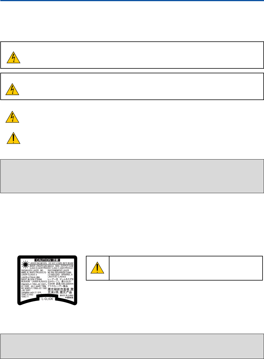
CAUTION
Do not look into the laser pointer while it is on and do not point the
laser beam at a person. Serious injury could result.
This label is underneath the remote control.
ii
Important Information
RF Interference (for USA only)
WARNING
The Federal Communications Commission does not allow any modifications or changes to the unit EXCEPT those specified by
NEC Solutions (America), Inc. in this manual. Failure to comply with this government regulation could void your right to operate
this equipment. This equipment has been tested and found to comply with the limits for a Class B digital device, pursuant to Part
15 of the FCC Rules. These limits are designed to provide reasonable protection against harmful interference in a residential
installation. This equipment generates, uses, and can radiate radio frequency energy and, if not installed and used in accordance
with the instructions, may cause harmful interference to radio communications. However, there is no guarantee that interference
will not occur in a particular installation.
If this equipment does cause harmful interference to radio or television reception, which can be determined by turning the
equipment off and on, the user is encouraged to try to correct the interference by one or more of the following measures:
•Reorient or relocate the receiving antenna.
•Increase the separation between the equipment and receiver.
•Connect the equipment into an outlet on a circuit different from that to which the receiver is connected.
•Consult the dealer or an experienced radio / TV technician for help.
For UK only: In UK, a BS approved power cable with moulded plug has a Black (five Amps) fuse installed for use with this equipment.
If a power cable is not supplied with this equipment please contact your supplier.
Important Safeguards
These safety instructions are to ensure the long life of your projector and to prevent fire and shock. Please read them
carefully and heed all warnings.
Installation
1. For best results, use your projector in a darkened room.
2. Place the projector on a flat, level surface in a dry area away from dust and moisture.
3. Do not place your projector in direct sunlight, near heaters or heat radiating appliances.
4. Exposure to direct sunlight, smoke or steam can harm internal components.
5. Handle your projector carefully. Dropping or jarring can damage internal components.
6. Do not place heavy objects on top of the projector.
7. If you wish to have the projector installed on the ceiling:
a. Do not attempt to install the projector yourself.
b. The projector must be installed by qualified technicians in order to ensure proper operation and reduce the
risk of bodily injury.
c. In addition, the ceiling must be strong enough to support the projector and the installation must be in accor-
dance with any local building codes.
d. Please consult your dealer for more information.
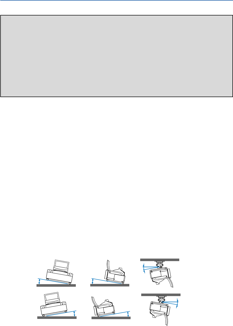
Place the projector in a horizontal position
The tilt angle of the projector should not exceed 10 degrees, nor should the projector be installed in any way other than
the desktop and ceiling mount, otherwise lamp life could decrease dramatically.
10°10°
10°10°
10°
10°

iii
Important Information
Fire and Shock Precautions
1. Ensure that there is sufficient ventilation and that vents are unobstructed to prevent the build-up of heat inside
your projector. Allow at least 4 inches (10 cm) of space between your projector and a wall.
2. Prevent foreign objects such as paper clips and bits of paper from falling into your projector.
Do not attempt to retrieve any objects that might fall into your projector. Do not insert any metal objects such as
a wire or screwdriver into your projector. If something should fall into your projector, disconnect it immediately
and have the object removed by a qualified NEC service personnel.
3. Do not place any liquids on top of your projector.
4. Do not look into the mirror or the light source while the projector is on. Serious damage to your eyes could
result.
5. Keep any items such as magnifying glass out of the light path of the projector. The light being projected from the
mirror is extensive, therefore any kind of abnormal objects that can redirect light coming out of the mirror, can
cause unpredictable outcome such as fire or injury to the eyes.
6. Do not block the light path between the light source and the final mirror with any objects. Doing so could cause
the object to catch on fire.
7. The projector is designed to operate on a power supply of 100-240V AC 50/60 Hz. Ensure that your power
supply fits this requirement before attempting to use your projector.
8. Handle the power cable carefully and avoid excessive bending.
A damaged cord can cause electric shock or fire.
9. If the projector is not to be used for an extended period of time, disconnect the plug from the power outlet.
10. Do not touch the power plug during a thunderstorm. Doing so can cause electrical shock or fire.
11. Do not handle the power plug with wet hands.
12. When using a LAN cable:
For safety, do not connect to the connector for peripheral device wiring that might have excessive voltage.
CAUTION
•Do not try to touch the ventilation openings on the both sides as it can become heated while the projector is
turned on.
•Do not attempt to move or carry the projector using the mirror cover.
Doing so can result in the projector overturning and causing injury. Using the two side handles is the proper
way to move the projector.
When carrying or transporting the projector, close and lock the mirror cover with the mirror cover lock switch.
•The carrying handles are designed for the purpose of carrying the projector. Do not hang from the projector by
the carrying handles in a ceiling mounted installation. Doing so may result in the carrying handles separating
from the unit or the projector may separate from the mount resulting in personal injury.
• Select [High] in Fan mode if you continue to use the projector for consecutive days. (From the menu, select
[Setup] → [Options] → [Fan Mode] → [High].)
•Do not unplug the power cable from the wall outlet under any one of the following circumstances.
Doing so can cause damage to the projector:
*While the projector's lamp is on.
*While the cooling fans are running. (The cooling fans continue to work for 90 seconds after the projector is
turned off).
* While the PC CARD Access Indicator lights. Doing so can damage your PC memory card.

iv
Important Information
Lamp Replacement
•To replace the lamp, follow all instructions provided on page 134.
•Be sure to replace the lamp when the message “The lamp has reached the end of its usable life. Please
replace the lamp.” appears. If you continue to use the lamp after the lamp has reached the end of its usable
life, the lamp bulb may shatter, and pieces of glass may be scattered in the lamp case. Do not touch them as the
pieces of glass may cause injury.
If this happens, contact your NEC dealer for lamp replacement.
•Allow a minimum of 90 seconds to elapse after turning off the projector. Then turn off the main power switch,
disconnect the power cable and allow 60 minutes to cool the projector before replacing the lamp.

v
Table of Contents
Important Information ...........................................................................i
1. Introduction ......................................................................................1
What's in the Box? ........................................................................................................ 2
Introduction to the Projector ......................................................................................... 3
Part Names of the Projector ......................................................................................... 5
Opening and Closing the Mirror Cover ................................................................... 6
Top Features ........................................................................................................... 7
Ter minal Panel Features ......................................................................................... 8
Part Names of the Remote Control ............................................................................ 10
Battery Installation ................................................................................................ 12
Operating Range for Wireless Remote Control..................................................... 12
Remote Control Precautions ................................................................................. 12
Using the Remote Control in Wired Operation...................................................... 12
Part Names and Functions of the Supplied Electronic Pen (WT615 only) ................. 13
Battery Installation ................................................................................................ 13
Electronic Pen Precautions ................................................................................... 13
2. Installation and Connections ....................................................... 14
Setting Up the Screen and the Projector .................................................................... 16
Making Connections ................................................................................................... 19
When Viewing a DVI Digital Signal ....................................................................... 19
Connecting Your PC or Macintosh Computer........................................................ 19
To connect SCART output (RGB) ......................................................................... 20
Using two Analog COMPUTER inputs simultaneously ......................................... 21
Connecting an External Monitor ........................................................................... 22
Connecting Your DVD Player................................................................................. 23
Connecting Your VCR or Laser Disc Player .......................................................... 24
Connecting to a Network....................................................................................... 25
Inserting and Removing a PC Card ...................................................................... 27
Connecting the Supplied Power Cable ................................................................. 29
3. Projecting an Image (Basic Operation)...................................... 30
Turning on the Projector ............................................................................................. 31
Adjusting the Position and Size of the Projected Image (Focus Adjustments) ........... 33
Selecting a Source ..................................................................................................... 40
Optimizing an RGB Image Automatically ................................................................... 41
Turning Up or Down Volume ....................................................................................... 41
Adjusting Pincushion or Barrel Distortion (Pincushion) .............................................. 42
Using the Laser Pointer .............................................................................................. 44
쐊 Using the Electronic Pen (WT615 only)...................................................................... 45
쐎 Turning off the Projector ............................................................................................. 48
쐅 After Use..................................................................................................................... 49

vi
Table of Contents
4. Convenient Features ...................................................................... 50
Turning Off the Image and Sound ............................................................................... 51
Freezing a Picture....................................................................................................... 51
Using the Pointer ........................................................................................................ 51
Enlarging and Moving a Picture.................................................................................. 52
Getting Integrated Help .............................................................................................. 52
Using a USB Mouse ................................................................................................... 53
Using the Remote Mouse Function ............................................................................ 54
Making Freehand Drawings on a Projected Image (ChalkBoard) .............................. 55
쐎
Storing Images Displayed on the Projector on the PC card or USB memory (Capture)
.......... 56
쐅 Preventing Unauthorized Use of the Projector ........................................................... 57
쐈 Using a USB Memory Device or USB Memory Card Reader..................................... 62
쐉 Operation Using an HTTP Browser ............................................................................ 63
씈
Using the Projector to Operate a Computer Connected on a Network (Desktop Control Utility 1.0)
........ 66
5. Using the Viewer ............................................................................. 71
Making the Most out of the Viewer Function ............................................................... 72
Operating the Viewer Function from the Projector (playback) .................................... 73
쐋 Changing Background Logo ....................................................................................... 79
6. Using On-Screen Menu ................................................................. 80
Using the Menus......................................................................................................... 81
Menu tree ................................................................................................................... 82
Menu Elements........................................................................................................... 84
Menu Descriptions & Functions [Source] ................................................................... 85
쐄 Menu Descriptions & Functions [Adjust] ..................................................................... 88
쐂 Menu Descriptions & Functions [Setup] ..................................................................... 98
쐆 Menu Descriptions & Functions [Information] ........................................................... 126
쐊 Menu Descriptions & Functions [Reset] ................................................................... 129
7. Maintenance .................................................................................. 131
Handling and Care of Mirror Surface ........................................................................ 132
쐇 Cleaning the Cabinet ................................................................................................ 133
쐋 Replacing the Lamp................................................................................................. 134
8. Appendix ......................................................................................... 137
Troubleshooting ........................................................................................................ 138
Specifications ........................................................................................................... 142
Cabinet Dimensions ................................................................................................. 144
Pin Assignments of D-Sub COMPUTER Input Connector ....................................... 145
Compatible Input Signal List ..................................................................................... 146
PC Control Codes and Cable Connection ................................................................ 147
Using Software Keyboard ......................................................................................... 148
Troubleshooting Check List ....................................................................................... 149

1
1
Introduction
What's in the Box? ....................................................... 2
Introduction to the Projector ........................................ 3
Part Names of the Projector ........................................ 5
Opening and Closing the Mirror Cover ................................................................... 6
Top Features ........................................................................................................... 7
Te r minal Panel Features ......................................................................................... 8
Part Names of the Remote Control ........................... 10
Battery Installation ................................................................................................ 12
Operating Range for Wireless Remote Control .................................................... 12
Remote Control Precautions ................................................................................ 12
Using the Remote Control in Wired Operation ..................................................... 12
Part Names and Functions of
the Supplied Electronic Pen (WT615 only) ............ 13
Battery Installation ................................................................................................ 13
Electronic Pen Precautions .................................................................................. 13
2
1. Introduction
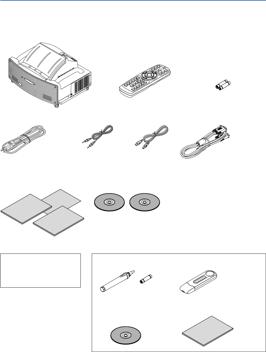
What's in the Box?
Make sure your box contains everything listed. If any pieces are missing, contact your dealer.
Please save the original box and packing materials if you ever need to ship your Projector.
Setup
Guide
NEC
Network
Setup Guide
Important
Information
Projector
Remote control
(7N900501)
Batteries (AAA
⳯
2)
Power cable
(7N080204) US
(7N080008) EU
RGB/VGA signal cable
(7N520032)
CD-ROM
User’s manual and User Supportware 2
For North America only
Registration card
Limited warranty
For Europe only
Guarantee policy
• Security sticker
• Mirror cleaning cloth (24BS7251)
• Dust-proof cover (24BS7272)
UNLOCK
MIRROR
LOCK
Remote Control
Cable
(7N520019)
USB cable
(7N520045)
WT615 only
• Electronic pen and battery
(7N900611)
(AA
⳯
1)
• USB memory device (7N960201)
See page 62.
• CD-ROM
User Supportware 2 Plus
(eBeam Interactive Software)
• eBeam Interactive Software Setup Guide

3
1. Introduction
Introduction to the Projector
This section introduces you to the WT615/WT610 Projector and describes key features and controls.
Congratulations on Your Purchase of the WT615/WT610 Projector
The WT615/WT610 is a sophisticated four aspherical mirror XGA projector that produces an enhanced display. With
the WT615/WT610 you will be able to project images up to 100” (measured diagonally). Enjoy crisp and sharp large
screen display from your PC, workstation or Macintosh computer, DVD player, VCR, satellite hookup, HDTV source, )
and images from your digital camera PC Card, compact flash memory or USB storage device. The WT615/WT610
provides for enhanced security options to help deter projector theft and provides for full projector control through the
PC control port (mini DIN 8Pin) and LAN support. With input and output flexibility and a full function remote, the
WT615/WT610 lets you enjoy larger than life viewing from a compact and easy to setup and use projector.
Features you’ll enjoy on the WT615/WT610:
•Extremely short focal length
•40" to 100" diagonal image display from 26 inches (66 cm) or less to the screen
• The electronic pen and the projector can be used to convert your whiteboard into a virtual touchscreen. (WT615
only)
• Built-in Wall Color Correction presets provide for adaptive color correction when projecting onto non-white
screen material (or a wall).
•USB memory or PC card interfaces provide for computer-free presentations.
•Enhanced smart security settings for password protection, cabinet control panel lock, menu lock and PC card
protection key to help prevent unauthorized access, adjustments and theft deterrence.
• High resolution display - up to UXGA compatible, XGA native resolution.
•Variable audio out control of external amplified speakers via the projector remote.
•Extensive user adjustable picture and color management settings.
•Display 16:9 or 4:3 aspect ratio sources and fill the screen.
•HDTV (1080i, 720p) and SDTV (480p/576p, 480i/576i) compatibility.
•Digital photo viewer to display larger than life images from your digital cameras PC card, compact flash card or
USB storage device.
•Wireless networking capable.
Present from anywhere in the room when using as a wireless LAN projector, no physical signal cable connec-
tion to a PC is required.
* The NEC optional wireless LAN card is required (NWL-100A or NWL-100E See page 25.).
•Supplied User Supportware 2 CD-ROM containing five software utilities allowing you to make the most of your
NEC projector.
•Eco-mode lamp technology for increased lamp life, reduced energy consumption and overall total cost of
ownership savings.
• Built-in laser pointer on the supplied remote control allows you to draw your audience's attention in a presenta-
tion.

4
About this user's manual
The fastest way to get started is to take your time and do everything right the first time. Take a few minutes now to
review the user's manual. This may save you time later on. At the beginning of each section of the manual you'll find an
overview. If the section doesn't apply, you can skip it.
•IBM is a trademark or registered trademark of International Business Machines Corporation.
• Mac, Macintosh and PowerBook are trademarks of Apple Computer, Inc., registered in the U.S. and other
countries.
• Windows, Windows 98, Windows Me, Windows XP or Windows 2000 are trademarks or registered trademarks
of Microsoft Corporation.
•Digital Light Processing and DLP are trademarks of Texas Instruments.
•Ulead is a trademark and/or registered trademark of Ulead Systems, Inc.
• eBeam and the eBeam logo are trademarks or registered trademarks of Luidia, Inc.
•Other product and company names mentioned in this user’s manual may be the trademarks or registered
trademarks of their respective holders.
1. Introduction
5
1. Introduction
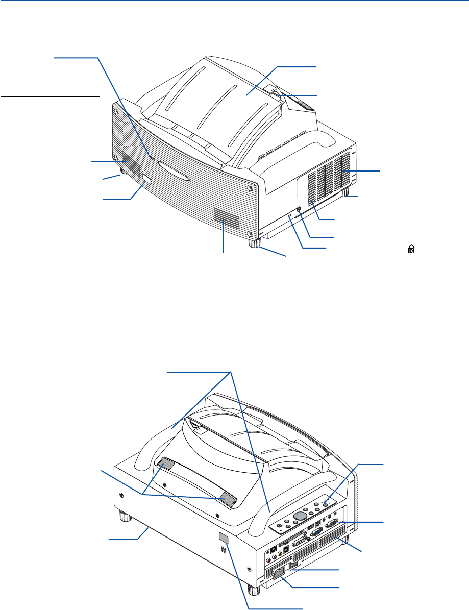
Part Names of the Projector
*This security slot supports the MicroSaver® Security System. MicroSaver® is a registered trademark of
Kensington Microware Inc. The logo is trademarked and owned by Kensington Microware Inc.
UNLOCK
MIRROR
LOCK
Ventilation (outlet)
Mirror cover
Speaker
Mirror cover lock switch
Foot
Lamp cover screw
Lamp cover
Foot
Speaker
Remote sensor
Front indicator
Lights blue to indicate that
the projector is turned on
or in the Standby mode.
NOTE: When [Standby Mode]
is set to “Power-saving”, this
indicator lights blue only with
power on.
Foot
Built-in Security Slot ( )*
POWER
ENTEER
MENU
SOURCE
FOCUS
PC CARD
EXIT
STATUS
LAMP
ON/
STAND BY
AUTO
ADJUST
3D
REFORM
SELECT
UNLOCK
MIRROR
LOCK
PC CARD
R-AUDIO IN-L/MONO
VIDEO IN S-VIDEO IN DVI-I IN
DVI-I
AUDIO IN AUDIO OUT
PCCONTROL
REMOTE
IN
COMPUTER IN MONITOR OUT
COMPUTER
USB
Remote sensor
Ventilation (inlet)
Controls
Te r minal panel
Main Power Switch
AC Input
Carrying handle
Ventilation (outlet)
Sensor for Electronic pen
(WT615 only)
6
1. Introduction
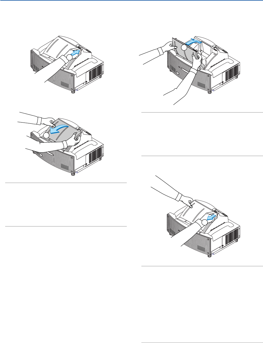
Opening and Closing the Mirror Cover
To open the mirror cover:
1. Slide the mirror cover lock switch to the unlock position.
UNLOCK
MIRROR
LOCK
1
2. Slowly open the mirror cover holding both ends.
UNLOCK
MIRROR
LOCK
2
NOTE:
•Do not release your hold of the mirror cover until the mirror cover
is fully open.
•Do not apply excessively strong pressure against the mirror cover
or mirror surface while opening it.
•Keep finger prints off the mirror surface. Leaving finger prints in
the mirror surface might cause an unwanted shadow and poor
picture quality.
To close the mirror cover:
1. Slowly close the mirror cover while holding both ends.
UNLOCK
MIRROR
LOCK
1
NOTE:
•Do not release your hold of the mirror cover until the mirror cover
is fully closed.
•Do not apply excessively strong pressure against the mirror cover
or mirror surface while closing it.
•Keep finger prints off the mirror surface. Leaving finger prints in
the mirror surface might cause an unwanted shadow and poor
picture quality.
2. Slide the mirror cover lock switch to the lock position.
UNLOCK
MIRROR
LOCK
2
NOTE:
•The projector cannot be turned on when the mirror cover is closed.
•Keep any items out of the light path or the mirror. Failure to do so
may cause objects to catch on fire in unexpected places.
•The projector has a sensor which detects an object in front of the
largest mirror or in the light path. If the sensor detects any object,
the projector will not turn on. If this happens while the projector is
turned on, the image is muted. In either case the STATUS indicator
lights in red.
•The projector has a temperature sensor which detects heat. If the
sensor detects excessive heat in the bottom of the mirror or in the
light path, the projector will not turn on. If this happens while the
projector is turned on, the projector will turn off (Standby mode).
In either case the STATUS indicator flashes in red.
7
1. Introduction
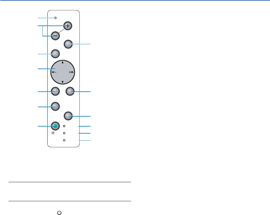
Top Features
1. POWER Button (ON / STAND BY)
Use this button to turn the power on and off when the
main power is supplied and the projector is in standby
mode.
NOTE: To turn on the projector, press and hold this button
for a minimum of two seconds. To turn off the projector,
press this button twice.
2. POWER Indicator ( )
When this indicator is green, the projector is on; when
this indicator is orange, it is in standby mode. See the
Power Indicator section on page 138 for more details.
3. STATUS Indicator
If this light blinks red rapidly, it indicates that an error
has occurred, the lamp cover is not attached properly
or the projector has overheated. If this light remains
orange, it indicates that you have pressed a cabinet
key while the Cabinet Button is locked. See the Sta-
tus Indicator section on page 138 for more details.
4. LAMP Indicator
If this light blinks red rapidly, it's warning you that the
projection lamp has exceeded 2000 hours (up to 4000
hours in Eco mode) of service. After this light appears,
replace the lamp as soon as possible. (See page 134).
If this is lit green continually, it indicates that the lamp
mode is set to Eco. See the Lamp Indicator section
on page 138 for more details.
5. SOURCE Button
Use this button to select a video source such as a PC,
VCR, DVD player or Viewer (PC card).
Press and release this button quickly to display the
Source List.
Each time this button is pressed for a minimum of ONE
second, the input source will change as follows:
Computer → DVI (DIGITAL) → DVI (ANALOG) →
Video → S-Video → Viewer → Computer → ...
If no input signal is present, the input will be skipped.
6. AUTO ADJUST Button
Use this button to adjust an RGB source for an opti-
mal picture. See page 41.
7. 3D REFORM Button
Press this button to enter 3D Reform mode to correct
the distortion, and make the image square.
Each time this button is pressed, the item will change
as follows:
Pincushion → Cornerstone → Keystone → ... (the
three items are available only when no adjustment is
made)
8. FOCUS (+) (–) Buttons
Adjusts the focus.
9. MENU Button
Displays the menu.
10. SELECT 왖왔왗왘 (+) (–) / Volume Buttons
왖왔 : Use these buttons to select the menu of the
item you wish to adjust.
왗왘 : Use these buttons to change the level of a
selected menu item. When no menus appear,
these buttons work as a volume control.
When the pointer is displayed, these 왖왔왗왘 buttons
move the pointer.
11. ENTER Button
Executes your menu selection and activates items
selected from the menu.
12. EXIT Button
Pressing this button will return to the previous menu
with saving changes.
While you are in the main menu, pressing this button
will close the menu.
13. PC CARD Access Indicator
Lights while accessing a PC card.
POWER
ENTER
MENU
SOURCE
FOCUS
PC CARD
EXIT
STATUS
LAMP
ON/
STAND BY
AUTO
ADJUST
3D
REFORM
SELECT
12
8
6
10
11
13
9
5
7
12
3
4
8
1. Introduction
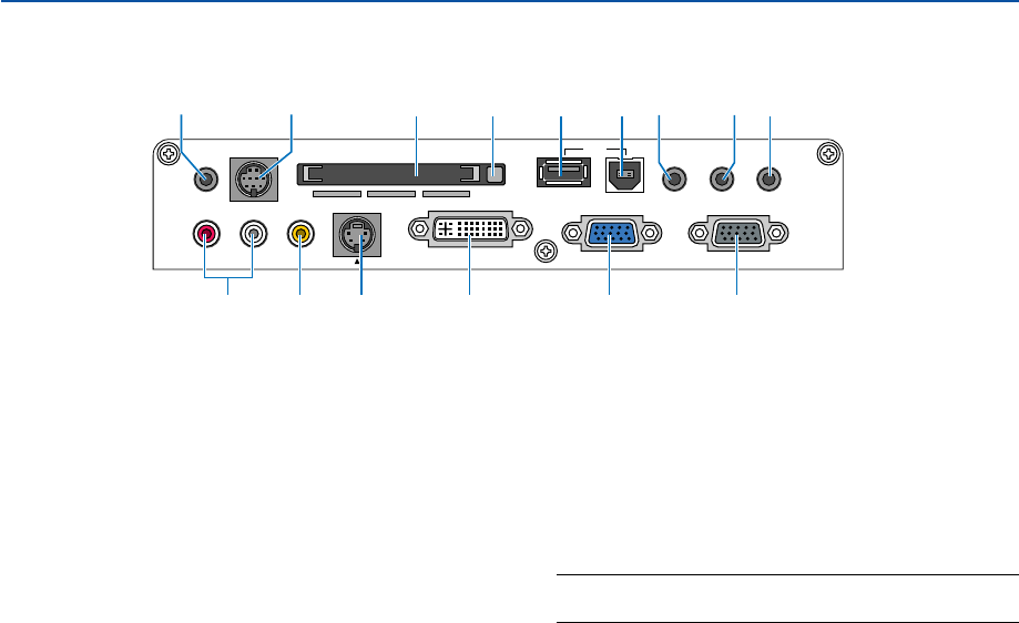
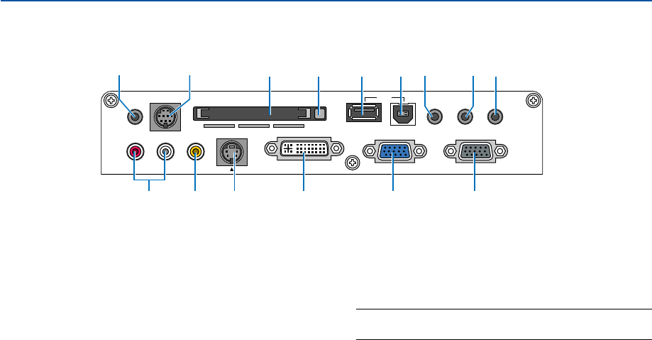
Te r minal Panel Features
1. COMPUTER IN / Component Input Connector
(Mini D-Sub 15 Pin)
Connect your computer or other analog RGB equip-
ment such as IBM compatible or Macintosh comput-
ers. Use the supplied RGB/VGA signal cable to con-
nect to your computer. This also serves as a compo-
nent input connector that allows you to connect a com-
ponent video output of component equipment such
as a DVD player. This connector also supports SCART
output signal. See page 20 for more details.
2. COMPUTER AUDIO IN Mini Jack (Stereo Mini)
This is where you connect audio output from your com-
puter or DVD player. A commercially available audio
cable is required.
3. DVI-I IN Connector (DVI-I 29 Pin)
Connect a computer with a DVI output using a com-
mercially available DVI-D cable.
This connector can be used to accept digital and ana-
log signal output from a computer with a DVI connec-
tor.
4. DVI-I AUDIO IN Mini Jack (Stereo Mini)
This is where you connect the audio output from your
computer when connected to the DVI input. A com-
mercially available audio cable is required.
5. MONITOR OUT Connector (Mini D-Sub 15 Pin)
You can use this connector to loop your computer
image to an external monitor from the COMPUTER
or the DVI-I input source.
The RGB analog signal set on “OUT Terminal” is out-
put during Standby mode. See pages 22 and 122.
6. AUDIO OUT Mini Jack (Stereo Mini)
Connect an additional audio equipment here to listen
to audio coming from your COMPUTER, DVI-I, VIDEO
or S-VIDEO input.
7. S-VIDEO IN Connector (Mini DIN 4 Pin)
Here is where you connect the S-Video input from an
external source like a VCR.
NOTE: S-Video provides more vivid color and higher
resolution than the traditional composite video format.
8. VIDEO IN Connector (RCA)
Connect a VCR, DVD player, laser disc player, or docu-
ment camera here to project video.
9. VIDEO AUDIO IN Jacks (RCA)
L: This is your left channel audio input for stereo
sound coming from the VIDEO source.
R: This is your right channel audio input for stereo
sound from the VIDEO source.
10. REMOTE IN Jack (Mini Jack)
Connect your remote control cable here for wired op-
eration.
11. PC CONTROL Port (Mini DIN 8 Pin)
Use this port to connect your PC or control system to
control your projector via a serial cable. This enables
you to control the projector using serial communica-
tion protocol. An optional serial cable (CA03D: 9Pin
D-Sub to 8 Pin Mini DIN) is required for this port. You
can also control the projector by using PC Control
Utility 3.0 contained on the supplied User Supportware
2 CD-ROM.
To do so you must first have PC Control Utility 3.0
installed on your PC. If you are writing your own pro-
gram, typical PC control codes are on page 147.
PC CARD
AUDIO IN
RL
/MONO
VIDEO IN S-VIDEO IN DVI-I IN COMPUTER IN MONITOR OUT
DVI-I COMPUTER
AUDIO IN AUDIO OUT
PCCONTROL
REMOTE
IN USB
1 5
6
12131514
3789
2410 11
9
1. Introduction
Te r minal Panel Features
PC CARD
AUDIO IN
RL
/MONO
VIDEO IN S-VIDEO IN DVI-I IN COMPUTER IN MONITOR OUT
DVI-I COMPUTER
AUDIO IN AUDIO OUT
PCCONTROL
REMOTE
IN USB
1 5
6
12131514
3789
2410 11
12. USB Port (Type B)
Connect this port to the USB port (type A) of your PC
using the supplied USB cable. You can operate your
computer's mouse functions from the remote control.
13. USB Port (Type A)
Connect a commercially available USB memory de-
vice or mouse that supports USB. You can operate
the menu or Viewer with the USB mouse via this port.
Note that this port should not be connected to a com-
puter and that there may be some brands of USB
mouse that the projector does not support.
14. PC CARD Slot
Insert a PC card, commercially available LAN card or
NEC optional wireless LAN card here.
NOTE: A dummy card is inserted into each slot at the time
of shipment. First remove the dummy cards before use.
15. PC CARD Eject Button
Press to eject a PC card partially.
10
1. Introduction
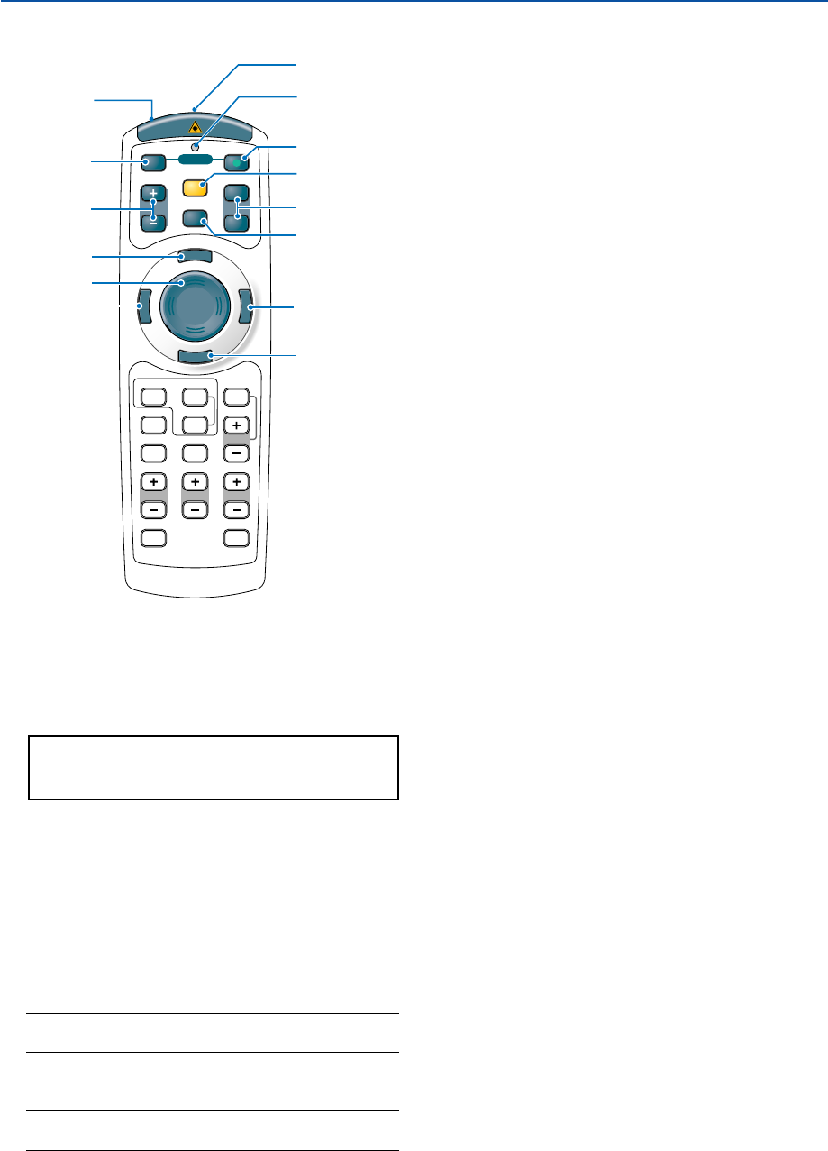
쐏 Part Names of the Remote Control
1. Infrared Transmitter/Laser Pointer
Transmits an infrared signal when any button other
than LASER is pressed.
Direct the remote control toward the remote sensor
on the projector cabinet.
Beams a laser light when the Laser button is pressed.
CAUTION:
* Do not look into the laser pointer while it is on.
* Do not point the laser beam at a person.
2. Remote Jack
Connect your remote control cable here for wired op-
eration.
3. LED
Flashes when any button is pressed.
4. POWER ON Button
When the main power is on, you can use this button
to turn your projector on.
NOTE: To turn on the projector, press and hold the
POWER ON button for a minimum of two seconds.
5. POWER OFF Button
You can use this button to turn your projector off.
NOTE: To turn off the projector, press the POWER OFF
button twice.
POINTER
LASER
MAGNIFY PAGE
OFF
POWER
ON
E
N
T
E
R
M
E
N
U
E
X
I
T
R
-
C
L
I
C
K
UP
DOWN
HELP
ZOOMFOCUS
SLIDE
VIEWER
VOLUME
3D REFORM
PIC-MUTE
FREEZE
AUTO ADJ.
COMPUTER
ASPECT
VIDEO
3
1
2
5
6
10
12
11
4
9
8
7
13
14
6. MAGNIFY (+) (–) Buttons
Use these buttons to adjust the image size.
The image can be magnified about the center of the
screen up to 400%. See page 52.
7. LASER Button
Press and hold this button to activate the laser pointer.
When lit, you can use the laser to draw your audience's
attention to a red dot that you can place on any ob-
ject. See page 44.
8. POINTER Button
Press this button to display the projector pointer. You
can move your pointer icon to the area you want on
the screen using the SELECT 왖왔왗 or 왘 button. See
page 51.
9. PAGE (UP) (DOWN) Buttons
Use these buttons to scroll the viewing area of the
window or to move to the previous or next slide in
PowerPoint on your computer when the supplied USB
cable is connected with your computer.
10. MENU Button
Displays the menu for various settings and adjust-
ments.
11. SELECT 왖왔왗왘 Button
This button is used for projector’s menu operation and
moving the magnified image.
This button also works as a computer mouse when
the supplied USB cable is connected with your com-
puter.
12. ENTER Button
Executes your menu selection and activates items
selected from the menu.
13. EXIT Button
Returns to the previous menu.
While you are in the main menu, pressing this button
will close the menu.
14. R-CLICK Button
Works as the mouse right button when the supplied
USB cable is connected with your computer.
11
1. Introduction
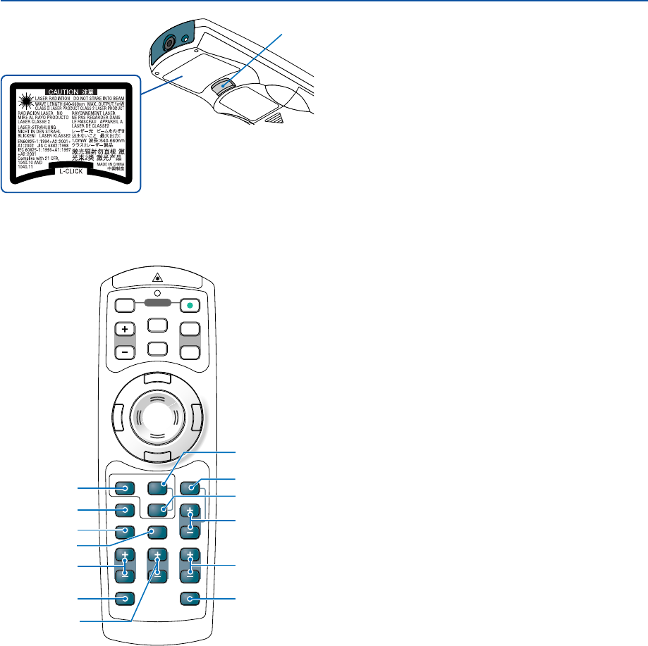
15. L-CLICK Button
Works as the mouse left button when the supplied
USB cable is connected with your computer.
VOLUME
3D REFORM
PIC-MUTE
FREEZE
ZOOMFOCUS
SLIDE
AUTO ADJ.
HELP
VIEWER
COMPUTER
ASPECT
VIDEO
POINTER
LASER
MAGNIFY PAGE
OFF
POWER
ON
E
N
T
E
R
M
E
N
U
E
X
I
T
R
-
C
L
I
C
K
UP
DOWN
16
21
22 20
25
28
18
19
17
23
24
27
26
20. SLIDE (+) (–) Buttons
Press (+) to select the next folder or slide and press
(–) to select the previous folder or slide.
21. ASPECT Button
Press this button to display the Aspect Ratio select
menu. See page 90.
22. PIC-MUTE Button
This button turns off the image and sound for a short
period of time. Press again to restore the image and
sound. See page 51.
23. HELP Button
Provides the online help. See page 52.
24. VOLUME (+) (–) Buttons
Press (+) to increase the volume and (–) to decrease
it. See page 41.
25. FOCUS (+) (–) Buttons
Adjust the focus.
26. ZOOM (+) (–) Buttons
Reduces the image size between 80% and 100%.
27. FREEZE Button
This button will freeze a picture. Press again to re-
sume motion. See page 51.
28. 3D REFORM Button
Press this button to enter 3D Reform to correct the
pincushion, the cornerstone or the keystone distor-
tion, and make the image square. See pages 42 and
99 - 102.
15
16. VIDEO Button
Press this button to toggle between Video and S-Video
inputs.
17. COMPUTER Button
Press this button to select the COMPUTER, DVI (DIGI-
TAL) or DVI (ANALOG) input.
18. AUTO ADJ. Button
Use this button to adjust an RGB source (COM-
PUTER) for an optimal picture. See page 41.
19. VIEWER Button
Press this button to select the Viewer source. See page
71.
12
1. Introduction
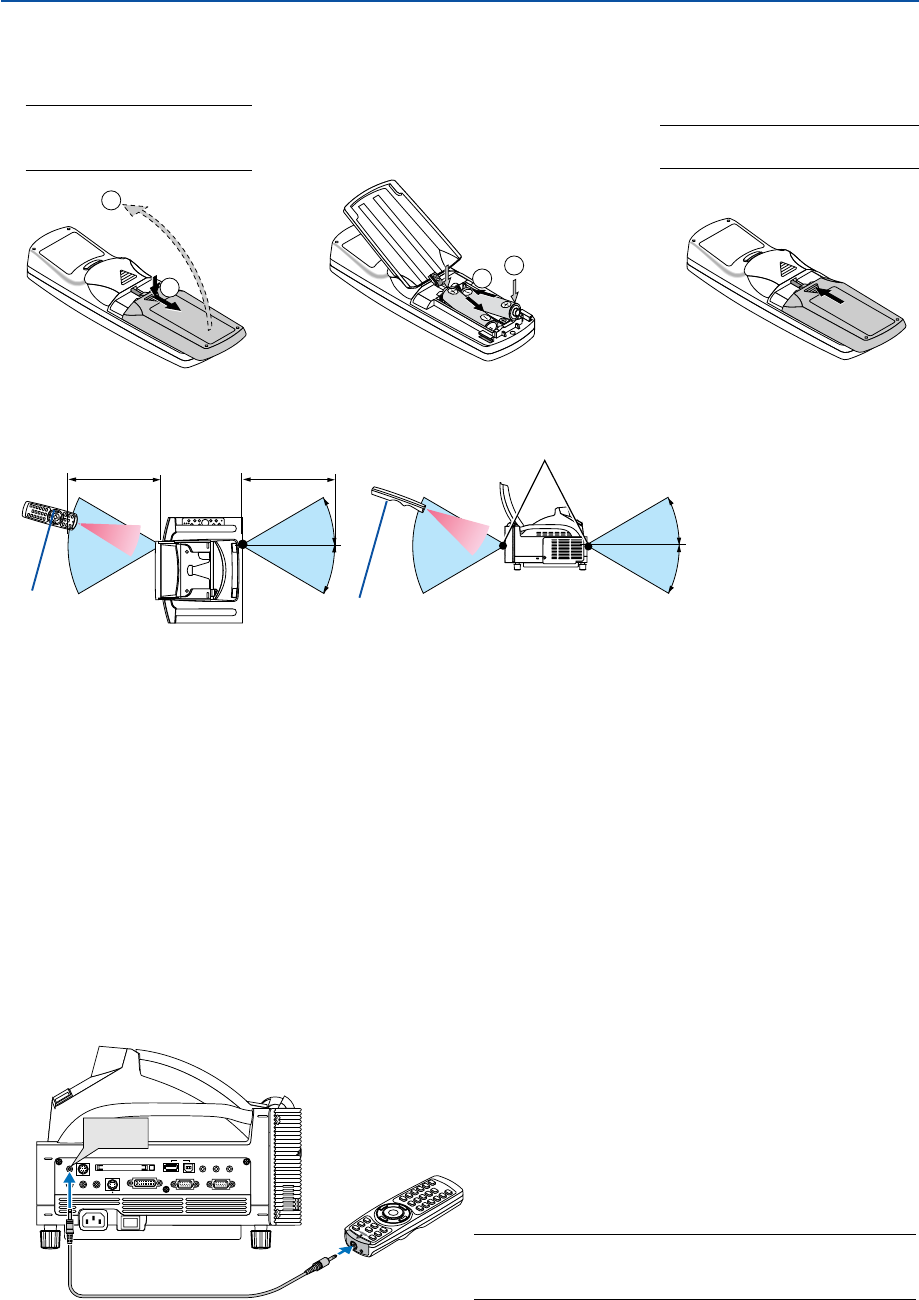
Battery Installation
1Remove the battery cover.
NOTE: Do not pull the battery
cover by force. Doing so can
result in its complete removal.
2Remove both old batteries and
install new ones (AAA). Ensure
that you have the batteries' po-
larity (+/ –) aligned correctly.
3Slip the cover back over the bat-
teries until it snaps into place.
NOTE: Do not mix different types of
batteries or new and old batteries.
•The infrared signal operates by line-of-sight up to a distance of about 22 feet/7 m and within a 60-degree angle of
the remote sensor on the projector cabinet.
•The projector will not respond if there are objects between the remote control and the sensor, or if strong light falls
on the sensor.
Weak batteries will also prevent the remote control from properly operating the projector.
Remote Control Precautions
•Handle the remote control carefully.
• If the remote control gets wet, wipe it dry immediately.
•Avoid excessive heat and humidity.
•If you will not be using the remote control for a long time, remove the batteries.
• Do not place the batteries upside down.
•Do not use new and old batteries together, or use different types of batteries together.
•Dispose of used batteries according to your local regulations.
Operating Range for Wireless Remote Control
1
2
12
30°
30°
30°
30°
7m/22 feet 7m/22 feet
Remote control
Remote sensor on the projector cabinet
Using the Remote Control in Wired Operation
Connect one end of the supplied remote cable to the REMOTE mini jack and the other end to the remote jack on the
remote control.
PC CARD
AUDIO IN
RL
/MONO
VIDEO IN S-VIDEO IN DVI-I IN COMPUTER IN MONITOR OUT
DVI-I COMPUTER
AUDIO IN AUDIO OUT
PCCONTROL
REMOTE
IN USB
REMOTE
IN
NOTE: Inserting the remote cable into the REMOTE IN jack will
automatically change the projector’s Standby mode to Normal
mode even if Power-saving mode has been selected.
Remote control
13
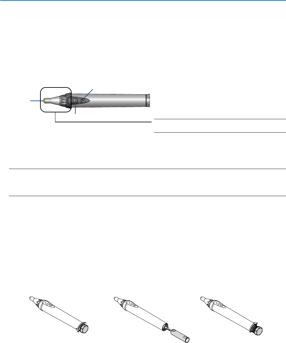
Part Names and Functions of the Supplied Electronic Pen (WT615 only)
The WT615 comes with an electronic pen.
The electronic pen works as a USB mouse connected to the projector. See page 53 for connecting a USB mouse.
The electronic pen and the projector’s sensors can be used to convert your whiteboard into a virtual touchscreen which
allows you to operate your projector’s menu or use the ChalkBoard feature. See “ Using the Electronic Pen” on page 45.
Important
Before you use the electronic pen or when you have changed the position of the projector or the screen size, be sure
to use [Calibration] to calibrate the electronic pen and the screen.
1. Introduction
The buttons work as computer mouse buttons.
Pen tip ................... Left click button
Button A ................ Right-click button
Button B ................ Button to turn on or off the ChalkBoard toolbar.
NOTE:
•Button A or B must be pressed and held for a minimum of 0.5 second.
• Pressing and holding the buttons A and B at the same time for a minimum of 0.5 second will change to “Pen Calibration”
mode. See also page 47.
Pen tip
Button A
Button B
Requirements for the Electronic Pen Function
•Screen size: 40” to 80”
•Projector orientation: “Desktop Front” and “Ceiling Front”
•[Screen Type]: “4:3”
•[Aspect Ratio]: “4:3”
•Digital Zoom: 100%
•[Cornerstone] and [Keystone]: Not performed
•Operating temperature: 59 to 95°F (15 to 35°C)
•[Resolution]: "Auto"
Battery Installation
123
Electronic Pen Precautions
•Handle the electronic pen carefully.
•If the electronic pen gets wet, wipe it dry immediately.
•Avoid excessive heat and humidity.
•If you will not be using the electronic pen for a long time, remove the battery.
•Dispose of a used battery according to your local regulations.
NOTE: Do not hold this part. Otherwise, the electronic pen
may not work properly.

14
2
Installation and Connections
Setting Up the Screen and the Projector ................... 16
Making Connections .................................................. 19
When Viewing a DVI Digital Signal ....................................................................... 19
Connecting Your PC or Macintosh Computer ....................................................... 19
To connect SCART output (RGB) ......................................................................... 20
Using two Analog COMPUTER inputs simultaneously ........................................ 21
Connecting an External Monitor ........................................................................... 22
Connecting Your DVD Player ................................................................................ 23
Connecting Your VCR or Laser Disc Player .......................................................... 24
Connecting to a Network ...................................................................................... 25
Inserting and Removing a PC Card...................................................................... 27
Connecting the Supplied Power Cable ................................................................. 29
15
2. Installation and Connections
Your projector is simple to set up and use.
But before you get started you must first:
1. Set up a screen and the projector.
NOTE: Using a warped screen can cause an image to appear distorted.
2. Connect your computer or video equipment to the projector. See page 19 to 28.
NOTE: To connect a network, see page 25.
3. Connect the supplied power cable. See page 29.
NOTE: Ensure that the power cable and any other cables are disconnected before moving the projector. When moving the
projector or when it is not in use, close the mirror cover on the top cabinet.
This section describes how to set up your projector and how to connect video and audio sources.
When installing the projector for the first time, read the WT615/WT610 Setup Guide carefully.
16
2. Installation and Connections
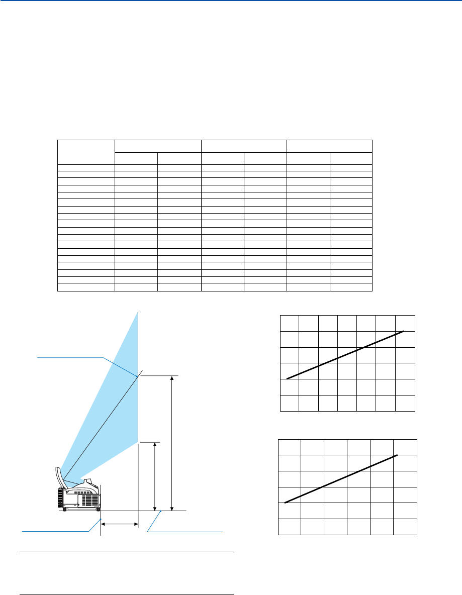
Setting Up the Screen and the Projector
1. Refer to "Throw Distance (C)" in the diagram and use a distance between the screen and projector that corre-
sponds to the screen size.
As an example, when projecting to a 60" screen, set the projector with a separation of approximately 10.4"/26.3
cm from the screen.
2. Refer to "Height (D)" below and adjust the screen height, or adjust the height of the projector stand.
As an example, when projecting to a 60" screen, adjust the height from the feet of the projector to the lower
edge of the screen to approximately 19.0"/48.2 cm.
C
D
Back of projector Projector foot
Screen center
0
20
40
60
80
100
120
051015 20 25 30
Throw distance C (inch)
Screen size (inch)
0
20
40
60
80
100
120
0 100 200 300 400 500 600 700
Throw distance C (mm)
Screen size (inch)
40
45
50
55
60
65
67
70
72
75
78
80
84
85
90
95
96
100
64
114
164
214
263
313
332
362
381
412
441
461
500
510
559
609
619
659
2.5
4.5
6.4
8.4
10.4
12.3
13.1
14.3
15.0
16.2
17.4
18.1
19.7
20.1
22.0
24.0
24.4
25.9
Screen size
(inch) Throw distance (C)
mm inch
354
386
418
450
482
514
526
546
558
577
596
609
635
641
673
704
711
737
13.9
15.2
16.5
17.7
19.0
20.2
20.7
21.5
22.0
22.7
23.5
24.0
25.0
25.2
26.5
27.7
28.0
29.0
Height (D)
mm inch
Height (B)
mm inch
NOTE
•There is a tolerance of +/–5% because of design values.
•The projection distance and the lower edge of the screen
are calculated using a 4:3 aspect ratio.
659
729
799
869
939
1010
1037
1080
1107
1149
1191
1219
1275
1289
1359
1428
1443
1499
25.9
28.7
31.5
34.2
37.0
39.7
40.8
42.5
43.6
45.2
46.9
48.0
50.2
50.7
53.5
56.2
56.8
59.0
B
17
2. Installation and Connections
40"-100"
90˚
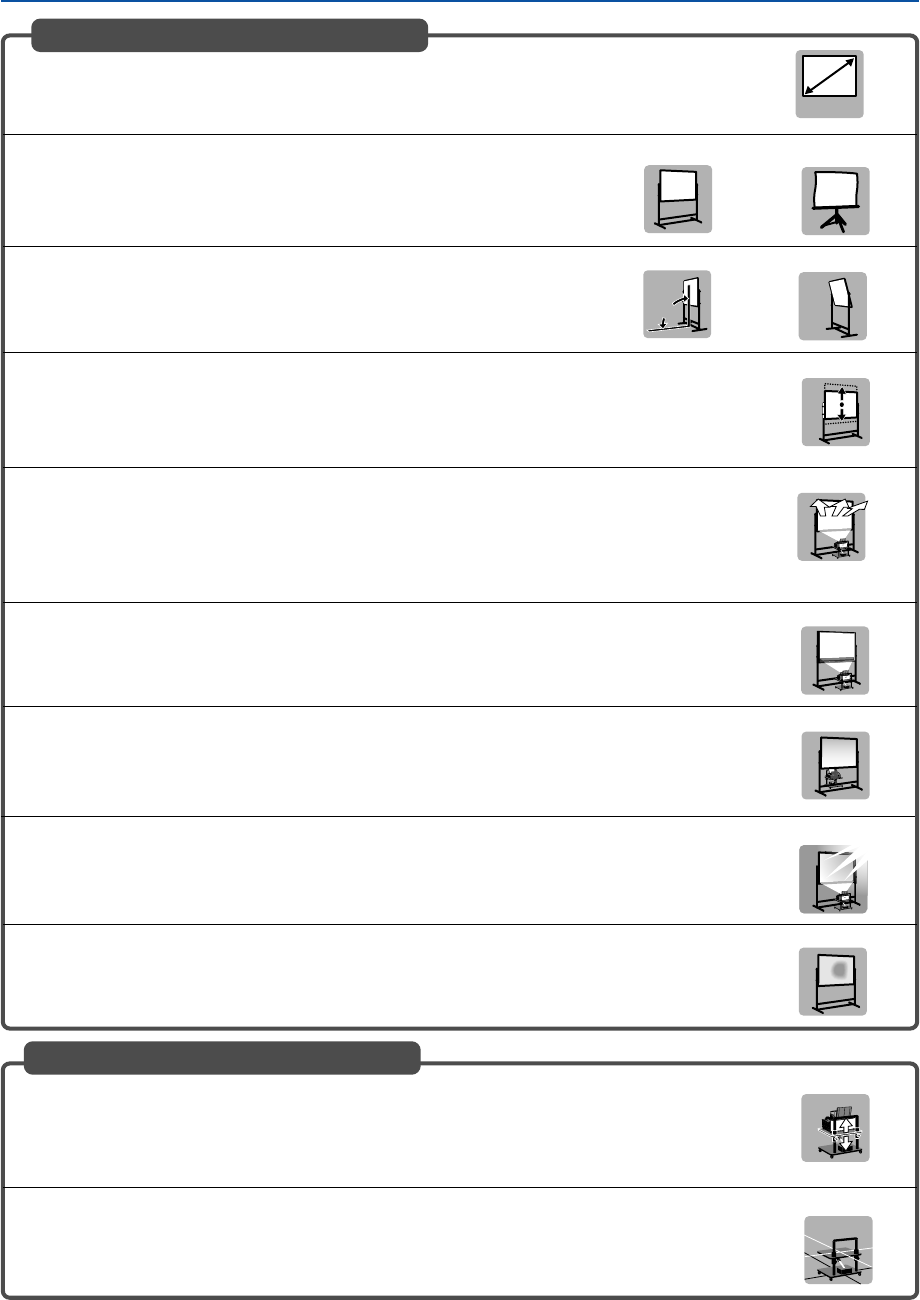
Screens Suited
•Screens with a soiled, scratched, or discolored area will not produce a clean image. Care
should be used in the handling of the screen.
Recommended Not recommended
Recommended Not recommended
Recommended
Not recommended
Not recommended
Not optimal
Not recommended
Not recommended
•Use a panel or tension type screen that has a flat surface.
Do not use roll type screens and other screens that bend or form a wavy
surface easily. Doing so will result in increased distortion of the projected
image.
•The projector can accommdate screen sizes from 40” (81.3 cm/32.0” W ⳯ 61.0 cm/24.0” H)
to 100 inch (203.2 cm/80.0” W ⳯ 152.4 cm/60.0” H).
•View the screen directly from the side so that it is perfectly vertical.
A slanted screen will result in increased keystone distortion.
•In using this projector, increasing the screen size will move the projection position upward. To
accommodate this, please use a screen that can be raised and lowered to a given screen
position. See page 16 for information about the positioning relationships between the screen
and this projector.
•High gain type screens are not optimal for use with this projector. The lower the screen gain
(i.e., screen gain on the order of 1), the better the appearance of the projected image.
For more information about screen gain, consult catalogs from screen manufacturers.
•Screen frames or pen shelves that protrude from the front of the screen surface may block
some of the light from the projector.
•Due to the projection angle of the projector, many standard rear projection screens may pro-
duce uneven brightness, hot spotting or not produce maximum brightness to the viewer. For
more details utilizing rear projection screens and their applications with this projector, please
contact your NEC dealer.
•Controlled ambient light environments will allow for an image of higher contrast and depth to
be displayed.
Level
Stands Suited
•Use a stand that will allow this projector to be set up in a level condition. Adjust the feet of the
stand to make sure it is level.
Recommended
Recommended
•In using this projector, increasing the screen size will move the projection position upward. To
accommodate this, please use a stand that has a height positioning adjustment. See page 16
for information about the positioning relationships between the screen and this projector.

18
2. Installation and Connections
Ambient environmental condition
•Do not place the screen near vents.
Air movement hitting the screen, causing the projected image to ripple.
•Do not illuminate the projector with strong light sources such as halogen lamp.
Doing so can cause the object detection sensor to malfunction, resulting in the projector not turning on.
Precautions for using the electronic pen (WT615 only)
•Use a hard-surface screen because you tap the screen using the electronic pen. Supported screen sizes are 40
to 80" (101.6 to 203.2 cm).
•Keep in mind that the electronic pen tip can cause scratches on the screen surface as the pen tip is made of
hard material.
•Do not use the electronic pen under the following conditions. Otherwise, the electronic pen may not work
properly.
-Near a device such as a CRT monitor or a TV set.
- In a room with the ceiling and walls made of metal which is prone to reflect sound waves.
-In a noisy place or a place where loud sounds can be heard
-In direct sunlight or near an inverter fluorescent lamp.
-Near an air conditioner or air blower
•Do not hold any part ahead of the black ring part of the electronic pen. Otherwise, the electronic pen may not
work properly.
•Do not use two or more electronic pens and projectors at the same time in the same room. Be sure to use the
electronic pen and the projector on a one-to-one basis.
• Operational temperature for electronic pen is 59° to 95°F (15° to 35°C).
19
2. Installation and Connections
PC CARD
AUDIO IN
RL
/MONO
VIDEO IN S-VIDEO IN DVI-I IN COMPUTER IN MONITOR OUT
DVI-I COMPUTER
AUDIO IN AUDIO OUT
PCCONTROL
REMOTE
IN USB
PHONE
PHONE
DVI-I IN
COMPUTER IN AUDIO IN COMPUTER
AUDIO IN DVI-I
Making Connections
NOTE: When using with a notebook PC, be sure to connect between the projector and the notebook PC before turning on the
power to the notebook PC. In most cases signal cannot be output from the RGB output unless the notebook PC is turned on after
connecting with the projector.
* If the screen goes blank while using your notebook PC, it may be the result of the computer's screen-saver or power manage-
ment software.
When Viewing a DVI Digital Signal
To project a DVI digital signal, be sure to connect the PC and the projector using a DVI cable (not supplied) before
turning on your PC or projector. Turn on the projector first and select DVI (DIGITAL) from the source menu before
turning on your PC.
Failure to do so may not activate the digital output of the graphics card resulting in no picture being displayed. Should
this happen, restart your PC.
Do not disconnect the DVI cable while the projector is running. If the signal cable has been disconnected and then re-
connected, an image may not be correctly displayed. Should this happen, restart your PC.
NOTE:
•Use a DVI cable or the one compliant with DDWG (Digital Display Working Group) DVI (Digital Visual Interface) revision 1.0
standard. The DVI cable should be within 5 m (196") long. Both single and dual types of DVI cable can be used.
•The DVI (DIGITAL) connector accepts VGA (640x480), SVGA (800x600), 1152x864, XGA (1024x768) and SXGA (1280x1024 @
up to 60Hz).
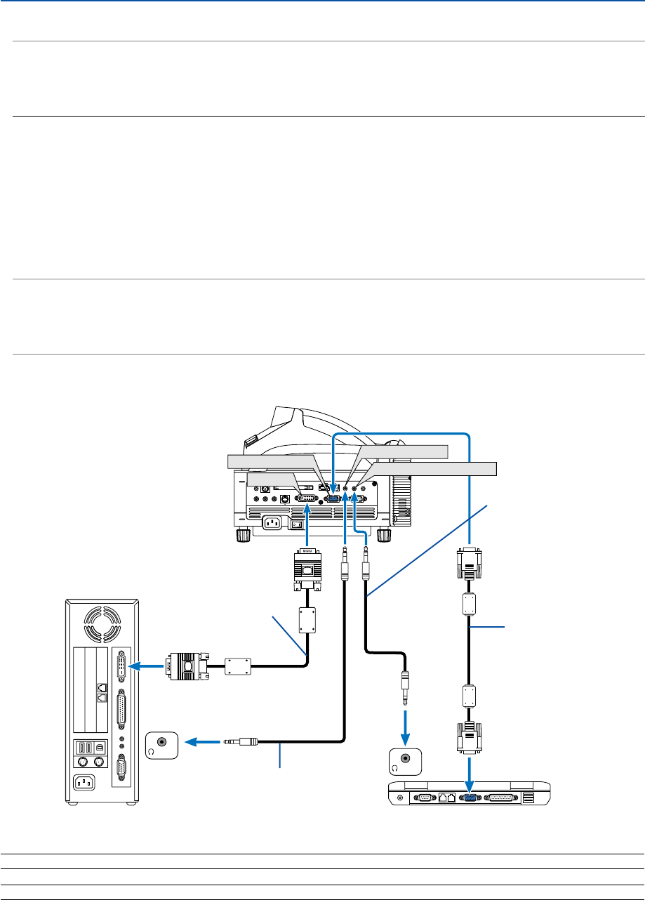
Connecting Your PC or Macintosh Computer
Audio cable (not supplied)
IBM VGA or Compatibles (Notebook type)
or Macintosh (Notebook type)
RGB/VGA signal cable
(supplied)
To mini D-Sub 15-pin
connector on the projector.
It is recommended that
you use a commercially
available distribution
amplifier if connecting a
signal cable longer than
the one supplied.
Audio cable (not supplied)
IBM PC or Compatibles (Desktop type)
or Macintosh (Desktop type)
DVI cable (not supplied)
NOTE: For older Macintosh, use a commercially available pin adapter (not supplied) to connect to your Mac's video port.
NOTE: The WT615/WT610 is not compatible with video decoded outputs of either the NEC ISS-6020 or ISS-6010.
20
2. Installation and Connections
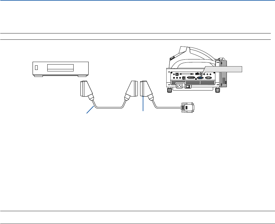
To connect SCART output (RGB)
Before connecting: An exclusive SCART adapter (ADP-SC1) and a commercially available SCART cable are re-
quired for this connection.
NOTE: Audio signal is not available for this connection.
PC CARD
AUDIO IN
RL
/MONO
VIDEO IN S-VIDEO IN DVI-I IN COMPUTER IN MONITOR OUT
DVI-I COMPUTER
AUDIO IN AUDIO OUT
PCCONTROL
REMOTE
IN USB
COMPUTER IN
1. Turn off the power to the projector and your video equipment.
2. Use the NEC ADP-SC1 SCART adapter and a commercially available SCART cable to connect the
COMPUTER input of your projector and a SCART output (RGB) of your video equipment.
3. Turn on the power to the projector and your video equipment.
4. Use the COMPUTER button on the remote control to select the COMPUTER input.
5. Press the MENU button on the remote control to display the menu.
6. From the Advanced menu, select [Setup]
→
[Options]
→
[Signal Select]
→
[Computer]
→
[Scart].
SCART is a standard European audio-visual connector for TVs, VCRs and DVD players. It is also referred
to as Euro-connector.
NOTE: The ADP-SC1 SCART adapter is obtainable from your NEC dealer in Europe. Contact your NEC dealer in Europe for more
information.
Projector
ADP-SC1
Female
To COMPUTER IN
Video equipment such as DVD player
Commercially available SCART cable
21
2. Installation and Connections
PC CARD
AUDIO IN
RL
/MONO
VIDEO IN S-VIDEO IN DVI-I IN COMPUTER IN MONITOR OUT
DVI-I COMPUTER
AUDIO IN AUDIO OUT
PCCONTROL
REMOTE
IN USB
COMPUTER IN
DVI-I IN
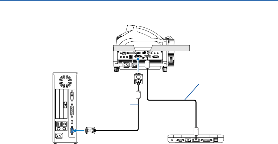
RGB/VGA signal cable
(supplied)
IBM PC or Compatibles (Notebook type)
or Macintosh (Notebook type)
IBM PC or Compatibles (Desktop
type) or Macintosh (Desktop type)
DVI-A to VGA cable
(not supplied)
Using two Analog COMPUTER inputs simultaneously
If you need to use two analog COMPUTER inputs simultaneously, connect a DVI-A to VGA cable as shown below.
22
2. Installation and Connections
PC CARD
AUDIO IN
RL
/MONO
VIDEO IN S-VIDEO IN DVI-I IN COMPUTER IN MONITOR OUT
DVI-I COMPUTER
AUDIO IN AUDIO OUT
PCCONTROL
REMOTE
IN USB
MONITOR OUT
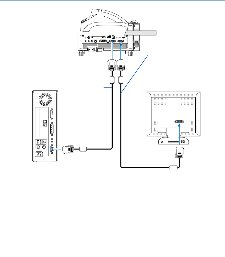
Connecting an External Monitor
RGB/VGA signal cable (commercially
available or supplied with an external
monitor)
You can connect a separate, external monitor to your projector to simultaneously view on a monitor the RGB analog
image you're projecting. To do so:
1. Turn off the power to your projector, monitor and computer.
2. Use a 15-pin cable to connect your monitor to the MONITOR OUT (Mini D-Sub 15 pin) connector on your
projector.
3. Turn on the projector, monitor and the computer.
NOTE:
•When the projector is in the Standby mode, the image may not be correctly displayed while the cooling fans are running
immediately after turning on or off the power. Note that the MONITOR OUT connector will not output an RGB signal during
Power-saving mode (See page 119 for enabling the Power-saving mode).
•Daisy chain connection is not possible.
RGB/VGA signal cable
(supplied)
To mini D-Sub 15-pin
connector on the projector.
It is recommended that you
use a commercially
available distribution
amplifier if connecting a
signal cable longer than the
supplied one.
23
2. Installation and Connections
PC CARD
AUDIO IN
RL
/MONO
VIDEO IN S-VIDEO IN DVI-I IN COMPUTER IN MONITOR OUT
DVI-I COMPUTER
AUDIO IN AUDIO OUT
PCCONTROL
REMOTE
IN USB
AUDIO IN
LR
AUDIO OUT
L R
Component
YCbCr
AUDIO IN COMPUTER
COMPUTER IN
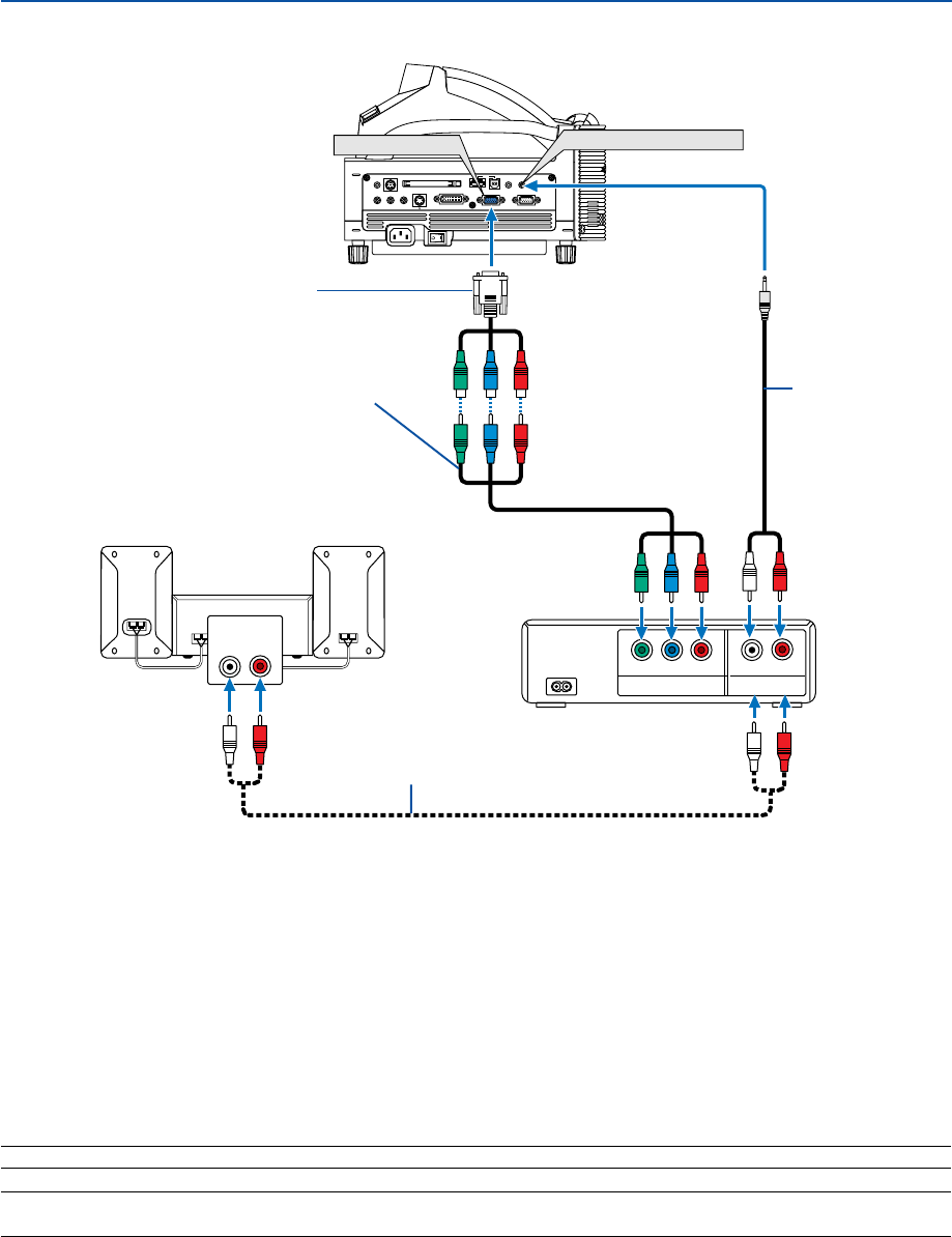
Connecting Your DVD Player
Audio cable (not supplied)
DVD player
You can connect your projector to a DVD player with component output or Video output. To do so, simply:
1. Turn off the power to your projector and DVD player.
2. If your DVD player has the component video (Y,Cb,Cr) output, use a commercially available component
video cable (RCA
⳯
3) and the optional 15-pin-to-RCA (female)
⳯
3 cable to connect your DVD player to
the COMPUTER IN connector on the projector.
For a DVD player without component video (Y,Cb,Cr) output, use an S-Video cable (not provided) to
connect the S-Video output of the DVD player to the S-Video Input of the projector.
3. Turn on the projector and DVD player.
NOTE: Refer to your DVD player's owner's manual for more information about your DVD player's video output requirements.
NOTE: Normally switching between RGB and component signals will be performed automatically, but if it fails, from the menu
select [Setup]
→
[Options]
→
[Signal Select]
→
[Component] for the RGB signal.
Audio Equipment
Component video RCA
⳯
3 cable
(not supplied)
Optional 15-pin-to-RCA
(female)
⳯
3 cable (ADP-CV1)
Audio cable
(not supplied)
24
2. Installation and Connections
AUDIO IN
LR
AUDIO OUT
L R
VIDEO OUT
S-VIDEOVIDEO
PC CARD
AUDIO IN
RL
/MONO
VIDEO IN S-VIDEO IN DVI-I IN COMPUTER IN MONITOR OUT
DVI-I COMPUTER
AUDIO IN AUDIO OUT
PCCONTROL
REMOTE
IN USB
AUDIO IN
VIDEO IN S-VIDEO IN
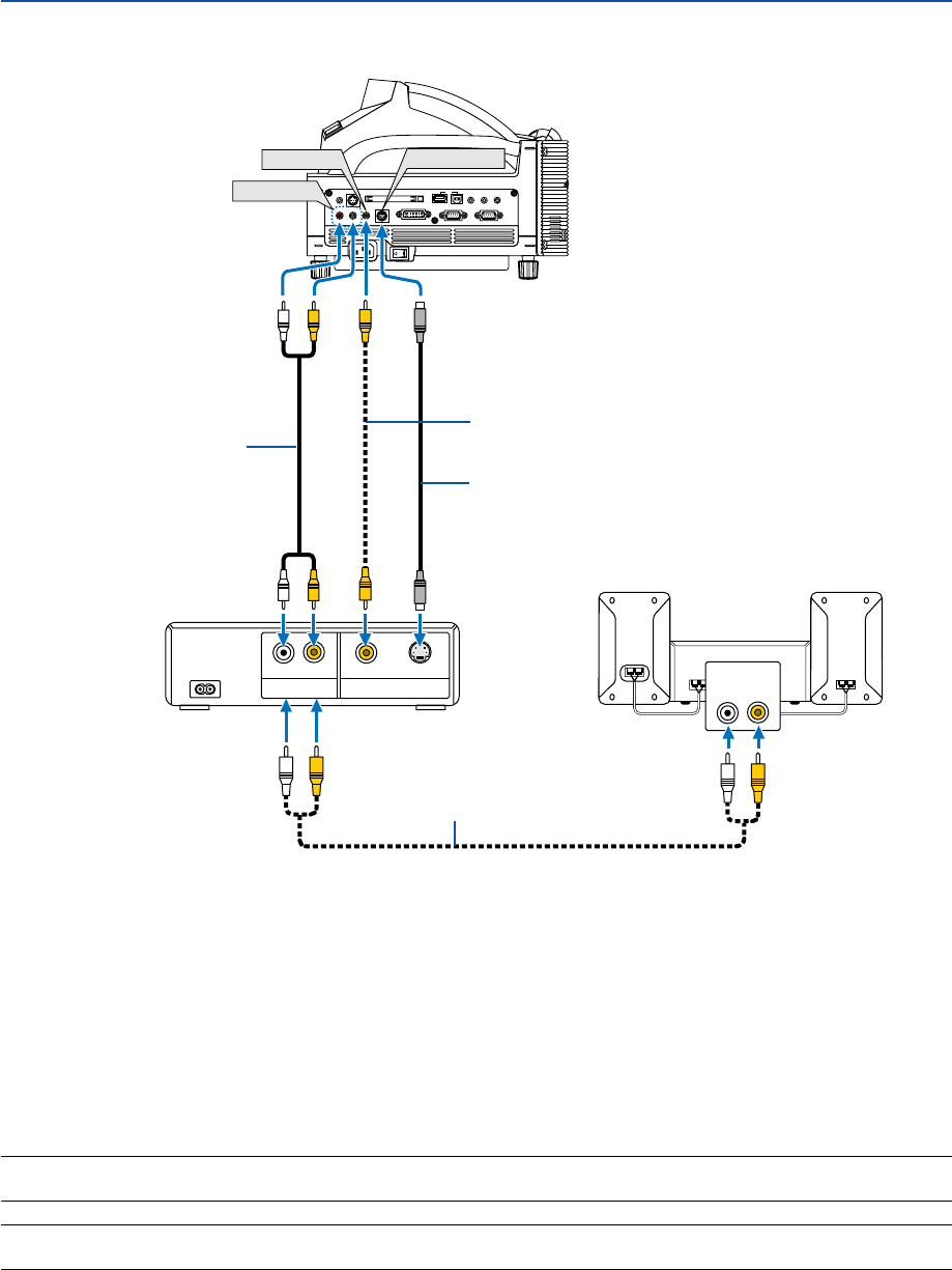
Connecting Your VCR or Laser Disc Player
Audio equipment
S-video cable (not supplied)
Video cable (not supplied)
Audio cable (not supplied)
VCR/ Laser disc player
Use common RCA cables (not provided) to connect your VCR, laser disc player or document camera to your projector.
To make these connections, simply:
1. Turn off the power to the projector and VCR, laser disc player or document camera.
2. Connect one end of your RCA cable to the video output connector on the back of your VCR or laser disc
player, connect the other end to the Video input on your projector. Use an audio cable (not supplied) to
connect the audio from your VCR or laser disc player to your audio equipment (if your VCR or laser disc
player has this capability). Be careful to keep your right and left channel connections correct for stereo
sound.
3. Turn on the projector and the VCR or laser disc player.
NOTE: Refer to your VCR or laser disc player owner's manual for more information about your equipment's video output
requirements.
NOTE: An image may not be displayed correctly when a Video or S-Video source is played back in fast-forward or fast-rewind via
a scan converter.
Audio cable (not supplied)
25
PC CARD
AUDIO IN
RL
/MONO
VIDEO IN S-VIDEO IN DVI-I IN COMPUTER IN MONITOR OUT
DVI-I COMPUTER
AUDIO IN AUDIO OUT
PCCONTROL
REMOTE
IN USB
Connecting to a Network
The WT615/WT610 comes standard with a PC Card slot which accepts a wired and wireless LAN card. Placing the
optional wireless LAN card (NWL-100A/E) in the PC card slot of the projector provides a wireless LAN connection. To
use a LAN connection, you are required to assign an IP address to the projector. For setting the LAN mode, see page
111 (From the menu, select [Setup] → [Installation] → [LAN Mode]).
*Two optional wireless LAN cards (NWL-100A and NWL-100E) are available. For a list of countries where
NEC's optional wireless LAN card (NWL-100 series) is available, refer to the Service Page for NEC Projectors
(http://www.nec-pj.com).
*For more information on supported wired LAN cards for the NEC projectors, refer to the Service Page for
NEC Projectors (http://www.nec-pj.com).
With the LAN connection, two features are available: Projector control and Picture transmission.
Projector control feature
With the wired or wireless LAN connection, you can control (power on/off, input select, etc.) and receive information
from the projector over the network using a computer. The following two methods are available:
* Using the HTTP Server feature on the projector. See page 63.
* Using PC Control Utility 3.0 from the supplied User Supportware 2 CD-ROM.
Picture transmission feature
With the wired or wireless LAN connection, you can send images and slides from a personal computer to the projector
which then can be projected on the screen. The following two methods are available:
*Using Image Express Utility 2.0 from the supplied User Supportware 2 CD-ROM.
*Using Ulead Photo Explore 8.0 from the supplied User Supportware 2 CD-ROM.
With the USB mouse connected to the projector, you can also operate the desktop screen on your Windows PC
connected to the LAN or the wireless LAN.
* Using Desktop Control Utility 1.0 from the supplied User Supportware 2 CD-ROM.
NOTE: Use a Wi-Fi certified wireless LAN card for your PC.
NOTE: For information about the five software utilities (Image Express Utility 2.0, Desktop Control Utility 1.0, Ulead Photo
Explorer 8.0, Viewer PPT Converter and PC Control Utility 3.0) contained on the supplied Projector User Supportware 2.0 CD-
ROM, see the supplied “Wired and Wireless Network Setup Guide”. See also each online help of the software utilities for
information about their functions and operations.
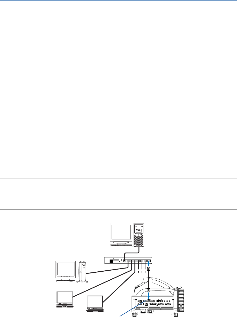
Example of LAN connection
(A) Example of wired LAN connection
Server
Hub
LAN cable (not supplied)
2. Installation and Connections
Wired LAN card (not supplied)
26
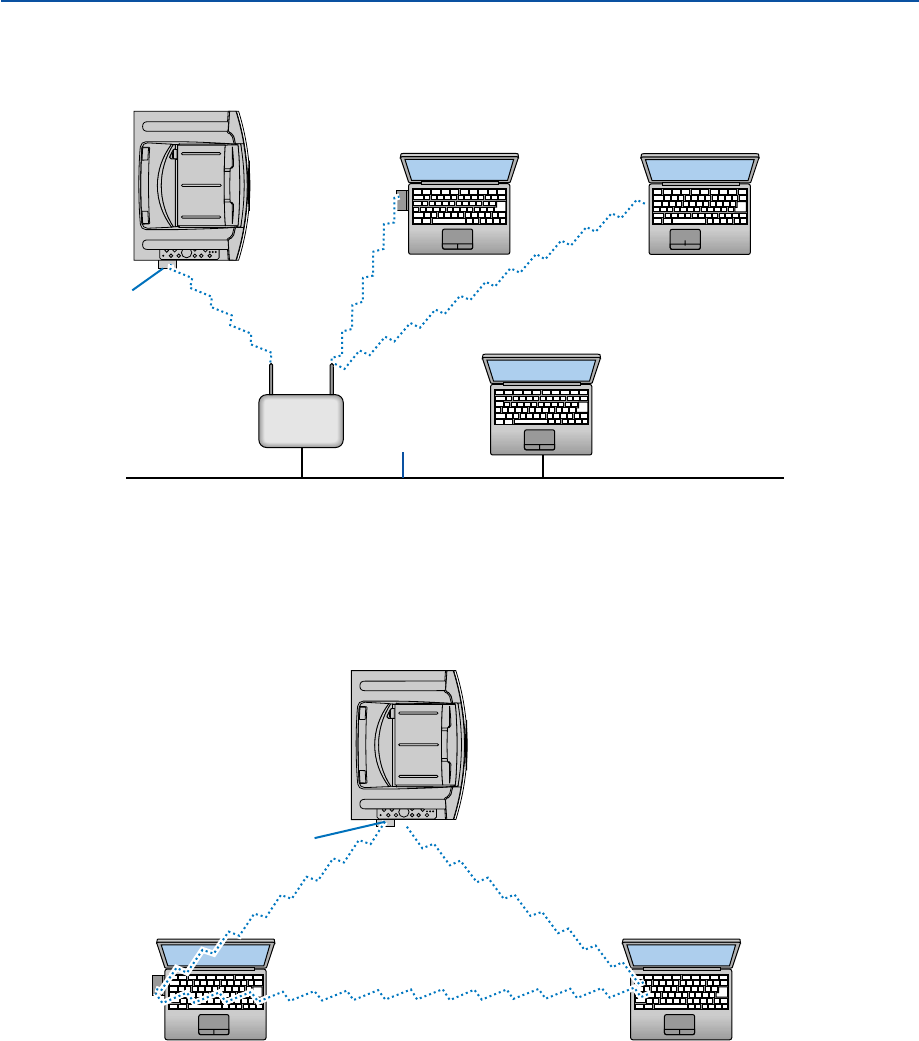
(B) Example of wireless LAN connection
(Network Type → Mode: Infrastructure)
2. Installation and Connections
Access Point
Wired LAN
To make connection with a wired LAN via an access point, you need to select the Infrastructure mode.
From the menu, select [Setup] → [Installation] → [LAN Mode] → “Profile” → “Advanced” → “Network Type” →“Mode”
→ “Infrastructure”.
(C) Example of wireless LAN connection (Network Type → Mode: 802.11 Ad Hoc)
To enable direct communication (i.e., peer-to-peer) between personal computers and projectors, you need to
select the 802.11 Ad Hoc mode.
From the menu, select [Setup] → [Installation] → [LAN Mode] → “Profile” → “Advanced” → “Network Type” →
“Mode” → “802.11 Ad Hoc”.
The 802.11 Ad hoc mode complies with IEEE802.11 standard.
When in Ad Hoc mode, only 802.11b is available for communication method.
Data transmission speed in Ad Hoc mode is limited up to 11Mbps.
Wireless LAN card (optional)
Wireless LAN card (optional)
Wireless LAN card Built-in wireless LAN function
Wireless LAN card Built-in wireless LAN function
27
2. Installation and Connections
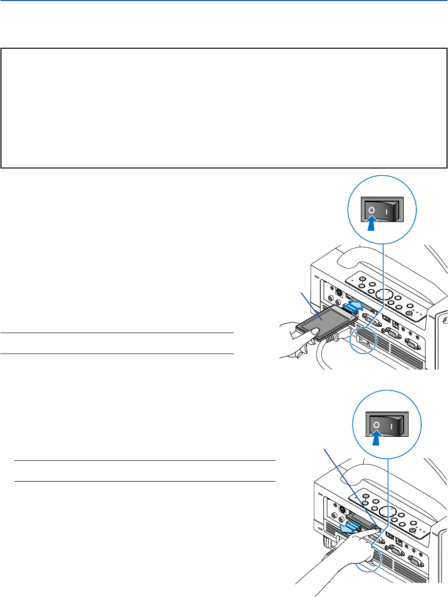
Inserting the PC Card
1. Turn off the main power switch before inserting the
PC card. (This step is needed only when the LAN
card being inserted into the projector's PC CARD
slot)
2. Hold the PC card horizontally and insert it slowly into
the PC card slot with its top facing up.
The eject button pops out once the PC card is fully inserted.
Check that the PC card is fully inserted.
NOTE: Do not try to force the PC card into the slot or you may bend
the pins inside the slot.
Inserting and Removing a PC Card
To insert the NEC optional wireless LAN card or a PC memory card (also referred to as PC card in this manual), follow
the steps below.
CAUTION:
* Direction for Inserting the PC Card
The PC card has a top and bottom and must be inserted into the PC card slot in a specific direction. It
cannot be inserted backwards or upside-down.
Attempting to force it into the slot in the wrong direction may break the internal pin and damage the card
slot. Refer to the PC card's operating instructions for the proper direction of insertion.
*Back up your PC card's data in case it will need to be restored.
*To prevent electrostatic discharge damage to the wireless LAN card, wear an anti-static wrist strap. If no
wrist strap is available, ground yourself by touching metal such as a door knob.
Removing the PC Card
1. Make sure that the PC CARD access indicator is not lit. (This
step is needed only when the PC memory card being inserted
into the projector’s PC CARD slot.)
NOTE: The PC CARD access indicator lights while its data is being
accessed.
2. To remove the LAN card, turn off the main power. (This step is
needed only when the LAN card being inserted into the
projector's PC CARD slot)
3. Press the eject button. The PC card pops out a little. Grasp the
edges of the PC card and pull it out.
POWER
ENTER
MENU
SOURCE
FOCUS
PC CARD
EXIT
STATUS
LAMP
ON/
STAND BY
AUTO
ADJUST
3D
REFORM
SELECT
PC CARD
AUDIO IN
L
/MONO
R
VIDEO IN S-VIDEO IN DVI-I IN COMPUTER IN MONITOR OUT
DVI-I RGB
AUDIO IN
USBAUDIO OUT
PCCONTROL
REMOTE
IN
POWER
ENTER
MENU
SOURCE
FOCUS
PC CARD
EXIT
STATUS
LAMP
ON/
STAND BY
AUTO
ADJUST
3D
REFORM
SELECT
PC CARD
AUDIO IN
L
/MONO
R
VIDEO IN S-VIDEO IN DVI-I IN COMPUTER IN MONITOR OUT
DVI-I RGB
AUDIO IN
USB AUDIO OUT
PCCONTROL
REMOTE
IN
PC card (not supplied)
Eject button

28
2. Installation and Connections
PC Card Type
The PC Card slot accepts PCMCIA Type II only.
NOTE: The projector does not support NTFS formatted flash memory card.
Be sure to use a flash memory card formatted with the FAT32, FAT16 or FAT file system.
To format your flash memory card in your computer, refer to the document or help file that comes with your Windows operating
systems.
29
2. Installation and Connections
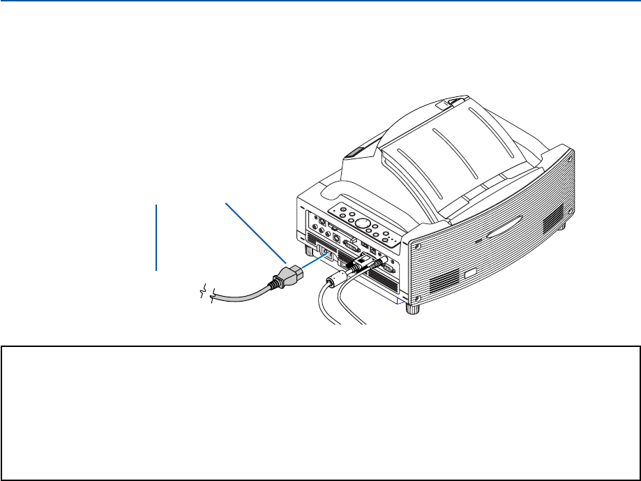
Connecting the Supplied Power Cable
Connect the supplied power cable to the projector.
First connect the supplied power cable's three-pin plug to the AC IN of the projector, and then connect the other plug
of the supplied power cable in the wall outlet.
Make sure that the prongs are fully inserted
into both the AC IN and the wall outlet.
←
To wall outlet
CAUTION:
Do not unplug the power cable from the wall outlet under any one of the following circumstances.
Doing so can cause damage to the projector or PC card:
•While the projector's lamp is On.
• While the cooling fans are running. The cooling fans continue to work for 90 seconds after the projector is
turned off.
• While the PC CARD Access Indicator lights. Doing so can damage your PC memory card.
POWER
ENTER
MENU
SOURCE
FOCUS
PC CARD
EXIT
STATUS
LAMP
ON/
STAND BY
AUTO
ADJUST
3D
REFORM
SELECT
UNLOCK
MIRROR
LOCK
PC CARD
AUDIO IN
RL
/MONO
VIDEO INS-VIDEO INDVI-I INCOMPUTER INMONITOR OUT
DVI-ICOMPUTER
AUDIO IN
USBAUDIO OUT
PCCONTROL
REMOTE
IN

30
3
Projecting an Image
(Basic Operation)
Tur ning on the Projector............................................. 31
Adjusting the Position and Size of the Projected Image
(Focus Adjustments) .............................................. 33
Selecting a Source .................................................... 40
쐏 Optimizing an RGB Image Automatically................... 41
Tur ning Up or Down Volume ...................................... 41
Adjusting Pincushion or Barrel Distortion
(Pincushion)........................................................... 42
Using the Laser Pointer ............................................. 44
Using the Electronic Pen (WT615 only) ..................... 45
Tur ning off the Projector............................................. 48
쐅 After Use.................................................................... 49
31
POINTER
LASER
MAGNIFY PAGE
OFF
POWER
ON
E
N
T
E
R
M
E
N
U
E
X
I
T
R
-
C
L
I
C
K
UP
DOWN
POWER
ENTER EXIT
STATUS
LAMP
ON/
STAND BY
AUTO
ADJUST
3D
REFORM
3. Projecting an Image (Basic Operation)
This section describes how to turn on the projector and to project a picture onto the screen.
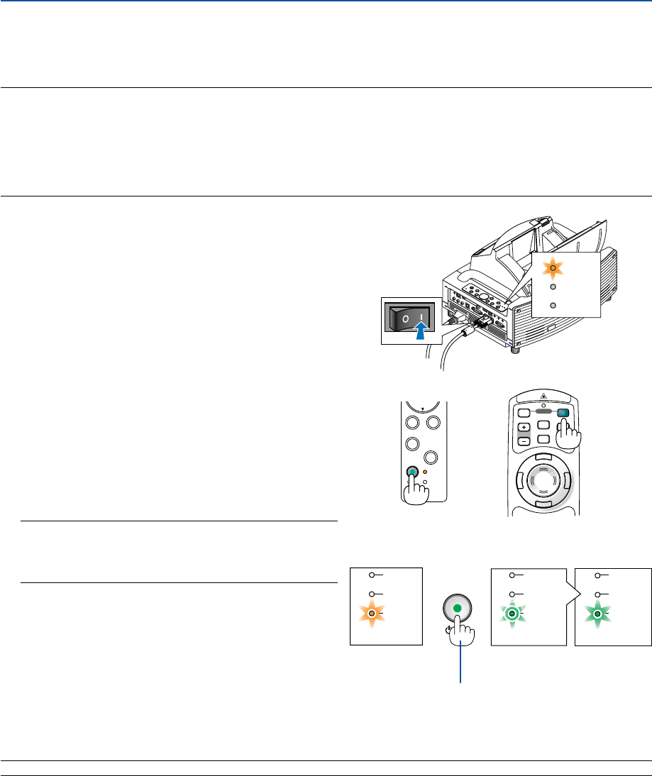
Turning on the Projector
NOTE:
• The projector has two power switches: a main power switch and a POWER (ON/STAND BY) button (POWER ON and OFF on the
remote control).
•When plugging in or unplugging the supplied power cable, make sure that the main power switch is pushed to the off (
䡬
)
position. Failure to do so may cause damage to the projector.
•The projector has a feature to prevent itself from being used by unauthorized individuals. To use this feature, register a
keyword. See "Security" in "Setup" on page 57 for more details.
1. Open the mirror cover. See page 6 for more details.
2. To turn on the main power to the projector, press the
Main Power switch to the on position ( I ).
•The POWER indicator will light orange.
See the Power Indicator section on page 138 for more
details.
3. Press the POWER (ON/STAND BY) button on the
projector cabinet or POWER ON button on the
remote control for a minimum of 2 seconds, when
the PWOER indicator turns a steady green the
projector is ready to use.
•After you turn on your projector, ensure that the
computer or video source is turned on.
NOTE: If you turn on the projector immediately after the lamp
is turned off or when the temperature is high, the fans run
without displaying an image for some time and then the
projector will display the image.
NOTE: When no signal is available, a blue, black or logo screen is displayed.
POWER
STATUS
LAMP
POWER POWER POWER
STATUS
LAMP
STATUS
LAMP
STATUS
LAMP
ON/
STAND BY
Standby Blinking for
one minute Power On
Steady orange
light Blinking green
light
Steady green
light
See page 138 for more details.
Press this button for a
minimum of 2 seconds.
Cabinet controls Remote control
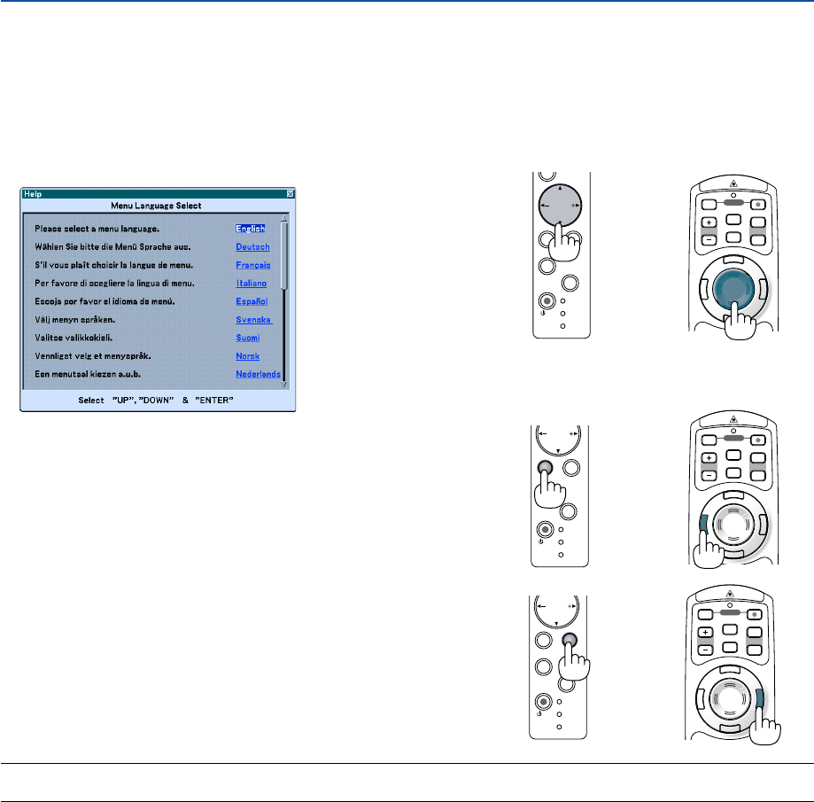
32
POWER
ENTER
SELECT
EXIT
STATUS
LAMP
ON/
STAND BY
AUTO
ADJUST
3D
REFORM
POINTER
LASER
MAGNIFY PAGE
OFF
POWER
ON
E
N
T
E
R
M
E
N
U
E
X
I
T
R
-
C
L
I
C
K
UP
DOWN
POWER
ENTER EXIT
STATUS
LAMP
ON/
STAND BY
AUTO
ADJUST
3D
REFORM
SELECT
3. Projecting an Image (Basic Operation)
Note on Startup screen (Menu Language Select screen)
When you first turn on the projector, you will get the Startup menu. This menu gives you the opportunity to select one
of the 21 menu languages.
To select a menu language, follow these steps:
1. Use the SELECT
왖
or
왔
button to select one of the
21 languages for the menu.
2. Press the ENTER button to execute the selection.
The menu will be displayed in the language you
have selected.
NOTE: Immediately after turning on the projector, screen flicker may occur. This is not a fault. Wait 3 to 5 minutes until the lamp
lighting is stabilized.
• When the Lamp mode is set to Eco, the Lamp indicator will light green.
•If one of the following things happens, the projector will not turn on.
-If the internal temperature of the projector is too high, the projector detects abnormal high temperature. In this
condition the projector will not turn on to protect the internal system. If this happens, wait for the projector's
internal components to cool down.
-When the lamp reaches its end of usable life, the projector will not turn on. If this happens, replace the lamp. See
page 134.
-If the lamp fails to light, and if the STATUS indicator flashes on and off in a cycle of six times, wait a full minute and
then turn on the power.
-When the mirror cover is closed.
-If the temperature sensor detects excessive heat in the bottom of the mirror or in the light path, the projector will
not turn on. Remove objects such as dust from the bottom of the mirror.
-The projector has a sensor which detects an object in front of the largest mirror or in the light path. If the sensor
detects any object, the projector will not turn on. Remove the object.
-Do not illuminate the projector with strong light source such as halogen lamp.
Doing so can cause the object detection sensor to malfunction, resulting in the projector not turning on.
•Immediately after turning on the projector and displaying an image, you cannot turn off the projector for 60 seconds.
POINTER
LASER
MAGNIFY PAGE
OFF
POWER
ON
R
-
C
L
I
C
K
E
N
T
E
R
M
E
N
U
E
X
I
T
UP
DOWN
POWER
ENTER
SELECT
EXIT
STATUS
LAMP
ON/
STAND BY
AUTO
ADJUST
3D
REFORM
POINTER
LASER
MAGNIFY PAGE
OFF
POWER
ON
R
-
C
L
I
C
K
E
N
T
E
R
M
E
N
U
E
X
I
T
UP
DOWN
3. To close the menu, press the EXIT button.
After this has been done, you can proceed to the menu operation.
If you want, you can select the menu language later. See "Lan-
guage" on page 103.
Cabinet controls Remote control
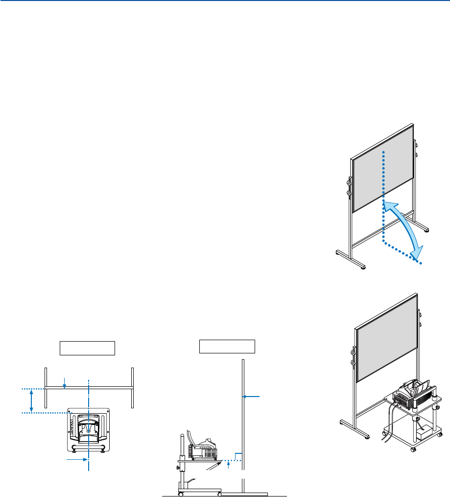
33
3. Projecting an Image (Basic Operation)
90˚
1. Check whether the screen is set up to be vertical by viewing it from
the side.
Adjusting the Position and Size of the Projected Image
(Focus Adjustments)
• After turning on the power, projected images may flicker for 3 to 5 minutes until the lamp lighting is stabilized.
Also after turning on the projector, the picture position may be slightly changed.
Wait 10 minutes until the light status and projected images become stable.
•If the screen is tilted vertically or horizontally, keystone distortion becomes large. Proceed with the following
steps to correctly set up the projector and the screen.
2. Check that the projector is set to be parallel with the screen.
90°
Top view Side view
Screen surface
Screen surface
Parallel
Align the
projector
center with
the screen
center
Bottom of projector
Operations common to both WT615 and WT610
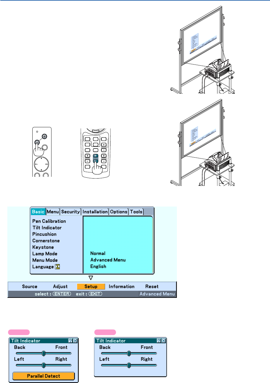
34
3. Projecting an Image (Basic Operation)
3. Press the MENU button.
The menu will be displayed.
4. Press the FOCUS +/- buttons and align the focus of the projected
image.
MENU
SOURCE
FOCUS
PC CARD
SELECT
FOCUS
HELP
ZOOM
SLIDE
VIEWER
VOLUME
3D REFORM
PIC-MUTE
FREEZE
R
-
C
L
I
C
K
AUTO ADJ.
COMPUTER
ASPECT
VIDEO
Cabinet controls Remote control
5. Use the SELECT
왘
button to select [Setup] and then press the ENTER button.
6. Use the SELECT
왖
or
왔
button to select [Tilt Indicator] and then press the ENTER button.
The test pattern will be displayed to fill the screen. At the same time the [Tilt Indicator] screen will be displayed at
the bottom of the screen.
WT615 WT610
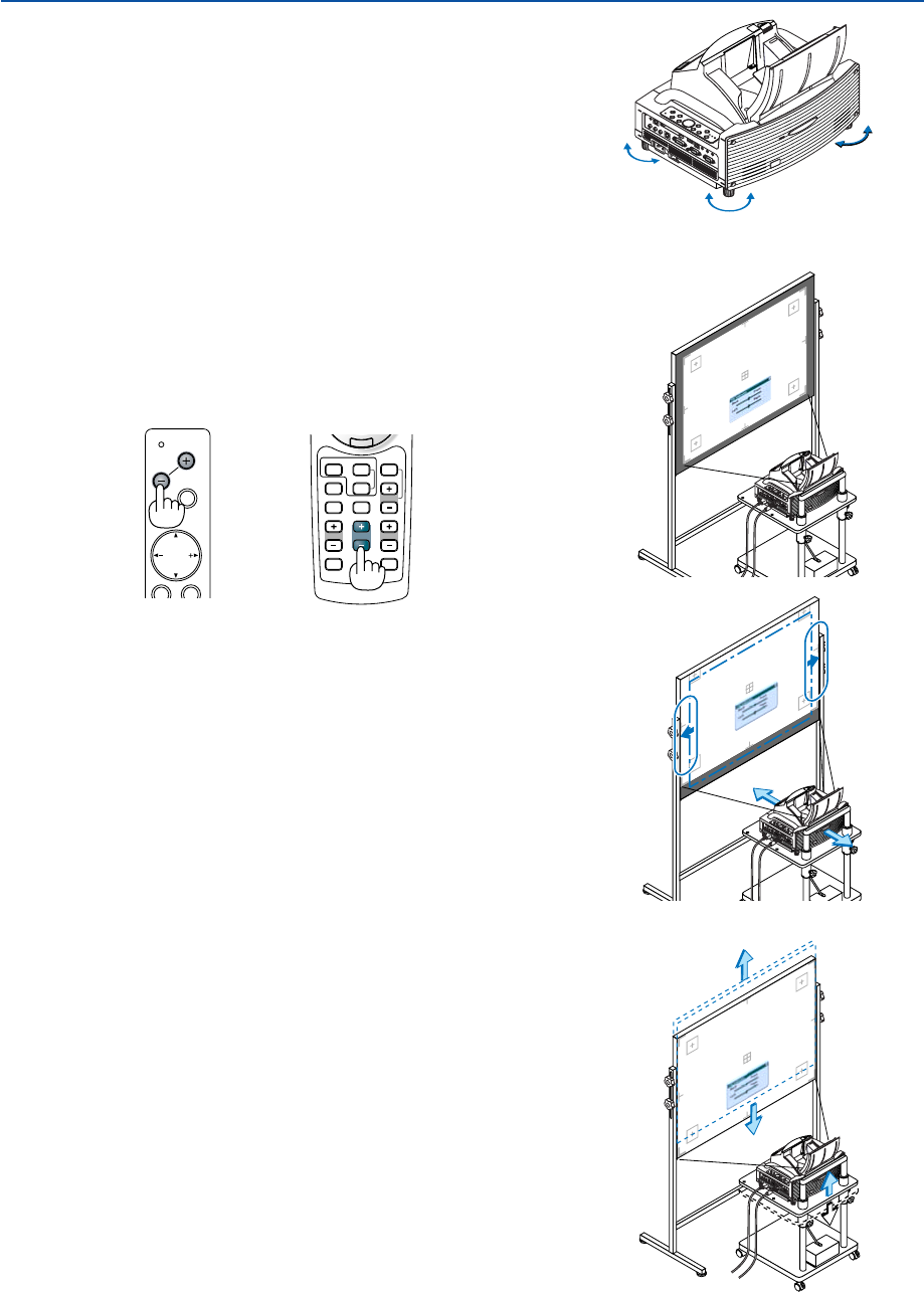
35
3. Projecting an Image (Basic Operation)
7. Adjust the height to keep the projector level by rotating the
feet on the front and the rear.
Tilting the projector will move the Tilt Indicator’s slider to the left or
right accordingly. Tilt the projector so that both of the sliders of
“Back/Front” and “Left/Right” are shown at the center. When the
slider reaches the center, it will become green.
Up Down
MENU
SOURCE
FOCUS
PC CARD
SELECT
FOCUS
HELP
ZOOM
SLIDE
VIEWER
VOLUME
3D REFORM
PIC-MUTE
FREEZE
R
-
C
L
I
C
K
AUTO ADJ.
COMPUTER
ASPECT
VIDEO
Cabinet controls Remote control
8. Press the FOCUS +/– buttons to align the focus of the projected
image.
A press of the FOCUS +/– buttons results in focus being taken simulta-
neously with the adjustment of vertical keystone distortion. See page 102.
9. Move the projector away from or closer to the screen and position it
so that the left and right sides of the projected image are aligned
with the width of the screen.
10. Adjust the height of the screen and the height of the stand to align
the lower edge of the projected image with the lower edge of the
screen.
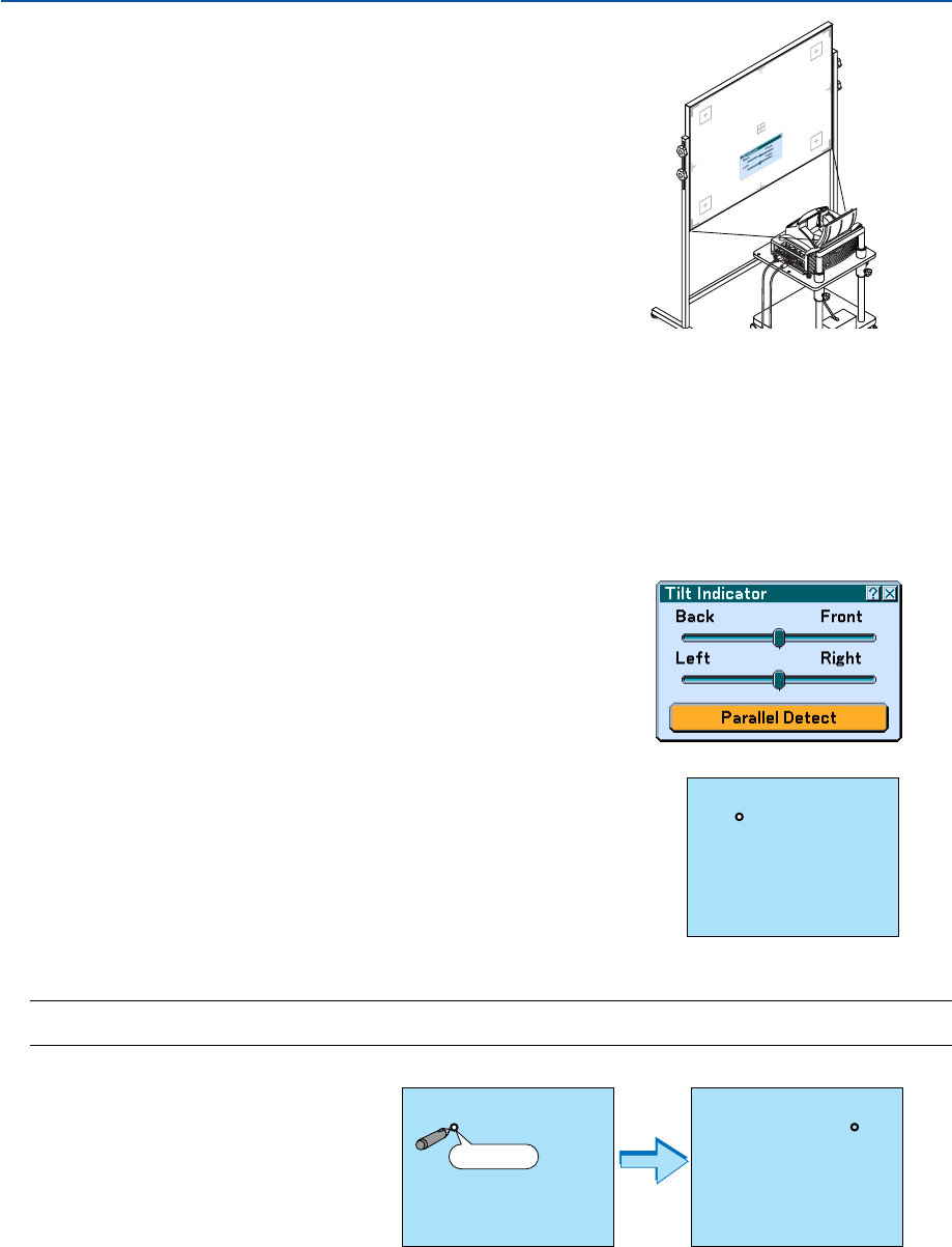
36
3. Projecting an Image (Basic Operation)
11. Press the FOCUS +/– buttons to align the focus of the projected
image again.
• Repeat step 9 to 11 if the display image is not aligned with the
screen.
•On the WT615 you can use the electronic pen to help you set up
the projector parallel to the screen. For more information, see
"Setting up the projector parallel to the screen" below.
12. To complete the adjustment, press the EXIT button three times.
The menu will disappear.
Setting up the projector parallel to the screen (WT615 only)
You can use the electronic pen to adjust so that the projector and the screen are parallel to each other.
1. Press the ENTER button while the [Tilt Indicator] screen is being
displayed.
A mark will be shown on the screen with a message: Tap the center of a
mark with the electronic pen. To cancel, press the button A.
2. Touch the center of a mark lightly with the electronic pen until the mark disappears.
NOTE: Hold the electronic pen upright against the screen when using it. Otherwise, the actual pen stroke may not be reflected
on the screen.
Another mark will be shown with a
message: Tap the center of a mark with
the electronic pen. To cancel, press the
button A.
Touch
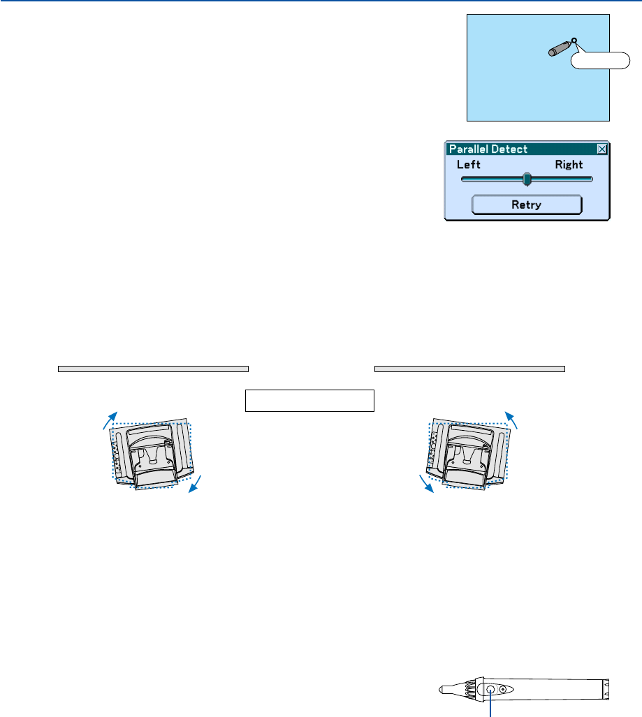
37
3. Projecting an Image (Basic Operation)
3. Touch the center of the mark lightly with the electronic pen.
The [Parallel Detect] screen will be displayed.
Touch
When the marker is in the center of the gauge, go to Step 6.
When the marker is not in the center of the gauge, it means that the projector and the screen are not parallel to
each other. Go to Step 4.
4. Rotate the projector right or left so that the projector is parallel to the screen.
Screen Screen
Top view
[The marker is on the left side] [The marker is on the right side]
Rotate the projector right. Rotate the projector left.
5. Touch the [Retry] button with the electronic pen.
Repeat Steps 2 to 4.
6. When the marker reaches the center of the gauge, press the button "A" on the electronic pen.
The [Tilt Indicator] screen will be displayed again.
Button “A”
7. Press the EXIT button three times.
The menu will be closed.
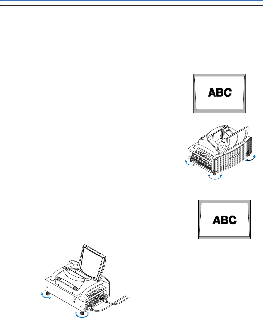
38
NOTE:
•In terms of the optical characteristics of this projector, in addition to keystone distortion (page 102), there may be occurrences
of slight pincushion type or barrel type distortion.
To adjust the projected image with the screen, first perform Steps 9 to 11 on pages 35 to 36 (Adjustment of the projection
distance
→
Height adjustment of the projected image
→
Focus adjustment), then align the 4 corners of the projected image
with the 4 corners of the screen. Following this, if the pincushion type or the barrel type distortion is conspicuous, please
perform "
Adjusting Pincushion or Barrel Distortion (Pincushion)" after you select a source you want to project.
• If the keystone distortion is not improved after pressing the FOCUS +/– buttons and adjusting the focus, or the aspect ratio
does not agree, make sure the screen or projector are not tilted.
[Symptom1]
In the case of keystone distortion (as illustrated), either the screen is directed
slightly upward or the projector is directed slightly upward.
[Action]
Tilt the top end of the screen to the front or rotate the front feet of the projector
to correct keystone distortion.
Up Down
[Symptom2]
In the case of keystone distortion (as illustrated), either the screen is directed
slightly downward or the projector is directed slightly downward.
[Action]
Tilt the bottom end of the screen to the front or rotate the rear feet (screen side) of
the projector to correct keystone distortion.
POWER
ENTER
MENU
SOURCE
FOCUS
PC CARD
EXIT
STATUS
LAMP
ON/
STAND BY
AUTO
ADJUST
3D
REFORM
SELECT
UNLOCK
MIRROR
LOCK
PC CARD
R-AUDIO IN-L/MONO
VIDEO IN S-VIDEO INDVI-I IN
DVI-I
AUDIO IN AUDIO OUT
PCCONTROL
REMOTE
IN
COMPUTER IN MONITOR OUT
COMPUTER
USB
Up Down
As illustrated in the diagram to the right below, when the top and bottom edges of
the image are not parallel to each other, it can be suspected that the screen and
the projector are not parallel to each other.
3. Projecting an Image (Basic Operation)

39
3. Projecting an Image (Basic Operation)
[Symptom 3]
As illustrated in the diagram to the right, when the left edge of the image is wid-
ened vertically, either the projector is not placed straight in front of the screen or
the projector is directed slightly to the left.
Conversely, when the right edge of the image is widened vertically, either the
projector is not placed straight in front of the screen or the projector is directed
slightly to the right.
[Action]
Place the projector straight in front of the screen.
Make sure that the screen and the projector are parallel to each other.
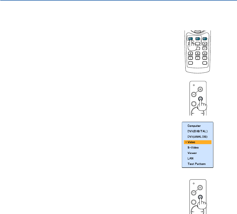
40
MENU
SOURCE
FOCUS
PC CARD
SELECT
3. Projecting an Image (Basic Operation)
Selecting a Source
Selecting the computer or video source
Using the Remote Control
Press any one of the COMPUTER, VIDEO or VIEWER buttons.
Detecting the Signal Automatically
Press and hold the SOURCE button for a minimum of 1 second, the projector will
search for the next available input source. Each time you press and hold the
SOURCE button for a minimum of 1 second, the input source will change as
follows:
Computer → DVI (DIGITAL) → DVI (ANALOG) → Video → S-Video → Viewer →
Computer → ...
If no input signal is present, the input will be skipped. When the input source you
wish to project is displayed, release the SOURCE button.
HELP
ZOOMFOCUS
SLIDE
VIEWER
ASPECT
VIDEO
VOLUME
3D REFORM
PIC-MUTE
FREEZE
R
-
C
L
I
C
K
AUTO ADJ.
COMPUTER
VIDEO
Selecting from Source List
Press and quickly release the SOURCE button on the projector cabinet to display
the Source list. Each time the SOURCE button is pressed, the input source will
change as follows: “Computer”, “DVI (DIGITAL/ANALOG)”, “Video” (VCR or laser
disc player), “S-Video”, “Viewer” (slides on a PC card) or “LAN” (LAN card).
To display the selected source, press the ENTER button.
MENU
SOURCE
FOCUS
PC CARD
SELECT
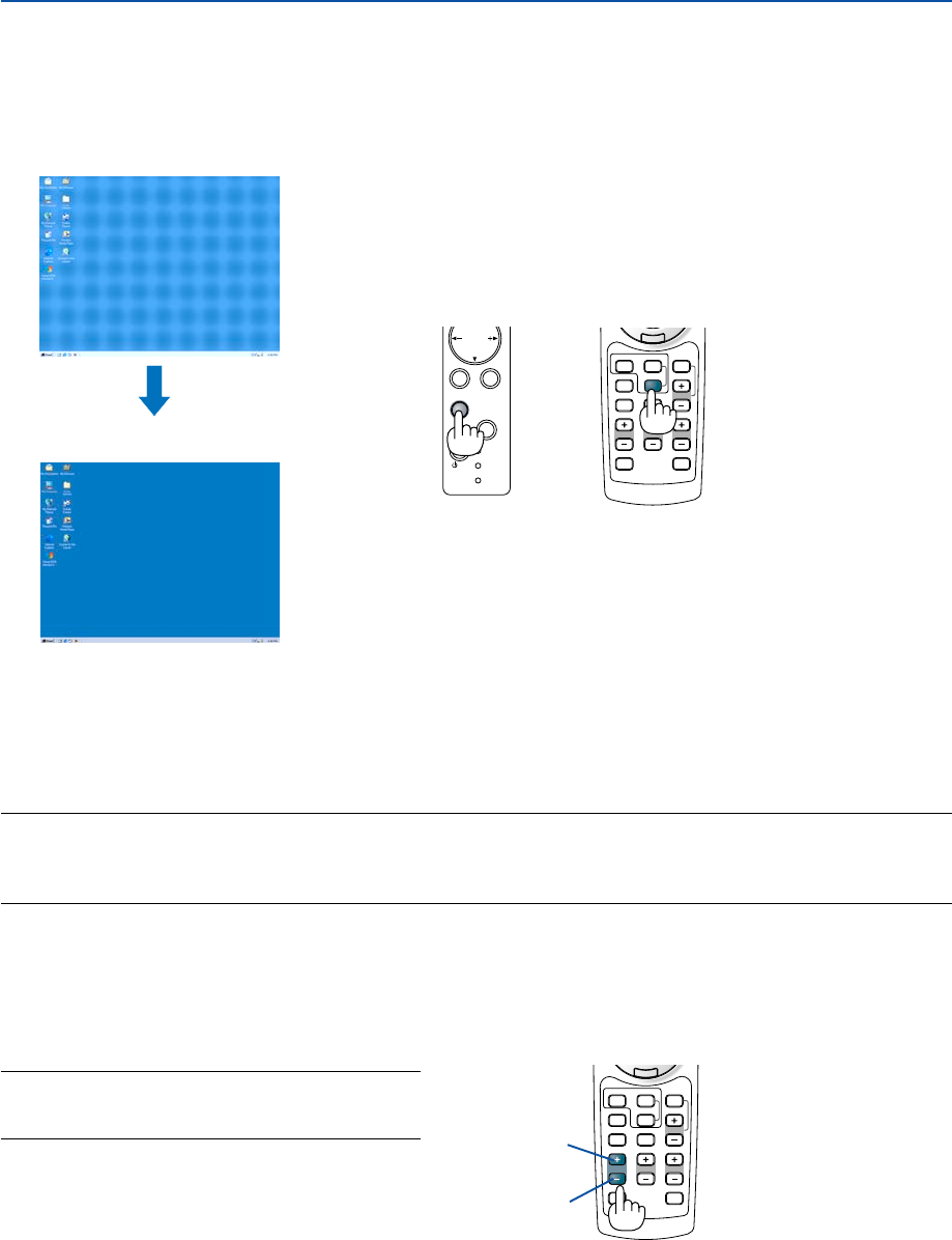
41
HELP
ZOOMFOCUS
SLIDE
VIEWER
ASPECT
VOLUME
3D REFORM
PIC-MUTE
FREEZE
R
-
C
L
I
C
K
AUTO ADJ.
COMPUTER
VIDEO
HELP
ZOOMFOCUS
SLIDE
VIEWER
ASPECT
VOLUME
3D REFORM
PIC-MUTE
FREEZE
R
-
C
L
I
C
K
AUTO ADJ.
COMPUTER
VIDEO
POWER
ENTER
SELECT
EXIT
STATUS
LAMP
ON/
STAND BY
AUTO
ADJUST
3D
REFORM
3. Projecting an Image (Basic Operation)
Optimizing an RGB Image Automatically
Adjusting the Image Using Auto Adjust
Optimizing an RGB image automatically.
Press the Auto Adjust button to optimize an RGB image automatically.
[Poor picture]
[Normal picture]
Press the Auto Adjust button to fine-tune the computer image or to remove any vertical banding that might appear and
to reduce video noise, dot interference or cross talk (this is evident when part of your image appears to be shimmer-
ing). This function adjusts the clock frequencies that eliminate the horizontal banding in the image. This function also
adjusts the clock phase to reduce video noise, dot interference or cross talk.
This adjustment may be necessary when you connect your computer for the first time.
NOTE:
•Some signals may take time or not be displayed correctly
•The Auto Adjust function does not work for component or video signals.
•If the Auto Adjust operation cannot optimize the RGB signal, try to adjust Clock and Phase manually. See page 95.
Turning Up or Down Volume
Increase volume
Decrease volume
Sound level from the speaker and the AUDIO OUT
jack (Stereo mini) on the projector can be adjusted.
NOTE: When no menus appear, the SELECT
왗
or
왘
buttons on the projector cabinet work as a volume
control.
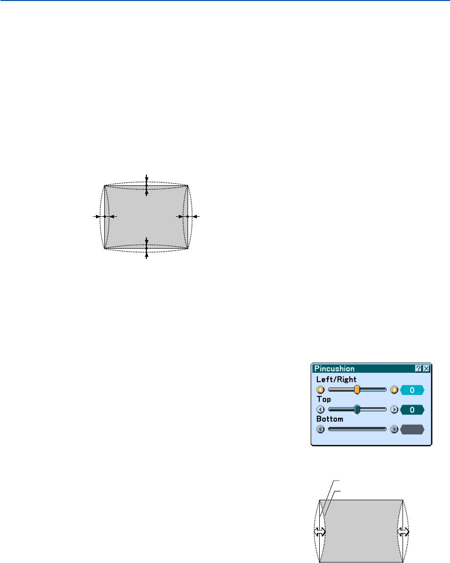
42
3. Projecting an Image (Basic Operation)
a
a
a
a
bb bb
Adjusting Pincushion or Barrel Distortion (Pincushion)
If pincushion or barrel distortion become conspicuous, adjust with [Pincushion].
Reference
•Pincushion or barrel distortion in this projector
The amount of pincushion and barrel distortion in this projector is 2% or less (TV distortion) in each of the
horizontal and vertical directions (for screen sizes of 40 inches to 100 inches).
As an example, the amount of distortion with a screen size of 60 inches (121.9 cm/48.0” W x 91.4 cm/36.0” H) is
within approximately 12 mm/0.47” in the horizontal direction and within approximately 9 mm/0.35” in the vertical
direction. When this projector is used with a 60-inch screen size, the amount of pincushion and barrel distortion
is at a minimum.
a: 1% or less of the screen height
(2% or less as TV distortion)
b: 1% or less of the screen width
(2% or less as TV distortion)
1Press the 3D REFORM button of the projector or the remote control.
The [Pincushion] screen will appear.
When the amount of pincushion or barrel distortion exceed 2% (TV distortion), please check whether the projector
and screen setup conditions are suitable.
Screen (solid line)
Projected area (dotted line)
•Press the SELECT
왖
or
왔
button and align the cursor with [Left/
Right], then press the SELECT
왗
or
왘
button to allow adjust-
ment of the left and right protrusions and indentations of the
projected image.
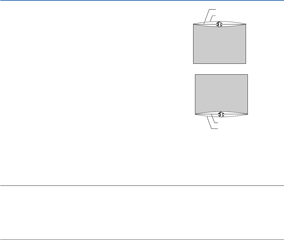
43
3. Projecting an Image (Basic Operation)
Screen (solid line)
Projected area (dotted line)
2. Press the ENTER button when [Pincushion] is completed.
Return to the menu.
3. Press the EXIT button a few times to make the menu disappear.
NOTE:
•In the [Pincushion] screen, when the [Top] adjustment value is "0", adjustment of [Bottom] will not be possible*.
Also note that when the adjustment value of the [Top] is a small value (on the order of +5), there will be almost no change of
the image even when the [Bottom] is adjusted.
•In the [Pincushion] screen, when the [Bottom] adjustment value is less than "0", a small portion can be lost at the bottom area
of the image. To display the lost portion, use the [Digital Zoom] function to reduce the size of the projected image*.
•When [Cornerstone] or [Keystone] has already been adjusted, selection of [Pincushion] will not be possible. To display
[Pincushion], return the adjustment values of [Cornerstone] or [Keystone] to the factory shipping conditions.
* Each note for [Top] and [Bottom] is reversed when the [Ceiling Rear] or [Ceiling Front] is selected in [Orienta-
tion] .
Reference
The [Pincushion] screen can also be displayed from the menu by going to [Setup] → [Basic].
•Press the SELECT
왖
or
왔
button and align the cursor with
[Bottom], then press the SELECT
왗
or
왘
button to allow adjust-
ment of the protrusions and indentations of the lower edge of the
projected image.
Screen (solid line)
Projected area (dotted line)
•Press the SELECT
왖
or
왔
button and align the cursor with [Top],
then press the SELECT
왗
or
왘
button to allow adjustment of the
protrusions and indentations of the upper edge of the projected
image.
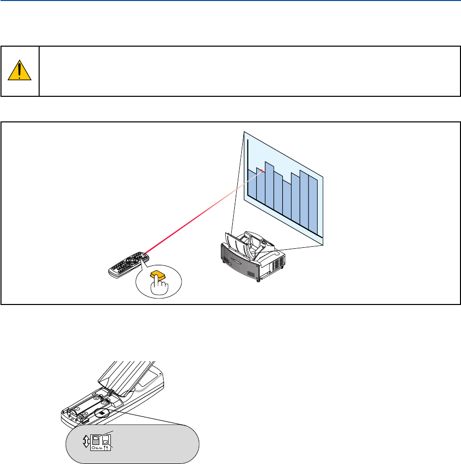
44
3. Projecting an Image (Basic Operation)
쐆 Using the Laser Pointer
You can use the laser to draw your audience's attention to a red dot that you can place on any object.
CAUTION:
• Do not look into the laser pointer while it is on.
• Do not point the laser beam at a person.
• Do not allow children to use the laser pointer.
Press and hold the LASER button to activate the laser pointer.
UNLOCK
MIRROR
LOCK
LASER
To disable the laser pointer, set the function switch to “Off”.
Decide whether to enable or disable the laser, then set the switch as necessary using the tip of a thin ball-point pen.
On this model, the other selector switch is not used.
ON
OFF
On: Enabled (the laser lights when the LASER button is pressed) [Factory default]
Off: Disabled (the laser does not light even when the LASER button is pressed)
Disable the laser when using in an environment in which the unit is accessible to children.
Not used
Laser enable/disable
switch
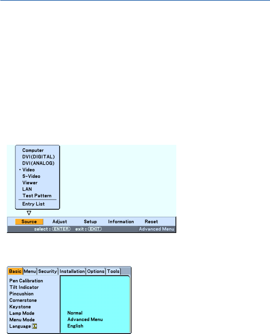
45
3. Projecting an Image (Basic Operation)
Using the Electronic Pen (WT615 only)
The electronic pen and the projector’s sensors can be used to convert your whiteboard into a virtual touchscreen
which allows you to operate your projector’s menu or use the ChalkBoard feature.
Important
• Be sure to set up the projector parallel to the screen. Otherwise, the actual pen stroke may not be displayed on
the screen.
•Before you use the electronic pen for the first time or when you have changed the position of the projector or the
screen size, be sure to use [Pen Calibration] to calibrate the electronic pen and the screen.
•Be sure to perform [Pincushion] correction before doing [Pen Calibration]. Otherwise, the actual pen stroke may
not be displayed on the screen.
Pen Calibration
Calibrate so that pen touches are properly detected by the sensor on the WT615.
1. Press the MENU button on the remote control or the projector cabinet.
The menu will be displayed.
2. Press the SELECT
왘
button twice to select [Setup] and press the ENTER button.
The [Basic] menu will be displayed.
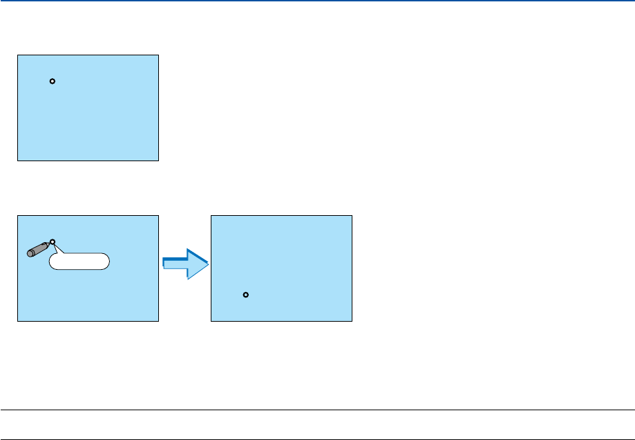
46
3. Press the SELECT
왖
or
왔
button to select [Pen Calibration] and press the ENTER button.
One “O ”mark will be displayed on the screen.
4. Touch the circle “O” mark lightly with the electronic pen.
Another “O” mark will be displayed on the screen.
Use the same procedure each time a circle "O" mark appears until you touch all the marks.
Your calibration settings are now saved.
This completes “Pen Calibration”.
NOTE: Hold the electronic pen upright against the screen when using it. Otherwise, the actual movement of the electronic pen
may not be displayed on the screen.
3. Projecting an Image (Basic Operation)
Touch
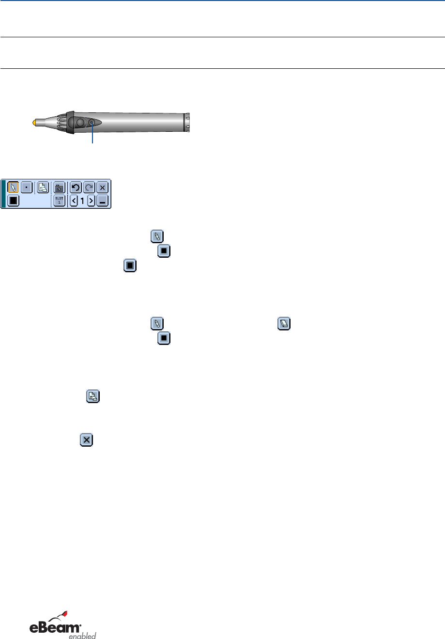
47
3. Projecting an Image (Basic Operation)
ChalkBoard Function
You can use the electronic pen to operate the ChalkBoard function. See also page 55.
NOTE: Hold the electronic pen upright against the screen when using it. Otherwise, the actual pen stroke may not be displayed on
the screen.
The electronic pen must be used at an angle less than 20 degrees from the upright position.
• Start ChalkBoard
Press and hold the button B on the electronic pen for a minimum of 0.5 second.
Button B
The ChalkBoard toolbar will be displayed at the bottom right of the screen.
•Drawing lines
[1] Tap the Drawing tool palette icon lightly and then tap the Pen icon.
[2] Tap the Line thickness palette icon and then tap your preferred line thickness icon.
[3] Tap the Color palette icon lightly and then tap your preferred line color icon.
[4] Touch and hold the pen tip to the screen lightly to write characters or draw patterns.
•Erasing lines
[1] Tap the Drawing tool palette icon and then tap the Eraser icon .
[2] Tap the Line thickness palette icon and then tap your preferred line thickness icon.
[3] Touch and hold the pen tip to the screen lightly to erase lines.
•Clear the Screen
Tap the Clear icon .
•Exit ChalkBoard
Tap the Exit icon .
Reference
•On the WT610 you can use the ChalkBoard function when connecting a USB mouse to the projector. See page
53 for more details.
•Notes and drawings that you draw on the screen can be captured and saved to the supplied USB memory
device. See page 56.
•About the supplied eBeam Interactive software
eBeam Interactive software is contained on the supplied CD-ROM (User Supportware 2 Plus) included with the
projector.
This software can be used to convert your screen into:
-A digital whiteboard with powerful meeting sharing capabilities (using eBeam software’s meeting applica-
tion); or
-A virtual touchscreen which allows you to completely control your computer and all of your applications
directly from the screen using the electronic pen.
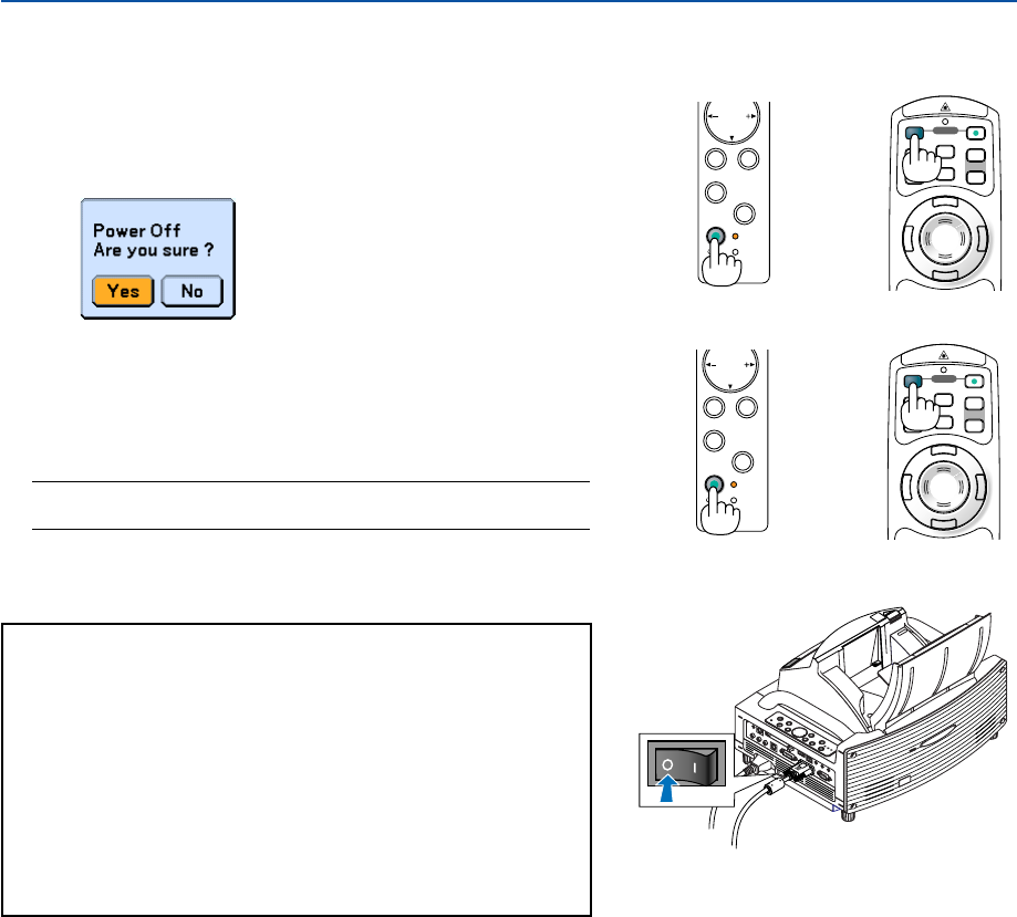
48
POINTER
LASER
MAGNIFY PAGE
OFF
POWER
ON
E
N
T
E
R
M
E
N
U
E
X
I
T
R
-
C
L
I
C
K
UP
DOWN
Turning off the Projector
To turn off the projector:
3. Projecting an Image (Basic Operation)
1. Press the POWER (ON/STAND BY) button on the projector
cabinet or the POWER OFF button on the remote control.
The "Power Off / Are you sure?" message will appear.
2. Press the ENTER button or the POWER (ON/STANDBY) or
the POWER OFF button again.
The POWER indicator will glow orange. After the projector turns
off, the cooling fans keep operating for 90 seconds (Cooling-off
time).
NOTE: Immediately after turning on the projector and displaying an
image, you cannot turn off the projector for 60 seconds.
3. Turn off the Main Power switch. The POWER indicator will
go out.
CAUTION
Do not unplug the power cable from the wall outlet or do
not turn off the main power under any one of the following
circumstances.
Doing so can cause damage to the projector or PC card:
•While the projector lamp is On.
• While the cooling fans are running. (The cooling fans
continue to work for 90 seconds after the projector is turned
off).
•While the PC CARD Access Indicator lights. Doing so can
damage your PC memory card.
POWER
ENTER
SELECT
EXIT
STATUS
LAMP
ON/
STAND BY
AUTO
ADJUST
3D
REFORM
POINTER
LASER
MAGNIFY PAGE
OFF
POWER
ON
E
N
T
E
R
M
E
N
U
E
X
I
T
R
-
C
L
I
C
K
UP
DOWN
POWER
ENTER
SELECT
EXIT
STATUS
LAMP
ON/
STAND BY
AUTO
ADJUST
3D
REFORM
Cabinet controls Remote control
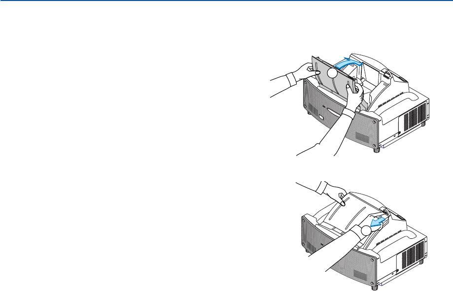
49
3. Projecting an Image (Basic Operation)
쐅 After Use
Preparation: Make sure that the main power is turned off.
1. Close the mirror cover.
After closing the mirror cover, lock the mirror cover by
sliding the mirror cover lock switch to the lock position.
UNLOCK
MIRROR
LOCK
1
UNLOCK
MIRROR
LOCK
2
2. Unplug the power cable.
3. Disconnect any other cables.
4. Retract adjustable tilt feet if extended.
5. Put the supplied dust-proof cover over the projector cabinet.

50
4
Convenient Features
Tur ning Off the Image and Sound .............................. 51
쐇 Freezing a Picture...................................................... 51
쐋 Using the Pointer ....................................................... 51
쐏 Enlarging and Moving a Picture................................. 52
쐄 Getting Integrated Help ............................................. 52
쐂 Using a USB Mouse .................................................. 53
쐆 Using the Remote Mouse Function ........................... 54
Making Freehand Drawings
on a Projected Image (ChalkBoard) ...................... 55
Storing Images Displayed on the Projector on the PC card
or USB memory (Capture)
......................................... 56
쐅 Preventing Unauthorized Use of the Projector .......... 57
쐈 Using a USB Memory Device or
USB Memory Card Reader.................................... 62
쐉 Operation Using an HTTP Browser ........................... 63
씈 Using the Projector to Operate a Computer Connected
on a Network (Desktop Control Utility 1.0) ............ 66
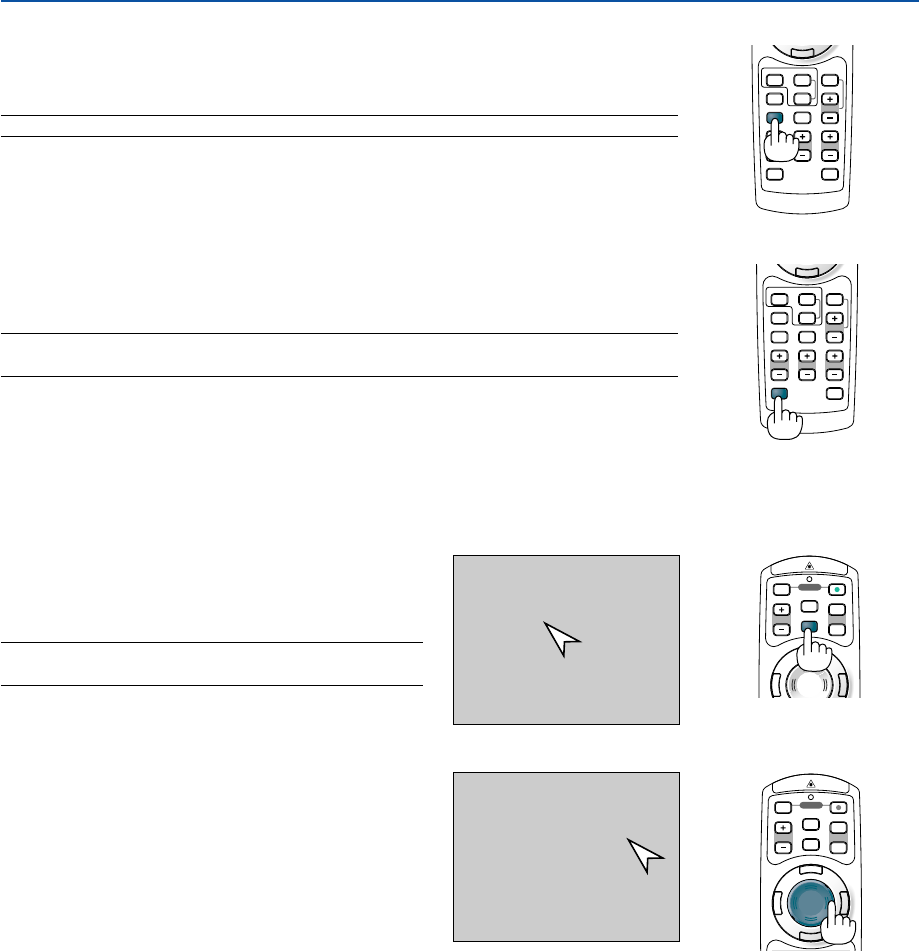
51
POINTER
LASER
MAGNIFY PAGE
OFF
POWER
ON
E
N
T
E
R
M
E
N
U
E
X
I
T
R
-
C
L
I
C
K
UP
DOWN
POINTER
LASER
MAGNIFY PAGE
OFF
POWER
ON
E
N
T
E
R
M
E
N
U
E
X
I
T
UP
DOWN
HELP
ZOOMFOCUS
SLIDE
VIEWER
ASPECT
VOLUME
3D REFORM
PIC-MUTE
FREEZE
R
-
C
L
I
C
K
AUTO ADJ.
COMPUTER
VIDEO
HELP
ZOOMFOCUS
SLIDE
VIEWER
ASPECT
VOLUME
3D REFORM
PIC-MUTE
FREEZE
R
-
C
L
I
C
K
AUTO ADJ.
COMPUTER
VIDEO
4. Convenient Features
쐃 Turning Off the Image and Sound
Press the PIC-MUTE button to turn off the image and sound for a short period of time.
Press again to restore the image and sound.
NOTE: The menu still remains visible even when the image is turned off.
쐇 Freezing a Picture
Press the FREEZE button to freeze a picture. Press again to resume motion.
NOTE: Pressing the MENU button will display the Capture menu that allows you to capture a
freezed image. See page 56 for more information.
쐋 Using the Pointer
Press the Pointer button to
display the pointer.
Use the Select button to
move the pointer.
You can use one of nine pointers to draw your
audience's attention to the portion of a projected im-
age you want.
NOTE: You can select one pointer from the menu. See page
125.
Press the POINTER button to display the pointer.
Use the SELECT 왖왔왗 or 왘 button to move the pointer.
Press the POINTER button again. The pointer will dis-
appear.
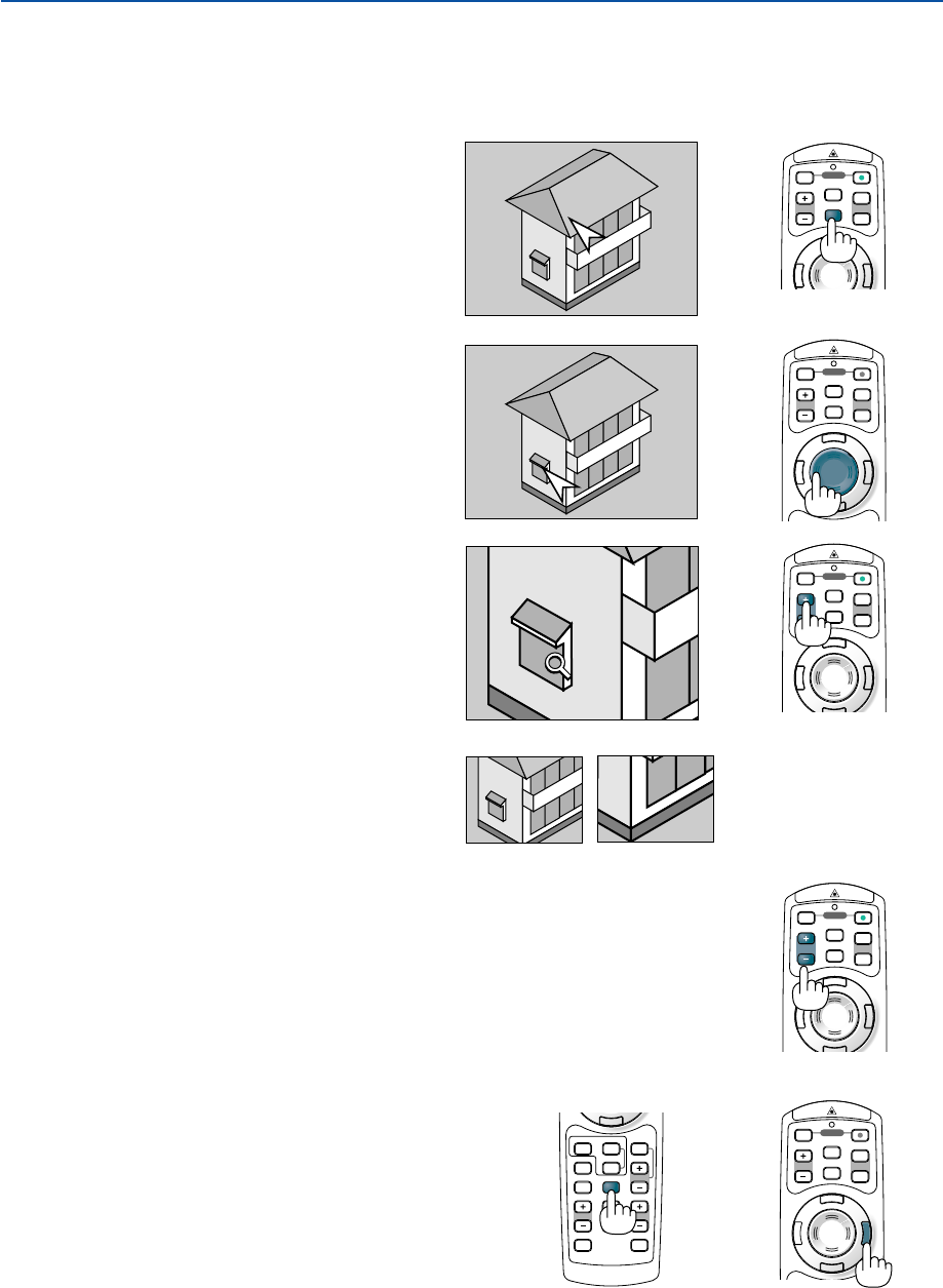
52
POINTER
LASER
MAGNIFY PAGE
OFF
POWER
ON
E
N
T
E
R
M
E
N
U
E
X
I
T
R
-
C
L
I
C
K
UP
DOWN
POINTER
LASER
MAGNIFY PAGE
OFF
POWER
ON
E
N
T
E
R
M
E
N
U
E
X
I
T
R
-
C
L
I
C
K
UP
DOWN
POINTER
LASER
MAGNIFY PAGE
OFF
POWER
ON
E
N
T
E
R
M
E
N
U
E
X
I
T
UP
DOWN
POINTER
LASER
MAGNIFY PAGE
OFF
POWER
ON
UP
DOWN
R
-
C
L
I
C
K
E
N
T
E
R
M
E
N
U
E
X
I
T
POINTER
LASER
MAGNIFY PAGE
OFF
POWER
ON
E
N
T
E
R
M
E
N
U
E
X
I
T
R
C
I
C
K
UP
DOWN
4. Convenient Features
쐏
Enlarging and Moving a Picture
You can enlarge the area you want up to 400 percent.
To do so:
1. Press the POINTER button to display the
pointer.
3. Enlarge the selected area.
When the MAGNIFY (+) button is pressed, the
image is magnified and the magnify icon will
be displayed. To magnify the selected area,
use the SELECT
왖왔왗
or
왘
button to move
the magnify icon and press the MAGNIFY (+)
button.
쐄 Getting Integrated Help
You get the contents about Help in English, German and
Japanese.
Display Help Exit Help
HELP
ZOOMFOCUS
SLIDE
VIEWER
ASPECT
VOLUME
3D REFORM
PIC-MUTE
FREEZE
R
-
C
L
I
C
K
AUTO ADJ.
COMPUTER
VIDEO
4. Return the image to the original size.
Press the MAGNIFY (-) button until the mag-
nify icon changes to the pointer.
2. Move the pointer to the area you want to
enlarge.
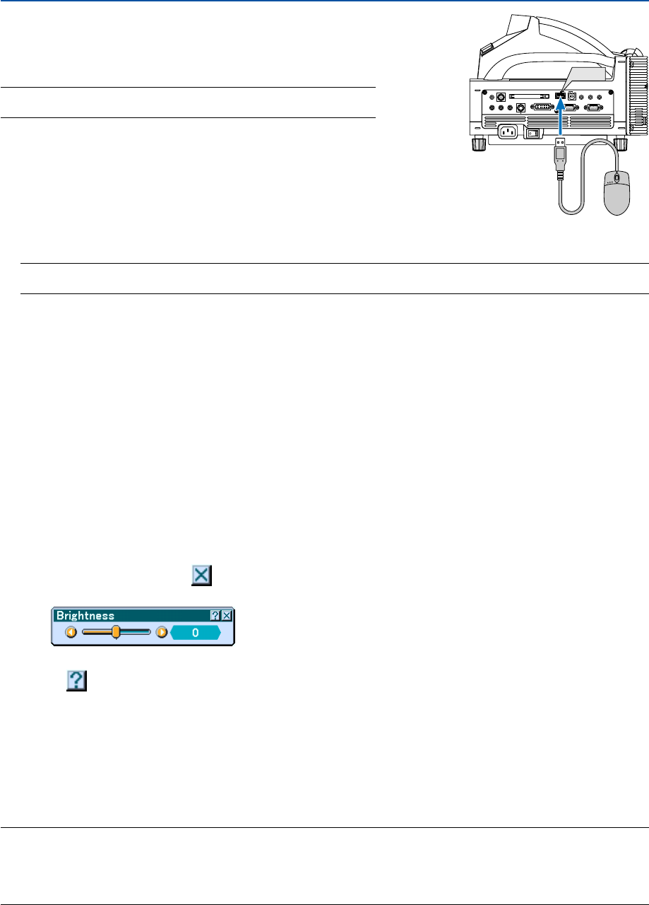
53
4. Convenient Features
쐂 Using a USB Mouse
Using a USB mouse gives you a smooth operation. A commercially
available USB mouse can be used.
NOTE: There may be some brands of a USB mouse that the projector does
not support.
Operating the Menus using the USB mouse
Mouse Cursor
When connecting a USB mouse to the USB port (Type A) of the projector, you get a mouse cursor on the screen.
Unless you use your USB mouse within 10 seconds, the mouse cursor disappears.
NOTE: You can change the shape of the mouse cursor. To do so, select the menu
→
[Setup]
→
[Tools]
→
[Mouse]
→
“Mouse Pointer”.
Menu Display
Clicking with the right mouse button displays the menu.
To close the menu, click anywhere in the background.
Adjusting and Setting Display
You can select a menu item and click with the left mouse button to make adjustments and settings.
Using the middle button on the mouse
The projector supports the middle button on your mouse.
With the middle button you can do the following:
•You can use a scroll bar in the menu or in help.
•You can click the middle button to display or hide the ChalkBoard toolbar.
Example:
Click (or press and hold) the left mouse button on the SELECT 왗 or 왘 to adjust the brightness. Or click and drag
the left mouse button on the slide bar horizontally to adjust it.
To save the adjustments, click . The display is closed.
•Click with the left mouse button to display a description of the selected menu item.
•Click and drag the title bar with the left mouse button to move the adjustment or setting dialog box.
Operating your computer’s mouse using the USB mouse connected to the projector
1. Connect a commercially available USB mouse to the USB port (Type A) of the projector.
2. Use the supplied USB cable to connect the USB port (Type B) of the projector and the USB port (Type A) of
your computer.
NOTE:
• Operation may be changed depending on condition of connection with the USB port (Type B) of the projector.
•When the menu is displayed, the USB mouse operates the projector. When the menu is not displayed, the USB mouse operates
your computer.
•This feature is available only on Windows 98, Windows Me, Windows 2000 and Windows XP
PC CARD
AUDIO IN
RL
/MONO
VIDEO IN S-VIDEO IN DVI-I IN COMPUTER IN MONITOR OUT
DVI-I COMPUTER
AUDIO IN AUDIO OUT
PCCONTROL
REMOTE
IN USB
USB
USB port (Type A)
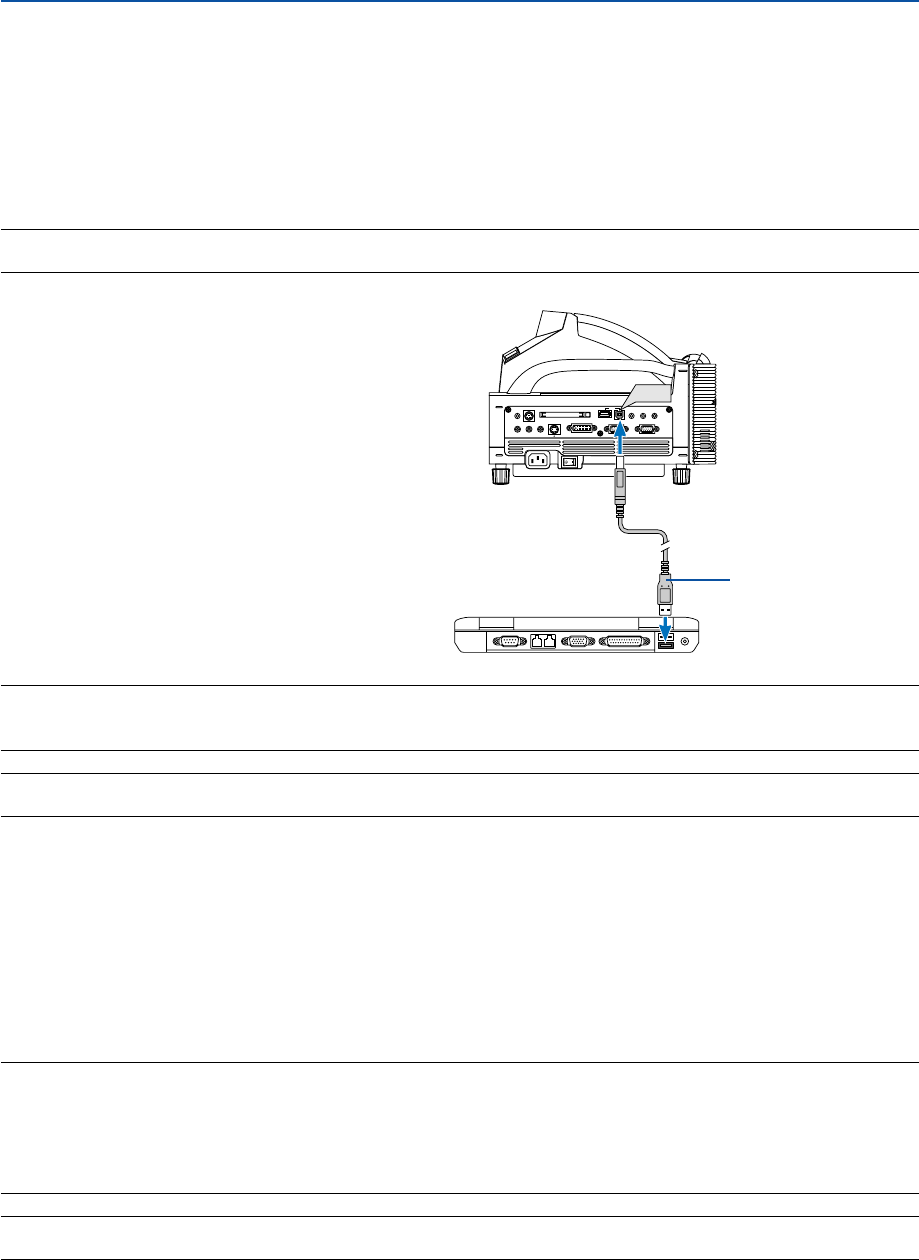
54
4. Convenient Features
쐆 Using the Remote Mouse Function
The built-in remote mouse function enables you to operate your computer's mouse functions from the remote control.
It is a great convenience for clicking through your computer-generated presentations.
Connecting to your computer for the remote mouse function
If you wish to use the remote mouse function, use the supplied USB cable to connect the USB port (Type B) of the
projector and the USB port (type A) of your computer.
NOTE: Depending on the type of connection or OS installed on your computer, you may have to restart your computer or change
your computer settings.
NOTE: In Windows XP, if the mouse cursor will not move correctly, do the following:
Clear the Enhance pointer precision check box underneath the mouse speed slider in the Mouse Properties dialog box [Pointer
Options tab].
NOTE: Wait at least 5 seconds after disconnecting the USB cable before reconnecting it and vice versa. The computer may not
identify the built-in mouse receiver if it is repeatedly connected and disconnected in rapid intervals.
Operating your computer’s mouse from the remote control
You can operate your computer's mouse from the remote control.
PAGE (UP) (DOWN) Button
:scrolls the viewing area of the window or to move to the previous or next slide in PowerPoint
on your computer.
SELECT Button 왖왔왗왘:moves the mouse cursor on your computer.
L-CLICK Button: works as the mouse left button.
R-CLICK Button: works as the mouse right button.
NOTE:
• When the menu is displayed, using the SELECT
왖왔왗
or
왘
button to operate your computer’s mouse will affect the operation
of both the menu and the mouse at the same time. To avoid this, turn off the menu and operate the mouse.
•With the menu, the Viewer or the ChalkBoard toolbar displayed, you can use the mouse to operate the projector while enlarging
an image with the MAGNIFY (+) or (–) button.
•To display the menu, press the MENU button on the remote control or the projector cabinet.
NOTE: You can change the Pointer speed on the Mouse Properties dialog box on the Windows. For more information, see the
user documentation or online help supplied with your computer.
USB port (Type B)
PC CARD
AUDIO IN
RL
/MONO
VIDEO IN S-VIDEO IN DVI-I IN COMPUTER IN MONITOR OUT
DVI-I COMPUTER
AUDIO IN AUDIO OUT
PCCONTROL
REMOTE
IN USB
USB
USB cable (supplied)
When using the USB Port
For PC, the remote mouse function can only be used with a
Windows 98, Windows ME, Windows XP or Windows 2000
operating system.
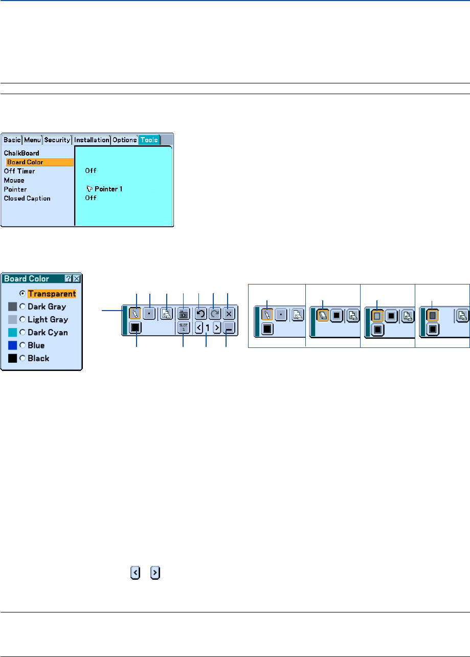
55
4. Convenient Features
Making Freehand Drawings on a Projected Image
(ChalkBoard)
The ChalkBoard feature allows you to write and draw messages on a projected image.
NOTE: The ChalkBoard feature is available only when the supplied electronic pen (WT615 only) or a USB mouse is used.
To display the ChalkBoard tool bar, click the middle button on your mouse, press and hold the button B of the elec-
tronic pen for a minimum of 0.5 second, or select [Setup] → [Tools] → [ChalkBoard] from the menu.
Selecting Board Color [Board Color]
This option allows you to select a board color of ChalkBoard.
쐅쐉씈씋
씉 씊
쐈
The tool bar contains the following icons.
Drag ................................... Drags to move the tool bar.
Drawing tool palette ........... Displays a drawing tool palette.
Pen ..................................... Displays the pen tool that you can draw or paint with.
Eraser ................................. Erases part of a drawing.
Box frame ........................... Draws a box frame.
Box paint ............................ Paints a box shape.
Line Thickness palette ........ Displays the pen or eraser palette containing four lines of different thickness from which you can select a line
you prefer.
Color palette ....................... Displays the color palette from which you can select a color you prefer for “Box frame” or “Boxpaint”.
Clear ................................... Clear the drawing completely from the ChalkBoard screen.
쐅 Capture ............................... Captures a drawing on the ChalkBoard screen and save it in PNG format to your PC-card inserted into the PC
card slot of the projector.
쐈
Drive (not displayed on WT610)
... Switches between PC Card slot or USB memory. USB memory devices are available for WT615 only.
쐉 Undo .................................. Undoes the last operation.
씈 Redo ................................... Redoes the last undone operation performed with Undo.
씉 Page number ...................... Use or to select a ChalkBoard page number between 1 and 4.
씊 Hide .................................... Hides the tool bar. Clicking anywhere on the screen displays the ChalkBoard tool bar again.
씋 Exit ..................................... Clears the complete drawing and exits the ChalkBoard.
NOTE:
•Your drawings will be stored in memory after a given time period. However, when a resolution is changed by switching a signal
or changing signal type, some picture information may be lost.
•Changing the [Board Color] will clear the current drawing.

56
4. Convenient Features
Storing Images Displayed on the Projector on the PC card or
USB memory (Capture)
The Capture features allows you to capture an image from a source that is currently being displayed. The image is
saved as JPEG in the PC card or USB memory.
[Important]
• USB memory devices are not available for the Capture function on the WT610.
• When saving captured images to a USB memory device on the WT615, be sure to use the USB memory device
included with the WT615. A commercially available USB memory device may be damaged.
Also do not use a commercially USB memory card reader. Using a USB memory card reader may cause
damage to a flash memory card.
NOTE:
•Unless a PC card or USB memory is inserted into the PC Card slot or USB port of the projector, the Capture feature is not
available.
•The "Card Error" display means that the free space of the PC card or USB memory is insufficient for saving images. Make more
space available on the card by erasing unwanted images with your PC. The number of images that can be captured depends on
the size of the PC card.
•Be sure not to turn off the power or remove the PC card or USB memory while capturing an image. Doing so could cause a
loss of the data in the PC card or USB memory or damage to the card itself.
• The Capture function is not available for DVI digital signal.
Preparations:
Insert the PC card into the PC card slot or USB memory into USB port of the projector.
Insert the PC card so that the end with the insertion direction arrow on the top goes in first.
* Press the eject button to eject the card.
1. Project the image you wish to store on the projector.
2. Press the FREEZE button on the remote contorol.
3. Press the MENU button to display the Capture menu.
Capture.................. Captures an image and save it as a JPEG file in a PC card or USB memory.
Drive...................... Select the PC Card or USB memory. You can capture an image and save it to your PC card or USB memory.
Exit ........................ Exits the Capture function. Another option to exit the Capture function is to press the MENU or EXIT button
on the remote control or projector cabinet.
4. Press the FREEZE button to resume the motion.
NOTE:
Captured images with a higher resolution than the projector's native resolution cannot be displayed correctly.
•File size of the captured image varies depending on the resolution of an input signal.
•An hourglass indicating that an image is being captured appears on the projector's display. Do not eject the PC card or turn off
the projector's power while this icon is displayed. Doing so will damage the PC card data. If the PC card data is damaged, use a
computer to repair the data.
•The “Drive” icon will not be displayed on the WT610.
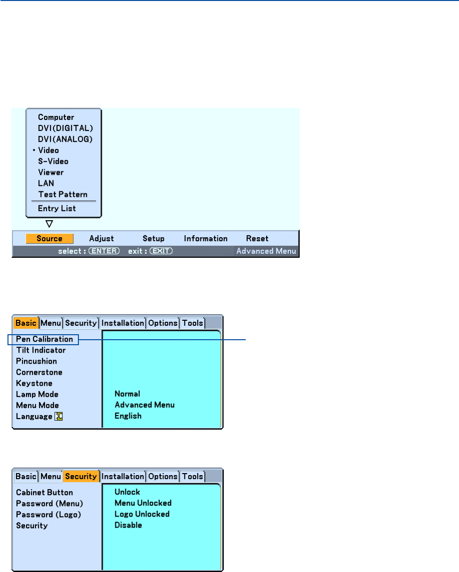
57
4. Convenient Features
쐅 Preventing Unauthorized Use of the Projector
Assigning a keyword prevents the projector from being used by unauthorized individuals.
Assigning a Keyword for the first time
1. Press the MENU button.
The menu will be displayed.
2. Press the SELECT
왘
button to select the Setup submenu and press the ENTER button.
The page tab “Basic” will be highlighted.
3. Press the SELECT
왘
button twice to select the page tab “Security”.
WT615 only
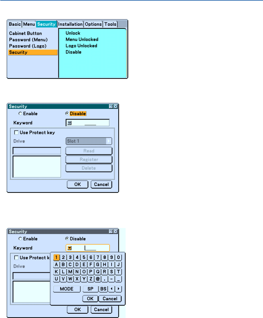
58
4. Convenient Features
4. Press the SELECT
왔
button four times to select “Security”.
5. Press the ENTER button to display the Security screen.
6. Press the SELECT
왔
button once to select the Keyword entry box and press the ENTER button.
The Software keyboard will be displayed.
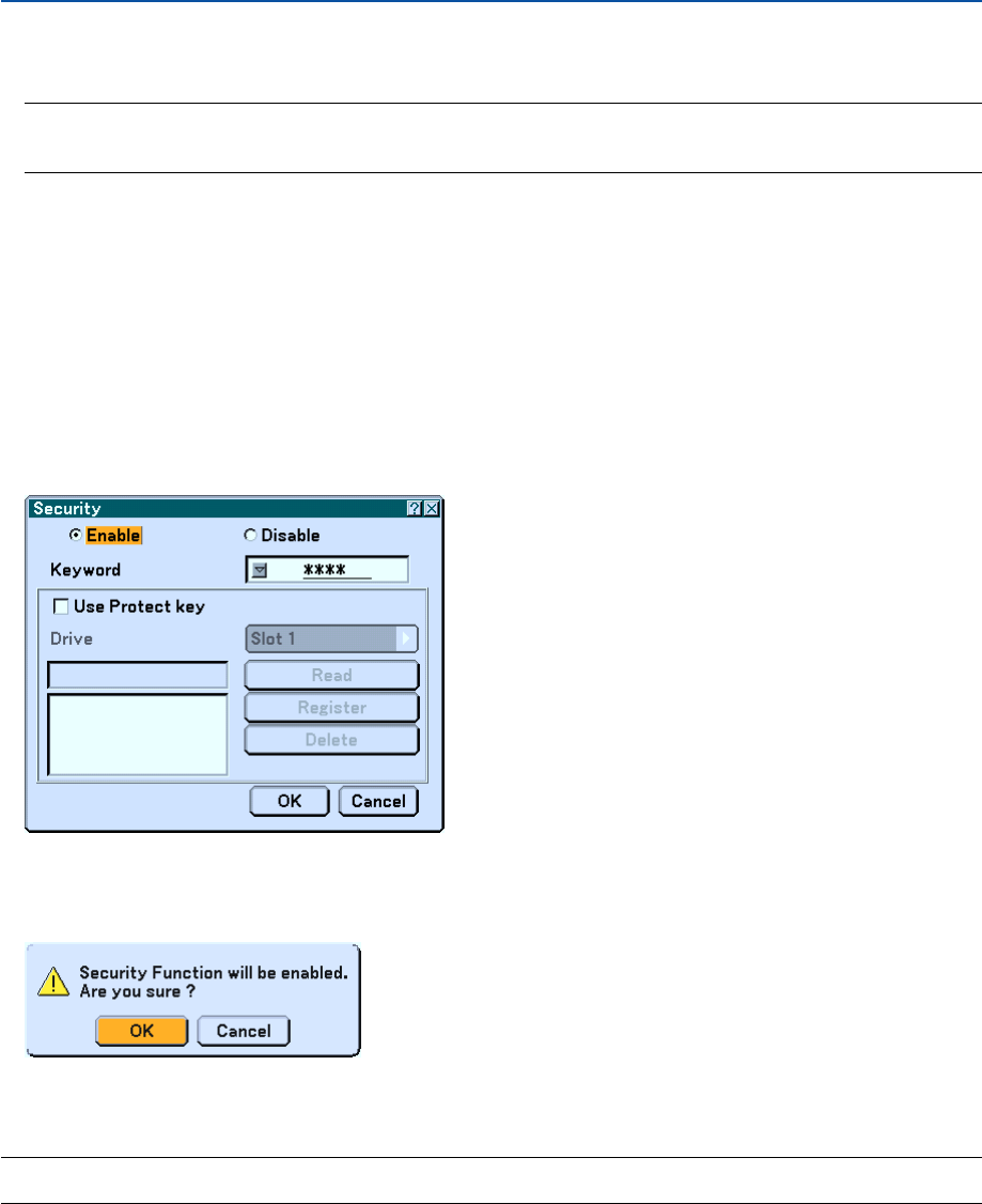
59
4. Convenient Features
7. Enter an alphanumeric keyword using the Software keyboard
For example, to enter “1234”, follow the steps 7-1 to 7-4 below.
NOTE:
• Please make a note of your keyword.
• Do not use spaces (SP) in your keyword.
7-1. Select the number “1” and press the ENTER button.
The asterisk “
쏄
” will be displayed in the Keyword entry box.
7-2. Press the SELECT
왘
button once to select “2” and press the ENTER button.
The asterisk “
쏄쏄
” will be displayed in the Keyword entry box.
7-3. For “3” and “4”, use the same procedure as step 7-2.
The asterisk “
쏄쏄쏄쏄
” will be displayed in the Keyword entry box.
7-4. Press the SELECT
왔
button to select “OK” and press the ENTER button.
The Software keyboard will disappear.
8. Press the SELECT
왖
button once to select“Disable” and press the SELECT
왗
button to select “Enable”.
9. Press the SELECT
왔
button to select “OK” and press the ENTER button.
The confirmation screen will be displayed.
10
.Press the ENTER button.
The Security Function is now enabled.
NOTE: A PC card can be used as a protect key. You can skip the keyword entry by inserting a registered PC card when turning on
the projector. See page 107.
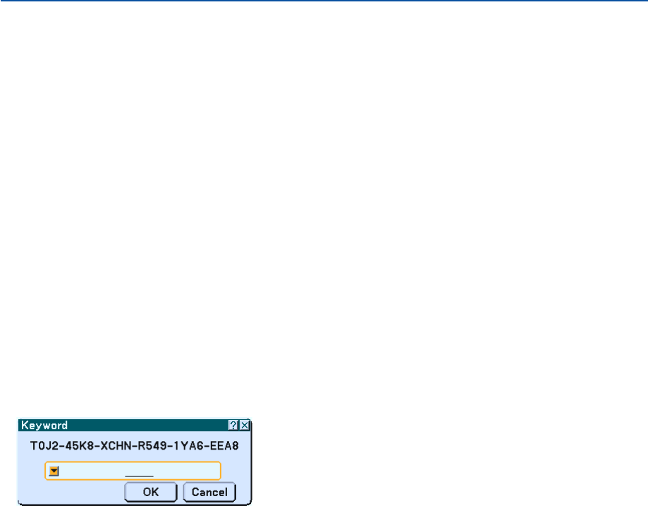
60
Checking If Security is enabled
Turn off the projector and turn it back on to check if the Security function is enabled.
1. Press the POWER (ON/STAND BY) button.
The "Power Off / Are you sure?" message will appear.
Press the ENTER button or the POWER (ON/STAND BY) or the POWER OFF button again.
The lamp lights off and the POWER indicator flashes orange. Please wait until the POWER indicator changes
from flashing to steady light.
2. When the POWER indicator lights steady orange, push the Main POWER switch to the off position (O).
The projector will turn off.
3. Push the Main POWER switch to the on position (I).
The POWER indicator lights orange. The projector is in standby condition.
4. Press and hold the POWER (ON/STAND BY) button for a minimum of two seconds.
The projector will turn on. The “Projector is locked! Enter your keyword.” message will be displayed at the bottom
of the screen.
5. Press the MENU button.
The Keyword entry screen will be displayed
6. Press the ENTER button.
The Software keyboard will be displayed.
7. Use the same procedures as steps 1 to 7 described in the “Assigning a Keyword for the first time”
section to enter “1234”.
Each time one number is entered, an “
쏄
” (asterisk) will appear. Keyword appears as asterisks so the real
keyword is hidden.
8. After entering your keyword, select “OK” and press the ENTER button.
The Software keyboard will disappear. This will allow you to operate the projector.
4. Convenient Features
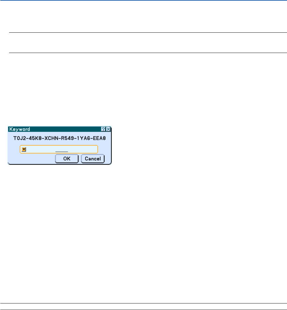
61
Disabling the Security
1. Press the MENU button.
The on-screen menu will be displayed.
NOTE: Immediately after the projector has been turned on and the “Projector is locked! Enter your keyword.” message is
displayed at the bottom of the screen, pressing the MENU button will display the Keyword entry page. At this time, pressing
the MENU button will display the on-screen menu.
2. Press the SELECT
왘
button to select “Setup” and press the ENTER button.
The page tab “Basic” will be highlighted.
3. Press the SELECT
왘
button twice to select the page tab “Security”.
4. Press the SELECT
왔
button four times to select “Security” and press the ENTER button.
The Keyword entry screen will be displayed
5. Press the ENTER button.
The Software keyboard will be displayed.
6. Use the same procedures as steps 1 to 7 described in the “Assigning a Keyword for the first time”
section to enter “1234”.
Each time one number is entered, an “
쏄
” (asterisk) will appear. Keyword appears as asterisks so the real
keyword is hidden.
7. After entering your keyword, select “OK” and press the ENTER button.
The Software keyboard will disappear. The Security screen will be displayed.
8. Highlight “Enable” and press the SELECT
왘
button to select “Disable”.
9. Press the SELECT
왔
button to select “OK” and press the ENTER button.
The Security Function is now disabled.
NOTE: Do not forget your keyword. However, if you forget your keyword, NEC will provide you with your Release Code.
4. Convenient Features
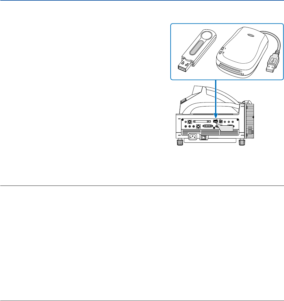
62
4. Convenient Features
쐈
Using a USB Memory Device or USB Memory Card Reader
The projector is compatible with either a USB memory device (A
USB memory device is supplied with the WT615) or USB memory
card reader which supports the viewer and security features.
[Important]
When saving captured images to a USB memory device on the
WT615, be sure to use the USB memory device included with the
WT615. A commercially available USB memory device may be dam-
aged.
Also do not use a commercially USB memory card reader. Using a
USB memory card reader may cause damage to a flash memory
card.
•To use a USB memory device or USB memory card reader,
connect the device to the USB port (type A).
•Select one of the drive icons for your USB memory in a pane
on the left side of the Viewer window.
•To use a USB memory device as a Protect key for Security
function, select one from the Drive icons in the Security setting
screen. See page 107.
• The drive icon is not displayed on the WT610.
NOTE:
•Some USB memory devices (brands) or USB memory card readers may not work.
•The projector does not support NTFS formatted flash memory card or USB memory device.
Be sure to use a flash memory card or USB memory device formatted with the FAT32, FAT16 or FAT file system.
To format your flash memory card or USB memory device in your computer, refer to the document or help file that comes with
your Windows.
•You cannot use a USB memory device and a USB memory card reader when connecting a USB mouse to the projector.
• Do not do the following while the USB memory device or USB memory card reader’s access indicator is lit or flashing (while
data is being accessed.) Doing so can damage your USB memory device or USB memory card reader in the reader. Back up
your data in case it will need to be restored.
*Pulling out the USB memory device or USB memory card reader from the USB port of the projector.
*Pulling out the memory card from the USB memory card reader
*Turning off the main power switch or unplugging the power cable.
•The drive for ”USB 1-4” is displayed only when the USB memory device or USB memory card reader is connected to the
projector. The drive for “USB 1-4” may be displayed differently from the one in the USB memory card reader.
•Some USB memory devices (brands) or USB memory card readers cannot be used as Protect key for the projector’s Security
function.
PC CARD
AUDIO IN
RL
/MONO
VIDEO IN S-VIDEO IN DVI-I IN COMPUTER IN MONITOR OUT
DVI-I COMPUTER
AUDIO IN AUDIO OUT
PCCONTROL
REMOTE
IN USB
USB

63
쐉 Operation Using an HTTP Browser
Overview
The use of HTTP server functions will allow control of the projector from a web browser without the installation of
special software. Please be sure to use “Microsoft Internet Explorer 4.x” or a higher version for the web browser. (This
device uses “JavaScript” and “Cookies” and the browser should be set to accept these functions. The setting method
will vary depending on the version of browser. Please refer to the help files and the other information provided in your
software.)
NOTE:
* The display’s or button’s response can be slowed down or operation may not be accepted depending the settings of your
network. Should this happen, consult your network administrator.
*The projector may not respond if its buttons are repeatedly pressed in rapid intervals. Should this happen, wait a moment and
repeat. If you still can’t get any response, turn off and back on the projector.
Access is gained to the HTTP server functions by specifying
http:// <the projector’s IP address> /index.html
in the entry column of the URL.
CAUTION:
Do not use the HTTP Server functions and PC Control Utility 3.0 included on the supplied CD-ROM. Using both at
the same time may result in a connection failure or slow response.
Preparation Before Use
Make network connections and set up the projector and confirm that it is complete before engaging in browser opera-
tions. (See “Setting LAN Mode” on page 111.)
Operation with a browser that uses a proxy server may not be possible depending on the type of proxy server and the
setting method. Although the type of proxy server will be a factor, it is possible that items that have actually been set
will not be displayed depending on the effectiveness of the cache, and the contents set from the browser may not be
reflected in operation. It is recommended that a proxy server not be used unless it is unavoidable.
Handling of the Address for Operation via a Browser
Regarding the actual address that is entered for the address or entered to the URL column when operation of the
projector is via a browser, the host name can be used as it is when the host name corresponding to the IP address of
the projector has been registered to the domain name server by a network administrator, or the host name corre-
sponding to the IP address of the projector has been set in the “HOSTS” file of the computer being used.
Example 1: When the host name of the projector has been set to “pj.nec.co.jp”,
http://pj.nec.co.jp/index.html
is specified for the address or the entry column of the URL.
Example 2: When the IP address of the projector is “192.168.73.1”, access is gained to the
HTTP server functions by specifying
http://192.168.73.1/index.html
for the address or the entry column of the URL.
4. Convenient Features
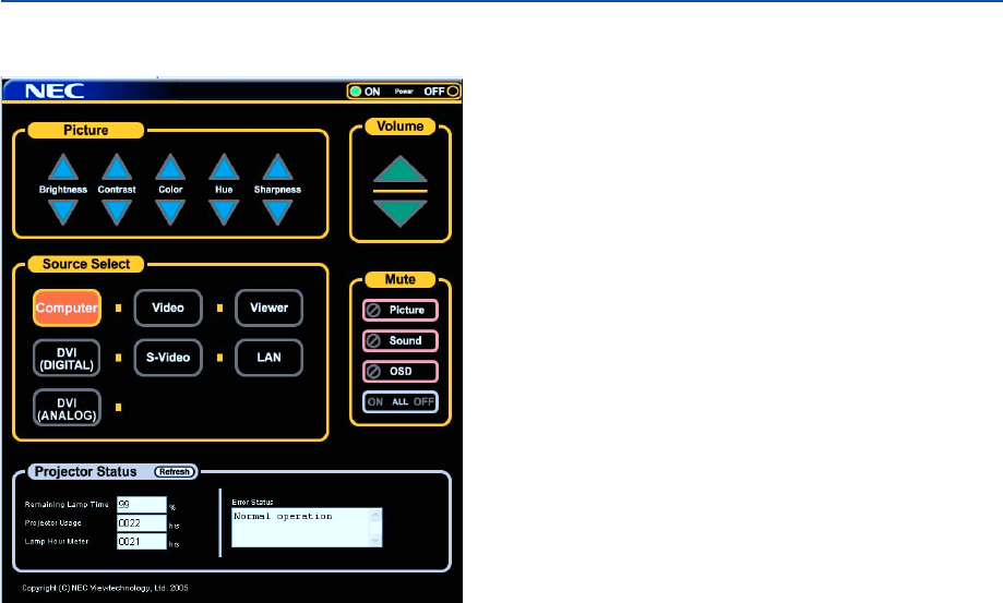
64
Structure of the HTTP Server
Power: This controls the power of the projector.
On ................... Power is switched on.
Off ................... Power is switched off.
Picture: Controls the video adjustment of the projector.
Brightness 왖... Increases the brightness adjustment value.
Brightness 왔... Decreases the brightness adjustment value.
Contrast 왖...... Increases the contrast adjustment value.
Contrast 왔...... Decreases the contrast adjustment value.
Color 왖........... Increases the color adjustment value.
Color 왔........... Decreases the color adjustment value.
Hue 왖............. Increases the hue adjustment value.
Hue 왔............. Decreases the hue adjustment value.
Sharpness 왖... Increases the sharpness adjustment value.
Sharpness 왔... Decreases the sharpness adjustment value.
• The functions that can be controlled will vary depending on the signal being input to the projector.
Volume: This controls the volume of the projector.
왖..................... Increases the volume adjustment value.
왔..................... Decreases the volume adjustment value.
Source Select: This switches the input connector of the projector.
Computer ........ Switches to the COMPUTER IN connector.
DVI (ANALOG/
DIGITAL) ....... Switches to the DVI-I IN connector.
Video ............... Switches to the VIDEO IN connector.
S-Video ........... Switches to the S-VIDEO IN connector.
Viewer ............. Switches to the Viewer.
LAN ................. Switches to a LAN signal.
4. Convenient Features

65
4. Convenient Features
Mute: This controls the mute function of the projector.
Picture On ....... Mutes the video.
Picture Off ....... Cancels the video muting.
Sound On ........ Mutes the audio.
Sound Off ........ Cancels the audio muting.
OSD On .......... Mutes the on-screen display.
OSD Off .......... Cancels the muting of the on-screen display.
All On .............. Mutes each of the video, audio, and on-screen display functions.
All Off .............. Cancels the muting of each of the video, audio, and on-screen display functions.
Projector Status: This displays the condition of the projector.
Refresh ....................... Updates the display of the following conditions.
Remaining Lamp Time
... Displays the remaining life of the lamp as a percentage.
Projector Usage .......... Displays how many hours the projector has been used.
Lamp Hour Meter ........ Displays how many hours the lamp has been used.
Error Status ................. Displays the status of errors occurring within the projector.

66
4. Convenient Features
씈 Using the Projector to Operate a Computer Connected on a
Network (Desktop Control Utility 1.0)
When Desktop Control Utility 1.0 on the included User Supportware 2 CD-ROM is installed on the computer, that
computer can be operated using the projector over a network.
For example, say you have a PowerPoint file on a computer in your office that you want to use for a presentation at a
meeting. If the computer in the office is connected by LAN to the projector in the meeting room, the projector can be
operated to project the image of the desktop of the computer (Windows 2000 or XP) in the office and display the
PowerPoint file during the meeting. This eliminates the need for taking the computer from the office to the meeting
room.
Meeting room
Office
Disclaimer
You can use the Desktop Control Utility 1.0 to operate a computer located in a separate room from the projector over
a network. This means there might be potential security risks that you may be exposed to which could cause damage
by unauthorized access or illegal use. We recommend you take some measures to prevent third parties from unautho-
rized access to your data or information.
We share neither liability nor responsibility to any loss or damages arising from information leak or power down
without notice.
NOTE: In Windows operating system, click “Control Panel”
→
“Power Options”
→
”System Standby”
→
”Never”. This will
disconnect a LAN connection when the computer goes in standby mode.
NOTE: To use the Desktop Control Utility 1.0, you need to have a USB mouse inserted into the USB port of the projector.
The WT615 does not require connection with a USB mouse because the electronic pen can be used for a USB mouse. This
section explains the operation by using a USB mouse.
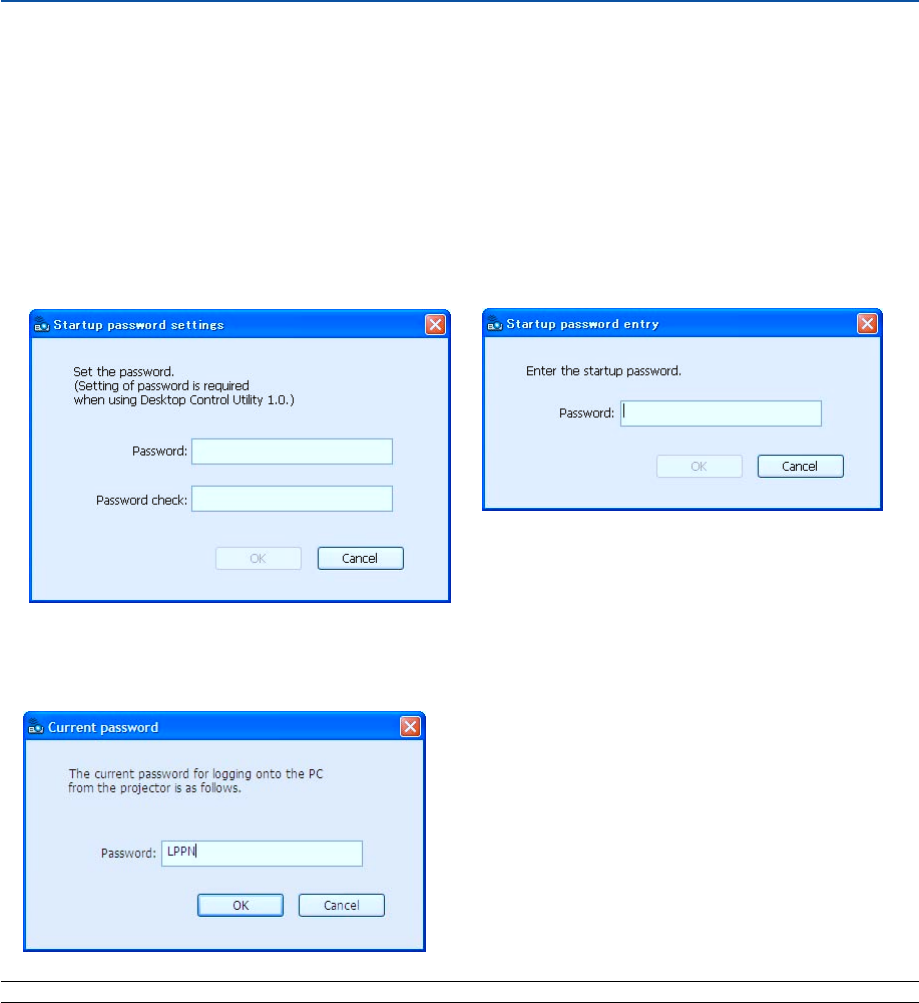
67
Operations on the Computer
1. Connect the computer to the LAN and make the required settings.
2. Install Desktop Control Utility 1.0 on the computer.
•For instructions on installation, refer to the included “Wired and Wireless Network Setup Guide”.
•For instructions on operating the software, see the Desktop Control Utility 1.0’s help file.
3. Prepare the documents to be presented at the meeting and save them on the computer.
4. Start up Desktop Control Utility 1.0.
The Startup password window appears.
Window at the first startup Window after entering your startup password
5. Input the startup password and click “OK”.
The “Current password” input window appears.
NOTE: The "Current password" will be changed each time you start Desktop Control Utility 1.0.
6. Make a note of the password.
7. Click “OK”.
Desktop Control Utility 1.0 starts.
Go to the room where the projector is installed, taking the password you made a note in the previous Step 6.
4. Convenient Features
Important:
•Your startup password will be required each
time you start Desktop Control Utility 1.0.
•If you forget or lost your startup password,
install the program again.
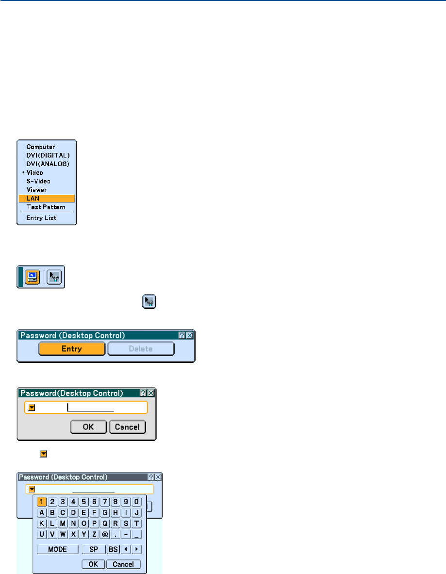
68
Operations on the projector – Connecting to the computer
1. Make the LAN settings on the projector.
Make the LAN settings at [Setup]
→
[Installation]
→
[LAN Mode] in the menu. (See page 111)
2. Connect a commercially available USB mouse to the projector. (See page 53)
3. Click anywhere on the screen with the USB mouse.
The menu appears.
4. Click [Source], then click “LAN”.
The help message is displayed.
The message is displayed only when a password for Desktop Control Utility 1.0 is not assigned.
5. Follow the message to press the MENU button on the projector cabinet or the remote control.
The connections bar appears at the bottom left of the screen.
6. Click the password input icon .
7. Click “Entry”.
The password input window appears.
8. Click .
The character input window appears. (See page 148.)
4. Convenient Features
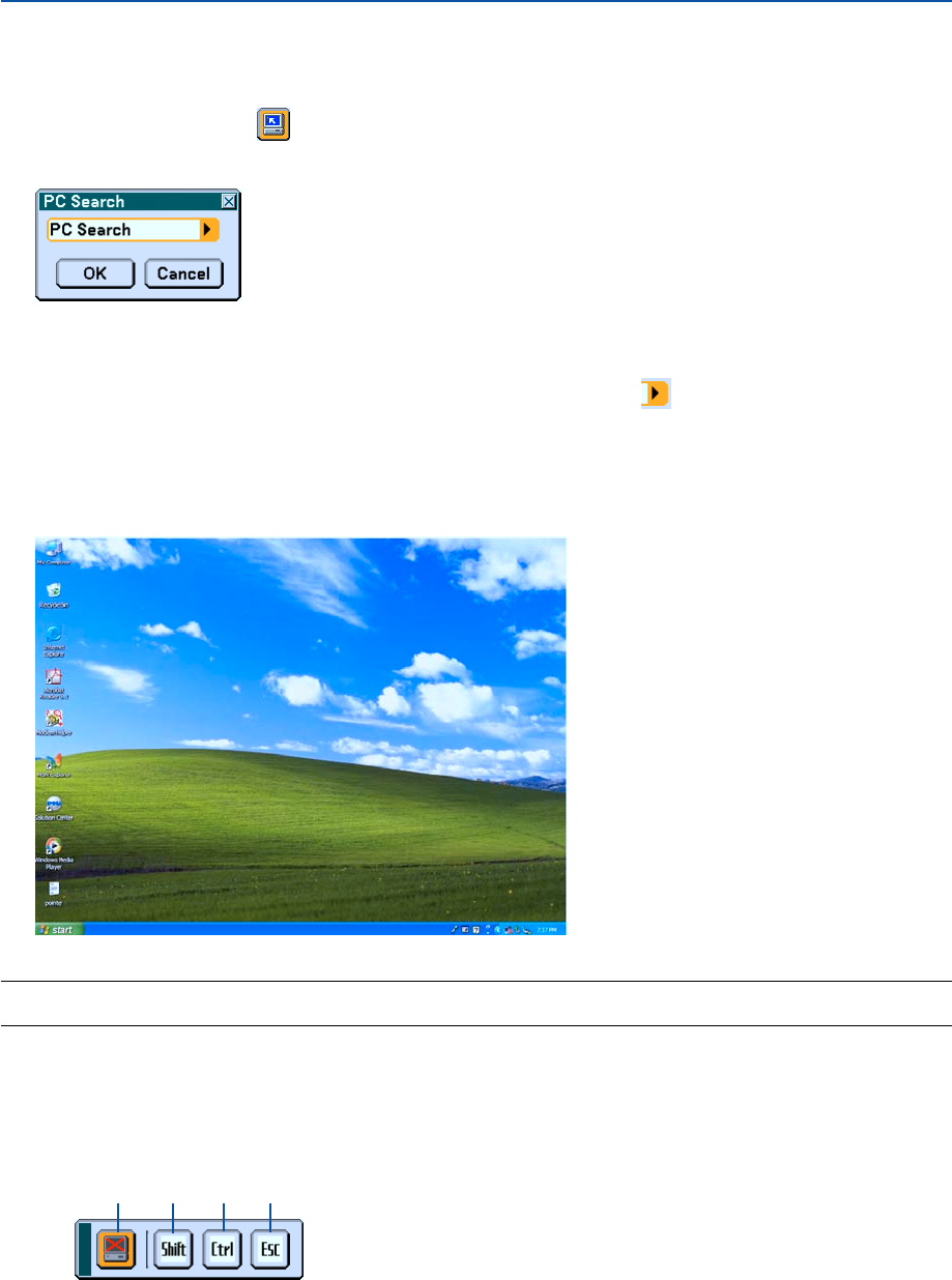
69
9. Input the password you made a note of in the previous Step [6] in “Operations on the Computer”.
10. Input the password and click “OK”.
The password input window is turned off.
11. Click the PC search icon .
The PC search window appears.
12. Click “OK”.
The connection selection window appears.
•To search by inputting the IP address of the connected computer, click on the PC Search window, click
“Input IP Address”, then click “OK”.
13. Click the computer to which you want to connect, then click “OK”.
The desktop of the connected computer appears.
NOTE: Once the desktop appears, the menu will no longer appear when the USB mouse is clicked. To display the menu while the
desktop is displayed, press the button on the projector itself or on the remote control.
Operations on the projector –Operating the desktop
A USB mouse connected to the projector can be used to operate the displayed desktop.
If the MENU button on the projector cabinet or the remote control is pressed while the desktop is displayed, an
additional operations bar appears at the bottom left of the screen.
4. Convenient Features
햲햳햴햵
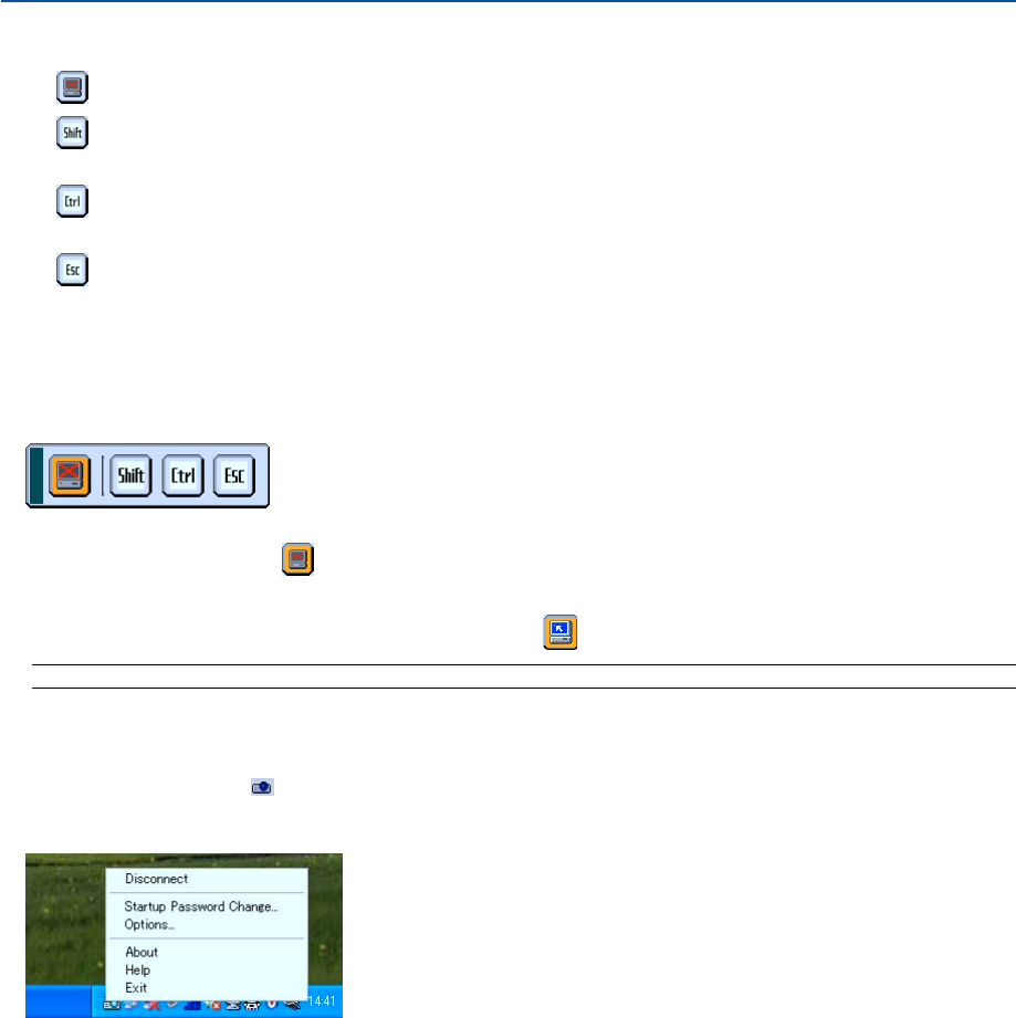
70
The following operations are available only with buttons on the projector cabinet or the remote control.
햲 Disconnect icon ................. Use to cut off communications with the computer.
햳 Shift icon ............................ Select this icon and press the ENTER button to set the shift lock mode. Select this icon and
press the ENTER button again to cancel the shift lock mode.
햴 Ctrl icon ............................. Select this icon and press the ENTER button to set the control lock mode. Select this icon
and press the ENTER button again to cancel the control lock mode.
햵 Esc icon ............................. Use to do the same operation as when the “Esc” button on the computer is pressed. Use it
for example to stop a PowerPoint slideshow.
Operations on the projector – Disconnecting communication
1. Press the MENU button while the desktop is displayed.
The additional operations bar appears at the bottom left of the screen.
2. Select the disconnect icon and press the ENTER button.
The connections bar appears at the bottom left of the screen.
To reconnect the communication, click the PC search icon and repeat steps 12 and 13 in the previous page.
NOTE: Disconnection is possible by clicking the projector icon and then "Disconnect" on the taskbar.
Operations on the projector – Exiting Desktop Control Utility 1.0
1. Click the projector icon on the taskbar while the desktop is displayed.
The pop-up menu will be displayed
2. Click “Exit”.
Desktop Control Utility 1.0 quits
3. Click anywhere on the screen.
The menu will be displayed.
4. Click [Source] and then click any other source than "LAN".
The menu will turn off.
4. Convenient Features


72
5. Using the Viewer
Making the Most out of the Viewer Function
Features
You can view presentation data, capture and play images on the projector. A PC card is used to view presentation data
prepared on the computer and to capture and play images projected with the projector.
The Viewer feature allows you to view slides stored on a PC memory card (referred to as PC card in this manual) or
USB memory on the projector. Even if no computer is available, presentations can be conducted simply with the
projector. This feature is convenient for holding presentations at meetings and in offices, as well as for playing images
taken on digital cameras.
NOTE:
•USB memory devices are available for WT615 only.
USB memory devices are not available for the Capture function on the WT610.
•To use the Viewer, first you need to create presentation materials on your PC (JPEG, BMP, GIF*1, PNG*1, Index*2 files).
For creating presentation materials using the Ulead Photo Explore 8.0, see the supplied "Wired and Wireless Network Setup
Guide" or On-line help in Ulead Photo Explorer 8.0.
*1Both PNG and GIF format support non-interlaced images only.
*2“Index” file is a file created using the Ulead Photo Explore 8.0 contained on the supplied NEC User Supportware 2 CD-ROM.
See the “NEC User Supportware 2 User’s Guide” included on the NEC User Supportware 2 CD-ROM for installing the Ulead
Photo Explore 8.0 on your computer.
Easy to use
•Presentations can be started immediately simply by inserting a PC card or USB memory (not supplied)
•Easy slide switching
•Remote control operation
•Jumping to a list of slides or any specific slide
Simple utility software (for computer)
•Ulead Photo Explore 8.0SE Basic operable on Windows XP/Windows 2000.
•Slides can be created by capturing the currently displayed image.
• Control screen for displaying lists of slides and editing.
*Microsoft, Windows and PowerPoint are registered trademarks of Microsoft Corporation.
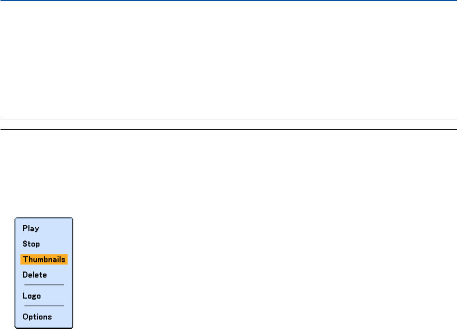
73
5. Using the Viewer
Operating the Viewer Function from the Projector (playback)
This section describes the operation for showing slides created using the Viewer function with the projector. It is also
possible to make slides directly from the images projected with the projector.
Projecting slides (Viewer)
Preparation: Use the Capture feature to store graphic files (JPEG, BMP, non-interlaced GIF or non-interlaced PNG
files) in a PC card or USB memory inserted into the projector’s slot. Or store JPEG or BMP files in a PC card or USB
memory inserted into your PC.
NOTE: USB memory devices are not available for the Capture function on the WT610.
1. Insert a PC card into the PC card slot or USB memory into the USB port of the projector.
2. Press the VIEWER button on the remote control or select the “Viewer” from the source list.
An image stored in the PC card or USB memory will be displayed.
3. Press the MENU button to display the Viewer menu.
The Viewer menu will appear when you press the MENU button on the remote control or the projector cabinet.
The Viewer menu includes the following commands:
Play ................... Plays back automatically or manually depending on the setting in Options. This allows you to move on to the
next slide when "Manual Play" is selected in the “Play Mode”.
Stop ................... This allows you to stop Auto Play while you are playing back and to resume playing from the selected slide
or folder when "Auto Play" is selected in the “Play Mode”.
Thumbnails........ Displays a list of thumbnails of Graphic files stored in the PC card inserted into the projector.
Delete ................ Deletes a captured slide(s) or all the captured slides in the Capture - specific folder.
Logo .................. Replace the default background logo with another logo in JPEG, BMP, non-interlaced GIF or non-interlaced
PNG format.
Options .............. Displays the Viewer setting options. See page 75 for more details.
4. Select “Play” and then press the ENTER button to display the first slide or to start playing slides auto-
matically.
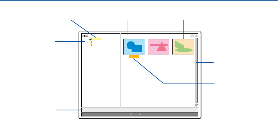
74
5. Using the Viewer
0000.jpg 0001.jpg 0002.jpg
3 Files
Slot 1
_CAP_
_RESTORE
RECYCLED
1/3 0000.jpg 60KB
select : ENTER
?
Cursor ..................................... Indicates the selected slide, folder or drive.
List of folders .......................... Indicates folders contained on a PC card or USB memory.
Information .............................. Indicates information of the selected file or folder.
Folder: folder name, creation date (month/day/year), creation time (hour/minute).
File: slide number/number of displayable slides in a folder, file name, creation date (month/day/
year), creation time (hour/minute), file size.
Number of files ........................ Indicates number of displayable slides in the selected folder. The maximum number of images
recognized as slides within one directory is about 1000.
Thumbnail/file name ................ Indicates thumbnails and names contained in a folder.
Scroll bar ................................. Used to view folders or files not visible in the window.
“__CAP__” folder .................... Will be created when the Capture is performed.
Viewer Window Elements
List of folders
Information
Number of files Thumbnail/file name
Scroll bar
Cursor (orange)
“_ _CAP_ _” folder
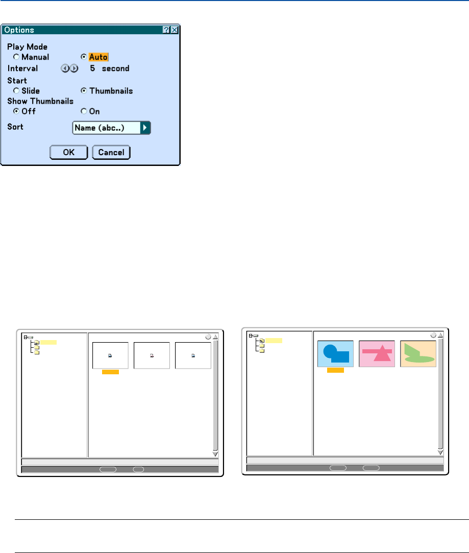
75
5. Using the Viewer
Setting Option for Viewer
Play Mode:
Manual .................. Views a slide manually when the Viewer source is selected.
Auto ...................... Plays back slides automatically when the Viewer source is selected.
Interval:
Specifies interval time between 5 and 300 seconds.
Start:
Specifies start screen when the Viewer source is selected.
Show Thumbnails:
Selecting the Viewer source will display a list of thumbnails of graphic files stored in the PC card or USB memory
when “On” is selected.
0000.jpg 0001.bmp 0002.jpg
3 Files
Slot 1
_CAP_
_RESTORE
RECYCLED
1/3 0000.jpg 60KB
select : ENTER folder :
EXIT
?
0000.jpg 0001.jpg 0002.jpg
3 Files
Slot 1
_CAP_
_RESTORE
RECYCLED
1/3 0000.jpg 60KB
select : ENTER
?
folder :
EXIT
“Off” “On”
Sort:
Rearranges the slides or thumbnails by name, extension, date or size.
NOTE: This setting is not available for the following folders:
* The "__CAP__" folder for captured images
* Folders created with the "Output Viewer" feature of Ulead Photo Explorer 8.0 or with Viewer PPT Converter 3.0
OK/Cancel:
To close the Options menu with saving changes, select "OK" and press the ENTER button.
To close the Options menu without saving changes, select "Cancel" and press the ENTER button.

76
Exiting Viewer
To exit Viewer, switch to another input such as Computer, DVI (DIGITAL/ANALOG), Video, S-Video or LAN.
*To switch to another input, there are two ways:
*Press the COMPUTER or VIDEO button on the remote control.
*Press the MENU button on the remote control to display the Viewer menu. Press the MENU button again to
display the main menu and select the input from the [Source] submenu.
With this function it is possible to switch directly to a slide when the picture of a VCR or computer is being projected.
Example: When conducting presentations using a combination of slides and moving pictures from a VCR, etc., it is
possible to switch from a Viewer slide to the video picture then back to the Viewer slide simply by using the Viewer
button.
NOTE: Even if you switch the current Viewer source to another source, the current slide is retained. When you return back to the
Viewer, you will get the slide that has been retained.
Viewing Digital Images
Digital images can be played with the Viewer if the following conditions are met:
•If the image can be stored on an MS-DOS format PC card.
• If the image can be stored in a format supported by the Viewer. With the Viewer, images on the card are
searched for in directories and images in JPEG, BMP, non-interlaced GIF or non-interlaced PNG format are
recognized as slides.
NOTE: The maximum number of images recognized as slides within one directory is about 1000.
5. Using the Viewer
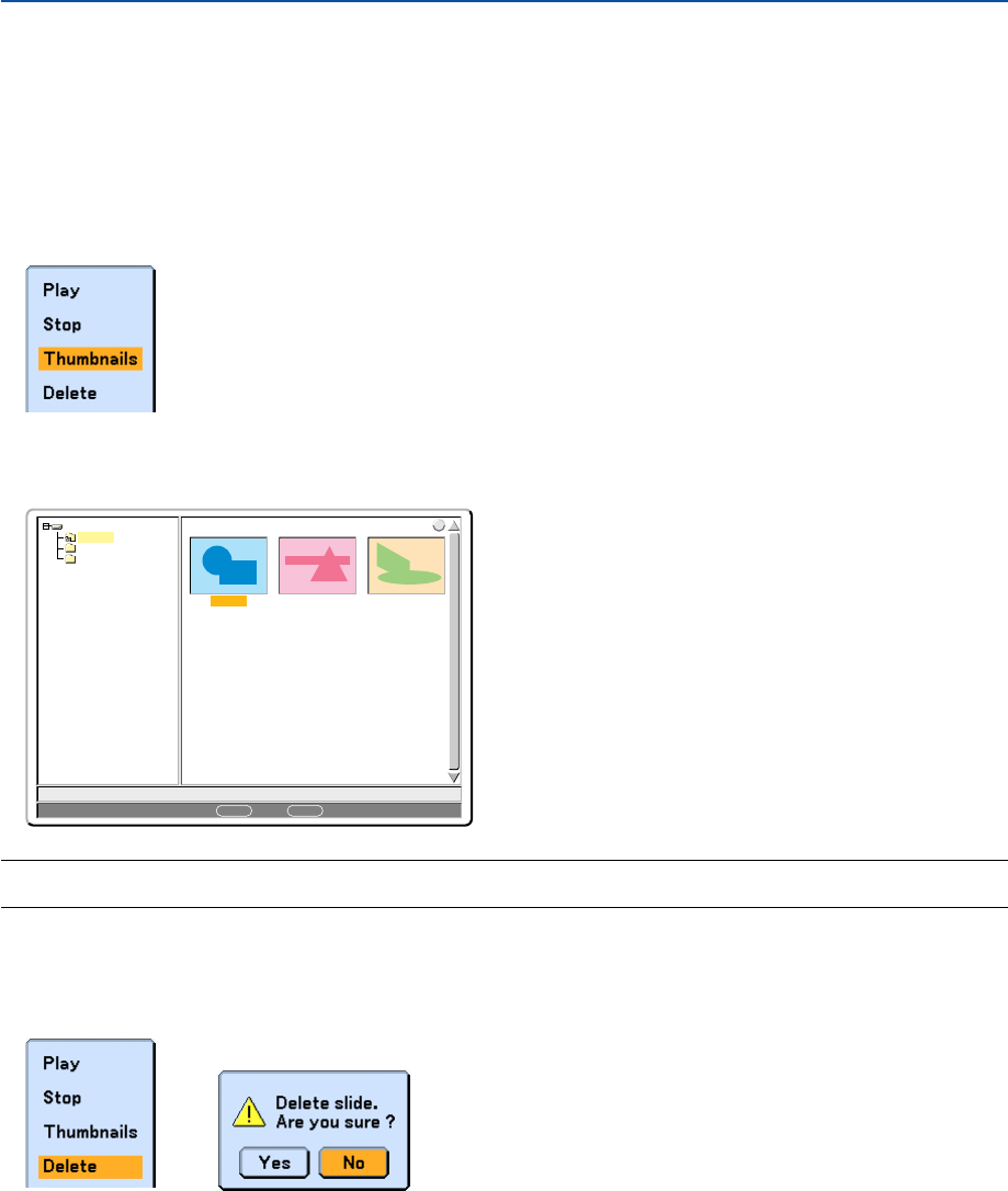
77
5. Using the Viewer
Deleting Captured Images
Using the Delete command on the Viewer menu allows you to delete captured images.
To delete captured images:
Preparation: Make sure that the PC card is inserted into the PC card slot or USB memory into the USB port of the
projector.
1. Press the VIEWER button on the remote control to display an image.
2. Press the MENU button to display the Viewer menu.
0000.jpg 0001.jpg 0002.jpg
3 Files
Slot 1
_CAP_
_RESTORE
RECYCLED
1/3 0000.jpg 60KB
select : ENTER
?
folder :
EXIT
3. Use the
왔
button to select “Thumbnails” and then press the ENTER button.
The Thumbnail screen will be displayed.
NOTE: To change highlight from the Thumbnails screen (pane on the right) to a directory tree (pane on the left) , press the EXIT
button. To return highlight to the Thumbnails screen, press the ENTER button.
4. Use the SELECT
왖왔왗 or 왘
button to select an image you wish to delete.
5. Press the MENU button to display the Viewer menu.
6. Use the SELECT
왔
button to select “Delete” and then press the ENTER button.
A confirmation message will be displayed.
7. Use the SELECT
왗
button to select “Yes” and then press the ENTER button.
This completes deleting.
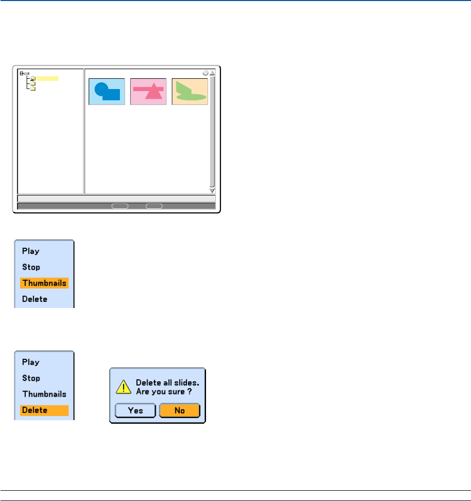
78
5. Using the Viewer
To delete all the captured images:
1. Repeat steps 1 to 3 in the above described procedure.
2. Press the EXIT button to select the “__CAP__” folder in the directory (pane on the left).
0000.jpg 0001.jpg 0002.jpg
3 Files
Slot 1
__CAP__
_RESTORE
RECYCLED
1/3 0000.jpg 60KB
select : ENTER folder : EXIT
?
3. Press the MENU button to display the Viewer menu.
4. Use the
왔
button to select “Delete” and then press the ENTER button.
5. Use the
왗
button to select “Yes” and then press the ENTER button.
This completes deleting.
NOTE: The vacant "__CAP__" folder stays even after you delete all the captured images.
A confirmation message will be displayed.
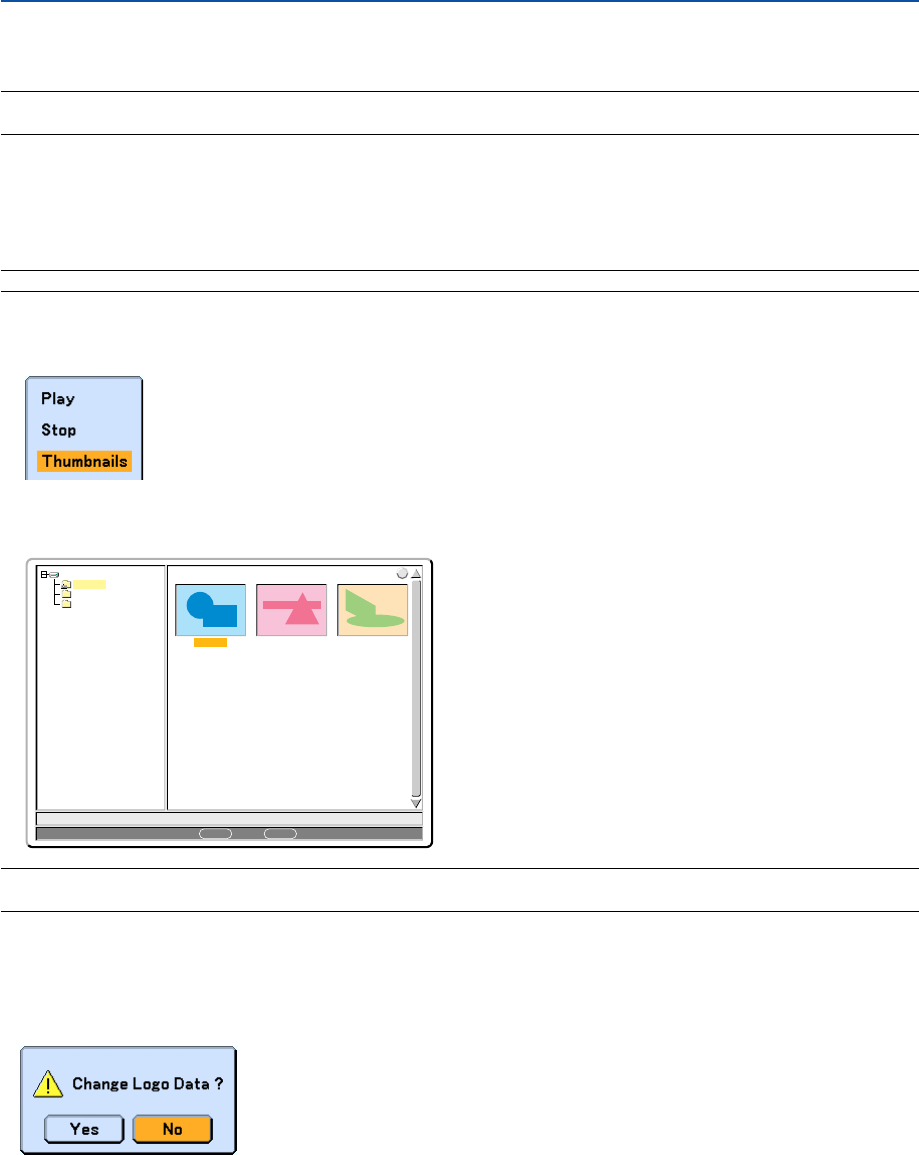
79
5. Using the Viewer
Changing Background Logo
You can change the default background logo using the Viewer feature.
NOTE: File size must be 256KB or less. File formats other than JPEG, BMP, non-interlaced GIF or non-interlaced PNG are not
available.
Preparation:
Use the Capture feature to store JPEG or BMP files in a PC card inserted into the projector’s slot or USB memory*
into projector’s USB port. Or store JPEG, BMP, non-interlaced GIF or non-interlaced PNG files in a PC card or
USB memory inserted into your PC’s slot or USB port and insert the PC card into the projector’s slot or USB
memory into the projector’s USB port.
*NOTE: USB memory devices are not available for the Capture function on the WT610.
1. Press the VIEWER button on the remote control to display an image.
2. Press the MENU button to display the Viewer menu.
0000.jpg 0001.jpg 0002.jpg
3 Files
Slot 1
_CAP_
_RESTORE
RECYCLED
1/3 0000.jpg 60KB
select : ENTER
?
folder :
EXIT
3. Use the SELECT
왔
button to select “Thumbnails” and then press the ENTER button.
The Thumbnail screen will be displayed.
NOTE: To change highlight from the Thumbnails screen (pane on the right) to a directory tree (pane on the left) , press the EXIT
button. To return highlight to the Thumbnails screen, press the ENTER button.
4. Use SELECT
왖왔왗
or
왘
button to select a file (slide) for your background logo.
5. Press the MENU button to display the Viewer menu.
6. Use the SELECT
왔
button to select "Logo" and then press the ENTER button.
A confirmation dialog box will be displayed.
7. Use the SELECT
왗
button to select “Yes” and press the ENTER button. This completes changing a logo
for the background.
* Once you have changed the background from the NEC logo to another, you cannot return the logo to back-
ground even by using “Reset”. To put the NEC logo back in the background logo, repeat the above steps. The
NEC logo file is included on the supplied User Supportware 2 CD-ROM (/Logo/nec_b_x.jpg).

80
6
Using On-Screen Menu
Using the Menus........................................................ 81
Menu tree .................................................................. 82
Menu Elements.......................................................... 84
Menu Descriptions & Functions [Source] .................. 85
Menu Descriptions & Functions [Adjust] .................... 88
Menu Descriptions & Functions [Setup] .................... 98
Menu Descriptions & Functions [Information] .......... 126
Menu Descriptions & Functions [Reset] .................. 129
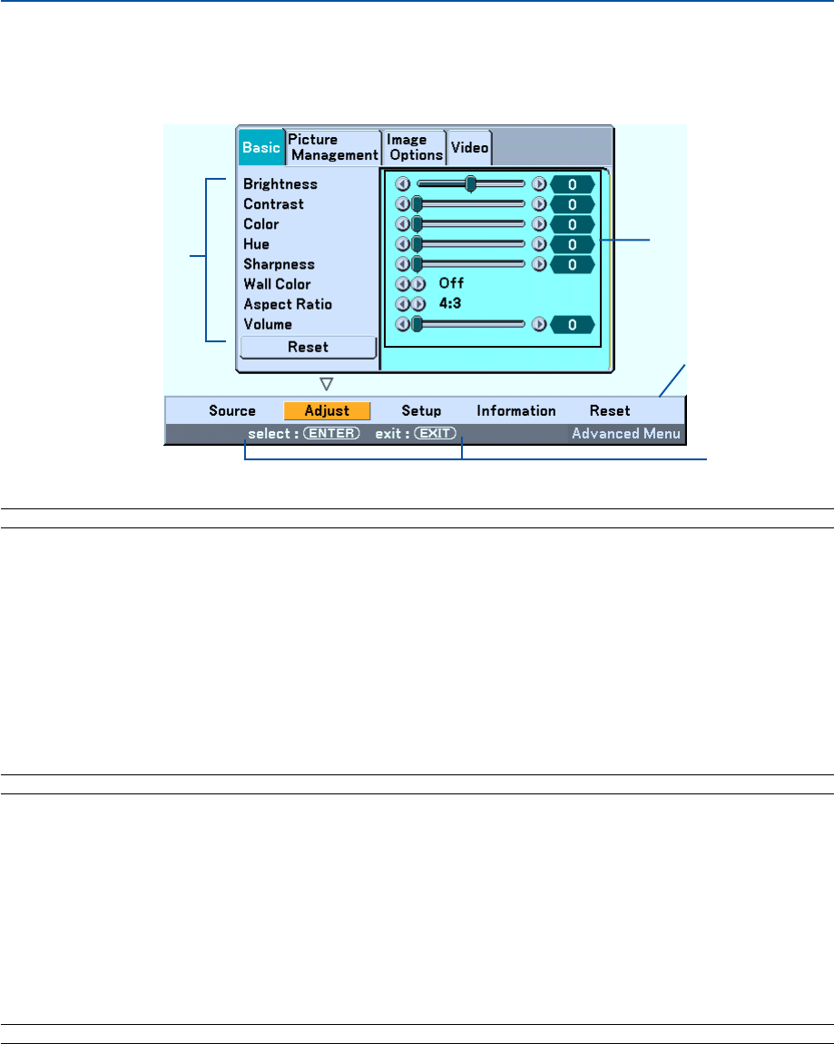
81
Using the Menus
1. Press the MENU button on the remote control or the projector cabinet to display the menu.
NOTE: The commands such as ENTER and EXIT in the gray bar show available buttons for your operation.
2. Press the SELECT
왗
or
왘
buttons on the remote control or the projector cabinet to display the
submenu.
3. Press the ENTER button on the remote control or the projector cabinet to select the top item or the first
tab.
4. Use the SELECT
왖
or
왔
buttons on the remote control or the projector cabinet to select the item you
want to adjust or set.
You can use the SELECT
왗
or
왘
button on the remote control or the projector cabinet to select the tab
you want.
NOTE: You can select a tab only when the tab color is orange.
5. Press the ENTER button on the remote control or the projector cabinet to display the submenu window.
6. Adjust the level or turn the selected item on or off by using the SELECT
왖왔왗
or
왘
button on the remote
control or the projector cabinet.
Changes are stored until that particular function is adjusted again.
7. Repeat steps 2 -6 to adjust an additional item, or press the EXIT button on the remote control or the
projector cabinet to quit the menu display.
NOTE: When a menu or message is displayed, several lines of information may be lost, depending on the signal or settings.
Main menu
Submenu window
Currently available
buttons
Submenu
6. Using On-Screen Menu
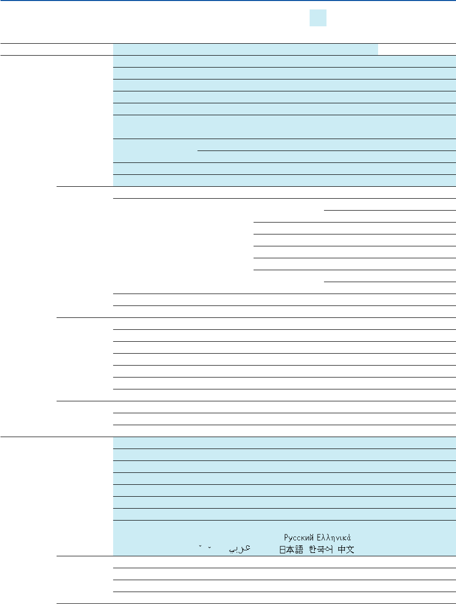
82
Menu tree
Menu Item
Source Computer, DVI (DIGITAL), DVI (ANALOG), Video, S-Video, Viewer, LAN, Test Pattern, Entry List
Adjust Basic Brightness
Contrast
Color
Hue
Sharpness
Wall Color Off, Blackboard, Blackboard (Gray), Light yellow, Light green, Light blue, Sky blue,
Light rose, Pink
Aspect Ratio 4:3 4:3, Letterbox, Wide Screen, Crop
16:9 4:3 Window, Letterbox, Wide Screen, 4:3 Fill
Volume
Reset
Picture Preset 1 to 5
Management Detail Settings Reference Presentation, Video, Movie,
Graphic, sRGB
Gamma Correction
Dynamic, Natural, Black Detail
Color Temperature
5000, 6500, 7800, 8500, 9300, 10500
White Peaking
White Balance Brightness RGB, Contrast RGB
Color Correction Red, Green, Blue,Yellow, Magenta,
Cyan, Color Gain
Signal Type RGB, Component
Video Filter Off, Less, More
Image Options Clock
Phase
Horizontal Position
Vertical Position
Blanking Top, Bottom, Left, Right
Resolution Auto, Native
Overscan 0%, 5%, 10%
Video Noise Reduction Off, Low, Medium, High
Color Matrix HDTV, SDTV
I/P Converter Deinterlace(Auto/Still), Interlace
Setup Basic Pen Calibration (WT615 only)
Tilt Indicator
Pincushion Left/Right, Top, Bottom
Cornerstone
Keystone Horizontal, Vertical
Lamp mode Normal, Eco
Menu Mode Basic Menu, Advanced Menu
Language English, Deutsch, Français, Italiano, Español, Svenska, Suomi, Norsk,
Nederlands, Türkçe, Polski, , , Magyar, Português,
C
estin
a
, , Dansk, , ,
Menu Menu Color Select Color1 to 5, Monochrome
Display Select Source: On, Off / Message: On, Off
Menu Display Time Manual, Auto 5 sec, Auto 15 sec, Auto 45 sec
Background Blue, Black, Logo
6. Using On-Screen Menu
Basic menu items are indicated by
shaded area.

83
6. Using On-Screen Menu
Menu Item
Setup Security Security Cabinet Button Unlock, Lock
Password (Menu) Entry, Delete
Password (Logo) Entry, Delete
Security Enable, Disable, Keyword, Use Protect Key, Drive, Read, Register, Delete
Installation Orientation Desktop Front, Ceiling Rear, Desktop Rear, Ceiling Front
Screen Screen Type: 4:3, 16:9 / Position
LAN Mode Profile
Profiles, DHCP, IP Address, Subnet Mask, Gateway, DNS Configuration,
Advanced: Network Type, Wep
Domain Host Name, Domain Name
Mail Alert Mail, Sender’s Address, SMTP Server Name,
Recipient’s Address 1-3
Projector Name
Communication Speed 4800, 9600, 19200, 38400 bps
Standby Mode Normal, Power-saving
Options Auto Adjust Off, Normal, Fine
Auto Start Off, On
Power Management Off, 0:05, 0:10, 0:20, 0:30
Fan Mode Auto, High
Default Source Select Last, Auto, Select (Computer, DVI (DIGITAL/ANALOG), Video, S-Video, Viewer, LAN)
Signal Select Computer RGB/Component, RGB, Componet, Scart
DVI (ANALOG) RGB/Component, RGB, Componet
Video Auto, NTSC3.58, NTSC4.43, PAL, PAL-M, PAL-N, PAL60, SECAM
S-Video Auto, NTSC3.58, NTSC4.43, PAL, PAL-M, PAL-N, PAL60, SECAM
OUT Terminal Last, Computer, DVI (ANALOG)
Tools ChalkBoard
Board Color Transparent, Dark Gray, Light Gray, Dark Cyan, Blue, Black
Digital Zoom Zoom, Horizontal Position, Vertical Position
Off Timer Off, 0:30, 1:00, 2:00, 4:00, 8:00, 12:00, 16:00
Mouse Mouse Pointer: Pointer 1 to 9 / Button: Right Hand, Left Hand /
Sensitivity: Fast, Medium, Slow
Pointer Pointer 1 to 9
Closed Caption Off, Caption 1-4, Text 1-4
Information Usage Time Remaining Lamp Time, Lamp Hour Meter, Projector Usage
Source Page1 Input Terminal, Signal Type, Video Type, Source Name, Entry No.
Source Page2 Horizontal Frequency, Vertical Frequency, Sync Type, Sync Polarity, Interlace
LAN Profile IP Address, Subnet Mask, Gateway, MAC Address
LAN Wireless SSID, Mode, WEP, Channel, Signal Level
Version Firmware, Data
Reset Current Signal, All Data, All Data (Including Entry List), Clear Lamp Hour Meter
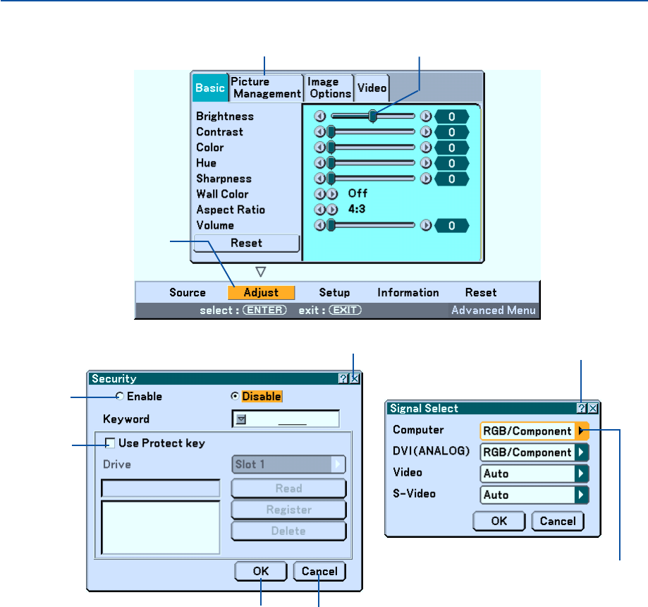
84
Menu Elements
Slider
Solid triangle
Highlight
Tab
Radio button
Check box
Cancel button
OK button
Menu windows or dialog boxes typically have the following elements:
Highlight................ Indicates the selected menu or item.
Solid triangle ......... Indicates further choices are available. A highlighted triangle indicates the item is active.
Tab ........................ Indicates a group of features in a dialog box. Selecting on any tab brings its page to the front.
Radio button ......... Use this round button to select an option in a dialog box.
Check box ............. Place a checkmark in the square box to turn the option On.
Slider ..................... Indicates settings or the direction of adjustment.
OK button .............. Press to confirm your setting. You will return to the previous menu.
Cancel button ........ Press to cancel your setting. You will return to the previous menu.
Close button .......... Click to close the window and saving changes. (USB mouse only)
Help button ........... Indicates that help about that feature is available (USB mouse only).
Help button
Close button
6. Using On-Screen Menu
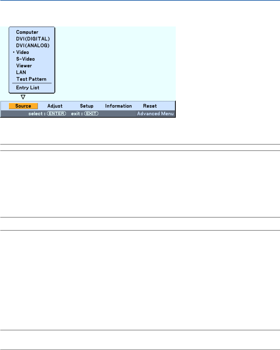
85
쐏 Menu Descriptions & Functions [Source]
Computer
Selects the computer connected to your Computer input connector signal.
NOTE: An optional component cable (Component V or ADP-CV1 cable) is needed for a component signal.
DVI (DIGITAL/ANALOG)
Selects the computer connected to the DVI input connector.
Video
Selects what is connected to your Video input-VCR, laser disc player, DVD player or document camera.
S-Video
Selects what is connected to your S-Video input-VCR, DVD player, or laser disc player.
NOTE: A frame may freeze for a brief period of time when a video is played back in fast-forward or fast-rewind with a Video or S-
Video source.
Viewer
This feature enables you to make presentations using a PC card that contains captured images and slides created
with the exclusive Photo Explore 8.0 for NEC contained on the CD-ROM. See the supplied “Wired and Wireless
Network Setup Guide” for installing the Photo Explore 8.0 for NEC.
See page 71 for viewing slides.
LAN
Selects a signal from the NEC optional wireless LAN card or a commercially available wired LAN card plugged into the
projector's card slot.
Test Pattern
Displays a test pattern to check your adjustments or image position.
NOTE:
• Select “Computer” for your source signal even when the COMPUTER IN connector is connected to a component signal.
• When you select “Viewer” or “LAN” for your source signal, sound of the DVI-I AUDIO IN mini jack will come from the speaker.
6. Using On-Screen Menu
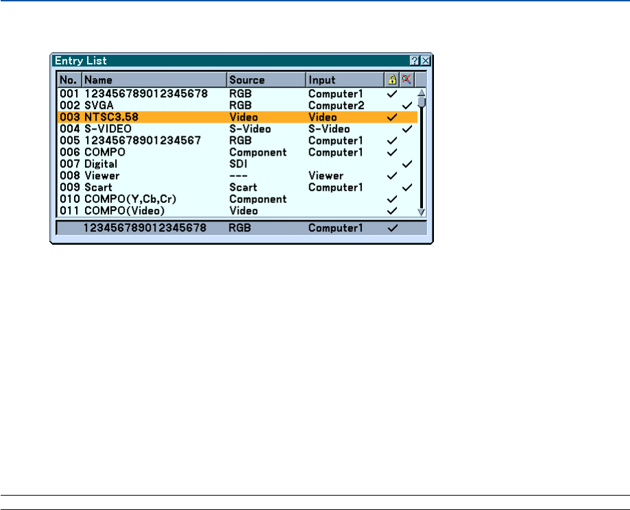
86
Entry List
Use the SELECT 왖 or 왔 button on your remote control or the projector cabinet to select the signal and press the
ENTER button on the remote control or the projector cabinet to display the Entry Edit Command screen.
Entering the Currently Projected Signal into the Entry List
1. Display the Entry List.
2. Use the SELECT
왖
or
왔
button on your remote control or the projector cabinet to select any number and
press the ENTER button on the remote control or the projector cabinet to display the Entry Edit Com-
mand screen.
3. Use the SELECT
왗
or
왘
button to select [Store] and press the ENTER button.
Using the Entry List
Making any adjustments to the current picture will automatically register its adjustments to the Entry List. The regis-
tered signal can be loaded any time from the Entry List.
NOTE: Up to 100 presets can be registered except settings on the Picture.
6. Using On-Screen Menu
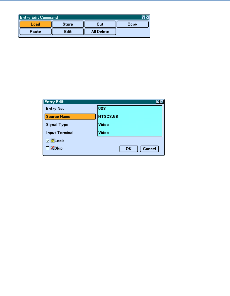
87
Entry Edit Command
You can edit signals on the Entry List.
Load ...................... Enables you to select a signal from the list.
Store ..................... Enables you to store the currently projected signal.
Cut ........................ Enables you to remove a selected signal from the list and place it on the "clipboard" in the projector.
Copy ...................... Enables you to copy a selected signal from the list and place it on the "clipboard" in the projector.
Paste ..................... Enables you to paste the signal placed on the "clipboard" to any other line of the list.
Edit ........................ Enables you to change source names.
Source Name:
Enter a signal name. Up to 18 alphanumeric characters can be used.
Input Terminal:
Change the input terminal.
Lock:
Set so that the selected signal cannot be deleted when "All Delete" is executed. After executing “Lock”, the
changes cannot be saved.
Skip:
Set so that the selected signal will be skipped during auto search.
When complete, select “OK” and press ENTER. To exit without storing the setting, select Cancel. Select
"Source Name" and press ENTER to display the Source Name Edit window. You can change source name on
this window. Press 왔 to display the software keyboard, which you can enter alphanumeric characters. See
page 148 for the key function of the software keyboard.
All Delete ............... This feature enables you to delete all the registered signals in the Entry List.
The following buttons are not available for the currently projecting signals:
1) The Cut and Paste buttons on the Entry Edit Command screen
2) The Input Terminal button on the Entry Edit screen
NOTE: When all the signals in the Entry List are deleted, the currently projected signal will be also deleted except locked signals.
6. Using On-Screen Menu
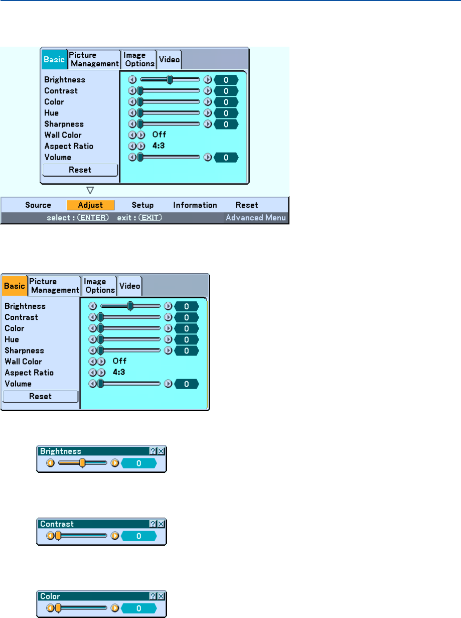
88
쐄 Menu Descriptions & Functions [Adjust]
Basic
[Brightness]
Adjusts the brightness level or the back raster intensity.
[Contrast]
Adjusts the intensity of the image according to the incoming signal.
[Color]
Increases or decreases the color saturation level (not valid for RGB and DVI digital).
6. Using On-Screen Menu
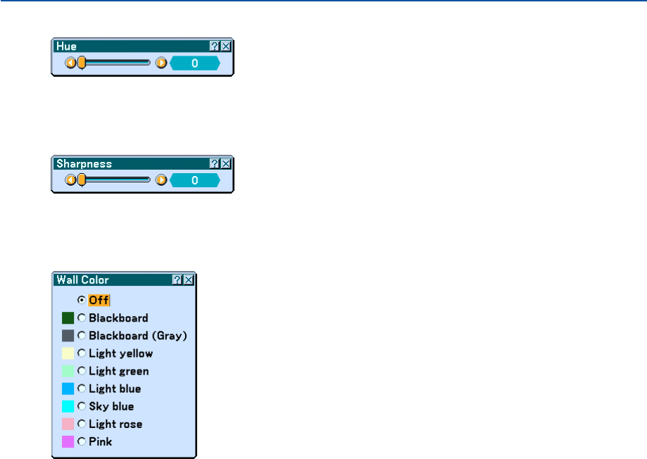
89
[Hue]
Varies the color level from +/- green to +/-blue. The red level is used as reference. This adjustment is only valid for
Video, Component and TV standard inputs (not valid for RGB and DVI digital).
[Sharpness]
Controls the detail of the image for Video (not valid for RGB and DVI digital).
Using the Wall Color Correction [Wall Color]
This function allows for quick adaptive color correction in applications where the screen material is not white.
The following nine options are available.
• OFF • Blackboard
• Blackboard (Gray) • Light yellow
• Light green • Light blue
• Sky blue • Light rose
• Pink
6. Using On-Screen Menu
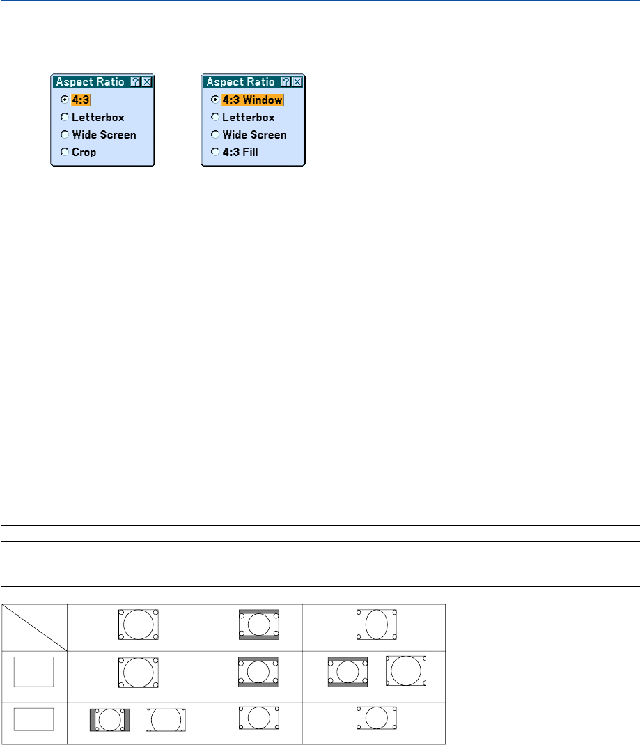
90
Selecting Aspect Ratio [Aspect Ratio] (not available for Viewer)
Screen Type 4:3 Screen Type 16:9
Aspect Ratio allows you to select the best Aspect mode to display your source image.
When screen type 4:3 is selected for the source, the following selections will display:
4:3 ......................... Standard 4:3 aspect
Letter Box .............. Reduced to display the true aspect with black borders on top and bottom
Wide Screen .......... Left & Right stretched with black borders on top and bottom
Crop ...................... Left & Right stretched. Left & Right sides cut. Available for 4:3 only.
When screen type 16:9 is selected for the source, the following selections will display:
4:3 Window ........... Reduced to display the true aspect with black borders on right and left
Letter Box .............. Standard 16:9 aspect
Wide Screen .......... Left and right stretched to display the true aspect
4:3 Fill ................... Stretched to display in 16:9 aspect ratio
NOTE: You can adjust image position vertically for a source with black borders on top and bottom. See page 110 for setting
image position.
Copyright
Please note that using this projector for the purpose of commercial gain or the attraction of public attention in a venue such as a
coffee shop or hotel and employing compression or expansion of the screen image with a "Aspect Ratio" or "Screen" setting may
raise concern about the infringement of copyrights which are protected by copyright law.
NOTE: During 3D Reform adjustment, "Aspect Ratio" may not be available.
Should this happen, first reset the 3D Reform data and then do setting again. Second repeat the 3D Reform adjustment.
Changing the aspect ratio can limit 3D Reform in its adjustable range.
Input
Signal
Screen
Type
4:3 Screen
16:9 Screen
4:3
4:3 Window 4:3 Fill
Squeeze
Wide Screen
Wide Screen
Crop
Letterbox
4:3 Letterbox
Letterbox
6. Using On-Screen Menu
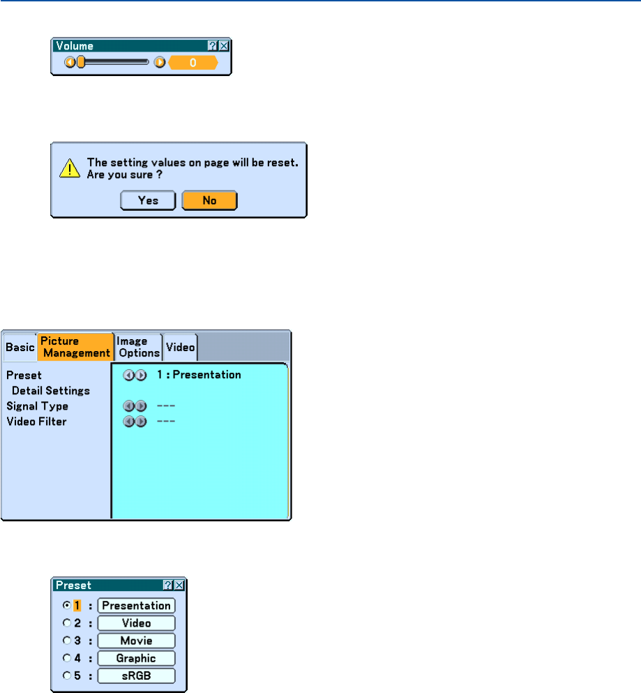
91
Controlling Volume [Volume]
You can adjust the volume level of the projector speakers and AUDIO OUT (Stereo Mini Jack).
Reset
To reset the settings for “Basic”, select “Reset” and press the ENTER button.
The message "The setting values on page will be reset. Are you sure?” will be displayed.
Select “Yes” and press the ENTER button. To return without storing settings, select “No” and press the ENTER button.
Picture Management
[Preset]
This option allows you to adjust neutral tint for yellow, cyan or magenta. There are 5 factory presets optimized for
various types of images, you can set user adjustable settings.
6. Using On-Screen Menu
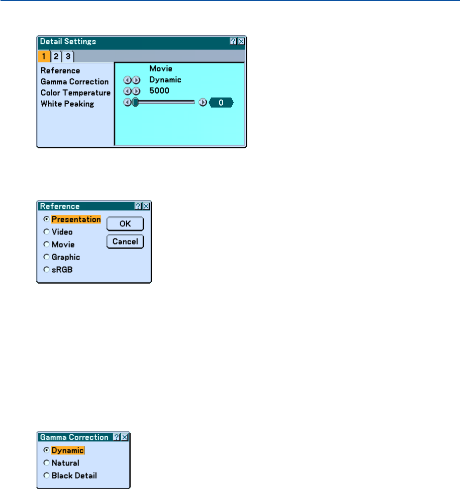
92
[Detail Settings]
This will provide you with three pages of menus that provide more detailed settings.
[Page1]
Selecting Reference Setting [Reference]
This feature allows you to use color correction or gamma values as reference data to optimize for various types of
images. You can select one of the following five settings.
Presentation ...... Recommended for making a presentation using a PowerPoint file.
Video ................. Recommended for regular picture such as TV program.
Movie ................ Recommended for movies.
Graphic .............. Recommended for graphics.
sRGB ................. Standard color values.
Selecting Gamma Correction Mode [Gamma Correction]
Each mode is recommended for:
Dynamic ............ Creates a high-contrast picture.
Natural ............... Natural reproduction of the picture.
Black Detail ........ Emphasizes detail in dark areas of the picture.
6. Using On-Screen Menu
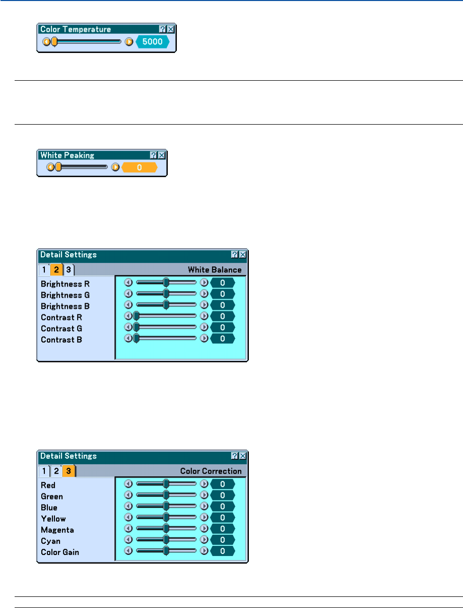
93
Adjusting Color Temperature [Color Temperature]
This feature adjusts the color temperature using the slider.
NOTE:
*When "Presentation" is selected in [Reference], this function is not available.
*When [White Balance] settings has been changed, the color temperature value on screen does not reflect the real color
temperature.
Adjusting Brightness of White Area [White Peaking]
Adjust the brightness of the white areas by using the slide bar. As the picture becomes dim, it looks more natural.
[Page 2]
Adjusting White Balance [White Balance]
This allows you to adjust the white balance. Brightness for each color (RGB) is used to adjust the black level of the
screen; Contrast for each color (RGB) to adjust the white level of the screen.
[Page 3]
Selecting Color Correction [Color Correction]
Adjusts red, green, blue, yellow, magenta and cyan each independently to correct the tint of the whole screen.
NOTE: When "Presentation" is selected in [Reference], this function is not available.
6. Using On-Screen Menu
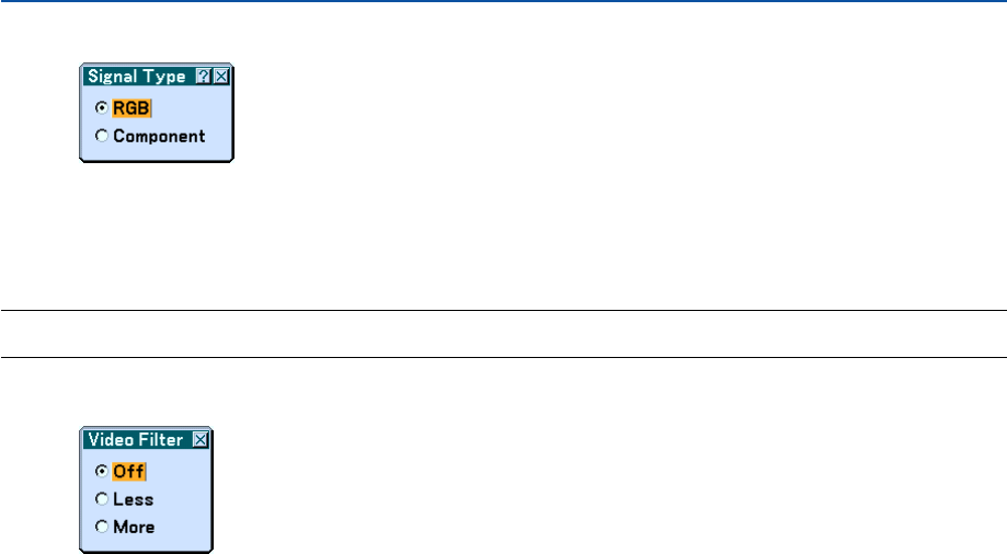
94
Selecting Signal Type [Signal Type]
Select either the computer signal type or the component signal type.
RGB ....................... Computer signal
Component............ Component signals such as Y/Cb/Cr, Y/Pb/Pr
NOTE: This feature is available on the computer signal only. If you do not get a better picture even when you set "Signal Select" to
"Component" in [Setup], set this to "Component".
Selecting Video Filter Level [Video Filter]
This function reduces video noise.
Off ......................... The filter is removed.
Less ...................... The low-pass filter is applied partially.
More...................... The low-pass filter is applied fully.
6. Using On-Screen Menu
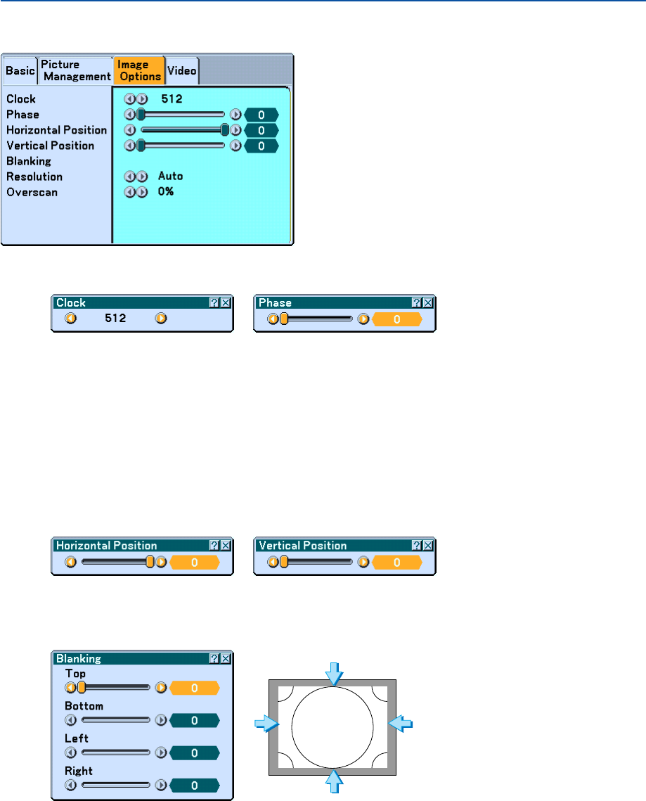
95
Image Options
Adjusting Clock and Phase [Clock/Phase]
This allows you to manually adjust Clock and Phase.
Clock ..................... Use this item to fine tune the computer image or to remove any vertical banding that might appear. This
function adjusts the clock frequencies that eliminate the horizontal banding in the image.
This adjustment may be necessary when you connect your computer for the first time.
Phase .................... Use this item to adjust the clock phase or to reduce video noise, dot interference or cross talk. (This is
evident when part of your image appears to be shimmering.)
Use "Phase" only after the "Clock" is complete.
Adjusting Horizontal/Vertical Position [Horizontal/Vertical Position]
Adjusts the image location horizontally and vertically.
Masking Unwanted Area [Blanking]
This feature allows you to mask any unwanted area of the screen image.
Adjust the Top, Bottom, Left or Right blanking with the SELECT 왗 or 왘 button.
6. Using On-Screen Menu
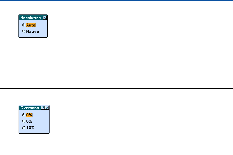
96
Selecting Resolution [Resolution]
This allows you to activate or deactivate the Advanced AccuBlend feature.
Auto ...................... Turns on the Advanced AccuBlend feature. The projector automatically reduces or enlarges the current
image to fit the full screen.
Native .................... Turns off the Advanced AccuBlend feature. The projector displays the current image in its true resolution.
NOTE:
*[Overscan], [Pincushion], [Cornerstone], [Keystone], [Aspect Ratio] and “Screen” are not available when [Resolution] is set to
“Native”.
* While you are displaying an image with the projector's native resolution or higher, [Resolution] is not available.
Selecting Overscan Percentage [Overscan]
Select overscan percentage (0%, 5% and 10%) for signal.
NOTE: The option “0%” may not be available depending on the input signal.
6. Using On-Screen Menu
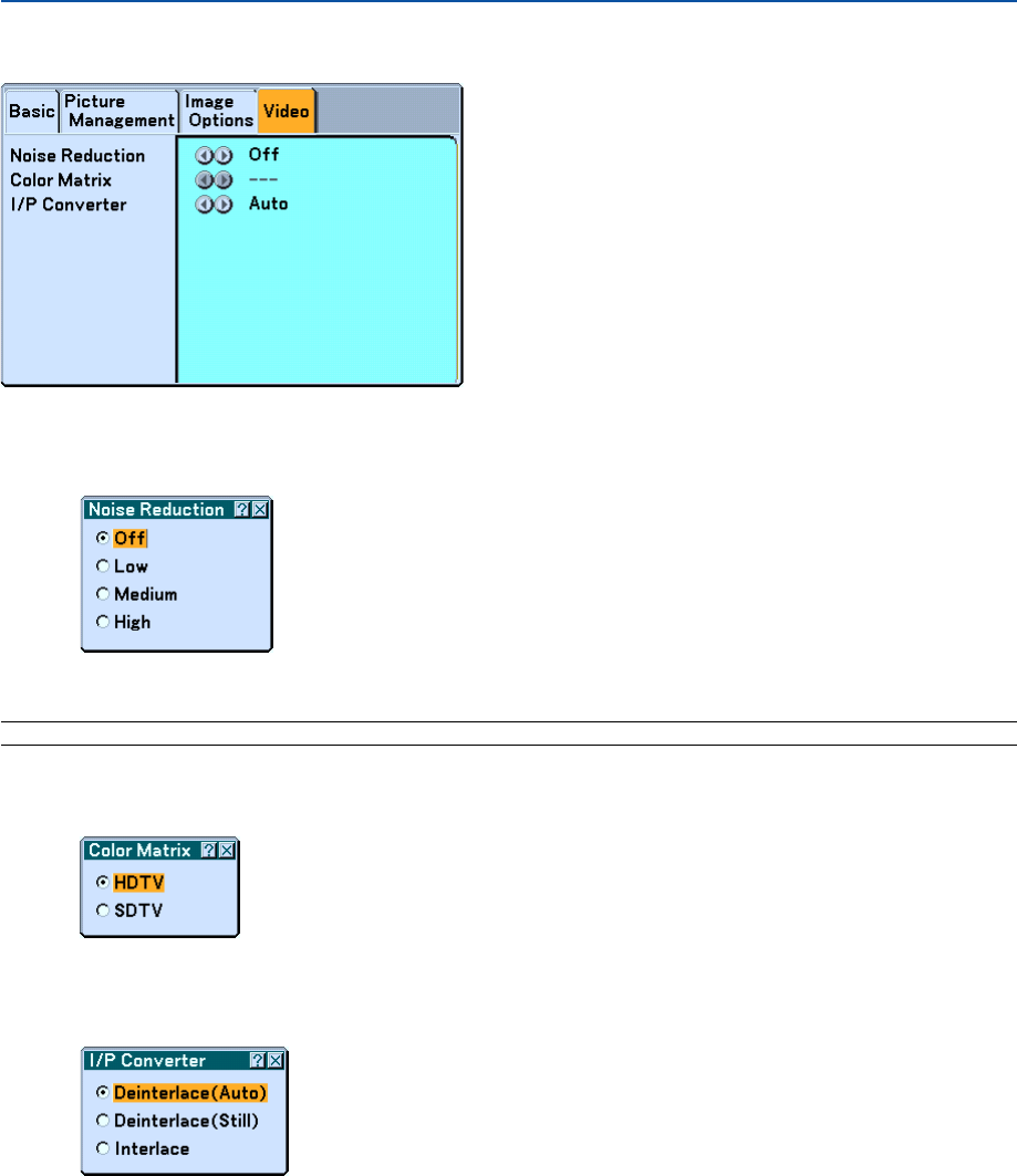
97
Video
Selecting Noise Reduction Level [Noise Reduction]
(not available for RGB, DVI digital, Viewer and LAN; available for TV standard inputs)
Select one of the three levels for reducing video noise: Low, Medium or High.
NOTE: The lower the Noise Reduction level, the better the image quality by way of higher video bandwidth.
Selecting Color Matrix [Color Matrix]
(not available for RGB, DVI digital, Viewer and LAN; available for TV standard inputs)
Select an appropriate color matrix for your input signal, either HDTV or SDTV.
Selecting Interlace or Deinterlace [I/P Converter]
This function allows you to select between "Interlace" and "Deinterlace".
Deinterlace (Auto) ....... The projector automatically determines a still or moving image to display a clear picture. If selecting
"Deinterlace (Auto)" causes excess jitter or artifacts, select "Interlace".
Deinterlace (Still) ......... Select when a still image is displayed. When this option is selected for a moving image, jitter or artifacts
can be seen.
Interlace ...................... Select when a moving image is displayed. This will eliminate jitter and artifacts in a moving image.
6. Using On-Screen Menu
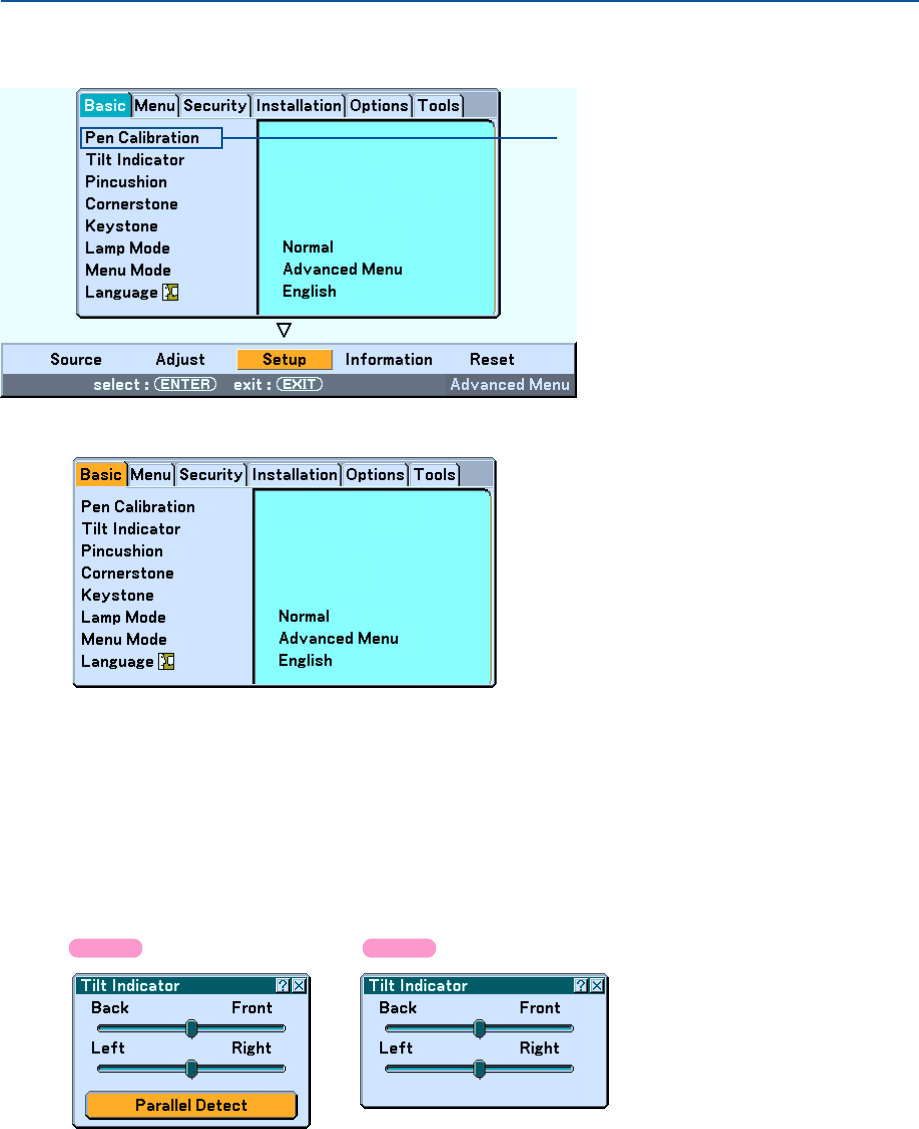
98
쐂 Menu Descriptions & Functions [Setup]
Basic
Pen Calibration (WT615 only)
Calibrate so that pen touches are properly detected by the sensor on the WT615.
Important
Before you use the electronic pen for the first time or when you have changed the position of the projector or the
screen size, be sure to use [Pen Calibration] to calibrate the electronic pen and the screen.
See “ Using the Electronic Pen (WT615 only)” on page 45 for more details.
Using Tilt Indicator [Tilt Indicator]
This option provides you with an indicator that will show you if the projector is level or not.
This is convenient when you are trying to get the projector level.
Use [Tilt Indicator] to place the projector level. For more information, see “ Adjusting the Position and Size of the
Projected Image (Focus Adjustment) on page 33.
The WT615 provides you with the parallel detection feature that helps you set up the projector parallel to the screen.
Tapping two points on the screen with the electronic pen will display the [Parallel Detect] screen. See page 36.
6. Using On-Screen Menu
WT615 only
WT615 WT610
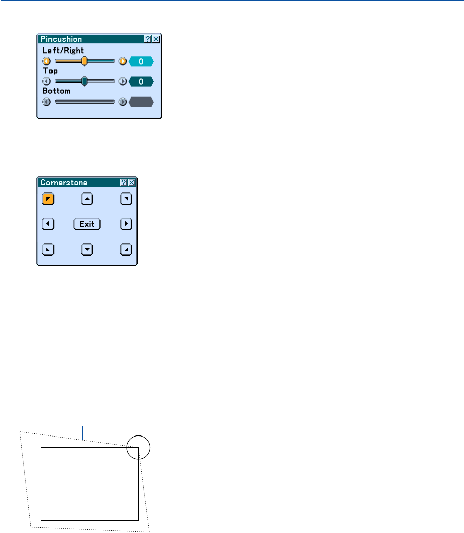
99
6. Using On-Screen Menu
Use the 3D Reform feature to correct (3D Reform correction) distortion to make the top or bottom and the left or right
side of the screen longer or shorter so that the projected image is rectangular.
Projected image
1. Press and hold the 3D REFORM button for a minimum of 2 seconds to reset current adjustments.
Current adjusments for “Pincushion”, “Cornerstone” or “Keystone” will be cleared.
2. Project an image so that the screen is smaller than the area of the raster.
3. Pick up any one of the corners and align the corner of the image with a corner of the screen.
The drawing shows the
upper right corner.
Screen
Selecting Cornerstone Mode [Cornerstone]
This option allows you to correct trapezoidal distortion.
Selecting this item will display the Cornerstone adjustment screen.
Correcting Pincushion Mode [Pincushion]
If the horizontal and vertical sides bend outwards, use [Pincushion] to correct the distortion. For more information, see
“ Adjusting Pincushion or Barrel Distortion [Pincushion]” on page 42.
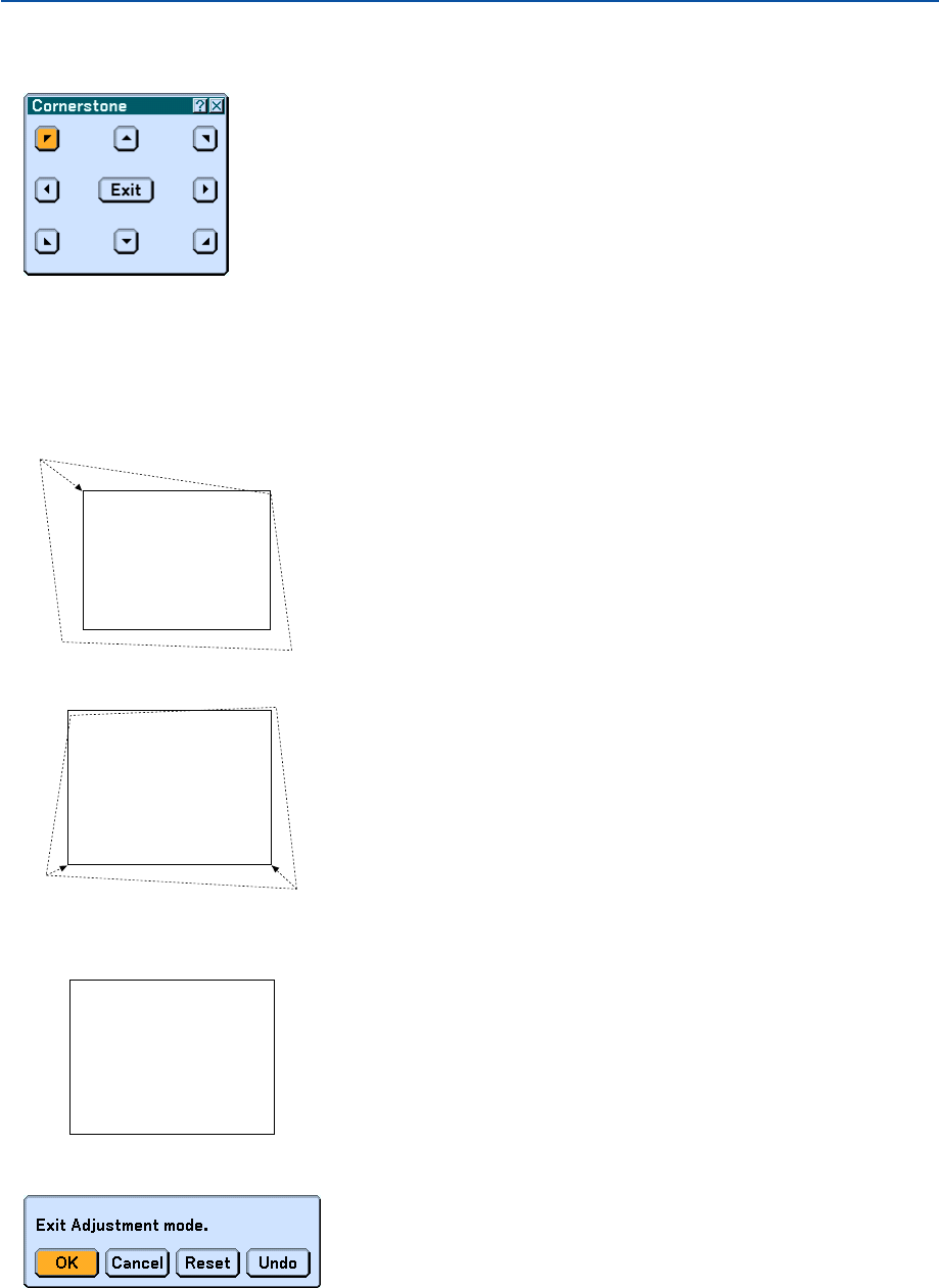
100
6. Using On-Screen Menu
Screen
Screen
8. Press the ENTER button.
Screen
9. Use the SELECT
왖왔왗
or
왘
button to select another icon which points in the direction.
On the Cornerstone adjustment screen, select “Exit” or press the EXIT button on the remote control.
The confirmation screen is displayed.
4. Press the 3D REFORM button on the remote control twice.
The Cornerstone adjustment screen is displayed.
5. Use the SELECT
왖왔왗
or
왘
button to select one icon which points in the direction you wish to move the
projected image frame.
6. Press the ENTER button.
7. Use the SELECT
왖왔왗
or
왘
button to move the projected image frame as shown on the example.
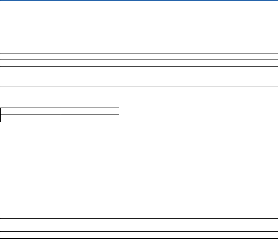
101
6. Using On-Screen Menu
*The following are conditions under which the maximum angle is achieved:
•Resolution is XGA
Higher resolution than XGA narrows the adjustable range.
•Menu items should be set as follows:
Aspect Ratio ........... 4:3
Screen Type............ 4:3
•Horizontal and Vertical are adjusted separately.
A combination of both adjustments narrows the adjustable range.
•When "4:3 Fill" is selected in Aspect Ratio, "Pincushion", "Cornerstone" and "Horizontal Keystone" are not avail-
able.
NOTE: If the Cornerstone screen is unavailable (grayed), press and hold the 3D REFORM button for a minimum of 2 seconds to
reset the current correction data. The Cornerstone function becomes available.
NOTE: The 3D Reform feature can cause an image to be slightly blurred because the correction is made electronically.
Horizontal
Max. +/– 5° approx.
Vertical
Max. -5° to 0° approx.
The adjustable ranges for 3D Reform are as follows:
10
.Press the SELECT
왗
or
왘
button to select the “OK” and press the ENTER button.
This completes the Cornerstone (3D Reform) correction.
Selecting “Cancel” will return to the adjustment screen without saving changes.
Selecting "Reset" will return to the factory default.
Selecting "Undo" will exit without saving changes.
NOTE: To reset the 3D Reform correction setting values, press and hold the 3D REFORM button for a minimum of 2 seconds.
NOTE: During 3D Reform adjustment, "Aspect Ratio" and "Screen" may not be available. Should this happen, first reset the 3D
Reform data and then do each setting. Second repeat the 3D Reform adjustment. Changing Aspect Ratio and/or Screen setting
can limit 3D Reform in its adjustable range.
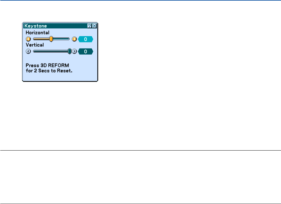
102
6. Using On-Screen Menu
Selecting Keystone Mode [Keystone]
This option allows you to correct keystone distortion manually.
Selecting this item will display the Keystone adjustment screen.
1. Press the SELECT
왗왘
button to adjust the horizontal keystone.
2. Press the SELECT
왖왔
button to select "Vertical".
3. Press the SELECT
왗왘
button to adjust the vertical keystone.
4. After completing, press the ENTER button. This will return to the menu screen.
NOTE:
•When "Resolution" is set to "Native", [Cornerstone], [Keystone] and [Pincushion] are not available.
•When any adjustment is made to the [Digital Zoom] or [Pincushion] option, the [Cornerstone] and [Keystone] options are not
available.
•To reset the 3D Reform correction setting values, press and hold the 3D REFORM button for a minimum of 2 seconds.
•Each time the 3D REFORM button is pressed, the item will change as follows: Pincushion
→
Cornerstone
→
Keystone
→
Pincushion
→
...
For information on “Cornerstone”, see “Selecting Cornerstone Mode [Cornerstone]” on page 99.
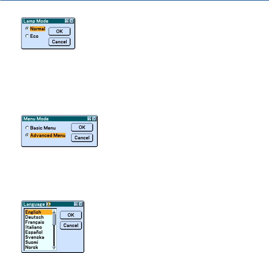
103
6. Using On-Screen Menu
Setting Lamp Mode to Normal or Eco [Lamp Mode]
This feature enables you to select two brightness modes of the lamp: Normal and Eco modes. The lamp life can be
extended up to 4000 hours by using the Eco mode. Selecting Eco mode decreases fan noise compared to in Normal
mode.
Normal Mode ........ This is the default setting (100% Brightness).
Eco Mode .............. Select this mode to increase the lamp life (75% Brightness).
Selecting Menu Mode [Menu Mode]
This feature allows you to select two menu modes: Basic Menu and Advanced Menu.
Basic Menu ........... This is the basic menu that contains minimum essentials of menus and commands.
Advanced Menu..... This is the menu that contains all the available menus and commands.
Selecting Menu Language [Language]
You can choose one of 21 languages for on-screen instructions.
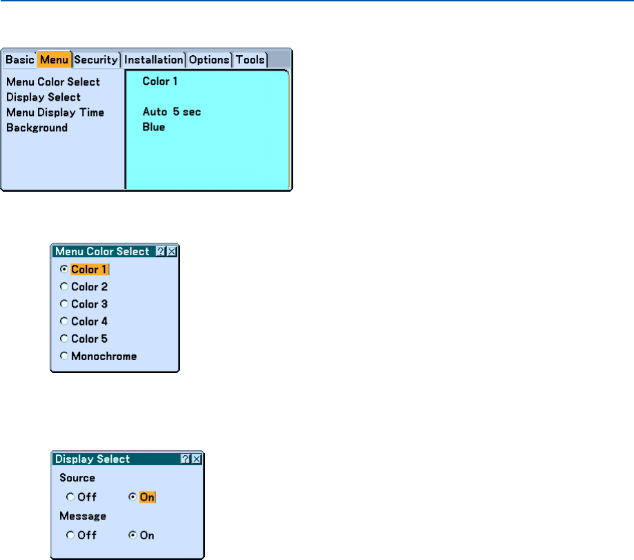
104
Menu
Selecting Menu Color [Menu Color Select]
You can choose a color for the menu.
Turning On / Off Source Display and Message [Display Select]
Source ................... This option turns on or off input name display such as Computer, DVI (DIGITAL/ANALOG), Video, and No
Input to be displayed in the top right corner of the screen.
Message ................ This option turns on and off messages. Even though selecting “Off”, the following message will appear.
* “The lamp has reached the end of its usable life. Please replace the lamp.” Press the EXIT button and the
message will disappear.
* “Projector is locked” When unlocking the projector security, the message will disappear.
6. Using On-Screen Menu
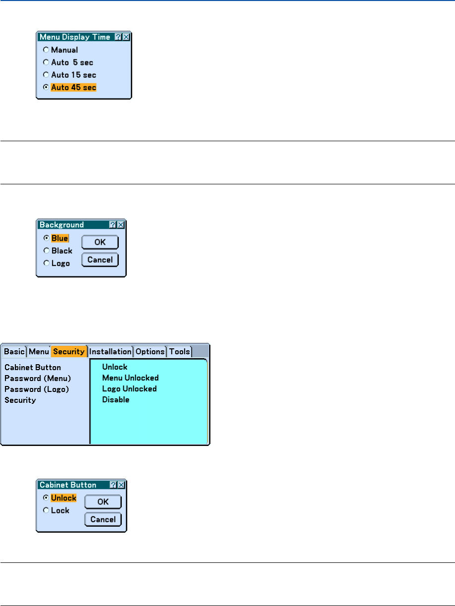
105
Selecting Menu Display Time [Menu Display Time]
This option allows you to select how long the projector waits after the last touch of a button to turn off the menu. The
preset choices are "Manual", "Auto 5 sec", "Auto 15 sec", and "Auto 45 sec". The "Auto 45 sec" is the factory preset.
NOTE:
•To display the last displayed menu again immediately after it is closed, press one of the MENU, the ENTER, the EXIT or the
SELECT
왖
or
왔
.
•The [Test Pattern] and [Tilt Indicator] screens will be displayed independent of the [Menu Display Time] setting.
Selecting a Color or Logo for Background [Background]
Use this feature to display a blue/black screen or logo when no signal is available. The default background is blue. You
can change the logo screen using the Viewer feature. See page 79.
Security
Disabling the Cabinet Buttons [Cabinet Button]
This option turns on or off the Cabinet Button Lock function.
NOTE:
•This Cabinet Button setting will not affect the remote control functions and the PC control function.
•When the cabinet buttons are locked, pressing and holding the EXIT button for about 10 seconds will change the setting to
unlock.
6. Using On-Screen Menu
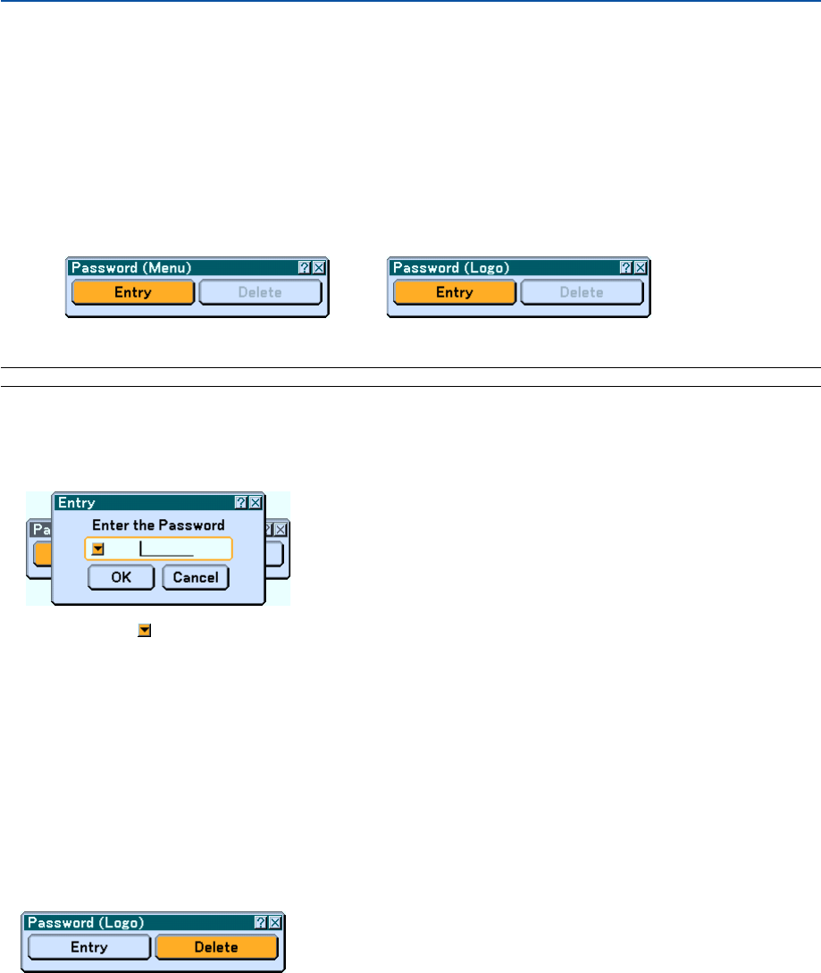
106
Setting a Password [Password (Menu)] / [Password (Logo)]
A password can be set for your projector to avoid operation by an unauthorized person.
When [Password (Menu)] is set, changing the menu from Basic to Advanced will display [Password (Menu)] input
screen.
When [Password (Logo)] is set, doing any one of the following two operations will display the Password input screen.
•Changing the background
•Changing the logo data in a PC card
Entry:
To assign your password:
NOTE: Up to 15 alphanumeric characters can be assigned.
1. Type a password.
Highlight "Entry" and press the ENTER button.
The "Enter the Password" screen will be displayed.
Make sure that is highlighted and then press the ENTER button.
The Software keyboard appears. Use the Software keyboard to type a password and then select "OK" on
the “Enter the Password” screen and press the ENTER button.
The [Confirm Password] screen will be displayed.
2. Type the same password again. Select "OK" on the “Enter the Password” screen and press the ENTER
button.
Your password will be assigned.
Delete:
To delete your password:
1. Select [Delete] and press the ENTER button. The "Current Password" screen will be displayed.
2. Use the Software keyboard to type your password. Select "OK" on the “Current Password” screen and
then press the ENTER button.
Your password will be deleted.
6. Using On-Screen Menu

107
Security
The Security function enables you to protect your projector so that the projector will not project a signal unless you
enter a keyword. There is also an option to lock the projector by using a registered PC card* as a protect key. Once you
have registered your PC card as a protect key, you are required to insert the registered PC card into the PC card slot
of the projector each time you turn on the projector. You can enable the Security function by using a keyword only.
*The projector does not support NTFS formatted flash memory card or USB memory device.
Be sure to use a flash memory card or USB memory device formatted with the FAT32, FAT16 or FAT file system.
To format your flash memory card or USB memory device in your computer, refer to the document or help file
that comes with your Windows.
Enable/Disable ....... This turns the Security function on or off.
Keyword ................ Enter an appropriate keyword when you use the Security function. (Up to 10 characters can be used.) The
Security function is available only when your keyword is entered.
Use Protect key ..... Check this box to lock your projector when using a PC card. To use a keyword without a PC card, do not
check this box.
Drive...................... Switches between PC Card slot and USB port (type A).
Read ...................... Reads data from a PC card.
Register ................. Registers data from the PC card. The Security function is not available unless at least one PC card is
registered. (if the “Use Protect key” check box is selected) Up to 5 PC cards can be registered.
Delete .................... Deletes data of a registered PC card.
To set up a keyword to enable the Security function without using a registered PC card.
1. Use the SELECT
왖
or
왔
button to select “Keyword” and use the software keyboard to enter a keyword.
NOTE: Please make a note of your keyword.
2. Use the SELECT
왖
or
왔
button to select “Enable” and use the SELECT
왖
or
왔
button to select “OK”,
then the Security function will be enabled.
An “Are you sure?” message will appear. Use the SELECT
왗
or
왘
button to select “Yes” and press the
ENTER button.
6. Using On-Screen Menu

108
The Security function takes effect.
To register a PC card as a protect key.
1. Insert a PC card into the PC card slot of the projector.
2. Use the SELECT
왖
or
왔
button to select "Use Protect Key" and press the ENTER button.
3. Use the SELECT
왖
or
왔
button to select "Read" and press the ENTER button.
Data of the PC card will be read into the projector.
4. Use the SELECT
왖
or
왔
button to select "Register" and press the ENTER button.
Downloaded data will be registered and be displayed in the list window.
5. Use the SELECT
왖
or
왔
button to select "Keyword" and use the software keyboard to enter a keyword.
NOTE: To use a PC card as a protect key, you must also set up a keyword. Please make a note of your keyword.
This completes registration of your PC card.
To enable Security, use the SELECT 왖 or 왔 button to select "Enable" and use the SELECT 왖 or 왔 button to select
"OK" and "Security function will be enabled. An “Are you sure?" message will appear. Use the SELECT 왗 or 왘 button
and press the ENTER button.
The Security function takes effect.
To turn on the projector when Security is enabled (when using your keyword only).
1. Press and hold the POWER button for a minimum of two seconds.
The projector will be turned on and display a message to the effect that the projector is security-pro-
tected.
2. Press the MENU button.
The Release Code input screen will be displayed.
3. Enter your keyword in the Release Code input screen.
You can view the projected image.
NOTE: Do not forget your keyword. However, if you forget your keyword, NEC or your dealer will provide you with your Release
Code. See more information at the end of this section.
6. Using On-Screen Menu

109
To turn on the projector when Security is enabled (when using PC card as a protect key).
1. Insert your registered PC card into the PC card slot.
2. Press and hold the POWER button for a minimum of two seconds.
The projector will turn on and then recognize the PC card. Once the image has been projected, it will
stay on without the PC card.
• The security disable mode is maintained until the main power is turned off (by setting the main power switch
to "O" or unplugging the power cord). In the following cases you will be asked to check the protect key or input
the keyword:
(1)When "OK" is selected at an image for which security is set and the power is turned off then back on
(2)When the main power is turned off then back on while the security function is enabled
(3)When you attempt to display an image for which security is set while the security function is enabled
•Blanks (spaces) cannot be used in the Keyword section.
To delete PC card data you registered.
1. Use the SELECT
왖
or
왔
button to select "Delete" and use the SELECT
왗
button to select the list win-
dow.
2. Use the SELECT
왖
or
왔
button to select the PC card data you wish to delete.
3. Press the SELECT
왘
button to select "Delete" and press the ENTER button.
The PC card data will be deleted.
If you've lost your registered PC card, proceed as follows:
NOTE: NEC or your dealer will provide you with your Release Code in exchange for your registered keyword and Request Code.
See more information at the end of this section.
1. Press and hold the POWER button for a minimum of two seconds.
The projector will be turned on and display a message to the effect that the projector is security-pro-
tected.
2. Press the MENU button.
The Release Code input screen will be displayed as well as your Request Code (24 alphanumeric
characters).
3. Enter your Release Code in the Release Code Input screen.
The projector will turn on.
*If the projector is turned on by entering the Release Code, your Security will be disabled.
NOTE:
•Some types of PC cards cannot be registered as your protect key.
•It is recommended that you register two or more PC cards in case you lose or damage your registered PC card.
• Formatting your registered PC card will disable your protect key function.
NOTE:
For additional information visit:
US : http://www.necvisualsystems.com
Europe : http://www.nec-europe.com
Global : http://www.nec-pj.com
6. Using On-Screen Menu
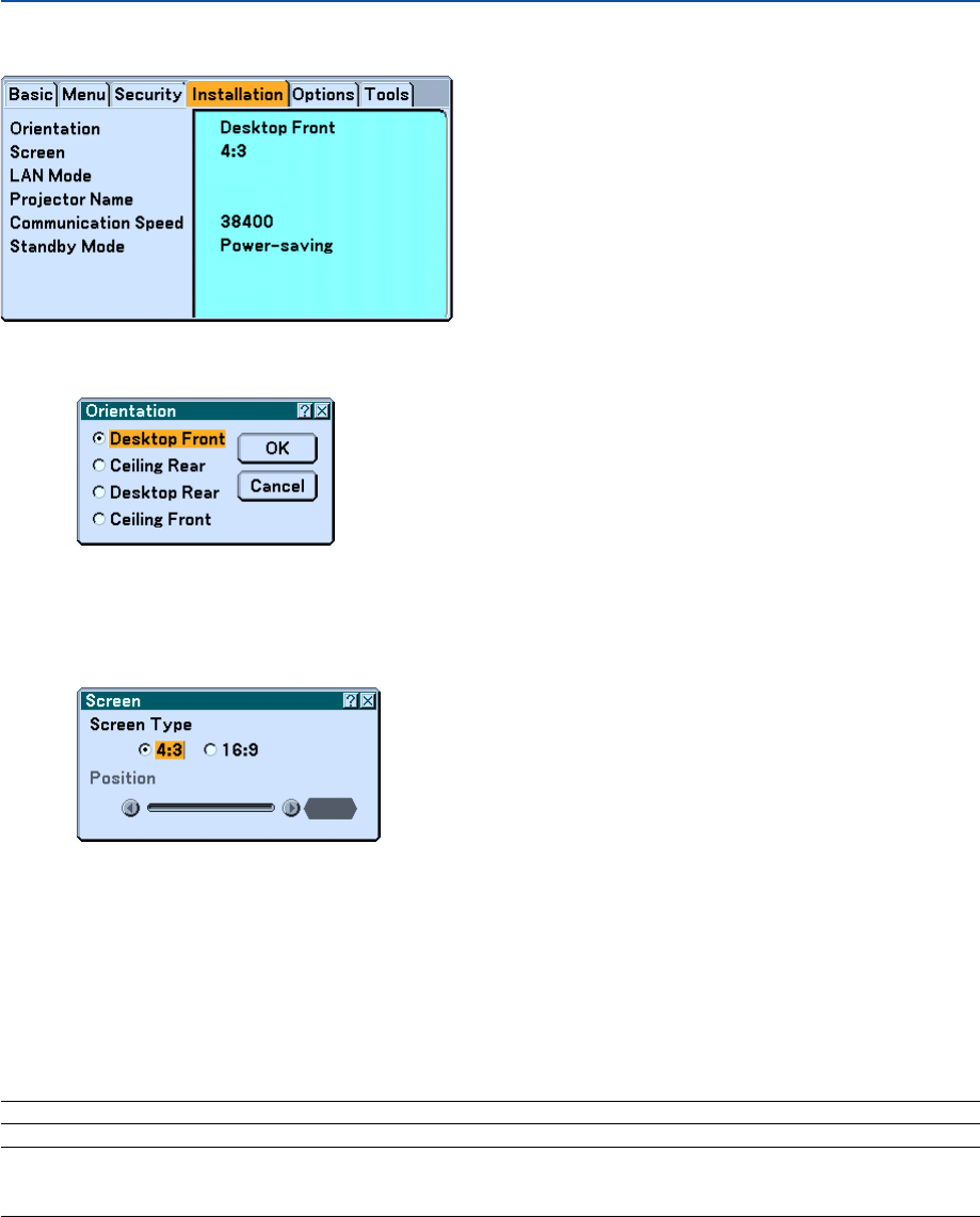
110
Installation
Selecting Projector Orientation [Orientation]
This reorients your image for your type of projection. The options are: desktop front projection, ceiling rear projection,
desktop rear projection, and ceiling front projection.
Selecting Aspect Ratio and Position for Screen [Screen]
Screen Type........... Select one of three options: 4:3 Screen or 16:9 Screen for the screen to be used. See also "Aspect Ratio" on
page 90.
Position ................. This feature allows you to adjust the vertical position of the image when 16:9 has been selected for the
screen type.
When 16:9 has been selected there is black area above and below the image. You can adjust the vertical
position of the image in these areas.
You can adjust the vertical position between top and bottom.
NOTE: This option is available only when “16:9” is selected in “Screen Type”.
NOTE: During 3D Reform adjustment, "Screen Type" and "Screen Position" may not be available. To make available, first reset the
3D Reform data and then do settings again. Secondly repeat the 3D Reform adjustment. Changing "Screen Type" and "Screen
Position" can limit 3D Reform in its adjustable range.
6. Using On-Screen Menu

111
[LAN Mode]
Setting LAN Mode
This feature allows you to set various setting items when the projector is used on your network.
CAUTION
•Consult with your network administrator about these settings.
•For wired LAN connection, use a commercially available wired LAN card and a LAN cable (Ethernet
cable). For more information on supported wired LAN cards for the NEC projectors, refer to the Service
Page for NEC Projectors (http://www.nec-pj.com).
•To use wired LAN, insert the wired LAN card into the PC Card slot.
See “Inserting and Removing a PC Card” on page 27.
•For wireless LAN connection, use the NEC optional wireless LAN card (NWL-100*).
* Last digit of the model code varies depending on which country you live in. For more information, visit
our Website.
US : http://www.necvisualsystems.com
Europe : http://www.neceurope.com
Global : http://www.nec-pj.com
•To use wireless LAN, insert the NEC optional wireless LAN card (NWL-100*) into the PC Card slot.
See "Inserting and Removing a PC Card” on page 27.
•Always insert or remove the LAN card when the main power is turned off. Failure to do so may cause
projector malfunction or damage to the LAN card. If the projector will not work correctly, turn off the
projector, wait 90 seconds, and turn it back on.
Hints on How to Set Up LAN Connection
To configure the projector to communicate on the network using the optional wireless LAN card:
1. Select the "Profile" tab for the optional wireless LAN card.
2. On the "Profile" tab, select a number from the "Profiles" list for your LAN settings.
Two settings can be stored in memory for each the wireless LAN card respectively.
3. On the "Profile" tab, turn on or off "DHCP", specify IP address, Subnet Mask, Gateway and DNS
Configuration. Select “OK” and press the ENTER button.
See page 113.
To recall the settings from memory:
After selecting the "Profile" tab, select the number from the "Profiles" list.
Select “OK” and press the ENTER button. See page 113.
To connect a DHCP server:
On the "Profile" tab, select "DHCP" and press the ENTER button. A check mark will be placed. Select again and
press the ENTER button. The check box will be cleared.
When setting an IP address without using a DHCP server, clear the check box for "DHCP". See page 113.
To set only for wireless LAN (Network Type and WEP):
1. On the "Profile" tab, select "Profiles" and then select "Profile 1" or "Profile 2".
2. On the "Profile" tab, select "Advanced” and press the ENTER button. The "Advanced" menu will be
displayed.
See page 114.
6. Using On-Screen Menu

112
To select a wireless LAN access point:
1. On the "Profile" tab, select "Profiles" and then select "Profile 1" or "Profile 2".
2. On the "Profile" tab, select "Advanced” and press the ENTER button.
3. On the Advanced menu, select "Network Type"
→
"Site Survey" and press the ENTER button.
4. Select "Mode" and then select "Infrastructure".
See pages 113 and 114.
To receive error messages or information on the remaining lamp life via e-mail:
1. On the "Mail" tab, select "Alert Mail" and press the ENTER button. A check mark will be placed.
2. Set "Sender's Address", "SMTP Server Name" and "Recipient's Address". Select “OK” and press the
ENTER button.
See page 117.
To execute "Easy Connection” using Image Express Utility 2.0:
The "Easy Connection" is a mode that can abbreviate the troublesome LAN settings when using the Image Ex-
press Utility 2.0 and connecting the PC and projector via a wireless LAN.
The Image Express Utility 2.0 is contained on the supplied User Supportware 2 CD-ROM. To use "Easy Connec-
tion", select "Profile" → "Profiles" → "Easy Connection". See page 113.
6. Using On-Screen Menu
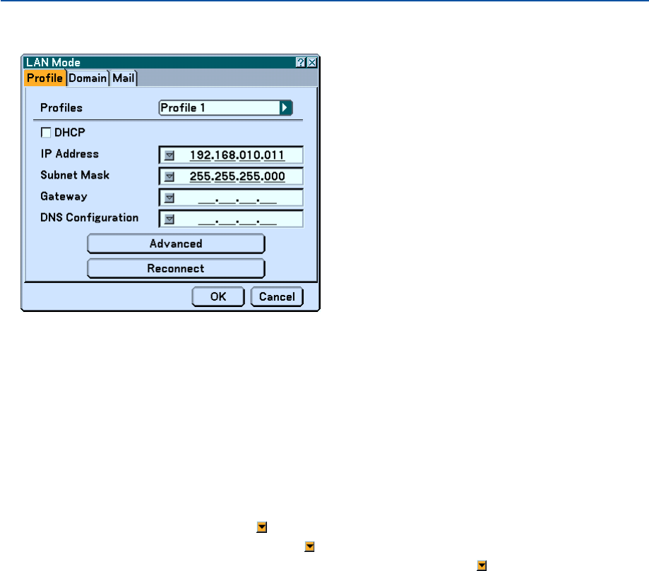
113
6. Using On-Screen Menu
Profile
Profiles (for PC Card):
To execute a wireless LAN easily using Image Express Utility 2.0, select “Easy Connection.
Up to two settings for the optional wireless LAN card can be stored in memory of the projector.
Select "Profile 1" or "Profile 2" and then do settings for "DHCP" and the other options.
After doing this, select “OK” and press the ENTER button. This will store your settings in memory.
DHCP:
Place a check mark to automatically assign an IP address to the projector from your DHCP server.
Clear this check box to register the IP address or subnet mask number obtained from your network administrator.
IP Address............. Set your IP address. Press to display the software keyboard and type in 12 numeric characters.
Subnet Mask ......... Set your subnet mask number. Press to display the software keyboard and type in 12 numeric characters.
Gateway ................ Set the default gateway of the network connected to the projector. Press to display the software keyboard
and type in 12 numeric characters.
DNS Configuration Type in the IP address of the DNS server on the network connected to the projector. Twelve numeric charac-
ters are used.
Advanced .............. Displays the Advanced menu which includes various setting for wireless LAN connection (Network Type
and WEP). See the Advanced menu later on.
Reconnect ............. Use this button to connect the projector to a network.
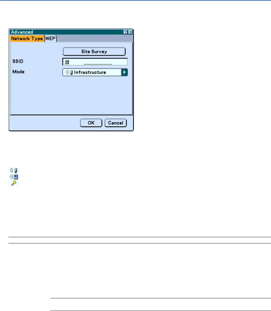
114
6. Using On-Screen Menu
Advanced menu
Network Type (required for wireless only)
Site Survey:
Displays a list of available SSIDs for wireless LAN on site. Select an SSID which you can access.
To select an SSID, highlight the SSID and use the SELECT 왘 to select “OK” and press the ENTER button.
: access point
: Ad Hoc PC
: WEP enabled
NOTE: You cannot connect to a device with the SSID for Channel 14 because it is not displayed in the list.
SSID (Network name):
Enter an identifier (SSID) for wireless LAN when selecting [Infrastructure] or [802.11 Ad Hoc] in [Mode]. Commu-
nication can be done only with equipment whose SSID matches SSID for your wireless LAN. Up to 32 alphanu-
meric characters can be used.
NOTE: To disable SSID, select a space (null) or "ANY"(All caps).
Mode:
Select communication method when using wireless LAN.
Infrastructure ........ Select this option when communicating with one or more equipment connected to the wireless or wired
LAN network via an access point.
802.11 Ad Hoc ...... Select this option when using the wireless LAN to directly communicate with a computer in peer-to-peer
mode. This is a method that meets the IEEE802.11 wireless standard.
NOTE: When in Ad Hoc mode, only 802.11b is available for communication method.
Data transmission speed in Ad Hoc mode is limited up to 11Mbps.
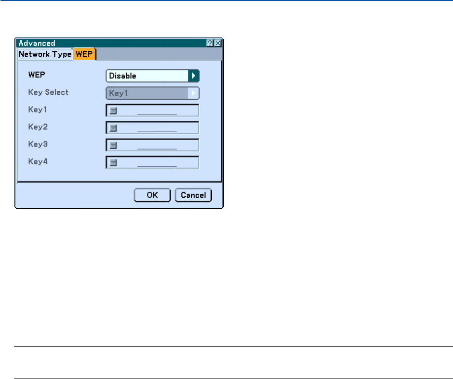
115
WEP (required for wireless only)
Select this option whether using the WEP (Wired Equivalent Privacy) key for encryption or not. To use encryption,
specify WEP key.
Disable .................. Will not turn on the encryption feature. Your communications may be monitored by someone.
64bit ...................... Uses 64-bit datalength for secure transmission.
128bit .................... Uses 128-bit datalength for secure transmission. This option will increase privacy and security when com-
pared to use of 64-bit datalength encryption.
152bit .................... Uses 152-bit datalength for secure transmission. This option will increase privacy and security when com-
pared to use of 128-bit datalength encryption.
NOTE:
•The WEP settings must be the same as communication devices such as PC or access point in your wireless network.
•When you use WEP, your image transmission speed will slow down.
Key Select:
Selects one key from the four keys below when selecting [64bit], [128bit] or [152bit] in [WEP].
Key1-4:
Enter encryption key when selecting [64bit], [128bit] or [152bit] in [WEP].
Up to 5 characters can be set in 64 bit, up to 13 characters in 128 bit and up to 16 characters in 152 bit. Press the
“HEX” button to change to “ASCII” to set the key in ASCII digit. You can toggle this button between “ASCII” and
“HEX”.
The key can also be set in hexadecimal digit.
*Enter 0X(numeral and alphabet respectively) right in front of your key code.
*Hexadecimal uses 0 to 9 and A to F.
*When setting in a hexadecimal digit, up to 10 characters can be set in 64 bit, up to 26 characters in 128 bit
and up to 32 characters in 152 bit.
6. Using On-Screen Menu
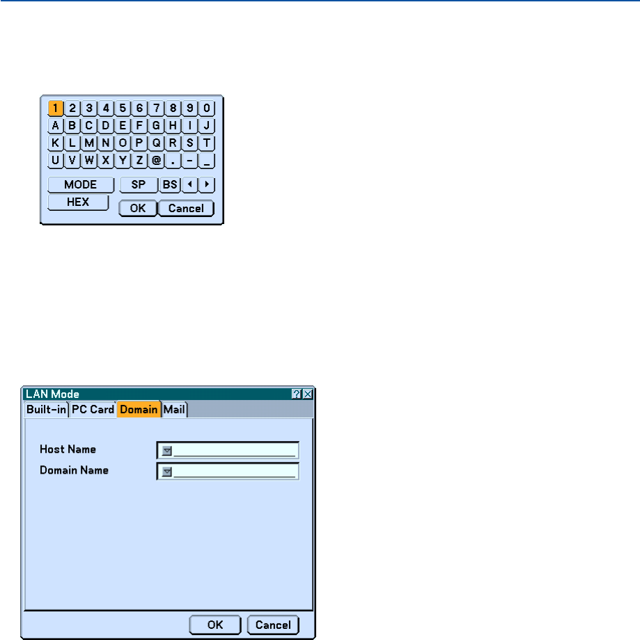
116
Using Software Keyboard to enter an encryption key
1. Select one of Key 1, Key 2, Key 3 and Key 4 and press the ENTER button.
The software keyboard will be displayed.
2. Use the SELECT
왖왔왗
or
왘
button to select one key and press the ENTER button.
3. After finishing entering the WEP key, use the SELECT
왖왔왗
or
왘
button to select [OK] and press the
ENTER button.
The software keyboard will disappear.
Domain
Host Name ............ Type in a hostname. Up to 60 alphanumeric characters can be used.
Domain Name ....... Type in domain name of the network connected to the projector. Up to 60 alphanumeric characters can be
used.
6. Using On-Screen Menu
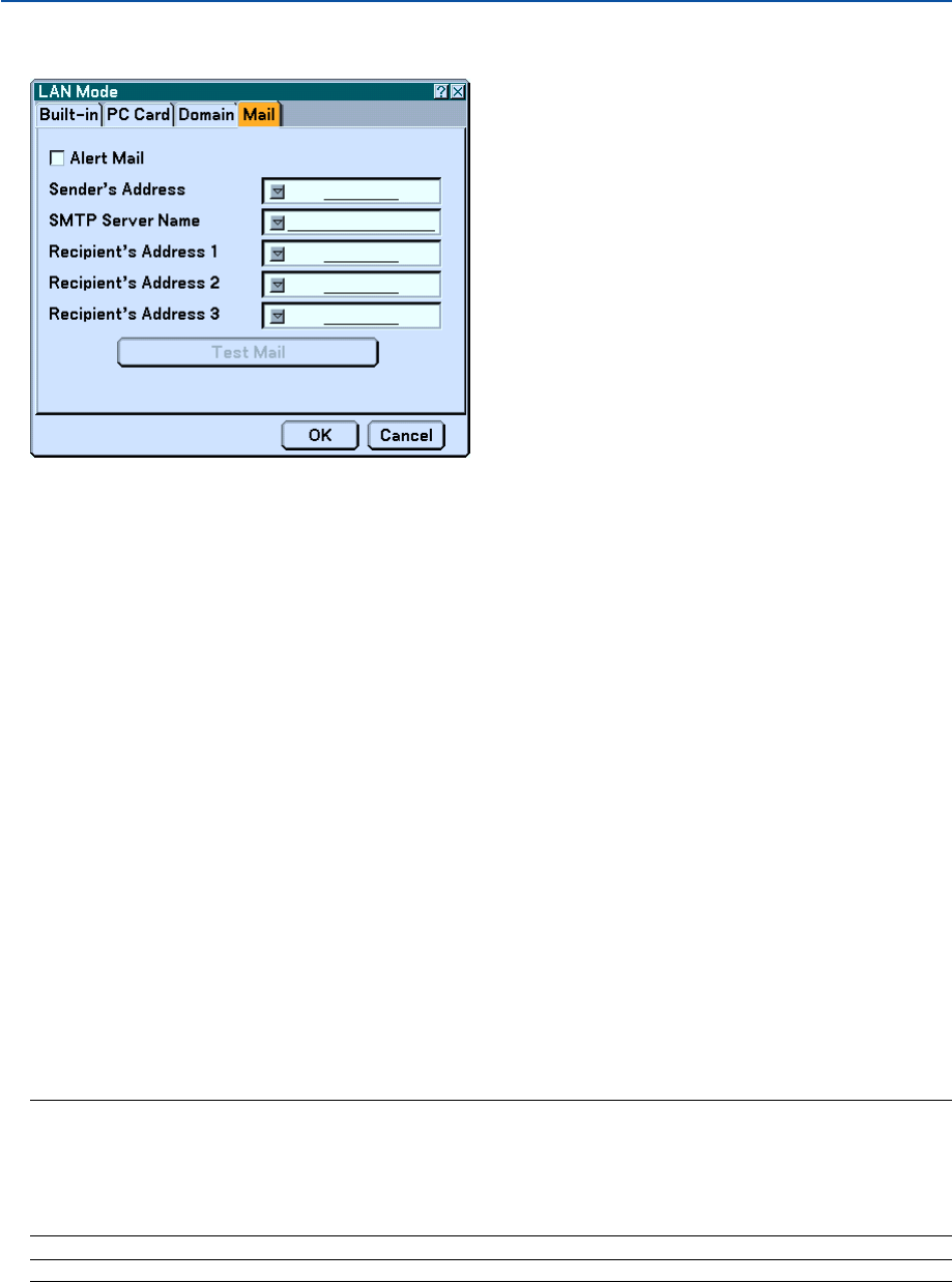
117
Mail
Alert Mail:
Checking this box enables Alert Mail feature.
This option notifies your computer of an error message via e-mail when using wireless or wired LAN. The error
message will be noticed when the projector lamp has reached the end of its usable life or an error occurs in the
projector.
Sample of a message sent from the projector:
The lamp is at the end of its usable life. Please replace the lamp.
Projector Name: X X X X
Lamp Hour Meter: xxxx [H]
Projector Usage: xxxxxx [H]
Sender's Address:
Specify the senders address. Use the Software keyboard. Up to 60 alphanumeric and symbols characters can be
used. See "Using Software Keyboard" in Appendix for more details.
SMTP Server Name:
Type in the SMTP server name to be connected to the projector. Up to 60 alphanumeric characters can be used.
Recipient's Address 1 to 3:
Type in your recipient's address. Up to 60 alphanumeric and symbols characters can be used.
Test Mail:
Send a test mail to check if your settings are correct.
NOTE:
• If you entered an incorrect address in a test, you may not receive an Alert mail. Should this happen, check if the Recipient's
Address is correctly set.
•Unless any one of the "Sender's Address", "SMTP Server's Name" or "Recipient's Address 1-3" is selected, "Test Mail" is not
available.
•Be sure to highlight “OK” and press the ENTER button before executing “Test Mail”.
NOTE: To use the Mail Alert feature on wireless LAN connection, select "Infrastructure" for "Mode" in "Network Type."
6. Using On-Screen Menu
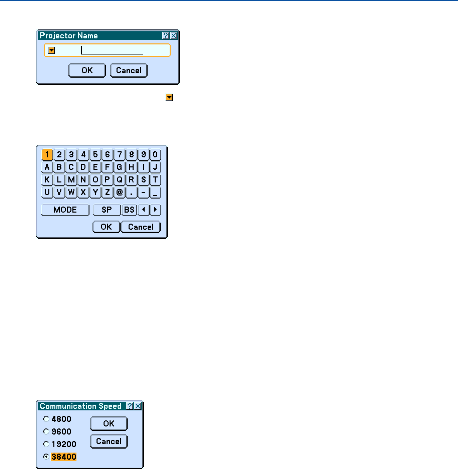
118
Specifying a Name for Your Projector [Projector Name]
Specify a unique projector name. Press to display the software keyboard and type in. Up to 16 alphanumeric
characters can be used. After entering a name, select “OK” and press the ENTER button.
Using Software Keyboard
1 to 0 and
Characters ....... Use to type in password or keyword.
MODE .................... Selects one of three modes for alphabet and special characters.
SP ......................... Inserts a space
BS ......................... Deletes one character backward
왗.......................... Returns to the previous
왘.......................... Advances to the next
OK ......................... Executes the selection
Cancel ................... Cancels the selection
Selecting Communication Speed [Communication Speed]
This feature sets the baud rate of the PC Control port (Mini DIN 8 Pin). It supports data rates from 4800 to 38400 bps.
The default is 38400 bps. Select the appropriate baud rate for your equipment to be connected (depending on the
equipment, a lower baud rate may be recommended for long cable runs).
6. Using On-Screen Menu
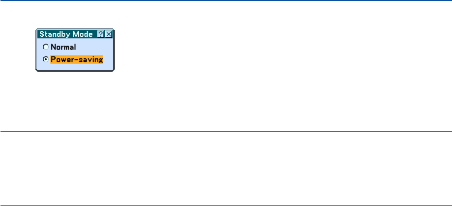
119
6. Using On-Screen Menu
Selecting Power-saving in Standby Mode
The projector has two standby modes: Normal and Power-saving.
Power-saving mode is the mode that allows you to put the projector in the power-saving condition which consumes
less power than the Normal mode. The projector is preset for Normal mode at the factory.
NOTE:
•The MONITOR OUT function is not available during Power-saving mode.
•Control through the PC Control connector and LAN mode is not available during Power-saving mode. For PC control and LAN
mode of the projector it is recommended to leave the projector in the Normal mode.
•Normal mode .................. Power indicator: Orange light/ Status indicator: Green light
Power-saving mode ........ Power indicator: Orange light/Status indicator: Off
See back page for a complete table of indicator messages.
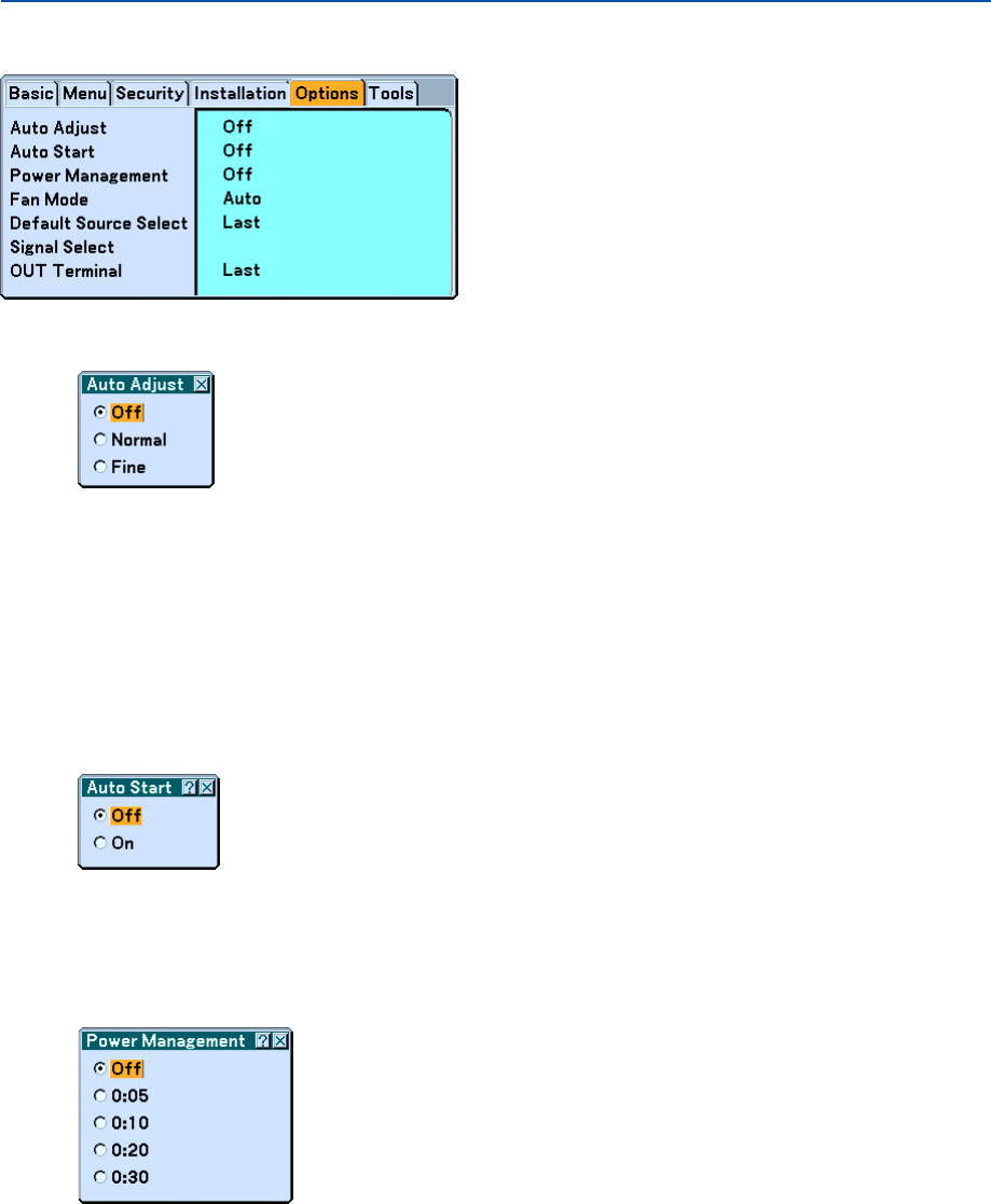
120
Options
Setting Auto Adjust [Auto Adjust]
This feature sets the Auto Adjust mode so that the RGB image can be automatically or manually adjusted for noise
and stability. You can automatically make adjustment in two ways: Normal and Fine.
Off ......................... The RGB image will not be automatically adjusted.
You can manually optimize the RGB image.
Normal .................. Default setting. The RGB image will be automatically adjusted. Normally select this option.
Fine ....................... Select this option if fine adjustment is needed. It takes more time to switch to the source than when "Normal"
is selected.
Enabling Auto Start [Auto Start]
Tur ns the projector on automatically when the power cable is inserted into an active power outlet and the main power
switch is turned on. This eliminates the need to always use the "Power" button on the remote control or projector
cabinet.
Enabling Power Management [Power Management]
When this option is selected you can enable the projector to automatically turn off (at the selected time) if there is no
signal received by any input.
6. Using On-Screen Menu
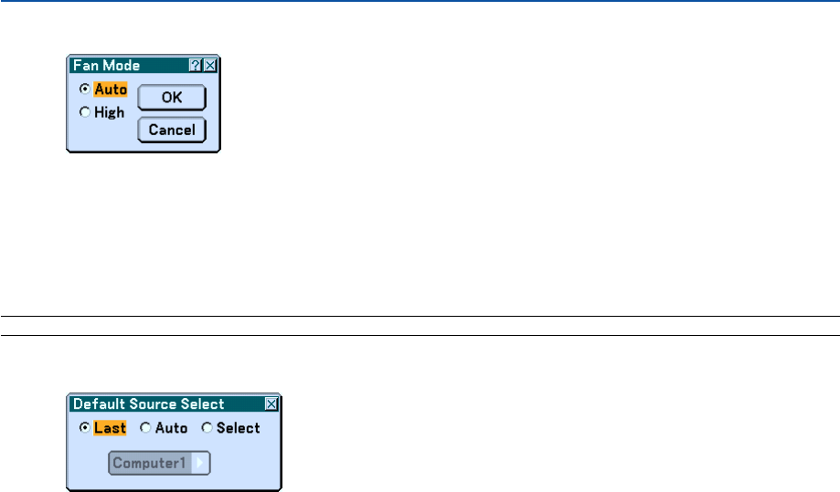
121
Enabling High Speed Fan Mode [Fan Mode]
This option allows you to select two modes for fan speed: Auto mode and High speed mode.
Auto ...................... The built-in fans automatically run at a variable speed according to the internal temperature.
High ...................... The built-in fans run at high speed.
When you wish to cool down the temperature inside the projector quickly, select “High”.
NOTE: Select “High” mode if you continue to use the projector for consecutive days.
Selecting Default Source [Default Source Select]:
You can set the projector to default to any one of its inputs each time
the projector is turned on.
Last ....................... Sets the projector to default to the previous or last active input each time the projector is turned on.
Auto ...................... Searches for an active source in order of Computer → DVI (DIGITAL) → DVI (ANALOG) → Video → S-
Video → Viewer → LAN → Computer and displays the first found source.
Select .................... Displays the selected source input every time the projector is started up. Select an input from the pull-down
menu.
6. Using On-Screen Menu
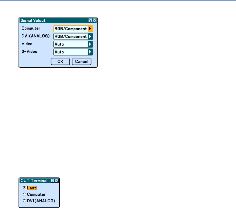
122
Selecting Signal Format [Signal Select]
Computer
Allows you to set "Computer" to automatically detect an incoming RGB or component source such as a computer
or DVD player. However there may be some RGB and component signals that the projector is
unable to detect. In this case, select "RGB" or "Component".
Select "Scart" in "Computer" for the European Scart signal.
DVI (ANALOG)
Allows you to choose “DVI (ANALOG)" for an RGB source such as a computer, or "Component" for a component
video source such as a DVD player. Normally select "RGB/ Component" and the projector automatically detects an
either incoming signal. However there may be some component signals that the projector is unable to detect. If this
is the case, select "Component".
Video and S-Video
This feature enables you to select video standards manually.
Normally select "Auto". Select the video standard from the pulldown menu. This must be done for Video and S-
Video separately.
Setting MONITOR OUT Connector [OUT Terminal]
This option allows you to determine which RGB or component source is output from the MONITOR OUT connector
during Standby mode.
Last ....................... The signal from the last COMPUTER or DVI-I input will be output to the MONITOR OUT connector.
Computer .............. The signal from the COMPUTER input will be output to the MONITOR OUT connector.
DVI(ANALOG)........ The signal from the DVI-I input will be output to the MONITOR OUT connector.
6. Using On-Screen Menu
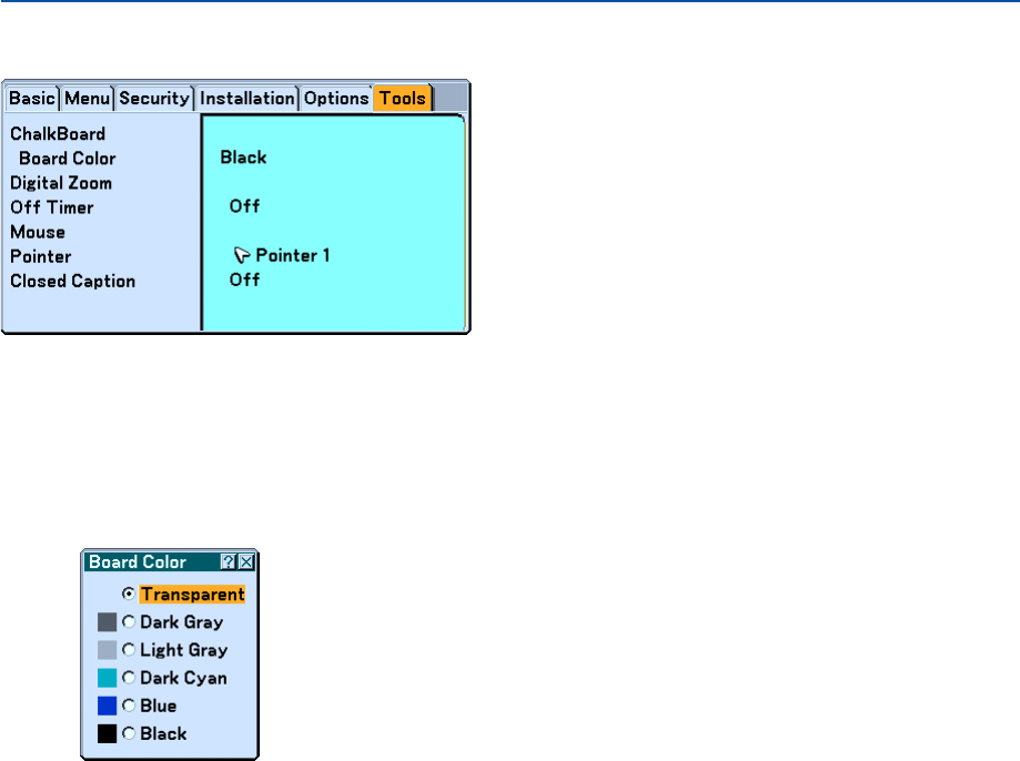
123
Tools
Selecting the ChalkBoard [ChalkBoard]
This option displays the ChalkBoard tool bar. The ChalkBoard function can also be used with the electronic pen on
WT615.
See page 47.
Selecting Board Color [Board Color]
This option allows you to select a board color of ChalkBoard.
6. Using On-Screen Menu
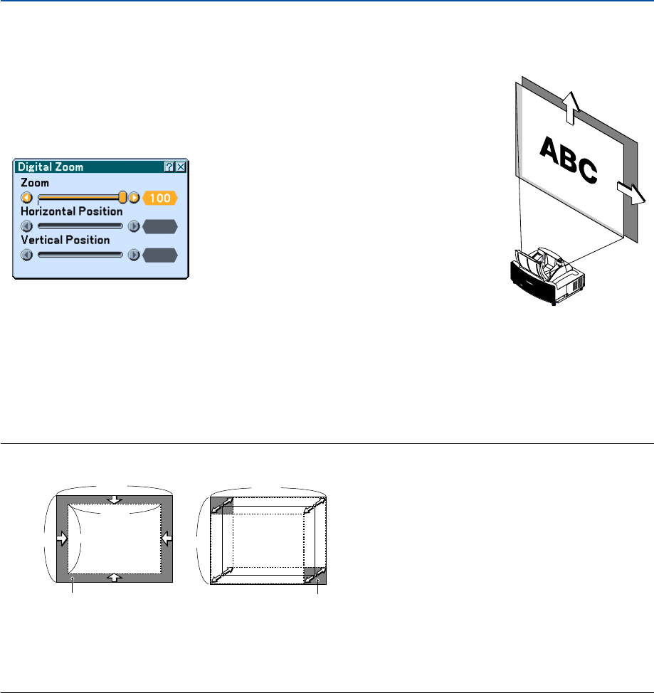
124
6. Using On-Screen Menu
NOTE:
•The “Horizontal/Vertical Position” option can be adjusted within a range of 100%.
Adjustable zoom area Movable area of displayed
image
100
%
100
%
80
%
80
%
100
%
100
%
•When any adjustment is made to the “Cornerstone” or “Keystone” option, the “Digital Zoom” option is not available.
* The Digital Zoom option may blur an image because the image is electronically compressed.
* The Digital Zoom option can reduce the image down to 80% of its original size while keeping aspect ratio the same as the
original.
Press the ZOOM button on the remote control to display the Digital Zoom
menu.
Use the SELECT
왖
or
왔
button to select the Zoom, Horizontal Position or
Vertical Position.
Zoom
You can reduce the image size between 80% and 100% using the ZOOM
button (+/–).
Horizontal Position
Use the SELECT
왗
or
왘
button to move the picture right or left.
Vertical Position
Use the SELECT
왗
or
왘
button to adjust the picture up or down.
Usng Digital Zoom [Digital Zoom]
This option allows you to reduce and move the projected image.
Selecting this item will display the Digital Zoom adjustment screen.
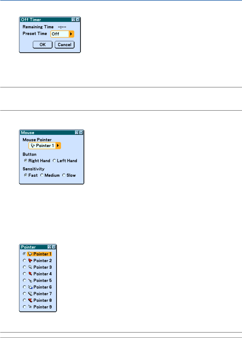
125
Using Off Timer [Off Timer]
1. Select your desired time between 30 minutes and 16 hours: Off, 0:30, 1:00, 2:00, 4:00, 8:00, 12:00, 16:00.
2. Select “OK” and press the ENTER button on the remote control.
3. The remaining time starts counting down.
4. The projector will turn off after the countdown is complete.
NOTE:
•To cancel the preset time, set "Off" for the preset time or turn off the power.
• When the remaining time reaches 3 minutes before the projector is turned off, the "Projector will turn off in 3 minutes"
message will be displayed on the bottom of the screen.
Setting Mouse Pointer, Button and Sensitivity [Mouse]
This option lets you to change your USB mouse settings. The mouse settings feature is available for USB mouse only.
Choose the settings you want:
Mouse Pointer ....... Pointer 1 - 9
Mouse Button ........ "Right Hand" or "Left Hand"
Mouse Sensitivity .. "Fast", "Medium" or "Slow"
Selecting Projecting Pointer Icon [Pointer]
This enables you to select from nine different Pointer icons for the "POINTER" button on your remote control.
After moving your Pointer icon to the area you want on the screen, press the MAGNIFY button on the remote control
to enlarge the selected area on the screen. See page 52 for more details.
NOTE: There may be cases where the Pointer function is not available (ex. A non-interlace signal at 15kHz such as video game.)
6. Using On-Screen Menu
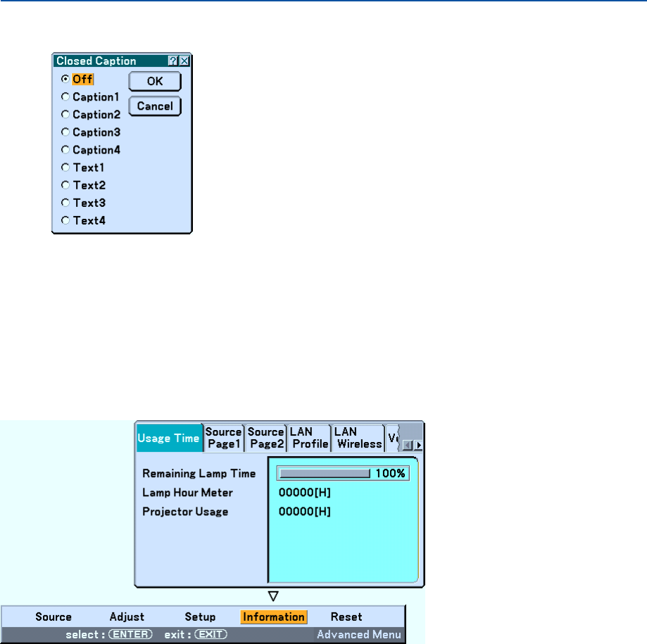
126
Setting Closed Caption [Closed Caption]
This option sets several closed caption modes that allows text
to be superimposed on the projected image.
Caption 1-4 ........... Text is superimposed.
Text 1-4 ................. Text is displayed in full screen.
Off ......................... This exits the closed caption mode.
쐆 Menu Descriptions & Functions [Information]
Displays the lamp and the projector usage hours, the status of the current signal and settings and LAN settings. This
dialog box has six pages.
The information included is shown on the following pages.
6. Using On-Screen Menu
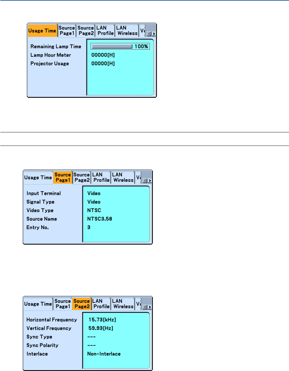
127
Usage Time
Remaining Lamp Time (%)
Lamp Hour Meter (H)
Projector Usage (H)
NOTE: The progress indicator shows the percentage of remaining lamp life. The value informs you of the amount of lamp and
projector usage respectively.
Source Page1
Input Terminal Signal Type
Video Type Source Name
Entry No.
Source Page2
Horizontal Frequency Vertical Frequency
Sync Type Sync Polarity
Interlace
6. Using On-Screen Menu
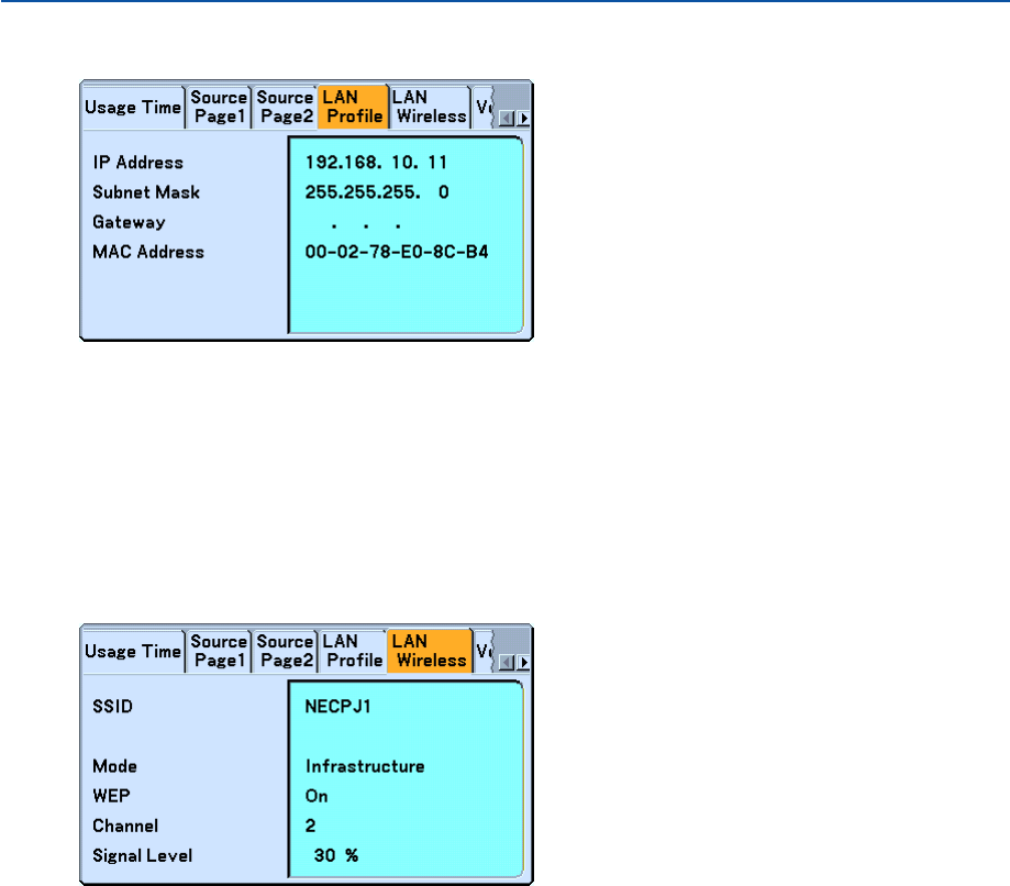
128
LAN Profile
This page shows information on settings for a LAN card.
IP Address............. Indicates the IP address of the projector when a LAN card is used.
Subnet Mask ......... Indicates the subnet mask of the projector when a LAN card is used.
Gateway ................ Indicates the gateway of the network connected to the projector when a LAN card is used.
MAC Address ........ Indicates the MAC address of a LAN card.
LAN Wireless
This page shows information on settings for the optional wireless LAN card.
SSID ...................... Indicates the identifier (SSID) for your wireless LAN.
Mode ..................... Indicates that "Infrastructure" or "802.11 Ad Hoc" is selected for your communication method
WEP ...................... Indicates your selected datalength encryption: On or Off
Channel ................. Indicates the channel you selected in the Site Survey. The channel must match for all wireless devices
communicating on your wireless LAN.
Signal Level ........... Indicates receiving condition of radio signal level while you are using a wireless LAN connection (Only when
PC Card is used)
6. Using On-Screen Menu
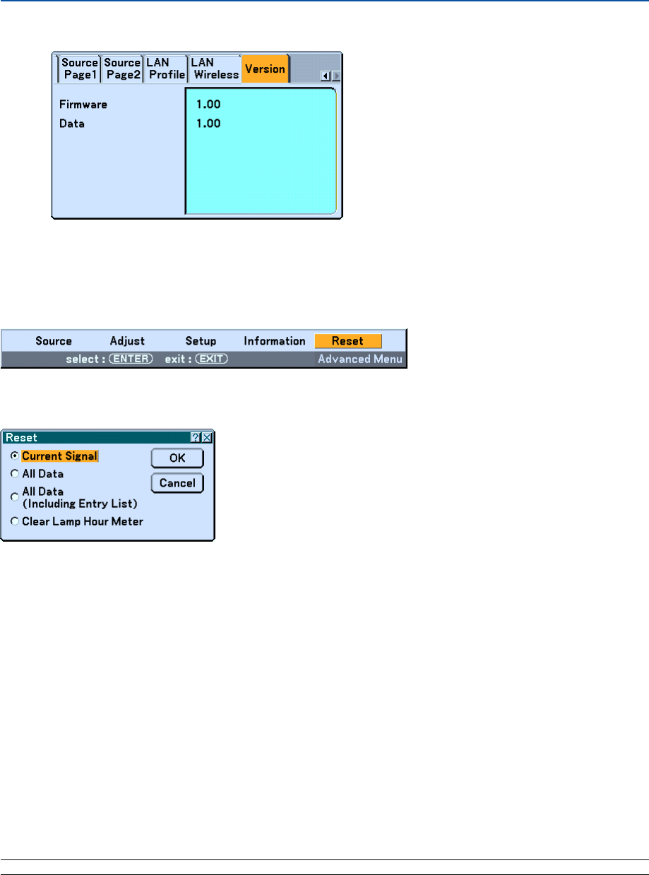
129
6. Using On-Screen Menu
Version
Firmware
Data
쐊 Menu Descriptions & Functions [Reset]
Returning to Factory Default
The Reset feature allows you to change adjustments and settings to the factory preset for sources by the following
methods:
[Current Signal]
Resets the adjustments for the current signal to the factory preset levels.
All the items in “Adjust (except “Wall Color”) can be reset.
[All Data]
Reset all the adjustments and settings for all the signals to the factory preset except Entry List, Pen Calibration
(WT615 only), Language, Background, Cabinet Button Lock, Password (Menu), Password (Logo), Security, LAN
Mode, Projector Name, Communication Speed, Standby Mode, Remaining Lamp Time, Lamp Hour Meter and
Projector Usage.
[All Data (Including Entry List)]
Reset all the adjustments and settings for all the signals to the factory preset except Pen Calibration (WT615 only),
Language, Background, Cabinet Button Lock, Password (Menu), Password (Logo), Security, LAN Mode, Projector
Name, Communication Speed, Standby Mode, Remaining Lamp Time, Lamp Hour Meter and Projector Usage.
Also deletes all the signals in the Entry List and returns to the factory preset.
NOTE: Locked signals in Entry List cannot be reset.

130
6. Using On-Screen Menu
Clearing Lamp Hour Meter [Clear Lamp Hour Meter]
Resets the lamp clock back to zero.
NOTE: The projector will turn off and go into standby mode after 2100 hours (up to 4100 hours in Eco mode) of service. In this
condition you cannot clear the lamp hour meter on the menu. If this happens, press the "HELP" button on the remote control for
ten seconds to reset the lamp clock back to zero. Do this only after replacing the lamp.

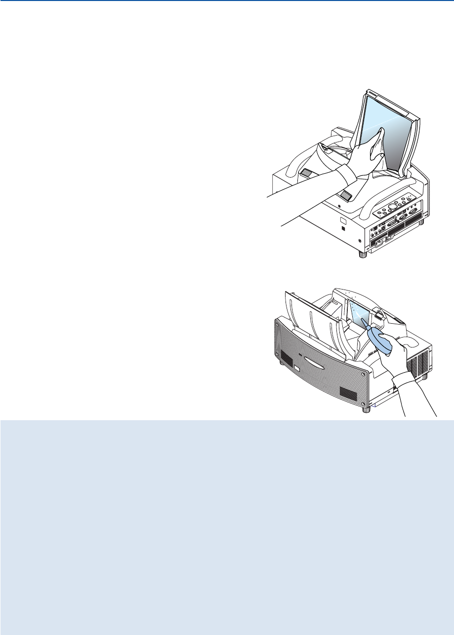
132
7. Maintenance
This section describes the simple maintenance procedures you should follow to replace the lamp, and to clean the
cabinet and the mirror.
POWER
ENTEER
MENU
SOURCE
FOCUS
PC CARD
EXIT
STATUS
LAMP
ON/
STAND BY
AUTO
ADJUST
3D
REFORM
SELECT
UNLOCK
MIRROR
LOCK
PC CARD
R-AUDIO IN-L/MONO
VIDEO IN S-VIDEO IN DVI-I IN
DVI-I
AUDIO IN AUDIO OUT
PCCONTROL
REMOTE
IN
COMPUTER IN MONITOR OUT
COMPUTER
USB
Handling and Care of Mirror Surface
If the projector is not to be used for an extended period of time, close the mirror cover.
This will protect the projector against dropping an object or gathering dust.
Consult with your dealer when using the projector exposed to smoke or dust.
Long-term exposure to sulfide can corrode the mirror surface.
If the mirror surface is soiled with fingers prints or dust, wipe them
off with the supplied cleaning cloth.
When removing sandy dust, use a blower to blow off dust or brush
it off softly and wipe the mirror surface with the supplied cleaning
cloth.
Cleaning the mirror face
Keep finger prints off the mirror surface. Do not scratch the
mirror surface with a hard or pointed object.
Leaving a defect in the mirror surface might cause an unwanted
shadow and poor picture quality.
UNLOCK
MIRROR
LOCK
• Do not blow your breath against the mirror surface, which can accidentally put your saliva on the mirror
surface.
Leaving foreign grease stains, oil-smudged finger prints or salt on the mirror surface can cause damage to
the reflective coating on the mirror surface.
Use only the supplied cleaning cloth to clean the mirror surface. Failure to do so can mar the mirror
surface.
•Do not force the cleaning cloth against the mirror surface or apply excessively strong pressure against it.
Do not scratch it with your nails while wiping off.
•Never use strong detergents or solvents such as thinner or benzene. Doing so can corrode the reflective
coating on the mirror surface.
If heavily soiled and wiping with the cleaning cloth will not work, use absolute alcohol. After the mirror
surface is dried, wipe it with the cleaning cloth again.
• If the supplied cleaning cloth is soiled, wash it. It is recommended you wash it every after two to three uses.
Do not allow long-term close contact with rubber or vinyl products because this could cause the reflective
coating of the mirror surface to deteriorate.
•Do not spray volatile substances such as insect repellent on the mirror surface.
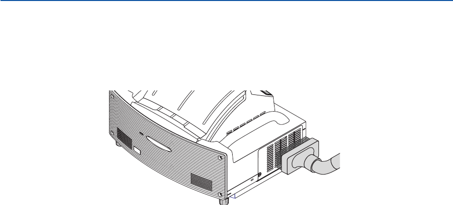
133
7. Maintenance
*The projector has a sensor which detects an object in front of the largest mirror or in the light path. If the sensor
detects any object, the projector will not turn on. If this happens while the projector is turned on, the image is
muted. In either case the STATUS indicator flashes in red.
*The projector has a temperature sensor which detects excessive heat. If the sensor detects heat in the bottom
of the mirror or in the light path, the projector will not turn on. If this happens while the projector is turned on, the
projector will turn off (the Standby mode). In either case the STATUS indicator flashes in red.
Cleaning the Cabinet
1. Turn off the projector before cleaning.
2. Clean the cabinet periodically with a damp cloth. If heavily soiled, use a mild detergent. Never use strong
detergents or solvents such as alcohol or thinner.
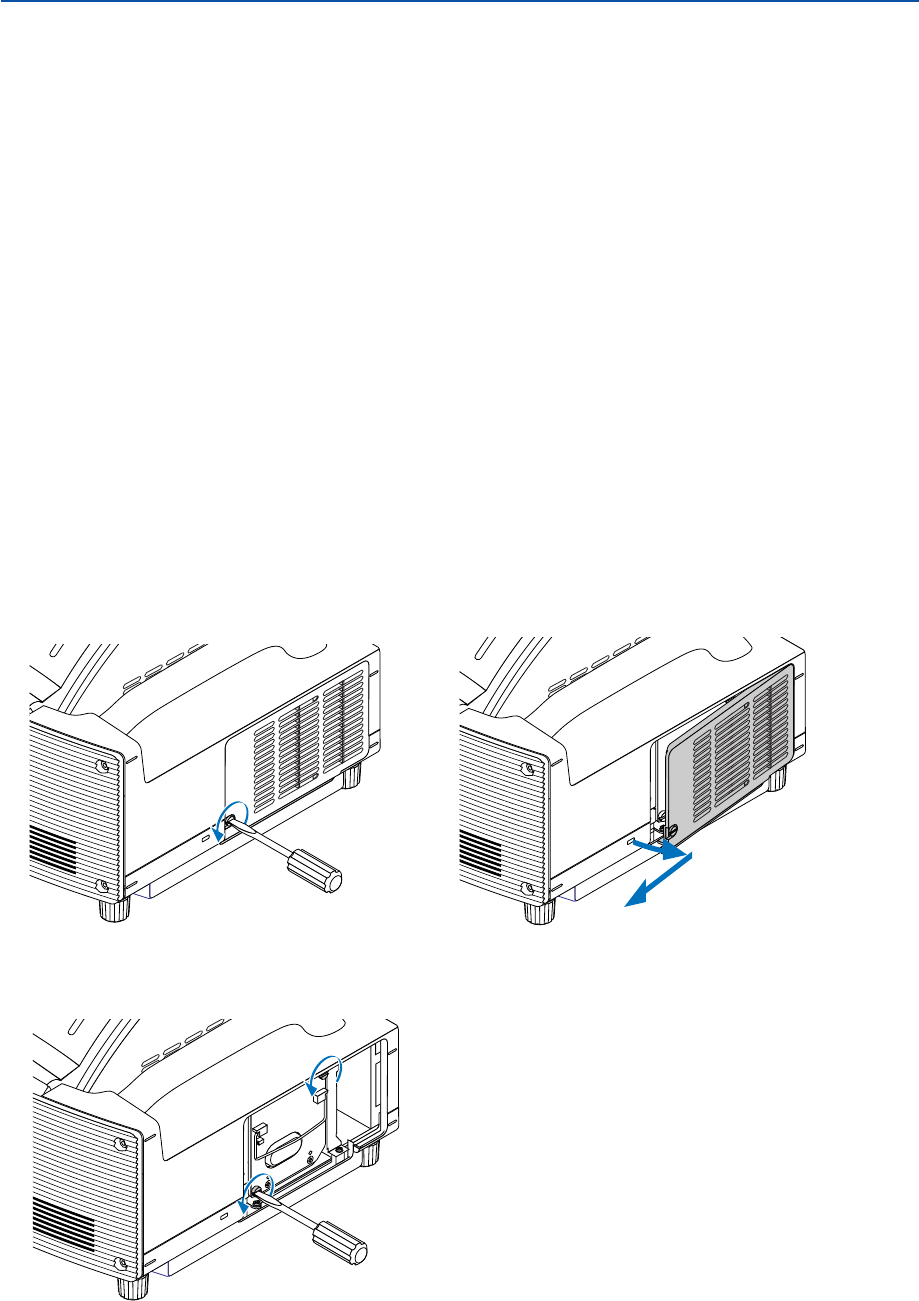
134
7. Maintenance
Replacing the Lamp
After your lamp has been operating for 2000 hours (up to 4000 hours : Eco mode) or longer, the "Lamp" indicator in the
cabinet will blink red and the message will appear. Even though the lamp may still be working, replace it at 2000 hours
(up to 4000 hours : Eco mode) to maintain optimal projector performance.
CAUTION
• DO NOT TOUCH THE LAMP immediately after it has been used. It will be extremely hot. Turn the projector off,
wait 90 seconds, turn off the main power switch, and then disconnect the power cable. Allow at least one hour
for the lamp to cool before handling.
• DO NOT REMOVE ANY SCREWS except the lamp cover screw and two lamp case screws. You could receive
an electric shock.
• Do not break the glass on the lamp housing.
Keep finger prints off the glass surface on the lamp housing. Leaving finger prints in the glass surface might
cause an unwanted shadow and poor picture quality.
•The projector will turn off and go into standby mode after 2100 hours (up to 4100 hours : Eco mode) of service.
If this happens, be sure to replace the lamp. If you continue to use the lamp after 2000 hours (up to 4000 hours :
Eco mode) of use, the lamp bulb may shatter, and pieces of glass may be scattered in the lamp housing. Do not
touch them as the pieces of glass may cause injury.
If this happens, contact your NEC dealer for lamp replacement.
To replace the lamp:
1. Loosen the lamp cover screw until the screwdriver goes into a freewheeling condition and remove the
lamp cover. The lamp cover screw is not removable.
2. Loosen the two screws securing the lamp housing until the screwdriver goes into a freewheeling
condition. The two screws are not removable.
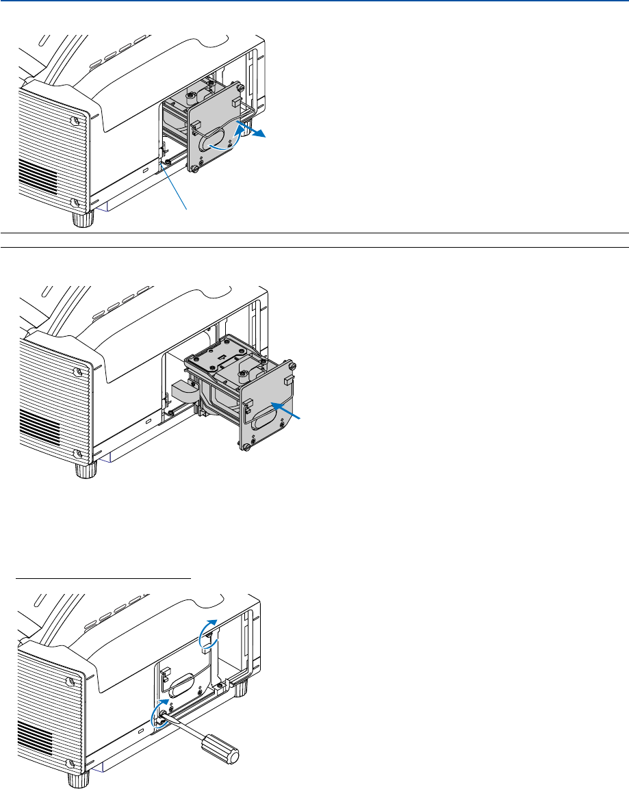
135
7. Maintenance
3. Remove the lamp housing by pulling out the handle.
NOTE: There is an interlock on this case to prevent the risk of electrical shock. Do not attempt to circumvent this interlock.
4. Insert a new lamp housing until the lamp housing is plugged into the socket.
CAUTION
Do not use a lamp other than the NEC replacement lamp (WT61LP).
5. Secure it in place with the two screws.
Be sure to tighten the screws.
Interlock
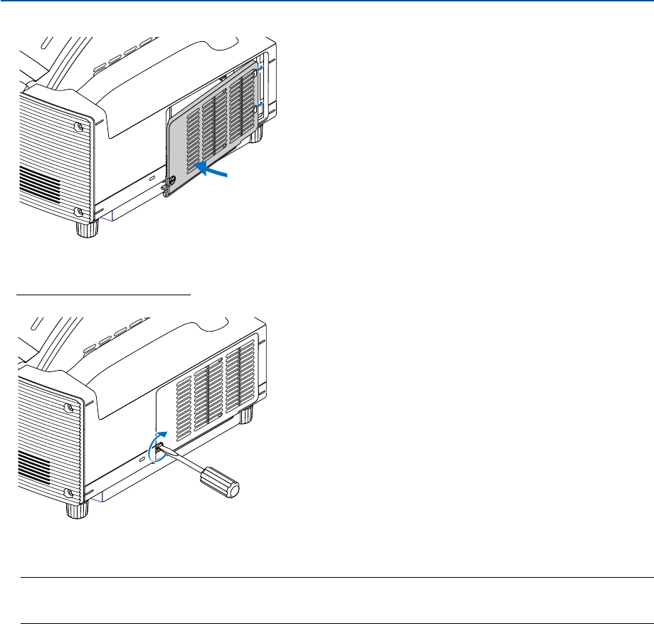
136
7. Maintenance
6. Reattach the lamp cover.
7. Tighten the lamp cover screw.
Be sure to tighten the screw.
8. After you install a new lamp, select the menu [Reset]
→
[Clear Lamp Hour Meter] to clear the Remaining
Lamp Time and the Lamp Hour Meter.
NOTE: When the lamp exceeds 2100 hours (up to 4100 hours in Eco mode) of service, the projector cannot turn on and the
menu is not displayed. If this happens, press the HELP button on the remote control for a minimum of 10 seconds while in
standby mode. When the lamp time clock is reset to zero, the LAMP indicator goes out.

137
8
Appendix
Troubleshooting ...................................................... 138
Specifications ......................................................... 142
Cabinet Dimensions ............................................... 144
Pin Assignments of D-Sub COMPUTER Input
Connector ............................................................ 145
Compatible Input Signal List ................................... 146
PC Control Codes and Cable Connection .............. 147
Using Software Keyboard ....................................... 148
Troubleshooting Check List ..................................... 149
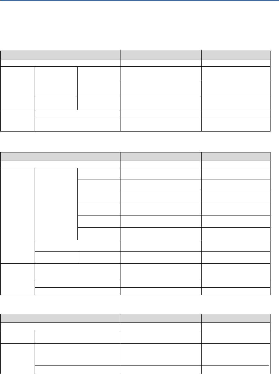
138
8. Appendix
Troubleshooting
This section helps you resolve problems you may encounter while setting up or using the projector.
Indicator Messages
POWER Indicator
Indicator Condition Projector Condition Note
Off
Blinking light
Steady light
Green
Orange
Green
Orange
0.5 sec On,
0.5 sec Off
2.5 sec On,
0.5 sec Off
0.5 sec On,
0.5 sec Off
The main power is off
The projector is getting ready to turn on.
Off Timer is activated.
The projector is cooling down.
The projector is turned on.
The projector is in Normal standby or
Power-saving standby mode.
–
Wait for a moment.
–
Wait for a moment.
–
–
STATUS Indicator
Indicator Condition Projector Condition Note
Off
Blinking light
Steady light
Red
Green
Orange
Orange
Red
Green
1 cycle (0.5 sec On,
2.5 sec Off)
2 cycle (0.5 sec On,
0.5 sec Of)
3 cycle (0.5 sec On,
0.5 sec Off)
4 cycle (0.5 sec On,
0.5 sec Off)
6 cycle (0.5 sec On,
0.5 sec Off)
1 cycle(0.5 sec On,
2.5 sec Off)
Normal
Lamp cover error
Temperature error
Temperature error due to dust
Power error
Fan error
Lamp error
Re-firing the lamp (The projector is cool-
ing down.)
Network conflict
Cabinet button is locked
A hand or an object blocks the light path.
The projector is in Normal standby mode.
–
Replace the lamp cover correctly.
(Page 136)
The projector is overheated. Move
the projector to a cooler location.
Remove dust in the light path.
Power unit will not work correctly.
Fans will not work correctly.
Lamp fails to light. Wait a full
minute and then turn on again.
The projector is re-firing. Wait for a
moment.
Network will not work correctly.
You have pressed cabinet button
when Cabinet Button is locked.
(Page 105)
Remove it from the light path.
–
LAMP Indicator
Indicator Condition Projector Condition Note
Off
Blinking light
Steady light
Normal
Lamp has reached its end of life. Lamp
replacement message will be displayed.
Lamp has been used beyond its limit. The
projector will not turn on until the lamp is
replaced.
Lamp mode is set to Eco mode
Red
Red
Green
–
Replace the lamp.
(Page 134)
Replace the lamp.
(Page 134)
–
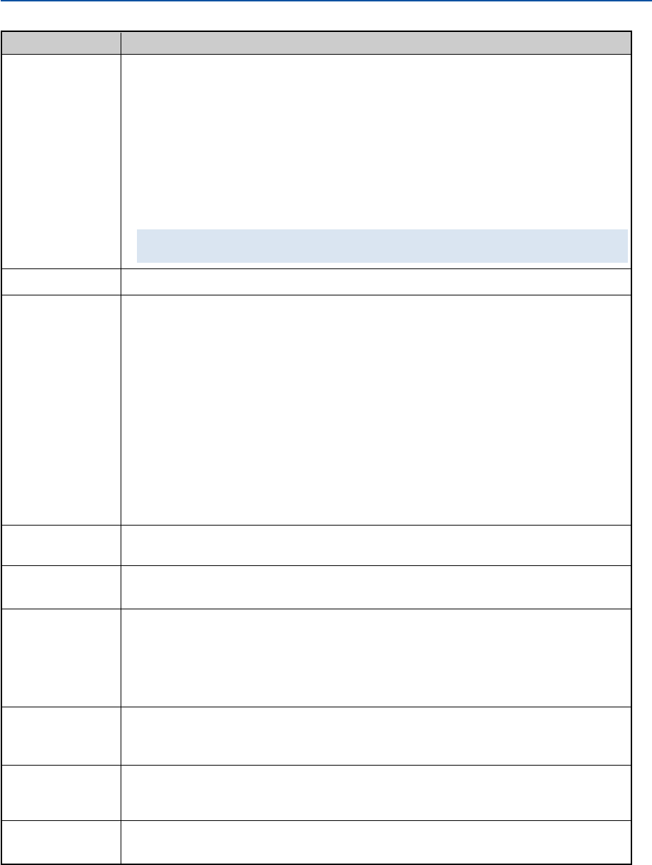
139
8. Appendix
Common Problems & Solutions (See also "Power/Status/Lamp Indicator" on page 138.)
Does not turn on
Will turn off
No picture
Color tone or hue is
unusual
Image isn’t square to
the screen
Picture is blurred
Image is scrolling
vertically, horizontally
or both
Remote control does
not work
Indicator is lit or
blinking
•Check that the power cable is plugged in and that the power button on the projector cabinet or the remote
control is on. See pages 29 and 31.
•Ensure that the lamp cover is installed correctly. See page 136.
•Check to see if the projector has overheated or the lamp usage exceeds 2100 hours (up to 4100 hours : Eco
mode). If there is insufficient ventilation around the projector or if the room where you’re presenting is par-
ticularly warm, move the projector to a cooler location.
• If you turn on the projector immediately after the lamp is turned off or when the temperature is high, the fans
run without displaying an image for some time and then the projector will display the image. Wait for a
moment.
•The lamp may fail to light. Wait a full minute and then turn on the power again.
• The lamp has reached the end of its usable life. Replace the lamp. See page 134.
After replacing the lamp, press and hold the HELP button on the remote control for a minimum of 10 seconds
to clear the lamp usage time. This will allow you to turn on the projector.
•Ensure that the Power Management is off. See page 120.
•Use the SOURCE button on the projector cabinet or the COMPUTER, VIDEO or VIEWER button on the remote
control to select your source. See page 40.
•Ensure your cables are connected properly.
•Use menus to adjust the brightness and contrast. See page 88.
•Open the mirror cover. See page 6.
•Reset the settings or adjustments to factory preset levels using the Reset in the Menu. See page 129.
•Enter your registered keyword if the Security function is enabled. See page 60.
•When using with a notebook PC, be sure to connect between the projector and the notebook PC before turning
on the power to the notebook PC. In most cases signal cannot be output from RGB output unless the notebook
PC is turned on after connecting with the projector.
*If the screen goes blank while using your remote control, it may be the result of the computer's screen-
saver or power management software.
*If you accidentally hit the POWER button on the remote control, wait 90 seconds and then press the POWER
button again to resume.
•See also the next page.
• Check if an appropriate color is selected in "Wall Color". If so, select an appropriate option. See page 89.
•Adjust "Hue" in "Adjust". See page 89.
•Reposition the projector to improve its angle to the screen. See page 33.
•Use the 3DReform function to correct the trapezoid distortion. See page 99.
•Adjust the focus. See page 35.
•Reposition the projector to improve its angle to the screen. See page 33.
•Ensure that the distance between the projector and screen is within the adjustment range of the lens. See page
16.
•Condensation may form on the mirror if the projector is cold, brought into a warm place and is then turned on.
Should this happen, let the projector stand until there is no condensation on the mirror.
•Use the SOURCE button on the projector cabinet or the COMPUTER, VIDEO or VIEWER button on the remote
control to select your source (Video, S-Video, Computer, Viewer or LAN). See page 40.
•Adjust the computer image manually with the “Clock”/“Phase” in “Adjust” → “Image Options”. See page 95.
•Install new batteries. See page 12.
•Make sure there are no obstacles between you and the projector.
• Stand within 22 feet (7 m) of the projector. See page 12.
•See the POWER/STATUS/LAMP Indicator on page 138.
Problem Check These Items

140
8. Appendix
Vertical stripes in RGB
mode
USB mouse does not
work
Electronic pen does
not work (WT615 only)
•Press the AUTO ADJUST button on the projector cabinet or the AUTO ADJ. button on the remote control. See
page 41.
•Adjust the computer image manually with the “Clock”/“Phase” in “Adjust” → “Image Options”. See page 95.
•Make sure that your USB mouse is properly connected to the projector.
The projector may not support some brands of a USB mouse.
•Check if you meet the requirements listed on page 13.
•Check if you have performed the pen calibration. When using the electronic pen for the first time, you need to
do so. See page 45.
•Make sure that you do not use the electronic pen in the following conditions. See page 18.
-Near a device such as a CRT monitor or a TV set.
- In a room with the ceiling and walls made of metal which is prone to reflect sound waves.
-In a noisy place or a place where loud sounds can be heard
-In direct sunlight or near an inverter fluorescent lamp.
- Near an air conditioner or air blower
•Make sure that you do not use two or more electronic pens at the same time in the same room. See page 18.
•Make sure that you do not use the electronic pens with two or more projectors at the same time in the same
room. See page 18.
•Check if you performed Pincushion correction, Cornerstone correction or Keystone correction. The electronic
pen will not work when you performed Cornerstone correction or Keystone correction. See page 18.
•Check if the battery has run down. If so, replace it with a new battery.
Problem Check These Items
For more information contact your dealer.

141
8. Appendix
If there is no picture, or the picture is not displayed correctly.
•Power on process for the projector and the PC.
Be sure to connect the RGB cable between the projector and the computer before turning on the computer.
There are some notebook PCs, which do not output signal unless there is a projector or monitor connected first.
NOTE: You can check the horizontal frequency of the current signal in the projector’s menu under Information. If it reads
“0kHz”, this means there is no signal being output from the computer. See page 127 or go to next step.
•Enabling the computer’s external display.
Displaying an image on the notebook PC’s screen does not necessarily mean it outputs a signal to the projec-
tor. When using a PC compatible laptop, a combination of function keys will enable/disable the external display.
Usually, the combination of the ‘Fn” key along with one of the 12 function keys gets the external display to come
on or off. For example, NEC laptops use Fn + F3, while Dell laptops use Fn + F8 key combinations to toggle
through external display selections.
•Non-standard signal output from the computer
If the output signal from a notebook PC is not an industry standard, the projected image may not be displayed
correctly. Should this happen, deactivate the notebook PC’s LCD screen when the projector display is in use.
Each notebook PC has a different way of deactivating/reactivating the local LCD screens as described in the
previous step. Refer to your computer’s documentation for detailed information.
•Image displayed is incorrect when using a Macintosh
When using a Macintosh with the projector, set the DIPswitch of the Mac adapter (not supplied with the projec-
tor) according to your resolution. After setting, restart your Macintosh for the changes to take affect.
For setting display modes other than those supported by your Macintosh and the projector, changing the DIP
switch on a Mac adapter may bounce an image slightly or may display nothing. Should this happen, set the DIP
switch to the 13” fixed mode and then restart your Macintosh. After that, restore the DIP switches to a
displayable mode and then restart the Macintosh again.
NOTE: A Video Adapter cable manufactured by Apple Computer is needed for a PowerBook which does not have a mini D-Sub
15-pin connector.
•Mirroring on a PowerBook
*When using the projector with a Macintosh PowerBook, output may not be set to 1024 x 768 unless “mirror-
ing” is off on your PowerBook. Refer to owner’s manual supplied with your Macintosh computer for mirroring.
•Folders or icons are hidden on the Macintosh screen
Folders or icons may not be seen on the screen. Should this happen, select [View] ->[Arrange] from the Apple
menu and arrange icons.

142
8. Appendix
Specifications
This section provides technical information about the WT615/WT610 DLP™ Projector's performance.
Model Number WT615/WT610
Optical
DMD™ 0.7" Single Chip Digital Micromirror Device (DMD™), aspect ratio 4:3
Resolution 1024 ⳯ 768 pixels* up to UXGA with Advanced AccuBlend
Mirror Aspherical mirror ⳯ 4
Lamp 275 W DC standard (210W Eco mode)
Image Size 40" - 100" (1.0 - 2.5 m) diagonal,
40" - 80" (1.0 - 2.0 m) with electronic pen
Projection Distance
2.52" - 25.94" / 64 - 659 mm (2.52" - 18.15" / 64 - 461 mm with electronic pen)
Projection Angle 55°
Electrical
Inputs 1 RGB (Mini D-Sub 15p), 1 DVI-I (HDCP** supported), 1 S-Video (Mini
DIN 4p), 1 Video, 1 PC Card, 2 Stereo Mini Audio, 1 (L/R) RCA Audio,
1 PC Control (Mini DIN 8p), 1 Remote Control
Outputs 1 RGB (Mini D-Sub 15p), 1 Stereo Mini Audio
USB Port 1 A Type, 1 B Type
Video Compatibility NTSC, NTSC4.43, PAL, PAL-60, PAL-N, PAL-M, SECAM, 1080i, 720p,
576p, 576i, 480p, 480i (w/optional cable)
Scan Rate Horizontal: 15 kHz to 100 kHz (RGB: 24 kHz or over)
Vertical: 48 Hz to 120 Hz
Video Bandwidth RGB: 100 MHz (-3dB)
Pixel Clock Freq Less than 135 MHz
Color Reproduction 16.7 million colors simultaneously, Full color
Horizontal Resolution NTSC / NTSC4.43/PAL / YCbCr: 540 TV lines
SECAM: 300 TV lines
RGB: 1024 dots (H) ⳯ 768 dots (V)
External Control PC CONTROL (Mini DIN 8 pin), IR, LAN (optional), USB
Sync Compatibility Separate Sync / Composite Sync / Sync on G
Built-in Speakers 1W ⳯ 2 (Stereo)
Power Requirement 100 - 240V AC, 50/60Hz
Input Current 3.9 - 1.7A
Power Consumption 370W in Lamp Normal mode
300W in Lamp Eco mode
12W in Normal Standby mode
0.6W in Power-saving Standby mode
* Effective pixels are more than 99.99%.
** What is HDCP/HDCP technology?
HDCP is an acronym for High-bandwidth Digital Content Protection. High bandwidth Digital Content
Protection (HDCP) is a system for preventing illegal copying of video data sent over a Digital Visual
Interface (DVI).
If you are unable to view material via the DVI input, this does not necessarily mean the projector is not
functioning properly. With the implementation of HDCP, there may be cases in which certain content is
protected with HDCP and might not be displayed due to the decision/intention of the HDCP community
(Digital Content Protection, LLC).

143
8. Appendix
Mechanical
Installation Orientation: Desktop/Front, Desktop/Rear, Ceiling/Front, Ceiling/Rear
Dimensions 15.0" (W) ⳯ 12.5" (H) ⳯ 12.3" (D) (with the mirror cover open)
15.0" (W) ⳯ 8.9" (H) ⳯ 11.7" (D) (with the mirror cover closed)
380 mm (W) ⳯ 318 mm (H) ⳯ 313 mm (D) (with the mirror cover open)
380 mm (W) ⳯ 227 mm (H) ⳯ 296 mm (D) (with the mirror cover closed)
Net Weight 14.1 lbs/6.4 kg
Environmental Considerations
Operational Temperatures : 41° to 95°F (5° to 35°C), 20% to 80% humidity
(non-condensing)
(Operational temperature for electronic pen: 59° to 95°F (15° to 35°C)
Storage Temperatures : 14° to 122°F (-10° to 50°C), 20% to 80% humidity
(non-condensing)
Regulations UL/C-UL Approved (UL 60950, CSA 60950)
Meets DOC Canada Class B requirements
Meets FCC Class B requirements
Meets AS/NZS CISPR.22 Class B
Meets EMC Directive (EN55022, EN55024, EN61000-3-2, EN61000-3-3)
Meets Low Voltage Directive (EN60950, TÜV GS Approved)
For additional information visit:
US : http://www.necvisualsystems.com
Europe : http://www.neceurope.com
Global : http://www.nec-pj.com
Digital Light Processing and DLP are trademarks of Texas Instruments.
The specifications are subject to change without notice.
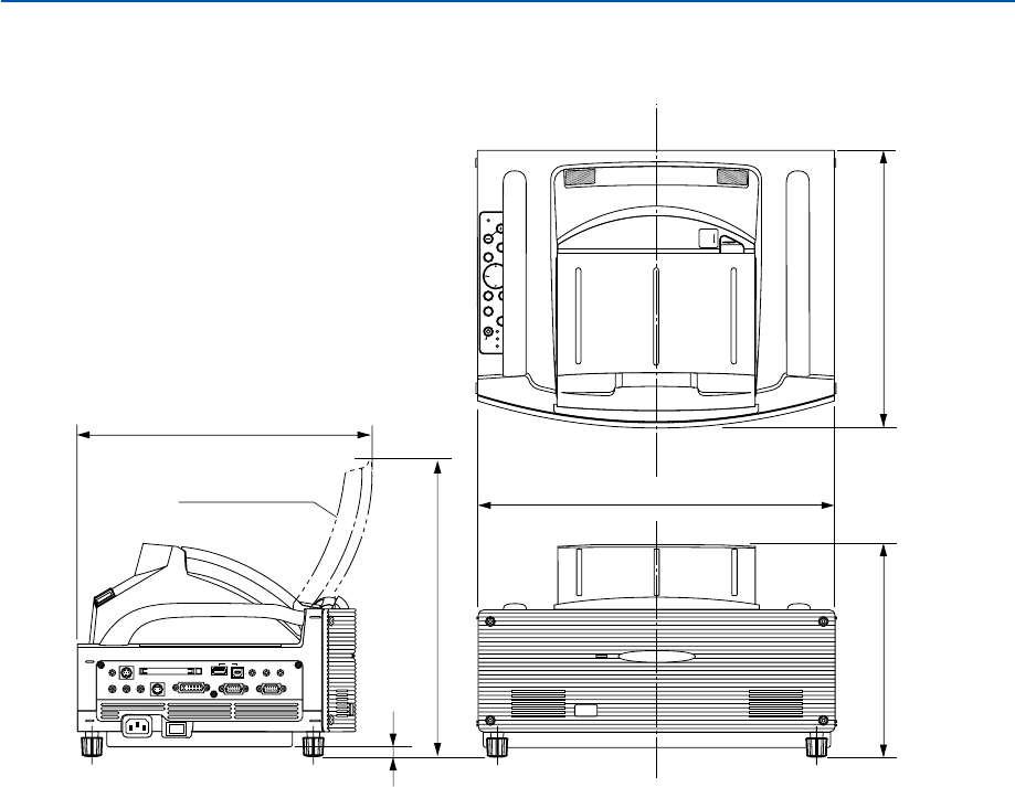
144
8. Appendix
Cabinet Dimensions
Unit: mm (inch)
POWER
ENTER
MENU
SOURCE
FOCUS
PC CARD
SELECT
EXIT
STATUS
LAMP
ON/
STAND BY
AUTO
ADJUST
3D
REFORM
380 (15.0)
313 (12.3)
318 (12.5)
296 (11.7)
227 (8.9)
10.6 (0.42)
UNLOCK
MIRROR
LOCK
PC CARD
AUDIO IN
RL
/MONO
VIDEO IN S-VIDEO IN DVI-I IN COMPUTER IN MONITOR OUT
DVI-I RGB
AUDIO INUSB AUDIO OUT
PCCONTROL
REMOTE
IN
With mirror cover open
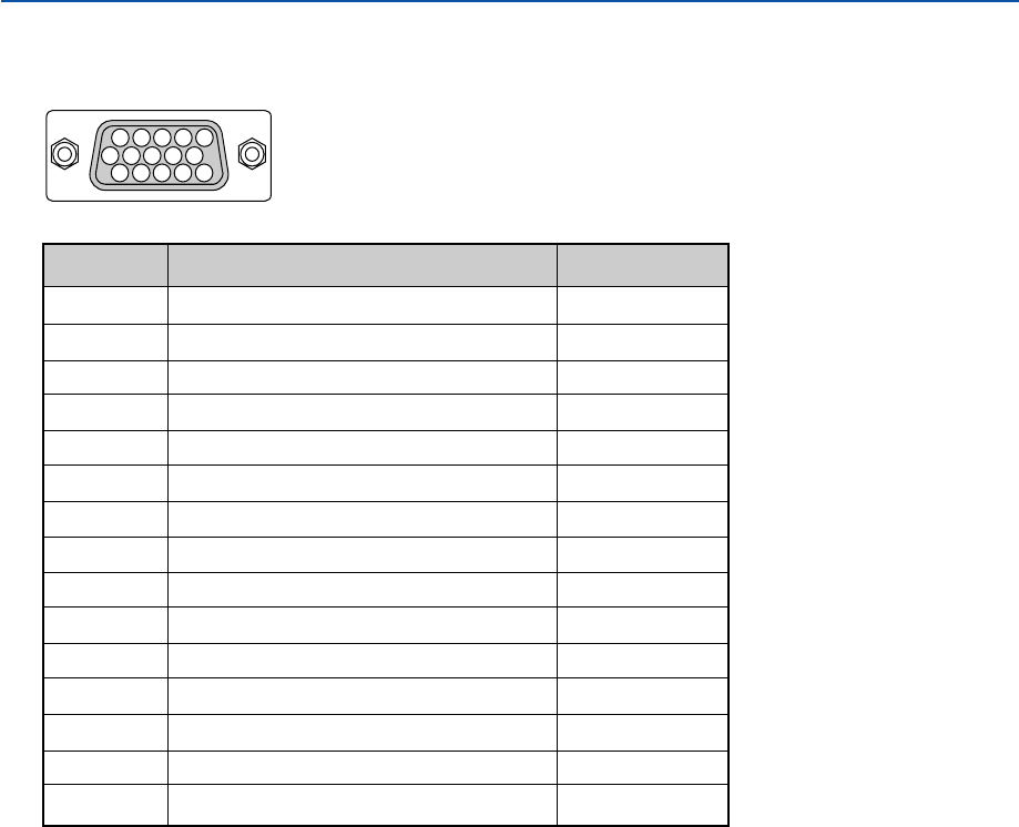
145
Mini D-Sub 15 Pin Connector
Pin Assignments of D-Sub COMPUTER Input Connector
Signal Level
Video signal : 0.7Vp-p (Analog)
Sync signal : TTL level
11 12 13 14 15
678910
12345
8. Appendix
Pin No. RGB Signal (Analog) YCbCr Signal
1Red Cr
2Green or Sync on Green Y
3Blue Cb
4Ground
5Ground
6Red Ground Cr Ground
7Green Ground Y Ground
8Blue Ground Cb Ground
9No Connection
10 Sync Signal Ground
11 SCART Sync
12 Bi-directional DATA (SDA)*
13 Horizontal Sync or Composite Sync
14 Vertical Sync
15 Data Clock*
* DDC2 supported

146
8. Appendix
Compatible Input Signal List
Signal Resolution Frequency H. Refresh Rate Dot Clock
( Dots ) ( kHz ) ( Hz ) ( MHz )
#: Images in above flagged with # are compressed with Advanced AccuBlend.
D: Images above flagged with “D” are supported by digital signal.
NOTE: Some composite sync signals may not be displayed correctly.
Signals other than those specified in the table above may not be displayed correctly. If this should happen, change the refresh
rate or resolution on your PC. Refer to Display Properties help section of your PC for procedures.
UXGA (1600
⳯
1200) is supported for separate sync signal only.
NTSC – 15.734 60 –
PAL–15.625 50 –
SECAM – 15.625 50 –
DVESA 640 ⳯480 31.47 59.94 25.175
IBM 640 ⳯480 31.47 60 25.175
MAC 640 ⳯480 31.47 60 25.175
MAC 640 ⳯480 34.97 66.67 31.334
MAC 640 ⳯480 35 66.67 30.24
DVESA 640 ⳯480 37.86 72.81 31.5
DVESA 640 ⳯480 37.5 75 31.5
IBM 640 ⳯480 39.375 75 31.49
DVESA 640 ⳯480 43.269 85.01 36
IBM 720 ⳯350 31.469 70.09 28.322
DVESA 720 ⳯400 37.927 85.04 35.5
IBM 720 ⳯350 39.44 87.85 35.5
IBM 720 ⳯400 39.44 87.85 35.5
DVESA 800 ⳯600 35.16 56.25 36
DVESA 800 ⳯600 37.879 60.32 40
DVESA 800 ⳯600 48.077 72.19 50
DVESA 800 ⳯600 46.88 75 49.5
DVESA 800 ⳯600 53.674 85.06 56.25
MAC 832 ⳯624 49.725 74.55 57.283
VESA 1024 ⳯768 35.5 43 Interlaced 44.9
DVESA 1024 ⳯768 48.363 60 65
DVESA 1024 ⳯768 56.476 70.07 75
MAC 1024 ⳯768 60.241 74.93 80
DVESA 1024 ⳯768 60.023 75.03 78.75
DVESA 1024 ⳯768 68.677 85 94.5
#D VESA 1152 ⳯864 67.5 75 108
#MAC 1152 ⳯870 68.681 75.06 100
#SUN 1152 ⳯900 61.796 65.95 92.94
#SGI 1152 ⳯900 71.736 76.05 105.6
#D VESA 1280 ⳯960 60 60 108
#D VESA 1280 ⳯1024 63.981 60.02 108
#MAC 1280 ⳯1024 69.89 65.2 118.5
#HP 1280 ⳯1024 78.125 72.01 135
#SUN 1280 ⳯1024 81.13 76.11 135
#VESA 1280 ⳯1024 79.976 75.03 135
#VESA 1280 ⳯1024 91.146 85.02 157.5
#VESA 1400 ⳯1050 60.00
#VESA 1600 ⳯1200 75.00 60.00 162.00
#
HDTV
(1080i)(1125i)
1920 ⳯1080 33.75 60 Interlace 74.25
#
HDTV
(1080i)(1125i)
1920 ⳯1080 28.13 50 Interlace 74.25
#
HDTV (720p)(750p)
1280 ⳯720 45 60 Progressive 74.25
SDTV (480p)(525p)
–31.47 59.94 Progressive 27
#VESA 1600 ⳯1200 75.0 60 162
#VESA 1600 ⳯1200 81.3 65 175.5
#VESA 1600 ⳯1200 87.5 70 189
#VESA 1600 ⳯1200 93.75 75 202.5
DVD YCbCr – 15.734 59.94 Interlaced –
DVD YCbCr – 15.625 50 Interlaced –

147
8. Appendix
Cable Connection
Communication Protocol
Baud rate ........................................ 38400 bps
Data length ..................................... 8 bits
Parity .............................................. No parity
Stop bit .......................................... One bit
X on/off .......................................... None
Communications procedure ........... Full duplex
NOTE: Depending on the equipment, a lower baud rate may be recommended for long cable runs.
PC Control Codes and Cable Connection
PC Control Codes
Function Code Data
POWER ON 02H 00H 00H 00H 00H 02H
POWER OFF 02H 01H 00H 00H 00H 03H
INPUT SELECT COMPUTER 02H 03H 00H 00H 02H 01H 01H 09H
INPUT SELECT DVI (ANALOG) 02H 03H 00H 00H 02H 01H 02H 0AH
INPUT SELECT DVI (DIGITAL) 02H 03H 00H 00H 02H 01H 1AH 22H
INPUT SELECT VIDEO 02H 03H 00H 00H 02H 01H 06H 0EH
INPUT SELECT S-VIDEO 02H 03H 00H 00H 02H 01H 0BH 13H
INPUT SELECT VIEWER 02H 03H 00H 00H 02H 01H 1FH 27H
PICTURE MUTE ON 02H 10H 00H 00H 00H 12H
PICTURE MUTE OFF 02H 11H 00H 00H 00H 13H
SOUND MUTE ON 02H 12H 00H 00H 00H 14H
SOUND MUTE OFF 02H 13H 00H 00H 00H 15H
ON SCREEN MUTE ON 02H 14H 00H 00H 00H 16H
ON SCREEN MUTE OFF 02H 15H 00H 00H 00H 17H
ASPECT RATIO (4:3 Screen)
4:3 03H 10H 00H 00H 05H 18H 00H 00H 00H 00H 30H
Letterbox 03H 10H 00H 00H 05H 18H 00H 00H 01H 00H 31H
Widescreen 03H 10H 00H 00H 05H 18H 00H 00H 02H 00H 32H
Crop 03H 10H 00H 00H 05H 18H 00H 00H 03H 00H 33H
ASPECT RATIO (16:9 Screen)
4:3 Window 03H 10H 00H 00H 05H 18H 00H 00H 00H 00H 30H
Letterbox 03H 10H 00H 00H 05H 18H 00H 00H 01H 00H 31H
Widescreen 03H 10H 00H 00H 05H 18H 00H 00H 02H 00H 32H
4:3 Fill 03H 10H 00H 00H 05H 18H 00H 00H 04H 00H 34H
AUTO ADJUST 02H 0FH 00H 00H 02H 05H 00H 18H
NOTE: Contact your local dealer for a full list of PC Control Codes if needed.
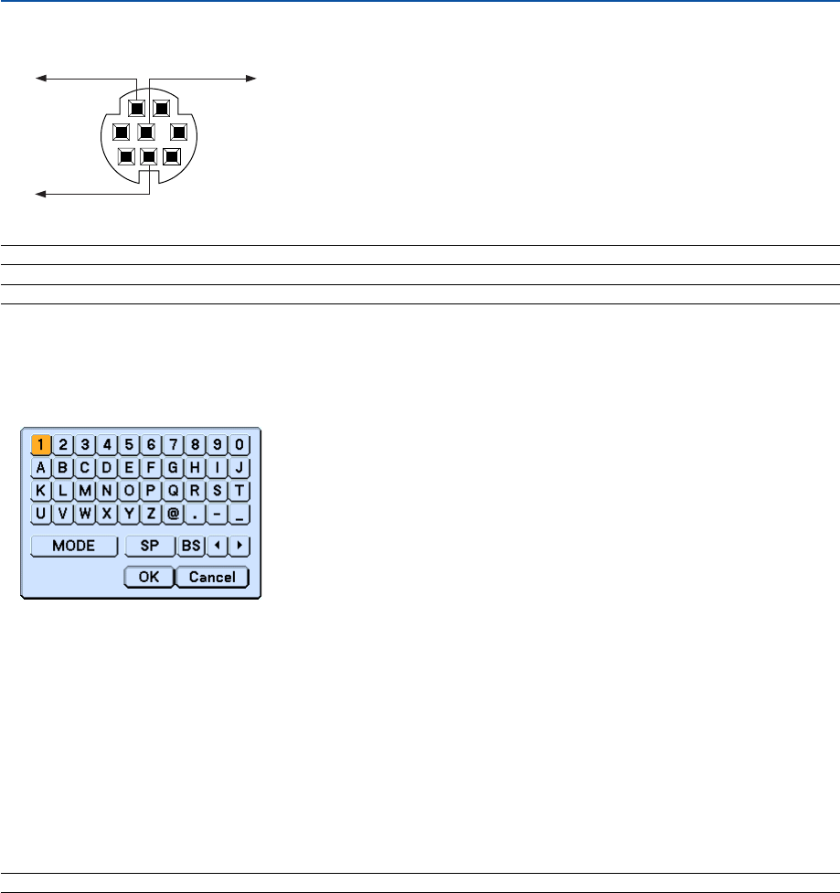
148
8. Appendix
Using Software Keyboard
1 to 0 and Characters
.............................. Use to type in password or keyword.
MODE .................... Selects one of three modes for alphabet and special characters.
SP ......................... Inserts a space
BS ......................... Deletes one character backward
왗.......................... Returns to the previous
왘.......................... Advances to the next
OK ......................... Executes the selection
Cancel ................... Cancels the selection
NOTE: You can drag the Software keyboard on the screen by clicking and holding any part on the keyboard except buttons.
NOTE1: Pins 2, 3, 5, 6 and 8 are used inside the projector.
NOTE 2: For long cable runs it is recommended to set communication speed within projector menus to 9600 bps.
PC Control Connector (DIN-8P)
12
5
43
678
To RxD of PC
To TxD of PC To GND of PC
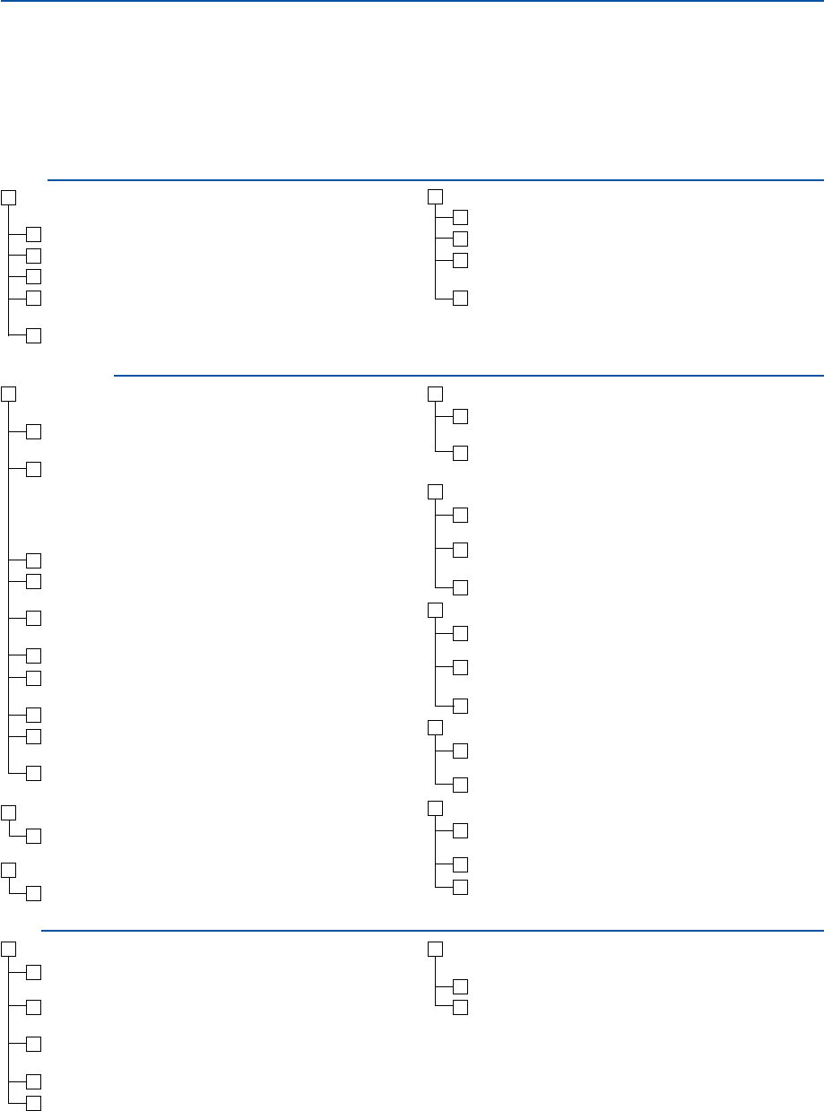
149
No image is displayed from your PC or video equipment to the
projector.
Still no image even though you connect the projector to the PC
first, then start the PC.
Enabling your notebook PC’s signal output to the projector.
•A combination of function keys will enable/disable the ex-
ternal display. Usually, the combination of the “Fn” key along
with one of the 12 function keys turns the external display
on or off.
No image (blue background, logo, no display).
Still no image even though you press the AUTO ADJUST but-
ton.
Still no image even though you carry out “Reset” in the
projector’s menu.
Signal cable's plug is fully inserted into the input connector
A message appears on the screen.
( _____________________________________________ )
The source connected to the projector is active and available.
Still no image even though you adjust the brightness and/or
the contrast.
Input source's resolution and frequency are supported by the
projector.
쐊 Troubleshooting Check List
Before contacting your dealer or service personnel, check the following list to be sure repairs are needed also by
referring to the “Troubleshooting” section in your user’s manual. This checklist below will help us solve your problem
more efficiently.
* Print the following pages.
Frequency of occurrence 䡺 always 䡺 sometimes (How often?_____________________) 䡺 other (__________________)
Power
No power (POWER indicator does not light green) See also “Sta-
tus Indicator (STATUS)”.
Power cable's plug is fully inserted into the wall outlet.
Main power switch is pressed to the ON position.
Lamp cover is installed correctly .
Lamp Hour Meter (lamp operation hours) was cleared after
lamp replacement.
No power even though you press and hold the POWER button
for a minimum of 2 seconds.
Shut down during operation.
Power cable's plug is fully inserted into the wall outlet.
Lamp cover is installed correctly .
Power Management is turned off (only models with the Power
Management function).
Sleep Timer is turned off (only models with the Sleep Timer
function ).
Video and Audio
Image is too dark.
Remains unchanged even though you adjust the brightness
and/or the contrast.
Image is distorted.
Image appears to be trapezoidal (unchanged even though you
carry out the “Focus”, “Keystone" or “3D Reform” adjustment).
Parts of the image are lost.
Still unchanged even though you press the AUTO ADJUST but-
ton.
Still unchanged even though you carry out “Reset” in the
projector’s menu.
Image is shifted in the vertical or horizontal direction.
Horizontal and vertical positions are correctly adjusted on a
computer signal.
Input source's resolution and frequency are supported by the
projector.
Some pixels are lost.
Image is flickering.
Still unchanged even though you press the AUTO ADJUST but-
ton.
Still unchanged even though you carry out “Reset” in the
projector’s menu.
Image shows flickering or color drift on a computer signal.
Image appears blurry or out of focus.
Still unchanged even though you checked the signal’s resolu-
tion on PC and changed it to projector’s native resolution.
Still unchanged even though you adjusted the focus.
No sound.
Audio cable is correctly connected to the audio input of the
projector.
Still unchanged even though you adjusted the volume level.
AUDIO OUT is connected to your audio equipment (only mod-
els with the AUDIO OUT connector).
Other
Remote control does not work.
No obstacles between the sensor of the projector and the re-
mote control.
Projector is placed near a fluorescent light that can disturb the
infrared remote controls.
One or more remote sensors are enabled (only models with
the Remote Sensor Selection function).
Batteries are new and are not reversed in installation.
If present on the remote control, projector selector switch is
not used.
Buttons on the projector cabinet do not work ( only models with
the Key Lock function).
Cabinet Button Lock is not turned on or is disabled in the menu.
Still unchanged even though you press and hold the EXIT but-
ton for a minimum of 10 seconds.
8. Appendix

150
In the space below please describe your problem in detail.
Information on application and environment where your projector is used
Projector
Model number:
Serial No.:
Date of purchase:
Lamp operating time (hours):
Lamp Mode: 䡺 Normal 䡺 Eco
Information on input signal:
Horizontal synch frequency [ ] kHz
Vertical synch frequency [ ] Hz
Synch polarity H 䡺 (+) 䡺 (–)
V 䡺 (+) 䡺 (–)
Synch type 䡺 Separate 䡺 Composite
䡺 Sync on Green
STATUS Indicator:
Steady light 䡺 Orange 䡺 Green
Flashing light [ ] cycles
Remote control model number:
Signal cable
NEC standard or other manufacturer’s cable?
Model number: Length: inch/m
Distribution amplifier
Model number:
Switcher
Model number:
Adapter
Model number:
Projector
PC
DVD player
Installation environment
Screen size: inch
Screen type: 䡺 White matte 䡺 Beads 䡺 Polarization
䡺 Wide angle 䡺 High contrast
Throw distance: feet/inch/m
Orientation: 䡺 Ceiling mount 䡺 Desktop
Power outlet connection:
䡺Connected directly to wall outlet
䡺Connected to power cord extender or other (the num-
ber of connected equipment______________)
䡺Connected to a power cord reel or other (the number
of connected equipment______________)
Computer
Manufacturer:
Model number:
Notebook PC 䡺 / Desktop 䡺
Native resolution:
Refresh rate:
Video adapter:
Other:
Video equipment
VCR, DVD player, Video camera, Video game or other
Manufacturer:
Model number:
8. Appendix
Ver. 2 2/05
NEC SOLUTIONS’ PROJECTOR PRODUCTS
NEC Solutions (America), Inc. (hereafter NEC Solutions) warrants
this product to be free from defects in material and workmanship
under the following terms.
HOW LONG IS THE WARRANTY
NEC Solutions’ WT610 projector is covered by a two (2) year
limited parts and labor warranty from the date of the first cus-
tomer purchase. The lamp when used under normal operating
conditions is warranted for 500 hours or 90 days, whichever
comes first.
WHO IS PROTECTED
This warranty may be enforced only by the first purchaser, and is
not transferable.
WHAT IS COVERED AND WHAT IS NOT COVERED
Except as specified below, this warranty covers all defects in
material or workmanship in this product.
NEC SOLUTIONS’ LIABILITY FOR ANY DEFECTIVE PRODUCT IS
LIMITED TO THE REPAIR OR REPLACEMENT OF THE PRODUCT
AT NEC SOLUTIONS’ OPTION. REPLACEMENT PRODUCTS MAY
BE NEW OR RECONDITIONED PRODUCTS, AND REPLACEMENT
PARTS MAY BE NEW OR SERVICEABLE USED PARTS. The follow-
ing are not covered by the limited warranty and NEC Solutions
shall not be liable for:
1. Any product which is not distributed in the U.S.A. or Canada
by NEC Solutions or which is not purchased, installed, and
operated in the U.S.A or Canada.
2. Any product on which the serial number has been defaced,
modified or removed.
3. Normal decrease in lamp light output over time.
4. Damage, deterioration or malfunction resulting from:
a. Accident, misuse, abuse, neglect, improper ventilation, fire,
dust, smoke, water, lightning or other acts of nature, unau-
thorized product modification, or failure to follow instruc-
tions supplied with the product.
b. Repair or attempted repair by anyone other than a NEC
Solutions authorized service center.
c. Any shipment of the product (claims must be presented to
the carrier).
d. Removal or installation of the product.
e. Any other cause which does not relate to a product defect.
f. Use of the product beyond normal operating conditions.
Normal operating conditions are defined as product use
not in excess of 8 hours per day and 260 days per year.
5. Cartons, carrying cases, shipping cases, batteries, external
cabinets, magnetic tapes, or any accessories used in connec-
tion with the product.
6. Service required as a result of third party components.
WHAT NEC SOLUTIONS WILL PAY FOR
NEC Solutions will pay labor and material expenses for covered
items, but NEC Solutions will not pay for the following:
1. Removal or installation charges.
2. Costs of technical adjustments, set-up, maintenance, or adjust-
ment of user controls.
3. Payment of shipping and related charges incurred in returning
the product for warranty repair.
LIMITED WARRANTY (USA and Canada only)
HOW YOU CAN GET WARRANTY SERVICE
1. To obtain service on your product, consult the dealer from whom
you purchased the product.
2.
Whenever warranty service is required, the original dated invoice
(or a copy) must be presented as proof of warranty coverage. In
order to obtain warranty service, you may be required to describe
and demonstrate the problem to your dealer or to NEC Solutions.
3. All products returned to NEC Solutions for service MUST have
prior approval. To receive approval or for the name of the
nearest NEC Solutions authorized service center, call NEC
Solutions at 800-836-0655.
4. It shall be your obligation and expense to ship the product,
freight prepaid, or to deliver it to a NEC Solutions authorized
service center, in either the original package or a similar pack-
age affording an equal degree of protection.
5.
In the event a product is returned to NEC Solutions for warranty
service, and it is determined that there is no product defect or that
the product condition is not covered by this limited warranty, a
diagnostic service fee may be charged to the customer.
LIMITATION OF IMPLIED WARRANTIES
EXCEPT AS EXPRESSLY SET FORTH IN THIS LIMITED WARRANTY,
NEC SOLUTIONS MAKES NO OTHER WARRANTIES, EXPRESS
OR IMPLIED, INCLUDING BUT NOT LIMITED TO ANY IMPLIED
WARRANTIES OR CONDITIONS OF MERCHANTABILITY AND
FITNESS FOR A PARTICULAR PURPOSE. ANY IMPLIED WARRAN-
TIES THAT MAY BE IMPOSED BY LAW ARE LIMITED TO THE TERMS
AND DURATION OF THIS LIMITED WARRANTY.
EXCLUSION OF DAMAGES
NEC SOLUTIONS’ LIABILITY FOR ANY DEFECTIVE PRODUCT IS
LIMITED TO THE REPAIR OR REPLACEMENT OF THE PRODUCT
AT NEC SOLUTIONS’ OPTION. NEC SOLUTIONS SHALL NOT
BE LIABLE FOR:
1. DAMAGE TO OTHER PROPERTY CAUSED BY ANY DEFECTS
IN THIS PRODUCT, DAMAGES BASED UPON INCONVE-
NIENCE, LOSS OF USE OF THE PRODUCT, LOSS OF TIME,
COMMERCIAL LOSS; OR
2. ANY OTHER DAMAGES, WHETHER INCIDENTAL, CONSE-
QUENTIAL OR OTHERWISE.
HOW STATE LAW RELATES TO THE WARRANTY
SOME STATES DO NOT ALLOW LIMITATIONS ON HOW LONG
AN IMPLIED WARRANTY LASTS AND/OR DO NOT ALLOW THE
EXCLUSION OR LIMITATION OF INCIDENTAL OR CONSEQUEN-
TIAL DAMAGES, SO THE ABOVE LIMITATIONS AND EXCLU-
SIONS MAY NOT APPLY TO YOU. THIS LIMITED WARRANTY
GIVES YOU SPECIFIC LEGAL RIGHTS, AND YOU MAY HAVE
OTHER RIGHTS WHICH VARY FROM STATE TO STATE.
FOR MORE INFORMATION, CONTACT:
NEC SOLUTIONS (AMERICA), INC.
1250 N. Arlington Heights Road
Itasca, Illinois 60143-1248
TELEPHONE 800-836-0655
www.necvisualsystems.com
Customers are cautioned that product performance is affected by
system configuration, software, the application, customer data,
and operator control, among other factors. While NEC Solutions’
products are considered to be compatible with many systems, the
specific functional implementation by the customers of the prod-
uct may vary. Therefore, the suitability of a product for a specific
purpose or application must be determined by the customer and
is not warranted by NEC Solutions.
Printed in Japan
7N8P5511
Ver1. 01/05
Printed on recycled paper
DECLARATION OF CONFORMITY
U.S. Responsible Party:
Address:
Tel. No.:
NEC Solutions (America), Inc.
1250 N. Arlington Heights Road
Itasca, Illinois 60143
(630) 467-5000
Type of Product:
Equipment Classification:
Models:
Projector
Class B Peripheral
WT610
We hereby declare that the equipment specified above
conforms to the technical standards as specified in the FCC Rules.
This device complies with Part 15 of FCC Rules. Operation is subject to the following two conditions.
(1) This device may not cause harmful interference, and (2) this device must accept any interference
received, including interference that may cause undesired operation.
