Nedap N V BOOSTER4 Inductive Proximity Card Reader User Manual BOOSTERS 2G
N. V. Nederlandsche Apparatenfabriek NEDAP Inductive Proximity Card Reader BOOSTERS 2G
User manual
2011-04-01
This information is furnished for guidance, and with no guarantee as to its accuracy or completeness; its publication conveys
no license under any patent or other right, nor does the publisher assume liability for any consequence of its use; specifica-
tions and availability of goods mentioned in it are subject to change without notice; it is not to be reproduced in any way, in
whole or in part, without the written consent of the publisher.
© Nedap IDEAS, P.O. Box 103, NL-7140 AC GROENLO Page 1 of 21
BOOSTERS 2G
USER'S GUIDE
PROX-BOOSTER 2G
SMARTCARD-BOOSTER 2G
TRANSITION-BOOSTER 2G
PROX-BOOSTER TACHO 2G
INCL. CONFIGURATION SOFTWARE

BOOSTERS 2G
© Nedap IDEAS, P.O. Box 103, NL-7140 AC GROENLO Page 2 of 21
CONTENTS
1 INTRODUCTION ....................................................................................................................................................................................... 3
2 INSTALLATION ......................................................................................................................................................................................... 4
2.1 DIMENSIONS ............................................................................................................................................................................... 4
2.2 TEMPERATURE CONSIDERATIONS ..................................................................................................................................... 4
2.3 SOLAR CONTROL WINDSHIELDS ......................................................................................................................................... 4
2.4 PROX-BOOSTER TACHO .......................................................................................................................................................... 5
3 IDENTIFYING THE BOOSTER WITH A TRANSIT ............................................................................................................................. 6
3.1 HOW TO USE THE BOOSTER .................................................................................................................................................. 6
3.2 READER OUTPUT BOOSTER INFO ....................................................................................................................................... 6
3.3 READER OUTPUT TACHO INFO ............................................................................................................................................ 7
4 SMARTCARD CONFIGURATION ......................................................................................................................................................... 8
4.1 CONFIGURATION PROCEDURE ............................................................................................................................................ 8
4.2 HOW TO CREATE A CONFIGURATION CARD .................................................................................................................. 8
4.2.1 TARGET DEVICE ........................................................................................................................................................ 9
4.2.2 CREATION PROCEDURE ......................................................................................................................................... 9
4.2.3 DEFAULT CONFIGURATION .............................................................................................................................. 15
4.3 PROGRAM THE CONFIGURATION CARD ....................................................................................................................... 16
4.3.1 USING A SUPPORTED PROGRAMMER ........................................................................................................... 16
4.3.2 USING ANOTHER PROGRAMMER ................................................................................................................... 17
4.4 TESTING THE CONFIGURATION ........................................................................................................................................ 18
4.5 CONFIGURATION FILES ........................................................................................................................................................ 18
5 MTR CONFIGURATION ....................................................................................................................................................................... 19
6 BUZZER INDICATIONS ........................................................................................................................................................................ 20
7 BATTERY REPLACEMENT ................................................................................................................................................................... 20
A TECHNICAL SPECIFICATIONS ........................................................................................................................................................... 21
B PART NUMBERS .................................................................................................................................................................................... 21

BOOSTERS 2G
© Nedap IDEAS, P.O. Box 103, NL-7140 AC GROENLO Page 3 of 21
1 INTRODUCTION
The Prox-Booster, Smartcard-Booster and Transition-Booster are dual ID tags enabling simultaneous
identification of the inserted personal ID card and the embedded vehicle ID resulting in rapid driver and vehicle
monitoring. The Prox-Booster tacho additionally sends the tacho-counter value, which relates to the travelled
distance of the vehicle.
The Booster allows an inserted Proximity or Smartcard driver ID card and embedded vehicle ID to be read from a
distance up to 10 meters (33 feet) in combination with NEDAP TRANSIT readers. This solution substantially
enhances the level of security when controlling activities of vehicles that are regularly used by different drivers.
Additionally a fully integrated vehicle and personnel access solution can be implemented.
For more details about the NEDAP TRANSIT reader refer to the TRANSIT installation guide.
The combined vehicle and driver ID is a unique NEDAP patented feature. Optionally the vehicle-ID can be
sacrificed if more information from the personal ID card is required.
The following personal ID card types are identified with the Boosters.
• Prox-Booster (tacho) NEDAP, EM and HID PROX
• Smartcard-Booster MIFARE (incl. DESFIRE EV1), HID iCLASS, ISO14443A, ISO15693 and Calypso.
• Transition-Booster all of the above
For 120 kHz : CGDBOOSTER4 and 1444A-BOOSTER4
For 120 and 13560 kHz : CGDBOOSTER5 and 1444A-BOOSTER5
For 13560 kHz : CGDBOOSTER5 and 1444A-BOOSTER5
Compliance statement
This device complies with part 15 of the FCC Rules and to RSS210 of Industry Canada.
Operation is subject to the following two conditions:
(1) this device may not cause harmful interference, and
(2) this device must accept any interference received, including interference that may cause undesired operation.
Déclaration Conformité
Cet appareil se conforme aux normes RSS exemptés de license du Industry Canada.
L'opération est soumis aux deux conditions suivantes
(1) cet appareil ne doit causer aucune interférence, et
(2) cet appareil doit accepter n'importe quelle interférence, y inclus interférence qui peut causer une opération
non pas voulu de cet appareil.
Warning
Changes or modifications not expressly approved by the party responsible for compliance could void
the user’s authority to operate the equipment.
BOOSTERS 2G
© Nedap IDEAS, P.O. Box 103, NL-7140 AC GROENLO Page 4 of 21
2 INSTALLATION
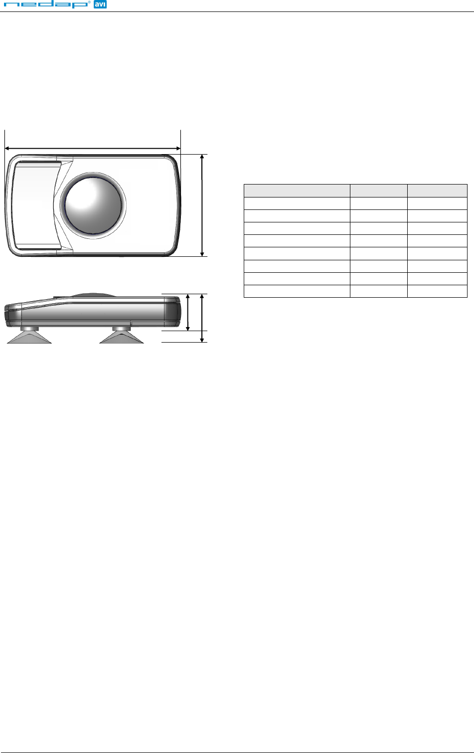
2.1 DIMENSIONS
The Boosters are easily mounted to the inside of the car’s windshield by means of suction cups. Users should
ensure the visual contact between the Booster and any TRANSIT reader is unobstructed with items such as
stickers or metallized windshields (see also chapter 2.3 about solar control windshields).
Note that the Booster's suction cups must be faced toward the reader to achieve maximum reading distance.
Dimension
Length X 111 mm 4.37 "
Width Y 65 mm 2.56 "
Height Z 32 mm 1.26 "
Body height H 24 mm 0.95 "
Tacho wire
wire length 1700 mm 67 "
wire thickness 2 x 0.25 mm 2 x AWG 23
2
Booster Dimensions
2.2 TEMPERATURE CONSIDERATIONS
The Booster is designed to operate within the extreme temperature ranges, which often occur behind a vehicle’s
windshield during the winter or summer seasons (-20°C to 85°C / -4°F to +185°F). However the personal
identification card inserted in the Booster may not be designed to withstand such temperatures and could suffer
damage as a result.
Nedap recommends to remove the personal identification card when not in use.
CAUTION: DO NOT LEAVE CARD IN ACCESS DEVICE WHEN LEAVING THE VEHICLE, AS THIS PRESENTS A SECURITY
RISK.
CAUTION: DO NOT LEAVE CARD IN ACCESS DEVICE FOR LONG PERIODS OF TIME IN EXTREME HEAT, AS THIS MAY
DAMAGE THE CARD.
2.3 SOLAR CONTROL WINDSHIELDS
From 1997 onwards several car manufacturers introduced vehicles with solar control windshields. The solar
control windshields are equipped with a metalized coating, which can block the TRANSIT signal from the Booster
mounted on the inside of the windshield of the vehicle.
Most of these windshields have a metal free zone where transponders can be mounted. The metal free zone of
metalized windshields is most often found in the middle of the windshield behind and slightly below the rear
view mirror. In vehicles manufactured after 1998 the metal free zone should be indicated on the window.
We advise the owner to contact the local car dealer if it is not clear where the aperture is exactly positioned in a
certain vehicle and where the transponder should be mounted.
X
Y
H Z

BOOSTERS 2G
© Nedap IDEAS, P.O. Box 103, NL-7140 AC GROENLO Page 5 of 21
2.4 PROX-BOOSTER TACHO
The prox-booster tacho is a special booster version that should be wired to the speed pulse generator of your
vehicle. The exact wiring details and connection location very much depend upon the brand, type and model of
your vehicle. Contact your vehicle dealer for more information about the speed pulse generator in your vehicle.
Tacho input specifications:
• Input voltage: 6V to 24V (max. 30V).
• Polarity reversal tolerant.
• Input prescaler 1:256.
• Maximum pulse frequency 850Hz.
• Maximum vehicle speed 255km/h (at 12 pulses/meter).
hkm/2556.3
12
850 =×=
.
BOOSTERS 2G
© Nedap IDEAS, P.O. Box 103, NL-7140 AC GROENLO Page 6 of 21
3 IDENTIFYING THE BOOSTER WITH A TRANSIT
3.1 HOW TO USE THE BOOSTER
Place the Booster on the inside of the windscreen of your vehicle as described in chapter 2.
The driver inserts his personal identification card and activates the Booster’s button.
A beep should indicate that the card was successfully read. A low beep indicates that card reading failed
The TRANSIT reader can identify your card up to a distance of 10 meters (=33 ft).
.
After 5 seconds the Booster returns into sleep mode. The booster will remain active when in 'always-on'-mode.
The driver should remove his personal identification card from the Booster when leaving the vehicle.
3.2 READER OUTPUT BOOSTER INFO
The Prox/Smartcard-Booster is a battery operated passive tag. The information from the tag is sent to the reader
by a method called modulated backscatter. This means that the 2.45GHz signal coming from the reader's
antenna is modified in such way that it can be recognized by the reader.
The examples below assume that a TRANSIT PS270 reader with P81 firmware is used and show the messages
transmitted on the RS-232 interface to a host system (TXD). Refer to the TRANSIT firmware manuals for more
details about the reader communication protocol.
Combi-Booster mode (Vehicle-ID + Driver-ID)
The Booster cannot be identified until the driver inserts his personal identification card and pushes the Booster’s
button. Once the button is pushed the Booster reads the personal identification card and beeps
Example: vehicle-id = 123, driver-id = E4947C46,
upon a
successful read. Both vehicle-id and driver-id are transmitted to the host system for 5 seconds. Afterwards the
Booster automatically deactivates again. The booster will remain active when in 'always-on'-mode.
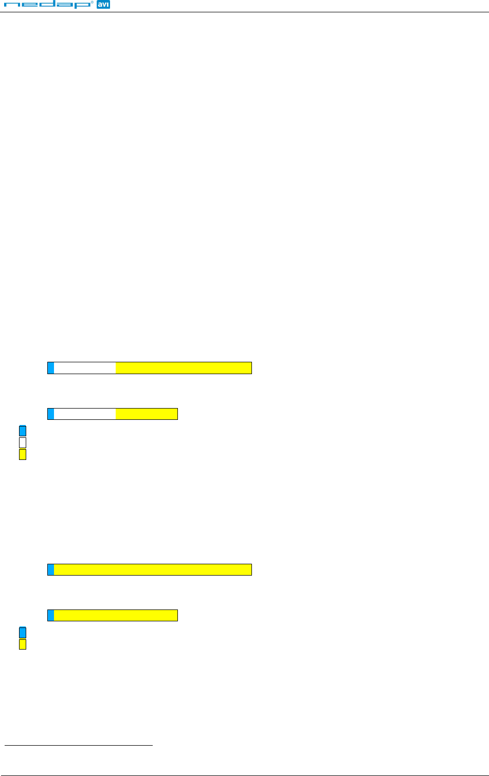
TXD = Y000000012300000000000000E4947C46CRLF
If 'Standard-length' is configured, the following message is transmitted to the host.
TXD = U000000012300E4947C46CRL
Event identifier ('Y' or 'U').
F
Vehicle-id (10 digits).
Driver-id (10 or 22 digits).
Booster mode (Only Driver-ID)
The Booster is 'sleeping' until the driver inserts his personal identification card and pushes the Booster’s button.
Once the button is pushed the Booster reads the personal identification card and beeps
Example: driver-id = 871111111117100944,
upon a successful read.
The data is transmitted to the host system for 5 seconds. After that the Booster automatically deactivates again.
The booster will remain active when in 'always-on'-mode.
TXD = Z00000000000000871111111117100944CRLF
If 'Standard-length' is configured, the following message is transmitted to the host.
TXD = U00871111111117100944CRL
Event identifier ('Z' or 'U').
F
Driver-id (20 or 32 digits).
See chapter 6 for details about the buzzer indications.
BOOSTERS 2G
© Nedap IDEAS, P.O. Box 103, NL-7140 AC GROENLO Page 7 of 21
3.3 READER OUTPUT TACHO INFO
Tacho-Booster mode (Vehicle-ID + Driver-ID + Tacho-Counter)
The prox-booster tacho should be connected to the speed pulse generator of your vehicle. The prox-booster will
count the number of pulses generated.
The Booster cannot be identified until the driver inserts his personal identification card and pushes the Booster’s
button. Once the button is pushed the Booster reads the personal identification card and beeps
upon a
successful read. Both vehicle-id, driver-id and tacho-counter are transmitted to the host system for 5 seconds.
Afterwards the Booster automatically deactivates again. The tacho counter will be updated while the booster is
deactivated. The booster will remain active when in 'always-on'-mode.
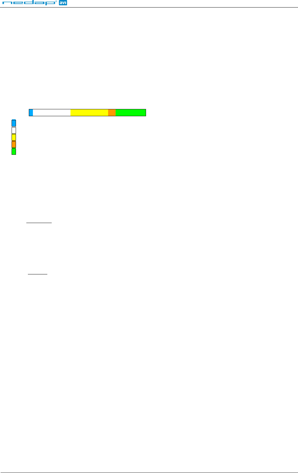
Example reader output: vehicle-id = 123, driver-id = E4947C46, tacho-counter = 2AC4,
TXD = X000000012300E4947C468000002AC4CRLF
Event identifier ('X' = triple identifier detection event).
Vehicle-id (10 digits).
Driver-id (10 digits).
Additional data identifier ('80' = tacho counter).
Additional data (in this case the tacho counter value).
How to calculate the constant factor required to convert tacho counter value into travelled distance.
• Get the vehicle's initial mileage
)(
1
M=
and the initial tacho counter value
)(
1
T=
.
• Drive the vehicle for a significant amount of miles (or kilometers).
• Then again get the actual mileage
)(
2
M=
and the actual tacho counter value
)( 2
T=
.
• Now calculate the number of counts per mile (or km) by using the following formula:
( )
( )
12
12
MM
TT
K−
−
=
How to calculate the vehicle's travelled distance.
• Get the actual tacho counter value
)( n
T=
• Calculate travelled distance by using the following formula:
( )
K
TT
Dn
n1
−
=
• Calculate the current mileage by using the following formula:
1
MDM nn +=
.
BOOSTERS 2G
© Nedap IDEAS, P.O. Box 103, NL-7140 AC GROENLO Page 8 of 21
4 SMARTCARD CONFIGURATION
The Smartcard-Booster and the Transition-Booster can be configured by means of a configuration card. This
configuration card is a Mifare Classic 1K or 4K card that is programmed with the configuration settings.
Configuration is only required if the factory default settings are not sufficient. The default settings are described
in chapter 4.2.3.
4.1 CONFIGURATION PROCEDURE
Every Booster used in the application should be configured with the configuration card. The simple
configuration procedure is described below.
Insert the configuration card in the Booster and push the button. The Booster sounds the buzzer with an
increasing frequency (♪ ♪ ♪) to indicate that the configuration card is accepted
.
4.2 HOW TO CREATE A CONFIGURATION CARD
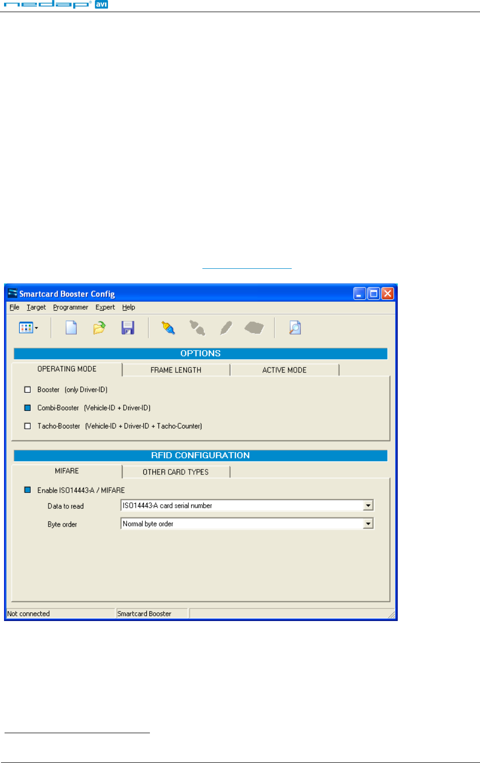
NEDAP has developed a software application that allows system integrators to create configuration cards. This
software can be downloaded from our website www.nedapavi.com.
Smartcard-Booster Config software
See chapter 6 for details about the buzzer indications.

BOOSTERS 2G
© Nedap IDEAS, P.O. Box 103, NL-7140 AC GROENLO Page 9 of 21
4.2.1 TARGET DEVICE
The Booster Configuration software can be used to configure a number of different devices. The user-interface is
adapted to the selected target device. Select in the ‘Target’ menu which device you are about to configure.
Smartcard-Booster
Transition Booster
Prox Booster EM4x50
not covered in this manual
MTR Module
see chapter 5
4.2.2 CREATION PROCEDURE
Follow the procedure below to create a configuration card with application specific settings.
1. Specify OPERATING MODE (see chapter 4.2.2.1)
2. Specify FRAME LENGTH (see chapter 4.2.2.2)
3. Specify ACTIVE_MODE (see chapter 4.2.2.3)
4. Specify RFID CONFIGURATION settings (see chapter 4.2.2.4)
5. Save the configuration settings into a file.
6. Write the configuration into a blank Mifare Classic 1K or 4K card.
4.2.2.1 OPERATING MODE
Booster (only Driver-ID)
Up to 16 bytes of data from the personal identification card is read. The Vehicle-ID is omitted.
Combi-Booster (Vehicle-ID + Driver-ID)
Vehicle-ID combined with up to 11 bytes from the personal identification card is read.
Tacho-Booster (Vehicle-ID + Driver-ID + Tacho-Counter)
Vehicle-ID and Driver-ID combined with Tacho-Counter value. If this option is selected than automatically
extended-length is selected.
4.2.2.2 FRAME LENGTH
This affects the length of the message sent to TRANSIT reader.
Extended length (longer Driver-ID)
Select extended-length in order to support all transponder types and maximum amount of data. The
extended-length may be not compatible with older firmware versions in the TRANSIT reader. You might
need to upload new firmware into the reader.
The identification speed is a bit slower compared to applying standard-length.
Standard length (backwards compatible, faster identification)
Select standard-length in applications where compatibility with older types of transponders or where fast
identification is important.
Please note that when reading low-frequency cards with a Transition-Booster this setting is not used.
For NEDAP and EM cards the extended-length is not required and therefore the Booster will automatically use
standard-length (even if extended-length is selected in the configuration).
For HID PROX the extended-length is required so extended-length is used automatically if such a card is
identified (even if standard-length is selected in the configuration).

BOOSTERS 2G
© Nedap IDEAS, P.O. Box 103, NL-7140 AC GROENLO Page 10 of 21
4.2.2.3 ACTIVE MODE
Two activation modes are possible: Switched or Always-on.
The setting can only be changed when the Booster originally was in switched mode !!!
Switched mode is selected when the operating mode is Booster (only Driver-ID).
Switched mode (active for approx. 5 seconds)
In switched mode the booster is active for approx. 5 seconds after the booster's button is pushed and
then autmatically returns into sleep mode.
Always-on (continuously active)
In always-on mode the booster remains active. When the booster's button is pushed the booster will read
the inserted card. If a card is identified, the booster will check every few minutes if the inserted card is still
present.
4.2.2.4 RFID CONFIGURATION
ISO14443-A / MIFARE
Enable or disable the reading of ISO14443-A / MIFARE cards.
Data to read:
For ISO14443-A cards the card serial number can be read. The cascaded card serial number (e.g. used in
Mifare UltraLight cards) is also supported. For MIFARE cards also other encrypted information from the
card can be read. Select one of the following choices:
ISO14443-A card serial number
MIFARE UltraLight data (see chapter 4.2.2.5 for more details)
MIFARE Classic sector data (see chapter 4.2.2.6 for more details)
MIFARE DESFIRE file data (see chapter 4.2.2.7 for more details)
The byte order can be set to normal or reversed.
NEDAP PM
Enable or disable the reading of NEDAP PM cards. NEDAP PM cards are always transmitted to the TRANSIT
using standard-length.
EM4102 (and compatible)
Enable or disable the reading of EM4102 and compatible cards. EM4102 cards are always transmitted to
the TRANSIT using standard-length.
HID PROX
Enable or disable the reading of HID PROX cards. HID PROX cards are always transmitted to the TRANSIT
using extended-length.
HID iCLASS CSN
Enable or disable the reading of HID iCLASS cards. Only the card serial number can be read from these
cards.
ISO15693 / LEGIC Advant CSN
Enable or disable the reading of ISO15693 / LEGIC Advant cards. Only card serial number can be read from
these cards.
Not supported on the Smartcard-Booster.
Cannot be disabled on MTR.

BOOSTERS 2G
© Nedap IDEAS, P.O. Box 103, NL-7140 AC GROENLO Page 11 of 21
Calypso
Enable or disable the reading of Calypso cards.
Data to read:
For Calypso cards the 4-byte PUPI or information from always accessible files can be read. The Booster
does not support the Calypso SAM to fully support the Calypso encrypted file system. Select one of the
following choices:
PUPI (pseudo unique PICC identifier)
Calypso file data
Byte order:
The byte order can be set to normal or reversed.
Short File Identifier:
Calypso SFI (Short File Identifier) in range from 1 .. 30. Some files have no SFI. Only files with an SFI are
supported.
Record Number:
A file may contain more than one record. Numbered from 1 to the maximum number of records.
Data Length:
Number of bytes to transmit. The maximum number of bytes is dependant upon the operating-mode and
frame-length settings.
Data Offset:
Number of bytes to skip.
BOOSTERS 2G
© Nedap IDEAS, P.O. Box 103, NL-7140 AC GROENLO Page 12 of 21
4.2.2.5 READING MIFARE ULTRALIGHT DATA
The Mifare UltraLight transponders’ 512 bit EEPROM memory is organized in 16 pages with 4 bytes each.
Page Number
Page number to start reading from (in range from 0 .. 15).
Always 4 pages are read. The reading will wrap around to page number 0 if additional data after page 15
should be read.
Data Length
Number of bytes to transmit. The maximum number of bytes is dependant upon the operating-mode and
frame-length settings.
Data Offset
Number of bytes to skip.
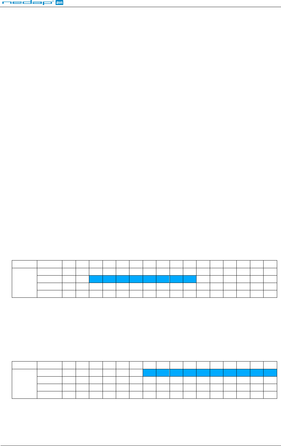
Example:
Data to read: MIFARE UltraLight data
Byte order: Normal
Page Number: 4
Data Length: 8
Data Offset: 2
Always 16 bytes are read from the card and in this example the reading starts at page 4, thus pages 4, 5, 6 and
7 are read. The first 2 bytes are skipped because the offset is set to 2. The following 8 bytes are transmitted
because the configured data length is 8.
Byte 0 Byte 1 Byte 2 Byte 3
Page 4 skipped skipped DATA DATA
Page 5 DATA DATA DATA DATA
Page 6 DATA DATA ignored ignored
Page 7 ignored ignored ignored ignored
Reverse example:
Data to read: MIFARE UltraLight data
Byte order: Reverse
Page Number: 5
Data Length: 10
Data Offset: 6
Always 16 bytes are read from the card and in this example the reading starts at page 5, thus pages 5, 6, 7 and
8 are read. After the byte order is reversed, the first 6 bytes are skipped because the offset is set to 6. The
following 10 bytes are transmitted because the configured data length is 10.
Byte 3 Byte 2 Byte 1 Byte 0
Page 8 skipped skipped skipped skipped
Page 7 skipped skipped DATA DATA
Page 6 DATA DATA DATA DATA
Page 5 DATA DATA DATA DATA
BOOSTERS 2G
© Nedap IDEAS, P.O. Box 103, NL-7140 AC GROENLO Page 13 of 21
4.2.2.6 READING MIFARE CLASSIC SECTOR DATA
The Mifare Classic 1K and 4K cards are fully supported. Also other Mifare cards which are compatible (such as
Mifare Plus and SmartMX) can be used. The memory is organized in sectors with blocks. Every block consists of
16 bytes.
Upon configuring the smartcard-booster for reading MIFARE DESFIRE cards, the following parameters must be
specified.
Sector Number
Sector number to read data from (in range from 0 .. 39).
Block Number
Block number to read data from. The block number must be in range from 0 .. 3 for the first 32 sectors. For
the sectors 32 .. 39 the block number can range from 0 .. 15.
Data Length
Number of bytes to transmit. The maximum number of bytes is dependant upon the operating-mode and
frame-length settings.
Data Offset
Number of bytes to skip.
Read Key
Key A or Key B can be used to authenticate to the card.
Select which key to use and the key itself.
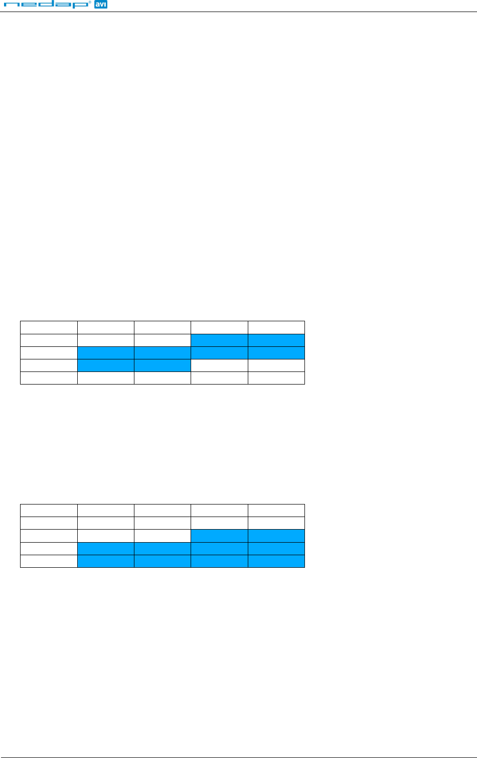
Example:
Data to read: MIFARE Classic sector data
Byte order: Normal
Sector Number: 1
Block Number: 1
Data Length: 8
Data Offset: 2
The settings above will read the data below shown in blue.
Sector Block 0 1 2 3 4 5 6 7 8 9 10 11 12 13 14 15
1
0 x x x x x x x x x x x x x x x x
1 x x D D D D D D D D x x x x x x
2 x x x x x x x x x x x x x x x x
3 x x x x x x x x x x x x x x x x
Reverse example:
Data to read: MIFARE Classic sector data
Byte order: Reverse
Sector Number: 2
Block Number: 0
Data Length: 10
Data Offset: 6
The settings above will read the data below shown in blue.
Sector Block 15 14 13 12 11 10 9 8 7 6 5 4 3 2 1 0
2
0 x x x x x x D D D D D D D D D D
1 x x x x x x x x x x x x x x x x
2 x x x x x x x x x x x x x x x x
3 x x x x x x x x x x x x x x x x

BOOSTERS 2G
© Nedap IDEAS, P.O. Box 103, NL-7140 AC GROENLO Page 14 of 21
4.2.2.7 READING MIFARE DESFIRE FILE DATA
The MIFARE DESFIRE cards are fully supported. Also other newer DESFIRE EV1 cards can be used. Including the
DES, 3DES, 3 Key 3DES and AES encryptions.
The DESFIRE card's memory is organized using a flexible file system. This file system allows several different
applications on a single card. Every application is identified by it's 3 byte application identifier (AID). Each
application may contain up to 32 files.
Upon configuring the smartcard-booster for reading MIFARE DESFIRE cards, the following parameters must be
specified.
Application ID
Three byte application identifier (AID).
File number
File number in the range from 0 .. 31.
Communication mode
Plain.
Plain secured by MACing.
Fully enciphered.
Data Length
Number of bytes to transmit. The maximum number of bytes is dependant upon the operating-mode and
frame-length settings.
Data Offset
Number of bytes to skip.
Encryption
None (skip authentication)
Native DES/3DES
ISO DES/3DES
3 Key 3DES
AES
Key number
Key number in range from 0 to 13.
Key
Security authentication key. Depending upon the selected encryption method and key number. The
encryption key is 16 or 24 bytes.
BOOSTERS 2G
© Nedap IDEAS, P.O. Box 103, NL-7140 AC GROENLO Page 15 of 21
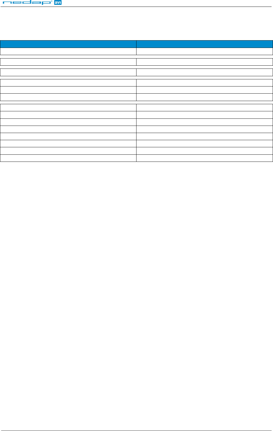
4.2.3 DEFAULT CONFIGURATION
In the table below the default configuration is shown.
Configuration settings Default value
Operating mode Combi-Booster (Vehicle-ID + Driver-ID)
Frame length Extended-length (longer Driver-ID)
Active mode Switched mode
ISO14443-A / MIFARE Enabled
Data to read ISO14443-A card serial number
Byte order Normal
NEDAP PM Enabled
EM4102 (and compatible) Enabled
HID PROX Enabled
HID iCLASS CSN Enabled
ISO15693 / LEGIC Advant CSN Enabled
Calypso Enabled
Data to read PUPI
Byte order Normal
BOOSTERS 2G
© Nedap IDEAS, P.O. Box 103, NL-7140 AC GROENLO Page 16 of 21
4.3 PROGRAM THE CONFIGURATION CARD
4.3.1 USING A SUPPORTED PROGRAMMER
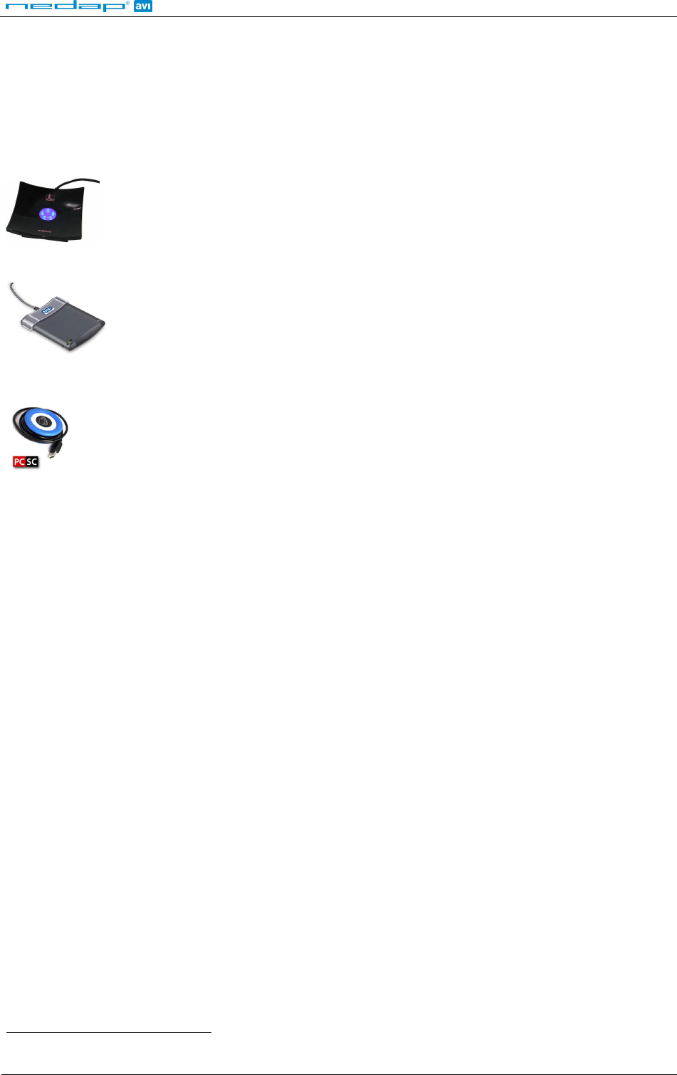
The software supports a few different programming devices. The NXP Pegoda, the HID OMNIKEY 5x21 and PC/SC
contactless readers from the Springcard CSB6 Family (e.g. Prox 'n' Roll PC/SC).
4.3.1.1 NXP PEGODA PROGRAMMER
Connect the NXP Pegoda Mifare programmer to a USB port on your computer. USB drivers
must be installed as described in the NXP documentation.
In the ‘Programmer’ menu select the 'NXP Pegoda' and click ‘Connect’ to connect to the
programmer.
4.3.1.2 HID OMNIKEY 5x21-CL PROGRAMMER
Connect the HID OMNIKEY 5x21-CL USB programmer to a USB port on your computer. USB
drivers must be installed as described in HID documentation.
In the ‘Programmer’ menu select 'HID OMNIKEY' and click ‘Connect’.
4.3.1.3 SPRINGCARD CSB6
The SpringCard CSB6 and Prox 'n' Roll PC/SC share the same architecture. Install the PC/SC
drivers as described in the SpringCard documentation. Connect the CSB6 to a USB port on
your computer.
In the ‘Programmer’ menu select 'SpringCard CSB6' and click ‘Connect’.
4.3.1.4 PROGRAMMING
Once the connection has been established and all configuration settings are entered, place an empty Mifare
Classic 1K or 4K card on the programmer.
To program the configuration into the Mifare card click ‘Write configuration into card’ in the ‘Programmer’ menu.
The message ‘Configuration written into card’ should appear to indicate that the programming action was
successful.
The software will warn you with the message ‘Overwrite configuration card’ if there is already a configuration on
the Mifare card. Click ‘Yes’ to proceed and overwrite the configuration on the card or click ‘No’ to abort.
4.3.1.5 READ BACK
It is also possible to read back what configuration is programmed into a configuration card. Click ‘Read
configuration from card’ in the ‘Programmer’ menu.
The HID OMNIKEY programmer sometimes requires to remove and replace the config card before re-
accessing the card is possible.
BOOSTERS 2G
© Nedap IDEAS, P.O. Box 103, NL-7140 AC GROENLO Page 17 of 21
4.3.2 USING ANOTHER PROGRAMMER
If there is no supported programmer available you can use any other Mifare programmer to write the
configuration into a Mifare classic card.
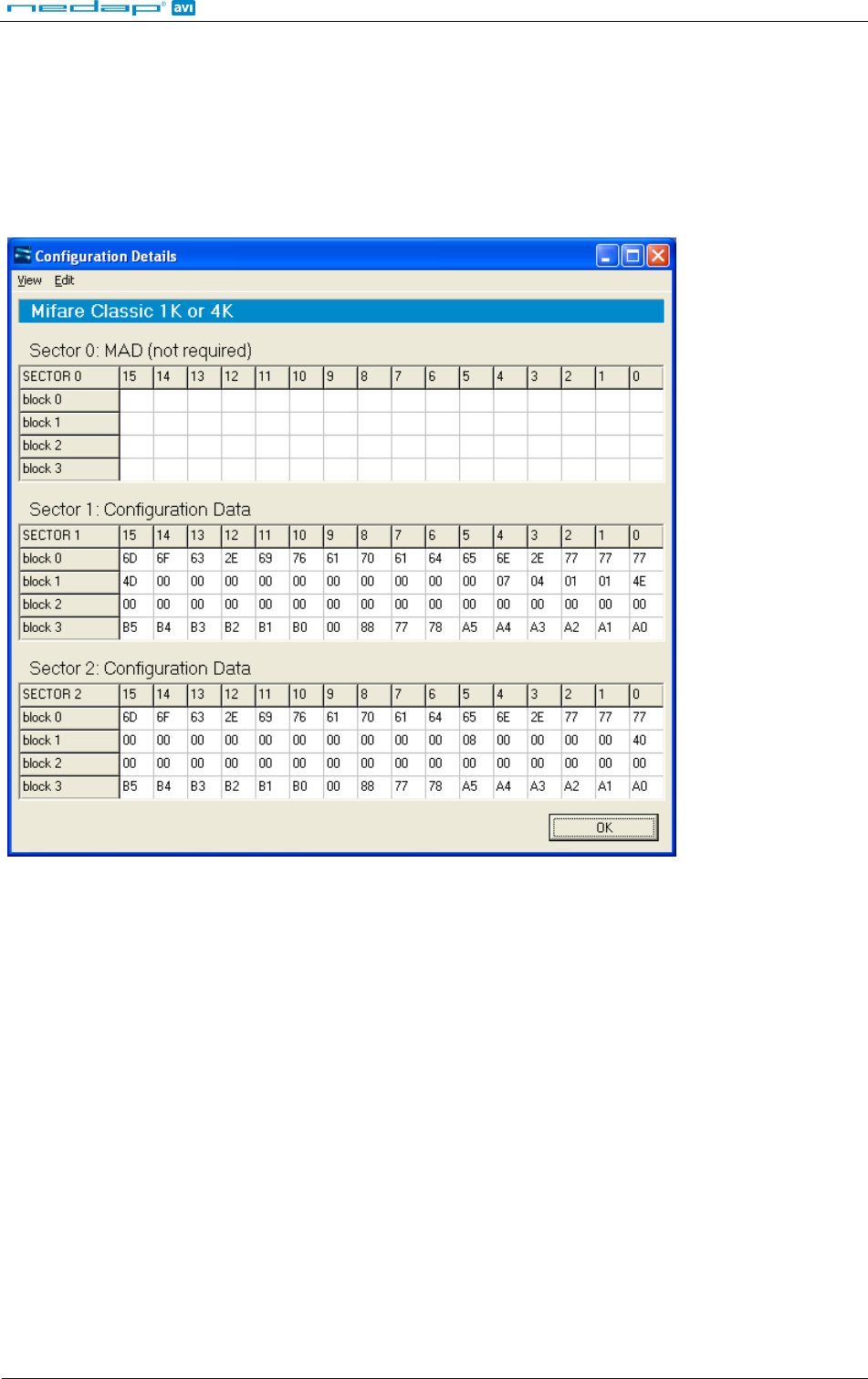
The configuration data should be written into sector 1 and 2 of a Mifare Classic 1K or 4K card. The contents of
these sectors is not explained, but can be shown by the configuration software by clicking ‘Show configuration
details’ in the ‘Expert’ menu.
Configuration Data
Sector 0 is reserved for MAD (Mifare Application Directory). If the MAD is programmed, the Nedap configuration
sectors should have application id 517F.
4.3.2.1 COPY TO CLIPBOARD
Copy the configuration data to clipboard by clicking ‘Copy to clipboard’ in the ‘Edit’ menu.
4.3.2.2 CUSTOMIZING VIEW
In the ‘View’ menu the viewing can be customized in such way that it best matches your programming software.
Click ‘Change Hex Prefix…’ to specify a specific prefix that is shown before every configuration data byte. Below
is shown the configuration data with prefix ‘0x’.
0x77 0x77 0x77 0x2E 0x6E 0x65 0x64 0x61 0x70 0x61 0x76 0x69 0x2E 0x63 0x6F 0x6D
0x4E 0x01 0x01 0x07 0x07 0x00 0x00 0x00 0x00 0x00 0x00 0x00 0x00 0x00 0x00 0x4E
0x00 0x00 0x00 0x00 0x00 0x00 0x00 0x00 0x00 0x00 0x00 0x00 0x00 0x00 0x00 0x00
0xA0 0xA1 0xA2 0xA3 0xA4 0xA5 0x78 0x77 0x88 0x00 0xB0 0xB1 0xB2 0xB3 0xB4 0xB5
Besides the hex prefix also the byte order can be changed from within the ‘View’ menu.
BOOSTERS 2G
© Nedap IDEAS, P.O. Box 103, NL-7140 AC GROENLO Page 18 of 21
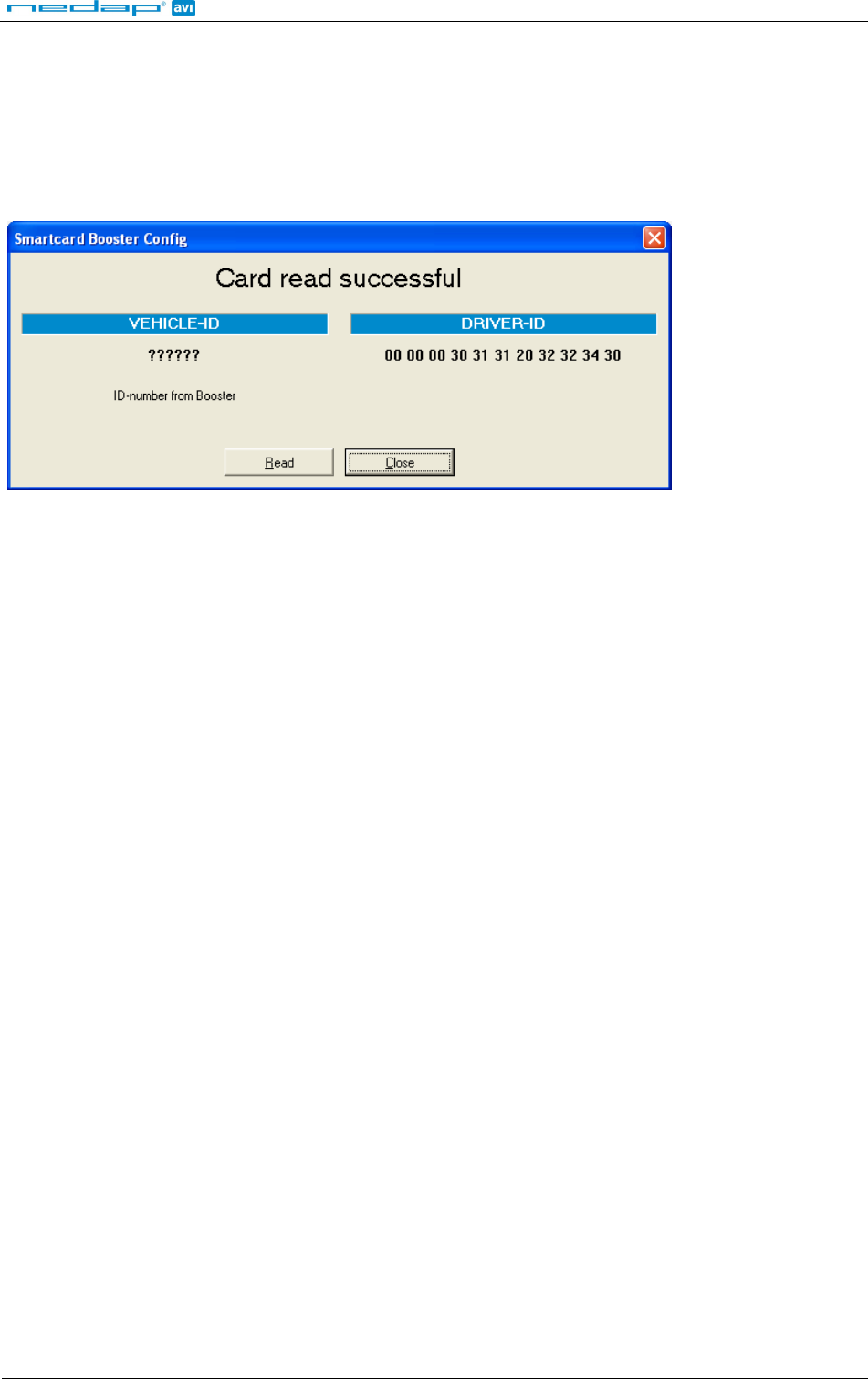
4.4 TESTING THE CONFIGURATION
The MIFARE settings can be tested before loading it into the Smartcard-Booster using a supported mifare reader.
From the ‘Programmer' menu choose ‘Test configuration’.
Place the Mifare card (not the config card) on the reader and click the ‘Read’ button.
The reader reads the Mifare card according to the current configuration settings.
The software displays the driver-id number as it will be identified by the TRANSIT.
Configuration Test
If the card is not read or if the wrong data is shown under DRIVER-ID then check if the configuration settings are
correct. Remember that only MIFARE cards can be tested this way.
4.5 CONFIGURATION FILES
Your configuration can be saved into a so-called Smartcard Booster Config File (*.sbcf). These files contain all the
configuration settings as you have defined them. Saved Config Files can be easily opened from within the File
menu.

BOOSTERS 2G
© Nedap IDEAS, P.O. Box 103, NL-7140 AC GROENLO Page 19 of 21
5 MTR CONFIGURATION
The MTR Module (Multi-Technology Reader) is especially designed to read low-frequency proximity cards and
ISO compliant smartcards directly on the TRANSIT Entry reader at short range without Booster.
The MTR is configured in exactly the same way as the Smartcard Booster. Refer to chapter 4 on page 8 for more
information about the configuration procedure.
For more details about the TRANSIT Entry reader and the MTR refer to the separate documentation.
BOOSTERS 2G
© Nedap IDEAS, P.O. Box 103, NL-7140 AC GROENLO Page 20 of 21
6 BUZZER INDICATIONS
The Booster's built-in buzzer gives audible feedback upon various conditions. The table below describes the
buzzer indications.
Buzzer Description
1 beep Card read
1 short low beep Failed to read card (not in configuration)
3 beeps increasing frequency ♪ ♪ ♪ Configuration card accepted
6 beeps increasing frequency Power on (Smartcard-Booster / Transition-Booster / MTR)
3 beeps Power on (Prox-Booster)
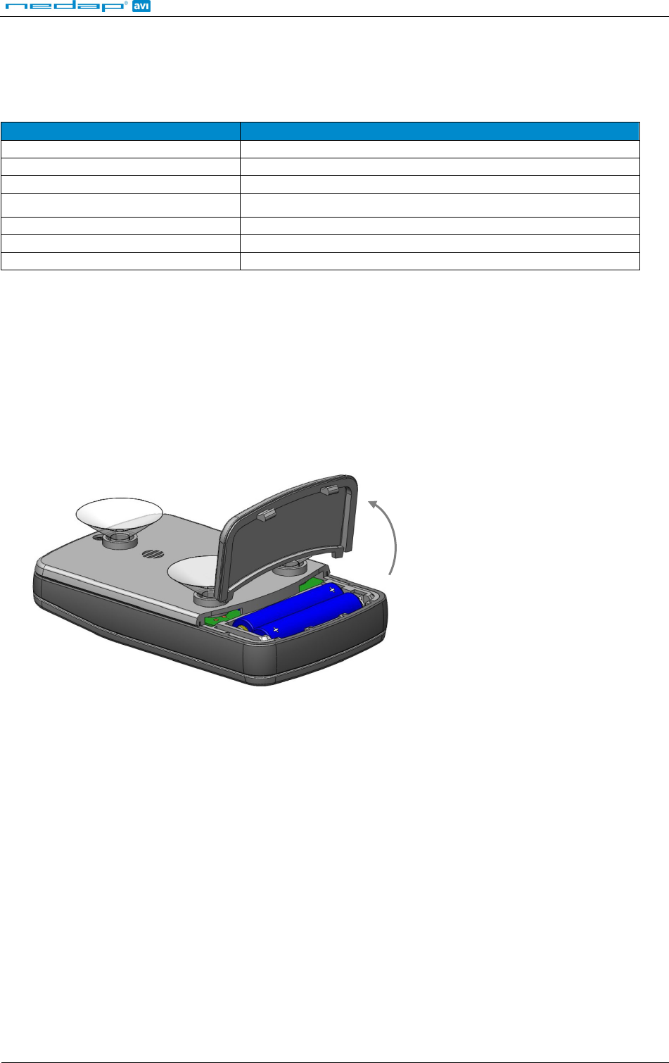
7 BATTERY REPLACEMENT
The Smartcard-Booster contain two replaceable non-rechargeable lithium AAA batteries. The average lifetime of
these batteries is approximately 5 years. When replacement becomes necessary follow the procedure below.
1. Open the battery compartment.
2. Remove both batteries. Follow local environment protection laws / regulations for disposal of used batteries.
3. Replace with two new batteries of same type. Make sure that the polarity matches the indicated polarity.
4. Close the battery compartment and verify if the booster is working properly.
BOOSTERS 2G
© Nedap IDEAS, P.O. Box 103, NL-7140 AC GROENLO Page 21 of 21
A TECHNICAL SPECIFICATIONS
Dimensions 111 x 65 x 24 mm (4.4 x 2.6 x 1.0 in)
Weight 120 gram (4.2 oz)
Protection IP32 Approx. NEMA 2
Operating temperature -20°C … +85°C (-4°F … +140°F)
Storage temperature -40°C … +85°C (-40°F … +140°F)
Color Grey RAL 7035
Relative humidity 10% … 93% non-condensing
Identification range Typically 10 meters (33 ft) line-of-sight required
B PART NUMBERS
PROX/SMARTCARD-BOOSTERS
Prox-Booster 2G part number: 9948538
Smartcard-Booster 2G part number: 9948554
Transition-Booster 2G part number: 9948562
Prox-Booster tacho 2G part number: ………
READER
TRANSIT PS270 long range reader part number: 9990410
TRANSIT Entry reader part number: 9876200
ENTRY READER ACCESSORIES
MTR Module part number: 7816650