Nedap N V COMBI-BOOSTER2 Anti Pilferage device User Manual COMBI BOOSTER
N. V. Nederlandsche Apparatenfabriek NEDAP Anti Pilferage device COMBI BOOSTER
UserManual.wiki
>
Nedap N V
>
COMBI BOOSTER2 User Manual
User Manual
Navigation menu
Upload a User Manual
Namespaces
Wiki Guide
HTML
PDF
Info
Views
User Manual
Discussion / Help
Navigation
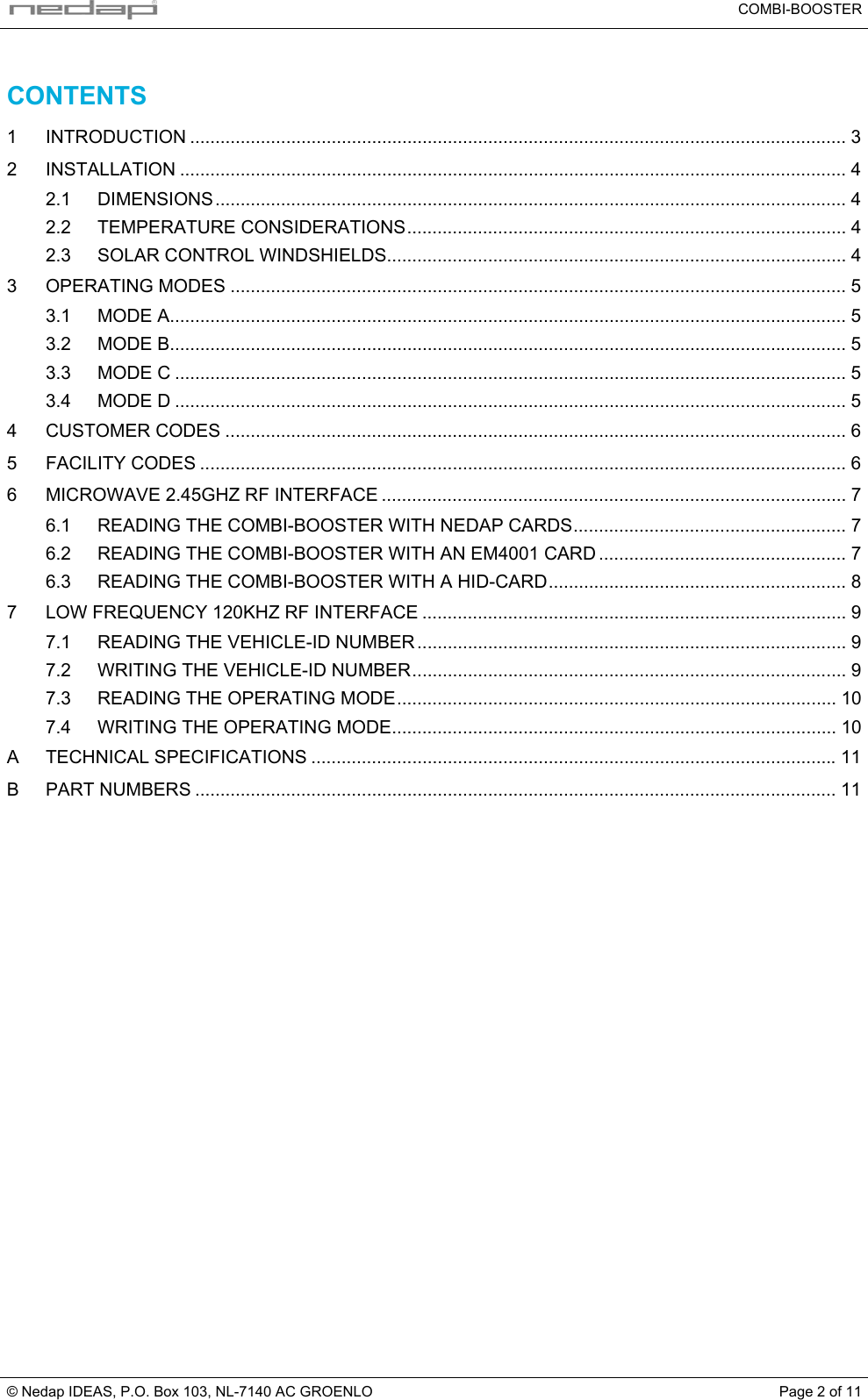
![COMBI-BOOSTER © Nedap IDEAS, P.O. Box 103, NL-7140 AC GROENLO Page 3 of 11 1 INTRODUCTION The Combi-Booster is an intelligent microwave RF-ID transponder designed for fleet owners who want identification of vehicle and driver at the same time. The Combi-Booster is mounted behind the windshield of a vehicle and is programmed with the vehicle's id-number. The inserted credit card sized tag generates the driver's id-number. The combination of driver-id and vehicle-id brings the flexibility needed for fleet owners to control their vehicles even when different drivers are driving the vehicles. The Combi-Booster combines both id-numbers (vehicle and driver) into one message, which is transmitted to the TRANSIT microwave RF-ID reader. The Combi-Booster was developed based upon the unique patent of the Nedap dual band technology. This patented technology enables reading of the low frequency credit card sized tag by the TRANSIT microwave reader. The microwave technology in the 2.45GHz band allows identification at a distance up to 10 meters, even at high speeding passage. The Combi-Booster can be used for two types of Nedap low frequency cards, the thin ISO-card and the thicker XS-card. The firmware of the Combi-Booster also supports 64-bit manchester encoded transponders such as the EM4001. A special Combi-Booster version is available which can read HID-cards. This device complies with Part 15 of the FCC Rules. Operation is subject to the following two conditions: (1) this device may not cause harmful interference, and (2) this device must accept any interference received, including interference that may cause undesired operation. 2.45GHzRF signalvehicle-id + driver-idTRANSITreaderCombi-Booster [vehicle-id]insertedcredit cardsized tag[driver-id] Combi-Booster[vehicle-id]120kHzRF signalvehicle-idXS110Wread/write Key features: • Unique patented dual band technology • Combined vehicle-id and driver-id • Easy interior mounting • Push button activation • Long life time (up to 6 years) • Multiple read](https://usermanual.wiki/Nedap-N-V/COMBI-BOOSTER2/User-Guide-489346-Page-3.png)