Nedap N V ECO41356 Inductive RFID card Reader operating on 13.56 MHz User Manual 14 Manual CGDECO41356
N. V. Nederlandsche Apparatenfabriek NEDAP Inductive RFID card Reader operating on 13.56 MHz 14 Manual CGDECO41356
UserManual.wiki
>
Nedap N V
>
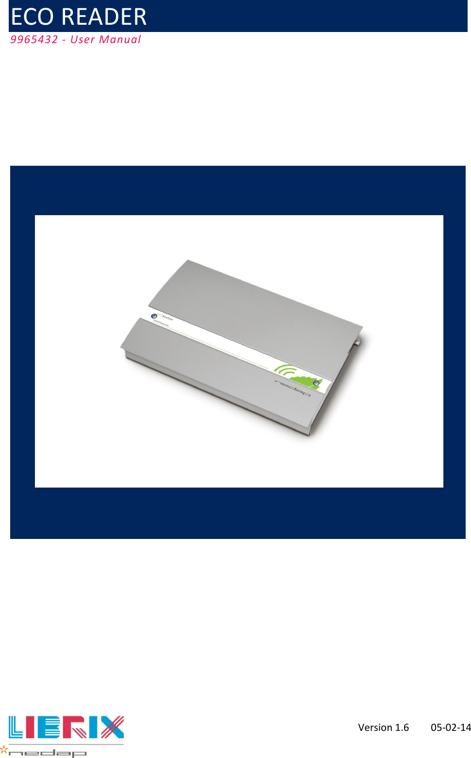
ECO41356 User Manual
14_Manual CGDECO41356
Navigation menu
Upload a User Manual
Namespaces
Wiki Guide
HTML
PDF
Info
Views
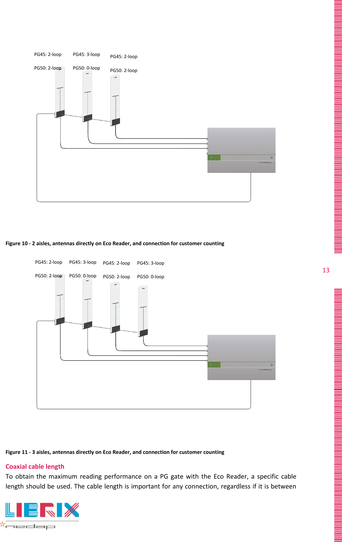
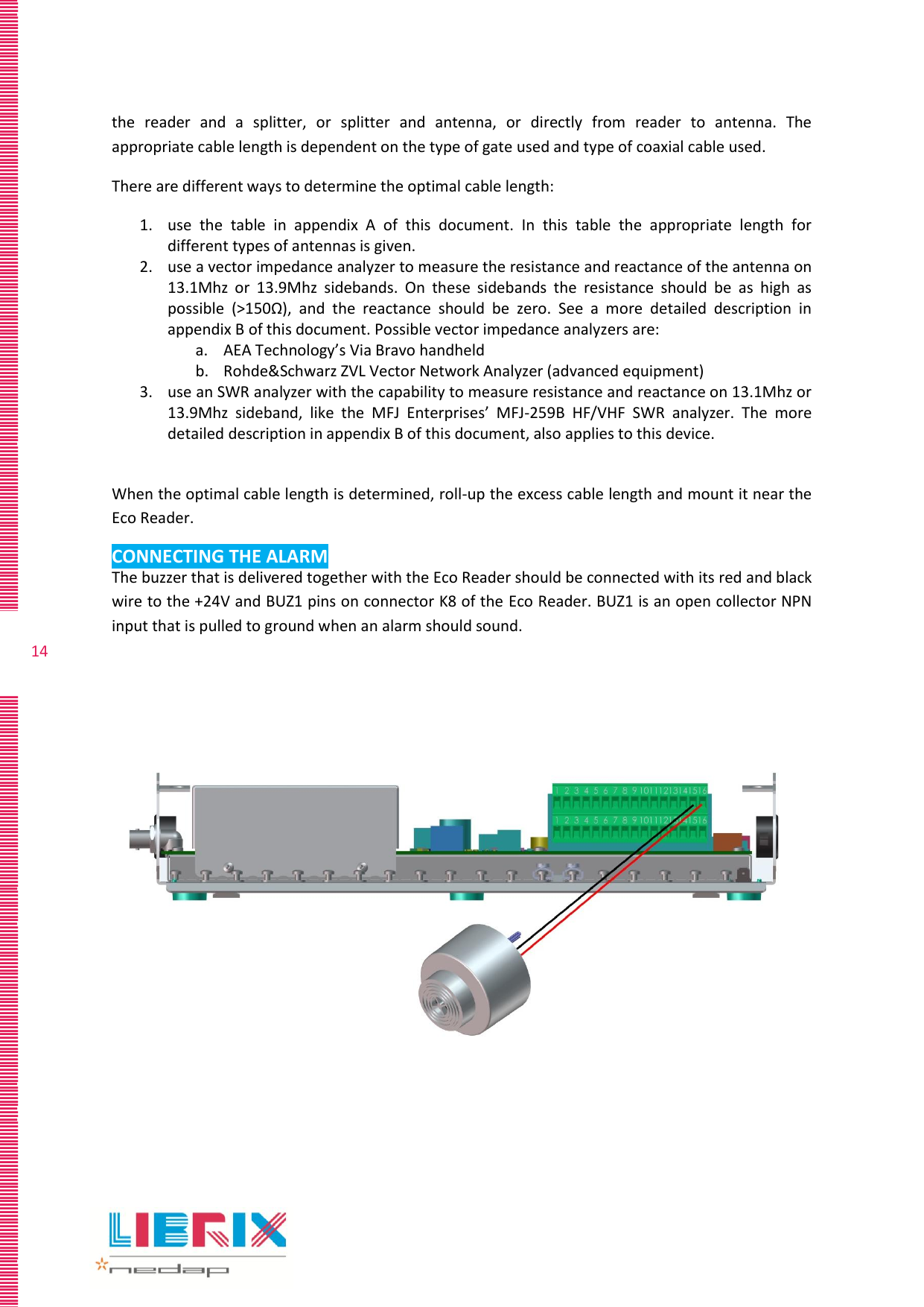
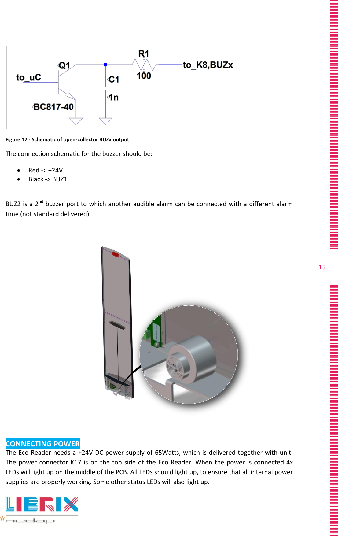
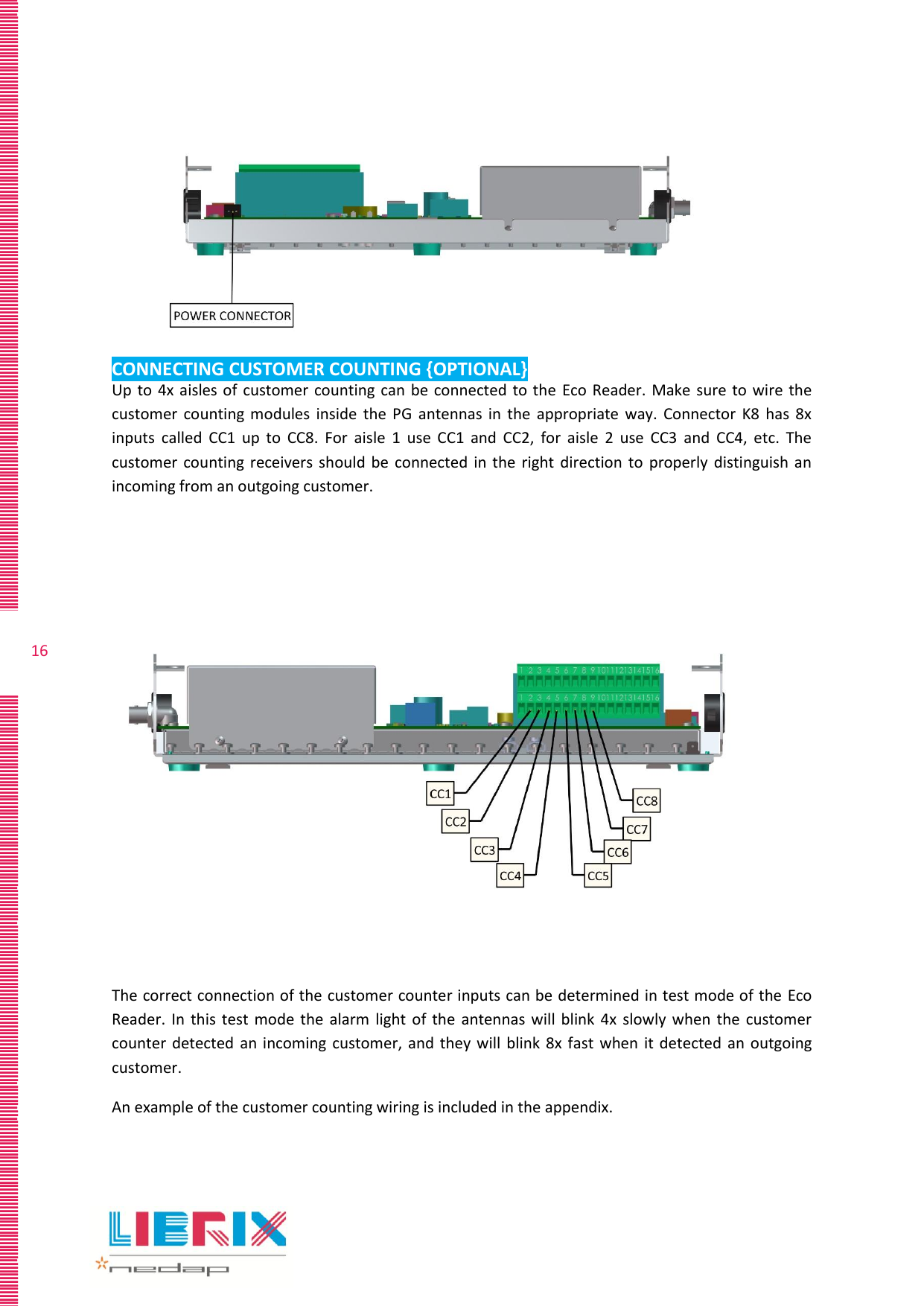
User Manual
Discussion / Help
Navigation