Nedap N V FC180RRF Anti-Pilferage device User Manual Manual FC line

N. V. Nederlandsche Apparatenfabriek NEDAP Anti-Pilferage device Manual FC line
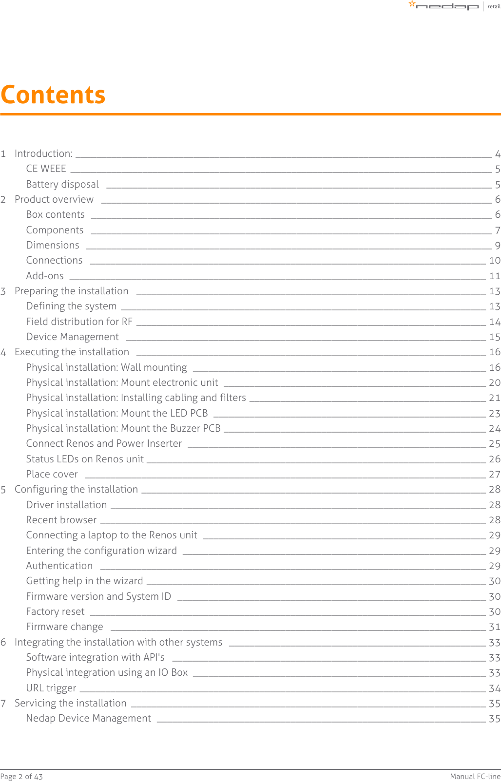
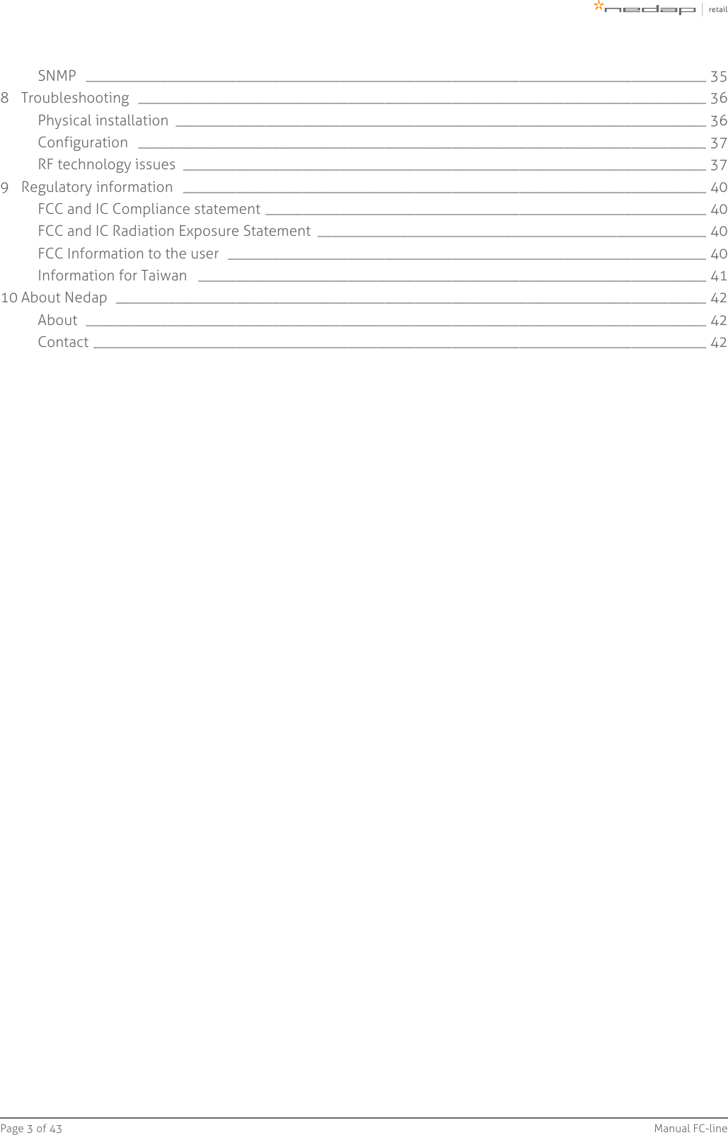
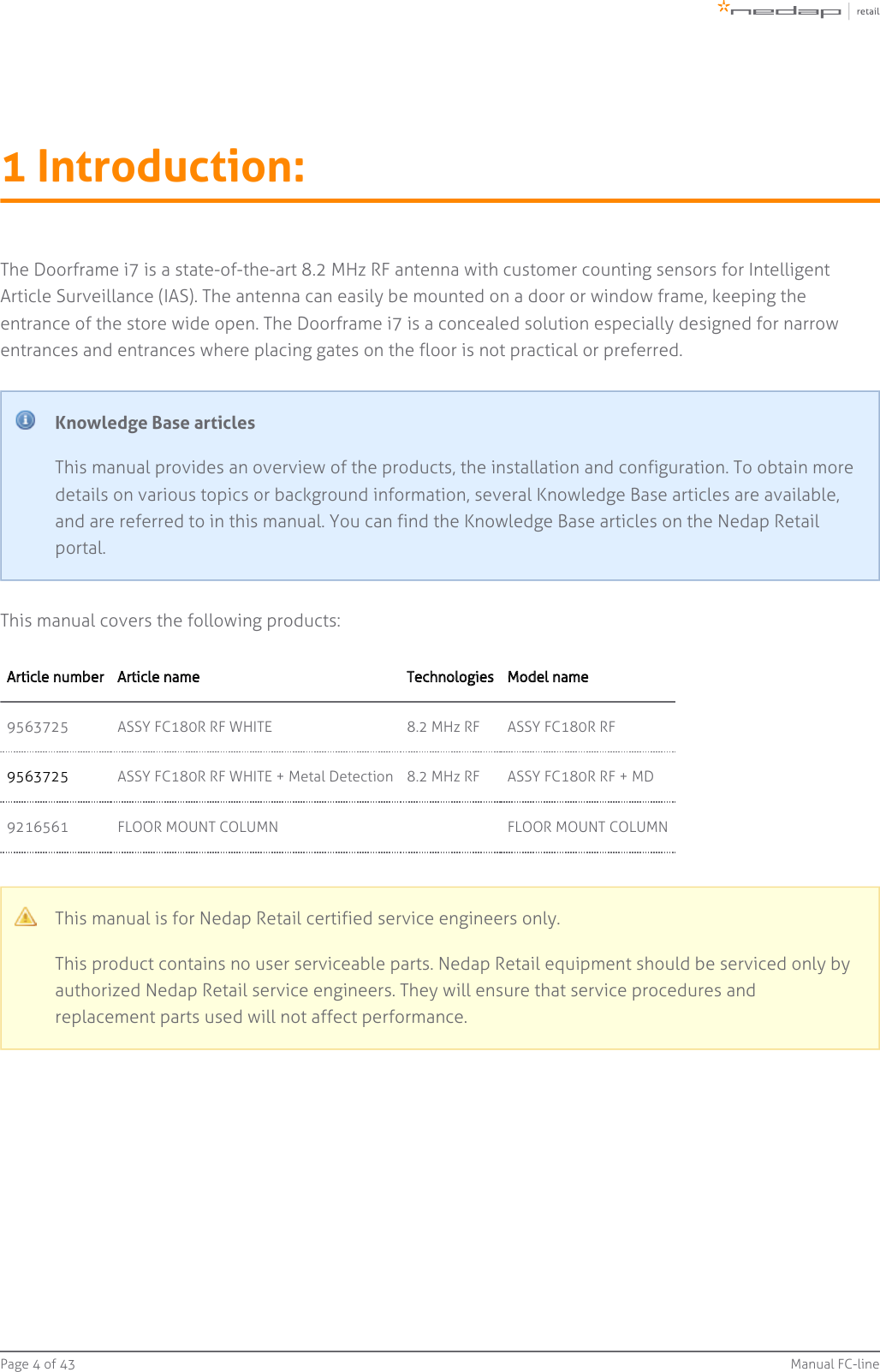
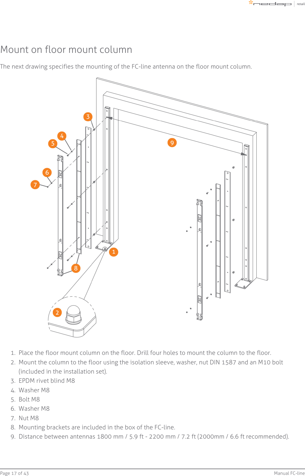
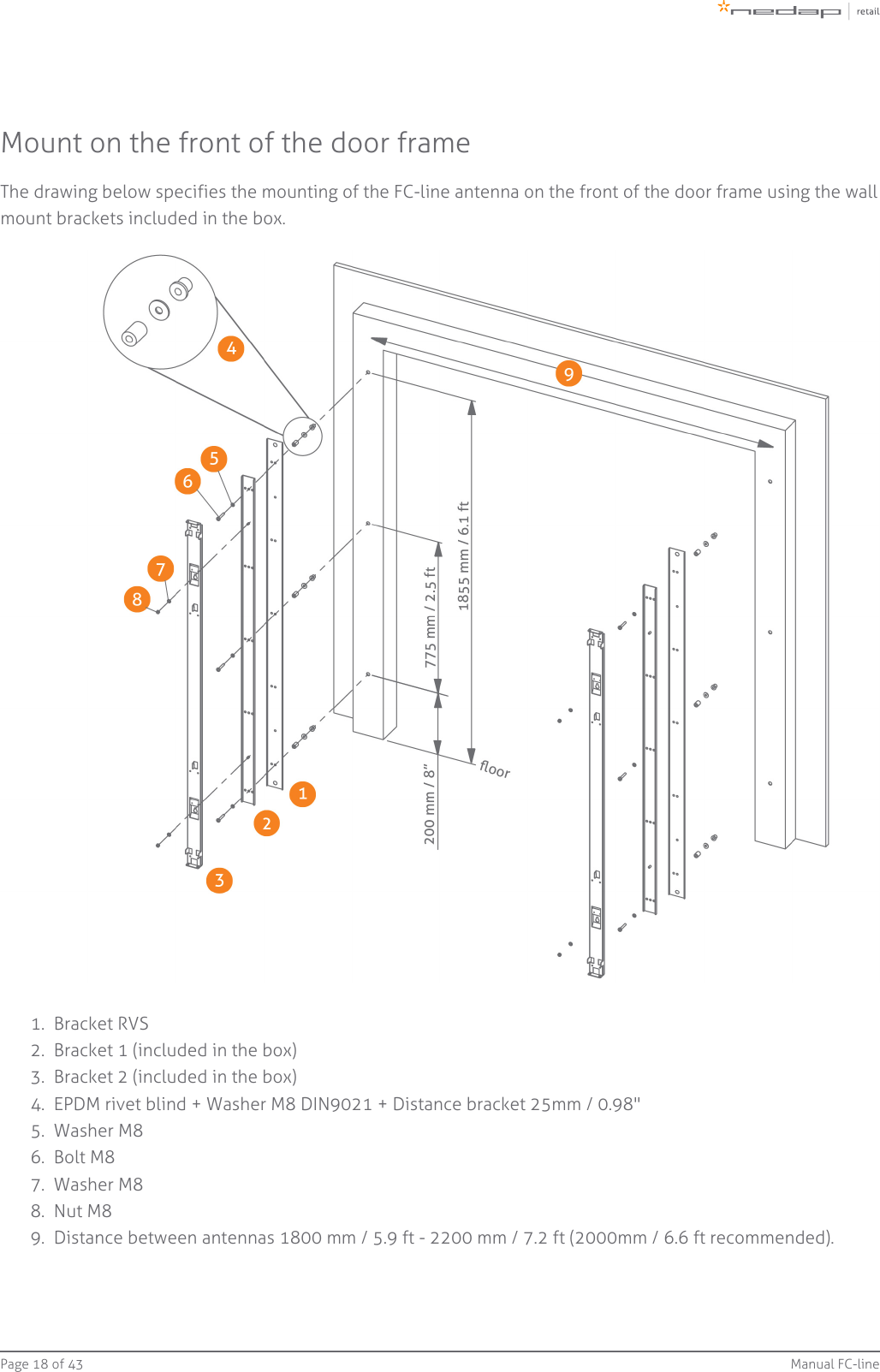
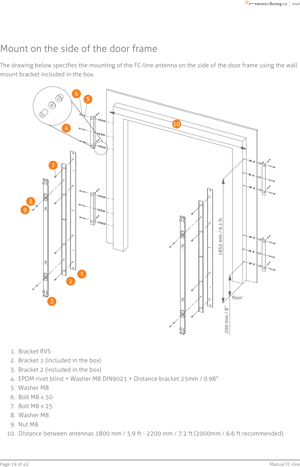
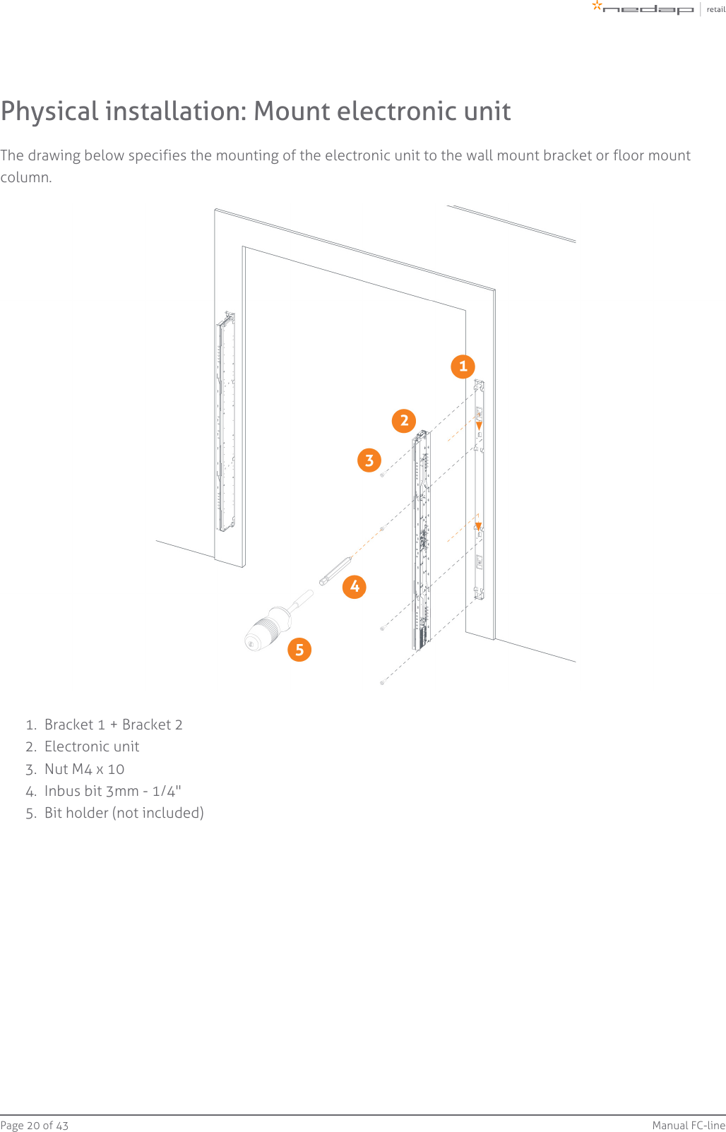
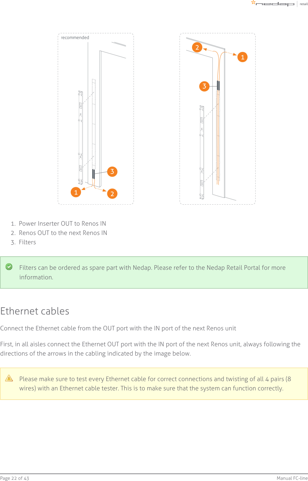
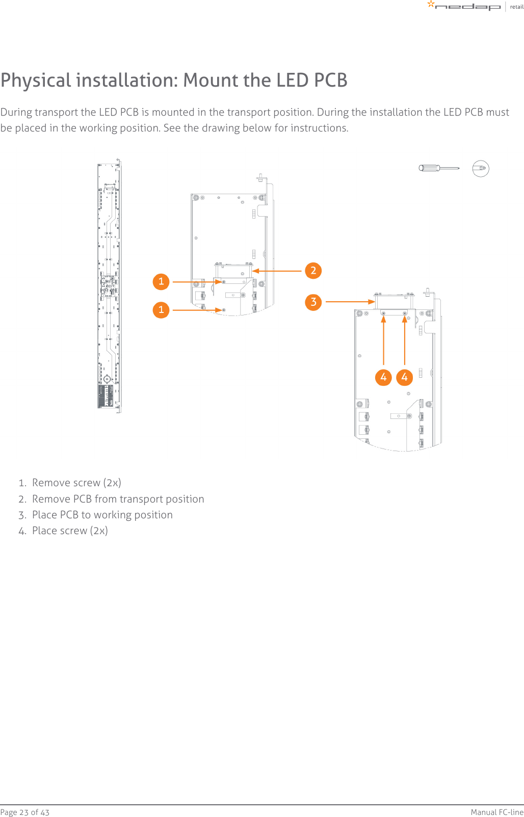
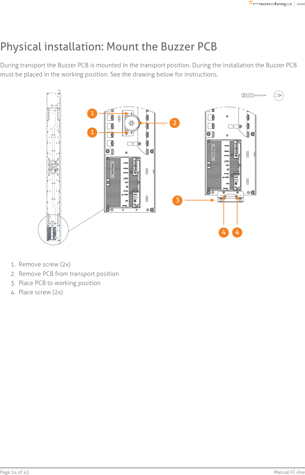
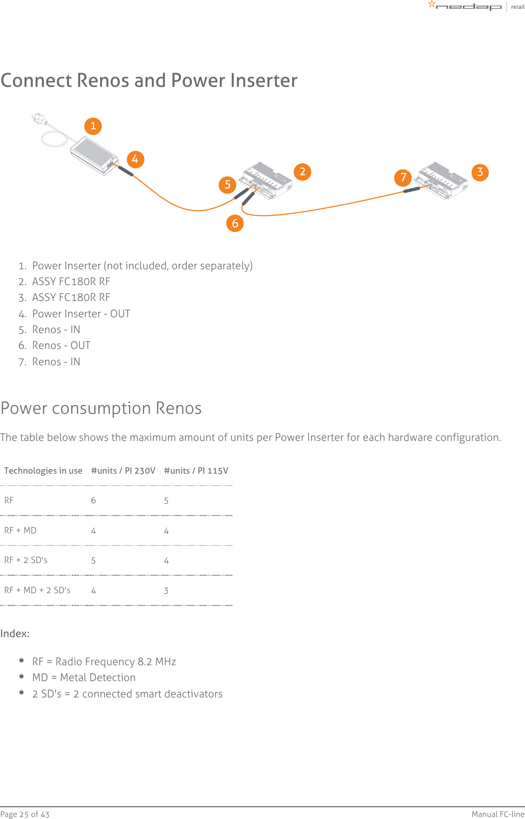
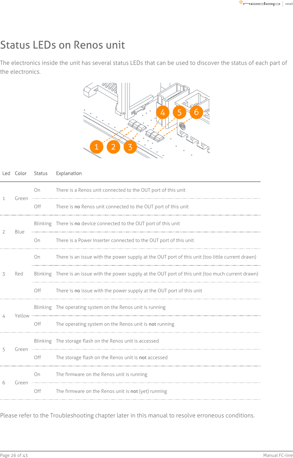
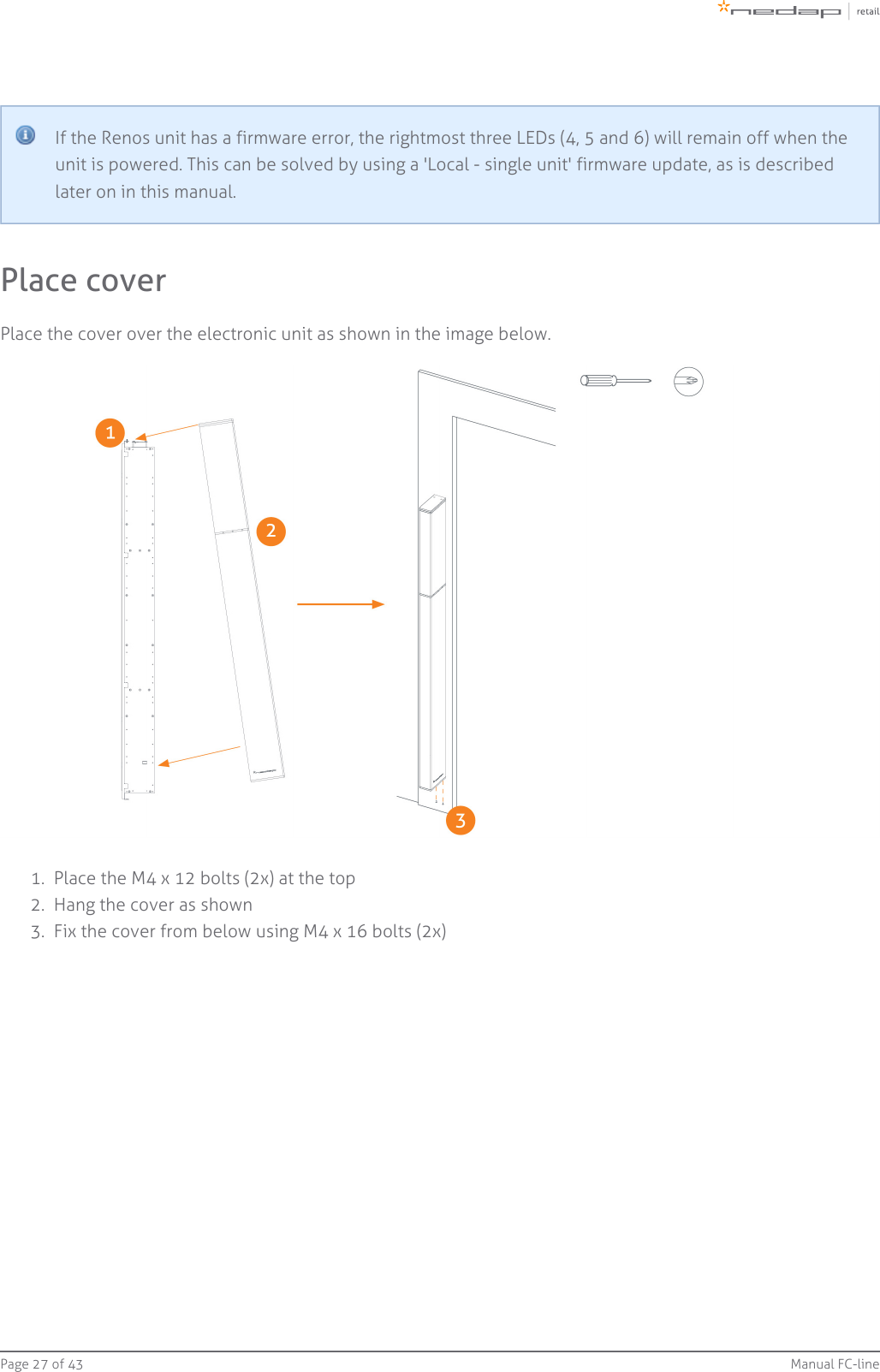
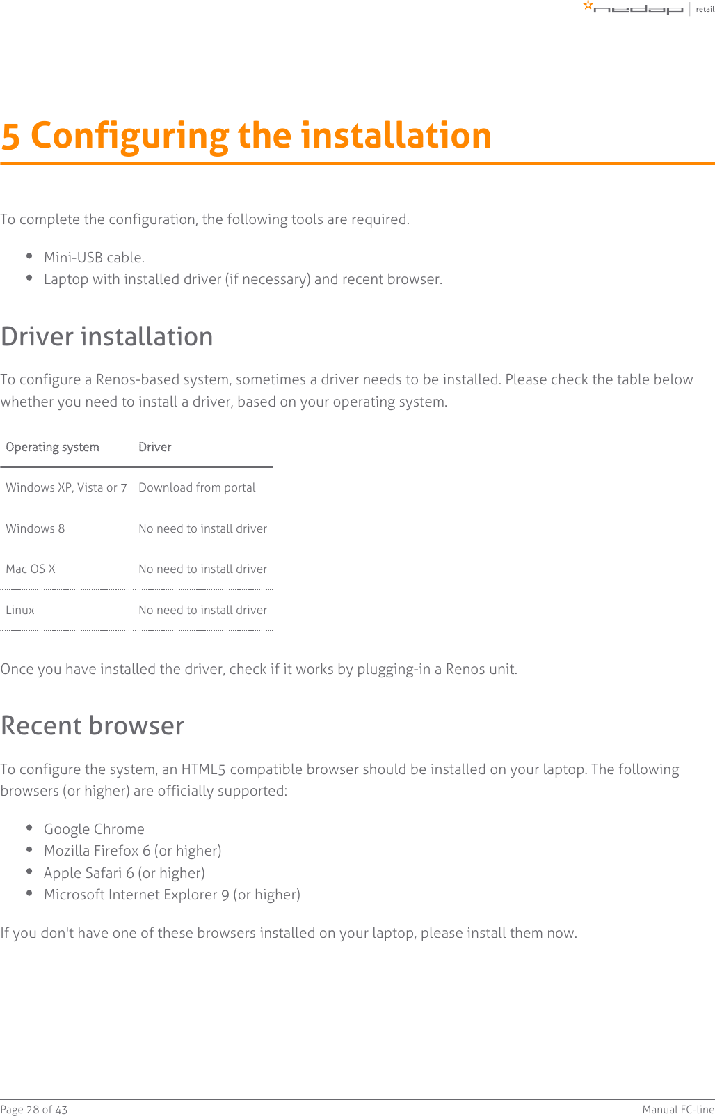
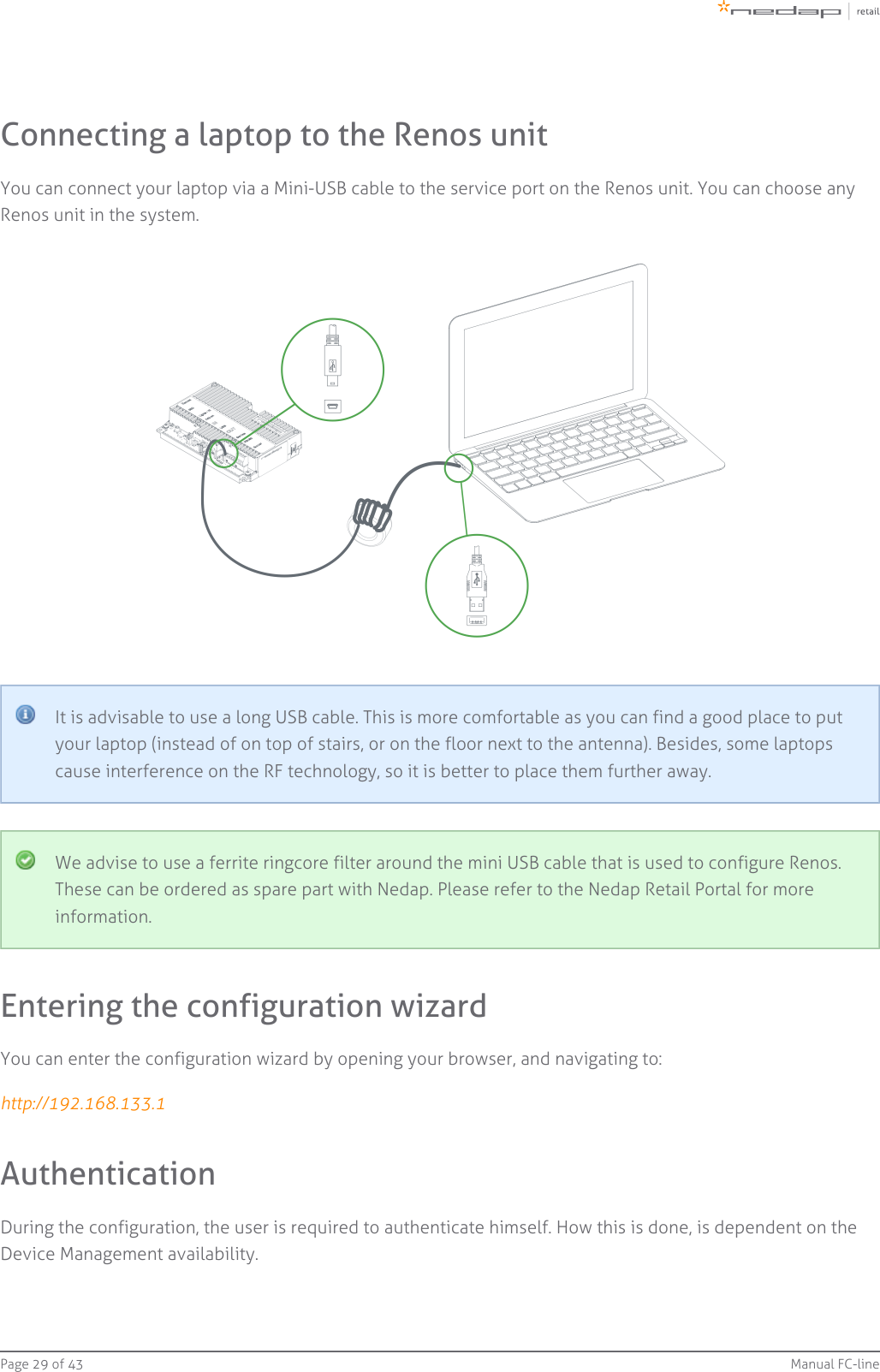
TempConfidential_14_Manual FC-line-v68-20150716_1037 CGDFC180RRF

PRELIMINARYDoorframe i7Manual FC-line
Page   of 2 43 Manual FC-lineContents1 Introduction: _________________________________________________________________________________ 4CE WEEE  __________________________________________________________________________________ 5Battery disposal  ___________________________________________________________________________ 52 Product overview  ____________________________________________________________________________ 6Box contents  ______________________________________________________________________________ 6Components  ______________________________________________________________________________ 7Dimensions  _______________________________________________________________________________ 9Connections  _____________________________________________________________________________ 10Add-ons  _________________________________________________________________________________ 113 Preparing the installation  ____________________________________________________________________ 13Defining the system  _______________________________________________________________________ 13Field distribution for RF ____________________________________________________________________ 14Device Management  ______________________________________________________________________ 154 Executing the installation  ____________________________________________________________________ 16Physical installation: Wall mounting  _________________________________________________________ 16Physical installation: Mount electronic unit  ___________________________________________________ 20Physical installation: Installing cabling and filters ______________________________________________ 21Physical installation: Mount the LED PCB  _____________________________________________________ 23Physical installation: Mount the Buzzer PCB ___________________________________________________ 24Connect Renos and Power Inserter  __________________________________________________________ 25Status LEDs on Renos unit __________________________________________________________________ 26Place cover  ______________________________________________________________________________ 275 Configuring the installation ___________________________________________________________________ 28Driver installation _________________________________________________________________________ 28Recent browser ___________________________________________________________________________ 28Connecting a laptop to the Renos unit  _______________________________________________________ 29Entering the configuration wizard  ___________________________________________________________ 29Authentication  ___________________________________________________________________________ 29Getting help in the wizard __________________________________________________________________ 30Firmware version and System ID  ____________________________________________________________ 30Factory reset  _____________________________________________________________________________ 30Firmware change  _________________________________________________________________________ 316 Integrating the installation with other systems  __________________________________________________ 33Software integration with API's  _____________________________________________________________ 33Physical integration using an IO Box  _________________________________________________________ 33URL trigger _______________________________________________________________________________ 347 Servicing the installation  _____________________________________________________________________ 35Nedap Device Management  ________________________________________________________________ 35
Page   of 3 43 Manual FC-lineSNMP  ___________________________________________________________________________________ 358 Troubleshooting  ____________________________________________________________________________ 36Physical installation  _______________________________________________________________________ 36Configuration  ____________________________________________________________________________ 37RF technology issues  ______________________________________________________________________ 379 Regulatory information  ______________________________________________________________________ 40FCC and IC Compliance statement ___________________________________________________________ 40FCC and IC Radiation Exposure Statement  ____________________________________________________ 40FCC Information to the user  ________________________________________________________________ 40Information for Taiwan  ____________________________________________________________________ 4110 About Nedap  _______________________________________________________________________________ 42About  ___________________________________________________________________________________ 42Contact __________________________________________________________________________________ 42
Page   of 4 43 Manual FC-line1 Introduction:The Doorframe i7 is a state-of-the-art 8.2 MHz RF antenna with customer counting sensors for IntelligentArticle Surveillance (IAS). The antenna can easily be mounted on a door or window frame, keeping theentrance of the store wide open. The Doorframe i7 is a concealed solution especially designed for narrowentrances and entrances where placing gates on the floor is not practical or preferred.Knowledge Base articlesThis manual provides an overview of the products, the installation and configuration. To obtain moredetails on various topics or background information, several Knowledge Base articles are available,and are referred to in this manual. You can find the Knowledge Base articles on the Nedap Retailportal.This manual covers the following products:Article number Article name Technologies Model name9563725 ASSY FC180R RF WHITE 8.2 MHz RF ASSY FC180R RF9563725 ASSY FC180R RF WHITE + Metal Detection 8.2 MHz RF ASSY FC180R RF + MD9216561 FLOOR MOUNT COLUMN FLOOR MOUNT COLUMNThis manual is for Nedap Retail certified service engineers only.This product contains no user serviceable parts. Nedap Retail equipment should be serviced only byauthorized Nedap Retail service engineers. They will ensure that service procedures andreplacement parts used will not affect performance.
Page   of 5 43 Manual FC-lineCE WEEEThis European Standard specifies a markingof electrical and electronic equipment in accordance with Article 11(2) of Directive2002/96/EC (WEEE); This is in addition to the marking requirement in Article 10(3) of thisDirective which requires producers to mark electrical and electronic equipment put on themarket after 13 August 2005 with a ‘crossed-out wheeled bin’ symbol.that applies to electrical and electronic equipment falling under Annex IA of Directive2002/96/EC, provided the equipment concerned is not part of another type of equipment thatdoes not fall within the scope of this Directive. Annex IB of Directive 2002/96/EC contains anindicative list of the products, which fall under the categories set out in Annex IA of thisDirective;that serves to clearly identify the producer of the equipment and that the equipment has beenput on the market after 13 August 2005.Battery disposalThis product contains a non-rechargeable lithium battery. Replace only with the same or equivalent typerecommended by the manufacturer (Panasonic CR2032 lithium button cell). At the end of its useful life, undervarious state and local laws, it may be illegal to dispose of this battery into the municipal waste stream. Checkwith your local solid waste officials for details in your area for recycling options or proper disposal.CautionRisk of explosion if battery is replaced by an incorrect type.Dispose of used batteries according to the instructions.
Page   of 6 43 Manual FC-line2 Product overviewIn this document the following abbreviations will be used from here onwards:'RF technology' is an abbreviation for 8.2 MHz RF technology.Box contentsArticle number Article name Box contents9563725 ASSY FC180R RF WHITEFC180R RF gate with Renos RF insideFrame for wall mountingInstallation setMetal detection is optional and must be ordered separately, article number #9563717.Floor mount column is optional and must be ordered separately, article number #9216561.
Page   of 7 43 Manual FC-lineComponentsThe Doorframe i7 is based on the Renos platform. The Renos platform is developed by Nedap Retailspecifically for retail applications. The Doorframe i7 has several serviceable parts. These are explained in thetable below and highlighted in the schematic drawings.
Page   of 8 43 Manual FC-lineNumber Component Description1 Lights The red LED lights can be used for user feedback or alarms.2Customercounter Integrated customer counter.350 ohmPCB The 50 ohm PCB takes care of the connection between the Renos unit, the RF antenna and the lights.4Metaldetection The metal detection unit (optional) must be placed here and is used to detect metal objects.5 Renos unit The Renos unit is the main processing unit of an FC product. It takes care of powering the system, datacommunication between units and with the outside world. It is equipped with an RF detection engine.6 Buzzer The buzzer can be used for user feedback or alarms.7 Cover White removable cover for easy access to the connections.
Page   of 9 43 Manual FC-lineDimensions
Page   of 10 43 Manual FC-lineConnectionsBelow a Renos unit is displayed, with a description of all its connectors and what they are used for.Number Connector Usage1 50 ohm Connect the Renos unit to the 50 ohm PCB. The 50 ohm PCB connects both the light and the RFantenna.2 Infrared beams Connect to the optional infrared beam sensors.3 Add-on Provide power and synchronization to add-ons.4 Network IN Connected to the Network OUT of a previous Renos unit or a Power Inserter.5 USB Connect accessories to Renos.6 Network OUT Connected to the Network IN of a previous unit or a Power Inserter. Can also be left unconnected orconnected to the customer network.7Mini  USB _  _ service  port_  Connect your laptop to configure the Renos system.8 RS485 connector Connect to the optional Nedap RF Smart Deactivator.9 Buzzer connector Connect to the included buzzer.
Page   of 11 43 Manual FC-lineAdd-onsMetal DetectionThe Renos Metal Detection unit (#9563717) can be used to detect foil-lined bags, which are sometimes usedby thieves to prevent the RF tags from being read by the detection system or reader. With metal detection, wecan detect metal objects and provide a discrete alarm to the store employees.Restrictions for metal detectionYou need a minimum of 2 gates with Metal Detection units to work.Only possible when there are no moving doors with metal (i.e. an aluminum frame around thedoor).Please note that for the connection of the Metal Detection in the FC-line antenna a longerconnection cable is needed (800 mm / 2.6 ft).
Page   of 12 43 Manual FC-lineRF security dashboardThe Renos platform has a built-in RF security dashboard. It can be enabled by entering a license key during theconfiguration wizard. The customer can then visit the dashboard via the web browser. To make this work, theRenos system should be either connected to the customer network, or a stand-alone set-up with a routershould be made.
Page   of 13 43 Manual FC-line1.  2.  3 Preparing the installationWhen preparing an installation with FC-line products, there are a few things that should be taken into account:How many gates one needs to cover an entrance or door.Where the gates will be placed in relation to the environment, for example to minimize interference(RF).It is preferred to install the FC-line gate on the floor mount column. This will up the performance of thesystem and still gives a clean look in the store.What cabling need to be applied (Cat 5E cable).The maximum distance between antennas is 2200 mm / 7.2 ft (2000mm / 6.6 ft recommended).Mounting distance from the ground must be 200 mm / 8".For mounting on concrete and stone walls, chemical anchors are preferredFor mounting on steel frames, EPDM rivet blinds are necessary, which are included in the installationsetDistance brackets (25 mm / 0.98") are provided in the installation set, when possible install the FC-lineproducts with these distance brackets. This will improve the performance of the system, especiallyrecommended for steel frames.The firewall settings that need to be in place to enable Device ManagementDefining the systemWhen the store owner requires gates to be placed at several locations, one needs to decide on how tocombine these gates into one or multiple systems. The following rules shall be taken into account:Create as large systems as possible. To minimize interference between gates, the Renos platform has abuilt-in synchronization mechanism. For this synchronization mechanism to work, the gates need to beconnected in one system.However, the maximum cable length requirements needs to be satisfied. If it is not possible to put allthe gates in one system due to the maximum cable length requirements of 100 meters / 109 yd, youcan split the gates into two or more systems. In this case assign each system a different multi-system during the RF configuration.channel
Page   of 14 43 Manual FC-lineField distribution for RFThere are two modes of operation for RF technology. The mode can be configured during the configurationwizard. There is an RF field in between gates. This mode is preferred for the best performance of theFocused field.system. There is an RF field around the gate. This mode is mainly used when the gates are placed near theFull field.checkouts, as you can have one gate covering a relatively large area.Infra-read beam sensorsPlease note that when you want to use infrared beam sensors for customer counting, you can onlycount customers in between the gates. So, if you set RF to full field, you are not able to countcustomers outside of the gates.
Page   of 15 43 Manual FC-lineDevice ManagementAll the Renos-based products can be connected to the Nedap Device Management Service. This serviceprovides:Monitoring. Critical system parameters are monitored 24/7. As soon as something is wrong with thesystem, an alert is generated to the supporting partner.Remote log-in. Via the Device Management portal it is possible for an authorized Nedap-certifiedengineer to access the user interface of the system to make changes to the configuration or accesssystem logs.Remote Firmware update. It is possible to install new firmware releases remotely.To use Device Management, please make sure that the following firewall ports are opened before installation:TCP port 443 outgoing to *.nedapretail.comThis can be verified by connecting your laptop to the customer network, open your browser and navigate to . You should see a special page there.https://api.nedapretail.comIt is also possible to do this via an HTTPS proxy, however, the remote log-in feature is not available then.For more details, please see the Knowledge Base article on Device Management.If Device Management is available at a certain site, it is possible to pre-configure a system, such thatthe field engineer will have an easier job. For more information, please refer to the Knowledge Basearticle on Pre-configuration.
Page   of 16 43 Manual FC-line4 Executing the installationWhen all the preparations are taken into account, the installation of the system can take place. The installationconsists of physically mounting the system in the right orientation, installing the cabling and applying powerto the system.Physical installation: Wall mountingThe FC-line gates can be mounted in three different methods:Mounted on the floor mount column (recommended)Mounted on the front of the door frameMounted on the side of the door frameDistance to the floorThe distance to the floor should be at least 200 mm / 8" to have enough space for cabling and filters.Rotation of the antennaThe antenna can be rotated vertically to create the optimal focussed RF field. Please note that onlywhen both sensitive sides of the two antennas are facing each other, the maximum distance of 2200mm / 7.2 ft can be obtained. When rotating the antenna, please make sure the Customer CounterPCB's also face each other to work properly. The Customer Counter PCB can easily be rotated insidethe antenna.Prevent interferenceUsing the floor mount column increases the performance of the FC-line gate. It prevents interferencefrom the door frame or wall behind the door frame. When mounting the FC-line gate to the doorframe, using the distance brackets included in the installation set, will help prevent interference.Order floor mount column seperatelyThe floor mount column is not included in the product, but should be ordered separately, articlenumber 9216561.
Page   of 17 43 Manual FC-line1.  2.  3.  4.  5.  6.  7.  8.  9.  Mount on floor mount columnThe next drawing specifies the mounting of the FC-line antenna on the floor mount column.Place the floor mount column on the floor. Drill four holes to mount the column to the floor.Mount the column to the floor using the isolation sleeve, washer, nut DIN 1587 and an M10 bolt(included in the installation set).EPDM rivet blind M8Washer M8Bolt M8Washer M8Nut M8Mounting brackets are included in the box of the FC-line.Distance between antennas 1800 mm / 5.9 ft - 2200 mm / 7.2 ft (2000mm / 6.6 ft recommended).
Page   of 18 43 Manual FC-line1.  2.  3.  4.  5.  6.  7.  8.  9.  Mount on the front of the door frameThe drawing below specifies the mounting of the FC-line antenna on the front of the door frame using the wallmount brackets included in the box.Bracket RVSBracket 1 (included in the box)Bracket 2 (included in the box)EPDM rivet blind + Washer M8 DIN9021 + Distance bracket 25mm / 0.98"Washer M8Bolt M8Washer M8Nut M8Distance between antennas 1800 mm / 5.9 ft - 2200 mm / 7.2 ft (2000mm / 6.6 ft recommended).
Page   of 19 43 Manual FC-line1.  2.  3.  4.  5.  6.  7.  8.  9.  10.  Mount on the side of the door frameThe drawing below specifies the mounting of the FC-line antenna on the side of the door frame using the wallmount bracket included in the box.Bracket RVSBracket 1 (included in the box)Bracket 2 (included in the box)EPDM rivet blind + Washer M8 DIN9021 + Distance bracket 25mm / 0.98"Washer M8Bolt M8 x 50Bolt M8 x 25Washer M8Nut M8Distance between antennas 1800 mm / 5.9 ft - 2200 mm / 7.2 ft (2000mm / 6.6 ft recommended).
Page   of 20 43 Manual FC-line1.  2.  3.  4.  5.  Physical installation: Mount electronic unitThe drawing below specifies the mounting of the electronic unit to the wall mount bracket or floor mountcolumn.Bracket 1 + Bracket 2Electronic unitNut M4 x 10Inbus bit 3mm - 1/4"Bit holder (not included)
Page   of 21 43 Manual FC-line1.  2.  3.  Physical installation: Installing cabling and filtersDuring the preparation phase, the exact cabling required was already determined. Now these cables can beplaced.All wiring should be done according to local regulations.When cables are installed, it is recommended to mark them with IN and OUT, or PREVIOUS and NEXT,as this will allow you to distinguish them from each other.FiltersPlease note that filters should be placed around the cables to reduce interference with other systems. Thesefilters are delivered together with the system.Filter should be placed at:Every Power Inserter: around the Ethernet cable, both at the OUT and IN port.Every Renos unit: around the Ethernet cable, both at the OUT and IN port.Every 9 m / 30 ft. for longer Ethernet cables.To save yourself a huge amount of frustration, please first place the filters   attaching thebeforeconnectors. The other way around is not possible. Many have tried before.
Page   of 22 43 Manual FC-line1.  2.  3.  Power Inserter OUT to Renos INRenos OUT to the next Renos INFiltersFilters can be ordered as spare part with Nedap. Please refer to the Nedap Retail Portal for moreinformation.Ethernet cablesConnect the Ethernet cable from the OUT port with the IN port of the next Renos unitFirst, in all aisles connect the Ethernet OUT port with the IN port of the next Renos unit, always following thedirections of the arrows in the cabling indicated by the image below.Please make sure to test every Ethernet cable for correct connections and twisting of all 4 pairs (8wires) with an Ethernet cable tester. This is to make sure that the system can function correctly.
Page   of 23 43 Manual FC-line1.  2.  3.  4.  Physical installation: Mount the LED PCBDuring transport the LED PCB is mounted in the transport position. During the installation the LED PCB mustbe placed in the working position. See the drawing below for instructions.Remove screw (2x)Remove PCB from transport positionPlace PCB to working positionPlace screw (2x)
Page   of 24 43 Manual FC-line1.  2.  3.  4.  Physical installation: Mount the Buzzer PCBDuring transport the Buzzer PCB is mounted in the transport position. During the installation the Buzzer PCBmust be placed in the working position. See the drawing below for instructions.Remove screw (2x)Remove PCB from transport positionPlace PCB to working positionPlace screw (2x)
Page   of 25 43 Manual FC-line1.  2.  3.  4.  5.  6.  7.  Connect Renos and Power InserterPower Inserter (not included, order separately)ASSY FC180R RFASSY FC180R RFPower Inserter - OUTRenos - INRenos - OUTRenos - INPower consumption RenosThe table below shows the maximum amount of units per Power Inserter for each hardware configuration.Technologies in use #units / PI 230V #units / PI 115VRF 6 5RF + MD 4 4RF + 2 SD's 5 4RF + MD + 2 SD's 4 3Index:RF = Radio Frequency 8.2 MHzMD = Metal Detection2 SD's = 2 connected smart deactivators
Page   of 26 43 Manual FC-lineStatus LEDs on Renos unitThe electronics inside the unit has several status LEDs that can be used to discover the status of each part ofthe electronics.Led Color Status Explanation1 GreenOn There is a Renos unit connected to the OUT port of this unitOff There is   Renos unit connected to the OUT port of this unitno2 BlueBlinking There is   device connected to the OUT port of this unitnoOn There is a Power Inserter connected to the OUT port of this unit3 RedOn There is an issue with the power supply at the OUT port of this unit (too little current drawn)Blinking There is an issue with the power supply at the OUT port of this unit (too much current drawn)Off There is   issue with the power supply at the OUT port of this unitno4 YellowBlinking The operating system on the Renos unit is runningOff The operating system on the Renos unit is   runningnot5 GreenBlinking The storage flash on the Renos unit is accessedOff The storage flash on the Renos unit is   accessednot6 GreenOn The firmware on the Renos unit is runningOff The firmware on the Renos unit is   (yet) runningnotPlease refer to the Troubleshooting chapter later in this manual to resolve erroneous conditions.
Page   of 27 43 Manual FC-line1.  2.  3.  If the Renos unit has a firmware error, the rightmost three LEDs (4, 5 and 6) will remain off when theunit is powered. This can be solved by using a 'Local - single unit' firmware update, as is describedlater on in this manual.Place coverPlace the cover over the electronic unit as shown in the image below.Place the M4 x 12 bolts (2x) at the topHang the cover as shownFix the cover from below using M4 x 16 bolts (2x)
Page   of 28 43 Manual FC-line5 Configuring the installationTo complete the configuration, the following tools are required.Mini-USB cable.Laptop with installed driver (if necessary) and recent browser.Driver installationTo configure a Renos-based system, sometimes a driver needs to be installed. Please check the table belowwhether you need to install a driver, based on your operating system.Operating system DriverWindows XP, Vista or 7 Download from portalWindows 8 No need to install driverMac OS X No need to install driverLinux No need to install driverOnce you have installed the driver, check if it works by plugging-in a Renos unit.Recent browserTo configure the system, an HTML5 compatible browser should be installed on your laptop. The followingbrowsers (or higher) are officially supported:Google ChromeMozilla Firefox 6 (or higher)Apple Safari 6 (or higher)Microsoft Internet Explorer 9 (or higher)If you don't have one of these browsers installed on your laptop, please install them now.
Page   of 29 43 Manual FC-lineConnecting a laptop to the Renos unitYou can connect your laptop via a Mini-USB cable to the service port on the Renos unit. You can choose anyRenos unit in the system.It is advisable to use a long USB cable. This is more comfortable as you can find a good place to putyour laptop (instead of on top of stairs, or on the floor next to the antenna). Besides, some laptopscause interference on the RF technology, so it is better to place them further away.We advise to use a ferrite ringcore filter around the mini USB cable that is used to configure Renos.These can be ordered as spare part with Nedap. Please refer to the Nedap Retail Portal for moreinformation.Entering the configuration wizardYou can enter the configuration wizard by opening your browser, and navigating to:http://192.168.133.1AuthenticationDuring the configuration, the user is required to authenticate himself. How this is done, is dependent on theDevice Management availability.
Page   of 30 43 Manual FC-line1.  2.  3.  4.  a.  b.  c.  5.  6.  7.  The system is connected to Device Management: you can directly enter your Nedap Retail usernameand password.The system is not connected to Device Management, and you don't have a Nedap Retail authenticationsoftware: choose one of the following steps:If your laptop is able to connect to Device Management via a 3G dongle or Wi-Fi, you can usethis option to enter your username and password.If that is not available, you can use your smartphone.If your smartphone has no internet access, you can call our support to get an authenticationcode.Please contact support for more details on how to obtain a Nedap Retail username and password.Getting help in the wizardIf something is not clear, each page has a question mark button in the top right corner. You can click this to getmore information on what is expected to do on a certain page.Firmware version and System IDWhen you ask for support for a specific system, the support engineer will always ask you for the firmwareversion and the system ID. The firmware version is displayed in the right top of the configuration wizard. If youclick the firmware version, a pop-up will appear that shows the System ID.Factory resetTo execute a factory reset on a single Renos unit, the following steps need to be executed:Turn off the system by removing the power cable of the Power Inserter.Connect a Mini-USB cable from the USB service port to the USB port on the Renos unit.Reconnect the power cable to the Power Inserter.The LED that usually indicates that the firmware is running (the green LED on the right) will show thefollowing behavior:Blink couple of timesStay onBlink couple of timesWhen this is completed, wait one minute before proceeding.Turn off the power.Remove the USB cable.Turn on the power.
Page   of 31 43 Manual FC-line1.  2.  3.  Configuration is lostPlease note that when doing a factory reset, all settings and configuration of the unit are lost. Thefirmware version does not change.Firmware changeThere are three ways to change the firmware version on a Renos-based system:Device Management update. The update can be executed via the Device Management service.Local - single unit flash. The update can be executed by inserting a USB stick with the right firmwareinto the USB port.Local - complete system flash. The update can be executed during the configuration wizard with fileson your laptop.If the system is integrated with a 3rd party system, please confirm the firmware version with that 3rdparty before installing it.Device Management updateTo update the firmware via Device Management, please make sure the system is configured, delivered andconnected to the Device Management service. Then, navigate to the Device Management website and use thefunctionality there to initiate the firmware update.Local - single unit flashDownload the correct firmware image file from the Nedap Retail portal. Extract this file to a USB stick. Turn offthe power of the system. Insert the USB stick in the USB port of a Renos unit. Power the system. Wait untilLEDs 4, 5 and 6 are off again. This can take around ten minutes. Then turn off the power again, remove the USBstick and turn on the power.Configuration is lostPlease note that when using 'local - single unit flash' firmware change, all settings and configurationof the unit are lost.It's only possible to execute this on-site and not remotely, as the system needs to be re-configuredbefore it is usable again.
Page   of 32 43 Manual FC-lineLocal - complete system flashDownload the correct firmware image file from the Nedap Retail portal. Enter the configuration wizard andaccept all Renos units in the system that should be updated. Press the Advanced button and follow the stepsto change the firmware. One of these steps is to upload the firmware image file.Configuration is lostPlease note that when using 'local - complete system flash' firmware change, all settings andconfiguration of the system are lost.It's only possible to execute this on-site and not remotely, as the system needs to be re-configuredbefore it is usable again.
Page   of 33 43 Manual FC-line6 Integrating the installation with othersystemsIt is highly recommended to integrate the FC-line product into other solutions in use at the end customer.Software integration with API'sThe Renos platform offers several API endpoints that deliver events. Those events include:RF alarmsInfrared beam sensor eventsFor more information please refer to the Software integration page on the Nedap Retail Portal withdocumentation and examples.Physical integration using an IO BoxIt is also possible to integrate other systems via relay contact outputs and inputs. This is not directly providedby the Renos unit, but can be done via a 3rd party IO Box.Supported 3rd party IO BoxAt the moment, the following 3rd party IO Box is supported:MOXA ioLogik E1214The IO Box should be connected to a Renos unit via a USB to Ethernet adaptor.An output on an IO Box can be switched when one of these events occur:There is an RF alarmSomeone has pressed the attention button on the RF deactivatorThe deactivator has deactivated a RF labelActivating an input on the IO Box can be used to control the system in the following way:Disable RF transmitter
Page   of 34 43 Manual FC-lineURL triggerNetwork-based devices that have an http-based-API can be triggered with the URL trigger mode. At thismoment   cameras and Renos Pager are supported. A control URL (a link containing information) of thisAxisdevice can be triggered by an RF alarm, Metal Detection alarm or an Attention Button alarm. The URL shouldbe created in the device. The communication can be further configured in the configuration wizard. Make surethat this device is reachable by the Renos system.
Page   of 35 43 Manual FC-line7 Servicing the installationWhen the installation has been completed and delivered, it is possible to service the installation via NedapDevice Management. Besides, we provide monitoring options locally via SNMP.Nedap Device ManagementVia Nedap Device Management the following features are available, when the system is connected to NedapDevice Management.System monitoring via some key metrics. The following key metrics are available:Whether all Renos units are activeWhether all infrared beam sensors are operating without blocked aislesWhether the buzzers and lights are mutedFirmware update. As described before, the firmware of the Renos system can be updated via DeviceManagement.Remote log-in. It is possible to access the configuration wizard remotely via Device Management.These features are available via a web interface and an API, which can be used to integrate Nedap DeviceManagement into 3rd party solutions. For more information, please contact support.SNMPTo allow for local monitoring of Renos systems, and integration into existing IT infrastructure we supportSimple Network Management Protocol (SNMP). The following variables are available on the Renos platform:One or more Renos units are not reachableOne or more infrared beam sensors are blockedThe system is connected to Device ManagementRenos systems use SNMP version 2c, community public. The MIB file is available on the Renos system itself viathe URL http:// /snmp (for example, that is   when(ip address of the system) http://192.168.133.1/snmpconnected to the USB service port).
Page   of 36 43 Manual FC-line8 TroubleshootingIf the system is not working correctly, please check the troubleshooting options below. If it is not possible tosolve your issue, you can find support options in the next chapter.Physical installationSymptom Cause SolutionThe red LED (3) on aRenos unit is on.The current drawn out of the OUT port of the Renos unit istoo low. The cabling at the OUT port of the Renos unit doesnot satisfy the maximum length requirements.Verify whether the cabling length in thesystem satisfies the requirements posedearlier in this document.The current drawn out of the OUT port of the Renos unit istoo low. The connectors of the Ethernet cable at the OUTport of the Renos unit are not mated properly.Check the Ethernet cabling at the OUTport of the Renos unit with a Ethernetcable tester.The red LED (3) on aRenos unit is blinking.The current drawn out of the OUT port of the Renos unit istoo high. Too much Renos unit and add-ons connected toone Power Inserter.Verify the number of Renos units andadd-ons connected to the Power Inserterswith the table earlier in this document.The current drawn out of the OUT port of the Renos unit istoo high. There is a short circuit in the cabling leaving theOUT port of this Renos unit.Check the Ethernet cabling at the OUTport of the Renos unit with an Ethernetcable tester.The green LED (1) on aRenos unit is off, butthere is a unit behind thisunit.There is an issue in the cabling between those unit, suchthat the following unit is not recognized.Check Ethernet cabling with an Ethernetcable tester.
Page   of 37 43 Manual FC-line1.  2.  a.  b.  ConfigurationSymptom Cause SolutionIt is not possible to access theconfiguration web interface.Renos unit has not started yetVerify the green "firmware running" LED onthe Renos unit (6). If this LED is not on, verifythe system has power or wait five minutes andtry again.Mini USB cable not attached to Renos unit andlaptop Attach cable to Renos unit and laptop.Driver not installed On Windows 7 and older you manually needto install a driver to support Renos.I have put a system together,but I only see a part of all unitsduring the hardware discovery.During configuration, the WAN access port willbe ‘closed’ for internal network traffic. If youcombine two systems later on, this needs to bere-openend.Do a factory reset on the unit that waspreviously used as WAN entry point.If that doesn't work, do a factory reset on allunits.There is a cabling error. Please check all Ethernet cabling with anEthernet cable tester.Not all Power Inserters are powered, or someRenos units are not fully started.Verify the green "firmware running" LED onthe Renos unit (6). If this LED is not on, verifythe system has power or wait five minutes andtry again.There is a firmware failure,indicated by the fact that allthree LEDs 4, 5 and 6 are off onthe Renos unit.Something might has gone wrong with afirmware update.Use the 'local - single' unit firmware updatemechanism to restore the unit.RF technology issuesWhen there are issues with RF technology during the configuration (the gates show as orange or red in thewizard), please follow the following steps:Check the parameters in the RF Advanced Config of the configuration wizard, RF gate performancesection. Probably one of those parameters is red or orange.Disable all transmitters.If all parameters in the RF gate performance section turn green again, there is a couplingproblem (the transmitter couples with a label-like object in environment). Please continue at the'coupling problem' section.
Page   of 38 43 Manual FC-line2.  b.  If all parameters in the RF gate performance section remain orange or red, there is an activeinterferer (another device that transmit radio waves around the 8.2 MHz RF spectrum, likeanother EAS system, an engine or a power supply). Please continue at the 'active interferer'section.Coupling problemCoupling problems are caused by objects that act as a label to the RF system. For example metallicdoorframes, metal checkouts, cabling: everything that runs in a loop and is metallic.To solve these problems, there are a few things you can try:Tighten screws in the metallic construction. This might work for checkouts or customer guidance rails.Try to interrupt the metallic loop. This can be done by using non-metallic parts inside those loops, or tomake a cut in them.Create a shortcut in the metallic loop, to make it smaller. In this way it will resonate at a differentfrequency.If the above solutions don't solve the problem, you can decrease the sensitivity of the system. This can bedone by ticking the 'reduced sensitivity' button in the RF Advanced Config.If a decreased sensitivity doesn't work, and there is only one type of label or tag in the store, youalso have the option to increase the 'receiver delay', in steps of 3 dB.If these things don't solve the problem, please contact support.Active interfererThe first step is to try to locate the source of the active interferer. You can do this by unplugging electronicdevices around the gate (or move them away), and see if the parameters in the 'RF gate performance' sectionimprove, or when the average height of the spectrum is reduced. If this is the case, you have identified theactive interferer.When the active interferer is known, the following solutions are possible:Try to move the active interferer away from the gate as far as possible.Try to apply filters around the cabling of the active interferer.Shield the active interferer with aluminum foil of at least 0.05 mm (2 mil.).If the above solutions don't solve the problem, you can decrease the sensitivity of the system. This can bedone by ticking the 'reduced sensitivity' button in the RF Advanced Config.
Page   of 39 43 Manual FC-lineThere are also standard click-on ferrites available that can be used to reduce active interferencesources (e.g. Würth 742 711 31) If these things don't solve the problem, please contact support.
Page   of 40 43 Manual FC-line9 Regulatory informationFCC and IC Compliance statementThis device complies with part 15 of the FCC Rules and to RSS210 of Industry Canada. Operation is subject tothe following two conditions:(1) this device may not cause harmful interference, and(2) this device must accept any interference received, including interference that may cause undesiredoperation.Changes or modifications not expressly approved by the party responsible for compliance could void theuser’s authority to operate the equipment.Cet appareil se conforme aux normes RSS 210 exemptés de license du Industry Canada. L’opération estsoumis aux deux conditions suivantes:(1) cet appareil ne doit causer aucune interférence, et(2) cet appareil doit accepter n’importe quelle interférence, y inclus interférence qui peut causer uneopération non pas voulu de cet appareil.Les changements ou modifications n’ayant pas été expressément approuvés par la partie responsable de laconformité peuvent faire perdre à l’utilisateur l’autorisation de faire fonctionner le matériel.FCC and IC Radiation Exposure StatementThis equipment complies with FCC and Canadian radiation exposure limits set forth for an uncontrolledenvironment. This equipment should be installed and operated with a minimum distance of 20 cm betweenthe radiator and your body. This transmitter must not be co-located or operating in conjunction with any otherantenna or transmitter.Cet équipement est conforme a RSS-102 limites énoncées pour un environne- ment non contrôlé. Cetéquipement doit être installé et utilisé avec une distance minimale de 20 cm entre le radiateur et votre corps.This Class B digital apparatus complies with Canadian ICES-003 Cet appareil numérique de Classe B estconforme à la norme Canadienne ICES-003.FCC Information to the userNote: This equipment has been tested and found to comply with the limits for a class B digital devices,pursuant to part 15 of the FCC Rules. These limits are designed to provide reasonable protection againstharmful interference in a residential installation. This equipment generates, uses and can radiate radio
Page   of 41 43 Manual FC-linefrequent energy and, if not installed and used in accordance with the instructions, may cause harmfulinterference to radio communications.However, there is no guarantee that interference will not occur in a particular installation. If this equipmentdoes not cause harmful interference to radio or television reception, which can be determine by turning theequipment off and on, the user is encouraged to try to correct the interference by one or more of thefollowing measures:Reorient or relocate the receiving antenna.Increase the separation between the equipment and receiver.Connect the equipment into an outlet on a circuit different from that to which the receiver.Any changes or modifications not expressly approved by the party responsible for compliance couldvoid the user's authority to operate the equipment. To ensure compliance with FCC regulations, useonly the shielded interface cables provided with the product, or additional specified components oraccessories that can be used with the installation of the product.Information for Taiwan第十二條  經型式認證合格之低功率射頻電機,非經許可,公司、商號或使用者均不得擅自變更頻率、加大功率或變更原設計之特性及功能。第十四條  低功率射頻電機之使用不得影響飛航安全及干擾合法通信;經發現有干擾現象時,應立即停用,並改善至無干擾時方得繼續使用。前項合法通信,指依電信法規定作業之無線電通信。低功率射頻電機須忍受合法通信或工業、科學及醫療用電波輻射性電機設備之干擾。
Page   of 42 43 Manual FC-line10 About NedapAboutAt Nedap Retail, we work around the globe to deliver industry-leading products, services and solutions for ourcustomers’ diverse needs in loss prevention, stock management and store monitoring. Our inventive thinkingand collaborative spirit allows us to deliver tailor-made solutions for the fast paced retail sector.We simplify retail management while improving your customers’ shopping experience. By taking mostrecurring tasks off your hands, we create time for you to devote to your customers. And that is what retail is allabout. Whether you run a small local store or a large international chain, you will benefit from our broad rangeof products, ideas and services. Nedap solutions are built upon 40 years of global experience, marketexpertise and close cooperation with leading retailers. Our worldwide operations are supported by a flexiblenetwork of certified partners across the globe. Nedap systems are future-proof (RFID-ready), cost-efficient andeco-friendly. Our mission is simply to make sure your customers maintain the best shopping experience whilstwe help you protect your profits. Our philosophy: "your store - our store."ContactIf you need any further details or require help in preparing an installation, executing an installation orservicing an installation you are always welcome to contact our support team at: support-retail@nedap.com.Suggestions for improving our products and documentation are of course always welcome.
Page   of 43 43 Manual FC-lineLast modification: 16 July 2015 10:34N.V. Nederlandsche Apparatenfabriek 'Nedap'Parallelweg 2dNL-7141 DC Groenlothe Netherlands

Navigation menu