Nedap N V FLEUREAS Anti Pilferage Device User Manual Manual FLEUReas
N. V. Nederlandsche Apparatenfabriek NEDAP Anti Pilferage Device Manual FLEUReas
UserManual.wiki
>
Nedap N V
>
FLEUREAS User Manual
User manual
Navigation menu
Upload a User Manual
Namespaces
Wiki Guide
HTML
PDF
Info
Views
User Manual
Discussion / Help
Navigation
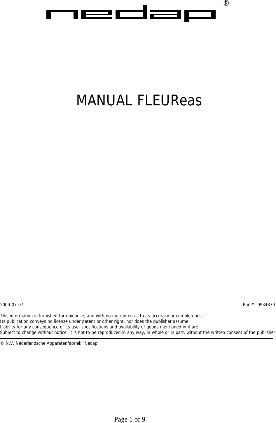
![Page 5 of 9 1 INTRODUCTION Thank’s for purchasing the Nedap Electronic Article Surveillance (=EAS) system FLEUReas N.V. Nederlandsche Apparatenfabriek “Nedap” further on called Nedap manufactures some of the most reliable and scalable EAS Systems of the market today. With this system your able to reduce the shoplifting costs the best in combination with Nedap’s tag line. Some of the advantages are: 1. On the antenna there is an additional advertising space; 2. The antenna color can be chosen for a fitting look in the shop; 3. There is the opportunity to integrate the customer counting feature to measure the visitor stream; 4. Optional is the communication at the system to the outside world via GSM/GPRS, PSTN or LAN. The FLEUReas system produces an acoustic - and visual signal when it detects an operating tag by means of the antennas and will identify a visitor with the active tag on one of his carried items. FLEUReas is developed for small configurations. It starts with 2 antennas for one entrance scalable up to 4 antenna’s for 3 entrances. For the different configurations are Electronics units available: • For a 2 antennas Electronics unit : 9922857; • For a 3 antennas Electronics unit : 9922849; • For a 4 antennas Electronics unit : 9922 822; With FLEUReas you’re able to build bigger systems and integrate it into the Nedap OS/T line. There fore should be used electronics unit: 9922679. 2 System overview PS 2cables3cables4cablesIR BeamTx TxRx RxDetectionarea DetectionareaMainsTag142/35 76 8 910 Figure 1 Functional system overview The FLEAReas consists of the following components: 1. AC/DC Power supply 100 – 240 Vac / 30 Vdc Nedap article number: 9651403 2. Antenna frame 30 cm Model: FL-AS article number: 8760004 [grey] or 8760012 [black] 3. Antenna frame 45 cm Model: FL-AL article number: 8760055 [grey] or 8760063 [black] 4. Electronic units consisting of the transceiver board article number: 9922679, 9922822, 9922849 or 9922857 5. Optional Communication & Grow unit PSTN. Article number: 9922628 Contains PSTN Type: MT5600SMI-92 by Multitech CE approved, Canada IC: 125 11142A and USA FCC complies with 47 CFR Part 68: AU7USA-46014-MD-E or any other CE, FCC and IC approved PSTN. 6. Optional Communication & Grow unit GSM/GPRS. Article number: 9922636 Contains GSM/GPRS type: MTSMC–G-F4 by Multitech CE approved , Canada IC: 125A-0027 and USA FCC ID: AU79U07A31817 or any other approved FCC or IC approved GSM](https://usermanual.wiki/Nedap-N-V/FLEUREAS/User-Guide-1141182-Page-5.png)
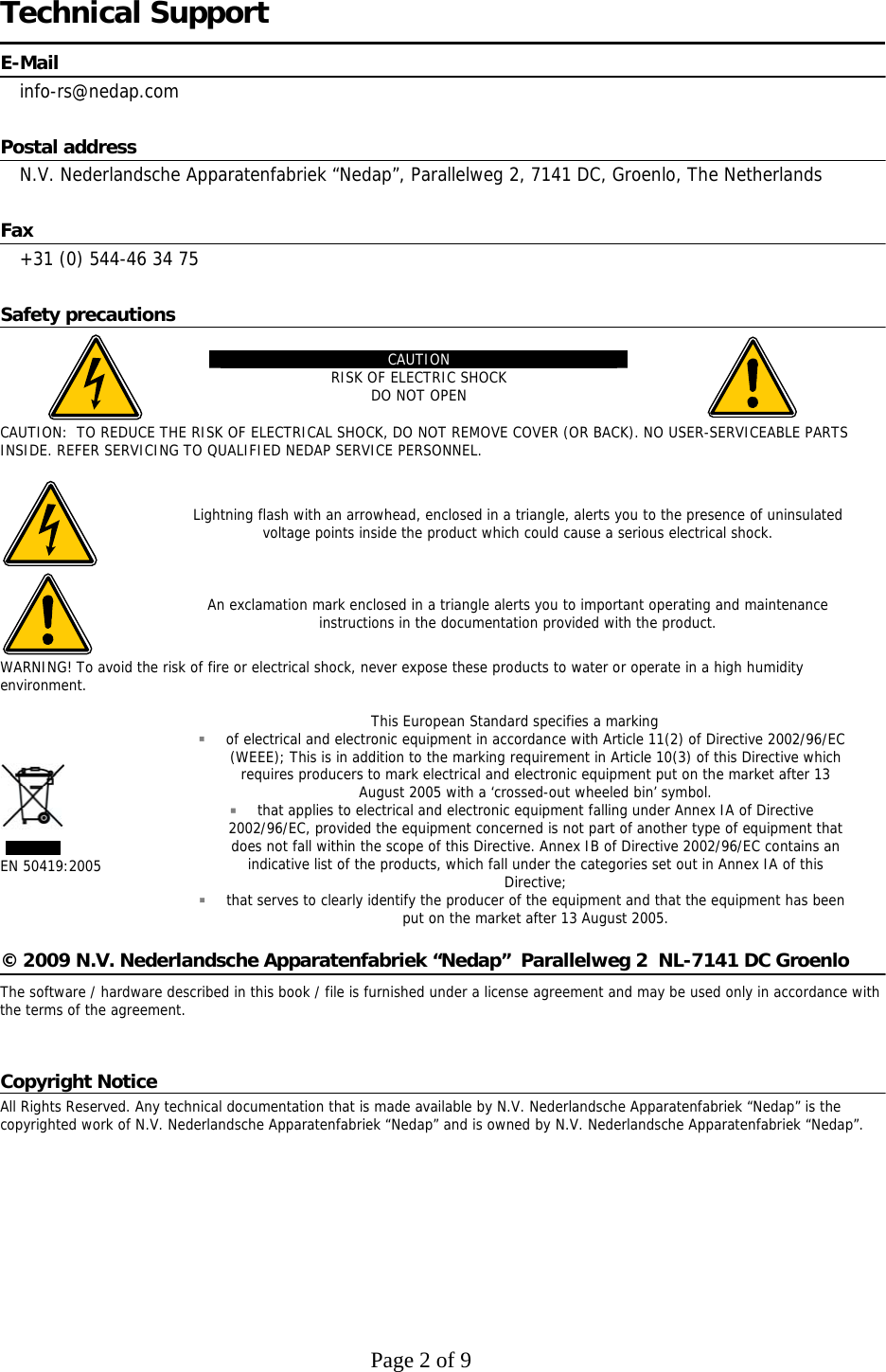
![Page 6 of 9 7. Optional Communication & Grow unit LAN. Article number: 9922644 Contains LAN type: XPORT by Lantronix 8. Optional Communication & Grow unit Customer Counting. Article number: 9926402 9. Optional Customer Counting Unit Tx, for FL-AS or FL-AL antennas 10. Optional Customer Counting Unit Rx, for FL-AS or FL-AL antennas The FLEUReas system is complete wired up and ready for use. You only have to follow the next steps. • Install the FLEUReas system according the: FLEUReas installation guide lines; • Power up the FLEUReas system; • Check the functionality; • Call Nedap Customer Support for quick hands-on problem solution in case of unforeseen trouble [see Technical Support]; • Distance between two antennas when using hard tags Ø50 mm and FL-AS antennas is: 2.2 m; • Distance between two antennas when using paper tags 4x4 and FL-AS antennas is: 1.7 m; • Distance between two antennas when using hard tags Ø50 mm and FL-AL antennas is: 2.45 m; • Distance between two antennas when using paper tags 4x4 and FL-AL antennas is: 2.0 m; • Distance between an antenna and a wall, door, sliding door etc. must be at least 200 mm; • Distance between an antenna and the nearest tagged item must be at least 2000 mm.](https://usermanual.wiki/Nedap-N-V/FLEUREAS/User-Guide-1141182-Page-6.png)
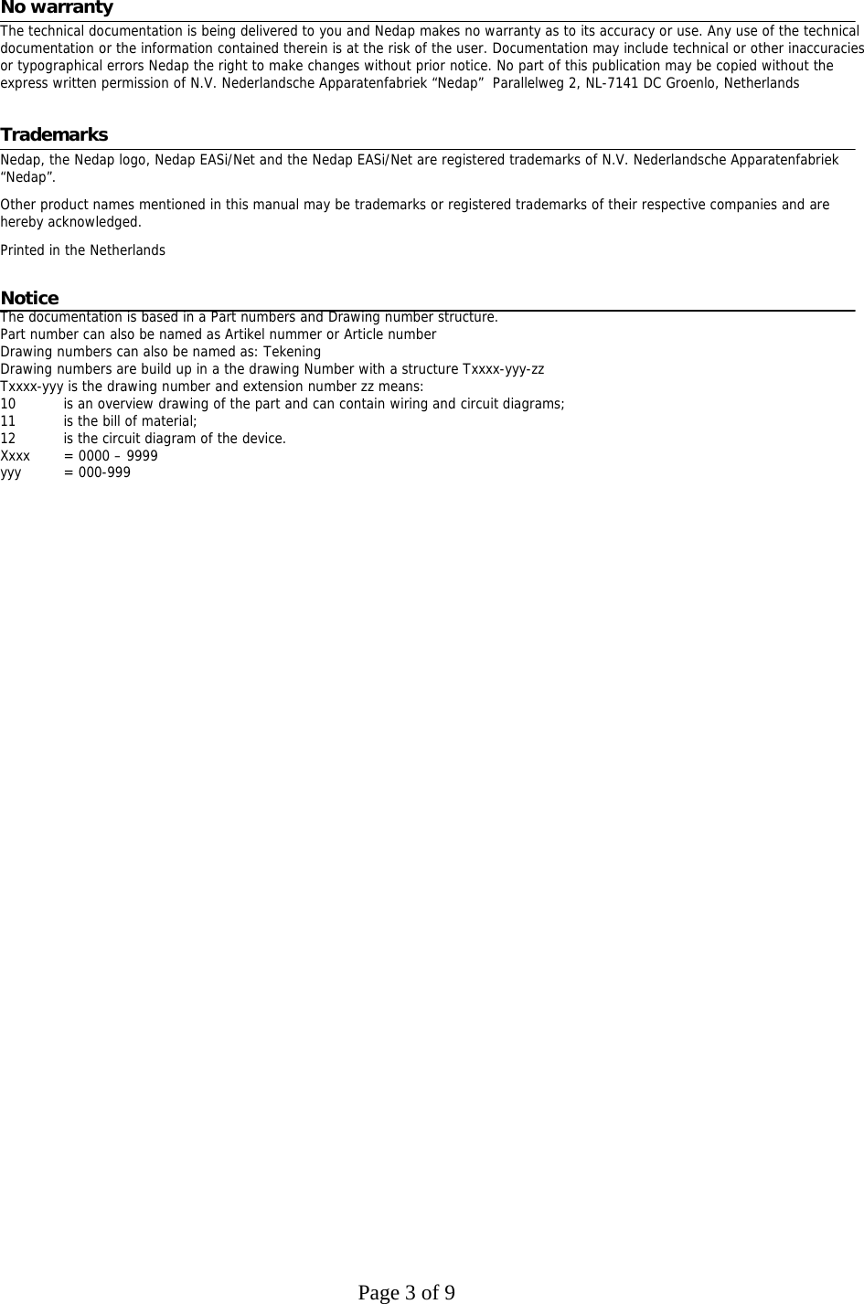
![Page 7 of 9 3 Wiring diagram Schematically diagrams below shows an example of the connections between used modules. The picture shows the full configuration that can be built up. Figure 2 Example full configuration The connections for a full configuration are: 1 Mains Cable Power Adapter Connects the Main power to the Power Adapter 2 DC power line Connects 30VDC from the Power Adapter to the Electronics Unit [9922679, 9922822, 9922849 or 9922857] 3 Tx coax cable Connects the Tx Output from the Electronics Unit EC-x to the Match PCB FL-AS or FL-AL. (7829663/7831455) Cable is provided with filters. The cable carries the RF signal including a 30VDC signal for lighting. 4 Rx coax cable Connects the Rx Input from the Match PCB FL-AS or FL-AL 7829663/7831455 to the Electronics Unit EC-x. Cable is provided with filters. The cable carries the RF signal including a 30VDC signal for lighting. 5 Rx coax cable Connects the Rx Output from the Electronics Unit EC-x to the Match PCB FL-AS/AL 7829663 or 7831455. Cable is provided with filters. The cable carries the RF signal including a 30VDC signal for lighting. 6 Tx coax cable Connects the Tx Input from the Match PCB FL-AS/AL 7829663 or 7831455 to the Electronics Unit EC-x. Cable is provided with filters. The cable carries the RF signal including a 30VDC signal for lighting. 7 Grow Cable Connects Electronics Unit to one of the Communication & Grow Units [9922628 or 9922636 or 9922644 or 9926402]. Carries 30VDC, Serial communication and inputs for CC Units AS/AL.](https://usermanual.wiki/Nedap-N-V/FLEUREAS/User-Guide-1141182-Page-7.png)
![Page 8 of 9 8 Signal cable CC Units AS/AL Rx or Tx Connects one of the Communication & Grow Units to one of the CC Units AS/AL Rx [8014434 series or 8016608 series] 9 Signalling cable Connects one of the Communication & Grow Units to one of the CC Units AS/AL Tx [8014507 series or 8016461 series] 10 Signalling cable Connects one of the two Communication & Grow Units to a LAN or PSTN network. 11 Signalling cable The Electronics Units can be connected to an OS/T master system. 4 FCC Declarations Compilance statements (part15.19) This device complies with part 15 of the FCC Rules and to RSS210 of Industry Canada. Operating is subject to the following two conditions: (1) this device may not cause harmful interference, and (2) this device must accept any interference received, including interference that may cause undesired operation. Warning (part15.21) Changes or modifications not expressly approved by party responsible for compliance could void the user’s authority to operate the equipment. This in particular is applicable for the antenna which can be delivered with the FLEUReas System. RF Exposure (OET Bulletin 65) To comply with FCC RF exposure requirements for mobile transmitting devices, this transmitter should only be used or installed at locations where there is at least 20cm separation distance between the antenna and all persons. Information to the User (Part 15.106(b)) Note: This equipment has been tested and found to comply with the limits for a class B digital devices, pursuant to part 15 of the FCC Rules. These limits are designed to provide reasonable protection against harmful interference in a residential installation. This equipment generates, uses and can radiate radio frequent energy and, if not installed and used in accordance with the instructions, may cause harmful interference to radio communications. However, there is no guarantee that interference will not occur in a particular installation. If this equipment does not cause harmful interference to radio or television reception, which can be determine by turning the equipment off and on , the user is encouraged to try to correct the interference by one or more of the following measures: - Reorient or relocate the receiving antenna. - Increase the separation between the equipment and receiver. - Connect the equipment into an outlet on a circuit different from that to which the receiver is connected. - Consult the dealer or an experienced radio/TV technician for help.](https://usermanual.wiki/Nedap-N-V/FLEUREAS/User-Guide-1141182-Page-8.png)
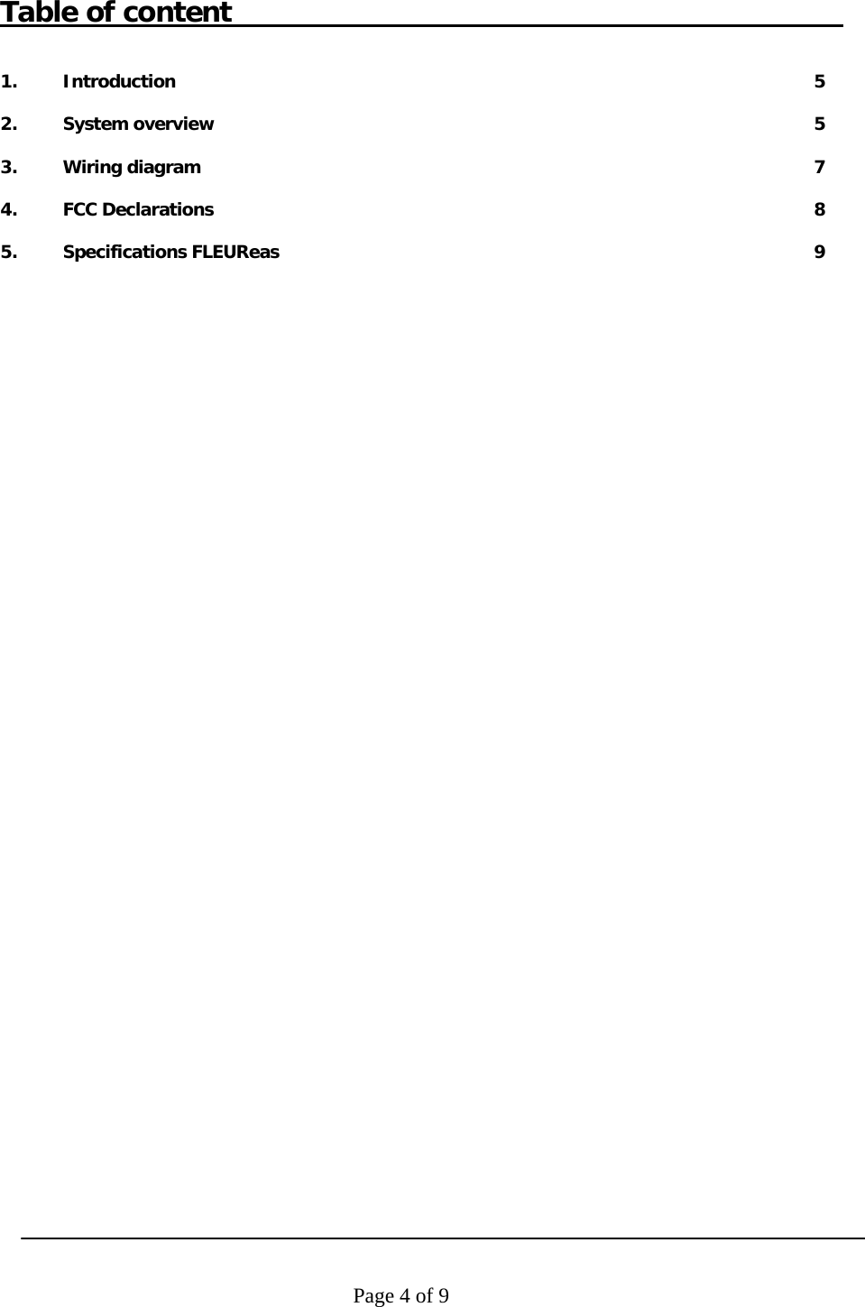
![Page 9 of 9 5 Specifications FLEUReas. Enviromental Description Antenna Hight 1665mm 322 mm[8760004, 8760012] Antenna Width 462mm[8760055, 8760063] Antenna Base 100mm Frame thickness 70mm 12Kg [8760004, 8760012] Weight 15Kg [8760055, 8760063] Material Construction Aluminium ABS HI-121 and Calibre 201-15 FL-AS and FL-AL Material Covers Metal EC30 and EC45 Protection Class IP20 Min. Typical Max. Condition Operating frequency 7.4 MHz 8.8 MHz Operational temperature 0°C 40 °C Storage temperature -10°C +70°C Relative Humidity 20% 90% non-condensing Operating Distance 0.9m 2.4m Between antenna, Tag dependant Input Requirements and electrical specifications Description Min. Typical Max. Condition Input Voltage 90VAC 264VAC Full Range; 50/60Hz Input Current - - 2A 90VAC 50Hz Line Frequency 47 Hz 50-60Hz 63Hz - Inrush Current @25°C 60A 230VAC Cold Start Operation Voltage 29.1VDC 30VDC 30.9VDC Power 15W 20W 230VAC 50Hz Regulations Safety approvals of the Power Adapter: · cULus according to UL/CSA 60950-1 · Japan PSE · CE Europe according to EN60950-1 Telecom system approval · Canada IC ID according to RSS210 IC ID: 1444A-FLEUREAS · US according to FCC Part 15 FCC ID: CGDFLEUREAS · CE according to EN 300 330 · Japan pending In compliance with Human exposure assessment according to: · EN50357 and EN50364 · ICNIRP Guidelines · IEEE C95.1 · RSS102 · ARIB STD-38 Electromagnetic compatibility · EN 301 489 (Emission according to CISPR 22) · IEC 61000-6-2 · IEC 61000-6-3 · CISPR 22](https://usermanual.wiki/Nedap-N-V/FLEUREAS/User-Guide-1141182-Page-9.png)