Nedap N V INVEXS190 Inductive Proximity Card Reader User Manual Invexs190 InstallManual US v6
N. V. Nederlandsche Apparatenfabriek NEDAP Inductive Proximity Card Reader Invexs190 InstallManual US v6
Contents
- 1. manual pt 1
- 2. manual pt 2
manual pt 1

Date : 08 April 2013 Version 6
This information is furnished for guidance, and with no guarantee as to its accuracy or completeness; its publication conveys no licence under any patent or other right,
nor does the publisher assume liability for any consequence of its use; specifications and availability of goods mentioned in it are subject to change without notice; it is
not to be reproduced in any way, in whole or in part, without the written consent of the publisher.
© Nedap N.V. P.O. Box 6 NL-7140 AC GROENLO The Netherlands
Page 1 of 4
Part.no.:
5281121
Invexs 190 readers
Mifare DESfire dual technology mullion readers
GENERAL
The Invexs 190 reader series is capable of reading (simultaneously) Mifare
and DESFire credentials due to its dual reader technology. The Invexs 190
is designed to be used on door pillars (mullion) and suitable for outside and
inside use. A model with keypad is also available.
The Invexs output must be set to RS485 protocol (encrypted).
Functionality and output are determined by the configuration of the Invexs
reader. The configuration is defined using the programm AEreco, and
deployed by the configuration card or via AEmon.
Three LEDs (red, green, blue) and beeper are included. LEDs around the
keypad ciphers light up only in case a PIN code is requested.
The pigtail cable can be lead directly backwards or when using the
additional spacer (art. nr . 9949887) to the top or bottom.
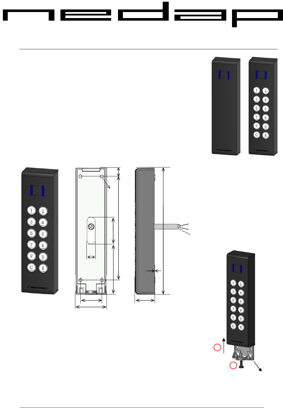
DIMENSIONS
MOUNTING PROCEDURE INVEXS
For mounting the Invexs 190, the mounting plate must be placed on the wall
first.
For removing the mounting plate from the Invexs 190, unscrew the screw
(1) (Torx, M5) at the bottom of the Invexs and push the Invexs 190 slightly
up (2). The plate can be mounted using the 4 holes
.
Place the cable to the correct position and replace the Invexs 190.
®
Install M
anual
Dimensions: 7.52 x 2 x 1.2 in.
4 mounting holes available at 1.26 x 6.1in
Cable pigtail: 10 x 26AWG shielded, 10 ft
Optional spacer (max thickness 0.4 in) is
available for other cable outlet (top or
bottom)
Un screw
Push up
2
1
Mounting
plate
1
191
30
10 x
26AWG
Shield
32
155
12
40
14.5
50
4 x 5
75
Note: drawing dimensions are in mm

Invexs 190 readers
© Nedap N.V.
Invexs 190 readers
Install Manual Page 2 of
4
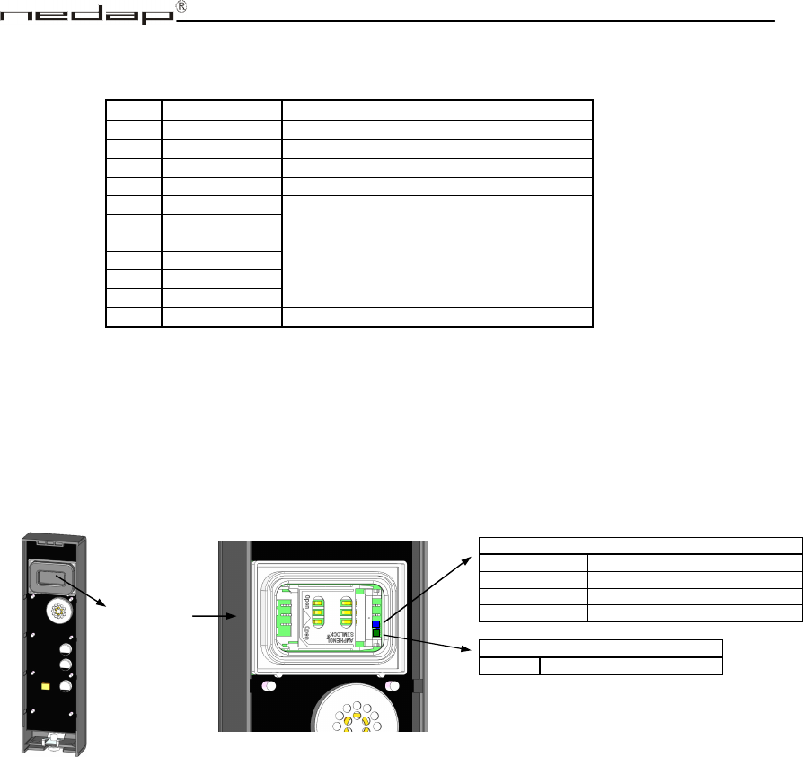
SAM cover
CONNECTIONS
Invexs is not hot-swappable, so when making or changing connections, power must be switched Off.
Remark:
Cable shield (wire 11) must be connected to the metal case of the external device
LED INDICATORS INSIDE / BACKSIDE
There are two LED’s available: Blue for Status (of application), Green for Identification (both visible
behind the SAM cover at the back side)
Wire Colour Function
1 Red Power in (12-30VDC)
2 Black Power Ground
3 Grey RS485 A (-)
4 Violet RS485 B (+)
5 Green
Do not connect
Reserved for future use
6 White
7 Yellow
8 Pink
9 Blue
10 Brown
11 Shield / Metal EM shield (connected to power ground)
ID (green)
Blinking
Card detected
ST: STATUS (blue)
Slow blinking Application running (operating)
Fast blinking Downloading or error during loading
2 short flashes Application present but not active
3 short flashes No application present

Invexs 190 readers
© Nedap N.V.
Invexs 190 readers
Install Manual Page 3 of
4
LED INDICATORS FRONT
At the front a three colour LED is positioned at the middle of the Invexs
Depending of the used configuration the function of these LEDs can differ:
• Green LED: Card is been authorised (UL led)
• Red LED: Card is not authorised (NA led), controller is stand-by
• Blue LED:
Blinks fast: No configuration is availabele at this Invexs (present Configuration
card or load Configuration first).
Continuously ON: Determined by configuration: E.g. Reader stand-by.
(Blue LED is activated if UL is OFF and NA is more than 1 sec OFF)
Remark: Function of LEDs and Beeper is controlled by used application settings of Invexs.
FIRMWARE
Pay attention that the firmware loaded in the Invexs together with the Invexs type and configuration
determines functionality and protocols.
Default (from factory) the Invexs handles the credentials on several ways simultaneously:
Mifare cards (CSN) as: RS485NR, RF data
Remark: The Invexs 190 requires dedicated firmware (not identical to the Invexs 170 firmware)
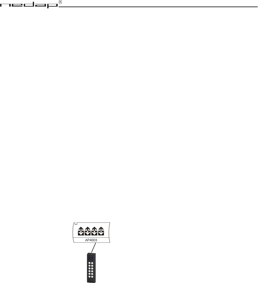
SYSTEM CONFIGURATIONS (how to connect Invexs readers)
Remark: Configurations can be determined by the AEreco (loaded by AEmon or configuration card).
BEEPER INDICATIONS
Beeper is also used for indication of loading the configuration:
• High sound beep (‘happy sound’): Configuration is loaded correct, second high sound beep
indicates that this configuration can be used with this Invexs
• Low sound beep (‘unhappy sound’): Configuration is not correct loaded or no configuration
available at startup
To AP4x03 readers with RS485 special encrypted
protocol. (LED’s, Beeper, Keys and Display are
controlled over the RS485 communication)
AEOS RS485 interface

Invexs 190 readers
© Nedap N.V.
Invexs 190 readers
Install Manual Page 4 of
4
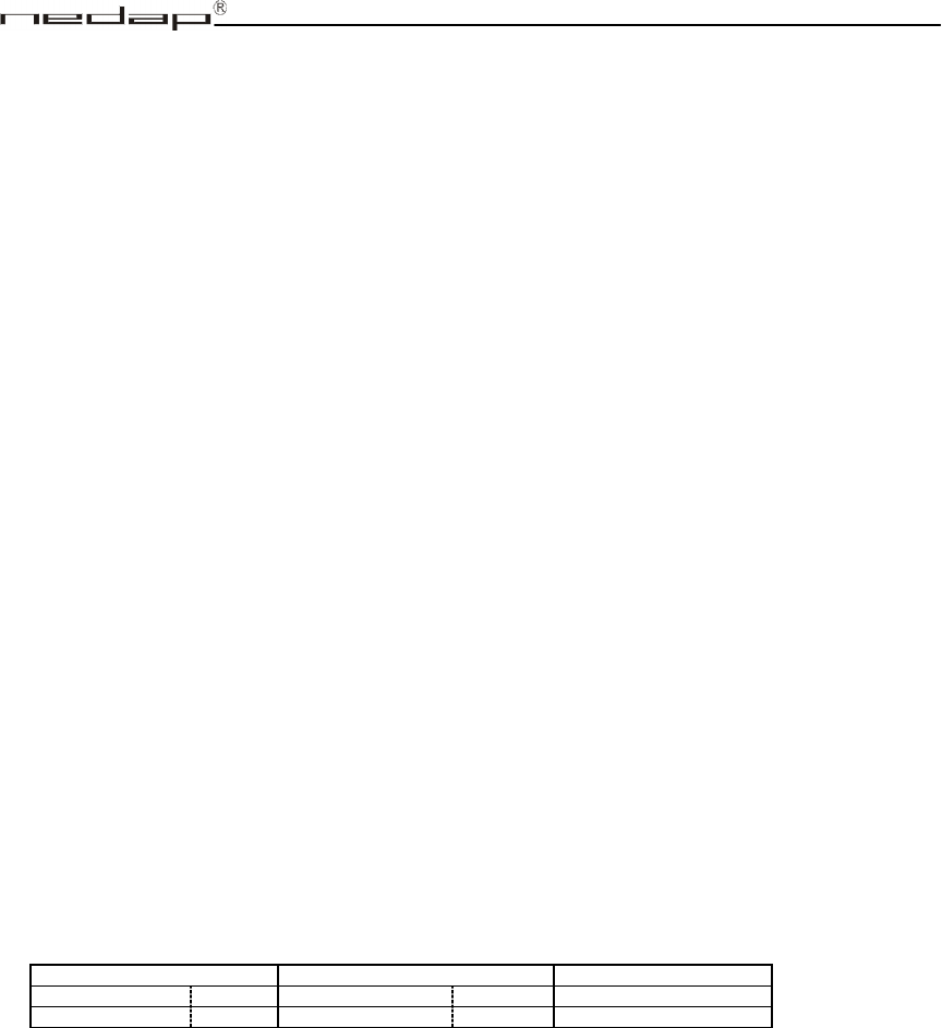
SPECIFICATIONS Invexs 190 Product numbers see table below:
Invexs 190 Reader Invexs 190 Reader + Keypad Credentials
Invexs M190 9945512 Invexs MK190 9948422 Mifare
Invexs MD190 9948406 Invexs MDK190 9948457 Mifare + DESFire
Dimensions: 7.52 x 2 x 1.2 in
Protection: IP65 Weight: ± 0.78 lb
Power Supply: 12VDC – 30VDC Power consumption:
M/MD190: 60mA@12VDC, 35mA@24VDC
MK/MDK190: 90mA@12VDC, 45mA@24VDC
Environment: Temperature: Operating and Storage: -31°F to +150°F
Relative humidity: 10 – 93% non condensing
Communication: RS485 (Encrypted AEOS protocol to AP4x03, (firmware APx003rs485NR).
Indicators: UL (green) NA (red) ,MD (blue)
Antennas (internal): 13.56 MHz, Mifare compatible Detection distance Mifare card: 1.5 in
R&TTE: Hereby, Nedap N.V., declares that these products comply with the essential requirements and provisions of the
Directive 1999/5/EC of the European Parliament and of the council of March 9, 1999 on Radio equipment and
Telecommunications Terminal Equipment and the mutual recognition of their conformity and with the provisions
of Annex IV (Conformity Assessment procedure referred to in article 10).
CABLE SPECIFICATIONS
10 wire shielded cable of approx. 10 ft length included (pig tail). Extensions can be made:
RS485: 22AWG twisted pairs, shielded, max cable length: 3280 ft, cable capacity <= 33pF/ft.
Power: 22AWG twisted pairs, shielded, max cable length: 160 ft.
MORE INFORMATION: For more detailed information contact your local Nedap supplier or check the internet site.
FCC and IC CERTIFICATIONS
This device complies with part 15 of the FCC Rules and to RSS210 of Industry Canada.
Operation is subject to the following two conditions:
(1) this device may not cause harmful interference, and
(2) this device must accept any interference received, including interference that may cause
undesired operation.
Changes or modifications not expressly approved by the party responsible for compliance could void
the user’s authority to operate the equipment.
Cet appareil se conforme aux normes RSS 210 exemptés de license du Industry Canada.
L'opération est soumis aux deux conditions suivantes:
(1) cet appareil ne doit causer aucune interférence, et
(2) cet appareil doit accepter n'importe quelle interférence, y inclus interférence qui peut causer
une opération non pas voulu de cet appareil.
Les changements ou modifications n’ayant pas été expressément approuvés par la partie responsable de
la conformité peuvent faire perdre à l’utilisateur l’autorisation de faire fonctionner le matériel.