Nedap N V IQ-MD4 Anti Pilferage system User Manual
N. V. Nederlandsche Apparatenfabriek NEDAP Anti Pilferage system Users Manual
user manual


2
OS/T Course 2003 © NEDAP Retail Support 2003
© 2003 Nedap Retail Support -
Netherlands
Parallelweg 2d, 7141 DC Groenlo
The software / hardware described in this book / file is furnished under a license agreement and may be used only in accordance with the
terms of the agreement.
Documentation version 1.0
Copyright Notice
All Rights Reserved.
Any technical documentation that is made available by Nedap Retail Support is the
copyrighted work of Nedap Retail Support and is owned by Nedap Retail Support.
NO WARRANTY. The technical documentation is being delivered to you AS-IS and
Nedap Retail Support makes no warranty as to its accuracy or use. Any use of the
technical documentation or the information contained therein is at the risk of the user.
Documentation may include technical or other inaccuracies or typographical errors.
Nedap Retail Support the right to make changes without prior notice.
No part of this publication may be copied without the express written permission of
Nedap Retail Support, Parallelweg 2d, 7141 DC Groenlo, Netherlands
Trademarks
Nedap, the Nedap logo, Nedap EASi/Net and the Nedap EASi/Net are registered trademarks of Nedap N.V. Groenlo.
Other product names mentioned in this manual may be trademarks or registered
trademarks of their respective companies and are hereby acknowledged.
Printed in the Netherlands

3
OS/T Course 2003 © NEDAP Retail Support 2003
Technical Support:
- E-mail:support-rs@nedap.nl
- H. Hammer
+31 (0) 544 47 15 19
h.hammer@nedap.nl
- H. Broekhuis
+31 (0) 544 47 15 02
h.broekhuis@nedap.nl
- Fax:
+31 (0) 544 46 58 14
Visitor’s address:
Nedap Retail Support
Parallelweg 2d
Groenlo
Netherlands
Postal address:
Nedap Retail Support
Postbus 102
7140 AC Groenlo
Netherlands

4
OS/T Course 2003 © NEDAP Retail Support 2003
Table of contents
Technical Support: .................................................................................................................................... 3
BQ PCB ............................................................................................................................................. 5
EQ PCB ............................................................................................................................................. 7
EQ3E PCB......................................................................................................................................... 9
IQ PCB............................................................................................................................................. 11
IQ3E PCB ........................................................................................................................................ 13
Attenuation....................................................................................................................................... 15
IO Connector K23 ............................................................................................................................ 16
IO Connector K24 ............................................................................................................................ 16
System configurations ..................................................................................................................... 17
BQ System , 1 aisle, Deactivatorunit ............................................................................................... 18
EQ System , 3 aisles ....................................................................................................................... 19
IQ System , 7 aisles, MD CC........................................................................................................... 21
Checklist modem settings iNCC ...................................................................................................... 20
Connecting a PC to a XQ or EQ/IQ Unit ......................................................................................... 28
Connecting a XQ or EQ/IQ unit to a modem ................................................................................... 29
Connecting to an ISDN line using the DeTeWe TA33 terminal adapter ......................................... 30
5
OS/T Course 2003 © NEDAP Retail Support 2003
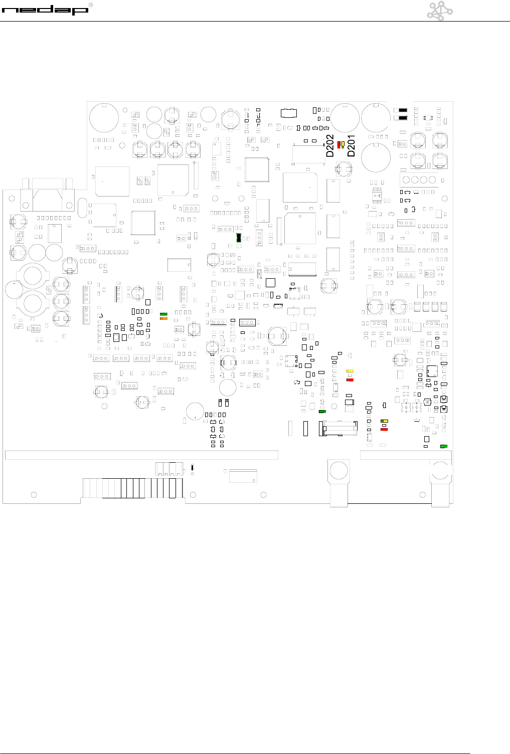
BQ PCB
K16
K5 K300
K11
K23
K24
K203
K204
D311
D300
D301
D19
D16
P3
D25
D26
K19
K205 K201 K202
K3

6
OS/T Course 2003 © NEDAP Retail Support 2003
The following points can be used:
K3 Oscilloscope Tx K201 Handheld terminal RxTx
K5 Output Tx (connector 3) K202 Oscilloscope Rx
K9 Jumper Attenuation K203 Jumper
K11 Power Input K204 Jumper
K12 Jumper Attenuation K205 Handheld terminal NCC
K13 Jumper Attenuation K300 Output Rx (connector 1)
K15 Jumper Attenuation P1 PA Drive Adjustment
K16 RS232 Interface Connector P2 Phase Adjustment Tx
K21 Connector FCI P3 Mixer Bias Adjustment
K23 IO Connector P4 Slave Data communication Rx
K24 IO Connector P5 Master Data communication Rx
Indicator leds:
D11 Mux Connector 1 TX D48 Customer Counting: Led on = active
D12 Mux Connector 2 TX D202 Communication Error RxTx
D16 Lamp On Connector 3 D220 Label Detection Alarm NCC on = detection
D19 Lamp Overload Connector 3 D221 Communication Error NCC
D25 Sweep Lock D300 Lamp Overload Connector 1
D26 Center Lock D301 Lamp On Connector 1
D201 Label Alarm RxTx D311 Mux Connector 1 RX
D47 Customer Counting: Led on = active D202 Communication Error RxTx
7
OS/T Course 2003 © NEDAP Retail Support 2003
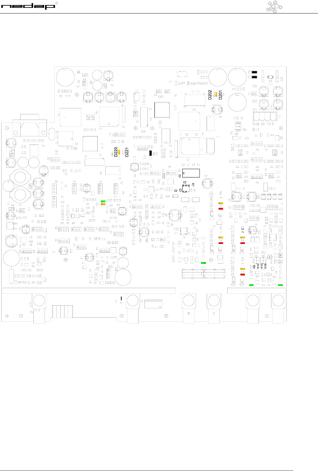
EQ PCB
K23
K6 K10 K4 K5 K301 K300
D311D312
D300
D301
D302
D303
P3
D16
D19
D17
D18
K203
K204
K201 K202
K3
K21
K205
K16
K19
D25
D26
D11
P4
P5
P2
P1
15

8
OS/T Course 2003 © NEDAP Retail Support 2003
The following points can be used:
K3 Oscilloscope Tx K201 Handheld terminal RxTx
K4 Output Tx (connector 4) K202 Oscilloscope Rx
K5 Output Tx (connector 3) K203 Jumper
K6 Synchronization In K204 Jumper
K9 Jumper Attenuation K205 Handheld terminal NCC
K10 Master connector K300 Output Rx (connector 1)
K11 Power Input K301 Output Rx (connector 2)
K12 Jumper Attenuation P1 PA Drive Adjustment
K13 Jumper Attenuation P2 Phase Adjustment Tx
K15 Jumper Attenuation P3 Mixer Bias Adjustment
K16 RS232 Interface Connector P4 Slave Data communication Rx
K21 Connector FCI P5 Master Data communication Rx
K23 IO Connector
Indicator leds:
D11 Mux Connector 1 TX D202 Communication Error RxTx
D12 Mux Connector 2 TX D220 Label Detection Alarm NCC on = detection
D16 Lamp On Connector 3 D221 Communication Error NCC
D17 Lamp On Connector 4 D300 Lamp Overload Connector 1
D18 Lamp Overload Connector 4 D301 Lamp On Connector 1
D19 Lamp Overload Connector 3 D302 Lamp Overload Connector 2
D25 Sweep Lock D303 Lamp On Connector 2
D26 Center Lock D311 Mux Connector 1 RX
D201 Label Alarm RxTx D312 Mux Connector 2 RX
9
OS/T Course 2003 © NEDAP Retail Support 2003
EQ3E PCB
D312
D300
D301
D302
D303
D16
D19
D18
D17
D311
D11
K201 K202
K3
P3
P1
P2
K6 K4 K5 K301 K300
K11
K7
P4
D11D11D11D11D11
D12
K204
K203
K
116
K23

10
OS/T Course 2003 © NEDAP Retail Support 2003
The following points can be used:
K3 Oscilloscope Tx K24 IO Connector
K4 Output Tx (connector 4) K201 Handheld terminal RxTx
K5 Output Tx (connector 3) K202 Oscilloscope Rx
K6 Synchronization In K203 Jumper
K7 Synchronization In K204 Jumper
K9 Jumper Attenuation K300 Output Rx (connector 1)
K11 Power Input K301 Output Rx (connector 2)
K12 Jumper Attenuation P1 PA Drive Adjustment
K13 Jumper Attenuation P2 Phase Adjustment Tx
K15 Jumper Attenuation P3 Mixer Bias Adjustment
K21 Connector FCI
Indicator leds:
D11 Mux Connector 1 TX D202 Communication Error RxTx
D12 Mux Connector 2 TX D300 Lamp Overload Connector 1
D16 Lamp On Connector 3 D301 Lamp On Connector 1
D17 Lamp On Connector 4 D302 Lamp Overload Connector 2
D18 Lamp Overload Connector 4 D303 Lamp On Connector 2
D19 Lamp Overload Connector 3 D311 Mux Connector 1 RX
D201 Label Alarm RxTx D312 Mux Connector 2 RX
11
OS/T Course 2003 © NEDAP Retail Support 2003
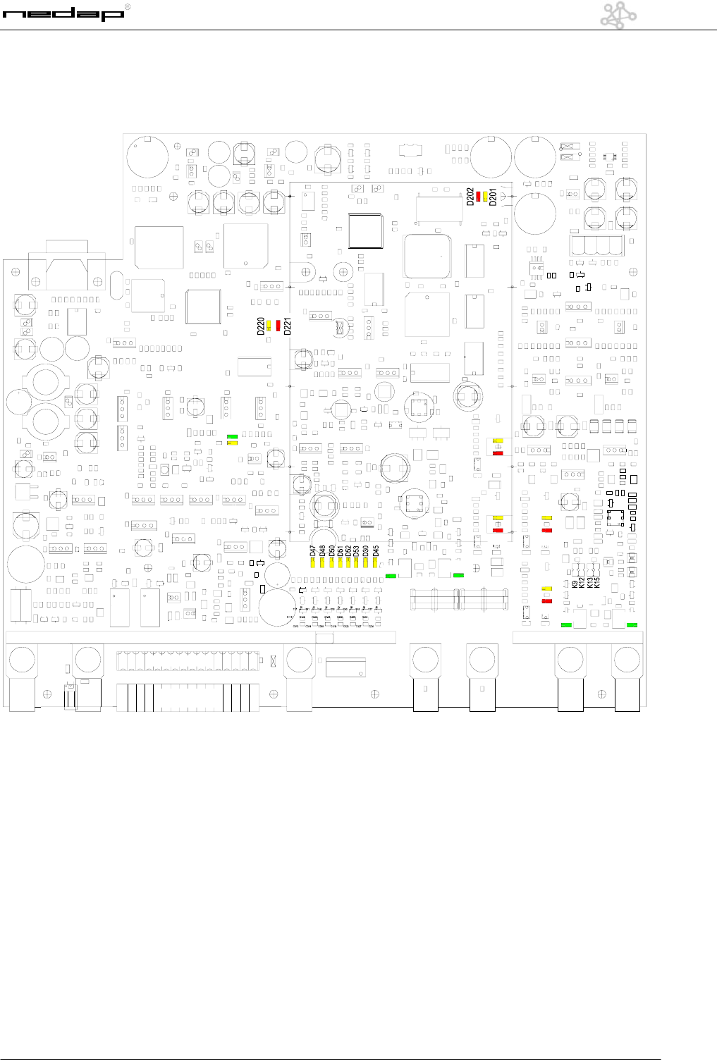
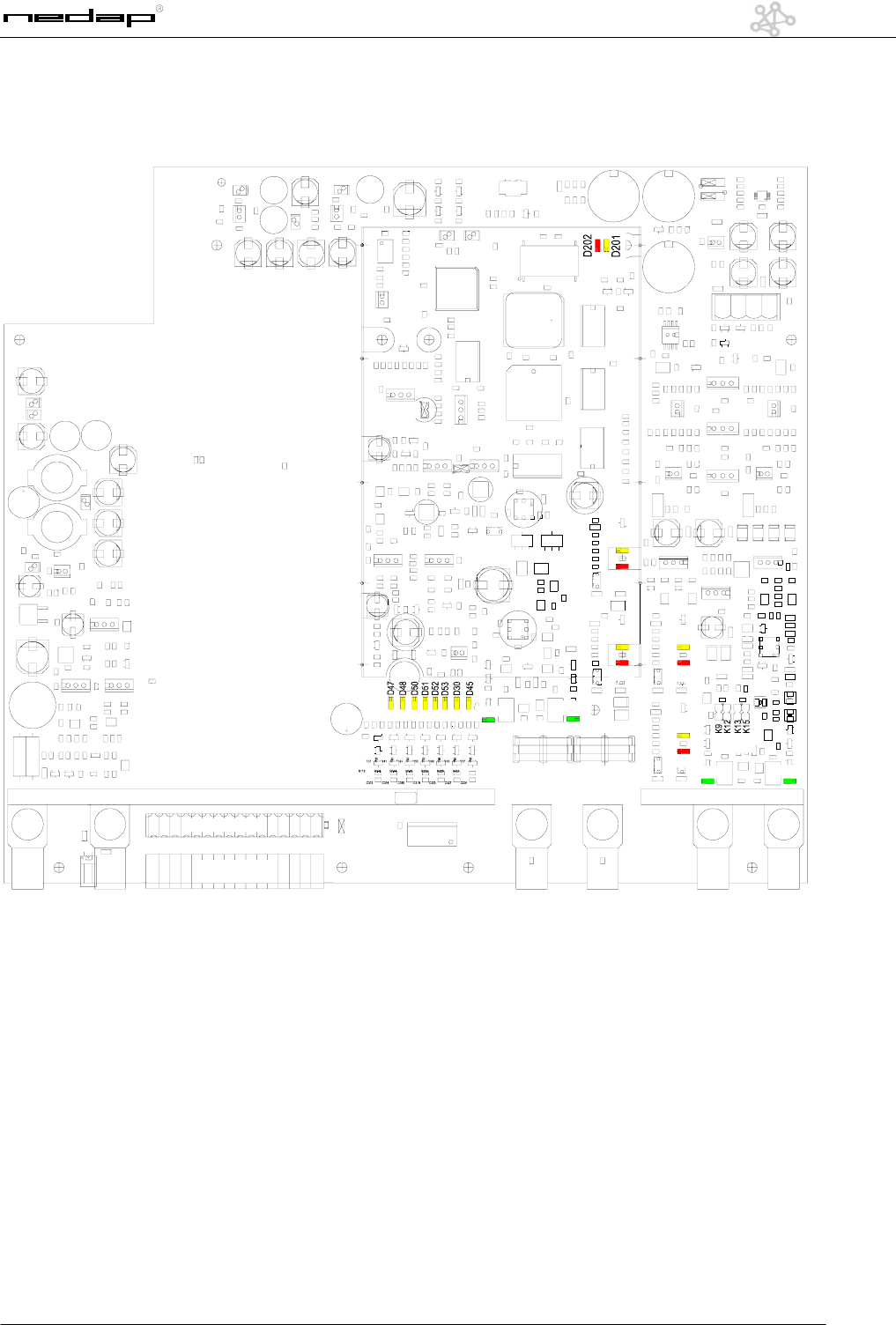
IQ PCB
D312
D300
D301
D302
D303
D16
D19
D18
D17
D25
D26
D311
D11
K201 K202
K3
P3
P5
P1
P2
K205
K16
K6 K10 K4 K5 K301 K300
K11
116
116
P4
K7
P4
D12
K204
K203
K
K23
K24

12
OS/T Course 2003 © NEDAP Retail Support 2003
The following points can be used:
K3 Oscilloscope Tx K23 IO Connector
K4 Output Tx (connector 4) K24 IO Connector
K5 Output Tx (connector 3) K201 Handheld terminal RxTx
K6 Synchronization In K202 Oscilloscope Rx
K7 Synchronization In K203 Jumper
K9 Jumper Attenuation K204 Jumper
K10 Master connector K205 Handheld terminal NCC
K11 Power Input K300 Output Rx (connector 1)
K12 Jumper Attenuation K301 Output Rx (connector 2)
K13 Jumper Attenuation P1 PA Drive Adjustment
K15 Jumper Attenuation P2 Phase Adjustment Tx
K16 RS232 Interface Connector P3 Mixer Bias Adjustment
K19 Jumper P4 Slave Data communication Rx
K21 Connector FCI P5 Master Data communication Rx
Indicator leds:
D11 Mux Connector 1 TX D51 Customer Counting: Led on = active
D12 Mux Connector 2 TX D52 Customer Counting: Led on = active
D16 Lamp On Connector 3 D53 Customer Counting: Led on = active
D17 Lamp On Connector 4 D201 Label Alarm RxTx
D18 Lamp Overload Connector 4 D202 Communication Error RxTx
D19 Lamp Overload Connector 3 D220 Label Detection Alarm NCC on = detection
D25 Sweep Lock D221 Communication Error NCC
D26 Center Lock D300 Lamp Overload Connector 1
D30 Customer Counting: Led on = active D301 Lamp On Connector 1
D45 Customer Counting: Led on = active D302 Lamp Overload Connector 2
D47 Customer Counting: Led on = active D303 Lamp On Connector 2
D48 Customer Counting: Led on = active D311 Mux Connector 1 RX
D50 Customer Counting: Led on = active D312 Mux Connector 2 RX
13
OS/T Course 2003 © NEDAP Retail Support 2003
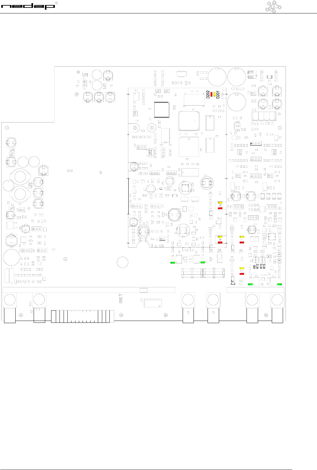
IQ3E PCB
D312
D300
D301
D302
D303
D16
D19
D18
D17
D311
D11
K201 K202
K3
P3
P1
P2
K6 K4 K5 K301 K300
K11
P4
D12
K204
K203
K
K7
116
116
K23
K24

14
OS/T Course 2003 © NEDAP Retail Support 2003
The following points can be used:
K3 Oscilloscope Tx K23 IO Connector
K4 Output Tx (connector 4) K24 IO Connector
K5 Output Tx (connector 3) K201 Handheld terminal RxTx
K6 Synchronization In K202 Oscilloscope Rx
K7 Synchronization In K203 Jumper
K9 Jumper Attenuation K204 Jumper
K11 Power Input K300 Output Rx (connector 1)
K12 Jumper Attenuation K301 Output Rx (connector 2)
K13 Jumper Attenuation P1 PA Drive Adjustment
K15 Jumper Attenuation P2 Phase Adjustment Tx
K19 Jumper P3 Mixer Bias Adjustment
K21 Connector FCI
Indicator leds:
D11 Mux Connector 1 TX D51 Customer Counting: Led on = active
D12 Mux Connector 2 TX D52 Customer Counting: Led on = active
D16 Lamp On Connector 3 D53 Customer Counting: Led on = active
D17 Lamp On Connector 4 D201 Label Alarm RxTx
D18 Lamp Overload Connector 4 D202 Communication Error RxTx
D19 Lamp Overload Connector 3 D300 Lamp Overload Connector 1
D30 Customer Counting: Led on = active D301 Lamp On Connector 1
D45 Customer Counting: Led on = active D302 Lamp Overload Connector 2
D47 Customer Counting: Led on = active D303 Lamp On Connector 2
D48 Customer Counting: Led on = active D311 Mux Connector 1 RX
D50 Customer Counting: Led on = active D312 Mux Connector 2 RX
15
OS/T Course 2003 © NEDAP Retail Support 2003
Attenuation
D312
D300
D301
D302
D303
D16
D19
D18
D17
D311
D11
P3
K4 K5 K301 K300
= 0 dB
= 6 dB
= 12 dB
= 18 dB
Jumpers
It is possible to attenuate the
receiver input sensitivity with 6, 12
or 18dB. In this way the receiver is
capable of accepting the high level
of the coupled transmitter signal
when the panels are too close to
eachother. When the distance
between the antenna’s is below 1.5
metre the attenuator should be
used to avoid overloading of the
receiving input.
16
OS/T Course 2003 © NEDAP Retail Support 2003
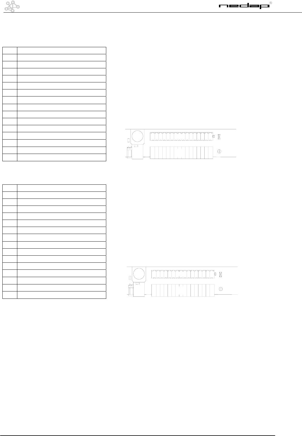
IO Connector K23
1 = DRF2b count in2
2 = DRF2b count in1
3 = DRF2b enable burst
4 = DRF2b sync 150 Hz
5 = Gnd general
6 = +33V
7 = Gnd Customer Counting
8 = sensor in 8
9 = sensor in 7
10 = sensor in 6
11 = sensor in 5
12 = sensor in 4
13 = sensor in 3
14 = sensor in 2
15 = sensor in 1
16 = +15V Customer Counting
IO Connector K24
1 = Ry1 C
2 = Ry1 NO
3 = Ry1 NC
4 = Ry2 C
5 = Ry2 NO
6 = Ry2 NC
7 = opto in 1
8 = opto in 2
9 = common opto inputs
10 = opto out 2
11 = opto out 1
12 = common opto outputs
13 = I2C Sda
14 = I2c Scl
15 = + 6Volt
16 = Gnd
116
116
K23
K24
116
116
K23
K24

17
OS/T Course 2003 © NEDAP Retail Support 2003
System configurations
1. Shown configurations are examples
2. Settings may differ from the store you are installing - programming
3. Shown firmware is version 1.406 X and 1.407 X, used for these examples, your version may be different!
18
OS/T Course 2003 © NEDAP Retail Support 2003
BQ System , 1 aisle, Deactivatorunit
RX TX
S1
K3
K5
J1
Deactivator DRF2B
BQ - Unit
To deactivator
31-20-3002tidE7
45:35:11tseT4
A/604.1MMsutatS1
03E5QEtoobeRC
hsalF9peewS7
medoM6mralA4
tuOnI3krowteN1
sevalSC
03E5sserddA
FFFFsevalstceteDC
000000000000<C5B4
000000000000<0000
000000000000<0000
000000000000<0000
sgnittesevaS7
erotseR4
enoD
)eunitnocotcsE(
03E5sserddA
FFFFsevalstceteDC
hsalF9peewS7
medoM6mralA4
tuOnI3krowteN1
sevalSC
hsalF9peewS7
medoM6mralA4
tuOnI3krowteN1
sevalSC
MM
tidE7
krowteN1
sevalstceteDC
)kcehc(sevalSC
hsalF9
sgnittesevaS7
31-20-3002tidE7
45:35:11tseT4
A/604.1SMsutatS1
C5B41QItoobeRC
hsalF9XR7
tuOnI6XT4
1deL7nO<1xxuM
1111puorG
ruobhgienmralA
DCBA
0000000003E5<03E5
000000000000<0000
sgnittesevaS7
erotseR4
enoD
)eunitnocotcsE(
xuM7
mralA4
rewoP1
hsalF9XR7
tuOnI6XT4
rettimsnarTSM
tidE7
XT4
xuM7
mralA4
hsalF9
sgnittesevaS7
xuM7
mralA4
rewoP1
DCBAesahP
1111nnoC
31-20-3002tidE7
45:35:11tseT4
A/604.1SMsutatS1
C5B41QItoobeRC
hsalF9XR7
tuOnI6XT4
revieceRSM
tidE7
tidEXR7
StuM8xuM7
tucM5mrlA4
omdA3lgiS2sneS1
pocS0qerFC
1deL7nO<1xuM
DCBAesahP
1111nnoC
1111puorG
StuM8xuM7
tucM5mrlA4
omdA3lgiS2sneS1
pocS0qerFC
xuM7
31-20-3002tidE7
45:35:11tseT4
A/604.1SMsutatS1
C5B41QItoobeRC
hsalF9XR7
tuOnI6XT4
tuOnISM
tidE7
tidEtuOnI6
<1egasU
)1/0(tcaed/eerF7
)*(oCuC4
)4/2(lateM1
01deepS<1edoMdA
000xfuBdA
020202<32xaM
000xtnerruC
45BniaG<54AniaG
45DniaG<45CniaG
04WPxaM8hserT
tluafeD0
sgnittesevaS7
erotseR4
enoD
)eunitnocotcsE(
hsalF9XR7
tuOnIXT4
hsalF9
sgnittesevaS7
StuM8xuM7
tucM5mrlA4
omdA3lgiS2sneS1
pocS0qerFC
6
sneS1
omdA3
StuM8xuM7
tucM5mrlA4
omdA3lgiS2sneS1
pocS0qerFC
<1elbanEtcaeD
00tuOnI
s1tuo1niesluP
03emiT05lvL
<1egasU
)1/0(tcaed/eerF7
)*(oCuC4
)4/2(lateM1
hsalF9
sgnittesevaS7
hsalF9XR7
tuOnI6XT4
sgnittesevaS7
erotseR4
enoD
)eunitnocotcsE(
tcaed/eerF7
DCBAesahP
1cgA
rewoP1
xuM7
mralA4
rewoP1
111<21rewoP
0011lautcA
xuM7
mralA4
rewoP1
A
19
OS/T Course 2003 © NEDAP Retail Support 2003
EQ System, 3 aisles
7 Edit 2003-02-13
4 Test 11:53:54
1 Status MM 1.406/A
C Reboot EQ 5E30
7 Sweep 9 Flash
4 Alarm 6 Modem
1 Network 3 InOut
C Slaves
Address 5E30
C Detect slaves FFFF
4B5C<0000 0000 0000
0000<0000 0000 0000
0000<0000 0000 0000
0000<0000 0000 0000
7 Save settings
4 Restore
Done
(Esc to continue)
Address 5E30
C Detect slaves FFFF
7 Sweep 9 Flash
4 Alarm 6 Modem
1 Network 3 InOut
C Slaves
7 Sweep 9 Flash
4 Alarm 6 Modem
1 Network 3 InOut
C Slaves
MM
7 Edit
1 Network
C Detect slaves
C Slaves (check)
9 Flash
7 Save settings
7 Edit 2003-02-13
4 Test 11:53:54
1 Status MS 1.406/A
C Reboot EQ3 4B5C
7 RX 9 Flash
4 TX 6 InOut
Mux x 4< On 7 Led 1
Group 1 1 1 1
Alarm neighbour
A B C D
4B5C<4B5C 4B5C 0000
0000 0000 0000 0000
7 Save settings
4 Restore
Done
(Esc to continue)
7 Mux
4 Alarm
1 Power
7 RX 9 Flash
4 TX 6 InOut
MS Transmitter
7 Edit
4 TX
7 Mux
4 Alarm
9 Flash
7 Save settings
7 Mux
4 Alarm
1 Power
Phase A B C D
Conn 3 3 4 4
7 Edit 2003-02-13
4 Test 11:53:54
1 Status MS 1.406/A
C Reboot EQ3 4B5C
7 RX 9 Flash
4 TX 6 InOut
MS Receiver
7 Edit
7 RX Edit
7 Mux 8 MutS
4 Alrm 5 Mcut
1 Sens 2 Sigl 3 Admo
C Freq 0 Scop
Mux 4< On 7 Led 1
Phase A B C D
Conn 1 2 2 2
Group 1 1 1 1
7 Mux 8 MutS
4 Alrm 5 Mcut
1 Sens 2 Sigl 3 Admo
C Freq 0 Scop
7 Mux
GainA 54< GainB 54
GainC 54 GainD 54
Tresh 8 MaxPW 40
0 Default
7 Save settings
4 Restore
Done
(Esc to continue)
7 RX 9 Flash
4 TX 6 InOut
9 Flash
7 Save settings
7 Mux 8 MutS
4 Alrm 5 Mcut
1 Sens 2 Sigl 3 Admo
C Freq 0 Scop
7 RX 9 Flash
4 TX 6 InOut
1 Sens
7 Mux 8 MutS
4 Alrm 5 Mcut
1 Sens 2 Sigl 3 Admo
C Freq 0 Scop
Phase A B C D
Agc 1
1 Power
7 Mux
4 Alarm
1 Power
Power 12< 12 12 12
Actual 12 12 12 12
7 Mux
4 Alarm
1 Power
K23
K6 K10 K4 K5 K301 K300
K201 K202
K3
K205
K16
15
AB C
4 3 2 1
Ext Rel 0< 0 0 0
AlrmEna 1 1 1 0
Buzzer Ena 1 Mode 0
Lvl 0 Time 0
4 Alarm
EQ - Unit
20
OS/T Course 2003 © NEDAP Retail Support 2003
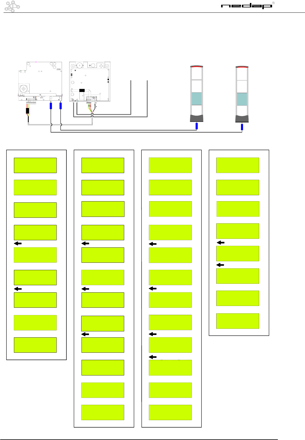
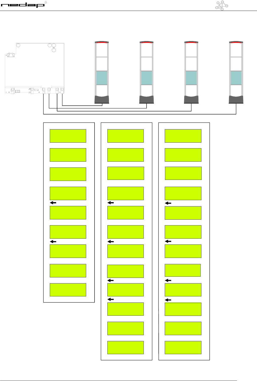
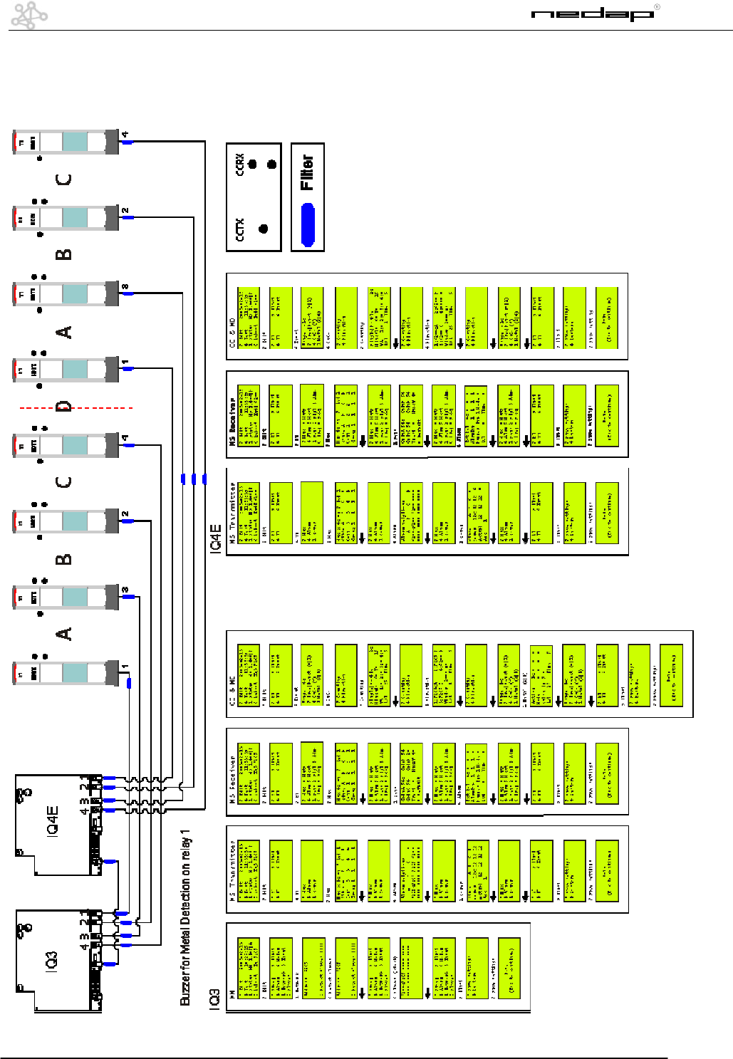
IQ System, 7 aisles, Customer Counting, Metal
Detection
See last page for an
extended view
21
OS/T Course 2003 © NEDAP Retail Support 2003
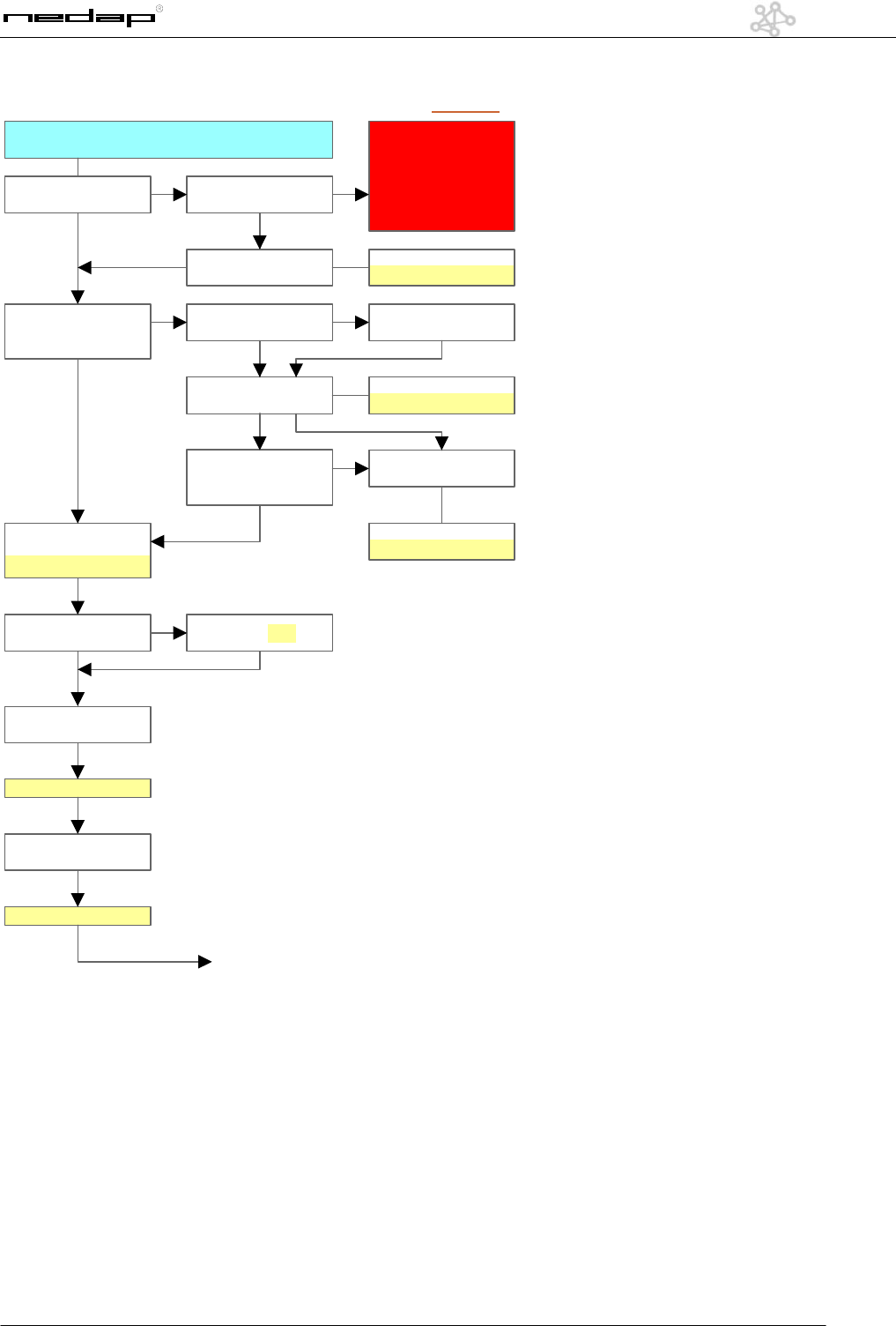
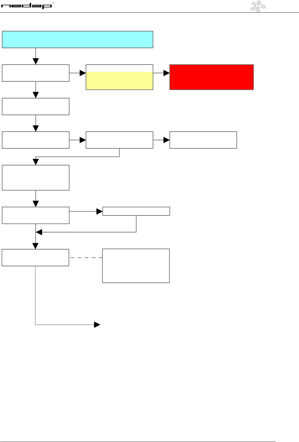
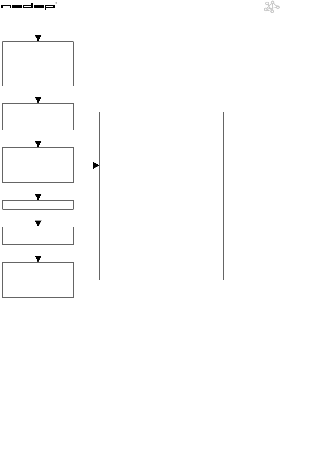
Checklist modem settings iNCC
Is there an analog
line present?
Install
telephoneline
NO
YES
Is the line available at
the place of the
installation?
When is the
line ready?
Date ready
__ - __ - _____
Will this be arranged
by third party?
Will this be arranged
by Nedap?
When is the
line ready?
NO NO
Date ready
__ - __ - _____
YES YES
Is the line ready before
the installation of
the OS/T system?
Problems?
extra visit
NO
Phone number of
this line
___________________
YES
YES Date visit
__ - __ - _____
Prefix for calling
outside the store Prefix: ___
YES
Is it possible to call
interlocal?
NO
YES / NO
Is it possible to call
international?
YES / NO
Next page
PRE -INSTALLATION
CAUTION:
ISDN connections to the
internet are
NOT
supported at this moment.
Connecting to an ISDN-line
is possible with a DeTeWe TA33
converter, but is
NOT
supported by Nedap
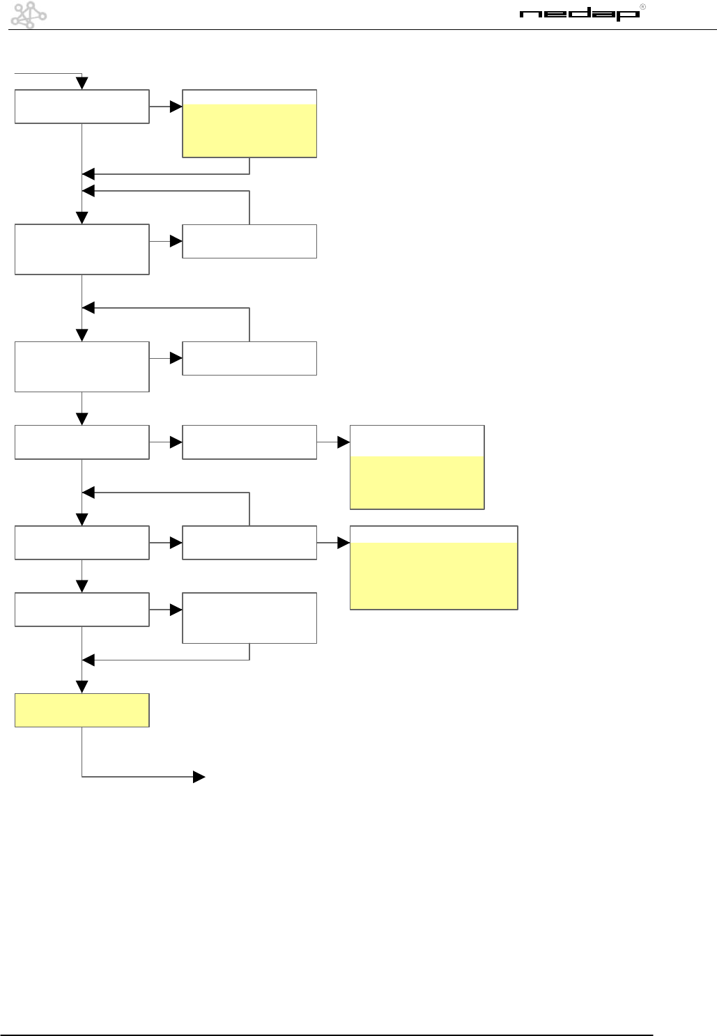
22
OS/T Course 2003 © NEDAP Retail Support 2003
Is this line blocked for
special phonenumbers?
Blocked for:
________________
________________
________________
NO
YES
Can this line be
approached through a
telephonecentral?
At what time can there
be called In or OUT
Is there an ISP present
at the customer?
NO
On-site installation
Can this line be
used for
data-transport?
Is this a shared line? Times to call:
example: 02 h 15m
____ h ____ m
____ h ____ m
____ h ____ m
Arrange an ISP ISP stettings:
Provider:_________________
Phonenumber:____________
IP: ______________________
Password:________________
NO
YES
YES
Did you enquire
a Store-ID?
Store-ID: ___
Mail/Fax Nedap for a
Store-ID by filling in
the applicationform
NO
YES
YES
YES
Arrange connecting
through the cental
NO
YES
YES
Arrange
data-transport
NO
YES
YES
23
OS/T Course 2003 © NEDAP Retail Support 2003
What brand and type
is the modem?
Modem:
Brand:__________
Type:___________
Connect the modem of
the iNCC to the
laptop / pc
INSTALLATION ON SITE
CAUTION:
Nedap recommends
NOT
to
use a US Robotics modem
Test the line with an
analog telephone
Call with this telephone
the ISP
You will hear a sound
like you are calling a fax
Check your
telephoneline
YES
NO
Next page
Test the modem by
calling the ISP
Solve problem
FAIL
Save the configuration
as AT&W
OK
OK
AT&W setting:
Go to Control panel, modem,
modemproperties, advanced
Extra initialization commands:
AT&W
24
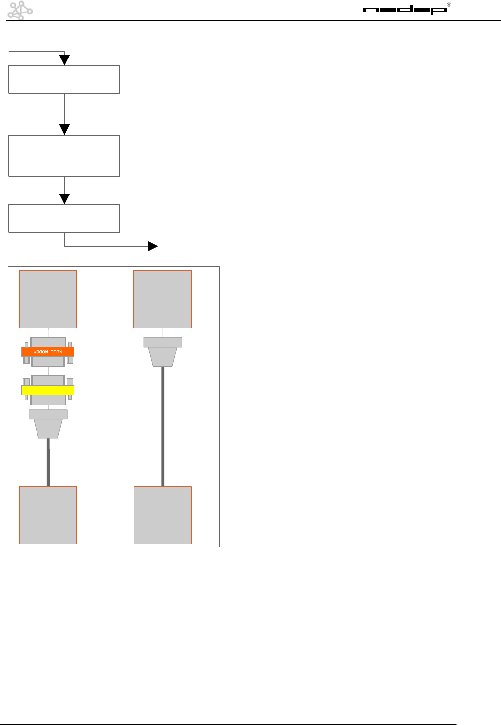
OS/T Course 2003 © NEDAP Retail Support 2003
Program the ISP
settings and the
Store-ID into the iNCC
Next page
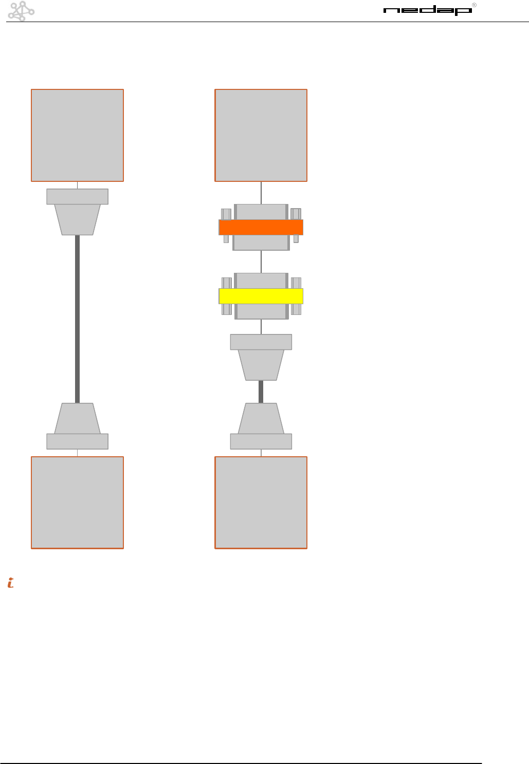
Disconnect the PC and
connect the modem
Connect the PC with
the iNCC
M
F
F
F
M
F
XQ EQ / IQ
MODEM MODEM
GENDER CHANGER
M
M
Direct
modem cable
Direct
modem cable
25
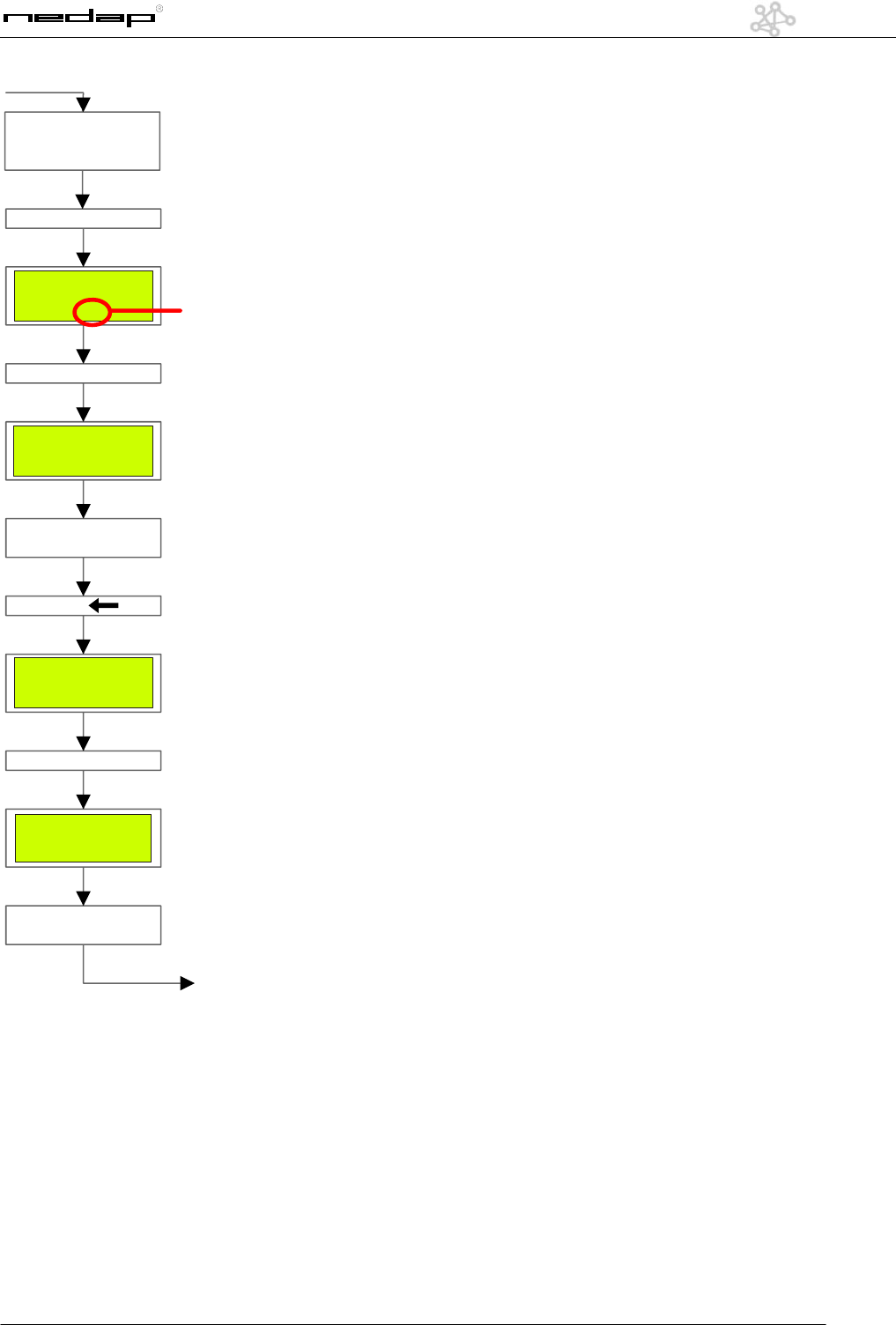
OS/T Course 2003 © NEDAP Retail Support 2003
Place the handterminal
in the MM part of the
unit
7 Modem
4 Internet
Store 19<
Modem 3<Auto 0
Connect 0 Logon 0
Bits 8 Par N Stop 1
Baud 38400 Pin 0000
Press "6"
Press "7"
Check if "Connect" = 0
0= Modem recognized
Press " "
7 Modem
4 Internet
Store 19<
Press "4"
Dial interval 1440<
Max connect 30
Syslog free 796
High 320 Low 64
Check and / or
change these settings
Next page
Your StoreID
26
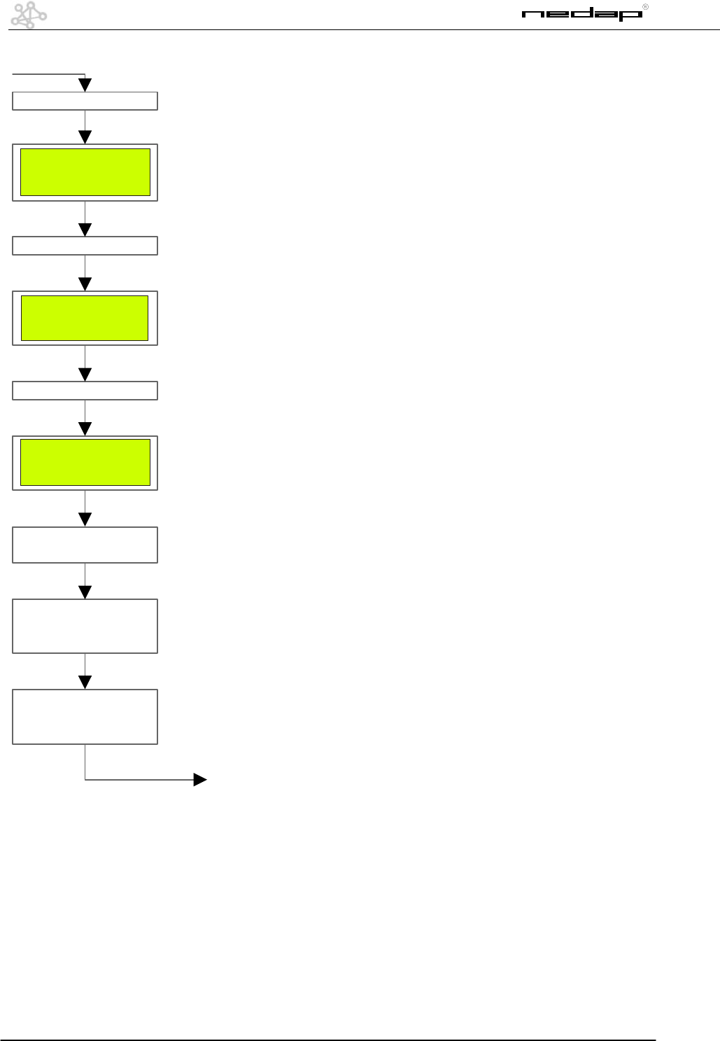
OS/T Course 2003 © NEDAP Retail Support 2003
Press "ESC"
Press "6"
7 Edit 2002-09-06
4 Tests 10:18:04
1 Status MM 1.406/A
C Reboot EQ 7862
7 Alarm
4 Bridging 6 Modem
1 Network 3 InOut
C Timer
Ival 1412 Con 118
Wait 0 DialNow 0
Ppp 00.00 0 0
Attempt 0 Modem 0
Press "1"
Press "E"
(pressing E will
start dialing)
"DialNow" will get "1"
Con will get 4
minutes higher
Press "C"
(Clearing the statusview)
Next page
27
OS/T Course 2003 © NEDAP Retail Support 2003
Connection OK
Take a look at the
PPP status: When PPP
is "3F" then data will
be send to the database
When data is send, PPP
status will be FF or BF
When the modem is
switching from
"0" > "-1" > "0" it is
starting to call out of
the store
Modem "2", starts
calling and is getting
"3"
Modem
-1 = No modem - Wrong cable / modem
switched off / wrong modem
0 = Modem found - default value
1 = Modem connected - someone is
connecting to the NCC
2 = Modem is trying to connect
3 = Connection present- NCC is connected
to the other side
Ppp = Point to Point Protocol
(when modem status is 3)
00 = No PPP - No modem connection / provider
does not understand the options
01 = LCP ISP is ready - NCC can not handle
the provider options
03 = LCP NCC is ready- Wrong name or Password
07 = PAP NCC is ready- Provider does not
understand IPCP options
0F = IPCP ISP is ready- NCC does not understand
IPCP options
1F = IPCP NCC is ready- TOP-server can not be
found / wrong IP-number and/or provider
does not support protocol
3F = TOP started- Default value
7F = TOP execute- Default value (very rare)
FF = Hangup- Default value (very rare)
Make a drawing of the
systemconfiguration
and mail / fax it to the
Nedap in Groenlo
28
OS/T Course 2003 © NEDAP Retail Support 2003
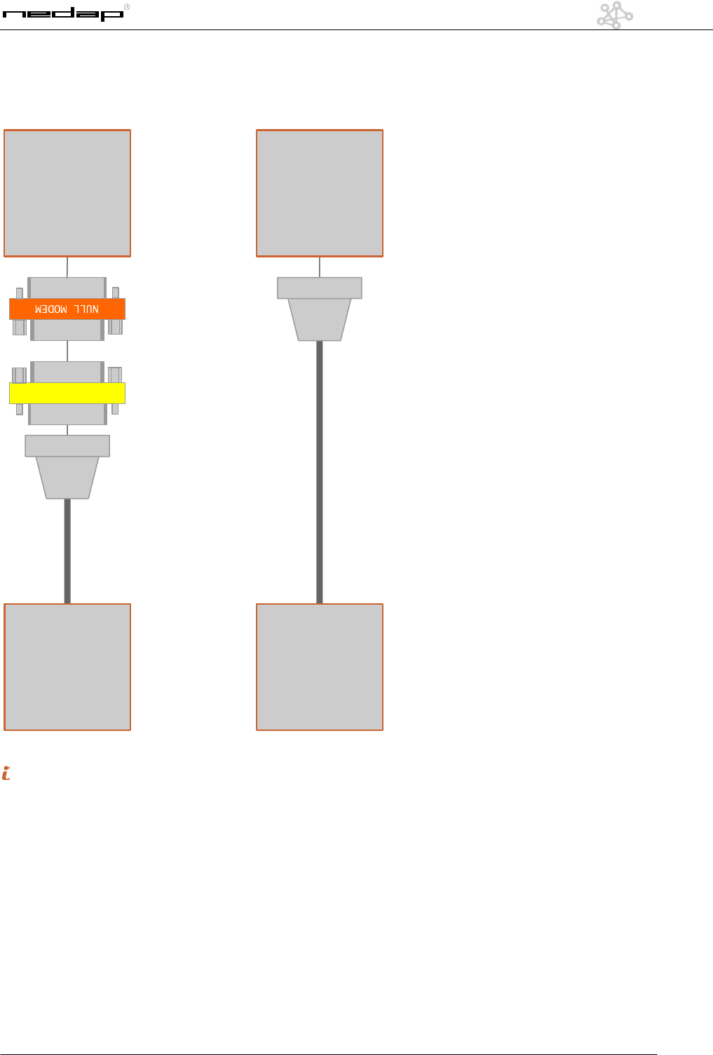
Connecting a PC to a XQ or EQ/IQ Unit
NULL MODEM
M
F
GENDER CHANGER
F
F
PC
RS232
XQ EQ / IQ
M
F
M
F
M
PC
RS232
M
F
M
RS232
9P SUB-D
Extension cable
RS232
9P SUB-D
Extension cable
F = Female, M = Male
29
OS/T Course 2003 © NEDAP Retail Support 2003
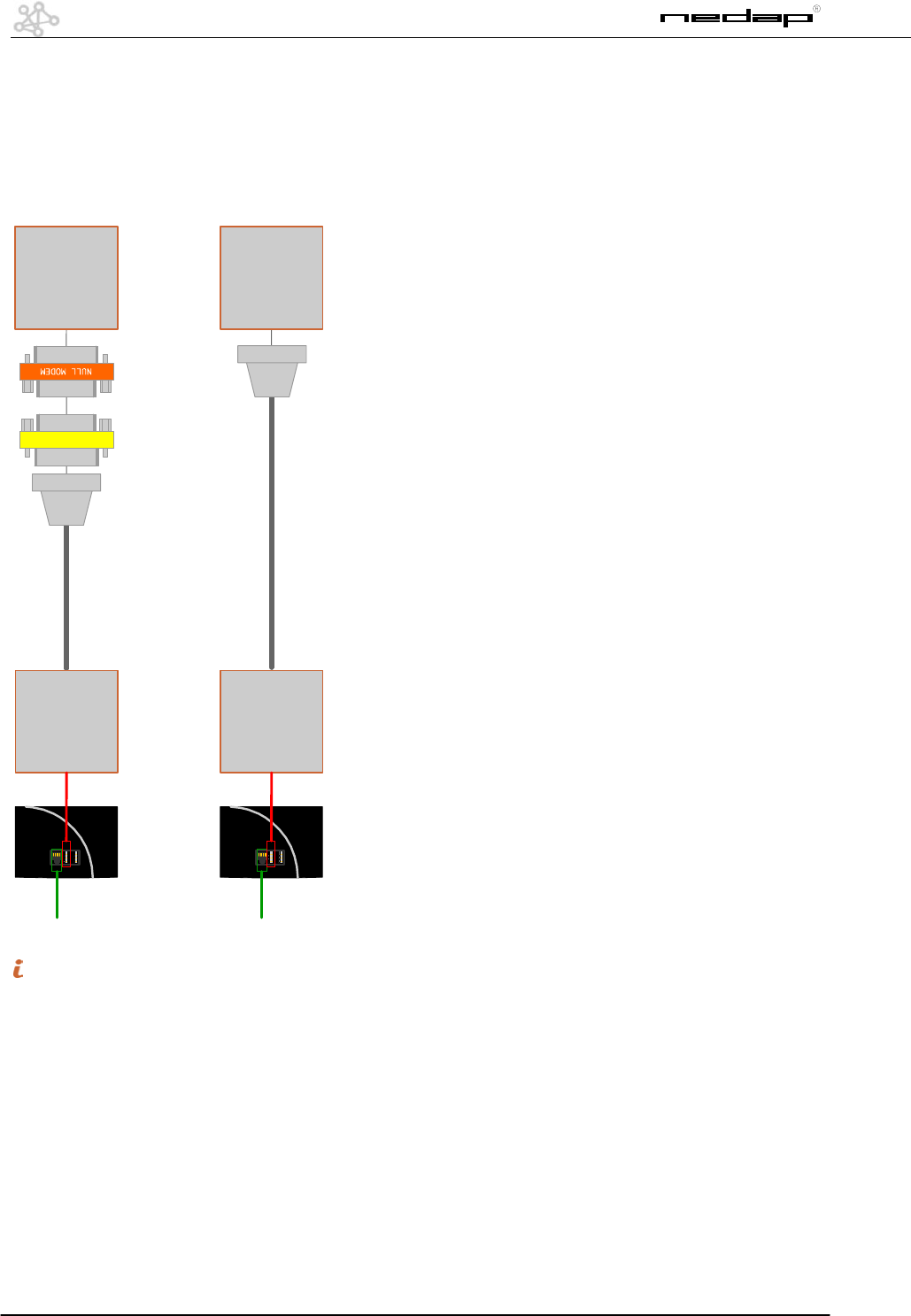
Connecting a XQ or EQ/IQ unit to a modem
M
F
F
F
M
F
XQ EQ / IQ
MODEM MODEM
GENDER CHANGER
M
M
Direct
modem cable
Direct
modem cable
F = Female, M = Male
30
OS/T Course 2003 © NEDAP Retail Support 2003
Connecting to an ISDN line using the DeTeWe TA33
terminal adapter
At the moment this manual is written, connecting a ISDN modem to a XQ or an EQ/IQ Unit is NOT supported. The
connection shown below can be used in case of an ISDN telephone line.
DeTeWe
TA33
ISDN A/B A/B
M
F
F
F
M
F
XQ EQ / IQ
ANALOG
MODEM
ANALOG
MODEM
GENDER CHANGER
M
M
Direct
modem cable
Direct
modem cable
ISDN
DeTeWe
TA33
ISDN A/B A/B
DeTeWe TA33
Terminal Adapter
Analog -> ISDN
ISDN
F = Female, M = Male
K23
K6 K10 K4 K5 K301 K300
K201 K202
K3
K205
16
1
16
1
K24
AB C
4 3 2 1
DA BC
K23
K6 K10 K4 K5 K301 K300
K201 K202
K3
K205
16
1
16
1
K24
4 3 2 1
RX TX RX TX RX TX RX TX
7 Edit 2003-02-13
4 Test 10:26:15
1 Status MM 1.407/A
C Reboot IQ 52C5
7 Sweep 9 Flash
4 Alarm 6 Modem
1 Network 3 InOut
C Slaves
Address 52C5
C Detect slaves FFFF
6288<72C5 0000 0000
0000 0000 0000 0000
7 Save settings
4 Restore
Done
(Esc to continue)
Address 52C5
C Detect slaves FFFF
7 Sweep 9 Flash
4 Alarm 6 Modem
1 Network 3 InOut
C Slaves
7 Sweep 9 Flash
4 Alarm 6 Modem
1 Network 3 InOut
C Slaves
MM
7 Edit
1 Network
C Detect slaves
C Slaves (check)
9 Flash
7 Save settings
7 Edit 2003-02-13
4 Test 11:33:39
1 Status MS 1.406/B
C Reboot IQ3 72C5
7 RX 9 Flash
4 TX 6 InOut
Mux x 4< On 7 Led 1
Group 1 1 1 1
Alarm neighbour
A B C D
72C5<72C5 72C5 6288
0000 0000 0000 0000
7 Save settings
4 Restore
Done
(Esc to continue)
7 Mux
4 Alarm
1 Power
7 RX 9 Flash
4 TX 6 InOut
MS Transmitter
7 Edit
4 TX
7 Mux
4 Alarm
9 Flash
7 Save settings
7 Mux
4 Alarm
1 Power
Phase A B C D
Conn 3 3 4 4
7 Edit 2003-02-13
4 Test 11:33:39
1 Status MS 1.406/B
C Reboot IQ3 72C5
7 RX 9 Flash
4 TX 6 InOut
MS Receiver
7 Edit
7 RX
7 Mux 8 MutS
4 Alrm 5 Mcut
1 Sens 2 Sigl 3 Admo
C Freq 0 Scop
Mux 4< On 7 Led 1
Phase A B C D
Conn 1 2 2 1
Group 1 1 1 1
7 Mux 8 MutS
4 Alrm 5 Mcut
1 Sens 2 Sigl 3 Admo
C Freq 0 Scop
7 Mux
GainA 54< GainB 54
GainC 54 GainD 20
Tresh 8 MaxPW 40
0 Default
7 Save settings
4 Restore
Done
(Esc to continue)
7 RX 9 Flash
4 TX 6 InOut
9 Flash
7 Save settings
7 Mux 8 MutS
4 Alrm 5 Mcut
1 Sens 2 Sigl 3 Admo
C Freq 0 Scop
7 RX 9 Flash
4 TX 6 InOut
1 Sens
7 Mux 8 MutS
4 Alrm 5 Mcut
1 Sens 2 Sigl 3 Admo
C Freq 0 Scop
Phase A B C D
Agc 1
1 Power
7 Mux
4 Alarm
1 Power
Power 12< 12 12 12
Actual 12 12 12 12
7 Mux
4 Alarm
1 Power
Ext Rel 0< 0 0 0
AlrmEna 1 1 1 0
Buzzer Ena 1 Mode 0
Lvl 0 Time 0
4 Alarm
MDRX MDTX MDRX MDTX MDRX MDTX MDRX MDTX
IQ3 IQ4E
IQ3 IQ4E
7 Edit 2003-02-13
4 Test 11:33:39
1 Status MS 1.406/B
C Reboot IQ3 72C5
7 RX 9 Flash
4 TX 6 InOut
CC & MD
7 Edit
6 InOut
Usage 4<
7 Free/Deact (0/1)
4 CuCo (*)
1 Metal (2/4)
7 Counting
4 Direction
Single/Double 2<
MinPuls 60 TO 15
WA 1:0 2:0 3:0 4:0
Lvl 25 Time 5
4 CuCo
7 Save settings
4 Restore
Done
(Esc to continue)
7 RX 9 Flash
4 TX 6 InOut
9 Flash
7 Save settings
1:72C5<A 2:72C5 B
3:72C5 C 4:6288 D
Window 2000 ms
LvL 1 Time 5
7 RX 9 Flash
4 TX 6 InOut
Action 1< 0 0 0
Mode 0 0 0 0
Pulse in 5 s
Lvl 25 Time 5
1 Metal (2/4)
7 Counting
7 Counting
4 Direction
4 Direction
7 Counting
4 Direction
Usage 4<
7 Free/Deact (0/1)
4 CuCo (*)
1 Metal (2/4)
Usage 4<
7 Free/Deact (0/1)
4 CuCo (*)
1 Metal (2/4)
7 Edit 2003-02-13
4 Test 11:33:39
1 Status MS 1.406/B
C Reboot IQ4E 6288
7 RX 9 Flash
4 TX 6 InOut
Mux x 4< On 7 Led 1
Group 1 1 1 1
Alarm neighbour
A B C D
6288<6288 6288 0000
0000 0000 0000 0000
7 Save settings
4 Restore
Done
(Esc to continue)
7 Mux
4 Alarm
1 Power
7 RX 9 Flash
4 TX 6 InOut
MS Transmitter
7 Edit
4 TX
7 Mux
4 Alarm
9 Flash
7 Save settings
7 Mux
4 Alarm
1 Power
Phase A B C D
Conn 3 3 4 4
7 Edit 2003-02-13
4 Test 11:33:39
1 Status MS 1.406/B
C Reboot IQ4E 6288
7 RX 9 Flash
4 TX 6 InOut
MS Receiver
7 Edit
7 RX
7 Mux 8 MutS
4 Alrm 5 Mcut
1 Sens 2 Sigl 3 Admo
C Freq 0 Scop
Mux 4< On 7 Led 1
Phase A B C D
Conn 1 2 2 1
Group 1 1 1 1
7 Mux 8 MutS
4 Alrm 5 Mcut
1 Sens 2 Sigl 3 Admo
C Freq 0 Scop
7 Mux
GainA 54< GainB 54
GainC 54 GainD 54
Tresh 8 MaxPW 40
0 Default
7 Save settings
4 Restore
Done
(Esc to continue)
7 RX 9 Flash
4 TX 6 InOut
9 Flash
7 Save settings
7 Mux 8 MutS
4 Alrm 5 Mcut
1 Sens 2 Sigl 3 Admo
C Freq 0 Scop
7 RX 9 Flash
4 TX 6 InOut
1 Sens
7 Mux 8 MutS
4 Alrm 5 Mcut
1 Sens 2 Sigl 3 Admo
C Freq 0 Scop
Phase A B C D
Agc 1
1 Power
7 Mux
4 Alarm
1 Power
Power 12< 12 12 6
Actual 12 12 12 0
7 Mux
4 Alarm
1 Power
Ext Rel 0< 0 0 0
AlrmEna 1 1 1 1
Buzzer Ena 1 Mode 0
Lvl 0 Time 0
4 Alarm
7 Edit 2003-02-13
4 Test 11:33:39
1 Status MS 1.406/B
C Reboot IQ4E 6288
7 RX 9 Flash
4 TX 6 InOut
CC & MD
7 Edit
6 InOut
Usage -1<
7 Free/Deact (0/1)
4 CuCo (*)
1 Metal (2/4)
7 Counting
4 Direction
Single/Double 2<
MinPuls 60 TO 15
WA 1:0 2:0 3:0 4:0
Lvl 1 Time 5
4 CuCo
7 Save settings
4 Restore
Done
(Esc to continue)
7 RX 9 Flash
4 TX 6 InOut
9 Flash
7 Save settings
1:6288<A 2:6288 B
3:6288 C 4:0000 0
Window 2000 ms
LvL 25 Time 5
7 RX 9 Flash
4 TX 6 InOut
7 Counting
7 Counting
4 Direction
4 Direction
7 Counting
4 Direction
Usage -1<
7 Free/Deact (0/1)
4 CuCo (*)
1 Metal (2/4)
13241324
CCTX CCRX
Filter
Buzzer for Metal Detection on relay 1


Manual MD4 including 62,75 MHz
NEDAP RETAIL SUPPORT
Metal Detection

2
Manual MD4 V1.3 © NEDAP Retail Support 2003
Caution!
This document is made for Adobe Acrobat Reader 5.0 or higher.
You can download this version of the reader at www.adobe.com
Technical Support:
- support-rs@nedap.nl
- H. Hammer
+31 (0) 544-47 15 19
h.hammer@nedap.nl
- H. Broekhuis
+31 (0) 544-47 15 02
h.broekhuis@nedap.nl
Visitor’s address:
Nedap Retail Support
Parallelweg 2d
Groenlo
Netherlands
Postal address:
Nedap Retail Support
Postbus 102
7140 AC Groenlo
Netherlands

3
Manual MD4 V1.3 © NEDAP Retail Support 2003
Table of content
Technical Support: 2
Modification of the OS/T Metal Detection operating frequency from 66 kHz to 62.75 kHz. 4
1 General 5
2 Block diagram 6
2.1 Explanation of the diagram 7
3 Printed Circuit Board 8
4 Metal Detection PCB in XQ unit 9
5 Metal Detection PCB in EQ/IQ unit 9
6 Handheld terminal settings 10

4
Manual MD4 V1.3 © NEDAP Retail Support 2003
Modification of the OS/T Metal Detection
operating frequency from 66 kHz to 62.75 kHz.
In DSP3 systems the Metal Detection (MD) had an operating frequency of 48 kHz, independent of the
8.2 MHz sweep generation system. It could run as a stand-alone system.
In the OS/T system, it is possible to set up a system including MD with internal electronics in the panels
and a single coax connection between the panels.
To realize that, the operating frequency of the OS/T MD had to be derived from the OS/T sweep
frequency. The required modification also gave the opportunity to choose a higher operating frequency.
That was desired because of an enhanced detectability of metal-lined bags with a very thin aluminum
layer, like used in certain types of “Cool Bags”.
The new operating frequency was chosen at 66 kHz, 8 kHz above the Acousto-Magnetic (AM)
operating frequency of Sensormatic, in stead of 10 kHz below it, but still within a frequency band where
the same level of fieldstrength (72 dBµA/m) is allowed, and not on the frequency’s of several
positioning systems, time standards and submarine communications.
Unfortunately this carefully chosen frequency appeared to be exactly the listen frequency of Security
Tag or Xpondr frequency divider EAS systems. The transmitter frequency of Xpondr is 132 kHz, so the
Nedap MD does not suffer from any interference of a Xpondr system.
When installed in neighbor shops, an Xpondr system appeared to be completely deaf.
Therefore we had to modify the operating frequency to a nominal 62.75 kHz in stead of 66 kHz.
This small frequency shift has the least impact in the modification of several filter components.
With the sweep-extend of the OS/T system on position 3, this frequency shifts down to 60.57 kHz.
This range is sufficiently below 66 kHz to prevent interference problems with both digital and older
analog Xpondr systems.
The drawback unfortunately is that 62.75 kHz is closer to the AM frequency. A Nedap MD system can
function on a distance of about 20 m away from an AM system. This minimum distance now should be
at least 25 m.

5
Manual MD4 V1.3 © NEDAP Retail Support 2003
1 General
The OST combination NCC4 and external RX4/TX4 can be fitted with up to 8 antenna’s making it
possible to guard up to 4 entrance separately.
This MD4 pcb also makes it possible for the Metal Detection to connect and process up to 4 different
entrances separately.
Like the FCI (Flat Cable Interface) pcb this MD4 pcb is also connected to the feature connector on the
OST RX4 or TX4. The MD4 pcb does not need tuning and holds no jumpers.
In addition to the 4 Metal Detection in/outputs the pcb is fitted with 4 extra inputs. Floating contacts can
be connected to these inputs, for instance to count tag decouplings or shop open/closed.
6
Manual MD4 V1.3 © NEDAP Retail Support 2003
2 Block diagram
+33V
+24V +15V +5V
LM2672 78M15 78M05
BST82
74HC123
1-shot
74HC123
1-shot
VCO
132Kc
74HC4040
Deler
74HC4046
74HC74
D - FF
BST82
BC807
BC817
/start
66Kc
600Hz
600Hz
74HC573 74HC4052
74HC573
+
ext_clk(I/0)
ext_io(I/0)
in
2 x 4mux
buffer
latch mute_3

7
Manual MD4 V1.3 © NEDAP Retail Support 2003
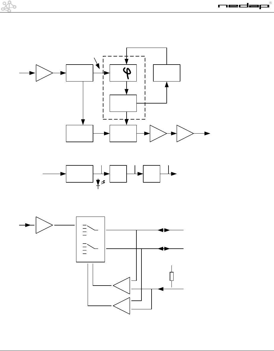
2.1 Explanation of the diagram
On the OST feature connector a 600Hz repeated signal is available from which the flat cable
interface produces the 66 kHz which is used on the metal detection PCB’s.
The /start pulse from the feature connector are infect two very narrow pulses about120uSec
apart and repeated in a more or less 600 Hz rhythm.
On every first pulse a 1 shot 74HC123) is triggered to produce a more or less 600 Hz block
signal used a reference signal for a PLL (74HC4046). The VCO of the PLL block oscillates on
132 kHz which by means of a programmable divider divides this signal to around 600 Hz.
This signal is then used on the Comp In. of the PLL and the 132 kHz is locked. Another 1 shot
triggers a divider by 2 circuit to output the 66 kHz signal which is available on the 4 data cable
outputs.
An alarm from the MD RX is shaped and buffered (74hc573) and presented on one of the
inputs of a 2 x 4mux (74hc4052). Dependent on the mute_3 signal, ext_clk and ext_i/o are
used to address the latch (74hc573) or read the output of the mux.
8
Manual MD4 V1.3 © NEDAP Retail Support 2003
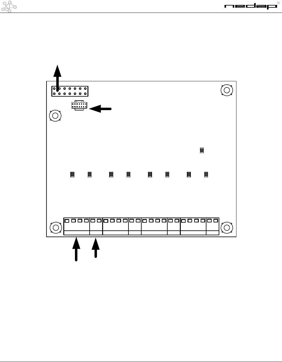
3 Printed Circuit Board
connection to feature
conn. OST
MD
extra IN
gnd
24Vdc
alarm
66kc
gnd
gnd
gnd
gnd
gnd
gnd
gnd
24Vdc
24Vdc
24Vdc
extra conn.
9
Manual MD4 V1.3 © NEDAP Retail Support 2003
4 Metal Detection PCB in XQ unit
4.1 Circuit board in unit XQ
The MD4 pcb is intended to be placed on top of the TX-PCB* inside the external unit shown above.
A CC4 pcb can be placed inside the unit as well.
* Connecting the MD4 PCB to a NR4 on a external NRT4 Unit will decrease EAS performance
OST-PCB
MD4-CC4 PCB
feature conn.
bottom entry
conn.
board stacker
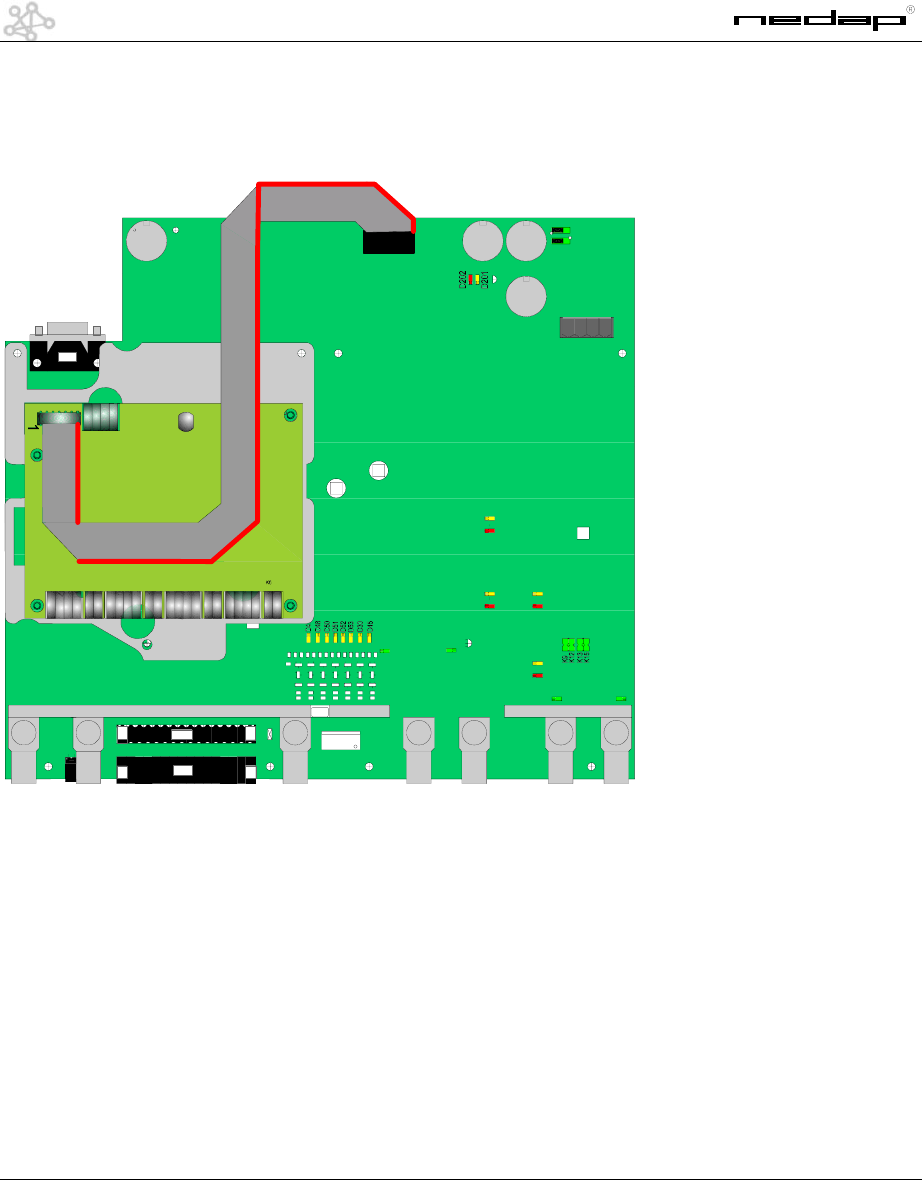
10
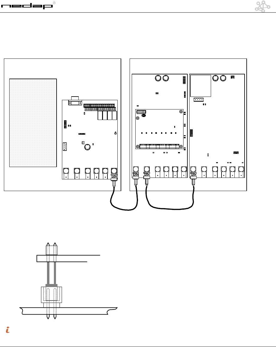
Manual MD4 V1.3 © NEDAP Retail Support 2003
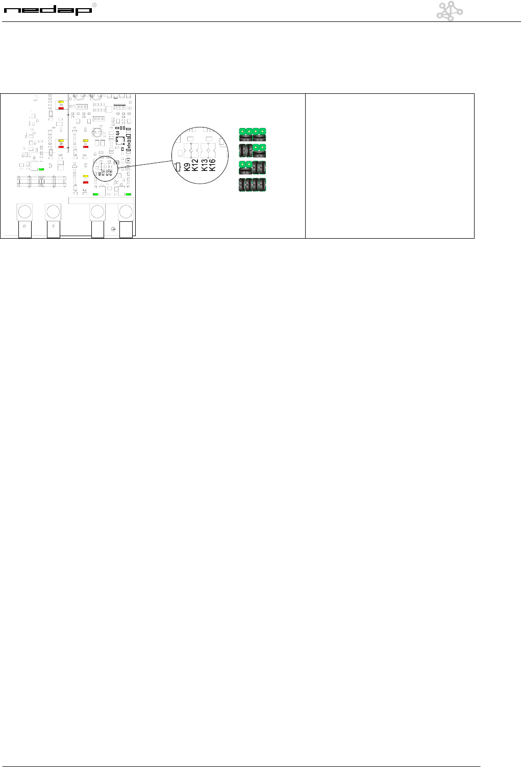
5 Metal Detection PCB in EQ/IQ unit
D312
D300
D301
D302
D303
D16
D19
D18
D17
D25
D26
D311
D11
K201 K202
K3
P3
P5
P1
P2
K205
K16
K6 K10 K4 K5 K301 K300
K11
116
116
P4
K7
D12
K204
K203
K24
K23
K21
1
7K
5K4K3K2K
1K
41K 2L
31K 21K 11K
The MD4 PCB will be mounted on the metal plate on top of the IQ unit.
It will be connected with a flat-cable to connector K21 (FCI) of the IQ PCB.
See the drawing for the right polarity.
6 Handheld terminal settings
For the handheld-terminal settings see the manual of the handheld-terminal (version 1.300 or higher).
11
Manual MD4 V1.3 © NEDAP Retail Support 2003
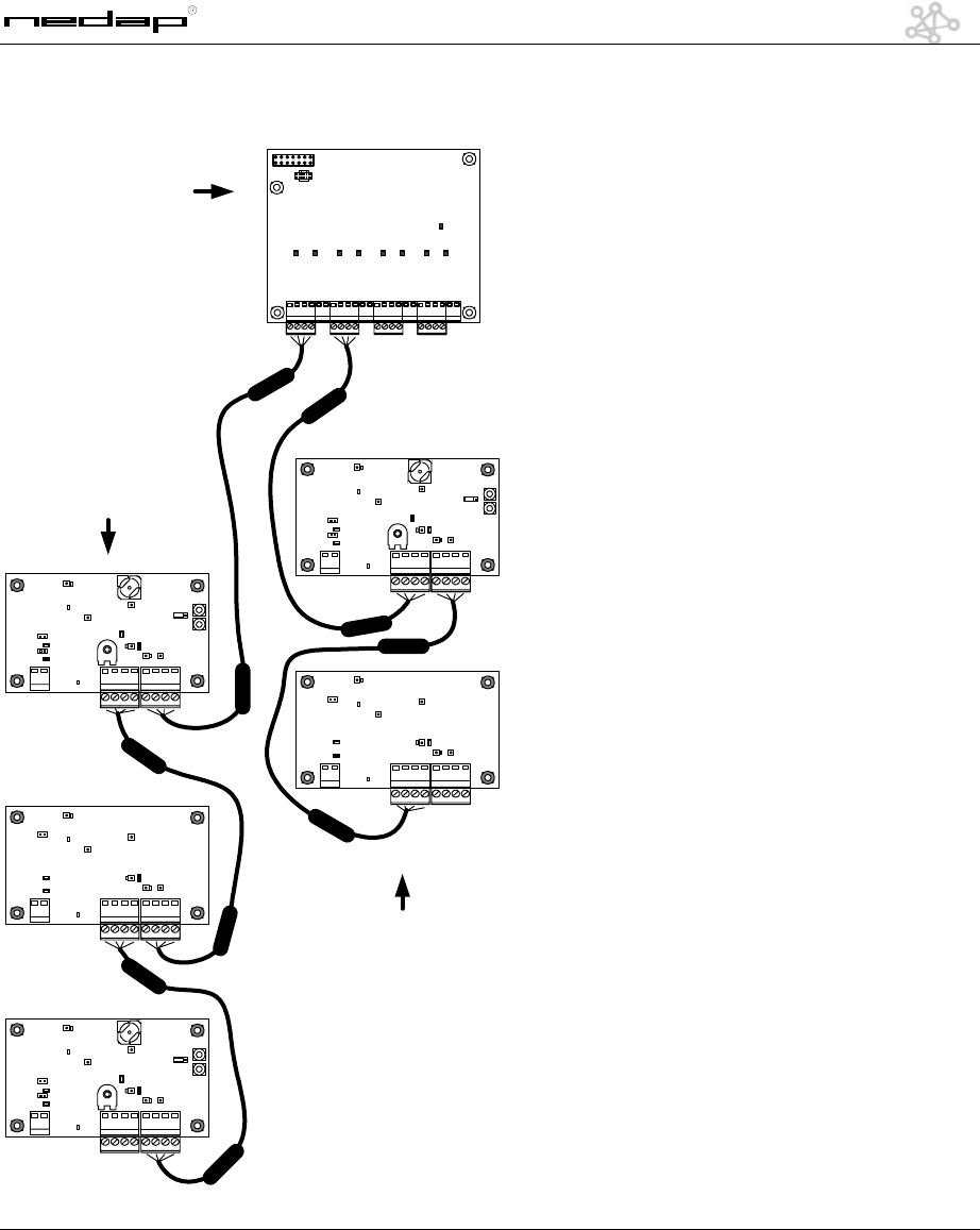
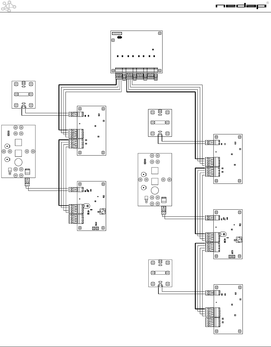
7 Wiring examples
Entrance 1
3 Panel
3 x MD Rx TX RX
Entrance 2
2 Panel
2 x MD RX TX
MD4 pcb
Filter
12
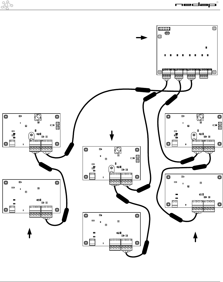
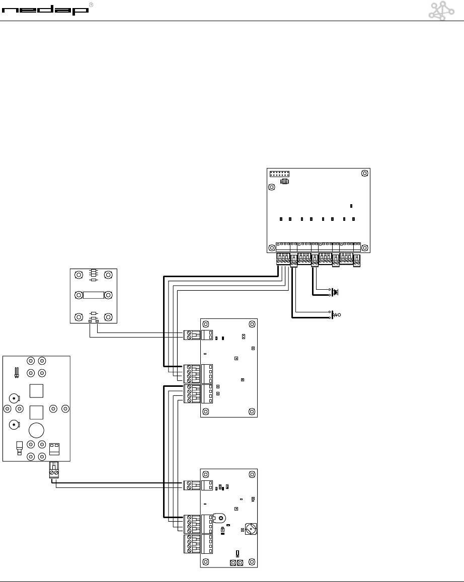
Manual MD4 V1.3 © NEDAP Retail Support 2003
Entrance 1
2 Panel
2 x MD Rx TX
Entrance 2
2 Panel
2 x MD RX TX
MD4 pcb
Entrance 3
2 Panel
2 x MD RX TX
Filter
13
Manual MD4 V1.3 © NEDAP Retail Support 2003
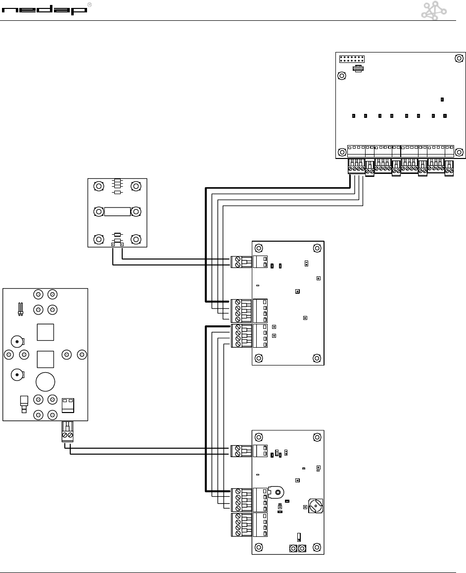
gnd
24Vdc
alarm
66kc
gnd
gnd
gnd
gnd
gnd
gnd
gnd
24Vdc
24Vdc
24Vdc
gnd
alarm
66kc
+24V
gnd
alarm
66kc
+24V
MD-TX
MD-RX
EQ45 Panel 1
EQ45 Panel 2
MD4
14
Manual MD4 V1.3 © NEDAP Retail Support 2003
gnd
24Vdc
alarm
66kc
gnd
gnd
gnd
gnd
gnd
gnd
gnd
24Vdc
24Vdc
24Vdc
gnd
alarm
66kc
+24V
gnd
alarm
66kc
+24V
MD-TX
MD-RX
EQ45 Panel 1
EQ45 Panel 2
MD4
gnd
alarm
66kc
+24V
gnd
alarm
66kc
+24V
MD-TX
MD-RX
EQ45 Panel 3
EQ45 Panel 4
gnd
alarm
66kc
+24V
MD-TX
EQ45 Panel 5
15
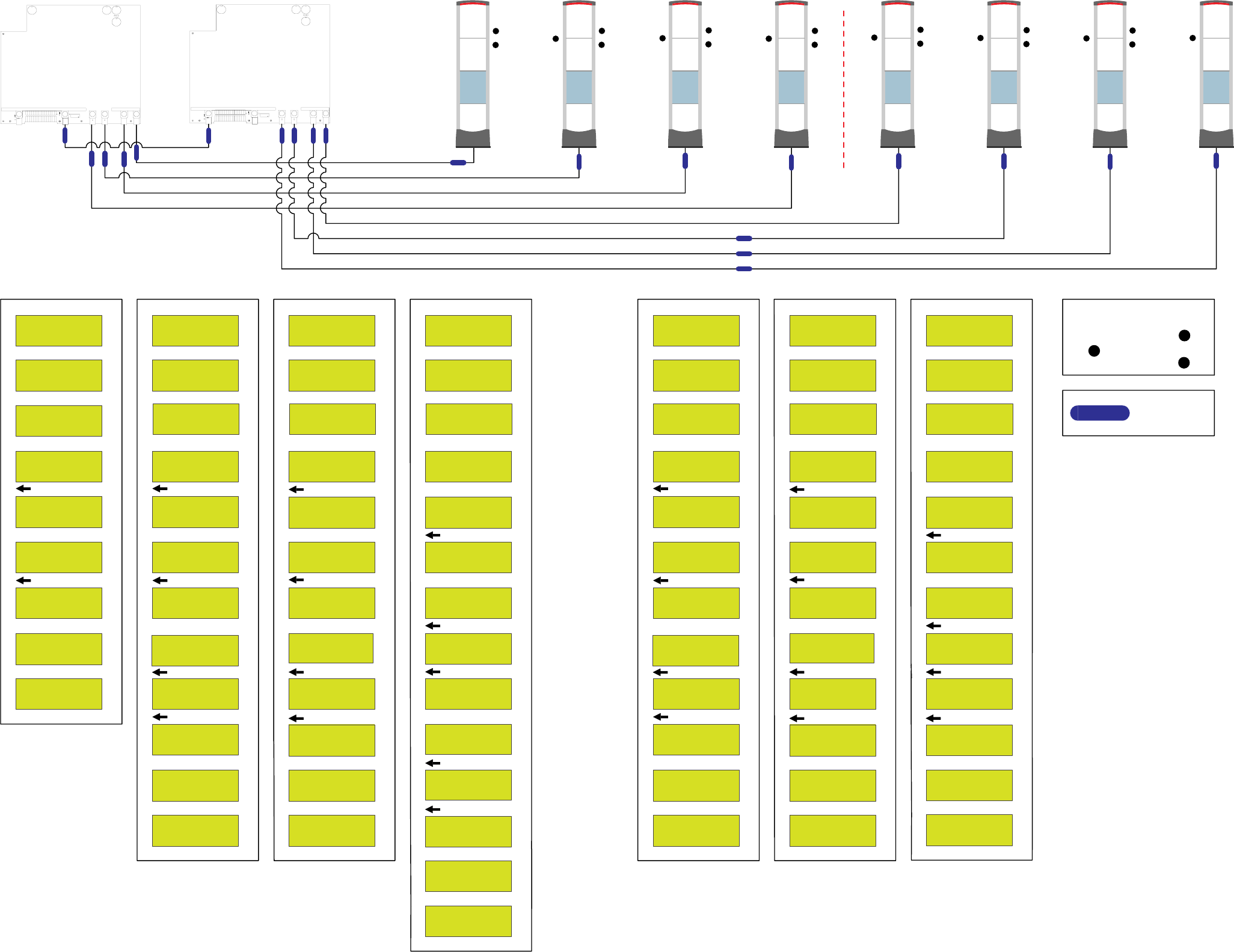
Manual MD4 V1.3 © NEDAP Retail Support 2003
The MD4 is designed to be used in combination with the OST external TX unit.
Metal detection now can be used in the same entrance configuration as you connect your OST external
RX/TX. As on the OST unit, 4 independent Metal Detection connectors are available with independent
alarming. (alarming is per entrance not per aisle).
As you see there is no change in how to loop the Metal Detection pcb’s together.
Only be sure to connect only one entrance per connector on the MD4 pcb.
This MD4 is also fitted with 4 additional “alarm-inputs” which can be used for a variety of options. Only
a floating contact is needed. One can use the contacts for instance as detection “shop open/closed” –
guard on watch – alarm cause – etc etc.
gnd
24Vdc
alarm
66kc
gnd
gnd
gnd
gnd
gnd
gnd
gnd
24Vdc
24Vdc
24Vdc
gnd
alarm
66kc
+24V
gnd
alarm
66kc
+24V
MD-TX
MD-RX
EQ45 Panel 1
EQ45 Panel 2
MD4
push button
door switch